33 RADIAL ARM BENCH AND FLOOR DRILL PRESSES · 2018-06-29 · Position ring against top of rack so...
20
operating manual & parts list 80341A & 80342A 33″ RADIAL ARM BENCH AND FLOOR DRILL PRESSES Read carefully and follow all safety rules and operating instructions before first use of this product. 30982.29-0111
Transcript of 33 RADIAL ARM BENCH AND FLOOR DRILL PRESSES · 2018-06-29 · Position ring against top of rack so...

operating manual & parts list 80341A & 80342A
33″
RADIAL ARM BENCH AND FLOOR DRILL PRESSES
Read carefully and follow all safety rules and operating instructions before first use of this product.
30982.29-0111

DESCRIPTION
Palmgren Radial Arm Drill Presses feature a heavy cast iron base,work table and head. Head moves 12” forward and backward usinga rack and pinion. Head also swivels 360° around column, tilts 90°right and 45° left. Work table height is also adjustable using rackand pinion. Table can be tilted 45° both right and left, and rotates360° on a vertical axis. Work table surface is precision groundwhich features slots for secure, accurate mounting of workpiece.Other features of the Palmgren drill press are an enclosed ballbearing quill assembly, quick belt change and tension mechanism,positive quick-adjust feed depth stop and a 1/2 HP, 1725 RPM motor.Chuck and chuck arbor are included.
Palmgren drill presses are ideal for use in home shops, mainte-nance shops and light industrial applications. Spindle speeds areadjustable for drilling steel, cast iron, aluminum, wood and plastic.
UNPACKING
Check for loose, missing or damaged parts. If any damage or losshas occurred, claim must be filed with carrier immediately. Checkfor completeness. Immediately report missing parts to dealer.
Drill press is shipped unassembled. Locate and identify the follow-ing assemblies and loose parts (Refer to Figures 1 and 2):
MODEL 80341A BENCH DRILL PRESS
A Head AssemblyB Column AssemblyC BaseD Table and Bracket Assembly with Worm GearE Quill Feed Handle (3)F Table Crank HandleG Retaining RingH RackI Drill Chuck with KeyJ YokeK Strap
Not Shown: Chuck arbor, Drift key, Lock handle, Shoe, M10 x 30 Hexhead bolts (2), M10 Flat washers (2), M10 Hex nuts (2), M8 x 30 Hexhead bolts (4), M8 Flat washers (4), M8 Lock washers (4), and 3mmand 4mm hex wrenches.
MODEL 80342A FLOOR DRILL PRESS
A Head AssemblyB ColumnC Column FlangeD BaseE Table Arm and Bracket Assembly with Worm GearF Extension ArmG TableH Drill Chuck with KeyI Table Crank HandleJ Quill Feed Handle (3)K Retaining RingL Rack
Not Shown: Chuck arbor, Drift key, Lock handle, Shoe, M10 x 40 Hexhead bolts (4), M8 Flat Washers (4), M8 Lock washers (4), and 3mm,4mm and 5mm hex wrenches.
IMPORTANT: The tool has been coated with a protective coating.In order to ensure proper fit and operation the coating must beremoved. Remove coating with mild solvents such as mineral spir-its and a soft cloth. Nonflam mable solvents are recommended.After cleaning, cover all exposed surfaces with a light coating of oil.Paste wax is recommended for table top.
CAUTION: Never use highly volatile solvents. Avoid getting clean-ing solution on paint as it may tend to deteriorate these finishes.Use soap and water on painted components.
SPECIFICATIONS
MODEL 80341A
Chuck size . . . . . . . . . . . . . . . . . . . . . . . . . . . . . . . . . . . . . . . . . . . 1-16mm, 3JTSpindle taper . . . . . . . . . . . . . . . . . . . . . . . . . . . . . . . . . . . . . . . . . . . . . . . . MT2Spindle travel . . . . . . . . . . . . . . . . . . . . . . . . . . . . . . . . . . . . . . . . . . . . . . . 3.15”Quill diameter . . . . . . . . . . . . . . . . . . . . . . . . . . . . . . . . . . . . . . . . . . . . . . . 1.85”Quill collar diameter . . . . . . . . . . . . . . . . . . . . . . . . . . . . . . . . . . . . . . . . . 2.16”Column diameter. . . . . . . . . . . . . . . . . . . . . . . . . . . . . . . . . . . . . . . . . . . . 2.36”Speeds. . . . . . . . . . . . . . . . . . . . . . . . . . . . . . . . . . . . . . . . . . . . . . . . . . . . . . . . . . 5RPM . . . . . . . . . . . . . . . . . . . . . . . . . . . . . . . . . . . . . . . . . . . . . . . . . . . . 575-3520Swing. . . . . . . . . . . . . . . . . . . . . . . . . . . . . . . . . . . . . . . . . . . . . . . . . . . . . . . 9-33”Head tilt . . . . . . . . . . . . . . . . . . . . . . . . . . . . . . . . . . . . . . . . . . . . . . . . 45°L, 90°RTable size . . . . . . . . . . . . . . . . . . . . . . . . . . . . . . . . . . . . . . . . . . . . . . . . . 87/8 x 9”Table slot . . . . . . . . . . . . . . . . . . . . . . . . . . . . . . . . . . . . . . . . . . . . . . . . . . . . . . 1/2”Base size. . . . . . . . . . . . . . . . . . . . . . . . . . . . . . . . . . . . . . . . . . . . . . 101/8 x 163/4”Base working surface. . . . . . . . . . . . . . . . . . . . . . . . . . . . . . . . . . . . . . 91⁄2 x 9”Drilling capacity (cast iron) . . . . . . . . . . . . . . . . . . . . . . . . . . . . . . . . . . . . . 5/8”Distance, spindle to table . . . . . . . . . . . . . . . . . . . . . . . . . . . . . . . . . . 31/4-15”Distance, spindle to base . . . . . . . . . . . . . . . . . . . . . . . . . . . . . . . . . . . . . . 22”Overall height. . . . . . . . . . . . . . . . . . . . . . . . . . . . . . . . . . . . . . . . . . . . . . . . . 37”Weight . . . . . . . . . . . . . . . . . . . . . . . . . . . . . . . . . . . . . . . . . . . . . . . . . . . . 100 lbsMotor . . . . . . . . . . . . . . . . . . . . . . . . . . . . 1/2 HP, 115 V, 1725 RPM, 4.8 Amps
2
Palmgren Operating Manual & Parts List 80341A & 80342A
Figure 1 – Model 80341A Unpacking
DE
F
H
J KI
C
B
A
G
Figure 2 – Model 80342A Unpacking
D
L
E
FH
JK
IC
B
A
G

3
UNPACKING (CONTINUED)
MODEL 80342A
Chuck size . . . . . . . . . . . . . . . . . . . . . . . . . . . . . . . . . . . . . . . . . . . 1-16mm, 3JTSpindle taper . . . . . . . . . . . . . . . . . . . . . . . . . . . . . . . . . . . . . . . . . . . . . . . . MT2Spindle travel . . . . . . . . . . . . . . . . . . . . . . . . . . . . . . . . . . . . . . . . . . . . . . . 3.15”Quill diameter . . . . . . . . . . . . . . . . . . . . . . . . . . . . . . . . . . . . . . . . . . . . . . . 1.85”Quill collar diameter . . . . . . . . . . . . . . . . . . . . . . . . . . . . . . . . . . . . . . . . . 2.16”Column diameter. . . . . . . . . . . . . . . . . . . . . . . . . . . . . . . . . . . . . . . . . . . . 2.76”Speeds. . . . . . . . . . . . . . . . . . . . . . . . . . . . . . . . . . . . . . . . . . . . . . . . . . . . . . . . . . 5RPM . . . . . . . . . . . . . . . . . . . . . . . . . . . . . . . . . . . . . . . . . . . . . . . . . . . . 575-3520Swing. . . . . . . . . . . . . . . . . . . . . . . . . . . . . . . . . . . . . . . . . . . . . . . . . . . . . . . 9-33”Head tilt . . . . . . . . . . . . . . . . . . . . . . . . . . . . . . . . . . . . . . . . . . . . . . . . 45°L, 90°RTable size. . . . . . . . . . . . . . . . . . . . . . . . . . . . . . . . . . . . . . . . . . . . . 103⁄8 x 10³⁄8” Table slot . . . . . . . . . . . . . . . . . . . . . . . . . . . . . . . . . . . . . . . . . . . . . . . . . . . . . . 1/2”Base size . . . . . . . . . . . . . . . . . . . . . . . . . . . . . . . . . . . . . . . . . . . . . . . 14 x 233/4”Base working surface . . . . . . . . . . . . . . . . . . . . . . . . . . . . . . . . . 127⁄8 x 123⁄8”Drilling capacity (cast iron) . . . . . . . . . . . . . . . . . . . . . . . . . . . . . . . . . . . . . 5/8”Distance, spindle to table . . . . . . . . . . . . . . . . . . . . . . . . . . . . . . . . . . . . 4-30”Distance, spindle to base . . . . . . . . . . . . . . . . . . . . . . . . . . . . . . . . . . . . . . 50”Overall height. . . . . . . . . . . . . . . . . . . . . . . . . . . . . . . . . . . . . . . . . . . . . . . . . 65”Weight . . . . . . . . . . . . . . . . . . . . . . . . . . . . . . . . . . . . . . . . . . . . . . . . . . . . 150 lbsMotor . . . . . . . . . . . . . . . . . . . . . . . . . . . . . . . . 1/2 HP, 115 V, 1725 RPM, 4.8 A
SAFETY RULES
PROPOSITION 65 WARNING: Some dust created by powersanding, sawing, grinding, drilling and other construction activitiescontains chemicals known to the state of California to cause can-cer, birth defects or other reproductive harm.
Some examples of these chemicals are:
• Lead from lead-based paints.
• Crystalline silica from bricks and cement and other masonry products.
• Arsenic and chromium from chemically-treated lumber.
Your risk from these exposures vary, depending on how often youdo this type of work. To reduce your exposure to these chemicals:work in a well ventilated area and work with approved safetyequipment. Always wear OSHA/NIOSH approved, properly fittingface mask or respirator when using such tools.
Before any work is done, carefully read the cautions listed. Workingsafely prevents accidents.
BE PREPARED FOR JOB• Wear proper apparel. Do not wear loose clothing, gloves, neck-
ties, rings, bracelets or other jewelry which may get caught inmoving parts of machine.
• Wear protective hair covering to contain long hair.
• Wear safety shoes with non-slip soles.
• Wear safety glasses which comply with United States ANSIZ87.1. Everyday glasses have only impact resistant lenses. Theyare NOT safety glasses.
• Wear face mask or dust mask if cutting operation is dusty.
• Be alert and think clearly. Never operate power tools whentired, intoxicated or when taking medications that causedrowsiness.
WORK AREA SHOULD BE READY FOR JOB• Keep work area clean. Cluttered work areas and work benches
invite accidents.
• Do not use power tools in dangerous environments. Do not usepower tools in damp or wet locations. Do not expose powertools to rain.
• Work area should be properly lighted.
• Proper electrical outlet should be available for tool.Three-prong plug should be plugged directly into properlygrounded, three-prong receptacle.
• Extension cords should have a grounding prong, and the threewires of the extension cord should be of the correct gauge.
• Keep visitors at a safe distance from work area.
• Keep children out of workplace. Make workshop childproof. Usepadlocks, master switches or remove switch keys to preventany unintentional use of power tools.
TOOL SHOULD BE MAINTAINED• Always unplug tool prior to inspection.
• Read operating instructions manual for specific maintainingand adjusting procedures.
• Keep tool lubricated.
• Use sharp cutters and keep the tool clean for safest operation.
• Remove adjusting tools. Form the habit of checking that adjust-ing tools are removed before turning on the machine.
• Keep all parts in working order. Check to determine that theguard or other parts will operate properly and perform theirintended function.
• Check for damaged parts. Check for alignment of moving parts,binding, breakage, mounting and any other condition that mayaffect a tool’s operation.
• Damaged parts should be properly repaired or replaced. Donot perform makeshift repairs. (Use the parts list provided toorder replacement parts.)
KNOW HOW TO USE TOOL• Use the right tool for the job. Do not force tool or attachment
to do a job for which it was not designed.
• Disconnect tool when changing accessories such as bits, cut-ters and the like.
• Avoid accidental start-up. Make sure switch is in OFF positionbefore plugging in.
• Do not force tool. It will work most efficiently at the rate forwhich it was designed.
• Handle workpiece correctly. Secure work with clamps or vise.Leave hands free to operate machine to protect hands from possible injury.
• Never leave a tool running unattended. Turn the power off anddo not leave tool until it comes to a complete stop.
• Do not overreach. Keep proper footing and balance.
• Never stand on tool. Serious injury could occur if tool is tippedor if cutter is unintentionally contacted.
• Keep hands away from moving parts and cutting surfaces.
• Know your tool. Learn its operation, application and specificlimitations.
• Feed work into a bit or cutter against the direction of rotationof bit or cutter.
• Turn the machine off if it jams. A cutter jams when it digs toodeeply into the workpiece. (The motor force keeps it stuck inworkpiece.)
• Use recommended accessories. Refer to page 13. Use ofimproper accessories may cause risk of injury to persons.
• Clamp workpiece or brace against column to prevent rotation.
• Use recommended speed for drill accessory and workpiecematerial.
WARNING: Think Safety! Safety is a combination of operatorcommon sense and alertness at all times when drill press is beingused.
Palmgren Operating Manual & Parts List 80341A & 80342A

ASSEMBLY
Refer to Figures 3 - 12 and 22.
MOUNT COLUMN ASSEMBLY TO BASE (80341A)Refer to Figures 3 and 23.
• Place base on flat level surface.
• Mount column assembly to base using four hex head bolts, lockwashers and flat washers.
• Push supporting yoke (Ref. No. 6) into holes at rear of base (Ref.No. 1) with bent portion of yoke facing down.
• Use strap, washers, bolts and nuts (Ref. Nos. 2 - 5) to secure yokein position.
MOUNT COLUMN ASSEMBLY TO BASE (80342A)Refer to Figure 4.
• Place base on flat level surface.
• Mount column flange to base using four hex head bolts, lockwashers and flat washers.
• Insert column into flange. Push column down until it seats inflange. Secure column in position with the two set screws.
MOUNT TABLE BRACKET ASSEMBLY (80341A)Refer to Figures 5 and 6, page 4 and 5.
• Make sure worm gear is in the table bracket and engages pin-ion teeth.
• Place rack inside table bracket. Slide rack into the slot in thebracket so that rack teeth engage the pinion gear in the bracket.Large non-machined portion of rack should be at top.
4
Palmgren Operating Manual & Parts List 80341A & 80342A
ColumnFlange
Rack
Table BracketAssembly
Figure 5 – Position Table Bracket Assembly on Column
Figure 3 – Mount Column Assembly to Base (80341A)
Hex Head Bolts
Column Assembly
Base
Figure 4 – Mount Column Flange to Base
Column
Hex Head Bolts
Set Screw
Flange
Base
Palmgren Operating Manual & Parts List 80341A & 80342A
5
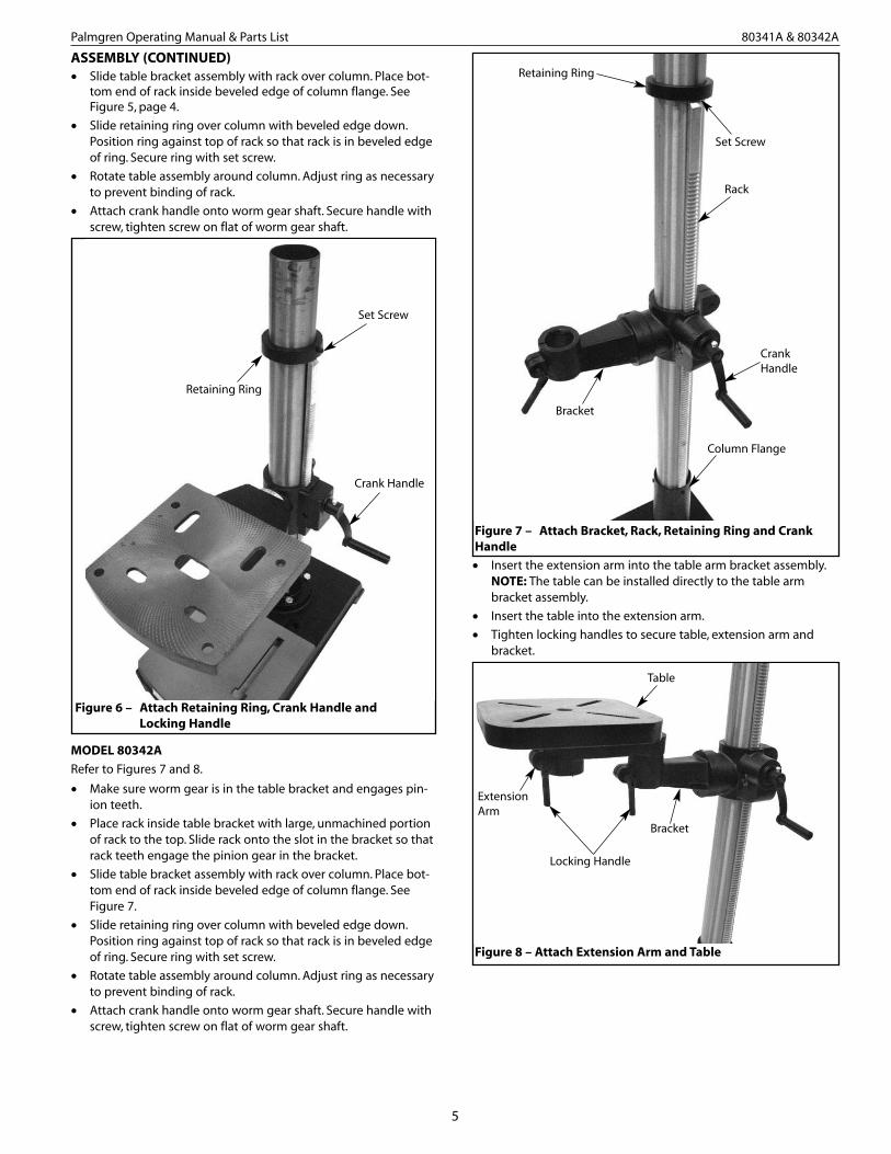
ASSEMBLY (CONTINUED)• Slide table bracket assembly with rack over column. Place bot-
tom end of rack inside beveled edge of column flange. SeeFigure 5, page 4.
• Slide retaining ring over column with beveled edge down.Position ring against top of rack so that rack is in beveled edgeof ring. Secure ring with set screw.
• Rotate table assembly around column. Adjust ring as necessaryto prevent binding of rack.
• Attach crank handle onto worm gear shaft. Secure handle withscrew, tighten screw on flat of worm gear shaft.
MODEL 80342A
Refer to Figures 7 and 8.
• Make sure worm gear is in the table bracket and engages pin-ion teeth.
• Place rack inside table bracket with large, unmachined portionof rack to the top. Slide rack onto the slot in the bracket so thatrack teeth engage the pinion gear in the bracket.
• Slide table bracket assembly with rack over column. Place bot-tom end of rack inside beveled edge of column flange. SeeFigure 7.
• Slide retaining ring over column with beveled edge down.Position ring against top of rack so that rack is in beveled edgeof ring. Secure ring with set screw.
• Rotate table assembly around column. Adjust ring as necessaryto prevent binding of rack.
• Attach crank handle onto worm gear shaft. Secure handle withscrew, tighten screw on flat of worm gear shaft.
• Insert the extension arm into the table arm bracket assembly.NOTE: The table can be installed directly to the table armbracket assembly.
• Insert the table into the extension arm.
• Tighten locking handles to secure table, extension arm andbracket.
Figure 6 – Attach Retaining Ring, Crank Handle and Locking Handle
Retaining Ring
Set Screw
Crank Handle
Figure 8 – Attach Extension Arm and Table
Bracket
ExtensionArm
Locking Handle
Table
Figure 7 – Attach Bracket, Rack, Retaining Ring and CrankHandle
Retaining Ring
Set Screw
Bracket
Rack
Column Flange
CrankHandle

6
Palmgren Operating Manual & Parts List 80341A & 80342A
ASSEMBLY (CONTINUED)
MOUNT HEAD ASSEMBLYRefer to Figures 9 and 10.
WARNING: Although compact, the drill press head assembly isheavy. Two people are required to mount the drill press headassembly onto the column.
• Place locking shoe into the cavity in the ram bracket.
WARNING: Do not install the head assembly onto column unlessthe locking shoe is in place. The head assembly cannot be properlysecured to the column without locking shoe.
• Slide drill press head assembly onto top of column.
• Position head so that it is centered over base.
• Secure head assembly into position by tightening the lockinghandles (see Figure 10).
MOUNT CHUCK AND ARBORRefer to Figure 22, page 12.
• Be sure spindle, arbor and chuck tapers are clean and dry. Makesure quill is completely retracted.
• Use the provided chuck key (Ref. No. 1) to adjust the jaws of thechuck (Ref. No. 2) until they are recessed inside the drill chuckbody.
• Place drill chuck on a workbench face down. Arbor (Ref. No. 80)has a short taper and a long taper. Place short taper into top ofdrill chuck and tap with a rubber or wooden mallet.
• Slide arbor into the spindle (Ref. No. 4) while slowly rotatingdrill chuck. Spindle has a rectangular pocket in which the tangfits into. Once tang is oriented correctly, drill chuck will notrotate without turning the spindle.
• Tap the end of drill chuck with a rubber or wooden mallet toseat it into the spindle.
• Use a hammer to carefully tap chuck securely onto the spindle.
MOUNT QUILL FEED HANDLESRefer to Figure 11.
• Thread the three quill feed handles into the threaded holes onthe pinion hub.
ADJUST V-BELT TENSIONRefer to Figure 12.
• Open the pulley cover and loosen both motor lock knobs (oneon each side of the head).
• Push motor back to apply tension to v-belt.
• Correct tension is obtained when the v-belt can be flexedapproximately 3/8” at belt midpoint using finger pressure.
• When correct tension is obtained, secure motor in position bytightening motor lock knobs.
Figure 10 - Secure Head Assembly
Head AngleLocking Handle
Head RotationLocking Handle
Figure 11 - Install Quill Feed Handles
Pinion Hub
Quill Feed Handle
Figure 12 - Adjust V-belt Tension
MotorLockKnob
Figure 9 – Place Locking Shoe Into the Cavity in Ram Bracket
Ram Bracket
Cavity
Locking Shoe

INSTALLATION
MOUNT DRILL PRESSRefer to Figure 13, page 7.
WARNING: The drill press must be mounted securely to a stand,bench or floor to prevent tipping of the machine which couldcause severe personal injury.• Drill press must be mounted to flat level surface. Use shims or
machine mounts if necessary.
• Be sure to bolt drill press to floor or bench securely to preventtipping and minimize vibration.
• Tighten all nuts and bolts that may have loosened during shipment.
POWER SOURCEThe motor is designed for operation on the voltage and frequencyspecified. Normal loads will be handled safely on voltages notmore than 10% above or below the specified voltage.
Running the unit on voltages which are not within the range maycause overheating and motor burn out. Heavy loads require thatthe voltage at motor terminals be no less than the voltage speci-fied.
Drill press requires a 115 volt, 60 Hz power source.
GROUNDING INSTRUCTIONSWARNING: Improper connection of equipment grounding con-ductor can result in the risk of electrical shock. Equipment shouldbe grounded while in use to protect operator from electrical shock.
Check with a qualified electrician if grounding instructions are notunderstood or if in doubt as to whether the tool is properlygrounded.
This tool is equipped with an approved 3-conductor cord rated upto 150V and a 3-prong grounding type plug (see Figure 14) foryour protection against shock hazards.
Grounding plug should be plugged directly into a properlyinstalled and grounded 3-prong grounding-type receptacle, asshown (Figure 14).
Do not remove or alter grounding prong in any manner. In theevent of a malfunction or breakdown, grounding provides a pathof least resistance for electrical shock.
WARNING: Do not permit fingers to touch the terminals of plugwhen installing or removing from outlet.Plug must be plugged into matching outlet that is properlyinstalled and grounded in accordance with all local codes andordinances. Do not modify plug provided. If it will not fit in outlet,have proper outlet installed by a qualified electrician.Inspect tool cords periodically, and if damaged, have repaired byan authorized service facility.Green (or green and yellow) conductor in cord is the groundingwire. If repair or replacement of the electric cord or plug is neces-sary, do not connect the green (or green and yellow) wire to a liveterminal.Where a 2-prong wall receptacle is encountered, it must bereplaced with a properly grounded 3-prong receptacle installed inaccordance with National Electric Code and local codes and ordi-nances.WARNING: This work should be performed by a qualified electrician.A temporary 3-prong to 2-prong grounding adapter (see Figure15) is available for connecting plugs to a two pole outlet if it is properly grounded.
Do not use a 3-prong to 2-prong grounding adapter unless permit-ted by local and national codes and ordinances.
(A 3-prong to 2-prong grounding adapter is not permitted inCanada.) Where permitted, the rigid green tab or terminal on theside of the adapter must be securely connected to a permanentelectrical ground such as a properly grounded water pipe, a prop-erly grounded outlet box or a properly grounded wire system.
Many cover plate screws, water pipes and outlet boxes are notproperly grounded. To ensure proper ground, grounding meansmust be tested by a qualified electrician.
EXTENSION CORDS• The use of any extension cord will cause some drop in voltage
and loss of power.
• Wires of the extension cord must be of sufficient size to carrythe current and maintain adequate voltage.
• Use the table to determine the minimum wire size (A.W.G.)extension cord.
• Use only 3-wire extension cords having 3-prong groundingtype plugs and 3-pole receptacles which accept the tool plug.
• If the extension cord is worn, cut, or damaged in any way,replace it immediately.
EXTENSION CORD LENGTHWire Size. . . . . . . . . . . . . . . . . . . . . . . . . . . . . . . . . . . . . . . . . . . . . . . . . . . A.W.G.Up to 25 ft.. . . . . . . . . . . . . . . . . . . . . . . . . . . . . . . . . . . . . . . . . . . . . . . . . . . . . 1825-100 ft. . . . . . . . . . . . . . . . . . . . . . . . . . . . . . . . . . . . . . . . . . . . . . . . . . . . . . . 16100-150 ft. . . . . . . . . . . . . . . . . . . . . . . . . . . . . . . . . . . . . . . . . . . . . . . . . . . . . . 14NOTE: Using extension cords over 150 ft. long is not recommended.
7
Palmgren Operating Manual & Parts List 80341A & 80342A
Figure 13 - Secure Drill Press to Bench or Stand
Mounting Holes(Mounting bolts not included)
Figure 14 – 3-Prong Receptacle
Grounding Prong
3-Prong Plug
Properly Grounded Outlet
Figure 15 – 2-Prong Receptacle with Adapter
Make Sure This Is Connected To AKnown Ground
2-Prong Receptacle
Grounding Lug
Adapter
3-Prong Plug

INSTALLATION (CONTINUED)
ELECTRICAL CONNECTIONSWARNING: All electrical connections must be performed by aqualified electrician. Make sure unit is off and disconnected frompower source while motor is mounted, connected, reconnected oranytime wiring is inspected.
• The motor is wired for 115 volts and in a clockwise rotation asviewed from shaft end of motor.
• The motor cord must be secured to protect the wiring connec-tions from possible strain.
• The power supply to motor is controlled by a locking rockerswitch. Power lines are connected to the quick connect termi-nals of the switch.
• The green ground line must remain securely fastened to themotor ground terminal and drill press head to provide propergrounding.
OPERATION
WARNING: Read and understand operating instructions andparts manual before operating this machine.
CAUTION: The operation of any power tool can result in foreignobjects being thrown into the eyes, which can result in severe eyedamage. Always wear safety glasses complying with United StatesANSI Z87.1 (shown on package) before commencing power tooloperation.
ON/OFF SWITCHRefer to Figure 16.
The ON/OFF switch is located on the front of the drill press head.To turn the drill press On, move the switch up to the ONposition. To turn the drill press Off, move the switch down to theOFF position.
The drill press can be locked from unauthorized use by locking theswitch. To lock the switch:
• Turn the switch to OFF position and disconnect drill press frompower source.
• Pull the key out. The switch cannot be turned on with the keyremoved.
NOTE: Should the key be removed from the switch at the ON posi-tion, the switch can be turned off but cannot be turned on again.
• To replace key, slide key into the slot on switch until it snaps.
SPEED ADJUSTMENTSRefer to Figures 12 and 17.
WARNING: Be sure drill press is turned off and is disconnectedfrom power source before adjusting speeds.
• To change spindle speed, loosen motor lock knob (see Figure14), and push the motor toward front of drill press. This willloosen the belt and permit relocating the belt to the desiredpulley groove for the required spindle speed (See Figure 17.
• After belt has been repositioned, push motor toward rear ofdrill press and tighten motor lock knob.
• Check belt for proper tension and make any final adjustment. Abelt is properly tensioned when light pressure applied to mid-point of the belt produces about 3/8” deflection.
HEAD ADJUSTMENTSRefer to Figures 18 and 19, page 9.
WARNING: Be sure drill is turned off and is disconnected frompower source before adjusting head.
• Head can be tilted 45° right and 90° left.
• To tilt head loosen head angle lock handle. Then pull out guidepin and turn guide pin 90°.
• Tilt head to desired angle, aligning reference mark on ram with corresponding angle on the scale. Secure in position by tightening head angle lock handle.
8
Palmgren Operating Manual & Parts List 80341A & 80342A
Figure 16 - Locking Key
SpindleRotation
5-5
4-4
3-3
2-2
1-1
3520
2630
1860
1120
575
in/mm
5/16 7.9
3/8 9.5
5/8 15.9
7/8 22.2
11/4 31.8
in/mm
3/16 4.8
1/4 6.4
3/8 9.5
1/2 12.7
3/4 19.0
in/mm
11/64 4.4
7/32 5.6
11/32 8.7
15/32 11.9
11/16 17.5
in/mm
5/32 4.0
3/16 4.8
5/16 7.9
7/16 11.1
5/8 15.9
in/mm
7/64 2.8
1/8 3.2
1/4 6.4
11/32 8.7
1/2 12.7
in/mm
3/32 2.4
3/32 2.4
5/32 4.0
1/4 6.4
3/8 9.5
in/mm
1/16 1.6
1/16 1.6
1/8 3.2
3/16 4.8
5/16 7.9
in/mm
1/32 0.8
3/64 1.2
1/16 1.6
1/8 3.2
1/4 6.4
BeltLocation RPM Wood
ZincDiecast
Alum. &Brass Plastic
Cast Iron & Bronze
Steel Mild &Malleable
Steel Cast &Med.Carbon
SteelStainless &Tool
Figure 17 – Spindle Speed Adjustment
Recommended Drill Size per Material for 5 Speeds
5
4
3
2
1
5
4
3
2
1
Spindle Motor
Locking Key

9
Palmgren Operating Manual & Parts List 80341A & 80342A
OPERATION (CONTINUED)• To return head to 0° vertical position, loosen head angle lock
handle, rotate guide pin 90° and tilt head. The guide pin willsnap into slot at 0° vertical. Secure in position by tighteninghead angle lock handle.
• To move head forward and backward, loosen head angle lockhandle. Turn head traverse knob until head is in desired posi-tion. Secure head by tightening head angle lock handle.
• To rotate head about the column, loosen head rotation lockhandle. Rotate head to desired position and secure by tighten-ing head rotation lock handle.
TABLE ADJUSTMENTS• Height adjustments: To adjust table, loosen locking handle and
turn crank handle to desired height. Immediately retightentable bracket locking handle.
• Rotation of work table : Loosen table locking handle and rotate table to desired position and retighten handle. (Refer to Figure 7, page 5).
• Tilting work table: Loosen hex head bolt. Remove pin and nut.To do this, tighten nut until pin slips out easily. Tilt table todesired angle up to 45° and retighten hex head bolt. Reinsertpin and nut when returning the table to 0° position.
• To obtain more distance between chuck and table, the worktable can be rotated 180° and base can be used as a work sur-face. This permits drilling of larger objects.
• Clamp table securely after adjustments have been made. (See Figure 20).
DEPTH STOP ADJUSTMENTRefer to Figure 21.
To control drilling depth, loosen hub locking knob and rotate hubuntil the desired depth on scale coincides with the pointer. Tightenknob to secure hub in position. Use this feature to drill more thanone hole to the same depth.
MOUNT DRILL BITWARNING: Be sure drill press is turned off and is disconnectedfrom power source before adjusting speeds.
• Place drill bit in jaws of drill chuck.• Tighten chuck with drill chuck key. Be sure to tighten the chuck
using all three key positions on the chuck body and removechuck key.
Figure 18 - Right Side of Head Assembly
Head AngleLock HandleHead Traverse Knob
Reference Mark
Scale
Ram
Figure 19 - Left Side of Head Assembly
Guide Pin
Slot
Head RotationLock Handle
Figure 20 - Tilting Worktable
Pin and Nut
Hex HeadBolt
Figure 21 - Depth Stop Operation
Hub Locking Knob
Pointer
Scale
Hub

10
Palmgren Operating Manual & Parts List 80341A & 80342A
MAINTENANCE
WARNING: Turn switch off and remove plug from power sourceoutlet before maintaining or lubricating your drill press
V-BELTReplace V-belt when worn.
LUBRICATIONThe ball bearings are lubricated at the factory and need no furtherlubrication. Using 20wt. non detergent oil, periodically lubricatethe splines (grooves) in the spindle and the rack (teeth on thequill) as follows:
• Lower spindle assembly (Figure 22, Ref. No. 3) all the way down.• Apply lubricant around the inside of the hole in the spindle
pulley (Figure 22, Ref. No. 72).• Apply lubricant to rack (teeth) on quill (Figure 22, Ref. No. 6)
while extended below drill press head.• Apply lubricant to rack and pinion gear (Figures 23 and 24, Ref.
Nos. 11 and 22) on column and table assembly.
CLEAN MOTORFrequently blow out any dust that may accumulate inside motor. Ifpower cord is worn, cut or damaged in any way, have it replacedimmediately.

11
Palmgren Operating Manual & Parts List 80341A & 80342A
SYMPTOM
Spindle does not turn
Noisy spindle
Noisy operation
Bit burns or smokes
Excessive drill runout or wobble
Drill bit binds in workpiece
POSSIBLE CAUSES
1. No power to drill press
2. Defective switch
3. Defective motor
Defective bearings
1. Incorrect belt tension
2. Dry spindle
3. Loose spindle
4. Loose motor pulley
1. Incorrect speed
2. Chips not coming out of table
3. Dull bit
4. Feeding too slow
5. Bit not lubricated
6. Bit running backwards
1. Bent bit
2. Bit not properly installed in chuck
3. Chuck not properly installed
4. Worn spindle bearings
1. Workpiece pinching bit or excessive feed
2. Improper belt tension
3. Workpiece not supported or clamped properly
CORRECTIVE ACTION
1. Check wiring, fuse or circuit breaker
2. Replace switch
3. Replace motor
Replace bearings
1. Adjust tension
2. Lubricate spindle
3. Tighten pulley nut
4. Tighten set screw in pulley
1. Change speed
2. Retract bit frequently to clear chips
3. Sharpen or replace bit
4. Feed faster; enough to allow drill to cut
5. Lubricate bit
6. Check motor rotation to be sure it is clockwise facing shaft end
1. Replace bit
2. Install bit properly
3. Install chuck properly
4. Replace bearings
1. Support or clamp work, decrease feed pressure
2. Adjust tension tighter
3. Support or clamp workpiece securely
TROUBLESHOOTING
12
Palmgren Operating Manual & Parts List 80341A & 80342A
12
56
5758
98
39
11
6
37
31
34
32
35
2938
36
1918
24
25
6566
67
68
69
69
70 60
10
3
20
2221 23
4
5
54
55
75
76
44
43
47
17
46
27
80
33
53
78
6077
5046
68
7172
74
73
28 15
30
51
4149
46
61
62 63
64
59
59
48
14
77
1540
16
1
7
2
45
26
26
13
42
52
79
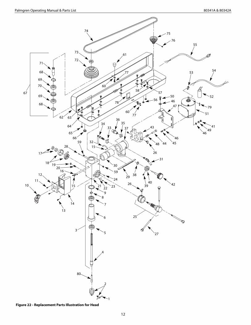
Figure 22 - Replacement Parts Illustration for Head

13
Palmgren Operating Manual & Parts List 80341A & 80342A
* Standard hardware item available locally.Δ Not shown.
REPLACEMENT PARTS LIST FOR HEAD
Recommended Accessories
Δ Multi Tool Stand 70102
Δ Drill Press Guard 15008
Δ 3” Drill Press Vise 12303
Δ 4” Drill Press Vise 12403
Ref.No. Description Part No. Qty.
1 Chuck Key 30535.00 1
2 Chuck with Key (incl. Ref No. 1) 30536.00 1
3 Lower Spindle Assembly 30537.00 1
(incl. Ref. Nos. 4-9)
4 Spindle 30538.00 1
5 6005Z Ball Bearing 00956.00 1
6 Quill 30539.00 1
7 6003Z Ball Bearing 05092.00 1
8 3AMI-17 Retaining Ring 00341.00 1
9 Rubber Bumper 30540.00 1
10 Switch 26035.00 1
11 4-1.6 x 12mm Threadforming Screw 22655.00 2
12 Switch Plate 30541.00 1
13 5-0.8 x 14mm Pan Head Screw * 4
14 Cover 30542.00 1
15 4-0.7 x 5mm Pan Head Screw * 4
16 4mm Serrated Washer * 2
17 12-1.50mm Hex Nut 07817.00 2
18 Cap cover and spring 30543.00 1
19 10-1.5mm Hex Nut * 1
20 10-1.5 x 30mm Dog Point Set Screw 30579.00 1
21 Drill Press Head 30544.00 1
22 Pointer 22620.00 1
23 Rivet 22621.00 1
24 Threaded Pin 30545.00 1
25 Quill Feed Assembly 30546.00 1
(incl. Ref. Nos. 26 and 27)
26 Knob 22622.00 2
27 Handle with grip 30547.00 3
28 4 x 25mm Spring Pin 01509.00 1
29 Radial Rack 30548.00 1
30 Ram 30549.00 1
31 Handle 30577.00 1
32 Scale 30550.00 1
33 Locking Shoe 30551.00 1
34 Handle 30552.00 2
35 16-2.0mm Hex Nut * 1
36 Guide Pin Assembly 30553.00 1
37 Ram Bracket (Model 80341) 30554.00 1
37 Ram Bracket (Model 80342) 30555.00 1
38 3AMI-10 Retaining Ring 00221.00 1
39 5-0.8 x 6mm Set Screw * 1
40 Gear 30556.00 1
Ref.No. Description Part No. Qty.
41 8-1.25mm Hex Nut * 4
42 Knob 30557.00 1
43 Bracket 30558.00 1
44 Tension Adjustment Bar 30559.00 1
45 8-1.25 x 25mm Hex Head Bolt * 4
46 8mm Flat Washer * 12
47 Motor Mount Plate 30560.00 1
48 Spring 30578.00 1
49 8mm Lock Washer * 4
50 8-1.25 x 20mm Hex Head Bolt * 4
51 Motor (incl. Ref. Nos. 52-54) 30561.00 1
52 Capacitor 30562.00 1
53 Strain Relief 01413.00 1
54 Motor Cord 30563.00 1
55 Line Cord 30564.00 1
56 Grommet 30565.00 2
57 6mm Flat Washer * 8
58 6-1.0 x 12mm Pan Head Screw * 4
59 8-1.25 x 8mm Set Screw * 3
60 5mm Flat Washer * 3
61 Knob 30566.00 1
62 Pulley Housing 30567.00 1
63 6-1.0 x 14mm Pan Head Screw * 4
64 Cord Clamp 30568.00 4
65 6-1.0mm Hex Nut * 4
66 Grommet 04076.00 1
67 Upper Spindle Assembly 30569.00 1
(incl. Ref. Nos. 68-71)
68 3BMI-47 Retaining Ring 04790.00 2
69 6204ZZ Ball Bearing 00803.00 2
70 Spacer 30570.00 1
71 Upper Spindle Sleeve 30571.00 1
72 Spindle Pulley 30572.00 1
73 Pulley Nut 30573.00 1
74 V-Belt 30574.00 1
75 Motor Pulley 30575.00 1
76 6-1.0 x 10mm Set Screw * 1
77 5-0.8 x 10mm Pan Head Screw * 3
78 Latch 30576.00 1
79 5 x 5 x 40mm Key 07885.00 2
80 Arbor 18908.00 1
Δ Operator’s Manual 30982.29 1

14
Palmgren Operating Manual & Parts List 80341A & 80342A
Figure 23 - Replacement Parts Illustration for Base (Model 80341A)
15
22
21
19
18
6
20
23
16
9
8
7
1312
14
5
42
3
1
24
10
11
17

15
Palmgren Operating Manual & Parts List 80341A & 80342A
REPLACEMENT PARTS LIST FOR BASE (MODEL 80341A)
* Standard hardware item available locally.
Ref.No. Description Part Number Qty.
1 Base 30898.00 1
2 Clamp 30899.00 1
3 10mm Flat Washer * 2
4 10-1.5mm Hex Nut * 2
5 10-1.5 x 30mm Hex Head Bolt * 2
6 Supporting Yoke 30900.00 1
7 8mm Flat Washer * 4
8 8mm Lock Washer * 4
9 8-1.25 x 30mm Hex Head Bolt * 4
10 Column Assembly 30901.00 1
11 Rack 30902.00 1
12 12-1.75 x 30mm Hex Head Bolt * 1
13 12mm Lock Washer * 1
14 Table 30903.00 1
15 Pinion Gear Shaft 30904.00 1
16 Scale with Rivets 30905.00 1
17 Locking Handle 30906.00 1
18 Worm Gear 30907.00 1
19 Rack Retaining Ring 30908.00 1
20 8-1.25 x 10mm Set Screw * 1
21 Table Bracket Assembly (Incl.Ref. Nos. 15, 16, & 22) 30909.00
22 Pinion Gear 30910.00 1
23 5-0.8 x 12mm Pan Head Screw * 1
24 Crank 30911.00 1
16
Palmgren Operating Manual & Parts List 80341A & 80342A
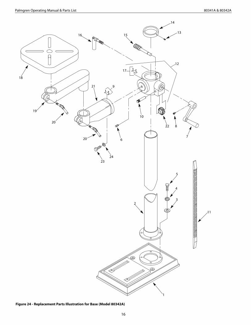
Figure 24 - Replacement Parts Illustration for Base (Model 80342A)
22
12
14
15
6
8
10
4
13
5
18
19
17
21
3
20
20
11
2423
9
1
7
2
16

17
Palmgren Operating Manual & Parts List 80341A & 80342A
* Standard hardware item available locally.
REPLACEMENT PARTS LIST FOR BASE (MODEL 80342A)
Ref.No. Description Part Number Qty.
1 Base 30912.00 1
2 Column Assembly 30913.00 1
3 10mm Flat Washer * 4
4 10mm Lock Washer * 4
5 10-1.5 x 35mm Hex Head Bolt * 4
6 6-1.0 x 10mm Dog Point Set Screw 06858.00 1
7 Crank Handle 30915.00 1
8 5-0.8 x 12mm Pan Head Screw * 1
9 Indicator with Rivets 30927.00 1
10 Pinion Gear Shaft 30917.00 1
11 Rack 30914.00 1
12 Table Bracket Assembly (Incl. Ref. No. 9, 10 & 17) 30918.00 1
13 6-1.0 x 12mm Set Screw * 1
14 Rack Retaining Ring 30919.00 1
15 Worm Gear 30920.00 1
16 Locking Handle 30921.00 1
17 Scale with Rivets 30922.00 1
18 Table 30923.00 1
19 Table Arm Extension 30924.00 1
20 Locking Handle 30925.00 2
21 Table Arm 30926.00 1
22 Pinion Gear 30916.00 1
23 16-2.0 x 25mm Hex Head Bolt * 1
24 16mm Lock Washer * 1
18
Palmgren Operating Manual & Parts List 80341A & 80342A
Service Record
Palmgren 33” Radial Arm Bench Drill Press (80341A)
Date Maintenance Performed Replacement Components Required

19
Palmgren Operating Manual & Parts List 80341A & 80342A
Service Record
Palmgren 33” Radial Arm Floor Drill Press (80342A)
Date Maintenance Performed Replacement Components Required

Palmgren Operating Manual & Parts List 80341A & 80342A
LIMITED WARRANTY
Palmgren warrants their products to be free of deficiency in material or workmanship. The duration of this warranty is expressively limited to one year parts and labor unless otherwise noted beginning from the date of delivery to the originaluser. The following Palmgren products carry the following warranties on parts with a 1 year warranty on labor:
• USA Machine vises – Lifetime
• Imported Machine vises – 2 years
• Bench vises – 2 years
• Positioning tables – 2 years
• Bench grinders & buffers – 3 years
• Tapping machines – 2 years
• Drilling machines – 2 years
• Finishing machines – 2 years
• Band saws – 2 years
• Work stands – 2 years
The obligation of Palmgren is limited solely to the repair or replacement, at our option, at its factory or authorized repairagent of any part that should prove deficient. The warranty does not cover expendable and/or wear parts (i.e. v-belts, coatedabrasives), damage to tools arising from alteration, abuse or use other than their intended purpose, packing and freight.Purchaser must lubricate and maintain the product under normal operating conditions at all times. Proper use and careinstructions are provided in the operator’s manual. Failure to follow these instructions will void the warranty.
This warranty is the purchaser’s exclusive remedy against Palmgren for any deficiency in its products. Under no circumstancesis Palmgren liable for any direct, indirect, incidental, special or consequential damages including lost profits in any way relatedto the use or inability to use our products. This warranty gives you specific legal rights which may vary from state to state.
SERVICE & REPAIR1. If a Palmgren product requires a repair or warranty service DO NOT return the product to the place of purchase.
2. All warranty related work must be evaluated and approved by Palmgren.
3. Prior to returning any item the user must obtain factory approval and a valid RGA number.
4. For instructions and RGA number call toll free (800) 621-6145.