Viessmann - Vitodens 300 - Lets FixIt · Vitodens 300 Type WB3A ,49and66kW Gas fired wall mounted...
148
VIESMANN Installation instructions for heating engineers Vitodens 300 Type WB3A, 49 and 66 kW Gas fired wall mounted condensing boiler natural gas and LPG version VITODENS 300 5862 570 GB 5/2004 Dispose after installation
Transcript of Viessmann - Vitodens 300 - Lets FixIt · Vitodens 300 Type WB3A ,49and66kW Gas fired wall mounted...

VIESMANNInstallation instructionsfor heating engineers
Vitodens 300Type WB3A, 49 and 66 kWGas fired wall mounted condensing boilernatural gas and LPG version
VITODENS 300
5862 570 GB 5/2004 Dispose after installation

Please follow these safety instructions closely to prevent accidents andmaterial losses.
Safety instructions explained
! Important informationThis symbol warns against therisk of material losses andenvironmental pollution.
NoteDetails identified by the words "Note"contain additional information.
Safety regulations
Installation, initial start-up, inspection,maintenance and repairs must be car-ried out by a competent person(heating engineer/installation contrac-tor).Observe all current safety regulationsas defined by DIN, EN, DVGW, TRGI,TRF, VDE or all locally applicablestandards.See also the safety instructions in theVitotec Technical Guide folder.
Before working on the equipment/heating system, isolate the mainselectrical supply (e.g. by removing aseparate mains fuse or by means of amains electrical isolator) and safe-guard against unauthorised reconnec-tion.Close the main gas shut-off valve andsafeguard against unauthorisedreopening.Electrical assemblies provided on sitemust be type-approved.
Work on gas equipment
This must only be carried out by anapproved gas fitter.Observe all commissioning work spe-cified for gas installations to TRGI orTRF and all local regulations.Please observe all commissioningwork specified for gas systems.
Safety instructions
2
5862570GB

Preparing for installationProduct information .................................................................................... 4Preparations for boiler installation ............................................................... 4
InstallationInstalling the boiler and making all connections ........................................... 6& Wall mounting bracket installation ............................................................ 6& Hanging the boiler into the wall mounting bracket ..................................... 7Heating water (primary) connection............................................................. 8Flue gas connection.................................................................................... 8Condensate connection .............................................................................. 8Gas connection .......................................................................................... 9Opening the control unit housing ................................................................. 10Electrical connections................................................................................. 11& Routing connecting cables ....................................................................... 13Closing control unit housing and inserting user interface ............................. 14Front panel installation................................................................................ 15Commissioning and adjustments................................................................. 15
Index
3
5862570GB

Vitodens 300, Type WB3A
Set up for operation with natural gas E or LPG P.The natural gas E version can be converted to natural gas LL using a conver-sion kit.The LPG P version can be converted to natural gas E or LL using a conversionkit.
Preparations for boiler installation
A Heating flow G1½" B Safety valve
Product information
4
5862570GB

C DHW cylinder flow G1½"D Gas connectionE DHW cylinder return G1½"F Heating return G1½"
G Expansion vesselH Cable arrangement areaK Recommended dimensionL Condensate drain
1. Prepare the water connections.Thoroughly flush the heating sys-tem.
2. Prepare the gas connectionaccording to TRGI or TRF or alllocal regulations.
3. Prepare the electrical connections.& Mains cable: NYM-J 3 x 1.5 mm2,fuse max. 16 A, 230 V~, 50 Hz.
& Accessory cables: NYM with therequired number of conductorsfor the external connections.
& All cables in area H should pro-trude 1200 mm from the wall.
Preparations for boiler installation (cont.)
5
5862570GB

Wall mounting bracket installation
NoteThe enclosed screws and rawl plugs are only suitable for concrete. For otherconstruction materials, use fixings which are suitable for 110 kg loads.
A Reference point: boiler top edgeB Boiler installation template
(included with the boiler)
C Top edge finished floorD Recommendation
Installing the boiler and making all connections
6
5862570GB

Hanging the boiler into the wall mounting bracket
Installing the boiler and making all connections (cont.)
7
5862570GB

A Heating flowB DHW flowC Gas connectionD DHW returnE Heating returnF Expansion vessel
Connect the boiler to the on-site pipe-work.
Flue gas connection
Connect the balanced flue pipe. Flue gas system installationinstructions
Condensate connection
Connect the condensate drain with apipe air vent valve sloping to the pub-lic sewer.
Heating water (primary) connection
8
5862570GB

A Gas connection
Conversion to other gastypes:Conversion kit installationinstructions
Information regarding operationwith LPGWe recommend the installation of anexternal safety solenoid valve wheninstalling the boiler in rooms belowground level.
1. Carry out a leak test.
! Important informationExcessive test pressureleads to damage to the boi-ler and gas train.Max. test pressure150 mbar. If a higher pres-sure is required for leaktests, separate the boilerand the gas train from themains gas supply (undo fit-tings).
2. Purge the gas supply pipe.
Gas connection
9
5862570GB

Opening the control unit housing
10
5862570GB

Notes regarding the connection of accessoriesFor details of accessories, also observe the separate installation instruc-tions provided.
A Radio clock connectionB Heating circuit pump or boiler cir-
cuit pump
Electrical connections
11
5862570GB

C Vitotrol 100 UTD (only for controlunits operating with a constanttemperature)
D Vitotrol 100 UTA (only for controlunits operating with a constanttemperature)
Plug 230 V~fÖ Power supply
& Never interchange cores L1 andN.
& Install an isolator in the mainssupply line which simulta-neously separates all non-earthed conductors from themains with at least 3 mm contactseparation.
& Max. fuse rating 16 A.sÖ Heating circuit pump or boiler cir-
cuit pumplH & Mains supply - accessories
(230 V ~ 50 Hz). Where the boi-ler is installed in a bathroom orshower room, the mains supplyof accessories outside the wetarea must not be connected tothe control unit. The power sup-ply connection for accessoriescan be made immediately at thecontrol unit, if the boiler isinstalled outside damp areas.This connection is directly con-trolled with the system ON/OFFswitch (max. 4 A).
& Vitotrol 100 UTA& Vitotrol 100 UTD
Low voltage plug! Outside temperature sensor
(only for weather-compensatedmode)Installation& North or northwestern wall, 2to 2.5 m above ground level. Inmulti-storey buildings, in theupper half of the second floor
& Not above windows, doors orventilation outlets
& Not immediately below balconyor gutter
& Do not render over& Two core cable with a maxi-mum length of 35 m and across-section of 1.5 mm2
? Flow temperature sensor for lowloss header (accessories)
% Cylinder temperature sensor(part of the DHW cylinder con-nection set).Connection to cables with plugsoutside of the control unit.
aVG KM BUS user (accessory)& Vitotrol 200 or 300 remote con-trol
& Vitocom 100& Extension kit for one heatingcircuit with mixer
& Vitosolic& External extension H1 or H2
Electrical connections (cont.)
12
5862570GB

Routing connecting cables
! Important informationConnecting cables are damaged if they touch hot components.When routing and securing connecting cables on site, ensure that themaximum permissible cable temperatures are not exceeded.
A Low voltage connectionsB 230 V connectionsC Internal extension
D Main PCBE Communications module
Electrical connections (cont.)
13
5862570GB

Closing control unit housing and inserting user interface
14
5862570GB

Commissioning and adjustments
For commissioning and adjustment, see service instructions.
Front panel installation
15
5862570GB

16
Printedonenvironmentally
-friendly,
chlorine-freebleach
edpaper
5862570GB
Subject
totech
nicalm
odifications
Viessmann LimitedHortonwood 30, Telford, TF1 7YP, GBTelephone: +44 1952 675000Fax: +44 1952 675040www.viessmann.co.uk

VIESMANNService instructionsfor heating engineers
Vitodens 300Type WB3A, 49 and 66 kWGas fired wall mounted condensing boilernatural gas and LPG version
See applicability on the last page
VITODENS 300
5692 550 GB 5/2004 Please keep safe

Please follow these safety instructions closely to prevent accidents andmaterial losses.
Safety instructions explained
DangerThis symbol warns against therisk of injury.
! Important informationThis symbol warns against therisk of material losses andenvironmental pollution.
NoteDetails identified by the words "Note"contain additional information.
Warranty
All warranty rights are void if theseservice instructions are not observed.
Target group
These service instructions are exclu-sively designed for qualified person-nel.Work on gas equipment must only becarried out by a registered gas fitter.Only approved contractors may mod-ify this equipment for countries otherthan those designated on the typeplate. That contractor will thenarrange for the relevant approval inthat country.Electrical work must only be carriedout by a qualified electrician.The system must be commissioned bythe system installer or a qualified per-son authorised by the installer.
Regulations
Observe the following during servicework:& all legal instructions regarding theprevention of accidents,
& the TRGI, TRF and special regula-tions, e.g. those of the BDH,
& all legal instructions regardingenvironmental protection,
& the Code of Practice by relevanttrade associations and all local reg-ulations.
If you notice a smell of gas
DangerEscaping gas can cause explo-sions which may lead to ser-ious injury.& Do not smoke. Preventnaked flames and sparks.Never switch electrical lightsor equipment.
& Open windows and doors.& Close the gas shut-off valve.& Remove all personnel fromthe danger zone.
& Observe the safety regula-tions of your local gas sup-plier which can be found onthe gas meter.
& Notify your heating contrac-tor from outside the building.
Safety instructions
2
Safety instructions
5692550GB
If you smell flue gas
DangerFlue gas may lead to life-threa-tening poisoning.& Shut down the heating sys-tem.
& Ventilate the boiler room.& Close all doors leading to theliving space.
Repair work
It is not permitted to carry out repairson parts that fulfil a safety function.Use only original Viessmann spareparts, or equivalent parts that havebeen approved by Viessmann.
Service work on the heating system
& Isolate the system from mains sup-ply, e.g. by removing a separatefuse or by means of a mains electri-cal isolator, and check that it is nolonger 'live'.
& Safeguard the system againstunauthorised reconnection.
& When using gas as fuel, also closethe main gas shut-off valve andsafeguard against unauthorisedreopening.
Ancillary components, spare andwearing parts
! Important informationComponents which are nottested with the heating system,the installation of non-approved spare parts andunauthorised conversion maylead to damage to the heatingsystem, which may affect theirfunction and limit our warranty.For conversions or replace-ments, use only original partsfrom Viessmann or those whichare approved by Viessmann.
Safety instructions (cont.)
3
Safety instructions5692550GB

Initial start-up, inspection, maintenanceSteps - initial start-up, inspection and maintenance ..................................... 5Further details regarding the individual steps .............................................. 7
CodingCode 1........................................................................................................ 38Code 2........................................................................................................ 42Resetting the coding to the delivered condition ........................................... 62
Service scansService level summary................................................................................ 63Temperatures, boiler coding card and brief scans ....................................... 64Checking outputs (relay test) ...................................................................... 68Scanning operating conditions and sensors ................................................ 70
TroubleshootingCalling up fault code history ........................................................................ 73Call up current fault codes .......................................................................... 73Checking and acknowledging faults ............................................................ 75Repairs ...................................................................................................... 85
Function descriptionConstant temperature control units ............................................................. 95Weather-compensated control units ............................................................ 96Extensions for external connections (accessory) ......................................... 98Control functions ........................................................................................ 102
DesignsConnection and wiring diagrams – internal connections .............................. 107Connection and wiring diagrams – external connections.............................. 109
Parts lists .................................................................................................. 111
Commissioning/service reports ............................................................... 118
Specification ............................................................................................. 124
CertificatesDeclaration of conformity ............................................................................ 125Manufacturer's certificate according to the 1st BImSchV [Germany]............. 126
Keyword index .......................................................................................... 127
Index
4
Index
5692550GB

For further instructions on individual steps, see pages indicated
Commissioning steps
Inspection steps
Maintenance steps Page
! ! !
����
�������
����������
• 1. Filling the heating system . . . . . . . . . . . . . . . . . . . . . . . . . . . . . . . . . . . . . . . . . . . . . . . . . 7
• 2. Venting the boiler . . . . . . . . . . . . . . . . . . . . . . . . . . . . . . . . . . . . . . . . . . . . . . . . . . . . . . . . . . . . . . . . . . 8
• 3. Venting the heating system . . . . . . . . . . . . . . . . . . . . . . . . . . . . . . . . . . . . . . . . . . . . . . . 8
• 4. Filling the siphon with water . . . . . . . . . . . . . . . . . . . . . . . . . . . . . . . . . . . . . . . . . . . . . 9
• 5. Checking the electrical mains connection
• 6. Language selection (if required) - only for theweather-compensated control units . . . . . . . . . . . . . . . . . . . . . . . . . . . . . . 9
• • 7. Setting the time and date (if required) - only forweather-compensated control units . . . . . . . . . . . . . . . . . . . . . . . . . . . . . . 9
• • 8. Checking the gas type . . . . . . . . . . . . . . . . . . . . . . . . . . . . . . . . . . . . . . . . . . . . . . . . . . . . . . . . . 10
• 9. Changing the gas type (see separate installationinstructions)
• • • 10. Function sequence and possible faults . . . . . . . . . . . . . . . . . . . . . . . 10
• • • 11. Checking static and supply pressure . . . . . . . . . . . . . . . . . . . . . . . . . . . 12
• • • 12. Checking the CO2 settings . . . . . . . . . . . . . . . . . . . . . . . . . . . . . . . . . . . . . . . . . . . . . . . . 14
• 13. Setting the max. output . . . . . . . . . . . . . . . . . . . . . . . . . . . . . . . . . . . . . . . . . . . . . . . . . . . . . . 16
• • • 14. Checking all connections on the primary and DHWside for leaks
• • • 15. Checking the burner (recording values onpage 118 of commissioning report)
• 16. Checking the balanced flue system for soundness(annular gap check) . . . . . . . . . . . . . . . . . . . . . . . . . . . . . . . . . . . . . . . . . . . . . . . . . . . . . . . . . . . . . 17
• • 17. Removing the burner and checking the burnergasket (replace gasket every two years) . . . . . . . . . . . . . . . . . . . . . . 18
• • 18. Checking the burner gauze assembly . . . . . . . . . . . . . . . . . . . . . . . . . . . 19
• • 19. Checking and adjusting the ignition and ionisationelectrodes . . . . . . . . . . . . . . . . . . . . . . . . . . . . . . . . . . . . . . . . . . . . . . . . . . . . . . . . . . . . . . . . . . . . . . . . . . . . . . . . 19
Steps - initial start-up, inspection and maintenance
5
Initial start-up, inspection, maintenance5692550GB

Commissioning steps
Inspection steps
Maintenance steps Page
! ! !
����
�������
����������
• • 20. Cleaning the combustion chamber/heatingsurfaces and installing the burner . . . . . . . . . . . . . . . . . . . . . . . . . . . . . . . . . 21
• • 21. Checking the condensate drain and cleaning thesiphon. . . . . . . . . . . . . . . . . . . . . . . . . . . . . . . . . . . . . . . . . . . . . . . . . . . . . . . . . . . . . . . . . . . . . . . . . . . . . . . . . . . . . . . . 22
• • 22. Checking the neutralising system (if installed)
• • • 23. Checking the diaphragm expansion vessel andsystem pressure
• • • 24. Checking the function of all safety valves
• • • 25. Checking tightness of electrical connections
• • • 26. Checking all gas equipment for soundness atoperating pressure . . . . . . . . . . . . . . . . . . . . . . . . . . . . . . . . . . . . . . . . . . . . . . . . . . . . . . . . . . . . . . . 22
• • • 27. Checking the ionisation current . . . . . . . . . . . . . . . . . . . . . . . . . . . . . . . . . . . . . . 23
• • • 28. Checking the external LPG safety valve (ifinstalled)
• 29. Matching the control unit to the heating system . . . . . . . 24
• 30. Connecting the control unit to the LON system(only for weather-compensated control units) . . . . . . . . . . 31
• 31. Implementing a user check (in conjunction withthe LON system) . . . . . . . . . . . . . . . . . . . . . . . . . . . . . . . . . . . . . . . . . . . . . . . . . . . . . . . . . . . . . . . . . . . . 32
• 32. Adjusting heating curves (only for weather-compensated control units) . . . . . . . . . . . . . . . . . . . . . . . . . . . . . . . . . . . . . . . . . . . . . . 33
• 33. Instructing the system user . . . . . . . . . . . . . . . . . . . . . . . . . . . . . . . . . . . . . . . . . . . . . . 36
• 34. Scanning and resetting the "Maintenance" display 37
Steps - initial start-up, inspection and maintenanc . . . (cont.)
6
Initial start-up, inspection, maintenance
5692550GB

Filling the heating system
1. Check the charge pressure of thediaphragm expansion vessel.
2. Close the gas shut-off valve.
3. ! Important informationUnsuitable fill waterincreases the level of depos-its and corrosion and maylead to boiler damage.& Thoroughly flush the entireheating system prior to fill-ing with water.
& Only use fill water of pota-ble quality.
& Soften fill water harderthan 20 °dH (3.58 mmol/l).For suitable means ofwater softening, see theVitotec pricelist.
& An anti-freeze additive sui-table for heating systemscan be mixed with the fillwater.
Fill the heating system via the boi-ler fill & drain valve A (minimumsystem pressure > 0.8 bar).
4. Close the boiler fill & drainvalve A.
Further details regarding the individual steps
7
Initial start-up, inspection, maintenance5692550GB

Venting the boiler
1. Close the shut-off valves on theheating water side.
2. Connect the drain hose to the boilerfill & drain valve B.
3. Open valves A and B, and ventat mains pressure, until no sound ofescaping air can be heard.
4. Close valves A and B, and openthe primary shut-off valves.
Venting the heating system
1. Close the gas shut-off valve andstart the control unit.
2. Activate the venting program viacoding address 2F:1.
NoteTo call up code 1 and for setting thecoding address, see page 38.For function and sequence of theventing program, see page 103.
3. Check the system pressure.
Further details regarding the individual steps (cont.)
8
Initial start-up, inspection, maintenance
5692550GB

Filling the siphon with water
1. Remove the retaining clip andsiphon A.
2. Fill the siphon with water.
3. Fit siphon A and secure with theretaining clip.
Language selection (if required) - only for the weather-com-pensated control units
1. Press c.
2. Select the required languagewith b.
3. Confirm with d.
Setting the time and date (if required) - only for weather-com-pensated control units
NoteDuring commissioning, or after prolonged time out of use, it may be necessaryto set the time and date.
1. Press D.
2. Set the correct time with a/b.
3. Confirm with d; Date will then bedisplayed.
4. Set the current date with a/b.
5. Confirm with d.
Further details regarding the individual steps (cont.)
9
Initial start-up, inspection, maintenance5692550GB

Checking the gas type
! Important informationThe natural gas version cannot beconverted to LPG.
1. Enquire about the gas type andWobbe index (Wo) from your localmains gas or LPG supplier.
NoteIn the delivered condition, Vito-dens 300 is set up for natural gas Eor LPG P.Natural gas E version:The boiler can be operated in theWobbe index range 12.0 to16.1 kWh/m3 (43.2 to 58.0 MJ/m3).LPG P version:The boiler can be operated in theWobbe index range 21.4 to22.5 kWh/m3 (76.9 to 81.0 MJ/m3).
2. Compare the gas category (gastype) and gas group with the detailson the label on the gas train andthe cap plate.
3. If these details do not match thefuel provided, the burner must beconverted according to the detailsprovided by the mains gas or theLPG supplier.
See separate conversion kitinstallation instructions.
After conversion from& Natural gas E or LPG P to nat-ural gas LLThe boiler can be operated in theWobbe index range 10.0 to13.1 kWh/m3 (36.0 to 47.2 MJ/m3).
& LPG P to natural gas EThe boiler can be operated in theWobbe index range 12.0 to16.1 kWh/m3 (43.2 to 58.0 MJ/m3).
4. Set the gas type via codingaddress 1E at the control unit.
NoteTo call up code 1 and for setting thecoding address, see page 38.
5. Record the gas type in the servicereport on page 118.
Function sequence and possible faults
For further details regarding faults, see page 75.
Further details regarding the individual steps (cont.)
10
Initial start-up, inspection, maintenance
5692550GB
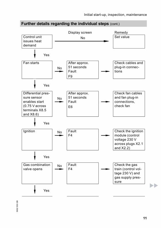
Display screen RemedyControl unitissues heatdemand
No Set value
Yes
Fan starts
No
After approx.51 seconds
Check cables andplug-in connec-tionsFault
F9
Yes
Differential pres-sure sensorenables start(0.75 V acrossterminals X8.5and X8.6)
No
After approx.51 seconds
Check fan cablesand fan plug-inconnections,check fan
Fault
E6
Yes
Ignition No Fault Check the ignitionmodule (controlvoltage 230 Vacross plugs X2.1and X2.2)
F4
Yes
Gas combinationvalve opens
No Fault Check the gastrain (control vol-tage 230 V) andgas supply pres-sure
F4
Yes
Further details regarding the individual steps (cont.)
11
Initial start-up, inspection, maintenance5692550GB

Ionisation cur-rent builds(higher than5 µA) No
Fault Check electrodeadjustment andgas pipe for air-locks
Symbol A F4
Yes
Operational bur-ner
Stops below setboiler tempera-ture and restarts
Check flue gassystem for sound-ness (flue gasrecirculation),check gas flowpressure
Checking static and supply pressure
DangerHigher CO emissions can lead to poisoning.Measure the CO value before and after any work on gas equipment toprevent any health hazards and to ensure the perfect operational condi-tion of the system.
Operation with LPGFlush the LPG tank twice during commissioning/replacement. Thoroughly ventthe tank and gas lines after flushing.
Further details regarding the individual steps (cont.)
12
Initial start-up, inspection, maintenance
5692550GB

1. Close the gas shut-off valve.
2. Release the screw inside test nip-ple PE A on the gas combinationvalve , but do not remove, and con-nect the pressure gauge.
3. Open the gas shut-off valve.
4. Check the static pressure; it shouldbe a max. of 57.5 mbar. Record theactual value in the service report.
5. Start up boiler.
NoteDuring commissioning, the boilercan enter a fault state because ofairlocks in the gas pipe. Afterapprox. 5 seconds, press E toreset the burner.
6. Check the supply (flow) pressure; itshould be& 20 mbar for natural gas,& 50 mbar for LPG.
NoteUse suitable test equipment with aresolution of at least 0.1 mbar tomeasure the supply pressure.
Record the actual value in the ser-vice report.Take the action shown in the table.
Further details regarding the individual steps (cont.)
13
Initial start-up, inspection, maintenance5692550GB

Supply (flow)pressure for nat-ural gas
Supply (flow)pressure forLPG
Remedy
Below 17.4 mbar Below 42.5 mbar Do not start up. Notify your mains gas orLPG supplier.
17.4 to 57.5 mbar 42.5 to57.5 mbar
Start up boiler.
Above 57.5 mbar Above 57.5 mbar Install a separate gas governor down-stream of the system and regulate thepressure to 20 mbar for natural gas or50 mbar for LPG.Notify your mains gasor LPG supplier.
7. Shut down the boiler, close the gasshut-off valve, remove the pressuregauge, and close test nipple Awith the screw.
8. Open the gas shut-off valve andstart the boiler.
DangerGas escaping from the testnipple leads to a risk ofexplosion.Check test nipple A forsoundness.
Checking the CO2 settings
Vitodens 300 is factory-set for natural gas E or LPG P. The natural gas E versioncan be converted to natural gas LL using a conversion kit. The LPG P versioncan be converted to natural gas E or LL using a conversion kit.During commissioning or maintenance, check the CO2 level at the boiler adap-tor.
NoteThe MatriX burner for Vitodens 300 is preset for the entire gas group. Therefore,the burner requires no further setting or adjustment.
Subject to the Wobbe index, the CO2 content fluctuates between
Further details regarding the individual steps (cont.)
14
Initial start-up, inspection, maintenance
5692550GB

& 6.6 to 10.0 % for natural gas E& 7.0 to 10.0 % for natural gas LL and& approx. 10.0 % for LPG P.
Compare the actual CO2 value with the above CO2 value ranges for the indivi-dual gas groups (check the gas group with your mains gas or LPG supplier).If the actual CO2 value deviates by more than 1 % for natural gas or 0.5 % forLPG, proceed as follows:& Check whether the correct gas restrictor has been installed.& Check the balanced flue system for soundness, see page 17.
1. Connect a flue gas analyser at theflue gas aperture A on the boileradaptor.
2. Open the gas shut-off valve, com-mission the boiler and create a heatdemand.
3. Select the lower rated output.
Constant temperature control units:& Press both keys 9 and d simul-taneously, until the display shows1.
Weather-compensated controlunits:& Press both keys 9 and d simul-taneously until the display shows"Relay test".
& With a/b in the display, select"Basic load".
4. Check the CO2 content. Should theactual value deviate by more than1 % from the above range, imple-ment steps from page 15 (possiblyreplace the burner).
5. Enter actual values into the servicereport.
Further details regarding the individual steps (cont.)
15
Initial start-up, inspection, maintenance5692550GB

6. Set the upper rated output.
Constant temperature control units:& With a/b in the display, select2.
Weather-compensated controlunits:& With a/b in the display, select"Full load".
7. Check the CO2 content. Should theactual value deviate by more than1 % from the above range, imple-ment steps from page 15 (possiblyreplace the burner).
8. After testing, press d.
9. Enter actual values into the servicereport.
Setting the max. output
NoteThe max. output can be limited for heating operation. You can limit the outputvia the modulation range.
1. Start up boiler.
2. Press both K and F simulta-neously until 100 flashes on thedisplay, (equals 100 % of the ratedoutput) and A appears. Onweather-compensated controlunits, the display additionallyshows "Max. output".
3. With a/b select the requiredvalue in % of rated output as max.output.
4. Confirm the set value with d.
5. Record the settings for max. outputon the additional type plateincluded with the technical docu-mentation. Affix the type plate nextto the original type plate on top ofthe boiler.
NoteThe output can also be limited forDHW loading. For this, change codingaddress 6F in code 2.
Further details regarding the individual steps (cont.)
16
Initial start-up, inspection, maintenance
5692550GB
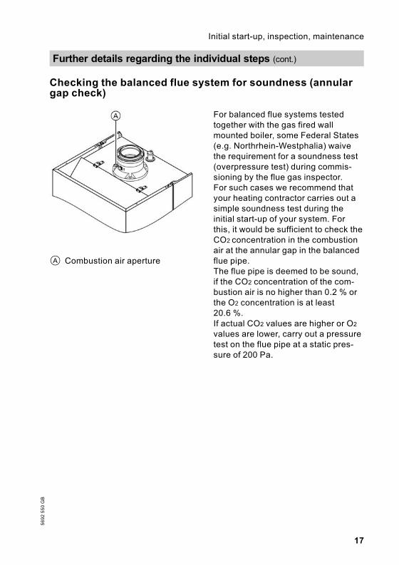
Checking the balanced flue system for soundness (annulargap check)
A Combustion air aperture
For balanced flue systems testedtogether with the gas fired wallmounted boiler, some Federal States(e.g. Northrhein-Westphalia) waivethe requirement for a soundness test(overpressure test) during commis-sioning by the flue gas inspector.For such cases we recommend thatyour heating contractor carries out asimple soundness test during theinitial start-up of your system. Forthis, it would be sufficient to check theCO2 concentration in the combustionair at the annular gap in the balancedflue pipe.The flue pipe is deemed to be sound,if the CO2 concentration of the com-bustion air is no higher than 0.2 % orthe O2 concentration is at least20.6 %.If actual CO2 values are higher or O2
values are lower, carry out a pressuretest on the flue pipe at a static pres-sure of 200 Pa.
Further details regarding the individual steps (cont.)
17
Initial start-up, inspection, maintenance5692550GB

Removing the burner and checking the burner gasket(replace gasket every two years)
1. Switch OFF the control unit ON/OFF switch and the mains electricalsupply.
2. Close the gas shut-off valve andsafeguard against reopening.
3. Pull electrical cables from fanmotor A, differential pressure sen-sor B, gas valve C, ionisationelectrode D, ignition electrodesE and earth F.
4. Release gas connection pipe Gfixing screws and fittings.
5. Release six nuts H and removethe burner.
! Important informationPrevent damage to the wiremesh.Never rest the burner on thegauze assembly.
6. Check the burner gasket (see partslist) for damage.Generally, replace the burner gas-ket every two years.
Further details regarding the individual steps (cont.)
18
Initial start-up, inspection, maintenance
5692550GB

Checking the burner gauze assembly
Replace the burner gauze assembly if the wire mesh is damaged.
1. Remove electrodes A.
2. Turn thermal insulation ring Bclockwise and remove.
3. Release the eight Torx screws Cand remove the burner gauzeassembly D.
4. Remove the old gauze assemblygasket E.
5. Insert a new burner gauze assem-bly with a new gasket, and securewith eight Torx screws.
NoteTorque: 4.5 Nm
6. Refit the thermal insulation ring B.
Checking and adjusting the ignition and ionisation electro-des
A Ionisation electrode B Ignition electrodes
Further details regarding the individual steps (cont.)
19
Initial start-up, inspection, maintenance5692550GB

1. Check the electrodes for wear andcontamination.
2. Clean the electrodes with a smallbrush (not with a wire brush) oremery paper.
! Important informationWire meshdo not damage.
3. Check all clearances. If the gapsare not as specified or the electro-des are damaged, replace andalign the electrodes together withnew gaskets. Tighten the electrodefixing screws with 2 Nm.
Further details regarding the individual steps (cont.)
20
Initial start-up, inspection, maintenance
5692550GB

Cleaning the combustion chamber/heating surfaces andinstalling the burner
1. If required, clean combustionchamber A and heatingsurfaces B with a brush or flushwith water.
! Important informationScratches on parts whichare in contact with fluegases can lead to corrosion.Only use plastic brushes andNOT wire brushes.
Apply a solvent-/potassium-freecleaning agent if residues remain:& Remove soot deposits with alka-line cleaning agents with addi-tional surfactants (e.g. Fauch600).
& Remove coatings and surfacediscolouration (yellow-brown)with slightly acidic, chloride-freecleaning agents based on phos-phoric acid (e.g. Antox 75 E).
& Thoroughly flush with water.
NoteFauch 600 and Antox 75 E are sup-plied by:Hebro Chemie GmbHRostocker Straße 40D 41199 Mönchengladbachc: Intec Bassersdorf AGGrindelstrasse 12PostfachCH-8303 Bassersdorf
2. Install the burner and torque nutsdiagonally with 4.5 Nm.
Further details regarding the individual steps (cont.)
21
Initial start-up, inspection, maintenance5692550GB

3. Secure the gas supply pipe with anew gasket.
4. Check the gas connections forsoundness.
DangerEscaping gas leads to a riskof explosion.Check all fittings for sound-ness.
5. Connect the electrical cables/leadsto each corresponding component.
Checking the condensate drain and cleaning the siphon
1. Check at the siphon, that the con-densate can freely drain.
2. Remove the retaining clip and thesiphon.
3. Clean the siphon.
4. Fit the siphon and secure with theretaining clip.
Checking all gas equipment for soundness at operating pres-sure
DangerEscaping gas leads to a risk ofexplosion.Check gas equipment forsoundness.
Further details regarding the individual steps (cont.)
22
Initial start-up, inspection, maintenance
5692550GB

Checking the ionisation current
A Adaptor line (available as acces-sory)
B Control unit cable
1. Remove the cable and connect thetest equipment.
2. Set the upper rated output.
Constant temperature control units:& Press K and d simultaneouslyfor at least 2 seconds.
& With a/b in the display, select2.
Weather-compensated controlunits:& Press K and d simultaneouslyfor at least 2 seconds.
& With a/b in the display, select"Full load".
NoteThe minimum ionisation currentshould be at least 5 µA as soon asthe flame is established (approx. 2 -3 seconds after opening the gastrain).
3. If the ionisation current is < 5 µA\;& Check the electrode gap, seepage 19.
& Check the control unit power sup-ply.
4. After testing, press d.
5. Record the actual value in the ser-vice report.
Further details regarding the individual steps (cont.)
23
Initial start-up, inspection, maintenance5692550GB

Matching the control unit to the heating system
NoteThe control unit must be matched to the system equipment. Various systemcomponents are automatically recognised by the control unit, and codes areautomatically set.& For selection of an appropriate design, see the following diagrams.& For coding steps, see page 38.
System design 1
With/without DHW heating with 1 heating circuit without mixer
! Outside temperature sensor (onlyfor weather-compensated controlunits)or
lH Vitotrol 100 (only for constanttemperature control units)
% Cylinder temperature sensorsÖ Heating circuit pump
sA Cylinder loading pump (connec-tion via external extension H1)
sK Cylinder loading pump (connec-tion via internal extension H1 orH2)
A Internal extension H1 or H2orExternal extension H1
Further details regarding the individual steps (cont.)
24
Initial start-up, inspection, maintenance
5692550GB

Required coding AddressFunction relay of the internal extension: Cylinder loadingpump
53:3
System design 2
With/without DHW heating with 1 heating circuit with mixer and systemseparation
! Outside temperature sensor? Flow temperature sensor% Cylinder temperature sensorsÖ Heating circuit pumpsA Cylinder loading pump (connec-
tion via external extension H1)sK Cylinder loading pump (connec-
tion via internal extension H1 orH2)
lH Power supplyaVG KM BUS
A Internal extension H1 or H2orExternal extension H1
B Extension kit for 1 heating circuitwith mixer
C Maximum temperature controller(underfloor heating)
D Heating circuit pump (sec-ondary)
E Heating circuit pump (primary)F Heat exchanger for system
separationG Expansion vessel
Further details regarding the individual steps (cont.)
25
Initial start-up, inspection, maintenance5692550GB

Required coding Address1 heating circuit with mixer& with DHW cylinder 00:4& without DHW cylinder 00:3Function relay of the internal extension: Cylinder loadingpump
53:3
System design 3
With/without DHW heating with low loss header, 1 heating circuit withoutmixer and 1 heating circuit with mixer
! Outside temperature sensor? Flow temperature sensor% Cylinder temperature sensorsÖ Heating circuit pump or boiler
circuit pumpsA Cylinder loading pump (connec-
tion via external extension H1)lH Power supplyaVG KM BUS
A External extension H1B Low loss headerC Extension kit for 1 heating circuit
with mixerD Maximum temperature controller
(underfloor heating)
Further details regarding the individual steps (cont.)
26
Initial start-up, inspection, maintenance
5692550GB

E Heating circuit pump heating cir-cuit with mixer
F Heating circuit pump heating cir-cuit without mixer (connectionvia external extension H1)
Required coding Address— —
Further details regarding the individual steps (cont.)
27
Initial start-up, inspection, maintenance5692550GB

System design 4
With/without DHW heating with 3 or more heating circuits with mixer andlow loss header
! Outside temperature sensor? Flow temperature sensor% Cylinder temperature sensorsÖ Heating circuit pump or boiler cir-
cuit pumpsA Cylinder loading pump (connec-
tion via external extension H1)
sK Cylinder loading pump (connec-tion via internal extension H1 orH2)
fÖ Power supplygS Mixer motorA Internal extension H1 or H2
orExternal extension H1
B Low loss header
Further details regarding the individual steps (cont.)
28
Initial start-up, inspection, maintenance
5692550GB

C Vitotronic 050D Maximum temperature controller
(underfloor heating)
E Heating circuit pumpF Mixer motor
Required coding AddressFunction relay of the internal extension: Cylinder loadingpump
53:3
Further details regarding the individual steps (cont.)
29
Initial start-up, inspection, maintenance5692550GB

System design 5
Multi-boiler system with/without DHW heating with several heating circuitswith mixer and low loss header
! Outside temperature sensor? Flow temperature sensor heat-
ing circuits?/§ Flow temperature sensor / low
loss header% Cylinder temperature sensorsÖ Heating circuit pump or boiler
circuit pumpsA Cylinder loading pump
fÖ Power supplygS Mixer motoraVG KM BUSA Low loss headerB Vitotronic 333C Maximum temperature control-
ler (underfloor heating system)D Heating circuit pumpE Mixer motor
Further details regarding the individual steps (cont.)
30
Initial start-up, inspection, maintenance
5692550GB

Required coding AddressMulti-boiler system with Vitotronic 333 01:2
NoteCodes for multi-boiler system, seeVitotronic 333 installation and operat-ing instructions.
Connecting the control unit to the LON system (only forweather-compensated control units)
The LON communication module (accessory) must be plugged in.
Installation instructionsLON communication module
NoteData transfer via the LON system can take 2 to 3 minutes.
Setting up LON user numbers
Adjust the user number via codingaddress 77 (see below).
In a LON system, the same numbercannot be allocated twice.
Updating the LON user list
Only possible, if all users are connected, and the control unit is encoded as faultmanager (code 79:1).
1. Press L and d simultaneouslyfor approx. 2 seconds. User checkinitiated (see page 32).
2. Press e. The user list is updatedafter approx. 2 minutes. Usercheck completed.
Single boiler system with Vitotronic 050 and Vitocom 300
Further details regarding the individual steps (cont.)
31
Initial start-up, inspection, maintenance5692550GB

Boiler controlunit
Vitotronic 050 Vitotronic 050 Vitocom
User no. 1Code 77:1
User no. 10Code 77:10
User no. 11Set code 77:11
User no. 99
Control unit isfault manager*1Code 79:1
Control unit is notfault manager*1Code 79:0
Control unit is notfault manager*1Code 79:0
Control unit isfault manager
Sent time via LONCode 7b:1
Time received viaLONSet code 81:3
Time received viaLONSet code 81:3
Time receivedvia LON
Transmit outsidetemperature viaLONSet code 97:2
Outside tempera-ture is received viaLONSet code 97:1
Outside tempera-ture is received viaLONSet code 97:1
—
Fault monitoringLON user code9C:20
Fault monitoringLON user code9C:20
Fault monitoringLON user code9C:20
—
Implementing a user check (in conjunction with the LON sys-tem)
Communication with the system devices connected to the fault manager istested with a user check.Preconditions:& The control unit must be encoded as fault manager (code 79:1).& The LON user number must be encoded in all control units (see page 31).& The fault manager user list must be up to date (see page 31).
Further details regarding the individual steps (cont.)
32
Initial start-up, inspection, maintenance
5692550GB
*1In each heating system, only one Vitotronic may be encoded as fault manager.

A Consecutive list numberB User number
1. Press L and d simultaneouslyfor approx. 2 seconds. User checkinitiated.
2. Select the required user with aand b.
3. Activate checking with d."Check" flashes until its comple-tion. The display and all key illumi-nations of the selected user flashfor approx. 60 seconds.& "Check OK" flashes during com-munication between bothdevices.
& "Check not OK" flashes if thereis no communication betweenboth devices. Check LON con-nection.
4. For checking further users, proceedas for items 2 and 3.
5. Press L and d simultaneouslyfor approx. 1 second. User checkcompleted.
Adjusting heating curves (only for weather-compensatedcontrol units)
The heating curves illustrate the rela-tionship between the outside tem-perature and the boiler water or theflow temperature. To put it simply: thelower the outside temperature, thehigher the boiler water or flow tem-perature. The room temperature,again, depends on the boiler water orthe flow temperature.
Settings in the delivered condition:& Slope = 1.4& Level = 0
Generally, the slope of the heatingcurve lies& in the range of A for underfloorheating systems,
& in the range of B for low tempera-ture heating systems (according tothe Energy Savings Order [Ger-many]).
Further details regarding the individual steps (cont.)
33
Initial start-up, inspection, maintenance5692550GB

Changing slope and level
A Changing the slopeB Changing the level
1. Modify the slope in code 1 with cod-ing address d3 (see page 38).Value adjustable from 0.2 to 3.5.
2. Modify the slope in code 1 with cod-ing address d4 (see page 38).Value adjustable from –13 to +40 K.
Further details regarding the individual steps (cont.)
34
Initial start-up, inspection, maintenance
5692550GB

Adjusting the set room temperature
Standard room temperature:
1. Select a heating circuit:& Press a.1r flashes on the display.
& Select heating circuit A1 (heatingcircuit without mixer):Press d.
& Select heating circuit M2 (heatingcircuit with mixer):– Press a.– 2r flashes on the display.– Press d.
Example 1: Modifying the standardroom temperature from 20 °C to 26 °C
A Boiler water or flow temperaturein °C
B Outside temperature in °CC Set room temperature in °CD Heating circuit pump OFFE Heating circuit pump ON
2. Adjust the set day temperature withrotary selector ts.The value will be automaticallyadopted after approx. 2 seconds.Accordingly, the heating curve isadjusted along the set room tem-perature axis, which results in mod-ified start/shutdown characteristicsof the heating circuit pumps, if theheating circuit pump logic is acti-vated.
Further details regarding the individual steps (cont.)
35
Initial start-up, inspection, maintenance5692550GB

Reduced room temperature:
1. Select a heating circuit:& Press a.1r flashes on the display.
& Select heating circuit A1 (heatingcircuit without mixer):Press d.
& Select heating circuit M2 (heatingcircuit with mixer):– Press a.– 2r flashes on the display.– Press d.
Example 2: Modifying the reducedroom temperature from 5 °C to 14 °C.
A Boiler water or flow temperaturein °C
B Outside temperature in °CC Set room temperature in °CD Heating circuit pump OFFE Heating circuit pump ON
2. Call up the set night temperaturewith E.
3. Change this value with a and b.
4. Confirm the set value with d.
Instructing the system user
The system installer must hand the operating instructions to the system userand instruct them in the operation of the system.
Further details regarding the individual steps (cont.)
36
Initial start-up, inspection, maintenance
5692550GB

Scanning and resetting the "Maintenance" display
The red fault indicator flashes when the limits set via coding address 21 and 23have been reached. As regards the operating interface display:& For constant temperature control units, the hours run (subject to setting) orthe given time interval and the clock symbol flashes.
& For weather-compensated control units "Maintenance" flashes.
NoteSet code 24:1 and then code 24:0, if maintenance is implemented before main-tenance is displayed; the set maintenance parameters for hours run and intervalare then reset to 0.
1. Press c.Maintenance scan is activated.
2. Scan maintenance messageswith a or b.
3. Press d, for weather-compen-sated control units also confirm thedisplay "Acknowledge: Yes"with d."Maintenance" is cancelled fromthe display and the red fault indica-tor continues to flash.
NoteAn acknowledged maintenancemessage can be redisplayed bypressing d (approx. 3 seconds).
After maintenance has been carriedout
1. Reset code 24:1 to 24:0.The red fault indicator is extin-guished.
NoteIf coding address 24 is not reset, anew "Maintenance" message willbe displayed on Monday at07:00 h.
2. If required:& Press c.& Reset burner hours run, burnerstarts and consumption (seepage 70).
& Press c.
Further details regarding the individual steps (cont.)
37
Initial start-up, inspection, maintenance5692550GB

Call up code 1
1. Press K and L simultaneouslyfor approx. 2 seconds.
2. Select the required coding addresswith a or b; the address flashes.Confirm with d; the value flashes.
NoteCodes are displayed in plain texton weather-compensated controlunits. Codes, which are not rele-vant because of the equipmentlevel of your heating system orbecause of settings of other codes,will not be displayed.
3. Change this value with a and b;confirm with d. The display brieflyshows "adopted", then the addressflashes again. Select additionaladdresses (if required) with aor b.
4. Press K and L simultaneouslyfor approx. 1 second.
Code 1
38
Coding
5692550GB
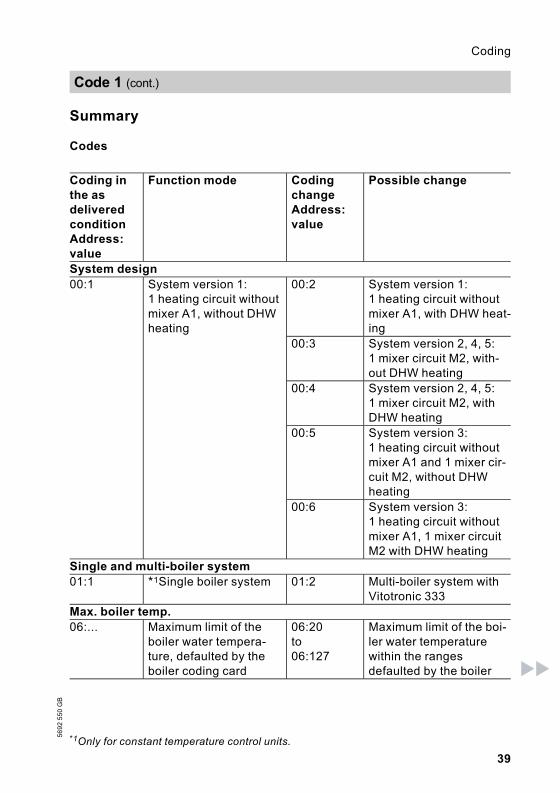
Summary
Codes
Coding inthe asdeliveredconditionAddress:value
Function mode CodingchangeAddress:value
Possible change
System design00:1 System version 1:
1 heating circuit withoutmixer A1, without DHWheating
00:2 System version 1:1 heating circuit withoutmixer A1, with DHW heat-ing
00:3 System version 2, 4, 5:1 mixer circuit M2, with-out DHW heating
00:4 System version 2, 4, 5:1 mixer circuit M2, withDHW heating
00:5 System version 3:1 heating circuit withoutmixer A1 and 1 mixer cir-cuit M2, without DHWheating
00:6 System version 3:1 heating circuit withoutmixer A1, 1 mixer circuitM2 with DHW heating
Single and multi-boiler system01:1 *1Single boiler system 01:2 Multi-boiler system with
Vitotronic 333Max. boiler temp.06:... Maximum limit of the
boiler water tempera-ture, defaulted by theboiler coding card
06:20to06:127
Maximum limit of the boi-ler water temperaturewithin the rangesdefaulted by the boiler
Code 1 (cont.)
39
Coding5692550GB
*1Only for constant temperature control units.

Coding inthe asdeliveredconditionAddress:value
Function mode CodingchangeAddress:value
Possible change
Gas type1E:0 Natural gas operation,
defaulted by the boilercoding card
1E:1 LPG operation, defaultedby the boiler coding card
Venting/filling2F:0 Venting program dis-
abled2F:1 Venting program enabled2F:2 Filling program enabled
User no.77:1 LON user number 77:2
to77:99
LON user number, adjus-table from 1 to 99:1 - 4 = boiler5 = cascade10 - ... = Vitotronic 05099 = Vitocom
NoteAllocate each numberonly once.
DHW priority A1A2:2 DHW cylinder priority
applicable to heatingcircuit pump and mixer
A2:0 Without cylinder priorityfor heating circuit pump
DHW priority M2A2:2 DHW cylinder priority
applicable to heatingcircuit pump and mixer
A2:0 Without DHW cylinderpriority applicable toheating circuit pump andmixer
A2:1 DHW cylinder priorityonly applicable to mixer
A2:3toA2:15
Modulating DHW cylinderpriority
Summer econ. A1A5:5 *1With heating circuit
pump logic functionA5:0 Without heating circuit
pump logic function
Code 1 (cont.)
40
Coding
5692550GB
*1Only for weather-compensated control units.

Coding inthe asdeliveredconditionAddress:value
Function mode CodingchangeAddress:value
Possible change
Summer econ. M2A5:5 *1With heating circuit
pump logic functionA5:0 Without heating circuit
pump logic functionMin. flow temp. A1C5:20 Electronic limit of the
minimum flow tempera-ture: 20 °C
C5:1toC5:127
Minimum limit adjustablefrom 1 to 127 °C
Min. flow temp. M2C5:20 Electronic limit of the
minimum flow tempera-ture: 20 °C
C5:1toC5:127
Minimum limit adjustablefrom 1 to 127 °C
Max. flow temp. A1C6:75 *1Electronic maximum
flow temperature limit at75 °C
C6:1toC6:127
Maximum limit adjustablefrom 1 to 127 °C
Max. flow. temp. M2C6:75 *1Electronic maximum
flow temperature limit at75 °C
C6:1toC6:127
Maximum limit adjustablefrom 1 to 127 °C
Slope A1d3:14 *1Heating curve slope =
1.4d3:2tod3:35
Heating curve slopeadjustable from 0.2 to 3.5(see page 33)
Slope M2d3:14 *1Heating curve slope =
1.4d3:2tod3:35
Heating curve slopeadjustable from 0.2 to 3.3(see page 33)
Level A1d4:0 *1Heating curve level =
0d4:–13tod4:40
Heating curve leveladjustable from –13 to 40(see page 33)
Level M2d4:0 *1Heating curve level =
0d4:–13tod4:40
Heating curve leveladjustable from –13 to 40(see page 33)
Code 1 (cont.)
41
Coding5692550GB
*1Only for weather-compensated control units.

Calling up code 2
1. Press L and G simultaneouslyfor approx. 2 seconds; confirmwith d.
2. Select the required coding addresswith a or b; the address flashes.Confirm with d; the value flashes.
3. Change this value with a and b;confirm with d. The display brieflyshows "adopted", then the addressflashes again. Select additionaladdresses (if required) with aor b.
4. Press L and G simultaneouslyfor approx. 1 second.
Overall summary
The coding addresses are grouped in accordance with the following functionranges. The respective function range is displayed.Scroll through the ranges in the following sequence with a or b.
Function range Coding addressesSystem design 00 and 01Boiler/burner 06 to 54DHW 56 to 73General 76 to 9FBoiler circuit (heating circuit A1 withoutmixer)
A0 to F7
Mixer circuit (heating circuit M2 with mixer) A0 to F7
NoteCodes, which are not relevant because of the equipment level of your heatingsystem or because of settings of other codes, will not be displayed.For heating systems with 1 heating circuit without mixer and 1 heating circuitwith mixer, initially the possible coding addresses A0 to F7 are scrolled for theheating circuit without mixer A1, then those for the heating circuit with mixer M2.
Code 2
42
Coding
5692550GB

Codes
Coding inthe asdeliveredconditionAddress:value
Function mode CodingchangeAddress:value
Possible change
System design00:1 System design 1:
1 heating circuit withoutmixer A1, without DHWheating
00:2 System design 1:1 heating circuit withoutmixer A1, with DHW heat-ing
00:3 System design 2, 4, 5:1 mixer circuit M2, with-out DHW heating
00:4 System design 2, 4, 5:1 mixer circuit M2, withDHW heating
00:5 System design 3:1 heating circuit withoutmixer A1 and 1 mixer cir-cuit M2, without DHWheating
00:6 System design 3:1 heating circuit withoutmixer A1, 1 mixer circuitM2 with DHW heating
01:1 *1Single boiler system 01:2 Multi-boiler system withVitotronic 333
Boiler/burner06:... Maximum limit of the
boiler water tempera-ture, defaulted by theboiler coding card
06:20to06:127
Maximum limit of the boi-ler water temperaturewithin the rangesdefaulted by the boiler
07:1 *1Boiler number inmulti-boiler systems
07:2to07:4
Boiler number 2 to 4 inmulti-boiler systems
1E:0 Natural gas operation,defaulted by the boilercoding card
1E:1 LPG operation, defaultedby the boiler coding card
Code 2 (cont.)
43
Coding5692550GB
*1Only for constant temperature control units.

Coding inthe asdeliveredconditionAddress:value
Function mode CodingchangeAddress:value
Possible change
21:0 No maintenance indica-tionBurner
21:1to21:100
The number of hours runbefore the burner shouldbe serviced is adjustablefrom 100 to 10000 hours(each step represents100 hours)
23:0 No time interval for bur-ner maintenance
23:1to23:24
Time interval adjustablefrom 1 to 24 months
24:0 No "Maintenance" dis-play
24:1 "Maintenance" display(the address is automati-cally set and must bemanually reset aftermaintenance has beencompleted)
25:0 *1No recognition of out-side temperature sen-sor or remotemonitoring
25:1 Recognition of outsidetemperature sensor andfault monitoring
28:0 No burner interval igni-tion
28:1 The burner is forced ONonce every 24 hours
2E:0 Without external exten-sion
2E:1 Including external exten-sion (automatical adjust-ment on connection)
2F:0 Venting program dis-abled
2F:1 Venting program enabled2F:2 Filling program enabled
30:1 Internal variable speedcirculation pump (auto-matic adjustment)
30:0 Internal circulation pumpwithout variable speed(e.g. temporarily for ser-vice)
31:65 Set speed of the inter-nal circulation pumpwhen operated as boilercircuit pump 65 %,defaulted by the boilercoding card
31:0to31:100
Set speed adjustablefrom 0 to 100 %
Code 2 (cont.)
44
Coding
5692550GB
*1Only for constant temperature control units.

Coding inthe asdeliveredconditionAddress:value
Function mode CodingchangeAddress:value
Possible change
32:0 Signal "External lock-out" on circulationpumps: All pumps arecontrolled
32:1to32:15
Signal "External lockout"on circulation pumps:See the following table
Coding Internalcircula-tion pump
Heating cir-cuit pumpHeating cir-cuit withoutmixer
Heating circuitpumpHeating circuitwith mixer
Cylinder loadingpump
0 Controlfunct.
Control funct. Control funct. Control funct.
1 Controlfunct.
Control funct. Control funct. OFF
2 Controlfunct.
Control funct. OFF Control funct.
3 Controlfunct.
Control funct. OFF OFF
4 Controlfunct.
OFF Control funct. Control funct.
5 Controlfunct.
OFF Control funct. OFF
6 Controlfunct.
OFF OFF Control funct.
7 Controlfunct.
OFF OFF OFF
8 OFF Control funct. Control funct. Control funct.9 OFF Control funct. Control funct. OFF10 OFF Control funct. OFF Control funct.11 OFF Control funct. OFF OFF12 OFF OFF Control funct. Control funct.13 OFF OFF Control funct. OFF14 OFF OFF OFF Control funct.15 OFF OFF OFF OFF
Code 2 (cont.)
45
Coding5692550GB

Coding inthe asdeliveredconditionAddress:value
Function mode CodingchangeAddress:value
Possible change
Boiler/burner34:0 Signal "External
demand" on circulationpumps: All pumps arecontrolled
34:1to34:23
Signal "External demand"on circulation pumps:See the following table
Coding Internalcirculationpump
Heating cir-cuit pumpHeating cir-cuit withoutmixer
Heating cir-cuit pumpHeating cir-cuit withmixer
Cylinder loading pump
0 Controlfunct.
Controlfunct.
Control funct. Control funct.
1 Controlfunct.
Controlfunct.
Control funct. OFF
2 Controlfunct.
Controlfunct.
OFF Control funct.
3 Controlfunct.
Controlfunct.
OFF OFF
4 Controlfunct.
OFF Control funct. Control funct.
5 Controlfunct.
OFF Control funct. OFF
6 Controlfunct.
OFF OFF Control funct.
7 Controlfunct.
OFF OFF OFF
8 OFF Controlfunct.
Control funct. Control funct.
9 OFF Controlfunct.
Control funct. OFF
10 OFF Controlfunct.
OFF Control funct.
11 OFF Controlfunct.
OFF OFF
12 OFF OFF Control funct. Control funct.
Code 2 (cont.)
46
Coding
5692550GB

Coding Internalcirculationpump
Heating cir-cuit pumpHeating cir-cuit withoutmixer
Heating cir-cuit pumpHeating cir-cuit withmixer
Cylinder loading pump
13 OFF OFF Control funct. OFF14 OFF OFF OFF Control funct.15 OFF OFF OFF OFF16 ON Control
funct.Control funct. Control funct.
17 ON Controlfunct.
Control funct. OFF
18 ON Controlfunct.
OFF Control funct.
19 ON Controlfunct.
OFF OFF
20 ON OFF Control funct. Control funct.21 ON OFF Control funct. OFF22 ON OFF OFF Control funct.23 ON OFF OFF OFF
Coding inthe asdeliveredconditionAddress:value
Function mode CodingchangeAddress:value
Possible change
Boiler/burner50:0 Alternative control
(automatic adjustmentupon recognition of theoperating interface)
50:1 Constant temperaturecontrol units
50:3 Weather-compensatedcontrol units
52:0 Without flow tempera-ture sensor for low lossheader
52:1 With flow temperaturesensor for low lossheader (automatic adjust-ment upon recognition)
Code 2 (cont.)
47
Coding5692550GB

Coding inthe asdeliveredconditionAddress:value
Function mode CodingchangeAddress:value
Possible change
53:1 Function relay 2 of theinternal extension:DHW circulation pump
53:0 Function relay 2: Centralfault
53:2 Function relay 2: Externalheating circuit pump(heating circuit withoutmixer)
53:3 Function relay 2: Externalcylinder loading pump
54:0 Without solar controlunit
54:1 With Vitosolic 10054:2 With Vitosolic 200 (auto-
matic adjustment onrecognition)
Domestic hot water56:0 DHW temperature
adjustable from 10 to60 °C
56:1 DHW temperature adjus-table from 10 to 95 °C(only for gas fired boilers)Observe the max. per-missible DHW tempera-ture
58:0 Without auxiliary func-tion for DHW loading
58:1to58:95
Input of set DHW value 2;adjustable from 1 to95 °C (observe codingaddress 56)
59:0 DHW cylinder loading:Starting point -2.5 KStopping point +2.5 K
59:1to59:10
Starting point adjustablefrom 1 to 10 K below theset value
5b:0 DHW cylinder directlyconnected to the boiler
5b:1 DHW cylinder connecteddownstream of the lowloss header
60:10 *1During DHW loading,the boiler water tem-perature is up to 20 Khigher than the setDHW temperature
60:5to60:25
The difference betweenthe boiler water tempera-ture and the set DHWtemperature is adjustablefrom 10 to 50 K
Code 2 (cont.)
48
Coding
5692550GB
*1Only for weather-compensated control units.

Coding inthe asdeliveredconditionAddress:value
Function mode CodingchangeAddress:value
Possible change
62:2 Circulation pump with 2minutes run-on time
62:0 Circulation pump withoutrun-on
62:1to62:15
Run-on time adjustablefrom 1 to 15 minutes
63:0 *1Without auxiliaryfunction for DHW load-ing
63:1 Additional function: 1 xdaily
63:2to63:14
Every 2 to every 14 days
63:15 2 x daily65:... Information regarding
the type of divertervalve (not adjustable)
65:0 Without diverter valve65:1 Diverter valve by Viess-
mann65:2 Diverter valve by Wilo65:3 Diverter valve by Grund-
fos67:40 In conjunction with Vito-
solic solar control unit:Set DHW value 3
67:0to67:60
DHW set value adjusta-ble from 0 to 60 °C
6C:100 Set speed internal DHWloading pump 100 %
6C:0to6C:100
Set speed adjustablefrom 0 to 100 %
6F:100 Max. output duringDHW loading 100 %,defaulted by the boilercoding card
6F:0to6F:100
Max. output during DHWloading adjustable from 0to 100 %
71:0 *2DHW circulationpump: On according toDHW time program
71:1 OFF during DHW loadingto set value 1
71:2 ON during DHW loadingto set value 1
72:0 *2DHW circulationpump: ON according totime program
72:1 OFF during DHW loadingto set value 2
72:2 ON during DHW loadingto set value 2
Code 2 (cont.)
49
Coding5692550GB
*1Only for constant temperature control units.*2Only for weather-compensated control units.

Coding inthe asdeliveredconditionAddress:value
Function mode CodingchangeAddress:value
Possible change
73:0 *1DHW circulationpump: ON according totime program
73:1to73:6
During the time program1x/h ON for 5 minutesup to 6x/h ON for 5 min-utes
73:7 Constantly ONGeneral76:0 Without LON communi-
cation module76:1 With LON communication
module; automatic recog-nition
76:2 With KM BUS/cascadecommunication module;automatic recognition
77:1 LON user number 77:2to77:99
LON user number, adjus-table from 1 to 99:1 - 4 = boiler5 = cascade10 - ... = Vitotronic 05099 = Vitocom
NoteAllocate each numberonly once.
79:1 Control unit is faultmanager*1
79:0 Control unit is not faultmanager
7b:1 Send time to LON*1
7b:0 Do not send time to LON
7E:0 *2Without flue gas cas-cade
7E:1 With flue gas cascade
7F:1 *2Detached house 7F:0 Multi-occupancy houseSeparate adjustment forholiday program and timeprogram for DHW load-ing, as option
Code 2 (cont.)
50
Coding
5692550GB
*1Only for weather-compensated control units.*2Only for constant temperature control units.

Coding inthe asdeliveredconditionAddress:value
Function mode CodingchangeAddress:value
Possible change
80:1 With 5 seconds' timedelay for fault message;message will be issued,if a fault persists for atleast 5 seconds
80:0 Without time delay80:2to80:199
Time delay adjustablefrom 10 to 995; 1 step =5 s
81:1 Automatic summer/win-ter changeover
81:0 Manual summer/winterchangeover
81:2 The application of theradio clock module will berecognised automatically
81:3 Accept time via LON88 :0 Temperature display in
Celsius88 :1 Temperature display in
Fahrenheit90:128 Time constant for calcu-
lating the adjusted out-side temperature21.3 hours
90:0to90:199
Fast (low values) or slow(high values) matching offlow temperature subjectto set value if the outsidetemperature changes;1 step = 10 min
91:0 *1No external operatingmode changeover viaexternal extension
91:1 External heating programchangeover applies toheating circuit withoutmixer
91:2 External heating programchangeover applies toheating circuit with mixer
91:3 External heating programchangeover applies toheating circuit withoutmixer and heating circuitwith mixer
95:0 Without Vitocom 100communication inter-face
95:1 With Vitocom 100 com-munication interface;automatic recognition
Code 2 (cont.)
51
Coding5692550GB
*1Only for weather-compensated control units.

Coding inthe asdeliveredconditionAddress:value
Function mode CodingchangeAddress:value
Possible change
97:0 *1The outside tempera-ture of the sensor con-nected to the controlunit is utilised internally
97:1 Outside temperature isadopted by the LON BUS
97:2 The outside temperatureof the sensor connectedto the control unit will beutilised internally andtransmitted via LON BUSto any connected Vitotro-nic 050.
98:1 Viessmann systemnumbers (in conjunctionwith monitoring of sev-eral systems via Vito-com 300)
98:1to98:5
System number adjusta-ble from 1 to 5
9b:70 Minimum set boilerwater temperature incase of externaldemand
9b:1to9b:127
Set temperature adjusta-ble from 1 to 127 °C
9C:20 *1Monitoring LON usersWhen there is noresponse from a user,values defaulted insidethe control unit continueto be used for a further20 minutes. Only thenwill a fault message betriggered.
9C:0 No monitoring9C:5to9C:60
Time adjustable from 5 to60 minutes
9F:8 *1Differential tempera-ture 8 K; only in con-junction with a mixercircuit
9F:0to9F:40
Differential temperatureadjustable from 0 to 40 K
Boiler circuit, mixer circuitA0:0 *1Without remote con-
trolA0:1 With Vitotrol 200 (auto-
matic recognition)A0:2 With Vitotrol 300 (auto-
matic recognition)
Code 2 (cont.)
52
Coding
5692550GB
*1Only for weather-compensated control units.

Coding inthe asdeliveredconditionAddress:value
Function mode CodingchangeAddress:value
Possible change
A2:2 With DHW cylinderpriority applicable toheating circuit pumpand mixer
A2:0 Without DHW cylinderpriority applicable toheating circuit pump andmixer
A2:1 With DHW priority applic-able to mixer: The mixeris closed whilst DHW isloaded; the heating cir-cuit pump operates *1
A2:3toA2:15
Reduced priority appl. tomixer; i.e. the heating cir-cuit receives a reducedamount of energy *1
A3:2 *2Outside temperaturebelow 1 °C: Heating cir-cuit pump ONOutside temperatureabove 3 °C: Heating cir-cuit pump OFF
NoteWhen selecting a valuebelow 1 °C there will bea risk of pipes outsidethe thermal insulationenvelope of the housefreezing-up. Thestandby mode, in parti-cular, should beobserved, e.g. duringholidays.
A3:-9toA3:15
Heating circuit pump ON/OFF (see the followingtable)
Code 2 (cont.)
53
Coding5692550GB
*1Only adjustable for mixer circuit M2.*2Only for weather-compensated control units.

Parameters Heating circuit pumpAddress A3:... ON at OFF at-9 -10 °C -8 °C-8 -9 °C -7 °C-7 -8 °C -6 °C-6 -7 °C -5 °C-5 -6 °C -4 °C-4 -5 °C -3 °C-3 -4 °C -2 °C-2 -3 °C -1 °C-1 -2 °C 0 °C0 -1 °C 1 °C1 0 °C 2 °C2to15
1 °Cto14 °C
3 °C
16 °C
Coding inthe asdeliveredconditionAddress:value
Function mode CodingchangeAddress:value
Possible change
Boiler circuit, mixer circuitA4:0 *1With frost protection A4:1 No frost protection,
adjustment only possibleif code A3:-9 is selected.
NoteWhen selecting a valuebelow 1 °C there will be arisk of pipes outside thethermal insulation envel-ope of the house freez-ing-up. The standbymode, in particular,should be observed, e.g.during holidays.
Code 2 (cont.)
54
Coding
5692550GB
*1Only for weather-compensated control units.

Coding inthe asdeliveredconditionAddress:value
Function mode CodingchangeAddress:value
Possible change
A5:5 *1With heating circuitpump logic function(economy circuit): Heat-ing circuit pump OFF, ifthe outside temperature(AT) is 1 K higher thanthe set room tempera-ture (RTSet )AT > RTSet +1 K
A5:0 Without heating circuitpump logic function
A5:1toA5:15
With heating circuit pumplogic function: Heatingcircuit pump OFF, if (seethe following table)
Parameter addressA5:...
With heating circuit pump logic function: Heatingcircuit pump OFF, if
1 AT > RTSet +5 K2 AT > RTSet +4 K3 AT > RTSet +3 K4 AT > RTSet +2 K5 AT > RTSet +1 K6 AT > RTSet
7to
AT > RTSet -1 K
15 AT > RTSet - 9 K
Code 2 (cont.)
55
Coding5692550GB
*1Only for weather-compensated control units.

Coding inthe asdeliveredconditionAddress:value
Function mode CodingchangeAddress:value
Possible change
Boiler circuit, mixer circuitA6:36 *1Extended economy
circuit inactiveA6:5toA6:35
Extended economy cir-cuit enabled, i.e. the bur-ner and heating circuitpump will be switchedOFF, and the mixer willbe closed at a variablevalue, which is adjustablebetween 5 and 35 °C plus1 °C. This value is basedon the adjusted outsidetemperature, comprisingthe actual outside tem-perature and a time con-stant, which takes thecooling down of an aver-age building into consid-eration.
A7:0 *1Without mixer econ-omy function
A7:1 With mixer economyfunction (extended heat-ing circuit pump logic):Heating circuit pump alsoOFF, if the mixer wasclosed for longer than20 minutes. Heatingpump ON,& if the mixer changes tocontrol modeor
& after cylinder loading(for 20 min.)or
& if there is a risk of frost.
Code 2 (cont.)
56
Coding
5692550GB
*1Only for weather-compensated control units.

Coding inthe asdeliveredconditionAddress:value
Function mode CodingchangeAddress:value
Possible change
A8:1 *1Heating circuit M2(mixer circuit) creates ademand for the internalcirculation pump
A8:0 Heating circuit M2 (mixercircuit) creates nodemand for the internalcirculation pump
A9:7 *1With pump idle per-iod: Heating circuitpump OFF in case ofset value modification(by changing the oper-ating mode or changingthe set room tempera-ture)
A9:0 *1Without pump idle per-iod
A9:1toA9:15
With pump idle time,adjustable from 1 to 15
b0:0 *1With remote control:Heating mode/reducedmode: Weather-com-pensated*2
b0:1 Heating mode: Weather-compensatedReduced mode: Withroom temperature hook-up
b0:2 Heating mode: With roomtemperature hook-upReduced mode: Weather-compensated
b0:3 Heating mode/reducedmode: With room tem-perature hook-up
b2:8 With remote control unitand for the heating cir-cuit, heating with roomtemperature hook-upmust be encoded:Room influence factor8*2
b2:0 Without room influenceb2:1tob2:64
Room influence factoradjustable from 1 to 64
Code 2 (cont.)
57
Coding5692550GB
*1Only for weather-compensated control units.*2Change the coding for the heating circuit without mixer A1 or for mixer circuit M2, if theremote control unit affects that heating circuit.

Coding inthe asdeliveredconditionAddress:value
Function mode CodingchangeAddress:value
Possible change
b5:0 *1With remote control:Without room tempera-ture-dependent heatingcircuit pump logic func-tion*2
b5:1tob5:8
Heating circuit pumplogic function - see thefollowing table
Parameteraddress b5:...
With heating circuit pump logic function: Heating cir-cuit pump OFF, if
1: active RTActual > RTSet + 5 K; passive RTActual < RTSet + 4 K2: active RTActual > RTSet + 4 K; passive RTActual < RTSet + 3 K3: active RTActual > RTSet + 3 K; passive RTActual < RTSet + 2 K4: active RTActual > RTSet + 2 K; passive RTActual < RTSet + 1 K5: active RTActual > RTSet + 1 K; passive RTActual < RTSet
6: active RTActual > RTSet; passive RTActual < RTSet - 1 K7: active RTActual > RTSet - 1 K; passive RTActual < RTSet - 2 K8: active RTActual > RTSet - 2 K; passive RTActual < RTSet - 3 K
Coding inthe asdeliveredconditionAddress:value
Function mode CodingchangeAddress:value
Possible change
Boiler circuit, mixer circuitC5:20 *1Electronic limit of the
minimum flow tempera-ture: 20 °C
C5:1toC5:127
Minimum limit adjustablefrom 1 to 127 °C
C6:74 *1Electronic limit of themaximum flow tempera-ture: 74 °C
C6:0toC6:127
Maximum limit adjustablefrom 1 to 127 °C
d3:14 *1Heating curve slope =1.4
d3:2to
Heating curve slopeadjustable from 0.2 to 3.5
Code 2 (cont.)
58
Coding
5692550GB
*1Only for weather-compensated control units.*2Change the coding for the heating circuit without mixer A1 or for mixer circuit M2, if theremote control unit affects that heating circuit.

Coding inthe asdeliveredconditionAddress:value
Function mode CodingchangeAddress:value
Possible change
d3:35 (see page 33)d4:0 *3Heating curve level =
0d4:–13tod4:40
Heating curve leveladjustable from –13 to 40(see page 33)
d5:0 *3The external operat-ing mode changeoverchanges the heatingprogram to "Constantoperation with reducedroom temperature"
d5:1 The external operatingmode changeoverchanges the heating pro-gram to "Constant opera-tion with standard roomtemperature"
E1:1 *3With remote control:Set day value is adjus-table at the remote con-trol unit from 10 to30 °C
E1:0 Set day value adjustablefrom 3 to 23 °C
E1:2 Set day value adjustablefrom 17 to 37 °C
E2:50 *3With remote controlunit and for the heatingcircuit, heating withroom temperature hook-up must be encoded:No display correction ofthe actual room tem-perature
E2:0toE2:49
Display correction – 5 KorDisplay correction – 0.1 K
E2:51toE2:99
Display correction +0.1 KorDisplay correction +4.9 K
E5:0 *3Without variablespeed circuit pump
E5:1 With variable speed cir-cuit pump; automaticrecognition
E6:65 *3Max. speed of thevariable speed pump =65 % of max. speed instandard mode
E6:0toE6:100
Maximum speed adjusta-ble from 0 to 100 % ofmax. speed
E7:30 *3Min. speed of the vari-able speed pump =30 % of max. speed
E7:0toE7:100
Minimum speed adjusta-ble from 0 to 100 % ofmax. speed
E8:1 *3Min. speed subject tothe setting in codingaddress E9
E8:0 Speed subject to the set-ting in coding address E7
Code 2 (cont.)
59
Coding5692550GB
*3Only for weather-compensated control units.

Coding inthe asdeliveredconditionAddress:value
Function mode CodingchangeAddress:value
Possible change
E9:45 *1Speed of the variablespeed pump = 45 % ofmax. speed in reducedmode
E9:0toE9:100
Speed adjustable from 0to 100 % of max. speed
Mixer circuitF1:0 Screed drying function
disabled*1
F1:1toF1:5
Screed drying functionadjustable in accordancewith 5 optional tempera-ture time profiles (seepage 104)
NoteObserve the screed dry-ing supplier's instruc-tions.
Observe DIN 4725-2 orlocal regulations. Thereport to be provided bythe heating contractormust contain the follow-ing heat-up details:& Heat-up data withrespective flow tem-peratures
& Max. flow temperatureachieved
& Operating conditionand outside tempera-ture during handover.
The function continuesafter power failure orafter the control unit hasbeen switched OFF. Theheating program rw
will be started, after the
Code 2 (cont.)
60
Coding
5692550GB
*1Only for weather-compensated control units.

Coding inthe asdeliveredconditionAddress:value
Function mode CodingchangeAddress:value
Possible change
screed-drying functionhas been completed or ifthe address is manuallyset to 0.
F1:6toF1:15
Constant flow tempera-ture 20 °C
F2:8 *2Time limit for partyoperation 8 hours orexternal operatingmode changeover viapush button*3
F2:0 No time limit for partymode
F2:1toF2:12
Time limit adjustable from1 to 12 hours*3*3
F5:12 Run-on time of the inter-nal circulation pump inheating mode
F5:0 No run-on time of theinternal circulation pump
F5:1toF5:20
Run-on time of the inter-nal circulation pumpadjustable from 1 to20 minutes
F6:0 *4In "DHW only" operat-ing mode, the internalcirculation pump is per-manently OFF
F6:1toF6:24
In "DHW only" operatingmode, the internal circu-lation pump will bestarted 1 to 24 times perday for 10 minutesrespectively
F6:25 In "DHW only" operatingmode, the internal circu-lation pump is perma-nently ON
F7:0 *4In "Standby mode",the internal circulationpump is permanentlyOFF
F7:0 In "Standby mode", theinternal circulation pumpis permanently OFF
F7:1to
In "Standby mode", theinternal circulation pump
Code 2 (cont.)
61
Coding5692550GB *2Only for weather-compensated control units.
*3In heating program rw, the party mode ends automatically when changing over tooperation with standard room temperature.
*4Only for constant temperature control units.

Coding inthe asdeliveredconditionAddress:value
Function mode CodingchangeAddress:value
Possible change
F7:24 will be started 1 to 24times per day for10 minutes respectively
F7:25 *5In "Standby mode", theinternal circulation pumpis permanently ON
Resetting the coding to the delivered condition
1. Press L and G simultaneouslyfor approx. 2 seconds.
2. Press e.Confirm "Basic setting? Yes"with d.With a or b, you can select"Basic setting? Yes" or "Basic set-ting? No".
Code 2 (cont.)
62
Coding
5692550GB
*5Only for constant temperature control units.

Function Key combination Exit PageTemperatures, boiler cod-ing card and brief scans
Press K and G simulta-neously for approx.2 seconds
Press d 64
Relay test Press K and d simulta-neously for approx.2 seconds
Press d 68
Max. output (heatingmode)
Press K and F simulta-neously for approx.2 seconds
Press d 16
Operating condition Press c Press c 70Maintenance scan c (if "Maintenance"
flashes)Press d –
Adjusting the display con-trast
Press d and b simulta-neously; display darkens
– –
Press d and a simulta-neously; display becomeslighter
– –
Fault history Press G and d simulta-neously for approx.2 seconds
– –
User check (in conjunc-tion with LON system)
Press L and d simulta-neously for approx.2 seconds
– –
Emissions test functionS
Press F and E simulta-neously for approx.2 seconds
Press Fand Esimulta-neously
–
Coding level 1Plain text display
Press K and L simulta-neously for approx.2 seconds
Press Kand Lsimulta-neously
38
Coding level 2Numerical display
Press L and G simulta-neously for approx.2 seconds
Press Land Gsimulta-neously
42
Max. output in heatingmode
Press K and F simulta-neously for approx.2 seconds
Press Kand Fsimulta-neously
16
Service level summary
63
Service scans5692550GB

Weather-compensated control units
1. For two heating circuits – selectheating circuit:& Press a.1r flashes on the display.
& Select heating circuit A1 (heatingcircuit without mixer):Press d.
& Select heating circuit M2 (heatingcircuit with mixer):– Press a.– 2r flashes on the display.– Press d.
2. Press K and G simultaneouslyfor approx. 2 seconds.
3. Select the required scan with aand b.
4. Press d.
The following values can be scanned, subject to the actual equipment level:
& Slope A1 – Level A1& Slope M2 – Level M2& Adj. outside temp.& Outside temp., actual
The adjusted outside temperature can be resetto the current outside temperature with e.
& Boiler temp., set& Boiler temp., actual& DHW temp., set& DHW temp., actual& DHW outlet temp., actual& DHW outlet temp., set& Flow temperature, set& Flow temperature, actual
Heating circuit with mixerHeating circuit with mixer
& Mixed flow temp., set& Mixed flow temp., actual
Low loss headerLow loss header
& Boiler coding card& Brief scan 1toBrief scan 8
Temperatures, boiler coding card and brief scans
64
Service scans
5692550GB

Display screenBriefscan
Boilercodingcard
N/A N/A X X X X
1 Software versionControl unit
VersionBoiler (EEPROM)
VersionBurner control unit(EEPROM)
2 System design 1 to6indication in accor-dance with the rele-vant design
DisplayKM BUSusers
Max. demand temperature
3 N/A SoftwareversionPro-gram-ming unit
SoftwareversionMixerexten-sion kit
SoftwareversionSolarcontrolunit
SoftwareversionLONsystem
SoftwareversionExt. exten-sion
4 Software versionBurner control unit
TypeBurner control unit
Boiler type
5 0: No ext.demandor oper-atingmodechange-over1: Ext.demandor oper-atingmodechange-over pre-sent
0: Noext.blocking1: Ext.blockingpresent
N/A External hook-up 0 to 10 V,displayed in %
6 Number of LONusers
SoftwareversionThirdpartycontrol-ler
Max. output,displayed in %
Temperatures, boiler coding card and brief scans (cont.)
65
Service scans5692550GB

Display screenBriefscan
Heating circuit 1(boiler circuit A1)
Heating circuit 2(mixer circuit M2)
7 N/A N/A Remotecontrol0: excl.1: Vito-
trol200
2: Vito-trol300
SoftwareversionRemotecontrol
Remotecontrol0: excl.1: Vito-
trol200
2: Vito-trol300
SoftwareversionRemotecontrol
Internal circulationpump
Heating circuit pumpboiler circuit A1
Heating circuit pumpmixer circuit M2
8 Variablespeedpump0: excl.1: Wilo2: Grun-
dfos
SoftwareversionVariablespeedpump
Variablespeedpump0: excl.1: Wilo2: Grun-
dfos
SoftwareversionVariablespeedpump
Variablespeedpump0: excl.1: Wilo2: Grun-
dfos
SoftwareversionVariablespeedpump
Constant temperature control units
1. Press K and G simultaneouslyfor approx. 2 seconds.Scanning enabled.
2. Select the required scan with aand b.
3. Press d.Scanning is completed.
Temperatures, boiler coding card and brief scans (cont.)
66
Service scans
5692550GB

Display screenBrief scan
0 Systemdesign,indicationin accor-dance withthe design
Software versionControl unit
SoftwareversionUser inter-face
1 SoftwareversionSolarpanel
Software versionBurner control unit
SoftwareversionExt. exten-sion
SoftwareversionCascademodule
E 0: No ext.demand oroperatingmodechange-over1: Ext.demand oroperatingmodechange-over pre-sent
0: No ext.blocking1: Ext.blockingpresent
External hook-up 0 to 10 V,displayed in %
3 Set boiler temperature at the boilertemperature sensor
A Highest demand temperature4 Burner control unit type Boiler type5 Set cylinder temperature at the cylin-
der temperature sensor (currentvalue)
b Max. heating output in %C Boiler coding card (hexa-decimal)c Version
Equipment (EEPROM)VersionBurner control unit(EEPROM)
Temperatures, boiler coding card and brief scans (cont.)
67
Service scans5692550GB

Display screenBrief scan
d Variablespeedpump0: excl.1: Wilo2: Grund-
fos
SoftwareversionVariablespeed pump
Checking outputs (relay test)
Weather-compensated control units
1. Press K and d simultaneouslyfor approx. 2 seconds.Relay test enabled.
2. Select the relay outputs with aand b.
3. Press d.Relay test is completed.
Subject to the actual equipment level, the following relay outputs can be con-trolled:
Display DescriptionBasic load Burner modulation lower outputFull load Burner modulation upper outputHeating valve Diverter valve set to heating modeValve central pos. Changeover valve in central position (fill)DHW valve Diverter valve set to DHW modeInt. pump ON Int. pump/output 20 ONClose mixer Mixer extensionOpen mixer Mixer extensionHeating circ. pump M2 ON Mixer extensionOutput int. Internal extensionHeating circ. pump A1 ON Ext. extensionCylinder loading pump ON Ext. extensionDHW circ. pump ON Ext. extensionCentral fault display ON Ext. extension
Temperatures, boiler coding card and brief scans (cont.)
68
Service scans
5692550GB

Display DescriptionSolar pump ON Vitosolic
Constant temperature control units
1. Press K and d simultaneouslyfor approx. 2 seconds.Relay test enabled.
2. Select the relay outputs with aand b.
3. Press d.Relay test enabled.
Subject to the actual equipment level, the following relay outputs can be con-trolled:
Display Description1 Burner modulation lower output2 Burner modulation upper output3 Diverter valve set to heating mode4 Valve in central position5 Valve set to DHW mode6 Internal pump/output 20 ON10 Output sK internal extension11 Heating circuit pump A1 external extension12 Cylinder loading pump external extension13 DHW circulation pump external extension14 Central fault external extension
Checking outputs (relay test) (cont.)
69
Service scans5692550GB

Weather-compensated control units
1. Select a heating circuit:& Press a.1r flashes on the display.
& Select heating circuit A1 (heatingcircuit without mixer):Press d.
& Select heating circuit M2 (heatingcircuit with mixer):– Press a.– 2r flashes on the display.– Press d.
2. Press c.
3. Select the required operating con-dition scan with a or b.
4. Press c.
Heating circuits A1 and M2Operating condition display(subject to system equip-ment level)
Description
User no. Encoded user no. in the LON systemHoliday program Displayed only if a holiday program has been
set upDate of departure DateDate of return DateOutside temperature, ... °C Actual valueBoiler temperature, ... °C Actual valueFlow temperature, ... °C Actual value (only for heating circuit M2)Standardroom temperature, ... °C
Set value
Room temperature, ... °C Actual valueExt. set room temp., ... °C If external hook-upDHW temperature, ... °C Actual DHW temperatureSolar DHW temp., ... °C Actual valueCollector temperature, ... °C Actual valueMixed flow temp., ... °C Actual value, only with low loss headerBurner, ...h*1 Hours run
Burner starts, ...*1*1 Actual value
Solar energy Displayed in kW/hTimeDate
Scanning operating conditions and sensors
70
Service scans
5692550GB
*1Reset hours run and burner starts after maintenance has been completed. You can resetthe hours run to 0 by pressing e.

Operating condition display(subject to system equip-ment level)
Description
Burner OFF or ONInt. pump OFF or ON Output 20Int. output OFF or ON Internal extensionHeating pump OFF or ON External extension or extension kit for one heat-
ing circuit with mixer installedCylinder loading pump OFFor ON
Displayed only if the external extension isinstalled
DHW circulation pump OFFor ON
Displayed only if the external extension isinstalled
Central fault display OFF orON
Displayed only if the external extension isinstalled
Mixer, mixer open or mixerclose
Display only if the extension kit for one heatingcircuit with mixer is installed
Solar pump OFF or ON Displayed only if Vitosolic is installedSolar pump ...h Hours runVarious languages Each language can be selected as permanent
display language with d.
Constant temperature control units
1. Press c.
2. Select the required operating con-dition scan with a or b.
3. Press c.
Operating condition display (sub-ject to system equipment level)
Description
0 01 Equipment no. in case of multi-boilersystems
1 15 °C/°F*1 Outside temperature sensor - actualvalue (only if an outside temperaturesensor is connected)
3 65 °C/°F*1 Boiler temperature sensor - actual value
5 50 °C/°F*1 Cylinder temperature sensor - actualvalue
5□ 45 °C/°F*1 Solar - actual DHW temperature
6 70 °C/°F*1 Actual value - collector sensor
Scanning operating conditions and sensors (cont.)
71
Service scans5692550GB
*1Displayed in °F if the relevant code has been selected and with the fourth display digit.

Operating condition display (sub-ject to system equipment level)
Description
263572 h Burner hours run030529 Burner starts001417 h Hours run - solar circuit pump002850 Solar energy in kW/h
Scanning operating conditions and sensors (cont.)
72
Service scans
5692550GB

The most recent 10 faults are saved and may be called up.
1. Press G and d simultaneouslyfor approx. 2 seconds.
2. Call up the individual fault codeswith a or b.
Fault code order Fault code1...10
most recent...10th from mostrecent
All saved fault codes can bedeleted with e.
3. Press d.
Call up current fault codes
Red fault indicator U flashes for allfaults."Fault" flashes in the programmingunit display when a fault message isissued.
A fault in the burner control unitcauses the display to flash E.
Calling up fault code history
73
Troubleshooting5692550GB

Control unit faults
1. Find current fault with c.
2. Select additional fault codeswith a and b.
3. Acknowledge fault.
The fault can be acknowledgedwith d. The fault message in thedisplay will be hidden, but red faultindicator A continues to flash. Anew fault message will be shown inthe display if an acknowledged faultis not removed by 07:00 h the fol-lowing day.
Fault on the burner control unit
1. Find current fault with c.
2. Select additional fault codeswith a and b.
3. Acknowledge fault.
The fault can be acknowledgedwith d. The fault message in thedisplay will be hidden, but red faultindicator A continues to flash. Anew fault message will be shown inthe display if an acknowledged faultis not removed by 07:00 h the fol-lowing day.
Call up current fault codes (cont.)
74
Troubleshooting
5692550GB

4. E in the display indicates that theburner control unit is locked out.After the fault has been removed,acknowledge by pressing reset E.
Fault display design
A Fault symbolB Plain text fault display (only for
weather-compensated controlunits)
C Fault numberD Fault code
Plain text fault display& Burner control unit& Outside temperature sensor& Flow sensor& Boiler sensor& Mixed flow sensor& DHW cylinder sensor& Flue gas sensor& DHW outlet sensor& Room temperature sensor& Collector sensor& Solar DHW sensor& Remote control
1. Calling up acknowledged faultmessagesPress d for approx. 3 seconds.The fault will then be displayed.
2. Select the acknowledged faultwith a or b.
Checking and acknowledging faults
Weather-compensated control units
Red fault indicator U flashes for allfaults.A fault message code flashes in theprogramming unit display when a faultmessage is issued.Any fault codes present may be calledup with a or b.
Call up current fault codes (cont.)
75
Troubleshooting5692550GB

Constant temperature control units
NoteThe fault can be acknowledgedwith d. The fault message in the dis-play will be hidden, but the red faultindicator U continues to flash. A newfault message will be displayed if anacknowledged fault is not removed bythe following morning.
Calling up acknowledged fault mes-sagesPress d for approx. 2 seconds;select the acknowledged fault with aor b.
Displayedfault code
Const. Weat-her-comp.
Systemcharacter-istics
Cause Remedy
0F X X Controlmode
Maintenance Carry outmaintenance.Set code 24:0after mainte-nance
10 X X Controlsaccordingto 0 °C out-side tem-perature
Outside tempera-ture sensor shortedout
Check theoutside tem-perature sen-sor (seepage 85)
18 X X Outside tempera-ture sensor leadbreak
20 X X Controlswithoutflow tem-peraturesensor(low lossheader)
System flow tem-perature sensorshorted out
Check thelow lossheader sen-sor (seepage 87)
28 X X System flow tem-perature sensorlead break
Checking and acknowledging faults (cont.)
76
Troubleshooting
5692550GB

Displayedfault code
Const. Weat-her-comp.
Systemcharacter-istics
Cause Remedy
30 X X Burnerblocked
Boiler temperaturesensor shorted out
Check theboiler tem-perature sen-sor (seepage 87)
38 X X Boiler temperaturesensor lead break
40 X Mixercloses
Heating circuit M2flow temperaturesensor shorted out
Check theflow tempera-ture sensor
48 X Heating circuit M2flow temperaturesensor lead break
50 X X No DHWheating
Cylinder tempera-ture sensor shortedout
Check thecylinder tem-perature sen-sor (seepage 87)
58 X X Cylinder tempera-ture sensor leadbreak
51 X X No DHWheating
Cylinder tempera-ture sensor 2shorted out
Check thecylinder tem-perature sen-sor (seepage 87)
59 X X Cylinder tempera-ture sensor 2 leadbreak
92 X X Controlmode
Solar: Collectortemperature sensorshorted out
Check sensor
9A X X Collector tempera-ture sensor leadbreak
93 X X Controlmode
Solar: Sensor S3shorted out
Check sensor
9b X X Sensor S3 leadbreak
Checking and acknowledging faults (cont.)
77
Troubleshooting5692550GB

Displayedfault code
Const. Weat-her-comp.
Systemcharacter-istics
Cause Remedy
94 X X Controlmode
Solar: Cylindertemperature sensorshorted out
Check sensor
9C X X Cylinder tempera-ture sensor leadbreak
9F X X Controlmode
Solar control unitfault message
See solarcontrol unitserviceinstructions
A7 X Controlmode
Faulty operatinginterface
Replaceoperatinginterface
b0 X X Burnerblocked
Flue gas tempera-ture sensor shortcircuit
Check theflue gas tem-perature sen-sor (seepage 88)
b8 X X Flue gas tempera-ture sensor break
b1 X X Controlmode
Communicationfault – program-ming unit (internal)
Check con-nections andreplace theprogrammingunit, if neces-sary
b4 X X Emissionstest mode
Internal fault ana-log converter
Replace con-trol unit
b5 X X Controlmode
Internal fault Replace con-trol unit
b7 X X Burnerblocked
Boiler coding cardmissing, faulty orincorrect cardinserted
Plug in theboiler codingcard orreplace, iffaulty
Checking and acknowledging faults (cont.)
78
Troubleshooting
5692550GB

Displayedfault code
Const. Weat-her-comp.
Systemcharacter-istics
Cause Remedy
bA X Mixer M2continuesto regulate
Communicationfault - extension kitfor mixer circuit M2
Check theextension kitconnectionsand coding.Start theextension kit.
bC X Controlmode with-out remotecontrol
Communicationfault - Vitotrolremote controlheating circuit A1
Check con-nections,cable, codingaddress A0and theremote con-trol DIPswitches
bd X Controlmode with-out remotecontrol
Communicationfault - Vitotrolremote controlheating circuit M2
bE X Controlmode
Vitotrol remotecontrol incorrectlyencoded
Check theDIP switchsettings ofthe remotecontrol
bF X Controlmode
Incorrect LON com-munication module
Replace theLON commu-nication mod-ule
C2 X X Controlmode
Communicationfault - solar controlunit
Check con-nections andcodingaddress 54
C5 X X Controlmode,max. pumpspeed
Communicationfault - variablespeed internalpump
Check codingaddress 30settings;check theheating cir-cuit pumpDIP switchsettings
Checking and acknowledging faults (cont.)
79
Troubleshooting5692550GB

Displayedfault code
Const. Weat-her-comp.
Systemcharacter-istics
Cause Remedy
C6 X Controlmode,max. pumpspeed
Communicationfault - variablespeed heating cir-cuit pump, heatingcircuit M2
Check codingaddress E5settings;check theheating cir-cuit pumpDIP switchsettings
C7 X X Controlmode,max. pumpspeed
Communicationfault - variablespeed heating cir-cuit pump, heatingcircuit A1
Check codingaddress E5settings;check theheating cir-cuit pumpDIP switchsettings
Cd X X Controlmode
Communicationfault Vitocom 100(KM BUS)
Check con-nections andVitocom 100
CE X X Controlmode
Communicationfault - ext. exten-sion
Check con-nections andcodingaddress 2Esettings
CF X Controlmode
Communicationsfault - LON commu-nication module
Replace theLON commu-nication mod-ule
dA X Controlmode with-out roominfluence
Room temperaturesensor heating cir-cuit A1 shorted out
Check theroom tem-perature sen-sor - heatingcircuit A1
db X Heating circuit M2room temperaturesensor shorted out
Check theroom tem-perature sen-sor - heatingcircuit M2
Checking and acknowledging faults (cont.)
80
Troubleshooting
5692550GB

Displayedfault code
Const. Weat-her-comp.
Systemcharacter-istics
Cause Remedy
dd X Room temperaturesensor heating cir-cuit A1 lead break
Check theroom tem-perature sen-sor forheating cir-cuit A1
dE X Heating circuit M2room temperaturesensor lead break
Check theroom tem-perature sen-sor forheating cir-cuit M2
E4 X X Burnerblocked
Fault - supply vol-tage
Replace con-trol unit
E5 X X Burnerblocked
Internal fault Check theionisationelectrode andleads. Checkflue gas sys-tem forsoundness.Press E.
E6 X X Burner infault state
Flue gas/air supplysystem blocked
Check theflue gas/airsupply sys-tem. Checkthe differen-tial pressuresensor.Press E.
F0 X X Burnerblocked
Internal fault Replace con-trol unit
Checking and acknowledging faults (cont.)
81
Troubleshooting5692550GB

Displayedfault code
Const. Weat-her-comp.
Systemcharacter-istics
Cause Remedy
F1 X X Burner infault state
Flue gas tempera-ture limiter hasresponded
Check theheating sys-tem waterlevel. Ventthe heatingsystem.Press resetE no soonerthan after20 minutes.
F2 X X Burner infault state
Temperature limiterhas responded
Check theheating sys-tem waterlevel. Checkthe circula-tion pump.Vent the heat-ing system.Check thetemperaturelimiter andleads.Press E.
F3 X X Burner infault state
The flame signal isalready present atburner start
Check theionisationelectrode andleads.Press E.
Checking and acknowledging faults (cont.)
82
Troubleshooting
5692550GB

Displayedfault code
Const. Weat-her-comp.
Systemcharacter-istics
Cause Remedy
F4 X X Burner infault state
No flame signal ispresent
Check theionisationelectrode andleads, mea-sure the ioni-sation cur-rent, checkthe gas pres-sure, checkthe gas com-binationvalve, igni-tion, ignitionmodule, igni-tion electro-des and thecondensatedrain.Press E.
F7 X X Burnerblocked
Differential pres-sure sensor faulty
Check the dif-ferential pres-sure sensorand lead.
F8 X X Burner infault state
Fuel valve closestoo late
Check gascombinationvalve. Checkboth controlpaths.Press E.
F9 X X Burner infault state
Fan speed too lowat burner start
Check thefan, check thefan cablesand supply,check the fancontrol.Press E.
Checking and acknowledging faults (cont.)
83
Troubleshooting5692550GB

Displayedfault code
Const. Weat-her-comp.
Systemcharacter-istics
Cause Remedy
FA X X Burner infault state
Fan speed too highat burner start
Check thefan, check thefan cables,check the fancontrol.Press E.
Fd X X Burnerblocked
Burner control unitfault
Check theignition elec-trodes andleads. Checkwhether astrong inter-ference(EMC) fieldexists nearthe equip-ment.Press E.If the fault isnot removed,replace thecontrol unit.
FE X X Burnerblocked
Strong interference(EMC) field nearby;alternatively boilercoding card ormain PCB faulty
Remove EMCinterference.If the equip-ment will notrestart, checkthe boilercoding cardand replace,or replace thecontrol unit.
Checking and acknowledging faults (cont.)
84
Troubleshooting
5692550GB

Displayedfault code
Const. Weat-her-comp.
Systemcharacter-istics
Cause Remedy
FF X X Burnerblocked
Internal fault Remove EMCinterference.If the equip-ment will notrestart, checkthe boilercoding cardand replace,or replace thecontrol unit.
Repairs
Checking the outside temperature sensor (weather-compen-sated control units)
1. Pull plug X3 from the control unit.
Checking and acknowledging faults (cont.)
85
Troubleshooting5692550GB

2. Test the resistance of the outsidetemperature sensor across term-inals X3.1 and X3.2 on the discon-nected plug and compare with thecurve.
3. Where actual values strongly devi-ate from the curve values, discon-nect the wires at the sensor andrepeat test directly at the sensor.
4. Depending on the result, replacecable or outside temperature sen-sor.
Repairs (cont.)
86
Troubleshooting
5692550GB

Check the boiler temperature sensor, cylinder temperaturesensor or the flow temperature sensor for low loss header
1. Boiler temperature sensor: Pull theleads from boiler temperaturesensor A and measure the resis-tance.Cylinder temperature sensor: Pullthe plug % from the cable harnesson the control unit and measure theresistance.Flow temperature sensor: Pullplug X3 from the control unit andmeasure the resistance acrossterminals X3.4 and X3.5.
Repairs (cont.)
87
Troubleshooting5692550GB

2. Check the sensor resistance andcompare actual values with thecurve.
3. Replace the sensor in case ofsevere deviation.
DangerThe boiler temperature sen-sor is immersed in the heat-ing water (risk of scalding).Drain the boiler before repla-cing the sensor.
Checking the flue gas temperature sensor
The flue gas temperature sensor locks out the boiler when the permissible fluegas temperature is exceeded. The lockout can be reset no sooner than after 20minutes by pressing reset E.
NoteThe equipment will also be locked out again for 20 minutes if the mains powersupply is switched OFF.
Repairs (cont.)
88
Troubleshooting
5692550GB

1. Pull the leads from the flue gastemperature sensor A.
2. Check the sensor resistance andcompare actual values with thecurve.
3. Replace the sensor in case ofsevere deviation.
Repairs (cont.)
89
Troubleshooting5692550GB

Checking the thermocouple
If the burner control unit cannot bereset after a fault shutdown, althoughthe boiler water temperature is belowapprox. 90 °C:& Pull the leads fromthermocouple A.
& Check the continuity of the thermo-couple with a multimeter.
& Remove the faulty thermocouple.& Install a new thermocouple.& After commissioning, press resetbutton E on the control unit.
Checking and replacing pressure differential sensor
Check the sensor in case of fault messages concerning the differential pressuresensor:& Correct installation& Electrical connection& Correct position of the O-rings inside the adaptor& Are the test nipples closed with plugs?Replace the sensor if fault messages persist.
Repairs (cont.)
90
Troubleshooting
5692550GB

Checking O-rings: 1. Pull off the electrical plug A.
2. Remove sensor B by pulling itupwards.
3. Ensure that both O-rings C areproperly inserted into apertureadaptor retainers D.
4. Insert the sensor with connectionnipples into the gas combinationvalve adaptor and push in until itclicks into place.
5. Reconnect the electrical plug-inconnector on the sensor.
Repairs (cont.)
91
Troubleshooting5692550GB

Checking the fuse
1. Switch OFF the mains power.
2. Release the lateral closures andpivot the control unit down.
3. Remove cover A.
4. Check fuse F1.
Repairs (cont.)
92
Troubleshooting
5692550GB

Extension kit for heating circuit with mixer
Checking the rotational direction of the mixer motor
A Rotational direction switchB ON/OFF switch 8
1. Switch OFF the motor and restart itat the main ON/OFF switch. Thedevice will carry out the followingself-test:& Mixer close (150 seconds)& Pump ON (10 seconds)& Mixer open (10 seconds)& Mixer close (10 seconds)Then standard control mode recom-mences.
2. Note the rotational direction of themixer motor during the self-test.Then set the mixer manually to the"Open" position.
NoteThe flow temperature sensor mustnow sense a higher temperature. Ifthe temperature falls, either themotor is turning in the wrong direc-tion or the mixer set is incorrectlyfitted.
Mixer installation instruc-tions
3. Adjust the rotational direction of themixer motor (if required).& Switch position I for heatingreturn from the l.h. side (as deliv-ered condition).
& Switch position II for heatingreturn from the r.h. side.
Repairs (cont.)
93
Troubleshooting5692550GB

Checking Vitotronic 050 (accessory)
Vitotronic 050 is connected with the control unit via the LON system. To test theconnection, implement a user check on the boiler control unit (see page 32).
Repairs (cont.)
94
Troubleshooting
5692550GB

Heating modeThe set boiler water temperature willbe maintained in the "central heatingand DHW heating" G program,when a demand is raised by the roomtemperature-dependent clock thermo-stat. If no demand is received, the boi-ler water temperature will be held atthe defaulted frost protection tem-perature.
DHW heatingThe DHW heating will be activated ifthe cylinder temperature falls 2.5 Kbelow the set cylinder temperature.The burner and the cylinder loadingpump are switched ON. In the deliv-ered condition, the set boiler tempera-ture lies 20 K higher than the set DHWtemperature (adjustable in codingaddress 60). If the actual cylindertemperature rises 2.5 K above the setcylinder temperature, the burner willbe switched OFF and the cylinderloading pump run-on time will be acti-vated.
A Heating programsB Comfort modeC InformationD Basic settingsE Confirmation/acknowledgement
F Setting valuesG DHW temperatureH Emissions test functionK Boiler water temperature
Constant temperature control units
95
Function description5692550GB

Heating modeThe control unit determines a set boi-ler water temperature subject to out-side temperature or room temperature(if a room temperature-dependentremote control is connected) and theslope/level of the heating curve. Thedetermined set boiler water tempera-ture is then transferred to the burnercontrol unit. From the set and actualboiler water temperatures, the burnercontrol unit calculates the modulationlevel and controls the burner accord-ingly. The burner control unit limits theboiler water temperature: through thecontrol thermostat to 84 °C andthrough the electronic temperaturelimiter to 82 °C. The thermocouple inthe safety chain locks out the burnercontrol unit at a boiler water tempera-ture of 100 °C.
DHW heatingThe DHW heating will be activated ifthe cylinder temperature falls 2.5 Kbelow the set cylinder temperature.The burner and the cylinder loadingpump are switched ON. In the deliv-ered condition, the set boiler watertemperature lies 20 K above the setcylinder temperature. If the actualcylinder temperature rises 2.5 Kabove the set cylinder temperature,the burner will be switched OFF andthe cylinder loading pump run-on timewill be activated.Supplementary DHW heatingThe backup heating function is acti-vated, if a switching period is selectedfor the fourth time phase. This periodmust lie outside the switching timesfor standard DHW heating to enablethe control unit to recognise the sig-nal. The set temperature value forbackup heating is adjustable in codingaddress 58.
Weather-compensated control units
96
Function description
5692550GB

A Heating circuit time programB DHW time program
and DHW circulation (if connectedto the control unit)
C Holiday programD InformationE Heating programsF Standard room temperatureG Economy mode
H Party modeK Basic settingsL Confirmation/acknowledgementM Setting valuesN DHW temperatureO Emissions test functionP Reduced room temperatureR Date/time
Weather-compensated control units (cont.)
97
Function description5692550GB

Internal extension H1
The internal extension is integratedinto the control unit housing. As alter-native, the following functions can beconnected to relay output sK. Thefunction is allocated via codingaddress 53:
& Central fault message (code 53:0)& Cylinder loading pump (code 53:3)& DHW circulation pump (code 53:1)& Heating circuit pump for heating cir-cuit without mixer (code 53:2)
An external safety valve can be con-nected to connection gD.
Extensions for external connections (accessory)
98
Function description
5692550GB
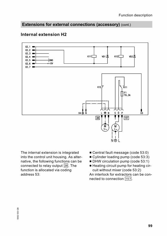
Internal extension H2
The internal extension is integratedinto the control unit housing. As alter-native, the following functions can beconnected to relay output sK. Thefunction is allocated via codingaddress 53:
& Central fault message (code 53:0)& Cylinder loading pump (code 53:3)& DHW circulation pump (code 53:1)& Heating circuit pump for heating cir-cuit without mixer (code 53:2)
An interlock for extractors can be con-nected to connection aBJ.
Extensions for external connections (accessory) (cont.)
99
Function description5692550GB

External extension H1
The external extension is connectedto the boiler control unit via the KMBUS. The following functions can becontrolled or processed via this exten-sion:sÖ Heating circuit pump for heating
circuit without mixersA Cylinder loading pumpsK DHW circulation pumpfÖ Power supplygÖ Central fault message
aVD & External blocking(terminals 2 - 3)
& External demand(terminals 1 - 2)
& External operating mode chan-geover (terminals 1 - 2)
aVF External set value 0 to 10 VaVG KM BUSThe allocation of the "External chan-geover of operating mode" function isselected via coding address 91.
Extensions for external connections (accessory) (cont.)
100
Function description
5692550GB

External extension H2
The external extension is connectedto the boiler control unit via the KMBUS. The following functions can becontrolled or processed via this exten-sion:sK DHW circulation pumpfÖ Power supply
aVD & External blocking(terminals 2 - 3)
& External demand(terminals 1 - 2)
& External operating mode chan-geover (terminals 1 - 2)
aVG KM BUSThe allocation of the "External chan-geover of operating mode" function isselected via coding address 91.
Extensions for external connections (accessory) (cont.)
101
Function description5692550GB

External operating mode changeover
The "External operating mode chan-geover" function is connected viaexternal extension input aVD. Withcoding address 91 you can select theheating circuit to which the change-over of operating mode should apply:
Coding Changeover of operating mode affects:91:0 No changeover91:1 Heating circuit without mixer (A1)91:2 Heating circuit with mixer (M2)91:3 Heating circuit without mixer and heating
circuit with mixer
With coding address d5, you canselect in which direction the change-over should be made for each heatingcircuit:
Coding Changeover of operating mode affects:d5:0 Changeover towards "Constantly reduced"
or "Constant standby mode" (subject tothe selected set value)
d5:1 Changeover towards "Constant heatingmode"
You can select the duration of theoperating mode changeover with cod-ing address F2.
Coding Changeover of operating mode affects:F2:0 No changeover of operating modeF2:1 toF2:12
Duration of the operating mode change-over 1 to 12 hours
The changeover of operating moderemains active as long as the contactremains closed, but no less than thedefault duration selected with codingaddress F2.
Control functions
102
Function description
5692550GB

External blocking
The "External blocking" function isconnected via the external extensioninput aVD.
In coding address 32 you can selectthe influence the signal "Ext. block-ing" should have on the connected cir-culation pumps.
External demand
The "External demand" function isconnected via the external extensioninput "aVD".In coding address 34 you can selectthe influence the signal "Ext. demand"should have on the connected circula-tion pumps.
In coding address 9b, you can selectthe minimum set boiler water tem-perature in case of external demand.
Venting program
NoteClose the gas shut-off valve whenoperating the venting program.
During the venting program, the circu-lation pump will be alternatelyswitched ON and OFF for 30 secondsrespectively over a period of20 minutes.
The burner is switched OFF duringthe venting program.The venting program is activated viacoding address 2F:1. The program isautomatically deactivated after20 minutes, and the coding address isset to 0.
Filling program
NoteClose the gas shut-off valve whenoperating the filling program.
Control functions (cont.)
103
Function description5692550GB

Filling with the control unit switched ON
If the system is to be filled with thecontrol unit switched ON, the pumpwill be started via coding address2F:2. The burner shuts down if thisfunction is activated via codingaddress 2F. The program is automati-cally deactivated after 20 minutes,and the coding address is set to 0.
Screed function
The screed drying functions enablesthe drying of a freshly laid screed. Forthis, always observe the instructionsissued by the screed manufacturer.
Various temperature profiles areavailable for selection.
Temperature profile: Diagram 1 (DIN 4725 part 4) code F1:1
Temperature profile: Diagram 2 code F1:2
Control functions (cont.)
104
Function description
5692550GB

Temperature profile: Diagram 3 code F1:3
Temperature profile: Diagram 4 code F1:4
Temperature profile: Diagram 5 code F1:5
Control functions (cont.)
105
Function description5692550GB

Temperature profile: Factory-set code F1:6 to F1:15
Control functions (cont.)
106
Function description
5692550GB

A1 Main PCB§ Boiler temperature sensor
% Cylinder temperature sensoraA Ionisation electrode
Connection and wiring diagrams – internal connections
107
Designs5692550GB

aG Flue gas temperature sensordD Flow switchfJ Temperature limiter
gF Ignition unita-Ö Fan motoraNF Differential pressure sensor
Connection and wiring diagrams – internal connectio . . . (cont.)
108
Designs
5692550GB

A1 Main PCB A2 Mains supply unit
Connection and wiring diagrams – external connections
109
Designs5692550GB

A3 OptolinkA4 Burner control unitA5 Operating interfaceA6 Coding cardA7 Connection adaptorA8 LON communication moduleA9 Internal extension H1S1 ON/OFF switchS2 Reset button! Outside temperature sensor? Flow temperature sensor low
loss header% Cylinder temperature sensor
sÖ Internal circulation pump(heating circuit pump or boilercircuit pump)
sK Circulation pump or central faultmessage
dD Flow switchdG Gas solenoid valvefÖ Power supplygD External LPG safety valvelH Mains power supply - acces-
sories and Vitotrol 100a-Ö Fan motoraYA Gas governoraVG KM BUS
Connection and wiring diagrams – external connectio . . . (cont.)
110
Designs
5692550GB

Spare parts informationQuote the type and serial no. (see type plate) and the item no. of the requiredpart (as per this parts list).Obtain standard parts from your local supplier.
006 Burner (with item 007, 009 to019, 021, 022, 023 and 046)
007 Burner gauze assembly008 Electronic box – radial fan009 Radial fan012 Gas pipe (incl. gaskets)013 Conversion kit for natural gas E
(gas restrictor)014 Conversion kit for natural gas LL
(gas restrictor)015 Conversion kit for LPG (gas
restrictor)016 Gas train017 Ignition unit018 Gas pipe019 Burner insulating ring021 Burner gauze assembly gasket,
large022 Burner profile packing023 Burner gauze assembly gasket024 Heat exchanger025 Boiler adaptor026 Lip seal Ø 150027 Lip seal Ø 100028 Plug029 Quick-acting air vent valve030 Grommet031 Flow switch032 Diaphragm safety valve033 Siphon034 Condensate hose035 Ball valve036 Return pipe extension037 Sealing panel038 Edge protector039 Front panel042 Wall mounting fixture
044 Pressure gauge and fem. con-nection
046 Differential pressure sensor047 Grommet048 Safety springs049 Thermocouple050 Temperature sensor052 Expansion vessel connection054 Locking bracket055 Gravity brake056 Flue gas temperature sensor057 Vitodens control unit058 Rear cover059 Support060 Damper061 Pressure gauge retainer062 Clip063 Hinge064 Coding card065 Fuse066 Operating interface for constant
temperature operation067 Operating interface for weather-
compensated operation069 Outside temperature sensor090 Micro switch
Wearing parts010 Ignition electrode011 Ionisation electrode
Parts not shown001 Operating instructions for con-
stant temperature operation002 Operating instructions for
weather-compensated operation003 Service instructions005 Installation instructions
Parts lists
111
Parts lists5692550GB

020 Set of small burner parts040 Touch-up spray paint, Vitowhite041 Touch-up paint stick, Vitowhite045 Special grease051 Gasket set053 Heat conducting paste070 Access guard074 Test adaptor ionisation current
test
075 Cable harness X8/X9076 Mains cable - motor electronics077 Connecting cable - motor078 Internal ionisation lead079 Cable harness aux. earth/54/35080 Cable harness ionisation/KM
BUSA Type plate
Parts lists (cont.)
112
Parts lists
5692550GB

Parts lists (cont.)
113
Parts lists5692550GB

Parts lists (cont.)
114
Parts lists
5692550GB

Parts lists (cont.)
115
Parts lists5692550GB

Parts lists (cont.)
116
Parts lists
5692550GB

Parts lists (cont.)
117
Parts lists5692550GB

Setting and test values Set value Initial start-up
Date:By:
Static pressure mbar max. 57.5 mbar
Supply pressure (flow pressure)= for natural gas E mbar 17.4 to
57.5 mbar= for natural gas LL mbar 17.4 to
57.5 mbar= for LPG mbar 42.5 to
57.5 mbarTick gas type
Carbon dioxide content CO2
& at lower rated output % byvol.
& at upper rated output % byvol.
Oxygen content O2
& at lower rated output % byvol.
& at upper rated output % byvol.
Carbon monoxide content CO& at lower rated output ppm& at upper rated output ppm
Ionisation current µA min. 5 µA
Commissioning/service reports
118
Commissioning/service reports
5692550GB

Maintenance/ser-vice
Maintenance/service
Maintenance/service
Maintenance/ser-vice
Commissioning/service reports (cont.)
119
Commissioning/service reports5692550GB

Setting and test values Set value Maintenance/service
Date:By:
Static pressure mbar max. 57.5 mbar
Supply pressure (flow pressure)= for natural gas E mbar 17.4 to
57.5 mbar= for natural gas LL mbar 17.4 to
57.5 mbar= for LPG mbar 42.5 to
57.5 mbarTick gas type
Carbon dioxide content CO2
& at lower rated output % byvol.
& at upper rated output % byvol.
Oxygen content O2
& at lower rated output % byvol.
& at upper rated output % byvol.
Carbon monoxide content CO& at lower rated output ppm& at upper rated output ppm
Ionisation current µA min. 5 µA
Commissioning/service reports (cont.)
120
Commissioning/service reports
5692550GB

Maintenance/ser-vice
Maintenance/service
Maintenance/service
Maintenance/ser-vice
Commissioning/service reports (cont.)
121
Commissioning/service reports5692550GB

Setting and test values Set value Maintenance/service
Date:By:
Static pressure mbar max. 57.5 mbar
Supply pressure (flow pressure)= for natural gas E mbar 17.4 to
57.5 mbar= for natural gas LL mbar 17.4 to
57.5 mbar= for LPG mbar 42.5 to
57.5 mbarTick gas type
Carbon dioxide content CO2
& at lower rated output % byvol.
& at upper rated output % byvol.
Oxygen content O2
& at lower rated output % byvol.
& at upper rated output % byvol.
Carbon monoxide content CO& at lower rated output ppm& at upper rated output ppm
Ionisation current µA min. 5 µA
Commissioning/service reports (cont.)
122
Commissioning/service reports
5692550GB

Maintenance/ser-vice
Maintenance/service
Maintenance/service
Maintenance/ser-vice
Commissioning/service reports (cont.)
123
Commissioning/service reports5692550GB

Rated voltage: 230 V~Rated frequency: 50 HzRated current : 6.3 A~Safety class: IProtection level: IP X 4 D to
EN 60529
Permissible ambient temperature& in operation: 0 to +40 °C& during storageand transport:
-20 to +65 °C
Electronic tempera-ture limiter setting:
81 °C
Temperature limitersetting:
100 °C (fixed)
Mains fuse: max. 16 A
Power consumption& Burner: max. 60 W& Control unit: max. 10 VA
Gas fired boiler, category II 2ELL3PRated output TV/TR 50/30 °C kW 12.2 to 49 16.6 to 66Rated heat load range kW 11.5 to
46.315.6 to 62.2
Connection values*1Relative to the max. loadwith with HuB
Natural gas E 9.45 kWh/m3
34.02 MJ/m3m3/h
4.90 6.58
Natural gas LL 8.13 kWh/m3
29.25 MJ/m3m3/h
5.69 7.65
LPG 12.79kWh/m3
46.04 MJ/m3m3/h
3.62 4.86
Product ID _-0085 BO 0338
Product characteristics (to EnEV [Germany])Rated output range kW 12.2 to 49 16.6 to 66Efficiency at& 100 % of rated output % 97.2 97.3& 30 % of rated output % 107.1 107.3Standby loss q B,70*2 % 0.5 0.4
Power consumption*2 for& 100 % of rated output W 277 321& 30 % of rated output W 92 107
Specification
124
Specification
5692550GB*1The supply values are only for reference (e.g. in the gas contract application) or to esti-
mate the supplementary volumetric settings. Because of factory settings, the gas pres-sure must not be altered from these values. Reference: 15 °C, 1013 mbar.
*2Max. limit to EnEV.

Declaration of conformity for Vitodens 300
We, Viessmann Werke GmbH & Co KG, D-35107 Allendorf, declare as soleresponsible body, that the product
Vitodens 300
conforms to the following stan-dards:
This product is designated in accor-dance with the following directives:
DIN 4702–6 90/396/EECEN 297 89/336/EECEN 483 73/23/EECEN 625 92/42/EECEN 677EN 50 165EN 60 335EN 61 000-3-2 as follows:EN 61 000-3-3 _-0085
EC Declaration of conformity by an authorised body according to EMVG article10.2 Certificate number: E9 02 08 1730.This product complies with the requirements of the Efficiency Directive(92/42/EEC) for: Condensing boilersThe product characteristics determined as system values for the product Vito-dens 300 as part of EC type testing according to the Efficiency Directive(see specification table), can be utilised to assess the energy consumption ofheating and ventilation equipment to DIN V 4701-10 which is specified by theEnEV [Germany].
Allendorf, 14.01.04 Viessmann Werk GmbH&Co KG
pp. Manfred Sommer
Declaration of conformity
125
Certificates5692550GB

We, Viessmann Werke GmbH & Co KG, D-35107 Allendorf, confirm that the fol-lowing product meets the NOx limits specified by 1st BImSchV Paragraph 7 (2)[Germany]:
Vitodens 300
Allendorf, 14.01.04 Viessmann Werk GmbH&Co KG
pp. Manfred Sommer
Manufacturer's certificate according to the 1st BImSchV [Germany]
126
Certificates
5692550GB
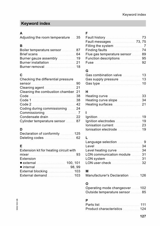
AAdjusting the room temperature . . . . 35
BBoiler temperature sensor . . . . . . . . . . . . . 87Brief scans . . . . . . . . . . . . . . . . . . . . . . . . . . . . . . . . . . 64Burner gauze assembly . . . . . . . . . . . . . . . . 19Burner installation . . . . . . . . . . . . . . . . . . . . . . . . 21Burner removal . . . . . . . . . . . . . . . . . . . . . . . . . . . . 18
CChecking the differential pressuresensor . . . . . . . . . . . . . . . . . . . . . . . . . . . . . . . . . . . . . . . . . 90Cleaning agent . . . . . . . . . . . . . . . . . . . . . . . . . . . . 21Cleaning the combustion chamber . 21Code . . . . . . . . . . . . . . . . . . . . . . . . . . . . . . . . . . . . . . . . . . . 38Code 1 . . . . . . . . . . . . . . . . . . . . . . . . . . . . . . . . . . . . . . . . 38Code 2 . . . . . . . . . . . . . . . . . . . . . . . . . . . . . . . . . . . . . . . . 42Coding during commissioning . . . . . . . 24Commissioning . . . . . . . . . . . . . . . . . . . . . . . . . . . . . 7Condensate drain . . . . . . . . . . . . . . . . . . . . . . . . . 22Cylinder temperature sensor . . . . . . . . . 87
DDeclaration of conformity . . . . . . . . . . . . 125Deleting codes . . . . . . . . . . . . . . . . . . . . . . . . . . . . . 62
EExtension kit for heating circuit withmixer . . . . . . . . . . . . . . . . . . . . . . . . . . . . . . . . . . . . . . . . . . . 93Extension& external . . . . . . . . . . . . . . . . . . . . . . . . . . 100, 101& internal . . . . . . . . . . . . . . . . . . . . . . . . . . . . . . . 98, 99External blocking . . . . . . . . . . . . . . . . . . . . . . . 103External demand . . . . . . . . . . . . . . . . . . . . . . . . 103
FFault history . . . . . . . . . . . . . . . . . . . . . . . . . . . . . . . . . 73Fault messages . . . . . . . . . . . . . . . . . . . . . 73, 75Filling the system . . . . . . . . . . . . . . . . . . . . . . . . . . 7Finding faults . . . . . . . . . . . . . . . . . . . . . . . . . . . . . . . 74Flue gas temperature sensor . . . . . . . . . 89Function descriptions . . . . . . . . . . . . . . . . . . . 95Fuse . . . . . . . . . . . . . . . . . . . . . . . . . . . . . . . . . . . . . . . . . . . 92
GGas combination valve . . . . . . . . . . . . . . . . . 13Gas supply pressure . . . . . . . . . . . . . . . . . . . . 13Gas type . . . . . . . . . . . . . . . . . . . . . . . . . . . . . . . . . . . . . . 10
HHeating curve . . . . . . . . . . . . . . . . . . . . . . . . . . . . . . 33Heating curve slope . . . . . . . . . . . . . . . . . . . . . 34Heating surfaces . . . . . . . . . . . . . . . . . . . . . . . . . . 21
IIgnition . . . . . . . . . . . . . . . . . . . . . . . . . . . . . . . . . . . . . . . . 19Ignition electrodes . . . . . . . . . . . . . . . . . . . . . . . . 19Ionisation current . . . . . . . . . . . . . . . . . . . . . . . . . 23Ionisation electrode . . . . . . . . . . . . . . . . . . . . . . 19
LLanguage selection . . . . . . . . . . . . . . . . . . . . . . . 9Level . . . . . . . . . . . . . . . . . . . . . . . . . . . . . . . . . . . . . . . . . . . 34Level heating curve . . . . . . . . . . . . . . . . . . . . . . 34LON communication module . . . . . . . . . 31LON system . . . . . . . . . . . . . . . . . . . . . . . . . . . . . . . . . 31LON user check . . . . . . . . . . . . . . . . . . . . . . . . . . . 32
MManufacturer's Declaration . . . . . . . . . 126
OOperating mode changeover . . . . . . . 102Outside temperature sensor . . . . . . . . . . 85
PParts list . . . . . . . . . . . . . . . . . . . . . . . . . . . . . . . . . . . . 111Product characteristics . . . . . . . . . . . . . . . 124
Keyword index
127
Keyword index5692550GB

RRelay test . . . . . . . . . . . . . . . . . . . . . . . . . . . . . . . . . . . . 68Resetting the coding to the deliveredcondition . . . . . . . . . . . . . . . . . . . . . . . . . . . . . . . . . . . . . 62
SSafety chain . . . . . . . . . . . . . . . . . . . . . . . . . . . . . . . . 90Scanning . . . . . . . . . . . . . . . . . . . . . . . . . . . . . . . . . . . . . 64Scanning operating conditions . . . . . . 70Scanning sensors . . . . . . . . . . . . . . . . . . . . . . . . 70Screed drying . . . . . . . . . . . . . . . . . . . . . . . . . . . . 104Screed function . . . . . . . . . . . . . . . . . . . . . . . . . . 104Service level summary . . . . . . . . . . . . . . . . . 63Service report . . . . . . . . . . . . . 118, 120, 122Setting the date . . . . . . . . . . . . . . . . . . . . . . . . . . . . . 9Setting the output . . . . . . . . . . . . . . . . . . . . . . . . . 16Setting the time . . . . . . . . . . . . . . . . . . . . . . . . . . . . . 9Setting up LON user numbers . . . . . . . 31Siphon . . . . . . . . . . . . . . . . . . . . . . . . . . . . . . . . . . . . . . . . 22Slope . . . . . . . . . . . . . . . . . . . . . . . . . . . . . . . . . . . . . . . . . . 34Soundness test, balanced fluesystem . . . . . . . . . . . . . . . . . . . . . . . . . . . . . . . . . . . . . . . . 17Specification . . . . . . . . . . . . . . . . . . . . . . . . . . . . . . 124Static pressure . . . . . . . . . . . . . . . . . . . . . . . . . . . . . 13Supply pressure . . . . . . . . . . . . . . . . . . . . . . . . . . . 12System designs . . . . . . . . . . . . . . . . . . . . . 24, 39System pressure . . . . . . . . . . . . . . . . . . . . . . . . . . . 7
TTemperature scans . . . . . . . . . . . . . . . . . . . . . . . 64Testing functions . . . . . . . . . . . . . . . . . . . . . . . . . . 68Testing outputs . . . . . . . . . . . . . . . . . . . . . . . . . . . . 68Thermocouple . . . . . . . . . . . . . . . . . . . . . . . . . . . . . . 90
VVenting . . . . . . . . . . . . . . . . . . . . . . . . . . . . . . . . . . . . . . . . . 8Venting program . . . . . . . . . . . . . . . . . . . . . . . . 103Vitotronic 050 . . . . . . . . . . . . . . . . . . . . . . . . . . . . . . 94
WWiring diagrams . . . . . . . . . . . . . . . . . . . . . . . . . 107
Keyword index (cont.)
128
Keyword index
5692550GB

129
5692550GB

130
5692550GB

131
5692550GB

Applicability
12.3 to 49 kW 16.6 to 66 kWNatural gas version Natural gas versionfrom serial no. from serial no.7176 778 3 00001 7176 779 3 00001LPG version LPG versionfrom serial no. from serial no.7176 780 3 00001 7176 781 3 00001
132
Printedonenvironmentally
-friendly,
chlorine-freebleach
edpaper
5692550GB
Subject
totech
nicalm
odifications
Viessmann LimitedHortonwood 30, Telford, TF1 7YP, GBTelephone: +44 1952 675000Fax: +44 1952 675040www.viessmann.co.uk