Videx v. Triteq Lock and Security
31
Johnathan E. Ma nsfiel d, OSB No. 055 390 Email [email protected] Peter E. Heu ser , OSB No. 8112 81 Email: [email protected] Schwabe, Williamson & Wyatt, P.C. Pacwest Center 1211 SW 5th Ave., Suite 1900 Portland, OR 97204 Telephone 503.222. 9981 Fax 503.796.2900 Of Attorneys for Plaintiff, Videx, Inc. FILED 29 ' ( ~ I ' l l 14:42 USDC'ORE IN THE UNITED STATES DISTRICT COURT FOR THE DISTRICT OF OREGON EUGENE DIVISION VIDEX, INC., an Oregon corporation, No. I I: D 3 3 ~ Ai-\ Plaintiff, COMPLAINT FOR PATENT vs. INFRINGEMENT TRITEQ LOCK AND SECURITY, LLC, DEMAND FOR JURY TRIAL an Illinois limited liability corporation, Defendant. Plaintif f Videx, Inc. alleges as follows: I. NATURE OF LAWSUIT 1. This is a patent infringement lawsuit brought under the patent laws of the United States, 35 U.S.C. §§ 271, 281, 283-285. II . TH E PARTIES 2. Plai ntiff Videx is an Oregon corporation with its principal place of business in Corvallis, Oregon. Videx is a leader in the design and manufacture o f electronic access control Page I - COMPLAINT FOR PATENT INFRINGEMENT SCHWABE. ~ ' < ! m e w : ~ t t ! . . WYATI, PC. P_ICenler 1211 SW 5th Ave., Suite 1900 Portland, OR 97204 Telephone 503.222.9981 Fax 503.796.2900 PDXl123953/182947/JEMJ8476796.1 lo C! C) OC) 7 0 %
-
Upload
priorsmart -
Category
Documents
-
view
223 -
download
0
Transcript of Videx v. Triteq Lock and Security

8/3/2019 Videx v. Triteq Lock and Security
http://slidepdf.com/reader/full/videx-v-triteq-lock-and-security 1/30
Johnathan E. Mansfield, OSB No. 055390Email [email protected] Peter E. Heuser, OSB No. 811281Email: [email protected] Schwabe, Williamson & Wyatt, P.C.Pacwest Center
1211 SW 5th Ave., Suite 1900Portland, OR 97204Telephone 503.222.9981Fax 503.796.2900
Of Attorneys for Plaintiff, Videx, Inc.
FILED 29 ' ( ~ I ' l l 14:42 USDC'ORE
IN THE UNITED STATES DISTRICT COURT
FOR THE DISTRICT OF OREGON
EUGENE DIVISION
VIDEX, INC., an Oregon corporation, No. I I:D 3 3 ~ Plaintiff, COMPLAINT FOR PATENT
vs. INFRINGEMENT
TRITEQ LOCK AND SECURITY, LLC, DEMAND FOR JURY TRIAL
an Illinois limited liability corporation,
Defendant.
Plaintiff Videx, Inc. alleges as follows:
I. NATURE OF LAWSUIT
1. This is a patent infringement lawsuit brought under the patent laws of the United
States, 35 U.S.C. §§ 271, 281, 283-285.
II. THE PARTIES
2. PlaintiffVidex is an Oregon corporation with its principal place of business in
Corvallis, Oregon. Videx is a leader in the design and manufacture of electronic access control
Page I - COMPLAINT FOR PATENT INFRINGEMENT SCHWABE. ~ ' < ! m e w : ~ t t ! . . WYATI, PC.
P_ ICen l e r
1211 SW 5th Ave., Suite 1900 Portland, OR 97204
Telephone 503.222.9981 Fax 503.796.2900
PDXl123953/182947/JEMJ8476796.1
lo C! C)OC)7 0%

8/3/2019 Videx v. Triteq Lock and Security
http://slidepdf.com/reader/full/videx-v-triteq-lock-and-security 2/30
products. Videx's award-winning CyberLock® products have been installed in doors, safes,
cabinets, vending machine and other containers, wherever an innovative and cost-effective
security solution is required.
3. Defendant TriTeq Lock and Security, LLC is an Illinois limited liability
corporation with its principal business address in Elk Grove Village, Illinois.
III. JURISDICTION AN D VENUE
4. This Court has subject matter jurisdiction under 28 U.S.C. §§ 1331 and 1338.
5. This Court has general and specific personal jurisdiction over TriTeq because on
information and belief: TriTeq maintains continuous and systematic contacts with the State of
Oregon, and TriTeq has sold and offered for sale to customers in this district products that
infringe one or more claims ofVidex's patent.
6. Venue is proper in this Court under 28 U.S.c. §§ 1391(b), 1391 (c), and/or
1400(b).
IV. BACKGROUND
7. Since its founding in 1979, Videx has distinguished itself from the competition by
its innovative approach to solving its customers' problems. In the late 1990s, Videx's founder
realized that electronic and computer technology could be used to greatly improve security for
businesses, leading to increased safety and adding to the bottom line. This led Videx to create
many inventions that have received patents in the U.S. and abroad.
8. Videx is the owner of the entire right, title and interest in U.S. Patent No.
6,564,600 ("the '600 Patent"), entitled "ELECTRONIC ACCESS CONTROL DEVICE," issued
May 20,2003 (attached as "Exhibit A"). All maintenance fees have been paid.
9. The '600 patent is directed to an electronic access control device. As generally
stated in the patent abstract, an electronic access control device has a movable locking member.
A locking mechanism is operable to control the locking member. A movement detector generates
a first condition in response to movement of the locking member. A key detector generates a
SCHWABE, WILLIAMSON & WYATT, P.C.Page 2- COMPLAINT FOR PATENT INFRINGEMENT Attorneys at LawPacwesl Center
1211 SW5thAve., Suite 1900Portland, OR 97204
Telephone 503.222.9981 Fax 503.796.2900
PDXl123953/182947/JEMl8476796.1
8/3/2019 Videx v. Triteq Lock and Security
http://slidepdf.com/reader/full/videx-v-triteq-lock-and-security 3/30
. . . \
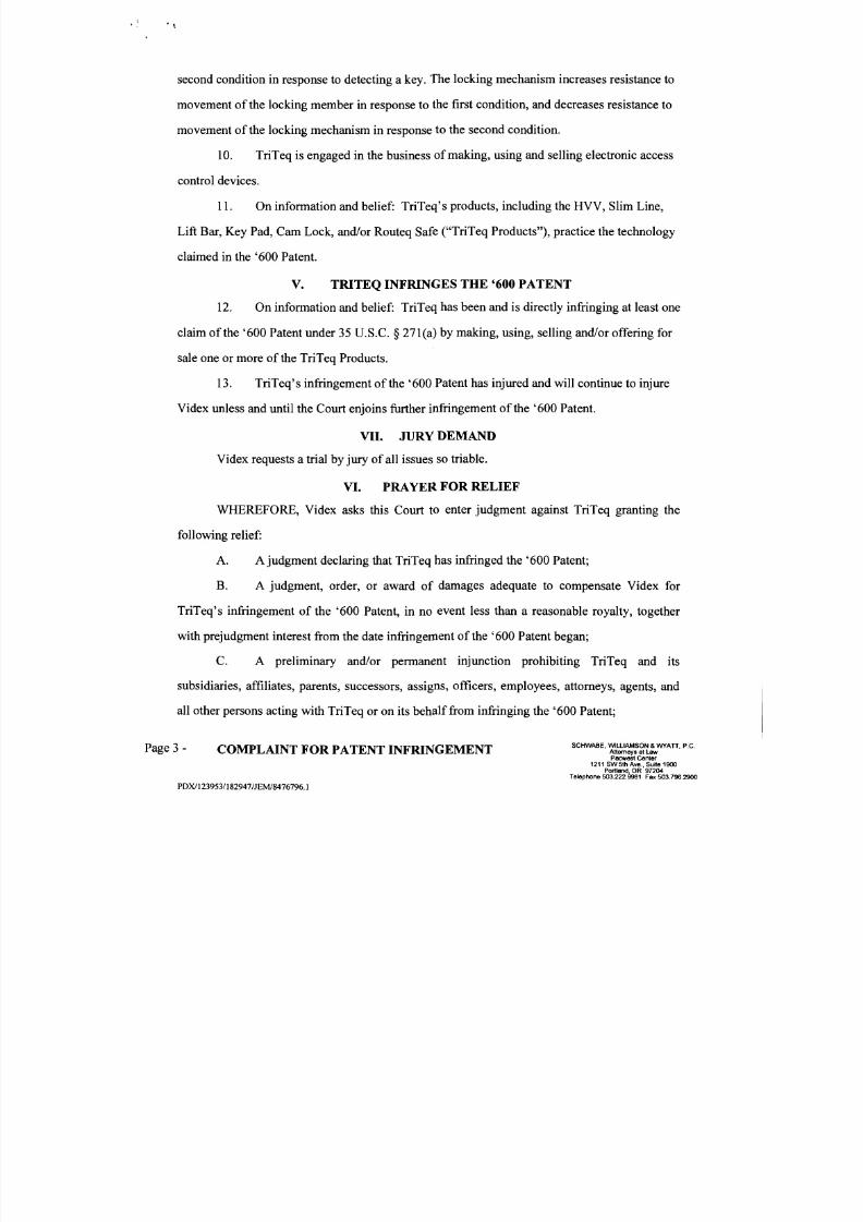
second condition in response to detecting a key. The locking mechanism increases resistance to
movement of the locking member in response to the first condition, and decreases resistance to
movement of the locking mechanism in response to the second condition.
10.TriTeq is engaged in the business
ofmaking, using and selling electronic access
control devices.
11. On information and belief: TriTeq's products, including the HVV, Slim Line,
Lift Bar, Key Pad, Cam Lock, and/or Routeq Safe ("TriTeq Products"), practice the technology
claimed in the '600 Patent.
V. TRITEQ INFRINGES THE '600 PATENT
12. On information and belief: TriTeq has been and is directly infringing at least one
claim of the '600 Patent under 35 U.S.C. § 271(a) by making, using, selling and/or offering for
sale one or more of the TriTeq Products.
13. TriTeq's infringement of the '600 Patent has injured and will continue to injure
Videx unless and until the Court enjoins further infringement of the '600 Patent.
VII. JURY DEMAND
Videx requests a trial by jury of all issues so triable.
VI. PRAYER FOR RELIEF
WHEREFORE, Videx asks this Court to enter judgment against TriTeq granting the
following relief:
A. A judgment declaring that TriTeq has infringed the '600 Patent;
B. A judgment, order, or award of damages adequate to compensate Videx for
TriTeq's infringement of the '600 Patent, in no event less than a reasonable royalty, together
with prejudgment interest from the date infringement of the '600 Patent began;
C. A preliminary and/or permanent injunction prohibiting TriTeq and its
subsidiaries, affiliates, parents, successors, assigns, officers, employees, attorneys, agents, and
all other persons acting with TriTeq or on its behalf from infringing the '600 Patent;
SCHWABE. WIU.IAMSON & WYATT. P.C.Page 3- COMPLAINT FOR PATENT INFRINGEMENT Attomeys at lawPacwest Center
1211 SW 5th Ave., Suite 1900 Por1land, OR 97204
Telephone 503.222.9981 Fax 503.796.2900
PDXlI 23953/1 82947/JEMl8476796. I

8/3/2019 Videx v. Triteq Lock and Security
http://slidepdf.com/reader/full/videx-v-triteq-lock-and-security 4/30
.\
D. An accounting to determine information relevant to establishing the extent of
TriTeq's infringement and amount ofVidex's damages;
E. An award of costs and attorneys' fees, pursuant to 35 U.S.C. § 285 to the extent
the Court finds this case to be exceptional;
F. An order trebling the damage award under 35 U.S.C. § 284, together with
prejudgment interest; and
O. Such other and further relief as this Court may deem proper and just.
Dated this 29th day ofNovember, 2011.
Respectfully submitted,
S C H W ~ E , W A M S ~ ~ &7AIT ' P.c.
By: ~ ~ E ~ = = = ; : : : : : : : = = : = =. Mansfield, OSB No. 055390
Peter . euser, OSB No. 811281Telephone 503.222.9981OfAttorneys for Videx, Inc.
SCHWABE, WILLIAMSON & WYATI, P.C.Page 4 - COMPLAINT FOR PATENT INFRINGEMENT Attorneysat LawPacwes\ Center
1211 SW 5th Ave., Suite 1900 Portland, OR 97204
Telephone 503.222.9981 Fax 503.796.2900
PDXfl 23953/1 82947/JEMJ8476796, 1

8/3/2019 Videx v. Triteq Lock and Security
http://slidepdf.com/reader/full/videx-v-triteq-lock-and-security 5/30
.\ IIII I I I I I I I I I I ~ I I I I I I I I I I I I I . I I I I I I I I I I USOO6564600Bl
(12) United States Patent (10) Patent No.: US 6,564,600 BlDavis
(54) ELECTRONIC ACCESS CONTROL DEVICE
(75) Inventor:
(73) Assignee:
( . ) Notice:
Paul R. Davis, Corvallis, OR (US)
Vide", Inc., Corvallis, OR (US)
Subject to any disclaimer, the term of tbis
patent is extended or adjusted under 35U.S.c. 154(b) by 0 days.
(21) AppJ. No.: 09/499,5.56
(22) Filed: Feb. 7, 2000
Related U.s. Application Data
(63) Continuation-in-part of application No. 09/264,246, filed onMar. 8, 1999, now abandoned.
(51) Int. CI.7 ................................................ EO.5B 47/06
(52) U.S. CI ........................ 70/277; 70/278.2; 70/278.7;70/283
(58) Field of Searcb ....................... 70/277,432,278.1,70/278.2,278.3,283, 283.1,279.1,278.7
(56) References Cited
U.s. PATENT DOCUMENTS
2,212,251 A • &119402,271,966 A • 2/19422,475,220 A • 7/19492,763,888 A 9/1956
3,241,344 A • 3/1966
3,731,963 A 5/19733,733,861 A • 5/1973
3,843,174 A 10/19744,099,752 A 7/1978
4,127,966 A 12/19784,148,092 A • 4/1979
Seelinger Baribault
Cbaulk et al.
BiUeter Peters Pond .......................... Lester .............. ........... Bogunovich et al ........
292/14470/153
292/166
Geringer ..................... 292/144
Schmidt ...................... 49/141 Martin ..... ..... .... ..... .. 70/149 X
(45) Date of Patent: May 20,2003
4,262,504 A 4/1981
4,557,121 A 12/19854,579,376 A 411986
4,702,094 A 10/19874,789,859 A • 1211988
4,982,587 A • 1/1991
5,010,751 A • 4/19915,177,988 A 1/19935,216,909 A 6/1993
5,339,662 A &11994
5,421,178 A 6/19955,609,051 A 3/19975,819,563 A • 10/1998
5,878,612 A • 3/19996,064,316 A • 5/2000
6,082,153 A • 7/2000
Inoue ....................... 70/151 R Charlton ................... 70/129 X Charton ... ..... .... ..... ..... 292/144
Peterson ...................... 70/241 aarhon et aI. ........ 361/172 X Tzou ............... ............ 70/492
Schwartz et al. ..... ..... ... 70/276 Bushnell ................... 70/175 X Armoogam ..... ..... ..... 70/283 X Goldman .................. 70/432 X Hamel et al. ................. 70/283 Donaldson ..... ..... .. 70/303 A X Bianco .. ..... ..... .... ..... 70/283 X
Mauer .... ..... ..... .... .... 70/283 X Glick et al. ................. 70/63 X
Schoel! et al. ................ 70/1.5
FOREIGN PATENT DOCUMENTS
EP 0148701 • 7/1985 .................. 70/283
* cited by examiner
Primary Examiner-Lloyd A. Gall
(74) Attorney, Agent, or Firm-Chemoff, Vilhauer,
McClung & Stenzel, LLP
(57) ABSTRACT
An electronic access control device has a movable locking
member. A locking mechanism is operable to control the
locking member. A movement detector generates a first
condition in response to movement of the locking member.
A key detector generales a second condition in response to
detecting a key. The locking mechanism increases resistanceto movement of the locking member in response to the first
condition, and decreases resistance to movement of thelocking mechanism in r ~ < ; p o n s e to the second condition.
16 Claims, 16 Drawing Sbeets
/'-.7
EXHIBIT A
Page 1 of 26

8/3/2019 Videx v. Triteq Lock and Security
http://slidepdf.com/reader/full/videx-v-triteq-lock-and-security 6/30
· '
u.s. Patent May 20, 2003 Sheet 1 of 16 US 6,564,600 Bl
FIG.l
12,)
122
22)
12
122
24
20 FIG.2
EXHIBIT A
Page 2of26

8/3/2019 Videx v. Triteq Lock and Security
http://slidepdf.com/reader/full/videx-v-triteq-lock-and-security 7/30
108
6b
, ,
""Omm )( FIG.3AJ:J:( ' 1 ) _ -124w OJ
0-; TO
;::;»0 )

8/3/2019 Videx v. Triteq Lock and Security
http://slidepdf.com/reader/full/videx-v-triteq-lock-and-security 8/30
u.s. Patent May 20,2003 Sheet 3 of 16 US 6,564,600 Bl
"III::: « /.ttt::. I""') I O·0::0lJ.. ......
LL
I I
I I
I I
I I
I I
I I
I I
I I
I I
ccM•
0-..COI""')
NLO
I I
I I
EXHIBIT A
Page 4 of 26

8/3/2019 Videx v. Triteq Lock and Security
http://slidepdf.com/reader/full/videx-v-triteq-lock-and-security 9/30
u.s. Patent May 20, 2003 Sheet 4 of 16 US 6,564,600 BI
• otoo .....-..
r1 I I I I I I I I
r-):t I I I I • I I I I I I : LL __
I \-,.'1--
I I I I I , I I ,
V "0 'V ~ , . . t l N I
I I I I I I \ I
H\ : : 'W J I I I 0-' I I I ..... I" V 'r ~ : o :
I • I ...... I I • I I I I I I I I
: LL\-.1I I
\ --ri-I ,
H\ " "'WJ I, II
....-'l, I 4 ...... " I
I I, ' , I
0 0 ',1../,N " ', I
. . . . 01 ' , I
..... ..... ,I, I
\', '
..
~ ' ' ' ' ' ' ' ' ' , :.,__ J..I. __ ....
.....
.. 0to
.....
<0. -....
v o
()
EXHIBIT A
Page 5 of 26

8/3/2019 Videx v. Triteq Lock and Security
http://slidepdf.com/reader/full/videx-v-triteq-lock-and-security 10/30
u.s. Patent May 20, 2003 Sheet 5 of 16 US 6,564,600 Bl
44
17
132
116Q
46~ - = : l - - - l FIG.6
44\ f - . ~ l ____ ______
)
FIG.7 40
EXHIBIT A
Page 6 of 26

8/3/2019 Videx v. Triteq Lock and Security
http://slidepdf.com/reader/full/videx-v-triteq-lock-and-security 11/30
.'
u.s. Patent May 20, 2003 Sheet 6 of 16 US 6,564,600 Bl
9
70
132
GJ46
_-L-__ _ _ I- ~ _ _ _ _ _ ' _ _ _ _
FIG.8
FIG.9 40!
EXHIBIT A
Page 70f26

8/3/2019 Videx v. Triteq Lock and Security
http://slidepdf.com/reader/full/videx-v-triteq-lock-and-security 12/30
u.s. Patent May 20, 2003 Sheet 7 of 16 US 6,564,600 Bl
11
-4 4
\'-----"""""'")II
"76 .. -.. ,I".
, , ' . .J 1
46
FIG.l0
FIG.ll
EXHIBIT A
Page 8 of 26

8/3/2019 Videx v. Triteq Lock and Security
http://slidepdf.com/reader/full/videx-v-triteq-lock-and-security 13/30
u.s. Patent May 20,2003 Sheet 8 of 16 US 6,564,600 Bl
500
\
502
90
raj
FIG.12
EXHIBIT A
Page 9 of 26

8/3/2019 Videx v. Triteq Lock and Security
http://slidepdf.com/reader/full/videx-v-triteq-lock-and-security 14/30
,
u.s. Patent May 20, 2003 Sheet 9 of 16 US 6,564,600 HI
90-L130 KEY \
I DETECTOR I
LED BEEPER I/'
I - -132
-""'"
"-
- CLOCK '--134
8\6- EEPROM I - -98
SWITCH CPUEEPROM88 - I - -98
-
- COIL ' - -150
IrDA- f--..-..136.138LEDS
REG 1--97
FIG.13
9 VOLTr-96BATTERY
EXHIBIT A
Page 10 of 26

8/3/2019 Videx v. Triteq Lock and Security
http://slidepdf.com/reader/full/videx-v-triteq-lock-and-security 15/30
KEY DETECTOR L200READS DEVICE 1 -
230
ERROR COMMUN
EV
216
SAV
.--. MAS
N 210 208
N
OPEN BEEP ADD KEY TOSET OPEN FLAGS DELEEPROM r-214
AVE STATUS ADD KEY BEEP
LED ON DEL
222
'"Om 228 (mx 212(OJ:<D_ SET OPEN FLAGS
..... OJ SAVE MASTER KEY EVENT
..... -1 MASTER KEY BEEPs,» LED ONI\.)
0>

8/3/2019 Videx v. Triteq Lock and Security
http://slidepdf.com/reader/full/videx-v-triteq-lock-and-security 16/30
u.s. Patent May 20, 2003 Sheet 11 of 16 US 6,564,600 Bl
N
SWITCH ON
300
Y
316
POWERUP LOCK
REVERSE SOLENOID 306
WAIT FORINPUT
Y
SOUND ALARMPOWERUP LOCK
SA VE OPEN EVENT
N
Y
SAVE TAMPER
EVENT
"l14v
316WAIT FOR
INPUT
FIG.15
EXHIBIT A
Page 12 of 26

8/3/2019 Videx v. Triteq Lock and Security
http://slidepdf.com/reader/full/videx-v-triteq-lock-and-security 17/30
u.s. Patent May 20,2003 Sheet 12 of 16 US 6,564,600 Bl
400IrDA/WAND
COMM.
" RS232 IrDA
SYNCHRONIZE SYNCHRONIZE RS232 IrDA
READ COMMAND BYTES
DENY BEEP WAIT FOR INPUT
GET DATA FROM
EEPROM OR READ RTC
SEND SYNCHRONIZA nON
READ DATASIGNAL
WRITESEND DATA
EEPROM/RTC
SUCCESS BEEP WAIT FOR INPUT
WAIT FOR
INPUT
FIG.16
EXHIBIT A
Page 13 of 26

8/3/2019 Videx v. Triteq Lock and Security
http://slidepdf.com/reader/full/videx-v-triteq-lock-and-security 18/30
".
u.s. Patent May 20,2003 Sheet 13 of 16 US 6,564,600 HI
38
\51
-48
51 51
49
FIG.17
EXHIBIT A
Page 14 of 26

8/3/2019 Videx v. Triteq Lock and Security
http://slidepdf.com/reader/full/videx-v-triteq-lock-and-security 19/30
"Om1»><
@c'o::x:
CD -..... 00
01=iQ,» FIG.18 646I\.)
0>
C£JUS: JUg §l.hl#lUM4M¥A4 l ,WS r. &CU;"
8/3/2019 Videx v. Triteq Lock and Security
http://slidepdf.com/reader/full/videx-v-triteq-lock-and-security 20/30
u.s. Patent May 20, 2003 Sheet 15 of 16 US 6,564,600 Bl
652
__ ~ ~ ~ t L ~ ~ 6 7 4 638
.-...--r---'.J
r - - " " I - I 639
L.r-1.....;;;;:::r-708
636
- 6 44
646
FIG.19
FIG.20
EXHIBIT A
Page 16 of 26

8/3/2019 Videx v. Triteq Lock and Security
http://slidepdf.com/reader/full/videx-v-triteq-lock-and-security 21/30
u.s. Patent May 20, 2003 Sheet 16 or 16 US 6,564,600 Bl
- 6 44
-----I '- 646
FIG.21
_ _ _ 624
FIG.22
EXHIBIT A
Page 17 of 26
8/3/2019 Videx v. Triteq Lock and Security
http://slidepdf.com/reader/full/videx-v-triteq-lock-and-security 22/30
5
10
15
20
25
30
35
40
45
50
55
60
65
US 6,564,600 B1
1ELECTRONIC ACCESS CONTROL DEVICE
This application is a continuation-in-part of U.S. patentapplication Ser. No. 09/264,246, filed Mar. 8, 1999, nowabandoned.
BACKGROUND OF 'm E INVENTION
The present invention relates to an electronic accesscontrol device, and more particularly to an electronic lockhaving a solenoid which increases or decreases resistence to
opening the lock.
Electronic locks are well known and have been used tocontrol the functioning of a locking mechanism. Inparticular, solenoids have been used as part of an electroniclock to restrain a latch that prevents movement of a lockingbolt. An example of such a system is shown in Nakauchi,U.S. Pat. No. 4,798,068. Electronic locks have the advantage of allowing the use of electronic keys, which enables
such locks to keep track of different keys. However, electronic locks suffer from several disadvantages. First. thelocks consume electrical power. Thus, such locks eithermust be connected to a permanent power source, or must be
supplied with a battery. Often, it is not practical to connect
an electronic lock to a permanent source of power. Powerconsumption by an electronic lock, however, can quicklydeplete the power in the battery, requiring either large, bulkybatteries or frequent replacement of batteries.
Electronic locks which use a solenoid suffer from anotherdisadvantage in that such locks may be opened with a sharp
blow to the lock. For example, in the electronic lockdisclosed in Nakauchi U.S. Pat. No. 4,798,068, a magnetholds a latch in place, resisting the force of a spring whichurges the latch toward an unlocked position. Such a lockingmechanism may be unlocked by the expedient of a sharp
blow to the outside of tbe lock. A sharp blow can jar thelatch, causing the latcb to move or become displaced from
tbe magnet, and thus causing the latcb to move to an open
position.
Electronic locks may also be susceptible to picking.
Electronic locks usually have openings to allow entry of anelectronic key to open the lock. However, the openings in
the electronic lock may provide access to the inside of the
lock and allow the lock to be picked. It is further desirableto install electronic locks on existing cabinets and drawers.
However, mounting the locks on the exterior surfaces of thedoors may allow access to the mounting screws or bolts. Thelock would then be susceptible to being removed from thecabinet or drawer by cutting or drilling out the screws orbolts which attach the lock to the drawer.
Electronic access control devices also can be difficult to
use because of the necessity of storing key data within the
device. Typically, such devices contain a memory whichstores the key codes for electronic keys which are authorizedto open the device. The key codes, however, must be entered
into the memory. Over time, it may be desirable to update
the memory, to add keys or to delete keys which areauthorized to access the device. Updating the memory of theinstalled device to include the new information can bedifficult and time consuming. This is typically carried out byconnecting the electronic access control device to acomputer, which then downloads the key access informationto the memory of the electronic access control device.However, inputting the updated key access information andthen carrying a computer to the device to update lockinformation is burdensome and time consuming.
In addition, it is also desirable for each electronic accesscontrol device to bave a master key which controls access to
2the device and which may be authorized to perform additional device functions. However, this requires initializing
the memory with the master key code. I f initialization occursat the manufacturer, then the device and master key mnst bekept together and sold as a unit. If initialization occurs after
the device is installed, then a computer must be connectedto
the memoryto
download the master key information. Ineither event, entering master key data and maintainingdevice and master key pairings can be time consuming and
difficult.
What is therefore desired is an electronic access controldevice tbat utilizes low power, that is not susceptible to
opening in response to sharp blows to the device, which doesnot present openings through which the device may bepicked or through which the device mountings may beaccessed, which is not easily removed from the exteriorsurface to which it is mounted and which provides a system
for managing key authorization information which is easy to
use.
BRIEF SUMMARY OF THE INVENTION
In a first separate preferred aspect of the invention, the
present invention provides an electronic access controldevice having a movable locking member. A locking mechanism is operable to control the locking member. Amovementdetector generates a first condition in response to movementof the locking member. A key detector generates a secondcondition in response to detecting a key. The locking mecha
nism increases resistance to movement of the locking member in response to the first condition, and decreases resis
tance to movement of the locking mechanism in response to
the second condition.
In a second separate preferred aspect of the invention, the
electronic access control device has a control mechanismregulated by a computer system. A key detector generates
different key codes in response to detecting at least some
keys. A computer system stores a plurality of authorized keycooes, the computer system being operable to regulate the
control mechanism in response to an authorized key cooe.The computer system stores a master key code in responseto a first key code received from the.key detector so that thefirst key detected by the key detector becomes a master keycapable of controlling storage of the authorized key codes.
In a third separate preferred aspect of the invention, anelectronic access control device has an enclosure comprisedof at least a housing and a base member detachably matingly
engageable with one another. The enclosure contains alocking mechanism to control a locking member baving
respective locked and open positions. The base member hasmounting members that attach the base member to a surface.A catch mechanism cooperates with the housing and thebase member to limit relative movement therebetween when
the housing is matingly engaged with the base member toform the enclosure and the locking member is in the locked
position.The several aspects of the present invention provide at
least one or more of the following advantages. The presentinvention provides an electronic access control device whichutilizes only small amounts of power to operate the device.The electronic access control device is also more resistant to
opening in response to a blow to the exterior of the device.The invention further provides an electronic access control
device which is less susceptible to being picked. In addition,the electronic access control device provides greater protection to the mounting members to prevent removal of themounting members of the device. Finally, the present inven-
EXHIBIT A
Page 18 of 26

8/3/2019 Videx v. Triteq Lock and Security
http://slidepdf.com/reader/full/videx-v-triteq-lock-and-security 23/30
5
10
15
20
25
30
35
40
45
50
55
60
65
US 6,564,600 Bi
3 4 tion provides an electronic access control device that enableseasy management of keys which are authorized to acmate
the device.
The foregoing and other feamres and advantages of the
invention will be more readily understood upon consider
ation of the following detailed description of the invention,
taken in conjunction with the accompanying drawings.
BRIEF DESCRIPTION OF WE SEVERAL VIEWS OF WE DRAWINGS
FIG. 1 shows a perspective view of an electronic access
control device of the present invention mounted to the
exterior of two adjoining surfaces.
FIG. 2 shows another perspective view of an electronic
access control device of FIG. 1.
FIG. 3A shows an exploded view of several parts of the
electronic access control device of FIG. 1.
FIG. 3B shows an exploded view of the remaining parts
of the electronic access control device of FIG. 1 not shown
in FIG. 3A.
FIG. 4 shows a side partial sectional view of the electronic
access device of FIG. 1.
FIG. 5 shows a bottom view of the electronic access
device of FIG. 1.
FIG. 6 shows a partial view from the bottom of the
electronic access control device of FIG. 1.
FIG. 7 shows a view taken along the line 7 -7 of FIG. 6.
FIG. 8 shows the same view as FIG. 6 except the locking
member has been rotated toward the open position.
FIG. 9 shows a view taken along the line 9 -9 of FIG. 8.
FIG. 10 shows the same view as FIG. 6 except the locking
mechanism is partially opened.
FIG. 11 shows a view taken along the line 11-11 of FIG.
10.
FIG. 12 shows another exemplary embodiment of an
electronic access control device of the present invention.
FIG. 13 shows an exemplary block diagram of a circuitfor an electronic access control device of the present inven
tion.
FIG. 14 shows a flow chart for an exemplary key man
agement and detection system of the present invention.
FIG. 15 shows a flow chart for an exemplary method of
controlling current through a solenoid of an exemplary
electronic access control device of the present invention.
FIG. 16 shows a flow chart for an exemplary data com
munication method.
FIG. 17 shows a cross section view of an exemplarysolenoid.
FIG. 18 shows a partial view from the bottom of analternative electronic access control device.
FIG. 19 is a view similar to a portion of FIG. 18, but with
the locking member partially rotated toward the open posi
tion.FIG. 20 is a partial cross section taken along the line
20---20 of FIG. 19.
FIG. 21 is the same view as in FIGS. 18 and 19, but the
locking member rotated to the open position.
FIG. 22 is cross section taken along the line 22-22 of
FIG. 21.
DETAlLED DESCRIPTION OF TIlE
PREFERRED EMBODIMENT
Referring now to the drawings, wherein like numerals
refer to like elements, in one preferred embodiment the
present invention provides an electronic access control
device such as an electronic lock 10comprised of a lock unit
12 and a strike unit 14. FIG. 1 shows a perspective view of
an exemplary embodiment of the electronic lock 10 mounted
to surfaces 16a and 16b. The electronic lock 10 is suitable
for use in a wide variety of environments, such as with
cabinets, file drawers, doors, windows, desk drawers, chests,panels, or the like. In use, the lock unit 12 is mounted on one
surface 16a, and the strike unit 14 is mounted on another
surface 16b, so that when locked the lock unit 12 and strike
unit 14 prevent movement of the two surfaces with respect
to each other. Nevertheless, the various aspects of the
present invention need not be incorporated into a surface
mounted lock and may also be used in environments where
the lock unit 12 andlor the strike unit 14 are recessed or
embedded inside of a door or wall.
The Locking Mechanism
Referring now to FIGS. 3A and 3B, the lock unit 12 is
comprised of a base member 20 and a housing 22. The lock
unit 12 contains a locking member 24 which is movable
between an open and a locked position. In the open position,
the locking member 24 is recessed within the housing 22. Inthe locked position. the locking member 24 extends out ofthe housing 22 and is operable with the strike unit 14 to
secure the lock unit 12 relative to the strike unit 14.
Aknob 26 is connected to a shaft 28 which passes through
the housing 22 and is counected to the locking member 24.
Rotation of the knob 26 causes the locking member 24 to
rotate from the open to the locked position. The top of the
housing 22 has a recess 30 in which the knob 26 rotates, but
alternatively the knob 26 may be mounted flush with the topexterior surface of the housing 22.
The locking member 24 has an arcuate catch portion 32
which is used to secure the lock unit 12 with respect to the
strike unit 14. When the locking member 24 is in the locked
position, the arcuate catch portion 32 passes through the
strike nnit 14, so that the arcuate catch portion 32 passes
through two slots 34a, b in the strike unit 14 and around acentral memher 36 of the strike unit 14. Thus, in the locked
position, the locking member 24 secures the lock unit 12 to
the strike unit 14. Alternatively, the locking member 24could be a straight rod or bolt, or may be of any other
elongate shape so as to extend between the lock unit 12 and
strike unit 14 when in the locked position. FIG. 6 shows tbe
lock unit 12 and strike unit 14 secured together and the catch
portion 32 passing through the two slots 34a and 34b and
around the central member 36 of the strike unit 14. FIG. 10
shows the locking member 24 rotated partially toward the
open position. FIG. 2 shows the locking member 24 fully
rotated toward the open position so that the locking member
24 is fully retracted within the housing 22.
Returning to FIGS. 3A and 3B, a locking mechanism
controls movement of the locking member 24 from the
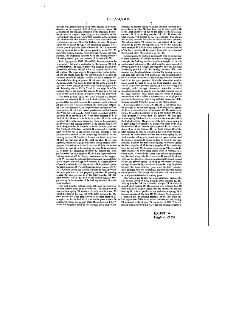
locked position to the open position. Preferably, the lockingmechanism is comprised of a solenoid 38 which is mounted
on a printed circuit board 40, a latch member 42 mounted ona support plate 44, and a spring plate 46. The solenoid 38 iscomprised of a permanent magnet 48 surrounding a coil SO
of wire, as shown in FIG. 17. FIG. 17 shows a cross section
of the solenoid having a permanent magnet 48, coil SO, pole
pieoe 51 for focusing the magnetic field, insulating plate 49
and solenoid contacts 39. The permanent magnet 48 is
cylindrical with its two poles located at the top and bottomof the solenoid 38. The coil 50 is wound around a pole piece
51 so that an electric current passing through the coil SO
EXHIBIT A
Page 19 of 26
8/3/2019 Videx v. Triteq Lock and Security
http://slidepdf.com/reader/full/videx-v-triteq-lock-and-security 24/30
10
20
30
40
50
60
US 6,564,600 Bl
5induces a magnetic field which is either aligned in tbe samedirection as tbe magnetic field of tbe permanent magnet 48
or aligned in the opposite direction of the magnetic field of
the permanent magnet, depending on the direction of thecurrent fiow. The ci rcuit board 40 is mounted to the housing,and tbe solenoid 38 is attached to the circuit board 40 so that
a projecting member 52 of the locking member 24 passesunder the solenoid 38 when the projecting member 52 is
rotated past the position of the solenoid 38. FIG. 7 shows the
locking member 24 in tbe locked position, while FIG. 11
shows tbe locking member rotated partially toward the open
position, the projecting member 52 of the locking member
24 having rotated past the position of the solenoid 38.
Referring again to FIGS. 3A and 3B, tbe support plate 44
is generally fiat and is connected to tbe housing 22 with 15
several screws. The support plate 44 is mounted beneath the
printed circuit board 40 and holds the printed circuit board
40 in place. The support plate 44 supports the latch member
42 and the spring plate 46. The support plate 44 defines anelongate groove 54 which contains the latch member 42.
One end of the elongate groove 54 is located directly below
tbe solenoid 38. The latch member 42 fits in the groove 54
and has a pivot surface 56 which rests on the support plate
44. Referring also to FlGS. 7 and 11, the edge 58 of thesupport plate at the end of tbe groove 54 acts as a fulcrum 25
to allow the latch member 42 to pivot within the groove 54.
The front portion 60 of the latch member 42 extendsbeneath the solenoid 38. In the locked position, the front
portion 60 of tbe latch member 42 is adjacent to the solenoid38 and preferably directly contacts the permanent magnet
48. The latch member 42 is shaped so that the top 62 of the
front portion 60 is fiat and makes good contact with solenoid
38. When tbe latch member 42 is placed in contact with the
solenoid 38 as shown in FIG. 7, tbe latch member 42 is in
tbe locked position, so that the front portion 60 of the latch 35
member 42 is in the same horizontal plane as the projecting
member 52 of the locking member 24 to prevent rotation of
the locking member 24 from the locked to the open position.The front end of the latch member 42 is squared, so that the
latch member 42 in the locked position presents a flat,perpendicular surface to the projecting member 52 of the
locking member 24. Similarly, tbe rear end 64 of the groove
54 and the rear end 66 of the latch member 42 are also
squared, with surfaces perpendicular to the top surface of the
support plate 44 when tbe latch member 42 is in the locked 45
position, so that when the locking member 24 is rotated so
as to press the projecting member 52 against tbe front
portion 60 oftbe latch member 42, the force imparted by the
locking member 42 is directly transferred to the support
plate 44. Because tbe intervening surfaces are perpendicularto the support plate 44, the latch member 42 will not slip out
of position when the locking member 24 is pushed agaiust
the latch member 42. This is illustrated more particularly by
FIG. 9, which shows the locking member 24 rotated toward
the open position and tbe projecting member 52 pressing 55
against the front portion 60 of the latch member 42. Thelatch member 42 in FIG. 9 is in the locked position, thuspreventing further rotation of the locking member 24 to the
open position.
The latch member 42 has a ridge 68 along the bottom of
the rear portion of the latch member 42. The spr ing plate 46
has a release spring 70 which preferably ends in a loop 72
which fits around the ridge 68 of the latch member 42. The
pivot surface 56 of the rear portion of the latch member 42
is angled, so tbat in the locked position the pivot surface 56 65
angles away from the support plate 44, as shown in FIG. 7.
When tbe magnetic field of the solenoid 38 is sufficiently
6reduced, the release spring 70 causes the latch member 42 topivot about the edge SS, thus lowering the front portion 60of the latch member 42 out of tbe plane of the projectingmember 52 of the locking member 24. FIG. 11 shows thelatch member 42 pivoted to the open position. This allowsthe locking member 24 to be rotated to the open position.
The release spring 70 presses the rear portion of the latchmember 42 toward the support plate 44, so that when the
latch member 42 is in the open position, the pivot surface 56
of the latch member 42 is pressed flush with the bottom of
tbe support plate 44, as shown in FlG. 11.
Alternatively, the locking mechanism may be comprised
of other elements and in other alternative arrangements. For
example, the locking member may be a straight rod or bolt
as discussed previously. The latch member may, instead of
pivoting, move in a straight line direction into and out of an
interfering position with the locking member. The latchmember may be placed above or below the locking member,
and need only interfere with a por tion of the locking member
so as to resist movement of the locking member from the
locked to the open position. Similarly. alternative mecha
nisms could be used to urge the latch member from the
closed to the open position instead of a release spring. For
example, coiled springs, elastomers. solenoids, or othermechanisms could be used to urge the latch member toward
the open position. Thus, many different types of locking
mechanisms which utilize a solenoid may be employed to
achieve the function of interfering with tbe movement of the
locking member from the locked to tbe open position.
Referring again to FIGS. 3A, 3B and 7, the spring plate
46 also has an anti-release spring 74 which presses against
the front portion 60 of the latch member 42. The anti-release
spring 74 resists movement of the front portion 60 of the
latch member 42 away from the solenoid 38. The anti-release spring 74 thus acts to retain the latch member 42 in
the locked position. The purpose of the anti-release spring isto prevent the latch member 42 from being jarred away from
the solenoid 38 and into tbe open position. In the event of asharp blow to the housing 22, the front portion 60 of the
latch member 42 may be jarred in a direction away from thesolenoid 38. In tbe absence of the anti-release spring 74, the
latch member 42 may be jarred into the open position, and
the locking member 24 would be free to rotate to the open
position. Because the anti-release spring 74 presses against
the latch member 42 i f the latch member 42 is jarred away
from the solenoid 38, the anti-release spring 74 prevents the
latch member 42 from being jarred open in response to a
sharp blow. Alternatively, other anti-release mechmisms
may be used to urge tbe latch member 42 toward the closed
position. For example, otber materials could be used iusteadof the anti-release spring 74, such as elastomers or coiled
springs. Alternatively, a mechanical member may be placed
beneath the latch member, preventing the latch member
from pivoting until the mechanical member has been moved
out of position. The spring plate 46 also could be made of
several pieces instead of a unitary piece.The locking unit U also has a mechanism for pushing the
mti-release spring 74 away from the latch member 42. Thelocking member 24 has a beveled dimple 76 in which is
seated a ball bearing 78. The support plate 44 has a hole SO
with a diameter slightly larger than tbe diameter of the ball
bearing 78. A front portion of tbe anti-release spring 74 is
located underneatb the hole SO. The dimple 76 is located in
a position on the locking member 24 so that when thelocking me mber 24 is in the locked position, the ball bearing
78 is seated in tbe dimple 76, as shown in FlG. 7. In the
locked position shown in FIG. 7, the ball bearing 78 rests in
EXHIBIT A
Page 20 of 26

8/3/2019 Videx v. Triteq Lock and Security
http://slidepdf.com/reader/full/videx-v-triteq-lock-and-security 25/30
5
10
15
20
25
30
35
40
45
50
55
60
65
US 6,564,600 Bl
7the hole 80 in the support plate 44 and is retained by theanti-release spring 74, which prevents the ball bearing 78from slipping out of the hole 80 in the support plate 44.When the locking member 24 is rotated, as shown by flG.
9, the dimple 76 moves relative to the ball bearing 78, sincethe ball bearing 78 is prevented from rotating with thedimple 76 by the edge of the hole 80 in the support plate 44.
Accordingly, the ball bearing 78 is pushed by the beveledsurface of the dimple 76 to the bottom surface of the locking
member 24. The ball bearing 78 in tum pushes the anti-release spring 74 to the open position away from the latch
member 42. With the anti-release spring 74 pushed awayfrom the latch member 42, the latch member 42 is free topivot to the open position. FIG. 11 illustrates the ball bearing78 resting on the bottom of the locking member 24 after the
locking member has been rotated toward the open position.
Alternatively, the mechanism for pushing the anti-releasespring away from the latch member may be accomplished
using other methods, such as other mechanical systems topush the anti-release spring away from the latch member 42in response to movement of the locking member 24.
The lock unit 12 also has a mechanism for detectingmovement of the locking member 24. The spring plate 46
includes a switch spring 82 which presses against the switchbutton 84 of a switch 86 mounted on the printed circuitboard 40. In the locked position shown in flG. 7, the switch
button 84 is depressed by the switch spring 82. When theswitch spring 82 is pushed away from the switch button 84
as shown in FIG. 9, the switch 86 is opened, causing a signalto be sent to a microprocessor 88. The switch spring 82 is
connected to the front portion of the anti-release spring 74,so that the switch spring 82 is pushed away from the switch
button 84 by the ball bearing 78 in the same manner as theanti-release spring 74 is pushed by the ball bearing 78, as
shown by FIGS. 9 and 11. Thus, the ball bearing 78, switch
spring 82 and switch 86 act collectively as a movementdetector to detect movement of the locking member 24 from
the closed position toward the open position. Other systemsmay be used to detect movement of the locking member 24.
The switch 86, for example, could be connected directly tothe locking member 24. Instead of using a switch, movement
of the locking member could be used to generate an elec
tromagnetic signal which could be detected. Movement of
the locking member could also be detected optically.
The lock l,lDit 12 also includes a key detector 90. The keydetector 90 may be any device which can read a key 92 and
send a signal corresponding to the key 92 to the micropro
cessor 88 to enable the lock to determine whether anauthorized key has been presented. The key detector mayaccept electronic, magnetic or mechanical keys. The keydetector could also comprise a data port for receiving a
digital code, or comprise a keypad or mechanical entrysystem such as a series of numbered buttons or mechanicaldials. In any of these systems, the key detector detects a key,code, password, or other representation of a key or key code
and transmits a signal to the microprocessor correspondingto the key or key code.
In a preferred embodiment, the key detector 90 uses atouch button system sold under the trade name TouchMemory Button by Dallas Semiconductor of Dallas, Tex.The system operates by providing a key 92 which contains
an integrated circuit housed within a stainless steel container. The system is passive, in that the key 92 has no powersource. The key detector 90, in response to being touched bya key 92 (as illustrated in FIG. 2), sends a signal to the key92 to read the key code of the key 92 encoded in theintegrated circuit in the key 92. Every key 92 is unique and
8provides a unique key code. After reading the key code of
the key 92, the key detector 90 sends a signal to themicroprocessor corresponding to the key code of the key 92.Because the touch button key detector 90 uses a Hat surface94 to detect key codes and does not present an opening to theinterior of the lock unit 12, the use of the touch button keydetector 90 and keys 92 greatly reduce the susceptibility of
the lock to being picked.
The lock unit 12 also contains a power supply 96 pref
erably in the form of a battery. Preferably, a 9-volt lithiumor alkaline battery is used, but other types of batteries having
other voltages may be used. A voltage regulator 97 regulatespower from the power supply % to the microprocessor 88.
Alternatively, a permanent power supply may be providedby connecting the electronic lock to a power line, such as a
standard 120 volt power line. The power supply 96 suppliespower to the solenoid 38 and the other electronics in theelectronic lock. The power supply 96 is connected to themicroprocessor 88, which controls the direction of currentflowing from the power supply 96 to the coil 50 in the
solenoid 38. Preferably, to conserve power, the power sup
ply 96 does not supply power to the solenoid 38 when thelocking member 24 is in the locked position. However, if a
permanent source of power is available, the solenoid 38could be connected to a power supply % so that current is
constantly flowing through the coil 50 in a direction suchthat the induced magnetic field of the coil 50 is aligned with
the permanent magnet to hold the latch member 42 in the
locked position. Since in the preferred mode of operation thepower supply 96 only directs power to the coil 50 in
response to a signal from the microprocessor 88, the amountof power used by the electronic lock is very small.
The electronic lock may operate as follows. When thelocking member 24 is in the locked position shown in flGS.6 and 7, the latch member 42 is held in the locked position
by the anti-release spring 74 and the permanent magnet ofthe solenoid 38. Preferably, no power is flowing through the
coil SO of the solenoid 38. Referring to FIG. 2, a key 92 ispresented to the key detector 90. The microprocessor 88
keeps stored in memory 98 the key codes which are authorized to open the lock. Referring now to FIG. 14, the keydetector 90 in box 200 generates a signal corresponding to
the key code from the key detector 90 to the microprocessor88. In box 202, the microprocessor 88 determines whether
the device presented to the key detector 90 is a key 92.Assuming a master key has not been presented, the microprocessor 88 proceeds througb the s teps shown in boxes 204,
206, and 208 until it reaches box 210. In box 210, themicroprocessor 88 determines whether the key codereceived from the key detector 90 matches an authorized keycode stored in the memory 98. If an authorized key code isreceived, the microprocessor 88 in box 212 sets a status open
flag indicating the lock may be opened. If a master key ispresented, the microproces..'iOr proceeds to box 222 and
again sets a status open flag to indicate the lock may be
opened.The knob 26 may then be turned, which causes the
anti-release spring 74 to be pushed away from the latchmember 42 and also causes the switch 86 to send a signal to
the microprocessor 88 indicating the locking member 24 hasbeen moved. Referring now to HG. 15, when the microprocessor 88 receives a signal from the switch 86, the
microprocessor 88 in box 300 checks the status open flag to
determine whether the lock may be opened. If the statusopen flag indicates the lock may be opened, the microprocessor 88 in box 302 checks to see if the switch has alreadybeen on, and i f not, in box 304 directs current from the
EXHIBIT A
Page 21 of26

8/3/2019 Videx v. Triteq Lock and Security
http://slidepdf.com/reader/full/videx-v-triteq-lock-and-security 26/30
5
10
15
20
25
30
35
40
45
50
55
60
65
US 6,564,600 Bl
9power supply 96 to the coil SO io a direction that causes themagnetic field induced in the coil SO to be aligned oppositeto the magnetic field of the permanent magnet. The ioducedmagnetic, field of the coil SO is sufficiently strong so that the
release spring 70 pivots the latch member 42 from the lockedposition to the open position. As shown io FIGS. 10 and 11,the locking member 24 may then be rotated by the knob 26
toward the open position. Alternatively, the microprocessor
could direct power to the coil SO immediately in response to
receiving an authorized key code from the key detector 90instead of waiting for a signal from the switch 86.
As can be seen in FIG. 9, wben the anti-release spring 74
is pushed away from the latch member 42, the latch member
42 is susceptible to being jarred open by a sharp blow to the
housiog 22. To prevent this. i f the switch 86 is open (as inFIGS. 8 and 9) and no signal for an authorized key has been
received, the microprocessor 88 directs an electric currentfrom the power supply 96 to the coil SO of the solenoid 38.
This is shown by boxes 300 and 306 of HG. IS. The currentflows through the coil SO in the opposite direction of the
current flow used to open the lock. lolL';, the microproces/,or
88 directs tbe current througb the coil SO so that the ioducedmagnetic field in the coil SO is aligned in the same direction
as the magnetic field of the permanent magnet. Thus, theresulting force imparted by the solenoid 38 on the latch
member 42 can be greatly increased. By increasing tbeamount of magnetic force applied to the latch member 42 in
response to an unauthorized attempt to open the lock, the
current How through the solenoid 38 reduces the suscepti
bility of the latch member 42 from being jarred out of place
in response to a sharp blow to the housing 22.
In addition, reversing the current How io tbe solenoid 38
in response to an unauthorized attempt to open the lock
allows a smaller permanent magnet witb a reduced magnetic
field to be used with the lock, because the reversed current
flow aids the permanent magnet in holding the latch member
42 io place. A smaller permanent magnet has several advan
tages. First, a smaller permanent magnet with a reducedmagnetic field requires a smaller induced magnetic field to
allow tbe release spring 70 to pivot the latch member 42 tothe open position. This translates into less power consump
tion by the lock. In addition, a smaller permanent magnet
reduces the size and cost of the electronic lock.
FIGS. 18-22 show an alternative preferred embodiment
of a lock unit 612 of the present invention having an
alternative locking mechanism. Uke numerals correspond to
like elements illustrated in the embodiment shown in FIGS.
1-12. In this embodiment, solenoid 38 of the embodiment of
FIGS. 1-12 is replaced with an electric motor 638. As in the
embodiment in FIGS. 1-12, a knob is connected to a shaft
which passes through the housing and is connected to the
locking member 624. Rotation of the knob 26 causes the
locking member 624 to rotate from the open to the locked
position. A locking mechanism controls movement of the
locking member 624 from the locked position to the open
position. The locking mechanism is comprised of an electricmotor 638 which is mounted on the support plate 644, a latch
member 642 mounted on the support plate 644, and a springplate 646. The electric motor 638 has attached to it a shaft
639 and a rotating member 700. Power is supplied to theelectric motor 638 from a ballery by electrical connections
640. The electric motor 638 may be an electric motor froma vibrating pager. A bracket 636 holds the motor 638 in
place. FIG. 18 shows the locking member 624 io the locked
position while FIG. 19 shows the locking member rotated
partially toward the open position. FIG. 21 shows the lockmember 624 rotated completely to the open position.
10
Referring now to FIGS. 18, 19 and 21, the support plate644 defines an elongatc groove 6 54 which contains the latchmember 642. The elongate groove 654 is located adjacent tothe electric motor 638. 'Ioe latch member 642 fits in thegroove 654 and has a pivot surface 656 which rests on thesupport plate 644. The edge 658 of the support plate at theend of the groove 654 acts as a fulcrum to allow the latchmember 642 to pivot within the groove 654. As shown in
FIG. 20, when the latch member 642 is in the locked
position, the front portion 660 of the latch member 642
confronts the blocking surface 652 of the locking member
624 to prevent rotation of the locking member 624 from the
locked to the open position. The latch member 642 has a
ridge 668 along the bottom of the rear portion of the latch
member 642. The spring plate 646 has a release spring 670
which preferably ends in a loop 672 which fits around the
ridge 668 of the latch member 642. The pivot surface 656 of
the latch member 642 is angled so that in the locked position
the pivot surface 6S6 angles away from the support plate644, as shown in FIG. 20.
The electric motor 638 prevents movement of the latch
member 642 as follows. The rotating member 700 is in the
shape of a partial cylinder. In the locked position the curved
portion 702 of the rotating member 700 faces and/or contacts the bottom of the latch member 642, thus interfering
with the pivoting movement of the latch member 642 from
the closed to the open position. A resilient spring arm 704
presses agaiost a lower Hat surface 706 of the rotating
member 700 so as to resist rotation of the rotating member700 in the counter-clockwise direction (as viewed io FIG.
20) while a stop 708 prevents rotation of the rotatingmember in the clockwise direction. The spring arm 704 may
be made from plastic or any other suitable sturdy, flexiblematerial. Collectively the spring arm 704 and stop 708
bracket the rotating member 700 to prevent the rotating
member 700 from being jarred by a sharp blow to the lockunit into a non-interfering position.
When the lock microprocessor 88 receives a signal indicating authorized access power is provided from the battery
to the motor 638 so as to rotate the rotating member 700 ina counler-c1ockwise direction so tbat the curved portion 702
is moved to a non-interferiog position with respect to the
latch member 642, as shown in FIG. 22. The stop 708
prevents further rotation of the rotating member 700. Only
a short bUrst of power is supplied to the motor 638 so that
the rotating member 700 is rotated out of interference, but
power is not continuously supplied so as to avoid running
down the battery. The spring arm 704 is sufficiently flexible
so that the spring arm 704 allows the rotating member 700
to rotate counter·c1ockwise, such that the spriog arm 704 islocated beneath the curved portion 702 of the rotating
member as shown io FIG. 22. When the rotating member
700 is rotated counter-clockwise to a non-interferingposition, the releasc spring 670 causes the latch member 642
to pivot about the edge 658, thus lowering the front portion
660 of the latch member 642 out of the plane of the blockingsurface 652 of the locking member 624. FIG. 22 shows thelatch member 642 pivoted to the open position. This allows
the locking member 624 to be rotated to the open position.
The release spring 670 presses the rear portion of the latchmember 642 toward the support plate 644 so that when the
latch member 642 is in the open position the pivot surface656 of the latch member 642 is pressed flush with the bottomof the support plate 644, as shown in FIG. 22.
When the lock member 624 is rotated back to the lockedposition, the motor 638 is energized so as to rotate the
rotating member 700 back to an ioterfering position as
EXHIBIT A
Page 22 of 26

8/3/2019 Videx v. Triteq Lock and Security
http://slidepdf.com/reader/full/videx-v-triteq-lock-and-security 27/30
10
20
30
40
50
60
US 6,564,600 Bl
11 12 shown in FIG. 20. lb e stop 708 prevents further rotation of
the rotating member 700 in the counterclockwise direction,while the spring arm 704 returns to a position above the flatsurface 706 of the rotating member.
The spring plate 670 also has an anti-release spring 674which presses against the front portion 660 of the latchmember 642. The anti-release spring 674 resists movementof the front portion 660 of the latch member 642 away fromthe locked position. The anti-release spring 674 thus acts to
retain the latch member 642 in the locked position. Thepurpose of the anti-release spring is to prevent the latch
member 642 from being jarred into the open position. In theabsence of the anti-release spring 674, tbe latch member 642may be jarred by a sharp blow to the lock unit into the openposition, allowing the locking member 624 to be rotated to 15
the open position. Because the anti-release spring 674presses against the latch member 642, the anti-release spring674 prevents the latch member 642 from being jarred openin response to a sharp blow.
The lock unit 612 also has a mechanism for pushing theanti-release spring 674 away from the latch member 642.The locking member 624 bas a beveled dimple 676 in whichis seated a ball bearing 678. The support plate 644 has a hole
680 with a diameter slightly larger than the diameter of theball bearing 678. A portion of the anti-release spring 674 is 25
located underneath the hole 680. In the locked positionshown in FIG. 18, the ball bearing 678 rests in the hole 680in the support plate 644 and is retained by the anti-releasespring 674, which prevents the ball bearing 678 fromslipping out of the hole 680 in the support plate 644. Whenthe locking member 624 is rotated toward the open position,as sllown by FlG. 19, the dimple 676 moves relative to the
ball bearing 678, since the ball bearing 678 is preventedfrom rotating with the dimple 676 by the edge of the hole
680 in the support plate 644. Accordingly, the ball bearing 35
678 is pushed by the beveled surface of the dimple 676 to the
bottom surface of the locking member 624. The ball bearing
678 in turn pushes the anti-release spring 674 to the openposition away from the latch member 642. With the anti
release spring 674 puslled away from the latch member 642,the latch member 642 is free to pivot to the open position.
FIG. 21 illustrates the ball bearing 678 resting on the bottomof the locking member 624 after the locking member 624 hasbeen rotated to the open position.
The lock unit 612 also has a mechanism for detecting 45
movement of the locking member 624. The spring plate 646includes an electrical contact 682 which presses against
another electrical contact 686 mounted beneath the supportplate. In the locked position shown in FlG. 18, the contact
682 is pressed against contact 686 to form a closed circuit.When the contact 682 is pushed away from the contact 686,an open circuit is created, which is detected by the micro
processor 88. The contact 682 is mounted on the anti-releasespring 674, so that the contact 682 is pushed away from thecontact 686 by the ball bearing 678 in the same manner as 55
the anti-release spring 674 is pushed by the ball bearing 678.Thus, the ball bearing 678, contact 682 and contact 686 actcollectively as a movement detector to detect movement of
the locking member 624 from the closed position toward the
open position.
When the movement detector detects movement of the
lock member 624 without an authorized key being presentedto the lock, the microprocessor causes the motor 638 to beenergized so as to rotate in the clockwise direction so that the
rotating member is pushed against the stop 708, as viewed 65
in FlG. 20. The motor 638 continues to apply power so longas the movement detector indicates that the lock member
624 has been moved but no authorized signal has beenreceived by the microprocessor 88. The stop 708 prevents
rotation of the rotating member 700 to a non-interferingposition. By continuously supplying power to the motor 638,
the rotating member 700 is firmly held in an interferingposition to prevent pivotal movement of the latch member
642 from the open to the closed position. Thus, both thespring arm 704 and the motor 638 act together to urge therotating member 700 toward an interfering position in
response to an unauthorized attempt to open the lock. lbis
prevents the lock from being opened by jarring the latchmember 642 into the open position when the lock member624 is rotated.
Assembly and Mounting
Referring now to FIGS. 1 througil 5, in one preferredaspect of the invention, the electronic lock 10 is mounted to
the exterior surfaces 100, b of a drawer, cabinet, door, orother similar structure or device. The base member 20preferably has a plurality of mounting members 100, each of
which passes through a respective hole 102 in base member
20, to mount the lock unit 12 to the surface 16. The mountingmembers 100 may be screws, bolts, or any suitable mechani
cal fastening device. The base member 20 has severalengaging members 104 projecting away from the horizontal
plane 106 of the base member 20. 1be engaging members104 are "L" shaped, having a portion projecting perpendicularly away from the plane 106 and another tab portion 108directed generally parallel to the plane 106. The base member 20 also has a front portion 110 projecting away from the
plane 106 at a generally perpendicular angle. The frontportion 110 of the base member 20 has a slot 112 througilwhich the catch portion 32 of the locking member 24 passeswhen rotated to the locked position.
The housing 22 and base member 20 fit together to form
an enclosure containing the various components of theelectronic lock 10. 1be housing 22 is sized to surround the
base member 20, so that the bottom periphery 114 of thehousing 22 surrounds the base member 20. Preferably, the
bottom periphery 114 of the housing 22 is flu...h with thesurface 16 on which the lock unit 12 is mounted. Because the
housing 22 surrounds the base member 20 and is flush withthe surface 16, the housing 22 prevents access to themounting members 100, Thus, when the housing 22 andbase member 20 are secured to eacb other to form an
enclosure, the mounting members 100 cannot be accessed to
remove the lock unit 12 by attempting to cut or drill out the
monnting members 100.
The housing 22 and base member 20 are secured to eachother with the engaging members 104, The tab portions 108
of the engaging members 104 fit in receiving slots 116 of thesupport plate 44, To attach the housing 22 to the base
member 20, the tab portions 108 of the engaging members104 are first pushed through the receiving slots 116 of thesupport plate 44. The housing 22 is then moved laterally
relative to the base member 20, so that the tab portions 108of the engaging members 104 hook over the support plate44.As the housing 22 is moved laterally, the front portion of
the housing 22 is moved toward the front portion 110 of the
base member 20 until the front portion of the base member110 abuts the housing 22 and the support plate 44. Becausethe tabs 108 hook over the support plate 44, the housing 22cannot be pulled vertically away from the base member 20without first sliding the housing 22 laterally relative to thebase member 20. FIGS. 4 and 5 illustrate the assembledhousing 22 and base member 20, showing the tab portions108 hooked over the support plate 44.
EXHIBIT A
Page 23 of 26

8/3/2019 Videx v. Triteq Lock and Security
http://slidepdf.com/reader/full/videx-v-triteq-lock-and-security 28/30
5
10
15
20
25
30
35
40
45
50
55
60
65
US 6,564,600 Bl
13
The base member 20 and housing 22 are further secured
to prevent lateral movement through a catch spring 118
attached to the base member 20. The catch spring 118
protrudes inwardly from the base member 20. The supportplate 44 has a lip 120 which is located at the front of the
support plate 44. When the housing 22 moves laterally
relative to the base member 20 , the lip 120 travels toward thecatch spring 118. The lip 120 depresses the catch spring 118
as the housing 22 continues to move into engagement with
the base member 20. When the lip 120 passes the catch
spring 118, the catch spring 118 springs back into its relaxed
position. In the relaxed position, the catch spring 118
interferes with the lip UO when the housing 22 is pushed
laterally in the opposite direction to remove the housing 22
from the base member 20. Thus, the catch spring 118 and lip
120 together prevent the base member 20 and housing 22
from becoming separated. FIGS. 4 and S show the catch
spring 118 in the relaxed position and abutting the lip UO to
prevent relative lateral movement of the housing 22 with
respect to the base member 20.
When the housing 22 and base member 20 are assembled,
the catch spring 118 may be depressed by inserting a tool
through the slot 112 and pressing down against the catchspring 118. This can onl y be done when the locking member
24 is rotated to the open position, and the lock unit U is
moved relative to the strike unit 14 so that there is enough
room to insert a tool into the slot 112, as shown in FlG. 2.
With the catch spring 118 depressed, the lip UO is free totravel over and past the catch spring 118 when the housing
22 is pushed laterally with respect to the base member 20 to
disengage the tab portions 108 from the support plate 44.
Alternatively, other mechanisms may be used to matingly
engage the housing 22 with the base member 20. Othermechanical catches or latches may be used to secure the
housing to the base member. In addition, the base member
and housing may be composed of one or more units, such
that the enclosure is formed by more than two elements.
The electronic lock 10 presents few openings through
which the electronic lock 10 may be picked when the lockunit 12 and strike unit 14 are secured together. Like the lock
unit 12, the strike unit 14 is comprised of two parts, a basemember 122 and a housing 124. The base member has two
slots 34a, b for receiving the catch portion 32 of the locking
member 24, and a central member 36 between the slots 34.
When the lock unit U and strike unit 14 are secured
together, the catch portion 32 passes through the slot lU of
the housing 22 as well as the slots 340, b of the strike unit
14. The locking member 24 substantially fills each of the
slots. Thus, it is very difficult to pick the electronic lock 10
because the housings of the lock unit 12 and strike unit 14
do not present any openings, and the locking member 24 fills
the slots in the lock unit U and the strike unit 14.
Key Management
In another separate preferred aspect of the invention, akey management system is provided to manage which keys
are authorized to open the electronic lock 10. Referring toFIG. 13, the electronic lock 10 includes a memory 98 for
storing key codes corresponding to keys which are autho-
rized to open the electronic lock 10. When a key 92 isdetected by the key detector 90 (as in FlG. 2), the key
detector 90 sends a signal to the microprocessor 88 in the
form of a key code corresponding to the key 92. The
microprocessor 88 compares the received key code with theauthorized key codes stored in the memory 98, and i f the key
92 is an authorized key, the lock may be opened.
14The electronic lock 10 has a microprocessor 88 (shown
schematically in FIG. 13) which is used to receive signalsfrom the key detec tor 90. The electronic lock 10 has memory98 in the form of Electronically Erasable Program able Read
Only Memory (EEPROM) which is connected to the micro-processor 88. Collectively, the microprocessor 88 and asso-ciated memory 98 comprise a computer system. The com-puter system which may be used in the present inventionmay be any device, whether a microprocessor alone or incombination with other processors and/or memory devices,which performs the functions described herein relating to thereading, writing, deleting, storing and comparing of infor-
mation relating to key codes.
In order to add and delete authorized key codes stored inmemory 98, the key management system preferably utilizesa master key. In a preferred embodiment, the master key isthe first key detected by the key detector 90. When power is
first supplied to the microprocessor 88, the memory 98
contains no authorized key codes. Referring now to FIG. 14,when the microprocessor 88 in box 204 receives a first keycode generated by the key detector 90, the microprocessor88 in box 216 adds the key code of the first key to theauthorized key codes stored in the memory 98. In addition,the microprocessor 88 in box 216 stores the first key code as
the master key code in the memory.
By storing the first key code to be detected as the masterkey code, the key management system greatly reduces thecomplexity of providing a master key for the lock. Masterkeys do not need to be created especially for any particular
lock. Because the first key touched to the electronic lockbecomes the master key, it is not necessary to program each
lock to store a particular key code as the master key. Thus.electronic locks may be manufactured identically and can be
used with any key as the master key.
The master key may be used to add and delete key codes
from the stored authorized key codes. Referring again to
FIG. 14, when the microprocessor 88.in box 206 receives a
signal corresponding to the key code for the master key, the
event is saved in box 222. If the microprocessor 88 then
receives a second signal corresponding to a second key, the
microprocessor proceeds to box 208, in which the micro-processor determines whether tbe second key is an autho-
rized key and whether the key code for the master key has
been received within a certain amount of time (as saved inbox 222). I f the second key is not an authorized key, and the
master key code was already received within the predeter-
mined time, then the microprocessor 88 in box 214 adds the
second key code to the authorized key codes stored in
memory 98. It is therefore easy to add numerous key codes
to the memory 98 of the electronic lock 10 by simply first
placing the master key on the key detector 90, and then
placing on the key detector 90 the keys which are desired to
be added as autborized keys. The system therefore avoids
the necessity of separately programming the lock to store
key codes in memory which are authorized to open the lock.
In a similar fashion, a key code may be deleted from the
authorized keys in the memory 98 by first placing the key tobe deleted on the key detector 90 and then placing the master
key on the key detector 90. In box 218, when the micro-
processor 88 has received a signal corresponding to a first
authorized key followed by a signal corresponding to themaster key (and the signal for the master key is received
within a predetermined amount of time after receiving the
signal corresponding to the first key), the microproeessor 88
in box 220 removes the first key code from the authorized
key codes stored in memory 98.
Thus, it is easy to update the authorized key codes in
memory 98 at any lime, including after the electronic lock
EXHIBIT A
Page 24 of 26

8/3/2019 Videx v. Triteq Lock and Security
http://slidepdf.com/reader/full/videx-v-triteq-lock-and-security 29/30
10
20
30
40
50
60
US 6,564,600 Bl
15 16 has been installed and in use for a period of time. It is onlynecessary to use the master key in combination with the keyswhich are desired to be removed from or added to tbeauthorized key codes in memory. The authorized key codesin the memory 98 of an installed lock may be Updated bysimply touching the key detector 90 with the keys w h i ~ h should be added to or removed from the memory msequence with the master key. It is not necessary to reprogram the lock by downloading new programming or files of
authorized key codes to the microprocessor 88 or memory98. The key management system thus greatly reduces thecomplexity of storing authorized keys in the memory of thelock, and updating the authorized key codes in the memory
periodically.
In addition to adding or deleting authorized keys from 15
memory, the master key may be used to control other lockfunctions., such as accessing the memory, opening the lockat specified times, turning off an alarm, etc. Such functions
may not be accessible to the other authorized keys which arenot a master key.
In a preferred embodiment, the key management system
uses the touch memory button keys described in connectionwith the locking mechanism. These keys each have a unique
serial number, or key code, so that each key provides a
unique key code. Thus, once a first key has been detected, 25there is only a single key which can be the master key.
While the key management system may be used inconnection with the electronic lock 10 of the presentinvention, it also finds utility in other electronic access
control devices which utilize electronic keys andior keycodes. Thus, the key management system could be used withany kind of electronic access control device that uses acomputer system to track keys andlor key codes. It is only
necessary for the system to receive signals corresponding tokey codes for particular keys. It is preferred that each key
35have a unique code. However, the system may be used with
a set of keys in which several keys have the same code.
In addition, the key management system could be used
with systems that do not include a locking mechanism but do
use keys andlor key codes to authorize access. Referring toFIG. 12, in one such system SOO a door unit SOl containinga key detector 90 and a computer system may be used with
a stationary unit 504. The door unit contains the key
management system of the present invention. The door unitS02 contains a proximity detector (not shown) to detect
45when the door unit S02 is moved relative to the stationaryunit SOl. The key management system is used to determinewhether movement of the door unit S02 relative to the
stationary unit 504 is authorized. If an authorized key isdetected, the door unit S02 may be moved relative to thestationary unit 504 without an alarm sounding. However, ifan authorized key is not detected, an alarm in the door unit
S02 will sound in response to unauthorized movement of the
door unit SOl relative to the stationary unit S04.
Alternatively, the key management system could be used55
witb an appliance or device to which it is desired to restrictaccess, such as a television or a computer, by controlling thepower to the device with a control access device. In otherwords, tbe key management system of the present inventionmay be used in any device in which a computer systemcontrols or regulates access to or use of the device and inwhich the computer system will allow use or access of the
device in response to a signal from an authorized key.
Lock Fuoctions65
The electronic lock also includes other components wbichare useful to operation of the electronic lock but are not
necessary. The electronic lock 10 may include an LED 130which may be used to indicate the status of the lock, such asthat the electronic lock is on, that an authorized key has been
detected and tbat the lock may be opened, or that the battery
power is low. The electronic lock 10 may also include abeeper 132 to similarly communicate the status of the lock.
The beeper 132 may be used to communicate, for example,when a master key has been detected, wben an authorized
key is detected, when a key code has been added to theauthorized key codes in memory, and when a key has beendeleted. The beeper 132 may also be used to sound an alarmin response to an attempt to open the electronic lock 10 bymoving the locking member 24 without first using an
authorized key. This is shown in box 310 of FIG. IS. In box308, after determining that the switch 86 has been open formore than one second, the microprocessor in box 88 causes
the beeper 132 to sound an alarm.
The electronic lock 10 may also include a system forkeeping track of events. The electronic lock 10 may have aclock 134 which is set to the current time when the lock is
first initialized. The microprocessor 88 stores in the memory98 each key code detected by the key detector 90. Thus, the
microprocessor 88 stores attempts to use both authorizedkeys and unauthorized keys. For each event, the microprocessor 88 may store other information, such as whether the
electronic lock 10 was opened, when the lock 10 was locked,whether an error occurred in a lock function, or whether an
attempt was made to open the lock 10 without an authorized
key.
Data may be retrieved from or sent to the memory 98 in
a variety of ways. For example, data may be transmitted
using an infra-red communication system, such as those
which operate in conformance with IRDA standards. The
electronic lock 10 may have an ernilling diode 136 andtransmitting diode 138 to allow infrared communication
with the microprocessor 88. Data may also be communicated over a cable using an RS232 communication standard.For example, in electronic lock 10 the key detector 90 also
serves to allow communication with external devices usingan RS232 communication protocol. The electronic lock
therefore may be used to receive or send data to a personalcomputer, such as., for example, a Palm Pilot™ sold by
3COM®, which includes infrared communication capabilities and the ability to communicate over a cable. Data mayalso be transmitted using any other standard method for
transmitting digital information.
Flow cbarts showing tbe operation of an exemplary
embodiment of an electronic lock are shown in FIGS.
14-16. FIG. 14 is a flowchart for an exemplary method of
detecting a device such as a communication device or a key,and in response either performing steps from the key management system or allowing data communication. FIG. IS isa flowchart for an exemplary method of determiningwhether, in response to a signal from the switch 86, to sound
an alarm or to open the lock. FIG. 16 is a flowchart for anexemplary method of transmitting data to and from thememory of the electronic lock from eitber an RS232 port,such as through key detector 90, or an infra-red port, sucb asthe infra-red LEDs 136, 138.
The terms and expressions which have been employed inthe foregoing specification are used therein as terms of
description and not of limitation, and there is no intention,in the use of such terms and expressions, of excludingequivalents of the features shown and descnbed or portionsthereof, it being recognized that the scope of the invention
is defined and limited only by the claims wbich follow.
EXHIBIT A
Page 25 of 26

8/3/2019 Videx v. Triteq Lock and Security
http://slidepdf.com/reader/full/videx-v-triteq-lock-and-security 30/30
•
US 6,564,600 Bl
17What is claimed is:
1. An electronic access control device, comprising:
(a) a movable locking member;
(b) a latch member movable between an open position and
a locked position, said latch member in said lockedposition interfering with movement of said locking
member;
(c) an electrical unit operable to control said latch member
and connected to a power supply;
(d) a movement detector that generates a first signal in
response to movement of said locking member;
(e) a key detector that generates a second signal inresponse to detecting a key; and
(1) said power supply directing current in said electrical
unit in one direction to increase resistance to movement
of said locking member in response to said first signal,
and said power supply directing current in said electrical unit in an opposite direction to decrease resis
lance to movement of said locking member in response
to said second signal.
2. The electronic access control device of claim 1, further
including a releasing mechanism to move said latch memberto said open position when current flows in said electrical
unit in response to said second signal.
3. The electronic access control device of claim 2 wherein
said releasing mechanism is a spring.
4. The electronic access control device of claim I , furtherincluding an anti-releasing mechanism that urges said latch
member toward said locked position.
S. The electronic access control device of claim 4 wherein
said anti-releasing mechanism is a spring.
6. The electronic access control device of claim 4, further
including a releasing mechanism to move said latch member
to said open position when current flows in said electrical
unit in response to said second signal.
7. The electronic access control device of claim 1 wherein
said locking member, said latch member, said electrical unit,
and said power supply are housed in an enclosure comprised
of at least two parts, said two parts being matingly engage
able with one anotber.
8. The electronic access control device of claim I, further
comprising a key management system wherein a first key
detected by said key detector becomes a master key.
10
15
20
25
30
35
40
189. The electronic access control device of claim 8 wherein
said key management system stores a plurality of authorized
key codes, and said key management system adds anotherkey code to said authorized key codes in response to
receiving from said key detector a signal corresponding tosaid master key and another signal corresponding to anotherkey.
10. The electronic access control device of claim 1
wherein said electrical unit is an electric motor.
11. An electronic access control device, comprising:
(a) a movable locking member;
(b) a locking mechanism operable to control said locking
member;
(c) a movement detec tor that generates a first condition in
response to movement of said locking member;
(d) a key detector that generates a second condition in
response to detecting a key; and
(e) said locking mechanism increasing resistance to
movement of said locking member in response to saidfirst condition, and said locking mechanism decreasing
resistance to movement of said locking member in
response to said second condition.
12. The electronic access control device of claim 11,further including an anti-releasing mechanism operable with
said locking mechanism to increase resistance to movement
of said locking member.
13. The electronic access control device of claim 11
wherein said locking mechanism includes an electric motor.14. The electronic access control device of claim 11
wherein said locking member and said locking mechanism
are housed in an enclosure comprised of at least two parts,
said two pa rts being matingly engage able with one another.
15. The electronic access control device of claim 11,
further comprising a key management system wherein a first
key detected by said key detector becomes a master key.
16. The electronic access control device of claim IS,
wherein said key management system stores a plurality of
authorized key codes, and said key management system
adds another key code to said authorized key codes in
response to receiving from said key detector a signal cor
responding to said master key and another signal corre
sponding to another key.
* '" * * *