VideoEdge_NVR_Training_4.01(Aligns With D0 Manual)
272
VideoEdge NVR Server 4.1, victor client and victor site manager training
-
Upload
wayne-dinh -
Category
Documents
-
view
87 -
download
1
Transcript of VideoEdge_NVR_Training_4.01(Aligns With D0 Manual)

VideoEdge NVR Server 4.1, victor client and victor site
manager training
Housekeeping!
Class start/stop times Breaks Lunch Bathrooms Phones Beepers/cell phones (silent please!) Emergencies Quiet please, when near employee work areas
2

Course delivery and Student Guides
In general, each lesson will have a presentation delivered by the instructor. You will then be asked to work through a series of Lab Exercises. Once these have been completed, you should inform your instructor that you have completed the lesson.
The Student Guide is for use alongside the presentations delivered by your instructor.
The Student Guide is designed in a Task-Oriented style so that you can quickly reference how to complete a particular task whilst in the field, or at home, with little or no help at all.
The Student Guide also contains some additional information for you to read over by yourself, as well as all the Lab Exercises necessary to complete the training course.
3
VideoEdge NVR Server

5
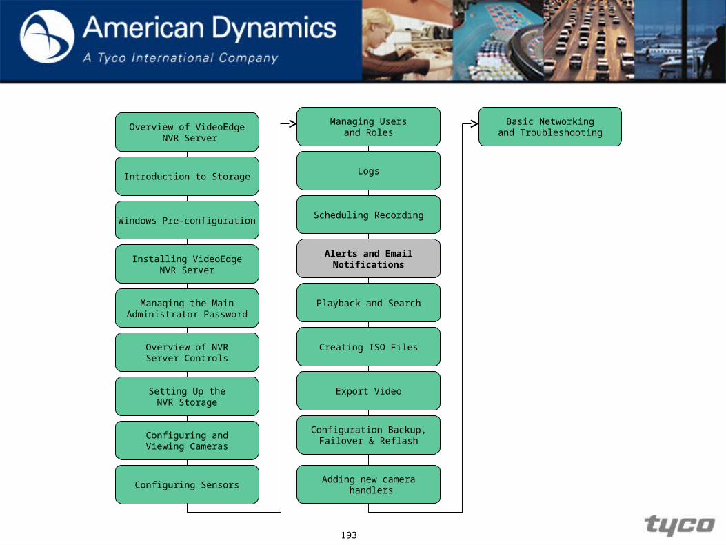
Overview of VideoEdge NVR Server
Introduction to Storage
Installing VideoEdgeNVR Server
Managing the MainAdministrator Password
Overview of NVRServer Controls
Setting Up theNVR Storage
Configuring andViewing Cameras
Configuring Sensors
Logs
Scheduling Recording
Alerts and EmailNotifications
Playback and Search
Creating ISO Files
Export Video
Configuration Backup,Failover & Reflash
Windows Pre-configuration
Managing Usersand Roles
Adding new camera handlers
Basic Networkingand Troubleshooting
VideoEdge NVR Server
Overview of VideoEdge NVR Server

7
Objectives
1. Understand the purpose of VideoEdge NVR Server Enterprise Server software application.
2. Understand the basic approach and overall architecture of the VideoEdge NVR.
3. Understand the purpose for using other software applications to interact with the VideoEdge NVR Server System.
Purpose of the VideoEdge NVR ServerEnterprise Server
The purpose of the VideoEdge NVR Server is to allow customers to easily transform Dell R710 and T310 servers into advanced and powerful NVR servers.
The VideoEdge NVR Server software is an IP-based security system that uses TCP/IP protocols to communicate over networks.
A VideoEdge server is an appliance based NVR server
8

9CONFIDENTIAL
Network Overview

10
VideoEdge NVR ServerKey features
Includes embedded Linux kernel (Operating System)
Includes VideoEdge NVR software (Application)
- Web server
- Camera, user, & storage management
- License file based on total # CAM slots on NVR
Access via Web (Thin) Client or with victor client
1 Year software warranty & extended via SSA
11
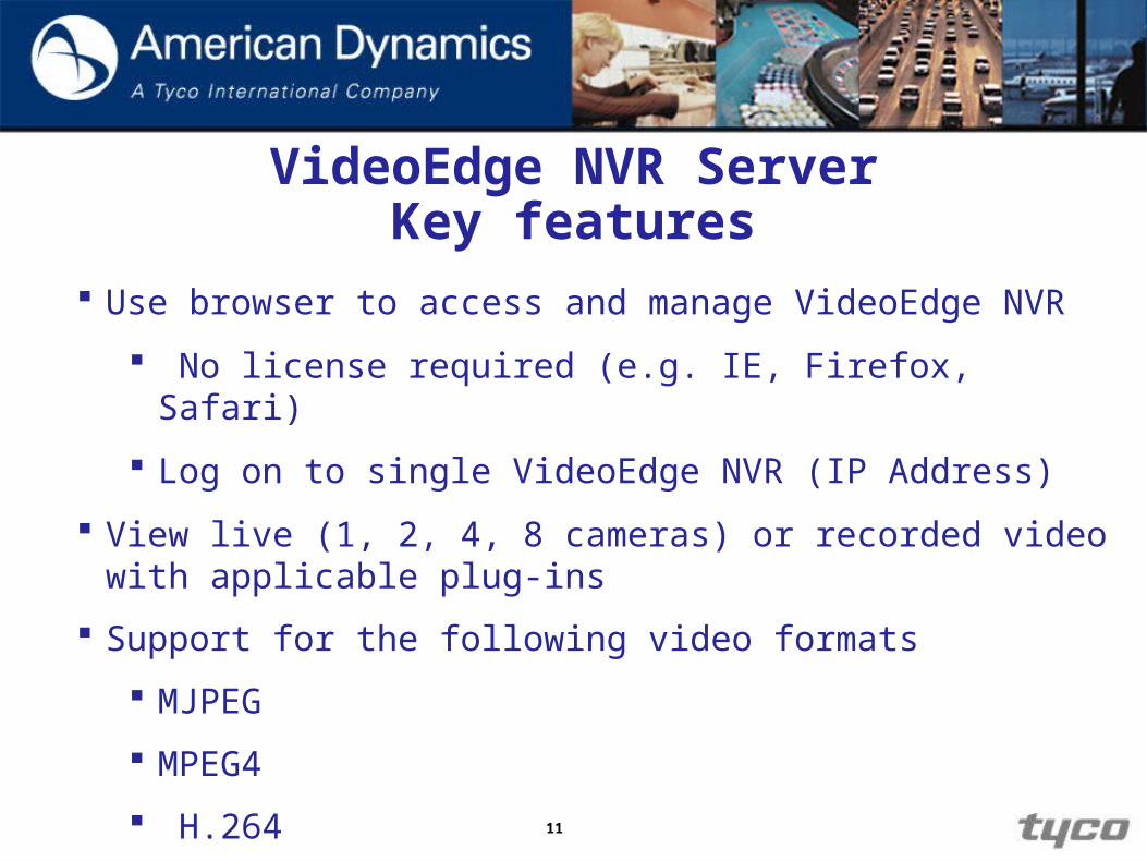
Use browser to access and manage VideoEdge NVR
No license required (e.g. IE, Firefox, Safari)
Log on to single VideoEdge NVR (IP Address)
View live (1, 2, 4, 8 cameras) or recorded video with applicable plug-ins
Support for the following video formats
MJPEG
MPEG4
H.264
VideoEdge NVR ServerKey features

12
Streaming Audio – NVR 4.1 supports storage and playback of up to 128 video streams (with corresponding audio streams from cameras with audio support) to a victor Client.
Server-side Motion Detection – The NVR supports server-side motion detection on MJPEG and MPEG4 video streams.
NVR Server-side Support for client playback controls –The NVR responds to forward/backward playback, fast playback and time positioning commands (jump back / forward) from the victor client.
VideoEdge NVR ServerKey features
13
Overview of VideoEdge NVR Server
Introduction to Storage
Installing VideoEdgeNVR Server
Managing the MainAdministrator Password
Overview of NVRServer Controls
Setting Up theNVR Storage
Configuring andViewing Cameras
Configuring Sensors
Logs
Scheduling Recording
Alerts and EmailNotifications
Playback and Search
Creating ISO Files
Export Video
Configuration Backup,Failover & Reflash
Windows Pre-configuration
Managing Usersand Roles
Adding new camera handlers
Basic Networkingand Troubleshooting

Introduction to storage

15
Objectives
By the end of the module you will be able to:
1. Understand the requirements and considerations of external storage.
2. Understand how to utilize storage sections.
3. Configure AD Fiber Storage.
Setting Concepts
16
Setting Concepts
We are covering the introduction to storage module at this point in the course as it is important to have the correct storage setup strategy before we connect any recorders.
17
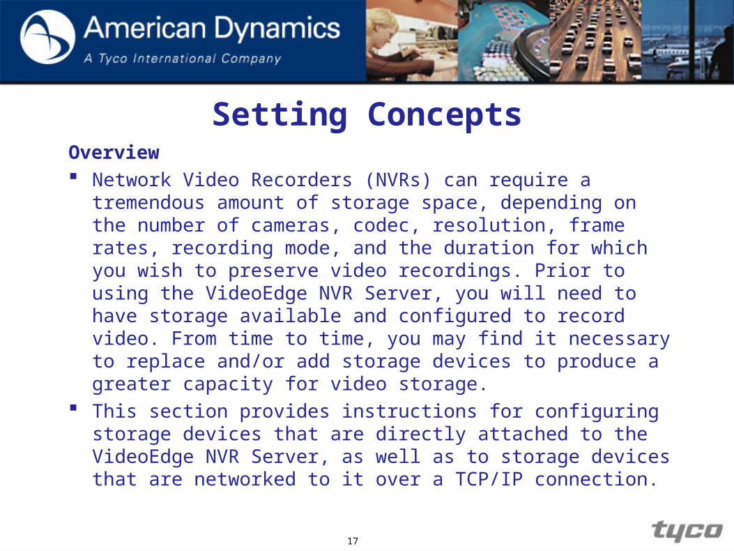
Overview Network Video Recorders (NVRs) can require a
tremendous amount of storage space, depending on the number of cameras, codec, resolution, frame rates, recording mode, and the duration for which you wish to preserve video recordings. Prior to using the VideoEdge NVR Server, you will need to have storage available and configured to record video. From time to time, you may find it necessary to replace and/or add storage devices to produce a greater capacity for video storage.
This section provides instructions for configuring storage devices that are directly attached to the VideoEdge NVR Server, as well as to storage devices that are networked to it over a TCP/IP connection.
Setting Concepts

Storage Concepts
iSCSI This standard is used to transmit data over local area
networks (LANs), wide area networks (WANs) and can enable location-independent data storage and retrieval from any devices on the network.
A system that uses iSCSI requires an initiator. Initiators are iSCSI clients and they can either be in software or hardware.
iSCSI does not require dedicated cabling; it can use existing switching and IP equipment. As a result, iSCSI is thought to be a low-cost alternative to Fibre Channel, which requires dedicated infrastructure.
18

Storage Concepts
Fibre Channel Fibre Channel, or FC, is a gigabit-speed network
technology primarily used for storage networking. It started in the supercomputer field, but has become the standard connection type for storage area networks (SAN) in enterprise storage.
Fibre Channel Host Bus Adapters (HBAs) are available for all major open systems, computer architectures, and buses, including PCI and SBus. They are needed to connect a Fibre storage device to a server.
19
Storage Concepts
Direct Attached Storage
This term is used to differentiate non-networked storage from networking systems such as NAS and SAN.
However, DAS cannot share information or space with other servers.
DAS are usually connected via SCSI cables, along with a SCSI terminator.
20
Storage Concepts
Storage Configuration Options
JBOD – Just a Bunch of Disks
RAID – Redundant Array of Inexpensive Disks
21
Storage Concepts
JBOD
The JBOD storage configuration is a group of disks without any RAID features, depending on configuration in BIOS.
VideoEdge NVR Server uses a JBOD configuration for internal server drives.
In NVR Server systems, JBOD is rarely used with external devices.
22
Storage Concepts
RAID
An umbrella term for computer data storage schemes that
distribute data across multiple disks for increased input/output performance and/or better reliability.
Since RAID systems use multiple disks, they are often referred to as disk groups.
Disk groups are also known as known as volumes or RAID arrays.
23

Storage Concepts
RAID
There are different types of RAID configurations. Some of the best known configurations are RAID 0, 1, 5 and 1+0.
Each configuration uses an approach to storage that can provide fault tolerance, additional availability of data, redundancy, additional performance, or more than one of these factors.
24

Storage Concepts
Key RAID Concepts
Mirroring – Duplicating data to more than one disk.
Striping – Splitting data across more than one disk.
Error Correction – Storing redundant data so problems can be detected and possibly fixed.
25
Storage Concepts
Some Common RAID Types
RAID 0 – Uses striping to provide extra performance and
capacity but does not provide data protection (lack of mirroring or parity).
RAID 1 – Uses mirroring to provide 1:1 backup, which increases read performance or reliability at the expense of capacity. This configuration is often used with databases due to better transaction time and availability.
26

Storage Concepts
Some Common RAID Types RAID 1+0 (or 10) – is a mirrored data set (RAID 1) which is
then stripped (RAID 0), hence the name “1+0”. A RAID 1+0 array requires a minimum of four drives – two mirrors drives to hold half of the stripped data, plus another two mirrored for the other half of the data. In LINUX, MD RAID 10 is a non-nested RAID type like RAID 1 that only requires a minimum of two drives and may give read performance on the level of RAID 0.
27

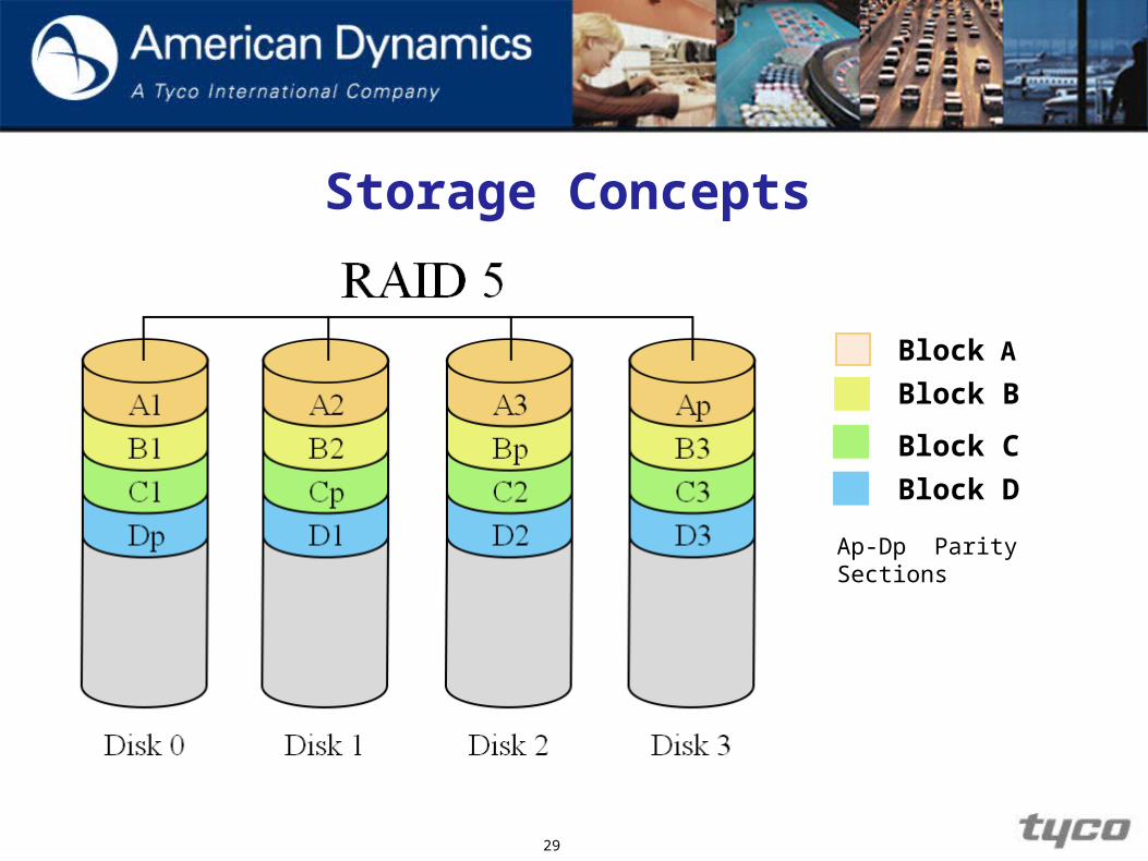
Some Common RAID Types RAID 5 – Preserves against the loss of any one disk by
combining the contents of three or more disks. However, the total storage capacity is reduced by one disk.
This configuration is often used with VideoEdge because of RAID 5’s performance in situations where data transfers are I/O intensive.
28
Storage Concepts
Storage Concepts
29
Block A
Block B
Block C
Block D
Ap-Dp Parity Sections
Storage Concepts
Virtual Disks
A virtual disk represents an individually addressable (logical) SCSI device that is part of a physical SCSI device (target).
Virtual disks are also known as volumes or LUNs (Logical Unit Numbers).
In enterprise-level systems, virtual disks usually represent segments of large RAID disk arrays.
30

31
Storage Concepts
Storage Strategy for Fiber Raid Storage / Fiber Extended Storage (FRS/FES) RAID Device
In order to properly configure any NVR solution, it is important to understand how much storage you will require on each NVR Server and how to configure it to maximize the overall performance. This will be dictated by:
The type of storage that will be used The total number of cameras, make/model, resolution,
codec, FPS, compression, recording mode The file size of the camera’s video stream that is to be
recorded The required retention period for stored video
32
Setting Up the NVR Storage
Storage Strategy for FRS/FES RAID Device
Are you using a Raid0, Raid1 or Raid5 configuration?
Configure the LUN’s/Virtual Disk’s to be no more than 2TB in size.
How many cameras being installed on the VideoEdge NVR will help determine how many Array’s/Storage Disk Groups are created.
33
Setting Up the NVR Storage
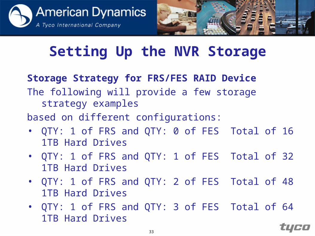
Storage Strategy for FRS/FES RAID Device
The following will provide a few storage strategy examples
based on different configurations:
• QTY: 1 of FRS and QTY: 0 of FES Total of 16 1TB Hard Drives
• QTY: 1 of FRS and QTY: 1 of FES Total of 32 1TB Hard Drives
• QTY: 1 of FRS and QTY: 2 of FES Total of 48 1TB Hard Drives
• QTY: 1 of FRS and QTY: 3 of FES Total of 64 1TB Hard Drives
34
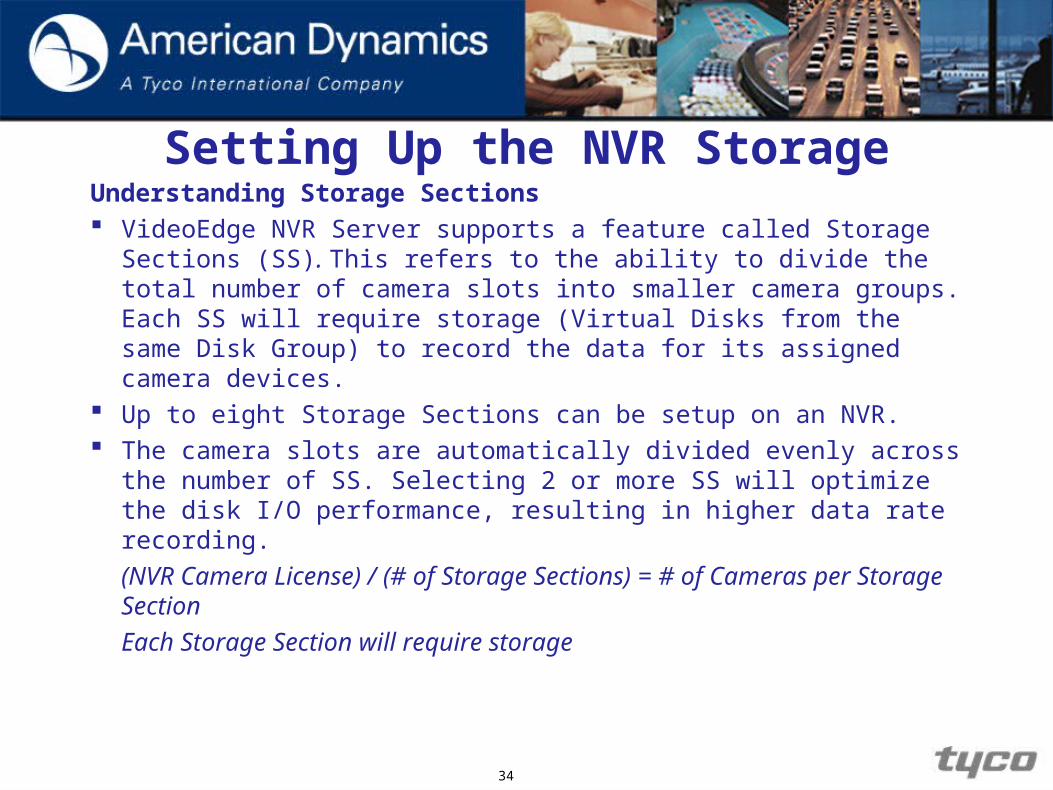
Understanding Storage Sections VideoEdge NVR Server supports a feature called Storage
Sections (SS). This refers to the ability to divide the total number of camera slots into smaller camera groups. Each SS will require storage (Virtual Disks from the same Disk Group) to record the data for its assigned camera devices.
Up to eight Storage Sections can be setup on an NVR. The camera slots are automatically divided evenly across the
number of SS. Selecting 2 or more SS will optimize the disk I/O performance, resulting in higher data rate recording.
(NVR Camera License) / (# of Storage Sections) = # of Cameras per Storage Section
Each Storage Section will require storage
Setting Up the NVR Storage
35
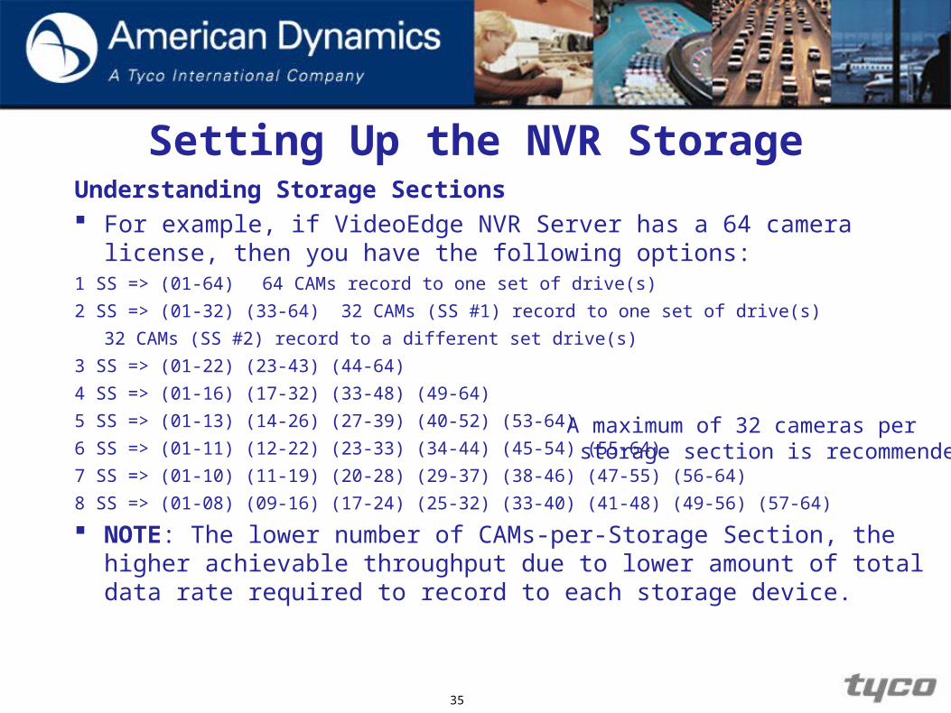
Setting Up the NVR StorageUnderstanding Storage Sections For example, if VideoEdge NVR Server has a 64 camera license, then you
have the following options:1 SS => (01-64) 64 CAMs record to one set of drive(s)
2 SS => (01-32) (33-64) 32 CAMs (SS #1) record to one set of drive(s)
32 CAMs (SS #2) record to a different set drive(s)
3 SS => (01-22) (23-43) (44-64)
4 SS => (01-16) (17-32) (33-48) (49-64)
5 SS => (01-13) (14-26) (27-39) (40-52) (53-64)
6 SS => (01-11) (12-22) (23-33) (34-44) (45-54) (55-64)
7 SS => (01-10) (11-19) (20-28) (29-37) (38-46) (47-55) (56-64)
8 SS => (01-08) (09-16) (17-24) (25-32) (33-40) (41-48) (49-56) (57-64)
NOTE: The lower number of CAMs-per-Storage Section, the higher achievable throughput due to lower amount of total data rate required to record to each storage device.
A maximum of 32 cameras per storage section is recommended
36
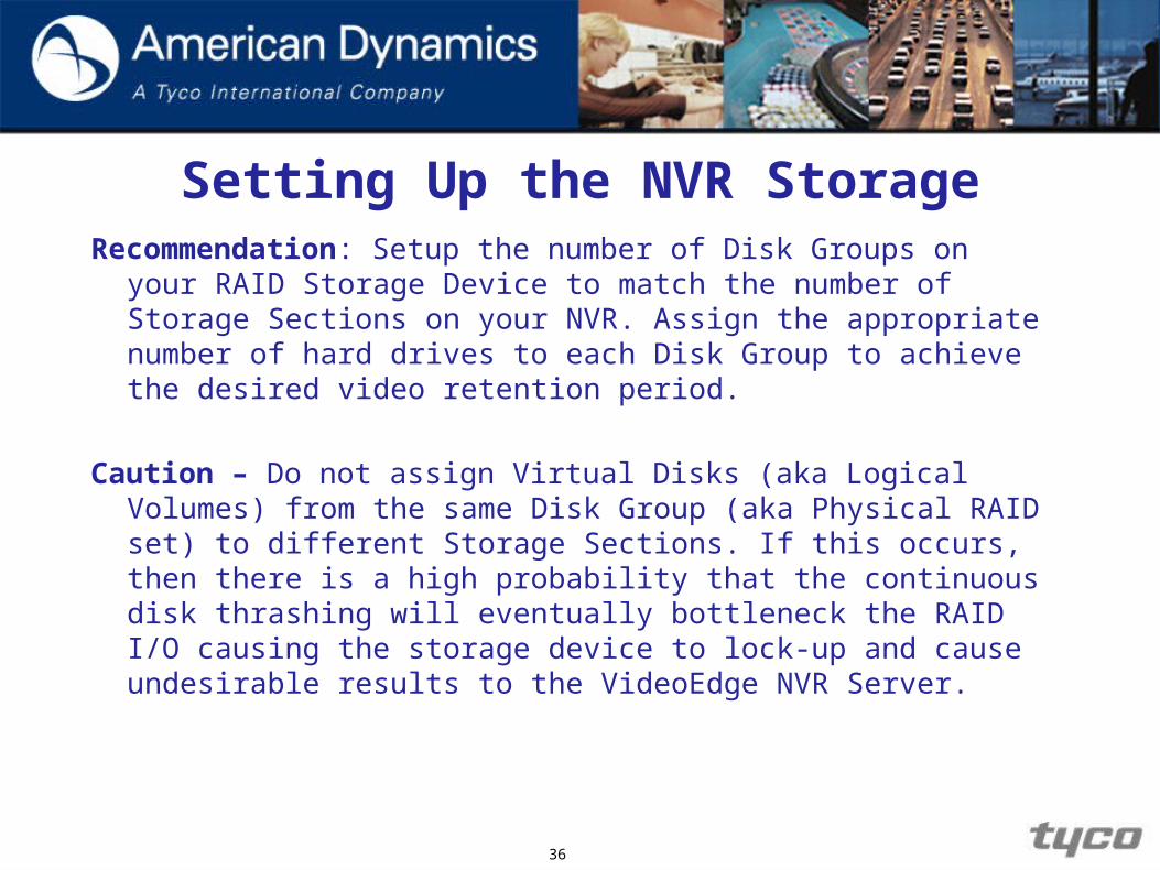
Setting Up the NVR StorageRecommendation: Setup the number of Disk Groups on your
RAID Storage Device to match the number of Storage Sections on your NVR. Assign the appropriate number of hard drives to each Disk Group to achieve the desired video retention period.
Caution – Do not assign Virtual Disks (aka Logical Volumes) from the same Disk Group (aka Physical RAID set) to different Storage Sections. If this occurs, then there is a high probability that the continuous disk thrashing will eventually bottleneck the RAID I/O causing the storage device to lock-up and cause undesirable results to the VideoEdge NVR Server.
Caution – While you can change (increase) the number of Storage Sections on an NVR, it is recommended that you do NOT attempt to decrease this number because it will remove access to recorded video on the higher Storage Sections.
37
Setting Up the NVR Storage
38
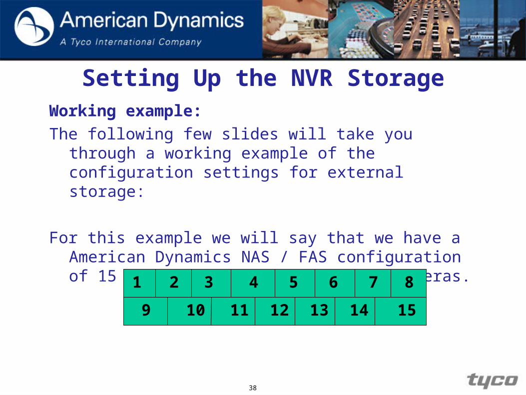
Setting Up the NVR StorageWorking example:
The following few slides will take you through a working example of the configuration settings for external storage:
For this example we will say that we have a American Dynamics NAS / FAS configuration of 15 disks. We will also have 64 cameras.
21 3 4 5 6 7 8
9 10 11 12 13 14 15

39
Setting Up the NVR Storage
From these 15 Disks we then decide on the maximum number of disk groups to use.
For this example we will use disk groups of 4, therefore:
15 / 4 = 3.75
However if we want to include a hot spare in case of drive failure then we must change our numbers accordingly i.e. if we use 1 hot spare then:
14 / 4 = 3.5
21 3 4 5 6 7 8
9 10 11 12 13 14 15
40
Setting Up the NVR Storage
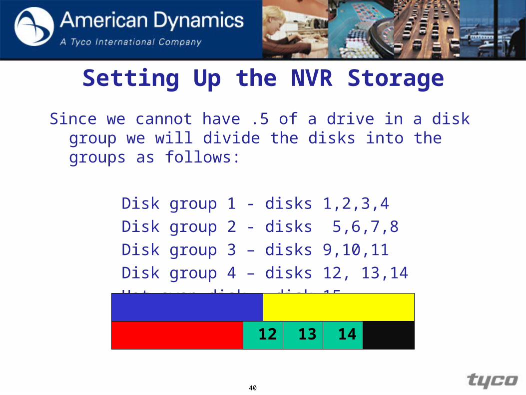
Since we cannot have .5 of a drive in a disk group we will divide the disks into the groups as follows:
Disk group 1 - disks 1,2,3,4
Disk group 2 - disks 5,6,7,8
Disk group 3 – disks 9,10,11
Disk group 4 – disks 12, 13,14
Hot swap disk – disk 15
21 3 4 5 6 7 8
9 10 11 12 13 14 15
41
Setting Up the NVR Storage
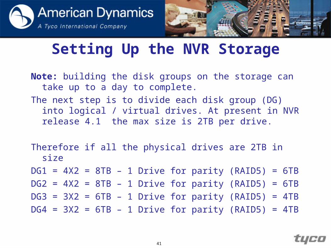
Note: building the disk groups on the storage can take up to a day to complete.
The next step is to divide each disk group (DG) into logical / virtual drives. At present in NVR release 4.1 the max size is 2TB per drive.
Therefore if all the physical drives are 2TB in size
DG1 = 4X2 = 8TB – 1 Drive for parity (RAID5) = 6TB
DG2 = 4X2 = 8TB – 1 Drive for parity (RAID5) = 6TB
DG3 = 3X2 = 6TB – 1 Drive for parity (RAID5) = 4TB
DG4 = 3X2 = 6TB – 1 Drive for parity (RAID5) = 4TB

42
Setting Up the NVR Storage
All logical drives are 2TB in size. You should name the Logical Drives by Group and Name for easy reference if you decide to use Storage Sections.
DG1 6TB DG3 4TB DG4 4TBDG2 6TB
LD1 LD2 LD3 LD1 LD2LD1 LD2 LD3 LD1 LD2
DG1 8TB DG3 6TB DG4 6TBDG2 8TB
DG1 2TB DG3 2TB DG4 2TBDG1 2TB1 Drive set for parity
1 Drive set for parity
1 Drive set for parity
1 Drive set for parity
43
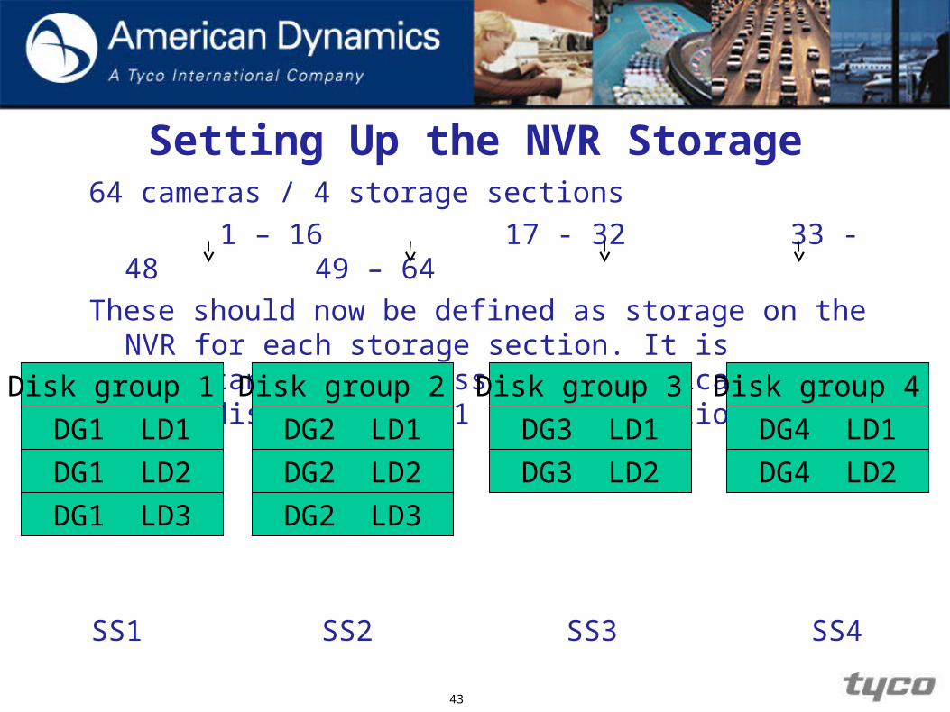
Setting Up the NVR Storage64 cameras / 4 storage sections
1 – 16 17 - 32 33 - 48 49 – 64
These should now be defined as storage on the NVR for each storage section. It is important to only assign the logical drives in 1 disk group to 1 storage section.Disk group 1
DG1 LD1
DG1 LD2
DG1 LD3
Disk group 2
DG2 LD1
DG2 LD2
Disk group 3
DG3 LD1
DG3 LD2
Disk group 4
DG4 LD1
DG4 LD2
SS1 SS2 SS3 SS4
DG2 LD3

44
Setting Up the NVR Storage
Make sure when the storage is created NAS / FAS is used as Primary storage. You can also create Alarm and ISO storage.
Any drive can be used for level 1 backup storage, however it is recommended that Local drives are used.
Note: DO NOT set cameras to record while NVR is building
disks as this will prolong the building time.

45
Setting Up the NVR StorageCalculating Storage Requirements1. Determine QTY of Edge Devices and Anticipated Settings Make/Model,
Codec/Rez/FPS/Compress, Activity, Record Hours
2. Calculate Data Rate for Each Device Using Vendor Calculators (examples):AD: http://www.americandynamics.net/Support/CalcDefault.aspx
Axis: http://www.axis.com/products/video/design_tool/calculator.htm
Sony: http://pro.sony.com/bbsccms/ext/cat/camsec/cameraCalc3/HTML/NTSC_Calculator.html
3. Enter Info into VideoEdge NVR Storage Requirement CalculatorAD: http://www.americandynamics.net/calculators/Calc_NVR_Storage_Requirement.html
4. Output will Provide Total Bandwidth and Storage Requirements. May need to lower camera count per NVR to meet network and storage requirements when dealing with many cameras, large resolution, or retention.
46
Setting Up the NVR StorageOverview of AD Fibre RAID Storage (FRS/FES) Fibre RAID Storage is an NVR extended storage device acting as
a Fibre Direct-Attached Storage (DAS) or iSCSI device. As a Fibre device, a Fibre Host Bus Adapter (HBA) must be
installed in the NVR and uses Fibre Optic cable connection. As an iSCSI device, 3rd Gigabit Ethernet NIC must be installed in
the NVR and uses CAT 5e/6 Ethernet connection. The R710 NVR 4.1 has the additional NIC card pre-installed, NOTE: The Optliplex XE NVR 4.1does not support external
storage. NVR currently supports Single Path Mode and not Multipath
mode.
47
Setting Up the NVR Storage
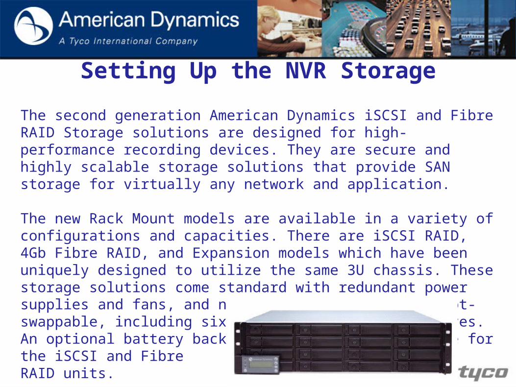
The second generation American Dynamics iSCSI and Fibre RAID Storage solutions are designed for high-performance recording devices. They are secure and highly scalable storage solutions that provide SAN storage for virtually any network and application.
The new Rack Mount models are available in a variety of configurations and capacities. There are iSCSI RAID, 4Gb Fibre RAID, and Expansion models which have been uniquely designed to utilize the same 3U chassis. These storage solutions come standard with redundant power supplies and fans, and nearly every component is hot-swappable, including sixteen lockable hot-swap drives. An optional battery backup module is also available for the iSCSI and FibreRAID units.

48
Setting Up the NVR Storage Storage Strategy for FRS/FES RAID Device
Recommendations:
• The FRS/FES supports a maximum of 8 Disk Groups (aka RAID sets).
• Each Disk Group can be “carved up” into one or more Virtual Disks (aka Volumes or LUNs). The VideoEdge NVR Server recommends 2TB or smaller size.
• Virtual Disks from a single Disk Group must be assigned to the same NVR Storage Section. This will eliminate the possibility of unnecessary disk thrashing caused when the same set of physical disks (DG’s) are being used by different sets of cameras (aka Storage Sections).

49
Setting Up the NVR Storage Storage Strategy for FRS/FES RAID Device
Recommendations:• Make sure the drives in the external storage units,
primary or expansion are all the same size. • Verify that you have the latest firmware patch or upgrade
for your controller.
• The VideoEdge NVR currently supports Single Path mode only and does not support MPIO.
• Make sure to leave a minimum of a 2U space between storage units.
• Start the camera’s recording after all the drives have been formatted and their status is “Ready”.

50
Setting Up the NVR Storage
Logging into the FRS/FES RAID Device
After completing the Disk Group and Virtual Disk configurations of the FRS/FES, it will take some time for the RAID to complete building and initialization process. While this process completes we will continue with the VideoEdge training and complete the addition of the configured storage in a later module.

51
Setting Up the NVR Storage
Connecting NVR to FRS/FES Using Fibre
If you use the FRS/FES as a Direct Attached Storage device
(fastest performance), then you must install a supported Fibre
HBA Card into the VideoEdge NVR Server.
1. Power OFF the VideoEdge NVR Server and install the Fibre HBA Card into a compatible slot.
2. Insert the transceiver into the Fibre controller.
3. Power ON the NVR.

52
Setting Up the NVR StorageConnecting NVR to FRS/FES Using iSCSI
If you use the FRS/FES as an iSCSI Storage device, then you
must use the Gigabit Ethernet Card installed into the
VideoEdge NVR 4.01 Servers (NIC 3 on the R710 and T310).
1. Power ON the NVR and login as an administrator.
2. Click Devices link on the System Administrator page.
3. Click Configure iSCSI button.
4. Check the Enable iSCSI box and click Save.

53
Connecting NVR to FRS/FES Using iSCSI cont’d
7. Click Reboot link on bottom left pane and then OK to enable the iSCSI Initiator on the NVR.
8. Log into the VideoEdge NVR Server.
9. Click Devices link on the System Administrator page.
10.Click Configure iSCSI button.
11.Write down the Initiator Name “iqn” number of your NVR.

54
Setting Up the NVR StorageLogging into the FRS/FES RAID Device
As we do not have Fibre units for everyone to configure we will now log into a remote Fibre Raid Storage unit and go through the setup to configure the storage.
Note: If you use the FRS/FES as a Direct Attached Storage device (fastest performance), then you must install a supported Fibre HBA Card into the VideoEdge NVR Server.
Refer to the Fibre RAID Expansion Unit QSG & Manuals for the installation and configuration instructions. NOTE: All hard drives used must have the same capacity!!!

55
Setting Up the NVR StorageLogging into the FRS/FES RAID Device1. Connect your client PC to the Fibre RAID Storage (FRS)
Eth0 or Eth1 NIC directly using a cross-over cable or Gigabit network switch.
2. If needed, change the static IP address of your PC to the same subnet as the FRS. For example, set the IP address to 192.168.0.100 / 255.255.255.0 if the FRS is set to its default setting of 192.168.0.1 (or .2) / 255.255.255.0.
3. Ping the FRS from your client PC to confirm that you can successfully communicate with it by typing at the command prompt, PING 192.168.0.1 or PING 192.168.0.2. If you cannot, check the cables, the IP address of the FRS and Client, plus the firewall settings on the Client PC.

56
Logging into the FRS/FES RAID Device cont’d
4. Log onto the Fibre RAID Storage by entering the FRS IP address in the URL line of the web browser.
5. Log in using the default administrator account. The user name is “admin” and the password is also “admin”.

57
Overview of VideoEdge NVR Server
Introduction to Storage
Installing VideoEdgeNVR Server
Managing the MainAdministrator Password
Overview of NVRServer Controls
Setting Up theNVR Storage
Configuring andViewing Cameras
Configuring Sensors
Logs
Scheduling Recording
Alerts and EmailNotifications
Playback and Search
Creating ISO Files
Export Video
Configuration Backup,Failover & Reflash
Windows Pre-configuration
Managing Usersand Roles
Adding new camera handlers
Basic Networkingand Troubleshooting

Windows Pre-configuration
Windows Pre-configuration
Objectives
1. Verify Windows operating system (OS) and Service Pack.
2. Install the prerequisite software and correct drivers.
3. Identify and configure Windows settings to optimize performance.
59

Windows Pre-configuration
Overview
This chapter covers the basic Windows pre-configuration settings and software that must be installed before we can begin to interact with the VideoEdge NVR Server(s) with a web browser effectively.
60

Windows Pre-configuration
Verifying the Windows Operating System and Service Pack
Before we can use a client PC to access the VideoEdge NVR Server(s) and use the client software, we need to verify which Windows OS is currently installed.
61

Windows Pre-configuration
Verifying the Windows Operating System and Service Pack
62

Windows Pre-configuration
Verifying the Windows Operating System and Service Pack
63
Windows Pre-configuration
Installing Windows Prerequisite Software Prerequisite Software
Microsoft windows Explorer version 7 or 8 Apple QuickTime 7.6 – For interoperability with cameras using MPEG4
and H.264. Sun Microsystems Java 6 Standard Edition Adobe Acrobat 8.0 Reader – (optional) Used to read documentation in
PDF format. Install the correct drivers for PC’s system devices—such as video card
and Network Interface Card (NICs) drivers—so that they operate correctly.
64

Windows Pre-configuration
Installing Windows Prerequisite Software
There are several items that need to be installed on the client PC before we can effectively interact with the client software applications and the VideoEdge NVR Server(s).
All items can be downloaded from their respective websites. The Microsoft items can be downloaded through Windows Automatic Updates or manually from their website.
If you automatically download updates, make sure you save the updates first and make sure that they are the correct versions before installing them.
Correct drivers must also be installed for the hardware. For instance, it’s extremely important to load the manufacturer’s driver for a video card. By NOT installing the correct drivers, you may get undesired effects and/or damage the client PC and its hardware.
65

Windows Pre-configuration
Verifying Successful Installation of Prerequisite Software After installing the prerequisite software, we can now verify if the
software has been installed correctly.
To verify that the software has been installed, we will need to do the following:
1. Click Start in the Windows taskbar.
2. Click Control Panel.
3. Click Add or Remove Programs.
You will now see all the programs that are currently installed on the client PC. If you check the box, Show Updates, you will see an extended list of all Microsoft updates that have been applied to that PC.
66

Windows Pre-configuration
Optimization of Windows Performance
There are many things that can be done to enhance the performance of Windows. However, there are two settings that we will be concerned with. These two settings are the:
1. Paging File
2. Setting QuickTime preferences
67

Windows Pre-configuration
Optimization of Windows Performance
To configure Hardware Accelerator:
Right-click the Desktop. Select Properties.
68

Windows Pre-configuration
Optimization of Windows Performance
Select the Settings tab. Click Advanced.
69
Windows Pre-configuration
Optimization of Windows Performance
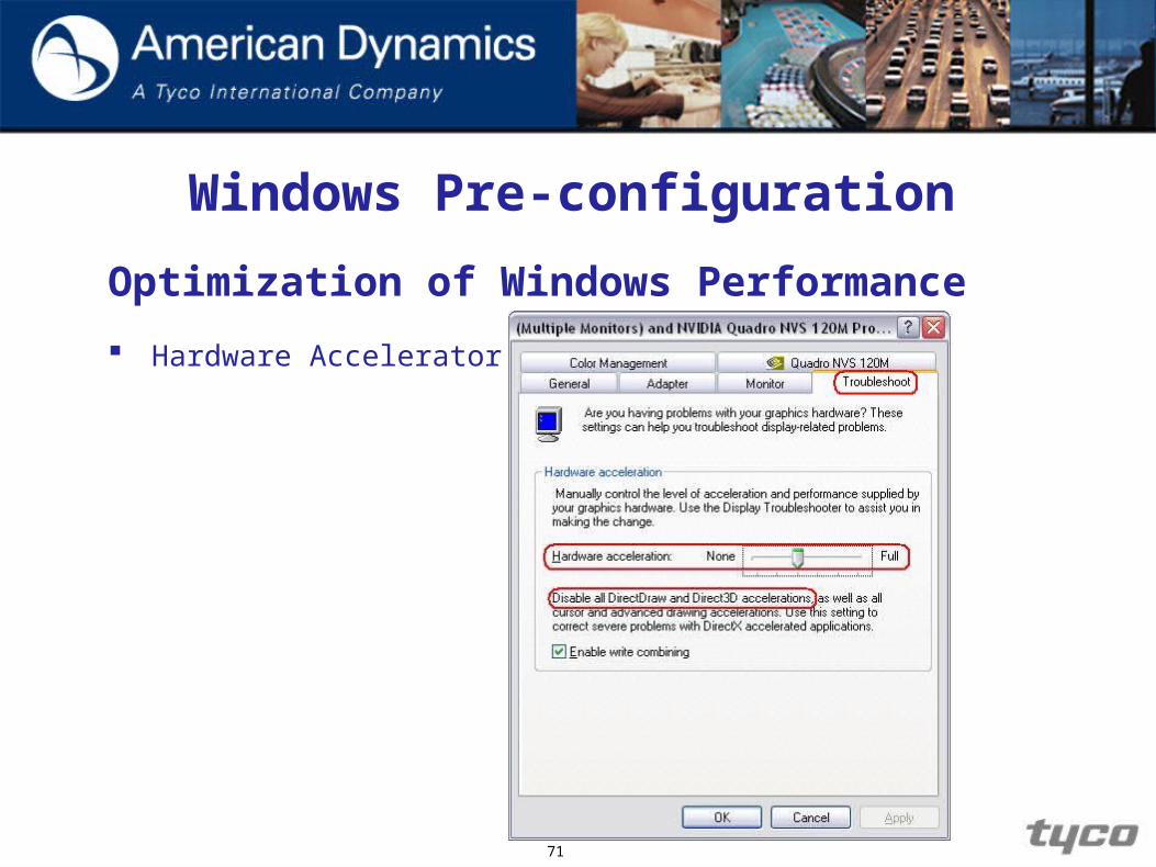
Select the Troubleshoot tab.
Slide the Hardware Accelerator bar until the message Disable all DirectDraw and Direct3D accelerations... appears.
70
Windows Pre-configuration
Optimization of Windows Performance
Hardware Accelerator
71

Windows Pre-configuration
Optimization of Windows Performance
Now that we have configured the Hardware Accelerator setting, we can proceed to configure the Paging File.
72

Windows Pre-configuration
Optimization of Windows Performance
To configure the Paging File:
Click Start in Windows taskbar. Right-click My Computer . Select Properties.
Select the Advanced tab. Under Performance select Settings.
73

Windows Pre-configuration
Optimization of Windows Performance
Select Advanced tab. Click the Change button in Virtual Memory
74

Windows Pre-configuration
Optimization of Windows Performance
Under Paging file size for selected drive, select System managed size and click Set.
Click Ok. System may prompt to reboot PC. Please follow prompts to reboot the PC.
75

76
Overview of VideoEdge NVR Server
Introduction to Storage
Installing VideoEdgeNVR Server
Managing the MainAdministrator Password
Overview of NVRServer Controls
Setting Up theNVR Storage
Configuring andViewing Cameras
Configuring Sensors
Logs
Scheduling Recording
Alerts and EmailNotifications
Playback and Search
Creating ISO Files
Export Video
Configuration Backup,Failover & Reflash
Windows Pre-configuration
Managing Usersand Roles
Adding new camera handlers
Basic Networkingand Troubleshooting
Installing VideoEdge NVR Server
Installing VideoEdge NVR Server
Objectives
1. Locate the NVR on the network.
2. Request and install license for the NVR.
3. Identify the current firmware on the NVR.
78

Installing VideoEdge NVR Server
79
Processor Intel® Xeon E5620 2.4Ghz, 12M Cache,Turbo, HT, 1066MHz Memory 4GB Memory (2x2GB), 1066MHz Dual Ranked UDIMMs for 1
Processor, Adv ECC Optical drive DVD+/-RW, SATA, INTERNAL HDD for installation 1TB 7.2K RPM Near Line SAS 3.5in Hot Plug Hard Drive
HDD for video storage 5 x 1TB 7.2K RPM Near Line SAS 3.5in Hot Plug Hard Drive RAID Controller PERC 6/i SAS RAID Controller 2x4 Connectors, Internal,
PCIe256MB Cache, x6 Chassis (supports up to 16 drives)
Network Interface Cards Two Embedded Broadcom, GB Ethernet NICS with TOE Graphics Card Onboard graphics card High Resolution Color Monitor 800 x 600 resolution or higher monitor with 16-bit color
Keyboard for NVR Install USB Keyboard Host bus adapter for any
extended video storage LSI 7104EP-LC Fibre Channel Host Bus Adapter Operating System No operating system required
Dell Power Edge R710

Installing VideoEdge NVR Server
80
Processor Dual Core E5300/2.60Ghz, 2M, 800FSB Memory 4BG NON-ECC,133Mhz DDR3,2X2G HDD for installation 500 GB 7200 RPSM SATA-II HDD for video storage* 500 GB Option
1 TB Option2 TB Option
Network Interface Cards 2 x 1 GN Ethernet NICs High Resolution Color Monitor 800 x 600 resolution or higher monitor with 16-bit color Keyboard for NVR Install USB keyboard Operating System No Operating system required
* NOTE: The total throughput of the OptiPlex XE is 50 Mbps.
Dell OptiPlex XE

Locating and Licensing the NVR over the Network
The NVR has the software preinstalled so once the network has been connected on LAN 1 the next step is to locate and configure the NVR.
To complete these steps refer to the Student Guide
and complete the following procedures:
1. Accessing The VideoEdge NVR Server Over the Network.
2. Specify the VideoEdge NVR as a trusted site.
3. Log Into VideoEdge NVR Server.
4. Licensing Your VideoEdge NVR.Note: In release 4.1 you have the ability to add a temporary license.
81
Configuring the NVR Network Settings
There are several ways to connect your cameras and your VideoEdge NVR Server. However, by using a network topology with 2 LANs, 1 for the Local Area Network backbone and 1 for the IP camera network, the user will have added an extra layer of security for the cameras and can keep track of who is accessing the system.
82

Configuring the NVR Network Settings
83
Web clients
Configuring the NVR Network Settings
The NVR can be configured to operate in a wide area network (WAN) configuration. The Setup WAN page lets you specify the name or IP address that can be used to access an NVR located behind a NAT firewall (such as a corporate LAN) that presents a single public address for connections from outside the LAN.
You can also specify the ports that are used for HTTP, secure HTTP, and streaming (RTSP) connections to the NVR. In addition, the General Settings page allows you to change the RTSP Streaming Port.
84

85
Configuring the NVR Network Settings
To configure the NVR network settings refer to the
Student Guide and complete the following procedures:
1. Configuring the Network Settings for LAN1.
2. Disabling the LAN2 DHCP Server.
3. Configuring the Network Settings for the Camera Network LAN2.
4. Configuring Wide Area Network SettingsNote: The last step in each of these procedures is to
reboot the NVR. However, if all three procedures are
completed in sequence you only need to reboot at the end
of the third procedure.
86

Configuring the NVR Server as an NTP and/or DHCP Server
From the Network administrative link, you can also enable the VideoEdge NVR Server to act as an NTP server and/or DHCP server.
If NTP is enabled the VideoEdge NVR Server will become the master for other VideoEdge NVR Servers to synchronize their system clocks. (Only 1 NVR should be set to be the NTP for the network,
however see note below) If the DHCP setting is enabled the VideoEdge NVR Server will
issue IP addresses from its LAN 1 NIC to associated devices.
Note: Using the NVR Server as an NTP or DHCP server
is not recommended for most installations.
87

Time & Date
Setting the time and date
The time and date can either be set manually or it can be set using NTP servers.
88

Configuring the NVR Server as an NTP and/or DHCP Server
To Setup the NVR Server as an NTP Server and/or DHCP, server and also set the time and date.
Refer to the Student Guide and complete the following
procedures:To Setup the NVR Server as an NTP server.To Setup the NVR Server as an DHCP Server. Setting Time and Date. Specify an NTP Server.
89

Identifying the Current Software Version on the VideoEdge NVR Server:
Sometimes it’s necessary to identify the current firmware
of the VideoEdge NVR Server for support purposes.
To locate the version of the firmware: Click on the ABOUT button in the upper-right corner of the
webpage.
90
Software version
Number of camera licenses
Camera Handler Pack

91
Overview of VideoEdge NVR Server
Introduction to Storage
Installing VideoEdgeNVR Server
Managing the MainAdministrator Password
Overview of NVRServer Controls
Setting Up theNVR Storage
Configuring andViewing Cameras
Configuring Sensors
Logs
Scheduling Recording
Alerts and EmailNotifications
Playback and Search
Creating ISO Files
Export Video
Configuration Backup,Failover & Reflash
Windows Pre-configuration
Managing Usersand Roles
Adding new camera handlers
Basic Networkingand Troubleshooting

Managing the Main Administrator Password
Managing the VideoEdge NVR Server ID and Main Administrator’s Password
Objective
By the end of the module you will be able to change the
VideoEdge NVR Server’s main administrator login
password.
93

Managing the VideoEdge NVR Server ID and Main Administrator’s Password
The VideoEdge NVR Server’s main administrator username is admin and cannot be changed.
It is strongly advised not to hand out the main administrator’s username/password since admin users have complete access to the system.
94

Managing the VideoEdge NVR Server ID and Main Administrator’s Password
95
Refer to the procedure Changing the System ID and
Admin Password in your student guide and complete the
steps to rename your NVR server.
Note : For the changes to take effect the NVR must be
rebooted.
Review
1. Is it possible to change the main administrator’s login ID?
2. What actions must you take before changes to the VideoEdge NVR Server ID and admin password will have effect?
96

97
Overview of VideoEdge NVR Server
Introduction to Storage
Installing VideoEdgeNVR Server
Managing the MainAdministrator Password
Overview of NVRServer Controls
Setting Up theNVR Storage
Configuring andViewing Cameras
Configuring Sensors
Logs
Scheduling Recording
Alerts and EmailNotifications
Playback and Search
Creating ISO Files
Export Video
Configuration Backup,Failover & Reflash
Windows Pre-configuration
Managing Usersand Roles
Adding new camera handlers
Basic Networkingand Troubleshooting

98
Overview of NVR Server Controls

Overview of VideoEdge NVR Server Controls
Objective
By the end of the module you will have explored the
layout of the VideoEdge NVR Server GUI.
99

Overview of VideoEdge NVR Server Controls
Overview
The VideoEdge NVR Server software transforms a Dell R710 or T310 server into an Enterprise NVR that can be administered via a web browser.
A workstation logging into the VideoEdge NVR Server using the web browser will require appropriate plug-ins for viewing any live video: Sun Microsystems Java for MJPEG Apple QuickTime for MPEG4
100

Overview of VideoEdge NVR Server Controls
In the NVR GUI there are 3 main administrative links:
1. Networks – Used primarily to change the main and camera network settings of the VideoEdge NVR Server.
2. System – Used primarily to make any system changes to the VideoEdge NVR Server (i.e. storage configuration, create users and groups).
3. Video – Used primarily to make any changes for camera configurations (i.e. adding/deleting cameras from the NVR).
101
Overview of VideoEdge NVR Server Controls
Refer to the Student Guide and complete the procedures in the following sections of the Student Manual:
Logging into the NVR Navigating the VideoEdge NVR Server’s interface
102

103
Overview of VideoEdge NVR Server
Introduction to Storage
Installing VideoEdgeNVR Server
Managing the MainAdministrator Password
Overview of NVRServer Controls
Setting Up theNVR Storage
Configuring andViewing Cameras
Configuring Sensors
Logs
Scheduling Recording
Alerts and EmailNotifications
Playback and Search
Creating ISO Files
Export Video
Configuration Backup,Failover & Reflash
Windows Pre-configuration
Managing Usersand Roles
Adding new camera handlers
Basic Networkingand Troubleshooting

Setting Up the NVR Storage

Setting Up the NVR Storage
Objectives
1. Configure local storage devices.
2. Verify storage devices.
3. Connecting to an iSCSI device.
4. Add and remove storage devices.
5. Connect to a remote storage device.
105
Setting Up the NVR StorageOverview Network Video Recorders (NVRs) can require a tremendous
amount of storage space, depending on the number of cameras, resolution, and frame rate of the recordings, and the duration for which you wish to preserve video recordings.
A good starting point of the VideoEdge NVR Server system is to have storage configured to record data returned by your NVRs. From time to time, you may find it necessary to replace or add a storage device to produce a greater capacity for video storage.
This section provides instructions for configuring storage devices that are physically connected to the VideoEdge NVR Server, as well as to storage devices that are networked to the VideoEdge NVR Server over a TCP/IP connection.
106
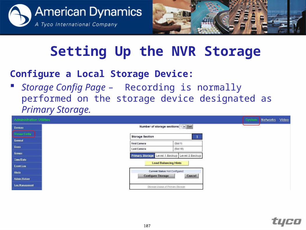
Setting Up the NVR Storage
Configure a Local Storage Device: Storage Config Page – Recording is normally performed on
the storage device designated as Primary Storage.
107
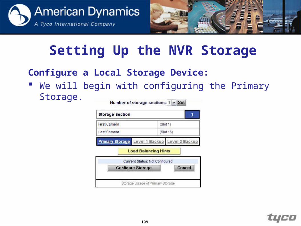
Setting Up the NVR Storage
Configure a Local Storage Device: We will begin with configuring the Primary Storage.
108

Setting Up the NVR Storage
Configure a Local Storage Device: A Storage Section contains a group of cameras, each
matched to a storage device(s). You can select as many storage sections as you have storage devices or cameras (whichever number is smaller) and no more.
The cameras will be divided evenly across the storage sections, and all the footage from each storage section will record on the storage devices matched to that section. Selecting a number of storage sections other than 1 (in which case all footage from all cameras goes to a single storage unit) optimizes the recording by spreading the amount of cameras across your storage devices.
109
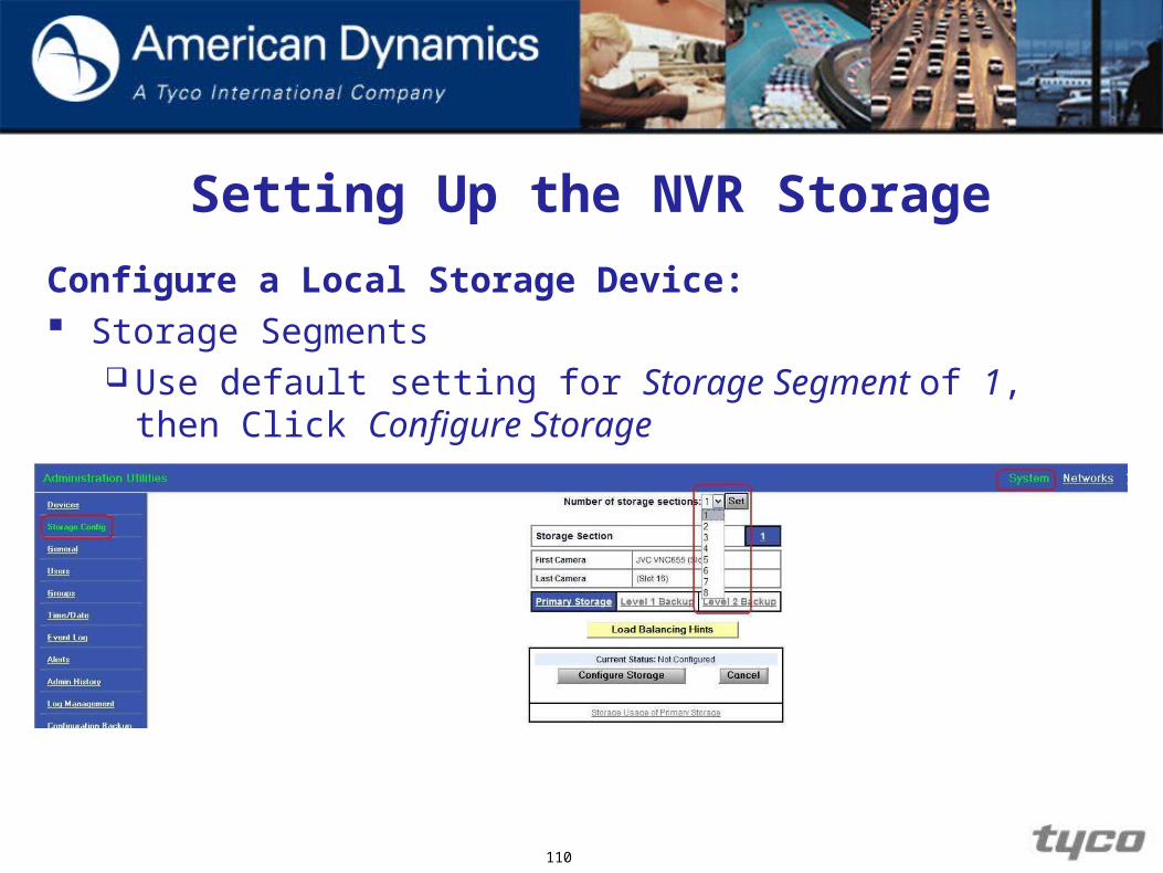
Setting Up the NVR Storage
Configure a Local Storage Device: Storage Segments
Use default setting for Storage Segment of 1, then Click Configure Storage
110
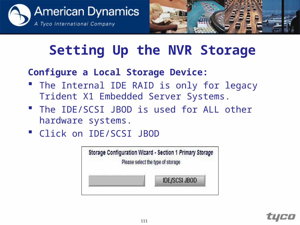
Setting Up the NVR Storage
Configure a Local Storage Device: The Internal IDE RAID is only for legacy Trident X1
Embedded Server Systems. The IDE/SCSI JBOD is used for ALL other hardware
systems. Click on IDE/SCSI JBOD
111

Setting Up the NVR StorageConfigure a Local Storage Device: Select configuration for each drive. For both Alarm Archive and ISO Images, there are radio
buttons. If you select one or both of the radio buttons for a particular storage unit instead of None, space will be set aside in a partition on that storage unit to record that sort of data (Alarm Archive and/or ISO Images).
Click Continue.
112
Setting Up the NVR Storage
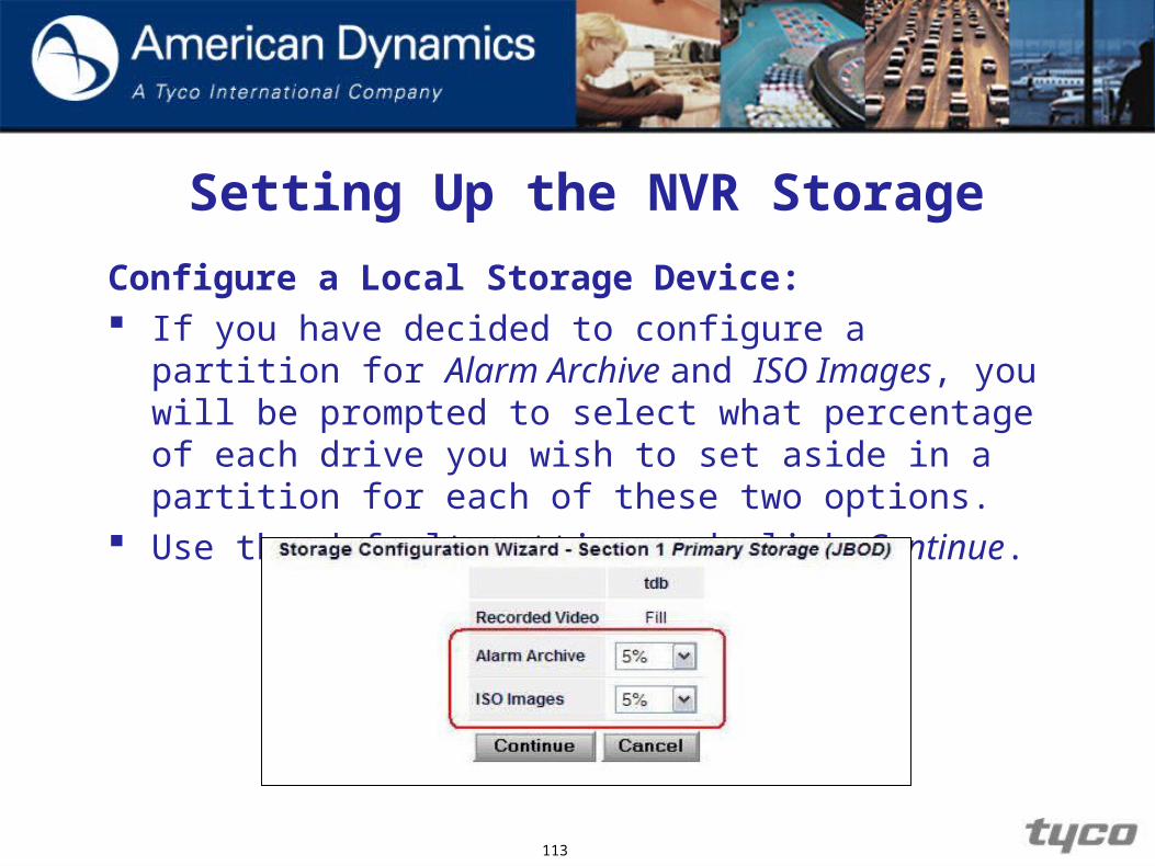
Configure a Local Storage Device: If you have decided to configure a partition for Alarm
Archive and ISO Images, you will be prompted to select what percentage of each drive you wish to set aside in a partition for each of these two options.
Use the default setting and click Continue.
113

Setting Up the NVR Storage
Configure a Local Storage Device: You will be shown a summary of your selections and
prompted to continue, as shown below.
114

Setting Up the NVR StorageConfigure a Local Storage Device: With the new configuration decided, you will be given one
last prompt, this time, left-click Continue in order to reboot the system, as shown below.
115
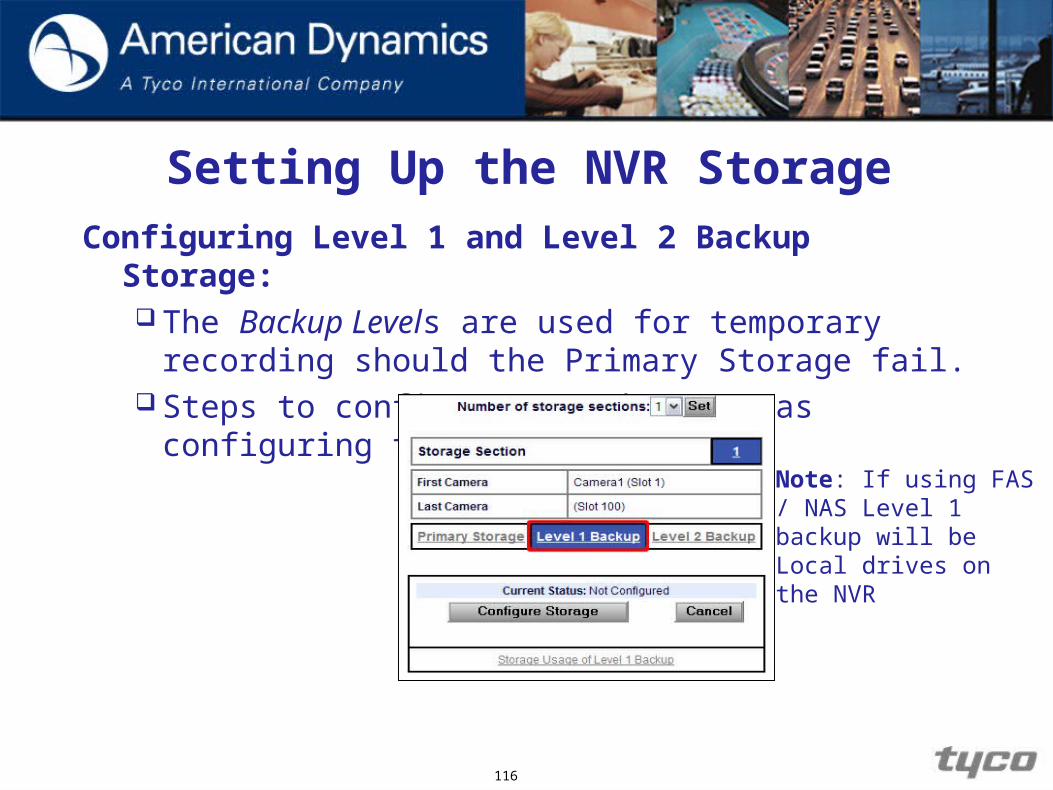
Setting Up the NVR StorageConfiguring Level 1 and Level 2 Backup Storage:
The Backup Levels are used for temporary recording should the Primary Storage fail.
Steps to configure are the same as configuring the Primary Storage
116
Note: If using FAS / NAS Level 1 backup will be Local drives on the NVR

Reviewing Storage Usage
117
Once the storage has been configured, summary information on the storage usage can be obtained by selecting the corresponding Storage Usage link at the bottom of the storage configuration pages. The summary information per storage section is available on: Recording capacity Storage used Oldest video
Video hours Storage per hour

Setting Up the NVR Storage
118
Verify Storage Devices:
Left-click on the Systems link in the upper right corner of the current webpage.
Left-click on the Devices link in the left-hand sidebar.

Setting Up the NVR Storage
Verify Storage Devices: In the main pane of the screen, a list of storage devices
detected by your system is displayed, as shown below:
119
Setting Up the NVR Storage
Verify Storage Devices:
The devices on the list may have all been detected by the system, but not necessarily configured. Ensure that the device you are looking for is present on the list. If it is not, then it is either physically disconnected or experiencing a hardware problem.
From the Devices link, you can also configure an iSCSI device.
120
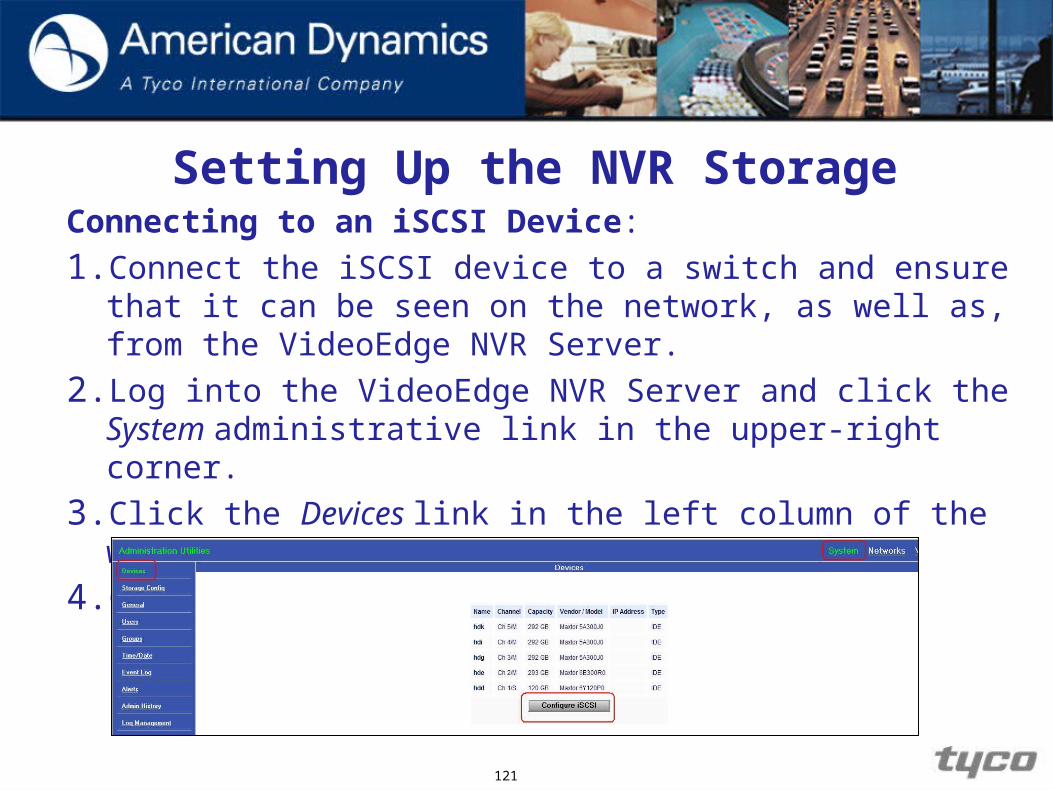
Setting Up the NVR StorageConnecting to an iSCSI Device:
1. Connect the iSCSI device to a switch and ensure that it can be seen on the network, as well as, from the VideoEdge NVR Server.
2. Log into the VideoEdge NVR Server and click the System administrative link in the upper-right corner.
3. Click the Devices link in the left column of the web page.
4. Click Configure iSCSI.
121

Setting Up the NVR Storage
Connecting to an iSCSI Device: Enable iSCSI
122

Setting Up the NVR Storage
Connecting to an iSCSI Device:
Reboot the VideoEdge NVR Server for the changes to take effect.
Log back into the VideoEdge NVR Server and navigate back to the iSCSI configuration screen via the System administrative link, and then the Devices link.
123
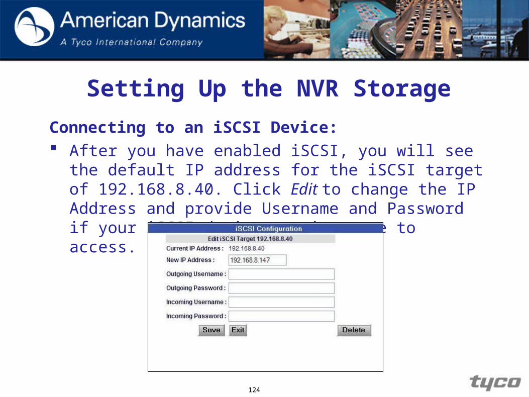
Setting Up the NVR Storage
Connecting to an iSCSI Device: After you have enabled iSCSI, you will see the default IP
address for the iSCSI target of 192.168.8.40. Click Edit to change the IP Address and provide Username and Password if your iSCSI device requires one to access.
124
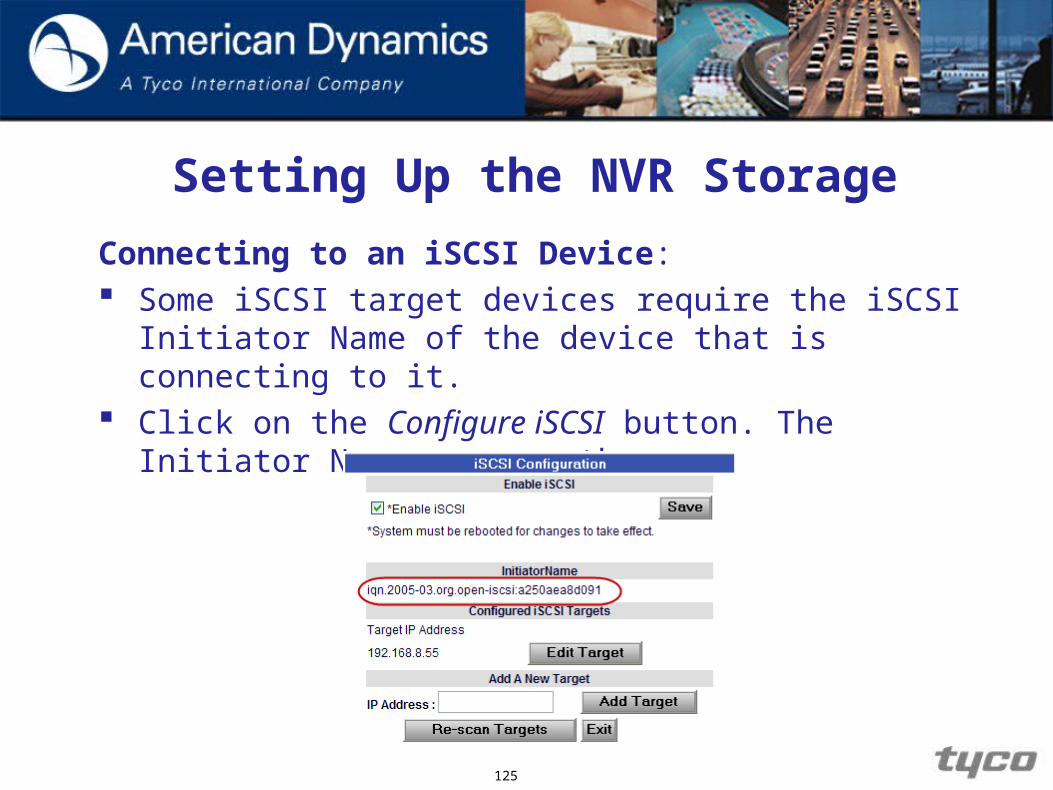
Setting Up the NVR Storage
Connecting to an iSCSI Device: Some iSCSI target devices require the iSCSI Initiator
Name of the device that is connecting to it. Click on the Configure iSCSI button. The Initiator Name
appears there.
125
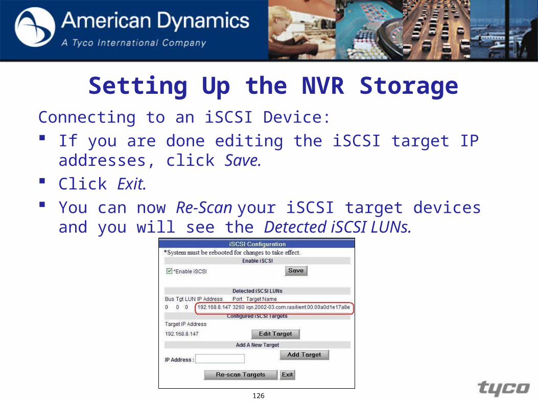
Setting Up the NVR StorageConnecting to an iSCSI Device: If you are done editing the iSCSI target IP addresses, click
Save. Click Exit. You can now Re-Scan your iSCSI target devices and you
will see the Detected iSCSI LUNs.
126

Setting Up the NVR Storage
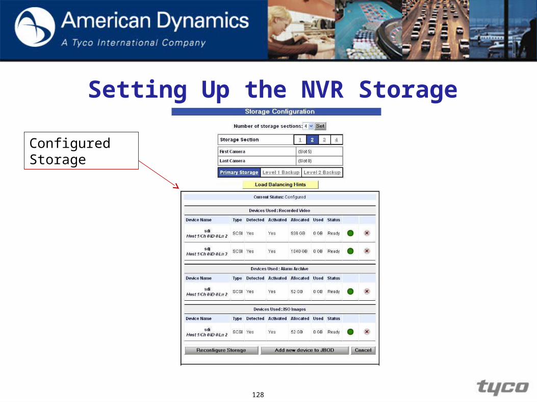
Review Storage Configuration: To review or modify storage configuration, it is not
necessary to setup the entire configuration again. Left-click on the Systems link in the upper right corner of
the current webpage. The current storage configuration settings will be displayed
in the main pane.
127
Setting Up the NVR Storage
128
Configured Storage

Setting Up the NVR Storage
Adding or Removing Storage Devices to the Existing
Configuration: The VideoEdge NVR Server gives you the ability to add or
remove storage devices from an existing storage configuration without having to reconfigure all the storage.
You can access this feature by clicking on the System link and then clicking on the Storage Config link.
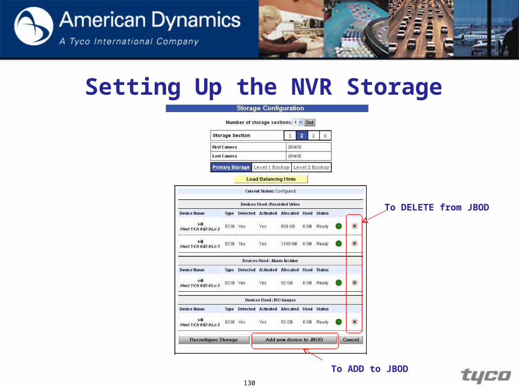
To add or remove a new storage device to the existing configuration, left-click the button labeled Add new device to JBOD or click the red “X” to remove a hard-drive to storage respectively.
129
Setting Up the NVR Storage
130
To DELETE from JBOD
To ADD to JBOD

Setting Up the NVR Storage
Adding or Removing Storage Devices to the Existing
Configuration:
If you are adding a storage device to the VideoEdge NVR Server, you will be presented with a list of the available storage devices. Continue to configure storage devices as you would when you Configure a Local Storage Device.
131

Setting Up the NVR Storage
Adding or Removing Storage Devices to the Existing
Configuration: If you are removing a storage device from the VideoEdge
NVR Server, follow the prompts to confirm the change after clicking the Red “X” to successfully remove the storage device from the system.
132

Setting Up the NVR Storage
Adding or Removing Storage Devices to the Existing
Configuration:
133
Setting Up the NVR Storage
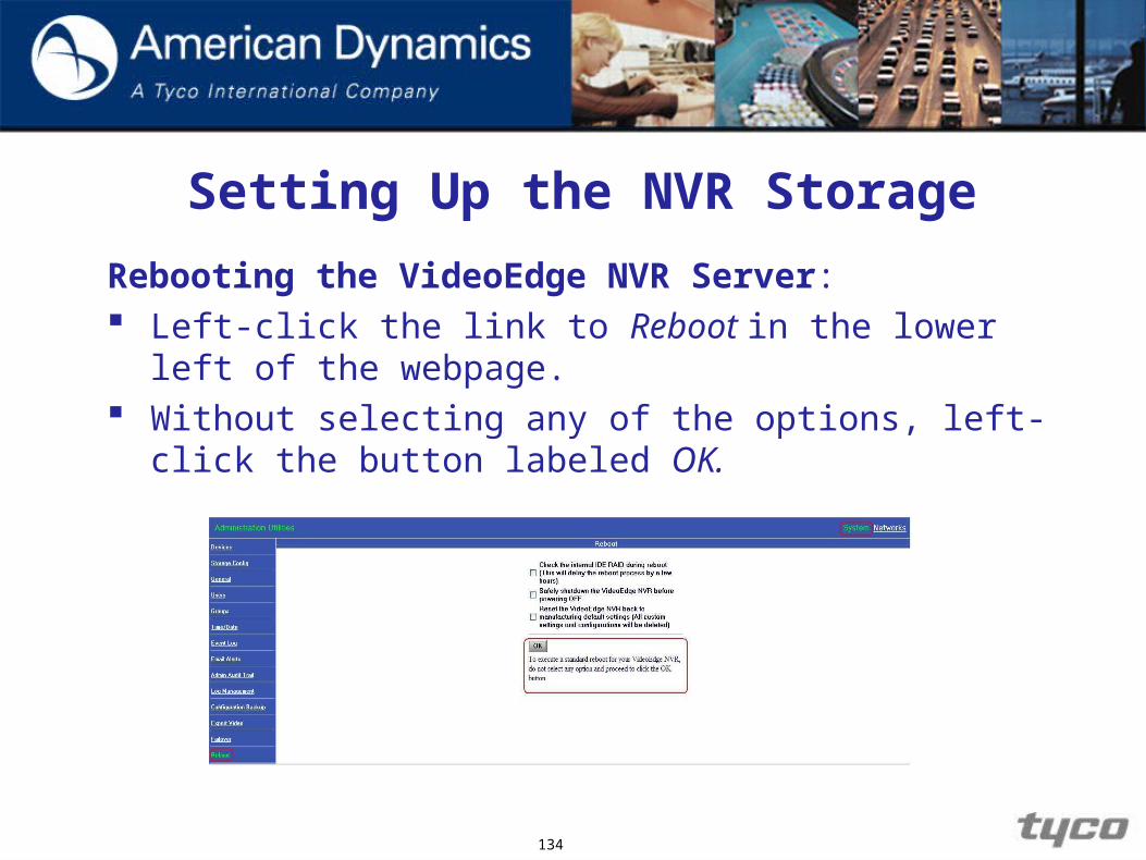
Rebooting the VideoEdge NVR Server: Left-click the link to Reboot in the lower left of the
webpage. Without selecting any of the options, left-click the button
labeled OK.
134

Setting Up the NVR Storage
Review
1. Which procedures must be executed before changes to the VideoEdge NVR Server’s storage configuration go into effect?
2. On the webpage to review storage configuration settings, what button should be left-clicked to remove a storage device from the configuration?
3. How is space on a storage device reserved for recording ISO imaging or alarm archiving data?
135
136
Overview of VideoEdge NVR Server
Introduction to Storage
Installing VideoEdgeNVR Server
Managing the MainAdministrator Password
Overview of NVRServer Controls
Setting Up theNVR Storage
Configuring andViewing Cameras
Configuring Sensors
Logs
Scheduling Recording
Alerts and EmailNotifications
Playback and Search
Creating ISO Files
Export Video
Configuration Backup,Failover & Reflash
Windows Pre-configuration
Managing Usersand Roles
Adding new camera handlers
Basic Networkingand Troubleshooting
Configuring and Viewing Cameras

Configuring and Viewing Cameras
Objectives:
1. Add a camera to the VideoEdge NVR Server.
2. Configure camera’s General, Audio, Alert, and Access settings.
3. Select a camera’s recording mode.
4. Configure PTZ for individual cameras.
5. Configure advance features for individual cameras.
6. Configure Motion Detection for individual cameras.
7. Utilize the Password Group function for cameras.
138

Configuring and Viewing Cameras
Overview Due to the “open” architecture of the VideoEdge NVR
Server, we are able to support many makes and models of cameras that use different video compression technologies and view them simultaneously. Currently, the VideoEdge NVR Server supports MJPEG, MPEG4, and H.264 video compression.
During this lesson, we will learn how to add a camera to the VideoEdge NVR Server and configure all of its settings, including features such as Motion Detection and Password Groups.
139

Configuring and Viewing Cameras
Adding an IP Enabled Camera to the VideoEdge NVR Server
Since we support three different types of video compression technologies, we will start by adding MJPEG cameras.
Adding cameras that support MPEG4 and H.264 are carried out in the same manner but the configuration settings may differ slightly and will be shown as we go through this lesson.
140

Configuring and Viewing Cameras
Adding an IP Enabled Camera to the VideoEdge NVR Server
There are 2 methods of adding cameras to the NVR:
1. Manually adding and configuring cameras
2. Using the automatic discovery of cameras
141

Configuring and Viewing Cameras
Manually adding an IP camera to the NVR
Using the manual process for adding IP cameras to the NVR will involve manual entry of the camera’s network configuration settings e.g. IP address.
Refer to the Student Guide and complete the procedures:
Manually adding an IP Camera or encoder to the VideoEdge NVR.
142

Configuring and Viewing Cameras
Once the cameras are installed there are four different recording modes and their designated colors are as follows:
Red - Camera is not recording.Green - Camera is recording continuously without
motion detection. If this mode is selected, you will not be able to receive motion alert notifications.
Yellow - Camera is recording continuously with alert detection. Use this recording mode if you wish to receive alert notifications.
Orange - Camera will begin to record only when an alert has been detected.
143

Configuring and Viewing CamerasAutomatic Discovery of Cameras
The Auto-Discovery link gives VideoEdge NVR Server the ability to add cameras to the VideoEdge NVR Server without having to manually to add them.
However, not all cameras can use this function as some manufacturers require that the cameras be pre-configured prior to being added to a network.
Refer to the Student Guide and complete the procedure for
Automatic Discovery of Cameras.
144

Configuring and Viewing Cameras
Viewing the camera list
If you need an overview of the cameras that are currently on the NVR, once cameras have been added, go to the upper right-hand of the screen and select the Browse icon. Then select the Camera List link on the left and a webpage that displays all the available cameras will appear.
Refer to the Student Guide for details on how to display the
cameras added to your NVR.
145
Configuring and Viewing Cameras
146
Configuring Camera’s General, Audio, Alert, and Access
Permission Settings Due to the video compression technology that MPEG4
uses, some options and/or features found under the General and Alert Settings for MJPEG cameras, will NOT be available for those cameras that are using MPEG4 and H.264 codec.
The configuration settings in the Student Guide are for a camera using MJPEG but configuration steps are the same for cameras using MPEG4 and H.264.
Configuring and Viewing CamerasGeneral Settings With the General Settings link you can configure the camera to
view at different frames per second, change the camera name, and many other options as well.
Alert Settings The Alert Settings link is used to change the recording and viewing
of live images based on motion detection or other event-based alerts.
For example, if you have a camera that is using the MJPEG codec, you can set the recording and the viewing of live images to 5 FPS and CIF resolution, you can change the alert settings so that when an alert comes in, the FPS and resolution increases to 30 FPS and 4CIF resolution, providing the clearest possible image of the event.
147

Configuring and Viewing Cameras
Audio Settings
The Audio Settings link allows you to configure audio settings for cameras that support audio streams.
The audio settings you can adjust include:
- enabling audio streams
- adjusting the volume
- selecting a codec
- selecting a bit rate.
148

Configuring and Viewing Cameras
Dry contacts
The Dry Contacts link is used to configure dry contact inputs that you wish to associate with a particular camera. These sensors are typically used in doorways, and are activated, for example, when a door is opened, the NVR Server can command cameras to pan-tilt-zoom to pre-determined locations and record video for a specified period.
149

Configuring and Viewing Cameras
Access Permissions Levels No Access – used for covert operations. Hides camera
from camera list in client software applications. Guard – access to PTZ cameras, view live cameras, view
full screen video and Search/Playback of recorded video. Supervisor – same as Guard and ability to view motion
detection and advanced settings and also start and stop recording.
For a full list of access permissions see Appendix A in the student manual.
150

Configuring and Viewing CamerasImport Settings: You can also import the Access Permission settings of one
camera and apply it to another camera or group. To import camera permission settings from one camera to
another, or one group to another, select the group or camera to which you wish to import settings from the View Details for Group or View Details for Camera pull down menu, respectively.
151
Configuring and Viewing Cameras
152
Configuring Advanced Features (for an Individual Camera)
With the VideoEdge NVR Server, we can access the advanced features of a camera while maintaining the same GUI, regardless of the make and model of the camera. The adjustable advance settings of an individual camera
(for instance, lens control, quality, balance, etc.) depend on the make and model of the camera, and are displayed beneath the camera viewing area on the Details webpage.
Configuring and Viewing Cameras
153
Refer to the Student Guide and complete the following
procedures within the Configuring Camera’s General, Audio,
Alert, and Access Permission Settings:
• General Settings
• Audio Settings
• Dry Contact Settings
• Alert Settings
• Camera Access Permissions
• Access Permission Levels
• Import Settings
• Configuring Advance Features for an Individual Camera

Configuring and Viewing Cameras
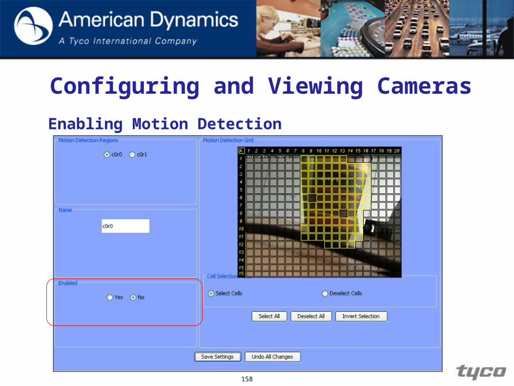
Enabling Motion Detection VideoEdge NVR Server provides server side software
based motion detection. Release 4.01 does not support camera side motion detection.
154

Configuring and Viewing Cameras
Enabling Motion Detection
The motion detection configuration page can be accessed by selecting and applying the Generate Motion Meta Data tick box.
Once enabled the Motion Alarms option becomes available
155
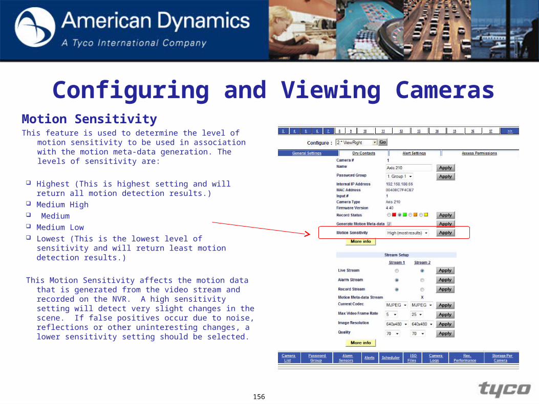
Configuring and Viewing CamerasMotion SensitivityThis feature is used to determine the level of motion
sensitivity to be used in association with the motion meta-data generation. The levels of sensitivity are:
Highest (This is highest setting and will return all motion detection results.)
Medium High Medium Medium Low Lowest (This is the lowest level of sensitivity and will
return least motion detection results.)
This Motion Sensitivity affects the motion data that is generated from the video stream and recorded on the NVR. A high sensitivity setting will detect very slight changes in the scene. If false positives occur due to noise, reflections or other uninteresting changes, a lower sensitivity setting should be selected.
156

Configuring and Viewing CamerasStream Setup
The NVR allows for up to 2 streams from each camera to be supported.
Each stream can then be configured for use as:
Live streamAlarm streamRecorded streamGenerate motion meta data
This allows for a mixture in quality of live, recoded and alarm video, e.g. you may require a high quality live video stream for the guard to view and a lower record quality to save on storage, but also to have recoded video to jump to a high quality if an alert is detected.
The More info gives suggestions of the quality settings that can be selected.
Note: Motion Meta-data cannot be collected on a H.264 stream. 157
Configuring and Viewing Cameras
158
Enabling Motion Detection
Configuring and Viewing Cameras
159
Defining Motion Detection Parameters
After enabling Motion Detection, we can begin to define what parameters will trigger an event.
Each camera can have up to two independent motion detection ranges.

Two Motion Detection Regions
160

Configuring and Viewing CamerasDefining Motion Detection Parameters: Selecting cells with
Motion Grid.
161
Configuring and Viewing Cameras
Refer to the Student Guide and complete the procedures
for Enabling Motion Detection and Defining Motion
Detection Parameters.
162
Configuring and Viewing Cameras
Using Password Groups
When adding cameras initially, the VideoEdge NVR Server must use the default Username/Password for the admin / root account assigned by the camera manufacturer.
The Password Groups feature changes the password that NVR will use to login to cameras, but does NOT change the camera’s passwords.
Note: if changing a camera’s admin password it is recommended to change it on the camera first.
163

Configuring and Viewing Cameras
164
New Password Groups
165
Overview of VideoEdge NVR Server
Introduction to Storage
Installing VideoEdgeNVR Server
Managing the MainAdministrator Password
Overview of NVRServer Controls
Setting Up theNVR Storage
Configuring andViewing Cameras
Configuring Sensors
Logs
Scheduling Recording
Alerts and EmailNotifications
Playback and Search
Creating ISO Files
Export Video
Configuration Backup,Failover & Reflash
Windows Pre-configuration
Managing Usersand Roles
Adding new camera handlers
Basic Networkingand Troubleshooting

Configuring Sensors
Configuring Sensors
Objectives
By the end of this module you will be able to:
1. Configure dry contact sensors.
167
Configuring Sensors
Overview The VideoEdge NVR Server can also use external
sensors. When an external sensor triggers an alert, the VideoEdge NVR Server will PTZ the camera in the direction from which the alert had originated. This module will cover the external sensor the VideoEdge NVR Server currently supports:
1. Dry Contact Sensor- Used primarily with access control systems. For example, a door opening would trip a dry contact.
168

Configuring Sensors Overview The sensors are connected to the alarm inputs of a
camera that is attached to the NVR, they are not connected directly to the NVR.
Refer to the Student Guide and review the sections
Configuring Alarm Sensors and Configuring a Dry Contact
Sensor.
Please ask your trainer if Dry Contacts are available for use with the cameras?
169

170
Overview of VideoEdge NVR Server
Introduction to Storage
Installing VideoEdgeNVR Server
Managing the MainAdministrator Password
Overview of NVRServer Controls
Setting Up theNVR Storage
Configuring andViewing Cameras
Configuring Sensors
Logs
Scheduling Recording
Alerts and EmailNotifications
Playback and Search
Creating ISO Files
Export Video
Configuration Backup,Failover & Reflash
Windows Pre-configuration
Managing Usersand Roles
Adding new camera handlers
Basic Networkingand Troubleshooting

Managing Users and Roles

Managing Users and Roles
Objectives
By the end of the module you will be able to: Add and remove Users. Modify user information. Add and remove Roles. Transfer Users between Roles. Configure camera permissions by Role. Describe the different access types.
172
Managing Users and Roles Different users may require access to the VideoEdge NVR
Server and may have different levels of access requirements. As an administrator, you will have the ability to create and configure users and roles and set their level of access permissions for cameras based on their user level.
The main administrator or any other user with administrator rights can grant administrative access to any user. This feature is useful for sharing the administrator’s
workload, and should be guarded carefully by those responsible for the VideoEdge NVR Server because all administrators have complete access to all features of the VideoEdge NVR Server.
173
Managing Users and Roles
Note: Both the User Name and the Password are case
sensitive, with the User Name field allowing 24 characters and the password field 15 characters. Certain non alpha numeric characters are not allowed e.g. &,(,).
174

Managing Users and Roles Administrators can assign non-administrators to roles. Each role is given access to different features of the system,
enabling administrators to control the access of non-administrators to the system.
For example, a user whose ID is bsmith might be assigned to the Guard role, with all the accesses that the other members of that role share. Another user might be assigned by an administrator to a role called Supervisor, with a higher level of access.
NOTE: Users with administrator rights cannot be placed in a
role and do not appear in any of the user roles.
175
Managing Users and Roles
Refer to the Student Guide and complete the following Role
sections: Adding / Editing / Deleting a User Creating a Role Transferring Users between Roles Deleting a Role Configuring Camera Access Permissions by Role Configuring Camera Access Permissions by Camera
176
177
Overview of VideoEdge NVR Server
Introduction to Storage
Installing VideoEdgeNVR Server
Managing the MainAdministrator Password
Overview of NVRServer Controls
Setting Up theNVR Storage
Configuring andViewing Cameras
Configuring Sensors
Logs
Scheduling Recording
Alerts and EmailNotifications
Playback and Search
Creating ISO Files
Export Video
Configuration Backup,Failover & Reflash
Windows Pre-configuration
Managing Usersand Roles
Adding new camera handlers
Basic Networkingand Troubleshooting

System logs & Scheduling

Logs & Scheduling
Objectives
By the end of this module you will be able understand the use
of the different logs and set up a recording schedule.
179

Logs
Overview:
The logs will contain such items as when Motion Detection, system changes and alerts have occurred or when the NVR was rebooted.
These logs can also be uploaded to an FTP server should that be necessary.
180
Logs
The following logs are available on the NVR:
Admin Audit Trail Alerts Log Camera Log Event Log
181
Logs
Admin Audit Trail
Tracked changes would include a reboot of the system, re-flashing the unit with upgraded firmware, setting the time and date, adding or deleting users, and so forth.
The Admin Audit Trail log cannot be deleted or modified because the system does not allow file level access
182

Logs
Alerts Log
The Alerts log provides a record of motion detection events recorded by cameras on motion detection mode (either motion-based recording or continuous recording with motion detection).
Each event entry has a link to view the video that recorded the motion event, and another link to archive the entry.
183
Logs
Camera Log
The Camera Log provides information on camera reboots, changes to camera recording status, and the use of Pan-Tilt-Zoom (PTZ) and other controls.
184

Logs
Event Log
The Event Log can be used to help troubleshoot but is primarily used by the developers and Technical Support of the product.
185
Logs
Refer to the Student Guide and complete the following
sections: Accessing the Admin Audit Log Accessing the Alerts Log Accessing the Camera Logs Accessing the Event Log Uploading the Logs to an FTP server
186
Review: Logs
1. What are the names of the two main administrative links where the various logs can be found?
2. Why might someone want to upload logs to an FTP server?
187
Scheduling Recording
Overview
The VideoEdge NVR Server not only records on a number of different bases (continuous, upon motion detection, and continuous with motion detection), it also allows scheduled recording.
With the Scheduler, a user can establish the sort of recording each camera should perform during any given hour of the day, any day of the week
188
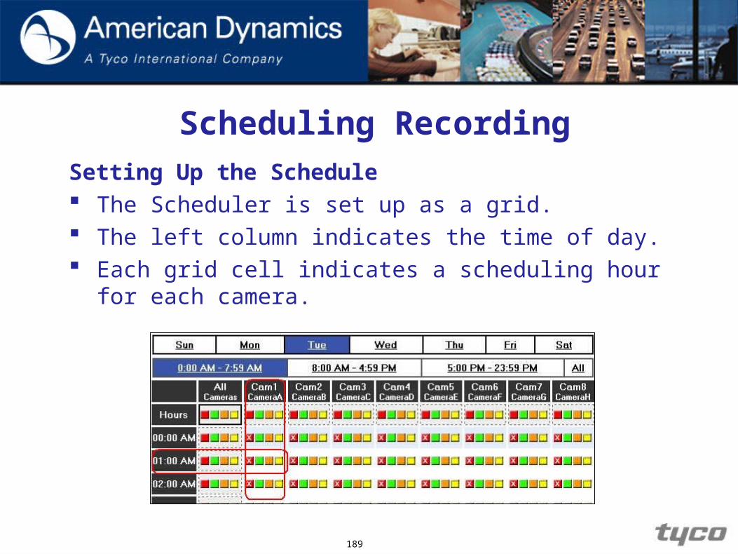
Scheduling RecordingSetting Up the Schedule The Scheduler is set up as a grid. The left column indicates the time of day. Each grid cell indicates a scheduling hour for each
camera.
189

Scheduling Recording
Setting Up the Schedule
Each Scheduler grid cell has four colored boxes that you can select from: RED - no recording. GREEN - continuous recording without motion
detection. ORANGE - alert detection based recording. YELLOW - continuous recording with alert detection.
190
Scheduling Recording
Refer to the Student Guide and complete the procedure Setting Up the Schedule to set up recording schedules for the cameras you have attached to your NVR.
191

Scheduling Recording
1. Camera 1 is enabled for motion detection, with areas of interest etc set up and the scheduler for camera 1 is marked green for one hour from 8:00 a.m. to 9:00 a.m. on Mondays, at all other times it is set to yellow. If there is motion in the areas of interest of camera 1 on Monday at 08:30, will the motion be recorded and will a motion alarm be raised by the NVR?
2. How do you schedule all cameras to record in the same way easily?
192
193
Overview of VideoEdge NVR Server
Introduction to Storage
Installing VideoEdgeNVR Server
Managing the MainAdministrator Password
Overview of NVRServer Controls
Setting Up theNVR Storage
Configuring andViewing Cameras
Configuring Sensors
Logs
Scheduling Recording
Alerts and EmailNotifications
Playback and Search
Creating ISO Files
Export Video
Configuration Backup,Failover & Reflash
Windows Pre-configuration
Managing Usersand Roles
Adding new camera handlers
Basic Networkingand Troubleshooting

Alerts and Email Notifications
Alerts and Email NotificationsObjectives
By the end of the module you will be able to:
1. Navigate to the Alerts Log.
2. Know the Alerts Log features.
3. Configure Email Notifications.
195
Alerts and Email Notifications
Overview
After configuring cameras and the VideoEdge NVR Server to receive alerts, you have to know how to manage them.
In this section you will also learn how to send email notification of alerts to different users.
196
Alerts and Email Notifications
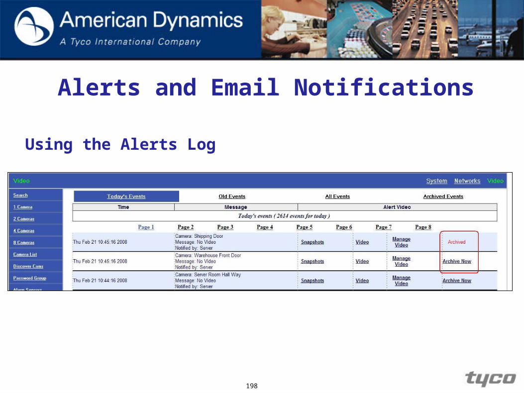
Using the Alert Log Each log entry contains buttons labeled to perform the
following functions:
Video - This feature is used to view the alert as a video.
Archive Now - This feature is used if you wish to archive the alert so that it does not get written over.
197
Alerts and Email Notifications
198
Using the Alerts Log
Alerts and Email Notifications
Using the Alerts Log
You will not be able to use this feature if the Alarm Archive has not been configured when the Primary Storage has been configured during VideoEdge NVR Server’s initial setup.
The maximum number of events that can be recorded in the log on a daily basis is 261400, due to legacy support issues. After 261400 events have been recorded in the event log during a given day, the slots in the log are gradually recycled.
199
Alerts and Email Notifications
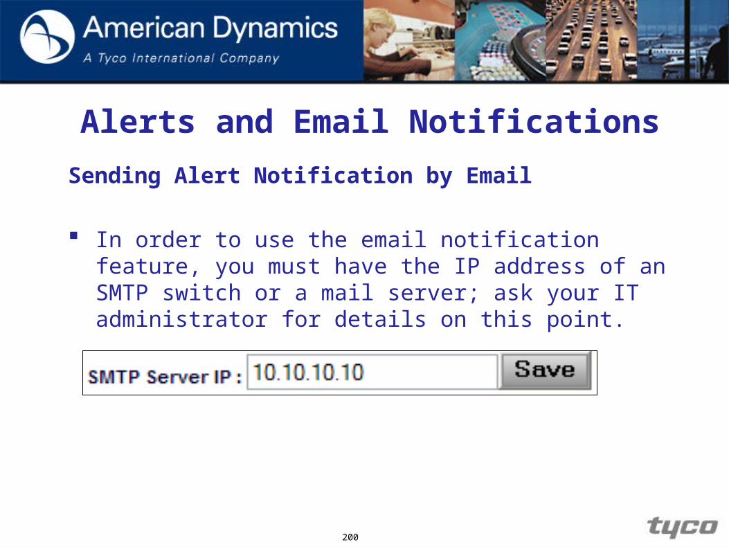
Sending Alert Notification by Email
In order to use the email notification feature, you must have the IP address of an SMTP switch or a mail server; ask your IT administrator for details on this point.
200

Alerts and Email Notifications
Sending Alert Notification by Email
You can configure the type of email notification. You can also send email alerts to a single email address or
to a recipient list.
201

Alerts and Email Notifications
Sending Alert Notification by Email
Refer to the Student Guide and complete the following sections: Using the Alert Logs Setting up Notification Building the Recipient List.
202
Alerts and Email Notifications
Review Question
1. Before we can receive email alert notifications, what must be provided?
203

204
Overview of VideoEdge NVR Server
Introduction to Storage
Installing VideoEdgeNVR Server
Managing the MainAdministrator Password
Overview of NVRServer Controls
Setting Up theNVR Storage
Configuring andViewing Cameras
Configuring Sensors
Logs
Scheduling Recording
Alerts and EmailNotifications
Playback and Search
Creating ISO Files
Export Video
Configuration Backup,Failover & Reflash
Windows Pre-configuration
Managing Usersand Roles
Adding new camera handlers
Basic Networkingand Troubleshooting

Playback and Search
Playback and Search
Objectives
By the end of the module you will be able to:
1. Demonstrate how to view video.
2. Demonstrate how to replay video.
3. Demonstrate how to search video footage for a specific time or incident.
206
Playback and Search
Overview
The ability to record and store video is only useful if it can be replayed. The ability to replay footage is enhanced by the ability to search video without sequentially viewing a lengthy segment. VideoEdge NVR Server contains controls to address these needs.
207

Playback and Search
Playback
While viewing a live video feed, the options that are available are: PTZ (on PTZ cameras) Large (on non-PTZ cameras) Details Lockout Replay
208

Playback and Search
Replaying Video
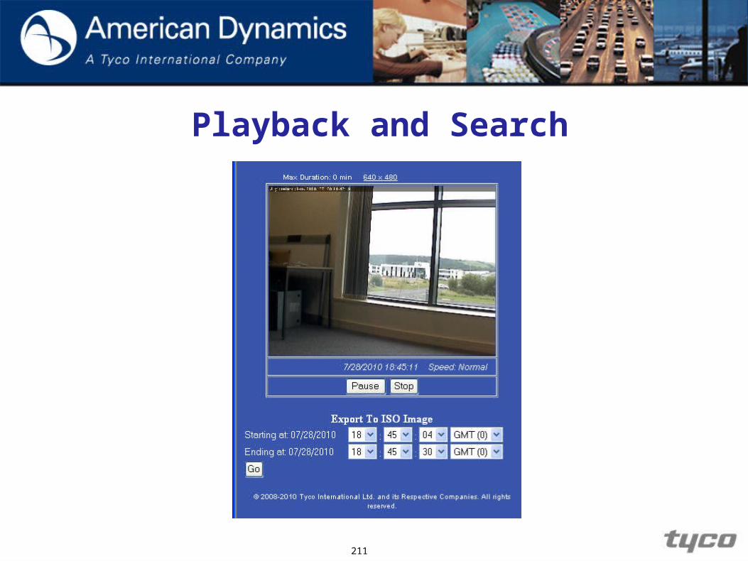
By default, the VideoEdge NVR Server will play approximately one minute of video. During Replay, you can select the options to enlarge the video (change the viewing resolution) for better viewing and create an ISO image.
209

Playback and Search
Searching for Recorded Video
The video recorded from each camera can be searched using date and time criteria.
The search results may be exported as an ISO.
210
Playback and Search
211

Playback and Search
Review the Student Guide and complete the following
sections to review and search recent recorded video:
Viewing Live Video Replaying Video Searching for Recorded Video
212

213
Overview of VideoEdge NVR Server
Introduction to Storage
Installing VideoEdgeNVR Server
Managing the MainAdministrator Password
Overview of NVRServer Controls
Setting Up theNVR Storage
Configuring andViewing Cameras
Configuring Sensors
Logs
Scheduling Recording
Alerts and EmailNotifications
Playback and Search
Creating ISO Files
Export Video
Configuration Backup,Failover & Reflash
Windows Pre-configuration
Managing Usersand Roles
Adding new camera handlers
Basic Networkingand Troubleshooting

Creating ISO Files

Creating ISO Files
Objectives
By the end of this module you will be able to:
1. Create ISO images of video footage
2. Access ISO images
215
Creating ISO Files
Overview
Creating an ISO-standard image of video footage is useful because the ISO-standard is a generic format that contains only the video footage data without any data specific to one platform or another, one codec or another, even one set of hardware or another.
Note: ISO images are NOT the same as .AVI or .MOV files,
and cannot be played in Window’s Media player or QuickTime.
216

Creating ISO Files
Creating an ISO Image
In order to have the ability to create ISO Images, the Primary Storage MUST be configured with a partition for ISO images during the initial setup of the VideoEdge NVR Server.
If the Primary Storage has not been configured for ISO Images, you will need to delete the storage configuration and reconfigure with the ISO Image partition. In doing so, you will delete any video previously recorded.
217
Creating ISO Files
Accessing ISO Images Once an ISO image has been created it can be accessed through
the ISO Files option from the Video menu.
Caution
When ISO Images are created the file containing the ISO image is assigned an alpha-numeric name created during the MD5 Checksum so that the video can be validated with the VideoEdge NVR Server from which it came. It is very important not to change the file name. Tampered ISO images will lose forensic and evidential value in courts of law.
218

Creating ISO Files
Accessing ISO Files
In order to view video from the ISO image file, you must use Vx Player or Vx Client management software or victor player.
Once the ISO file has been burned to a CD/DVD it can be played using most media players e.g. windows media player
219
Creating ISO Files
Refer to the Student Guide and complete the sections to create and access an ISO image for a section of 5 minutes of recorded video.
220

Creating ISO Files
Review
1. What must be configured during the initial setup of the VideoEdge NVR Server before you can create ISO Images?
2. What is the maximum amount of time an ISO Image can be created? Why?
3. What is needed to burn the ISO Image to CD/DVD?
4. True or False: An ISO Image can be played back using Window’s Media Player and/or Apple’s QuickTime.
5. What is the MD5 Checksum algorithm used for?
221
222
Overview of VideoEdge NVR Server
Introduction to Storage
Installing VideoEdgeNVR Server
Managing the MainAdministrator Password
Overview of NVRServer Controls
Setting Up theNVR Storage
Configuring andViewing Cameras
Configuring Sensors
Logs
Scheduling Recording
Alerts and EmailNotifications
Playback and Search
Creating ISO Files
Export Video
Configuration Backup,Failover & Reflash
Windows Pre-configuration
Managing Usersand Roles
Adding new camera handlers
Basic Networkingand Troubleshooting
Configuration Backup, Failover, and Update

Configuration Backup, Failover and Upgrading
Objectives
By the end of this module you will be able to:
1. Backup the VideoEdge NVR Server configuration.
2. Restore the VideoEdge NVR Server configuration.
3. Configure VideoEdge NVR Server for Failover mode.
4. Upgrade / update the NVR software from an image file.
224

Configuration Backup, Failover and Upgrading
Overview With the VideoEdge NVR Server, you can recover a server,
with all its users and camera information, in less than five minutes as long as you have a configuration backup.
The Configuration Backup can be saved to a flash drive and the backup can be uploaded over the network if necessary.
To give added redundancy to the VideoEdge NVR Server(s), you can configure one to act as a failover NVR that will monitor the other VideoEdge NVR Server(s).
Should one fail, the monitoring VideoEdge NVR Server will automatically begin to record from the cameras that were associated with the VideoEdge NVR Server that had failed.
225

Configuration Backup, Failover and Upgrading
Backing Up the VideoEdge NVR Server Configuration
1. After re-installing the VideoEdge NVR Server, be sure to apply the license file BEFORE continuing on. You will NOT be able to upload the configuration file until AFTER the license file has been applied.
2. Log into the VideoEdge NVR Server as the Administrator.
3. Left-click the System link in the upper-right corner of the webpage.
4. Left-click the link to the Configuration Backup page to open it as shown in the next slide.
226
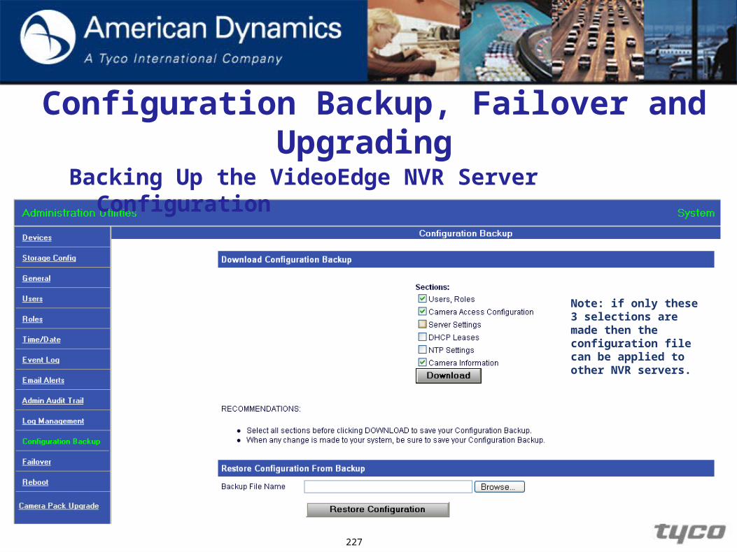
Configuration Backup, Failover and Upgrading
Backing Up the VideoEdge NVR Server Configuration
227
Note: if only these 3 selections are made then the configuration file can be applied to other NVR servers.

Configuration Backup, Failover and Upgrading
Backing Up the VideoEdge NVR Server Configuration There are several options to choose from when doing a
configuration backup. Select the options related to the configurations you want to backup: Users and Roles – backup users and groups profiles. Camera Access Configuration – backup camera access
configurations Server Settings – backup of storage configuration. DHCP Leases – backup of all leased IP addresses. NTP Settings – backup of all NTP settings. Camera Information - backup of camera information and
slots taken.
228

Configuration Backup, Failover and Upgrading
Restoring the VideoEdge NVR Server Configuration Left-click the System link. Left-click the link to the Configuration Backup.
229
Note: When a configuration backup file is being used to restore a NVR’s configuration the target NVR must have the same number of storage sections available as the NVR from which the configuration backup file was taken.
Configuration Backup, Failover and Upgrading
Configuring Failover for VideoEdge NVR Server
Along with making a Configuration Backup, you can also configure a VideoEdge NVR Server to act as a Failover NVR. When in Failover mode, the VideoEdge NVR Server can monitor the other VideoEdge NVR Server(s) over the network.
Should a VideoEdge NVR Server fail, the Failover VideoEdge NVR Server will automatically begin to record the cameras from those cameras that were previously recording to the VideoEdge NVR Server that has failed. All user and access information will have been transferred to the failover VideoEdge NVR Server as well.
230

Configuration Backup, Failover and Upgrading
Configuring Failover for VideoEdge NVR Server To Configure Failover:
231

Configuration Backup, Failover and Upgrading
Configuring Failover for VideoEdge NVR Server The VideoEdge NVR Server will automatically reboot. After the VideoEdge NVR Server reboots, return to the Failover page.
Input the IP address of the VideoEdge NVR Server(s) that you want to monitor for failover.
Use the Heartbeat Timeout parameter to determine how long the NVR will wait before it starts the failover process.
Check the box Monitor in the column at the right of the web page beside each VideoEdge NVR Server IP address you have added.
Click Save when you have completed adding the IP addresses to the VideoEdge NVR Server.
The failover VideoEdge NVR Server will now monitor the network for any other VideoEdge NVR Server(s) for failure.
232

Configuration Backup, Failover and Upgrading
Configuring Failover for VideoEdge NVR Server
233
Configuration Backup, Failover and Upgrading
Configuring Failover for VideoEdge NVR Server
In order for failover mode to work properly, all VideoEdge NVR Server(s) MUST have the same firmware.
The Failover VideoEdge NVR Server MUST be licensed and should be licensed for the maximum amount of cameras that an active VideoEdge NVR Server has.
The Failover VideoEdge NVR Server MUST have its storage configured.
The Failover VideoEdge NVR Server MUST be able to connect to BOTH the cameras and the active VideoEdge NVR Server(s) over the network.
234
Configuration Backup, Failover and Upgrading
Terminating Failover Mode
After you have fully recovered the failed VideoEdge NVR Server and are ready to put it back on the network, you will need to Terminate the failover mode for the monitor VideoEdge NVR Server so that it can continue to monitor other VideoEdge NVR Servers for failures.
CAUTION: Any video recorded while in failover mode will need to be exported or it will be lost when failover mode is terminated.
235
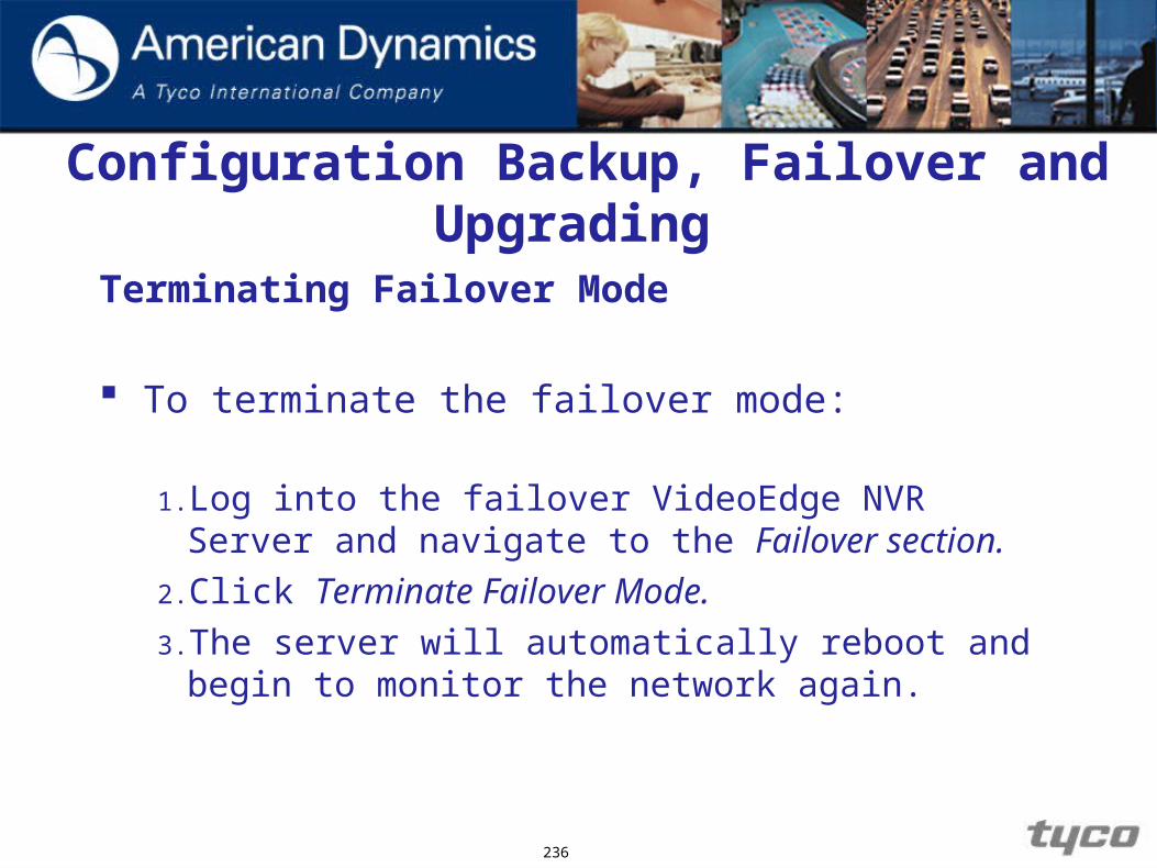
Configuration Backup, Failover and Upgrading
Terminating Failover Mode
To terminate the failover mode:
1. Log into the failover VideoEdge NVR Server and navigate to the Failover section.
2. Click Terminate Failover Mode.
3. The server will automatically reboot and begin to monitor the network again.
236

Configuration Backup, Failover and Upgrading
Terminating Failover Mode
237

Configuration Backup, Failover and Upgrading
Refer to the Student manual and complete the following procedures:
1.Practice backing up the system configuration of the VideoEdge NVR Server to your local client.
2.Practice restoring the VideoEdge NVR Server system configuration from the configuration file you saved to your local client.
3.Configure failover mode for the VideoEdge NVR Server.
4.Upgrade / Update the NVR software.
238

Configuration Backup and Failover
Review
1. Why might you need to back up your VideoEdge NVR Server configuration?
2. What must each VideoEdge NVR Server have in order for failover mode to work properly?
239

240
Overview of VideoEdge NVR Server
Introduction to Storage
Installing VideoEdgeNVR Server
Managing the MainAdministrator Password
Overview of NVRServer Controls
Setting Up theNVR Storage
Configuring andViewing Cameras
Configuring Sensors
Logs
Scheduling Recording
Alerts and EmailNotifications
Playback and Search
Creating ISO Files
Export Video
Configuration Backup,Failover & Reflash
Windows Pre-configuration
Managing Usersand Roles
Adding new camera handlers
Basic Networkingand Troubleshooting

Adding new Camera handlers
Adding new Camera Handlers
Objectives
1. Update the camera handler pack on the NVR
242

Adding new Camera Handlers
Overview
Existing camera handlers can be upgraded or new camera handler packs installed on the NVR, without the need to reload or reboot the server.
A summary of all currently installed camera handler packs can be viewed from the Camera Pack Upgrade web page.
CAUTIONRecording and dry contact processing will be stopped while a camera handler pack is
being upgraded.
243

Adding new Camera Handlers
Accessing the camera pack upgrade menu
The Cameras Pack Upgrade menu button is located at the bottom of the System screen.
244

Adding new Camera Handlers
Refer to the Student manual and complete the following procedure:
1.Upgrading the camera handler pack
245

246
Overview of VideoEdge NVR Server
Introduction to Storage
Installing VideoEdgeNVR Server
Managing the MainAdministrator Password
Overview of NVRServer Controls
Setting Up theNVR Storage
Configuring andViewing Cameras
Configuring Sensors
Logs
Scheduling Recording
Alerts and EmailNotifications
Playback and Search
Creating ISO Files
Export Video
Configuration Backup,Failover & Reflash
Windows Pre-configuration
Managing Usersand Roles
Adding new camera handlers
Basic Networkingand Troubleshooting
Basic Networking and Troubleshooting

Basic Networking and Troubleshooting
Objectives
1. Configure Windows’ network settings.
2. Assign multiple IP addresses for a client PC.
3. Perform basic network troubleshooting techniques.
248

Basic Networking and Troubleshooting
Overview
The lesson covers Windows network configuration settings and basic network troubleshooting techniques and assumes that you have the basic understanding of the fundamentals of networking.
249

Basic Networking and Troubleshooting
Configure Windows Network Settings
Before your client PC can be seen on any network by other PCs and/or networked devices, it is necessary that it has been assigned an IP address. For the purpose of this class, we will configure the TCP/IP settings for the client PC so that it can see the VideoEdge NVR Server(s) and other client PCs over the network.
First, lets verify what your Windows Network Connections are:
1. Click Start in the Windows taskbar.
2. Mouse-over My Network Places and right-click.
3. Select Properties.
250
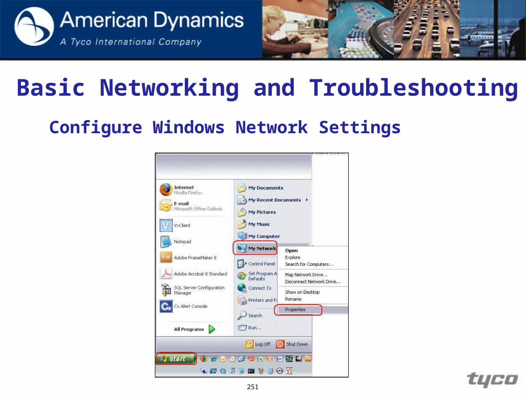
Basic Networking and Troubleshooting
Configure Windows Network Settings
251
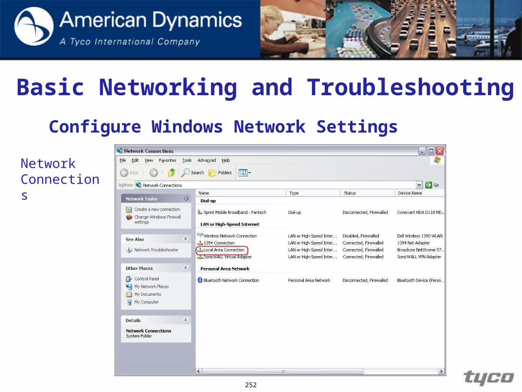
Basic Networking and Troubleshooting
Configure Windows Network Settings
252
NetworkConnections

Basic Networking and Troubleshooting
Configure Windows Network Settings
The Local Area Connection refers to the primary
Network Interface Card (NIC) that is on the client PC.
We will need to configure the settings for the connection.
1. Right-click Local Area Connection.
2. Select Properties.
253
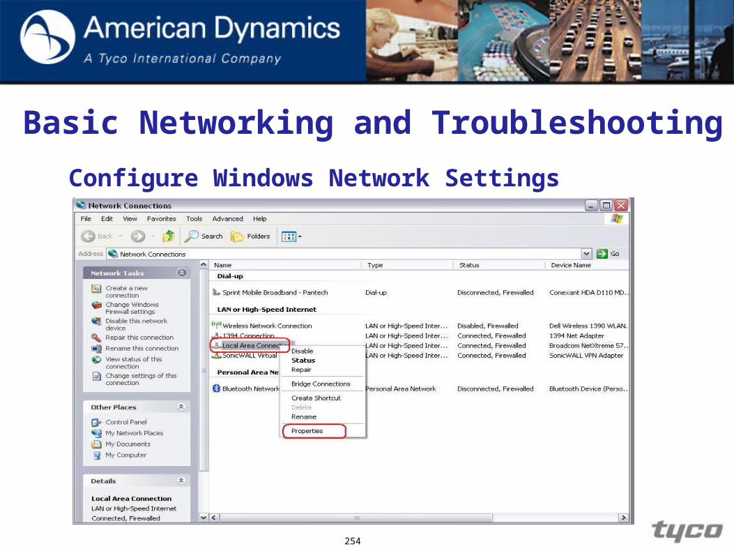
Basic Networking and Troubleshooting
Configure Windows Network Settings
254
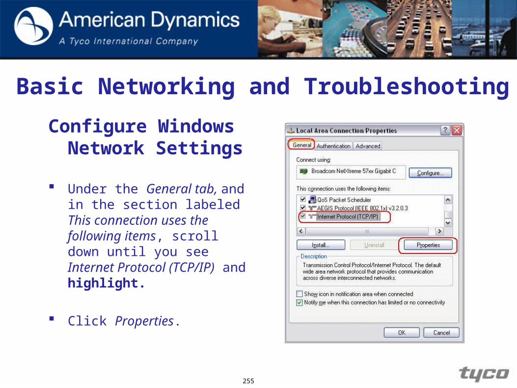
Basic Networking and Troubleshooting
Configure Windows Network Settings
Under the General tab, and in the section labeled This connection uses the following items, scroll down until you see Internet Protocol (TCP/IP) and highlight.
Click Properties.
255
Basic Networking and Troubleshooting
Configure Windows Network Settings
When the Internet Protocol (TCP/IP) Properties box appears, you are given a couple of options that you can choose from for setting up the IP address of the client PC.
Under the General tab, you have the following options:
1. Obtain IP address automatically
2. Use the following IP address
3. Obtain DNS server address automatically
4. Use the following DNS server addresses
256

Basic Networking and Troubleshooting
Configure Windows Network Settings
257

Basic Networking and Troubleshooting
Basic Network Troubleshooting Techniques
There are times when you have assigned an IP address to all of your network devices and when you try to connect to them over the network, you are unable to.
However, there are some basic network troubleshooting techniques that can be done to help resolve your connectivity issues.
258

Basic Networking and Troubleshooting
Basic Network Troubleshooting Techniques
There are several commands that we can use from a Windows DOS Command Prompt to help troubleshoot a network. From the DOS command prompt, we can use the following commands:
1. IPCONFIG /all – This command displays a client PC’s NIC configuration settings.
2. PING -This command is used to check basic network connectivity.
3. Tracert - This command is used to display the path to which a packet might take to reach its destination.
259
Basic Networking and Troubleshooting
Launching Windows DOS Command Prompt
To use the PING and Tracert commands, we will need to use the Windows DOS Command Prompt.
You can launch the Windows DOS Command Prompt by:1. Selecting Start > Run at the Desktop
2. Entering cmd at the Run prompt
260

Basic Networking and Troubleshooting
Launching Windows DOS Command Prompt
261

Basic Networking and Troubleshooting
Launching Windows DOS Command Prompt
262

Basic Networking and Troubleshooting
Using the IPCONFIG /ALL Command
263

Basic Networking and Troubleshooting
Using the IPCONFIG /ALL Command
As you can see from the above example, there are many items listed that can be helpful for troubleshooting. The main items to pay attention to are the Physical Address (the MAC address of the NIC) and the IP addresses that have been assigned for that NIC.
When adding multiple IP addresses to a workstation, you will see them all listed here as well.
264

Basic Networking and Troubleshooting
Troubleshooting with the PING and Tracert Commands
One of the most commonly used tools is the PING command. There are several things that we can check when using the PING command:
PING 127.0.0.1 - This command is a loopback testing address. The results will let us know if the NIC is properly working. Without going into the details, the loopback testing is to check the TCP/IP protocol stack.
265

Basic Networking and Troubleshooting
Troubleshooting with the PING and Tracert Commands PING
266

Basic Networking and Troubleshooting
Troubleshooting with the PING and Tracert Commands
PING the workstation’s IP address that you have assigned it. If PING is unsuccessful, verify your configured IP address settings.
PING the remote host IP address. If PING is unsuccessful, verify IP address of the remote host device. When using the PING command, it also displays how long the packet took to reach its destination. This comes in very handy when checking for network latency.
267
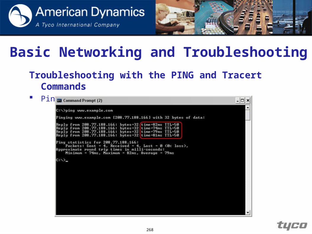
Basic Networking and Troubleshooting
Troubleshooting with the PING and Tracert Commands Ping Remote
268
Basic Networking and Troubleshooting
Troubleshooting with the PING and Tracert Commands
Another tool that can be used is the Tracert command. This command will display other network devices that are along the path from which the packet took to reach its destination.
This tool is best for locating a single point of failure on a network.
269

Basic Networking and Troubleshooting
Troubleshooting with the PING and Tracert Commands Tracert
270

Basic Networking and Troubleshooting
Troubleshooting with the PING and Tracert Commands
If you are still experiencing connectivity issues, then there are some other items you can troubleshoot:
1. Hardware connectivity
2. Software configuration
Anything associated with network that is associated with the network devices you are working with.
271

EndEnd