VICTORIA UNIVERSITY OF WELLINGTON Te Whare … · D.1 syslog-ng.conf in Security Onion ... 2.4...
83
VICTORIA UNIVERSITY OF WELLINGTON Te Whare W¯ ananga o te ¯ Upoko o te Ika a M¯ aui School of Engineering and Computer Science Te Kura M¯ atai P ¯ ukaha, P ¯ urorohiko PO Box 600 Wellington New Zealand Tel: +64 4 463 5341 Fax: +64 4 463 5045 Internet: offi[email protected] Detecting and mitigating DNS amplification attacks using SDN Ben Vidulich Supervisors: Qiang Fu, Andy Linton, Dean Pemberton, Nemir Shaker, Ewen McNeill Submitted in partial fulfilment of the requirements for Bachelor of Engineering. Abstract DNS amplification attacks have become a prevalent means of taking down websites or servers on the internet. Although there are many possible solutions to mitigate the attacks the solutions are not widely implemented and few solu- tions have the capability of operating on internet-exchange (100GBps+) levels of traffic. This report presents a new approach to mitigating the attacks that aims to succesfully operate on high-traffic networks and effectively reduce the number of attacks without the need for widespread adoption.
-
Upload
hoanghuong -
Category
Documents
-
view
218 -
download
0
Transcript of VICTORIA UNIVERSITY OF WELLINGTON Te Whare … · D.1 syslog-ng.conf in Security Onion ... 2.4...
VICTORIA UNIVERSITY OF WELLINGTONTe Whare Wananga o te Upoko o te Ika a Maui
School of Engineering and Computer ScienceTe Kura Matai Pukaha, Purorohiko
PO Box 600WellingtonNew Zealand
Tel: +64 4 463 5341Fax: +64 4 463 5045
Internet: [email protected]
Detecting and mitigating DNS
amplification attacks using SDN
Ben Vidulich
Supervisors: Qiang Fu, Andy Linton, DeanPemberton, Nemir Shaker, Ewen McNeill
Submitted in partial fulfilment of the requirements forBachelor of Engineering.
Abstract
DNS amplification attacks have become a prevalent means of taking downwebsites or servers on the internet. Although there are many possible solutionsto mitigate the attacks the solutions are not widely implemented and few solu-tions have the capability of operating on internet-exchange (100GBps+) levels oftraffic. This report presents a new approach to mitigating the attacks that aims tosuccesfully operate on high-traffic networks and effectively reduce the numberof attacks without the need for widespread adoption.


Acknowledgments
I would like to my supervisors at VUW — Qiang Fu, Andy Linton, and Dean Pemberton —for their advice and support during the project. Dean also contributed the idea that becamethe design that was used during the project.
I would also like to thank Nemir Shaker at CityLink for his support as my industrysupervisor, and Ewen McNeill and Nic Cave-Lynch for their assistance during the industryproject.
The project was inspired by the blog posts of Matthew Prince at CloudFlare.
i

ii
Contents
1 Introduction 1
1.1 Problem statement . . . . . . . . . . . . . . . . . . . . . . . . . . . . . . . . . . 11.2 Objective . . . . . . . . . . . . . . . . . . . . . . . . . . . . . . . . . . . . . . . . 21.3 Contributions . . . . . . . . . . . . . . . . . . . . . . . . . . . . . . . . . . . . . 21.4 Note . . . . . . . . . . . . . . . . . . . . . . . . . . . . . . . . . . . . . . . . . . . 31.5 Organisation of the report . . . . . . . . . . . . . . . . . . . . . . . . . . . . . . 3
2 Background and literature review 5
2.1 Components of a DNS amplification attack . . . . . . . . . . . . . . . . . . . . 52.1.1 Distributed denial of service attack . . . . . . . . . . . . . . . . . . . . . 52.1.2 Reflection attack . . . . . . . . . . . . . . . . . . . . . . . . . . . . . . . 62.1.3 Amplification attack . . . . . . . . . . . . . . . . . . . . . . . . . . . . . 6
2.2 DNS amplification attack . . . . . . . . . . . . . . . . . . . . . . . . . . . . . . . 72.3 Mitigating DNS amplification attacks . . . . . . . . . . . . . . . . . . . . . . . 9
2.3.1 Blackholing . . . . . . . . . . . . . . . . . . . . . . . . . . . . . . . . . . 92.3.2 Source Address Verification . . . . . . . . . . . . . . . . . . . . . . . . . 92.3.3 Disabling recursion on authoritative name servers . . . . . . . . . . . . 102.3.4 Limiting recursion to authorised clients . . . . . . . . . . . . . . . . . . 112.3.5 Response Rate Limiting . . . . . . . . . . . . . . . . . . . . . . . . . . . 112.3.6 Reactive DDoS defence . . . . . . . . . . . . . . . . . . . . . . . . . . . 12
2.4 Case studies . . . . . . . . . . . . . . . . . . . . . . . . . . . . . . . . . . . . . . 142.4.1 DNS amplification attack on Spamhaus . . . . . . . . . . . . . . . . . . 142.4.2 400 GBps NTP amplification attack on CloudFlare . . . . . . . . . . . . 142.4.3 DNS amplification attack on Spark New Zealand . . . . . . . . . . . . 14
2.5 What is software defined networking . . . . . . . . . . . . . . . . . . . . . . . 152.6 Summary . . . . . . . . . . . . . . . . . . . . . . . . . . . . . . . . . . . . . . . . 15
3 Design 17
3.1 Possible approaches . . . . . . . . . . . . . . . . . . . . . . . . . . . . . . . . . . 173.1.1 DNS Response Rate Limiting . . . . . . . . . . . . . . . . . . . . . . . . 173.1.2 Detect attacks using an intrusion detection system . . . . . . . . . . . . 183.1.3 Conclusion . . . . . . . . . . . . . . . . . . . . . . . . . . . . . . . . . . 18
3.2 Selected approach . . . . . . . . . . . . . . . . . . . . . . . . . . . . . . . . . . . 183.2.1 Detection . . . . . . . . . . . . . . . . . . . . . . . . . . . . . . . . . . . . 193.2.2 Mitigation . . . . . . . . . . . . . . . . . . . . . . . . . . . . . . . . . . . 19
4 Implementation 21
4.1 Ryu . . . . . . . . . . . . . . . . . . . . . . . . . . . . . . . . . . . . . . . . . . . 214.2 Morepork . . . . . . . . . . . . . . . . . . . . . . . . . . . . . . . . . . . . . . . . 21
4.2.1 Layer-two switch layer . . . . . . . . . . . . . . . . . . . . . . . . . . . . 22
iii

4.2.2 Tripwire layer . . . . . . . . . . . . . . . . . . . . . . . . . . . . . . . . . 23
4.2.3 Mirror layer . . . . . . . . . . . . . . . . . . . . . . . . . . . . . . . . . . 24
4.2.4 Firewall layer . . . . . . . . . . . . . . . . . . . . . . . . . . . . . . . . . 24
4.2.5 Main layer . . . . . . . . . . . . . . . . . . . . . . . . . . . . . . . . . . . 25
4.3 Intrusion Detection System . . . . . . . . . . . . . . . . . . . . . . . . . . . . . 25
4.3.1 Security Onion . . . . . . . . . . . . . . . . . . . . . . . . . . . . . . . . 25
4.3.2 IDS Python script . . . . . . . . . . . . . . . . . . . . . . . . . . . . . . . 26
4.4 Flow tables . . . . . . . . . . . . . . . . . . . . . . . . . . . . . . . . . . . . . . . 26
5 Evaluation 29
5.1 Introduction . . . . . . . . . . . . . . . . . . . . . . . . . . . . . . . . . . . . . . 29
5.2 Test scenarios . . . . . . . . . . . . . . . . . . . . . . . . . . . . . . . . . . . . . 30
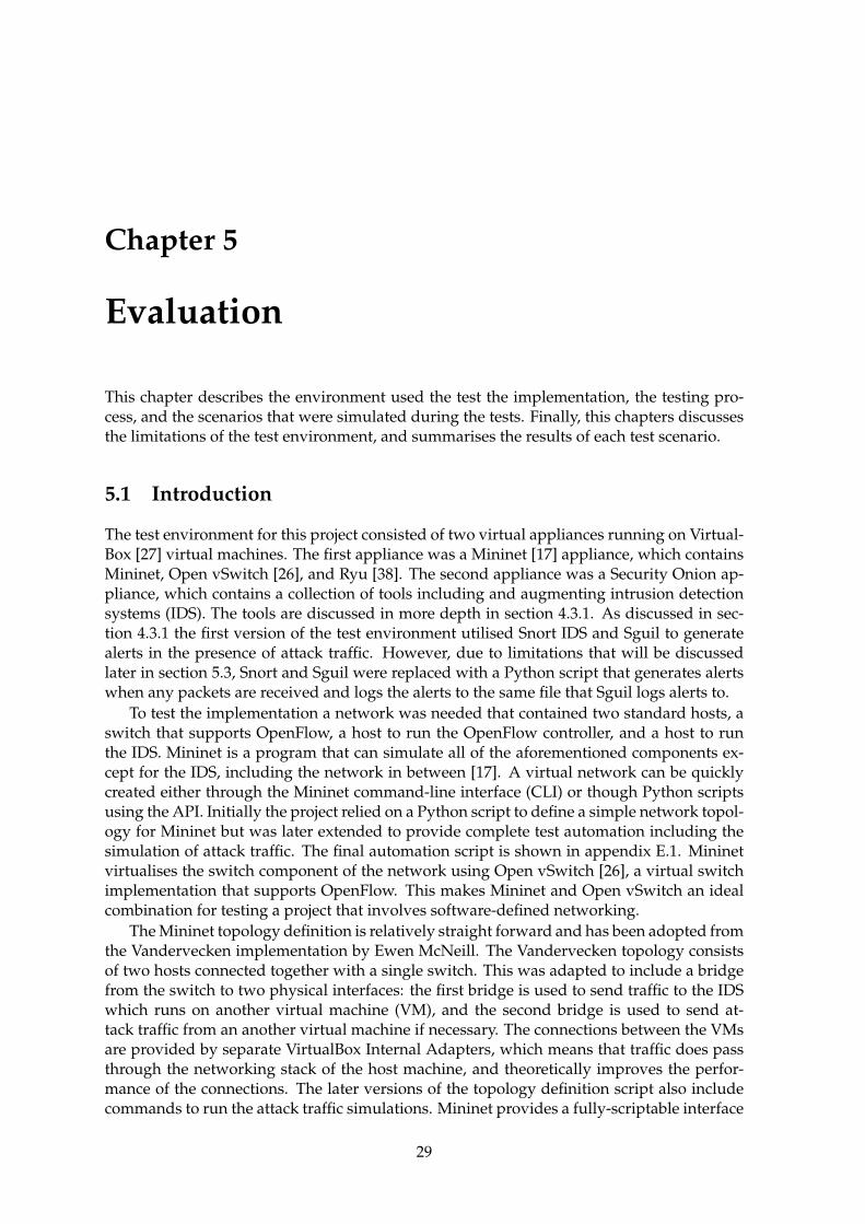
5.2.1 High bandwidth flow with attack traffic . . . . . . . . . . . . . . . . . . 31
5.2.2 High bandwidth flow with legitimate traffic . . . . . . . . . . . . . . . 31
5.2.3 Low bandwidth request traffic with high bandwidth response traffic . 33
5.3 Limitations of the test environment . . . . . . . . . . . . . . . . . . . . . . . . . 35
5.4 Summary . . . . . . . . . . . . . . . . . . . . . . . . . . . . . . . . . . . . . . . . 36
6 Conclusion and future work 37
6.1 Strengths of the implementation . . . . . . . . . . . . . . . . . . . . . . . . . . 37
6.2 Weaknesses of the implementation . . . . . . . . . . . . . . . . . . . . . . . . . 38
6.3 Future work . . . . . . . . . . . . . . . . . . . . . . . . . . . . . . . . . . . . . . 38
A Example of a large DNS response 41
B Morepork source code 43
B.1 simple monitor.py . . . . . . . . . . . . . . . . . . . . . . . . . . . . . . . . . . 43
B.2 layer tripwire.py . . . . . . . . . . . . . . . . . . . . . . . . . . . . . . . . . . . 44
B.3 layer mirror.py . . . . . . . . . . . . . . . . . . . . . . . . . . . . . . . . . . . . 46
B.4 layer firewall.py . . . . . . . . . . . . . . . . . . . . . . . . . . . . . . . . . . . . 48
B.5 main.py . . . . . . . . . . . . . . . . . . . . . . . . . . . . . . . . . . . . . . . . . 50
B.6 configloader.py . . . . . . . . . . . . . . . . . . . . . . . . . . . . . . . . . . . . 52
B.7 idsbase.py . . . . . . . . . . . . . . . . . . . . . . . . . . . . . . . . . . . . . . . 52
B.8 securityonion.py . . . . . . . . . . . . . . . . . . . . . . . . . . . . . . . . . . . 53
B.9 collector.py . . . . . . . . . . . . . . . . . . . . . . . . . . . . . . . . . . . . . . . 53
B.10 tripwire.py . . . . . . . . . . . . . . . . . . . . . . . . . . . . . . . . . . . . . . . 56
C Example flow tables 59
D IDS configuration and code 61
D.1 syslog-ng.conf in Security Onion . . . . . . . . . . . . . . . . . . . . . . . . . . 61
D.2 ids.py . . . . . . . . . . . . . . . . . . . . . . . . . . . . . . . . . . . . . . . . . . 62
E Mininet automated test scripts 63
E.1 mininet-topo.py . . . . . . . . . . . . . . . . . . . . . . . . . . . . . . . . . . . . 63
E.2 mn-run.sh . . . . . . . . . . . . . . . . . . . . . . . . . . . . . . . . . . . . . . . 66
E.3 Example output . . . . . . . . . . . . . . . . . . . . . . . . . . . . . . . . . . . . 66
iv

F Spark’s comment on their September 2014 issues 67
F.1 The DNS Issue . . . . . . . . . . . . . . . . . . . . . . . . . . . . . . . . . . . . . 68F.1.1 What happened? . . . . . . . . . . . . . . . . . . . . . . . . . . . . . . . 68F.1.2 How did they get access through the Spark Network? . . . . . . . . . . 68F.1.3 What did Spark do? . . . . . . . . . . . . . . . . . . . . . . . . . . . . . 68F.1.4 Why only Spark? . . . . . . . . . . . . . . . . . . . . . . . . . . . . . . . 69
v

vi

Figures
1.1 Visual representation of DDoS attacks recorded by Arbor Networks on Febru-ary 10 2014 [19] . . . . . . . . . . . . . . . . . . . . . . . . . . . . . . . . . . . . 2
2.1 Example of a Smurf attack [31] . . . . . . . . . . . . . . . . . . . . . . . . . . . 72.2 Anatomy of a DNS amplification attack [5] . . . . . . . . . . . . . . . . . . . . 82.3 Simple workflow of BCP 38 during a DDoS attack [30] . . . . . . . . . . . . . . 102.4 Graph displaying traffic before and after deploying DNS RRL to a root DNS
server [44] . . . . . . . . . . . . . . . . . . . . . . . . . . . . . . . . . . . . . . . 12
4.1 Layers of implementation and data flow to other components . . . . . . . . . 22
5.1 Results of simulating high-bandwidth attack flow across the implementation 315.2 Results of simulating a legitimate high-bandwidth flow across the implemen-
tation . . . . . . . . . . . . . . . . . . . . . . . . . . . . . . . . . . . . . . . . . . 325.3 Results demonstrating the port traffic being mirrored to the IDS . . . . . . . . 335.4 Network topology diagram with two switches . . . . . . . . . . . . . . . . . . 345.5 Results of simulating a DNS amplification attack with two switches . . . . . . 34
vii

viii
Chapter 1
Introduction
The internet, a tool originally created to make it easier for researchers to collaborate ontheir work, has become a prevalent part of society that has extended far beyond its originalintentions. E-commerce, social networking, gaming, blogging, and telecommunications area small number of common uses of the internet today. The original designers of the internetmade the assumption that everyone connected to the internet could be trusted, howeverthat is no longer the case. Attackers are taking advantage of this poor assumption to causechaos for innocent (and other malicious) participants of the internet.
An especially common goal of internet attackers is to force websites offline for politicalor financial reasons. Attackers use Distributed Denial of Service (DDoS) attacks to achievetheir goals. A DDoS attack can force a website offline by consuming all of the resources of thecomputers that host the website. While a victim web server is trying to process and respondto the bulk requests of the attacker it cannot do the same for the requests of legitimate users.Figure 1.1 shows how DDoS attacks are widespread, varying largely in origin, destination,bandwidth, and attack type.
1.1 Problem statement
DDoS attacks are largely possible due to poor router hygiene and server misconfiguration.Many routers do not check the source addresses of the packets they forward, allowing at-tackers to fake the origin of malicious content they send. Responses to these spoofed requestsare then delivered to an unsuspecting recipient. Servers are misconfigured to respond torequests from anyone on the internet when it is likely that they were intended to be used bya smaller number of users. It is suggested that administrators of these servers are unawareof the risks of configuring their servers to allow open access, or they do not know how tolock down the configuration on their servers. Another potential problem is with servers thatrun out-of-date versions of software: vulnerabilities in the servers are actively exploited byattackers and this can lead to more potential unwilling participants of DDoS attacks.
A solution is required that will dampen the effect of DDoS attacks while requiring min-imal change to existing internet infrastructure. It is to be assumed that server administra-tors will not fix their misconfigured servers or routers, or keep server software up-to-date.Therefore, the solution should be placed under the control of proactive administrators inkey locations across the internet. These key locations will have large amounts of regulartraffic flowing through them and the volume is likely to increase as additional uses for theinternet become available, so the solution should be highly scalable.
1
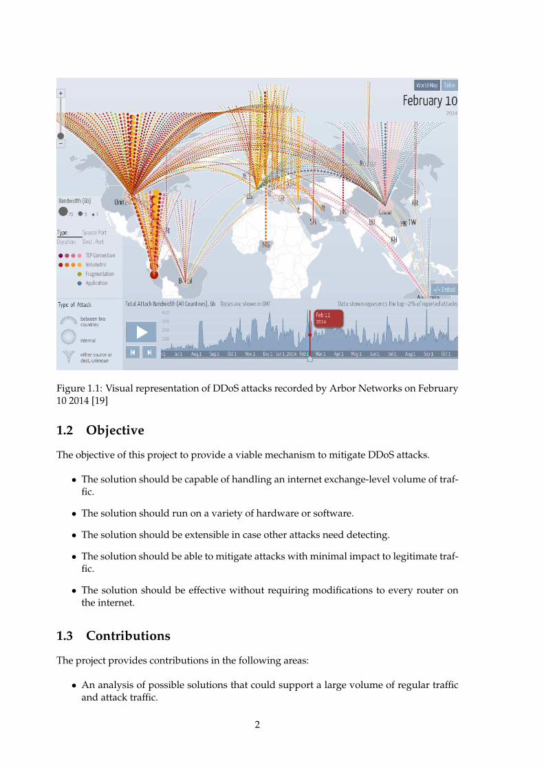
Figure 1.1: Visual representation of DDoS attacks recorded by Arbor Networks on February10 2014 [19]
1.2 Objective
The objective of this project to provide a viable mechanism to mitigate DDoS attacks.
• The solution should be capable of handling an internet exchange-level volume of traf-fic.
• The solution should run on a variety of hardware or software.
• The solution should be extensible in case other attacks need detecting.
• The solution should be able to mitigate attacks with minimal impact to legitimate traf-fic.
• The solution should be effective without requiring modifications to every router onthe internet.
1.3 Contributions
The project provides contributions in the following areas:
• An analysis of possible solutions that could support a large volume of regular trafficand attack traffic.
2
• The design and implementation of a mechanism for detecting amplification attacks.
• The design and implementation of a mechanism for mitigating amplification attacks.
• The development of a mechanism to test the effectiveness of an amplification attackdetection and mitigation system.
1.4 Note
There was a risk that the original industry-based project (titled Bringing the world’s first SDNcontrolled Internet Exchange into production) would not be completed in time due to legal andorganisational issues. To mitigate the risk a plan was established for an alternative projectthat would continue to use SDN but to solve a different problem. The risk occurred andwhat follows in this report is the outcome of the alternative project.
1.5 Organisation of the report
The rest of the report is organised as follows:
Chapter 2 describes in detail the components of a DNS amplification attack, potential ap-proaches to mitigating DNS amplification attacks, and introduces Software-DefinedNetworking (SDN). Then it explores real-world examples of amplification attacks.
Chapter 3 compares potential approaches to solving the problem and describes in depththe approach that is taken to solve the problem in this project.
Chapter 4 describes how the solution has been implemented.
Chapter 5 evaluates the effectiveness of a solution in terms of the project’s requirements.
Chapter 6 concludes the project and discusses future work that could be performed on theproject.
3

4
Chapter 2
Background and literature review
This chapter seeks to dissect and explain the components of a DNS amplification attack andinvestigate methods from industry and academia to detect and mitigate these attacks. Alsoincluded in this chapter are case studies of DNS amplification attacks occurring in the realworld.
2.1 Components of a DNS amplification attack
An attack is usually constructed of multiple fundamental components that exploit weak-nesses in a system. This section will describe the components that form a DNS amplificationattack.
2.1.1 Distributed denial of service attack
A Distributed Denial of Service (DDoS) attack can be broken into two parts: distributed anddenial of service. Fundamentally, a denial of service attack is where legitimate users’ accessto a service is impeded by the attempts of an attacker [22]. If the attacker is successful thenno legitimate access to the service is possible. A common method used by attackers to denyservice to legitimate users is to consume the resources of the service so that the resourcescannot be used to serve legitimate users.
The attacker can consume a greater amount of the service’s resources by attacking withmore resources — thus denying the service to more users. Increasing the resources in anattack is achieved by having several computers distributed across the internet [35]. A non-distributed attack can generally be mitigated by blocking the IP address of the attacker.However, this becomes difficult with a DDoS attack because there is an overwhelmingnumber of attack sources — blocking individual IP addresses of attackers becomes time-consuming, new attack sources may appear, and it may be difficult to distinguish betweenattackers and legitimate users. A common technique to overcome DDoS attacks is to black-hole the IP address(es) being targeted. Blackholing will be discussed further in section 2.3.1.
An attacker distributes a DoS attack by taking control of unsuspecting users’ computersand turning them into zombies that can be controlled remotely [35]. A network of remote-controlled zombie computers is known as a botnet (robot network) [15]. Each computer ina botnet is usually infected with some sort of malware and is then known as a zombie. Azombie can be instructed to perform a number of tasks including but not limited to sendingspam, clicking advertising, and contributing to DDoS attacks.
5
2.1.2 Reflection attack
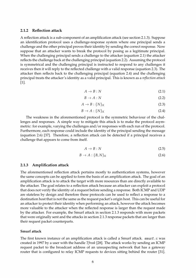
A reflection attack is a sub-component of an amplification attack (see section 2.1.3). Supposean identification protocol uses a challenge-response system where one principal sends achallenge and the other principal proves their identity by sending the correct response. Nowsuppose that an attacker wants to break the protocol by posing as a legitimate principal.When the challenging principal sends a challenge to the attacker (equation 2.1) the attackerreflects the challenge back at the challenging principal (equation 2.2). Assuming the protocolis symmetrical and the challenging principal is instructed to respond to any challenges itreceives then it will reply to the reflected challenge with a valid response (equation 2.3). Theattacker then reflects back to the challenging principal (equation 2.4) and the challengingprincipal treats the attacker’s identity as a valid principal. This is known as a reflection attack[1].
A → B : N (2.1)
B → A : N (2.2)
A → B : {N}K (2.3)
B → A : {N}K (2.4)
The weakness in the aforementioned protocol is the symmetric behaviour of the chal-lenges and responses. A simple way to mitigate this attack is to make the protocol asym-metric: for example, varying the challenges and/or responses with each run of the protocol.Furthermore, each response could include the identity of the principal sending the message(equation 2.6) [37]. Therefore, a reflection attack can be detected if a principal receives achallenge that appears to come from itself.
A → B : N (2.5)
B → A : {B, N}K (2.6)
2.1.3 Amplification attack
The aforementioned reflection attack pertains mostly to authentication systems, howeverthe same concepts can be applied to form the basis of an amplification attack. The goal of anamplification attack is to attack the target with more resources than are directly available tothe attacker. The goal relates to a reflection attack because an attacker can exploit a protocolthat does not verify the identity of a request before sending a response. Both ICMP and UDPare stateless by design and therefore these protocols can be used to reflect a response to adestination host that is not the same as the request packet’s origin host. This can be useful foran attacker to protect their identity when performing an attack, however the attack becomesmore valuable to the attacker when the reflected response is larger than the request madeby the attacker. For example, the Smurf attack in section 2.1.3 responds with more packetsthat were originally sent and the attacks in section 2.1.3 response packets that are larger thantheir request packet counterparts.
Smurf attack
The first known instance of an amplification attack is called a Smurf attack. smurf.c wascreated in 1997 by a user with the handle Tfreak [28]. The attack works by sending an ICMPrequest packet to the broadcast address of an unsuspecting network that has a gatewayrouter that is configured to relay ICMP requests to devices sitting behind the router [31].
6

Figure 2.1: Example of a Smurf attack [31]
The source address of the ICMP request packets is spoofed to match the IP address of thetarget host. When the unsuspecting hosts send their ICMP replies they are directed at thetarget host. The amplification factor of a Smurf attack depends on the number of hosts thatreceive the ICMP request sent to the broadcast address. For example, in figure 2.1 thereare five hosts behind the poorly-configured router which means the amplification factor is 5times.
Smurf attacks are easily mitigated by configuring routers not to forward ICMP requeststo the broadcast address of a network [31]. Alternatively, individual hosts could be config-ured to ignore ICMP requests but this may prevent purposeful network diagnostics.
UDP-based amplification attacks
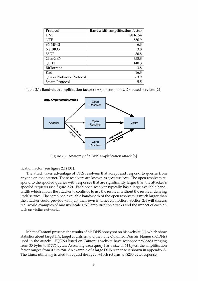
Tfreak is also known to have created the first UDP-based amplification attack, called Frag-gle after its file name fraggle.c [28]. Like ICMP, UDP has no handshaking mechanism andno other way to verify the source IP address of a packet. Therefore, weaknesses in publicly-accessible servers that use the UDP protocol can be used to launch amplification attacks [24].Instead of relying on the number of response packets to generate an amplification factor, anattacker can send a small UDP request packet that generates a much larger UDP responsepacket. Figure 2.1 shows several common services that operate over UDP and their associ-ated Bandwidth Amplification Factor (BAF). BAF, as shown in equation 2.7, measures thesize of the response payload compared to the request payload. Figure 2.1 lists CharGENas the protocol with the highest bandwidth amplification factor. CharGEN is a mostly un-used [2] protocol that generates a stream of assorted characters over a network socket. OverUDP the response payload size can be up to 512 bytes depending on the size specified in therequest.
B.A.F. =payload size(response)
payload size(request)(2.7)
2.2 DNS amplification attack
DNS amplification attacks are a prime attack vector for attackers: they support queries overUDP - allowing the source address to be spoofed - and they have a high bandwidth ampli-
7
Protocol Bandwidth amplification factor
DNS 28 to 54
NTP 556.9
SNMPv2 6.3
NetBIOS 3.8
SSDP 30.8
CharGEN 358.8
QOTD 140.3
BitTorrent 3.8
Kad 16.3
Quake Network Protocol 63.9
Steam Protocol 5.5
Table 2.1: Bandwidth amplification factor (BAF) of common UDP-based services [24]
Figure 2.2: Anatomy of a DNS amplification attack [5]
fication factor (see figure 2.1) [31].
The attack takes advantage of DNS resolvers that accept and respond to queries fromanyone on the internet. These resolvers are known as open resolvers. The open resolvers re-spond to the spoofed queries with responses that are significantly larger than the attacker’sspoofed requests (see figure 2.2). Each open resolver typically has a large available band-width which allows the attacker to continue to use the resolver without the resolver denyingitself service. The combined available bandwidth of the open resolvers is much larger thanthe attacker could provide with just their own internet connection. Section 2.4 will discussreal-world examples of massive-scale DNS amplification attacks and the impact of each at-tack on victim networks.
Matteo Cantoni presents the results of his DNS honeypot on his website [4], which showstatistics about target IPs, target countries, and the Fully Qualified Domain Names (FQDNs)used in the attacks. FQDNs listed on Cantoni’s website have response payloads rangingfrom 35 bytes to 37776 bytes. Assuming each query has a size of 64 bytes, the amplificationfactor ranges from 0.5 to 590. An example of a large DNS response is shown in appendix A.The Linux utility dig is used to request doc.gov, which returns an 8230 byte response.
8
2.3 Mitigating DNS amplification attacks
There have been various attempts to mitigate DNS amplification attacks - some attempts aretemporary measures to withstand specific attacks, while other attempts try to permanentlymitigate attacks. This section will cover some of the common techniques for mitigating theseattacks.
2.3.1 Blackholing
The act of blackholing is to instruct a router to drop incoming traffic before it reaches thedestination network [18] [34]. This approach allows temporary relief from an incomingDDoS attack by preventing attack traffic from reaching critical components on a network. Amore specific definition of a blackhole is a configuration where incoming IP packets destinedfor a specific host or network are forwarded to a null queue (thus dropping the packets). Thedisadvantage of this technique is that all incoming traffic is dropped, including traffic fromlegitimate users. If the attacker’s target has multiple redundant networks then the targetcould null route (blackhole) incoming attack traffic on one network and direct legitimatetraffic to a different site or network.
2.3.2 Source Address Verification
Since all amplification attacks (and many DDoS attacks in general) depend on the ability tospoof the source IP address of a packet, there have been attempts to prevent attackers fromusing this ability such as BCP 38 [9]. BCP 38 filters incoming packets by verifying that itis possible to reach the network of the packet’s source IP address through the interface onwhich the packet was received [23]. For example, a router on the edge of an ISP’s networkchecks the source IP address of any incoming packets. If the source IP address of the packetmatches a network prefix that is known and known to originate from that interface then thepackets are allowed to enter the ISP’s network. Figure 2.3 demonstrates the actions of BCP38 during a DDoS attack: forged packets from the attacker’s network are dropped whilepackets legitimate packets from the attacker’s network are allowed into the ISP’s network.
A criticism of Source Address Validation (SAV) is that network operators must all imple-ment SAV for the technique to be effective [43]. Enabling SAV on all networks would be anexpensive exercise and given the number of network operators and devices connected to theinternet it would be difficult to ensure every device supports and enables SAV. MandatingSAV would be difficult, if not impossible, because there is no way to determine from theoutside whether SAV is active and there is no business case for a network operator to havean audit performed internally.
Furthermore, Vixie writes that SAV would not directly solve the problem that causesDDoS attacks. The SAV technique assumes that forged packets have a source IP addressthat is invalid in context (for example, a RFC 1918 address) or the router receiving the packetwould normally use a different interface to sent packets to that source IP address. However,the target IP address of a DDoS attack might appear to be valid if the unsuspecting routeruses that same interface or routing path to send packets to the target IP address. For ex-ample, an attack being bounced through New Zealand to and from other countries may beundetected by SAV due to the limited number of paths a packet can take to enter or leaveNew Zealand.
9

Figure 2.3: Simple workflow of BCP 38 during a DDoS attack [30]
Ingress filtering has been suggested by authors of many academic papers [6] [13] andhas become a best current practice (BCP 38 [9]) for the internet community. As mentionedin section 2.3.2, routers compare the source addresses of incoming packets against their for-warding tables to ensure the packets come from known prefixes and are allowed to be re-ceived on that interface. For example, a router may be configured to only allow packets fromx.x.y.y/zz on its ingress link. The router would check the source address of incoming pack-ets and if the source address does not match the prefix x.x.y.y/zz then the source address isdeemed invalid and the packet is dropped. Kong et al. [13] argue that a router must knowwhich prefixes are allowed to send traffic to the router’s incoming interface. This may bethe case when the router is used to peer with another network, thus access to the networkis provided to a limited number of hosts, but if the router is used for upstream transit thenincoming packets could effectively come from any other host on the internet. Therefore, thistechnique is more effective if all routers on the internet implement ingress filtering since thefiltering is performing at the source — before the potentially spoofed packets reach the restof the internet.
2.3.3 Disabling recursion on authoritative name servers
Most authoritative name servers are intentionally made internet-accessible so that the do-main names for which these name server have authority can be queried by public internetusers. Since most DNS server applications can perform both authoritative functions andrecursive functions it is possible that an authoritative name server unintentionally providesrecursive functionality to anyone who queries the DNS server, including public internetusers. This kind of DNS server is called an open resolver and is described in more depth insection 2.2.
10
The recommended action to prevent an authoritative name server from being used asan open resolver is to disable the recursive functionality on the name server [23] [41]. Themost common use of an authoritative name server is in a public internet environment wherethere is no need for recursion to be enabled. On the other hand, authoritative name serversin a private network environment may need to use both functions at once. For example,in a Split DNS configuration [7] the internal name server might be configured to resolvedomain names to RFC 1918 [36] addresses and provide recursive functionality to hosts inthe network, while the external name server might be configured to resolve domain namesto public IP addresses. In this example it would be acceptable to allow recursion on theinternal authoritative name server but the external authoritative name server should haverecursion disabled to prevent the name server from being used in a DDoS attack.
2.3.4 Limiting recursion to authorised clients
Instead of completely disabling recursion (as in section 2.3.3), DNS servers can be configuredto allow queries from certain blocks of IP addresses [23] [5]. For example, an ISP may wish toonly recursively resolve queries from their own customers. However, even a DNS resolverthat is limited customers can be susceptible to DDoS attacks as explained in section 2.4.3.
2.3.5 Response Rate Limiting
A relatively new approach to mitigating DDoS attacks is a methodology called DNS Re-sponse Rate Limiting (DNS RRL) [42]. The methodology is based on the idea that a cachingresolver should not need to request a resource record (RR) more often than the time-to-live (TTL) of the RR. In other words, the resolver counts number of times queries are re-ceived from a given source address for a specific RR within a given time frame. If a counterreaches a certain threshold within the specified time frame then subsequent requests fromthat source address for that RR are not replied to. Spoofed packets will all have the samesource address and will most likely be requesting the same RR too. Replies to these requestswill quickly become limited. It is highly unlikely that a legitimate user would request thesame RR within the given time frame, due to caching, and therefore it is unlikely that a le-gitimate user would be affected by the rate limiting. However, if a legitimate user’s queriesare dropped due to rate limiting then the user can try again over TCP, since TCP requestsare harder to spoof, or send their request to a different resolver.
Figure 2.4 shows the incoming and outgoing traffic to a DNS root zone server before andafter DNS RRL was implemented on the server. Prior to the implementation of DNS RRL theamplification effect is clearly demonstrated. After the attacker gives up, it becomes clear thatthe attacker’s traffic composed most of the input traffic to the server but did not compose alarge portion of the output traffic. This suggests the attack became highly ineffective afterDNS RRL was implemented.
Vixie provides an economic viewpoint in [43] when he describes a DDoS attack: an at-tacker seeks to minimise their cost while maximising their utility. This means that an at-tacker will try to reduce the amount of traffic they need to send themselves to cause thegreatest impact to their target. By design, DNS RRL limits the number of responses it sendsin a given time frame. This means that an attacker that is reflecting traffic through a serverthat has implemented DNS RRL will send less traffic at the target than the attacker wouldby directly sending traffic at the target. This attenuating effect in theory should discoursethe attacker from using the hardened resolver in their attack. If enough resolvers implement
11
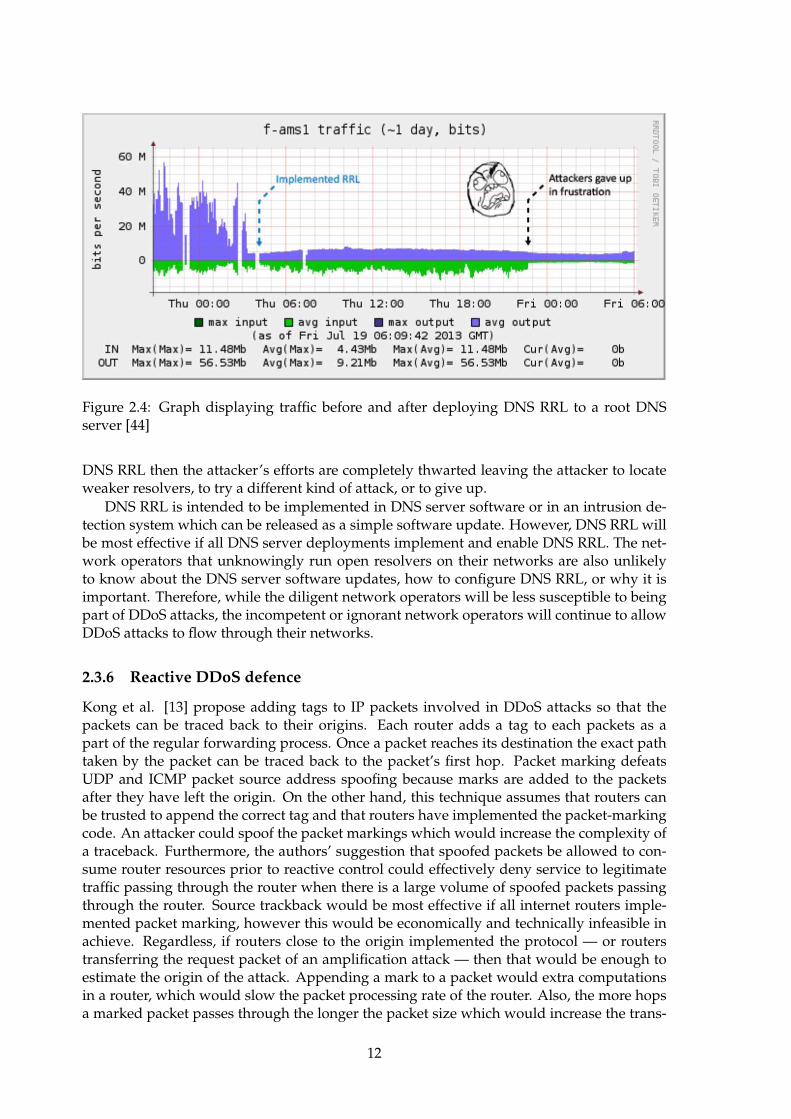
Figure 2.4: Graph displaying traffic before and after deploying DNS RRL to a root DNSserver [44]
DNS RRL then the attacker’s efforts are completely thwarted leaving the attacker to locateweaker resolvers, to try a different kind of attack, or to give up.
DNS RRL is intended to be implemented in DNS server software or in an intrusion de-tection system which can be released as a simple software update. However, DNS RRL willbe most effective if all DNS server deployments implement and enable DNS RRL. The net-work operators that unknowingly run open resolvers on their networks are also unlikelyto know about the DNS server software updates, how to configure DNS RRL, or why it isimportant. Therefore, while the diligent network operators will be less susceptible to beingpart of DDoS attacks, the incompetent or ignorant network operators will continue to allowDDoS attacks to flow through their networks.
2.3.6 Reactive DDoS defence
Kong et al. [13] propose adding tags to IP packets involved in DDoS attacks so that thepackets can be traced back to their origins. Each router adds a tag to each packets as apart of the regular forwarding process. Once a packet reaches its destination the exact pathtaken by the packet can be traced back to the packet’s first hop. Packet marking defeatsUDP and ICMP packet source address spoofing because marks are added to the packetsafter they have left the origin. On the other hand, this technique assumes that routers canbe trusted to append the correct tag and that routers have implemented the packet-markingcode. An attacker could spoof the packet markings which would increase the complexity ofa traceback. Furthermore, the authors’ suggestion that spoofed packets be allowed to con-sume router resources prior to reactive control could effectively deny service to legitimatetraffic passing through the router when there is a large volume of spoofed packets passingthrough the router. Source trackback would be most effective if all internet routers imple-mented packet marking, however this would be economically and technically infeasible inachieve. Regardless, if routers close to the origin implemented the protocol — or routerstransferring the request packet of an amplification attack — then that would be enough toestimate the origin of the attack. Appending a mark to a packet would extra computationsin a router, which would slow the packet processing rate of the router. Also, the more hopsa marked packet passes through the longer the packet size which would increase the trans-
12
mission delay between hops and require packet segmentation if the mark field dynamicallyexpanded.
Attack traffic could be throttled instead of filtered, according to Mahajan et al. [14].When a router detects a spike in traffic it can ask its upstream router to throttle the trafficbeing sent to it. The spike in traffic is detected by measuring the loss rate of a link andwhen a significant loss is sustained for a certain length of time then a spike in traffic is saidto have occurred. Mahajan et al. suggest historical loss rate values as a baseline to distin-guish between regular and irregular amounts of congestion. Kong et al. [13] criticise thisapproach, suggesting that this mechanism may be ineffective against an aggressive attackwith multiple attack flows. This would make the mechanism ineffective to operate on arouter that is situated near to the target of a distributed attack. The pushback mechanismis described to ask upstream neighbours that are sending presumed attack traffic to throttlethe amount of traffic being sent to this router. This approach would be effective assumingacknowledgements do not get lost on the congested link and the upstream router also sup-ports the pushback protocol. Mahajan et al. describe the pushback mechanism as optional,however pushback would be extremely useful for routers near an attack target. There is alsoa traffic throttling element for the router under attack. This element functions very similarlyto common Quality of Service (QoS) implementations but with a dynamic approach: attacktraffic traffic is directed onto a virtual queue that, like a normal queue, drops packets whenthe queue is full. The advantage of this approach is that the virtual queue fills before thenormal queues and therefore only attack traffic is dropped, however the implementation ofthe virtual queue will require extra memory and more computations along the forwardingpath.
Sun et al. [39] focus on an efficient method to distinguish between and filter legitimateDNS traffic and attack DNS traffic. Their detection scheme focuses on the traffic ingressand egress to an ISP: any incoming or outgoing DNS request should have a correspondingresponse in the other direction. If there is a significant imbalance of incoming and outgoingDNS packets then an attack is most likely occurring. To distinguish between DNS requestsand responses Sun et al. focus on UDP traffic with either a source or destination port of53. A request packet will have a destination port of 53 and a response packet will have asource port of 53. The DNS response flag is also set to 1 for a response packet. The numberof requests and responses passing through the router is compared and the value is passedthrough a low-pass filter for smoothing. If the output of the filter is greater than zero thenan attack is present. Once the presence of a DNS amplification attack has been detected Sunet al. pass DNS response traffic through their two-bloom filter. The filter scheme worksby storing a 4-tuple (source IP, destination IP, source port, DNS transaction ID) in one ofthe two bloom filters. All DNS requests collected in the first time interval are stored in thefirst bloom filter and all DNS requests collected in the second time interval are stored inthe second bloom filter. The bloom filters are flushed in an alternating pattern at the endof a time interval so that DNS requests for at least the last time interval and at most thelast two time intervals are stored. When an incoming DNS response is received its 4-tuple islooked up in both of the bloom filters. If a matching 4-tuple was found in a bloom filter thenthere is a high probability that the response is legitimate. Bloom filters have the possibilityof returning false positives and therefore there is a small chance that attack traffic will betreated as legitimate traffic, however a majority of the attack traffic will be filtered. Sunet al. demonstrate the effectiveness of their solution on a link with a rate of 39.8 GBps,which would allow the solution to implemented by medium-sized transit providers withlittle demand for memory and little CPU overhead. This solution is DNS specific making itdifficult to expand to other UDP-based attacks, however it could be a highly preventativemechanism without needing every router on the internet to implement the solution.
13
2.4 Case studies
This section describes examples of real-world attacks with large attack vectors or with largeimplications.
2.4.1 DNS amplification attack on Spamhaus
In the first quarter of 2013 not-for-profit anti-spam organisation Spamhaus was knocked of-fline by a DNS amplification attack that peaked at over 100 GBps of amplification traffic.Mimososo writes in Threatpost [16] that users of the Dutch webhost Cyberbunker were un-happy to be flagged as spam and they retaliated with this attack, which brought down theSpamhaus website. This attack matches all the common characteristics of a DNS amplifica-tion attack: many open resolvers (over 30,000 resolvers recorded during the attack), spoofedDNS query packets (36 bytes in length), and massively amplified DNS response packets(3,008 bytes in length; 100x amplification factor) [33].
2.4.2 400 GBps NTP amplification attack on CloudFlare
CloudFlare was also subject to an attack of similar volume in February, however this at-tack reached nearly 400 GBps of attack traffic. This attack exploited a misconfiguration inNTP servers, however NTP amplification attacks operate in basically the same way as anyother UDP-based amplification attack: source address is spoofed and response packet islarger than the request packet. Prince notes in his blog post [32] that open NTP servers areless common than open DNS resolvers, however NTP servers tend to be more powerfulmachines with higher available bandwidths, and NTP responses can be much larger thanDNS responses which increases the amplification factor per response. Therefore, fewer NTPservers are needed to cause the equivalent amount of damage as a DNS amplification at-tack. The advantage for an attacker to require fewer servers to perform the attack is fewermachines are needed to send the spoofed requests. Prince suggests the attacker could haveused a single server to send spoofed requests to the 4,529 NTP servers involved in the 400GBps attack.
NTP amplification attacks are possible due to a specific command that can be issuedagainst an NTP server called MON GETLIST [20] [10]. The command is used to get a list ofmachines that have interacted with the NTP server. The maximum list size is 600 entries,which is transmitted as a 48 kB response. This equates to an amplification factor of 206 times.Server administrators can prevent their NTP servers from participating in NTP amplificationattacks by disabling the MON GETLIST command on their NTP servers or by limiting the IPaddresses that may execute the command. Prince argues that the command serves littlepurpose and therefore there is no need for the command to be enable at all [32].
2.4.3 DNS amplification attack on Spark New Zealand
Internet service provider Spark experienced an outage to their DNS infrastructure in Septem-ber 2014 when the infrastructure came under attack by their customers’ devices. Sparkclaimed [12] the attack was targeted at servers in Europe, however the attack overwhelmedSpark’s DNS servers instead. While Spark did not appear to be certain of what caused theattack their infrastructure the two most likely hypotheses were that their customers wereaffected by malware — based on the presence and behaviour of malware in other parts ofthe world at that time — and open DNS resolvers on some of their customer’s modems.
Although Spark do not describe the exact cause of the attack (see appendix F), it is rea-sonable to assume that a significant amount of DNS traffic reached Spark’s DNS servers and
14
overwhelmed the servers. It is possible that malware infected customers’ devices and themalware either intentionally used Spark’s DNS servers to amplify the attack or the malwarecreator forgot to specify the open resolvers to use and the devices infected with the malwaresent the DNS queries to Spark’s DNS servers by default. If customer modems were config-ured as open DNS resolvers then both scenarios are applicable to the modems too. Anotherpossibility is that the modems were configured as DNS relays rather than recursive resolversand therefore DNS queries received by the modems were automatically relayed to Spark’sDNS servers.
2.5 What is software defined networking
The definition of software defined networking (SDN) is a widely explored area with manydifferent answers. The two most common definitions of SDN are: the separation of thedata plane from the control plane, and the centralisation of control [25]. Control of an SDNusually is usually programmatic; rather than having network functions defined in vendor-controlled firmware the control is written in software and can be updated more or less on-the-fly and deployed to multiple network devices at once. The separation allows multiplenetwork devices to be controlled from the same controller which makes administration eas-ier and reduces the demand for complex network devices. Since the controller is writtenentirely in software it can operate in a physical or virtualised environment as necessary.Since the network devices become commoditised: hardware becomes interchangeable andthe network functions can even run on commodity virtualisation hardware just as the con-troller functions can.
SDN allows a switch, or any other network function, to be customised beyond the customisation-level provided by a typical network device vendor. Economies of scale makes it costly fora vendor to produce small numbers of highly-customised products and therefore productcustomisation is generally limited. The ability to customise a switch is especially importantto this project because the ability to add additional logic to a switch with minimal impactto performance makes it more difficult for security features such as DDoS prevention to becircumvented and allows the additional logic to run in high traffic volume environmentswhere a classic firewall would not be feasible.
2.6 Summary
There are several examples of approaches from industry and academia to solve the problemof DNS amplification attacks, however the attacks are still prevalent as demonstrated withthe case studies. The ideal solution is to educate system administrators on how to correctlyconfigure a DNS server so that it cannot be used as an open DNS resolver, and then to fix theconfiguration of all the open DNS resolvers on the internet. However, this is a unrealisticsolution due to the large number of server administrators that needed educating and thelarge number of open DNS resolvers that need locking-down. Although the approachesto solving this problem in other ways are numerous, none of them seem to have made asignificant impact on reducing the number of DNS amplification attacks. Many of thesesolutions are only applicable to small networks or require installation on a large number ofdevices across the internet. A new solution is needed that can operate on a small number ofdevices in large networks and have a large effect.
15

16
Chapter 3
Design
This chapter evaluates potential approaches to solving the problem and then describes theselected outcome as a high-level overview.
3.1 Possible approaches
This section describes a selection of approaches that could be used to detect and mitigateDNS amplification attacks. Parts of the approaches are discussed in more depth in sec-tion 2.3.
3.1.1 DNS Response Rate Limiting
A system that implements DNS Response Rate Rimiting (DNS RRL) keeps a record of thenumber of time times a given source address requests a certain resource record (RR) [42].If the source address requests the RR too many times within a specified amount of timethen the system stop responding to request from that address for that particular record. Ifa legitimate request for the record becomes limited then the requester can switch to usingTCP instead of UDP, which is not prone to source address spoofing, or request the recordfrom another name server. DNS RRL is discussed in more depth in section 2.3.5.
In a DNS server
DNS RRL has already been implemented in the DNS server program BIND and there is ev-idence that this technique is effective at mitigating DNS amplification attacks [44], so thereis little possibility for additional contribution in this manner. However, this solution doesnot address all of the requirements of the project. For example, DNS RRL is not directlyextendible to other kinds of DDoS attacks. Each other attack type, for example NTP amplifi-cation attacks, would require a separate design and implementation. Although it is possible,it is unlikely that any hardware-based DNS server implementations would get patched forDNS RRL due to number of different models and the time-consuming firmware updatesthat would need to take place.
With SDN
Instead of implementing DNS RRL directly on DNS servers it could be implemented inswitches at key internet locations using SDN — operating in almost exactly the same way.The benefit is that more traffic passes through the switch and therefore there is more op-portunity to detect attacks. Also, it is harder for an attacker to circumvent the mechanism
17
because the attacker most likely cannot affect the actions of a layer two device. On the otherhand, the switch cannot inspect the contents of a DNS packet and therefore every DNSpacket would need to be sent to the controller. The controller would have to inspect thepacket and send legitimate packets back to the control plane. The link between the switchand the controller may not be able to handle the load of the DNS traffic and it could addunnecessary load the CPU of the controller. If the controller overloaded then it may not beable to respond to messages from switches, which would cause further disruption to legiti-mate traffic. The process of sending DNS packets to and from the controller would add extralatency to the delivery of DNS packets which would not meet the requirement of the projectthat the detection and mitigation mechanism must mitigate attacks with minimal impact tolegitimate traffic. Similarly when applied to a DNS server, the DNS RRL implementationusing SDN would scale well to other kinds of similar attacks. Although SDN would be iteasier to extend the mechanism to other attack types the extension itself would add moreload to the system.
3.1.2 Detect attacks using an intrusion detection system
Network Intrusion Detection Systems (NIDS) by definition are designed to detect attacks ona network. Traffic on the edge of a network could be passed through an NIDS to detect theattack and then a firewall or Intrusion Prevention System (IPS) could be used to mitigatethe attack. Kambourakis et al. suggest a similar approach in their paper [11]. IDSs tendto have large extendible rule sets that can detect a large number of attacks. An IDS wouldstruggle to perform when all traffic on a large network is passed through it. The CPU wouldbe heavily consumed and there may not be enough available bandwidth to pass all trafficthrough the IDS.
3.1.3 Conclusion
DNS RRL does not seem like a worthwhile approach. There is already an adequate contribu-tion to implementing DNS RRL on DNS servers and an implementation of DNS RRL usingSDN does not seem feasible. However, the use of SDN would accommodate a level of flexi-bility around flow control that the other solutions do not offer. An IDS would be a suitablesolution in a small network but would struggle to handle the load of a large network.
3.2 Selected approach
The best parts of the possible approaches could be combined to create a solution that isextensible, can handle a large amount of traffic, and is effective at detecting and mitigatingattacks. Specifically, the SDN functionality would allow for large amounts of traffic to behandled and the IDS would provide an effective detection system. An SDN switch could beused to mirror some of the traffic to the IDS at a time and the IDS could determine whetheran attack is present in the mirrored traffic. If so, the switch could drop the attack traffic andlet the remaining traffic pass. Otherwise, the switch could mirror a different selection oftraffic to the IDS and repeat the process.
For the purposes of this project it should be assumed that the combined throughput ofthe data plane ports is greater than the combined throughput of the ports used for mirroring.Therefore, the solution must selectively mirror traffic to the IDS, rather than mirroring alltraffic. The simplest selection is to mirror traffic on a per-port basis. However, if multipleports need to be mirrored then this may still exceed the link capacity of the mirror port.
18

A potentially effective solution would be to mirror traffic on a particular port when trafficappears to originate from specific UDP ports.
3.2.1 Detection
Each port on the switch will have a dummy OpenFlow rule: each rule will match trafficentering the switch on an ingress port and then take the normal action for each packet. Atypical action for a packet in a switch is the perform layer 2 forwarding. The purpose ofthese dummy OpenFlow rules is to provide per-port traffic statistics since each OpenFlowrule automatically collects traffic statistics.
DNS amplification attacks will be detected as an increase in traffic to a port. This will bemeasured in two ways: first by measuring the number of packets per second on a port. Oncethis rate reaches a certain threshold of slightly higher than typical peak load this OpenFlowrule or tripwire will be said to have tripped. This method will be effective at detecting thepossibly of attacks during peak load
For the purposes of this project the IDS will be considered a black box. The input is a sub-set of the traffic traversing the switch and the expected output is indication of whether theinput traffic contains packets that constitute an attack; how the IDS determines the presenceof attack traffic is not relevant to the course. Furthermore, the absence of specific require-ments for the IDS allows a greater choice of specific IDS product. Different administratorsof exchanges may have different preferences of IDS.
3.2.2 Mitigation
When the IDS indicates that attack traffic is present, the OpenFlow controller will insert anOpenFlow rule to drop subsequent traffic. The rule should be specific enough to preventunnecessary disruption to legitimate traffic but general enough to catch any variations inthe attack traffic. On the other hand the IDS should detect any variations in the attack trafficand the OpenFlow controller can create separate rules for the variations or group the rulesas necessary.
The counters associated with this new OpenFlow rule should be monitored by the con-troller to determine whether the attack traffic ceases. When the attack traffic ceases theOpenFlow rule should be removed to prevent disruption to legitimate users.
19

20
Chapter 4
Implementation
The primary contribution in this project is the implementation of a potential solution to de-tect and mitigate DNS amplification attacks. This chapter will describe the implementationin depth.
4.1 Ryu
Ryu is an OpenFlow controller that was selected to be used in the project implementation.It is a well-tested controller written in Python that is easy to build OpenFlow applicationson top of [38].
4.2 Morepork
Morepork is the name given to the application that operates on top of Ryu. The primarycontribution of this project is implemented as this application. The application extends uponsimple switch 13.py, which is an example Ryu application that provides layer-two switchfunctionality and operates using the OpenFlow version 1.3 protocol.
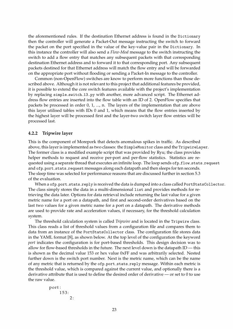
There are four distinct components within the OpenFlow application: layer-two switch,tripwire, port mirroring, and the firewall. Each of these components operate relatively in-dependently and have been implemented as a set of layers (shown in figure 4.1). Each layeris a Python class that extends the layer below. The layer-two switch functionality is the bot-tom layer and forms the base of the application. The application can operate using onlythis layer an would simply provide the core functions of a typical layer-two switch. Ontop of the layer-two switch layer is the tripwire layer. This is implemented by two classes:SimpleMonitor, another example script provided by Ryu, and TripwireLayer, which inter-prets the port and flow statistics that are received over a data path. The interpreted data isthen consumed by MirrorLayer, the class in the next layer up, which builds a list of portsthat need to mirror incoming traffic to the IDS. This layer also sends the instructions to theswitch that enable and disable the port mirroring. The next layer up is provided by theFirewallLayer class. This layer has the most independence from the other layers because itsonly data input is a feed of alerts from the IDS. Each time it receives an alert from the IDSit builds an instruction to drop matching traffic and sends that instruction to the datapath.The following sections describe the layers of the application in more depth.
21

Figure 4.1: Layers of implementation and data flow to other components
4.2.1 Layer-two switch layer
The layer-two switch functionality is provided entirely by simple switch 13.py and is notconsidered a contribution to the project.
When a packet is received at the switch the switch will look for an entry in the flow tablethat matches the destination Ethernet address of the packet. If a matching flow is not foundthen the default action is taken (defined in OpenFlow as the table-miss flow entry [29]). Thedefault action defined by the SimpleSwitch class is to forward the packet to the controllerusing the OpenFlow Packet-In message. The controller application has a Python Dictionary
object that stores destination Ethernet addresses as keys and switch port numbers as val-ues. Each data path has a separate Dictionary object. If the destination Ethernet addressof the packet in the Packet-In message is not found in the Dictionary object then the con-troller generates a Packet-Out message with the packet and the destination port field is setto OFPP FLOOD which will cause the switch to forward the packet out all ports except theport that the packet came in on and any ports that are disabled [29]. The source Ethernetaddress of the packet is added to the Dictionary, with the port number it was receivedon, if it is not already there. When a host replies to the packet that was flooded the replypacket will be sent to the switch, which will record the source Ethernet address and sourceport, and then it will instruct the switch to forward the reply to the destination following
22
the aforementioned rules. If the destination Ethernet address is found in the Dictionary
then the controller will generate a Packet-Out message instructing the switch to forwardthe packet on the port specified in the value of the key-value pair in the Dictionary. Inthis instance the controller will also send a Flow-Mod message to the switch instructing theswitch to add a flow entry that matches any subsequent packets with that correspondingdestination Ethernet address and to forward it to that corresponding port. Any subsequentpackets destined for that Ethernet address will match the flow entry and will be forwardedon the appropriate port without flooding or sending a Packet-In message to the controller.
Common (non-OpenFlow) switches are know to perform more functions than those de-scribed above. Although it is not relevant to this project that additional features be provided,it is possible to extend the core switch features available with the project’s implementationby replacing simple switch 13.py with another, more advanced script. The Ethernet ad-dress flow entries are inserted into the flow table with an ID of 2. OpenFlow specifies thatpackets be processed in order 0, 1, ..., n. The layers of the implementation that are abovethis layer utilised tables with IDs 0 and 1, which means that the flow entries inserted bythe highest layer will be processed first and the layer-two switch layer flow entries will beprocessed last.
4.2.2 Tripwire layer
This is the component of Morepork that detects anomalous spikes in traffic. As describedabove, this layer is implemented as two classes: the SimpleMonitor class and the TripwireLayer.The former class is a modified example script that was provided by Ryu; the class provideshelper methods to request and receive per-port and per-flow statistics. Statistics are re-quested using a separate thread that executes an infinite loop. The loop sends ofp flow stats request
and ofp port stats requestmessages along each datapath and then sleeps for ten seconds.The sleep time was selected for performance reasons that are discussed further in section 5.3of the evaluation.
When a ofp port stats reply is received the data is dumped into a class called PortStatsCollector.The class simply stores the data in a multi-dimensional list and provides methods for re-trieving the data later. Options for data retrieval include returning the last value for a givenmetric name for a port on a datapath, and first and second-order derivatives based on thelast two values for a given metric name for a port on a datapath. The derivative methodsare used to provide rate and acceleration values, if necessary, for the threshold calculationsystem.
The threshold calculation system is called Tripwire and is located in the Tripwire class.This class reads a list of threshold values from a configuration file and compares them todata from an instance of the PortStatsCollector class. The configuration file stores datain the YAML format [8], as shown below. At the top level of the configuration the keywordport indicates the configuration is for port-based thresholds. This design decision was toallow for flow-based thresholds in the future. The next level down is the datapath ID — thisis shown as the decimal value 153 or hex value 0xFF and was arbitrarily selected. Nestedfurther down is the switch port number. Next is the metric name, which can be the nameof any metric that is returned by the ofp port stats reply message. Within each metric isthe threshold value, which is compared against the current value, and optionally there is aderivative attribute that is used to define the desired order of derivative — or set to 0 to usethe raw value.
port :1 5 3 :
2 :
23

r x b y t e s :threshold : 600000000d e r i v a t i v e : 1
When new port statistics are received, processing of the thresholds is triggered. Each ofthe thresholds defined in the configuration file is compared to its associated current value. Ifthe current value is greater than the threshold value then it is stored in a multi-dimensionallist with the boolean value True. Otherwise, it is stored with the boolean value False. Thelist is then made available to the above Mirror layer. A potential improvement would beto read the thresholds from the configuration file at regular intervals rather than only whenthe application starts. This would allow adjustments to the thresholds without restartingthe OpenFlow application.
4.2.3 Mirror layer
The mirror layer is responsible for maintaining a list of ports that need to be mirrored anda list of ports that are currently being mirrored. The first list is based on the data from theTripwire layer. If any of the metrics for a port have their boolean value set to True then athreshold has been tripped on that port and therefore traffic ingress to that port must bemirrored. The Mirror layer sends a Flow-Mod message that instructs the switch to add aflow entry to the table with an ID of 1. The entry matches any traffic ingress to the portwith the tripped threshold and the actions are to forward the packet on the port connectedto the IDS and to Goto-Table 2. The purpose of the first action is to allow the IDS to inspectthe traffic from the threshold-tripping port in greater depth. The second action allows theswitch to perform regular packet forwarding functions for traffic entering that port. One ofthe goals of the project is to mitigate attacks with minimal disruption to legitimate traffic:until the IDS flags traffic as attack traffic the switch must assume that the traffic is legitimateand allow it to be processed in a regular manner.
Port mirroring for a port is disabled for a port when all values for that port fall belowtheir associated thresholds. If there is a single attack flow amongst the traffic on the mirroredport then the IDS will generate an alert for that flow and the Firewall layer will instruct theswitch to drop the attack flow traffic. Maintaining the assumption that there is only oneattack flow, the process of dropping all traffic in that flow will most likely cause the metricvalues to fall back below their associated thresholds triggering the port mirroring to stop forthat port. This is an ideal situation because the attack is mitigated and the IDS is not beingmade to filter through legitimate traffic. The other scenario is when there are multiple attackflows ingress to a port: if the IDS alerts on one of the flows and subsequent traffic for thatflow is dropped then it is likely that the combined effort of all the attack flows will keep thecurrent metric values above the threshold value. This will have the effect of continuing toport mirror traffic to the IDS which will alert on the remaining flows until enough flows areblocked to drive the metric values back below the thresholds.
4.2.4 Firewall layer
This is the component of Morepork that is made aware of attacks that have been confirmedto be present in all of the traffic that is passing through the switch. As mentioned earlier inthis chapter, this layer is largely independent of all of the other layers. The only input of thislayer is the stream of alerts from the IDS. The only output of this layer is a set of Flow-Modmessages sent to the switch. Alerts from the IDS are received by this layer through a UDPsocket listening on port 514. The alerts take the form of syslog events. A regular expressionis used to extract the source and destination IP addresses, the IP protocol (TCP or UDP), and
24
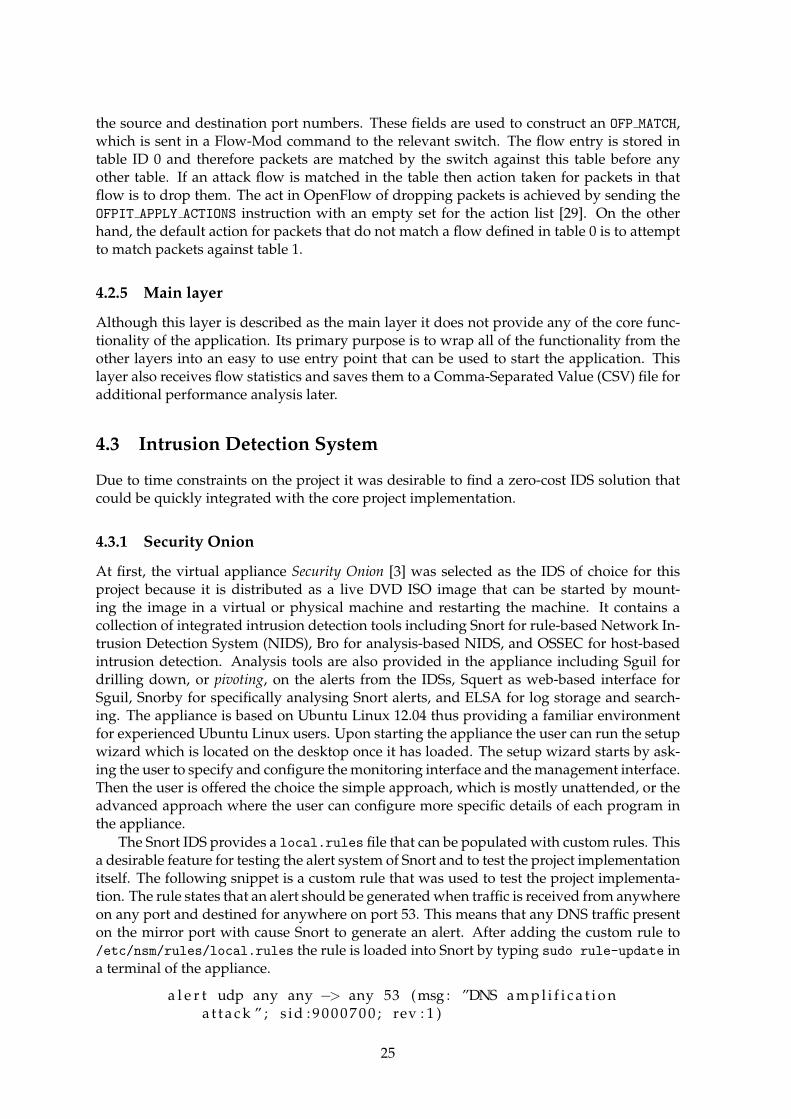
the source and destination port numbers. These fields are used to construct an OFP MATCH,which is sent in a Flow-Mod command to the relevant switch. The flow entry is stored intable ID 0 and therefore packets are matched by the switch against this table before anyother table. If an attack flow is matched in the table then action taken for packets in thatflow is to drop them. The act in OpenFlow of dropping packets is achieved by sending theOFPIT APPLY ACTIONS instruction with an empty set for the action list [29]. On the otherhand, the default action for packets that do not match a flow defined in table 0 is to attemptto match packets against table 1.
4.2.5 Main layer
Although this layer is described as the main layer it does not provide any of the core func-tionality of the application. Its primary purpose is to wrap all of the functionality from theother layers into an easy to use entry point that can be used to start the application. Thislayer also receives flow statistics and saves them to a Comma-Separated Value (CSV) file foradditional performance analysis later.
4.3 Intrusion Detection System
Due to time constraints on the project it was desirable to find a zero-cost IDS solution thatcould be quickly integrated with the core project implementation.
4.3.1 Security Onion
At first, the virtual appliance Security Onion [3] was selected as the IDS of choice for thisproject because it is distributed as a live DVD ISO image that can be started by mount-ing the image in a virtual or physical machine and restarting the machine. It contains acollection of integrated intrusion detection tools including Snort for rule-based Network In-trusion Detection System (NIDS), Bro for analysis-based NIDS, and OSSEC for host-basedintrusion detection. Analysis tools are also provided in the appliance including Sguil fordrilling down, or pivoting, on the alerts from the IDSs, Squert as web-based interface forSguil, Snorby for specifically analysing Snort alerts, and ELSA for log storage and search-ing. The appliance is based on Ubuntu Linux 12.04 thus providing a familiar environmentfor experienced Ubuntu Linux users. Upon starting the appliance the user can run the setupwizard which is located on the desktop once it has loaded. The setup wizard starts by ask-ing the user to specify and configure the monitoring interface and the management interface.Then the user is offered the choice the simple approach, which is mostly unattended, or theadvanced approach where the user can configure more specific details of each program inthe appliance.
The Snort IDS provides a local.rules file that can be populated with custom rules. Thisa desirable feature for testing the alert system of Snort and to test the project implementationitself. The following snippet is a custom rule that was used to test the project implementa-tion. The rule states that an alert should be generated when traffic is received from anywhereon any port and destined for anywhere on port 53. This means that any DNS traffic presenton the mirror port with cause Snort to generate an alert. After adding the custom rule to/etc/nsm/rules/local.rules the rule is loaded into Snort by typing sudo rule-update ina terminal of the appliance.
a l e r t udp any any −> any 53 (msg : ”DNS a m p l i f i c a t i o na t t a c k ” ; s id : 9 0 0 0 7 0 0 ; rev : 1 )
25
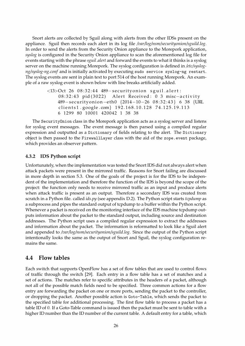
Snort alerts are collected by Sguil along with alerts from the other IDSs present on theappliance. Sguil then records each alert in its log file /var/log/nsm/securityonion/sguild.log.In order to send the alerts from the Security Onion appliance to the Morepork application,syslog is configured in the Security Onion appliance to scan the aforementioned log file forevents starting with the phrase sguil alert and forward the events to what it thinks is a syslogserver on the machine running Morepork. The syslog configuration is defined in /etc/syslog-ng/syslog-ng.conf and is initially activated by executing sudo service syslog-ng restart.The syslog events are sent in plain text to port 514 of the host running Morepork. An exam-ple of a raw syslog event is shown below with line breaks artificially added.
<13>Oct 26 0 8 : 3 2 : 4 4 489− secur i tyonion s g u i l a l e r t :0 8 : 3 2 : 4 3 pid ( 3 0 2 2 ) Aler t Received : 0 3 misc−a c t i v i t y489− secur i tyonion−eth0 {2014−10−26 0 8 : 3 2 : 4 3} 6 38 {URLc l i e n t s 1 . google . com} 1 9 2 . 1 6 8 . 1 0 . 1 2 8 7 4 . 1 2 5 . 1 9 . 1 1 36 1299 80 10001 420042 1 38 38
The SecurityOnion class in the Morepork application acts as a syslog server and listensfor syslog event messages. The event message is then parsed using a compiled regularexpression and outputted as a Dictionary of fields relating to the alert. The Dictionary
object is then passed to the FirewallLayer class with the aid of the zope.event package,which provides an observer pattern.
4.3.2 IDS Python script
Unfortunately, when the implementation was tested the Snort IDS did not always alert whenattack packets were present in the mirrored traffic. Reasons for Snort failing are discussedin more depth in section 5.3. One of the goals of the project is for the IDS to be indepen-dent of the implementation and therefore the function of the IDS is beyond the scope of theproject: the function only needs to receive mirrored traffic as an input and produce alertswhen attack traffic is present as an output. Therefore a secondary IDS was created fromscratch in a Python file. called ids.py (see appendix D.2). The Python script starts tcpdump asa subprocess and pipes the standard output of tcpdump to a buffer within the Python script.Whenever a packet is received on the monitoring interface of the IDS machine tcpdump out-puts information about the packet to the standard output, including source and destinationaddresses. The Python script uses a compiled regular expression to extract the addressesand information about the packet. The information is reformatted to look like a Sguil alertand appended to /var/log/nsm/securityonion/sguild.log. Since the output of the Python scriptintentionally looks the same as the output of Snort and Sguil, the syslog configuration re-mains the same.
4.4 Flow tables
Each switch that supports OpenFlow has a set of flow tables that are used to control flowsof traffic through the switch [29]. Each entry in a flow table has a set of matches and aset of actions. The matches refer to specific attributes in the headers of a packet, althoughnot all of the possible match fields need to be specified. Three common actions for a flowentry are forwarding the packet on one or more ports, sending the packet to the controller,or dropping the packet. Another possible action is Goto-Table, which sends the packet tothe specified table for additional processing. The first flow table to process a packet has atable ID of 0. If a Goto-Table command is issued then the packet must be sent to table with ahigher ID number than the ID number of the current table. A default entry for a table, which
26

is known as the Table-Miss entry, is defined with an empty match set and an action that isusually either to goto another table or send the packet to the controller.
Figure 4.1 shows an example of the flow table entries that are created in the implementa-tion. An incoming packet is first sent to table 0, which contains flow entries with no actions.This has the effect of dropping the packet if the packet matches that particular flow entry.The Table-Miss entry sends the packet to table 1 for processing. Table 1 contains instructionsto forward packets on the port that has been designated for port mirroring. In the imple-mentation port 3 was chosen because ports 1 and 2 were used for the Mininet hosts thatsend and receive the attack traffic. In addition to forwarding the packet to the mirror port,a matching packet is also sent to table 2 for processing. The extra action has the effect ofallowing the packet to be delivered to its intended destination, thus minimising disruptionto legitimate traffic. If the packet does not match a flow entry in table 1 then the default ac-tion is to send the packet to table 2. Table 2 matches on destination Ethernet addresses andforwards packets to the correct port — this is the standard function of a layer-two switch.See appendix C for a dump of the flow table from the Open vSwitch instance during one ofthe implementation tests.
table id in port eth dst ip src ip dst udp sport udp dport Instructions
0 1 aa:bb:cc:dd:ee:ff 1.2.3.4 5.6.7.8 12345 53 Apply-Actions {}0 * * * * * * Goto-Table 1
1 1 * * * * *Apply-Actions {Output: mirrGoto-Table 2
1 * * * * * * Goto-Table 22 1 aa:bb:cc:dd:ee:ff * * * * Apply-Actions {Output: destination2 * * * * * * Packet-In
Table 4.1: Example flow table entries
27

28
Chapter 5
Evaluation
This chapter describes the environment used the test the implementation, the testing pro-cess, and the scenarios that were simulated during the tests. Finally, this chapters discussesthe limitations of the test environment, and summarises the results of each test scenario.
5.1 Introduction
The test environment for this project consisted of two virtual appliances running on Virtual-Box [27] virtual machines. The first appliance was a Mininet [17] appliance, which containsMininet, Open vSwitch [26], and Ryu [38]. The second appliance was a Security Onion ap-pliance, which contains a collection of tools including and augmenting intrusion detectionsystems (IDS). The tools are discussed in more depth in section 4.3.1. As discussed in sec-tion 4.3.1 the first version of the test environment utilised Snort IDS and Sguil to generatealerts in the presence of attack traffic. However, due to limitations that will be discussedlater in section 5.3, Snort and Sguil were replaced with a Python script that generates alertswhen any packets are received and logs the alerts to the same file that Sguil logs alerts to.
To test the implementation a network was needed that contained two standard hosts, aswitch that supports OpenFlow, a host to run the OpenFlow controller, and a host to runthe IDS. Mininet is a program that can simulate all of the aforementioned components ex-cept for the IDS, including the network in between [17]. A virtual network can be quicklycreated either through the Mininet command-line interface (CLI) or though Python scriptsusing the API. Initially the project relied on a Python script to define a simple network topol-ogy for Mininet but was later extended to provide complete test automation including thesimulation of attack traffic. The final automation script is shown in appendix E.1. Mininetvirtualises the switch component of the network using Open vSwitch [26], a virtual switchimplementation that supports OpenFlow. This makes Mininet and Open vSwitch an idealcombination for testing a project that involves software-defined networking.
The Mininet topology definition is relatively straight forward and has been adopted fromthe Vandervecken implementation by Ewen McNeill. The Vandervecken topology consistsof two hosts connected together with a single switch. This was adapted to include a bridgefrom the switch to two physical interfaces: the first bridge is used to send traffic to the IDSwhich runs on another virtual machine (VM), and the second bridge is used to send at-tack traffic from an another virtual machine if necessary. The connections between the VMsare provided by separate VirtualBox Internal Adapters, which means that traffic does passthrough the networking stack of the host machine, and theoretically improves the perfor-mance of the connections. The later versions of the topology definition script also includecommands to run the attack traffic simulations. Mininet provides a fully-scriptable interface
29
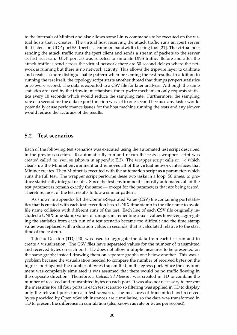
to the internals of Mininet and also allows some Linux commands to be executed on the vir-tual hosts that it creates. The virtual host receiving the attack traffic runs an iperf serverthat listens on UDP port 53. Iperf is a common bandwidth testing tool [21]. The virtual hostsending the attack traffic runs the iperf client and sends a stream of packets to the serveras fast as it can. UDP port 53 was selected to simulate DNS traffic. Before and after theattack traffic is send across the virtual network there are 30 second delays where the net-work is running but there is no network activity. This allows the tripwire layer to calibrateand creates a more distinguishable pattern when presenting the test results. In addition torunning the test itself, the topology script starts another thread that dumps per-port statisticsonce every second. The data is exported to a CSV file for later analysis. Although the samestatistics are used by the tripwire mechanism, the tripwire mechanism only requests statis-tics every 10 seconds which would reduce the sampling rate. Furthermore, the samplingrate of a second for the data export function was set to one second because any faster wouldpotentially cause performance issues for the host machine running the tests and any slowerwould reduce the accuracy of the results.
5.2 Test scenarios
Each of the following test scenarios was executed using the automated test script describedin the previous section. To automatically run and re-run the tests a wrapper script wascreated called mn-run.sh (shown in appendix E.2). The wrapper script calls mn -c whichcleans up the Mininet environment and removes all of the virtual network interfaces thatMininet creates. Then Mininet is executed with the automation script as a parameter, whichruns the full test. The wrapper script performs these two tasks in a loop, 50 times, to pro-duce statistically integral results. Since the test environment is mostly automated, all of thetest parameters remain exactly the same — except for the parameters that are being tested.Therefore, most of the test results follow a similar pattern.
As shown in appendix E.1 the Comma-Separated Value (CSV) file containing port statis-tics that is created with each test execution has a UNIX time stamp in the file name to avoidfile name collision with different runs of the test. Each line of each CSV file originally in-cluded a UNIX time stamp value for unique, incrementing x-axis values however, aggregat-ing the statistics from each run of a test scenario became too difficult and the time stampvalue was replaced with a duration value, in seconds, that is calculated relative to the starttime of the test run.
Tableau Desktop (TD) [40] was used to aggregate the data from each test run and tocreate a visualisation. The CSV files have separated values for the number of transmittedand received bytes on each port. TD does not allow multiple measures to be presented onthe same graph; instead drawing them on separate graphs one below another. This was aproblem because the visualisation needed to compare the number of received bytes on theingress port against the number of bytes transmitted on the egress port. Since the environ-ment was completely simulated it was assumed that there would be no traffic flowing inthe opposite direction. Therefore, a Calculated Measure was created in TD to combine thenumber of received and transmitted bytes on each port. It was also not necessary to presentthe measures for all four ports in each test scenario so filtering was applied in TD to displayonly the relevant ports for each test scenario. The measures of transmitted and receivedbytes provided by Open vSwitch instances are cumulative, so the data was transformed inTD to present the difference in cumulation (also known as rate or bytes per second).
30
5.2.1 High bandwidth flow with attack traffic
The first test scenario tests the base case for this project: attack traffic is sent through a switchrunning the implementation and the attack traffic is detected and mitigated. Although thisbehaviour does not reflect a real-world a network environment, it was desirable to build thetest environment where only a single flow of traffic was for the simulation. Such an environ-ment increases the likelihood that clear-set results demonstrating whether the implementa-tions works or does not work will be available. Subsequent test scenarios are provided tosimulate other flows of traffic in a controlled manner.
Figure 5.1 shows the attack traffic is starting to enter the switch at 30 seconds into thetest and immediately exit the switch. Then, 10 seconds later when the port statistics becomeavailable to the tripwire system the threshold is flagged as having been reached and the traf-fic is mirrored to the mirror port which feeds into the IDS. Within one the IDS generates analert for the attack traffic and notifies the firewall layer of the implementation. The firewalllayer inserts flow entry to drop the attack traffic and one second later the attack traffic isdropped rather than exiting the switch. The attack traffic continues to be sent to the switchuntil 150 seconds into the test where it stops and within fours seconds there is no longer anytraffic flowing though the virtual network at all.
Figure 5.1: Results of simulating high-bandwidth attack flow across the implementation
5.2.2 High bandwidth flow with legitimate traffic
To test that legitimate traffic is unaffected by the implementation a scenario has been createdwhere a single flow of legitimate passes through the switch with the implementation run-
31

ning. The legitimate traffic is a high-bandwidth flow and therefore will exceed the thresholddefined in the tripwire system. An example of a real-life scenario where this test would beapplicable would be a switch on the edge of a relatively small network: the network wouldhave a relatively low threshold and therefore a file transfer, for example, would consume alarge amount of the available bandwidth but can be considered legitimate traffic.
The legitimate traffic, as shown in figure 5.2 begins to enter the switch at 30 secondsinto the test and immediately exits the switch. 10 seconds later, when the port statistics arecollected by the tripwire system, the flow is treated as suspicious and the ingress port trafficis mirrored to the IDS (shown in figure 5.3). Since the IDS does not detected any attacktraffic it does not generate an alert. Therefore, the legitimate traffic continues to exit theswitch until iperf stops sending traffic at 150 seconds into the test.
Figure 5.2: Results of simulating a legitimate high-bandwidth flow across the implementa-tion
An improved version of this scenario would include a flow of legitimate traffic and aflow of attack traffic entering a switch on the same port. The combination of the two flowswould exceed the threshold defined in the tripwire system and both flows would be mir-rored to the IDS. The intended outcome would be an alert from the IDS matching the flowof the attack traffic which would result in a flow entry to drops packets from the attack flow— the legitimate traffic flow would not match this flow entry and would continue to be for-warded by the switch as per normal. Due to the limitation in ids.py that all traffic receivedon the mirror port is flagged as attack traffic it was not possible to build this enhanced sce-nario within the time constraints.
32
Figure 5.3: Results demonstrating the port traffic being mirrored to the IDS
5.2.3 Low bandwidth request traffic with high bandwidth response traffic
While the scenario in section 5.2.1 tests for any kind of high-bandwidth attack, it does notnecessarily test the specific vectors of a DNS amplification attack. Like other amplifica-tion attacks, a DNS amplification attack sends a small request packet with a forged sourceaddress and the unsuspecting server replies with a large response that goes to the forgedaddress rather than to the attacker. Figure 5.4 shows an example of a network topologywhere the attack sends spoofed traffic from its own network to a network with an openDNS resolver and the replies are sent to a victim host in a third network. The edge routersbetween these networks are connected via switches (for example, in an internet exchange)and both the switches in this scenario are running the implementation. The hypothesis ofthis scenario is that the switch between the attacker’s network and the network with theopen DNS resolver will not detect the attack because the request traffic will not consumeenough bandwidth to reach the tripwire threshold. However, the response traffic will belarge enough to reach the threshold and therefore the switch between the network with theopen DNS resolver and the victim network will detect and mitigate the attack.
The attack starts at 30 seconds into each test run with the request traffic entering andexiting the first switch without triggering the port mirroring (see figure 5.5). At the sametime the response traffic begins entering the second switch and exiting towards the victimnetwork. Another 10 seconds pass and the controller application receives port statistics fromboth switches. Since the traffic passing through the first switch does not reach the thresholdvalue port mirroring is not enabled for the ingress port of the first switch. Therefore, the
33
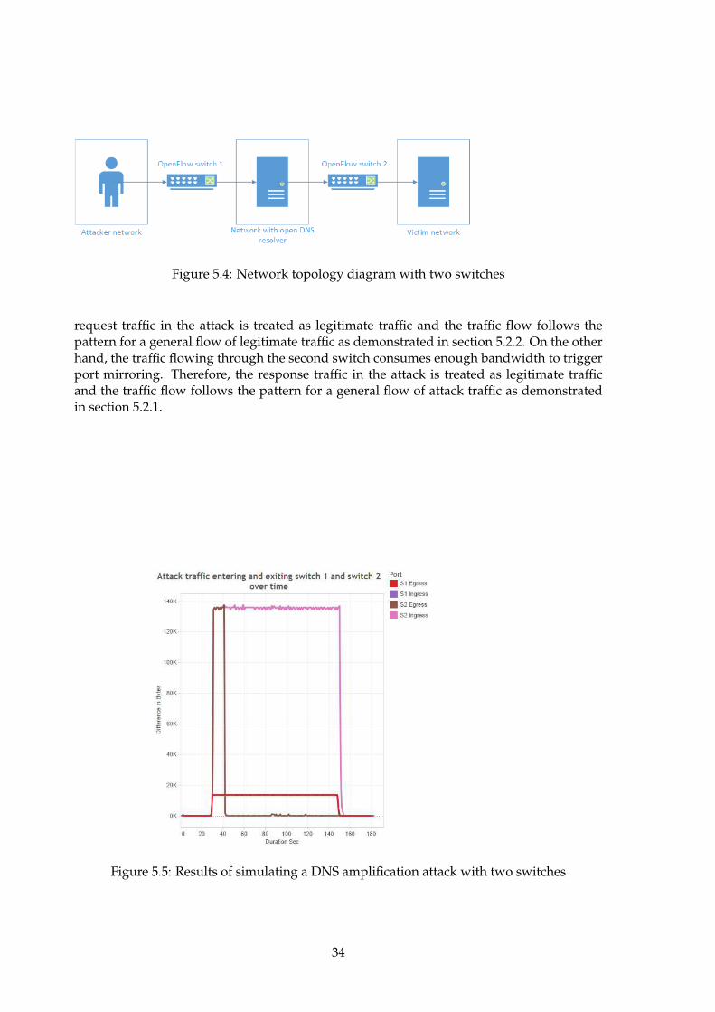
Figure 5.4: Network topology diagram with two switches
request traffic in the attack is treated as legitimate traffic and the traffic flow follows thepattern for a general flow of legitimate traffic as demonstrated in section 5.2.2. On the otherhand, the traffic flowing through the second switch consumes enough bandwidth to triggerport mirroring. Therefore, the response traffic in the attack is treated as legitimate trafficand the traffic flow follows the pattern for a general flow of attack traffic as demonstratedin section 5.2.1.
Figure 5.5: Results of simulating a DNS amplification attack with two switches
34
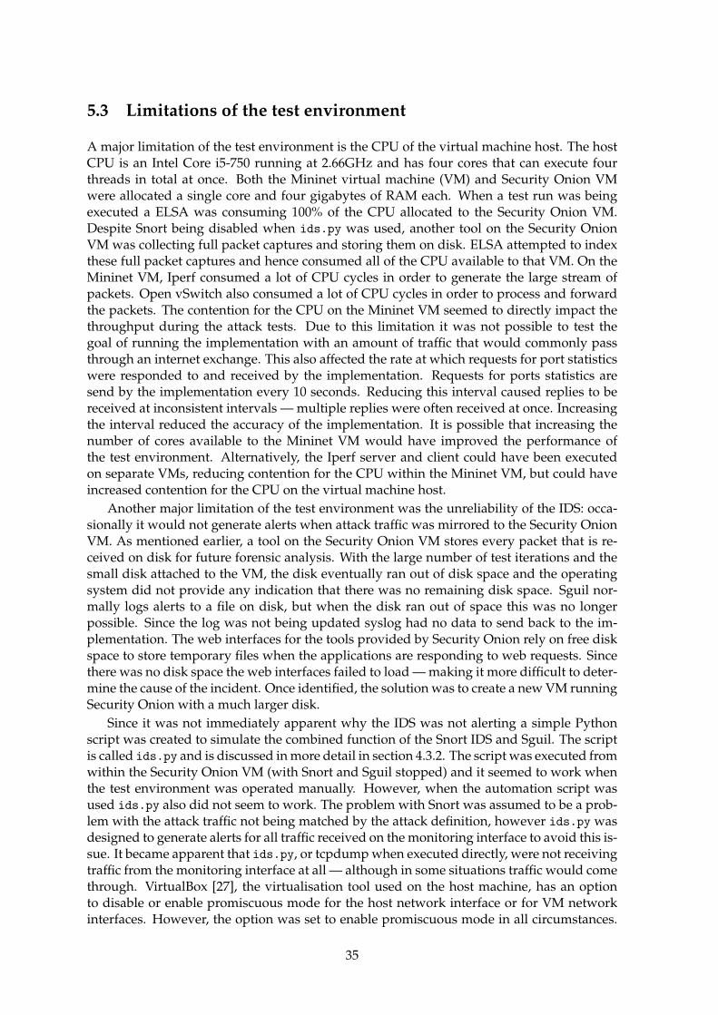
5.3 Limitations of the test environment
A major limitation of the test environment is the CPU of the virtual machine host. The hostCPU is an Intel Core i5-750 running at 2.66GHz and has four cores that can execute fourthreads in total at once. Both the Mininet virtual machine (VM) and Security Onion VMwere allocated a single core and four gigabytes of RAM each. When a test run was beingexecuted a ELSA was consuming 100% of the CPU allocated to the Security Onion VM.Despite Snort being disabled when ids.py was used, another tool on the Security OnionVM was collecting full packet captures and storing them on disk. ELSA attempted to indexthese full packet captures and hence consumed all of the CPU available to that VM. On theMininet VM, Iperf consumed a lot of CPU cycles in order to generate the large stream ofpackets. Open vSwitch also consumed a lot of CPU cycles in order to process and forwardthe packets. The contention for the CPU on the Mininet VM seemed to directly impact thethroughput during the attack tests. Due to this limitation it was not possible to test thegoal of running the implementation with an amount of traffic that would commonly passthrough an internet exchange. This also affected the rate at which requests for port statisticswere responded to and received by the implementation. Requests for ports statistics aresend by the implementation every 10 seconds. Reducing this interval caused replies to bereceived at inconsistent intervals — multiple replies were often received at once. Increasingthe interval reduced the accuracy of the implementation. It is possible that increasing thenumber of cores available to the Mininet VM would have improved the performance ofthe test environment. Alternatively, the Iperf server and client could have been executedon separate VMs, reducing contention for the CPU within the Mininet VM, but could haveincreased contention for the CPU on the virtual machine host.
Another major limitation of the test environment was the unreliability of the IDS: occa-sionally it would not generate alerts when attack traffic was mirrored to the Security OnionVM. As mentioned earlier, a tool on the Security Onion VM stores every packet that is re-ceived on disk for future forensic analysis. With the large number of test iterations and thesmall disk attached to the VM, the disk eventually ran out of disk space and the operatingsystem did not provide any indication that there was no remaining disk space. Sguil nor-mally logs alerts to a file on disk, but when the disk ran out of space this was no longerpossible. Since the log was not being updated syslog had no data to send back to the im-plementation. The web interfaces for the tools provided by Security Onion rely on free diskspace to store temporary files when the applications are responding to web requests. Sincethere was no disk space the web interfaces failed to load — making it more difficult to deter-mine the cause of the incident. Once identified, the solution was to create a new VM runningSecurity Onion with a much larger disk.
Since it was not immediately apparent why the IDS was not alerting a simple Pythonscript was created to simulate the combined function of the Snort IDS and Sguil. The scriptis called ids.py and is discussed in more detail in section 4.3.2. The script was executed fromwithin the Security Onion VM (with Snort and Sguil stopped) and it seemed to work whenthe test environment was operated manually. However, when the automation script wasused ids.py also did not seem to work. The problem with Snort was assumed to be a prob-lem with the attack traffic not being matched by the attack definition, however ids.py wasdesigned to generate alerts for all traffic received on the monitoring interface to avoid this is-sue. It became apparent that ids.py, or tcpdump when executed directly, were not receivingtraffic from the monitoring interface at all — although in some situations traffic would comethrough. VirtualBox [27], the virtualisation tool used on the host machine, has an optionto disable or enable promiscuous mode for the host network interface or for VM networkinterfaces. However, the option was set to enable promiscuous mode in all circumstances.
35
Assuming this was the problem the Security Onion VM would not have been allowed toenable promiscuous mode which would have prevented all of the packet capturing toolsfrom capturing packets. However, this did not seem to be the problem either because thenetwork activity indicator for the Security Onion VM showed that the traffic was not beingreceived by the VM at all, however the traffic was being transmitted by the Mininet VM. An-other symptom of the issue as experienced by ids.py and tcpdump occurred whenever theautomated test script was executed: the packet capture would stop prematurely. The mostsignificant difference between the automated execution of a test and the manual executionof a test was the order in which components were started: in the automated test ids.pywas started first and the automated script was started second. In a manual test Mininetwas started first, then ids.py, and finally iperf for the attack simulation. When Mininetis started it instructions Open vSwitch to create virtual network interfaces and attach itselfto the VM’s physical network interfaces (in the case of this project’s network topology def-inition). Although not confirmed, it is suspected that Open vSwitch disables the networkinterface momentarily in order to attach itself to the interface. When the interface is disabledit may disrupt the interface in the Security Onion VM since the interfaces of the two VMsare connected together with VirtualBox internal network adapters. This issue was unresolv-able, and the workaround during the tests was to manually start and stop ids.py duringthe warm-up and cool-down phases of each test run.
5.4 Summary
To evaluate the implementation three test scenarios were constructed and executed in ancontrolled environment using Mininet. The first test scenario sent a single flow of attack traf-fic through a switch running the implementation with the expectation that the flow wouldbe stopped. This was to test the implementation against the objective, which is to detect andto mitigate DNS amplification attacks. Since the parameters of the test scenario are quitevague, the scenario also tests the goal of being extensible so that other attack types can bedetected and mitigated. The results suggest that after a small window where the attack suc-cessfully passes through the switch the attack flow is dropped. The second test scenariosent a single flow of legitimate traffic through a switch running the implementation withthe expectation that the flow would not be stopped. This was to test the requirement thatthe implementation has little impact on legitimate traffic. The results suggest that the legit-imate traffic is completely unaffected by the implementation despite the traffic exceedingthe threshold and being deemed as suspicious. The third test scenario sent a small amountof attack through one switch and a large amount of attack traffic through another switchto simulate an amplification attack where requests are small and responses are large. Thepurpose of this test was to test the objective specifically, rather than in the broad sense. Theresults suggest that a DNS amplification attack can be mitigated when the DNS responsespass through a switch running the implementation, but it is possible that the DNS requestswill not detected or mitigated by the implementation. The results also suggest that theimplementation would be more effective with more locations on the internet running theimplementation, however the solution is still likely to detect and mitigate attacks with asmall number of instances of the implementation running.
36
Chapter 6
Conclusion and future work
DNS amplification attacks are currently a common technique used by attackers to denyservice to legitimate users. This has become a problem because attackers able to constructthese attacks with large amplification factors that cause majors amounts of congestion andpreviously suggested techniques to mitigate these attacks have been unsuccessful. Whilethe project implementation is successful in terms of the objective, there are some weaknessesto implementation too. This chapter seeks to discuss the strengths and weaknesses of theproject, and to suggest future work that could improve this project.
6.1 Strengths of the implementation
Section 5.4 made the suggestion that the implementation has met the objective of the course.This section will discuss some of the specific project requirements that have also been achieved.
The implementation is supposed to run on a variety of hardware or software. Due totime constraints the implementation was not tested on hardware. However, the implemen-tation supports any device that supports OpenFlow version 1.3 and therefore the onus ison switch vendors to provide hardware or software switches. The core implementation is asoftware application that runs on top of Ryu — a software-based OpenFlow controller. Asdemonstrated with the test environment, Morepork and Ryu can run in a virtual machine ifnecessary, but in theory could run on a physical machine too. The IDS has been treated asa black box that accepts a specific input and produces a specific output. There is no expec-tation as to how the Intrusion Detection System (IDS) is implemented which means it couldalso run in hardware or software.
The black box approach of the IDS also addresses the extensibility of the project. Theattacks that can be detected by the implementation depends directly on the configurationand implementation of the IDS. There are large rule sets available for Snort that could beused with the project. Additionally, Snort allows for custom rules to be defined — whichwas the preferred method for evaluating this project.
The implementation reduces the impact of the detection and mitigation mechanism onlegitimate traffic by offloading the responsibility of detecting attacks to another machine (theIDS). If the IDS fails for some reason or the link between the switch and the IDS becomescongested or otherwise unavailable then the switch will stop mitigating attacks but willcontinue to function as a normal switch.
The implementation is designed to run on a switch, not a router, and therefore addressesthis requirement slightly differently. The third test scenario (see section 5.2.3) demonstratesthat although it is not necessary to run the implementation on all switches it would definitelyimprove the effectiveness of the implementation. A more important factor is the run the
37
implementation on switches that handle large amounts of internet traffic and are potentiallysubject to the presence of more attack traffic. To address this factor the goal of runningthe implementation in an internet exchange environment (or with an equivalent amount oftraffic) was introduced to the project.
6.2 Weaknesses of the implementation
Testing with the amount of traffic commonly seen in an internet exchange (IX) was not pos-sible due to the limitations of the test environment. Therefore, there is no evidence that theimplementation could operate in an IX. On the other hand, future work could be done toimprove the test environment and this may be enough to demonstrate the implementationworking with an exchange-level amount of traffic.
Since the objective of the project is targeted at DNS amplification attacks and more gen-erally distributed denial of service attacks (DDoS) there is an assumption that the attacksbeing mitigated will have large flows of attack traffic. For small-scale DDoS attacks or forattacks that rely on vectors that do not include sending large amounts of network traffic,this implementation is suggested to be ineffective. Furthermore, the implementation as-sumes the switch is trying to protect its own amount of available bandwidth rather thanstopping the attack itself. If the threshold on a port is set to a value that is slightly higherthan the daily peak load value for that port and the attacker decides to execute their attackduring an off-peak time then the implementation will not detect or mitigate the attack. Onthe other hand, an attack during the off-peak time of both the switch and the victim of theattacker is less likely to cause denial of service and by definitely of peak is going to impactfewer legitimate users.
6.3 Future work
This section discusses potential changes and improvements to the project for the future.For reasons discussed in section 3.1.2 it is desirable to reduce the amount of traffic that
is mirrored to the IDS. The current project design reduces the traffic by deciding on a per-switch port basis whether the traffic needs to be mirrored or not. It is unlikely that allof the traffic entering a port will be attack traffic and therefore the solution could be im-proved by mirroring traffic on a per-flow basis. The port-based mirroring would providea coarse-gained filter in attempt to find an attack flow and once a port has been flagged assuspicious then the mirroring process could be applied per-flow for that specific port. Traf-fic would only be mirrored once one or more traffic flows have been flagged as especiallysuspicious. On the other hand, thresholds would be unsuitable to whether a particular flowis suspicious. It is unlikely that each flow has the same characteristics, which would re-quire individual thresholds for individual flows and the thresholds would need to change.If this process were to be applied then machine-learning would be required to improve theaccuracy of the detection process.
Once an attack has been detected by the IDS and the implementation has blocked theattack flow, then assuming that no other attack traffic has been detected from the port beingmirrored then the port should stop being mirrored. This another attempt to reduce theamount of traffic being sent to the IDS. Furthermore, it is possible that multiple ports triptheir thresholds at once and the implementation will mirror traffic from those ports to theIDS. If the combined bandwidth of the ports being mirrored exceeds the capacity of the linkbetween the switch and the IDS then some of the mirrored traffic may be dropped. Althoughthis will not impact the forwarding of legitimate packets through the switch it will impact
38
the ability for the IDS to detect attack traffic. If the IDS becomes overwhelmed with trafficthen it may not be able to alert the switch about specific attacks. On the other hand, if it doesmanage to inform the switch about an attack then the switch can block the attack flow whichwill stop that flow from being mirrored to the IDS. This behaviour is possible because theflow table with the drop rules are evaluated before the mirror rules and forwarding rules- this was an intentional part of the design. To ensure the IDS is never overwhelmed withtraffic the implementation could set a limit on the number of ports that can have trafficmirrored to the IDS. Combining with the idea from above, when no attacks are detected bythe IDS in the mirrored traffic then those ports should stop being mirrored to the IDS andthe other ports can then be mirrored.
Due to time constraints the code to remove an attack flow entry from the flow table wasnever implemented. Although this does not immediately cause any immediate issues forany of the components it may cause issues for legitimate traffic in the future that coincidentlymatches the attack flow vectors (specifically for DNS requests or responses). Also, some ofthe configuration was hard-coded within the code of each layer of the implementation —for example the port number that traffic is mirrored to. These configuration options shouldbe moved to an external configuration file and the code to read the configuration file shouldbe moved from the tripwire layer to a layer that allows all the other layers to access theconfiguration.
39

40

Appendix A
Example of a large DNS response
This is an example of a large DNS response that has been generated by the command-lineutility dig. The lines are truncated, however the message size is recoreded as 8320 bytes atthe bottom of the output — this demonstrates the full size of the response.
$ dig ANY doc . gov @x . x . y . y; ; Truncated , r e t r y i n g in TCP mode .
; <<>> DiG 9.8.3 −P1 <<>> ANY doc . gov; ; g loba l opt ions : +cmd; ; Got answer :; ; −>>HEADER<<− opcode : QUERY, s t a t u s : NOERROR, id : 60091; ; f l a g s : qr rd ra ; QUERY: 1 , ANSWER: 44 , AUTHORITY: 6 , ADDITIONAL: 4
; ; QUESTION SECTION :; doc . gov . IN ANY
; ; ANSWER SECTION :doc . gov . 10798 IN RRSIG SOA 8 2 10800 20141119070630 20141020060630 1doc . gov . 10798 IN RRSIG SOA 8 2 10800 20141119070630 20141020060630 5doc . gov . 10798 IN SOA hchbens1 . doc . gov . dnsadmin . doc . gov . 2014072865 36doc . gov . 10798 IN RRSIG TXT 8 2 10800 20141106123148 20141007123106 1doc . gov . 10798 IN RRSIG TXT 8 2 10800 20141106123148 20141007123106 1doc . gov . 10798 IN TXT ”MS=ms91611337”doc . gov . 10798 IN TXT ”khbl4plXHgnKtHsVtFp6P2+2C/Tpn/Vl/4xMUy+3yN8KPPzDdoc . gov . 10798 IN RRSIG MX 8 2 10800 20141114023329 20141015020647 11doc . gov . 10798 IN RRSIG MX 8 2 10800 20141114023329 20141015020647 14doc . gov . 10798 IN MX 10 smtpedge1 . uspto . gov .doc . gov . 10798 IN MX 10 smtpedge2 . uspto . gov .doc . gov . 298 IN RRSIG AAAA 8 2 300 20141107173951 20141008164211 11766doc . gov . 298 IN RRSIG AAAA 8 2 300 20141107173951 20141008164211 14811doc . gov . 298 IN AAAA 2 6 1 0 : 2 0 : : 2 0 : 5 ec : d0c : d0c : d0cdoc . gov . 298 IN RRSIG A 8 2 300 20141113001227 20141013234923 11766 docdoc . gov . 298 IN RRSIG A 8 2 300 20141113001227 20141013234923 14811 docdoc . gov . 298 IN A 1 7 0 . 1 1 0 . 2 2 5 . 1 9 4doc . gov . 3598 IN RRSIG NSEC 8 2 3600 20141108231129 20141009230013 1doc . gov . 3598 IN RRSIG NSEC 8 2 3600 20141108231129 20141009230013 1doc . gov . 3598 IN NSEC a s s o c i a t e . doc . gov . A NS SOA MX TXT AAAA RRSIG
41
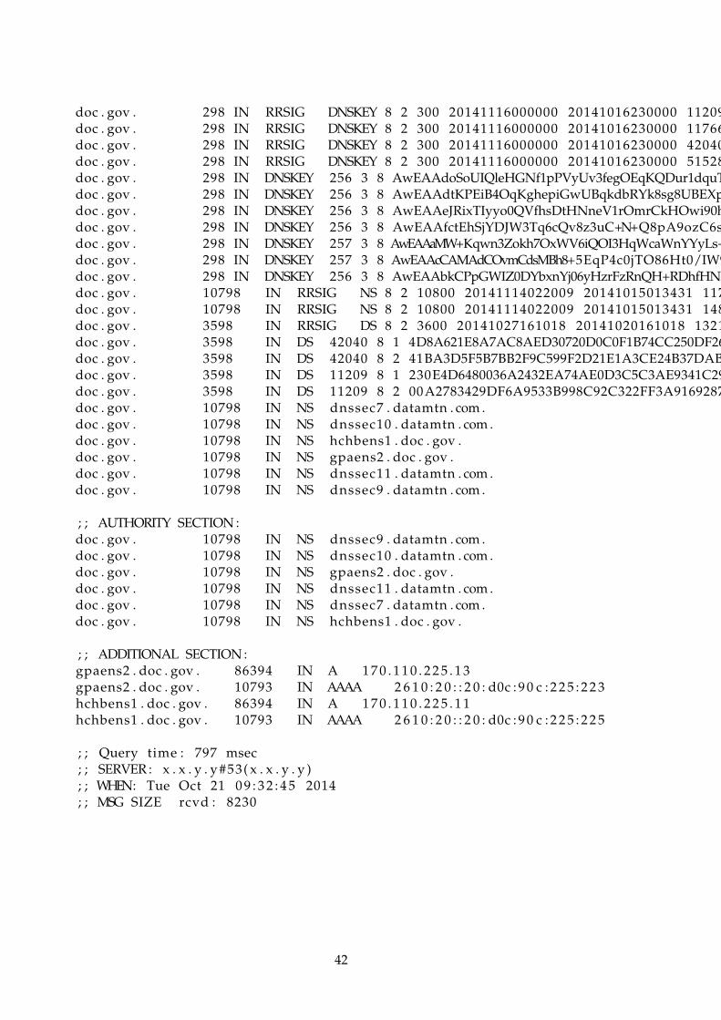
doc . gov . 298 IN RRSIG DNSKEY 8 2 300 20141116000000 20141016230000 11209doc . gov . 298 IN RRSIG DNSKEY 8 2 300 20141116000000 20141016230000 11766doc . gov . 298 IN RRSIG DNSKEY 8 2 300 20141116000000 20141016230000 42040doc . gov . 298 IN RRSIG DNSKEY 8 2 300 20141116000000 20141016230000 51528doc . gov . 298 IN DNSKEY 256 3 8 AwEAAdoSoUIQleHGNf1pPVyUv3fegOEqKQDur1dquTdoc . gov . 298 IN DNSKEY 256 3 8 AwEAAdtKPEiB4OqKghepiGwUBqkdbRYk8sg8UBEXpdoc . gov . 298 IN DNSKEY 256 3 8 AwEAAeJRixTIyyo0QVfhsDtHNneV1rOmrCkHOwi90hdoc . gov . 298 IN DNSKEY 256 3 8 AwEAAfctEhSjYDJW3Tq6cQv8z3uC+N+Q8pA9ozC6sedoc . gov . 298 IN DNSKEY 257 3 8 AwEAAaMW+Kqwn3Zokh7OxWV6iQOI3HqWcaWnYYyLs+doc . gov . 298 IN DNSKEY 257 3 8 AwEAAcCAMAdCOvmCdsMBh8+5EqP4c0jTO86Ht0/IW9doc . gov . 298 IN DNSKEY 256 3 8 AwEAAbkCPpGWIZ0DYbxnYj06yHzrFzRnQH+RDhfHNkdoc . gov . 10798 IN RRSIG NS 8 2 10800 20141114022009 20141015013431 117doc . gov . 10798 IN RRSIG NS 8 2 10800 20141114022009 20141015013431 148doc . gov . 3598 IN RRSIG DS 8 2 3600 20141027161018 20141020161018 1321doc . gov . 3598 IN DS 42040 8 1 4D8A621E8A7AC8AED30720D0C0F1B74CC250DF26doc . gov . 3598 IN DS 42040 8 2 41BA3D5F5B7BB2F9C599F2D21E1A3CE24B37DABEdoc . gov . 3598 IN DS 11209 8 1 230E4D6480036A2432EA74AE0D3C5C3AE9341C29doc . gov . 3598 IN DS 11209 8 2 00A2783429DF6A9533B998C92C322FF3A9169287doc . gov . 10798 IN NS dnssec7 . datamtn . com .doc . gov . 10798 IN NS dnssec10 . datamtn . com .doc . gov . 10798 IN NS hchbens1 . doc . gov .doc . gov . 10798 IN NS gpaens2 . doc . gov .doc . gov . 10798 IN NS dnssec11 . datamtn . com .doc . gov . 10798 IN NS dnssec9 . datamtn . com .
; ; AUTHORITY SECTION :doc . gov . 10798 IN NS dnssec9 . datamtn . com .doc . gov . 10798 IN NS dnssec10 . datamtn . com .doc . gov . 10798 IN NS gpaens2 . doc . gov .doc . gov . 10798 IN NS dnssec11 . datamtn . com .doc . gov . 10798 IN NS dnssec7 . datamtn . com .doc . gov . 10798 IN NS hchbens1 . doc . gov .
; ; ADDITIONAL SECTION :gpaens2 . doc . gov . 86394 IN A 1 7 0 . 1 1 0 . 2 2 5 . 1 3gpaens2 . doc . gov . 10793 IN AAAA 2 6 1 0 : 2 0 : : 2 0 : d0c : 9 0 c : 2 2 5 : 2 2 3hchbens1 . doc . gov . 86394 IN A 1 7 0 . 1 1 0 . 2 2 5 . 1 1hchbens1 . doc . gov . 10793 IN AAAA 2 6 1 0 : 2 0 : : 2 0 : d0c : 9 0 c : 2 2 5 : 2 2 5
; ; Query time : 797 msec; ; SERVER : x . x . y . y #53( x . x . y . y ); ; WHEN: Tue Oct 21 0 9 : 3 2 : 4 5 2014; ; MSG SIZE rcvd : 8230
42

Appendix B
Morepork source code
Morepork is the name given to the project implementation. This is the primary contributionof the project. A description of the code is found in chapter 4. Note that the longer lines aretruncated.
B.1 simple monitor.py
from operator import a t t r g e t t e r
from ryu . app import s imple switch 13from ryu . c o n t r o l l e r import ofp eventfrom ryu . c o n t r o l l e r . handler import CONFIG DISPATCHER, MAIN DISPATCHER, DEAD Dfrom ryu . c o n t r o l l e r . handler import s e t e v c l sfrom ryu . ofproto import o fpro to v1 3from ryu . l i b import hub
c l a s s SimpleMonitor ( s imple switch 13 . SimpleSwitch13 ) :
def i n i t ( s e l f , ∗args , ∗∗kwargs ) :super ( SimpleMonitor , s e l f ) . i n i t (∗ args , ∗∗kwargs )s e l f . datapaths = {}s e l f . monitor thread = hub . spawn ( s e l f . monitor )
@ s e t e v c l s ( ofp event . EventOFPStateChange ,[MAIN DISPATCHER, DEAD DISPATCHER ] )
def s t a t e c h a n g e h a n d l e r ( s e l f , ev ) :’ ’ ’
Keep the l i s t of datapaths up−to−date .’ ’ ’datapath = ev . datapathi f ev . s t a t e == MAIN DISPATCHER :
i f not datapath . id in s e l f . datapaths :s e l f . logger . debug ( ’ r e g i s t e r datapath : %016x ’ , datapath . id )s e l f . datapaths [ datapath . id ] = datapath
e l i f ev . s t a t e == DEAD DISPATCHER :i f datapath . id in s e l f . datapaths :
s e l f . logger . debug ( ’ u n r e g i s t e r datapath : %016x ’ , datapath . id )
43

del s e l f . datapaths [ datapath . id ]
def monitor ( s e l f ) :’ ’ ’P o l l each datapath f o r new s t a t s .’ ’ ’while True :
f o r dp in s e l f . datapaths . values ( ) :s e l f . r e q u e s t s t a t s ( dp )
hub . s leep ( 1 0 )
def r e q u e s t s t a t s ( s e l f , datapath ) :s e l f . logger . debug ( ’ send s t a t s request : %016x ’ , datapath . id )ofproto = datapath . ofprotoparser = datapath . o f p r o t o p a r s e r
req = parser . OFPFlowStatsRequest ( datapath )datapath . send msg ( req )
req = parser . OFPPortStatsRequest ( datapath , 0 , ofproto . OFPP ANY)datapath . send msg ( req )
@ s e t e v c l s ( ofp event . EventOFPPortStatsReply , MAIN DISPATCHER)def p o r t s t a t s r e p l y h a n d l e r ( s e l f , ev ) :
body = ev . msg . body
s e l f . logger . i n f o ( ’ datapath port ’’ rx−pkts rx−bytes rx−e r r o r ’’ tx−pkts tx−bytes tx−error ’ )
s e l f . logger . i n f o(’−−−−−−−−−−−−−−−− −−−−−−−− ’’−−−−−−−− −−−−−−−− −−−−−−−− ’’−−−−−−−− −−−−−−−− −−−−−−−−’)
f o r s t a t in sor ted ( body , key= a t t r g e t t e r ( ’ port no ’ ) ) :s e l f . logger . i n f o ( ’%016x %8x %8d %8d %8d %8d %8d %8d ’ ,
ev . msg . datapath . id , s t a t . port no ,s t a t . rx packets , s t a t . rx bytes , s t a t . r x e r r o r s ,s t a t . tx packets , s t a t . t x b y t e s , s t a t . t x e r r o r s )
B.2 layer tripwire.py
from ryu . c o n t r o l l e r import ofp eventfrom ryu . c o n t r o l l e r . handler import CONFIG DISPATCHER, MAIN DISPATCHER, DEAD DISfrom ryu . c o n t r o l l e r . handler import s e t e v c l sfrom ryu . l i b import hub
from morepork . app import simple monitorfrom morepork . t r i p w i r e import c o l l e c t o rfrom morepork . t r i p w i r e import t r i p w i r e
44

c l a s s TripwireLayer ( simple monitor . SimpleMonitor ) :
t r i p w i r e t a b l e i d = 2p o l l t i m e = 10
def i n i t ( s e l f , ∗args , ∗∗kwargs ) :super ( TripwireLayer , s e l f ) . i n i t (∗ args , ∗∗kwargs )s e l f . c o l l e c t o r = c o l l e c t o r . P o r t S t a t s C o l l e c t o r ( )s e l f . t r i p w i r e = t r i p w i r e . Tripwire ( s e l f . logger , s e l f . c o l l e c t o r )
def add flow ( s e l f , datapath , p r i o r i t y , match , a c t i o n s ) :’ ’ ’Override method in s imple switch 13 so we can placeswitch flows in the t a b l e number of our choosing .’ ’ ’o fproto = datapath . ofprotoparser = datapath . o f p r o t o p a r s e r
i n s t = [ parser . OFPInstruct ionAct ions ( ofproto . OFPIT APPLY ACTIONS ,a c t i o n s ) ]
mod = parser . OFPFlowMod( datapath=datapath , p r i o r i t y = p r i o r i t y ,match=match , i n s t r u c t i o n s = i n s t , t a b l e i d = s e l f
datapath . send msg (mod)
def add defaul t f low ( s e l f , datapath , t a b l e i d , g o t o t a b l e i d =None ) :’ ’ ’
Adds a d e f a u l t flow f o r a t a b l e . Defaul t a c t i o n i sto goto the next t a b l e ( s p e c i f i e d by g o t o t a b l e i d ) .’ ’ ’i f not g o t o t a b l e i d : re turn
ofproto = datapath . ofprotoparser = datapath . o f p r o t o p a r s e rmatch = parser . OFPMatch ( )
i n s t = [ parser . OFPInstructionGotoTable ( g o t o t a b l e i d ) ]mod = parser . OFPFlowMod( datapath=datapath , p r i o r i t y =0 ,
match=match , i n s t r u c t i o n s = i n s t , t a b l e i d = t a b l e i d )
datapath . send msg (mod)
def p r i n t t r i p w i r e s ( s e l f ) :wires = s e l f . t r i p w i r e . p r o c e s s p o r t s t a t s ( )s e l f . logger . i n f o ( ’ datapath port ’
’ metr ic value ’’ threshold tripped ’ )
s e l f . logger . i n f o(’−−−−−−−−−−−−−−−− −−−−−−−− ’’−−−−−−−−−−−−−−−− −−−−−−−−−−−−− ’’−−−−−−−−−−−−− −−−−−−−’)
45
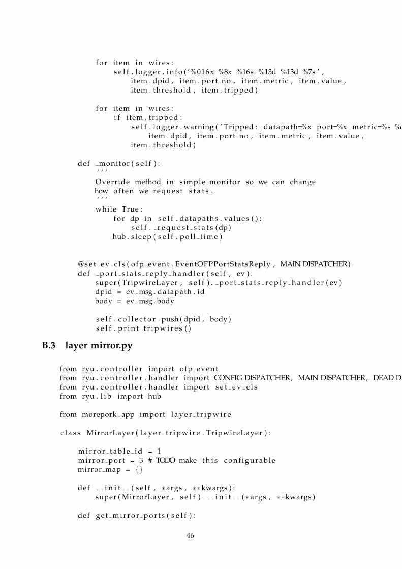
f o r item in wires :s e l f . logger . i n f o ( ’%016x %8x %16s %13d %13d %7s ’ ,
item . dpid , item . port no , item . metric , item . value ,item . threshold , item . tr ipped )
f o r item in wires :i f item . tr ipped :
s e l f . logger . warning ( ’ Tripped : datapath=%x port=%x metr ic=%s %ditem . dpid , item . port no , item . metric , item . value ,
item . threshold )
def monitor ( s e l f ) :’ ’ ’Override method in simple monitor so we can changehow of ten we request s t a t s .’ ’ ’while True :
f o r dp in s e l f . datapaths . values ( ) :s e l f . r e q u e s t s t a t s ( dp )
hub . s leep ( s e l f . p o l l t i m e )
@ s e t e v c l s ( ofp event . EventOFPPortStatsReply , MAIN DISPATCHER)def p o r t s t a t s r e p l y h a n d l e r ( s e l f , ev ) :
super ( TripwireLayer , s e l f ) . p o r t s t a t s r e p l y h a n d l e r ( ev )dpid = ev . msg . datapath . idbody = ev . msg . body
s e l f . c o l l e c t o r . push ( dpid , body )s e l f . p r i n t t r i p w i r e s ( )
B.3 layer mirror.py
from ryu . c o n t r o l l e r import ofp eventfrom ryu . c o n t r o l l e r . handler import CONFIG DISPATCHER, MAIN DISPATCHER, DEAD DISfrom ryu . c o n t r o l l e r . handler import s e t e v c l sfrom ryu . l i b import hub
from morepork . app import l a y e r t r i p w i r e
c l a s s MirrorLayer ( l a y e r t r i p w i r e . TripwireLayer ) :
m i r r o r t a b l e i d = 1mirror por t = 3 # TODO make t h i s c o n f i g u r a b l emirror map = {}
def i n i t ( s e l f , ∗args , ∗∗kwargs ) :super ( MirrorLayer , s e l f ) . i n i t (∗ args , ∗∗kwargs )
def g e t m i r r o r p o r t s ( s e l f ) :
46
re turn s e l f . m i r r o r i n p o r t s
def add mirror port ( s e l f , dpid , i n p o r t ) :’ ’ ’
Add a c t i o n to mirror t r a f f i c to the mirror port ,then go to the switch t a b l e to forward the t r a f f i cnormally .’ ’ ’datapath = s e l f . datapaths [ dpid ]ofproto = datapath . ofprotoparser = datapath . o f p r o t o p a r s e rmatch = parser . OFPMatch ( i n p o r t = i n p o r t )
a c t i o n s = [ parser . OFPActionOutput ( s e l f . mir ror por t ) ]i n s t = [ parser . OFPInstruct ionAct ions ( ofproto . OFPIT APPLY ACTIONS ,
a c t i o n s ) , parser . OFPInstructionGotoTable ( s e l f . t r i p w i r e t a b l e i d ) ]mod = parser . OFPFlowMod( datapath=datapath , p r i o r i t y =1 ,
match=match , i n s t r u c t i o n s = i n s t , t a b l e i d = s e l f . m i r r o r t a b l e i d )datapath . send msg (mod)
s e l f . logger . warning ( ’ Added port mirror %d −−> %d on datapath %x ’ ,in por t , s e l f . mirror port , dpid )
def remove mirror port ( s e l f , dpid , i n p o r t ) :datapath = s e l f . datapaths [ dpid ]ofproto = datapath . ofprotoparser = datapath . o f p r o t o p a r s e rmatch = parser . OFPMatch ( i n p o r t = i n p o r t )
mod = parser . OFPFlowMod( datapath=datapath , match=match ,command=ofproto . OFPFC DELETE , t a b l e i d = s e l f . m i r r o r t a b l e i d ,out por t=ofproto . OFPP ANY, out group=ofproto .OFPG ANY)
datapath . send msg (mod)
s e l f . logger . warning ( ’ Removed port mirror %d −−> %d on datapath %x ’ ,in por t , s e l f . mirror port , dpid )
def update mirror ports ( s e l f , wires ) :new map = {}f o r wire in wires :
i f wire . dpid not in new map :new map [ wire . dpid ] = {}
i f wire . port no not in new map [ wire . dpid ] :new map [ wire . dpid ] [ wire . port no ] = wire . t r ipped
i f ( not new map [ wire . dpid ] [ wire . port no ] andwire . t r ipped ) :new[ wire . dpid ] [ wire . port no ] = True
47

old map = s e l f . mirror mapf o r dpid , por ts in new map . i t e r i t e m s ( ) :
f o r port no , tr ipped in ports . i t e r i t e m s ( ) :i f dpid not in old map :
old map [ dpid ] = {}
i f port no not in old map [ dpid ] :old map [ dpid ] [ port no ] = F a l s e
i f t r ipped and not old map [ dpid ] [ port no ] :s e l f . add mirror port ( dpid , port no )
e l i f not tr ipped and old map [ dpid ] [ port no ] :s e l f . remove mirror port ( dpid , port no )
# e l s e i f new=true and old=true# => already port mirroring# e l s e i f new= f a l s e and old= f a l s e# => never tr ipped
s e l f . mirror map = new map
@ s e t e v c l s ( ofp event . EventOFPSwitchFeatures , CONFIG DISPATCHER)def s w i t c h f e a t u r e s h a n d l e r ( s e l f , ev ) :
super ( MirrorLayer , s e l f ) . s w i t c h f e a t u r e s h a n d l e r ( ev )
datapath = ev . msg . datapaths e l f . add defaul t f low ( datapath , s e l f . m i r r o r t a b l e i d , s e l f . t r i p w i r e t a
@ s e t e v c l s ( ofp event . EventOFPPortStatsReply , MAIN DISPATCHER)def p o r t s t a t s r e p l y h a n d l e r ( s e l f , ev ) :
super ( MirrorLayer , s e l f ) . p o r t s t a t s r e p l y h a n d l e r ( ev )
wires = s e l f . t r i p w i r e . p r o c e s s p o r t s t a t s ( )s e l f . update mirror ports ( wires )
B.4 layer firewall.py
from ryu . c o n t r o l l e r import ofp eventfrom ryu . c o n t r o l l e r . handler import CONFIG DISPATCHER, MAIN DISPATCHER, DEAD DISfrom ryu . c o n t r o l l e r . handler import s e t e v c l sfrom ryu . l i b import hubfrom ryu . ofproto import e therfrom ryu . ofproto import i n e t
from morepork . app import l a y e r m i r r o rfrom morepork . ids import secur i tyonion
c l a s s Firewal lLayer ( l a y e r m i r r o r . MirrorLayer ) :
f i r e w a l l t a b l e i d = 0f i r e w a l l d r o p s = {}
48
i d s l i s t e n a d d r e s s = ’ 0 . 0 . 0 . 0 ’i d s l i s t e n p o r t = 514
def i n i t ( s e l f , ∗args , ∗∗kwargs ) :super ( Firewal lLayer , s e l f ) . i n i t (∗ args , ∗∗kwargs )s e l f . ids = secur i tyonion . SecurityOnion ( s e l f . logger )s e l f . ids . i d s a l e r t s u b s c r i b e ( s e l f . i d s a l e r t h a n d l e r )s e l f . ids . l i s t e n ( s e l f . i d s l i s t e n a d d r e s s , s e l f . i d s l i s t e n p o r t )
def g e t f i r e w a l l d r o p s ( s e l f ) :re turn s e l f . f i r e w a l l d r o p s
def add f i rewal l drop ( s e l f , dpid , ev ) :’ ’ ’I f t r a f f i c flow should be dropped then add flow r u l eto match t h a t flow and apply no a c t i o n s . There i s nogoto t a b l e i n s t r u c t i o n to prevent the normal switchf u n c t i o n s and thus dropping the packet .’ ’ ’datapath = s e l f . datapaths [ dpid ]ofproto = datapath . ofprotoparser = datapath . o f p r o t o p a r s e r
s r c p o r t = i n t ( ev . s r c p o r t )d s t p o r t = i n t ( ev . d s t p o r t )i f ev . proto == ’ 6 ’ : # TCP
match = parser . OFPMatch ( i p v 4 s r c =ev . s r c i p , ipv4 ds t=ev . ds t ip ,t c p s r c = s r c p o r t , t c p d s t =dst por t , e th type=ether . ETH TYPEi p p r o t o= i n e t . IPPROTO TCP )
proto = ’TCP’e l i f ev . proto == ’ 1 7 ’ : # UDP
match = parser . OFPMatch ( i p v 4 s r c =ev . s r c i p , ipv4 ds t=ev . ds t ip ,udp src= s r c p o r t , udp dst=dst por t , e th type=ether . ETH TYPEi p p r o t o= i n e t . IPPROTO UDP)
proto = ’UDP’e l s e :
re turn
a c t i o n s = [ ]i n s t = [ parser . OFPInstruct ionAct ions ( ofproto . OFPIT APPLY ACTIONS ,
a c t i o n s ) ]mod = parser . OFPFlowMod( datapath=datapath , p r i o r i t y =1 ,
match=match , i n s t r u c t i o n s = i n s t , t a b l e i d = s e l f . f i r e w a l l t a b l e i d )datapath . send msg (mod)
s e l f . logger . warning ( ’ Adding entry to drop t r a f f i c flow %s %s :%s −−> %proto , ev . s r c i p , ev . s r c p o r t , ev . ds t ip , ev . ds t por t , dpid )
def remove f irewal l drop ( s e l f , dpid , match ) :datapath = s e l f . datapaths [ dpid ]
49

ofproto = datapath . ofprotoparser = datapath . o f p r o t o p a r s e r
mod = parser . OFPFlowMod( datapath=datapath , match=match ,command=ofproto . OFPFC DELETE , t a b l e i d = s e l f . f i r e w a l l t a b l e i d ,out por t=ofproto . OFPP ANY, out group=ofproto .OFPG ANY)
datapath . send msg (mod)
s e l f . logger . warning ( ’ Removed flow to drop t r a f f i c ’ )
@ s e t e v c l s ( ofp event . EventOFPSwitchFeatures , CONFIG DISPATCHER)def s w i t c h f e a t u r e s h a n d l e r ( s e l f , ev ) :
super ( Firewal lLayer , s e l f ) . s w i t c h f e a t u r e s h a n d l e r ( ev )
datapath = ev . msg . datapaths e l f . add defaul t f low ( datapath , s e l f . f i r e w a l l t a b l e i d , s e l f . m i r r o r t a
@ s e t e v c l s ( ofp event . EventOFPFlowStatsReply , MAIN DISPATCHER)def f l o w s t a t s r e p l y h a n d l e r ( s e l f , ev ) :
super ( Firewal lLayer , s e l f ) . f l o w s t a t s r e p l y h a n d l e r ( ev )
# Check flow s t a t threshold f o r drop flows# I f s t a t < threshold# remove f irewal l drop ( . . . )
def i d s a l e r t h a n d l e r ( s e l f , ev ) :# Stop the a t t a c k on a l l datapathsf o r dpid in s e l f . datapaths :
s e l f . add f i rewal l drop ( dpid , ev )
B.5 main.py
import datetimeimport os . path
from ryu . c o n t r o l l e r import ofp eventfrom ryu . c o n t r o l l e r . handler import CONFIG DISPATCHER, MAIN DISPATCHER, DEAD DISfrom ryu . c o n t r o l l e r . handler import s e t e v c l sfrom ryu . l i b import hub
from morepork . app import l a y e r f i r e w a l l
c l a s s MoreporkApp ( l a y e r f i r e w a l l . F i rewal lLayer ) :
f l o w s t a t s f i l e = ’ flow−s t a t s−%s . csv ’
def i n i t ( s e l f , ∗args , ∗∗kwargs ) :super ( MoreporkApp , s e l f ) . i n i t (∗ args , ∗∗kwargs )
t = datetime . datetime . today ( )
50
s e l f . f l o w s t a t s f i l e = s e l f . f l o w s t a t s f i l e % t . s t r f t i m e ( ’% s ’ )
# TODO i n i t conf ig here and r e p l a c e TRIPWIRE CONF
@ s e t e v c l s ( ofp event . EventOFPFlowStatsReply , MAIN DISPATCHER)def f l o w s t a t s r e p l y h a n d l e r ( s e l f , ev ) :
body = ev . msg . body
i f not os . path . i s f i l e ( s e l f . f l o w s t a t s f i l e ) :with open ( s e l f . f l o w s t a t s f i l e , ’w’ ) as myfi le :
myfi le . wri te (” dpid , in por t , out port , ipv4 src , ipv4 dst , t c p s r c
with open ( s e l f . f l o w s t a t s f i l e , ’ a ’ ) as myfi le :dpid = ev . msg . datapath . idf o r s t a t in body :
i f ’ in por t ’ in s t a t . match :i n p o r t = s t a t . match [ ’ in por t ’ ]
e l s e :i n p o r t = ’ ’
t r y :out por t = s t a t . i n s t r u c t i o n s [ 0 ] . a c t i o n s [ 0 ] . port
except :out por t = ’ ’
i f ’ ipv4 src ’ in s t a t . match :i p v 4 s r c = s t a t . match [ ’ ipv4 src ’ ]
e l s e :i p v 4 s r c = ’ ’
i f ’ ipv4 dst ’ in s t a t . match :ipv4 ds t = s t a t . match [ ’ ipv4 dst ’ ]
e l s e :ipv4 ds t = ’ ’
i f ’ t c p s r c ’ in s t a t . match :t c p s r c = s t a t . match [ ’ t c p s r c ’ ]
e l s e :t c p s r c = ’ ’
i f ’ t cp ds t ’ in s t a t . match :t c p d s t = s t a t . match [ ’ t cp ds t ’ ]
e l s e :t c p d s t = ’ ’
i f ’ udp src ’ in s t a t . match :udp src = s t a t . match [ ’ udp src ’ ]
e l s e :udp src = ’ ’
51
i f ’ udp dst ’ in s t a t . match :udp dst = s t a t . match [ ’ udp dst ’ ]
e l s e :udp dst = ’ ’
packet count = s t a t . packet countbyte count = s t a t . byte countd u r a t i o n s e c = s t a t . d u r a t i o n s e cmyfi le . wri te (”%s ,%s ,%s ,%s ,%s ,%s ,%s ,%s ,%s ,%s ,%s ,% s\n” % ( dpid , i
s e l f . logger . i n f o ( ’ Wrote flow s t a t s to %s ’ , s e l f . f l o w s t a t s f i l e )
B.6 configloader.py
import c o l l e c t i o n simport yaml
c l a s s ConfigLoader ( o b j e c t ) :
@staticmethoddef load ( f i lename ) :
stream = f i l e ( f i lename , ’ r ’ )dump = yaml . load ( stream )Config = c o l l e c t i o n s . namedtuple ( ’ Config ’ , dump. keys ( ) )re turn Config (∗∗dump)
B.7 idsbase.py
import zope . event
c l a s s IdsBase ( o b j e c t ) :’ ’ ’I n t e r a c t i o n s with s p e c i f i c IDS s o l u t i o n s shouldbe implemented in t h e i r own c l a s s e s t h a ti n h e r i t t h i s c l a s s .’ ’ ’
def i d s a l e r t s u b s c r i b e ( s e l f , func ) :’ ’ ’Functions t h a t want to r e c e i v e a l e r t s from the IDSshould use t h i s method to subscr ibe .’ ’ ’zope . event . s u b s c r i b e r s . append ( func )
def i d s a l e r t f i r e ( s e l f , ev ) :’ ’ ’C lasses t h a t i n h e r i t t h i s c l a s s should use t h i smethod to n o t i f y s u b s c r i b e r s t h a t an a l e r t hasoccurred .
ev should be a Dic t ionary of f i e l d s t h a t conta in
52
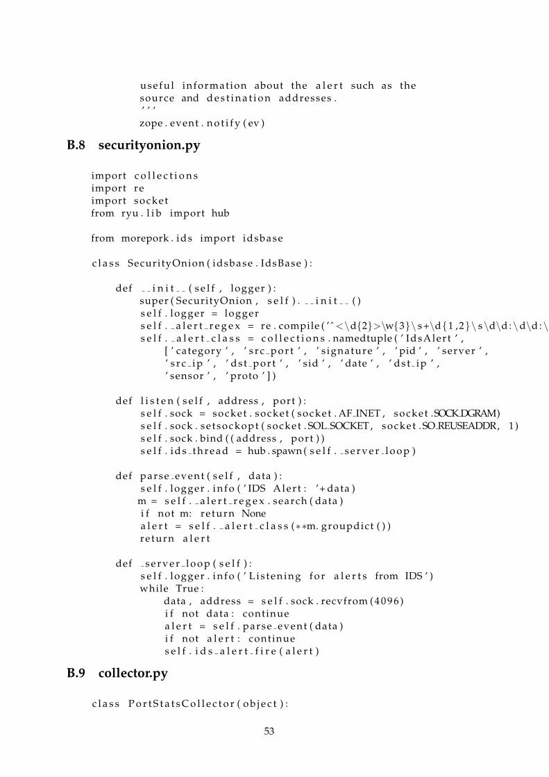
usefu l information about the a l e r t such as thesource and d e s t i n a t i o n addresses .’ ’ ’zope . event . n o t i f y ( ev )
B.8 securityonion.py
import c o l l e c t i o n simport reimport socketfrom ryu . l i b import hub
from morepork . ids import idsbase
c l a s s SecurityOnion ( idsbase . IdsBase ) :
def i n i t ( s e l f , logger ) :super ( SecurityOnion , s e l f ) . i n i t ( )s e l f . logger = loggers e l f . a l e r t r e g e x = re . compile ( ’ˆ <\d{2}>\w{3}\ s+\d{1 ,2}\ s\d\d : \d\d : \ds e l f . a l e r t c l a s s = c o l l e c t i o n s . namedtuple ( ’ IdsAler t ’ ,
[ ’ category ’ , ’ s r c p o r t ’ , ’ s ignature ’ , ’ pid ’ , ’ server ’ ,’ s r c i p ’ , ’ ds t por t ’ , ’ sid ’ , ’ date ’ , ’ ds t ip ’ ,’ sensor ’ , ’ proto ’ ] )
def l i s t e n ( s e l f , address , port ) :s e l f . sock = socket . socket ( socket . AF INET , socket .SOCK DGRAM)s e l f . sock . se tsockopt ( socket . SOL SOCKET , socket . SO REUSEADDR, 1)s e l f . sock . bind ( ( address , port ) )s e l f . i d s t h r e a d = hub . spawn ( s e l f . s e r v e r l o o p )
def parse event ( s e l f , data ) :s e l f . logger . i n f o ( ’ IDS Aler t : ’+ data )
m = s e l f . a l e r t r e g e x . search ( data )i f not m: re turn Nonea l e r t = s e l f . a l e r t c l a s s (∗∗m. groupdict ( ) )re turn a l e r t
def s e r v e r l o o p ( s e l f ) :s e l f . logger . i n f o ( ’ L i s t e n i n g f o r a l e r t s from IDS ’ )while True :
data , address = s e l f . sock . recvfrom ( 4 0 9 6 )i f not data : continuea l e r t = s e l f . parse event ( data )i f not a l e r t : continues e l f . i d s a l e r t f i r e ( a l e r t )
B.9 collector.py
c l a s s P o r t S t a t s C o l l e c t o r ( o b j e c t ) :
53

s t o r e = {}
def has dpid ( s e l f , dpid ) :’ ’ ’Check i f s t a t s f o r datapath ID e x i s t’ ’ ’re turn dpid in s e l f . s t o r e
def has port no ( s e l f , dpid , port no ) :’ ’ ’Check i f s t a t s f o r port e x i s t f o r a given datapath’ ’ ’i f not s e l f . has dpid ( dpid ) :
re turn F a l s e
re turn port no in s e l f . s t o r e [ dpid ] . keys ( )
def has metr ic ( s e l f , dpid , port no , metr ic ) :’ ’ ’Check i f s t a t s f o r metr ic e x i s t f o r given port and datapath’ ’ ’i f not s e l f . has port no ( dpid , port no ) :
re turn F a l s e
i f len ( s e l f . s t o r e [ dpid ] [ port no ] ) == 0 :re turn F a l s e
re turn h a s a t t r ( s e l f . s t o r e [ dpid ] [ port no ] [ 0 ] , metr ic )
def por ts ( s e l f , dpid ) :’ ’ ’Gets a l i s t of por ts f o r a given datapath ID’ ’ ’i f not s e l f . has dpid ( dpid ) :
re turn None
return s e l f . s t o r e [ dpid ] . keys ( )
def push ( s e l f , dpid , s t a t s ) :’ ’ ’S t o r e s the r e s u l t s from a port s t a t s reply’ ’ ’i f dpid not in s e l f . s t o r e :
s e l f . s t o r e [ dpid ] = {}
f o r s e t in s t a t s :port no = s e t . port noi f port no not in s e l f . s t o r e [ dpid ] :
s e l f . s t o r e [ dpid ] [ port no ] = [ ]
54

s e l f . s t o r e [ dpid ] [ port no ] . append ( s e t )
# Limit each l i s t s i z e to 2 itemsi f len ( s e l f . s t o r e [ dpid ] [ port no ] ) > 2 :
del s e l f . s t o r e [ dpid ] [ port no ] [ 0 ]
def l a s t v a l u e ( s e l f , dpid , port no , metr ic ) :’ ’ ’Gets the l a s t value f o r a metr ic’ ’ ’i f not s e l f . has metr ic ( dpid , port no , metr ic ) :
s e l f . logger . warning ( ’ Metric not found : %s port no=%8x dpid=%016x( metric , port no , dpid ) )
va l s = s e l f . g e t d a t a p o i n t s ( dpid , port no , metr ic )i f va l s i s not None :
re turn va ls [ 1 ]
def order1 ( s e l f , dpid , port no , metr ic ) :’ ’ ’C a l c u l a t e s the 1 st−order d e r i v a t i v e of a metr ic’ ’ ’i f not s e l f . has metr ic ( dpid , port no , metr ic ) :
s e l f . logger . warning ( ’ Metric not found : %s port no=%8x dpid=%016x( metric , port no , dpid ) )
va l s = s e l f . g e t d a t a p o i n t s ( dpid , port no , metr ic )i f va l s i s not None :
re turn ( va l s [ 1 ] − va ls [ 0 ] ) / va l s [ 2 ]e l s e :
re turn 0
def order2 ( s e l f , dpid , port no , metr ic ) :’ ’ ’C a l c u l a t e s the 2nd−order d e r i v a t i v e of a metr ic’ ’ ’i f not s e l f . has metr ic ( dpid , port no , metr ic ) :
s e l f . logger . warning ( ’ Metric not found : %s port no=%8x dpid=%016x( metric , port no , dpid ) )
va l s = s e l f . g e t d a t a p o i n t s ( dpid , port no , metr ic )i f va l s i s not None :
re turn ( ( va l s [ 1 ] − va ls [ 0 ] ) / va l s [ 2 ] ) / va l s [ 2 ]e l s e :
re turn 0
def g e t d a t a p o i n t s ( s e l f , dpid , port no , metr ic ) :’ ’ ’Gets the l a s t two datapoints and time d e l t a
55

’ ’ ’i f ( dpid not in s e l f . s t o r e or
port no not in s e l f . s t o r e [ dpid ] . keys ( ) ) :re turn None
d a t a s e t s = s e l f . s t o r e [ dpid ] [ port no ] [ −2 : ]i f len ( d a t a s e t s ) < 2 :
re turn None
i f ( not h a s a t t r ( d a t a s e t s [ 0 ] , metr ic ) ornot h a s a t t r ( d a t a s e t s [ 1 ] , metr ic ) ) :re turn None
a = g e t a t t r ( d a t a s e t s [ 0 ] , metr ic )b = g e t a t t r ( d a t a s e t s [ 1 ] , metr ic )dt = d a t a s e t s [ 1 ] . d u r a t i o n s e c − d a t a s e t s [ 0 ] . d u r a t i o n s e cre turn [ a , b , dt ]
B.10 tripwire.py
import os
from c o l l e c t i o n s import namedtuplefrom ryu . c o n t r o l l e r import event
from morepork . conf ig import c o n f i g l o a d e r
c l a s s Tripwire ( o b j e c t ) :
ENV TRIPWIRE CONF = ’TRIPWIRE CONF’
def i n i t ( s e l f , logger , c o l l e c t o r ) :s e l f . logger = loggers e l f . c o l l e c t o r = c o l l e c t o r
s e l f . load environment ( )s e l f .CONF = c o n f i g l o a d e r . ConfigLoader . load ( s e l f . t r i p w i r e c o n f )
s e l f . wire = namedtuple ( ’ Wire ’ , ’ dpid , port no , metric , value , thresho
def load environment ( s e l f ) :i f s e l f . ENV TRIPWIRE CONF in os . environ :
s e l f . t r i p w i r e c o n f = os . environ [ s e l f . ENV TRIPWIRE CONF]e l s e :
s e l f . logger . e r r o r ( ’ Environment v a r i a b l e not found : %s ’ %s e l f . ENV TRIPWIRE CONF)
s e l f . t r i p w i r e c o n f = None
def p r o c e s s f l o w s t a t s ( s e l f ) :’ ’ ’
56

Run threshold checks on flow s t a t s’ ’ ’re turn [ ] # TODO
def p r o c e s s p o r t s t a t s ( s e l f ) :’ ’ ’
Run threshold checks on port s t a t s’ ’ ’conf = s e l f .CONF. portc o l = s e l f . c o l l e c t o r
r e s u l t s = [ ]
f o r dpid , por ts in conf . i t e r i t e m s ( ) :i f not c o l . has dpid ( dpid ) : continue
f o r port no , metr i cs in ports . i t e r i t e m s ( ) :i f not c o l . has port no ( dpid , port no ) : continue
f o r metric , s e t t i n g s in metr ics . i t e r i t e m s ( ) :i f not c o l . has metr ic ( dpid , port no , metr ic ) : continue
i f ’ threshold ’ not in s e t t i n g s :s e l f . logger . warning ( ’ Threshold not defined f o r port−b
( metric , port no , dpid ) )continue
i f ’ der iva t ive ’ in s e t t i n g s :d e r i v a t i v e = s e t t i n g s [ ’ der iva t ive ’ ]
e l s e :d e r i v a t i v e = 0
i f s e t t i n g s [ ’ der iva t ive ’ ] == 2 :val = c o l . order2 ( dpid , port no , metr ic )
e l i f s e t t i n g s [ ’ der iva t ive ’ ] == 1 :val = c o l . order1 ( dpid , port no , metr ic )
e l s e :val = c o l . l a s t v a l u e ( dpid , port no , metr ic )
threshold = s e t t i n g s [ ’ threshold ’ ]t r ipped = val >= threshold
r e s u l t s . append ( s e l f . wire ( dpid , port no , metric , val , thr
re turn r e s u l t s
57

58

Appendix C
Example flow tables
This is an example of the flow tables ina switch when suspicious traffic is detected and portmirroring flow entries have been added to the tables.
s t a t s r e p l y ( xid =0 x e 6 6 e f 4 f f ) : f l a g s =none type =1( flow )cookie =0 , d u r a t i o n s e c =114s , durat ion nsec =772000000 s , t a b l e i d =0 , p r i o r i t y =0 , ncookie =0 , d u r a t i o n s e c =84s , durat ion nsec =305000000 s , t a b l e i d =1 , p r i o r i t y =1 , n pcookie =0 , d u r a t i o n s e c =114s , durat ion nsec =772000000 s , t a b l e i d =1 , p r i o r i t y =0 , ncookie =0 , d u r a t i o n s e c =84s , durat ion nsec =721000000 s , t a b l e i d =2 , p r i o r i t y =1 , n pcookie =0 , d u r a t i o n s e c =84s , durat ion nsec =720000000 s , t a b l e i d =2 , p r i o r i t y =1 , n pcookie =0 , d u r a t i o n s e c =114s , durat ion nsec =773000000 s , t a b l e i d =2 , p r i o r i t y =0 , n
59

60
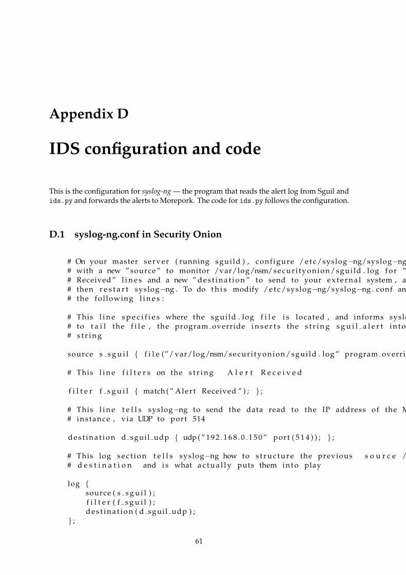
Appendix D
IDS configuration and code
This is the configuration for syslog-ng — the program that reads the alert log from Sguil andids.py and forwards the alerts to Morepork. The code for ids.py follows the configuration.
D.1 syslog-ng.conf in Security Onion
# On your master server ( running sgui ld ) , conf igure / e t c /syslog−ng/syslog−ng# with a new ” source ” to monitor /var/log/nsm/secur i tyonion/sgui ld . log f o r ”# Received ” l i n e s and a new ” d e s t i n a t i o n ” to send to your e x t e r n a l system , an# then r e s t a r t syslog−ng . To do t h i s modify / e t c /syslog−ng/syslog−ng . conf and# the fol lowing l i n e s :
# This l i n e s p e c i f i e s where the sgui ld . log f i l e i s located , and informs syslo# to t a i l the f i l e , the program override i n s e r t s the s t r i n g s g u i l a l e r t i n t o# s t r i n g
source s s g u i l { f i l e (”/ var/log/nsm/secur i tyonion/sgui ld . log ” program overrid
# This l i n e f i l t e r s on the s t r i n g A l e r t R e c e i v e d
f i l t e r f s g u i l { match (” Aler t Received ” ) ; } ;
# This l i n e t e l l s syslog−ng to send the data read to the IP address of the M# instance , via UDP to port 514
d e s t i n a t i o n d sguil udp { udp ( ” 1 9 2 . 1 6 8 . 0 . 1 5 0 ” port ( 5 1 4 ) ) ; } ;
# This log s e c t i o n t e l l s syslog−ng how to s t r u c t u r e the previous s o u r c e /# d e s t i n a t i o n and i s what a c t u a l l y puts them i n t o play
log {source ( s s g u i l ) ;f i l t e r ( f s g u i l ) ;d e s t i n a t i o n ( d sgui l udp ) ;
} ;
61
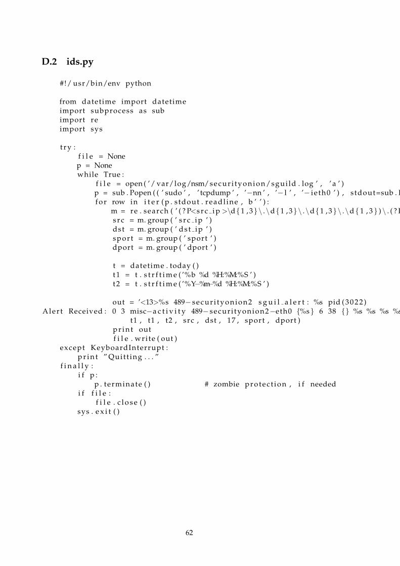
D.2 ids.py
#!/ usr/bin/env python
from datetime import datetimeimport subprocess as subimport reimport sys
t r y :f i l e = Nonep = Nonewhile True :
f i l e = open ( ’/ var/log/nsm/secur i tyonion/sgui ld . log ’ , ’ a ’ )p = sub . Popen ( ( ’ sudo ’ , ’ tcpdump ’ , ’−nn ’ , ’− l ’ , ’− i e th0 ’ ) , s tdout=sub . Pf o r row in i t e r ( p . s tdout . readl ine , b ’ ’ ) :
m = re . search ( ’ ( ? P<s r c i p >\d{1 , 3}\ .\d{1 , 3}\ .\d{1 , 3}\ .\d { 1 , 3 } ) \ . ( ? Ps r c = m. group ( ’ s r c i p ’ )dst = m. group ( ’ ds t ip ’ )spor t = m. group ( ’ sport ’ )dport = m. group ( ’ dport ’ )
t = datetime . today ( )t1 = t . s t r f t i m e ( ’%b %d %H:%M:%S ’ )t2 = t . s t r f t i m e ( ’%Y−%m−%d %H:%M:%S ’ )
out = ’<13>%s 489− secur i tyonion2 s g u i l a l e r t : %s pid ( 3 0 2 2 )Aler t Received : 0 3 misc−a c t i v i t y 489− secur i tyonion2−eth0 {%s} 6 38 {} %s %s %s %s
t1 , t1 , t2 , src , dst , 17 , sport , dport )p r i n t outf i l e . wri te ( out )
except KeyboardInterrupt :p r i n t ” Quit t ing . . . ”
f i n a l l y :i f p :
p . terminate ( ) # zombie protec t ion , i f neededi f f i l e :
f i l e . c l o s e ( )sys . e x i t ( )
62
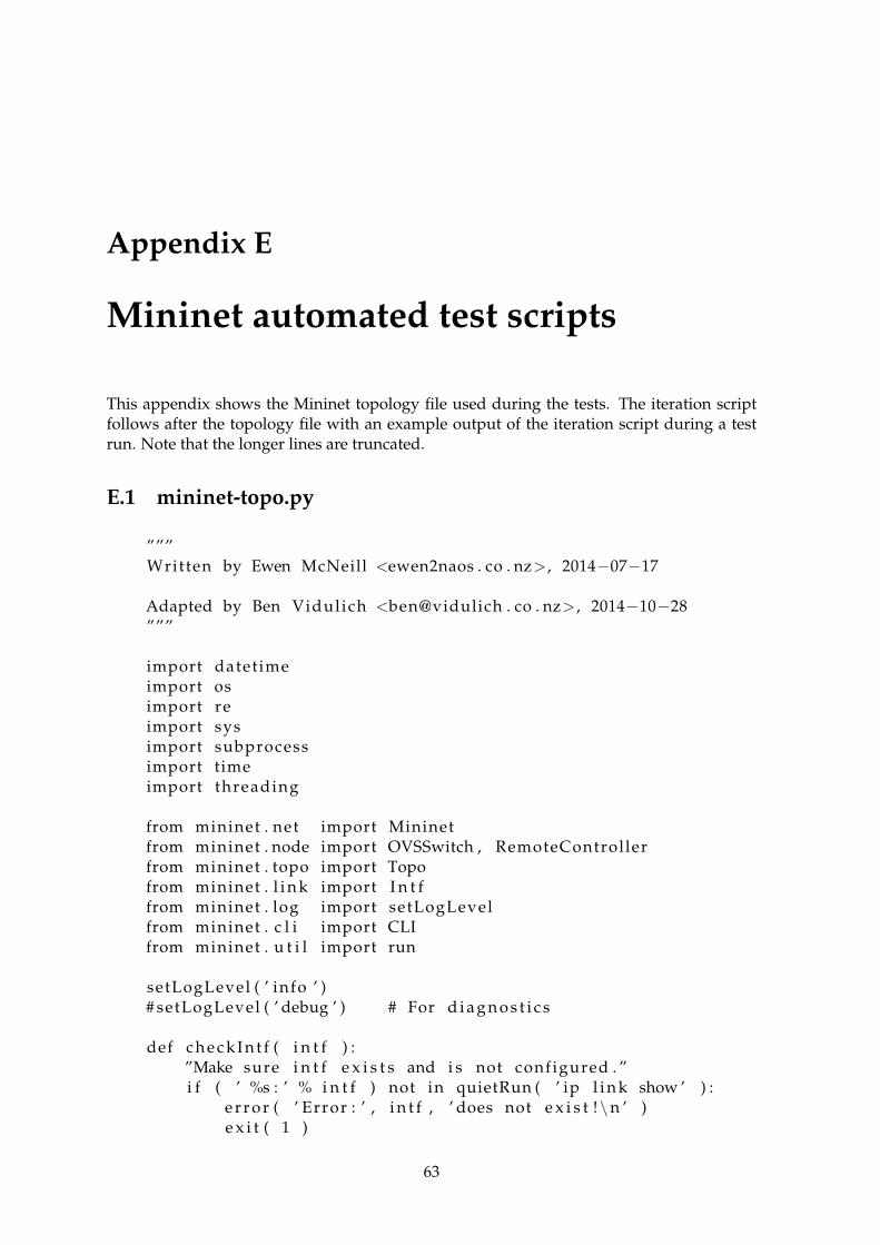
Appendix E
Mininet automated test scripts
This appendix shows the Mininet topology file used during the tests. The iteration scriptfollows after the topology file with an example output of the iteration script during a testrun. Note that the longer lines are truncated.
E.1 mininet-topo.py
”””Written by Ewen McNeill <ewen2naos . co . nz> , 2014−07−17
Adapted by Ben Vidulich <ben@vidulich . co . nz> , 2014−10−28”””
import datetimeimport osimport reimport sysimport subprocessimport timeimport threading
from mininet . net import Mininetfrom mininet . node import OVSSwitch , RemoteControllerfrom mininet . topo import Topofrom mininet . l i n k import I n t ffrom mininet . log import setLogLevelfrom mininet . c l i import CLIfrom mininet . u t i l import run
setLogLevel ( ’ info ’ )# setLogLevel ( ’ debug ’ ) # For d i a g n o s t i c s
def c h e c k I n t f ( i n t f ) :”Make sure i n t f e x i s t s and i s not configured . ”i f ( ’ %s : ’ % i n t f ) not in quietRun ( ’ ip l i n k show ’ ) :
e r r o r ( ’ Error : ’ , i n t f , ’ does not e x i s t !\n ’ )e x i t ( 1 )
63

ips = re . f i n d a l l ( r ’\d+\ .\d+\ .\d+\ .\d+ ’ , quietRun ( ’ i f c o n f i g ’ + i n t f ) )i f ips :
e r r o r ( ’ Error : ’ , i n t f , ’ has an IP address , ’’ and i s probably in use !\n ’ )
e x i t ( 1 )
c l a s s MeasurementThread ( threading . Thread ) :
p o r t s t a t s f i l e = ’ port−s t a t s−%s . csv ’
def i n i t ( s e l f , switch ) :super ( MeasurementThread , s e l f ) . i n i t ( )s e l f . switch = switchs e l f . s top = threading . Event ( )
i f ’TAG’ in os . environ :s e l f . tag = os . environ [ ’TAG’ ]
e l s e :s e l f . tag = ’ ’
s e l f . dump pattern = re . compile ( r ’ port \ s +(?P<port > .∗ ) : rx pkts =(?P<rx p
t = datetime . datetime . today ( )s e l f . s t a r t t i m e = i n t ( t . s t r f t i m e ( ’% s ’ ) )s e l f . p o r t s t a t s f i l e = s e l f . p o r t s t a t s f i l e % s e l f . s t a r t t i m e
i f not os . path . i s f i l e ( s e l f . p o r t s t a t s f i l e ) :with open ( s e l f . p o r t s t a t s f i l e , ’w’ ) as myfi le :
myfi le . wri te (” durat ion sec , tag , port , rx bytes , rx pkts , t x b y t e s ,
def run ( s e l f ) :while not s e l f . stopped ( ) :
time . s leep ( 1 )t = datetime . datetime . today ( )now = i n t ( t . s t r f t i m e ( ’% s ’ ) )durat ion = now − s e l f . s t a r t t i m edump = s e l f . switch . dpct l ( ’dump−ports ’ )matches = [m. groupdict ( ) f o r m in re . f i n d i t e r ( s e l f . dump pattern , dwith open ( s e l f . p o r t s t a t s f i l e , ’ a ’ ) as myfi le :
f o r m in matches :myfi le . wri te (”%s ,%s ,%s ,%s ,%s ,%s ,% s\n” % ( duration , s e l f . ta
def stop ( s e l f ) :s e l f . s top . s e t ( )
def stopped ( s e l f ) :re turn s e l f . s top . i s S e t ( )
c l a s s MoreporkOneSwitch ( Topo ) :”Morepork One Switch example topology ”
64
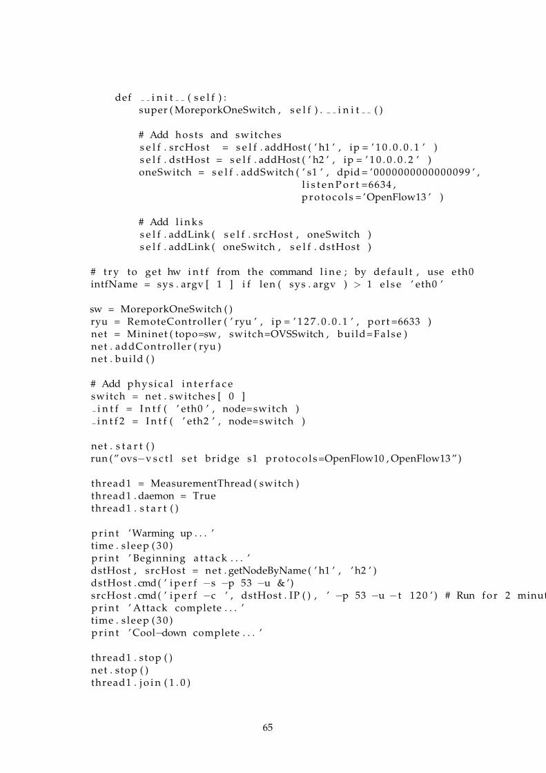
def i n i t ( s e l f ) :super ( MoreporkOneSwitch , s e l f ) . i n i t ( )
# Add hosts and switchess e l f . srcHost = s e l f . addHost ( ’ h1 ’ , ip = ’ 1 0 . 0 . 0 . 1 ’ )s e l f . dstHost = s e l f . addHost ( ’ h2 ’ , ip = ’ 1 0 . 0 . 0 . 2 ’ )oneSwitch = s e l f . addSwitch ( ’ s1 ’ , dpid = ’0000000000000099 ’ ,
l i s t e n P o r t =6634 ,p r o t o c o l s = ’OpenFlow13 ’ )
# Add l i n k ss e l f . addLink ( s e l f . srcHost , oneSwitch )s e l f . addLink ( oneSwitch , s e l f . dstHost )
# t r y to get hw i n t f from the command l i n e ; by defaul t , use eth0intfName = sys . argv [ 1 ] i f len ( sys . argv ) > 1 e l s e ’ eth0 ’
sw = MoreporkOneSwitch ( )ryu = RemoteController ( ’ ryu ’ , ip = ’ 1 2 7 . 0 . 0 . 1 ’ , port =6633 )net = Mininet ( topo=sw , switch=OVSSwitch , bui ld=F a l s e )net . addControl ler ( ryu )net . bui ld ( )
# Add phys ica l i n t e r f a c eswitch = net . switches [ 0 ]
i n t f = I n t f ( ’ eth0 ’ , node=switch )i n t f 2 = I n t f ( ’ eth2 ’ , node=switch )
net . s t a r t ( )run (” ovs−v s c t l s e t bridge s1 p r o t o c o l s =OpenFlow10 , OpenFlow13 ”)
thread1 = MeasurementThread ( switch )thread1 . daemon = Truethread1 . s t a r t ( )
p r i n t ’Warming up . . . ’time . s leep ( 3 0 )p r i n t ’ Beginning a t t a c k . . . ’dstHost , srcHost = net . getNodeByName ( ’ h1 ’ , ’ h2 ’ )dstHost . cmd( ’ i p e r f −s −p 53 −u & ’)srcHost . cmd( ’ i p e r f −c ’ , dstHost . IP ( ) , ’ −p 53 −u −t 1 2 0 ’ ) # Run f o r 2 minutp r i n t ’ Attack complete . . . ’time . s leep ( 3 0 )p r i n t ’ Cool−down complete . . . ’
thread1 . stop ( )net . stop ( )thread1 . j o i n ( 1 . 0 )
65
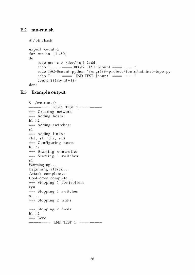
E.2 mn-run.sh
#!/ bin/bash
export count=1f o r run in { 1 . . 5 0 }do
sudo mn −c > /dev/n u l l 2>&1echo ”−−−−−===== BEGIN TEST $count =====−−−−−”sudo TAG=$count python ˜/ engr489−p r o j e c t / t o o l s /mininet−topo . pyecho ”−−−−−===== END TEST $count =====−−−−−”count=$ ( ( count + 1 ) )
done
E.3 Example output
$ ./mn−run . sh−−−−−===== BEGIN TEST 1 =====−−−−−∗∗∗ Creat ing network∗∗∗ Adding hosts :h1 h2∗∗∗ Adding switches :s1∗∗∗ Adding l i n k s :( h1 , s1 ) ( h2 , s1 )∗∗∗ Configuring hostsh1 h2∗∗∗ S t a r t i n g c o n t r o l l e r∗∗∗ S t a r t i n g 1 switchess1Warming up . . .Beginning a t t a c k . . .Attack complete . . .Cool−down complete . . .∗∗∗ Stopping 1 c o n t r o l l e r sryu∗∗∗ Stopping 1 switchess1 . .∗∗∗ Stopping 2 l i n k s
∗∗∗ Stopping 2 hostsh1 h2∗∗∗ Done−−−−−===== END TEST 1 =====−−−−−
66
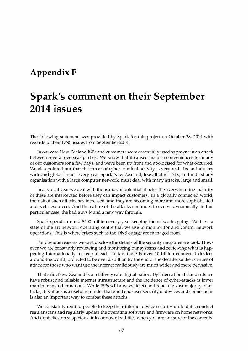
Appendix F
Spark’s comment on their September2014 issues
The following statement was provided by Spark for this project on October 28, 2014 withregards to their DNS issues from September 2014.
In our case New Zealand ISPs and customers were essentially used as pawns in an attackbetween several overseas parties. We know that it caused major inconveniences for manyof our customers for a few days, and weve been up front and apologised for what occurred.We also pointed out that the threat of cyber-criminal activity is very real. Its an industrywide and global issue. Every year Spark New Zealand, like all other ISPs, and indeed anyorganisation with a large computer network, must deal with many attacks, large and small.
In a typical year we deal with thousands of potential attacks the overwhelming majorityof these are intercepted before they can impact customers. In a globally connected world,the risk of such attacks has increased, and they are becoming more and more sophisticatedand well-resourced. And the nature of the attacks continues to evolve dynamically. In thisparticular case, the bad guys found a new way through.
Spark spends around $400 million every year keeping the networks going. We have astate of the art network operating centre that we use to monitor for and control networkoperations. This is where crises such as the DNS outage are managed from.
For obvious reasons we cant disclose the details of the security measures we took. How-ever we are constantly reviewing and monitoring our systems and reviewing what is hap-pening internationally to keep ahead. Today, there is over 10 billion connected devicesaround the world, projected to be over 25 billion by the end of the decade, so the avenues ofattack for those who want use the internet maliciously are much wider and more pervasive.
That said, New Zealand is a relatively safe digital nation. By international standards wehave robust and reliable internet infrastructure and the incidence of cyber-attacks is lowerthan in many other nations. While ISPs will always detect and repel the vast majority of at-tacks, this attack is a useful reminder that good end-user security of devices and connectionsis also an important way to combat these attacks.
We constantly remind people to keep their internet device security up to date, conductregular scans and regularly update the operating software and firmware on home networks.And dont click on suspicious links or download files when you are not sure of the contents.
67

F.1 The DNS Issue
F.1.1 What happened?
Cyber criminals based overseas appear to have been attacking web addresses in EasternEurope, and were bouncing the traffic off Spark customer connections, in what is known asa distributed denial of service (DDoS) attack.
The DDoS attack was dynamic, predominantly taking the shape of an amplified DNSattack which means an extremely high number of connection requests in the order of thou-sands per second - were being sent to a number of overseas web addresses with the intentionof overwhelming and crashing them. Each of these requests, as it passes through our net-work, queries our DNS server before it passes on so our servers were bearing the full bruntof the attack.
While the Spark network never crashed, we did experience extremely high traffic loadshitting our DNS servers which meant many customers had either slow or at times no con-nectivity (as their requests were timing out).
There were multiple attacks, which were dynamic in nature. They began on Friday night,subsided, and then began again early Saturday, continuing over the day. By early Sundaymorning traffic levels were back to normal. We saw the nature of the attack evolve over theperiod, possibly due to the cyber criminals monitoring our response and modifying theirattack to circumvent our mitigation measures in a classic whack a mole scenario.
F.1.2 How did they get access through the Spark Network?
During the attack, we observed that a small number of customer connections were involvedin generating the vast majority of the traffic. This was consistent with customers having mal-ware on their devices and the timing coincided with other DNS activity related to malwarein other parts of the world.
However, while we believe malware was as a potential factor, we also identified thatcyber criminals had been accessing vulnerable customer modems on our network. Thesemodems have been identified as having open DNS resolver functionality, which means theycan be used to carry out internet requests for anyone on the internet. This makes it easierfor cyber criminals to bounce an internet request off them (making it appear that the NZmodem was making the request, whereas it actually originates from an overseas source).
Most of these modems were not supplied by Spark and tend to be older or lower-endmodems. What remains clear is that good end user security remains an important way tocombat these attacks. With the proliferation of devices in households, that means both thesecurity within your device and the security of your modem.
F.1.3 What did Spark do?
We disconnected those modems from our network and contacted all the affected customers.We have also taken steps at a network level to mitigate this modem vulnerability. We alsoscanned our entire broadband customer base to identify any other customers who may beusing modems with similar vulnerabilities and contacted those customers to advise themon what they should do.
With respect to malware we continue to strongly encourage our customers to keep theirinternet device security up to date, conduct regular scans and regularly update the operatingsoftware and firmware on their home network. We also continue to advise customers not toclick on suspicious links or download files when they are not sure of the contents.
68

We have also taken steps at the network level to make it more difficult for cyber criminalsto exploit the DNS open resolver modem vulnerability and were using the latest technologyto strengthen our network monitoring and management capabilities. For security reasonswe cant detail these steps, however this is an ongoing battle to stay one step ahead of cybercriminals who are continually using more and more sophisticated tactics.
One of the mitigation options in response to the DDoS attacks involves blocking port53, which effectively stops one of the means for some customer devices and modems to bemisused. Were aware other ISPs did the same thing to combat this latest development incyber-threats. However in certain cases blocking port 53 does have other impacts on con-nectivity. So since the weekend weve been continuing to make enhancements and changes.
As part of these enhancements, we took some further steps to enable us to better lookunder the hood across some parts of the network. While the initial measures taken hadlargely mitigated the impact of the attacks, we didnt have total visibility of everything thatwas going on, especially in terms of abnormal traffic patterns.
Within the first hour of taking these further steps we saw DNS traffic coming from justthree of our home broadband customers representing 4% of our total DNS traffic for thatperiod. One connection alone had 1.2 million DNS requests in an hour. As we have port 53blocked, we believe that this may be due to malware previously installed on these customersdevices. We dont believe this is a new attack, its likely the malware was installed before theattack.
During the weekend issues that among other things we saw incoming traffic being bouncedoff a number of vulnerable customer modems (those with DNS open resolver functionality).Further insights did not involve any significant level of incoming traffic, which tends topoint to device malware, rather than a specific modem issue. This demonstrates there werea number of different vectors involved in the weekends DDoS attacks.
This is just one vivid illustration of the potential scale of cyber-threats and the impactthat can be generated from just a very small number of connections. Like all ISPs we seeevidence of literally thousands of attacks every year and the vast majority of these neverimpact on the customer experience across our network because of proactive management.
F.1.4 Why only Spark?
We cant say what other networks experienced. However, cyber criminals often look forclusters of IP addresses to use in any particular DDoS attack. That makes it more likely thatthese IP addresses belong to the customers of a single ISP even more likely with a large ISPlike Spark.
69

70

Bibliography
[1] ANDERSON, R. Security Engineering: A Guide to Building Dependable Distributed Systems.Wiley, 2008.
[2] BAMBENEK, J. A Chargen-based DDoS? Chargen is still a thing? https://isc.sans.
edu/diary/A+Chargen-based+DDoS%3F+Chargen+is+still+a+thing%3F/15647. [On-line; accessed 20-Oct-2014].
[3] BURKS, D. Security Onion. http://blog.securityonion.net/p/securityonion.
html. [Online; accessed 31-Oct-2014].
[4] CANTONI, M. Honeypot DNS and amplification attacks. http://www.nothink.org/
honeypot_dns.php. [Online; accessed 21-Oct-2014].
[5] CORNELL, D. DNS Amplification Attacks. http://labs.opendns.com/2014/03/17/
dns-amplification-attacks/. [Online; accessed 21-Oct-2014].
[6] DUBENDORFER, T., BOSSARDT, M., AND PLATTNER, B. Adaptive distributed trafficcontrol service for ddos attack mitigation. In Parallel and Distributed Processing Sympo-sium, 2005. Proceedings. 19th IEEE International (April 2005), pp. 8 pp.–.
[7] EASTEP, T. M. Simple way to set up Split DNS. http://shorewall.net/SplitDNS.
html. [Online; accessed 21-Oct-2014].
[8] EVANS, C. C. YAML. http://www.yaml.org/. [Online; accessed 30-Oct-2014].
[9] FERGUSON, P., AND SENIE, D. BCP 38 - Network Ingress Filtering: Defeating Denialof Service Attacks which employ IP Source Address Spoofing. RFC 2827, May 2000.
[10] GRAHAM-CUMMING, J. Understanding and mitigatingNTP-based DDoS attacks. http://blog.cloudflare.com/
understanding-and-mitigating-ntp-based-ddos-attacks/. [Online; accessed22-Oct-2014].
[11] KAMBOURAKIS, G., MOSCHOS, T., GENEIATAKIS, D., AND GRITZALIS, S. A fair solu-tion to dns amplification attacks. In Digital Forensics and Incident Analysis, 2007. WDFIA2007. Second International Workshop on (Aug 2007), pp. 38–47.
[12] KEALL, C. RAW DATA: Spark releases Q+A on out-ages, cyber-attack. http://www.nbr.co.nz/article/
raw-data-spark-releases-qa-outages-cyber-attack-ck-162069. [Online; ac-cessed 22-Oct-2014].
[13] KONG, J., MIRZA, M., SHU, J., YOEDHANA, C., GERLA, M., AND LU, S. Random flownetwork modeling and simulations for ddos attack mitigation. In IEEE InternationalConference on Communications, 2003. ICC ’03 (May 2003), vol. 1, pp. 487–491 vol.1.
71
[14] MAHAJAN, R., BELLOVIN, S. M., FLOYD, S., IOANNIDIS, J., PAXSON, V., AND
SHENKER, S. Controlling high bandwidth aggregates in the network. SIGCOMM Com-put. Commun. Rev. 32, 3 (July 2002), 62–73.
[15] MICROSOFT. What is a botnet? http://www.microsoft.com/security/resources/
botnet-whatis.aspx. [Online; accessed 20-Oct-2014].
[16] MIMOSO, M. Spamhaus DDoS Attacks Triple Sizeof Attacks on US Banks. http://threatpost.com/
spamhaus-ddos-attacks-triple-size-attacks-us-banks-032713/77675. [On-line; accessed 22-Oct-2014].
[17] MININET TEAM. Mininet. http://mininet.org/. [Online; accessed 31-Oct-2014].
[18] MORROW, C. Customer Blackhole Community. http://www.he.net/adm/blackhole.html. [Online; accessed 21-Oct-2014].
[19] NETWORKS, A. Digital Attack Map. http://www.digitalattackmap.com/. [Online;accessed 27-Oct-2014].
[20] NIST. Vulnerability Summary for CVE-2013-5211. http://web.nvd.nist.gov/view/vuln/detail?vulnId=CVE-2013-5211. [Online; accessed 22-Oct-2014].
[21] NLANR/DAST. Iperf. https://iperf.fr/. [Online; accessed 31-Oct-2014].
[22] OF HOMELAND SECURITY, D. DNS Amplification Attacks. https://www.us-cert.
gov/ncas/tips/ST04-015. [Online; accessed 20-Oct-2014].
[23] OF HOMELAND SECURITY, D. DNS Amplification Attacks. https://www.us-cert.
gov/ncas/alerts/TA13-088A. [Online; accessed 19-Oct-2014].
[24] OF HOMELAND SECURITY, D. UDP-based Amplification Attacks. https://www.
us-cert.gov/ncas/alerts/TA14-017A. [Online; accessed 20-Oct-2014].
[25] OPEN NETWORKING FOUNDATION. Software-Defined Networking (SDN) Defini-tion. https://www.opennetworking.org/sdn-resources/sdn-definition. [Online;accessed 21-Oct-2014].
[26] OPEN VSWITCH. Open vSwitch. http://openvswitch.org/. [Online; accessed 31-Oct-2014].
[27] ORACLE. VirtualBox. https://www.virtualbox.org/. [Online; accessed 31-Oct-2014].
[28] PBUG. Tfreak. http://hackepedia.org/?title=Tfreak. [Online; accessed 20-Oct-2014].
[29] PFAFF, B., LANTZ, B., HELLER, B., BARKER, C., BECKMANN, C., COHN, D., TA-LAYCO, D., ERICKSON, D., MCDYSAN, D., WARD, D., CRABBE, E., GIBB, G., AP-PENZELLER, G., TOURRILHES, J., TONSING, J., PETTIT, J., YAP, K., POUTIEVSKI, L.,VICISANO, L., CASADO, M., TAKAHASHI, M., KOBAYASHI, M., YADAV, N., MCKE-OWN, N., DHEUREUSE, N., BALLAND, P., RAMANATHAN, R., PRICE, R., SHERWOOD,R., DAS, S., GANDHAM, S., YABE, T., YIAKOUMIS, Y., AND KIS, Z. L. OpenFlowSwitch Specification. Specification, Open Networking Foundation, June 2012.
[30] PORTER, R. DDoS and BCP 38. https://isc.sans.edu/diary/DDoS+and+BCP+38/
17735. [Online; accessed 21-Oct-2014].
72
[31] PRINCE, M. Deep Inside a DNS Amplification DDoS Attack. http://blog.
cloudflare.com/deep-inside-a-dns-amplification-ddos-attack/. [Online; ac-cessed 20-Oct-2014].
[32] PRINCE, M. Technical Details Behind a 400Gbps NTP Am-plification DDoS Attack. http://blog.cloudflare.com/
technical-details-behind-a-400gbps-ntp-amplification-ddos-attack/. [On-line; accessed 22-Oct-2014].
[33] PRINCE, M. The DDoS That Knocked Spamhaus Offline(And How We Mitigated It). http://blog.cloudflare.com/
the-ddos-that-knocked-spamhaus-offline-and-ho/. [Online; accessed 22-Oct-2014].
[34] PROLEXIC. DoS and DDoS Glossary of Terms. http://www.prolexic.com/
knowledge-center-dos-and-ddos-glossary.html. [Online; accessed 20-Oct-2014].
[35] PROLEXIC. DDoS Boot Camp: Basic Training for an Increasing Cyber Threat.
[36] REKHTER, Y., MOSKOWITZ, B., KARRENBERG, D., DE GROOT, G., AND LEAR, E. Ad-dress Allocation for Private Internets. RFC 1918, February 1996.
[37] RYAN, P., AND SCHNEIDER, S. A. The modelling and analysis of security protocols: the cspapproach. Addison-Wesley Professional, 2001.
[38] RYU SDN FRAMEWORK COMMUNITY. Ryu. http://osrg.github.io/ryu/. [Online;accessed 31-Oct-2014].
[39] SUN, C., LIU, B., AND SHI, L. Efficient and low-cost hardware defense against dnsamplification attacks. In IEEE Global Telecommunications Conference, 2008. IEEE GLOBE-COM 2008. (Nov 2008), pp. 1–5.
[40] TABLEAU SOFTWARE. Tableau. http://www.tableausoftware.com/. [Online; accessed31-Oct-2014].
[41] TECHNET, M. Disable Recursion on the DNS Server. http://technet.microsoft.
com/en-us/library/ee649165(v=ws.10).aspx. [Online; accessed 21-Oct-2014].
[42] VIXIE, P. DNS Response Rate Limiting (DNS RRL). TN 1, April 2012.
[43] VIXIE, P. Rate-limiting State: The edge of the Internet is an unruly place. ACMQueue12, 2 (February 2014).
[44] WINSTEAD, E. Response Rate Limiting with BIND. APRICOT 2014, 2014.
73