Vibratory Plate - Wacker Neusonproducts.wackerneuson.com/manuals/Operators/0109983en_003.pdf ·...
36
www.wackergroup.com Operator´s Manual Vibratory Plate DPU 100-70 0109983en 003 12.2008
Transcript of Vibratory Plate - Wacker Neusonproducts.wackerneuson.com/manuals/Operators/0109983en_003.pdf ·...
www.wackergroup.com
Operator´s Manual
Vibratory Plate
DPU 100-70
0109983en 003
12.2008

Operating instructions
1
1. Foreword
For your own safety and protection from bodily injuries, carefully read,
understand and follow the safety instructions in this manual.
Please operate and maintain your Wacker machine in accordance with
the instructions in this manual. Your Wacker machine will reward your
attention by giving trouble-free operation and a high degree of
availability.
Replace defective machine components immediately.
All rights, especially the right for copying and distribution are reserved
Copyright 2008 by Wacker Construction Equipment AG
No part of this publication may be reproduced in any form or by any
means, electronic or mechanical, including photocopying, without
express permission in writing from Wacker Construction Equipment AG.
Any type of reproduction, distribution or saving on data carriers of any
type or method not authorized by Wacker represents an infringement of
valid copyrights and will be prosecuted. We expressly reserve the right
to technical modifications - even without express due notice - which aim
at improving our machines or their safety standards.
Table of contents
1. Foreword 1
2. Safety instructions 4
2.1 General instructions ............................................................................. 42.2 Operation .............................................................................................. 42.3 Safety checks ....................................................................................... 62.4 Maintenance ......................................................................................... 62.5 Transport .............................................................................................. 72.6 Maintenance checks ............................................................................. 7
3. Technical Data 8
4. Description 10
4.1 Field of applications ............................................................................ 104.2 Dimensions ......................................................................................... 104.3 Recommendations on compaction ..................................................... 104.4 Compaction without extension plates ................................................. 114.5 Max. admissible inclination ................................................................. 114.6 Description of function ........................................................................ 12
5. Transport to work site 14
6. Operation 15
6.1 Starting ............................................................................................... 156.2 Forward and reverse motion .............................................................. 166.3 Switching off ....................................................................................... 16
7. Maintenance 17
7.1 Maintenance schedule ....................................................................... 177.2 Oil bath air cleaner ............................................................................. 187.3 Engine oil level control ....................................................................... 197.4 Battery acid level control .................................................................... 207.5 Hydraulic oil level control .................................................................... 207.6 Exciter oil level control ........................................................................ 21
2
Table of contents
8. Faults 22
8.1 Troubleshooting and fault clearance .................................................. 228.2 Starting with external battery etc. ....................................................... 23
9. Electricwiring diagram 24
10. Hydraulic connections diagram 26
11. Lables 27
EC - Conformity Certificate 29
DIN EN ISO 9001 CERTIFICATE 31
3
Safety instructions
2. Safety instructions
safety instructions for the use of vibratory plates withcombustion engines
2.1 General instructions
2.1.1 Vibratory plates may only be operated by persons who
∗ are at least 18 years of age
∗ are physically and mentally fit for this job
∗ have been instructed in guiding vibratory plates and proved their abilityfor the job to the employer
∗ may be expected to carry out the job they are charged with carefully.
The persons must be assigned the job of guiding vibratory plates bythe employer.
2.1.2 Vibratory plates may only be used for compaction jobs. Both themanufacturer’s operating instructions and these safety instructionshave to be observed.
2.1.3 The persons charged with the operation of vibratory plates have to bemade familiar with the necessary safety measures relating to themachine. In case of extraordinary uses the employer shall give thenecessary additional instructions.
2.1.4 It is possible that these vibratory plates exceed the admissibleassessment sound level of 89 dB (A). Employees must wear personalear protection if the sound level reaches 89 dB (A) or more.
2.2 Operation
2.2.1 The function of operation levers or elements is not to be influenced orrendered ineffective.
2.2.2 During operation the operator may not leave the control elements.
2.2.3 The operator has to stop the engine of the vibratory plate before goingon breaks. The machine has to be placed such that it cannot turn over.
2.2.4 Stop engine before filling fuel tank. When refilling fuel tank, do notallow fuel to come into contact with the hot part of the engine or spillonto the ground.
2.2.5 Do not smoke or handle open fire near this machine.
SV00076GB 4
Safety instructions
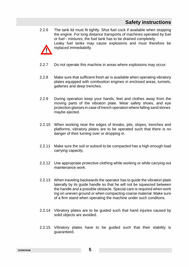
2.2.6 The tank lid must fit tightly. Shut fuel cock if available when stoppingthe engine. For long distance transports of machines operated by fuelor fuel - mixtures, the fuel tank has to be drained completely.Leaky fuel tanks may cause explosions and must therefore bereplaced immediatelly.
2.2.7 Do not operate this machine in areas where explosions may occur.
2.2.8 Make sure that sufficient fresh air is available when operating vibratoryplates equipped with combustion engines in enclosed areas, tunnels,galleries and deep trenches.
2.2.9 During operation keep your hands, feet and clothes away from themoving parts of the vibraton plate. Wear safety shoes, and eyeprotection glasses in case of trench operation where falling sand stonesmaybe ejected.
2.2.10 When working near the edges of breaks, pits, slopes, trenches andplatforms, vibratory plates are to be operated such that there is nodanger of their turning over or dropping in.
2.2.11 Make sure the soil or subsoil to be compacted has a high enough loadcarrying capacity.
2.2.12 Use appropriate protective clothing while working or while carrying outmaintenance work.
2.2.13 When traveling backwards the operator has to guide the vibration platelaterally by its guide handle so that he will not be squeezed betweenthe handle and a possible obstacle. Special care is required when working on uneven ground or when compacting coarse material. Make sureof a firm stand when operating the machine under such conditons.
2.2.14 Vibratory plates are to be guided such that hand injuries caused bysolid objects are avoided.
2.2.15 Vibratory plates have to be guided such that their stability isguaranteed.
SV00076GB 5
Safety instructions
2.3 Safety checks
2.3.1 Vibratory plates may only be operated with all safety devices installed.
2.3.2 Before starting operation, the operator has to check that all control andsafety devices function properly.
2.3.3 Only use original spare parts. Modifications to this machine includingthe adjustment of the maximum engine speed set by the manufacturerare subject to the express approval of WACKER. In case ofnonobservance all liabilities shall be refused.
2.3.4 The machine must to be switched off immediately in case of defectsjeopardizing the operational safety of the equipment.
2.3.5 Process materials and operating fuels must be stowed away inreceptacles or containers marked according to the respectivemanufacturers specifications.
2.4 Maintenance
2.4.1 Only use original spare parts. Modifications to this machine includingthe adjustment of the maximum speed set by the manufacturer aresubject to the express approval of WACKER. In case ofnonobservance all liabilities shall be refused.
2.4.2 All drive units have to be switched off before carrying out maintenancejobs. Deviations from this are only allowed if the maintenance or jobsrequire a running engine.
2.4.3 When working on vibratory plates equipped with electric starter,disconnect battery before carrying out maintenance or repair jobs onthe electric parts of the machine.
2.4.4 Remove pressure from hydraulic lines before working on them.Caution: take care when removing hydraulic lines, for the oil may bevery hot (up. over 80o C). Precautions are to be taken to prevent oilfrom splashing into the operator’s eyes.
2.4.5 All safety devices must be reinstalled properly immediately aftermaintenance and repair jobs have been completed.
2.4.6 Do not hose down the machine with water after each use to avoidpossible malfunctions. Do not use high pressure washers nor chemicalproducts.
SV00076GB 6
Safety instructions
2.5 Transport
2.5.1 During transport, loading and unloading of vibration plates by meansof lifting devices, appropriate slinging means or hooks have to be usedon the lifting points provided for this purpose on the vibratory plate.
2.5.2 The load-carrying capacity of the loading ramps has to be sufficientand the ramps have to be secure such that they cannot turn over.Make sure that no one be endangered by machines turning over byslipping or by moving machine parts.
2.5.3 When being transported on vehicles, precautions have to be taken thatvibration plates do not slip or turn over.
2.6 Maintenance checks
2.6.1 According to the conditions and frequency of use, vibratory plateshave to be checked for safe operation at least once a year by skilledtechnicians, such as those found at WACKER-service depots andhave to be repaired if necessary.
Please also observe the corresponding rules and regulations valid in yourcountry.
SV00076GB 7
Technical Data
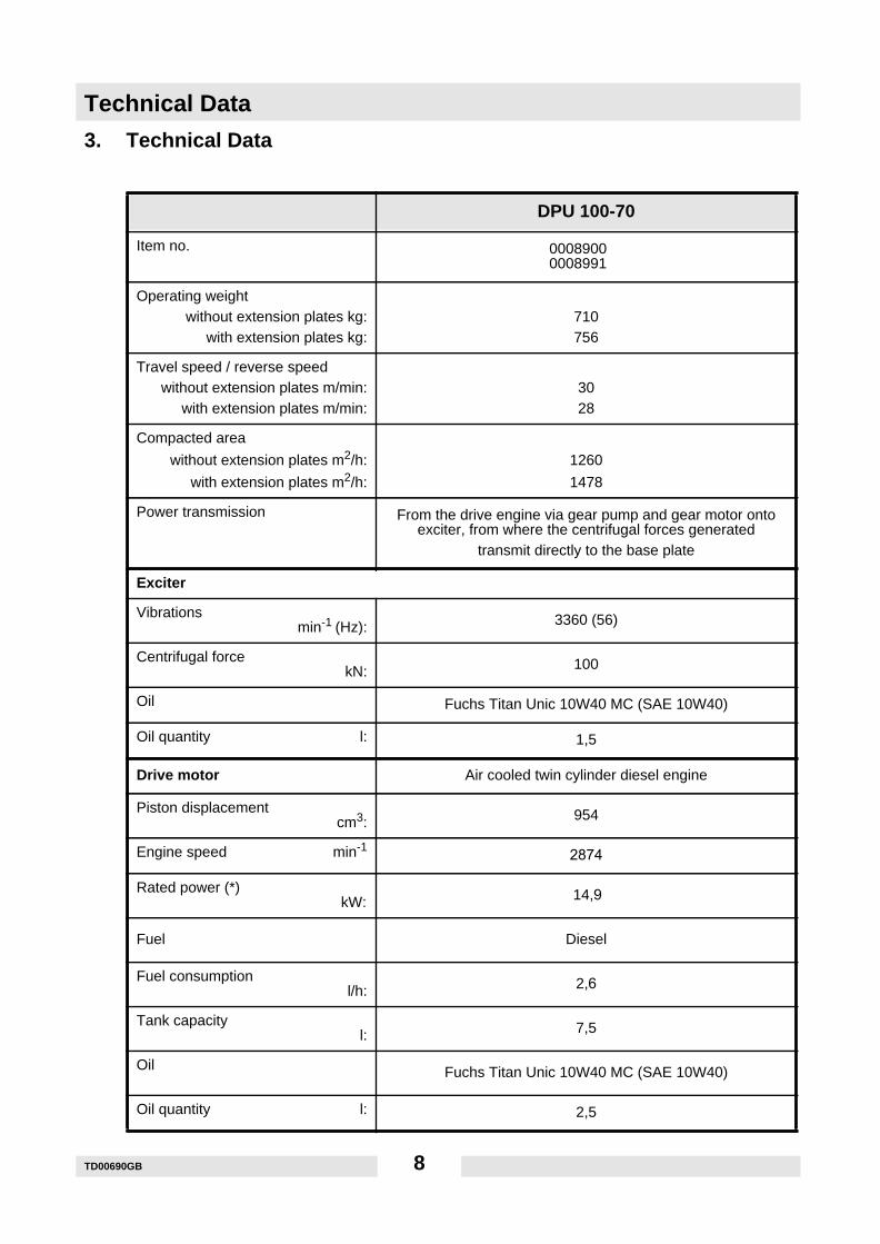
3. Technical Data
DPU 100-70
Item no. 00089000008991
Operating weightwithout extension plates kg:
with extension plates kg:710756
Travel speed / reverse speedwithout extension plates m/min:
with extension plates m/min:3028
Compacted area
without extension plates m2/h:
with extension plates m2/h:
1260
1478
Power transmission From the drive engine via gear pump and gear motor ontoexciter, from where the centrifugal forces generated
transmit directly to the base plate
Exciter
Vibrationsmin-1 (Hz): 3360 (56)
Centrifugal forcekN: 100
Oil Fuchs Titan Unic 10W40 MC (SAE 10W40)
Oil quantity l: 1,5
Drive motor Air cooled twin cylinder diesel engine
Piston displacementcm3: 954
Engine speed min-1 2874
Rated power (*) kW: 14,9
Fuel Diesel
Fuel consumptionl/h: 2,6
Tank capacityl: 7,5
Oil Fuchs Titan Unic 10W40 MC (SAE 10W40)
Oil quantity l: 2,5
TD00690GB 8
Technical Data
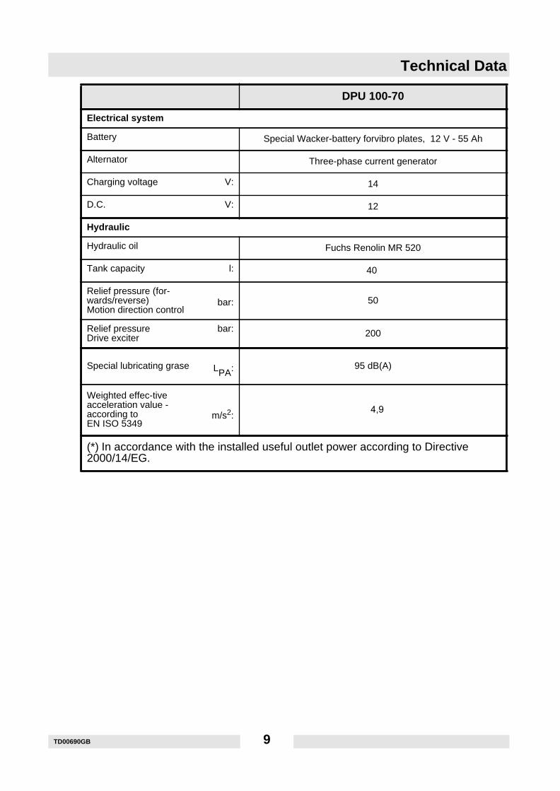
Electrical system
Battery Special Wacker-battery forvibro plates, 12 V - 55 Ah
Alternator Three-phase current generator
Charging voltage V: 14
D.C. V: 12
Hydraulic
Hydraulic oil Fuchs Renolin MR 520
Tank capacity l: 40
Relief pressure (for-wards/reverse)Motion direction control
bar: 50
Relief pressureDrive exciter
bar: 200
Special lubricating grase LPA: 95 dB(A)
Weighted effec-tiveacceleration value -according toEN ISO 5349
m/s2: 4,9
(*) In accordance with the installed useful outlet power according to Directive2000/14/EG.
DPU 100-70
TD00690GB 9
Description
4. Description
4.1 Field of applications
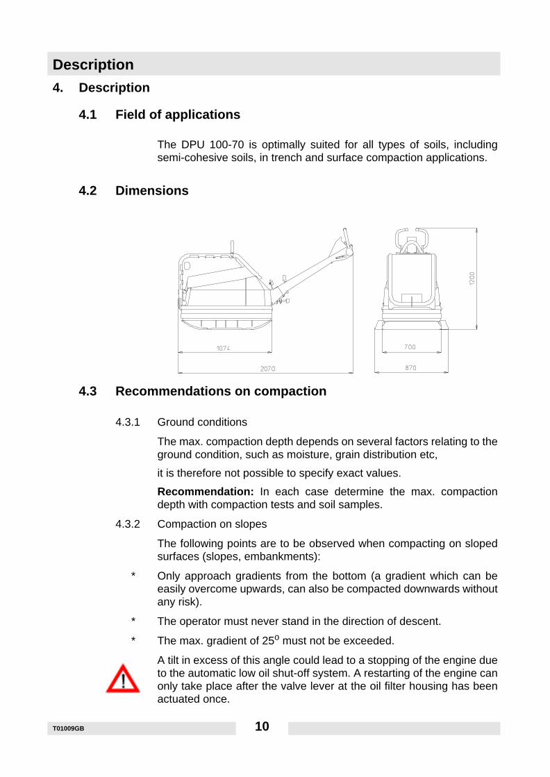
The DPU 100-70 is optimally suited for all types of soils, includingsemi-cohesive soils, in trench and surface compaction applications.
4.2 Dimensions
4.3 Recommendations on compaction
4.3.1 Ground conditions
The max. compaction depth depends on several factors relating to theground condition, such as moisture, grain distribution etc,
it is therefore not possible to specify exact values.
Recommendation: In each case determine the max. compactiondepth with compaction tests and soil samples.
4.3.2 Compaction on slopes
The following points are to be observed when compacting on slopedsurfaces (slopes, embankments):
∗ Only approach gradients from the bottom (a gradient which can beeasily overcome upwards, can also be compacted downwards withoutany risk).
∗ The operator must never stand in the direction of descent.
∗ The max. gradient of 25o must not be exceeded.
A tilt in excess of this angle could lead to a stopping of the engine dueto the automatic low oil shut-off system. A restarting of the engine canonly take place after the valve lever at the oil filter housing has beenactuated once.
T01009GB 10
Description
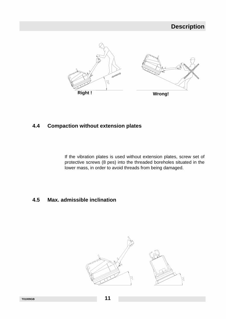
4.4 Compaction without extension plates
If the vibration plates is used without extension plates, screw set ofprotective screws (8 pes) into the threaded boreholes situated in thelower mass, in order to avoid threads from being damaged.
4.5 Max. admissible inclination
Right ! Wrong!
T01009GB 11
Description
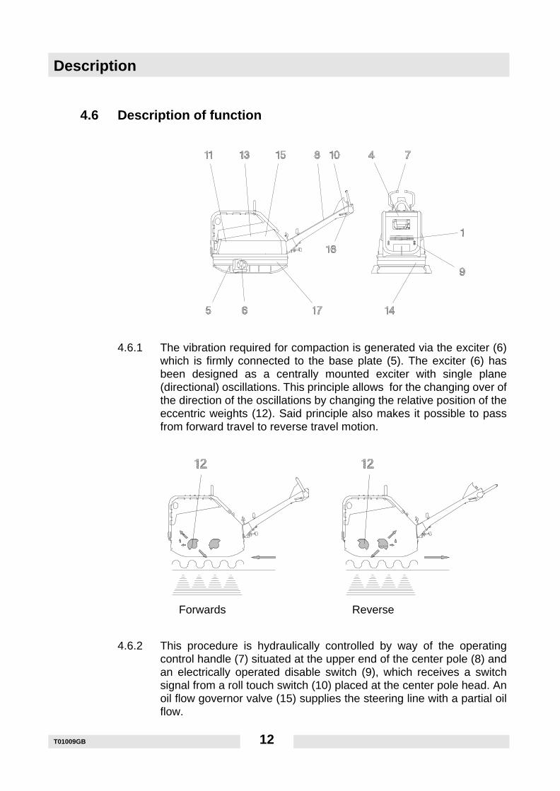
4.6 Description of function
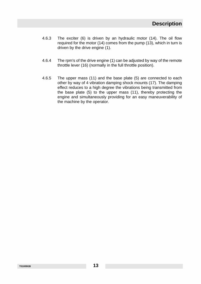
4.6.1 The vibration required for compaction is generated via the exciter (6)which is firmly connected to the base plate (5). The exciter (6) hasbeen designed as a centrally mounted exciter with single plane(directional) oscillations. This principle allows for the changing over ofthe direction of the oscillations by changing the relative position of theeccentric weights (12). Said principle also makes it possible to passfrom forward travel to reverse travel motion.
4.6.2 This procedure is hydraulically controlled by way of the operatingcontrol handle (7) situated at the upper end of the center pole (8) andan electrically operated disable switch (9), which receives a switchsignal from a roll touch switch (10) placed at the center pole head. Anoil flow governor valve (15) supplies the steering line with a partial oilflow.
Forwards Reverse
T01009GB 12
Description
4.6.3 The exciter (6) is driven by an hydraulic motor (14). The oil flowrequired for the motor (14) comes from the pump (13), which in turn isdriven by the drive engine (1).
4.6.4 The rpm's of the drive engine (1) can be adjusted by way of the remotethrottle lever (16) (normally in the full throttle position).
4.6.5 The upper mass (11) and the base plate (5) are connected to eachother by way of 4 vibration damping shock mounts (17). The dampingeffect reduces to a high degree the vibrations being transmitted fromthe base plate (5) to the upper mass (11), thereby protecting theengine and simultaneously providing for an easy maneuverability ofthe machine by the operator.
T01009GB 13
Transport to work site
T01010GB 14
5. Transport to work site
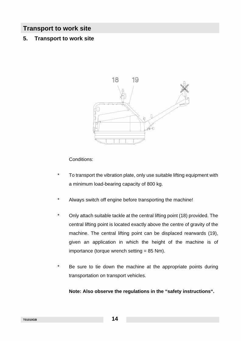
Conditions:
∗ To transport the vibration plate, only use suitable lifting equipment with
a minimum load-bearing capacity of 800 kg.
∗ Always switch off engine before transporting the machine!
∗ Only attach suitable tackle at the central lifting point (18) provided. The
central lifting point is located exactly above the centre of gravity of the
machine. The central lifting point can be displaced rearwards (19),
given an application in which the height of the machine is of
importance (torque wrench setting = 85 Nm).
∗ Be sure to tie down the machine at the appropriate points during
transportation on transport vehicles.
Note: Also observe the regulations in the “safety instructions“.
Operation
6. Operation
6.1 Starting
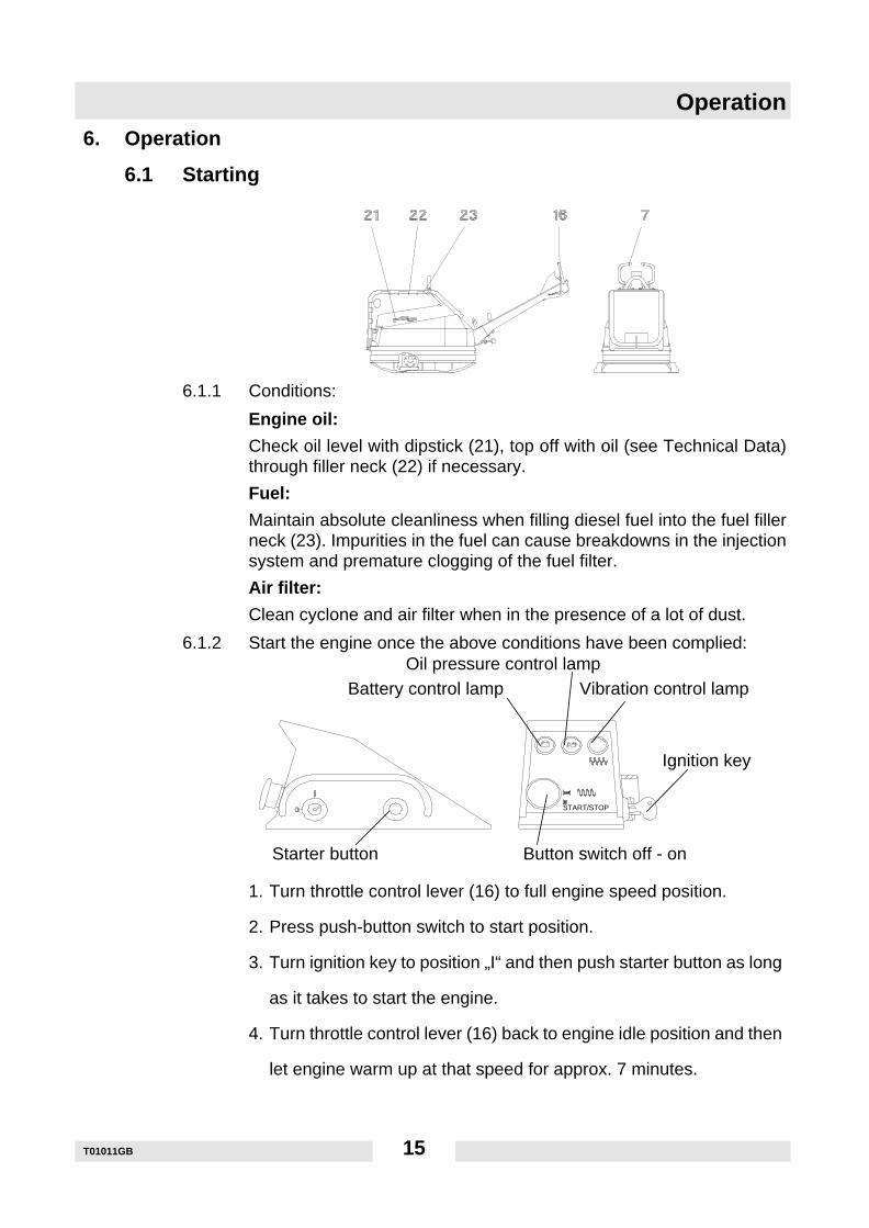
6.1.1 Conditions:
Engine oil:
Check oil level with dipstick (21), top off with oil (see Technical Data)through filler neck (22) if necessary.
Fuel:
Maintain absolute cleanliness when filling diesel fuel into the fuel fillerneck (23). Impurities in the fuel can cause breakdowns in the injectionsystem and premature clogging of the fuel filter.
Air filter:
Clean cyclone and air filter when in the presence of a lot of dust.
6.1.2 Start the engine once the above conditions have been complied:
1. Turn throttle control lever (16) to full engine speed position.
2. Press push-button switch to start position.
3. Turn ignition key to position „I“ and then push starter button as long
as it takes to start the engine.
4. Turn throttle control lever (16) back to engine idle position and then
let engine warm up at that speed for approx. 7 minutes.
Button switch off - onStarter button
Battery control lampOil pressure control lamp
Vibration control lamp
Ignition key
START/STOP
T01011GB 15
Operation
6.2 Forward and reverse motion
1. Push throttle control lever (16) to full rpm’s position.
2. The vibration is connected by pulling the press button switch out of
the start position.
3. The travel direction is defined by way of the operating control handle
(7).
4. The vibratory plate will automatically travel forwards (away from the
operator) if the operating control handle (7) is released (dead man's
handle).
6.3 Switching off
1. Push down press button switch from vibration position to stop
position. The control lamp will extinguish.
2. Move throttle lever (16) all the way to the stop position.
3. Turn the ignition key to the stop position and pull off once engine
has stopped turning. The control lamp will turn off.
T01011GB 16
Maintenance
7. Maintenance
7.1 Maintenance schedule
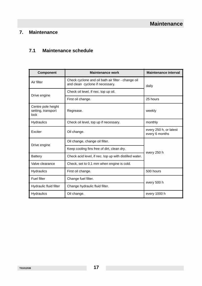
Component Maintenance work Maintenance interval
Air filterCheck cyclone and oil bath air filter - change oiland clean cyclone if necessary. daily
Drive engineCheck oil level, if nec. top up oil.
First oil change. 25 hours
Centre pole heightsetting, transportlock
Regrease. weekly
Hydraulics Check oil level, top up if necessary. monthly
Exciter Oil change.every 250 h, or latestevery 6 months
Drive engineOil change, change oil filter.
every 250 hKeep cooling fins free of dirt, clean dry.
Battery Check acid level, if nec. top up with distilled water.
Valve clearance Check, set to 0,1 mm when engine is cold.
Hydraulics First oil change. 500 hours
Fuel filter Change fuel filter.every 500 h
Hydraulic fluid filter Change hydraulic fluid filter.
Hydraulics Oil change. every 1000 h
T01012GB 17
Maintenance
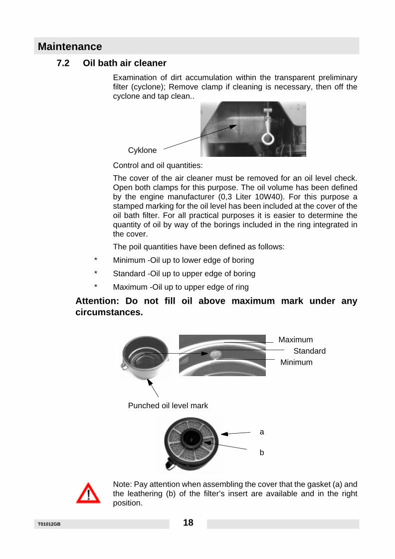
7.2 Oil bath air cleaner
Examination of dirt accumulation within the transparent preliminaryfilter (cyclone); Remove clamp if cleaning is necessary, then off thecyclone and tap clean..
Control and oil quantities:
The cover of the air cleaner must be removed for an oil level check.Open both clamps for this purpose. The oil volume has been definedby the engine manufacturer (0,3 Liter 10W40). For this purpose astamped marking for the oil level has been included at the cover of theoil bath filter. For all practical purposes it is easier to determine thequantity of oil by way of the borings included in the ring integrated inthe cover.
The poil quantities have been defined as follows:
∗ Minimum -Oil up to lower edge of boring
∗ Standard -Oil up to upper edge of boring
∗ Maximum -Oil up to upper edge of ring
Attention: Do not fill oil above maximum mark under anycircumstances.
Note: Pay attention when assembling the cover that the gasket (a) andthe leathering (b) of the filter’s insert are available and in the rightposition.
Cyklone
Punched oil level mark
a
b
MaximumStandard
Minimum
T01012GB 18
Maintenance
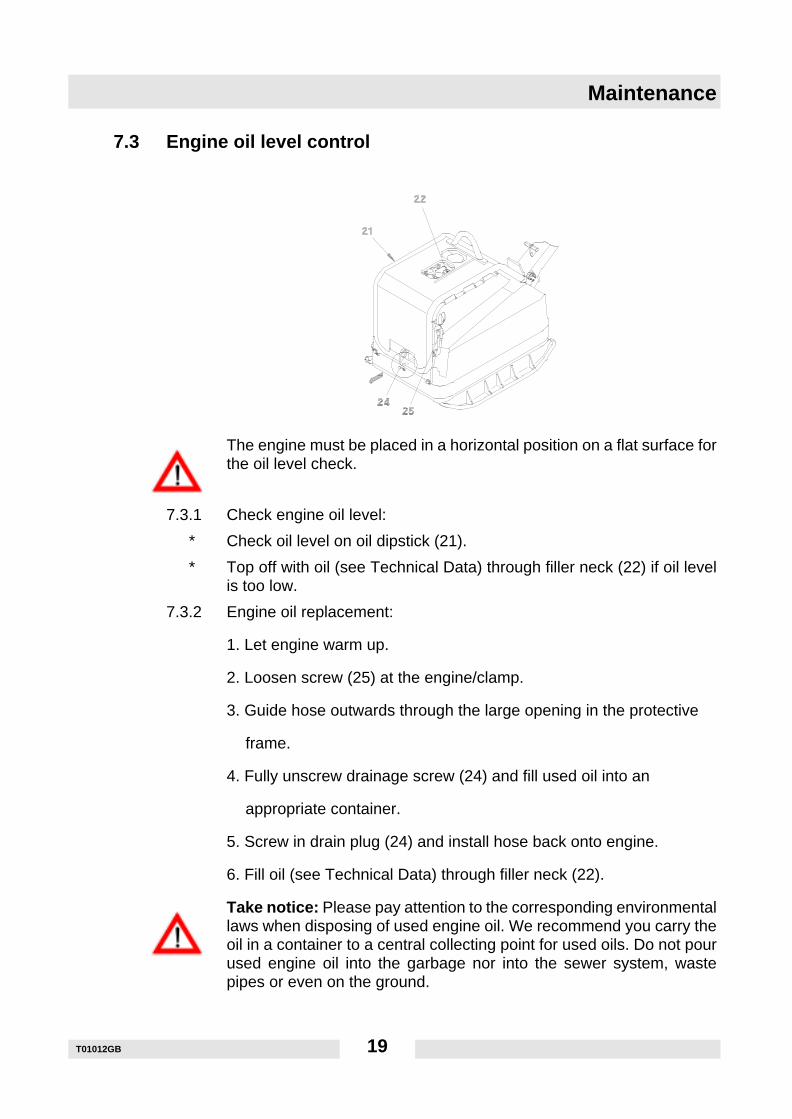
7.3 Engine oil level control
The engine must be placed in a horizontal position on a flat surface forthe oil level check.
7.3.1 Check engine oil level:
∗ Check oil level on oil dipstick (21).
∗ Top off with oil (see Technical Data) through filler neck (22) if oil levelis too low.
7.3.2 Engine oil replacement:
1. Let engine warm up.
2. Loosen screw (25) at the engine/clamp.
3. Guide hose outwards through the large opening in the protective
frame.
4. Fully unscrew drainage screw (24) and fill used oil into an
appropriate container.
5. Screw in drain plug (24) and install hose back onto engine.
6. Fill oil (see Technical Data) through filler neck (22).
Take notice: Please pay attention to the corresponding environmentallaws when disposing of used engine oil. We recommend you carry theoil in a container to a central collecting point for used oils. Do not pourused engine oil into the garbage nor into the sewer system, wastepipes or even on the ground.
T01012GB 19
Maintenance
7.4 Battery acid level control7.4.1 Check battery acid level
1. Open right maintenance cover.
2. Check acid level and top up with distilled water if necessary.
3. Close maintenance cover again.
Be sure to check if the positive pole cover is in the correct positionbefore closing the maintenance cover.
Note: Only replace a defective battery with an original Wacker battery.Conventional batteries are not designed to withstand the high vibrationload.
7.4.2 Replace battery
Removal: first disconnect the negative, then the positive pole.
Assembly: first connect the positive, then the negative pole.
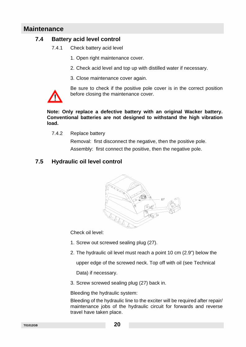
7.5 Hydraulic oil level control
Check oil level:
1. Screw out screwed sealing plug (27).
2. The hydraulic oil level must reach a point 10 cm (2.9”) below the
upper edge of the screwed neck. Top off with oil (see Technical
Data) if necessary.
3. Screw screwed sealing plug (27) back in.
Bleeding the hydraulic system:
Bleeding of the hydraulic line to the exciter will be required after repair/maintenance jobs of the hydraulic circuit for forwards and reversetravel have taken place.
T01012GB 20
Maintenance
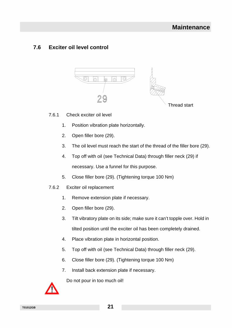
7.6 Exciter oil level control
7.6.1 Check exciter oil level
1. Position vibration plate horizontally.
2. Open filler bore (29).
3. The oil level must reach the start of the thread of the filler bore (29).
4. Top off with oil (see Technical Data) through filler neck (29) if
necessary. Use a funnel for this purpose.
5. Close filler bore (29). (Tightening torque 100 Nm)
7.6.2 Exciter oil replacement
1. Remove extension plate if necessary.
2. Open filler bore (29).
3. Tilt vibratory plate on its side; make sure it can’t topple over. Hold in
tilted position until the exciter oil has been completely drained.
4. Place vibration plate in horizontal position.
5. Top off with oil (see Technical Data) through filler neck (29).
6. Close filler bore (29). (Tightening torque 100 Nm)
7. Install back extension plate if necessary.
Do not pour in too much oil!
Thread start
T01012GB 21
Faults
8. Faults
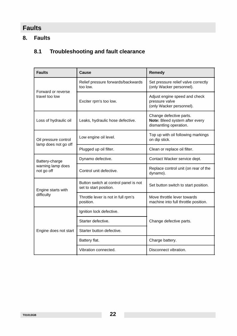
8.1 Troubleshooting and fault clearance
Faults Cause Remedy
Forward or reversetravel too low
Relief pressure forwards/backwardstoo low.
Set pressure relief valve correctly(only Wacker personnel).
Exciter rpm's too low.Adjust engine speed and checkpressure valve(only Wacker personnel).
Loss of hydraulic oil Leaks, hydraulic hose defective.Change defective parts.Note: Bleed system after everydismantling operation.
Oil pressure controllamp does not go off
Low engine oil level.Top up with oil following markingson dip stick.
Plugged up oil filter. Clean or replace oil filter.
Battery-chargewarning lamp doesnot go off
Dynamo defective. Contact Wacker service dept.
Control unit defective.Replace control unit (on rear of thedynamo).
Engine starts withdifficulty
Button switch at control panel is notset to start position.
Set button switch to start position.
Throttle lever is not in full rpm’sposition.
Move throttle lever towardsmachine into full throttle position.
Engine does not start
Ignition lock defective.
Change defective parts.Starter defective.
Starter button defective.
Battery flat. Charge battery.
Vibration connected. Disconnect vibration.
T01013GB 22
Faults
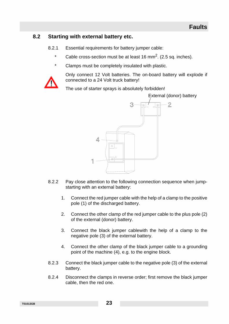
8.2 Starting with external battery etc.
8.2.1 Essential requirements for battery jumper cable:
∗ Cable cross-section must be at least 16 mm2. (2.5 sq. inches).
∗ Clamps must be completely insulated with plastic.
Only connect 12 Volt batteries. The on-board battery will explode ifconnected to a 24 Volt truck battery!
The use of starter sprays is absolutely forbidden!
8.2.2 Pay close attention to the following connection sequence when jump-starting with an external battery:
1. Connect the red jumper cable with the help of a clamp to the positivepole (1) of the discharged battery.
2. Connect the other clamp of the red jumper cable to the plus pole (2)of the external (donor) battery.
3. Connect the black jumper cablewith the help of a clamp to thenegative pole (3) of the external battery.
4. Connect the other clamp of the black jumper cable to a groundingpoint of the machine (4), e.g. to the engine block.
8.2.3 Connect the black jumper cable to the negative pole (3) of the externalbattery.
8.2.4 Disconnect the clamps in reverse order; first remove the black jumpercable, then the red one.
External (donor) battery
T01013GB 23
Electricwiring diagram
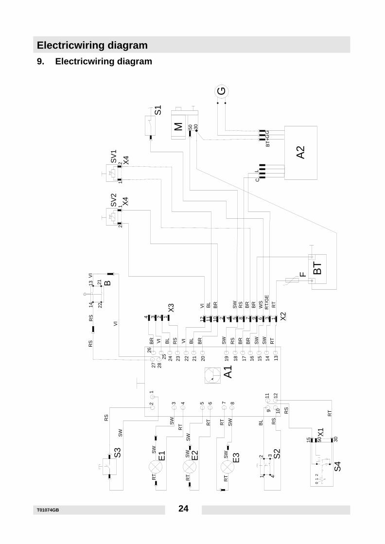
9. Electricwiring diagram
1413 21
22
50
G
50 30
15
0 1
2
RT
SW
12
43
30
A2
M
136978512 11 10 2 44 3 2 1
BT
+G
G
BT
12
12
A1
E3E2
RT
SWSW
RT
RT
E1
RT
RT
SW
SW
RS
BL
RS
RT
S2
SWS
W
RS
RS
VI
VI
RS
BR VI
BL
RS VI
BL
BR
SW
RS
BR
BR
SW
SW
RT
F
VI
BL
BR
SW
RS
BR
BR
WS
RT
/GE
RT
12 3 4 5 6 7 8
9 10
11 1213141516171819202122232425
2627 28
BS
V2
SV
1
S1
S3
S4
X1
X2X
3
X4
X4
CL
T01074GB 24
Electricwiring diagram
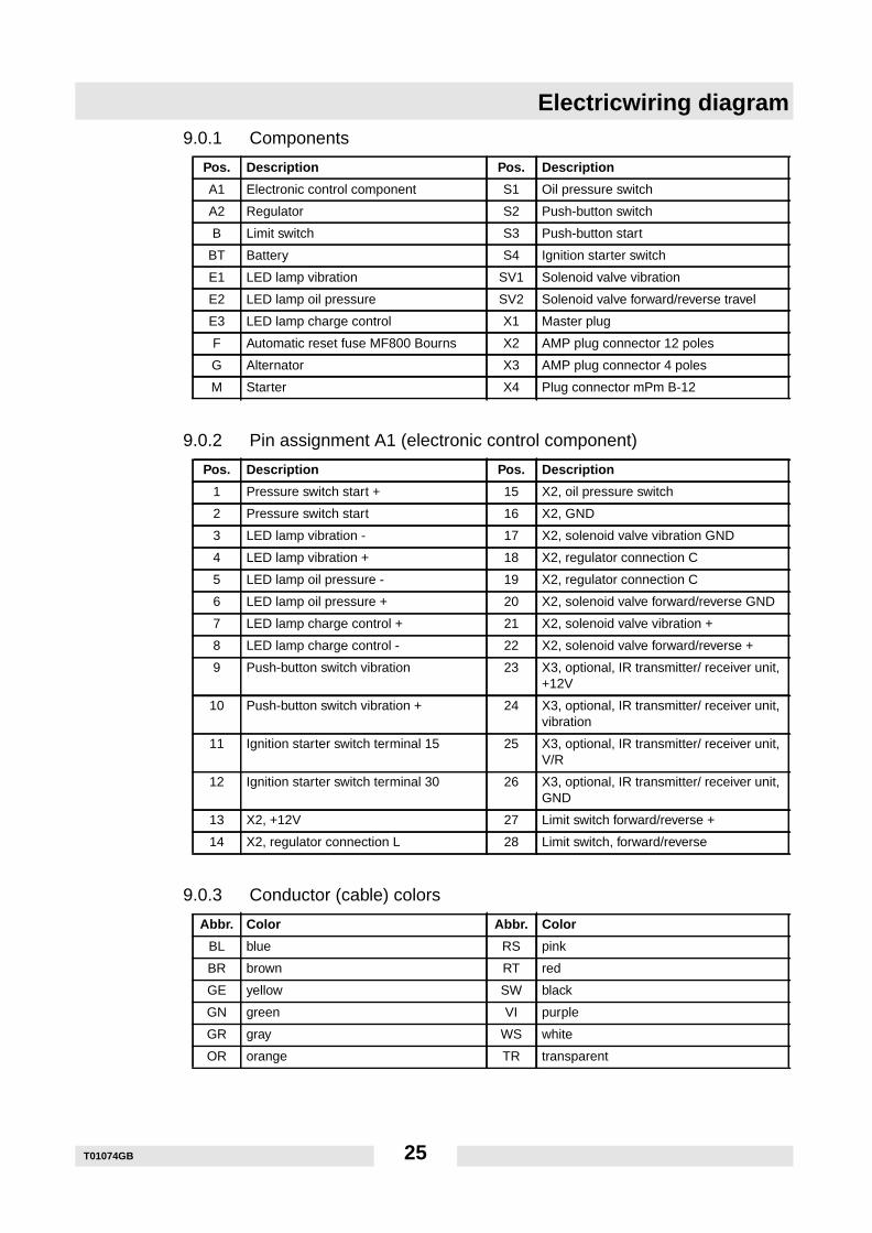
9.0.1 Components9.0.2 Pin assignment A1 (electronic control component)
9.0.3 Conductor (cable) colors
Pos. Description Pos. Description
A1 Electronic control component S1 Oil pressure switch
A2 Regulator S2 Push-button switch
B Limit switch S3 Push-button start
BT Battery S4 Ignition starter switch
E1 LED lamp vibration SV1 Solenoid valve vibration
E2 LED lamp oil pressure SV2 Solenoid valve forward/reverse travel
E3 LED lamp charge control X1 Master plug
F Automatic reset fuse MF800 Bourns X2 AMP plug connector 12 poles
G Alternator X3 AMP plug connector 4 poles
M Starter X4 Plug connector mPm B-12
Pos. Description Pos. Description
1 Pressure switch start + 15 X2, oil pressure switch
2 Pressure switch start 16 X2, GND
3 LED lamp vibration - 17 X2, solenoid valve vibration GND
4 LED lamp vibration + 18 X2, regulator connection C
5 LED lamp oil pressure - 19 X2, regulator connection C
6 LED lamp oil pressure + 20 X2, solenoid valve forward/reverse GND
7 LED lamp charge control + 21 X2, solenoid valve vibration +
8 LED lamp charge control - 22 X2, solenoid valve forward/reverse +
9 Push-button switch vibration 23 X3, optional, IR transmitter/ receiver unit,+12V
10 Push-button switch vibration + 24 X3, optional, IR transmitter/ receiver unit,vibration
11 Ignition starter switch terminal 15 25 X3, optional, IR transmitter/ receiver unit,V/R
12 Ignition starter switch terminal 30 26 X3, optional, IR transmitter/ receiver unit,GND
13 X2, +12V 27 Limit switch forward/reverse +
14 X2, regulator connection L 28 Limit switch, forward/reverse
Abbr. Color Abbr. Color
BL blue RS pink
BR brown RT red
GE yellow SW black
GN green VI purple
GR gray WS white
OR orange TR transparent
T01074GB 25
Hydraulic connections diagram
T01073GB 26
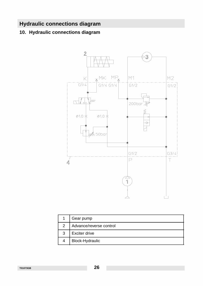
10. Hydraulic connections diagram
1 Gear pump
2 Advance/reverse control
3 Exciter drive
4 Block-Hydraulic
Lables
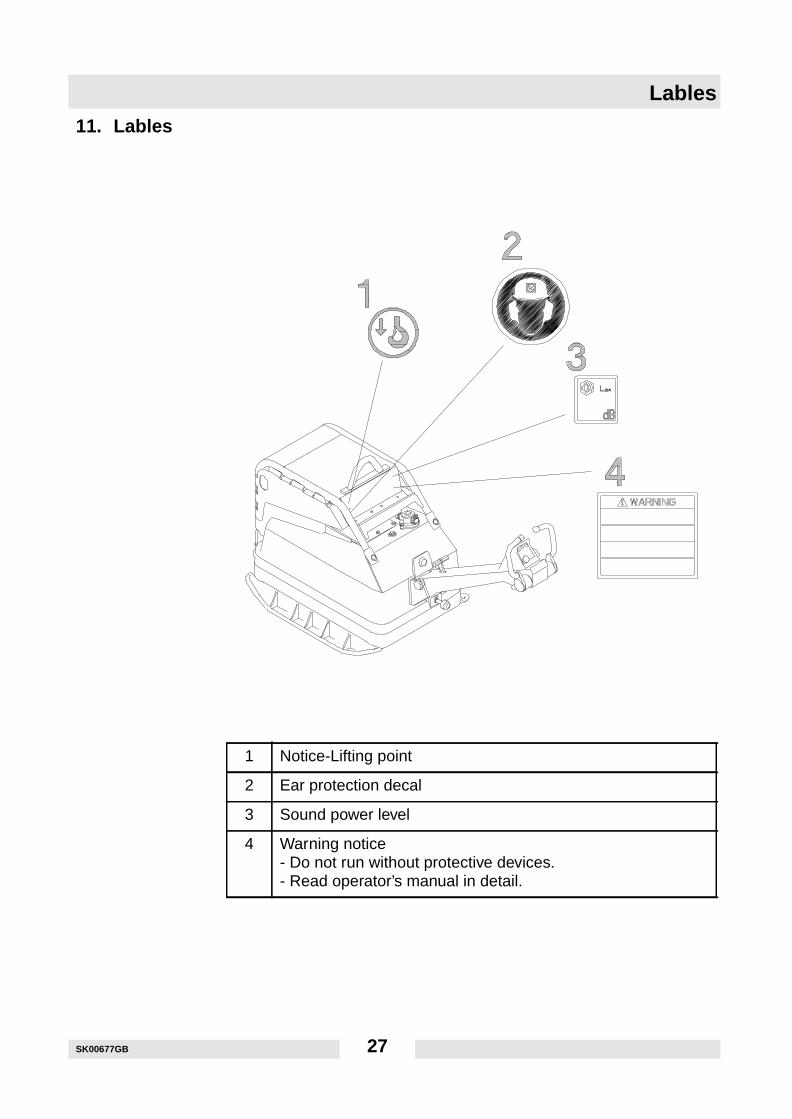
11. Lables
1 Notice-Lifting point
2 Ear protection decal
3 Sound power level
4 Warning notice- Do not run without protective devices.- Read operator’s manual in detail.
SK00677GB 27

Lables
SK00677GB 28
C0034007GBBes
chei
nigu
ng b
itte
sorg
fälti
g au
fbew
ahre
n / F
ile c
ertif
icat
e ca
refu
lly
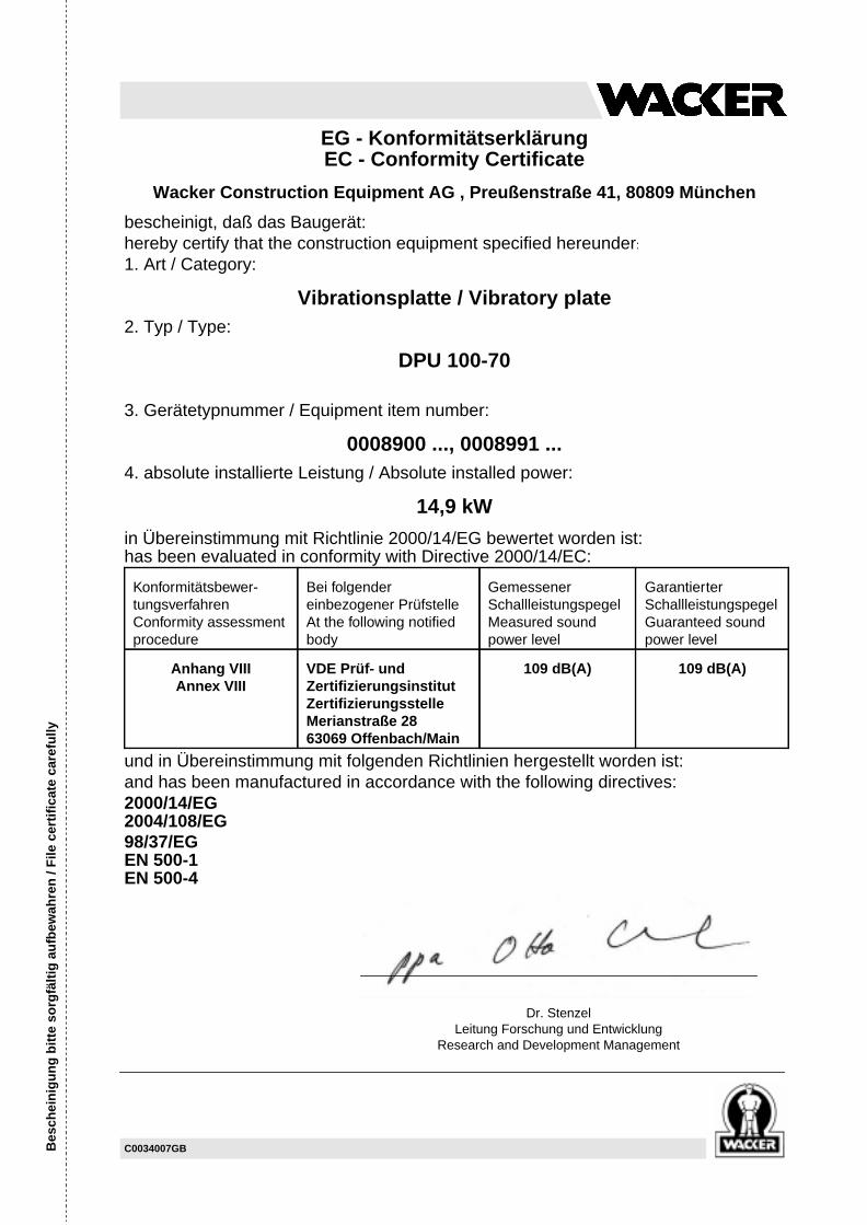
EG - KonformitätserklärungEC - Conformity Certificate
Wacker Construction Equipment AG , Preußenstraße 41, 80809 München
bescheinigt, daß das Baugerät:hereby certify that the construction equipment specified hereunder:
1. Art / Category:
Vibrationsplatte / Vibratory plate2. Typ / Type:
DPU 100-70
3. Gerätetypnummer / Equipment item number:
0008900 ..., 0008991 ...4. absolute installierte Leistung / Absolute installed power:
14,9 kW
in Übereinstimmung mit Richtlinie 2000/14/EG bewertet worden ist:has been evaluated in conformity with Directive 2000/14/EC:
und in Übereinstimmung mit folgenden Richtlinien hergestellt worden ist:and has been manufactured in accordance with the following directives:2000/14/EG2004/108/EG98/37/EGEN 500-1EN 500-4
Konformitätsbewer-tungsverfahrenConformity assessmentprocedure
Bei folgendereinbezogener PrüfstelleAt the following notifiedbody
GemessenerSchallleistungspegelMeasured soundpower level
GarantierterSchallleistungspegelGuaranteed soundpower level
Anhang VIIIAnnex VIII
VDE Prüf- undZertifizierungsinstitutZertifizierungsstelleMerianstraße 2863069 Offenbach/Main
109 dB(A) 109 dB(A)
Dr. StenzelLeitung Forschung und Entwicklung
Research and Development Management

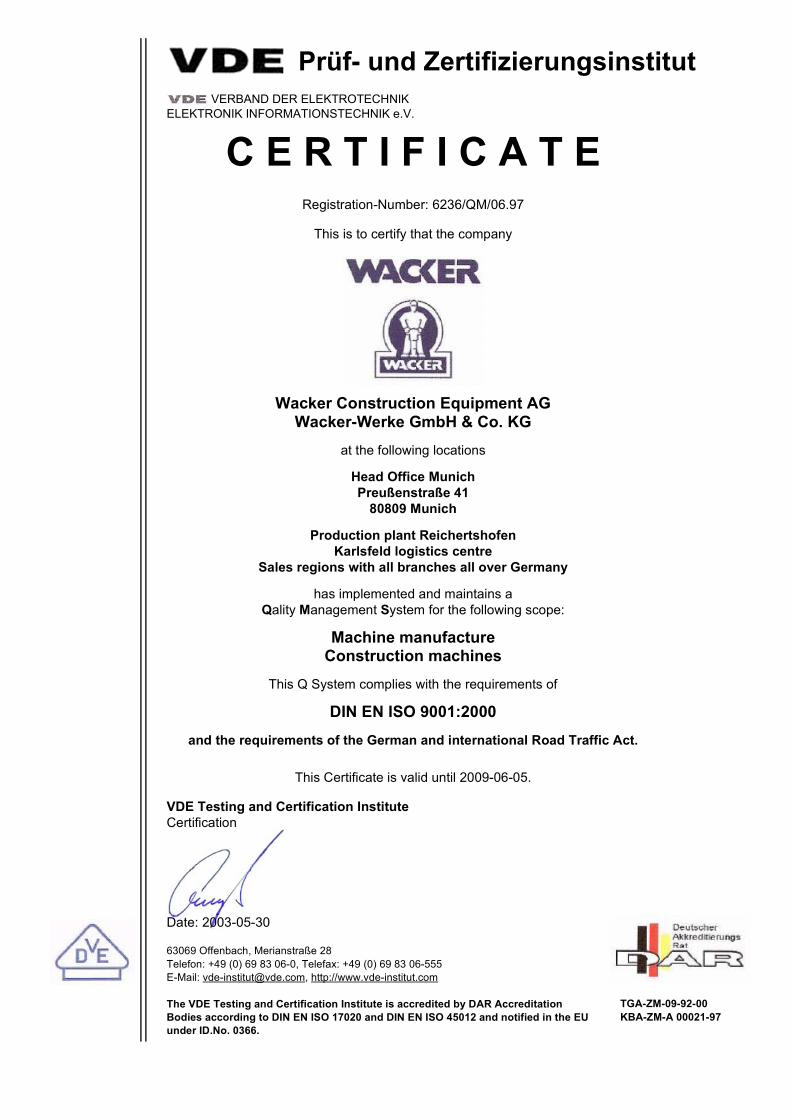
Prüf- und Zertifizierungsinstitut VERBAND DER ELEKTROTECHNIK
ELEKTRONIK INFORMATIONSTECHNIK e.V.
C E R T I F I C A T ERegistration-Number: 6236/QM/06.97
This is to certify that the company
Wacker Construction Equipment AGWacker-Werke GmbH & Co. KG
at the following locations
Head Office MunichPreußenstraße 41
80809 Munich
Production plant ReichertshofenKarlsfeld logistics centre
Sales regions with all branches all over Germany
has implemented and maintains a Qality Management System for the following scope:
Machine manufactureConstruction machines
This Q System complies with the requirements of
DIN EN ISO 9001:2000and the requirements of the German and international Road Traffic Act.
This Certificate is valid until 2009-06-05.
VDE Testing and Certification InstituteCertification
Date: 2003-05-30
63069 Offenbach, Merianstraße 28Telefon: +49 (0) 69 83 06-0, Telefax: +49 (0) 69 83 06-555E-Mail: [email protected], http://www.vde-institut.com
The VDE Testing and Certification Institute is accredited by DAR AccreditationBodies according to DIN EN ISO 17020 and DIN EN ISO 45012 and notified in the EUunder ID.No. 0366.
TGA-ZM-09-92-00KBA-ZM-A 00021-97
DIN EN ISO 9001 Certificate

Wacker Construction Equipment AG - Preußenstraße 41 - 80809 München - Tel.: +49-(0)89-3 54 02-0 - Fax: +49-(0)89-3 54 02-390Wacker Corporation - P.O. Box 9007 - Menomonee Falls, WI 53052-9007 - Tel.: +1-(1)(262)-255-0500 - Fax: +1-(1)(262)-255-0550 - Tel.: (800)770-0957Wacker Asia Pacific Operations-Skyline Tower, Suite 2303, 23/F, 39 Wang Kwong Road, Kowloon Bay, Hong Kong-Tel.: +852 2406 6032-Fax: +852 2406 6021