
G 125 G 160 - Wacker Neusonproducts.wackerneuson.com/manuals/Operators/0154596en_005.pdf · G 125/G...
80
Mobile Generator G 125 G 160 OPERATOR’S MANUAL 0154596en 005 0707 0 1 5 4 5 9 6 E N
Transcript of G 125 G 160 - Wacker Neusonproducts.wackerneuson.com/manuals/Operators/0154596en_005.pdf · G 125/G...

Mobile Generator
G 125G 160
OPERATOR’S MANUAL
0154596en 005
0707
0 1 5 4 5 9 6 E N


G 125/G 160 Table of Contents
1 Foreword 6
2 Safety Information 72.1 Service Safety ...................................................................................... 92.2 Operator Safety while using Internal Combustion Engines ................ 112.3 Towing Safety ..................................................................................... 122.4 Reporting Trailer Safety Defects ........................................................ 122.5 Label Location .................................................................................... 132.6 Safety and Operating Labels .............................................................. 15
3 Operation 243.1 Control Panels .................................................................................... 243.2 Generator Monitoring ......................................................................... 263.3 Engine Monitoring .............................................................................. 273.4 Engine Shutdown Faults .................................................................... 283.5 Current Overload Fault ....................................................................... 293.6 Application .......................................................................................... 303.7 Voltage Selector Switch ..................................................................... 313.8 Emergency Stop Switch ..................................................................... 323.9 Main Line Circuit Breaker ................................................................... 333.10 Engine Start Switch ............................................................................ 343.11 Voltage Adjustment Rheostat ............................................................. 343.12 Warning Light ..................................................................................... 343.13 Connection Lugs ................................................................................ 353.14 Ground Connection ............................................................................ 363.15 Convenience Receptacles .................................................................. 363.16 Remote Run Terminal Block .............................................................. 363.17 Panel Door Interlock Switch ............................................................... 363.18 Terminal Connections ........................................................................ 373.19 Before Starting ................................................................................... 383.20 Manual Start-up .................................................................................. 403.21 Running the Generator ....................................................................... 423.22 Engine Power Correction Factors ...................................................... 423.23 Shutting Down Generator ................................................................... 443.24 Cold Weather Start-up ........................................................................ 443.25 Lifting .................................................................................................. 443.26 Overnight Storage .............................................................................. 443.27 Long-term Storage ............................................................................. 443.28 Automatic/Remote Start-up ................................................................ 453.29 Remote/Transfer Switch ..................................................................... 463.30 Towing ................................................................................................ 47
wc_bo0154596en_005TOC.fm 3
Table of Contents G 125/G 160
4 Maintenance 49
4.1 Periodic Maintenance Schedule ..........................................................494.2 New Machines .....................................................................................504.3 Resetting the Periodic Maintenance Timer .........................................504.4 Air Cleaner ..........................................................................................514.5 Engine Lubrication ...............................................................................524.6 Engine Coolant ....................................................................................534.7 Trailer Maintenance .............................................................................534.8 Troubleshooting Automatic Shutdown .................................................544.9 Generator and Receptacle Wiring - G 125 ..........................................564.10 Generator and Receptacle Wiring - G 160 ..........................................584.11 Trailer Wiring .......................................................................................604.12 Engine Wiring ......................................................................................62
5 Factory-Installed Options 65
5.1 Block Heater ........................................................................................655.2 Fuel/Water Separator ..........................................................................665.3 Electronic Governor .............................................................................675.4 LCD Strip Heater .................................................................................685.5 Low Coolant Shutdown .......................................................................695.6 Lube Level Maintainer .........................................................................705.7 Temperature-Activated Shutters .........................................................715.8 Lockable Battery Disconnect ...............................................................715.9 Wiring Diagram ....................................................................................735.10 Wiring Diagram Components ..............................................................745.11 Cam-Lock ............................................................................................755.12 Containment System ...........................................................................76
wc_bo0154596en_005TOC.fm 4

G 125/G 160 Table of Contents
6 Technical Data 77
6.1 Engine Data ........................................................................................ 776.2 Generator Data ................................................................................... 786.3 Trailer and Skid Data .......................................................................... 796.4 Dimensions ......................................................................................... 80
wc_bo0154596en_005TOC.fm 5

Foreword
wc_tx000001gb diesel.fm 6
CALIFORNIA Proposition 65 Warning:
Diesel engine exhaust, some of its constituents, and certain vehiclecomponents contain or emit chemicals known to the State of Californiato cause cancer and birth defects or other reproductive harm.
1 Foreword
This manual provides information and procedures to safely operateand maintain this Wacker model. For your own safety and protectionfrom injury, carefully read, understand and observe the safetyinstructions described in this manual.
Keep this manual or a copy of it with the machine. If you lose thismanual or need an additional copy, please contact WackerCorporation. This machine is built with user safety in mind; however,it can present hazards if improperly operated and serviced. Followoperating instructions carefully! If you have questions about operatingor servicing this equipment, please contact Wacker Corporation.
The information contained in this manual was based on machines inproduction at the time of publication. Wacker Corporation reserves theright to change any portion of this information without notice.
All rights, especially copying and distribution rights, are reserved.
Copyright 2007 by Wacker Corporation.
No part of this publication may be reproduced in any form or by anymeans, electronic or mechanical, including photocopying, withoutexpress written permission from Wacker Corporation.
Any type of reproduction or distribution not authorized by WackerCorporation represents an infringement of valid copyrights and will beprosecuted. We expressly reserve the right to make technicalmodifications, even without due notice, which aim at improving ourmachines or their safety standards.
WARNING

G 125/G 160 Safety Information
2 Safety Information
This manual contains DANGER, WARNING, CAUTION, NOTICE andNOTE callouts which must be followed to reduce the possibility ofpersonal injury, damage to the equipment, or improper service.
This is the safety alert symbol. It is used to alert you to potentialpersonal injury hazards. Obey all safety messages that follow thissymbol to avoid possible injury or death.
DANGER indicates a hazardous situation which, if not avoided, willresult in death or serious injury.
WARNING indicates a hazardous situation which, if not avoided, couldresult in death or serious injury.
CAUTION indicates a hazardous situation which, if not avoided, couldresult in minor or moderate injury.
NOTICE: Used without the safety alert symbol, NOTICE indicates ahazardous situation which, if not avoided, could result in propertydamage.
Note: Contains additional information important to a procedure.Danger of Electrocution!
Danger of electrocution or severe electrical shock is presentthroughout the generator any time the engine is running! Read allsafety notes contained in this section before operating or servicing thisequipment.
No one except a trained electrician, familiar with this equipment,should attempt repairs to the generator! Test procedures which requirethat the generator be running must be performed using extremecaution.
This machine is built with user safety in mind; however, like anyelectrical device it can present serious hazards if improperly operatedand serviced. Follow instructions carefully! Should questions ariseduring operation or service of this equipment, contact WackerCorporation.
DANGER
WARNING
CAUTION
DANGER
wc_si000076gb.fm 7
Safety Information G 125/G 160
Operating SafetyFamiliarity and proper training are required for the safe operation of themachine. Machines operated improperly or by untrained personnelcan be dangerous. Read the operating instructions contained in boththis manual and the Engine Manual and familiarize yourself with thelocation and proper use of all controls. Inexperienced operators shouldreceive instruction from someone familiar with the machine beforebeing allowed to operate it.
2.0.1 NEVER operate the generator when open containers of fuel, paint, orother flammable liquids are near.
2.0.2 NEVER place flammable material or liquids near the generator.
2.0.3 NEVER operate the generator, or tools attached to the generator, withwet hands.
2.0.4 NEVER use worn electrical cords. Severe electrical shock andequipment damage may result.
2.0.5 NEVER operate the machine indoors unless exhaust fumes can beadequately ventilated.
2.0.6 NEVER overload the generator. The total amperage of the tools andequipment attached to the generator must not exceed the load ratingof the generator.
2.0.7 NEVER allow untrained personnel to operate or service the generator.The generator set should be set up by a certified electrician.
2.0.8 NEVER operate generator in standing water.
2.0.9 NEVER touch the hot engine, exhaust, or generator components.Burns will result.
2.0.10 NEVER start a unit in need of repair.
2.0.11 Use the emergency stop button only in an actual emergency. DO NOTrestart the engine until the cause of the trouble has been determinedand fixed.
2.0.12 ALWAYS wear hearing protection when operating equipment.
2.0.13 ALWAYS follow starting and stopping instructions described in thismanual. Know how to operate and stop generator before starting it.
2.0.14 ALWAYS make a walk-around inspection of the generator set beforestarting it. Open side doors and visually inspect engine compartmentfor obvious damage or the presence of foreign objects which mightaffect operation.
2.0.15 ALWAYS keep the machine at least one meter (three feet) away fromstructures, buildings, and other equipment during use.
2.0.16 ALWAYS store the machine properly when it is not being used. Themachine should be stored in a clean, dry location out of the reach ofchildren.
WARNING
wc_si000076gb.fm 8
G 125/G 160 Safety Information
2.0.17 ALWAYS keep the area immediately surrounding and underneath themachine clean, neat, and free of debris and combustible materials.Make sure that the area overhead is clear of debris that could fall ontoor into the machine or exhaust compartment.
2.0.18 ALWAYS be sure the machine is on a firm, level surface and will nottip, roll, slide, or fall while operating.
2.0.19 ALWAYS remove all tools, cords, and other loose items from thegenerator before starting it.
2.0.20 ALWAYS make certain the machine is well-grounded and securelyfastened to a good earthen ground per national and local regulations.
BACKFEED FROM THE GENERATOR INTO THE PUBLIC POWERDISTRIBUTION SYSTEM CAN CAUSE SERIOUS INJURY ORDEATH TO UTILITY WORKERS!
Improper connection of generator to a building’s electrical system canallow electrical current from the generator to backfeed into utility lines.This may result in electrocution of utility workers, fire, or explosion.Connections to a building’s electrical system must be made by aqualified electrician and comply with all applicable laws and electricalcodes.
If connected to a building’s electrical system the generator must meetthe power, voltage, and frequency requirements of the equipment inthe building. Differences in power, voltage, and frequencyrequirements may exist and improper connection may lead toequipment damage, fire, and personal injury or death.
2.1 Service Safety
A poorly maintained machine can become a safety hazard! In orderfor the machine to operate safely and properly over a long period oftime, periodic maintenance and occasional repairs are necessary.
2.1.1 NEVER perform even routine service (oil/filter changes, cleaning,etc.) unless all electrical components are shut down. Beforeservicing this machine, make sure the engine start switch is turned tooff “O”, the circuit breakers are open (off), the emergency stop switchis closed (pushed in), and the negative terminal on battery isdisconnected. Attach a “DO NOT START” sign to the control panel.This will notify everyone that the unit is being serviced and will reducethe chance of someone inadvertently trying to start the unit. If the unitis connected to a remote start or transfer switch, make sure the remoteswitch is also off and tagged.
DANGER
WARNING
wc_si000076gb.fm 9

Safety Information G 125/G 160
2.1.2 Ground ConnectionThe generator must be connected to a good earthen ground forproper operating safety!
A central “equipment ground” is provided at the customer connectionlugs. This point is connected directly to the generator set base. Allother system grounds are connected to this central point. Ground thegenerator in accordance with the standards defined in national, stateand local regulations.
2.1.3 DO NOT attempt to open the radiator cap while the unit is running orbefore the engine has cooled down. Severe burns may result!
2.1.4 DO NOT allow water to accumulate around the base of the machine.If water is present, move the machine and allow the machine to drybefore servicing.
2.1.5 DO NOT service the machine if your clothing or skin is wet.
2.1.6 DO NOT allow untrained personnel to service this equipment. Onlytrained electrical technicians should be allowed to service the electricalcomponents of this equipment.
2.1.7 DO NOT modify the machine without the express written approval ofthe manufacturer.
2.1.8 When cleaning the unit, DO NOT pressure wash the control panel,generator end, or any other electrical components. Never allow waterto accumulate around the base of the generator set. If water is present,DO NOT service!
2.1.9 ALWAYS replace the safety devices and guards after repairs andmaintenance.
2.1.10 ALWAYS let the engine cool before transporting or servicing it.
2.1.11 ALWAYS remain aware of moving parts and keep hands, feet, andloose clothing away from the moving parts of the machine.
2.1.12 ALWAYS replace all guards, fasten doors and make sure all safetydevices operate properly after making repairs or servicing theequipment.
2.1.13 ALWAYS keep hands, feet, and loose clothing away from the movingparts on the generator and engine.
2.1.14 ALWAYS keep the machine clean and labels legible. Replace allmissing and hard-to-read labels. Labels provide important operatinginstructions and warn of dangers and hazards.
2.1.15 ALWAYS check all external fasteners at regular intervals.
2.1.16 ALWAYS make sure slings, chains, hooks, ramps, jacks and othertypes of lifting devices are attached securely and have enough weight-bearing capacity to lift or hold the machine safely. Always remainaware of the location of other people in the area when lifting themachine.
wc_si000076gb.fm 10
G 125/G 160 Safety Information
2.2 Operator Safety while using Internal Combustion Engines
Internal combustion engines present special hazards during operationand fueling. Read and follow the warning instructions in the engineOwner’s Manual and the safety guidelines below. Failure to follow thewarnings and safety standards could result in severe injury or death.
2.2.1 DO NOT run engine indoors or in an area with poor ventilation unlessexhaust hoses are used.
2.2.2 DO NOT fill or drain the fuel tank near an open flame, while smoking,or while the engine is running.
2.2.3 DO NOT refuel a hot or running engine.
2.2.4 ALWAYS refill the fuel tank in a well-ventilated area.
2.2.5 DO NOT touch or lean against hot exhaust pipes.
2.2.6 ALWAYS replace the fuel tank cap after refueling.
2.2.7 DO NOT start the engine if fuel has spilled or a fuel odor is present.Move the generator away from the spill and wipe the generator drybefore starting.
2.2.8 DO NOT remove the radiator cap when the engine is running or hot.The radiator fluid is hot and under pressure and may cause severeburns!
DANGER
wc_si000076gb.fm 11
Safety Information G 125/G 160
2.3 Towing Safety
Towing a large trailer requires special care. Both the trailer and vehiclemust be in good condition and securely fastened to each other toreduce the possibility of an accident.
2.3.1 ALWAYS check that the hitch and coupling on the vehicle are ratedequal to, or greater than, the trailer's “gross vehicle weight rating”(GVWR).
2.3.2 ALWAYS inspect the hitch and coupling for wear or damage. DO NOTtow the trailer using defective parts.
2.3.3 ALWAYS make sure the coupling is securely fastened to the vehicle.
2.3.4 ALWAYS check the tires on the trailer for tread wear, inflation, andcondition. Replace worn tires.
2.3.5 ALWAYS connect the safety chains.
2.3.6 ALWAYS connect the breakaway cable safety hook to the bumper orrear of the vehicle. DO NOT attach it to the hitch.
2.3.7 ALWAYS test the surge brakes on the trailer and the brakes on thevehicle that will be used for towing.
2.3.8 ALWAYS make sure directional and trailer lights are connected andworking properly.
2.3.9 ALWAYS check that the lug nuts holding the wheels are tight and thatnone are missing.
2.4 Reporting Trailer Safety Defects
If you believe your trailer has a defect which could cause a crash orcould cause injury or death, you should immediately inform theNational Highway Traffic Safety Administration (NHTSA) in addition tonotifying Wacker Corporation.
If NHTSA receives similar complaints, it may open an investigation;and if it finds that a safety defect exists in a group of vehicles, it mayorder a recall and remedy campaign. However, NHTSA cannotbecome involved in individual problems between you, your dealer, orWacker Corporation.
To contact NHTSA, you may either contact the Auto Safety Hotline toll-free at 1-800-424-9393 (or 366-0129 in Washington DC area),www.nhtsa.com, or write to NHTSA, U.S. Department ofTransportation, 400 7th Street SW, (NSA-11), Washington, DC 20590.You can also obtain other information about motor vehicle safety fromthe Auto Safety Hotline.
WARNING
wc_si000076gb.fm 12

G 125/G 160 Safety Information
2.5 Label Location
wc_si000076gb.fm 13

Safety Information G 125/G 160
wc_si000076gb.fm 14

G 125/G 160 Safety Information
2.6 Safety and Operating Labels
Ref. Label Meaning
A
B WARNING! Pressurized contents. Do not open when hot!
C WARNING! Lock doors. Access can cause electric shock or injury.
D CAUTION! Lifting point.
E CAUTION! Never change switch position with engine running. Results in damage to machine.
WARNING! Electric shock will cause serious injury or death.
INSTRUCTIONS DE REMORQUAGETOWING INSTRUCTIONS ABSCHLEPPINSTRUKTIONEN INSTRUCCIONES DE REMOLQUE1. READ OPERATOR'S MANUAL.2. USE HITCH RATED FRO TRAILER'S "GROSS VEHICLE WEIGHT RATING".3. SECURELY ATTACH TRAILER TO TOW VEHICLE.4. ATTACH SAFETY CHAINS USING CROSS PATTERN.5. ATTACH BREAKDOWN CHAIN TO VEHICLE.6. CHECK TRAILER LIGHTS.
1. BETRIEBSVORSCHRIFT LESEN.2. ANHANGEVORRICHTUNG VERWENDEN, DIE DER GESAMTBETRIEBSGEWICHTSKLASSE ENTSPRICHT.3. ANHANGER SICHER AM ZUGFAHRZEUG BEFESTIGEN.4. SICHERHEITSKETTEN KREUZWEISE ANBRINGEN.5. ABREISSKETTE AM FAHRZEUG ANBRINGEN.6. ANHANGERLEUCHTEN PRUFEN.
1. LEA EL MANUAL DEL OPERARIO.2. UTILICE UN ACOPLE CORRECTAMENTE CLASIFICADO PARA LA "CLASE DE PESO BUTO" DEL VEHICULO DEL REMOLQUE.3. ASEGURESE DE AMARRAR CORRECTAMENTE EL REMOLQUE AL VEHICULO DE REMOLQUE.4. FIJE EN CRUZ LAS CADENAS DE SEGURIDAD.5. FIJE EN EL VEHICULO DE REMOLQUE LA CADENA DE DESPRENDIMIENTO.6. CONTROLE LAS LUCES DEL REMOLQUE.
1. LIRE LA NOTICE D'EMPLOI.2. UTILISER UN GROCHET D'ATTELAGE CONFORME AU DEBIT NOMINAL DU POIDS BRUT DE VEHICULE DU TRACTEUR.3. ATTACHER LA REMORQUE FERMEMENT AU VEHICULE TRACTEUR.4. ATTACHER LES CHAINES DE SURETTE EN UTILISANT UNE METHODE CROISEE.5. ATTACHER LA CHAINE DE REMORQUAGE AU VEHICULE.6. VERIFIER LES LAMPES DE LA REMORQUE.
1148
94
wc_si000076gb.fm 15
Safety Information G 125/G 160
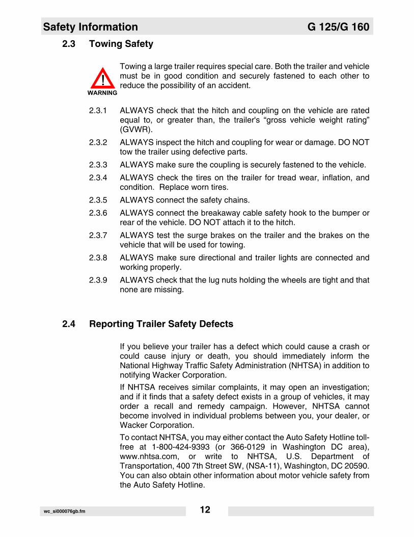
F DANGER! Asphyxiation hazard. Read the Opera-tor’s Manual for instructions. No sparks, flames, or burning objects near machine. Stop the engine before adding fuel. Use only diesel fuel.
G Tie-down point.
H WARNING! To prevent hearing loss, wear hearing protection.Hand injury if entangled in moving belt.Rotating machinery! Do not reach inside with engine running.WARNING! Hot surface!CAUTION! Avoid spraying water into generator.
I WARNING! Hot surface!
J Electrical ground
K WARNING! Electric shock will cause serious injury or death.
Ref. Label Meaning
wc_si000076gb.fm 16

G 125/G 160 Safety Information
L
M Operator’s Manual must be stored on machine. Replacement Operator’s Man-ual can be ordered through your local Wacker distributor.
N DANGER! Electric shock will cause serious injury or death. Danger of asphyxiation!
Ref. Label Meaning
a
wc_si000076gb.fm 17

Safety Information G 125/G 160
O WARNING! Generator can automatically start which can cause serious injury. Disconnect bat-tery before servicing.
P WARNING!Read and understand the supplied Oper-ator’s Manual before operating the machine. Failure to do so increases the risk of injury to yourself or others.
Q WARNING! To reduce the risk of electrical shock, read the operator’s manual. Improper connection of the generator to a build-ing’s electrical system can allow electri-cal current from the generator to backfeed into utility lines. This may result in electrocution of utility workers, fire or explosion. Connections to a building’s electrical system must be made by a qualified electrician and comply with all applicable laws and electrical codes.
R Remote start operation. Read operator’s manual for instructions.
Ref. Label Meaning
REMOTE STARTFERNSTARTARRANQUE REMOTODEMARRAGE A DISTANCE
1148
97
wc_si000076gb.fm 18
G 125/G 160 Safety Information
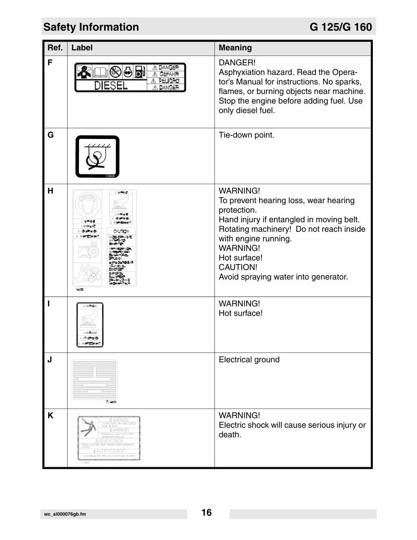
S CAUTION!Receptacles not to be used when:Selector switch set to 208/120V and volt-age greater than 228V.Selector switch set to 480/277V and volt-age greater than 457V.
T WARNING! Disconnect battery before servicing.Read the Operator's Manual.
U
V Operator’s Manual must be stored on machine. Replacement Operator’s Man-ual can be ordered through your local Wacker distributor.
W CAUTION! Avoid spraying water into generator.
X WARNING!To prevent hearing loss, wear hearing protection when operating the machine.WARNING! Pressurized contents. Do not open when hot!WARNING! Hand injury if entangled in moving belt.WARNING! Rotating machinery! Do not reach inside with engine running.
Ref. Label Meaning
� � � � � � �
� � � � � � � � � � �
� � � � � � � �
� � � � � �
POUR REMORQUEG - FEUX DE STOP ET DE DIRECTION DY - FEUX DE STOP ET DE DIRECTION GBr -FEUX D'ARRIERE, DE POSITION ET DE PLAQUE D'IMMATRICULATION
W - MISE A TERRE
L - FREINS ELECTRIQUESB - CHARGE DE LA BATTERIE
G - RECHTES BREMSLICHT UND BLINKERY - LINKES BREMSLICHT UND BLINKERBr -SCHLUSS-, SEITEN- UND KENNZEICHENLEUCHTE
W - ERDUNG
L - ELEKTRISCHE BREMSEB - BATTERIE-LADUNG
ANHÄNGER-VERDRAHTUNGTRAILER WIRING
G - RIGHT BRAKE LIGHT AND DIRECTIONALY - LEFT BRAKE LIGHT AND DIRECTIONALBr -TAIL, SIDE AND LICENSE PLATE LIGHTSW - GROUND
L - ELECTRIC BRAKESB - BATTERY CHARGE
DE REMOLQUEG - LUZ FRENO Y GIRO DERECHAY - LUZ FRENO Y GIRO IZQUIERDABr -LUZ TRASERA, LATERAL Y PLACA DE MATRICULA
W - TIERRA
L - FRENOS ELECTRICOSB - CARGA BATERIA
1156
81
DISPOSITION DES CABLES CANALISATION ELECTRICA
wc_si000076gb.fm 19

Safety Information G 125/G 160
Y Operating the main circuit breaker sup-plies or interrupts power to the customer connection lugs.
Z Neutral bonded to frame.
AA FusesRead the operator's manual for machine information.1 - Controller2 - Not used3 - Not used4 - Not used
BB WARNING!Electric shock at cooling fins.
CC G 125 and G 160 - Engine Wiring
Ref. Label Meaning
L1 L2 L311
4893
wc_si000076gb.fm 20
G 125/G 160 Safety Information
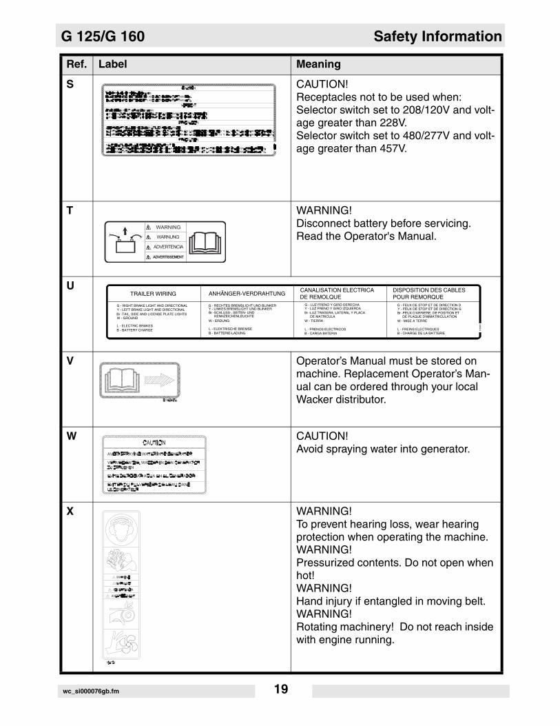
DD G 125 Generator and Receptacle Wiring
G 160 Generator and Receptacle Wiring
EE WARNING! Hot surface!
FF CAUTION: Do not use battery disconnect switch while engine is running. Damage to electrical components may occur.
Ref. Label Meaning
....
CAUTION
VORSICHT
PRECAUCION
PRECAUTION
..
173394
DO�NOT�USE�THE�BATTERY�DISCONNECT�SWITCH�WHILE�ENGINE�ISDO�NOT�USE�THE�BATTERY�DISCONNECT�SWITCH�WHILE�ENGINE�ISRUNNING.�DAMAGE�TO�THE�ELECTRICAL�COMPONENTS�MAY�OCCUR.RUNNING.�DAMAGE�TO�THE�ELECTRICAL�COMPONENTS�MAY�OCCUR.
BATTERIETRENNSCHALTER�NICHT�BENUTZEN,�WAHREND�MOTOR�LAUFT!BATTERIETRENNSCHALTER�NICHT�BENUTZEN,�WAHREND�MOTOR�LAUFT!BESCHADIGUNG�DER�ELEKTRISCHEN�BESTANDEILE�KANN�AUFTRETEN.BESCHADIGUNG�DER�ELEKTRISCHEN�BESTANDEILE�KANN�AUFTRETEN.
NO�UTILICE�EL�INTERRUPTOR�DE�LA�DESCONEXION�DE�LA�BATERIANO�UTILICE�EL�INTERRUPTOR�DE�LA�DESCONEXION�DE�LA�BATERIAMIENTRAS�QUE�EL�MOTOR�ESTA�FUNCIONANDO.�DANOS�A�LOSMIENTRAS�QUE�EL�MOTOR�ESTA�FUNCIONANDO.�DANOS�A�LOSCOMPONENTES�ELECTRICOS�PUEDEN�OCURRIR.COMPONENTES�ELECTRICOS�PUEDEN�OCURRIR.
N�UTILISER�PAS�LE�COMMUTATEUR�DE�DEBRANCHEMENT�DE�BATTERIEN�UTILISER�PAS�LE�COMMUTATEUR�DE�DEBRANCHEMENT�DE�BATTERIETANDIS�QUE�LE�MOTEUR�TOURNE.��DES�DOMMAGES�AUX�COMPOSANTS�TANDIS�QUE�LE�MOTEUR�TOURNE.��DES�DOMMAGES�AUX�COMPOSANTS�ELECTRIQUES�PEUVENT�SE�PRODUIRE.ELECTRIQUES�PEUVENT�SE�PRODUIRE.
wc_si000076gb.fm 21

Safety Information G 125/G 160
A nameplate listing the model number, item number, revision number, and serial number is attached to each unit. Please record the information found on this plate so it will be available should the name-plate become lost or damaged. When ordering parts or requesting service infor-mation, you will always be asked to spec-ify the model number, item number, revision number, and serial number of the unit.
This machine may be covered by one or more patents.
Certification Label (VIN Number)Also attached to each unit is a Certifica-tion Label. This label specifies that the trailer conforms with all Federal Motor Vehicle Standards in effect at the time of manufacture. The label includes the Vehi-cle Identification Number (VIN) for the trailer.
Ref. Label Meaning
wc_si000076gb.fm 22

G 125/G 160 Safety Information
Notes:wc_si000076gb.fm 23

Operation G 125/G 160
3 Operation
3.1 Control Panels
� � � � � � � � � � �
� � � � � �
� � � � �
� � � �
� � �
� � � � !
� �
� �� �"
! � � � � � � �! � � � � � � � #� � � � � $ � % � � � � �� % � � � � � � % � � � �
� � � % � � & ! � � � �# � � ! � � � �� � � � � $ & � % � � �� % � � � � � & � && & & & & � � ! � � � �
� � � ! � � ! �! � � � � � � � ' ! � � � �� � � � ! � � � � % � �� � ! � � % � � � & �& & & & � ( � � � & � � � � � � �
� � � % � � & � � ! ) � � *� � � % � � � � + � � ) � � � � � � � & � � � % � � � ! � & � � � % � �
� � ! ) � � * & � � � '� � + � � & � � � � � �, � � $ � & � & ) � � � � � � � � � � � � � � & � ! �
� � � � � � � �
��
�
�
�
� �
�
�
�
! � " ! � " ! �# ! �# ! �
���"-�
� . / 0 ! . � 1 2 3 & � 4 5 6 . �
7 89 �3 6 :
; , < � = % 2 � 4 � 0 & * � 0
% > ; . 3
9 �
� ? . 5 & � 4 5 6 . �
@ @ @ @ @ @
�"���
$
wc_tx000202gb.fm 24

G 125/G 160 Operation
Ref. Description Ref. Description
a. Control Panel Access Door l. Circuit Breaker (120V, 20 Amp) - two
b. Main Circuit Breaker m. Circuit Breaker (120/240V, 50 Amp) - two
c. Voltage Adjustment Rheostat n. Twist-Lock Receptacle (120/240 VAC, 30 Amp)
d. Engine Air Filter Gauge o. Twist-Lock Receptacle (120/240 VAC, 50 Amp) - two
e. Shutdown LED p. GFI Receptacle (120 VAC, 20 Amp) - two
f. Pre-alarm LED r. Remote Run Terminal Block
g. LCD Panel s. Interlock Switch
h. Engine Start Switch t. Customer Connection Terminal Lugs
j. Engine Hours Switch v. Ground Connection
k. Circuit Breaker (120/240V, 30 Amp)
wc_tx000202gb.fm 25

Operation G 125/G 160
3.2 Generator Monitoring
Generator information is displayed on the top line of the LCD panel andis scrolled continuously while the generator is operating, to show thevoltage, amperage and frequency of each phase.
Note: To prevent the display from scrolling, press the ENG HRS switchdown.
Volts “V”- Displays the AC output voltage being produced by thegenerator.
Phase “Ø” - Indicates which phase is currently being displayed.
Amps “A” - Displays the AC output amperage produced by thegenerator. If the generator is operating at no-load, output amperagewill display a 0.
Hertz “Hz” - Displays output frequency.
Sample display with engine running.
Sample display in “Auto” mode.
208 1 24 6078 85% 175 14.3
UNIT IN AUTO Ø 100% 85 13.2
wc_tx000202gb.fm 26
G 125/G 160 Operation
3.3 Engine Monitoring
With the engine start switch set to “RUN/START” or “REMOTESTART”, engine information will be continuously displayed on thebottom line of the LCD panel.
OIL - Displays engine oil pressure. The gauge registers oilpressure between 0–100 psi. Normal operating pressure is between60–80 psi. If oil pressure drops below 15 psi, the engine willautomatically shut down.
FUEL - Indicates the relative fuel level in the fuel tank. If fuellevel drops to 5% the engine will automatically shut down.
TEMPERATURE - Displays the temperature of the engine'scoolant. If the coolant temperature gets too high, the engine willautomatically shut down.
BATTERY - This gauge measures the engine starting batteryvoltage. A normal reading is 13.5–14.5V. If the gauge falls muchbelow or above these values, the engine charging system should bechecked. With the engine switch set to “REMOTE START” and thegenerator in stand-by mode, actual battery voltage is displayed.
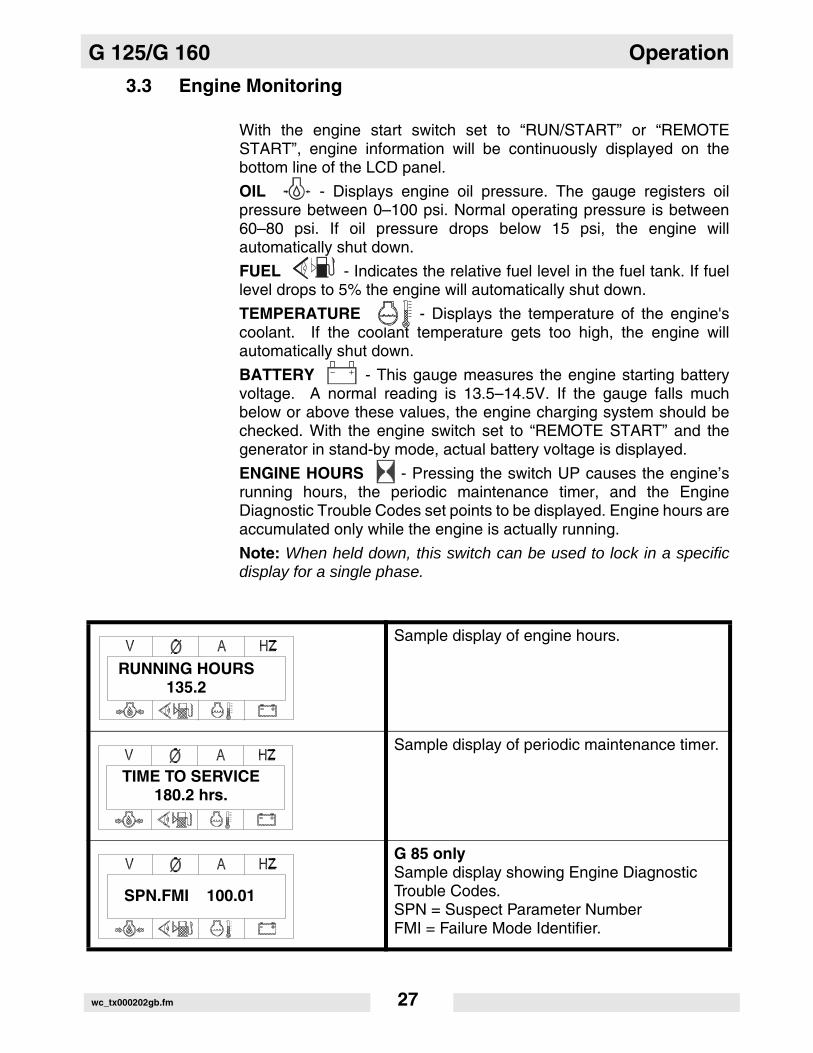
ENGINE HOURS - Pressing the switch UP causes the engine’srunning hours, the periodic maintenance timer, and the EngineDiagnostic Trouble Codes set points to be displayed. Engine hours areaccumulated only while the engine is actually running.
Note: When held down, this switch can be used to lock in a specificdisplay for a single phase.
Sample display of engine hours.
Sample display of periodic maintenance timer.
G 85 onlySample display showing Engine Diagnostic Trouble Codes.SPN = Suspect Parameter NumberFMI = Failure Mode Identifier.
RUNNING HOURS135.2
TIME TO SERVICE180.2 hrs.
SPN.FMI 100.01
wc_tx000202gb.fm 27

Operation G 125/G 160
3.4 Engine Shutdown Faults
The engine control module (ECM) continuously monitors vital enginefunctions for fault conditions. When a fault condition occurs, the enginewill shut down and the LCD panel will display the fault causing theshutdown. To reset the Engine Control Module and resume operation,return the Engine Start Switch manually to off “O”. Also refer to SectionWarning Light.
Indicates that the emergency stop button has been depressed. This display will remain on until the emergency stop button is pulled back out.
G 85 onlySample display showing Engine Diagnostic Trouble Codes.SPN = Suspect Parameter NumberFMI = Failure Mode Identifier.
Indicates that the engine speed exceeded approximately 2000 rpm (110% of its rated speed of 1800 rpm) and the ECM has auto-matically shut the engine down.
An overcrank fault is displayed when the engine fails to start during the normal cranking cycle, and the Engine Control Module has automatically shut down the generator due to an overcrank condition.
A low fuel fault condition will be displayed when the fuel tank drops to 5% and the Engine Control Module has shut the engine down. This fault condition prevents the fuel lines from running completely dry and avoids the need to bleed the lines when the tank is refilled.
Indicates that the engine speed dropped below 55 Hz for more than 15 seconds and the ECM has automatically shut the engine down.
EMERGENCYSTOP
SPN.FMI 100.01
FAULTOVERSPEED 2200
FAULTOVERCRANK
LOW FUEL
FAULTUNDERSPEED
wc_tx000202gb.fm 28
G 125/G 160 Operation
3.5 Current Overload Fault
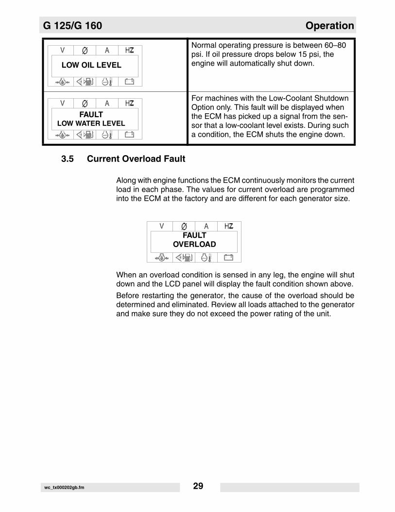
Along with engine functions the ECM continuously monitors the currentload in each phase. The values for current overload are programmedinto the ECM at the factory and are different for each generator size.
When an overload condition is sensed in any leg, the engine will shutdown and the LCD panel will display the fault condition shown above.
Before restarting the generator, the cause of the overload should bedetermined and eliminated. Review all loads attached to the generatorand make sure they do not exceed the power rating of the unit.
Normal operating pressure is between 60–80 psi. If oil pressure drops below 15 psi, the engine will automatically shut down.
For machines with the Low-Coolant Shutdown Option only. This fault will be displayed when the ECM has picked up a signal from the sen-sor that a low-coolant level exists. During such a condition, the ECM shuts the engine down.
LOW OIL LEVEL
FAULTLOW WATER LEVEL
FAULTOVERLOAD
wc_tx000202gb.fm 29

Operation G 125/G 160
3.6 Application
Heavy-duty, compact, sound-attenuated generators designed toprovide single and three-phase power for construction, commercial,and industrial applications where reliable power is needed.
NOTICE: Do not exceed the power output of the generator. Damageto tools or generator will occur. Refer to Technical Data.
When using the generator as a standby or substitute power supply,make sure the voltage and phase rotation of the line connectionsmatch those of the utility lines or of any other power source normallyused. Failure to match phase rotation and voltage may causeequipment connected to the generator to operate incorrectly!This could create unsafe operating conditions.
NOTICE: DO NOT exceed the rated current limit of any receptacle.
wc_tx000202gb.fm 30

G 125/G 160 Operation
3.7 Voltage Selector Switch
See Graphic: wc_gr000505
The voltage selector switch is located in a separate enclosure on thegenerator on the opposite side of the machine.
The selector switch is a three-position switch which mechanicallychanges the connections between the generator output leads and theterminal lugs on the generator. This allows three different volt rangesto be selected.
120/240 VAC 1Ø
120/208 VAC 3Ø
139/240 VAC 3Ø (Refer to Section Voltage Adjustment Rheostat.)
277/480 VAC 3Ø
Voltage ranges are selected by rotating the handle on the switch to thedesired voltage. The switch is equipped with a locking mechanism.This allows the voltage setting to be locked in place to preventunauthorized personnel from changing the voltage selection. To lockswitch in position, push lock up and attach a padlock through theopenings in the locking strip.
NOTICE: NEVER CHANGE THE VOLTAGE SELECTOR SWITCHWITH THE ENGINE RUNNING. This can cause arcing and canseverely damage the switch and the generator windings.
DANGER OF ELECTROCUTION! High voltage is present inside thispanel when the generator is operating!
DANGER
� � � � � � � � � � �
� � "� � �
� � �� � �
� " �� A A
2
wc_tx000202gb.fm 31

Operation G 125/G 160
3.8 Emergency Stop Switch
See Graphic: wc_gr000506
The emergency stop switch (b) is the red button located to the left ofthe control panel and can be accessed with the panel doors closed.The button is electrically isolated from the switch and also from the restof the metering panel.
Close the emergency stop switch by pushing the red button in. Closingthe emergency stop switch opens the main circuit breaker and the fuelsolenoid and results in the engine shutting down. The switch willremain closed until the button is rotated and it pops out.
NOTICE: PRESS THE EMERGENCY STOP BUTTON ONLY IN THECASE OF AN ACTUAL EMERGENCY WHERE THE GENERATORMUST BE STOPPED IMMEDIATELY! In all other instances, open themain line circuit breaker and then turn the engine start switch to off “O”.
E
MERGENCY
S T O P
wc_gr000506
b
wc_tx000202gb.fm 32
G 125/G 160 Operation
3.9 Main Line Circuit Breaker
See Graphic: wc_gr000527
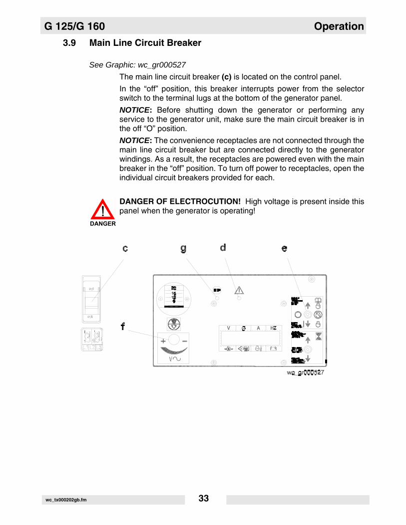
The main line circuit breaker (c) is located on the control panel.
In the “off” position, this breaker interrupts power from the selectorswitch to the terminal lugs at the bottom of the generator panel.
NOTICE: Before shutting down the generator or performing anyservice to the generator unit, make sure the main circuit breaker is inthe off “O” position.
NOTICE: The convenience receptacles are not connected through themain line circuit breaker but are connected directly to the generatorwindings. As a result, the receptacles are powered even with the mainbreaker in the “off” position. To turn off power to receptacles, open theindividual circuit breakers provided for each.
DANGER OF ELECTROCUTION! High voltage is present inside thispanel when the generator is operating!
DANGER
wc_tx000202gb.fm 33

Operation G 125/G 160
3.10 Engine Start Switch
See Graphic: wc_gr000527
The engine start switch (e) is a three-position switch: “REMOTESTART”, off “O”, and “START/RUN”. The “REMOTE START” positionis the normal setting used when using the generator as a back-uppower supply connected to a remote switch. In the REMOTE STARTposition, the generator is in stand-by mode and will not start until theremote switch closes. In the “START/RUN” position, the switchimmediately starts the engine start cycle and activates the startermotor to crank the engine. When set in the “REMOTE START” or“START/RUN position, the switch applies battery power to the controlmodule to turn on the LCD panel, and also energizes the engine’selectrical system. In the off “O” position, power to the engine’selectrical system, including the fuel solenoid, is disconnected.
3.11 Voltage Adjustment Rheostat
See Graphic: wc_gr000527
Directly below the filter minder is the voltage adjustment rheostat (f).Use the rheostat to adjust the AC voltage output. Loosen locking nutand turn adjusting screw clockwise to increase voltage, counter-clockwise to decrease voltage. The voltage can be monitored at theLCD panel.
3.12 Warning Light
See Graphic: wc_gr000527
The amber warning light (d) on the metering panel will turn on prior toan engine fault condition occurring. This acts as a pre-alarm to callattention to a potential fault condition. At the same time the warninglight goes on, the LCD panel will begin blinking to indicate whichengine function is approaching its fault value.
Engine Pre-alarms:
• Fuel Level = 25%
• High Temperature = 226°F
• Low Oil Pressure = 20 psi
• Time to Service = 250 hours
wc_tx000202gb.fm 34
G 125/G 160 Operation
3.13 Connection Lugs
See Graphic: wc_gr000508
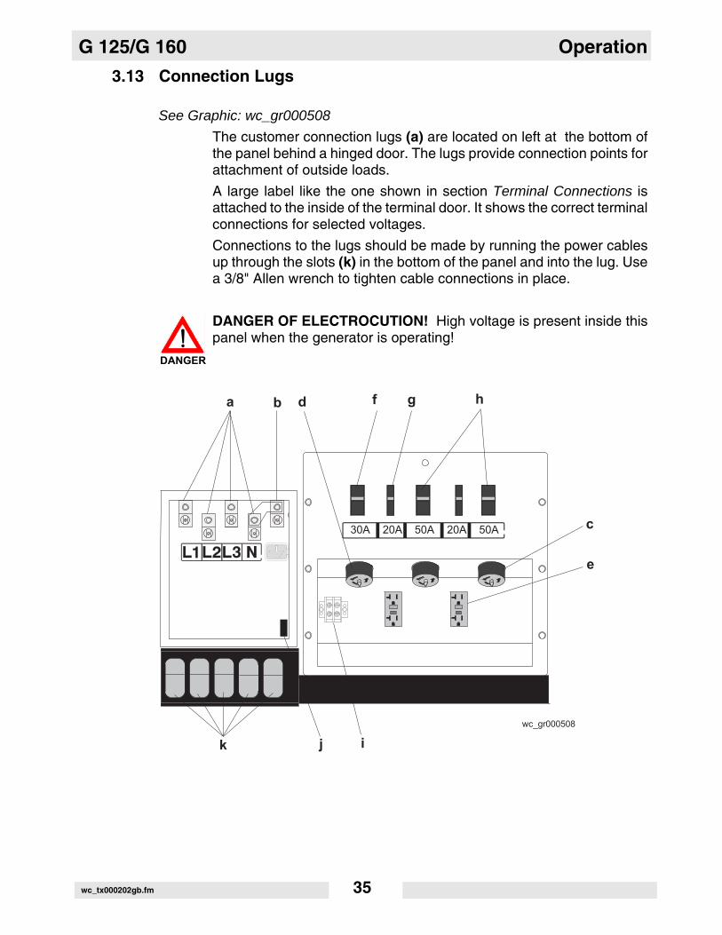
The customer connection lugs (a) are located on left at the bottom ofthe panel behind a hinged door. The lugs provide connection points forattachment of outside loads.
A large label like the one shown in section Terminal Connections isattached to the inside of the terminal door. It shows the correct terminalconnections for selected voltages.
Connections to the lugs should be made by running the power cablesup through the slots (k) in the bottom of the panel and into the lug. Usea 3/8" Allen wrench to tighten cable connections in place.
DANGER OF ELECTROCUTION! High voltage is present inside thispanel when the generator is operating!
DANGER
� � � � � � � � � � "
�"���
� � �� � �� � �� � � � � �
� � � ���
�
�
� � %
wc_tx000202gb.fm 35

Operation G 125/G 160
3.14 Ground Connection
See Graphic: wc_gr000508
A ground connection (b) is located next to the terminal lugs. The unitmust have this ground lug connected to a good earthen ground forproper operating safety in compliance with NEC and local standards.
3.15 Convenience Receptacles
See Graphic: wc_gr000508
The generator is equipped with two 120V/240V twist lock receptacles(c) rated at 50A, and one 120V/240V twist lock receptacles (d) ratedat 30A. The two 120V duplex receptacles (e) are equipped withground fault interrupts (GFI). Receptacles do not connect through themain line circuit breaker. Each receptacle is protected by its own circuitbreaker (f, g, h) which is located directly above it. Power to thereceptacles is available any time the generator engine is running, evenwith the main line circuit breaker open.
Note: When the voltage selector switch is in the 480 V / 3Ø position,voltage at the duplex receptacles is 139 V, and voltage at the 30/50 Areceptacles is 139/240 V. When the voltage selector switch is in the208 V / 3Ø position, voltage at the 30/50 A receptacles is 120/208 V.When the voltage selector switch is in the 208 V / 3Ø position, thevoltage can be adjusted with the voltage adjustment rheostat (f) to 240V / 3Ø. The voltage at the duplex receptacles is 139 V, and voltage atthe 30/50 A receptacles is 139/240 V.
3.16 Remote Run Terminal Block
See Graphic: wc_gr000508
The remote run terminal block (i) is located just to the left of the 120Vduplex receptacles. It provides connection points for installation of aremote start switch. When it is connected to a transfer switch, it allowsthe generator to be used as a standby power supply.
3.17 Panel Door Interlock Switch
See Graphic: wc_gr000508
The customer connection lugs panel access door is equipped with aninterlock switch (j). When the door is opened this switch automaticallytrips the main circuit breaker. Voltage to the receptacles will not be cut.
wc_tx000202gb.fm 36

G 125/G 160 Operation
3.18 Terminal Connections
ALL CONNECTIONS TO THE TERMINALS MUST BE MADE BY ATRAINED ELECTRICIAN.
BACKFEED FROM THE GENERATOR INTO THE UTILITY’SDISTRIBUTION SYSTEM CAN CAUSE A SERIOUS INJURY ORDEATH TO UTILITY WORKERS!
Improper connection of generator to a building’s electrical system canallow electrical current from the generator to backfeed into utility lines.This may result in electrocution of utility workers, fire or explosion.Connections to a building’s electrical system must be made by aqualified electrician and comply with all applicable laws and electricalcodes.
DANGER OF ELECTROCUTION! ALWAYS OPEN MAIN CIRCUITBREAKER AND SET ENGINE STOP SWITCH TO OFF “O”BEFORE INSPECTING OR ATTEMPTING ANY CONNECTIONS TOTHE TERMINAL BLOCK! LETHAL VOLTAGE COULD BEPRESENT ON THE TERMINAL LUGS!
DANGER
DANGER
wc_tx000202gb.fm 37

Operation G 125/G 160
3.19 Before Starting
Before putting the generator into service, review each item on thefollowing checklist. Because generators are often run for long periodsof time unattended, it is important to make sure that the unit is set upproperly to reduce possible problems.
Failure to follow the procedures listed may cause injury to personnel ordamage to the generator. Be certain that all persons setting up thegenerator are certified or fully trained on the installation of thegenerator.
• Check for any damage that might have been caused during shipping or towing.
• Check to make sure no debris has lodged in vents, near radiator or around fan. Check to make sure that the exhaust compartment is clean and nothing is touching the muffler or exhaust pipes.
• Check that generator is level.
• Chock trailer wheels.
• Check that generator is grounded to a good earthen ground per local regulations and NEC standards.
• Check engine oil, coolant and fuel levels, and fill as required.
• Determine voltage needs. Set voltage selector switch and make cor-rect terminal connections.
• Check that all electrical connections were made in compliance with local regulations and NEC standards.
• Check fan belt and hoses on engine for loose connections or fraying. Tighten or replace as required.
• Close and secure side panel access doors.
• Review and follow safety instructions found in the front of this manual.
WARNING
wc_tx000202gb.fm 38

G 125/G 160 Operation
Notes:wc_tx000202gb.fm 39

Operation G 125/G 160
3.20 Manual Start-up
See Graphic: wc_gr000505, wc_gr000506, wc_gr000527
Before starting the generator set for the first time, thoroughly reviewthe pre-start-up checklist in the previous section. Proceed withgenerator start-up only after checking each item in that section.
Thoroughly read and make sure you understand the engine Operator’sManual supplied with the generator. Follow the steps below and theillustration on the opposite page in the order listed.
When using the generator as a standby or substitute power supply,make sure the voltage and phase rotation of the line connectionsmatch those of the utility lines or of any other power source normallyused. Failure to match phase rotation and voltage may causeequipment connected to the generator to operate incorrectly!This could create unsafe operating conditions.
3.20.1 Check position of Voltage Selector Switch (a) and make sure it is setfor the desired voltage output. Lock the switch be in place.
3.20.2 Make sure the Engine Start Switch (e) is in the off “O” position.
3.20.3 Turn main line circuit breaker (c) and convenience receptacle circuitbreakers to off “O”. This will disconnect all loads from the generator.
3.20.4 Move Engine Start Switch (e) to “REMOTE START” to check operationof engine control module. The LCD panel should momentarily display“UNIT IN AUTO” and engine information. Check fuel level and batteryvalues.
3.20.5 Press in the Emergency Stop Button (b). The LCD panel should read“EMERGENCY STOP”. Release the stop button after verifying thedisplay, and return the Engine Start Switch to off “O”.
3.20.6 Start engine by moving the Engine Start Switch to the “START/RUN”position.
After displaying “INITIALIZING” sequence, the LCD display will read“STARTING ENGINE” as the engine begins its crank cycle. Thenormal cycle is for the engine to crank for 15 seconds, then rest for 10seconds. This cycle will repeat three (3) times. If the engine does notstart within this time, the Engine Control Module will shut down theengine and - will be displayed on the LCD panel. To repeat crank cycle,return start switch to off “O” to reset Engine Control Module. Allowstarter motor to cool between start-up attempts.
WARNING
wc_tx000202gb.fm 40

G 125/G 160 Operation
� � � � � � � � � � �
� � "� � �
� � �� � �
� " �� A A
2
E
MERGENCY
S T O P
wc_gr000506
b
wc_tx000202gb.fm 41

Operation G 125/G 160
3.21 Running the Generator
See Graphic: wc_gr000527
Leave the Engine Start Switch (e) in the “START/RUN” position whilethe generator is operating. If the generator was started using a remoteswitch, leave Engine Start Switch in the “REMOTE START” position.Let the generator run for a few minutes to warm engine before closingmain circuit breaker.
Before closing breakers, make sure that any electrical devicesattached downstream from the generator will not start upunexpectedly.
While the generator is running, check for excessive vibration, oil leaks,or coolant leaks.
Before placing the Engine Start Switch (e) in the “REMOTESTART” position, verify that the contacts on any remote switch linkedto the generator set are OPEN. This will prevent the generator fromimmediately starting when the Engine Start Switch is moved to the“REMOTE START” position.
3.22 Engine Power Correction Factors
See Graphic: wc_gr001227
Performance data on John Deere engines are measured at thefollowing standard conditions:
• 29.31 inches of mercury dry air pressure
• 600 feet altitude
• 0 % relative humidity
• 77°F air intake temperature
• 104°F fuel inlet temperature
Refer to the table to estimate the engine power decrease in percent,as environmental factors vary from the standard conditions.
MODEL FUEL TEMP RISE of 1.8°F
AIR TEMP RISE of 10°F
ALTITUDE RISE of 305 m
(1000 ft)
RELATIVE HUMIDITY
RISE of 10%
G 125G 160
0.19 0.50 see chart below
0.07
WARNING
WARNING
wc_tx000202gb.fm 42

G 125/G 160 Operation
36
34
32
30
28
26
24
22
20
18
16
14
12
10
8
6
4
2
07 8 9 10 11 12 13 14 15 16 17 18
(2,1) (2,4) (2,75) (3,0) (3,3) (3,6) (4,0) (4,3) (4,6) (4,9) (5,2) (5,5)
wc_gr001227Altitude x 1000 Feet
En
gin
e P
ow
er D
erat
ion
(%
)
wc_tx000202gb.fm 43
Operation G 125/G 160
3.23 Shutting Down Generator
Check with other personnel on the jobsite and let them know thatpower is being turned off. Make sure that the power shutdown will notcreate any hazards by turning off devices such as pumps, heaters, orlights that may need to be kept on.
3.23.1 Remove all loads from generator.
3.23.2 Open (turn to off “O”) main line circuit breaker.
3.23.3 Let engine run for approximately 5 minutes to allow it to cool down.
3.23.4 Move Engine Start Switch to the off “O” position.
3.24 Cold Weather Start-up
Good cold-weather starting requires that the battery be at peak power,the correct weight motor oil is used, and the starter motor is in goodcondition. The ECM will automatically activate the cold starting aidwhen the temperature is low enough and will display “AIR INTAKEHEATER” during the time the cold starting aid is activated.
3.25 Lifting
A central lifting eye is located at the top of the generator and isattached to a lifting frame inside the housing.
Refer to the Technical Data for the proper operating weight of thegenerator. Make sure the lifting devices have sufficient capacity to liftthe unit safely.
When lifting the generator, attach a hook or sling securely to the liftingeye.
3.26 Overnight Storage
When storing unit overnight, make sure all access doors are closedand padlocked.
DO NOT store generator overnight in a low lying area that might fill withwater during a heavy storm.
3.27 Long-term Storage
If the generator is being stored for several months, follow the enginemanufacturer’s recommendations for long-term storage. Theseprocedures are designed to help minimize engine corrosion.
wc_tx000202gb.fm 44

G 125/G 160 Operation
3.28 Automatic/Remote Start-up
In the “REMOTE START” position the generator can be startedremotely, either through a transfer switch or some other type of remotestart switch. “REMOTE START” is the normal setting when using thegenerator as a standby power supply. Before placing the generator inthe automatic start-up mode, review the pre-start and manual Start-upsections in this manual and follow procedure below.
Before placing the Engine Start Switch (e) in the “REMOTESTART” position, verify that the contacts on any remote switch linkedto the generator set are OPEN. This will prevent the generator fromimmediately starting when the Engine Start Switch is moved to the“REMOTE START” position.
3.28.1 Perform a manual start at least once to verify that the metering panelis operating correctly. Refer to Section Before Starting and ManualStart-up sections in this manual.
3.28.2 If a check of auto start-up circuit is desired, attach a short jumper wire(minimum 16 gauge insulated) between the two terminals on theremote run terminal block. This applies a ground to the Engine ControlModule to complete the start circuit. The engine should crank, start andrun.
Move the Engine Start Switch to off “O” to stop engine. Remove jumperfrom remote run terminals after testing is complete.
3.28.3 Secure generator by closing and locking all doors.
3.28.4 Set Engine Start Switch to “REMOTE START” and close main linecircuit breaker.
The generator is now ready for automatic start-up.
If the generator is to be used as a stand-by power supply for more thana month, provisions must be made to maintain battery charge. This canbe done either by attaching a battery charger to the battery or bystarting generator manually and running engine periodically tomaintain charge. See Section Manual Start-up.
WARNING
wc_tx000202gb.fm 45

Operation G 125/G 160
3.29 Remote/Transfer Switch
When the generator is used as a standby power supply, it must beequipped with a device which isolates it from the utility’s distributionsystem.
Failure to isolate the generator from the utility’s electricaldistribution system could cause output from the generator tobackfeed into the utility lines and cause injury or death to utilityworkers!
The same is true if using the generator as a backup to some other typeof power supply system.
A transfer switch is designed to transfer electrical loads from thenormal power source (utility) to the emergency power source(generator) when normal voltage falls below a prescribed level.
The transfer switch automatically returns the load back to the normalsource when power is restored back to operating levels.
Installation of a transfer switch or other type of remote starting deviceis the responsibility of the generator user. Installation of such devicesmust be performed by a qualified electrician following all directionssupplied by the manufacturer of the switch. If attaching generator to apower supply normally serviced by a utility company, notify the utilitycompany and check local and state regulations. Familiarize yourselfwith all instructions and warning labels supplied with the switch.
When using the generator as a standby or substitute power supply,make sure the voltage and phase rotation of the line connectionsmatch those of the utility lines, or of any other power source normallyused. Failure to match phase rotation and voltage may causeequipment connected to the generator to operate incorrectly!This could create unsafe operating conditions.
Lethal voltage is always present in the transfer switch once it has beenproperly installed!
DANGER
WARNING
DANGER
wc_tx000202gb.fm 46
G 125/G 160 Operation
3.30 Towing
See Graphic: wc_gr000510
The generator trailer is equipped with brakes, lights, and couplerconnection. Before towing the generator, perform the following:
3.30.1 Check that the towing vehicle and hitch have a rating equal to orgreater than the GVWR. Refer to the Technical Data.
3.30.2 Check the condition of both the coupler and hitch. DO NOT tow thetrailer if the coupler or hitch is damaged.
3.30.3 Make sure that the hitch and coupler are compatible. The generatortrailer is equipped with either a pintle type coupler (a) or 50 mm (2 in.)ball coupler.
3.30.4 Check that the directional and running lights on the trailer are working.
3.30.5 Connect the safety chains (c) using a crossed pattern under the trailertongue.
3.30.6 On trailers with surge or electric brakes, connect the breakaway cable(b) on the trailer coupler to the rear bumper or frame of the vehicle.This cable will actuate the brake system on the trailer if both thecoupling and safety chains have failed. The breakaway cable is not aparking brake and should not be used as one.
3.30.7 Check that all fasteners on the coupling are secure.
3.30.8 Check the tread wear and inflation on tires. Make sure that all lug nutsare in place and are tight.
3.30.9 Check the operation of the optional surge brakes by braking thevehicle at a slow speed before entering traffic. Both the vehicle and thetrailer should brake smoothly. If the trailer seems to be pushing, checkthe fluid level (d) in the surge brakes or the operation of the electricbrakes.
A film of grease on the coupler will extend coupler and ball life andeliminate squeaking. Wipe the coupler and ball clean and apply freshgrease each time the trailer is towed.
NOTICE: When towing, maintain extra space between vehicles andavoid soft shoulders, curbs and sudden lane changes. If you have notpulled a trailer before, practice turning, stopping, and backing up in anarea away from heavy traffic.
DO NOT exceed 55 mph when towing a trailer.
In most states, large trailers must be registered and licensed by theState Department of Transportation. Before towing, be sure to checklicensing requirements.
wc_tx000202gb.fm 47

Operation G 125/G 160
� � � � � � � � � � �
��
� �
wc_tx000202gb.fm 48
G 125/G 160 Maintenance
4 Maintenance
4.1 Periodic Maintenance Schedule
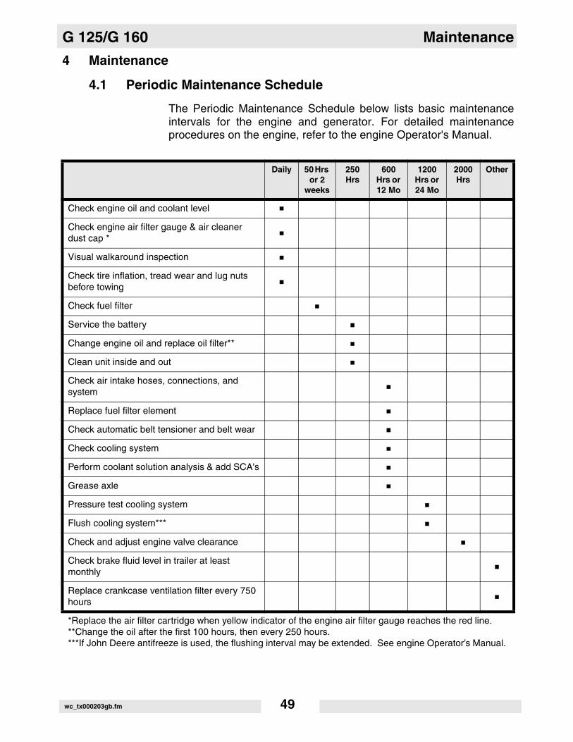
The Periodic Maintenance Schedule below lists basic maintenanceintervals for the engine and generator. For detailed maintenanceprocedures on the engine, refer to the engine Operator's Manual.
Daily 50 Hrs or 2
weeks
250 Hrs
600 Hrs or 12 Mo
1200Hrs or 24 Mo
2000 Hrs
Other
Check engine oil and coolant level
Check engine air filter gauge & air cleaner dust cap *
Visual walkaround inspection
Check tire inflation, tread wear and lug nuts before towing
Check fuel filter
Service the battery
Change engine oil and replace oil filter**
Clean unit inside and out
Check air intake hoses, connections, and system
Replace fuel filter element
Check automatic belt tensioner and belt wear
Check cooling system
Perform coolant solution analysis & add SCA's
Grease axle
Pressure test cooling system
Flush cooling system***
Check and adjust engine valve clearance
Check brake fluid level in trailer at least monthly
Replace crankcase ventilation filter every 750 hours
*Replace the air filter cartridge when yellow indicator of the engine air filter gauge reaches the red line.**Change the oil after the first 100 hours, then every 250 hours. ***If John Deere antifreeze is used, the flushing interval may be extended. See engine Operator’s Manual.
wc_tx000203gb.fm 49

Maintenance G 125/G 160
4.2 New Machines
4.2.1 Run generator at least 60–100% of continuous load for the first 100hours.
4.2.2 Change engine oil and replace oil filter after the first 50 hours.
4.3 Resetting the Periodic Maintenance Timer
After maintenance has been performed on the generator, it isnecessary to reset the periodic maintenance timer.
• If the periodic maintenance timer is at zero, press the ENG. HRSswitch UP and hold for 10 seconds until the “TIME TO SERVICE”resets to 250 hours.
• If the service time is greater than zero (maintenance was performedprior to the timer running out) press and hold the ENG. HRS switch UPand hold for 30 seconds. This will reset the “TIME TO SERVICE” to250 hours.
wc_tx000203gb.fm 50

G 125/G 160 Maintenance
4.4 Air Cleaner
See Graphic: wc_gr000511
Replace the air filter cartridge when yellow indicator of the engine airfilter gauge reaches the red line.
The air cleaner assembly contains a one-piece single element air filtercartridge (c).
To replace the air filter cartridge:
• Remove the end cover (d), then discard the entire air filter cartridge.
• Insert a new air filter cartridge, then
• Re-install the end cover, making sure that the dust cap (e) is cleanand is pointing downward.
Periodically, make sure the inlet pipe (f) is free from obstructions.
Check all connections and make sure they are snug. An air leak at theneck clamp, gauge connection, or intake pipe can quickly lead toexpensive engine repairs.
• Make sure that the intake piping (a) is fully engaged over the neckof the filter to ensure a good seal.
• If the filter housing, gauge connection (b), neck, or inlet pipe arecrushed or damaged, replace them immediately.
� � � � � � � � � � �
� � � �
� �
wc_tx000203gb.fm 51

Maintenance G 125/G 160
4.5 Engine Lubrication
Check engine oil daily before starting engine.
DO NOT operate engine if oil level is below ADD mark on dipstick.Always keep oil level within the crosshatch pattern or “full” mark ondipstick.
Change oil after first 100 hours of operation and every 250 hoursthereafter. Refer to the engine manufacturer’s Operator’s Manual forlubrication specifications.
Break-in Service
4.5.1 This engine is factory-filled with John Deere Engine Break-in Oil.Operate the engine at heavy loads with minimal idling during thebreak-in period. DO NOT exceed 100 hours of operation with break-inoil.
4.5.2 If the engine has significant operating time at light load, or makeup oilis required in the first 100 hour period, a longer break-in period may berequired. In these situations, an additional 100 hour break-in period isrecommended using a new change of John Deere Engine Break-In Oiland a new John Deere oil filter.
NOTICE: DO NOT add makeup oil until the oil level is BELOW theADD mark on dipstick. John Deere Engine Break-In Oil (TY22041)should be used to make up any oil consumed during the break-inperiod.
4.5.3 During the first 20 hours, avoid prolonged periods of no load orsustained maximum load operation. If engine is to run for longer than5 minutes without a load, shut unit down.
4.5.4 After the first 100 hours, change engine oil and replace engine oil filter.Fill crankcase with seasonal viscosity grade oil.
wc_tx000203gb.fm 52
G 125/G 160 Maintenance
4.6 Engine Coolant
Check the coolant level of the radiator with the engine cold. After initialfilling of radiator to 3/4" below bottom of filler neck, maintain properlevel in overflow bottle daily.
NEVER remove radiator cap or drain plug while engine is hot!Pressurized coolant can cause serious burns.
Shut off engine. Only remove radiator cap when it is cool enough totouch with bare hands. Slowly loosen cap to relieve pressure first,before removing it completely.
Solutions of antifreeze and supplemental coolant additives MUST beused year-round. Automotive-type coolants do not contain the correctcoolant additives to protect heavy-duty diesel engines. They oftencontain a high concentration of silicates which can damage the engineand cooling system. Refer to engine Operator’s Manual for coolantrecommendations.
4.7 Trailer Maintenance
Tires - Keep tires inflated to the proper pressure as shown on the tiresidewall, and check tread periodically for wear. Replace tires asrequired.
Wheels - Check that lug nuts holding wheels are tight. Replace anymissing nuts immediately.
Axle Hubs - Grease axle hubs through grease fittings using a goodwheel bearing grease.
Brakes - Check operation of brakes before each trip.
Check level of brake fluid in actuator at front of trailer at regularintervals. Fill to approximately 1" below top of reservoir using DOT-3heavy-duty brake fluid. Tighten filler plug securely.
Note: If fluid level has fallen too low, bleed brake lines to remove anyair trapped in lines.
WARNING
wc_tx000203gb.fm 53

Maintenance G 125/G 160
4.8 Troubleshooting Automatic Shutdown
There are several automatic shutdown conditions: low oil pressure,high coolant temperature, engine overspeed, engine underspeed,engine overcrank, and low fuel. When these occur, the operator canperform certain diagnostic tests to help identify the problem. Most ofthese diagnostics deal with the engine.
The generator, however, can also cause problems. Consult a qualifiedelectrician or your nearest WACKER Dealer for possible causes ofgenerator problems. For SPN.FMI Diagnostic Codes, contactWACKER or John Deere service departments.
Anytime the generator is down for service, secure it by closing andlocking all doors, and hang a "DO NOT RUN" sign on the meteringpanel.
Low Oil Pressure Shutdown
4.8.1 Check engine oil level using dipstick. Add oil if required.
4.8.2 Carefully inspect engine for oil leaks.
4.8.3 If oil level is good, start engine and verify loss of oil pressure. Shutdown engine immediately if oil pressure value does not read at least15 psi within 5 seconds.
Check the oil pressure shutdown sender and connecting wiring on theengine block. Check for Diagnostic Trouble Codes.
4.8.4 If oil level, oil pressure sender and connecting wiring are good, the faultcould be caused by an engine failure.
High Coolant Temperature Shutdown
4.8.1 Restart engine and read water temperature. Stop engine iftemperature is above 226°F. Normal engine operating temperature isbetween 170°-190° F.
4.8.2 Allow engine to cool to a safe temperature and inspect coolant level inradiator. Add coolant as needed.
4.8.3 Carefully inspect coolant hoses and engine block for leaks.
4.8.4 Check that fan belt for water pump is tight.
4.8.5 Check the high temperature shutdown sender and connecting wiringon engine block. Check for Diagnostic Trouble Codes.
4.8.6 If sender and wiring are good, consult engine manufacturer’sOperator’s Manual or Service Manual for possible causes of engineoverheating.
WARNING
wc_tx000203gb.fm 54

G 125/G 160 Maintenance
Overspeed or Underspeed Shutdown
Restart engine and read the AC frequency meter. Meter should read60 Hz under no-load condition.
Overcrank Shutdown
4.8.1 Check fuel level.
4.8.2 Check for proper operation of fuel pump.
4.8.3 If engine still does not start, refer to engine manufacturer’s Operator’sManual or Service Manual for possible engine problems.
Low Fuel Level Shutdown
4.8.1 Check fuel level.
Note: Warning light will come on when fuel level drops below 25%.Engine will shut down only when level drops below 5%.
4.8.2 Check for leaks in fuel tank.
4.8.3 Check for Diagnostic Trouble Codes.
4.8.4 If fuel level is good, check fuel level sender and connecting wiring onengine. Check for continuity between sender on tank and enginecontrol module. See wiring diagrams.
wc_tx000203gb.fm 55

Maintenance G 125/G 160
4.9 Generator and Receptacle Wiring - G 125
Ref. Description Ref. Description
1. Lug safety limit switch 11. 240V 30A receptacle
2. Mechanical lugs 12. Engine Control Module (ECM)
3. Buss bar 13. Plug 4 - line voltage inputs
4. Main breaker 14. Plug 3 - current transformer inputs
5. Shunt 15. Voltage selector switch
6. 120V 20A GFI receptacle 16. Generator
7. 120V breaker 17. Voltage regulator
8. 240V 50A breaker 18. Voltage adjustment rheostat
9. 240V 30A breaker 19. Terminal Block
10. 240V 50A receptacle 20. Terminal Strip
wc_tx000203gb.fm 56

G 125/G 160 Maintenance
� � � � � � � � � � �
� B� "� � �� � �� A
# C� � �
� �
� � # @
� �
� A � � � �� -
� " � � � B
� -� �
� �
B � � � �
� -
� �
� �
� �
� A
� "
A
"
� �
� �
� �
� B
�
� �
�
� �
�
�
� �
�
� � @ �
� � @ �
� � @ �
, �
�
# C# @
�# @# C�
B � � +� � � +
�B
A
� ��
� �
� �
� � �
� � �
� � �
� �
�
�
�
�
�
B
�
�
�
� �
� �
� �
*
�
*
, �
, �
, �,
,,
,&
� �
� "� A
� B
,
,&
� �
� -
� A
, �
� � *
� �� � � �
� �
� � � �
, � &
� � @ � � � @ � � � @ �
,
, �
, & ,,
,,
,,
-
, � &
� �� � � �
� �
� � *� � * � � *
� � *
, &
, &, &
, &, &
,
, ,
-
-
# C # @
� -
�
� -
� �
�
�
�
B B
A A
� �
� �
� �
"
"
-
�
�
wc_tx000203gb.fm 57

Maintenance G 125/G 160
4.10 Generator and Receptacle Wiring - G 160
Ref. Description Ref. Description
1 Lug safety limit switch 11 240V 30A receptacle
2 Mechanical lugs 12 Engine Control Module (ECM)
3 Buss bar 13 Plug 4 - line voltage inputs
4 Main breaker 14 Plug 3 - current transformer inputs
5 Shunt 15 Voltage selector switch
6 120V 20A GFI receptacle 16 Generator
7 120V breaker 17 Voltage regulator
8 240V 50A breaker 18 Voltage adjustment rheostat
9 240V 30A breaker 19 Terminal Block
10 240V 50A receptacle 20 Terminal Block
wc_tx000203gb.fm 58

G 125/G 160 Maintenance
wc_tx000203gb.fm 59

Maintenance G 125/G 160
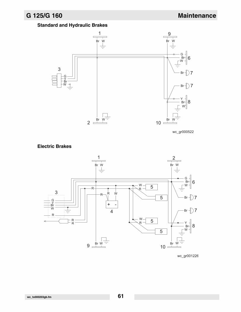
4.11 Trailer Wiring
Ref. Description
1 Front right side amber light
2 Front left side amber light
3 Trailer plug
4 Battery
5 Brake solenoid
6 Right rear taillight
7 License plate holder lights
8 Left rear taillight
9 Rear right side red light
10 Rear left side red light
Ref. Wire Colors Rear Lights Side Lights Harness
B BLACK Ground Ground Battery charge
Br BROWN Taillight Tail, side and license plate
L BLUE
R RED Brake light Power Electric brakes
Y YELLOW Left brake light and directional
G GREEN Right brake light and directional
W WHITE Ground
wc_tx000203gb.fm 60
G 125/G 160 Maintenance
Standard and Hydraulic BrakesElectric Brakes
� � � � � � � � � � �
, � , �� �
, ��
�
, �
�
*
, � �, � �
*�
, ��
� -
"
B
� � �
�, �
, �
A
A
� � � � � � � � � � B
C @
, � , �� �
, ��
, �
, �
�
, ��
*
�
�
�
�
� �
A
"
, � �, � �
��
B
- � �
�
�
*�
, ��
�
A
��
�
� � �
�
�
wc_tx000203gb.fm 61

Maintenance G 125/G 160
4.12 Engine Wiring
Engine
Wires
Ref. Description Ref. Description
1 Safety interlock switch 11 Intake heater relay
2 Mechanical lugs 12 Plug 2 (engine start outputs)
3 Main circuit breaker 13 Run/off/auto switch
4 Shunt 14 Battery
5 Emergency Stop switch 15 10A fuse
6 Engine control module 16 Starter relay
7 Plug 1 (engine sender inputs) 17 Starter
8 Remote start contacts 18 Alternator
9 Fuel level sender 19 Terminal block
10 Intake heater - ---
Ref. Description Ref. Description
18 Battery + 62 Fuel Level
53 Battery + 63 Crank
56 Cold Crank Delay 64 Run/Fuel
59 Battery - 73 Remote Annunciator
60 Remote Start 75 Remote Annunciator
61 E-Stop - ---
wc_tx000203gb.fm 62

G 125/G 160 Maintenance
87
412
14
422
429
082
050
wc_tx000203gb.fm 63

Maintenance G 125/G 160
Notes:wc_tx000203gb.fm 64

Mobile Generators Factory-Installed Options
5 Factory-Installed Options
This machine may be equipped with one or more of the following factory-installedoptions. To verify if any of these options are installed on your machine, contact theWACKER Corporation at 1-800-770-0957. A nameplate listing the Model Number, ItemNumber, Revision, and Serial Number is attached to each unit. Please have thisinformation available when contacting WACKER Corporation.
5.1 Block Heater
See Graphic: wc_gr001709
The engine block heater option includes a block heater (a) with a cord(b). The function of the block heater is to heat the engine coolant/engine block to improve cold-weather engine starting. Plug the cordinto a 120V power supply.
wc_tx000380gb.fm 65

Factory-Installed Options Mobile Generators
5.2 Fuel/Water Separator
See Graphic: wc_gr001705
The fuel/water separator separates water from the fuel on models withIsuzu engines. Empty the separator water bowl (a) as needed byopening the water bowl drain (b). The separator element should bechanged each time the fuel filter is changed—approximately every 600hours of operation.
To change the element:
5.2.1 Loosen the element retainer (d) and remove the retainer and element(c) from the separator head.
5.2.2 Unscrew the water bowl from the element.
wc_tx000380gb.fm 66

Mobile Generators Factory-Installed Options
5.3 Electronic Governor
See Graphic: wc_gr001714, wc_gr001715, wc_gr001716, wc_gr001717
The electronic governor option consists of an electronic module (a orb) and an electronic actuator (c or d). The module senses rotation ofthe flywheel, then sends a signal to the electronic actuator that governsthe fuel injection system. The system is designed to precisely regulateengine rpm, and thus frequency, to within approximately 0.25%. Seeelectronic governor manufacturer's literature for detailed information.
wc_tx000380gb.fm 67

Factory-Installed Options Mobile Generators
5.4 LCD Strip Heater
See Graphic: wc_gr001724, wc_gr001725
The LCD strip heater option includes a thermostat module (a) and aclear heater strip that is bonded to the LCD (b) of the ECM. Thepurpose of the strip heater is to prevent the LCD from being damagedby extremely cold temperatures. The resistance of the coiled elementof the heater is sensed by the thermostat. The resistance of theelement changes with temperature. At approximately -30°C, theresistance value triggers the thermostat to send power to the element.The LED (c) of the thermostat module flashes during operation.
It is important to note that the LCD strip heater is always on and thusdraws power (a very small amount) from the battery even when the unitis not running. If the battery should fail, the heater will also fail. Be sureto keep the battery charged when the generator is not in use.
wc_tx000380gb.fm 68

Mobile Generators Factory-Installed Options
5.5 Low Coolant Shutdown
See Graphic: wc_gr001708
The low-coolant shutdown system consists of an electronic sensor thatmonitors coolant level. The sensor (a) is mounted to the radiator andwired into the ECM. The sensor probe (b) is submerged in radiatorcoolant. If the probe senses no coolant, it sends a signal to the ECM.The ECM program includes a 10-second timer to protect fromnuisance shutdowns. If after the ten seconds coolant levels are stillsensed as being low, the ECM shuts down the engine. The ECM willthen display the “FAULT LOW WATER LEVEL”. Allow the engine tocool before adding additional coolant.
NEVER remove the radiator cap while the engine is hot! Pressurizedcoolant can cause serious burns.
If it is necessary to open the radiator, only do so with the engine off,and only when coolant is cool enough to touch with bare hands. Slowlyloosen the radiator cap to relieve pressure first, before removing itcompletely.
Note: The sensor may be disabled by unplugging the wire harness.This action will not shut down the machine.
WARNING
wc_tx000380gb.fm 69

Factory-Installed Options Mobile Generators
5.6 Lube Level Maintainer
See Graphic: wc_gr001711, wc_gr001712, wc_gr001713
The lube level maintainer system protects the engine from low oillevels by providing an additional 6-quart oil reservoir. Oil from thereservoir is gravity-fed from the oil reservoir (a) through the controlvalve (b) and into the engine oil pan as needed. The valve includes asightglass (c) through which the oil level can be seen. This oil level isthe same as that measured by the engine dipstick. A float inside thevalve detects low oil levels and opens the valve to supply the neededoil. The system is wired to the ECM and includes a low oil shutdown incase the oil in the reservoir is depleted. If the engine shuts down dueto low oil, the ECM will display “FAULT LOW OIL LEVEL”. Fill theengine and the additional oil reservoir with oil before placing thegenerator back into service.
Note: On machines with the Isuzu engine, the reservoir is mounted tothe enclosure door.
NOTICE: To prevent overfilling the engine with oil, place the shutoffvalve (d) in the closed position when moving or towing the generator.Once the generator is in position, open the valve.
wc_tx000380gb.fm 70

Mobile Generators Factory-Installed Options
5.7 Temperature-Activated Shutters
See Graphic: wc_gr001706, wc_gr001707
The shutters (a) are mounted to the top of the generator enclosure.The shutters are designed to keep the engine compartment warm, thusincreasing engine temperature during cold weather operation. Theshutters are activated through a wax-pellet actuator (b) that isconnected to the generator's cooling system. As radiator coolantwarms, the wax-pellet actuator engages a linkage (c) that opens theshutters. As the coolant cools, the shutters close.
5.8 Lockable Battery Disconnect
See Graphic: wc_gr004338
A lockable ON/OFF switch is available which disconnects the battery.A padlock (not included) securely locks the switch in the OFF position.If equipped, the battery disconnect switch is mounted to the upper skidbeneath the access door on either the right or left side of the machine.
NOTICE: Do not use the battery disconnect switch while the engine isrunning. Damage to electrical components may occur.
wc_gr001707
a
wc_tx000380gb.fm 71

Mobile Generators Factory-Installed Options
5.9 Wiring Diagram
Wire Colors
B Black R Red Y Yellow Or Orange
G Green T Tan Br Brown Pr Purple
L Blue V Violet Cl Clear Sh Shield
P Pink W White Gr Gray LL Light blue
80
12V
87
88
R
80
91
89R
B
87
Or
86
R
R
R B+
R
82
8385
81
83
GB
W
B
8482
81
Bl
B
R R
4
11
Y
Or91
90
90 8889
R
B
W
1
2
3
4
5
6
7
12
8
9
10
11
wc_gr001868
NO
C
NC
+
–
wc_tx000380gb.fm 72
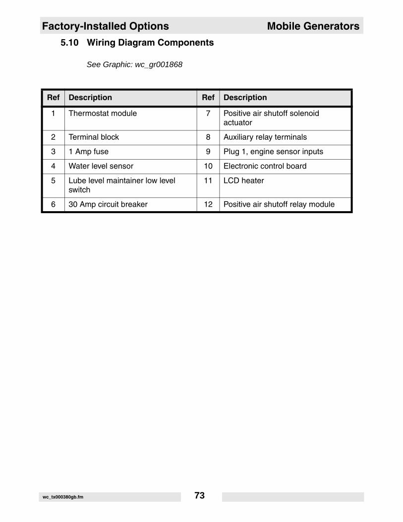
Factory-Installed Options Mobile Generators
5.10 Wiring Diagram Components
See Graphic: wc_gr001868
Ref Description Ref Description
1 Thermostat module 7 Positive air shutoff solenoid actuator
2 Terminal block 8 Auxiliary relay terminals
3 1 Amp fuse 9 Plug 1, engine sensor inputs
4 Water level sensor 10 Electronic control board
5 Lube level maintainer low level switch
11 LCD heater
6 30 Amp circuit breaker 12 Positive air shutoff relay module
wc_tx000380gb.fm 73

Mobile Generators Factory-Installed Options
5.11 Cam-Lock
See Graphic: wc_gr002584
A second optional outlet panel features cam-lock connectors (u) foreasy tool changes. The door is equipped with an interlock switch (q).When the door is opened this switch automatically trips the main circuitbreaker.
wc_tx000380gb.fm 74

Factory-Installed Options Mobile Generators
5.12 Containment System
See Graphic: wc_gr002647
Overspills and leaks are captured in the containment system. Thecontainment system holds over 110% of the fluid contained in themachine.
The containment system should be checked every 50 hours or 2weeks and drained when necessary. If fluid is found in the containmenttank, trace the cause of the leak and correct.
Note: In the interests of environmental protection, place impermeablesheeting and a container under the machine to collect the liquid whichdrains off. Dispose of this liquid in accordance with environmentalprotection legislation.
wc_tx000380gb.fm 75

G 125/G 160 Technical Data
6 Technical Data
6.1 Engine Data
G 125000926106200670620068
G 160000930606200690620070
Engine
Engine make / type John Deere / 6.8L
Model 6068TF275 6068HF275
Number of cylinders 6
Displacement cm3 (in3) 6800 (414)
Engine speed rpm 1800
Power @ 1800 rpm -continuous/standby
kW/Hp 123/165 164/220
Coolant capacity l (qts.) 37.8 (40) 24.2 (25.6)
Oil capacity l (qts.) 18.9 (20.0) 32.0 (34.0)
Battery Volts/CCa 12/1000
Fuel type Diesel
Fuel tank capacity l (gal.) 927 (245)
Fuel consumption, continuous load l/hr (gal./hr) 29.0 (7.7) 37.1 (9.8)
Running time, continuous load Hours 31.9 25.0
wc_td000075gb.fm 76

Technical Data G 125/G 160
6.2 Generator Data
G 125000926106200670620068
G 160000930606200690620070
Generator
Make/Type Marathon/ Brushless
Model 362 PSL 1650 363 PSL 1661
Generator speed rpm 1800
Voltage selector switch 3 position
AC voltages available 120/240 zig-zag120/208 low-wye277/480 Hi-wye
Frequency 60 Hz
Power factor 1ø3ø
1.00.8
Voltage regulation ±1.00%
Insulation class H
Sound level at 7 m (23 ft.) dB(A) 68 69
AC receptacles 2 duplex, 3 twist-lock
1ø 120 GFI duplex Amps 2-20
1ø 120/240 V twist lock Amps 1-30A 2-50A
Standby Output kW/kVA 109/136 141/176
Prime Output kW/kVA 98/122 128/160
Main breaker Amps 400 500
wc_td000075gb.fm 77

G 125/G 160 Technical Data
6.3 Trailer and Skid Data
G 125000926106200670620068
G 160000930606200690620070
Trailer and Skid
Dry weight of skid kg (lbs.) 2331 (5140) 2400 (5290)
Operating weight of skid kg (lbs.) 3139 (6920) 3207 (7070)
Trailer weight kg (lbs.) 649 (1430)
GVWR kg (lbs.) 4082 (9000)
Surge brakes Fluid type DOT3
Tires size 7.50x16
wc_td000075gb.fm 78

Technical Data G 125/G 160
6.4 Dimensions
mm (inches)
� � � � � � � � - � -
& # ' ! ( ) " ! *
& + + , ( ) ' + *
# # - !) . + *
, + " ( ) & + # *
& ' " ( ) & # " *
& - # -) - , *
wc_td000075gb.fm 79

Wacker Construction Equipment AG · Preußenstraße 41 · D-80809 München · Tel.: +49-(0)89-3 54 02 - 0 · Fax: +49 - (0)89-3 54 02-3 90Wacker Corporation · P.O. Box 9007 · Menomonee Falls, WI 53052-9007 · Tel. : (262) 255-0500 · Fax: (262) 255-0550 · Tel. : (800) 770-0957Wacker Asia Pacific Operations · Skyline Tower, Suite 2303, 23/F · 39 Wang Kwong Road, Kowloon Bay, Hong Kong · Tel. +852 2406 60 32 · Fax: +852 2406 60 21


![Air Servo Cylinder air.pdf · How to Order Bore size 125 125 mm 160 160 mm 200 200 mm 250 250 mm 320 320 mm Stroke [mm] 125 250 160 200, 300 200 200, 300 250 350, 450 320 200, 350,](https://static.fdocuments.us/doc/165x107/60c57874778cca0a96064de1/air-servo-cylinder-airpdf-how-to-order-bore-size-125-125-mm-160-160-mm-200-200.jpg)


