Version 6.11 Client User Guide March 2013 - aimetis.com · New Features in Symphony 6.11 ......
157
Version 6.11 Client User Guide March 2013
Transcript of Version 6.11 Client User Guide March 2013 - aimetis.com · New Features in Symphony 6.11 ......

Version 6.11
Client User Guide
March 2013

Disclaimers and Legal Information
Copyright © 2013 Aimetis Inc. All rights reserved.
This guide is for informational purposes only. AIMETIS MAKES NO WARRANTIES, EXPRESS, IMPLIED OR STATUTORY, AS TO THE INFORMATION IN THIS DOCUMENT.
Complying with all applicable copyright laws is the responsibility of the user. Without limiting the rights under copyright, no part of this document may be reproduced, stored in or introduced into a retrieval system, or transmitted in any form or by any means (electronic, mechanical, photocopying, recording, or otherwise), or for any purpose, without the express written permission of Aimetis Corp.
Aimetis may have patents, patent applications, trademarks, copyrights, or other intellectual property rights covering subject matter in this document. Except as expressly provided in any written license agreement from Aimetis, the furnishing of this document does not give you any license to these patents, trademarks, copyrights, or other intellectual property.
Aimetis and Aimetis Symphony are either registered trademarks or trademarks of Aimetis Corp. in the United States and/or other countries.
Portions Copyright © 1993-2013 ARH Inc.
Portions of this software are based in part on the work of the Independent JPEG Group.

Document History
Document History
Sym-6.11-P-300
Table 1. Changes to this manual
Date Description
March 2013
New Features in Symphony 6.11 • User can drag camera from maps to Video Wall - “Using Maps” on page 17• Audio icons in Navigation bar - “Audio” on page 33• Client Settings for Audio output on Sound tab - “ Sound” on page 57 and “Figure 63.
Sound tab” on page 57• All users can view and modify their user information - “ Modifying User Information” on
page 72• Drag and drop camera from Quick Find search into camera panel - “ Quick Find” on page
107, “Figure 44. Drag camera from Quick Find search into camera panel” on page 107• Override label in Camera Tree indicates that recording on the camera has been stopped
- “Figure 19. Override label beside camera” on page 15• Schedule PTZ camera tours to hour or minute ranges - “Figure 39. Schedule when camera
tour active” on page 102• Maps sorted alphabetically, new map listed automatically now with original filename,
partial matches displayed based on text in search field - “Figure 21. Map Navigation” on page 17, “ To add a map:” on page 18
• Client Settings for Device Pack updates on Update tab - “ Update” on page 64, “Figure 68. Update tab” on page 64
• New Advanced tab in client settings contains options from prior Memory and Logging tabs, and new option to enable/disable messages to the user in the event of a Symphony Client crash - “ Advanced” on page 65, “Figure 70. Advanced tab” on page 65
Updated/Clarified
• “Figure 20. Device Tree configuration options” on page 16• “ Reports” on page 115
Document Historyiii

Document History
November 15, 2012
New features in Symphony 6.10.1:“Appearance Tab” on page 38 - Multi-streaming in Symphony for analytics and Camera Views reduces server and client CPU and CPU transcoding. “Reports” on page 115• “User Permissions” on page 115• All reports except Heat Map allow you to select more than one camera.• “Heat Map Image” on page 128 - Using Interval Time and Dwell Threshold• “Figure 61. Sensitivity tab” on page 130
Improvements to this manual:
“Tracking Tab” on page 45
September 13, 2012
Revised: “ Adding Digital Input and Output to Maps” on page 27. Supported DIO devices now listed in KB article: http://www.aimetis.com/Support/kbarticle.aspx?ID=10141
September 12, 2012
• “Timeline Colour Code” on page 3 - added edge storage and PT091• Correction to “Heat Map Image" procedure content for Sensitivity tab, missing Dwell
Time information: “7. Since the Heat Map Image report was selected, the Sensitivity tab is enabled.” on page 130
August 2012
Release 6.10
• Camera Views: “Figure 18. Camera Views saved in Camera Tree dialog box” on page 14, “Placing Camera Views on Maps” on page 20
• “Figure 34. Playback Mode with context menu options displayed” on page 31 - New context menu
• “Figure 35. White arrows on timeline indicate start and end time for video export” on page 32
• Go back to previous state after seconds - “Activity Tab” on page 39• “Symphony Client Settings” on page 48 - “Video” on page 53 - new Direct connect to
camera option• Camera View tab - in previous releases Multi View - “Camera View” on page 55• “Symphony Client Settings” on page 48 - procedure for each tab in the Symphony Client
Settings dialog box• “Figure 46. Camera View Settings dialog box with Activity tab active” on page 39,
“Camera View” on page 55• “Register New Server” on page 67 - new process• “ Logging In, Switching Users, and Supervisor Logon” on page 69• Symphony saves format and destination of Video Export within a session - “Using
Export” on page 90• “Object Counts Across a Line” on page 125: Can now select multiple cameras. “Figure 59.
Line tab - extending and shaping the counting line” on page 126. Can now generate an Information Summary on Counts In and Out
Table 1. Changes to this manual (Continued)
Date Description
Document Historyiv

Document History
June 13, 2012
Revised:• White, black, and pink indicators in timeline:“Timeline Colour Code” on page 3• “Figure 45. Camera View Settings dialog box with Appearance tab active” on page 38 -
Render Mode now labeled Display Mode
• “Figure 58. Alarms tab” on page 51 - Policy column heading now labeled Rule
• “ Using a Joystick” on page 98 -“ Advanced Usage Only” on page 98Added:• “Figure 61. Camera View tab” on page 55 - New Camera view tool button default
behavior option
May 2012Added• “Tracking Color” on page 86• “Camera Tour” on page 99
February 28, 2012
Release 6.9.1• “Using Export” on page 90 - Right-click on Timeline to establish Start and End points for
exported video:• “Figure 19. Right-click context menu on Timeline” on page 91• “Figure 20. Start and End arrow times reflected in Video Export dialog box” on
page 91• Images from scheduled Heat Map reports:
• “In scheduled reports, only an image can be emailed/saved for a Heat Map Report.” on page 122
• “In scheduled reports, Symphony can email/save images ONLY for Heat Map reports.” on page 125
Revised:• “ To acknowledge an alarm (rule on map):” on page 27• “ To mark an alarm:” on page 114
Table 1. Changes to this manual (Continued)
Date Description
Document Historyv
Document History
January 31, 2012
Release 6.9Revised• “Working with Carousels” on page 89 - Access Carousels ONLY by clicking Carousel icon
in Tool Strip• “Running a Report from the Web” on page 135 - If Camera Tree contains more than 100
devices, the Web Client shows video from cameras as separate pages, navigated by forward and back buttons.
Added“Exporting Video” on page 90• New Add button “Figure 18. Export Video dialog box” on page 90• Export video from multiple cameras“Figure 21. Select cameras from which to export
video” on page 92• Exclude audio export in AVI files “Figure 22. AVI file type selected” on page 92• “ Video Playlist for Large AVI File Export” on page 94“Reports” on page 115• “Figure 48. Reports dialog box” on page 116• “Figure 50. Selecting a device in Report Designer dialog box” on page 117• “Figure 52. Distribution>Email subtab showing an email list for reports” on page 119• “Figure 53. Distrubtion>File subtab - Format in which generated report to be saved” on
page 120• “Figure 54. Schedule when reports will be run” on page 121• “Figure 58. Send Report to Email distribution list or save to File” on page 124
Sym-6.8-P-304
December 15, 2011
Release 6.8.2Added:• Instructions for Video Export log file and using md5sum, see “Figure 23. Video Export log
file” on page 93• “Figure 62. Aimetis Symphony Web Access” on page 135• “Figure 63. Web Login” on page 136Revised:• “Exporting Video” on page 90: The filename is saved as <CameraName> - <Capture
Resolution> - <Capture FPS> - <Capture Format>_YYYYMMDD_HHMMSS
Table 1. Changes to this manual (Continued)
Date Description
Document Historyvi

Document History
December 6, 2011
Release 6.8.1Revised:• “Figure 1. Main Console” on page 1• “Figure 2. Timeline” on page 2• “Figure 4. Tool Strip button clicked to display the Address bar” on page 3• “Figure 33. Live Mode” on page 30• “Figure 34. Playback Mode with context menu options displayed” on page 31• “Figure 36. Multi View icons” on page 33• “Figure 2. Search button” on page 74• Introductory information to “View Search Results” on page 79• “Using Export” on page 90: “Figure 22. AVI file type selected” on page 92Added:• Definition for In Stock Counts report in “Reports” on page 115• Information on Sensitivity tab for “Heat Map Image” on page 128 in “ Reports” on page
115• “Using Export” on page 90: “Figure 24. Segment large files using the Split Files at option”
on page 93
November 28, 2011
Release 6.8Revised:• “Camera Tree” on page 14• “Customizing the Camera Tree” on page 15• “Adding a Map” on page 18• “Placing Cameras on Maps” on page 19• “(Optional) Creating Map Hot Links” on page 21• “Deleting a Map, Removing a Camera Icon or a Hot Link” on page 24• “Adding Digital Input and Output to Maps” on page 27• “Activating an Output Device Using the Map Context Menu” on page 29• “Figure 60. Video tab” on page 53 - default renderer• “Figure 59. Line tab - extending and shaping the counting line” on page 126 in “Reports”
on page 115
Added:
• “Figure 20. Device Tree configuration options” on page 16• “Display Four Historical Video Streams Concurrently in Fast Forward Mode” on page 37• “Using Export” on page 90• Email reports to distribution list in various formats - “Figure 52. Distribution>Email
subtab showing an email list for reports” on page 119 and “Figure 58. Send Report to Email distribution list or save to File” on page 124
Removed:LPR Search - now in Aimetis Symphony - Automatic License Plate Recognition Guide. See https://www.aimetis.com/xnet/Support/documentation.aspx
Sym-6.7-P-302
Table 1. Changes to this manual (Continued)
Date Description
Document Historyvii

Document History
October 3, 2011 Added:• “Creating Two Heat Map Reports to Run from the Web” on page 137
August 18, 2011
ClarificationADAM hardware devices only for Digital I/O on Maps “Adding Digital Input and Output to Maps” on page 27Added:“Example 1 ” on page 41 for “Activity Tab” on page 39 in “Customizing Video Panel Properties” on page 38
August 2011
Release 6.7Added:• “Icons on Map” on page 25• “Acknowledging Rules on Maps” on page 27• “Adding Digital Input and Output to Maps” on page 27• “Maps” on page 56 in “Symphony Client Settings” on page 48• “Support for AXIS T8310 Surveillance Control Board” on page 104
Sym-6.6-P-300.2
June 3, 2011 Icon change for Notes and Examples.Font change - highly readable for both online and print documents.
May 16, 2011 “LPR” on page 82
Sym-6.5-P-300.4
January 21, 2011 Added: “Running a Report from the Web” on page 135
December 3, 2010 Added: “Recent Alarms/Motion” on page 84
Table 1. Changes to this manual (Continued)
Date Description
Document Historyviii

Document History
November 10, 2010
Revised:• “Figure 1. Main Console” on page 1• Options in Lock tab of Symphony Client Settings dialog box, see “Lock” on page 62• “Figure 7. View Search Results dialog box” on page 79Removed:• Server SetsAdded: • Refine Search option, see “View Search Results” on page 79• Maximum size video clip, see “Exporting Video” on page 90• “Recurring Search” on page 81• “Monitoring with Symphony” on page 109• “Alarm Console” on page 111• “Enable or Disable Alarms for Server” on page 113• “Marking Alarms” on page 114• “Reports” on page 115• “Object Counts Across a Line” on page 125• “Heat Map Image” on page 128• “Object Counts” on page 132• “Object Statistics” on page 133• “Alarm Counts” on page 134• “Reporting Issues to Aimetis” on page 138
October 6, 2010 First version of this document. Symphony v6.5.3
Table 1. Changes to this manual (Continued)
Date Description
Document Historyix
Conventions Preface
Preface
Conventions
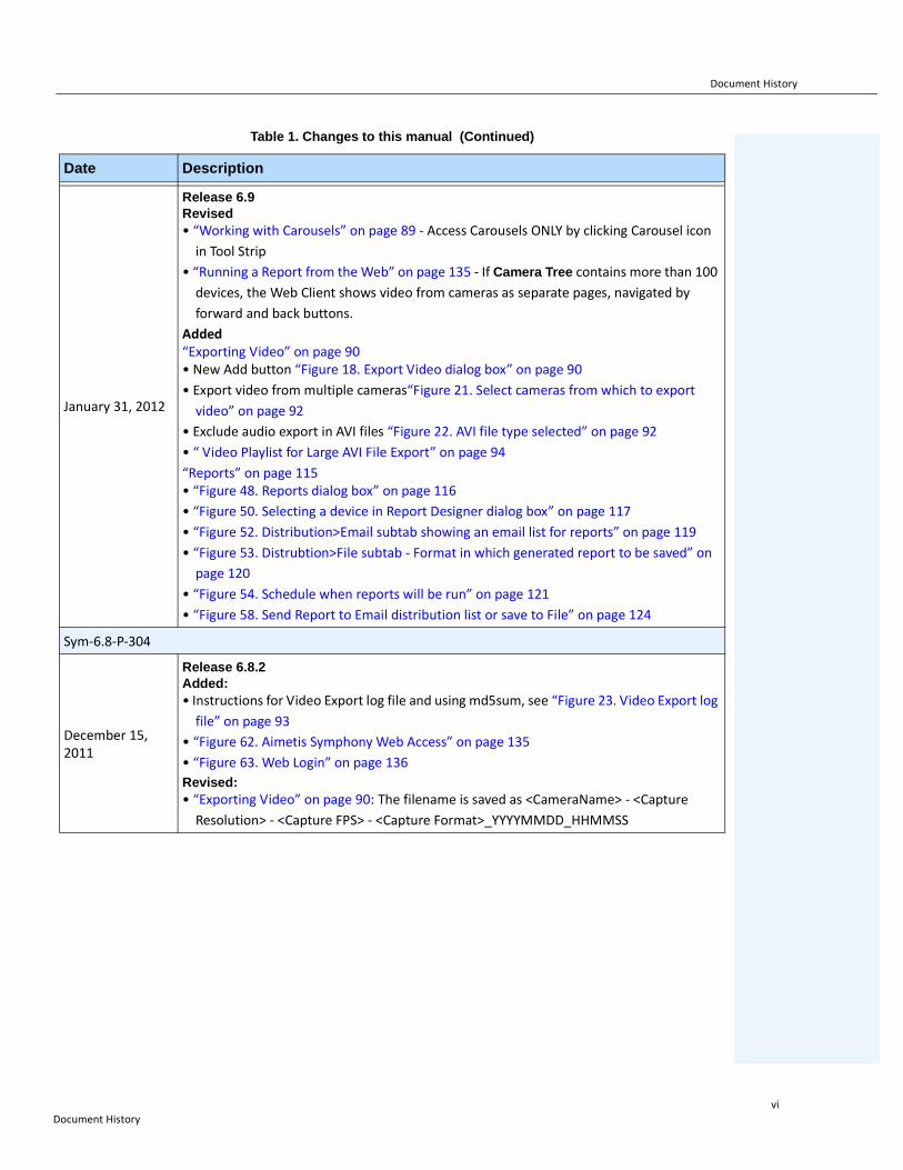
Table 1. Symbols and formatting used in this manual
Icon Caption/Format Description
Note
Additional information.
Example
Example scenario.
Important
Vital additional instructions or links.
Caution
You could lose recording footage or you must pay close attention to setting changes.
Bold, Arial FontGraphic User Interface term (button, menu, window, option) or keyboard item.
Italic, Arial Emphasis, new term, or an external reference.
Prefacex

Document Suite Preface
Document Suite
Table 2. Aimetis documents and videos
Document Name Links
Symphony Release Notes https://www.aimetis.com/Xnet/downloads/documentation.aspx
Symphony Installation Guide https://www.aimetis.com/Xnet/downloads/documentation.aspx
Symphony Administration Guide https://www.aimetis.com/Xnet/downloads/documentation.aspx
Symphony Analytics Guide https://www.aimetis.com/Xnet/downloads/documentation.aspx
Symphony Client User Guide https://www.aimetis.com/Xnet/downloads/documentation.aspx
Knowledge Base Articles http://www.aimetis.com/Support/knowledgebase.aspx
Case Studies http://www.aimetis.com/Solutions/customers-case-studies.aspx
White Papers http://www.aimetis.com/Solutions/whitepapers.aspx
Application Video Samples https://www.aimetis.com/Xnet/Marketing/collateral-library.aspx
Recorded Webinars http://www.aimetis.com/Events/webinars.aspx
Product Tour https://www.aimetis.com/Xnet/Marketing/collateral-library.aspx
Supported Video Devices List http://www.aimetis.com/Support/supported-video-devices.aspx
Licensing http://www.aimetis.com/Symphony/default--licensing.aspx
FAQ https://www.aimetis.com/Xnet/Support/faqs.aspx
Prefacexi

Aimetis Xnet Portal Preface
Aimetis Xnet Portal
Figure 1. Aimetis Xnet home page
Xnet is the Aimetis Online Portal: www.aimetis.com/Xnet
You can :
• Order Licenses• Manage Sub-Partner Accounts• Access Technical Support & Downloads• Access Sales & Marketing Tools• Access Aimetis Software Translation
Note: Access to tools depends on account type, for example, Distributor, Certified Partner, Authorized Partner, End-User. For instructions, see Table 3 on page xii.
Table 3. Instructions for using the Xnet
XnetXnet Instructions Links
XnetXnet Training Manual - Resellers
https://www.aimetis.com/Xnet/Marketing/collateral-library.aspx
Recorded Webinar - Xnet Training - Distributors https://www.aimetis.com/Xnet/Marketing/collateral-library.aspx
Prefacexii

Aimetis Xnet Portal Preface
Recorded Webinar - Xnet Training - Channel Partners
https://www.aimetis.com/Xnet/Marketing/collateral-library.aspx
Xnet Training Manual - Distributors
https://www.aimetis.com/Xnet/Marketing/collateral-library.aspx
Aimetis Symphony Architectural and Engineering Specification
https://www.aimetis.com/Xnet/Marketing/collateral-library.aspx
Hardware Benchmarks guidelines for 10, 20, 40 and 200 camera systems.
https://www.aimetis.com/Xnet/Marketing/collateral-library.aspx
Table 3. Instructions for using the Xnet
XnetXnet Instructions Links
Prefacexiii

Contact Us Preface
Contact Us
Table 4. Contact links, addresses, phone numbers
Contact Type Description
About Aimetis http://www.aimetis.com/Company/default.aspx
Contact link http://www.aimetis.com/Company/contact.aspx
Support link http://www.aimetis.com/Support/default.aspx
Americas
Aimetis Headquarters500 Weber Street NorthWaterloo, Ontario, CanadaN2L 4E9Phone: +1866-544-2804 or +1 519-746-8888 Fax: +1 519-746-6444
EMEA
Aimetis GmbHAm Prime Parc 765479 RaunheimGermanyTelefon: +49 (0) 6142 207 98 60Fax: +49 (0) 6142 207 98 89www.aimetis.de
Asia - Pacific
Aimetis ChinaRm. 1328 Yunsun Tower2025 Zhongshan West RoadXuhui, ShanghaiChina 200235Phone: 86-21-6182-6916Fax: 86-21-6182-6777
Prefacexiv
Table of Contents
Chapter 1: ....................................................................1
Symphony Client Main Console ............................................................................. 1
Timeline ...................................................................................................................... 2
Address Bar ............................................................................................................... 3
Alarm Log ................................................................................................................. 5
Customizing the Alarm Log ........................................................................................ 5
Tree View of Alarm Filtering Options ......................................................................... 9
Camera View ............................................................................................................ 10
Alarm Details ............................................................................................................ 11
Date .......................................................................................................................... 12
Application Log ...................................................................................................... 13
Camera Tree ........................................................................................................... 14
Customizing the Camera Tree ................................................................................. 15
Ban Video from Cameras and Camera Groups ....................................................... 16
Using Maps ............................................................................................................. 17
Viewing a Map .......................................................................................................... 17
Adding a Map ........................................................................................................... 18
Placing Cameras on Maps ....................................................................................... 19
Placing Camera Views on Maps .............................................................................. 20
(Optional) Creating Map Hot Links ........................................................................... 21
Deleting a Map, Removing a Camera Icon or a Hot Link ......................................... 24
Icons on Map ............................................................................................................ 25
Placing Rules on Maps ............................................................................................ 26
Acknowledging Rules on Maps ................................................................................ 27
Adding Digital Input and Output to Maps ................................................................. 27
Activating an Output Device Using the Map Context Menu ..................................... 29
Video Panels ........................................................................................................... 30
xv

Live View Mode ........................................................................................................ 30
Video Playback Mode .............................................................................................. 31
Navigation Menu Usage (in video playback mode) .................................................. 33
Camera View Layout ................................................................................................ 34
Display Four Historical Video Streams Concurrently in Fast Forward Mode ........... 37
Customizing Video Panel Properties ................................................................... 38
Appearance Tab ....................................................................................................................................38Activity Tab ............................................................................................................... 39
Child Tab .................................................................................................................. 44
Tracking Tab ............................................................................................................ 45
Other Tab ................................................................................................................. 47
Symphony Client Settings .................................................................................... 48
Startup ...................................................................................................................... 49
Display ..................................................................................................................... 50
Alarms ...................................................................................................................... 51
Video ........................................................................................................................ 53
Camera View ............................................................................................................ 55
Maps ........................................................................................................................ 56
Sound ....................................................................................................................... 57
Regional ................................................................................................................... 59
User Settings ............................................................................................................ 60
Global ....................................................................................................................... 61
Lock .......................................................................................................................... 62
Update ...................................................................................................................... 64
Advanced ................................................................................................................. 65
Server List .............................................................................................................. 66
Register New Server .............................................................................................. 67
Logging In, Switching Users, and Supervisor Logon ........................................ 69
Logging on with Supervisor Privileges ..................................................................... 71
Modifying User Information .................................................................................. 72
xvi

Chapter 2: ................................................................. 73
Searching Video by Using the Search Tool ........................................................ 73
Search Tool .............................................................................................................. 73
View Search Results ............................................................................................. 79
Recurring Search ................................................................................................... 81
LPR ......................................................................................................................... 82
Activity for All Cameras ........................................................................................ 83
Recent Alarms/Motion ........................................................................................... 84
Tracking Color ....................................................................................................... 86
Bookmarks ............................................................................................................. 87
Carousels ............................................................................................................... 88
Creating or Modifying Carousels .............................................................................. 88
Working with Carousels ........................................................................................... 89
Exporting Video ..................................................................................................... 90
Using Search ............................................................................................................ 90
Using Export ............................................................................................................. 90
Alarm ID, Camera ID, and Keyboard Navigation ................................................. 95
Using PTZ Cameras ............................................................................................... 96
Using the PTZ Controls ............................................................................................ 96
Using the Mouse to Control a PTZ Camera ............................................................. 97
Using a Joystick ....................................................................................................... 98
Camera Tour ............................................................................................................ 99
Support for AXIS T8310 Surveillance Control Board ............................................. 104
Quick Find ............................................................................................................ 107
Messenger ............................................................................................................ 108
Monitoring with Symphony ................................................................................ 109
Using Multiple Monitors .......................................................................................... 109
Using the Site Map ................................................................................................. 109
Using Alarm Log ..................................................................................................... 109
Marking Alarms ...................................................................................................... 110
Using the Alarm Console ....................................................................................... 110
Using the Timeline ................................................................................................. 110
xvii

Viewing Activity for all Cameras ............................................................................. 110
Using a Carousel .................................................................................................... 110
Disabling Alarms .................................................................................................... 110
Alarm Console ..................................................................................................... 111
Enable or Disable Alarms for Server ................................................................. 113
Marking Alarms .................................................................................................... 114
Reports ................................................................................................................. 115
User Permissions ................................................................................................... 115
How to Use the Report Manager ............................................................................ 115
General Procedure for Using the Report Manager ................................................ 116
Object Counts Across a Line .................................................................................. 125
Heat Map Image ..................................................................................................... 128
Object Counts ........................................................................................................ 132
Object Statistics ..................................................................................................... 133
Alarm Counts ......................................................................................................... 134
Running a Report from the Web ........................................................................ 135
Creating Two Heat Map Reports to Run from the Web ......................................... 137
Reporting Issues to Aimetis ............................................................................... 138
xviii
Symphony Client Main Console Chapter 1
Chapter 1
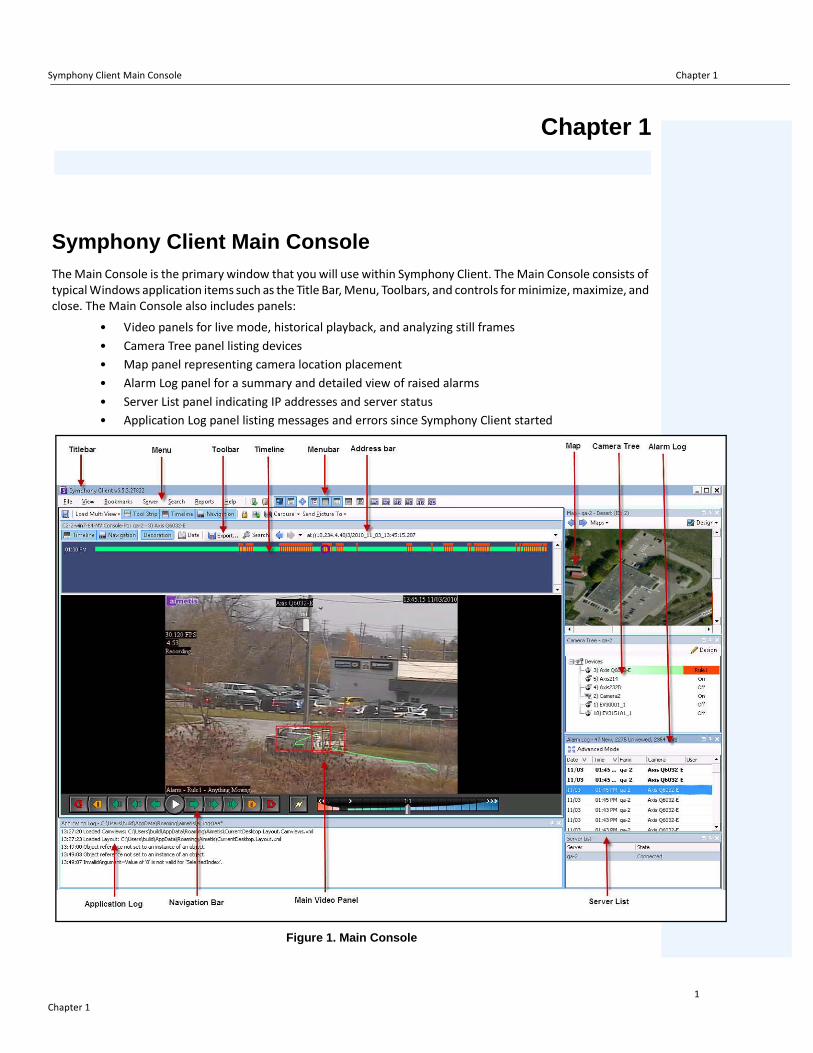
Symphony Client Main ConsoleThe Main Console is the primary window that you will use within Symphony Client. The Main Console consists of typical Windows application items such as the Title Bar, Menu, Toolbars, and controls for minimize, maximize, and close. The Main Console also includes panels:
• Video panels for live mode, historical playback, and analyzing still frames• Camera Tree panel listing devices• Map panel representing camera location placement• Alarm Log panel for a summary and detailed view of raised alarms• Server List panel indicating IP addresses and server status• Application Log panel listing messages and errors since Symphony Client started
Figure 1. Main Console
Chapter 11

Timeline Chapter 1
Timeline
The Timeline is a powerful way to view everything that has happened in a day at a glance. The Timeline is integrated in the main view of Symphony Client.
Figure 2. Timeline
Procedure
To display the timeline:
• Click the Timeline buttonOR
• Right-click on the Video Panel and select Show Timeline.
If you click anywhere on the Timeline, a still image for that time will appear in the main view.
Chapter 12

Address Bar Chapter 1
Timeline Colour Code• Green: No relevant foreground activity was detected.• Contrasting green bar: Indicates that video was not recorded locally in the Windows machine, but
Symphony is already downloading the video from an AXIS camera. Symphony does not analyze video downloaded from the camera. As such, it does not determine activity type, for example, broken rule or video signal lost.
• Yellow-orange: Indicates activity.• Red: A Rule was broken that resulted in an alarm being raised. By default, rules are summarized on
the Timeline using a red square. You can customize how rules are displayed on the Timeline from the Alarms tab in the Symphony Client Settings dialog box. See “Symphony Client Settings” on page 48.
• Gray: Poor video quality.• White: Access granted.• Black: Access denied.• Purple circle: Always indicates the Timeline position for what is currently being viewed in the
Video Panel.• Pink horizontal bar: Indicates that camera is not in the home position. Visible only when camera
set up with auto tracking (PT090/PT091 video analytic).
Address Bar
The address bar contains a Symphony link to the last selected video position. Each time you click on the Timeline or navigate to a different camera on a different server, this information is recorded. This allows you to navigate backwards or forwards from your current position.
Figure 3. Address bar
Procedure
To display the address bar:
• Click the Tool Strip button. The address bar is displayed.
Figure 4. Tool Strip button clicked to display the Address bar
Chapter 13
Address Bar Chapter 1
Procedure
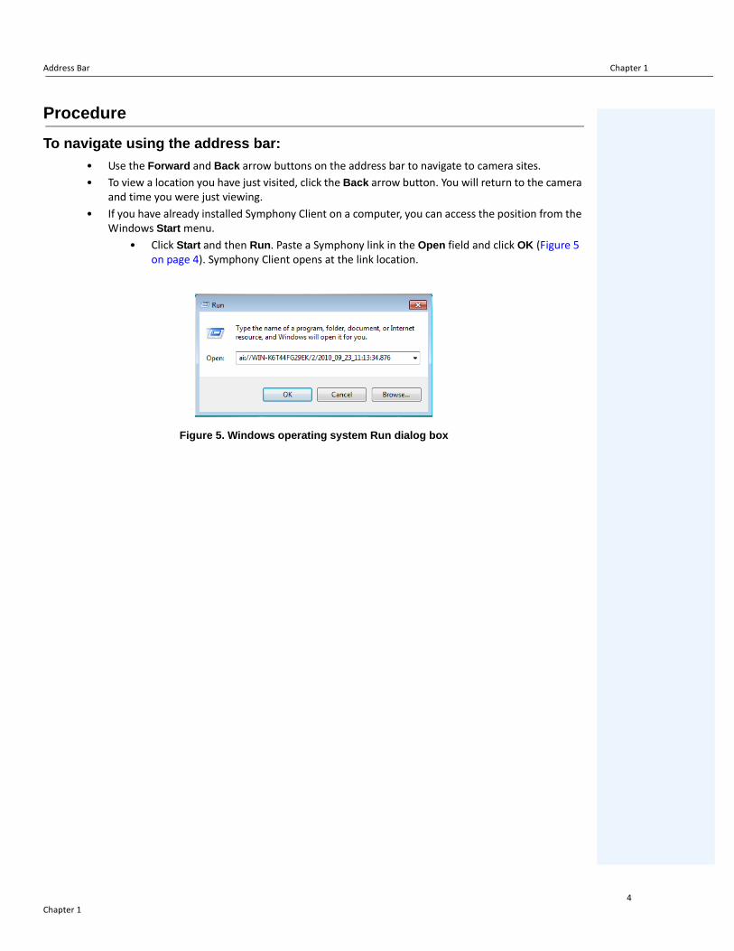
To navigate using the address bar:
• Use the Forward and Back arrow buttons on the address bar to navigate to camera sites. • To view a location you have just visited, click the Back arrow button. You will return to the camera
and time you were just viewing.• If you have already installed Symphony Client on a computer, you can access the position from the
Windows Start menu.• Click Start and then Run. Paste a Symphony link in the Open field and click OK (Figure 5
on page 4). Symphony Client opens at the link location.
Figure 5. Windows operating system Run dialog box
Chapter 14

Alarm Log Chapter 1
Alarm LogThe Alarm Log panel shows a list of alarms for connected servers.
Procedure
To display the alarm log panel:
• From the View menu, select Alarm Log.
OR
• Click the Alarm Log icon on the Menu Toolbar.
Figure 6. Alarm Log
Customizing the Alarm Log
By default, the Alarm Log panel is docked inside the main view. However the Alarm Log panel can be dragged into a second monitor and configured to display more information. In Advanced Mode, the Alarm Log panel provides detailed information: camera view, alarm details, thumbnails of alarms.
Procedure
To display the Alarm Log in Advanced Mode:
• Click the Advanced Mode button in the Alarm Log panel.
Figure 7. Alarm Log panel with Advanced Mode button
Chapter 15

Customizing the Alarm Log Chapter 1
Figure 8. Alarm Log expanded to show Advanced Mode view
Chapter 16

Customizing the Alarm Log Chapter 1
Column ChooserThe Column Chooser menu option allows you to customize which columns are displayed.
Procedure
To use the Column Chooser:
1. Right-click on one of the column headings in the Alarm Log panel and select Column Chooser.
2. Drag columns from the Customization dialog box to the column headings in the Alarm Log or drag column headings from the Alarm Log into the Customization dialog box.
Figure 9. Column Chooser
Grouping Columns in the Alarm LogGrouping by columns is an effective way of organizing the potentially long list of alarms. A typical use would be to group all alarms by Server, then by Camera as shown in Figure 10 on page 8.
Procedure
To group by column:
• Drag the desired column heading into the area marked by the text Drag a column header here to group by that column.
Chapter 17

Customizing the Alarm Log Chapter 1
Figure 10. Before grouping
Figure 11. Grouping by Camera
Chapter 18

Tree View of Alarm Filtering Options Chapter 1
Tree View of Alarm Filtering Options
In the Advanced Mode, the alarm filter options are displayed.
Procedure
To display a tree view of the alarm filtering options:
• Click the Filters toolbar button.• Select Viewed to show only those alarms that have already been viewed.• Select Unviewed to show only those alarms that have not yet been viewed.• Select All to show all alarms.• Select Marked to show only those alarms that have already been marked
(acknowledged). See “Alarm Details” on page 11.• Select Unmarked to show only those alarms that have not yet been marked
(acknowledged). See “Alarm Details” on page 11.
Figure 12. Filters for viewing alarms
Chapter 19

Camera View Chapter 1
Camera View
A Camera View panel can be docked within the Alarm Log panel, or dragged onto another display monitor.
Procedure
To display a camera view:
• Click the Camera View toolbar button.
Figure 13. Camera View displayed
Chapter 110

Alarm Details Chapter 1
Alarm Details
The Alarm Details panel can be docked within the Alarm Log or dragged onto another display monitor.
Procedure
To display alarm details:
1. Click the Alarm Details toolbar button.
2. (Optional) Enter any relevant details in the Alarm Comments area and click Save.
Figure 14. Alarm Details dialog box
Chapter 111

Date Chapter 1
Date
The Calendar allows you to load alarms for all connected servers for a specific date. Days displayed in bold weight font contain video data.
Procedure
To display the calendar:
• Click the Date toolbar filter button.
Figure 15. Calendar selection to view archived alarms
Chapter 112

Application Log Chapter 1
Application LogThe Application Log panel is at the bottom of the Main Console. It lists errors and messages that have occurred since Symphony Client was started.
Procedure
To activate the application log:
1. From the View menu, select Application Log. ORClick the Application Log icon in the Menu Toolbar.
2. Double-click on any entry in the Application Log panel and the entire message will be displayed.
Figure 16. Application Log expanded to show details
Chapter 113

Camera Tree Chapter 1
Camera TreeBy default, the Camera Tree panel is shown in the top right of the Main Console. The Camera Tree is the default method of navigating in the user interface of Symphony Client between cameras. Like tree or folder organization of files in common Windows applications, all cameras are listed in a predefined order. In Symphony Client, the cameras are listed in order of camera ID. Each camera has a unique ID and is set automatically by the system as cameras are added.
Procedure
To display the Camera Tree:
• From the View menu, select Camera Tree. The Camera Tree can be docked to the main console, or undocked and dragged to any monitor.
Figure 17. Camera Tree - How camera IDs are organized - I/O Devices with status displayed
Figure 18. Camera Views saved in Camera Tree dialog box
Chapter 114

Customizing the Camera Tree Chapter 1
The Override label beside a camera indicates that recording on the camera has been stopped. Specifically, the Record Video setting in the camera configuration was changed by a user by right-clicking in the Camera Tree and selecting Stop Recording. The Override label reminds the user to right-click and select Resume Record mode when necessary.
Figure 19. Override label beside camera
Customizing the Camera Tree
Procedure
To customize the Camera Tree:
1. Access the Camera Tree panel one of the following ways:
• From the Server menu, select Device Tree Configuration. The Device Tree Configuration dialog box opens.
OR• From the View menu, select Camera Tree. Click the Design button in the right corner of
the Camera Tree dialog box. The Device Tree Configuration dialog box opens.
2. To add a folder to your camera tree, click Add.
3. To delete the currently selected object, either a camera or folder, click Delete.
4. Click Options in the upper right corner of the dialog box. You can select or clear the Show Device Icons, Show Device Numbers, and Show Digital I/O check boxes to modify the display of these items.
5. To add a camera to the tree, select a camera from the right pane. Drag and drop it with your mouse in the left pane.
Note: The Device Tree can be automatically generated and maintained from an external source. In this scenario, Symphony needs to query the source for changes in the camera tree structure. Define the time interval to query the source in the Device Tree Synchronization found in “Managing General Settings” in the Administration and Analytics Guide.
Chapter 115

Ban Video from Cameras and Camera Groups Chapter 1
Figure 20. Device Tree configuration options
Ban Video from Cameras and Camera Groups
In the Camera Tree, the (right-click) Ban Video context-menu item allows you to ban video from cameras and camera groups. Only users and groups with specified permissions can use this feature.
• When Ban Video is selected for camera(s) and/or group(s), the permissions for View Live Video and View Historical Video access will be changed to Deny.
• When Unban Video is selected for camera(s) and/or group(s), the permissions for View Live Video and View Historical Video access will be changed to Unspecified.
For details on user groups and permissions, see the Aimetis Symphony Administration Guide.
Chapter 116

Using Maps Chapter 1
Using MapsSymphony allows you to upload an image (jpg, gif or bmp file) to be used as a map (visual representation) of your camera configuration. You place cameras, Camera Views, and/or digital input and output devices on the maps. These devices/views are represented by icons.
You can click on a camera icon or click and drag a camera icon from the maps to panels in your main console or Video Wall to immediately change the image displayed in a panel.
• “Viewing a Map"• “Adding a Map” on page 18• “Placing Cameras on Maps” on page 19• “Placing Camera Views on Maps” on page 20• “(Optional) Creating Map Hot Links” on page 21• “Deleting a Map, Removing a Camera Icon or a Hot Link” on page 24• “Icons on Map” on page 25• “Acknowledging Rules on Maps” on page 27• “Adding Digital Input and Output to Maps” on page 27• “Activating an Output Device Using the Map Context Menu” on page 29
Viewing a Map
Procedure
To display the map:
• From the View menu, select Map Navigation. Any maps already in your system are displayed. Use the left and right arrows to scroll through all maps.
• When searching for a map, partial matches are listed based on text entered in the search field.
Figure 21. Map Navigation
Chapter 117

Adding a Map Chapter 1
Adding a Map
Procedure
To add a map:
1. From the View menu, select Map Navigation.
2. In the upper right corner of the Map dialog box, click Edit Maps. The Edit Maps dialog box opens. Maps are sorted alphabetically.
3. Click New Map and then browse for the image file you want to use for the new map (jpg, gif or bmp) and click Open. The map is displayed.
4. The new map is listed with its filename. The Edit Maps dialog box focuses on the new map in the list.
5. Click OK.
Figure 22. Edit Maps dialog box
Chapter 118

Placing Cameras on Maps Chapter 1
Placing Cameras on Maps
Procedure
To place cameras on the Map:
1. From the View menu, select Map Navigation.
2. In the upper right corner of the Map dialog box, click Edit Maps. The Edit Maps dialog box opens.
3. From the right pane listing the cameras in the Devices tab, drag and drop your cameras to the map with your mouse. (Cameras are not added to the map by default.)
4. (Optional) Rotate the icon so that the arrow represents the angle of the camera lens:
a. Right-click on a camera icon on the map and select Rotate. b. Move your mouse and the arrow will rotate.c. Left-click your mouse to accept the position.
5. (Optional) To remove a camera icon from the map, right-click on camera icon and select Remove from Map.
6. Click OK to save settings.
Figure 23. Drag cameras onto map
Chapter 119
Placing Camera Views on Maps Chapter 1
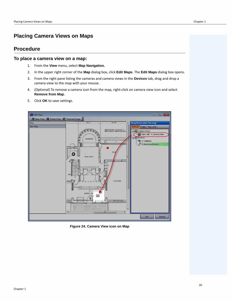
Placing Camera Views on Maps
Procedure
To place a camera view on a map:
1. From the View menu, select Map Navigation.
2. In the upper right corner of the Map dialog box, click Edit Maps. The Edit Maps dialog box opens.
3. From the right pane listing the cameras and camera views in the Devices tab, drag and drop a camera view to the map with your mouse.
4. (Optional) To remove a camera icon from the map, right-click on camera view icon and select Remove from Map.
5. Click OK to save settings.
Figure 24. Camera View icon on Map
Chapter 120

(Optional) Creating Map Hot Links Chapter 1
(Optional) Creating Map Hot Links
In larger sites where you want to have more than one site map, you can layer maps by creating hot links. For example, one main map can contain hot links that open detailed maps of a particular area.
Procedure
To create a map hot link:
1. From the View menu, select Map Navigation.
2. Scroll through the maps to select the one which will have hot links.
Figure 25. Scroll through maps
3. In the upper right corner of the Map dialog box, click Edit Maps. The Edit Maps dialog box opens.
4. Ensure that you have at least two maps to link. If not, follow “To add a map:” on page 18.
5. Select a primary map on which you want to add a hot link.
6. Click the Map Links tab. A list of all maps is displayed. Select a map that will open when the user clicks on a hot link in the primary map:
• Select the map name and drag it onto the map. The link appears as a box on the map (Figure 26 on page 22).
Chapter 121

(Optional) Creating Map Hot Links Chapter 1
Figure 26. Drag Map Link to primary map
7. Right-click on the hot link box to display the context menu.
a. To resize the box to cover a larger area, select Resize and then move your mouse.• The box size decreases as you move your mouse pointer towards the box.• The box size increases as you move your mouse away from the box. • Left-click the mouse to accept a size.
b. To change the colour of the hot link box, select Change Color. The Color dialog box opens, displaying a range of colors.
Figure 27. Color dialog box
Chapter 122

(Optional) Creating Map Hot Links Chapter 1
c. To change the opacity of the box, select Change Opacity and use the sliding scale to make the box more transparent or more opaque (Figure 28 on page 23).
Figure 28. Change Opacity option on hot link
8. When the box is the right size, color, and opacity, click OK.
9. Test the link. Click on the hot box link in the primary map. The associated map should open.
Figure 29. Area of the hot link box on the map
Chapter 123
Deleting a Map, Removing a Camera Icon or a Hot Link Chapter 1
Deleting a Map, Removing a Camera Icon or a Hot Link
Procedure
To delete a map:
1. From the View menu, select Map Navigation.
2. In the upper right corner of the Map dialog box, click Edit Maps. The Edit Maps dialog box opens.
3. Under the Map column heading, select the map you want to delete.
4. Click the Delete Map button.
5. Click OK.
Procedure
To remove a camera icon from a map:
1. From the View menu, select Map Navigation.
2. In the upper right corner of the Map dialog box, click Edit Maps. The Edit Maps dialog box opens.
3. Under the Map column heading, select the map containing the camera icon you want to remove.
4. Right-click on the camera icon. Select Remove from Map.
5. Click OK.
Procedure
To remove a hot link from a map:
1. From the View menu, select Map Navigation.
2. In the upper right corner of the Map dialog box, click Edit Maps. The Edit Maps dialog box opens.
3. Under the Map column heading, select the map containing the hot link you want to remove.
4. Right-click on the hot link. Select Remove from Map.
5. Click OK.
Chapter 124

Icons on Map Chapter 1
ates
ted
ted
Icons on Map
Use the following legend to understand the icons placed on maps.
Table 1. Map Icon Legend
Icon Icon Description Represents Colours Indicate
Filled in circle Rule on a camera You can set colours to indicate various stas necessary
Triangle pointing up in circle
Digital Input(e.g., person presses a button, which causes an appropriate action in the system)
Green arrow, white background - not activatedGreen arrow, yellow background - activa
Triangle pointing down in circle
Digital Output(e.g., motion sensor detects motion and closes a gate)
Green arrow, white background - not activatedGreen arrow, yellow background - activa
Circle containing an arrow Camera
Green arrow - recordingOrange arrow - activityRed arrow - alarm
Orange circle - camera currently selected
Box around a circle containing an arrow PTZ Camera
Green arrow - recordingOrange arrow - activityRed arrow - alarm
Orange circle - camera currently selected
Door
Access control device(e.g., key card or key fob)
Green - access grantedRed - access denied
Chapter 125

Placing Rules on Maps Chapter 1
Figure 30. Example of a typical map with camera, PTZ camera, digital I/O, and control access device icons, and rules
Placing Rules on Maps
Procedure
To place rules on a map:
1. From the View menu, select Map Navigation.
2. Scroll through the maps to select the one which will have rules.
3. In the upper right corner of the Map dialog box, click Edit Maps. The Edit Maps dialog box opens.
4. Click the Rules tab. From the right pane listing the rules, drag and drop your rules to the map with your mouse.
5. Click OK to save settings.
Chapter 126

Acknowledging Rules on Maps Chapter 1
Acknowledging Rules on Maps
Procedure
To acknowledge an alarm (rule on map):
1. From the View menu, select Alarm Log OR click the Alarm Log icon on the Menu Toolbar.
2. Right-click on the alarm you want to acknowledge.
3. Select an action to perform:
• Mark as Alarm - To mark as a real alarm.• Mark as False Alarm - To mark as a false alarm. • Mark as Real Actionable - To mark as a real alarm that requires action, for example,
security staff should investigate the alarm.
Adding Digital Input and Output to Maps
Not on all devices. See list in Knowledge Base article:http://www.aimetis.com/Support/kbarticle.aspx?ID=10141
The Map Configuration dialog box contains a Devices tab, listing all cameras and digital input and output devices. You can customize digital input and output names to help identify them. For instructions, see the Administration and Analytics Guide.
Icon Icon Description Represents Colours Indicate
Triangle pointing up in circle
Digital Input(e.g., person presses a button, which causes an appropriate action in the system)
Green arrow up, white background = not activated
Green arrow up, yellow background = activated
Triangle pointing down in circle
Digital Output(e.g., motion sensor detects motion and closes a gate)
Green arrow down, white background = not activated
Green arrow down, yellow background = activated
Important: The Show Digital I/O option on the must be enabled in Device Tree Configuration dialog box for the digital I/O to be displayed, regardless of which specific inputs/outputs are selected. See “Customizing the Camera Tree” on page 15.
Chapter 127

Adding Digital Input and Output to Maps Chapter 1
Procedure
To place digital inputs/outputs on the Map:
1. From the View menu, select Map Navigation.
2. Scroll through the maps to select the one which will have rules.
3. In the upper right corner of the Map dialog box, click Edit Maps. The Edit Maps dialog box opens.
4. Click the Devices tab. From the right pane listing the devices, drag and drop the digital devices to the map with your mouse.
5. Click OK to save settings.
Figure 31. Digital I/O on map displayed with arrow icons
Chapter 128

Activating an Output Device Using the Map Context Menu Chapter 1
Activating an Output Device Using the Map Context Menu
Procedure
To activate output device using the context menu:
1. Right-click on the device. The context menu opens.
2. Click Activate. The icon turns yellow.
Figure 32. Activating an Output device on a MapOnly Output device has context menu for Activate
Chapter 129

Video Panels Chapter 1
Video PanelsVideo Panels show live video, recorded video, and allow you to analyze still frames. All Video Panels, including the Main Video Panel, can optionally include a Timeline and a Navigation Bar. These options and others are available by right-clicking on the Video Panel to display the context menu.
Live View Mode
By default, cameras show live images in the Main Console.
Figure 33. Live Mode
Procedure
To navigate to different cameras:
• Click on a camera in the Camera Tree panel or Map to switch cameras. To exit live mode:
• Click on Timeline and you automatically enter playback mode.
Chapter 130

Video Playback Mode Chapter 1
Video Playback Mode
If Timeline or Alarm Log is clicked, video playback mode begins.
Figure 34. Playback Mode with context menu options displayed
Procedure
To select options for playback mode:
Right-click on the video panel in playback mode, to view other context menu options:
• Full Screen - Opens Main Console in Full Screen mode. Right-click to exit full screen.• Play at RealTime Speed- Set the Speed Slider to real time speed.• Unlock PTZ (Return Home)- Forces PTZ back to home position.• PTZ Lock Properties - PTZ Lock dialog box opens. Indicates who has PTZ locked and when that
lock expires. Options to Unlock, Lock Indefinitely, Lock 5 minutes, Lock for user-defined minutes.
• Send Picture To - You can automatically send picture to Printer, Email Recipient as a Link, a File, the Clipboard, or to the Clipboard as a Link
• Camera Tour - Allows you to Edit (or Create) a Camera Tour, and Enable or Disable a Tour. If Enable or Disable is selected while playing historical video, the Video Panel will switch to Live mode.
• Show Tool Strip, Show Timeline, Show Navigation Bar - A check mark beside each feature indicates that it is displayed with the video panel.
• Settings - Launches the Camera View Settings dialog box with several settings for appearance, what to do when activity occurs, digital tracking, and other miscellaneous options. See “Customizing Video Panel Properties” on page 38.
Chapter 131

Video Playback Mode Chapter 1
You can also indicate video export times using the Timeline - Right-click on the Timeline for a specific panel and select Mark Export Start and Mark Export End for a video you want to export. Indicators are right and left arrows.
Figure 35. White arrows on timeline indicate start and end time for video export
Chapter 132

Navigation Menu Usage (in video playback mode) Chapter 1
Navigation Menu Usage (in video playback mode)
Figure 36. Navigation buttons
• Navigates forward and backward by alarm, activity (motion), 10 seconds, 1 second, 1 frame.• Controls video playback speed as well as reverse playback speed.• Switches back to Live mode from playback mode.
Figure 37. Navigation forward
AudioDepending on camera make and Symphony Client Settings (Sound tab), audio icons are also part of the navigation bar.
Icon Description
To speak on the selected camera, click and hold the microphone icon.The icon becomes red and sound is being recorded.
Click the mute button to control sound (on/off) coming from the selected camera.
Chapter 133

Camera View Layout Chapter 1
Camera View Layout
Camera View layout allows you to view multiple camera views at the same time. You can configure Symphony to display 1 to 25 cameras at once. You can have more than one multi view dialog box open.
Since Camera View layout is made up of individual Video Panels, it is possible to configure them individually for appearance, the activities to perform upon alarm events, whether or not to have Timelines, Navigation Bars, etc. The behavior of each video panel can be customized (“Customizing Video Panel Properties” on page 38).
In Symphony version 6.9 and prior, Camera View layout is referred to as Multi View.
Figure 38. Camera View - 4 panels example
Depending on the default setting in your Client Settings, a camera view can open as a floating view or a docked view. For default settings, see “Symphony Client Settings", specifically the tab with “Camera View” on page 55.
Chapter 134

Camera View Layout Chapter 1
Procedure
To load a Camera View display:
1. In the Menu toolbar, click one of the camera view icons (1, 4, 6, 9, 16, 25). Depending on the default setting in your Client Settings, a camera view can open as a floating view or a docked view.
2. (Optional) To switch between a default view (either docked or floating view), press the Ctrl button on your keyboard and with your mouse click the desired camera view icon (1, 4, 6, 9, 16, 25).
3. Drag cameras from the Map panel or Camera Tree panel onto panes in the camera view.
Figure 39. Camera View icons
Procedure
To save your currently configured Camera View for later use:
1. Click the Save icon in the Toolbar. The Save As dialog opens.
Figure 40. Save As icon for Camera Views
2. Select the New View option and enter a name for the view in the adjacent field.
3. Click OK to save the camera view.
Figure 41. Camera View saved
Chapter 135

Camera View Layout Chapter 1
To load a saved Camera View (multi view):
• From the View menu, select Load Camera View Layout, and select a named view.or
• Click on a named camera view in the Camera Tree.
Figure 42. Camera View listed in Camera Tree
Floating Camera ViewFloating Camera View windows are typically used where the operator has more than one monitor. A floating camera view can be dragged to the second monitor.
• From the View menu, select Floating Camera View.
Docked Camera View• From the View menu, select Docked Camera View.
Chapter 136

Display Four Historical Video Streams Concurrently in Fast Forward Mode Chapter 1
If some cameras do not have video for the start time the user has specified, one or more panels may display video for 1 second from a future time while the panels synchronize.
Display Four Historical Video Streams Concurrently in Fast Forward Mode
You can play 4 historical synchronized video streams in Fast Forward mode or Reverse mode at 16 times real speed concurrently using the Lock times on navigation feature.
Figure 43. Four panels - Lock on time navigation enabled
Figure 44. All 4 videos in Fast Forward mode“No footage found message” displayed in panel of camera with no recorded video for a particular time
Chapter 137

Customizing Video Panel Properties Chapter 1
Customizing Video Panel PropertiesEach video panel can be configured with advanced options. A video panel can be in the Camera View (see “Camera View Layout” on page 34) or the Main Console.
Procedure
To customize camera view settings:
1. Right-click on the image in the video panel and select Settings.
2. The Camera View Settings dialog box opens with several settings for:
• appearance (such as title, video information overlay)• views that can be displayed when an activity occurs • digital tracking (zooming in on an activity)• global settings (that is, applying changes to all video panels)
Appearance Tab
Figure 45. Camera View Settings dialog box with Appearance tab active
• Title - Displays camera number.• Timeline - Enables whether Timeline height should be resized automatically.• Video Decorations Overlay - Enables video annotations.• Video Quality- You can set a smaller stream on the client to reduce bandwidth. Multi-streaming in
Symphony for analytics and Camera Views reduces server and client CPU and CPU transcoding. If camera accommodates multiple video streams, allows you to select the video quality for this panel
Chapter 138

Activity Tab Chapter 1
(Default, Lowest resolution, Closest fit to panel size, Closest fit not smaller than panel size, Highest resolution). Stream Selector on Appearance tab in the Camera View Settings has been redesigned and renamed Video Quality in Symphony 6.10.1.
• Display Mode - specifies how Symphony Client displays video for the camera in the panel (Default, Actual size, Maintain Aspect Ratio, Fit to Window). If video is not displaying properly, try changing the Display Mode. Some video cards do not support all video display modes. RGB display modes require more CPU power than the default display mode.
Activity Tab
Figure 46. Camera View Settings dialog box with Activity tab active
• “Event"• “Display” on page 40• “Action” on page 40• “Example 1 ” on page 41
EventYou can force a Video Panel to automatically switch to a specific view when an event occurs.
• The switching event can be an alarm (defined in Rules), or it can be motion (detected by motion analytics engines such as VE150, VE160, VE250). An alarm can be from an I/O device that is associated with a camera.
Chapter 139

Activity Tab Chapter 1
• Limit action to specific cameras - If you are connected to many farms/servers/cameras you may want a view to automatically switch only to a subset of all cameras. You select the cameras that should be in this set. This is useful if you have 4 Multi Views open and you are monitoring 1000 cameras where there is rarely activity. The 4 Video Panels within a Multi View window can be configured to always show video from the last 4 cameras that had activity.
Display Choose whether you want to automatically switch to the live video or to the still image.
Action An action can be performed after the switched view:
• Disable switching after switch occurs - As an example scenario, imagine a Video Panel switches and the operator watches the camera, then another alarm occurs on a different camera that causes a second switch to a new view. The operator may be frustrated that the view has automatically changed. In such a case, it might be useful to Disable switching after one switch occurs. However, if the operator needs to re-enable switching, the operator must right-click on the live view and select the Enable Automatic Switching menu option.
• Hide switched view after seconds - If the view should be blank unless an event of interest has occurred, then select this option. When no event has occurred, the panel will be black with the text “Waiting for event.” When an event occurs, the video will pop up and a countdown timer will be displayed that shows how many seconds are left until the “Waiting for event” state. The number of seconds to wait before blacking out the live view can be specified in the text box.
• Go back to previous state after seconds - As an example scenario, you are watching live (or historica)l video for camera 1. The panel switches to show an alarm raised from camera 2. Sixty seconds later, camera 1 goes back to previous state, that is, continues playing live (or historical) video for camera 1.
Note:
1. Symphony will not automatically switch a Video Panel to a camera that is already being displayed in another camera panel in that Camera View.
2. After a Video Panel automatically switches it will not automatically switch to another camera for 8 seconds.
3. If multiple Video Panels within a Camera View switch based on activity, only one will switch - the one that switched furthest in the past. Each Camera View operates independently; therefore, if you have 2 cameras in different Camera Views set to automatically switch based on activity, they may both be showing the same camera.
4. To disable switching, the user must click on the video image in the panel.
Chapter 140

Activity Tab Chapter 1
Important: To hide the view until next event, one-time only, right-click on the Video Panel and select Hide View Until Next Event.
Example 1 Alarm Launching Multiple Cameras
An intruder breaks through door and enters room. • Camera 1 focused on door.• Cameras 2, 3, and 4 – all show interior space related to door.• In Symphony Client 2 x 2 multi-view panels with no cameras currently displayed
Task:• Set up Symphony so that image from Camera 1 appears immediately in a multi-view
panel when an alarm is raised and that cameras near the door are also displayed immediately when an alarm is raised on Camera 1.
Set up rule in Rule Wizard
1. In the Rule Wizard, Camera 1, which is focused on a door, is selected. The appropriate Video Engine and mask are set up as necessary.
Figure 47. Rule Wizard - Event
2. Click Next.
3. In the Alarm tab, you select all the cameras from which you want to see an image if an alarm occurs on Camera 1. In this example, you want to see images from Cameras 2, 3, and 4 if an alarm is triggered on Camera 1.
Chapter 141

Activity Tab Chapter 1
Figure 48. Rule Wizard - Alarm tab (View other cameras on alarm)
4. Click Next and set up the Schedule.
5. Click Save to save the Rule name for this scenario.
6. Click OK to close the Server Configuration dialog box.
Set up a camera view panel:
1. In a camera-view panel (for example, 2x2), right-click ONLY on the first panel (Panel 1).
2. From the context menu, select Settings. The Camera View Settings dialog box appears.
3. Click the Activity tab.
4. Select the Switch view when alarm occurs check box.
5. Select the Show alarm cameras in other panels check box. (This option forces all the other panels in the Multi-view to display images from cameras associated with Camera 1. Recall, in the Rule Wizard, Cameras 2, 3, and 4 were selected to be viewed if an alarm was triggered on Camera 1.)
Example 1 Alarm Launching Multiple Cameras (Continued)
Chapter 142

Activity Tab Chapter 1
Figure 49. Client View Settings dialog box - Activity tab
When an alarm occurs on Camera 1, Panel 1 will now display the image from Camera 1 AND the other panels will display images from Cameras 2, 3, and 4.
Example 1 Alarm Launching Multiple Cameras (Continued)
Chapter 143

Child Tab Chapter 1
Child Tab
Figure 50. Child tab
You can force a Video Panel to always show the latest alarm image for the camera being displayed in another Video Panel (Primary Video Panel). When you change the camera being shown in the Primary Video Panel (either automatically or manually) the Secondary Video Panel switches to the most recent alarm.
In the Panel Name field, you can change the long panel name to a word or phrase you can easily identify.
Procedure
To display a listing of the most recent alarm/motion images:
• From the View menu in the main console, select Recent Alarm/Motion JPEGs. The Recent Alarms/Motion JPEGs dialog box opens.
Chapter 144

Tracking Tab Chapter 1
Tracking Tab
Figure 51. Tracking tab
The digital zoom option in the Tracking tab allows you to see a digitally magnified image of a tracked scene.
Procedure
To digitally zoom:
1. Select the Digitally zoom in on hot spots check box and click OK.
2. Select a point where an object was tracked.
Figure 52. Timeline
3. Click Play.
Chapter 145

Tracking Tab Chapter 1
Figure 53. Click Play
Notice how the image has been magnified at the tracked area. In this example, the area in and near the green box.
Figure 54. Image magnified at the tracked area
Chapter 146

Other Tab Chapter 1
Other Tab
Figure 55. Other tab
• Applies changes selected in other tabs to all video panels.
Chapter 147
Symphony Client Settings Chapter 1
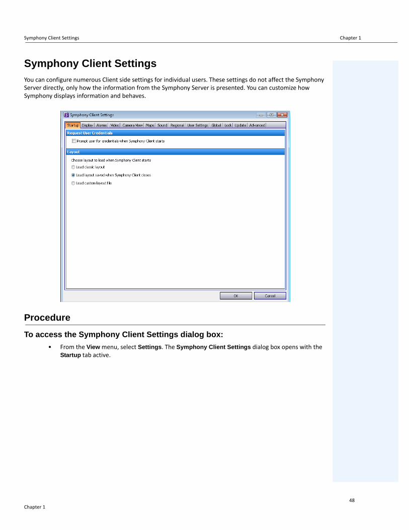
Symphony Client SettingsYou can configure numerous Client side settings for individual users. These settings do not affect the Symphony Server directly, only how the information from the Symphony Server is presented. You can customize how Symphony displays information and behaves.
Procedure
To access the Symphony Client Settings dialog box:
• From the View menu, select Settings. The Symphony Client Settings dialog box opens with the Startup tab active.
Chapter 148

Startup Chapter 1
Startup
The default layout at startup for the current user can be defined. • You can require a user to enter credentials when Symphony Client starts by enabling the Prompt
user for credentials when Symphony Client starts check box.• Classic layout displays the Main Console, Map panel, Camera Tree panel, Alarm Log panel, and
the Application Log panel.
Figure 56. Startup tab for selecting layout
Chapter 149
Display Chapter 1
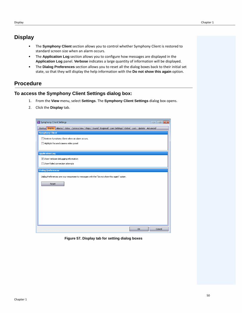
Display
• The Symphony Client section allows you to control whether Symphony Client is restored to standard screen size when an alarm occurs.
• The Application Log section allows you to configure how messages are displayed in the Application Log panel. Verbose indicates a large quantity of information will be displayed.
• The Dialog Preferences section allows you to reset all the dialog boxes back to their initial set state, so that they will display the help information with the Do not show this again option.
Procedure
To access the Symphony Client Settings dialog box:
1. From the View menu, select Settings. The Symphony Client Settings dialog box opens.
2. Click the Display tab.
Figure 57. Display tab for setting dialog boxes
Chapter 150

Alarms Chapter 1
Alarms
Procedure
To access the Symphony Client Settings dialog box:
1. From the View menu, select Settings. The Symphony Client Settings dialog box opens.
2. Click the Alarms tab.
Figure 58. Alarms tab
• The Alarm Notification section allows you to specify if a dialog box should pop up after an alarm (Rule broken) occurs, or if an alarm icon should be added to the system tray.
Chapter 151

Alarms Chapter 1
Figure 59. Alarm notification
• The Alarm Box section allows you to customize alarm colours displayed in the Timeline, and what alarms to show in the Alarm Log by Rule. By default, all alarms will create a Red Dot in the Timeline, and all Rules that are broken will appear in the Alarm Log. By customizing the Timeline, it is easier to locate specific events. You can configure what colour each Rule should represent in the Timeline.
Chapter 152

Video Chapter 1
Video
Procedure
To access the Symphony Client Settings dialog box:
1. From the View menu, select Settings. The Symphony Client Settings dialog box opens.
2. Click the Video tab
Figure 60. Video tab
• The PTZ Movement section allows you to define the PTZ movement behaviour in the live view.• The Default Video Decorations section allows you to define how images are displayed with video
annotations such as time information or messages. By default, Symphony overlays boxes and paths on the live video. You can switch whether Symphony should decorate (display the video annotation on) the image. This affects only how live video is displayed and does not change how Symphony records video.
• Decoration information is always recorded separately and not written directly on the video images.
• This is a client-side setting that does not affect other users. The same video can be viewed by one Symphony Client user with decorations enabled, and by another without decorations enabled.
• This setting also effects video play back settings. You can choose to overlay decorations for recorded video you are playing back.
Chapter 153

Video Chapter 1
• Video Quality – If a camera accommodates multiple video streams, allows you to select the video quality for the entire Symphony Client (Lowest resolution, Closest fit to panel size, Closest fit not smaller than panel size, Highest resolution).
• Video Decoration Settings – Allows you to change the font size of decorations based on percentage. By default it is set at a readable 100%. If you need large font, set it to 200%. To see the change in font size, you must switch panels or restart Symphony Client.
• Display Mode - Specifies how Symphony Client displays video in a panel (Actual Size, Maintain Aspect Ratio, Fit to Window) and how it renders video.
• Some video cards do not support all video render modes. • RGB render modes require more CPU power than the default render mode.• In Symphony versions before 6.8, the default was Video Renderer Default. If
your video does not play with the Video Mixing Renderer 9, custom presenter, select Video Renderer Default from the Renderer drop-down list.
• Direct connect to camera - Depending on camera, allows direct connection to camera instead of the server when Support Direct Connect check box selected in camera configuration. See Aimetis Symphony Administration Guide.
Chapter 154

Camera View Chapter 1
Camera View
Procedure
To access the Symphony Client Settings dialog box:
1. From the View menu, select Settings. The Symphony Client Settings dialog box opens.
2. Click the Camera View tab.
Figure 61. Camera View tab
• Symphony allows you to open a split screen or virtual video matrix window that can show 1 to 25 cameras simultaneously. This requires a lot of CPU resources on the client PC.
• Frame Rate section - allows you to configure whether to run Camera View windows at a decreased frame rate to reduce CPU load on the client PC.
• Camera view tool button default behaviour section - allows you to select the default camera view layout (either floating for docked) when Symphony Client is launched.
In Symphony version 6.9 and prior, the Camera View tab is referred to as Multi View tab.Should you run a Camera View (multi view) at a decreased frame rate? What is the benefit?
• If you run it at 1 FPS instead of 5, 15, 30, you benefit from decreased client CPU and GPU load, about 10% of current values (a major savings).
What is the loss?
• Video will not be smooth.
When should you consider it?
• Use this feature if you have a large number of panels in the Camera View (multi-view), for example, 9 or more panels.
• If your CPU & GPU are powerful enough, you probably never have to reduce the frame rate.
Chapter 155

Maps Chapter 1
Maps
You set up how alarms on Maps are displayed. For example, flashing for a given amount of seconds when an alarm occurs, or continuous flashing until alarms are acknowledged.
Procedure
To access the Symphony Client Settings dialog box:
1. From the View menu, select Settings. The Symphony Client Settings dialog box opens.
2. Click the Maps tab.
Figure 62. Maps tab
Chapter 156

Sound Chapter 1
Sound
Figure 63. Sound tab
Procedure
To access the Symphony Client Settings dialog box:
1. From the View menu, select Settings. The Symphony Client Settings dialog box opens.
2. Click the Sound tab.
You can customize sound configuration within Symphony Client.
• In the Audio Settings section, you can specify:• Default Sound Mode - How Symphony Client plays audio for live and recorded video
from a specific panel, all panels, or no sound. (Prior to Symphony 6.11 referred to as audio streaming.)
Audio Output - Playing audio on a remote camera• Input Device - Can be a microphone from which sound will be captured and played on
the (remote) camera's speaker.
Chapter 157

Sound Chapter 1
• Play audio file if you click Talk while holding Ctrl check box - To allow users to play a pre-recorded PCM file on the remote camera's speaker for testing or announcement purposes, select the Play audio file if you click Talk while holding Ctrl check box. The user must click the Microphone icon (Talk button) in the Navigation bar while pressing the Ctrl key on the client station keyboard.
• Musical Note icon - Click the musical note icon to open the file location for the audio file you want to use. The audio file must be a PCM Wavefile.
• Sound meter - Responds to your voice or audio file ensuring that your client machine is registering sound correctly that will be heard through the remote camera’s speakers.
• In the Event Sounds section you can specify a default sound to be played for alarms.• Continuous sound - Each policy (in addition to the existing sound) may have a
continuous sound that plays until all alarms based on the given policy have been acknowledged. You must have the Play sound when an alarm occurs check box selected for any sound to play. If any existing sounds are being played, clearing the Play sound when an alarm occurs check box stops the sound.
Chapter 158

Regional Chapter 1
Regional
• You can specify the language of Symphony Client. By default, Symphony Client will use your Windows system language. If your Windows is using a language not supported by Symphony Client, it will automatically select English.
• You can also customize how the date and time are displayed in Symphony Client by selecting a format from Date Format drop-down box and, if necessary, selecting the Use 24 Hour Time display check box.
Procedure
To access the Symphony Client Settings dialog box:
1. From the View menu, select Settings. The Symphony Client Settings dialog box opens.
2. Click the Regional tab.
Figure 64. Regional tab
Chapter 159

User Settings Chapter 1
User Settings
You can directly edit the initialization (.ini) file which stores all the user-specific settings of Symphony Client. We do not recommend that you change these advanced settings.
Procedure
To access the Symphony Client Settings dialog box:
1. From the View menu, select Settings. The Symphony Client Settings dialog box opens.
2. Click the User Settings tab.
Figure 65. User Settings
Chapter 160

Global Chapter 1
Global
Paths define where to store client configuration and farm registration.
Procedure
To access the Symphony Client Settings dialog box:
1. From the View menu, select Settings. The Symphony Client Settings dialog box opens.
2. Click the Global tab.
Figure 66. Global tab
Chapter 161

Lock Chapter 1
Lock
In some cases, you may want to lock the user interface to prevent users from changing the configuration.
• Panel resizing/moving - Prohibits user changing size of panels as well as moving and docking the panels.
• Panel adding/closing - Prohibits user adding panels to the user interface or closing them in the current layout.
• Camera selection - Prohibits user changing camera in the view through the camera tree or through the map.
• Exit Symphony - Prohibits user from exiting Symphony.• Set Passphrase button - Creates a password to lock/unlock the interface. The user will be
prompted for a password.
Procedure
To access the Symphony Client Settings dialog box:
1. From the View menu, select Settings. The Symphony Client Settings dialog box opens.
2. Click the Lock tab.
Figure 67. Lock tab
Chapter 162
Lock Chapter 1
Procedure
To lock the user interface:
1. In the Lock tab of the Symphony Client Settings dialog box, select the interface features you want to lock.
2. Click the Set Passphrase button. Enter a pass phrase that the user must enter (if necessary) to later unlock the interface and lick OK.
3. From the View menu of the Main Console, select Lock.
To unlock the Symphony Client:
1. From the View menu on the Main Console, select Unlock. The Unlock Symphony dialog box opens.
2. Enter the pass phrase that was defined when locking the interface and click OK. The interface is now unlocked.
Chapter 163

Update Chapter 1
Update
The options in this tab are typically selected by an Administrator. You can select whether the Server or Client machine manages Device Pack updates.
• If you select that the Server manage Device Pack updates, then you must indicate when Device Pack updates will be installed on the Client machine in the Server Configuration Server Farm dialog. See the Administration manual for instructions.
Procedure
To access the Symphony Client Settings dialog box:
1. From the View menu, select Settings. The Symphony Client Settings dialog box opens.
2. Click the Update tab.
Figure 68. Update tab
The Client user will be prompted with one of the following messages during a Device Pack installation:
Figure 69. Device Pack Installation Update Message to Client User
• If any issues are encountered during the installation process, consult Device Pack Installation Errors.
• For Device Pack Installation Wizard instructions, consult How to install a Device Pack.
Chapter 164

Advanced Chapter 1
Advanced
In the Advanced tab, you can:
• Configure memory usage conditions under which Symphony Client will restart• Set the level of information (low, medium, high) that Symphony Client should log for system
functions. If you select Low, the client logs will contain less detail, but system performance will be better. Increasing the log level provides more detailed information if a problem is encountered, but can impact system performance. If unsure, leave the default selection.
• Enable/disable messages to the user in the event of a Symphony Client crash by selecting the Silently handle crashes check box.
Procedure
To access the Symphony Client Settings dialog box:
1. From the View menu, select Settings. The Symphony Client Settings dialog box opens.
2. Click the Advanced tab.
Figure 70. Advanced tab
Chapter 165

Server List Chapter 1
Server ListThe Server List panel is on the right side of the Main Console. It lists the servers along with their connection status.
Procedure
To display and customize the Server List panel:
1. From the View menu, select Server List. The currently selected server is highlighted, and any server operations that are performed via the Server menu will act on this selected server.
2. Right-click on the top title bar. The context menu appears where the Column Chooser allows you to customize which fields are displayed.
Figure 71. Right-click on Server List panel title bar
3. Right-click on a server from the Server List panel. A context menu pops up that allows you to Add, Edit, Delete, Enable, Disable, and view Properties of the selected servers.
Figure 72. Right-click on a server
The Server List panel can be docked in the Main Console or undocked and moved to another monitor.
Chapter 166

Register New Server Chapter 1
Register New ServerSymphony Server Registration allows Symphony Client to connect to a Symphony Server over a network. You need at least one server registered because the server houses the database and all configuration settings.
Procedure
To register the Symphony server:
1. From the File menu, select New Symphony Server Registration. The Add Symphony Server Connection dialog box opens.
Figure 73. Add Symphony Server Connection
2. Click the drop-down arrow in the Address field. A list of possible servers appears.
Figure 74.
Chapter 167

Register New Server Chapter 1
3. Select one of the servers.
• If the Symphony Server is running on a nonstandard TCP port, you can enter an address with colon suffix followed by the TCP port number. If you do not suffix with a port, it will try the default port, 50,000.
• Enter a descriptive Name that will appear in Symphony Client for this address. This information is not used to connect.
• In the User field, enter a user name for a user who will have access to the server.• Enter the password that is set up for the user.
Procedure
To edit the Symphony Server connection information:
1. In the Server List dialog box, right-click on the server name you want to edit, and select Edit.
Figure 75. Right-click on server name in Server List
2. The Edit Symphony Server Connection dialog box opens. You can edit the description Name of the server, the User name and Password.
Figure 76. Edit Symphony Server Connection
Chapter 168

Logging In, Switching Users, and Supervisor Logon Chapter 1
Logging In, Switching Users, and Supervisor LogonYou can log in, log off, switch users, or even log two users in at the same time on the same machine granting them higher user privileges than they normally have on an individual basis.
Procedure
To log off/log into Symphony Client:
1. In Symphony Client, from the File menu, select Log Off All Servers.
2. The Log Off All Servers confirmation dialog box opens. Click OK.
Figure 77.
3. Symphony Client displays the Access Denied message.
Figure 78. Logon screen after user has logged off Symphony Client
4. To log back into Symphony, select the Server to log on to. (You can log onto all servers with the same credentials.)
5. Enter the User and Password and click OK. The name of the user appears in the Symphony Client title bar.
Chapter 169
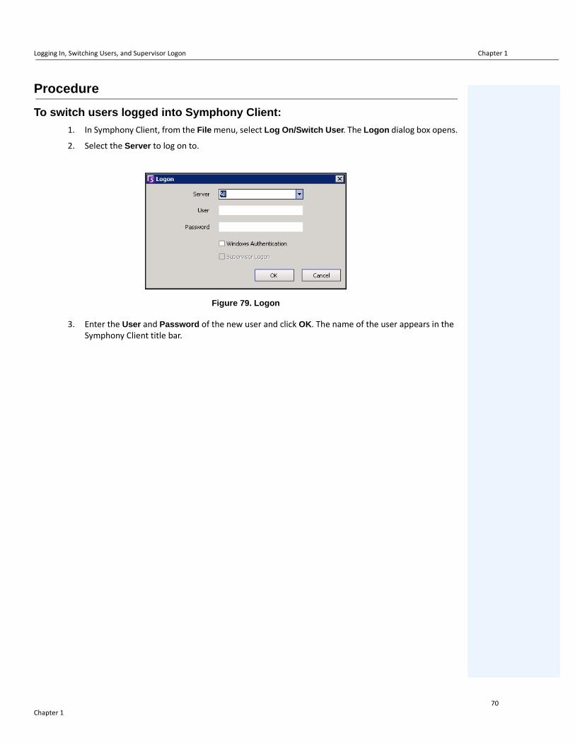
Logging In, Switching Users, and Supervisor Logon Chapter 1
Procedure
To switch users logged into Symphony Client:
1. In Symphony Client, from the File menu, select Log On/Switch User. The Logon dialog box opens.
2. Select the Server to log on to.
Figure 79. Logon
3. Enter the User and Password of the new user and click OK. The name of the user appears in the Symphony Client title bar.
Chapter 170

Logging on with Supervisor Privileges Chapter 1
Logging on with Supervisor Privileges
Procedure
To log on with supervisor privileges:
1. In Symphony Client, from the File menu, select Log On/Switch User. The Logon dialog box opens.
2. Select the Server to log on to with supervisor privileges. The Supervisor Logon check box is enabled.
Figure 80. Logon
3. Enter the User and Password of one of the two users.
4. Select the Supervisor Logon check box. More fields appear.
5. Enter the User and Password of the second user wanting to log on at the same time.
6. Enter the Supervisor User name. It is the same name of the virtual user you created in the User Configuration dialog box.
Figure 81. Supervisor Logon fields displayed
7. In the Reason field, enter information that describes why you are logging in with supervisor privileges.
8. Click OK. You can now use the system.
Chapter 171

Modifying User Information Chapter 1
Modifying User InformationAll users can view and modify their user information. Farm registration is automatically updated if credentials are changed through the User Configuration dialog box on the local machine.
Procedure
To modify user information:
1. From the Server menu, select User Configuration. The User Configuration dialog box opens.
2. In the left pane, click your user name. The User Information dialog box opens.
3. Modify any necessary information such as User Name, Password, Name, Email, Phone, Description.
4. Click Apply.
Figure 82. User Configuration
Note: If Active Directory mode was defined during setup, no password is stored in Symphony as the Windows domain password will be used. See your Administrator.
Chapter 172

Searching Video by Using the Search Tool Chapter 2
Chapter 2
Searching Video by Using the Search ToolSymphony provides two methods of searching video: using the Timeline or the Search tool.
• The Timeline is integrated in the main interface of Symphony Client and summarizes a full day's activity. This is useful if you want an overview of the entire day on the current camera. See “Timeline” on page 2.
• The Search tool allows your to query video for specific events in specific parts of the video.
Search Tool
The Search tool allows you to search recorded video for motion or alarms in specified areas of interest. Symphony will search based on your criteria and create a mini movie and thumbnails showing the results. For example, you may search for all activity around a car for the last 24 hours. Symphony will create a video containing only activity that occurred in an area of an image designated by you. The result may be a five minute movie, depending on how much activity was found.
Chapter 273

Search Tool Chapter 2
Figure 1. Search dialog box
Procedure
To perform a search:
1. From the toolbar, click the Search button (Figure 2). The Search dialog box opens (Figure 1 on page 74 ).
Figure 2. Search button
2. From the Analytics Engines list, select the engine. Depending on the analytics engine you choose, you can mark the area of interest for searching or select a class of objects to search for such as people or vehicles. Each engine has different search options that you can use.
Chapter 274

Search Tool Chapter 2
Figure 3. Analytics Engines selection list
Some options might be:• Using the displayed image from the video, you define the area in blue (a mask) where
objects in motion should be detected. Figure 4 on page 76• Select the Erase option to erase the blue mask.• Select the Draw option to draw the blue mask. • The Size slider adjusts the pen thickness.
• Alternatively, digital fences can be used as the search criteria. Select Any fence to draw a digital fences. Selecting All fences denotes that the object must pass through all fence lines to result in resulting search video. Figure 5 on page 76
• Select the Class of object you wish to search for, such as People, Vehicles or Unknown objects (unknown objects are objects that were tracked but were not classified as people or vehicles). Figure 5 on page 76
• Select the Behavior to filter by, such as loitering. Figure 5 on page 76
Chapter 275

Search Tool Chapter 2
Figure 4. Search dialog box
Figure 5. Search options
Chapter 276

Search Tool Chapter 2
3. Specify your search From and To dates. For more advanced settings, click the Advanced button (Figure 6).
Figure 6. Basic to Advanced settings in the Search dialog box
• One Time Search - The search will be performed only once using the date range you selected.
• Specified Interval Search - You can specify to search between a date and time range. For example, between July 26 and July 30, but only between 6:38pm and 7:38pm.
• Recurring Search - Allows you to specify a search that Symphony will continuously perform until you end it. For example, between 18:00 and 8:00 each day. This option may be useful if you want automated searches done at specific times for review.
• Title - A user defined tile for the search can be defined.• Email address - To notify a user the search is complete. • Seconds before clip and Seconds after clip - Can be modified by entering a numeric
value that represents the seconds before or after the event Symphony should begin to play the resulting video.
• Everything - Will not filter any video. The resulting movie will include all frames between the From and To search times.
• Any Movement - Symphony will search for all activity between a specific date and time.• Alarms Only - Allows you to select the specific events to search for as defined by the
Rules.
Chapter 277

Search Tool Chapter 2
• Events (group area) - Allows you to combine different search events in order to further filter the results. For example, you can search for people loitering AND cars parking within 60 seconds, and only these combined events would be displayed in the search results.
4. If the search is being conducted against a PTZ camera, select the Home Position to search in. Home Positions are configured in the Camera Tour. See “Using PTZ Cameras” on page 96.
5. Click Search to start search. The View Search Results dialog box opens. See “View Search Results” on page 79.
Chapter 278

View Search Results Chapter 2
View Search ResultsAfter you perform a Search, the View Search Results dialog automatically opens.
Figure 7. View Search Results dialog box
Procedure
To manually open the View Search Results dialog box:
1. From the Search menu select View Search Results, or if you have the Search dialog box open, click the Search button. The View Search Results dialog box displays all your previous searches.
2. You have several options once a search result is selected from the list:
• The right pane of the View Search Results dialog box displays snapshots of each event for the currently selected search.
• To get a better view of the image, click on the snapshot in the right pane and the image will be displayed in the main video panel. (Note that the selected snapshot must be an existing archived image in the system in order for it to be displayed.)
• To play a search - Click the Play button in the toolbar. Symphony Player will automatically open and play the video of the selected result.
• To refine a search - Click the Refine Search button in the toolbar. The Search dialog box opens. See “Search Tool” on page 73.
• To delete a search - Click the Delete button (X) in the toolbar. The corresponding .aira and .mpeg files will be deleted from the server.
Chapter 279

View Search Results Chapter 2
• To save a search to your computer - Click the Export button and select Download AIRA. The video will be saved in .aira format to your PC. You require Symphony Player to play .aira files.
• To save as an .mpeg format - Click the Export button and select Download MPEG. This will save it as MPEG4v2 format which can be played in a wide variety of media players including Microsoft Media Player.
• To email a search result video - Click the Export button and select E-Mail Link.
Figure 8. Menu options in View Search Results dialog box
Chapter 280

Recurring Search Chapter 2
Recurring SearchRecurring searches are set up in the Advanced search options. For details, see “Search Tool” on page 73.
Figure 9. Recurring Search
You can manage your recurring searches from the Recurring Search Definitions dialog box.
Procedure
To manage recurring searches:
1. From the Search menu, select Manage Recurring Searches. The Recurring Search Definitions dialog box opens showing a list of your named search recurring search types. Server farms are listed in a drop-down box.
2. Click on the named search. The Refine Search and Delete buttons become active.
3. If you click Refine Search, the Search dialog box opens where you can adjust settings. See “Search Tool” on page 73.
Figure 10. Recurring Search Definitions
Chapter 281

LPR Chapter 2
LPRThis menu option is available only if you have purchased and completed the License Plate Recognition (LPR) installation.
Figure 11. Main menu access in Symphony Client for LPR
Automatic License Plate Recognition is available as a video engine inside Aimetis Symphony. The VE410 allows you to detect and index license plates. It is designed for vehicle access control applications as well as traffic control and enforcement applications.
For complete instructions on field installation and planning, software installation, and analytics configuration, see the Aimetis Automatic License Plate Recognition (ALPR) Guide.
Chapter 282

Activity for All Cameras Chapter 2
Activity for All CamerasThe Activity For Cameras view makes it easy to compare the Timelines for all or a group of cameras on all servers for the specified date range. It is also useful if you want a snapshot of all activity on all your cameras for a day
Procedure
To see activity for all cameras:
1. From the View menu in the main console, select Activity for Cameras.
2. (Optional) Click on the Timeline and the corresponding image is loaded in the Main View.
Figure 12. Activity For Cameras dialog box
• Upon altering the date range, clicking Reload will load all the cameras' timeline information for the new date range.
• Zoom In and Zoom Out allow you to quickly change the granularity of the time bars shown.• One Camera View button uses one Video Panel to show the result of navigating with the
timelines. If not depressed, then each time you click on a timeline a new Video Panel will be created.
Chapter 283

Recent Alarms/Motion Chapter 2
Recent Alarms/MotionThe Recent Alarms/Motion feature is ideal for the following scenarios when you want to:
• see which alarms happened around a given time to determine what is going on• prioritize alarms so that you know which of the most recent you should be dealing with• see where there was motion to determine if an alarm setting is necessary in certain areas• learn to differentiate between a true alarm and activity-only in your monitored area• see recent activity/alarms if you have stepped away from your monitor for any reason
Procedure
To display the Recent Alarm/Motion JPEGs feature:
• From the View menu in the main console, select Recent Alarm/Motion JPEGs. The Recent Alarms/Motion JPEGs dialog box opens.
Figure 13. Recent Alarm/Motion JPEGs panel
This feature allows you to view images (JPEGs) of alarm or motion instances based on the selected cameras.
Chapter 284

Recent Alarms/Motion Chapter 2
Table 1. Feature Usage
Button/Field Description
AlarmsView unique alarm JPEGs of the selected cameras in reverse-chronological order (starting with most recent) in a sequence of instances with Minimum Interval Seconds between the alarm occurrences.
Motions
View unique motion JPEGs of the selected cameras in reverse-chronological order (starting with most recent) in a sequence of instances with Minimum Interval Seconds between the motion occurrences.
This is specific to the redundant alarms that are ignored by the Alarm Log and Timeline because they have occurred within quick succession of a unique alarm. These alarms can be identified when Symphony tags them as “Too many alarms, ignored” in the Live View panel.
Both Alarms and Motions can be selected at the same time, enabling both unique and redundant alarms to be displayed. Each image will have the Minimum Interval Seconds between them.
Number of JPEGs (1-200)
Limit the number of JPEGs displayed between 1 and 200, and arrange the images in different layouts, each staying consistent with the reverse-chronological ordering.
Minimum Interval Seconds (1-60)
Minimum Interval Seconds determines the number of seconds in between a set of adjacent images for a unique alarm (or motion).
Reducing this setting will display a larger, more granular set of JPEGs, as there will be less time between the displayed alarm instances. Increasing the setting will, in contrast, reduce the set.
Note: Changing the Minimum Interval Seconds from, for example 60 to 3, will not change the snapshots in the displayed set, but will affect new snapshots that are displayed. New snapshots will be set at the new Minimum Interval Seconds.
Event LogView the listed changes to the cameras selected, as you click the Alarms or Motions button.
Select the cameras to view JPEGs
Select the cameras from which to view images (JPEGs).
rows/column icons representing display layout
2 medium size images in a row2 medium size images, one above the othersmall images in a row - use horizontal scroll bar to view allsmall images in a column - use vertical scroll bar to view all
Chapter 285

Tracking Color Chapter 2
Tracking ColorA Symphony video analytic engine may be running on your system. Tracking lines may appear as the camera follows an object through an area. These tracking lines vary in color according to object tracked and video engine used.
Figure 14. Same parking lot: blue tracking line for person, and yellow tracking line for vehicle
Chapter 286

Bookmarks Chapter 2
BookmarksYou can add a bookmark for what is currently showing in the Main Video Panel. This could either be live playing video, historical playing video, or a still image. After you have added a bookmark it will appear on the Bookmarks menu, just like Favorites in Microsoft Internet Explorer.
Procedure
To add a bookmark:
1. From the Bookmarks menu, select Add Bookmark.
2. Enter a name for the bookmark.
3. (Optional) To make the bookmark visible to all connected users, select the Shared check box.
4. Click OK.
Figure 15. Add Bookmark dialog box
Procedure
To manage bookmarks:
1. From the Bookmarks menu, select Manage Bookmarks.
2. Select a bookmark to delete or share. Shared bookmarks are visible to all connected users.
3. Click OK to complete the action and close the dialog box.
Figure 16. Manage Bookmarks dialog box
Chapter 287

Carousels Chapter 2
CarouselsCarousels allow you to loop through multiple cameras across multiple servers in the same server farm, pausing on each camera for a defined period of time.
Procedure
To access Carousels:
1. From the Server, select Configuration. The Server Configuration dialog box opens.
2. In the left pane, click Carousels. The Carousels Summary dialog box opens.
Creating or Modifying Carousels
Figure 17. Server Configuration - Carousel
Chapter 288
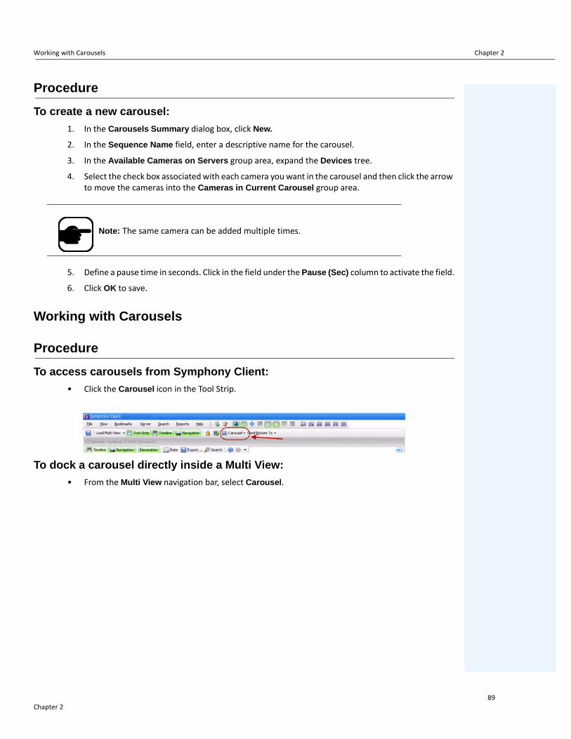
Working with Carousels Chapter 2
Procedure
To create a new carousel:
1. In the Carousels Summary dialog box, click New.
2. In the Sequence Name field, enter a descriptive name for the carousel.
3. In the Available Cameras on Servers group area, expand the Devices tree.
4. Select the check box associated with each camera you want in the carousel and then click the arrow to move the cameras into the Cameras in Current Carousel group area.
5. Define a pause time in seconds. Click in the field under the Pause (Sec) column to activate the field.
6. Click OK to save.
Working with Carousels
Procedure
To access carousels from Symphony Client:
• Click the Carousel icon in the Tool Strip.
To dock a carousel directly inside a Multi View:
• From the Multi View navigation bar, select Carousel.
Note: The same camera can be added multiple times.
Chapter 289

Exporting Video Chapter 2
Exporting VideoYou can export video from the Symphony server two ways:
• You can perform a Search and save it to disk from the View Search Results dialog box.• You can export video by selecting a time period to export using the Export button in the toolbar.
Using Search
1. Perform your search. For details, see “Searching Video by Using the Search Tool” on page 73.
2. Right-click a search result from the list. Save the result in one of the following formats.
• Click the Export button and select Download AIRA. The video will be saved in .aira format to your PC. You require Symphony Player to play .aira files.
• Click the Export button and select Download MPEG. This will save it as MPEG4v2 format which can be played in a wide variety of media players including Microsoft Media Player.
Using Export
Figure 18. Export Video dialog box
1. Select a point on the Timeline.
• Option 1:a. Click on the Timeline to the location you want to begin the export.b. Click the Export button in the toolbar. The Export Video dialog box opens.c. By default Symphony sets parameters for a movie clip starting 60 seconds before the
timeline clicked time, until 60 seconds after it. Alter these settings as necessary in the Start Time and End Time fields.
Chapter 290

Using Export Chapter 2
• If you create an END point to the left of the START point, the START will be removed before the END is created.
• If the cameras are changed after a selection is made, the END point is removed.
• If you select a Start and End point from the Timeline first, the Video Export dialog box displays corresponding Start and End dates.
• If you do NOT first select Start and End points in the Timeline, but open the Video Export dialog box, the Start/End arrows will be created in the Timeline +/- 1 minute from the current selection. Arrows in the Timeline will match the Start/End dates shown in the Video Export dialog box.
• In Live View, if you first launch the Video Export dialog box, only the Start point arrow will be displayed in the Timeline. The End point arrow will appear in the Timeline after a minute, that is, when time has passed and the Timeline shows a historical moment.
• If no End point is selected, Symphony displays an End arrow on the Timeline two minutes after the Start arrow.
• If no Start point is selected, Symphony displays a Start arrow on the Timeline two minutes before the End arrow.
• Option 2:a. Right-click a starting point on the Timeline and from the context-menu select Mark
Export Start.
Figure 19. Right-click context menu on Timeline
b. Right-click an ending point on the Timeline and from the context-menu select Mark Export End.
c. Click the Export button in the toolbar. The Export Video dialog box opens. The points in the Timeline are reflected in the Start Time and End Time fields in the Export Video dialog box.
Figure 20. Start and End arrow times reflected in Video Export dialog box
Note: Once the Video Export dialog box is displayed, if you change a Start Time or End Time in the Video Export dialog box and click outside the date control fields, the arrows in the Timeline will change to reflect this. However, the Start Time and End Time fields in the Export Video dialog box are NOT updated when changing the Start and End points on the Timeline.
Chapter 291

Using Export Chapter 2
2. Select the camera(s) from which to export video for the time period. Click Add. The Select Camera to Export dialog box opens. Select the check box associated with the camera(s).
Figure 21. Select cameras from which to export video
3. Select Symphony Video or AVI from the Format field.
a. If you selected AVI, the Export Video dialog box expands to display more options.
Figure 22. AVI file type selected
Chapter 292

Using Export Chapter 2
Symphony saves the format and destination of your last export within a session.
b. (Optional) By default, decorations are included on the exported video. You can clear the check boxes to remove the decorations.
c. By default, Video and Audio Codecs are selected. Use the drop-down lists to select other codecs that are installed on your Windows system.
d. By default, audio is exported. To exclude audio, clear the Export Audio check box.
4. By default, the video file and a log file will be saved on your Desktop. If necessary, change the location of the saved files by altering the path in the Destination Folder field.
• The video filename is saved as <CameraName> - <Capture Resolution> - <Capture FPS> - <Capture Format>_YYYYMMDD_HHMMSS with the .avi or .aira extension. The date and time reflects the start of the recorded clip.
• The video log file is named in the same manner as the video file but with a .txt extension. The exported video file contains an MD5 checksum (a digital signature). It is used to verify that the video file has not been altered.
Figure 23. Video Export log file
• To verify the checksum, you must run md5sum against the video file and verify that the number matches the value in the log file. See the Aimetis Knowledge Base for instructions: http://www.aimetis.com/Support/kbarticle.aspx?ID=10086
5. From the Split Files at drop-down list in the Export Video dialog box, you can select file size segment: 10, 100, 640, 700, or 2000 MB. You can also enter any value in the field between 2 and 2000 MB.
• Files are created by default in approximately 640 MB segments.• Consecutive files have a timestamp that represents the start of that file.
Figure 24. Segment large files using the Split Files at option
Chapter 293

Using Export Chapter 2
6. Click Export. A message is displayed indicating that your file has been saved. You have the option of opening the directory where the video file has been stored.
Figure 25. Export Video - successful export message
Video Playlist for Large AVI File ExportWhen exporting a large file into segments in AVI format, a playlist is created.
Procedure
To launch a playlist:
1. Open the M3U file in Windows Media Player. The files play in order, one after another.
Figure 26. Video clips from large video export - M3U file for playist
2. In Library mode in Windows Media Player, you can click Play to view the list of AVI files.
Figure 27. Windows Media Player displaying playlist of vide
Chapter 294

Alarm ID, Camera ID, and Keyboard Navigation Chapter 2
Alarm ID, Camera ID, and Keyboard NavigationIn addition to navigating cameras using the Camera Tree or Site Map, Symphony supports navigation by Alarm ID, Camera ID, and keyboard navigation.
Procedure
To navigate cameras:
1. From the View menu in the Main Console, select Go to. The Enter Address dialog box opens. (Selecting F5 on the keyboard also opens this window.)
2. Enter the camera ID or alarm ID and click OK.
Figure 28. Navigating by Alarm ID or Camera ID
Chapter 295

Using PTZ Cameras Chapter 2
Using PTZ CamerasWhen working with PTZ cameras, you can set multiple home positions (for a camera tour), and pan, tilt and zoom right from Symphony Client using a standard keyboard and mouse.
To move the camera you can:
• Use the PTZ navigation controls (PTZ button on the toolbar)• Left-click the mouse to zoom in on a region and right-click to pan. See “Using the Mouse to Control
a PTZ Camera” on page 97.• Connect a USB joystick to the client PC running Symphony Client. See “Using a Joystick” on page
98.
Using the PTZ Controls
Procedure
To open the control dialog of the dome or PTZ camera:
• Click the PTZ toolbar button, or from the View menu, select PTZ Controls. PTZ Navigation is summarized as follows.
• The arrows move a dome or PTZ camera up and down, left and right. A fixed camera will be digitally moved (must be digitally zoomed first).
• The +/- allows you to digitally zoom in or out (fixed camera), or optically zoom in and out (dome or PTZ cameras).
• Clicking the Home icon will automatically bring the camera back to its user-defined Home Position.
• The numbers represent camera tour locations and provide easy navigation.• Lock/Unlock icons • Rabbit and Tortoise slider controls speed.
Figure 29. PTZ Camera Controls
Figure 30. PTZ controls for Iris, Brightness, Focus, and Contrast
Chapter 296

Using the Mouse to Control a PTZ Camera Chapter 2
Using the Mouse to Control a PTZ Camera
Procedure
To zoom in on an area using your mouse:
1. Left click on the live view to re-center to this position.
2. Drag your mouse around the object you want to zoom on. A green box appears around the area as you drag your mouse.
3. Release the mouse button and the PTZ camera zooms on the area of interest.
Figure 31. Zooming with mouse
Chapter 297

Using a Joystick Chapter 2
Procedure
To pan using your mouse:
1. Right-click the live view to simulate a joystick control.
2. Drag the mouse in the direction you want to move the camera. A red arrow is drawn on the image.
3. Adjust the length of the line to control speed of the camera.
4. Release the mouse button and the PTZ camera pans to the area of interest.
Figure 32. Panning with mouse
Using a Joystick
1. Connect a USB joystick to the client PC running Symphony Client.
2. From the View menu, select Joystick.
Advanced Usage Only1. If the joystick sensitivity is not high enough, edit %appdata%\aimetis\acc.ini and change the
following parameters with the default values:
[joystick]maxpan=100maxtilt=100maxzoom=100pollinterval=50deadzone=20
• If response is too sensitive, try lowering the max values to 80 or 50.• If the PTZ control appears jerky/erratic, decrease the pollinterval.• If the joystick moves while idle, increase the deadzone (between 1 and 100).
2. Save the acc.ini and then restart Symphony Client for the changes to take effect.
Chapter 298

Camera Tour Chapter 2
Camera Tour
Procedure
To set up a camera tour:
1. In the Camera Tree, right-click on a PTZ camera. From the context menu, select Camera Tour. The Camera Tour dialog box opens.
Figure 33. Right-click on PTZ camera - Camera Tour menu option
Figure 34. Camera Tour dialog box
Chapter 299
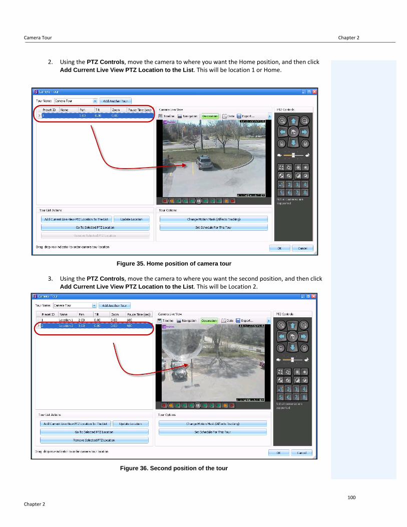
Camera Tour Chapter 2
2. Using the PTZ Controls, move the camera to where you want the Home position, and then click Add Current Live View PTZ Location to the List. This will be location 1 or Home.
Figure 35. Home position of camera tour
3. Using the PTZ Controls, move the camera to where you want the second position, and then click Add Current Live View PTZ Location to the List. This will be Location 2.
Figure 36. Second position of the tour
Chapter 2100

Camera Tour Chapter 2
4. Using the PTZ Controls, move the camera to each location you need for a tour, clicking Add Current Live View PTZ Location to the List each time. You can set up 8 locations (stops) on the camera tour.
Figure 37. Third position of the tour
5. For each location, you can define the amount of time in seconds that the camera pauses in that location. Enter the amount in seconds, for example, for a pause of 10 minutes you enter 600 seconds in the Pause Time field.
Figure 38. Pause time field editable for each tour location
6. You can define a schedule for when the camera tour should be active. Click Set Schedule for this Tour. The Schedule dialog box opens. By default, the entire date/time chart is red, indicating Active.
Chapter 2101

Camera Tour Chapter 2
Figure 39. Schedule when camera tour active
7. By default, the Inactive option is selected. Using your mouse, click on the date and time intervals you want the Camera Tour to be inactive (green) and click OK.
• You can set tour schedules to per minute ranges. Click on at least two squares in one column. Hover your mouse over the first square or the last square in the column (earliest or latest hour interval). Arrow range buttons appear. Click the arrows to change times to per minute ranges.
8. Make any adjustments as necessary to your tour and click OK.
Chapter 2102

Camera Tour Chapter 2
In the main console, with the PTZ Controls visible, you can click on the numbers. For example, 1 moves the camera to the Home position (Location 1) on the tour.
Figure 40. Numbers in PTZ Controls represent camera tour positions
Figure 41. Clicking 2 in PTZ Controls moves the camera to Location 2 in the camera tour
Chapter 2103

Support for AXIS T8310 Surveillance Control Board Chapter 2
Support for AXIS T8310 Surveillance Control Board
You can use the joystick, keypad, and jog dial units of the AXIS T8310 Surveillance Control Board with Symphony. All units interact with the Main View.
• “Joystick Buttons"• “Keypad Buttons” on page 105• “Jog Dial” on page 105• “Switching Control between Panels” on page 106
Procedure
To access all units in the control board from within Symphony:
• From the View menu, select Joystick.
Joystick Buttons
If PTZ control through joystick is too fast, you can limit the speed by editing the acc.ini file.
1. Edit %appdata%\aimetis\acc.ini and change the following parameters with the default values:
[joystick]
maxpan=100
maxtilt=100
maxzoom=100
pollinterval=100
deadzone=20
• maxpan, maxtilt, and maxzoom values can range from 0 to 100• pollinterval values are in milliseconds• deadzone value is a percentage of physical x, y, and z range
2. If response is too sensitive, try lowering the values.
3. Save the acc.ini file and restart Symphony Client for the changes to take effect.
The modules do not control Camera View (multiview) or Video Wall.
Table 2. Joystick functions
Button Live View Mode
J1 Go to Preset ID 1
J2 Go to Preset ID 2
J3 Go to Preset ID 3
J4 Go to Preset ID 4
Chapter 2104

Support for AXIS T8310 Surveillance Control Board Chapter 2
Keypad Buttons
Jog Dial
Table 3. Keypad functions
Button Function Action
Starts live video for the current camera. Enter camera ID and click button.
Moves PTZ camera in preset pattern. Enter Preset ID and click button.
Shows a historical jpeg image for a given time in the current day.(Does not start automatically.)
Enter a time (hhmm) and click button. Example: Enter 1300 and click button.A jpeg image is shown for 13:00 (1:00 pm) for the current day.
Table 4. Jog Dial functions
Button Function Action
Opens the Add Bookmark dialog box.
Click to add a bookmark.
Shows a jpeg image of the previous foreground activity from the current location in the time line.
Click to go back to previous foreground activity.
Plays or pauses video. Click Play/Pause as necessary.
Shows a jpeg image of the next foreground activity from the current location in the time line.
Click to go forward to next foreground activity.
Outer dial Changes video speed.
Turn right to play video faster.Turn left to play video at slower rate.Turn to red portion of slide to play video backwards.
Inner dial Shows a video frame.
Turn clockwise to show next video frame.Turn counterclockwise to show previous video frame.
Chapter 2105

Support for AXIS T8310 Surveillance Control Board Chapter 2
Switching Control between PanelsThe View button has four small squares and is located under the F1 button on the Axis keypad.
Figure 42. View button on Axis keypad
Procedure
To switch between multi views:
1. On the Axis keypad, enter XXYYYZZ.
• X is the monitor number• Y is the multiview number • Z is the panel number within multiview
2. Click the View button. The multiview panel name will now be represented as "Hostname-Mxx-MVyyy-Pzz".
To switch between multi view panels and switch camera displayed in panel:
1. On the Axis keypad, enter XXYYYZZC.
• X is the monitor number• Y is the multi view number • Z is the panel number within multiview• C is the camera number
2. Click the View button.
To switch control to main Live view panel:
1. On the Axis keypad, enter 0 and click the View button.
Chapter 2106

Quick Find Chapter 2
Quick FindThis tool allows you to search for cameras. The search text you enter can match partly or completely with the Name, Description or ID/Code of the camera. Those additional parameters are configured per camera in the Device configuration. The Quick Find will look for instances in the selected parameters for a match and the result will display a list of cameras.
Procedure
To open the Quick Find dialog box:
1. From the View menu in the Main Console, select Quick Find.
2. Click the drop-down arrow next to the Find button to reveal all search parameters.
3. Select the check boxes for the parameters you want your search to cover.
4. Click Find. A list of possible matches is displayed.
Figure 43. Quick Find dialog box
You can drag and drop results from a Quick Find search into any camera panel.
Figure 44. Drag camera from Quick Find search into camera panel
Chapter 2107

Messenger Chapter 2
MessengerThis tool allows you to send messages to any user or user group in the system. Anyone who is logged in will see this message as a popup in Symphony Client or at the top of an Internet Explorer page.
Procedure
To use the Messenger tool:
1. From the View menu, select Messenger. The Messenger dialog box opens.
2. Select the users or groups to send the message to.
3. Enter your message in the message box and click Send.
Figure 45. Messenger dialog box
Chapter 2108

Monitoring with Symphony Chapter 2
Monitoring with SymphonyMonitoring alarms with Symphony is easy and efficient. Symphony has been designed to maximize human attention on the cameras that need it most. The following are guidelines as to how you can maximize the monitoring experience in Symphony.
• “Using Multiple Monitors"• “Using the Site Map"• “Using Alarm Log"• “Marking Alarms” on page 110• “Using the Alarm Console” on page 110• “Using the Timeline” on page 110• “Viewing Activity for all Cameras” on page 110• “Using a Carousel” on page 110• “Disabling Alarms” on page 110
Using Multiple Monitors
For most users, using one monitor with Symphony Client is fine. The Main Console displays and summarizes activity across your enterprise adequately. For more advanced users or monitoring stations, the ability to see multiple windows and cameras at once may be a requirement. Symphony Client supports multiple monitors (the number of monitors depends on your PCs ability to decompress multiple video streams). This gives you the ability to display the Main Console in one screen, and the Multi-Live on the other display. The Multi-Live view can be configured to automatically update which cameras are displayed, focusing your attention on only those cameras where activity is detected by Symphony. It is also easy to manually drag and drop cameras into a Multi-Live view window, by left clicking a camera and dragging it into a Multi-Live view pane. Using two monitors with Multi-live and the Main Console makes this less awkward and more efficient.
Using the Site Map
To navigate to different cameras (to see a live view) simply left click on the Site Map on the camera you wish to see. You can also drag a camera from the Site Map into a Multi-Live view pane.
The colours of the camera indicate camera status.
• Green - a normal video signal is detected, but no activity is detected• Yellow - activity is detected• Red - an alarm has occurred on the camera • Grey - the camera signal is lost• White - problem with Symphony on that camera
Using Alarm Log
The Alarm Log is in the Main Console is much like your email inbox. Symphony Client can be connected to multiple Symphony Servers at once. Each time an Symphony Server causes an alarm, it pushes a message to Symphony Client, and a new alarm entry appears in the Alarm Log. Simply click on new Alarms as they come in, and Symphony will automatically jump to the correct server and camera which caused the Alarm, allowing you to quickly inspect the video content.
Chapter 2109
Marking Alarms Chapter 2
Marking Alarms
After a new alarm comes in, and you have inspected the alarm, you can mark the alarm as a real alarm, or a false alarm, with your additional notes. This allows security administrators to generate reports on how many alarms were detected by Symphony, the response time by security personnel, and keep track of real alarms to false alarms.
Using the Alarm Console
The Alarm Console enables you to respond to alarms through your Internet connection, provided that you have a speaker configured on the remote location. When alarms arrive through the Alarm Log, and you have assessed the alarm, marked it as false or real and added comments, you may choose to use the Alarm Console to engage a perpetrator. With the Alarm Console, you can speak, play sounds and more.
Using the Timeline
The Timeline is an integrated display within the Main Console. The Timeline summarizes the activity per bar on a 30 minute basis. It is a quick way to know whether activity was detected before or after the alarm, without having to manually review video. If there is some activity summarized on the Timeline, simply click on it to view a still image of that event. To watch video playback, simply click Play on the bottom navigation bar.
Viewing Activity for all Cameras
The View Activity for all Cameras dialog box allows you to see a merged Timeline of multiple cameras. Through the Main Console, the currently selected camera's Time Graph is visible, but if you want to compare that with other cameras, you can see this summary through the View Activity for all Cameras dialog box.
Using a Carousel
A carousel is a user-definable group of cameras that will loop through on a pre-determined schedule.
Disabling Alarms
If too many alarms are coming in from a particular server or camera, you can temporarily disable alarms so the Alarm Log is not flooded with nuisance alarms.
Chapter 2110

Alarm Console Chapter 2
Alarm ConsoleThe Alarm Console lets you manually speak or play a sound at a remote Symphony server installation. This is useful when manually responding to an alarm event in real-time, where you may wish to ward off trespassers.
Procedure
To access the Alarm Console:
• From the Server menu, select Alarms Console.
Figure 46. Alarm Console
Feature Description
Speak over Loud Speaker
You can enter text that will be played at the remote location. The master list is a text file that contains different spoken strings, and it appears in the This is private property field. This content is specific to each installed Symphony Client. If you have multiple people connecting to the Symphony server from different locations, they will each have their own list of things that they can say.
Say itAfter entering new text in the Speak over Loud Speaker drop-down box, or selecting existing phrases from the drop-down box, click Say it to play the text at the remote location. Symphony converts the text string into voice at the remote site.
Add to master list
You can add text to the master list, which will be available as an option in the Speak over Loud Speaker drop-down list for future use.
Remove from master list You can remove stored text from the master list.
Chapter 2111

Alarm Console Chapter 2
Add a .wav file from your computer to Symphony
Upload a .wav file from your local PC to the Symphony Server.
Play Sound Symphony will play the sound you have selected in the Play Sound field.
Remove selected .wav from Symphony
Delete a sound file from the Symphony Server.
Relays
It may be useful to manually turn a relay on or off. A siren or other audible alarm can be connected to Relay inputs or outputs, or doors could be opened or closed by triggering a relay. Select the Device and Relay# (number) of the device and click On to turn on the relay or Off to turn off.
Feature Description
Chapter 2112

Enable or Disable Alarms for Server Chapter 2
Enable or Disable Alarms for Server
EnableThe Enable Alarms for Server dialog box allows you to enable all alarms for the currently selected server, if they were previously disabled using the Disable Alarms for Server dialog.
Procedure
To access the Disable Alarms for Server dialog box:
• From the Server menu, select Enable Alarms for Server.
DisableThe Disable Alarms for Server dialog box allows you to disable all alarms for the currently selected server. This is useful in cases where all alarms should be disabled for a period of time on the server. This is faster than manually disabling individual Rules.
Procedure
To access the Disable Alarms for Server dialog:
1. From the Server menu, select Disable Alarms for Server.
2. Specify the amount of time to disable the alarms for the current server.
Chapter 2113

Marking Alarms Chapter 2
Marking AlarmsThe Alarm Log dialog box shows a list of alarms for connected servers.
Procedure
To mark an alarm:
1. Right click on the alarm you wish to mark. (Multiple alarms can be marked simultaneously if you select a range of alarms using standard Windows click followed by Shift-click or Ctrl-click.)
2. Select an action to perform:
• Print and Export To - The Preview dialog box opens. You can export to various files types, print the alarm information or send the information via email.
• Mark As Alarm - To mark as a real alarm.• Mark as False Alarm - To mark as a false alarm. • Mark as Real Actionable - To mark as a real alarm that requires action, for example,
security staff should investigate the alarm.• View Alarm Details -To add comments to the alarm. • Highlight New Alarm - To automatically select new alarms when raised and switch
cameras and show the alarm image in the main view.
3. Click Save when finished.
Chapter 2114

Reports Chapter 2
ReportsSymphony comes standard with the following reports.
• Object Counts Across a line - Textual report which shows counts across a user definable line per camera
• Heat Map Image - Graphical report which overlays traffic patterns on image• Object Counts - Textual report which summarizes in table form object counts across many
cameras• Object Statistics - Graphical report which compares object traffic and dwell time• Alarm Counts -Textual report which summarizes alarm totals
User Permissions
Reports require the following user permissions to execute them:
• Common to all reports - Connect, Execute Report • Object Counts Across Line - [no other rights] • Object Counts - [no other rights] • Object Statistics - [no other rights] • Alarm Counts - [no other rights] • Heat Map - Search
How to Use the Report Manager
1. Read through “General Procedure for Using the Report Manager” on page 116 to get a overview of the process.
2. See the following instructions for specific reports:
• “Object Counts Across a Line” on page 125• “Heat Map Image” on page 128• “Object Counts” on page 132• “Object Statistics” on page 133• “Alarm Counts” on page 134• “Running a Report from the Web” on page 135• “Creating Two Heat Map Reports to Run from the Web” on page 137
Chapter 2115

General Procedure for Using the Report Manager Chapter 2
General Procedure for Using the Report Manager
Procedure
To access the Reports dialog:
1. From Reports menu, select Manage. The Reports dialog box opens.
Figure 47. Main menu - Reports>Manage
Figure 48. Reports dialog box
• New Report - Click New Report to create a new Report.• Edit - To modify an existing Report, select it on the list and click Edit.• Delete - To delete an existing Report, select it on the list and click Delete.• Run - To generate an existing Report.• Copy - To copy an existing Report. • Shared Reports - Denotes whether the Report is accessible for other users or private to
the current user.
2. You can design reports by clicking the New Report button. The Report Designer dialog box opens.
3. Enter a Name for the report and select the Report Type. You may also select a Default View of Table or Graph.
Chapter 2116

General Procedure for Using the Report Manager Chapter 2
Figure 49. New Report button launches Report Designer
4. All reports (except Heat Map report) allow you to select multiple cameras. You select devices in the Camera tab. Click Add a Camera and then select one or more cameras from the list.
Figure 50. Selecting a device in Report Designer dialog box
Chapter 2117
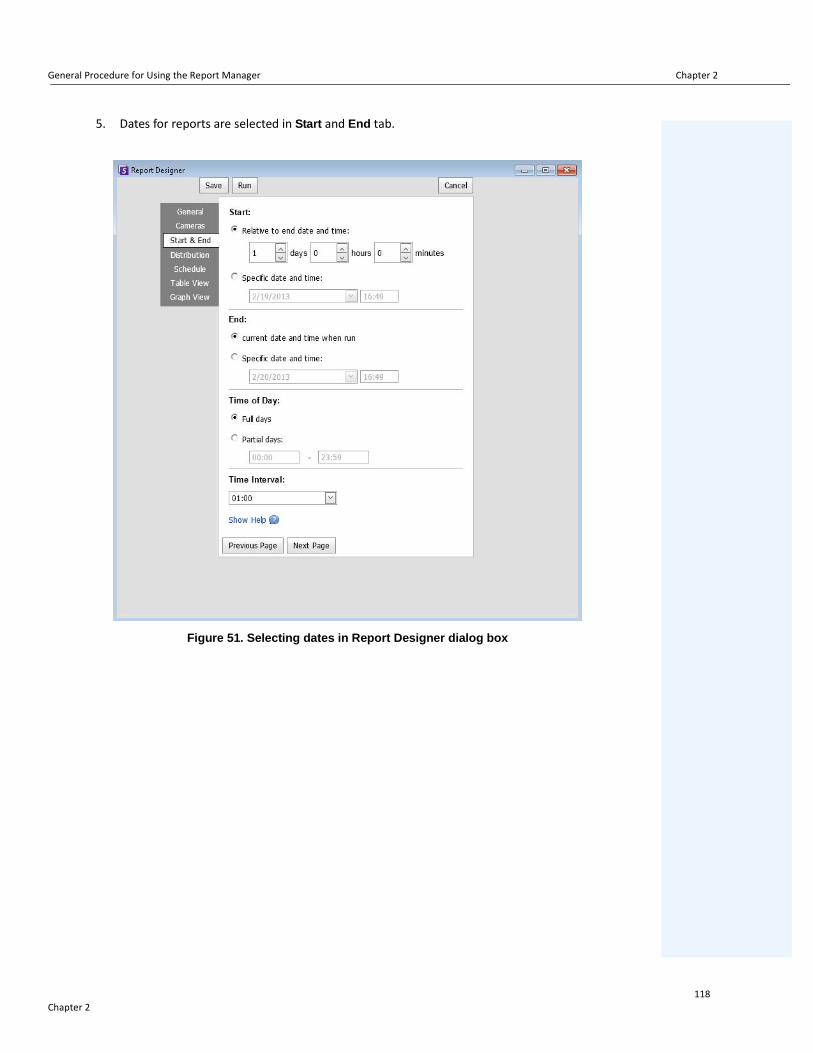
General Procedure for Using the Report Manager Chapter 2
5. Dates for reports are selected in Start and End tab.
Figure 51. Selecting dates in Report Designer dialog box
Chapter 2118

General Procedure for Using the Report Manager Chapter 2
6. Select the format and create an email recipient list for the report in the Distribution> Email tab. Formats include: PDF, CSV (comma separated document), or XML.
Figure 52. Distribution>Email subtab showing an email list for reports
Note: The Generate Image option is valid only for Heat Map reports.The Include Summary Information option is valid only for Object Counts Across a Line reports.
Chapter 2119

General Procedure for Using the Report Manager Chapter 2
7. You can select a file format in which to save the generated report. In the Distribution> File tab. You can save the generated report as a PDF, a CSV (comma separated document), or as an XML document.
Figure 53. Distrubtion>File subtab - Format in which generated report to be saved
Note: The Generate Image option is valid only for Heat Map reports.The Include Summary Information option is valid only for Object Counts Across a Line reports.Depending on write-permissions, the generated report will be stored in the \Data\Reports folder on the master server machine.
Chapter 2120

General Procedure for Using the Report Manager Chapter 2
8. Schedule when reports should be run including the time range of data, the recurrence, and schedule range.
Figure 54. Schedule when reports will be run
Chapter 2121

General Procedure for Using the Report Manager Chapter 2
9. Click Run to generate the report and then click the Table View or Graph View tabs.
Figure 55. Results of running a report in Table format
Figure 56. Results of running a report in Graph format
Chapter 2122

General Procedure for Using the Report Manager Chapter 2
10. In Table format, you can export the data to Excel, CSV, PDF, or RTF format. Click the Table tab and then Export to.
Figure 57. Exporting file type options
Note: The Export option saves only tabular data; therefore, it will not include a generated heat map image even if you selected Generate Image for the Heat Map report in the Distribution (Email or File) tab.
Chapter 2123

General Procedure for Using the Report Manager Chapter 2
11. Using Send Report
a. To send the generated report to the recipient list you created in the Distribution>Email subtab (previously), click Send Report and then Email.
b. To save the generated report in the format and in the location you selected in the Distribution>File subtab (previously), click Send Report and then File.
Figure 58. Send Report to Email distribution list or save to File
Note: For Heat Map ReportsIf the Generate Image option was selected in the Email Distribution tab, then when you click Send Report>Email, the generated image will be sent.If the Generate Image option was selected in the File tab, then when you click Send Report>File, the generated image will be saved to C:\Users\Build\Documents\Reports.
Important: If you encounter a problem saving your file, contact your Administrator or consult the Aimetis Symphony Administration Guide. You may not have permission to save files on your machine.
Chapter 2124

Object Counts Across a Line Chapter 2
Object Counts Across a Line
This report allows you to generate statistics regarding the number of objects crossing a user defined line.
Procedure
To access the Object Counts Across A Line report:
1. From Reports menu, select Manage. The Reports dialog box opens.
2. Click New Report. The Reports Designer dialog box opens.
3. From the General tab, enter a description for the report in the Name field.
4. Under Report Type, select the Objects Counts Across a Line option.
5. Click Next Page or the next option in the vertical tabs list.
6. In the Cameras tab, click Add a Camera and then select one or more cameras from the list.
7. In the Start & End tab, define the start and end time of the report.
8. Click Next to open the Line tab. From the drop-down list, select a camera and add a line where objects should be counted. Do this for each camera you select. Move the line to where objects should be counted.
• To extend the line: Click on the background image to create a new line segment from the existing line to the point clicked.
• To delete a segment: Click the Delete Segment button, which removes the last segment. Delete Segment will not remove the last (original) line segment to ensure there is at least one line segment for the report.
• To reshape the line: Hover the mouse over the box segment end-point: the cursor changes to a hand. Click and drag. The cursor changes to a move shape icon (arrows) and allows you to drag the vertex.
Option Description
Start
Select whether to use a Relative time to execute the report or a specific date and time. For example, if this Report was saved with the intention of running it in the future, selecting a Relative start of 7 days would mean the report start time would be 7 days from each time the report is executed. Using a specific date and time is only useful if this report is intended to be run only once and not in the future.
EndIf a Relative time was selected in the Start section, selecting Now would set the report time dynamically to the time the report was run. If a specific data and time was selected it is most likely that a specific date and time for the end of the report is appropriate.
Time of Day
Searching by Full Days will include all 24 hours in a day. In cases where a search should spend multiple days but only a certain period of time per say, Partial days should be selected. For example, we may search across 7 days but only 10:00 - 20:00 each day, to filter out results that happened outside of store hours.
Time Interval Select the Time Interval to be used in the Report.
Chapter 2125

Object Counts Across a Line Chapter 2
Figure 59. Line tab - extending and shaping the counting line
9. Select the format and create an email recipient list for the report in the Distribution> Email tab. Formats include: PDF, CSV (comma separated document), XML, and bitmap image. You can also include Summary Information about Counts In and Counts Out.
10. Schedule when reports should be run including the time range of data, the recurrence, and schedule range.
11. Click Next to continue. On the Table View tab, define which columns should be included in the report. Select the Column link and drag a column header into top header. This causes information to be grouped by the column category. By default, all available columns are shown in the Table View unless manually removed. Click Next Page to continue.
Chapter 2126

Object Counts Across a Line Chapter 2
Figure 60. Columns in Report Designer
12. (Optional) Select a Graph Type, Graph Size, and Graph Default (for example, Count In or Count Out for the Information Summary. (Graph Size is the image size of the report graphic).
13. Select Save and then Run to finish the report.
14. To save the generated report in the format you selected in the Distribution>File subtab (previously), click Send Report and then File.
Important: Depending on write-permissions, the generated report will be stored in the \Data\Reports folder on the master server machine. (This default folder is designated during the initial Symphony installation and setup or can be changed in the Server Path field.
Contact your Administrator or consult the Aimetis Symphony Administration Guide.
Chapter 2127

Heat Map Image Chapter 2
Heat Map Image
This report allows you to generate a report on the number of objects that were in different parts of the image.
Procedure
To access the Heat Map Image report:
1. From Reports menu, select Manage. The Reports dialog box opens.
2. Click New Report. The Reports Designer dialog box opens.
3. From the General tab, enter a description for the report in the Name field.
4. Under Report Type, select the Heat Map Image option.
5. In the Cameras tab, click Add a Camera and then select one or more cameras from the list.
6. In the Start & End tab, define the start and end time of the report.
Important: If you have an existing Heat Map report from a Symphony release prior to 6.10.1, the new columns of data may not appear. To ensure that all columns are displayed:
1. Select the report and click Edit.
2. Click Save to re-save the report in the Report Designer. All columns will be displayed correctly when you run the report.
Option Description
Start
Select whether to use a Relative time to execute the report or a specific date and time. For example, if this Report was saved with the intention of running it in the future, selecting a Relative start of 7 days would mean the report start time would be 7 days from each time the report is executed. Using a specific date and time is only useful if this report is intended to be run only once and not in the future.
EndIf a Relative time was selected in the Start section, selecting Now would set the report time dynamically to the time the report was run. If a specific data and time was selected it is most likely that a specific date and time for the end of the report is appropriate.
Chapter 2128

Heat Map Image Chapter 2
Time of Day
Searching by Full Days will include all 24 hours in a day. In cases where a search should spend multiple days but only a certain period of time per say, Partial days should be selected. For example, we may search across 7 days but only 10:00 - 20:00 each day, to filter out results that happened outside of store hours.
Time Interval
Sums the total number of objects dwelling in a defined zone and calculates the average dwell times in the zone for that aggregated period.
For example, if the data is grouped into two hour segments, the report sums the total number of people occupying the zone and the average time those people dwelled in the zone for each two hour period.
Us this for: Aggregate dwell time on Heat Map Report Allows you to collect data hourly (for example) to determine:
• How many people were dwelling in different zones and the average length of time they were in those zones.
• How many people dwelled longer than a pre-defined threshold value. Example Scenario:Collect data hourly on how many people were standing in the breakfast cereal aisle for more than 20 seconds and how long those people, on average, dwelled there.
Each block of time in the time range is collected and reported, regardless of whether there was anyone dwelling in the zone in that period.
To see the raw data for the heat map, select the None option in the Time Interval field. The non-aggregated report is similar to the aggregated report in that it shares the same columns. Each row describes the value of a single object through a zone.
Option Description
Chapter 2129

Heat Map Image Chapter 2
7. Since the Heat Map Image report was selected, the Sensitivity tab is enabled.
Figure 61. Sensitivity tab
The Sensitivity information actually relates to the Heat Map View tab. In the Heat Map View tab, you select whether the Object Paths or the Object Dwell Time will be the default graphic shown when the report is finished. • Object Paths - view by number of objects that have passed through a location• Object Dwell Time – view by total amount of time objects spent at a location
Intersections - Points in the image which more than one path passed throughA range of colors is used to define how many paths passed through a point. This helps you see the most common paths for objects even in an area where there was at least one object at every point. BUT some areas of the image, which you are not interested in, may have an unusually low or high number of intersections. This can cause the range of colors used in other areas to be too small to see meaningful differences. • Set Minimum Intersections to the bottom of the color range. Any area with fewer than this
number of intersections will be hidden. • Set Maximum Intersections to the top end of the color range. All areas with more than this
number of intersections will be in the same color.
Dwell Time - Shows the paths that objects followed. Dwell time is the length of time an object was found at particular point. Color is used to show the length of dwell time. At points where more than one object passed, the color represents the average of the dwell time for all the objects. But some areas of the image, which you are not interested in, that have unusually low or high dwell time. This would correspond with unusually fast moving objects or almost motionless objects. This can cause the range of colors used in other areas to be too small to see meaningful differences. • Set Minimum Dwell Time to set the bottom of the color range. Any point with an average
dwell time less than this number will be hidden. • Set Maximum Dwell Time to set the top end of the color range. All points with an average
dwell time above this number will be in the same color.
Dwell Threshold - Allows you to set how many people were dwelling longer than a definable threshold.
Chapter 2130

Heat Map Image Chapter 2
8. Select the format and create an email recipient list for the report in the Distribution> Email tab. Formats include: PDF, CSV (comma separated document), XML, and bitmap image.
9. Schedule when reports should be run including the time range of data, the recurrence, and schedule range.
10. On the Table View tab, define which columns should be included in the report. Select the Column link and drag a column header into top header. This causes information to be grouped by the column category. By default, all available column are shown in the Table View unless manually removed. Click Next to continue.
11. In the Heat Map View tab, define if the Object Paths or the Object Dwell Time will be the default graphic shown when the report is finished. If the image is too large, select the Resize image for screen resolution check box. (If the image does not fit to the screen resolution, the check box will be displayed regardless of whether the window is maximized.)
• Object Paths - view by number of objects that have passed through a location• Object Dwell Time – view by total amount of time objects spent at a location
12. Click Add Zone each time a specific area in the scene is to be included in the report.
a. Click the Zone name, such as Zone 0 to edit the name of the box b. Click Update to save changes. c. (Optional) To delete a zone, click the zone name (for example, click on the name
Zone 0) and click Remove Zone.
13. Select Save and then Run to finish the report. To save the generated report in the format you selected in the Distribution>File subtab (previously), click Send Report and then File
Chapter 2131

Object Counts Chapter 2
Object Counts
This report allows users to generate a report on the number of objects that were tracked inside the Motion Mask of the camera.
Procedure
To access the Object Counts report:
1. From Reports menu, select Manage. The Reports dialog box opens.
2. Click New Report. The Reports Designer dialog box opens.
3. From the General tab, enter a description for the report in the Name field.
4. Under Report Type, select the Object Counts option.
5. In the Cameras tab, click Add a Camera and then select one or more cameras from the list.
6. In the Start & End tab, define the start and end time of the report.
7. Select the format and create an email recipient list for the report in the Distribution> Email tab. Formats include: PDF, CSV (comma separated document), XML, and bitmap image.
8. Schedule when reports should be run including the time range of data, the recurrence, and schedule range.
9. On the Table View tab, define which columns should be included in the report. Select the Column link and drag a column header into top header. This causes information to be grouped by the column category. By default, all available column are shown in the Table View unless manually removed. Click Next to continue.
10. Define Graph Type and the Graph Size (the Graph Size is the image size of the report graphic).
11. Select Save and then Run to finish the report.
12. After the report is run, select the Table tab to Export the data if necessary to Excel, CSV, PDF, or RTF format. To save the generated report in the format you selected in the Distribution>File subtab (previously), click Send Report and then File
Option Description
Start
Select whether to use a Relative time to execute the report or a specific date and time. For example, if this Report was saved with the intention of running it in the future, selecting a Relative start of 7 days would mean the report start time would be 7 days from each time the report is executed. Using a specific date and time is only useful if this report is intended to be run only once and not in the future.
EndIf a Relative time was selected in the Start section, selecting Now would set the report time dynamically to the time the report was run. If a specific data and time was selected it is most likely that a specific date and time for the end of the report is appropriate.
Time of Day
Searching by Full Days will include all 24 hours in a day. In cases where a search should spend multiple days but only a certain period of time per say, Partial days should be selected. For example, we may search across 7 days but only 10:00 - 20:00 each day, to filter out results that happened outside of store hours.
Time Interval Select the Time Interval to be used in the Report.
Chapter 2132

Object Statistics Chapter 2
Object Statistics
This report allows users to generate a report on the number of objects that were in different parts of the image.
Procedure
To access the Object Statistics report:
1. From Reports menu, select Manage. The Reports dialog box opens.
2. Click New Report. The Reports Designer dialog box opens.
3. From the General tab, enter a description for the report in the Name field.
4. Under Report Type, select the Object Statistics option.
5. In the Cameras tab, click Add a Camera and then select one or more cameras from the list.
6. In the Start & End tab, define the start and end time of the report.
7. Select the format and create an email recipient list for the report in the Distribution> Email tab. Formats include: PDF, CSV (comma separated document), XML, and bitmap image.
8. Schedule when reports should be run including the time range of data, the recurrence, and schedule range.
9. On the Table View tab, define which columns should be included in the report. Select the Column link and drag a column header into top header. This causes information to be grouped by the column category. By default, all available column are shown in the Table View unless manually removed. Click Next to continue.
10. Define Graph Type and the Graph Size (the Graph Size is the image size of the report graphic).
11. Select Save and then Run to finish the report. To save the generated report in the format you selected in the Distribution>File subtab (previously), click Send Report and then File
Option Description
Start
Select whether to use a Relative time to execute the report or a specific date and time. For example, if this Report was saved with the intention of running it in the future, selecting a Relative start of 7 days would mean the report start time would be 7 days from each time the report is executed. Using a specific date and time is only useful if this report is intended to be run only once and not in the future.
EndIf a Relative time was selected in the Start section, selecting Now would set the report time dynamically to the time the report was run. If a specific data and time was selected it is most likely that a specific date and time for the end of the report is appropriate.
Time of Day
Searching by Full Days will include all 24 hours in a day. In cases where a search should spend multiple days but only a certain period of time per say, Partial days should be selected. For example, we may search across 7 days but only 10:00 - 20:00 each day, to filter out results that happened outside of store hours.
Time Interval Select the Time Interval to be used in the Report.
Chapter 2133

Alarm Counts Chapter 2
Alarm Counts
This report allows users to generate a report on the number of alarms that occurred for a given time period. Alarms are defined by Rules.
Procedure
To access the Alarm Counts report:
1. From Reports menu, select Manage. The Reports dialog box opens.
2. Click New Report. The Reports Designer dialog box opens.
3. From the General tab, enter a description for the report in the Name field.
4. Under Report Type, select the Alarm Counts option.
5. In the Cameras tab, click Add a Camera and then select one or more cameras from the list.
6. In the Start & End tab, define the start and end time of the report.
7. Select the format and create an email recipient list for the report in the Distribution> Email tab. Formats include: PDF, CSV (comma separated document), XML, and bitmap image.
8. Schedule when reports should be run including the time range of data, the recurrence, and schedule range.
9. On the Table View tab, define which columns should be included in the report. Select the Column link and drag a column header into top header. This causes information to be grouped by the column category. By default, all available column are shown in the Table View unless manually removed. Click Next to continue.
10. Define Graph Type and the Graph Size (the Graph Size is the image size of the report graphic).
11. Select Save and then Run to finish the report. To save the generated report in the format you selected in the Distribution>File subtab (previously), click Send Report and then File.
Option Description
Start
Select whether to use a Relative time to execute the report or a specific date and time. For example, if this Report was saved with the intention of running it in the future, selecting a Relative start of 7 days would mean the report start time would be 7 days from each time the report is executed. Using a specific date and time is only useful if this report is intended to be run only once and not in the future.
EndIf a Relative time was selected in the Start section, selecting Now would set the report time dynamically to the time the report was run. If a specific data and time was selected it is most likely that a specific date and time for the end of the report is appropriate.
Time of Day
Searching by Full Days will include all 24 hours in a day. In cases where a search should spend multiple days but only a certain period of time per say, Partial days should be selected. For example, we may search across 7 days but only 10:00 - 20:00 each day, to filter out results that happened outside of store hours.
Time Interval Select the Time Interval to be used in the Report.
Chapter 2134

Running a Report from the Web Chapter 2
Running a Report from the WebAimetis Symphony includes a web interface. Each server has its own web interface. The web interface is designed to mimic the windows rich client (Symphony Client) as much as possible.
If the Camera Tree contains more than 100 devices, the Web Client shows video from cameras as separate pages, navigated by forward and back buttons.
All core features such as Alarm Log, Timeline, Reporting and live video streaming are included.
Figure 62. Aimetis Symphony Web Access
Important: To view a Heat Map report for both Object Paths and Object Dwell Times, you must first create 2 reports in Symphony Client. See “Creating Two Heat Map Reports to Run from the Web” on page 137.
Chapter 2135
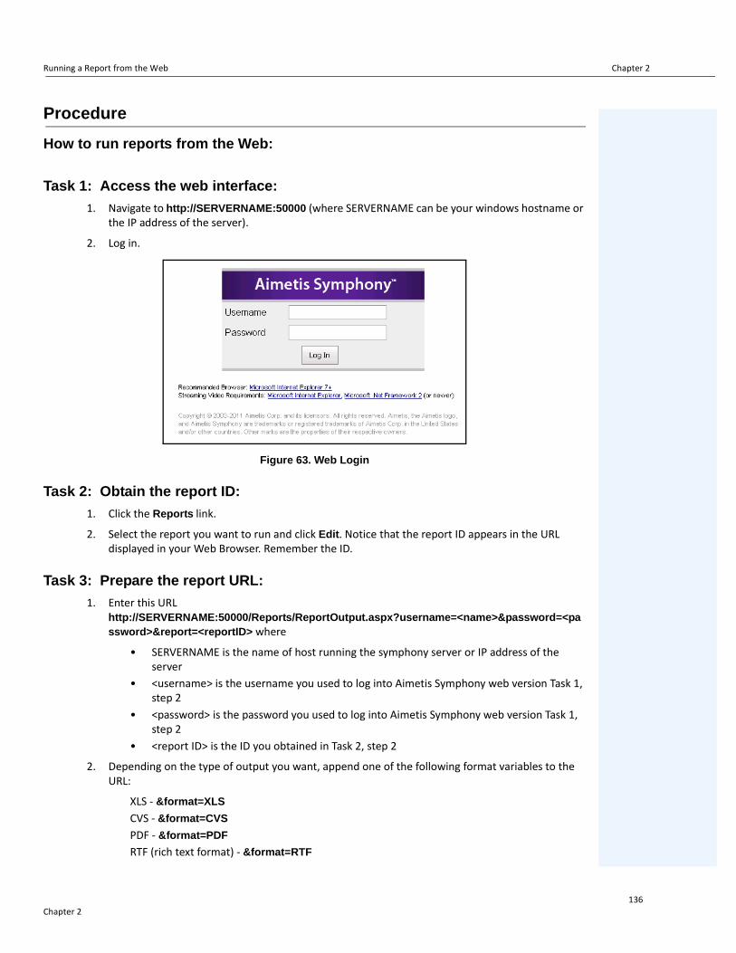
Running a Report from the Web Chapter 2
Procedure
How to run reports from the Web:
Task 1: Access the web interface:
1. Navigate to http://SERVERNAME:50000 (where SERVERNAME can be your windows hostname or the IP address of the server).
2. Log in.
Figure 63. Web Login
Task 2: Obtain the report ID:
1. Click the Reports link.
2. Select the report you want to run and click Edit. Notice that the report ID appears in the URL displayed in your Web Browser. Remember the ID.
Task 3: Prepare the report URL:
1. Enter this URL http://SERVERNAME:50000/Reports/ReportOutput.aspx?username=<name>&password=<password>&report=<reportID> where
• SERVERNAME is the name of host running the symphony server or IP address of the server
• <username> is the username you used to log into Aimetis Symphony web version Task 1, step 2
• <password> is the password you used to log into Aimetis Symphony web version Task 1, step 2
• <report ID> is the ID you obtained in Task 2, step 2
2. Depending on the type of output you want, append one of the following format variables to the URL:
XLS - &format=XLS
CVS - &format=CVS
PDF - &format=PDF
RTF (rich text format) - &format=RTF
Chapter 2136

Creating Two Heat Map Reports to Run from the Web Chapter 2
Task 4: Invoke the URL in the command line:
Use a command line program to invoke the URL to output the report. You can use a program such as CURL (http://curl.haxx.se/download.html)
1. For example, in the command line, enter:
curl -L –O <URL>, where <URL> is the URL specified in Task 3 (<http://SERVERNAME:50000/Reports/ReportOutput.aspx?username=<name>&password=<password>&report=<reportID>)
2. The script runs and the corresponding file is saved locally. You can create a batch script to run all the desired reports at once.
Creating Two Heat Map Reports to Run from the Web
To view a Heat Map Report for both Object Paths and Object Dwell Times from the Web, you must first create 2 reports in Symphony Client.
Procedure
How to set up heat map reports to be run from the Web:
1. From Reports menu, select Manage. The Reports dialog box opens.
2. Click New Report.
3. Select the Heat Map Image option and for convenience, name the first report Heat Map Object Paths.
4. Set up the report as you want, but in the Heat Map View screen, ensure that you select Object Paths from the Default Map drop-down list.
5. Save the map.
6. Create another new Heat Map Image report, this time naming it Heat Map Object Dwell Time.
7. Set up the report as you want, but in the Heat Map View screen, ensure that you select Object Dwell Time from the Default Map drop-down list.
8. Save the map.
9. To view the information from the Web, you must run 2 reports. As such you will use the report IDs for the Heat Map Object Paths and for Heat map Object Dwell Time. Follow the Web instructions “How to run reports from the Web:” on page 136.
Note: A heat map or graph is output as a bitmap image (.bmp).
Chapter 2137

Reporting Issues to Aimetis Chapter 2
Reporting Issues to AimetisYou can log issues with Aimetis through the Symphony Client.
Procedure
To report an issue:
1. From Help menu, select Report an Issue. The Aimetis Symphony Error Report dialog box opens.
Figure 64. Main menu - Help>Report an Issue
2. Enter details and then click Submit Report.
Figure 65. Aimetis Symphony Error Report dialog box
Chapter 2138

139
Copyright © 2013 Aimetis Inc. All rights reserved.This guide is for informational purposes only. AIMETIS MAKES NO WARRANTIES, EXPRESS, IMPLIED OR STATUTORY, AS TO THE INFORMATION IN THIS DOCUMENT.Complying with all applicable copyright laws is the responsibility of the user. Without limiting the rights under copyright, no part of this document may be reproduced, stored in or introduced into a retrieval system, or transmitted in any form or by any means (electronic, mechanical, photocopying, recording, or otherwise), or for any purpose, without the express written permission of Aimetis Corp. Aimetis may have patents, patent applications, trademarks, copyrights, or other intellectual property rights covering subject matter in this document. Except as expressly provided in any written license agreement from Aimetis, the furnishing of this document does not give you any license to these patents, trademarks, copyrights, or other intellectual property.Aimetis and Aimetis Symphony are either registered trademarks or trademarks of Aimetis Corp. in the United States and/or other countries.Portions Copyright © 1993-2013 ARH Inc.Portions of this software are based in part on the work of the Independent JPEG Group.