Velbus, RS232 control - LinTronic Denmark · Velbus, RS232 control When you save a Memory Map to...
21
http://www.lintronic.dk Velbus, RS232 control h t t p : / / w w w . l i n t r o n i c . d k UPDATED: 080623
Transcript of Velbus, RS232 control - LinTronic Denmark · Velbus, RS232 control When you save a Memory Map to...

http://www.lintronic.dk
Velbus, RS232 control
h t t p : / / w w w . l i n t r o n i c . d k
UPDATED: 080623

http://www.lintronic.dk
Velbus, RS232 control
LinTonic's
send optional RS232 commands to a device,when triggered by an infrared remote control,digital switches, contacts, relays, X10 signals,etc.
The triggers to control the TT455-RT-238, andthe related commands to be executed ortransmitted, are configured in our PC basedConfigurator program.
TT455-RT-238 can be re-configured at anygiven time.
LinTronic offer customized firmware to suiteyour needs.
TT455-RT-238 Signal Convertermay work as a standalone unit, configured to
VelBusVMB1RSRS232 interface
RADIO
LIGHT
TV CD
DVD
SATATAPE
RECORD
VTAPE
9
8
7 6
5
4 3
2
1 MENU
0
TEXT
GO
EXIT
LIST
STOP
>
>
BANG & O
LUFSEN
>
>
>
>>
>

http://www.lintronic.dk
Velbus, RS232 control
2
3
5
2
3
5
Male MaleRS232 cable crossed
VelBusVMB1RSRS232 interface
http://www.lintronic.dk
Velbus, RS232 control
- 12V + L H - PB
Supply Bus Switch
ADR
ADR
MODE
TIME
N.C. COMMON N.O.
12 volt+-
230 vacfused
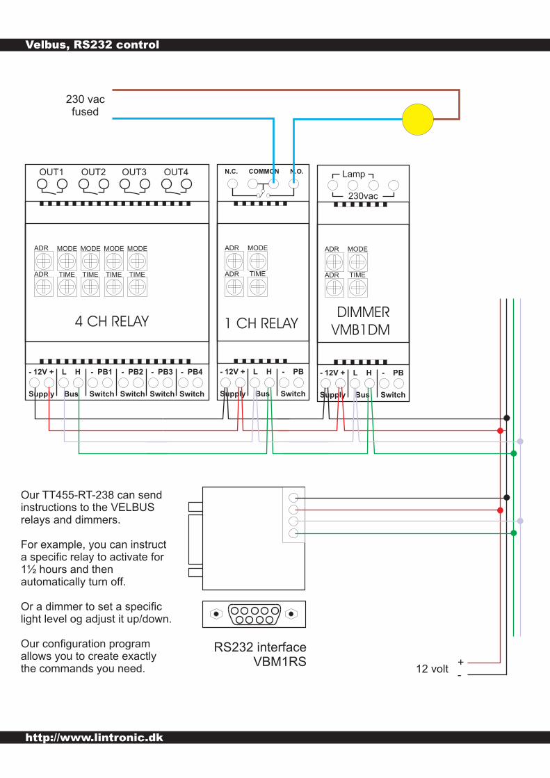
RS232 interfaceVBM1RS
Our TT455-RT-238 can sendinstructions to the VELBUSrelays and dimmers.
For example, you can instructa specific relay to activate for1½ hours and thenautomatically turn off
Or a dimmer to set a specificlight level og adjust it up/down.
Our configuration programallows you to create exactlythe commands you need.
.
1 CH RELAY
- 12V + L H - PB1
Supply Bus Switch
ADR
ADR
4 CH RELAY
MODE
TIME
MODE
TIME
MODE
TIME
MODE
TIME
- PB2
Switch
- PB3
Switch
- PB4
Switch
OUT1 OUT2 OUT3 OUT4
- 12V + L H - PB
Supply Bus Switch
230vac
Lamp
DIMMER
VMB1DM
ADR
ADR
MODE
TIME
http://www.lintronic.dk
Velbus, RS232 control
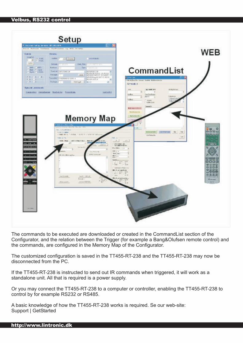
The commands to be executed are downloaded or created in the CommandList section of theConfigurator, and the relation between the Trigger (for example a Bang&Olufsen remote control) andthe commands, are configured in the Memory Map of the Configurator.
The customized configuration is saved in the TT455-RT-238 and the TT455-RT-238 may now bedisconnected from the PC.
If the TT455-RT-238 is instructed to send out IR commands when triggered, it will work as astandalone unit. All that is required is a power supply.
Or you may connect the TT455-RT-238 to a computer or controller, enabling the TT455-RT-238 tocontrol by for example RS232 or RS485.
A basic knowledge of how the TT455-RT-238 works is required. Se our web-site:Support | GetStarted

http://www.lintronic.dk
Velbus, RS232 control
Simply manually enter the commands as plain text and save when done.You can always open the Local CommandsListFiles and add/delete/change commands.
Due to the dynamic nature of these commands, please do NOT upload your customizedcommands to our web-database. Your commands will most likely not work for other customersusing other addresses for their dimmers/relays.
No need to TEST commands.It will not work while connected to the computer as the TT455-RT-238 must be connected to anVELBUS system.
xx

http://www.lintronic.dk
Velbus, RS232 control
The information (commands) controlling the TT455-RT-238 to send out VELBUS RS232 commands,consist of 8 pcs. 3-digit numbers. These commands can be created in the CommandList sectionof the TT455-RT-238's Configurator.
769001000000000000000001= command
Pa7 = Repeat (fixed 001)Pa6 = Data3 (3 digits)Pa5 = Data2 (3 digits)Pa4 = Data1 (3 digits)Pa3 = Command (3 digits)Pa2 = Address (3 digits, 001-248)Pa1 = ID (3 digits, 001 = VELBUS)769 = Dynamic RS232 commands
You create commands for your own personal use.The commands you create are stored onto your computer for later use/modification.
As the commands are intended for your system (address match etc.) the commands cannot beuploaded to our web-database. Others would not be able to use them, unless they set up theirVELBUS modules to match your addresses, timing, etc.
Structure:
Customize your own VELBUS commands

http://www.lintronic.dk
Velbus, RS232 control
VELBUS COMMAND 0
NOTE:
769001000000000000000001= command
Pa7 = Repeat (fixed 001)Pa6 = Data3 (3 digits)Pa5 = Data2 (3 digits)Pa4 = Data1 (3 digits)Pa3 = Command (3 digits)Pa2 = Address (3 digits, 001-248)Pa1 = ID (3 digits, 001 = VELBUS)769 = Dynamic RS232 commands
Pa1 = 001 (VELBUS)
Pa2 = Address (001 - 248)
Pa3 = Command, Button Status = 000
Pa4 = Buttons just activated (Range 001 - 008)
Pa5 = Buttons released (Range 001 - 008)
Pa6 = Buttons activated for a longer time (> 0.85 sec, Range 001 - 008)
Pa7 = Fixed 001
PA4 - PA6 use binary numbers to indicate which buttons have been activated/relased. Following an 8-bit pattern, insert 1's in the relavant places and calculate the decimal number (000 - 255) to beinserted in the relavant parameter.
Example:Switch 1 (bit 0) and switch 4 (bit 3) just activated = 0b00001001. PA4 = decimal 9.Switch 2 (bit 1) and switch 7 (bit 6) released = 0b01000010. PA5 = decimal 66.If no buttons have been activated for a longer time, PA6 = decimal 0.
Button status

http://www.lintronic.dk
Velbus, RS232 control
VELBUS COMMAND 1
769001000000000000000001= command
Pa7 = Repeat (fixed 001)Pa6 = Data3 (3 digits)Pa5 = Data2 (3 digits)Pa4 = Data1 (3 digits)Pa3 = Command (3 digits)Pa2 = Address (3 digits, 001-248)Pa1 = ID (3 digits, 001 = VELBUS)769 = Dynamic RS232 commands
Pa1 = 001 (VELBUS)
Pa2 = Address (001 - 248)
Pa3 = Command, Turn relay off = 001
Pa4 = Relay number (Range 001 - 004)
Pa5 = Fixed 000
Pa6 = Fixed 000
Pa7 = Fixed 001
Turn relay Off

http://www.lintronic.dk
Velbus, RS232 control
VELBUS COMMAND 2
769001000000000000000001= command
Pa7 = Repeat (fixed 001)Pa6 = Data3 (3 digits)Pa5 = Data2 (3 digits)Pa4 = Data1 (3 digits)Pa3 = Command (3 digits)Pa2 = Address (3 digits, 001-248)Pa1 = ID (3 digits, 001 = VELBUS)769 = Dynamic RS232 commands
Pa1 = 001 (VELBUS)
Pa2 = Address (001 - 248)
Pa3 = Command, Turn relay On = 002
Pa4 = Relay number (Range 001 - 004)
Pa5 = Fixed 000
Pa6 = Fixed 000
Pa7 = Fixed 001
Turn relay On

http://www.lintronic.dk
Velbus, RS232 control
VELBUS COMMAND 3
TIMER VALUE
769001000000000000000001= command
Pa7 = Repeat (fixed 001)Pa6 = Data3 (3 digits)Pa5 = Data2 (3 digits)Pa4 = Data1 (3 digits)Pa3 = Command (3 digits)Pa2 = Address (3 digits, 001-248)Pa1 = ID (3 digits, 001 = VELBUS)769 = Dynamic RS232 commands
Pa1 = 001 (VELBUS)
Pa2 = Address (001 - 248)
Pa3 = Command, Turn relay On, Timer = 003
Pa4 = Relay number (Range 001 - 004)
Pa5 = Timer High (Range 000 - 255)
Pa6 = Timer Low (Range 000 - 255)
Pa7 = Fixed 001
Timer unit is seconds and value is calculated from "Timer High" * 256 + "Timer Low".
Example:You want the relay to be turned on for 1½ hours = 1.5 * 60 * 60 = 5400 seconds.Timer High = 5400 / 256 = 21.Timer Low = 5400 - ( 256 * 21) = 24.For relay to run for 1½ hours, set Pa5 to "021" and Pa6 to "024".
Maximum Timer value = 255 * 256 + 255 = 65535 seconds ~ 18 hours.
If Pa5 and Pa6 are both set to "000" then the relay will run for the time set by the dip switches.
Turn relay On, Timer

http://www.lintronic.dk
Velbus, RS232 control
VELBUS COMMAND 4
769001000000000000000001= command
Pa7 = Repeat (fixed 001)Pa6 = Data3 (3 digits)Pa5 = Data2 (3 digits)Pa4 = Data1 (3 digits)Pa3 = Command (3 digits)Pa2 = Address (3 digits, 001-248)Pa1 = ID (3 digits, 001 = VELBUS)769 = Dynamic RS232 commands
Pa1 = 001 (VELBUS)
Pa2 = Address (001 - 248)
Pa3 = Command, Blind Stop = 004
Pa4 = Blind number (Range 001 - 002)
Pa5 = Fixed 000
Pa6 = Fixed 000
Pa7 = Fixed 001
BLIND STOP

http://www.lintronic.dk
Velbus, RS232 control
VELBUS COMMAND 5
769001000000000000000001= command
Pa7 = Repeat (fixed 001)Pa6 = Data3 (3 digits)Pa5 = Data2 (3 digits)Pa4 = Data1 (3 digits)Pa3 = Command (3 digits)Pa2 = Address (3 digits, 001-248)Pa1 = ID (3 digits, 001 = VELBUS)769 = Dynamic RS232 commands
Pa1 = 001 (VELBUS)
Pa2 = Address (001 - 248)
Pa3 = Command, Blind Up = 005
Pa4 = Blind number (Range 001 - 002)
Pa5 = Fixed 000
Pa6 = Fixed 000
Pa7 = Fixed 001
BLIND UP

http://www.lintronic.dk
Velbus, RS232 control
VELBUS COMMAND 6
769001000000000000000001= command
Pa7 = Repeat (fixed 001)Pa6 = Data3 (3 digits)Pa5 = Data2 (3 digits)Pa4 = Data1 (3 digits)Pa3 = Command (3 digits)Pa2 = Address (3 digits, 001-248)Pa1 = ID (3 digits, 001 = VELBUS)769 = Dynamic RS232 commands
Pa1 = 001 (VELBUS)
Pa2 = Address (001 - 248)
Pa3 = Command, Blind Down = 006
Pa4 = Blind number (Range 001 - 002)
Pa5 = Fixed 000
Pa6 = Fixed 000
Pa7 = Fixed 001
BLIND DOWN

http://www.lintronic.dk
Velbus, RS232 control
VELBUS COMMAND 7
769001000000000000000001= command
Pa7 = Repeat (fixed 001)Pa6 = Data3 (3 digits)Pa5 = Data2 (3 digits)Pa4 = Data1 (3 digits)Pa3 = Command (3 digits)Pa2 = Address (3 digits, 001-248)Pa1 = ID (3 digits, 001 = VELBUS)769 = Dynamic RS232 commands
Pa1 = 001 (VELBUS)
Pa2 = Address (001 - 248)
Pa3 = Command, Turn on light dimmer = 007
Pa4 = Dimmer Channel (001 = dimmer channel 1)
Pa5 = Level in percentage (Range 000 - 100)
Pa6 = Fade time in seconds (Range 001 - 250)
Pa7 = Fixed 001
Turn on light dimmer at "level" over "fade time"

http://www.lintronic.dk
Velbus, RS232 control
VELBUS COMMAND 8
TIMER VALUE
769001000000000000000001= command
Pa7 = Repeat (fixed 001)Pa6 = Data3 (3 digits)Pa5 = Data2 (3 digits)Pa4 = Data1 (3 digits)Pa3 = Command (3 digits)Pa2 = Address (3 digits, 001-248)Pa1 = ID (3 digits, 001 = VELBUS)769 = Dynamic RS232 commands
Pa1 = 001 (VELBUS)
Pa2 = Address (001 - 248)
Pa3 = Command, Start dimmer timer on time = 008
Pa4 = Dimmer Channel (001 = dimmer channel 1)
Pa5 = Timer High (range 000 - 255)
Pa6 = Timer Low (range 000 - 255)
Pa7 = Fixed 001
Timer unit is seconds and value is calculated from "Timer High" * 256 + "Timer Low".
Example:You want the dimmer to be turned on for 1½ hours = 1.5 * 60 * 60 = 5400 seconds.Timer High = 5400 / 256 = 21.Timer Low = 5400 - ( 256 * 21) = 24.For relay to run for 1½ hours, set Pa5 to "021" and Pa6 to "024".
Maximum Timer value = 255 * 256 + 255 = 65535 seconds ~ 18 hours.
If Pa5 and Pa6 are both set to "000" then the dimmer will run for the time set by the dip switches.
PS: The dimmer must already be On. If off,it will not turn on first.
Start dimmer timer "on time"

http://www.lintronic.dk
Velbus, RS232 control
VELBUS COMMAND 13
TIMER VALUE
769001000000000000000001= command
Pa7 = Repeat (fixed 001)Pa6 = Data3 (3 digits)Pa5 = Data2 (3 digits)Pa4 = Data1 (3 digits)Pa3 = Command (3 digits)Pa2 = Address (3 digits, 001-248)Pa1 = ID (3 digits, 001 = VELBUS)769 = Dynamic RS232 commands
Pa1 = 001 (VELBUS)
Pa2 = Address (001 - 248)
Pa3 = Command, Start relay blink, Timer = 013
Pa4 = Relay number (Range 001 - 004)
Pa5 = Timer High (Range 000 - 255)
Pa6 = Timer Low (Range 000 - 255)
Pa7 = Fixed 001
Timer unit is seconds and value is calculated from "Timer High" * 256 + "Timer Low".
Example:You want the relay to blink for 1½ hours = 1.5 * 60 * 60 = 5400 seconds.Timer High = 5400 / 256 = 21.Timer Low = 5400 - ( 256 * 21) = 24.For relay to blink for 1½ hours, set Pa5 to "021" and Pa6 to "024".
Maximum Timer value = 255 * 256 + 255 = 65535 seconds ~ 18 hours.
If Pa5 and Pa6 are both set to "000" then the relay will blink for the time set by the dip switches.
PS: Relay will start blink even if already off.
Start relay blink, Timer

http://www.lintronic.dk
Velbus, RS232 control
When you save a Memory Map to the TT455-RT-238, holding an RS232 command (732 static or 769dynamic), then the Configurator will uncheck "Send trigger to Bus" and Save settings.
This will prevent the TT455-RT-238 from sending a command of the detected remote control command,so we do not confuse the receiving RS232 device.
You can mix InfraRed and RS232 commands in your Memory Map as you want.

http://www.lintronic.dk
Velbus, RS232 control
It is NOT necessary to change the default baudrate/settings of the TT455-RT-238.
The TT455-RT-238 will continue working with the Configurator on 19200 bps, n,8,1 although yoursystem might require something else.
The firmware is designed to automatically send out the commands at the correct baudrate/settingsas required by the system to be controlled.
http://www.lintronic.dk
Velbus, RS232 control
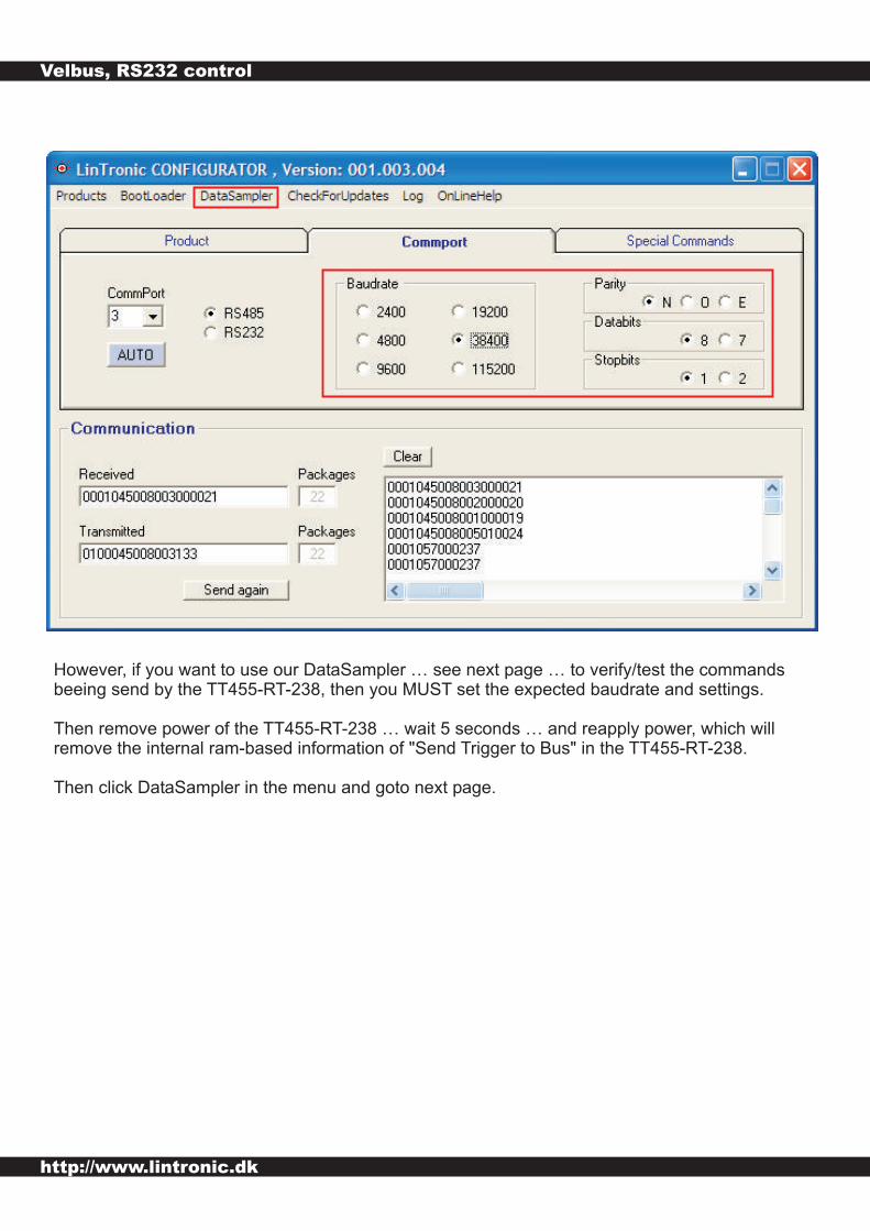
However, if you want to use our DataSampler … see next page … to verify/test the commandsbeeing send by the TT455-RT-238, then you MUST set the expected baudrate and settings.
Then remove power of the TT455-RT-238 … wait 5 seconds … and reapply power, which willremove the internal ram-based information of "Send Trigger to Bus" in the TT455-RT-238.
Then click DataSampler in the menu and goto next page.

http://www.lintronic.dk
Velbus, RS232 control
Then activate the remote control to trigger the TT455-RT-238 to send out the RS232 commands.
View them in PLAIN or ASCII format as you wish.