Vegapuls 64
84
Level and Pressure Operating Instruction VEGAPULS 64 and VEGAPULS 81
description
Operating instruction for radar sensor
Transcript of Vegapuls 64

Level and Pressure
Operating InstructionVEGAPULS 64 and VEGAPULS 81

2 VEGAPULS 64 and 81
Contents
Safety information
The described module must only be installed andoperated as described in this operating instruc-tion. Please note that other action can causedamage for which VEGA does not take respon-sibility.
Contents
Safety information ........................................................................ 2
1 Product description
1.1 Function ................................................................................ 4
1.2 Application features ............................................................. 5
1.3 Adjustment ........................................................................... 5
1.4 Antennas ............................................................................... 7
2 Types and versions
2.1 Two instrument series ........................................................... 8
2.2 Type survey .......................................................................... 8
2.3 Configuration of measuring systems ................................. 10
3 Technical data
3.1 Technical data .................................................................... 19
3.2 Approvals ........................................................................... 22
3.3 Dimensions ......................................................................... 23

VEGAPULS 64 and 81 3
4 Mounting and installation
4.1 General installation instructions ......................................... 32
4.2 Measurement of liquids ...................................................... 35
4.3 Measurement of solids ....................................................... 40
4.4 Measurement through the vessel wall ............................... 41
4.5 False echoes ...................................................................... 44
4.6 Installation fault .................................................................. 46
5 Electrical connection
5.1 Connection and connection cable ..................................... 49
5.3 Connection diagrams of VEGAPULS 64 series ................. 50
5.4 Connection diagram of VEGAPULS 81 series ................... 51
6 Set-up
6.1 Adjustment structure .......................................................... 54
6.2 Adjustment with PC ............................................................ 55
6.3 Save and copy adjustment data ........................................ 63
6.4 Adjustment with signal conditioning instrument ................ 67
6.5 Menu survey to the signal conditioning instrument .......... 73
Contents

4 VEGAPULS 64 and 81
Product description
1 Product description
1.1 Function
Radio detection and ranging: Radar.VEGAPULS radar sensors are used for con-tinuous and non-contact distance measure-ment. The measured distance corresponds toa filling height and is provided as level.
emission – reflection – receipt
Smallest 5,8 GHz radar signals are emittedfrom the antenna of the radar sensor as shortpulses. The radar impulses reflected by thesensor environment and the product are re-ceived by the antenna as radar echoes. Therunning period of the radar impulses fromemission to receipt is proportional to the dis-tance and hence to the level.
VEGAPULS radar sensors can reach this in aspecial procedure of the time transformationwhich spreads more than 3,6 million echopictures per second in a slow-motion picture,then freezes and evaluates them.
The radar pulses are emitted by the antennasystem as impulse packets with a pulse dura-tion of 1 ns and impulse breaks of 278 ns; thiscorresponds to a pulse package frequency of3,6 MHz. In the pulse breaks the antennasystem operates as receiver. Hence signalrunning periods of less than one millionth of asecond must be processed and the echopictures must be evaluated in a fraction of asecond.
Hence it is possible for the VEGAPULS radarsensors to evaluate the slow-motion pictures ofthe sensor environment precisely and in detailin cycles of 0,1 seconds without using verytime consuming frequency analysis necessaryfor other radar principles.
Virtually all products can be measured
Radar signals physically react similar to visiblelight. According to the quantum theory theypenetrate empty space. Hence they are notbound such as e.g. sound to a conductiveproduct (air) and spread like light with lightvelocity. The radar signals react to two electri-cal primary quantities:- the electrical conductivity of a substance.- the dielectric constant of a substance.
1 ns
278 ns
emission - reflection - receipt
Measur-ingdistance
Time transformation
t t
Pulse sequence

VEGAPULS 64 and 81 5
1.2 Application features
• Level, difference and object measurementon liquids and solids.
• Measuring range 0 … 35 m.• Non-contact and abrasion free.• Measurement under operating pressures up
to 64 bar and product temperatures of morethan 1000°C.
• Approved in all Ex-zones (PTB, CENELEC,FM, CSA).
• Ship and offshore approvals (GL, LRS,ABS).
• Digital or analogue 0 … 20 mA measuringsignal.
• Individual outputs: e.g. current, voltage,relay, transistor…
• Connection to all BUS-systems such asSiemens 3964 R, Interbus S, Profibus,Modbus…
• Up to 15 sensors to a two-wire line.• Measurement through vessel walls of plastic
vessels.• Sea-water resistant, chemically high-resist-
ance: PTFE, 1.4571 (stst), alloy C2 (2.4602),alloy C4 (2.4610), Tantalum, GK-AlSi11powder-coated(3.2211.02).
• Unaffected by temperature changes andproduct density.
• Unaffected by noise, steam, dust, gas com-positions or innert gas layering.
• All slightly conductive products and prod-ucts with a dielectric constant εr > 1,5 canbe measured.
• Indication of measured values integrated inthe sensor (VEGAPULS 81); optionally exter-nal indication of measured values, whichcan be mounted at a distance of up to 25 maway from the sensor in Ex-zone 0.
• No approval necessary: General telecom-munication approval (approved for opera-tion outside and outside closed metallicvessels).
Product description
1.3 Adjustment
Each application is unique, hence each radarsensor requires some basic information onapplication and environment.
Operation and parameter adjustment on theradar sensors is carried out with- PC or- signal conditioning instrument.
Adjustment with PC
The set-up and adjustment of VEGAPULSradar sensors is generally made on the PCwith the adjustment program VVO (VEGAVisual Operating) under Windows®. The pro-gram is menu-guided by pictures, graphicsand process visualizations for quick operationand parameter adjustment.
Sensor with analogue 0 … 20 mA-signal output(compact instrument), adjustment with PC onthe sensor signal line or directly on the sensor
2

6 VEGAPULS 64 and 81
Product description: Adjustment
On the sensor, on the branch of signal lines orin the process control system you will haveaccess to the sensors. The adjustment soft-ware allows a glance into each vessel.
The adjustment and parameter data can bestored on PC and transferred to other sensors.
The adjustment program VVO divides theadjustment in three stages:- operator (adjustment and indication of
measured values)- maintenance (parameter adjustment)- planning (service and system parameters).
The adjustment stages are protected by ac-cess hierarchies so that important parameteradjustments or service adjustments are sepa-rated from the standard adjustment. By usinga password, the adjustment values, param-eters and service adjustments are protectedagainst manipulation.
Sensor with digital signal output (VBUS), foradjustment the PC is either plugged to thetwo-wire signal line (e.g. on a terminal socket)or directly to the VEGALOG 571 Processingsystem or to the VEGAMET signal conditioninginstrument
VEGALOG
571 CPU
VEGALOG
571 EV
CPU
2
Beside the PC, sensors with digital signaloutput (VBUS) can also be adjusted with thesignal conditioning instrument
2
Adjustment with signal conditioninginstrument
Beside the PC, sensors with digital transmis-sion of measured data (VBUS) can also bedirectly adjusted with the connected signalconditioning instrument.
In addition VEGAMET 514 V and 515 V signalconditioning instruments have and adjustmentmodule by which you can carry the parameteradjustment in text dialogue.

VEGAPULS 64 and 81 7
1.4 Antennas
The antenna is the eye of the radar sensors.The antenna shape does not lead to assumehow precise the geometrical form of an an-tenna must be adapted to the physical fea-tures of the electromagnetic fields. A shape,deciding on the sensitivity, similar to the sensi-tivity of a directional microphone.
Four antenna systems are available for differ-ent applications and process requirements.Each system is featured out beside the focus-ing characteristics by special chemical andphysical features.
Horn antenna
Horn antennas are best suitedfor most applications. Theyfocus the radar signals verywell. Manufactured out of1.4571 (stst), alloy C4, alloyC22 or Tantalum are very rug-ged and physically as well aschemically resistant. They aresuitable for pressures up to64 bar and with appropriate
cooling for product temperatures of more than1000°C.
Product description
Rod antenna
Rod antennas with high chemi-cal resistance require smallerflange diameters (DN 50). Theantenna rod and the wettedflange parts are completelymanufactured from PTFE sothat the rod antenna can beeasily cleaned and is henceinsensitive to condensation.The rod antenna is suitable forpressures up to 16 bar andtemperatures up to 200°C.
Pipe antenna
Pipe antennas on surge orbypass pipes only form acomplete antenna system inconjunction with a measuringpipe which can be also bent.Pipe antennas are best suitedfor products with strong prod-uct movements or productswith low dielectric constant.
The measuring pipe means aconductor for the radar sig-nals. The running period of theradar signals changes in the
pipe and depends on the pipe diameter. Theelectronics must be programmed against thepipe inner diameter so that the running periodcan be adapted.

8 VEGAPULS 64 and 81
Types and versions
2 Types and versions
2.1 Two instrument series
The two instrument series are generally identi-cal in their function and efficiency as well as inthe shape of their antenna systems. Howeverthe housing construction, the materials usedand their electronic construction are different.
An indicating instrument with analogue anddigital indication is optimally mounted in thesensors of VEGAPULS 81 series.
2.2 Type surveyVEGAPULS 64 VEGAPULS 81 F VEGAPULS 81 D
FV DV FK DK A B C D E A B C D E
Measuring range 0 … 20 m,- optionally 35 m (on request) • • • • • • • • • • • • • •
Output signal- 0 … 20 mA analogue – – • • – – – • • – – – • •- digital • • – – • • • – – • • • – –
Supply and output signal- via a two-wire line • • – – – • – – – – • – – –- separately via
2 two-wire lines – – • • – – • • • – – • • •- via a four-wire line – – – – • – – – – • – – – –
Ex Zone 0 approved – – – – • • • • • • • • • •StEx Zone 10 approved • • • • • • • • • • • • • •
Classification- supply EEx… – – – – i e e e e i e e e e- output signal EEx… – – – – i e e e i i e e e i- circuit for external indicating
instrument VEGADIS 10 Ex – – – – i i i i i i i i i i
Housing made of- plastic • • • • – – – – – – – – – –- powder-coated Aluminium alloy – – – – • • • • • • • • • •
VEGAPULS64 F… 64 D…
VEGAPULS81 F… 81 D…

VEGAPULS 64 and 81 9
Type code:
VEGAPULS 64 X X …
Type 64: V - Digital output signalK - Analogue 0 … 20 mA output signal
Type 81: A - Digital output signal together with supply in EEx iB - Digital output signal together with supply in EEx eC - Digit. output signal in EEx e, sep. supply in EEx eD - Anal. output signal in EEx e, sep. supply in EEx eE - Anal. output signal in EEx i, sep. supply in EEx e
F - Horn antenna or pipe antennaD - Rod antennaInstrument seriesMeasuring principle (PULS for radar)
Types and versions
Classification
Classification EEx i intrinsically safe
With classification “i“ (intrinsically safe) electri-cal circuits are produced which cannot ignitean explosive mixture or explosive substanceneither during operation or in case of failure.Hence it is ensured that the electrical energyused (short-circuit) is lower than the ignitionenergy required to ignite the substance.
In addition the capacitive and inductive en-ergy storage is restricted such that they can-not store sufficient energy to ignite an explo-sive mixture.
With the classification “e“ (increased safety)measures taken which avoid that a connected,non-intrinsically safe circuit can ignite an ex-plosive mixture or explosive substance.
Selected materials, increased contact andtrack distances as well as lowest componenttemperatures exclude sparks and heating.
Classification EEx d
With the classification “d“ (pressure tight en-capsulation) instruments are constructed suchthat even in case a mixture inside the instru-ment ignites, no ignition energy escape to theexplosive atmosphere.
Classification EEx e increased safety

10 VEGAPULS 64 and 81
Types and versions: Configuration of measuring systems
Measuring system with one VEGAPULS 64 sensor (compact instrument)
• Analogue, standardized 0 … 20 mA-current signal as signal output. For adjustment, a digitaladjustment signal is superimposed to the 0 … 20 mA-sensor signal.
• Adjustment and parameter adjustment via a PC and the adjustment program VVO. For adjust-ment the PC is connected via the adapter VEGACONNECT to the 0 … 20 mA-signal line.
• Optionally an external digital/analogue indication. The indication can be separated from thesensor up to 25 m.
• The max. permissible resistance (load) of the 0 … 20 mA-signal output is 500 Ω.
In case the input resistors of the processing systems connected to the 0 … 20 mA-signal outputare less than 100 Ω, a resistor of more than 100 Ω must be switched into the 0 ... 20 mA signalline for the adjustment period.
The digital adjustment signal is short-circuited or damped via too small input resistors so that thedigital communication with the PC would no more be ensured.
2
2
2
–+
0 … 20 mA signaloutput and staticdigital adjustmentsignal
Resistor≥ 100 Ω
VEGACONNECT
PC with adjustmentsoftware VEGA VisualOperating
VEGAPULS 64 FKwith integralprocessing
2.3 Configuration of measuring systems
A measuring system of sensors with a 0 … 20 mA signal output (compact instrument) consistsonly of one sensor. For sensors with digital signal output, the measuring system consists of onesensor and one VEGAMET signal conditioning instrument or the VEGALOG Processing system.
On this page and the following ones you will see measuring systems with sensors providing alevel proportional 0 ... 20 mA current (compact instruments) as output signal.
On the following pages you will see measuring systems with sensors delivering a digital signal aVEGAMET signal conditioning instrument or to the VEGALOG Processing system. Signal condi-tioning instrument or Processing system deliver with these sensors various level proportionaloutput signals such as 0 … 20 mA currents, 0 … 10 V voltage or switching signals (relay) .

VEGAPULS 64 and 81 11
Measuring system with one VEGAPULS 81 sensor (compact instru-ment type D or E)
• Analogue, standardized 0 … 20 mA-current signal as signal output. For adjustment, a digitaladjustment signal is superimposed to the 0 … 20 mA-signal output.
• Approved in Ex Zone 0. Supply in EEx e (increased safety); output signal in EEx i (intrinsicallysafe) or EEx e (increased safety).
• Adjustment and parameter adjustment via PC and the adjustment program VVO. For adjust-ment the PC is connected via the adapter VEGACONNECT with a two-wire line to the0 … 20 mA-signal line.
• Optionally an external digital/analogue indication. The indication can be separated from thesensor in Ex zone 0 up to 25 m.
• The max. permissible resistance (load) of the 0 … 20 mA-signal output is 500 Ω.
In case the input resistors of the processing systems connected to the 0 … 20 mA-signal outputare less than 100 Ω, a resistor of more than 100 Ω must be switched in front of the Processingsystem for the adjustment period.
The digital adjustment signal is short-circuited or damped such via too small input resistors thatthe digital communication with the PC would no more be ensured.
If the 0 … 20 mA-signal output is operated without resistor (load), adjustment is also not possi-ble. Load the 0 … 20 mA-signal output during adjustment with a load resistor of 100 Ω to 500 Ω.
4 2
2
–+
0 … 20 mA signaloutput and super-imposed digitaladjustment signal
Resistor≥ 100 Ω
VEGACONNECT
PC with adjustment softwareVEGA Visual Operating
VEGAPULS 81 Fwith integralprocessing
Ex-area Non-Ex-area
EEx e orEEx i
EEx e
EEx i
Types and versions: Configuration of measuring systems
EEx i
Zone 1
Zone 0

12 VEGAPULS 64 and 81
Measuring system with one or two VEGAPULS 64 sensors on theVEGAMET 514 V or 515 V signal conditioning instrument
• Digital output signal; signal processing in the signal conditioning instrument.• Up to two sensors on one two-wire line. The two-wire line transmits the power supply, the dig-
ital output signal as well as the static adjustment signal of the sensors.• Adjustment and parameter adjustment via a PC and the adjustment program VVO. The PC is
connected via the adapter VEGACONNECT to the sensor, the signal line or to the signal condi-tioning instrument. In addition adjustment and parameter adjustment is possible with the signalconditioning instrument.
• Optionally an external digital/analogue indication. The indication can be separated from thesensor up to 25 m.
• The permissible max. resistor of the two-wire signal and supply line is 15 Ω per wire or max.1000 m cable length between sensor and signal conditioning instrument.
2
2
VEGAMET 514V
2
VEGAMET 515V
Signal conditioninginstrument VEGAMET514 V in housing type505
VEGACONNECT
PC with adjustment softwareVEGA Visual Operating
VEGAPULS 64with digitalsignal output
VEGAPULS 64with digital signaloutput
VEGACONNECT
PC with adjustment softwareVEGA Visual Operating
Signal conditioninginstrumentVEGAMET 515 V inhousing type 505
Screened cable for strong electromag-netic interferences
Current outputs
Voltage outputs
Relay outputs
Fail safe relay
Digital connectability
Outputs (see also Product Informa-tion “signal conditioning instru-ments series 500“)
Current outputs
Voltage outputs
Relay outputs
Fail safe relay
Digital connectability
Outputs (see also Product Informa-tion “signal conditioning instrumentsseries 500“)
Screened cable for strong electromag-netic interferences
Types and versions: Configuration of measuring systems

VEGAPULS 64 and 81 13
Types and versions: Configuration of measuring systems
Measuring system with 1 … 5 VEGAPULS 64 sensors per two-wire lineon the processing system VEGALOG 571
• Digital output signal; signal processing in the processing system.• Up to five sensors on one two-wire line, 15 sensors (three groups with 5 sensors each) on one
input card. The two-wire line transmits the power supply, the digital output signal as well as thesuperimposed adjustment signal.
• Adjustment and parameter adjustment via a PC and the adjustment program VVO. The PC isconnected via a RS 232-cable to the processing system. In addition the PC can be directlyconnected to the sensor or the signal line via the adapter VEGACONNECT.
• Optionally an external digital/analogue indication. The indication can be separated from thesensor up to 25 m.
• The max. permissible resistor of the two-wire line is 15 Ω per wire or max. 1000 m cable lengthbetween sensor and signal conditioning instrument.
VEGALOG571 CPU
VEGALOG571 EV
2
2
2
2
2
2
2
CPU
Current outputs
Voltage outputs
Relay outputs
Transistor outputs
Fail safe outputs
Indication outputs
Digital connectabilityConnection to all BUS-systems
Outputs (see also Product Information“Processing system VEGALOG 571“)
Processing system VEGALOG571 with input cards in 19“-rack, up to 15 sensors (3 x 5)per card
VEGACONNECT
VEGAPULS 64 with digitalsignal output, up to 5 sensorson one two-wire line
PC with adjustment softwareVEGA Visual Operating
Screened cable for strong electromag-netic interferences
14 VEGAPULS 64 and 81
Types and versions: Configuration of measuring systems
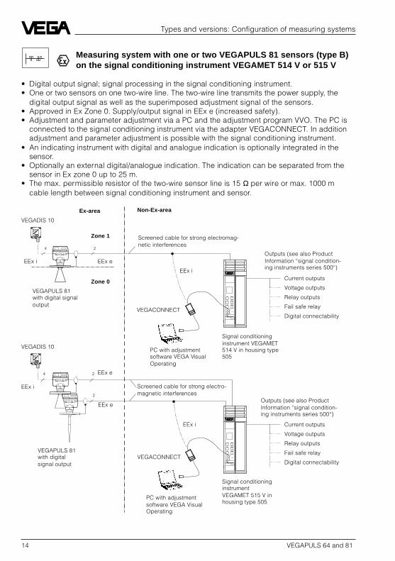
Measuring system with one or two VEGAPULS 81 sensors (type B)on the signal conditioning instrument VEGAMET 514 V or 515 V
• Digital output signal; signal processing in the signal conditioning instrument.• One or two sensors on one two-wire line. The two-wire line transmits the power supply, the
digital output signal as well as the superimposed adjustment signal of the sensors.• Approved in Ex Zone 0. Supply/output signal in EEx e (increased safety).• Adjustment and parameter adjustment via a PC and the adjustment program VVO. The PC is
connected to the signal conditioning instrument via the adapter VEGACONNECT. In additionadjustment and parameter adjustment is possible with the signal conditioning instrument.
• An indicating instrument with digital and analogue indication is optionally integrated in thesensor.
• Optionally an external digital/analogue indication. The indication can be separated from thesensor in Ex zone 0 up to 25 m.
• The max. permissible resistor of the two-wire sensor line is 15 Ω per wire or max. 1000 mcable length between signal conditioning instrument and sensor.
2
2
2
4
4
VEGAMET 514V
VEGAMET 515V
VEGADIS 10
Signal conditioninginstrument VEGAMET514 V in housing type505
VEGACONNECT
VEGAPULS 81with digital signaloutput
VEGADIS 10
VEGAPULS 81with digitalsignal output
VEGACONNECT
PC with adjustmentsoftware VEGA VisualOperating
Screened cable for strong electromag-netic interferences
Outputs (see also ProductInformation “signal condition-ing instruments series 500“)
Outputs (see also ProductInformation “signal condition-ing instruments series 500“)
Screened cable for strong electro-magnetic interferences
Ex-area Non-Ex-area
EEx i EEx e
EEx i
EEx e
EEx e
EEx i
EEx i
PC with adjustmentsoftware VEGA VisualOperating
Signal conditioninginstrumentVEGAMET 515 V inhousing type 505
Current outputs
Voltage outputs
Relay outputs
Fail safe relay
Digital connectability
Current outputs
Voltage outputs
Relay outputs
Fail safe relay
Digital connectability
Zone 1
Zone 0

VEGAPULS 64 and 81 15
Types and versions: Configuration of measuring systems
Measuring system with 1 … 5 VEGAPULS 81 sensors (type B) pertwo-wire line on the processing system VEGALOG 571
• Digital output signal; signal processing in the processing system.• Up to five sensors on one two-wire line; 15 sensors (in three groups with five sensors each) on
one input card. The two-wire line transmits the power supply, the digital output signal as wellas the superimposed adjustment signal.
• Approved in Ex Zone 0, supply/output signal in EEx e (increased safety).• Adjustment and parameter adjustment via a PC and the adjustment program VVO. The PC is
directly connected to the computer module of the processing system via an interface cable(RS 232).
• An indicating instrument with digital and analogue indication is optionally integrated in thesensor.
• Optionally an external digital/analogue indication. The indication can separated from the sen-sor in Ex zone 0 up to 25 m.
• The max. permissible resistor of the two-wire signal and supply line is 15 Ω per wire or max.1000 m cable length between processing system and sensor.
VEGALOG571 CPU
VEGALOG
571 EV
2
2
2
2
2
4
4
2
CPU
Current outputs
Voltage outputs
Relay outputs
Transistor outputs
Fail safe outputs
Indication outputs
Digital connectabilityConnection to all BUS-systems
Outputs (see also ProductInformation “Processingsystem VEGALOG 571“)
VEGADIS 10
Processing systemVEGALOG 571 with inputcards in 19“-rack, up to 15sensors (3 x 5) per card
VEGACONNECT
VEGAPULS 81 with digitalsignal output, up to 5 sensorson one two-wire line
PC with adjustment softwareVEGA Visual Operating
Screened cable for strong electro-magnetic interferences
Ex-area Non-Ex-area
EEx i
EEx e
EEx i
EEx e
EEx i

16 VEGAPULS 64 and 81
Types and versions: Configuration of measuring systems
Measuring system with 1 … 15 VEGAPULS 81 sensors (type C) pertwo-wire line with separate power supply on the processing systemVEGALOG 571
• Digital output signal; signal processing in the processing system.• 15 sensors on one two-wire line. The two-wire line transmits the digital output signal as well as
the superimposed adjustment signal of up to 15 sensors. The power supply is made sepa-rately by a local voltage source.
• Approved in Ex Zone 0. Supply and output signal in EEx e (increased safety).• Adjustment and parameter adjustment via a PC and the adjustment program VVO. The PC is
directly connected to the computer module of the processing system via an interface cable(RS 232).
• An indicating instrument with digital and analogue indication is optionally integrated in thesensor.
• Optionally an external digital/analogue indication. The indication can be separated from thesensor in Ex zone 0 up to 25 m.
• The max. permissible resistor of the two-wire signal line is 15 Ω per wire or max. 1000 m cablelength between sensor and processing system.
VEGALOG571 CPU
VEGALOG571 EV
2
2
2
2
2
CPU
4
4
–+
–+
2
–+
2
2
2
2
Current outputs
Voltage outputs
Relay outputs
Transistor outputs
Fail safe outputs
Indication outputs
Digital connectabilityConnection to all BUS-systems
Outputs (see also ProductInformation “Processingsystem VEGALOG 571“)
VEGADIS 10
Processing systemVEGALOG 571 with inputcards in 19“-rack. Up to 15sensors an one card and onone two-wire line
VEGACONNECT
VEGAPULS 81with digital signaloutput, up to 15sensors on onetwo-wire line
PC with adjustment softwareVEGA Visual Operating
Screened cable for strong electromag-netic interferences
Ex-area Non-Ex-area
EEx i
EEx e
EEx i
EEx e
EEx e
EEx i
EEx e
EEx e

VEGAPULS 64 and 81 17
Types and versions: Configuration of measuring systems
4
4
4
VEGAMET 514V
VEGATRENN 547
VEGAMET 515V
VEGATRENN 547
4
4
Measuring system with VEGAPULS 81 sensors (type A); one sensorper four-wire line via separator VEGATRENN 547 on the signal con-ditioning instrument VEGAMET 514 V or 515 V
• Digital output signal; signal processing in the signal conditioning instrument.• One sensor on one four-wire line. The four-wire line transmits the power supply, the digital
output signal as well as the superimposed adjustment signal.• Approved in Ex Zone 0. Supply/output signal in EEx i (intrinsically safe).• Adjustment and parameter adjustment via a PC and the adjustment program VVO- The PC is
connected to the signal conditioning instrument via the adapter VEGACONNECT. In additionadjustment and parameter adjustment is possible with the signal conditioning instrument.
• An indicating instrument with digital and analogue indication is optionally integrated in thesensor.
• Optionally an external digital/analogue indication. The indication can be separated from thesensor in Ex zone 0 up to 25 m.
• The permissible max. resistor of the four-wire line is 7,5 Ω per wire or max. 1000 m cablelength between sensor and safety barrier/signal conditioning instrument.
VEGADIS 10
Signal conditioninginstrument VEGAMET514 V with separatorVEGATRENN 547 inhousing type 506
VEGACONNECT
PC with adjustmentsoftware VEGA VisualOperating
VEGAPULS 81with digitalsignal output
VEGADIS 10
VEGAPULS 81with digitalsignal output
VEGACONNECT
PC with adjustmentsoftware VEGA VisualOperating
Signal conditioninginstrument VEGAMET515 V with separatorVEGATRENN 547 inhousing type 506
Screened sensor cable for strongelectromagnetic interferences
Current outputs
Voltage outputs
Relay outputs
Fail safe relay
Digital connectability
Outputs (see also ProductInformation “signal condi-tioning instruments series500“)
Current outputs
Voltage outputs
Relay outputs
Fail safe relay
Digital connectability
Outputs (see also ProductInformation “signal condition-ing instruments series 500“)
Screened sensor cable for strongelectromagnetic interferences
Ex-area Non-Ex-area
EEx i
EEx i
EEx i
EEx i
EEx i
EEx i
EEx i
18 VEGAPULS 64 and 81
Types and versions: Configuration of measuring systems
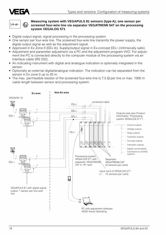
Measuring system with VEGAPULS 81 sensors (type A); one sensor perscreened four-wire line via separator VEGATRENN 547 on the processingsystem VEGALOG 571
• Digital output signal; signal processing in the processing system.• One sensor per four-wire line. The screened four-wire line transmits the power supply, the
digital output signal as well as the adjustment signal.• Approved in Ex Zone 0 (EEx ib). Supply/output signal in Ex-concept EEx i (intrinsically safe).• Adjustment and parameter adjustment via a PC and the adjustment program VVO. For adjust-
ment the PC is connected directly to the computer module of the processing system via aninterface cable (RS 232).
• An indicating instrument with digital and analogue indication is optionally integrated in thesensor.
• Optionally an external digital/analogue indication. The indication can be separated from thesensor in Ex zone 0 up to 25 m.
• The max. permissible resistor of the screened four-wire line is 7,5 Ω per line or max. 1000 mcable length between sensor and processing system.
4
4
4
4
4
4
VEGALOG571 CPU
VEGALOG571 EV
CPU
VEGATRENN547
VEGATRENN547
VEGATRENN547
44
44
44
Current outputs
Voltage outputs
Relay outputs
Transistor outputs
Fail safe outputs
Indication outputs
Digital connectability
Connection to all BUS-systems
Outputs (see also ProductInformation “Processingsystem VEGALOG 571“)
VEGADIS 10
VEGAPULS 81 with digital signaloutput, 1 sensor per four-wireline
PC with adjustment softwareVEGA Visual Operating
Ex-area Non-Ex-area
EEx i
EEx i
EEx i
EEx i
EEx i
Input card of VEGALOG 571(1 … 15 sensors per card)
Processing systemVEGALOG 571 withseparator VEGATRENN547 in 19“-rack
SeparatorVEGATRENN 547(2 sensors per card)
screened cable
EEx i

VEGAPULS 64 and 81 19
Technical data
3 Technical data
3.1 Technical data
Power supply
VEGAPULS 64…Supply voltage(with separate supply) 16 … 36 V DC; 20,4 … 26,4 V AC
110, 130, 230 V AC; –15 % … 10 %max. current consumption 160 mAmax. power consumption 3,6 W, 4 VAVEGAPULS 81…Supply voltage(with separate supply) 24 V DC (20 … 36 V DC)
24 V AC (20,4 … 26,4 V AC)90 … 250 V AC
max. current consumption 200 mAmax. power consumption-type A, B, C 3,6 W, 11 VA- type D, E 4,5 W, 13 VA
Measuring range
Standard 0 … 20 mOption 0 … 35 mMeasurement in surge or bypass pipe- DN 50 0 … 16 m- DN 100 0 … 19 mOption- DN 50 0 … 28 m- DN 100 0 … 33 m
Output signal
VEGAPULS 64- type …V… digital measuring signal (VBUS)- type …K… 0 … 20 mA-current signal, load max. 500 ΩVEGAPULS 81- type A, B, C digital measuring signal (VBUS)- type D, E 0 … 20 mA-current signal, load max. 500 Ω
Ex-technical data VEGAPULS 81
Temperature class ambient temperature on the antenna system inEx-areas
- T6 85°C- T5 100°C- T4 135°C- T3 150°C (with temperature adapter 200°C)Classification- type A EEx d ia [ia] II C T6 (supply in “ib“)- type B, C, D and E EEx d e ia [ia] II C T6Approved for gas group IIC

20 VEGAPULS 64 and 81
Technical data
Error limits
Linearity error < 0,1 %Temperature drift 0,015 %/10 K0 … 20 mA current output of thecompact instruments (DA-converter) 0,025 %
Characteristics
Frequency 5,8 GHz (USA 6,3 GHz)Intervals 0,1 sResolution 1 mmMin. span (min/max adjustment)- analogue output signal 10 mm- digital output signal 5 mm (50 mm at a measuring range > 32 m)Beam angle (at –3 dB)- horn antenna
DN 100 30°DN 150 20°DN 250 14°
- rod antenna 24°
Ambient conditions
Vessel pressure- general 0 … 16 bar- option 0 … 64 bar- PP-flange (VEGAPULS 64) 0 … 0,5 bar- StEx Zone 10 (VEGAPULS 64) 0 … 1,15 barAmbient temperature on the housing- VEGAPULS 64 -30°C … +60°C- VEGAPULS 81 -30°C … +65°C (non-Ex-area)
-20°C … +60°C (Ex-area)Flange temperature- types F… -40°C … +150°C- types D… -100°C … +200°C- PP-flange (VEGAPULS 64) -40°C … +80°C- option (with cooling facility) more than 1000°C (product temperature)Storage and transport temperature -40°C … +80°CProtection IP 67Protection class IOvervoltage category IIISelf-heating VEGAPULS 64… StEx at an ambient temperature of 40°C
StEx-instruments reach 45°C on the flange and55°C on the housing.

VEGAPULS 64 and 81 21
Connection lines
Type 64 FV, DV; 81 FB, DB- Supply and digital signal via a two-wire line,
line resistor max. 15 Ω per line or 1000 m cable lengthType 81 FA, DA- Supply and digital signal via a screened four-wire line,
line resistor max. 7,5 Ω per line or 1000 m cable lengthType 81 FC, DC- Supply and digital signal separately
- Signal via a two-wire line, line resistor max. 15 Ω per line or 1000 m cable length
- Supply via one 2 or 3 wire line (230 V AC)Type 64 FK, DK; 81 FD, DD, FE, DE- Supply and analogue 0 … 20 mA signal separately
- Signal via a two-wire line, load max. 500 Ω- Supply via one 2 or 3 wire line (230 V AC)
Cross-section area of conductor general 2,5 mm2
Earth connection max. 4 mm2
Cable entries- VEGAPULS 64 1 … 3 Pg 13,5 (cable diameter 5 … 10,5 mm)- VEGAPULS 81 1 … 4 M20 x 1,5 (cable diameter 5 … 9 mm)
Materials
Housing- VEGAPULS 64 PBT- VEGAPULS 81 3.2211.02 (AlSi11, GK-AlSi11)Flange- Standard 1.4571 (stst), PP (only VEGAPULS 64 with DN250)- Option alloy C4 (2.4610), alloy C22 (2.4602), TantalumHorn antenna (antenna horn)- Standard 1.4571 (stst)- Option alloy C4 (2.4610), alloy C22 (2.4602), TantalumAntenna seal of the horn antenna- Standard Viton- Option KalrezRod antenna (antenna rod) PTFEFlange coating (only rod antennas) PTFE
Weight
dependent on flange size, apprVEGAPULS 64 VEGAPULS 81
- DN 50 6,5 kg 9 kg- DN 80 8,5 kg 11 kg- DN 100 10 kg 12 kg- DN 150 14 kg 16,5 kg- DN 250 28,5 kg (PP: 8 kg) 31 kg (PP: 10 kg)- ANSI 2" 6 kg 8,5 kg- ANSI 3" 7,5 kg 10 kg- ANSI 4" 11,5 kg 14 kg- ANSI 6" 16 kg 18 kg- ANSI 10" 36 kg 38 kg
Technical data

22 VEGAPULS 64 and 81
CE-conformity
VEGAPULS radar instruments meet the protective regulations of EMVG (89/336/EWG) andNSR (73/23/EWG). The conformity has been judged acc. to the following standards:EMVG Emission EN 50 081 - 2: 1993
Susceptibility EN 50 082 - 2: 1995NSR EN 61 010 - 1: 1993
3.2 Approvals
When using the radar sensors in Ex and StEx-areas or on ships, the instruments must besuitable and approved for these applicationsand explosion zones. The suitability ischecked by the approval authorities and certi-fied by approval documents.
VEGAPULS 64 radar sensors are approved forStEx Zone 10.
VEGAPULS 81 are approved for Ex Zone 0(CENELEC, PTB).
VEGAPULS radar sensors are tested andapproved by the following authorities:
- PTB(Physikalisch Technische Bundesanstalt)
- FM(Factory Mutual Rese)
- ABS(American Bureau of Shipping)
- LRS(Lloyds Register of Shipping)
- GL(German Lloyd)
- CSA(Canadian Standards Association)
Technical data

VEGAPULS 64 and 81 23
Technical data
3.3 Dimensions
VEGAPULS 64 F…, standard and StEx-versions
ø125
90˚
260 x 150
247
18
22ø165
ø18
ø160
45˚
ø76
260 x 150
247
2084ø200
ø18
260 x 150
247
2012
0
45
ø180ø96
ø220
ø18
DN 50Pipe antenna
DN 80Horn antenna
DN 100Horn antenna

24 VEGAPULS 64 and 81
Technical data
260 x 150
247
2220
5
45˚
ø240
ø146
ø285
ø22
357,
5 392
260 x 150
247
2038
0
ø241
30
352 60
ø28
ø355
30°ø26
DN 150Horn antenna
DN 250Horn antenna
VEGAPULS 64 and 81 25
Technical data
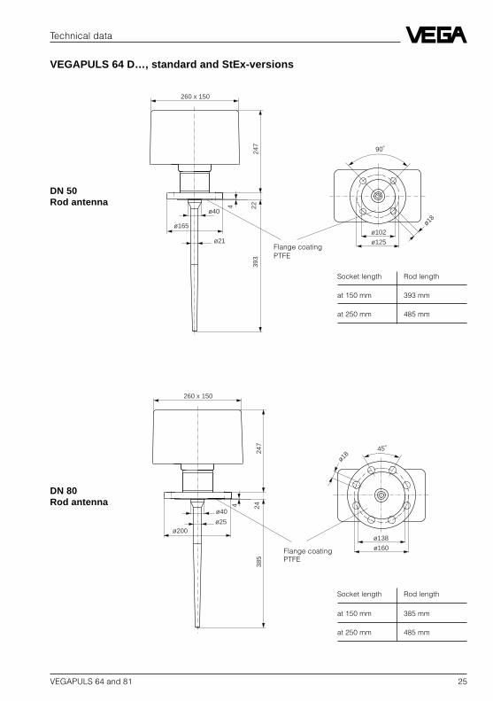
VEGAPULS 64 D…, standard and StEx-versions
ø40
ø21
260 x 150
4
247
2239
3
ø125
90˚
ø165 ø18
ø102
260 x 150
4
247
24
ø138
45˚
385
ø200
ø40
ø25
ø18
ø160
Socket length Rod length
at 150 mm 393 mm
at 250 mm 485 mm
Socket length Rod length
at 150 mm 385 mm
at 250 mm 485 mm
DN 50Rod antenna
DN 80Rod antenna
Flange coatingPTFE
Flange coatingPTFE

26 VEGAPULS 64 and 81
Technical data
ø40
ø25
260 x 150
4
247
24
45˚
ø18038
5
ø220
ø18
ø157
260 x 150
4
247
26
45˚
ø216
ø40
ø25
385
ø285
ø22
ø240
Socket length Rod length
at 150 mm 385 mm
at 250 mm 485 mm
Socket length Rod length
at 150 mm 385 mm
at 250 mm 485 mm
DN 100Rod antenna
DN 150Rod antenna
Flange coatingPTFE
Flange coatingPTFE

VEGAPULS 64 and 81 27
Technical data
VEGAPULS 81 F…, instruments for all Ex-areas
ø125
90˚
225
280
18
22
ø165ø18
ø160
45˚
ø76
2084ø200
ø18
225
280
2012
0
45
ø180ø96
ø220
ø18
225
280
DN 50Pipe antenna
DN 80Horn antenna
DN 100Horn antenna

28 VEGAPULS 64 and 81
Technical data
2220
5
45˚
ø240
ø146
ø285
ø22
225
280
2038
0
ø241
ø355
30°ø26
225
280
DN 150Horn antenna
DN 250Horn antenna

VEGAPULS 64 and 81 29
Technical data
VEGAPULS 81 D…, instruments for all Ex-areas
Socket length Rod length
at 150 mm 393 mm
at 250 mm 485 mm
ø40
ø21
4 2239
3
ø102
90˚
ø165 ø18
225
280
ø1254 24
ø138
45˚
385
ø200
ø40
ø25
ø18
225
280
ø160
Socket length Rod length
at 150 mm 385 mm
at 250 mm 485 mm
DN 50Rod antenna
DN 80Rod antenna
Flange coatingPTFE
Flange coatingPTFE

30 VEGAPULS 64 and 81
Technical data
ø40
ø254 24
45˚
ø180
385
ø220
ø18
225
280
ø157
4 26
45˚
ø240
ø40
ø25
385
ø285
ø22
225
280
ø216
Socket length Rod length
at 150 mm 385 mm
at 250 mm 485 mm
Socket length Rod length
at 150 mm 385 mm
at 250 mm 485 mm
DN 100Rod antenna
DN 150Rod antenna
Flange coatingPTFE
Flange coatingPTFE

VEGAPULS 64 and 81 31
Technical data
Flange dimensions acc. to ANSI
D = outer flange diameterb = flange thicknessk = diameter of hole circled1 = seal ledge diameterf = seal ledge strength
1/16
" = ca. 1,6 mmd
2= diameter of holes
Size Flange Seal ledge HolesD b k d
1No. d
2
2" 150 psi 152,4 20,7 120,7 91,9 4 19,13" 150 psi 190,5 25,5 152,4 127,0 4 19,14" 150 psi 228,6 25,5 190,5 157,2 8 19,16" 150 psi 279,4 27,0 241,3 215,9 8 22,410" 150 psi 405,4 30,2 361,9 323,8 12 25,4
External housing VEGADIS 1028
56
85
120
108
38 ø5
108
135
Mounting on carrier rail 35 x 7,5 acc. to EN50 022 or flat screwed Pg 13,5
f
d
b
d
kD
2
1
Note:Cable diameter of the outer cable min. 5 mm andmax. 10,5 mm.The seal effect of the cable entry is hence notensured.

32 VEGAPULS 64 and 81
Mounting and installation
4 Mounting and installation
4.1 General installation instructions
Measuring range
The reference pane for the measur-ing range of the radar sensors isalways the lower part of the sensor.The measuring range of both instru-ment series (VEGAPULS 64 andVEGAPULS 81) is generally0 … 20 m. Optionally sensors with ameasuring range of 0 … 35 m canbe supplied. For measurements insurge or bypass pipes (pipe an-tenna) the max. measuring distanceis reduced by appr. 20%. Pleasenote for measurements where theproducts are filled up to the sensorflange, that build-up on the antennacan cause faulty measurements.
Measuring range (operating range) and maximalmeasuring distance
Emission cone of a horn antenna on theDN 100 flange
full empty
18 m
2 m
Mea
surin
gra
nge
max. measuring distance 20 m(optionally 35 m)
0
10 m
20 m
30 m
0 m
35 m
30°
40°
100%
50%
9,49,412 12m5,3 5,3
Measuringdistance
Emission cone and false reflections
The radar signals are focused by the antennasystem. The signals leave the antenna, similarto a light beam of a headlight, in the form of acone. This emission cone depends on theantenna used.
Each object in this emission cone causes areflection of the radar signals. Especially dur-ing the first meters of the emission cones,pipes, struts etc. cause strong false reflec-tions. E.g. in a distance of 6 m the false signalof a pipe is 9 time more than in a distance of18 m.
The energy of the radar signal spreads in caseof interfering surfaces which are further awaythan a larger surface, so that reflected falsesignals are weaker and hence more uncriticalthan in the narrow range.

VEGAPULS 64 and 81 33
Note the sensor axis is directed vertically tothe product surface, avoid installations withinthe 100%-cone such as e.g. pipes and struts.
If possible provide a “clear view“ inside theemission cone to the product and avoid instal-lations in the first third of the emission cone.
Optimum measuring conditions are availablewhen the emission cone is free from installa-tions.
Mounting and installation: General installation instructions
Emission cone of a DN 150 horn antenna
Emission cone of a rod antenna (independenton flange size)
Emission cone of a DN 250 horn antenna
0
10 m
20 m
30 m
0 m
35 m
20°
30°
100%
50%
6 969 m3,5 3,5
04,36,7 4,3 6,7
10 m
20 m
30 m
0 m
35 m
14°
22°
100%
50%
2,5 2,5 m0
10 m
20 m
30 m
0 m
35 m
24°
35°
100%
50%
7,37,310,5 10,5 m4,2 4,2
Measuringdistance
Measuringdistance
Measuringdistance

34 VEGAPULS 64 and 81
False reflection
Flat installations and struts cause large falsereflections. They reflect the radar signal withhigh energy density.
Mounting and installation: General installation instructions
Profiles with smooth interfering surfaces causelarge interfering signals
Round profiles diffusely spread the radarsignals
Cover flat profiles with scatting screens
Smoothed interfering surfaces have a diffusereflection of the radar signals and cause falsereflections with low energy density. Hence theyare more uncritical than reflections on flatsurfaces.
If flat installations in the range of the radarsignals cannot be avoided, it is recommendedto reflect the interfering signals with a scatter-ing screen. Due to this scattering the interfer-ing signals will be less energetic and diffuseso that they can be filtered by the sensor.

VEGAPULS 64 and 81 35
Mounting and installation
4.2 Measurement of liquids
Horn antenna
Horn antenna on DIN-socket pieceMost of the time the mounting of radar sensorsis made on very short DIN-socket pieces. Theinstrument flange is the reference pane for themeasuring range. The antenna should alwaysprotrude out of the flange pipe.
Mounting on short DIN-socket piece
Mounting on a longer DIN-socket piece
Mounting on a dished boiler tank
Mounting on arched vessel ceilings
Reference pane
> 10 mm
> 10 mm
Reference pane
1/2
Vessel radius
When the DIN-socket piece is longer, pleasenote that the horn antenna must protrude atleast 10 mm out of the socket.
When mounting on dished boiler or basketarch vessel ceilings also on the long socketside, the antenna has to protrude at least10 mm.
Do not mount the instrument on arched vesselceilings in the middle of the tank or close tothe outer wall of the vessel, but appr. 1/2 vesselradius from the middle or from the outer vesselwall. Arched tank ceilings act for the radarsignals like a paraboloidal reflector. If theradar sensor is placed in the “focus“ of aparabolic tank cover, the sensor receivesamplified false echoes. Note that the radarsensor is mounted outside the “focus”, henceparabolic amplified false echoes are avoided.

36 VEGAPULS 64 and 81
Mounting and installation: Measurements of liquids
Rod antenna on DIN-socket piece
Rod antenna directly on vessel opening
≤ 150 mm
Openingø 50 mm
Mounting directly on the flat vessel ceiling
Reference pane
Horn antenna directly on the vessel ceilingDependent on the stability of the vessel (sen-sor weight), the flat mounting directly on thevessel ceiling would be a good and favourablesolution. The top side of the vessel is the refer-ence pane.
Rod antenna
Rod antenna on DIN-socket pieceThe PTFE (Teflon) rod antenna is especiallyused in aggressive products such as lyes andacids. Applications in the food processingindustry with aseptic vessels require reactionneutral measuring systems often with smallervessel openings. The teflon rod antenna is notonly reaction neutral but can be also mountedto very small vessel openings with 50 mmaccess.
For measurements of liquids with the Teflonrod antenna, the mounting is made on astraight DIN-socket piece. The socket howevermust not be longer than 150 mm (when usinga longer antenna, not longer than 250 mm).The rod antenna is available in flange sizes ofDN 50, DN 80, DN 100 and DN 150.
Rod antenna directly on vessel openingAlternatively to the socket mounting, the rodantenna can also mounted directly to thecircular vessel opening (holes).
Note that the mechanical load of the PTFE-rodantenna is restricted. If the antenna is sub-jected to lateral power, their will be danger ofdeformation or break.

VEGAPULS 64 and 81 37
Mounting and installation: Measurements of liquids
Pipe antenna(surge or bypass pipe)
Pipe antennas are preferably used on vesselswith many installations such as e.g. calorifiers,heat exchangers or quick stirrers. The meas-urement of products with strong turbulences,and installations in the vessel do not causefalse reflections.
By focusing of the radar signal within themeasuring pipe, also products with smalldielectric constants (ε
r 1,5 … 3) can be meas-
ured.
Pipe antenna system in the tank
Pipe flange system as bypass pipe
Extended bypass pipe
Surge hole
Typeplate
max.
min.
Surge pipewelded to thetank
Surge pipe in thesocket piece
100 %
0 %
Casting nose
50 %
0 %
100 %
The surge pipes which open at the bottommust reach the requested min. level as ameasurement is only possible in the pipe.
Note the upper required ventilation hole in thesurge pipe. These ventilation and surge holesmust be in one axis with the type plate(VEGAPULS 64) or the casting nose(VEGAPULS 81).
As an alternative to the surge pipe in the ves-sel, a pipe antenna outside the vessel is possi-ble as a bypass pipe.
Note that with the measurement in a pipe, themax. measuring range is slightly reduced (seeTechnical Data).

38 VEGAPULS 64 and 81
Mounting and installation: Measurements of liquids
Adhesive productsWhen measuring adhesive products, the innerdiameter of the surge pipe must be larger. Forslightly adhesive products or products neutralto adhesions, a measuring pipe of 50 mm isgood and cheap. For adhesive products thesurge pipe must have a larger nominal width(e.g. 100 mm) so that build-up does not causeMeasuring errors. Surge pipe diameters of DN50 to DN 150 can be selected.
Pipe antenna with DN 50, DN 80, DN 100 andDN 150
DN 150DN 100
DN 80DN 50
ø150ø100
ø80ø50
Inhomogeneous productsIf you want to measure inhomogeneous orlaminated products in a surge pipe, the surgepipe must be provided with holes, long holesor slots. These openings ensure that the liquidin the pipe is mixed and corresponds to therest of the vessel liquid.
The more inhomogeneous the measured prod-uct, the tighter the openings should be.
Opening in the surge pipe with inhomogene-ous products
Breather hole forhomogeneous prod-ucts
Row of holes forslightly inhomogene-ous products
Dense two of holeswith inhomogeneousproducts
Row of slots withstrongly inhomogene-ous products

VEGAPULS 64 and 81 39
For reasons of the radar signal polarization theholes and slots must be positioned in two rowsdisplaced by 180°.
The mounting of the radar sensor is then suchthat the type plate of VEGAPULS 64 or thecasting nose of VEGAPULS 81 is in one axiswith the rows of holes.
Surge pipe with stop valveWhen using a stop valve in the surge pipe, it ispossible to carry out maintenance and servicework without opening the vessel (e.g. withliquid gas or toxic products).
Requirement for an interference free operationis a ball valve outlet corresponding to the pipediameter. The ball valve must not have anycoarse edges or throats in the outlet againstthe measuring pipe.
VEGAPULS 64: Row of holes in one axis withthe type plate
Lockable measuring pipe on a pipe antennasystem
VEGAPULS 81: Row of holes in one axis withthe casting nose
Type plate
Casting nose
DN 50
ø50
Ball valve
Breather hole
Mounting and installation: Measurements of liquids

40 VEGAPULS 64 and 81
Mounting and installation
4.3 Measurement of solids
As with liquids, the instrument for solid vesselsis most of the time mounted on a short DIN-socket piece.
Differing from the liquid measurement forwhich the sensor must be in rectangular posi-tion and hence vertical to the product surface,the angle of repose must be considered forsolids. Optimum measurements are achievedeven when the sensor axis point is vertically tothe solid surface.
DIN-flange directed in the inclination angle onthe angle of repose of the solid
Alternatively to the inclined welded DIN-flangeyou can either use on a large DIN-flange aconical adapter with an adapter flange plate oryou use a flange pipe adapter. Please notethat due to the inclined position of the sensor alarger flange must be selected than normallyrequired for the horn antenna.
Wedge flange with adapter plate as closing
Flange pipe adapter
> 10 mm
100 %
35 %
0 %
> 10 mm
Adapter plate
Wedge flange
> 10 mm

VEGAPULS 64 and 81 41
Mounting and installation
4.4 Measurement through thevessel wall
Radar signals can penetrate very non-conduc-tive products such as glass or plastic. Thisfeature is very important for some applications.In processes where high-purity is requiredsuch as for semi-conductor production orsubstances which are very aggressive it isfavourable that the system remains closed andthe measurement can be carried out throughthe walls of plastic vessels.
A completely non-contact level measurementis possible for products with good reflectingfeatures. Products with good electrical con-ductivity or with an ε
r of more than 10 can be
measured through closed plastic vessels.
Reflection lawsPhysically the fundamental laws of reflectionshould be noted. The radar signal is partlyreflected when penetrating plastic. Anotherpart of the radar signal reaches the product inthe vessel, to reach from the radar sensor asthe real useful reflection.
Gating out of vessel interfering reflections
Emitting power, vessel reflection and radarsignal power reaching the product
The part of the radar signals reflected on thevessel ceiling is detected by the sensor asfalse echo.
When the vessel ceiling or the penetratedplastic window is inclined in an angle of 35° to45° to the sensor axis and the sensor with theantenna keeps a distance to the vessel orwindow of more than 400 mm the false echo isreflected laterally and can no more be re-ceived.
Gating out of window interfering reflections
emitted power
power reaching theproduct
Plastic tank
~ 400 mm
35°…45°
~ 400 mm
35°…45°
Plastic tank
Glass/plasticwindow

42 VEGAPULS 64 and 81
Optimization of the penetrated substanceIf it is not possible to gate out the interferingreflection when penetrating a vessel or a win-dow, the interfering reflection can be nearlydeleted by the optimized thickness of thepenetrated medium.
The interfering reflections are composed oftwo single reflections. One reflection whenpenetrating the substance and one reflectionwhen the waves leave the penetrated sub-stance.
It is a special feature of the reflection on theincoming surface, that it is reflected with aphase jump of half wavelength. The signalsreflected on the outgoing surface are reflectedwithout phase jump.
Two false reflection on the wave incomingsurface (with phase jump) and on the waveoutgoing surface (without phase jump) whichare eliminating one another
D
Emitted wave
Reflection withphase jump
Plastic vesselceiling
Reflection withoutphase jump
Mounting and installation: Measurement through the vessel wall
Sensor too close to the outer vessel wall
Wrong
If you want to measure through the wall of aplastic vessel, make sure that the sensor is nottoo close to the outer wall of the vessel. Theemission cone of the sensor must detect theproduct well and must not detect the vesselambient or the vessel wall.

VEGAPULS 64 and 81 43
It is hence possible to optimize the thicknessof the penetrated substance so that the tworeflection waves eliminate or compensate eachother.
The following table shows the optimum sub-stance thickness for the most important plas-tics and glasses which are suitable for pen-etration with radar sensors.
Note:The optimum thickness or an integral multipleof the optimum thickness can be also providedby addition of several substance plate of iden-tical materials. The plants must fit flush, with-out gaps.
Penetrated substance εr
optimum thickness D in mm
PE Polyethylene 2,3 17 (34; 51 …)PTFE Polytetrafluorethylene 2,1 18 (36; 54 …)PVDF Polyvinylidenfluoride ~ 7 8 (16; 24; 32 …)PP Polypropylene 2,3 17 (34; 51 …)Glass Borosilicate (Maxas, Duran) 5,5 11 (22; 33; 34 …)Glass Rasotherm 4,6 12 (24; 36; 48 …)Glass Labortherm 8,1 9 (18; 27; 36 …)Quartz glass ~ 4 13 (26; 39; 52 …)POM Polyoxymethylene 3,7 13,5 (27; 40,5; 54 …)Polyester 4,6 12 (24; 36; 48 …)Plexiglass Polyacrylate 3,1 14,5 (29; 43,5; 58 …)PC Polycarbonate ~ 2,8 16 (32; 48 …)
Mounting and installation: Measurement through the vessel wall

44 VEGAPULS 64 and 81
Mounting and installation
4.5 False echoes
The installation place of the radar sensorshould be selected so, that no struts or mate-rial inflow cross the radar signals. The follow-ing examples and instructions show the mostfrequent measuring problems and how theycan be avoided.
Vessels with shoulders
Vessel forms with flat shoulders to the antennacan considerably influence the measurementdue to their hard false echoes. Screens abovethese flat shoulders spread the false echoesand ensure a reliable measurement.
Inlet gates, e.g for material mixing with flatupper side pointing to the radar sensor shouldbe covered by an angle screen. Hence thefalse echo is gated out.
Vessels with shoulders (flat shoulders)
Vessel with shoulders (inlet gate)
Vessel installations
Vessel installations such as e.g. a ladder oftencause false echoes. Provide free access of theradar signals to the measured product whenplanning your measuring point.
Struts
Struts as well as vessel installations can causestrong fale echoes and superimpose the usefulecho. Small screens avoid effectively a directfalse echo reflection. The false echoes arediffusely gated out and filtered out by themeasuring electronics as “echo noise“.
Vessel installations
Struts
Correct Wrong
Correct Wrong
Correct Wrong
Correct Wrong
Ladder Ladder
Screens
VEGAPULS 64 and 81 45
Mounting and installation: False echoes
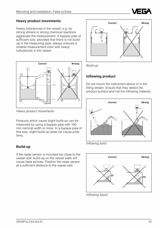
Heavy product movements
Heavy turbulences in the vessel, e.g. bystrong stirrers or strong chemical reactionsaggravate the measurement. A bypass pipe ofsufficient size, provided that there is not build-up in the measuring pipe, always ensures areliable measurement even with heavyturbulences in the vessel.
Products which cause slight build-up can bemeasured by using a bypass pipe with 100mm nominal width or more. In a bypass pipe ofthis size, slight build-up does not cause prob-lems.
Build-up
If the radar sensor is mounted too close to thevessel wall, build-up on the vessel walls willcause false echoes. Position the radar sensorat a sufficient distance to the vessel wall.
Heavy product movements
Inflowing product
Do not mount the instrument above or in thefilling stream. Ensure that they detect theproduct surface and not the inflowing material.
Build-up
Inflowing solid
Inflowing liquid
Correct Wrong
Correct Wrong
Correct Wrong
Correct Wrong
50 %
0 %
46 VEGAPULS 64 and 81
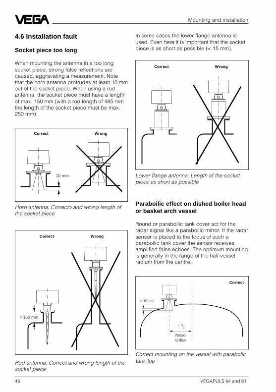
4.6 Installation fault
Socket piece too long
When mounting the antenna in a too longsocket piece, strong false reflections arecaused, aggravating a measurement. Notethat the horn antenna protrudes at least 10 mmout of the socket piece. When using a rodantenna, the socket piece must have a lengthof max. 150 mm (with a rod length of 485 mmthe length of the socket piece must be max.250 mm).
Mounting and installation
In some cases the lower flange antenna isused. Even here it is important that the socketpiece is as short as possible (< 15 mm).
Horn antenna: Correcto and wrong length ofthe socket piece
Rod antenna: Correct and wrong length of thesocket piece
Paraboilic effect on dished boiler heador basket arch vessel
Round or paraboilic tank cover act for theradar signal like a paraboilic mirror. If the radarsensor is placed to the focus of such aparaboilic tank cover the sensor receivesamplified false echoes. The optimum mountingis generally in the range of the half vesselradium from the centre.
Lower flange antenna: Length of the socketpiece as short as possible
Correct mounting on the vessel with parabolictank top
Correct Wrong
>Ê10Êmm
Ê10Êmm
< 150 mm
Correct
Correct Wrong
Correct Wrong
~ 1/2
Vesselradius

VEGAPULS 64 and 81 47
Mounting and installation: Installation fault
Pipe antenna on a surge pipe withoutventilation hole
Pipe antenna systems must be provided with abreathing hole on the upper edge of the surgepipe. A missing hole will cause faulty measure-ments.
Pipe antenna: The surge pipe oen to the bot-tom must have a ventilation or breathing holeon top
VEGAPULS 64 on a surge pipe: The polariza-tion direction is in line with the type plate. Thesensor must be directed with the type plate tothe rows of holes
Wrong
Wrong mounting on the vessel with parabolictank ceiling
Pipe antenna, wrong polarizationdirection
When measuring in a surge pipe, especially ifthere are holes in the pipe for mixing, it isimportant that the radar sensor is directed tothe rwo of holes.
The two rows of holes of the surge pipe dis-placed by 180° must be in line with the polari-zation direction of the radar signals. The po-larization direction is either in line with positionwhere the type plate is fixed (VEGAPULS 64)or in line with the casting nose on the lowerpart of the housing (VEGAPULS 81).
Type plate
Correct Wrong
Correct Wrong

48 VEGAPULS 64 and 81
Wrong directing to the product surface
A directing of the sensor which does not pointto the product surface will cause a weakmeasuring signal. If possible direct the sensoraxis vertically to the product surface, to reachoptimum measuring results.
Mounting and installation: Installation fault
Sensor too close to the vessel wall
If the radar sensor is mounted too close to thevessel wall, strong interfering signals can becaused. Build-up, rivets, screws or weld jointssuperimpose their echoes to the useful signalor useful echo. Hence note a sufficient dis-tance of the sensor to the vessel wall.
In case of good reflection conditions (liquidswithout vessel installations) we recommendyou select the sensor distance so that there isno vessel wall within the inner emission cone.For liquids with worse reflection conditions it isuseful that there are also no interefering instal-lations within the outer emission cone. Notechapter “2.1 General installation instructions“.
Foam generation
Strong, dense and creamy foam on the prod-uct can cause faulty measurements. Providemeasures to avoid foam or measure in a by-pass pipe. Check if necessary the use ofanother measuring principle e.g. capacitiveelectrodes or hydrostatic pressure transmit-ters.
Direct sensor vertically to the product surface
Correct Wrong
VEGAPULS 81 on a surge pipe: The polariza-tion direction is in line with the casting nose.The sensor must be directed with the castinnose to the rows of holes or openings
Casting nose
Ladder
Correct Wrong

VEGAPULS 64 and 81 49
Electrical connection
5 Electrical connection
5.1 Connection and connectioncable
Safety information
Ensure that the instrument is unpressurizedbefore you start work. Always switch off thepower supply before you carry out clampingwork on the radar sensors. Protect yourselfand the instruments.
Skilled staffInstruments which are not operated with aprotective low voltage must only be connectedby skilled staff.
Connection
A standard two-wire cable can be used asconnection for the output signal. Very often the“electromagnetic pollution“ by electronic ac-tuators, energy transmission and transmittingstations is so considerable that the two-wirecable for the output signals (digital or ana-logue) should be screened.
We recommend to use a screening. Thisscreening prevents against future interfer-ences. Earth the screen of the signal line al-ways at one sensor side and use a low imped-ance earth connection (foundation, plate ormains earth).
Ex-protection
If an instrument is used in hazardous areas,the appropriate regulations, conformity certifi-cates and type approvals for systems in Ex-areas must be noted (e.g. DIN 0165).
Intrinsically safe circuits with more than oneactive facility (instrument delivering electricalenergy) must not be connected. Note thespecial installation regulations (DIN 0165).
Connection cable
Note that the connection cable must be speci-fied for the expected operating temperaturesin your systems.
Cables with intrinsically safe circuits must bemarked (blue) and must not be used for othercircuits.

50 VEGAPULS 64 and 81
Electrical connection
VEGA PULS 64 K
8 94 5 6 7
I out
–(N)
VEGACONNECTECHOFOX
10power supply + –
0/4…20 mA
serviceR
ser.no.
R
–+
+ –
+(L1)
0 … 20 mA current output
Note:The cable diameter of the connection cables must be min.5 mm ø and max. 10,5 mm ø. Hence the seal effect of thecable entry will not be ensured.
Instruction:Only carry out screening on one sensor end. Screen terminaland earth terminal are electrically connected.
VEGAPULS 64 FK/DK
Sensors with analog 0 … 20 mA currentoutput
5.3 Connection diagrams ofVEGAPULS 64 series
Open the terminal box by loosening the fourscrews on the upper side of the housing andremove the yellow cover. Connect the radarsensor acc. to the following connection dia-gram. Take the earth/screen connection andconnect to system earth.
VEGAPULS 64 FV/DV
Sensors with digital measuring signal
VEGA PULS 64 V
8 94 5 6 7
VBUS
+ –
VEGACONNECTECHOFOX
10407V, 509V, 512V, 514V, 571EV
serviceR
ser.no.
R
+
+ –
+ –
Supply and digitalmeasuring signal
Optionally for external, sepa-rate power supply
Cable entries1 … 3 Pg 13,5

VEGAPULS 64 and 81 51
5.4 Connection diagram ofVEGAPULS 81 series
Loosen the six hexagon socket screws on theupper side of the sensor and remover thecover of the terminal box. On the upper innerside of the terminal box cover there is a bentpin. Insert this pin in the terminal box coverinto the mean upper hole of the open terminalbox. hence the terminal box cover is keptcarefully during the connection work.
Connect the screen of the sensor cable withan earth conductor of the power supply (e.g.supply with 90 … 250 V AC) to the screen andearth terminal in the terminal box. Connectthen the system earth (foundation or plateearth) with the outer earth connection terminalon the upper back side of the yellow sensorhousing or on the back of the flange.
Electrical connection
5 6 7 8 9 10
+5V SCL GND I + I - U + U - I + I -
1 2 3 4
SDA
Terminal board withintrinsically safe circuits(EEx ia)
Terminal board withcircuits in increasedsafety (EEx e)
Cable entries1 … 4 M20 x 1,5 (cablediameter 5 … 9 mm)
Note:The cable diameter of the connection cablesmust be min. 5 mm ø and max. 9 mm ø.Otherwise the seal effect of the cable entrieswill not be ensured.
Open terminal box of VEGAPULS 81 - total view
Earth termi-nal
Note:Carry out screening only on one sensor end. Screen terminaland earth terminal are electrically connected.
Screen and earthterminal
Screen and earthterminal or earthconductor

52 VEGAPULS 64 and 81
Electrical connection: Connection diagram VEGAPULS 81
VEGAPULS 81 FA and VEGAPULS 81 DA, digital output signal (VBUS) EEx ibSupply and output signal via separator intrinsically safe on a four-wire line.
VEGAPULS 81 FB and VEGAPULS 81 DB, digital output signal (VBUS) EEx eUp to five sensors with supply and output signal in EEx e on one two-wire line.
VEGAPULS 81 FC and VEGAPULS 81 DC, digital output signal (VBUS) EEx eSeparate supply, up to 15 sensors with their output signal (VBUS) on one two-wire line, two-wireline of the supply and two-wire line of the signal output in "e".
5 6 7 8 1 2 3 4
+5V SCL GNDSDA + – + –
4321
+–+–
– z30 + z32 – d32 + d32
– 4 + 3 – 2 + 1
5 6 7 8 1 2 3 4
+5V SCL GNDSDA U+ U-
4321
+–
5 6 7 8 1 2 3 4
+5V SCL GNDSDA U+ U- + –
4321
+–
+–
for optionalexternalindication(VEGADIS 10)
for optionalexternalindication(VEGADIS10)
for optionalexternalindication(VEGADIS10)
20 … 36 V DC20,5 … 26,5 V AC90 … 250 V AC
Digital output signal(VBUS) to the signalconditioning instru-ment VEGAMET orVEGALOG
Supply and digitaloutput signal (VBUS)from and to thesignal conditioninginstrumentVEGAMET orVEGALOG
Supply and digitaloutput signal(VBUS) fromseparatorVEGATRENN 547
or
from safety barriertype 146 orVEGATRENN 546
(ia) (ib)
(ia)(e)
(ia)(e)
(e)

VEGAPULS 64 and 81 53
Electrical connection: Connection diagram VEGAPULS 81
5 6 7 8 1 2 3 4
+5V SCL GNDSDA U+ U- I+ I-
4321
+–
+–
5 6 7 8 9 10 1 2 3 4
+5V SCL GNDSDA I + I - U+ U-
+–
+–
4321
for optionalexternalindication(VEGADIS 10)
for optionalexternal indica-tion (VEGADIS10)
0/4 … 20 mA
20 … 36 V DC20,5 … 26,5 V AC90 … 250 V AC
(ia)(e)
(e)
(ia)
VEGAPULS 81 FD and VEGAPULS 81 DD, analogue 0/4 … 20 mA-output signal in EEx e(compact instrument)Supply and output signal in "e"
0/4 … 20 mA
20 … 36 V DC20,5 … 26,5 V AC90 … 250 V AC
(e)
(ia)
VEGAPULS 81 FE and VEGAPULS 81 DE, analogue 0/4 … 20 mA-output signal in EEx ia(compact instrument)Supply in "e", output signal in "ia"

54 VEGAPULS 64 and 81
Set-up
6 Set-up
6.1 Adjustment structure
The radar sensors of VEGAPULS 64 andVEGAPULS 81 series have no direct adjust-ment elements.
All radar sensors are generally adjusted withthe PC and the adjustment software VVO(VEGA Visual Operating). The signal line of theradar sensors is hence superimposed with adigital adjustment signal.
Sensors with digital measuring data transmis-sion (VBUS) can be adjusted beside the PCalso directly with the connected signal condi-tioning instrument VEGAMET 514 V or 515 V.
Note:Always note the following sequence for theset-up of a sensor:- first create new measurement loop.- then carry out the configuration and
parameter adjustment.
By creating a new measurement loop, thesensor is activated. The sensor is set to theparameter to be measured (level, distance)and a measurement loop name can be pro-vided. For sensors with digital output signal,the sensor must be additionally co-ordinatedto an input of the signal conditioning instru-ment or an input of the processing system.
Adjustment with PC
Requirements:- PC; IBM-compatible, with a free standard
interface, operating memory ≥ 4 MB.- Program surface Windows® (up from version
3.0)- Adjustment software VVO (VEGA Visual
Operating)- Interface converter VEGACONNECT or a
standard RS 232-interface cable (for meas-uring systems in conjunction with process-ing system VEGALOG 571).
For adjustment, the PC is connected with thestandard RS 232-connection via the interfaceconverter VEGACONNECT to the measuringsystem. VEGACONNECT is either connectedwith the two-wire output to the sensor signalline (e.g. on a connection socket), pluggedinto the CONNECT-sockets at the front side ofthe signal conditioning instrument or con-nected with the measuring signal terminals ofthe sensor (VBUS-terminals).
Work with the processing system VEGALOG571, connect the PC with the CPU of theprocessing system directly to a RS 232-inter-face cable (standard cable).
Adjust with the signal conditioning in-strument
The signal conditioning instruments are pro-vided with a 6-key adjustment module with textdisplay. The adjustment module ensures likethe adjustment software VVO, the adjustmentof the signal conditioning instrument itself andthe adjustment of the radar sensor.
Before you start the set-up:Do not be frightened by the many pictures,adjustment steps and menus on the followingpages. Carry out the set-up step-by-step viaPC or signal conditioning instrument.
VEGAPULS 64 and 81 55
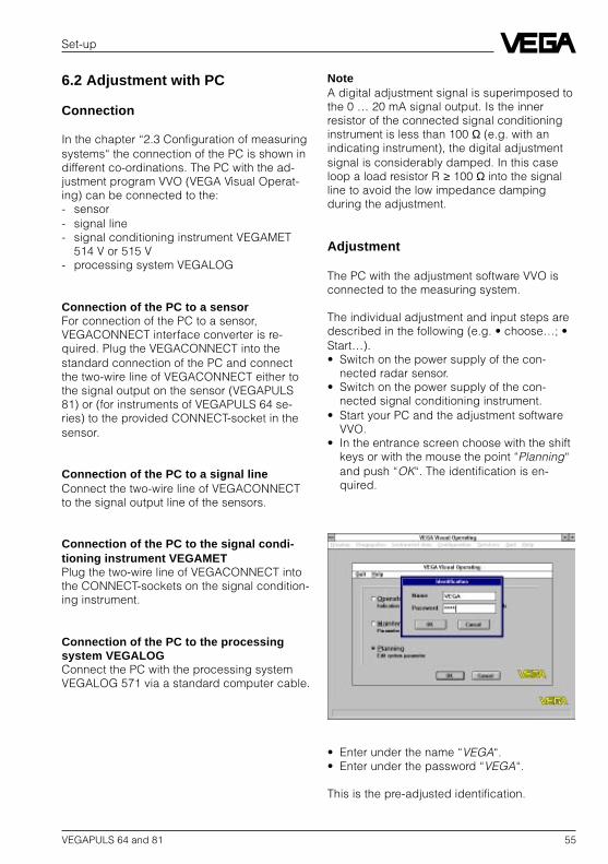
NoteA digital adjustment signal is superimposed tothe 0 … 20 mA signal output. Is the innerresistor of the connected signal conditioninginstrument is less than 100 Ω (e.g. with anindicating instrument), the digital adjustmentsignal is considerably damped. In this caseloop a load resistor R ≥ 100 Ω into the signalline to avoid the low impedance dampingduring the adjustment.
Adjustment
The PC with the adjustment software VVO isconnected to the measuring system.
The individual adjustment and input steps aredescribed in the following (e.g. • choose…; •Start…).• Switch on the power supply of the con-
nected radar sensor.• Switch on the power supply of the con-
nected signal conditioning instrument.• Start your PC and the adjustment software
VVO.• In the entrance screen choose with the shift
keys or with the mouse the point “Planning“and push “OK“. The identification is en-quired.
Set-up
6.2 Adjustment with PC
Connection
In the chapter “2.3 Configuration of measuringsystems“ the connection of the PC is shown indifferent co-ordinations. The PC with the ad-justment program VVO (VEGA Visual Operat-ing) can be connected to the:- sensor- signal line- signal conditioning instrument VEGAMET
514 V or 515 V- processing system VEGALOG
Connection of the PC to a sensorFor connection of the PC to a sensor,VEGACONNECT interface converter is re-quired. Plug the VEGACONNECT into thestandard connection of the PC and connectthe two-wire line of VEGACONNECT either tothe signal output on the sensor (VEGAPULS81) or (for instruments of VEGAPULS 64 se-ries) to the provided CONNECT-socket in thesensor.
Connection of the PC to a signal lineConnect the two-wire line of VEGACONNECTto the signal output line of the sensors.
Connection of the PC to the signal condi-tioning instrument VEGAMETPlug the two-wire line of VEGACONNECT intothe CONNECT-sockets on the signal condition-ing instrument.
Connection of the PC to the processingsystem VEGALOGConnect the PC with the processing systemVEGALOG 571 via a standard computer cable.
• Enter under the name “VEGA“.• Enter under the password “VEGA“.
This is the pre-adjusted identification.
56 VEGAPULS 64 and 81
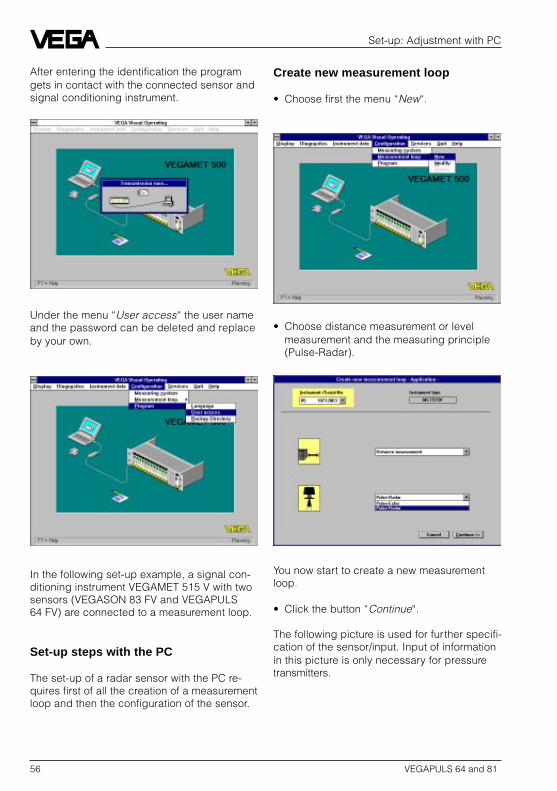
After entering the identification the programgets in contact with the connected sensor andsignal conditioning instrument.
Set-up: Adjustment with PC
Under the menu “User access“ the user nameand the password can be deleted and replaceby your own.
Create new measurement loop
• Choose first the menu “New“.
• Choose distance measurement or levelmeasurement and the measuring principle(Pulse-Radar).
You now start to create a new measurementloop.
• Click the button “Continue“.
The following picture is used for further specifi-cation of the sensor/input. Input of informationin this picture is only necessary for pressuretransmitters.
In the following set-up example, a signal con-ditioning instrument VEGAMET 515 V with twosensors (VEGASON 83 FV and VEGAPULS64 FV) are connected to a measurement loop.
Set-up steps with the PC
The set-up of a radar sensor with the PC re-quires first of all the creation of a measurementloop and then the configuration of the sensor.

VEGAPULS 64 and 81 57
Set-up: Adjustment with PC
The signal conditioning instrument VEGAMEThas two inputs. In the picture “New application– select measuring loop“ you co-ordinate theradar sensor to an input (TAG) in the con-nected signal conditioning instrument. Theinputs are called “measuring loop 1 and meas-uring loop 2“. However this is only required forsensors with digital signal output.
• Click to “OK“.
If a measurement loop is already created inthe signal conditioning instrument your areinformed that the existing measurement loopwill be overwritten.
The following data transmission lasts someminutes.
• Click to “Sensor co-ordination“.
You enter the menu “Sensor co-ordination“.
• Click to “Input“.
The available sensor numbers for selectionand co-ordination to the input are offered.
• Select the sensor which should be co-ordinated to the input.
When you cross additional functions you havethe possibility, e.g. to co-ordinate to the inputof the actual signal conditioning instrumentalso the input of the other signal conditioninginstrument.
It is hence possible, to process a sensor con-nected in another signal conditioning instru-ment in the actual signal conditioning instru-ment.
However you have co-ordinated the sensorwhich is connected to the actual signal condi-tioning instrument also to the actual signalconditioning instrument for processing whichis usual.
• Confirm with “OK“ and the input with the co-ordinated sensor number is displayed.
• Confirm with “OK“.• Click to “Continue“.
• Click again to “Continue“.

58 VEGAPULS 64 and 81
Set-up: Adjustment with PC
Now the picture “Create new measurementloop – Measurement loop designation“.
• Click to the button “Distance“.
• Enter in the field “Measurement loop de-scription“ a measurement loop name.
In this menu you can chose with which outputsignally your level should be processed, e.g.as current, voltage, relay, circuit etc.
• Confirm with “OK“.
The previous picture appears again.
• Click to “Quit“.
The adjustments are transmitted, this lastssome seconds.
Parameter adjustment
You have created a new measurement loop inthe previous chapter. Hence you have chosenthe measuring principle, co-ordinated thesensor with its number to an input, to provide aname for the measurement loop and if neces-sary determined by which outputs (current,relay etc.) your measuring signal/sensor signalshould be processed.
Now the parameter adjustment for the sensormust be carried out. Enter in the menu “Pa-rameter adjustment“ how the conditioningsand outputs will be configured, carry out theadjustment and the sensor optimization.
Following the menus “Adjustment“ and “Sen-sor optimization“ are described. The otherparameter menus are described in the operat-ing instructions of the signal conditioninginstruments VEGAMET 514 V or 515 V, as wellas the processing system VEGALOG 571 andconcern just the signal processing of yourmeasured value.
• Choose the menu “Instrument data/Parameter adjustment“.
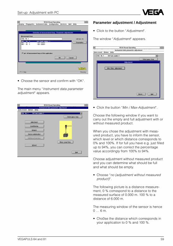
VEGAPULS 64 and 81 59
Set-up: Adjustment with PC
Parameter adjustment / Adjustment
• Click to the button “Adjustment“.
The window “Adjustment“ appears.
• Choose the sensor and confirm with “OK“.
The main menu “Instrument data parameteradjustment“ appears.
• Click the button “Min / Max-Adjustment“.
Choose the following window if you want tocarry out the empty and full adjustment with orwithout measured product.
When you chose the adjustment with meas-ured product, you have to inform the sensor,which level or which distance corresponds to0% and 100%. If for full you have e.g. just filledup to 94%, you can correct the percentagevalue accordingly from 100% to 94%.
Choose adjustment without measured productand you can determine what should be fulland what should be empty.
• Choose “no (adjustment without measuredproduct)“.
The following picture is a distance measure-ment, 0 % correspond to a distance to themeasured surface of 0.000 m. 100 % to adistance of 6.000 m.
The measuring window of the sensor is hence0 … 6 m.
• Cho0se the distance which corresponds inyour application to 0 % and 100 %.

60 VEGAPULS 64 and 81
Set-up: Adjustment with PC
Mounting arrangement
• Choose in the menu picture “Sensor optimi-zation“ the menu “Mounting arrangement“.
The menu window “Mounting arrangement“appears.
• Confirm the adjustment carried out with“OK“.
After the data transmission the window “Ad-justment“ appears again.
• Click to “Quit“.
Parameter adjustment / Sensoroptimization
• Click to the button “Sensor optimization“.
The window “Sensor choice for sensor optimi-zation“ appears. Here you have just onechoice: “Sensor A“. This window may seemunimportant, however if e.g. digital pressuretransmitters are adjusted with the adjustmentsoftware VVO, further options will be availablein this window.
Now a data transmission of a few seconds iscarried out and the menu picture “Sensoroptimization“ is then displayed.
• Choose the mounting arrangement corre-sponding to your measurement loop. Notethe instructions in chapter “4 Mounting andinstallation“.
• Confirm the selected installation place with“OK“.
Again the menu window “Sensor optimization“appears.• Click now to “Sensor A“.

VEGAPULS 64 and 81 61
Set-up: Adjustment with PC
Measuring environment
• Choose “Measuring environment“.
• Click to “Measuring range“.
The window “Measuring range limitation“ isopened.
• Adjust in the window “Measuring rangelimitation“ the range in which you want tomeasure. In general the measuring rangecorresponds to the vessel height.
• Click to “Save“.• Choose in the window “Measuring environ-
ment“ the button “Measuring conditions“.• Adjust in the window “Measuring conditions“
the appropriate option of your measuredproduct and confirm with “OK“.
• Finally chose in the window “Measuringenvironment“ the button “Measured valuecorrection“.
In the window “Echo curve“ now the echoprofile of your vessel and probable strongfalse echoes are displayed. Use this indicationto improve if necessary the installation positionof your sensor and to remove or reduce prob-able false echo sources.
• Quit the window “Echo curve“ by clicking to“Quit“.
In the window “Measured value correction“ theechoes detected by the radar sensor aredisplayed.
• Choose out of the detected echoes, theecho corresponding to your measuringdistance.
• Quit this menu by entering or choosing yourmeasuring distance to the measured prod-uct with “OK“.
• Quit the window “Measuring environment“by clicking to “Quit“.
You are now again in the menu “Sensor optimi-zation“.
Echo curve
In the menu “Echo curve“ the echo profile ofyour measurement is displayed.
• Hence click to “Echo curve“.

62 VEGAPULS 64 and 81
• Click to “Create new“.
The false echoes are marked and you will seethe modified false echo curve. In the list, thefalse echoes, their length with start and end aswell as the amplitude in dB are stated.
Set-up: Adjustment with PC
• Click to “Quit“.
You are again in the menu “Sensor optimiza-tion“.
• Click to “Quit“.
You are again in the menu “Sensor choice forsensor optimization“.
• Click again to “Quit“.
You are again in the menu “Instrument dataparameter adjustment“.
• Click again to “Quit“.
In the window “False echo storage“ you caninduce the sensor to mark and save falseechoes between sensor and product surface.The ECHOFOX®-sensor electronics then treatsthe false echoes differently from the usefulecho and considers this in the internal database.
• Click to “Learn false echoes“.
The measured distance to product surface isenquired.
• Enter the measured distance.
False echo storage
If you have problems with false echoes, youcan carry out a sensor optimization with themenu “False echo storage“.
• Click to “False echo storage“.

VEGAPULS 64 and 81 63
Set-up
6.3 Save and copy adjustment data
The configuration of the sensors and signalconditioning instruments or the processingsystem can be:- saved “Backup“- administrated (deleted, shifted and com-
ments can be added to the backup) “Editbackup“
- copied (transfer adjustments to other instru-ments) “Restore configuration“
The saving of the instrument adjustments inthe menu “Backup“ corresponds to a databackup. In the menu “Restore configuration“such a data backup can be re-written into theinstruments or transferred to other instruments.
In the menus for saving, copying and adminis-trating of the data you can choose whetheryou want to save, copy or administrate thesensor data to the data set of the signal condi-tioning instrument or the processing system.
If you save e.g. in the menu “Backup/ Sen-sors“ the sensor data, all adjustments andinputs will be saved which you have carriedout in the menu “Sensor optimization“.
Save in the menu “Backup / Signal condition-ing instruments“ the data set of the signalconditioning instrument or the processingsystem, all parameters and configuration dataof a measurement loop except the pure sensordata are saved.
When you have set-up your measurementloop, you can now save the adjustment data.
Save
• Click with the mouse to the menu “Services“.• Choose “Backup“ and click to “Sensors“.
The menu window “Backup“ opens when youchoose if you want to save each sensor insingle files or if you want to compile a group ofsensors in one file (“Compile several sensorsin one file“).
• Choose “Compile several sensors in onefile“
Under “Choice of sensors to be saved“ youchoose the sensors which you want to save ina group.

64 VEGAPULS 64 and 81
• Hence hold the key “Strg“ or “CTRL“ pushedand click to the sensor numbers which youwant to include in the sensor group to besaved.
• Provide the sensor group with a name. Inthe example “OSSI2511.G01“.
• Enter in the field “Backup notes“ someadditional backup information for easier co-ordination of saved data later on.
• Click to “Save“ and confirm the securityenquiry with “yes“.
Save the data of the signal conditioning instru-ments in the same way. Hence choose themenu “Services / Backup / Signal conditioninginstruments“.
Copy
Saved instrument dated can be enquiredagain with the menu “Services / Configuration“and their adjustments can be used. In additionthe instrument data can be transmitted to newsensors or signal conditioning instruments.
Set-up: Store and copy adjustment data
• Hence choose the menu “Services / RestoreConfiguration / Sensors“.
• In the menu window “Restore Configuration“you choose the appropriate backup file andthe sensor or the instruments the configura-tion of which you want to restore.
• Click to “Display all data bases“• Choose the backup file.• Choose in the left top corner the sensor, the
configuration of which you want to restore.• Choose in the bottom left corner the instru-
ment number, the adjustments of which youwant to restore.
• Click to “Restore to“.

VEGAPULS 64 and 81 65
Set-up: Store and copy adjustment data
Hence you have transferred the sensor datafrom the backup file into the connected sensor.
You can now transfer this sensor data to theadditional sensors: If you have to set up e.g.new radar sensors for a tank storage plant andif an existing measurement is completely iden-tical with the new application (vessel, arrange-ment, product), the adjustment data of aninstalled sensor can be transferred to the newsensors.
Administrate adjustment data
In the menu “Edit backup“ you can delete thebackup files with the saved sensor and signalconditioning instrument data or provide themwith notes.
• Choose on top of the window “Choice ofsensor data“. The backup files with thesaved sensor data will be displayed. In theleft field in the center you can choose theappropriate backup file you want to deleteor provide with a note.
• Click to the requested backup file.
In the field “Backup notes“ you can add ormodify notes.
• Click to “Save“ when you have entered ormodified the notes.
• Click to “Delete“ if you want to delete abackup file.
• Hence click in the main menu “Service“ tothe menu “Edit backup“.
The window “Edit backup“ opens.

66 VEGAPULS 64 and 81
Set-up: Store and copy adjustment data
Data base check
When you get in contact with your measure-ment loops via the adjustment software VVO,the adjustment program checks whether theadjustments in the signal conditioning instru-ment or the sensor correspond with the adjust-ments of the adjustment software.
If e.g. after the set-up of a measurement loopwith the adjustment software (via PC) on thesignal conditioning instrument VEGAMET, anadjustment had been modified, the followinginformation is displayed when connecting thePC again with the measurement loop.
If you want to add notes to the backup fileswith saved signal conditioning instruments orwant to delete them, choose “ChoiceVEGAMET“. You come to the appropriatewindow “Edit backup“, where you can addnotes or delete backup files like for the sensordata.
- With “Load data from VEGAMET“ you takeover the complete adjustment of the meas-urement loop into the PC and the adjustmentsoftware.
- With “Transfer data to VEGAMET“ youoverwrite the adjustments of the measure-ment loop in the VEGAMET with the adjust-ments in the adjustment software VVO.

VEGAPULS 64 and 81 67
6.4 Adjustment with signalconditioning instrument
In general the radar sensors are adjusted withthe PC and the adjustment software VVO.Radar sensors with digital signal output how-ever can be also adjusted with the adjustmentand indication module of the signal condition-ing instruments VEGAMET 514 V or 515 V,however not the sensors with 0 … 20 mA-signal output (compact instruments).
Set-up
Sensors with digital output signal are con-nected with a two-wire cable to a signal condi-tioning instrument VEGAMET 514 V or 515 V orto the processing system VEGALOG 571. Viathis two-wire line also the communication withthe sensor is transmitted beside the powersupply and the measuring signal.
The adjust with the adjustment module thesignal conditioning instrument and the con-nected radar sensors.
Indication and adjustment module of a signal conditioning instrument VEGAMET513 … 515
ESC OK
– +
1 2
on
100
%
CONNECT
515 V
Acc. to the parameter, change value orselect out of list
Select menu point parameter or shiftflashing cursor
Acc. to the menu point, save theadjusted value or go to the lower menu
Branch, i.e. jump into the lowermenu with [OK]
Acc. to the menu point, canceladjustment or jump into theupper menu
Display,indication of- measured value- menu point- parameter- value
Analogue LED-indication(0 … 100 %)

68 VEGAPULS 64 and 81
Set-up: Adjustment with signal conditioning instrument
Menu structure of the signal conditioning instruments VEGAMET 514 V and 515 V
Measured value indication
The stage of the measured value indication is the upper menu stage. Here you can scroll with thekeys “→“ and “←“ between the following indications:- Indication MST1; measured value of sensor 1- Indication MST2; measured value of sensor 2- Indication MST3; measured value externally or value of the differential measurement- Indication MST1-2; measured value sensor 1 and sensor 2Fault signals are displayed from the indication via the appropriate indication.
Main menu
You can enquire up to five menus in the main menu stage.With the keys “→“ and “←“ you scroll to the five main menus:- Configuration- Additional functions- Parameter adjustment MST1- Parameter adjustment MST2- Parameter adjustment MST3The menu “Parameter adjustment“ can be enquired when the measurement loop is created andconfigured in the configuration menu.
ESC
OK
OK
OK
OK
ESC
ESC
TAG1%
36.9
TAG2%
TAG3%
Menu point
Parameter
Value
Add.func-tion
Con-figura-tion
Param.TAG3
Param.TAG2
Param.TAG1
Pass-wordoff
Out-puts
Meas-uringloop
InputsSimu-lation
OutputProcess-ing
Adjust-ment
Scaling Lin.curve
Integra-tiontime
10
Measuringvalue indica-tion
Mainmenu
Submenu1
Menu choice within the menustage as well as selection of fixedparameters
Submenu2
MST1-2

VEGAPULS 64 and 81 69
Adjustment steps with the signal con-ditioning instrument
You adjust the signal conditioning instrumentand the sensor with the six keys on the signalconditioning instrument (–; +; ←; →; ESC; OK).
The basic set-up steps:- First create a new measurement loop with
the menu “Configuration / Configurationmeasurement loop“
- Then co-ordinate the sensor to an input ofthe signal conditioning instrument in themenu “Configuration / Configuration inputs /Input no.…“
- In the submenu “Sensor optimization“ out ofthe menu “Configuration / Configurationinputs“ you then carry out the configurationand parameter adjustment of the sensor.
Hence the set-up of the radar sensor is carriedout. In the main menu “Parameter adjustment“and in the menu “Configuration / Configurationoutputs“ you choose how the sensor valuesshould be processed and provided. E.g. youcarry out the adjustment, the scaling, theparameter adjustment, the current outputs orthe adjustment of the relay functions.
First set-up with the signal condition-ing instrument
After you have connected the radar sensor (s)with a screened two-wire cable to the signalconditioning instrument VEGAMET 514 V or515 V switch on the power supply for the sig-nal conditioning instrument. The signal condi-tioning instrument powers then the sensor (s)with energy.
Types C, D and E of VEGAPULS 81 series arepowered separately. Connect the sensors likethe signal conditioning instrument to the powersupply.
Fault signalsNormally you get fault signals. This is normalfor the first set-up. Hence carry out an instru-ment reset first before you create a measure-ment loop and you carry out the parameteradjustment.
Set-up: Adjustment with signal conditioning instrument
ResetCarry out a reset first to provide a definedinstrument condition. Proceed acc. to thefollowing steps: Push the left key until in thedisplay (right) the appropriate indication ap-pears. “OK…OK“ means that you have to push“OK“ until the requested indication appears inthe display.
Key: Display:OK…OK The fault signal disappears. First the
measurement loop (TAG) withoutmeasured value is indicated.
OK Then parameter TAG1…3 appears.
Note:If no adjustment is made for appr. 15 seconds,the indication jumps back to the stage of themeasured value indication or to the fault sig-nal. Then push again “OK“ until the fault signalextinguishes.
→…→ Additional functionsOK Password off→…→ Reset VEGAMETOK Reset configurationOK To defaultOK Reset OK?OK Reset now OK?OK
The indication flashed and VEGAMET is resetto the default values.
→…→ Linked applicationOK delete all MSTOK Reset OK?OK Reset now OK?OK
The indication flashes and all measurementloops are reset to linked application. The menu“Linked application“ appears again.
If you want to carry out a differential measure-ment with two sensors, the following adjust-ments are necessary. Continue your adjust-ment under “Quit reset menu“. However if youneed single measurements, continue with theadjustment.
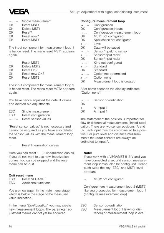
70 VEGAPULS 64 and 81
Set-up: Adjustment with signal conditioning instrument
→…→ Single measurementOK Reset MST1OK Delete MST1OK Reset?OK Reset now?OK Reset MST1
The input component for measurement loop 1is hence reset. The menu reset MST1 appearsagain.
→ Reset MST2OK Delete MST2OK Reset OK?OK Reset now OK?OK Reset MST2
The input component for measurement loop 2is hence reset. The menu reset MST2 appearsagain.
You have hence adjusted the default valuesand deleted old adjustments.
ESC Single measurementESC Reset configuration→…→ Reset sensor values
“Reset sensor values“ is not necessary andcannot be enquired as you have also deletedthe sensor values with the measurement loopreset.
→ Reset linearization curves
Here you can reset 1 … 3 linearization curves.If you do not want to use new linearizationcurves, you can be skipped and the resetmenu can be quit.
Quit reset menuESC Reset VEGAMETESC Additional functions
You are now again in the main menu stagewhich is below the stage of the measuredvalue indication.
In the menu “Configuration“ you now createnew measurement loops. The parameter ad-justment menus cannot yet be enquired.
Configure measurement loop→…→ ConfigurationOK Configuration inputs→…→ Configuration measurement loopOK MST1 not configuredOK Application not configured+…– LevelOK Data will be saved→…→ Sensor/Input, no sensor+…– Sensor/Input radarOK Sensor/Input radar→…→ Kind not configured+…– StandardOK Standard→…→ Option not determined+…– Option noneOK Measurement loop is created
After some seconds the display indicates“Option none“.
→…→ Sensor co-ordinationOK+ A input 1OK A input 1
The statement of the position is important forflow or differential measurements (linked appli-cation. There are two sensor positions (A andB). Each input must be co-ordinated to a posi-tion. For pure level and distance measure-ments the radar sensors are always co-ordinated to input A.
Note:If you work with a VEGAMET 515 V and youhave connected a second sensor, measure-ment loop 2 must also be configured. Hencepush twice the key “ESC“ and MST1 levelappears.
→ MST2 not configured
Configure here measurement loop 2 (MST2)like you proceeded for measurement loop 1(configure measurement loop).
ESC Sensor co-ordinationESC Measurement loop 1 level (or dis-
tance) or measurement loop 2 level

VEGAPULS 64 and 81 71
You have created a new measurement loopwhich you now have to co-ordinate to an inputin the signal conditioning instrument andconfigure the input.
Configuration inputsESC Configuration measurement loop→…→ Configuration inputsOK Input no. 1OK Input of this MET
With the + and – keys you can choose whetherthe input component 1 will be provided withmeasured data by input 1 of the connectedsensor or you want to take over the measureddata from another signal conditioning instru-ment. You can co-ordinate a real connectedsensor to an input component in the signalconditioning instrument or take over measureddata from another signal conditioning instru-ment.
OK Input of this MET
You have co-ordinated to the input compo-nents of the signal conditioning instrument theactually connected sensor by having con-firmed “Input of this MET“ with OK.
The measurement loop is now processed ininput 1.
→…→ Serial number not configured
If two sensors are connected, choose with theplus and minus keys the serial number of thesensor which you want to co-ordinate to input1. In addition you have the possibility to enterthe serial number manually.
+ … + Serial number XXXXXOK The signal conditioning instrument
reads the serial number of the sen-sors and the serial number appears.
→…→ Sensor valuesOK Min. measuring range XXXXX
Use the shift key for indication of the min. andmax. measuring range of the sensor. Thesedata are used for your information and cannotbe modified.
Sensor optimization
Now change to the menu “Sensor optimiza-tion“. In this menu the sensor can be adaptedto the measuring conditions and environment.
ESC Sensor values→…→ Sensor optimizationOK Sensor TAG radar sensor
In the menu sensor optimization the radarsensor is adjusted via the measuring signalline. Here you configure the radar sensor. Inthis menu the signal conditioning instrument isa pure adjustment module for adjustment ofthe sensor.
The menu “Sensor optimization“ is in themenu:Configuration
Configuration inputsInput no. 1 (2)
Sensor optimization TAG… (A)
–– Sensor TAG (free choice for themeasurement loop name)OK
–– Enter name (with “+, –, ←, →“)
–– Mounting arrangement(push “OK“ and choose with “+“ or “–“ themounting arrangement corresponding toyour application)
• Unconsidered (none of all)• Socket “OK“, “→“ socket length• Window “OK“, “→“ distance window
(distance of the flange to the measur-ing window)
• On vessel (radar) “OK“, “→“ distancevessel (distance of the flange to thevessel ceiling when measuringthrough the vessel ceiling)
• Below ceiling “OK“, “→“ distanceceiling (distance of the sensor flangeto the ceiling)
• In pipe (radar) “OK“, “→“ inner diam-eter (pipe inner diameter)
• Window in pipe “OK“, “→“ distancewindow (distance of the flange to themeasuring window when measuringthrough a window)
–– Measuring environment
Set-up: Adjustment with signal conditioning instrument
–
+

72 VEGAPULS 64 and 81
–– Measured value correction
–– Measured value corr. OK?–– measured dist.
–– Spreading speed
–– automatic correction–– Corr. spread. speed
–– measured dist. in m
–– Correction factor in %
–– False echo storage
–– Create new storage–– Create new OK?
–– Measured distance m X.XX(“+“, “–“ for correction)
–– Create new now! OK?–– Saving runs
–– Sensor reset
–– Basic adjustment(Reset without history memory)
–– Delete all parameters now OK?–– Reset now?
–– Reset runs–– Total reset
(Reset with history memory)–– Basic adjustment OK?
–– Reset now?–– Reset runs
–– Time factor (choose with “+“ and “–“ )
–– Actual distance(actual distance indication in mm)
Set-up: Adjustment with signal conditioning instrument
(OK)
–– Meas. range–– Start–– End
–– Measuring conditions (push “OK“and choose with “+“ and “–“ themeasuring condition correspondingto your application)
• Measuring conditionunconsidered
–– unconsideredYesNo
–– quick changeYesNo
–– fluctuating surfaceYesNo
–– foam generationYesNo
–– compile echoesYesNo
• Measuring condition liquid–– quick change
YesNo
–– fluctuating surfaceYesNo
–– foam generationYesNo
–– compile echoesYesNo
• Measuring condition solid–– quick change
YesNo
–– strong dust generationYesNo
–– compile echoesYesNo
–
+
–
+
–
+

VEGAPULS 64 and 81 73
6.5 Menu survey to the signalconditioning instrument
Configuration (main menu stage)
–– Configuration inputs
–– Input 1–– Input of–– Serial no. XXX–– Sensor values (Info)–– Sensor optimization (A)
(A) see previous pages
–– Input 2 as input 1
–– Input 4–– Input of–– Channel no.
–– Configuration measurement loops;Choice: linked or single application
–– MST1 … MST3–– Application–– Sensor/Input–– Type (Standard)–– Option–– Sensor co-ordination (A, B, C)
–– MST-Name, MST1(provide a name with “+, –, ←, →“)
–– Fault signal–– Tare–– Monitoring
–– MST2 as MST1
–– MST3 as MST1
–– Instrument address(deleted up from software version 6,0)
Set-up: Adjustment with signal conditioning instrument
You have carried out the sensor optimizationfor measurement loop 1. Now quit the menu“Sensor optimization“.
ESC Sensor optimizationESC Input no. 1
Note:If you have connected a second radar sen-sor to input 2 (VEGAMET 515 V) also carryout the configuration and sensor adaptionfor this sensor.
→ Input 2OK Input of this MET
Now carry out the adjustment for measure-ment loop 2, like for measurement loop 1,this also means under the menus “Configu-ration inputs“ and “Sensor optimization“.
You have hence configured the inputs and themeasurement loop in the menu “Configura-tion“. In this main menu you must alsoconfigure the outputs.
In the main menu “Parameter adjustment“ youdetermine by which parameters (min., max.,scaling) your measuring signal should beprocessed. The menu survey is on the follow-ing pages. Further instructions are stated inthe operating instruction of your signal condi-tioning instrument.
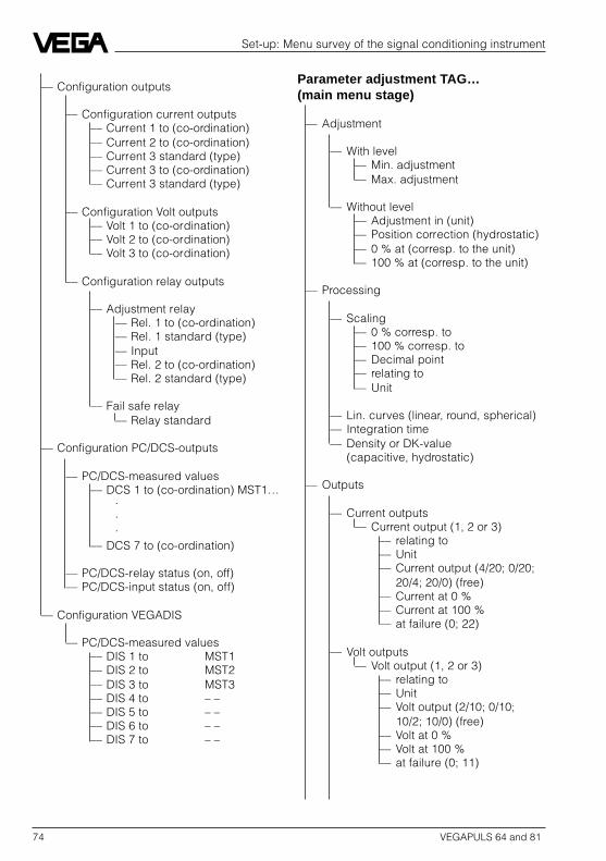
74 VEGAPULS 64 and 81
Parameter adjustment TAG…(main menu stage)
–– Adjustment
–– With level–– Min. adjustment–– Max. adjustment
–– Without level–– Adjustment in (unit)–– Position correction (hydrostatic)–– 0 % at (corresp. to the unit)–– 100 % at (corresp. to the unit)
–– Processing
–– Scaling–– 0 % corresp. to–– 100 % corresp. to–– Decimal point–– relating to–– Unit
–– Lin. curves (linear, round, spherical)–– Integration time–– Density or DK-value
(capacitive, hydrostatic)
–– Outputs
–– Current outputs–– Current output (1, 2 or 3)
–– relating to–– Unit–– Current output (4/20; 0/20;
20/4; 20/0) (free)–– Current at 0 %–– Current at 100 %–– at failure (0; 22)
–– Volt outputs–– Volt output (1, 2 or 3)
–– relating to–– Unit–– Volt output (2/10; 0/10;
10/2; 10/0) (free)–– Volt at 0 %–– Volt at 100 %–– at failure (0; 11)
–– Configuration outputs
–– Configuration current outputs–– Current 1 to (co-ordination)–– Current 2 to (co-ordination)–– Current 3 standard (type)–– Current 3 to (co-ordination)–– Current 3 standard (type)
–– Configuration Volt outputs–– Volt 1 to (co-ordination)–– Volt 2 to (co-ordination)–– Volt 3 to (co-ordination)
–– Configuration relay outputs
–– Adjustment relay–– Rel. 1 to (co-ordination)–– Rel. 1 standard (type)–– Input–– Rel. 2 to (co-ordination)–– Rel. 2 standard (type)
–– Fail safe relay–– Relay standard
–– Configuration PC/DCS-outputs
–– PC/DCS-measured values–– DCS 1 to (co-ordination) MST1…
···
–– DCS 7 to (co-ordination)
–– PC/DCS-relay status (on, off)–– PC/DCS-input status (on, off)
–– Configuration VEGADIS
–– PC/DCS-measured values–– DIS 1 to MST1–– DIS 2 to MST2–– DIS 3 to MST3–– DIS 4 to – ––– DIS 5 to – ––– DIS 6 to – ––– DIS 7 to – –
Set-up: Menu survey of the signal conditioning instrument

VEGAPULS 64 and 81 75
Additional functions (main menustage)
–– Password
–– Lin. curves edit–– Lin. curve 1–– Lin. curve 2–– Lin. curve 3
–– Info–– Input info–– VEGAMET-Info–– Program info–– Measurement loop infor
–– Language–– Deutsch–– English–– Francais–– Italiano–– Espanol
–– Reset VEGAMET (E)–– Reset configuration–– Reset sensor values–– Reset Lin. curves
–– Service–– Current output–– Volt output
Note:The menu points marked with the letters (A),(B), (C), (D) and (E) in bolt print have addi-tional submenus. These are shown on thefollowing pages.
–– Relay outputs–– Relay output (1 or 2)
–– relating to–– Unit–– Type (B)
(e.g. overfill protection)–– Low (switch point in %)–– High (switch point in %)–– at failure (off or
keep switching condition)–– Additional functions
–– Switching delay–– t on–– t off
–– MET-indication (C)–– PC/DCS-outputs (C)–– DIS-outputs (C)–– Simulation (+ or –)
–– Special functions(D)
–– Reset measurement loop(Reset distance)
–– Failure mode–– Real value correction–– Manual correction–– Density correction–– εr-correction
Set-up: Menu survey of the signal conditioning instrument

76 VEGAPULS 64 and 81
Parameter adjustment TAG…Outputs
Relay outputs (1 or 2)Type (B)
–– Type :(push “OK“ and choose with “+“ and “–“ therequested relay function off)
• Raising tendency
The relay of relay output 1 de-energizeswhen the raising average value out of“t ges.“ exceeds the previously defined%-value.
• Falling tendency
same function, however with fallingaverage value.
–– Deviation in % 2 If the level change exceeds this adjusted %-value,the tendency determination responds. 0 … 110 %,example 2 % (modification) per t ges.
–– Deviation per time
–– Scanning time in s 60 Adjustment range 0 … 999 sExample 60 s corresponds to 1 minute
–– Number ofscannings 4 Adjustment range 0 … 99 steps
Example: t ges = ta • n = 60 • 4 = 240 s = 4 min.,i.e. after every 4 minutes the average value of thedeviation is generated and the result is comparedwith the given deviation in %, here in the example2 %.
Set-up: Menu survey of the signal conditioning instrument
d b zt
%
1 2 3 4
ta
t ges.
n = 4
Relay outp.
ta = scanning timen = number of scannings
d b zt
1 2 3 4
ta
t ges.
n = 4
%
Relay outp.
ta = scanning timen = number of scannings
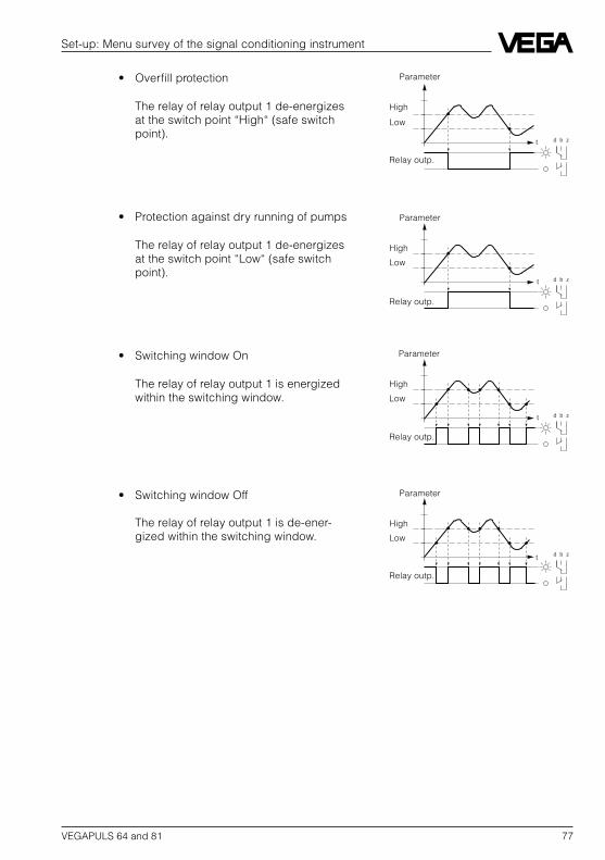
VEGAPULS 64 and 81 77
• Overfill protection
The relay of relay output 1 de-energizesat the switch point “High“ (safe switchpoint).
• Protection against dry running of pumps
The relay of relay output 1 de-energizesat the switch point “Low“ (safe switchpoint).
• Switching window On
The relay of relay output 1 is energizedwithin the switching window.
• Switching window Off
The relay of relay output 1 is de-ener-gized within the switching window.
Set-up: Menu survey of the signal conditioning instrument
d b zt
High
Low
Relay outp.
Parameter
d b zt
High
Low
Relay outp.
Parameter
d b zt
d b zt
High
Low
Relay outp.
High
Low
Relay outp.
Parameter
Parameter

78 VEGAPULS 64 and 81
Set-up: Menu survey of the signal conditioning instrument
• Monitoring With the choice “Monitoring“ in the menu “Con-figuration / Configuration measurement loops“ themenu point “Monitoring“ is released and the moni-toring function for the relay can be enquired.
–– Monitoring to “High“
The relay of relay output 1 de-energizes when exceeding the %-value adjusted under High.
–– Monitoring to “Low“
The relay of relay output 1 de-energizes when decreasing the %-value adjusted under Low.
–– Monitoring to “High and Low“
The relay of relay output 1 de-energizes when exceeding anddecreasing the %-value adjustedunder High and Low.
–– at failure
–– relating to undetermined
–– Unit
Relay outp.
High
frozenmeasur-ing value
d b z
t
%
Keyswitch
d b z
t
%
Relay outp.
Keyswitch
frozenmeasur-ing valueLow
d b z
t
%
Relay outp.
High
Keyswitch
Low
frozenmeasur-ing value

VEGAPULS 64 and 81 79
Set-up: Menu survey of the signal conditioning instrument
Parameter adjustmentOutputs (C)
–– MET-indication
–– relating to Percent etc. choice acc. to list
–– Unit % etc. choice adapted to above determination
–– PC/DCS-outputs
–– PC/DCS output 1
–– relating to Percent etc. choice acc. to list
–– Unit % etc. choice adapted to above determination
–– PC/DCS output 2 … 7 as described above
–– DIS-outputs
–– DIS-output 1
–– relating to Percent etc. choice acc. to list
–– Unit % etc. choice adapted to above determination
–– DIS-output 2 … 7 as described above

80 VEGAPULS 64 and 81
Set-up: Menu survey of the signal conditioning instrument
Parameter adjustmentSpecial function (D)
–– Reset measurement loop (e.g.level) With this reset all parameter values of–– Reset OK? measurement loop TAG1 will be reset to
–– Reset now! OK? factory setting.
–– Failure mode Standard No fault signal<–10% Fault signal when exceeding and/or decreasing<110% the adjusted measuring range>110%<-10a.>110%<-110a.>110%
Automatic correctionsAn additional sensor (correction signal) installed on a reference point, corrects the outputresults to the value valid in this point. The position of this reference point is defined in % inthe following menu points to the adjusted measuring range.
All following menu points for correction are only indicated when they have ben previouslyactivated in the menu range "Configuration measurement loop" menu point "Option".
–– Real value correction 0.0 % Only with option - Real value correction
–– Density correction 50.0 % Only with option - Density correction
–– εr-correction 50.0 % Only with option - Correction in the point
–– Manual corrections
–– Offset correction Only visible with hydrost. pressure transmittersCarry out correction only on unpressurized sensor.
–– Offset correction OK?
–– Correction now! OK?
–– Real value correction Only visible with hydrost. pressure transmittersThe correction is carried out to the %-value
–– Correction at 0.0 % adjusted in this menu point
–– Correction really?
–– Correction now! OK?

VEGAPULS 64 and 81 81
Set-up: Menu survey of the signal conditioning instrument
Additional functionsReset VEGAMET (E)
–– Reset Configuration
–– to Default With Reset to Default the whole configuration–– Reset OK? and parameter adjustment (probably all TAGs)
–– Reset now! OK? are reset to factory setting.However the basic configuration remains,e.g. level measurement pressurized.
–– to linked application The single measurements available at the–– delete all TAGs? moment will be deleted and a pre-configuration
–– etc. to linked application is generated instead.
–– to single measurement–– Delete TAG1? A linked application available at the moment
–– etc. will be deleted and a pre-configuration to single.
–– Delete TAG2? measurements will be generated instead.–– etc.
–– Reset sensor values
–– Reset input 1 The sensor data of the sensor connected to–– Reset OK? input 1 will be deleted
–– Reset now! OK?–– Reset input 2 as above, however input 2–– Delete all sensor values as above, however input 1 and 2
–– Reset linearization curves
–– Reset Lin. curve 1 With this reset the index markers of–– Reset OK? linearization curve 1 will be deleted
–– Reset now! OK?–– Reset Lin. curve 2 as above, however linearization curve 2–– Reset Lin. curve 3 as above, however linearization curve 3–– Reset all curves as above, however all linearization curves

82 VEGAPULS 64 and 81
Notes

VEGAPULS 64 and 81 83
Notes

ISO 9001
VEGA Grieshaber KGAm Hohenstein 113D-77761 SchiltachPhone (0 78 36) 50 - 0Fax (0 78 36) 50 - 201Fax (0 78 36) 50 - 203
Technical data subject to alterations 2.19 308 / Jan. ’97