Vegapuls 63
92
Operating Instructions Radar sensor for continuous level measurement of liquids VEGAPULS 63 4 … 20 mA/HART - two-wire Document ID: 36511
description
Operating instructions for radar sensor Vegapuls 63
Transcript of Vegapuls 63

Operating InstructionsRadar sensor for continuous level measurement of liquids
VEGAPULS 634 … 20 mA/HART - two-wire
Document ID: 36511

2
Contents
VEGAPULS 63 • 4 … 20 mA/HART - two-wire
36511-EN-150625
Contents1 About this document
1.1 Function ........................................................................................................................... 41.2 Target group ..................................................................................................................... 41.3 Symbols used................................................................................................................... 4
2 For your safety2.1 Authorised personnel ....................................................................................................... 52.2 Appropriate use ................................................................................................................ 52.3 Warning about incorrect use ............................................................................................. 52.4 General safety instructions ............................................................................................... 52.5 CE conformity ................................................................................................................... 62.6 NAMUR recommendations .............................................................................................. 62.7 Radio license for Europe .................................................................................................. 62.8 Radio license for USA/Canada ......................................................................................... 62.9 Environmental instructions ............................................................................................... 7
3 Product description3.1 Configuration .................................................................................................................... 83.2 Principle of operation........................................................................................................ 93.3 Packaging, transport and storage ................................................................................... 103.4 Accessories and replacement parts ............................................................................... 10
4 Mounting4.1 General instructions ....................................................................................................... 134.2 Mounting instructions ..................................................................................................... 144.3 Measurement setup - Pipes ........................................................................................... 19
5 Connecting to power supply5.1 Preparing the connection ............................................................................................... 245.2 Connecting ..................................................................................................................... 255.3 Wiring plan, single chamber housing.............................................................................. 275.4 Wiring plan, double chamber housing ............................................................................ 275.5 Wiring plan, double chamber housing Ex d ia ................................................................ 295.6 Double chamber housing with DIS-ADAPT .................................................................... 305.7 Wiring plan - version IP 66/IP 68 (1 bar) ......................................................................... 315.8 Switch-on phase............................................................................................................. 31
6 Set up with the display and adjustment module6.1 Insert display and adjustment module ............................................................................ 326.2 Adjustment system ......................................................................................................... 336.3 Measured value indication - Selection national language ............................................... 346.4 Parameter adjustment .................................................................................................... 356.5 Saving the parameter adjustment data ........................................................................... 54
7 Setup with PACTware7.1 Connect the PC .............................................................................................................. 557.2 Parameter adjustment .................................................................................................... 567.3 Saving the parameter adjustment data ........................................................................... 57
8 Set up with other systems8.1 DD adjustment programs ............................................................................................... 588.2 Field Communicator 375, 475 ........................................................................................ 58
3
Contents
VEGAPULS 63 • 4 … 20 mA/HART - two-wire
3651
1-EN
-150
625
9 Diagnosis, asset management and service9.1 Maintenance .................................................................................................................. 599.2 Measured value and event memory ............................................................................... 599.3 Asset Management function ........................................................................................... 609.4 Rectify faults ................................................................................................................... 639.5 Exchanging the electronics module ................................................................................ 679.6 Software update ............................................................................................................. 689.7 How to proceed if a repair is necessary .......................................................................... 68
10 Dismount10.1 Dismounting steps.......................................................................................................... 6910.2 Disposal ......................................................................................................................... 69
11 Supplement11.1 Technical data ................................................................................................................ 7011.2 Dimensions .................................................................................................................... 77
Safety instructions for Ex areasTakenoteoftheExspecificsafetyinstructionsforExapplications.These instructions are attached as documents to each instrument with Ex approval and are part of the operating instructions manual.
Editing status: 2015-06-17

4
1 About this document
VEGAPULS 63 • 4 … 20 mA/HART - two-wire
36511-EN-150625
1 About this document
1.1 FunctionThis operating instructions manual provides all the information you need for mounting, connection and setup as well as important instruc-tionsformaintenanceandfaultrectification.Pleasereadthisinforma-tion before putting the instrument into operation and keep this manual accessible in the immediate vicinity of the device.
1.2 Target groupThis operating instructions manual is directed to trained specialist personnel. The contents of this manual should be made available to these personnel and put into practice by them.
1.3 Symbols usedInformation, tip, noteThis symbol indicates helpful additional information.Caution: If this warning is ignored, faults or malfunctions can result.Warning: If this warning is ignored, injury to persons and/or serious damage to the instrument can result.Danger: If this warning is ignored, serious injury to persons and/or destruction of the instrument can result.
Ex applicationsThis symbol indicates special instructions for Ex applications.
• ListThe dot set in front indicates a list with no implied sequence.
→ ActionThis arrow indicates a single action.
1 Sequence of actionsNumbers set in front indicate successive steps in a procedure.
Battery disposalThis symbol indicates special information about the disposal of bat-teries and accumulators.

5
2 For your safety
VEGAPULS 63 • 4 … 20 mA/HART - two-wire
3651
1-EN
-150
625
2 For your safety
2.1 Authorised personnelAll operations described in this operating instructions manual must be carried out only by trained specialist personnel authorised by the plant operator.During work on and with the device the required personal protective equipment must always be worn.
2.2 Appropriate useVEGAPULS 63 is a sensor for continuous level measurement.Youcanfinddetailedinformationabouttheareaofapplicationinchapter "Product description".Operational reliability is ensured only if the instrument is properly usedaccordingtothespecificationsintheoperatinginstructionsmanual as well as possible supplementary instructions.
2.3 Warning about incorrect useInappropriate or incorrect use of the instrument can give rise to application-specifichazards,e.g.vesseloverfillordamagetosystemcomponents through incorrect mounting or adjustment. Also the pro-tectivecharacteristicsoftheinstrumentcanbeinfluenced.
2.4 General safety instructionsThis is a state-of-the-art instrument complying with all prevailing regulations and guidelines. The instrument must only be operated in a technicallyflawlessandreliablecondition.Theoperatorisresponsiblefor the trouble-free operation of the instrument.During the entire duration of use, the user is obliged to determine the compliance of the necessary occupational safety measures with the current valid rules and regulations and also take note of new regula-tions.The safety instructions in this operating instructions manual, the na-tional installation standards as well as the valid safety regulations and accident prevention rules must be observed by the user.For safety and warranty reasons, any invasive work on the device beyond that described in the operating instructions manual may be carried out only by personnel authorised by the manufacturer. Arbi-traryconversionsormodificationsareexplicitlyforbidden.The safety approval markings and safety tips on the device must also be observed.Depending on the instrument version, the emitting frequencies are in the C, K or W band range. The low emitting frequencies are far below the internationally approved limit values. When used correctly, the device poses no danger to health.

6
2 For your safety
VEGAPULS 63 • 4 … 20 mA/HART - two-wire
36511-EN-150625
2.5 CE conformityThedevicefulfillsthelegalrequirementsoftheapplicableECguide-lines.ByaffixingtheCEmarking,weconfirmsuccessfultestingoftheproduct.YoucanfindtheCECertificateofConformityinthedownloadsectionof our homepage.
Electromagnetic compatibilityInstruments in four-wire or Ex-d-ia version are designed for use in an industrial environment. Nevertheless, electromagnetic interference from electrical conductors and radiated emissions must be taken into account, as is usual with class A instruments according to EN 61326-1.Iftheinstrumentisusedinadifferentenvironment,theelectromag-netic compatibility to other instruments must be ensured by suitable measures.
2.6 NAMUR recommendationsNAMUR is the automation technology user association in the process industry in Germany. The published NAMUR recommendations are acceptedasthestandardinfieldinstrumentation.ThedevicefulfillstherequirementsofthefollowingNAMURrecom-mendations:
• NE 21 – Electromagnetic compatibility of equipment• NE 43 – Signal level for malfunction information from measuring
transducers• NE53–Compatibilityoffielddevicesanddisplay/adjustment
components• NE107–Self-monitoringanddiagnosisoffielddevicesFor further information see www.namur.de.
2.7 Radio license for EuropeThe instrument is approved according to EN 302372-1/2 (2006-04) for use in closed vessels.
2.8 Radio license for USA/CanadaThe instrument is in conformity with part 15 of the FCC regulations. Take note of the following two regulations:
• This device may not cause interference, and• This device must accept any interference, including interference
that may cause undesired operation of the device
Modificationsnotexpresslyapprovedbythemanufacturerwillleadtoexpiry of the operating licence according to FCC/IC.The instrument is in conformity with RSS-210 of the IC regulations.The instrument may only be used in closed vessels made of metal, concrete,orfibre-reinforcedplastic.

7
2 For your safety
VEGAPULS 63 • 4 … 20 mA/HART - two-wire
3651
1-EN
-150
625
2.9 Environmental instructionsProtection of the environment is one of our most important duties. That is why we have introduced an environment management system with the goal of continuously improving company environmental pro-tection.Theenvironmentmanagementsystemiscertifiedaccordingto DIN EN ISO 14001.Pleasehelpusfulfillthisobligationbyobservingtheenvironmentalinstructions in this manual:
• Chapter "Packaging, transport and storage"• Chapter "Disposal"

8
3 Product description
VEGAPULS 63 • 4 … 20 mA/HART - two-wire
36511-EN-150625
3 Product description
3.1 ConfigurationThetypelabelcontainsthemostimportantdataforidentificationanduse of the instrument:
2
1
14
15
16
17
13
12
11
5
3
6
4
78910
Fig. 1: Layout of the type label (example)1 Instrument type2 Product code3 Approvals4 Power supply and signal output, electronics5 Protection rating6 Measuring range7 Process and ambient temperature, process pressure8 Material, wetted parts9 Hardware and software version10 Order number11 Serial number of the instrument12 Data-Matrix-Code for smartphone app13 Symbol of the device protection class14 ID numbers, instrument documentation15 Reminder to observe the instrument documentation16 NotifiedauthorityforCEmarking17 Approval directive
The type label contains the serial number of the instrument. With it youcanfindthefollowinginstrumentdataonourhomepage:
• Product code (HTML)• Delivery date (HTML)• Order-specificinstrumentfeatures(HTML)• Operating instructions and quick setup guide at the time of ship-
ment (PDF)• Order-specificsensordataforanelectronicsexchange(XML)• Testcertificate(PDF)-optionalGo to www.vega.com, "VEGATools" and "Instrument search". Enter the serial number.Alternatively, you can access the data via your smartphone:
Type label
Serial number - Instru-ment search
9
3 Product description
VEGAPULS 63 • 4 … 20 mA/HART - two-wire
3651
1-EN
-150
625
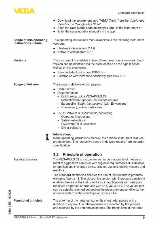
• Download the smartphone app "VEGATools" from the "Apple App Store" or the "GooglePlayStore"
• Scan the Data Matrix code on the type label of the instrument or• Enter the serial number manually in the app
This operating instructions manual applies to the following instrument versions:
• Hardware version from 2.1.0• Software version from 4.5.1
Theinstrumentisavailableintwodifferentelectronicsversions.Eachversioncanbeidentifiedviatheproductcodeonthetypelabelaswell as on the electronics.
• Standard electronics type PS60HK.-• Electronics with increased sensitivity type PS60HS.-
The scope of delivery encompasses:
• Radar sensor• Documentation
– Quick setup guide VEGAPULS 63 – Instructions for optional instrument features – Ex-specific"Safety instructions" (with Ex versions) – ifnecessary,furthercertificates
• DVD "Software & Documents", containing – Operating instructions – Safety instructions – PACTware/DTM Collection – Driver software
Information:In the operating instructions manual, the optional instrument features are described. The respective scope of delivery results from the order specification.
3.2 Principle of operationThe VEGAPULS 63 is a radar sensor for continuous level measure-ment of aggressive liquids or with hygienic requirements. It is suitable for applications in storage tanks, process vessels, dosing vessels and reactors.The standard electronics enables the use of instruments in products withanεr-Wert≥1.8.Theelectronicsversionwithincreasedsensitivityenables the use of the instrument also in applications with very poor reflectivepropertiesorproductswithanεrvalue≥1.5.Thevaluesthatcan be actually reached depend on the measurement conditions, the antenna system or the standpipe or bypass tube.
The antenna of the radar sensor emits short radar pulses with a durationofapprox.1ns.Thesepulsesarereflectedbytheproductand received by the antenna as echoes. The transit time of the radar
Scope of this operating instructions manual
Versions
Scope of delivery
Application area
Functional principle

10
3 Product description
VEGAPULS 63 • 4 … 20 mA/HART - two-wire
36511-EN-150625
pulses from emission to reception is proportional to the distance and hence to the level. The determined level is converted into an appropri-ate output signal and outputted as measured value.
3.3 Packaging, transport and storageYour instrument was protected by packaging during transport. Its capacity to handle normal loads during transport is assured by a test based on ISO 4180.The packaging of standard instruments consists of environment-friendly, recyclable cardboard. For special versions, PE foam or PE foil is also used. Dispose of the packaging material via specialised recycling companies.
Transport must be carried out in due consideration of the notes on the transport packaging. Nonobservance of these instructions can cause damage to the device.
The delivery must be checked for completeness and possible transit damage immediately at receipt. Ascertained transit damage or con-cealed defects must be appropriately dealt with.
Up to the time of installation, the packages must be left closed and stored according to the orientation and storage markings on the outside.Unless otherwise indicated, the packages must be stored only under the following conditions:
• Not in the open• Dry and dust free• Not exposed to corrosive media• Protected against solar radiation• Avoiding mechanical shock and vibration
• Storage and transport temperature see chapter "Supplement - Technicaldata-Ambientconditions"
• Relative humidity 20 … 85 %
3.4 Accessories and replacement partsThe display and adjustment module PLICSCOM is used for measured value indication, adjustment and diagnosis. It can be inserted into the sensor or the external display and adjustment unit and removed at any time.Youcanfindfurtherinformationintheoperatinginstructions"Display and adjustment module PLICSCOM" (Document-ID 27835).
The interface adapter VEGACONNECT enables the connection of communication-capable instruments to the USB interface of a PC. For parameter adjustment of these instruments, the adjustment software PACTware with VEGA-DTM is required.Youcanfindfurtherinformationintheoperatinginstructions"Interface adapterVEGACONNECT" (Document-ID 32628).
Packaging
Transport
Transport inspection
Storage
Storage and transport temperature
PLICSCOM
VEGACONNECT

11
3 Product description
VEGAPULS 63 • 4 … 20 mA/HART - two-wire
3651
1-EN
-150
625
The VEGADIS 81 is an external display and adjustment unit for VEGA plics® sensors.For sensors with double chamber housing the interface adapter "DISADAPT" is also required for VEGADIS 81.Youcanfindfurtherinformationintheoperatinginstructions"VE-GADIS81" (Document-ID 43814).
The adapter "DISADAPT" is an accessory part for sensors with dou-ble chamber housings. It enables the connection of VEGADIS 81 to the sensor housing via an M12 x 1 plug.Youcanfindfurtherinformationinthesupplementaryinstructions"AdapterDISADAPT" (Document-ID 45250).
VEGADIS 82 is suitable for measured value indication and adjustment of sensors with HART protocol. It is looped into the 4 … 20 mA/HART signal cable.Youcanfindfurtherinformationintheoperatinginstructions"VE-GADIS82" (Document-ID 45300).
PLICSMOBILE T61 is an external GSM/GPRS radio unit for transmis-sion of measured values and for remote parameter adjustment of plics® sensors. Adjustment is carried out via PACTware/DTM and the integrated USB connection.Youcanfindfurtherinformationinthesupplementaryinstructions"PLICSMOBILET61" (Document-ID 37700).
PLICSMOBILE is an internal GSM/GPRS radio unit for transmission of measured values and for remote parameter adjustment of plics® sensors. Adjustment is carried out via PACTware/DTM and the inte-grated USB connection.Youcanfindfurtherinformationinthesupplementaryinstructions"PLICSMOBILEGSM/GPRSradiomodule" (Document-ID 36849).
The protective cover protects the sensor housing against soiling and intense heat from solar radiation.Youwillfindadditionalinformationinthesupplementaryinstructionsmanual "Protective cover" (Document-ID 34296).
Screwedflangesareavailableindifferentversionsaccordingtothefollowing standards: DIN 2501, EN 1092-1, BS 10, ASME B 16.5, JIS B 2210-1984, GOST 12821-80.Youcanfindadditionalinformationinthesupplementaryinstructionsmanual "FlangesaccordingtoDIN-EN-ASME-JIS" (Document-ID 31088).
Electronics module "VEGAPULS series 60" is a replacement part for radarsensorsofVEGAPULSseries60.Adifferentversionisavailablefor each type of signal output.Youcanfindfurtherinformationintheoperatinginstructions"Elec-tronicsmoduleVEGAPULSseries60" (Document-ID 36801).
VEGADIS 81
DISADAPT
VEGADIS 82
PLICSMOBILE T61
PLICSMOBILE
Protective cap
Flanges
Electronics module

12
3 Product description
VEGAPULS 63 • 4 … 20 mA/HART - two-wire
36511-EN-150625
The supplementary electronics is a replacement part for sensors with double chamber housing and 4 … 20 mA/HART - two-wire.Youcanfindfurtherinformationintheoperatinginstructions"Supple-mentaryelectronicsfor4…20mA/HART-two-wire" (Document-ID 42764).
Supplementary electron-ics for double chamber housing
13
4 Mounting
VEGAPULS 63 • 4 … 20 mA/HART - two-wire
3651
1-EN
-150
625
4 Mounting
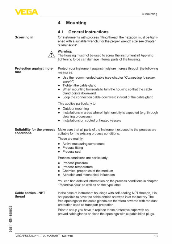
4.1 General instructionsOninstrumentswithprocessfittingthread,thehexagonmustbetight-enedwithasuitablewrench.Fortheproperwrenchsizeseechapter"Dimensions".
Warning:The housing must not be used to screw the instrument in! Applying tightening force can damage internal parts of the housing.
Protect your instrument against moisture ingress through the following measures:
• Use the recommended cable (see chapter "Connecting to power supply")
• Tighten the cable gland• Whenmountinghorizontally,turnthehousingsothatthecable
gland points downward• Loop the connection cable downward in front of the cable gland
This applies particularly to:
• Outdoor mounting• Installations in areas where high humidity is expected (e.g. through
cleaning processes)• Installations on cooled or heated vessels
Make sure that all parts of the instrument exposed to the process are suitable for the existing process conditions.These are mainly:
• Active measuring component• Processfitting• Process seal
Process conditions are particularly:
• Process pressure• Process temperature• Chemical properties of the medium• AbrasionandmechanicalinfluencesYoucanfinddetailedinformationontheprocessconditionsinchapter"Technicaldata" as well as on the type label.
In the case of instrument housings with self-sealing NPT threads, it is not possible to have the cable entries screwed in at the factory. The free openings for the cable glands are therefore covered with red dust protection caps as transport protection.Prior to setup you have to replace these protective caps with ap-proved cable glands or close the openings with suitable blind plugs.
Screwing in
Protection against mois-ture
Suitability for the process conditions
Cable entries - NPT thread

14
4 Mounting
VEGAPULS 63 • 4 … 20 mA/HART - two-wire
36511-EN-150625
4.2 Mounting instructionsThe PTFE washer of the antenna encapsulation serves also as process seal.To compensate the normal prestress loss due to the seal materials, youhavetousealsodiscspringsinadditiontotheflangescrewsforfasteningPTFEplatedflanges.Werecommendflexibleretainingwashers(e.g.SchnorrVSorS)ordetent edged rings (e.g. Gross VS KD).Suitable retaining elements are also available from us.The retaining elements are attached with the versions for process temperatures -196 … +200 °C (-321 … +392 °F).
Size Article no. Type
M16, 7/8" 32880 Detent edged ringGross VS KD
M20, 3/4" 32881 Detent edged ringGross VS KD
M24, 5/8" 32882 Retaining washerSchnorr VS or S
Tosealeffectively,thefollowingrequirementsmustbefulfilled:1. Makesurethenumberofflangescrewscorrespondstothenum-
berofflangeholes2. Use disc springs to compensate the preload loss of the PTFE
washer
21
Fig.2:Useofdiscsprings1 Single disc spring2 Laminated disc spring
3. Tighten screws with the necessary torque (see chapter "Technical data")
Note:It is recommended, retightening the screws in regular intervals depending on process pressure and temperature. Recommended torque (see chapter "Technical data").
The emitted radar impulses of the radar sensor are electromagnetic waves. The polarisation is the direction of the electrical wave compo-nent.Byturningtheinstrumentintheconnectionflangeormountingboss,thepolarisationcanbeusedtoreducetheeffectsoffalseechoes.Thepositionofthepolarisationismarkedontheprocessfittingoftheinstrument.
Sealing to the process
Polarisation

15
4 Mounting
VEGAPULS 63 • 4 … 20 mA/HART - two-wire
3651
1-EN
-150
625
1
Fig. 3: Position of the polarisation1 Marking hole
When mounting the VEGAPULS 63, keep a distance of at least 200 mm (7.874 in) to the vessel wall. If the sensor is installed in the center of dished or round vessel tops, multiple echoes can arise. These can, however, be suppressed by an appropriate adjustment (see chapter "Setup").If you cannot maintain this distance, you should carry out a false signal storage during setup. This applies particularly if buildup on the vessel wall is expected. In such cases, we recommend repeating the false signal storage at a later date with existing buildup.
> 200 mm(7.87")
Fig. 4: Mounting of the radar sensor on round vessel tops
In vessels with conical bottom it can be advantageous to mount the sensor in the center of the vessel, as measurement is then possible down to the lowest point of the vessel bottom.
Installation position
16
4 Mounting
VEGAPULS 63 • 4 … 20 mA/HART - two-wire
36511-EN-150625
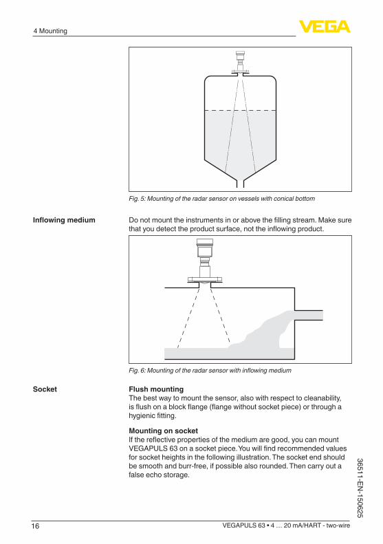
Fig. 5: Mounting of the radar sensor on vessels with conical bottom
Donotmounttheinstrumentsinorabovethefillingstream.Makesurethatyoudetecttheproductsurface,nottheinflowingproduct.
Fig.6:Mountingoftheradarsensorwithinflowingmedium
Flush mountingThe best way to mount the sensor, also with respect to cleanability, isflushonablockflange(flangewithoutsocketpiece)orthroughahygienicfitting.
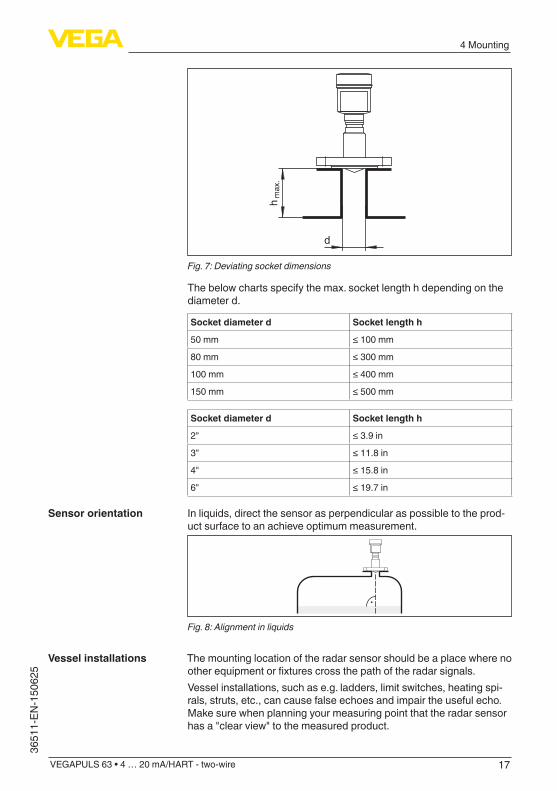
Mounting on socketIfthereflectivepropertiesofthemediumaregood,youcanmountVEGAPULS63onasocketpiece.Youwillfindrecommendedvaluesfor socket heights in the following illustration. The socket end should be smooth and burr-free, if possible also rounded. Then carry out a false echo storage.
Inflowingmedium
Socket
17
4 Mounting
VEGAPULS 63 • 4 … 20 mA/HART - two-wire
3651
1-EN
-150
625
d
hm
ax.
Fig. 7: Deviating socket dimensions
The below charts specify the max. socket length h depending on the diameter d.
Socket diameter d Socket length h
50 mm ≤100mm
80 mm ≤300mm
100 mm ≤400mm
150 mm ≤500mm
Socket diameter d Socket length h
2" ≤3.9in
3" ≤11.8in
4" ≤15.8in
6" ≤19.7in
In liquids, direct the sensor as perpendicular as possible to the prod-uct surface to an achieve optimum measurement.
Fig. 8: Alignment in liquids
The mounting location of the radar sensor should be a place where no otherequipmentorfixturescrossthepathoftheradarsignals.Vessel installations, such as e.g. ladders, limit switches, heating spi-rals, struts, etc., can cause false echoes and impair the useful echo. Make sure when planning your measuring point that the radar sensor has a "clear view" to the measured product.
Sensor orientation
Vessel installations

18
4 Mounting
VEGAPULS 63 • 4 … 20 mA/HART - two-wire
36511-EN-150625
In case of existing vessel installations, a false echo storage should be carried out during setup.If large vessel installations such as struts or supports cause false echoes, these can be attenuated through supplementary measures. Small,inclinedsheetmetalbafflesabovetheinstallationsscattertheradarsignalsandpreventdirectinterferingreflections.
Fig.9:Coverflat,large-areaprofileswithdeflectors
If there are agitators in the vessel, a false signal storage should be carried out with the agitators in motion. This ensures that the interfer-ingreflectionsfromtheagitatorsaresavedwiththebladesindifferentpositions.
Fig. 10: Agitators
Throughtheactionoffilling,stirringandotherprocessesinthevessel,compact foams that considerably damp the emitted signals may form on the product surface.If foams are causing measurement errors, the biggest possible radar antennas, the electronics with increased sensitivity or low frequency radar sensors (C band) should be used.As an alternative, sensors with guided microwave can be used. These areunaffectedbyfoamgenerationandarebestsuitedforsuchap-plications.
Agitators
Foam generation

19
4 Mounting
VEGAPULS 63 • 4 … 20 mA/HART - two-wire
3651
1-EN
-150
625
4.3 Measurement setup - PipesByusingasurgepipeinthevessel,theinfluenceofvesselinstalla-tions and turbulence can be excluded. Under these prerequisites, the measurementofproductswithlowdielectricvalues(εrvalue≤1.6)ispossible.Note the following illustrations and instructions for measurement in a surge pipe.
Information:Measurement in a surge pipe is not recommended for extremely adhesive products.
100%
1
2
3
4
5
6
8
9
10
7
15°
45°
0%
Fig.11:ConfigurationsurgepipeVEGAPULS631 Radar sensor2 Polarisation marking3 Threadorflangeontheinstrument4 Vent hole5 Holes6 WeldingconnectionthroughU-profile7 Ball valve with complete opening8 Surge pipe end9 Reflectorsheet10 Fastening of the surge pipe
Measurement in a surge pipe
Configurationsurgepipe

20
4 Mounting
VEGAPULS 63 • 4 … 20 mA/HART - two-wire
36511-EN-150625
ø 60,3 mm(2.37")
ø 88,9 mm(3.5")
d x
2
26 mm(1.02")15 mm
(0.59") 2 mm(0.08")2 mm
(0.08")
5 mm(0.20")
4 mm(0.16")
80 m
m(3
.15"
)
80 m
m(3
.15"
)
75°
4 m
m(0
.16"
)8
mm
(0.3
2")
75°
4 m
m(0
.16"
)8
mm
(0.3
2")
d x
2
ø 88,9 mm(3.5")ø 60,3 mm
(2.37")
11
Fig.12:Weldingconnectionwithsurgepipeextensionfordifferentexamplediameters1 Position of the welded joint with longitudinally welded pipes
Instructions of orientation of the polarisation:• Note marking of the polarisation on the sensor• Withthreadedversions,themarkingisonthehexagon,withflange
versionsbetweentwoflangeholes• The marking must be in one plane with the holes in the surge pipe
Instructions for the measurement:• The 100 % point must be below the upper vent hole and the
antenna edge• The 0 % point is the end of the surge pipe• During parameter adjustment, select "Application standpipe" and
enter the tube diameter to compensate for errors due to running time shift
• A false signal suppression with the installed sensor is recom-mended but not mandatory
• The measurement through a ball valve with unrestricted channel is possible
Surge pipe extension
Instructions and require-ments, surge pipe

21
4 Mounting
VEGAPULS 63 • 4 … 20 mA/HART - two-wire
3651
1-EN
-150
625
Constructive requirements:• Material metal, smooth inner surface• Preferably pultruded or straight beaded stainless steel tube• Welded joint should be straight and lie in one axis with the holes• Flanges are welded to the tube according to the orientation of the
polarisation• Whenusingaballvalves,alignthetransitionsontheinsideandfix
accurately• Gapsizewithjunctions≤0.1mm• Surge pipes must extend all the way down to the requested min.
level, as measurement is only possible within the tube• Diameterofholes≤5mm,anynumberOK,ononesideorcom-
pletely through• The antenna diameter of the sensor should correspond to the
inner diameter of the tube• Diameter should be constant over the complete length
Instructions for surge pipe extension:• The ends of the extension tubes must be bevelled and exactly
aligned• WeldedconnectionviaexternalUprofilesaccordingtoillustration
above.LengthoftheUprofilesshouldbeatleastdoublethetubediameter
• Do not weld through the pipe wall. The surge pipe must remain smooth inside. Roughness and beads on the inside caused by unintentional penetration should be removed since they cause strong false echoes and encourage buildup
• Anextensionviaweldingneckflangesorpipecollarsisnotrecom-mended.
An alternative to measurement in a surge pipe is measurement in a bypass tube outside of the vessel.
Measurement in the bypass tube

22
4 Mounting
VEGAPULS 63 • 4 … 20 mA/HART - two-wire
36511-EN-150625
0 %
100 %
12
5
4
3
6
Fig.13:Configurationbypass1 Radar sensor2 Polarisation marking3 Instrumentflange4 Distance sensor reference plane to upper tube connection5 Distance of the tube connections6 Ball valve with complete opening
Instructions of orientation of the polarisation:• Note marking of the polarisation on the sensor• Withthreadedversions,themarkingisonthehexagon,withflange
versionsbetweentwoflangeholes• The marking must be in one plane with the tube connections to the
vessel
Instructions for the measurement:• The 100 % point may not be above the upper tube connection to
the vessel• The 0 % point may not be below the lower tube connection to the
vessel• Min. distance, sensor reference plane to upper edge of upper tube
connection > 300 mm• During parameter adjustment, select "Application standpipe" and
enter the tube diameter to compensate for errors due to running time shift
• A false signal suppression with the installed sensor is recom-mended but not mandatory
• The measurement through a ball valve with unrestricted channel is possible
Configurationbypass
Instructions and require-ments, bypass

23
4 Mounting
VEGAPULS 63 • 4 … 20 mA/HART - two-wire
3651
1-EN
-150
625
Constructional requirements on the bypass pipe:• Material metal, smooth inner surface• In case of an extremely rough tube inner surface, use an inserted
tube (tube in tube) or a radar sensor with tube antenna• Flanges are welded to the tube according to the orientation of the
polarisation• Gapsizewithjunctions≤0.1mm,forexample,whenusingaball
valveorintermediateflangeswithsinglepipesections• The antenna diameter of the sensor should correspond to the
inner diameter of the tube• Diameter should be constant over the complete length

24
5 Connecting to power supply
VEGAPULS 63 • 4 … 20 mA/HART - two-wire
36511-EN-150625
5 Connecting to power supply
5.1 Preparing the connectionAlways keep in mind the following safety instructions:
Warning:Connect only in the complete absence of line voltage.
• The electrical connection must only be carried out by trained personnel authorised by the plant operator.
• If overvoltage surges are expected, overvoltage arresters should be installed.
Power supply and current signal are carried on the same two-wire cable.Theoperatingvoltagecandifferdependingontheinstrumentversion.Thedataforpowersupplyarespecifiedinchapter"Technicaldata".Provide a reliable separation between the supply circuit and the mains circuits according to DIN EN 61140 VDE 0140-1.Keepinmindthefollowingadditionalfactorsthatinfluencetheoperat-ing voltage:
• Lower output voltage of the power supply unit under nominal load (e.g. with a sensor current of 20.5 mA or 22 mA in case of fault)
• Influenceofadditionalinstrumentsinthecircuit(seeloadvaluesinchapter "Technicaldata")
The instrument is connected with standard two-wire cable without screen. If electromagnetic interference is expected which is above the test values of EN 61326-1 for industrial areas, screened cable should be used.Use cable with round cross section for instruments with housing and cablegland.Toensurethesealeffectofthecablegland(IPprotectionrating),findoutwhichcableouterdiameterthecableglandissuitablefor.Useacableglandfittingthecablediameter.We generally recommend the use of screened cable for HART multi-drop mode.
With plastic housing, the NPT cable gland or the Conduit steel tube must be screwed without grease into the threaded insert.Max. torque for all housings see chapter "Technicaldata".
If screened cable is required, we recommend connecting the cable screen on both ends to ground potential. In the sensor, the screen must be connected directly to the internal ground terminal. The ground terminal on the outside of the housing must be connected to the ground potential (low impedance).In Ex systems, the grounding is carried out according to the installa-tion regulations.
Safety instructions
Voltage supply
Connection cable
Cable gland ½ NPT
Cable screening and grounding

25
5 Connecting to power supply
VEGAPULS 63 • 4 … 20 mA/HART - two-wire
3651
1-EN
-150
625
In electroplating and CCP systems (cathodic corrosion protection) it mustbetakenintoaccountthatsignificantpotentialdifferencesexist.This can lead to unacceptably high currents in the cable screen if it is grounded at both ends.
Information:Themetallicpartsoftheinstrument(processfitting,transmitter,concentric tube, etc.) are connected with the inner and outer ground terminal on the housing. This connection exists either directly via con-necting metallic parts or, in case of instruments with external electron-ics, via the screen of the special connection cable.Youcanfindspecificationsonthepotentialconnectionsinsidetheinstrument in chapter "Technicaldata".
5.2 ConnectingThe voltage supply and signal output are connected via the spring-loaded terminals in the housing.Connection to the display and adjustment module or to the interface adapter is carried out via contact pins in the housing.
Information:The terminal block is pluggable and can be removed from the electronics. To do this, lift the terminal block with a small screwdriver and pull it out. When reinserting the terminal block, you should hear it snap in.
Proceed as follows:1. Unscrew the housing lid2. If a display and adjustment module is installed, remove it by turn-
ing it slightly to the left.3. Loosen compression nut of the cable entry gland4. Remove approx. 10 cm (4 in) of the cable mantle, strip approx.
1 cm (0.4 in) of insulation from the ends of the individual wires5. Insert the cable into the sensor through the cable entry
Connection technology
Connection procedure

26
5 Connecting to power supply
VEGAPULS 63 • 4 … 20 mA/HART - two-wire
36511-EN-150625
Fig. 14: Connection steps 5 and 6 - Single chamber housing
Fig. 15: Connection steps 5 and 6 - Double chamber housing
6. Insert the wire ends into the terminals according to the wiring plan
Information:Solidcoresaswellasflexiblecoreswithwireendsleevesareinsert-eddirectlyintotheterminalopenings.Incaseofflexiblecoreswithoutend sleeves, press the terminal from above with a small screwdriver, the terminal opening is then free. When the screwdriver is released, the terminal closes again.Youcanfindfurtherinformationonthemax.wirecross-sectionunder"Technicaldata/Electromechanicaldata"
7. Check the hold of the wires in the terminals by lightly pulling on them
8. Connect the screen to the internal ground terminal, connect the outer ground terminal to potential equalisation
27
5 Connecting to power supply
VEGAPULS 63 • 4 … 20 mA/HART - two-wire
3651
1-EN
-150
625
9. Tighten the compression nut of the cable entry gland. The seal ring must completely encircle the cable
10. Reinsert the display and adjustment module, if one was installed11. Screw the housing lid back onTheelectricalconnectionisfinished.
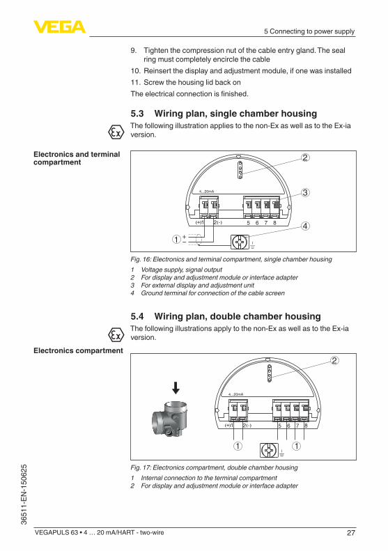
5.3 Wiring plan, single chamber housingThe following illustration applies to the non-Ex as well as to the Ex-ia version.
51 2+( ) (-) 6 7 8
4...20mA
2
3
41
Fig.16:Electronicsandterminalcompartment,singlechamberhousing1 Voltage supply, signal output2 For display and adjustment module or interface adapter3 For external display and adjustment unit4 Groundterminalforconnectionofthecablescreen
5.4 Wiring plan, double chamber housingThe following illustrations apply to the non-Ex as well as to the Ex-ia version.
5 6 7 8
4...20mA
1 2+( ) (-)
2
1 1
Fig.17:Electronicscompartment,doublechamberhousing1 Internal connection to the terminal compartment2 For display and adjustment module or interface adapter
Electronics and terminal compartment
Electronics compartment
28
5 Connecting to power supply
VEGAPULS 63 • 4 … 20 mA/HART - two-wire
36511-EN-150625
51 2+( ) (-) 6 7 8
4...20mA Display
2
3
41
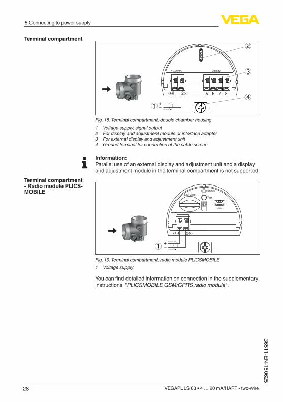
Fig.18:Terminalcompartment,doublechamberhousing1 Voltage supply, signal output2 For display and adjustment module or interface adapter3 For external display and adjustment unit4 Groundterminalforconnectionofthecablescreen
Information:Parallel use of an external display and adjustment unit and a display and adjustment module in the terminal compartment is not supported.
1
USB
Status
TestSIM-Card
1 2+( ) (-)
Fig.19:Terminalcompartment,radiomodulePLICSMOBILE1 Voltage supply
Youcanfinddetailedinformationonconnectioninthesupplementaryinstructions "PLICSMOBILEGSM/GPRSradiomodule".
Terminal compartment
Terminal compartment - Radio module PLICS-MOBILE

29
5 Connecting to power supply
VEGAPULS 63 • 4 … 20 mA/HART - two-wire
3651
1-EN
-150
625
5.5 Wiring plan, double chamber housing Ex d ia
31
2
5 6 7 81 2( ) (-)+
4...20mA
Fig.20:Electronicscompartment,doublechamberhousingExdia1 Internal connection to the terminal compartment2 For display and adjustment module or interface adapter3 Internal connection to the plug connector for external display and adjust-
ment unit (optional)
Note:HART multidrop mode is not possible when using an Ex-d-ia instru-ment.
4...20mA
1 2+( ) (-) 2
1
Fig.21:Terminalcompartment,doublechamberhousingExdia1 Voltage supply, signal output2 Groundterminalforconnectionofthecablescreen
34
1 2
Fig.22:Topviewoftheplugconnector1 Pin 12 Pin 23 Pin 34 Pin 4
Electronics compartment
Terminal compartment
Plug M12 x 1 for external display and adjustment unit

30
5 Connecting to power supply
VEGAPULS 63 • 4 … 20 mA/HART - two-wire
36511-EN-150625
Contact pin Colour connection ca-ble in the sensor
Terminal, electronics module
Pin 1 Brown 5
Pin 2 White 6
Pin 3 Blue 7
Pin 4 Black 8
5.6 Double chamber housing with DIS-ADAPT
3
1
2
Fig.23:ViewtotheelectronicscompartmentwithDISADAPTforconnectionofthe external display and adjustment unit1 DISADAPT2 Internal plug connection3 Plug connector M12 x 1
34
1 2
Fig. 24: View to the plug connector M12 x 11 Pin 12 Pin 23 Pin 34 Pin 4
Contact pin Colour connection ca-ble in the sensor
Terminal, electronics module
Pin 1 Brown 5
Pin 2 White 6
Pin 3 Blue 7
Pin 4 Black 8
Electronics compartment
Assignment of the plug connector
31
5 Connecting to power supply
VEGAPULS 63 • 4 … 20 mA/HART - two-wire
3651
1-EN
-150
625
5.7 Wiring plan - version IP 66/IP 68 (1 bar)
1
2
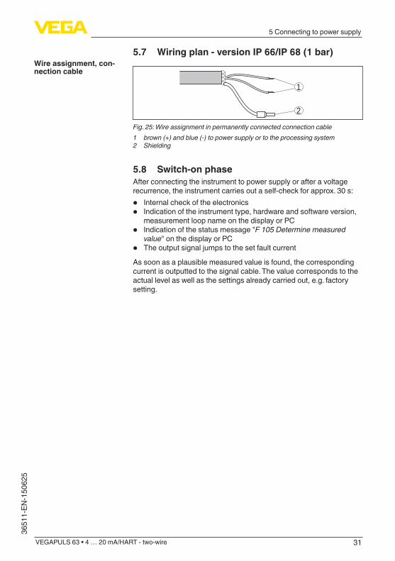
Fig. 25: Wire assignment in permanently connected connection cable1 brown (+) and blue (-) to power supply or to the processing system2 Shielding
5.8 Switch-on phaseAfter connecting the instrument to power supply or after a voltage recurrence, the instrument carries out a self-check for approx. 30 s:
• Internal check of the electronics• Indication of the instrument type, hardware and software version,
measurement loop name on the display or PC• Indication of the status message "F 105 Determine measured
value" on the display or PC• The output signal jumps to the set fault current
As soon as a plausible measured value is found, the corresponding current is outputted to the signal cable. The value corresponds to the actual level as well as the settings already carried out, e.g. factory setting.
Wire assignment, con-nection cable
32
6 Set up with the display and adjustment module
VEGAPULS 63 • 4 … 20 mA/HART - two-wire
36511-EN-150625
6 Set up with the display and adjustment module
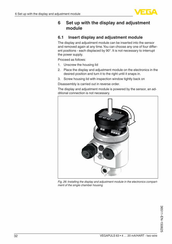
6.1 Insert display and adjustment moduleThe display and adjustment module can be inserted into the sensor andremovedagainatanytime.Youcanchooseanyoneoffourdiffer-ent positions - each displaced by 90°. It is not necessary to interrupt the power supply.Proceed as follows:1. Unscrew the housing lid2. Place the display and adjustment module on the electronics in the
desired position and turn it to the right until it snaps in.3. Screw housing lid with inspection window tightly back onDisassembly is carried out in reverse order.The display and adjustment module is powered by the sensor, an ad-ditional connection is not necessary.
Fig. 26: Installing the display and adjustment module in the electronics compart-ment of the single chamber housing

33
6 Set up with the display and adjustment module
VEGAPULS 63 • 4 … 20 mA/HART - two-wire
3651
1-EN
-150
625
1 2
Fig. 27: Installing the display and adjustment module in the double chamber housing1 In the electronics compartment2 In the terminal compartment
Note:Ifyouintendtoretrofittheinstrumentwithadisplayandadjustmentmodule for continuous measured value indication, a higher lid with an inspection glass is required.
6.2 Adjustment system
1
2
Fig. 28: Display and adjustment elements1 LC display2 Adjustment keys
• [OK] key:Key functions

34
6 Set up with the display and adjustment module
VEGAPULS 63 • 4 … 20 mA/HART - two-wire
36511-EN-150625
– Move to the menu overview – Confirmselectedmenu – Edit parameter – Save value
• [->] key: – Presentation, change measured value – Select list entry – Select menu items in the quick setup – Select editing position
• [+] key: – Change value of the parameter
• [ESC] key: – Interrupt input – Jump to next higher menu
You adjust the instrument via the four keys of the display and adjust-ment module. The individual menu items are shown on the LC display. Youcanfindthefunctionsoftheindividualkeysinthepreviousillustration.
By pushing the [+] and [->] keys once, the edited value or the cursor changes by one position. By pushing the keys longer than 1 s the change will be continuously.By pushing the [OK] and [ESC] keys simultaneously for more than 5 s, a return to the basic menu is caused. The menu language is then switched over to "English".Approx. 60 minutes after the last pressing of a key, an automatic reset tomeasuredvalueindicationistriggered.Anyvaluesnotconfirmedwith [OK] will not be saved.
6.3 Measured value indication - Selection national language
With the [->]keyyoumovebetweenthreedifferentindicationmodes.Inthefirstview,theselectedmeasuredvalueisdisplayedinlargedigits.In the second view, the selected measured value and a correspond-ing bar graph presentation are displayed.In the third view, the selected measured value as well as a second se-lectable value, e.g. the temperature of the electronics, are displayed.
During the initial setup of an instrument shipped Ex works,use the "OK" key to get to the menu "National language".
Adjustment system
Time functions
Measured value indica-tion
35
6 Set up with the display and adjustment module
VEGAPULS 63 • 4 … 20 mA/HART - two-wire
3651
1-EN
-150
625
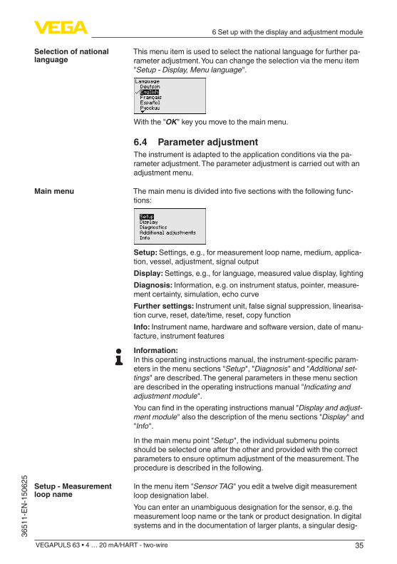
This menu item is used to select the national language for further pa-rameter adjustment. You can change the selection via the menu item "Setup - Display, Menu language".
With the "OK" key you move to the main menu.
6.4 Parameter adjustmentThe instrument is adapted to the application conditions via the pa-rameter adjustment. The parameter adjustment is carried out with an adjustment menu.
Themainmenuisdividedintofivesectionswiththefollowingfunc-tions:
Setup: Settings, e.g., for measurement loop name, medium, applica-tion, vessel, adjustment, signal outputDisplay: Settings, e.g., for language, measured value display, lightingDiagnosis: Information, e.g. on instrument status, pointer, measure-ment certainty, simulation, echo curveFurther settings: Instrument unit, false signal suppression, linearisa-tion curve, reset, date/time, reset, copy functionInfo: Instrument name, hardware and software version, date of manu-facture, instrument features
Information:Inthisoperatinginstructionsmanual,theinstrument-specificparam-eters in the menu sections "Setup", "Diagnosis" and "Additional set-tings" are described. The general parameters in these menu section are described in the operating instructions manual "Indicating and adjustment module".Youcanfindintheoperatinginstructionsmanual"Display and adjust-ment module" also the description of the menu sections "Display" and "Info".
In the main menu point "Setup", the individual submenu points should be selected one after the other and provided with the correct parameters to ensure optimum adjustment of the measurement. The procedure is described in the following.
In the menu item "SensorTAG" you edit a twelve digit measurement loop designation label.You can enter an unambiguous designation for the sensor, e.g. the measurement loop name or the tank or product designation. In digital systems and in the documentation of larger plants, a singular desig-
Selection of national language
Main menu
Setup - Measurement loop name

36
6 Set up with the display and adjustment module
VEGAPULS 63 • 4 … 20 mA/HART - two-wire
36511-EN-150625
nationmustbeenteredforexactidentificationofindividualmeasuringpoints.The available digits comprise:
• Letters from A … Z• Numbers from 0 … 9• Special characters +, -, /, -
Eachmediumhasdifferentreflectionproperties.Withliquids,furtherinterferingfactorsarefluctuationproductsurfaceandfoamgenera-tion. With bulk solids, these are dust generation, material cone and additional echoes from the vessel wall.Toadaptthesensortothesedifferentmeasuringconditions,theselection "Liquid" or "Bulk solid" should be made in this menu item.
Through this selection, the sensor is adapted perfectly to the product andmeasurementreliability,particularlyinproductswithpoorreflec-tive properties, is considerably increased.Enter the requested parameters via the appropriate keys, save your settings with [OK] and jump to the next menu item with the [ESC] and the [->] key.
In addition to the medium, also the application, i.e. the measuring site, caninfluencethemeasurement.With this menu item, the sensor can be adapted to the applications. The adjustment possibilities depend on the selection "Liquid" or "Bulk solid" under "Medium".
The following options are available when "Liquid" is selected:
Setup - Medium
Setup - Application

37
6 Set up with the display and adjustment module
VEGAPULS 63 • 4 … 20 mA/HART - two-wire
3651
1-EN
-150
625
The selection "Standpipe" opens a new window in which the inner diameter of the applied standpipe is entered.
The following features form the basis of the applications:
Storage tank:• Setup: large-volumed, upright cylindrical, spherical• Productspeed:slowfillingandemptying• Process/measurement conditions:
– Condensation – Smooth product surface – High requirements to the measurement accuracy
• Properties, sensor: – Slight sensitivity against sporadic false echoes – Stable and reliable measured values through averaging – High accuracy – Short reaction time of the sensor not required
Storage tank with product circulation:• Setup: large-volumed, upright cylindrical, spherical• Productspeed:slowfillingandemptying• Installations: small laterally mounted or large top mounted stirrer• Process/measurement conditions:
– Relatively smooth product surface – High requirements to the measurement accuracy – Condensation – Slight foam generation – Overfillingpossible
• Properties, sensor: – Slight sensitivity against sporadic false echoes – Stable and reliable measured values through averaging – High accuracy because not adjusted for max. speed – False signal suppression recommended
Storage tank on ships (Cargo Tank):• Productspeed:slowfillingandemptying• Vessel:
– Installations in the bottom section (bracers, heating spirals) – High sockets 200 … 500 mm, also with large diameters
• Process/measurement conditions: – Condensation, buildup by movement – Max. requirement on measurement accuracy from 95 %
• Properties, sensor: – Slight sensitivity against sporadic false echoes – Stable and reliable measured values through averaging

38
6 Set up with the display and adjustment module
VEGAPULS 63 • 4 … 20 mA/HART - two-wire
36511-EN-150625
– High accuracy – False signal suppression required
Stirrer vessel (reactor):• Setup:allvesselsizespossible• Product speed:
– Fasttoslowfillingpossible – Vesselisveryoftenfilledandemptied
• Vessel: – Socket available – Large agitator blades of metal – Vortex breakers, heating spirals
• Process/measurement conditions: – Condensation, buildup by movement – Strong spout generation – Very agitated surface, foam generation
• Properties, sensor: – Higher measurement speed through lower averaging – Sporadic false echoes are suppressed
Dosing vessel:• Setup:allvesselsizespossible• Product speed:
– Fastfillingandemptying – Vesselisveryoftenfilledandemptied
• Vessel: narrow installation situation• Process/measurement conditions:
– Condensation, buildup on the antenna – Foam generation
• Properties, sensor: – Measurementspeedoptimizedbyvirtuallynoaveraging – Sporadic false echoes are suppressed – False signal suppression recommended
Standpipe:• Productspeed:veryfastfillingandemptying• Vessel:
– Vent hole – Joinslikeflanges,weldjoints – Shifting of the running time in the tube
• Process/measurement conditions: – Condensation – Buildup
• Properties, sensor: – Measurementspeedoptimizedthroughlittleaveraging – Entering the tube inside diameter takes the running time shift
into consideration – Echo detection sensitivity reduced
Bypass:• Product speed:
– Fastuptoslowfillingwithshortuptolongbypasstubepossible – Often the level is hold via a control facility

39
6 Set up with the display and adjustment module
VEGAPULS 63 • 4 … 20 mA/HART - two-wire
3651
1-EN
-150
625
• Vessel: – Lateral outlets and inlets – Joinslikeflanges,weldjoints – Shifting of the running time in the tube
• Process/measurement conditions: – Condensation – Buildup – Separation of oil and water possible – Overfillingintotheantennapossible
• Properties, sensor: – Measurementspeedoptimizedthroughlittleaveraging – Entering the tube inside diameter takes the running time shift
into consideration – Echo detection sensitivity reduced – False signal suppression recommended
Plastic tank:• Vessel:
– Measurementfixmountedorintegrated – Measurement depending on the application through the vessel
top – With empty vessel, the measurement can be carried out
through the bottom• Process/measurement conditions:
– Condensation on the plastic ceiling – In outside facilities water and snow on the vessel top possible
• Properties, sensor: – False signals outside the vessel are not taken into consideration – False signal suppression recommended
Transportable plastic tank:• Vessel:
– Materialandthicknessdifferent – Measurement through the vessel top
• Process/measurement conditions: – Measured value jump with vessel change
• Properties, sensor: – Quickadaptationtochangingreflectionconditionsthrough
vessel change – False signal suppression required
Open water (gauge measurement):• Gauge rate of change: slow gauge change• Process/measurement conditions:
– Distance sensor to water surface to big – Extreme damping of output signal due to wave generation – Ice and condensation on the antenna possible – Spiders and insect nestle in the antennas – Floating material and animals sporadically on the water surface
• Properties, sensor: – Stable and reliable measured values through high averaging – Insensitive in the close range

40
6 Set up with the display and adjustment module
VEGAPULS 63 • 4 … 20 mA/HART - two-wire
36511-EN-150625
Openflume(flowmeasurement):• Gauge rate of change: slow gauge change• Process/measurement conditions:
– Ice and condensation on the antenna possible – Spiders and insect nestle in the antennas – Smooth water surface – Exact measurement result required – Distance to the water surface normally relatively high
• Properties, sensor: – Stable and reliable measured values through high averaging – Insensitive in the close range
Rain water overfall (weir):• Gauge rate of change: slow gauge change• Process/measurement conditions:
– Ice and condensation on the antenna possible – Spiders and insect nestle in the antennas – Turbulent water surface – Sensorfloodingpossible
• Properties, sensor: – Stable and reliable measured values through high averaging – Insensitive in the close range
Demonstration:• Adjustment for all applications which are not typically level meas-
urement – Instrument demonstration – Object recognition/monitoring (additional settings required)
• Properties, sensor: – Sensor accepts all measured value changes within the measur-
ing range immediately – High sensitivity against interferences, because virtually no
averaging
Caution:Ifliquidswithdifferentdielectricconstantsseparateinthevessel,forexample through condensation, the radar sensor can detect under certain circumstances only the medium with the higher dielectric constant. Keep in mind that layer interfaces can cause faulty meas-urements.If you want to measure the total height of both liquids reliably, please contact our service department or use an instrument specially de-signed for interface measurement.
The following options are available when "Bulk solid" is selected:
The following features form the basis of the applications:

41
6 Set up with the display and adjustment module
VEGAPULS 63 • 4 … 20 mA/HART - two-wire
3651
1-EN
-150
625
Silo (slender and high):• Vessel of metal: weld joints• Process/measurement conditions:
– Filling aperture too close to the sensor – System noise in completely empty silo increased
• Properties, sensor: – Stable measured values through higher averaging – False signal suppression during setup recommended, required
for automatic false signal suppression – Automaticfalsesignalsuppressionwithpartlyfilledvessel
Bunker (large-volume):• Vessel of concrete or metal:
– Structured vessel walls – Installations present
• Process/measurement conditions: – Large distance to the medium – Large angles of repose
• Properties, sensor: – Mean averaging – High measured value jumps are accepted
Bunkerwithfastfilling:• Vessel of concrete or metal, also multiple chamber silo:
– Structured vessel walls – Installations present
• Process/measurement conditions: – Measured value jumps, e.g. through truck loading – Large distance to the medium – Large angles of repose
• Properties, sensor: – Lower averaging – Very high measured value jumps are accepted
Heap:• Sensor mounting on movable conveyor belts• Detectionoftheheapprofile• Heightdetectionduringfilling• Process/measurement conditions:
– Measuredvaluejumps,e.g.bytheprofileoftheheaportrav-erses
– Large angles of repose – Measurementnearthefillingstream
• Properties, sensor: – Mean averaging – High measured value jumps are accepted
Crusher:• Vessel: installations, wear and protective facilities available• Process/measurement conditions:
– Measured value jumps, e.g. through truck loading – Fast reaction time – Large distance to the medium

42
6 Set up with the display and adjustment module
VEGAPULS 63 • 4 … 20 mA/HART - two-wire
36511-EN-150625
• Properties, sensor: – Little averaging – Max. reaction speed, very high measured value jumps are
accepted
Demonstration:• Adjustment for all applications which are not typically level meas-
urement – Instrument demonstration – Object recognition/monitoring (additional settings required)
• Properties, sensor: – Sensor accepts all measured value changes within the measur-
ing range immediately – High sensitivity against interferences, because virtually no
averaging
Through this selection, the sensor is adapted optimally to the applica-tion or the location and measurement reliability under the various basic conditions is increased considerably.Enter the requested parameters via the appropriate keys, save your settings with [OK] and jump to the next menu item with the [ESC] and the [->] key.
Alsothevesselformcaninfluencethemeasurementapartfromthemedium and the application. To adapt the sensor to these measure-mentconditions,thismenuitemoffersyoudifferentoptionsforvesselbottom and ceiling in case of certain applications.
Enter the requested parameters via the appropriate keys, save your settings with [OK] and jump to the next menu item with the [ESC] and the [->] key.
With this selection, the operating range of the sensor is adapted to thevesselheightandthereliabilitywithdifferentframeconditionsisincreased considerably.The min. adjustment must be carried out independently of this.
Enter the requested parameters via the appropriate keys, save your settings with [OK] and jump to the next menu item with the [ESC] and the [->] key.
Since the radar sensor is a distance measuring instrument, the distance from the sensor to the product surface is measured. For indication of the real level, an allocation of the measured distance to the percentage height must be carried out.
Setup - Vessel form
Setup - Vessel height, measuring range
Setup - Adjustment
43
6 Set up with the display and adjustment module
VEGAPULS 63 • 4 … 20 mA/HART - two-wire
3651
1-EN
-150
625
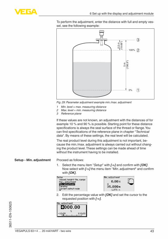
To perform the adjustment, enter the distance with full and empty ves-sel, see the following example:
100%
0%
0,5
m(1
9.68
")5
m(1
96.9
")
2
1
3
Fig.29:Parameteradjustmentexamplemin./max.adjustment1 Min. level = max. measuring distance2 Max. level = min. measuring distance3 Reference plane
If these values are not known, an adjustment with the distances of for example 10 % and 90 % is possible. Starting point for these distance specificationsisalwaysthesealsurfaceofthethreadorflange.Youcanfindspecificationsofthereferenceplaneinchapter"Technicaldata". By means of these settings, the real level will be calculated.The real product level during this adjustment is not important, be-cause the min./max. adjustment is always carried out without chang-ing the product level. These settings can be made ahead of time without the instrument having to be installed.
Proceed as follows:1. Select the menu item "Setup" with [->]andconfirmwith[OK].
Now select with [->] the menu item "Min. adjustment"andconfirmwith [OK].
2. Edit the percentage value with [OK] and set the cursor to the requested position with [->].
Setup - Min. adjustment

44
6 Set up with the display and adjustment module
VEGAPULS 63 • 4 … 20 mA/HART - two-wire
36511-EN-150625
3. Set the requested percentage value with [+] and save with [OK]. The cursor jumps now to the distance value.
4. Enter the suitable distance value in m for the empty vessel (e.g. distance from the sensor to the vessel bottom) corresponding to the percentage value.
5. Save settings with [OK] and move with [ESC] and [->] to the max. adjustment.
Proceed as follows:1. Select with [->]themenuitemMax.adjustmentandconfirmwith
[OK].
2. Prepare the percentage value for editing with [OK] and set the cursor to the requested position with [->].
3. Set the requested percentage value with [+] and save with [OK]. The cursor jumps now to the distance value.
4. Enter the appropriate distance value in m (corresponding to the percentage value) for the full vessel. Keep in mind that the max. level must lie below the min. distance to the antenna edge.
5. Save settings with [OK]
Todampprocess-dependentmeasuredvaluefluctuations,setanintegration time of 0 … 999 s in this menu item.
Depending on the sensor type, the factory setting is 0 s or 1 s.
Setup - Max. adjustment
Setup - Damping

45
6 Set up with the display and adjustment module
VEGAPULS 63 • 4 … 20 mA/HART - two-wire
3651
1-EN
-150
625
In the menu item "Current output mode" you determine the output characteristics and reaction of the current output in case of failure.
The default setting is output characteristics 4 … 20 mA, failure mode < 3.6 mA.
In the menu item "CurrentoutputMin./Max.", you determine the reac-tion of the current output during operation.
The default setting is min. current 3.8 mA and max. current 20.5 mA.
In this menu item, the PIN is activated/deactivated permanently. Enteringa4-digitPINprotectsthesensordataagainstunauthorizedaccessandunintentionalmodifications.IfthePINisactivatedperma-nently, it can be deactivated temporarily (i.e. for approx. 60 min.) in any menu item.
Only the following functions are permitted with activated PIN:
• Select menu items and show data• Read data from the sensor into the display and adjustment mod-
ule.
Caution:With active PIN, adjustment via PACTware/DTM as well as other systems is also blocked.
In delivery status, the PIN is "0000".
This menu item enables the setting of the requested national lan-guage.
Setup - Current output mode
Setup - Current output Min./Max.
Lock setup - adjustment
Display - Language

46
6 Set up with the display and adjustment module
VEGAPULS 63 • 4 … 20 mA/HART - two-wire
36511-EN-150625
In the delivery status, the sensor is set to the ordered national lan-guage.
Inthismenuitemyoucandefinetheindicationofthemeasuredvalueon the display.
The default setting for the indication value is e.g. distance with radar sensors.
The optionally integrated background lighting can be adjusted via the adjustment menu. The function depends on the level of the supply voltage, see operating instructions of the respective sensor.
In delivery status, the lighting is switched on.
In this menu item, the device status is displayed.
The respective min. and max. measured value is saved in the sensor. The values are displayed in the menu item "Peak values".
Display - Displayed value
Display - Backlight
Diagnostics - Device status
Diagnosis - Peak value

47
6 Set up with the display and adjustment module
VEGAPULS 63 • 4 … 20 mA/HART - two-wire
3651
1-EN
-150
625
The respective min. and max. measured value of the electronics temperature is saved in the sensor. These values as well as the actual temperature value are displayed in the menu item "Peak values".
When non-contact level sensors are used, the measurement can be influencedbytherespectiveprocessconditions.Inthismenuitem,the measurement reliability of the level echo is displayed as dB value. The measurement reliability equals signal strength minus noise. The higher the value, the more reliable the measurement. With a function-ing measurement, the values are > 10 dB.
In this menu item you can simulate measured values via the current output. This allows the signal path to be tested, e.g. through down-stream indicating instruments or the input card of the control system.
How to start the simulation:1. Push [OK]2. Select the requested simulation variable with [->]andconfirm
with [OK].3. With [OK]youstartthesimulation,firstofalltheactualmeasured
value is displayed in %4. Start the editing mode with [OK]5. Set the requested numerical value with [+] and [->].6. Push [OK]
Note:During simulation, the simulated value is outputted as 4 … 20 mA cur-rent value and digital HART signal.
Diagnosis - Electronics temperature
Diagnosis - Measurement reliability
Diagnosis - Simulation
48
6 Set up with the display and adjustment module
VEGAPULS 63 • 4 … 20 mA/HART - two-wire
36511-EN-150625
How to interrupt the simulation:
→ Push [ESC]
Information:The simulation is automatically terminated 10 minutes after the last pressing of a key.
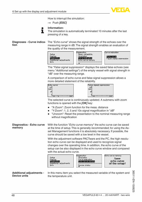
The "Echocurve" shows the signal strength of the echoes over the measuring range in dB. The signal strength enables an evaluation of the quality of the measurement.
The "False signal suppression" displays the saved false echoes (see menu "Additional settings") of the empty vessel with signal strength in "dB" over the measuring range.A comparison of echo curve and false signal suppression allows a more detailed statement of the reliability.
Theselectedcurveiscontinuouslyupdated.Asubmenuwithzoomfunctions is opened with the [OK] key:
• "X-Zoom":Zoomfunctionforthemeas.distance• "Y-Zoom":1,2,5and10xsignalmagnificationin"dB"• "Unzoom":Resetthepresentationtothenominalmeasuringrange
withoutmagnification
With the function "Echocurvememory" the echo curve can be saved at the time of setup. This is generally recommended; for using the As-set Management functions it is absolutely necessary. If possible, the curve should be saved with a low level in the vessel.With the adjustment software PACTware and the PC, the high resolu-tionechocurvecanbedisplayedandusedtorecognizesignalchanges over the operating time. In addition, the echo curve of the setup can be also displayed in the echo curve window and compared with the actual echo curve.
In this menu item you select the measured variable of the system and the temperature unit.
Diagnoses - Curve indica-tion
Diagnostics - Echo curve memory
Additional adjustments - Device units

49
6 Set up with the display and adjustment module
VEGAPULS 63 • 4 … 20 mA/HART - two-wire
3651
1-EN
-150
625
Thefollowingcircumstancescauseinterferingreflectionsandcaninfluencethemeasurement:
• High sockets• Vessel installations such as struts• Agitators• Buildup or welded joints on vessel walls
Note:A false signal suppression detects, marks and saves these false signals so that they are no longer taken into account in the level measurement.
This should be done with a low level so that all potential interfering reflectionscanbedetected.Proceed as follows:1. Select with [->] the menu item "False signal suppression" and
confirmwith[OK].
2. Confirmagainwith[OK].
3. Confirmagainwith[OK].
4. Confirmagainwith[OK] and enter the actual distance from the sensor to the product surface.
5. All interfering signals in this section are detected by the sensor andstoredafterconfirmingwith[OK].
Note:Check the distance to the product surface, because if an incorrect (too large) value is entered, the existing level will be saved as a false signal. The level would then no longer be detectable in this area.
Additional adjustments - False signal suppression

50
6 Set up with the display and adjustment module
VEGAPULS 63 • 4 … 20 mA/HART - two-wire
36511-EN-150625
If a false signal suppression has already been saved in the sensor, the following menu window appears when selecting "False signal suppression":
Delete: An already created false signal suppression will be com-pletely deleted. This is useful if the saved false signal suppression no longer matches the metrological conditions in the vessel.Extend: is used to extend an already created false signal suppres-sion. This is useful if a false signal suppression was carried out with a too high level and not all false signals could be detected. When selecting "Extend", the distance to the product surface of the created false signal suppression is displayed. This value can now be changed and the false signal suppression can be extended to this range.
Alinearizationisnecessaryforallvesselsinwhichthevesselvolumedoesnotincreaselinearlywiththelevel-e.g.ahorizontalcylindri-cal or spherical tank - and the indication or output of the volume is required.Correspondinglinearizationcurvesarepreprogrammedfor these vessels. They represent the correlation between the level percentage and vessel volume.By activating the appropriate curve, the volume percentage of the vessel is displayed correctly. If the volume should not be displayed in percent but e.g. in l or kg, a scaling can be also set in the menu item "Display".
Enter the requested parameters via the appropriate keys, save your settings and jump to the next menu item with the [ESC] and [->] key.
Caution:Note the following if instruments with appropriate approval are used aspartofanoverfillprotectionsystemaccordingtoWHG:If a linearisation curve is selected, the measuring signal is no longer necessarilylineartothefillingheight.Thismustbeconsideredbytheuser especially when adjusting the switching point on the limit signal transmitter.
Enteringa4-digitPINprotectsthesensordataagainstunauthorizedaccessandunintentionalmodification.Inthismenuitem,thePINisdisplayed or edited and changed. However, this menu item is only available if adjustment is enabled in the menu "Setup".
Additional adjustments - Linearization curve
Additional settings - PIN

51
6 Set up with the display and adjustment module
VEGAPULS 63 • 4 … 20 mA/HART - two-wire
3651
1-EN
-150
625
In delivery status, the PIN is "0000".
In this menu item, the internal clock of the sensor is adjusted.
With a reset, certain parameter adjustments carried out by the user are reset.
The following reset functions are available:Delivery status: Restoring the parameter settings at the time of ship-mentfromthefactoryincl.theorder-specificsettings.Acreatedfalsesignalsuppression,user-programmablelinearizationcurveaswellasthe measured value memory will be deleted.Basic settings: Resetting of the parameter settings, incl. special parameters, to the default values of the respective instrument. Any stored false signal suppression or user programmable linearisation curve, as well as the measured value memory, is deleted.Setup: Resetting of the parameter settings to the default values of the respective instrument in the menu item Setup. User-generated false signal suppression, user-programmed linearisation curve, measured value memory as well as event memory remain untouched. The linearisation is set to linear.False signal suppression: Deleting a previously created false signal suppression. The false signal suppression created in the factory remains active.Peak values, measured value: Resetting of the measured min. and max. distances to the actual measured value.The following table shows the default values of the instrument. De-pending on the instrument version, not all menu items are available or somemaybedifferentlyassigned:
Additional adjustments - Date/Time
Additional adjustments - Reset

52
6 Set up with the display and adjustment module
VEGAPULS 63 • 4 … 20 mA/HART - two-wire
36511-EN-150625
Menu Menu item Default value
Setup Measurement loop name
Sensor
Medium Liquid/WaterBulk solids/Crushed stones, gravel
Application Storage tankSilo
Vessel form Vessel bottom, dished boiler endVessel top, dished boiler end
Vessel height/Measuring range
Recommended measuring range, see "Technicaldata" in the supplement
Min. adjustment Recommended measuring range, see "Technicaldata" in the supplement
Max. adjustment 0,000 m(d)
Damping 0.0 s
Current output mode
4 … 20 mA, < 3.6 mA
Current output Min./Max.
Min. current 3.8 mA, max. current 20.5 mA
Lock adjustment Released
Display Language Like order
Displayed value Distance
Display unit m
Scalingsize Volumel
Scaling 0.00 lin %, 0 l100.00 lin %, 100 l
Backlight Switched on
Additional adjust-ments
Distance unit m
Temperature unit °C
Probe length Length of the standpipe Ex factory
Linearisation curve
Linear
HART mode StandardAddress 0
ThesensorofferstheHARTmodesstandardandMultidrop.Inthismenu item you determine the HART modes and enter the address with Multidrop.
Additional adjustments - HART mode

53
6 Set up with the display and adjustment module
VEGAPULS 63 • 4 … 20 mA/HART - two-wire
3651
1-EN
-150
625
Themodestandardwiththefixedaddress0meansoutputofthemeasured value as 4 … 20 mA signal.In Multidrop mode, up to 63 sensors can be operated on one two-wire cable. An address between 1 and 63 must be assigned to each sen-sor.1)
The default setting is standard with address 0.
The instrument settings are copied with this function. The following functions are available:
• Store data from the sensor into the indicating/adjustment module.• Store data from the display and adjustment module in the sensor
The following data or settings for adjustment of the display and ad-justment module are saved:
• All data of the menu "Setup" and "Display"• In the menu "Additional settings" the items "Distance unit, tem-
perature unit and linearization"• Thevaluesoftheuserprogrammablelinearizationcurve
The copied data are permanently saved in an EEPROM memory in the display and adjustment module and remain there even in case of power failure. From there, they can be written into one or more sen-sors or kept as backup for a possible sensor exchange.The type and the volume of the copied data depend on the respective sensor.
Note:Before the data are stored in the sensor, a check is carried out to determineifthedatafitthesensor.Ifthedatadonotfit,afaultsignalis triggered or the function is blocked. When data are being written into the sensor, the display shows which instrument type the data originate from and which TAG-no. this sensor had.
In this menu, you read out the instrument name and the instrument serial number:
In this menu item, the hardware and software version of the sensor is displayed.
Additional adjustments - Copy instrument settings
Info - Instrument name
Info - Instrument version
1) The4…20mAsignaloftheHARTsensorisswitchedoff.Thesensorconsumes a constant current of 4 mA. The measuring signal is transmitted exclusively as digital HART signal.
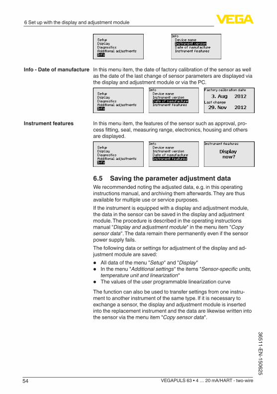
54
6 Set up with the display and adjustment module
VEGAPULS 63 • 4 … 20 mA/HART - two-wire
36511-EN-150625
In this menu item, the date of factory calibration of the sensor as well as the date of the last change of sensor parameters are displayed via the display and adjustment module or via the PC.
In this menu item, the features of the sensor such as approval, pro-cessfitting,seal,measuringrange,electronics,housingandothersare displayed.
6.5 Saving the parameter adjustment dataWe recommended noting the adjusted data, e.g. in this operating instructions manual, and archiving them afterwards. They are thus available for multiple use or service purposes.If the instrument is equipped with a display and adjustment module, the data in the sensor can be saved in the display and adjustment module. The procedure is described in the operating instructions manual "Display and adjustment module" in the menu item "Copy sensor data". The data remain there permanently even if the sensor power supply fails.The following data or settings for adjustment of the display and ad-justment module are saved:
• All data of the menu "Setup" and "Display"• In the menu "Additional settings" the items "Sensor-specificunits,
temperature unit and linearization"• ThevaluesoftheuserprogrammablelinearizationcurveThe function can also be used to transfer settings from one instru-ment to another instrument of the same type. If it is necessary to exchange a sensor, the display and adjustment module is inserted into the replacement instrument and the data are likewise written into the sensor via the menu item "Copy sensor data".
Info - Date of manufacture
Instrument features

55
7 Setup with PACTware
VEGAPULS 63 • 4 … 20 mA/HART - two-wire
3651
1-EN
-150
625
7 Setup with PACTware
7.1 Connect the PC
3
1
2
Fig. 30: Connection of the PC directly to the sensor via the interface adapter1 USBcabletothePC2 InterfaceadapterVEGACONNECT3 Sensor
1
5
2 4
3 OPEN
TWIST
USB
LOCK
Fig.31:ConnectingthePCviaHARTtothesignalcable1 Sensor2 HARTresistance250Ω(optionaldependingonprocessing)3 Connection cable with 2 mm pins and terminals4 Processingsystem/PLC/Voltagesupply5 Interfaceadapter,forexampleVEGACONNECT4
Note:With power supply units with integrated HART resistance (internal resistanceapprox.250Ω),anadditionalexternalresistanceisnotnecessary. This applies, e.g. to the VEGA instruments VEGATRENN 149A, VEGAMET 381, VEGAMET 391. Common Ex separators are alsousuallyequippedwithasufficientcurrentlimitationresistance.In
Via the interface adapter directly on the sensor
Via the interface adapter and HART
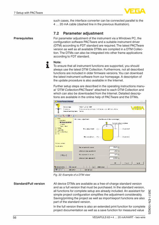
56
7 Setup with PACTware
VEGAPULS 63 • 4 … 20 mA/HART - two-wire
36511-EN-150625
such cases, the interface converter can be connected parallel to the 4 … 20 mA cable (dashed line in the previous illustration).
7.2 Parameter adjustmentFor parameter adjustment of the instrument via a Windows PC, the configurationsoftwarePACTwareandasuitableinstrumentdriver(DTM) according to FDT standard are required. The latest PACTware version as well as all available DTMs are compiled in a DTM Collec-tion. The DTMs can also be integrated into other frame applications according to FDT standard.
Note:To ensure that all instrument functions are supported, you should always use the latest DTM Collection. Furthermore, not all described functionsareincludedinolderfirmwareversions.Youcandownloadthe latest instrument software from our homepage. A description of the update procedure is also available in the Internet.
Further setup steps are described in the operating instructions manu-al "DTMCollection/PACTware" attached to each DTM Collection and which can also be downloaded from the Internet. Detailed descrip-tions are available in the online help of PACTware and the DTMs.
Fig.32:ExampleofaDTMview
All device DTMs are available as a free-of-charge standard version and as a full version that must be purchased. In the standard version, all functions for complete setup are already included. An assistant for simpleprojectconfigurationsimplifiestheadjustmentconsiderably.Saving/printing the project as well as import/export functions are also part of the standard version.In the full version there is also an extended print function for complete project documentation as well as a save function for measured value
Prerequisites
Standard/Full version

57
7 Setup with PACTware
VEGAPULS 63 • 4 … 20 mA/HART - two-wire
3651
1-EN
-150
625
and echo curves. In addition, there is a tank calculation program as well as a multiviewer for display and analysis of the saved measured value and echo curves.The standard version is available as a download under www.vega.com/downloads and "Software". The full version is avail-able on CD from the agency serving you.
7.3 Saving the parameter adjustment dataWe recommend documenting or saving the parameter adjustment data via PACTware. That way the data are available for multiple use or service purposes.
58
8 Set up with other systems
VEGAPULS 63 • 4 … 20 mA/HART - two-wire
36511-EN-150625
8 Set up with other systems
8.1 DD adjustment programsDevice descriptions as Enhanced Device Description (EDD) are available for DD adjustment programs such as, for example, AMS™ and PDM.Thefilescanbedownloadedatwww.vega.com/downloads under "Software".
8.2 Field Communicator 375, 475Device descriptions for the instrument are available as EDD for pa-rameter adjustment with the Field Communicator 375 or 475.For the integration of the EDD in the Field Communicator 375 or 475, the software "Easy Upgrade Utility" is required which is available from the manufacturer. This software is updated via the Internet and new EDDs are automatically taken over into the device catalogue of this software after they are released by the manufacturer. They can then be transferred to a Field Communicator.

59
9 Diagnosis, asset management and service
VEGAPULS 63 • 4 … 20 mA/HART - two-wire
3651
1-EN
-150
625
9 Diagnosis, asset management and service
9.1 MaintenanceIf the device is used correctly, no maintenance is required in normal operation.
9.2 Measured value and event memoryThe instrument has several memories which are available for diagno-sis purposes. The data remain even with voltage interruption.
Up to 100,000 measured values can be stored in the sensor in a ring memory. Each entry contains date/time as well as the respective measured value. Storable values are for example:
• Distance• Filling height• Percentage value• Lin. percent• Scaled• Current value• Meas. reliability• Electronics temperature
When the instrument is shipped, the measured value memory is active and stores distance, measurement certainty and electronics temperature every 3 minutes.The requested values and recording conditions are set via a PC with PACTware/DTM or the control system with EDD. Data are thus read out and also reset.
Up to 500 events are automatically stored with a time stamp in the sensor (non-deletable). Each entry contains date/time, event type, event description and value. Event types are for example:
• Modificationofaparameter• Switch-onandswitch-offtimes• Status messages (according to NE 107)• Error messages (according to NE 107)
The data are read out via a PC with PACTware/DTM or the control system with EDD.
The echo curves are stored with date and time and the corresponding echo data. The memory is divided into two sections:Echo curve of the setup: This is used as reference echo curve for the measurement conditions during setup. Changes in the measure-ment conditions during operation or buildup on the sensor can thus berecognized.Theechocurveofthesetupisstoredvia:
• PC with PACTware/DTM • Control system with EDD • Display and adjustment module
Measured value memory
Event memory
Echo curve memory
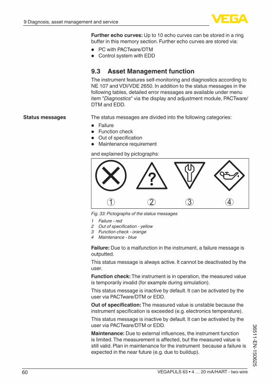
60
9 Diagnosis, asset management and service
VEGAPULS 63 • 4 … 20 mA/HART - two-wire
36511-EN-150625
Further echo curves: Up to 10 echo curves can be stored in a ring bufferinthismemorysection.Furtherechocurvesarestoredvia:
• PC with PACTware/DTM • Control system with EDD
9.3 Asset Management functionThe instrument features self-monitoring and diagnostics according to NE 107 and VDI/VDE 2650. In addition to the status messages in the following tables, detailed error messages are available under menu item "Diagnostics" via the display and adjustment module, PACTware/DTM and EDD.
The status messages are divided into the following categories:
• Failure• Function check• Outofspecification• Maintenance requirement
and explained by pictographs:
41 2 3Fig. 33: Pictographs of the status messages1 Failure - red2 Outofspecification-yellow3 Function check - orange4 Maintenance - blue
Failure: Due to a malfunction in the instrument, a failure message is outputted.This status message is always active. It cannot be deactivated by the user.Function check: The instrument is in operation, the measured value is temporarily invalid (for example during simulation).This status message is inactive by default. It can be activated by the user via PACTware/DTM or EDD.Outofspecification: The measured value is unstable because the instrumentspecificationisexceeded(e.g.electronicstemperature).This status message is inactive by default. It can be activated by the user via PACTware/DTM or EDD.Maintenance:Duetoexternalinfluences,theinstrumentfunctionislimited.Themeasurementisaffected,butthemeasuredvalueisstill valid. Plan in maintenance for the instrument because a failure is expected in the near future (e.g. due to buildup).
Status messages

61
9 Diagnosis, asset management and service
VEGAPULS 63 • 4 … 20 mA/HART - two-wire
3651
1-EN
-150
625
This status message is inactive by default. It can be activated by the user via PACTware/DTM or EDD.
The following table shows the error codes in the status message "Failure"andgivesinformationonthereasonandrectification.Keepin mind that some information is only valid with four-wire instruments.
CodeText message
Cause Rectification DevSpec State in CMD 48
F013no measured value available
– Sensor does not detect an echo during operation
– Antenna system dirty or defective
– Check or correct installation and/or parameter adjust-ment
– Clean or exchange process compo-nent or antenna
Bit 0 of Byte 0…5
F017Adjustment span too small
– Adjustment not withinspecification
– Change adjust-ment accord-ing to the limit values(differencebetween min. and max.≥10mm)
Bit 1 of Byte 0…5
F025Error in the lin-earizationtable
– Index markers are not continuously rising, for example illogical value pairs
– Checklineariza-tion table
– Delete table/Cre-ate new
Bit 2 of Byte 0…5
F036No operable software
– Failed or inter-rupted software update
– Repeat software update
– Check electronics version
– Exchanging the electronics
– Send instrument for repair
Bit 3 of Byte 0…5
F040Error in the electronics
– Hardware defect – Exchanging the electronics
– Send instrument for repair
Bit 4 of Byte 0…5
F080General soft-ware error
– General software error
– Disconnect operat-ingvoltagebriefly
Bit 5 of Byte 0…5
F105Determine measured value
– The instrument is still in the start phase, the measured value could not yet be determined
– Wait for the end of the switch-on phase
– Duration depend-ing on the version and parameter adjustment up to approximately 3 min.
Bit 6 of Byte 0…5
Failure
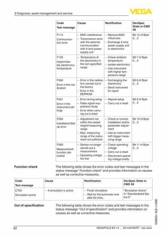
62
9 Diagnosis, asset management and service
VEGAPULS 63 • 4 … 20 mA/HART - two-wire
36511-EN-150625
CodeText message
Cause Rectification DevSpec State in CMD 48
F113Communica-tion error
– EMC interference – Transmission error
with the external communication with 4-wire power supply unit
– Remove EMC influences
– Exchange 4-wire power supply unit or electronics
Bit 12 of Byte 0…5
F125Impermissi-ble electronics temperature
– Temperature of the electronics in thenon-specifiedrange
– Check ambient temperature
– Isolate electronics – Use instrument
with higher tem-perature range
Bit 7 of Byte 0…5
F260Error in the cal-ibration
– Error in the calibra-tion carried out in the factory
– Error in the EEPROM
– Exchanging the electronics
– Send instrument for repair
Bit 8 of Byte 0…5
F261Error in the instrument set-tings
– Error during setup – False signal sup-
pression faulty – Error when carry-
ing out a reset
– Repeat setup – Carry out a reset
Bit 9 of Byte 0…5
F264Installation/Set-up error
– Adjustment not within the vessel height/measuring range
– Max. measuring range of the instru-mentnotsufficient
– Check or correct installation and/or parameter adjust-ment
– Use an instrument with bigger meas-uring range
Bit 10 of Byte 0…5
F265Measurement function dis-turbed
– Sensor no longer carries out a measurement
– Operating voltage too low
– Check operating voltage
– Carry out a reset – Disconnect operat-ingvoltagebriefly
Bit 11 of Byte 0…5
The following table shows the error codes and text messages in the status message "Function check" and provides information on causes as well as corrective measures.
CodeText message
Cause Rectification DevSpec State in CMD 48
C700Simulation active
– A simulation is active – Finish simulation – Wait for the automatic end
after 60 mins.
"Simulation Active" in"StandardizedSta-tus 0"
The following table shows the error codes and text messages in the status message "Outofspecification" and provides information on causes as well as corrective measures.
Function check
Outofspecification

63
9 Diagnosis, asset management and service
VEGAPULS 63 • 4 … 20 mA/HART - two-wire
3651
1-EN
-150
625
CodeText message
Cause Rectification DevSpec State in CMD 48
S600Impermissible elec-tronics temperature
– Temperature of the electron-icsinthenon-specifiedrange
– Check ambient temperature – Isolate electronics – Use instrument with higher
temperature range
Bit 5 of Byte 14…24
S601Overfilling
– Dangerofvesseloverfilling – Make sure that there is no furtherfilling
– Check level in the vessel
Bit 6 of Byte 14…24
The following table shows the error codes and text messages in the status message "Maintenance" and provides information on causes as well as corrective measures.
CodeText message
Cause Rectification DevSpec State in CMD 48
M500Error with the reset de-livery status
– With the reset to delivery status, the data could not be restored
– Repeat reset – LoadXMLfilewithsensor
data into the sensor
Bit 0 of Byte 14…24
M501Error in the non-active linearizationtable
– Hardware error EEPROM – Exchanging the electronics – Send instrument for repair
Bit 1 of Byte 14…24
M502Error in the diagnosis memory
– Hardware error EEPROM – Exchanging the electronics – Send instrument for repair
Bit 2 of Byte 14…24
M503Meas. reliability too low
– The echo/noise ratio is too small for reliable measure-ment
– Check installation and process conditions
– Clean the antenna – Change polarisation direc-
tion – Use instrument with higher
sensitivity
Bit 3 of Byte 14…24
M504Error on an device in-terface
– Hardware defect – Check connections – Exchanging the electronics – Send instrument for repair
Bit 4 of Byte 14…24
M505No echo available
– Level echo can no longer be detected
– Clean the antenna – Use a more suitable
antenna/sensor – Remove possible false
echoes – Optimizesensorposition
and orientation
Bit 7 of Byte 14…24
9.4 Rectify faultsThe operator of the system is responsible for taking suitable meas-ures to rectify faults.
Thefirstmeasuresare:
Maintenance
Reaction when malfunc-tion occurs
Procedure for fault recti-fication

64
9 Diagnosis, asset management and service
VEGAPULS 63 • 4 … 20 mA/HART - two-wire
36511-EN-150625
• Evaluation of fault messages, for example via the display and adjustment module
• Checking the output signal• Treatment of measurement errors
Further comprehensive diagnostics options are available with a PC with PACTware and the suitable DTM. In many cases, the reasons can bedeterminedinthiswayandfaultsrectified.
Connect a multimeter in the suitable measuring range according to the wiring plan. The following table describes possible errors in the current signal and helps to eliminate them:
Error Cause Rectification
4 … 20 mA signal not stable
– Fluctuations of the measured variable
– Set damping appropriate to the instrument via the display and adjustment module or PACTware/DTM
4 … 20 mA signal missing
– Electrical con-nection faulty
– Check connection according to chapter "Connection steps" and if necessary, correct according to chapter "Wiring plan"
– Voltage supply missing
– Check cables for breaks; repair if necessary
– Operating volt-age too low or load resistance too high
– Check, adapt if necessary
Current sig-nal greater than 22 mA or less than 3.6 mA
– Electronics module in the sensor defec-tive
– Exchange the instrument or send it in for repair
The below tables show typical examples of application-related meas-urementerrorswithliquids.Themeasurementerrorsaredifferentiatedaccording to the following:
• Constant level• Filling• Emptying
The images in column "Errorpattern" show the real level as a broken line and the level displayed by the sensor as a continuous line.
12
Leve
l
time0
1 Real level2 Level displayed by the sensor
Check the 4 … 20 mA signal
Treatment of measure-ment errors with liquids

65
9 Diagnosis, asset management and service
VEGAPULS 63 • 4 … 20 mA/HART - two-wire
3651
1-EN
-150
625
Notes:• Wherever the sensor displays a constant value, the reason could
also be the fault setting of the current output to "Hold value"• If the level indication is too low, the reason could be a line resist-
ance that is too high
Measurement error with constant level
Fault description Error pattern Cause Rectification
1. Measured value shows a too low or too high level
Leve
l
time0
– Min./max. adjustment not correct
– Adapt min./max. adjustment
– Incorrectlinearizationcurve – Adaptlinearizationcurve
– Installation in a bypass tube or standpipe, hence running time error (small measurement error close to 100 %/large error close to 0 %)
– Check parameter "Application" with respect to vessel form, adapt if necessary (bypass, standpipe, diameter)
2. Measured value jumps towards 0 % Le
vel
time0
– Multiple echo (vessel top, product surface) with amplitude higher than the level echo
– Check parameter "Application", especially vessel top, type of medium, dished bottom, high dielectric constant, and adapt if necessary
3. Measured value jumps towards 100 % Le
vel
time0
– Due to the process, the ampli-tude of the level echo sinks
– A false signal suppression was not carried out
– Carry out a false signal sup-pression
– Amplitude or position of a false signal has changed (e.g. con-densation, buildup); false signal suppression no longer matches actual conditions
– Determine the reason for the changed false signals, carry out false signal suppression, e.g. with condensation
Measurementerrorduringfilling
Fault description Error pattern Cause Rectification
4. Measured value re-mains unchanged duringfilling
Leve
l
time0
– False signals in the close range too big or level echo too small
– Strong foam or spout genera-tion
– Max. adjustment not correct
– Eliminate false signals in the close range
– Check measurement situation: Antenna must protrude out of the socket, installations
– Remove contamination on the antenna
– In case of interferences due to installations in the close range: Change polarisation direction
– Create a new false signal sup-pression
– Adapt max. adjustment
5. Measured value re-mains in the bottom sectionduringfilling
Leve
l
time0
– Echo from the tank bottom larger than the level echo, for example, with products with εr < 2.5 oil-based, solvents
– Check parameters Medium, Vessel height and Floor form, adapt if necessary

66
9 Diagnosis, asset management and service
VEGAPULS 63 • 4 … 20 mA/HART - two-wire
36511-EN-150625
Fault description Error pattern Cause Rectification
6. Measured value re-mains momentarily unchangedduringfill-ing and then jumps to the correct level
Leve
l
time0
– Turbulence on the product surface,quickfilling
– Check parameters, change if necessary, e.g. in dosing ves-sel, reactor
7. Measured value jumps towards 0 % duringfilling
Leve
l
time0
– Amplitude of a multiple echo (vessel top - product surface) is larger than the level echo
– Check parameter "Application", especially vessel top, type of medium, dished bottom, high dielectric constant, and adapt if necessary
– The level echo cannot be distin-guished from the false signal at a false signal position (jumps to multiple echo)
– In case of interferences due to installations in the close range: Change polarisation direction
– Chose a more suitable installa-tion position
8. Measured value jumps towards 100 % duringfilling
Leve
l
time0
– Due to strong turbulence and foamgenerationduringfilling,the amplitude of the level echo sinks. Measured value jumps to the false signal
– Carry out a false signal sup-pression
9. Measured value jumps sporadically to 100%duringfilling
Leve
l
time0
– Varying condensation or con-tamination on the antenna
– Carry out a false signal sup-pression or increase false signal suppression with con-densation/contamination in the close range by editing
10. Measured value jumpsto≥100%or0 m distance
Leve
l
time0
– Level echo is no longer detected in the close range due to foam generation or false signals in the close range. The sensorgoesintooverfillprotec-tion mode. The max. level (0 m distance) as well as the status message"Overfillprotection"are outputted.
– Check measuring site: Antenna must protrude out of the socket
– Remove contamination on the antenna
– Use a sensor with a more suit-able antenna
Measurement error during emptying
Fault description Error pattern Cause Rectification
11. Measured value re-mains unchanged in the close range during emptying
Leve
l
time0
– False signal larger than the level echo
– Level echo too small
– Eliminate false signal in the close range. Check: Antenna must protrude from the socket
– Remove contamination on the antenna
– In case of interferences due to installations in the close range: Change polarisation direction
– After eliminating the false sig-nals, the false signal suppres-sion must be deleted. Carry out a new false signal suppression

67
9 Diagnosis, asset management and service
VEGAPULS 63 • 4 … 20 mA/HART - two-wire
3651
1-EN
-150
625
Fault description Error pattern Cause Rectification
12. Measured value jumps towards 0 % during emptying
Leve
l
time0
– Echo from the tank bottom larger than the level echo, for example, with products with εr < 2.5 oil-based, solvents
– Check parameters Type of medium, Vessel height and Floor form, adapt if necessary
13. Measured value jumps sporadically to-wards 100 % during emptying
Leve
l
time0
– Varying condensation or con-tamination on the antenna
– Carry out false signal suppres-sion or increase false signal suppression in the close range by editing
– With bulk solids, use radar sen-sor with purging air connection
Depending on the reason for the fault and the measures taken, the steps described in chapter "Setup" must be carried out again or must be checked for plausibility and completeness.
Should these measures not be successful, please call in urgent cases the VEGA service hotline under the phone no. +49 1805 858550.The hotline is also available outside normal working hours, seven days a week around the clock.Sinceweofferthisserviceworldwide,thesupportisprovidedinEnglish. The service itself is free of charge, the only costs involved are the normal call charges.
9.5 Exchanging the electronics moduleIf the electronics module is defective, it can be replaced by the user.In Ex applications, only instruments and electronics modules with ap-propriate Ex approval may be used.
If there is no electronics module available on site, the electronics module can be ordered through the agency serving you. The electron-icsmodulesareadaptedtotherespectivesensoranddifferinsignaloutput or voltage supply.The new electronics module must be loaded with the default settings of the sensor. These are the options:
• In the factory• Or on site by the user
In both cases, the serial number of the sensor is needed. The serial numbers are stated on the type label of the instrument, on the inside of the housing as well as on the delivery note.Whenloadingonsite,firstofalltheorderdatamustbedownloadedfrom the Internet (see operating instructions manual "Electronicsmodule").
Caution:Alluser-specificsettingsmustbeenteredagain.Hence,youhavetocarry out a new setup after the electronics exchange.If you have stored the data of the parameter adjustment during the firstsetupofthesensor,youcantransferthesetothereplacementelectronics module. A new setup is no more necessary.
Reaction after fault recti-fication
24 hour service hotline
68
9 Diagnosis, asset management and service
VEGAPULS 63 • 4 … 20 mA/HART - two-wire
36511-EN-150625
9.6 Software updateThe following components are required to update the instrument software:
• Instrument• Voltage supply• Interface adapter VEGACONNECT• PC with PACTware• CurrentinstrumentsoftwareasfileYoucanfindthecurrentinstrumentsoftwareaswellasdetailedinformation on the procedure under "www.vega.com/downloads" and "Software".
Caution:Instruments with approvals can be bound to certain software versions. Thereforemakesurethattheapprovalisstilleffectiveafterasoftwareupdate is carried out.Youcanfinddetailedinformationatwww.vega.com/downloads and "Approvals".
9.7 How to proceed if a repair is necessaryYoucanfindarepairformaswellasdetailedinformationonhowtoproceed at www.vega.com/downloads and "Formsandcertificates".By doing this you help us carry out the repair quickly and without hav-ing to call back for needed information.If a repair is necessary, please proceed as follows:
• Printandfilloutoneformperinstrument• Clean the instrument and pack it damage-proof• Attach the completed form and, if need be, also a safety data
sheet outside on the packaging• Please contact the agency serving you to get the address for
thereturnshipment.Youcanfindtheagencyonourhomepagewww.vega.com.
69
10 Dismount
VEGAPULS 63 • 4 … 20 mA/HART - two-wire
3651
1-EN
-150
625
10 Dismount
10.1 Dismounting stepsWarning:Before dismounting, be aware of dangerous process conditions such as e.g. pressure in the vessel or pipeline, high temperatures, cor-rosive or toxic products etc.
Take note of chapters "Mounting" and "Connecting to power supply" and carry out the listed steps in reverse order.
10.2 DisposalThe instrument consists of materials which can be recycled by spe-cialised recycling companies. We use recyclable materials and have designed the parts to be easily separable.Correctdisposalavoidsnegativeeffectsonhumansandtheenviron-ment and ensures recycling of useful raw materials.Materials: see chapter "Technicaldata"If you have no way to dispose of the old instrument properly, please contact us concerning return and disposal.
WEEE directive 2002/96/EGThis instrument is not subject to the WEEE directive 2002/96/EG and the respective national laws. Pass the instrument directly on to a spe-cialised recycling company and do not use the municipal collecting points. These may be used only for privately used products according to the WEEE directive.

70
11 Supplement
VEGAPULS 63 • 4 … 20 mA/HART - two-wire
36511-EN-150625
11 Supplement
11.1 Technical dataGeneral data316L corresponds to 1.4404 or 1.4435Materials, wetted parts
Ʋ Hygienic antenna encapsulation PTFE, TFM-PTFE, PFA Ʋ Surface roughness of the antenna encapsulation
Ra < 0.8 µm
Ʋ Additional process seal with certain hygienicfittings
FKM, EPDM
Materials, non-wetted parts Ʋ Processfitting 316L Ʋ Plastic housing plastic PBT (Polyester) Ʋ Aluminium die-casting housing Aluminium die-casting AlSi10Mg, powder-coated - basis:
Polyester Ʋ Stainless steel housing 316L Ʋ Seal between housing and housing cover
NBR (stainless steel housing, precision casting), silicone (aluminium/plastic housing; stainless steel housing, electropolished)
Ʋ Inspection window in housing cover (optional)
Polycarbonate
Ʋ Ground terminal 316LOhmic contact BetweengroundterminalandprocessfittingProcessfittings
Ʋ Flanges DIN from DN 25, ASME from 1" Ʋ Hygienicfittings Clamp, slotted nut according to DIN 11851, hygienic
fittingwithsaddleflangeaccordingtoDIN11864-2-A,SMS
Weight (depending on housing, process fittingandantenna)
approx. 3.5 … 15.5 kg (4.409 … 33.95 lbs)
Requiredtorqueoftheflangescrews 60 Nm (44.25 lbf ft)Recommended torque for tightening the flangescrews
60 … 100 Nm (44.25 … 73.76 lbf ft)
Max. torque for NPT cable glands and Conduit tubes Ʋ Plastic housing 10 Nm (7.376 lbf ft) Ʋ Aluminium/Stainless steel housing 50 Nm (36.88 lbf ft)
Input variableMeasured variable The measured quantity is the distance between process
fittingofthesensorandproductsurface.Thereferenceplaneisthesealsurfaceontheprocessfittingorthelowersideoftheflange.

71
11 Supplement
VEGAPULS 63 • 4 … 20 mA/HART - two-wire
3651
1-EN
-150
625
3
4 2
1
Fig. 48: Data of the input variable1 Reference plane2 Measured variable, max. measuring range3 Length antenna cone4 Usefulmeasuringrange
Standard electronicsMax. measuring range 35 m (114.8 ft)Recommended measuring range
Ʋ Flange DN 50, 2" up to 15 m (49.21 ft) Ʋ Flange DN 80, 3" up to 35 m (114.8 ft)
Electronics with increased sensitivityMax. measuring range 75 m (246.1 ft)Flange DN 50, 2" up to 15 m (49.21 ft)Flange DN 80, 3" up to 35 m (114.8 ft)
Output variableOutput signal 4 … 20 mA/HARTRange of the output signal 3.8 … 20.5 mA/HART (default setting)Signal resolution 0.3 µAResolution, digital < 1 mm (0.039 in)Failure signal current output (adjustable) mA-value unchanged 20.5 mA, 22 mA, < 3.6 mAMax. output current 22 mAStarting current ≤3.6mA;≤10mAfor5msafterswitchingon
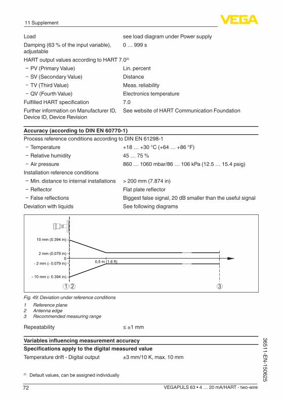
72
11 Supplement
VEGAPULS 63 • 4 … 20 mA/HART - two-wire
36511-EN-150625
Load see load diagram under Power supplyDamping (63 % of the input variable), adjustable
0 … 999 s
HART output values according to HART 7.02)
Ʋ PV (Primary Value) Lin. percent Ʋ SV (Secondary Value) Distance Ʋ TV (Third Value) Meas. reliability Ʋ QV (Fourth Value) Electronics temperature
FulfilledHARTspecification 7.0Further information on Manufacturer ID, Device ID, Device Revision
See website of HART Communication Foundation
Accuracy (according to DIN EN 60770-1)Process reference conditions according to DIN EN 61298-1
Ʋ Temperature +18 … +30 °C (+64 … +86 °F) Ʋ Relative humidity 45 … 75 % Ʋ Air pressure 860 … 1060 mbar/86 … 106 kPa (12.5 … 15.4 psig)
Installation reference conditions Ʋ Min. distance to internal installations > 200 mm (7.874 in) Ʋ Reflector Flatplatereflector Ʋ Falsereflections Biggest false signal, 20 dB smaller than the useful signal
Deviation with liquids See following diagrams
0,5 m (1.6 ft)
10 mm (0.394 in)
- 10 mm (- 0.394 in)
02 mm (0.079 in)
- 2 mm (- 0.079 in)
1 2 3
Fig. 49: Deviation under reference conditions1 Reference plane2 Antenna edge3 Recommended measuring range
Repeatability ≤±1mm
VariablesinfluencingmeasurementaccuracySpecificationsapplytothedigitalmeasuredvalueTemperature drift - Digital output ±3mm/10K,max.10mm
2) Default values, can be assigned individually

73
11 Supplement
VEGAPULS 63 • 4 … 20 mA/HART - two-wire
3651
1-EN
-150
625
Additional deviation through electromag-netic interference acc. to EN 61326
<±50mm
SpecificationsapplyalsotothecurrentoutputTemperature drift - Current output ±0.03%/10Krelatingtothe16mAspanmax.±0.3%Deviation on the current output through analogue/digital conversion
<±15µA
Deviation in the current output due to strong, high-frequency electromagnetic fieldsacc.toEN61326
<±150µA
InfluenceofthesuperimposedgasandpressuretotheaccuracyThe propagation speed of the radar impulses in gas or vapour above the medium is reduced by highpressure.Thiseffectdependsonthesuperimposedgasorvapourandisespeciallylargeatlow temperatures.Thefollowingtableshowstheresultingdeviationforsometypicalgasesandvapours.Thespecifiedvalues refer to the distance. Positive values mean that the measured distance is too large, negative values that the measured distance is too small.
Gas phase Temperature Pressure
1 bar (14.5 psig)
10 bar (145 psig)
50 bar (725 psig)
100 bar (1450 psig)
200 bar (2900 psig)
Air 20 °C/68 °F 0.00 % 0.22 % 1.2 % 2.4 % 4.9 %
200 °C/392 °F -0.01 % 0.13 % 0.74 % 1.5 % 3.0 %
400 °C/752 °F -0.02 % 0.08 % 0.52 % 1.1 % 2.1 %
Hydrogen 20 °C/68 °F -0.01 % 0.10 % 0.61 % 1.2 % 2.5 %
200 °C/392 °F -0.02 % 0.05 % 0.37 % 0.76 % 1.6 %
400 °C/752 °F -0.02 % 0.03 % 0.25 % 0.53 % 1.1 %
Steam (satu-rated steam)
100 °C/212 °F 0.26 % - - - -
180 °C/356 °F 0.17 % 2.1 % - - -
264 °C/507 °F 0.12 % 1.44 % 9.2 % - -
366 °C/691 °F 0.07 % 1.01 % 5.7 % 13.2 % 76 %
Characteristics and performance dataMeasuring frequency K-band(26GHztechnology)Measuring cycle time
Ʋ Standard electronics approx. 450 ms Ʋ Electronics with increased sensitivity approx.
700 ms
Step response time3) ≤3sBeam angle4)
Ʋ Clamp 2", 3" 18°
3) Time span after a sudden measuring distance change by max. 0.5 m in liquid applications, max 2 m with bulk solidsapplications,untiltheoutputsignalhastakenforthefirsttime90%ofthefinalvalue(IEC61298-2).
4) Outsidethespecifiedbeamangle,theenergyoftheradarsignalisreducedby50%(-3dB).

74
11 Supplement
VEGAPULS 63 • 4 … 20 mA/HART - two-wire
36511-EN-150625
Ʋ Clamp 3½", 4" 10° Ʋ Slotted nut DN 50 18° Ʋ Slotted nut DN 80 10° Ʋ Flange DN 50, ANSI 2" 18° Ʋ Flange DN 80 … DN 150, AN-SI 3" … 6"
10°
Emitted HF power (depending on the parameter adjustment)5)
Ʋ Average spectral transmission power density
-14dBm/MHzEIRP
Ʋ Max. spectral transmission power density
+43dBm/50MHzEIRP
Ʋ Max. power density at a distance of 1 m
< 1 µW/cm²
Ambient conditionsAmbient, storage and transport tempera-ture
-40 … +80 °C (-40 … +176 °F)
Process conditionsThefollowingspecificationsareforinformation.Thespecificationsonthetypeplatemustbenoted.Temperature
Antenna encapsulation Version Process temperature (measured on the process fitting)
PTFE Standard -40 … +200 °C (-40 … +392 °F)
Low temperature -196 … +200 °C (-321 … +392 °F)
TFM-PTFE 8 mm Standard -40 … +150 °C (-40 … +302 °F)
Low temperature -196 … +200 °C (-321 … +392 °F)
PFA Standard -40 … +200 °C (-40 … +392 °F)
PFA 8 mm Standard -40 … +200 °C (-40 … +392 °F)
PTFE with additional pro-cess seal
FKM -25 … +130 °C (-13 … +266 °F)
EPDM -40 … +130 °C (-40 … +266 °F)
Pressure
Version Processfitting,pressurestage
Vessel pressure
Standard Flange PN 6 -1 … 6 bar (-100 … 600 kPa/-14.5 … 87 psig)
Flange PN 10 (150 lb) -1 … 10 bar (-100 … 1000 kPa/-14.5 … 145 psig)
Flange PN 16 (300 lb), PN 40 (600 lb)
-1 … 16 bar (-100 … 1600 kPa/-14.5 … 232 psig)
Tieftemperature version up to -196 °C (-321 °F)
Flange DN 50, DN 80 PN 16, PN 402", 3" 300 lb 600 lb
-1 … 20 bar (-100 … 2000 kPa/-14.5 … 290 psig)
5) EIRP: Equivalent Isotropic Radiated Power.
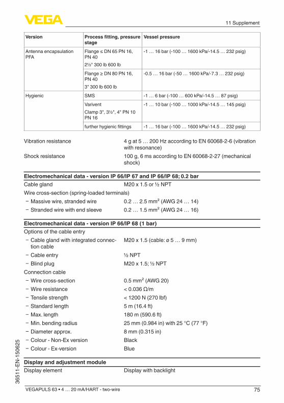
75
11 Supplement
VEGAPULS 63 • 4 … 20 mA/HART - two-wire
3651
1-EN
-150
625
Version Processfitting,pressurestage
Vessel pressure
Antenna encapsulation PFA
Flange≤DN65PN16,PN 402½" 300 lb 600 lb
-1 … 16 bar (-100 … 1600 kPa/-14.5 … 232 psig)
Flange≥DN80PN16,PN 403" 300 lb 600 lb
-0.5 … 16 bar (-50 … 1600 kPa/-7.3 … 232 psig)
Hygienic SMS -1 … 6 bar (-100 … 600 kPa/-14.5 … 87 psig)
VariventClamp 3", 3½", 4" PN 10 PN 16
-1 … 10 bar (-100 … 1000 kPa/-14.5 … 145 psig)
furtherhygienicfittings -1 … 16 bar (-100 … 1600 kPa/-14.5 … 232 psig)
Vibration resistance 4gat5…200HzaccordingtoEN60068-2-6(vibrationwith resonance)
Shock resistance 100 g, 6 ms according to EN 60068-2-27 (mechanical shock)
Electromechanical data - version IP 66/IP 67 and IP 66/IP 68; 0.2 barCable gland M20 x 1.5 or ½ NPTWire cross-section (spring-loaded terminals)
Ʋ Massive wire, stranded wire 0.2 … 2.5 mm² (AWG 24 … 14) Ʋ Stranded wire with end sleeve 0.2 … 1.5 mm² (AWG 24 … 16)
Electromechanical data - version IP 66/IP 68 (1 bar)Options of the cable entry
Ʋ Cable gland with integrated connec-tion cable
M20 x 1.5 (cable: ø 5 … 9 mm)
Ʋ Cable entry ½ NPT Ʋ Blind plug M20 x 1.5; ½ NPT
Connection cable Ʋ Wire cross-section 0.5 mm² (AWG 20) Ʋ Wire resistance <0.036Ω/m Ʋ Tensile strength < 1200 N (270 lbf) Ʋ Standard length 5 m (16.4 ft) Ʋ Max. length 180 m (590.6 ft) Ʋ Min. bending radius 25 mm (0.984 in) with 25 °C (77 °F) Ʋ Diameter approx. 8 mm (0.315 in) Ʋ Colour - Non-Ex version Black Ʋ Colour - Ex-version Blue
Display and adjustment moduleDisplay element Display with backlight

76
11 Supplement
VEGAPULS 63 • 4 … 20 mA/HART - two-wire
36511-EN-150625
Measured value indication Ʋ Number of digits 5 Ʋ Sizeofdigits W x H = 7 x 13 mm
Adjustment elements 4 keysProtection rating
Ʋ unassembled IP 20 Ʋ mounted in the housing without lid IP 40
Materials Ʋ Housing ABS Ʋ Inspection window Polyester foil
Interface to the external display and adjustment unitData transmission Digital (I²C-Bus)Connection cable Four-wire
Sensor version Configuration,connectioncable
Cable length Standard cable Special cable Screened
4 … 20 mA, 4 … 20 mA/HART 50 m ● – –
ProfibusPA,Founda-tion Fieldbus 25 m – ● ●
Integrated clockDate format Day.Month.YearTime format 12 h/24 hTimezoneExfactory CETRate deviation max. 10.5 min/year
Measurement electronics temeratureResolution 0.1 °C (1.8 °F)Accuracy ±1°C(1.8°F)Permissible temperature range -40 … +85 °C (-40 … +185 °F)
Voltage supplyOperating voltage UB
Ʋ Non-Ex instrument 9.6 … 35 V DC Ʋ Ex ia instrument 9.6 … 30 V DC Ʋ Ex-d-ia instrument 14 … 35 V DC Ʋ Ex-d-ia instrument with ship approval 15 … 35 V DC
Operating voltage UB - illuminated display and adjustment module Ʋ Non-Ex instrument 16 … 35 V DC Ʋ Ex ia instrument 16 … 30 V DC Ʋ Ex-d-ia instrument No lighting (integrated ia barrier)

77
11 Supplement
VEGAPULS 63 • 4 … 20 mA/HART - two-wire
3651
1-EN
-150
625
Reverse voltage protection IntegratedPermissible residual ripple - Non-Ex, Ex-ia instrument
Ʋ for 9.6 V< UB < 14 V ≤0.7Veff(16…400Hz) Ʋ for 18 V< UB < 36 V ≤1.0Veff(16…400Hz)
Permissible residual ripple - Ex-d-ia instrument Ʋ for 18 V< UB < 36 V ≤1Veff(16…400Hz)
Load resistor Ʋ Calculation (UB - Umin)/0.022 A Ʋ Example - Non-Ex instrument with UB= 24 V DC
(24V-9.6V)/0.022A=655Ω
Electrical protective measuresProtection rating
Housing material Version IP-protection class NEMA protection
Plastic Single chamber IP 66/IP 67 NEMA4X
Double chamber IP 66/IP 67 NEMA4X
Aluminium Single chamber IP 66/IP 68 (0.2 bar)IP 68 (1 bar)
NEMA 6PNEMA 6P
Double chamber IP 66/IP 67IP 66/IP 68 (0.2 bar)IP 68 (1 bar)
NEMA4XNEMA 6PNEMA 6P
Stainless steel, electro-polished
Single chamber IP 66/IP 68 (0.2 bar) NEMA 6P
Stainless steel, precision casting
Single chamber IP 66/IP 68 (0.2 bar)IP 68 (1 bar)
NEMA 6PNEMA 6P
Double chamber IP 66/IP 67IP 66/IP 68 (0.2 bar)IP 68 (1 bar)
NEMA4XNEMA 6PNEMA 6P
Protection rating (IEC 61010-1) III
ApprovalsInstrumentswithapprovalscanhavedifferenttechnicalspecificationsdependingontheversion.For that reason the associated approval documents of these instruments have to be carefully noted. They come with the delivery or can be downloaded under www.vega.com, "VEGATools" and "Instrument search" as well as under www.vega.com/downloads and "Approvals".
11.2 DimensionsThe following dimensional drawings represent only an extract of all possible versions. Detailed dimensional drawings can be downloaded at www.vega.com/downloads under "Drawings".
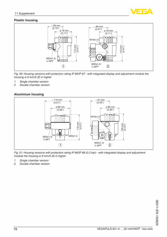
78
11 Supplement
VEGAPULS 63 • 4 … 20 mA/HART - two-wire
36511-EN-150625
Plastic housing~ 69 mm(2.72")
ø 79 mm(3.11")
112
mm
(4.4
1")
M20x1,5/½ NPT
~ 84 mm(3.31")
M16x1,5
112
mm
(4.4
1")
M20x1,5/½ NPT1 2
ø 79 mm(3.11")
Fig.50:HousingversionswithprotectionratingIP66/IP67-withintegrateddisplayandadjustmentmodulethehousingis9mm/0.35inhigher1 Single chamber version2 Double chamber version
Aluminium housing
21
ø 86 mm(3.39")
~ 116 mm(4.57")
116
mm
(4.5
7")
M20x1,5M20x1,5/½ NPT
~ 87 mm(3.43")
M16x1,5
ø 86 mm(3.39")
120
mm
(4.7
2")
M20x1,5/½ NPT
Fig.51:HousingversionswithprotectionratingIP66/IP68(0.2bar)-withintegrateddisplayandadjustmentmodulethehousingis9mm/0.35inhigher1 Single chamber version2 Double chamber version
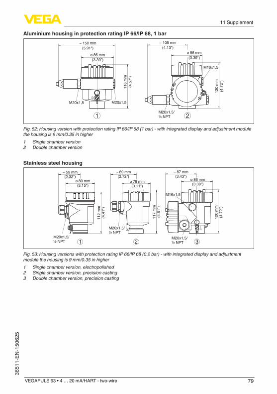
79
11 Supplement
VEGAPULS 63 • 4 … 20 mA/HART - two-wire
3651
1-EN
-150
625
Aluminium housing in protection rating IP 66/IP 68, 1 bar
120
mm
(4.7
2")
~ 105 mm(4.13")
116
mm
(4.5
7")
~ 150 mm(5.91")
ø 86 mm(3.39")
ø 86 mm(3.39")
M20x1,5/½ NPT
M16x1,5
2
M20x1,5M20x1,5
1
Fig.52:HousingversionwithprotectionratingIP66/IP68(1bar)-withintegrateddisplayandadjustmentmodulethehousingis9mm/0.35inhigher1 Single chamber version2 Double chamber version
Stainless steel housing~ 69 mm(2.72")
ø 79 mm(3.11")
117
mm
(4.6
1")
M20x1,5/½ NPT
~ 59 mm(2.32")
ø 80 mm(3.15")
112
mm
(4.4
1")
M20x1,5/½ NPT
~ 87 mm(3.43")
ø 86 mm(3.39")
120
mm
(4.7
2")
M20x1,5/½ NPT
M16x1,5
321
Fig.53:HousingversionswithprotectionratingIP66/IP68(0.2bar)-withintegrateddisplayandadjustmentmodulethehousingis9mm/0.35inhigher1 Single chamber version, electropolished2 Single chamber version, precision casting3 Double chamber version, precision casting

80
11 Supplement
VEGAPULS 63 • 4 … 20 mA/HART - two-wire
36511-EN-150625
Stainless steel housing with protection rating IP 66/IP 68, 1 bar
117
mm
(4.6
1")
~ 103 mm(4.06") ø 79 mm
(3.11")
120
mm
(4.7
2")
~ 105 mm(4.13") ø 86 mm
(3.39")
M20x1,5
M20x1,5/½ NPT
M16x1,5
~ 93 mm(3.66") ø 80 mm
(3.15")
112
mm
(4.4
1")
M20x1,5/½ NPT
321
Fig.54:HousingversionwithprotectionratingIP66/IP68(1bar)-withintegrateddisplayandadjustmentmodulethehousingis9mm/0.35inhigher1 Single chamber version, electropolished2 Single chamber version, precision casting3 Double chamber version, precision casting
VEGAPULS63,flangeversion
31,5
mm
(1.2
4")
163,
5 m
m (6
.44"
)
ø 75 mm (2.95")
3
2
4 m
m /
8mm
(0.1
6" /
0.32
")
15,5
mm
(0.6
1")
102
mm
(4.0
2")
ø 44 mm (1.73")
1
3
4 m
m /
8 m
m(0
.16"
/ 0.
32")
Fig.55:VEGAPULS63,flangeversion1 DN50/DN65and2"/2½"2 FromDN80andfrom3"3 WithstainlesssteelhousingsandAluminiumdoublechamberhousings,thisdimensionis98mm(3.86")
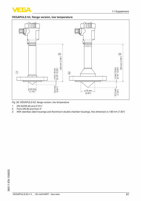
81
11 Supplement
VEGAPULS 63 • 4 … 20 mA/HART - two-wire
3651
1-EN
-150
625
VEGAPULS63,flangeversion,lowtemperature
202
mm
(7.9
5")
3 3
ø 44 mm(1.73")
4 m
m /
8 m
m(0
.16"
/ 0.
32")
ø 75 mm(2.95")15
,5 m
m(0
.61"
)
202
mm
(7.9
5")
31,5
mm
(1.2
4")
1 2
4 m
m /
8 m
m(0
.16"
/ 0.
32")
Fig.56:VEGAPULS63,flangeversion,lowtemperature1 DN50/DN65and2"/2½"2 FromDN80andfrom3"3 WithstainlesssteelhousingsandAluminiumdoublechamberhousings,thisdimensionis198mm(7.80")

82
11 Supplement
VEGAPULS 63 • 4 … 20 mA/HART - two-wire
36511-EN-150625
VEGAPULS63,hygienicfitting1
ø 90 mm(3.54")
ø 78 mm(3.07")
101
mm
(3.9
8")
38 m
m(1
.50"
)15
mm
(0.5
9")
101
mm
(3.9
8")
38 m
m(1
.50"
)15
mm
(0.5
9")
89 m
m(3
.50"
)16
mm
(0.6
3")ø 50 mm
(1.97")15
mm
(0.5
9")
83 m
m(3
.27"
)ø 90 mm(3.54")
ø 66 mm(2.60")
5 55
5 5
51 2
3 54
Fig.57:VEGAPULS63,hygienicfitting11 NeumoBiocontrol2 TuchenhagenVariventDN253 HygienicfittingLA4 HygienicfittingLB5 WithstainlesssteelhousingsandAluminiumdoublechamberhousings,thisdimensionis4mm(0.157")less

83
11 Supplement
VEGAPULS 63 • 4 … 20 mA/HART - two-wire
3651
1-EN
-150
625
VEGAPULS63,hygienicfitting2
ISO2852DN 50 / 2"
w
Clamp-Stutzenclamp-socketDIN32676/
DN 50 / 2,5"DN 65 / 3"DN 80 / 3,5"DN 100 / 4"
ø 64ø 77,5ø 91ø 106ø 119
2
3
315
,4 m
m(0
.6")w
98 m
m(3
.86"
)
161
mm
(6.3
4")
31,5
mm
(1.2
4")
w
1
Fig.58:VEGAPULS63,hygienicfitting21 Clamp2"(ø64mm),2½"(ø77.5mm),3"(ø91mm)accordingtoDIN32676,ISO2852/316L2 Clamp3½"(ø106mm),4"(ø119mm)accordingtoDIN32676,ISO2852/316L3 WithstainlesssteelhousingsandAluminiumdoublechamberhousings,thisdimensionis4mm(0.157")less
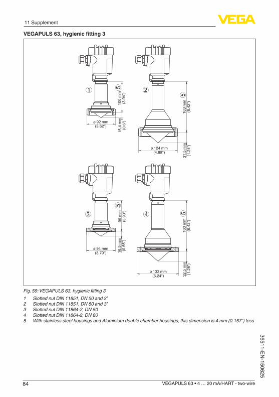
84
11 Supplement
VEGAPULS 63 • 4 … 20 mA/HART - two-wire
36511-EN-150625
VEGAPULS63,hygienicfitting3
1 5
5
2
3 4
5
5
16,5
mm
(0.6
5")
ø 92 mm(3.62")
ø 124 mm(4.88")
99 m
m(3
.90"
)15
,4 m
m(0
.6")
100
mm
(3.9
4")
163
mm
(6.4
2")
31,5
mm
(1.2
4")
163
mm
(6.4
2")
32,5
mm
(1.2
8")
ø 94 mm(3.70")
ø 133 mm(5.24")
Fig.59:VEGAPULS63,hygienicfitting31 SlottednutDIN11851,DN50and2"2 SlottednutDIN11851,DN80and3"3 Slotted nut DIN 11864-2, DN 504 Slotted nut DIN 11864-2, DN 805 WithstainlesssteelhousingsandAluminiumdoublechamberhousings,thisdimensionis4mm(0.157")less
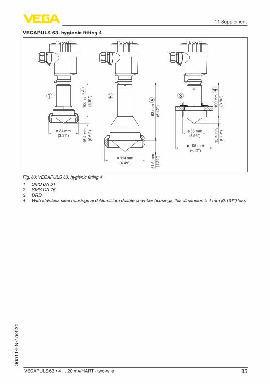
85
11 Supplement
VEGAPULS 63 • 4 … 20 mA/HART - two-wire
3651
1-EN
-150
625
VEGAPULS63,hygienicfitting4
ø 84 mm(3.31")
ø 114 mm(4.49")
163
mm
(6.4
2")
31,5
mm
(1.2
4")
100
mm
(3.9
4")
15,4
mm
(0.6
1")
1 2
4
4
100
mm
(3.9
4")
15,4
mm
(0.6
1")
3
ø 65 mm(2.56")
ø 105 mm(4.13")
4
Fig.60:VEGAPULS63,hygienicfitting41 SMS DN 512 SMS DN 763 DRD4 WithstainlesssteelhousingsandAluminiumdoublechamberhousings,thisdimensionis4mm(0.157")less

86
11 Supplement
VEGAPULS 63 • 4 … 20 mA/HART - two-wire
36511-EN-150625
11.3 Industrial property rightsVEGA product lines are global protected by industrial property rights. Further information see www.vega.com.Only in U.S.A.: Further information see patent label at the sensor housing.VEGA Produktfamilien sind weltweit geschützt durch gewerbliche Schutzrechte.Nähere Informationen unter www.vega.com.Les lignes de produits VEGA sont globalement protégées par des droits de propriété intellec-tuelle. Pour plus d'informations, on pourra se référer au site www.vega.com.VEGA lineas de productos están protegidas por los derechos en el campo de la propiedad indus-trial. Para mayor información revise la pagina web www.vega.com.Линии продукции фирмы ВЕГА защищаются по всему миру правами на интеллектуальную собственность. Дальнейшую информацию смотрите на сайте www.vega.com.VEGA系列产品在全球享有知识产权保护。进一步信息请参见网站<www.vega.com。
11.4 TrademarkAll the brands as well as trade and company names used are property of their lawful proprietor/originator.

87
INDEX
VEGAPULS 63 • 4 … 20 mA/HART - two-wire
3651
1-EN
-150
625
INDEX
AAdjustment 43, 44Application
– Bulk solid 40 – Liquid 36 – Standpipe 37
BBacklight 46
CCable entry 13Check output signal 64Connecting
– Electrically 25 – To the PC 55
Connection – Cable 24 – Steps 25 – Technology 25
Copy sensor settings 53Current output Min./Max. 45Current output mode 45Curve indication
– Echo curve 48 – False signal suppression 48
DDamping 44Date/Time 51Default values 51Deviation 64Device units 48
EEcho curve memory 59Echo curve of the setup 48EDD (Enhanced Device Description) 58Electronics and terminal compartment, single chamber housing 27Electronics temperature 47Error codes 62Event memory 59
FFalse signal suppression 49Faultrectification63Foam generation 18Functional principle 9
GGrounding 24
HHART
– Resistor 55HART mode 52
IIndication of the measured value 46Instrument version 53
LLanguage 45Linearisation curve 50Lock adjustment 45
MMain menu 35Meas. reliability 47Measured value memory 59Measurement in a surge pipe 19Measurement in the bypass tube 21Measurement loop name 35
NNAMUR NE 107 61, 63
OOperation
– System 34OverfillprotectionaccordingtoWHG50
PPeak value indicator 46PIN 45, 50
RRead out info 53Reflectionproperties36Repair 68Reset 51
SSensor status 46Service hotline 67Simulation 47Socket 16Status messages - NAMUR NE 107 60

88
INDEX
VEGAPULS 63 • 4 … 20 mA/HART - two-wire
36511-EN-150625
TType label 8
VVessel form 42Vessel height 42Vessel installations 17

89
Notes
VEGAPULS 63 • 4 … 20 mA/HART - two-wire
3651
1-EN
-150
625

90
Notes
VEGAPULS 63 • 4 … 20 mA/HART - two-wire
36511-EN-150625

91
Notes
VEGAPULS 63 • 4 … 20 mA/HART - two-wire
3651
1-EN
-150
625

Printing date:
VEGA Grieshaber KGAm Hohenstein 11377761 SchiltachGermany
3651
1-E
N-1
5062
5
All statements concerning scope of delivery, application, practical use and operat-ing conditions of the sensors and processing systems correspond to the information available at the time of printing.Subject to change without prior notice
© VEGA Grieshaber KG, Schiltach/Germany 2015
Phone +49 7836 50-0Fax +49 7836 50-201E-mail: [email protected]