VariCam LT Ready Live White Paper - business.panasonic.de · VariCam LT Ready for Live White Paper...
17
VariCam LT Ready for Live White Paper February 19, 2018
Transcript of VariCam LT Ready Live White Paper - business.panasonic.de · VariCam LT Ready for Live White Paper...

VariCam LT Ready for Live White Paper
February 19, 2018

VariCam LT Ready for Live White Paper
1
1. IntroductionThis white paper describes the method for setting up a VariCam LT for operation in a multi‐camera system.
VariCam LT Version 6.0 offers improved live operation functionality, and can now be controlled with the Panasonic AK‐HRP1000GJ/1005GJ remote operation panel (ROP). The VariCam LT also features new “shading modes” for image enhancement in locations suitable for ROP use.
2. Required Devices and Versions
・VariCam LT (AU‐V35LT1G) Version : 27.98‐00‐0.00 or later・ROP (AK‐HRP1000GJ/HRP1005GJ) Version : 4.45‐00‐0.01 or later・ROP(AK‐HRP200G) Version : 4.01‐00‐0.01 or later
When used with the AK‐HRP1000GJ/HRP1005GJ:• Switching hub with PoE support• LAN cable (straight cabling, Category 5e or higher, maximum length of 100 m)
When used with the AK‐HRP200G:• LAN cable (Category 5e or higher)*A crossover cable should be used when connecting the VariCam LT directly to an AK‐HRP200G, and a straight cable should be used when connecting through hubs etc.
3. Image Enhancement Parameters and ROP Supported Items
The following shading modes have been added to VariCam LT Version 6.0 and later to facilitate use in multi‐camera systems.
(1) Main Color: V‐Log, Grading Sel: ShadingWhile still using the V‐Log signal for recording, outputs such as Gain and Pedestal can be controlled with the ROP. Since there are no major image enhancement changes, it is recommended to use this together with 3D LUTfor enhancement. This mode can be useful when Camera outputs are live, and recorded images are graded in postproduction.
(2) Main Color: Shading, Gamma Sel: V‐LogControllable parameters are almost the same as (1), but ROP control also applies to the recorded images, except for 3D LUT. Applying 3D LUT during post‐processing will reproduce the same images as the output.This mode can be useful when images are enhanced to a certain degree on set, and LUT and other tweaks are added in postproduction.
(3) Main Color: Shading, Gamma Sel: BC GammaThis mode enables as almost all VariCam LT image enhancement settings as possible to be controlled by the ROP. 3D LUT cannot be used. This mode is recommended for situations where there is no postproduction and the entire shot will be composed on set.It is also possible to adjust the gamma, enabling more flexibility of adjustment than the scene 1‐5 preset gammas.
According to Main Color, Grading SEL, Gamma SEL settings include the above mode, VariCam LT can be used to control the following items via the ROP.
3.1. Supported parameters for each Main Color Settings

VariCam LT Ready for Live White Paper
2
[AK‐HRP1000GJ/1005GJ Controllable Items]
[SHADING‐related settings]
[General settings]
MENU SETTINGS
MAIN COLOR V‐LOG SCENE1‐5 SHADING
noteGRADING SEL
INTERNALEXTERNAL
SHADING OFF OFF
GAMMA SELECT ‐ ‐ V‐709V‐406060V‐452080
VIDEO45VIDEO50
V‐LOG BCGAMMA
Controllable item
R/G/B Gain Y Y Y Y Y Y
R/G/B PedestalMaster Pedestal
Y Y Y Y Y Y
CHROMALevel / Phase
Y* Y Y Y* * level only
R/B GAMMAMaster GAMMA
Y Y
BLACK GAMMA Y
KNEE Y Y
WHITE CLIP Y Y
HD OUTPUT DETAIL Y only for output
DETAIL Y Y Y Y Y not for LT codec
SKIN DETAIL Y Y Y Y Y not for LT codec
LINEAR MATRIX Y Y Y Y
COLOR CORRECTION Y Y Y Y
MENU SETTINGS
MAIN COLOR V‐LOG SCENE1‐5 SHADING
noteGRADING SEL
INTERNALEXTERNAL
SHADING OFF OFF
GAMMA SELECT ‐ ‐ V‐709V‐406060V‐452080
VIDEO45VIDEO50
V‐LOG BCGAMMA
Controllable item
CAMERA MENU Y Y Y Y Y Y Y
Lens IRIS Y Y Y Y Y Y Y
Auto IRIS Y Y Y Y Y Y Y
FPS (VFR) Select Y Y Y Y Y Y Y select from Preset
SHUTTER Select Y Y Y Y Y Y Y select from Preset
EI Select Y Y Y Y Y Y Y
WB Select Y Y Y Y Y Y Y select from Preset
AWB Y Y Y Y Y Y Y
ABB Y Y Y Y Y Y Y
NR Y Y Y Y Y Y Y
REC Start/Stop Y Y Y Y Y Y Y
5600K override Y Y Y Y Y Y Y
CALL Y Y Y Y Y Y Y
Color Bars Y Y Y Y Y Y Y
CDL Y
3D LUT Select Y Y Y

VariCam LT Ready for Live White Paper
3
[AK‐HRP200G Controllable Items]
The Flare/Pedestal Volume setting of the AK‐HRP200G is set to “Flare” by default. When controlling R/B pedestals,the Setup Mode must be accessed and the “Flare Pedestal Volume” must be set to “Pedestal.”For details, refer to Annex1 “HRP200G Set‐up Mode”.
MENU SETTINGS
MAIN COLOR V‐LOG SCENE1‐5 SHADING
noteGRADING SEL
INTERNALEXTERNAL
SHADING OFF OFF
GAMMA SELECT ‐ ‐ V‐709V‐406060V‐452080
VIDEO45VIDEO50
V‐LOG BCGAMMA
Controllable item
R/B Gain Y Y Y Y Y Y
R/B PedestalMaster Pedestal
Y Y Y Y Y Y
KNEE Y* Y* * ON/OFF only
HD OUTPUT DTL Y only for output
DETAIL Y Y Y Y Y not for LT codec
SKIN DETAIL Y* Y* Y* Y* Y*not for LT codec* ON/OFF only
LINEAR MATRIX Y* Y* Y* Y* * ON/OFF only
COLOR CORRECTION Y* Y* Y* Y* * ON/OFF only
MENU SETTINGS
MAIN COLOR V‐LOG SCENE1‐5 SHADING
noteGRADING SEL
INTERNALEXTERNAL
SHADING OFF OFF
GAMMA SELECT ‐ ‐ V‐709V‐406060V‐452080
VIDEO45VIDEO50
V‐LOG BCGAMMA
Controllable item
CAMERA MENU Y Y Y Y Y Y Y
Lens IRIS Y Y Y Y Y Y Y
Auto IRIS Y Y Y Y Y Y Y
SHUTTER Select Y Y Y Y Y Y Y select from Preset
EI Select Y* Y* Y* Y* Y* Y* Y* * cannot change EI mode
AWB Y Y Y Y Y Y Y
ABB Y Y Y Y Y Y Y
REC Start/Stop Y Y Y Y Y Y Y
Color Bars Y Y Y Y Y Y Y
[SHADING‐related settings]
[General settings]
VariCam LT Ready for Live White Paper
4
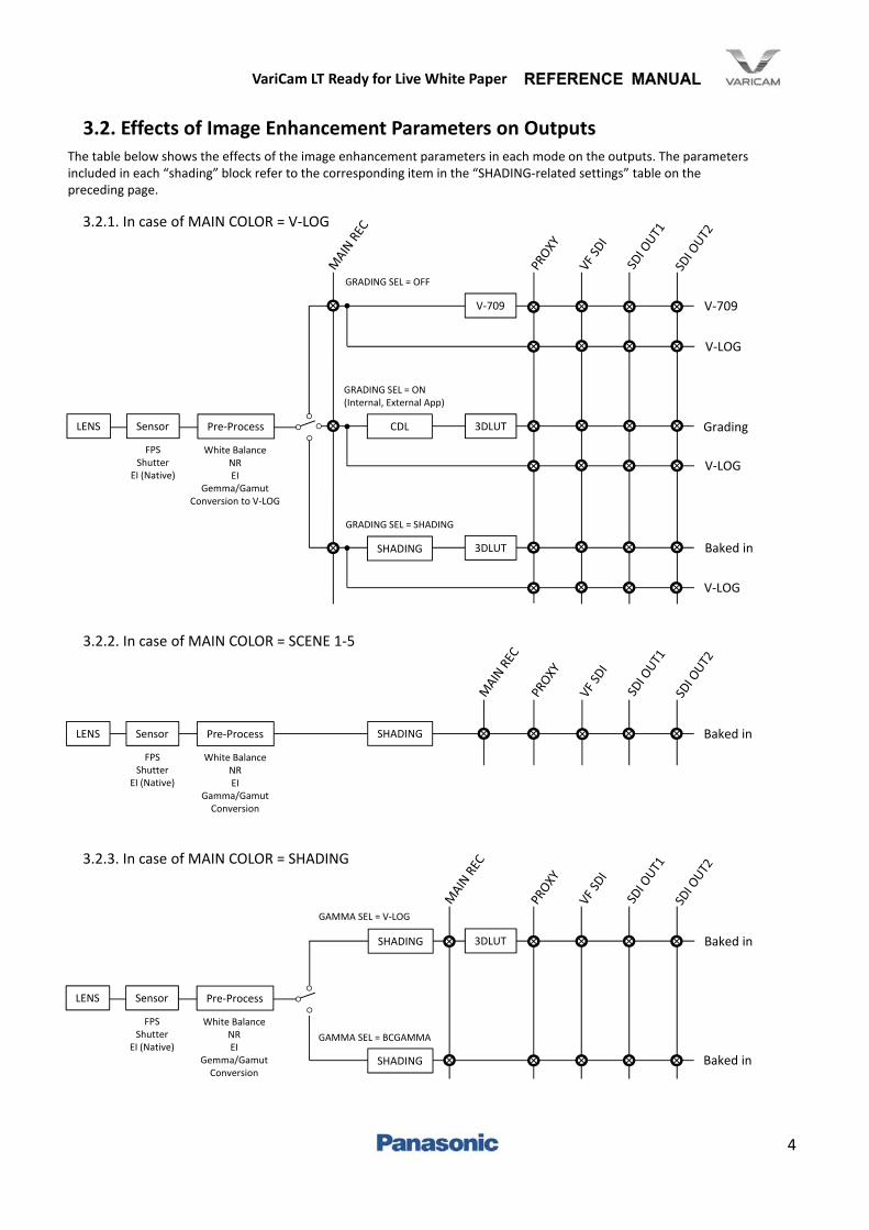
3.2. Effects of Image Enhancement Parameters on Outputs
3.2.1. In case of MAIN COLOR = V‐LOG
GRADING SEL = OFF
V‐709
CDL 3DLUT
SHADING 3DLUT
GRADING SEL = ON(Internal, External App)
GRADING SEL = SHADING
3.2.2. In case of MAIN COLOR = SCENE 1‐5
3.2.3. In case of MAIN COLOR = SHADING
GAMMA SEL = V‐LOG
3DLUT
GAMMA SEL = BCGAMMA
SHADING
The table below shows the effects of the image enhancement parameters in each mode on the outputs. The parameters included in each “shading” block refer to the corresponding item in the “SHADING‐related settings” table on the preceding page.
LENS Sensor Pre‐Process
FPSShutter
EI (Native)
White BalanceNREI
Gemma/GamutConversion to V‐LOG
SHADINGLENS Sensor Pre‐Process
FPSShutter
EI (Native)
White BalanceNREI
Gamma/GamutConversion
SHADING
LENS Sensor Pre‐Process
FPSShutter
EI (Native)
White BalanceNREI
Gemma/GamutConversion
V‐709
V‐LOG
Grading
Baked in
V‐LOG
V‐LOG
Baked in
Baked in
Baked in

VariCam LT Ready for Live White Paper
5
4. Connection Example and Settings
Ethernet
Ethernet
GENLOCK IN (Return Video / Genlock)
SDI OUT1 (Clean signal)
GPIO (Tally)
SDI OUT2 (Menu)
When connected to an ROP, even if the VariCam LT’s MENU→OUTPUT SETTINGS→SDI OUT→MENU DISP is set to“Off,” selecting “Camera Menu On” from the ROP menu will display the menu on SDI OUT2.In addition, even if the VariCam LT MENU→OUTPUT SETTINGS→SDI OUT→SDI OUT 2 CLEAN VIEW is set to “On”or MENU→OUTPUT SETTINGS→SDI OUT INDICATOR→SDI OUT 2 SW is set to “Off,” the ROP CHAR button will only affect SDI OUT2 and will toggle OSD on and off. CHAR is also set to “Off” when the VariCam LT is connected to theROP.
[Recommended Settings]MENU ‐> OUTPUT SETTINGS ‐> SDI OUT ‐> MENU DISP : OFFMENU ‐> OUTPUT SETTINGS ‐> SDI OUT ‐> SDI OUT1 CLEAN VIEW : ON
4.1. Connection Example
4.3. SDI Output Settings
Connect the RETURN signal to the GENLOCK signal at the GENLOCK IN terminal. The signal must be 1080 SDI. Use a switching hub with PoE support to connect the ROP to the LAN terminal.
• When the VariCam LT is connected to an ROP, the six buttons on the home screen cannot be used to move to thesetting screens. (However, the Menu button can be used to access the list menu.)
• The response to parameter changes from the ROP is delayed while the Home or Menu screen is displayed. It is recommended to keep the View screen displayed when using an ROP to control the device.
• The Surround View function is not available when Grading SEL is set to “Shading” or when “Main Color” is set to “Shading.”• Depending on the lens being used, the Iris response to ROP commands may be delayed.
4.2. Restrictions and Notes

VariCam LT Ready for Live White Paper
6
The following is the configuration information for which Return is valid. 720p and SD signals are not supported.
RETUERN VIDEO SDI INPUT FORMAT
SYSTEM FORMAT1080/23.98 1080/24.00 1080/25.00 1080/29.97 1080/50.00 1080/59.94
True P PsF True P PsF True P PsF True P PsF P I P I
23.98P V V ‐ ‐ ‐ ‐ ‐ ‐ ‐ ‐ ‐ ‐
24.00P ‐ ‐ V V ‐ ‐ ‐ ‐ ‐ ‐ ‐ ‐
25.00P ‐ ‐ ‐ ‐ V V ‐ ‐ V V ‐ ‐
29.97P ‐ ‐ ‐ ‐ ‐ ‐ V V ‐ ‐ V V
50.00P ‐ ‐ ‐ ‐ V V ‐ ‐ V V ‐ ‐
59.94P ‐ ‐ ‐ ‐ ‐ ‐ V V ‐ ‐ V V
50.00I ‐ ‐ ‐ ‐ V V ‐ ‐ V V ‐ ‐
59.94I ‐ ‐ ‐ ‐ ‐ ‐ V V ‐ ‐ V V
4.5. Fan Settings
The fan mode can be changed in MENU→SYSTEM SETTINGS→FAN→FAN SPEED.A new “Live Mode” has been added as of VariCam LT Version 6.0. In Live Mode, the fan is normally operatedat a low speed. However, when a preset temperature is reached, the fan speed is optimized for the [MAIN CODEC] settings (the same speeds as when MATCH CODEC settings are made).This setting can also be changed from ROP MENU→SYSTEM CAM. (AK‐HRP1000GJ/1005GJ only)
4.4. Genlock/Return Video Settings
When using the Return function, Genlock must either be externally synchronized (using VariCam as a slave device) or the Return signal itself must be locked to the VariCam LT (using VariCam as a master device).
[Genlock Settings](When used as a slave device): MENU → SYSTEM SETTINGS → GENLOCK → GENLOCK MODE: EXT(When used as a master device): MENU → SYSTEM SETTINGS → GENLOCK → GENLOCK MODE: INT
The Return function can be assigned to the following switches.From MENU→SYSTEM SETTINGS→USER SWITCHES, assign the function to the switch of your choice:‐USER1‐USER2‐USER3‐USER GRIP1‐USER GRIP2‐LENS RET SW

VariCam LT Ready for Live White Paper
7
5. VariCam LT and ROP Connection Settings
5.1. Steps to Connect a VariCam LT with an ROP
5.2. VariCam LT Network Settings
VariCam LT network settings
ROP settings
User authentication settings
The following are the steps for connecting a VariCam LT with an ROP.
These can only be set from the VariCam LT (see 5.2).
These can be set in ROP or Easy IP setup software or In ROP setup software (see 5.3).
These settings are not required when using the devices under the default settings. However, there are notes for those who have used VariCam LT before Version 6.0(see 5.4).
1. From MENU→PERIPHERAL→LAN PROPERTY, set each of the following items as needed.DHCP: DHCP auto‐configuration settingIP ADDRESS: IP addressSUBNET MASK: Subnet maskDEFAULT GATEWAY: Default gatewayPRIMARY DNS: The primary DNS server to useSECONDARY DNS: The secondary DNS server to useDHCP SERVER: DHCP server configuration setting
2. From MENU→PERIPHERAL→NETWORK SEL, select LAN
5.3. ROP Settings
1. From ROP MENU→ROP IP SETTING, set each of the following items as needed.ROP IP ADDRESS: IP addressROP SUBNET MASK: Subnet maskROP DEFAULT GATEWAY: Default gateway
2. From ROP MENU→CAMERA IP SETTING, set the IP address for the camera number you wish to connect to the above IP address set on the VariCam LT and set PORT to “49152.”
3. From ROP MENU→CONNECT SETTING, set the “CONNECT MODE” for the camera number set in step 1 above to “LAN (AU).”
*For step 1 above, the parameter can also be set using Easy IP setup software. In addition, the parameters in steps 2 and 3 can also be set using ROP setup software.
Here, we present only the basic method for connecting the VariCam LT with an ROP. For more detail, refer to the operating guide for your VariCam LT and your ROP.Please note in advance that the use of the AK‐HRP200G requires a PC for connection settings.
5.3.1 When using the AK‐HRP1000GJ/1005GJ

VariCam LT Ready for Live White Paper
8
5.4. User Authentication Settings
In addition to the above, user authentication is also required to connect a VariCam LT to an ROP.This is due to the requirement that the network account set on the VariCam LT (which can be viewed in MENU→PERIPHERAL→NETWORK FUNC→ACCOUNT LIST) match the user information set on the ROP (which canbe viewed and set via the ROP setup software).
When using versions prior to VariCam LT Version 6.0 with the AK‐HRP200G, it was necessary to change the network settings on one of the two devices, since their default accounts were not the same.
In VariCam LT Version 6.0, the ROP default account, “username: admin, password: 12345” has been added to the default accounts on the VariCam, enabling the devices to be connected without first making the user authentication settings.
*However, for users updating from a version prior to Version 6.0 via software update, the new account information will only be added after the device has been initialized. After backing up your important data, use MENU→SYSTEM SETTINGS→INITIALIZE→LOAD FACTORY DATA to initialize the device, or add the above account by following the manual procedure.
1. Access Setup Mode on the AK‐HRP200G and set each of the following items as needed.ROP IP ADDRESS: IP addressROP SUBNET MASK: Subnet maskROP DEFAULT GATEWAY: Default gateway
2. Connect the PC and ROP on the network, open the ROP setup software and open the Camera List tab.Here, set the following items:CONNECTION MODE: IP ModeCAMERA TYPE: Camcorder IPIP ADDRESS: The IP address of the camera you wish to connect (the IP address set on the VariCam LT in thesection above)CAMERA PORT NO: 49152
After setting the above items, click the SET button to apply the changes.
*For step 1 above, the parameter can also be set using Easy IP setup software.
5.3.2 When using the AK‐HRP200G
5.4.1. About User Authentication for Connections(for Users Who Have Updated from Versions Prior to VariCam LT Version 6.0)

VariCam LT Ready for Live White Paper
9
5.4.2. Steps for Manually Adding a User Account
[ To set an account on the ROP]Connect the PC and ROP on the network, open the ROP setup software and open the User Auth tab.Clicking the REFRESH button here will display the old username.Fill in the New Username, Old Password, New Password and Retype New Password fields with the desired data andclick SET to complete the setting process.The default factory account settings for new devices are “username: admin, password: 12345.”
[Adding an account to the VariCam LT]Access MENU→PERIPHERAL→NETWORK FUNC→USER ACCOUNT to add the account.Access MENU→PERIPHERAL→NETWORK FUNC→ACCOUNT LIST to see a list of the currently added accounts.The default settings for new devices are made in one of the following configurations.Username: guest/Password: p2guestUsername: admin/Password: 12345(The “admin” account was added in Version 6.0 and later. Users originally using versions prior to Version 6.0 may use the “Initialize” command to initialize the device andadd the new account.)

VariCam LT Ready for Live White Paper
10
6. Special Operations
6.1. Recording Operation
STORE + HEAD Press and hold FILES
AK‐HRP1000GJ AK‐HRP1005GJ
Recording can be triggered on the AK‐HRP1000GJ by pressing the STORE and HEAD buttons; on the AK‐HRP1005GJ by pressing and holding the FILES button; and on the AK‐HRP200G by pressing the STORE and HEAD POWER buttons.*This functionality can only be used when MENU→REC SETTINGS→REC FUNCTION→REC MODE is set to “Normal”on the VariCam LT.
STORE + HEAD POWER
AK‐HRP200G
6.2. Main Color Switching Operation
With the AK‐HRP1000GJ, the Main Color can be switched by pressing the SCENE FILE button. Scenes 1‐5 on the ROP map to Main Color scenes 1‐5, and scene 6 on the ROP maps to Main Color shading. When no scene is selected on the ROP, the Main Color will be set to V‐LOG.*Switching cannot be performed while the VariCam LT is recording or playing back data or during FPGA configuration.

VariCam LT Ready for Live White Paper
11
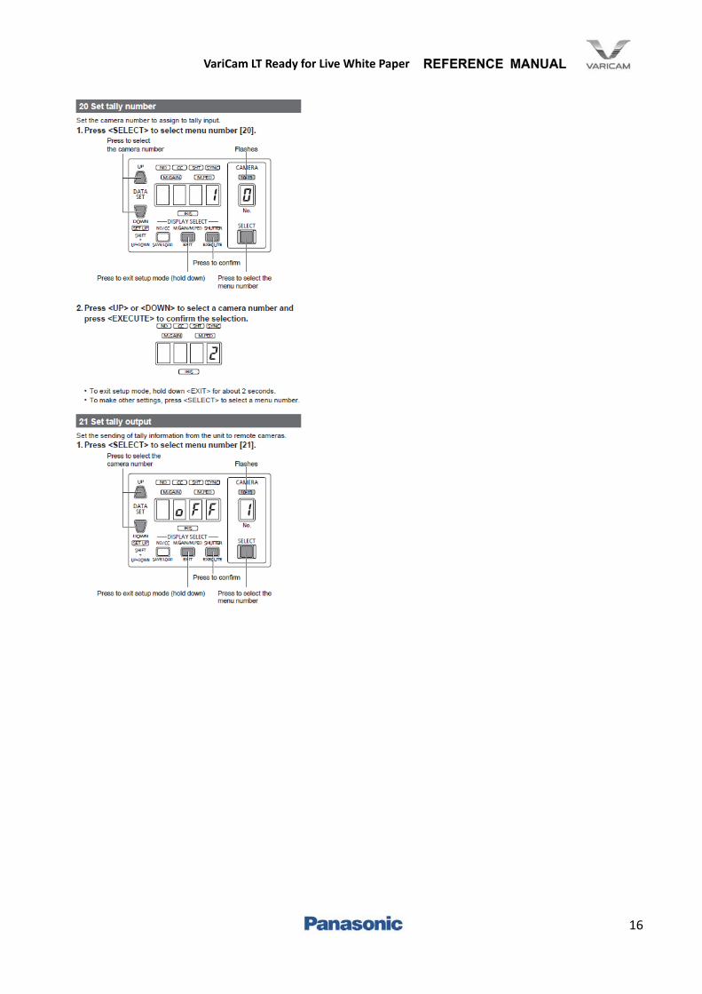
Tally settings are made as follows.For the AK‐HRP1000GJ/1005GJAccess ROP MENU→SYSTEM CAM to change the settings.TALLY CONTROL: Set Tally notifications to on or off.TALLY INPUT: Select the camera number to which Tally notifications are sent.
For the AK‐HRP200GAccess Setup Mode to change the settings.For details, refer to the Annex1 AK‐HRP200G “Setup Mode” documentation.
6.3. Tally Input
A Tally signal can be sent as input to ROP preview connector pins 3 and 4 (or pins 8 and 9 on the AK‐HRP1005GJ).
AK‐HRP1000GJ AK‐HRP1005GJ
6.3.1 ROP Settings
AK‐HRP200G
(8)(9)

VariCam LT Ready for Live White Paper
12
6.3.2 VariCam LT Settings
Tally lights the Tally lamps on the VariCam LT VF (VCVF10). The Tally signal can be accessed via the DC OUT/RS terminals.
REC Tally settings can be made on the VariCam. It is recommended to make them so as not to interfere with external inputs.MENU→OUTPUT SETTINGS→VF SDI INDICATOR→REC TALLY: This can be used to switch the recording statusdisplay mode. RED: The red Tally lamp is litGREEN: The green Tally lamp is litCHAR: “REC” is shown in characters in the viewfinder

VariCam LT Ready for Live White Paper
13
Annex 1. HRP200G Set‐up Mode

VariCam LT Ready for Live White Paper
14

VariCam LT Ready for Live White Paper
15
VariCam LT Ready for Live White Paper
16


![VariCam ROP Operation Guide...2. Select [VariCam ROP] from the list at the left side of the Settings screen. 3. The settings screen for this application will be displayed. So, set](https://static.fdocuments.us/doc/165x107/60f94435a93db050ce4bdf6c/varicam-rop-operation-guide-2-select-varicam-rop-from-the-list-at-the-left.jpg)