Variable-Frequency Grid-Sequence Detector Based on a Quasi ...
12
2552 IEEE TRANSACTIONS ON POWER ELECTRONICS, VOL. 25, NO. 10, OCTOBER 2010 Variable-Frequency Grid-Sequence Detector Based on a Quasi-Ideal Low-Pass Filter Stage and a Phase-Locked Loop Eider Robles, Salvador Ceballos, Josep Pou, Member, IEEE, Jos´ e Luis Mart´ ın, Member, IEEE, Jordi Zaragoza, Student Member, IEEE, and Pedro Iba ˜ nez, Member, IEEE Abstract—This paper proposes a filtered-sequence phase-locked loop (FSPLL) structure for detection of the positive sequence in three-phase systems. The structure includes the use of the Park transformation and moving average filters (MAF). Performance of the MAF is mathematically analyzed and represented in Bode diagrams. The analysis allows a proper selection of the window width of the optimal filter for its application in the dq transformed variables. The proposed detector structure allows fast detection of the grid voltage positive sequence (within one grid voltage cy- cle). The MAF eliminates completely any oscillation multiple of the frequency for which it is designed; thus, this algorithm is not af- fected by the presence of imbalances or harmonics in the electrical grid. Furthermore, the PLL includes a simple-frequency detector that makes frequency adaptive the frequency depending blocks. This guarantees the proper operation of the FSPLL under large frequency changes. The performance of the entire PLL-based de- tector is verified through simulation and experiment. It shows very good performance under several extreme grid voltage conditions. Index Terms—Frequency detection, grid-connected converters, moving average filter (MAF), phase-locked loop (PLL), sequence detector. I. INTRODUCTION G RID-SEQUENCE detection and synchronization is an issue of vital importance, especially under unbalanced and distorted conditions. This information is needed for the proper operation of grid-connected power electronic systems, such as power quality conditioners [1]–[4], distributed gener- ation [5] and storage systems, uninterruptible power supplies (UPS), and flexible ac transmission systems (FACTS). Many synchronizing methods have been presented over the recent years. Some of these are based on a phase-locked loop (PLL) Manuscript received October 16, 2009; revised January 4, 2010 and March 4, 2010; accepted April 27, 2010. Date of current version September 17, 2010. Recommended for publication by Associate Editor P. Mattavelli. E. Robles, S. Ceballos, and P. Iba˜ nez are with the Energy Unit, Tecna- lia Technology Center, 48170 Zamudio, Spain (e-mail: [email protected]; [email protected]; [email protected]). J. Pou and J. Zaragoza are with the Terrassa Industrial Electronics Group, Department of Electronic Engineering, Technical University of Catalonia, 08222 Terrassa, Spain (e-mail: [email protected]; [email protected]). J. L. Martin is with the Department of Electronics and Telecommuni- cations, University of the Basque Country, 48013 Bilbao, Spain (e-mail: [email protected]). Color versions of one or more of the figures in this paper are available online at http://ieeexplore.ieee.org. Digital Object Identifier 10.1109/TPEL.2010.2050492 including a feedback loop with the purpose of controlling a magnitude, which is dependent on the voltage phase angle [6]–[11]. PLLs are possibly the most widely used synchronization methods in the case of grid-connected three-phase systems [12], [13]. The dynamic response of some methods, such as the one described in [14], is good under balanced grid voltages, but very slow when these are designed to operate under unbalanced or distorted grid voltages. The fast PLL method presented in [15] can cancel the influence of certain harmonics, however, the im- plementation of this method is highly complex and should be limited to canceling the effect of only a few harmonics. In [16], a novel control algorithm based on multiple reference frame theory is proposed to eliminate the low-order harmonic compo- nents in the ac currents of grid-tied converters when input ac voltages are unbalanced or contain low-order harmonics. The performance of the PLL-based synchronization method used in [17] is good, even under voltage imbalances and distortion. Nevertheless, in order to implement this, a number of practi- cal problems relating to the normalization of the detected angle within the moving average filter (MAF) stage must be resolved to avoid overflow. Additionally, this solution was not designed to operate under variable frequency. Other kinds of synchronization algorithms are based on the instantaneous symmetrical components theory [18]–[21]. Some of these have a quick dynamic response and can work with vari- able frequency, but grid harmonics are only attenuated and not completely canceled. However, Yazdani et al. [22] propose an interesting synchronization algorithm consisting of a frequency estimator unit, three adaptive notch filter (ANF) based subfil- ters and a symmetrical components calculator. It also proposes a modified multiblock structure, which allows harmonic com- plete cancellation. In [23], a comparison is made between this method, the DSOGI-PLL [24] and the dual second order gen- eralized integrator-frequency locked loop (DSOGI-FLL) [21], which is also based on an ANF, proving that the multiblock three-phase ANF can reduce the time response even if the grid is affected by harmonics. An alternative method [25] also applies the symmetric com- ponents theory and extracts the fundamental frequency positive sequence by performing simple calculations. This completely eliminates several harmonics and employs finite-impulse re- sponse filters to attenuate the rest. Most of these methods are designed to work at a nominal frequency and allow little deviation from this. To overcome 0885-8993/$26.00 © 2010 IEEE
Transcript of Variable-Frequency Grid-Sequence Detector Based on a Quasi ...
2552 IEEE TRANSACTIONS ON POWER ELECTRONICS, VOL. 25, NO. 10, OCTOBER 2010
Variable-Frequency Grid-Sequence Detector Basedon a Quasi-Ideal Low-Pass Filter Stage and a
Phase-Locked LoopEider Robles, Salvador Ceballos, Josep Pou, Member, IEEE, Jose Luis Martın, Member, IEEE,
Jordi Zaragoza, Student Member, IEEE, and Pedro Ibanez, Member, IEEE
Abstract—This paper proposes a filtered-sequence phase-lockedloop (FSPLL) structure for detection of the positive sequence inthree-phase systems. The structure includes the use of the Parktransformation and moving average filters (MAF). Performanceof the MAF is mathematically analyzed and represented in Bodediagrams. The analysis allows a proper selection of the windowwidth of the optimal filter for its application in the dq transformedvariables. The proposed detector structure allows fast detectionof the grid voltage positive sequence (within one grid voltage cy-cle). The MAF eliminates completely any oscillation multiple of thefrequency for which it is designed; thus, this algorithm is not af-fected by the presence of imbalances or harmonics in the electricalgrid. Furthermore, the PLL includes a simple-frequency detectorthat makes frequency adaptive the frequency depending blocks.This guarantees the proper operation of the FSPLL under largefrequency changes. The performance of the entire PLL-based de-tector is verified through simulation and experiment. It shows verygood performance under several extreme grid voltage conditions.
Index Terms—Frequency detection, grid-connected converters,moving average filter (MAF), phase-locked loop (PLL), sequencedetector.
I. INTRODUCTION
GRID-SEQUENCE detection and synchronization is anissue of vital importance, especially under unbalanced
and distorted conditions. This information is needed for theproper operation of grid-connected power electronic systems,such as power quality conditioners [1]–[4], distributed gener-ation [5] and storage systems, uninterruptible power supplies(UPS), and flexible ac transmission systems (FACTS). Manysynchronizing methods have been presented over the recentyears. Some of these are based on a phase-locked loop (PLL)
Manuscript received October 16, 2009; revised January 4, 2010 and March4, 2010; accepted April 27, 2010. Date of current version September 17, 2010.Recommended for publication by Associate Editor P. Mattavelli.
E. Robles, S. Ceballos, and P. Ibanez are with the Energy Unit, Tecna-lia Technology Center, 48170 Zamudio, Spain (e-mail: [email protected];[email protected]; [email protected]).
J. Pou and J. Zaragoza are with the Terrassa Industrial Electronics Group,Department of Electronic Engineering, Technical University of Catalonia, 08222Terrassa, Spain (e-mail: [email protected]; [email protected]).
J. L. Martin is with the Department of Electronics and Telecommuni-cations, University of the Basque Country, 48013 Bilbao, Spain (e-mail:[email protected]).
Color versions of one or more of the figures in this paper are available onlineat http://ieeexplore.ieee.org.
Digital Object Identifier 10.1109/TPEL.2010.2050492
including a feedback loop with the purpose of controlling amagnitude, which is dependent on the voltage phase angle[6]–[11].
PLLs are possibly the most widely used synchronizationmethods in the case of grid-connected three-phase systems [12],[13]. The dynamic response of some methods, such as the onedescribed in [14], is good under balanced grid voltages, but veryslow when these are designed to operate under unbalanced ordistorted grid voltages. The fast PLL method presented in [15]can cancel the influence of certain harmonics, however, the im-plementation of this method is highly complex and should belimited to canceling the effect of only a few harmonics. In [16],a novel control algorithm based on multiple reference frametheory is proposed to eliminate the low-order harmonic compo-nents in the ac currents of grid-tied converters when input acvoltages are unbalanced or contain low-order harmonics. Theperformance of the PLL-based synchronization method usedin [17] is good, even under voltage imbalances and distortion.Nevertheless, in order to implement this, a number of practi-cal problems relating to the normalization of the detected anglewithin the moving average filter (MAF) stage must be resolvedto avoid overflow. Additionally, this solution was not designedto operate under variable frequency.
Other kinds of synchronization algorithms are based on theinstantaneous symmetrical components theory [18]–[21]. Someof these have a quick dynamic response and can work with vari-able frequency, but grid harmonics are only attenuated and notcompletely canceled. However, Yazdani et al. [22] propose aninteresting synchronization algorithm consisting of a frequencyestimator unit, three adaptive notch filter (ANF) based subfil-ters and a symmetrical components calculator. It also proposesa modified multiblock structure, which allows harmonic com-plete cancellation. In [23], a comparison is made between thismethod, the DSOGI-PLL [24] and the dual second order gen-eralized integrator-frequency locked loop (DSOGI-FLL) [21],which is also based on an ANF, proving that the multiblockthree-phase ANF can reduce the time response even if the gridis affected by harmonics.
An alternative method [25] also applies the symmetric com-ponents theory and extracts the fundamental frequency positivesequence by performing simple calculations. This completelyeliminates several harmonics and employs finite-impulse re-sponse filters to attenuate the rest.
Most of these methods are designed to work at a nominalfrequency and allow little deviation from this. To overcome
0885-8993/$26.00 © 2010 IEEE
ROBLES et al.: VARIABLE-FREQUENCY GRID-SEQUENCE DETECTOR BASED ON A QUASI-IDEAL LOW-PASS FILTER STAGE 2553
this drawback, frequency detectors are included in their struc-tures to make them frequency adaptive [26]. A number of otherstructures have inherently frequency adaptive capability [27].Nevertheless, these approaches usually increase the complex-ity, worsen the dynamic response and decrease the capability towork in the presence of distorted voltages.
The use of MAFs in the detection of the positive sequence isrelatively recent [17], [28]–[31]. They act as ideal filters whenthe window width is properly selected for the application. How-ever, in [28], the inclusion of the MAF in the closed loop ofthe PLL slows down the response and makes the adjustmentof the controller more difficult [30]. In [17], the MAF is placedoutside the control loop. Thus, the dynamic response of the PLLis faster. Nevertheless, the MAF is applied to the output angle,which may lead to stationary errors in presence of multiple har-monics as detailed in [31]. In [29], the MAF is applied to thedq components of the grid voltages. This solution is optimum,since the dynamics of the PLL is fast and the detection of theangle is very precise. However, it is not frequency adaptive. Itsbehavior is good under small frequency changes, but leads to asignificant phase angle error in the presence of large frequencydeviations. However, Freijedo et al. [30] make a correction onthe detected angle according to the frequency change. However,since the window width of the MAF is not updated with thefrequency, the harmonics are not completely canceled when thefrequency changes. Furthermore, the attenuation characteristicsof the MAF are slightly degraded.
The synchronization method presented in this paper is basedon [29]. Nevertheless, it is extended to make it frequency adap-tive. Furthermore, the MAF is analyzed in more detail and morerealistic and harder experimental tests are made. This methodallows rapid detection of the positive sequence of the grid volt-ages and is no longer affected by the presence of imbalances orharmonics in the electrical grid.
The paper is organized as follows. Grid voltages are char-acterized in dq coordinates in Section II. Section III reviewsthe principles of operation of moving average filters (MAFs).Sections IV and V show the general structure of the proposedfiltered-sequence PLL (FSPLL) and a number of simulationresults. Section VI is devoted to the frequency detector andvariable-frequency FSPLL. Section VII makes a comparativebetween the proposed detector and other two PLLs found in theliterature. The experimental results are described in Section VIIIand Section IX sets out the conclusions.
II. CHARACTERIZATION OF GRID VOLTAGES IN dqCOORDINATES
Grid voltages can be considered a positive sequence withthe addition of negative and zero sequences (unbalanced volt-ages). They can also include harmonic components, which canbe either balanced or unbalanced (harmonic distortion). The ob-jective of a positive-sequence detector is to determine the mag-nitude and phase of the positive-sequence fundamental compo-nent, disregarding all unwanted components in the grid voltages.
The grid voltages containing the fundamentals and harmon-ics, which can be positive or negative sequences, are represented
as following: va
vb
vc
= V+1
cos(ωt)
cos(ωt − 2π/3)cos(ωt + 2π/3)
+∞∑
n = −∞n �= + 1
Vn
cos(nωt + θn )
cos(nωt − 2π/3 + θn )cos(nωt + 2π/3 + θn )
(1)
in which V+1 and Vn are the amplitudes of the fundamentals andthe harmonics, respectively. Note that for n = −1, the secondterm in (1) corresponds to a fundamental negative sequence.
The voltage vector can be represented in dq coordinatesthrough the Park transformation using a synchronous referenceframe rotating at the fundamental frequency. If this transforma-tion is applied to the voltages in (1), the following vd and vq
components are obtained
[vd
vq
]= V+1
√32
[cos(θo)sin(θo)
]
+∞∑
n = −∞n �= + 1
Vn
√32
[cos[(n − 1)ωt + θo + θn ]
sin[(n − 1)ωt + θo + θn ]
](2)
where the angle θo corresponds to the initial position of the d-axis in the dq transformation. It is quite common to synchronizethe d-axis with the voltage vector (θo = 0), hence, under idealgrid voltages, the component in the q-axis (vq ) is zero and thecomponent in the d-axis (vd ) is constant and takes the maximumvalue V+1
√3/2.
However, according to (2), voltage imbalances and distor-tion will cause oscillations in the two components (vd andvq ). The frequency of these oscillations is (n − 1)ω for apositive-sequence harmonic and (|n| + 1)ω for a negative se-quence. Therefore, one can conclude that a negative sequenceand odd-order harmonics generate even-order frequency oscil-lations, and even-order harmonics generate odd-order frequencyoscillations.
III. MAF
In order to use vd and vq components to obtain the real angleof the positive sequence, the oscillations caused by distortionhave to be removed. An MAF structure may be very usefulbecause, under certain conditions, it can perform as an ideallow-pass filter. The performance of the MAF is analyzed in thefollowing.
Application of the MAF operator to an input signal x(τ) isgiven by
x(t) =1
Tw
∫ t
t−Tw
x(τ)dτ . (3)
An example of the performance of the MAF is shown in Fig. 1.The filter provides the mean value of the input signal in the timeperiod from t − Tw to t, where Tw is the window width. There isalways an intrinsic delay related to the window width; therefore,

2554 IEEE TRANSACTIONS ON POWER ELECTRONICS, VOL. 25, NO. 10, OCTOBER 2010
Fig. 1. Performance example of the MAF.
the larger Tw is, the slower the detection dynamic. If the inputsignal contains sinusoidal components, whose frequency is aninteger multiple of the equivalent frequency of the MAF (fw =1/Tw ), the output signal will be free of oscillations containingonly the mean value of the input signal. The MAF will needa period of time Tw to gather the data and obtain the correctoutput, hence, this is the delay produced by the MAF.
In Fig. 1, grid voltages suffer an asymmetric voltage dip(20%, 40%, and 60%) that generates a negative sequence in thedq components. The window width is 0.01 s, that is half theinput signal period and exactly the negative-sequence period.The MAF can eliminate the input oscillation after gathering thedata. When the input signal changes suddenly, the output ofthe MAF has an error during Tw until the window contains aninteger number of oscillations and the MAF obtains again themean value.
Selection of the window width is an important issue. Depend-ing on this, the MAF is able to perform as an ideal low-pass filterfor some input frequency components.
For a better understanding of the MAF, the transfer functionhas been obtained and analyzed. Given an input signal
x(t) = A sin(ωt + θ0) (4)
with ω = 2π/T . The output of the MAF will be
x(t) =A
ωTw{cos[ω(t − Tw ) + θ0 ] − cos(ωt + θ0)}. (5)
Applying the Laplace transform to (4) and (5), the transferfunction for θ0 = 0 becomes
GMAF(s) =X(s)X(s)
=ω sin(ωTw ) − s[1 − cos(ωTw )]
ω2Tw. (6)
Substituting s = jω
GMAF(jω) =X(jω)X(jω)
=sin(ωTw ) − j[1 − cos(ωTw )]
ωTw. (7)
The magnitude and phase expressions are as following:
|GMAF(jω)| =√
2ωTw
√1 − cos(ωTw ) (8)
and
ϕ[GMAF(jω)] = −arctan
[1 − cos(ωTw )
sin(ωTw )
]= −ωTw
2. (9)
Fig. 2. Frequency response of the MAF.
The MAF is a finite-impulse response (FIR) filter that, as shownin (9), has linear-phase response, being the time of the delayconstant and known.
From (8), the output magnitude of the MAF is zero whenever[1 − cos(ωTw )] = 0, i.e.,
ωTw = k2π for k = 1, 2, 3, . . . (10)
or
Tw
T=
f
fw= k for k = 1, 2, 3, . . . . (11)
Fig. 2 shows the frequency response of the MAF. In this rep-resentation, the window width of the MAF is Tω = T , being Tthe input signal period. Observe that the frequency componentsthat comply with (11) are canceled completely; therefore, allof the input signal are harmonics. The frequency componentsclose to the filter-node frequencies will not be canceled, butvery attenuated. Additionally, according to (9), the MAF showslinear phase.
When using the MAF to filter dq components, if Tw = T/2,the dq even-order oscillations from odd-order harmonics andthe negative sequence would be completely removed. If even-order harmonics with significant amplitudes are expected, thewindow width of the MAF should be increased to Tw = T .
IV. FSPLL
Fig. 3 shows the structure of the proposed positive-sequencedetector. First, the grid voltage vector is transformed using asynchronous reference frame rotating at fundamental frequency(ωf ) and with an arbitrary angular position (θf ). The compo-nents vd and vq may contain oscillations due to harmonics anda negative voltage sequence. Both components are thus filteredthrough the MAF; therefore, if an appropriate window width isused, vd and vq will be constant and containing only the positivesequence of the grid voltages.
As shown in Fig. 4, the vq component is not necessarily zerobecause the angle used in the Park transformation is arbitrary.Thus, the voltage vector is not on the d-axis, but on another
ROBLES et al.: VARIABLE-FREQUENCY GRID-SEQUENCE DETECTOR BASED ON A QUASI-IDEAL LOW-PASS FILTER STAGE 2555
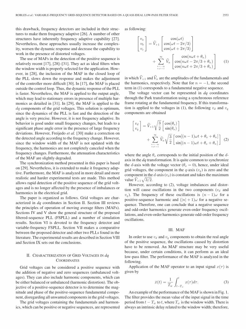
Fig. 3. Structure of the proposed PLL.
Fig. 4. Synchronization diagram of the proposed PLL.
d′-axis of a reference frame rotating at ωgrid with an unknownangular position θ+ .
In this structure, the dq output variables of the MAF are trans-formed back into abc components with the same arbitrary angleθf . The obtained signals (va , vb , vc ) correspond to the funda-mental positive-sequence grid voltages, and therefore, they areclean of any distortion or imbalance. For this reason, this stage isconsidered to perform as a quasi-ideal filter for the three-phasevoltage components. The variables are again transformed intodq coordinates, but in this case, the synchronization angle (θ+ )is obtained by a classical control loop that forces the componentv+
q to be zero through a proportional and integral (PI) regulator.The output of the PI (ω+ ) is integrated to obtain θ+ . It shouldbe remarked that, in this structure, the PI regulator parameterscan be tuned to achieve a quick response of the PLL because un-wanted oscillations are not expected in the v+
q component. Thisis a significant advantage compared with other methods [14],which do not include the filtering stage presented in this paper.
The same structure of Fig. 3 can be used to obtain the negativesequence of the input grid voltages by imposing on the Park andiPark transformations an arbitrary angle rotating in the oppositedirection (θ− = −θ+ ).
V. SIMULATION RESULTS
The FSPLL has been simulated in order to test its perfor-mance. Simulation results have been obtained through MAT-LAB/Simulink. In both simulations, the rms line-to-neutral gridvoltage is 220 V at 50 Hz, and both Park and iPark transfor-mations are tuned to perform at 50 Hz. A window width ofTw = T/2, where T is the grid voltage period, is selected forthe MAFs. The main variables of the proposed FSPLL are dis-played: (a) grid voltages; (b) the dq components before and(c) after the MAF; (d) the dq synchronized variables in the PLL;(e) the input voltage positive sequence; (f) the real (red) anddetected angle (blue); and (g) the error in the detected angle.
Fig. 5. FSPLL simulation results phase jump and voltage dip. (a) Grid volt-ages. (b) dq components before and (c) after the MAF. (d) dq synchronizedvariables in the PLL. (e) Positive sequence of the input grid voltages. (f) Real(dashed) and detected angle. (g) Error in the detected angle.
The MAF needs a Tw time to collect all the data (10 ms). Afterthat, the FSPLL detects the angle without error.
In Fig. 5, a π/2 phase jump is introduced at t = 20 ms. Thedetected angle has an initial error of π/2 that is corrected in a Tw
time. At t = 50 ms, an asymmetrical voltage dip is introduced(60%, 20%, and 0%), thus, a fundamental negative sequenceappears in the dq components. The oscilations are canceledcompletely after the MAF in a Tw time.
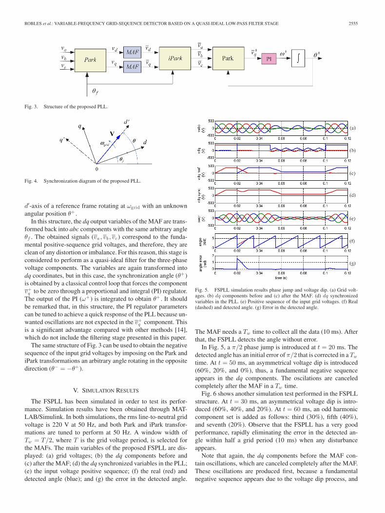
Fig. 6 shows another simulation test performed in the FSPLLstructure. At t = 30 ms, an asymmetrical voltage dip is intro-duced (60%, 40%, and 20%). At t = 60 ms, an odd harmoniccomponent set is added as follows: third (30%), fifth (40%),and seventh (20%). Observe that the FSPLL has a very goodperformance, rapidly eliminating the error in the detected an-gle within half a grid period (10 ms) when any disturbanceappears.
Note that again, the dq components before the MAF con-tain oscillations, which are canceled completely after the MAF.These oscillations are produced first, because a fundamentalnegative sequence appears due to the voltage dip process, and
2556 IEEE TRANSACTIONS ON POWER ELECTRONICS, VOL. 25, NO. 10, OCTOBER 2010
Fig. 6. Constant-frequency FSPLL simulation results. Voltage dip, harmonics,and frequency change. (a) Grid voltages. (b) dq components before and (c) afterthe MAF. (d) dq synchronized variables in the PLL. (e) Positive sequence ofthe input grid voltages. (f) Real (dashed) and detected angle. (g) Error in thedetected angle.
next, due to the harmonic distortion. From the results, one canconclude that the proposed FSPLL can overcome phase jumps,voltage dips, and high harmonic distortion.
At t = 100 ms, the grid frequency changes up to 55 Hz.Now the detected angle shows a constant error of 0.16 rad ap-proximately, even when the disturbances in the grid voltagesdisappear. This is due to the fact that first, Park and iPark trans-formations use a synchronous frame rotating at a frequencydifferent from the fundamental of the grid (ωf ), and second,the window width of the MAF is set to a different frequency,thus, it will not contain an integer number of oscillations of thedq components and will not be able to filter them properly. Asshown in Fig. 2, if the frequency is not exact, oscillations willnot be canceled, but attenuated.
As shown in this example, the proposed positive-sequencedetector has a very good performance in the presence of griddisturbances. However, a grid frequency other than the nominalvalue will produce a proportional error in the detected angle.
VI. VARIABLE-FREQUENCY FSPLL
A. Frequency Detector
To make the FSPLL frequency adaptive, the real frequencyshould be measured to update the frequency dependent blocks.Several methods for the frequency measurement have been pro-posed in the literature. There are the methods based on zero-crossing detection [32]–[39], Fourier transform [36], [40], [41],Kalman filtering [42], PLL based [43], and adaptive notch filterbased [44].
Among these, the ones based on zero-crossing detection arethe simplest. The main idea of these methods is to measure
the time elapsed between two consecutive zero crossings of thegrid voltage, and as a function of this time, estimate the fre-quency. These methods work quite well under undistorted gridconditions. However, in the presence of harmonics or other griddisturbances, they may lead to erroneous frequency estimationsdue to the nonreal crossing points caused by the distortion. Inorder to improve its behavior under these circumstances, severalalgorithms have been proposed [32]–[39]. Almost all of themare based on the attenuation of the undesired harmonic compo-nents and noise as a prior stage. For example, Asnin et al. [32]and [33] propose a prior filter stage based on a FIR filter. A morecomplicated multistage filter is introduced in [34] and [35]. Inboth cases, the aim of including the filters is to attenuate thegrid voltage distortion.
In [36], the required filter stage is implemented making useof a discrete Fourier transformation (DFT) working with a fixedwindow width. In this case, if the width of the window is equalto the period of the grid voltage, the DFT algorithm works asan ideal low-pass filter. On the other hand, if the width of thewindow does not match exactly the period of the voltage, theDFT does not work as an ideal low-pass filter, but its behavior isstill good enough to estimate the frequency. Finally, in a numberof literatures [37]–[39], the grid voltages are approximated by alow-order polynomial coefficients of which are obtained makinguse of the least-square technique (LST). In these cases, due tothe low order of the chosen polynomial, the high-frequencycomponents of the grid voltages are attenuated.
The positive-sequence detector proposed in this paper doesnot need a very accurate frequency measurement to operateproperly. A slight frequency change affects mainly two blocks:Park and iPark transformations, and the MAFs. If the angle ofthe Park transformation has not exactly the same frequency asthe grid voltage, the transformed vd and vq will not be constant.They will oscillate at a frequency of the difference between thereal frequency and the transformation frequency. In the caseof the MAFs, the window width will not match exactly theperiod of the input signal oscillation. Consequently, imbalancesand harmonic disturbances will not be canceled by the MAFscompletely, however, they will be very attenuated, as shown inFig. 2. This error is analyzed in the following. A slight frequencydifference is represented as follows:
ωd = ωreal − ωf (12)
where ωreal is the real-grid frequency and ωf is the frequencyfixed for the Park and iPark transformations and the MAFs. Themain frequency of the transformed dq components will be ωd .From (7)
limω→0
GMAF(jω) = 1 (13)
what for ω = 0 implies
|GMAF(jω)| = 1 and (14)
ϕ[GMAF(jω)] = 0. (15)
For a relatively small frequency as ωd , (8) and (9), and Fig. 2,show that the error in magnitude and phase will be very small.For example, for ωd = 0.5 Hz being Tw = 0.01 s (half the input

ROBLES et al.: VARIABLE-FREQUENCY GRID-SEQUENCE DETECTOR BASED ON A QUASI-IDEAL LOW-PASS FILTER STAGE 2557
Fig. 7. Block diagram of the frequency detector.
signal period), the magnitude and phase result in
|GMAF(jω)| = 0.9993 and (16)
ϕ[GMAF(jω)] = 0.0157 (17)
what proves a very small error in the filtered components, andthus, in the detected angle.
Therefore, in this paper, a relatively simple, but efficientadaptive zero-crossing method is proposed. Fig. 7 shows theflowchart of this detection method. At the beginning of the pro-cess, two zero-crossing points are needed to calculate the initialfrequency. The detector has been designed to allow frequencychanges of up to 25 Hz/s. Hence, every time the frequency isupdated, the upper and lower frequency limits are calculated todetermine a 25-Hz/s frequency band around this new frequency.Then, it will wait for the following zero-crossing point and pro-ceed differently depending on weather it is within the band ornot. If it is within the band, the frequency is updated and thenew limits are calculated. If not, it will look before and afterthe band, which is the closest zero-crossing point to the band,and save it. Neither the frequency nor the frequency limits willbe updated with this last point, but the detector will start count-ing from it waiting for the next zero-crossing point. Both thepositive- and negative-slope zero-crossing points can be usedfor detecting the frequency in order to improve the detectiondynamics. The best way to avoid errors due to transitories whendisturbances appear, is to use both crossing points and calculatethe frequency separately.
The following situations may occur depending on the locationof the next zero-crossing point.
Fig. 8. Zero crossing in the accepted band.
Fig. 9. Zero crossing outside the accepted band.
1) A zero-crossing point is found in the 25 Hz/s band. Itis considered to be a valid value and the frequency isupdated. This situation is shown in Fig. 8. Grid voltagesstart undisturbed and suddenly one harmonic componentis added. In this case, the transition is not strong enoughand the zero-crossing point is found within the band. Anyother zero-crossing point before or after the band may notbe considered if there has been a crossing point within theband.
2) There are several zero-crossing points within the band.When the first zero-crossing point is found, the frequencyis updated and the new band limits are calculated. Thealgorithm will look for a new zero-crossing point muchfurther from the second zero-crossing point. Hence, thiswill be outside the new band, and therefore, will not beconsidered.
3) There is a zero-crossing point before the band. This isshown in Fig. 9. This zero-crossing point would representan important frequency change and may not be real, butcaused by a transitory disturbance, in this case, the sud-den addition of a harmonic component set. This uncertaincrossing point is saved, but the frequency is not updated.If the next zero-crossing point is found in the 25 Hz/s bandof the previous one, the frequency will then be updated.
4) There is a zero-crossing point after the band. If no zero-crossing point is found before or within the band, thisuncertain crossing point is saved, but the frequency is not

2558 IEEE TRANSACTIONS ON POWER ELECTRONICS, VOL. 25, NO. 10, OCTOBER 2010
Fig. 10. Simulation result of the proposed frequency detector. (a) Gridvoltages. (b) Detected frequency. (c) Detected frequency error.
updated. If the next zero-crossing point is found in the25 Hz/s band of the previous one, the frequency will thenbe updated.
5) There are zero-crossing points before and after the band. Inthis case, the nearest point to the band is taken and saved,but again, the frequency is not updated until the next zero-crossing point is within the band. This could representnonreal-crossing points due to any kind of disturbanceand the frequency will be updated properly within a gridvoltage cycle.
When no zero-crossing point is found in the band, the nearestpoint to the band is saved. This is usually due to a transitoryin the grid voltage. The waveform will be periodical, and thus,in the following period a new zero-crossing point will be foundwithin the band of the saved one and the frequency updated.
There are several ways of performing the method. In thisPLL application, a high level of precision is not required be-cause deviations of up to 1 Hz provoke a slight, but acceptablelevel of error in the positive-sequence detection. However, it ispreferable to apply the method to more than one phase. It canbe applied to line-to-neutral phases, line-to-line phases, or α–βtransformed phases.
1) Line-to-neutral voltages: Three frequency detectors areneeded. The average of the detected three frequencies isaccepted as the frequency value. Any frequency changewill be detected quickly, up to three measurements aremade within a period. When a phase fails, the average ofthe remaining phases will be used. If two phases fail, thefrequency will be calculated with the remaining phase.
2) Line-to-line voltages: This is similar to the previous case.The only difference is that if one phase fails, there willstill be three line-to-line phases to detect the frequency.Only when two phases fail one line-to-line phase will goto zero.
3) α − β transformed components: This only needs two fre-quency detectors, but the frequency is updated less often.α − β components can still be used when a phase fails.Furthermore, if two phases fail, one variable (α or β) canstill be used for the frequency update.
Fig. 10 shows the performance of the frequency detector in thepresence of distorted grid voltages when the frequency varies.The simulation starts with 220 V at 50 Hz. At t = 60 ms, the
Fig. 11. Variable-frequency FSPLL simulation results. 0.5 Hz step-frequencychange with a distorted grid. (a) Grid voltages. (b) Real and detected (dashed)frequency. (c) Real (dashed) and detected angle. (d) Error in the detected angle.(e) dq components of the positive sequence. (f) Positive sequence of the inputgrid voltages.
Fig. 12. Comparative simulation in the presence of harmonics. (a) Grid volt-ages. (b) Error in the detected angle for the FSPLL. (c) Error in the detectedangle for DSOGI-FLL. (d) Error in the detected angle for DSOGI-PLL.
frequency starts increasing at 20 Hz/s and it reaches 54 Hz at theend of the simulation. At t = 180 ms third and fifth harmonicsare included with an amplitude of 50% and 30% of the funda-mental. Observe that the error in the frequency detected is smallduring the variation until it stabilizes. The FSPLL hardly noticesthis error. At t = 340 ms, a phase jump of π is introduced. A

ROBLES et al.: VARIABLE-FREQUENCY GRID-SEQUENCE DETECTOR BASED ON A QUASI-IDEAL LOW-PASS FILTER STAGE 2559
Fig. 13. Comparative simulation in the presence of a voltage dip and phase jump. (a) Grid voltages. (b) Error in the detected angle for the FSPLL, DSOGI-FLL,and DSOGI-PLL.
TABLE ICOMPARATIVE IN THE PRESENCE OF HARMONICS
phase jump is usually the worst disturbance for a frequency de-tector. Note that the proposed frequency detector is not affectedby such an abrupt phase jump.
B. Variable-Frequency FSPLL
In the structure shown in Fig. 3, several blocks are designedto perform at a constant frequency. The simulation test shownin Fig. 6 proves that a grid frequency different from the one se-lected will provoke errors in the FSPLL variables. To solve thisproblem, the frequency-dependent blocks have to be updatedwith the calculated frequency. One of the parameters that needsto be changed is the frequency of the arbitrary angle used inthe Park and iPark transformations. In this way, the transformeddq components will be constant without the low-frequency os-cillation produced by the frequency difference. Also the MAFwindow width has to be updated in accordance with the esti-mated frequency. Consequently, the MAF window will alwayscontain an integer number of unwanted oscillations, thus beingcapable of filtering them.
Fig. 11 shows a simulation of the variable-frequency FSPLLfor a frequency step change of 0.5 Hz in the presence of a single-phase voltage dip (20%) and a fifth-order harmonic (20%). Thefrequency detector takes approximately one cycle to detect thecorrect frequency, meanwhile the FSPLL has a little and accept-able error. This error is too little to be noticed in the detectedpositive sequence.
VII. COMPARATIVE SIMULATIONS
The proposed variable-frequency FSPLL has been comparedin the presence of the main grid disturbances, to other threerepresentative detectors found in the literature: the DSOGI-PLL [24], the DSOGI-FLL [21], and the three-phase ANF [22].
TABLE IICOMPARATIVE IN THE PRESENCE OF A VOLTAGE DIP
TABLE IIICOMPARATIVE IN THE PRESENCE OF A PHASE JUMP
TABLE IVCOMPARATIVE IN THE PRESENCE OF A STEP-FREQUENCY VARIATION
The detectors have been modeled and tuned as described in thereferences.
In the next simulations, the rms line-to-neutral grid voltageis 220 V at 50 Hz. In Fig. 12, an odd harmonic component set isadded as follows: fifth (30%), seventh (20%), and 11th (30%).In the presence of harmonics, the FSPLL needs a Tw time tocorrect the error, while the DSOGI-FLL and the DSOGI-PLLcannot completely cancel the effects of the harmonics andmaintain an error. The three-phase ANF can also removecompletely the error.
Fig. 13 shows the behavior of the three PLLs in the presenceof a three-phase voltage dip (20%) and a π/10 phase jump.Again, the FSPLL needs a Tw time to completely correct theerror. The DSOGI-PLL and the three-phase ANF have a highertransitory error, but a fast performance, while the DSOGI-FLLhas slower dynamics.
Tables I–IV summarize the performance of the four detectorsin the presence of the main grid disturbances. The following

2560 IEEE TRANSACTIONS ON POWER ELECTRONICS, VOL. 25, NO. 10, OCTOBER 2010
Fig. 14. Experimental results. Constant-frequency input, voltage dip, and high harmonic distortion. (a) Grid voltages. (b) Detected angle. (c) Detected frequency.(d) dq synchronized variables in the PLL. (e) Positive sequence.
Fig. 15. Experimental results. Varying-frequency input and voltage dip. (a) Grid voltages. (b) Detected angle. (c) Detected frequency. (d) Error in the detectedfrequency. (e) dq synchronized variables in the PLL. (f) Positive sequence.
data are displayed. The stationary errors in the detected phase(ephase), the detected magnitude of the positive sequence (emag ),and the detected frequency (efreq ). Additionally, the settling timeof the detected phase (tsphase), detected magnitude of the pos-itive sequence (tsmag ), and detected frequency (tsfreq) withinthe 2% of the steady state for the DSOGI-FLL, DSOGI-PLL,and three-phase ANF are shown. In the case of the variable-frequency FSPLL, this time corresponds to the time needed tocorrect the error completely (0% of the steady state). These datahave been obtained through simulation. In this study, the instantsof transitions and the harmonic phases are on the basis of theworst case for all the sequence detectors under evaluation.
Table I shows a comparative when an odd-order harmoniccomponent set fifth (30%) and seventh (20%) is added. As shownin Fig. 12, the variable-frequency FSPLL and the three-phase
ANF cancel the effects of the harmonics, while the other twoPLLs can only attenuate the error.
In Tables II and III, the behavior of the four detectors whena three-phase voltage dip (20%) appears and the effect of aphase jump of 2π/3 is analyzed separately. In both cases,all the detectors achieve zero stationary errors. Again, thevariable-frequency FSPLL needs a Tw time to completelyremove the errors. The settling time (2%) is shown for the otherthree detectors.
Finally, in Table IV, the effect of a frequency step changeof 0.5 Hz is shown. In this case, all the detectors achieve zerostationary errors, and t0 phase, t0 mag, and t0 freq represent the timeneeded to achieve the steady state (within 0% of error).
As shown in this comparison, the main advantages of the pro-posed variable-frequency FSPLL are the complete cancellation

ROBLES et al.: VARIABLE-FREQUENCY GRID-SEQUENCE DETECTOR BASED ON A QUASI-IDEAL LOW-PASS FILTER STAGE 2561
Fig. 16. Experimental results. Zoom of the transitory of Fig. 15. (a) Gridvoltages. (b) Detected angle. (c) Detected frequency. (d) Error in the detectedfrequency. (e) dq synchronized variables in the PLL. (f) positive sequence.
Fig. 17. Grid-connected NPC converter.
of the harmonics, the short- and fixed-response time in all thecases except in the presence of frequency variations because ofthe short delay of the frequency detector, and the capacity towithstand very high distorted conditions. Additionally, the ef-fect of the perturbations in the proposed detector is always thesame irrespective of the exact moment of appearance and thesame tuning parameters are optimum for every disturbance.
VIII. EXPERIMENTAL RESULTS
The proposed algorithm was programmed in a DSP boardTMS320F2812 and a number of experimental results were ob-tained. A three-phase generator CMC-156 from Omicron wasused to provide the grid voltages. All the tests were performed
Fig. 18. Experimental results. Real unbalance and distortion. (a) Grid voltages.(b) dq components before the MAF. (c) dq synchronized variables in the PLL.(d) Detected angle.
with a line-to-neutral voltage of 50 Vrms at 50 Hz except othervalues specified.
Fig. 14 displays the main variables of the proposed FSPLL.The grid frequency is maintained constant at 50 Hz throughoutthe process. An abrupt short circuit occurs at t = 60 ms (a 100%single-phase voltage dip). At t = 140 ms, the previous voltagedip recovers and a three-phase 70% voltage dip, as well as anodd harmonic set is introduced as follows. Up to the 25th har-monic according to Vh = Vfundamental/h for h = 3, 5, . . . , 25.The variability of the extracted frequency around the real fre-quency at 50 Hz is shown. The sampling frequency is 10 kHz,thus, 50 Hz would suppose 200 samples/period. The measureoscillates between two samples (200 samples ±1 when the fre-quency is fixed at 50 Hz). Observe the fast detection of the fun-damental amplitude change. There is no change in the positive-sequence phase during this process, as the detected angle shows.Thus, the frequency and angle are detected accurately, showinga good performance in the presence of voltage dips and highharmonic distortion.
The experimental test of Fig. 15 shows the performance of thevariable-frequency FSPLL when the input voltage has a time-varying frequency. The error in the detected frequency is alsoshown for a better clarity. The input frequency starts at 50 Hz. Att = 250 ms, it starts to vary at 10 Hz/s up to 59 Hz. In addition,a single-phase voltage dip of 30% occurs at t = 500 ms until theend. Fig. 16 shows a zoom of the transitory. Note that even inthe presence of such adverse operating conditions, the proposedpositive-sequence detector is able to detect the angle correctlyand the dq components are synchronized perfectly.
The proposed FSPLL has been used in a real application toconnect an neutral point clamped (NPC) converter to a 400 Vgrid, as shown in Fig. 17. The system has been subjected to ahard distortion in the test of Fig. 18. Observe that even undersuch a pessimistic scenario, the high distortion of the positivesequence dq components is removed and an accurate detectionof the angle is performed.
IX. CONCLUSION
In this paper, a new PLL has been presented for positive-sequence detection in a three-phase system. The structure isbased on a MAF that guarantees complete cancellation of the
2562 IEEE TRANSACTIONS ON POWER ELECTRONICS, VOL. 25, NO. 10, OCTOBER 2010
effects produced by grid voltage imbalances and harmonics onthe detected variables. Moreover, the parameters of the PI con-trollers are tuned to achieve a wide closed-loop bandwidth, thus,the dynamic response of the system is improved significantly.This is possible because unwanted oscillations have been re-moved in a previous stage. Simulation and experimental resultshave been presented, which verify good performance of thesystem in the presence of harmonics, imbalances, and phasechanges in the grid voltages. Performance of the presented PLLhas proved considerably better than the basic PLL design. In ad-dition, it shows clear advantages in the presence of harmonicsover the newest and more sophisticated positive-sequence detec-tors. On the other hand, it has a similar dynamic response and be-havior in the presence of voltage dips. A remarkable advantageof the proposed system is its simplicity compared to those witha similar performance. Furthermore, the PLL includes a simple-frequency detector that makes it frequency adaptive. This guar-antees its proper operation even under large frequency changes.
REFERENCES
[1] M. Cirrincione, M. Pucci, G. Vitale, and A. Miraoui, “Current harmoniccompensation by a single-phase shunt active power filter controlled byadaptive neural filtering,” IEEE Trans. Ind. Electron., vol. 56, no. 8,pp. 3128–3143, Aug. 2009.
[2] K. H. Kwan, Y. C. Chu, and P. L. So, “Model-based H-infinity control ofa unified power quality conditioner,” IEEE Trans. Ind. Electron., vol. 56,no. 7, pp. 2493–2504, Jul. 2009.
[3] C.A. Busada, H. G. Chiacchiarini, and J. C. Balda, “Synthesis of sinusoidalwaveform references synchronized with periodic signals,” IEEE Trans.Power Electron., vol. 23, no. 2, pp. 581–590, Mar. 2008.
[4] A. Pigazo, V. M. Moreno, and E. J. Estebanez, “A recursive Park trans-formation to improve the performance of synchronous reference framecontrollers in shunt active power filters,” IEEE Trans. Power Electron.,vol. 24, no. 9, pp. 2065–2075, Sep. 2009.
[5] M. Dai, M. N. Marwali, J.-W. Jung, and A. Keyhani, “Power flow controlof a single distributed generation unit,” IEEE Trans. Power Electron.,vol. 23, no. 1, pp. 343–352, Jan. 2008.
[6] M. Silva, B. M. Lopes, B. J. C. Filho, R. P. Campana, and W.C. Bosventura, “Performance evaluation of PLL algorithms for single-phase grid-connected systems,” in Proc. Ind. Appl. Conf. Annu. Meeting2004, Oct., vol. 4, pp. 2259–2263.
[7] M. Karimi-Ghartemani and M. Reza Iravani, “A nonlinear adaptive filterfor online signal analysis in power systems: Applications,” IEEE Trans.Power Del., vol. 17, no. 2, pp. 617–622, Apr. 2002.
[8] M. Karimi-Ghartemani, H. Karimi, and M. Reza Iravani, “Amagnitude/phase-locked loop system based on estimation of frequencyand in-phase/quadrature-phase amplitudes,” IEEE Trans. Ind. Electron.,vol. 51, no. 2, pp. 511–517, Apr. 2004.
[9] T. Thacker, R. Wang, D. Dong, R. Burgos, F. Wang, and D. Boroyevich,“Phase-locked loops using state variable feedback for single-phase con-verter systems,” in Proc. APEC2009, Washington, DC, Feb. 15–19,pp. 864–870.
[10] R. M. Santos Filho, P. F. Seixas, P. C. Cortizo, L. A. B. Torres, and A.F. Souza, “Comparison of three single-phase PLL algorithms for UPSapplications,” IEEE Trans. Ind. Electron., vol. 55, no. 8, pp. 2923–2932,Aug. 2008.
[11] M. Ciobotaru, R. Teodorescu, and F. Blaabjerg, “A new single-phasePLL structure base on second order generalized integrator,” in Proc.PESC2006, Jun., vol. 4, pp. 1–6.
[12] D. Jovcic, “Phase locked loop system for FACTS,” IEEE Trans. PowerSyst., vol. 18, no. 3, pp. 1116–1124, Aug. 2003.
[13] L. G. B. Barbosa, Rolim, D. R. Rodrigues, and da Costa, Jr, M. Aredes,“Analysis and software implementation of a robust synchronizing PLLcircuit based on the pq theory,” IEEE Trans. Ind. Electron., vol. 53, no. 6,pp. 1919–1926, Dec. 2006.
[14] S.-K. Chung, “A phase tracking system for three phase utility interfaceinverters,” IEEE Trans. Power Electron., vol. 15, no. 3, pp. 431–438, May2000.
[15] P. Rodrıguez, J. Pou, J. Bergas, J. I. Candela, R. Burgos, andD. Boroyevich, “Decoupled double synchronous reference frame PLLfor power converters control,” IEEE Trans. Power Electron., vol. 22,no. 2, pp. 584–592, Mar. 2007.
[16] P. Xiao, K. A. Corzine, and G. K. Venayagamoorthy, “Multiple referenceframe-based control of three-phase PWM boost rectifiers under unbal-anced and distorted input conditions,” IEEE Trans. Power Electron.,vol. 23, no. 4, pp. 2006–2017, Jul. 2008.
[17] J. Pou, E. Robles, S. Ceballos, J. Zaragoza, A. Arias, and P. Ibanez,“Control of back-to-back-connected neutral-point-clamped converters inwind mill applications,” presented at the EPE2007, Dresden, Denmark,Sep. 2–5.
[18] S. Alepuz, S. Busquets, J. Bordonau, J. Pontt, C. Silva, and J. Rodrıguez,“Fast on-line symmetrical components separation method for synchro-nization and control purposes in three phase distributed power generationsystems,” presented at the EPE2007, Dresden, Denmark, Sep. 2–5.
[19] M. Karimi-Ghartemani and M. Reza Iravani, “A method for synchroniza-tion of power electronic converters in polluted and variable-frequencyenvironments,” IEEE Trans. Power Syst., vol. 19, no. 3, pp. 1263–1270,Aug. 2004.
[20] S. Alepuz, S. Busquets-Monge, J. Bordonau, A. Martinez-Velasco,C. Silva, J. Pontt, and J. Rodriguez, “Control strategies based on sym-metrical components for grid-connected converters under voltage dips,”IEEE Trans. Ind. Electron., vol. 56, no. 6, pp. 2162–2173, Jun. 2009.
[21] P. Rodrıguez, A. Luna, M. Ciobotaru, R. Teodorescu, and F. Blaabjerg,“Advanced grid synchronization system for power converters under un-balanced and distorted operating conditions,” in Proc. IEEE IECON2006,Paris, France, Nov. 7–10, pp. 5173–5178.
[22] D. Yazdani, M. Mojiri, A. Bakhshai, and G. Joos, “A fast and accuratesynchronization technique for extraction of symmetrical components,”IEEE Trans. Power Electron., vol. 24, no. 3, pp. 674–684, Mar. 2009.
[23] D. Yazdani, A. Bakhshai, and P. K. Jain, “Grid synchronization techniquesfor converter interfaced distributed generation systems,” in Proc. IEEEECCE 2009, Sep. 20–24, pp. 2007–2014.
[24] P. Rodriguez, R. Teodorescu, I. Candela, A. V. Timbus, M. Liserre, andF. Blaabjerg, “New positive-sequence voltage detector for grid synchro-nization of power converters under faulty grid conditions,” in Proc. IEEEPESC2006, Jeju, South Korea, Jun. 18–22, pp. 1–7.
[25] H. E. P. Souza, F. Bradaschia, F. A. S. Neves, M. C. Cavalcanti, G. M.S. Azevedo, and J. P. Arruda, “A method for extracting the fundamentalfrequency positive-sequence voltage vector based on simple mathematicaltransformations,” IEEE Trans. Ind. Electron., vol. 56, no. 5, pp. 1539–1547, May 2009.
[26] R. F. de Camargo and H. Pinheiro, “Synchronisation method for three-phase PWM converters under unbalanced and distorted grid,” IEE Proc.-Electr. Power Appl., vol. 153, no. 5, pp. 763–772, Sep. 2006.
[27] H. S. Timorabadi and F. P. Dawson, “A three-phase frequency adap-tive digital phase locked loop for measurement, control, and protectionin power systems,” in Proc. IEEE PCC2007, Nagoya, Japan, Apr. 2–5,pp. 183–190.
[28] A. Ghoshal and V. John, “A Method to Improve PLL Performance underabnormal grid conditions,” presented at the NPEC2007, Indian Instituteof Science, Bangalore, India, Dec. 17–19.
[29] E. Robles, S. Ceballos, J. Pou, J. Zaragoza, and I. Gabiola, “Grid syn-chronization method based on a quasi-ideal low-pass filter stage and aphase-locked loop,” in Proc. IEEE PESC2008, Rhodes, Greece, Jun. 15–19, pp. 4056–4061.
[30] F. D. Freijedo, J. Doval-Gandoy, O. Lopez, and E. Acha, “A generic open-loop algorithm for three-phase grid voltage/current synchronization withparticular reference to phase, frequency, and amplitude estimation,” IEEETrans. Power Electron., vol. 24, no. 1, pp. 94–107, Jan. 2009.
[31] E. Robles, J. Pou, S. Ceballos, I. Gabiola, and M. Santos, “Grid sequencedetector based on a stationary reference frame,” presented at the Eur. Conf.Power Electron. Appl., Barcelona, Spain, Sep. 8–10. 2009.
[32] L. Asnin, V. Backmutsky, and M. Gankin, “Comparative characteristicsof main methods for dynamic estimation of frequency and magnitudeparameters in power systems,” in Proc. 22nd Conv. Electr. Electron. Eng.,Dec.1, 2002, pp. 35–38.
[33] L. Asnin, V. Backmutsky, M. Gankin, J. Blashka, and M. Sedlachek, “DSPmethods for dynamic estimation of frequency and magnitude parametersin power system transients,” presented at the Power Tech 2008, vol. 4,Porto, Portugal, Sep. 10–13.
[34] O. Vainio and S. J. Ovaska, “Digital filtering for robust 50/60 Hz zero-crossing detectors,” IEEE Trans. Instrum. Meas., vol. 45, no. 2, pp. 426–430, Apr. 1996.

ROBLES et al.: VARIABLE-FREQUENCY GRID-SEQUENCE DETECTOR BASED ON A QUASI-IDEAL LOW-PASS FILTER STAGE 2563
[35] O. Vainio and S. J. Ovaska, “Noise reduction in zero crossing detectionby predictive digital filtering,” IEEE Trans. Ind. Electron., vol. 42, no. 1,pp. 58–62, Feb. 1995.
[36] M. B. Duric and Z. R. Durisic, “Frequency measurement in power net-works in the presence of harmonics using fourier and zero crossing tech-nique,” in Proc. Power Tech 2005, St. Petersburg, Russia, Jun. 27–30,pp. 1–6.
[37] M. M. Begovic, P. M. Djuric, S. Dunlap, and A. G. Phadke, “Frequencytracking in power networks in the presence of harmonics,” IEEE Trans.Power Del., vol. 8, no. 2, pp. 480–486, Apr. 1993.
[38] D. W. P. Thomas and M. S. Woolfson, “Evaluation of frequency trackingmethods,” IEEE Trans. Power Del., vol. 16, no. 3, pp. 367–371, Jul. 2001.
[39] M. Sanaye-Pasand and V. J. Marandi, “Frequency estimation of distortedsignals for control and protection of power system,” in Proc. 8th IEE Int.Conf. Dev. Power Syst. Protection, Amsterdam, The Netherlands, Apr.5–8, 2004, pp. 631–634.
[40] H. K. Kwok and D. L. Jones, “Improved instantaneous frequency estima-tion using an adaptive short-time fourier transform,” IEEE Trans. SignalProcess., vol. 48, no. 10, pp. 2964–2972, Oct. 2000.
[41] J. Yang and C. Liu, “A precise calculation of power system frequency,”IEEE Trans. Power Del., vol. 16, no. 3, pp. 361–366, Jul. 2001.
[42] A. Routray, A. K. Pradhan, and K. P. Rao, “A novel Kalman filter forfrequency estimation of distorted signals in power systems,” IEEE Trans.Instrum. Meas., vol. 51, no. 3, pp. 469–479, Jun. 2002.
[43] H. Karimi, M. Karimi-Ghartemani, and M. R. Iravani, “Estimation offrequency and its rate of change for applications in power systems,” IEEETrans. Power Del., vol. 19, no. 2, pp. 472–480, Apr. 2004.
[44] M. Mojiri, M. Karimi-Ghartemani, and A. Bakhshai, “Estimation of powersystem frequency using an adaptive notch filter,” IEEE Trans. Instrum.Meas., vol. 56, no. 6, pp. 2470–2477, Dec. 2007.
Eider Robles was born in Bilbao, Spain, in 1980. Shereceived the M.S. degree in electronic and automaticengineering from the University of Deusto, Bilbao,in 2003. She is currently working toward the Ph.D.degree in the Department of Electronic Engineering,University of the Basque Country, Bilbao.
Since 2003, she has been with the Robotiker-Tecnalia Research Centre, Zamudio, Spain, whereshe is currently a Research Engineer in the EnergyUnit. She is author or coauthor of more than 20 tech-nical papers. Her research interests include the grid
connection and control of synchronous wind turbines with multilevel converters.
Salvador Ceballos received the B.Sc degree inphysics from the University of Cantabria, Santander,Spain, in 2001, and the B.Eng. and Ph.D. degreesin electronic engineering from the University of theBasque Country, Bilbao, Spain, in 2002 and 2008,respectively.
Since 2002, he has been with the Robotiker-Tecnalia Research Centre, Zamudio, Spain, wherehe is currently a Development Engineer in the En-ergy Unit. From May 2008 to May 2009, he was aVisiting Researcher at the Hydraulic and Maritime
Research Centre, University College Cork, Cork, Ireland. He has authored orcoauthored more than 30 published technical papers. His research interestsinclude multilevel converters, fault-tolerant power electronic topologies, andrenewable energy systems.
Josep Pou (S’97–A’02–M’03) received the B.S.,M.S., and Ph.D. degrees in electrical engineeringfrom the Technical University of Catalonia (UPC),Terrassa, Spain, in 1989, 1996, and 2002, respec-tively.
During 1989, he was the Technical Director ofPolylux S.A. In 1990, he joined as an Assistant Pro-fessor with the Faculty of UPC, where he becamean Associate Professor in 1993. From February 2001to January 2002, and from February 2005 to Jan-uary 2006, he was a Researcher in the Center for
Power Electronics Systems, Virginia Polytechnic Institute and State University(Virginia Tech), Blacksburg, VA. He has authored or coauthored more than 80published technical papers. He has been involved in several industrial projectsand educational programs in the fields of power electronics and systems. Hisresearch interests include modeling and control of power converters, multilevelconverters, power quality, renewable energy systems, and motor drives.
Jose Luis Martın (M’97) received the M.S. andPh.D. degrees in electrical engineering from the Uni-versity of the Basque Country, Bilbao, Spain, in 1988and 1992, respectively.
From 1989 to 1995, he was an Assistant Profes-sor of electronic technology in the Electronics andTelecommunications Department, University of theBasque Country, where he became an Associate Pro-fessor in 1995, and the Head of the Electronics andTelecommunications Department from 1995 to 2001.From 2001 to 2005, he was a Vice-Dean of the Fac-
ulty of Engineering, Bilbao. He has been involved with the Applied ElectronicsResearch Team of the University of the Basque Country.
Jordi Zaragoza (S’08) received the B.S. degree inelectronic engineering and the M.S. degree in au-tomatic and electronic industrial engineering fromthe Technical University of Catalonia (UPC), Ter-rassa, Spain, in 2001 and 2004, respectively, wherehe is currently working toward the Ph.D. degree inthe Terrassa Industrial Electronic Group, Departmentof Electronic Engineering.
In 2003, he was an Assistant Professor at UPC.From September 2006 to September 2007, he was aResearcher with the Energy Unit, Robotiker-Tecnalia
Research Centre, Zamudio, Spain. He has authored or coauthored more than20 published technical papers. His current research interests include modelingand control of power converters, multilevel converters, wind energy, and powerquality.
Pedro Ibanez (M’04) was born in Bilbao, Spain, in1964. He received the M.Sc. and Ph.D. degree inelectrical engineering from the University of BasqueCountry, Bilbao, in 1988 and 1991, respectively.
From 1988 to 1997, he was an Assistant Pro-fessor of electronic technology in the Electron-ics and Telecommunications Department, Univer-sity of Basque Country, where he became an As-sociate Professor in 1997. Since 1992, he has beenwith Robotiker-Tecnalia Research Centre, Zamudio,Spain, where he is currently the Technology Director
of the Energy Unit. He has been engaged in many projects related to electronicssystems, digital control systems, and power converters for energy applications.He has been involved in more than 30 research projects supported by publicinstitutions (included EU) and private companies. He is the author or coauthorof more than 30 technical papers.


![QUASI-BIGEBRES DE LIE ET ALGEBRES QUASI-BATALIN ...streaming.ictp.it/preprints/P/99/174.pdf3 Quasi-bigebres de Lie Les quasi-bigebres de Lie [6] (appelees quasi-bigebres jacobiennes](https://static.fdocuments.us/doc/165x107/60aa5fd4a787df4f051abfc1/quasi-bigebres-de-lie-et-algebres-quasi-batalin-3-quasi-bigebres-de-lie-les.jpg)