"Vanity of vanities," says the Preacher; "Vanity of vanities, all is vanity." (Eccl. 1:2 - NKJ)

Segments of these instructions will relate to your vanity. Please read these instructions thoroughly and ensure the appropriate instructions
are used during the installation
Vanity Installation Instructions
April 2016

IMPORTANT The vanity must not be exposed to excessive moisture e.g. directly beside a bath or open shower.
The materials used in the manufacture of Clearlite vanities are water resistant NOT WATER-PROOF. If the installation is likely to encounter excessive moisture please consult your merchant for further advice.
When tiling, do not cut the tiles to fit around the vanity. Pre-tile then place the vanity in front (the warranty does not cover any costs associated with re-tiling or re-decoration).
Ensure the water temperature at the tap outlet does not exceed 55°C. This will void warranty Do not expose the vanity to solvents. Only use cleaning agents recommended for acrylics.
Tools and Materials
Drill and drill bits Spirit level Masking tape Tape Measure Caulking gun Screws Screw driver Pencil Silicone Sealant Cleaning materials
Floor Standing Vanity Installation
1. Inspect that the unit is correct and undamaged. 2. Check that the floor is level and the walls plumb and straight
If the floor is out of level use a proprietary floor levelling compound to level. It is important that the cabinet is fully supported by its base so the door
and drawers will operate correctly The wall must not be bowed in either the horizontal or vertical plane as
this will cause a twist in the cabinet resulting in door & drawer alignment issues and the soft close mechanisms not functioning
3. Remove the plastic transportation feet from the cabinet base. 4. Place the cabinet into the proposed position. Mark the positions of any plumb-
ing outlets Access to the cabinet can be made easy by the removal of the shelf, doors and drawers. Refer to ’Removal & Alignment’ section. When removing the drawers ensure their positions are recorded as they are not interchangeable.
5 Remove the cabinet. Cut the holes required to accommodate the plumbing.
6. Return the cabinet into position and recheck that it is sitting level and is not
twisted 7. If your cabinet has a recessed back rail a packer will need to be placed be-
tween back panel and wall at the screw fixing points to eliminate any distortion of the rear rail
8. Attach the vanity to the wall by screwing the back top rail of the cabinet into
studs or nogs. Use No.8 x 50 countersunk screws or similar
Important Do not induce a twist in the cabinet when screwing to the wall. The
cabinet must remain true for the doors, drawers and Soft close mechanisms to operate correctly
9. Once the cabinet is in position the vanity top can be installed . Please refer to the Vanity top installation section
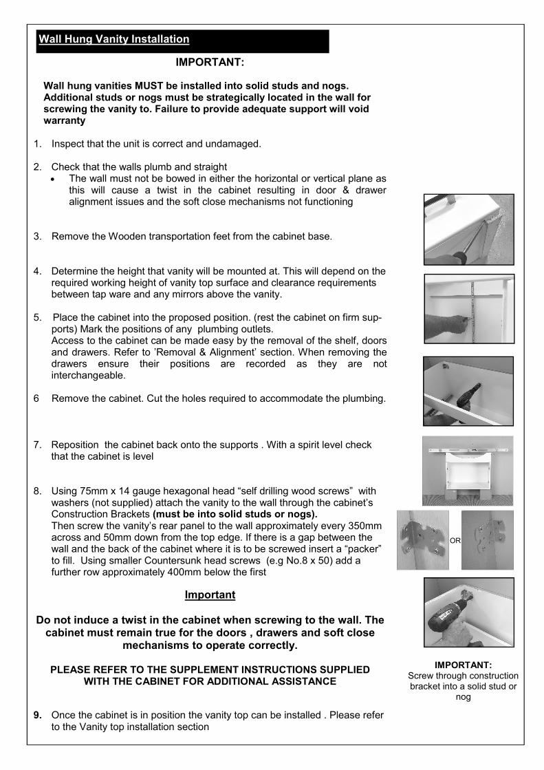
Wall Hung Vanity Installation
IMPORTANT:
Wall hung vanities MUST be installed into solid studs and nogs. Additional studs or nogs must be strategically located in the wall for screwing the vanity to. Failure to provide adequate support will void warranty
1. Inspect that the unit is correct and undamaged. 2. Check that the walls plumb and straight
The wall must not be bowed in either the horizontal or vertical plane as this will cause a twist in the cabinet resulting in door & drawer alignment issues and the soft close mechanisms not functioning
3. Remove the Wooden transportation feet from the cabinet base. 4. Determine the height that vanity will be mounted at. This will depend on the
required working height of vanity top surface and clearance requirements between tap ware and any mirrors above the vanity.
5. Place the cabinet into the proposed position. (rest the cabinet on firm sup-
ports) Mark the positions of any plumbing outlets. Access to the cabinet can be made easy by the removal of the shelf, doors and drawers. Refer to ’Removal & Alignment’ section. When removing the drawers ensure their positions are recorded as they are not interchangeable.
6 Remove the cabinet. Cut the holes required to accommodate the plumbing.
7. Reposition the cabinet back onto the supports . With a spirit level check that the cabinet is level
8. Using 75mm x 14 gauge hexagonal head “self drilling wood screws” with
washers (not supplied) attach the vanity to the wall through the cabinet’s Construction Brackets (must be into solid studs or nogs). Then screw the vanity’s rear panel to the wall approximately every 350mm across and 50mm down from the top edge. If there is a gap between the wall and the back of the cabinet where it is to be screwed insert a “packer” to fill. Using smaller Countersunk head screws (e.g No.8 x 50) add a further row approximately 400mm below the first
Important
Do not induce a twist in the cabinet when screwing to the wall. The cabinet must remain true for the doors , drawers and soft close
mechanisms to operate correctly.
PLEASE REFER TO THE SUPPLEMENT INSTRUCTIONS SUPPLIED WITH THE CABINET FOR ADDITIONAL ASSISTANCE
9. Once the cabinet is in position the vanity top can be installed . Please refer
to the Vanity top installation section
OR
IMPORTANT: Screw through construction bracket into a solid stud or
nog

1. To cut the holes use a high-speed steel hole saw of an appropriate size in an electric drill operating at a moderate speed. When cut-ting, apply gentle downwards pressure in a slow circular move-ment, minimising vibration. Take special care when nearing the end of the cut by supporting the drill so it does not impact on the vanity top surface. Carefully withdraw the drill / hole-saw when completed.
Drilling Tap Holes in the vanity top (if required)
1. Clean the perimeter of the vanity and the underside of the top ensuring they are free of dust and contaminants
2. Apply a small bead of neutral cure silicone (not supplied) to the four corners of the cabinet, as shown.
3. Place the vanity top into position 4. Install the tap-ware.
If the tap-ware being installed does not have a gasket to seal it to the vanity top it is recommended that silicone sealant be applied to the underside of tap-ware flange.
5. Install the waste. Seal the underside of the waste flange with either Plumbers putty or silicone sealant.
If tap-ware and waste are to be fitted immediately after installation, care must be taken to ensure top remains in correct position until silicone is cured
Caution
Do not over tighten the waste fitting during installation
PLEASE NOTE: All PLUMBING CONNECTIONS MUST BE MADE BY A REGISTERED PLUMBER
Allow the sealant to cure for a minimum of 24 hrs before use
Vanity Top Installation
Sealing the Vanity
To ensure the vanity is protected from potential water damage the following areas must also be sealed using a sanitary grade silicone sealant.
The base of the cabinet to the floor The sides of the cabinet to the wall The rear edge of any vanity top to the wall The underside of the vanity top to cabinet The perimeter of a basin to the bench top and the wall if
applicable
A neat finish will be achieved by masking along the areas being sealed
Allow the sealant to cure for a minimum of 24hrs before use.
Special note about Vitreous China Tops The process of manufacturing vitreous china products is complex. During its manufacture the product shrinks significantly which can at times lead to the product being slightly twisted. At the time of installation it may be necessary insert small spacers between the cabinet and underside of the VC top for it to sit even
Silicone
Silicone
Silicone
Silicone
Silicone

The cabinet doors are factory set but should your installation require further adjustment, use the adjustment screws provided on the hinge mechanism. A No.2 Pozi Drive Screwdriver will be required. 1. To adjust the doors “ vertically” loosen the two hinge mounting
screws on both sets of door hinges. Lift or lower the door as re-quired, then lightly retighten.
2. To adjust the doors “left or right” simply rotate the front adjust-
ment screw clockwise or anticlockwise until the desired position is achieved.
3. To adjust the doors “in or out” loosen the rear adjustment screw
and slide the door into desired position, then retighten screw. 4. To remove the door from the cabinet press the lug at the rear of
the hinge and pivot the rear of the hinge outwards. 5. To re-attach, position the front of the hinge so the two front lugs
fit into the rebates on the base plate, press the rear of the hinge until it clicks back into place.
1
Doors
2
3
4
5
Door / Drawer Alignment & Removal

Soft Drawer Closing - Type A (Classic Floor and Classic Wall Hung Vanities)
1. To remove the draw simply pull the drawer out its maximum opening.
2. Lift the front of the drawer box and remove. Note: When
removing drawers ensure their positions are recorded as they are not interchangeable
3. To reinsert simply reverse the procedure. 4. The Soft Drawer closer mechanism must be extended before
reinstalling the drawer. If it is not extended, please follow the steps below
Resetting the Soft closer
a. If the Soft drawer mechanism is not extended at the time of
reinstalling the drawer
b. Take hold of the front white tab on the mechanism and carefully pull forward
c. The white tab will automatically engage into the slot of the main body. Once in this position the soft closer is ready to accept the drawer for reinstallation
1
2 3
4a
4b
4c
Door / Drawer Alignment & Removal

Soft Drawer Closing - Type B (2 styles)
To Remove the Drawer 1. To remove the drawer simply open to its full extent
and depress the levers on each side of the drawer. Slide the drawer forward and remove
To Reinstall the Drawer 2. Extend the drawer runners to their maximum open-
ing position 3. Place the drawer onto the runners until the locking
tab locates into the rear of the drawer. 4. While holding the drawer pull the runner forward
until it engages the clip and locks into place. 5. When the runner it is located correctly it will “click”
into position. And it will now be held in the slots 6. Close the drawer and check alignment. The front of
the drawers may be marginally raised or lowered by depressing and rotating the other blue lever (type A ) or rolling the wheel left or right (type B)
IMPORTANT: The vanity must remain true when fixed to the wall for the soft closing drawer
mechanisms to operate. If the wall is bowed it must either be straightened or packers placed behind the vanity to ensure to remove any twist or bow
Ensure any debris that may have been left during the installation is removed from the
cabinet and the soft close runner mechanisms. Failure to remove any debris may cause ineffective operation of the soft drawer closers and possible failure
Maximum working load per drawer = 9kg
1
2
4
Door / Drawer Alignment & Removal
6
Type A Type B
CLICK!
SLOT 5 CLICK!
SLOT
3