VALLIAMMAI ENGINEERING COLLEGE Semester/EC6011... · of EMI, Conducted and Radiated EMI emission...
12
1 VALLIAMMAI ENGINEERING COLLEGE SRM Nagar, Kattankulathur – 603 203 Question Bank DEPARTMENT OF ELECTRONICS AND COMMUNIUCATION EC6011 ELECTROMAGNETIC INTERFERENCE AND COMPATIBILITY Regulation: 2013 Academic Year: 2017 – 2018 (Odd Semester) Prepared By Dr. S. Ramesh, Associate Professor, Dr. N. Rajesh, AP- O.G, Mrs. K. Kamala, AP - S.G.
Transcript of VALLIAMMAI ENGINEERING COLLEGE Semester/EC6011... · of EMI, Conducted and Radiated EMI emission...

1
VALLIAMMAI ENGINEERING COLLEGE
SRM Nagar, Kattankulathur – 603 203
Question Bank
DEPARTMENT OF ELECTRONICS AND COMMUNIUCATION
EC6011 ELECTROMAGNETIC INTERFERENCE AND COMPATIBILITY
Regulation: 2013
Academic Year: 2017 – 2018 (Odd Semester)
Prepared By
Dr. S. Ramesh, Associate Professor,
Dr. N. Rajesh, AP- O.G,
Mrs. K. Kamala, AP - S.G.
2
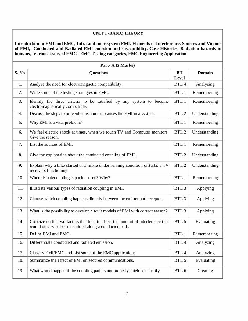
UNIT I ‐BASIC THEORY
Introduction to EMI and EMC, Intra and inter system EMI, Elements of Interference, Sources and Victims
of EMI, Conducted and Radiated EMI emission and susceptibility, Case Histories, Radiation hazards to
humans, Various issues of EMC, EMC Testing categories, EMC Engineering Application.
Part‐ A (2 Marks)
S. No Questions BT
Level
Domain
1. Analyze the need for electromagnetic compatibility. BTL 4 Analyzing
2. Write some of the testing strategies in EMC. BTL 1 Remembering
3. Identify the three criteria to be satisfied by any system to become
electromagnetically compatible.
BTL 1 Remembering
4. Discuss the steps to prevent emission that causes the EMI in a system. BTL 2 Understanding
5. Why EMI is a vital problem? BTL 1 Remembering
6. We feel electric shock at times, when we touch TV and Computer monitors.
Give the reason.
BTL 2 Understanding
7. List the sources of EMI. BTL 1 Remembering
8. Give the explanation about the conducted coupling of EMI. BTL 2 Understanding
9. Explain why a bike started or a mixie under running condition disturbs a TV
receivers functioning.
BTL 2 Understanding
10. Where is a decoupling capacitor used? Why? BTL 1 Remembering
11. Illustrate various types of radiation coupling in EMI. BTL 3 Applying
12. Choose which coupling happens directly between the emitter and receptor. BTL 3 Applying
13. What is the possibility to develop circuit models of EMI with correct reason? BTL 3 Applying
14. Criticize on the two factors that tend to affect the amount of interference that
would otherwise be transmitted along a conducted path.
BTL 5 Evaluating
15. Define EMI and EMC. BTL 1 Remembering
16. Differentiate conducted and radiated emission. BTL 4 Analyzing
17. Classify EMI/EMC and List some of the EMC applications. BTL 4 Analyzing
18. Summarize the effect of EMI on secured communications. BTL 5 Evaluating
19. What would happen if the coupling path is not properly shielded? Justify
BTL 6 Creating

3
20. How can the hazards due to radiation be reduced or prevented? BTL 6 Creating
Part‐B (16 Marks)
1. (i) Write short notes on EMI Testing categories (10)
(ii) What are the various parameters of measurement? Give their relevant
units. (6)
BTL 1 Remembering
2. (i) List out all the sources and victims of EMI with examples? (8)
(ii) Write the various mechanisms in which electromagnetic interference can
travel from its source to the receptor. (8)
BTL 1 Remembering
3. (i) What is an intersystem EMI? How does it affect equipment in an EM
environment? (8)
(ii) Select and write about the case histories related to intersystem EMI. (8)
BTL 1 Remembering
4. (i) What is an intra system EMI? How does it affect equipment in an EM
environment? (8)
(ii) Write about the case histories related to intersystem EMI. (8)
BTL 1 Remembering
5. (i) Distinguish between the features of conducted EMI and radiated EMI. (8)
(ii) Explain the interference elements present in an EMI system (8)
BTL 2 Understanding
6. (i) Give an account on radiation hazards. (8)
(ii) Explain in detail the conducted EMI and radiated EMI with examples. (8)
BTL 2 Understanding
7. (i) Identify how a conducted emission occurs in an EM environment. (8)
(ii) Explain the tests performed for the conducted susceptibility. (8)
BTL 2 Understanding
8. (i) Illustrate proper industrial citations to explain the significance of EMI in a
system design. (8)
(ii) Show how celestial bodies act as a source of EMI. (8)
BTL 3 Applying
9. (i) Select a proper testing methodology for radiation emissions and
susceptibility. Explain. (8)
(ii) Interpret the lightning discharge as a source of EMI and discuss on the
strong sources of atmospheric noise. (8)
BTL 3 Applying
10. (i) Analyze how an electrostatic discharge occur. (8)
(ii) Investigate on details of how an EMI is caused by radiation Hazards. (8)
BTL 4 Analyzing
11. (i) Explain the measurement performed for the conducted emission? (8)
(ii) Examine the role of decoupling capacitors in digital IC‟s. (8)
BTL 4 Analyzing
12. (i) Analyze the various issues of EMC in brief. (6)
(ii) How does the conduction emission occur in Switched mode power
supply? Discuss about the common mode noise in SMPS. (10)
BTL 4
Analyzing
13. Consider the past historical facts. Criticize on the impact of radio
communication. Also discuss how lightning discharges affect the
transmission line communication. (16)
BTL 5 Evaluating
14. Generalize the discrimination between time domain and frequency domain
EMI. Why analysis is made in frequency approach analysis, design and
BTL 6 Creating

4
location of high voltage equipments? (16)
UNIT II COUPLING MECHANISMS
Electromagnetic field sources and Coupling paths, Coupling via the supply network, Common mode
coupling, Differential mode coupling, Impedance coupling, Inductive and Capacitive coupling, Radiative
coupling, Ground loop coupling, Cable related emissions and coupling, Transient sources, Automotive
transients.
PART‐A (2 Marks)
S.No. Questions BT
Level
Domain
1. List out the types of coupling between cables. BTL 1 Remembering
2. Define ground coupled interference. BTL 1 Remembering
3. Draw the elements of interference in a basic system with source and receptor. BTL 1 Remembering
4. What is transient coupling and factors that influence grounding scheme? BTL 1 Remembering
5. Draw common mode and differential mode coupling in circuits. BTL 1 Remembering
6. Describe the effect of cross talk with reference to EMI/EMC design issues. BTL 2 Understanding
7. Give suitable explanation for „Ground‟ with respect to working on electrical
gadgets.
BTL 2 Understanding
8. Express the impacts of electromagnetic emission. BTL 2 Understanding
9. Discuss the way by which one can avoid power mains interference. BTL 2 Understanding
10. Illustrate the steps in the procedure to analyze EMP susceptibility. BTL 3 Applying
11. What would happen if conductive transfer occurs? BTL 6 Creating
12. Classify the factors that the noise voltage developed in a closed loop, depend
on.
BTL 3 Applying
13. Criticize the need of ground loop coupling. BTL 5 Evaluating
14. Explain Automotive transient. BTL 4 Analyzing
15. Analyze the drawbacks of various coupling mechanisms. BTL 4 Analyzing
16. Explain power supply and power main coupling. BTL 4 Analyzing
17. Combine the effect of radiation and conduction coupling and discuss its
effect.
BTL 6 Creating
18. Define LISN. BTL 1 Remembering
19. Point out the important techniques to control EMI at source point. BTL 3 Applying
20. Explain how the field coupling affects the system? BTL 5 Evaluating

5
PART‐B (16 Marks)
S.No. Questions BT
Level
Domain
1
(i) What are the electromagnetic field sources found in an electromagnetic
environment? Discuss. (8)
(ii) Define coupling. What are the types of coupling encountered in an EM
environment? Discuss. (8)
BTL 1 Remembering
2 (i) Define coupling path. What are the electromagnetic interferences that
occur in the coupling path? (8)
(ii) What is common mode coupling? Show how it affects a system in an
electromagnetic environment. (8)
BTL 1 Remembering
3 (i) Define radiated differential mode coupling? How In what way this is
different from the radiated common mode coupling? (8)
(ii) What are transient sources? How does the lightning discharge affect the
electronic equipments? (8)
BTL 1 Remembering
4 (i) What is ground loop coupling? State the causes of ground loop coupling.
(6)
(ii) Show how ground loop coupling affects the grounding in a system that is
a part of the electromagnetic environment. (10)
BTL 1 Remembering
5 (i) Illustrate in detail the conducted and radiated coupling. (8)
(ii) Demonstrate the common impedance ground couplings with examples.
(8)
BTL 2 Understanding
6 (i) Demonstrate the effect of cross talk in a three conductor transmission line.
(8)
(ii) Discuss in detail about power supply coupling. (8)
BTL 2 Understanding
7 (i) Describe the cable related emissions and coupling briefly. (8)
(ii) Summarize on Automotive transients. (8)
BTL 2 Understanding
8 (i) Describe about the inductive coupling supporting with neat diagrams and
scenarios. (8)
(ii) Explain how the electrostatic discharge affects the digital circuits and
control panels. (8)
BTL 3 Applying
9 (i) Explain the capacitive coupling that occurs between the two cables
running parallel to each other. (8)
(ii) Identify how surges occurring on power supply affect the appliances.
Explain. (8)
BTL 3 Applying
10. (i) Explain the concept behind cross talk with help of PCB in detail. (6)
(ii) Analyze how a coupling / surges takes place on main power supply
network and how does it affect the appliances / network and how it can be
avoided with appropriate design. (10)
BTL 4 Analyzing
11. (i) Examine how common mains supply acts as a frequent source of
conducted interference. (8)
BTL 4 Analyzing

6
(ii) Illustrate the electromagnetic impact of cable coupling in a system
design. (8)
12. (i) Analyze the effects of inductance in a two wire cable system. (8)
(ii) Describe the effects of the capacitance that exists between the cables.(8)
BTL 4
Analyzing
13. (i) Justify the reasons of how the cable coupling, near and far coupling of
EM fields produced can be reduced. Also, suggest the ways to enhance the
immunity of circuits/equipments/systems. (8)
(ii) Evaluate the effects of radiative coupling in an EM environment. (8)
BTL5 Evaluating
14. (i) How an electromagnetic field that appears in the atmosphere does get
coupled into the transmission or power cables? Calculate the induced
voltage and current due to this coupling action. (8)
(ii) Develop the scenario which demonstrates the electromagnetic coupling
between an emitter and a receptor. Support it with neat diagrams. (8)
BTL 6 Creating
UNIT III EMI MITIGATION TECHNIQUES
Working principle of Shielding and Murphy’s Law, LF Magnetic shielding, Apertures and shielding
effectiveness, Choice of Materials for H, E, and free space fields, Gasketting and sealing, PCB Level shielding,
Principle of Grounding, Isolated grounds, Grounding strategies for Large systems, Grounding for mixed
signal systems, Filter types and operation, Surge protection devices, Transient protection.
PART A
S. No Questions BT
Level
Domain
1. Analyze EMI shielding and its need. BTL 4 Analyzing
2. What is Murphy‟s Law? BTL 1 Remembering
3. List the Choice of Materials for shielding. BTL 1 Remembering
4. Define shielding effectiveness. BTL 1 Remembering
5. Formulate the shielding effectiveness of E and H‐fields. BTL 6 Creating
6. Summarize various shielding methods. BTL 2 Understanding
7. Interpret the all the tests that can be carried over in a shielding room. BTL 2 Understanding
8. Explain the need for EMI Gaskets. BTL 4 Analyzing

7
9. Explain the different Gasketting for EMI sealing. BTL 5 Evaluating
10. List out the coupling situations to be addressed during the physical layout
process.
BTL 1 Remembering
11. Classify the procedures for effective grounding in PCB design BTL 4 Analyzing
12. Discuss about the advantages of multipoint grounding. BTL 2 Understanding
13. Chemical Salting has to be repeated for every 2 or 3 years for better
grounding effect–Justify.
BTL 5 Evaluating
14. Illustrate the terms grounding and bonding, opto - isolator? BTL 3 Applying
15. Classify EMI filters. BTL 3 Applying
16. What is meant by „bulging‟ capacitor? BTL 1 Remembering
17. Estimate the insertion loss of the filter. BTL 6 Creating
18. Estimate the functionality of transient suppressors. BTL 2 Understanding
19. Draw the diagram of gas tube surge suppressor and arrestors. BTL 1 Remembering
20. Show all the procedures that have to be considered for cable routing. BTL 3 Applying
PART – B
1. Discuss the various types of shielding techniques and derive the expression
for the attenuation due to single shield and multimedia laminated shield with
neat diagrams and equations. (16)
BTL 2
Understanding
2. (i) Show that the electromagnetic leakage occurs through shielding joints.
(6)
(ii) Suggest the methods to reduce this electromagnetic leakage. (10)
BTL 3 Applying
3. (i)How can a gasket be used to suppress the EM leakage at joints? (8)
(ii)Write notes on sealing for EMI leakage. (8)
BTL 1 Remembering
4. Explain in detail about the different types of system grounding for
EMI/EMC. (16)
BTL 2 Understanding
5. (i) Describe a filter help in suppressing undesired conducted electromagnetic
interference?
(ii) Support your answer with the help of lumped element low pass filter.
(8)+(8)
BTL 4 Analyzing
6. (i) Summarize on the methods to measure the grounding with examples.(8)
(ii) Brief out the preventions to be followed while earthing. (8)
BTL 1 Remembering
7. Analyze the factors considered for a telephone line filter design. How does
this factor influence the filter design? Explain with necessary examples. (16)
BTL 4 Analyzing
8. Summarize about various lumped element low pass filters for EMI
mitigation. Also compare their performances. (16)
BTL 2
Understanding

8
9. Write notes on(i)Surge protection and suppression (ii)Transient protection
and suppression (ii) Low Frequency (LF) magnetic field shielding
(5)+(5)+(6)
BTL 1 Remembering
10. “The insertion loss of a particular filter depends on the source and load
impedances, and therefore cannot be stated independently of the termination
impedances.”Justify the above statement and prove it numerically. Also,
determine the insertion loss at 150kHz and 30MHz for a differential mode
and common mode. (16)
BTL 5 Evaluating
11. For a Residential power distribution system, analyze the requirements and
the steps to design a safety grounding system considering the two wires and
three wires grounding scenario. (16)
BTL 6 Creating
12. (i) Investigate on how the components election and mounting controls EMI.
(6)
(ii) Explain about PCB to chassis ground connection and effects of apertures.
(10)
BTL 4 Analyzing
13. (i) What are all the procedures grounding strategies i) Large systems ii)
Mixed signal systems? (8)
(ii) Brief about electromagnetic compatibility that is achieved while PCB is
prepared for industry applications. (8)
BTL 1
Remembering
14. (i) Illustrate the consequence of different shielding materials over the
shielding. Tabulate some of the shielding materials and their uses. (8)
(ii) Demonstrate how does an isolation transformer control EMI? Explain
Shielding and filtering methods of controlling EMI. (8)
BTL 3 Applying
UNIT IV STANDARDS AND REGULATION
Need for Standards, Generic/General Standards for Residential and Industrial environment, Basic Standards,
Product Standards, National and International EMI Standardizing Organizations; IEC, ANSI, FCC, AS/NZS,
CISPR, BSI, CENELEC, ACEC. Electro Magnetic Emission and susceptibility standards and specifications,
MIL461E Standards.
PART A
S. No Questions BT
Level
Domain
1. List out the EMI/EMC civilian standards. BTL 1 Remembering
2. What for MILSTD-461, 462 and 463 are used? BTL 1 Remembering
3. Which the FCC limits are for conducted and radiated emissions for class A
equipments?
BTL 1 Remembering
4. Give the reason why CISPR standards evolved. BTL 2 Understanding
5. Can High Voltage lines be allowed to cross residential sites? Justify. BTL 5 Evaluating
6. Quote the CISPR standards for EMIC. BTL 1 Remembering
7. Illustrate at least two standards for design guidelines and test&
Measurement procedures published by IEEE/ANSI.
BTL 3 Applying

9
8. State the objective of requirements CS103/104/105. BTL 1 Remembering
9. Identify the expansion of the terms CISPR, FCC. BTL 3 Applying
10. Differentiate military and civilian standards. BTL 4 Analyzing
11. Propose the Standards for generic products to be used in industrial
environments?
BTL 6 Creating
12. Summarize few parameters of MIL461E / 462. BTL 2 Understanding
13. Define IEC and BSI. BTL 1 Remembering
14. Discuss the special requirements of MIL STD 461E for EMC testing? BTL 2 Understanding
15. Interpret the purpose of EMC standards? BTL 2 Understanding
16. Construct the main function of ACEC. BTL 3 Applying
17. Analyze the key for Conducted Emission (CE) EMC standards? BTL 4 Analyzing
18. Prepare the AS/NZS standards? BTL 6 Creating
19. Assess modular approval standards. BTL 5 Evaluating
20. Point out the two types of EMC Product standard. BTL 4 Analyzing
PART – B
1. What does the standard MIL461E emphasize? What are the problems one
may face by violating the regulations in it? If possible, a case study be
referred to support your justification. (16)
BTL 1 Remembering
2. (i) Express the needs to meet for EMI standards? Explain. (8)
(ii) Discuss in detail the specifications for emission and susceptibility given
in MIL461E standard. (8)
BTL 2 Understanding
3. Develop the conducted interference controls, radiated interference controls and
susceptibility at intermediate levels of exposure in MIL STD 461/462
standard. (16)
BTL 6 Creating
4. (i) Compare Euro norms standards in Japan. (8)
(ii) Infer details about EMI specifications and its limits with respect to
civilian and military standards. (8)
BTL 4 Analyzing
5. Analyze the purpose of EMI standards and give different types of standards
that followed in different countries? (16)
BTL 4 Analyzing
6. Distinguish between the FCC‟s EMC requirement and the European Union‟s
EMC requirements? What additional emission requirements does the
European Union have that the FCC does not? (16)
BTL 2 Understanding
7. Write about Civilian standards FCC, Comite Special des Perturbations Radio
electrique (CISPR) and International Electro technical Commission (IEC)
standards. (5+5+6)
BTL 1 Remembering

10
8. (i) Explain in detail the usage of ANSI standards in EMC area. (8)
(ii) Point out why military standards are more stringent for RE and RS. (8)
BTL 4 Analyzing
9. (i) List out the IEC specifications adopted by ANSI standard. (8)
(ii) Briefly explain the MIL standards are useful in the area of EMI/EMC.
(8)
BTL 1 Remembering
10. Summarize FCC and CISPR Conducted Emission (CE) and Radiated
Emission (RE) standards. (16)
BTL 2 Understanding
11. Write short notes on (i) British Standard Institution (BSI)
(ii) Comite European de Normalisation Electrotechniques (CENELEC).(8+8)
BTL 1 Remembering
12. (i) Determine the generic standards for residential and industrial
environments. (8)
(ii) Validate the VDE standards and pulsed interference immunity. (8)
BTL 5 Evaluating
13. (i) Demonstrate the regulatory model for radiated emissions from electrical
equipment. (8)
(ii) Show that how US organizations involved with EMC for commercial
standards. (8)
BTL 3 Applying
14. Illustrate on how the spectrum conservation can be achieved through proper
frequency assignment. (16)
BTL 3 Applying
UNIT V EMI TEST METHODS AND INSTRUMENTATION
Fundamental considerations, EMI shielding Effectiveness tests, Open field test, TEM cell for immunity test,
Shielded Chamber, Shielded anechoic chamber, EMI test receivers, Spectrum Analyzer, EMI test wave
simulators, EMI coupling networks, Line impedance stabilization networks, Feed through capacitors,
Antennas, Current Probes, MIL-STD test methods, Civilian test methods
PART A
S.No Question BTL
level
Domain
1 Draw two arrangements of OATS BTL 1 Remembering
2 Why is shielded chamber needed for EMI testing? BTL 1 Remembering
3 Enlist the test methods available to measure the Shielding Effectiveness also
give the expression.
BTL 1 Remembering
4 Illustrate the significance of narrow band testing. BTL2 Understanding
5 Assess the Near Field sources in Shielding effectiveness. BTL5 Evaluating
6 List the various measurement precautions in OATS BTL 1 Remembering
7 Illustrate the block diagram of ESD simulator. BTL 3 Applying
8 What is the need for coupling/decoupling network and show the basic
arrangements.
BTL 1 Remembering
9 Identify at least two standards for test &measurement procedures published by
IEEE/ANSI.
BTL 3 Applying

11
10 Compare radiated measurements for class A devices and others. BTL4 Analyzing
11 Formulate the spectrum bandwidth that will be occupied by a radio station BTL6 Creating
12 Give some commonly used test antenna and the useful frequency range for
each.
BTL2 Understanding
13 State various types of EM modeling methodologies used in signal integrity
analysis.
BTL 1 Remembering
14 Generalize the requirements of Military STD for EMC testing? BTL2 Understanding
15 Discuss on how test bed is selected for ESD testing. BTL2 Understanding
16 With LISN illustrate the basic circuit used for RI measurements BTL 3 Applying
17 Point out two very important needs for TEM cell. BTL 4 Analyzing
18 Develop the equation for the measurement of site attenuation and Antenna
Factor (AF).
BTL 6 Creating
19 Summarize the sources of inaccuracies in the TEM cell measurements. BTL 5 Evaluating
20 Differentiate Military standard and Civilian standards in measurements. BTL 4 Analyzing
PART B
1 Give a detailed account on EMI test receivers and EMI test wave simulators.
(16)
BTL 1 Remembering
2 (i) Explain the principles of operation of current probe. (8)
(ii) Discuss in detail about the functioning of feed through capacitor. (8)
BTL 2 Understanding
3 (i) Formulate the various EMI Test instruments. (8)
(ii) Develop a test bed for EFT. (8)
BTL 6 Creating
4 (i) Examine the method of measuring site attenuation and antenna factor. (8)
(ii) Infer about EMI specifications and its limits with respect to civilian and
military standards. (6)
BTL 4 Analyzing
5 Outline the construction of an anechoic chamber used for EMI measurement
and explain the procedure for RE and RS measurement. (16)
BTL 4 Analyzing
6 (i) Describe about the open area test site measurements. What are its
limitations? (8)
(ii) Outline the characteristics of open area test site. (8)
BTL 2 Understanding
7 Write short notes on Broadband measurement antennas
(i) The Bi-conical Antenna (8)
(ii) Log-Periodic Antenna (8)
BTL 1 Remembering
8 (i) Explain briefly about the measurements using an anechoic chamber. (8)
(ii) Explain about Line Impedance Stabilization Networks. (8)
BTL 4 Analyzing
9 (i) List out the various equipment used for Conducted EMI. (6)
(ii) Explain briefly the MIL-STD test methods useful in the area of
EMI/EMC. (10)
BTL 1 Remembering
10 (i) Outline various shielding effectiveness test used to determine the level of
attenuation of an EMI shield. (10)
(ii) Illustrate the construction of the Shielded anechoic chamber. (6)
BTL 2 Understanding

12
11 Write short notes on
(i) Measurement of CM and DM Interferences.
(ii) Conducted EMI in ships and Aircraft. (8+8)
BTL 1 Remembering
12 (i) Explain about the source of inaccuracies using anechoic chamber
measurements. (8)
(ii) Enumerate the measurements using EMI Rx and spectrum analyzer. (8)
BTL 5 Evaluating
13 (i) Demonstrate the Radiation Susceptibility test using TEM cell. (8)
(ii) How do you perform testing using Giga Hertz TEM cell? (8)
BTL 3 Applying
14 (i) Illustrate on how the spectrum conservation can be achieved through
proper frequency assignment. (10)
(ii) Construct an EMI coupling network and give its need. (6)
BTL 3 Applying