Valex 01 Tube Pipe Fittings Catalog - SERMAX
108
C O M P O N E N T S • M A N U F A C T U R I N G • AS S E M B L Y • T E S T I N G Tube, Pipe Fittings Stainless Steel
Transcript of Valex 01 Tube Pipe Fittings Catalog - SERMAX

Co
mponents • mAnUFACtURInG • AssemBLY • testInG
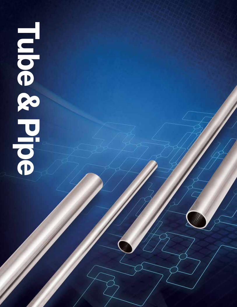
Tube, Pipe
FittingsStainless Steel

One Trusted Source - WorldwideIf ever there were industries with a low tolerance for imperfection, they would be the semiconductor, TFT/LCD, and solar industries. At Valex, these are our customers. As manufacturing processes grow more precise, our customers’ needs for stainless steel piping systems evolve to ever more demanding levels of cleanliness, leak integrity, corrosion resistance, and surface finish. A consistent and reliable source for the highest quality components and assemblies is essential for their success.
For over four decades, Valex has been the leading manufacturer of stainless steel tube, fittings, valves, and assemblies that allow our customers to meet their construction schedules and yield goals. Along the way, we’ve introduced the most important advances in fittings design, electropolishing, precision cleaning, and integrated assemblies. With three manufacturing plants, each strategically located in major markets, Valex offers the largest capacity of any supplier. We are the only manufacturer of the full size range of products used by global customers - inch sizes and JIS sizes - all under Valex control.
Our unrivaled experience, in-house capacity, unmatched product breadth, and singular focus on only the most demanding industries have led customers around the world to the same conclusion - Valex is their one trusted source.
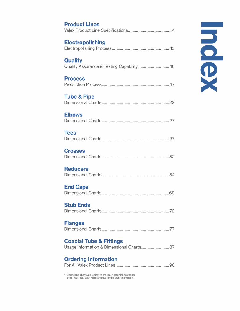
Product Lines Valex Product Line Specifications ................................................. 4
Electropolishing Electropolishing Process ................................................................. 15
Quality Quality Assurance & Testing Capability .................................... 16
Process Production Process ............................................................................ 17
Tube & Pipe Dimensional Charts ............................................................................ 22
Elbows Dimensional Charts ............................................................................ 27
Tees Dimensional Charts ............................................................................ 37
Crosses Dimensional Charts ............................................................................ 52
Reducers Dimensional Charts ............................................................................ 54
End Caps Dimensional Charts ............................................................................69
Stub Ends Dimensional Charts .............................................................................72
Flanges Dimensional Charts .............................................................................77
Coaxial Tube & Fittings Usage Information & Dimensional Charts ............................... 87
Ordering Information For All Valex Product Lines ............................................................ 96
Index
* Dimensional charts are subject to change. Please visit Valex.com or call your local Valex representative for the latest information.

444
Product Lines
Ultra High Purity, Electropolished • 401
• 301
• LDEP
Cleaned for Oxygen Service • 201
• 101
• CFOS
Hasteloy® C-22® Alloy* • 444
• 222
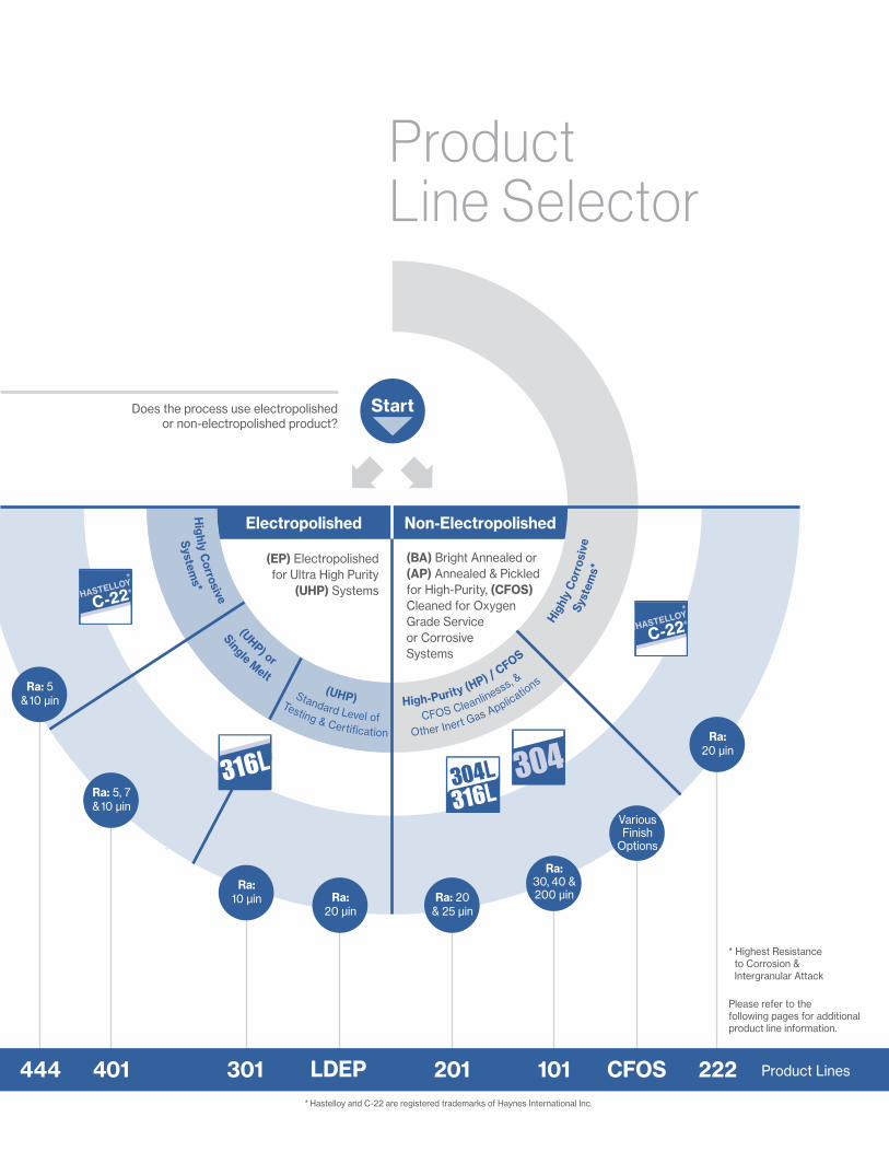
Product Lines
5
* Highest Resistance to Corrosion & Intergranular Attack
Please refer to the following pages for additional product line information.
CFOS 222 Product Lines
(EP) Electropolished for Ultra High Purity
(UHP) Systems
(BA) Bright Annealed or (AP) Annealed & Pickled for High-Purity, (CFOS) Cleaned for Oxygen Grade Service or Corrosive Systems
Product Line Selector
Ra: 20 & 25 µin
Ra: 20 µin
Ra: 30, 40 & 200 µin
Various Finish
Options
* Hastelloy and C-22 are registered trademarks of Haynes International Inc.
Ra: 5 & 10 µin
444
Ra: 5, 7 & 10 µin
401
Ra: 10 µin
301
Ra: 20 µin
LDEP 201 101 CFOS 222 Product Lines
Does the process use electropolished or non-electropolished product?
Electropolished Non-Electropolished
Start
Other Inert Gas Applications
CFOS Cleanlinesss, &
High-Purity (HP) / CFOS
Testing & Certifi cation
Standard Level of
(UHP)
Single Melt
(UHP) or
System
s*H
ighly Corrosive
Syst
ems*
Highl
y C
orro
sive

Product Lines
6
401Product Line
Applications Ultra High Purity Systems requiring the highest grade of materials and certifications, Electropolished
Alloy 316L Stainless steel, single-melt or double-melt (seamless or welded, depending on size)
Sizes ASTM Tube: 1/8" to 6" ASTM Fittings: 1/4" to 6" JIS Pipe: 8A to 300A
I.D. Surface Finish Options A5: 5 µin Ra max A7: 7 µin Ra max B0: 10 µin Ra max C0: 10 µin Ra
Tolerances In accordance with ASTM: A 269, A 632 & JIS: G 3459
Weld Ends Tube: Square ends suitable for orbital welding Pipe: Square or beveled end options
Testing & Inspection • Visual inspection • Surface roughness measurement • Helium-leak testing
• Scanning Electron Microscopy (SEM) • Auger Electron Microscopy (AES)
Valex Specification SP-9220
• Election Spectroscopy for Chemical Analysis (ESCA or XPS) • Particle testing
• Moisture testing
Marking & Traceability Each component is traceable to its producing mill and heat by an identification number marked within 24" (610mm) of one end.
Labeling Each component's bag is affixed with a label identifying the component's part number, date and Valex lot number.
Documentation A quality inspection certificate is furnished with each shipment. The report contains the following information: • Material composition & applicable specification designation • Nominal outside diameter size • Chemical composition • Statement of quality assurance testing • Inspection Certificate type 3.1 per EN 10204:2004
• Lot & heat identification for traceability
Packaging All components are purged with UHP nitrogen, capped, double-bagged and packaged for shipment in such a manner, which prevents damage to product and primary product packaging.

Product Lines
7
301 Product Line
Valex Specification SP-9223
Applications Ultra High Purity Systems, Electropolished
Alloy 316L Stainless steel, single-melt (seamless or welded, depending on size)
Sizes ASTM Tube: 1/8" to 6"
I.D. Surface Finish 10 µin Ra
Tolerances In accordance with ASTM: A 269 & A 632
Weld Ends Square ends are suitable for orbital welding
Testing & Inspection • Visual inspection
• Surface roughness measurement
• Dimensional inspection
Marking & Traceability Each component is traceable to its producing mill and heat by an identification number marked within 24" (610mm) of one end.
Labeling Each component's bag is affixed with a label identifying the component's part number, date and Valex lot number.
Documentation A quality inspection certificate is furnished with each shipment. The report contains the following information:
• Material composition & applicable specification designation
• Nominal outside diameter size
• Chemical composition
• Statement of quality assurance testing
• Inspection Certificate type 3.1 per EN 10204:2004
• Lot & heat identification for traceability
Packaging All components are purged with UHP nitrogen, capped, double-bagged and packaged for shipment in such a manner, which prevents damage to product and primary product packaging.

Product Lines
8
LDEPProduct Line
Valex Specification SP-9235
Applications Ultra High Purity Systems, Electropolished
Alloy 316L Stainless steel, single-melt (seamless or welded, depending on size)
Sizes JIS Pipe: 25A to 600A ASTM/ASME Pipe: NPS 2 to NPS 12
I.D. Surface Finish 20 µin Ra average, 25 µin Ra max
Tolerances In accordance with applicable ASTM, ASME & JIS specifications
Weld Ends Square or beveled end options
Testing & Inspection • Visual inspection
• Surface roughness measurement
• Dimensional inspection
Marking & Traceability Each component is traceable to its producing mill and heat by an identification number marked within 24" (610mm) of one end.
Labeling Each component's bag is affixed with a label identifying the component's part number, date and Valex lot number.
Documentation A quality inspection certificate is furnished with each shipment. The report contains the following information:
• Material composition & applicable specification designation
• Nominal outside diameter size
• Chemical composition
• Statement of quality assurance testing
• Inspection Certificate type 3.1 per EN 10204:2004
• Lot & heat identification for traceability
Packaging All components are capped, bagged and packaged for shipment in such a manner, which prevents damage to product and primary product packaging.
Product Lines
9
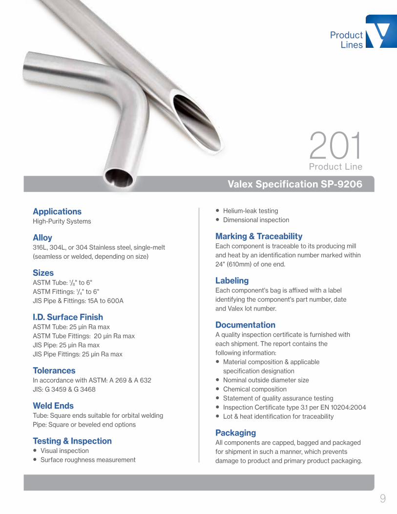
201Product Line
Valex Specification SP-9206
Applications High-Purity Systems
Alloy 316L, 304L, or 304 Stainless steel, single-melt (seamless or welded, depending on size)
Sizes ASTM Tube: 1/8" to 6" ASTM Fittings: 1/4" to 6" JIS Pipe & Fittings: 15A to 600A
I.D. Surface Finish ASTM Tube: 25 µin Ra max ASTM Tube Fittings: 20 µin Ra max JIS Pipe: 25 µin Ra max JIS Pipe Fittings: 25 µin Ra max
Tolerances In accordance with ASTM: A 269 & A 632 JIS: G 3459 & G 3468
Weld Ends Tube: Square ends suitable for orbital welding Pipe: Square or beveled end options
Testing & Inspection • Visual inspection
• Surface roughness measurement
• Helium-leak testing
• Dimensional inspection
Marking & Traceability Each component is traceable to its producing mill and heat by an identification number marked within 24" (610mm) of one end.
Labeling Each component's bag is affixed with a label identifying the component's part number, date and Valex lot number.
Documentation A quality inspection certificate is furnished with each shipment. The report contains the following information:
• Material composition & applicable specification designation
• Nominal outside diameter size
• Chemical composition
• Statement of quality assurance testing
• Inspection Certificate type 3.1 per EN 10204:2004
• Lot & heat identification for traceability
Packaging All components are capped, bagged and packaged for shipment in such a manner, which prevents damage to product and primary product packaging.

Product Lines
10
101Product Line
Valex Specification SP-9204
Applications High-Purity Systems
Alloy 316L, 304L, or 304 Stainless steel, single-melt (seamless or welded, depending on size)
Sizes ASTM Tube: 1/8" to 6" JIS Pipe: 15A to 600A
I.D. Surface Finish ASTM Tube: 1/8" to 4" = 30 µin Ra 6" = 200 µin Ra JIS Pipe: 15A to 100A = 40 µin Ra 125A to 600A = 200 µin Ra
Tolerances In accordance with ASTM: A 269 & A 632, JIS: G 3459 & G 3468
Weld Ends Tube: Square ends suitable for orbital welding Pipe: Square or beveled end options
Testing & Inspection • Visual inspection
• Surface roughness measurement
• Dimensional inspection
Marking & Traceability Each component is traceable to its producing mill and heat by an identification number marked within 24" (610mm) of one end.
Labeling Each component's bag is affixed with a label identifying the component's part number, date and Valex lot number.
Documentation A quality inspection certificate is furnished with each shipment. The report contains the following information:
• Material composition & applicable specification designation
• Nominal outside diameter size
• Chemical composition
• Statement of quality assurance testing
• Inspection Certificate type 3.1 per EN 10204:2004
• Lot & heat identification for traceability
Packaging All components are capped, bagged and packaged for shipment in such a manner, which prevents damage to product and primary product packaging.
Product Lines
11
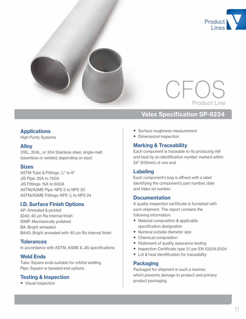
CFOSProduct Line
Valex Specification SP-9234
Applications High Purity Systems
Alloy 316L, 304L, or 304 Stainless steel, single-melt (seamless or welded, depending on size)
Sizes ASTM Tube & Fittings: 1/4" to 6" JIS Pipe: 25A to 750A JIS Fittings: 15A to 600A ASTM/ASME Pipe: NPS 2 to NPS 30 ASTM/ASME Fittings: NPS 1/2 to NPS 24
I.D. Surface Finish Options AP: Annealed & pickled ID40: 40 µin Ra Internal finish IDMP: Mechanically polished BA: Bright annealed BA40: Bright annealed with 40 µin Ra internal finish
Tolerances In accordance with ASTM, ASME & JIS specifications
Weld Ends Tube: Square ends suitable for orbital welding Pipe: Square or beveled end options
Testing & Inspection • Visual inspection
• Surface roughness measurement
• Dimensional inspection
Marking & Traceability Each component is traceable to its producing mill and heat by an identification number marked within 24" (610mm) of one end.
Labeling Each component's bag is affixed with a label identifying the component's part number, date and Valex lot number.
Documentation A quality inspection certificate is furnished with each shipment. The report contains the following information:
• Material composition & applicable specification designation
• Nominal outside diameter size
• Chemical composition
• Statement of quality assurance testing
• Inspection Certificate type 3.1 per EN 10204:2004
• Lot & heat identification for traceability
Packaging Packaged for shipment in such a manner, which prevents damage to product and primary product packaging.
Product Lines
12
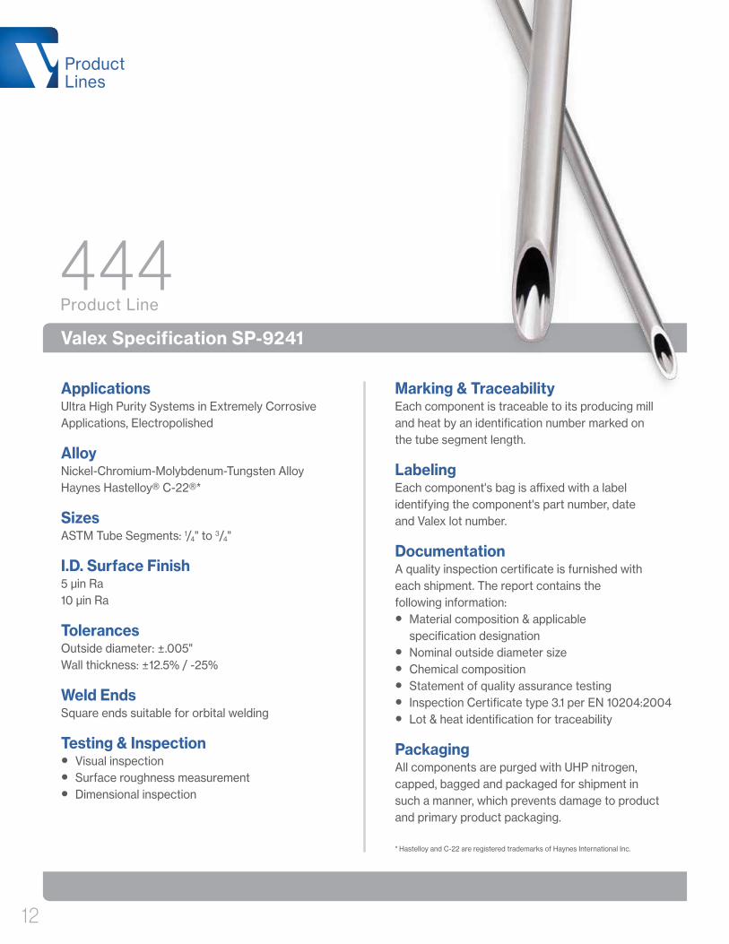
444Product Line
Valex Specification SP-9241
Applications Ultra High Purity Systems in Extremely Corrosive Applications, Electropolished
Alloy Nickel-Chromium-Molybdenum-Tungsten Alloy Haynes Hastelloy® C-22®*
Sizes ASTM Tube Segments: 1/4" to 3/4"
I.D. Surface Finish 5 µin Ra 10 µin Ra
Tolerances Outside diameter: ±.005" Wall thickness: ±12.5% / -25%
Weld Ends Square ends suitable for orbital welding
Testing & Inspection • Visual inspection
• Surface roughness measurement
• Dimensional inspection
Marking & Traceability Each component is traceable to its producing mill and heat by an identification number marked on the tube segment length.
Labeling Each component's bag is affixed with a label identifying the component's part number, date and Valex lot number.
Documentation A quality inspection certificate is furnished with each shipment. The report contains the following information:
• Material composition & applicable specification designation
• Nominal outside diameter size
• Chemical composition
• Statement of quality assurance testing
• Inspection Certificate type 3.1 per EN 10204:2004
• Lot & heat identification for traceability
Packaging All components are purged with UHP nitrogen, capped, bagged and packaged for shipment in such a manner, which prevents damage to product and primary product packaging.
* Hastelloy and C-22 are registered trademarks of Haynes International Inc.

Product Lines
13
Applications Extremely corrosive systems
Alloy Nickel-Chromium-Molybdenum-Tungsten Alloy Haynes Hastelloy® C-22®*
Sizes ASTM Tube: 1/4" to 3/4"
I.D. Surface Finish 20 µin Ra max
Tolerances Outside diameter: ±.005" Wall thickness: ±12.5%
Weld Ends Square ends suitable for orbital welding
Testing & Inspection • Visual inspection
• Surface roughness measurement
• Fittings leak test
• Dimensional inspection
Marking & Traceability Each component is traceable to its producing mill and heat by an identification number marked within 24" (610mm) of one end.
Labeling Each component's bag is affixed with a label identifying the component's part number, date and Valex lot number.
Documentation A quality inspection certificate is furnished with each shipment. The report contains the following information:
• Material composition & applicable specification designation
• Nominal outside diameter size
• Chemical composition
• Statement of quality assurance testing
• Inspection Certificate type 3.1 per EN 10204:2004
• Lot & heat identification for traceability
Packaging All components are purged with UHP nitrogen, capped, bagged and packaged for shipment in such a manner, which prevents damage to product and primary product packaging.
* Hastelloy and C-22 are registered trademarks of Haynes International Inc.
222Product Line
Valex Specification SP-9207

Product Lines
14
Coaxial Product Line
Valex Specification SP-9222
Applications Contingent upon customers specifications
Alloy 316L, 304L, or 304 Stainless steel, (Tubing & sleeves are seamless or welded, depending on customers specifications)
Sizes ASTM Tube: .250" x .500" .500" x .750" 1.00" x 1.25" .375" x .625" .750" x 1.00" 1.50" x 2.00"
I.D. Surface Finish Options A5: 5 µin Ra max A7: 7 µin Ra max B0: 10 µin Ra max C0: 10 µin Ra
Tolerances In accordance with ASTM: A 269 & A 632
Weld Ends Square ends suitable for orbital welding
Testing & Inspection Outer Tube:
• Visual Inspection
• Dimensional Inspection
• Outer Tube Leak Testing
Inner Tube:
• Per Valex Specification: SP-9204, SP-9206, SP-9207, SP-9220, oe SP-9223
Marking & Traceability Each component is traceable to its producing mill and heat by an identification number.
Labeling Each component's bag is affixed with a label identifying the component's part number, date and Valex lot number.
Documentation A quality inspection certificate for the inner tube is furnished with each shipment. The report contains the following information:
• Material composition & applicable specification designation
• Nominal outside diameter size
• Chemical composition
• Statement of quality assurance testing
• Inspection Certificate type 3.1 per EN 10204:2004
• Lot & heat identification for traceability
Packaging Assembled product packaged per applicable specification.

Smoothing Out the Peaks & ValleysWhen the highest levels of purity, corrosion resistance, and overall performance are required, customers select Valex UHP electropolished (EP) products. Under magnification, raw material surfaces appear rough, and composed of many “peaks and valleys”. During our EP process, surface metal is removed ion-by-ion, at an electron-microscopic level. Parts are subjected to an electrolytic solution and current, where surface material is selectively dissolved, more aggressively at the peaks than the valleys, smoothing out these undulations. The result is a micro-smooth and contaminant-free surface.
Electropolished surfaces benefit from increased corrosion resistance, and improved surface finish, resulting in increased production yields at customer sites. Our EP processes have been refined and tuned over multiple decades, to produce the most uniform, repeatable finishes – that are universally accepted as the gold-standard for which to compare.
SEM photos at 500X magnification Raw
ElectropolishedMechanically Polished
Valex electropolishing
leaves the material surface
microscopically smooth
& essentially featureless.
Protective oxide layer
Microscopic surface profile after electropolishing
Microscopic surface profile before electropolishing
Peaks are more aggressively removed due to higher current density
+ Current Source
The Electropolishing Process
Anode (Part)
Cathode
Electrolyte
Tank
++
Electropolishing

Quality
Tested Beyond the StandardProduct testing and certification are in strict accordance with industry-leading Valex specifications. Going well beyond our own requirements, we have brought sophisticated testing technology in-house, including a Scanning Electron Microscope (SEM) to assure electropolish quality and metallurgical integrity, as well as X-ray Fluorescence (XRF) spectroscopy equipment to verify elemental composition of the stainless steel. These, and many other steps unique to us, add unmatched levels of control that assure Valex products not only meet, but exceed specifications and customer expectations.
Process
Processed for SuccessContinued refinement and advancement is the inevitable progression for Valex-designed manufacturing equipment and processes. Over the years, these developments have resulted in the largest range of choice for size and surface finish options of ASTM, ASME, and JIS components available to our customers.
All of our products conform to identical Valex specifications, using the same proven processes and equipment at each of our three manufacturing facilities. Each facility consistently manufactures product exceeding performance requirements, while creating and maintaining Ultra High Purity using ISO Class 5 clean rooms with semiconductor-quality deionized water and nitrogen – assuring the highest levels of product integrity and performance.
Process
18
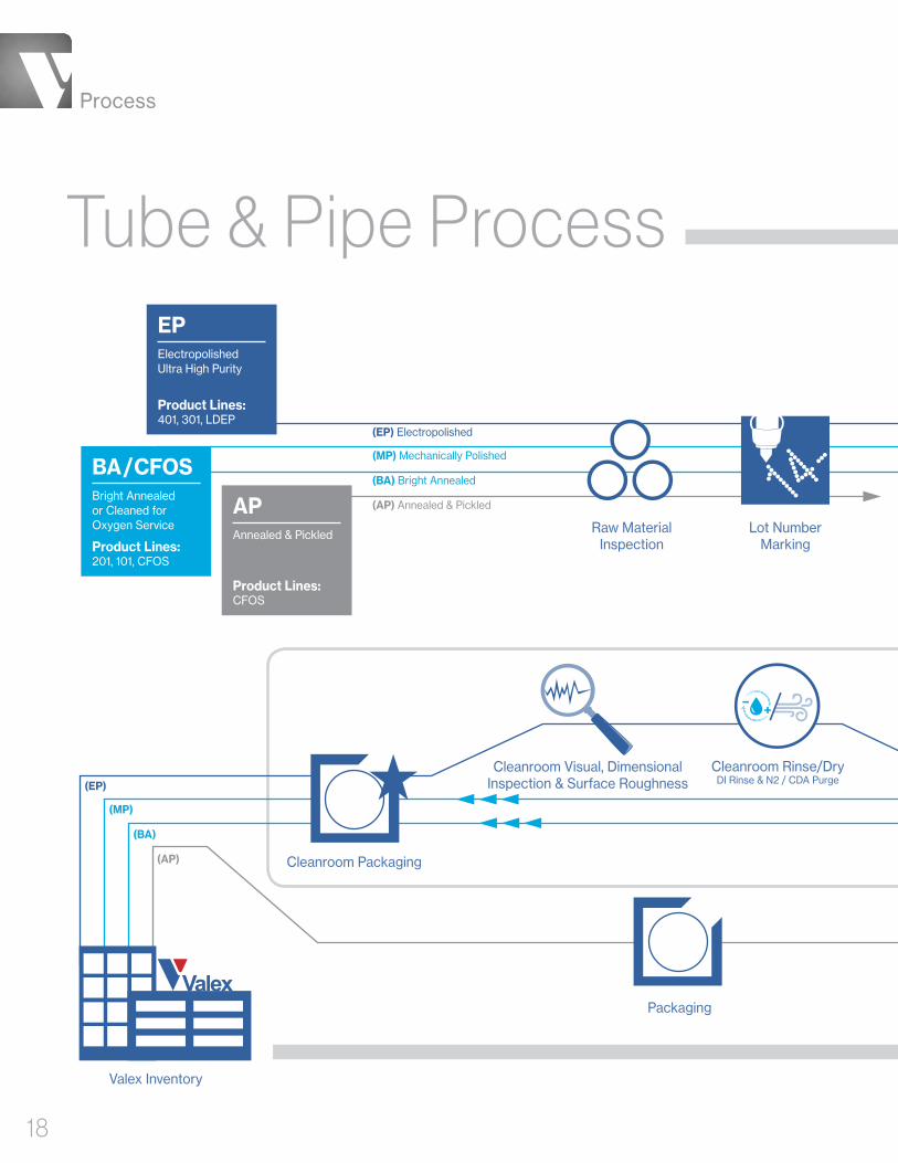
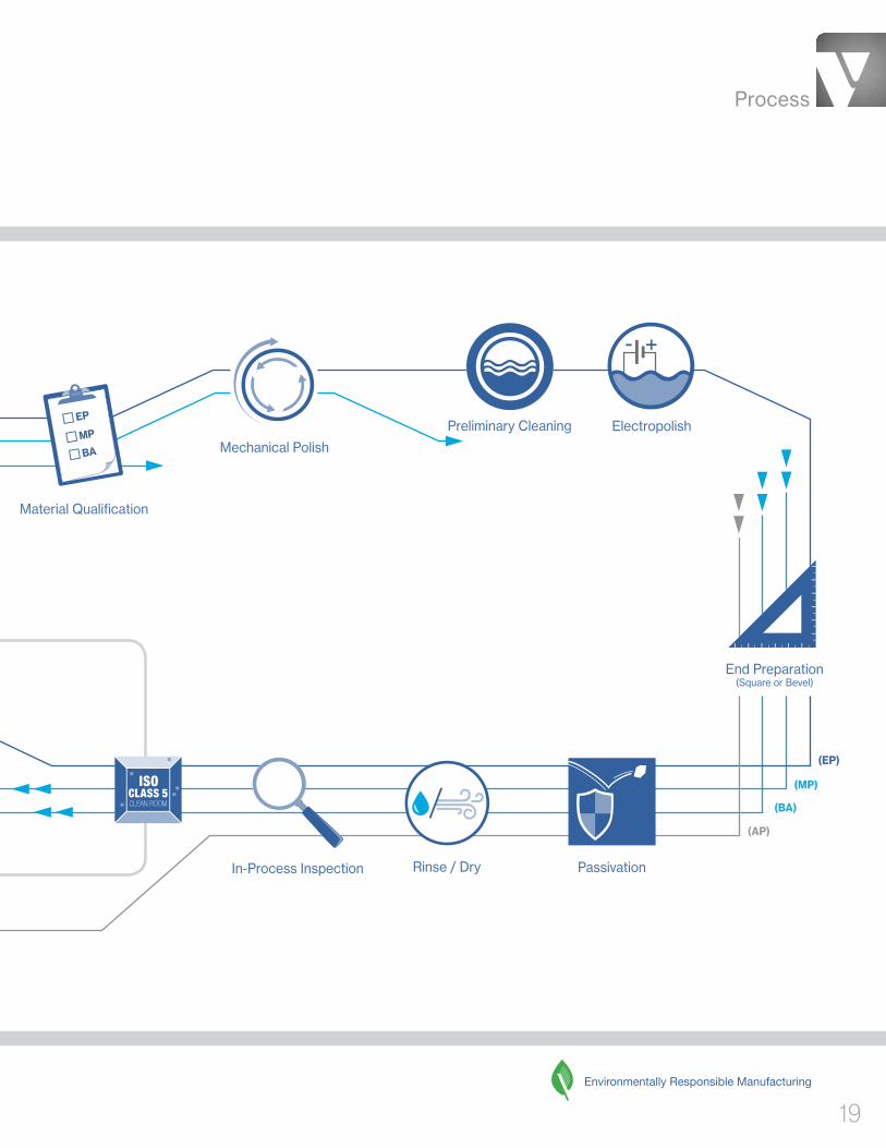
Tube & Pipe Process
(MP) Mechanically Polished
(BA) Bright Annealed
(AP) Annealed & Pickled
(EP) Electropolished
EPElectropolished Ultra High Purity
Product Lines: 401, 301, LDEP
APAnnealed & Pickled
Product Lines: CFOS
Valex Inventory
Cleanroom Packaging
Cleanroom Visual, Dimensional Inspection & Surface Roughness
(MP)
(BA)
(AP)
(EP)
Raw Material Inspection
Lot Number Marking
Cleanroom Rinse/Dry DI Rinse & N2 / CDA Purge
Packaging
BA/CFOSBright Annealed or Cleaned for Oxygen Service
Product Lines: 201, 101, CFOS
Process
19
Material Qualification
Mechanical Polish
Preliminary Cleaning Electropolish
End Preparation (Square or Bevel)
PassivationRinse / Dry
(MP)
(EP)
(BA)
(AP)
Environmentally Responsible Manufacturing
In-Process Inspection
Process
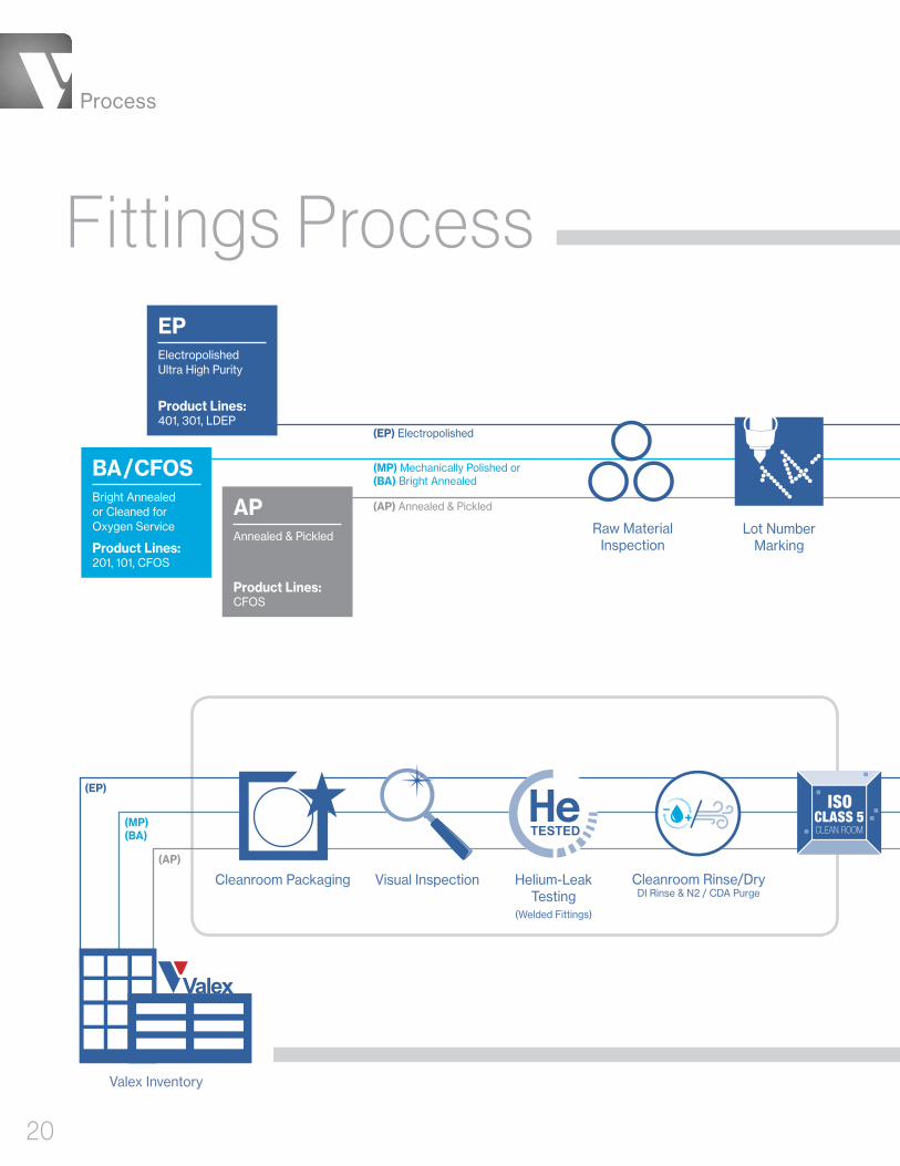
20
Fittings Process
(MP) Mechanically Polished or (BA) Bright Annealed
(AP) Annealed & Pickled
(EP) Electropolished
BA/CFOSBright Annealed or Cleaned for Oxygen Service
Product Lines: 201, 101, CFOS
EPElectropolished Ultra High Purity
Product Lines: 401, 301, LDEP
APAnnealed & Pickled
Product Lines: CFOS
Valex Inventory
(AP)
(EP)
(MP) (BA)
Cleanroom Rinse/Dry DI Rinse & N2 / CDA Purge
Cleanroom Packaging Helium-Leak Testing
(Welded Fittings)
Visual Inspection
Lot Number Marking
Raw Material Inspection

Process
21
(MP) (BA)
(AP)
Rinse / Dry
Fittings Fabrication (As required per
fitting type & process)
• Cut• Machine• Pull• Bend• Weld
Passivation O.D. Finishing (As required per fitting process)
I.D. Finishing (As required per fitting process)
Electropolish
End Preparation (Square or Bevel)
Dimensional Inspection
Preliminary Cleaning
In-Process Inspection
(EP)
Environmentally Responsible Manufacturing
DimensionsWeights Pressures
22
Tube & P
ipe

DimensionsWeights
Pressures
23
Size
Size
O.D.
O.D.
Wall
Wall
Weight per foot (lbs.)
Weight per foot (lbs.)
Maximum Safe Working Pressure*
Maximum Safe Working Pressure*
PSI Seamless
PSI SeamlessPSI Seamless
PSI Welded
PSI Welded
Bar Seamless
Bar Seamless
Bar Welded
Bar Welded 444 222
Dimensions in Inches
Dimensions in Inches
1/8" .125 .028 .03 7,805 N/A 538 N/A
1/4" .250 .035 .08 4,598 N/A 317 N/A
1/4" .250 .039 .09 5,189 N/A 358 N/A
3/8" .375 .035 .13 2,974 N/A 205 N/A
3/8" .375 .039 .14 3,341 N/A 230 N/A
1/2" .500 .049 .24 3,136 2,509 216 173
3/4" .750 .065 .48 2,759 2,207 190 152
1" 1.000 .065 .65 2,039 1,631 141 113
1-1/2" 1.500 .065 1.00 1,340 1,072 92 74
2" 2.000 .065 1.35 995 796 69 55
2-1/2" 2.500 .065 1.70 793 635 55 44
3" 3.000 .065 2.05 659 528 45 36
4" 4.000 .083 3.49 631 505 44 35
6" 6.000 .109 6.90 551 440 38 30
1/4" .250 .035 .08 7,972 N/A 550 N/A
3/8" .375 .035 .13 5,169 N/A 356 N/A
1/2" .500 .049 .24 5,465 N/A 377 N/A
3/4" .750 .065 .48 4,810 N/A 332 N/A
Product Lines
Product Line
Wall
O.D.
* Gauge pressure is listed.
Notes: 1. Maximum safe working pressure is calculated per ASME B 31.3-2014, paragraph 304.1.2 (formula 3a). Calculations assume maximum allowable O.D. and minimum allowable wall thickness (worst case scenario). 2. Material: TP 304L or TP 316L per ASTM A269 and A632. 3. Temperature range used for above calculations is -20°F to 300°F, -28.8°C to 148.9°C. For recommended working pressures higher than 300°F, please consult factory.
* Gauge pressure is listed.
Notes: 1. Maximum safe working pressure is calculated per ASME B 31.3-2014, paragraph 304.1.2 (formula 3a). Calculations assume maximum allowable O.D. and minimum allowable wall thickness (worst case scenario). 2. Material: Hastelloy® C-22®, Hastelloy and C-22 are registered trademarks of Haynes International Inc. 3. Temperature range used for above calculations is -20°F to 300°F, -28.8°C to 148.9°C. For recommended working pressures higher than 300°F, please consult factory.
Tube ASTM A269 / A632
Tube Hastelloy® C-22®
401 301 201 101 CFOS

DimensionsWeights Pressures
24
Wall
O.D.
Dimensions in Inches
NPS 2 10S 2.375 .109 2.66 1,367 1,094 94 75
NPS 2-1/2 10S 2.875 .120 3.56 1,243 994 86 69
NPS 3 10S 3.500 .120 4.36 1,017 814 70 56
NPS 3-1/2 10S 4.000 .120 5.01 888 711 61 49
NPS 4 10S 4.500 .120 5.66 789 631 54 44
NPS 5 10S 5.563 .134 7.83 708 566 49 39
NPS 6 10S 6.625 .134 9.36 594 475 41 33
NPS 8 10S 8.625 .148 13.50 504 403 35 28
NPS 10 10S 10.750 .165 18.79 449 360 31 25
NPS 12 10S 12.750 .180 24.34 414 331 29 23
NPS 14 10S 14.000 .188 27.94 394 315 27 22
NPS 16 10S 16.000 .188 31.98 344 275 24 19
NPS 18 10S 18.000 .188 36.03 306 245 21 17
NPS 20 10S 20.000 .218 46.40 N/A 255 N/A 18
NPS 22 10S 22.000 .218 51.09 N/A 232 N/A 16
NPS 24 10S 24.000 .250 63.88 N/A 244 N/A 17
NPS 30 10S 30.000 .312 99.66 N/A 244 N/A 17
Size Sch. O.D. Wall Weight per foot (lb.)
Maximum Safe Working Pressure*PSI Seamless PSI Welded Bar Seamless Bar Welded
* Gauge pressure is listed.
Notes: 1. Maximum safe working pressure is calculated, per ASME B31.3-2014, paragraph 304.1.2 Calculations assume maximum allowable O.D. and minimum allowable wall thickness (worst case scenario). 2. Material: TP304, TP 304L or TP 316L per ASTM A312 3. Temperature range used for above calculations is -20°F to 300°F, -28.8°C to 148.9°C. For recommended working pressures higher than 300°F, please consult factory.
Product Lines
LDEP CFOS
Pipe ASTM A312, Schedule 10S

DimensionsWeights
Pressures
25
Dimensions in Millimeters
8A 5S 13.8 1.20 .38 2,511 2,009 173 139
10A 5S 17.3 1.20 .48 1,988 1,590 137 110
15A 5S 21.7 1.65 .82 2,324 1,859 160 128
20A 5S 27.2 1.65 1.05 1,839 1,471 127 101
25A 5S 34.0 1.65 1.32 1,460 1,168 101 81
32A 5S 42.7 1.65 1.68 1,154 923 80 64
40A 5S 48.6 1.65 1.92 1,011 808 70 56
50A 5S 60.5 1.65 2.41 808 646 56 45
65A 5S 76.3 2.10 3.87 836 668 58 46
80A 5S 89.1 2.10 4.53 713 571 49 39
90A 5S 101.6 2.10 5.19 624 499 43 34
100A 5S 114.3 2.10 5.85 554 443 38 31
125A 5S 139.8 2.80 9.52 605 484 42 33
150A 5S 165.2 2.80 11.29 511 408 35 28
200A 5S 216.3 2.80 14.84 389 311 27 21
250A 5S 267.4 3.40 22.28 382 306 26 21
300A 5S 318.5 4.00 31.22 377 302 26 21
350A 5S 355.6 4.00 34.90 N/A 264 N/A 18
400A 5S 406.4 4.50 44.89 N/A 260 N/A 18
450A 5S 457.2 4.50 50.56 N/A 231 N/A 16
500A 5S 508.0 5.00 62.42 N/A 231 N/A 16
550A 5S 558.8 5.00 68.72 N/A 209 N/A 14
600A 5S 609.6 5.50 82.46 N/A 211 N/A 15
650A 5S 660.4 5.50 89.40 N/A 195 N/A 13
700A 5S 711.2 5.50 96.33 N/A 181 N/A 12
750A 5S 762.0 6.50 121.88 N/A 200 N/A 14
Size Sch. O.D. Wall Weight per meter (kg.)
Maximum Safe Working Pressure*401 LDEP 201 101 CFOS
PSI Seamless PSI Welded Bar Seamless Bar Welded
Product Lines
Wall
O.D.
* Gauge pressure is listed.
Notes: 1. Maximum safe working pressure is calculated, per ASME B31.3-2014, paragraph 304.1.2. Calculations assume maximum allowable O.D. and minimum allowable wall thickness (worst case scenario). 2. Material: SUS 304LTP or SUS 316LTP per JIS G3459, and SUS 304 LTPY, SUS 316 LTPY per JIS G3468 3. Temperature range used for above calculations is -20°F to 300°F, -28.8°C to 148.9°C. For recommended working pressures higher than 300°F, please consult factory.
Pipe JIS G3459 / G3468, Schedule 5S

DimensionsWeights Pressures
26
Dimensions in Millimeters
8A 10S 13.8 1.65 .50 3,743 2,994 258 206
10A 10S 17.3 1.65 .64 2,946 2,357 203 163
15A 10S 21.7 2.10 1.02 3,081 2,465 212 170
20A 10S 27.2 2.10 1.31 2,429 1,943 168 134
25A 10S 34.0 2.80 2.17 2,604 2,083 180 144
32A 10S 42.7 2.80 2.77 2,047 1,638 141 113
40A 10S 48.6 2.80 3.18 1,788 1,431 123 99
50A 10S 60.5 2.80 4.01 1,424 1,140 98 79
65A 10S 76.3 3.00 5.46 1,204 963 83 66
80A 10S 89.1 3.00 6.41 1,027 821 71 57
90A 10S 101.6 3.00 7.34 898 718 62 50
100A 10S 114.3 3.00 8.29 796 637 55 44
125A 10S 139.8 3.40 11.51 737 589 51 41
150A 10S 165.2 3.40 13.65 622 497 43 34
200A 10S 216.3 4.00 21.08 558 446 38 31
250A 10S 267.4 4.00 26.15 450 360 31 25
300A 10S 318.5 4.50 35.07 425 340 29 23
350A 10S 355.6 5.00 43.51 N/A 330 N/A 23
400A 10S 406.4 5.00 49.81 N/A 289 N/A 20
450A 10S 457.2 5.00 56.11 N/A 256 N/A 18
500A 10S 508.0 5.50 68.59 N/A 254 N/A 18
550A 10S 558.8 5.50 75.53 N/A 231 N/A 16
600A 10S 609.6 6.50 97.29 N/A 250 N/A 17
650A 10S 660.4 8.00 129.53 N/A 292 N/A 20
700A 10S 711.2 8.00 139.62 N/A 271 N/A 19
750A 10S 762.0 8.00 149.71 N/A 253 N/A 17
Size Sch. O.D. Wall Weight per meter (kg.)
Maximum Safe Working Pressure*401 LDEP 201 101 CFOS
PSI Seamless PSI Welded Bar Seamless Bar Welded
Product Lines
Wall
O.D.
* Gauge pressure is listed.
Notes: 1. Maximum safe working pressure is calculated, per ASME B31.3-2014, paragraph 304.1.2. Calculations assume maximum allowable O.D. and minimum allowable wall thickness (worst case scenario). 2. Material: SUS 304LTP or SUS 316LTP per JIS G3459, and SUS 304 LTPY, SUS 316 LTPY per JIS G3468 3. Temperature range used for above calculations is -20°F to 300°F, -28.8°C to 148.9°C. For recommended working pressures higher than 300°F, please consult factory.
Pipe JIS G3459 / G3468, Schedule 10S

Elbows
• 90° Elbows
• 45° Elbows
Dimensions
28
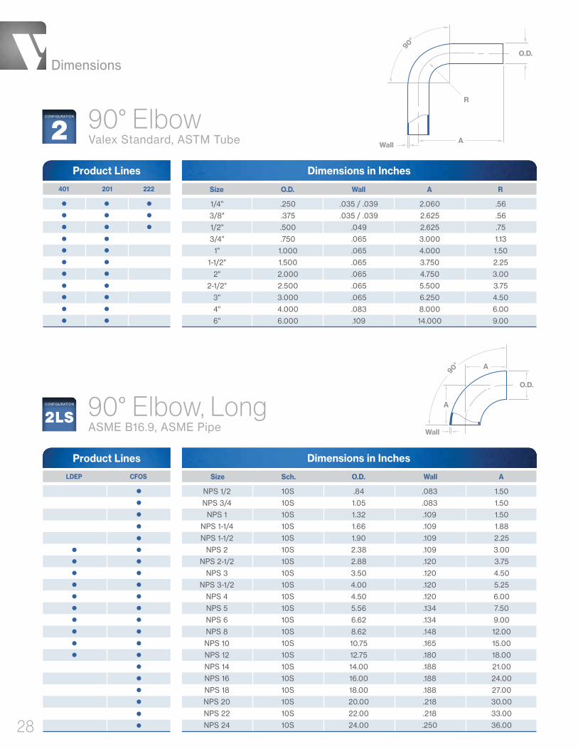
Dimensions in Inches
90° Elbow Valex Standard, ASTM Tube
Size O.D. Wall A R 401 201 222
Product Lines
1/4" .250 .035 / .039 2.060 .56
3/8" .375 .035 / .039 2.625 .56
1/2" .500 .049 2.625 .75
3/4" .750 .065 3.000 1.13
1" 1.000 .065 4.000 1.50
1-1/2" 1.500 .065 3.750 2.25
2" 2.000 .065 4.750 3.00
2-1/2" 2.500 .065 5.500 3.75
3" 3.000 .065 6.250 4.50
4" 4.000 .083 8.000 6.00
6" 6.000 .109 14.000 9.00
AWall
90°
O.D.
R
2CONFIGURATION
90° Elbow, LongASME B16.9, ASME Pipe
Dimensions in Inches
NPS 1/2 10S .84 .083 1.50
NPS 3/4 10S 1.05 .083 1.50
NPS 1 10S 1.32 .109 1.50
NPS 1-1/4 10S 1.66 .109 1.88
NPS 1-1/2 10S 1.90 .109 2.25
NPS 2 10S 2.38 .109 3.00
NPS 2-1/2 10S 2.88 .120 3.75
NPS 3 10S 3.50 .120 4.50
NPS 3-1/2 10S 4.00 .120 5.25
NPS 4 10S 4.50 .120 6.00
NPS 5 10S 5.56 .134 7.50
NPS 6 10S 6.62 .134 9.00
NPS 8 10S 8.62 .148 12.00
NPS 10 10S 10.75 .165 15.00
NPS 12 10S 12.75 .180 18.00
NPS 14 10S 14.00 .188 21.00
NPS 16 10S 16.00 .188 24.00
NPS 18 10S 18.00 .188 27.00
NPS 20 10S 20.00 .218 30.00
NPS 22 10S 22.00 .218 33.00
NPS 24 10S 24.00 .250 36.00
Size Sch. O.D. Wall A
Product Lines
2LSCONFIGURATION
O.D.
A
Wall
A
90°
LDEP CFOS

Dimensions
29
Dimensions in Inches
90° Elbow, ShortASME B16.9, ASME Pipe
NPS 1 10S 1.32 .109 1.00
NPS 1-1/4 10S 1.66 .109 1.25
NPS 1-1/2 10S 1.90 .109 1.50
NPS 2 10S 2.38 .109 2.00
NPS 2-1/2 10S 2.88 .120 2.50
NPS 3 10S 3.50 .120 3.00
NPS 3-1/2 10S 4.00 .120 3.50
NPS 4 10S 4.50 .120 4.00
NPS 5 10S 5.56 .134 5.00
NPS 6 10S 6.62 .134 6.00
NPS 8 10S 8.62 .148 8.00
NPS 10 10S 10.75 .165 10.00
NPS 12 10S 12.75 .180 12.00
NPS 14 10S 14.00 .188 14.00
NPS 16 10S 16.00 .188 16.00
NPS 18 10S 18.00 .188 18.00
NPS 20 10S 20.00 .218 20.00
NPS 22 10S 22.00 .218 22.00
NPS 24 10S 24.00 .250 24.00
Size Sch. O.D. Wall A LDEP CFOS
Product Lines
2SSCONFIGURATION
O.D.
A
Wall
A
90°

Dimensions
30
Dimensions in Millimeters
90° Elbow, LongValex Standard, JIS Pipe
Product Lines
8A 13.8 1.20 1.65 55 25.4
10A 17.3 1.20 1.65 62 25.4
15A 21.7 1.65 2.10 75 38.1
20A 27.2 1.65 2.10 75 38.1
25A 34.0 1.65 2.80 75 38.1
32A 42.7 1.65 2.80 94 47.6
40A 48.6 1.65 2.80 104 57.2
50A 60.5 1.65 2.80 123 76.2
65A 76.3 2.10 3.00 147 95.3
80A 89.1 2.10 3.00 166 114.3
100A 114.3 2.10 3.00 204 152.4
125A 139.8 2.80 3.40 250 190.5
150A 165.2 2.80 3.40 290 228.6
200A 216.3 2.80 4.00 375 304.8
250A 267.4 3.40 4.00 461 381.0
300A 318.5 4.00 4.50 537 457.2
350A 355.6 4.00 5.00 613 533.4
400A 406.4 4.50 5.00 690 609.6
450A 457.2 4.50 5.00 766 685.8
500A 508.0 5.00 5.50 842 762.0
550A 558.8 5.00 5.50 918 838.2
600A 609.6 5.50 6.50 994 914.4
Size O.D. 5S Wall 10S Wall A R 401 LDEP 201 101 CFOS
2LCONFIGURATION
AWall
R
O.D.
90°
Dimensions
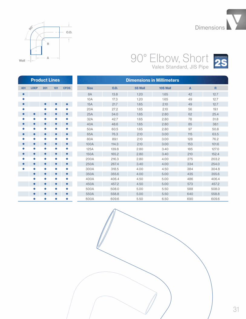
31
401 LDEP 201 101 CFOS
Dimensions in Millimeters
90° Elbow, ShortValex Standard, JIS Pipe
8A 13.8 1.20 1.65 42 12.7
10A 17.3 1.20 1.65 49 12.7
15A 21.7 1.65 2.10 49 12.7
20A 27.2 1.65 2.10 56 19.1
25A 34.0 1.65 2.80 62 25.4
32A 42.7 1.65 2.80 78 31.8
40A 48.6 1.65 2.80 85 38.1
50A 60.5 1.65 2.80 97 50.8
65A 76.3 2.10 3.00 115 63.5
80A 89.1 2.10 3.00 128 76.2
100A 114.3 2.10 3.00 153 101.6
125A 139.8 2.80 3.40 185 127.0
150A 165.2 2.80 3.40 210 152.4
200A 216.3 2.80 4.00 275 203.2
250A 267.4 3.40 4.00 334 254.0
300A 318.5 4.00 4.50 384 304.8
350A 355.6 4.00 5.00 435 355.6
400A 406.4 4.50 5.00 486 406.4
450A 457.2 4.50 5.00 573 457.2
500A 508.0 5.00 5.50 588 508.0
550A 558.8 5.00 5.50 640 558.8
600A 609.6 5.50 6.50 690 609.6
Size O.D. 5S Wall 10S Wall A R
Wall
O.D.
A
R
90°
2SCONFIGURATION
Product Lines
Dimensions
32
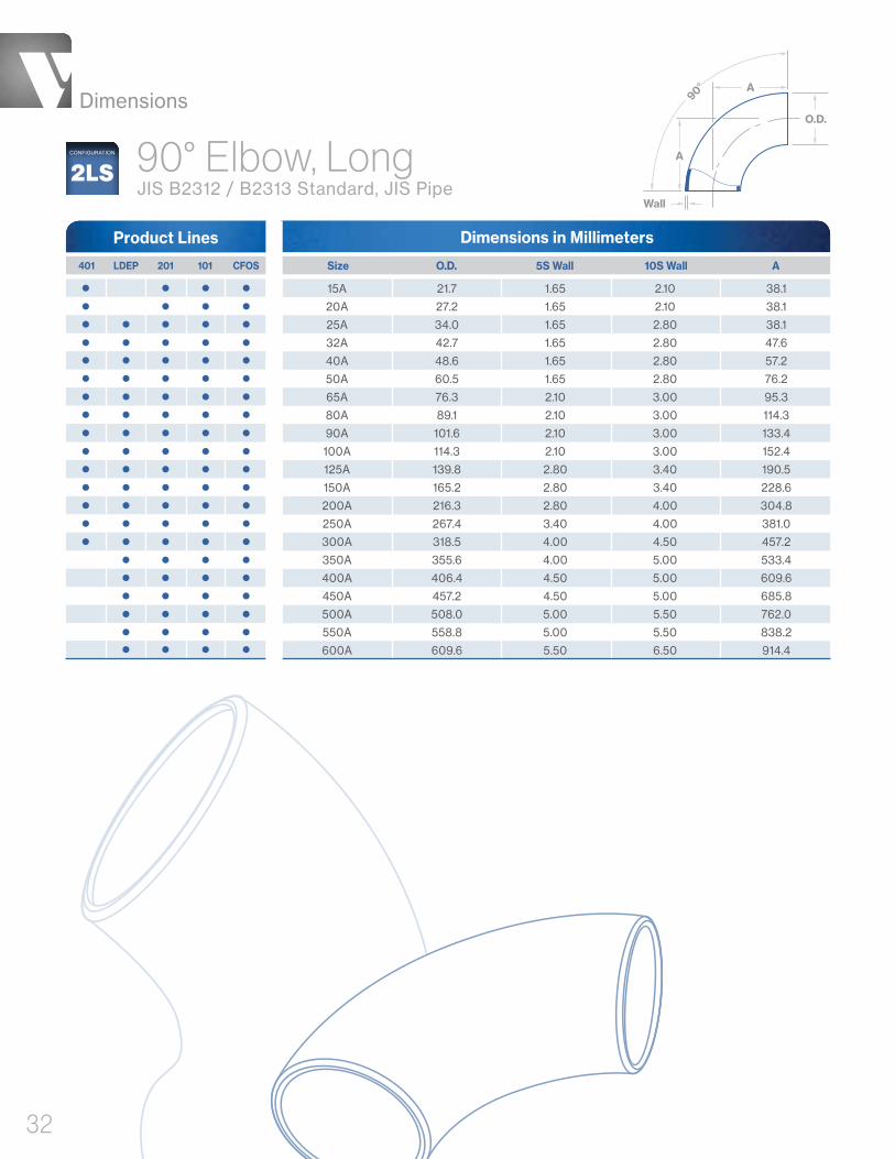
Dimensions in Millimeters
90° Elbow, Long JIS B2312 / B2313 Standard, JIS Pipe
15A 21.7 1.65 2.10 38.1
20A 27.2 1.65 2.10 38.1
25A 34.0 1.65 2.80 38.1
32A 42.7 1.65 2.80 47.6
40A 48.6 1.65 2.80 57.2
50A 60.5 1.65 2.80 76.2
65A 76.3 2.10 3.00 95.3
80A 89.1 2.10 3.00 114.3
90A 101.6 2.10 3.00 133.4
100A 114.3 2.10 3.00 152.4
125A 139.8 2.80 3.40 190.5
150A 165.2 2.80 3.40 228.6
200A 216.3 2.80 4.00 304.8
250A 267.4 3.40 4.00 381.0
300A 318.5 4.00 4.50 457.2
350A 355.6 4.00 5.00 533.4
400A 406.4 4.50 5.00 609.6
450A 457.2 4.50 5.00 685.8
500A 508.0 5.00 5.50 762.0
550A 558.8 5.00 5.50 838.2
600A 609.6 5.50 6.50 914.4
Size O.D. 5S Wall 10S Wall A
Product Lines
401 LDEP 201 101 CFOS
2LSCONFIGURATION
O.D.
A
Wall
A
90°

Dimensions
33
Dimensions in Inches
Size O.D. Wall A R 401 201 222
Product Lines
1/4" .250 .035 / .039 1.100 .56
3/8" .375 .035 / .039 2.000 .56
1/2" .500 .049 2.500 .75
3/4" .750 .065 2.500 1.13
1" 1.000 .065 3.125 1.50
1-1/2" 1.500 .065 2.500 2.25
2" 2.000 .065 3.000 3.00
2-1/2" 2.500 .065 3.375 3.75
3" 3.000 .065 3.625 4.50
4" 4.000 .083 4.500 6.00
6" 6.000 .109 8.750 9.00
45° ElbowValex Standard, ASTM Tube 2K
CONFIGURATION
Dimensions in Millimeters
25A 34.0 1.65 2.80 25.4
32A 42.7 1.65 2.80 31.8
40A 48.6 1.65 2.80 38.1
50A 60.5 1.65 2.80 50.8
65A 76.3 2.10 3.00 63.5
80A 89.1 2.10 3.00 76.2
90A 101.6 2.10 3.00 88.9
100A 114.3 2.10 3.00 101.6
125A 139.8 2.80 3.40 127.0
150A 165.2 2.80 3.40 152.4
200A 216.3 2.80 4.00 203.2
250A 267.4 3.40 4.00 254.0
300A 318.5 4.00 4.50 304.8
350A 355.6 4.00 5.00 355.6
400A 406.4 4.50 5.00 406.4
450A 457.2 4.50 5.00 457.2
500A 508.0 5.00 5.50 508.0
550A 558.8 5.00 5.50 558.8
600A 609.6 5.50 6.50 609.6
Size O.D. 5S Wall 10S Wall A
Product Lines
401 LDEP 201 101 CFOS
90° Elbow, Short JIS B2312 / B2313 Standard, JIS Pipe
2SSCONFIGURATION
A
O.D.
Wall
A
90°
A
Wall
O.D.
45°
R
A

Dimensions
34
Dimensions in Inches
45° Elbow, LongASME B16.9 Standard, ASME Pipe
NPS 1/2 10S .84 .083 .62
NPS 3/4 10S 1.05 .083 .75
NPS 1 10S 1.32 .109 .88
NPS 1-1/4 10S 1.66 .109 1.00
NPS 1-1/2 10S 1.90 .109 1.12
NPS 2 10S 2.38 .109 1.38
NPS 2-1/2 10S 2.88 .120 1.75
NPS 3 10S 3.50 .120 2.00
NPS 3-1/2 10S 4.00 .120 2.25
NPS 4 10S 4.50 .120 2.50
NPS 5 10S 5.56 .134 3.12
NPS 6 10S 6.62 .134 3.75
NPS 8 10S 8.62 .148 5.00
NPS 10 10S 10.75 .165 6.25
NPS 12 10S 12.75 .180 7.50
NPS 14 10S 14.00 .188 8.75
NPS 16 10S 16.00 .188 10.00
NPS 18 10S 18.00 .188 11.25
NPS 20 10S 20.00 .218 12.50
NPS 22 10S 22.00 .218 13.50
NPS 24 10S 24.00 .250 15.00
Size Sch. O.D. Wall A LDEP CFOS
Product Lines
2KLSCONFIGURATION
45°
O.D.
Wall
A
A

Dimensions
35
45° ElbowValex Standard, JIS Pipe
Dimensions in Millimeters
8A 13.8 1.20 1.65 40 25.4
10A 17.3 1.20 1.65 47 25.4
15A 21.7 1.65 2.10 52 38.1
20A 27.2 1.65 2.10 52 38.1
25A 34.0 1.65 2.80 52 38.1
32A 42.7 1.65 2.80 66 47.6
40A 48.6 1.65 2.80 70 57.2
50A 60.5 1.65 2.80 78 76.2
65A 76.3 2.10 3.00 91 95.3
80A 89.1 2.10 3.00 99 114.3
100A 114.3 2.10 3.00 115 152.4
125A 139.8 2.80 3.40 145 190.5
150A 165.2 2.80 3.40 155 228.6
200A 216.3 2.80 4.00 195 304.8
250A 267.4 3.40 4.00 237 381.0
300A 318.5 4.00 4.50 269 457.2
350A 355.6 4.00 5.00 296 533.4
400A 406.4 4.50 5.00 333 609.6
450A 457.2 4.50 5.00 365 685.8
500A 508.0 5.00 5.50 400 762.0
550A 558.8 5.00 5.50 432 838.2
600A 609.6 5.50 6.50 464 914.4
Size O.D. 5S Wall 10S Wall A R
Product Lines
401 LDEP 201 101 CFOS
2KCONFIGURATION
A
Wall
O.D.
45°
R
A
Dimensions
36
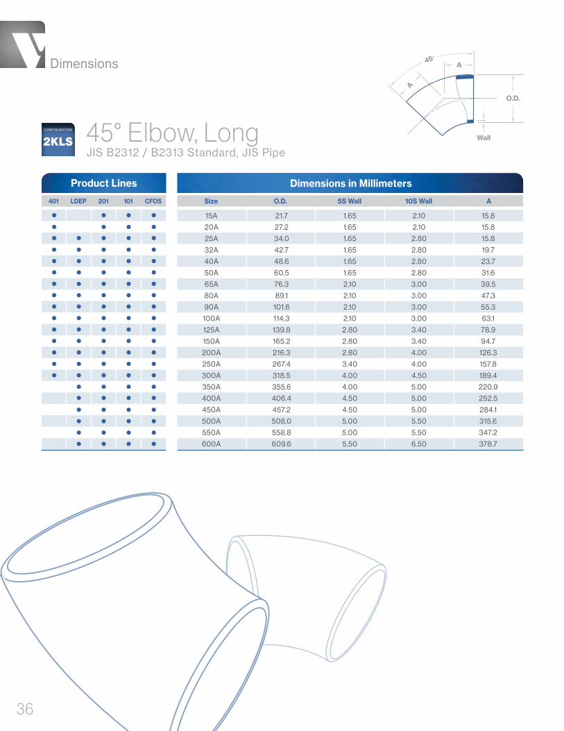
Dimensions in Millimeters
45° Elbow, Long JIS B2312 / B2313 Standard, JIS Pipe
15A 21.7 1.65 2.10 15.8
20A 27.2 1.65 2.10 15.8
25A 34.0 1.65 2.80 15.8
32A 42.7 1.65 2.80 19.7
40A 48.6 1.65 2.80 23.7
50A 60.5 1.65 2.80 31.6
65A 76.3 2.10 3.00 39.5
80A 89.1 2.10 3.00 47.3
90A 101.6 2.10 3.00 55.3
100A 114.3 2.10 3.00 63.1
125A 139.8 2.80 3.40 78.9
150A 165.2 2.80 3.40 94.7
200A 216.3 2.80 4.00 126.3
250A 267.4 3.40 4.00 157.8
300A 318.5 4.00 4.50 189.4
350A 355.6 4.00 5.00 220.9
400A 406.4 4.50 5.00 252.5
450A 457.2 4.50 5.00 284.1
500A 508.0 5.00 5.50 315.6
550A 558.8 5.00 5.50 347.2
600A 609.6 5.50 6.50 378.7
Size O.D. 5S Wall 10S Wall A 401 LDEP 201 101 CFOS
Product Lines
2KLSCONFIGURATION
45°
O.D.
Wall
A
A
Tees
• Equal Tees
• Reducing Tees

Dimensions
38
Dimensions in Inches
Equal TeeValex Standard, ASTM Tube
1/4" x 1/4" .250 .035 / .039 1.750
3/8" x 3/8" .375 .035 / .039 1.750
1/2" x 1/2" .500 .049 2.125
3/4" x 3/4" .750 .065 2.125
1" x 1" 1.000 .065 2.500
1-1/2" x 1-1/2" 1.500 .065 2.750
2" x 2" 2.000 .065 3.250
2-1/2" x 2-1/2" 2.500 .065 3.500
3" x 3" 3.000 .065 5.500
4" x 4" 4.000 .083 6.000
6" x 6" 6.000 .109 10.625
Size O.D. Wall A 401 201 222
Product Lines
O.D.
Wall
Wall
O.D.
A
A A7CONFIGURATION
Dimensions in Inches
Equal TeeASME B16.9 Standard, ASME Pipe
NPS 1/2 x NPS 1/2 10S .84 .083 1.00
NPS 3/4 x NPS 3/4 10S 1.05 .083 1.12
NPS 1 x NPS 1 10S 1.32 .109 1.50
NPS 1-1/4 x NPS 1-1/4 10S 1.66 .109 1.88
NPS 1-1/2 x NPS 1-1/2 10S 1.90 .109 2.25
NPS 2 x NPS 2 10S 2.38 .109 2.50
NPS 2-1/2 x NPS 2-1/2 10S 2.88 .120 3.00
NPS 3 x NPS 3 10S 3.50 .120 3.38
NPS 3-1/2 x NPS 3-1/2 10S 4.00 .120 3.75
NPS 4 x NPS 4 10S 4.50 .120 4.12
NPS 5 x NPS 5 10S 5.56 .134 4.88
NPS 6 x NPS 6 10S 6.62 .134 5.62
NPS 8 x NPS 8 10S 8.62 .148 7.00
NPS 10 x NPS 10 10S 10.75 .165 8.50
NPS 12 x NPS 12 10S 12.75 .180 10.00
NPS 14 x NPS 14 10S 14.00 .188 11.00
NPS 16 x NPS 16 10S 16.00 .188 12.00
NPS 18 x NPS 18 10S 18.00 .188 13.50
NPS 20 x NPS 20 10S 20.00 .218 15.00
NPS 22 x NPS 22 10S 22.00 .218 16.50
NPS 24 x NPS 24 10S 24.00 .250 17.00
LDEP CFOS
Product Lines
O.D.Wall
Wall
O.D.
A
A A
Size Sch. O.D. Wall A
7CONFIGURATION
Dimensions
39
O.D.Wall
Wall
O.D.
A
A A
Size O.D. A5S Wall 10S Wall
Dimensions in Millimeters
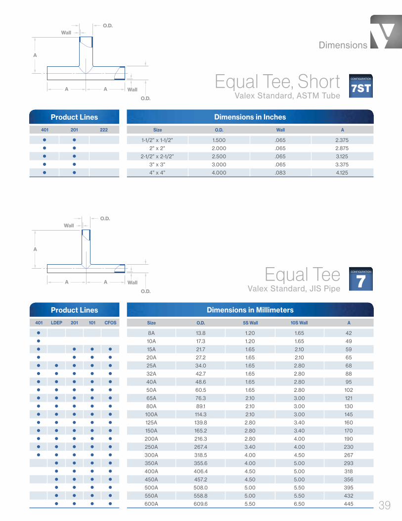
Equal Tee Valex Standard, JIS Pipe
8A 13.8 1.20 1.65 42
10A 17.3 1.20 1.65 49
15A 21.7 1.65 2.10 59
20A 27.2 1.65 2.10 65
25A 34.0 1.65 2.80 68
32A 42.7 1.65 2.80 88
40A 48.6 1.65 2.80 95
50A 60.5 1.65 2.80 102
65A 76.3 2.10 3.00 121
80A 89.1 2.10 3.00 130
100A 114.3 2.10 3.00 145
125A 139.8 2.80 3.40 160
150A 165.2 2.80 3.40 170
200A 216.3 2.80 4.00 190
250A 267.4 3.40 4.00 230
300A 318.5 4.00 4.50 267
350A 355.6 4.00 5.00 293
400A 406.4 4.50 5.00 318
450A 457.2 4.50 5.00 356
500A 508.0 5.00 5.50 395
550A 558.8 5.00 5.50 432
600A 609.6 5.50 6.50 445
Product Lines
401 LDEP 201 101 CFOS
7CONFIGURATION
O.D.Wall
Wall
O.D.
A
A A
Size O.D. AWall
Dimensions in Inches
Equal Tee, Short Valex Standard, ASTM Tube
1-1/2" x 1-1/2" 1.500 .065 2.375
2" x 2" 2.000 .065 2.875
2-1/2" x 2-1/2" 2.500 .065 3.125
3" x 3" 3.000 .065 3.375
4" x 4" 4.000 .083 4.125
Product Lines
401 201 222
CONFIGURATION
7ST

Dimensions
40
Equal TeeJIS B2312 / B2313 Standard, JIS Pipe
Dimensions in Millimeters
Size O.D. 5S Wall 10S Wall A 401 LDEP 201 101 CFOS
Product Lines
15A 21.7 1.65 2.10 25.4
20A 27.2 1.65 2.10 28.6
25A 34.0 1.65 2.80 38.1
32A 42.7 1.65 2.80 47.6
40A 48.6 1.65 2.80 57.2
50A 60.5 1.65 2.80 63.5
65A 76.3 2.10 3.00 76.2
80A 89.1 2.10 3.00 85.7
90A 101.6 2.10 3.00 95.3
100A 114.3 2.10 3.00 104.8
125A 139.8 2.80 3.40 123.8
150A 165.2 2.80 3.40 142.9
200A 216.3 2.80 4.00 177.8
250A 267.4 3.40 4.00 215.9
300A 318.5 4.00 4.50 254.0
350A 355.6 4.00 5.00 279.4
400A 406.4 4.50 5.00 304.8
450A 457.2 4.50 5.00 342.9
500A 508.0 5.00 5.50 381.0
550A 558.8 5.00 5.50 419.1
600A 609.6 5.50 6.50 431.8
7SCONFIGURATION
O.D.Wall
Wall
O.D.
A
AA

Dimensions
41
O.D. 2
Wall 2
Wall 1O.D. 1
A
A A
Dimensions in Inches
3/8" x 1/4" .375 .035 / .039 .250 .035 / .039 1.750
1/2" x 1/4" .500 .049 .250 .035 / .039 2.125
1/2" x 3/8" .500 .049 .375 .035 / .039 2.125
3/4" x 1/4" .750 .065 .250 .035 / .039 2.125
3/4" x 3/8" .750 .065 .375 .035 / .039 2.125
3/4" x 1/2" .750 .065 .500 .049 2.125
1" x 1/4" 1.000 .065 .250 .035 / .039 2.500
1" x 3/8" 1.000 .065 .375 .035 / .039 2.500
1" x 1/2" 1.000 .065 .500 .049 2.500
1" x 3/4" 1.000 .065 .750 .065 2.500
1-1/2" x 1/4" 1.500 .065 .250 .035 / .039 2.750
1-1/2" x 3/8" 1.500 .065 .375 .035 / 0.39 2.750
1-1/2" x 1/2" 1.500 .065 .500 .049 2.750
1-1/2" x 3/4" 1.500 .065 .750 .065 2.750
1-1/2" x 1" 1.500 .065 1.000 .065 2.750
2" x 1/4" 2.000 .065 .250 .035 / .039 3.250
2" x 3/8" 2.000 .065 .375 .035 / .039 3.250
2" x 1/2" 2.000 .065 .500 .049 3.250
2" x 3/4" 2.000 .065 .750 .065 3.250
2" x 1" 2.000 .065 1.000 .065 3.250
2" x 1-1/2" 2.000 .065 1.500 .065 3.250
2-1/2" x 1/4" 2.500 .065 .250 .035 / .039 3.500
2-1/2" x 3/8" 2.500 .065 .375 .035 / .039 3.500
2-1/2" x 1/2" 2.500 .065 .500 .049 3.500
2-1/2" x 3/4" 2.500 .065 .750 .065 3.500
2-1/2" x 1" 2.500 .065 1.000 .065 3.500
2-1/2" x 1-1/2" 2.500 .065 1.500 .065 3.500
2-1/2" x 2" 2.500 .065 2.000 .065 3.500
3" x 1/4" 3.000 .065 .250 .035 / .039 3.750
3" x 3/8" 3.000 .065 .375 .035 / .039 3.750
3" x 1/2" 3.000 .065 .500 .049 3.750
3" x 3/4" 3.000 .065 .750 .065 3.750
3" x 1" 3.000 .065 1.000 .065 3.750
3" x 1-1/2" 3.000 .065 1.500 .065 3.750
3" x 2" 3.000 .065 2.000 .065 3.750
3" x 2-1/2" 3.000 .065 2.500 .065 3.750
4" x 1/4" 4.000 .083 .250 .035 / .039 4.250
4" x 3/8" 4.000 .083 .375 .035 / .039 4.250
4" x 1/2" 4.000 .083 .500 .049 4.250
4" x 3/4" 4.000 .083 .750 .065 4.250
4" x 1" 4.000 .083 1.000 .065 4.250
4" x 1-1/2" 4.000 .083 1.500 .065 4.250
4" x 2" 4.000 .083 2.000 .065 4.250
4" x 2-1/2" 4.000 .083 2.500 .065 4.250
4" x 3" 4.000 .083 3.000 .065 6.000
Size O.D 1 Wall 1 O.D. 2 Wall 2 A 401 201 222
Product Lines
Reducing TeeValex Standard, ASTM Tube 7R
CONFIGURATION

Dimensions
42
Dimensions in Inches
6" x 1/4" 6.000 .109 .250 .035 / .039 6.000
6" x 3/8" 6.000 .109 .375 .035 / .039 6.000
6" x 1/2" 6.000 .109 .500 .049 6.000
6" x 3/4" 6.000 .109 .750 .065 6.000
6" x 1" 6.000 .109 1.000 .065 6.000
6" x 1-1/2" 6.000 .109 1.500 .065 6.000
6" x 2" 6.000 .109 2.000 .065 6.000
6" x 2-1/2" 6.000 .109 2.500 .065 6.000
6" x 3" 6.000 .109 3.000 .065 11.000
6" x 4" 6.000 .109 4.000 .083 11.000
Size O.D 1 Wall 1 O.D. 2 Wall 2 A 401 201 222
Product Lines
Reducing TeeValex Standard, ASTM Tube CONTINUED
7RCONFIGURATION
Reducing TeeASME B16.9 Standard, ASME Pipe7R
CONFIGURATION
O.D. 2Wall 2
Wall 1
O.D. 1
B
AA
Dimensions in Inches
NPS 3/4 x NPS 1/2 10S x 10S 1.05 .083 .84 .083 1.12 1.12
NPS 1 x NPS 1/2 10S x 10S 1.32 .109 .84 .083 1.50 1.50
NPS 1 x NPS 3/4 10S x 10S 1.32 .109 1.05 .083 1.50 1.50
NPS 1-1/4 x NPS 1/2 10S x 10S 1.66 .109 .84 .083 1.88 1.88
NPS 1-1/4 x NPS 3/4 10S x 10S 1.66 .109 1.05 .083 1.88 1.88
NPS 1-1/4 x NPS 1 10S x 10S 1.66 .109 1.32 .109 1.88 1.88
NPS 1-1/2 x NPS 1/2 10S x 10S 1.90 .109 .84 .083 2.25 2.25
NPS 1-1/2 x NPS 3/4 10S x 10S 1.90 .109 1.05 .083 2.25 2.25
NPS 1-1/2 x NPS 1 10S x 10S 1.90 .109 1.32 .109 2.25 2.25
NPS 1-1/2 x NPS 1-1/4 10S x 10S 1.90 .109 1.66 .109 2.25 2.25
NPS 2 x NPS 3/4 10S x 10S 2.38 .109 1.05 .083 2.50 1.75
NPS 2 x NPS 1 10S x 10S 2.38 .109 1.32 .109 2.50 2.00
NPS 2 x NPS 1-1/4 10S x 10S 2.38 .109 1.66 .109 2.50 2.25
NPS 2 x NPS 1-1/2 10S x 10S 2.38 .109 1.90 .109 2.50 2.38
NPS 2-1/2 x NPS 1 10S x 10S 2.88 .120 1.32 .109 3.00 2.25
NPS 2-1/2 x NPS 1-1/4 10S x 10S 2.88 .120 1.66 .109 3.00 2.50
NPS 2-1/2 x NPS 1-1/2 10S x 10S 2.88 .120 1.90 .109 3.00 2.62
NPS 2-1/2 x NPS 2 10S x 10S 2.88 .120 2.38 .109 3.00 2.75
NPS 3 x NPS 1-1/4 10S x 10S 3.50 .120 1.66 .109 3.38 2.75
NPS 3 x NPS 1-1/2 10S x 10S 3.50 .120 1.90 .109 3.38 2.88
NPS 3 x NPS 2 10S x 10S 3.50 .120 2.38 .109 3.38 3.00
NPS 3 x NPS 2-1/2 10S x 10S 3.50 .120 2.88 .120 3.38 3.25
NPS 3-1/2 x NPS 1-1/2 10S x 10S 4.00 .120 1.90 .109 3.75 3.12
NPS 3-1/2 x NPS 2 10S x 10S 4.00 .120 2.38 .109 3.75 3.25
NPS 3-1/2 x NPS 2-1/2 10S x 10S 4.00 .120 2.88 .120 3.75 3.50
NPS 3-1/2 x NPS 3 10S x 10S 4.00 .120 3.50 .120 3.75 3.62
Product Lines
ASize Sch. O.D. 1 Wall 1 BO.D. 2 Wall 2 LDEP CFOS

Dimensions
43
NPS 4 x NPS 1-1/2 10S x 10S 4.50 .120 1.90 .109 4.12 3.38
NPS 4 x NPS 2 10S x 10S 4.50 .120 2.38 .109 4.12 3.50
NPS 4 x NPS 2-1/2 10S x 10S 4.50 .120 2.88 .120 4.12 3.75
NPS 4 x NPS 3 10S x 10S 4.50 .120 3.50 .120 4.12 3.88
NPS 4 x NPS 3-1/2 10S x 10S 4.50 .120 4.00 .120 4.12 4.00
NPS 5 x NPS 2 10S x 10S 5.56 .134 2.38 .109 4.88 4.12
NPS 5 x NPS 2-1/2 10S x 10S 5.56 .134 2.88 .120 4.88 4.25
NPS 5 x NPS 3 10S x 10S 5.56 .134 3.50 .120 4.88 4.38
NPS 5 x NPS 3-1/2 10S x 10S 5.56 .134 4.00 .120 4.88 4.50
NPS 5 x NPS 4 10S x 10S 5.56 .134 4.50 .120 4.88 4.62
NPS 6 x NPS 2-1/2 10S x 10S 6.62 .134 2.88 .120 5.62 4.75
NPS 6 x NPS 3 10S x 10S 6.62 .134 3.50 .120 5.62 4.88
NPS 6 x NPS 3-1/2 10S x 10S 6.62 .134 4.00 .120 5.62 5.00
NPS 6 x NPS 4 10S x 10S 6.62 .134 4.50 .120 5.62 5.12
NPS 6 x NPS 5 10S x 10S 6.62 .134 5.56 .134 5.62 5.38
NPS 8 x NPS 3-1/2 10S x 10S 8.62 .148 4.00 .120 7.00 6.00
NPS 8 x NPS 4 10S x 10S 8.62 .148 4.50 .120 7.00 6.12
NPS 8 x NPS 5 10S x 10S 8.62 .148 5.56 .134 7.00 6.38
NPS 8 x NPS 6 10S x 10S 8.62 .148 6.62 .134 7.00 6.62
NPS 10 x NPS 4 10S x 10S 10.75 .165 4.50 .120 8.50 7.25
NPS 10 x NPS 5 10S x 10S 10.75 .165 5.56 .134 8.50 7.50
NPS 10 x NPS 6 10S x 10S 10.75 .165 6.62 .134 8.50 7.62
NPS 10 x NPS 8 10S x 10S 10.75 .165 8.62 .148 8.50 8.00
NPS 12 x NPS 5 10S x 10S 12.75 .180 5.56 .134 10.00 8.50
NPS 12 x NPS 6 10S x 10S 12.75 .180 6.62 .134 10.00 8.62
NPS 12 x NPS 8 10S x 10S 12.75 .180 8.62 .148 10.00 9.00
NPS 12 x NPS 10 10S x 10S 12.75 .180 10.75 .165 10.00 9.50
NPS 14 x NPS 6 10S x 10S 14.00 .188 6.62 .134 11.00 9.38
NPS 14 x NPS 8 10S x 10S 14.00 .188 8.62 .148 11.00 9.75
NPS 14 x NPS 10 10S x 10S 14.00 .188 10.75 .165 11.00 10.12
NPS 14 x NPS 12 10S x 10S 14.00 .188 12.75 .180 11.00 10.62
NPS 16 x NPS 6 10S x 10S 16.00 .188 6.62 .134 12.00 10.38
NPS 16 x NPS 8 10S x 10S 16.00 .188 8.62 .148 12.00 10.75
NPS 16 x NPS 10 10S x 10S 16.00 .188 10.75 .165 12.00 11.12
NPS 16 x NPS 12 10S x 10S 16.00 .188 12.75 .180 12.00 11.62
NPS 16 x NPS 14 10S x 10S 16.00 .188 14.00 .188 12.00 12.00
NPS 18 x NPS 8 10S x 10S 18.00 .188 8.62 .148 13.50 11.75
NPS 18 x NPS 10 10S x 10S 18.00 .188 10.75 .165 13.50 12.12
NPS 18 x NPS 12 10S x 10S 18.00 .188 12.75 .180 13.50 12.62
NPS 18 x NPS 14 10S x 10S 18.00 .188 14.00 .188 13.50 13.00
NPS 18 x NPS 16 10S x 10S 18.00 .188 16.00 .188 13.50 13.00
NPS 20 x NPS 8 10S x 10S 20.00 .218 8.62 .148 15.00 12.75
NPS 20 x NPS 10 10S x 10S 20.00 .218 10.75 .165 15.00 13.12
NPS 20 x NPS 12 10S x 10S 20.00 .218 12.75 .180 15.00 13.62
NPS 20 x NPS 14 10S x 10S 20.00 .218 14.00 .188 15.00 14.00
NPS 20 x NPS 16 10S x 10S 20.00 .218 16.00 .188 15.00 14.00
NPS 20 x NPS 18 10S x 10S 20.00 .218 18.00 .188 15.00 14.50
Reducing TeeASME B16.9 Standard, ASME Pipe CONTINUED
7RCONFIGURATION
Dimensions in InchesProduct Lines
ASize Sch. O.D. 1 Wall 1 BO.D. 2 Wall 2 LDEP CFOS

Dimensions
44
Reducing TeeASME B16.9 Standard, ASME Pipe CONTINUED
7RCONFIGURATION
Dimensions in InchesProduct Lines
ASize Sch. O.D. 1 Wall 1 BO.D. 2 Wall 2 LDEP CFOS
NPS 22 x NPS 10 10S x 10S 22.00 .218 10.75 .165 16.50 14.12
NPS 22 x NPS 12 10S x 10S 22.00 .218 12.75 .180 16.50 14.62
NPS 22 x NPS 14 10S x 10S 22.00 .218 14.00 .188 16.50 15.00
NPS 22 x NPS 16 10S x 10S 22.00 .218 16.00 .188 16.50 15.00
NPS 22 x NPS 18 10S x 10S 22.00 .218 18.00 .188 16.50 15.50
NPS 22 x NPS 20 10S x 10S 22.00 .218 20.00 .218 16.50 16.00
NPS 24 x NPS 10 10S x 10S 24.00 .250 10.75 .165 17.00 15.12
NPS 24 x NPS 12 10S x 10S 24.00 .250 12.75 .180 17.00 15.62
NPS 24 x NPS 14 10S x 10S 24.00 .250 14.00 .188 17.00 16.00
NPS 24 x NPS 16 10S x 10S 24.00 .250 16.00 .188 17.00 16.00
NPS24 x NPS 18 10S x 10S 24.00 .250 18.00 .188 17.00 16.50
NPS 24 x NPS 20 10S x 10S 24.00 .250 20.00 .218 17.00 17.00
NPS 24 x NPS 22 10S x 10S 24.00 .250 22.00 .218 17.00 17.00
Dimensions
45
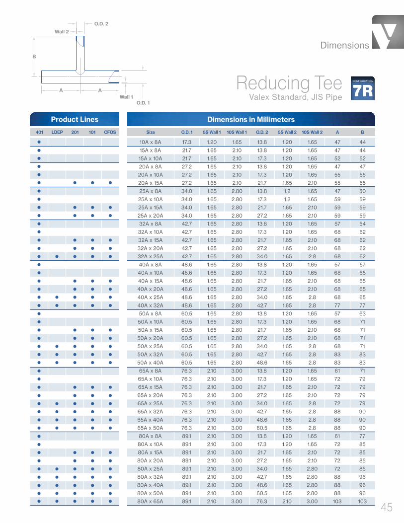
10A x 8A 17.3 1.20 1.65 13.8 1.20 1.65 47 44
15A x 8A 21.7 1.65 2.10 13.8 1.20 1.65 47 44
15A x 10A 21.7 1.65 2.10 17.3 1.20 1.65 52 52
20A x 8A 27.2 1.65 2.10 13.8 1.20 1.65 47 47
20A x 10A 27.2 1.65 2.10 17.3 1.20 1.65 55 55
20A x 15A 27.2 1.65 2.10 21.7 1.65 2.10 55 55
25A x 8A 34.0 1.65 2.80 13.8 1.2 1.65 47 50
25A x 10A 34.0 1.65 2.80 17.3 1.2 1.65 59 59
25A x 15A 34.0 1.65 2.80 21.7 1.65 2.10 59 59
25A x 20A 34.0 1.65 2.80 27.2 1.65 2.10 59 59
32A x 8A 42.7 1.65 2.80 13.8 1.20 1.65 57 54
32A x 10A 42.7 1.65 2.80 17.3 1.20 1.65 68 62
32A x 15A 42.7 1.65 2.80 21.7 1.65 2.10 68 62
32A x 20A 42.7 1.65 2.80 27.2 1.65 2.10 68 62
32A x 25A 42.7 1.65 2.80 34.0 1.65 2.8 68 62
40A x 8A 48.6 1.65 2.80 13.8 1.20 1.65 57 57
40A x 10A 48.6 1.65 2.80 17.3 1.20 1.65 68 65
40A x 15A 48.6 1.65 2.80 21.7 1.65 2.10 68 65
40A x 20A 48.6 1.65 2.80 27.2 1.65 2.10 68 65
40A x 25A 48.6 1.65 2.80 34.0 1.65 2.8 68 65
40A x 32A 48.6 1.65 2.80 42.7 1.65 2.8 77 77
50A x 8A 60.5 1.65 2.80 13.8 1.20 1.65 57 63
50A x 10A 60.5 1.65 2.80 17.3 1.20 1.65 68 71
50A x 15A 60.5 1.65 2.80 21.7 1.65 2.10 68 71
50A x 20A 60.5 1.65 2.80 27.2 1.65 2.10 68 71
50A x 25A 60.5 1.65 2.80 34.0 1.65 2.8 68 71
50A x 32A 60.5 1.65 2.80 42.7 1.65 2.8 83 83
50A x 40A 60.5 1.65 2.80 48.6 1.65 2.8 83 83
65A x 8A 76.3 2.10 3.00 13.8 1.20 1.65 61 71
65A x 10A 76.3 2.10 3.00 17.3 1.20 1.65 72 79
65A x 15A 76.3 2.10 3.00 21.7 1.65 2.10 72 79
65A x 20A 76.3 2.10 3.00 27.2 1.65 2.10 72 79
65A x 25A 76.3 2.10 3.00 34.0 1.65 2.8 72 79
65A x 32A 76.3 2.10 3.00 42.7 1.65 2.8 88 90
65A x 40A 76.3 2.10 3.00 48.6 1.65 2.8 88 90
65A x 50A 76.3 2.10 3.00 60.5 1.65 2.8 88 90
80A x 8A 89.1 2.10 3.00 13.8 1.20 1.65 61 77
80A x 10A 89.1 2.10 3.00 17.3 1.20 1.65 72 85
80A x 15A 89.1 2.10 3.00 21.7 1.65 2.10 72 85
80A x 20A 89.1 2.10 3.00 27.2 1.65 2.10 72 85
80A x 25A 89.1 2.10 3.00 34.0 1.65 2.80 72 85
80A x 32A 89.1 2.10 3.00 42.7 1.65 2.80 88 96
80A x 40A 89.1 2.10 3.00 48.6 1.65 2.80 88 96
80A x 50A 89.1 2.10 3.00 60.5 1.65 2.80 88 96
80A x 65A 89.1 2.10 3.00 76.3 2.10 3.00 103 103
401 LDEP 201 101 CFOS
O.D. 2
Wall 2
Wall 1O.D. 1
B
A A 7RCONFIGURATIONReducing Tee
Valex Standard, JIS Pipe
ASize O.D. 1 5S Wall 1 10S Wall 1 O.D. 2 B5S Wall 2 10S Wall 2
Dimensions in MillimetersProduct Lines

Dimensions
46
100A x 8A 114.3 2.10 3.00 13.8 1.20 1.65 61 90
100A x 10A 114.3 2.10 3.00 17.3 1.20 1.65 72 98
100A x 15A 114.3 2.10 3.00 21.7 1.65 2.10 72 98
100A x 20A 114.3 2.10 3.00 27.2 1.65 2.10 72 98
100A x 25A 114.3 2.10 3.00 34.0 1.65 2.80 72 98
100A x 32A 114.3 2.10 3.00 42.7 1.65 2.80 88 109
100A x 40A 114.3 2.10 3.00 48.6 1.65 2.80 88 109
100A x 50A 114.3 2.10 3.00 60.5 1.65 2.80 88 109
100A x 65A 114.3 2.10 3.00 76.3 2.10 3.00 116 116
100A x 80A 114.3 2.10 3.00 89.1 2.10 3.00 116 116
125A x 8A 139.8 2.80 3.40 13.8 1.20 1.65 80 110
125A x 10A 139.8 2.80 3.40 17.3 1.20 1.65 100 120
125A x 15A 139.8 2.80 3.40 21.7 1.65 2.10 100 120
125A x 20A 139.8 2.80 3.40 27.2 1.65 2.10 100 120
125A x 25A 139.8 2.80 3.40 34.0 1.65 2.80 100 120
125A x 32A 139.8 2.80 3.40 42.7 1.65 2.80 120 130
125A x 40A 139.8 2.80 3.40 48.6 1.65 2.80 120 130
125A x 50A 139.8 2.80 3.40 60.5 1.65 2.80 120 130
125A x 65A 139.8 2.80 3.40 76.3 2.10 3.00 140 140
125A x 80A 139.8 2.80 3.40 89.1 2.10 3.00 140 140
125A x 100A 139.8 2.80 3.40 114.3 2.10 3.00 140 140
150A x 8A 165.2 2.80 3.40 13.8 1.20 1.65 90 130
150A x 10A 165.2 2.80 3.40 17.3 1.20 1.65 110 140
150A x 15A 165.2 2.80 3.40 21.7 1.65 2.10 110 140
150A x 20A 165.2 2.80 3.40 27.2 1.65 2.10 110 140
150A x 25A 165.2 2.80 3.40 34.0 1.65 2.80 110 140
150A x 32A 165.2 2.80 3.40 42.7 1.65 2.80 130 150
150A x 40A 165.2 2.80 3.40 48.6 1.65 2.80 130 150
150A x 50A 165.2 2.80 3.40 60.5 1.65 2.80 130 150
150A x 65A 165.2 2.80 3.40 76.3 2.10 3.00 150 160
150A x 80A 165.2 2.80 3.40 89.1 2.10 3.00 150 160
150A x 100A 165.2 2.80 3.40 114.3 2.10 3.00 150 160
150A x 125A 165.2 2.80 3.40 139.8 2.80 3.40 170 170
200A x 8A 216.3 2.80 4.00 13.8 1.20 1.65 100 150
200A x 10A 216.3 2.80 4.00 17.3 1.20 1.65 120 160
200A x 15A 216.3 2.80 4.00 21.7 1.65 2.10 120 160
200A x 20A 216.3 2.80 4.00 27.2 1.65 2.10 120 160
200A x 25A 216.3 2.80 4.00 34.0 1.65 2.80 120 160
200A x 32A 216.3 2.80 4.00 42.7 1.65 2.80 140 170
200A x 40A 216.3 2.80 4.00 48.6 1.65 2.80 140 170
200A x 50A 216.3 2.80 4.00 60.5 1.65 2.80 140 170
200A x 65A 216.3 2.80 4.00 76.3 2.10 3.00 160 180
200A x 80A 216.3 2.80 4.00 89.1 2.10 3.00 160 180
200A x 100A 216.3 2.80 4.00 114.3 2.10 3.00 160 180
200A x 125A 216.3 2.80 4.00 139.8 2.80 3.40 180 190
200A x 150A 216.3 2.80 4.00 165.2 2.80 3.40 180 190
401 LDEP 201 101 CFOS
7RCONFIGURATION
ASize O.D. 1 5S Wall 1 10S Wall 1 O.D. 2 B5S Wall 2 10S Wall 2
Reducing TeeValex Standard, JIS Pipe CONTINUED
Dimensions in MillimetersProduct Lines
O.D. 2
Wall 2
Wall 1O.D. 1
B
A A

Dimensions
47
250A x 8A 267.4 3.40 4.00 13.8 1.20 1.65 110 180
250A x 10A 267.4 3.40 4.00 17.3 1.20 1.65 130 190
250A x 15A 267.4 3.40 4.00 21.7 1.65 2.10 130 190
250A x 20A 267.4 3.40 4.00 27.2 1.65 2.10 130 190
250A x 25A 267.4 3.40 4.00 34.0 1.65 2.80 130 190
250A x 32A 267.4 3.40 4.00 42.7 1.65 2.80 150 200
250A x 40A 267.4 3.40 4.00 48.6 1.65 2.80 150 200
250A x 50A 267.4 3.40 4.00 60.5 1.65 2.80 150 200
250A x 65A 267.4 3.40 4.00 76.3 2.10 3.00 170 210
250A x 80A 267.4 3.40 4.00 89.1 2.10 3.00 170 210
250A x 100A 267.4 3.40 4.00 114.3 2.10 3.00 170 210
250A x 125A 267.4 3.40 4.00 139.8 2.80 3.40 190 220
250A x 150A 267.4 3.40 4.00 165.2 2.80 3.40 190 220
250A x 200A 267.4 3.40 4.00 216.3 2.80 4.00 190 220
300A x 8A 318.5 4.00 4.50 13.8 1.20 1.65 130 210
300A x 10A 318.5 4.00 4.50 17.3 1.20 1.65 150 230
300A x 15A 318.5 4.00 4.50 21.7 1.65 2.10 150 230
300A x 20A 318.5 4.00 4.50 27.2 1.65 2.10 150 230
300A x 25A 318.5 4.00 4.50 34.0 1.65 2.80 150 230
300A x 32A 318.5 4.00 4.50 42.7 1.65 2.80 170 240
300A x 40A 318.5 4.00 4.50 48.6 1.65 2.80 170 240
300A x 50A 318.5 4.00 4.50 60.5 1.65 2.80 170 240
300A x 65A 318.5 4.00 4.50 76.3 2.10 3.00 190 250
300A x 80A 318.5 4.00 4.50 89.1 2.10 3.00 190 250
300A x 100A 318.5 4.00 4.50 114.3 2.10 3.00 190 250
300A x 125A 318.5 4.00 4.50 139.8 2.80 3.40 250 260
300A x 150A 318.5 4.00 4.50 165.2 2.80 3.40 250 260
300A x 200A 318.5 4.00 4.50 216.3 2.80 4.00 250 260
300A x 250A 318.5 4.00 4.50 267.4 3.40 4.00 250 260
350A x 15A 355.6 4.00 5.00 21.7 1.65 2.10 170 240
350A x 20A 355.6 4.00 5.00 27.2 1.65 2.10 170 240
350A x 25A 355.6 4.00 5.00 34.0 1.65 2.80 170 240
350A x 32A 355.6 4.00 5.00 42.7 1.65 2.80 200 260
350A x 40A 355.6 4.00 5.00 48.6 1.65 2.80 200 260
350A x 50A 355.6 4.00 5.00 60.5 1.65 2.80 200 260
350A x 65A 355.6 4.00 5.00 76.3 2.10 3.00 230 260
350A x 80A 355.6 4.00 5.00 89.1 2.10 3.00 230 260
350A x 100A 355.6 4.00 5.00 114.3 2.10 3.00 230 260
350A x 125A 355.6 4.00 5.00 139.8 2.80 3.40 280 280
350A x 150A 355.6 4.00 5.00 165.2 2.80 3.40 280 280
350A x 200A 355.6 4.00 5.00 216.3 2.80 4.00 280 280
350A x 250A 355.6 4.00 5.00 267.4 3.40 4.00 280 280
350A x 300A 355.6 4.00 5.00 318.5 4.00 4.50 280 280
401 LDEP 201 101 CFOS
7RCONFIGURATIONReducing Tee
Valex Standard, JIS Pipe CONTINUED
ASize O.D. 1 5S Wall 1 10S Wall 1 O.D. 2 B5S Wall 2 10S Wall 2
Dimensions in MillimetersProduct Lines

Dimensions
48
400A x 15A 406.4 4.50 5.00 21.7 1.65 2.10 180 270
400A x 20A 406.4 4.50 5.00 27.2 1.65 2.10 180 270
400A x 25A 406.4 4.50 5.00 34.0 1.65 2.80 180 270
400A x 32A 406.4 4.50 5.00 42.7 1.65 2.80 200 280
400A x 40A 406.4 4.50 5.00 48.6 1.65 2.80 200 280
400A x 50A 406.4 4.50 5.00 60.5 1.65 2.80 200 280
400A x 65A 406.4 4.50 5.00 76.3 2.10 3.00 230 280
400A x 80A 406.4 4.50 5.00 89.1 2.10 3.00 230 280
400A x 100A 406.4 4.50 5.00 114.3 2.10 3.00 230 280
400A x 125A 406.4 4.50 5.00 139.8 2.80 3.40 280 290
400A x 150A 406.4 4.50 5.00 165.2 2.80 3.40 280 290
400A x 200A 406.4 4.50 5.00 216.3 2.80 4.00 280 290
400A x 250A 406.4 4.50 5.00 267.4 3.40 4.00 280 290
400A x 300A 406.4 4.50 5.00 318.5 4.00 4.50 280 290
400A x 350A 406.4 4.50 5.00 355.6 4.00 5.00 300 300
450A x 15A 457.2 4.50 5.00 21.7 1.65 2.10 180 295
450A x 20A 457.2 4.50 5.00 27.2 1.65 2.10 180 295
450A x 25A 457.2 4.50 5.00 34.0 1.65 2.80 180 295
450A x 32A 457.2 4.50 5.00 42.7 1.65 2.80 200 310
450A x 40A 457.2 4.50 5.00 48.6 1.65 2.80 200 310
450A x 50A 457.2 4.50 5.00 60.5 1.65 2.80 200 310
450A x 65A 457.2 4.50 5.00 76.3 2.10 3.00 230 310
450A x 80A 457.2 4.50 5.00 89.1 2.10 3.00 230 310
450A x 100A 457.2 4.50 5.00 114.3 2.10 3.00 230 310
450A x 125A 457.2 4.50 5.00 139.8 2.80 3.40 280 320
450A x 150A 457.2 4.50 5.00 165.2 2.80 3.40 280 320
450A x 200A 457.2 4.50 5.00 216.3 2.80 4.00 280 320
450A x 250A 457.2 4.50 5.00 267.4 3.40 4.00 280 320
450A x 300A 457.2 4.50 5.00 318.5 4.00 4.50 280 320
450A x 350A 457.2 4.50 5.00 355.6 4.00 5.00 340 340
450A x 400A 457.2 4.50 5.00 406.4 4.50 5.00 340 340
500A x 15A 508.0 5.00 5.50 21.7 1.65 2.10 180 325
500A x 20A 508.0 5.00 5.50 27.2 1.65 2.10 180 325
500A x 25A 508.0 5.00 5.50 34.0 1.65 2.80 180 325
500A x 32A 508.0 5.00 5.50 42.7 1.65 2.80 200 340
500A x 40A 508.0 5.00 5.50 48.6 1.65 2.80 200 340
500A x 50A 508.0 5.00 5.50 60.5 1.65 2.80 200 340
500A x 65A 508.0 5.00 5.50 76.3 2.10 3.00 230 340
500A x 80A 508.0 5.00 5.50 89.1 2.10 3.00 230 340
500A x 100A 508.0 5.00 5.50 114.3 2.10 3.00 230 340
500A x 125A 508.0 5.00 5.50 139.8 2.80 3.40 280 360
500A x 150A 508.0 5.00 5.50 165.2 2.80 3.40 280 360
500A x 200A 508.0 5.00 5.50 216.3 2.80 4.00 280 360
401 LDEP 201 101 CFOS
7RCONFIGURATION
ASize O.D. 1 5S Wall 1 10S Wall 1 O.D. 2 B5S Wall 2 10S Wall 2
Reducing TeeValex Standard, JIS Pipe CONTINUED
Dimensions in MillimetersProduct Lines
O.D. 2
Wall 2
Wall 1O.D. 1
B
A A
Dimensions
49
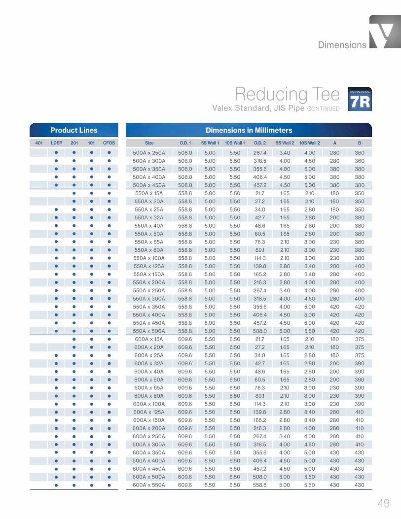
500A x 250A 508.0 5.00 5.50 267.4 3.40 4.00 280 360
500A x 300A 508.0 5.00 5.50 318.5 4.00 4.50 280 360
500A x 350A 508.0 5.00 5.50 355.6 4.00 5.00 380 380
500A x 400A 508.0 5.00 5.50 406.4 4.50 5.00 380 380
500A x 450A 508.0 5.00 5.50 457.2 4.50 5.00 380 380
550A x 15A 558.8 5.00 5.50 21.7 1.65 2.10 180 350
550A x 20A 558.8 5.00 5.50 27.2 1.65 2.10 180 350
550A x 25A 558.8 5.00 5.50 34.0 1.65 2.80 180 350
550A x 32A 558.8 5.00 5.50 42.7 1.65 2.80 200 380
550A x 40A 558.8 5.00 5.50 48.6 1.65 2.80 200 380
550A x 50A 558.8 5.00 5.50 60.5 1.65 2.80 200 380
550A x 65A 558.8 5.00 5.50 76.3 2.10 3.00 230 380
550A x 80A 558.8 5.00 5.50 89.1 2.10 3.00 230 380
550A x 100A 558.8 5.00 5.50 114.3 2.10 3.00 230 380
550A x 125A 558.8 5.00 5.50 139.8 2.80 3.40 280 400
550A x 150A 558.8 5.00 5.50 165.2 2.80 3.40 280 400
550A x 200A 558.8 5.00 5.50 216.3 2.80 4.00 280 400
550A x 250A 558.8 5.00 5.50 267.4 3.40 4.00 280 400
550A x 300A 558.8 5.00 5.50 318.5 4.00 4.50 280 400
550A x 350A 558.8 5.00 5.50 355.6 4.00 5.00 420 420
550A x 400A 558.8 5.00 5.50 406.4 4.50 5.00 420 420
550A x 450A 558.8 5.00 5.50 457.2 4.50 5.00 420 420
550A x 500A 558.8 5.00 5.50 508.0 5.00 5.50 420 420
600A x 15A 609.6 5.50 6.50 21.7 1.65 2.10 180 375
600A x 20A 609.6 5.50 6.50 27.2 1.65 2.10 180 375
600A x 25A 609.6 5.50 6.50 34.0 1.65 2.80 180 375
600A x 32A 609.6 5.50 6.50 42.7 1.65 2.80 200 390
600A x 40A 609.6 5.50 6.50 48.6 1.65 2.80 200 390
600A x 50A 609.6 5.50 6.50 60.5 1.65 2.80 200 390
600A x 65A 609.6 5.50 6.50 76.3 2.10 3.00 230 390
600A x 80A 609.6 5.50 6.50 89.1 2.10 3.00 230 390
600A x 100A 609.6 5.50 6.50 114.3 2.10 3.00 230 390
600A x 125A 609.6 5.50 6.50 139.8 2.80 3.40 280 410
600A x 150A 609.6 5.50 6.50 165.2 2.80 3.40 280 410
600A x 200A 609.6 5.50 6.50 216.3 2.80 4.00 280 410
600A x 250A 609.6 5.50 6.50 267.4 3.40 4.00 280 410
600A x 300A 609.6 5.50 6.50 318.5 4.00 4.50 280 410
600A x 350A 609.6 5.50 6.50 355.6 4.00 5.00 430 430
600A x 400A 609.6 5.50 6.50 406.4 4.50 5.00 430 430
600A x 450A 609.6 5.50 6.50 457.2 4.50 5.00 430 430
600A x 500A 609.6 5.50 6.50 508.0 5.00 5.50 430 430
600A x 550A 609.6 5.50 6.50 558.8 5.00 5.50 430 430
401 LDEP 201 101 CFOS
7RCONFIGURATIONReducing Tee
Valex Standard, JIS Pipe CONTINUED
ASize O.D. 1 5S Wall 1 10S Wall 1 O.D. 2 B5S Wall 2 10S Wall 2
Dimensions in MillimetersProduct Lines

Dimensions
50
Reducing TeeJIS B2312 / B2313 Standard, JIS Pipe
O.D. 2
Wall 2
Wall 1
O.D. 1
B
A A
Dimensions in Millimeters
Size O.D. 1 5S Wall 1 10S Wall1 O.D. 2 5S Wall 2 10S Wall 2 A B 401 LDEP 201 101 CFOS
Product Lines
20A x 15A 27.2 1.65 2.10 21.7 1.65 2.10 28.6 28.6
25A x 15A 34.0 1.65 2.80 21.7 1.65 2.10 38.1 38.1
25A x 20A 34.0 1.65 2.80 27.2 1.65 2.10 38.1 38.1
32A x 15A 42.7 1.65 2.80 21.7 1.65 2.10 47.6 47.6
32A x 20A 42.7 1.65 2.80 27.2 1.65 2.10 47.6 47.6
32A x 25A 42.7 1.65 2.80 34.0 1.65 2.80 47.6 47.6
40A x 15A 48.6 1.65 2.80 21.7 1.65 2.10 57.2 57.2
40A x 20A 48.6 1.65 2.80 27.2 1.65 2.10 57.2 57.2
40A x 25A 48.6 1.65 2.80 34.0 1.65 2.80 57.2 57.2
40A x 32A 48.6 1.65 2.80 42.7 1.65 2.80 57.2 57.2
50A x 20A 60.5 1.65 2.80 27.2 1.65 2.10 63.5 44.5
50A x 25A 60.5 1.65 2.80 34.0 1.65 2.80 63.5 50.8
50A x 32A 60.5 1.65 2.80 42.7 1.65 2.80 63.5 57.2
50A x 40A 60.5 1.65 2.80 48.6 1.65 2.80 63.5 60.3
65A x 25A 76.3 2.10 3.00 34.0 1.65 2.80 76.2 57.2
65A x 32A 76.3 2.10 3.00 42.7 1.65 2.80 76.2 63.5
65A x 40A 76.3 2.10 3.00 48.6 1.65 2.80 76.2 66.7
65A x 50A 76.3 2.10 3.00 60.5 1.65 2.80 76.2 69.9
80A x 32A 89.1 2.10 3.00 42.7 1.65 2.80 85.7 69.9
80A x 40A 89.1 2.10 3.00 48.6 1.65 2.80 85.7 73.0
80A x 50A 89.1 2.10 3.00 60.5 1.65 2.80 85.7 76.2
80A x 65A 89.1 2.10 3.00 76.3 2.10 3.00 85.7 82.6
90A x 40A 101.6 2.10 3.00 48.6 1.65 2.80 95.3 79.4
90A x 50A 101.6 2.10 3.00 60.5 1.65 2.80 95.3 82.6
90A x 65A 101.6 2.10 3.00 76.3 2.10 3.00 95.3 88.9
90A x 80A 101.6 2.10 3.00 89.1 2.10 3.00 95.3 92.1
100A x 40A 114.3 2.10 3.00 48.6 1.65 2.80 104.8 85.7
100A x 50A 114.3 2.10 3.00 60.5 1.65 2.80 104.8 88.9
100A x 65A 114.3 2.10 3.00 76.3 2.10 3.00 104.8 95.3
100A x 80A 114.3 2.10 3.00 89.1 2.10 3.00 104.8 98.4
100A x 90A 114.3 2.10 3.00 101.6 2.10 3.00 104.8 101.6
125A x 50A 139.8 2.80 3.40 60.5 1.65 2.80 123.8 104.8
125A x 65A 139.8 2.80 3.40 76.3 2.10 3.00 123.8 108.0
125A x 80A 139.8 2.80 3.40 89.1 2.10 3.00 123.8 111.1
125A x 90A 139.8 2.80 3.40 101.6 2.10 3.00 123.8 114.3
125A x 100A 139.8 2.80 3.40 114.3 2.10 3.00 123.8 117.5
150A x 65A 165.2 2.80 3.40 76.3 2.10 3.00 142.9 120.7
150A x 80A 165.2 2.80 3.40 89.1 2.10 3.00 142.9 123.8
150A x 90A 165.2 2.80 3.40 101.6 2.10 3.00 142.9 127.0
150A x 100A 165.2 2.80 3.40 114.3 2.10 3.00 142.9 130.2
150A x 125A 165.2 2.80 3.40 139.8 2.80 3.40 142.9 136.5
7RSCONFIGURATION

Dimensions
51
Reducing Tee JIS B2312 / B2313 Standard, JIS Pipe CONTIN-
Dimensions in Millimeters
Size O.D. 1 5S Wall 1 10S Wall1 O.D. 2 5S Wall 2 10S Wall 2 A B 401 LDEP 201 101 CFOS
Product Lines
200A x 90A 216.3 2.80 4.00 101.6 2.10 3.00 177.8 152.4
200A x 100A 216.3 2.80 4.00 114.3 2.10 3.00 177.8 155.6
200A x 125A 216.3 2.80 4.00 139.8 2.80 3.40 177.8 161.9
200A x 150A 216.3 2.80 4.00 165.2 2.80 3.40 177.8 168.3
250A x 100A 267.4 3.40 4.00 114.3 2.10 3.00 215.9 184.2
250A x 125A 267.4 3.40 4.00 139.8 2.80 3.40 215.9 190.5
250A x 150A 267.4 3.40 4.00 165.2 2.80 3.40 215.9 193.7
250A x 200A 267.4 3.40 4.00 216.3 2.80 4.00 215.9 203.2
300A x 125A 318.5 4.00 4.50 139.8 2.80 3.40 254.0 215.9
300A x 150A 318.5 4.00 4.50 165.2 2.80 3.40 254.0 219.1
300A x 200A 318.5 4.00 4.50 216.3 2.80 4.00 254.0 228.6
300A x 250A 318.5 4.00 4.50 267.4 3.40 4.00 254.0 241.3
350A x 150A 355.6 4.00 5.00 165.2 2.80 3.40 279.4 238.1
350A x 200A 355.6 4.00 5.00 216.3 2.80 4.00 279.4 247.7
350A x 250A 355.6 4.00 5.00 267.4 3.40 4.00 279.4 257.2
350A x 300A 355.6 4.00 5.00 318.5 4.00 4.50 279.4 269.9
400A x 150A 406.4 4.50 5.00 165.2 2.80 3.40 304.8 263.5
400A x 200A 406.4 4.50 5.00 216.3 2.80 4.00 304.8 273.1
400A x 250A 406.4 4.50 5.00 267.4 3.40 4.00 304.8 282.6
400A x 300A 406.4 4.50 5.00 318.5 4.00 4.50 304.8 295.3
400A x 350A 406.4 4.50 5.00 355.6 4.00 5.00 304.8 304.8
450A x 200A 457.2 4.50 5.00 216.3 2.80 4.00 342.9 298.5
450A x 250A 457.2 4.50 5.00 267.4 3.40 4.00 342.9 308.0
450A x 300A 457.2 4.50 5.00 318.5 4.00 4.50 342.9 320.7
450A x 350A 457.2 4.50 5.00 355.6 4.00 5.00 342.9 330.2
450A x 400A 457.2 4.50 5.00 406.4 4.50 5.00 342.9 330.2
500A x 200A 508.0 5.00 5.50 216.3 2.80 4.00 381.0 323.9
500A x 250A 508.0 5.00 5.50 267.4 3.40 4.00 381.0 333.4
500A x 300A 508.0 5.00 5.50 318.5 4.00 4.50 381.0 346.1
500A x 350A 508.0 5.00 5.50 355.6 4.00 5.00 381.0 355.6
500A x 400A 508.0 5.00 5.50 406.4 4.50 5.00 381.0 355.6
500A x 450A 508.0 5.00 5.50 457.2 4.50 5.00 381.0 368.3
550A x 400A 558.8 5.00 5.50 406.4 4.50 5.00 419.1 381.0
550A x 450A 558.8 5.00 5.50 457.2 4.50 5.00 419.1 393.7
550A x 500A 558.8 5.00 5.50 508.0 5.00 5.50 419.1 406.4
600A x 450A 609.6 5.50 6.50 457.2 4.50 5.00 431.8 419.1
600A x 500A 609.6 5.50 6.50 508.0 5.00 5.50 431.8 431.8
600A x 550A 609.6 5.50 6.50 558.8 5.00 5.50 431.8 431.8
7RSCONFIGURATION

Dimensions
52
Crosses
• Equal Crosses

Dimensions
53
Dimensions in Inches
Equal CrossValex Standard, ASTM Tube
1/4" x 1/4" .250 .035 / .039 1.750
3/8" x 3/8" .375 .035 / .039 1.750
1/2" x 1/2" .500 .049 2.125
3/4" x 3/4" .750 .065 2.125
1" x 1" 1.000 .065 2.500
1-1/2" x 1-1/2" 1.500 .065 2.750
2" x 2" 2.000 .065 3.250
2-1/2" x 2-1/2" 2.500 .065 3.500
3" x 3" 3.000 .065 5.500
4" x 4" 4.000 .083 6.000
6" x 6" 6.000 .109 10.625
Size O.D. Wall A 401 201 222
Product Lines
O.D.
Wall
Wall
O.D.
A
A
AA9
CONFIGURATION
Dimensions in Inches
Equal CrossASME B16.9 Standard, ASME Pipe
NPS 1/2 x NPS 1/2 10S x 10S .84 .083 1.00
NPS 3/4 x NPS 3/4 10S x 10S 1.05 .083 1.12
NPS 1 x NPS 1 10S x 10S 1.32 .109 1.50
NPS 1-1/4 x NPS 1-1/4 10S x 10S 1.66 .109 1.88
NPS 1-1/2 x NPS 1-1/2 10S x 10S 1.90 .109 2.25
NPS 2 x NPS 2 10S x 10S 2.38 .109 2.50
NPS 2-1/2 x NPS 2-1/2 10S x 10S 2.88 .120 3.00
NPS 3 x NPS 3 10S x 10S 3.50 .120 3.38
NPS 3-1/2 x NPS 3-1/2 10S x 10S 4.00 .120 3.75
NPS 4 x NPS 4 10S x 10S 4.50 .120 4.12
NPS 5 x NPS 5 10S x 10S 5.56 .134 4.88
NPS 6 x NPS 6 10S x 10S 6.62 .134 5.62
NPS 8 x NPS 8 10S x 10S 8.62 .148 7.00
NPS 10 x NPS 10 10S x 10S 10.75 .165 8.50
NPS 12 x NPS 12 10S x 10S 12.75 .180 10.00
NPS 14 x NPS 14 10S x 10S 14.00 .188 11.00
NPS 16 x NPS 16 10S x 10S 16.00 .188 12.00
NPS 18 x NPS 18 10S x 10S 18.00 .188 13.50
NPS 20 x NPS 20 10S x 10S 20.00 .218 15.00
NPS 22 x NPS 22 10S x 10S 22.00 .218 16.50
NPS 24 x NPS 24 10S x 10S 24.00 .250 17.00
Size Sch. O.D. Wall A LDEP CFOS
Product Lines
O.D.Wall
Wall
O.D.
A
A
A A
9CONFIGURATION

Dimensions
54
Reducers
• Concentric Reducers
• Cap Reducers

Dimensions
55
Dimensions in Inches
Concentric Reducer, Short Valex Standard, ASTM Tube
3/8" x 1/4" .375 .035 / .039 .250 .035 / .039 1.500 .73 .73
1/2" x 1/4" .500 .049 .250 .035 / .039 1.500 .70 .73
1/2" x 3/8" .500 .049 .375 .035 / .039 1.500 .73 .73
3/4" x 1/4" .750 .065 .250 .035 / .039 2.000 .96 .90
3/4" x 3/8" .750 .065 .375 .035 / .039 2.000 .96 .93
3/4" x 1/2" .750 .065 .500 .049 2.000 .96 .97
1" x 1/4" 1.000 .065 .250 .035 / .039 2.000 .98 .80
1" x 3/8" 1.000 .065 .375 .035 / .039 2.000 .98 .84
1" x 1/2" 1.000 .065 .500 .049 2.000 .98 .88
1" x 3/4" 1.000 .065 .750 .065 2.000 .98 .95
1-1/2" x 1/4" 1.500 0.65 .250 .035 / .039 2.250 .98 .91
1-1/2" x 3/8" 1.500 .065 .375 .035 / .039 2.250 .98 .95
1-1/2" x 1/2" 1.500 .065 .500 .049 2.250 .98 .98
1-1/2" x 3/4" 1.500 .065 .750 .065 2.250 .98 1.05
1-1/2" x 1" 1.500 .065 1.000 .065 2.250 1.00 1.11
2" x 1/4" 2.000 .065 .250 .035 / .039 2.500 1.00 1.00
2" x 3/8" 2.000 .065 .375 .035 / .039 2.500 1.00 1.03
2" x 1/2" 2.000 .065 .500 .049 2.500 1.00 1.07
2" x 3/4" 2.000 .065 .750 .065 2.500 1.00 1.14
2" x 1" 2.000 .065 1.000 .065 3.375 1.00 1.00
2" x 1-1/2" 2.000 .065 1.500 .065 2.500 1.00 1.00
Product Lines
A B CSize O.D. 2 Wall 2O.D. 1 Wall 1 401 201 222
Wall 2
O.D. 2
Wall 1
O.D. 1
B
A
C
31SCONFIGURATION

Dimensions
56
Dimensions in Inches
Concentric Reducer Valex Standard, ASTM Tube
3/8" x 1/4" .375 .035 / .039 .250 .035 / .039 2.750 1.344
1/2" x 1/4" .500 .049 .250 .035 / .039 2.750 1.313
1/2" x 3/8" .500 .049 .375 .035 / .039 2.750 1.344
3/4" x 1/4" .750 .065 .250 .035 / .039 2.750 1.250
3/4" x 3/8" .750 .065 .375 .035 / .039 2.750 1.281
3/4" x 1/2" .750 .065 .500 .049 2.750 1.313
1" x 1/4" 1.000 .065 .250 .035 / .039 3.000 1.313
1" x 3/8" 1.000 .065 .375 .035 / .039 3.000 1.344
1" x 1/2" 1.000 .065 .500 .049 3.000 1.375
1" x 3/4" 1.000 .065 .750 .065 3.000 1.438
1-1/2" x 1/4" 1.500 .065 .250 .035 / .039 5.250 2.313
1-1/2" x 3/8" 1.500 .065 .375 .035 / .039 5.250 2.344
1-1/2" x 1/2" 1.500 .065 .500 .049 5.250 2.375
1-1/2" x 3/4" 1.500 .065 .750 .065 5.250 2.438
1-1/2" x 1" 1.500 .065 1.000 .065 5.250 2.500
2" x 1/4" 2.000 .065 .250 .035 / .039 5.500 2.313
2" x 3/8" 2.000 .065 .375 .035 / .039 5.500 2.344
2" x 1/2" 2.000 .065 .500 .049 5.500 2.375
2" x 3/4" 2.000 .065 .750 .065 5.500 2.438
2" x 1" 2.000 .065 1.000 .065 5.500 2.500
2" x 1-1/2" 2.000 .065 1.500 .065 5.500 2.625
2-1/2" x 1/4" 2.500 .065 .250 .035 / .039 5.750 2.313
2-1/2" x 3/8" 2.500 .065 .375 .035 / .039 5.750 2.344
2-1/2" x 1/2" 2.500 .065 .500 .049 5.750 2.375
2-1/2" x 3/4" 2.500 .065 .750 .065 5.750 2.438
2-1/2" x 1" 2.500 .065 1.000 .065 5.750 2.500
2-1/2" x 1-1/2" 2.500 .065 1.500 .065 5.750 2.625
2-1/2" x 2" 2.500 .065 2.000 .065 5.750 2.750
3" x 1/2" 3.000 .065 .500 .049 6.000 2.375
3" x 3/4" 3.000 .065 .750 .065 6.000 2.438
3" x 1" 3.000 .065 1.000 .065 6.000 2.500
3" x 1-1/2" 3.000 .065 1.500 .065 6.000 2.625
3" x 2" 3.000 .065 2.000 .065 6.000 2.750
4" x 3/4" 4.000 .083 .750 .065 6.500 2.438
4" x 1" 4.000 .083 1.000 .065 6.500 2.500
4" x 1-1/2" 4.000 .083 1.500 .065 6.500 2.625
4" x 2" 4.000 .083 2.000 .065 6.500 2.750
4" x 2-1/2" 4.000 .083 2.500 .065 8.000 2.000
4" x 3" 4.000 .083 3.000 .065 6.500 3.000
6" x 1" 6.000 .109 1.000 .065 11.500 3.000
6" x 1-1/2" 6.000 .109 1.500 .065 11.500 3.000
6" x 2" 6.000 .109 2.000 .065 11.500 3.000
6" x 2-1/2" 6.000 .109 2.500 .065 11.500 3.000
6" x 3" 6.000 .109 3.000 .065 11.500 3.000
6" x 4" 6.000 .109 4.000 .083 11.500 3.000
Product Lines
AWall 2O.D. 2Wall 1O.D. 1 BSize 401 201 222
Wall 2Wall 1
O.D. 2O.D. 1
B B
A
31CONFIGURATION

Dimensions
57
Concentric Reducer ASME B16.9 Standard, ASME Pipe
A
Wall 2
Wall 1
O.D. 2O.D. 1
Dimensions in Inches
NPS 3/4 x NPS 1/2 10S x 10S 1.05 .083 .84 .083 1.50
NPS 1 x NPS 1/2 10S x 10S 1.32 .109 .84 .083 2.00
NPS 1 x NPS 3/4 10S x 10S 1.32 .109 1.05 .083 2.00
NPS 1-1/4 x NPS 1/2 10S x 10S 1.66 .109 .84 .083 2.00
NPS 1-1/4 x NPS 3/4 10S x 10S 1.66 .109 1.05 .083 2.00
NPS 1-1/4 x NPS 1 10S x 10S 1.66 .109 1.32 .109 2.00
NPS 1-1/2 x NPS 1/2 10S x 10S 1.90 .109 .84 .083 2.50
NPS 1-1/2 x NPS 3/4 10S x 10S 1.90 .109 1.05 .083 2.50
NPS 1-1/2 x NPS 1 10S x 10S 1.90 .109 1.32 .109 2.50
NPS 1-1/2 x NPS 1-1/4 10S x 10S 1.90 .109 1.66 .109 2.50
NPS 2 x NPS 3/4 10S x 10S 2.38 .109 1.05 .083 3.00
NPS 2 x NPS 1 10S x 10S 2.38 .109 1.32 .109 3.00
NPS 2 x NPS 1-1/4 10S x 10S 2.38 .109 1.66 .109 3.00
NPS 2 x NPS 1-1/2 10S x 10S 2.38 .109 1.90 .109 3.00
NPS 2-1/2 x NPS 1 10S x 10S 2.88 .120 1.32 .109 3.50
NPS 2-1/2 x NPS 1-1/4 10S x 10S 2.88 .120 1.66 .109 3.50
NPS 2-1/2 x NPS 1-1/2 10S x 10S 2.88 .120 1.90 .109 3.50
NPS 2-1/2 x NPS 2 10S x 10S 2.88 .120 2.38 .109 3.50
NPS 3 x NPS 1-1/4 10S x 10S 3.50 .120 1.66 .109 3.50
NPS 3 x NPS 1-1/2 10S x 10S 3.50 .120 1.90 .109 3.50
NPS 3 x NPS 2 10S x 10S 3.50 .120 2.38 .109 3.50
NPS 3 x NPS 2-1/2 10S x 10S 3.50 .120 2.88 .120 3.50
NPS 3-1/2 x NPS 1-1/4 10S x 10S 4.00 .120 1.66 .109 4.00
NPS 3-1/2 x NPS 1-1/2 10S x 10S 4.00 .120 1.90 .109 4.00
NPS 3-1/2 x NPS 2 10S x 10S 4.00 .120 2.38 .109 4.00
NPS 3-1/2 x NPS 2-1/2 10S x 10S 4.00 .120 2.88 .120 4.00
NPS 3-1/2 x NPS 3 10S x 10S 4.00 .120 3.50 .120 4.00
NPS 4 x NPS 1-1/2 10S x 10S 4.50 .120 1.90 .109 4.00
NPS 4 x NPS 2 10S x 10S 4.50 .120 2.38 .109 4.00
NPS 4 x NPS 2-1/2 10S x 10S 4.50 .120 2.88 .120 4.00
NPS 4 x NPS 3 10S x 10S 4.50 .120 3.50 .120 4.00
NPS 4 x NPS 3-1/2 10S x 10S 4.50 .120 4.00 .120 4.00
NPS 5 x NPS 2 10S x 10S 5.56 .134 2.38 .109 5.00
NPS 5 x NPS 2-1/2 10S x 10S 5.56 .134 2.88 .120 5.00
NPS 5 x NPS 3 10S x 10S 5.56 .134 3.50 .120 5.00
NPS 5 x NPS 3-1/2 10S x 10S 5.56 .134 4.00 .120 5.00
NPS 5 x NPS 4 10S x 10S 5.56 .134 4.50 .120 5.00
NPS 6 x NPS 2-1/2 10S x 10S 6.62 .134 2.88 .120 5.50
NPS 6 x NPS 3 10S x 10S 6.62 .134 3.50 .120 5.50
NPS 6 x NPS 3-1/2 10S x 10S 6.62 .134 4.00 .120 5.50
NPS 6 x NPS 4 10S x 10S 6.62 .134 4.50 .120 5.50
NPS 6 x NPS 5 10S x 10S 6.62 .134 5.56 .134 5.50
Product Lines
Size Sch. O.D. 1 Wall 1 O.D. 2 Wall 2 A LDEP CFOS
31CONFIGURATION

Dimensions
58
Size Sch. O.D. 1 Wall 1 O.D. 2 Wall 2 A
Concentric ReducerASME B16.9 Standard, ASME Pipe CONTINUED
Dimensions in Inches
NPS 8 x NPS 3-1/2 10S x 10S 8.62 .148 4.00 .120 6.00
NPS 8 x NPS 4 10S x 10S 8.62 .148 4.50 .120 6.00
NPS 8 x NPS 5 10S x 10S 8.62 .148 5.56 .134 6.00
NPS 8 x NPS 6 10S x 10S 8.62 .148 6.62 .134 6.00
NPS 10 x NPS 4 10S x 10S 10.75 .165 4.50 .120 7.00
NPS 10 x NPS 5 10S x 10S 10.75 .165 5.56 .134 7.00
NPS 10 x NPS 6 10S x 10S 10.75 .165 6.62 .134 7.00
NPS 10 x NPS 8 10S x 10S 10.75 .165 8.62 .148 7.00
NPS 12 x NPS 5 10S x 10S 12.75 .180 5.56 .134 8.00
NPS 12 x NPS 6 10S x 10S 12.75 .180 6.62 .134 8.00
NPS 12 x NPS 8 10S x 10S 12.75 .180 8.62 .148 8.00
NPS 12 x NPS 10 10S x 10S 12.75 .180 10.75 .165 8.00
NPS 14 x NPS 6 10S x 10S 14.00 .188 6.62 .134 13.00
NPS 14 x NPS 8 10S x 10S 14.00 .188 8.62 .148 13.00
NPS 14 x NPS 10 10S x 10S 14.00 .188 10.75 .165 13.00
NPS 14 x NPS 12 10S x 10S 14.00 .188 12.75 .180 13.00
NPS 16 x NPS 8 10S x 10S 16.00 .188 8.62 .148 14.00
NPS 16 x NPS 10 10S x 10S 16.00 .188 10.75 .165 14.00
NPS 16 x NPS 12 10S x 10S 16.00 .188 12.75 .180 14.00
NPS 16 x NPS 14 10S x 10S 16.00 .188 14.00 .188 14.00
NPS 18 x NPS 10 10S x 10S 18.00 .188 10.75 .165 15.00
NPS 18 x NPS 12 10S x 10S 18.00 .188 12.75 .180 15.00
NPS 18 x NPS 14 10S x 10S 18.00 .188 14.00 .188 15.00
NPS 18 x NPS 16 10S x 10S 18.00 .188 16.00 .188 15.00
NPS 20 x NPS 12 10S x 10S 20.00 .218 12.75 .180 20.00
NPS 20 x NPS 14 10S x 10S 20.00 .218 14.00 .188 20.00
NPS 20 x NPS 16 10S x 10S 20.00 .218 16.00 .188 20.00
NPS 20 x NPS 18 10S x 10S 20.00 .218 18.00 .188 20.00
NPS 22 x NPS 14 10S x 10S 22.00 .218 14.00 .188 20.00
NPS 22 x NPS 16 10S x 10S 22.00 .218 16.00 .188 20.00
NPS 22 x NPS 18 10S x 10S 22.00 .218 18.00 .188 20.00
NPS 22 x NPS 20 10S x 10S 22.00 .218 20.00 .218 20.00
NPS 24 x NPS 16 10S x 10S 24.00 .250 16.00 .188 20.00
NPS 24 x NPS 18 10S x 10S 24.00 .250 18.00 .188 20.00
NPS 24 x NPS 20 10S x 10S 24.00 .250 20.00 .218 20.00
NPS 24 x NPS 22 10S x 10S 24.00 .250 22.00 .218 20.00
Product Lines
31CONFIGURATION
LDEP CFOS

Dimensions
59
Dimensions in Millimeters
10A x 8A 17.3 1.20 1.65 13.8 1.20 1.65 90 36 29
15A x 8A 21.7 1.65 2.10 13.8 1.20 1.65 100 36 29
15A x 10A 21.7 1.65 2.10 17.3 1.20 1.65 100 36 36
20A x 8A 27.2 1.65 2.10 13.8 1.20 1.65 105 36 29
20A x 10A 27.2 1.65 2.10 17.3 1.20 1.65 105 36 36
20A x 15A 27.2 1.65 2.10 21.7 1.65 2.10 105 36 36
25A x 8A 34.0 1.65 2.80 13.8 1.20 1.65 120 36 29
25A x 10A 34.0 1.65 2.80 17.3 1.20 1.65 120 36 36
25A x 15A 34.0 1.65 2.80 21.7 1.65 2.10 120 36 36
25A x 20A 34.0 1.65 2.80 27.2 1.65 2.10 120 36 36
32A x 8A 42.7 1.65 2.80 13.8 1.20 1.65 125 46 29
32A x 10A 42.7 1.65 2.80 17.3 1.20 1.65 125 46 36
32A x 15A 42.7 1.65 2.80 21.7 1.65 2.10 125 46 36
32A x 20A 42.7 1.65 2.80 27.2 1.65 2.10 125 46 36
32A x 25A 42.7 1.65 2.80 34.0 1.65 2.80 125 46 36
40A x 8A 48.6 1.65 2.80 13.8 1.20 1.65 130 46 29
40A x 10A 48.6 1.65 2.80 17.3 1.20 1.65 130 46 36
40A x 15A 48.6 1.65 2.80 21.7 1.65 2.10 130 46 36
40A x 20A 48.6 1.65 2.80 27.2 1.65 2.10 130 46 36
40A x 25A 48.6 1.65 2.80 34.0 1.65 2.80 130 46 36
40A x 32A 48.6 1.65 2.80 42.7 1.65 2.80 130 46 46
50A x 8A 60.5 1.65 2.80 13.8 1.20 1.65 140 46 29
50A x 10A 60.5 1.65 2.80 17.3 1.20 1.65 140 46 36
50A x 15A 60.5 1.65 2.80 21.7 1.65 2.10 140 46 36
50A x 20A 60.5 1.65 2.80 27.2 1.65 2.10 140 46 36
50A x 25A 60.5 1.65 2.80 34.0 1.65 2.80 140 46 36
50A x 32A 60.5 1.65 2.80 42.7 1.65 2.80 140 46 46
50A x 40A 60.5 1.65 2.80 48.6 1.65 2.80 140 46 46
65A x 8A 76.3 2.10 3.00 13.8 1.20 1.65 165 51 29
65A x 10A 76.3 2.10 3.00 17.3 1.20 1.65 165 51 36
65A x 15A 76.3 2.10 3.00 21.7 1.65 2.10 165 51 36
65A x 20A 76.3 2.10 3.00 27.2 1.65 2.10 165 51 36
65A x 25A 76.3 2.10 3.00 34.0 1.65 2.80 165 51 36
65A x 32A 76.3 2.10 3.00 42.7 1.65 2.80 165 51 46
65A x 40A 76.3 2.10 3.00 48.6 1.65 2.80 165 51 46
65A x 50A 76.3 2.10 3.00 60.5 1.65 2.80 165 51 46
80A x 8A 89.1 2.10 3.00 13.8 1.20 1.65 170 51 29
80A x 10A 89.1 2.10 3.00 17.3 1.20 1.65 170 51 36
80A x 15A 89.1 2.10 3.00 21.7 1.65 2.10 170 51 36
80A x 20A 89.1 2.10 3.00 27.2 1.65 2.10 170 51 36
80A x 25A 89.1 2.10 3.00 34.0 1.65 2.80 170 51 36
80A x 32A 89.1 2.10 3.00 42.7 1.65 2.80 170 51 46
80A x 40A 89.1 2.10 3.00 48.6 1.65 2.80 170 51 46
80A x 50A 89.1 2.10 3.00 60.5 1.65 2.80 170 51 46
Product Lines
Size O.D. 1 5S Wall 1 10S Wall 1 O.D. 2 5S Wall 2 10S Wall 2 A B C 401 LDEP 201 101 CFOS
Concentric Reducer Valex Standard, JIS Pipe 31
CONFIGURATION
Wall 2Wall 1
O.D. 2O.D. 1
A
B C

Dimensions
60
Dimensions in Millimeters
80A x 65A 89.1 2.10 3.00 76.3 2.10 3.00 170 51 51
100A x 8A 114.3 2.10 3.00 13.8 1.20 1.65 180 51 29
100A x 10A 114.3 2.10 3.00 17.3 1.20 1.65 180 51 36
100A x 15A 114.3 2.10 3.00 21.7 1.65 2.10 180 51 36
100A x 20A 114.3 2.10 3.00 27.2 1.65 2.10 180 51 36
100A x 25A 114.3 2.10 3.00 34.0 1.65 2.80 180 51 36
100A x 32A 114.3 2.10 3.00 42.7 1.65 2.80 180 51 46
100A x 40A 114.3 2.10 3.00 48.6 1.65 2.80 180 51 46
100A x 50A 114.3 2.10 3.00 60.5 1.65 2.80 180 51 46
100A x 65A 114.3 2.10 3.00 76.3 2.10 3.00 180 51 51
100A x 80A 114.3 2.10 3.00 89.1 2.10 3.00 180 51 51
125A x 8A 139.8 2.80 3.40 13.8 1.20 1.65 250 56 29
125A x 10A 139.8 2.80 3.40 17.3 1.20 1.65 250 56 36
125A x 15A 139.8 2.80 3.40 21.7 1.65 2.10 250 56 36
125A x 20A 139.8 2.80 3.40 27.2 1.65 2.10 250 56 36
125A x 25A 139.8 2.80 3.40 34.0 1.65 2.80 250 56 36
125A x 32A 139.8 2.80 3.40 42.7 1.65 2.80 250 56 46
125A x 40A 139.8 2.80 3.40 48.6 1.65 2.80 250 56 46
125A x 50A 139.8 2.80 3.40 60.5 1.65 2.80 250 56 46
125A x 65A 139.8 2.80 3.40 76.3 2.10 3.00 250 56 51
125A x 80A 139.8 2.80 3.40 89.1 2.10 3.00 250 56 51
125A x 100A 139.8 2.80 3.40 114.3 2.10 3.00 250 56 51
150A x 8A 165.2 2.80 3.40 13.8 1.20 1.65 260 56 29
150A x 10A 165.2 2.80 3.40 17.3 1.20 1.65 260 56 36
150A x 15A 165.2 2.80 3.40 21.7 1.65 2.10 260 56 36
150A x 20A 165.2 2.80 3.40 27.2 1.65 2.10 260 56 36
150A x 25A 165.2 2.80 3.40 34.0 1.65 2.80 260 56 36
150A x 32A 165.2 2.80 3.40 42.7 1.65 2.80 260 56 46
150A x 40A 165.2 2.80 3.40 48.6 1.65 2.80 260 56 46
150A x 50A 165.2 2.80 3.40 60.5 1.65 2.80 260 56 46
150A x 65A 165.2 2.80 3.40 76.3 2.10 3.00 260 56 51
150A x 80A 165.2 2.80 3.40 89.1 2.10 3.00 260 56 51
150A x 100A 165.2 2.80 3.40 114.3 2.10 3.00 260 56 51
150A x 125A 165.2 2.80 3.40 139.8 2.80 3.40 260 56 56
200A x 8A 216.3 2.80 4.00 13.8 1.20 1.65 280 56 29
200A x 10A 216.3 2.80 4.00 17.3 1.20 1.65 280 56 36
200A x 15A 216.3 2.80 4.00 21.7 1.65 2.10 280 56 36
200A x 20A 216.3 2.80 4.00 27.2 1.65 2.10 280 56 36
200A x 25A 216.3 2.80 4.00 34.0 1.65 2.80 280 56 36
200A x 32A 216.3 2.80 4.00 42.7 1.65 2.80 280 56 46
200A x 40A 216.3 2.80 4.00 48.6 1.65 2.80 280 56 46
200A x 50A 216.3 2.80 4.00 60.5 1.65 2.80 280 56 46
200A x 65A 216.3 2.80 4.00 76.3 2.10 3.00 280 56 51
200A x 80A 216.3 2.80 4.00 89.1 2.10 3.00 280 56 51
Product Lines
Size O.D. 1 5S Wall 1 10S Wall 1 O.D. 2 5S Wall 2 10S Wall 2 A B C 401 LDEP 201 101 CFOS
Concentric Reducer Valex Standard, JIS Pipe CONTINUED
31CONFIGURATION
Wall 2Wall 1
O.D. 2O.D. 1
A
B C
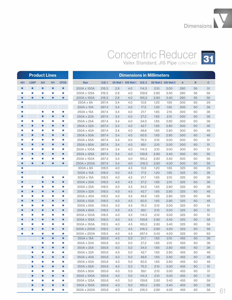
Dimensions
61
Dimensions in Millimeters
200A x 100A 216.3 2.8 4.0 114.3 2.10 3.00 280 56 51
200A x 125A 216.3 2.8 4.0 139.8 2.80 3.40 280 56 56
200A x 150A 216.3 2.8 4.0 165.2 2.80 3.40 280 56 56
250A x 8A 267.4 3.4 4.0 13.8 1.20 1.65 300 60 29
250A x 10A 267.4 3.4 4.0 17.3 1.20 1.65 300 60 36
250A x 15A 267.4 3.4 4.0 21.7 1.65 2.10 300 60 36
250A x 20A 267.4 3.4 4.0 27.2 1.65 2.10 300 60 36
250A x 25A 267.4 3.4 4.0 34.0 1.65 2.80 300 60 36
250A x 32A 267.4 3.4 4.0 42.7 1.65 2.80 300 60 46
250A x 40A 267.4 3.4 4.0 48.6 1.65 2.80 300 60 46
250A x 50A 267.4 3.4 4.0 60.5 1.65 2.80 300 60 46
250A x 65A 267.4 3.4 4.0 76.3 2.10 3.00 300 60 51
250A x 80A 267.4 3.4 4.0 89.1 2.10 3.00 300 60 51
250A x 100A 267.4 3.4 4.0 114.3 2.10 3.00 300 60 51
250A x 125A 267.4 3.4 4.0 139.8 2.80 3.40 300 60 56
250A x 150A 267.4 3.4 4.0 165.2 2.80 3.40 300 60 56
250A x 200A 267.4 3.4 4.0 216.3 2.80 4.00 300 60 56
300A x 8A 318.5 4.0 4.5 13.8 1.20 1.65 325 60 29
300A x 10A 318.5 4.0 4.5 17.3 1.20 1.65 325 60 36
300A x 15A 318.5 4.0 4.5 21.7 1.65 2.10 325 60 36
300A x 20A 318.5 4.0 4.5 27.2 1.65 2.10 325 60 36
300A x 25A 318.5 4.0 4.5 34.0 1.65 2.80 325 60 36
300A x 32A 318.5 4.0 4.5 42.7 1.65 2.80 325 60 46
300A x 40A 318.5 4.0 4.5 48.6 1.65 2.80 325 60 46
300A x 50A 318.5 4.0 4.5 60.5 1.65 2.80 325 60 46
300A x 65A 318.5 4.0 4.5 76.3 2.10 3.00 325 60 51
300A x 80A 318.5 4.0 4.5 89.1 2.10 3.00 325 60 51
300A x 100A 318.5 4.0 4.5 114.3 2.10 3.00 325 60 51
300A x 125A 318.5 4.0 4.5 139.8 2.80 3.40 325 60 56
300A x 150A 318.5 4.0 4.5 165.2 2.80 3.40 325 60 56
300A x 200A 318.5 4.0 4.5 216.3 2.80 4.00 325 60 56
300A x 250A 318.5 4.0 4.5 267.4 3.40 4.00 325 60 60
350A x 15A 355.6 4.0 5.0 21.7 1.65 2.10 455 60 36
350A x 20A 355.6 4.0 5.0 27.2 1.65 2.10 455 60 36
350A x 25A 355.6 4.0 5.0 34.0 1.65 2.80 455 60 36
350A x 32A 355.6 4.0 5.0 42.7 1.65 2.80 455 60 46
350A x 40A 355.6 4.0 5.0 48.6 1.65 2.80 455 60 46
350A x 50A 355.6 4.0 5.0 60.5 1.65 2.80 455 60 46
350A x 65A 355.6 4.0 5.0 76.3 2.10 3.00 455 60 51
350A x 80A 355.6 4.0 5.0 89.1 2.10 3.00 455 60 51
350A x 100A 355.6 4.0 5.0 114.3 2.10 3.00 455 60 51
350A x 125A 355.6 4.0 5.0 139.8 2.80 3.40 455 60 56
350A x 150A 355.6 4.0 5.0 165.2 2.80 3.40 455 60 56
350A x 200A 355.6 4.0 5.0 216.3 2.80 4.00 455 60 56
Product Lines
Size O.D. 1 5S Wall 1 10S Wall 1 O.D. 2 5S Wall 2 10S Wall 2 A B C 401 LDEP 201 101 CFOS
Concentric Reducer Valex Standard, JIS Pipe CONTINUED
31CONFIGURATION

Dimensions
62
Dimensions in Millimeters
350A x 250A 355.6 4.00 5.00 267.4 3.40 4.00 455 60 60
350A x 300A 355.6 4.00 5.00 318.5 4.00 4.50 455 60 60
400A x 15A 406.4 4.50 5.00 21.7 1.65 2.10 480 65 36
400A x 20A 406.4 4.50 5.00 27.2 1.65 2.10 480 65 36
400A x 25A 406.4 4.50 5.00 34.0 1.65 2.80 480 65 36
400A x 32A 406.4 4.50 5.00 42.7 1.65 2.80 480 65 46
400A x 40A 406.4 4.50 5.00 48.6 1.65 2.80 480 65 46
400A x 50A 406.4 4.50 5.00 60.5 1.65 2.80 480 65 46
400A x 65A 406.4 4.50 5.00 76.3 2.10 3.00 480 65 51
400A x 80A 406.4 4.50 5.00 89.1 2.10 3.00 480 65 51
400A x 100A 406.4 4.50 5.00 114.3 2.10 3.00 480 65 51
400A x 125A 406.4 4.50 5.00 139.8 2.80 3.40 480 65 56
400A x 150A 406.4 4.50 5.00 165.2 2.80 3.40 480 65 56
400A x 200A 406.4 4.50 5.00 216.3 2.80 4.00 480 65 56
400A x 250A 406.4 4.50 5.00 267.4 3.40 4.00 480 65 60
400A x 300A 406.4 4.50 5.00 318.5 4.00 4.50 480 65 60
400A x 350A 406.4 4.50 5.00 355.6 4.00 5.00 480 65 60
450A x 15A 457.2 4.50 5.00 21.7 1.65 2.10 505 65 36
450A x 20A 457.2 4.50 5.00 27.2 1.65 2.10 505 65 36
450A x 25A 457.2 4.50 5.00 34.0 1.65 2.80 505 65 36
450A x 32A 457.2 4.50 5.00 42.7 1.65 2.80 505 65 46
450A x 40A 457.2 4.50 5.00 48.6 1.65 2.80 505 65 46
450A x 50A 457.2 4.50 5.00 60.5 1.65 2.80 505 65 46
450A x 65A 457.2 4.50 5.00 76.3 2.10 3.00 505 65 51
450A x 80A 457.2 4.50 5.00 89.1 2.10 3.00 505 65 51
450A x 100A 457.2 4.50 5.00 114.3 2.10 3.00 505 65 51
450A x 125A 457.2 4.50 5.00 139.8 2.80 3.40 505 65 56
450A x 150A 457.2 4.50 5.00 165.2 2.80 3.40 505 65 56
450A x 200A 457.2 4.50 5.00 216.3 2.80 4.00 505 65 56
450A x 250A 457.2 4.50 5.00 267.4 3.40 4.00 505 65 60
450A x 300A 457.2 4.50 5.00 318.5 4.00 4.50 505 65 60
450A x 350A 457.2 4.50 5.00 355.6 4.00 5.00 505 65 60
450A x 400A 457.2 4.50 5.00 406.4 4.50 5.00 505 65 65
500A x 15A 508.0 5.00 5.50 21.7 1.65 2.10 630 70 36
500A x 20A 508.0 5.00 5.50 27.2 1.65 2.10 630 70 36
500A x 25A 508.0 5.00 5.50 34.0 1.65 2.80 630 70 36
500A x 32A 508.0 5.00 5.50 42.7 1.65 2.80 630 70 46
500A x 40A 508.0 5.00 5.50 48.6 1.65 2.80 630 70 46
500A x 50A 508.0 5.00 5.50 60.5 1.65 2.80 630 70 46
500A x 65A 508.0 5.00 5.50 76.3 2.10 3.00 630 70 51
500A x 80A 508.0 5.00 5.50 89.1 2.10 3.00 630 70 51
500A x 100A 508.0 5.00 5.50 114.3 2.10 3.00 630 70 51
500A x 125A 508.0 5.00 5.50 139.8 2.80 3.40 630 70 56
500A x 150A 508.0 5.00 5.50 165.2 2.80 3.40 630 70 56
Product Lines
Size O.D. 1 5S Wall 1 10S Wall 1 O.D. 2 5S Wall 2 10S Wall 2 A B C 401 LDEP 201 101 CFOS
Concentric Reducer Valex Standard, JIS Pipe CONTINUED
31CONFIGURATION
Wall 2Wall 1
O.D. 2O.D. 1
A
B C
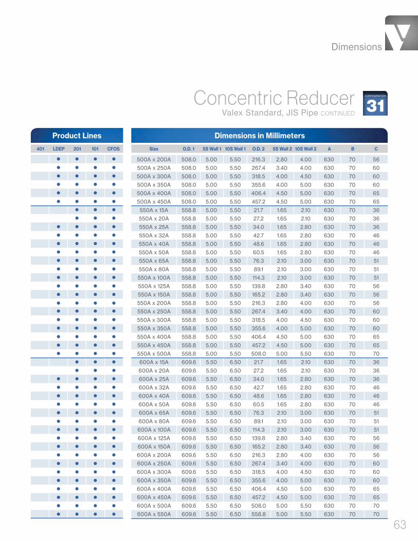
Dimensions
63
Dimensions in Millimeters
500A x 200A 508.0 5.00 5.50 216.3 2.80 4.00 630 70 56
500A x 250A 508.0 5.00 5.50 267.4 3.40 4.00 630 70 60
500A x 300A 508.0 5.00 5.50 318.5 4.00 4.50 630 70 60
500A x 350A 508.0 5.00 5.50 355.6 4.00 5.00 630 70 60
500A x 400A 508.0 5.00 5.50 406.4 4.50 5.00 630 70 65
500A x 450A 508.0 5.00 5.50 457.2 4.50 5.00 630 70 65
550A x 15A 558.8 5.00 5.50 21.7 1.65 2.10 630 70 36
550A x 20A 558.8 5.00 5.50 27.2 1.65 2.10 630 70 36
550A x 25A 558.8 5.00 5.50 34.0 1.65 2.80 630 70 36
550A x 32A 558.8 5.00 5.50 42.7 1.65 2.80 630 70 46
550A x 40A 558.8 5.00 5.50 48.6 1.65 2.80 630 70 46
550A x 50A 558.8 5.00 5.50 60.5 1.65 2.80 630 70 46
550A x 65A 558.8 5.00 5.50 76.3 2.10 3.00 630 70 51
550A x 80A 558.8 5.00 5.50 89.1 2.10 3.00 630 70 51
550A x 100A 558.8 5.00 5.50 114.3 2.10 3.00 630 70 51
550A x 125A 558.8 5.00 5.50 139.8 2.80 3.40 630 70 56
550A x 150A 558.8 5.00 5.50 165.2 2.80 3.40 630 70 56
550A x 200A 558.8 5.00 5.50 216.3 2.80 4.00 630 70 56
550A x 250A 558.8 5.00 5.50 267.4 3.40 4.00 630 70 60
550A x 300A 558.8 5.00 5.50 318.5 4.00 4.50 630 70 60
550A x 350A 558.8 5.00 5.50 355.6 4.00 5.00 630 70 60
550A x 400A 558.8 5.00 5.50 406.4 4.50 5.00 630 70 65
550A x 450A 558.8 5.00 5.50 457.2 4.50 5.00 630 70 65
550A x 500A 558.8 5.00 5.50 508.0 5.00 5.50 630 70 70
600A x 15A 609.6 5.50 6.50 21.7 1.65 2.10 630 70 36
600A x 20A 609.6 5.50 6.50 27.2 1.65 2.10 630 70 36
600A x 25A 609.6 5.50 6.50 34.0 1.65 2.80 630 70 36
600A x 32A 609.6 5.50 6.50 42.7 1.65 2.80 630 70 46
600A x 40A 609.6 5.50 6.50 48.6 1.65 2.80 630 70 46
600A x 50A 609.6 5.50 6.50 60.5 1.65 2.80 630 70 46
600A x 65A 609.6 5.50 6.50 76.3 2.10 3.00 630 70 51
600A x 80A 609.6 5.50 6.50 89.1 2.10 3.00 630 70 51
600A x 100A 609.6 5.50 6.50 114.3 2.10 3.00 630 70 51
600A x 125A 609.6 5.50 6.50 139.8 2.80 3.40 630 70 56
600A x 150A 609.6 5.50 6.50 165.2 2.80 3.40 630 70 56
600A x 200A 609.6 5.50 6.50 216.3 2.80 4.00 630 70 56
600A x 250A 609.6 5.50 6.50 267.4 3.40 4.00 630 70 60
600A x 300A 609.6 5.50 6.50 318.5 4.00 4.50 630 70 60
600A x 350A 609.6 5.50 6.50 355.6 4.00 5.00 630 70 60
600A x 400A 609.6 5.50 6.50 406.4 4.50 5.00 630 70 65
600A x 450A 609.6 5.50 6.50 457.2 4.50 5.00 630 70 65
600A x 500A 609.6 5.50 6.50 508.0 5.00 5.50 630 70 70
600A x 550A 609.6 5.50 6.50 558.8 5.00 5.50 630 70 70
Product Lines
Size O.D. 1 5S Wall 1 10S Wall 1 O.D. 2 5S Wall 2 10S Wall 2 A B C 401 LDEP 201 101 CFOS
Concentric Reducer Valex Standard, JIS Pipe CONTINUED
31CONFIGURATION

Dimensions
64
Dimensions in Millimeters
15A x 8A 21.7 1.65 2.10 13.8 1.20 1.65 60 25.4
15A x 10A 21.7 1.65 2.10 17.3 1.20 1.65 67 25.4
20A x 8A 27.2 1.65 2.10 13.8 1.20 1.65 60 25.4
20A x 10A 27.2 1.65 2.10 17.3 1.20 1.65 67 25.4
20A x 15A 27.2 1.65 2.10 21.7 1.65 2.10 67 25.4
25A x 8A 34.0 1.65 2.80 13.8 1.20 1.65 73 38.1
25A x 10A 34.0 1.65 2.80 17.3 1.20 1.65 80 38.1
25A x 15A 34.0 1.65 2.80 21.7 1.65 2.10 80 38.1
25A x 20A 34.0 1.65 2.80 27.2 1.65 2.10 80 38.1
32A x 8A 42.7 1.65 2.80 13.8 1.20 1.65 73 38.1
32A x 10A 42.7 1.65 2.80 17.3 1.20 1.65 80 38.1
32A x 15A 42.7 1.65 2.80 21.7 1.65 2.10 80 38.1
32A x 20A 42.7 1.65 2.80 27.2 1.65 2.10 80 38.1
32A x 25A 42.7 1.65 2.80 34.0 1.65 2.80 80 38.1
40A x 8A 48.6 1.65 2.80 13.8 1.20 1.65 73 38.1
40A x 10A 48.6 1.65 2.80 17.3 1.20 1.65 80 38.1
40A x 15A 48.6 1.65 2.80 21.7 1.65 2.10 80 38.1
40A x 20A 48.6 1.65 2.80 27.2 1.65 2.10 80 38.1
40A x 25A 48.6 1.65 2.80 34.0 1.65 2.80 80 38.1
40A x 32A 48.6 1.65 2.80 42.7 1.65 2.80 90 38.1
50A x 8A 60.5 1.65 2.80 13.8 1.20 1.65 73 38.1
50A x 10A 60.5 1.65 2.80 17.3 1.20 1.65 80 38.1
50A x 15A 60.5 1.65 2.80 21.7 1.65 2.10 80 38.1
50A x 20A 60.5 1.65 2.80 27.2 1.65 2.10 80 38.1
50A x 25A 60.5 1.65 2.80 34.0 1.65 2.80 80 38.1
50A x 32A 60.5 1.65 2.80 42.7 1.65 2.80 90 38.1
50A x 40A 60.5 1.65 2.80 48.6 1.65 2.80 90 38.1
65A x 8A 76.3 2.10 3.00 13.8 1.20 1.65 73 38.1
65A x 10A 76.3 2.10 3.00 17.3 1.20 1.65 80 38.1
65A x 15A 76.3 2.10 3.00 21.7 1.65 2.10 80 38.1
65A x 20A 76.3 2.10 3.00 27.2 1.65 2.10 80 38.1
65A x 25A 76.3 2.10 3.00 34.0 1.65 2.80 80 38.1
65A x 32A 76.3 2.10 3.00 42.7 1.65 2.80 90 38.1
65A x 40A 76.3 2.10 3.00 48.6 1.65 2.80 90 38.1
65A x 50A 76.3 2.10 3.00 60.5 1.65 2.80 90 38.1
80A x 8A 89.1 2.10 3.00 13.8 1.20 1.65 85 50.8
80A x 10A 89.1 2.10 3.00 17.3 1.20 1.65 92 50.8
80A x 15A 89.1 2.10 3.00 21.7 1.65 2.10 92 50.8
80A x 20A 89.1 2.10 3.00 27.2 1.65 2.10 92 50.8
80A x 25A 89.1 2.10 3.00 34.0 1.65 2.80 92 50.8
80A x 32A 89.1 2.10 3.00 42.7 1.65 2.80 102 50.8
80A x 40A 89.1 2.10 3.00 48.6 1.65 2.80 102 50.8
80A x 50A 89.1 2.10 3.00 60.5 1.65 2.80 102 50.8
80A x 65A 89.1 2.10 3.00 76.3 2.10 3.00 110 50.8
Product Lines
Size O.D. 1 5S Wall 1 10S Wall 1 O.D. 2 5S Wall 2 10S Wall 2 A B 401 LDEP 201 101 CFOS
Cap Reducer Valex Standard, JIS Pipe33
CONFIGURATION
Wall 2
Wall 1
O.D. 2O.D. 1
A
B

Dimensions
65
Dimensions in Millimeters
100A x 8A 114.3 2.10 3.00 13.8 1.20 1.65 98 63.5
100A x 10A 114.3 2.10 3.00 17.3 1.20 1.65 105 63.5
100A x 15A 114.3 2.10 3.00 21.7 1.65 2.10 105 63.5
100A x 20A 114.3 2.10 3.00 27.2 1.65 2.10 105 63.5
100A x 25A 114.3 2.10 3.00 34.0 1.65 2.80 105 63.5
100A x 32A 114.3 2.10 3.00 42.7 1.65 2.80 115 63.5
100A x 40A 114.3 2.10 3.00 48.6 1.65 2.80 115 63.5
100A x 50A 114.3 2.10 3.00 60.5 1.65 2.80 115 63.5
100A x 65A 114.3 2.10 3.00 76.3 2.10 3.00 125 63.5
100A x 80A 114.3 2.10 3.00 89.1 2.10 3.00 125 63.5
125A x 8A 139.8 2.80 3.40 13.8 1.20 1.65 120 76.2
125A x 10A 139.8 2.80 3.40 17.3 1.20 1.65 130 76.2
125A x 15A 139.8 2.80 3.40 21.7 1.65 2.10 130 76.2
125A x 20A 139.8 2.80 3.40 27.2 1.65 2.10 130 76.2
125A x 25A 139.8 2.80 3.40 34.0 1.65 2.80 130 76.2
125A x 32A 139.8 2.80 3.40 42.7 1.65 2.80 140 76.2
125A x 40A 139.8 2.80 3.40 48.6 1.65 2.80 140 76.2
125A x 50A 139.8 2.80 3.40 60.5 1.65 2.80 140 76.2
125A x 65A 139.8 2.80 3.40 76.3 2.10 3.00 150 76.2
125A x 80A 139.8 2.80 3.40 89.1 2.10 3.00 150 76.2
125A x 100A 139.8 2.80 3.40 114.3 2.10 3.00 150 76.2
150A x 8A 165.2 2.80 3.40 13.8 1.20 1.65 130 88.9
150A x 10A 165.2 2.80 3.40 17.3 1.20 1.65 140 88.9
150A x 15A 165.2 2.80 3.40 21.7 1.65 2.10 140 88.9
150A x 20A 165.2 2.80 3.40 27.2 1.65 2.10 140 88.9
150A x 25A 165.2 2.80 3.40 34.0 1.65 2.80 140 88.9
150A x 32A 165.2 2.80 3.40 42.7 1.65 2.80 150 88.9
150A x 40A 165.2 2.80 3.40 48.6 1.65 2.80 150 88.9
150A x 50A 165.2 2.80 3.40 60.5 1.65 2.80 150 88.9
150A x 65A 165.2 2.80 3.40 76.3 2.10 3.00 160 88.9
150A x 80A 165.2 2.80 3.40 89.1 2.10 3.00 160 88.9
150A x 100A 165.2 2.80 3.40 114.3 2.10 3.00 160 88.9
150A x 125A 165.2 2.80 3.40 139.8 2.80 3.40 170 88.9
200A x 8A 216.3 2.80 4.00 13.8 1.20 1.65 140 101.6
200A x 10A 216.3 2.80 4.00 17.3 1.20 1.65 150 101.6
200A x 15A 216.3 2.80 4.00 21.7 1.65 2.10 150 101.6
200A x 20A 216.3 2.80 4.00 27.2 1.65 2.10 150 101.6
200A x 25A 216.3 2.80 4.00 34.0 1.65 2.80 150 101.6
200A x 32A 216.3 2.80 4.00 42.7 1.65 2.80 160 101.6
200A x 40A 216.3 2.80 4.00 48.6 1.65 2.80 160 101.6
200A x 50A 216.3 2.80 4.00 60.5 1.65 2.80 160 101.6
200A x 65A 216.3 2.80 4.00 76.3 2.10 3.00 170 101.6
200A x 80A 216.3 2.80 4.00 89.1 2.10 3.00 170 101.6
200A x 100A 216.3 2.80 4.00 114.3 2.10 3.00 170 101.6
Product Lines
Size O.D. 1 5S Wall 1 10S Wall 1 O.D. 2 5S Wall 2 10S Wall 2 A B 401 LDEP 201 101 CFOS
Cap Reducer Valex Standard, JIS Pipe CONTINUED
33CONFIGURATION
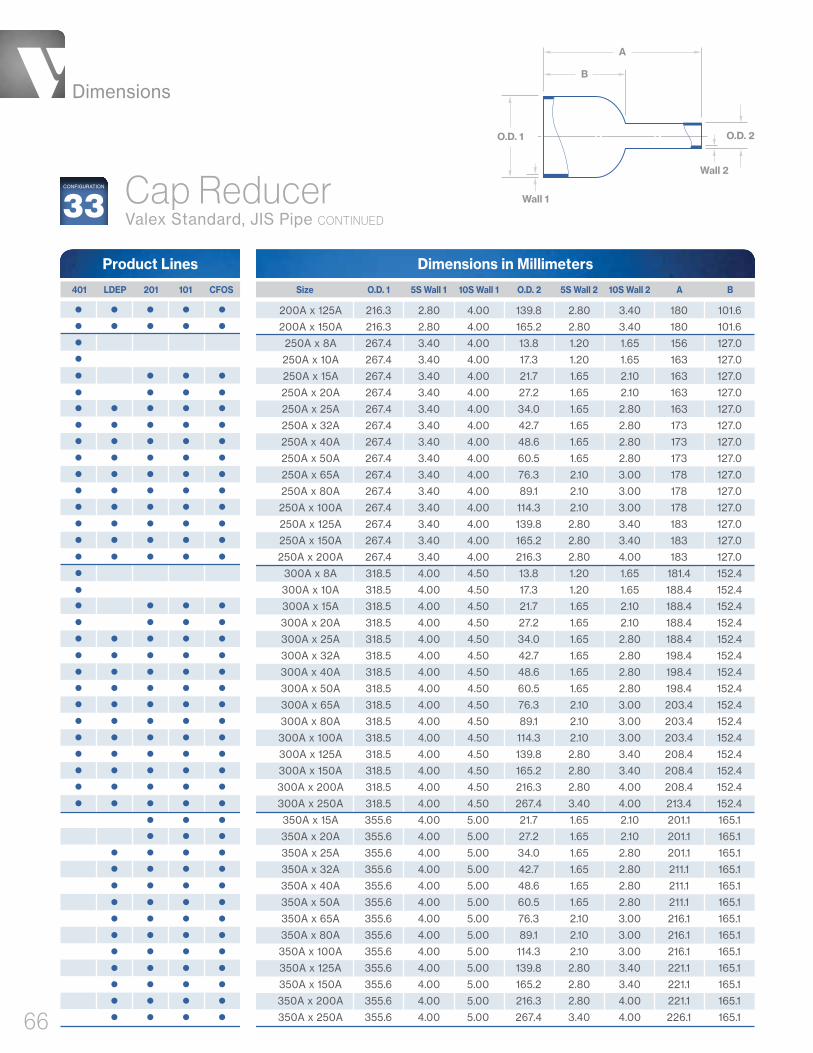
Dimensions
66
Dimensions in Millimeters
200A x 125A 216.3 2.80 4.00 139.8 2.80 3.40 180 101.6
200A x 150A 216.3 2.80 4.00 165.2 2.80 3.40 180 101.6
250A x 8A 267.4 3.40 4.00 13.8 1.20 1.65 156 127.0
250A x 10A 267.4 3.40 4.00 17.3 1.20 1.65 163 127.0
250A x 15A 267.4 3.40 4.00 21.7 1.65 2.10 163 127.0
250A x 20A 267.4 3.40 4.00 27.2 1.65 2.10 163 127.0
250A x 25A 267.4 3.40 4.00 34.0 1.65 2.80 163 127.0
250A x 32A 267.4 3.40 4.00 42.7 1.65 2.80 173 127.0
250A x 40A 267.4 3.40 4.00 48.6 1.65 2.80 173 127.0
250A x 50A 267.4 3.40 4.00 60.5 1.65 2.80 173 127.0
250A x 65A 267.4 3.40 4.00 76.3 2.10 3.00 178 127.0
250A x 80A 267.4 3.40 4.00 89.1 2.10 3.00 178 127.0
250A x 100A 267.4 3.40 4.00 114.3 2.10 3.00 178 127.0
250A x 125A 267.4 3.40 4.00 139.8 2.80 3.40 183 127.0
250A x 150A 267.4 3.40 4.00 165.2 2.80 3.40 183 127.0
250A x 200A 267.4 3.40 4.00 216.3 2.80 4.00 183 127.0
300A x 8A 318.5 4.00 4.50 13.8 1.20 1.65 181.4 152.4
300A x 10A 318.5 4.00 4.50 17.3 1.20 1.65 188.4 152.4
300A x 15A 318.5 4.00 4.50 21.7 1.65 2.10 188.4 152.4
300A x 20A 318.5 4.00 4.50 27.2 1.65 2.10 188.4 152.4
300A x 25A 318.5 4.00 4.50 34.0 1.65 2.80 188.4 152.4
300A x 32A 318.5 4.00 4.50 42.7 1.65 2.80 198.4 152.4
300A x 40A 318.5 4.00 4.50 48.6 1.65 2.80 198.4 152.4
300A x 50A 318.5 4.00 4.50 60.5 1.65 2.80 198.4 152.4
300A x 65A 318.5 4.00 4.50 76.3 2.10 3.00 203.4 152.4
300A x 80A 318.5 4.00 4.50 89.1 2.10 3.00 203.4 152.4
300A x 100A 318.5 4.00 4.50 114.3 2.10 3.00 203.4 152.4
300A x 125A 318.5 4.00 4.50 139.8 2.80 3.40 208.4 152.4
300A x 150A 318.5 4.00 4.50 165.2 2.80 3.40 208.4 152.4
300A x 200A 318.5 4.00 4.50 216.3 2.80 4.00 208.4 152.4
300A x 250A 318.5 4.00 4.50 267.4 3.40 4.00 213.4 152.4
350A x 15A 355.6 4.00 5.00 21.7 1.65 2.10 201.1 165.1
350A x 20A 355.6 4.00 5.00 27.2 1.65 2.10 201.1 165.1
350A x 25A 355.6 4.00 5.00 34.0 1.65 2.80 201.1 165.1
350A x 32A 355.6 4.00 5.00 42.7 1.65 2.80 211.1 165.1
350A x 40A 355.6 4.00 5.00 48.6 1.65 2.80 211.1 165.1
350A x 50A 355.6 4.00 5.00 60.5 1.65 2.80 211.1 165.1
350A x 65A 355.6 4.00 5.00 76.3 2.10 3.00 216.1 165.1
350A x 80A 355.6 4.00 5.00 89.1 2.10 3.00 216.1 165.1
350A x 100A 355.6 4.00 5.00 114.3 2.10 3.00 216.1 165.1
350A x 125A 355.6 4.00 5.00 139.8 2.80 3.40 221.1 165.1
350A x 150A 355.6 4.00 5.00 165.2 2.80 3.40 221.1 165.1
350A x 200A 355.6 4.00 5.00 216.3 2.80 4.00 221.1 165.1
350A x 250A 355.6 4.00 5.00 267.4 3.40 4.00 226.1 165.1
Product Lines
Size O.D. 1 5S Wall 1 10S Wall 1 O.D. 2 5S Wall 2 10S Wall 2 A B 401 LDEP 201 101 CFOS
Cap Reducer Valex Standard, JIS Pipe CONTINUED
33CONFIGURATION
Wall 2
Wall 1
O.D. 2O.D. 1
A
B
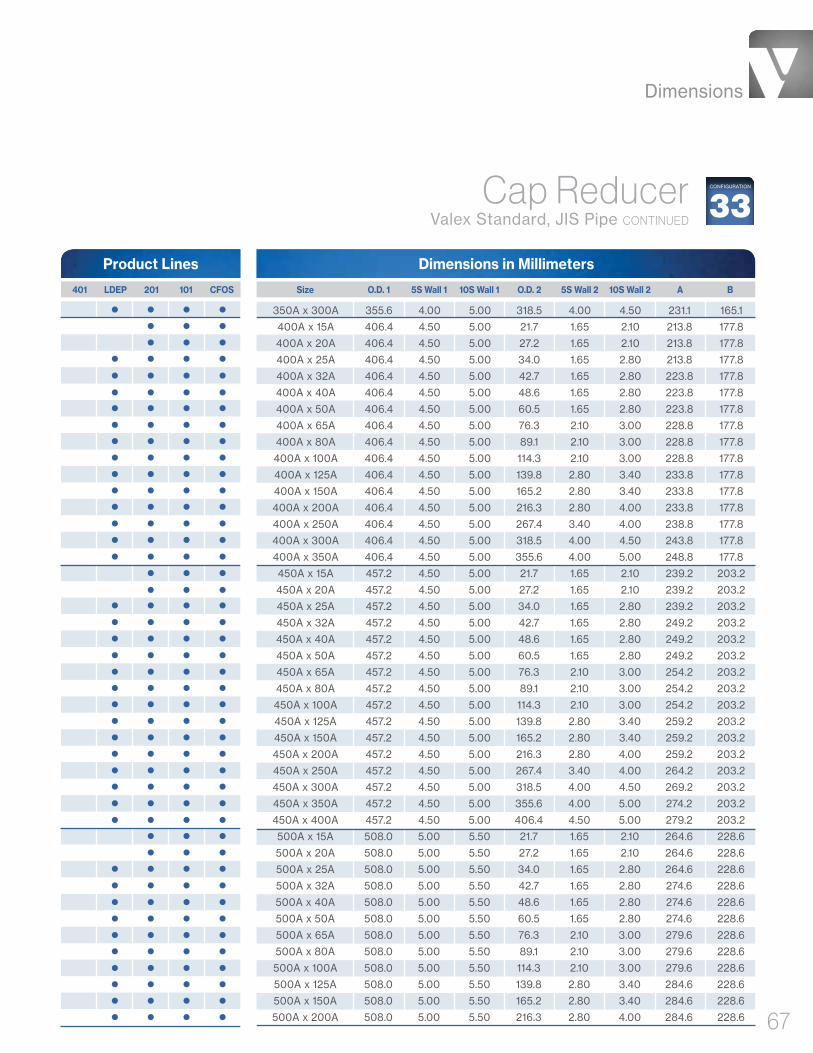
Dimensions
67
Dimensions in Millimeters
350A x 300A 355.6 4.00 5.00 318.5 4.00 4.50 231.1 165.1
400A x 15A 406.4 4.50 5.00 21.7 1.65 2.10 213.8 177.8
400A x 20A 406.4 4.50 5.00 27.2 1.65 2.10 213.8 177.8
400A x 25A 406.4 4.50 5.00 34.0 1.65 2.80 213.8 177.8
400A x 32A 406.4 4.50 5.00 42.7 1.65 2.80 223.8 177.8
400A x 40A 406.4 4.50 5.00 48.6 1.65 2.80 223.8 177.8
400A x 50A 406.4 4.50 5.00 60.5 1.65 2.80 223.8 177.8
400A x 65A 406.4 4.50 5.00 76.3 2.10 3.00 228.8 177.8
400A x 80A 406.4 4.50 5.00 89.1 2.10 3.00 228.8 177.8
400A x 100A 406.4 4.50 5.00 114.3 2.10 3.00 228.8 177.8
400A x 125A 406.4 4.50 5.00 139.8 2.80 3.40 233.8 177.8
400A x 150A 406.4 4.50 5.00 165.2 2.80 3.40 233.8 177.8
400A x 200A 406.4 4.50 5.00 216.3 2.80 4.00 233.8 177.8
400A x 250A 406.4 4.50 5.00 267.4 3.40 4.00 238.8 177.8
400A x 300A 406.4 4.50 5.00 318.5 4.00 4.50 243.8 177.8
400A x 350A 406.4 4.50 5.00 355.6 4.00 5.00 248.8 177.8
450A x 15A 457.2 4.50 5.00 21.7 1.65 2.10 239.2 203.2
450A x 20A 457.2 4.50 5.00 27.2 1.65 2.10 239.2 203.2
450A x 25A 457.2 4.50 5.00 34.0 1.65 2.80 239.2 203.2
450A x 32A 457.2 4.50 5.00 42.7 1.65 2.80 249.2 203.2
450A x 40A 457.2 4.50 5.00 48.6 1.65 2.80 249.2 203.2
450A x 50A 457.2 4.50 5.00 60.5 1.65 2.80 249.2 203.2
450A x 65A 457.2 4.50 5.00 76.3 2.10 3.00 254.2 203.2
450A x 80A 457.2 4.50 5.00 89.1 2.10 3.00 254.2 203.2
450A x 100A 457.2 4.50 5.00 114.3 2.10 3.00 254.2 203.2
450A x 125A 457.2 4.50 5.00 139.8 2.80 3.40 259.2 203.2
450A x 150A 457.2 4.50 5.00 165.2 2.80 3.40 259.2 203.2
450A x 200A 457.2 4.50 5.00 216.3 2.80 4.00 259.2 203.2
450A x 250A 457.2 4.50 5.00 267.4 3.40 4.00 264.2 203.2
450A x 300A 457.2 4.50 5.00 318.5 4.00 4.50 269.2 203.2
450A x 350A 457.2 4.50 5.00 355.6 4.00 5.00 274.2 203.2
450A x 400A 457.2 4.50 5.00 406.4 4.50 5.00 279.2 203.2
500A x 15A 508.0 5.00 5.50 21.7 1.65 2.10 264.6 228.6
500A x 20A 508.0 5.00 5.50 27.2 1.65 2.10 264.6 228.6
500A x 25A 508.0 5.00 5.50 34.0 1.65 2.80 264.6 228.6
500A x 32A 508.0 5.00 5.50 42.7 1.65 2.80 274.6 228.6
500A x 40A 508.0 5.00 5.50 48.6 1.65 2.80 274.6 228.6
500A x 50A 508.0 5.00 5.50 60.5 1.65 2.80 274.6 228.6
500A x 65A 508.0 5.00 5.50 76.3 2.10 3.00 279.6 228.6
500A x 80A 508.0 5.00 5.50 89.1 2.10 3.00 279.6 228.6
500A x 100A 508.0 5.00 5.50 114.3 2.10 3.00 279.6 228.6
500A x 125A 508.0 5.00 5.50 139.8 2.80 3.40 284.6 228.6
500A x 150A 508.0 5.00 5.50 165.2 2.80 3.40 284.6 228.6
500A x 200A 508.0 5.00 5.50 216.3 2.80 4.00 284.6 228.6
Product Lines
Size O.D. 1 5S Wall 1 10S Wall 1 O.D. 2 5S Wall 2 10S Wall 2 A B 401 LDEP 201 101 CFOS
Cap Reducer Valex Standard, JIS Pipe CONTINUED
33CONFIGURATION

Dimensions
68
Dimensions in Millimeters
500A x 250A 508.0 5.00 5.50 267.4 3.40 4.00 289.6 228.6
500A x 300A 508.0 5.00 5.50 318.5 4.00 4.50 294.6 228.6
500A x 350A 508.0 5.00 5.50 355.6 4.00 5.00 299.6 228.6
500A x 400A 508.0 5.00 5.50 406.4 4.50 5.00 304.6 228.6
500A x 450A 508.0 5.00 5.50 457.2 4.50 5.00 309.6 228.6
550A x 15A 558.8 5.00 5.50 21.7 1.65 2.10 290.0 254.0
550A x 20A 558.8 5.00 5.50 27.2 1.65 2.10 290.0 254.0
550A x 25A 558.8 5.00 5.50 34.0 1.65 2.80 290.0 254.0
550A x 32A 558.8 5.00 5.50 42.7 1.65 2.80 300.0 254.0
550A x 40A 558.8 5.00 5.50 48.6 1.65 2.80 300.0 254.0
550A x 50A 558.8 5.00 5.50 60.5 1.65 2.80 300.0 254.0
550A x 65A 558.8 5.00 5.50 76.3 2.10 3.00 305.0 254.0
550A x 80A 558.8 5.00 5.50 89.1 2.10 3.00 305.0 254.0
550A x 100A 558.8 5.00 5.50 114.3 2.10 3.00 305.0 254.0
550A x 125A 558.8 5.00 5.50 139.8 2.80 3.40 310.0 254.0
550A x 150A 558.8 5.00 5.50 165.2 2.80 3.40 310.0 254.0
550A x 200A 558.8 5.00 5.50 216.3 2.80 4.00 310.0 254.0
550A x 250A 558.8 5.00 5.50 267.4 3.40 4.00 314.0 254.0
550A x 300A 558.8 5.00 5.50 318.5 4.00 4.50 319.0 254.0
550A x 350A 558.8 5.00 5.50 355.6 4.00 5.00 324.0 254.0
550A x 400A 558.8 5.00 5.50 406.4 4.50 5.00 329.0 254.0
550A x 450A 558.8 5.00 5.50 457.2 4.50 5.00 334.0 254.0
550A x 500A 558.8 5.00 5.50 508.0 5.00 5.50 339.0 254.0
600A x 15A 609.6 5.50 6.50 21.7 1.65 2.10 302.7 266.7
600A x 20A 609.6 5.50 6.50 27.2 1.65 2.10 302.7 266.7
600A x 25A 609.6 5.50 6.50 34.0 1.65 2.80 302.7 266.7
600A x 32A 609.6 5.50 6.50 42.7 1.65 2.80 312.7 266.7
600A x 40A 609.6 5.50 6.50 48.6 1.65 2.80 312.7 266.7
600A x 50A 609.6 5.50 6.50 60.5 1.65 2.80 312.7 266.7
600A x 65A 609.6 5.50 6.50 76.3 2.10 3.00 317.7 266.7
600A x 80A 609.6 5.50 6.50 89.1 2.10 3.00 317.7 266.7
600A x 100A 609.6 5.50 6.50 114.3 2.10 3.00 317.7 266.7
600A x 125A 609.6 5.50 6.50 139.8 2.80 3.40 322.7 266.7
600A x 150A 609.6 5.50 6.50 165.2 2.80 3.40 322.7 266.7
600A x 200A 609.6 5.50 6.50 216.3 2.80 4.00 322.7 266.7
600A x 250A 609.6 5.50 6.50 267.4 3.40 4.00 327.7 266.7
600A x 300A 609.6 5.50 6.50 318.5 4.00 4.50 332.7 266.7
600A x 350A 609.6 5.50 6.50 355.6 4.00 5.00 337.7 266.7
600A x 400A 609.6 5.50 6.50 406.4 4.50 5.00 342.7 266.7
600A x 450A 609.6 5.50 6.50 457.2 4.50 5.00 347.7 266.7
600A x 500A 609.6 5.50 6.50 508.0 5.00 5.50 352.7 266.7
600A x 550A 609.6 5.50 6.50 558.8 5.00 5.50 357.7 266.7
Product Lines
Size O.D. 1 5S Wall 1 10S Wall 1 O.D. 2 5S Wall 2 10S Wall 2 A B 401 LDEP 201 101 CFOS
Cap Reducer Valex Standard, JIS Pipe CONTINUED
33CONFIGURATION
Wall 2
Wall 1
O.D. 2O.D. 1
A
B

End Caps
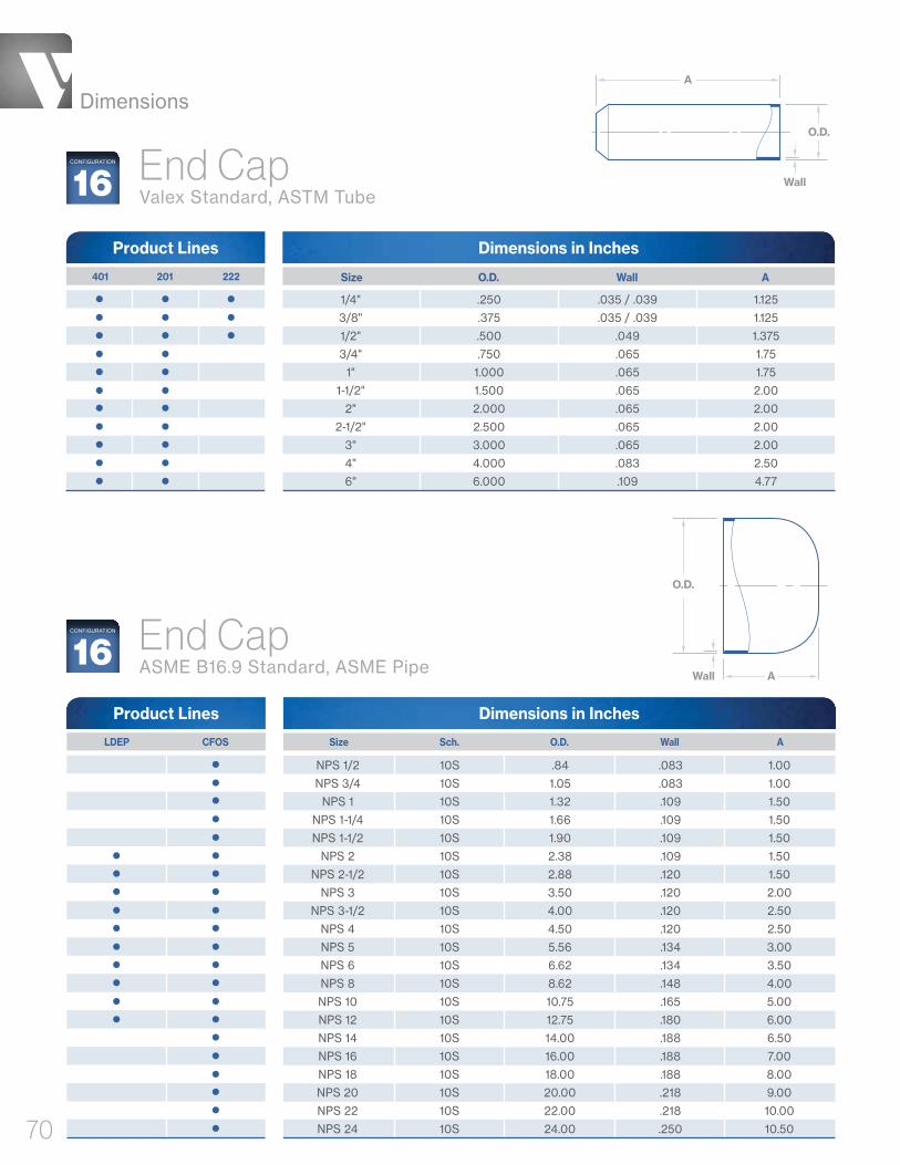
Dimensions
70
Dimensions in Inches
Size O.D. Wall A 401 201 222
Product Lines
1/4" .250 .035 / .039 1.125
3/8" .375 .035 / .039 1.125
1/2" .500 .049 1.375
3/4" .750 .065 1.75
1" 1.000 .065 1.75
1-1/2" 1.500 .065 2.00
2" 2.000 .065 2.00
2-1/2" 2.500 .065 2.00
3" 3.000 .065 2.00
4" 4.000 .083 2.50
6" 6.000 .109 4.77
Wall
O.D.
A
End Cap Valex Standard, ASTM Tube16
CONFIGURATION
End Cap ASME B16.9 Standard, ASME Pipe
Dimensions in Inches
NPS 1/2 10S .84 .083 1.00
NPS 3/4 10S 1.05 .083 1.00
NPS 1 10S 1.32 .109 1.50
NPS 1-1/4 10S 1.66 .109 1.50
NPS 1-1/2 10S 1.90 .109 1.50
NPS 2 10S 2.38 .109 1.50
NPS 2-1/2 10S 2.88 .120 1.50
NPS 3 10S 3.50 .120 2.00
NPS 3-1/2 10S 4.00 .120 2.50
NPS 4 10S 4.50 .120 2.50
NPS 5 10S 5.56 .134 3.00
NPS 6 10S 6.62 .134 3.50
NPS 8 10S 8.62 .148 4.00
NPS 10 10S 10.75 .165 5.00
NPS 12 10S 12.75 .180 6.00
NPS 14 10S 14.00 .188 6.50
NPS 16 10S 16.00 .188 7.00
NPS 18 10S 18.00 .188 8.00
NPS 20 10S 20.00 .218 9.00
NPS 22 10S 22.00 .218 10.00
NPS 24 10S 24.00 .250 10.50
Product Lines
Size Sch. O.D. Wall A LDEP CFOS
Wall
O.D.
A16
CONFIGURATION

Dimensions
71
Dimensions in Millimeters
Size O.D. 5S Wall 10S Wall A 401 LDEP 201 101 CFOS
Product Lines
15A 21.7 1.65 2.10 25.4
20A 27.2 1.65 2.10 25.4
25A 34.0 1.65 2.80 38.1
32A 42.7 1.65 2.80 38.1
40A 48.6 1.65 2.80 38.1
50A 60.5 1.65 2.80 38.1
65A 76.3 2.10 3.00 38.1
80A 89.1 2.10 3.00 50.8
90A 101.6 2.10 3.00 63.5
100A 114.3 2.10 3.00 63.5
125A 139.8 2.80 3.40 76.2
150A 165.2 2.80 3.40 88.9
200A 216.3 2.80 4.00 101.6
250A 267.4 3.40 4.00 127.0
300A 318.5 4.00 4.50 152.4
350A 355.6 4.00 5.00 165.1
400A 406.4 4.50 5.00 177.8
450A 457.2 4.50 5.00 203.2
500A 508.0 5.00 5.50 228.6
550A 558.8 5.00 5.50 254.0
600A 609.6 5.50 6.50 266.7
End Cap JIS B2312 Standard, JIS Pipe 16
CONFIGURATION
Wall
O.D.
A
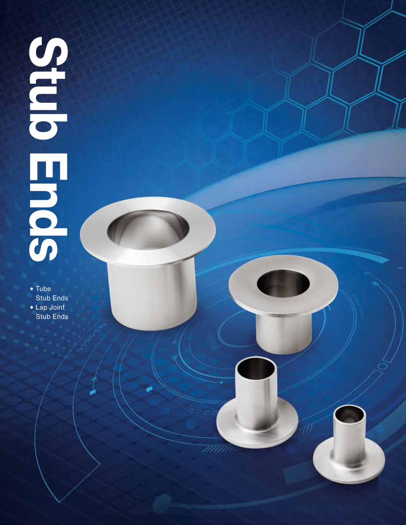
Dimensions
72
Stub Ends
• Tube Stub Ends
• Lap Joint Stub Ends

Dimensions
73
38SECONFIGURATION
Tube Stub End, ShortValex Standard, ASTM Tube
Dimensions in Inches
Size O.D. Wall A B C 401 201
Product Lines
1/2" .500 .065 1.375 1.625 .098
3/4" .750 .065 1.375 1.688 .098
1" 1.000 .065 1.625 2.000 .130
1-1/2" 1.500 .065 1.750 2.875 .130
2" 2.000 .065 1.500 3.625 .130
2-1/2" 2.500 .065 2.000 4.125 .130
3" 3.000 .065 2.250 5.000 .166
4" 4.000 .083 2.625 6.188 .166
6" 6.000 .109 3.000 8.500 .218
Wall
O.D.B
A
C
38LECONFIGURATION
Tube Stub End, Long Valex Standard, ASTM Tube
Dimensions in Inches
Size O.D. Wall A B C 401 201
Product Lines
1/2" .500 .049 2.875 1.625 .098
3/4" .750 .065 2.875 1.688 .098
1" 1.000 .065 3.125 2.000 .130
1-1/2" 1.500 .065 3.250 2.875 .130
2" 2.000 .065 3.000 3.625 .130
2-1/2" 2.500 .065 4.000 4.125 .130
3" 3.000 .065 4.250 5.000 .166
4" 4.000 .083 5.625 6.188 .166
6" 6.000 .109 7.000 8.500 .218
Wall
O.D.B
A
C
Use With
38PF
Use With
38PF

Dimensions
74
Wall
O.D.
A
B
R
C
Dimensions in InchesProduct Lines
Size Sch. O.D. Wall A R B C LDEP CFOS
NPS 1/2 10S .809 - .896 .083 3.00 .12 1.38 .083
NPS 3/4 10S 1.019 - 1.106 .083 3.00 .12 1.69 .083
NPS 1 10S 1.284 - 1.376 .109 4.00 .12 2.00 .109
NPS 1-1/4 10S 1.629 - 1.716 .109 4.00 .19 2.50 .109
NPS 1-1/2 10S 1.869 - 1.965 .109 4.00 .25 2.88 .109
NPS 2 10S 2.344 - 2.456 .109 6.00 .31 3.62 .109
NPS 2-1/2 10S 2.844 - 2.966 .120 6.00 .31 4.12 .120
NPS 3 10S 3.469 - 3.596 .120 6.00 .38 5.00 .120
NPS 3-1/2 10S 3.969 - 4.096 .120 6.00 .38 5.50 .120
NPS 4 10S 4.469 - 4.593 .120 6.00 .44 6.19 .120
NPS 5 10S 5.532 - 5.683 .134 8.00 .44 7.31 .134
NPS 6 10S 6.594 - 6.743 .134 8.00 .50 8.50 .134
NPS 8 10S 8.594 - 8.743 .148 8.00 .50 10.62 .148
NPS 10 10S 10.719 - 10.913 .165 10.00 .50 12.75 .165
NPS 12 10S 12.719 - 12.913 .180 10.00 .50 15.00 .180
NPS 14 10S 13.969 - 14.170 .188 12.00 .50 16.25 .188
NPS 16 10S 15.969 - 16.180 .188 12.00 .50 18.50 .188
NPS 18 10S 17.969 - 18.190 .188 12.00 .50 21.00 .188
NPS 20 10S 19.969 - 20.240 .218 12.00 .50 23.00 .218
NPS 24 10S 23.969 - 24.240 .250 12.00 .50 27.25 .250
Lap Joint Stub End, Long ASME B16.9 Standard, ASME Pipe
Use With
38LJ
38LACONFIGURATION

Dimensions
75
Dimensions in InchesProduct Lines
Size Sch. O.D. Wall A R B C LDEP CFOS
NPS 1/2 10S .809 - .896 .083 2.00 .12 1.38 .083
NPS 3/4 10S 1.019 - 1.106 .083 2.00 .12 1.69 .083
NPS 1 10S 1.284 - 1.376 .109 2.00 .12 2.00 .109
NPS 1-1/4 10S 1.629 - 1.716 .109 2.00 .19 2.50 .109
NPS 1-1/2 10S 1.869 - 1.965 .109 2.00 .25 2.88 .109
NPS 2 10S 2.344 - 2.456 .109 2.50 .31 3.62 .109
NPS 2-1/2 10S 2.844 - 2.966 .120 2.50 .31 4.12 .120
NPS 3 10S 3.469 - 3.596 .120 2.50 .38 5.00 .120
NPS 3-1/2 10S 3.969 - 4.096 .120 3.00 .38 5.50 .120
NPS 4 10S 4.469 - 4.593 .120 3.00 .44 6.19 .120
NPS 5 10S 5.532 - 5.683 .134 3.00 .44 7.31 .134
NPS 6 10S 6.594 - 6.743 .134 3.50 .50 8.50 .134
NPS 8 10S 8.594 - 8.743 .148 4.00 .50 10.62 .148
NPS 10 10S 10.719 - 10.913 .165 5.00 .50 12.75 .165
NPS 12 10S 12.719 - 12.913 .180 6.00 .50 15.00 .180
NPS 14 10S 13.969 - 14.170 .188 6.00 .50 16.25 .188
NPS 16 10S 15.969 - 16.180 .188 6.00 .50 18.50 .188
NPS 18 10S 17.969 - 18.190 .188 6.00 .50 21.00 .188
NPS 20 10S 19.969 - 20.240 .218 6.00 .50 23.00 .218
NPS 24 10S 23.969 - 24.240 .250 6.00 .50 27.25 .250
Lap Joint Stub End, Short ASME B16.9 Standard, ASME Pipe
Wall
O.D.
A
B
R
C
Use With
38LJ
38SACONFIGURATION
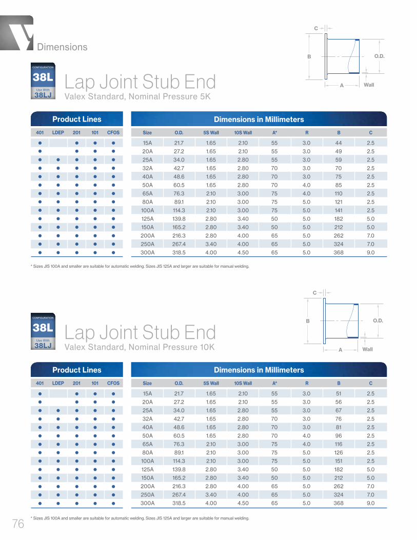
Dimensions
76
Dimensions in MillimetersProduct Lines
Size O.D. 5S Wall 10S Wall A* R B C 401 LDEP 201 101 CFOS
15A 21.7 1.65 2.10 55 3.0 44 2.5
20A 27.2 1.65 2.10 55 3.0 49 2.5
25A 34.0 1.65 2.80 55 3.0 59 2.5
32A 42.7 1.65 2.80 70 3.0 70 2.5
40A 48.6 1.65 2.80 70 3.0 75 2.5
50A 60.5 1.65 2.80 70 4.0 85 2.5
65A 76.3 2.10 3.00 75 4.0 110 2.5
80A 89.1 2.10 3.00 75 5.0 121 2.5
100A 114.3 2.10 3.00 75 5.0 141 2.5
125A 139.8 2.80 3.40 50 5.0 182 5.0
150A 165.2 2.80 3.40 50 5.0 212 5.0
200A 216.3 2.80 4.00 65 5.0 262 7.0
250A 267.4 3.40 4.00 65 5.0 324 7.0
300A 318.5 4.00 4.50 65 5.0 368 9.0
Lap Joint Stub End Valex Standard, Nominal Pressure 5K
* Sizes JIS 100A and smaller are suitable for automatic welding. Sizes JIS 125A and larger are suitable for manual welding.
Dimensions in MillimetersProduct Lines
Size O.D. 5S Wall 10S Wall A* R B C 401 LDEP 201 101 CFOS
15A 21.7 1.65 2.10 55 3.0 51 2.5
20A 27.2 1.65 2.10 55 3.0 56 2.5
25A 34.0 1.65 2.80 55 3.0 67 2.5
32A 42.7 1.65 2.80 70 3.0 76 2.5
40A 48.6 1.65 2.80 70 3.0 81 2.5
50A 60.5 1.65 2.80 70 4.0 96 2.5
65A 76.3 2.10 3.00 75 4.0 116 2.5
80A 89.1 2.10 3.00 75 5.0 126 2.5
100A 114.3 2.10 3.00 75 5.0 151 2.5
125A 139.8 2.80 3.40 50 5.0 182 5.0
150A 165.2 2.80 3.40 50 5.0 212 5.0
200A 216.3 2.80 4.00 65 5.0 262 7.0
250A 267.4 3.40 4.00 65 5.0 324 7.0
300A 318.5 4.00 4.50 65 5.0 368 9.0
Lap Joint Stub End Valex Standard, Nominal Pressure 10K
* Sizes JIS 100A and smaller are suitable for automatic welding. Sizes JIS 125A and larger are suitable for manual welding.
Wall
O.D.B
A
C
Wall
O.D.B
A
C
Use With
38LJ
38LCONFIGURATION
Use With
38LJ
38LCONFIGURATION

Flanges
• Weld Neck Flanges
• Blind Flanges
• Blank Flanges
• Lap Joint Flanges
• Tube Plate Flanges

Dimensions
78
Weld Neck Flange ASME B16.5 Class 150 Flange With ASTM Tube Stub
Dimensions in Inches
1/2" NPS 1/2 .500 .049 3.50 2.38 3.00 .38 4
3/4" NPS 3/4 .750 .065 3.88 2.75 3.00 .44 4
1" NPS 1 1.000 .065 4.25 3.12 3.00 .50 4
1-1/2" NPS 1-1/2 1.500 .065 5.00 3.88 3.00 .62 4
2" NPS 2 2.000 .065 6.00 4.75 3.50 .69 4
3" NPS 3 3.000 .065 7.50 6.00 4.50 .88 4
4" NPS 4 4.000 .083 9.00 7.50 4.50 .88 8
6" NPS 6 6.000 .109 11.00 9.50 4.50 .94 8
Tube Size Flange Size O.D. Wall A B C D 401 201
Product Lines
O.D.
ASTM Tube
ASME B16.5 Class 150 Flange
Wall
D
C
B
A
(.06")38CONFIGURATION
D
C
B
A(.06")Blind Flange ASME B16.5 Standard, Class 150
38BFCONFIGURATION
Dimensions in Inches
NPS 1/2 3.50 2.38 .625 .38 4
NPS 3/4 3.88 2.75 .625 .44 4
NPS 1 4.25 3.12 .625 .50 4
NPS 1-1/4 4.62 3.50 .625 .56 4
NPS 1-1/2 5.00 3.88 .625 .62 4
NPS 2 6.00 4.75 .750 .69 4
NPS 2-1/2 7.00 5.50 .750 .81 4
NPS 3 7.50 6.00 .750 .88 4
NPS 3-1/2 8.50 7.00 .750 .88 8
NPS 4 9.00 7.50 .750 .88 8
NPS 5 10.00 8.50 .875 .88 8
NPS 6 11.00 9.50 .875 .94 8
NPS 8 13.50 11.75 .875 1.06 8
NPS 10 16.00 14.25 1.000 1.12 12
NPS 12 19.00 17.00 1.000 1.19 12
NPS 14 21.00 18.75 1.125 1.31 12
NPS 16 23.50 21.25 1.125 1.38 16
NPS 18 25.00 22.75 1.250 1.50 16
NPS 20 27.50 25.00 1.250 1.62 20
NPS 24 32.00 29.50 1.375 1.81 20
Product Lines
BA D # of Bolts Size C LDEP CFOS
# of Bolts
Weld

Dimensions
79
Dimensions in Millimeters
Size A B C D E F # of Bolts 401 LDEP 201 101 CFOS
Product Lines
10A 75 55 39 1 9 12 4
15A 80 60 44 1 9 12 4
20A 85 65 49 1 10 12 4
25A 95 75 59 1 10 12 4
32A 115 90 70 2 12 15 4
40A 120 95 75 2 12 15 4
50A 130 105 85 2 14 15 4
65A 155 130 110 2 14 15 4
80A 180 145 121 2 14 19 4
90A 190 155 131 2 14 19 4
100A 200 165 141 2 16 19 8
125A 235 200 176 2 16 19 8
150A 265 230 206 2 18 19 8
200A 320 280 252 2 20 23 8
250A 385 345 317 2 22 23 12
300A 430 390 360 3 22 23 12
350A 480 435 403 3 24 25 12
400A 540 495 463 3 24 25 16
450A 605 555 523 3 24 25 16
500A 655 605 573 3 24 25 20
550A 720 665 630 3 26 27 20
600A 770 715 680 3 26 27 20
Blank Flange JIS B2220 Standard, Nominal Pressure 5K
38BFCONFIGURATION
ED
F
B
C
A

Dimensions
80
Blank Flange JIS B2220 Standard, Nominal Pressure 10K
38BFCONFIGURATION
Dimensions in Millimeters
Size A B C D E F # of Bolts 401 LDEP 201 101 CFOS
Product Lines
10A 90 65 46 1 12 15 4
15A 95 70 51 1 12 15 4
20A 100 75 56 1 14 15 4
25A 125 90 67 1 14 19 4
32A 135 100 76 2 16 19 4
40A 140 105 81 2 16 19 4
50A 155 120 96 2 16 19 4
65A 175 140 116 2 18 19 4
80A 185 150 126 2 18 19 8
90A 195 160 136 2 18 19 8
100A 210 175 151 2 18 19 8
125A 250 210 182 2 20 23 8
150A 280 240 212 2 22 23 8
200A 330 290 262 2 22 23 12
250A 400 355 324 2 24 25 12
300A 445 400 368 3 24 25 16
350A 490 445 413 3 26 25 16
400A 560 510 475 3 28 27 16
450A 620 565 530 3 30 27 20
500A 675 620 585 3 30 27 20
550A 745 680 640 3 34 33 20
600A 795 730 690 3 36 33 24
ED
F
C
A
B

Dimensions
81
Compatible with Product Lines*
Use With 38LA/38SA
Dimensions in Inches
NPS 1/2 3.50 2.38 .90 .625 .38 .62 .12 4
NPS 3/4 3.88 2.75 1.11 .625 .44 .62 .12 4
NPS 1 4.25 3.12 1.38 .625 .50 .69 .12 4
NPS 1-1/4 4.62 3.50 1.72 .625 .56 .81 .19 4
NPS 1-1/2 5.00 3.88 1.97 .625 .62 .88 .25 4
NPS 2 6.00 4.75 2.46 .750 .69 1.00 .31 4
NPS 2-1/2 7.00 5.50 2.97 .750 .81 1.12 .31 4
NPS 3 7.50 6.00 3.60 .750 .88 1.19 .38 4
NPS 3-1/2 8.50 7.00 4.10 .750 .88 1.25 .38 8
NPS 4 9.00 7.50 4.60 .750 .88 1.31 .44 8
NPS 5 10.00 8.50 5.69 .875 .88 1.44 .44 8
NPS 6 11.00 9.50 6.75 .875 .94 1.56 .50 8
NPS 8 13.50 11.75 8.75 .875 1.06 1.75 .50 8
NPS 10 16.00 14.25 10.92 1.000 1.12 1.94 .50 12
NPS 12 19.00 17.00 12.92 1.000 1.19 2.19 .50 12
NPS 14 21.00 18.75 14.18 1.125 1.31 3.12 .50 12
NPS 16 23.50 21.25 16.19 1.125 1.38 3.44 .50 16
NPS 18 25.00 22.75 18.20 1.250 1.50 3.81 .50 16
NPS 20 27.50 25.00 20.25 1.250 1.62 4.06 .50 20
NPS 24 32.00 29.50 24.25 1.375 1.81 4.38 .50 20
BA C D E F R # of Bolts Size LDEP CFOS
CE
B
A
F
R
D
Lap Joint FlangeASME B16.5 Standard, Class 150
38LJCONFIGURATION
* Lap joint flanges are only available in CFOS, but are compatible with the product lines listed above.

Dimensions
82
Lap Joint Flange JIS B2220 Standard, Nominal Pressure 5K
Dimensions in Millimeters
Size A B C D E # of Bolts 401 LDEP 201 101 CFOS
15A 80 60 23.4 12 9 4
20A 85 65 28.9 12 10 4
25A 95 75 35.6 12 10 4
32A 115 90 44.3 15 12 4
40A 120 95 50.4 15 12 4
50A 130 105 62.7 15 14 4
65A 155 130 78.7 15 14 4
80A 180 145 91.6 19 14 4
100A 200 165 116.9 19 16 8
125A 235 200 143.0 19 16 8
150A 265 230 168.4 19 18 8
200A 320 280 219.5 23 20 8
250A 385 345 271.7 23 22 12
300A 430 390 322.8 23 22 12
E
D
B
C
A
Use With
38L
38LJCONFIGURATION
Compatible with Product Lines*
* Lap joint flanges are only available in CFOS, but are compatible with the product lines listed above.
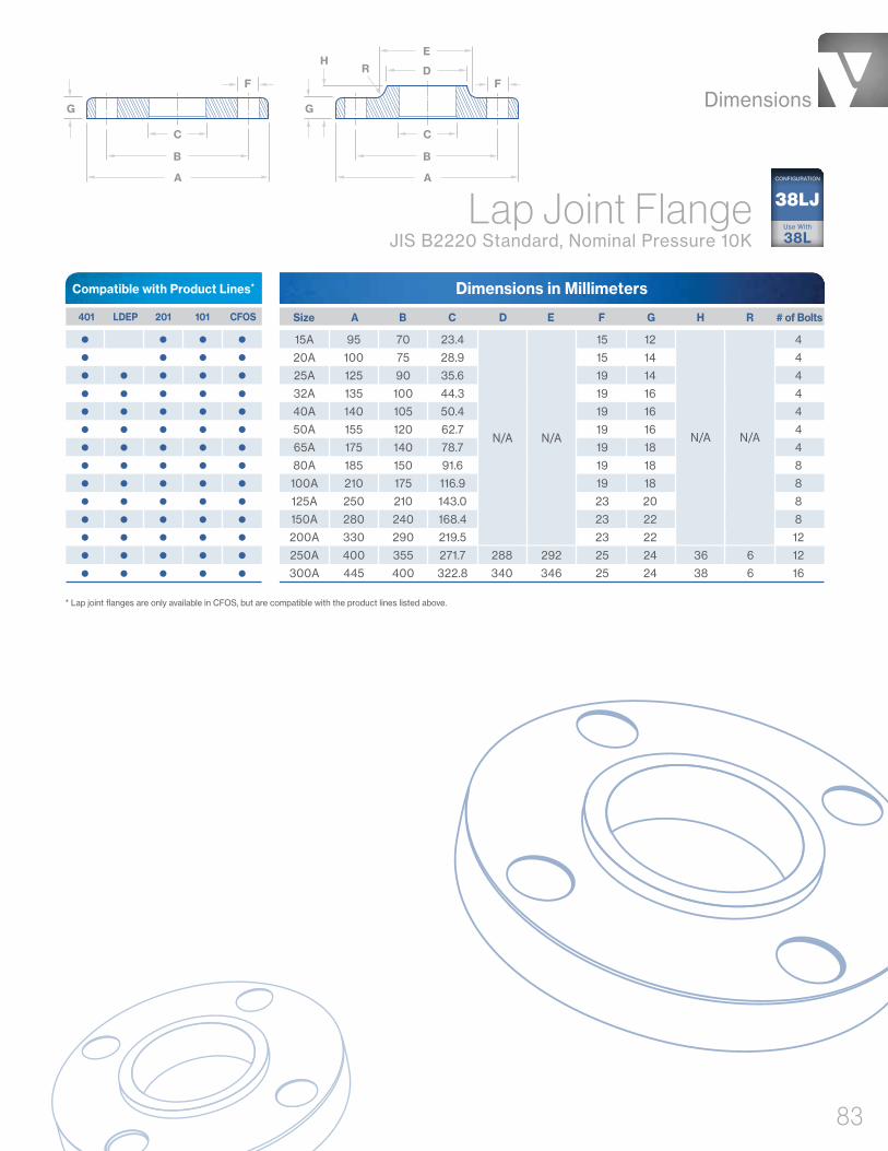
Dimensions
83
Compatible with Product Lines*
G G
H
F F
B B
C C
D
E
A A
R
Lap Joint Flange JIS B2220 Standard, Nominal Pressure 10K
Dimensions in Millimeters
Size A B C D E F G H R # of Bolts 401 LDEP 201 101 CFOS
15A 95 70 23.4 15 12 4
20A 100 75 28.9 15 14 4
25A 125 90 35.6 19 14 4
32A 135 100 44.3 19 16 4
40A 140 105 50.4 19 16 4
50A 155 120 62.7 19 16 4
65A 175 140 78.7 19 18 4
80A 185 150 91.6 19 18 8
100A 210 175 116.9 19 18 8
125A 250 210 143.0 23 20 8
150A 280 240 168.4 23 22 8
200A 330 290 219.5 23 22 12
250A 400 355 271.7 288 292 25 24 36 6 12
300A 445 400 322.8 340 346 25 24 38 6 16
Use With
38L
38LJCONFIGURATION
* Lap joint flanges are only available in CFOS, but are compatible with the product lines listed above.
N/AN/AN/AN/A

C
E
B
A(.06")
D
F
Weld Neck FlangeASME B16.5 Standard, Class 150
38WNCONFIGURATION
Dimensions in Inches
NPS 1/2 3.50 2.38 .62 .625 .38 1.81 4
NPS 3/4 3.88 2.75 .82 .625 .44 2.00 4
NPS 1 4.25 3.12 1.05 .625 .50 2.12 4
NPS 1-1/4 4.62 3.50 1.38 .625 .56 2.19 4
NPS 1-1/2 5.00 3.88 1.61 .625 .62 2.38 4
NPS 2 6.00 4.75 2.07 .750 .69 2.44 4
NPS 2-1/2 7.00 5.50 2.47 .750 .81 2.69 4
NPS 3 7.50 6.00 3.07 .750 .88 2.69 4
NPS 3-1/2 8.50 7.00 3.55 .750 .88 2.75 8
NPS 4 9.00 7.50 4.03 .750 .88 2.94 8
NPS 5 10.00 8.50 5.05 .875 .88 3.44 8
NPS 6 11.00 9.50 6.07 .875 .94 3.44 8
NPS 8 13.50 11.75 7.98 .875 1.06 3.94 8
NPS 10 16.00 14.25 10.02 1.000 1.12 3.94 12
NPS 12 19.00 17.00 12.00 1.000 1.19 4.44 12
NPS 14 21.00 18.75 1.125 1.31 4.94 12
NPS 16 23.50 21.25 1.125 1.38 4.94 16
NPS 18 25.00 22.75 1.250 1.50 5.44 16
NPS 20 27.50 25.00 1.250 1.62 5.62 20
NPS 24 32.00 29.50 1.375 1.81 5.94 20
Product Lines
B CA D E F # of Bolts Size LDEP CFOS
Customer
Specified
Dimensions
84

Weld Neck Flange JIS B2220 Standard, Nominal Pressure 5K
Dimensions in Millimeters
Size A B C D E F G H I # of Bolts 401 LDEP 201 101 CFOS
Product Lines
10A 75 55 39 12.7 17.3 12 1 9 24 4
15A 80 60 44 16.1 21.7 12 1 9 25 4
20A 85 65 49 21.6 27.2 12 1 10 28 4
25A 95 75 59 27.6 34.0 12 1 10 30 4
32A 115 90 70 35.7 42.7 15 2 12 33 4
40A 120 95 75 41.6 48.6 15 2 12 34 4
50A 130 105 85 52.9 60.5 15 2 14 36 4
65A 155 130 110 67.9 76.3 15 2 14 39 4
80A 180 145 121 80.7 89.1 19 2 14 41 4
90A 190 155 131 93.2 101.6 19 2 14 41 4
100A 200 165 141 105.3 114.3 19 2 16 41 8
125A 235 200 176 130.8 139.8 19 2 16 43 8
150A 265 230 206 155.2 165.2 19 2 18 49 8
200A 320 280 252 204.7 216.3 23 2 20 53 8
250A 385 345 317 254.2 267.4 23 2 22 61 12
300A 430 390 360 304.7 318.5 23 3 22 62 12
350A 480 435 403 339.8 355.6 25 3 24 73 12
400A 540 495 463 390.6 406.4 25 3 24 76 16
450A 605 555 523 441.4 457.2 25 3 24 79 16
500A 655 605 573 492.2 508.0 25 3 24 79 20
550A 720 665 630 543.0 558.8 27 3 26 81 20
600A 770 715 680 593.8 609.6 27 3 26 81 20
38WNCONFIGURATION
HI
F
B
C
D
E
A
G
Dimensions
85

Compatible with Product Lines
38WNCONFIGURATION Weld Neck Flange
JIS B2220 Standard, Nominal Pressure 10K
Dimensions in Millimeters
Size A B C D E F G # of Bolts 401 LDEP 201 101 CFOS
Product Lines
10A 90 65 46 12.7 15 1 12 4
15A 95 70 51 16.1 15 1 12 4
20A 100 75 56 21.6 15 1 14 4
25A 125 90 67 27.6 19 1 14 4
32A 135 100 76 35.7 19 2 16 4
40A 140 105 81 41.6 19 2 16 4
50A 155 120 96 52.9 19 2 16 4
65A 175 140 116 67.9 19 2 18 4
80A 185 150 126 80.7 19 2 18 8
90A 195 160 136 93.2 19 2 18 8
100A 210 175 151 105.3 19 2 18 8
125A 250 210 182 130.8 23 2 20 8
150A 280 240 212 155.2 23 2 22 8
200A 330 290 262 204.7 23 2 22 12
250A 400 355 324 254.2 25 2 24 12
300A 445 400 368 304.7 25 3 24 16
350A 490 445 413 339.8 25 3 26 16
400A 560 510 475 390.6 27 3 28 16
450A 620 565 530 441.4 27 3 30 20
500A 675 620 585 492.2 27 3 30 20
550A 745 680 640 543.0 33 3 32 20
600A 795 730 690 593.8 33 3 32 24
Dimensions in Inches
Size A B* C D E # of Bolts **
1/2" 3.50 2.38 .563 .625 .375 4
3/4" 3.88 2.75 .788 .625 .500 4
1" 4.25 3.13 1.063 .625 .500 4
1-1/2" 5.00 3.88 1.563 .625 .500 4
2" 6.00 4.75 2.063 .750 .500 4
2-1/2" 7.00 5.50 2.563 .750 .500 4
3" 7.50 6.00 3.063 .750 .500 4
4" 9.00 7.50 4.063 .750 .500 8
6" 11.00 9.50 6.063 .875 .563 8
Tube Plate Flange Valex Standard, ASTM Tube
401 201
D C E
B
AUse With
38LE/38SE
38PFCONFIGURATION
* Tube plate flanges are only available in 201, but compatible with the product lines shown above.** Tube plate flanges are bolt compatible (but not pressure compatible) to ASME B16.5 Class 150 flanges.
G
E
B
C
D
A
F
Dimensions
86

Offered In: • Tube
• 90° Elbows
• 45° Elbows
• Equal Tees
• Reducing Tees
• Concentric Reducers
• Purge Tees
• Sleeves
• Weld Glands
• Terminators
• Bulkhead Fittings
Coaxial Tube System
Valex pioneered the stainless steel Coaxial Tube System more than 30 years ago to meet the requirements set forth in codes and ordinances written at the inception of the semiconductor industry. Since then, we’ve gone on to design and deliver a full range of tube and fittings that “double-contain” toxic and hazardous gases for particularly dangerous processes. To provide absolute safety, all coaxial products are designed for automatic orbital welding in joint connections.
Coaxial Tube
& Fittings
► SECONDARY CONTAINMENT ►
PROCESS GAS PATH
PRO
CES
S G
AS
PATH
► SECONDARY CONTAINMENT ►
► S
EC
ON
DA
RY
CO
NTA
INM
EN
T ►
► S
EC
ON
DA
RY
CO
NTA
INM
EN
T ►
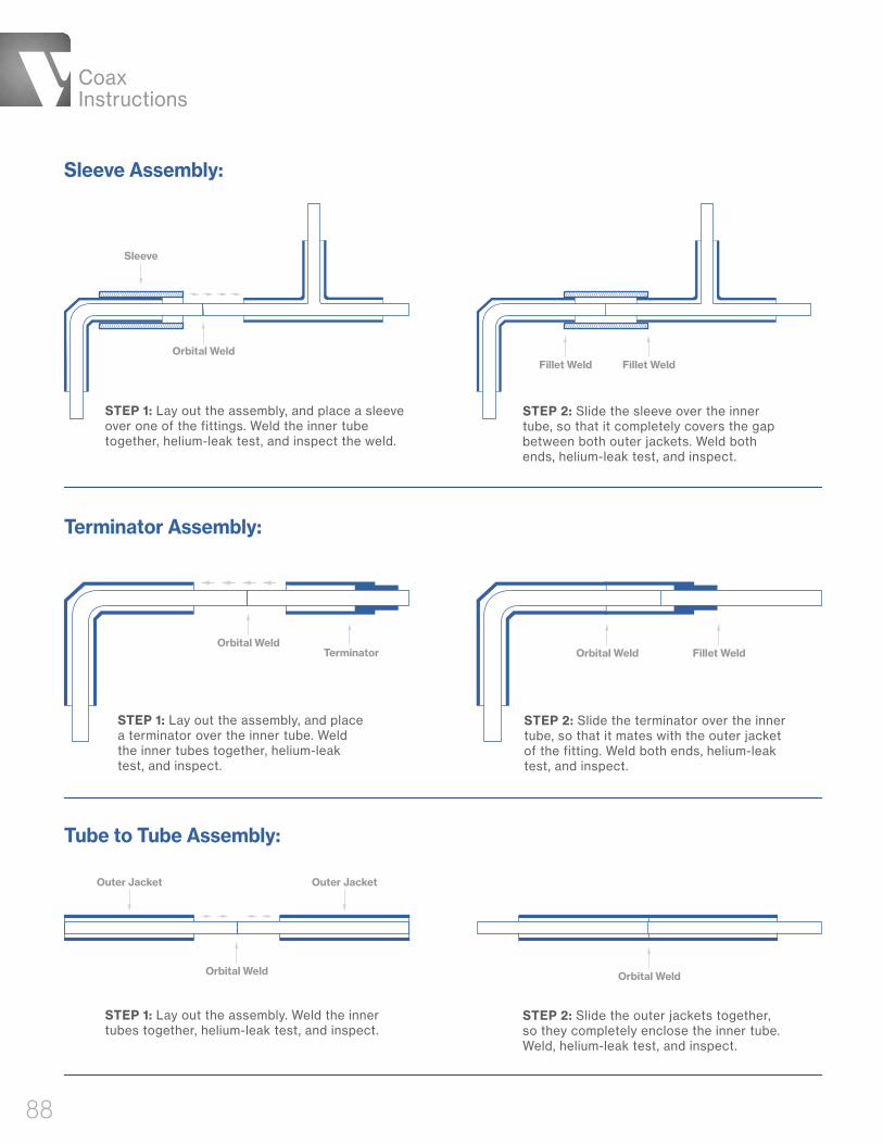
STEP 1: Lay out the assembly, and place a sleeve over one of the fittings. Weld the inner tube together, helium-leak test, and inspect the weld.
STEP 1: Lay out the assembly, and place a terminator over the inner tube. Weld the inner tubes together, helium-leak test, and inspect.
STEP 1: Lay out the assembly. Weld the inner tubes together, helium-leak test, and inspect.
Sleeve Assembly:
Terminator Assembly:
Tube to Tube Assembly:
Orbital Weld Orbital Weld
Outer Jacket Outer Jacket
STEP 2: Slide the sleeve over the inner tube, so that it completely covers the gap between both outer jackets. Weld both ends, helium-leak test, and inspect.
STEP 2: Slide the terminator over the inner tube, so that it mates with the outer jacket of the fitting. Weld both ends, helium-leak test, and inspect.
STEP 2: Slide the outer jackets together, so they completely enclose the inner tube. Weld, helium-leak test, and inspect.
Orbital Weld
Orbital WeldOrbital Weld Fillet WeldTerminator
Fillet WeldFillet Weld
Sleeve
Coax Instructions
88

Wall 2Wall 1
O.D. 2O.D. 1
PSI Seamless
PSI Seamless 222
Dimensions in Inches
Dimensions in Inches
1/4" .250 .035 .500 .049 .33 2,509 173
3/8" .375 .035 .625 .049 .44 1,981 137
1/2" .500 .049 .750 .065 .74 2,207 152
Product Lines
Product Line
* Gauge pressure is listed.
Notes: 1. Maximum safe pressure calculated per ASME B 31.3-2014, paragraph 304.1.2 (formula 3a). Calculations assume maximum allowable O.D. and minimum allowable wall thickness (worst case scenario) for the outer jacket only. 2. Pressures listed in the chart above are based on welded outer jacket material. Inner tube and outer jacket tube material per ASTM A269 TP 304L or TP 316L.
* Gauge pressure is listed.
Notes: 1. Maximum safe pressure calculated per ASME B 31.3-2014, paragraph 304.1.2 (formula 3a). Calculations assume maximum allowable O.D. and minimum allowable wall thickness (worst case scenario) for the outer jacket only. 2. Pressures listed in the chart above are based on welded outer jacket material per ASTM A269 TP 304L or TP 316L. Inner tube material is Hastelloy® C-22®. Hastelloy and C-22 are registered trademarks of Haynes International Inc.
401 301 201 101 Size Weight per foot (lbs.)
Maximum Pressure*Inner Tube Outer TubePSIO.D. 1 O.D. 2 BarWall 1 Wall 2
Size Weight per foot (lbs.)
Maximum Pressure*Inner Tube Outer TubePSIO.D. 1 O.D. 2 BarWall 1 Wall 2
1/4" .250 .035 .500 .049 .32 2,509 173
1/4" .250 .039 .500 .049 .33 2,509 173
3/8" .375 .035 .625 .049 .43 1,981 137
3/8" .375 .039 .625 .049 .44 1,981 137
1/2" .500 .049 .750 .065 .72 2,207 152
3/4" .750 .065 1.00 .065 1.13 1,631 113
1" 1.00 .065 1.25 .065 1.48 1,294 89
1-1/2" 1.50 .065 2.00 .065 2.36 796 55
2" 2.00 .065 2.50 .065 3.06 635 44
Coaxial Tube ASTM A269 / A632
Coaxial Tube Hastelloy® C-22® Inner Tube
with Stainless Steel Outer Jacket
DimensionsWeights
Pressures
89

Dimensions
90
Coaxial 90° Elbow Valex Standard, ASTM Tube
Dimensions in Inches
1/4" .250 .035 .500 .049 4.375 1.00 .56
3/8" .375 .035 .625 .049 4.125 1.00 .56
1/2" .500 .049 .750 .065 4.250 1.00 .75
3/4" .750 .065 1.000 .065 6.750 1.75 1.12
1" 1.000 .065 1.250 .065 7.125 1.75 1.50
1-1/2" 1.500 .065 2.000 .065 8.375 2.00 2.25
2" 2.000 .065 2.500 .065 9.000 2.00 3.00
Product Lines
Size*O.D. 1 O.D. 2Wall 1 Wall 2
A B RInner Tube Outer Tube
401 201 222
* Size is based on o.d. of inner tube.
2CONFIGURATION
O.D. 2 O.D. 1
A
Wall 1Wall 2
R
90°
B
BA
Dimensions in Inches
1/4" .250 .035 .500 .049 4.000 1.00 .56
3/8" .375 .035 .625 .049 3.875 1.00 .56
1/2" .500 .049 .750 .065 3.875 1.00 .75
3/4" .750 .065 1.000 .065 6.125 1.75 1.12
1" 1.000 .065 1.250 .065 6.250 1.75 1.50
1-1/2" 1.500 .065 2.000 .065 7.120 2.00 2.25
Product Lines
Size*O.D. 1 O.D. 2Wall 1 Wall 2
A B RInner Tube Outer Tube
401 201 222
* Size is based on o.d. of inner tube.
Coaxial 45° Elbow Valex Standard, ASTM Tube2K
CONFIGURATION
O.D. 2O.D. 1R
A
Wall 1
Wall 2
B
45°
B
A

Dimensions
91
Dimensions in Inches
1/4" x 1/4" .250 .035 / .039 .500 .049 3.875 1.00
3/8" x 3/8" .375 .035 / .039 .625 .049 4.000 1.00
1/2" x 1/2" .500 .049 .750 .065 4.000 1.00
3/4" x 3/4" .750 .065 1.000 .065 6.375 1.75
1" x 1" 1.000 .065 1.250 .065 6.500 1.75
1-1/2" x 1-1/2" 1.500 .065 2.000 .065 7.625 2.00
Product Lines
Size*O.D. 1 O.D. 2Wall 1 Wall 2
A BInner Tube Outer Tube
401 201 222
* Size is based on o.d. of inner tube.
Coaxial Equal Tee Valex Standard, ASTM Tube 7
CONFIGURATION
O.D. 2
Wall 2
Wall 2O.D. 2
Wall 1
Wall 1
O.D. 1
O.D. 1A A
B“B”
B
A
Dimensions in Inches
3/8" x 1/4" .375 .035 / .039 .250 .035 / .039 .625 .049 .500 .049 3.875 4.125 1.00 1.00
1/2" x 1/4" .500 .049 .250 .035 / .039 .750 .065 .500 .049 3.875 4.125 1.00 1.00
1/2" x 3/8" .500 .049 .375 .035 / .039 .750 .065 .625 .049 4.000 4.125 1.00 1.00
3/4" x 1/4" .750 .065 .250 .035 / .039 1.000 .065 .500 .049 6.125 4.250 1.75 1.00
3/4" x 3/8" .750 .065 .375 .035 / .039 1.000 .065 .625 .049 6.250 4.250 1.75 1.00
3/4" x 1/2" .750 .065 .500 .049 1.000 .065 .750 .065 6.250 4.250 1.75 1.00
1" x 1/4" 1.000 .065 .250 .035 / .039 1.250 .065 .500 .049 6.125 4.375 1.75 1.00
1" x 3/8" 1.000 .065 .375 .035 / .039 1.250 .065 .625 .049 6.250 4.375 1.75 1.00
1" x 1/2" 1.000 .065 .500 .049 1.250 .065 .750 .065 6.250 4.375 1.75 1.00
1" x 3/4" 1.000 .065 .750 .065 1.250 .065 1.000 .065 6.375 6.625 1.75 1.75
1-1/2" x 1/2" 1.500 .065 .500 .049 2.000 .065 .750 .065 7.000 7.000 2.00 1.75
1-1/2" x 3/4" 1.500 .065 .750 .065 2.000 .065 1.000 .065 7.125 7.000 2.00 1.75
1-1/2" x 1" 1.500 .065 1.000 .065 2.000 .065 1.250 .065 7.250 7.000 2.00 1.75
2" x 1/2" 2.000 .065 .500 .049 2.500 .065 .750 .065 7.750 9.000 2.00 1.75
2" x 1" 2.000 .065 1.000 .065 2.500 .065 1.250 .065 8.000 7.250 2.00 1.75
Product Lines
Size*O.D. 1 O.D. 3Wall 1 Wall 3O.D. 2 O.D. 4Wall 2 Wall 4
CBA DInner Tube Outer Tube
401 201 222
* Size is based on o.d. of inner tube.
Coaxial Reducing TeeValex Standard, ASTM Tube 7R
CONFIGURATION
O.D. 3
Wall 3
Wall 4O.D. 4
Wall 1
Wall 2
O.D. 2
O.D. 1A A
CC
D
B

Dimensions
92
Compatible with Product Lines
Coaxial Concentric Reducer Valex Standard, ASTM Tube
* Size is based on o.d. of inner tube.
Dimensions in Inches
3/8" x 1/4" .375 .035 / .039 .250 .035 / .039 .625 .049 .500 .049 4.00 4.00 1.34 2.34 2.60 1.47
1/2" x 1/4" .500 .049 .250 .035 / .039 .750 .065 .500 .049 4.00 4.00 1.31 2.31 2.56 1.56
1/2" x 3/8" .500 .049 .375 .035 / .039 .750 .065 .625 .049 4.00 4.00 1.34 2.34 2.59 1.59
3/4" x 1/4" .750 .065 .250 .035 / .039 1.000 .065 .500 .049 5.00 5.75 2.00 3.88 2.75 1.63
3/4" x 3/8" .750 .065 .375 .035 / .039 1.000 .065 .625 .065 5.00 5.75 2.03 3.79 2.78 1.54
3/4" x 1/2" .750 .065 .500 .049 1.000 .065 .750 .065 5.00 5.75 2.06 3.94 2.81 1.69
1" x 1/4" 1.000 .065 .250 .035 / .039 1.250 .065 .500 .049 5.00 5.75 2.06 3.81 2.56 1.56
1" x 3/8" 1.000 .065 .375 .035 / .039 1.250 .065 .625 .049 5.00 5.75 2.09 3.84 2.59 1.59
1" x 1/2" 1.000 .065 .500 .049 1.250 .065 .750 .065 5.00 5.75 2.13 3.88 2.63 1.63
1" x 3/4" 1.000 .065 .750 .065 1.250 .065 1.000 .065 6.50 6.50 2.19 3.94 4.19 2.44
1-1/2" x 1/4" 1.500 .065 .250 .035 / .039 2.000 .065 .500 .049 5.75 6.75 2.31 4.38 2.81 1.63
1-1/2" x 3/8" 1.500 .065 .375 .035 / .039 2.000 .065 .625 .049 5.75 6.75 2.34 4.41 2.84 1.66
1-1/2" x 1/2" 1.500 .065 .500 .049 2.000 .065 .750 .065 5.75 6.75 2.38 4.44 2.88 1.69
1-1/2" x 3/4" 1.500 .065 .750 .065 2.000 .065 1.000 .065 7.25 7.50 2.44 4.50 4.44 2.50
1-1/2" x 1" 1.500 .065 1.000 .065 2.000 .065 1.250 .065 7.25 7.50 2.50 4.56 4.50 2.56
2" x 1/4" 2.000 .065 .250 .035 / .039 2.500 .065 .500 .049 6.00 7.00 2.31 4.38 2.81 1.63
2" x 3/8" 2.000 .065 .375 .035 / .039 2.500 .065 .625 .049 6.00 7.00 2.34 4.41 2.84 1.66
2" x 1/2" 2.000 .065 .500 .049 2.500 .065 .750 .065 6.00 7.00 2.38 4.44 2.88 1.69
2" x 3/4" 2.000 .065 .750 .065 2.500 .065 1.000 .065 7.50 7.75 2.44 4.50 4.44 2.50
2" x 1" 2.000 .065 1.000 0.65 2.500 .065 1.250 .065 7.50 7.75 2.50 4.56 4.50 2.56
2" x 1-1/2" 2.000 .065 1.500 .065 2.500 .065 2.000 .065 8.00 8.00 2.63 4.75 5.13 3.00
Product Lines
D 401 201 222
Size*O.D. 1 O.D. 3 Inner InnerWall 1 Wall 3 Outer OuterO.D. 2 O.D. 4Wall 2 Wall 4
BAInner Tube Outer Tube C
A
DC
O.D. 4
O.D. 3
Wall 3
O.D. 1
Wall 1
Wall 4B
DC
O.D. 2
Wall 2
31CONFIGURATION
Dimensions in Inches
1/4" .500 .049 2.875 1.90 1/4"
3/8" .625 .049 3.000 1.96 1/4"
1/2" .750 .065 3.000 2.01 1/4"
3/4" 1.000 .065 4.625 2.14 1/4"
1" 1.250 .065 4.750 2.26 1/4"
1-1/2" 2.000 .065 5.625 2.64 1/4"
2" 2.500 .065 5.750 2.89 1/4"
Size* O.D. Wall A B Face-Seal Size 401 201 222
* Size indicates inner tubing the purge tee is compatible with.Note:1. Purge tees are offered in grade TP 316L for all product lines.
A A
FS
B
O.D.
Wall
Coaxial Male Purge Tee Valex Standard, ASTM Tube7P
CONFIGURATION

Dimensions
93
Compatible with Product Lines
Product Lines
Dimensions in Inches
1/4" .500 .049 2.875 1.90 1/4"
3/8" .625 .049 3.000 1.96 1/4"
1/2" .750 .065 3.000 2.01 1/4"
3/4" 1.000 .065 4.625 2.14 1/4"
1" 1.250 .065 4.750 2.26 1/4"
1-1/2" 2.000 .065 5.625 2.64 1/4"
2" 2.500 .065 5.750 2.89 1/4"
Size* O.D. Wall A B Face-Seal Size 401 201 222
Coaxial Female Purge TeeValex Standard, ASTM Tube
* Size indicates inner tubing the purge tee is compatible with.
Note:1. Purge tees are offered in grade TP 316L for all product lines.
A A
FS
B
O.D.
Wall
7PFCONFIGURATION
Coaxial Purge Tee With Male Face-Seal Gland
Valex Standard, ASTM Tube
Dimensions in Inches
1/4" .250 .035 .500 .049 3.875 3.875 1.00 1.90 1/4" 1/4"
3/8" .375 .035 .625 .049 4.000 4.000 1.00 1.96 3/8" 1/4"
1/2" .500 .049 .750 .065 4.000 4.000 1.00 2.01 1/2" 1/4"
Size*O.D. 1 O.D. 2 FS 1Wall 1 Wall 2 FS 2
A B C DInner Tube Outer Tube Face-Seal Size
401 201
* Size is based on o.d. of inner tube.
7PFSCONFIGURATION
B A
FS 2
FS 1
CD
O.D. 2
O.D. 1
Wall 2
Wall 1

Dimensions
94
Compatible with Product Lines
Coaxial Sleeve Valex Standard, ASTM Tube
Dimensions in Inches
Size* O.D. I.D. A (Standard Length) A (Additional Lengths) 401 201 222
1/4" .625 .507 2.50 4.00 / 5.00 / 6.00
3/8" .750 .632 2.50 4.00 / 5.00 / 6.00
1/2" .875 .758 2.50 4.00 / 5.00 / 6.00
3/4" 1.125 1.008 4.00 4.00 / 5.00 / 6.00
1" 1.375 1.258 4.00 N/A
1-1/2" 2.125 2.023 4.50 N/A
2" 2.625 2.523 4.50 N/A
A
O.D.I.D.
12CONFIGURATION
* Sleeve size indicates the size of coax tubing the sleeve is compatible with.
Note: 1. Sleeves are offered in grade TP 316L for all product lines.
B
A
FSO.D. 2
O.D. 1
Wall 2
Wall 1
Dimensions in Inches
1/4" .250 .035 .500 .049 3.50 .850 - 1.060 1/4"
3/8" .375 .035 .625 .049 3.50 .850 - 1.060 3/8"
1/2" .500 .049 .750 .065 3.50 .850 - 1.060 1/2"
Product Lines
Size*O.D. 1 FSO.D. 2Wall 1 Wall 2
A BInner Tube Face-Seal SizeOuter Tube
401 201
* Size is based on o.d. of inner tube.
Coaxial Female Face-Seal Weld Gland Valex Standard, ASTM Tube
14FSCONFIGURATION

Dimensions
95
Compatible with Product Lines
BA
FSO.D. 2
O.D. 1
Wall 2
Wall 1
Coaxial Male Face-Seal Weld Gland Valex Standard, ASTM Tube
15FSCONFIGURATION
Dimensions in Inches
1/4" .250 .035 .500 .049 3.50 .850 - 1.060 1/4"
3/8" .375 .035 .625 .049 3.50 .850 - 1.060 3/8"
1/2" .500 .049 .750 .065 3.50 .850 - 1.060 1/2"
Product Lines
Size*Wall 2Wall 1 O.D. 2O.D. 1 FS
A BOuter TubeInner Tube Face-Seal Size
401 201
* Size is based on o.d. of inner tube.
AB C
O.D. 2I.D. 1 I.D. 2O.D. 1
Dimensions in Inches
Size* O.D. 1 I.D. 1 O.D. 2 I.D. 2 A B C 401 201 222
1/4" .500 .402 .325 .255 1.25 .37 .25
3/8" .625 .527 .450 .380 1.25 .37 .25
1/2" .750 .620 .603 .506 1.25 .37 .25
3/4" 1.000 .870 .885 .756 2.00 .50 .25
1" 1.250 1.120 1.135 1.006 2.00 .50 .25
1-1/2" 2.000 1.870 1.635 1.511 2.25 .75 .25
2" 2.500 2.360 2.135 2.011 2.25 .75 .25
Coaxial Terminator Valex Standard, ASTM Tube 16
CONFIGURATION
* Terminator size indicates the size of coax tubing the terminator is compatible with.
Dimensions in Inches
Size* O.D. I.D. A B Hex Nut 401 201 222
1/4" .500 .402 3.625 1.00 3/4-16UNF
3/8" .625 .527 3.625 1.00 7/8-14UNF
1/2" .750 .620 3.625 1.00 1-1/16-12UNF
3/4" 1.000 .870 5.125 1.75 1-5/16-12UNF
1" 1.250 1.120 5.125 1.75 1-5/8-12UNF
Coaxial Bulkhead Fitting Valex Standard, ASTM Tube
17BHCONFIGURATION
* Bulkhead fitting size indicates the size of coax tubing the bulkhead fitting is compatible with.Note: Bulkhead fittings are offered in grade TP 316L for all product lines.
A
BBO.D.
Hex Nut
I.D.
Compatible with Product Lines

Ordering Information
96
Ordering Info.
Tube & Pipe • ASTM Tube Sizes
• JIS Pipe Sizes
• ASTM Tube, ASTM Pipe & JIS Pipe Sizes
Fittings • ASTM Tube Sizes
• JIS Pipe Sizes
• ASTM Tube, ASTM Pipe & JIS Pipe Sizes
Coaxial Tube & Fittings • ASTM Tube Sizes

Ordering Information
97
Tube
Notes:* ® HASTELLOY and C-22 are registered trademarks of Haynes International Inc. 1 . See Valex SP-9200 sheet 9 for breakdown of alloy chemistries and melt type.
ProcessT1A = SP-9204 (Product Line 101)T2A = SP 9206 (Product Line 201)T3A = SP-9223 (Product Line 301)T4A = SP-9220 (Product Line 401)TMC = SP-9207 (Product Line 222)
Size Use for: 20-foot & 6-meter 4-meter Length Tube Length Tube
00125 .13 = .125" Diameter00250 .25 = .25" Diameter00375 .38 = .375" Diameter00500 .50 = .5" Diameter00750 .75 = .75" Diameter01000 1.0 = 1" Diameter01500 1.5 = 1.5" Diameter02000 2.0 = 2" Diameter 02500 2.5 = 2.5" Diameter03000 3.0 = 3" Diameter04000 4.0 = 4" Diameter06000 6.0 = 6" Diameter
Surface Finish & VisualsUsed only for 401 product lineA5 = 5µin Ra Max, Superior VisualsA7 = 7µin Ra Max, Superior VisualsB0 = 10µin Ra Max, Standard VisualsC0 = 10µin Ra, Relaxed Visuals
Used Only for 4-meter Length Tube
Wall Thickness028 = .028" Thick035 = .035" Thick039 = .039" Thick049 = .049" Thick065 = .065" Thick083 = .083" Thick109 = .109" Thick
Alloy1
0S = 316L Seamless0W = 316L Welded2S = 304L Seamless2W = 304L Welded3S = 304L Seamless3W = 304L WeldedAS = 304 SeamlessAW = 304 WeldedHS = Hastelloy® C-22® (Seamless)*KS = 316L Seamless VIM/VARNS = 316L Seamless (ASTM Standard)NW = 316L Welded (ASTM Standard)QS = 316L SeamlessQW = 316L WeldedVS = 316L Seamless VIM/VAR
T 4 A 0 2 8
B 0
x4
. 31
Q S
Product Lines: 401, 301, 201, 101 & 222
Example 1:
Example 2:
4T Q . 0 BA S 1 3 2 08-- -x4 Use Only for 4-meter Length Tube
} 2 0T 00 5 0A S 0 0 4 9-- -
Not all possible part number combinations are available. Part number options may be subject to change. Refer to SP-9200 at Valex.com for the latest revision. Please contact Valex for availability.
ASTM Tube Sizes
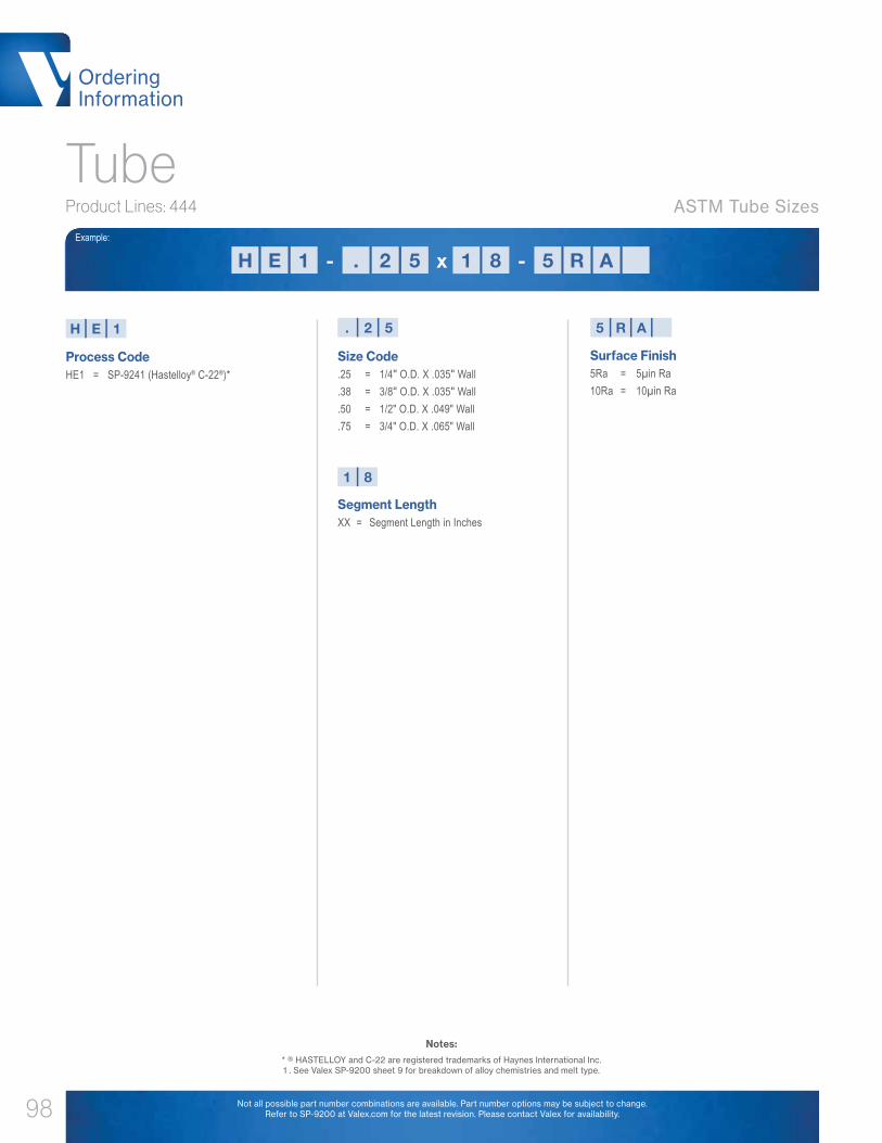
Ordering Information
98
Tube
Process CodeHE1 = SP-9241 (Hastelloy® C-22®)*
Size Code.25 = 1/4" O.D. X .035" Wall.38 = 3/8" O.D. X .035" Wall.50 = 1/2" O.D. X .049" Wall.75 = 3/4" O.D. X .065" Wall
H E 1
Product Lines: 444
Example:
Surface Finish5Ra = 5µin Ra10Ra = 10µin Ra
5 R A
EH . 511 2 5 R8 A- x -
ASTM Tube Sizes
Not all possible part number combinations are available. Part number options may be subject to change. Refer to SP-9200 at Valex.com for the latest revision. Please contact Valex for availability.
. 2 5
Segment LengthXX = Segment Length in Inches
1 8
Notes:* ® HASTELLOY and C-22 are registered trademarks of Haynes International Inc. 1 . See Valex SP-9200 sheet 9 for breakdown of alloy chemistries and melt type.
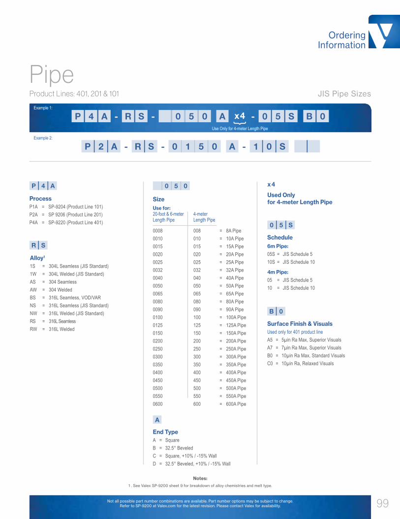
Ordering Information
99
Pipe
ProcessP1A = SP-9204 (Product Line 101)P2A = SP 9206 (Product Line 201)P4A = SP-9220 (Product Line 401)
Alloy1
1S = 304L Seamless (JIS Standard)1W = 304L Welded (JIS Standard)AS = 304 SeamlessAW = 304 WeldedBS = 316L Seamless, VOD/VARNS = 316L Seamless (JIS Standard)NW = 316L Welded (JIS Standard)RS = 316L SeamlessRW = 316L Welded
P 4 A 0 5 0
R S
End TypeA = SquareB = 32.5° BeveledC = Square, +10% / -15% WallD = 32.5° Beveled, +10% / -15% Wall
A
Product Lines: 401, 201 & 101
Example 1:
Example 2:
Notes:1 . See Valex SP-9200 sheet 9 for breakdown of alloy chemistries and melt type.
Size Use for: 20-foot & 6-meter 4-meter Length Pipe Length Pipe
0008 008 = 8A Pipe0010 010 = 10A Pipe0015 015 = 15A Pipe0020 020 = 20A Pipe0025 025 = 25A Pipe0032 032 = 32A Pipe0040 040 = 40A Pipe0050 050 = 50A Pipe0065 065 = 65A Pipe0080 080 = 80A Pipe0090 090 = 90A Pipe 0100 100 = 100A Pipe0125 125 = 125A Pipe0150 150 = 150A Pipe0200 200 = 200A Pipe0250 250 = 250A Pipe0300 300 = 300A Pipe0350 350 = 350A Pipe0400 400 = 400A Pipe0450 450 = 450A Pipe0500 500 = 500A Pipe0550 550 = 550A Pipe0600 600 = 600A Pipe
Used Only for 4-meter Length Pipe
Schedule 6m Pipe: 05S = JIS Schedule 510S = JIS Schedule 10
4m Pipe:05 = JIS Schedule 510 = JIS Schedule 10
Surface Finish & VisualsUsed only for 401 product lineA5 = 5µin Ra Max, Superior VisualsA7 = 7µin Ra Max, Superior VisualsB0 = 10µin Ra Max, Standard VisualsC0 = 10µin Ra, Relaxed Visuals
0 5
B 0
x4
S
4P R 0A S 0 5 0 5 S BA 0- - -x4 Use Only for 4-meter Length Pipe
} 2P R 0 1A S 1 5 0 0 SA- - -
JIS Pipe Sizes
Not all possible part number combinations are available. Part number options may be subject to change. Refer to SP-9200 at Valex.com for the latest revision. Please contact Valex for availability.

Ordering Information
100
Tube & Pipe
ASTM Tube Example: CS-1/2x.049-BA Valex CFOS Spec Tube, 316L Seamless, 1/2" O.D. x .049" Wall, BA Finish Option, Squared Ends
JIS Pipe Example: AW-250BX10S-AP Valex CFOS Spec Pipe, 304 Welded, JIS Size 250A x Schedule 10, AP Finish Option, Beveled Ends
NPS Pipe Example: DW-250LX20S-BA40 Valex CFOS Spec Pipe, 304L Welded, NPS 10 (DN 250) x Schedule 20, BA Finish Option with 40 Ra, Squared Ends
Process / AlloyCS = 316L SeamlessCW = 316L WeldedDS = 304L SeamlessDW = 304L WeldedAS = 304 SeamlessAW = 304 Welded
End Type
ASTM Tube:Blank = Square
JIS Pipe:A = SquareB = BeveledJ = Square, -20% WallK = Beveled, -20% Wall
NPS Pipe:L = SquareM = BeveledN = Square, -20% WallP = Beveled, -20% Wall
Surface Finish AP = CFOS, O.D. = AP, I.D. = APBA = CFOS, O.D. = BA, I.D. = BABA40 = CFOS, O.D. = BA, I.D. = 40 Ra BAEP = LDEP, O.D. = BA, I.D. = EP 20 Ra Ave / 25 Ra MaxID40 = CFOS, O.D. = AP, I.D. = 40 Ra BA IDMP = CFOS, O.D. = AP, I.D. = BA
Wall Thickness Tube Wall:.035 = .035" Thick.039 = .039" Thick.049 = .049" Thick.065 = .065" Thick.083 = .083" Thick.109 = .109" Thick
Pipe Schedule:5S = Schedule 510S = Schedule 1040S = Schedule 4080S = Schedule 80
SizeASTM Tube:1/4 = .25" Diameter3/8 = .375" Diameter1/2 = .5" Diameter3/4 = .75" Diameter1 = 1" Diameter1-1/2 = 1.5" Diameter2 = 2" Diameter2-1/2 = 2.5" Diameter3 = 3" Diameter4 = 4" Diameter6 = 6" Diameter
JIS & NPS Pipe:25 = DN 25 (JIS 25A)32 = DN 32 (JIS 32A)40 = DN 40 (JIS 40A)50 = DN 50 (NPS 2 / JIS 50A)65 = DN 65 (NPS 2-1/2 / JIS 65A)80 = DN 80 (NPS 3 / JIS 80A)90 = DN 90 (NPS 3-1/2 / JIS 90A)100 = DN 100 (NPS 4 / JIS 100A)125 = DN 125 (NPS 5 / JIS 125A)150 = DN 150 (NPS 6 / JIS 150A)200 = DN 200 (NPS 8 / JIS 200A)250 = DN 250 (NPS 10 / JIS 250A)
D W
L1
1 S0
Product Lines: CFOS & LDEP
300 = DN 300 (NPS 12 / JIS 300A)350 = DN 350 (NPS 14 / JIS 350A)400 = DN 400 (NPS 16 / JIS 400A)450 = DN 450 (NPS 18 / JIS 450A)500 = DN 500 (NPS 20 / JIS 500A)550 = DN 550 (NPS 22 / JIS 550A)600 = DN 600 (NPS 24 / JIS 600A)650 = DN 650 (JIS 650A)700 = DN 700 (JIS 700A)750 = DN 750 (NPS 30 / JIS 750A)
B A
Example :
ASTM Tube, ASTM Pipe & JIS Pipe Sizes
Not all possible part number combinations are available. Part number options may be subject to change. Refer to SP-9200 at Valex.com for the latest revision. Please contact Valex for availability.
4 0
5 0
B1 A0L SD W 1- -x 4 05 0

Ordering Information
101
Fittings
Single Wall Fitting Example 1: E2-.5-B0 Valex 401 Spec, 90° Elbow, 1/2" O.D. x .049" Wall, 10 Ra Max, 0S Chemistry, Standard Visuals
Single Wall Fitting Example 2: Q7R-1x.5-A5 Valex 401 Spec, Reducing Tee, 1" (.065" Wall) x 1/2" (.049" Wall), 5 Ra Max, VS Chemistry, Superior Visuals
Not all possible part number combinations are available. Part number options may be subject to change. Refer to SP-9200 at Valex.com for the latest revision. Please contact Valex for availability.
Process / Alloy1
B = SP-9206 (Product Line 201) 0S/0W/A4 (316L)D = SP-9206 (Product Line 201) 2S/2W (304L)E = SP-9220 (Product Line 401) 0S/0W/A4 (316L)H = SP-9207 (Product Line 222) HS (Hastelloy® C-22®)*Q = SP-9220 (Product Line 401) VS (316L)RB = SP-9206 (Product Line 201) RS/RW (316L)RE = SP-9220 (Product Line 401) RS/RW (316L)
Size.25 = 1/4" O.D. x .035" Wall.25M = 1/4" O.D. x .039" (1mm) Wall.375 = 3/8" O.D. x .035" Wall.375M = 3/8" O.D. x .039" (1mm) Wall.5 = 1/2" O.D. x .049" Wall.75 = 3/4" O.D. x .065" Wall.75M = 3/4" O.D. x .049" Wall1 = 1" O.D. x .065" Wall1.5 = 1-1/2" O.D. x .065" Wall2 = 2" O.D. x .065" Wall2.5 = 2-1/2" O.D. x .065" Wall3 = 3" O.D. x .065" Wall4 = 4" O.D. x .083" Wall6 = 6" O.D. x .109" Wall
Used Only for Reducing FittingsPlease refer to "size" code if applicable.
Surface Finish & Visuals Used only for 401 product lineA5 = 5µin Ra Max, Superior VisualsA7 = 7µin Ra Max, Superior VisualsB0 = 10µin Ra Max, Standard VisualsC0 = 10µin Ra, Relaxed Visuals
Configuration2 = 90° Elbow2W = 90° Elbow, WLD2K = 45° Elbow2KW = 45° Elbow, WLD7 = Equal Tee7W = Equal Tee, WLD7R = Reducing Tee7RW = Reducing Tee, WLD7RWW = Reducing Tee, WLD x WLD9 = Cross16 = End Cap16W = End Cap, WLD31 = Conc. Reducer31(S) = Conc. Reducer, Short Type31W = Conc. Reducer, WLD x SMLS31WW = Conc. Reducer, WLD x WLD38 = Weld Neck Flange w/ SMLS Tube38W = Weld Neck Flange w/ WLD Tube38SE = Tube Stub End, Short38LE = Tube Stub End, Long38PF = Tube Plate Flange
E
( ). 5
7
Product Lines: 401, 201 & 222
B 0
Example:
R . 57
BE 0. 57 - -x ( )Used Only for Reducing Fittings
R . 7 5
ASTM Tube Sizes
Notes:* ® HASTELLOY and C-22 are registered trademarks of Haynes International Inc. 1 . See Valex SP-9200 sheet 9 for breakdown of alloy chemistries and melt type.

Ordering Information
102
Fittings
Process / Alloy1
JA = SP-9204 (Product Line 101) AS/AW (304)JB = SP 9206 (Product Line 201) RS/RW (316L)JD = SP-9206 (Product Line 201) AS/AW (304)JE = SP-9220 (Product Line 401) RS/RW (316L)
ScheduleBlank = 5ST = 10S
Face-Type (Flange Only)1 = Full Face2 = Raised Face3 = Grooved Face
Used Only for Reducing FittingsPlease refer to the "size, end type and schedule" codes if applicable.
Surface Finish & Visuals Used only for 401 product lineA5 = 5µin Ra Max, Superior VisualsA7 = 7µin Ra Max, Superior VisualsB0 = 10µin Ra Max, Standard VisualsC0 = 10µin Ra, Relaxed Visuals
End TypeA = SquareB = 32.5° BeveledC = Square, +10% / -15% WallD = 32.5° Beveled, +10% / -15% Wall
Flange TypeS = JIS 5KT = JIS 10K
Configuration2S = 90° Elbow, Short Radius2L = 90° Elbow, Long Radius2WS = 90° Elbow, Short Radius, WLD2WL = 90° Elbow, Long Radius, WLD2K = 45° Elbow2KW = 45° Elbow, WLD2SS = 90° Elbow, Short, JIS B23122LS = 90° Elbow, Long, JIS B2312 2WSS = 90° Elbow, Short, JIS B2313, WLD2WLS = 90° Elbow, Long, JIS B2313, WLD2KLS = 45° Elbow, Long, JIS B23122KWLS = 45° Elbow, Long, JIS B2313, WLD7 = Equal Tee7W = Equal Tee, WLD7R = Reducing Tee7RW = Reducing Tee, WLD7RWW = Reducing Tee, WLD x WLD7RN = Reducing Tee, No Riser7S = Equal Tee, JIS B2312 / B23137RS = Reducing Tee, JIS B2312 / B23137RSN = Reducing Tee, JIS B2312 / B2313, No Riser16 = End Cap16W = End Cap, WLD31 = Conc. Reducer31W = Conc. Reducer, WLD x SMLS31WW = Conc. Reducer, WLD x WLD31FF = Conc. Reducer, Formed, No Tangent31FS = Conc. Reducer, No Tangent Large, Small Tangent SMLS31SF = Conc. Reducer, Large Tangent SMLS, No Tangent Small 31FW = Conc. Reducer, No Tangent Large, Small Tangent WLD
J E
T
( )4 A0 T
A
7 WR
Product Lines: 401, 201 & 101
B 0
Example:
J B4E R 8 00 TA T7 W 0 A- -x ( )Used Only for Reducing Fittings
JIS Pipe Sizes
Not all possible part number combinations are available. Part number options may be subject to change. Refer to SP-9200 at Valex.com for the latest revision. Please contact Valex for availability.
Notes:1 . See Valex SP-9200 sheet 9 for breakdown
of alloy chemistries and melt type.
Size8 = 8A Pipe10 = 10A Pipe15 = 15A Pipe20 = 20A Pipe25 = 25A Pipe32 = 32A Pipe40 = 40A Pipe50 = 50A Pipe65 = 65A Pipe80 = 80A Pipe90 = 90A Pipe100 = 100A Pipe125 = 125A Pipe150 = 150A Pipe200 = 200A Pipe250 = 250A Pipe300 = 300A Pipe350 = 350A Pipe400 = 400A Pipe450 = 450A Pipe500 = 500A Pipe550 = 550A Pipe600 = 600A Pipe
8 0
31WF = Conc. Reducer, Large Tangent WLD, No Tangent Small33 = Conc. Reducer, Cap Type33FF = Cap Reducer, Formed, No Tangent33FS = Cap Reducer, No Tangent Large, Small Tangent SMLS33SF = Cap Reducer Large Tangent SMLS, No Tangent Small33FW = Cap Reducer, No Tangent Large, Small Tangent WLD33WF = Cap Reducer, Large Tangent WLD, No Tangent Small38BF = Blank Flange38L = Lap Joint Stub End, JIS38LJ = Lap Joint Flange38WN = Weld Neck Flange

Ordering Information
103
Fittings
AlloyAF = 304CF = 316LDF = 304L
Size
ASTM Tube:04 = .25" Diameter06 = .375" Diameter08 = .5" Diameter12 = .75" Diameter16 = 1" Diameter24 = 1.5" Diameter
JIS & NPS Pipe:70 = DN 15 (NPS 1/2 / JIS 15A)71 = DN 20 (NPS 3/4 / JIS 20A)72 = DN 25 (NPS 1 / JIS 25A)73 = DN 32 (NPS 1-1/4 / JIS 32A)74 = DN 40 (NPS 1-1/2 / JIS 40A)75 = DN 50 (NPS 2 / JIS 50A)76 = DN 65 (NPS 2-1/2 / JIS 65A)77 = DN 80 (NPS 3 / JIS 80A)78 = DN 90 (NPS 3-1/2 / JIS 90A)79 = DN 100 (NPS 4 / JIS 100A)80 = DN 125 (NPS 5 / JIS 125A)81 = DN 150 (NPS 6 / JIS 150A)82 = DN 200 (NPS 8 / JIS 200A)83 = DN 250 (NPS 10 / JIS 250A)84 = DN 300 (NPS 12 / JIS 300A)85 = DN 350 (NPS 14 / JIS 350A)86 = DN 400 (NPS 16 / JIS 400A)87 = DN 450 (NPS 18 / JIS 450A)88 = DN 500 (NPS 20 / JIS 500A)89 = DN 550 (NPS 22 / JIS 550A)90 = DN 600 (NPS 24 / JIS 600A)
Type Code ASTM Tube:Blank = Square
JIS Pipe:A = SquareB = BeveledJ = Square, -20% WallK = Beveled, -20% Wall
Wall ASTM Tube:B = .035" WallC = .039" WallD = .049" WallF = .065” Wall G = .083” WallJ = .109” Wall
JIS & NPS Pipe:Blank = 5ST = 10SV = 40SW = 80S
Flange Type (Flange Only):1 = Flat / Full Face2 = Raised Face3 = Grooved Face
Used Only for Reducing FittingsPlease refer to "size, end type and wall" codes if applicable.
Finish CodeBlank = No Finish Requirement1 = CFOS, O.D. = AP, I.D. = AP2 = CFOS, O.D. = BA, I.D. = BA3 = CFOS, O.D. = BA, I.D. = 40 Ra BA4 = LDEP, O.D. = BA, I.D. = EP 20 Ra Ave / 25 Ra Max5 = CFOS, O.D. = AP, I.D. = 40 Ra BA6 = CFOS, O.D. = AP, I.D. = BA
Configuration2S = 90° Elbow, Short Radius2L = 90° Elbow, Long Radius2WS = 90° Elbow, Short Radius, WLD2WL = 90° Elbow, Long Radius, WLD 2K = 45° Elbow2KW = 45° Elbow, WLD2SS = 90° Elbow, Short, ASME B16.9 / JIS B23122LS = 90° Elbow, Long, ASME B16.9 / JIS B23122WSS = 90° Elbow, Short, ASME B16.9 / JIS B2312, WLD2WLS = 90° Elbow, Long, ASME B16.9 / JIS B2312, WLD2KLS = 45° Elbow, Long, ASME B16.9 / JIS B23122KWLS = 45° Elbow, Long, ASME B16.9 / JIS B2312, WLD7 = Equal Tee7W = Equal Tee, WLD7R = Reducing Tee7RW = Reducing Tee, WLD7RWW = Reducing Tee, WLD x WLD7S = Equal Tee, JIS B23127RS = Reducing Tee, JIS B23129 = Equal Cross16 = End Cap16W = End Cap, WLD31 = Conc. Reducer31W = Conc. Reducer, WLD x SMLS31WW = Conc. Reducer, WLD x WLD33 = Cap Reducer38BF = Blind / Blank Flange38L = Lap Joint Stub End, JIS38LA = Lap Joint Stub End, Long Pattern, Type "A", ASME B16.938SA = Lap Joint Stub End, Short Pattern, Type "A", ASME B16.938LJ = Lap Joint Flange38WN = Weld Neck Flange
D F 8 4
P
T
( )8 1 P T
7
Product Lines: CFOS & LDEP
1
Example:
R W
Used Only for Reducing Fittings
D 18F P T 1 P T7 - -( )R W 8 4
ASTM Tube, ASME Pipe & JIS Pipe Sizes
32 = 2" Diameter40 = 2.5" Diameter48 = 3" Diameter64 = 4" Diameter96 = 6" Diameter
Per Valex specification SP-9234 (CFOS) and SP-9235 (LDEP). Not all possible part number combinations are available. Part number options may be subject to change. Refer to SP-9200 at Valex.com for the latest revision. Please contact Valex for availability.
NPS Pipe:L = SquareM = BeveledN = Square, -20% WallP = Beveled, -20% WallFlange Type:Q = Class 150, B16.5S = JIS B2220, 5KT = JIS B2220, 10K
Fitting Example 1: CF31W-82PT81PT-4 Valex LDEP Spec, Concentric Reducer, NPS 8 (Sch 10) x NPS 6 (Sch 10), 20 Ra, EP, 316L

Ordering Information
104
Coaxial Tube
Inner ProcessCT1A = SP-9204 (Product Line 101)CT2A = SP-9206 (Product Line 201)CT3A = SP-9223 (Product Line 301)CT4A = SP-9220 (Product Line 401)CTMC = Per SP-9207 (Product Line 222)
Inner Alloy1
0S = 316L Seamless0W = 316L Welded2S = 304L Seamless2W = 304L Welded3S = 304L Seamless3W = 304L WeldedHS = Hastelloy® C-22® (Seamless)*KS = 316L Seamless VIM/VARNS = 316L Seamless (ASTM Standard)NW = 316L Welded (ASTM Standard)QS = 316L SeamlessQW = 316L WeldedRS = 316L SeamlessRW = 316L Welded (JIS Standard)VS = 316L Seamless VIM/VAR
Surface Finish & VisualsUsed only for 401 product lineA5 = 5µin Ra Max, Superior VisualsA7 = 7µin Ra Max, Superior VisualsB0 = 10µin Ra Max, Standard VisualsC0 = 10µin Ra, Relaxed Visuals
Outer Alloy1
S = 316L 0S SeamlessW = 316L 0W Welded2S = 304L Seamless2W = 304L WeldedAW = 304 WeldedNS = 316L Seamless (ASTM Standard)RS = 316L SeamlessRW = 316L Welded
C T 4 A V S
Product Lines: 401, 301, 201, 101 & 222
A 5
Example:
ASTM Tube Sizes
Used Only for 4-Meter Length Tube
x4
Inner Size Use for: 20-foot 4-meter & 6-meter Length Length Tube Tube
.25 .25 = .25" Diameter
.25M .25M = .25" Diameter (1mm Wall)
.375 .38 = .375" Diameter
.375M .38M = .375" Diameter (1mm Wall)
.5 .5 = .5" Diameter
.75 .75 = .75" Diameter1 1 = 1" Diameter1.5 1.5 = 1.5" Diameter2 2 = 2" Diameter
( )7. X X X53 X
W
4 7C .V AA 5T 3S 5W - -- x4 Use Only for 4-meter Length Tube
}
Notes:1 . See Valex SP-9200 sheet 9 for breakdown of alloy chemistries and melt type.
Not all possible part number combinations are available. Part number options may be subject to change. Refer to SP-9200 at Valex.com for the latest revision. Please contact Valex for availability.
-

Ordering Information
105
Coaxial Fittings
Inner Process / Alloy1
C = SP-9220 (Product Line 401) 0S/0W (316L)CB = SP-9206 (Product Line 201) 0S/0W (316L)HC = SP-9207 (Product Line 222) HS (Hastelloy® C-22®)*R = SP-9220 (Product Line 401) VS (316L)RC = SP-9220 (Product Line 401) RS/RW (316L)W = SP-9220 (Product Line 401) KS (316L)
Surface Finish & VisualsUsed only for 401 product lineA5 = 5µin Ra Max, Superior VisualsA7 = 7µin Ra Max, Superior VisualsB0 = 10µin Ra Max, Standard VisualsC0 = 10µin Ra, Relaxed Visuals
Outer Alloy1
Blank = 0S/0W (316L)2 = 2S/2W (304L)A = AW (304)N = NS (316L)R = RS/RW (316L)
C
Configuration2 = 90° Elbow2K = 45° Elbow7 = Equal Tee7R = Reducing Tee7P = Coax Purge Tee, Male7PF = Coax Purge Tee, Female7PFS = Coax Purge Tee w/ FS, Male12 = Coax Sleeve14FS = Coax FS Weld Gland, Female15FS = Coax FS Weld Gland, Male16 = Coax Terminator17BH = Coax Bulkhead Fitting31 = Concentric Reducer
3 1
Product Lines: 401, 201 & 222
B 0
Example:
ASTM Tube Sizes
Used Only for Reducing Fittings Please refer to the size code for dimensions, if applicable.
( ). 52
Size.25 = 1/4" O.D. x .035" Wall Inner Tube 1/2" O.D. x .049" Wall Outer Tube.25M = 1/4" O.D. x .039" (1mm) Wall Inner Tube 1/2" O.D. x .049" Wall Outer Tube.375 = 3/8" O.D. x .035" Wall Inner Tube 5/8" O.D. x .049" Wall Outer Tube.375M = 3/8" O.D. x .039" (1mm) Wall Inner Tube 5/8" O.D. x .049" Wall Outer Tube.5 = 1/2" O.D. x .049" Wall Inner Tube 3/4" O.D. x .065" Wall Outer Tube.75 = 3/4" O.D. x .065" Wall Inner Tube 1" O.D. x .065" Wall Outer Tube.75M = 3/4" O.D. x .049" Wall Inner Tube 1" O.D. x .065" Wall Outer Tube1 = 1" O.D. x .065" Wall Inner Tube 1-1/4" O.D. x .065" Wall Outer Tube1.5 = 1-1/2" O.D. x .065" Wall Inner Tube 2" O.D. x .065" Wall Outer Tube2 = 2" O.D. x .065" Wall Inner Tube 2-1/2" O.D. x .065" Wall Outer Tube
. 5
3 B1C . 5 02. 5- -( )x Use Only for Reducing Fittings
Coaxial Fitting Example 1: C2-.25-A5 Valex 401 Spec, Coaxial 90° Elbow, 1/4" ( .035" wall) Inner, 1/2" (.049" Wall) Outer, Superior Visuals, 5 Ra Max, 0S Inner Chemistry, 0S Outer Chemistry.
Not all possible part number combinations are available. Part number options may be subject to change. Refer to SP-9200 at Valex.com for the latest revision. Please contact Valex for availability.
Notes:* ® HASTELLOY and C-22 are registered trademarks of Haynes International Inc. 1 . See Valex SP-9200 sheet 9 for breakdown of alloy chemistries and melt type.


Benefit From World Leadership
World class components from Valex don’t just end at tube, pipe and fittings. Our product offerings extend to ball valves, instrumentation valves, headers, manifolds, and more. For more information, please visit our website at www.valex.com, or contact your Valex representative for details. Benefit from world leadership, and benefit from Valex.
C1710
COMPONENTS • MANUFACTURING • ASSEMBLY • TESTIN
G
High-Purity Ball Valves
Process Cooling Water
PCW Ball Valves
Mini Ball Valve
COMPONENTS • MANUFACTURING • ASSEMBLY • TESTIN
G
ManifoldsCO
MPONENTS • MANUFACTURING • ASSEMBLY • TESTING

6080 Leland Street Ventura, CA 93003
Phone: 805-658-0944
Valex Corporate Offices & Manufacturing
32 Hansan-Gil Chungbuk-Myon Pyongtaek-City
Kyonggi Province, Korea Phone: 82-31-683-0119
No. 559 Yuanzhong Road Nanhui Industrial Zone Pudong New District
Shanghai, China 201399 Phone: 86-21-58183189
www.valex.com