VACUUM LOADERS VL and VLP Series - Novatec · NOVATEC VL Series vacuum loaders are completely...
22
© 2012 Novatec, Inc. All Rights Reserved Page 2 VL-VLP IM 10-24-2012 Models: VL-5, VL-12, VL-19, VL-38 VLP-5, VLP-12, VLP-19, VLP-38 VACUUM LOADERS VL and VLP Series DOCUMENT: VL-VLP IM 10-24-2012 VL Model Pellet and Regrind Loader VLP Model Powder Loader VL-MM Machine Mount Pellet Loader LOGO! Self - Contained Loader Control © NOVATEC, Inc. 2012 All Rights Reserved
Transcript of VACUUM LOADERS VL and VLP Series - Novatec · NOVATEC VL Series vacuum loaders are completely...
© 2012 Novatec, Inc. All Rights Reserved Page 2 VL-VLP IM 10-24-2012
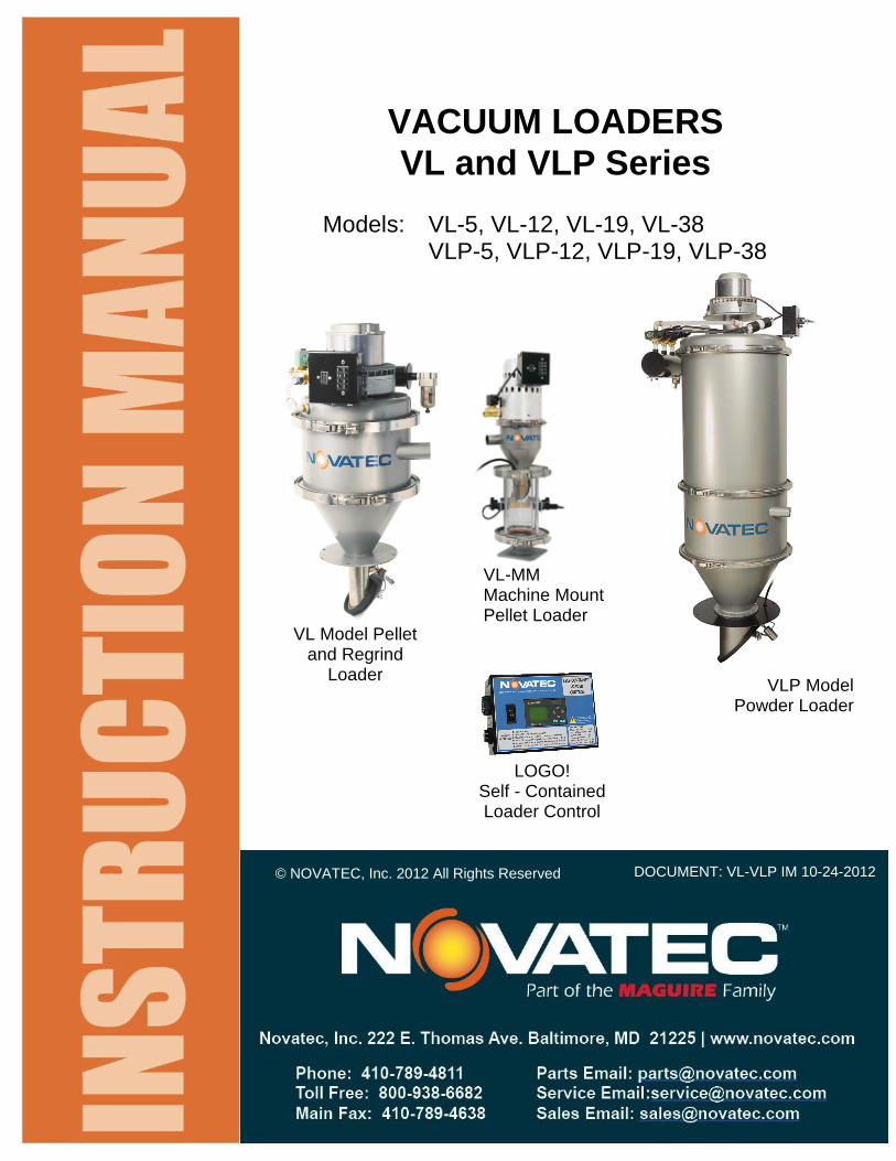
Models: VL-5, VL-12, VL-19, VL-38
VLP-5, VLP-12, VLP-19, VLP-38
VACUUM LOADERS
VL and VLP Series
DOCUMENT: VL-VLP IM 10-24-2012
VL Model Pellet and Regrind
Loader VLP Model
Powder Loader
VL-MM Machine Mount Pellet Loader
LOGO! Self - Contained Loader Control
© NOVATEC, Inc. 2012 All Rights Reserved

© NOVATEC, Inc, 2012 All Rights Reserved VL-VLP IM 10-24 2012
2
NOTES:
Please record the following information, which is specific to this piece of equipment, in the space provided. Our Parts/Service Department will need these numbers to properly respond to any of your requests.
Instruction Manual: VL-VLP IM 10-24-12 Model #:___________________________ Serial #____________________________
DISCLAIMER: NOVATEC, Inc. shall not be liable for errors contained in this Instruction Manual nor for misinterpretation of information contained herein. NOVATEC shall not, in any event, be held liable for any special, indirect or consequential damages in connection with performance or use of this information.

© NOVATEC, Inc, 2012 All Rights Reserved VL-VLP IM 10-24 2012
3
Table of Contents 1-PRINCIPLE OF OPERATION ...................................................................................................... 4
2-UNPACKING AND INSPECTION ................................................................................................ 4
3-VL SPECIFICATIONS .................................................................................................................. 5
4-VLP SPECIFICATIONS ............................................................................................................... 6
5-LOADER INSTALLATION ........................................................................................................... 7
5.1 CONTROL INSTALLATION .............................................................................................................. 7
6-OPERATION OVERVIEW ........................................................................................................... 8
7-NO-LOAD ALARM FEATURE ...................................................................................................... 8
8-ADJUSTING the LOADER CONTROL ........................................................................................ 9
8.1 TO CHANGE LOADING PARAMETERS ........................................................................................ 9
8.2 PARAMETERS EXPLANATION ....................................................................................................... 9
9-INITIAL START UP .................................................................................................................... 11
9.1 CONVEYING NOTES ....................................................................................................................... 11
10-MAINTENANCE ....................................................................................................................... 12
10.1- VL Series - FLAT FILTER CLEANING: ...................................................................................... 12
10.2- VLP Series - CARTRIDGE FILTER CLEANING: ..................................................................... 13
10.3- VACUUM MOTOR BRUSH REPLACEMENT ........................................................................... 14
10.4- VL-12 through VL-38 and VLP-12 through VLP-38 MOTOR BRUSH REPLACEMENT .. 15
10.5- VL-5, VLP-5 MOTOR BRUSH REPLACEMENT ...................................................................... 15
10.6- MOTOR REPLACEMENT ............................................................................................................ 16
11-TROUBLESHOOTING ............................................................................................................. 17
12-WARRANTY – NOVATEC, INC. - Effective Date 6-12-2012 ................................................... 18
13- ELECTRICAL DRAWINGS ..................................................................................................... 19
14-VL SERIES LOADER PARTS LIST ......................................................................................... 21
15-VLP SERIES LOADERS PARTS LIST .................................................................................... 22
© NOVATEC, Inc, 2012 All Rights Reserved VL-VLP IM 10-24 2012
4
1- PRINCIPLE OF OPERATION
NOVATEC vacuum loaders utilize a powerful motor to create a vacuum, which draws material into a chamber. After the load time setting has expired, the vacuum motor is turned off and the negative pressure in the chamber is relieved. Material in the chamber then falls through the bottom, past the flapper while compressed air is pulsed through the filter to dislodge any contaminants or fines that may have accumulated. This cycle is repeated as many times as necessary, until the unit is shut off by the rise of the conveyed material in the area below the loader which trips the level switch, removing the ‘demand’ signal. Machine mounted units do not have a demand switch actuated by the discharge flapper valve, but instead utilize a remote sensor for demand. The sensor is attached to an adjustable bracket that slides along the length of a clear sight tube serving as a Just-in-Time (JIT) material hopper mounted between the machine throat and loader discharge. The sensor height on the site tube determines the level of material that triggers a demand for more material and a new load cycle. The sensor may be either a capacitance style, with sensitivity adjustment, or a pair of photoelectric sensors, an emitter and a receiver. The bottom flange is normally supplied undrilled to allow the customer to drill the appropriate mounting pattern for a particular machine.
2- UNPACKING AND INSPECTION NOVATEC Vacuum loaders are shipped complete, with all controls for automatic operation. The only utilities required are a 115 or 220 volt power supply (depending on voltage of control), and clean, dry compressed air at approximately 80 PSI. After receipt of the unit, completely inspect it for damage. Although the units are packaged securely, vibration and mishandling during transit can cause damage.

© NOVATEC, Inc, 2012 All Rights Reserved VL-VLP IM 10-24 2012
5
3- VL SPECIFICATIONS NOVATEC VL Series vacuum loaders are completely automatic self-cleaning vacuum loaders designed to convey virgin pellets and regrind materials from storage containers to drying hoppers or directly to process machines. Machine Mount Models with a sight glass are available as standards for all VL and VLP models. Each unit is shipped complete with all controls for immediate operation, and include a hardware package. The hardware package includes 15 feet of flexible vacuum hose, hose clamps and a material pick up lance.
Options: Additional tubing and fittings (Rigid tubing, elbows, bolted couplers, etc.) Alternate sight glass sizes are available for most Machine Mount models. 220/1/50-60 Volt Power Brushless Motor for VL-38 Accessories:
asVR-MM-8
asVR-MM-12
asVR-MM-16
8 lb. Sight Glass Conversion Kit
12 lb. Sight Glass Conversion Kit
16 lb. Sight Glass Conversion Kit
Conversion Kit to increase sight glass capacity for VL & VLP-12 and -19 models. Includes base, borosilicate glass, top adapter plate and discharge valve.
© NOVATEC, Inc, 2012 All Rights Reserved VL-VLP IM 10-24 2012
6
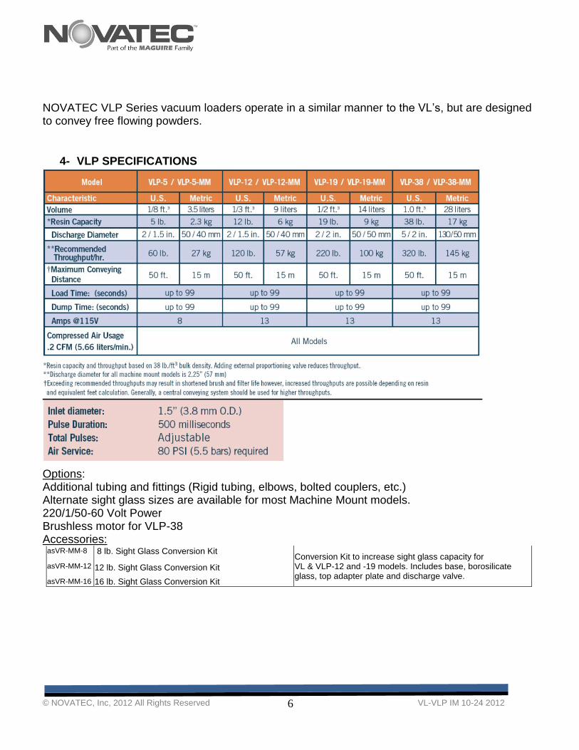
NOVATEC VLP Series vacuum loaders operate in a similar manner to the VL’s, but are designed to convey free flowing powders.
4- VLP SPECIFICATIONS
Options: Additional tubing and fittings (Rigid tubing, elbows, bolted couplers, etc.) Alternate sight glass sizes are available for most Machine Mount models. 220/1/50-60 Volt Power Brushless motor for VLP-38 Accessories:
asVR-MM-8
asVR-MM-12
asVR-MM-16
8 lb. Sight Glass Conversion Kit
12 lb. Sight Glass Conversion Kit
16 lb. Sight Glass Conversion Kit
Conversion Kit to increase sight glass capacity for VL & VLP-12 and -19 models. Includes base, borosilicate glass, top adapter plate and discharge valve.

© NOVATEC, Inc, 2012 All Rights Reserved VL-VLP IM 10-24 2012
7
5- LOADER INSTALLATION Mount the loader body to the hopper lid, positioning it so that the material inlet is directed towards the material pick up point. Make sure the dump valve flapper plate has enough room to freely operate. Secure the loader to the hopper lid with captive bolts or clamps to ensure a safe installation with no chance of hardware vibrating loose. On machine mounted units, the bottom flange is usually supplied undrilled to allow a range of mounting patterns and hardware choices. A gasket is used to provide a tight seal between the loader base and the machine throat. Ensure a tight seal when securing the loader to the hopper or machine. This is particularly important for VLP units that will be conveying powder. The conveying line should be horizontal and/or vertical, using a 90 degree radius bend for directional changes, and it should be as direct as possible with no slope. All line connections should be vacuum tight. Rigid conveying tubing should be properly supported by the installer to provide a safe and secure installation. Use flexible material handling hose to connect the material pick-up lance or vacuum take-off box to the conveying line. The flexible hose should be only as long as needed, since excess hose will reduce loader efficiency. Connect a clean, dry compressed air supply line to the filter on the accumulator tank. The minimum requirement for effective filter cleaning is 80 PSI. CAUTION:
1. DO NOT EXCEED 125 PSI. COMPRESSED AIR. 2. PROPER SUPPORT OF ALL CONVEYING LINES AND A SECURE MOUNTING OF THE
HOPPER LOADER IS NECESSARY FOR A SAFE INSTALLATION.
5.1 CONTROL INSTALLATION The VL/VLP control box may be mounted in a location that is convenient for the operator, making sure that the control cable will extend to the junction box on the lid of the hopper loader. The power and connections cables should be carefully routed away from hot components or surfaces and away from high voltage lines that may produce undesirable electrical noise. Connect the control to the power source as required by the nameplate located on the side of the loader control box.
CAUTION: FOLLOW ALL NATIONAL and LOCAL ELECTRICAL CODES.
To machine or
other destination
VL or VLP Vacuum Loader
Loader
Control
Power Source
Flex Hose (supplied) and/or
rigid tubing
Pick-up Lance
Material Destination
Material Source
Compressed Air

© NOVATEC, Inc, 2012 All Rights Reserved VL-VLP IM 10-24 2012
8
6- OPERATION OVERVIEW
Pressing the OFF/ON switch will start the vacuum motor, creating vacuum suction through the conveying line, to the pick-up wand and the loader will load material into the loader’s vacuum chamber for an adjustable length of time. When the load time is completed, the vacuum motor will stop, allowing material in the vacuum chamber to relax and flow through the dump valve to the hopper or machine below. Simultaneously, the filter will be cleaned with pulses of compressed air blown down through the filter media. The dump time and the number of pulses used to clean the filter are adjustable. Load and dump/pulse cycles will continue until the drying hopper, surge bin or machine hopper below the loader is full, at which time loaded material will either hold the dump valve flapper open or trigger a sensor, placing the system in a holding mode. As material is consumed by the process and flows from the hopper below the loader, the material level will fall, the flapper will close or sensor will be uncovered, and the loader will begin to load automatically again, to keep the hopper full. NOTE: Once the vacuum motor starts, a loading cycle will continue through the load, dump, and pulse cycles, even if the dump flapper is held open. The loader control senses a full condition only after the completion of the dump/pulse cycle.
7- NO-LOAD ALARM FEATURE The No-Load alarm feature monitors the dump flapper on hopper mounted units, to assure it opens as it should by material discharging after loading. If the flapper does not open 3 seconds after the dump sequence has started, the no load alarm on the side of the control will sound. On machine mounted units, the No-Load alarm monitors the photo-eye demand sensor on the glass base to determine if loaded material interrupts the sensor path. The alarm horn can be silenced with the silence pushbutton on the side of the control.

© NOVATEC, Inc, 2012 All Rights Reserved VL-VLP IM 10-24 2012
9
No-Load Alarm Horn
Alarm Horn Silencer
8- ADJUSTING the LOADER CONTROL
The VL and VLP series loaders from NOVATEC employ a Siemens brand, model LOGO! Mini-PLC Control for loading functions. The control is housed in a rugged enclosure and is factory programmed for functions related to vacuum loading. NOTE: The user may adjust certain parameters of the control to fine tune their loader’s operation, but changing settings other than those listed can damage control operation. The control is equipped with a small LCD screen that displays operating and programming prompts, plus pushbuttons to aid in selecting parameters and making changes. A No-Load alarm horn is located on the side of the enclosure along with a silence button. Instructions listed here are repeated on the control face for ease of use.
8.1 TO CHANGE LOADING PARAMETERS
Press ESC key.
Select SET PARAM and press OK.
Use arrow buttons to select parameter from this list.
Press OK. Make changes by selecting desired digit.
Increase or decrease setting with up/down arrows.
When complete, press OK. Press ESC twice to exit.
8.2 PARAMETERS EXPLANATION
Motor-on Time (B3 T), measured in seconds, is the amount of time the vacuum motor will run to load material into the loader’s vacuum chamber. Too little time will result in insufficient loading and will shorten motor life with too many start/stop cycles. Too much time will pack the loader full of material, prematurely blinding the filter and possibly clogging the conveying line. This setting should be adjusted over the course of several normal loading cycles to ‘just fill’ (but not overfill) the loader’s vacuum chamber. NOTE: VLP series powder loaders include an extended body to house the cartridge filter(s). Loaded material should not be allowed to be filled up into this extended hopper area. It is intended only as a housing for the filter cartridges(s), not a hopper for collecting loaded material.
Dump Alarm Time (B4 T), measured in seconds, is the pause time between the completion of Motor On Time and movement of the discharge flapper. This time setting drives the No-Load alarm feature by determining if material was actually loaded and dumped, but prevents false alarms from slow moving material discharge. This setting may be increased if nuisance alarms occur from slow moving material (IE: fluffy regrind) that is typically slow to evacuate the loader. It may be decreased if the No-Load alarm is too slow to respond to your material supply needs (IE: frequent shortages of material flow).
PARAMETERS: Motor-on Time B3 T Dump Alarm Time B4 T Dump Time B5 T Blowback Count B11 Prop Valve A Time B16 T Prop Valve B Time B18 T
© NOVATEC, Inc, 2012 All Rights Reserved VL-VLP IM 10-24 2012
10
Dump Time (B5 T), measured in seconds, is the setting for how long the loader will remain at rest after loading, to allow material to evacuate the loader. This setting may be increased in case the material is very slow moving and/or to provide an extended OFF period for the loader (IE: if the loader is used to off-load a granulator).
Blowback Count (B11), is the number of blowback pulses that occur following loading for the compressed air system to clean the filter(s). Compressed is blown down through the filters in the opposite direction of the vacuum loading air, blasting collected fines and dust from the filter media and into the loaded material. Typically, more blasts will clean the filters better and extend the time between manual filter cleaning and provide more efficient loading. However, compressed air is expensive and too many blasts waste this resource. Also, blasts that extend beyond the dump sequence may actually be strong enough to create dusting issues around the loader.
Prop Valve A Time (B16 T) and Prop Valve B Time (B18 T), each measured in seconds, is the amount of time dedicated to the loading of two materials with the use of an optional, external Proportioning Valve. The Proportioning Valve is installed on the material inlet of the VL or VLP loader (see separate instructions, accompanying the valve) and shuttles internal plungers between allowing A (typically virgin) and B (typically regrind) materials to be loaded during the course of the Motor-On time. Time setting A counts down during loading at which time the valve switches to allow the B time setting to take over. A and B will repeat until the Motor-on time expires. Short A and B time settings will allow multiple ‘layers’ of virgin and regrind materials to be loaded for rough ‘mixing’ of the two materials during loading. However, short cycles require each flow of material to start, then stop, possibly resulting in very little material being conveyed to the loader. Trial and error settings of Motor-on time and A and B times are suggested to optimize these settings.

© NOVATEC, Inc, 2012 All Rights Reserved VL-VLP IM 10-24 2012
11
9- INITIAL START UP For optimum loader operation, adjust the load time so that the vacuum chamber is almost
completely full at the end of the load cycle. Do not allow the chamber to overfill. NOTE: VLP series powder loaders include an extended body to house the cartridge filter(s). Loaded material should not be allowed to be filled up into this extended hopper area. It is intended only as a housing for the filter cartridges(s), not a hopper for collecting loaded material. Adjust the dump time so that it is only 1 to 2 seconds longer than the time necessary to completely empty the chamber. The number of pulses needed to clean the filter depends upon the material being conveyed. Clean, virgin pellets require minimum filter cleaning while very dusty regrind or powder may necessitate a maximum filter cleaning sequence. Adjust the pulse cycle so the filter(s) remain clean. A mid range setting is suggested as a starting point.
9.1 CONVEYING NOTES Materials, which contain a large percentage of fines or powder, may require increased filter cleaning. This can be achieved by the following technique.
A) Set the load time to minimum. B) Set the dump and pulse time to maximum. C) Increase the compressed air pressure. CAUTION: DO NOT EXCEED 125 PSI.

© NOVATEC, Inc, 2012 All Rights Reserved VL-VLP IM 10-24 2012
12
Remove Clamping Ring
Carefully Remove Motor
Lid
10- MAINTENANCE
CAUTION: Disconnect electrical power and compressed air supplies before any type of
loader maintenance. Typical maintenance for self-contained vacuum loaders consists of two main areas: Filter cleaning and motor brush replacement.
10.1- VL Series - FLAT FILTER CLEANING: VL Series loaders are typically used for conveying virgin pellets and/or regrind. The amount of dust within the conveyed materials will determine the frequency of necessary manual filter cleaning. NOTE: Although the blowback system of the VL loaders will extend the operational life of the filter media, it cannot be relied upon alone. Frequent checks of the filter accompanied by thorough manual cleanings are required, in addition to cleanings during material changes to prevent cross contamination. The filter media may be removed for inspection and cleaning by unclamping the ring clamp of the lid, directly below the motor. If necessary, unplug the control cable and disconnect the air line.
Carefully remove the motor lid and expose the flat filter directly below the lid. The filter may now be removed for inspection and cleaning.
Vacuum cleaning the bottom of the filter is recommended to remove collected resin debris, dust and fines. If compressed air is used, be sure to wear goggles and blow from the top (coarse screen side) of the filter down through the filter media. Never bang the filter against a hard surface to dis-lodge debris. Distortion of the media or sealing ring can result. Once clean, thoroughly inspect the filter for severe wear, holes, tears and material abrasion. Any break in the filter media indicates the need for new filter. Do not attempt to repair the media. Remember that the filter protects the vacuum motor and holes or any kind of leakage through the filter can allow material to pass into and through the motor, severely shortening the motor’s life, possibly creating a fire hazard and sending material dust into the air around the loader. In addition, examine the sealing ring around the filter media. This ring provides the vacuum seal between the motor lid, the filter and the loader body. The ring must be smooth, clean and intact to provide a suitable seal for vacuum sealing. Replace the filter if the seal is not in perfect shape. Once cleaning/inspection is complete, the filter may be reinstalled by placing it on the flat rim of the loader body (cloth DOWN and coarse screen UP) and placing the motor lid down upon it and centering the filter between the two. Replace the clamp and tighten. With newly installed filters, the clamp may need to be adjusted to provide a vacuum-tight and mechanically firm seal.

© NOVATEC, Inc, 2012 All Rights Reserved VL-VLP IM 10-24 2012
13
Vacuum Cleaning of filter(s) exterior is recommended
If compressed air is used, blow down through inside of to
outside.
VLP Cartridge Filter
10.2- VLP Series - CARTRIDGE FILTER CLEANING: VLP Series loaders are typically used for conveying free flowing powder materials. For this task, they are equipped with higher capacity cartridge filters. The amount of dust within the conveyed materials will determine the frequency of necessary manual filter cleaning. NOTE: Although the blowback system of the loader will extend the operational life of the filter media, it cannot be relied upon alone. Frequent checks of the filter accompanied by thorough manual cleanings are required, in addition to cleanings during material changes to prevent cross contamination. CAUTION: Disconnect electrical power and compressed air supplies before any type of loader maintenance. The cartridge filter(s) may be removed for inspection and cleaning by unclamping the ring clamp of the lid, directly below the motor. If necessary, unplug the control cable and disconnect the air line. Carefully remove the motor lid and expose the cartridge filter mounting plate directly below the lid. The cartridge filter mounting plate, with the cartridge filter(s) installed below it may now be carefully removed for inspection and cleaning. If only light cleaning of the cartridge filter(s) is required, the filter(s) may remain installed onto the filter plate and cleaned in place. However, full removal and thorough cleaning of each cartridge is highly recommended. Vacuum clean the outside of the filter(s) to remove collected resin debris, dust and fines. If compressed air is used, be sure to wear goggles and blow from the inside of the filter(s) down through and out of the filter media. Never bang the filter(s) against a hard surface to dis-lodge debris. Distortion of the media or sealing ring(s) can result.
Once clean, thoroughly inspect the filter(s) for severe wear, holes, tears and material abrasion. Any break in the filter media indicates the need for new filter cartridge. Do not attempt to repair the media. Remember that the filter protects the vacuum motor and holes or any kind of leakage through the filter can allow material to pass into and through the motor, severely shortening the motor’s life, possibly creating a fire hazard and sending material dust into the air around the loader. In addition, examine the sealing ring around the top of each filter cartridge. This seal provides the vacuum seal between the cartridge filter and the filter mounting plate and must be fully intact. Replace the cartridge if this seal is not perfect. NOTE: Polyester filter cartridges, supplied as standard with all NOVATEC VLP loaders are washable to extend their life. Use only clean water, sprayed at medium pressure through the media from the inside out to remove dust and debris. The cartridge must be thoroughly dried before being put back into service. A commercial drying device may be used, or the cartridge can be thoroughly drained of water and water droplets and left to dry for no less than 24 hours. Once each cartridge is cleaned, completely dry and inspected, it may be re-installed onto the filter
© NOVATEC, Inc, 2012 All Rights Reserved VL-VLP IM 10-24 2012
14
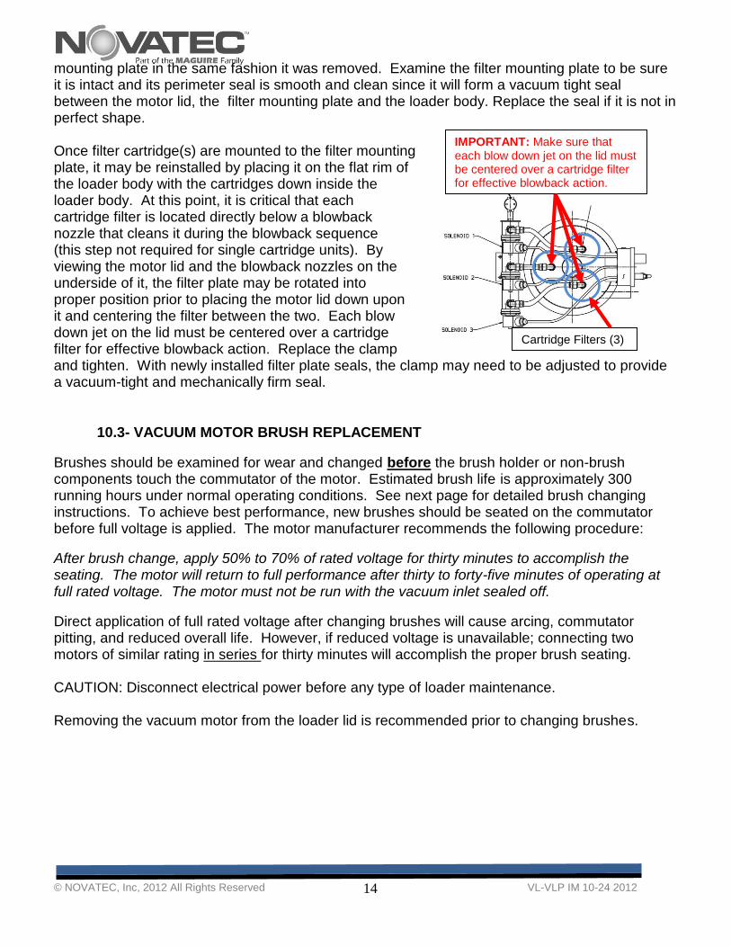
IMPORTANT: Make sure that each blow down jet on the lid must be centered over a cartridge filter for effective blowback action.
Cartridge Filters (3)
mounting plate in the same fashion it was removed. Examine the filter mounting plate to be sure it is intact and its perimeter seal is smooth and clean since it will form a vacuum tight seal between the motor lid, the filter mounting plate and the loader body. Replace the seal if it is not in perfect shape. Once filter cartridge(s) are mounted to the filter mounting plate, it may be reinstalled by placing it on the flat rim of the loader body with the cartridges down inside the loader body. At this point, it is critical that each cartridge filter is located directly below a blowback nozzle that cleans it during the blowback sequence (this step not required for single cartridge units). By viewing the motor lid and the blowback nozzles on the underside of it, the filter plate may be rotated into proper position prior to placing the motor lid down upon
it and centering the filter between the two. Each blow down jet on the lid must be centered over a cartridge filter for effective blowback action. Replace the clamp and tighten. With newly installed filter plate seals, the clamp may need to be adjusted to provide a vacuum-tight and mechanically firm seal.
10.3- VACUUM MOTOR BRUSH REPLACEMENT Brushes should be examined for wear and changed before the brush holder or non-brush components touch the commutator of the motor. Estimated brush life is approximately 300 running hours under normal operating conditions. See next page for detailed brush changing instructions. To achieve best performance, new brushes should be seated on the commutator before full voltage is applied. The motor manufacturer recommends the following procedure:
After brush change, apply 50% to 70% of rated voltage for thirty minutes to accomplish the seating. The motor will return to full performance after thirty to forty-five minutes of operating at full rated voltage. The motor must not be run with the vacuum inlet sealed off.
Direct application of full rated voltage after changing brushes will cause arcing, commutator pitting, and reduced overall life. However, if reduced voltage is unavailable; connecting two motors of similar rating in series for thirty minutes will accomplish the proper brush seating. CAUTION: Disconnect electrical power before any type of loader maintenance. Removing the vacuum motor from the loader lid is recommended prior to changing brushes.

© NOVATEC, Inc, 2012 All Rights Reserved VL-VLP IM 10-24 2012
15
10.4- VL-12 through VL-38 and VLP-12 through VLP-38 MOTOR BRUSH
REPLACEMENT 1. Remove metal band from mid-section of motor
by unscrewing the sheet metal screw in the side. Pull the cover back away from the motor, sliding it gently over the wires that pass through the grommet opposite the screw. The brushes are visible inside, towards the base of the motor.
2. Remove the screws on each side of each brush that hold the brush retaining clip. A screwdriver may be inserted through the holes in the top of the motor to aid in this process. Remove the clip carefully to be sure nothing drops into the motor fan housing opening towards the middle of the motor.
3. The brush is contained within a plastic holder and is connected to the electrical lead through a spade lug terminal. Gently pull or pry the lug off the brush holder taking care to not damage the lead or the lug.
4. New brush may be installed by reversing the above steps. When securing the brush in the motor housing with the retainer clip, be sure the brush is properly nested in the motor frame before securing the screws.
5. Repeat steps 2 thru 4 for the adjacent brush. 6. Replace the metal band onto the mid-section, while carefully routing the wires through the
grommet. It is notched to fit in only one position. Secure with single screw. Reinstall cover over motor.
10.5- VL-5, VLP-5 MOTOR BRUSH REPLACEMENT Remove metal cover from motor.
1. Remove plastic shield from top of motor by squeezing the top of each spring clip (A) while prying the cover up away from colored brush holder (green-120 volts, red-220 volts). Cover can be worked up and off, one side at a time. Take care to not break small positioning stubs and grip tabs (B) on the plastic cover.
2. Remove two black screws that hold down brush retaining clip. Once removed, brush will be released, but still connected to the short electrical lead. Use caution to avoid damaging the lead.
3. Pry electrical lug out of the brush holder in the direction of the motor armature, taking care to not separate the wire from the lug.
4. New brush may now be connected to the electrical lead by reversing this procedure. Push the lug firmly between the brass brush holder and its plastic housing.
1 2
3
4
A
B
1
2
3
4
5
© NOVATEC, Inc, 2012 All Rights Reserved VL-VLP IM 10-24 2012
16
5. Reinstall new brush into motor housing and replace the retaining clip. Be sure to properly
seat the nub on the bottom of the brush holder into the motor housing groove. 6. Repeat steps 2 thru 5 for the adjacent brush. 7. Replace the plastic shield on top of the motor by aligning it on top of the motor and pushing
down until the spring clips on each brush snap into place. 8. Reinstall metal cover over motor.
10.6- MOTOR REPLACEMENT Disconnect all power from the loader system. Disconnect the motor wiring from the junction box located on the lid of the chamber. Remove the three springs that clamp the motor to the lid. The motor can now be removed. Check the gasket that seals the vacuum motor to the lid and renew if necessary. Reverse the above steps to install the vacuum motor. Connect power and verify that the system is operating correctly.

© NOVATEC, Inc, 2012 All Rights Reserved VL-VLP IM 10-24 2012
17
11- TROUBLESHOOTING
Most loader problems are a result of a dirty filter, air leaks or improper adjustments. These items should be checked before assuming equipment failure.
Problem Investigate Motor will not run A, B, C, H, and L Inadequate or no vacuum D, E, F, G, J Inadequate or no material flow D, E, F, and G, I, K Motor runs but proportioning solenoid not operating L
CHECK CONDITIONS SOLUTION A. Power Supply No voltage or voltage incorrect Check incoming power supply
voltage at outlet B. Stop/Start Switch No voltage through switch Replace switch
C. Vacuum motor No voltage at motor See A,B, & L
D. Filter Filter dirty Replace filter
(Also see G & J) E. Air Ducts Obstructed Remove obstruction F. Leaks in system Air leaking into system Replace gaskets & repair leaks as necessary G. Blowback air Increase pressure
pressure incorrect Low pressure (not to exceed 125 psi)
H. Limit switch No voltage through switch Replace switch I. Load Time Chamber not filling sufficiently Increase load time
Chamber over-filling Decrease load time J. Pulse rate Insufficient to clean filter Increase rate K. Dump time Insufficient to allow complete Increase time
emptying of chamber L. Pulse solenoid Correct voltage at solenoid Replace solenoid
© NOVATEC, Inc, 2012 All Rights Reserved VL-VLP IM 10-24 2012
18
12- WARRANTY – NOVATEC, INC. - Effective Date 6-12-2012
NOVATEC, INC. offers COMPREHENSIVE PRODUCT WARRANTIES on all of our plastics auxiliary equipment. We warrant each NOVATEC manufactured product to be free from defects in materials and workmanship, under normal
use and service for the periods listed under “Warranty Periods”. The obligation of NOVATEC, under this warranty, is limited to repairing or furnishing, without charge, a similar part to replace any part which fails under normal use due to a material or workmanship defect, within its respective warranty period. It is the purchaser’s responsibility to provide NOVATEC with immediate written notice of any such suspected defect. Warranted replacement parts are billed and shipped freight pre-paid. The purchaser must return the suspect defective part, freight prepaid and with identifying documentation to receive full credit for the part returned. NOVATEC shall not be held liable for damages or delay caused by defects. No allowance will be made for repairs or alterations without the written consent or approval of NOVATEC. The provisions in equipment specifications are descriptive, unless expressly stated as warranties. The liability of NOVATEC to the purchaser, except as to title, arising out of the supplying of the said equipment, or its use, whether based upon warranty, contract or negligence, shall not in any case exceed the cost of correcting defects in the equipment as herein provided. All such liability shall terminate upon the expiration of said warranty periods. NOVATEC shall not in any event be held liable for any special, indirect or consequential damages. Commodities not manufactured by NOVATEC are warranted and guaranteed to NOVATEC by the original manufacturer and then only to the extent that NOVATEC is able to enforce such warranty or guaranty. NOVATEC, Inc. has not authorized anyone to make any warranty or representation other than the warranty contained here. Non-payment of invoice beyond 90 days will invalidate the warranty. A renewed warranty can be purchased directly from NOVATEC. Please note that we always strive to satisfy our customers in whatever manner is deemed most expedient to overcome any issues in connection with our equipment.
Warranty Period: Note: All warranty periods commence with the shipment of the equipment to the customer.
VL & VLP Series Loaders = 1 Year
Exclusions: Routine maintenance/replacement parts are excluded from the warranty. These include, but are not limited to: hoses, desiccant, filters, filter elements, wiper seals, gaskets, dew point sensors, infrared lamps, motors, internal solenoids, fuses and motor brushes. Use with abrasive materials will void the warranty of any standard product. Wear resistant options may be available to extend usable service life with abrasive materials. NOVATEC reserves the right to limit the warranty if the customer installs replacement parts that do not meet the specifications of the original parts supplied by NOVATEC.
*Specific Exclusions: 1. NovaDrier warranty is void if coalescing filters are not replaced on a 6-month or yearly basis (per instruction manual) and/or membrane has been exposed to ozone. 2.Touch screen controls on NovaWheel dryers have a 2-year warranty. All other controls have a 1-year warranty 3. NovaVac Dryer -The ability of the canisters to hold vacuum will be compromised if the vacuum seal edge is damaged from mishandling. We do not warranty canisters damaged from improper handling. We do, however, warranty the seals. 4. LOAD CELLS on our WSB’s are covered by NOVATEC standard warranty as long as they have not been damaged from improper handling. 5. Velocity Control Valve warranty is voided if unit is placed in direct material flow.
This warranty shall not apply to equipment: 1. Repaired or altered without written approval of NOVATEC unless such repair or alteration was, in our judgment, not responsible for the failure 2. Which has been subject to misuse, negligence, accident or incorrect wiring by others 3. Warranty is void if processing rates exceed manufacturer-recommended levels or if damage is caused by ineffective power isolation and/or power spikes/sags or incorrect installation.
NOTE: All conditions and content of this warranty are subject to changes without notice.
© NOVATEC, Inc, 2012 All Rights Reserved VL-VLP IM 10-24 2012
19
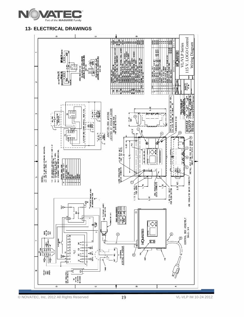
13- ELECTRICAL DRAWINGS
VL
/VL
P S
erie
s
11
5 V
. L
OG
O C
on
tro
l
Wir
ing
Dia
gra
m

© NOVATEC, Inc, 2012 All Rights Reserved VL-VLP IM 10-24 2012
20
VL
/VL
P S
erie
s
23
0 V
. L
OG
O C
on
tro
l
Wir
ing
Dia
gra
m

© NOVATEC, Inc, 2012 All Rights Reserved VL-VLP IM 10-24 2012
21
14- VL SERIES LOADER PARTS LIST
04533 Brush set for #04250 Vacuum Motor For VL-5 Loader
50036 Carbon Brushes, set of two Carbon Brushes, set of two, for motor part #50033 & 01381, for VL-12, -19-38
04505 Deflector Assembly, Articulated, 1.5” Deflector assembly for 1.5" line size.
08989 Dump Flapper for MM, Aluminum Dump Flapper, Aluminum (flapper only) for Machine Mount Dump Flapper assembly (#09662)
01-1664 Dump Flapper for MM, SS Dump Flapper, Stainless Steel (flapper only) for Machine Mount Dump Flapper assembly (#09662)
09662 Dump Valve assembly for Machine Mount, with Flapper
Dump Valve assembly with Aluminum Flapper, for Machine Mount assemblies.
02778 Dump Valve Flapper, 2" Aluminum
08598 Dump Valve Flapper, 2" SS
02155 Dump Valve Flapper, Optional SS, for 5” dump valve
Optional Stainless Steel Flapper for the 5" dump valve used on VL-38
50210 Dump Valve Flapper, Standard Aluminum, for 5” dump valve
Standard Aluminum Flapper for the 5" dump valve used on VL-38
04529 Filter Assembly 6.75" dia, polyester Standard Filter Assembly, 6.75" dia, Polyester filter with expanded metal backing and molded rubber gasket.
04544 Filter Assembly, 11.5" dia, Polyester Standard Filter Assembly, 11.5" dia, Polyester filter with expanded metal backing and molded rubber gasket.
05373 Filter Assembly, 17.5" dia, 400 mesh Nylon
Optional Filter Assembly, 17.5" dia, Tight-Weave 400 mesh Nylon filter with expanded metal backing clamped together with a rubber coated u channel perimeter seal.
04545 Filter Assembly, 17.5" dia, Polyester Standard Filter Assembly, 17.5" dia, Polyester filter with expanded metal backing and molded rubber gasket.
02724 Gasket seal, 3", Optional High Heat Silicone Red, (500 degrees F)
Optional Silicone High-Heat (500 degree) Gasket, 3" (nominal). Discharge Gasket for the 2" dump valve.
01695 Gasket seal, 3", Standard Neoprene Black, (200 degrees F)
Standard Neoprene (200 degree) Gasket, 3" (Nominal). Standard Discharge Gasket for the 2" dump valve.
02106 Gasket seal, 5", Optional High Heat Silicone Red, (500 degrees)
Optional High-Heat (500 degree) Discharge Gasket for the VL-38 5" dump valve, 6.875" diameter
50026 Gasket seal, 5", Standard Neoprene black, (200 degrees)
Standard Neoprene (200 degree) Discharge Gasket for the VL-38 5" dump valve, 6.875" diameter
50245 Mercury Tilt Switch
09029 PLC, LOGO, 230RC, 115-230vac
08758 Sight Glass, Tube, 3.5" diameter x 8" long Tube Borosilicate Glass, 3.5" OD, 8" Long (2 lb.)
09007 Solid State Relay, 115vac
04250 Vacuum Motor, 115 volts AC For VL-5
50033 Vacuum Motor. 115 Volts AC For VL-12,-19,-38.
09758 VL Controller, complete, 115 vac VL control box, complete with PLC control, and interconnect cable with 8 pin plug.
097581 VL Controller, complete, 230 vac VL control box, complete with PLC control, and interconnect cable with 8 pin gang plug.
asVR-MM-8
asVR-MM-12
asVR-MM-16
8 lb. Sight Glass Conversion Kit
12 lb. Sight Glass Conversion Kit
16 lb. Sight Glass Conversion Kit
Conversion Kit to increase sight glass capacity for VL & VLP-12 and -19 models. Includes base, borosilicate glass, top adapter plate and discharge valve.
Part #: Description Additional Information

© NOVATEC, Inc, 2012 All Rights Reserved VL-VLP IM 10-24 2012
22
15- VLP SERIES LOADERS PARTS LIST
04533 Brush set for #04250 Vacuum Motor For VLP-5
50036 Carbon Brushes, set of two Carbon Brushes, set of two, for motor part #50033 & 01381. VLP-12, -19, -38
04505 Deflector Assembly, Articulated, 1.5” Deflector assembly for 1.5" line size.
08989 Dump Flapper for MM, Aluminum Dump Flapper, Aluminum (flapper only) for Machine Mount Dump Flapper assembly (#09662)
01-1664 Dump Flapper for MM, SS Dump Flapper, Stainless Steel (flapper only) for Machine Mount Dump Flapper assembly (#09662)
09662 Dump Valve assembly for Machine Mount, with Flapper Dump Valve assembly with Aluminum Flapper, for Machine Mount assemblies.
02778 Dump Valve Flapper, 2" Aluminum
08598 Dump Valve Flapper, 2" SS
02155 Dump Valve Flapper, Optional SS, for 5” dump valve Optional Stainless Steel Flapper for the 5" dump valve used on VLP-12, -19, -38
50210 Dump Valve Flapper, Standard Aluminum, for 5” dump valve
Standard Aluminum Flapper for the 5" dump valve used on VLP-12, -19, -38.
11644 Filter Cartridge - 4" O.D. X 10" long (3) required for VLP-12 and VLP-19 (1) required for VLP-5
11645 Filter Cartridge - 6" O.D. x 20" long (3) required For VLP-38
KIT-S0018 Filter Cartridge Kit - Includes: (3) of part #11645 Filter Cartridge, 6" OD X 3.5" ID x 20"Lg, Polyester W/PTFE
For VLP-38
KIT-S0016 Filter Kit, includes three (3) of part #11644 Filter Cartridge
Kit includes three (3) of part #11644, Filter Cartridge, 4 OD X 2.5 ID X 10Lg, Polyester W/PTFE, 1 Micron. For VLP-12, -19
02724 Gasket seal, 3", Optional High Heat Silicone Red, (500 degrees F)
Optional Silicone High-Heat (500 degree) Gasket, 3" (nominal). Used for a Discharge Gasket for the 2" dump valve.
01695 Gasket seal, 3", Standard Neoprene Black, (200 degree F)
Standard Neoprene (200 degree) Gasket, 3" (Nominal); Used for the Standard Discharge Gasket for the 2" dump valve.
02106 Gasket seal, 5", Optional High Heat Silicone Red, (500 degree)
Optional High-Heat (500 degree) Discharge Gasket for the 5" dump valve, 6.875" diameter
50026 Gasket seal, 5", Standard Neoprene black, (200 degree)
Standard Neoprene (200 degree) Discharge Gasket for the 5" dump valve, 6.875" diameter
50245 Mercury Tilt Switch
09029 PLC, LOGO, 230RC, 115-230vac
08758 Sight Glass, Tube, 3.5" diameter x 8" long Tube Borosilicate Glass, 3.5" OD, 8" Long
09007 Solid State Relay, 115vac
04250 Vacuum Motor, 115 volts AC For VLP-5
50033 Vacuum Motor. 115 Volts AC For VL-12,-19,-38
09758 VL Controller, complete, 115vac Replacement VL control box, complete with LOGO mini-PLC controller, line cable and plug and interconnect cable with 8 pin gang plug. 115vac operation
097581 VL Controller, complete, 230vac Replacement VL control box, complete with LOGO mini-PLC controller, line cable and plug and interconnect cable with 8 pin gang plug. 230vac operation
asVR-MM-8
asVR-MM-12
asVR-MM-16
8 lb. Sight Glass Conversion Kit
12 lb. Sight Glass Conversion Kit
16 lb. Sight Glass Conversion Kit
Conversion Kit to increase sight glass capacity for VL & VLP-12 and -19 models. Includes base, borosilicate glass, top adapter plate and discharge valve.
Part #: Description Additional Information