

vacon 20 ac drives - radion.co.il · 3.2.2Control cabling 31 3.2.3Allowed option boards in Vacon20...
164
vacon ® 20 ac drives hvac application manual
Transcript of vacon 20 ac drives - radion.co.il · 3.2.2Control cabling 31 3.2.3Allowed option boards in Vacon20...

vacon®20ac drives
hvac application manual

Document: DPD01738A1Release date: April, 2015
1.Safety 11.1Warnings 11.2Safety instructions 31.3Earthing and earth fault protection 31.4Before running the motor 5
2.Receipt of delivery 62.1Type designation code 62.2Storage 62.3Maintenance 7
2.3.1Capacitor recharge 72.4Warranty 82.5Manufacturer’s declaration of conformity 9
3.Installation 103.1Mechanical installation 10
3.1.1Vacon 20 dimensions 143.1.2Cooling 183.1.3Power losses 193.1.4EMC levels 263.1.5Changing the EMC protection class from C2 to C4 27
3.2Cabling and connections 293.2.1Power cabling 293.2.2Control cabling 313.2.3Allowed option boards in Vacon20 353.2.4Screw of cables 383.2.5Cable and fuse specifications 403.2.6General cabling rules 433.2.7Stripping lengths of motor and mains cables 443.2.8Cable installation and the UL standards 443.2.9Cable and motor insulation checks 44
4.Commissioning 464.1Commissioning steps of Vacon 20 46
5.Fault tracing 486.Vacon 20 Application Interface 54
6.1Introduction 546.2Control I / O 56
7.Control panel 587.1General 587.2Display 587.3Keypad 59
Software package: FW0208V001.vcx
1

1
7.4Navigation on the Vacon 20 control panel 617.4.1Main menu 617.4.2Reference menu 627.4.3Monitoring menu 637.4.4Parameter menu 677.4.5System menu 68
8.STANDARD application parameters 708.1Quick setup parameters (Virtual menu, shows when par. 16.2 = 1) 718.2Motor settings (Control panel: Menu PAR -> P1) 758.3Start / stop setup (Control panel: Menu PAR -> P2) 788.4Frequency references (Control panel: Menu PAR -> P3) 798.5Ramps and brakes setup (Control panel: Menu PAR -> P4) 808.6Digital inputs (Control panel: Menu PAR -> P5) 828.7Analogue inputs (Control panel: Menu PAR -> P6) 838.8Digital outputs (Control panel: Menu PAR -> P7) 848.9Analogue outputs (Control panel: Menu PAR -> P8) 868.10Fieldbus Data-Mapping (Control panel: Menu PAR -> P9) 878.11Prohibited Frequencies (Control panel: Menu PAR -> P10) 888.12Limit Supervisions (Control panel: Menu PAR -> P11) 898.13Protections (Control panel: Menu PAR -> P12) 908.14Fault autoreset parameters (Control panel: Menu PAR -> P13) 928.15PID control parameters (Control panel: Menu PAR -> P14) 938.16Motor Pre-heat (Control panel: Menu PAR -> P15) 958.17Easy usage menu (Control panel: Menu PAR -> P16) 958.18Fire mode (Control panel: Menu PAR -> P17) 968.19System parameters 98
9.Parameter descriptions 1059.1Motor settings (Control panel: Menu PAR -> P1) 1059.2Start / stop setup (Control panel: Menu PAR -> P2) 1119.3Frequency references (Control panel: Menu PAR -> P3) 1199.4Ramps & brakes setup (Control panel: Menu PAR -> P4) 1219.5Digital inputs (Control panel: Menu PAR -> P5) 1269.6Analogue inputs (Control panel: Menu PAR -> P6) 1279.7Digital outputs (Control panel: Menu PAR -> P7) 1289.8Analogue outputs (Control panel: Menu PAR -> P8) 1299.9Fieldbus Data-Mapping (Control panel: Menu PAR -> P9) 1309.10Prohibited Frequencies (Control panel: Menu PAR -> P10) 1319.11Protections (Control panel:Menu Par->P12) 1329.12Automatic reset (Control panel: Menu PAR -> P13) 1399.13PID control parameters (Control panel: Menu PAR -> P14) 1409.14Application setting (Control panel: Menu PAR->P16) 143
9.15System parameter 1449.16Modbus RTU 146
9.16.1Termination resistor 1469.16.2Modbus address area 1469.16.3Modbus process data 147
10.Technical data 15210.1Vacon 20 technical data 15210.2Power ratings 154
10.2.1Vacon 20 – Mains voltage 208-240 V 15410.2.2Vacon 20 – Mains voltage 115 V 15510.2.3Vacon 20 – Mains voltage 380-480 V 15510.2.4Vacon 20 – Mains voltage 600 V 156
10.3Brake resistors 156
1

1

safety vacon • 1
1. SAFETYONLY A COMPETENT ELECTRICIAN IS ALLOWED TO CARRY OUT THE ELECTRICAL INSTALLATION!
This manual contains clearly marked cautions and warnings which are intended for your personal safety and to avoid any unintentional damage to the product or con-nected appliances.Please read the information included in cautions and warnings carefully:
1.1 Warnings
=Dangerous voltageRisk of death or severe injury
=General warningRisk of damage to the product or connected appliances
The components of the power unit of the frequency converter are live when Vacon 20 is connected to mains. Coming into contact with this voltage is extremely dangerous and may cause death or severe injury. The control unit is isolated from the mains potential.
The motor terminals U, V, W (T1, T2, T3) and the possible brake resistor terminals - / + are live when Vacon 20 is connected to mains, even if the motor is not running.
The control I / O-terminals are isolated from the mains poten-tial. However, the relay output terminals may have a danger-ous control voltage present even when Vacon 20 is disconnected from mains.
The earth leakage current of Vacon 20 frequency converters exceeds 3.5 mA AC. According to standard EN61800-5-1, a reinforced protective ground connection must be ensured.
If the frequency converter is used as a part of a machine, the machine manufacturer is responsible for providing the machine with a main switch (EN 60204-1).
If Vacon 20 is disconnected from mains while running the motor, it remains live if the motor is energized by the process. In this case the motor functions as a generator feeding energy to the frequency converter.
24-hour support +358 (0)201 212 575 • Email: [email protected]
1

2 • vacon safety
1
After disconnecting the frequency converter from the mains, wait until the fan stops and the indicators on the display go out. Wait 5 more minutes before doing any work on Vacon 20 connections.
The motor can start automatically after a fault situation, if the autoreset function has been activated.
Tel. +358 (0)201 2121 • Fax +358 (0)201 212205

safety vacon • 3
1.2 Safety instructions
The Vacon 20 frequency converter has been designed for fixed installations only.
Do not perform any measurements when the frequency con-verter is connected to the mains.
Do not perform any voltage withstand tests on any part of Vacon 20. The product safety is fully tested at factory.
Prior to measurements on the motor or the motor cable, dis-connect the motor cable from the frequency converter.
Do not open the cover of Vacon 20. Static voltage discharge from your fingers may damage the components. Opening the cover may also damage the device. If the cover of Vacon 20 is opened, warranty becomes void.
1.3 Earthing and earth fault protectionThe Vacon 20 frequency converter must always be earthed with an earthing conduc-tor connected to the earthing terminal. See figure below:
MI1 - MI3
24-hour support +358 (0)201 212 575 • Email: [email protected]
1

4 • vacon safety
1
MI4
MI5
• The earth fault protection inside the frequency converter protects only the converter itself against earth faults.
• If fault current protective switches are used they must be tested with the drive with earth fault currents that are possible to arise in fault situations.
Tel. +358 (0)201 2121 • Fax +358 (0)201 212205

safety vacon • 5
1.4 Before running the motor
Checklist:
Before starting the motor, check that the motor is mounted properly and ensure that the machine connected to the motor allows the motor to be started.
Set the maximum motor speed (frequency) according to the motor and the machine connected to it.
Before reversing the motor shaft rotation direction make sure that this can be done safely.
Make sure that no power correction capacitors are connected to the motor cable.
NOTE! You can download the English and French product manuals with applica-ble safety, warning and caution information from www.vacon.com/downloads.
REMARQUE Vous pouvez télécharger les versions anglaise et française des ma-nuels produit contenant l’ensemble des informations de sécurité, avertisse-ments et mises en garde applicables sur le site www.vacon.com/downloads.
24-hour support +358 (0)201 212 575 • Email: [email protected]
1

6 • vacon receipt of delivery
2
2. RECEIPT OF DELIVERY
After unpacking the product, check that no signs of transport damages are to be found on the product and that the delivery is complete (compare the type designation of the product to the code below).
Should the drive have been damaged during the shipping, please contact primarily the cargo insurance company or the carrier.
If the delivery does not correspond to your order, contact the supplier immediately.
2.1 Type designation code
Figure 2.1: Vacon 20 type designation code
2.2 Storage
If the frequency converter is to be kept in store before use make sure that the ambi-ent conditions are acceptable:
Storing temperature -40…+70 °C
Relative humidity < 95%, no condensation
VACON0020- 1L- 0001- 1 +OPTIONS
Vacon 20
1L = Single phase3L = Three phases
1 =115V2 = 208 - 230V4 = 380 - 480V7 = 600 V
Output Current
Input Voltage
+OptionsEMC2QPESQFLG
+DLNL = Dutch+DLNO = Norwegian+DLPT = Portuguese+DLRU = Russian+DLSE = Swedish+DLTR = Turkish+DLUS = US Englishempty = English
Language of the documentation+DLCN = Chinese+DLCZ = Czech+DLDE = German+DLDK = Danish+DLES = Spanish+DLFI = Finnish+DLFR = French+DLIT = Italian
Input phase
Tel. +358 (0)201 2121 • Fax +358 (0)201 212205

receipt of delivery vacon • 7
2.3 Maintenance
In normal operating conditions, Vacon 20 frequency converters are maintenance-free. However, regular maintenance is recommended to ensure a trouble-free oper-ating and a long lifetime of the drive. We recommended to follow the table below for maintenance intervals.
2.3.1 Capacitor recharge
After a longer storage time the capacitors need to be recharge in order to avoid ca-pacitor damage. Possible high leakage current through the capacitors must be lim-ited. The best way to achieve this is to use a DC-power supply with adjustable current limit.
1) Set the current limit to 300…800 mA according to the size of the drive.
2) Then connect the DC-power supply to the input phase L1 and L2.
3) Then set the DC-voltage to the nominal DC-voltage level of the (1.35*Un AC) and supply the converter for at least 1 h.
If DC-voltage is not available and the unit has been stored much longer than 12 months deenergized, consult the factory before connecting power.
Maintenance interval Maintenance action
Whenever necessary • Clean headsink*
Regular • Check tightening torques of terminals
12 months (If stored)
• Check input and output terminals and con-trol I / O terminals.
• Clean cooling tunnel.*• Check operation of cooling fan, check for
corrosion on terminals, busbars and other surfaces.*
6 - 24 months (depending on environment)• Check and clean and clean cooling fans: Main fan* Interminal fan*
* Only for frame 4 and frame 5
24-hour support +358 (0)201 212 575 • Email: [email protected]
2

8 • vacon receipt of delivery
2
2.4 Warranty
Only manufacturing defects are covered by the warranty. The manufacturer as-sumes no responsibility for damages caused during or resulting from transport, re-ceipt of the delivery, installation, commissioning or use.
The manufacturer shall in no event and under no circumstances be held responsible for damages and failures resulting from misuse, wrong installation, unacceptable ambient temperature, dust, corrosive substances or operation outside the rated specifications. Neither can the manufacturer be held responsible for consequential damages.
The Manufacturer's time of warranty is 18 months from the delivery or 12 months from the commissioning whichever expires first (Vacon Warranty Terms).
The local distributor may grant a warranty time different from the above. This war-ranty time shall be specified in the distributor's sales and warranty terms. Vacon as-sumes no responsibility for any other warranties than that granted by Vacon itself.
In all matters concerning the warranty, please contact first your distributor.
Tel. +358 (0)201 2121 • Fax +358 (0)201 212205
receipt of delivery vacon • 9
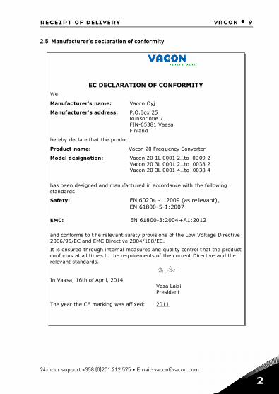
2.5 Manufacturer’s declaration of conformity
EC DECLARATION OF CONFORMITYWe
Manufacturer's name: Vacon Oyj
Manufacturer's address: P.O.Box 257eitnirosnuR
asaaV18356-NIFdnalniF
hereby declare that the product
Product name: Vacon 20 Frequency Converter
Model designation: Vacon 20 1L 0001 2…to 0009 228300ot…21000L302nocaV48300ot…41000L302nocaV
has been designed and manufactured in accordance with the followingstandards:
Safety: EN 60204 -1:2009 (as re levant),EN 61800-5-1:2007
EMC: EN 61800-3:2004+A1:2012
and conforms to t he relevant safety provisions of the Low Voltage Directive2006/95/EC and EMC Directive 2004/108/EC.
It is ensured through internal measures and quality control t hat the productconforms at all times to the requirements of the current Directive and therelevant standards.
In Vaasa, 16th of April, 2014isiaLaseV
tnediserP
The year the CE marking was affixed: 2011
24-hour support +358 (0)201 212 575 • Email: [email protected]
2

10 • vacon installation
3
3. INSTALLATION
3.1 Mechanical installation
There are two possible ways to mount Vacon 20 in the wall. For MI1-MI3, either screw or DIN-rail mounting; For MI4-MI5, screw or flange mounting.
Figure 3.1: Screw mounting, MI1 - MI3
Figure 3.2: Screw mounting, MI4 - MI5
Note! See the mounting dimensions on the back of the drive. More details in Chapter 3.1.1.
=M5
MI3
MI1
=M4
MI2
=M5
LOCREM
BACKRESET
OK
LOCREM
BACKRESET
OK
LOCREM
BACKRESET
OK
MI4=M 6
=M 6
MI5
LOCREM
BACKRESET
OK
LOCREM
BACKRESET
OK
Tel. +358 (0)201 2121 • Fax +358 (0)201 212205

installation vacon • 11
Figure 3.3: DIN-rail mounting, MI1 - MI3
Figure 3.4: Flange mounting, MI4 - MI5
1 2
LOCREM
BACKRESET
OK
24-hour support +358 (0)201 212 575 • Email: [email protected]
3

12 • vacon installation
3
Figure 3.5: Flange mounting cutout dimensions for MI4 (Unit: mm)
Figure 3.6: Flange mounting cutout dimensions for MI5 (Unit: mm)
Tel. +358 (0)201 2121 • Fax +358 (0)201 212205

installation vacon • 13
Figure 3.7: Flange mounting depth dimensions for MI4 and MI5 (Unit: mm)
MI5MI4
24-hour support +358 (0)201 212 575 • Email: [email protected]
3

14 • vacon installation
3
3.1.1 Vacon 20 dimensions
Figure 3.8: Vacon 20 dimensions, MI1 - MI3
Figure 3.9: Vacon 20 dimensions, MI4 - MI5
W2W3
W (W1)
H (
H1
)
H2
H3
D2
D (D1)
W2W3
H (
H1
)
W (W1) D (D1)
H3
H2
Tel. +358 (0)201 2121 • Fax +358 (0)201 212205

installation vacon • 15
Type H1 H2 H3 W1 W2 W3 D1 D2
MI1 160.1 147 137.3 65.5 37.8 4.5 98.5 7
MI2 195 183 170 90 62.5 5.5 101.5 7
MI3 254.3 244 229.3 100 75 5.5 108.5 7
MI4 370 350.5 336.5 165 140 7 165 -
MI5 414 398 383 165 140 7 202 -Table 3.1: Vacon 20 dimensions in millimetres
Frame Dimensions(mm) Weight*
W H D (kg.)
MI1 66 160 98 0.5
MI2 90 195 102 0.7
MI3 100 254.3 109 1
MI4 165 370 165 8
MI5 165 414 202 10
*without shipping packageTable 3.2: Vacon 20 frame dimensions (mm) and weights (kg)
Frame Dimensions(Inches) Weight*
W H D (Ibs.)
MI1 2.6 6.3 3.9 1.2
MI2 3.5 9.9 4 1.5
MI3 3.9 10 4.3 2.2
MI4 6.5 14.6 6.5 18
MI5 6.5 16.3 8 22
*without shipping packageTable 3.3: Vacon 20 frame dimensions (Inch) and weights (Ibs)
24-hour support +358 (0)201 212 575 • Email: [email protected]
3
16 • vacon installation
3
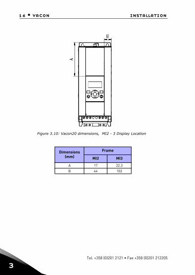
Figure 3.10: Vacon20 dimensions, MI2 - 3 Display Location
Dimensions(mm)
Frame
MI2 MI3
A 17 22.3
B 44 102
Tel. +358 (0)201 2121 • Fax +358 (0)201 212205

installation vacon • 17
Figure 3.11: Vacon20 dimensions, MI4 - 5 Display Location
Dimensions(mm)
Frame
MI2 MI3
A 205 248.5
B 87 87
24-hour support +358 (0)201 212 575 • Email: [email protected]
3

18 • vacon installation
3
3.1.2 Cooling
Enough free space shall be left above and below the frequency converter to ensure sufficient air circulation and cooling. You will find the required dimensions for free space in the table below.
If several units are mounted above each other the required free space equals C + D (see figure below). Moreover, the outlet air used for cooling by the lower unit must be directed away from the air intake of the upper unit.
The amount of cooling air required is indicated below. Also make sure that the tem-perature of the cooling air does not exceed the maximum ambient temperature of the converter.
*. Min clearance A and B for drives for MI1 ~ MI3 can be 0 mm if the ambient temperature is below 40 degrees.
Figure 3.12: Installation space
A = clearance around the freq. converter (see also B) B = distance from one frequency converter to another or distance to cabinet wall C = free space above the frequency converterD = free space underneath the frequency converter
NOTE! See the mounting dimensions on the back of the drive. Leave free space for cooling above (100 mm), below (50 mm), and on the sides (20 mm) of Vacon 20! (For MI1 - MI3, side-to-side installation allowed only if the ambient tem-perature is below 40 °C; For MI4-MI5, side-to-side installation is not allowed.
Min clearance (mm)
Type A* B* C D
MI1 20 20 100 50
MI2 20 20 100 50
MI3 20 20 100 50
MI4 20 20 100 100
MI5 20 20 120 100Table 3.4: Min. clearances around AC drive
Type Cooling air required (m³/h)
MI1 10
MI2 10
MI3 30
MI4 45
MI5 75Table 3.5: Required cooling air
B
C
BA
D
A
Tel. +358 (0)201 2121 • Fax +358 (0)201 212205

installation vacon • 19
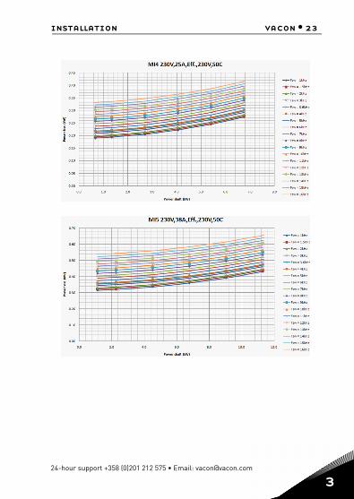
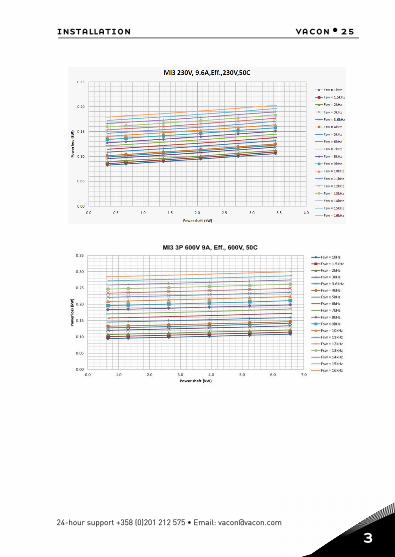
3.1.3 Power losses
If the operator wants to raise the switching frequency of the drive for some reason (typically e.g. in order to reduce the motor noise), this inevitably affects the power losses and cooling requirements, for different motor shaft power, operator can se-lect the switching frequency according to the graphs below.
MI1 - MI5 3P 400 V POWER LOSS
24-hour support +358 (0)201 212 575 • Email: [email protected]
3

20 • vacon installation
3
Tel. +358 (0)201 2121 • Fax +358 (0)201 212205

installation vacon • 21
MI1 - MI5 3P 230 V POWER LOSS
24-hour support +358 (0)201 212 575 • Email: [email protected]
3

22 • vacon installation
3
Tel. +358 (0)201 2121 • Fax +358 (0)201 212205

24 • vacon installation
3
MI1 - MI3 1P 230 V POWER LOSS
Tel. +358 (0)201 2121 • Fax +358 (0)201 212205
26 • vacon installation
3
3.1.4 EMC levels
EN61800-3 defines the division of frequency converters into four classes according to the level of electromagnetic disturbances emitted, the requirements of a power system network and the installation environment (see below). The EMC class of each product is defined in the type designation code.
Category C1: Frequency converters of this class comply with the requirements of category C1 of the product standard EN 61800-3 (2004). Category C1 ensures the best EMC characteristics and it includes converters the rated voltage of which is less than 1000 V and which are intended for use in the 1st environment.NOTE: The requirements of class C are fulfilled only as far as the conducted emis-sions are concerned.
Category C2: Frequency converters of this class comply with the requirements of category C2 of the product standard EN 61800-3 (2004). Category C2 includes con-verters in fixed installations and the rated voltage of which is less than 1000 V. The class C2 frequency converters can be used both in the 1st and the 2nd environment.
Category C4: The drives of this class do not provide EMC emission protection. These kinds of drives are mounted in enclosures.
Environments in product standard EN 61800-3 (2004)
First environment: Environment that includes domestic premises. It also includes establishments directly connected without intermediate transformers to a low-volt-age power supply network which supplies buildings used for domestic purposes.
NOTE: houses, apartments, commercial premises or offices in a residential building are examples of first environment locations.
Second environment: Environment that includes all establishments other than those directly connected to a low-voltage power supply network which supplies buildings used for domestic purposes.NOTE: industrial areas, technical areas of any building fed from a dedicated trans-former are examples of second environment locations.
Tel. +358 (0)201 2121 • Fax +358 (0)201 212205

installation vacon • 27
3.1.5 Changing the EMC protection class from C2 to C4
The EMC protection class of MI1-3 frequency converters can be changed from class C2 to class C4 (except 115V and 600V drives) by removing the EMC-capacitor discon-necting screw, see figure below. MI4 & 5 can also be changed by removing the EMC jumpers.
Note! Do not attempt to change the EMC level back to class C2. Even if the procedure above is reversed, the frequency converter will no longer fulfil the EMC require-ments of class C2!
Figure 3.13: EMC protection class, MI1 - MI3
Figure 3.14: EMC protection class, MI4
24-hour support +358 (0)201 212 575 • Email: [email protected]
3

28 • vacon installation
3
Figure 3.15: EMC protection class, MI5
Figure 3.16: Jumpers
• Remove the main cover and locate the two jumpers.• Disconnect the RFI-filters from ground by lifting the jumpers up
from their default positions. See Figure 3.16.
Tel. +358 (0)201 2121 • Fax +358 (0)201 212205

installation vacon • 29
3.2 Cabling and connections
3.2.1 Power cabling
Note! Tightening torque for power cables is 0.5 - 0.6 Nm (4-5 in.lbs).
Figure 3.17: Vacon 20 power connections, MI1
Figure 3.18: Vacon 20 power connections, MI2 - MI3
1~ (230V)
3~ (230V, 400V)
Motor out
MAINS MOTOR
Strip theplastic cablecoating for360° earthing
L1 L2/N L3 U/T1 V/T2 W/T3R+ R-
1~ (230V)
3~(230V, 400V, 600V)
1~ (115V)
MAINS MOTORBRAKERESISTOR
External brake resistor
Motor out
Strip theplasticcablecoatingfor 360°earthing
3~(230V, 400V,600V)
24-hour support +358 (0)201 212 575 • Email: [email protected]
3

30 • vacon installation
3
Figure 3.19: Vacon 20 power connections, MI4
Figure 3.20: Vacon 20 power connections, MI5
MAINS MOTOR
Motor out
BrakeRESISTOR
3~ (380, 480V)
MAINS MOTOR
Motor out
BrakeRESISTOR
3~ (380, 480V)
Tel. +358 (0)201 2121 • Fax +358 (0)201 212205
installation vacon • 31
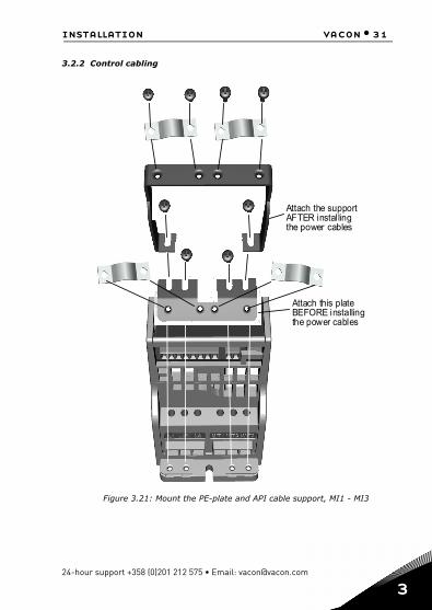
3.2.2 Control cabling
Figure 3.21: Mount the PE-plate and API cable support, MI1 - MI3
Attach this plateBEFORE installingthe power cables
Attach the supportAFTER installingthe power cables
24-hour support +358 (0)201 212 575 • Email: [email protected]
3
32 • vacon installation
3
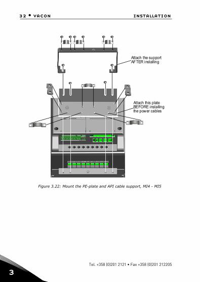
Figure 3.22: Mount the PE-plate and API cable support, MI4 - MI5
Attach the supportAFTER installing
Attach this plateBEFORE installingthe power cables
Tel. +358 (0)201 2121 • Fax +358 (0)201 212205

installation vacon • 33
Figure 3.23: Open the lid, MI1 - MI3
Figure 3.24: Open the lid, MI4 - MI5
24-hour support +358 (0)201 212 575 • Email: [email protected]
3

34 • vacon installation
3
Figure 3.25: Install the control cables. MI1 - MI3. See Chapter 6.2
Figure 3.26: Install the control cables. MI4 - MI5. See Chapter 6.2
Strip the plasticcable coating for360°earthing
Control cabletighteningtorque: 0.4 Nm
Tel. +358 (0)201 2121 • Fax +358 (0)201 212205

installation vacon • 35
3.2.3 Allowed option boards in Vacon20
See below for the allowed option boards in the slot:
Note! When OPT-B1 / OPT-B4 used in Vacon20, +24VDC (±10%, min.300mA) power should be supplied to Terminal 6 (+24_out) and Terminal 3 (GND) in control board.
Option boards (all boards are varnished)
OPT-EC-V EtherCat
OPT-E3-V Profibus DPV1 (Screw connector)
OPT-E5-V Profibus DPV1 (D9 connector)
OPT-E6-V CANopen
OPT-E7-V DeviceNet
OPT-E9-V ModbusTCP & Profinet
OPT-B1-V 6 x DI/DO, each I/O can be individually
OPT-B2-V 2 x Relay output + Thermistor
OPT-B4-V 1 x AI, 2 x AO (isolated)
OPT-B5-V 3 x Relay output
OPT-B9-V 1 x RO, 5 x DI (42-240 VAC)
OPT-BH-V 3 x Temperature measurement (support for PT100, PT1000, NI1000, KTY84-130, KTY84-150, KTY84-131 sensors)
OPT-BF-V 1 x AO, 1 x DO, 1 x RO
SLOT E5 E6 B1 B2 B9 BHE3EC E7 E9 B4 B5 BF
24-hour support +358 (0)201 212 575 • Email: [email protected]
3

36 • vacon installation
3
Option board assembly structure:
1
2
3
Tel. +358 (0)201 2121 • Fax +358 (0)201 212205

38 • vacon installation
3
3.2.4 Screw of cables
Figure 3.27: MI1 screws
Figure 3.28: MI2 screws
M4*8 Screws 12pcs
M4*8 Screws 10pcs
Tel. +358 (0)201 2121 • Fax +358 (0)201 212205

installation vacon • 39
Figure 3.29: MI3 screws
Figure 3.30: MI4 - MI5 screw
M4*8 Screws 10pcs
M4*10 Screws 4pcs
M4*17 Screws 6pcs
M4*9 Screws 14pcs
24-hour support +358 (0)201 212 575 • Email: [email protected]
3

40 • vacon installation
3
3.2.5 Cable and fuse specifications
Use cables with heat resistance of at least +70 °C. The cables and the fuses must be dimensioned according to the tables below. Installation of cables according to UL regulations is presented in Chapter 3.2.8.The fuses function also as cable overload protection.These instructions apply only to cases with one motor and one cable connection from the frequency converter to the motor. In any other case, ask the factory for more in-formation.
EMC category cat. C2 cat. C4
Mains cable types 1 1
Motor cable types 3 1
Control cable types 4 4
Table 3.6: Cable types required to meet standards. EMC categories are described in Chapter 3.1.4
Cable type Description
1Power cable intended for fixed installation and the specific mains voltage. Shielded cable not required.(NKCABLES / MCMK or similar recommended)
2Power cable equipped with concentric protection wire and intended for the specific mains voltage.(NKCABLES / MCMK or similar recommended).
3
Power cable equipped with compact low-impedance shield and intended for the specific mains voltage.(NKCABLES / MCCMK, SAB / ÖZCUY-J or similar recommended).*360º earthing of both motor and FC connection required to meet the standard
4 Screened cable equipped with compact low-impedance shield (NKCA-BLES /Jamak, SAB / ÖZCuY-O or similar).
Table 3.7: Cable type descriptions
Tel. +358 (0)201 2121 • Fax +358 (0)201 212205

installation vacon • 41
Frame Type Fuse[A]
Mains cable
Cu [mm2]
Motor cable
Cu [mm2]
Terminal cable size (min/max)
Main terminal
[mm2]
Earth terminal
[mm2]
Control terminal
[mm2]
Relay terminal
[mm2]
MI2 0001-0004 20 2*2.5+2.5 3*1.5+1.5 1.5-4 1.5-4 0.5-1.5 0.5-1.5
MI3 0005 32 2*6+6 3*1.5+1.5 1.5-4 1.5-4 0.5-1.5 0.5-1.5Table 3.8: Cable and fuse sizes for Vacon 20, 115 V, 1~
Frame Type Fuse[A]
Mains cable
Cu [mm2]
Motor cable
Cu [mm2]
Terminal cable size (min/max)
Main terminal
[mm2]
Earth terminal
[mm2]
Control terminal
[mm2]
Relay terminal
[mm2]
MI1 0001-0003 10 2*1.5+1.5 3*1.5+1.5 1.5-4 1.5-4 0.5-1.5 0.5-1.5
MI2 0004-0007 20 2*2.5+2.5 3*1.5+1.5 1.5-4 1.5-4 0.5-1.5 0.5-1.5
MI3 0009 32 2*6+6 3*1.5+1.5 1.5-6 1.5-6 0.5-1.5 0.5-1.5Table 3.9: Cable and fuse sizes for Vacon 20, 208 - 240 V, 1~
Frame Type Fuse[A]
Mains cable
Cu [mm2]
Motor cable
Cu [mm2]
Terminal cable size (min/max)
Main terminal
[mm2]
Earth terminal
[mm2]
Control terminal
[mm2]
Relay terminal
[mm2]
MI1 0001-0003 6 3*1.5+1.5 3*1.5+1.5 1.5-4 1.5-4 0.5-1.5 0.5-1.5
MI2 0004-0007 10 3*1.5+1.5 3*1.5+1.5 1.5-4 1.5-4 0.5-1.5 0.5-1.5
MI3 0011 20 3*2.5+2.5 3*2.5+2.5 1.5-6 1.5-6 0.5-1.5 0.5-1.5
MI4 0012-0025202540
3*6+6 3*6+6 1-10Cu 1-10 0.5-1.5 0.5-1.5
MI5 0031-0038 40 3*10+10 3*10+10 2.5-50Cu / Al 2.5-35 0.5-1.5 0.5-1.5
Table 3.10: Cable and fuse sizes for Vacon 20, 208 - 240 V, 3~
24-hour support +358 (0)201 212 575 • Email: [email protected]
3
42 • vacon installation
3
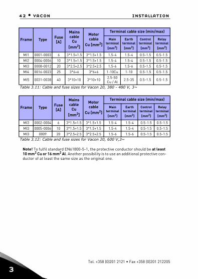
Note! To fulfil standard EN61800-5-1, the protective conductor should be at least 10 mm2 Cu or 16 mm2 Al. Another possibility is to use an additional protective con-ductor of at least the same size as the original one.
Frame Type Fuse[A]
Mains cable
Cu [mm2]
Motor cable
Cu [mm2]
Terminal cable size (min/max)
Main terminal
[mm2]
Earth terminal
[mm2]
Control terminal
[mm2]
Relay terminal
[mm2]
MI1 0001-0003 6 3*1.5+1.5 3*1.5+1.5 1.5-4 1.5-4 0.5-1.5 0.5-1.5
MI2 0004-0006 10 3*1.5+1.5 3*1.5+1.5 1.5-4 1.5-4 0.5-1.5 0.5-1.5
MI3 0008-0012 20 3*2.5+2.5 3*2.5+2.5 1.5-6 1.5-6 0.5-1.5 0.5-1.5
MI4 0016-0023 25 3*6+6 3*6+6 1-10Cu 1-10 0.5-1.5 0.5-1.5
MI5 0031-0038 40 3*10+10 3*10+10 2.5-50 Cu / Al 2.5-35 0.5-1.5 0.5-1.5
Table 3.11: Cable and fuse sizes for Vacon 20, 380 - 480 V, 3~
Frame Type Fuse[A]
Mains cable
Cu [mm2]
Motor cable
Cu [mm2]
Terminal cable size (min/max)
Main terminal
[mm2]
Earth terminal
[mm2]
Control terminal
[mm2]
Relay terminal
[mm2]
MI3 0002-0004 6 3*1.5+1.5 3*1.5+1.5 1.5-4 1.5-4 0.5-1.5 0.5-1.5
MI3 0005-0006 10 3*1.5+1.5 3*1.5+1.5 1.5-4 1.5-4 0.5-1.5 0.5-1.5
MI3 0009 20 3*2.5+2.5 3*2.5+2.5 1.5-6 1.5-6 0.5-1.5 0.5-1.5Table 3.12: Cable and fuse sizes for Vacon 20, 600 V,3~
Tel. +358 (0)201 2121 • Fax +358 (0)201 212205
installation vacon • 43
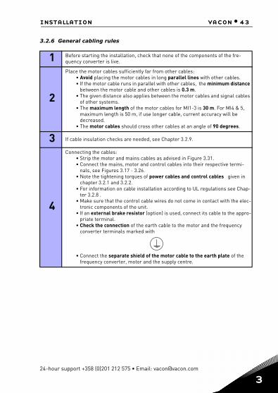
3.2.6 General cabling rules
1 Before starting the installation, check that none of the components of the fre-quency converter is live.
2
Place the motor cables sufficiently far from other cables:• Avoid placing the motor cables in long parallel lines with other cables.• If the motor cable runs in parallel with other cables, the minimum distance
between the motor cable and other cables is 0.3 m.• The given distance also applies between the motor cables and signal cables
of other systems.• The maximum length of the motor cables for MI1-3 is 30 m. For MI4 & 5,
maximum length is 50 m, if use longer cable, current accuracy will be decreased.
• The motor cables should cross other cables at an angle of 90 degrees.
3 If cable insulation checks are needed, see Chapter 3.2.9.
4
Connecting the cables:• Strip the motor and mains cables as advised in Figure 3.31.• Connect the mains, motor and control cables into their respective termi-
nals, see Figures 3.17 - 3.26.• Note the tightening torques of power cables and control cables given in
chapter 3.2.1 and 3.2.2.• For information on cable installation according to UL regulations see Chap-
ter 3.2.8 .• Make sure that the control cable wires do not come in contact with the elec-
tronic components of the unit.• If an external brake resistor (option) is used, connect its cable to the appro-
priate terminal.• Check the connection of the earth cable to the motor and the frequency
converter terminals marked with
• Connect the separate shield of the motor cable to the earth plate of the frequency converter, motor and the supply centre.
24-hour support +358 (0)201 212 575 • Email: [email protected]
3

44 • vacon installation
3
3.2.7 Stripping lengths of motor and mains cables
Figure 3.31: Stripping of cables
Note! Strip also the plastic cover of the cables for 360 degree earthing. See Figures 3.17, 3.18 and 3.25.
3.2.8 Cable installation and the UL standards
To meet the UL (Underwriters Laboratories) regulations, a UL-approved copper ca-ble with a minimum heat-resistance of +60 / 75 °C must be used.
Use Class 1 wire only.
The units are suitable for use on a circuit capable of delivering not more than 50,000 rms symmetrical amperes, 600V maximum, when protected by T and J Class fuses. For MI4 without DC-choke, maximum short circuit current has to be not more than 2.3 kA, for MI5 without DC-choke, maximum short circuit current has to be not more than 3.8 kA.
Integral solid state short circuit protection does not provide branch circuit protec-tion. Branch circuit protection must be provided in accordance with the National Electric Code and any additional local codes. Branch circuit protection provided by fuses only.
Motor overload protection provided at 110% of full load current.
3.2.9 Cable and motor insulation checks
These checks can be performed as follows if motor or cable insulations are suspect-ed to be faulty.
1. Motor cable insulation checksDisconnect the motor cable from terminals U / T1, V / T2 and W / T3 of the frequency converter and from the motor. Measure the insulation resistance of the motor cable
20 mm35 mm
8 mm
Earth conductor
8 mm
Tel. +358 (0)201 2121 • Fax +358 (0)201 212205

installation vacon • 45
between each phase conductor as well as between each phase conductor and the protective ground conductor.The insulation resistance must be >1 MOhm.
2. Mains cable insulation checksDisconnect the mains cable from terminals L1, L2 / N and L3 of the frequency con-verter and from the mains. Measure the insulation resistance of the mains cable be-tween each phase conductor as well as between each phase conductor and the protective ground conductor. The insulation resistance must be >1 MOhm.
3. Motor insulation checksDisconnect the motor cable from the motor and open the bridging connections in the motor connection box. Measure the insulation resistance of each motor winding. The measurement voltage must equal at least the motor nominal voltage but not exceed 1000 V. The insulation resistance must be >1 MOhm.
24-hour support +358 (0)201 212 575 • Email: [email protected]
3

46 • vacon commissioning
4
4. COMMISSIONING
Before commissioning, read the warnings and instructions listed in Chapter 1!
4.1 Commissioning steps of Vacon 20
1 Read carefully the safety instructions in Chapter 1 and follow them.
2
After the installation, make sure that:• both the frequency converter and the motor are grounded.• the mains and motor cables comply with the requirements given in Chap-
ter 3.2.5.• the control cables are located as far as possible from the power. cables
(see Chapter 3.2.6, step 2) and the shields of the shielded cables are con-nected to protective earth.
3 Check the quality and quantity of cooling air (Chapter 3.1.2).
4 Check that all Start / Stop switches connected to the I / O terminals are in Stop-position.
5 Connect the frequency converter to mains.
6Set the parameters of group 1 according to the requirements of your application. At least the following parameters should be set:
• motor nominal speed (par. 1.3)• motor nominal current (par. 1.4)• application type (par. 16.1)
You will find the values needed for the parameters on the motor rating plate.
Tel. +358 (0)201 2121 • Fax +358 (0)201 212205

commissioning vacon • 47
7
Perform test run without motor. Perform either Test A or Test B:
A) Control from the I / O terminals:• Turn the Start/Stop switch to ON position.• Change the frequency reference (potentiometer).• Check the Monitoring Menu and make sure that the value of Output fre-
quency changes according to the change of frequency reference.• Turn the Start / Stop switch to OFF position.
B) Control from the keypad:• Select the keypad as the control place with par 2.1. You can also move to
keypad control by pressing Loc / Rem button or select Local control with par 2.5.
• Push the Start button on the keypad.• Check the Monitoring Menu and make sure that the value of Output fre-
quency. changes according to the change of frequency reference.• Push the Stop button on the keypad.
8
Run the no-load tests without the motor being connected to the process, if possi-ble. If this is impossible, secure the safety of each test prior to running it. Inform your co-workers of the tests.
• Switch off the supply voltage and wait up until the drive has stopped.• Connect the motor cable to the motor and to the motor cable terminals of
the frequency converter.• See to that all Start / Stop switches are in Stop positions.• Switch the mains ON.• Repeat test 7A or 7B.
9 Perform an identification run (see par. 1.19), especially if the application requires a high startup torque or a high torque with low speed.
10Connect the motor to the process (if the no-load test was running without the motor being connected).
• Before running the tests, make sure that this can be done safely.• Inform your co-workers of the tests.• Repeat test 7A or 7B.
24-hour support +358 (0)201 212 575 • Email: [email protected]
4

48 • vacon fault tracing
5
5. FAULT TRACINGWhen a fatal fault is detected by the frequency converter control electronics, the drive will stop and the symbol FT and the fault code blinked on the display are in the following format, e.g.:
The active fault can be reset by pressing BACK / RESET button when the API is in ac-tive fault menu level (FT XX), or pressing BACK / RESET button with long time (> 2 s) when the API is in active fault submenu level (F5.x ), or via the I / O terminal or field bus. Reset fault history (long push > 5 s), when the API is in fault history submenu level (F6.x). The faults with subcode and time labels are stored in the Fault history submenu which can be browsed. The different fault codes, their causes and correct-ing actions are presented in the table below.
Fault code Fault name Possible cause Correcting actions
1 Overcurrent
Frequency converter has detected too high a current (>4*IN) in the motor cable:
• sudden heavy load increase• short circuit in motor cables• unsuitable motor
Check loading.Check motor size.Check cables.
2 Overvoltage
The DC-link voltage has exceeded the internal safety limit:
• deceleration time is too short• high overvoltage peaks in
mains
Increase the deceleration time (Par.4.3 or Par.4.6)
3 Earth fault
Current measurement has detected extra leakage current at start:
• insulation failure in cables or motor
Check motor cables and motor
Table 5.1: Fault codes
Fault code (02 = overvoltage)
FT 2
Tel. +358 (0)201 2121 • Fax +358 (0)201 212205

fault tracing vacon • 49
8 System fault • component failure• faulty operation
Reset the fault and restart.If the fault re-occurs, con-tact the distributor near to you.NOTE! If fault F8 occurs, find out the subcode of the fault from the Fault His-tory menu under Id xxx!
9 Under voltage
The DC-link voltage has gone below the internal safety limit:
• most probable cause: supply voltage is too low
• frequency converter internal fault
• Power outages
In case of temporary sup-ply voltage break reset the fault and restart the fre-quency converter. Check the supply voltage. If it is adequate, an internal fail-ure has occurred.Contact the distributor near to you.
10 Input phase fault Input phase is missing Check supply voltage, fuses and cable.
11 Output phase faultCurrent measurement has detected that there is no current in one motor phase.
Check motor cable andmotor.
13 Frequency converter under temperature
Heat sink temperature is under -10 °C
Check the ambient tem-perature.
14 Frequency converter over temperature Heat sink is overheated.
Check that the cooling air flow is not blocked.Check the ambient tem-perature.Clean the heatsink dust.Make sure that the switching frequency is not too high in relation to ambient temperature and motor load.
15 Motor stalled Motor stall protection has tripped.
Check that the motor is able to rotate freely.
16 Motor over tempera-ture
Motor overheating has been detected by frequency converter motor temperature model. Motor is overloaded.
Decrease the motor load.If no motor overload exists, check the temper-ature model parameters.
Fault code Fault name Possible cause Correcting actions
Table 5.1: Fault codes
24-hour support +358 (0)201 212 575 • Email: [email protected]
5

50 • vacon fault tracing
5
17 Motor underload Motor underload protection has tripped.
Check motor and load, e.g. for broken belts or dry pumps.
22 EEPROM checksum fault
Parameter save fault• faulty operation• component failure
Contact the distributor near to you.
25 Microcontroller watchdog fault
• faulty operation• component failure
Reset the fault and restart.If the fault re-occur, con-tact the distributor near to you.
27 Back EMF protection
Drive has detected that the mag-netized motor is running in start situation.
• A rotating PM-motor
Make sure that there is no rotating PM-motor when the start command is given.
29 Thermistor faultThe thermistor input of option board has detected increase of the motor temperature.
Check motor cooling and loading. Check thermistor connection (If thermistor input of the option board is not in use it has to be short circuited).
34 Internal bus commu-nication
Ambient interference or defective hardware.
If the fault re-occur, con-tact the distributor near to you.
35 Application fault Application is not working prop-erly.
Contact the distributor near to you.
41 IGBT Overtemperature Overtemperature alarm is issued when the IGBT switch tempera-ture exceeds 110 °C.
Check loading.Check motor size.Make identification run.
50Analog input select 20% - 100% (selected signal range 4 to 20 mA or 2 to 10 V)
Current at the analogue input is < 4mA; Voltage at the analogue input is < 2 V.
• control cable is broken or loose.
• signal source has failed.
Check the current loop circuitry.
51 External fault
Digital input fault. Digital input has been programmed as exter-nal fault input and this input is active.
Remove the external device fault.
Fault code Fault name Possible cause Correcting actions
Table 5.1: Fault codes
Tel. +358 (0)201 2121 • Fax +358 (0)201 212205

fault tracing vacon • 51
52 Door Panel fault Control place is keypad, but door panel has been disconnected.
Check the connection between optional board and API. If connection is correct, contact the near-est Vacon distributor.
53 Fieldbus faultThe data connection between the fieldbus Master and the fieldbus of the drive has broken.
Check installation.If installation is correct, contact the nearest Vacon distributor.
54 Slot fault The connection between optional board and API has been broken.
Check board and slot. Contact the nearest Vacon distributor.
55 Wrong run fault (FWD/REV conflict)
Run forward and backward are high at the same time.
Check I/O control signal 1 and I/O control signal 2.
57 Idenfication fault Identification run has failed.
Run command was removed before comple-tion of identification run.Motor is not connected to frequency converter.There is load on motor shaft.
111 Temperature fault Over low or over high temperature Check temperature signal from OPTBH board
F08 SubCode Fault
60 Watchdog reset
61 SW stack overflow
62 HW stack overflow
63 Misalignment
64 Illegal op
65 PLL lost lock / Low CPU voltage
66 EEPROM Device
67 EEPROM Queue full
68 MPI communication (dead or CRC errors)
70 CPU load
Table 5.2: Fault subcodes from power
Fault code Fault name Possible cause Correcting actions
Table 5.1: Fault codes
24-hour support +358 (0)201 212 575 • Email: [email protected]
5

52 • vacon fault tracing
5
71 External oscillator
72 Fault in Power triggered by user
F08 SubCode Fault
84 MPI CRC
86 MPI2 CRC
89 HMI receive buffer overflow
90 MODBUS receive buffer overflow
93 Power source cannot be recognized (triggered as alarm)
96 MPI queue full
97 MPI off line error
98 MPI driver error
99 Option Board Driver Error
100 Option Board Configure Error
104 OBI channel full
105 OBI memory allocate fail
106 OBI object queue full
107 OBI HMI queue full
108 OBI SPI queue full
111 Parameter copy error
113 Frequency detective timer overflow
114 PC control time out error
115 Device Property data format tree too deep exceed 3
120 Task stack overflow
Table 5.2: Fault Subcodes from control API
F22 SubCode Fault
1 DA_CN, Power down data counter error
2 DA_PD, Power down data restore fail
3 DA_FH, Fault history data error
Table 5.2: Fault subcodes
F08 SubCode Fault
Table 5.2: Fault subcodes from power
Tel. +358 (0)201 2121 • Fax +358 (0)201 212205

fault tracing vacon • 53
4 DA_PA, Restore parameter CRC error
5 Reserved.
6 DA_PER_CN, Persist data counter error
7 DA_PER_PD, Persist data restore fail
F35 SubCode Fault
1 Application software flash error
2 Application header error
Table 5.2: Fault subcodes
F22 SubCode Fault
Table 5.2: Fault subcodes
24-hour support +358 (0)201 212 575 • Email: [email protected]
5
54 • vacon vacon 20 api
6
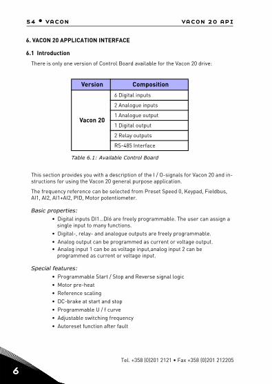
6. VACON 20 APPLICATION INTERFACE
6.1 Introduction
There is only one version of Control Board available for the Vacon 20 drive:
This section provides you with a description of the I / O-signals for Vacon 20 and in-structions for using the Vacon 20 general purpose application.
The frequency reference can be selected from Preset Speed 0, Keypad, Fieldbus, AI1, AI2, AI1+AI2, PID, Motor potentiometer.
Basic properties:• Digital inputs DI1…DI6 are freely programmable. The user can assign a
single input to many functions.• Digital-, relay- and analogue outputs are freely programmable.• Analog output can be programmed as current or voltage output.• Analog input 1 can be as voltage input,analog input 2 can be
programmed as current or voltage input.
Special features:• Programmable Start / Stop and Reverse signal logic• Motor pre-heat• Reference scaling• DC-brake at start and stop • Programmable U / f curve • Adjustable switching frequency • Autoreset function after fault
Version Composition
Vacon 20
6 Digital inputs
2 Analogue inputs
1 Analogue output
1 Digital output
2 Relay outputs
RS-485 Interface
Table 6.1: Available Control Board
Tel. +358 (0)201 2121 • Fax +358 (0)201 212205

vacon 20 api vacon • 55
• Protections and supervisions (all fully programmable; off, alarm, fault):• Analog input low fault• External fault• Undervoltage fault• Earth fault• Motor thermal, stall and underload protection• Fieldbus communication• Output phase fault• Thermistor fault
• 8 preset speeds• Analogue input range selection, signal scaling and filtering• PID-controller
24-hour support +358 (0)201 212 575 • Email: [email protected]
6

56 • vacon vacon 20 api
6
mA
1-10 k
6.2 Control I / OTerminal Signal Factory preset Description1 +10 Vref Ref. voltage out Maximum load 10 mA2 AI1 Analog signal in 1 Freq. reference P) 0 - 10 V, Ri = 250 kΩ
3 GND I / O signal ground6 24 Vout 24 V output for DI's ±20%, max. load 50 mA
7 DI_C Digital Input Common
Digital Input Common for DI1- DI6, refer to Table 6.3 for DI sink type
8 DI1 Digital input 1 Start forward P) Positive, Logic1: 18…30V,Logic0: 0…5V; Negative, Logic1: 0…10V, Logic0: 18…30V;Ri = 10KΩ (floating)
9 DI2 Digital input 2 Start reverse P)
10 DI3 Digital input 3 Fault reset P)
A A RS485 signal A FB Communication NegativeB B RS485 signal B FB Communication Positive
4 AI2 Analog signal in 2 PID actual value and Freq. reference P)
Default:0(4) - 20 mA, Ri ≤ 250 ΩOther:0 - + 10 V, Ri = 250 kΩSelectable through microswitch
5 GND I / O signal ground
13 DO- Digital Output Common
Digital Output Common
14 DI4 Digital input 4 Preset speed B0 P) As DI1
15 DI5 Digital input 5 Preset speed B1 P) As DI1,Selectable through microswitch
16 DI6 Digital input 6 External Fault P) As DI1
18 AO Analog Output Output frequency P) 0 - 10 V, RL ≥ 1 KΩ0(4) - 20 mA, RL ≤ 500ΩSelectable through microswitch
20 DO Digital signal out Active = READY P) Open collector, max. load 35 V / 50 mA
22 RO1 NO Relay out 1 Active = RUN P) Switching load:
250 Vac / 3 A, 24V DC 3A23 RO1 CM
24 RO2 NC Relay out 2Active = FAULT P) Switching load:
250 Vac / 3 A, 24V DC 3A25 RO2 CM26 RO2 NOTable 6.2: Vacon 20 General purpose application default I / O configuration and connections for control board P) = Programmable function, see parameter lists and descriptions, chapters 8 and 9.
Tel. +358 (0)201 2121 • Fax +358 (0)201 212205

vacon 20 api vacon • 57
Figure 6.1: Microswitchs
Vacon 20 I / O terminals:
Terminal Signal Factory preset Description3 GND I / O signal ground6 24 Vout 24 V output for DI's ±20%, max. load 50 mA
7 DI_C Digital Input Common
Digital Input Common for DI1-DI6
8 DI1 Digital input 1 Start forward P)
Positive, Logic1: 18…+30V, Logic0: 0…5V; Negative, Logic1: 0…10V, Logic0: 18…30V; Ri = 10KΩ (floating)
9 DI2 Digital input 2 Start reverse P) 10 DI3 Digital input 3 Fault reset P)
14 DI4 Digital input 4 Preset speed B0 P)
Positive, Logic1: 18…+30V, Logic0: 0…5V; Negative, Logic1: 0…10V, Logic0: 18…30V; Ri = 10KΩ (floating)
15 DI5 Digital input 5 Preset speed B1 P) Only for DI.16 DI6 Digital input 6 External Fault P) Only for DI.
Table 6.3: DI Sink Type, remove jumper J500 and connect the wire using table 6.3
DI
En
coN
or
AO
Vm
A
AI2
Vm
A
RS
485
-te
rm
ON
S1S2S3S4J500
OFF
4 5 13 14 15 16 2018
1 2 3 6 7 8 9 10
22 23 26
2425
AI2 GND DO- DI4 DI5 DI6 AO DO+ R13 R14 * R24
+10VAI1 GND 24V DI-C DI1 DI2 DI3 A B R21 R22
24-hour support +358 (0)201 212 575 • Email: [email protected]
6
58 • vacon control panel
7
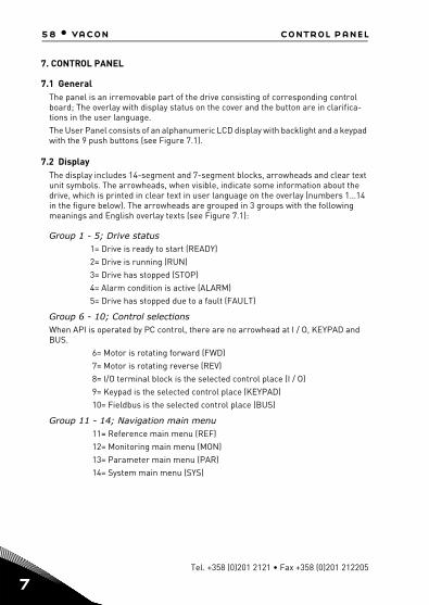
7. CONTROL PANEL
7.1 GeneralThe panel is an irremovable part of the drive consisting of corresponding control board; The overlay with display status on the cover and the button are in clarifica-tions in the user language.The User Panel consists of an alphanumeric LCD display with backlight and a keypad with the 9 push buttons (see Figure 7.1).
7.2 DisplayThe display includes 14-segment and 7-segment blocks, arrowheads and clear text unit symbols. The arrowheads, when visible, indicate some information about the drive, which is printed in clear text in user language on the overlay (numbers 1…14 in the figure below). The arrowheads are grouped in 3 groups with the following meanings and English overlay texts (see Figure 7.1):
Group 1 - 5; Drive status1= Drive is ready to start (READY)2= Drive is running (RUN)3= Drive has stopped (STOP)4= Alarm condition is active (ALARM)5= Drive has stopped due to a fault (FAULT)
Group 6 - 10; Control selectionsWhen API is operated by PC control, there are no arrowhead at I / O, KEYPAD and BUS.
6= Motor is rotating forward (FWD) 7= Motor is rotating reverse (REV) 8= I/O terminal block is the selected control place (I / O) 9= Keypad is the selected control place (KEYPAD) 10= Fieldbus is the selected control place (BUS)
Group 11 - 14; Navigation main menu 11= Reference main menu (REF) 12= Monitoring main menu (MON) 13= Parameter main menu (PAR) 14= System main menu (SYS)
Tel. +358 (0)201 2121 • Fax +358 (0)201 212205

control panel vacon • 59
Figure 7.1: Vacon 20 Control panel
7.3 KeypadThe keypad section of the control panel consists of 9 buttons (see Figure 7.1). The buttons and their functions are described as Table 7.1. The drive stops by pressing the keypad STOP button, regardless of the selected con-trol place when Par. 2.7 (Keypad stop button) is 1. If Par. 2.7 is 0, the drive stops by keypad STOP button only when control place is keypad. The drive starts by pressing the keypad START button when the selected control place is KEYPAD or LOCAL con-trol.
1 2 3 4 5
6 7 8 9 10
11
13
14
12
READY RUN STOP ALARM FAULT
FWD REV I/O KEYPAD BUS
SYS
PAR
REF
MON
BACKRESET
LOCREM
OK
24-hour support +358 (0)201 212 575 • Email: [email protected]
7

60 • vacon control panel
7
NOTE! The status of all the 9 buttons are available for application program!
Symbol Button Name Function Description
Start Motor START from the panel
STOP Motor STOP from the panel
OK
Used for confirmation.Enter edit mode for parameter. Alternate in display between the parameter value and parameter code.Reference frequency value adjusting no need to press OK-button to confirm.
Back / ResetCancels edited parameterMove backwards in menu levelsReset fault indication
Up and Down
Select root parameter number on root-parameter list, Up decrease / Down increase parameter number, Up increase / Down decrease parameter value change.
Left and Right
Available in REF,PAR and SYS menu parameter digit setting when changing value.MON,PAR and SYS can also use left and right button to navigate the parameter group, like e.g.,in MON menu use right button from V1.x to V2.x to V3.x.Can be used to change direction in REF menu in local mode:-Right arrow would mean reverse (REV)-Left arrow would mean forward (FWD)
Loc / Rem Change control place
Table 7.1: Keypad Function
OK
BACKRESET
LOCREM
Tel. +358 (0)201 2121 • Fax +358 (0)201 212205

control panel vacon • 61
7.4 Navigation on the Vacon 20 control panelThis chapter provides you with information on navigating the menus on Vacon 20 and editing the values of the parameters.
7.4.1 Main menu
The menu structure of Vacon 20 control software consists of a main menu and sev-eral submenus. Navigation in the main menu is shown below:
Figure 7.2: The main menu of Vacon 20
F WD R EV I/O K EY PAD BUS
RE F
M ON
PAR
SYS SYS
SYS SYS
SYS SYS
SYS SYS
FA ULTALAR MS TO PRE AD Y RU N
FW D REV I/O KEY PAD BU S
RE F
PA R
FAULTALARMS T OPR EAD Y RUN
MO N
F W D REV I/O KEY PAD BUS
RE F
PAR
FAUL TA LA RMSTO PREAD Y RUN
M ON
FW D RE V I/O KE YP AD BU S
REF
PAR
F AULTALARMS TO PRE AD Y RUN
MO N
F W D RE V I/O KE YP AD BU S
REF
PAR
F AULTALARMS TO PRE AD Y RUN
MO N
F W D RE V I/O KE YP A D BU S
REF
PAR
F AULTAL AR MS TO PRE A DY RU N
MO N
FW D RE V I/ O KE YP A D B US
R EF
PAR
FAU LTALAR MSTO PREAD Y RU N
MO N
PRES S
PRES S
PRES S
PRES S
PRESS
F WD REV I/O KEY PAD B US
RE F
M O N
PAR
FAULTALAR MS T OPRE ADY R U N
PRESS
PRESS
OK
OK
OK
OK
OK
In this menuyou canbrowse themonitoringvalues.
In this menuyou canbrowse andedit theparameters.
Dispalys thekeypad referencevalueregardless ofthe selectedcontron place.
Here you will beable to browsesystem parameterand faultsubmenu.
MONITORINGMENU
REFERENCEMENU
PARAMETERMENU
SYSTEMMENU
HzHz
24-hour support +358 (0)201 212 575 • Email: [email protected]
7
62 • vacon control panel
7
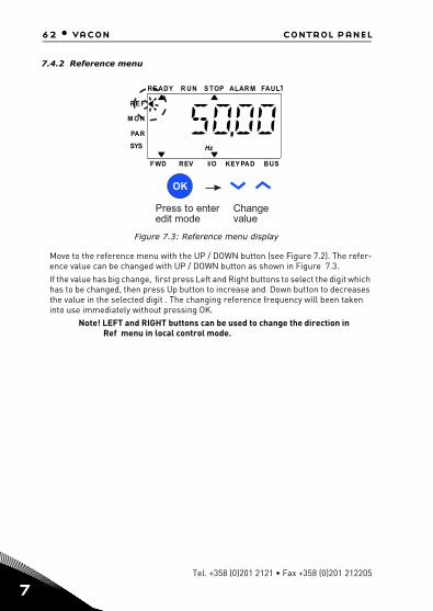
7.4.2 Reference menu
Figure 7.3: Reference menu display
Move to the reference menu with the UP / DOWN button (see Figure 7.2). The refer-ence value can be changed with UP / DOWN button as shown in Figure 7.3. If the value has big change, first press Left and Right buttons to select the digit which has to be changed, then press Up button to increase and Down button to decreases the value in the selected digit . The changing reference frequency will been taken into use immediately without pressing OK.
Note! LEFT and RIGHT buttons can be used to change the direction in Ref menu in local control mode.
Press to enteredit mode
Changevalue
OK
SYS
FWD REV I/O KEY PAD BUS
RE F
M O N
PAR
FAULTALAR MS TOPRE ADY R UN
Hz
Tel. +358 (0)201 2121 • Fax +358 (0)201 212205

control panel vacon • 63
7.4.3 Monitoring menu
Figure 7.4: Monitoring menu display
Monitoring values are actual values of measured signals as well as status of some control settings. It is visible in Vacon 20 display, but it can not be edited. The moni-toring values are listed in Table 7.2.Pressing Left/Right button to change the actual parameter to the first parameter of the next group, to browse monitor menu from V1.x to V2.1 to V3.1 to V4.1. After en-tering the desired group, the monitoring values can be browsed by pressing UP /DOWN button, as shown in Figure 7.4.In MON menu the selected signal and its value are alternateing in the display by pressing OK button.
Note! Turn on drive power, arrowhead of main menu is at MON, V x.x or monitor parameter value of Vx.x is displayed in Panel.Display Vx.x or monitor parameter value of Vx.x is determined by the last show status before power shut down. E.g., it was V4.5, and it is also V4.5 when restart.
OK
OK
OK
1 2
3
Press Left/Right to browseother Monitoring groups
Prsess Down tobrowse V4.5
5 Press OK V4.5 is display
4 Preess OK the value isdisplayed
FAULTALARMSTOPREADY RU N
REF
M ON
PAR
SYS
RE F
M ON
PAR
SYS
FAULTALARMS TOPREADY RU N
FWD R EV I/O K EYPAD BUS FWD R EV I/O K EYPAD BUS
Press OK to enterMonitoring menu
RE F
M ON
PAR
SYS
FAULTALARMS TOPREADY RU N
FWD R EV I/O K EYPAD BUS
REF
M ON
PAR
SYS
FAULTALARMSTOPREADY RU N
FWD R EV I/O K EYPAD BUS
FAULTALARMS TOPREADY RU N
REF
MON
PAR
SYS
FWD R EV I/O K EYPAD BUS
24-hour support +358 (0)201 212 575 • Email: [email protected]
7

64 • vacon control panel
7
Code Monitoring signal Unit ID Description
V1.1 Output frequency Hz 1 Output frequency to motor
V1.2 Frequency reference Hz 25 Frequency reference to motor con-trol
V1.3 Motor speed rpm 2 Calculated motor speed
V1.4 Motor current A 3 Measured motor current
V1.5 Motor torque % 4 Calculated actual / nominal torque of the motor
V1.6 Motor shaft power % 5 Calculated actual / nominal power of the motor
V1.7 Motor voltage V 6 Motor voltage
V1.8 DC-link voltage V 7 Measured DC-link voltage
V1.9 Unit temperature °C 8 Heatsink temperature
V1.10 Motor temperature % 9 Calculated motor temperature
V1.11 Output Power KW 79 Output power from drive to motor
V2.1 Analog input 1 % 59 AI1 signal range in percent of used range
V2.2 Analog input 2 % 60 AI2 signal range in percent of used range
V2.3 Analog output % 81 AO signal range in percent of used range
V2.4 Digital input status DI1, DI2, DI3 15 Digital input status
V2.5 Digital input status DI4, DI5, DI6 16 Digital input status
V2.6 RO1, RO2, DO 17 Relay / digital output status
V2.11 Analog input E1 % 61Analogue input signal 1 in % from option board, hidden until an option board is connected
V2.12 Analog output E1 % 31Analogue output signal 1 in % from option board, hidden until an option board is connected
V2.13 Analog output E2 % 32Analogue output signal 2 in % from option board, hidden until an option board is connected
Table 7.2: Monitoring values
Tel. +358 (0)201 2121 • Fax +358 (0)201 212205

control panel vacon • 65
V2.14 DIE1, DIE2, DIE3 33
This monitor value shows status of the digital inputs 1-3 from option board, hidden until an option board is connected
V2.15 DIE4, DIE5, DIE6 34
This monitor value shows status of the digital inputs 4-6 from option board, hidden until an option board is connected
V2.16 DOE1, DOE2, DOE3 35
This monitor value shows status of the relay outputs 1-3 from option board, hidden until an option board is connected
V2.17 DOE4, DOE5, DOE6 36
This monitor value shows status of the relay outputs 4-6 from option board, hidden until an option board is connected
V2.18 Temperature input 1 50
Measured value of Temperature input 1 in temperature unit (Cel-sius or Kelvins) by parameter set-ting, hidden until an option board is connected
V2.19 Temperature input 2 51
Measured value of Temperature input 2 in temperature unit (Cel-sius or Kelvins) by parameter set-ting, hidden until an option board is connected
V2.20 Temperature input 3 52
Measured value of Temperature input 3 in temperature unit (Cel-sius or Kelvins) by parameter set-ting, hidden until an option board is connected
V3.1 Drive status word 43
Bit codes status of driveB0 = ReadyB1 = RunB2 = ReverseB3 = FaultB6 = RunEnableB7 = AlarmActiveB12 = RunRequestB13 = MotorRegulatorActive
Code Monitoring signal Unit ID Description
Table 7.2: Monitoring values
24-hour support +358 (0)201 212 575 • Email: [email protected]
7

66 • vacon control panel
7
V3.2 Application status word 89
Bit codes status of application:B3 = Ramp 2 ActiveB5 = Remote CTRL Place 1 activeB6 = Remote CTRL Place 2 activeB7 = Fieldbus Control ActiveB8 = Local Control ActiveB9 = PC Control ActiveB10 = Preset Frequencies Active
V3.3 DIN status word 56
B0 = DI1B1 = DI2B2 = DI3B3 = DI4B4 = DI5B5 = DI6B6 = DIE1B7 = DIE2B8 = DIE3B9 = DIE4B10 = DIE5B11 = DIE6
V4.1 PID setpoint % 20 Regulator setpoint
V4.2 PID feedback value % 21 Regulator actual value
V4.3 PID error % 22 Regulator error
V4.4 PID output % 23 Regulator output
V4.5 Process 29 Scaled process variablesee par. 15.18
V5.1 Fire mode status 1597
0 = Disabled1 = Enabled2 = Activated (Enabled + DI Open) 3 = Test Mode
V5.2 Fire mode counter 1679
Fire mode counter tells how many times fire mode has been acti-vated. This counter can not be reset.
V5.3 Warranty affected device 1682
1 = Device is warranty affected as critical fautls triggered in fire mode0 = Normal device
Code Monitoring signal Unit ID Description
Table 7.2: Monitoring values
Tel. +358 (0)201 2121 • Fax +358 (0)201 212205
control panel vacon • 67
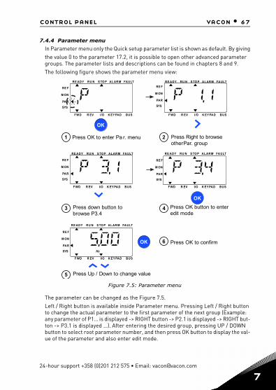
7.4.4 Parameter menu
In Parameter menu only the Quick setup parameter list is shown as default. By givingthe value 0 to the parameter 17.2, it is possible to open other advanced parameter groups. The parameter lists and descriptions can be found in chapters 8 and 9.The following figure shows the parameter menu view:
Figure 7.5: Parameter menu
The parameter can be changed as the Figure 7.5. Left / Right button is available inside Parameter menu. Pressing Left / Right button to change the actual parameter to the first parameter of the next group (Example: any parameter of P1… is displayed -> RIGHT button -> P2.1 is displayed -> RIGHT but-ton -> P3.1 is displayed …). After entering the desired group, pressing UP / DOWN button to select root parameter number, and then press OK button to display the val-ue of the parameter and also enter edit mode.
OK
OK
2 Press Right to browseotherPar. group
4 Press OK button to enteredit mode
3 Press down button tobrowse P3.4
5 Press Up / Down to change value
OK 6 Press OK to confirm
FAULTALAR MS TO PRE ADY RU N
RE F
M ON
PAR
SYS
RE F
M ON
PAR
SYS
RE F
M ON
PAR
SYS
FAULTALARMS TO PRE ADY RU N
FAULTALARMS TO PRE ADY RU N
FWD R EV I/O K EY PAD BUS F WD R EV I/O K EY PAD BUS
F WD R EV I/O K EY PAD BUS
1 Press OK to enter Pa r. menu
FAULTALARMS TO PRE ADY RU N
RE F
M ON
PAR
SYS
F WD R EV I/O K EY PAD BUS
FAULTALARMS TO PRE ADY RU N
RE F
M ON
PAR
SYS
F WD R EV I/O K EY PAD BUS
Hz
24-hour support +358 (0)201 212 575 • Email: [email protected]
7
68 • vacon control panel
7
In edit mode, Left and Right buttons are used to select the digit which has to be changed, and Up increases / Down decreases parameter value.In edit mode, the value of Px.x is displayed blinkingly in the panel. After about 10 s, Px.x is displayed in the panel again if you don't press any button.
Note! In edit mode, if you edit the value and don't press OK button, the value isn't changed successfully. In edit mode, if you don't edit the value, you can press Reset /Back button to display Px.x again.
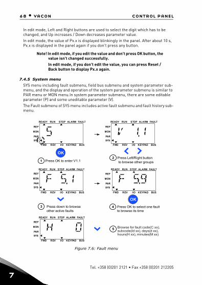
7.4.5 System menu
SYS menu including fault submenu, field bus submenu and system parameter sub-menu, and the display and operation of the system parameter submenu is similar to PAR menu or MON menu.In system parameter submenu, there are some editable parameter (P) and some uneditable parameter (V).The Fault submenu of SYS menu includes active fault submenu and fault history sub-menu.
Figure 7.6: Fault menu
OK
Press OK to enter V1.11Press Left/Right buttonto browse other groups
2
Press down to browseother active faults
3
REF
MON
PAR
SYS
FAULTALARMSTOP
FWD REV I/O KEYPAD BUS
READY RUN
OK
Press OK to select one faultto browse its time
4
REF
MON
PAR
SYS
FAULTALARMSTOPREADY RUN
FWD REV I/O KEYPAD BUS
Browse for fault code(C xx),subcode(Id xx), days(d xx),hours(H xx), minutes(M xx)
5
REF
MON
PAR
SYS
FAULTALARMSTOPREADY RUN
FWD REV I/O KEYPAD BUS
REF
MON
PAR
SYS
FAULTALARMSTOPREADY RUN
FWD REV I/O KEYPAD BUS
REF
MON
PAR
SYS
FAULTALARMSTOPREADY RUN
FWD REV I/O KEYPAD BUS
Tel. +358 (0)201 2121 • Fax +358 (0)201 212205

control panel vacon • 69
In active fault situation, FAULT arrow is blinking and the display is blinking active fault menu item with fault code. If there are several active faults, you can check it by entering the active fault submenu F5.x. F5.1 is always the latest active fault code. The active faults can be reset by pressing BACK / RESET button with long time (>2 s), when the API is in active fault submenu level (F5.x). If the fault cannot be reset, the blinking continues. It is possible to select other display menus during active fault, but in this case the display returns automatically to the fault menu if no button is pressed in 10 seconds. The fault code, subcode and the operating day, hour and minute val-ues at the fault instant are shown in the value menu (operating hours = displayed reading).
Note! Fault History can be reset by long pressing the BACK / RESET button for 5 second time,when the API is in fault history sub-menu level (F6.x), it will also clear all active faults.
See Chapter 5 for fault descriptions.
24-hour support +358 (0)201 212 575 • Email: [email protected]
7

70 • vacon parameters
8
8. STANDARD APPLICATION PARAMETERS
On the next pages you can find the lists of parameters within the respective param-eter groups. The parameter descriptions are given in Chapter 9.
Explanations:Code: Location indication on the keypad; Shows the operator the present
Monitoring value number or Parameter numberParameter: Name of monitoring value or parameterMin: Minimum value of parameterMax: Maximum value of parameterUnit: Unit of parameter value; given if availableDefault: Factory preset valueID: ID number of the parameter (used with fieldbus control)
More information on this parameter available in chapter 9: ‘Param- eter descriptions’ click on the parameter name.
Modifiable only in stop state
NOTE: This manual is for Vacon 20 standard application only. If you need more ap-plication information, please download the appropriate user manual on http://www.vacon.com -> Support & Downloads.
i
Tel. +358 (0)201 2121 • Fax +358 (0)201 212205

parameters vacon • 71
i
i
i
24-hour support +358 (0)201 212 575 • Email: [email protected]
8.1 Quick setup parameters (Virtual menu, shows when par. 16.2 = 1)
Code Parameter Min Max Unit Default ID Note
Motor nominal voltage 180 690 V Varies 110
Motor nominal frequency 30,00 320,00 Hz 50,00 /
60,00 111
Motor nominal speed 30 20000 rpm 1440 /
1720 112
Motor nominal current
0,2 x INunit
2,0 x INunit
A INunit 113
Motor cos (Power Factor)
0,30 1,00 0,85 120
Current limit0,2 x INunit
2,0 x INunit
A1,5 x INunit
107
Torque boost 0 1 0 109
P1.23 Energy optimiza-tion 0 1 0 666
Energy optimization, the frequency converter search for the minimum current in order to save energy and lower motor noise.
P2.1 Remote control place 1 selection 0 2 0 172
Start function 0 1 0 505
Stop function 0 1 0 506
Min frequency 0,00 P3.2 Hz 0,00 101
Max frequency P3.1 320,00 Hz 50,00 /60,00 102
P3.3
Remote control place 1 frequency reference selec-
tion
1 Varies 7 117
P3.4 Preset speed 0 P3.1 P3.2 Hz 5,00 180
P3.5 Preset speed 1 P3.1 P3.2 Hz 10,00 105
P3.6 Preset speed 2 P3.1 P3.2 Hz 15,00 106
P3.7 Preset speed 3 P3.1 P3.2 Hz 20,00 126
Table 8.1: Quick setup parameters
P1.1
P1.2
P1.3
P1.4
P1.5
P1.7i
P1.15i
i
P2.2i
P2.3i
P3.1
P3.2
i
i
8

72 • vacon parameters
8
i
Accelerationtime 1 0,1 3000,0 s 3,0 103
Deceleration time 1 0,1 3000,0 s 3,0 104
P6.1 AI1 range 0 1 0 379
P6.5 AI2 range (see the P6.1) 0 1 0 390
P10.1 Prohibit fre-quency range 1
low limit
0,00 P3.2 Hz 0,00 509
P10.2 Prohibit fre-quency range 1
high limit
0,00 P3.2 Hz 0,00 510
P13.1 Automatic reset 0 1 0 731
Setpoint source selection 0 Varies 0 332
0 = Fixed setpoint %1 = AI12 = AI23 = ProcessDataIn1(0-100%)4 = ProcessDataIn2(0-100%)5 = ProcessDataIn3(0-100%)6 = ProcessDataIn4(0-100%)7 = AIE18 = Temperature input 19 = Temperature input 210 = Temperature input 3
P14.2 Fixed setpoint 1 0,0 100,0 % 50,0 167 Fixed setpoint
P14.3 Fixed setpoint 2 0,0 100,0 % 50,0 168 Alternative fixed set-point, selectable with DI
Code Parameter Min Max Unit Default ID Note
Table 8.1: Quick setup parameters
P4.2
P4.3
P14.1
Tel. +358 (0)201 2121 • Fax +358 (0)201 212205

parameters vacon • 73
P14.4 Feedback source selection
0 Varies 1 334 0 = AI11 = AI22 = ProcessDataIn1(0-100%)3 = ProcessDataIn2(0-100%)4 = ProcessDataIn3(0-100%)5 = ProcessDataIn4(0-100%)6 = AI2-AI17 = AIE18 = Temperature input 19 = Temperature input 210 = Temperature input 3
P14.5 Feedback value min
0,0 50,0 % 0,0 336 Value at minimum sig-nal
P14.6 Feedback value max
10,0 300,0 % 100,0 337 Value at maximum sig-nal
P14.11 Sleep min fre-quency
0,00 P3.2 Hz 25,00 1016 Threshold for enter sleep
P14.12 Sleep delay 0 3600 s 30 1017 Delay for enter sleep
P14.13 Wake up level 0,0 100,0 % 90,0 1018 Threshold for exit sleep
P14.14 Sleep setpoint boost
0,0 50,0 % 10,0 1071Referred to setpoint
P14.15 Setpoint boost time
0 60 s 10 1072Boost time after P14.12
P16.2 Parameter conceal 0 1 1 115
P18.1 Fire mode pass-word
0 9999 0 1599 1234 = Test mode1001 = Enable1515 = Disable
P18.2 Fire mode fre-quency select
0 Varies 0 1617 Fire mode frequency presetNOTE! This parameter will be locked when fire mode is active. To change the parameter you have to disable fire mode.
Code Parameter Min Max Unit Default ID Note
Table 8.1: Quick setup parameters
24-hour support +358 (0)201 212 575 • Email: [email protected]
8
74 • vacon parameters
8
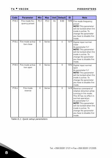
P18.3 Fire mode fre-quency preset
P3.1 P3.2 Hz 8.00 1598 Fire mode frequency presetNOTE! This parameter will be locked when fire mode is active. To change the parameter you have to disable fire mode.
P18.4 Fire mode activa-tion close
0 Varies 6 1619 Digital input normal closeAs parameter 5.1NOTE! This parameter will be locked when fire mode is active. To change the parameter you have to disable fire mode.
P18.5 Fire mode activa-tion open
0 Varies 0 1596 Digital input normal openAs parameter 5.1NOTE! This parameter will be locked when fire mode is active. To change the parameter you have to disable fire mode.
P18.6 Fire mode reverse
0 Varies 0 1618 Reverse command of rotation direction while running in fire mode. This DI has no effect in normal operation.As parameter 5.1NOTE! This parameter will be locked when fire mode is active. To change the parameter you have to disable fire mode.
Code Parameter Min Max Unit Default ID Note
Table 8.1: Quick setup parameters
Tel. +358 (0)201 2121 • Fax +358 (0)201 212205

parameters vacon • 75
i
i
i
i
i
i
i
i
i
i
i
8.2 Motor settings (Control panel: Menu PAR -> P1)
Code Parameter Min Max Unit Default ID Note
Motor nominal voltage 180 690 V Varies 110
Motor nominal fre-quency 30,00 320,00 Hz 50,00 /
60,00 111
Motor nominal speed 30 20000 rpm 1440 /
1720 112
Motor nominal current
0,2 x INunit
2,0 x INunit
A INunit 113
Motor cos(Power Factor)
0,30 1,00 0,85 120
Motor type 0 1 0 650 0 = Induction1 = Permanent magnet
Current limit0,2 x INunit
2,0 x INunit
A1,5 x INunit
107
Motor control mode 0 1 0 600 0 = Frequency control
1 = Open loop speed control
U / f ratio 0 2 0 1080 = Linear1 = Square2 = Programmable
Field weakening point
8,00 320,00 Hz 50,00 /60,00 602
Field weakening point voltage 10,00 200,00 % 100,00 603
U / f mid point frequency 0,00 P1.10 Hz 50,00 /
60,00 604
U / f mid point voltage 0,00 P1.11 % 100,00 605
Zero freq voltage 0,00 40,00 % Varies 606
Torque Boost 0 1 0 109 0 = Disabled1 = Enabled
Switching frequency 1,5 16,0 kHz 4,0 / 2,0 601
Motor identification 0 1 0 631
0 = not active1 = standstill identification (need run command within 20s to activate)2 = ID with run
Table 8.2: Motor settings
P1.1
P1.2
P1.3
P1.4
P1.5
P1.6
P1.7
P1.8
P1.9
P1.10
P1.11
P1.12
P1.13
P1.14
P1.15
P1.16
P1.17
24-hour support +358 (0)201 212 575 • Email: [email protected]
8

76 • vacon parameters
8
i
i
i
i
Rs voltage drop 0,00 100,00 % 0,00 662
Overvoltage controller 0 2 1 607
0 = Disabled1 = Enabled: default mode2 = Enabled: shock load mode
Undervoltage controller 0 1 1 608
0 = Disable1 = Enabled
Sine filter 0 1 0 5220 = Not in use1 = In use
Modulator type 0 65535 28928 648
Bit 1 = Discontinuous mod-ulationBit 2 = Pulse dropping in over modulationBit 6 = Under modulationBit 8 = Instantaneous DC voltage compensationBit 11 = Low noise Bit 12 = Dead time com-pensationBit 13 = Flex error com-pensation
Energy optimiza-tion 0 1 0 666
Energy optimization, the fre-quency converter search for the minimum current in order to save energy and lower motor noise:0 = Disabled1 = Enable
I/f start enable 0 1 0 534
The I/f Start function is typi-cally used with permanent magnet motors (PM) to start the motor with constant cur-rent control. This is useful with high power motors in which the resistance is low and the tuning of the U/f curve difficult.Applying the I/f Start function may also prove useful in pro-viding sufficient torque for the motor at startup.0 = Disabled1 = Enable
Code Parameter Min Max Unit Default ID Note
Table 8.2: Motor settings
P1.18
P1.19
P1.20
P1.21
P1.22
P1.23
P1.24
Tel. +358 (0)201 2121 • Fax +358 (0)201 212205

parameters vacon • 77
i
i
i
24-hour support +358 (0)201 212 575 • Email: [email protected]
NOTE! These parameters are shown, when P16.2 = 0.
I/f start fre-quency refer-
ence limit1 100 % 10 535
Output frequency limit below which the defined I/f start cur-rent is fed to motor.
I/f start current reference 0 100.0 % 80.0 536
The current fed to the motor when the I/f start function is activated.
Voltage limiter enable 0 1 1 1079
Voltage limiter function addresses problem with very high DC-link voltage ripple with 1-phase drives when fully loaded. Very high ripple in DC link voltage will transform to high current and torque ripple, which can disturb some users. Voltage limiter function limits maximum output voltage to bottom of DC-voltage ripple. This reduces current and torque ripple, but decreases maximum output power since voltage is limited and more current is needed.0 = Disabled1 = Enabled
Code Parameter Min Max Unit Default ID Note
Table 8.2: Motor settings
P1.25
P1.26
P1.27
8

78 • vacon parameters
8
8.3
Table 8.3: Start / stop setup
Code Parameter Min Max Unit Default ID Note
P2.1iRemote Control
Place 1 Selection 0 2 0 1720 = I / O terminals 1 = Fieldbus2 = Keypad
P2.2i Start function 0 1 0 505 0 = Ramping1 = Flying start
P2.3i Stop function 0 1 0 506 0 = Coasting 1 = Ramping
P2.4iI / O Start / Stop
logic 0 4 2 300
I / O control I / O control signal 1 signal 20 Forward Reverse1 Fwd(edge) Inverted Stop 2 Fwd(edge) Bwd(edge)3 Start Reverse4 Start(edge) Reverse
P2.5i Local / Remote 0 1 0 211 0 = Remote control1 = Local control
P2.6 Keypad control direction 0 1 0 123 0 = Forward
1 = Backward
P2.7 Keypad stop but-ton 0 1 1 114 0 = Keypad control only
1 = Always
P2.8 Remote Control Place 2 Selection 0 2 0 173
0 = I / O terminals 1 = Fieldbus2 = Keypad
P2.9keypad button
lock 0 1 0 15520 0 = unlock all keypad button 1 = Loc/Rem button locked
Start / stop setup (Control panel: Menu PAR -> P2)
Tel. +358 (0)201 2121 • Fax +358 (0)201 212205

parameters vacon • 79
8.4 Frequency references (Control panel: Menu PAR -> P3)
NOTE! These parameters are shown, when P16.2 = 0.
Code Parameter Min Max Unit Default ID Note
Min frequency 0,00 P3.2 Hz 0,00 101
Max frequency P3.1 320,00 Hz 50,00 /60,00 102
P3.3
Remote Control Place 1 fre-
quency refer-ence selection
1 Varies 7 117
1 = Preset speed 02 = Keypad 3 = Fieldbus 4 = AI1 5 = AI26 = PID7 = AI1+ AI28 = Motor potentiometer9 = AIE110 = Temperature input 111 = Temperature input 212 = Temperature input 3
P3.4 Preset speed 0 P3.1 P3.2 Hz 5,00 180
P3.5 Preset speed 1 P3.1 P3.2 Hz 10,00 105
P3.6 Preset speed 2 P3.1 P3.2 Hz 15,00 106
P3.7 Preset speed 3 P3.1 P3.2 Hz 20,00 126
P3.8 Preset speed 4 P3.1 P3.2 Hz 25,00 127
P3.9 Preset speed 5 P3.1 P3.2 Hz 30,00 128
P3.10 Preset speed 6 P3.1 P3.2 Hz 40,00 129
P3.11 Preset speed 7 P3.1 P3.2 Hz 50,00 130
P3.12
Remote Control Place 2 fre-
quency refer-ence selection
1 Varies 5 131 As parameter P3.3
P3.13 Motor Poten-tionmeter Ramp 1 50 Hz/s 5 331
P3.14Motor Poten-
tionmeter Reset 0 2 2 3670 = No reset1 = Reset if stopped2 = Reset if powered down
Table 8.4: Frequency references
P3.1
P3.2
i
i
iii
iii
i
i
24-hour support +358 (0)201 212 575 • Email: [email protected]
8

80 • vacon parameters
8
8.5 Ramps and brakes setup (Control panel: Menu PAR -> P4)
Code Parameter Min Max Unit Default ID Note
Ramp S-shape 1 0,0 10,0 s 0,0 500
Acceleration time 1 0,1 3000,0 s 3,0 103
Deceleration time 1 0,1 3000,0 s 3,0 104
Ramp S-shape 2 0,0 10,0 s 0,0 501
Acceleration time 2 0,1 3000,0 s 10,0 502
Deceleration time 2 0,1 3000,0 s 10,0 503
Flux Braking 0 3 0 520
0 = Off1 = Deceleration2 = Chopper3 = Full mode
Flux Braking Cur-rent
0,5 x INunit
2,0 x INunit
A INunit 519
DC Braking Current0,3 x INunit
2,0 x INunit
A INunit 507
Stop DC current time 0,00 600,00 s 0,00 508 0 = Not active
Stop DC current frequency 0,10 10,00 Hz 1,50 515
Start DC current time 0,00 600,00 s 0,00 516
P4.13 Accel2 Frequency Threshold 0.00 P3.2 Hz 0,00 527 0,00 = Disabled
P4.14 Decel2 Frequency Threshold 0,00 P3.2 Hz 0,00 528 0,00 = Disabled
P4.15 External Brake: Open Delay 0,00 320,00 s 0,20 1544
P4.16External Brake: Open Frequency
limit0,00 P3.2 Hz 1,50 1535
Table 8.5: Ramps and brakes setup
P4.1i
P4.2
P4.3
P4.4
P4.5
P4.6i
P4.7i
P4.8
P4.9
P4.10i
P4.11i
P4.12i
Tel. +358 (0)201 2121 • Fax +358 (0)201 212205

parameters vacon • 81
P4.17External Brake : Close Frequency
limit0,00 P3.2 Hz 1,00 1539
P4.18External Brake : Close Frequency limit in Reverse
0,00 P3.2 Hz 1,50 1540
P4.19External Brake : Open/Close Cur-
rent limit0,0 200,0 % 20,0 1585
Code Parameter Min Max Unit Default ID Note
Table 8.5: Ramps and brakes setup
i
24-hour support +358 (0)201 212 575 • Email: [email protected]
8

82 • vacon parameters
8
8.6 Digital inputs (Control panel: Menu PAR -> P5)
Code Parameter Min Max Unit Default ID Note
P5.1 I / O control signal 1 0 Varies 1 403
0 = Not used1 = DI12 = DI2 3 = DI3 4 = DI45 = DI5 6 = DI67 = DIE18 = DIE29 = DIE310 = DIE411 = DIE512 = DIE6
P5.2 I / O control signal 2 0 Varies 2 404
P5.3 Reverse 0 Varies 0 412
P5.4 Ext. fault Close 0 Varies 0 405
P5.5 Ext. fault Open 0 Varies 0 406
P5.6 Fault reset 0 Varies 3 414
P5.7 Run enable 0 Varies 0 407
P5.8 Preset speed B0 0 Varies 0 419
P5.9 Preset speed B1 0 Varies 0 420
P5.10 Preset speed B2 0 Varies 0 421
P5.11 Ramp time 2 selection 0 Varies 0 408
P5.12 Motor potentiometer up 0 Varies 0 418
P5.13 Motor potentiometer down 0 Varies 0 417
P5.14 Remote control place 2 0 Varies 0 425
P5.15 Remote control plece freq reference 2 0 Varies 0 343
P5.16 PID setpoint 2 0 Varies 0 1047
P5.17 Motor PreHeat ON 0 Varies 0 1044
Table 8.6: Digital inputs
i
i
i
i
i
Tel. +358 (0)201 2121 • Fax +358 (0)201 212205

parameters vacon • 83
8.7 Analogue inputs (Control panel: Menu PAR -> P6)
Code Parameter Min Max Unit Default ID Note
P6.1 AI1 range 0 1 0 379 0 = 0 - 100%1 = 20% - 100%
P6.2 AI1 Custom min -100,00 100,00 % 0,00 380
P6.3 AI1 Custom max -100,00 300,00 % 100,00 381
P6.4 AI1 filter time 0,0 10,0 s 0,1 378
P6.5 AI2 range 0 1 0 390 As parameter P6.1
P6.6 AI2 Custom min -100,00 100,00 % 0,00 391 As parameter P6.2
P6.7 AI2 Custom max -100,00 300,00 % 100,00 392 As parameter P6.3
P6.8 AI2 filter time 0,0 10,0 s 0,1 389 As parameter P6.4
P6.9 AIE1 range 0 1 0 143As parameter P6.1, hid-den until an option board is connected.
P6.10 AIE1 Custom Min -100,00 100,00 % 0,00 144As parameter P6.2, hid-den until an option board is connected.
P6.11 AIE1 Custom Max -100,00 300,00 % 100,00 145As parameter P6.3, hid-den until an option board is connected.
P6.12 AIE1 Filter time 0,0 10,0 s 0,1 142As parameter P6.4, hid-den until an option board is connected.
Table 8.7: Analogue inputs
i
i
24-hour support +358 (0)201 212 575 • Email: [email protected]
8

84 • vacon parameters
8
8.8 Digital outputs (Control panel: Menu PAR -> P7)
Code Parameter Min Max Unit Default ID Selections
P7.1 RO1 signal selection 0 Varies 2 313
0 = Not used1 = Ready2 = Run3 = Fault4 = Fault Inverted5 = Warning6 = Reversed7 = At Speed8 = Motor regulator active9 = FB Control Word.B1310 = FB Control Word.B1411 = FB Control Word.B1512 = Output freq superv.13 = Output torque superv.14 = Unit temperature superv.15 = Analogue input superv.16 = Preset Speed Active17 = External Brake ctrl18 = Keypad control active19 = I / O control active20 = Temperature supervision
P7.2 RO2 signal selcetion 0 Varies 3 314 As parameter 7.1
P7.3DO1 signal selcetion 0 Varies 1 312 As parameter 7.1
P7.4 RO2 inversion 0 1 0 1588 0 = No inversion1 = Inverted
P7.5 RO2 ON delay 0,00 320,00 s 0,00 460
P7.6 RO2 OFF delay 0,00 320,00 s 0,00 461
P7.7 RO1 inversion 0 1 0 1587 0 = No inversion1 = Inverted
P7.8 RO1 ON delay 0,00 320,00 s 0,00 458
P7.9 RO1 OFF delay 0,00 320,00 s 0,00 459
P7.10 DOE1 signal selection 0 Varies 0 317
As parameter 7.1, hidden until an option board is con-nected.
P7.11 DOE2 signal selection 0 Varies 0 318
As parameter 7.1, hidden until an option board is con-nected.
Table 8.8: Digital outputs
i
Tel. +358 (0)201 2121 • Fax +358 (0)201 212205

parameters vacon • 85
P7.12 DOE3 signal selection 0 Varies 0 1386
As parameter 7.1, hidden until an option board is con-nected.
P7.13 DOE4 signal selection 0 Varies 0 1390
As parameter 7.1, hidden until an option board is con-nected.
P7.14 DOE5 signal selection 0 Varies 0 1391
As parameter 7.1, hidden until an option board is con-nected.
P7.15 DOE6 signal selection 0 Varies 0 1395
As parameter 7.1, hidden until an option board is con-nected.
Code Parameter Min Max Unit Default ID Selections
Table 8.8: Digital outputs
24-hour support +358 (0)201 212 575 • Email: [email protected]
8

86 • vacon parameters
8
8.9 Analogue outputs (Control panel: Menu PAR -> P8)
Code Parameter Min Max Unit Default ID Selections
P8.1Analog output
signal selection 0 14 1 307
0 = Not used1 = Output freq. (0-fmax)2 = Output current (0-InMotor)3 = Motor torque (0-TnMotor)4 = PID output (0 - 100%)5 = Freq. refer. (0-fmax)6 = Motor speed (0-nmax)7 = Motor power (0-PnMotor)8 = Motor Voltage (0-UnMotor)9 = DC-link Voltage (0 - 1000 V)10 = Process Data In1 (0 - 10000)11 = Process Data In2 (0 - 10000)12 = Process Data In3 (0 - 10000)13 = Process Data In4 (0 - 10000)14 = Test 100%
P8.2Analog output
minimum 0 1 0 310 0 = 0 mA1 = 4 mA
P8.3 Analog output scaling 0,0 1000,0 % 100,0 311
P8.4 Analog output fil-ter time
0,00 10,00 s 0,10 308
P8.5 Analog output E1 signal selection
0 14 0 472As parameter P8.1, hidden until an option board is con-nected.
P8.6 Analog output E1 minimum
0 1 0 475As parameter P8.2, hidden until an option board is con-nected.
P8.7 Analog output E1 scaling 0,0 1000,0 % 100,0 476
As parameter P8.3, hidden until an option board is con-nected.
P8.8 Analog output E1 filter time 0,00 10,00 s 0,10 473
As parameter P8.4, hidden until an option board is con-nected.
Table 8.9: Analogue outputs
i
i
Tel. +358 (0)201 2121 • Fax +358 (0)201 212205

parameters vacon • 87
8.10 Fieldbus Data-Mapping (Control panel: Menu PAR -> P9)
P8.9 Analog output E2 signal selection
0 14 0 479As parameter P8.1, hidden until an option board is con-nected.
P8.10 Analog output E2 minimum
0 1 0 482As parameter P8.2, hidden until an option board is con-nected.
P8.11 Analog output E2 scaling 0,0 1000,0 % 100,0 483
As parameter P8.3, hidden until an option board is con-nected.
P8.12 Analog output E2 filter time 0,00 10,00 s 0,10 480
As parameter P8.4, hidden until an option board is con-nected.
Code Parameter Min Max Unit Default ID Note
P9.1FB Data Output 1
selection 0 Varies 0 852
0 = Frequency reference1 = Output reference2 = Motor speed3 = Motor current4 = Motor voltage5 = Motor torque6 = Motor power7 = DC link voltage8 = Active fault code9 = AI110 = AI211 = Digital input state12 = PID feedback value13 = PID setpoint14 = AIE1
P9.2 FB Data Output 2 selection 0 Varies 1 853
P9.3 FB Data Output 3 selection 0 Varies 2 854
P9.4 FB Data Output 4 selection
0 Varies 4 855
P9.5 FB Data Output 5 selection 0 Varies 5 856
Table 8.10: Fieldbus Data-Mapping
Code Parameter Min Max Unit Default ID Selections
Table 8.9: Analogue outputs
i
24-hour support +358 (0)201 212 575 • Email: [email protected]
8
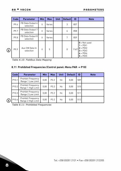
88 • vacon parameters
8
8.11 Prohibited Frequencies (Control panel: Menu PAR -> P10)
P9.6 FB Data Output 6 selection
0 Varies 3 857
P9.7 FB Data Output 7 selection 0 Varies 6 858
P9.8 FB Data Output 8 selection
0 Varies 7 859
P9.9Aux CW Data In
selection 0 5 0 1167
0 = Not used1 = PDI12 = PDI23 = PDI34 = PDI45 = PDI5
Code Parameter Min Max Unit Default ID Note
P10.1 Prohibit Frequency Range 1 Low Limit 0,00 P3.2 Hz 0,00 509
P10.2 Prohibit Frequency Range 1 High Limit 0,00 P3.2 Hz 0,00 510
P10.3 Prohibit Frequency Range 2 Low Limit 0,00 P3.2 Hz 0,00 511
P10.4Prohibit Frequency Range 2 High Limit 0,00 P3.2 Hz 0,00 512
Table 8.11: Prohibited Frequencies
Code Parameter Min Max Unit Default ID Note
Table 8.10: Fieldbus Data-Mapping
i
i
Tel. +358 (0)201 2121 • Fax +358 (0)201 212205

parameters vacon • 89
8.12 Limit Supervisions (Control panel: Menu PAR -> P11)
Code Parameter Min Max Unit Default ID Note
P11.1Output freq.
supervision func-tion
0 2 0 3150 = Not used1 = Low limit2 = High limit
P11.2 Output freq. supervision limit 0,00 P3.2 Hz 0,00 316
P11.3 Torque supervi-sion function 0 2 0 348
0 = Not used1 = Low limit2 = High limit
P11.4 Torque supervi-sion limit 0,0 300,0 % 0,0 349
P11.5 Unit Temperature Supervision 0 2 0 354
P11.6 Unit Temperature Supervision Limit -10 100 °C 40 355
P11.7 Analogue input superv signal 0 Varies 0 356
0 = AI11 = AI22 = AIE1
P11.8 AI superv ON level 0,00 100,00 % 80,00 357
P11.9 AI superv OFF level 0,00 100,00 % 40,00 358
P11.10 Temperature supervision input 1 7 1 1431
Binary-coded selection of signals to use for tem-perature supervisionB0 = Temperature input 1B1 = Temperature input 2B2 = Temperature input 3NOTE! Hidden until an option board is con-nected.
P11.11Temperature
supervision func-tion
0 2 2 1432As parameter 11.1, hid-den until an option board is connected.
P11.12 Temperature supervision limit
-50,0/223,2
200,0/473,2 80,0 1433
Temperature supervision threshold, hidden until an option board is con-nected.
Table 8.12: Limit Supervisions
24-hour support +358 (0)201 212 575 • Email: [email protected]
8

90 • vacon parameters
8
8.13 Protections (Control panel: Menu PAR -> P12)
Code Parameter Min Max Unit Default ID Note
P12.1 Analog Input low fault 0 4 1 700
0 = No action1 = Alarm2 = Alarm, preset alarm frequency3 = Fault: Stop function4 = Fault: Coast
Under voltage fault 1 2 2 727
1 = No response (no fault generated but drive still stops modulation)2 = Fault: Coast
Earth fault 0 3 2 703
0 = No action1 = Alarm2 = Fault: Stop function3 = Fault: Coast
Output Phase Fault
0 3 2 702 As parameter 12.3
Stall protection 0 3 0 709 As parameter 12.3
Under load pro-tection
0 3 0 713 As parameter 12.3
Motor thermal protection 0 3 2 704 As parameter 12.3
Mtp:Ambient temperature -20 100 °C 40 705
Mtp:Zero speed cooling
0,0 150,0 % 40,0 706
Mtp:Thermal time constant 1 200 min Varies 707
Stall Current 0,002,0 x INunit
A INunit 710
Stall time 0,00 300,00 s 15,00 711
Stall frequency 0,10 320,00 Hz 25,00 712
UL:Field weaken-ing load 10,0 150,0 % 50,0 714
UL:Zero freq load 5,0 150,0 % 10,0 715
UL:Time limit 1,0 300,0 s 20,0 716
Table 8.13: Protections
P12.2
P12.3
P12.4
P12.5i
P12.6i
P12.7i
P12.8i
P12.9i
P12.10i
P12.11i
P12.12i
P12.13
P12.14i
P12.15
P12.16i
Tel. +358 (0)201 2121 • Fax +358 (0)201 212205

parameters vacon • 91
P12.17 Analog Input low fault delay
0,0 10,0 s 0,5 1430
External fault 0 3 2 701 As parameter 12.3
P12.19 Fieldbus fault 0 4 3 733 As parameter 12.1
P12.20 Preset alarm fre-quency P3.1 P3.2 Hz 25,00 183
P12.21 Parameters edit lock 0 1 0 819 0 = Edit enabled
1 = Edit disabled
P12.22 Thermistor Fault 0 3 2 732
Hidden until option board supporting ther-mistor is connected:0 = No action1 = Alarm2 = Fault: Stop function3 = Fault: Coast
P12.23 FWD/REV con-flict supervision 0 3 1 1463 As parameter 12.3
P12.24 Temperature fault 0 3 0 740
As parameter P12.3, hid-den until an OPTBH board is connected.
P12.25 Temperature fault input 1 7 1 739
Binary-coded selection of signals to use for alarm and fault triggeringB0 = Temperature input 1B1 = Temperature input 2B2 = Temperature input 3NOTE! Hidden until an OPTBH board is connected.
P12.26 Temperature fault mode 0 2 2 743
0 = Not used1 = Low limit2 = High limit
P12.27 Temperature fault limit
50,0/223,2
200,0/473,2 100,0 742
Temperature fault threshold, hidden until an OPTBH board is con-nected/
Code Parameter Min Max Unit Default ID Note
Table 8.13: Protections
P12.18
24-hour support +358 (0)201 212 575 • Email: [email protected]
8

92 • vacon parameters
8
NOTE! These parameters are shown, when P16.2 = 0.
8.14 Fault autoreset parameters (Control panel: Menu PAR -> P13)
NOTE! These parameters are shown, when P16.2 = 0.
Input phase fault 0 3 3 730
0 = No action1 = Alarm2 = Fault: Stop function3 = Fault: Coast
Motor tempera-ture
memory mode0 2 0 15521
0 = Disabled1 = Constant mode2 = Last value mode
Code Parameter Min Max Unit Default ID Note
Automatic Reset 0 1 0 731 0 = Disabled1 = Enable
Wait time 0,10 10,00 s 0,50 717
Trial time 0,00 60,00 s 30,00 718
Trials number 1 10 3 759
Restart Function 0 2 2 7190 = Ramping1 = Flying 2 = By start function
Table 8.14: Fault autoreset parameters
Code Parameter Min Max Unit Default ID Note
Table 8.13: Protections
P12.28i
P12.29i
P13.1i
P13.2
P13.3i
P13.4
P13.5
Tel. +358 (0)201 2121 • Fax +358 (0)201 212205

parameters vacon • 93
i
i
i
8.15 PID control parameters (Control panel: Menu PAR -> P14)
Code Parameter Min Max Unit Default ID Note
P14.1 Setpoint source selection 0 Varies 0 332
0 = Fixed setpoint %1 = AI12 = AI2 3 = ProcessDataIn1(0 -100%)4 = ProcessDataIn2(0 -100%)5 = ProcessDataIn3(0 -100%)6 = ProcessDataIn4(0 -100%)7 = AIE18 = Temperature input 19 = Temperature input 210 = Temperature input 3
P14.2 Fixed setpoint 1 0,0 100,0 % 50,0 167 Fixed setpoint
P14.3 Fixed setpoint 2 0,0 100,0 % 50,0 168 Alternative fixed setpoint, selectable with DI
P14.4 Feedback source selection 0 Varies 1 334
0 = AI11 = AI22 = ProcessDataIn1(0 -100%)3 = ProcessDataIn2(0 -100%)4 = ProcessDataIn3(0 -100%)5 = ProcessDataIn4(0 -100%)6 = AI2-AI17 = AIE18 = Temperature input 19 = Temperature input 210 = Temperature input 3
P14.5 Feedback value minumum 0,0 50,0 % 0,0 336 Value at minimum signal
P14.6Feedback value
maximum 10,0 300,0 % 100,0 337 Value at maximum signal
P14.7 P gain 0,0 1000,0 % 100,0 118 Proportional gain
P14.8 I time 0,00 320,00 s 10,00 119 Integrative time
Table 8.15: PID control parameters
24-hour support +358 (0)201 212 575 • Email: [email protected]
8

94 • vacon parameters
8
i
i
i
i
i
i
i
NOTE! These parameters are shown, when P17.2 = 0.
P14.9 D time 0,00 10,00 s 0,00 132 Derivative time
P14.10 Error inversion 0 1 0 340 0 = Direct1 = Inverted
P14.11 Sleep minimum frequency 0,00 P3.2 Hz 25,00 1016 Threshold for enter sleep
P14.12 Sleep delay 0 3600 s 30 1017 Delay for enter sleep
P14.13 Wake up error 0,0 100,0 % 90 1018 Threshold for exit sleep
P14.14 Sleep setpoint boost 0,0 50,0 % 10,0 1071 Referred to setpoint
P14.15 Setpoint boost time 0 60 s 10 1072 Boost time after P14.12
P14.16Sleep maxi-mum loss 0,0 50,0 % 5,0 1509 Referred to feedback value
after boost
P14.17Sleep loss check
time 1 300 s 30 1510 After boost time P14.15
P14.18 Process unit source select 0 5 0 1513
0 = PID feedback value1 = Output frequency2 = Motor speed 3 = Motor torque4 = Motor power5 = Motor current
P14.19 Process unit decimal digits 0 3 1 1035 Decimals on display
P14.20Process unit
minimum value 0,0 P15,21 0,0 1033 Process min value
P14.21Process unit
maximum value P15.20 3200,0 100,0 1034 Process max value
P14.22 Temperature min value
-50,0/223,2 P15.23 0,0 1706
Temperature min value for PID and frequency refer-ence scale, hidden until an OPTBH board is connected
P14.23 Temperature max value P15.22 200,0/
473,2 100,0 1707
Temperature max value for PID and frequency refer-ence scale, hidden until an OPTBH board is connected
Code Parameter Min Max Unit Default ID Note
Table 8.15: PID control parameters
Tel. +358 (0)201 2121 • Fax +358 (0)201 212205

parameters vacon • 95
i
8.16 Motor Pre-heat (Control panel: Menu PAR -> P15)
8.17 Easy usage menu (Control panel: Menu PAR -> P16)
Code Parameter Min Max Unit Default ID Note
P15.1 Motor Pre-heat Function 0 2 0 1225
0 = Not used1 = Always in stop state2 = Controlled by digital input
P15.2 Motor Pre-heat Current 0
0,5 x INunit
A 0 1227
Table 8.16: Motor Pre-heat
Code Parameter Min Max Unit Default ID Note
Active fire mode parameter
group0 3 0 540
0 = Disable fire mode parameter group wizard1 = Enable fire mode parameter group wizardNOTE! Visible only when Startup wizard is active.
P16.2 Parameterconceal 0 1 1 115
0 = All parameters visible1 = Only quick setup parameter group visible
P16.3 Temperature unit 0 1 0 1197
0 = Celsius1 = KelvinsNOTE! Hidden until an OPTBH board is con-nected.
P16.4 Application access word 0 30000 0 2362
Input the right password could review parameter group 17.
Table 8.17: Easy usage menu parameters
P16.1
i
24-hour support +358 (0)201 212 575 • Email: [email protected]
8

96 • vacon parameters
8
8.18 Fire mode (Control panel: Menu PAR -> P17)Drive ignores all commands from keypad, fieldbus and PC tool and preset frequency when activated. If activated, alarm sign is shown on the keypad and warranty is void.In order to enable the function, you need to set a password in the description field for parameter Fire Mode password. Please not the NC (normally closed) type of this in-put!NOTE! THE WARRANTY IS VOID IF THIS FUNCTION IS ACTIVATED! There is also a different password for test mode to be used for testing the Fire Mode without war-ranty becoming void.
Code Parameter Min Max Unit Default ID NoteP17.1 Fire mode pass-
word0 9999 0 1599 1234 = Test mode
1001 = Enable1515 = Disable
P17.2 Fire mode fre-quency select
0 Varies 0 1617 0 = Fire mode preset1 = Preset speed 02 = Keypad3 = Fieldbus4 = AI15 = AI26 = PID7 = AI+AI28 = Motor potentiometer9 = AIE110 = Temperature input 111= Temperature input 212 = Temperature input 3NOTE! This parameter will be locked when pass-word for fire mode is activated (not in the test mode), and not only when fire mode input is set. To change the parameter you have to disable fire mode.
P17.3 Fire mode fre-quency preset
P3.1 P3.2 Hz 8.00 1598 Fire mode frequency pre-setNOTE! This parameter will be locked when pass-word for fire mode is activated (not in the test mode), and not only when fire mode input is set. To change the parameter you have to disable fire mode.
Table 8.18: Fire mode
Tel. +358 (0)201 2121 • Fax +358 (0)201 212205

parameters vacon • 97
P17.4 Fire mode activa-tion close
0 Varies 6 1619 Digital input, if fire mode is enable or in test mode then when digital input is closed, fire mode will be active.As parameter 5.1NOTE! This parameter will be locked when pass-word for fire mode is activated (not in the test mode), and not only when fire mode input is set. To change the parameter you have to disable fire mode.
P17.5 Fire mode activa-tion open
0 Varies 0 1596 Digital input, if fire mode is enable or in test mode then when digital input is open, fire mode will be active.As parameter 5.1NOTE! This parameter will be locked when pass-word for fire mode is activated (not in the test mode), and not only when fire mode input is set. To change the parameter you have to disable fire mode.
P17.6 Fire mode reverse
0 Varies 0 1618 Reverse command of rotation direction while running in fire mode. This DI has no effect in normal operation.As parameter 5.1NOTE! This parameter will be locked when pass-word for fire mode is activated (not in the test mode), and not only when fire mode input is set. To change the parameter you have to disable fire mode.
Code Parameter Min Max Unit Default ID Note
Table 8.18: Fire mode
24-hour support +358 (0)201 212 575 • Email: [email protected]
8

98 • vacon parameters
8
8.19 System parameters
Code Parameter Min Max Default ID Note
Software information (MENU SYS->V1)
V1.1 API SW ID 2314
V1.2 API SW version 835
V1.3 Power SW ID 2315
V1.4 Power SW version 834
V1.5 Application ID 837
V1.6 Application revision 838
V1.7 System load 839
When no field bus Option Board or no OPT-BH Board has been installed, the Modbus comm. Parameters are as follows
V2.1 Communication status 808
Status of Modbus communication. Format: xx.yyy where xx = 0 - 64 (Num-ber of error messages) yyy = 0 - 999 (Number of good messages)
P2.2 Fieldbus protocol 0 1 0 809 0 = Not used1 = Modbus used
P2.3 Slave address 1 255 1 810
P2.4 Baud rate 0 8 5 811
0 = 3001 = 6002 = 12003 = 24004 = 48005 = 96006 = 192007 = 384008 = 57600
P2.6 Parity type 0 2 0 813
0 = None1 = Even2 = OddThe Stop Bit is 2-bit When Parity type is 0 = None; The Stop Bit is 1-bit When Parity type is 1 = Even or 2 = Odd
Table 8.19: System parameters
Tel. +358 (0)201 2121 • Fax +358 (0)201 212205
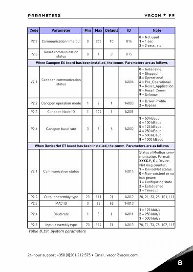
parameters vacon • 99
P2.7 Communication time out 0 255 10 8140 = Not used 1 = 1 sec 2 = 2 secs, etc
P2.8 Reset communication status 0 1 0 815
When Canopen E6 board has been installed, the comm. Parameters are as follows
V2.1 Canopen communication status 14004
0 = Initialising 4 = Stopped 5 = Operational 6 = Pre_Operational 7 = Reset_Application8 = Reset_Comm 9 = Unknow
P2.2 Canopen operation mode 1 2 1 14003 1 = Driver Profile2 = Bypass
P2.3 Canopen Node ID 1 127 1 14001
P2.4 Canopen baud rate 3 8 6 14002
3 = 50 kBaud4 = 100 kBaud5 = 125 kBaud6 = 250 kBaud7 = 500 kBaud8 = 1000 kBaud
When DeviceNet E7 board has been installed, the comm. Parameters are as follows
V2.1 Communication status 14014
Status of Modbus com-munication. Format: XXXX.Y, X = Device-Net msg counter, Y = DeviceNet status. 0 = Non-existent or no bus power. 1 = Configuring state 2 = Established 3 = Timeout
P2.2 Output assembly type 20 111 21 14012 20, 21, 23, 25, 101, 111
P2.3 MAC ID 0 63 63 14010
P2.4 Baud rate 1 3 1 140111 = 125 kbit/s2 = 250 kbit/s3 = 500 kbit/s
P2.5 Input assembly type 70 117 71 14013 70, 71, 73, 75, 107, 117
Code Parameter Min Max Default ID Note
Table 8.19: System parameters
24-hour support +358 (0)201 212 575 • Email: [email protected]
8

100 • vacon parameters
8
When ProfidBus E3/E5 board has been installed, the comm. Parameters are as follows
V2.1 Communication status 14022
V2.2 Fieldbus protocol status 14023
V2.3 Active protocol 14024
V2.4 Active buad rate 14025
V2.5 Telegram type 14027
P2.6 Operate mode 1 3 1 140211 = Profidrive2 = Bypass3 = Echo
P2.7 Slave address 2 126 126 14020
When ModbusTCP & Profinet E9 board has been installed,the comm.Parameters are as fol-lows
V2.1 IP Part1 1 233 14232 current IP Address Part1
V2.2 IP Part2 0 255 14233 current IP Address Part2
V2.3 IP Part3 0 255 14234 current IP Address Part3
V2.4 IP Part4 0 255 14235 current IP Address Part4
V2.5 Subnet Mask P1 0 255 14236 current Subnet Mask Part1
V2.6 Subnet Mask P2 0 255 14237 current Subnet Mask Part2
V2.7 Subnet Mask P3 0 255 14238 current Subnet Mask Part3
V2.8 Subnet Mask P4 0 255 14239 current Subnet Mask Part4
V2.9 Default GW P1 0 255 14240 current Default Gate-way Part1
V2.10 Default GW P2 0 255 14241 current Default Gate-way Part2
V2.11 Default GW P3 0 255 14242 current Default Gate-way Part3
V2.12 Default GW P4 0 255 14243 current Default Gate-way Part4
Code Parameter Min Max Default ID Note
Table 8.19: System parameters
Tel. +358 (0)201 2121 • Fax +358 (0)201 212205

parameters vacon • 101
V2.13FB Protocol Status “Ini-
tializing, Stopped, Opera-tional, Faulted”
14244
V2.14 Communication Status 14245
0-64 Number of mes-sages with errors,0-999 Number of mes-sages without com-munication errors
V2.15 Drive control word 14246 Control word in drive format (hex)
V2.16 Drive Status word 14247 Status word in drive format (hex)
V2.17 Profile control word 14248 Control word in proto-col format (hex)
V2.18 Profile status word 14249 Status word in proto-col format (hex)
P2.19 Protocol 1 2 1 14230Active Protocol.1= ModbusTCP,2= ProfinetIO
P2.20 IP Address Mode 1 2 2 14231
IP mode. 1=DHCP,2=fixed.When in DHCP mode,the IP address cannot be changed manually
P2.21 IP Part1 1 223 192 14180 IP Address Part1
P2.22 IP Part2 0 255 168 14181 IP Address Part2
P2.23 IP Part3 0 255 0 14182 IP Address Part3
P2.24 IP Part4 0 255 10 14183 IP Address Part4
P2.25 Subnet Mask P1 0 255 255 14184 Subnet Mask Part 1
P2.26 Subnet Mask P2 0 255 255 14185 Subnet Mask Part 2
P2.27 Subnet Mask P3 0 255 0 14186 Subnet Mask Part 3
P2.28 Subnet Mask P4 0 255 0 14187 Subnet Mask Part 4
P2.29 Default GW P1 0 255 192 14188 Default Gateway Part1
P2.30 Default GW P2 0 255 168 14189 Default Gateway Part2
P2.31 Default GW P3 0 255 0 14190 Default Gateway Part3
Code Parameter Min Max Default ID Note
Table 8.19: System parameters
24-hour support +358 (0)201 212 575 • Email: [email protected]
8

102 • vacon parameters
8
P2.32 Default GW P4 0 255 1 14191 Default Gateway Part4
P2.33 Comm.Timeout 0 65535 10 14200 Comm.Timeout
When OPT-BH board has been installed, the comm. Parameters are as follows
P2.1 Sensor 1 type 0 6 0 14072
0 = No Sensor1 = PT1002 = PT10003 = Ni10004 = KTY845 = 2 x PT1006 = 3 x PT100
P2.2 Sensor 2 type 0 6 0 14073
0 = No Sensor1 = PT1002 = PT10003 = Ni10004 = KTY845 = 2 x PT1006 = 3 x PT100
P2.3 Sensor 3 type 0 6 0 14074
0 = No Sensor1 = PT1002 = PT10003 = Ni10004 = KTY845 = 2 x PT1006 = 3 x PT100
When OPT-EC board has been installed ,the comm. Parameters are as follows
V2.1 version number 0 Version number of the board software
V2.2 Board status 0 State of the OPTEC board application
Code Parameter Min Max Default ID Note
Table 8.19: System parameters
Tel. +358 (0)201 2121 • Fax +358 (0)201 212205
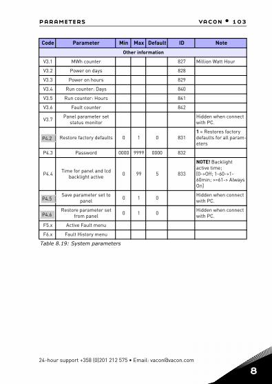
parameters vacon • 103
Other information
V3.1 MWh counter 827 Million Watt Hour
V3.2 Power on days 828
V3.3 Power on hours 829
V3.4 Run counter: Days 840
V3.5 Run counter: Hours 841
V3.6 Fault counter 842
V3.7 Panel parameter set status monitor
Hidden when connect with PC.
Restore factory defaults 0 1 0 8311 = Restores factory defaults for all param-eters
P4.3 Password 0000 9999 0000 832
P4.4 Time for panel and lcd backlight active 0 99 5 833
NOTE! Backlight active time;[0->Off; 1-60->1-60min; >=61-> Always On]
Save parameter set to panel 0 1 0 Hidden when connect
with PC.
Restore parameter set from panel 0 1 0 Hidden when connect
with PC.
F5.x Active Fault menu
F6.x Fault History menu
Code Parameter Min Max Default ID Note
Table 8.19: System parameters
P4.2
P4.5
P4.6
24-hour support +358 (0)201 212 575 • Email: [email protected]
8

104 • vacon parameters
8
Tel. +358 (0)201 2121 • Fax +358 (0)201 212205

parameter descriptions vacon • 105
9. PARAMETER DESCRIPTIONS
On the next pages you can find the descriptions of certain parameters. The descrip-tions have been arranged according to parameter group and number.
9.1 Motor settings (Control panel: Menu PAR -> P1)
1.7 CURRENT LIMIT
This parameter determines the maximum motor current from the frequency converter. To avoid motor overload, set this parameter according to the rated current of the motor. The current limit is equal to (1.5 x In) by default.
1.8 MOTOR CONTROL MODE
With this parameter the user can select the motor control mode. The selec-tions are:
0 = Frequency control:Drive frequency reference is set to output frequency without slip com-pensation. Motor actual speed is finally defined by motor load.
1 = Open loop speed control:Drive frequency reference is set to motor speed reference. The motor speed remains the same regardless of motor load. Slip is compensat-ed.
1.9 U / F RATIO There are three selections for this parameter:
0 = Linear:The voltage of the motor changes linearly with the frequency in the constant flux area from 0 Hz to the field weakening point where the field weakening point voltage is supplied to the motor. Linear U / f ratio should be used in constant torque applications. See Figure 9.1.This default setting should be used if there is no special need for an-other setting.
24-hour support +358 (0) 201 212 575 • Email: [email protected]
9
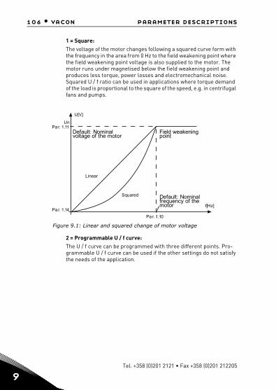
106 • vacon parameter descriptions
9
1 = Square:The voltage of the motor changes following a squared curve form with the frequency in the area from 0 Hz to the field weakening point where the field weakening point voltage is also supplied to the motor. The motor runs under magnetised below the field weakening point and produces less torque, power losses and electromechanical noise. Squared U / f ratio can be used in applications where torque demand of the load is proportional to the square of the speed, e.g. in centrifugal fans and pumps.
U[V]
f[Hz]
UnPar. 1.11
Par. 1.14
Par. 1.10
Default: Nominalvoltage of the motor
Linear
Squared
Field weakeningpoint
Default: Nominalfrequency of themotor
Figure 9.1: Linear and squared change of motor voltage
2 = Programmable U / f curve:The U / f curve can be programmed with three different points. Pro-grammable U / f curve can be used if the other settings do not satisfy the needs of the application.
Tel. +358 (0)201 2121 • Fax +358 (0)201 212205

parameter descriptions vacon • 107
U nP a r. 1.11
U [V ]
f[H z]
P a r. 1 .13
P a r. 1.14
Defau lt: Nom inalvo ltage of the m otor
F ie ld weakeningpo in t
Defau lt: Nom ina lfrequency of them otor
P a r. 1 .12 P a r. 1 .10
Figure 9.2: Programmable U / f curve
1.10 FIELD WEAKENING POINT
The field weakening point is the output frequency at which the output voltage reaches the value set with par. 1.11.
1.11 FIELD WEAKENING POINT VOLTAGE
Above the frequency at the field weakening point, the output voltage remains at the value set with this parameter. Below the frequency at the field weaken-ing point, the output voltage depends on the setting of the U / f curve param-eters. See parameters 1.9-1.14 and Figures 9.1 and 9.2.
When the parameters 1.1 and 1.2 (nominal voltage and nominal frequency of the motor) are set, the parameters 1.10 and 1.11 are automatically given the corresponding values. If you need different values for the field weakening point and the voltage, change these parameters after setting the parameters 1.1 and 1.2.
1.12 U / F MIDDLE POINT FREQUENCY
If the programmable U / f curve has been selected with the parameter 1.9, this parameter defines the middle point frequency of the curve. See Figure 9.2.
1.13 U / F MIDDLE POINT VOLTAGE
If the programmable U / f curve has been selected with the parameter 1.9, this parameter defines the middle point voltage of the curve. See Figure 9.2.
1.14 ZERO FREQUENCY VOLTAGE
This parameter defines the zero frequency voltage of the curve. See Figures 9.1 and 9.2.
24-hour support +358 (0) 201 212 575 • Email: [email protected]
9
108 • vacon parameter descriptions
9
1.15 TORQUE BOOST
When this parameter has been activated, the voltage to the motor changes au-tomatically with high load torque which makes the motor produce sufficient torque to start and run at low frequencies. The voltage increase depends on the motor type and power. Automatic torque boost can be used in applications with high load torque, e.g. in conveyors.
0 = Disabled1 = Enabled
Note: In high torque - low speed applications - it is likely that the motor will overheat. If the motor has to run a prolonged time under these conditions, special attention must be paid to cooling the motor. Use external cooling for the motor if the temperature tends to rise too high.
Note: The best performance can be reached by running motor identification, see par. 1.18.
1.16 SWITCHING FREQUENCY
Motor noise can be minimised using a high switching frequency. Increasing the switching frequency reduces the capacity of the frequency converter unit.
Switching frequency for Vacon 20: 1.5…16 kHz.
1.19 MOTOR IDENTIFICATION
0 = Not active1 = Standstill identification
When Standstill identification is selected, the drive will perform an ID-run when it is started from selected control place. Drive has to be started within 20 seconds, otherwise identification is aborted.The drive does not rotate the motor during Standstill identification. When ID run is ready the drive is stopped. Drive will start normally, when the next start command is given.After end the identification, the drive need stop the start command. If control place is Keypad, user need press stop button. If control place is IO,user need put DI(Control signal) inactivate. If control place is fieldbus, user need set the control bit to 0.The ID run improves the torque calculations and the automatic torque boost function. It will also result in a better slip compensation in speed control (more accurate RPM).The parameters below will change after ID run successfully,
a. P1.8 Motor control modeb. P1.9 U / f ratioc. P1.12 U / f mid point frequency
Tel. +358 (0)201 2121 • Fax +358 (0)201 212205

parameter descriptions vacon • 109
d. P1.13 U / f mid point voltagee. P1.14 Zero freq voltagef. P1.19 Motor identification (1->0)g. P1.20 Rs voltage drop
Note!The nameplate data of the motor has to be set BEFORE doing ID run.
1.21 OVERVOLTAGE CONTROLLER
0 = Disabled1 = Enabled, Standard mode (Minor adjustments of OP frequency are made)2 = Enabled, Shock load mode (Controller adjusts OP freq. up to max.freq.)
1.22 UNDERVOLTAGE CONTROLLER
0 = Disable1 = Enable
These parameters allow the under-/overvoltage controllers to be switched out of operation. This may be useful, for example, if the mains supply voltage varies more than –15% to +10% and the application will not tolerate this over-/undervoltage. In this case, the regulator controls the output frequency taking the supply fluctuations into account.
When a value other than 0 is selected also the Closed Loop overvoltage con-troller becomes active (in Multi-Purpose Control application).
Note: Over-/undervoltage trips may occur when controllers are switched out of operation.
1.25 EFFICIENCY OPTIMIZATION
Energy optimization, the frequency converter search for the minimum current in order to save energy and lower motor noise, 0 = disabled, 1 = enable.
1.26 I/F START ENABLE
The I/f Start function is typically used with permanent magnet motors (PM) to start the motor with constant current control. This is useful with high power motors in which the resistance is low and the tuning of the U/f curve difficult. Applying the I/f Start function may also prove useful in providing sufficient torque for the motor at startup.
24-hour support +358 (0) 201 212 575 • Email: [email protected]
9

110 • vacon parameter descriptions
9
I/f Start Current
I/f Start Frequency
Output Frequency
Motor Current
Time [s]
Figure 9.3: I/f Start
1.27 I/F START FREQUENCY REFERENCE LIMIT
Output frequency limit below which the defined I/f start current is fed to mo-tor.
1.28 I/F START CURRENT REFERENCE
The current fed to the motor when the I/f start function is activated.
1.29 VOLTAGE LIMITER ENABLE
Voltage limiter function addresses problem with very high DC-link voltage rip-ple with 1-phase drives when fully loaded. Very high ripple in DC-link voltage will transform to high current and torque ripple, which can disturb some us-ers. Voltage limiter function limits maximum output voltage to bottom of DC-voltage ripple. This reduces current and torque ripple, but decreases maxi-mum output power since voltage is limited and more current is needed. 0 = disable, 1 = enable.
Tel. +358 (0)201 2121 • Fax +358 (0)201 212205

parameter descriptions vacon • 111
9.2 Start / stop setup (Control panel: Menu PAR -> P2)
2.1 REMOTE CONTROL PLACE SELECTION
With this parameter, the user can select the active control place, frequency converter can be selected with P3.3/P3.12. The selections are:
0 = I / O terminal1 = Fieldbus2 = Keypad
Note: You can select control place by pressing Loc / Rem button or with par. 2.5(Local / Remote), P2.1 will have no effect in local mode.
Local = Keyp ad is the control placeRemote = Control place determined by P2.1
2.2 START FUNCTION
The user can select two start functions for Vacon 20 with this parameter:
0 = Ramp startThe frequency converter starts from 0 Hz and accelerates to the set frequency reference within the set acceleration time (See detailed de-scription: ID103). (Load inertia, torque or starting friction may cause prolonged acceleration times).1 = Flying startThe frequency converter is able to start into a running motor by apply-ing small current pulses to motor and searching for the frequency cor-responding to the speed the motor is running at. Searching starts from the maximum frequency towards the actual frequency until the cor-rect value is detected. Thereafter, the output frequency will be in-creased/decreased to the set reference value according to the set acceleration/deceleration parameters.Use this mode if the motor is coasting when the start command is giv-en. With the flying start it is possible to start the motor from actual speed without forcing the speed to zero before ramping to reference.
2.3 STOP FUNCTION
Two stop functions can be selected in this application:
0 = CoastingThe motor coasts to a halt without control from the frequency convert-er after the Stop command.
1 = Ramping
24-hour support +358 (0) 201 212 575 • Email: [email protected]
9
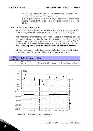
112 • vacon parameter descriptions
9
After the Stop command, the speed of the motor is decelerated ac-cording to the set deceleration parameters. If the regenerated energy is high it may be necessary to use an exter-nal braking resistor for to be able to decelerate the motor in accepta-ble time.
2.4 I / O START STOP LOGIC
Values 0...4 offer possibilities to control the starting and stopping of the AC drive with digital signal connected to digital inputs. CS = Control signal.
The selections including the text 'edge' shall be used to exclude the possibility of an unintentional start when, for example, power is connected, re-connected after a power failure, after a fault reset, after the drive is stopped by Run En-able (Run Enable = False) or when the control place is changed to I / O control. The Start / Stop contact must be opened before the motor can be started.
I/O stop logic uses accurate stop mode.Accurate stop mode is that the stop time is fixed from falling edge of DI to power stopping the drive.
Selection number Selection name Note
0 CS1:ForwardCS2:Backward The functions take place when the contacts are closed.
Figure 9.4: Start/Stop logic, selection 0
1 2 3 4 5 6 7 8 9 10 11 12 13
t
Outputfrequerty
0 Hz
Setfrequerty
Setfrequerty
REV
FWD
Run enable
Ctrl signal 1
Ctrl signal 2
Keypadstart button
Keypadstop button
Tel. +358 (0)201 2121 • Fax +358 (0)201 212205

parameter descriptions vacon • 113
Explanations
1 Control signal (CS) 1 actives causing the output frequency to rise. The motor runs forward.
8 Run enable signal is set to FALSE, which drops the frequency to 0.The run enable signal is configured with par. 5.7.
2 If start forward signal [CS1] and start reverse signal [CS2] are active simulta-neously, there is alarm 55 in LCD panel when P13.23 FWD/REV conflict supervi-sion=1.
9 Run enable signal is set to TRUE, which causes the frequency to rise towards the set frequency because CS1 is still active.
3 CS1 is inactivated which caused the direction to start changing (FWD to REV) because CS2 is still active, and alarm 55 should be disappeared in a while time.
10 Keypad stop button is pressed and the frequency fed to the motor drops to 0.(This signal only works if Par. 2.7 [Key-pad stop button] = 1)
4 CS2 inactivates and the frequency fed to the motor drops to 0.
11 The drive starts through pushing the Start button on the keypad.
5 CS2 actives again causing the motor to accelerate (REV) towards the set fre-quency.
12 The keypad stop button is pushed again to stop the drive. (This signal only works if Par. 2.7 [Keypad stop button] = 1)
6 CS2 inactivates and the frequency fed to the motor drops to 0.
13 The attempt to start the drive through pushing the Start button is not success-ful because CS1 is inactive.
7 CS1 actives and the motor accelerates (FWD) towards the set frequency.
24-hour support +358 (0) 201 212 575 • Email: [email protected]
9

114 • vacon parameter descriptions
9
1 2 3 4 5 6 7 8 9
t
Outputfrequerty
0 Hz
Setfrequerty
Setfrequerty
REV
FWD
Run enable
Ctrl signal 1
Ctrl signal 2
Keypadstop button
Figure 9.5: Start/Stop logic, selection 1
Selection number Selection name Note
1 CS1:Forward(edge)CS2:Inverted stop
Explanations
1 Control signal (CS) 1 actives causing the output frequency to rise. The motor runs forward.
6 CS1 activates and the motor accelerates (FWD) towards the set frequency because the Run enable signal has been set to TRUE.
2 CS2 inactivates causing the frequency to drop to 0.
7 Keypad stop button is pressed and the frequency fed to the motor drops to 0.(This signal only works if Par.2.7 [Key-pad stop button] = 1)
3 CS1 activates causing the output fre-quency to rise again. The motor runs forward.
8 CS1 activates causing the output fre-quency to rise again. The motor runs forward.
4 Run enable signal is set to FALSE, which drops the frequency to 0. The run enable signal is configured with par. 5.7.
9 CS2 inactivates causing the frequency to drop to 0.
5 Start attempt with CS1 is not successful because Run enable signal is still FALSE.
Tel. +358 (0)201 2121 • Fax +358 (0)201 212205

parameter descriptions vacon • 115
1 2 3 4 5 6 7 8 9 10 11
t
Outputfrequerty
0 Hz
Setfrequerty
Setfrequerty
REV
FWD
Run enable
Ctrl signal 1
Ctrl signal 2
Keypadstop button
Figure 9.6: Start/Stop logic, selection 2
Selection number Selection name Note
2 CS1:Forward(edge)CS2:Backward(edge)
Shall be used to exclude the possibility of an unintentional start. The Start / Stop contact must be opened before the motor can be restarted.
Explanations:
1 Control signal (CS) 1 actives causing the output frequency to rise. The motor runs forward.
7 Run enable signal is set to FALSE, which drops the frequency to 0.The run enable signal is configured with par. 5.7.
2 If start forward signal [CS1] and start reverse signal [CS2] are active simultane-ously, there is alarm 55 in LCD panel when P13.23 FWD/REV conflict supervision=1.
8 CS1 activates and the motor accelerates(FWD) towards the set frequencybecause the Run enable signal has beenset to TRUE.
3 CS1 is inactivated the motor is still stopped though CS2 is still active, and alarm 55 should be disappeared in a while time.
9 Keypad stop button is pressed and the frequency fed to the motor drops to 0.(This signal only works if Par.2.7 [Key-pad stop button] = 1)
4 CS2 activates again causing the motor to accelerate (REV) towards the set frequency.
10 CS1 is opened and closed again which causes the motor to start.
5 CS2 inactivates and the frequency fed to the motor drops to 0.
11 CS1 inactivates and the frequency fed to the motor drops to 0.
6 CS1 activates and the motor accelerates (FWD) towards the set frequency.
24-hour support +358 (0) 201 212 575 • Email: [email protected]
9

116 • vacon parameter descriptions
9
1 2 3 4 5 6 7 8 9 10 11 12
t
Outputfrequerty
0 Hz
Setfrequerty
Setfrequerty
REV
FWD
Run enable
Ctrl signal 1
Ctrl signal 2
Keypadstart button
Keypadstop button
Figure 9.7: Start/Stop logic, selection 3
Selection number Selection name Note
3 CS1:StartCS2:Reverse
Explanations:
1 Control signal (CS) 1 actives causing the output frequency to rise. The motor runs forward.
7 Run enable signal is set to FALSE, which drops the frequency to 0.The run enable signal is configured with par. 5.7.
2 CS2 activates which causes the direction to start changing (FWD to REV).
8 Run enable signal is set to TRUE, which causes the frequency to rise towards the set frequency because CS1 is still active.
3 CS2 is inactivated which causes the direction to start changing (REV to FWD) because CS1 is still active.
9 Keypad stop button is pressed and the frequency fed to the motor drops to 0.(This signal only works if Par.2.7 [Key-pad stop button] = 1)
4 Also CS1 inactivates and the frequency drops to 0.
10 The drive starts through pushing the Start button on the keypad.
5 Despite the activates of CS2,the motor does not start because CS1 is inactive.
11 The drive is stopped again with the Stop button on the Keypad.
6 CS1 activates causing the output fre-quency to rise again. The motor runs forward because CS2 is inactive.
12 The attempt to start the drive through pushing the Start button is not success-ful because CS1 is inactive.
Tel. +358 (0)201 2121 • Fax +358 (0)201 212205

parameter descriptions vacon • 117
1 2 3 4 5 6 7 8 9 10 11
t
Outputfrequerty
0 Hz
Setfrequerty
Setfrequerty
REV
FWD
Run enable
Ctrl signal 1
Ctrl signal 2
Keypadstop button
Figure 9.8: Start/Stop logic, selection 4
Selection number Selection name Note
4 CS1:Start(edge)CS2:Reverse
Shall be used to exclude the possibility of an unin-tentional start. The Start / Stop contact must be opened before the motor can be restarted.
Explanations:
1 Control signal (CS) 1 actives causing the output frequency to rise. The motor runs forward because CS2 is inactive..
7 Run enable signal is set to FALSE, which drops the frequency to 0.The run enable signal is configured with par. 5.7.
2 CS2 activates which causes the direction to start changing (FWD to REV).
8 Before a successful start can take place, CS1 must be opened and closed again.
3 CS2 is inactivated which causes the direction to start changing (REV to FWD) because CS1 is still active.
9 Keypad stop button is pressed and the frequency fed to the motor drops to 0.(This signal only works if Par.2.7 [Key-pad stop button] = 1)
4 Also CS1 inactivates and the frequency drops to 0.
10 Before a successful start can take place, CS1 must be opened and closed again.
5 Despite the activation of CS2, the motor does not start because CS1 is inactive.
11 CS1 inactivates and the frequency drops to 0.
6 CS1 activates causing the output fre-quency to rise again. The motor runs forward because CS2 is inactive.
24-hour support +358 (0) 201 212 575 • Email: [email protected]
9
118 • vacon parameter descriptions
9
2.5 LOCAL / REMOTE
This parameter defines whether the control place of the drive is remote (I / O or FieldBus) or local.
0 = Remote Control1 = Local Control
The priority order of selecting control place is
1. PC control from Vacon live operation window2. Loc / Rem button3. Forced from I / O terminal
Tel. +358 (0)201 2121 • Fax +358 (0)201 212205

parameter descriptions vacon • 119
9.3 Frequency references (Control panel: Menu PAR -> P3)
3.3 REMOTE CONTROL PLACE FREQUENCY REFERENCE SELECTION
It defines the selected frequency reference source when the drive is remote control. A second reference source is programmable in par. 3.12.
1 = Preset speed 02 = Keypad reference3 = Fieldbus Reference4 = AI15 = AI26 = PID7 = AI1+AI28 = Motor potentiometer
3.4 - 3.11 PRESET SPEEDS 0 - 7Preset speed 0 is used as frequency reference when P3.3 = 1.
Preset speeds 1 - 7 can be used to determine frequency references that are applied when appropriate combinations of digital inputs are activated. Preset speeds can be activated from digital inputs despite of the active control place.
Parameter values are automatically limited between the minimum and maxi-mum frequencies. (par. 3.1, 3.2).
Table 9.1: Preset speeds 1 - 7
Speed Preset speed B2
Preset speed B1
Preset speed B0
Preset speed 1 x
Preset speed 2 x
Preset speed 3 x x
Preset speed 4 x
Preset speed 5 x x
Preset speed 6 x x
Preset speed 7 x x x
24-hour support +358 (0) 201 212 575 • Email: [email protected]
9
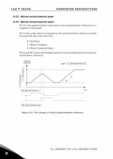
120 • vacon parameter descriptions
9
3.13 MOTOR POTENTIOMETER RAMP
3.14 MOTOR POTENTIOMETER RESET
P3.13 is the speed variation ramp when motor potentiometer reference is in-creased or decreased.
P3.14 tells under which circumstances the potentiometers reference should be reset and start over from 0 Hz.
0 = No Reset1 = Reset if stopped2 = Reset if powered down
P5.12 and P5.13 sets which digital inputs increase and decrease the motor po-tentiometers reference.
time
x
y
y/x = P Motor potentiometer ramp
I/O Motor potentiometer up
I/O Motor potentiometer down
FrequencyReference
PM
in F
req
ue
ncy
PM
ax
Fre
qu
enc
y
Figure 9.9: The change of motor potentiometers reference
Tel. +358 (0)201 2121 • Fax +358 (0)201 212205

parameter descriptions vacon • 121
9.4 Ramps & brakes setup (Control panel: Menu PAR -> P4)
4.1 RAMP S-SHAPE
The start and end of the acceleration and deceleration ramp can be smoothed with this parameter. Setting value 0 gives a linear ramp shape which causes acceleration and deceleration to act immediately to the changes in the refer-ence signal.
Setting value 0.1…10 seconds for this parameter produces an S-shaped accel-eration/deceleration. The acceleration and deceleration times are determined with parameters 4.2 and 4.3.
P4.2, 4.3
[Hz]
[t]
P4.1
P4.1
Figure 9.10: S-shaped acceleration/deceleration
4.2 ACCELERATION TIME 14.3 DECELERATION TIME 14.4 RAMP S-SHAPE 24.5 ACCELERATION TIME 24.6 DECELERATION TIME 2
These limits correspond to the time required for the output frequency to ac-celerate from the zero frequency to the set maximum frequency, or to decel-erate from the set maximum frequency to zero frequency.
The user can set two different acceleration/deceleration time and set two dif-ferent ramp s-shape for one application.The active set can be selected with the selected digital input (par. 5.11).
24-hour support +358 (0) 201 212 575 • Email: [email protected]
9

122 • vacon parameter descriptions
9
4.7 FLUX BRAKING
Instead of DC braking, flux braking is a useful form of braking with motors of max. 15 kW.
When braking is needed, the frequency is reduced and the flux in the motor is increased, which in turn increases the motor's capability to brake. Unlike DC braking, the motor speed remains controlled during braking.
0 = Off1 = Deceleration2 = Chopper3 = Full Mode
Note: Flux braking converts the energy into heat at the motor, and should be used intermittently to avoid motor damage.
4.10 STOP DC CURRENT TIME
Determines if braking is ON or OFF and the braking time of the DC-brake when the motor is stopping. The function of the DC-brake depends on the stop function, par. 2.3.
0 = DC brake is not active>0 = DC brake is active and its function depends on the Stop function, (par. 2.3). The DC braking time is determined with this parameter.
Par. 2.3 = 0 (Stop function = Coasting):
After the stop command, the motor coasts to a stop without control from the frequency converter.
With the DC injection, the motor can be electrically stopped in the shortest possible time, without using an optional external braking resistor.
The braking time is scaled by the frequency when the DC-braking starts. If the frequency is greater, or equal to the nominal frequency of the motor, the set value of parameter 4.10 determines the braking time. When the frequency is 10% of the nominal, the braking time is 10% of the set value of parameter 4.10.
Tel. +358 (0)201 2121 • Fax +358 (0)201 212205

parameter descriptions vacon • 123
fn fn
t t
t = 1 x par. 4.10 t = 0,1 x par. 4.10
0,1 x fn
RUN
STOP
RUN
STOP
Output frequency
Motor speed
Output frequency
Motor speed
DC-braking ON
DC-braking ON
fout fout
Figure 9.11: DC-braking time when Stop mode = Coasting
Par. 2.3 = 1 (Stop function = Ramp):
After the Stop command, the speed of the motor is reduced according to the set deceleration parameters, if the inertia of the motor and load allows that, to the speed defined with parameter 4.11, where the DC-braking starts.The braking time is defined with parameter 4.10. See Figure 9.12.
t = par. 4.
t
Par. 4.1
Motor speed
Output frequency
DC-braking
RUNSTOP
fout
1
10
Figure 9.12: DC-braking time when Stop mode = Ramp
24-hour support +358 (0) 201 212 575 • Email: [email protected]
9

124 • vacon parameter descriptions
9
4.11 STOP DC CURRENT FREQUENCY
It is the output frequency at which the DC-braking is applied.
4.12 START DC CURRENT TIME
DC-brake is activated when the start command is given. This parameter de fines the time for how long DC current is fed to motor before acceleration starts. After the brake is released, the output frequency increases according to the set start function by par. 2.2.
t
Pa r4.12
Par 4.9
RUNSTOP
Outputfrequency
DC-brakingcurrent
Figure 9.13: DC braking time at start
4.15 EXTERNAL BRAKE: OPEN DELAY
4.16 EXTERNAL BRAKE: OPEN FREQUENCY LIMIT
4.17 EXTERNAL BRAKE: CLOSE FREQUENCY LIMIT
4.18 EXTERNAL BRAKE: CLOSE FREQUENCY LIMIT IN REVERSE
4.19 EXTERNAL BRAKE: OPEN / CLOSE CURRENT LIMIT
External brake control is used for controlling a mechanical brake on the mo-tor by digital / relay output by selecting value 17 for parameters P8.1, P8.2 or P8.3. Brake is closed while relay is open and vice versa.
Opening brake conditions:
There are three different conditions for opening the brake, all must be true, if used.1. The Open frequency limit (P4.16) must be reached.
Tel. +358 (0)201 2121 • Fax +358 (0)201 212205

parameter descriptions vacon • 125
2. When the Opening frequency limit has been reached the Open delay (P4.15) must also elapse. Note! The output frequency is held at the Open frequency limit until this.
3. When the two previous conditions are reached. The brake will open if the output current is higher than the current limit.(P4.19)
Notice that any of the previous conditions can be left out by setting their val-ues to zero.
Time
Output Frequency
ActualReference
P Open Frequency Limit
P Open delay
External Brake
1 2
1 = Open frequency Limit reached 2
3
= Open delay elapsed
= Brake opens ifExternal Brake:Current limitis exceeded.
3Brakeclosed Brake open
Relayclosed
Relay open
Figure 9.14: Starting / opening sequence with external brake
Closing brake conditions:
There are 2 conditions for closing the brake again. It’s enough that one is true for the brake to close.1. If there is no run command active and output frequency goes below Close
frequency limit (P4.17) or Close frequency limit in reverse (P4.18), depend-ing on direction of rotation.
OR2. Output current has gone below Current limit.(P4.19)
24-hour support +358 (0) 201 212 575 • Email: [email protected]
9
126 • vacon parameter descriptions
9
9.5 Digital inputs (Control panel: Menu PAR -> P5)These parameters are programmed using the FTT-method (Function To Ter-minal), where you have a fixed input or output that you define a certain func-tion for. You can also define more than one function to a digital input, e.g. Start signal 1 and Preset Speed B1 to DI1.
The selections for these parameters are:0 = Not used1 = DI12 = DI2 3 = DI3 4 = DI45 = DI5 6 = DI6
5.1 I / O CTRL SIGNAL 1
5.2 I / O CTRL SIGNAL 2P5.1 and P5.2 : See P2.4 (I/O start stop logic) for function
5.3 REVERSE
The digital input only active when P2.4 (I/O Start stop logic) =1The motor will run in reverse when the rising edge of P5.3 is happened.
5.11 RAMP TIME 2 SELECTION
Contact open: Acceleration / Deceleration time 1 and Ramp S-shape selectedContact closed: Acceleration / Deceleration time 2 and Ramp S-shape2 selected
Set Acceleration / Deceleration time with parameters 4.2 and 4.3 and the al-ternative Acceleration / Deceleration time with 4.4 and 4.5.
Set Ramp S-shape with Par. 4.1 and the alternative Ramp S-shape2 with Par. 4.4
5.16 PID SETPOINT 2
Digital input high activates setpoint 2 (P15.3), when P15.1=0.
5.17 MOTOR PREHEAT ACTIVE
Digital input high activates the Motor preheat function (if P16.1 = 2) which feeds DC-Current to the motor in stop state.
Tel. +358 (0)201 2121 • Fax +358 (0)201 212205

parameter descriptions vacon • 127
9.6 Analogue inputs (Control panel: Menu PAR -> P6)
6.3 AI1 CUSTOM MAXIMUM
6.4 AI1 FILTER TIME
6.6 AI2 CUSTOM MINIMUM
6.7 AI2 CUSTOM MAXIMUM
These parameters set the analogue input signal for any input signal span from minimum to maximum.
6.8 AI2 FILTER TIME
This parameter, given a value greater than 0, activates the function that filters out disturbances from the incoming analogue signal.
Long filtering time makes the regulation response slower. See
%
100%
63%
Par. 6.4Par. 6.8
t [s]
Filtered signal
Unfiltered signal
Figure 9.15.
Figure 9.15: AI1 and AI2 signal filtering
24-hour support +358 (0) 201 212 575 • Email: [email protected]
9
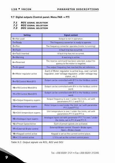
128 • vacon parameter descriptions
9
9.7 Digital outputs (Control panel: Menu PAR -> P7)
7.1 RO1 SIGNAL SELECTION7.2 RO2 SIGNAL SELCETION7.3 DO1 SIGNAL SELCETION
Table 9.2: Output signals via RO1, RO2 and DO1
Setting Signal content
0 = Not used Output is not in operation.
1 = Ready The frequency converter is ready to operate.
2 = Run The frequency converter operates (motor is running).
3 = Fault A fault trip has occurred.
4 = Fault inverted A fault trip has not occurred.
5 = Warning A warning is active.
6 = Reversed The reverse command has been selected, output fre-quency to the motor is negative.
7 = At speed The output frequency has reached the set reference.
8 = Motor regulator activeEach of Motor regulator is active (e.g., over current
regulator, over voltage regulator, under voltage reg-ulator, etc.)
9 = FB Control Word.B13 Output can be controlled with B13 in the fieldbus control word.
10 = FB Control Word.B14 Output can be controlled with B14 in the fieldbus control word.
11 = FB Control Word.B15 Output can be controlled with B15 in the fieldbus control word.
12 = Output frequency superv. Output frequency is over / under the limits, set with parameters P11.1 and P11.2.
13 = Output torque superv. Motor torque is over/under the limit, se t with parameter P11.3 and P11.4
14 = Unit temperature superv. Unit temperature is over / under the limits, set with parameters P11.5 and P11.6.
15 = Analogue input superv. Analogue inputs set with parameter P11.7 is over / under the limits, set in P11.8 and P11.9.
16 = Preset Speed Active Each of preset speeds are activated.
17 = External Brake control External Brake control. Closed = Brake open, Open = Brake closed.
18 = Keypad control active Keypad is set as the current control place.
19 = I / O control active I / O is set as the current control place.
Tel. +358 (0)201 2121 • Fax +358 (0)201 212205

parameter descriptions vacon • 129
9.8 Analogue outputs (Control panel: Menu PAR -> P8)
8.1 ANALOG OUTPUT SIGNAL SELECTION
0 = Not used1 = Output frequency (0 - fmax)2 = Output current (0 - InMotor)3 = Motor torque (0 - TnMotor)4 = PID output (0 - 100%)5 = Frequency reference (0 - fmax)6 = Motor speed (0 - nmax)7 = Motor power (0 - PnMotor)8 = Voltage (0 - UnMotor)9 = DC-link Voltage (0 - 1000V)10 = Process Data In1 (0 - 10000)11 = Process Data In2 (0 - 10000)12 = Process Data In3 (0 - 10000)13 = Process Data In4 (0 - 10000)14 = Test 100%
8.2 ANALOG OUTPUT MINIMUM
0 = 0 V / 0 mA1 = 2 V / 4 mA
24-hour support +358 (0) 201 212 575 • Email: [email protected]
9

130 • vacon parameter descriptions
9
9.9 Fieldbus Data-Mapping (Control panel: Menu PAR -> P9)
9.1 FB DATA OUT 1 SELECTION
Parameter couples read only variables to output process data 1.
0 = Frequency reference1 = Output reference2 = Motor speed3 = Motor current4 = Motor voltage5 = Motor torque6 = Motor power7 = DC link voltage8 = Active fault code9 = Analogue AI110 = Analogue AI211 = Digital input state12 = PID feedback value13 = PID setpoint
9.9 AUX CW DATA IN SELECTION
Parameter defines the input process data coupled to Aux Control Word.
0 = Not used1 = PDI12 = PDI23 = PDI34 = PDI45 = PDI5
Tel. +358 (0)201 2121 • Fax +358 (0)201 212205

parameter descriptions vacon • 131
9.10 Prohibited Frequencies (Control panel: Menu PAR -> P10)
10.1 PROHIBIT FREQUENCY RANGE 1: LOW LIMIT
10.2 PROHIBIT FREQUENCY RANGE 1: HIGH LIMIT
10.3 PROHIBIT FREQUENCY RANGE 2: LOW LIMIT
10.4 PROHIBIT FREQUENCY RANGE 2: HIGH LIMIT
Two skip frequency regions are available if there is a need to avoid certain fre-quencies because of e.g. mechanical resonance. In this case the actual fre-quency reference sent to the motor control will be kept out of these ranges according to the example below, where one range is in use.
Actual Reference
Requested ReferenceLow Lim High Lim
Low Lim
High Lim
Figure 9.16: Frequency Range
24-hour support +358 (0) 201 212 575 • Email: [email protected]
9

132 • vacon parameter descriptions
9
9.11 Protections (Control panel:Menu Par->P12)
12.5 STALL PROTECTION
0 = No action1 = Alarm2 = Fault, stop function3 = Fault, coast
The motor stall protection protects the motor from short time overload situa-tions such as one caused by a stalled shaft. The reaction time of the stall pro-tection can be set shorter than that of motor thermal protection. The stall state is defined with two parameters, P12.11 (Stall current) and P12.13 (Stall frequency limit). If the current is higher than the set limit and the output fre-quency is lower than the set limit the stall state is true. There is actually no real indication of the shaft rotation. Stall protection is a type of over current protection.
12.6 UNDER LOAD PROTECTION
0 = No action1 = Alarm2 = Fault, stop function3 = Fault, coast
The purpose of the motor underload protection is to ensure that there is load on the motor when the drive is running. If the motor loses its load there might be a problem in the process, e.g. a broken belt or a dry pump.
Motor underload protection can be adjusted by setting the underload curve with parameters P12.14 (Underload protection: Field weakening area load) and P12.15 (Underload protection: Zero frequency load), see the figure below. The underload curve is a squared curve set between the zero frequency and the field weakening point. The protection is not active below 5Hz (the under-load time counter is stopped).
The torque values for setting the underload curve are set in percentage which refers to the nominal torque of the motor. The motor's name plate data, pa-rameter motor nominal current and the drive's nominal current IL are used to find the scaling ratio for the internal torque value. If other than nominal motor is used with the drive, the accuracy of the torque calculation decreases.
The default parameter value of the underload protection time limit is 20 sec-onds, which is the maximum time allowed for an underload state to exist be-fore causing a trip according to this parameter.
Tel. +358 (0)201 2121 • Fax +358 (0)201 212205

parameter descriptions vacon • 133
U nder load cu rve atze ro freq. P12.15= 10%
f5 H z
U nder load cu rv e at
Fie ld w eaken ingpo in t , P1.11
U nd e rlo ad a re a
To rq ue
Feild weakening point,P12.14(default)=50%
Figure 9.17: Underload protection
12.7 MOTOR THERMAL PROTECTION
0 = No action1 = Alarm2 = Fault, stop function3 = Fault, coast
If tripping is selected the drive will stop and activate the fault stage, if the tem-perature of the motor becomes too high. Deactivating the protection, i.e. set-ting parameter to 0, will reset the thermal model of the motor to 0%.
The motor thermal protection is to protect the motor from overheating. The drive is capable of supplying higher than nominal current to the motor. If the load requires this high current there is a risk that the motor will be thermally overloaded. This is the case especially at low frequencies. At low frequencies the cooling effect of the motor is reduced as well as its capacity. If the motor is equipped with an external fan the load reduction at low speeds is small.The motor thermal protection is based on a calculated model and it uses the output current of the drive to determine the load on the motor. The motor thermal protection can be adjusted with parameters. The thermal current IT specifies the load current above which the motor is overloaded. This current limit is a function of the output frequency.The thermal stage of the motor can be monitored on the control keypad display.
CAUTION! The calculated model does not protect the motor if the airflow to the motor is reduced by blocked air intake grill.
24-hour support +358 (0) 201 212 575 • Email: [email protected]
9

134 • vacon parameter descriptions
9
NOTE! To comply with UL 508C requirements motor over-tempera-ture sensing is required at installation if the parameter is set to 0.
Note: If you use long motor cables (max. 100m) together with small drives (<=1.5 kW) the motor current measured by the drive can be much higher than the actual motor current due to capacitive currents in the motor cable. Con-sider this when setting up the motor thermal protection functions.
12.8 MTP:AMBIENT TEMPERATURE When the motor ambient temperature must be taken into consideration, it is recommended to set a value for this parameter. The value can be set between -20 and 100 degrees Celsius.
12.9 MTP:ZERO SPEED COOLING
Defines the cooling factor at zero speed in relation to the point where the mo-tor is running at nominal speed without external cooling. The default value is set assuming that there is no external fan cooling the motor. If an external fan is used this parameter can be set to 90% (or even higher).
If you change the parameter P1.4 (Motor nominal current), this parameter is automatically restored to the default value.Setting this parameter does not af-fect the maximum output current of the drive which is determined by param-eter P1.7 alone.
The corner frequency for the thermal protection is 70% of the motor nominal frequency(P1.2).
The cooling power can be set between 0 - 150.0% x cooling power at nominal frequency. See Figure 9.18.
Tel. +358 (0)201 2121 • Fax +358 (0)201 212205

parameter descriptions vacon • 135
ffn
P13.9=40%
0
IT100%Overload area
Pcooling
Corner freq
Figure 9.18: Motor thermal current IT curve
12.10 MTP:THERMAL TIME CONSTANT
This time can be set between 1 and 200 minutes.
This is the thermal time constant of the motor. The bigger the frame and/or slower the speed of the motor, the longer the time constants. The time con-stant is the time within which the calculated thermal model has reached 63% of its final value.
The motor thermal time is specific to the motor design and it varies between different motor manufacturers.
If the motor's t6-time (t6 is the time in seconds the motor can safely operate at six times the rated current) is known (given by the motor manufacturer) the time constant parameter can be set basing on it. As a rule of thumb, the motor thermal time constant in minutes equals to 2 x t6. If the drive is in stop state the time constant is internally increased to three times the set parameter val-ue. See also Figure 9.19.
The cooling in stop stage is based on convection and the time constant is in-creased.
24-hour support +358 (0) 201 212 575 • Email: [email protected]
9

136 • vacon parameter descriptions
9
105%
Q = (I/IT)2 x (1-e-t/T)
I/IT
Trip area
Motor temperature
TimeMotor temperature
Time constantT*)
*) Changes by motor size andadjusted with parameter
Fault/warningactivation point,if selected w ithpar.
Motorcurrent
.1012
.712
Figure 9.19: Motor temperature calculation
P12.11 STALL CURRENTThe current can be set to 0.0…2xINunit.For a stall stage to occur, the current must have exceeded this limit. If parameter P1.7 Motor current limit is changed, this parameter is automatically calculated to 90% of the current lim-it. See Figure 9.20.
NOTE! In order to guarantee desired operation, this limit must be set below the current limit.
f
I
Par. P3.9.12
Par. P3.9.14
100K34.fh11
Stall area
Figure 9.20: Stall current
Tel. +358 (0)201 2121 • Fax +358 (0)201 212205
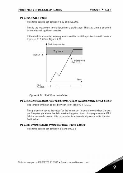
parameter descriptions vacon • 137
P12.12 STALL TIME This time can be set between 0.00 and 300.00s.
This is the maximum time allowed for a stall stage. The stall time is counted by an internal up/down counter.
If the stall time counter value goes above this limit the protection will cause a trip (see P12.5).See Figure 9.21.
Par.12.12Trip area
Time
Stall time counter
StallNo stall
Trip/warningPar. 12.5
Figure 9.21: Stall time calculation
P12.14 UNDERLOAD PROTECTION: FIELD WEAKENING AREA LOADThe torque limit can be set between 10.0-150.0 % x TnMotor.
This parameter gives the value for the minimum torque allowed when the out-put frequency is above the field weakening point. If you change parameter P1.4 (Motor nominal current) this parameter is automatically restored to the de-fault value.
P12.16 UNDERLOAD PROTECTION: TIME LIMITThis time can be set between 2.0 and 600.0 s.
24-hour support +358 (0) 201 212 575 • Email: [email protected]
9
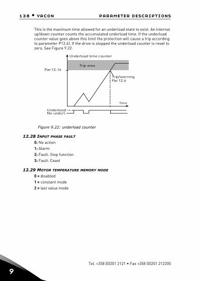
138 • vacon parameter descriptions
9
This is the maximum time allowed for an underload state to exist. An internal up/down counter counts the accumulated underload time. If the underload counter value goes above this limit the protection will cause a trip according to parameter P12.6). If the drive is stopped the underload counter is reset to zero. See Figure 9.22.
Par.12.16Trip area
Time
Underload time counter
UnderloadNo underl.
Trip/warningPar.12.6
Figure 9.22: underload counter
12.28 INPUT PHASE FAULT
0: No action1: Alarm2: Fault: Stop function3: Fault: Coast
12.29 MOTOR TEMPERATURE MEMORY MODE
0 = disabled1 = constant mode2 = last value mode
Tel. +358 (0)201 2121 • Fax +358 (0)201 212205

parameter descriptions vacon • 139
9.12 Automatic reset (Control panel: Menu PAR -> P13)
13.1 AUTOMATIC RESET
Activate the Automatic reset after fault with this parameter.
NOTE: Automatic reset is allowed for certain faults only.
Fault: 1. Under voltage2. Over voltage3. Over current 4. Motor over temperature 5. Under load
13.3 TRIAL TIME
The Automatic restart function restarts the frequency converter when the faults have disappeared and the waiting time has elapsed.
The time count starts from the first auto reset. If the number of faults occur-ring during the trial time exceeds trail number (the value of P13.4), the fault state becomes active. Otherwise the fault is cleared after the trial time has elapsed and the next fault starts the trial time count again. See Figure 9.23.
If a single fault remains during the trial time, a fault state is true.
Fault trigger
Motor stop signal
Motor start signal
Supervis ion
Restart 1 Restart 2
Trial timepar.14.3
Fault active
RESET/Fault reset
Autoreset function: (Trials = 2)
Wait timepar.14.2
Wait t imepar.14.2
Wait t imepar.14.2
Figure 9.23: Example of Automatic restarts with two restarts
24-hour support +358 (0) 201 212 575 • Email: [email protected]
9

140 • vacon parameter descriptions
9
9.13 PID control parameters (Control panel: Menu PAR -> P14)
14.5 FEEDBACK VALUE MINIMUM14.6 FEEDBACK VALUE MAXIMUM
This parameter sets the minimum and maximum scaling points for feedback value.
0V0mA
par. 14.5
Custom minpar. 6.2 /6.6
Custom max
par. 14.6
10V20mA
Analogue input
Controllerfeedback (%)
with custommin and maxscaling (%)
par. 6.3 /6.7
Figure 9.24: Feedback minimum and maximum
14.7 P GAIN
This parameter defines the gain of the PID controller. If the value of the pa-rameter is set to 100%, a change of 10% in the error value causes the control-ler output to change by 10%.
14.8 PID CONTROLLER I-TIME
This parameter defines the integration time of the PID controller. If this pa-rameter is set to 1,00 second, the controller output is changed by a value cor-responding to the output caused from the gain every second. (Gain*Error)/s.
14.9 PID CONTROLLER D-TIME
This parameter defines the derivative time of the PID controller. If this param-eter is set to 1,00 second, a change of 10% in the error value causes the con-troller output to change by 10%.
Tel. +358 (0)201 2121 • Fax +358 (0)201 212205

parameter descriptions vacon • 141
14.11 SLEEP MIN FREQUENCY
14.12 SLEEP DELAY
14.13 WAKE-UP ERROR
This function will put the drive into sleep mode if the frequency stays below the sleep limit for a longer time than that set with the Sleep Delay (P14.12). This means that the start command remains on, but the run request is turned off. When the actual value goes below, or above, the wake-up error depending on the set acting mode the drive will activate the run request again if the start command is still on.
Wake up errorP14.13
Actual value
Frequency
Sleep minfrequencyP14.11
Regulating mode Regulating modeSleep
P14.12
Sleep delay
Figure 9.25: Sleep min frequency, Sleep delay,Wake-up error
14.14 SLEEP SETPOINT BOOST
14.15 SETPOINT BOOST TIME
14.16 SLEEP MAX LOSS
14.17 SLEEP LOSS CHECK TIME
These parameters manage a more complex sleep sequence. After the time in P14.12, the setpoint is increased of the term in P14.14, for the time in P14.15. This will cause a higher output frequency.
24-hour support +358 (0) 201 212 575 • Email: [email protected]
9

142 • vacon parameter descriptions
9
Frequency reference is then forced at minimum frequency and the feedback value is sampled.
If the variation on the feedback value stays then lower than P14.16 for the time in P14.17, the drive will enter sleep condition.
If this sequence is not needed, then program P14.14 = 0%, P14.15 = 0 s, P14.16 = 50%, P14.17 = 1 s.
14.18 PROCESS UNIT SOURCE SELECTION
Monitor V4.5 can show a process value, proportional to a variable measured by the drive. Source variables are:
0 = PID feedback value (max: 100%) 1 = Output frequency (max: fmax) 2 = Motor speed (max: nmax) 3 = Motor torque (max: Tnom) 4 = Motor power (max: Pnom) 5 = Motor current (max: Inom)
14.19 PROCESS UNIT DECIMAL DIGITS
Number of decimals shown on monitor V4.5.
14.20 PROCESS UNIT MIN VALUE
Value shown on V4.5 when source variable is at its minimum.Proportionality is kept if source overtakes the minimum.
14.21 PROCESS UNIT MAX VALUE
Value shown on V4.5 when source variable is at its maximum. Proportionality is kept if source overtakes the maximum.
Tel. +358 (0)201 2121 • Fax +358 (0)201 212205

parameter descriptions vacon • 143
9.14 Application setting (Control panel: Menu PAR->P16)
16.1 ACTIVE FIRE MODE PARAMETER GROUP
This parameter is visible only when start wizard is active. With this parameter you can enable/disable fire mode parameters during start wizard.
16.4 APPLICATION ACCESS PASSWORD
Input the right password could review parameter group 17.
24-hour support +358 (0) 201 212 575 • Email: [email protected]
9

144 • vacon parameter descriptions
9
9.15 System parameter
4.3 PASSWORD
VACON20 API provides password function that is used when changing param-eter value.
Inside PAR or SYS menu the selected parameter symbol and its value are al-ternating in the display. The single OK button pressing causes entering to the parameter value change mode.
If password protection is ON, user is asked to enter the right password (de-fined with parameter P4.3) and press OK button before editing value is possi-ble. The password consists of four digit numbers, factory default value is 0000 = Password Disabled. Editing of all the parameters (including System param-eters) is prohibited if the correct password has not been entered. If wrong password is entered, pressing OK button causes return to the main level.
Password Parameters:
VACON20 API has one password parameter P4.3 "Password";Parameter P4.3 is a 4 digit number. Factory default will be 0000 = Password disabled; Any other value than 0000 will enable the password and it is not possible tochange parameters. In this status all parameters are visible;When navigate to Parameter P4.3, show “PPPP” as a parameter value if pass-word has been set.
Activating a password:Navigate to Parameter P4.3;Press OK button;Cursor (lowest horizontal segment) of the very left digit flashes; Select first digit of password by using UP and DOWN key; Press RIGHT button; Cursor of the second digit flashes; Select second digit of password by using UP and DOWN key; Press RIGHT button; Cursor of the third digit flashes; Select third digit of password by using UP and DOWN key;Press RIGHT button; Cursor of the fourth digit flashes; Select fourth digit by using UP and DOWN key; Press OK button --> the cursor of the first digit flashes;
Tel. +358 (0)201 2121 • Fax +358 (0)201 212205

parameter descriptions vacon • 145
Repeat insertion of password; Press OK button --> password is locked; In case of different values for the two passwords: display Fault; Press OK button --> repeat password a second time; To interrupt insertion of Password --> Press BACK / RES.
Disabling a password: Insert the actual password --> Press OK --> Password is automatically set to 0000;All parameters can then freely be changed; To enable password again --> see ‘Activating a password’ procedure.
Change of one parameter: User tries to change a parameter value when password is enabled --> display PW;Press OK button; Cursor (lowest horizontal segment) of the very left digit flashes; Select first digit of password by using UP and DOWN key; Press RIGHT button; Cursor of the second digit flashes; Select second digit of password by using UP and DOWN key; Press RIGHT button; Cursor of the third digit flashes; Select third digit of password by using UP and DOWN key; Press RIGHT button; Cursor of the fourth digit flashes;Select fourth digit by using UP and DOWN key;Press OK button;Current value of parameter to be changed will be display;Change parameter value as normal;Press OK --> New parameter value will be stored and Password is enabled again;For changing another parameter the procedure has to be repeated;In the case of wanting to change multiple parameters it is of advantage to set P4.3 to 0000; After the change of the parameter values password has to be activated again;
Forgotten password: Follow procedure "Disabling a password" and select 6020 as actual password.
24-hour support +358 (0) 201 212 575 • Email: [email protected]
9
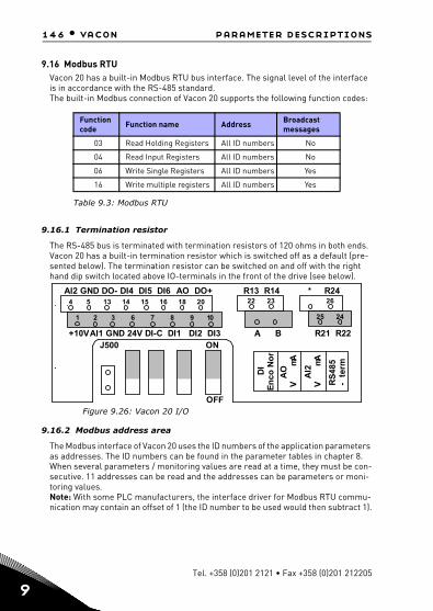
146 • vacon parameter descriptions
9
9.16 Modbus RTU Vacon 20 has a built-in Modbus RTU bus interface. The signal level of the interface is in accordance with the RS-485 standard.The built-in Modbus connection of Vacon 20 supports the following function codes:
9.16.1 Termination resistor
The RS-485 bus is terminated with termination resistors of 120 ohms in both ends. Vacon 20 has a built-in termination resistor which is switched off as a default (pre-sented below). The termination resistor can be switched on and off with the right hand dip switch located above IO-terminals in the front of the drive (see below).
Figure 9.26: Vacon 20 I/O
9.16.2 Modbus address area
The Modbus interface of Vacon 20 uses the ID numbers of the application parameters as addresses. The ID numbers can be found in the parameter tables in chapter 8. When several parameters / monitoring values are read at a time, they must be con-secutive. 11 addresses can be read and the addresses can be parameters or moni-toring values.Note: With some PLC manufacturers, the interface driver for Modbus RTU commu-nication may contain an offset of 1 (the ID number to be used would then subtract 1).
Function code Function name Address Broadcast
messages
03 Read Holding Registers All ID numbers No
04 Read Input Registers All ID numbers No
06 Write Single Registers All ID numbers Yes
16 Write multiple registers All ID numbers Yes
Table 9.3: Modbus RTU
4 5 13 14 15 16 2018
1 2 3 6 7 8 9 10
22 23 26
2425
AI2 GND DO- DI4 DI5 DI6 AO DO+ R13 R14 * R24
+10VAI1 GND 24V DI-C DI1 DI2 DI3 A B R21 R22
D
IE
nco
No
r
AO
V
mA
AI2
V
mA
RS
485
- t
erm
ON
OFF
J500
Tel. +358 (0)201 2121 • Fax +358 (0)201 212205

parameter descriptions vacon • 147
9.16.3 Modbus process data
Process data is an address area for fieldbus control. Fieldbus control is active when the value of parameter 2.1 (Control place) is 1 (= fieldbus). The content of the process data can be programmed in the application.The following tables present the process data contents in Vacon20 Application.
ID Modbus register Name Scale Type
2101 32101, 42101 FB Status Word - Binary coded
2102 32102, 42102 FB General Status Word - Binary coded
2103 32103, 42103 Reserved 0,01 %
2104 32104, 42104 Programmable by P9.1 (Default: Frequency reference) - -
2105 32105, 42105 Programmable by P9.2 (Default: Output frequency) 0,01 +/- Hz
2106 32106, 42106 Programmable by P9.3 (Default: Motor speed) 1 +/- Rpm
2107 32107, 42107 Programmable by P9.4 (Default: Motor voltage) 0,1 V
2108 32108, 42108 Programmable by P9.5 (Default: Motor torque) 0,1 +/- % (of nomi-
nal)
2109 32109, 42109 Programmable by P9.6 (Default: Motor current) 0,01 A
2110 32110, 42110 Programmable by P9.7 (Default: Motor power) 0,1 +/- % (of nomi-
nal)
2111 32111, 42111 Programmable by P9.8 (Default: DC link voltage) 1 V
Table 9.4: Output process data
ID Modbus register Name Scale Type
2001 32001, 42001 FB Control Word - Binary coded
2002 32002, 42002 FB General Control Word - Binary coded
2003 32003, 42003 Reserved 0,01 %
2004 32004, 42004 Programmable by P9.9
2005 32005, 42005 Programmable by P9.9
2006 32006, 42006 Programmable by P9.9
2007 32007, 42007 Programmable by P9.9
2008 32008, 42008 Programmable by P9.9
Table 9.5: Input process data
24-hour support +358 (0) 201 212 575 • Email: [email protected]
9

148 • vacon parameter descriptions
9
Note! 2004 - 2007 can set as PID Control Reference by setting P14.1(Set-point selection) or PID Actual value by setting P14.4(Feedback val-ue selection)! 2004 - 2007 can be set as the Analogue Output by P8.1, P8.5, P8.9.2004 - 2008 can set as Aux Control Word with P9.9:
b0: Run enable b1: acc / dec ramp 2 selection b2: freq reference 2 selection
Note!- AUX CW is active when configured, even if control place is not the fieldbus
- b0 Run enable is computed in AND with a possible Run enable sig-nal from digital input. Fall of enable will cause coasting stop.
Status word (output process data)Information about the status of the device and messages is indicated in the Status word. The Status word is composed of 16 bits the meanings of which are described in the table below:
2009 32009, 42009 - - -
2010 32010, 42010 - - -
2011 32011, 42011 - - -
BitDescription
Value = 0 Value = 1
B0, RDY Drive not ready Drive ready
B1, RUN Stop Run
B2, DIR Clockwise Counter-clockwise
B3, FLT No fault Fault active
B4, W No alarm Alarm active
B5, AREF Ramping Speed reference reached
B6, Z - Drive is running at zero speed
B7 - B15 - -
Table 9.6: Status word (output process data)
ID Modbus register Name Scale Type
Table 9.5: Input process data
Tel. +358 (0)201 2121 • Fax +358 (0)201 212205

parameter descriptions vacon • 149
General status word (output process data)Information about the status of the device and messages is indicated in the General status word. The General status word is composed of 16 bits the meanings of which are described in the table below:
Actual speed (output process data)This is actual speed of the frequency converter. The scaling is -10000...10000. The value is scaled in percentage of the frequency area between set minimum and max-imum frequency.
Control word (input process data)The three first bits of the control word are used to control the frequency converter. By using control word it is possible to control the operation of the drive. The mean-ings of the bits of control word are explained in the table below:
BitDescription
Value = 0 Value = 1
B0, RDY Drive not ready Drive ready
B1, RUN Stop Run
B2, DIR Clockwise Counter-clockwise
B3, FLT No fault Fault active
B4, W No alarm Alarm active
B5, AREF Ramping Speed reference reached
B6, Z - Drive is running at zero speed
B7, F - Fieldbus control active
B8 - B12 - -
BitControl place
I/O PC tool Keypad Fieldbus
B13 1 0 0 0
B14 0 1 1 0
B15 0 1 0 1
Table 9.7: General status word (output process data)
BitDescription
Value = 0 Value = 1
B0, RUN Stop Run
B1, DIR Clockwise Counter-clockwise
B2, RST Rising edge of this bit will reset active fault
B5, Quick ramp time Normal deceleration ramp time Quick deceleration ramp time
Table 9.8: Control word (input process data)
24-hour support +358 (0) 201 212 575 • Email: [email protected]
9

150 • vacon parameter descriptions
9
Speed reference (input process data)This is the Reference 1 to the frequency converter. Used normally as Speed refer-ence. The allowed scaling is 0...10000. The value is scaled in percentage of the fre-quency area between the set minimum and maximum frequencies.
Tel. +358 (0)201 2121 • Fax +358 (0)201 212205

parameter descriptions vacon • 151
24-hour support +358 (0) 201 212 575 • Email: [email protected]
9

152 • vacon technical data
1
10. TECHNICAL DATA
10.1 Vacon 20 technical data
Mains connection
Input voltage Uin
115 V, -15%...+10% 1~208…240 V, -15%...+10% 1~208…240 V, -15%...+10% 3~380 - 480 V, -15%...+10% 3~600 V, -15%...+10% 3~
Input frequency 45…66 Hz
Connection to mains Once per minute or less (normal case)
Supply network
Networks Vacon 20 (400 V) cannot be used with corner grounded networks
Short circuit current
Maximum short circuit current has to be < 50 kA, For MI4 with-out DC-choke, maximum short circuit current has to be < 2.3 kA, for MI5 without DC-choke, maximum short circuit current has to be < 3.8 kA
Motor connection
Output voltage 0 - Uin
Output current
Continuous rated current IN at ambient temperature max. +50 ºC (depends on the unit size), overload 1.5 x IN max1 min / 10 min
Starting current / torque
Current 2 x IN for 2 sec in every 20 sec period. Torque depends on motor
Output frequency 0…320 Hz
Frequency resolution 0,01 Hz
Control connection
Digital input Positive, Logic1: 18…+30V, Logic0: 0…5V; Negative, Logic1: 0…10V, Logic0: 18…30V; Ri = 10KΩ (floating)
Analogue input volt-age 0….+10V,Ri = 250KΩ
Analogue input cur-rent 0(4)…20mA, Ri ≤ 250Ω
Analogue output 0…10V, RL ≥ 1KΩ; 0(4)…20mA,RL ≤ 500Ω, Selectable through microswitch
Digital output Open collector, max. load 35V/50mA (floating)
Relay output Switching load: 250Vac/3A, 24V DC 3A
Auxiliary voltage ±20%,max.load 50mA
Table 10.1: Vacon 20 technical data
Tel. +358 (0)201 2121 • Fax +358 (0)201 212205
0

technical data vacon • 153
24-hour support +358 (0)201 212 575 • Email: [email protected]
Control character-istics
Control method Frequency Control U / fOpen Loop Sensorless Vector Control
Switching frequency 1...16 kHz; Factory default 4 kHz
Frequency reference Resolution 0.01 Hz
Field weakening point 30…320 Hz
Acceleration time 0.1…3000 sec
Deceleration time 0.1…3000 sec
Braking torque100%*TN with brake option (only in 3~ drives sizes MI2-5 ) 30%*TN without brake option
Ambient conditions
Ambient operating temperature
-10 °C (no frost)…+40 / 50 °C (depends on the unit size): rated loadability INSide by side installation for MI1-3 it is always 40 °C; For IP21/Nema1 option in MI1-3 the maximum temparture is also 40 °C
Storage temperature -40 °C…+70 °C
Relative humidity 0…95% RH, non-condensing, non-corrosive, no dripping water
Air quality:- chemical vapours- mech. particles
IEC 721-3-3, unit in operation, class 3C2IEC 721-3-3, unit in operation, class 3S2
Altitude 100% load capacity (no derating) up to 1000 m. 1% derating for each 100 m above 1000 m; max. 2000 m
Vibration:EN60068-2-6
3...150 HzDisplacement amplitude 1(peak) mm at 3...15.8 Hz Max accel-eration amplitude 1 G at 15.8...150 Hz
ShockIEC 68-2-27
UPS Drop Test (for applicable UPS weights)Storage and shipping: max 15 G, 11 ms (in package)
Enclosure class IP20 / IP21 / Nema1 for MI1-3, IP21/Nema 1 for MI4-5
Pollution degree PD2
EMC
Immunity Complies with EN50082-1, -2, EN61800-3
Emissions
230V : Complies with EMC category C2; With an internal RFI fil-terMI4&5 complies C2 with an optional DC choke and CM choke400V: Complies with EMC category C2; With an internal RFI fil-terMI4&5 complies C2 with an optional DC choke and CM chokeBoth: No EMC emission protection (Vacon level N): Without RFI filter
Standards For EMC: EN61800-3, For safety: UL508C, EN61800-5
Certifi-catesand manu-facturer’s declara-tions of conformity
For safety: CE, UL, cUL, KCFor EMC: CE, KC(see unit nameplate for more detailed approvals)
Table 10.1: Vacon 20 technical data
10

154 • vacon technical data
1
10.2 Power ratings
10.2.1 Vacon 20 – Mains voltage 208-240 V
* The maximum ambient operating temperature of these drives is +40 °C.
Mains voltage 208-240 V, 50/60 Hz, 1~ series
Freq. converter
type
Rated loadability Motor shaft power
Nominal inputcurrent Mechanical
sizeWeight (kg)
100% contin. current IN [A]
150% over-load current [A]
P[HP]
P[KW] [A]
0001 1.7 2.6 0.33 0.25 4.2 MI1 0.55
0002 2.4 3.6 0.5 0.37 5.7 MI1 0.55
0003 2.8 4.2 0.75 0.55 6.6 MI1 0.55
0004 3.7 5.6 1 0.75 8.3 MI2 0.7
0005 4.8 7.2 1.5 1.1 11.2 MI2 0.7
0007 7 10.5 2 1.5 14.1 MI2 0.7
0009* 9.6 14.4 3 2.2 22.1 MI3 0.99Table 10.2:Vacon 20 power ratings, 208-240 V
* The maximum ambient operating temperature of this drive is 40 °C!
Mains voltage 208 - 240 V, 50/60 Hz, 3~ series
Freq. converter
type
Rated loadability Motor shaft power
Nominal input current Mechanical
size Weight (kg)
100% contin. current IN [A]
150% over-load current[A]
P[HP]
P[KW] [A]
0001 1.7 2.6 0.33 0.25 2.7 MI1 0.55
0002 2.4 3.6 0.5 0.37 3.5 MI1 0.55
0003 2.8 4.2 0.75 0.55 3.8 MI1 0.55
0004 3.7 5.6 1 0.75 4.3 MI2 0.7
0005 4.8 7.2 1.5 1.1 6.8 MI2 0.7
0007* 7 10.5 2 1.5 8.4 MI2 0.7
0011* 11 16.5 3 2.2 13.4 MI3 0.99
0012 12.5 18.8 4 3 14.2 MI4 9
0017 17.5 26.3 5 4 20.6 MI4 9
0025 25 37.5 7.5 5.5 30.3 MI4 9
0031 31 46.5 10 7.5 36.6 MI5 11
0038 38 57 15 11 44.6 MI5 11Table 10.3: Vacon 20 power ratings, 208-240 V, 3~
Tel. +358 (0)201 2121 • Fax +358 (0)201 212205
0
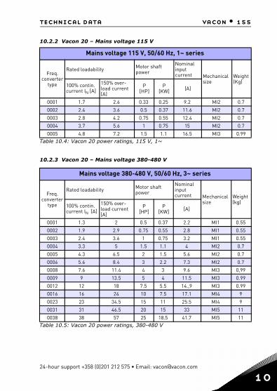
technical data vacon • 155
10.2.2 Vacon 20 – Mains voltage 115 V
10.2.3 Vacon 20 – Mains voltage 380-480 V
Mains voltage 115 V, 50/60 Hz, 1~ series
Freq. converter
type
Rated loadability Motor shaft power
Nominal input current Mechanical
sizeWeight (Kg)
100% contin. current IN [A]
150% over-load current[A]
P[HP]
P[KW] [A]
0001 1.7 2.6 0.33 0.25 9.2 MI2 0.7
0002 2.4 3.6 0.5 0.37 11.6 MI2 0.7
0003 2.8 4.2 0.75 0.55 12.4 MI2 0.7
0004 3.7 5.6 1 0.75 15 MI2 0.7
0005 4.8 7.2 1.5 1.1 16.5 MI3 0.99Table 10.4: Vacon 20 power ratings, 115 V, 1~
Mains voltage 380-480 V, 50/60 Hz, 3~ series
Freq. converter
type
Rated loadability Motor shaft power
Nominal input current Mechanical
size Weight (kg)
100% contin. current IN [A]
150% over-load current [A]
P[HP]
P[KW] [A]
0001 1.3 2 0.5 0.37 2.2 MI1 0.55
0002 1.9 2.9 0.75 0.55 2.8 MI1 0.55
0003 2.4 3.6 1 0.75 3.2 MI1 0.55
0004 3.3 5 1.5 1.1 4 MI2 0.7
0005 4.3 6.5 2 1.5 5.6 MI2 0.7
0006 5.6 8.4 3 2.2 7.3 MI2 0.7
0008 7.6 11.4 4 3 9.6 MI3 0,99
0009 9 13.5 5 4 11.5 MI3 0.99
0012 12 18 7.5 5.5 14.,9 MI3 0.99
0016 16 24 10 7.5 17.1 MI4 9
0023 23 34.5 15 11 25.5 MI4 9
0031 31 46.5 20 15 33 MI5 11
0038 38 57 25 18.5 41.7 MI5 11Table 10.5: Vacon 20 power ratings, 380-480 V
24-hour support +358 (0)201 212 575 • Email: [email protected]
10

156 • vacon technical data
1
10.2.4 Vacon 20 – Mains voltage 600 V
Note 1: The input currents are calculated values with 100 kVA line transformer supply.
Note 2: The mechanical dimensions of the units are given in Chapter 3.1.1.
Note 3: For PM motor, please select the drive power rating according to motor shaft power, not rated current.
10.3 Brake resistors
Vacon 20 type Minimum brak-ing resistance
Resistor type code (from Vacon NX family)
Light duty Heavy duty Resistance
MI2 204-240V,3~ 50 Ohm - - -
MI2 380-480V,3~ 118 Ohm - - -
MI3 204-240V, 3~ 31 Ohm - - -
MI3 380-480V, 3~ 55 Ohm BRR-0022-LD-5 BRR-0022-HD-5 63 Ohm
MI3 600V, 3~ 100 Ohm BRR-0013-LD-6 BRR-0013-HD-6 100 Ohm
MI4 204-240V, 3~ 14 Ohm BRR-0025-LD-2 BRR-0025-HD-2 30 Ohm
MI4 380-480V, 3~ 28 Ohm BRR-0031-LD-5 BRR-0031-HD-5 42 Ohm
MI5 204-240V, 3~ 9 Ohm BRR-0031-LD-2 BRR-0031-HD-2 20 Ohm
MI5 380-480V, 3~ 17 Ohm BRR-0045-LD-5 BRR-0045-HD-5 21 Ohm
Note! For MI2 and MI3, only 3-phase units are equipped with brake chopper.
For further information on brake resistors, please download Vacon NX Brake Resis-tor Manual (UD00971C) on http://www.vacon.com / Support & Downloads
Mains voltage 600 V, 50/60 Hz, 3~ series
Fre-quency
converter type
Rated loadability Motor shaft power
Nominal input current Mechanical
size Weight (kg)
100% contin. current IN [A]
150% over-load current [A]
P[HP]
P[KW] [A]
0002 1,7 2,6 1 0,75 2 MI3 0,99
0003 2,7 4,2 2 1,5 3,6 MI3 0,99
0004 3,9 5,9 3 2,2 5 MI3 0,99
0006 6,1 9,2 5 4 7,6 MI3 0,99
0009 9 13,5 7.5 5,5 10,4 MI3 0,99Table 10.6: Vacon 20 power ratings, 600 V
Tel. +358 (0)201 2121 • Fax +358 (0)201 212205
0


Rev.
Document ID:
Manual authoring:[email protected]
Vacon Suzhou Drives Co. Ltd.No. 71 Xinqing RoadSuzhou Industrial ParkSuzhou, Jiangsu Province,P.R. China, 215123
Subject to change without prior notice
© 2013 Vacon Plc.
Find your nearest Vacon office on the Internet at:
www.vacon.com