
vacon 100 - R&D Technology · Vacon 100 - Startup vacon • 2 24-hour support +358 (0)201 212 575...
198
vacon 100 ac drives application manual
Transcript of vacon 100 - R&D Technology · Vacon 100 - Startup vacon • 2 24-hour support +358 (0)201 212 575...

vacon 100ac drives
application manual

vacon • 0
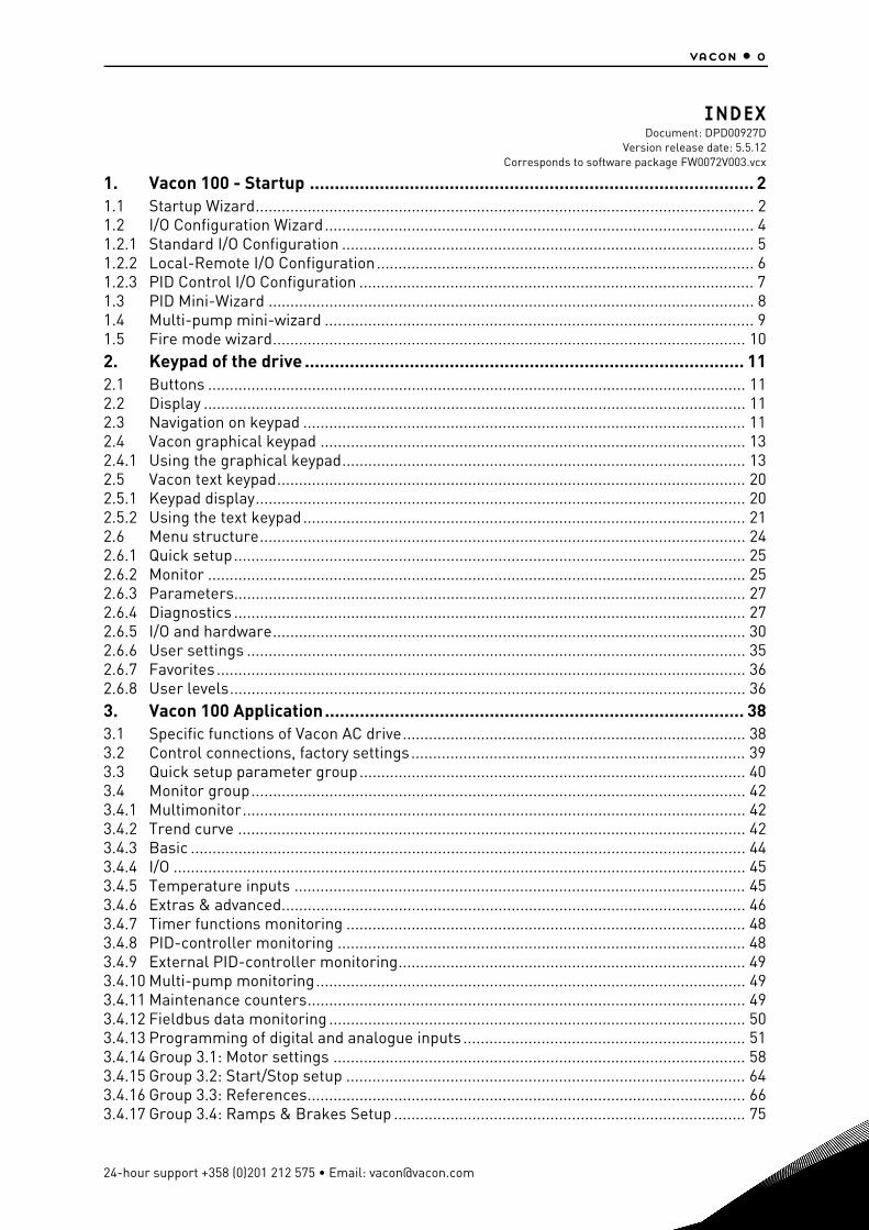
INDEX
Document: DPD00927DVersion release date: 5.5.12
Corresponds to software package FW0072V003.vcx
1. Vacon 100 - Startup ......................................................................................... 21.1 Startup Wizard................................................................................................................... 21.2 I/O Configuration Wizard................................................................................................... 41.2.1 Standard I/O Configuration ............................................................................................... 51.2.2 Local-Remote I/O Configuration....................................................................................... 61.2.3 PID Control I/O Configuration ........................................................................................... 71.3 PID Mini-Wizard ................................................................................................................ 81.4 Multi-pump mini-wizard ................................................................................................... 91.5 Fire mode wizard............................................................................................................. 102. Keypad of the drive ........................................................................................ 112.1 Buttons ............................................................................................................................ 112.2 Display ............................................................................................................................. 112.3 Navigation on keypad ...................................................................................................... 112.4 Vacon graphical keypad .................................................................................................. 132.4.1 Using the graphical keypad............................................................................................. 132.5 Vacon text keypad............................................................................................................ 202.5.1 Keypad display................................................................................................................. 202.5.2 Using the text keypad...................................................................................................... 212.6 Menu structure................................................................................................................ 242.6.1 Quick setup...................................................................................................................... 252.6.2 Monitor ............................................................................................................................ 252.6.3 Parameters...................................................................................................................... 272.6.4 Diagnostics ...................................................................................................................... 272.6.5 I/O and hardware............................................................................................................. 302.6.6 User settings ................................................................................................................... 352.6.7 Favorites.......................................................................................................................... 362.6.8 User levels....................................................................................................................... 363. Vacon 100 Application.................................................................................... 383.1 Specific functions of Vacon AC drive............................................................................... 383.2 Control connections, factory settings............................................................................. 393.3 Quick setup parameter group......................................................................................... 403.4 Monitor group.................................................................................................................. 423.4.1 Multimonitor.................................................................................................................... 423.4.2 Trend curve ..................................................................................................................... 423.4.3 Basic ................................................................................................................................ 443.4.4 I/O .................................................................................................................................... 453.4.5 Temperature inputs ........................................................................................................ 453.4.6 Extras & advanced........................................................................................................... 463.4.7 Timer functions monitoring ............................................................................................ 483.4.8 PID-controller monitoring .............................................................................................. 483.4.9 External PID-controller monitoring................................................................................ 493.4.10 Multi-pump monitoring................................................................................................... 493.4.11 Maintenance counters..................................................................................................... 493.4.12 Fieldbus data monitoring ................................................................................................ 503.4.13 Programming of digital and analogue inputs ................................................................. 513.4.14 Group 3.1: Motor settings ............................................................................................... 583.4.15 Group 3.2: Start/Stop setup ............................................................................................ 643.4.16 Group 3.3: References..................................................................................................... 663.4.17 Group 3.4: Ramps & Brakes Setup ................................................................................. 75
24-hour support +358 (0)201 212 575 • Email: [email protected]
vacon • 1
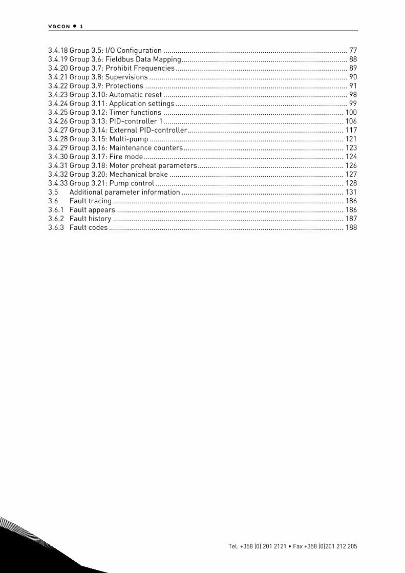
3.4.18 Group 3.5: I/O Configuration ........................................................................................... 773.4.19 Group 3.6: Fieldbus Data Mapping.................................................................................. 883.4.20 Group 3.7: Prohibit Frequencies..................................................................................... 893.4.21 Group 3.8: Supervisions .................................................................................................. 903.4.22 Group 3.9: Protections .................................................................................................... 913.4.23 Group 3.10: Automatic reset ........................................................................................... 983.4.24 Group 3.11: Application settings ..................................................................................... 993.4.25 Group 3.12: Timer functions ......................................................................................... 1003.4.26 Group 3.13: PID-controller 1......................................................................................... 1063.4.27 Group 3.14: External PID-controller............................................................................. 1173.4.28 Group 3.15: Multi-pump ................................................................................................ 1213.4.29 Group 3.16: Maintenance counters............................................................................... 1233.4.30 Group 3.17: Fire mode................................................................................................... 1243.4.31 Group 3.18: Motor preheat parameters........................................................................ 1263.4.32 Group 3.20: Mechanical brake ...................................................................................... 1273.4.33 Group 3.21: Pump control ............................................................................................. 1283.5 Additional parameter information ................................................................................ 1313.6 Fault tracing .................................................................................................................. 1863.6.1 Fault appears ................................................................................................................ 1863.6.2 Fault history .................................................................................................................. 1873.6.3 Fault codes .................................................................................................................... 188
Tel. +358 (0) 201 2121 • Fax +358 (0)201 212 205
Vacon 100 - Startup vacon • 2
1. VACON 100 - STARTUP
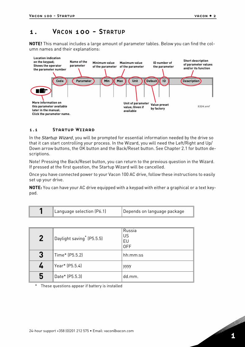
NOTE! This manual includes a large amount of parameter tables. Below you can find the col-umn names and their explanations:
1.1 Startup Wizard
In the Startup Wizard, you will be prompted for essential information needed by the drive so that it can start controlling your process. In the Wizard, you will need the Left/Right and Up/Down arrow buttons, the OK button and the Back/Reset button. See Chapter 2.1 for button de-scriptions.
Note! Pressing the Back/Reset button, you can return to the previous question in the Wizard. If pressed at the first question, the Startup Wizard will be cancelled.
Once you have connected power to your Vacon 100 AC drive, follow these instructions to easily set up your drive.
NOTE: You can have your AC drive equipped with a keypad with either a graphical or a text key-pad.
1 Language selection (P6.1) Depends on language package
2 Daylight saving* (P5.5.5)
* These questions appear if battery is installed
RussiaUSEUOFF
3 Time* (P5.5.2) hh:mm:ss
4 Year* (P5.5.4) yyyy
5 Date* (P5.5.3) dd.mm.
Location indicationon the keypad;Shows the operatorthe parameter number
Name of theparameter
Minimum valueof the parameter
Maximum valueof the parameter
Unit of parametervalue; Given ifavailable
Value presetby factory
ID number ofthe parameter
Short descriptionof parameter valuesand/or its function
9304.emfMore information onthis parameter availablelater in the manual.Click the parameter name.
24-hour support +358 (0)201 212 575 • Email: [email protected]
1
1
vacon • 3 Vacon 100 - Startup
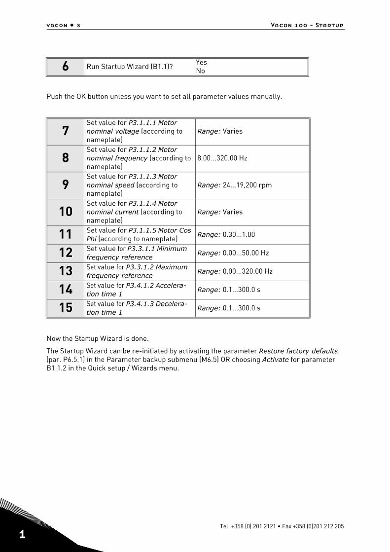
Push the OK button unless you want to set all parameter values manually.
Now the Startup Wizard is done.
The Startup Wizard can be re-initiated by activating the parameter Restore factory defaults (par. P6.5.1) in the Parameter backup submenu (M6.5) OR choosing Activate for parameter B1.1.2 in the Quick setup / Wizards menu.
6 Run Startup Wizard (B1.1)? YesNo
7Set value for P3.1.1.1 Motor nominal voltage (according to nameplate)
Range: Varies
8Set value for P3.1.1.2 Motor nominal frequency (according to nameplate)
8.00...320.00 Hz
9Set value for P3.1.1.3 Motor nominal speed (according to nameplate)
Range: 24...19,200 rpm
10Set value for P3.1.1.4 Motor nominal current (according to nameplate)
Range: Varies
11 Set value for P3.1.1.5 Motor Cos Phi (according to nameplate) Range: 0.30...1.00
12 Set value for P3.3.1.1 Minimum frequency reference
Range: 0.00...50.00 Hz
13 Set value for P3.3.1.2 Maximum frequency reference
Range: 0.00...320.00 Hz
14 Set value for P3.4.1.2 Accelera-tion time 1
Range: 0.1...300.0 s
15 Set value for P3.4.1.3 Decelera-tion time 1
Range: 0.1...300.0 s
Tel. +358 (0) 201 2121 • Fax +358 (0)201 212 205
Vacon 100 - Startup vacon • 4
1.2 I/O Configuration Wizard
I/O configuration wizard is activated in the Quick Setup / Wizards menu (B1.1.1).
This wizard is intended for the easy configuration of the drives standard I/O by selecting one of the preset I/O configurations.
Note! If you already have done some I/O configurations, please check them after running the wizard!
Following preset I/O configurations can be selected:
1 = Standard I/O
2 = Local-Remote I/O
3 = PID Control I/O
See the detailed configurations from the next pages.
24-hour support +358 (0)201 212 575 • Email: [email protected]
1
1
vacon • 5 Vacon 100 - Startup
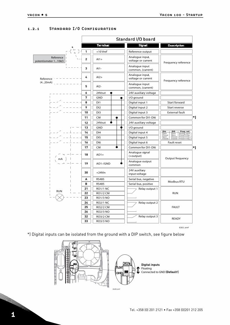
1.2.1 Standard I/O Configuration
*) Digital inputs can be isolated from the ground with a DIP switch, see figure below
RUN
FAULT
READY
Reference output+10 Vref1
24V auxiliary voltage24Vout6
Analogue input,voltage or current
Referencepotentiometer 1...10kΩ
Reference(4...20mA)
AI1+2
Analogue inputcommon, (current)AI1-3
Analogue input,voltage or currentAI2+4
Analogue inputcommon, (current)AI2-5
Analogue signal(+output)AO1+
RUN
18
Analogue outputcommonAO1-/GND19
24V auxiliaryinput voltage+24Vin30
24V auxiliary voltage24Vout12
I/O groundGND7
I/O groundGND13
Digital input 1DI18
Digital input 2DI29
Digital input 3DI310
Digital input 4DI414
Digital input 5DI515
Digital input 6DI616
Relay output 1RO1/1 NC21
22 RO1/2 CM
RO1/3 NO23
Common for DI1-DI6CM11
Common for DI1-DI6CM17
Serial bus, negativeRS485A
Serial bus, positiveRS485B
Relay output 2
Relay output 3
RO2/1 NC24
25 RO2/2 CM
RO2/3 NO26
32 RO3/2 CM
RO3/3 NO33
9301.emf
Frequency reference
Frequency reference
Start forward
Start reverse
External fault
DI4 DI5 Freq. ref.OpenClosedOpenClosed
OpenOpenClosedClosed
Analog input 1Preset Freq. 1Preset Freq. 2Preset Freq. 3
Fault reset
Output frequency
Modbus RTU
mA
*)
*)
9109.emf
Digital inputsFloatingConnected to GND (Default!)
Tel. +358 (0) 201 2121 • Fax +358 (0)201 212 205
Vacon 100 - Startup vacon • 6
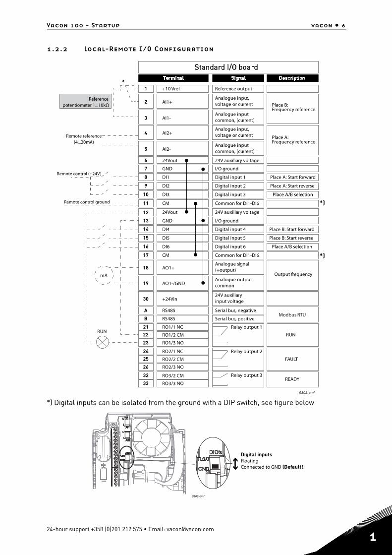
1.2.2 Local-Remote I/O Configuration
*) Digital inputs can be isolated from the ground with a DIP switch, see figure below
RUN
FAULT
READY
Reference output+10 Vref1
24V auxiliary voltage24Vout6
Analogue input,voltage or current
Referencepotentiometer 1...10kΩ
Remote reference(4...20mA)
AI1+2
Analogue inputcommon, (current)AI1-3
Analogue input,voltage or currentAI2+4
Analogue inputcommon, (current)AI2-5
Analogue signal(+output)AO1+
RUN
18
Analogue outputcommonAO1-/GND19
24V auxiliaryinput voltage+24Vin30
24V auxiliary voltage24Vout12
I/O groundGND7
I/O groundGND13
Digital input 1DI18
Digital input 2DI29
Digital input 3DI310
Digital input 4DI414
Digital input 5DI515
Digital input 6DI616
Relay output 1RO1/1 NC21
22 RO1/2 CM
RO1/3 NO23
Common for DI1-DI6CM11
Common for DI1-DI6CM17
Serial bus, negativeRS485A
Serial bus, positiveRS485B
Relay output 2
Relay output 3
RO2/1 NC24
25 RO2/2 CM
RO2/3 NO26
32 RO3/2 CM
RO3/3 NO33
9302.emf
Place B:Frequency reference
Place A: Start forward
Place A: Start reverse
Place A/B selection
Output frequency
Modbus RTU
Place A:Frequency reference
Place B: Start forward
Place B: Start reverse
Place A/B selection
Remote control (+24V)
Remote control ground
mA
*)
*)
9109.emf
Digital inputsFloatingConnected to GND (Default!)
24-hour support +358 (0)201 212 575 • Email: [email protected]
1
1
vacon • 7 Vacon 100 - Startup
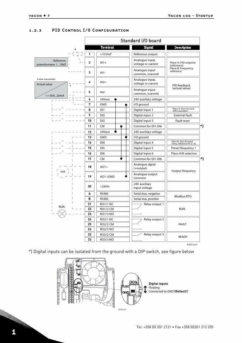
1.2.3 PID Control I/O Configuration
*) Digital inputs can be isolated from the ground with a DIP switch, see figure below
RUN
FAULT
READY
Reference output+10 Vref1
24V auxiliary voltage24Vout6
Analogue input,voltage or current
Referencepotentiometer 1...10kΩ
Actual value
2-wire transmitter
I = (0)4...20mA
AI1+2
Analogue inputcommon, (current)AI1-3
Analogue input,voltage or currentAI2+4
Analogue inputcommon, (current)AI2-5
Analogue signal(+output)AO1+
RUN
18
Analogue outputcommonAO1-/GND19
24V auxiliaryinput voltage+24Vin30
24V auxiliary voltage24Vout12
I/O groundGND7
I/O groundGND13
Digital input 1DI18
Digital input 2DI29
Digital input 3DI310
Digital input 4DI414
Digital input 5DI515
Digital input 6DI616
Relay output 1RO1/1 NC21
22 RO1/2 CM
RO1/3 NO23
Common for DI1-DI6CM11
Common for DI1-DI6CM17
Serial bus, negativeRS485A
Serial bus, positiveRS485B
Relay output 2
Relay output 3
RO2/1 NC24
25 RO2/2 CM
RO2/3 NO26
32 RO3/2 CM
RO3/3 NO339303.emf
Place A: PID setpoint(reference)Place B: Frequencyreference
PID feedback(actual value)
Place A: Start forward(PID controller)
External fault
Preset frequency 1
Output frequency
Modbus RTU
Fault reset
Place B: Start forward(Freq. reference P3.3.1.6)
Place A/B selection
+
-
mA
*)
*)
9109.emf
Digital inputsFloatingConnected to GND (Default!)
Tel. +358 (0) 201 2121 • Fax +358 (0)201 212 205
Vacon 100 - Startup vacon • 8
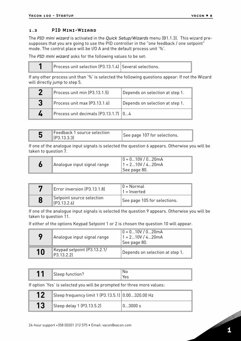
1.3 PID Mini-Wizard
The PID mini wizard is activated in the Quick Setup/Wizards menu (B1.1.3). This wizard pre-supposes that you are going to use the PID controller in the "one feedback / one setpoint" mode. The control place will be I/O A and the default process unit ‘%’.
The PID mini wizard asks for the following values to be set:
If any other process unit than ‘%’ is selected the following questions appear: If not the Wizard will directly jump to step 5.
If one of the analogue input signals is selected the question 6 appears. Otherwise you will be taken to question 7.
If one of the analogue input signals is selected the question 9 appears. Otherwise you will be taken to question 11.
If either of the options Keypad Setpoint 1 or 2 is chosen the question 10 will appear.
If option ‘Yes’ is selected you will be prompted for three more values:
1 Process unit selection (P3.13.1.4) Several selections.
2 Process unit min (P3.13.1.5) Depends on selection at step 1.
3 Process unit max (P3.13.1.6) Depends on selection at step 1.
4 Process unit decimals (P3.13.1.7) 0...4
5 Feedback 1 source selection (P3.13.3.3) See page 107 for selections.
6 Analogue input signal range0 = 0…10V / 0…20mA1 = 2…10V / 4…20mASee page 80.
7 Error inversion (P3.13.1.8) 0 = Normal1 = Inverted
8 Setpoint source selection (P3.13.2.6) See page 105 for selections.
9 Analogue input signal range0 = 0…10V / 0…20mA1 = 2…10V / 4…20mASee page 80.
10 Keypad setpoint (P3.13.2.1/P3.13.2.2) Depends on selection at step 1.
11 Sleep function? NoYes
12 Sleep frequency limit 1 (P3.13.5.1) 0.00...320.00 Hz
13 Sleep delay 1 (P3.13.5.2) 0...3000 s
24-hour support +358 (0)201 212 575 • Email: [email protected]
1
1
vacon • 9 Vacon 100 - Startup
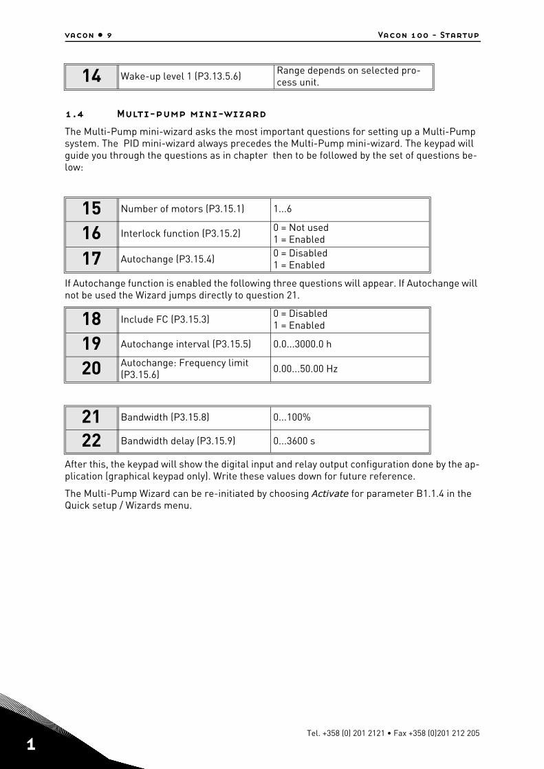
1.4 Multi-pump mini-wizard
The Multi-Pump mini-wizard asks the most important questions for setting up a Multi-Pump system. The PID mini-wizard always precedes the Multi-Pump mini-wizard. The keypad will guide you through the questions as in chapter then to be followed by the set of questions be-low:
If Autochange function is enabled the following three questions will appear. If Autochange will not be used the Wizard jumps directly to question 21.
After this, the keypad will show the digital input and relay output configuration done by the ap-plication (graphical keypad only). Write these values down for future reference.
The Multi-Pump Wizard can be re-initiated by choosing Activate for parameter B1.1.4 in the Quick setup / Wizards menu.
14 Wake-up level 1 (P3.13.5.6) Range depends on selected pro-cess unit.
15 Number of motors (P3.15.1) 1...6
16 Interlock function (P3.15.2) 0 = Not used1 = Enabled
17 Autochange (P3.15.4) 0 = Disabled1 = Enabled
18 Include FC (P3.15.3) 0 = Disabled1 = Enabled
19 Autochange interval (P3.15.5) 0.0...3000.0 h
20 Autochange: Frequency limit (P3.15.6) 0.00...50.00 Hz
21 Bandwidth (P3.15.8) 0...100%
22 Bandwidth delay (P3.15.9) 0...3600 s
Tel. +358 (0) 201 2121 • Fax +358 (0)201 212 205
Vacon 100 - Startup vacon • 10
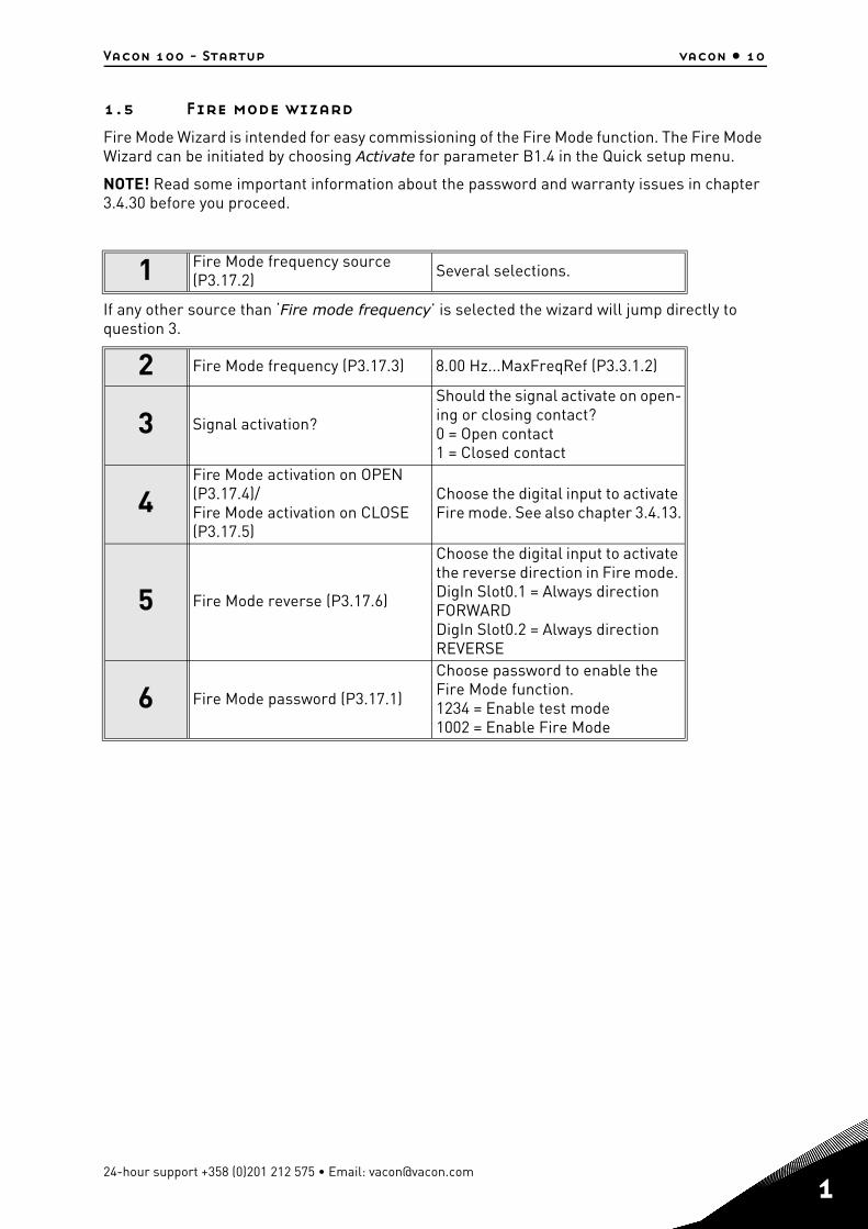
1.5 Fire mode wizard
Fire Mode Wizard is intended for easy commissioning of the Fire Mode function. The Fire Mode Wizard can be initiated by choosing Activate for parameter B1.4 in the Quick setup menu.
NOTE! Read some important information about the password and warranty issues in chapter 3.4.30 before you proceed.
If any other source than ‘Fire mode frequency’ is selected the wizard will jump directly to question 3.
1 Fire Mode frequency source (P3.17.2) Several selections.
2 Fire Mode frequency (P3.17.3) 8.00 Hz...MaxFreqRef (P3.3.1.2)
3 Signal activation?
Should the signal activate on open-ing or closing contact?0 = Open contact1 = Closed contact
4Fire Mode activation on OPEN (P3.17.4)/Fire Mode activation on CLOSE(P3.17.5)
Choose the digital input to activate Fire mode. See also chapter 3.4.13.
5 Fire Mode reverse (P3.17.6)
Choose the digital input to activate the reverse direction in Fire mode. DigIn Slot0.1 = Always direction FORWARDDigIn Slot0.2 = Always direction REVERSE
6 Fire Mode password (P3.17.1)
Choose password to enable the Fire Mode function.1234 = Enable test mode1002 = Enable Fire Mode
24-hour support +358 (0)201 212 575 • Email: [email protected]
1
2
vacon • 11 Keypad of the drive
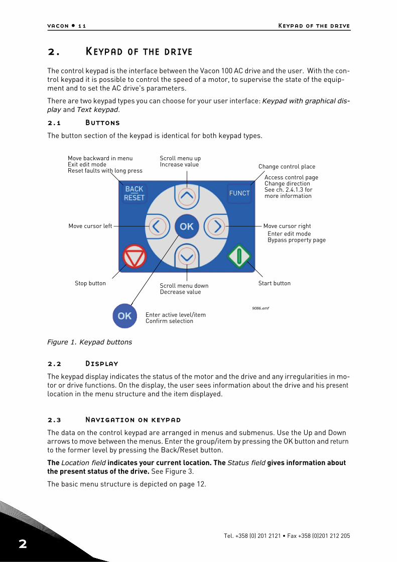
2. KEYPAD OF THE DRIVE
The control keypad is the interface between the Vacon 100 AC drive and the user. With the con-trol keypad it is possible to control the speed of a motor, to supervise the state of the equip-ment and to set the AC drive's parameters.
There are two keypad types you can choose for your user interface: Keypad with graphical dis-play and Text keypad.
2.1 Buttons
The button section of the keypad is identical for both keypad types.
Figure 1. Keypad buttons
2.2 Display
The keypad display indicates the status of the motor and the drive and any irregularities in mo-tor or drive functions. On the display, the user sees information about the drive and his present location in the menu structure and the item displayed.
2.3 Navigation on keypad
The data on the control keypad are arranged in menus and submenus. Use the Up and Down arrows to move between the menus. Enter the group/item by pressing the OK button and return to the former level by pressing the Back/Reset button.
The Location field indicates your current location. The Status field gives information about the present status of the drive. See Figure 3.
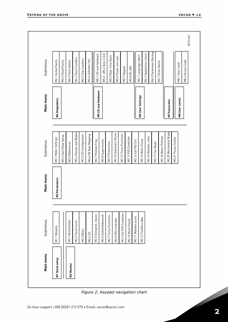
The basic menu structure is depicted on page 12.
FUNCT
9086.emf
Scroll menu upIncrease value
Scroll menu downDecrease value
Move cursor left Move cursor right
Move backward in menuExit edit modeReset faults with long press
Change control place
Access control pageChange directionSee ch. 2.4.1.3 formore information
Stop button Start button
Enter active level/itemConfirm selection
Enter edit modeBypass property page
Tel. +358 (0) 201 2121 • Fax +358 (0)201 212 205
Keypad of the drive vacon • 12
Figure 2. Keypad navigation chart
Mai
n m
enu
Subm
enus
Subm
enus
Subm
enus
Mai
n m
enu
Mai
n m
enu
M1
Qui
ck s
etup
M1.
1 W
izar
ds
M2.
1 M
ultim
onito
r
M2.
2Tr
end
Cur
ve
M2.
3 B
asic
M2.
4 I/
O
M2.
5Te
mpe
rat.
inpu
ts
M2.
6 Ex
tras
/Adv
ance
d
M2.
7 Ti
mer
Func
tions
M2.
8 P
ID C
ontro
ller
M2.
9 Ex
t PID
Con
trolle
r
M2.
10 M
ulti-
Pum
p
M2.
11 M
aint
en.c
ount
.
M2.
12 F
ield
bus
data
M2
Mon
itor
M3.
1 M
otor
Set
tings
M3.
2 St
art/
Stop
Set
up
M3.
3 R
efer
ence
s
M3.
4 R
amps
and
Bra
kes
M3.
5 I/
O C
onfig
urat
ion
M3.
6 FB
Dat
a M
appi
ng
M3.
7 Pr
ohib
itFr
eq
M3.
8 Su
perv
isio
ns
M3.
9 Pr
otec
tions
M3.
10 A
utom
atic
Res
et
M3.
12 T
imer
Func
tions
M3.
13 P
ID C
ontro
ller
M3.
14 E
xt P
ID C
trl
M3.
15 M
ulti-
Pum
p
M3.
16 M
aint
en. c
ntrs
M3.
17 F
ire M
ode
M3.
18 M
otor
Pre
heat
M3.
20 M
echa
nica
l Bra
ke
M3.
21 P
ump
Con
trol
M3
Para
met
ers
M5.
1 I/
O a
nd H
ardw
are
M5.
2...M
5.4
Slot
s C
,D,E
M5.
5 R
eal T
ime
Cloc
k
M5.
6Po
wer
uni
t set
t.
M5.
7 Ke
ypad
M5.
8 R
S-48
5
M6.
1 La
ngua
ge s
elec
t.
M6.
2 Ap
plica
tion
sele
ct.
M6.
5Pa
ram
eter
Bac
kup
M6.
7 D
rive
Nam
e
M8.
1 U
ser
Leve
l
M8.
2 Ac
cess
Cod
e
M4.
1 Ac
tive
Faul
ts
M4.
2 R
eset
Faul
ts
M4.
3Fa
ult h
isto
ry
M4.
4To
tal C
ount
ers
M4.
5Tr
ip C
ount
ers
M4.
6 So
ftw
are
Info
M4
Dia
gnos
tics
M5
I/O
and
Har
dwar
e
M6
Use
r Se
ttin
gs
M7
Favo
urite
s
M8
Use
r Le
vels
9073.e
mf
24-hour support +358 (0)201 212 575 • Email: [email protected]
2
2
vacon • 13 Keypad of the drive
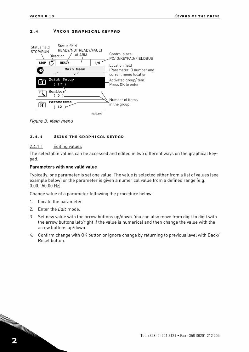
2.4 Vacon graphical keypad
Figure 3. Main menu
2.4.1 Using the graphical keypad
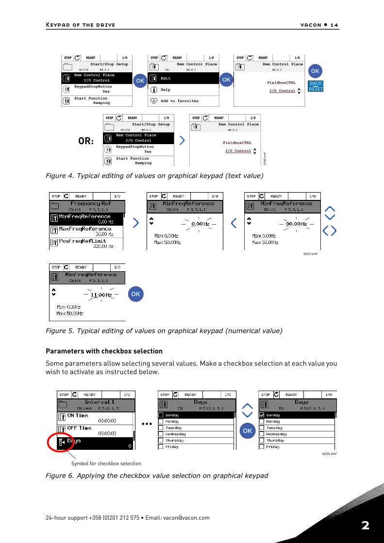
2.4.1.1 Editing values
The selectable values can be accessed and edited in two different ways on the graphical key-pad.
Parameters with one valid value
Typically, one parameter is set one value. The value is selected either from a list of values (see example below) or the parameter is given a numerical value from a defined range (e.g. 0.00...50.00 Hz).
Change value of a parameter following the procedure below:
1. Locate the parameter.
2. Enter the Edit mode.
3. Set new value with the arrow buttons up/down. You can also move from digit to digit with the arrow buttons left/right if the value is numerical and then change the value with the arrow buttons up/down.
4. Confirm change with OK button or ignore change by returning to previous level with Back/Reset button.
9159.emf
Main Menu
Quick Setup( 17 )
Parameters( 12 )
STOP READY I/O
ID: M1
( 5 )Monitor
Status fieldSTOP/RUN
Direction ALARM
Status fieldREADY/NOT READY/FAULT
Control place:PC/IO/KEYPAD/FIELDBUS
Activated group/item:Press OK to enter
Number of itemsin the group
Location field(Parameter ID number andcurrent menu location
Tel. +358 (0) 201 2121 • Fax +358 (0)201 212 205
Keypad of the drive vacon • 14
Figure 4. Typical editing of values on graphical keypad (text value)
Figure 5. Typical editing of values on graphical keypad (numerical value)
Parameters with checkbox selection
Some parameters allow selecting several values. Make a checkbox selection at each value you wish to activate as instructed below.
Figure 6. Applying the checkbox value selection on graphical keypad
STOP READY I/O
ID:172 M3.2.1 STOP READY I/O
ID: M3.2.1 STOP READY I/O
M3.2.1
STOP READY I/O
ID:172 M3.2.1 STOP READY I/O
M3.2.1
9160.e
mf
BACKRESET
OR:
Start/Stop Setup
Rem Control PlaceI/O Control
KeypadStopButtonYes
Start FunctionRamping
Edit
Help
Add to favorites
Rem Control Place Rem Control Place
I/O Control
FieldbusCTRL
Start/Stop Setup
Rem Control PlaceI/O Control
KeypadStopButtonYes
Start FunctionRamping
Rem Control Place
I/O Control
FieldbusCTRL
9257.emf
9256.emf
...
Symbol for checkbox selection
24-hour support +358 (0)201 212 575 • Email: [email protected]
2
2
vacon • 15 Keypad of the drive
2.4.1.2 Resetting fault
Instructions for how to reset a fault can be found in chapter 3.6.1 on page 184.
2.4.1.3 Function button
The FUNCT button is used for four functions:
1. to quickly access the Control page, 2. to easily change between the Local (Keypad) and Remote control places,3. to change the rotation direction and4. to quickly edit a parameter value.
Control places
The control place is the source of control where the drive can be started and stopped. Every control place has its own parameter for selecting the frequency reference source. The Local control place is always the keypad. The Remote control place is determined by parameter P3.2.1 (I/O or Fieldbus). The selected control place can be seen on the status bar of the keypad.
Remote control place
I/O A, I/O B and Fieldbus can be used as remote control places. I/O A and Fieldbus have the lowest priority and can be chosen with parameter P3.2.1 (Rem Control Place). I/O B, again, can bypass the remote control place selected with parameter P3.2.1 using a digital input. The digital input is selected with parameter P3.5.1.7 (I/O B Ctrl Force).
Local control
Keypad is always used as control place while in local control. Local control has higher priority than remote control. Therefore, if, for example, bypassed by parameter P3.5.1.7 through digi-tal input while in Remote, the control place will still switch to Keypad if Local is selected. Switching between Local and Remote Control can be done by pressing the FUNCT-button on the keypad or by using the "Local/Remote" (ID211) parameter.
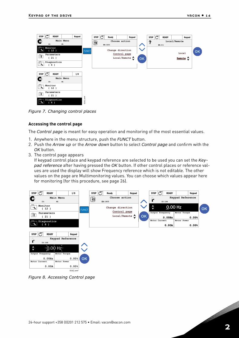
Changing control places
Change of control place from Remote to Local (keypad).
1. Anywhere in the menu structure, push the FUNCT button.2. Push the Arrow up or the Arrow down button to select Local/Remote and confirm with the
OK button.3. On the next display, select Local or Remote and again confirm with the OK button.4. The display will return to the same location as it was when the FUNCT button was pushed.
However, if the Remote control place was changed to Local (Keypad) you will be prompted for keypad reference.
Tel. +358 (0) 201 2121 • Fax +358 (0)201 212 205
Keypad of the drive vacon • 16
Figure 7. Changing control places
Accessing the control page
The Control page is meant for easy operation and monitoring of the most essential values.
1. Anywhere in the menu structure, push the FUNCT button.2. Push the Arrow up or the Arrow down button to select Control page and confirm with the
OK button.3. The control page appears
If keypad control place and keypad reference are selected to be used you can set the Key-pad reference after having pressed the OK button. If other control places or reference val-ues are used the display will show Frequency reference which is not editable. The other values on the page are Multimonitoring values. You can choose which values appear here for monitoring (for this procedure, see page 26).
Figure 8. Accessing Control page
( 21 )
STOP READY Keypad
ID: M1
( 12 )
( 6 )
ID:
STOP Ready Keypad
ID:1805?
ID:
STOP READY Keypad
ID:211
( 21 )
STOP READY I/O
ID: M1
( 12 )
( 6 ) 9161.e
mf
FUNCT
Remote
Main Menu
Parameters
Diagnostics
Monitor
Choose action
Local/Remote
Control page
Change direction
Local/Remote
Remote
Local
Main Menu
Parameters
Diagnostics
Monitor
( 21 )
STOP READY I/O
ID: M1
( 12 )
( 6 )
ID:
STOP Ready Keypad
ID:1805
STOP READY Keypad
( 6 )
0.00 Hz
0.00Hz
0.00A
0.00%
0.00%
ID:184
0.00 Hz
0.00Hz
0.00A
0.00%
0.00%
STOP READY Keypad
( 6 )
ID:168
0.00 Hz
0.00Hz
0.00A
0.00%
0.00%
9162.emf
Keypad ReferenceMain Menu
Parameters
Diagnostics
Monitor
Choose action
Local/Remote
Control page
Change direction
Output Frequency
Motor Current
Motor Torque
Motor Power
Keypad Reference
Output Frequency
Motor Current
Motor Torque
Motor Power
FUNCT
24-hour support +358 (0)201 212 575 • Email: [email protected]
2

2
vacon • 17 Keypad of the drive
Changing direction
Rotation direction of the motor can quickly be changed by applying the FUNCT button. NOTE! Changing direction command is not visible in the menu unless the selected control place is Local.
1. Anywhere in the menu structure, push the Funct button.2. Push the Arrow up or the Arrow down button to select Change direction and confirm with
the OK button.3. Then choose the direction you wish to run the motor to. The actual rotation direction is
blinking. Confirm with the OK button.4. The rotation direction changes immediately and the arrow indication in the status field
changes.
Quick edit
Through the Quick edit functionality you can quickly access the desired parameter by entering the parameter’s ID number.
1. Anywhere in the menu structure, push the FUNCT button.2. Push the Arrow up or the Arrow down buttons to select Quick Edit and confirm with the OK
button.3. Then enter the ID number of parameter or monitoring value you wish to access. Press OK
button to confirm.4. Requested Parameter/Monitoring value appears on the display (in editing/monitoring
mode.)
( 15 )
STOP READY I/O
ID: M1
( 7 )
( 6 )
ID:
RUN Ready Keypad
ID:1805 ID:
RUN Ready Keypad
ID:1805
( 15 )
STOP READY I/O
ID: M1
( 7 )
( 6 )
9163.a
i
FUNCT
Main Menu
Parameters
Diagnostics
Monitor
Choose action
Local/Remote
Control page
Change direction
Choose action
Forward
Reverse
Main Menu
Parameters
Diagnostics
Monitor
Tel. +358 (0) 201 2121 • Fax +358 (0)201 212 205
Keypad of the drive vacon • 18
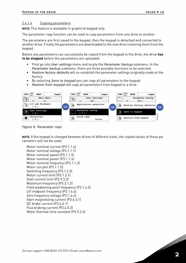
2.4.1.4 Copying parameters
NOTE: This feature is available in graphical keypad only.
The parameter copy function can be used to copy parameters from one drive to another.
The parameters are first saved to the keypad, then the keypad is detached and connected to another drive. Finally the parameters are downloaded to the new drive restoring them from the keypad.
Before any parameters can successfully be copied from the keypad to the drive, the drive has to be stopped before the parameters are uploaded.
• First go into User settings menu and locate the Parameter backup submenu. In the Parameter backup submenu, there are three possible functions to be selected:
• Restore factory defaults will re-establish the parameter settings originally made at the factory.
• By selecting Save to keypad you can copy all parameters to the keypad.• Restore from keypad will copy all parameters from keypad to a drive.
Figure 9. Parameter copy
NOTE: If the keypad is changed between drives of different sizes, the copied values of these pa-rameters will not be used:
Motor nominal current (P3.1.1.4)Motor nominal voltage (P3.1.1.1)Motor nominal speed (P3.1.1.3)Motor nominal power (P3.1.1.6)Motor nominal frequency (P3.1.1.2)Motor cos phii (P3.1.1.5)Switching frequency (P3.1.2.3)Motor current limit (P3.1.3.1)Stall current limit (P3.9.3.2)Maximum frequency (P3.3.1.2)Field weakening point frequency (P3.1.4.2)U/f midpoint frequency (P3.1.4.4)Zero frequency voltage (P3.1.4.6)Start magnetizing current (P3.4.3.1)DC brake current (P3.4.4.1)Flux braking current (P3.4.5.2)Motor thermal time constant (P3.9.2.4)
STOP READY Keypad
( 0 )
( 4 )
ID: M6
( 9 )
STOP READY Keypad
( 7 )
ID: M6.5M6.5
STOP READY Keypad
ID: M6.5M6.5.1
9164.e
mf
Main Menu
Favourites
User settings
I/O and Hardware
Drive name
User settings
Application selection
Parameter backup
DriveRestore from keypad
Restore factory defaults
Save to keypad
Parameter backup
24-hour support +358 (0)201 212 575 • Email: [email protected]
2
2
vacon • 19 Keypad of the drive
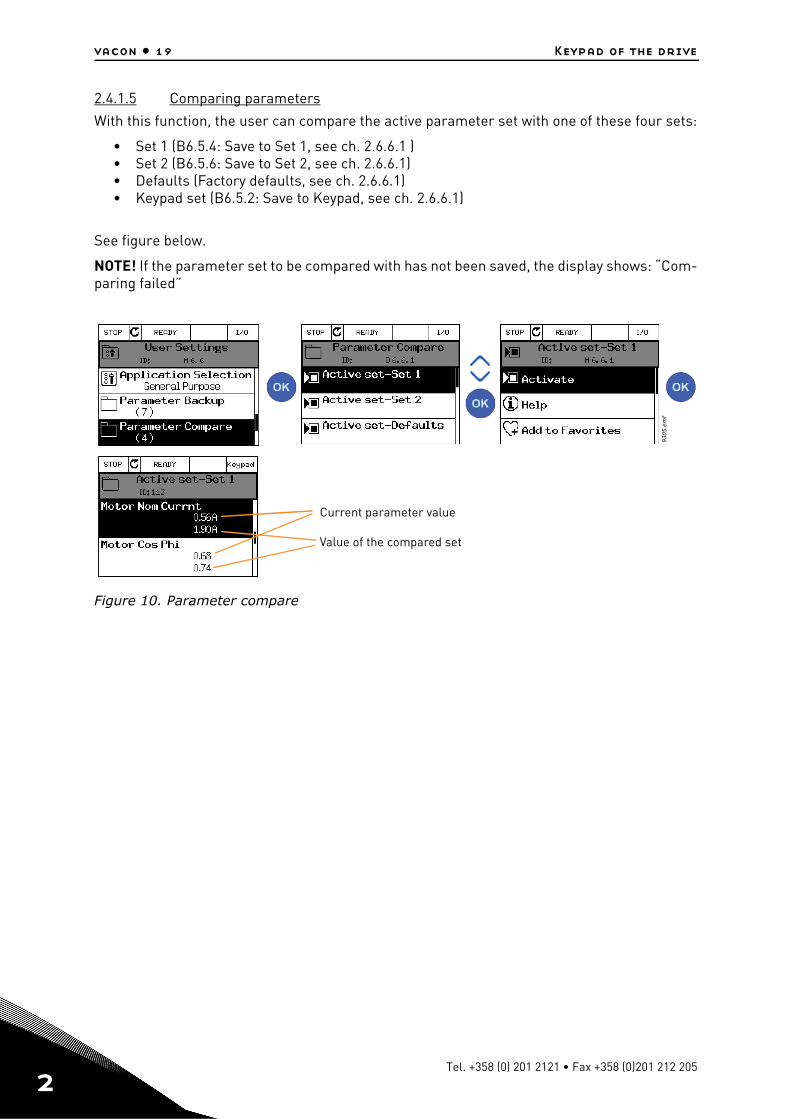
2.4.1.5 Comparing parameters
With this function, the user can compare the active parameter set with one of these four sets:
• Set 1 (B6.5.4: Save to Set 1, see ch. 2.6.6.1 )• Set 2 (B6.5.6: Save to Set 2, see ch. 2.6.6.1)• Defaults (Factory defaults, see ch. 2.6.6.1)• Keypad set (B6.5.2: Save to Keypad, see ch. 2.6.6.1)
See figure below.
NOTE! If the parameter set to be compared with has not been saved, the display shows: “Com-paring failed”
Figure 10. Parameter compare
9305.e
mf
Current parameter value
Value of the compared set
Tel. +358 (0) 201 2121 • Fax +358 (0)201 212 205
Keypad of the drive vacon • 20
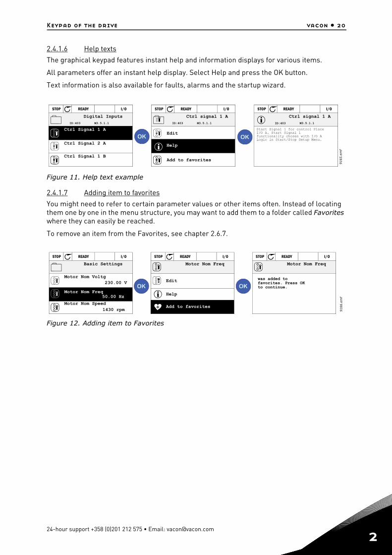
2.4.1.6 Help texts
The graphical keypad features instant help and information displays for various items.
All parameters offer an instant help display. Select Help and press the OK button.
Text information is also available for faults, alarms and the startup wizard.
Figure 11. Help text example
2.4.1.7 Adding item to favorites
You might need to refer to certain parameter values or other items often. Instead of locating them one by one in the menu structure, you may want to add them to a folder called Favorites where they can easily be reached.
To remove an item from the Favorites, see chapter 2.6.7.
Figure 12. Adding item to Favorites
( 6 )
STOP READY I/O
ID:403 M3.5.1.1
( 6 )
STOP READY I/O
ID:403 M3.5.1.1
STOP READY I/O
ID:403 M3.5.1.1
9165.e
mf
Digital Inputs
Ctrl Signal 1 A
Ctrl Signal 1 B
Ctrl Signal 2 A
Add to favorites
Ctrl signal 1 A
Edit
Help
Start Signal 1 for control PlaceI/O A. Start Signal 1functionality chosen with I/O ALogic in Start/Stop Setup Menu.
Ctrl signal 1 A
230.00 V
1430 rpm
STOP READY I/O
50.00 Hz
STOP READY I/O STOP READY I/O
9166.e
mf
Basic Settings
Motor Nom Voltg
Motor Nom Speed
Motor Nom Freq
Edit
Help
Motor Nom Freq
Add to favorites
Motor Nom Freq
was added tofavorites. Press OKto continue.
24-hour support +358 (0)201 212 575 • Email: [email protected]
2
2
vacon • 21 Keypad of the drive
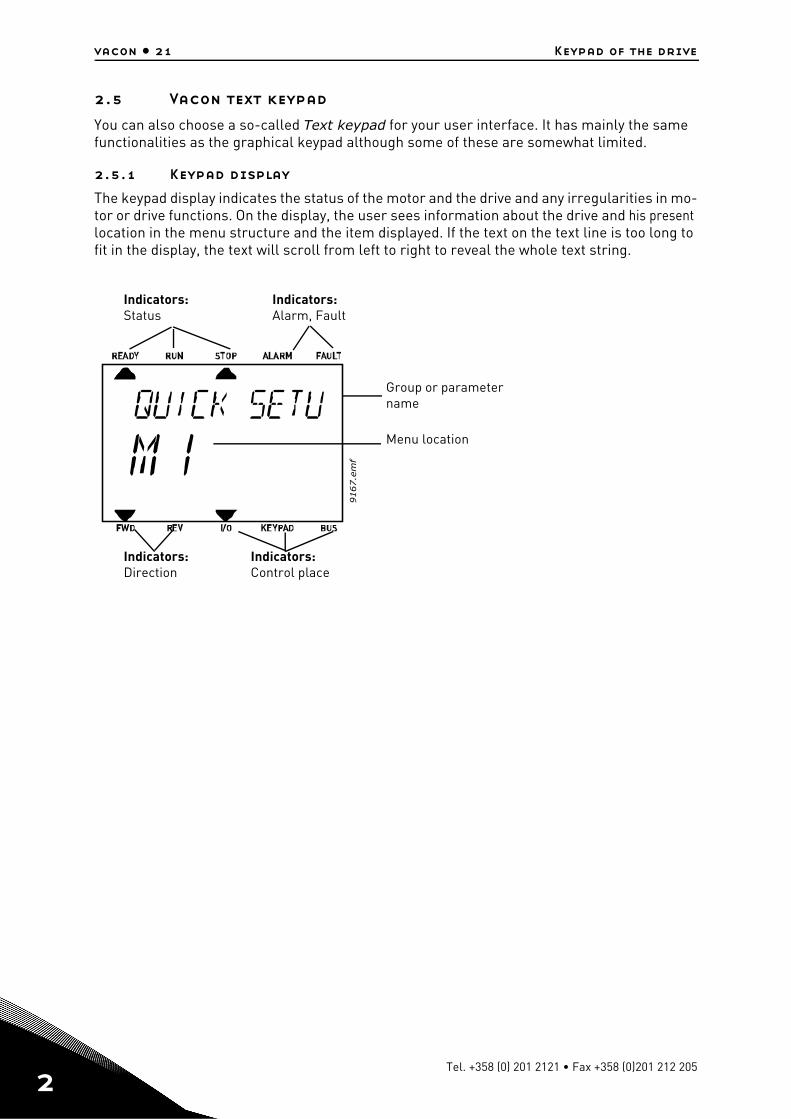
2.5 Vacon text keypad
You can also choose a so-called Text keypad for your user interface. It has mainly the same functionalities as the graphical keypad although some of these are somewhat limited.
2.5.1 Keypad display
The keypad display indicates the status of the motor and the drive and any irregularities in mo-tor or drive functions. On the display, the user sees information about the drive and his present location in the menu structure and the item displayed. If the text on the text line is too long to fit in the display, the text will scroll from left to right to reveal the whole text string.
9167.e
mf
Indicators: Status
Indicators: Alarm, Fault
Indicators: Direction
Indicators: Control place
Group or parameter name
Menu location
Tel. +358 (0) 201 2121 • Fax +358 (0)201 212 205
Keypad of the drive vacon • 22
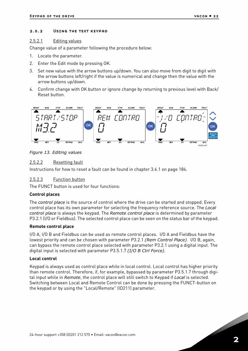
2.5.2 Using the text keypad
2.5.2.1 Editing values
Change value of a parameter following the procedure below:
1. Locate the parameter.
2. Enter the Edit mode by pressing OK.
3. Set new value with the arrow buttons up/down. You can also move from digit to digit with the arrow buttons left/right if the value is numerical and change then the value with the arrow buttons up/down.
4. Confirm change with OK button or ignore change by returning to previous level with Back/Reset button.
Figure 13. Editing values
2.5.2.2 Resetting fault
Instructions for how to reset a fault can be found in chapter 3.6.1 on page 184.
2.5.2.3 Function button
The FUNCT button is used for four functions:
Control places
The control place is the source of control where the drive can be started and stopped. Every control place has its own parameter for selecting the frequency reference source. The Local control place is always the keypad. The Remote control place is determined by parameter P3.2.1 (I/O or Fieldbus). The selected control place can be seen on the status bar of the keypad.
Remote control place
I/O A, I/O B and Fieldbus can be used as remote control places. I/O A and Fieldbus have the lowest priority and can be chosen with parameter P3.2.1 (Rem Control Place). I/O B, again, can bypass the remote control place selected with parameter P3.2.1 using a digital input. The digital input is selected with parameter P3.5.1.7 (I/O B Ctrl Force).
Local control
Keypad is always used as control place while in local control. Local control has higher priority than remote control. Therefore, if, for example, bypassed by parameter P3.5.1.7 through digi-tal input while in Remote, the control place will still switch to Keypad if Local is selected. Switching between Local and Remote Control can be done by pressing the FUNCT-button on the keypad or by using the "Local/Remote" (ID211) parameter.
9168.emf
BACKRESET
24-hour support +358 (0)201 212 575 • Email: [email protected]
2
2
vacon • 23 Keypad of the drive
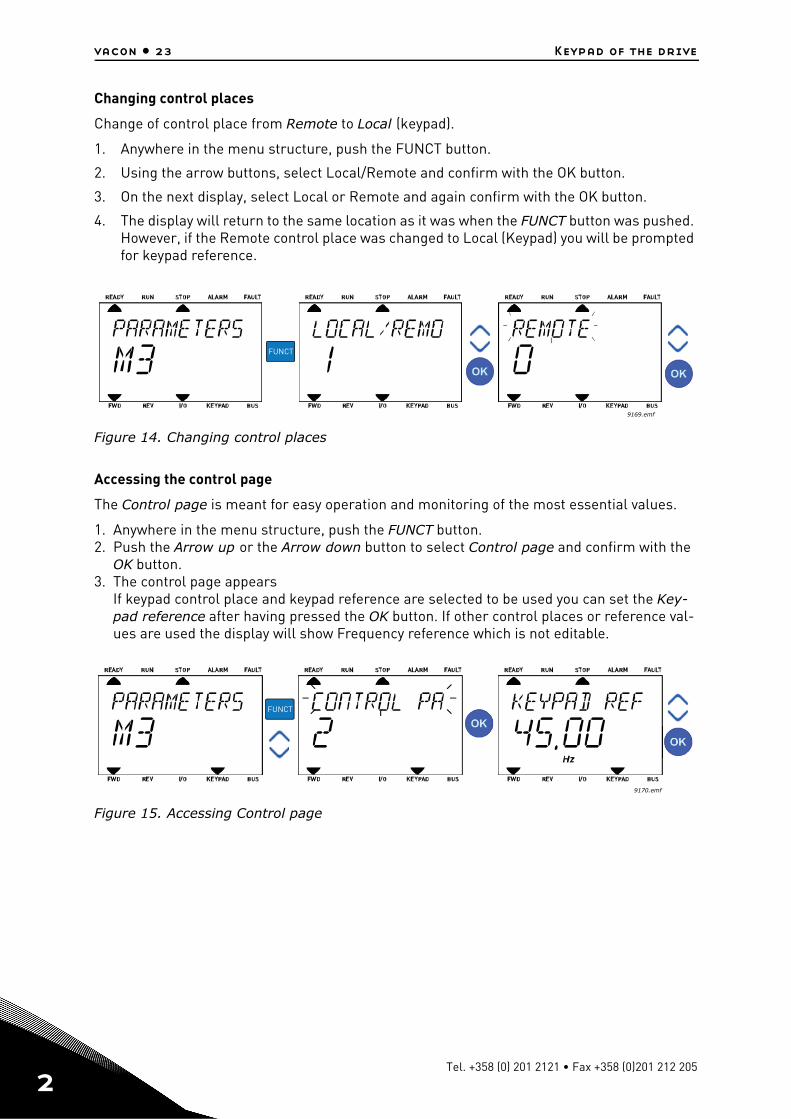
Changing control places
Change of control place from Remote to Local (keypad).
1. Anywhere in the menu structure, push the FUNCT button.
2. Using the arrow buttons, select Local/Remote and confirm with the OK button.
3. On the next display, select Local or Remote and again confirm with the OK button.
4. The display will return to the same location as it was when the FUNCT button was pushed. However, if the Remote control place was changed to Local (Keypad) you will be prompted for keypad reference.
Figure 14. Changing control places
Accessing the control page
The Control page is meant for easy operation and monitoring of the most essential values.
1. Anywhere in the menu structure, push the FUNCT button.2. Push the Arrow up or the Arrow down button to select Control page and confirm with the
OK button.3. The control page appears
If keypad control place and keypad reference are selected to be used you can set the Key-pad reference after having pressed the OK button. If other control places or reference val-ues are used the display will show Frequency reference which is not editable.
Figure 15. Accessing Control page
9169.emf
FUNCT
9170.emf
FUNCT
Tel. +358 (0) 201 2121 • Fax +358 (0)201 212 205
Keypad of the drive vacon • 24
Changing direction
Rotation direction of the motor can quickly be changed by applying the FUNCT button.NOTE! Changing direction command is not visible in the menu unless the selected control place is Local.
1. Anywhere in the menu structure, push the Funct button.2. Push the Arrow up or the Arrow down button to select Change direction and confirm with
the OK button.3. Then choose the direction you wish to run the motor to. The actual rotation direction is
blinking. Confirm with the OK button.4. The rotation direction changes immediately and the arrow indication in the status field
changes.
Quick edit
Through the Quick edit functionality you can quickly access the desired parameter by entering the parameter’s ID number.
1. Anywhere in the menu structure, push the FUNCT button.2. Push the Arrow up or the Arrow down buttons to select Quick Edit and confirm with the OK
button.3. Then enter the ID number of parameter or monitoring value you wish to access. Press OK
button to confirm.4. Requested Parameter/Monitoring value appears on the display (in editing/monitoring
mode.)
24-hour support +358 (0)201 212 575 • Email: [email protected]
2
2
vacon • 25 Keypad of the drive
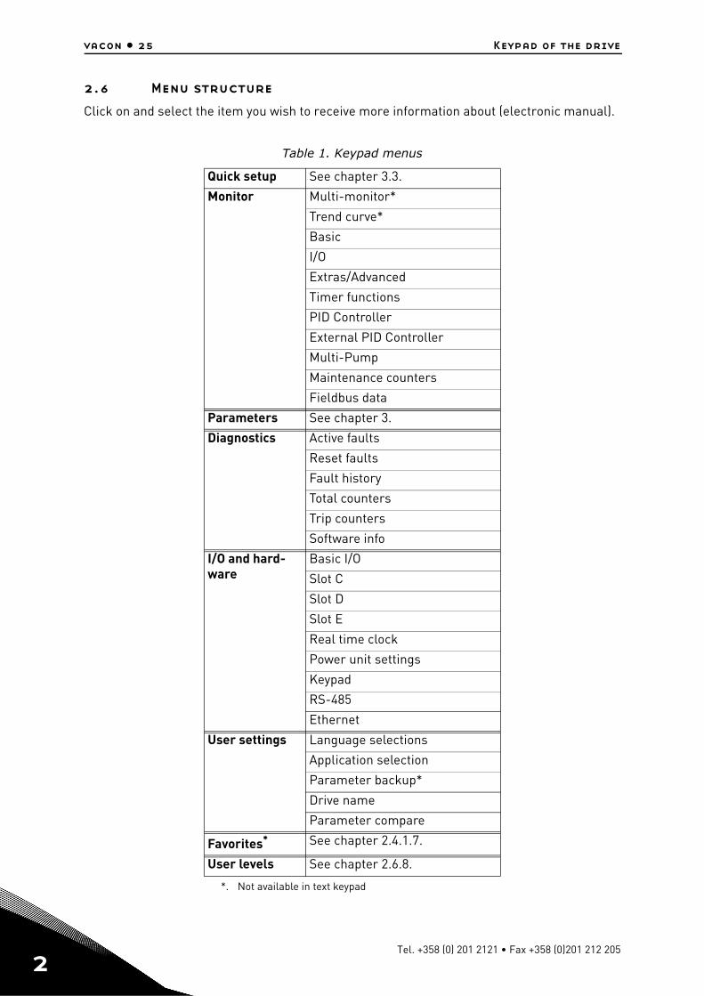
2.6 Menu structure
Click on and select the item you wish to receive more information about (electronic manual).
Table 1. Keypad menus
Quick setup See chapter 3.3.
Monitor Multi-monitor*
Trend curve*
Basic
I/O
Extras/Advanced
Timer functions
PID Controller
External PID Controller
Multi-Pump
Maintenance counters
Fieldbus data
Parameters See chapter 3.
Diagnostics Active faults
Reset faults
Fault history
Total counters
Trip counters
Software info
I/O and hard-ware
Basic I/O
Slot C
Slot D
Slot E
Real time clock
Power unit settings
Keypad
RS-485
Ethernet
User settings Language selections
Application selection
Parameter backup*
Drive name
Parameter compare
Favorites*
*. Not available in text keypad
See chapter 2.4.1.7.
User levels See chapter 2.6.8.
Tel. +358 (0) 201 2121 • Fax +358 (0)201 212 205
Keypad of the drive vacon • 26
2.6.1 Quick setup
The Quick Setup group includes the different wizards and quick setup parameters of the Vacon 100 Application. More detailed information on the parameters of this group you will find in chapter 3.3.
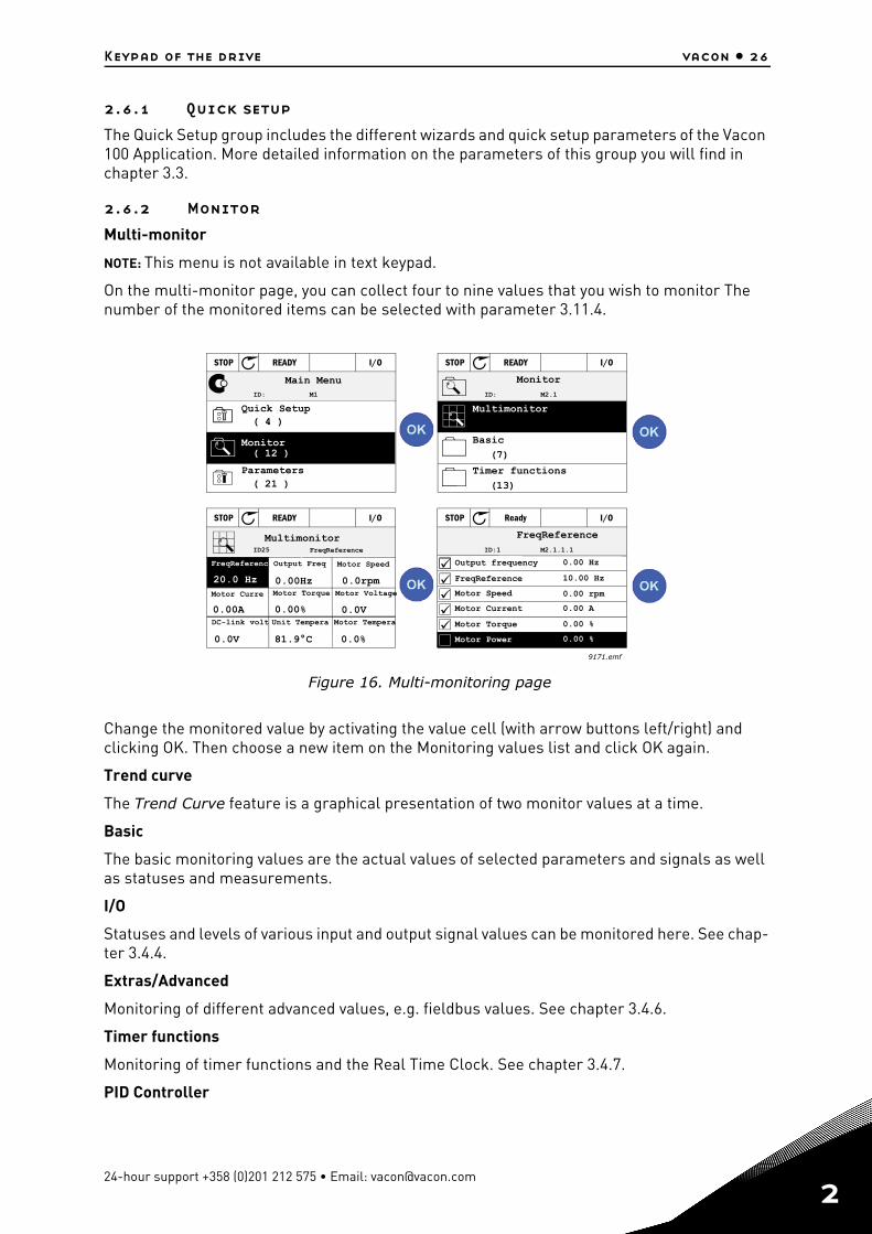
2.6.2 Monitor
Multi-monitor
NOTE: This menu is not available in text keypad.
On the multi-monitor page, you can collect four to nine values that you wish to monitor The number of the monitored items can be selected with parameter 3.11.4.
Figure 16. Multi-monitoring page
Change the monitored value by activating the value cell (with arrow buttons left/right) and clicking OK. Then choose a new item on the Monitoring values list and click OK again.
Trend curve
The Trend Curve feature is a graphical presentation of two monitor values at a time.
Basic
The basic monitoring values are the actual values of selected parameters and signals as well as statuses and measurements.
I/O
Statuses and levels of various input and output signal values can be monitored here. See chap-ter 3.4.4.
Extras/Advanced
Monitoring of different advanced values, e.g. fieldbus values. See chapter 3.4.6.
Timer functions
Monitoring of timer functions and the Real Time Clock. See chapter 3.4.7.
PID Controller
( 4 )
( 21 )
ID: M1
STOP READY I/O
( 12 )
(7)
(13)
STOP READY I/O
ID: M2.1
0.0rpm
STOP READY I/O
0.00 HzID25
0.00Hz
0.00A 0.00%
20.0 Hz
0.0V
0.0V 81.9°C 0.0%
ID:1 M2.1.1.1
STOP Ready I/O
0.00 Hz
10.00 Hz
0.00 rpm
0.00 A
0.00 %
0.00 %
9171.emf
Main Menu
Quick Setup
Parameters
Monitor
Monitor
Multimonitor
Basic
Timer functions
MultimonitorFreqReference
Output Freq
Motor Curre Motor Torque Motor Voltage
Motor Speed
Motor TemperaUnit TemperaDC-link volt
FreqReferenc
FreqReference
Output frequency
Motor Power
FreqReference
Motor Speed
Motor Current
Motor Torque
24-hour support +358 (0)201 212 575 • Email: [email protected]
2
2
vacon • 27 Keypad of the drive
Monitoring of PID controller values. See chapter 3.4.8.
External PID Controller
Monitoring of external PID controller values. See chapter 3.4.9.
Multi-Pump
Monitoring of values related to the use of several drives. See chapter 3.4.10.
Maintenance counters
Monitoring of values related to Maintenance counters. See chapter 3.4.11.
Fieldbus data
Fieldbus data shown as monitor values for debugging purposes at e.g. fieldbus commissioning. See chapter 3.4.12.
Tel. +358 (0) 201 2121 • Fax +358 (0)201 212 205
Keypad of the drive vacon • 28
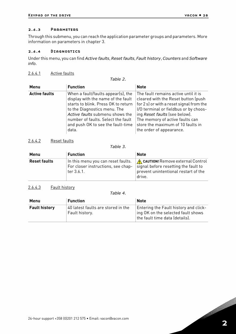
2.6.3 Parameters
Through this submenu, you can reach the application parameter groups and parameters. More information on parameters in chapter 3.
2.6.4 Diagnostics
Under this menu, you can find Active faults, Reset faults, Fault history, Counters and Software info.
2.6.4.1 Active faults
2.6.4.2 Reset faults
2.6.4.3 Fault history
Table 2.
Menu Function Note
Active faults When a fault/faults appear(s), the display with the name of the fault starts to blink. Press OK to return to the Diagnostics menu. The Active faults submenu shows the number of faults. Select the fault and push OK to see the fault-time data.
The fault remains active until it is cleared with the Reset button (push for 2 s) or with a reset signal from the I/O terminal or fieldbus or by choos-ing Reset faults (see below).The memory of active faults can store the maximum of 10 faults in the order of appearance.
Table 3.
Menu Function Note
Reset faults In this menu you can reset faults. For closer instructions, see chap-ter 3.6.1.
CAUTION! Remove external Control signal before resetting the fault to prevent unintentional restart of the drive.
Table 4.
Menu Function Note
Fault history 40 latest faults are stored in the Fault history.
Entering the Fault history and click-ing OK on the selected fault shows the fault time data (details).
13006.emf
24-hour support +358 (0)201 212 575 • Email: [email protected]
2
2
vacon • 29 Keypad of the drive
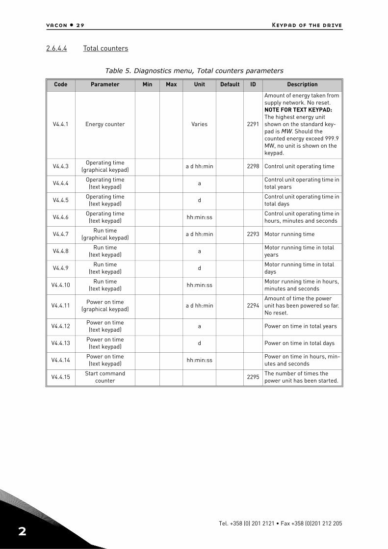
2.6.4.4 Total counters
Table 5. Diagnostics menu, Total counters parameters
Code Parameter Min Max Unit Default ID Description
V4.4.1 Energy counter Varies 2291
Amount of energy taken from supply network. No reset.NOTE FOR TEXT KEYPAD: The highest energy unit shown on the standard key-pad is MW. Should the counted energy exceed 999.9 MW, no unit is shown on the keypad.
V4.4.3Operating time
(graphical keypad)a d hh:min 2298 Control unit operating time
V4.4.4Operating time
(text keypad)a
Control unit operating time in total years
V4.4.5Operating time
(text keypad)d
Control unit operating time in total days
V4.4.6Operating time
(text keypad)hh:min:ss
Control unit operating time in hours, minutes and seconds
V4.4.7Run time
(graphical keypad)a d hh:min 2293 Motor running time
V4.4.8Run time
(text keypad)a
Motor running time in total years
V4.4.9Run time
(text keypad)d
Motor running time in total days
V4.4.10Run time
(text keypad)hh:min:ss
Motor running time in hours, minutes and seconds
V4.4.11Power on time
(graphical keypad)a d hh:min 2294
Amount of time the power unit has been powered so far. No reset.
V4.4.12Power on time (text keypad)
a Power on time in total years
V4.4.13Power on time (text keypad)
d Power on time in total days
V4.4.14Power on time (text keypad)
hh:min:ssPower on time in hours, min-utes and seconds
V4.4.15Start command
counter2295
The number of times the power unit has been started.
Tel. +358 (0) 201 2121 • Fax +358 (0)201 212 205
Keypad of the drive vacon • 30
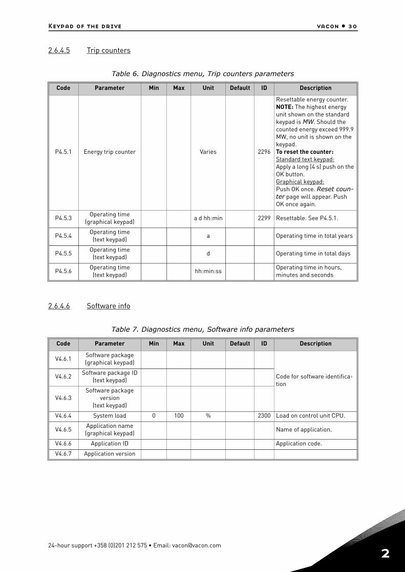
2.6.4.5 Trip counters
2.6.4.6 Software info
Table 6. Diagnostics menu, Trip counters parameters
Code Parameter Min Max Unit Default ID Description
P4.5.1 Energy trip counter Varies 2296
Resettable energy counter.NOTE: The highest energy unit shown on the standard keypad is MW. Should the counted energy exceed 999.9 MW, no unit is shown on the keypad.To reset the counter:Standard text keypad:Apply a long (4 s) push on the OK button.Graphical keypad:Push OK once. Reset coun-ter page will appear. Push OK once again.
P4.5.3Operating time
(graphical keypad)a d hh:min 2299 Resettable. See P4.5.1.
P4.5.4Operating time
(text keypad)a Operating time in total years
P4.5.5Operating time
(text keypad)d Operating time in total days
P4.5.6Operating time
(text keypad)hh:min:ss
Operating time in hours, minutes and seconds
Table 7. Diagnostics menu, Software info parameters
Code Parameter Min Max Unit Default ID Description
V4.6.1Software package(graphical keypad)
Code for software identifica-tion
V4.6.2Software package ID
(text keypad)
V4.6.3Software package
version(text keypad)
V4.6.4 System load 0 100 % 2300 Load on control unit CPU.
V4.6.5Application name(graphical keypad)
Name of application.
V4.6.6 Application ID Application code.
V4.6.7 Application version
24-hour support +358 (0)201 212 575 • Email: [email protected]
2
2
vacon • 31 Keypad of the drive
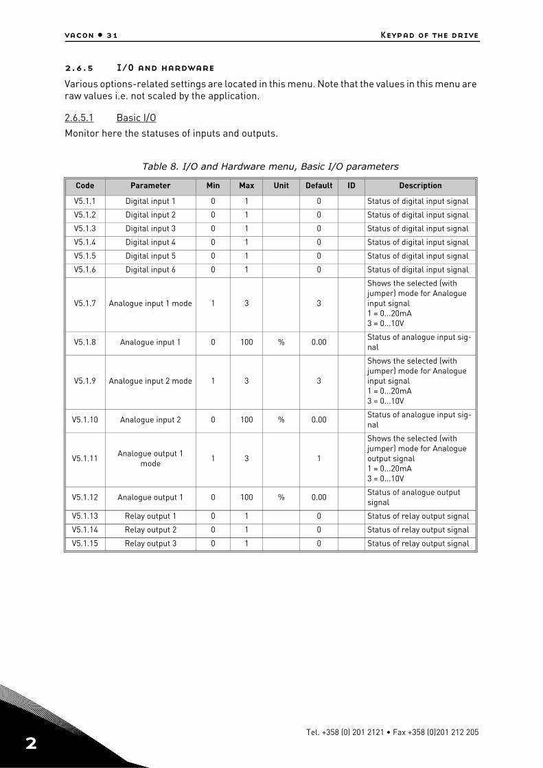
2.6.5 I/O and hardware
Various options-related settings are located in this menu. Note that the values in this menu are raw values i.e. not scaled by the application.
2.6.5.1 Basic I/O
Monitor here the statuses of inputs and outputs.
Table 8. I/O and Hardware menu, Basic I/O parameters
Code Parameter Min Max Unit Default ID Description
V5.1.1 Digital input 1 0 1 0 Status of digital input signal
V5.1.2 Digital input 2 0 1 0 Status of digital input signal
V5.1.3 Digital input 3 0 1 0 Status of digital input signal
V5.1.4 Digital input 4 0 1 0 Status of digital input signal
V5.1.5 Digital input 5 0 1 0 Status of digital input signal
V5.1.6 Digital input 6 0 1 0 Status of digital input signal
V5.1.7 Analogue input 1 mode 1 3 3
Shows the selected (with jumper) mode for Analogue input signal1 = 0...20mA3 = 0...10V
V5.1.8 Analogue input 1 0 100 % 0.00Status of analogue input sig-nal
V5.1.9 Analogue input 2 mode 1 3 3
Shows the selected (with jumper) mode for Analogue input signal1 = 0...20mA3 = 0...10V
V5.1.10 Analogue input 2 0 100 % 0.00Status of analogue input sig-nal
V5.1.11Analogue output 1
mode1 3 1
Shows the selected (with jumper) mode for Analogue output signal1 = 0...20mA3 = 0...10V
V5.1.12 Analogue output 1 0 100 % 0.00Status of analogue output signal
V5.1.13 Relay output 1 0 1 0 Status of relay output signal
V5.1.14 Relay output 2 0 1 0 Status of relay output signal
V5.1.15 Relay output 3 0 1 0 Status of relay output signal
Tel. +358 (0) 201 2121 • Fax +358 (0)201 212 205
Keypad of the drive vacon • 32
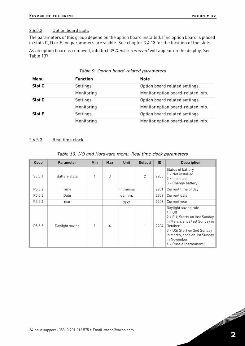
2.6.5.2 Option board slots
The parameters of this group depend on the option board installed. If no option board is placed in slots C, D or E, no parameters are visible. See chapter 3.4.13 for the location of the slots.
As an option board is removed, info text 39 Device removed will appear on the display. See Table 137.
2.6.5.3 Real time clock
Table 9. Option board-related parameters
Menu Function Note
Slot C Settings Option board related settings.
Monitoring Monitor option board-related info.
Slot D Settings Option board related settings.
Monitoring Monitor option board-related info.
Slot E Settings Option board related settings.
Monitoring Monitor option board-related info.
Table 10. I/O and Hardware menu, Real time clock parameters
Code Parameter Min Max Unit Default ID Description
V5.5.1 Battery state 1 3 2 2205
Status of battery. 1 = Not installed2 = Installed3 = Change battery
P5.5.2 Time hh:mm:ss 2201 Current time of day
P5.5.3 Date dd.mm. 2202 Current date
P5.5.4 Year yyyy 2203 Current year
P5.5.5 Daylight saving 1 4 1 2204
Daylight saving rule1 = Off2 = EU; Starts on last Sunday in March, ends last Sunday in October3 = US; Start on 2nd Sunday in March, ends on 1st Sunday in November4 = Russia (permanent)
24-hour support +358 (0)201 212 575 • Email: [email protected]
2
2
vacon • 33 Keypad of the drive
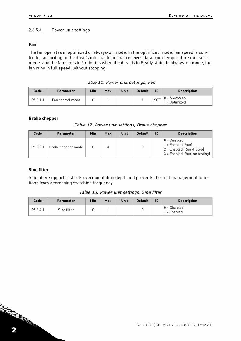
2.6.5.4 Power unit settings
Fan
The fan operates in optimized or always-on mode. In the optimized mode, fan speed is con-trolled according to the drive's internal logic that receives data from temperature measure-ments and the fan stops in 5 minutes when the drive is in Ready state. In always-on mode, the fan runs in full speed, without stopping.
Brake chopper
Sine filter
Sine filter support restricts overmodulation depth and prevents thermal management func-tions from decreasing switching frequency.
Table 11. Power unit settings, Fan
Code Parameter Min Max Unit Default ID Description
P5.6.1.1 Fan control mode 0 1 1 23770 = Always on1 = Optimized
Table 12. Power unit settings, Brake chopper
Code Parameter Min Max Unit Default ID Description
P5.6.2.1 Brake chopper mode 0 3 0
0 = Disabled1 = Enabled (Run)2 = Enabled (Run & Stop)3 = Enabled (Run, no testing)
Table 13. Power unit settings, Sine filter
Code Parameter Min Max Unit Default ID Description
P5.6.4.1 Sine filter 0 1 00 = Disabled1 = Enabled
Tel. +358 (0) 201 2121 • Fax +358 (0)201 212 205
Keypad of the drive vacon • 34
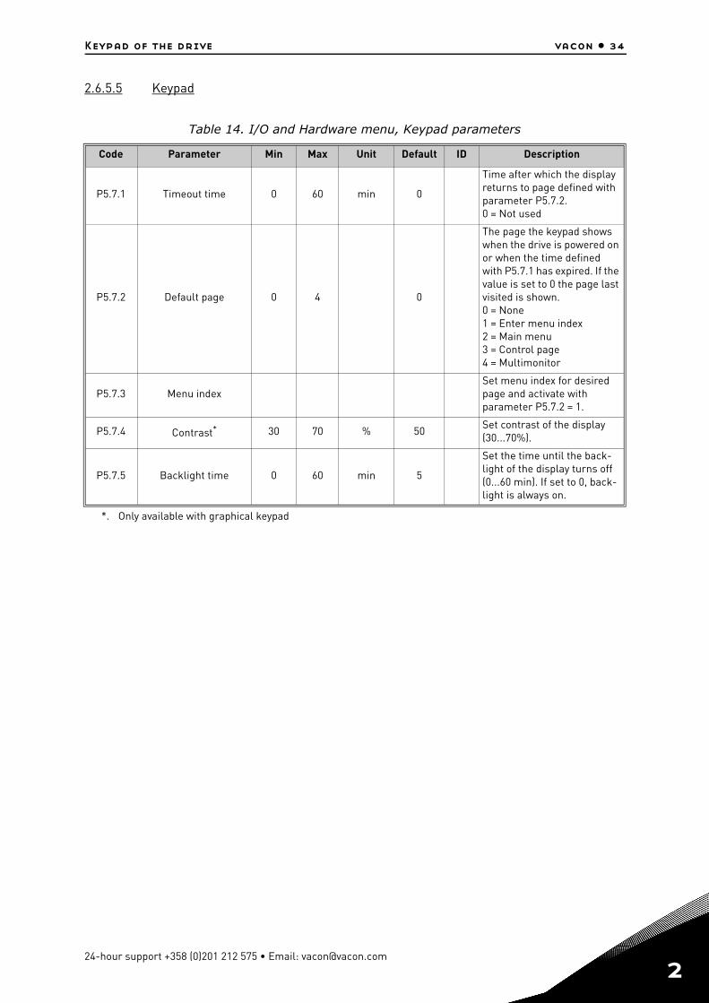
2.6.5.5 Keypad
Table 14. I/O and Hardware menu, Keypad parameters
Code Parameter Min Max Unit Default ID Description
P5.7.1 Timeout time 0 60 min 0
Time after which the display returns to page defined with parameter P5.7.2.0 = Not used
P5.7.2 Default page 0 4 0
The page the keypad shows when the drive is powered on or when the time defined with P5.7.1 has expired. If the value is set to 0 the page last visited is shown.0 = None1 = Enter menu index2 = Main menu3 = Control page4 = Multimonitor
P5.7.3 Menu indexSet menu index for desired page and activate with parameter P5.7.2 = 1.
P5.7.4 Contrast*
*. Only available with graphical keypad
30 70 % 50Set contrast of the display (30...70%).
P5.7.5 Backlight time 0 60 min 5
Set the time until the back-light of the display turns off (0...60 min). If set to 0, back-light is always on.
24-hour support +358 (0)201 212 575 • Email: [email protected]
2
2
vacon • 35 Keypad of the drive
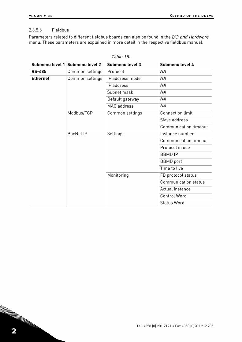
2.6.5.6 Fieldbus
Parameters related to different fieldbus boards can also be found in the I/O and Hardware menu. These parameters are explained in more detail in the respective fieldbus manual.
Table 15.
Submenu level 1 Submenu level 2 Submenu level 3 Submenu level 4
RS-485 Common settings Protocol NA
Ethernet Common settings IP address mode NA
IP address NA
Subnet mask NA
Default gateway NA
MAC address NA
Modbus/TCP Common settings Connection limit
Slave address
Communication timeout
BacNet IP Settings Instance number
Communication timeout
Protocol in use
BBMD IP
BBMD port
Time to live
Monitoring FB protocol status
Communication status
Actual instance
Control Word
Status Word
Tel. +358 (0) 201 2121 • Fax +358 (0)201 212 205
Keypad of the drive vacon • 36
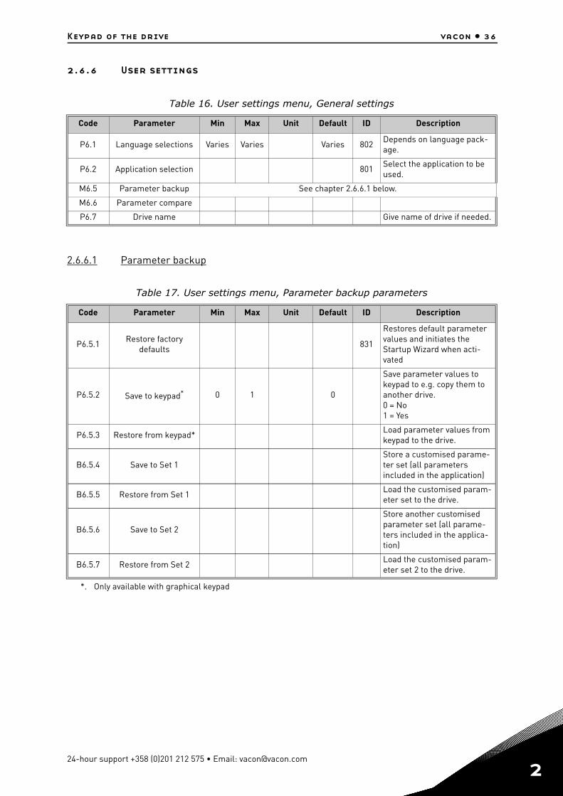
2.6.6 User settings
2.6.6.1 Parameter backup
Table 16. User settings menu, General settings
Code Parameter Min Max Unit Default ID Description
P6.1 Language selections Varies Varies Varies 802Depends on language pack-age.
P6.2 Application selection 801Select the application to be used.
M6.5 Parameter backup See chapter 2.6.6.1 below.
M6.6 Parameter compare
P6.7 Drive name Give name of drive if needed.
Table 17. User settings menu, Parameter backup parameters
Code Parameter Min Max Unit Default ID Description
P6.5.1Restore factory
defaults831
Restores default parameter values and initiates the Startup Wizard when acti-vated
P6.5.2 Save to keypad*
*. Only available with graphical keypad
0 1 0
Save parameter values to keypad to e.g. copy them to another drive.0 = No1 = Yes
P6.5.3 Restore from keypad*Load parameter values from keypad to the drive.
B6.5.4 Save to Set 1Store a customised parame-ter set (all parameters included in the application)
B6.5.5 Restore from Set 1Load the customised param-eter set to the drive.
B6.5.6 Save to Set 2
Store another customised parameter set (all parame-ters included in the applica-tion)
B6.5.7 Restore from Set 2Load the customised param-eter set 2 to the drive.
24-hour support +358 (0)201 212 575 • Email: [email protected]
2
2
vacon • 37 Keypad of the drive
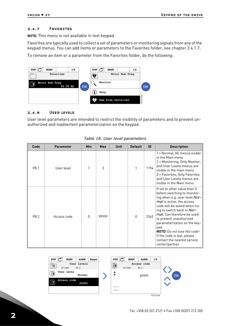
2.6.7 Favorites
NOTE: This menu is not available in text keypad.
Favorites are typically used to collect a set of parameters or monitoring signals from any of the keypad menus. You can add items or parameters to the Favorites folder, see chapter 2.4.1.7.
To remove an item or a parameter from the Favorites folder, do the following:
2.6.8 User levels
User level parameters are intended to restrict the visibility of parameters and to prevent un-authorized and inadvertent parameterization on the keypad.
Table 18. User level parameters
Code Parameter Min Max Unit Default ID Description
P8.1 User level 1 3 1 1194
1 = Normal; All menus visible in the Main menu2 = Monitoring; Only Monitor, and User Levels menus are visible in the main menu3 = Favorites; Only Favorites and User Levels menus are visible in the Main menu
P8.2 Access code 0 99999 0 2362
If set to other value than 0 before switching to monitor-ing when e.g. user level Nor-mal is active, the access code will be asked when try-ing to switch back to Nor-mal. Can therefore be used to prevent unauthorizedparameterization on the key-pad.NOTE! Do not lose the code! If the code is lost, please contact the nearest service center/partner.
50.00 Hz
STOP READY I/O
STOP READY I/O
9172.e
mf
Motor Nom Freq
Favorites
Help
Motor Nom Freq
Monitor
Rem from favorites
STOP READY KeypadALARM
ID:2362 P8.2
User levels
User levelNormal
Access code00000
STOP READY I/OALARM
00000
Min:0
Max:9
ID:2362 P8.2
Access code
9173.emf
Tel. +358 (0) 201 2121 • Fax +358 (0)201 212 205
Vacon 100 Application vacon • 38
3. VACON 100 APPLICATION
The Vacon AC drive contains a preloaded Vacon 100 application for instant use.
The parameters of this application are listed in chapter 3.4.13 of this manual and explained in more detail in chapter 3.5.
3.1 Specific functions of Vacon AC drive
Features
• Extensive wizards for start-up, PID-control, Multi-pump and Fire Mode used to facili-tate commissioning
• ‘Funct’ button for easy change between Local (keypad) and Remote control place. The remote control place is selectable by parameter (I/O or Fieldbus)
• 8 preset frequencies• Motor pontentiometer functions• Joystick control• Jogging function• 2 programmable ramp times, 2 supervisions and 3 ranges of prohibited frequencies• Forced stop• Control page for easy operation and monitoring of the most essential values.• Fieldbus data mapping• Automatic reset• Different pre-heat modes used to avoid condensation problems• Maximum output frequency 320Hz• Real-time clock and timer functions available (optional battery required). Possible to
program 3 time channels to achieve different functions on the drive (e.g. Start/Stop and Preset frequencies)
• External PID-controller available. Can be used to control e.g. a valve using the AC drive's I/O
• Sleep mode function which automatically enables and disables drive running with user defined levels to save energy.
• 2-zone PID-controller (2 different feedback signals; minimum and maximum control)• Two setpoint sources for the PID-control. Selectable with digital input• PID setpoint boost function• Feedforward function to improve the response to the process changes• Process value supervision• Multi-Pump control• Maintenance counter• Pump control functions: Priming Pump Control, Jockey Pump Control, Pump Impeller
Auto-Cleaning, Pump Input Pressure Supervision and Frost Protection function
24-hour support +358 (0)201 212 575 • Email: [email protected]
3
vacon • 39 Vacon 100 Application
3
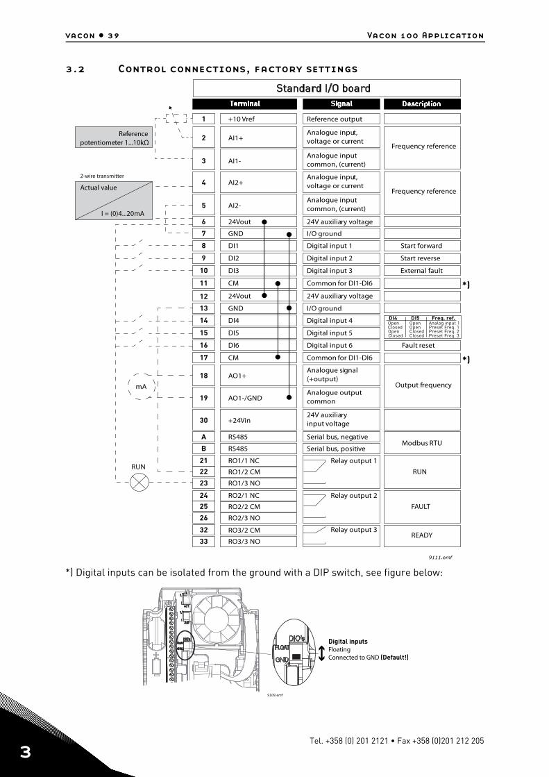
3.2 Control connections, factory settings
*) Digital inputs can be isolated from the ground with a DIP switch, see figure below:
RUN
FAULT
READY
*)
*)
Reference output+10 Vref1
24V auxiliary voltage24Vout6
Analogue input,voltage or current
Referencepotentiometer 1...10kΩ
Actual value
2-wire transmitter
I = (0)4...20mA
AI1+2
Analogue inputcommon, (current)AI1-3
Analogue input,voltage or currentAI2+4
Analogue inputcommon, (current)AI2-5
Analogue signal(+output)AO1+
RUN
18
Analogue outputcommonAO1-/GND19
24V auxiliaryinput voltage+24Vin30
24V auxiliary voltage24Vout12
I/O groundGND7
I/O groundGND13
Digital input 1DI18
Digital input 2DI29
Digital input 3DI310
Digital input 4DI414
Digital input 5DI515
Digital input 6DI616
Relay output 1RO1/1 NC21
22 RO1/2 CM
RO1/3 NO23
Common for DI1-DI6CM11
Common for DI1-DI6CM17
Serial bus, negativeRS485A
Serial bus, positiveRS485B
Relay output 2
Relay output 3
RO2/1 NC24
25 RO2/2 CM
RO2/3 NO26
32 RO3/2 CM
RO3/3 NO33
9111.emf
Frequency reference
Frequency reference
Start forward
Start reverse
External fault
DI4 DI5 Freq. ref.OpenClosedOpenClosed
OpenOpenClosedClosed
Analog input 1Preset Freq. 1Preset Freq. 2Preset Freq. 3
Fault reset
Output frequency
Modbus RTU
mA
9109.emf
Digital inputsFloatingConnected to GND (Default!)
Tel. +358 (0) 201 2121 • Fax +358 (0)201 212 205
Vacon 100 Application vacon • 40
3.3 Quick setup parameter group
The Quick Setup parameter group is a collection of parameters that are most commonly used during installation and commissioning. They are collected in the first parameter group so that they can be found fast and easily. They can, however, be also reached and edited in their actual parameter groups. Changing a parameter value in the Quick setup group also changes the val-ue of this parameter in its actual group
In the Quick Setup parameter group you will find the different wizards of the Vacon 100 Appli-cation. The wizards help you to quickly set up your drive for use prompting you for a number of essential data.
Table 19. Quick setup parameter group, wizards
Code Parameter Min Max Unit Default ID Description
1.1.1I/O Configuration wiz-
ard0 1 0 1673
0 = Do not activate1 = ActivateChoosing Activate initiates the IO configuration Wizard (see chapter 1.2)
1.1.2 Startup wizard 0 1 0 1170
0 = Do not activate1 = ActivateChoosing Activate initiates the Startup Wizard (see chapter 1.1).
1.1.3 PID Mini-Wizard 0 1 0 1670Choosing Activate initiates the PID Mini-Wizard (see chapter 1.3 ).
1.1.4 Multi-pump Wizard 0 1 0 1671Choosing Activate initiates the Multi-pump Wizard (see chapter 1.4).
1.1.5 Fire mode Wizard 0 1 0 1672Choosing Activate initiates the Fire mode Wizard (see chapter 1.5).
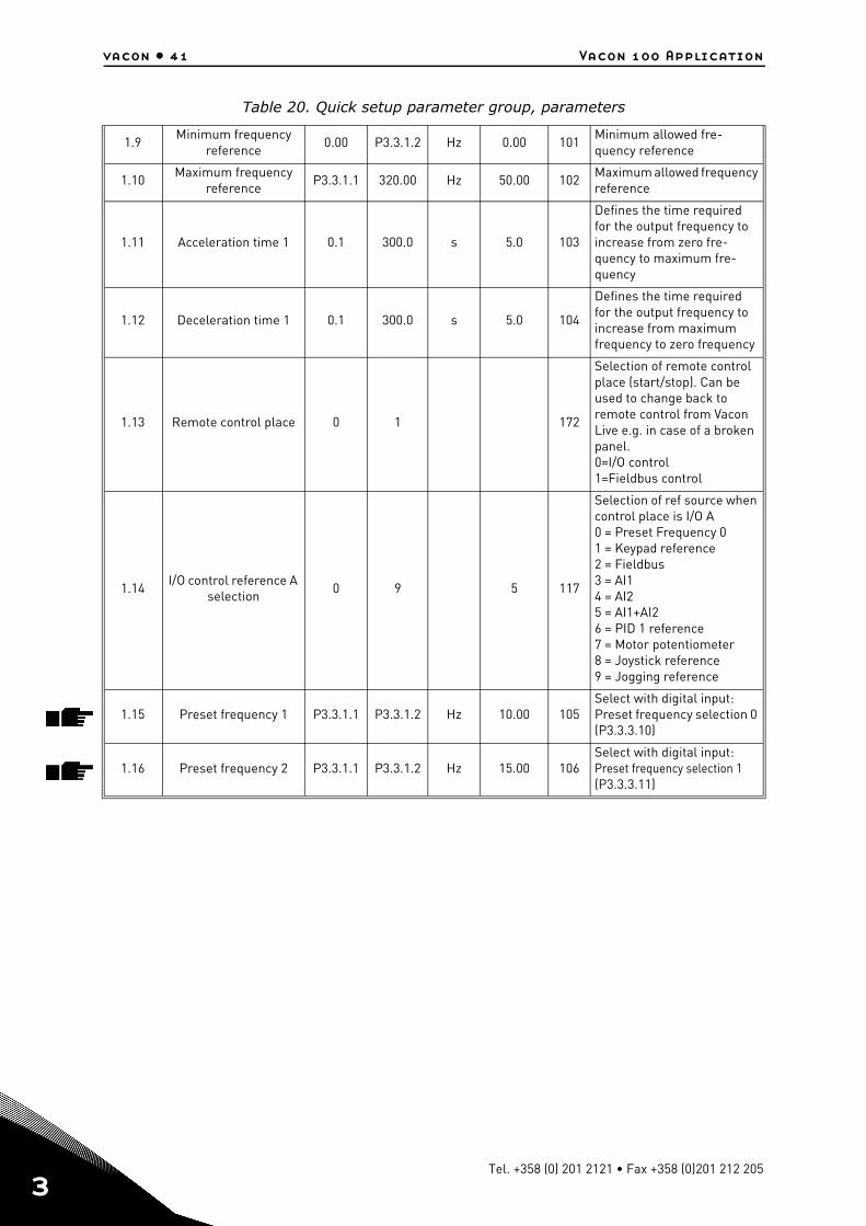
Table 20. Quick setup parameter group, parameters
Code Parameter Min Max Unit Default ID Description
1.2 Motor Nominal Voltage 0,0 20,0 V 0.0 110
Find this value Un on the
rating plate of the motor. Note also used connection (Delta/Star).
1.3Motor nominal fre-
quency0.0 2.0 Hz 0.0 111
Find this value fn on the rat-
ing plate of the motor.
1.4 Motor nominal speed 0 1 rpm 0 112Find this value nn on the rat-
ing plate of the motor.
1.5 Motor nominal current Varies Varies A 113Find this value In on the rat-
ing plate of the motor.
1.6 Motor Cos Phi 0.30 1.00 120Find this value on the rating plate of the motor
1.7 Motor Nominal Power Varies Varies kW/hp 116Find this value Pn on the rat-ing plate of the motor
1.8 Motor current limit Varies Varies A 107Maximum motor current from AC drive
24-hour support +358 (0)201 212 575 • Email: [email protected]
3
vacon • 41 Vacon 100 Application
3
1.9Minimum frequency
reference0.00 P3.3.1.2 Hz 0.00 101
Minimum allowed fre-quency reference
1.10Maximum frequency
referenceP3.3.1.1 320.00 Hz 50.00 102
Maximum allowed frequency reference
1.11 Acceleration time 1 0.1 300.0 s 5.0 103
Defines the time required for the output frequency to increase from zero fre-quency to maximum fre-quency
1.12 Deceleration time 1 0.1 300.0 s 5.0 104
Defines the time required for the output frequency to increase from maximum frequency to zero frequency
1.13 Remote control place 0 1 172
Selection of remote control place (start/stop). Can be used to change back to remote control from Vacon Live e.g. in case of a broken panel.0=I/O control1=Fieldbus control
1.14I/O control reference A
selection0 9 5 117
Selection of ref source when control place is I/O A0 = Preset Frequency 01 = Keypad reference2 = Fieldbus3 = AI14 = AI25 = AI1+AI26 = PID 1 reference7 = Motor potentiometer8 = Joystick reference9 = Jogging reference
1.15 Preset frequency 1 P3.3.1.1 P3.3.1.2 Hz 10.00 105Select with digital input:Preset frequency selection 0 (P3.3.3.10)
1.16 Preset frequency 2 P3.3.1.1 P3.3.1.2 Hz 15.00 106Select with digital input: Preset frequency selection 1 (P3.3.3.11)
Table 20. Quick setup parameter group, parameters
Tel. +358 (0) 201 2121 • Fax +358 (0)201 212 205
Vacon 100 Application vacon • 42
3.4 Monitor group
Vacon 100 AC drive provides you with a possibility to monitor the actual values of parameters and signals as well as statuses and measurements. Some of the values to be monitored are customizable.
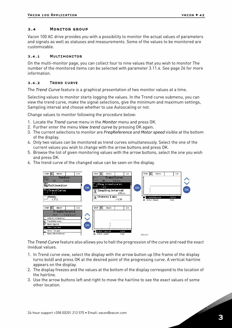
3.4.1 Multimonitor
On the multi-monitor page, you can collect four to nine values that you wish to monitor The number of the monitored items can be selected with parameter 3.11.4. See page 26 for more information.
3.4.2 Trend curve
The Trend Curve feature is a graphical presentation of two monitor values at a time.
Selecting values to monitor starts logging the values. In the Trend curve submenu, you can view the trend curve, make the signal selections, give the minimum and maximum settings, Sampling interval and choose whether to use Autoscaling or not.
Change values to monitor following the procedure below:
1. Locate the Trend curve menu in the Monitor menu and press OK.2. Further enter the menu View trend curve by pressing OK again.3. The current selections to monitor are FreqReference and Motor speed visible at the bottom
of the display.4. Only two values can be monitored as trend curves simultaneously. Select the one of the
current values you wish to change with the arrow buttons and press OK.5. Browse the list of given monitoring values with the arrow buttons, select the one you wish
and press OK.6. The trend curve of the changed value can be seen on the display.
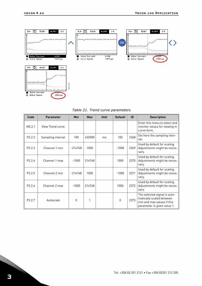
The Trend Curve feature also allows you to halt the progression of the curve and read the exact invidual values.
1. In Trend curve view, select the display with the arrow button up (the frame of the display turns bold) and press OK at the desired point of the progressing curve. A vertical hairline appears on the display.
2. The display freezes and the values at the bottom of the display correspond to the location of the hairline.
3. Use the arrow buttons left and right to move the hairline to see the exact values of some other location.
9250.emf
24-hour support +358 (0)201 212 575 • Email: [email protected]
3
vacon • 43 Vacon 100 Application
3
Table 21. Trend curve parameters
Code Parameter Min Max Unit Default ID Description
M2.2.1 View Trend curveEnter this menu to select and monitor values for viewing in curve form.
P2.2.2 Sampling interval 100 432000 ms 100 2368Set here the sampling inter-val.
P2.2.3 Channel 1 min -214748 1000 -1000 2369Used by default for scaling. Adjustments might be neces-sary.
P2.2.4 Channel 1 max -1000 214748 1000 2370Used by default for scaling. Adjustments might be neces-sary.
P2.2.5 Channel 2 min -214748 1000 -1000 2371Used by default for scaling. Adjustments might be neces-sary.
P2.2.6 Channel 2 max -1000 214748 1000 2372Used by default for scaling. Adjustments might be neces-sary.
P2.2.7 Autoscale 0 1 0 2373
The selected signal is auto-matically scaled between min and max values if this parameter is given value 1.
9251.e
mf
Tel. +358 (0) 201 2121 • Fax +358 (0)201 212 205
Vacon 100 Application vacon • 44
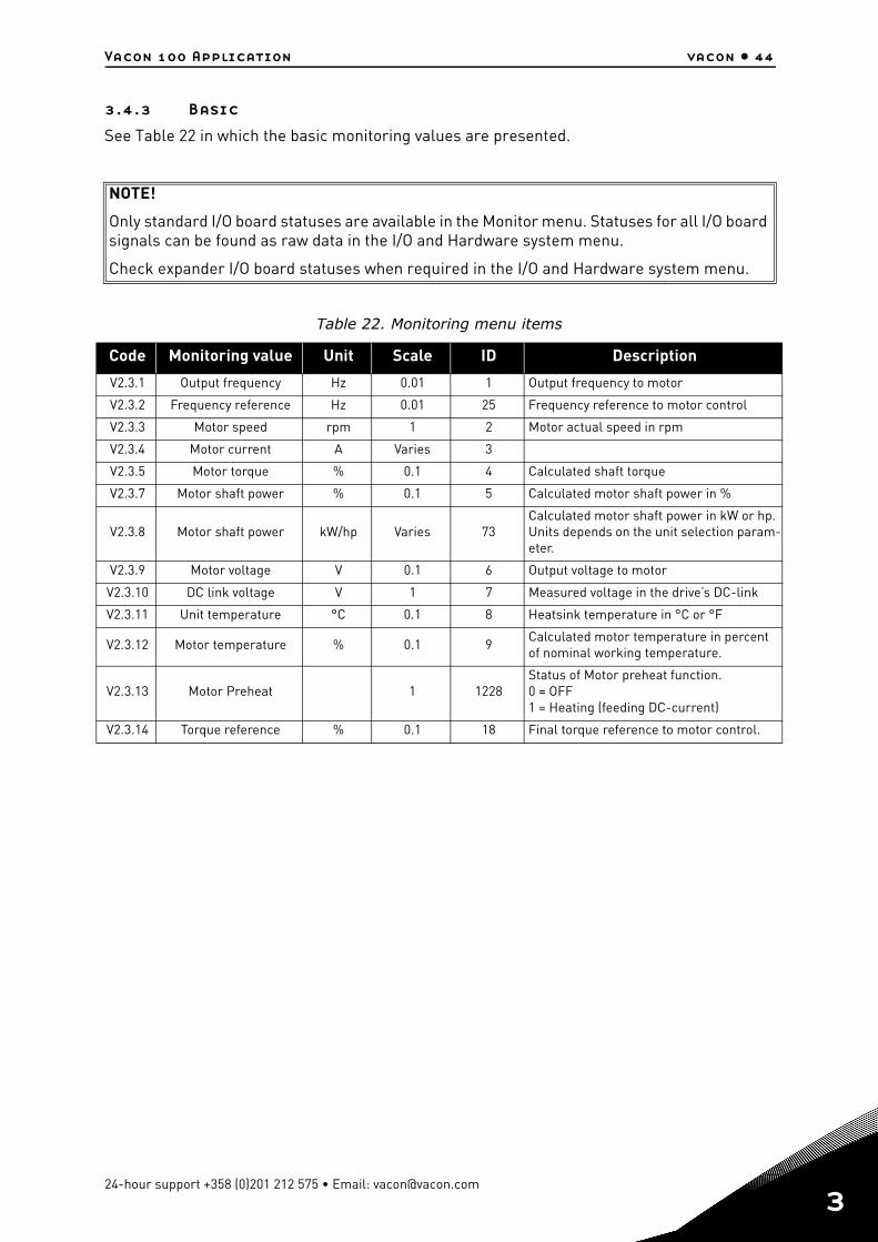
3.4.3 Basic
See Table 22 in which the basic monitoring values are presented.
NOTE!
Only standard I/O board statuses are available in the Monitor menu. Statuses for all I/O board signals can be found as raw data in the I/O and Hardware system menu.
Check expander I/O board statuses when required in the I/O and Hardware system menu.
Table 22. Monitoring menu items
Code Monitoring value Unit Scale ID Description
V2.3.1 Output frequency Hz 0.01 1 Output frequency to motor
V2.3.2 Frequency reference Hz 0.01 25 Frequency reference to motor control
V2.3.3 Motor speed rpm 1 2 Motor actual speed in rpm
V2.3.4 Motor current A Varies 3
V2.3.5 Motor torque % 0.1 4 Calculated shaft torque
V2.3.7 Motor shaft power % 0.1 5 Calculated motor shaft power in %
V2.3.8 Motor shaft power kW/hp Varies 73Calculated motor shaft power in kW or hp. Units depends on the unit selection param-eter.
V2.3.9 Motor voltage V 0.1 6 Output voltage to motor
V2.3.10 DC link voltage V 1 7 Measured voltage in the drive’s DC-link
V2.3.11 Unit temperature °C 0.1 8 Heatsink temperature in °C or °F
V2.3.12 Motor temperature % 0.1 9Calculated motor temperature in percent of nominal working temperature.
V2.3.13 Motor Preheat 1 1228Status of Motor preheat function.0 = OFF1 = Heating (feeding DC-current)
V2.3.14 Torque reference % 0.1 18 Final torque reference to motor control.
24-hour support +358 (0)201 212 575 • Email: [email protected]
3
vacon • 45 Vacon 100 Application
3
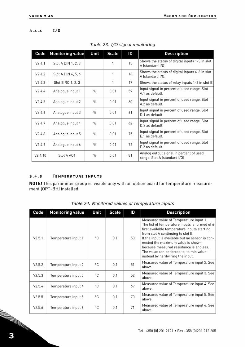
3.4.4 I/O
3.4.5 Temperature inputs
NOTE! This parameter group is visible only with an option board for temperature measure-ment (OPT-BH) installed.
Table 23. I/O signal monitoring
Code Monitoring value Unit Scale ID Description
V2.4.1 Slot A DIN 1, 2, 3 1 15Shows the status of digital inputs 1-3 in slot A (standard I/O)
V2.4.2 Slot A DIN 4, 5, 6 1 16Shows the status of digital inputs 4-6 in slot A (standard I/O)
V2.4.3 Slot B RO 1, 2, 3 1 17 Shows the status of relay inputs 1-3 in slot B
V2.4.4 Analogue input 1 % 0.01 59Input signal in percent of used range. Slot A.1 as default.
V2.4.5 Analogue input 2 % 0.01 60Input signal in percent of used range. Slot A.2 as default.
V2.4.6 Analogue input 3 % 0.01 61Input signal in percent of used range. Slot D.1 as default.
V2.4.7 Analogue input 4 % 0.01 62Input signal in percent of used range. Slot D.2 as default.
V2.4.8 Analogue input 5 % 0.01 75Input signal in percent of used range. Slot E.1 as default.
V2.4.9 Analogue input 6 % 0.01 76Input signal in percent of used range. Slot E.2 as default.
V2.4.10 Slot A AO1 % 0.01 81Analog output signal in percent of used range. Slot A (standard I/O)
Table 24. Monitored values of temperature inputs
Code Monitoring value Unit Scale ID Description
V2.5.1 Temperature input 1 °C 0.1 50
Measured value of Temperature input 1.The list of temperature inputs is formed of 6 first available temperature inputs starting from slot A continuing to slot E. If the input is available but no sensor is con-nected the maximum value is shown because measured resistance is endless. The value can be forced to its min value instead by hardwiring the input.
V2.5.2 Temperature input 2 °C 0.1 51Measured value of Temperature input 2. See above.
V2.5.3 Temperature input 3 °C 0.1 52Measured value of Temperature input 3. See above.
V2.5.4 Temperature input 4 °C 0.1 69Measured value of Temperature input 4. See above.
V2.5.5 Temperature input 5 °C 0.1 70Measured value of Temperature input 5. See above.
V2.5.6 Temperature input 6 °C 0.1 71Measured value of Temperature input 6. See above.
Tel. +358 (0) 201 2121 • Fax +358 (0)201 212 205
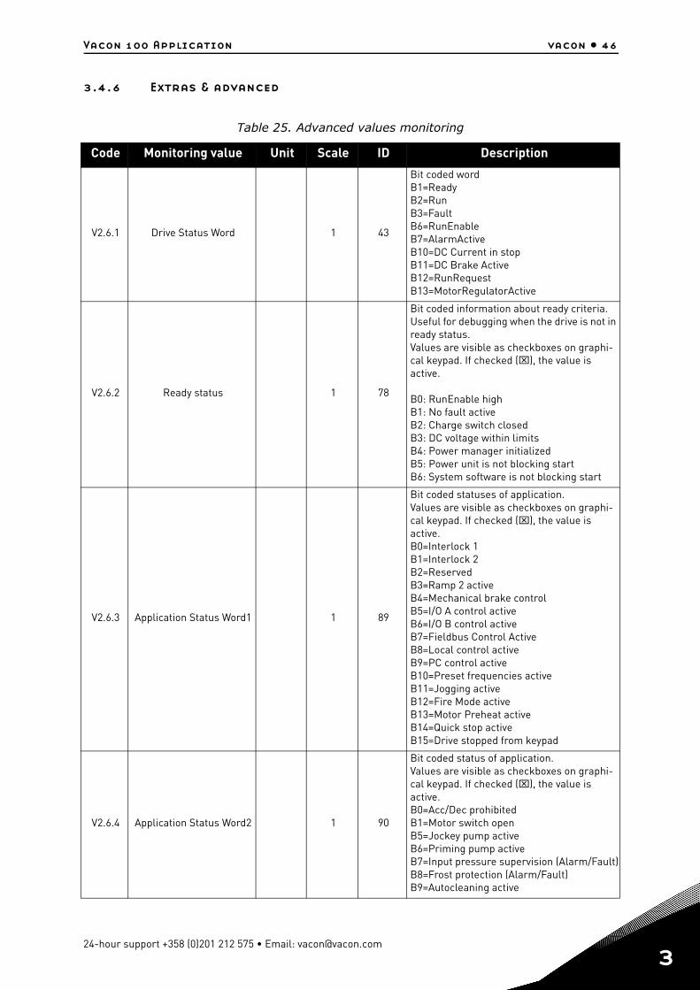
Vacon 100 Application vacon • 46
3.4.6 Extras & advanced
Table 25. Advanced values monitoring
Code Monitoring value Unit Scale ID Description
V2.6.1 Drive Status Word 1 43
Bit coded wordB1=ReadyB2=RunB3=FaultB6=RunEnableB7=AlarmActiveB10=DC Current in stopB11=DC Brake ActiveB12=RunRequestB13=MotorRegulatorActive
V2.6.2 Ready status 1 78
Bit coded information about ready criteria. Useful for debugging when the drive is not in ready status.Values are visible as checkboxes on graphi-cal keypad. If checked (), the value is active.
B0: RunEnable high B1: No fault active B2: Charge switch closed B3: DC voltage within limits B4: Power manager initialized B5: Power unit is not blocking start B6: System software is not blocking start
V2.6.3 Application Status Word1 1 89
Bit coded statuses of application.Values are visible as checkboxes on graphi-cal keypad. If checked (), the value is active.B0=Interlock 1B1=Interlock 2B2=ReservedB3=Ramp 2 activeB4=Mechanical brake controlB5=I/O A control activeB6=I/O B control activeB7=Fieldbus Control ActiveB8=Local control activeB9=PC control activeB10=Preset frequencies activeB11=Jogging activeB12=Fire Mode activeB13=Motor Preheat activeB14=Quick stop activeB15=Drive stopped from keypad
V2.6.4 Application Status Word2 1 90
Bit coded status of application.Values are visible as checkboxes on graphi-cal keypad. If checked (), the value is active.B0=Acc/Dec prohibitedB1=Motor switch openB5=Jockey pump activeB6=Priming pump activeB7=Input pressure supervision (Alarm/Fault)B8=Frost protection (Alarm/Fault)B9=Autocleaning active
24-hour support +358 (0)201 212 575 • Email: [email protected]
3
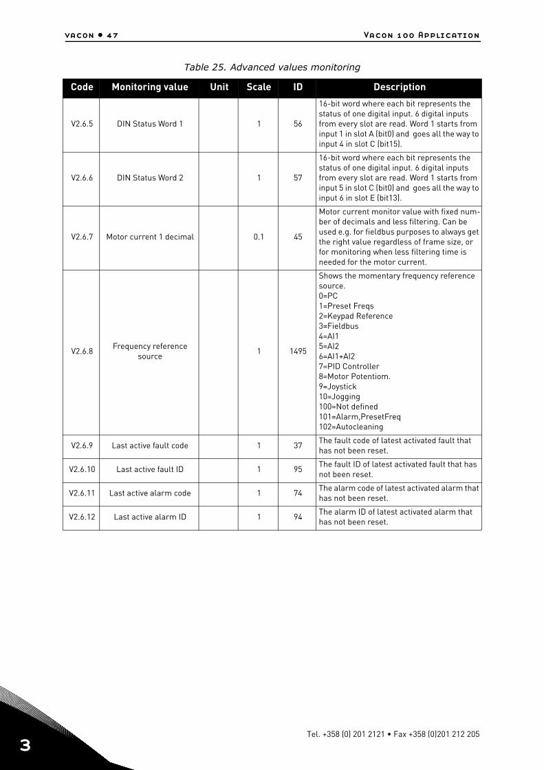
vacon • 47 Vacon 100 Application
3
V2.6.5 DIN Status Word 1 1 56
16-bit word where each bit represents the status of one digital input. 6 digital inputs from every slot are read. Word 1 starts from input 1 in slot A (bit0) and goes all the way to input 4 in slot C (bit15).
V2.6.6 DIN Status Word 2 1 57
16-bit word where each bit represents the status of one digital input. 6 digital inputs from every slot are read. Word 1 starts from input 5 in slot C (bit0) and goes all the way to input 6 in slot E (bit13).
V2.6.7 Motor current 1 decimal 0.1 45
Motor current monitor value with fixed num-ber of decimals and less filtering. Can be used e.g. for fieldbus purposes to always get the right value regardless of frame size, or for monitoring when less filtering time is needed for the motor current.
V2.6.8Frequency reference
source1 1495
Shows the momentary frequency reference source.0=PC1=Preset Freqs2=Keypad Reference3=Fieldbus4=AI15=AI26=AI1+AI27=PID Controller8=Motor Potentiom.9=Joystick10=Jogging100=Not defined101=Alarm,PresetFreq102=Autocleaning
V2.6.9 Last active fault code 1 37The fault code of latest activated fault that has not been reset.
V2.6.10 Last active fault ID 1 95The fault ID of latest activated fault that has not been reset.
V2.6.11 Last active alarm code 1 74The alarm code of latest activated alarm that has not been reset.
V2.6.12 Last active alarm ID 1 94The alarm ID of latest activated alarm that has not been reset.
Table 25. Advanced values monitoring
Code Monitoring value Unit Scale ID Description
Tel. +358 (0) 201 2121 • Fax +358 (0)201 212 205
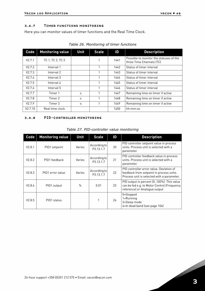
Vacon 100 Application vacon • 48
3.4.7 Timer functions monitoring
Here you can monitor values of timer functions and the Real Time Clock.
3.4.8 PID-controller monitoring
Table 26. Monitoring of timer functions
Code Monitoring value Unit Scale ID Description
V2.7.1 TC 1, TC 2, TC 3 1 1441Possible to monitor the statuses of the three Time Channels (TC)
V2.7.2 Interval 1 1 1442 Status of timer interval
V2.7.3 Interval 2 1 1443 Status of timer interval
V2.7.4 Interval 3 1 1444 Status of timer interval
V2.7.5 Interval 4 1 1445 Status of timer interval
V2.7.6 Interval 5 1 1446 Status of timer interval
V2.7.7 Timer 1 s 1 1447 Remaining time on timer if active
V2.7.8 Timer 2 s 1 1448 Remaining time on timer if active
V2.7.9 Timer 3 s 1 1449 Remaining time on timer if active
V2.7.10 Real time clock 1450 hh:mm:ss
Table 27. PID-controller value monitoring
Code Monitoring value Unit Scale ID Description
V2.8.1 PID1 setpoint VariesAccording to
P3.13.1.720
PID controller setpoint value in process units. Process unit is selected with a parameter.
V2.8.2 PID1 feedback VariesAccording to
P3.13.1.721
PID controller feedback value in process units. Process unit is selected with a parameter.
V2.8.3 PID1 error value VariesAccording to
P3.13.1.722
PID controller error value. Deviation of feedback from setpoint in process units. Process unit is selected with a parameter.
V2.8.4 PID1 output % 0.01 23PID output in percent (0..100%). This value can be fed e.g. to Motor Control (Frequency reference) or Analogue output
V2.8.5 PID1 status 1 24
0=Stopped1=Running3=Sleep mode4=In dead band (see page 104)
24-hour support +358 (0)201 212 575 • Email: [email protected]
3
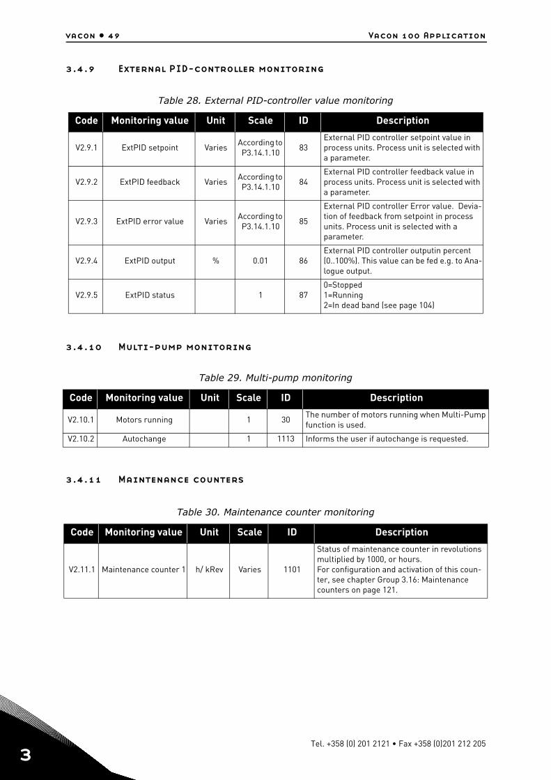
vacon • 49 Vacon 100 Application
3
3.4.9 External PID-controller monitoring
3.4.10 Multi-pump monitoring
3.4.11 Maintenance counters
Table 28. External PID-controller value monitoring
Code Monitoring value Unit Scale ID Description
V2.9.1 ExtPID setpoint VariesAccording to P3.14.1.10
83External PID controller setpoint value in process units. Process unit is selected with a parameter.
V2.9.2 ExtPID feedback VariesAccording to P3.14.1.10
84External PID controller feedback value in process units. Process unit is selected with a parameter.
V2.9.3 ExtPID error value VariesAccording to P3.14.1.10
85
External PID controller Error value. Devia-tion of feedback from setpoint in process units. Process unit is selected with a parameter.
V2.9.4 ExtPID output % 0.01 86External PID controller outputin percent (0..100%). This value can be fed e.g. to Ana-logue output.
V2.9.5 ExtPID status 1 870=Stopped1=Running2=In dead band (see page 104)
Table 29. Multi-pump monitoring
Code Monitoring value Unit Scale ID Description
V2.10.1 Motors running 1 30The number of motors running when Multi-Pump function is used.
V2.10.2 Autochange 1 1113 Informs the user if autochange is requested.
Table 30. Maintenance counter monitoring
Code Monitoring value Unit Scale ID Description
V2.11.1 Maintenance counter 1 h/ kRev Varies 1101
Status of maintenance counter in revolutions multiplied by 1000, or hours.For configuration and activation of this coun-ter, see chapter Group 3.16: Maintenance counters on page 121.
Tel. +358 (0) 201 2121 • Fax +358 (0)201 212 205
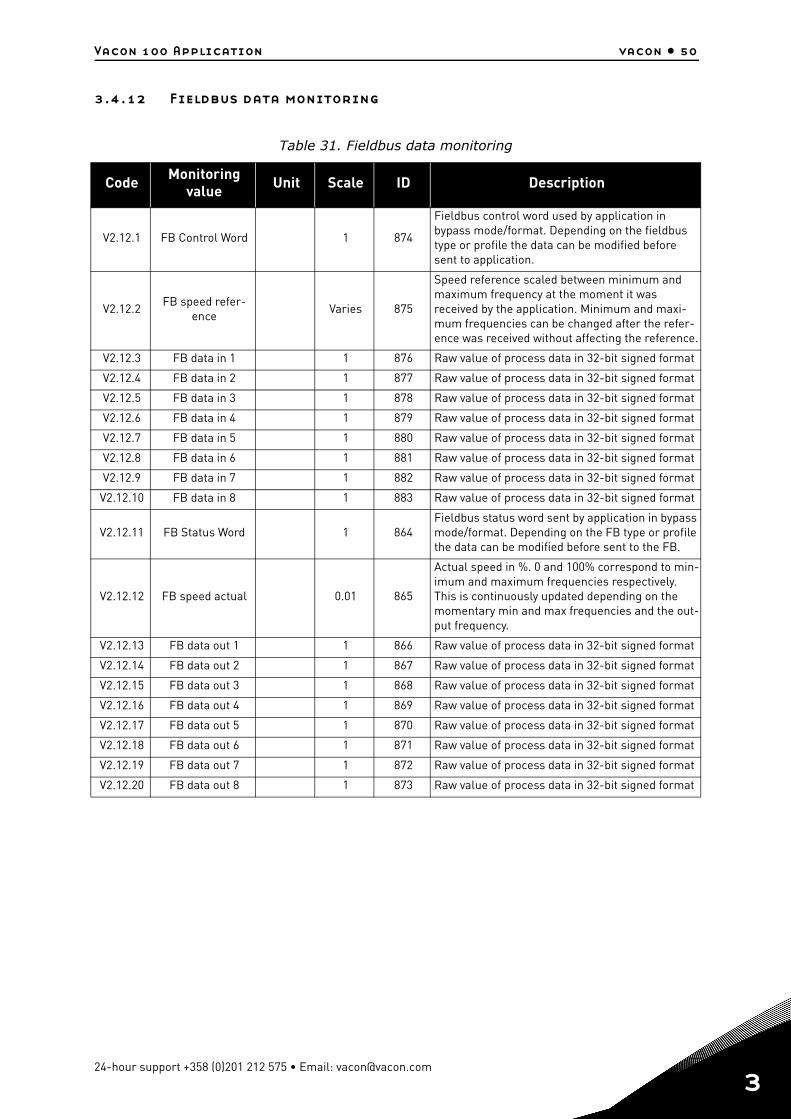
Vacon 100 Application vacon • 50
3.4.12 Fieldbus data monitoring
Table 31. Fieldbus data monitoring
Code Monitoring value Unit Scale ID Description
V2.12.1 FB Control Word 1 874
Fieldbus control word used by application in bypass mode/format. Depending on the fieldbus type or profile the data can be modified before sent to application.
V2.12.2FB speed refer-
enceVaries 875
Speed reference scaled between minimum and maximum frequency at the moment it was received by the application. Minimum and maxi-mum frequencies can be changed after the refer-ence was received without affecting the reference.
V2.12.3 FB data in 1 1 876 Raw value of process data in 32-bit signed format
V2.12.4 FB data in 2 1 877 Raw value of process data in 32-bit signed format
V2.12.5 FB data in 3 1 878 Raw value of process data in 32-bit signed format
V2.12.6 FB data in 4 1 879 Raw value of process data in 32-bit signed format
V2.12.7 FB data in 5 1 880 Raw value of process data in 32-bit signed format
V2.12.8 FB data in 6 1 881 Raw value of process data in 32-bit signed format
V2.12.9 FB data in 7 1 882 Raw value of process data in 32-bit signed format
V2.12.10 FB data in 8 1 883 Raw value of process data in 32-bit signed format
V2.12.11 FB Status Word 1 864Fieldbus status word sent by application in bypass mode/format. Depending on the FB type or profile the data can be modified before sent to the FB.
V2.12.12 FB speed actual 0.01 865
Actual speed in %. 0 and 100% correspond to min-imum and maximum frequencies respectively. This is continuously updated depending on the momentary min and max frequencies and the out-put frequency.
V2.12.13 FB data out 1 1 866 Raw value of process data in 32-bit signed format
V2.12.14 FB data out 2 1 867 Raw value of process data in 32-bit signed format
V2.12.15 FB data out 3 1 868 Raw value of process data in 32-bit signed format
V2.12.16 FB data out 4 1 869 Raw value of process data in 32-bit signed format
V2.12.17 FB data out 5 1 870 Raw value of process data in 32-bit signed format
V2.12.18 FB data out 6 1 871 Raw value of process data in 32-bit signed format
V2.12.19 FB data out 7 1 872 Raw value of process data in 32-bit signed format
V2.12.20 FB data out 8 1 873 Raw value of process data in 32-bit signed format
24-hour support +358 (0)201 212 575 • Email: [email protected]
3
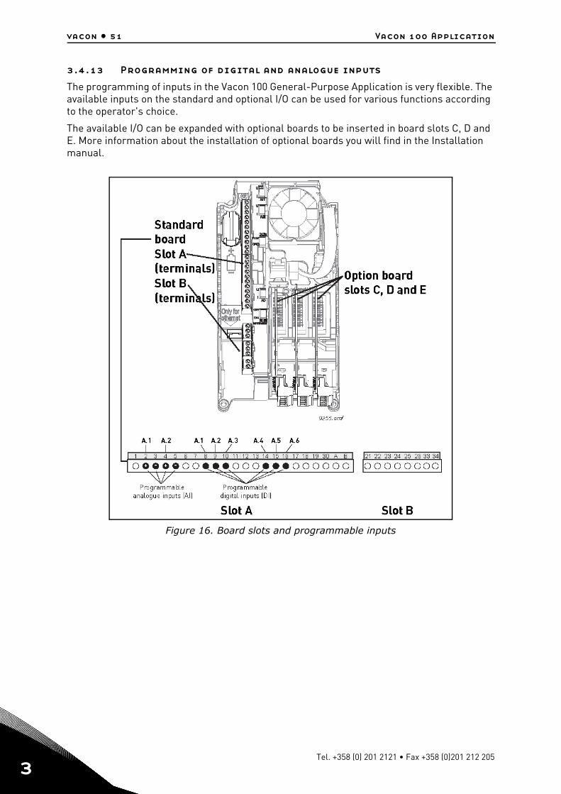
vacon • 51 Vacon 100 Application
3
3.4.13 Programming of digital and analogue inputs
The programming of inputs in the Vacon 100 General-Purpose Application is very flexible. The available inputs on the standard and optional I/O can be used for various functions according to the operator's choice.
The available I/O can be expanded with optional boards to be inserted in board slots C, D and E. More information about the installation of optional boards you will find in the Installation manual.
Figure 16. Board slots and programmable inputs
Tel. +358 (0) 201 2121 • Fax +358 (0)201 212 205
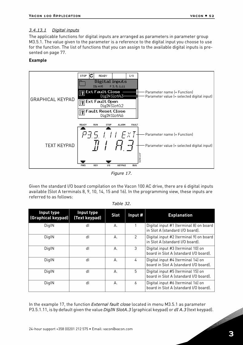
Vacon 100 Application vacon • 52
3.4.13.1 Digital inputs
The applicable functions for digital inputs are arranged as parameters in parameter group M3.5.1. The value given to the parameter is a reference to the digital input you choose to use for the function. The list of functions that you can assign to the available digital inputs is pre-sented on page 77.
Example
Figure 17.
Given the standard I/O board compilation on the Vacon 100 AC drive, there are 6 digital inputs available (Slot A terminals 8, 9, 10, 14, 15 and 16). In the programming view, these inputs are referred to as follows:
In the example 17, the function External fault close located in menu M3.5.1 as parameter P3.5.1.11, is by default given the value DigIN SlotA.3 (graphical keypad) or dI A.3 (text keypad).
Table 32.
Input type(Graphical keypad)
Input type(Text keypad) Slot Input # Explanation
DigIN dI A. 1 Digital input #1 (terminal 8) on board in Slot A (standard I/O board).
DigIN dI A. 2 Digital input #2 (terminal 9) on board in Slot A (standard I/O board).
DigIN dI A. 3 Digital input #3 (terminal 10) on board in Slot A (standard I/O board).
DigIN dI A. 4 Digital input #4 (terminal 14) on board in Slot A (standard I/O board).
DigIN dI A. 5 Digital input #5 (terminal 15) on board in Slot A (standard I/O board).
DigIN dI A. 6 Digital input #6 (terminal 16) on board in Slot A (standard I/O board).
GRAPHICAL KEYPAD
Parameter name (= Function)
Parameter name (= Function)
Parameter value (= selected digital input)
Parameter value (= selected digital input)
24-hour support +358 (0)201 212 575 • Email: [email protected]
3
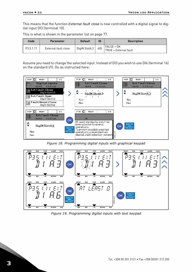
vacon • 53 Vacon 100 Application
3
This means that the function External fault close is now controlled with a digital signal to dig-ital input DI3 (terminal 10).
This is what is shown in the parameter list on page 77.
Assume you need to change the selected input. Instead of DI3 you wish to use DI6 (terminal 16) on the standard I/O. Do as instructed here:
Figure 18. Programming digital inputs with graphical keypad
Figure 19. Programming digital inputs with text keypad
Code Parameter Default ID Description
P3.5.1.11 External fault close DigIN SlotA.3 405FALSE = OK TRUE = External fault
9260.e
mf
BACKRESETBACK
RESET
Tel. +358 (0) 201 2121 • Fax +358 (0)201 212 205
Vacon 100 Application vacon • 54
Now, the function External fault close is controlled with a digital signal to digital input DI6 (ter-minal 16).
Table 33. Programming digital inputs
PROGRAMMING INSTRUCTIONS
Graphical keypad Text keypad
1. Select the parameter and push the Arrow right button.
1. Select the parameter and push the OK but-ton.
2. You are now in the Edit mode as the slot value DigIN SlotA. is blinking and under-lined. (Should you have more digital inputs available in your I/O, for example, through inserted option boards in slots C, D or E, they can also be selected here.). See 16.
2. You are now in the Edit mode as the letter d is blinking. (Should you have more digital inputs available in your I/O, for example, through inserted option boards in slots C, D or E, they can also be selected here.). See 16.
3. Push the Arrow right button again to acti-vate the terminal value 3.
3. Push the Arrow right button to activate the terminal value 3. The letter d stops blinking.
4. Push the Arrow up button three times to change the terminal value to 6. Confirm with OK button.
4. Push the Arrow up button three times to change the terminal value to 6. Confirm with OK button.
5. NOTE! If the digital input DI6 was already used for some other function a message is displayed. You might then want to change either of these selections.
5. NOTE! If the digital input DI6 was already used for some other function a message will scroll through the display. You might then want to change either of these selections.
NOTE!
The function is not assigned to any terminal, or, the the input is set to be always FALSE, if its value is DigIN Slot0.1 (graphical keypad) or dI 0.1 (text keypad). This is the default value of the majority of parameters in group M3.5.1.
On the other hand, some inputs have been by default set to be always TRUE. Their value shows DigIN Slot0.2 (graphical keypad) or dI 0.2 (text keypad).
NOTE! Also Time Channels can be assigned to digital inputs. See more information on page 98.
24-hour support +358 (0)201 212 575 • Email: [email protected]
3
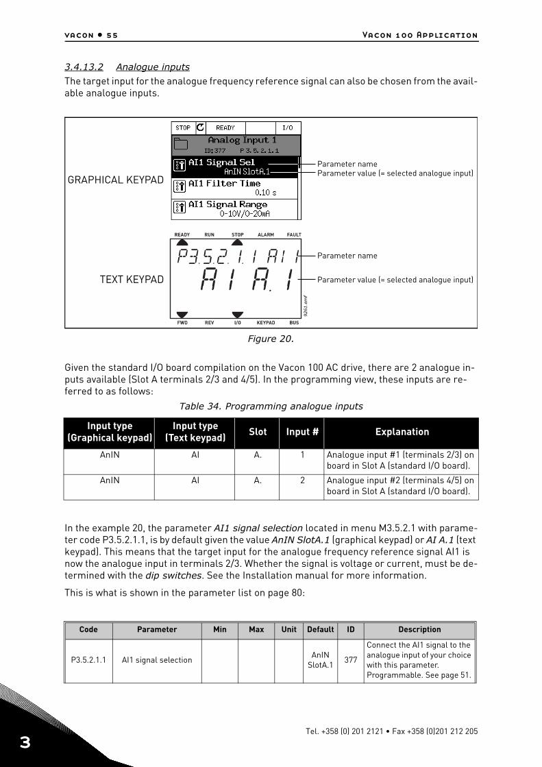
vacon • 55 Vacon 100 Application
3
3.4.13.2 Analogue inputs
The target input for the analogue frequency reference signal can also be chosen from the avail-able analogue inputs.
Figure 20.
Given the standard I/O board compilation on the Vacon 100 AC drive, there are 2 analogue in-puts available (Slot A terminals 2/3 and 4/5). In the programming view, these inputs are re-ferred to as follows:
In the example 20, the parameter AI1 signal selection located in menu M3.5.2.1 with parame-ter code P3.5.2.1.1, is by default given the value AnIN SlotA.1 (graphical keypad) or AI A.1 (text keypad). This means that the target input for the analogue frequency reference signal AI1 is now the analogue input in terminals 2/3. Whether the signal is voltage or current, must be de-termined with the dip switches. See the Installation manual for more information.
This is what is shown in the parameter list on page 80:
Table 34. Programming analogue inputs
Input type(Graphical keypad)
Input type(Text keypad) Slot Input # Explanation
AnIN AI A. 1 Analogue input #1 (terminals 2/3) on board in Slot A (standard I/O board).
AnIN AI A. 2 Analogue input #2 (terminals 4/5) on board in Slot A (standard I/O board).
Code Parameter Min Max Unit Default ID Description
P3.5.2.1.1 AI1 signal selectionAnIN
SlotA.1377
Connect the AI1 signal to the analogue input of your choice with this parameter. Programmable. See page 51.
GRAPHICAL KEYPAD
Parameter name
Parameter name
Parameter value (= selected analogue input)
TEXT KEYPAD Parameter value (= selected analogue input)
Tel. +358 (0) 201 2121 • Fax +358 (0)201 212 205
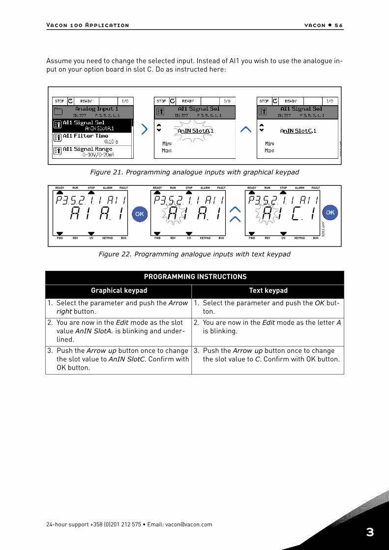
Vacon 100 Application vacon • 56
Assume you need to change the selected input. Instead of AI1 you wish to use the analogue in-put on your option board in slot C. Do as instructed here:
Figure 21. Programming analogue inputs with graphical keypad
Figure 22. Programming analogue inputs with text keypad
PROGRAMMING INSTRUCTIONS
Graphical keypad Text keypad
1. Select the parameter and push the Arrow right button.
1. Select the parameter and push the OK but-ton.
2. You are now in the Edit mode as the slot value AnIN SlotA. is blinking and under-lined.
2. You are now in the Edit mode as the letter A is blinking.
3. Push the Arrow up button once to change the slot value to AnIN SlotC. Confirm with OK button.
3. Push the Arrow up button once to change the slot value to C. Confirm with OK button.
9264
emf
24-hour support +358 (0)201 212 575 • Email: [email protected]
3
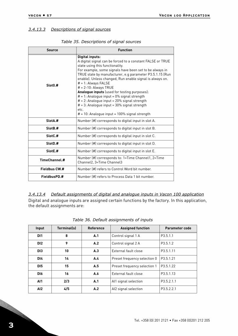
vacon • 57 Vacon 100 Application
3
3.4.13.3 Descriptions of signal sources
3.4.13.4 Default assignments of digital and analogue inputs in Vacon 100 application
Digital and analogue inputs are assigned certain functions by the factory. In this application, the default assignments are:
Table 35. Descriptions of signal sources
Source Function
Slot0.#
Digital inputs:A digital signal can be forced to a constant FALSE or TRUE state using this functionality.For example, some signals have been set to be always in TRUE state by manufacturer, e.g parameter P3.5.1.15 (Run enable). Unless changed, Run enable signal is always on.# = 1: Always FALSE# = 2-10: Always TRUEAnalogue inputs (used for testing purposes):# = 1: Analogue input = 0% signal strength# = 2: Analogue input = 20% signal strength# = 3: Analogue input = 30% signal strengthetc.# = 10: Analogue input = 100% signal strength
SlotA.# Number (#) corresponds to digital input in slot A.
SlotB.# Number (#) corresponds to digital input in slot B.
SlotC.# Number (#) corresponds to digital input in slot C.
SlotD.# Number (#) corresponds to digital input in slot D.
SlotE.# Number (#) corresponds to digital input in slot E.
TimeChannel.# Number (#) corresponds to: 1=Time Channel1, 2=Time Channel2, 3=Time Channel3
Fieldbus CW.# Number (#) refers to Control Word bit number.
FieldbusPD.# Number (#) refers to Process Data 1 bit number.
Table 36. Default assignments of inputs
Input Terminal(s) Reference Assigned function Parameter code
DI1 8 A.1 Control signal 1 A P3.5.1.1
DI2 9 A.2 Control signal 2 A P3.5.1.2
DI3 10 A.3 External fault close P3.5.1.11
DI4 14 A.4 Preset frequency selection 0 P3.5.1.21
DI5 15 A.5 Preset frequency selection 1 P3.5.1.22
DI6 16 A.6 External fault close P3.5.1.13
AI1 2/3 A.1 AI1 signal selection P3.5.2.1.1
AI2 4/5 A.2 AI2 signal selection P3.5.2.2.1
Tel. +358 (0) 201 2121 • Fax +358 (0)201 212 205
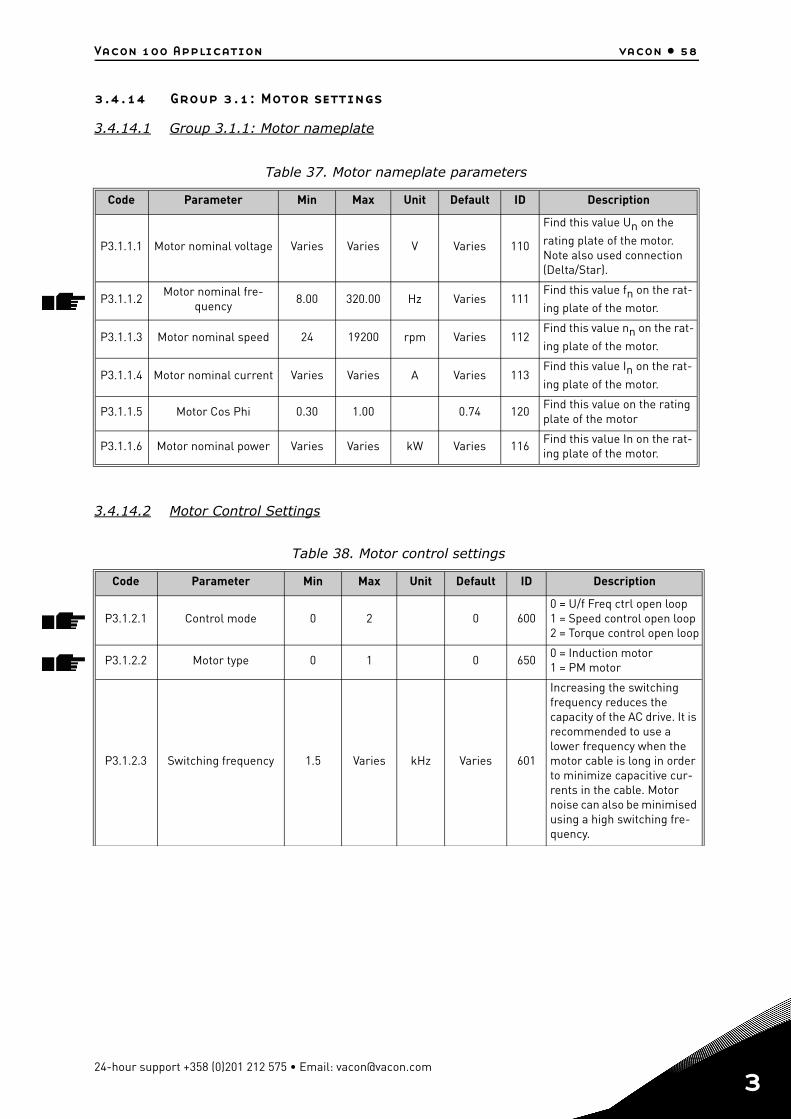
Vacon 100 Application vacon • 58
3.4.14 Group 3.1: Motor settings
3.4.14.1 Group 3.1.1: Motor nameplate
3.4.14.2 Motor Control Settings
Table 37. Motor nameplate parameters
Code Parameter Min Max Unit Default ID Description
P3.1.1.1 Motor nominal voltage Varies Varies V Varies 110
Find this value Un on the
rating plate of the motor. Note also used connection (Delta/Star).
P3.1.1.2Motor nominal fre-
quency8.00 320.00 Hz Varies 111
Find this value fn on the rat-
ing plate of the motor.
P3.1.1.3 Motor nominal speed 24 19200 rpm Varies 112Find this value nn on the rat-
ing plate of the motor.
P3.1.1.4 Motor nominal current Varies Varies A Varies 113Find this value In on the rat-
ing plate of the motor.
P3.1.1.5 Motor Cos Phi 0.30 1.00 0.74 120Find this value on the rating plate of the motor
P3.1.1.6 Motor nominal power Varies Varies kW Varies 116Find this value In on the rat-ing plate of the motor.
Table 38. Motor control settings
Code Parameter Min Max Unit Default ID Description
P3.1.2.1 Control mode 0 2 0 6000 = U/f Freq ctrl open loop1 = Speed control open loop2 = Torque control open loop
P3.1.2.2 Motor type 0 1 0 6500 = Induction motor1 = PM motor
P3.1.2.3 Switching frequency 1.5 Varies kHz Varies 601
Increasing the switching frequency reduces the capacity of the AC drive. It is recommended to use a lower frequency when the motor cable is long in order to minimize capacitive cur-rents in the cable. Motor noise can also be minimised using a high switching fre-quency.
24-hour support +358 (0)201 212 575 • Email: [email protected]
3
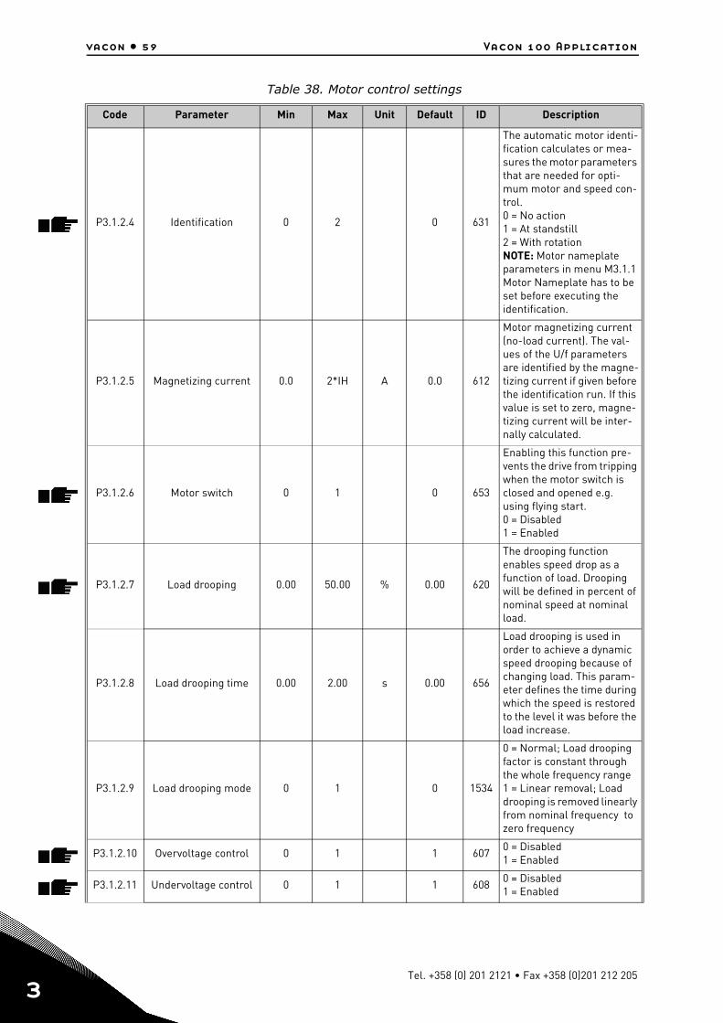
vacon • 59 Vacon 100 Application
3
P3.1.2.4 Identification 0 2 0 631
The automatic motor identi-fication calculates or mea-sures the motor parameters that are needed for opti-mum motor and speed con-trol.0 = No action1 = At standstill2 = With rotationNOTE: Motor nameplate parameters in menu M3.1.1 Motor Nameplate has to be set before executing the identification.
P3.1.2.5 Magnetizing current 0.0 2*IH A 0.0 612
Motor magnetizing current (no-load current). The val-ues of the U/f parameters are identified by the magne-tizing current if given before the identification run. If this value is set to zero, magne-tizing current will be inter-nally calculated.
P3.1.2.6 Motor switch 0 1 0 653
Enabling this function pre-vents the drive from tripping when the motor switch is closed and opened e.g. using flying start.0 = Disabled1 = Enabled
P3.1.2.7 Load drooping 0.00 50.00 % 0.00 620
The drooping function enables speed drop as a function of load. Drooping will be defined in percent of nominal speed at nominal load.
P3.1.2.8 Load drooping time 0.00 2.00 s 0.00 656
Load drooping is used in order to achieve a dynamic speed drooping because of changing load. This param-eter defines the time during which the speed is restored to the level it was before the load increase.
P3.1.2.9 Load drooping mode 0 1 0 1534
0 = Normal; Load drooping factor is constant through the whole frequency range1 = Linear removal; Load drooping is removed linearly from nominal frequency to zero frequency
P3.1.2.10 Overvoltage control 0 1 1 6070 = Disabled1 = Enabled
P3.1.2.11 Undervoltage control 0 1 1 6080 = Disabled1 = Enabled
Table 38. Motor control settings
Code Parameter Min Max Unit Default ID Description
Tel. +358 (0) 201 2121 • Fax +358 (0)201 212 205
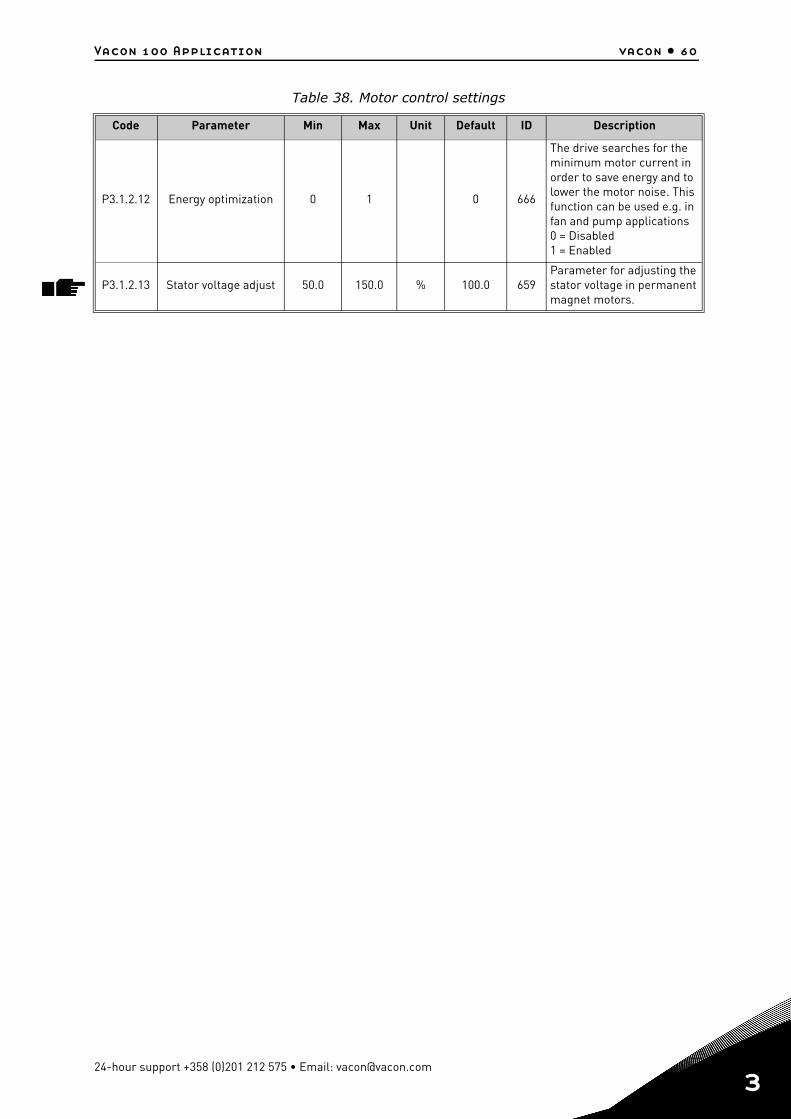
Vacon 100 Application vacon • 60
P3.1.2.12 Energy optimization 0 1 0 666
The drive searches for the minimum motor current in order to save energy and to lower the motor noise. This function can be used e.g. in fan and pump applications 0 = Disabled1 = Enabled
P3.1.2.13 Stator voltage adjust 50.0 150.0 % 100.0 659Parameter for adjusting the stator voltage in permanent magnet motors.
Table 38. Motor control settings
Code Parameter Min Max Unit Default ID Description
24-hour support +358 (0)201 212 575 • Email: [email protected]
3
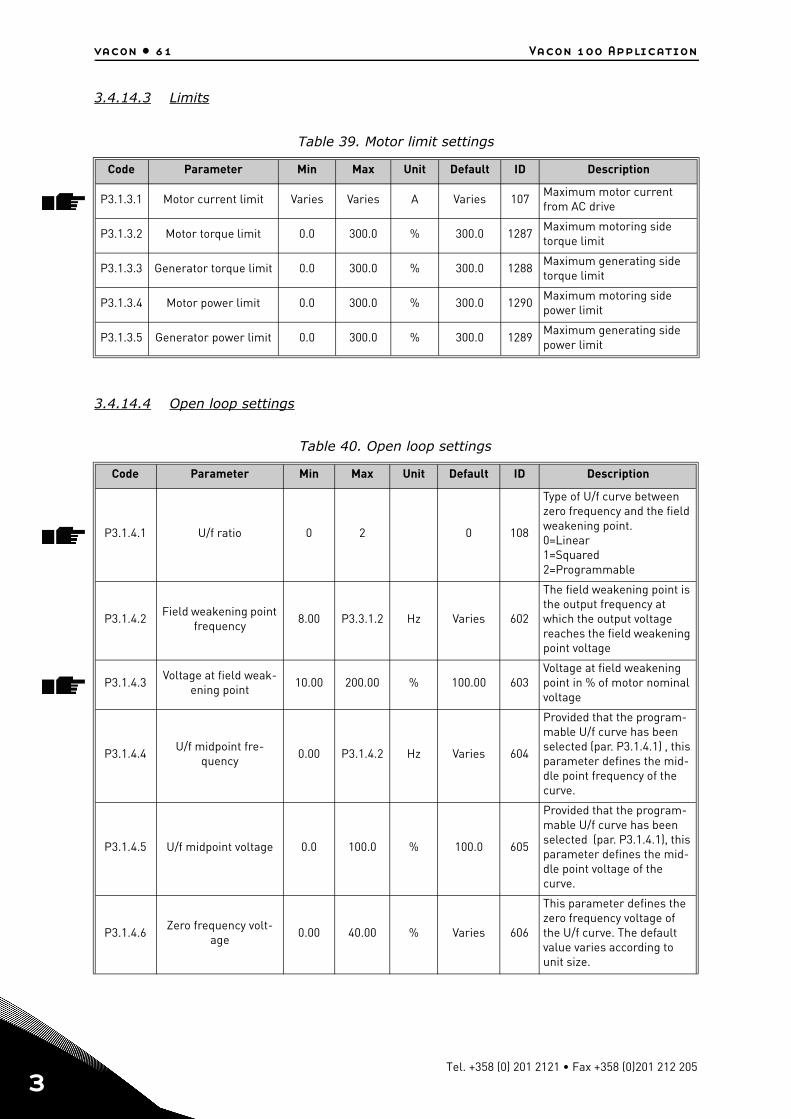
vacon • 61 Vacon 100 Application
3
3.4.14.3 Limits
3.4.14.4 Open loop settings
Table 39. Motor limit settings
Code Parameter Min Max Unit Default ID Description
P3.1.3.1 Motor current limit Varies Varies A Varies 107Maximum motor current from AC drive
P3.1.3.2 Motor torque limit 0.0 300.0 % 300.0 1287Maximum motoring side torque limit
P3.1.3.3 Generator torque limit 0.0 300.0 % 300.0 1288Maximum generating side torque limit
P3.1.3.4 Motor power limit 0.0 300.0 % 300.0 1290Maximum motoring side power limit
P3.1.3.5 Generator power limit 0.0 300.0 % 300.0 1289Maximum generating side power limit
Table 40. Open loop settings
Code Parameter Min Max Unit Default ID Description
P3.1.4.1 U/f ratio 0 2 0 108
Type of U/f curve between zero frequency and the field weakening point.0=Linear1=Squared2=Programmable
P3.1.4.2Field weakening point
frequency8.00 P3.3.1.2 Hz Varies 602
The field weakening point is the output frequency at which the output voltage reaches the field weakening point voltage
P3.1.4.3Voltage at field weak-
ening point10.00 200.00 % 100.00 603
Voltage at field weakening point in % of motor nominal voltage
P3.1.4.4U/f midpoint fre-
quency0.00 P3.1.4.2 Hz Varies 604
Provided that the program-mable U/f curve has been selected (par. P3.1.4.1) , this parameter defines the mid-dle point frequency of the curve.
P3.1.4.5 U/f midpoint voltage 0.0 100.0 % 100.0 605
Provided that the program-mable U/f curve has been selected (par. P3.1.4.1), this parameter defines the mid-dle point voltage of the curve.
P3.1.4.6Zero frequency volt-
age0.00 40.00 % Varies 606
This parameter defines the zero frequency voltage of the U/f curve. The default value varies according to unit size.
Tel. +358 (0) 201 2121 • Fax +358 (0)201 212 205
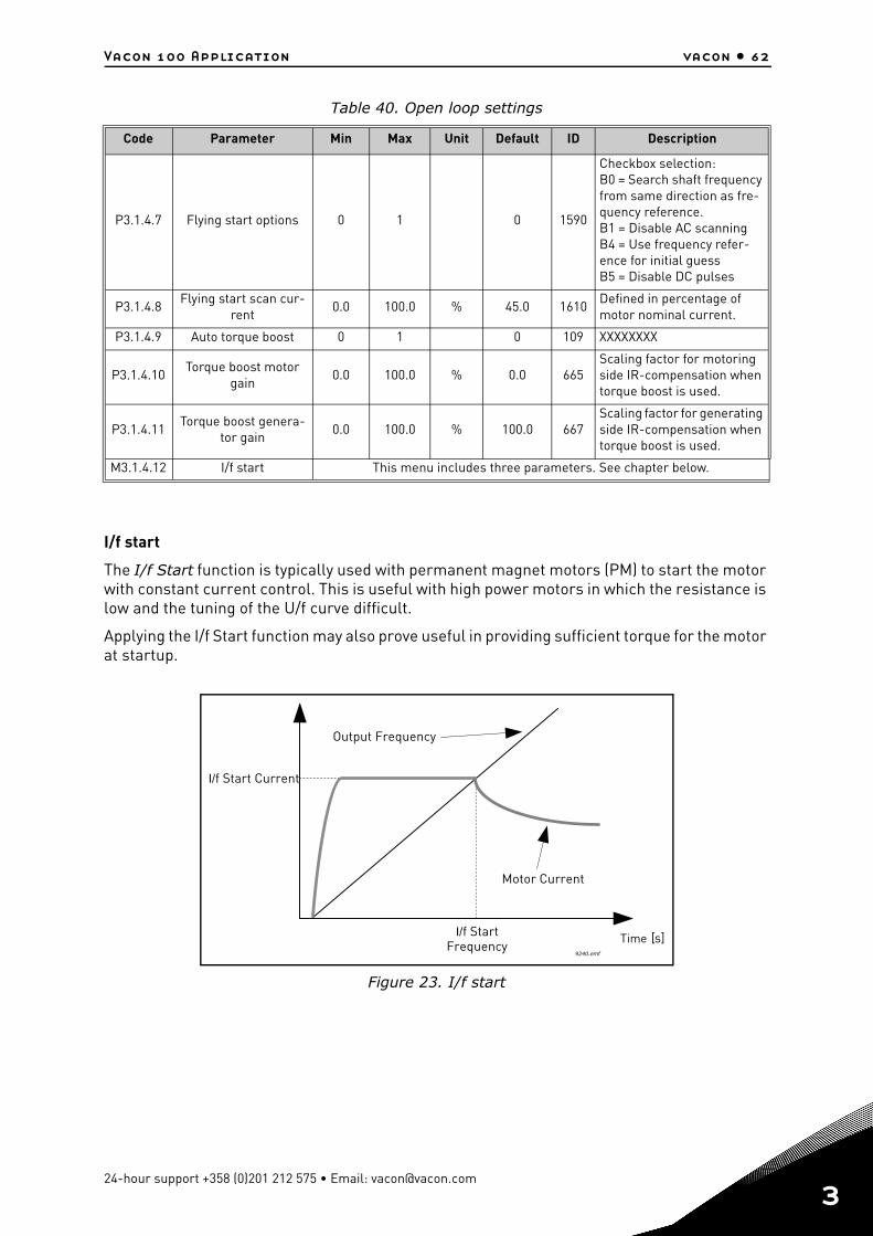
Vacon 100 Application vacon • 62
I/f start
The I/f Start function is typically used with permanent magnet motors (PM) to start the motor with constant current control. This is useful with high power motors in which the resistance is low and the tuning of the U/f curve difficult.
Applying the I/f Start function may also prove useful in providing sufficient torque for the motor at startup.
Figure 23. I/f start
P3.1.4.7 Flying start options 0 1 0 1590
Checkbox selection:B0 = Search shaft frequency from same direction as fre-quency reference. B1 = Disable AC scanningB4 = Use frequency refer-ence for initial guessB5 = Disable DC pulses
P3.1.4.8Flying start scan cur-
rent0.0 100.0 % 45.0 1610
Defined in percentage of motor nominal current.
P3.1.4.9 Auto torque boost 0 1 0 109 XXXXXXXX
P3.1.4.10Torque boost motor
gain0.0 100.0 % 0.0 665
Scaling factor for motoring side IR-compensation when torque boost is used.
P3.1.4.11Torque boost genera-
tor gain0.0 100.0 % 100.0 667
Scaling factor for generating side IR-compensation when torque boost is used.
M3.1.4.12 I/f start This menu includes three parameters. See chapter below.
Table 40. Open loop settings
Code Parameter Min Max Unit Default ID Description
Motor Current
Time [s]I/f StartFrequency
I/f Start Current
Output Frequency
9240.emf
24-hour support +358 (0)201 212 575 • Email: [email protected]
3
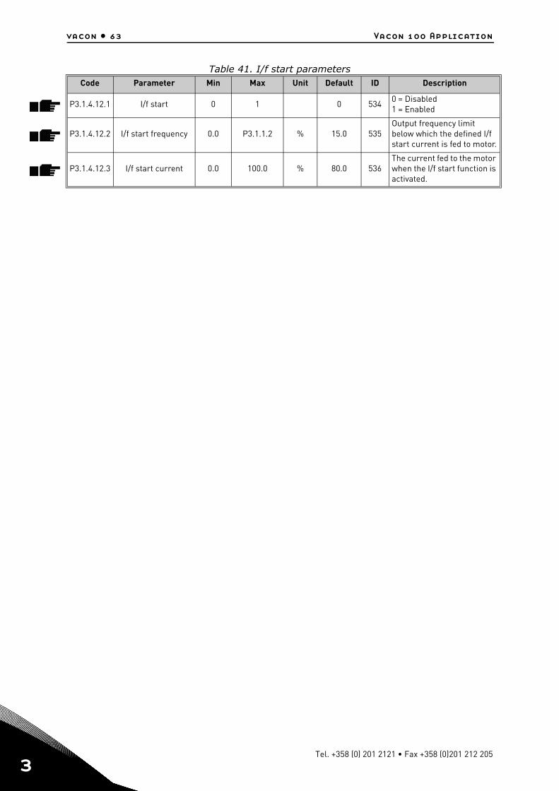
vacon • 63 Vacon 100 Application
3
Table 41. I/f start parametersCode Parameter Min Max Unit Default ID Description
P3.1.4.12.1 I/f start 0 1 0 5340 = Disabled1 = Enabled
P3.1.4.12.2 I/f start frequency 0.0 P3.1.1.2 % 15.0 535Output frequency limit below which the defined I/f start current is fed to motor.
P3.1.4.12.3 I/f start current 0.0 100.0 % 80.0 536The current fed to the motor when the I/f start function is activated.
Tel. +358 (0) 201 2121 • Fax +358 (0)201 212 205
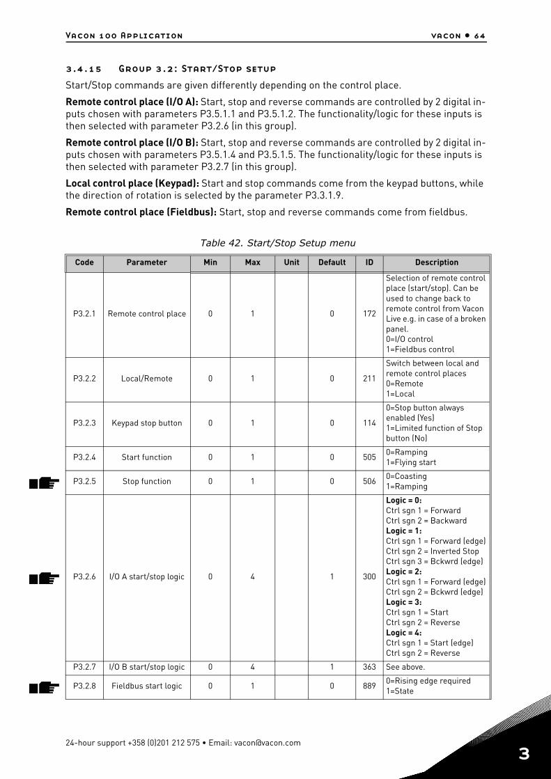
Vacon 100 Application vacon • 64
3.4.15 Group 3.2: Start/Stop setup
Start/Stop commands are given differently depending on the control place.
Remote control place (I/O A): Start, stop and reverse commands are controlled by 2 digital in-puts chosen with parameters P3.5.1.1 and P3.5.1.2. The functionality/logic for these inputs is then selected with parameter P3.2.6 (in this group).
Remote control place (I/O B): Start, stop and reverse commands are controlled by 2 digital in-puts chosen with parameters P3.5.1.4 and P3.5.1.5. The functionality/logic for these inputs is then selected with parameter P3.2.7 (in this group).
Local control place (Keypad): Start and stop commands come from the keypad buttons, while the direction of rotation is selected by the parameter P3.3.1.9.
Remote control place (Fieldbus): Start, stop and reverse commands come from fieldbus.
Table 42. Start/Stop Setup menu
Code Parameter Min Max Unit Default ID Description
P3.2.1 Remote control place 0 1 0 172
Selection of remote control place (start/stop). Can be used to change back to remote control from Vacon Live e.g. in case of a broken panel.0=I/O control1=Fieldbus control
P3.2.2 Local/Remote 0 1 0 211
Switch between local and remote control places0=Remote 1=Local
P3.2.3 Keypad stop button 0 1 0 114
0=Stop button always enabled (Yes)1=Limited function of Stop button (No)
P3.2.4 Start function 0 1 0 5050=Ramping1=Flying start
P3.2.5 Stop function 0 1 0 5060=Coasting1=Ramping
P3.2.6 I/O A start/stop logic 0 4 1 300
Logic = 0:Ctrl sgn 1 = ForwardCtrl sgn 2 = BackwardLogic = 1:Ctrl sgn 1 = Forward (edge)Ctrl sgn 2 = Inverted StopCtrl sgn 3 = Bckwrd (edge)Logic = 2:Ctrl sgn 1 = Forward (edge)Ctrl sgn 2 = Bckwrd (edge)Logic = 3:Ctrl sgn 1 = StartCtrl sgn 2 = ReverseLogic = 4:Ctrl sgn 1 = Start (edge)Ctrl sgn 2 = Reverse
P3.2.7 I/O B start/stop logic 0 4 1 363 See above.
P3.2.8 Fieldbus start logic 0 1 0 8890=Rising edge required1=State
24-hour support +358 (0)201 212 575 • Email: [email protected]
3
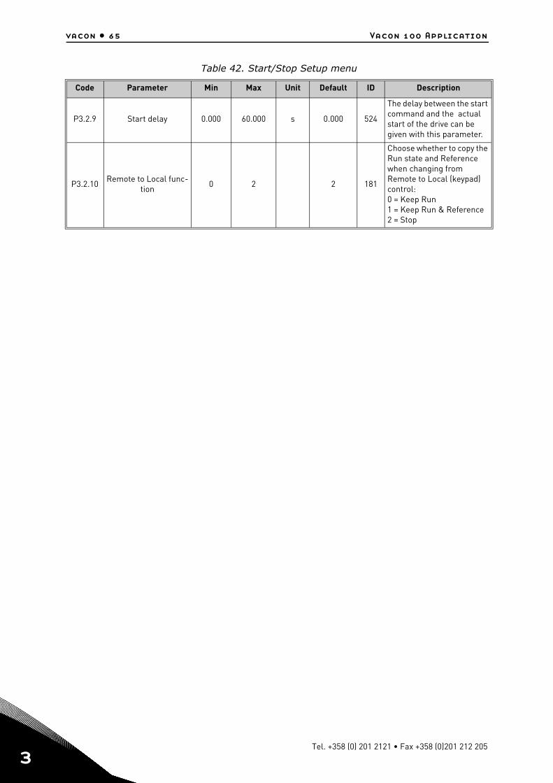
vacon • 65 Vacon 100 Application
3
P3.2.9 Start delay 0.000 60.000 s 0.000 524
The delay between the start command and the actual start of the drive can be given with this parameter.
P3.2.10Remote to Local func-
tion0 2 2 181
Choose whether to copy the Run state and Reference when changing from Remote to Local (keypad) control:0 = Keep Run 1 = Keep Run & Reference2 = Stop
Table 42. Start/Stop Setup menu
Code Parameter Min Max Unit Default ID Description
Tel. +358 (0) 201 2121 • Fax +358 (0)201 212 205
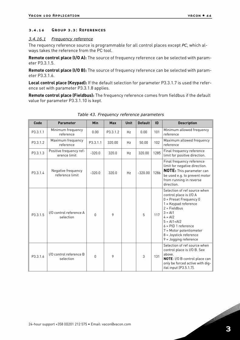
Vacon 100 Application vacon • 66
3.4.16 Group 3.3: References
3.4.16.1 Frequency reference
The requency reference source is programmable for all control places except PC, which al-ways takes the reference from the PC tool.
Remote control place (I/O A): The source of frequency reference can be selected with param-eter P3.3.1.5.
Remote control place (I/O B): The source of frequency reference can be selected with param-eter P3.3.1.6.
Local control place (Keypad): If the default selection for parameter P3.3.1.7 is used the refer-ence set with parameter P3.3.1.8 applies.
Remote control place (Fieldbus): The frequency reference comes from fieldbus if the default value for parameter P3.3.1.10 is kept.
Table 43. Frequency reference parameters
Code Parameter Min Max Unit Default ID Description
P3.3.1.1Minimum frequency
reference0.00 P3.3.1.2 Hz 0.00 101
Minimum allowed frequency reference
P3.3.1.2Maximum frequency
referenceP3.3.1.1 320.00 Hz 50.00 102
Maximum allowed frequency reference
P3.3.1.3Positive frequency ref-
erence limit-320.0 320.0 Hz 320.00 1285
Final frequency reference limit for positive direction.
P3.3.1.4Negative frequency
reference limit-320.0 320.0 Hz -320.00 1286
Final frequency reference limit for negative direction.NOTE: This parameter can be used e.g. to prevent motor from running in reverse direction.
P3.3.1.5I/O control reference A
selection0 9 5 117
Selection of ref source when control place is I/O A0 = Preset Frequency 01 = Keypad reference2 = Fieldbus3 = AI14 = AI25 = AI1+AI26 = PID 1 reference7 = Motor potentiometer8 = Joystick reference9 = Jogging reference
P3.3.1.6I/O control reference B
selection0 9 3 131
Selection of ref source when control place is I/O B. See above.NOTE: I/O B control place can only be forced active with dig-ital input (P3.5.1.7).
24-hour support +358 (0)201 212 575 • Email: [email protected]
3
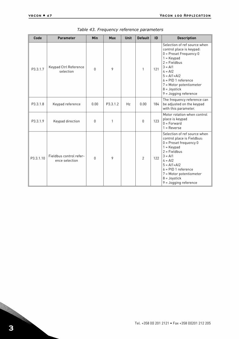
vacon • 67 Vacon 100 Application
3
P3.3.1.7Keypad Ctrl Reference
selection0 9 1 121
Selection of ref source when control place is keypad:0 = Preset Frequency 01 = Keypad2 = Fieldbus3 = AI14 = AI25 = AI1+AI26 = PID 1 reference7 = Motor potentiometer8 = Joystick9 = Jogging reference
P3.3.1.8 Keypad reference 0.00 P3.3.1.2 Hz 0.00 184The frequency reference can be adjusted on the keypad with this parameter.
P3.3.1.9 Keypad direction 0 1 0 123
Motor rotation when control place is keypad0 = Forward1 = Reverse
P3.3.1.10Fieldbus control refer-
ence selection0 9 2 122
Selection of ref source when control place is Fieldbus:0 = Preset frequency 01 = Keypad2 = Fieldbus3 = AI14 = AI25 = AI1+AI26 = PID 1 reference7 = Motor potentiometer8 = Joystick9 = Jogging reference
Table 43. Frequency reference parameters
Code Parameter Min Max Unit Default ID Description
Tel. +358 (0) 201 2121 • Fax +358 (0)201 212 205
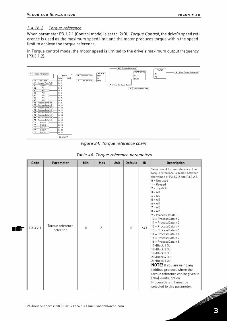
Vacon 100 Application vacon • 68
3.4.16.2 Torque reference
When parameter P3.1.2.1 (Control mode) is set to ‘2/OL’ Torque Control, the drive’s speed ref-erence is used as the maximum speed limit and the motor produces torque within the speed limit to achieve the torque reference.
In Torque control mode, the motor speed is limited to the drive’s maximum output frequency (P3.3.1.2).
Figure 24. Torque reference chain
Table 44. Torque reference parameters
Code Parameter Min Max Unit Default ID Description
P3.3.2.1Torque reference
selection0 21 0 641
Selection of torque reference. The torque reference is scaled between the values of P3.3.2.2 and P3.3.2.3.0 = Not used1 = Keypad2 = Joystick3 = AI14 = AI25 = AI36 = AI47 = AI58 = AI69 = ProcessDataIn 110 = ProcessDataIn 211 = ProcessDataIn 312 = ProcessDataIn 413 = ProcessDataIn 514 = ProcessDataIn 615 = ProcessDataIn 716 = ProcessDataIn 817=Block 1 Out18=Block 2 Out19=Block 3 Out20=Block 4 Out21=Block 5 OutNOTE! If you are using any fieldbus protocol where the torque reference can be given in [Nm] -units, option ProcessDataIn1 must be selected to this parameter.
I/OI/OI/OI/OI/OI/OFB 1FB 2FB 3FB 4FB 5FB 6FB 7FB 8V Block 1V Block 2V Block 3V Block 4V Block 5
VP
I/O
IN 0IN 1IN 2IN 3IN 4IN 5IN 6IN 7IN 8IN 9IN 10IN 11
IN 12IN 13IN 14IN 15IN 16IN 17IN 18IN 19IN 20IN 21
OUT
PMININMAX
P
P
P
IN
LIMIT
IN
TC
P
M
M
AIAIAIAIAIAI
123456
Process Data InProcess Data InProcess Data InProcess Data InProcess Data InProcess Data InProcess Data InProcess Data In
Not UsedKeypad Torq Ref
Joystick
Select
SelectTorque Ref Source SCALE
Torq Ref Min
Torq Ref Max
Torq Ref Dead Zone
DEAD ZONEFILTER
Torq Ref Filt Time
Final Torque Reference
Torque Reference
9242.emf
24-hour support +358 (0)201 212 575 • Email: [email protected]
3
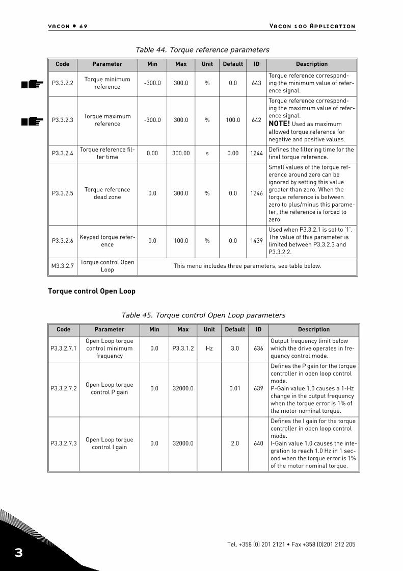
vacon • 69 Vacon 100 Application
3
Torque control Open Loop
P3.3.2.2Torque minimum
reference-300.0 300.0 % 0.0 643
Torque reference correspond-ing the minimum value of refer-ence signal.
P3.3.2.3Torque maximum
reference-300.0 300.0 % 100.0 642
Torque reference correspond-ing the maximum value of refer-ence signal.NOTE! Used as maximum allowed torque reference for negative and positive values.
P3.3.2.4Torque reference fil-
ter time0.00 300.00 s 0.00 1244
Defines the filtering time for the final torque reference.
P3.3.2.5Torque reference
dead zone0.0 300.0 % 0.0 1246
Small values of the torque ref-erence around zero can be ignored by setting this value greater than zero. When the torque reference is between zero to plus/minus this parame-ter, the reference is forced to zero.
P3.3.2.6Keypad torque refer-
ence0.0 100.0 % 0.0 1439
Used when P3.3.2.1 is set to ‘1’. The value of this parameter is limited between P3.3.2.3 and P3.3.2.2.
M3.3.2.7Torque control Open
LoopThis menu includes three parameters, see table below.
Table 45. Torque control Open Loop parameters
Code Parameter Min Max Unit Default ID Description
P3.3.2.7.1Open Loop torque control minimum
frequency0.0 P3.3.1.2 Hz 3.0 636
Output frequency limit below which the drive operates in fre-quency control mode.
P3.3.2.7.2Open Loop torque
control P gain0.0 32000.0 0.01 639
Defines the P gain for the torque controller in open loop control mode. P-Gain value 1.0 causes a 1-Hz change in the output frequency when the torque error is 1% of the motor nominal torque.
P3.3.2.7.3Open Loop torque
control I gain0.0 32000.0 2.0 640
Defines the I gain for the torque controller in open loop control mode.I-Gain value 1.0 causes the inte-gration to reach 1.0 Hz in 1 sec-ond when the torque error is 1% of the motor nominal torque.
Table 44. Torque reference parameters
Code Parameter Min Max Unit Default ID Description
Tel. +358 (0) 201 2121 • Fax +358 (0)201 212 205
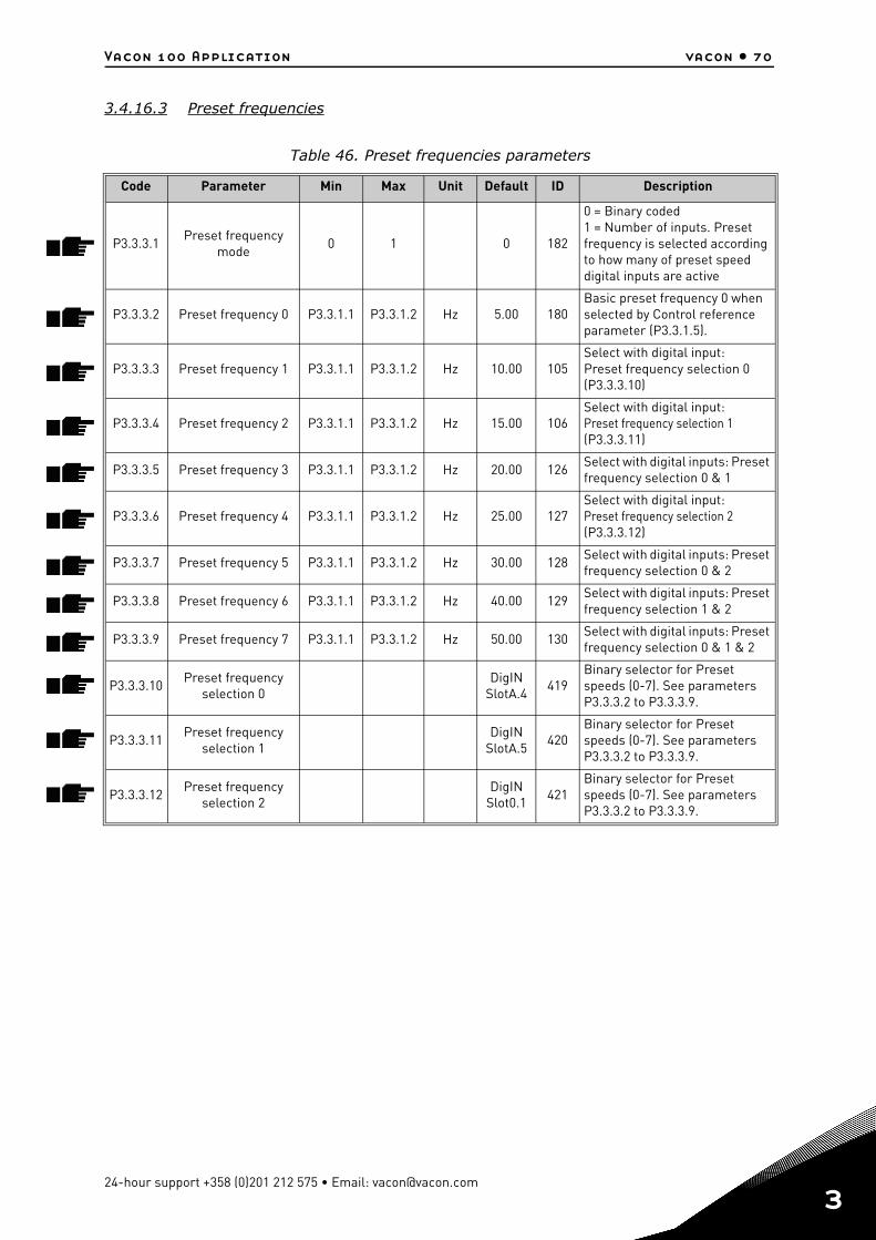
Vacon 100 Application vacon • 70
3.4.16.3 Preset frequencies
Table 46. Preset frequencies parameters
Code Parameter Min Max Unit Default ID Description
P3.3.3.1Preset frequency
mode0 1 0 182
0 = Binary coded1 = Number of inputs. Preset frequency is selected according to how many of preset speed digital inputs are active
P3.3.3.2 Preset frequency 0 P3.3.1.1 P3.3.1.2 Hz 5.00 180Basic preset frequency 0 when selected by Control reference parameter (P3.3.1.5).
P3.3.3.3 Preset frequency 1 P3.3.1.1 P3.3.1.2 Hz 10.00 105Select with digital input:Preset frequency selection 0 (P3.3.3.10)
P3.3.3.4 Preset frequency 2 P3.3.1.1 P3.3.1.2 Hz 15.00 106Select with digital input: Preset frequency selection 1 (P3.3.3.11)
P3.3.3.5 Preset frequency 3 P3.3.1.1 P3.3.1.2 Hz 20.00 126Select with digital inputs: Preset frequency selection 0 & 1
P3.3.3.6 Preset frequency 4 P3.3.1.1 P3.3.1.2 Hz 25.00 127Select with digital input: Preset frequency selection 2 (P3.3.3.12)
P3.3.3.7 Preset frequency 5 P3.3.1.1 P3.3.1.2 Hz 30.00 128Select with digital inputs: Preset frequency selection 0 & 2
P3.3.3.8 Preset frequency 6 P3.3.1.1 P3.3.1.2 Hz 40.00 129Select with digital inputs: Preset frequency selection 1 & 2
P3.3.3.9 Preset frequency 7 P3.3.1.1 P3.3.1.2 Hz 50.00 130Select with digital inputs: Preset frequency selection 0 & 1 & 2
P3.3.3.10Preset frequency
selection 0DigIN
SlotA.4419
Binary selector for Preset speeds (0-7). See parameters P3.3.3.2 to P3.3.3.9.
P3.3.3.11Preset frequency
selection 1DigIN
SlotA.5420
Binary selector for Preset speeds (0-7). See parameters P3.3.3.2 to P3.3.3.9.
P3.3.3.12Preset frequency
selection 2DigIN
Slot0.1421
Binary selector for Preset speeds (0-7). See parameters P3.3.3.2 to P3.3.3.9.
24-hour support +358 (0)201 212 575 • Email: [email protected]
3

vacon • 71 Vacon 100 Application
3
3.4.16.4 Motor potentiometer parameters
With a motor potentiometer function, the user can increase and decrease the output frequen-cy. By connecting a digital input to parameter P3.3.4.1 (Motor potentiometer UP) and having the digital input signal active, the output frequency will rise as long as the signal is active. The parameter P3.3.4.2 (Motor potentiometer DOWN) works vice versa, decreasing the output fre-quency.
The rate how the output frequency either rises or falls when Motor Potentiometer Up or Down is activated is determined by the Motor potentiometer ramp time (P3.3.4.3)
The Motor potentiometer reset parameter (P3.3.4.4) is used to choose whether to reset (set to MinFreq) the Motor Potentiometer frequency reference when stopped or when powered down.
Motor potentiometer frequency reference is available in all control places in menu Group 3.3: References. The motor potentiometer reference can be changed only when the drive is in run state.
Table 47. Motor potentiometer parameters
Code Parameter Min Max Unit Default ID Description
P3.3.4.1Motor potentiometer
UPDigIN
Slot0.1418
FALSE = Not activeTRUE = Active (Motor poten-tiometer reference INCREASES until the contact is opened)
P3.3.4.2Motor potentiometer
DOWNDigIN
Slot0.1417
FALSE = Not activeTRUE = Active (Motor poten-tiometer reference DECREASES until the contact is opened)
P3.3.4.3Motor potentiometer
ramp time0.1 500.0 Hz/s 10.0 331
Rate of change in the motor potentiometer reference when increased or decreased with parameters P3.3.4.1 or P3.3.4.2.
P3.3.4.4Motor potentiometer
reset0 2 1 367
Motor potentiometer fre-quency reference reset logic.0 = No reset1 = Reset if stopped2 = Reset if powered down
Tel. +358 (0) 201 2121 • Fax +358 (0)201 212 205
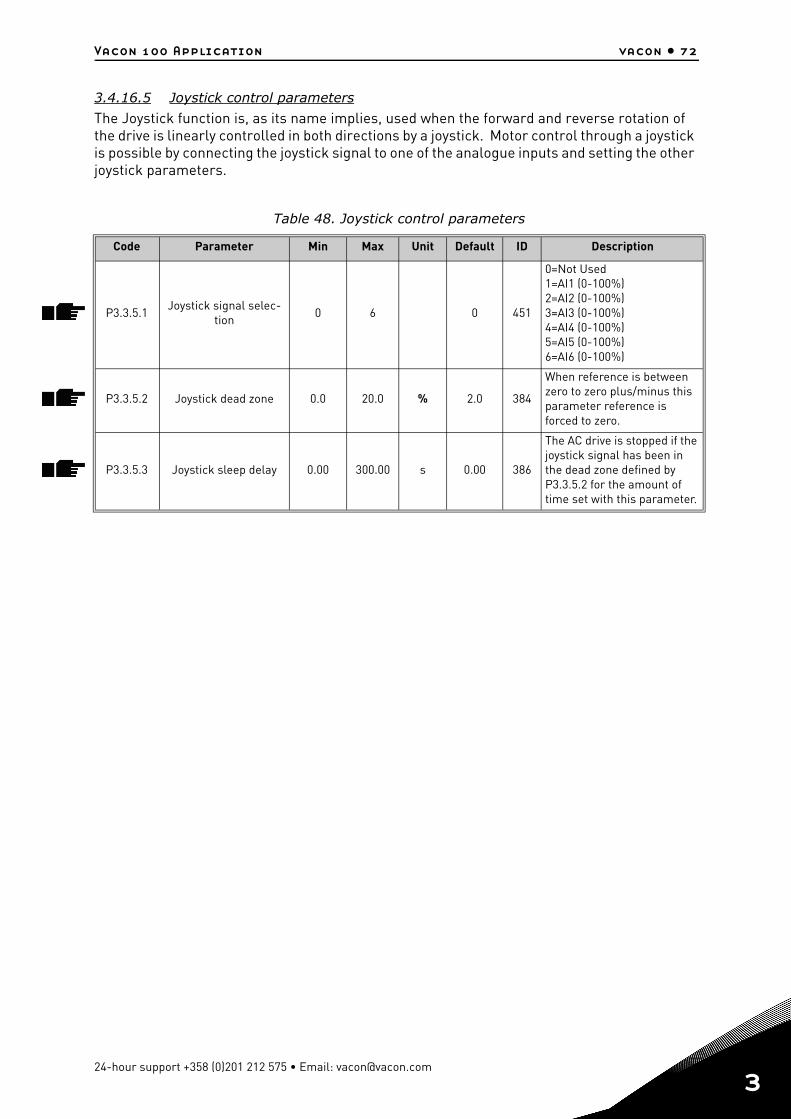
Vacon 100 Application vacon • 72
3.4.16.5 Joystick control parameters
The Joystick function is, as its name implies, used when the forward and reverse rotation of the drive is linearly controlled in both directions by a joystick. Motor control through a joystick is possible by connecting the joystick signal to one of the analogue inputs and setting the other joystick parameters.
Table 48. Joystick control parameters
Code Parameter Min Max Unit Default ID Description
P3.3.5.1Joystick signal selec-
tion0 6 0 451
0=Not Used1=AI1 (0-100%)2=AI2 (0-100%)3=AI3 (0-100%)4=AI4 (0-100%)5=AI5 (0-100%)6=AI6 (0-100%)
P3.3.5.2 Joystick dead zone 0.0 20.0 % 2.0 384
When reference is between zero to zero plus/minus this parameter reference is forced to zero.
P3.3.5.3 Joystick sleep delay 0.00 300.00 s 0.00 386
The AC drive is stopped if the joystick signal has been in the dead zone defined by P3.3.5.2 for the amount of time set with this parameter.
24-hour support +358 (0)201 212 575 • Email: [email protected]
3
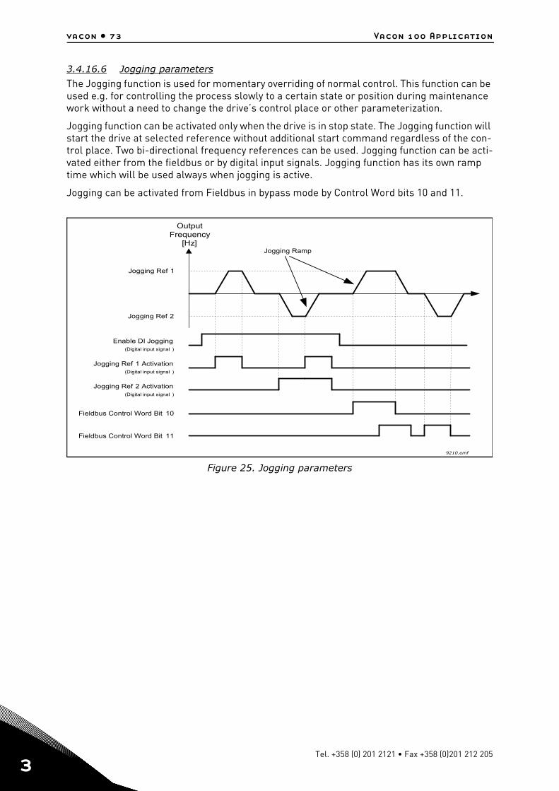
vacon • 73 Vacon 100 Application
3
3.4.16.6 Jogging parameters
The Jogging function is used for momentary overriding of normal control. This function can be used e.g. for controlling the process slowly to a certain state or position during maintenance work without a need to change the drive’s control place or other parameterization.
Jogging function can be activated only when the drive is in stop state. The Jogging function will start the drive at selected reference without additional start command regardless of the con-trol place. Two bi-directional frequency references can be used. Jogging function can be acti-vated either from the fieldbus or by digital input signals. Jogging function has its own ramp time which will be used always when jogging is active.
Jogging can be activated from Fieldbus in bypass mode by Control Word bits 10 and 11.
Figure 25. Jogging parameters
9210.emf
Jogging Ref 1
OutputFrequency
[Hz]
Jogging Ref 2
Jogging Ref 2 Activation(Digital input signal )
Jogging Ref 1 Activation(Digital input signal )
Enable DI Jogging(Digital input signal )
Jogging Ramp
Fieldbus Control Word Bit 11
Fieldbus Control Word Bit 10
Tel. +358 (0) 201 2121 • Fax +358 (0)201 212 205
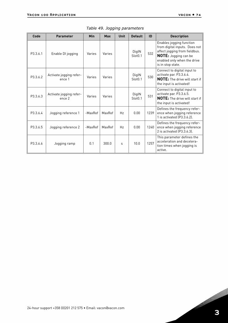
Vacon 100 Application vacon • 74
Table 49. Jogging parameters
Code Parameter Min Max Unit Default ID Description
P3.3.6.1 Enable DI jogging Varies VariesDigIN
Slot0.1532
Enables jogging function from digital inputs. Does not affect jogging from fieldbus.NOTE: Jogging can be enabled only when the drive is in stop state.
P3.3.6.2Activate jogging refer-
ence 1Varies Varies
DigIN Slot0.1
530
Connect to digital input to activate par. P3.3.6.4. NOTE: The drive will start if the input is activated!
P3.3.6.3Activate jogging refer-
ence 2Varies Varies
DigIN Slot0.1
531
Connect to digital input to activate par. P3.3.6.5. NOTE: The drive will start if the input is activated!
P3.3.6.4 Jogging reference 1 -MaxRef MaxRef Hz 0.00 1239Defines the frequency refer-ence when jogging reference 1 is activated (P3.3.6.2).
P3.3.6.5 Jogging reference 2 -MaxRef MaxRef Hz 0.00 1240Defines the frequency refer-ence when jogging reference 2 is activated (P3.3.6.3).
P3.3.6.6 Jogging ramp 0.1 300.0 s 10.0 1257
This parameter defines the acceleration and decelera-tion times when jogging is active.
24-hour support +358 (0)201 212 575 • Email: [email protected]
3
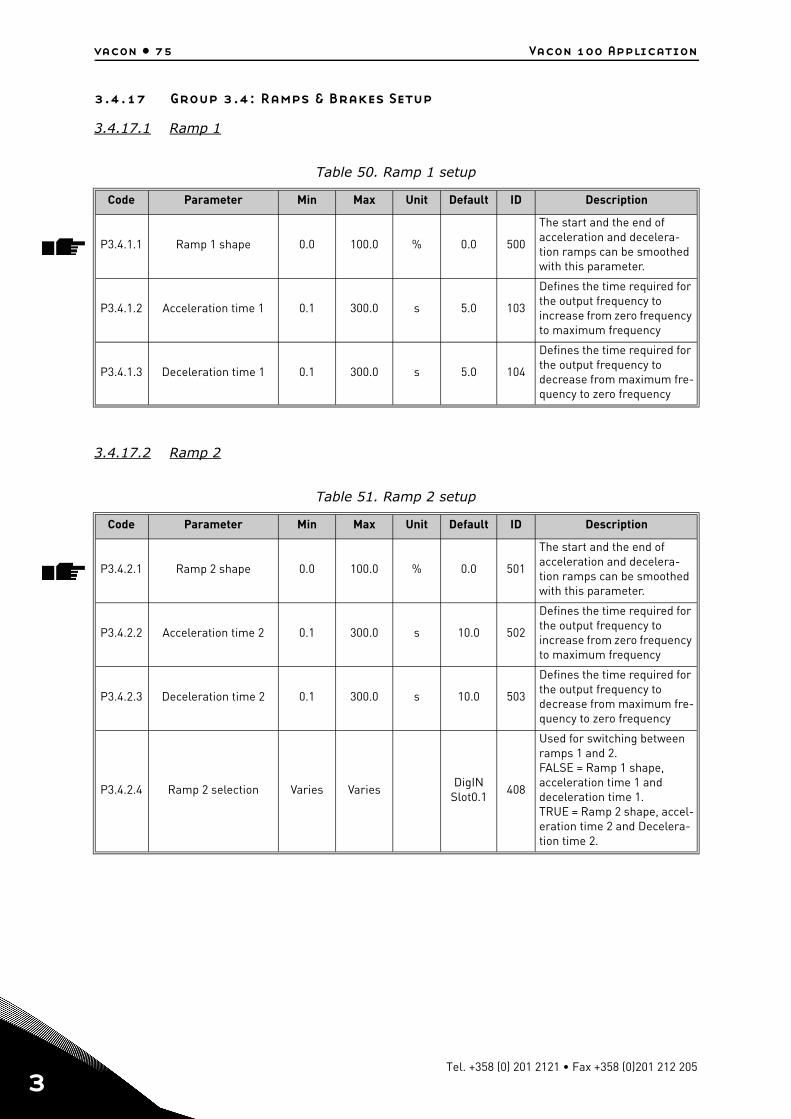
vacon • 75 Vacon 100 Application
3
3.4.17 Group 3.4: Ramps & Brakes Setup
3.4.17.1 Ramp 1
3.4.17.2 Ramp 2
Table 50. Ramp 1 setup
Code Parameter Min Max Unit Default ID Description
P3.4.1.1 Ramp 1 shape 0.0 100.0 % 0.0 500
The start and the end of acceleration and decelera-tion ramps can be smoothed with this parameter.
P3.4.1.2 Acceleration time 1 0.1 300.0 s 5.0 103
Defines the time required for the output frequency to increase from zero frequency to maximum frequency
P3.4.1.3 Deceleration time 1 0.1 300.0 s 5.0 104
Defines the time required for the output frequency to decrease from maximum fre-quency to zero frequency
Table 51. Ramp 2 setup
Code Parameter Min Max Unit Default ID Description
P3.4.2.1 Ramp 2 shape 0.0 100.0 % 0.0 501
The start and the end of acceleration and decelera-tion ramps can be smoothed with this parameter.
P3.4.2.2 Acceleration time 2 0.1 300.0 s 10.0 502
Defines the time required for the output frequency to increase from zero frequency to maximum frequency
P3.4.2.3 Deceleration time 2 0.1 300.0 s 10.0 503
Defines the time required for the output frequency to decrease from maximum fre-quency to zero frequency
P3.4.2.4 Ramp 2 selection Varies VariesDigIN
Slot0.1408
Used for switching between ramps 1 and 2. FALSE = Ramp 1 shape, acceleration time 1 and deceleration time 1. TRUE = Ramp 2 shape, accel-eration time 2 and Decelera-tion time 2.
Tel. +358 (0) 201 2121 • Fax +358 (0)201 212 205
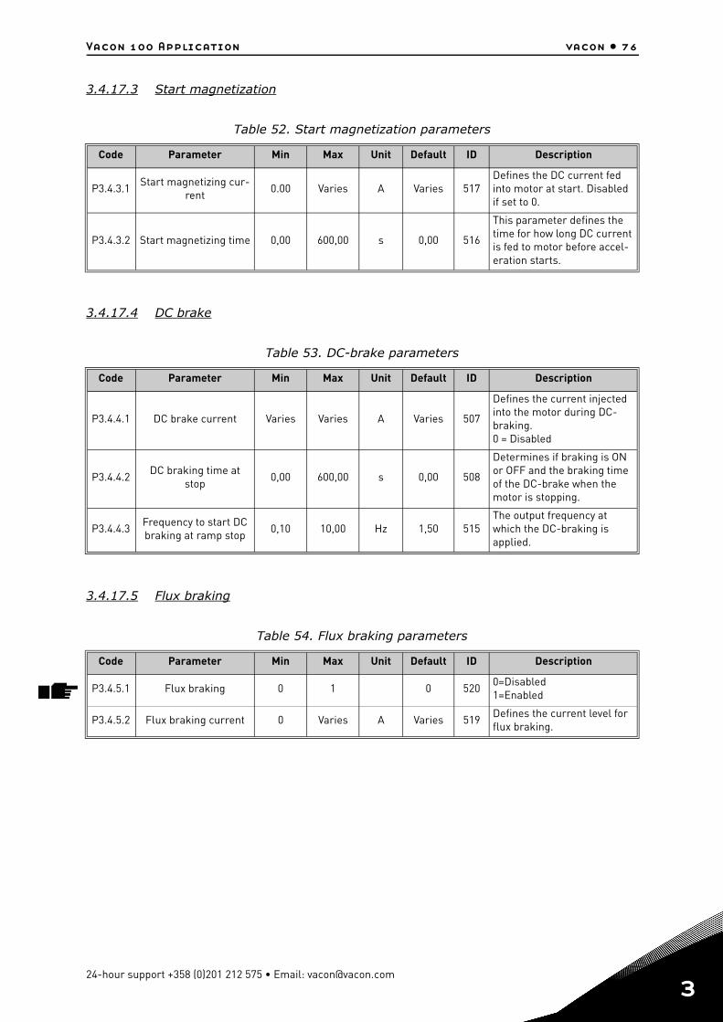
Vacon 100 Application vacon • 76
3.4.17.3 Start magnetization
3.4.17.4 DC brake
3.4.17.5 Flux braking
Table 52. Start magnetization parameters
Code Parameter Min Max Unit Default ID Description
P3.4.3.1Start magnetizing cur-
rent0.00 Varies A Varies 517
Defines the DC current fed into motor at start. Disabled if set to 0.
P3.4.3.2 Start magnetizing time 0,00 600,00 s 0,00 516
This parameter defines the time for how long DC current is fed to motor before accel-eration starts.
Table 53. DC-brake parameters
Code Parameter Min Max Unit Default ID Description
P3.4.4.1 DC brake current Varies Varies A Varies 507
Defines the current injected into the motor during DC-braking. 0 = Disabled
P3.4.4.2DC braking time at
stop0,00 600,00 s 0,00 508
Determines if braking is ON or OFF and the braking time of the DC-brake when the motor is stopping.
P3.4.4.3Frequency to start DC braking at ramp stop
0,10 10,00 Hz 1,50 515The output frequency at which the DC-braking is applied.
Table 54. Flux braking parameters
Code Parameter Min Max Unit Default ID Description
P3.4.5.1 Flux braking 0 1 0 5200=Disabled1=Enabled
P3.4.5.2 Flux braking current 0 Varies A Varies 519Defines the current level for flux braking.
24-hour support +358 (0)201 212 575 • Email: [email protected]
3
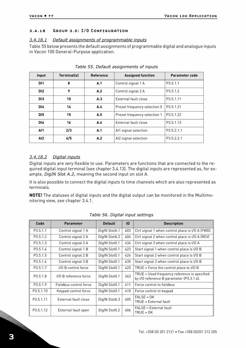
vacon • 77 Vacon 100 Application
3
3.4.18 Group 3.5: I/O Configuration
3.4.18.1 Default assignments of programmable inputs
Table 55 below presents the default assignments of programmable digital and analogue inputs in Vacon 100 General-Purpose application.
3.4.18.2 Digital inputs
Digital inputs are very flexible to use. Parameters are functions that are connected to the re-quired digital input terminal (see chapter 3.4.13). The digital inputs are represented as, for ex-ample, DigIN Slot A.2, meaning the second input on slot A.
It is also possible to connect the digital inputs to time channels which are also represented as terminals.
NOTE! The statuses of digital inputs and the digital output can be monitored in the Multimo-nitoring view, see chapter 3.4.1.
Table 55. Default assignments of inputs
Input Terminal(s) Reference Assigned function Parameter code
DI1 8 A.1 Control signal 1 A P3.5.1.1
DI2 9 A.2 Control signal 2 A P3.5.1.2
DI3 10 A.3 External fault close P3.5.1.11
DI4 14 A.4 Preset frequency selection 0 P3.5.1.21
DI5 15 A.5 Preset frequency selection 1 P3.5.1.22
DI6 16 A.6 External fault close P3.5.1.13
AI1 2/3 A.1 AI1 signal selection P3.5.2.1.1
AI2 4/5 A.2 AI2 signal selection P3.5.2.2.1
Table 56. Digital input settings
Code Parameter Default ID Description
P3.5.1.1 Control signal 1 A DigIN SlotA.1 403 Ctrl signal 1 when control place is I/O A (FWD)
P3.5.1.2 Control signal 2 A DigIN SlotA.2 404 Ctrl signal 2 when control place is I/O A (REV)
P3.5.1.3 Control signal 3 A DigIN Slot0.1 434 Ctrl signal 3 when control place is I/O A
P3.5.1.4 Control signal 1 B DigIN Slot0.1 423 Start signal 1 when control place is I/O B
P3.5.1.5 Control signal 2 B DigIN Slot0.1 424 Start signal 2 when control place is I/O B
P3.5.1.6 Control signal 3 B DigIN Slot0.1 435 Start signal 3 when control place is I/O B
P3.5.1.7 I/O B control force DigIN Slot0.1 425 TRUE = Force the control place to I/O B
P3.5.1.8 I/O B reference force DigIN Slot0.1 343TRUE = Used frequency reference is specified by I/O reference B parameter (P3.3.1.6).
P3.5.1.9 Fieldbus control force DigIN Slot0.1 411 Force control to fieldbus
P3.5.1.10 Keypad control force DigIN Slot0.1 410 Force control to keypad
P3.5.1.11 External fault close DigIN SlotA.3 405FALSE = OK TRUE = External fault
P3.5.1.12 External fault open DigIN Slot0.2 406FALSE = External faultTRUE = OK
Tel. +358 (0) 201 2121 • Fax +358 (0)201 212 205
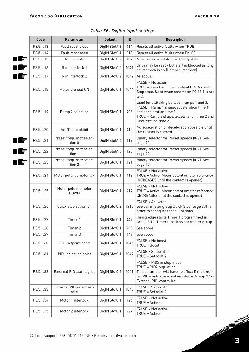
Vacon 100 Application vacon • 78
P3.5.1.13 Fault reset close DigIN SlotA.6 414 Resets all active faults when TRUE
P3.5.1.14 Fault reset open DigIN Slot0.1 213 Resets all active faults when FALSE
P3.5.1.15 Run enable DigIN Slot0.2 407 Must be on to set drive in Ready state
P3.5.1.16 Run interlock 1 DigIN Slot0.2 1041Drive may be ready but start is blocked as long as interlock is on (Damper interlock).
P3.5.1.17 Run interlock 2 DigIN Slot0.2 1042 As above.
P3.5.1.18 Motor preheat ON DigIN Slot0.1 1044
FALSE = No actionTRUE = Uses the motor preheat DC-Current in Stop state. Used when parameter P3.18.1 is set to 2.
P3.5.1.19 Ramp 2 selection DigIN Slot0.1 408
Used for switching between ramps 1 and 2. FALSE = Ramp 1 shape, acceleration time 1 and deceleration time 1. TRUE = Ramp 2 shape, acceleration time 2 and Deceleration time 2.
P3.5.1.20 Acc/Dec prohibit DigIN Slot0.1 415No acceleration or deceleration possible until the contact is opened.
P3.5.1.21Preset frequency selec-
tion 0DigIN SlotA.4 419
Binary selector for Preset speeds (0-7). See page 70.
P3.5.1.22Preset frequency selec-
tion 1DigIN SlotA.5 420
Binary selector for Preset speeds (0-7). See page 70.
P3.5.1.23Preset frequency selec-
tion 2DigIN Slot0.1 421
Binary selector for Preset speeds (0-7). See page 70.
P3.5.1.24 Motor potentiometer UP DigIN Slot0.1 418FALSE = Not activeTRUE = Active (Motor potentiometer reference INCREASES until the contact is opened)
P3.5.1.25Motor potentiometer
DOWNDigIN Slot0.1 417
FALSE = Not activeTRUE = Active (Motor potentiometer reference DECREASES until the contact is opened)
P3.5.1.26 Quick stop activation DigIN Slot0.2 1213FALSE = Activated.See parameter group Quick Stop (page 93) in order to configure these functions.
P3.5.1.27 Timer 1 DigIN Slot0.1 447Rising edge starts Timer 1 programmed in Group 3.12: Timer functions parameter group
P3.5.1.28 Timer 2 DigIN Slot0.1 448 See above
P3.5.1.29 Timer 3 DigIN Slot0.1 449 See above
P3.5.1.30 PID1 setpoint boost DigIN Slot0.1 1046FALSE = No boostTRUE = Boost
P3.5.1.31 PID1 select setpoint DigIN Slot0.1 1047FALSE = Setpoint 1TRUE = Setpoint 2
P3.5.1.32 External PID start signal DigIN Slot0.2 1049
FALSE = PID2 in stop modeTRUE = PID2 regulatingThis parameter will have no effect if the exter-nal PID-controller is not enabled in Group 3.14: External PID-controller.
P3.5.1.33External PID select set-
pointDigIN Slot0.1 1048
FALSE = Setpoint 1TRUE = Setpoint 2
P3.5.1.34 Motor 1 interlock DigIN Slot0.1 426FALSE = Not activeTRUE = Active
P3.5.1.35 Motor 2 interlock DigIN Slot0.1 427FALSE = Not activeTRUE = Active
Table 56. Digital input settings
Code Parameter Default ID Description
24-hour support +358 (0)201 212 575 • Email: [email protected]
3
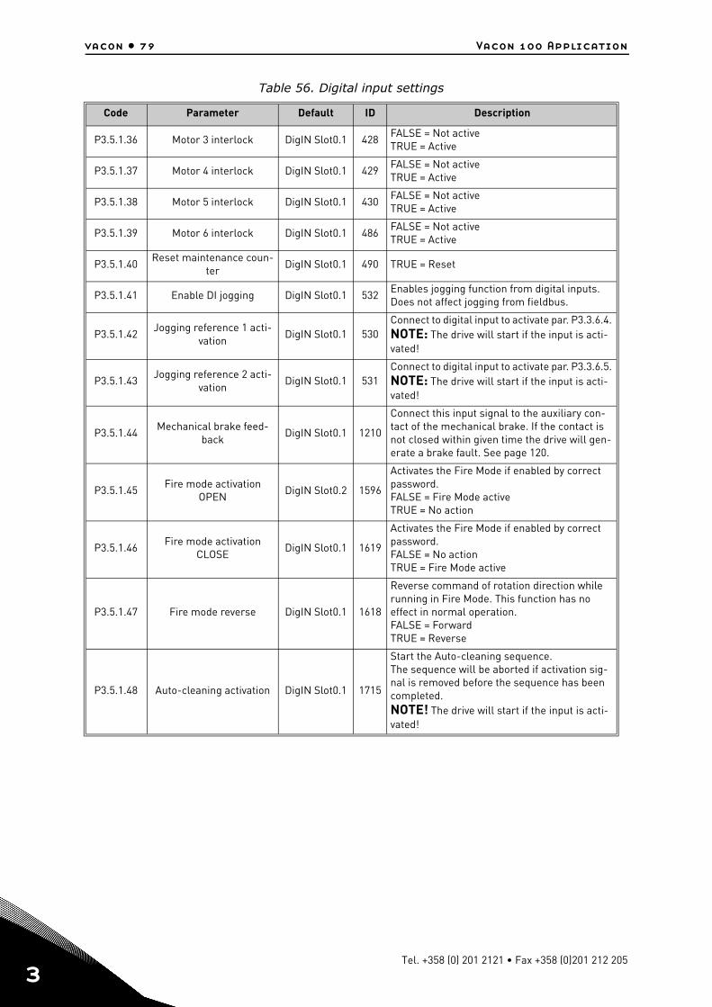
vacon • 79 Vacon 100 Application
3
P3.5.1.36 Motor 3 interlock DigIN Slot0.1 428FALSE = Not activeTRUE = Active
P3.5.1.37 Motor 4 interlock DigIN Slot0.1 429FALSE = Not activeTRUE = Active
P3.5.1.38 Motor 5 interlock DigIN Slot0.1 430FALSE = Not activeTRUE = Active
P3.5.1.39 Motor 6 interlock DigIN Slot0.1 486FALSE = Not activeTRUE = Active
P3.5.1.40Reset maintenance coun-
terDigIN Slot0.1 490 TRUE = Reset
P3.5.1.41 Enable DI jogging DigIN Slot0.1 532Enables jogging function from digital inputs. Does not affect jogging from fieldbus.
P3.5.1.42Jogging reference 1 acti-
vationDigIN Slot0.1 530
Connect to digital input to activate par. P3.3.6.4. NOTE: The drive will start if the input is acti-vated!
P3.5.1.43Jogging reference 2 acti-
vationDigIN Slot0.1 531
Connect to digital input to activate par. P3.3.6.5. NOTE: The drive will start if the input is acti-vated!
P3.5.1.44Mechanical brake feed-
backDigIN Slot0.1 1210
Connect this input signal to the auxiliary con-tact of the mechanical brake. If the contact is not closed within given time the drive will gen-erate a brake fault. See page 120.
P3.5.1.45Fire mode activation
OPENDigIN Slot0.2 1596
Activates the Fire Mode if enabled by correct password.FALSE = Fire Mode activeTRUE = No action
P3.5.1.46Fire mode activation
CLOSEDigIN Slot0.1 1619
Activates the Fire Mode if enabled by correct password.FALSE = No actionTRUE = Fire Mode active
P3.5.1.47 Fire mode reverse DigIN Slot0.1 1618
Reverse command of rotation direction while running in Fire Mode. This function has no effect in normal operation.FALSE = ForwardTRUE = Reverse
P3.5.1.48 Auto-cleaning activation DigIN Slot0.1 1715
Start the Auto-cleaning sequence.The sequence will be aborted if activation sig-nal is removed before the sequence has been completed.NOTE! The drive will start if the input is acti-vated!
Table 56. Digital input settings
Code Parameter Default ID Description
Tel. +358 (0) 201 2121 • Fax +358 (0)201 212 205
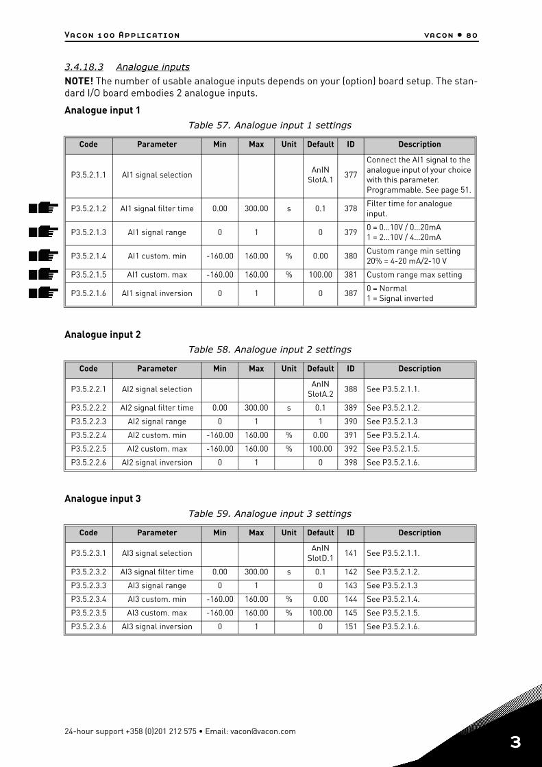
Vacon 100 Application vacon • 80
3.4.18.3 Analogue inputs
NOTE! The number of usable analogue inputs depends on your (option) board setup. The stan-dard I/O board embodies 2 analogue inputs.
Analogue input 1
Analogue input 2
Analogue input 3
Table 57. Analogue input 1 settings
Code Parameter Min Max Unit Default ID Description
P3.5.2.1.1 AI1 signal selectionAnIN
SlotA.1377
Connect the AI1 signal to the analogue input of your choice with this parameter. Programmable. See page 51.
P3.5.2.1.2 AI1 signal filter time 0.00 300.00 s 0.1 378Filter time for analogue input.
P3.5.2.1.3 AI1 signal range 0 1 0 3790 = 0…10V / 0…20mA1 = 2…10V / 4…20mA
P3.5.2.1.4 AI1 custom. min -160.00 160.00 % 0.00 380Custom range min setting20% = 4-20 mA/2-10 V
P3.5.2.1.5 AI1 custom. max -160.00 160.00 % 100.00 381 Custom range max setting
P3.5.2.1.6 AI1 signal inversion 0 1 0 3870 = Normal1 = Signal inverted
Table 58. Analogue input 2 settings
Code Parameter Min Max Unit Default ID Description
P3.5.2.2.1 AI2 signal selectionAnIN
SlotA.2388 See P3.5.2.1.1.
P3.5.2.2.2 AI2 signal filter time 0.00 300.00 s 0.1 389 See P3.5.2.1.2.
P3.5.2.2.3 AI2 signal range 0 1 1 390 See P3.5.2.1.3
P3.5.2.2.4 AI2 custom. min -160.00 160.00 % 0.00 391 See P3.5.2.1.4.
P3.5.2.2.5 AI2 custom. max -160.00 160.00 % 100.00 392 See P3.5.2.1.5.
P3.5.2.2.6 AI2 signal inversion 0 1 0 398 See P3.5.2.1.6.
Table 59. Analogue input 3 settings
Code Parameter Min Max Unit Default ID Description
P3.5.2.3.1 AI3 signal selectionAnIN
SlotD.1141 See P3.5.2.1.1.
P3.5.2.3.2 AI3 signal filter time 0.00 300.00 s 0.1 142 See P3.5.2.1.2.
P3.5.2.3.3 AI3 signal range 0 1 0 143 See P3.5.2.1.3
P3.5.2.3.4 AI3 custom. min -160.00 160.00 % 0.00 144 See P3.5.2.1.4.
P3.5.2.3.5 AI3 custom. max -160.00 160.00 % 100.00 145 See P3.5.2.1.5.
P3.5.2.3.6 AI3 signal inversion 0 1 0 151 See P3.5.2.1.6.
24-hour support +358 (0)201 212 575 • Email: [email protected]
3
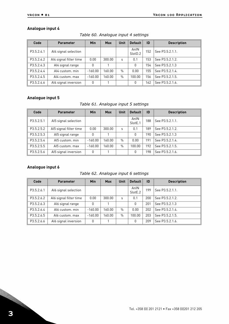
vacon • 81 Vacon 100 Application
3
Analogue input 4
Analogue input 5
Analogue input 6
Table 60. Analogue input 4 settings
Code Parameter Min Max Unit Default ID Description
P3.5.2.4.1 AI4 signal selectionAnIN
SlotD.2152 See P3.5.2.1.1.
P3.5.2.4.2 AI4 signal filter time 0.00 300.00 s 0.1 153 See P3.5.2.1.2.
P3.5.2.4.3 AI4 signal range 0 1 0 154 See P3.5.2.1.3
P3.5.2.4.4 AI4 custom. min -160.00 160.00 % 0.00 155 See P3.5.2.1.4.
P3.5.2.4.5 AI4 custom. max -160.00 160.00 % 100.00 156 See P3.5.2.1.5.
P3.5.2.4.6 AI4 signal inversion 0 1 0 162 See P3.5.2.1.6.
Table 61. Analogue input 5 settings
Code Parameter Min Max Unit Default ID Description
P3.5.2.5.1 AI5 signal selectionAnIN
SlotE.1188 See P3.5.2.1.1.
P3.5.2.5.2 AI5 signal filter time 0.00 300.00 s 0.1 189 See P3.5.2.1.2.
P3.5.2.5.3 AI5 signal range 0 1 0 190 See P3.5.2.1.3
P3.5.2.5.4 AI5 custom. min -160.00 160.00 % 0.00 191 See P3.5.2.1.4.
P3.5.2.5.5 AI5 custom. max -160.00 160.00 % 100.00 192 See P3.5.2.1.5.
P3.5.2.5.6 AI5 signal inversion 0 1 0 198 See P3.5.2.1.6.
Table 62. Analogue input 6 settings
Code Parameter Min Max Unit Default ID Description
P3.5.2.6.1 AI6 signal selectionAnIN
SlotE.2199 See P3.5.2.1.1.
P3.5.2.6.2 AI6 signal filter time 0.00 300.00 s 0.1 200 See P3.5.2.1.2.
P3.5.2.6.3 AI6 signal range 0 1 0 201 See P3.5.2.1.3
P3.5.2.6.4 AI6 custom. min -160.00 160.00 % 0.00 202 See P3.5.2.1.4.
P3.5.2.6.5 AI6 custom. max -160.00 160.00 % 100.00 203 See P3.5.2.1.5.
P3.5.2.6.6 AI6 signal inversion 0 1 0 209 See P3.5.2.1.6.
Tel. +358 (0) 201 2121 • Fax +358 (0)201 212 205
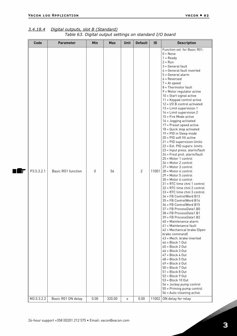
Vacon 100 Application vacon • 82
3.4.18.4 Digital outputs, slot B (Standard)Table 63. Digital output settings on standard I/O board
Code Parameter Min Max Unit Default ID Description
P3.5.3.2.1 Basic RO1 function 0 56 2 11001
Function sel. for Basic R01:0 = None1 = Ready2 = Run3 = General fault4 = General fault inverted5 = General alarm6 = Reversed7 = At speed8 = Thermistor fault9 = Motor regulator active10 = Start signal active11 = Keypad control active12 = I/O B control activated13 = Limit supervision 114 = Limit supervision 215 = Fire Mode active16 = Jogging activated17 = Preset speed active18 = Quick stop activated19 = PID in Sleep mode20 = PID soft fill active21 = PID supervision limits22 = Ext. PID superv. limits23 = Input press. alarm/fault24 = Frost prot. alarm/fault25 = Motor 1 control26 = Motor 2 control27 = Motor 3 control28 = Motor 4 control29 = Motor 5 control30 = Motor 6 control31 = RTC time chnl 1 control32 = RTC time chnl 2 control33 = RTC time chnl 3 control34 = FB ControlWord B1335 = FB ControlWord B1436 = FB ControlWord B1537 = FB ProcessData1.B038 = FB ProcessData1.B139 = FB ProcessData1.B240 = Maintenance alarm41 = Maintenance fault42 = Mechanical brake (Open brake command)43 = Mech. brake inverted44 = Block 1 Out45 = Block 2 Out46 = Block 3 Out47 = Block 4 Out48 = Block 5 Out49 = Block 6 Out50 = Block 7 Out51 = Block 8 Out52 = Block 9 Out53 = Block 10 Out54 = Jockey pump control55 = Priming pump control56 = Auto-cleaning active
M3.5.3.2.2 Basic R01 ON delay 0.00 320.00 s 0.00 11002 ON delay for relay
24-hour support +358 (0)201 212 575 • Email: [email protected]
3
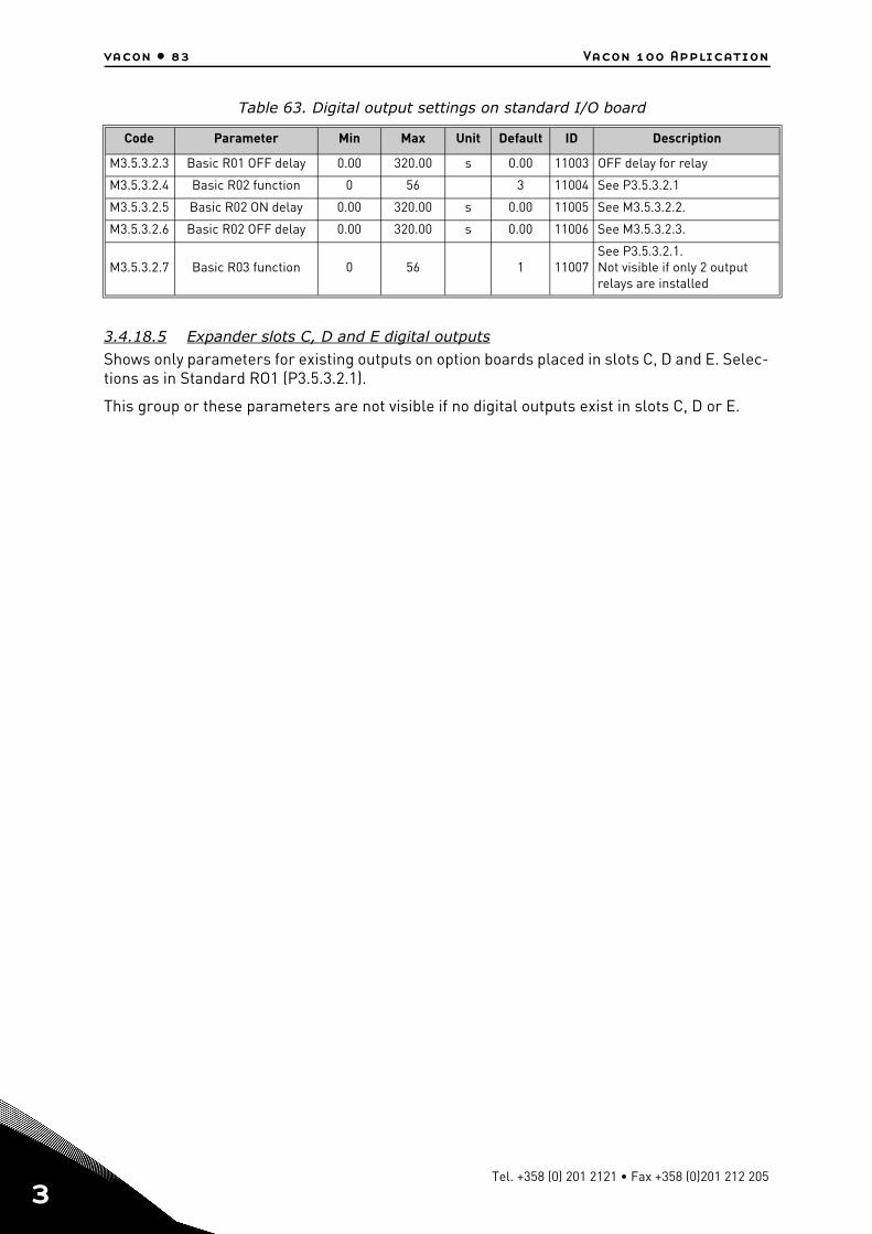
vacon • 83 Vacon 100 Application
3
3.4.18.5 Expander slots C, D and E digital outputs
Shows only parameters for existing outputs on option boards placed in slots C, D and E. Selec-tions as in Standard RO1 (P3.5.3.2.1).
This group or these parameters are not visible if no digital outputs exist in slots C, D or E.
M3.5.3.2.3 Basic R01 OFF delay 0.00 320.00 s 0.00 11003 OFF delay for relay
M3.5.3.2.4 Basic R02 function 0 56 3 11004 See P3.5.3.2.1
M3.5.3.2.5 Basic R02 ON delay 0.00 320.00 s 0.00 11005 See M3.5.3.2.2.
M3.5.3.2.6 Basic R02 OFF delay 0.00 320.00 s 0.00 11006 See M3.5.3.2.3.
M3.5.3.2.7 Basic R03 function 0 56 1 11007See P3.5.3.2.1.Not visible if only 2 output relays are installed
Table 63. Digital output settings on standard I/O board
Code Parameter Min Max Unit Default ID Description
Tel. +358 (0) 201 2121 • Fax +358 (0)201 212 205
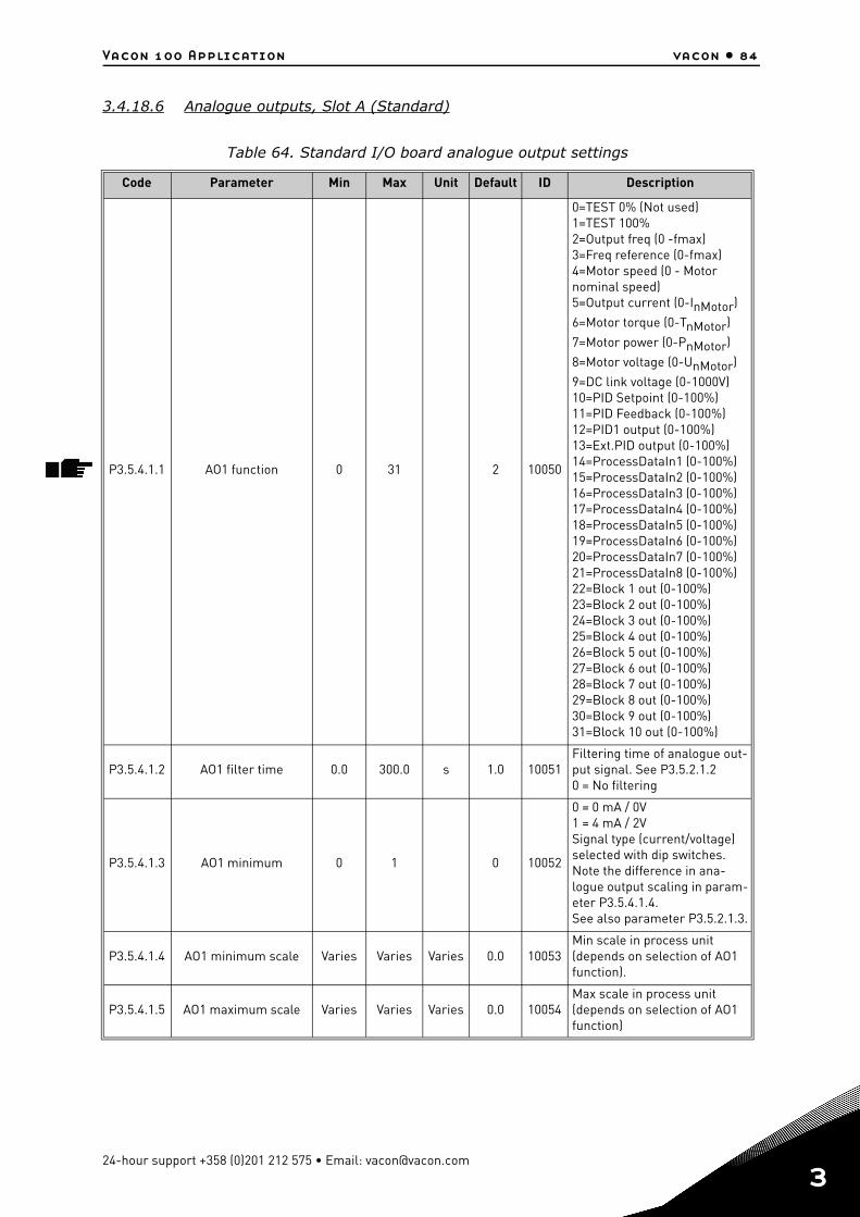
Vacon 100 Application vacon • 84
3.4.18.6 Analogue outputs, Slot A (Standard)
Table 64. Standard I/O board analogue output settings
Code Parameter Min Max Unit Default ID Description
P3.5.4.1.1 AO1 function 0 31 2 10050
0=TEST 0% (Not used)1=TEST 100%2=Output freq (0 -fmax)3=Freq reference (0-fmax)4=Motor speed (0 - Motor nominal speed)5=Output current (0-InMotor)
6=Motor torque (0-TnMotor)
7=Motor power (0-PnMotor)
8=Motor voltage (0-UnMotor)
9=DC link voltage (0-1000V)10=PID Setpoint (0-100%)11=PID Feedback (0-100%)12=PID1 output (0-100%)13=Ext.PID output (0-100%)14=ProcessDataIn1 (0-100%)15=ProcessDataIn2 (0-100%)16=ProcessDataIn3 (0-100%)17=ProcessDataIn4 (0-100%)18=ProcessDataIn5 (0-100%)19=ProcessDataIn6 (0-100%)20=ProcessDataIn7 (0-100%)21=ProcessDataIn8 (0-100%)22=Block 1 out (0-100%)23=Block 2 out (0-100%)24=Block 3 out (0-100%)25=Block 4 out (0-100%)26=Block 5 out (0-100%)27=Block 6 out (0-100%)28=Block 7 out (0-100%)29=Block 8 out (0-100%)30=Block 9 out (0-100%)31=Block 10 out (0-100%)
P3.5.4.1.2 AO1 filter time 0.0 300.0 s 1.0 10051Filtering time of analogue out-put signal. See P3.5.2.1.20 = No filtering
P3.5.4.1.3 AO1 minimum 0 1 0 10052
0 = 0 mA / 0V1 = 4 mA / 2VSignal type (current/voltage) selected with dip switches.Note the difference in ana-logue output scaling in param-eter P3.5.4.1.4.See also parameter P3.5.2.1.3.
P3.5.4.1.4 AO1 minimum scale Varies Varies Varies 0.0 10053Min scale in process unit (depends on selection of AO1 function).
P3.5.4.1.5 AO1 maximum scale Varies Varies Varies 0.0 10054Max scale in process unit (depends on selection of AO1 function)
24-hour support +358 (0)201 212 575 • Email: [email protected]
3
vacon • 85 Vacon 100 Application
3
3.4.18.7 Expander slots D to E analogue outputs
Shows only parameters for existing outputs on option boards placed in slots C, D and E. Selec-tions as in Standard AO1 (P3.5.4.1.1).
This group or these parameters are not visible if no digital outputs exist in slots C, D or E.
Tel. +358 (0) 201 2121 • Fax +358 (0)201 212 205
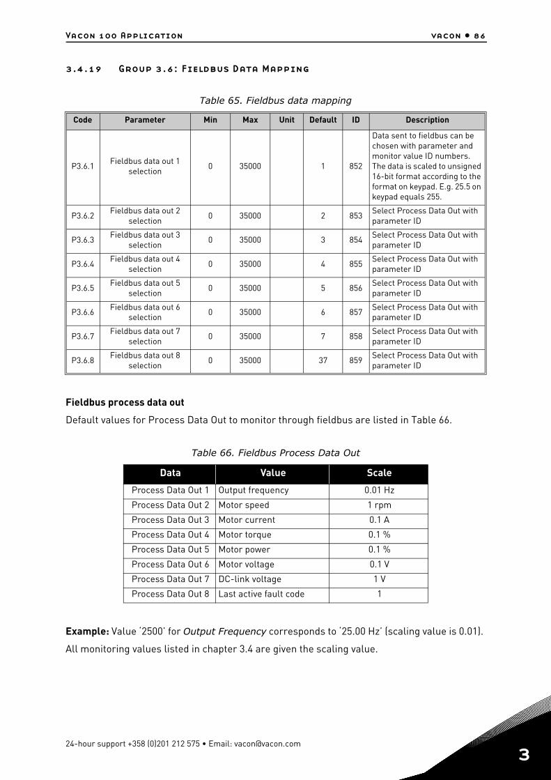
Vacon 100 Application vacon • 86
3.4.19 Group 3.6: Fieldbus Data Mapping
Fieldbus process data out
Default values for Process Data Out to monitor through fieldbus are listed in Table 66.
Example: Value ‘2500’ for Output Frequency corresponds to ‘25.00 Hz’ (scaling value is 0.01).
All monitoring values listed in chapter 3.4 are given the scaling value.
Table 65. Fieldbus data mapping
Code Parameter Min Max Unit Default ID Description
P3.6.1Fieldbus data out 1
selection0 35000 1 852
Data sent to fieldbus can be chosen with parameter and monitor value ID numbers. The data is scaled to unsigned 16-bit format according to the format on keypad. E.g. 25.5 on keypad equals 255.
P3.6.2Fieldbus data out 2
selection0 35000 2 853
Select Process Data Out with parameter ID
P3.6.3Fieldbus data out 3
selection0 35000 3 854
Select Process Data Out with parameter ID
P3.6.4Fieldbus data out 4
selection0 35000 4 855
Select Process Data Out with parameter ID
P3.6.5Fieldbus data out 5
selection0 35000 5 856
Select Process Data Out with parameter ID
P3.6.6Fieldbus data out 6
selection0 35000 6 857
Select Process Data Out with parameter ID
P3.6.7Fieldbus data out 7
selection0 35000 7 858
Select Process Data Out with parameter ID
P3.6.8Fieldbus data out 8
selection0 35000 37 859
Select Process Data Out with parameter ID
Table 66. Fieldbus Process Data Out
Data Value Scale
Process Data Out 1 Output frequency 0.01 Hz
Process Data Out 2 Motor speed 1 rpm
Process Data Out 3 Motor current 0.1 A
Process Data Out 4 Motor torque 0.1 %
Process Data Out 5 Motor power 0.1 %
Process Data Out 6 Motor voltage 0.1 V
Process Data Out 7 DC-link voltage 1 V
Process Data Out 8 Last active fault code 1
24-hour support +358 (0)201 212 575 • Email: [email protected]
3
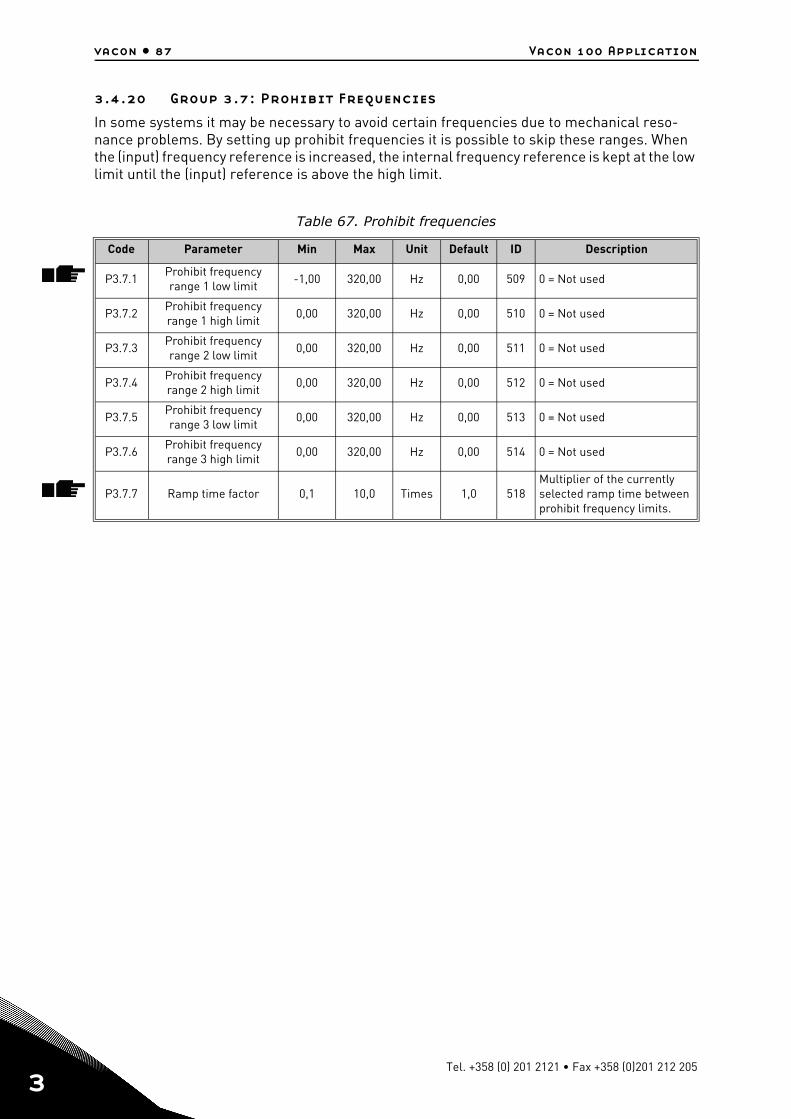
vacon • 87 Vacon 100 Application
3
3.4.20 Group 3.7: Prohibit Frequencies
In some systems it may be necessary to avoid certain frequencies due to mechanical reso-nance problems. By setting up prohibit frequencies it is possible to skip these ranges. When the (input) frequency reference is increased, the internal frequency reference is kept at the low limit until the (input) reference is above the high limit.
Table 67. Prohibit frequencies
Code Parameter Min Max Unit Default ID Description
P3.7.1Prohibit frequency range 1 low limit
-1,00 320,00 Hz 0,00 509 0 = Not used
P3.7.2Prohibit frequency range 1 high limit
0,00 320,00 Hz 0,00 510 0 = Not used
P3.7.3Prohibit frequency range 2 low limit
0,00 320,00 Hz 0,00 511 0 = Not used
P3.7.4Prohibit frequency range 2 high limit
0,00 320,00 Hz 0,00 512 0 = Not used
P3.7.5Prohibit frequency range 3 low limit
0,00 320,00 Hz 0,00 513 0 = Not used
P3.7.6Prohibit frequency range 3 high limit
0,00 320,00 Hz 0,00 514 0 = Not used
P3.7.7 Ramp time factor 0,1 10,0 Times 1,0 518Multiplier of the currently selected ramp time between prohibit frequency limits.
Tel. +358 (0) 201 2121 • Fax +358 (0)201 212 205
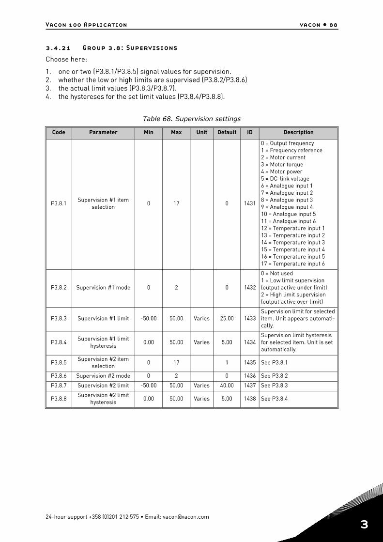
Vacon 100 Application vacon • 88
3.4.21 Group 3.8: Supervisions
Choose here:
1. one or two (P3.8.1/P3.8.5) signal values for supervision.2. whether the low or high limits are supervised (P3.8.2/P3.8.6)3. the actual limit values (P3.8.3/P3.8.7).4. the hystereses for the set limit values (P3.8.4/P3.8.8).
Table 68. Supervision settings
Code Parameter Min Max Unit Default ID Description
P3.8.1Supervision #1 item
selection0 17 0 1431
0 = Output frequency1 = Frequency reference2 = Motor current3 = Motor torque4 = Motor power5 = DC-link voltage6 = Analogue input 17 = Analogue input 28 = Analogue input 39 = Analogue input 410 = Analogue input 511 = Analogue input 612 = Temperature input 113 = Temperature input 214 = Temperature input 315 = Temperature input 416 = Temperature input 517 = Temperature input 6
P3.8.2 Supervision #1 mode 0 2 0 1432
0 = Not used1 = Low limit supervision(output active under limit)2 = High limit supervision(output active over limit)
P3.8.3 Supervision #1 limit -50.00 50.00 Varies 25.00 1433Supervision limit for selected item. Unit appears automati-cally.
P3.8.4Supervision #1 limit
hysteresis0.00 50.00 Varies 5.00 1434
Supervision limit hysteresis for selected item. Unit is set automatically.
P3.8.5Supervision #2 item
selection0 17 1 1435 See P3.8.1
P3.8.6 Supervision #2 mode 0 2 0 1436 See P3.8.2
P3.8.7 Supervision #2 limit -50.00 50.00 Varies 40.00 1437 See P3.8.3
P3.8.8Supervision #2 limit
hysteresis0.00 50.00 Varies 5.00 1438 See P3.8.4
24-hour support +358 (0)201 212 575 • Email: [email protected]
3

vacon • 89 Vacon 100 Application
3
3.4.22 Group 3.9: Protections
3.4.22.1 General
Table 69. General protections settings
Code Parameter Min Max Unit Default ID Description
P3.9.1.2Response to external
fault0 3 2 701
0 = No action1 = Alarm2 = Fault (Stop according to
stop function)3 = Fault (Stop by coasting)
P3.9.1.3Response to input
phase fault0 1 0 730
0 = 3-phase support1 = 1-phase supportNOTE! If 1-phase supply is used, 1-phase support must be selected.
P3.9.1.4 Undervoltage fault 0 1 0 7270 = Fault stored in history1 = Fault not stored in history
P3.9.1.5Response to output
phase fault0 3 2 702 See P3.9.1.2
P3.9.1.6Response to Fieldbus communication fault
0 5 3 733
0 = No action1 = Alarm2 = Alarm + preset fault fre-
quency (par. P3.9.1.12)3 = Fault (Stop according to
stop function)4 = Fault (Stop by coasting
P3.9.1.7Slot communication
fault0 3 2 734 See P3.9.1.2
P3.9.1.8 Thermistor fault 0 3 0 732 See P3.9.1.2
P3.9.1.9 PID Soft Fill fault 0 3 2 748 See P3.9.1.2
P3.9.1.10Response to PID1 supervision fault
0 3 2 749 See P3.9.1.2
P3.9.1.11Response to external PID supervision fault
0 3 2 757 See P3.9.1.2
P3.9.1.12 Earth fault 0 3 3 703
See P3.9.1.2NOTE! This fault can be configured in frames MR7 to MR9 only.
P3.9.1.13Preset alarm fre-
quencyP3.3.1.1 P3.3.1.2 Hz 25.00 183
This frequency used when fault response (in Group 3.9: Protections) is Alarm+preset frequency
Tel. +358 (0) 201 2121 • Fax +358 (0)201 212 205
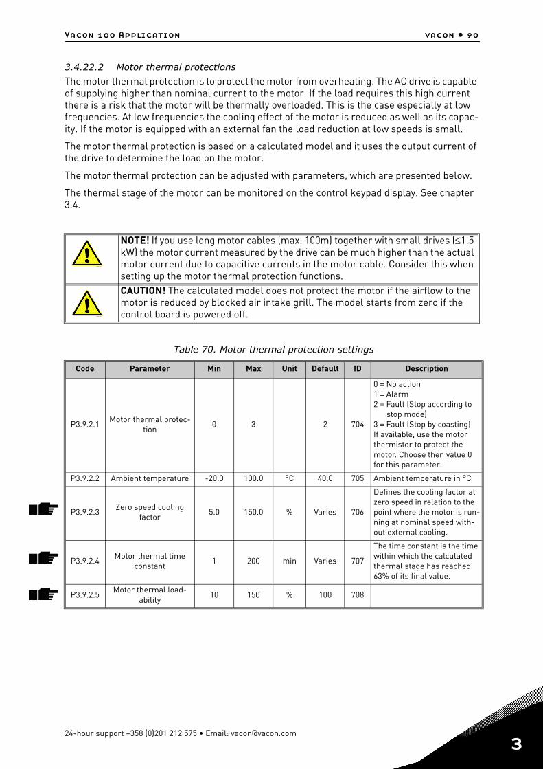
Vacon 100 Application vacon • 90
3.4.22.2 Motor thermal protections
The motor thermal protection is to protect the motor from overheating. The AC drive is capable of supplying higher than nominal current to the motor. If the load requires this high current there is a risk that the motor will be thermally overloaded. This is the case especially at low frequencies. At low frequencies the cooling effect of the motor is reduced as well as its capac-ity. If the motor is equipped with an external fan the load reduction at low speeds is small.
The motor thermal protection is based on a calculated model and it uses the output current of the drive to determine the load on the motor.
The motor thermal protection can be adjusted with parameters, which are presented below.
The thermal stage of the motor can be monitored on the control keypad display. See chapter 3.4.
NOTE! If you use long motor cables (max. 100m) together with small drives (1.5 kW) the motor current measured by the drive can be much higher than the actual motor current due to capacitive currents in the motor cable. Consider this when setting up the motor thermal protection functions.CAUTION! The calculated model does not protect the motor if the airflow to the motor is reduced by blocked air intake grill. The model starts from zero if the control board is powered off.
Table 70. Motor thermal protection settings
Code Parameter Min Max Unit Default ID Description
P3.9.2.1Motor thermal protec-
tion0 3 2 704
0 = No action1 = Alarm2 = Fault (Stop according to
stop mode)3 = Fault (Stop by coasting) If available, use the motor thermistor to protect the motor. Choose then value 0 for this parameter.
P3.9.2.2 Ambient temperature -20.0 100.0 °C 40.0 705 Ambient temperature in °C
P3.9.2.3Zero speed cooling
factor5.0 150.0 % Varies 706
Defines the cooling factor at zero speed in relation to the point where the motor is run-ning at nominal speed with-out external cooling.
P3.9.2.4Motor thermal time
constant1 200 min Varies 707
The time constant is the time within which the calculated thermal stage has reached 63% of its final value.
P3.9.2.5Motor thermal load-
ability10 150 % 100 708
13006.emf
13006.emf
24-hour support +358 (0)201 212 575 • Email: [email protected]
3
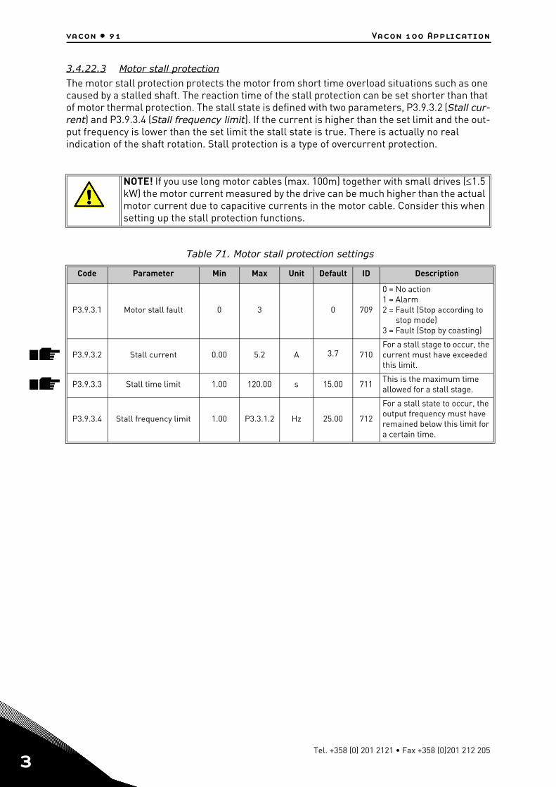
vacon • 91 Vacon 100 Application
3
3.4.22.3 Motor stall protection
The motor stall protection protects the motor from short time overload situations such as one caused by a stalled shaft. The reaction time of the stall protection can be set shorter than that of motor thermal protection. The stall state is defined with two parameters, P3.9.3.2 (Stall cur-rent) and P3.9.3.4 (Stall frequency limit). If the current is higher than the set limit and the out-put frequency is lower than the set limit the stall state is true. There is actually no real indication of the shaft rotation. Stall protection is a type of overcurrent protection.
NOTE! If you use long motor cables (max. 100m) together with small drives (1.5 kW) the motor current measured by the drive can be much higher than the actual motor current due to capacitive currents in the motor cable. Consider this when setting up the stall protection functions.
Table 71. Motor stall protection settings
Code Parameter Min Max Unit Default ID Description
P3.9.3.1 Motor stall fault 0 3 0 709
0 = No action1 = Alarm2 = Fault (Stop according to
stop mode)3 = Fault (Stop by coasting)
P3.9.3.2 Stall current 0.00 5.2 A 3.7 710For a stall stage to occur, the current must have exceeded this limit.
P3.9.3.3 Stall time limit 1.00 120.00 s 15.00 711This is the maximum time allowed for a stall stage.
P3.9.3.4 Stall frequency limit 1.00 P3.3.1.2 Hz 25.00 712
For a stall state to occur, the output frequency must have remained below this limit for a certain time.
13006.emf
Tel. +358 (0) 201 2121 • Fax +358 (0)201 212 205
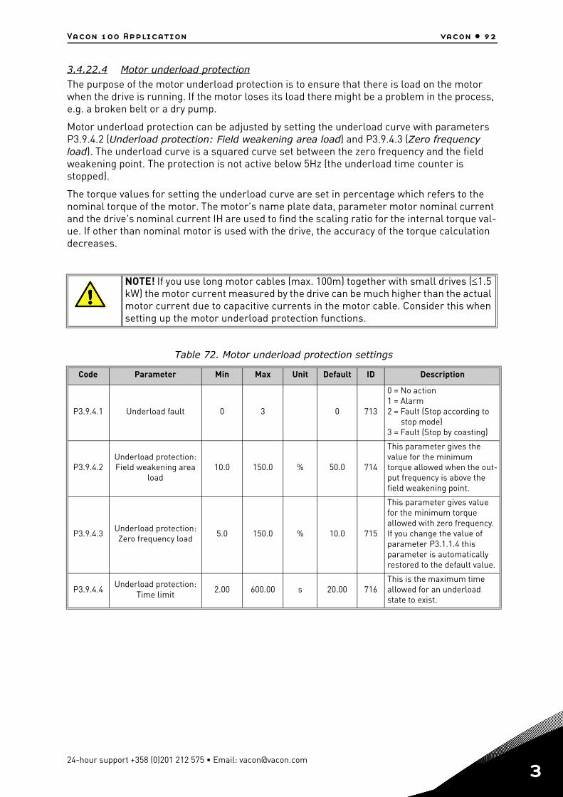
Vacon 100 Application vacon • 92
3.4.22.4 Motor underload protection
The purpose of the motor underload protection is to ensure that there is load on the motor when the drive is running. If the motor loses its load there might be a problem in the process, e.g. a broken belt or a dry pump.
Motor underload protection can be adjusted by setting the underload curve with parameters P3.9.4.2 (Underload protection: Field weakening area load) and P3.9.4.3 (Zero frequency load). The underload curve is a squared curve set between the zero frequency and the field weakening point. The protection is not active below 5Hz (the underload time counter is stopped).
The torque values for setting the underload curve are set in percentage which refers to the nominal torque of the motor. The motor's name plate data, parameter motor nominal current and the drive's nominal current IH are used to find the scaling ratio for the internal torque val-ue. If other than nominal motor is used with the drive, the accuracy of the torque calculation decreases.
NOTE! If you use long motor cables (max. 100m) together with small drives (1.5 kW) the motor current measured by the drive can be much higher than the actual motor current due to capacitive currents in the motor cable. Consider this when setting up the motor underload protection functions.
Table 72. Motor underload protection settings
Code Parameter Min Max Unit Default ID Description
P3.9.4.1 Underload fault 0 3 0 713
0 = No action1 = Alarm2 = Fault (Stop according to
stop mode)3 = Fault (Stop by coasting)
P3.9.4.2Underload protection: Field weakening area
load10.0 150.0 % 50.0 714
This parameter gives the value for the minimum torque allowed when the out-put frequency is above the field weakening point.
P3.9.4.3Underload protection: Zero frequency load
5.0 150.0 % 10.0 715
This parameter gives value for the minimum torque allowed with zero frequency.If you change the value of parameter P3.1.1.4 this parameter is automatically restored to the default value.
P3.9.4.4Underload protection:
Time limit2.00 600.00 s 20.00 716
This is the maximum time allowed for an underload state to exist.
13006.emf
24-hour support +358 (0)201 212 575 • Email: [email protected]
3

vacon • 93 Vacon 100 Application
3
3.4.22.5 Quick stop
Table 73. Quick stop settings
Code Parameter Min Max Unit Default ID Description
P3.9.5.1 Quick stop mode 0 2 1 1276
Method to stop the drive if the Quick stop function is activated from DI or fieldbus 0 = Coasting1 = Quick stop deceleration time2 = Stop according to Stop function (P3.2.5)
P3.9.5.2 Quick stop activation Varies VariesDigIN
Slot0.21213 FALSE = Activated
P3.9.5.3Quick stop decelera-
tion time0.1 300.0 s 3.0 1256
P3.9.5.4Response to Quick
stop fault 0 2 1 744
0 = No action1 = Alarm2 = Fault (Stop according to
Quick stop mode)
Tel. +358 (0) 201 2121 • Fax +358 (0)201 212 205
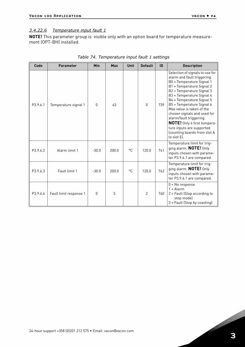
Vacon 100 Application vacon • 94
3.4.22.6 Temperature input fault 1
NOTE! This parameter group is visible only with an option board for temperature measure-ment (OPT-BH) installed.
Table 74. Temperature input fault 1 settings
Code Parameter Min Max Unit Default ID Description
P3.9.6.1 Temperature signal 1 0 63 0 739
Selection of signals to use for alarm and fault triggering. B0 = Temperature Signal 1 B1 = Temperature Signal 2B2 = Temperature Signal 3B3 = Temperature Signal 4B4 = Temperature Signal 5B5 = Temperature Signal 6Max value is taken of the chosen signals and used for alarm/fault triggering.NOTE! Only 6 first tempera-ture inputs are supported (counting boards from slot A to slot E).
P3.9.6.2 Alarm limit 1 -30.0 200.0 °C 120.0 741
Temperature limit for trig-ging alarm. NOTE! Only inputs chosen with parame-ter P3.9.6.1 are compared.
P3.9.6.3 Fault limit 1 -30.0 200.0 °C 120.0 742
Temperature limit for trig-ging alarm. NOTE! Only inputs chosen with parame-ter P3.9.6.1 are compared.
P3.9.6.4 Fault limit response 1 0 3 2 740
0 = No response 1 = Alarm2 = Fault (Stop according to
stop mode)3 = Fault (Stop by coasting)
24-hour support +358 (0)201 212 575 • Email: [email protected]
3
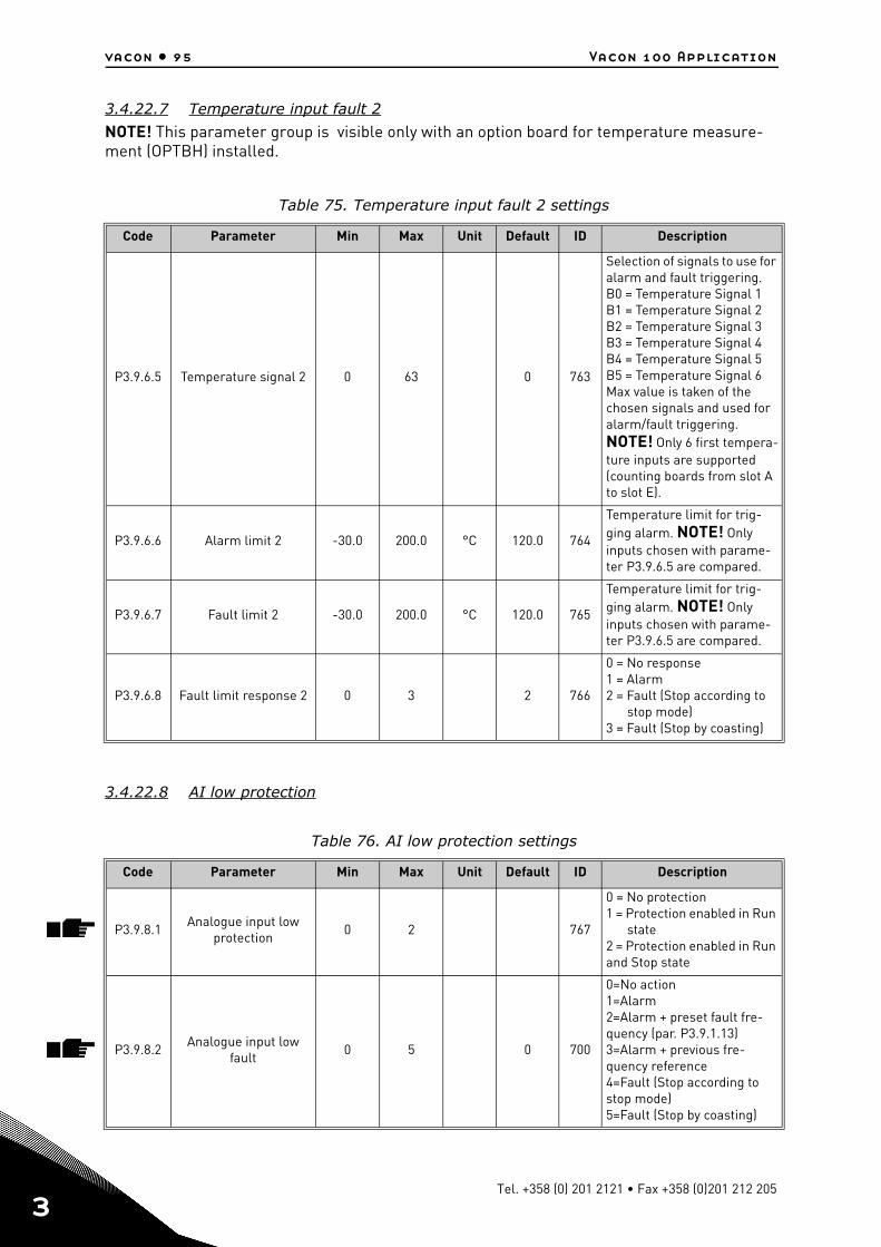
vacon • 95 Vacon 100 Application
3
3.4.22.7 Temperature input fault 2
NOTE! This parameter group is visible only with an option board for temperature measure-ment (OPTBH) installed.
3.4.22.8 AI low protection
Table 75. Temperature input fault 2 settings
Code Parameter Min Max Unit Default ID Description
P3.9.6.5 Temperature signal 2 0 63 0 763
Selection of signals to use for alarm and fault triggering. B0 = Temperature Signal 1 B1 = Temperature Signal 2B2 = Temperature Signal 3B3 = Temperature Signal 4B4 = Temperature Signal 5B5 = Temperature Signal 6Max value is taken of the chosen signals and used for alarm/fault triggering.NOTE! Only 6 first tempera-ture inputs are supported (counting boards from slot A to slot E).
P3.9.6.6 Alarm limit 2 -30.0 200.0 °C 120.0 764
Temperature limit for trig-ging alarm. NOTE! Only inputs chosen with parame-ter P3.9.6.5 are compared.
P3.9.6.7 Fault limit 2 -30.0 200.0 °C 120.0 765
Temperature limit for trig-ging alarm. NOTE! Only inputs chosen with parame-ter P3.9.6.5 are compared.
P3.9.6.8 Fault limit response 2 0 3 2 766
0 = No response 1 = Alarm2 = Fault (Stop according to
stop mode)3 = Fault (Stop by coasting)
Table 76. AI low protection settings
Code Parameter Min Max Unit Default ID Description
P3.9.8.1Analogue input low
protection0 2 767
0 = No protection 1 = Protection enabled in Run
state2 = Protection enabled in Run and Stop state
P3.9.8.2Analogue input low
fault0 5 0 700
0=No action1=Alarm2=Alarm + preset fault fre-quency (par. P3.9.1.13)3=Alarm + previous fre-quency reference4=Fault (Stop according to stop mode)5=Fault (Stop by coasting)
Tel. +358 (0) 201 2121 • Fax +358 (0)201 212 205
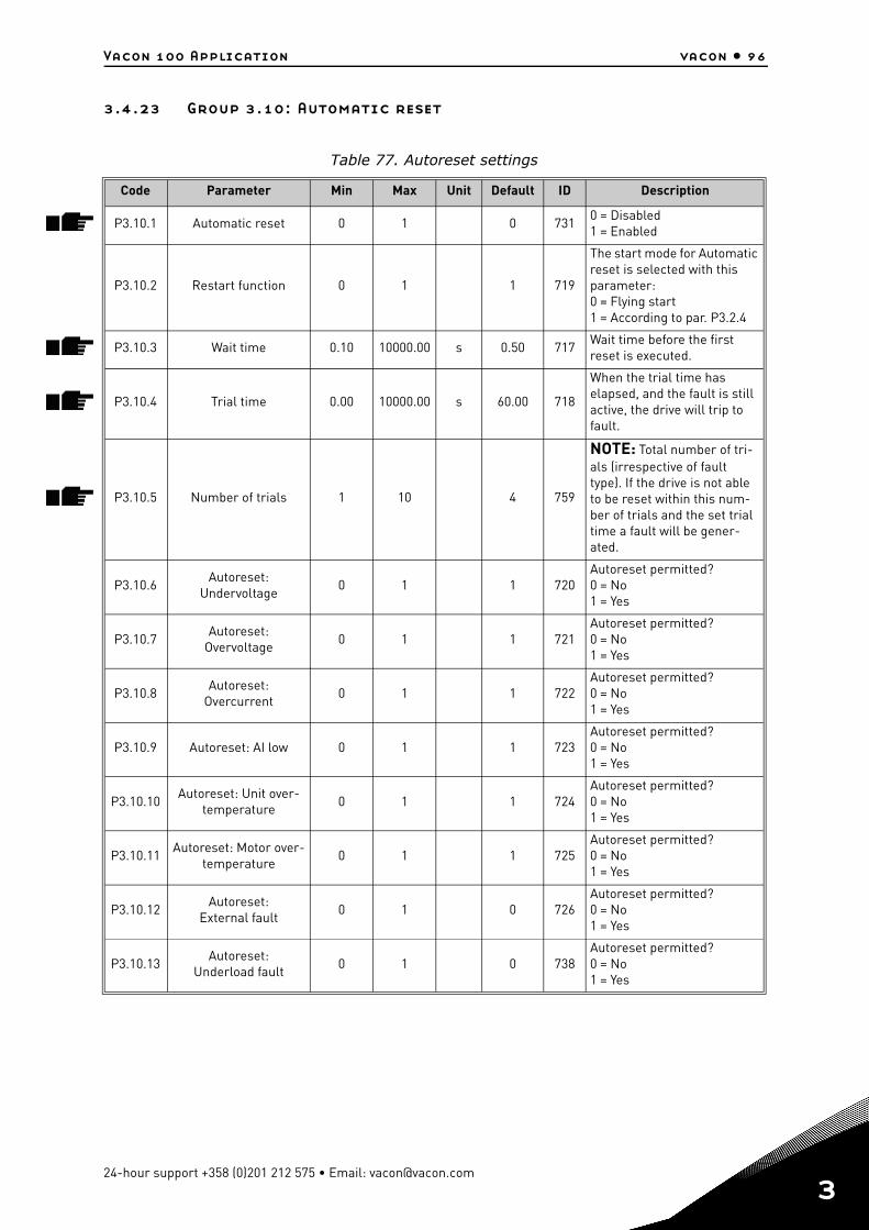
Vacon 100 Application vacon • 96
3.4.23 Group 3.10: Automatic reset
Table 77. Autoreset settings
Code Parameter Min Max Unit Default ID Description
P3.10.1 Automatic reset 0 1 0 7310 = Disabled1 = Enabled
P3.10.2 Restart function 0 1 1 719
The start mode for Automatic reset is selected with this parameter:0 = Flying start1 = According to par. P3.2.4
P3.10.3 Wait time 0.10 10000.00 s 0.50 717Wait time before the first reset is executed.
P3.10.4 Trial time 0.00 10000.00 s 60.00 718
When the trial time has elapsed, and the fault is still active, the drive will trip to fault.
P3.10.5 Number of trials 1 10 4 759
NOTE: Total number of tri-als (irrespective of fault type). If the drive is not able to be reset within this num-ber of trials and the set trial time a fault will be gener-ated.
P3.10.6Autoreset:
Undervoltage0 1 1 720
Autoreset permitted?0 = No1 = Yes
P3.10.7Autoreset:
Overvoltage0 1 1 721
Autoreset permitted?0 = No1 = Yes
P3.10.8Autoreset:
Overcurrent0 1 1 722
Autoreset permitted?0 = No1 = Yes
P3.10.9 Autoreset: AI low 0 1 1 723Autoreset permitted?0 = No1 = Yes
P3.10.10Autoreset: Unit over-
temperature0 1 1 724
Autoreset permitted?0 = No1 = Yes
P3.10.11Autoreset: Motor over-
temperature0 1 1 725
Autoreset permitted?0 = No1 = Yes
P3.10.12Autoreset:
External fault0 1 0 726
Autoreset permitted?0 = No1 = Yes
P3.10.13Autoreset:
Underload fault0 1 0 738
Autoreset permitted?0 = No1 = Yes
24-hour support +358 (0)201 212 575 • Email: [email protected]
3

vacon • 97 Vacon 100 Application
3
3.4.24 Group 3.11: Application settings
Table 78. Application settings
Code Parameter Min Max Unit Default ID Description
P3.11.1 Password 0 9999 0 1806 Administrator password
P3.11.2 C/F selection 0 1 0 1197
0 = Celsius1 = FahrenheitAll temperature-related parameters and monitoring values are presented in the selected unit.
P3.11.3 kW/hp selection 0 1 0 1198
0 = kW1 = hpAll power-related parame-ters and monitoring values are presented in the selected unit
P3.11.4 Multimonitor view 0 2 1 1196
Division of keypad display into sections in Multimon-itor view.0 = 2x2 sections1 = 3x2 sections2 = 3x3 sections
Tel. +358 (0) 201 2121 • Fax +358 (0)201 212 205
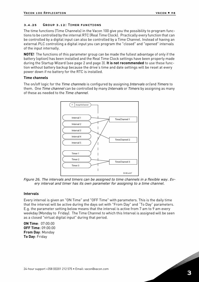
Vacon 100 Application vacon • 98
3.4.25 Group 3.12: Timer functions
The time functions (Time Channels) in the Vacon 100 give you the possibility to program func-tions to be controlled by the internal RTC (Real Time Clock). Practically every function that can be controlled by a digital input can also be controlled by a Time Channel. Instead of having an external PLC controlling a digital input you can program the "closed" and "opened" intervals of the input internally.
NOTE! The functions of this parameter group can be made the fullest advantage of only if the battery (option) has been installed and the Real Time Clock settings have been properly made during the Startup Wizard (see page 2 and page 3). It is not recommended to use these func-tion without battery backup because the drive’s time and date settings will be reset at every power down if no battery for the RTC is installed.
Time channels
The on/off logic for the Time channels is configured by assigning Intervals or/and Timers to them. One Time channel can be controlled by many Intervals or Timers by assigning as many of these as needed to the Time channel.
Figure 26. The intervals and timers can be assigned to time channels in a flexible way. Ev-ery interval and timer has its own parameter for assigning to a time channel.
Intervals
Every interval is given an "ON Time" and "OFF Time" with parameters. This is the daily time that the interval will be active during the days set with "From Day" and “To Day” parameters. E.g. the parameter setting below means that the interval is active from 7 am to 9 am every weekday (Monday to Friday). The Time Channel to which this Interval is assigned will be seen as a closed "virtual digital input" during that period.
ON Time: 07:00:00OFF Time: 09:00:00From Day: MondayTo Day: Friday
P
9146.emf
AssignToChannel
Interval 1
Interval 2
Interval 3
Interval 4
Timer 1
Timer 2
Timer 3
Interval 5
TimeChannel 1
TimeChannel 2
TimeChannel 3
24-hour support +358 (0)201 212 575 • Email: [email protected]
3
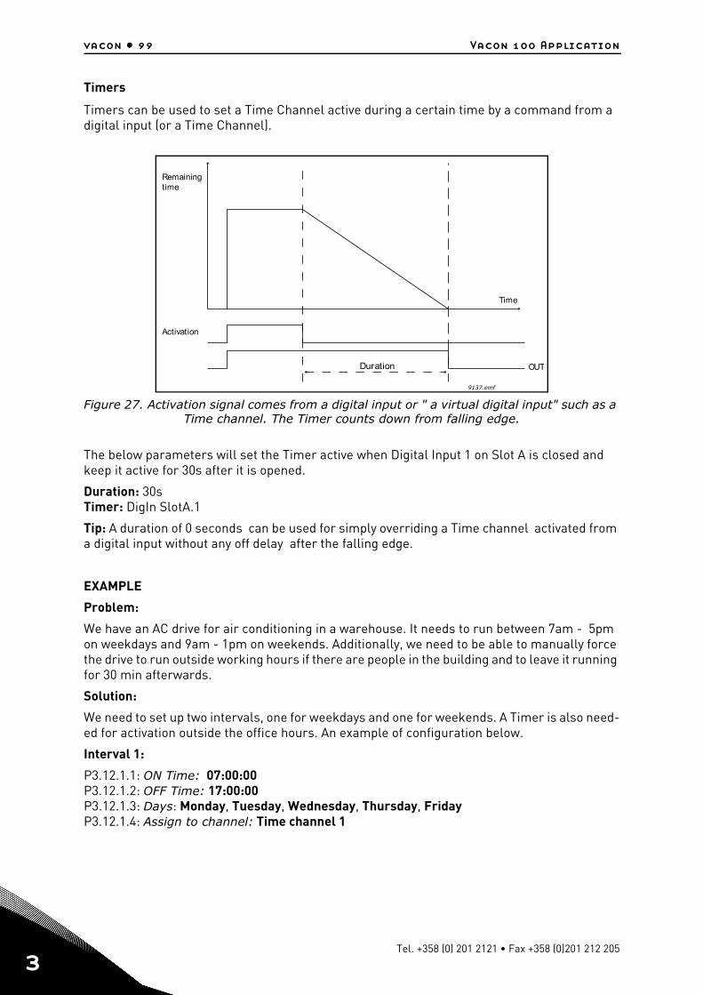
vacon • 99 Vacon 100 Application
3
Timers
Timers can be used to set a Time Channel active during a certain time by a command from a digital input (or a Time Channel).
Figure 27. Activation signal comes from a digital input or " a virtual digital input" such as a Time channel. The Timer counts down from falling edge.
The below parameters will set the Timer active when Digital Input 1 on Slot A is closed and keep it active for 30s after it is opened.
Duration: 30sTimer: DigIn SlotA.1
Tip: A duration of 0 seconds can be used for simply overriding a Time channel activated from a digital input without any off delay after the falling edge.
EXAMPLE
Problem:
We have an AC drive for air conditioning in a warehouse. It needs to run between 7am - 5pm on weekdays and 9am - 1pm on weekends. Additionally, we need to be able to manually force the drive to run outside working hours if there are people in the building and to leave it running for 30 min afterwards.
Solution:
We need to set up two intervals, one for weekdays and one for weekends. A Timer is also need-ed for activation outside the office hours. An example of configuration below.
Interval 1:
P3.12.1.1: ON Time: 07:00:00P3.12.1.2: OFF Time: 17:00:00P3.12.1.3: Days: Monday, Tuesday, Wednesday, Thursday, FridayP3.12.1.4: Assign to channel: Time channel 1
Duration
Remainingtime
Activation
Time
OUT
9137.emf
Tel. +358 (0) 201 2121 • Fax +358 (0)201 212 205
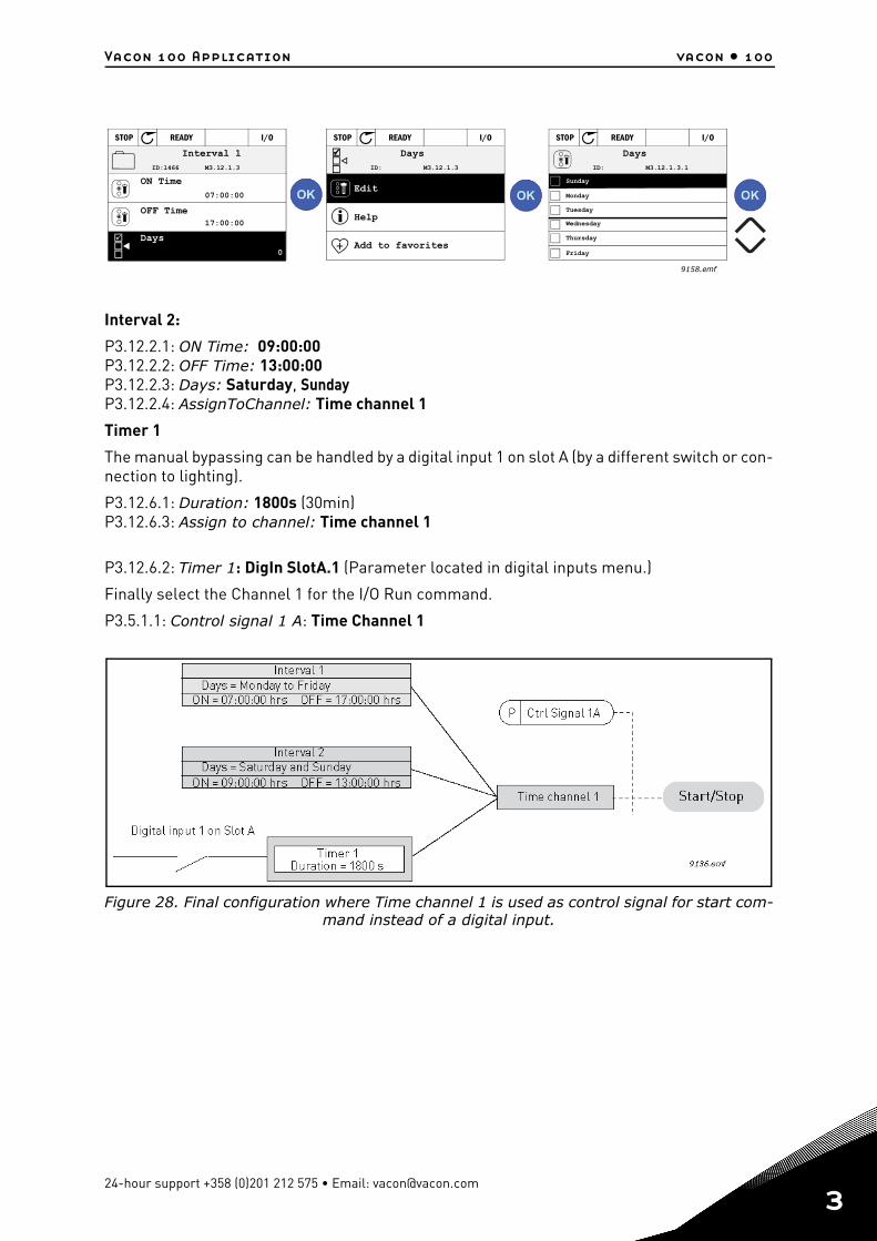
Vacon 100 Application vacon • 100
Interval 2:
P3.12.2.1: ON Time: 09:00:00P3.12.2.2: OFF Time: 13:00:00P3.12.2.3: Days: Saturday, SundayP3.12.2.4: AssignToChannel: Time channel 1
Timer 1
The manual bypassing can be handled by a digital input 1 on slot A (by a different switch or con-nection to lighting).
P3.12.6.1: Duration: 1800s (30min)P3.12.6.3: Assign to channel: Time channel 1
P3.12.6.2: Timer 1: DigIn SlotA.1 (Parameter located in digital inputs menu.)
Finally select the Channel 1 for the I/O Run command.
P3.5.1.1: Control signal 1 A: Time Channel 1
Figure 28. Final configuration where Time channel 1 is used as control signal for start com-mand instead of a digital input.
Interval 1 Days Days
Monday
Sunday
Tuesday
Wednesday
Thursday
Friday
ON Time
Days
Edit
Help
Add to favorites
STOP READY I/O STOP READY I/O STOP READY I/O
ID:1466 M3.12.1.3
07:00:00
17:00:00
0
ID: M3.12.1.3 ID: M3.12.1.3.1
OFF Time
9158.emf
24-hour support +358 (0)201 212 575 • Email: [email protected]
3
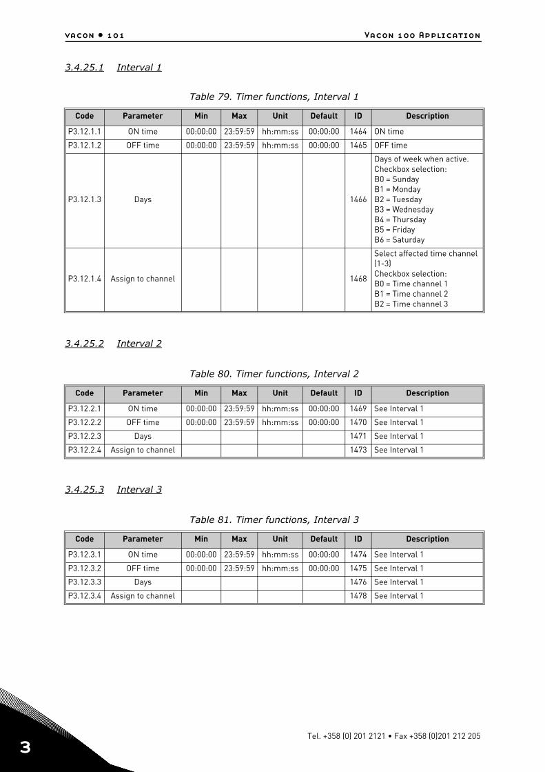
vacon • 101 Vacon 100 Application
3
3.4.25.1 Interval 1
3.4.25.2 Interval 2
3.4.25.3 Interval 3
Table 79. Timer functions, Interval 1
Code Parameter Min Max Unit Default ID Description
P3.12.1.1 ON time 00:00:00 23:59:59 hh:mm:ss 00:00:00 1464 ON time
P3.12.1.2 OFF time 00:00:00 23:59:59 hh:mm:ss 00:00:00 1465 OFF time
P3.12.1.3 Days 1466
Days of week when active.Checkbox selection:B0 = SundayB1 = MondayB2 = TuesdayB3 = WednesdayB4 = ThursdayB5 = FridayB6 = Saturday
P3.12.1.4 Assign to channel 1468
Select affected time channel (1-3)Checkbox selection:B0 = Time channel 1B1 = Time channel 2B2 = Time channel 3
Table 80. Timer functions, Interval 2
Code Parameter Min Max Unit Default ID Description
P3.12.2.1 ON time 00:00:00 23:59:59 hh:mm:ss 00:00:00 1469 See Interval 1
P3.12.2.2 OFF time 00:00:00 23:59:59 hh:mm:ss 00:00:00 1470 See Interval 1
P3.12.2.3 Days 1471 See Interval 1
P3.12.2.4 Assign to channel 1473 See Interval 1
Table 81. Timer functions, Interval 3
Code Parameter Min Max Unit Default ID Description
P3.12.3.1 ON time 00:00:00 23:59:59 hh:mm:ss 00:00:00 1474 See Interval 1
P3.12.3.2 OFF time 00:00:00 23:59:59 hh:mm:ss 00:00:00 1475 See Interval 1
P3.12.3.3 Days 1476 See Interval 1
P3.12.3.4 Assign to channel 1478 See Interval 1
Tel. +358 (0) 201 2121 • Fax +358 (0)201 212 205

Vacon 100 Application vacon • 102
3.4.25.4 Interval 4
3.4.25.5 Interval 5
3.4.25.6 Timer 1
Table 82. Timer functions, Interval 4
Code Parameter Min Max Unit Default ID Description
P3.12.4.1 ON time 00:00:00 23:59:59 hh:mm:ss 00:00:00 1479 See Interval 1
P3.12.4.2 OFF time 00:00:00 23:59:59 hh:mm:ss 00:00:00 1480 See Interval 1
P3.12.4.3 Days 1481 See Interval 1
P3.12.4.4 Assign to channel 1483 See Interval 1
Table 83. Timer functions, Interval 5
Code Parameter Min Max Unit Default ID Description
P3.12.5.1 ON time 00:00:00 23:59:59 hh:mm:ss 00:00:00 1484 See Interval 1
P3.12.5.2 OFF time 00:00:00 23:59:59 hh:mm:ss 00:00:00 1485 See Interval 1
P3.12.5.3 Days 1486 See Interval 1
P3.12.5.4 Assign to channel 1488 See Interval 1
Table 84. Timer functions, Timer 1
Code Parameter Min Max Unit Default ID Description
P3.12.6.1 Duration 0 72000 s 0 1489The time the timer will run when activated. (Activated by DI)
P3.12.6.2 Timer 1DigINSlot
0.1447
Rising edge starts Timer 1 programmed in Group 3.12: Timer functions parameter group.
P3.12.6.3 Assign to channel 1490
Select affected time channel (1-3)Checkbox selection:B0 = Time channel 1B1 = Time channel 2B2 = Time channel 3
24-hour support +358 (0)201 212 575 • Email: [email protected]
3

vacon • 103 Vacon 100 Application
3
3.4.25.7 Timer 2
3.4.25.8 Timer 3
Table 85. Timer functions, Timer 2
Code Parameter Min Max Unit Default ID Description
P3.12.7.1 Duration 0 72000 s 0 1491 See Timer 1
P3.12.7.2 Timer 2DigINSlot
0.1448 See Timer 1
P3.12.7.3 Assign to channel 1492 See Timer 1
Table 86. Timer functions, Timer 3
Code Parameter Min Max Unit Default ID Description
P3.12.8.1 Duration 0 72000 s 0 1493 See Timer 1
P3.12.8.2 Timer 3DigINSlot
0.1448 See Timer 1
P3.12.8.3 Assign to channel 1494 See Timer 1
Tel. +358 (0) 201 2121 • Fax +358 (0)201 212 205

Vacon 100 Application vacon • 104
3.4.26 Group 3.13: PID-controller 1
3.4.26.1 Basic settings
Table 87. PID controller 1 basic settings
Code Parameter Min Max Unit Default ID Description
P3.13.1.1 PID gain 0.00 1000.00 % 100.00 118
If the value of the parameter is set to 100% a change of 10% in the error value causes the controller output to change by 10%.
P3.13.1.2 PID integration time 0.00 600.00 s 1.00 119
If this parameter is set to 1,00s a change of 10% in the error value causes the con-troller output to change by 10.00%/s.
P3.13.1.3 PID derivation time 0.00 100.00 s 0.00 132
If this parameter is set to 1,00s a change of 10% in the error value during 1.00 s causes the controller output to change by 10.00%.
P3.13.1.4 Process unit selection 1 38 1 1036 Select unit for actual value.
P3.13.1.5 Process unit min Varies Varies Varies 0 1033
Value in Process units at 0% feedback or setpoint.This scaling is done for moni-toring purpose only. The PID controller still uses the per-centage internally for feed-backs and setpoints.
P3.13.1.6 Process unit max Varies Varies Varies 100 1034 See above.
P3.13.1.7 Process unit decimals 0 4 2 1035Number of decimals for pro-cess unit value
P3.13.1.8 Error inversion 0 1 0 340
0 = Normal (Feedback < Set-point -> Increase PID output)1 = Inverted (Feedback < Set-point -> Decrease PID output)
P3.13.1.9 Dead band Varies Varies Varies 0 1056
Dead band area around the setpoint in process units.The PID output is locked if the feedback stays within the deadband area for a pre-defined time.
P3.13.1.10 Dead band delay 0.00 320.00 s 0.00 1057
If the feedback stays within the dead band area for a pre-defined time, the output is locked.
24-hour support +358 (0)201 212 575 • Email: [email protected]
3
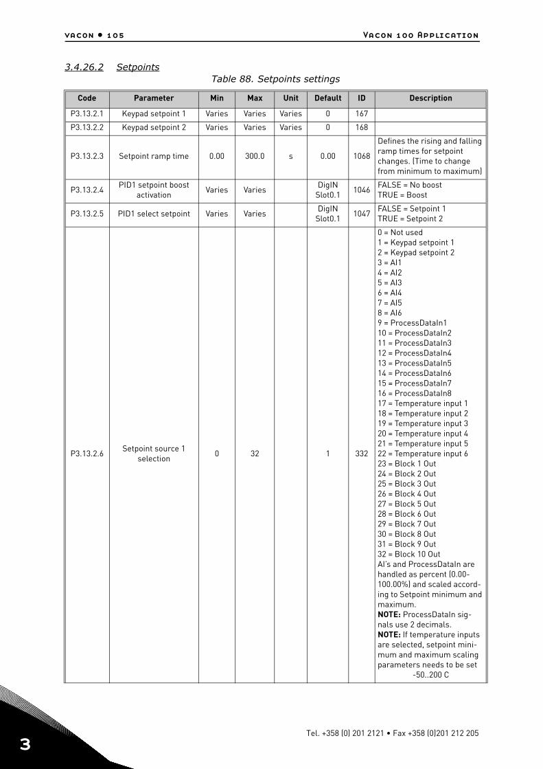
vacon • 105 Vacon 100 Application
3
3.4.26.2 SetpointsTable 88. Setpoints settings
Code Parameter Min Max Unit Default ID Description
P3.13.2.1 Keypad setpoint 1 Varies Varies Varies 0 167
P3.13.2.2 Keypad setpoint 2 Varies Varies Varies 0 168
P3.13.2.3 Setpoint ramp time 0.00 300.0 s 0.00 1068
Defines the rising and falling ramp times for setpoint changes. (Time to change from minimum to maximum)
P3.13.2.4PID1 setpoint boost
activationVaries Varies
DigIN Slot0.1
1046FALSE = No boostTRUE = Boost
P3.13.2.5 PID1 select setpoint Varies VariesDigIN
Slot0.11047
FALSE = Setpoint 1TRUE = Setpoint 2
P3.13.2.6Setpoint source 1
selection0 32 1 332
0 = Not used1 = Keypad setpoint 12 = Keypad setpoint 23 = AI14 = AI25 = AI36 = AI47 = AI58 = AI69 = ProcessDataIn110 = ProcessDataIn211 = ProcessDataIn312 = ProcessDataIn413 = ProcessDataIn514 = ProcessDataIn615 = ProcessDataIn716 = ProcessDataIn817 = Temperature input 118 = Temperature input 219 = Temperature input 320 = Temperature input 421 = Temperature input 522 = Temperature input 623 = Block 1 Out24 = Block 2 Out25 = Block 3 Out26 = Block 4 Out27 = Block 5 Out28 = Block 6 Out29 = Block 7 Out30 = Block 8 Out31 = Block 9 Out32 = Block 10 OutAI’s and ProcessDataIn are handled as percent (0.00-100.00%) and scaled accord-ing to Setpoint minimum and maximum. NOTE: ProcessDataIn sig-nals use 2 decimals.NOTE: If temperature inputs are selected, setpoint mini-mum and maximum scaling parameters needs to be set
-50..200 C
Tel. +358 (0) 201 2121 • Fax +358 (0)201 212 205
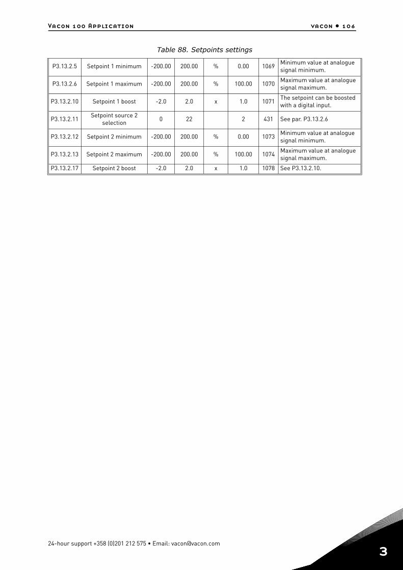
Vacon 100 Application vacon • 106
P3.13.2.5 Setpoint 1 minimum -200.00 200.00 % 0.00 1069Minimum value at analogue signal minimum.
P3.13.2.6 Setpoint 1 maximum -200.00 200.00 % 100.00 1070Maximum value at analogue signal maximum.
P3.13.2.10 Setpoint 1 boost -2.0 2.0 x 1.0 1071The setpoint can be boosted with a digital input.
P3.13.2.11Setpoint source 2
selection0 22 2 431 See par. P3.13.2.6
P3.13.2.12 Setpoint 2 minimum -200.00 200.00 % 0.00 1073Minimum value at analogue signal minimum.
P3.13.2.13 Setpoint 2 maximum -200.00 200.00 % 100.00 1074Maximum value at analogue signal maximum.
P3.13.2.17 Setpoint 2 boost -2.0 2.0 x 1.0 1078 See P3.13.2.10.
Table 88. Setpoints settings
24-hour support +358 (0)201 212 575 • Email: [email protected]
3
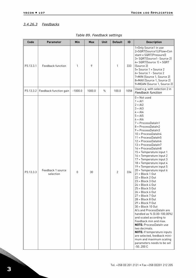
vacon • 107 Vacon 100 Application
3
3.4.26.3 Feedbacks
Table 89. Feedback settings
Code Parameter Min Max Unit Default ID Description
P3.13.3.1 Feedback function 1 9 1 333
1=Only Source1 in use2=SQRT(Source1);(Flow=Constant x SQRT(Pressure))3= SQRT(Source1- Source 2)4= SQRT(Source 1) + SQRT (Source 2)5= Source 1 + Source 26= Source 1 - Source 27=MIN (Source 1, Source 2)8=MAX (Source 1, Source 2)9=MEAN (Source 1, Source 2)
P3.13.3.2 Feedback function gain -1000.0 1000.0 % 100.0 1058Used e.g. with selection 2 in Feedback function
P3.13.3.3Feedback 1 source
selection0 30 2 334
0 = Not used1 = AI12 = AI23 = AI34 = AI45 = AI56 = AI67 = ProcessDataIn18 = ProcessDataIn29 = ProcessDataIn310 = ProcessDataIn411 = ProcessDataIn512 = ProcessDataIn613 = ProcessDataIn714 = ProcessDataIn815 = Temperature input 116 = Temperature input 217 = Temperature input 318 = Temperature input 419 = Temperature input 520 = Temperature input 621 = Block 1 Out22 = Block 2 Out23 = Block 3 Out24 = Block 4 Out25 = Block 5 Out26 = Block 6 Out27 = Block 7 Out28 = Block 8 Out29 = Block 9 Out30 = Block 10 OutAI’s and ProcessDataIn are handled as % (0.00-100.00%) and scaled according to Feedback min and max. NOTE: ProcessDataIn use two decimals.NOTE: If temperature inputs are selected, feedback mini-mum and maximum scaling parameters needs to be set -50..200 C
Tel. +358 (0) 201 2121 • Fax +358 (0)201 212 205
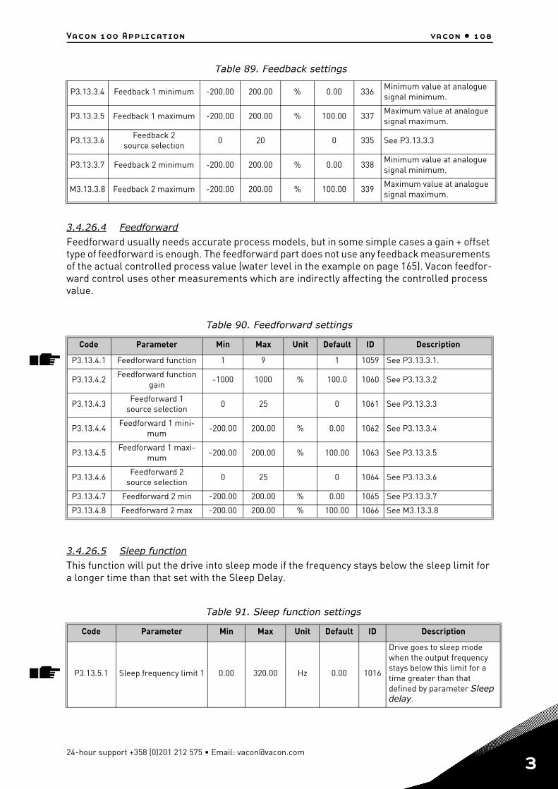
Vacon 100 Application vacon • 108
3.4.26.4 Feedforward
Feedforward usually needs accurate process models, but in some simple cases a gain + offset type of feedforward is enough. The feedforward part does not use any feedback measurements of the actual controlled process value (water level in the example on page 165). Vacon feedfor-ward control uses other measurements which are indirectly affecting the controlled process value.
3.4.26.5 Sleep function
This function will put the drive into sleep mode if the frequency stays below the sleep limit for a longer time than that set with the Sleep Delay.
P3.13.3.4 Feedback 1 minimum -200.00 200.00 % 0.00 336Minimum value at analogue signal minimum.
P3.13.3.5 Feedback 1 maximum -200.00 200.00 % 100.00 337Maximum value at analogue signal maximum.
P3.13.3.6Feedback 2
source selection0 20 0 335 See P3.13.3.3
P3.13.3.7 Feedback 2 minimum -200.00 200.00 % 0.00 338Minimum value at analogue signal minimum.
M3.13.3.8 Feedback 2 maximum -200.00 200.00 % 100.00 339Maximum value at analogue signal maximum.
Table 90. Feedforward settings
Code Parameter Min Max Unit Default ID Description
P3.13.4.1 Feedforward function 1 9 1 1059 See P3.13.3.1.
P3.13.4.2Feedforward function
gain-1000 1000 % 100.0 1060 See P3.13.3.2
P3.13.4.3Feedforward 1
source selection0 25 0 1061 See P3.13.3.3
P3.13.4.4Feedforward 1 mini-
mum-200.00 200.00 % 0.00 1062 See P3.13.3.4
P3.13.4.5Feedforward 1 maxi-
mum-200.00 200.00 % 100.00 1063 See P3.13.3.5
P3.13.4.6Feedforward 2
source selection0 25 0 1064 See P3.13.3.6
P3.13.4.7 Feedforward 2 min -200.00 200.00 % 0.00 1065 See P3.13.3.7
P3.13.4.8 Feedforward 2 max -200.00 200.00 % 100.00 1066 See M3.13.3.8
Table 91. Sleep function settings
Code Parameter Min Max Unit Default ID Description
P3.13.5.1 Sleep frequency limit 1 0.00 320.00 Hz 0.00 1016
Drive goes to sleep mode when the output frequency stays below this limit for a time greater than that defined by parameter Sleep delay.
Table 89. Feedback settings
24-hour support +358 (0)201 212 575 • Email: [email protected]
3
vacon • 109 Vacon 100 Application
3
3.4.26.6 Feedback supervision
Feedback supervision is used to control that the PID Feedback value (process actual value) stays within predefined limits. With this function you can e.g. detect a major pipe burst and stop unnecessary flooding. See more on page 165.
3.4.26.7 Pressure loss compensation
P3.13.5.2 Sleep delay 1 0 3000 s 0 1017
The minimum amount of time the frequency has to remain below the Sleep level before the drive is stopped.
P3.13.5.3 Wake-up level 1 Varies 0.0000 1018
Defines the level for the PID feedback value wake-up supervision. Uses selected process units.
P3.13.5.4 Sleep frequency limit 2 0.00 320.00 Hz 0.00 1075 See P3.13.5.1.
P3.13.5.5 Sleep delay 2 0 3000 s 0 1076 See P3.13.5.2.
P3.13.5.6 Wake-up level 2 Varies 0.0000 1077 See P3.13.5.3.
Table 92. Feedback supervision parameters
Code Parameter Min Max Unit Default ID Description
P3.13.6.1Enable feedback
supervision0 1 0 735
0 = Disabled1 = Enabled
P3.13.6.2 Upper limit Varies Varies Varies Varies 736Upper actual/process value supervision
P3.13.6.3 Lower limit Varies Varies Varies Varies 758Lower actual/process value supervision
P3.13.6.4 Delay 0 30000 s 0 737If the desired value is not reached within this time a fault or alarm is created.
P3.13.6.5Response to PID1 supervision fault
0 3 2 749
0 = No action1 = Alarm2 = Fault (Stop according to
stop mode)3 = Fault (Stop by coasting)
Table 93. Pressure loss compensation parameters
Code Parameter Min Max Unit Default ID Description
P3.13.7.1 Enable setpoint 1 0 1 0 1189
Enables pressure loss com-pensation for setpoint 1.0 = Disabled1 = Enabled
P3.13.7.2Setpoint 1 max com-
pensationVaries Varies Varies Varies 1190
Value added proportionally to the frequency. Setpoint compensation = Max compensation * (FreqOut-MinFreq)/(MaxFreq-MinFreq)
P3.13.7.3 Enable setpoint 2 0 1 0 1191 See P3.13.7.1.
P3.13.7.4Setpoint 2 max com-
pensationVaries Varies Varies Varies 1192 See P3.13.7.2.
Table 91. Sleep function settings
Tel. +358 (0) 201 2121 • Fax +358 (0)201 212 205
Vacon 100 Application vacon • 110
3.4.26.8 Soft fill
The process is brought to a certain level (P3.13.8.3) at slow frequency (P3.13.8.2) before the PID controller starts to control. In addition, you can also set a timeout for the soft fill function. If the set level is not reached within the timeout a fault is triggered. This function can be used e.g. to fill the empty pipe line slowly in order to avoid "water hammers" that could otherwise break the pipes.
It is recommended to use the Soft Fill function always when using the Multi Pump functionality.
Table 94. Soft fill settings
Code Parameter Min Max Unit Default ID Description
P3.13.8.1 Enable soft fill 0 1 0 10940 = Disabled1 = Enabled
P3.13.8.2 Soft fill frequency 0.00 50.00 Hz 20.00 1055The drive accelerates to this frequency before starting to control.
P3.13.8.3 Soft fill level Varies Varies Varies 0.0000 1095
The drive runs at the PID start frequency until the feedback reaches this value. At this point the controller starts to regulate (depending on acting mode).
P3.13.8.4 Soft fill timeout 0 30000 s 0 1096
If the desired value is not reached within this time a fault or alarm is created.0 = No timeout (NOTE! No fault triggered if value ‘0’ is set)
P3.13.8.5PID Soft Fill timeout
response0 3 2 738
0 = No action1 = Alarm2 = Fault (Stop according to stop mode)3 = Fault (Stop by coasting)
24-hour support +358 (0)201 212 575 • Email: [email protected]
3
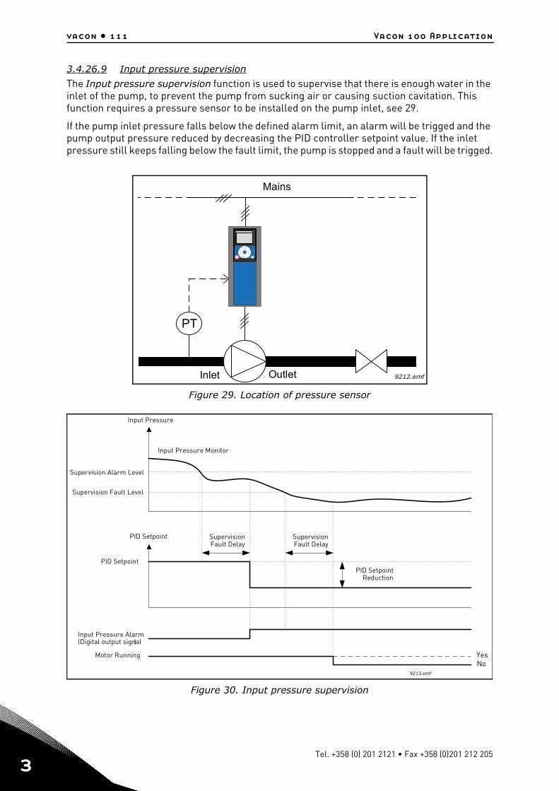
vacon • 111 Vacon 100 Application
3
3.4.26.9 Input pressure supervision
The Input pressure supervision function is used to supervise that there is enough water in the inlet of the pump, to prevent the pump from sucking air or causing suction cavitation. This function requires a pressure sensor to be installed on the pump inlet, see 29.
If the pump inlet pressure falls below the defined alarm limit, an alarm will be trigged and the pump output pressure reduced by decreasing the PID controller setpoint value. If the inlet pressure still keeps falling below the fault limit, the pump is stopped and a fault will be trigged.
Figure 29. Location of pressure sensor
Figure 30. Input pressure supervision
OK
PT
Mains
Inlet Outlet 9212.emf
( )
Input Pressure
Supervision Fault Level
Input Pressure AlarmDigital output signal
Supervision Alarm Level
Input Pressure Monitor
PID Setpoint
PID Setpoint
SupervisionFault Delay
SupervisionFault Delay
Motor Running YesNo
PID SetpointReduction
9213.emf
Tel. +358 (0) 201 2121 • Fax +358 (0)201 212 205
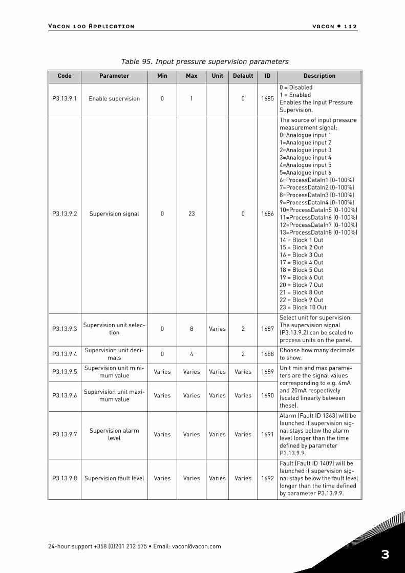
Vacon 100 Application vacon • 112
Table 95. Input pressure supervision parameters
Code Parameter Min Max Unit Default ID Description
P3.13.9.1 Enable supervision 0 1 0 1685
0 = Disabled1 = EnabledEnables the Input Pressure Supervision.
P3.13.9.2 Supervision signal 0 23 0 1686
The source of input pressure measurement signal:0=Analogue input 11=Analogue input 22=Analogue input 33=Analogue input 44=Analogue input 55=Analogue input 66=ProcessDataIn1 (0-100%)7=ProcessDataIn2 (0-100%)8=ProcessDataIn3 (0-100%)9=ProcessDataIn4 (0-100%)10=ProcessDataIn5 (0-100%)11=ProcessDataIn6 (0-100%)12=ProcessDataIn7 (0-100%)13=ProcessDataIn8 (0-100%)14 = Block 1 Out15 = Block 2 Out16 = Block 3 Out17 = Block 4 Out18 = Block 5 Out19 = Block 6 Out20 = Block 7 Out21 = Block 8 Out22 = Block 9 Out23 = Block 10 Out
P3.13.9.3Supervision unit selec-
tion0 8 Varies 2 1687
Select unit for supervision. The supervision signal (P3.13.9.2) can be scaled to process units on the panel.
P3.13.9.4Supervision unit deci-
mals0 4 2 1688
Choose how many decimals to show.
P3.13.9.5Supervision unit mini-
mum valueVaries Varies Varies Varies 1689
Unit min and max parame-ters are the signal values corresponding to e.g. 4mA and 20mA respectively (scaled linearly between these).
P3.13.9.6Supervision unit maxi-
mum valueVaries Varies Varies Varies 1690
P3.13.9.7Supervision alarm
levelVaries Varies Varies Varies 1691
Alarm (Fault ID 1363) will be launched if supervision sig-nal stays below the alarm level longer than the time defined by parameter P3.13.9.9.
P3.13.9.8 Supervision fault level Varies Varies Varies Varies 1692
Fault (Fault ID 1409) will be launched if supervision sig-nal stays below the fault level longer than the time defined by parameter P3.13.9.9.
24-hour support +358 (0)201 212 575 • Email: [email protected]
3
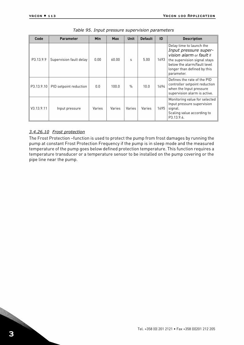
vacon • 113 Vacon 100 Application
3
3.4.26.10 Frost protection
The Frost Protection –function is used to protect the pump from frost damages by running the pump at constant Frost Protection Frequency if the pump is in sleep mode and the measured temperature of the pump goes below defined protection temperature. This function requires a temperature transducer or a temperature sensor to be installed on the pump covering or the pipe line near the pump.
P3.13.9.9 Supervision fault delay 0.00 60.00 s 5.00 1693
Delay time to launch the Input pressure super-vision alarm or fault if the supervision signal stays below the alarm/fault level longer than defined by this parameter.
P3.13.9.10 PID setpoint reduction 0.0 100.0 % 10.0 1694
Defines the rate of the PID controller setpoint reduction when the Input pressure supervision alarm is active.
V3.13.9.11 Input pressure Varies Varies Varies Varies 1695
Monitoring value for selected Input pressure supervision signal.Scaling value according to P3.13.9.4.
Table 95. Input pressure supervision parameters
Code Parameter Min Max Unit Default ID Description
Tel. +358 (0) 201 2121 • Fax +358 (0)201 212 205
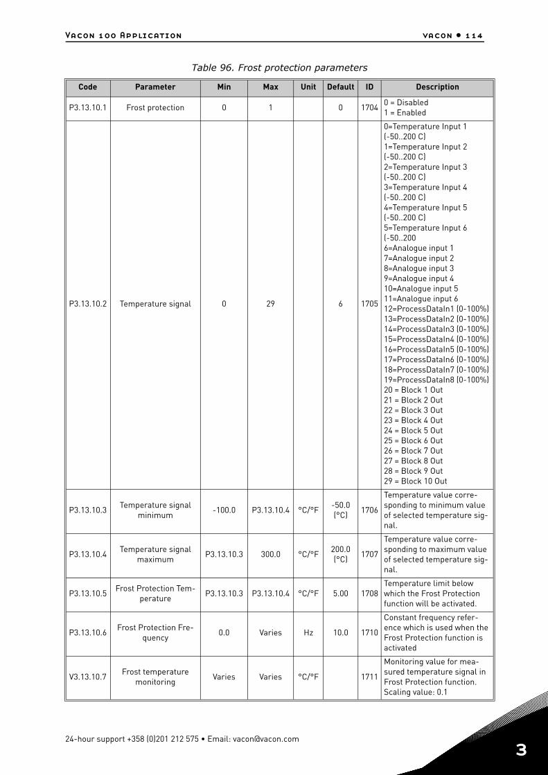
Vacon 100 Application vacon • 114
Table 96. Frost protection parameters
Code Parameter Min Max Unit Default ID Description
P3.13.10.1 Frost protection 0 1 0 17040 = Disabled1 = Enabled
P3.13.10.2 Temperature signal 0 29 6 1705
0=Temperature Input 1 (-50..200 C)1=Temperature Input 2 (-50..200 C)2=Temperature Input 3 (-50..200 C)3=Temperature Input 4 (-50..200 C)4=Temperature Input 5 (-50..200 C)5=Temperature Input 6 (-50..2006=Analogue input 17=Analogue input 28=Analogue input 39=Analogue input 410=Analogue input 511=Analogue input 612=ProcessDataIn1 (0-100%)13=ProcessDataIn2 (0-100%)14=ProcessDataIn3 (0-100%)15=ProcessDataIn4 (0-100%)16=ProcessDataIn5 (0-100%)17=ProcessDataIn6 (0-100%)18=ProcessDataIn7 (0-100%)19=ProcessDataIn8 (0-100%)20 = Block 1 Out21 = Block 2 Out22 = Block 3 Out23 = Block 4 Out24 = Block 5 Out25 = Block 6 Out26 = Block 7 Out27 = Block 8 Out28 = Block 9 Out29 = Block 10 Out
P3.13.10.3Temperature signal
minimum-100.0 P3.13.10.4 °C/°F
-50.0 (°C)
1706
Temperature value corre-sponding to minimum value of selected temperature sig-nal.
P3.13.10.4Temperature signal
maximumP3.13.10.3 300.0 °C/°F
200.0 (°C)
1707
Temperature value corre-sponding to maximum value of selected temperature sig-nal.
P3.13.10.5Frost Protection Tem-
peratureP3.13.10.3 P3.13.10.4 °C/°F 5.00 1708
Temperature limit below which the Frost Protection function will be activated.
P3.13.10.6Frost Protection Fre-
quency0.0 Varies Hz 10.0 1710
Constant frequency refer-ence which is used when the Frost Protection function is activated
V3.13.10.7Frost temperature
monitoringVaries Varies °C/°F 1711
Monitoring value for mea-sured temperature signal in Frost Protection function. Scaling value: 0.1
24-hour support +358 (0)201 212 575 • Email: [email protected]
3
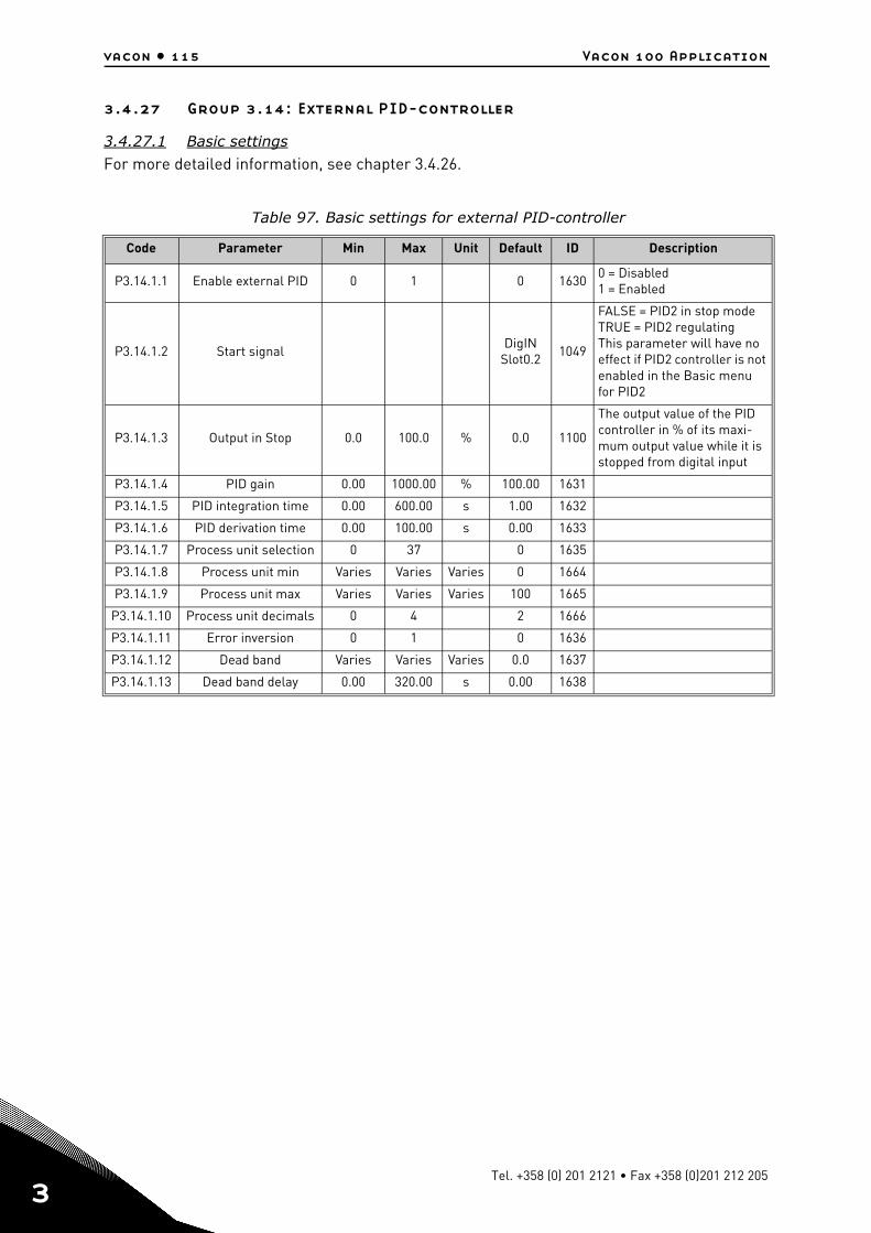
vacon • 115 Vacon 100 Application
3
3.4.27 Group 3.14: External PID-controller
3.4.27.1 Basic settings
For more detailed information, see chapter 3.4.26.
Table 97. Basic settings for external PID-controller
Code Parameter Min Max Unit Default ID Description
P3.14.1.1 Enable external PID 0 1 0 16300 = Disabled1 = Enabled
P3.14.1.2 Start signalDigIN
Slot0.21049
FALSE = PID2 in stop modeTRUE = PID2 regulatingThis parameter will have no effect if PID2 controller is not enabled in the Basic menu for PID2
P3.14.1.3 Output in Stop 0.0 100.0 % 0.0 1100
The output value of the PID controller in % of its maxi-mum output value while it is stopped from digital input
P3.14.1.4 PID gain 0.00 1000.00 % 100.00 1631
P3.14.1.5 PID integration time 0.00 600.00 s 1.00 1632
P3.14.1.6 PID derivation time 0.00 100.00 s 0.00 1633
P3.14.1.7 Process unit selection 0 37 0 1635
P3.14.1.8 Process unit min Varies Varies Varies 0 1664
P3.14.1.9 Process unit max Varies Varies Varies 100 1665
P3.14.1.10 Process unit decimals 0 4 2 1666
P3.14.1.11 Error inversion 0 1 0 1636
P3.14.1.12 Dead band Varies Varies Varies 0.0 1637
P3.14.1.13 Dead band delay 0.00 320.00 s 0.00 1638
Tel. +358 (0) 201 2121 • Fax +358 (0)201 212 205
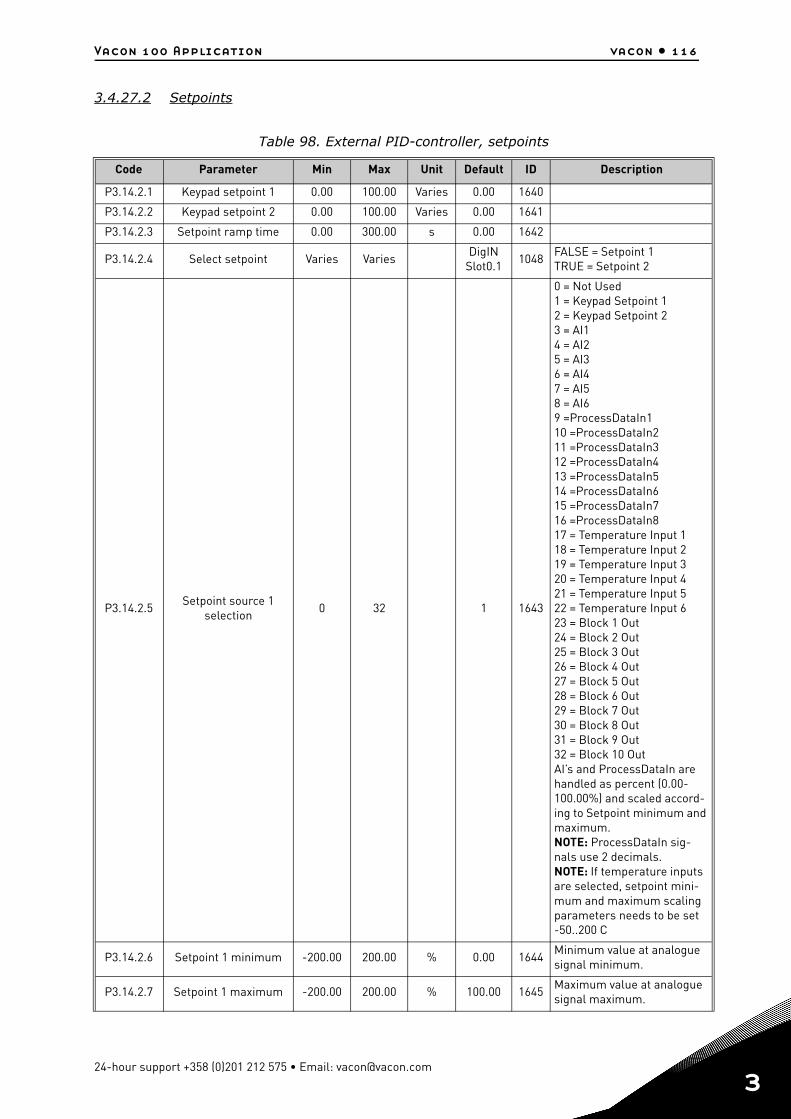
Vacon 100 Application vacon • 116
3.4.27.2 Setpoints
Table 98. External PID-controller, setpoints
Code Parameter Min Max Unit Default ID Description
P3.14.2.1 Keypad setpoint 1 0.00 100.00 Varies 0.00 1640
P3.14.2.2 Keypad setpoint 2 0.00 100.00 Varies 0.00 1641
P3.14.2.3 Setpoint ramp time 0.00 300.00 s 0.00 1642
P3.14.2.4 Select setpoint Varies VariesDigIN
Slot0.11048
FALSE = Setpoint 1TRUE = Setpoint 2
P3.14.2.5Setpoint source 1
selection0 32 1 1643
0 = Not Used1 = Keypad Setpoint 12 = Keypad Setpoint 23 = AI14 = AI25 = AI36 = AI47 = AI58 = AI69 =ProcessDataIn110 =ProcessDataIn211 =ProcessDataIn312 =ProcessDataIn413 =ProcessDataIn514 =ProcessDataIn615 =ProcessDataIn716 =ProcessDataIn817 = Temperature Input 118 = Temperature Input 219 = Temperature Input 320 = Temperature Input 421 = Temperature Input 522 = Temperature Input 623 = Block 1 Out24 = Block 2 Out25 = Block 3 Out26 = Block 4 Out27 = Block 5 Out28 = Block 6 Out29 = Block 7 Out30 = Block 8 Out31 = Block 9 Out32 = Block 10 OutAI’s and ProcessDataIn are handled as percent (0.00-100.00%) and scaled accord-ing to Setpoint minimum and maximum. NOTE: ProcessDataIn sig-nals use 2 decimals.NOTE: If temperature inputs are selected, setpoint mini-mum and maximum scaling parameters needs to be set -50..200 C
P3.14.2.6 Setpoint 1 minimum -200.00 200.00 % 0.00 1644Minimum value at analogue signal minimum.
P3.14.2.7 Setpoint 1 maximum -200.00 200.00 % 100.00 1645Maximum value at analogue signal maximum.
24-hour support +358 (0)201 212 575 • Email: [email protected]
3
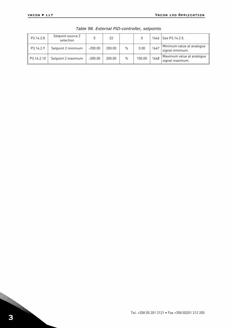
vacon • 117 Vacon 100 Application
3
P3.14.2.8Setpoint source 2
selection0 22 0 1646 See P3.14.2.5.
P3.14.2.9 Setpoint 2 minimum -200.00 200.00 % 0.00 1647Minimum value at analogue signal minimum.
P3.14.2.10 Setpoint 2 maximum -200.00 200.00 % 100.00 1648Maximum value at analogue signal maximum.
Table 98. External PID-controller, setpoints
Tel. +358 (0) 201 2121 • Fax +358 (0)201 212 205
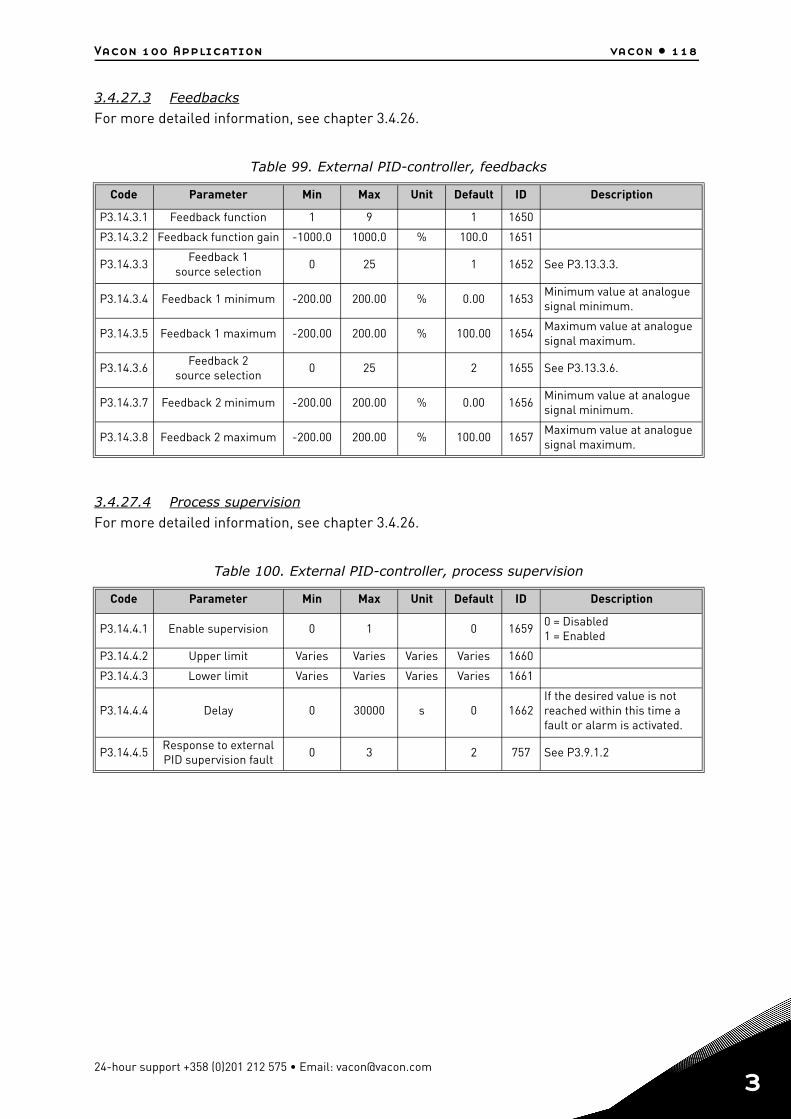
Vacon 100 Application vacon • 118
3.4.27.3 Feedbacks
For more detailed information, see chapter 3.4.26.
3.4.27.4 Process supervision
For more detailed information, see chapter 3.4.26.
Table 99. External PID-controller, feedbacks
Code Parameter Min Max Unit Default ID Description
P3.14.3.1 Feedback function 1 9 1 1650
P3.14.3.2 Feedback function gain -1000.0 1000.0 % 100.0 1651
P3.14.3.3Feedback 1
source selection0 25 1 1652 See P3.13.3.3.
P3.14.3.4 Feedback 1 minimum -200.00 200.00 % 0.00 1653Minimum value at analogue signal minimum.
P3.14.3.5 Feedback 1 maximum -200.00 200.00 % 100.00 1654Maximum value at analogue signal maximum.
P3.14.3.6Feedback 2
source selection0 25 2 1655 See P3.13.3.6.
P3.14.3.7 Feedback 2 minimum -200.00 200.00 % 0.00 1656Minimum value at analogue signal minimum.
P3.14.3.8 Feedback 2 maximum -200.00 200.00 % 100.00 1657Maximum value at analogue signal maximum.
Table 100. External PID-controller, process supervision
Code Parameter Min Max Unit Default ID Description
P3.14.4.1 Enable supervision 0 1 0 16590 = Disabled1 = Enabled
P3.14.4.2 Upper limit Varies Varies Varies Varies 1660
P3.14.4.3 Lower limit Varies Varies Varies Varies 1661
P3.14.4.4 Delay 0 30000 s 0 1662If the desired value is not reached within this time a fault or alarm is activated.
P3.14.4.5Response to external PID supervision fault
0 3 2 757 See P3.9.1.2
24-hour support +358 (0)201 212 575 • Email: [email protected]
3
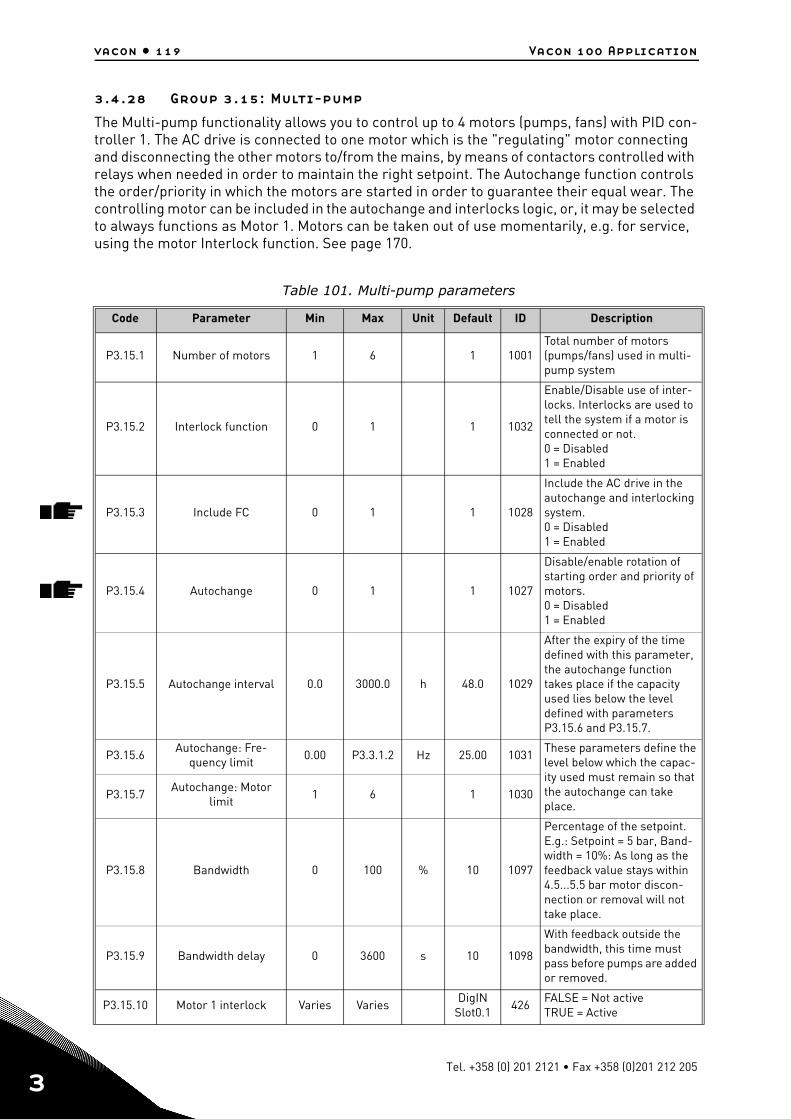
vacon • 119 Vacon 100 Application
3
3.4.28 Group 3.15: Multi-pump
The Multi-pump functionality allows you to control up to 4 motors (pumps, fans) with PID con-troller 1. The AC drive is connected to one motor which is the "regulating" motor connecting and disconnecting the other motors to/from the mains, by means of contactors controlled with relays when needed in order to maintain the right setpoint. The Autochange function controls the order/priority in which the motors are started in order to guarantee their equal wear. The controlling motor can be included in the autochange and interlocks logic, or, it may be selected to always functions as Motor 1. Motors can be taken out of use momentarily, e.g. for service, using the motor Interlock function. See page 170.
Table 101. Multi-pump parameters
Code Parameter Min Max Unit Default ID Description
P3.15.1 Number of motors 1 6 1 1001Total number of motors (pumps/fans) used in multi-pump system
P3.15.2 Interlock function 0 1 1 1032
Enable/Disable use of inter-locks. Interlocks are used to tell the system if a motor is connected or not.0 = Disabled1 = Enabled
P3.15.3 Include FC 0 1 1 1028
Include the AC drive in the autochange and interlocking system.0 = Disabled1 = Enabled
P3.15.4 Autochange 0 1 1 1027
Disable/enable rotation of starting order and priority of motors.0 = Disabled1 = Enabled
P3.15.5 Autochange interval 0.0 3000.0 h 48.0 1029
After the expiry of the time defined with this parameter, the autochange function takes place if the capacity used lies below the level defined with parameters P3.15.6 and P3.15.7.
P3.15.6Autochange: Fre-
quency limit0.00 P3.3.1.2 Hz 25.00 1031
These parameters define the level below which the capac-ity used must remain so that the autochange can take place.
P3.15.7Autochange: Motor
limit1 6 1 1030
P3.15.8 Bandwidth 0 100 % 10 1097
Percentage of the setpoint. E.g.: Setpoint = 5 bar, Band-width = 10%: As long as the feedback value stays within 4.5...5.5 bar motor discon-nection or removal will not take place.
P3.15.9 Bandwidth delay 0 3600 s 10 1098
With feedback outside the bandwidth, this time must pass before pumps are added or removed.
P3.15.10 Motor 1 interlock Varies VariesDigIN
Slot0.1426
FALSE = Not activeTRUE = Active
Tel. +358 (0) 201 2121 • Fax +358 (0)201 212 205
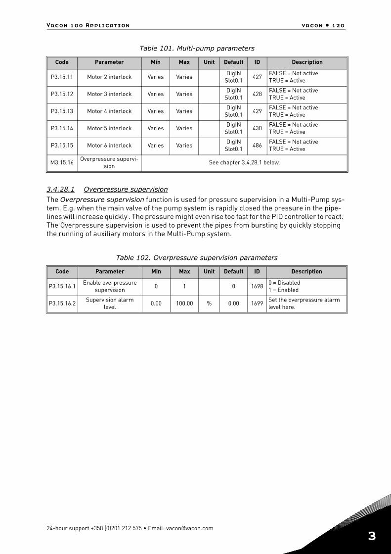
Vacon 100 Application vacon • 120
3.4.28.1 Overpressure supervision
The Overpressure supervision function is used for pressure supervision in a Multi-Pump sys-tem. E.g. when the main valve of the pump system is rapidly closed the pressure in the pipe-lines will increase quickly . The pressure might even rise too fast for the PID controller to react. The Overpressure supervision is used to prevent the pipes from bursting by quickly stopping the running of auxiliary motors in the Multi-Pump system.
P3.15.11 Motor 2 interlock Varies VariesDigIN
Slot0.1427
FALSE = Not activeTRUE = Active
P3.15.12 Motor 3 interlock Varies VariesDigIN
Slot0.1428
FALSE = Not activeTRUE = Active
P3.15.13 Motor 4 interlock Varies VariesDigIN
Slot0.1429
FALSE = Not activeTRUE = Active
P3.15.14 Motor 5 interlock Varies VariesDigIN
Slot0.1430
FALSE = Not activeTRUE = Active
P3.15.15 Motor 6 interlock Varies VariesDigIN
Slot0.1486
FALSE = Not activeTRUE = Active
M3.15.16Overpressure supervi-
sionSee chapter 3.4.28.1 below.
Table 102. Overpressure supervision parameters
Code Parameter Min Max Unit Default ID Description
P3.15.16.1Enable overpressure
supervision0 1 0 1698
0 = Disabled1 = Enabled
P3.15.16.2Supervision alarm
level0.00 100.00 % 0.00 1699
Set the overpressure alarm level here.
Table 101. Multi-pump parameters
Code Parameter Min Max Unit Default ID Description
24-hour support +358 (0)201 212 575 • Email: [email protected]
3
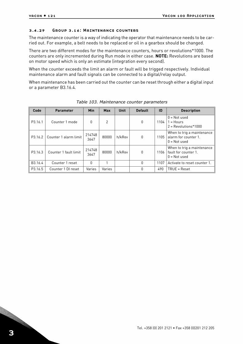
vacon • 121 Vacon 100 Application
3
3.4.29 Group 3.16: Maintenance counters
The maintenance counter is a way of indicating the operator that maintenance needs to be car-ried out. For example, a belt needs to be replaced or oil in a gearbox should be changed.
There are two different modes for the maintenance counters, hours or revolutions*1000. The counters are only incremented during Run mode in either case. NOTE: Revolutions are based on motor speed which is only an estimate (integration every second).
When the counter exceeds the limit an alarm or fault will be trigged respectively. Individual maintenance alarm and fault signals can be connected to a digital/relay output.
When maintenance has been carried out the counter can be reset through either a digital input or a parameter B3.16.4.
Table 103. Maintenance counter parameters
Code Parameter Min Max Unit Default ID Description
P3.16.1 Counter 1 mode 0 2 0 11040 = Not used1 = Hours2 = Revolutions*1000
P3.16.2 Counter 1 alarm limit214748
364780000 h/kRev 0 1105
When to trig a maintenance alarm for counter 1.0 = Not used
P3.16.3 Counter 1 fault limit214748
364780000 h/kRev 0 1106
When to trig a maintenance fault for counter 1.0 = Not used
B3.16.4 Counter 1 reset 0 1 0 1107 Activate to reset counter 1.
P3.16.5 Counter 1 DI reset Varies Varies 0 490 TRUE = Reset
Tel. +358 (0) 201 2121 • Fax +358 (0)201 212 205
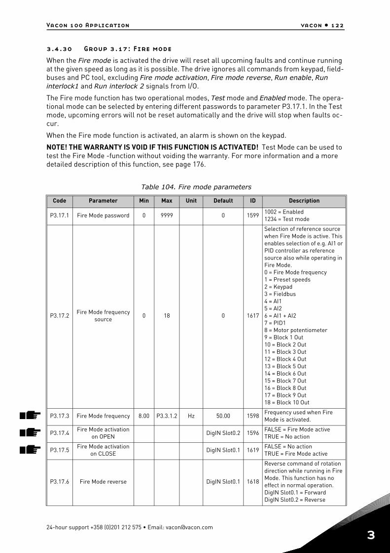
Vacon 100 Application vacon • 122
3.4.30 Group 3.17: Fire mode
When the Fire mode is activated the drive will reset all upcoming faults and continue running at the given speed as long as it is possible. The drive ignores all commands from keypad, field-buses and PC tool, excluding Fire mode activation, Fire mode reverse, Run enable, Run interlock1 and Run interlock 2 signals from I/O.
The Fire mode function has two operational modes, Test mode and Enabled mode. The opera-tional mode can be selected by entering different passwords to parameter P3.17.1. In the Test mode, upcoming errors will not be reset automatically and the drive will stop when faults oc-cur.
When the Fire mode function is activated, an alarm is shown on the keypad.
NOTE! THE WARRANTY IS VOID IF THIS FUNCTION IS ACTIVATED! Test Mode can be used to test the Fire Mode -function without voiding the warranty. For more information and a more detailed description of this function, see page 176.
Table 104. Fire mode parameters
Code Parameter Min Max Unit Default ID Description
P3.17.1 Fire Mode password 0 9999 0 15991002 = Enabled1234 = Test mode
P3.17.2Fire Mode frequency
source0 18 0 1617
Selection of reference source when Fire Mode is active. This enables selection of e.g. AI1 or PID controller as reference source also while operating in Fire Mode.0 = Fire Mode frequency1 = Preset speeds2 = Keypad3 = Fieldbus4 = AI15 = AI26 = AI1 + AI27 = PID18 = Motor potentiometer9 = Block 1 Out10 = Block 2 Out11 = Block 3 Out12 = Block 4 Out13 = Block 5 Out14 = Block 6 Out15 = Block 7 Out16 = Block 8 Out17 = Block 9 Out18 = Block 10 Out
P3.17.3 Fire Mode frequency 8.00 P3.3.1.2 Hz 50.00 1598Frequency used when Fire Mode is activated.
P3.17.4Fire Mode activation
on OPENDigIN Slot0.2 1596
FALSE = Fire Mode activeTRUE = No action
P3.17.5Fire Mode activation
on CLOSEDigIN Slot0.1 1619
FALSE = No actionTRUE = Fire Mode active
P3.17.6 Fire Mode reverse DigIN Slot0.1 1618
Reverse command of rotation direction while running in Fire Mode. This function has no effect in normal operation.DigIN Slot0.1 = ForwardDigIN Slot0.2 = Reverse
24-hour support +358 (0)201 212 575 • Email: [email protected]
3
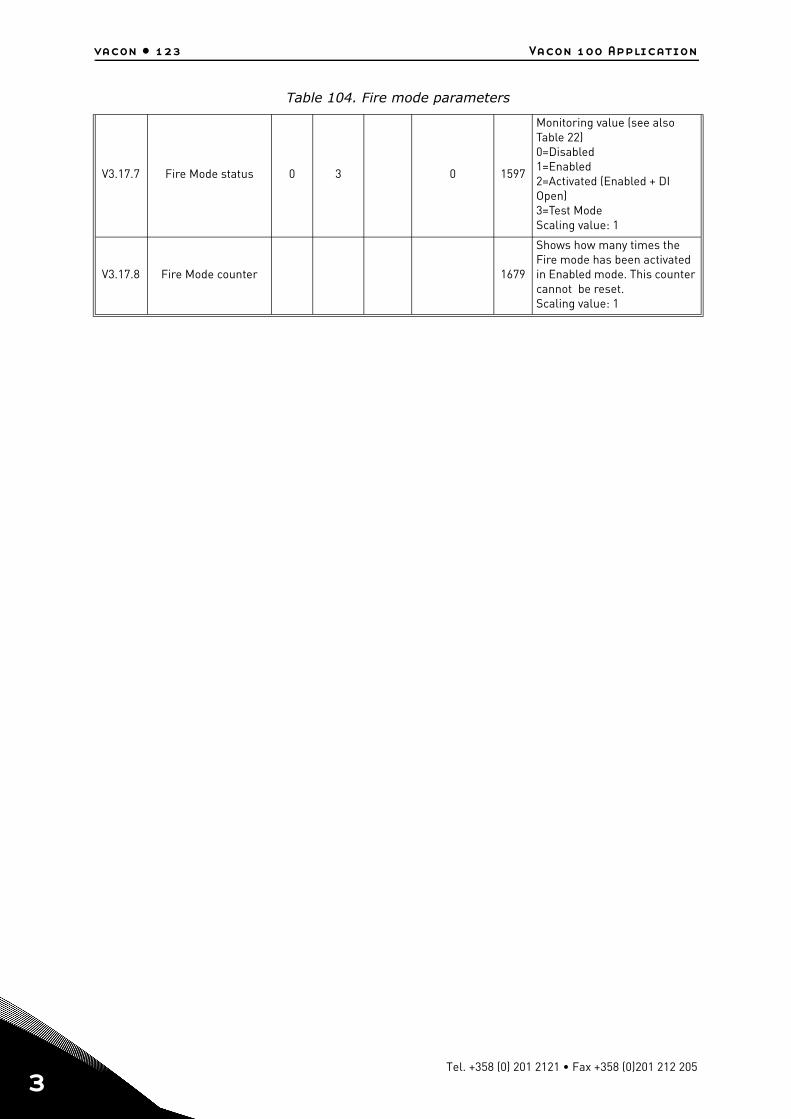
vacon • 123 Vacon 100 Application
3
V3.17.7 Fire Mode status 0 3 0 1597
Monitoring value (see also Table 22)0=Disabled1=Enabled2=Activated (Enabled + DI Open)3=Test ModeScaling value: 1
V3.17.8 Fire Mode counter 1679
Shows how many times the Fire mode has been activated in Enabled mode. This counter cannot be reset.Scaling value: 1
Table 104. Fire mode parameters
Tel. +358 (0) 201 2121 • Fax +358 (0)201 212 205
Vacon 100 Application vacon • 124
3.4.31 Group 3.18: Motor preheat parameters
Motor Preheat function is intended to keep the drive and motor warm in Stop state by injecting DC current to the motor e.g. to prevent condensation. Motor preheat can be activated either always in Stop state, by digital input or when drive heatsink temperature or motor temperature goes below a defined temperature.
Table 105. Motor preheat parameters
Code Parameter Min Max Unit Default ID Description
P3.18.1 Motor preheat function 0 4 0 1225
0 = Not used1 = Always in stop state2 = Controlled by DI3 = Temperature limit 4 = Temperature limit (Mea-sured motor temperature) NOTE! Function 4 requires temperature measurement option board to be installed.
P3.18.2Preheat temperature
limit-20 100 °C 0 1226
Motor preheat switches on when the heatsink tem-perature or measured motor temperature goes below this level provided that P3.18.1 is set to selections 3 or 4.
P3.18.3 Motor preheat current 0 1.85 A Varies 1227
DC current for pre-heating of motor and drive in stop state. Activated according to P3.18.1.
P3.18.4 Motor preheat ON Varies VariesDigIN
Slot0.11044
FALSE = No actionTRUE = Preheat activated in Stop stateUsed when parameter P3.18.1 is set to 2.NOTE! Also Time chan-nels can be connected to PreHeat ON provided that DIN Control (selection 2 for parameter P3.18.1) is used.
P3.18.5Preheat motor tem-
perature0 6 0 1045
Motor temperature mea-surement signal selection.0 = Not Used1 = Temperature Input 12 = Temperature Input 23 = Temperature Input 34 = Temperature Input 45 = Temperature Input 56 = Temperature Input 6NOTE! This parameter is not available if temperature measurement option board is not installed.
24-hour support +358 (0)201 212 575 • Email: [email protected]
3

vacon • 125 Vacon 100 Application
3
3.4.32 Group 3.20: Mechanical brake
Mechanical brake control is used to control an external mechanical brake by a digital output signal. Brake open/close command can be selected as a function of the digital output. The sta-tus of the mechanical brake can also be supervised if a brake feedback signal is connected to one of the drive’s digital inputs and the supervision is enabled.
Table 106. Mechanical brake parameters
Code Parameter Min Max Unit Default ID Description
P3.20.1 Brake control 0 2 0 1541
0 = Disabled1 = Enabled2 = Enabled with brake sta-tus supervision
P3.20.2Brake mechanical
delay0.00 60.00 s 0.00 353
Mechanical delay required to open the brake
P3.20.3Brake opening fre-
quency limitP3.20.4 P3.3.1.2 Hz 2.00 1535
Frequency limit for opening the mechanical brake
P3.20.4Brake closing fre-
quency limitP3.3.1.1 P3.3.1.2 Hz 2.00 1539
Frequency limit for closing the mechanical brake
P3.20.5 Brake current limit 0.0 Varies A 0.0 1085Mechanical brake will close immediately if motor cur-rent is below this value.
P3.20.6 Brake fault delay 0.00 60.00 s 2.00 352
If correct brake feedback signal is not received within this delay a brake fault is generated. NOTE! This delay is only used if the value of par. P3.20.1 is set to 2.
P3.20.7Response to Brake
fault0 3 0 1316
0 = No action1 = Alarm2 = Fault (Stop according to
stop mode)3 = Fault (Stop by coasting)
P3.20.8 Brake feedbackDigIN
Slot0.11210
Connect this input signal to the auxiliary contact of the mechanical brake. If the contact is not closed within given time the drive will generate a brake fault.
Tel. +358 (0) 201 2121 • Fax +358 (0)201 212 205
Vacon 100 Application vacon • 126
3.4.33 Group 3.21: Pump control
3.4.33.1 Auto-cleaning
The Auto-cleaning function is used to remove any dirt or other material that may have attached to the pump impeller. Auto-cleaning is used e.g. in wastewater systems to keep up the perfor-mance of the pump. Auto Cleaning function can also be used to clear the blocked pipe or valve.
Table 107. Auto-cleaning parameters
Code Parameter Min Max Unit Default ID Description
P3.21.1.1 Cleaning function 0 1 0 17140=Disabled1=Enabled
P3.21.1.2 Cleaning activationDigIN
Slot0.11715
Digital input signal used to start the Auto Cleaning sequence.Auto-cleaning sequence will be aborted if activation sig-nal is removed before the sequence has been com-pleted.NOTE: The drive will start if the input is activated!
P3.21.1.3 Cleaning cycles 1 100 5 1716Number of forward/reverse cleaning cycles.
P3.21.1.4Clean forward fre-
quency0.00 50.00 Hz 45.00 1717
Forward direction frequency in Auto-cleaning cycle.
P3.21.1.5 Clean forward time 0.00 320.00 s 2.00 1718Running time for forward direction frequency in Auto-cleaning cycle.
P3.21.1.6Clean reverse fre-
quency0.00 50.00 Hz 45.00 1719
Reverse direction frequency in Auto-cleaning cycle.
P3.21.1.7 Clean reverse time 0.00 320.00 s 0.00 1720Running time for reverse direction frequency in Auto-cleaning cycle
P3.21.1.8Cleaning acceleration
time0.1 300.0 s 0.1 1721
Motor acceleration time when Auto-cleaning is active
P3.21.1.9Cleaning deceleration
time0.1 300.0 s 0.1 1722
Motor deceleration time when Auto-cleaning is active
24-hour support +358 (0)201 212 575 • Email: [email protected]
3
vacon • 127 Vacon 100 Application
3
3.4.33.2 Jockey pump
Jockey pump is a smaller pump used to keep up the pressure in the pipeline e.g. during night time when the main pump is in sleep mode.
Table 108. Jockey pump parameters
Code Parameter Min Max Unit Default ID Description
P3.21.2.1 Jockey function 0 2 0 1674
0 = Not used1 = PID sleep: Jockey pump runs continuously when PID sleep is active2 = PID sleep (level): Jockey pump starts at predefined levels when PID sleep is active
P3.21.2.2 Jockey start level 0.00 100.00 % 0.00 1675
Jockey pump will start when PID Sleep is active and PID feedback signal goes below the level defined by this parameter.NOTE! This parameter is used only if P3.21.2.1 = 2 (PID Sleep(Level))
P3.21.2.3 Jockey stop level 0.00 100.00 % 0.00 1676
Jockey pump will stop when PID Sleep is active and PID feedback signal exceeds the level defined by this param-eter or PID-controller wakes from sleep.NOTE! This parameter is used only if P3.21.2.1 = 2 PID Sleep(Level)
Tel. +358 (0) 201 2121 • Fax +358 (0)201 212 205
Vacon 100 Application vacon • 128
3.4.33.3 Priming pump
Priming pump is a smaller pump which is used to prime the inlet of the bigger main pump to prevent the main pump from sucking air.
The priming pump function is used to control a smaller priming pump by the digital output sig-nal. A delay time can be defined to start the priming pump before the main pump is started. Priming pump will run continuously as long the main pump is running.
Table 109. Priming pump parameters
Code Parameter Min Max Unit Default ID Description
P3.21.3.1 Priming function 0 1 0 16770=Disabled1=Enabled
P3.21.3.2 Priming time 0.0 320.0 s 3.0 1678Defines the time to start the priming pump before the main pump is started.
24-hour support +358 (0)201 212 575 • Email: [email protected]
3
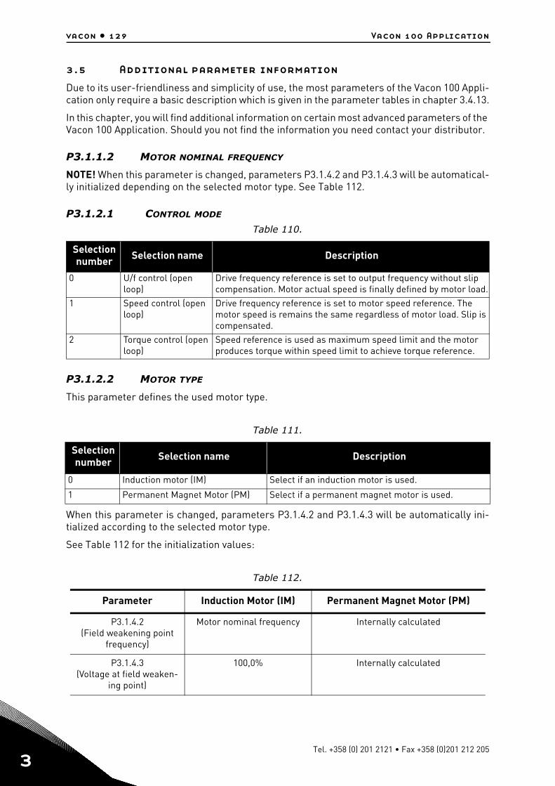
vacon • 129 Vacon 100 Application
3
3.5 Additional parameter information
Due to its user-friendliness and simplicity of use, the most parameters of the Vacon 100 Appli-cation only require a basic description which is given in the parameter tables in chapter 3.4.13.
In this chapter, you will find additional information on certain most advanced parameters of the Vacon 100 Application. Should you not find the information you need contact your distributor.
P3.1.1.2 MOTOR NOMINAL FREQUENCY
NOTE! When this parameter is changed, parameters P3.1.4.2 and P3.1.4.3 will be automatical-ly initialized depending on the selected motor type. See Table 112.
P3.1.2.1 CONTROL MODE
P3.1.2.2 MOTOR TYPE
This parameter defines the used motor type.
When this parameter is changed, parameters P3.1.4.2 and P3.1.4.3 will be automatically ini-tialized according to the selected motor type.
See Table 112 for the initialization values:
Table 110.
Selection number Selection name Description
0 U/f control (open loop)
Drive frequency reference is set to output frequency without slip compensation. Motor actual speed is finally defined by motor load.
1 Speed control (open loop)
Drive frequency reference is set to motor speed reference. The motor speed is remains the same regardless of motor load. Slip is compensated.
2 Torque control (open loop)
Speed reference is used as maximum speed limit and the motor produces torque within speed limit to achieve torque reference.
Table 111.
Selection number Selection name Description
0 Induction motor (IM) Select if an induction motor is used.
1 Permanent Magnet Motor (PM) Select if a permanent magnet motor is used.
Table 112.
Parameter Induction Motor (IM) Permanent Magnet Motor (PM)
P3.1.4.2(Field weakening point
frequency)
Motor nominal frequency Internally calculated
P3.1.4.3(Voltage at field weaken-
ing point)
100,0% Internally calculated
Tel. +358 (0) 201 2121 • Fax +358 (0)201 212 205
Vacon 100 Application vacon • 130
P3.1.2.4 IDENTIFICATION
The automatic motor identification calculates or measures the motor parameters that areneeded for optimum motor and speed control.
Identification Run is a part of tuning the motor and the drive specific parameters. It is a tool forcommissioning and service of the drive with the aim to find as good parameter values as pos-sible for most drives.
NOTE: Motor nameplate parameters has to be set before executing the identification run.
The automatic identification is activated by setting this parameter to desired value and givinga start command in the requested direction. The start command to the drive has to be givenwithin 20 s. If no start command is given within this time the identification run is cancelled, theparameter will be reset to its default setting and an Identification alarm will be launched.
The identification run can be stopped at any time with normal stop command and the parame-ter is reset to its default setting. An Identification alarm will be launched if the identificationrun has failed.
NOTE: New start command (Rising edge) is required to start the drive after identification.
P3.1.2.6 MOTOR SWITCH
This function is typically used if there is a switch between the drive and the motor. Such switch-es are often found in residential and industrial applications to make sure that an electrical cir-cuit can be completely de-energized from the motor for service or maintenance.
When this parameter is enabled and the motor switch is opened to disconnect the running mo-tor, the drive detects the loss of motor without tripping. It is not necessary to make any changesin the run command or the reference signal to the drive from the process control station. Whenthe motor is re-connected after completed maintenance by closing the switch, the drive de-tects the motor connection and runs the motor to the reference speed as per the process com-mands.
If the motor is rotating when re-connected, the drive detects the speed of the running motorthrough its Flying start feature and then controls it to desired speed as per the process com-mands.
Table 113.
Selection number Selection name Description
0 No action No identification requested.1 Identification at
standstillThe drive is run without speed to identify the motor parameters. The motor is supplied with current and voltage but with zero fre-quency. U/f ratio is identified.
2 Identification with motor rotating
The drive is run with speed to identify the motor parameters. U/f ratio and magnetization current are identified.NOTE: This identification run must be performed with no load on the motor shaft for accurate results.
24-hour support +358 (0)201 212 575 • Email: [email protected]
3
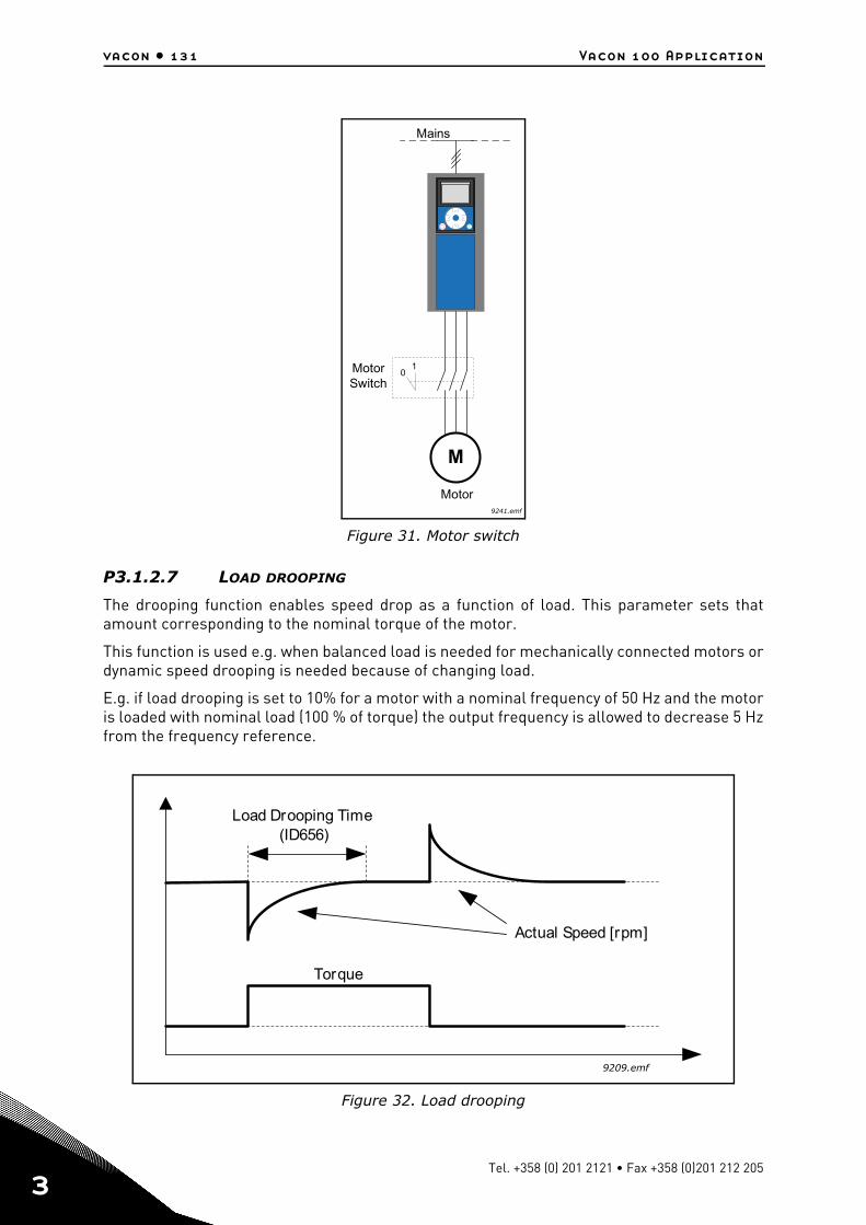
vacon • 131 Vacon 100 Application
3
Figure 31. Motor switch
P3.1.2.7 LOAD DROOPING
The drooping function enables speed drop as a function of load. This parameter sets thatamount corresponding to the nominal torque of the motor.
This function is used e.g. when balanced load is needed for mechanically connected motors ordynamic speed drooping is needed because of changing load.
E.g. if load drooping is set to 10% for a motor with a nominal frequency of 50 Hz and the motoris loaded with nominal load (100 % of torque) the output frequency is allowed to decrease 5 Hzfrom the frequency reference.
Figure 32. Load drooping
OK
M
01
9241.emf
Motor
Mains
MotorSwitch
9209.emf
Torque
Actual Speed [rpm]
Load Drooping Time(ID656)
Tel. +358 (0) 201 2121 • Fax +358 (0)201 212 205
Vacon 100 Application vacon • 132
P3.1.2.10 OVERVOLTAGE CONTROLP3.1.2.11 UNDERVOLTAGE CONTROL
These parameters allow the under-/overvoltage controllers to be switched out of operation.This may be useful, for example, if the mains supply voltage varies more than -15% to +10%and the application will not tolerate this over-/undervoltage. In this case, the regulator con-trols the output frequency taking the supply fluctuations into account.
P3.1.2.13 STATOR VOLTAGE ADJUST
NOTE! This parameter will be automatically set during the identification run. It is recommend-ed to make the identification run, if possible. See parameter P3.1.2.4.
Stator voltage adjust parameter is used only when Permanent magnet motor (PM motor) hasbeen selected for parameter P3.1.2.2. This parameter has no affect if Induction motor hasbeen selected. With an induction motor in use, the value has been internally forced to 100% andit cannot be changed.
When the value of parameter P3.1.2.2 (Motor type) parameter is changed to PMS Motor, theparameters P3.1.4.2 (Field weakening point frequency) and P3.1.4.3 (Voltage at field weaken-ing point) will be automatically extended up to the limits of the drive's full output voltage, re-taining the defined U/f-ratio. This internal extension is done to avoid running the PMS motor inthe field weakening area because the PMS motor nominal voltage is typically much lower thanthe full output voltage capability of the drive.
PMS motor nominal voltage typically represents the motor’s back-EMF voltage at nominal fre-quency, but depending on the motor manufacturer, it may represent e.g. the stator voltage atnominal load.
This parameter gives an easy way to adjust the drive’s U/f curve near to the motor’s back-EMFcurve without needing to change several U/f curve parameters.
The Stator voltage adjust parameter defines the drive’s output voltage in percent of the motor’snominal voltage at the motor’s nominal frequency.
The U/f curve of the drive is typically tuned slightly above the back-EMF curve of the motor. Themotor current increases the more the drive’s U/f-curve differs from the motor’s back-EMF -curve.
24-hour support +358 (0)201 212 575 • Email: [email protected]
3
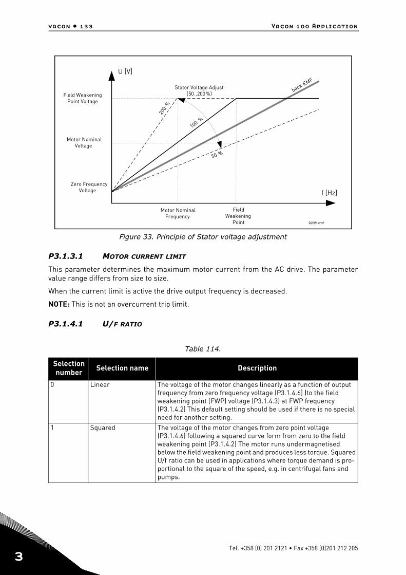
vacon • 133 Vacon 100 Application
3
Figure 33. Principle of Stator voltage adjustment
P3.1.3.1 MOTOR CURRENT LIMIT
This parameter determines the maximum motor current from the AC drive. The parametervalue range differs from size to size.
When the current limit is active the drive output frequency is decreased.
NOTE: This is not an overcurrent trip limit.
P3.1.4.1 U/F RATIO
Table 114.
Selection number Selection name Description
0 Linear The voltage of the motor changes linearly as a function of output frequency from zero frequency voltage (P3.1.4.6) )to the field weakening point (FWP) voltage (P3.1.4.3) at FWP frequency (P3.1.4.2) This default setting should be used if there is no special need for another setting.
1 Squared The voltage of the motor changes from zero point voltage (P3.1.4.6) following a squared curve form from zero to the field weakening point (P3.1.4.2) The motor runs undermagnetised below the field weakening point and produces less torque. Squared U/f ratio can be used in applications where torque demand is pro-portional to the square of the speed, e.g. in centrifugal fans and pumps.
f [Hz]
U [V]
(50..200%)
200
%
100 %
50 %
-
9208.emf
FieldWeakening
Point
Field WeakeningPoint Voltage
Motor NominalVoltage
Motor NominalFrequency
Stator Voltage Adjust back EMF
Zero FrequencyVoltage
Tel. +358 (0) 201 2121 • Fax +358 (0)201 212 205
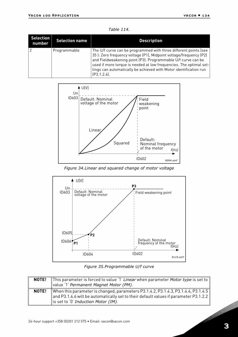
Vacon 100 Application vacon • 134
Figure 34.Linear and squared change of motor voltage
Figure 35.Programmable U/f curve
2 Programmable The U/f curve can be programmed with three different points (see 35 ): Zero frequency voltage (P1), Midpoint voltage/frequency (P2) and Fieldweakening point (P3). Programmable U/f curve can be used if more torque is needed at low frequencies. The optimal set-tings can automatically be achieved with Motor identification run (P3.1.2.4).
NOTE! This parameter is forced to value ‘1’ Linear when parameter Motor type is set to value ‘1’ Permanent Magnet Motor (PM).
NOTE! When this parameter is changed, parameters P3.1.4.2, P3.1.4.3, P3.1.4.4, P3.1.4.5 and P3.1.4.6 will be automatically set to their default values if parameter P3.1.2.2 is set to ‘0’ Induction Motor (IM).
Table 114.
Selection number Selection name Description
U[V]
f[Hz]
9094.emf
UnID603
ID602
Default: Nominalvoltage of the motor
Linear
Squared
Fieldweakeningpoint
Default:Nominal frequencyof the motor
UnID603
ID602
U[V]
f[Hz]
9119.emf
P1
P2
P3
ID604
ID605
ID606
Default: Nominalvoltage of the motor Field weakening point
Default: Nominalfrequency of the motor
24-hour support +358 (0)201 212 575 • Email: [email protected]
3
vacon • 135 Vacon 100 Application
3
P3.1.4.3 VOLTAGE AT FIELD WEAKENING POINT
Above the frequency at the field weakening point, the output voltage remains at the set maxi-mum value. Below the frequency at the field weakening point, the output voltage depends onthe setting of the U/f curve parameters. See parameters P3.1.4.1, P3.1.4.4 and P3.1.4.5.
When the parameters P3.1.1.1 and P3.1.1.2 (Motor nominal voltage and Motor nominal fre-quency) are set, the parameters P3.1.4.2 and P3.1.4.3 are automatically given the correspond-ing values. If you need different values for the field weakening point and the maximum outputvoltage, change these parameters after setting the parameters P3.1.1.1 and P3.1.1.2.
P3.1.4.9 AUTOMATIC TORQUE BOOST
Automatic torque boost can be used in applications where starting torque is high due to start-ing friction, e.g. in conveyors.
The voltage to the motor changes proportionally to required torque which makes the motorproduce more torque at start and when running at low frequencies.
Even with linear U/f curve, the torque boost has an affect but the best result will be achievedafter the identification run when programmable U/f curve is activated.
P3.1.4.12.1 I/F START
If the function is activated, the drive is set to current control mode and a constant current de-fined by P3.1.4.11.3 is fed to the motor until the drive output frequency exceeds the level de-fined with P3.1.4.11.2. When the output frequency has increased above I/f Start Frequencylevel, drive operation mode is changed smoothly back to normal U/f –control mode.
P3.1.4.12.2 I/F START FREQUENCY
I/f start function is used when the drive’s output frequency is below this frequency limit. Whenthe output frequency exceeds this limit, the drive operation mode is changed back to normalU/f control mode.
P3.1.4.12.3 I/F START CURRENT
This parameter defines the current to be fed to the motor when the I/f start function is activat-ed.
P3.2.5 STOP FUNCTION
P3.2.6 I/O A START/STOP LOGIC
Values 0...4 offer possibilities to control the starting and stopping of the AC drive with digitalsignal connected to digital inputs. CS = Control signal.
Table 115.
Selection number Selection name Description
0 Coasting The motor is allowed to stop on its own inertia. The control by the drive is discontinued and the drive current drops to zero as soon as the stop command is given.
1 Ramp After the Stop command, the speed of the motor is decelerated according to the set deceleration parameters to zero speed.
Tel. +358 (0) 201 2121 • Fax +358 (0)201 212 205
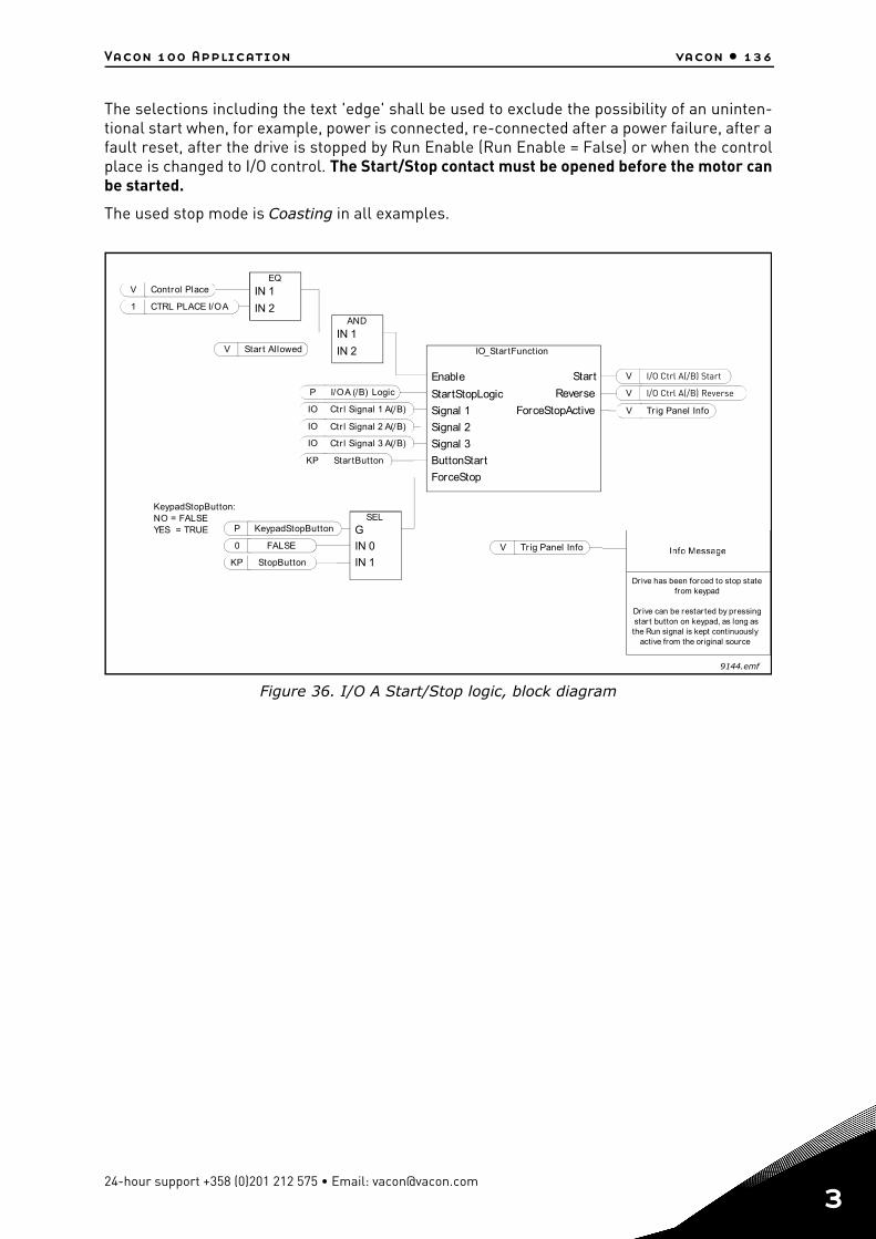
Vacon 100 Application vacon • 136
The selections including the text 'edge' shall be used to exclude the possibility of an uninten-tional start when, for example, power is connected, re-connected after a power failure, after afault reset, after the drive is stopped by Run Enable (Run Enable = False) or when the controlplace is changed to I/O control. The Start/Stop contact must be opened before the motor canbe started.
The used stop mode is Coasting in all examples.
Figure 36. I/O A Start/Stop logic, block diagram
IO
IO
P
P
KP
0
V
IO
SEL
G
IN 0
IN 1
KP
V
V
==
V
1
EQ
IN 1
IN 2AND
IN 1
IN 2V
V
9144.emf
NO FALSEYES TRUE
Info Message
IO_Star tFunction
I/O Ctrl A(/B) Start
I/O Ctrl A(/B) Reverse
Info Message
Ctr l Signal 1 A(/B)
Ctr l Signal 2 A(/B)
I/O A (/B) Logic
KeypadStopButton
StopButton
FALSE
Tr ig Panel Info
StartStopLogic
Signal 1
ForceStop
Signal 2
ButtonStart
Signal 3
StartEnable
Reverse
ForceStopActive
Star tButton
KeypadStopButton:
Tr ig Panel Info
Drive has been forced to stop statefrom keypad
Dr ive can be restar ted by pressingstar t button on keypad, as long asthe Run signal is kept continuously
active from the original source
Ctr l Signal 3 A(/B)
Control Place
CTRL PLACE I/O A
Star t Al lowed
24-hour support +358 (0)201 212 575 • Email: [email protected]
3
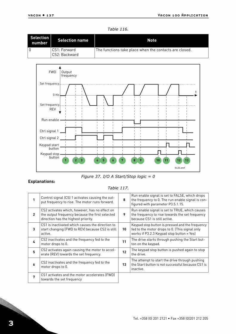
vacon • 137 Vacon 100 Application
3
Figure 37. I/O A Start/Stop logic = 0Explanations:
Table 116.
Selection number Selection name Note
0 CS1: ForwardCS2: Backward
The functions take place when the contacts are closed.
Table 117.
1 Control signal (CS) 1 activates causing the out-put frequency to rise. The motor runs forward.
8Run enable signal is set to FALSE, which drops the frequency to 0. The run enable signal is con-figured with parameter P3.5.1.15.
2CS2 activates which, however, has no effect on the output frequency because the first selected direction has the highest priority.
9Run enable signal is set to TRUE, which causes the frequency to rise towards the set frequency because CS1 is still active.
3CS1 is inactivated which causes the direction to start changing (FWD to REV) because CS2 is still active.
10Keypad stop button is pressed and the frequency fed to the motor drops to 0. (This signal only works if P3.2.3 Keypad stop button = Yes)
4CS2 inactivates and the frequency fed to the motor drops to 0.
11The drive starts through pushing the Start but-ton on the keypad.
5 CS2 activates again causing the motor to accel-erate (REV) towards the set frequency.
12 The keypad stop button is pushed again to stop the drive.
6 CS2 inactivates and the frequency fed to the motor drops to 0.
13The attempt to start the drive through pushing the Start button is not successful because CS1 is inactive.
7 CS1 activates and the motor accelerates (FWD) towards the set frequency
t
Outputfrequency
FWD
REV
Ctrl signal 2
Ctrl signal 1
Run enable
Set frequency
Set frequency
0 Hz
Keypad stopbutton
Keypad startbutton
1 2 3 4 5 6 7 8 9 10 11 12 13
9135.emf
Tel. +358 (0) 201 2121 • Fax +358 (0)201 212 205
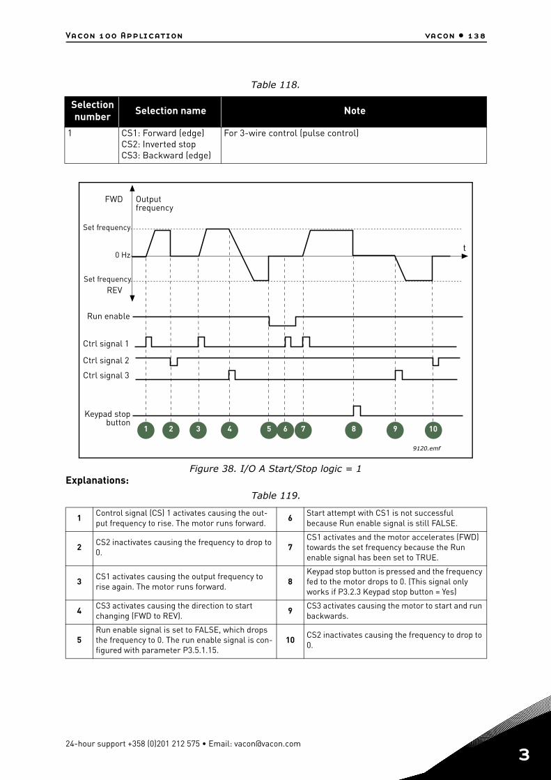
Vacon 100 Application vacon • 138
Figure 38. I/O A Start/Stop logic = 1Explanations:
Table 118.
Selection number Selection name Note
1 CS1: Forward (edge)CS2: Inverted stopCS3: Backward (edge)
For 3-wire control (pulse control)
Table 119.
1Control signal (CS) 1 activates causing the out-put frequency to rise. The motor runs forward.
6Start attempt with CS1 is not successful because Run enable signal is still FALSE.
2 CS2 inactivates causing the frequency to drop to 0.
7CS1 activates and the motor accelerates (FWD) towards the set frequency because the Run enable signal has been set to TRUE.
3CS1 activates causing the output frequency to rise again. The motor runs forward.
8Keypad stop button is pressed and the frequency fed to the motor drops to 0. (This signal only works if P3.2.3 Keypad stop button = Yes)
4CS3 activates causing the direction to start changing (FWD to REV).
9CS3 activates causing the motor to start and run backwards.
5Run enable signal is set to FALSE, which drops the frequency to 0. The run enable signal is con-figured with parameter P3.5.1.15.
10CS2 inactivates causing the frequency to drop to 0.
t
Outputfrequency
FWD
REV
Ctrl signal 2
Ctrl signal 1
Run enable
Set frequency
Set frequency
0 Hz
Keypad stopbutton
9120.emf
Ctrl signal 3
4 81 2 3 5 6 7 9 10
24-hour support +358 (0)201 212 575 • Email: [email protected]
3
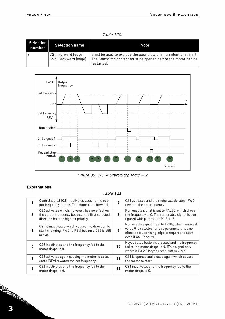
vacon • 139 Vacon 100 Application
3
Figure 39. I/O A Start/Stop logic = 2
Explanations:
Table 120.
Selection number Selection name Note
2 CS1: Forward (edge)CS2: Backward (edge)
Shall be used to exclude the possibility of an unintentional start. The Start/Stop contact must be opened before the motor can be restarted.
Table 121.
1Control signal (CS) 1 activates causing the out-put frequency to rise. The motor runs forward.
7CS1 activates and the motor accelerates (FWD) towards the set frequency
2CS2 activates which, however, has no effect on the output frequency because the first selected direction has the highest priority.
8Run enable signal is set to FALSE, which drops the frequency to 0. The run enable signal is con-figured with parameter P3.5.1.15.
3CS1 is inactivated which causes the direction to start changing (FWD to REV) because CS2 is still active.
9
Run enable signal is set to TRUE, which, unlike if value 0 is selected for this parameter, has no effect because rising edge is required to start even if CS1 is active.
4CS2 inactivates and the frequency fed to the motor drops to 0.
10Keypad stop button is pressed and the frequency fed to the motor drops to 0. (This signal only works if P3.2.3 Keypad stop button = Yes)
5CS2 activates again causing the motor to accel-erate (REV) towards the set frequency.
11CS1 is opened and closed again which causes the motor to start.
6 CS2 inactivates and the frequency fed to the motor drops to 0.
12 CS1 inactivates and the frequency fed to the motor drops to 0.
t
Outputfrequency
FWD
REV
Ctrl signal 2
Ctrl signal 1
Run enable
Set frequency
Set frequency
0 Hz
Keypad stopbutton
1 2 3 4 5 6 7 8 9 10 11 12
9121.emf
Tel. +358 (0) 201 2121 • Fax +358 (0)201 212 205
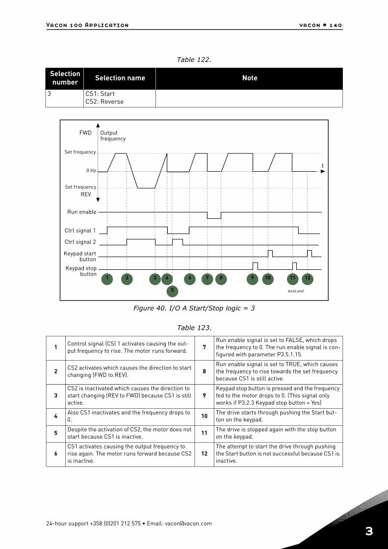
Vacon 100 Application vacon • 140
Figure 40. I/O A Start/Stop logic = 3
Table 122.
Selection number Selection name Note
3 CS1: StartCS2: Reverse
Table 123.
1Control signal (CS) 1 activates causing the out-put frequency to rise. The motor runs forward.
7Run enable signal is set to FALSE, which drops the frequency to 0. The run enable signal is con-figured with parameter P3.5.1.15.
2CS2 activates which causes the direction to start changing (FWD to REV).
8Run enable signal is set to TRUE, which causes the frequency to rise towards the set frequency because CS1 is still active.
3CS2 is inactivated which causes the direction to start changing (REV to FWD) because CS1 is still active.
9Keypad stop button is pressed and the frequency fed to the motor drops to 0. (This signal only works if P3.2.3 Keypad stop button = Yes)
4Also CS1 inactivates and the frequency drops to 0.
10The drive starts through pushing the Start but-ton on the keypad.
5Despite the activation of CS2, the motor does not start because CS1 is inactive.
11The drive is stopped again with the stop button on the keypad.
6CS1 activates causing the output frequency to rise again. The motor runs forward because CS2 is inactive.
12The attempt to start the drive through pushing the Start button is not successful because CS1 is inactive.
t
Outputfrequency
FWD
REV
Ctrl signal 2
Ctrl signal 1
Run enable
Set frequency
Set frequency
0 Hz
Keypad stopbutton
Keypad startbutton
1 2 3 4 6 7 8 9 10 11 12
9142.emf5
24-hour support +358 (0)201 212 575 • Email: [email protected]
3
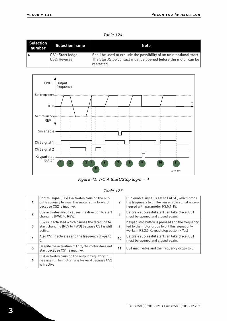
vacon • 141 Vacon 100 Application
3
Figure 41. I/O A Start/Stop logic = 4
Table 124.
Selection number Selection name Note
4 CS1: Start (edge)CS2: Reverse
Shall be used to exclude the possibility of an unintentional start. The Start/Stop contact must be opened before the motor can be restarted.
Table 125.
1Control signal (CS) 1 activates causing the out-put frequency to rise. The motor runs forward because CS2 is inactive.
7Run enable signal is set to FALSE, which drops the frequency to 0. The run enable signal is con-figured with parameter P3.5.1.15.
2CS2 activates which causes the direction to start changing (FWD to REV).
8Before a successful start can take place, CS1 must be opened and closed again.
3CS2 is inactivated which causes the direction to start changing (REV to FWD) because CS1 is still active.
9Keypad stop button is pressed and the frequency fed to the motor drops to 0. (This signal only works if P3.2.3 Keypad stop button = Yes)
4Also CS1 inactivates and the frequency drops to 0.
10Before a successful start can take place, CS1 must be opened and closed again.
5 Despite the activation of CS2, the motor does not start because CS1 is inactive.
11 CS1 inactivates and the frequency drops to 0.
6CS1 activates causing the output frequency to rise again. The motor runs forward because CS2 is inactive.
t
Outputfrequency
FWD
REV
Ctrl signal 2
Ctrl signal 1
Run enable
Set frequency
Set frequency
0 Hz
Keypad stopbutton
1 2 3 4
5
6 7 8 9 10
9143.emf
11
Tel. +358 (0) 201 2121 • Fax +358 (0)201 212 205
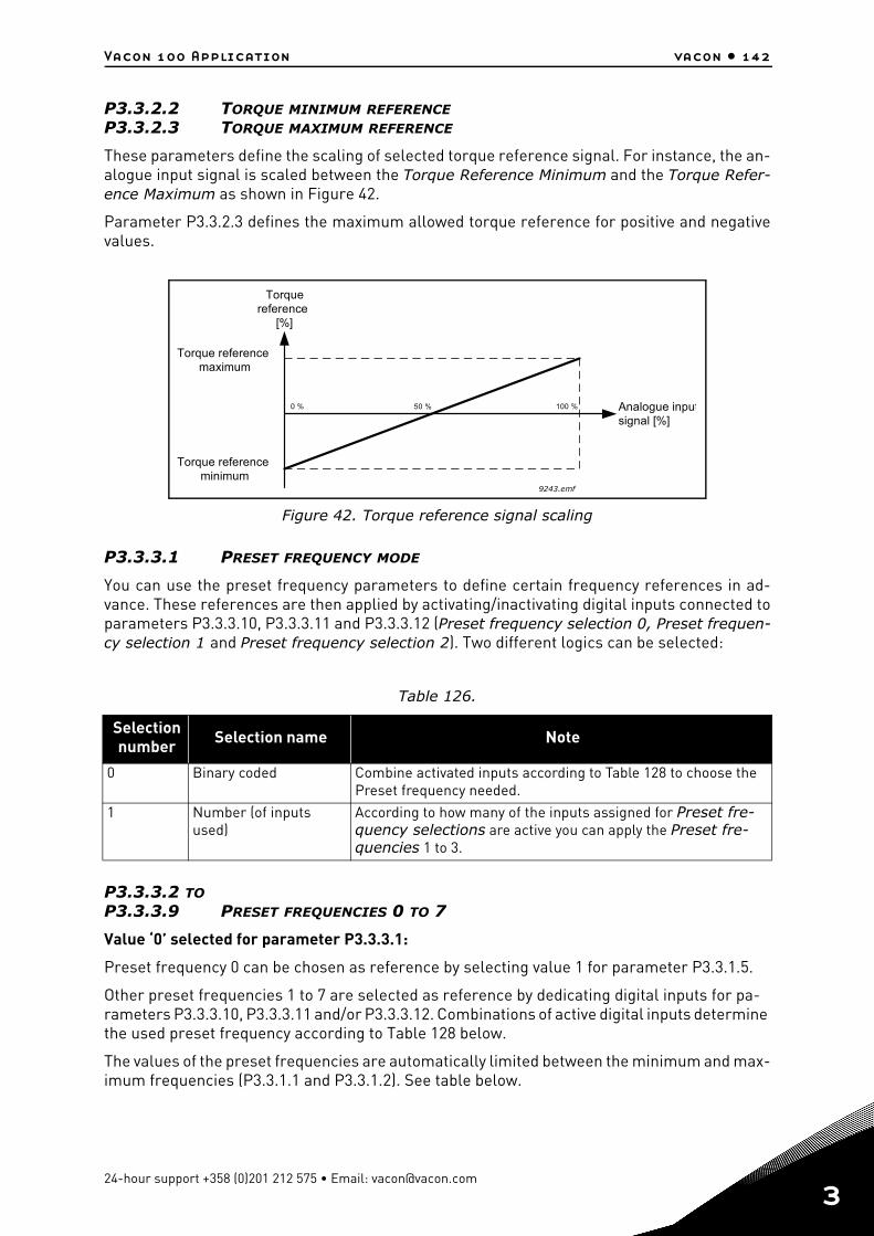
Vacon 100 Application vacon • 142
P3.3.2.2 TORQUE MINIMUM REFERENCEP3.3.2.3 TORQUE MAXIMUM REFERENCE
These parameters define the scaling of selected torque reference signal. For instance, the an-alogue input signal is scaled between the Torque Reference Minimum and the Torque Refer-ence Maximum as shown in Figure 42.
Parameter P3.3.2.3 defines the maximum allowed torque reference for positive and negativevalues.
Figure 42. Torque reference signal scaling
P3.3.3.1 PRESET FREQUENCY MODE
You can use the preset frequency parameters to define certain frequency references in ad-vance. These references are then applied by activating/inactivating digital inputs connected toparameters P3.3.3.10, P3.3.3.11 and P3.3.3.12 (Preset frequency selection 0, Preset frequen-cy selection 1 and Preset frequency selection 2). Two different logics can be selected:
P3.3.3.2 TOP3.3.3.9 PRESET FREQUENCIES 0 TO 7
Value ‘0’ selected for parameter P3.3.3.1:
Preset frequency 0 can be chosen as reference by selecting value 1 for parameter P3.3.1.5.
Other preset frequencies 1 to 7 are selected as reference by dedicating digital inputs for pa-rameters P3.3.3.10, P3.3.3.11 and/or P3.3.3.12. Combinations of active digital inputs determine the used preset frequency according to Table 128 below.
The values of the preset frequencies are automatically limited between the minimum and max-imum frequencies (P3.3.1.1 and P3.3.1.2). See table below.
Table 126.
Selection number Selection name Note
0 Binary coded Combine activated inputs according to Table 128 to choose the Preset frequency needed.
1 Number (of inputs used)
According to how many of the inputs assigned for Preset fre-quency selections are active you can apply the Preset fre-quencies 1 to 3.
[%]
100 %0 % 50 % Analogue inputsignal [%]
Torque referencemaximum
Torquereference
Torque referenceminimum
9243.emf
24-hour support +358 (0)201 212 575 • Email: [email protected]
3
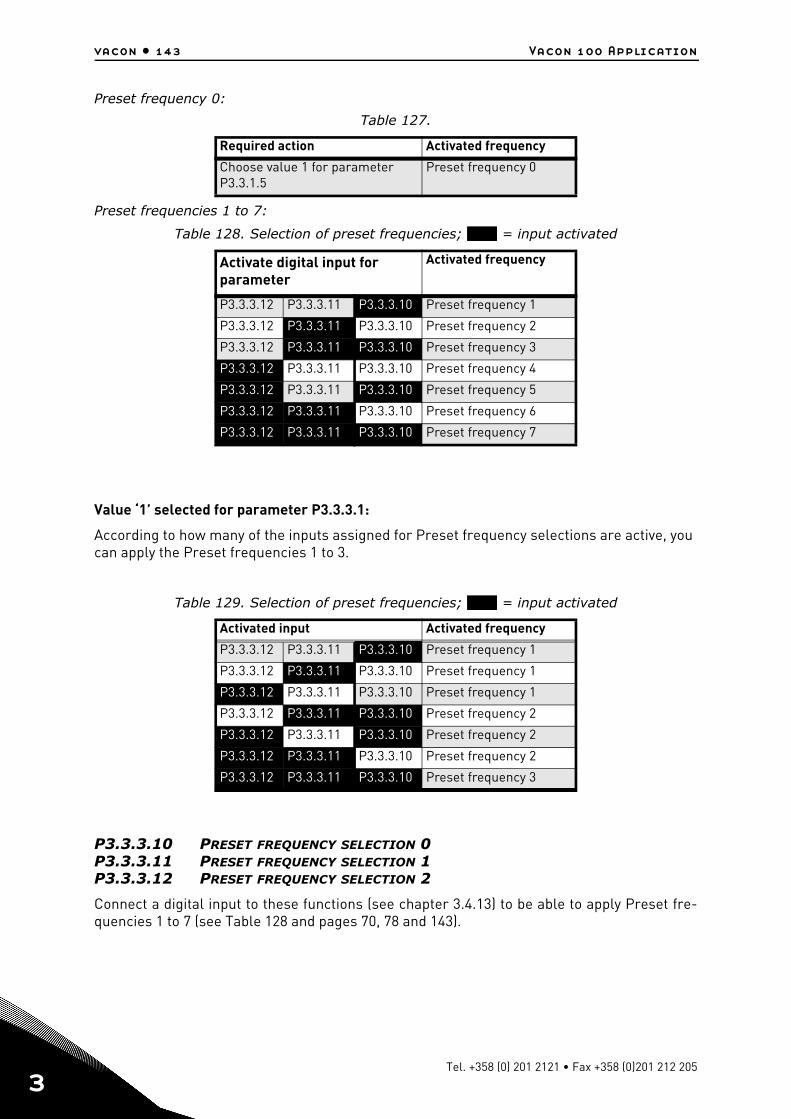
vacon • 143 Vacon 100 Application
3
Preset frequency 0:
Preset frequencies 1 to 7:
Value ‘1’ selected for parameter P3.3.3.1:
According to how many of the inputs assigned for Preset frequency selections are active, you can apply the Preset frequencies 1 to 3.
P3.3.3.10 PRESET FREQUENCY SELECTION 0P3.3.3.11 PRESET FREQUENCY SELECTION 1P3.3.3.12 PRESET FREQUENCY SELECTION 2
Connect a digital input to these functions (see chapter 3.4.13) to be able to apply Preset fre-quencies 1 to 7 (see Table 128 and pages 70, 78 and 143).
Table 127.
Required action Activated frequency
Choose value 1 for parameter P3.3.1.5
Preset frequency 0
Table 128. Selection of preset frequencies; = input activated
Activate digital input for parameter
Activated frequency
P3.3.3.12 P3.3.3.11 P3.3.3.10 Preset frequency 1
P3.3.3.12 P3.3.3.11 P3.3.3.10 Preset frequency 2
P3.3.3.12 P3.3.3.11 P3.3.3.10 Preset frequency 3
P3.3.3.12 P3.3.3.11 P3.3.3.10 Preset frequency 4
P3.3.3.12 P3.3.3.11 P3.3.3.10 Preset frequency 5
P3.3.3.12 P3.3.3.11 P3.3.3.10 Preset frequency 6
P3.3.3.12 P3.3.3.11 P3.3.3.10 Preset frequency 7
Table 129. Selection of preset frequencies; = input activated
Activated input Activated frequency
P3.3.3.12 P3.3.3.11 P3.3.3.10 Preset frequency 1
P3.3.3.12 P3.3.3.11 P3.3.3.10 Preset frequency 1
P3.3.3.12 P3.3.3.11 P3.3.3.10 Preset frequency 1
P3.3.3.12 P3.3.3.11 P3.3.3.10 Preset frequency 2
P3.3.3.12 P3.3.3.11 P3.3.3.10 Preset frequency 2
P3.3.3.12 P3.3.3.11 P3.3.3.10 Preset frequency 2
P3.3.3.12 P3.3.3.11 P3.3.3.10 Preset frequency 3
Tel. +358 (0) 201 2121 • Fax +358 (0)201 212 205
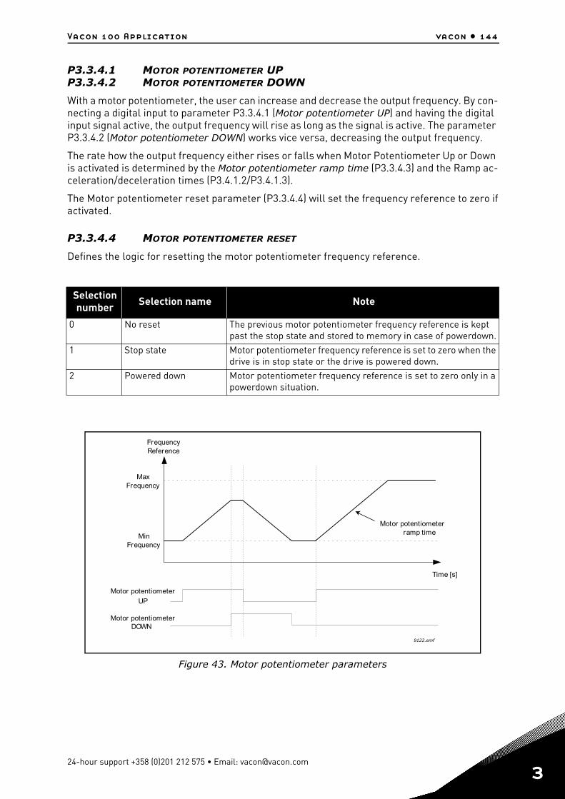
Vacon 100 Application vacon • 144
P3.3.4.1 MOTOR POTENTIOMETER UPP3.3.4.2 MOTOR POTENTIOMETER DOWN
With a motor potentiometer, the user can increase and decrease the output frequency. By con-necting a digital input to parameter P3.3.4.1 (Motor potentiometer UP) and having the digital input signal active, the output frequency will rise as long as the signal is active. The parameter P3.3.4.2 (Motor potentiometer DOWN) works vice versa, decreasing the output frequency.
The rate how the output frequency either rises or falls when Motor Potentiometer Up or Down is activated is determined by the Motor potentiometer ramp time (P3.3.4.3) and the Ramp ac-celeration/deceleration times (P3.4.1.2/P3.4.1.3).
The Motor potentiometer reset parameter (P3.3.4.4) will set the frequency reference to zero ifactivated.
P3.3.4.4 MOTOR POTENTIOMETER RESET
Defines the logic for resetting the motor potentiometer frequency reference.
Figure 43. Motor potentiometer parameters
Selection number Selection name Note
0 No reset The previous motor potentiometer frequency reference is kept past the stop state and stored to memory in case of powerdown.
1 Stop state Motor potentiometer frequency reference is set to zero when the drive is in stop state or the drive is powered down.
2 Powered down Motor potentiometer frequency reference is set to zero only in a powerdown situation.
9122.emf
Time [s]
MaxFrequency
MinFrequency
UP
Motor potentiometer
Motor potentiometer
Motor potentiometer
ramp time
DOWN
FrequencyReference
24-hour support +358 (0)201 212 575 • Email: [email protected]
3
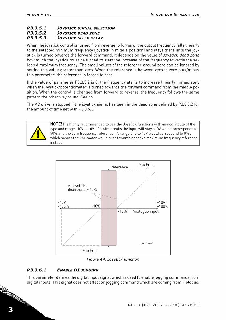
vacon • 145 Vacon 100 Application
3
P3.3.5.1 JOYSTICK SIGNAL SELECTIONP3.3.5.2 JOYSTICK DEAD ZONEP3.3.5.3 JOYSTICK SLEEP DELAY
When the joystick control is turned from reverse to forward, the output frequency falls linearlyto the selected minimum frequency (joystick in middle position) and stays there until the joy-stick is turned towards the forward command. It depends on the value of Joystick dead zonehow much the joystick must be turned to start the increase of the frequency towards the se-lected maximum frequency. The small values of the reference around zero can be ignored bysetting this value greater than zero. When the reference is between zero to zero plus/minusthis parameter, the reference is forced to zero.
If the value of parameter P3.3.5.2 is 0, the frequency starts to increase linearly immediatelywhen the joystick/potentiometer is turned towards the forward command from the middle po-sition. When the control is changed from forward to reverse, the frequency follows the samepattern the other way round. See 44 .
The AC drive is stopped if the joystick signal has been in the dead zone defined by P3.3.5.2 forthe amount of time set with P3.3.5.3.
Figure 44. Joystick function
P3.3.6.1 ENABLE DI JOGGING
This parameter defines the digital input signal which is used to enable jogging commands fromdigital inputs. This signal does not affect on jogging command which are coming from Fieldbus.
NOTE! It's highly recommended to use the Joystick functions with analog inputs of the type and range -10V...+10V. If a wire breaks the input will stay at 0V which corresponds to 50% and the zero frequency reference. A range of 0 to 10V would correspond to 0% , which means that the motor would rush towards negative maximum frequency reference instead.
13006.emf
-10%+10%
-10V-100%
+10V+100%
9123.emf
MaxFreqReference
AI joystickdead zone = 10%
Analogue input
-MaxFreq
Tel. +358 (0) 201 2121 • Fax +358 (0)201 212 205
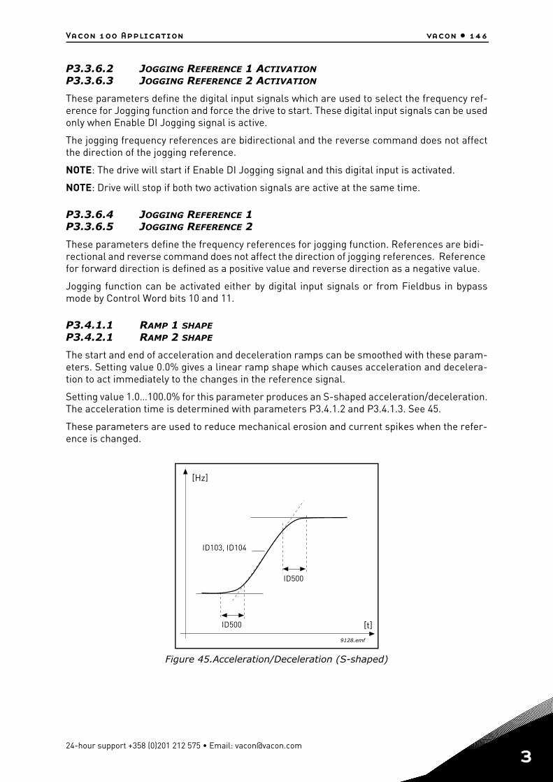
Vacon 100 Application vacon • 146
P3.3.6.2 JOGGING REFERENCE 1 ACTIVATIONP3.3.6.3 JOGGING REFERENCE 2 ACTIVATION
These parameters define the digital input signals which are used to select the frequency ref-erence for Jogging function and force the drive to start. These digital input signals can be usedonly when Enable DI Jogging signal is active.
The jogging frequency references are bidirectional and the reverse command does not affectthe direction of the jogging reference.
NOTE: The drive will start if Enable DI Jogging signal and this digital input is activated.
NOTE: Drive will stop if both two activation signals are active at the same time.
P3.3.6.4 JOGGING REFERENCE 1P3.3.6.5 JOGGING REFERENCE 2
These parameters define the frequency references for jogging function. References are bidi-rectional and reverse command does not affect the direction of jogging references. Reference for forward direction is defined as a positive value and reverse direction as a negative value.
Jogging function can be activated either by digital input signals or from Fieldbus in bypassmode by Control Word bits 10 and 11.
P3.4.1.1 RAMP 1 SHAPEP3.4.2.1 RAMP 2 SHAPE
The start and end of acceleration and deceleration ramps can be smoothed with these param-eters. Setting value 0.0% gives a linear ramp shape which causes acceleration and decelera-tion to act immediately to the changes in the reference signal.
Setting value 1.0…100.0% for this parameter produces an S-shaped acceleration/deceleration.The acceleration time is determined with parameters P3.4.1.2 and P3.4.1.3. See 45.
These parameters are used to reduce mechanical erosion and current spikes when the refer-ence is changed.
Figure 45.Acceleration/Deceleration (S-shaped)
ID103, ID104
[Hz]
[t]
ID500
ID500
9128.emf
24-hour support +358 (0)201 212 575 • Email: [email protected]
3
vacon • 147 Vacon 100 Application
3
P3.4.5.1 FLUX BRAKING
Instead of DC braking, flux braking is a useful way to raise the braking capacity in cases whereadditional brake resistors are not needed.
When braking is needed, the frequency is reduced and the flux in the motor is increased, whichin turn increases the motor's capability to brake. Unlike DC braking, the motor speed remainscontrolled during braking.
The flux braking can be set ON or OFF.
NOTE: Flux braking converts the energy into heat at the motor, and should be used intermit-tently to avoid motor damage.
P3.5.1.15 RUN ENABLE
Contact open: Start of motor disabledContact closed: Start of motor enabled
The AC drive is stopped according to the selected function at P3.2.5. The follower drive will al-ways coast to stop.
Tel. +358 (0) 201 2121 • Fax +358 (0)201 212 205
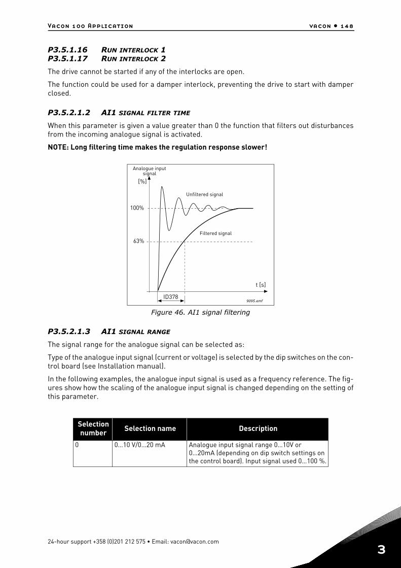
Vacon 100 Application vacon • 148
P3.5.1.16 RUN INTERLOCK 1P3.5.1.17 RUN INTERLOCK 2
The drive cannot be started if any of the interlocks are open.
The function could be used for a damper interlock, preventing the drive to start with damperclosed.
P3.5.2.1.2 AI1 SIGNAL FILTER TIME
When this parameter is given a value greater than 0 the function that filters out disturbancesfrom the incoming analogue signal is activated.
NOTE: Long filtering time makes the regulation response slower!
Figure 46. AI1 signal filtering
P3.5.2.1.3 AI1 SIGNAL RANGE
The signal range for the analogue signal can be selected as:
Type of the analogue input signal (current or voltage) is selected by the dip switches on the con-trol board (see Installation manual).
In the following examples, the analogue input signal is used as a frequency reference. The fig-ures show how the scaling of the analogue input signal is changed depending on the setting ofthis parameter.
Selection number Selection name Description
0 0…10 V/0…20 mA Analogue input signal range 0…10V or 0…20mA (depending on dip switch settings on the control board). Input signal used 0…100 %.
[%]
100%
63%
ID378
t [s]
9095.emf
Filtered signal
Unfiltered signal
Analogue inputsignal
24-hour support +358 (0)201 212 575 • Email: [email protected]
3
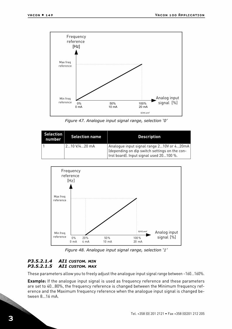
vacon • 149 Vacon 100 Application
3
Figure 47. Analogue input signal range, selection ‘0’
Figure 48. Analogue input signal range, selection ‘1’
P3.5.2.1.4 AI1 CUSTOM. MINP3.5.2.1.5 AI1 CUSTOM. MAX
These parameters allow you to freely adjust the analogue input signal range between -160…160%.
Example: If the analogue input signal is used as frequency reference and these parametersare set to 40…80%, the frequency reference is changed between the Minimum frequency ref-erence and the Maximum frequency reference when the analogue input signal is changed be-tween 8…16 mA.
Selection number Selection name Description
1 2…10 V/4…20 mA Analogue input signal range 2…10V or 4…20mA (depending on dip switch settings on the con-trol board). Input signal used 20…100 %.
[Hz]
[%]0% 100%50%0 mA 20 mA10 mA
9244.emf
Min freqreference
Max freqreference
Frequencyreference
Analog inputsignal
[Hz]
[%]0% 100 %50%20%0 mA 20 mA10 mA4 mA
Min freqreference
Max freqreference
Frequencyreference
Analog inputsignal
9245.emf
Tel. +358 (0) 201 2121 • Fax +358 (0)201 212 205
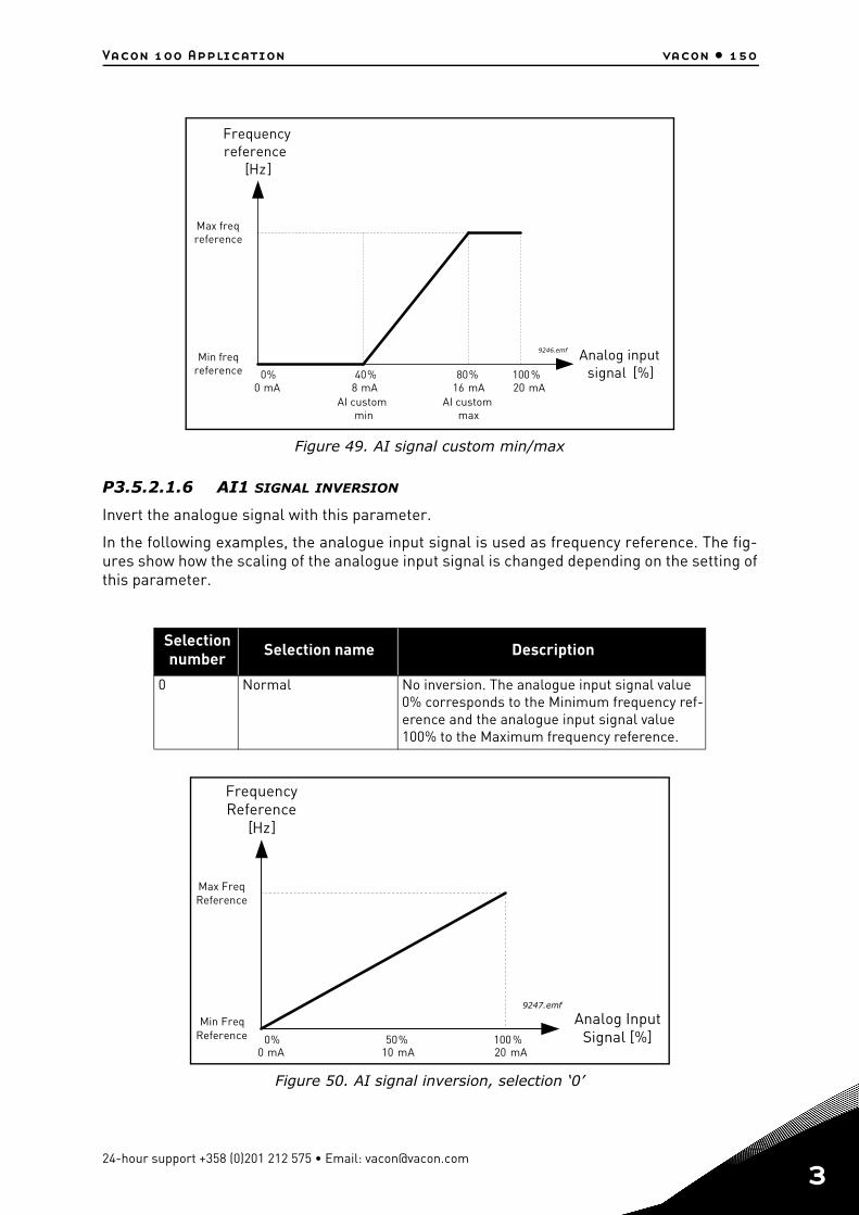
Vacon 100 Application vacon • 150
Figure 49. AI signal custom min/max
P3.5.2.1.6 AI1 SIGNAL INVERSION
Invert the analogue signal with this parameter.
In the following examples, the analogue input signal is used as frequency reference. The fig-ures show how the scaling of the analogue input signal is changed depending on the setting ofthis parameter.
Figure 50. AI signal inversion, selection ‘0’
Selection number Selection name Description
0 Normal No inversion. The analogue input signal value 0% corresponds to the Minimum frequency ref-erence and the analogue input signal value 100% to the Maximum frequency reference.
[Hz]
[%]0% 100%80%40%0 mA 20 mA16 mA8 mA
9246.emfMin freq
reference
Max freqreference
Frequencyreference
Analog inputsignal
AI custommin
AI custommax
Min FreqReference
Max FreqReference
FrequencyReference
[Hz]
Analog InputSignal [%]0% 100 %50%
0 mA 20 mA10 mA
9247.emf
24-hour support +358 (0)201 212 575 • Email: [email protected]
3
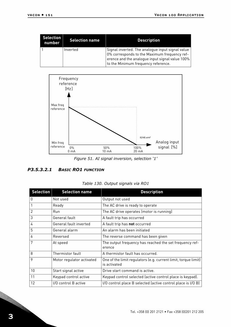
vacon • 151 Vacon 100 Application
3
Figure 51. AI signal inversion, selection ‘1’
P3.5.3.2.1 BASIC RO1 FUNCTION
Selection number Selection name Description
1 Inverted Signal inverted. The analogue input signal value 0% corresponds to the Maximum frequency ref-erence and the analogue input signal value 100% to the Minimum frequency reference.
Table 130. Output signals via RO1
Selection Selection name Description
0 Not used Output not used
1 Ready The AC drive is ready to operate
2 Run The AC drive operates (motor is running)
3 General fault A fault trip has occurred
4 General fault inverted A fault trip has not occurred
5 General alarm An alarm has been initiated
6 Reversed The reverse command has been given
7 At speed The output frequency has reached the set frequency ref-erence
8 Thermistor fault A thermistor fault has occurred.
9 Motor regulator activated One of the limit regulators (e.g. current limit, torque limit) is activated
10 Start signal active Drive start command is active.
11 Keypad control active Keypad control selected (active control place is keypad).
12 I/O control B active I/O control place B selected (active control place is I/O B)
Min freqreference
Max freqreference
Frequencyreference
[Hz]
Analog inputsignal [%]0% 100%50%
0 mA 20 mA10 mA
9248.emf
Tel. +358 (0) 201 2121 • Fax +358 (0)201 212 205
Vacon 100 Application vacon • 152
13 Limit supervision 1 Activates if the signal value falls below or exceeds the set supervision limit (P3.8.3 or P3.8.7) depending on the selected function.
14 Limit supervision 2
15 Fire Mode active Fire Mode function is active.
16 Jogging active Jogging function is active.
17 Preset Frequency active The preset frequency has been selected with digital input signals.
18 Quick Stop active Quick Stop function has been activated.
19 PID in Sleep mode PID-controller is in Sleep mode.
20 PID Soft Fill activated PID-controller Soft Fill function is activated.
21 PID feedback supervision PID-controller feedback value is beyond the supervision limits. See chapter 3.4.26.6.
22 ExtPID feedback supervi-sion
External PID-controller feedback value is beyond the supervision limits. See chapter 3.4.27.4.
23 Input pressure alarm The input pressure signal value of the pump has fallen below the value defined with parameter P3.13.9.7. See chapter 3.4.26.9.
24Frost protection alarm
The pump’s measured temperature has fallen below the level defined with parameter P3.13.10.5. See chapter 3.4.26.10.
25 Motor 1 control Contactor control for Multi-pump function
26 Motor 2 control Contactor control for Multi-pump function
27 Motor 3 control Contactor control for Multi-pump function
28 Motor 4 control Contactor control for Multi-pump function
29 Motor 5 control Contactor control for Multi-pump function
30 Motor 6 control Contactor control for Multi-pump function
31 Time channel 1 Status of Time channel 1
32 Time channel 2 Status of Time channel 2
33 Time channel 3 Status of Time channel 3
34 Fieldbus Control Word bit 13
Digital (relay) output control from Fieldbus control word bit 13.
35 Fieldbus Control Word bit 14
Digital (relay) output control from Fieldbus control word bit 14.
36 Fieldbus Control Word bit 15
Digital (relay) output control from Fieldbus control word bit 15.
37 Fieldbus Process Data In1 bit 0
Digital (relay) output control from Fieldbus Process Data In1, bit 0.
38 Fieldbus Process Data In1 bit 1
Digital (relay) output control from Fieldbus Process Data In1, bit 1.
39 Fieldbus Process Data In1 bit 2
Digital (relay) output control from Fieldbus Process Data In1, bit 2.
40 Maintenance counter 1 alarm
Maintenance counter has reached the alarm limit defined with parameter P3.16.2. See chapter 3.4.29.
41 Maintenance Counter 1 Fault
Maintenance counter has reached the alarm limit defined with parameter P3.16.3. See chapter 3.4.29.
Table 130. Output signals via RO1
Selection Selection name Description
24-hour support +358 (0)201 212 575 • Email: [email protected]
3
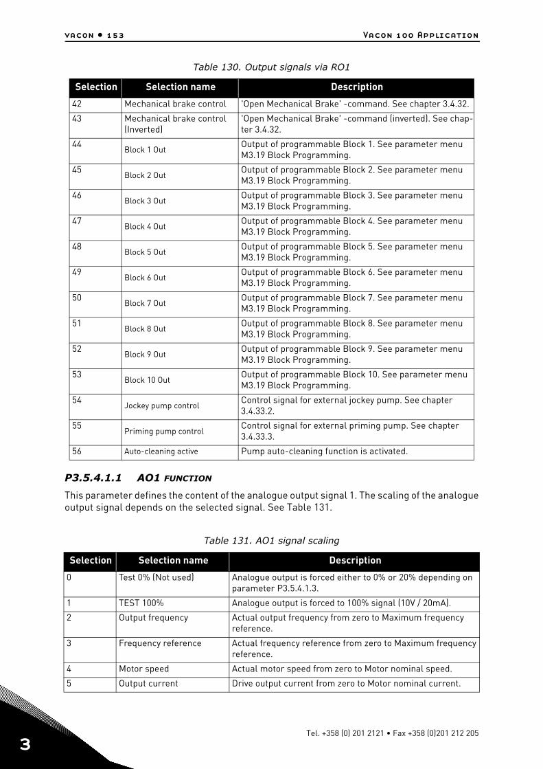
vacon • 153 Vacon 100 Application
3
P3.5.4.1.1 AO1 FUNCTION
This parameter defines the content of the analogue output signal 1. The scaling of the analogueoutput signal depends on the selected signal. See Table 131.
42 Mechanical brake control 'Open Mechanical Brake' -command. See chapter 3.4.32.
43 Mechanical brake control (Inverted)
'Open Mechanical Brake' -command (inverted). See chap-ter 3.4.32.
44Block 1 Out
Output of programmable Block 1. See parameter menu M3.19 Block Programming.
45Block 2 Out
Output of programmable Block 2. See parameter menu M3.19 Block Programming.
46Block 3 Out
Output of programmable Block 3. See parameter menu M3.19 Block Programming.
47Block 4 Out
Output of programmable Block 4. See parameter menu M3.19 Block Programming.
48Block 5 Out
Output of programmable Block 5. See parameter menu M3.19 Block Programming.
49Block 6 Out
Output of programmable Block 6. See parameter menu M3.19 Block Programming.
50Block 7 Out
Output of programmable Block 7. See parameter menu M3.19 Block Programming.
51Block 8 Out
Output of programmable Block 8. See parameter menu M3.19 Block Programming.
52Block 9 Out
Output of programmable Block 9. See parameter menu M3.19 Block Programming.
53Block 10 Out
Output of programmable Block 10. See parameter menu M3.19 Block Programming.
54Jockey pump control
Control signal for external jockey pump. See chapter 3.4.33.2.
55Priming pump control
Control signal for external priming pump. See chapter 3.4.33.3.
56 Auto-cleaning active Pump auto-cleaning function is activated.
Table 131. AO1 signal scaling
Selection Selection name Description
0 Test 0% (Not used) Analogue output is forced either to 0% or 20% depending on parameter P3.5.4.1.3.
1 TEST 100% Analogue output is forced to 100% signal (10V / 20mA).
2 Output frequency Actual output frequency from zero to Maximum frequency reference.
3 Frequency reference Actual frequency reference from zero to Maximum frequency reference.
4 Motor speed Actual motor speed from zero to Motor nominal speed.
5 Output current Drive output current from zero to Motor nominal current.
Table 130. Output signals via RO1
Selection Selection name Description
Tel. +358 (0) 201 2121 • Fax +358 (0)201 212 205
Vacon 100 Application vacon • 154
6 Motor torque Actual motor torque from zero to motor nominal torque (100%).
7 Motor power Actual motor power from zero to Motor nominal power (100%).
8 Motor voltage Actual motor voltage from zero to Motor nominal voltage.
9 DC-link voltage Actual DC-link voltage 0…1000V.
10 PID Setpoint PID Controller actual setpoint value (0…100%).
11 PID Feedback PID Controller actual feedback value (0…100%).
12 PID output PID controller output (0…100%).
13 ExtPID output External PID controller output (0…100%).
14 Fieldbus Process Data In 1 Fieldbus Process Data In 1 from 0…10000 (corresponding 0…100.00%).
15 Fieldbus Process Data In 2 Fieldbus Process Data In 2 from 0…10000 (corresponding 0…100.00%).
16 Fieldbus Process Data In 3 Fieldbus Process Data In 3 from 0…10000 (corresponding 0…100.00%).
17 Fieldbus Process Data In 4 Fieldbus Process Data In 4 from 0…10000 (corresponding 0…100.00%).
18 Fieldbus Process Data In 5 Fieldbus Process Data In 5 from 0…10000 (corresponding 0…100.00%).
19 Fieldbus Process Data In 6 Fieldbus Process Data In 6 from 0…10000 (corresponding 0…100.00%).
20 Fieldbus Process Data In 7 Fieldbus Process Data In 7 from 0…10000 (corresponding 0…100.00%).
21 Fieldbus Process Data In 8 Fieldbus Process Data In 8 from 0…10000 (corresponding 0…100.00%).
22 Block 1 Out Output of programmable Block 1 from 0…10000 (correspond-ing 0…100,00%). See parameter menu M3.19 Block Program-ming.
23 Block 2 Out Output of programmable Block 2 from 0…10000 (correspond-ing 0…100,00%). See parameter menu M3.19 Block Program-ming.
24 Block 3 Out Output of programmable Block 3 from 0…10000 (correspond-ing 0…100,00%). See parameter menu M3.19 Block Program-ming.
25 Block 4 Out Output of programmable Block 4 from 0…10000 (correspond-ing 0…100,00%). See parameter menu M3.19 Block Program-ming.
26 Block 5 Out Output of programmable Block 5 from 0…10000 (correspond-ing 0…100,00%). See parameter menu M3.19 Block Program-ming
27 Block 6 Out Output of programmable Block 6 from 0…10000 (correspond-ing 0…100,00%). See parameter menu M3.19 Block Program-ming
28 Block 7 Out Output of programmable Block 7 from 0…10000 (correspond-ing 0…100,00%). See parameter menu M3.19 Block Program-ming
Table 131. AO1 signal scaling
Selection Selection name Description
24-hour support +358 (0)201 212 575 • Email: [email protected]
3
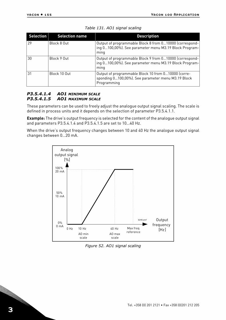
vacon • 155 Vacon 100 Application
3
P3.5.4.1.4 AO1 MINIMUM SCALEP3.5.4.1.5 AO1 MAXIMUM SCALE
These parameters can be used to freely adjust the analogue output signal scaling. The scale isdefined in process units and it depends on the selection of parameter P3.5.4.1.1.
Example: The drive’s output frequency is selected for the content of the analogue output signaland parameters P3.5.4.1.4 and P3.5.4.1.5 are set to 10…40 Hz.
When the drive’s output frequency changes between 10 and 40 Hz the analogue output signalchanges between 0…20 mA.
Figure 52. AO1 signal scaling
29 Block 8 Out Output of programmable Block 8 from 0…10000 (correspond-ing 0…100,00%). See parameter menu M3.19 Block Program-ming
30 Block 9 Out Output of programmable Block 9 from 0…10000 (correspond-ing 0…100,00%). See parameter menu M3.19 Block Program-ming
31 Block 10 Out Output of programmable Block 10 from 0…10000 (corre-sponding 0…100,00%). See parameter menu M3.19 Block Programming
Table 131. AO1 signal scaling
Selection Selection name Description
0 Hz [Hz]
[%]
0%
100%
50%
0 mA
20 mA
10 mA
10 Hz 40 Hz
9249.emf
Max freqreference
Outputfrequency
Analogoutput signal
AO minscale
AO maxscale
Tel. +358 (0) 201 2121 • Fax +358 (0)201 212 205
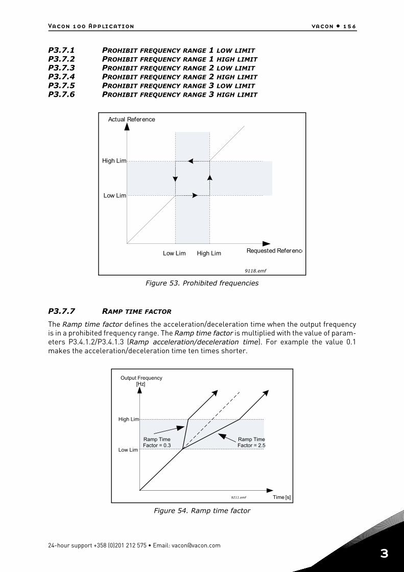
Vacon 100 Application vacon • 156
P3.7.1 PROHIBIT FREQUENCY RANGE 1 LOW LIMITP3.7.2 PROHIBIT FREQUENCY RANGE 1 HIGH LIMITP3.7.3 PROHIBIT FREQUENCY RANGE 2 LOW LIMITP3.7.4 PROHIBIT FREQUENCY RANGE 2 HIGH LIMITP3.7.5 PROHIBIT FREQUENCY RANGE 3 LOW LIMITP3.7.6 PROHIBIT FREQUENCY RANGE 3 HIGH LIMIT
Figure 53. Prohibited frequencies
P3.7.7 RAMP TIME FACTOR
The Ramp time factor defines the acceleration/deceleration time when the output frequencyis in a prohibited frequency range. The Ramp time factor is multiplied with the value of param-eters P3.4.1.2/P3.4.1.3 (Ramp acceleration/deceleration time). For example the value 0.1makes the acceleration/deceleration time ten times shorter.
Figure 54. Ramp time factor
Actual Reference
Requested ReferenceLow Lim High Lim
Low Lim
High Lim
9118.emf
[s]
[Hz]
Time
Output Frequency
Low Lim
High Lim
Ramp TimeFactor = 2.5
Ramp TimeFactor = 0.3
9211.emf
24-hour support +358 (0)201 212 575 • Email: [email protected]
3
vacon • 157 Vacon 100 Application
3
P3.9.1.2 RESPONSE TO EXTERNAL FAULT
An alarm message or a fault action and message is generated by an external fault externalfault signal in one of the programmable digital inputs (DI3 by default) using parametersP3.5.1.11 and P3.5.1.12. The information can also be programmed into any of the relay outputs.
P3.9.2.3 ZERO SPEED COOLING FACTOR
Defines the cooling factor at zero speed in relation to the point where the motor is running atnominal speed without external cooling. See 55.
The default value is set assuming that there is no external fan cooling the motor. If an externalfan is used this parameter can be set to 90% (or even higher).
If you change the parameter P3.1.1.4 (Motor nominal current), this parameter is automaticallyrestored to the default value.
Setting this parameter does not affect the maximum output current of the drive which is deter-mined by parameter P3.1.3.1 alone.
The corner frequency for the thermal protection is 70% of the motor nominal frequency(P3.1.1.2).
Figure 55. Motor thermal current IT curve
P3.9.2.4 MOTOR THERMAL TIME CONSTANT
This is the thermal time constant of the motor. The bigger the motor, the bigger the time con-stant. The time constant is the time within which the calculated thermal stage has reached63% of its final value.
The motor thermal time is specific to the motor design and it varies between different motormanufacturers. The default value of the parameter varies from size to size.
If the motor's t6-time (t6 is the time in seconds the motor can safely operate at six times therated current) is known (given by the motor manufacturer) the time constant parameter can beset basing on it. As a rule of thumb, the motor thermal time constant in minutes equals to 2*t6.If the drive is in stop stage the time constant is internally increased to three times the set pa-rameter value. The cooling in stop stage is based on convection and the time constant is in-creased.
See 57.
ffn
Par.ID706=40%
0
9129.emf
IT100%Overload area
Pcooling
Corner freq
Tel. +358 (0) 201 2121 • Fax +358 (0)201 212 205
Vacon 100 Application vacon • 158
Figure 56. Motor thermal time constant
P3.9.2.5 MOTOR THERMAL LOADABILITY
Setting value to 130% means that the nominal temperature will be reached with 130% of motornominal current.
Figure 57. Motor temperature calculation
I/IT
100%
63%
tT
t
9077.e
mf
T = Motor thermal time constant
Current
I/IT
t
t
T
105%
Trip area
Current
Loadability 80%Loadability 100%Loadability 130%
Fault/Alarm
9078.e
mf
24-hour support +358 (0)201 212 575 • Email: [email protected]
3
vacon • 159 Vacon 100 Application
3
P3.9.3.2 STALL CURRENT
The current can be set to 0.0…2*IL. For a stall stage to occur, the current must have exceededthis limit. See 58. If parameter P3.1.3.1 Motor current limit is changed, this parameter is au-tomatically calculated to 90% of the current limit. See page 91.
NOTE! In order to guarantee desired operation, this limit must be set below the current limit.
Figure 58. Stall characteristics settings
P3.9.3.3 STALL TIME LIMIT
This time can be set between 1.0 and 120.0s.
This is the maximum time allowed for a stall stage. The stall time is counted by an internal up/down counter.
If the stall time counter value goes above this limit the protection will cause a trip (seeP3.9.3.1). See page 91.
P3.9.4.2 UNDERLOAD PROTECTION: FIELD WEAKENING AREA LOAD
The torque limit can be set between 10.0-150.0 % x TnMotor.
This parameter gives the value for the minimum torque allowed when the output frequency isabove the field weakening point. See 59.
If you change parameter P3.1.1.4 (Motor nominal current) this parameter is automatically re-stored to the default value. See page 92.
f
I
Par. ID710
Par. ID712
9130.emf
Stall area
Tel. +358 (0) 201 2121 • Fax +358 (0)201 212 205
Vacon 100 Application vacon • 160
Figure 59. Setting of minimum load
P3.9.4.4 UNDERLOAD PROTECTION: TIME LIMIT
This time can be set between 2.0 and 600.0 s.
This is the maximum time allowed for an underload state to exist. An internal up/down countercounts the accumulated underload time. If the underload counter value goes above this limitthe protection will cause a trip according to parameter P3.9.4.1). If the drive is stopped the un-derload counter is reset to zero. See 60 and page 92.
Figure 60. Underload time counter function
Par.ID714
9131.emf
Par.ID715
f
5 Hz
Underload area
Torque
Fieldweakeningpoint
Par. ID716
9132.emf
Trip area
Time
Underload time counter
Underload•No underl.
Trip/warningpar. ID713
24-hour support +358 (0)201 212 575 • Email: [email protected]
3
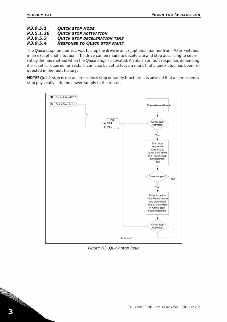
vacon • 161 Vacon 100 Application
3
P3.9.5.1 QUICK STOP MODEP3.5.1.26 QUICK STOP ACTIVATIONP3.9.5.3 QUICK STOP DECELERATION TIMEP3.9.5.4 RESPONSE TO QUICK STOP FAULT
The Quick stop function is a way to stop the drive in an exceptional manner from I/O or Fieldbus in an exceptional situation. The drive can be made to decelerate and stop according to sepa-rately defined method when the Quick stop is activated. An alarm or fault response, depending if a reset is required for restart, can also be set to leave a mark that a quick stop has been re-quested in the fault history.
NOTE! Quick stop is not an emergency stop or safety function! It is advised that an emergency stop physically cuts the power supply to the motor.
Figure 61. Quick stop logic
ORIN 1IN 2
FB
I/O
9124.emf
.
.
/
?
B
Yes
fault
Control Word 12
Quick Stop Activ Normal operation
Start stopsequence
according to”Quick Stop Mode”
and ”Quick StopDeceleration
Time”
Quick StopActivated
Quick StopActivated
NO
Drive forced to”Not Ready” mode
and alarmtrigged accordingto ”Quick StopFault Response”
Drive stopped
Yes
Tel. +358 (0) 201 2121 • Fax +358 (0)201 212 205
Vacon 100 Application vacon • 162
P3.9.8.1 ANALOQUE INPUT LOW PROTECTION
This parameter defines if the AI Low Protection is used or not.
AI Low protection is used to detect analog input signal failures if the input signal used as fre-quency reference or torque reference or PID/ExtPID controllers are configured to use analoginput signals.
The user can select if the protection is enabled only when the drive is in Run state or respec-tively in both Run and Stop states. Response for the AI Low Fault can be selected by parameterP3.9.8.2 AI Low Fault.
P3.9.8.2 ANALOQUE INPUT LOW FAULT
This parameter defines the response for F50 - AI Low Fault (Fault ID: 1050) if AI Low Protectionis enabled by parameter 3.9.8.1.
AI Low protection monitors the signal level of analogue inputs 1-6. AI Low fault or alarm isgenerated if parameter P3.9.8.1 AI Low Protection is Enabled and analogue input signal fallsbelow 50% of the defined minimum signal range for 3 seconds.
NOTE: AI Low Fault response 3 (Alarm + Previous Freq) can be used only if analog input 1 oranalog input 2 is used as frequency reference.
P3.10.1 AUTOMATIC RESET
Activate the Automatic reset after fault with this parameter.
NOTE: Automatic reset is allowed for certain faults only. By giving the parameters P3.10.6 toP3.10.13 the value 0 or 1 you can either allow or deny the automatic reset after the respectivefaults.
Table 132. AI low protection settings
Selection number Selection name Description
1 Protection disabled2 Protection enabled in
Run stateThe protection is enabled only when the drive is in run state
3 Protection enabled in Run and Stop
Protection is enabled in both, run and stop states
Table 133.
Selection number Selection name Description
1 Alarm2 Alarm P3.9.1.13 is set to frequency reference3 Alarm The last valid frequency is kept as fre-
quency reference4 Fault Stop according to Stop mode P3.2.55 Fault Stop by coasting
24-hour support +358 (0)201 212 575 • Email: [email protected]
3
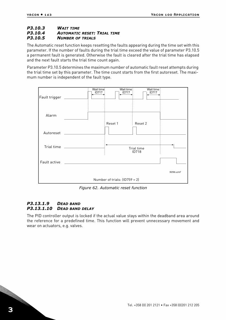
vacon • 163 Vacon 100 Application
3
P3.10.3 WAIT TIMEP3.10.4 AUTOMATIC RESET: TRIAL TIMEP3.10.5 NUMBER OF TRIALS
The Automatic reset function keeps resetting the faults appearing during the time set with thisparameter. If the number of faults during the trial time exceed the value of parameter P3.10.5a permanent fault is generated. Otherwise the fault is cleared after the trial time has elapsedand the next fault starts the trial time count again.
Parameter P3.10.5 determines the maximum number of automatic fault reset attempts during the trial time set by this parameter. The time count starts from the first autoreset. The maxi-mum number is independent of the fault type.
Figure 62. Automatic reset function
P3.13.1.9 DEAD BANDP3.13.1.10 DEAD BAND DELAY
The PID controller output is locked if the actual value stays within the deadband area aroundthe reference for a predefined time. This function will prevent unnecessary movement andwear on actuators, e.g. valves.
9096.emf
Fault trigger
Autoreset
Trial time
Wait timeID717
Reset 1 Reset 2
Trial timeID718
Fault active
Alarm
Number of trials: (ID759 = 2)
Wait timeID717
Wait timeID717
Tel. +358 (0) 201 2121 • Fax +358 (0)201 212 205
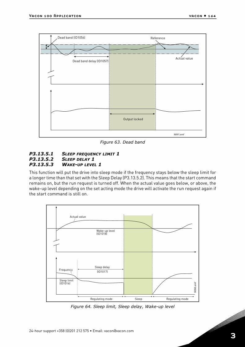
Vacon 100 Application vacon • 164
Figure 63. Dead band
P3.13.5.1 SLEEP FREQUENCY LIMIT 1P3.13.5.2 SLEEP DELAY 1P3.13.5.3 WAKE-UP LEVEL 1
This function will put the drive into sleep mode if the frequency stays below the sleep limit fora longer time than that set with the Sleep Delay (P3.13.5.2). This means that the start commandremains on, but the run request is turned off. When the actual value goes below, or above, thewake-up level depending on the set acting mode the drive will activate the run request again ifthe start command is still on.
Figure 64. Sleep limit, Sleep delay, Wake-up level
9097.emf
Dead band (ID1056) Reference
Dead band delay (ID1057)
Output locked
Actual value
9098.e
mf
Actual value
Wake-up level(ID1018)
Frequency
Sleep limit(ID1016)
Sleep delay
(ID1017)
SleepRegulating mode Regulating mode
24-hour support +358 (0)201 212 575 • Email: [email protected]
3
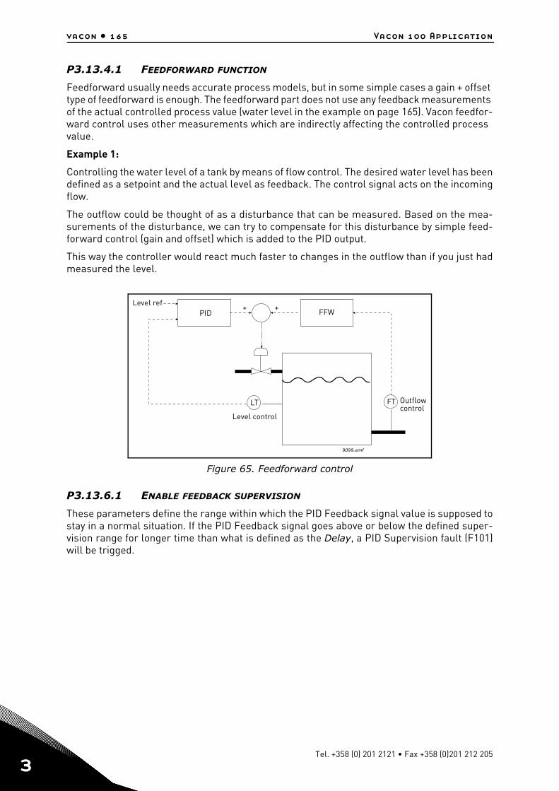
vacon • 165 Vacon 100 Application
3
P3.13.4.1 FEEDFORWARD FUNCTION
Feedforward usually needs accurate process models, but in some simple cases a gain + offset type of feedforward is enough. The feedforward part does not use any feedback measurements of the actual controlled process value (water level in the example on page 165). Vacon feedfor-ward control uses other measurements which are indirectly affecting the controlled process value.
Example 1:
Controlling the water level of a tank by means of flow control. The desired water level has beendefined as a setpoint and the actual level as feedback. The control signal acts on the incomingflow.
The outflow could be thought of as a disturbance that can be measured. Based on the mea-surements of the disturbance, we can try to compensate for this disturbance by simple feed-forward control (gain and offset) which is added to the PID output.
This way the controller would react much faster to changes in the outflow than if you just hadmeasured the level.
Figure 65. Feedforward control
P3.13.6.1 ENABLE FEEDBACK SUPERVISION
These parameters define the range within which the PID Feedback signal value is supposed tostay in a normal situation. If the PID Feedback signal goes above or below the defined super-vision range for longer time than what is defined as the Delay, a PID Supervision fault (F101)will be trigged.
PID+ +
LT FT
9099.emf
FFWLevel ref
Level control
Outflowcontrol
Tel. +358 (0) 201 2121 • Fax +358 (0)201 212 205
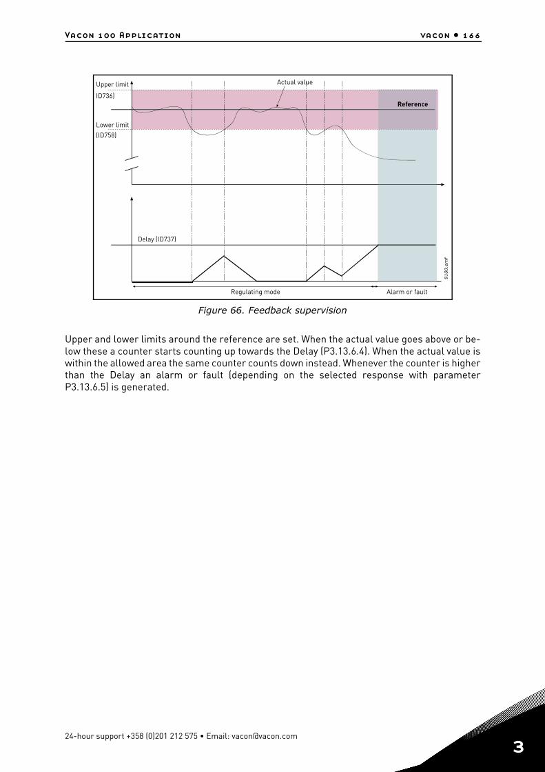
Vacon 100 Application vacon • 166
Figure 66. Feedback supervision
Upper and lower limits around the reference are set. When the actual value goes above or be-low these a counter starts counting up towards the Delay (P3.13.6.4). When the actual value iswithin the allowed area the same counter counts down instead. Whenever the counter is higherthan the Delay an alarm or fault (depending on the selected response with parameterP3.13.6.5) is generated.
9100.e
mf
Regulating mode
Upper limit
ID736)
Lower limit
(ID758)
Actual value
Delay (ID737)
Alarm or fault
Reference
24-hour support +358 (0)201 212 575 • Email: [email protected]
3
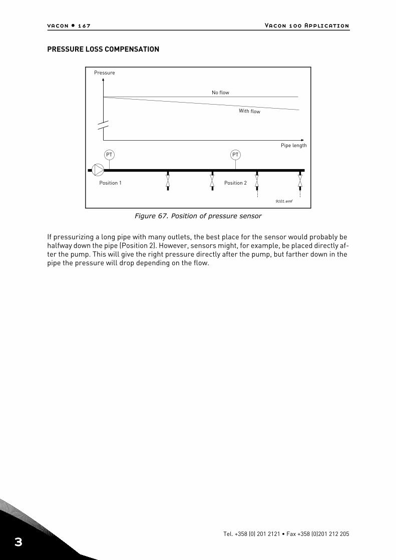
vacon • 167 Vacon 100 Application
3
PRESSURE LOSS COMPENSATION
Figure 67. Position of pressure sensor
If pressurizing a long pipe with many outlets, the best place for the sensor would probably be halfway down the pipe (Position 2). However, sensors might, for example, be placed directly af-ter the pump. This will give the right pressure directly after the pump, but farther down in the pipe the pressure will drop depending on the flow.
PT PT
9101.emf
Pressure
No flow
With flow
Pipe length
Position 1 Position 2
Tel. +358 (0) 201 2121 • Fax +358 (0)201 212 205
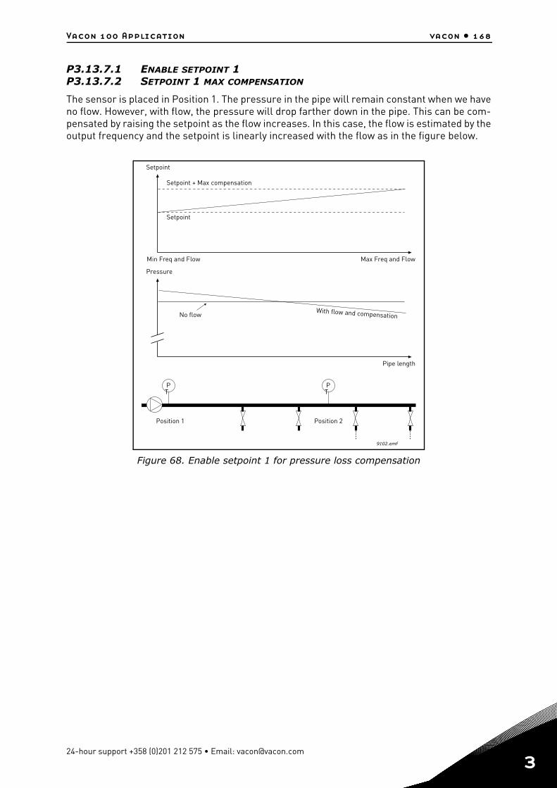
Vacon 100 Application vacon • 168
P3.13.7.1 ENABLE SETPOINT 1P3.13.7.2 SETPOINT 1 MAX COMPENSATION
The sensor is placed in Position 1. The pressure in the pipe will remain constant when we haveno flow. However, with flow, the pressure will drop farther down in the pipe. This can be com-pensated by raising the setpoint as the flow increases. In this case, the flow is estimated by theoutput frequency and the setpoint is linearly increased with the flow as in the figure below.
Figure 68. Enable setpoint 1 for pressure loss compensation
PT
PT
9102.emf
Position 1 Position 2
Pressure
No flowWith flow and compensation
Pipe length
Setpoint
Max Freq and FlowMin Freq and Flow
Setpoint + Max compensation
Setpoint
24-hour support +358 (0)201 212 575 • Email: [email protected]
3
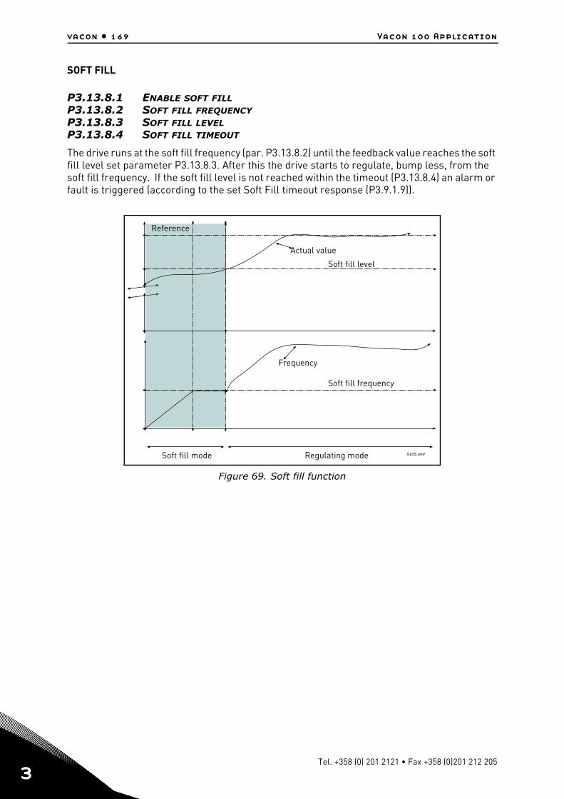
vacon • 169 Vacon 100 Application
3
SOFT FILL
P3.13.8.1 ENABLE SOFT FILLP3.13.8.2 SOFT FILL FREQUENCYP3.13.8.3 SOFT FILL LEVELP3.13.8.4 SOFT FILL TIMEOUT
The drive runs at the soft fill frequency (par. P3.13.8.2) until the feedback value reaches the soft fill level set parameter P3.13.8.3. After this the drive starts to regulate, bump less, from the soft fill frequency. If the soft fill level is not reached within the timeout (P3.13.8.4) an alarm or fault is triggered (according to the set Soft Fill timeout response (P3.9.1.9)).
Figure 69. Soft fill function
9105.emf
Reference
Soft fill level
Actual value
Soft fill mode Regulating mode
Frequency
Soft fill frequency
Tel. +358 (0) 201 2121 • Fax +358 (0)201 212 205
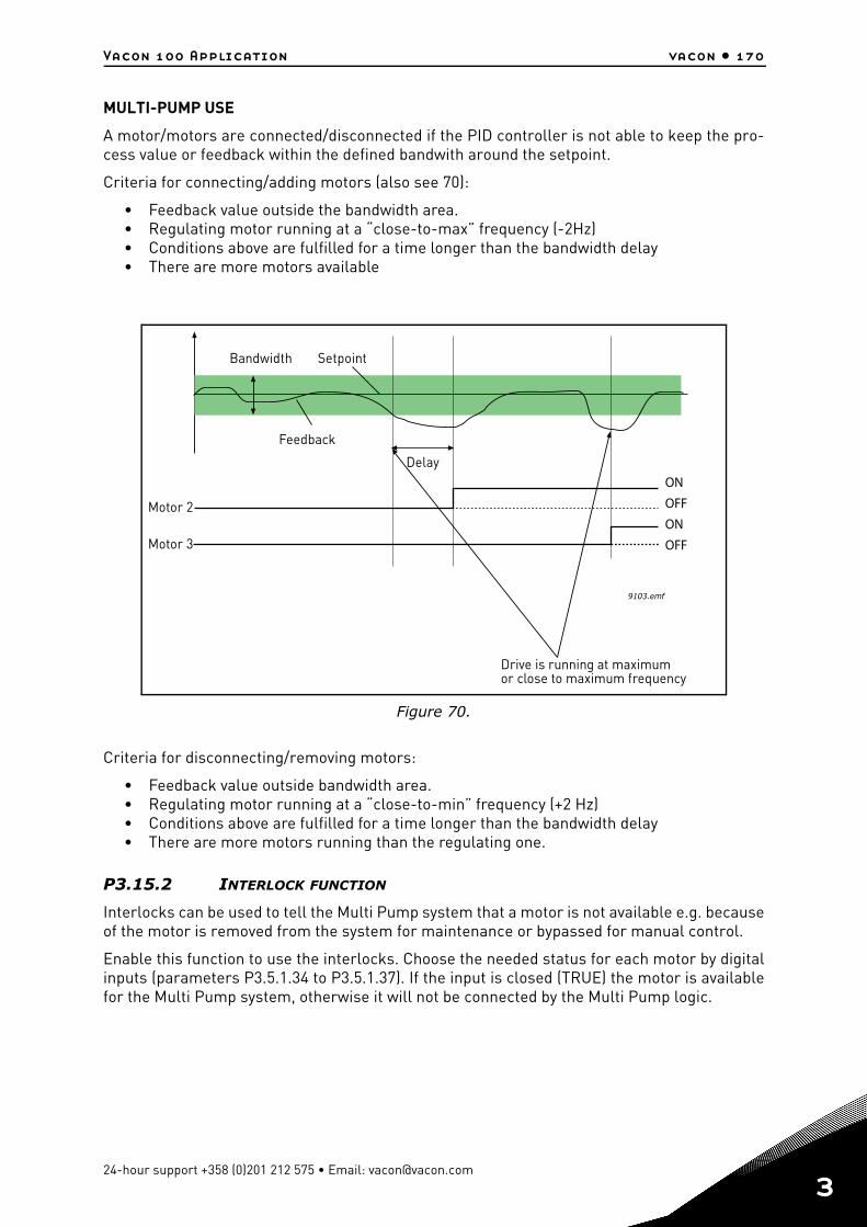
Vacon 100 Application vacon • 170
MULTI-PUMP USE
A motor/motors are connected/disconnected if the PID controller is not able to keep the pro-cess value or feedback within the defined bandwith around the setpoint.
Criteria for connecting/adding motors (also see 70):
• Feedback value outside the bandwidth area.• Regulating motor running at a “close-to-max” frequency (-2Hz)• Conditions above are fulfilled for a time longer than the bandwidth delay• There are more motors available
Figure 70.
Criteria for disconnecting/removing motors:
• Feedback value outside bandwidth area.• Regulating motor running at a “close-to-min” frequency (+2 Hz)• Conditions above are fulfilled for a time longer than the bandwidth delay• There are more motors running than the regulating one.
P3.15.2 INTERLOCK FUNCTION
Interlocks can be used to tell the Multi Pump system that a motor is not available e.g. becauseof the motor is removed from the system for maintenance or bypassed for manual control.
Enable this function to use the interlocks. Choose the needed status for each motor by digitalinputs (parameters P3.5.1.34 to P3.5.1.37). If the input is closed (TRUE) the motor is availablefor the Multi Pump system, otherwise it will not be connected by the Multi Pump logic.
9103.emf
ONOFFONOFF
Motor 2
Motor 3
Delay
Bandwidth
Feedback
Setpoint
Drive is running at maximumor close to maximum frequency
24-hour support +358 (0)201 212 575 • Email: [email protected]
3
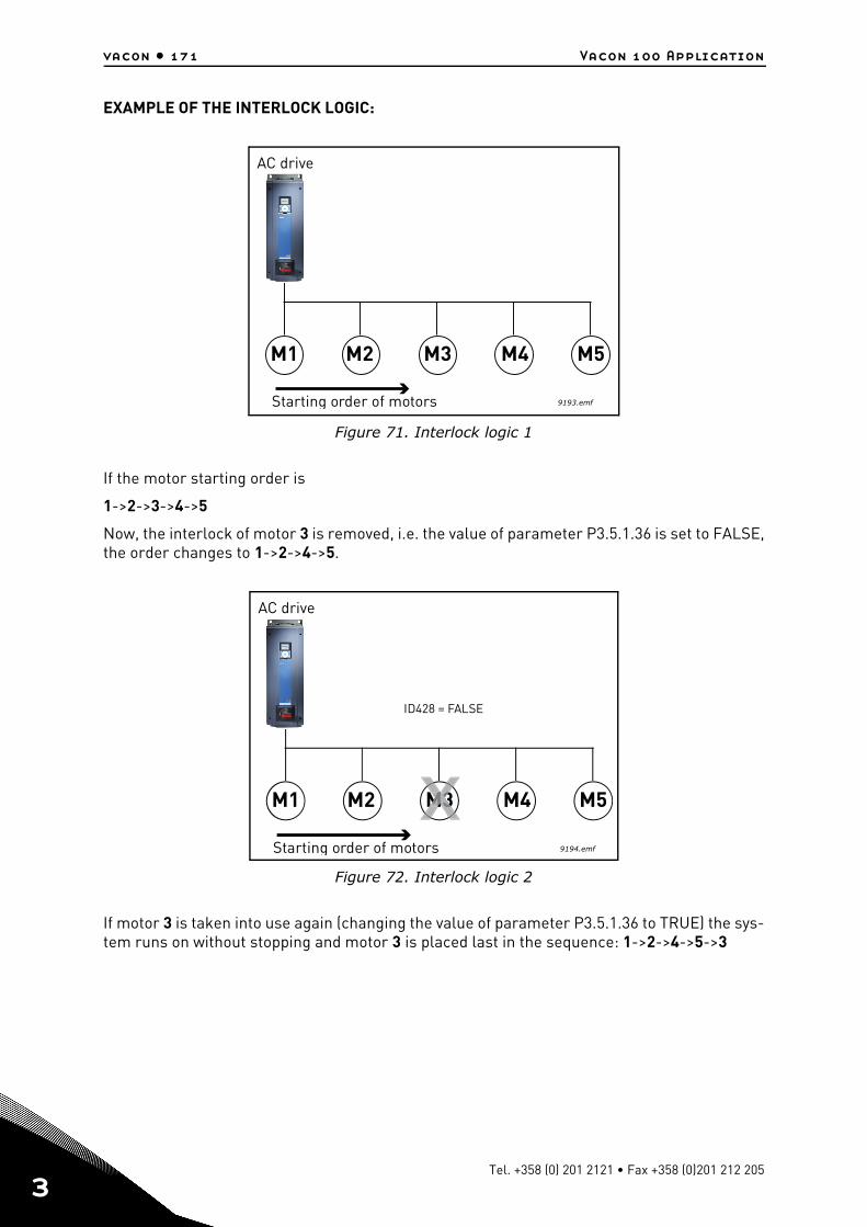
vacon • 171 Vacon 100 Application
3
EXAMPLE OF THE INTERLOCK LOGIC:
Figure 71. Interlock logic 1
If the motor starting order is
1->2->3->4->5
Now, the interlock of motor 3 is removed, i.e. the value of parameter P3.5.1.36 is set to FALSE,the order changes to 1->2->4->5.
Figure 72. Interlock logic 2
If motor 3 is taken into use again (changing the value of parameter P3.5.1.36 to TRUE) the sys-tem runs on without stopping and motor 3 is placed last in the sequence: 1->2->4->5->3
M1 M2 M3 M4 M5
Starting order of motors
AC drive
9193.emf
M1 M2 M3 M4 M5
Starting order of motors
ID428 = FALSE
AC drive
9194.emf
M33M3
Tel. +358 (0) 201 2121 • Fax +358 (0)201 212 205
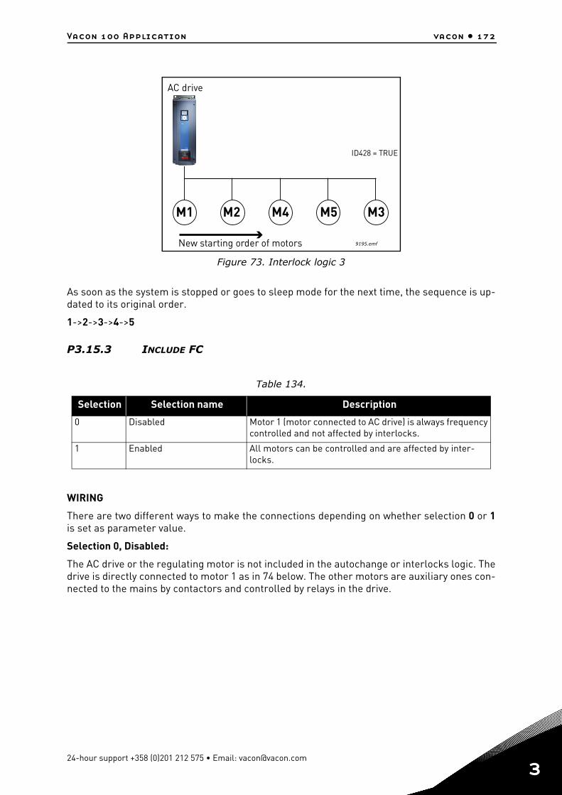
Vacon 100 Application vacon • 172
Figure 73. Interlock logic 3
As soon as the system is stopped or goes to sleep mode for the next time, the sequence is up-dated to its original order.
1->2->3->4->5
P3.15.3 INCLUDE FC
WIRING
There are two different ways to make the connections depending on whether selection 0 or 1is set as parameter value.
Selection 0, Disabled:
The AC drive or the regulating motor is not included in the autochange or interlocks logic. Thedrive is directly connected to motor 1 as in 74 below. The other motors are auxiliary ones con-nected to the mains by contactors and controlled by relays in the drive.
Table 134.
Selection Selection name Description
0 Disabled Motor 1 (motor connected to AC drive) is always frequency controlled and not affected by interlocks.
1 Enabled All motors can be controlled and are affected by inter-locks.
M1 M2 M4 M5 M3
New starting order of motors
ID428 = TRUE
AC drive
9195.emf
24-hour support +358 (0)201 212 575 • Email: [email protected]
3
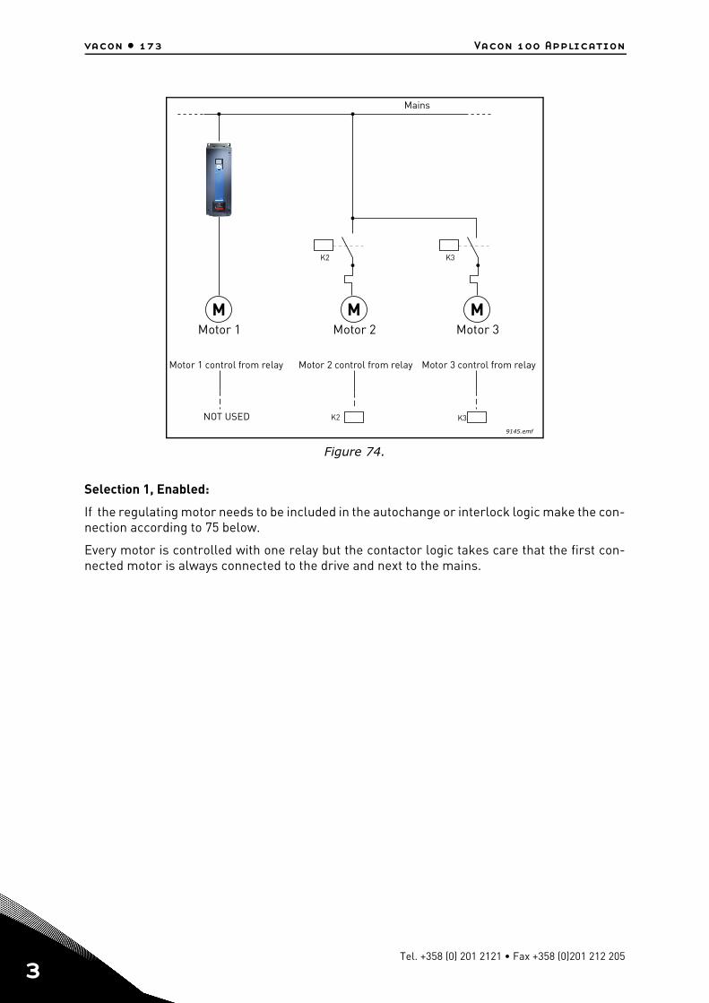
vacon • 173 Vacon 100 Application
3
Figure 74.
Selection 1, Enabled:
If the regulating motor needs to be included in the autochange or interlock logic make the con-nection according to 75 below.
Every motor is controlled with one relay but the contactor logic takes care that the first con-nected motor is always connected to the drive and next to the mains.
M M M
K2 K3
K2 K3
9145.emf
Motor 1 Motor 2 Motor 3
Motor 1 control from relay Motor 2 control from relay Motor 3 control from relay
NOT USED
Mains
Tel. +358 (0) 201 2121 • Fax +358 (0)201 212 205
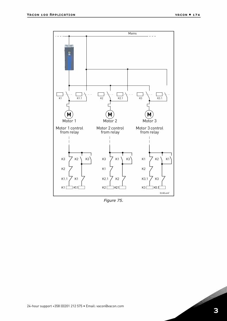
Vacon 100 Application vacon • 174
Figure 75.
M M M
K1 K1.1 K2 K2.1 K3 K3.1
9148.emf
K1 K1.1
K1.1 K1
K2
K3 K2 K3
K2 K2.1
K2.1 K2
K1
K3 K1 K3
K3 K3.1
K3.1 K3
K2
K1 K2 K1
Mains
Motor 1 Motor 2 Motor 3
Motor 1 controlfrom relay
Motor 2 controlfrom relay
Motor 3 controlfrom relay
24-hour support +358 (0)201 212 575 • Email: [email protected]
3
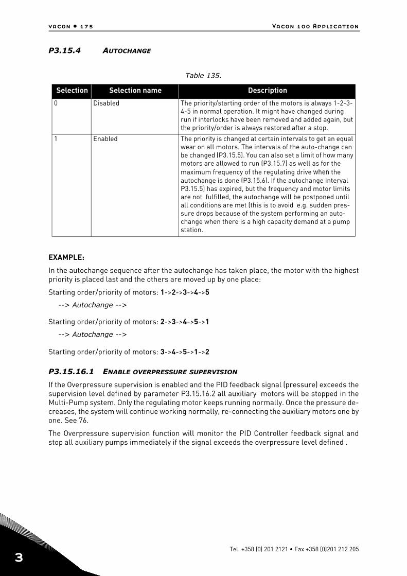
vacon • 175 Vacon 100 Application
3
P3.15.4 AUTOCHANGE
EXAMPLE:
In the autochange sequence after the autochange has taken place, the motor with the highestpriority is placed last and the others are moved up by one place:
Starting order/priority of motors: 1->2->3->4->5
--> Autochange -->
Starting order/priority of motors: 2->3->4->5->1
--> Autochange -->
Starting order/priority of motors: 3->4->5->1->2
P3.15.16.1 ENABLE OVERPRESSURE SUPERVISION
If the Overpressure supervision is enabled and the PID feedback signal (pressure) exceeds thesupervision level defined by parameter P3.15.16.2 all auxiliary motors will be stopped in theMulti-Pump system. Only the regulating motor keeps running normally. Once the pressure de-creases, the system will continue working normally, re-connecting the auxiliary motors one byone. See 76.
The Overpressure supervision function will monitor the PID Controller feedback signal andstop all auxiliary pumps immediately if the signal exceeds the overpressure level defined .
Table 135.
Selection Selection name Description
0 Disabled The priority/starting order of the motors is always 1-2-3-4-5 in normal operation. It might have changed during run if interlocks have been removed and added again, but the priority/order is always restored after a stop.
1 Enabled The priority is changed at certain intervals to get an equal wear on all motors. The intervals of the auto-change can be changed (P3.15.5). You can also set a limit of how many motors are allowed to run (P3.15.7) as well as for the maximum frequency of the regulating drive when the autochange is done (P3.15.6). If the autochange interval P3.15.5) has expired, but the frequency and motor limits are not fulfilled, the autochange will be postponed until all conditions are met (this is to avoid e.g. sudden pres-sure drops because of the system performing an auto-change when there is a high capacity demand at a pump station.
Tel. +358 (0) 201 2121 • Fax +358 (0)201 212 205
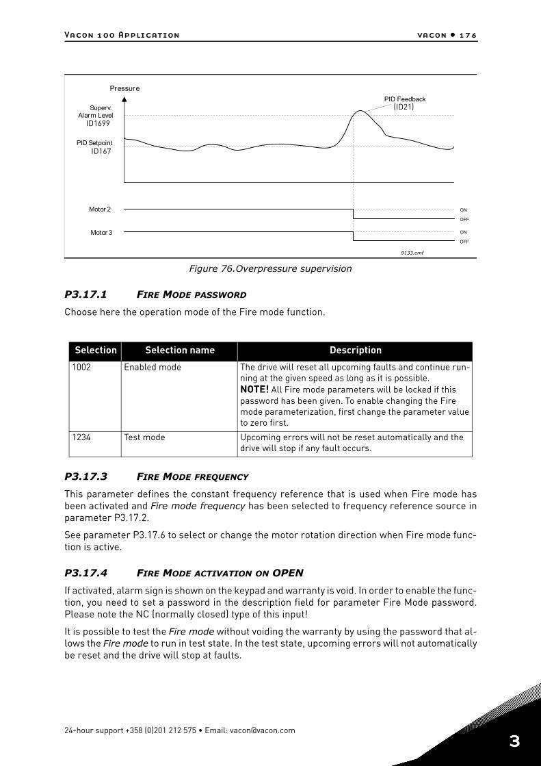
Vacon 100 Application vacon • 176
Figure 76.Overpressure supervision
P3.17.1 FIRE MODE PASSWORD
Choose here the operation mode of the Fire mode function.
P3.17.3 FIRE MODE FREQUENCY
This parameter defines the constant frequency reference that is used when Fire mode hasbeen activated and Fire mode frequency has been selected to frequency reference source inparameter P3.17.2.
See parameter P3.17.6 to select or change the motor rotation direction when Fire mode func-tion is active.
P3.17.4 FIRE MODE ACTIVATION ON OPEN
If activated, alarm sign is shown on the keypad and warranty is void. In order to enable the func-tion, you need to set a password in the description field for parameter Fire Mode password.Please note the NC (normally closed) type of this input!
It is possible to test the Fire mode without voiding the warranty by using the password that al-lows the Fire mode to run in test state. In the test state, upcoming errors will not automaticallybe reset and the drive will stop at faults.
Selection Selection name Description
1002 Enabled mode The drive will reset all upcoming faults and continue run-ning at the given speed as long as it is possible.NOTE! All Fire mode parameters will be locked if this password has been given. To enable changing the Fire mode parameterization, first change the parameter value to zero first.
1234 Test mode Upcoming errors will not be reset automatically and the drive will stop if any fault occurs.
Pressure
Motor 2
Superv.Alarm Level
PID Feedback
PID Setpoint
Motor 3 ON
OFF
ON
OFF
ID1699
ID167
(ID21)
9133.emf
24-hour support +358 (0)201 212 575 • Email: [email protected]
3
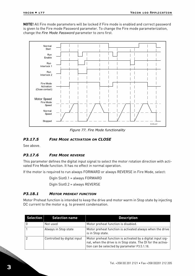
vacon • 177 Vacon 100 Application
3
NOTE! All Fire mode parameters will be locked if Fire mode is enabled and correct password is given to the Fire mode Password parameter. To change the Fire mode parameterization, change the Fire Mode Password parameter to zero first.
Figure 77. Fire Mode functionality
P3.17.5 FIRE MODE ACTIVATION ON CLOSE
See above.
P3.17.6 FIRE MODE REVERSE
This parameter defines the digital input signal to select the motor rotation direction with acti-vated Fire Mode function. It has no effect in normal operation.
If the motor is required to run always FORWARD or always REVERSE in Fire Mode, select:
DigIn Slot0.1 = always FORWARD
DigIn Slot0.2 = always REVERSE
P3.18.1 MOTOR PREHEAT FUNCTION
Motor Preheat function is intended to keep the drive and motor warm in Stop state by injectingDC current to the motor e.g. to prevent condensation.
Selection Selection name Description
0 Not used Motor preheat function is disabled.
1 Always in Stop state Motor preheat function is activated always when the drive is in Stop state.
2 Controlled by digital input Motor preheat function is activated by a digital input sig-nal, when the drive is in Stop state. The DI for the activa-tion can be selected by parameter P3.5.1.18.
9138.emf
NormalStart
RunEnable
RunInterlock 2
Fire ModeActivation
(Close contact)
Motor Speed
Stopped
NormalSpeed
Fire ModeSpeed
RunInterlock 1
Tel. +358 (0) 201 2121 • Fax +358 (0)201 212 205
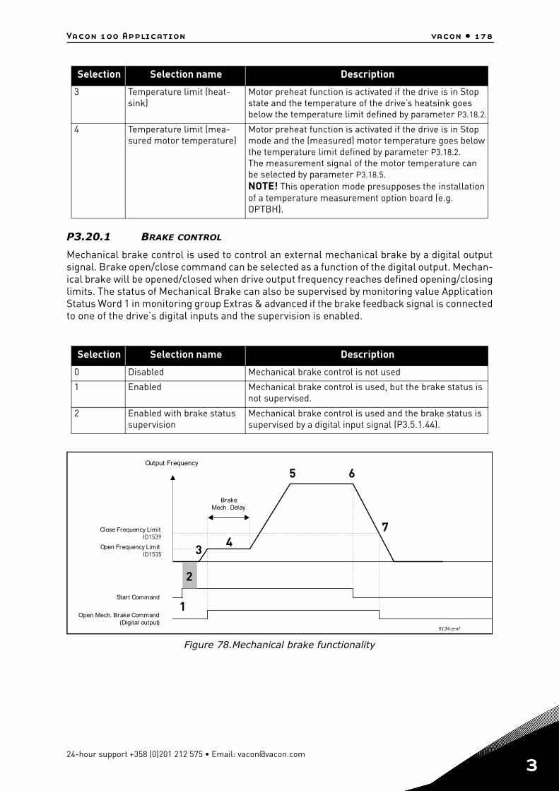
Vacon 100 Application vacon • 178
P3.20.1 BRAKE CONTROL
Mechanical brake control is used to control an external mechanical brake by a digital outputsignal. Brake open/close command can be selected as a function of the digital output. Mechan-ical brake will be opened/closed when drive output frequency reaches defined opening/closinglimits. The status of Mechanical Brake can also be supervised by monitoring value ApplicationStatus Word 1 in monitoring group Extras & advanced if the brake feedback signal is connectedto one of the drive’s digital inputs and the supervision is enabled.
Figure 78.Mechanical brake functionality
3 Temperature limit (heat-sink)
Motor preheat function is activated if the drive is in Stop state and the temperature of the drive’s heatsink goes below the temperature limit defined by parameter P3.18.2.
4 Temperature limit (mea-sured motor temperature)
Motor preheat function is activated if the drive is in Stop mode and the (measured) motor temperature goes below the temperature limit defined by parameter P3.18.2.The measurement signal of the motor temperature can be selected by parameter P3.18.5.NOTE! This operation mode presupposes the installation of a temperature measurement option board (e.g. OPTBH).
Selection Selection name Description
0 Disabled Mechanical brake control is not used
1 Enabled Mechanical brake control is used, but the brake status is not supervised.
2 Enabled with brake status supervision
Mechanical brake control is used and the brake status is supervised by a digital input signal (P3.5.1.44).
Selection Selection name Description
Close Frequency Limit
Output Frequency
Open Frequency Limit
BrakeMech. Delay
Open Mech. Brake Command(Digital output)
Start Command
ID1539
ID1535
9134.emf
1
2
3
5
4
6
7
24-hour support +358 (0)201 212 575 • Email: [email protected]
3
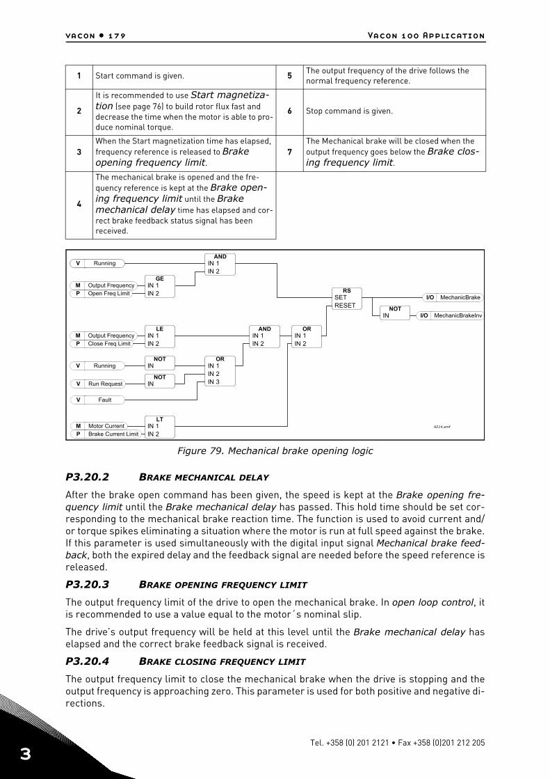
vacon • 179 Vacon 100 Application
3
Figure 79. Mechanical brake opening logic
P3.20.2 BRAKE MECHANICAL DELAY
After the brake open command has been given, the speed is kept at the Brake opening fre-quency limit until the Brake mechanical delay has passed. This hold time should be set cor-responding to the mechanical brake reaction time. The function is used to avoid current and/or torque spikes eliminating a situation where the motor is run at full speed against the brake.If this parameter is used simultaneously with the digital input signal Mechanical brake feed-back, both the expired delay and the feedback signal are needed before the speed reference isreleased.
P3.20.3 BRAKE OPENING FREQUENCY LIMIT
The output frequency limit of the drive to open the mechanical brake. In open loop control, itis recommended to use a value equal to the motor´s nominal slip.
The drive’s output frequency will be held at this level until the Brake mechanical delay haselapsed and the correct brake feedback signal is received.
P3.20.4 BRAKE CLOSING FREQUENCY LIMIT
The output frequency limit to close the mechanical brake when the drive is stopping and theoutput frequency is approaching zero. This parameter is used for both positive and negative di-rections.
1 Start command is given. 5 The output frequency of the drive follows the normal frequency reference.
2
It is recommended to use Start magnetiza-tion (see page 76) to build rotor flux fast and decrease the time when the motor is able to pro-duce nominal torque.
6 Stop command is given.
3When the Start magnetization time has elapsed, frequency reference is released to Brake opening frequency limit.
7The Mechanical brake will be closed when the output frequency goes below the Brake clos-ing frequency limit.
4
The mechanical brake is opened and the fre-quency reference is kept at the Brake open-ing frequency limit until the Brake mechanical delay time has elapsed and cor-rect brake feedback status signal has been received.
RS
AND12
GE12P
M
V Running
LE12P
M
NOT
NOT
V
V
V
V
OR123
AND12
OR12
LT12
MP
I/O
I/ONOT
SETRESET
ININ
ININOpen Freq Limit
Output Frequency
ININClose Freq Limit
Output Frequency
IN
IN
Running
Running
Run Request
Fault
INININ
ININ
ININ
ININ
Motor CurrentBrake Current Limit
MechanicBrake
MechanicBrakeInvIN
9214.emf
Tel. +358 (0) 201 2121 • Fax +358 (0)201 212 205
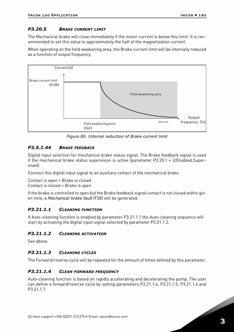
Vacon 100 Application vacon • 180
P3.20.5 BRAKE CURRENT LIMIT
The Mechanical brake will close immediately if the motor current is below this limit. It is rec-ommended to set this value to approximately the half of the magnetization current.
When operating on the field weakening area, the Brake current limit will be internally reducedas a function of output frequency.
Figure 80. Internal reduction of Brake current limit
P3.5.1.44 BRAKE FEEDBACK
Digital input selection for mechanical brake status signal. The Brake feedback signal is usedif the mechanical brake status supervision is active (parameter P3.20.1 = 2/Enabled,Super-vised).
Connect this digital input signal to an auxiliary contact of the mechanical brake.
Contact is open = Brake is closedContact is closed = Brake is open
If the brake is controlled to open but the Brake feedback signal contact is not closed within giv-en time, a Mechanical brake fault (F58) will be generated.
P3.21.1.1 CLEANING FUNCTION
If Auto-cleaning function is enabled by parameter P3.21.1.1 the Auto-cleaning sequence will start by activating the digital input signal selected by parameter P3.21.1.2.
P3.21.1.2 CLEANING ACTIVATION
See above.
P3.21.1.3 CLEANING CYCLES
The Forward/reverse cycle will be repeated for the amount of times defined by this parameter.
P3.21.1.4 CLEAN FORWARD FREQUENCY
Auto-cleaning function is based on rapidly accelerating and decelerating the pump. The usercan define a forward/reverse cycle by setting parameters P3.21.1.4, P3.21.1.5, P3.21.1.6 andP3.21.1.7.
(A)
(Hz)
ID1085
ID602
Brake current limit
Current
OutputfrequencyField weakening point
Field weakening area
9215.emf
24-hour support +358 (0)201 212 575 • Email: [email protected]
3
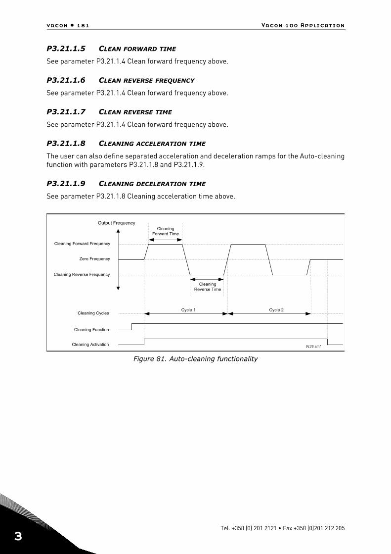
vacon • 181 Vacon 100 Application
3
P3.21.1.5 CLEAN FORWARD TIME
See parameter P3.21.1.4 Clean forward frequency above.
P3.21.1.6 CLEAN REVERSE FREQUENCY
See parameter P3.21.1.4 Clean forward frequency above.
P3.21.1.7 CLEAN REVERSE TIME
See parameter P3.21.1.4 Clean forward frequency above.
P3.21.1.8 CLEANING ACCELERATION TIME
The user can also define separated acceleration and deceleration ramps for the Auto-cleaningfunction with parameters P3.21.1.8 and P3.21.1.9.
P3.21.1.9 CLEANING DECELERATION TIME
See parameter P3.21.1.8 Cleaning acceleration time above.
Figure 81. Auto-cleaning functionality
Zero Frequency
Output Frequency
Cleaning Forward Frequency
Cleaning Reverse Frequency
CleaningForward Time
Cleaning Activation
CleaningReverse Time
Cleaning Function
Cycle 1 Cycle 2Cleaning Cycles
9139.emf
Tel. +358 (0) 201 2121 • Fax +358 (0)201 212 205
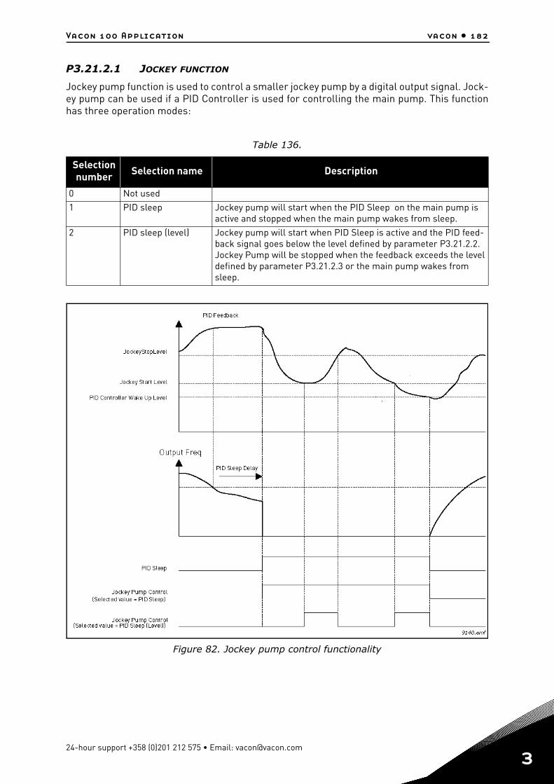
Vacon 100 Application vacon • 182
P3.21.2.1 JOCKEY FUNCTION
Jockey pump function is used to control a smaller jockey pump by a digital output signal. Jock-ey pump can be used if a PID Controller is used for controlling the main pump. This functionhas three operation modes:
Figure 82. Jockey pump control functionality
Table 136.
Selection number Selection name Description
0 Not used1 PID sleep Jockey pump will start when the PID Sleep on the main pump is
active and stopped when the main pump wakes from sleep.2 PID sleep (level) Jockey pump will start when PID Sleep is active and the PID feed-
back signal goes below the level defined by parameter P3.21.2.2. Jockey Pump will be stopped when the feedback exceeds the level defined by parameter P3.21.2.3 or the main pump wakes from sleep.
24-hour support +358 (0)201 212 575 • Email: [email protected]
3
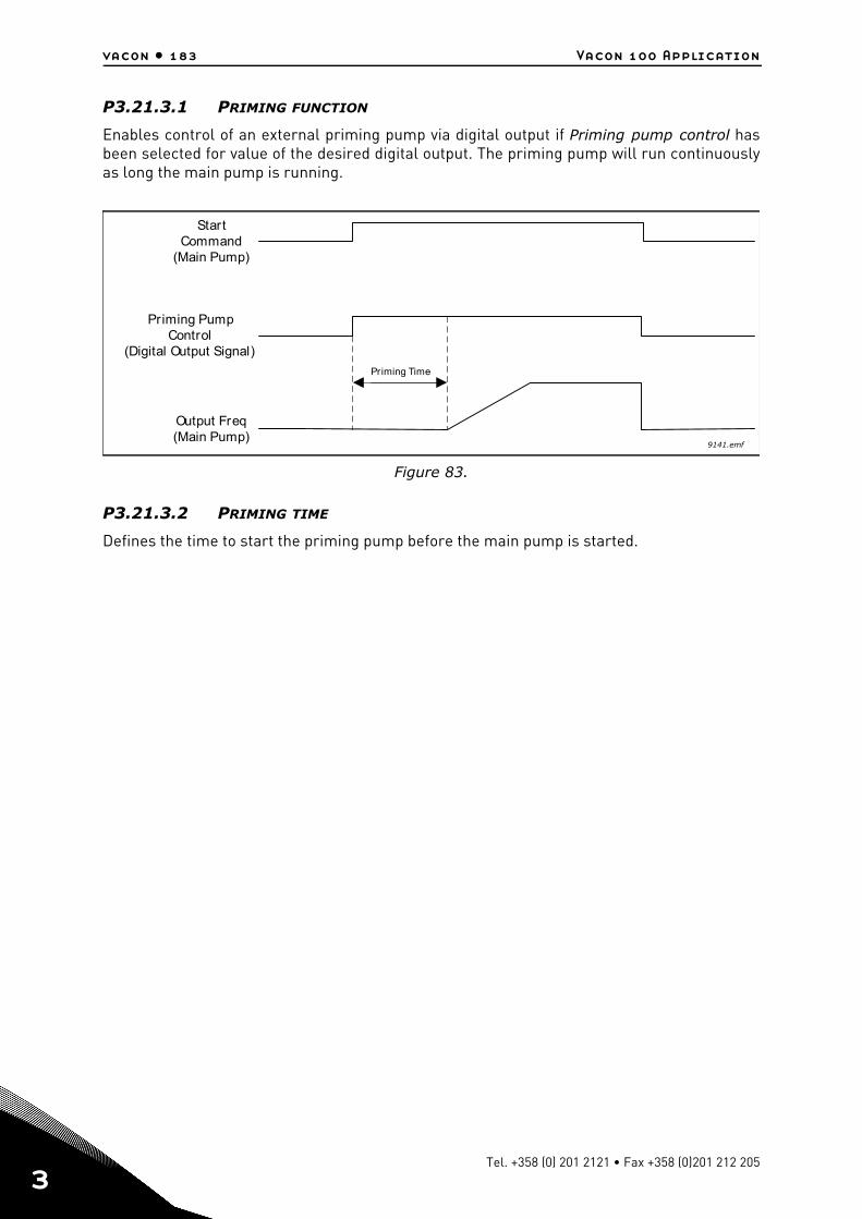
vacon • 183 Vacon 100 Application
3
P3.21.3.1 PRIMING FUNCTION
Enables control of an external priming pump via digital output if Priming pump control hasbeen selected for value of the desired digital output. The priming pump will run continuouslyas long the main pump is running.
Figure 83.
P3.21.3.2 PRIMING TIME
Defines the time to start the priming pump before the main pump is started.
StartCommand
(Main Pump)
Priming PumpControl
(Digital Output Signal)
Output Freq(Main Pump)
Priming Time
9141.emf
Tel. +358 (0) 201 2121 • Fax +358 (0)201 212 205
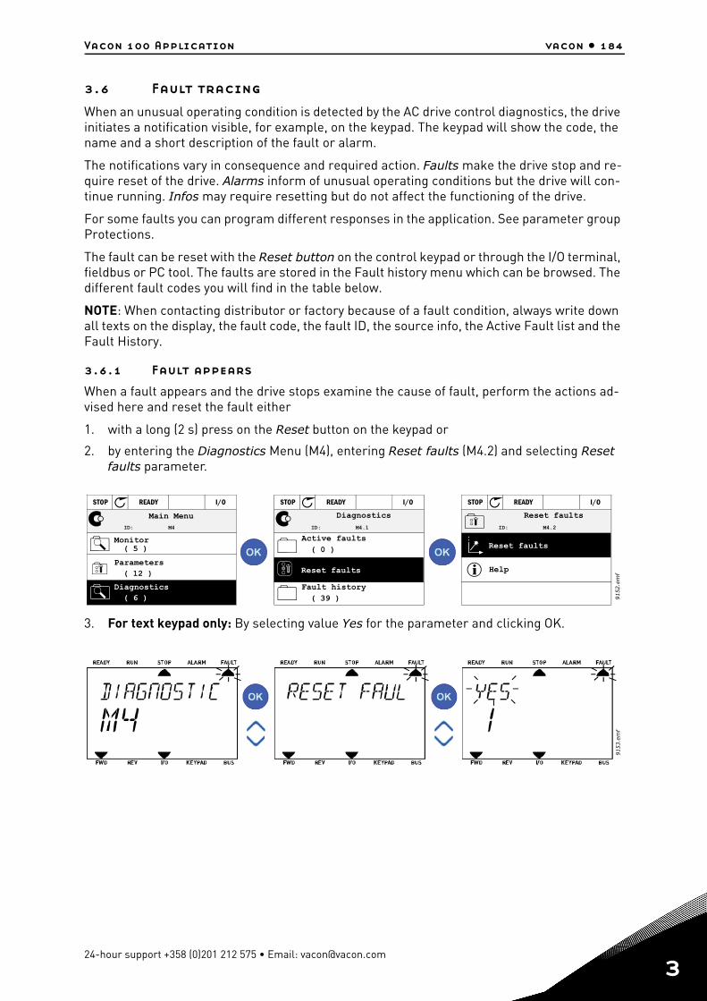
Vacon 100 Application vacon • 184
3.6 Fault tracing
When an unusual operating condition is detected by the AC drive control diagnostics, the drive initiates a notification visible, for example, on the keypad. The keypad will show the code, the name and a short description of the fault or alarm.
The notifications vary in consequence and required action. Faults make the drive stop and re-quire reset of the drive. Alarms inform of unusual operating conditions but the drive will con-tinue running. Infos may require resetting but do not affect the functioning of the drive.
For some faults you can program different responses in the application. See parameter group Protections.
The fault can be reset with the Reset button on the control keypad or through the I/O terminal, fieldbus or PC tool. The faults are stored in the Fault history menu which can be browsed. The different fault codes you will find in the table below.
NOTE: When contacting distributor or factory because of a fault condition, always write down all texts on the display, the fault code, the fault ID, the source info, the Active Fault list and the Fault History.
3.6.1 Fault appears
When a fault appears and the drive stops examine the cause of fault, perform the actions ad-vised here and reset the fault either
1. with a long (2 s) press on the Reset button on the keypad or
2. by entering the Diagnostics Menu (M4), entering Reset faults (M4.2) and selecting Reset faults parameter.
3. For text keypad only: By selecting value Yes for the parameter and clicking OK.
( 5 )( 12 )
( 6 )
ID: M4
STOP READY I/O
( 0 )
( 39 )
ID: M4.1
STOP READY I/O
ID: M4.2
STOP READY I/O
9152.e
mf
Main Menu
Monitor
Parameters
Diagnostics
Diagnostics
Active faults
Fault history
Reset faults
Reset faults
Reset faults
Help
9153.e
mf
24-hour support +358 (0)201 212 575 • Email: [email protected]
3
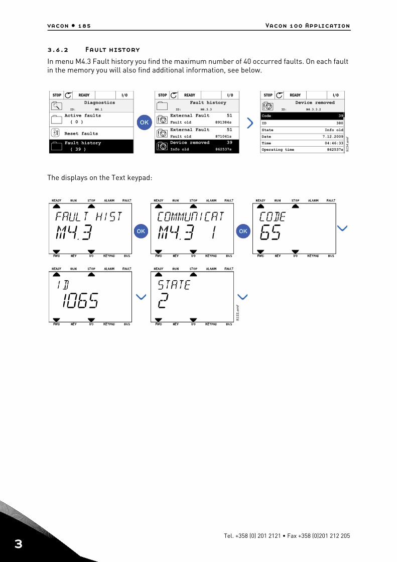
vacon • 185 Vacon 100 Application
3
3.6.2 Fault history
In menu M4.3 Fault history you find the maximum number of 40 occurred faults. On each fault in the memory you will also find additional information, see below.
The displays on the Text keypad:
( 0 )
( 39 )
ID: M4.1
STOP READY I/O
!!!
51
891384s
51
871061s
39
862537s
ID: M4.3.3
STOP READY I/O
! ID: M4.3.3.2
39
380
7.12.2009
04:46:33
862537s
STOP READY I/O
9154.e
mf
Diagnostics
Active faults
Reset faults
Fault history
Fault history
External Fault
Fault old
External Fault
Fault old
Device removed
Info old
Device removed
Code
ID
State Info old
Date
Time
Operating time
9155.e
mf
Tel. +358 (0) 201 2121 • Fax +358 (0)201 212 205
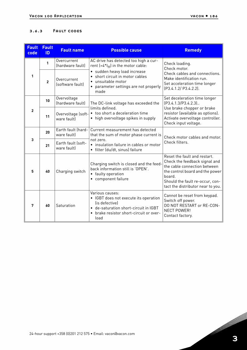
Vacon 100 Application vacon • 186
3.6.3 Fault codes
Fault code
FaultID Fault name Possible cause Remedy
1
1Overcurrent (hardware fault)
AC drive has detected too high a cur-rent (>4*IH) in the motor cable:• sudden heavy load increase• short circuit in motor cables• unsuitable motor• parameter settings are not properly
made
Check loading.Check motor.Check cables and connections.Make identification run.Set acceleration time longer (P3.4.1.2/ P3.4.2.2).
2Overcurrent (software fault)
2
10Overvoltage (hardware fault) The DC-link voltage has exceeded the
limits defined.• too short a deceleration time• high overvoltage spikes in supply
Set deceleration time longer (P3.4.1.3/P3.4.2.3)..Use brake chopper or brake resistor (available as options).Activate overvoltage controller.Check input voltage.
11Overvoltage (soft-ware fault)
3
20Earth fault (hard-ware fault)
Current measurement has detected that the sum of motor phase current is not zero.• insulation failure in cables or motor• filter (du/dt, sinus) failure
Check motor cables and motor.Check filters.
21Earth fault (soft-ware fault)
5 40 Charging switch
Charging switch is closed and the feed-back information still is ‘OPEN’.• faulty operation• component failure
Reset the fault and restart.Check the feedback signal and the cable connection between the control board and the powerboard.Should the fault re-occur, con-tact the distributor near to you.
7 60 Saturation
Various causes:• IGBT does not execute its operation
(is defective)• de-saturation short-circuit in IGBT• brake resistor short-circuit or over-
load
Cannot be reset from keypad. Switch off power.DO NOT RESTART or RE-CON-NECT POWER!Contact factory.
24-hour support +358 (0)201 212 575 • Email: [email protected]
3
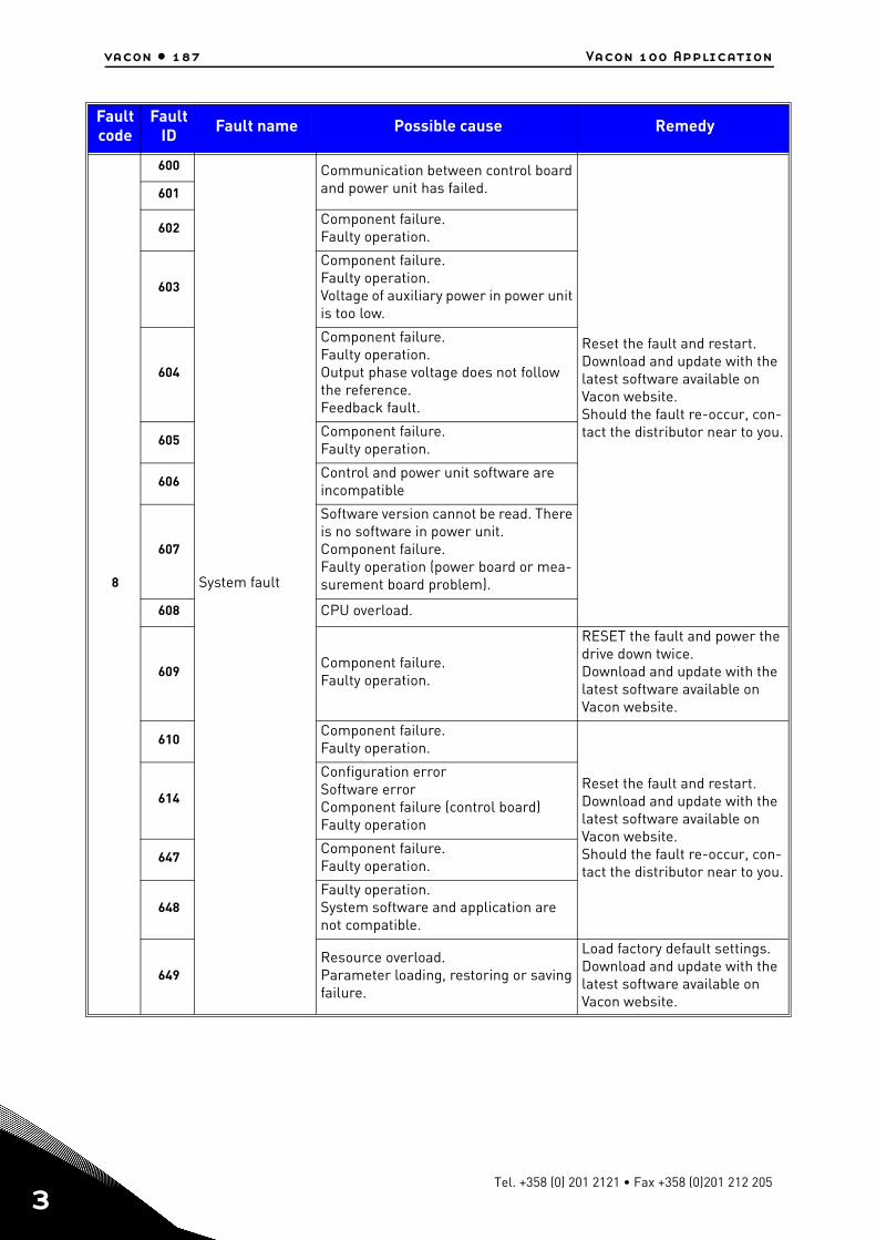
vacon • 187 Vacon 100 Application
3
8
600
System fault
Communication between control board and power unit has failed.
Reset the fault and restart.Download and update with the latest software available on Vacon website.Should the fault re-occur, con-tact the distributor near to you.
601
602Component failure.Faulty operation.
603
Component failure.Faulty operation.Voltage of auxiliary power in power unit is too low.
604
Component failure.Faulty operation.Output phase voltage does not follow the reference.Feedback fault.
605Component failure.Faulty operation.
606Control and power unit software are incompatible
607
Software version cannot be read. There is no software in power unit.Component failure.Faulty operation (power board or mea-surement board problem).
608 CPU overload.
609Component failure.Faulty operation.
RESET the fault and power the drive down twice.Download and update with the latest software available on Vacon website.
610Component failure.Faulty operation.
Reset the fault and restart.Download and update with the latest software available on Vacon website.Should the fault re-occur, con-tact the distributor near to you.
614
Configuration errorSoftware errorComponent failure (control board)Faulty operation
647Component failure.Faulty operation.
648Faulty operation.System software and application are not compatible.
649Resource overload.Parameter loading, restoring or saving failure.
Load factory default settings.Download and update with the latest software available on Vacon website.
Fault code
FaultID Fault name Possible cause Remedy
Tel. +358 (0) 201 2121 • Fax +358 (0)201 212 205
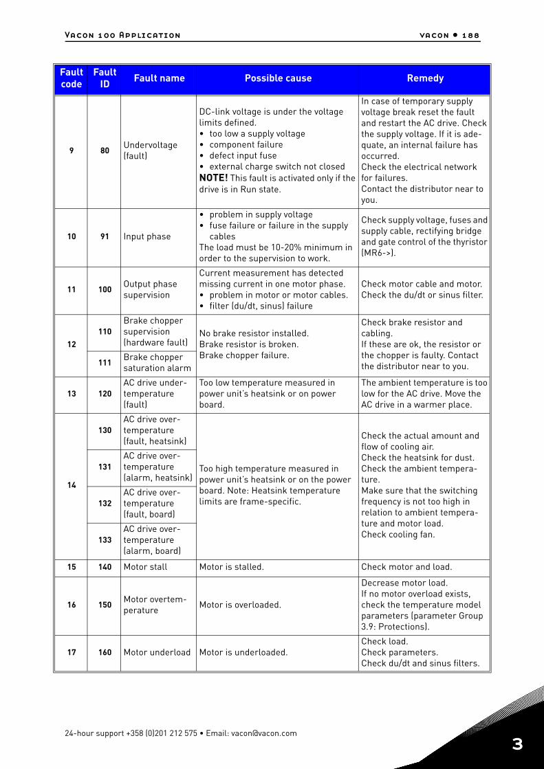
Vacon 100 Application vacon • 188
9 80Undervoltage (fault)
DC-link voltage is under the voltage limits defined.• too low a supply voltage• component failure• defect input fuse• external charge switch not closedNOTE! This fault is activated only if the drive is in Run state.
In case of temporary supply voltage break reset the fault and restart the AC drive. Check the supply voltage. If it is ade-quate, an internal failure has occurred.Check the electrical network for failures.Contact the distributor near to you.
10 91 Input phase
• problem in supply voltage• fuse failure or failure in the supply
cablesThe load must be 10-20% minimum in order to the supervision to work.
Check supply voltage, fuses andsupply cable, rectifying bridge and gate control of the thyristor (MR6->).
11 100Output phase supervision
Current measurement has detected missing current in one motor phase.• problem in motor or motor cables.• filter (du/dt, sinus) failure
Check motor cable and motor.Check the du/dt or sinus filter.
12
110Brake chopper supervision (hardware fault)
No brake resistor installed.Brake resistor is broken.Brake chopper failure.
Check brake resistor and cabling.If these are ok, the resistor or the chopper is faulty. Contact the distributor near to you.111
Brake chopper saturation alarm
13 120AC drive under-temperature (fault)
Too low temperature measured in power unit’s heatsink or on power board.
The ambient temperature is toolow for the AC drive. Move the AC drive in a warmer place.
14
130AC drive over-temperature (fault, heatsink)
Too high temperature measured in power unit’s heatsink or on the power board. Note: Heatsink temperature limits are frame-specific.
Check the actual amount and flow of cooling air.Check the heatsink for dust.Check the ambient tempera-ture.Make sure that the switching frequency is not too high in relation to ambient tempera-ture and motor load.Check cooling fan.
131AC drive over-temperature (alarm, heatsink)
132AC drive over-temperature (fault, board)
133AC drive over-temperature (alarm, board)
15 140 Motor stall Motor is stalled. Check motor and load.
16 150Motor overtem-perature Motor is overloaded.
Decrease motor load.If no motor overload exists, check the temperature model parameters (parameter Group 3.9: Protections).
17 160 Motor underload Motor is underloaded.Check load.Check parameters.Check du/dt and sinus filters.
Fault code
FaultID Fault name Possible cause Remedy
24-hour support +358 (0)201 212 575 • Email: [email protected]
3
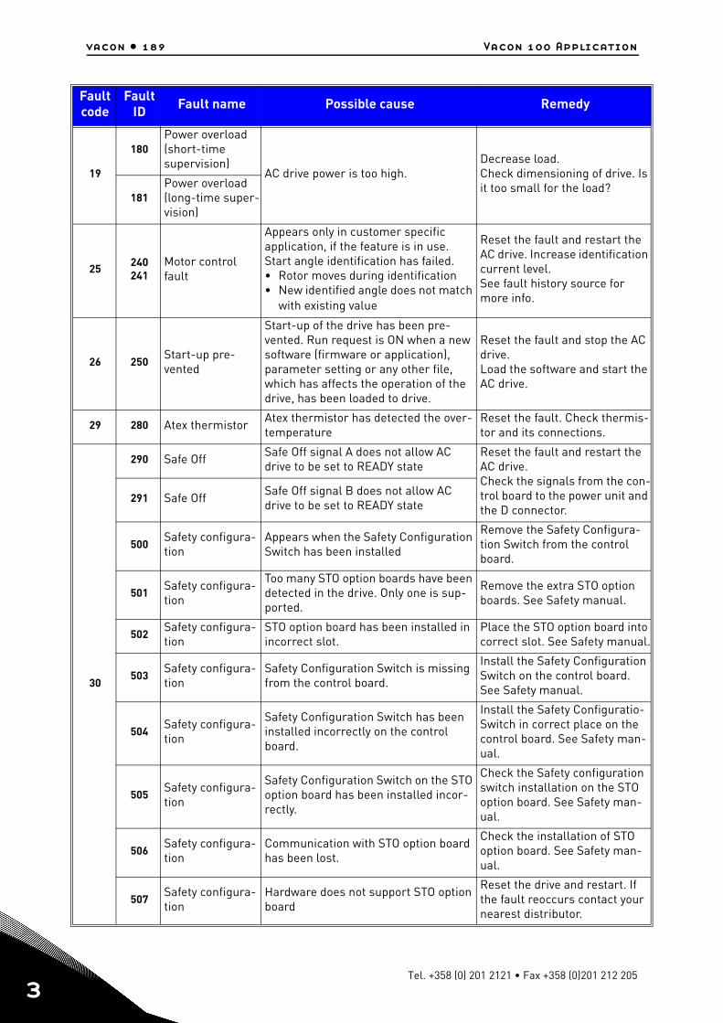
vacon • 189 Vacon 100 Application
3
19
180Power overload (short-time supervision)
AC drive power is too high.Decrease load.Check dimensioning of drive. Is it too small for the load?
181Power overload (long-time super-vision)
25 240241
Motor control fault
Appears only in customer specific application, if the feature is in use.Start angle identification has failed.• Rotor moves during identification• New identified angle does not match
with existing value
Reset the fault and restart the AC drive. Increase identificationcurrent level.See fault history source for more info.
26 250Start-up pre-vented
Start-up of the drive has been pre-vented. Run request is ON when a new software (firmware or application), parameter setting or any other file, which has affects the operation of the drive, has been loaded to drive.
Reset the fault and stop the AC drive.Load the software and start the AC drive.
29 280 Atex thermistor Atex thermistor has detected the over-temperature
Reset the fault. Check thermis-tor and its connections.
30
290 Safe Off Safe Off signal A does not allow AC drive to be set to READY state
Reset the fault and restart the AC drive. Check the signals from the con-trol board to the power unit and the D connector.
291 Safe Off Safe Off signal B does not allow AC drive to be set to READY state
500Safety configura-tion
Appears when the Safety Configuration Switch has been installed
Remove the Safety Configura-tion Switch from the control board.
501Safety configura-tion
Too many STO option boards have been detected in the drive. Only one is sup-ported.
Remove the extra STO option boards. See Safety manual.
502Safety configura-tion
STO option board has been installed in incorrect slot.
Place the STO option board into correct slot. See Safety manual.
503Safety configura-tion
Safety Configuration Switch is missing from the control board.
Install the Safety Configuration Switch on the control board. See Safety manual.
504Safety configura-tion
Safety Configuration Switch has been installed incorrectly on the control board.
Install the Safety Configuratio-Switch in correct place on the control board. See Safety man-ual.
505Safety configura-tion
Safety Configuration Switch on the STO option board has been installed incor-rectly.
Check the Safety configuration switch installation on the STO option board. See Safety man-ual.
506Safety configura-tion
Communication with STO option board has been lost.
Check the installation of STO option board. See Safety man-ual.
507Safety configura-tion
Hardware does not support STO option board
Reset the drive and restart. If the fault reoccurs contact your nearest distributor.
Fault code
FaultID Fault name Possible cause Remedy
Tel. +358 (0) 201 2121 • Fax +358 (0)201 212 205
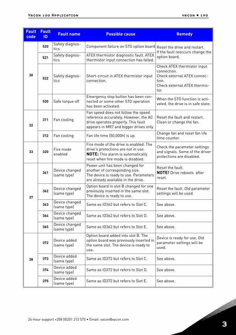
Vacon 100 Application vacon • 190
30
520Safety diagnos-tics Component failure on STO option board Reset the drive and restart.
If the fault reoccurs change the option board.521
Safety diagnos-tics
ATEX thermistor diagnostic fault. ATEX thermistor input connection has failed.
522Safety diagnos-tics
Short-circuit in ATEX thermistor input connection.
Check ATEX thermistor input connection.Check external ATEX connec-tion.Check external ATEX thermis-tor.
530 Safe torque offEmergency stop button has been con-nected or some other STO operation has been activated.
When the STO function is acti-vated, the drive is in safe state.
32
311 Fan cooling
Fan speed does not follow the speed reference accurately. However, the AC drive operates properly. This fault appears in MR7 and bigger drives only.
Reset the fault and restart. Clean or change the fan.
312 Fan cooling Fan life time (50,000h) is up. Change fan and reset fan life time counter.
33 320Fire mode enabled
Fire mode of the drive is enabled. The drive's protections are not in use. NOTE: This alarm is automatically reset when fire mode is disabled.
Check the parameter settings and signals. Some of the driver protections are disabled.
37
361Device changed (same type)
Power unit has been changed for another of corresponding size.The device is ready to use. Parameters are already available in the drive.
Reset the fault.NOTE! Drive reboots after reset.
362Device changed (same type)
Option board in slot B changed for one previously inserted in the same slot. The device is ready to use.
Reset the fault. Old parameter settings will be used.
363Device changed (same type) Same as ID362 but refers to Slot C. See above.
364Device changed (same type) Same as ID362 but refers to Slot D. See above.
365Device changed (same type) Same as ID362 but refers to Slot E. See above.
38
372Device added (same type)
Option board added into slot B. The option board was previously inserted in the same slot. The device is ready to use.
Device is ready for use. Old parameter settings will be used.
373Device added (same type) Same as ID372 but refers to Slot C. See above.
374Device added (same type) Same as ID372 but refers to Slot D. See above.
375Device added (same type) Same as ID372 but refers to Slot E. See above.
Fault code
FaultID Fault name Possible cause Remedy
24-hour support +358 (0)201 212 575 • Email: [email protected]
3
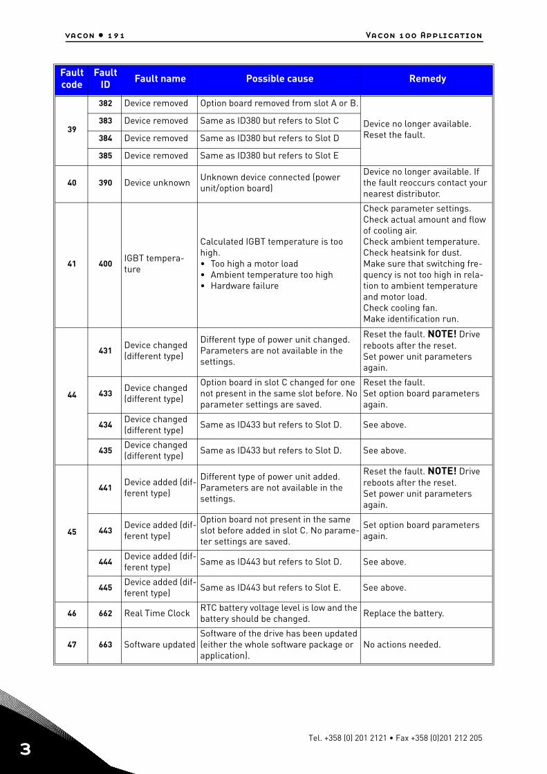
vacon • 191 Vacon 100 Application
3
39
382 Device removed Option board removed from slot A or B.
Device no longer available. Reset the fault.
383 Device removed Same as ID380 but refers to Slot C
384 Device removed Same as ID380 but refers to Slot D
385 Device removed Same as ID380 but refers to Slot E
40 390 Device unknown Unknown device connected (power unit/option board)
Device no longer available. If the fault reoccurs contact your nearest distributor.
41 400IGBT tempera-ture
Calculated IGBT temperature is too high.• Too high a motor load• Ambient temperature too high• Hardware failure
Check parameter settings.Check actual amount and flow of cooling air.Check ambient temperature.Check heatsink for dust.Make sure that switching fre-quency is not too high in rela-tion to ambient temperature and motor load.Check cooling fan.Make identification run.
44
431Device changed (different type)
Different type of power unit changed. Parameters are not available in the settings.
Reset the fault. NOTE! Drive reboots after the reset.Set power unit parameters again.
433Device changed (different type)
Option board in slot C changed for one not present in the same slot before. No parameter settings are saved.
Reset the fault.Set option board parameters again.
434Device changed (different type) Same as ID433 but refers to Slot D. See above.
435Device changed (different type) Same as ID433 but refers to Slot D. See above.
45
441Device added (dif-ferent type)
Different type of power unit added. Parameters are not available in the settings.
Reset the fault. NOTE! Drive reboots after the reset.Set power unit parameters again.
443Device added (dif-ferent type)
Option board not present in the same slot before added in slot C. No parame-ter settings are saved.
Set option board parameters again.
444Device added (dif-ferent type) Same as ID443 but refers to Slot D. See above.
445Device added (dif-ferent type) Same as ID443 but refers to Slot E. See above.
46 662 Real Time Clock RTC battery voltage level is low and the battery should be changed. Replace the battery.
47 663 Software updatedSoftware of the drive has been updated (either the whole software package or application).
No actions needed.
Fault code
FaultID Fault name Possible cause Remedy
Tel. +358 (0) 201 2121 • Fax +358 (0)201 212 205
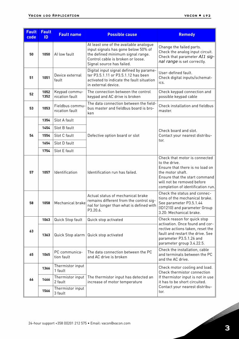
Vacon 100 Application vacon • 192
50 1050 AI low fault
At least one of the available analogue input signals has gone below 50% of the defined minimum signal range.Control cable is broken or loose.Signal source has failed.
Change the failed parts.Check the analog input circuit.Check that parameter AI1 sig-nal range is set correctly.
51 1051Device external fault
Digital input signal defined by parame-ter P3.5.1.11 or P3.5.1.12 has been activated to indicate the fault situation in external device.
User-defined fault. Check digital inputs/schemat-ics.
5210521352
Keypad commu-nication fault
The connection between the control keypad and AC drive is broken
Check keypad connection and possible keypad cable
53 1053Fieldbus commu-nication fault
The data connection between the field-bus master and fieldbus board is bro-ken
Check installation and fieldbus master.
54
1354 Slot A fault
Defective option board or slotCheck board and slot.Contact your nearest distribu-tor.
1454 Slot B fault
1554 Slot C fault
1654 Slot D fault
1754 Slot E fault
57 1057 Identification Identification run has failed.
Check that motor is connected to the drive.Ensure that there is no load on the motor shaft. Ensure that the start command will not be removed before completion of identification run.
58 1058 Mechanical brake
Actual status of mechanical brake remains different from the control sig-nal for longer than what is defined with P3.20.6.
Check the status and connec-tions of the mechanical brake.See parameter P3.5.1.44 (ID1210) and parameter Group 3.20: Mechanical brake.
63
1063 Quick Stop fault Quick stop activated Check reason for quick stop activation. Once found and cor-rective actions taken, reset the fault and restart the drive. See parameter P3.5.1.26 and parameter group 3.4.22.5.
1363 Quick Stop alarm Quick stop activated
65 1065PC communica-tion fault
The data connection between the PC and AC drive is broken
Check the installation, cable and terminals between the PC and the AC drive.
66
1366Thermistor input 1 fault
The thermistor input has detected an increase of motor temperature
Check motor cooling and load.Check thermistor connection If thermistor input is not in use it has to be short circuited.Contact your nearest distribu-tor.
1466Thermistor input 2 fault
1566Thermistor input 3 fault
Fault code
FaultID Fault name Possible cause Remedy
24-hour support +358 (0)201 212 575 • Email: [email protected]
3
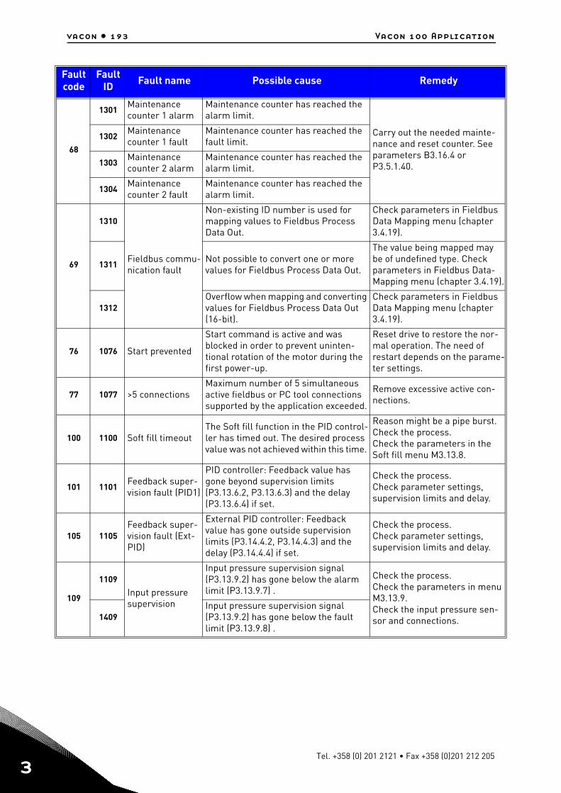
vacon • 193 Vacon 100 Application
3
68
1301Maintenance counter 1 alarm
Maintenance counter has reached the alarm limit.
Carry out the needed mainte-nance and reset counter. See parameters B3.16.4 or P3.5.1.40.
1302Maintenance counter 1 fault
Maintenance counter has reached the fault limit.
1303Maintenance counter 2 alarm
Maintenance counter has reached the alarm limit.
1304Maintenance counter 2 fault
Maintenance counter has reached the alarm limit.
69
1310
Fieldbus commu-nication fault
Non-existing ID number is used for mapping values to Fieldbus Process Data Out.
Check parameters in Fieldbus Data Mapping menu (chapter 3.4.19).
1311Not possible to convert one or more values for Fieldbus Process Data Out.
The value being mapped may be of undefined type. Check parameters in Fieldbus Data-Mapping menu (chapter 3.4.19).
1312Overflow when mapping and converting values for Fieldbus Process Data Out (16-bit).
Check parameters in Fieldbus Data Mapping menu (chapter 3.4.19).
76 1076 Start prevented
Start command is active and was blocked in order to prevent uninten-tional rotation of the motor during the first power-up.
Reset drive to restore the nor-mal operation. The need of restart depends on the parame-ter settings.
77 1077 >5 connectionsMaximum number of 5 simultaneous active fieldbus or PC tool connections supported by the application exceeded.
Remove excessive active con-nections.
100 1100 Soft fill timeoutThe Soft fill function in the PID control-ler has timed out. The desired process value was not achieved within this time.
Reason might be a pipe burst. Check the process.Check the parameters in the Soft fill menu M3.13.8.
101 1101Feedback super-vision fault (PID1)
PID controller: Feedback value has gone beyond supervision limits (P3.13.6.2, P3.13.6.3) and the delay (P3.13.6.4) if set.
Check the process.Check parameter settings, supervision limits and delay.
105 1105Feedback super-vision fault (Ext-PID)
External PID controller: Feedback value has gone outside supervision limits (P3.14.4.2, P3.14.4.3) and the delay (P3.14.4.4) if set.
Check the process.Check parameter settings, supervision limits and delay.
109
1109
Input pressure supervision
Input pressure supervision signal (P3.13.9.2) has gone below the alarm limit (P3.13.9.7) .
Check the process.Check the parameters in menu M3.13.9.Check the input pressure sen-sor and connections.1409
Input pressure supervision signal (P3.13.9.2) has gone below the fault limit (P3.13.9.8) .
Fault code
FaultID Fault name Possible cause Remedy
Tel. +358 (0) 201 2121 • Fax +358 (0)201 212 205
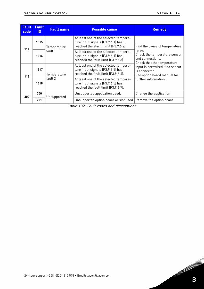
Vacon 100 Application vacon • 194
Table 137. Fault codes and descriptions
111
1315
Temperature fault 1
At least one of the selected tempera-ture input signals (P3.9.6.1) has reached the alarm limit (P3.9.6.2). Find the cause of temperature
raise.Check the temperature sensor and connections.Check that the temperature input is hardwired if no sensor is connected. See option board manual for further information.
1316At least one of the selected tempera-ture input signals (P3.9.6.1) has reached the fault limit (P3.9.6.3).
112
1317
Temperature fault 2
At least one of the selected tempera-ture input signals (P3.9.6.5) has reached the fault limit (P3.9.6.6).
1318At least one of the selected tempera-ture input signals (P3.9.6.5) has reached the fault limit (P3.9.6.7).
300700
UnsupportedUnsupported application used. Change the application
701 Unsupported option board or slot used. Remove the option board
Fault code
FaultID Fault name Possible cause Remedy
24-hour support +358 (0)201 212 575 • Email: [email protected]
3

Document ID:
Order code:
Rev. D
Manual authoring:[email protected]
Vacon Plc.Runsorintie 765380 VaasaFinland
Subject to change without prior notice© 2012 Vacon Plc.
Find your nearest Vacon office on the Internet at:
www.vacon.com
Find your nearest Vacon service centre on the Extranet at:
www.extra.vacon.com