
UWSH Chapter 8 - Secondary Propulsion Motors · PDF fileCHAPTER 8 SECONDARY PROPULSION MOTORS...
90
CHAPTER 8 SECONDARY PROPULSION MOTORS S0600-AA-PRO-080 1 OCTOBER 1998 Change 1 dated 15 AUGUST 1999 UNDERWATER SHIP HUSBANDRY MANUAL REVISION 1 Published by direction of Commander, Naval Sea Systems Command DISTRIBUTION STATEMENT C: Distribution authorized to U.S. Government agencies and their contractors; administrative/operational use, 1 October 1998. Other requests for this document shall be referred to the Naval Sea Systems Command (SEA 09T). DESTRUCTION NOTICE: Destroy by any method that will prevent disclosure of contents or reconstruction of the document. This manual supersedes S600-AA-PRO-080 dated 30 June 1993
Transcript of UWSH Chapter 8 - Secondary Propulsion Motors · PDF fileCHAPTER 8 SECONDARY PROPULSION MOTORS...
CHAPTER 8SECONDARY PROPULSION MOTORS
S0600-AA-PRO-080
1 OCTOBER 1998Change 1 dated 15 AUGUST 1999
UNDERWATER SHIP HUSBANDRY MANUAL
REVISION 1
Published by direction of Commander, Naval Sea Systems Command
DISTRIBUTION STATEMENT C: Distribution authorized to U.S. Government agencies and their contractors;
administrative/operational use, 1 October 1998. Other requests for this document shall be referred to the Naval
Sea Systems Command (SEA 09T).
DESTRUCTION NOTICE: Destroy by any method that will prevent disclosure of contents or
reconstruction of the document.
This manual supersedes S600-AA-PRO-080 dated 30 June 1993
S0600-AA-PRO-080
A Change 1
Page No. * Change No.
Title and A . . . . . . . . . . . . . . . . . . . . . . . . 1Certification Sheet . . . . . . . . . . . . . . . . . . 1blank . . . . . . . . . . . . . . . . . . . . . . . . . . . . 0Flyleaf-1 (Flyleaf-2 blank) . . . . . . . . . . . . 1i through ii . . . . . . . . . . . . . . . . . . . . . . . . 0iii through vii . . . . . . . . . . . . . . . . . . . . . . 1viii blank. . . . . . . . . . . . . . . . . . . . . . . . . . 18-1 through 8-13 . . . . . . . . . . . . . . . . . . . 08-14 blank . . . . . . . . . . . . . . . . . . . . . . . . 08-15 through 8-17 . . . . . . . . . . . . . . . . . . 08-18 through 8-18A . . . . . . . . . . . . . . . . . 18-18B blank . . . . . . . . . . . . . . . . . . . . . . . 18-19 through 8-28 . . . . . . . . . . . . . . . . . . 08-29 through 8-32 . . . . . . . . . . . . . . . . . . 18-33 through 8-40 . . . . . . . . . . . . . . . . . . 08-41 . . . . . . . . . . . . . . . . . . . . . . . . . . . . . 18-42 . . . . . . . . . . . . . . . . . . . . . . . . . . . . . 0 8-42A. . . . . . . . . . . . . . . . . . . . . . . . . . . . 18-42B blank . . . . . . . . . . . . . . . . . . . . . . . 18-43 through 8-52 . . . . . . . . . . . . . . . . . . 0
Page No. * Change No.
8-53 through 8-55. . . . . . . . . . . . . . . . . . 18-56 through 8-57. . . . . . . . . . . . . . . . . . 08-58 blank. . . . . . . . . . . . . . . . . . . . . . . . 08-59 . . . . . . . . . . . . . . . . . . . . . . . . . . . . 08-60 blank. . . . . . . . . . . . . . . . . . . . . . . . 08-61 . . . . . . . . . . . . . . . . . . . . . . . . . . . . 08-62 blank. . . . . . . . . . . . . . . . . . . . . . . . 08-63 . . . . . . . . . . . . . . . . . . . . . . . . . . . . 08-64 blank. . . . . . . . . . . . . . . . . . . . . . . . 08-65 . . . . . . . . . . . . . . . . . . . . . . . . . . . . 08-66 blank. . . . . . . . . . . . . . . . . . . . . . . . 08-67 . . . . . . . . . . . . . . . . . . . . . . . . . . . . 08-68 blank. . . . . . . . . . . . . . . . . . . . . . . . 08-69 . . . . . . . . . . . . . . . . . . . . . . . . . . . . 08-70 blank. . . . . . . . . . . . . . . . . . . . . . . . 08-71 . . . . . . . . . . . . . . . . . . . . . . . . . . . . 08-72 blank. . . . . . . . . . . . . . . . . . . . . . . . 08-73 . . . . . . . . . . . . . . . . . . . . . . . . . . . . 08-74 blank. . . . . . . . . . . . . . . . . . . . . . . . 0
LIST OF EFFECTIVE PAGES
* 0 in this column indicates an original page.
Date of original pages is: 1 October 1998Date of Change 1 is: 15 August 1999


RECORD OF CHANGES
S0600-AA-PRO-080
CHANGENO.
DATEOF
CHANGE
ENTEREDBY
TITLE AND/OR BRIEF DESCRIPTION**
Flyleaf-1/(Flyleaf-2 blank)
1 8-15-99 Add Chain Hoist CautionCorrect sub paragraph numberingin paragraph 8-3.5

S0600-AA-PRO-080
TABLE OF CONTENTS
Paragraph Page
SECTION 1 INTRODUCTION
8-1.1 GENERAL INFORMATION . . . . . . . . . . . . . . . . . . . . . . . . . . . . . . . . . . . . . . . . . . . 8-1
8-1.2 PURPOSE . . . . . . . . . . . . . . . . . . . . . . . . . . . . . . . . . . . . . . . . . . . . . . . . . . . . . . . . 8-1
8-1.3 SYSTEM DESCRIPTION. . . . . . . . . . . . . . . . . . . . . . . . . . . . . . . . . . . . . . . . . . . . . 8-1
8-1.4 REFERENCE DOCUMENTS . . . . . . . . . . . . . . . . . . . . . . . . . . . . . . . . . . . . . . . . . . 8-5
SECTION 2 PLANNING AND PREPARATION
8-2.1 GENERAL INFORMATION . . . . . . . . . . . . . . . . . . . . . . . . . . . . . . . . . . . . . . . . . . . 8-9
8-2.2 PLANNING . . . . . . . . . . . . . . . . . . . . . . . . . . . . . . . . . . . . . . . . . . . . . . . . . . . . . . . . 8-9
8-2.3 PREPARATION . . . . . . . . . . . . . . . . . . . . . . . . . . . . . . . . . . . . . . . . . . . . . . . . . . . . 8-9
8-2.4 TOOLS, MATERIALS, AND EQUIPMENT. . . . . . . . . . . . . . . . . . . . . . . . . . . . . . . . 8-9
SECTION 3 PROCEDURES FOR REMOVAL AND REPLACEMENT OF SSN 688 CLASS SPM AND ELECTRICAL CABLES
8-3.1 GENERAL: SSN 688 CLASS SUBMARINES . . . . . . . . . . . . . . . . . . . . . . . . . . . . 8-15
8-3.2 SECONDARY PROPULSION MOTOR REMOVAL PROCEDURE (SSN 688) . . . 8-16
8-3.3 COFFERDAM RIGGING, INSTALLATION, AND SPM REMOVAL (SSN 688) . . . 8-16
8-3.4 ELECTRICAL CABLE REMOVAL AND REPLACEMENT PROCEDURES (SSN 688) . . . . . . . . . . . . . . . . . . . . . . . . . . . . . . . . . . . . . . . . . . 8-25
8-3.5 SPM REPLACEMENT (SSN 688) . . . . . . . . . . . . . . . . . . . . . . . . . . . . . . . . . . . . . 8-28
8-3.6 SPM SUPPORT COLUMN HYDROSTATIC TEST PROCEDURES (SSN 688) . . 8-30
8-3.7 DEBRIEF SHIP'S FORCE . . . . . . . . . . . . . . . . . . . . . . . . . . . . . . . . . . . . . . . . . . . 8-32
8-3.8 PREPARE FINAL REPORT. . . . . . . . . . . . . . . . . . . . . . . . . . . . . . . . . . . . . . . . . . 8-32
SECTION 4 PROCEDURES FOR REMOVAL AND REPLACEMENT OF SPM AND ELECTRI-CAL CABLES SSN 637 AND SSN 640 CLASS
8-4.1 GENERAL: SSN 637 AND SSN 640 CLASS SUBMARINES . . . . . . . . . . . . . . . . 8-33
8-4.2 SPM REMOVAL PROCEDURES (SSN 637 and SSN 640) . . . . . . . . . . . . . . . . . 8-34
8-4.3 RECOMMENDED COFFERDAM RIGGING AND INSTALLATION. . . . . . . . . . . . 8-34
8-4.4 SPM REMOVAL (SSN 637 AND SSN 640) . . . . . . . . . . . . . . . . . . . . . . . . . . . . . . 8-41
8-4.5 ELECTRICAL CABLE REMOVAL AND REPLACEMENT PROCEDURES (SSN 637 and SSN 640) . . . . . . . . . . . . . . . . . . . . . . . . . . . . . . . . . . . . . . . . . . . . 8-45
8-4.6 SPM REPLACEMENT (SSN 637 AND SSN 640) . . . . . . . . . . . . . . . . . . . . . . . . . 8-52
8-4.7 COFFERDAM REMOVAL PROCEDURES (SSN 637 AND SSN 640) . . . . . . . . . 8-54
i

S0600-AA-PRO-080
8-4.8 DEBRIEF SHIP'S FORCE . . . . . . . . . . . . . . . . . . . . . . . . . . . . . . . . . . . . . . . . . . . 8-56
8-4.9 PREPARE FINAL REPORT. . . . . . . . . . . . . . . . . . . . . . . . . . . . . . . . . . . . . . . . . . 8-56
APPENDIX A PREPARATION OF BINTSUKE . . . . . . . . . . . . . . . . . . . . . . . . . . . . . . . . . . . 8-57
APPENDIX B TORQUE COMPUTATIONS . . . . . . . . . . . . . . . . . . . . . . . . . . . . . . . . . . . . . . 8-59
APPENDIX C SSN 640 FAIRING PLATE ALIGNMENT CHECKOFF . . . . . . . . . . . . . . . . . . 8-61
APPENDIX D SSN 637 FAIRING PLATE ALIGNMENT CHECKOFF . . . . . . . . . . . . . . . . . . 8-63
APPENDIX E SSN 688 FAIRING PLATE ALIGNMENT CHECKOFF . . . . . . . . . . . . . . . . . . 8-65
APPENDIX F SSN 688 CLASS HULL PENETRATIONS . . . . . . . . . . . . . . . . . . . . . . . . . . . 8-67
APPENDIX G SSN 637 CLASS HULL PENETRATIONS . . . . . . . . . . . . . . . . . . . . . . . . . . . 8-69
APPENDIX H SSN 640 CLASS HULL PENETRATIONS . . . . . . . . . . . . . . . . . . . . . . . . . . . 8-71
APPENDIX I SSBN 726 CLASS HULL PENETRATIONS . . . . . . . . . . . . . . . . . . . . . . . . . . 8-73
ii

S0600-AA-PRO-080
LIST OF ILLUSTRATIONS
Figure Page
8-1 SPM Location in SSN 688 Class Submarine . . . . . . . . . . . . . . . . . . . . . . . . . . . . . . . . . 8-2
8-2 Secondary Propulsion Motor and Associated Components (SSN 688) . . . . . . . . . . . . . 8-3
8-3 Secondary Propulsion Motor and Associated Components (SSN 640) . . . . . . . . . . . . . 8-4
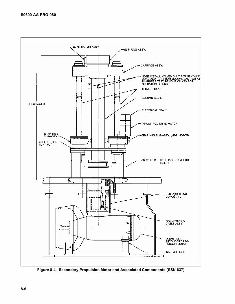
8-4 Secondary Propulsion Motor and Associated Components (SSN 637) . . . . . . . . . . . . . 8-6
8-5 Secondary Propulsion Motor and Associated Components (SSBN 726). . . . . . . . . . . . 8-7
8-6 Submarine Fairing Plate (SSN 688) . . . . . . . . . . . . . . . . . . . . . . . . . . . . . . . . . . . . . . . 8-17
8-6A Typical Running Block Flip . . . . . . . . . . . . . . . . . . . . . . . . . . . . . . . . . . . . . . . . . . . . .8-18A
8-7 Upper SPM Column Assembly (SSN 688) . . . . . . . . . . . . . . . . . . . . . . . . . . . . . . . . . . 8-19
8-8 SPM Rigged for Transfer to Crane. . . . . . . . . . . . . . . . . . . . . . . . . . . . . . . . . . . . . . . . 8-20
8-9 Configuration of SSN 688 Cofferdam. . . . . . . . . . . . . . . . . . . . . . . . . . . . . . . . . . . . . . 8-23
8-10 Typical SPM Cable Connection . . . . . . . . . . . . . . . . . . . . . . . . . . . . . . . . . . . . . . . . . . 8-24
8-11 Typical Cable Support Removal Technique. . . . . . . . . . . . . . . . . . . . . . . . . . . . . . . . . 8-26
8-12 Typical Rigging of SSN 637 and SSN 640 Cofferdam . . . . . . . . . . . . . . . . . . . . . . . . . 8-36
8-13 Submarine Fairing Plate (SSN 640) . . . . . . . . . . . . . . . . . . . . . . . . . . . . . . . . . . . . . . . 8-37
8-14 Submarine Fairing Plate (SSN 637) . . . . . . . . . . . . . . . . . . . . . . . . . . . . . . . . . . . . . . . 8-38
8-15 SPM Flood Holes (SSN 637) . . . . . . . . . . . . . . . . . . . . . . . . . . . . . . . . . . . . . . . . . . . . 8-40
8-16 Installation of Column Vent & Drain Valves (SSN 640 and SSN 637) . . . . . . . . . . . . . 8-42
8-16A Typical Running Block Flip . . . . . . . . . . . . . . . . . . . . . . . . . . . . . . . . . . . . . . . . . . . . .8-42A
8-17 Installation of Cover on Support Column Flange . . . . . . . . . . . . . . . . . . . . . . . . . . . . . 8-44
8-18 Boat Winch Installed . . . . . . . . . . . . . . . . . . . . . . . . . . . . . . . . . . . . . . . . . . . . . . . . . . 8-47
8-19 Removal of Support Ring for Slip Ring . . . . . . . . . . . . . . . . . . . . . . . . . . . . . . . . . . . . 8-48
8-20 Support Column with Secondary Seal . . . . . . . . . . . . . . . . . . . . . . . . . . . . . . . . . . . . . 8-49
8-21 Closure Plate Installation . . . . . . . . . . . . . . . . . . . . . . . . . . . . . . . . . . . . . . . . . . . . . . . 8-50
B-1 Torque Computations. . . . . . . . . . . . . . . . . . . . . . . . . . . . . . . . . . . . . . . . . . . . . . . . . . 8-59
C-1 SSN 640 Fairing Plate Alignment Check Off . . . . . . . . . . . . . . . . . . . . . . . . . . . . . . . . 8-61
D-1 SSN 637 Fairing Plate Alignment Checkoff . . . . . . . . . . . . . . . . . . . . . . . . . . . . . . . . . 8-63
E-1 SSN 688 Fairing Plate Alignment Check Off . . . . . . . . . . . . . . . . . . . . . . . . . . . . . . . . 8-65
F-1 SSN 68 Class Hull Penetrations . . . . . . . . . . . . . . . . . . . . . . . . . . . . . . . . . . . . . . . . . 8-67
G-1 SSN 637 Class Hull Penetrations . . . . . . . . . . . . . . . . . . . . . . . . . . . . . . . . . . . . . . . . 8-69
H-1 SSN 640 Class Hull Penetrations . . . . . . . . . . . . . . . . . . . . . . . . . . . . . . . . . . . . . . . . 8-71
I-1 SSBN 726 Class Hull Penetrations . . . . . . . . . . . . . . . . . . . . . . . . . . . . . . . . . . . . . . . 8-73
Change 1 iii

S0600-AA-PRO-080
LIST OF TABLES
Table Page
8-1 Tools, Materials, and Equipment for SPM Replacement . . . . . . . . . . . . . . . . . . . . . . . 8-11
iv Change 1

S0600-AA-PRO-080
SAFETY SUMMARY
GENERAL SAFETY PRECAUTIONS. Thefollowing general safety precautions supple-ment the specific warnings and cautionsthroughout this chapter. These general pre-cautions are related to the task of secondarypropulsion motors. They are precautions thatmust be understood and applied before andduring work on the SRD. In addition to the fol-lowing precautions, personnel must be familiarwith and observe safety precautions set forthin the following publications:
a. Navy Occupational Safety and HealthProgram Manual for Forces Afloat,OPNAVINST 5000.19 (Series)
b. Naval Ships’ Technical Manual(NSTM)
c. Technical/operating manuals forequipment
e. U.S. Navy Diving Manual, Volume I,NAVSEA-0944-LP-001-9010.
Rotation of propellers or opera-tion of underwater electricalequipment while divers are inthe vicinity can cause seriousinjury or death. Ensure thatship's equipment, including theSPM system, is de-energizedand tagged out as required byreference (h) prior to beginningunderwater operations. (pages8-15 and 8-33)
Divers shall clear the SPM cav-ity before the SPM is raised,lowered, or trained. (Page 8-16, 8-32, 8-34, 8-35, 8-39, and8-55)
All divers must be out of the
water when megger testing isbeing conducted. (pages 8-22,8-30 and 8-54))
It is essential that all tools andmaterials brought to the under-water job site are accounted forand removed at the completionof the job. Tools and materialsinadvertently left at the job sitecan generate unacceptablenoise and possibly causesevere damage to shipboardcomponents. Locally gener-ated work packages shallensure that a general tool andmaterial log sheet is preparedand maintained during allUWSH operations. (pages 8-15and 8-33).
Shut and tag out the ventvalves for the main ballasttanks 4A, 4B, 5A, and 5B.Ensure that the vent valvecover is installed on ballasttank 4A. (page 8-16).
Chain twist in the working chainloops of manual chain hoistsand chain falls will cause chainfailure. Chain twist in the work-ing chain loop occurs when thechain has an improper reevethrough the chain sprocketsOR (more often) the runningblock has flipped up andthrough any of the chain loops(see figures 8-6A and 8-16A).
All chain hoists and chain fallsissued with NAVSEA SUP-SALV Underwater Ship Hus-bandry equipment kits havebeen checked for chain twist
WARNING
CAUTION
Change 1 v

S0600-AA-PRO-080
and the chain hoist/fall hasbeen loosely two-blocked sothat the running block can notflip over into the working chainloops during shipment.
OPERATORS must ensurethat the running block is notflipped over into the chain loopscreating chain twist whiledeploying and rigging the chainhoists/falls.
To check for chain twist in thechain loop:
Hang the hoist from the tophook in a safe, accessiblelocation. Tighten the hoistuntil less then one foot ofseparation exists betweenthe hoist body and the run-ning block. The short throwallows for much easier visualdetection of twist in the indi-vidual chain reeves. Confirmthat none of the chain lengthsrunning from the working chainsprocket to the running chainsprocket (chain reeves) haveany twist caused by the runningblock being flipped over andthrough the loop of the chain. IfANY chain twist is detected, flipthe running block back throughthe chain loop until the twist isremoved. If ANY twist can notbe removed by flipping the run-ning block, the hoist chainMUST be removed from thehoist body and re-reeve exer-cising care not to twist thechain during installation (pages8-18, 8-42A, and 8-53).
Ensure that the SPM does notbottom out on the seabed whenlowering it from the SPM cavity.(pages 8-22 and 8-43).
Water contacting the electrical
cable connectors can damageinsulation and prevent properelectrical connection. Useextreme care when packagingand transporting electricalcables to the cofferdam. Useconnector caps as directed(ensuring proper o-ring com-pression) to prevent water frommaking contact with the cables.(page 8-27).
Ensure that there is clear com-munication between the diversand the crane operator to pre-vent the SPM from bottomingout on the seabed. (pages 8-29and 8-53).
An adapter or extension usedon a torque wrench increasesthe torque value. (page 8-29).
Shut and tag out the ventvalves for the main ballasttanks 5A, 5B, 6A and 6B forSSN 640 class submarines and4A, 4B, 5A and 5B for SSN 637class submarines. (page 8-34).
Water contacting the electricalcables can damage insulationand prevent proper electricalconnection. Use extreme carewhen packaging and transport-
Fig. 8-6A & 8-16A Typical Running Block Flip (one or two part chain reeve)
vi Change 1

S0600-AA-PRO-080
ing electrical cables to the cof-ferdam. (page 8-51).
Improper alignment of theflange surfaces could dislodgethe o-ring and prevent a properseal when the flange is tight-ened. Ensure that o-ring (item65) on the support columnflange has not been dislodged.(page 8-54).
Change 1 vii

S0600-AA-PRO-080
viii Change 1
THIS PAGE LEFT BLANK INTENTIONALLY

S0600-AA-PRO-080
CHAPTER 8SECONDARY PROPULSION MOTORS
SECTION 1. INTRODUCTION
8-1.1 GENERAL INFORMATION
Underwater ship husbandry provides opera-tional and maintenance advantages by allow-ing removal and replacement of secondarypropulsion motors (SPM) and SPM systemcomponents while the submarine is water-borne. The most obvious advantages are theelimination of costly dry docking and the expe-ditious return of the submarine to operationalstatus. Another advantage is that the SPMsystem components can be replaced virtuallyanywhere the submarine is berthed, providedthere is underwater clearance of at least tenfeet below the bottom edge of the cofferdamwhen it is attached to the hull. Adherence tothe procedures contained within this manualwill significantly increase the quality of under-water SPM maintenance operations.
8-1.2 PURPOSE
This chapter describes the Naval Sea Sys-tems Command (NAVSEA) approved proce-dures for the underwater removal andreplacement of SPMs on submarines (with theexception of SSBN 726 Class submarine pro-cedures, which are currently under develop-ment). These procedures provide detailed,standardized instructions for cofferdam instal-lation and removal, SPM replacement, andelectrical cable replacement. A listing ofrequired tools, materials, and equipment isincluded. These procedures have been usedand validated at various Navy ship mainte-nance facilities. The proper use of these pro-cedures will result in a permanent repair andwill eliminate the need for emergency orunscheduled dry docking.
8-1.3 SYSTEM DESCRIPTION
8-1.3.1 SSN 688 Class. The secondary pro-pulsion system in the SSN 688 Class subma-
rine consists of one SPM located on thestarboard side of the center line on the bottomof the submarine between frames 127 and131. This SPM has four major components:the motor, the electrical power system, thetraining and retracting mechanism, and theSPM controls. The SPM general location isshown in Figure 8-1. The controls are locatedwithin the ship and are not discussed in thischapter. The SPM drives a propeller whichoperates in a Kort nozzle attached to themotor housing. The electrical power systemconsists of the electrical hull fitting (EHF), thepower cables (with a motor connector on oneend and an EHF connector on the other end),and the electrical console (located inside thesubmarine). The training and retracting mech-anism consists of a main support column, ahydraulic training motor for rotating the unit,and a retracting hoist cylinder for raising andlowering the SPM. The SPM can providethrust at any relative heading of 0 degrees to200 degrees and will operate at angles up to60 degrees from the horizontal plane. TheSPM training and retracting mechanism isshown in Figure 8-2. When not in use, theSPM is retracted to a stored position within afree-flooding enclosure in a main ballast tank.The enclosure opening in the shell plating iscovered by a faired plate attached to theunderside of the SPM. This enclosure indesigned so that the motor is completelyimmersed in sea water except when the bal-last tanks are fully blown. Interlocks preventSPM operation while it is in the stored posi-tion. The SPM may be raised, lowered,started, stopped, and trained from its ownlocal control box. A remote control panel pro-vides for starting, stopping and training only.The unit is designed to be trained andretracted manually in the event of electricalfailure. NAVSEA S6260-CB-MMO-010, Sec-ondary Propulsion Submersible Motor techni-cal manual, and NAVSEA S9238-AB-MMA-
8-1

S0600-AA-PRO-080
010, Secondary Propulsion Motor technicalmanual, provide details on the configuration,operation, and maintenance of "wet winding"SPMs and "dry winding" (canned) SPMs,respectively. "Wet winding" SPMs allow sea-water to fill the motor and circulate through thebearings, windings, and the gap between the
rotor and stator. "Dry winding" SPMs use arotor and stator which are sealed in an Inconellining (canned) which isolates the windingsfrom seawater. Consult the technical manualship applicability list and the submarine'sonboard technical manual to confirm the typeof SPM used by a particular submarine.
8-1.3.2 SSN 640 Class. The secondary pro-pulsion system in the SSN 640 Class subma-rine consists of one SPM located along thecenter line on the bottom of the submarinebetween frames 112 and 117. The trainingand retracting mechanisms are electrically andhydraulically powered. The support structurefor the training and retracting devices aremounted inside the pressure hull of the sub-marine. The support structure actually formspart of the pressure hull. The hydraulic cylin-ders, which are bolted to the hull insert andstructural support, provide the means of rais-ing and lowering the main column, which isattached to the carriage. The SPM is mountedat the base of the column and outside thepressure hull. The carriage contains the
mounting of the training motor and gearassembly. The training motor provides theelectrical training of the SPM to any desiredlocation through 360 degrees. The SPM train-ing and retracting mechanism is shown in Fig-ure 8-3. When not in use, the SPM is retractedto a stored position within a free-floodingenclosure in a main ballast tank. The enclo-sure opening in the shell plating is covered bya faired plate attached to the underside of theSPM. This enclosure in designed so that themotor is completely immersed in sea waterexcept when the ballast tanks are fully blown.Interlocks prevent SPM operation while it is inthe stored position. The SPM may be raised,lowered, started, stopped, and trained from itsown local control box. A remote control panel
Figure 8-1. SPM Location in SSN 688 Class Submarine.
8-2

S0600-AA-PRO-080
provides for starting, stopping and trainingonly. The unit is designed to be trained andretracted manually in the event of electricalfailure. NAVSEA 0363-LP-100-3002, SSBN627 Class Secondary Propulsion Motor techni-cal manual, provides details on the configura-tion, operation, and maintenance of SPMs forSSN 640 Class submarines.
8-1.3.3 SSN 637 Class The secondary pro-pulsion system in the SSN 637 Class subma-rine consists of one SPM located along thecenter line on the bottom of the submarinebetween frames 72 and 76. The componentsof the training and retracting mechanisminclude the main column, upper yoke, two ballscrew assemblies, training and retracting
Figure 8-2. Secondary Propulsion Motor and Associated Components (SSN 688)
8-3

S0600-AA-PRO-080
motors and gear assemblies. The SPM ismounted at the base of the main column andoutside the pressure hull. The upper yoke con-tains the mounting of the training motor, train-
ing gear assembly and ball screw assemblies.The training motor provides the electrical train-ing of the SPM to any desired location through360 degrees. The ball screw assemblies pro-
Figure 8-3. Secondary Propulsion Motor and Associated Components (SSN 640)
8-4
S0600-AA-PRO-080
vide the means of raising or lowering the maincolumn. The retracting motor and brake withthe associated gear reduction units areattached to the top of the hull insert. The gearreduction units operate in tandem to rotate theball screws and extend or retract the upperyoke. The electric brake is connected to theretracting motor and is mechanically set tostop and hold the yoke in any position. TheSPM training and retracting mechanism isshown in Figure 8-4. When not in use, theSPM is retracted to a stored position within afree-flooding enclosure in a main ballast tank.The enclosure opening in the shell plating iscovered by a faired plate attached to theunderside of the SPM. This enclosure indesigned so that the motor is completelyimmersed in sea water except when the bal-last tanks are fully blown. Interlocks preventSPM operation while it is in the stored posi-tion. The SPM may be raised, lowered,started, stopped, and trained from its ownlocal control box. A remote control panel pro-vides for starting, stopping and training only.The unit is designed to be trained andretracted manually in the event of electricalfailure. NAVSEA 0963-LP-007-6000, Second-ary Propulsion System, Submersible Motor,Submarine technical manual, provides detailson the configuration, operation, and mainte-nance of "wet winding" SPMs for SSN 637Class submarines.
8-1.3.4 SSBN 726 Class. The secondarypropulsion motors on the SSBN 726 Classsubmarines are located on both sides of thecenter line on the bottom of the submarine.The SPMs can only be extended or retracted,they cannot be trained. The SPMs aremounted at the base of the main columnlocated outside of the pressure hull. TheSPMs can be independently operated, andeach has its own extend/retract mechanism.The extend/retract mechanism consists of ahydraulic control valve, a hydraulic hoistingmotor, an inboard gear box, an outboard gearbox, and a mechanical screw assembly. TheSPM extend/retract mechanism is shown inFigure 8-5. When not in use, the SPM isretracted to a stored position within a free-
flooding enclosure in a main ballast tank. Theenclosure opening in the shell plating is cov-ered by a faired plate attached to the under-side of the SPM. This enclosure in designedso that the motor is completely immersed insea water except when the ballast tanks arefully blown. Interlocks prevent operation whileit is in the stored position. The SPMs can onlybe raised, lowered, started and stopped fromtheir local control panel. The SPMs have noremote operating capability. The units aredesigned to be operated manually in the eventof a power failure. NAVSEA S9238-AB-MMA-010, Secondary Propulsion Motor technicalmanual, provides details on the configuration,operation, and maintenance of "dry winding"SPMs for SSBN 726 Class submarines. Con-sult the technical manual ship applicability listto confirm the proper technical manual for aparticular submarine. These waterbornereplacement procedures are currently underdevelopment.
8-1.4 REFERENCE DOCUMENTS
The documents listed below contain the tech-nical information required for the planning,preparation and execution of an SPM replace-ment operation for various submarine classes,with the exception of SSBN 726 Class subma-rines. Care should be taken to obtain and usethe most current version of these documents.They must be used during the planning phaseand shall be available on site during the con-duct of waterborne replacement operations.NAVSEA S0600-AA-PRO-020, UnderwaterShip Husbandry Manual: General Informationand Safety Precautions, provides informationon obtaining and using technical documents.
(a) Ship's Drawing Index: a thoroughreview and understanding of the follow-ing NAVSEA drawings are required forsuccessful SPM replacement opera-tions:
• 1197260 (Rev B or later) , ElectricalHull Fitting: contains all necessaryi n fo rma t i on conce rn ing SPMcable/EHF connector and cable/motor
8-5
S0600-AA-PRO-080
8-6
Figure 8-4. Secondary Propulsion Motor and Associated Components (SSN 637)

S0600-AA-PRO-080
8-7
Figure 8-5. Secondary Propulsion Motor and Associated Components (SSBN 726).

S0600-AA-PRO-080
connector installations, O-ring specifi-cations, hydrostatic testing require-men ts , and m in imum megaohmrequirements for resistance testing.SPM replacement should not beattempted without use of this drawing.
• 4454547, SPM Cables: includeshydrostatic testing requirements andinstallation requirements.
• 4494057 and 5942057, SSN 688Class Fairing Plate.
• 5006590, SSN 688 Class OutboardPenetrations.
• 2012206, SSN 640 Class FairingPlate.
• 2140608, SSN 637 Class Fairing Plate
(b) NAVSEA S6260-CB-MMO-010, Sec-ondary Propulsion Submersible MotorTechn i ca l Manua l and NAVS EAS9238-AB-MMA-010, Secondary Pro-
pulsion Motor Technical Manual (SSN688 Class submarines).
(c) NAVSEA 0363-LP-100-3002, Techni-cal Manual, SSBN 627/SSN 640 ClassSecondary Propulsion Motor.
(d) NAVSEA 0963-LP-007-6000, Techni-cal Manual, Secondary PropulsionSystem, Submersible Motor, Subma-rine (SSN 637 Class submarines).
(e) NAVSEA S9086-KC-STM-000, NSTMCH 300, Electric Plant General.
(f) NAVSEA S9086-CQ-STM-010, NSTMCH 081, Waterborne Underwater HullCleaning of Navy Ships.
(g) NAVSEA S9505-AM-GYD-010, Sub-mar ine Fas ten ing Cr i te r i a (NonNuclear).
(h) NAVSEA 0994-LP-001-9110 / 0927-LP-001-9110, U.S. Navy Diving Man-ual.
8-8

S0600-AA-PRO-080
PLANNING AND PREPARATION
SECTION 2
8-2.1 GENERAL INFORMATION
Planning is essential to the successful com-pletion of any underwater ship husbandrytask. Proper planning should begin at the ear-liest possible time, involve all concerned par-ties, and result in a written operational plan.General planning guidelines are presented inNAVSEA S0600-AA-PRO-020, UnderwaterShip Husbandry Manual: General Informationand Safety Precautions.
8-2.2 PLANNING
In planning an underwater SPM replacementoperation, consideration must be given notonly to general planning guidelines but also tothose aspects which are unique to the task,such as fabrication of an SPM cofferdam. Thescope of work may vary from a partial removalof the SPM for the purpose of conducting elec-trical tests to a complete SPM replacement.The ship's mooring position and depth ofwater under the center line on the bottom ofthe submarine are extremely important. Whenworking on SSN 688 Class SPMs, the subma-rine is required to be moored starboard sideto. However, since their SPMs are located oncenterline, SSN 637 and SSN 640 Class sub-marines may be moored either port or star-board side to. Also, when working on theSPM, water depth should allow a minimum often feet of clearance below the bottom edge ofthe cofferdam when it is attached to the hull.Scheduling and personnel requirementsdepend greatly on the ship's operating sched-ule and the time available to complete thetask. Coordination between divers, surfacesupport personnel, and ship's force engineer-ing personnel is mandatory and must bereflected in the operational plan.
8-2.3 PREPARATION
Preparation for the task consists of assem-bling all necessary material and personnelidentified in the planning phase and properlyarranging those resources on site. Table 8-1provides a listing of the tools, materials, andequipment required to perform the task.Appendices F through I depict the variousclass hull penetrations.
8-2.4 TOOLS, MATERIALS, AND EQUIP-MENT
Removal and replacement of the SPM and theelectrical cables require special equipmentand tools. The items listed in Table 8-1 repre-sent the minimum requirements necessary forSPM replacement. Many items have beendesigned especially for SPM replacementoperations. Their functions are described inthe following paragraphs. These items arealso available as a kit from NAVSEA 00C5.
NOTE
All tools transferred into sub-marine spaces (main ballasttanks, SPM enclosure, etc)shall be documented in a toolcheck-in sheet in order to avoidleaving tools in these spacesand creating mechanical and/ornoise problems.
8-2.4.1 Cofferdam. The cofferdam is manu-factured to conform specifically to the subma-rine's hull configuration. The cofferdamsprovide a dry environment which preventscontact between electrical components andthe water. Ensure that the required cofferdamis available during the planning stage. The
8-9

S0600-AA-PRO-080
cofferdam may be fabricated in accordancewith NAVSEA drawings: 6699589 for SSN 688Class submarines, 6697897 for SSN 637Class submarines, and 6697889 for SSN 640Class submarines.
8-2.4.2 Sealing Caps. During the removaland replacement of the SPM, sealing caps arerequired to be placed on the SPM electricalconnections to prevent contact with moisture.These items may be fabricated in accordancewith NAVSEA drawings 6697894 and6697891.
8-2.4.3 Special Tools. Specially configuredcable connector tools may have to be con-structed and used during the removal of theSPM electrical connector. See NAVSEA draw-ing 1197260, revision B.
8-2.4.4 Portsmouth Fitting Tool. A Ports-mouth fitting tool is required for the removal ofthe portsmouth electrical connectors from theElectrical Hull Fitting (EHF) on SSN 688 Class
submarines. See NAVSEA drawing 1197260(Rev B or later).
8-2.4.5 SPM Alignment Fixture. The SPMalignment fixture is designed to measure dis-tances between the SPM and the fairing plateto ensure proper fit-up. The alignment fixturemay be fabricated in accordance withNAVSEA drawing 6697988.
8-2.4.6 Cable Support Replacement Tool.The cable support replacement tool is used toremove and replace the cable support for theSSN 688 Class submarine. The cable supportreplacement tool may be fabricated in accor-dance with NAVSEA drawing 6697989.
8-2.4.7 Portsmouth Connector Caps. Dur-ing the removal and replacement of the SPM, portsmouth connector caps are required to be placed on the portsmouth connectors on the SPM cable to prevent contact with moisture. These items may be fabricated in accordance with NAVSEA drawing 6697892.
8-10
S0600-AA-PRO-080
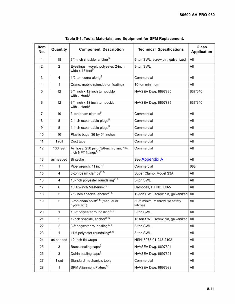
Table 8-1. Tools, Materials, and Equipment for SPM Replacement.
Item No.
Quantity Component Description Technical SpecificationsClass
Application
1 18 3/4-inch shackle, anchor5 9-ton SWL, screw pin, galvanized All
2 2 Eyeslings, two-ply polyester, 2-inch wide x 45 feet5
3-ton SWL All
3 4 1/2-ton come-along5 Commercial All
4 1 Crane, mobile (pierside or floating) 10-ton minimum All
5 12 3/4 inch x 12-inch turnbucklewith J-Hook5
NAVSEA Dwg. 6697835 637/640
6 12 3/4 inch x 18 inch turnbucklewith J-Hook5
NAVSEA Dwg. 6697835 637/640
7 10 3-ton beam clamps5 Commercial All
8 8 2-inch expandable plugs5 Commercial All
9 8 1-inch expandable plugs5 Commercial All
10 10 Plastic bags, 36 by 54 inches Commercial All
11 1 roll Duct tape Commercial All
12 100 feet Air hose: 250 psig, 3/8-inch diam, 1/4 inch NPT fittings2, 5
Commercial All
13 as needed Bintsuke See Appendix A All
14 1 Pipe wrench, 11 inch5 Commercial 688
15 4 3-ton beam clamps2, 5 Super Clamp, Model S3A All
16 4 18-inch polyester roundsling2, 5 3-ton SWL All
17 6 10 1/2-inch Masterlink 5 Campbell, PT NO. C0-5 All
18 2 7/8 inch shackle, anchor2, 5 12-ton SWL, screw pin, galvanized All
19 2 3-ton chain hoist2, 5 (manual or hydraulic6)
30-ft minimum throw, w/ safety latches
All
20 1 13-ft polyester roundsling2, 5 3-ton SWL All
21 2 1-inch shackle, anchor2, 5 16 ton SWL, screw pin, galvanized All
22 2 3-ft polyester roundsling2, 5 3-ton SWL All
23 1 11-ft polyester roundsling2, 5 3-ton SWL All
24 as needed 12-inch tie wraps NSN: 5975-01-243-2102 All
25 3 Brass sealing caps5 NAVSEA Dwg. 6697894 All
26 3 Delrin sealing caps5 NAVSEA Dwg. 6697891 All
27 1 set Standard mechanic’s tools Commercial All
28 1 SPM Alignment Fixture5 NAVSEA Dwg. 6697988 All
8-11

S0600-AA-PRO-080
Item No.
Quantity Component Description Technical SpecificationsClass
Application
29 1 Torpedo Level, 9 inch or smaller5 Commercial All
30 1 Torque wrench5 (100 ft-lbs and 250 ft-lbs, calibrated), manual or hydraulic6
Commercial All
31 8 Lock nuts, 1/2-13 UNC-3B Mil Spec: 17828-8CNSN: 5310-00-245-3504
All
32 8 Lock nuts, 3/4-10 UNC-3B Mil Spec: 17828-12NSN: 5310-01-160-2035
All
33 2 bottles Dry nitrogen w/fittings, hoses & regula-tor
Commercial All
34 as needed Sealant2, 5 Bostich 920 fast set, marine use All
35 8 or 16 1 5/8-inch self-locking nuts (8 for SSN 640 and SSN 637, 16 for SSN 688), 1-8 UNC-2B Heavy
Ni-Cu (QQ-N-281)Magnatek Louis Allis,part # 50P03012-0001
All
36 1 Chain wrench2, 5 KD Tools, part # 2595 All
37 as needed Silicone Compound NSN: 6850-00-702-4297 All
38 1 Lockwire pliers, 9 inch5 Commercial 688
39 75 feet Water Hose5 Commercial 688
40 1 5/8-inch Expandable Plug5 Commercial 688
41 2 Cable Support Replacement Tool5 NAVSEA Dwg. 6697989 688
42 1 Portsmouth Fitting Tool5 688
43 1 2 3/8-inch cable connectortool1, 4,5
688
44 1 1 15/16-inch cable connector tool1, 4, 5 688
45 3 Portsmouth Connector Caps5 NAVSEA Dwg. 6697892 688
46 2 1/2 inch O.D. expandable plugsor 1/2 inch IPT plugs2, 3
Expand-O-Seal, part # SP30760050N or NSN: 1560-00-959-2059
688
47 1 Hydrostatic test fixture5 NAVSEA Dwg. 6697893 688
48 75 feet Hydrostatic test tubing2, 5 Gates, part # 4C3, 1/4 inch SAE 100R3 G04198
688
49 1 Hydrostatic test pump2, 5 Haskell, part # 26817 688
50 2 0 to 15 psig hydraulic pressure gauge5 (calibrated)
Commercial 688
51 2 0 to 500 psig hydraulic pressure gauge5 (calibrated)
Commercial 688
Table 8-1. Tools, Materials, and Equipment for SPM Replacement.
8-12

S0600-AA-PRO-080
8-13
Item No.
Quantity Component Description Technical SpecificationsClass
Application
52 as needed Lockwire (.051 inch dia.) Ni-Cu (QQ-N-281) 688
53 1 Cofferdam5 NAVSEA Dwg. 6697898 688
54 1 Cofferdam5 NAVSEA Dwg. 6697897NAVSEA Dwg. 6697889
637640
55 1 Column Vent & Drain Valve Assy1 Valve
1 Air Inlet Fitting, 3/8 inch
1 Nipple, pipe
1 O-ring, 7/8 inch I.D. x 1 inch O.D.
Conbraco, part # 1040A-3/8NSN: 4820-01-076-6436
Hoffman Eng., part # MPB-3
Coltec Ind., part # 92008302NSN:4730-01-075-6960
Mil-R-25897CParker Seal part # 2-20
637/640
56 1 0-50 psig air gauge (calibrated) Commercial 637/640
57 1 Support column cover5 NAVSEA Dwg. 6697895 637/640
58 1 Gasket, cover5 NAVSEA Dwg. 6697895 637/640
59 1 Boat winch, 500 pound minimum with 1/4 inch x 15 ft wire rope5
McMaster-Carr, part # 3196T26. See Figure 8-18
637/640
60 1 Eyebolt, 3/8-13 UNC Commercial (200 lbs capacity) 637/640
61 1 3/8-inch shackle, anchor Commercial 637/640
62 1 Closure plate, gasket and accessories5 NAVSEA Dwg. 6697896 637/640
63 6 Screws, hex head5/16-18 UN-2A x 1-1/16 inch
Steel 637/640
64 1 Vacuum pump w/ vacuum hose2 DAYTON, part # 4ZS77 637/640
65 1 O-ring10-inch I.D. – 10 1/2-inch O.D
Buna-N, part # 2-449NSN: 5330-01-205-3173
637/640
66 1 O-ring8-inch I.D. – 8 1/2-inch O.D.
Buna-N, part # 2-445NSN: 5330-00-599-0974
637/640
67 1 Wrench, 2 1/2-inch crow’s foot2
(typical)4Snap-On, part # AN8508-40ANSN: 5120-00-184-8389
637/640
68 1 Wrench, 2 3/4-inch crow’s foot2
(typical) 4Snap-On, part # AN8508-44ANSN: 5120-00-184-8393
637/640
69 2 Blanking Flanges Forward Flange Port & Stbd Flange
NAVSEA Drawing 6697899 637/640
1. Special item that may be used
2 . Or suitable substitute
3 . May be used if the drain plugs on the SPM column are tapped
4. SPM locknut and coupling sizes vary. If items 67 and 68 do not fit, use appropriate size crows foot.
5. Item available in NAVSEA SPM kit.
6. Hydraulic hoist and hydraulic torque wrench are available through NAVSEA.
Table 8-1. Tools, Materials, and Equipment for SPM Replacement.

S0600-AA-PRO-080
THIS PAGE LEFT BLANK INTENTIONALLY
8-14

S0600-AA-PRO-080
PROCEDURES FOR REMOVAL AND REPLACEMENTOF SSN 688 CLASS SPM AND ELECTRICAL CABLES
SECTION 3
Rotation of propellers or opera-tion of underwater electricalequipment while divers are inthe vicinity can cause seriousinjury or death. Ensure thatship's equipment, including theSPM system, is de-energizedand tagged out as required byreference (h) prior to beginningunderwater operations.
It is essential that all tools andmaterials brought to the under-water job site are accounted forand removed at the completionof the job. Tools and materialsinadvertently left at the job sitecan generate unacceptablenoise and possibly causesevere damage to shipboardcomponents. Locally generatedwork packages shall ensurethat a general tool and materiallog sheet is prepared and main-tained during all UWSH opera-tions.
8-3.1 GENERAL: SSN 688 CLASS SUBMA-RINES
NOTE
Before beginning these proce-dures, ship's force shall isolateall SPM electrical system com-ponents inside the submarine(console, EHF) and meggerthese components separately
in accordance with reference(e) in order to ensure that theproblem is located outside thepressure hull. If any internalsystem component is faulty, itshould be repaired and the sys-tem should be reconnected andmeggered to see if the fault hasbeen corrected before anyaction is taken on the externalcomponents of the SPM sys-tem.
This section provides detailed procedures forremoval and replacement of an SPM on awaterborne SSN 688 Class submarine. A sep-arate set of procedures is included for removaland replacement of faulty electrical cables. Ifan electrical problem exists within the SPMsystem, reference (b) provides test proce-dures down to the SPM. If tests reveal thatthe fault is beyond the SPM cable connec-tions, divers must disconnect the powercables from the SPM to further isolate thefault. When this has been accomplished andthe cables and SPM terminals are known to bedry, ship's force personnel may conduct addi-tional electrical tests to further isolate the fault.When the results of this additional testinghave been evaluated, the cognizant repairactivity representative must determine theappropriate course of action to correct thefault. Electrical problems may be caused byfaulty cables, a faulty motor, or moisture onthe terminal connections.
NOTE
While the following proceduresrequire that topside personneland d ive rs work c lose l ytogether, certain steps must becarried out by particular per-sonnel. To clarify these steps,
WARNING
CAUTION
8-15
S0600-AA-PRO-080
abbreviations are placed at thebeginning of each step wherethe specific party needs to beidenti fied: (DV) representsdiver; (TOP) represents topsidepersonnel or ship's force, and(SHOP) represent s themachine shop personnel.
8-3.1.1 Removal of the SPM requires theuse of a cofferdam. Procedures for cofferdaminstallation and SPM replacement are pro-vided in the following paragraphs.
8-3.2 SECONDARY PROPULSION MOTORREMOVAL PROCEDURE (SSN 688)
8-3.2.1 (TOP) Tag out the SPM system andall sources of high pressure air associatedwith the SPM.
8-3.2.2 (DV) Measure and record the fairingplate vertical alignment with the hull (Figure 8-6). Measurements shall be taken forward, aft,port, and starboard. Each measurement shallbe recorded as positive if the outside surfaceof the plate is outside the hull outer surface,and negative if the fairing plate outer surfaceis inside of the hull outer surface. The fairingplate vertical alignment inside or outside thehull shall not exceed tolerances specified inNAVSEA drawing 4494057 or 5942057. Formeasurement charts, see Appendix E.
8-3.2.3 (DV) Measure the transverse gapbetween the fairing plate and the hull. Mea-surements should be taken forward, aft, port,and starboard. The transverse gap betweenthe fairing plate and the hull should be withinlocal repair activity QA criteria, but shall notexceed 1 inch at any point around the perime-ter. For measurement charts, see Appendix E.
Divers shall clear the SPM cav-ity before the SPM is raised,lowered, or trained.
NOTE
Ensure that all tag out proce-dures are in accordance withthe current shipboard instruc-tions.
Shut and tag out the ventvalves for the main ballasttanks 4A, 4B, 5A, and 5B.Ensure that the vent valvecover is installed on ballasttank 4A.
8-3.3 COFFERDAM RIGGING, INSTALLA-TION, AND SPM REMOVAL (SSN 688)
Divers shall clear the SPM cav-ity before the SPM is raised,lowered, or trained.
8-3.3.1 (TOP) Remove tags necessary tolower the SPM and fully lower the SPM.
8-3.3.2 (TOP) Tag out the SPM system toensure that it is not raised, lowered, or trained.
8-3.3.3 (DV) Lower the ballast tank 4A gratejust forward of the SPM cavity.
8-3.3.4 (DV) Enter ballast tank 4A andlocate the cable cover guide at the top of theSPM support column. Cut the lock wires andremove the four bolts holding the two cableclamps. Cut the lock wires and remove theeight 3/8-inch allen head screws on the top ofthe cable cover guide. Using a pipe wrench(item 14), remove the 1- 1/4-inch shaft whichaligns the cable guide by turning the shaftcounter-clockwise. The end of the shaft isthreaded and will disconnect at the bottom.Remove the guide and shaft from the supportcolumn by sliding it up the cables. Inspect thecables inside the column for any twisting, kink-
WARNING
CAUTION
WARNING
8-16

S0600-AA-PRO-080
Figure 8-6. Submarine Fairing Plate (SSN 688)
8-17

S0600-AA-PRO-080
ing, or other abnormalities which may preventthe cables from passing through the cablesupport at the bottom of the support column(Figure 8-7). Feed approximately two feet ofcable into the support column to allow forslack when removing the SPM from the col-umn.
NOTE
Each submarine has a differentI-beam configuration within theSPM cavity. Rigging attach-ment points will vary. The fol-lowing are typical steps forr igging and placement of I-beam clamps and chain hoists.
8-3.3.5 (DV) Install two I-beam clamps (item15) as close to center as possible on the for-ward I-beam above the SPM. Depending onthe I-beam configuration, install a 18-inch long3-ton SWL roundsling (item 16) or a 10 1/2-inch link (item 17) to each beam clamp using a3/4-inch shackle and join the roundslings orlinks together with a 7/8-inch shackle (item18). Install two other beam clamps as close tocenter as possible on the aft I-beam above theSPM in the same manner as the forward beamclamps. Install a 18-inch long, 3-ton SWLroundsling or a 10 1/2-inch link to each beamclamp using a 3/4-inch shackle and join theroundslings or links together with a 7/8-inchshackle. If I-beam configuration permits, onebeam clamp forward and aft may be usedinstead of two beam clamps forward and aft.Also, chain hoists may be attached directly tothe beam clamps.
NOTE
Ensure a minimum of 48 inchesclearance between the SPMand the overhead I -beamswithin the SPM cavity.
Chain twist in the working chainloops of manual chain hoistsand chain falls will cause chainfailure. Chain twist in the work-ing chain loop occurs when thechain has an improper reevethrough the chain sprocketsOR (more often) the runningblock has flipped up andthrough any of the chain loops(see figure 8-6A)
All chain hoists and chain fallsissued with NAVSEA SUP-SALV Underwater Ship Hus-bandry equipment kits havebeen checked for chain twistand the chain hoist/fall hasbeen loosely two-blocked sothat the running block can notflip over into the working chainloops during shipment.
OPERATORS must ensurethat the running block is notflipped over into the chain loopscreating chain twist whiledeploying and rigging the chainhoists/falls.
To check for chain twist in thechain loop:
Hang the hoist from the tophook in a safe, accessible loca-tion. Tighten the hoist until lessthen one foot of separationexists between the hoist bodyand the running block. Theshort throw allows for mucheasier visual detection of twistin the individual chain reeves.Confirm that none of the chainlengths running from the work-ing chain sprocket to the run-
CAUTION
8-18 Change 1

S0600-AA-PRO-080
ning chain sprocket (chainreeves) have any twist causedby the running block beingflipped over and through theloop of the chain. If ANY chaintwist is detected, flip the run-ning block back through thechain loop until the twist isremoved. If ANY twist can notbe removed by flipping the run-ning block, the hoist chainMUST be removed from thehoist body and re-reeve exer-cising care not to twist thechain during installation.
8-3.3.6 (DV) Attach a 3-ton chain hoist (item19) to the forward and aft 7/8-inch shackles.
8-3.3.7 (DV) Double wrap a 13-foot, 3-tonSWL polyester roundsling (item 20) in a bas-ket configuration around the forward end ofthe SPM. Make sure that the roundsling doesnot lie in the groove between the SPM and theforward shroud. Connect the roundsling to theforward chain hoist using a 1-inch shackle(item 21). Connect a 3-foot long, 3-ton SWLroundsling (item 22) as a lazy pendant in the1-inch shackle (see Figure 8-8) on top of theSPM, and drape the pendants on the star-board side of the SPM.
8-3.3.8 (DV) Double wrap an 11-foot, 3-tonSWL polyester roundsling (item 23) in a bas-ket configuration around the aft end of theSPM, forward of the Kort nozzle. Do not rigthrough or allow the roundsling to rest on theKort nozzle. Connect the roundsling to the aftchain hoist using a 1-inch shackle. Connect a3-foot long, 3-ton SWL roundsling as a lazypendant in the 1-inch shackle (see Figure 8-8)on top of the SPM, and drape the pendants onthe starboard side of the SPM.
8-3.3.9 (DV) Remove all slack from thechain hoists and roundsling rigging so thatthey are able to take the weight of the SPM asthe flange bolts are loosened.
8-3.3.10 (DV) Scribe a match mark on boththe SPM flange and the support columnflange.
8-3.3.11 (DV) Sequentially remove each ofthe sixteen 1-5/8-inch self-locking nuts on themain column flange.
Fig. 8-6A Typical Running Block Flip (one or two part chain reeve)
Change 1 8-18A

S0600-AA-PRO-080
8-18B Change 1
THIS PAGE INTENTIONALLY LEFT BLANK

S0600-AA-PRO-080
8-19
Figure 8-7. Upper SPM Column Assembly (SSN 688).

S0600-AA-PRO-080
8-20
Figure 8-8. SPM Rigged for Transfer to Crane.
S0600-AA-PRO-080
3.3.12 (DV) Upon receiving authorizationfrom the dive supervisor, use the forward andaft chain hoists to lower the SPM as much aspossible (approximately 30 inches) to gainaccess to the electrical connectors, but nolower than the slack in the electrical cables willallow.
8-3.3.13 (DV) Attach a beam clamp (item 7)and a 1/2-ton come-along (item 3) to the ceil-ing on the port side of the SPM cavity. Attachanother beam clamp and 1/2-ton come-alongto the starboard side of the ceiling.
NOTE
Ensure that there is clear com-munication between the diversand the crane operator to pre-vent the cofferdam from bot-toming out on the seabed.
8-3.3.14 (DV) Enter the SPM cavity andinstall standard wooden DC plugs or expand-able plugs (items 8 and 9) into the 1-inch drainholes in the SPM cavity.
8-3.3.15 (DV) Install a 5/8-inch expandableplug (item 40) on the bottom of the AN/BQN-13A distress beacon drain pipe. The drainpipe is located on the starboard side as youenter ballast tank 4A through the aft grate(refer to NAVSEA drawing 5006590, sectionA-A, item F-2).
8-3.3.16 (DV) Wrap a plastic bag (item 10)around the perforated end of the equalizationpipe that runs between ballast tanks 4A and5A, and secure the bag with duct tape (item11). The perforated end of the pipe is locatedon the topside of the SPM housing and runsdown the center of the bulkhead that dividesballast tank 4A and 4B.
8-3.3.17 (DV) Ensure that cables and motorconnecting terminals are positively identified.If no positive identification is apparent, markthe cables with tie wraps (item 24, one tiewrap for T1, two tie wraps for T2, etc.).
8-3.3.18 (TOP) Apply a liberal amount ofmarine sealant (item 34) to the entire matingsurface of the forward and aft halves of themounting ring assembly (Figure 8-9), includingthe cable penetration holes. Ensure that O-ring stock is in place and secure.
8-3.3.19 (DV) Install aft half of mounting ringassembly and gasket to SPM column flangeby placing mounting ring assembly all-threadrods thru column flange and securing using 1-inch washers and nuts on the all-thread rods.
8-3.3.20 (DV) Place appropriate SPM cablein its place in the aft mounting ring assemblyand bolt the forward half of mounting ring (withO-ring stock installed) to aft half of mountingring using 3/8-inch nuts, bolts, and washers,taking care not to damage SPM cable jacketsduring installation.
8-3.3.21 (TOP/DV) Install a shackle in the toppadeye of the port half of the cofferdam (thehalf with the 45 degree protrusion) and trans-fer the port half to the 1/2-ton come-along pre-viously rigged on the port side of the SPMenclosure ceiling.
8-3.3.22 (DV) Install the port side of the cof-ferdam by placing cofferdam all-thread rodsthru the mounting ring assembly and the col-umn flange and securing using 1 inch nuts andwashers on the all-thread rods.
8-3.3.23 (DV) Repeat the process for thestarboard half of the cofferdam.
8-3.3.24 (DV) Bolt cofferdam halves togetherusing 1/2 inch bolts, nuts, and washers.
8-3.3.25 (DV) After the cofferdam is tightly inplace with cofferdam gasket compressed, con-nect an LP air hose (item 12) to the air supplyfitting on the cofferdam. Dewater the coffer-dam. Check for leakage of air around the cof-ferdam gasket and seal leaks as necessary.Maintain a constant air flow into the cofferdamat a rate which will maintain the lowest waterlevel possible.
8-21

S0600-AA-PRO-080
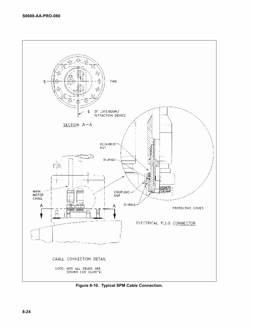
8-3.3.26 (DV) Depending on the type ofcable motor connector, use either the chainwrench (item 36) for a Joy type (imbedded O-ring) connector or cable connector tools (items43 and 44) for ITT Cannon type (three O-ring)connector to disconnect the electrical connec-tions (Figure 8-10).
NOTE
Cables associated with SSBN726 motors (which are some-times used on SSN 688 Classsubmarines) and SSN 688 dryw ind ing mo to rs r equ i re aslightly larger coupling nutwrench than a SSN 688 wetw ind ing mo tor. Refe r t oNAVSEA drawing 1197260,Rev B or later, for wrenchdimensional details.
8-3.3.27 (DV) Install brass sealing caps(item 25) on top of the SPM motor terminals.Install Delrin sealing caps (item 26) on thecable motor connectors. Ensure all sealingcaps are properly installed so that they com-press their associated sealing surfaces inorder to make a waterproof seal.
8-3.3.28 (DV) Lower the SPM until there issufficient clearance for removal.
Ensure that the SPM does notbottom out on the seabed whenlowering it from the SPM cavity.
NOTE
Some SPM installations utilizea spacer between the SPM andthe support column. In order toguarantee a good fit-up of thenew SPM with the fairing plateand the hull, any spacers mustbe reinstalled on the new SPMin the same configuration in
which they were found on theold unit.
8-3.3.29 (DV) Using the 7/8-inch shackleson the 45-foot eyeslings, connect the two 45-foot eyeslings from the pier crane to the two 3-foot "lazy" roundslings on the SPM (see Figure8-8).
8-3.3.30 (TOP) Following direction fromdivers, take up the slack on the pier crane untilit begins to support the weight of the SPM.
8-3.3.31 (DV/TOP) Slowly raise the piercrane while lowering the chain hoist until theSPM clears the ship and cofferdam.
8-3.3.32 (DV) Disconnect the chain hoistsfrom the SPM, leaving the shackles on theSPM.
8-3.3.33 (TOP) Remove the SPM from thewater using the pier crane and place it in asafe working area.
8-3.3.34 (DV) Remove any dowel pins fromthe support column flange.
All divers must be out of thewater when megger testing isbeing conducted.
8-3.3.35 (TOP) Megger test SPM cables inaccordance with NSTM CH 300, Section 300-4 to determine if cables are good, and recordthe test results in the work package. Refer toNAVSEA drawing 1197260 (Rev B or later) foracceptable component resistance values.
8-3.3.36 (SHOP) Ensure that the SPM align-ment fixture legs are fully retracted. Place theSPM alignment fixture (item 28) on top of theold SPM (include any spacer present on exist-ing installation) and snugly fasten the fixture tothe SPM using four of the sixteen used nuts at90 degree separation.
CAUTION
WARNING
8-22

S0600-AA-PRO-080
Figure 8-9. Configuration of SSN 688 Cofferdam.
Column
FlangeGasket
Gasket
MountingRingAssembly
Cofferdam
SPM
8-23
S0600-AA-PRO-080
Figure 8-10. Typical SPM Cable Connection.
8-24

S0600-AA-PRO-080
8-3.3.37 (SHOP) Turn the adjustment screwto bring the longitudinal cross arm level withthe SPM using a torpedo level (item 29).Adjust and lock the adjustment screw on thelongitudinal cross arm.
8-3.3.38 (SHOP) With the SPM alignment fix-ture level with the SPM, lower the retractablelegs until the tips of each leg are in contactwith the fairing plate.
8-3.3.39 (SHOP) Lock the legs in positionand mark points with chalk on the fairing platewhere the legs make contact.
8-3.3.40 (SHOP) Remove and place thealignment fixture in a safe working area.
NOTE
After the SPM alignment fixturehas been adjusted it is impor-tant that the fixture is not dis-turbed.
8-3.3.41 (SHOP) Disconnect and transferthe fairing plate to the new SPM. This is mosteasily accomplished if legs are loosened onthe new SPM body so they can be alignedwith existing fairing plate bolt holes. Using atorque wrench (item 30) and new lock nuts(items 31 and 32), tighten all leg threaded con-nectors and all other loosened threaded con-nectors in accordance with torque valuescalculated from reference (g). Final torque val-ues shall equal calculated torque values pluslock nut running torques. See NAVSEA draw-ing 4494057 or 5942057 for additional fairingplate details.
NOTE
If studs have to be installed orreplaced, do so in accordancewith reference (g).
8-3.3.42 (SHOP) Carefully place the SPMalignment fixture onto the new SPM (withspacer, if present in original installation) with-out applying any force on the alignment fixturelegs. The SPM to fairing plate height must be
equal to the previous height as measured bythe SPM alignment fixture.
8-3.3.43 (SHOP) Add or remove shim mate-rial as necessary for the SPM and fairingassembly to be within tolerance when fullyretracted into the ship.
NOTE
Corrections can be calculatedusing dimensions taken fromparagraph 8-3.2.2 and 8-3.2.3.
8-3.4 ELECTRICAL CABLE REMOVAL ANDREPLACEMENT PROCEDURES (SSN 688)
The underwater removal and replacement ofthe SPM electrical cables can be accom-plished only after the following conditions aremet:
a. Cofferdam installed and dewatered.
b. SPM separated from the support col-umn, cables disconnected, SPM prop-erly capped, cable motor connectorsproperly capped, triple-bagged, andtaped.
c. Cofferdam flooded, disassembled, andremoved.
8-3.4.1 (DV) Remove the three cable sup-port set screws. These are 5/16-inch Allenscrews located 21 inches above the SPM sup-port column flange.
8-3.4.2 (DV) Insert the cable supportreplacement tools (item 41) into the 1-inchdrains opposite each other in the cable sup-port and tighten them into place (see Figure 8-11).
8-3.4.3 (DV) Using the cable supportreplacement tools, evenly pull the cable sup-port out through the bottom of the support col-umn.
8-25

S0600-AA-PRO-080
Figure 8-11. Typical Cable Support Removal Technique.
8-26
S0600-AA-PRO-080
8-3.4.4 (DV) Remove the cable supportreplacement tool and the nut and bolt assem-bly from the cable support, remove the twocable support halves, and send them topside.
8-3.4.5 (DV) Remove the grate on the top ofthe electrical hull fitting (EHF) by looseningand removing the six 9/16-inch bolts.
8-3.4.6 (DV) Remove the 3/4-inch nuts fromthe cable bracket studs.
8-3.4.7 (DV) Remove the 3/16-inch setscrews from the EHF connector.
8-3.4.8 (DV) If the hydrostatic test fittingplugs in the cable connector interfere with theportsmouth fitting tool (item 42), remove theplugs.
8-3.4.9 (DV) Disconnect the bad cables(s)from the EHF using the portsmouth fitting tooland place the portsmouth connector cap(s)(item 45) onto the cable EHF connector.Ensure that all sealing caps are properlyinstalled so that they compress their associ-ated O-rings in order to make a waterproofseal.
8-3.4.10 (DV) Remove the banding from thecable tray.
8-3.4.11 (DV) Remove the bad cable(s) fromthe group and remove the cable(s) through thetop of the SPM column. Triple bag and tapethe EHF end of the cable(s).
NOTE
Ensure that new cable(s) havebeen machined in accordancewith note 25 on NAVSEA draw-ing 4454547.
Ensure that the cable insulationon new cables is not damagedduring installation.
8-3.4.12 (TOP) Mark motor connector endsof each new electrical cable to be installed
(T1-T1, T2-T2, and T3-T3) to match the mark-ings on the connectors. Inspect the EHF con-nector end of each new cable to ensure thatdimensions and configurations are the same.
8-3.4.13 (TOP) Megger new cables in accor-dance with NSTM CH 300, Section 300-3.60to determine if cables are good, and recordthe test results in the work package. Refer toNAVSEA drawing 1197260 (Rev B or later) foracceptable component resistance criteria.Install dried caps on both ends of new cable,ensuring proper O-ring compression. Triplebag and tape both ends of the cable.
Water contacting the electricalcable connectors can damageinsulation and prevent properelectrical connection. Useextreme care when packagingand transporting electricalcables to the cofferdam. Useconnector caps as directed(ensuring proper O-ring com-pression) to prevent water frommaking contact with the cables.
8-3.4.14 (DV) Enter ballast tank grate 4Awith the SPM cable(s) in hand.
NOTE
Ensure that the motor connec-tor ends of the new cablesenter the ballast tank first.
8-3.4.15 (DV) Lower the new cable(s) downthrough the top of the SPM column beginningwith the motor connector.
8-3.4.16 (DV) Blow dry the EHF terminalsand cable EHF connectors with dry nitrogen(item 33). Ensure that all electrical conductorsurfaces are clean and dry.
8-3.4.17 (DV) Connect the new cable(s) tothe EHF in accordance with NAVSEA drawing
CAUTION
8-27

S0600-AA-PRO-080
1197260 (Rev B or later), "Outboard CableInstallation" procedure.
8-3.4.18 (TOP) Hydrostatically test the EHFcable connection(s) in accordance withNAVSEA drawing 1197260 (revision B), "PostInstallation Tests Penetrator And OutboardCables" procedure.
8-3.4.19 (DV) Reinstall hydrostatic test fittingplugs in the EHF cable connector.
8-3.4.20 (DV) Reinstall the set screws intothe EHF cable connector.
8-3.4.21 (DV) Reinstall the cable bracket.
8-3.4.22 (DV/TOP) Scribe a line around thecenter of the edge of the cable support andreinstall the cable support around the cables.
8-3.4.23 (DV) Using the cable supportremoval tools, evenly push the cable supportinto place.
NOTE
Before installing, vertically alignthe set screw holes in the sup-port with the set screw holes inthe support column.
8-3.4.24 (DV) Align the scribed line with theset screw holes in the column and then alignthe holes as required. Install set screws.
8-3.4.25 (DV) Reinstall the grate over theEHF.
8-3.4.26 (DV) Band the cable on the cabletray.
8-3.5 SPM REPLACEMENT (SSN 688)
The underwater replacement of the SPM canonly be accomplished if the following condi-tions are met:
a. Cofferdam installed and dewatered.
b. Column lowered, cable motor connec-tor caps in place.
c. Old SPM removed.
d. Fairing plate and spacer (if present)transferred to new SPM and is withinfit-up tolerance.
e. All shipping protection removed fromnew SPM.
NOTE
SHIPALT 4018-D allows theuse of older SPMs (manufac-tured before 1974) which onlyhave fourteen holes in the SPMflange instead of the standardsixteen holes. Mounting thesemotors with fourteen studsmeets the shock requirementsfor the system. Bolt spacingpatterns are the same for bothins ta l l a t i ons . DO NO TATTEMPT TO INSTALL ADDI-TIONAL STUDS IN THESEMOTORS. Drilling may breakinto the dry winding cavity ofthese motors, thereby causinga leak path and shorting out themotor.
8-3.5.1 (SHOP) Transfer cable markingsfrom the old SPM to the new SPM.
8-3.5.2 (SHOP) Transfer flange marks fromthe old SPM to the new SPM.
8-3.5.3 (SHOP) Thoroughly clean the threemotor terminal pins on the new SPM. Meggertest the new SPM.
8-3.5.4 (SHOP) Apply a very light film of sili-cone compound (item 37) to the rubber sealsof the motor connectors. Ensure that all elec-trical contact surfaces are clean and dry.Install brass sealing caps (item 25), ensuringproper compression of rubber seals.
8-28
S0600-AA-PRO-080
8-3.5.5 (TOP) Double wrap a 13-foot, 3-tonSWL polyester roundsling (item 20) in a bas-ket configuration around the forward end ofthe SPM. Make sure that the roundsling doesnot lie in the groove between the SPM and theforward shroud. Connect the roundsling to a 3-foot long, 3-ton SWL "lazy" roundsling using a1-inch shackle on top of the SPM, and drapethe roundsling on the starboard side of theSPM.
8-3.5.6 (TOP) Double wrap a 11-foot, 3-tonSWL polyester roundsling (item 23) in a bas-ket configuration around the aft end of theSPM, forward of the Kort nozzle. Do not rigthrough or allow the roundsling to rest on theKort nozzle. Connect the roundsling to a 3-footlong, 3-ton SWL "lazy" roundsling using a 1-inch shackle on top of the SPM, and drape theroundsling on the starboard side of the SPM.
Ensure that there is clear com-munication between the diversand the crane operator to pre-vent the SPM from bottomingout on the seabed.
8-3.5.7 (TOP) Using the 7/8-inch shackles,connect the two 45-foot eyeslings from thepier crane to the two 3-foot roundslings on theSPM, and lower the new SPM into the water toa point where the SPM will clear the ship andcofferdam when raised by the chain hoists.
Refer to the CAUTION immedi-ately before paragraph 8-3.3.6.
8-3.5.8 (DV) Connect the chain hoists to the1-inch shackles on the "lazy" roundslings onthe SPM and take up all slack.
8-3.5.9 (DV/TOP) Slowly raise the SPM withthe chain hoists while lowering the pier crane
until the SPM has cleared the ship and the fullweight of the SPM is supported by the chainhoists.
8-3.5.10 (TOP) Remove the 45-foot eye-slings from the 3-foot roundslings on the SPM.
NOTE
Ensu re tha t t he shack lesremain on the 45-foot eyesling.
8-3.5.11 (DV) Raise the SPM until it con-tacts the bottom edge of the cofferdam. Thisposition should allow the electrical cables tobe connected.
8-3.5.12 (DV) Remove the caps from themotor terminals on the SPM and from thecable motor connectors.
8-3.5.13 (DV) Blow dry the cable motor con-nectors and motor terminals with dry nitrogen(item 33). Ensure that all electrical conductorsurfaces are clean and dry.
8-3.5.14 (DV) Conduct O-ring contact checkin accordance with NAVSEA drawing 1197260(Rev B or later), "Motor End Connector Instal-lation Procedure".
8-3.5.15 (DV) Depending on the type ofcable motor connector, use either the chainwrench (item 36) for Joy type (imbedded O-ring) connectors or a torque wrench with thecable connector tools (items 43 and 44) forITT Cannon type (three O-ring) connectors toconnect the cable motor connectors to theirproper terminals on the SPM. Installation shallbe in accordance with NAVSEA drawing1197260 (Rev B or later), "Motor End Connec-tor Installation" procedures and Appendix B.
An adapter or extension usedon a torque wrench increasesthe torque value.
CAUTION
CAUTION
CAUTION
Change 1 8-29
S0600-AA-PRO-080
All divers must be out of thewater when megger testing isbeing conducted.
8-3.5.16 (TOP) With the divers out of thewater, megger test the cables from inside theship and record the results to ensure properinstallation in accordance with the electricaltest procedures as described references (b)and (e). Refer to NAVSEA drawing 1197260(revision B) for acceptable component resis-tance criteria.
8-3.5.17 (DV) Apply marine sealant (item 34)to the SPM flange, around the base of thestuds, around the spacer (if present), and any-where else there could be a leak path duringthe hydrostatic test. Allow sealant to cure forat least one hour.
8-3.5.18 (DV) Secure LP air to the coffer-dam and vent the cofferdam.
8-3.5.19 (DV) Disassemble and remove cof-ferdam.
8-3.5.20 (DV) Mate the SPM with the col-umn flange using new self-locking nuts (item35). Sequentially torque the nuts to torque val-ues calculated in accordance with reference(g). Final torque values shall equal calculatedtorque values plus lock nut running torques.
8-3.6 SPM SUPPORT COLUMN HYDRO-STATIC TEST PROCEDURES (SSN 688)
8-3.6.1 (DV) Install two 1/2-inch O. D.expandable plugs (item 46) into the two drainholes at the bottom of the SPM column (or1/2-inch IPT plugs if drain holes are tapped).
8-3.6.2 (DV) Using a water hose (item 39),fill the SPM column with water to within a footof the top.
NOTE
Apply marine sealant liberallyand evenly to al l holes andsealing surfaces of the hydro-static test fixture (item 47) andSPM column before installingthe test fixture on top of the col-umn.
8-3.6.3 (DV) Install the hydrostatic test fixtureon the top of the SPM column using the eight3/8-inch allen cap screws used to secure thecable guide to the support column. Ensurethat O-ring stock is in place between thehalves of the test fixture. Ensure that packingmaterial is installed in the test fixture's cablepenetrations before cable clamps are installedand drawn down.
8-3.6.4 (DV) Open the vent valve on thehydrostatic test fixture.
8-3.6.5 (DV) Connect the water hose (item39) to the hydrostatic test fixture fill valve andfill the SPM column with water. When waterissues from the vent valve, stop filling.
8-3.6.6 (DV) Disconnect the water hose andshut the vent valve.
8-3.6.7 (DV/TOP) Using a minimum of 75feet of hydrostatic test tubing (item 48), con-nect the tubing from the hydrostatic pump(item 49) to the hydrostatic test fixture fillvalve.
All divers must be out of thewater when megger testing isbeing conducted.
8-3.6.8 (DV) With the proper gauges (items50 and 51) attached to the hydrostatic pumpand while simultaneously meggering the SPMcables, perform hydrostatic tests of the SPMmotor connectors in accordance with NAVSEAdrawing 1197260 (Rev B or later) (this proce-
WARNING
WARNING
8-30 Change 1

S0600-AA-PRO-080
dure does not test the SPM column; the col-umn is used as a pressure vessel in order tohydrostatically test the motor connectors):
(a) Pressurize to 100 psig for 10 minutes
(b) Record megger readings
(c) Reduce pressure to 0 psig
(d) Pressurize to 500 psig for 15 minutes
(e) Record megger readings
(f) Reduce pressure to 0 psig
(g) Repeat steps (d) thru (f) for a total ofthree 0-500 psig test cycles
NOTE
Megger each cable in accor-dance with references (b) and(e) during each hydrostaticcycle.
8-3.6.9 (TOP) Perform a final megger teston the SPM after it has been submerged in thewater for at least 24 hours.
8-3.6.10 (DV) Open the vent valve on thehydrostatic test fixture and disconnect thehydrostatic test tubing from the test fixture.
8-3.6.11 (DV) Remove the hydrostatic testfixture and clean off all marine sealant on thetest fixture and SPM column.
8-3.6.12 (DV) Pull the slack out of the elec-trical cables and reinstall both the cable coverguide and the shaft which aligns the cablecover guide. Tighten the 3/8-inch Allen headbolts and the four bolts on the cable clamps to48 ft-lbs above running torque and lockwire(item 52) them in place using lockwire pliers(item 38) in accordance with reference (g).
8-3.6.13 (DV) Remove the two expandableplugs (or 1/2-inch IPT plugs) from the SPMcolumn drain holes.
8-3.6.14 (DV) Remove rigging gear. Returngear to the surface.
8-3.6.15 (DV) Remove all tools and connec-tor caps from the SPM cavity and clear thetool log. Thoroughly inspect the SPM cavity forany loose gear.
8-3.6.16 (DV) Apply a handfull of grease tothe fairing plate bumper stops.
NOTE
Ensure that the SPM is in thezero degree relative bearingposition.
8-3.5.17 (TOP) Upon receiving authorizationfrom the dive supervisor, remove tags from theSPM system and proceed to fully raise theSPM. Tag out SPM system after SPM israised.
8-3.6.18 (DV) Measure and record the verti-cal fairing plate alignment with the hull. Mea-surements shall be taken forward, aft, port,and starboard (see Appendix E). Each mea-surement shall be recorded as positive if theoutside surface of the plate is outside the hullouter surface, and negative if the fairing plateouter surface is inside of the hull outer sur-face. The fairing plate vertical alignment insideor outside the hull shall not exceed tolerancesspecified in NAVSEA drawing 4494057 or5942057.
8-3.6.19 (DV) Measure the transverse gapbetween the fairing plate and the hull. Mea-surements should be taken forward, aft, port,and starboard (see Appendix E). The trans-verse gap between the fairing plate and thehull should be within local repair activity QAcriteria, but shall not exceed 1 inch at anypoint around the perimeter.
8-3.6.20 (TOP) Upon receiving authorizationfrom the dive supervisor, remove all tags.
Change 1 8-31

S0600-AA-PRO-080
Divers shall clear the SPM cav-ity before the SPM is raised,lowered, or trained.
8-3.6.21 (TOP) Lower and train the SPM.
8-3.6.22 (TOP) Perform propeller rotationtest on SPM to ensure proper cable hookup.
8-3.6.23 (TOP) Tag out the SPM system.
8-3.6.24 (DV) Inspect the fairing platebumper stops to ensure that the fairing plate isproperly seated in place within the hull of theship (even transfer of grease on bumperstops). If not, adjust stops. Inspect the cable atthe top of the column for sufficient slack.
8-3.6.25 (TOP) Upon receiving authorizationfrom the diving supervisor, remove the tagsfrom the SPM system. Prepare to raise theSPM.
NOTE
Ensure that the SPM is in thezero relative bearing position.
Divers shall clear the SPM cav-ity before the SPM is raised,lowered, or trained.
8-3.6.26 (TOP) Raise the SPM.
8-3.6.27 (TOP) Inform the ship's force orcognizant repair activity representative thatSPM related underwater work has been com-pleted.
8-3.7 DEBRIEF SHIP'S FORCE
(TOP) The lead dive supervisor should debriefthe proper ship’s officers on the final status ofthe SPM and/or cable replacement.
8-3.8 PREPARE FINAL REPORT
(TOP) Prepare a final report documenting theaccomplished repair. Documentation shouldconsist of inspection reports, data sheets,photographs, and video logs. The final reportshall include details regarding any problemsencountered, new or special tools needed, ormodifications to tools or procedures found tofacilitate the SPM and/or cable replacement.Send copy of final report to NAVSEA 00C5.
WARNING WARNING
8-32 Change 1

S0600-AA-PRO-080
PROCEDURES FOR REMOVAL AND REPLACEMENT OF SPM AND ELECTRICAL CABLES SSN 637 and SSN 640 CLASS
SECTION 4
Rotation of propellers or opera-tion of underwater electricalequipment while divers are inthe vicinity can cause seriousinjury or death. Ensure thatship’s equipment, including theSPM system, is de-energizedand tagged out as required byreference (h) prior to beginningunderwater operations.
It is essential that all tools andmaterials brought to the under-water job site are accounted forand removed at the completionof the job. Tools and materialsinadvertently left at the job sitecan generate unacceptablenoi se and poss ib ly causesevere damage to shipboardcomponents. Locally gener-ated work packages sha l lensure that a general tool andmaterial log sheet is preparedand main ta ined dur ing a l lUWSH operations.
8-4.1 GENERAL: SSN 637 AND SSN 640CLASS SUBMARINES
NOTE
Before beginning these proce-dures, ship's force shall isolateall SPM electrical system com-
ponents inside the submarine(console, slip ring, secondaryseal) and megger these com-ponents separately in accor-dance with reference (e) inorder to ensure that the prob-lem is located outside the pres-sure hull. If any internal systemcomponent is faulty, it shouldbe repaired and the systemshould be reconnected andmeggered to see if the fault hasbeen corrected before anyaction is taken on the externalcomponents of the SPM sys-tem.
This section provides detailed procedures forremoval and replacement of an SPM on awaterborne SSN 637 and SSN 640 Class sub-marine. A separate set of procedures isincluded for removal and replacement of faultyelectrical cables. If an electrical problem existswithin the SPM system, references (c) and (d)provide test procedures down to the second-ary seal. If tests reveal that the fault is beyondthe SPM cable connections, divers must dis-connect the power cables from the SPM to fur-ther isolate the fault. When this has beenaccomplished and the cables and SPM termi-nals are known to be dry, ship's force person-nel may conduct additional electrical tests tofurther isolate the fault. When the results ofthis additional testing have been evaluated,the cognizant repair activity representativemust determine the appropriate course ofaction to correct the fault. Electrical problemsmay be caused by faulty cables, a faultymotor, or moisture on the terminal connec-tions.
WARNING
CAUTION
8-33

S0600-AA-PRO-080
NOTE
While the following proceduresrequire that topside personneland d ive rs work c lose l ytogether, certain steps must becarried out by particular per-sonnel. To clarify these steps,abbreviations are placed at thebeginning of each step wherethe specific party needs to beidenti fied: (DV) representsdiver; (TOP) represents topsidepersonnel or ship's force, and(SHOP) represent s themachine shop personnel.
8-4.1.1 Removal of the SPM requires theuse of a cofferdam. Procedures for cofferdaminstallation and SPM replacement are pro-vided in the following paragraphs.
8-4.2 SPM REMOVAL PROCEDURES (SSN637 and SSN 640)
8-4.2.1 (TOP) Tag out the SPM system andall sources of high pressure air in the main bal-last tank related to the SPM.
8-4.2.2 (DV) Clean the area around the SPMopening (see Figures 8-13 and 8-14) in accor-dance with Naval Ship's Technical ManualS9086-CQ-STM-010 Chapter 081, Water-borne Underwater Hull Cleaning of NavyShips. Inspect the area for any obstructionsthat might interfere with the cofferdam seal.
8-4.2.3 (DV) Measure and record the fairingplate vertical alignment with the hull. Measure-ments shall be taken forward, aft, port, andstarboard. Each measurement shall berecorded as positive if the outside surface ofthe plate is outside the hull outer surface, andnegative if the fairing plate outer surface isinside of the hull outer surface. The fairingplate vertical alignment inside or outside thehull shall not exceed tolerances specified inNAVSEA drawing 2012206 (SSN 640 Class)or 2140608 (SSN 637 Class). For measure-
ment charts, see Appendix C for SSN 640 andAppendix D for SSN 637 Class submarines.
8-4.2.4 (DV) Measure the transverse gapbetween the fairing plate and the hull. Mea-surements shall be taken forward, aft, port,and starboard. The transverse gap betweenthe fairing plate and the hull should be withinlocal repair activity QA criteria, but shall notexceed 1 inch at any point around the perime-ter. For measurement charts, see Appendix Cfor SSN 640 and Appendix D for SSN 637Class submarines.
Divers shall clear the SPM cav-ity before the SPM is raised,lowered, or trained.
NOTE
Ensure that all tag out proce-dures are in accordance withthe current shipboard instruc-tions.
Shut and tag out the ventvalves for the main ballasttanks 5A, 5B, 6A and 6B forSSN 640 class submarines and4A, 4B, 5A and 5B for SSN 637class submarines.
8-4.3 RECOMMENDED COFFERDAM RIG-GING AND INSTALLATION
8-4.3.1 SSN 640 Class Submarines
8-4.3.1.1 (DV) Attach a 1/2-ton come-along(item 3) to the aft grate of ballast tank 5B.Attach another 1/2-ton come-along to the for-ward grate of ballast tank 6B (port).
WARNING
CAUTION
8-34

S0600-AA-PRO-080
8-4.3.1.2 (TOP) Using a 3/4-inch shackle(item 1), attach a 1/2-inch by 45-foot eyesling(item 2) to each of the two padeyes on thestarboard outboard side of the cofferdam (Fig-ure 8-12).
8-4.3.1.3 (TOP) Utilizing a pierside crane(item 4), lift and train the cofferdam using the45-foot eyeslings, over to the starboard side ofthe submarine between frames 111 and 116.
8-4.3.1.4 (TOP) Lower the cofferdam (item54) into the water until it is even with the bot-tom of the ship.
8-4.3.1.5 (DV) Using a 3/4-inch shackle,attach the outboard padeye on the forward-port side of the cofferdam to the come-alongon ballast tank 5B (port side).
8-4.3.1.6 (DV) Using a 3/4-inch shackle,attach the outboard padeye on the aft-portside of the cofferdam to the come-along at bal-last tank 6B (port).
8-4.3.1.7 (TOP/DV) Yard and stay the coffer-dam using the come-alongs and the pier craneto position the cofferdam under the SPMopening.
8-4.3.1.8 (DV) Using two 3/4-inch shackles,attach a 1/2 ton come-along between the mostaft grate of ballast tank 5A (stbd) and the out-board forward-starboard padeye on the coffer-dam.
8-4.3.1.9 (DV) Using two 3/4-inch shackles,attach a 1/2 ton come-along between the mostforward grate of ballast tank 6A (stbd) and theoutboard aft-starboard padeye on the coffer-dam.
8-4.3.1.10 (DV) Evenly take up tension on allthe come-alongs until the cofferdam is seatedon the hull of the ship and clear of the SPMopening.
8-4.3.1.11 (DV) Remove the two 45-foot eye-slings from the starboard side of the cofferdamleaving the shackles attached to the eyeslings.
Divers shall clear the SPM cav-ity before the SPM is raised,lowered, or trained.
8-4.3.1.12 (TOP) Remove tags necessary tolower the SPM, and fully lower the SPM.
8-4.3.1.13 (TOP) Tag out the SPM system toensure that it is not raised, lowered, or trained.
8-4.3.1.14 (DV) Attach turnbuckles with theclamp attached (items 5, 6 and 7), approxi-mately 10 turnbuckles and clamps, evenlyspaced, from the bottom of the cofferdam tothe lip of the SPM opening.
8-4.3.1.15 (DV) Gradually and evenly, takeup the tension in each of the turnbuckles untilthe cofferdam seal is compressed with thehull. Do not overtighten the turnbuckles.
8-4.3.1.16 (DV) Enter the SPM cavity andinstall expandable plugs or standard woodenDC plugs (items 8 and 9) into the 1-inch drainholes in the SPM cavity. If there is an equal-ization tube in the SPM cavity wrap it with aplastic bag (item 10) and secure with duct tape(item 11).
8-4.3.1.17 (DV) After the cofferdam is tightlyin place with the cofferdam gasket com-pressed all around, connect an LP air hose(item 12) to the air supply fitting on the coffer-dam. Dewater the SPM cavity and the coffer-dam. Check for gross leakage of air aroundthe cofferdam gasket and seal leaks as neces-sary. Maintain a constant air flow into the cof-ferdam at a rate which will maintain the lowestwater level possible.
WARNING
8-35

S0600-AA-PRO-080
8-36
Figure 8-12. Typical Rigging of SSN 637 and SSN 640 Cofferdam.

S0600-AA-PRO-080
8-37
Figure 8-13. Submarine Fairing Plate (SSN 640)

S0600-AA-PRO-080
8-38
Figure 8-14. Submarine Fairing Plate (SSN 637)

S0600-AA-PRO-080
NOTE
An effective sealant to fill gapsbetween the cofferdam gasketand the submarine hull is Bint-suke (item 13).
8-4.3.2 SSN 637 Class Submarines
8-4.3.2.1 (DV) Attach a 1/2-ton come-along(item 3) to the most forward grate of ballasttank 5B (port). Attach another 1/2-ton come-along to the aft grate of ballast tank 5B (port).
8-4.3.2.2 (TOP) Using a 3/4-inch shackle(item 1), attach a 1/2-inch by 45-foot eyesling(item 2) to each of the two padeyes on thestarboard outboard side of the cofferdam (Fig-ure 8-12).
8-4.3.2.3 (TOP) Using a pierside crane (item4), lift and train the cofferdam using the 45-foot eyeslings, over to the starboard side ofthe submarine between frames 72 and 77.
8-4.3.2.4 (TOP) Lower the cofferdam (item54) into the water until it is even with the bot-tom of the ship.
8-4.3.2.5 (DV) Using a 3/4-inch shackle,attach the padeye on the forward port side ofthe cofferdam to the come-along on the for-ward grate on 5B.
8-4.3.2.6 (DV) Using a 3/4-inch shackle,attach the padeye on the center-port side ofthe cofferdam to the come-along on the aftgrate on 5B.
8-4.3.2.7 (TOP/DV) Yard and stay the coffer-dam using the come-alongs and the piersidecrane to position the cofferdam under theSPM opening.
8-4.3.2.8 (DV) Using two 3/4-inch shackles,attach a 1/2-ton come-along between the for-ward starboard flood hole in the SPM cavityand the inboard forward-starboard padeye onthe cofferdam.
8-4.3.2.9 (DV) Using two 3/4-inch shackles,attach a 1/2-ton come-along between the aftstarboard flood hole in the SPM cavity and theinboard center-starboard padeye on the cof-ferdam.
8-4.3.2.10 (DV) Evenly take up tension on allthe come-alongs until the cofferdam is seatedon the hull of the ship.
NOTE
Make certain that the coffer-dam seal is between the SPMcavity flood holes and the bal-last tank grates and does notinterfere with the SPM fairingplate.
8-4.3.2.11 (DV) Remove the two 45-foot eye-slings from the starboard side of the cofferdamleaving the shackles attached to the eyeslings.
Divers shall clear the SPM cav-ity before the SPM is raised,lowered, or trained.
8-4.3.2.12 (TOP) Remove tags necessary tolower the SPM, and fully lower the SPM.
8-4.3.2.13 (TOP) Tag out the SPM system toensure that it is not raised, lowered, or trained.
8-4.3.2.14 (DV) Attach turnbuckles (items 5,6, and 7) with the clamp attached (approxi-mately 10 turn buckles and clamps) evenlyspaced, from the bottom of the cofferdam tothe lip of the SPM opening.
8-4.3.2.15 (DV) Gradually and evenly, takeup the tension in each of the turnbuckles untilthe cofferdam seal is compressed on the hull.Do not overtighten the turnbuckles.
8-4.3.2.16 (DV) Enter the SPM cavity andinstall expandable plugs or standard DC plugs(items 8 and 9) into the 1-inch drain holes in
WARNING
8-39

S0600-AA-PRO-080
the SPM cavity and the 1-1/2-inch vent holes.In accordance with NAVSEA drawing6697899, measure to fit blanking flanges (item
69) on the forward and port & starboard floodholes (four places) (Figure 8-15) and installblanking flanges.
Figure 8-15. SPM Flood Holes (SSN 637)
8-40

S0600-AA-PRO-080
8-4.3.2.17 (DV) After the cofferdam is tightlyin place with the cofferdam gasket com-pressed all around, connect an LP air hose tothe air supply fitting on the cofferdam. Dewa-ter the SPM cavity and the cofferdam. Checkfor gross leakage of air around the cofferdamgasket and seal leaks as necessary. Maintaina constant air flow in to the cofferdam at a ratewhich will maintain the lowest water level pos-sible.
NOTE
An effective sealant to fill gapsbetween the cofferdam gasketand submarine hull is Bintsuke(item 13).
8-4.4 SPM REMOVAL (SSN 637 AND SSN640)
8-4.4.1 (TOP) Test the tightness of the SPMmain column internal seals by installing thecolumn vent and drain valve assembly (item55) (Figure 8-17).
8-4.4.2 (TOP) Install a calibrated 0-50 psigair gauge (item 56) in the assembly ventvalve.
8-4.4.3 (TOP) Attach an LP air source to theassembly valve air inlet fitting.
8-4.4.4 (TOP) Ensure the valve to the pres-sure gauge is open, and pressurize the col-umn to 35 psig.
8-4.4.5 (TOP) Close the valve used to intro-duce the compressed air, but leave the valveto the pressure gauge open and let pressurestabilize.
8-4.4.6 (TOP) Monitor the pressure for 15minutes.
8-4.4.7 (DV/SF) If any air leakage isdetected by the loss of pressure in the column,investigate for the cause and correct the prob-lem before proceeding.
NOTE
If the leakage is at the SPMmotor flange, investigate forcause after the removal of themotor.
8-4.4.8 (TOP) After completion of the initialpressure test, decrease pressure inside themain column to the same pressure inside thecofferdam air cavity (air cavity pressure (psig)equals 0.445 times the depth in feet to the bot-tom edge of the cofferdam).
NOTE
Each submarine has a differentI-beam configuration within theSPM cavity. Rigging attach-ment points will vary. The fol-lowing steps are typical forrigging and placement of come-alongs and chain hoists.
8-4.4.9 (DV) Install two beam clamps (item15) as close to center as possible on the for-ward I-beam above the SPM. Install a 18-inchlong, 3-ton SWL roundsling (item 16) to eachbeam clamp using a 3/4-inch shackle and jointhe roundslings together with a 7/8-inchshackle (item 18). Install two other beamclamps as close to center as possible on theaft I-beam above the SPM in the same man-ner as the forward beam clamps. Install a 18-inch long, 3-ton SWL roundsling to each beamclamp using a 3/4-inch shackle and join theroundslings together with a 7/8-inch shackle.
NOTE
Ensure a minimum of 48 inchesclearance between the SPMand the overhead I -beamswithin the SPM cavity.
Change 1 8-41

S0600-AA-PRO-080
Figure 8-16. Installation of Column Vent & Drain Valves (SSN 640 and SSN 637)
8-42
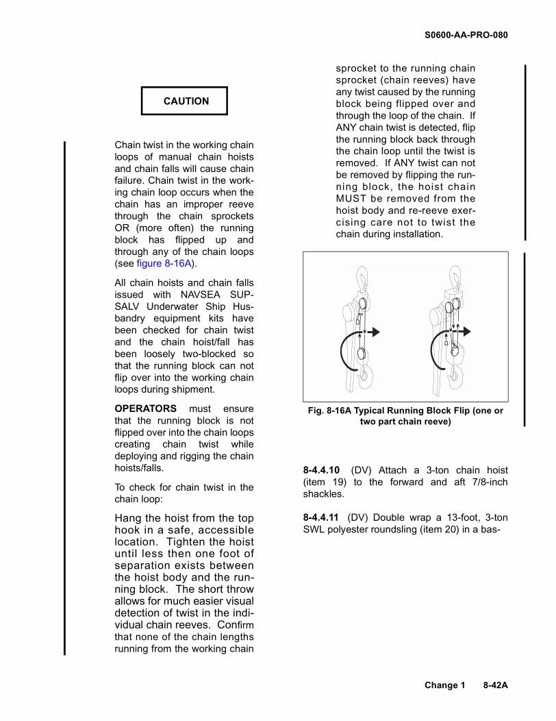
S0600-AA-PRO-080
Chain twist in the working chainloops of manual chain hoistsand chain falls will cause chainfailure. Chain twist in the work-ing chain loop occurs when thechain has an improper reevethrough the chain sprocketsOR (more often) the runningblock has flipped up andthrough any of the chain loops(see figure 8-16A).
All chain hoists and chain fallsissued with NAVSEA SUP-SALV Underwater Ship Hus-bandry equipment kits havebeen checked for chain twistand the chain hoist/fall hasbeen loosely two-blocked sothat the running block can notflip over into the working chainloops during shipment.
OPERATORS must ensurethat the running block is notflipped over into the chain loopscreating chain twist whiledeploying and rigging the chainhoists/falls.
To check for chain twist in thechain loop:
Hang the hoist from the tophook in a safe, accessiblelocation. Tighten the hoistuntil less then one foot ofseparation exists betweenthe hoist body and the run-ning block. The short throwallows for much easier visualdetection of twist in the indi-vidual chain reeves. Confirmthat none of the chain lengthsrunning from the working chain
sprocket to the running chainsprocket (chain reeves) haveany twist caused by the runningblock being flipped over andthrough the loop of the chain. IfANY chain twist is detected, flipthe running block back throughthe chain loop until the twist isremoved. If ANY twist can notbe removed by flipping the run-ning block, the hoist chainMUST be removed from thehoist body and re-reeve exer-cising care not to twist thechain during installation.
8-4.4.10 (DV) Attach a 3-ton chain hoist(item 19) to the forward and aft 7/8-inchshackles.
8-4.4.11 (DV) Double wrap a 13-foot, 3-tonSWL polyester roundsling (item 20) in a bas-
CAUTION
Fig. 8-16A Typical Running Block Flip (one or two part chain reeve)
Change 1 8-42A

S0600-AA-PRO-080
8-42B Change 1
THIS PAGE LEFT BLANK INTENTIONALLY

S0600-AA-PRO-080
ket configuration around the forward end ofthe SPM. Make sure that the roundsling doesnot lie in the groove between the SPM and theforward shroud. Connect the roundsling to theforward chain hoist using a 1-inch shackle(item 21). Connect a 3-foot long, 3-ton SWLroundsling (item 22) as a "lazy" pendant in the1-inch shackle (see Figure 8-8) on top of theSPM, and drape the roundslings on the star-board side of the SPM.
8-4.4.12 (DV) Double wrap an 11-foot, 3-tonSWL polyester roundsling (item 23) in a bas-ket configuration around the aft end of theSPM, forward of the Kort nozzle. Do not rigthrough or allow the roundsling to rest on theKort nozzle. Connect the roundsling to the aftchain hoist using a 1-inch shackle. Connect a3-foot long, 3-ton SWL roundsling as a "lazy"pendant in the 1-inch shackle (see Figure 8-8)on top of the SPM, and drape the roundslingson the starboard side of the SPM.
8-4.4.13 (DV) Remove all slack from thechain hoists and roundsling rigging so thatthey are able to take the weight of the SPM asthe flange bolts are loosened.
8-4.4.14 (DV) Scribe a match mark on boththe SPM flange and the column flange.
8-4.4.15 (DV) Sequentially remove each ofthe eight 1 5/8-inch self-locking nuts on thecolumn flange.
8-4.4.16 (DV) Upon receiving authorizationfrom the dive supervisor, use the forward andaft chain hoists to lower the SPM enough toexpose the electrical connectors, but no lowerthan the slack in the electrical cables will allow(approximately 8 inches).
8-4.4.17 (DV) Ensure that cables and motorconnecting terminals are positively identified.If positive identification is not apparent, markthe cables with tie wraps (item 24, one tiewrap for T1, two tie wraps for T2, etc.). Dis-connect the electrical connections using the 2-1/2-inch and 2-3/4-inch crow's foot (items 67and 68).
8-4.4.18 (DV) Install brass sealing caps (item25) on top of the SPM motor terminals. InstallDelrin sealing caps (item 26) on the cablemotor connectors. Ensure all sealing caps areproperly installed so that their sealing surfacesare compressed in order to make a waterproofseal.
8-4.4.18 (DV) Install the lower column cover(item 57) and gasket (item 58). Ensure that thelower column cover vent valve is in the closedposition (Figure 8-17).
8-4.4.19 (TOP) Ensure the valve to the pres-sure gauge is open, pressurize the column toapproximately 35 psig.
8-4.4.20 (TOP) Close the valve used tointroduce the compressed air, but leave thevalve to the air gauge open.
8-4.4.21 (TOP) Monitor the pressure for 15minutes.
8-4.4.22 (DV/SF) If any leakage is detectedby the loss of pressure, investigate for thecause and correct the problem before pro-ceeding.
8-4.4.23 (DV) Lower the SPM until there issufficient clearance between it and the walls ofthe cofferdam when raised by the pier crane.
Ensure that the SPM does notbottom out on the seabed whenlowering it from the SPM cavity.
8-4.4.24 (DV) Using the 7/8-inch shackleson the 45-foot pendants, connect the two 45-foot pendants from the pier crane to the two 3-foot lazy pendants on the SPM (see Figure 8-8).
8-4.4.25 (TOP) Following direction fromdivers, take up the slack on the pier crane untilit begins to support the weight of the SPM.
CAUTION
8-43

S0600-AA-PRO-080
8-44
Figure 8-17. Installation of Cover on Support Column Flange.

S0600-AA-PRO-080
8-4.4.26 (DV/TOP) Slowly raise the piercrane while lowering the chain hoist until theSPM clears the ship and cofferdam.
8-4.4.27 (DV) Disconnect the chain hoistsfrom the SPM, leaving the shackles on theSPM.
8-4.4.28 (TOP) Remove the SPM from thewater using the pier crane and place it in asafe working area.
8-4.4.29 (DV) Remove any dowel pins fromthe support column flange.
8-4.4.30 (SHOP) Ensure that the SPM align-ment fixture legs are fully retracted. Place theSPM alignment fixture (item 28) on top of theold SPM and snugly fasten the fixture to theSPM using four of the eight used nuts at 90degree separation.
8-4.4.31 (SHOP) Turn the adjustment screwto bring the longitudinal cross arm level withthe SPM using a torpedo level (item 29).Adjust and lock the adjustment screw on thelongitudinal cross arm.
8-4.4.32 (SHOP) With the SPM alignmentfixture level with the SPM, lower the retract-able legs until the tips of each leg are in con-tact with the fairing plate.
8-4.4.33 (SHOP) Lock the legs in positionand mark points with chalk on the fairing platewhere the legs make contact.
8-4.4.34 (SHOP) Remove and place thealignment fixture in a safe working area.
NOTE
After the SPM alignment fixturehas been adjusted it is impor-tant that the fixture is not dis-turbed.
8-4.4.35 (SHOP) Disconnect and transferthe fairing plate to the new SPM. This is mosteasily accomplished if legs are loosened at
the SPM body so they can be aligned withexisting fairing plate bolt holes. Using atorque wrench (item 30) and new lock nuts(items 31 and 32), tighten all leg threaded con-nectors and all other loosened threaded con-nectors in accordance with torque valuescalculated from reference (g). Final torque val-ues shall equal calculated torque values pluslock nut running torques. For additional fairingplate details for SSN 640 Class see NAVSEAdrawing 2012206; for SSN 637 Class seeNAVSEA drawing 2140608.
NOTE
If studs have to be installed orreplaced, do so in accordancereference (g).
8-4.4.36 (SHOP) Carefully place the SPMalignment fixture onto the new SPM withoutapplying any force on the legs. The SPM tofairing plate height must be equal to the previ-ous height as measured by the SPM align-ment fixture.
8-4.4.37 (SHOP) Add or remove shim mate-rial as necessary for the SPM and fairingassembly to be within tolerance when fullyretracted into the ship.
NOTE
Corrections can be calculatedusing dimensions taken fromparagraph 8-4.2.3 and 8-4.2.4.
8-4.5 ELECTRICAL CABLE REMOVAL ANDREPLACEMENT PROCEDURES (SSN 637and SSN 640)
The underwater removal and replacement ofthe SPM electrical cables can be accom-plished only after the following conditions aremet:
a. Cofferdam is installed and dewatered.
b. Column vent and drain assemblyinstalled.
8-45

S0600-AA-PRO-080
c. SPM separated from the support col-umn, cables disconnected, SPM termi-nals properly capped, cable motorconnectors properly capped, triple-bagged, and taped.
d. Column lowered, lower column cover inplace, vent valve closed.
8-4.5.1 (TOP) Mount a hand-operated boatwinch (item 59) between the two ball screwassemblies (Figure 8-18).
8-4.5.2 (TOP) With a scribe, benchmark thesupport ring for the slip ring, the column, andthe secondary seal disk (Figure 8-19).
8-4.5.3 (TOP) Remove the six 1/2-inch 13UNC hex nuts and lock washers from the studfor the secondary seal.
8-4.5.4 (TOP) Remove the support ring forthe slip ring from the support column.
8-4.5.5 (TOP) Install a 3/8-inch eyebolt in thesecondary seal disk (Figure 8-20), (item 60).
8-4.5.6 (TOP) Attach the soft eye of a 1/4-inch by 15 foot wire rope to the secondary sealdisk eyebolt with a 3/8-inch shackle (Figure 8-20, (item 61).
8-4.5.7 (TOP) Thread the bitter end of the1/4-inch wire rope through the bottom of thestuffing tube of the upper column closure plate(item 62).
8-4.5.8 (TOP) Install the upper column clo-sure plate and gasket to the top of the supportcolumn with six hex head screws (item 63)(Figure 8-21) and attach the bitter end of thewire rope to the boat winch, reeving it around.Do not put tension on the wire rope attachedto the secondary seal disc.
8-4.5.9 (TOP) Tighten the stuffing tubepacking gland in the upper column closureplate.
8-4.5.10 (DV) Close the vent valve in thelower column cover.
8-4.5.11 (TOP) Install a calibrated 0-50 psigair gauge in the upper column closure plate(see Figure 8-21).
8-4.5.12 (TOP) Attach an LP air source tothe upper column closure plate vent valve.
8-4.5.13 (TOP) Ensure the valve to the pres-sure gauge is open, and pressurize the col-umn to approximately 35 psig.
8-4.5.14 (TOP) Close the valve used tointroduce the compressed air, but leave thevalve to the air gauge open.
8-4.5.15 (TOP) Monitor the pressure for 15minutes.
8-4.5.16 (DV/SF) If any leakage is detectedby the loss of pressure, investigate for thecause and correct the problem before pro-ceeding.
NOTE
Air escaping around the uppercolumn closure plate indicatesan improper seal. It may benecessary to tighten the hexhead screws on the closureplate, or to remove the closureplate, clean all surfaces andreinstall the closure plate.
8-4.5.17 (DV/TOP) Pass the vacuum hose(item 64) into the cofferdam.
8-4.5.18 (DV) Connect the hose to the ventvalve in the lower column cover.
8-4.5.19 (DV) Open the vent valve in thelower column cover.
8-4.5.20 (TOP) Using the vacuum pump,draw a vacuum on the support column tounseat the secondary seal disk.
8-46
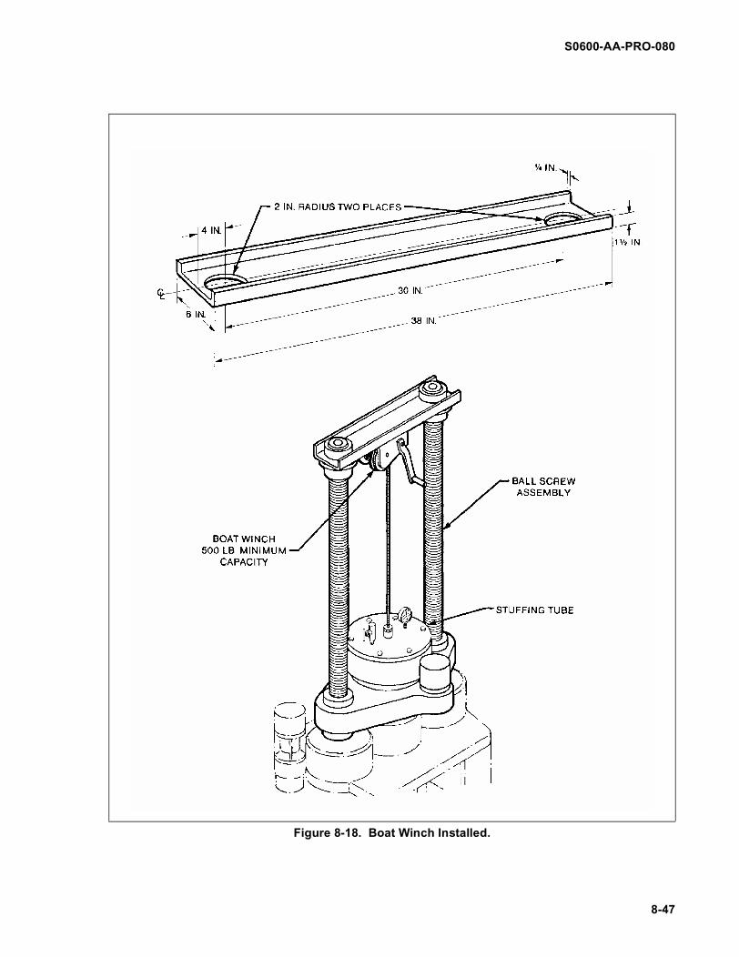
S0600-AA-PRO-080
Figure 8-18. Boat Winch Installed.
8-47
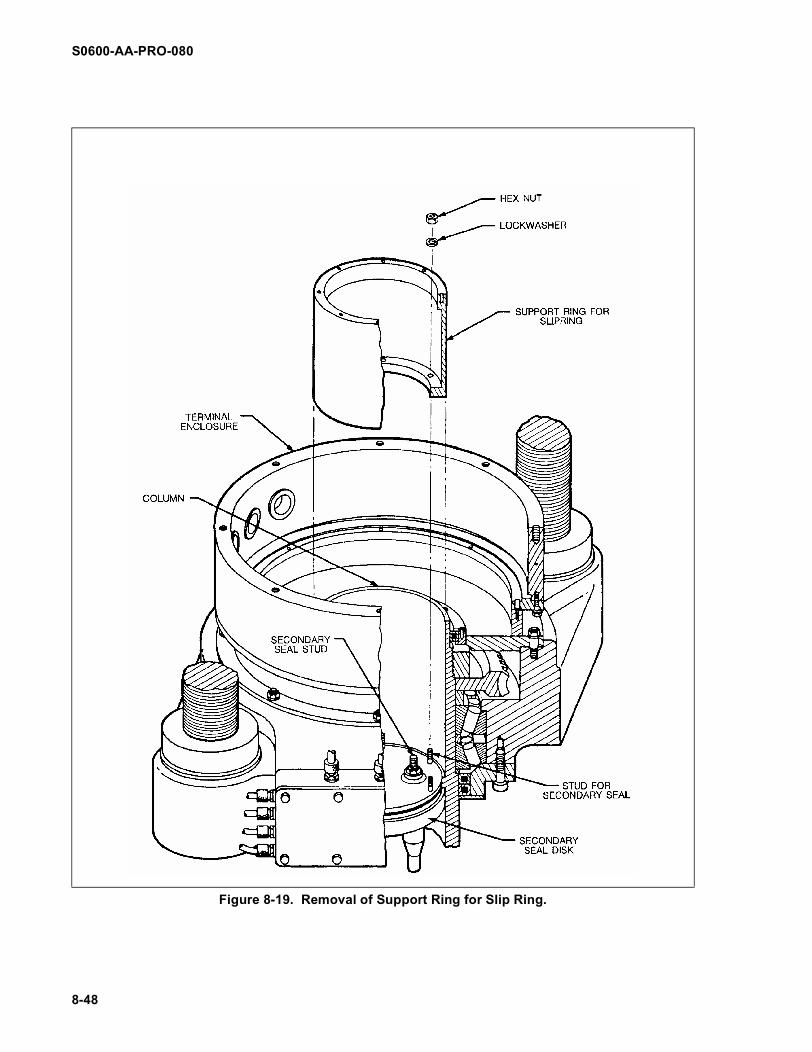
S0600-AA-PRO-080
Figure 8-19. Removal of Support Ring for Slip Ring.
8-48
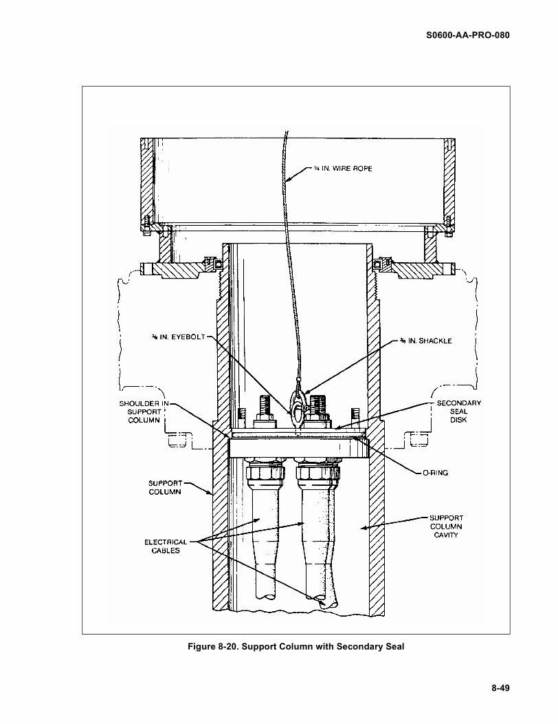
S0600-AA-PRO-080
Figure 8-20. Support Column with Secondary Seal
8-49

S0600-AA-PRO-080
Figure 8-21. Closure Plate Installation.
8-50

S0600-AA-PRO-080
NOTE
The stiffness of the electricalcables will prevent the second-ary seal disk from travelling anysignificant distance down thesupport column.
8-4.5.21 (DV) Close the vent valve in thelower column cover.
8-4.5.22 (DV) Disconnect the vacuum hosefrom the vent valve in the lower column over.
8-4.5.23 (TOP) Remove the slack in the 1/4-inch wire rope.
8-4.5.24 (DV) Open the vent valve in thelower column cover so that the interior of thesupport column equalizes with the pressure inthe cofferdam.
8-4.5.25 (DV) Remove the lower columncover from the bottom of the column.
8-4.5.26 (DV) Reeve out on the boat winchand pull the electrical cables and the second-ary seal disk down and out of the column.
NOTE
Ensure that the secondary sealdisk and cables do not get wet.
8-4.5.27 (DV) Disconnect the shackle fromthe eyebolt on the secondary disk and trans-port the electrical cables and secondary sealdisk to the surface in a dry environment. Theshackle will remain attached to the 1/4-inchwire rope.
8-4.5.28 (DV) Install the lower column coverand gasket on the bottom of the column, andperform another air tightness test.
8-4.5.29 (TOP) Remove and discard the O-ring from the secondary seal disk.
8-4.5.30 (TOP) Disconnect the electricalcables from the secondary seal disk.
8-4.5.31 (TOP) Mark both ends of each newelectrical cable with tie wraps (T1-T1, T2-T2and T3-T3) to match the markings on the SPMmotor connectors and on the secondary sealdisk connectors.
8-4.5.32 (TOP) Blow dry all electrical con-nectors individually with dry nitrogen immedi-ately prior to making connections. Ensure thatall electrical conductor surfaces are clean anddry.
8-4.5.33 (TOP) Connect each new electricalcable to its matching terminal on the second-ary seal disk.
8-4.5.34 (TOP) Transfer dry Delrin sealingcaps from old cable(s) to new cable(s), ensur-ing the caps are properly installed and com-press sealing surfaces.
8-4.5.35 (TOP) Conduct megger checks onall three electrical cables in accordance refer-ences (c) or (d), and (e).
8-4.5.36 (TOP) Lubricate and install a newO-ring (item 66) on the secondary seal disk.
Water contacting the electricalcables can damage insulationand prevent proper electricalconnection. Use extreme carewhen packaging and transport-ing electrical cables to the cof-ferdam.
NOTE
Dry hands before working onthe support column and cables.
8-4.5.37 (TOP) Equalize pressure within theSPM column by venting the valve on the uppercolumn closure plate.
CAUTION
8-51

S0600-AA-PRO-080
8-4.5.38 (DV) Transport the electrical cablesand secondary seal disk to the cofferdam in adry environment.
8-4.5.39 (DV) Remove the lower columncover from the bottom of the column.
NOTE
Do not a l low the elect ricalcables to contact water.
8-4.5.40 (DV) Attach the 1/4-inch wire rope(hanging in the support column) to the eyeboltin the secondary seal disk with the 3/8-inchshackle.
8-4.5.41 (TOP) Use the winch to pull thesecondary seal disk and the electrical cablesup inside the column until the secondary sealdisk is seated against the shoulder in theupper column ensuring that no water touchesthe cables.
8-4.5.42 (DV) Install the lower column coverand gasket on the bottom flange of the column(Figure 8-17).
8-4.5.43 (DV) Close the vent valve in thelower column cover.
8-4.5.44 (TOP) Ensure the valve to the pres-sure gauge is open and pressurize the columnto approximately 35 psig using the columnvent and drain assembly.
8-4.5.45 (TOP) Close the valve used to intro-duce the compressed air, but leave the valveto the pressure gauge open.
8-4.5.46 (TOP) Monitor the pressure for 15minutes.
8-4.5.47 (DV/SF) If any leakage is detectedby the loss of pressure, investigate for thecause and correct the problem before pro-ceeding.
8-4.5.48 (TOP) Decrease the pressureinside the main column to the same pressure
inside the cofferdam air cavity (air cavity pres-sure (psig) equals 0.445 times the depth infeet to the bottom edge of the cofferdam).
8-4.5.49 (TOP) Equalize pressure within theSPM column by venting the valve on the clo-sure plate. Disconnect upper closure plate.
8-4.5.50 (DV) Disconnect the 3/8-inchshackle and the 1/4-inch wire rope from theeyebolt in the secondary seal disk.
8-4.5.51 (TOP) Remove the eyebolt fromthe secondary seal disk.
8-4.5.52 (TOP) Install the support ring forthe slip ring with hex nuts and lock washers tocomplete the secondary seal installation (Fig-ure 8-19).
8-4.6 SPM REPLACEMENT (SSN 637 ANDSSN 640)
The underwater replacement of the SPM canonly be accomplished if the following condi-tions are met:
a. Cofferdam is installed and dewatered.
b. Column vent and drain assemblyinstalled.
c. Column lowered, cable motor connec-tor caps in place, lower column cover inplace, vent valve closed.
d. Old SPM removed.
e. Fairing plate attached to new SPM andis within fit-up tolerance.
f. All shipping protection removed fromnew SPM.
8-4.6.1 (SHOP) Transfer cable markingsfrom the old SPM to the new SPM.
8-4.6.2 (SHOP) Transfer flange marks fromthe old SPM to the new SPM.
8-52

S0600-AA-PRO-080
8-4.6.3 (SHOP) Thoroughly clean the threemotor terminal pins on the new SPM. Meggertest the new SPM.
8-4.6.4 (SHOP) Apply a very light film of sili-cone compound (item 37) to the rubber sealsof the motor connectors. Ensure that all elec-trical contact surfaces are clean and dry.Install brass sealing caps (item 25), ensuringproper compression of rubber seals..
8-4.6.5 (TOP) Double wrap a 13-foot, 3-tonSWL polyester roundsling (item 23) in a bas-ket configuration around the forward end ofthe SPM. Make sure that the roundsling doesnot lie in the groove between the SPM and theforward shroud. Connect the roundsling to a 3-foot long, 3-ton SWL "lazy" roundsling using a1-inch shackle on top of the SPM, and drapethe roundsling on the starboard side of theSPM.
8-4.6.6 (TOP) Double wrap a 11-foot, 3-tonSWL polyester roundsling (item 20) in a bas-ket configuration around the aft end of theSPM, forward of the Kort nozzle. Do not rigthrough or allow the roundsling to rest on theKort nozzle. Connect the roundsling to a 3-footlong, 3-ton SWL, "lazy" roundsling using a 1-inch shackle on top of the SPM, and drape thependant on the starboard side of the SPM.
Ensure that there is clear com-munication between the diversand the crane operator to pre-vent the SPM from bottomingout on the seabed.
8-4.6.7 (TOP) Using the 7/8-inch shackles,connect the two 45-foot eyeslings from thepier crane to the two 3-foot roundslings on theSPM, and lower the new SPM into the water toa point where the SPM will clear the ship andcofferdam when raised by the chain hoists.
Refer to CAUTION immediatelybefore paragraph 8-4.4.10.
8-4.6.8 (DV) Connect the chain hoists to the1-inch shackles on the "lazy" roundslings onthe SPM and take up all slack.
8-4.6.9 (DV/TOP) Slowly raise the SPM withthe chain hoists while lowering the pier craneuntil the SPM has cleared the ship and the fullweight of the SPM is borne by the chainhoists.
8-4.6.10 (TOP) Remove the 45-foot eye-slings from the 3-foot roundslings on the SPM.
NOTE
Ensu re tha t t he shack lesremain on the 45-foot eye-slings.
8-4.6.11 (DV) Open the vent valve on thelower column cover to equalize the pressurebetween the column and the cofferdam.
8-4.6.12 (DV) Remove the cover from thesupport column (Figure 8-18).
8-4.6.13 (DV) Remove and discard the O-ring from the column flange and install new O-ring (item 65).
8-4.6.14 (DV) Raise the SPM to a pointwhere the electrical cables can be connected.
8-4.6.15 (DV) Remove the caps from themotor terminals on the SPM and from thecable motor connectors.
8-4.6.16 (DV) Blow dry the motor connectorsand motor terminals with dry nitrogen (item33). Ensure that all electrical conductor sur-faces are clean and dry.
CAUTION
CAUTION
Change 1 8-53
S0600-AA-PRO-080
8-4.6.17 (DV) Conduct O-ring contact checkby lubricating the motor connector primaryrubber seal, installing the cable onto theproper motor terminal, torquing the connectorto 50 ft-lbs over running torque using the 2-1/2-inch and 2-3/4-inch crow's foot (items 67and 68) and torque wrenches, and thenremoving the cable connector. A clear imprintof the entire O-ring should be left on the seal-ing surface.
8-4.6.18 (DV) Lubricate the primary rubberseal again and connect the cables to theirproper terminals on the SPM. In accordancewith Appendix B, torque to 50 ft-lbs over run-ning torque using the 2-1/2-inch and 2-3/4-inch crow's foot (items 67 and 68) and torquewrenches.
All divers must be out of thewater when megger testing isbeing conducted.
8-4.6.19 (TOP) With the divers out of thewater, megger test the cables from inside theship and record the results to ensure properinstallation in accordance with the electricaltest procedures as described in references (c)or (d), and (e).
Improper alignment of theflange surfaces could dislodgethe O-ring and prevent a properseal when the flange is tight-ened. Ensure that O-ring (item65) on the support columnflange has not been dislodged.
8-4.6.20 (DV) Align the benchmark on theSPM flange with the benchmark on the sup-port column flange and carefully raise theSPM.
8-4.6.21 (DV) Mate the SPM with the col-umn flange using new self-locking nuts (item35). Sequentially torque the nuts to torque val-ues calculated in accordance with reference(g). Final torque values shall equal calculatedtorque values plus lock nut running torques.
8-4.6.22 (TOP) With LP air, blow down theSPM column to remove any water that may becontained in the column.
8-4.6.23 (TOP) Using the column vent anddrain assembly, and with the pressure gaugevalve open, pressurize the column to approxi-mately 35 psig.
8-4.6.24 (TOP) Shut the air inlet valve andmonitor the column pressure for 15 minutes todetermine if there is any air leakage, and doc-ument this test result.
NOTE
If any air leakage is detected bythe loss of air pressure, investi-gate for the cause and correctthe problem before proceeding.
8-4.6.25 (TOP) Remove column vent anddrain assembly and restore column to originaloperational condition.
8-4.6.26 (TOP) After the SPM has soaked insea water for 24 hours, megger check theSPM and SPM cables in accordance with ref-erences (c) or (d), and (e).
8-4.7 COFFERDAM REMOVAL PROCE-DURES (SSN 637 AND SSN 640)
8-4.7.1 (DV) Remove rigging gear andreturn gear to the surface.
8-4.7.2 (DV) Remove all tools and connectorcaps from the SPM cavity and clear the toollog. Thoroughly inspect the SPM cavity for anyloose gear.
8-4.7.3 (DV) Vent the cofferdam, loosen andremove all turnbuckles, and return them to the
WARNING
CAUTION
8-54 Change 1

S0600-AA-PRO-080
surface. Lower the cofferdam below the SPMand raise it to the pier, using reversed installa-tion procedures, paragraphs 8-4.3.1.1 through8-4.3.1.17 for SSN 640 Class Submarines orparagraphs 8-4.3.2.1 through 8-4.3.2.17 forSSN 637 Class Submarines.
8-4.7.4 (TOP) Place the cofferdam on thepier and disconnect the wire ropes from thecrane hook.
8-4.7.5 (TOP) Detach the wire ropes from thecofferdam.
8-4.7.6 (DV) Apply a handful of grease to thefairing plate bumper stops.
NOTE
Ensure that the SPM is in thezero degree relative bearingposition.
8-4.7.7 (TOP) Upon receiving authorizationfrom the dive supervisor, remove the tags fromthe SPM system and proceed to fully raise theSPM. Tag out SPM system after SPM israised
8-4.7.8 (DV) Measure and record the fairingplate vertical alignment with the hull. Measure-ments shall be taken forward, aft, port, andstarboard. Each measurement shall berecorded as positive if the outside surface ofthe plate is outside the hull outer surface, andnegative if the fairing plate outer surface isinside of the hull outer surface. The fairingplate vertical alignment inside or outside thehull shall not exceed tolerances specified inNAVSEA drawing 2012206 (SSN 640 Class)or 2140608 (SSN 637 Class).
8-4.7.9 (DV) Measure the transverse gapbetween the fairing plate and the hull. Mea-surements shall be taken forward, aft, port,and starboard. The transverse gap betweenthe fairing plate and the hull should be withinlocal repair activity QA criteria, but shall notexceed 1 inch at any point around the perime-ter.
8-4.7.10 (TOP) Upon receiving authorizationfrom the dive supervisor, remove all tags fromthe SPM system.
Divers shall clear the SPM cav-ity before the SPM is raised,lowered, or trained.
8-4.7.11 (TOP) Lower and train the SPM.
8-4.7.12 (TOP) Perform propeller rotationtest on SPM to ensure proper cable hookup.
8-4.7.13 (TOP) Tag out the SPM system.
8-4.7.14 (DV) Inspect the fairing platebumper stops to ensure that the fairing plate isproperly seated in place within the hull of theship (even transfer of grease on the bumperstops). If not, adjust bumper stops.
8-4.7.15 (TOP) Upon receiving authorizationfrom the diving supervisor, remove the tagsfrom the SPM system.
NOTE
Ensure that the SPM is in thezero relative bearing position.
Divers shall clear the SPM cav-ity before the SPM is raised,lowered, or trained.
8-4.7.16 (TOP) Raise the SPM.
8-4.7.17 (TOP) Inform the ship's force orcognizant repair activity representative thatSPM related underwater work has been com-pleted.
WARNING
WARNING
Change 1 8-55

S0600-AA-PRO-080
8-4.8 DEBRIEF SHIP'S FORCE
(TOP) The lead dive supervisor should debriefthe proper ship’s officers on the final status ofthe SPM and/or cable replacement.
8-4.9 PREPARE FINAL REPORT
(TOP) Prepare a final report documenting theaccomplished repair. Documentation shouldconsist of inspection reports, data sheets,
photographs, and video logs. The final reportshall include details regarding any problemsencountered, new or special tools needed, ormodifications to tools or procedures found tofacilitate the SPM and/or cable replacement.Send copy of final report to NAVSEA 00C5.
8-56

S0600-AA-PRO-080
8-57
APPENDIX A
Preparation of Bintsuke

S0600-AA-PRO-080
8-58
THIS PAGE LEFT BLANK INTENTIONALLY

S0600-AA-PRO-080
8-59
Figure B-1. Torque Computations
APPENDIX B
TORQUE COMPUTATIONS

S0600-AA-PRO-080
8-60
THIS PAGE LEFT BLANK INTENTIONALLY

S0600-AA-PRO-080
8-61
Figure C-1. SSN 640 Fairing Plate Alignment Check Off.
APPENDIX C.
SSN 640 FAIRING PLATE ALIGNMENT CHECK OFF
NOTES:
1. Fairing Plate Alignment Shall Be Recorded as Positive if it Extends Outside the Hull, andNegative if it Retracts Inside the Hull.

S0600-AA-PRO-080
8-62
THIS PAGE LEFT BLANK INTENTIONALLY

S0600-AA-PRO-080
8-63
Figure D-1. SSN 637 Fairing Plate Alignment Checkoff.
APPENDIX D.
SSN 637 FAIRING PLATE ALIGNMENT CHECK OFF
NOTES:
1. Fairing Plate Alignment Shall Be Recorded as Positive if it Extends Outside the Hull, andNegative if it Retracts Inside the Hull.

S0600-AA-PRO-080
8-64
THIS PAGE LEFT BLANK INTENTIONALLY

S0600-AA-PRO-080
8-65
Figure E-1. SSN 688 Fairing Plate Alignment Check Off.
APPENDIX E.
SSN 688 FAIRING PLATE ALIGNMENT CHECK OFF
NOTES:
1. Fairing Plate Alignment Shall Be Recorded as Positive if it Extends Outside the Hull, andNegative if it Retracts Inside the Hull.

S0600-AA-PRO-080
8-66
THIS PAGE LEFT BLANK INTENTIONALLY
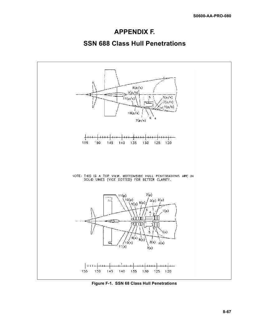
S0600-AA-PRO-080
8-67
Figure F-1. SSN 68 Class Hull Penetrations
APPENDIX F.
SSN 688 Class Hull Penetrations

S0600-AA-PRO-080
8-68
THIS PAGE LEFT BLANK INTENTIONALLY
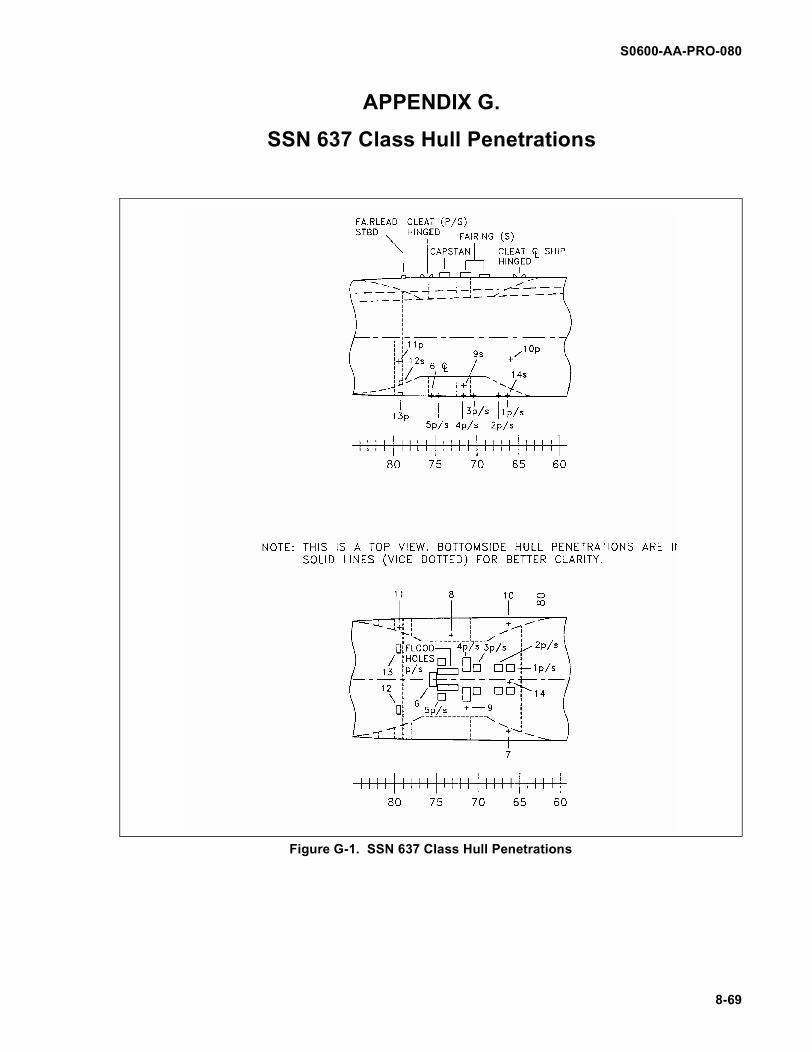
S0600-AA-PRO-080
8-69
Figure G-1. SSN 637 Class Hull Penetrations
APPENDIX G.
SSN 637 Class Hull Penetrations

S0600-AA-PRO-080
8-70
THIS PAGE LEFT BLANK INTENTIONALLY

S0600-AA-PRO-080
8-71
Figure H-1. SSN 640 Class Hull Penetrations
APPENDIX H.
SSN 640 Class Hull Penetrations

S0600-AA-PRO-080
8-72
THIS PAGE LEFT BLANK INTENTIONALLY

S0600-AA-PRO-080
Figure I-1. SSBN 726 Class Hull Penetrations
APPENDIX I.
SSBN 726 Class Hull Penetrations
8-73

S0600-AA-PRO-080
THIS PAGE LEFT BLANK INTENTIONALLY
8-74