Modelling Multiphase Induction Motors for Electric Ship ... · PDF fileModelling Multiphase...
7
Modelling Multiphase Induction Motors for Electric Ship Propulsion Systems JURI JATSKEVICH Electrical and Computer Engineering University of British Columbia Vancouver, BC V6T 1Z4 CANADA MIRKO MAKSIMCEV Marine Propulsion Systems Department of National Defense Hull, Quebec, KIA 0K2 CANADA Abstract: - The naval integrated power systems often utilize electrical machines with large number of phases and magnetic poles. The detailed computer models of electric ship propulsion motors are particularly useful for predicting the electro-mechanical and electrical transients. This paper describes a coupled-circuit physical- variable modelling of multiphase induction motors, which has similar accuracy as the conventional qd models but is easier to generalize and interconnect to the power electronic networks. The equations for the self and mutual inductance matrices for a machine with an arbitrary number of phases and/or phase groups on the stator and the rotor are presented. The paper describes the 3-, 6-, 9-, and 15-phase motor models and compares the simulated transients. It is shown that the motors with higher number of phases have a less severe torque ripple and the stator current increase following a loss of one phase. The proposed models can also be used for transient studies involving loss of multiple phases and/or inverter legs, inverter-motor interaction, switching harmonics, torque ripple, multiple faults, system-level studies, survivability, reconfiguration, etc. Key-Words: - naval electric systems, electric ship, propulsion, multiphase, induction motors. 1 Introduction The integrated power systems (IPS) of modern electric ships often utilize electrical machines with large number of phases and magnetic poles. A simplified diagram of a typical IPS is shown in Fig. 1, wherein several diesel-electric generators and two dual-winding induction propulsion motors are considered [1]. The system layout and appropriate switching gear are designed for operational redundancy and increased reliability. As such, a typical IPS represents a finite inertia electro- mechanical system with many power-electronic- based modules and various controls. Computer simulation represents a powerful mechanism for predicting the dynamic performance of electrical subsystems under various conditions. In particular, accurate dynamic/transient models can be used for investigating complex survivability scenarios involving, for example, a complete loss of one main bus (port or starboard) and featuring the subsequent dynamics of the automatic system reconfiguration. Other scenarios might involve investigating a fault caused by a missile hit of any major electrical equipment such as a generator or a Port Bus Starboard Bus Prime Mover SG Prime Mover SG Prime Mover SG Prime Mover SG Prime Mover SG Prime Mover SG Propulsion Converter IM Propulsion Converter Propulsion Converter IM Propulsion Converter Propulsion Motor Propulsion Motor CB CB CB CB CB CB CB CB CB CB CB CB Firewall Separation SS Loads CB SS Loads CB Fig. 1: Typical integrated power system (IPS). converter and predicting its impact on the overall system stability. Overall, interests include: (i) stability and dynamic performance under faults and pulsed loads, (ii) power quality, (iii) efficiency, (iv) automatic reconfiguration, and (v) survivability, which is the ultimate goal. Results of such studies in the preliminary design phase of any ship (i.e., Canadian Navy Joint Support Ship, Single Class Surface Combatant, Royal Navy's 2005 WSEAS/IASME Int. Conf. on ELECTROSCIENCE and TECHNOLOGY for NAVAL ENGINEERING and ALL-ELECTRIC SHIP Miami, Florida, USA, November 17-19, 2005 (pp10-16)
Transcript of Modelling Multiphase Induction Motors for Electric Ship ... · PDF fileModelling Multiphase...
Modelling Multiphase Induction Motors for Electric Ship Propulsion Systems
JURI JATSKEVICH
Electrical and Computer Engineering University of British Columbia
Vancouver, BC V6T 1Z4 CANADA
MIRKO MAKSIMCEV
Marine Propulsion Systems Department of National Defense
Hull, Quebec, KIA 0K2 CANADA
Abstract: - The naval integrated power systems often utilize electrical machines with large number of phases and magnetic poles. The detailed computer models of electric ship propulsion motors are particularly useful for predicting the electro-mechanical and electrical transients. This paper describes a coupled-circuit physical-variable modelling of multiphase induction motors, which has similar accuracy as the conventional qd models but is easier to generalize and interconnect to the power electronic networks. The equations for the self and mutual inductance matrices for a machine with an arbitrary number of phases and/or phase groups on the stator and the rotor are presented. The paper describes the 3-, 6-, 9-, and 15-phase motor models and compares the simulated transients. It is shown that the motors with higher number of phases have a less severe torque ripple and the stator current increase following a loss of one phase. The proposed models can also be used for transient studies involving loss of multiple phases and/or inverter legs, inverter-motor interaction, switching harmonics, torque ripple, multiple faults, system-level studies, survivability, reconfiguration, etc. Key-Words: - naval electric systems, electric ship, propulsion, multiphase, induction motors. 1 Introduction
The integrated power systems (IPS) of modern electric ships often utilize electrical machines with large number of phases and magnetic poles. A simplified diagram of a typical IPS is shown in Fig. 1, wherein several diesel-electric generators and two dual-winding induction propulsion motors are considered [1]. The system layout and appropriate switching gear are designed for operational redundancy and increased reliability. As such, a typical IPS represents a finite inertia electro-mechanical system with many power-electronic-based modules and various controls.
Computer simulation represents a powerful mechanism for predicting the dynamic performance of electrical subsystems under various conditions. In particular, accurate dynamic/transient models can be used for investigating complex survivability scenarios involving, for example, a complete loss of one main bus (port or starboard) and featuring the subsequent dynamics of the automatic system reconfiguration. Other scenarios might involve investigating a fault caused by a missile hit of any major electrical equipment such as a generator or a
Port Bus
Starboard Bus
Prime Mover
SG
Prime Mover
SG
Prime Mover
SG
Prime Mover
SG
Prime Mover
SG
Prime Mover
SG
Propulsion Converter
IMPropulsion Converter
Propulsion Converter
IMPropulsion Converter
Propulsion Motor
Propulsion Motor
CB
CB
CB
CB
CB
CB
CB
CB
CB
CB
CB
CB
Firewall Separation
SS LoadsCB
SS LoadsCB
Fig. 1: Typical integrated power system (IPS).
converter and predicting its impact on the overall system stability. Overall, interests include: (i) stability and dynamic performance under faults and pulsed loads, (ii) power quality, (iii) efficiency, (iv) automatic reconfiguration, and (v) survivability, which is the ultimate goal.
Results of such studies in the preliminary design phase of any ship (i.e., Canadian Navy Joint Support Ship, Single Class Surface Combatant, Royal Navy's
2005 WSEAS/IASME Int. Conf. on ELECTROSCIENCE and TECHNOLOGY for NAVAL ENGINEERING and ALL-ELECTRIC SHIPMiami, Florida, USA, November 17-19, 2005 (pp10-16)
T-45, etc.) can provide very valuable information about how to physically configure the vital electrical subsystems and/or modules in order to increase the survivability of the vessel. Moreover, considerable savings of time and funding can be achieved if, instead of building the real hardware demonstrators for concept validation, the investigation of various survivability scenarios is performed using the appropriate models and simulation tools.
This paper focuses on modelling the multiphase propulsion motors. Depending on the purpose of study, the propulsion motors may be modeled with different levels of accuracy using various techniques [2]. At a very approximate level, the steady-state calculations of the torque ripple and spacial harmonics may be sufficient [3], [4]. At the design stage, the finite element analysis (FEA) models [5] are often used. However, for the transient and/or system-level studies, the qd models [6] are typically used, wherein the number of equations is determined by the number of electric phases (windings). However, the generalized qd models for the special purpose propulsion motors with high number of phases are not always available in commonly used simulation packages. Moreover, when considering the nodal-analysis-based simulation languages (EMTP, PSCAD, VTB, etc.), the interface of the qd models with the power electronic inverters results in reduced accuracy and convergence problems.
The modelling presented in this paper is based on representing an electrical machine with arbitrary configuration of windings and phases as a collection of magnetically coupled circuits. Instead of using the transformed qd variables, the models are expressed in the physical machine’s variables and implemented using the state variable approach [7]-[11]. The model equations may be extended to the nodal-analysis-based simulation languages. The resulting dynamic models are fairly accurate and can be readily used for investigating various survivability scenarios that may be of interest to the Canadian Navy.
2 Detailed Machine Model There are numerous simulation languages and
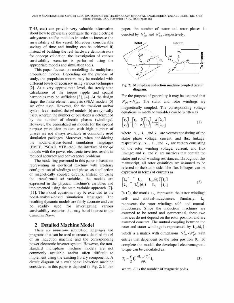
programs that can be used to create a detailed model of an induction machine and the corresponding power electronic inverter system. However, the non-standard multiphase machine models are not commonly available and/or often difficult to implement using the existing library components. A circuit diagram of a multiphase induction machine considered in this paper is depicted in Fig. 2. In this
paper, the number of stator and rotor phases is denoted by s
phN and rphN , respectively.
� �� �
� �� �
Θ�
��� �
� �� �
� �
� �
� �
� �� � ������
Fig. 2: Multiphase induction machine coupled circuit diagram.
For the purpose of generality it may be assumed that rph
sph NN ≠ . The stator and rotor windings are
magnetically coupled. The corresponding voltage equations in machine variables can be written as
��
���
�+�
�
���
���
���
�=�
�
���
�
r
s
r
s
r
s
r
s
dtd
v
v
�
�
ii
rr0
0 (1)
where sv , si , and s� are vectors consisting of the stator phase voltage, current, and flux linkage, respectively; rv , ri , and r� are vectors consisting of the rotor winding voltage, current, and flux linkage; and sr and rr are matrices that contain the stator and rotor winding resistances. Throughout this manuscript, all rotor quantities are assumed to be referred to the stator side. The flux linkages can be expressed in terms of currents as
( )( ) �
�
���
���
���
�=�
�
���
�
r
s
rrTsr
rsrs
r
s
ii
LLLL
�
�
θθ
(2)
In (2), the matrix sL represents the stator windings self- and mutual-inductances. Similarly, rL represents the rotor windings self- and mutual-inductances. Since the induction machines are assumed to be round and symmetrical, these two matrices do not depend on the rotor position and are assumed constant. The mutual coupling between the rotor and stator windings is represented by ( )rsr θL ,
which is a matrix with dimensions rph
sph NN × with
entries that dependent on the rotor position rθ . To complete the model, the developed electromagnetic torque can be calculated as
( )r
r
rsrTse
PT iLi
θθ
∂∂=
2 (3)
where P is the number of magnetic poles.
2005 WSEAS/IASME Int. Conf. on ELECTROSCIENCE and TECHNOLOGY for NAVAL ENGINEERING and ALL-ELECTRIC SHIPMiami, Florida, USA, November 17-19, 2005 (pp10-16)
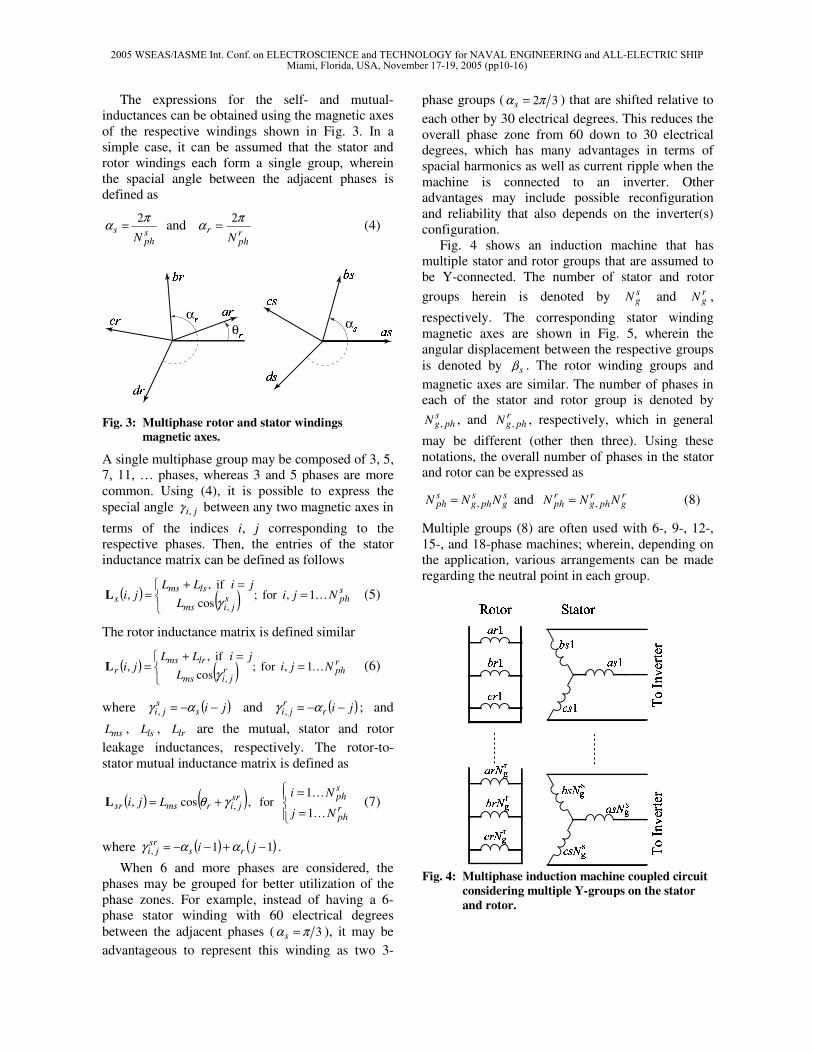
The expressions for the self- and mutual-inductances can be obtained using the magnetic axes of the respective windings shown in Fig. 3. In a simple case, it can be assumed that the stator and rotor windings each form a single group, wherein the spacial angle between the adjacent phases is defined as
sph
sN
πα 2= and rph
rN
πα 2= (4)
� �α�
� �� �
� �
α �θ�
� �
� �
� �
� �
Fig. 3: Multiphase rotor and stator windings magnetic axes.
A single multiphase group may be composed of 3, 5, 7, 11, … phases, whereas 3 and 5 phases are more common. Using (4), it is possible to express the special angle ji,γ between any two magnetic axes in
terms of the indices i, j corresponding to the respective phases. Then, the entries of the stator inductance matrix can be defined as follows
( ) ( ) sphs
jims
lsmss Nji
L
jiLLji �1,for ;
cos if ,
,,
=�� =+
= γL (5)
The rotor inductance matrix is defined similar
( ) ( ) rphr
jims
lrmsr Nji
L
jiLLji �1,for ;
cos if ,
,,
=�� =+
= γL (6)
where ( )jiss
ji −−= αγ , and ( )jirr
ji −−= αγ , ; and
msL , lsL , lrL are the mutual, stator and rotor leakage inductances, respectively. The rotor-to-stator mutual inductance matrix is defined as
( ) ( )�
�
=
=+= r
ph
sphsr
jirmssrNj
NiLji
�
�
1
1for , cos, ,γθL (7)
where ( ) ( )11, −+−−= ji rssr
ji ααγ .
When 6 and more phases are considered, the phases may be grouped for better utilization of the phase zones. For example, instead of having a 6-phase stator winding with 60 electrical degrees between the adjacent phases ( 3πα =s ), it may be advantageous to represent this winding as two 3-
phase groups ( 32πα =s ) that are shifted relative to each other by 30 electrical degrees. This reduces the overall phase zone from 60 down to 30 electrical degrees, which has many advantages in terms of spacial harmonics as well as current ripple when the machine is connected to an inverter. Other advantages may include possible reconfiguration and reliability that also depends on the inverter(s) configuration.
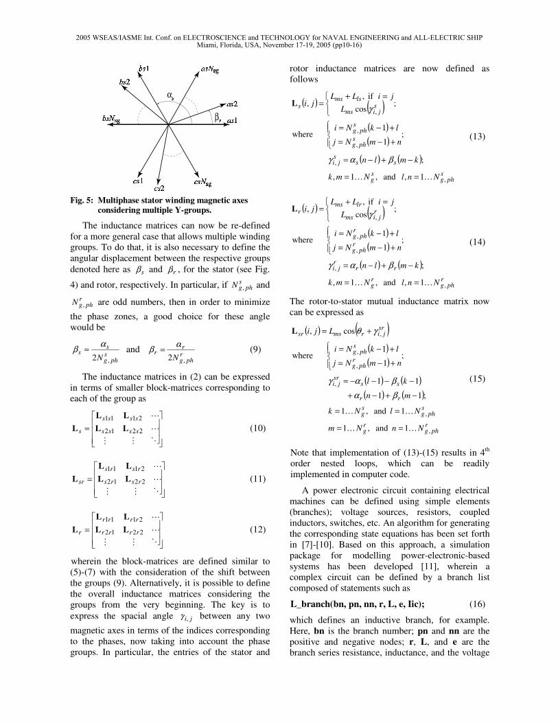
Fig. 4 shows an induction machine that has multiple stator and rotor groups that are assumed to be Y-connected. The number of stator and rotor groups herein is denoted by s
gN and rgN ,
respectively. The corresponding stator winding magnetic axes are shown in Fig. 5, wherein the angular displacement between the respective groups is denoted by sβ . The rotor winding groups and magnetic axes are similar. The number of phases in each of the stator and rotor group is denoted by
sphgN , , and r
phgN , , respectively, which in general
may be different (other then three). Using these notations, the overall number of phases in the stator and rotor can be expressed as
sg
sphg
sph NNN ,= and r
gr
phgrph NNN ,= (8)
Multiple groups (8) are often used with 6-, 9-, 12-, 15-, and 18-phase machines; wherein, depending on the application, various arrangements can be made regarding the neutral point in each group. � � ! � " # ! $ ! � "
% & '
% & (*)
+ & '
, & '
% - '+ - ', - '
+ & (.)
, & (*)
% - ( )+ - ( ), - (*)
/ 01 23456 45
/ 01 23456 45
77
7888
Fig. 4: Multiphase induction machine coupled circuit
considering multiple Y-groups on the stator and rotor.
2005 WSEAS/IASME Int. Conf. on ELECTROSCIENCE and TECHNOLOGY for NAVAL ENGINEERING and ALL-ELECTRIC SHIPMiami, Florida, USA, November 17-19, 2005 (pp10-16)
α9: ; <: ; =
: ; >.? @A ; <A ; =
B ; < B ; = B ; >*? @
A ; >*? @ β9
Fig. 5: Multiphase stator winding magnetic axes
considering multiple Y-groups.
The inductance matrices can now be re-defined for a more general case that allows multiple winding groups. To do that, it is also necessary to define the angular displacement between the respective groups denoted here as sβ and rβ , for the stator (see Fig.
4) and rotor, respectively. In particular, if sphgN , and
rphgN , are odd numbers, then in order to minimize
the phase zones, a good choice for these angle would be
sphg
ss
N ,2
αβ = and r
phg
rr
N ,2
αβ = (9)
The inductance matrices in (2) can be expressed in terms of smaller block-matrices corresponding to each of the group as
���
�
�
���
�
�
=���
�
�
2212
2111
ssss
ssss
s LLLL
L (10)
���
�
�
���
�
�
=���
�
�
2212
2111
rsrs
rsrs
sr LLLL
L (11)
���
�
�
���
�
�
=���
�
�
2212
2111
rrrr
rrrr
r LLLL
L (12)
wherein the block-matrices are defined similar to (5)-(7) with the consideration of the shift between the groups (9). Alternatively, it is possible to define the overall inductance matrices considering the groups from the very beginning. The key is to express the spacial angle ji,γ between any two
magnetic axes in terms of the indices corresponding to the phases, now taking into account the phase groups. In particular, the entries of the stator and
rotor inductance matrices are now defined as follows
( ) ( )( )( )
( ) ( )s
phgsg
sss
ji
sphg
sphg
sjims
lsmss
NnlNmk
kmln
nmNj
lkNi
L
jiLLji
,
,
,
,
,
1, and ,1,
;
;1
1 where
;cos
if ,,
�� ==
−+−=
�
�
+−=
+−=
�� =+
=
βαγ
γL
(13)
( ) ( )( )( )
( ) ( )r
phgrg
rrr
ji
rphg
rphg
rjims
lrmsr
NnlNmk
kmln
nmNj
lkNi
L
jiLLji
,
,
,
,
,
1, and ,1,
;
;1
1 where
;cos
if ,,
�� ==
−+−=
�
�
+−=
+−=
�� =+
=
βαγ
γL
(14)
The rotor-to-stator mutual inductance matrix now can be expressed as
( ) ( )( )( )
( ) ( )( ) ( )
rphg
rg
sphg
sg
rr
sssr
ji
rphg
sphg
srjirmssr
NnNm
NlNk
mn
kl
nmNj
lkNi
Lji
,
,
,
,
,
,
1 and ,1
1 and ,1
;11
11
;1
1 where
cos,
��
��
==
==
−+−+
−−−−=
�
�
+−=
+−=
+=
βαβαγ
γθL
(15)
Note that implementation of (13)-(15) results in 4th order nested loops, which can be readily implemented in computer code.
A power electronic circuit containing electrical machines can be defined using simple elements (branches); voltage sources, resistors, coupled inductors, switches, etc. An algorithm for generating the corresponding state equations has been set forth in [7]-[10]. Based on this approach, a simulation package for modelling power-electronic-based systems has been developed [11], wherein a complex circuit can be defined by a branch list composed of statements such as
L_branch(bn, pn, nn, r, L, e, Iic); (16)
which defines an inductive branch, for example. Here, bn is the branch number; pn and nn are the positive and negative nodes; r, L, and e are the branch series resistance, inductance, and the voltage
2005 WSEAS/IASME Int. Conf. on ELECTROSCIENCE and TECHNOLOGY for NAVAL ENGINEERING and ALL-ELECTRIC SHIPMiami, Florida, USA, November 17-19, 2005 (pp10-16)
source; and Iic is initial inductor current, respectively. A mutual inductance can be specified using a statement
L_mutual(b1, b2, Lm); (17)
where: b1 and b2 are the inductive branch numbers and Lm is the mutual inductance. Other circuit branches may be defined using similar syntax [11].
However, entering the mutual inductances for an electrical machine with a large number of phases and coupled windings can be quite tedious. Instead, (13)-(15) have been implemented as functions with the syntax similar to (16), (17). In particular, the stator or the rotor multiphase inductance matrices (13)-(14) can now be entered as
L_selfmx(B, Nph, Ng, Lm, Ll, beta); (18)
where B is an array containing the respective branches; Nph is the number of phases; Ng is the number of phase groups; Lm and Ll are the mutual and the leakage inductances, respectively; and beta is the angular displacement between the phase groups. The rotor-to-stator mutual inductance matrix (15) can be specified using the function
L_mutmx(B1,Nph1,Ng1,beta1,
B2,Nph2,Ng2,beta2, theta); (19)
where B1 and B2 are the arrays containing the respective stator and rotor branches; Nph1 and Nph2 are the number of phases in each; Ng1 and Ng2 are the number of phase groups in each; beta1 and beta2 are the respective angular displacements; and theta is the angle between the B1 and B2 (stator and rotor) windings.
It should be pointed out that because (13)-(15) are very general and include the single group case (5)-(7), the statements (18)-(19) can be used to define the inductance matrices corresponding to an induction machine with essentially any number of phases and/or winding groups configuration.
3 Computer Studies
Several multiphase induction motors have been implemented according to the methodology described in Section 2. The automated state model generator toolbox [11] interfaced with MATLAB/SimulinkTM [12] has been used to implement the final models. The per-unit parameters of the base case 3-phase 4-MW motor are summarized in Appendix a). The motors with 3, 6, 9, and 15 phases have been compared in a time-domain transient study, wherein a loss of one phase (winding) is assumed. All motors are assumed to be fed from an ideal voltage source inverter (VSI) with
respective number of phases. For the purpose of this paper, only the fundamental harmonic of the VSI has been considered, as it dominates in determining the averaged electromagnetic torque and the rms value of the stator phase currents. In all cases, the stator winding groups are assumed to have a common neutral point that is left floating.
In the following transient study, the motor is assumed to operate in a steady-state under full mechanical load. The propulsion load is assumed to have a predominantly quadratic torque-speed characteristic given in Appendix b). At st 1.0= , a-phase (of the first group) becomes open-circuited. This may happen due to a failure of the winding and/or the corresponding inverter leg. After that, the motor is continued to operate without adjusting the VSI output and/or operation. The corresponding transients are shown in Figs. 6 through 11. The results of these studies are summarized in Table 1.
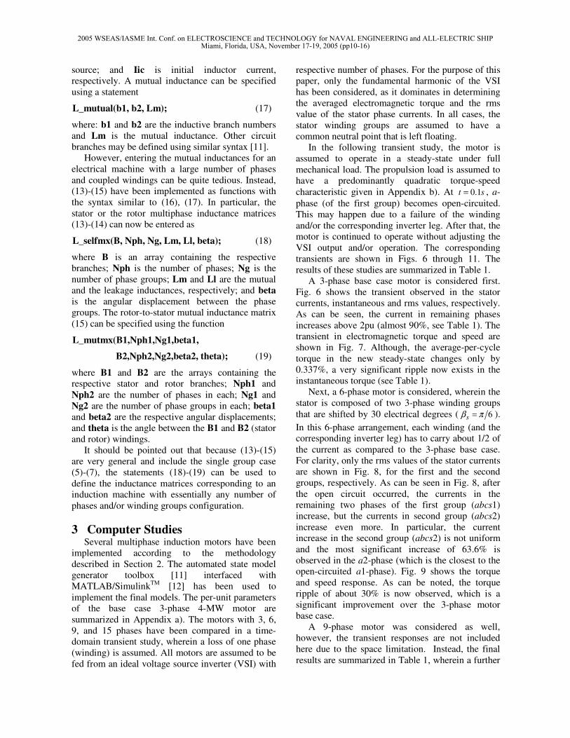
A 3-phase base case motor is considered first. Fig. 6 shows the transient observed in the stator currents, instantaneous and rms values, respectively. As can be seen, the current in remaining phases increases above 2pu (almost 90%, see Table 1). The transient in electromagnetic torque and speed are shown in Fig. 7. Although, the average-per-cycle torque in the new steady-state changes only by 0.337%, a very significant ripple now exists in the instantaneous torque (see Table 1).
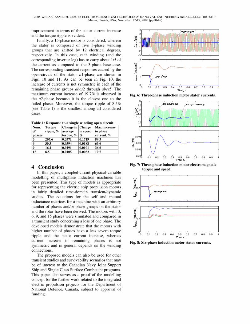
Next, a 6-phase motor is considered, wherein the stator is composed of two 3-phase winding groups that are shifted by 30 electrical degrees ( 6πβ =s ). In this 6-phase arrangement, each winding (and the corresponding inverter leg) has to carry about 1/2 of the current as compared to the 3-phase base case. For clarity, only the rms values of the stator currents are shown in Fig. 8, for the first and the second groups, respectively. As can be seen in Fig. 8, after the open circuit occurred, the currents in the remaining two phases of the first group (abcs1) increase, but the currents in second group (abcs2) increase even more. In particular, the current increase in the second group (abcs2) is not uniform and the most significant increase of 63.6% is observed in the a2-phase (which is the closest to the open-circuited a1-phase). Fig. 9 shows the torque and speed response. As can be noted, the torque ripple of about 30% is now observed, which is a significant improvement over the 3-phase motor base case.
A 9-phase motor was considered as well, however, the transient responses are not included here due to the space limitation. Instead, the final results are summarized in Table 1, wherein a further
2005 WSEAS/IASME Int. Conf. on ELECTROSCIENCE and TECHNOLOGY for NAVAL ENGINEERING and ALL-ELECTRIC SHIPMiami, Florida, USA, November 17-19, 2005 (pp10-16)
improvement in terms of the stator current increase and the torque ripple is evident.
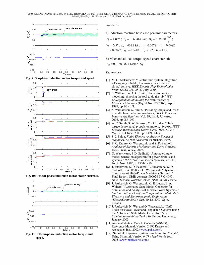
Finally, a 15-phase motor is considered, wherein the stator is composed of five 3-phase winding groups that are shifted by 12 electrical degrees, respectively. In this case, each winding (and the corresponding inverter leg) has to carry about 1/5 of the current as compared to the 3-phase base case. The corresponding transient responses caused by the open-circuit of the stator a1-phase are shown in Figs. 10 and 11. As can be seen in Fig. 10, the increase of currents is not symmetric in each of the remaining phase groups abcs2 through abcs5. The maximum current increase of 19.7% is observed in the a2-phase because it is the closest one to the failed phase. Moreover, the torque ripple of 8.5% (see Table 1) is the smallest among all considered cases.
Table 1: Response to a single winding open circuit. Num. of phases
Torque ripple, %
Change in average torque, %
Change in speed, %
Max. increase in phase current, %
3 207.6 0.3371 0.1719 89.3 6 30.3 0.0394 0.0188 63.6 9 16.4 0.0191 0.0101 36.6 15 8.5 0.0105 0.0052 19.7
4 Conclusion In this paper, a coupled-circuit physical-variable
modelling of multiphase induction machines has been presented. This type of models is appropriate for representing the electric ship propulsion motors in fairly detailed time-domain transient/dynamic studies. The equations for the self and mutual inductance matrices for a machine with an arbitrary number of phases and/or phase groups on the stator and the rotor have been derived. The motors with 3, 6, 9, and 15 phases were simulated and compared in a transient study concerning a loss of one phase. The developed models demonstrate that the motors with higher number of phases have a less severe torque ripple and the stator current increase, whereas current increase in remaining phases is not symmetric and in general depends on the winding connections.
The proposed models can also be used for other transient studies and survivability scenarios that may be of interest to the Canadian Navy Joint Support Ship and Single Class Surface Combatant programs. This paper also serves as a proof of the modelling concept for the further work related to the integrated electric propulsion projects for the Department of National Defence, Canada, subject to approval of funding.
-3
-2
-1
0
1
2
3
0 0.1 0.2 0.3 0.4 0.5 0.6 0.7 0.8 0.9 1 0
1
2
3
C D E F D G H I E
J KL MN OP QRS
T U V E W I XJ KL MN OP QR YZ[\S
C D E F D G H I E
Fig. 6: Three-phase induction motor stator currents.
0
0.5
1
1.5
2
2.5
3
0 0.1 0.2 0.3 0.4 0.5 0.6 0.7 0.8 0.9 10.98
0.985
0.99
0.995
1
] ^ _ ` a b c
d e fg hij
ω
k fg hij
^ l b m n l m n l ` o p brq ` s t u v u w ` n x ` s n y `
Fig. 7: Three-phase induction motor electromagnetic
torque and speed.
0
0.5
1
0 0.1 0.2 0.3 0.4 0.5 0.6 0.7 0.8 0.9 1 0
0.5
1
z { | } { ~ � � |
� � � | � � �
� �� ��� �� �������
� �� ��� �� �������
Fig. 8: Six-phase induction motor stator currents.
2005 WSEAS/IASME Int. Conf. on ELECTROSCIENCE and TECHNOLOGY for NAVAL ENGINEERING and ALL-ELECTRIC SHIPMiami, Florida, USA, November 17-19, 2005 (pp10-16)
0
0.5
1
1.5
2
0.98
0.985
0.99
0.995
1
0 0.1 0.2 0.3 0.4 0.5 0.6 0.7 0.8 0.9 1� � � � � � �
� � � ¡¢£
ω
¤ � ¡¢£
� ¥ � ¦ § ¥ ¦ § ¥ � ¨ © �«ª � ¬ ® ¯ ® ° � § ± � ¬ § ² �
Fig. 9: Six-phase induction motor torque and speed.
0
0.1
0.2
0.3
0
0.1
0.2
0.3
0
0.1
0.2
0.3
0
0.1
0.2
0.3
0 0.1 0.2 0.3 0.4 0.5 0.6 0.7 0.8 0.9 1 0
0.1
0.2
0.3
³ ´ µ ¶ ´ · ¸ ¹ µ
º » ¼ µ ½ ¹ ¾
¿ ÀÁ ÂÃÄ ÅÆ ÇÈ ÉÊËÌÍ
¿ ÀÁ ÂÃÎ ÅÆ ÇÈ ÉÊËÌÍ
¿ ÀÁ ÂÃÏ ÅÆ ÇÈ ÉÊËÌÍ
¿ ÀÁ ÂÃÐ ÅÆ ÇÈ ÉÊËÌÍ
¿ ÀÁ ÂÃÑ ÅÆ ÇÈ ÉÊËÌÍ
Fig. 10: Fifteen-phase induction motor stator currents.
0
0.5
1
1.5
2
0.98
0.985
0.99
0.995
1
0 0.1 0.2 0.3 0.4 0.5 0.6 0.7 0.8 0.9 1Ò Ó Ô Õ Ö × Ø
Ù Ú ÛÜ ÝÞß
ω
à ÛÜ ÝÞß
Ó á × â ã á â ã á Õ ä å ×çæ Õ è é ê ë ê ì Õ ã í Õ è ã î Õ
Fig. 11: Fifteen-phase induction motor torque and
speed.
Appendix a) Induction machine base case per-unit parameters:
MWPb 4= ; mkNTb ⋅= 10.694 ; s
radb 602 ⋅⋅= πω ;
kVVb 5= ; 461.88A=bI ; 0.0078=sr ; 0.0682=lsx 0.0072=rr ; 0.0682=lrx ; 3.2=mx ; 1.1s=H .
b) Mechanical load torque-speed characteristic
2rr 1.01580.0136 ωω ⋅+⋅=mT
References: [1] M. D. Maksimcev, “Electric ship system integration
– Designing reliable, low maintenance electric ships,” In proc. IEEE Electric Ship Technologies Symp. (ESTS'05), 25-27 July, 2005.
[2] S. Williamson, A. C. Smith, “Induction motor modelling-choosing the tool to do the job,” IEE Colloquium on Modelling the Performance of Electrical Machines (Digest No: 1997/166), April 1997, pp 1/1 - 1/4.
[3] S. Williamson, S. Smith, “Pulsating torque and losses in multiphase induction machines,” IEEE Trans. on Industry Applications, Vol. 39, Iss. 4, July-Aug. 2003, pp 986–993.
[4] A. C. Smith, S. Williamson, C. G. Hodge, “High torque dense naval propulsion motors,” In proc. IEEE Electric Machines and Drives Conf. (IEMDC'03), Vol. 3, 1-4 June, 2003, pp 1421–1427.
[5] S. J. Salon, Finite Element Analysis of Electrical Machines, Kluwer Academic Publishers, 1995.
[6] P. C. Krause, O. Wasynczuk, and S. D. Sudhoff, Analysis of Electric Machinery and Drive Systems, IEEE Press, Wiley, 2002.
[7] O. Wasynczuk, S.D. Sudhoff, “Automated state model generation algorithm for power circuits and systems,” IEEE Trans. on Power Systems, Vol. 11, Iss. 4, Nov. 1996, p. 1951-1956.
[8] J. Jatskevich, S. D. Pekarek, T, Skvarenina, S. D. Sudhoff, E. A. Walters, O. Wasynczuk, “Dynamic Simulation of High-Power Machinery Systems,” Final Report, SBIR contract N00024-97-C-4097, Naval Surface Warfare Center (NSWC), May 1999.
[9] J. Jatskevich, O. Wasynczuk, C. E. Lucas, E. A. Walters, “Automated State Model Generator for Simulation and Analysis of Electric Power Systems,” 6th International Conf. on Computational Methods in Electrical and Electromagnetic Engineering (ElectroComp 2003), Sep. 10-12, 2003, Split, Croatia.
[10] J. Jatskevich, N. Wu, and O. Wasynczuk, “CAD Tools for Naval Power and Propulsion Systems using the Automated State Model Generator” Naval Combat Survivability Task 11b, Purdue University, January 2003.
[11] Automated State Model Generator (ASMG), Reference Manual, Version 2, PC Krause and Associates Inc., 2002 (www.pcka.com).
[12] “Simulink: Dynamic System Simulation for Matlab”, Using Simulink Version 6, The MathWorks Inc., 2005 (www.mathworks.com).
2005 WSEAS/IASME Int. Conf. on ELECTROSCIENCE and TECHNOLOGY for NAVAL ENGINEERING and ALL-ELECTRIC SHIPMiami, Florida, USA, November 17-19, 2005 (pp10-16)