Utilizing Interactive Demos to Enhance Student Understanding

Paper ID #35683
Utilizing Computational Tools to Enhance Student’s Understanding ofLinkage Mechanism
Dr. Zhiyuan Yu
Dr. Zhiyuan Yu is an Assistant Professor of Engineering Technology at Miami University since Aug.,2019. Prior to joining Miami University, he was an Assistant Teaching Professor of Mechanical Engi-neering Technology at Pennsylvania State University from 2017 to 2019. He has developed a strong in-terest in undergraduate engineering education and has been teaching a wide range of courses in ME/METdepartment. He received his Ph.D. degree in Mechanical Engineering from Tennessee Technological Uni-versity in 2017. His research interests include linkage kinematics, computational mechanics, and moderntheory of gearing. His research in gear transmission have been applied in robotics, marine transmissions,machine tools, and construction machinery.
Dr. Jiawei Gong, Pennsylvania State University, Behrend College
Dr. Jiawei Gong is an assistant professor or Mechanical Engineering at The Pennsylvania state university,The Behrend College.
c©American Society for Engineering Education, 2021
Fall 2021 ASEE Middle Atlantic Section Conference
1
Utilizing Computational Tools to Enhance Student’s Understanding of Linkage Mechanism
Zhiyuan Yu
Engineering Technology
Miami University, Middletown, OH 45011
Jiawei Gong
Mechanical Engineering
Penn State University, Erie, PA 16510
Abstract
This research presents analysis of a quick return linkage mechanism utilizing computational
software Mathcad and Inventor. It is implemented as a class project to enhance Mechanical
Engineering and Mechanical Engineering Technology students’ understanding of linkage
mechanism in courses Dynamics and Machine Dynamics. The objectives of the project are to
teach (1) kinematic and kinetic analysis of linkage mechanism (2) engineering math software
Mathcad to solve the analytical model, (3) verifying the model by multibody dynamics
simulation software Inventor. Loop closure equations based on complex number are first
modeled and solved to find positions, velocities and accelerations of the linkage in Mathcad.
Based on the kinematic solution, a kinetic analysis is carried out using distributed mass models
in Mathcad as well as in Inventor simulation. The output slider position and the input link torque
are found identical to simulation results with negligible deviation. Integrating industry
commonly used software Mathcad and Inventor in the project reduces the mathematical
difficulties often encountered by engineering students. The course project assignment grade
demonstrates that the use of these tools enhances the student’s understanding for linkage
mechanism. The feedback from instructors shows the project make the course dynamic and
machine dynamics more engaging. The software-based project suits well for online teaching and
learning.
Keywords:
Linkage, Kinematics, Kinetics, Mathcad, Inventor

Fall 2021 ASEE Middle Atlantic Section Conference
2
1. Introduction
Linkage quick return mechanisms are using linkage to convert rotation motion input into
reciprocating motion output. And the forward stroke of the reciprocating slider is slower than the
backward stroke. The typical applications include metal shapers, press machines which prefer
slow speed high load working stroke and high speed low load return stroke to improve efficiency
[1]. Quick return linkage mechanism synthesis and analysis is covered in Mechanical
Engineering (ME) or Mechanical Engineering Technology (MET) programs’ junior year course
Machine Dynamics [2].
Teaching linkage kinematics and kinetics very often present challenges for the instructors
due to the mathematical difficulties and the students’ lack of understanding of the mechanism [3,
4]. Matlab and Excel program has been used to help students analyze linkage mechanism [5]. 3D
modeling and printing labs have also been developed to improve the teaching quality and
students’ understanding [6]. Reference [7] designs the linkage mechanism for robot gripper as
capstone projects.
In this study, Mathcad and Inventor Dynamic Simulation is used to solve for the kinematic
and kinetic quantities of a six bar Whitworth linkage mechanism as a class project for Dynamics
and Machine Dynamics. At Miami University, the project is used for MET Dynamics course
with emphasis on using the software and result interpolation to help student visualize linkage
mechanism. At Penn State Behrend, the projects described in this work were assigned to ME
students in the Machine Dynamics and completed within the first eight weeks with the course
lectures. After completing these projects, students should be able to: (1) analyze the kinematics
of planar linkage mechanisms, (2) use Mathcad programs to solve complex machine dynamics
problems or systems, (3) model and simulate linkage mechanism in Inventor. Our previous study
[8] showed that introducing practical applications to students is beneficial to their comprehension
and engagement. Similar conclusion can be drawn for this paper from the student project grade
and instructor survey. The complete solution to the mechanism, including course syllabi, the
Mathcad scripts, and CAD files will be provided for educators to modify and tailor for specific
needs. The models can be adopted by the engineering courses covering planar linkage
mechanisms projects.
Fall 2021 ASEE Middle Atlantic Section Conference
3
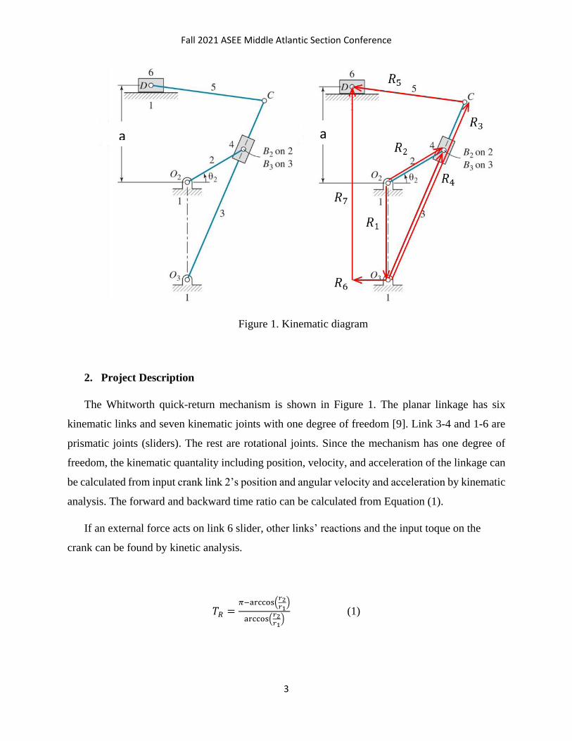
Figure 1. Kinematic diagram
2. Project Description
The Whitworth quick-return mechanism is shown in Figure 1. The planar linkage has six
kinematic links and seven kinematic joints with one degree of freedom [9]. Link 3-4 and 1-6 are
prismatic joints (sliders). The rest are rotational joints. Since the mechanism has one degree of
freedom, the kinematic quantality including position, velocity, and acceleration of the linkage can
be calculated from input crank link 2’s position and angular velocity and acceleration by kinematic
analysis. The forward and backward time ratio can be calculated from Equation (1).
If an external force acts on link 6 slider, other links’ reactions and the input toque on the
crank can be found by kinetic analysis.
𝑇𝑅 =𝜋−arccos(
𝑟2𝑟1
)
arccos(𝑟2𝑟1
) (1)
a a

Fall 2021 ASEE Middle Atlantic Section Conference
4
3. Kinematic and Kinetic Analysis and Verification
Kinematic analysis uses loop closure equation method [10]. Two kinematic loops are built.
The first loop consists the ground 1, input crank 2, and the slider 4, and the second loop includes
the output slider 6, rocker 3, and connecting rod 5 as shown in Figure 1, loop closure equations
can be modeled as,
𝑹𝟐 = 𝑹𝟏 + 𝑹𝟒 (2)
𝑹𝟑 + 𝑹𝟓 = 𝑹𝟔 + 𝑹𝟕 (3)
Equation (2) and (3) are vector equations with Rn as complex numbers [10].
Figure 2. Kinetic diagram
Fall 2021 ASEE Middle Atlantic Section Conference
5
The kinematic analysis including position, velocity, acceleration and kinetic analysis for joint
forces in Mathcad is attached as google drive shared file with link in Appendix.
The kinetic model is based on distributed mass kinetic model [2] as show in Figure 2.
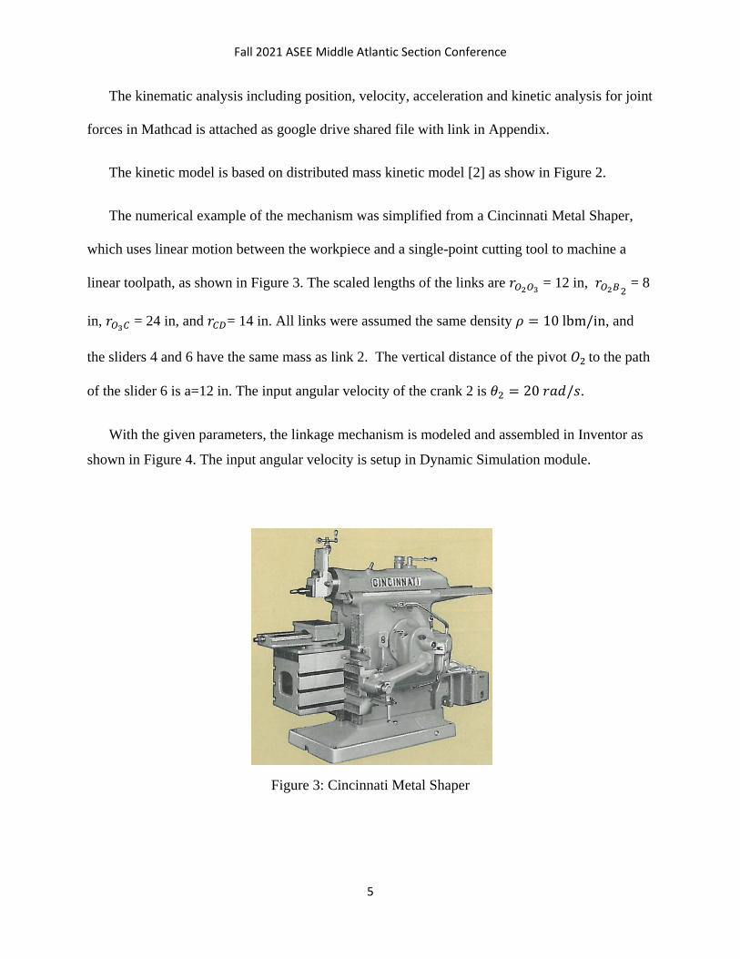
The numerical example of the mechanism was simplified from a Cincinnati Metal Shaper,
which uses linear motion between the workpiece and a single-point cutting tool to machine a
linear toolpath, as shown in Figure 3. The scaled lengths of the links are 𝑟𝑂2𝑂3 = 12 in, 𝑟𝑂2𝐵2
= 8
in, 𝑟𝑂3𝐶 = 24 in, and 𝑟𝐶𝐷= 14 in. All links were assumed the same density 𝜌 = 10 lbm/in, and
the sliders 4 and 6 have the same mass as link 2. The vertical distance of the pivot 𝑂2 to the path
of the slider 6 is a=12 in. The input angular velocity of the crank 2 is 𝜃2 = 20 𝑟𝑎𝑑/𝑠.
With the given parameters, the linkage mechanism is modeled and assembled in Inventor as
shown in Figure 4. The input angular velocity is setup in Dynamic Simulation module.
Figure 3: Cincinnati Metal Shaper

Fall 2021 ASEE Middle Atlantic Section Conference
6
Figure 4. Inventor Dynamic Simulation Model
To verify the analytical and simulation result, the slider position and input torque is shown in
Figure 5. The analytical results from Mathcad and simulation result from Inventor are identical
with deviation within 3%. Complete kinematic and kinetic analysis results can be found from
Appendix.

Fall 2021 ASEE Middle Atlantic Section Conference
7
(a)
(b)
Figure 5: (a) Positions of the slider 6 and (b) input toque on the crank 2.
4. Student Grade Analysis
A pilot engineering education study has been implemented in two summer session Dynamics
course, and three semesters Machine Dynamics course.

Fall 2021 ASEE Middle Atlantic Section Conference
8
In Dynamics, student teams will be offered with the analytical solution in Mathcad with the
project description. The project emphases on the student’s ability to establish the 3D model and
conduct dynamics simulation in Inventor, and then verify simulation results with analytical
results. The feedback from the instructors’ course survey is positive and the average students
course grade improved from 87.8 to 90.5 comparing two consecutive summer semesters. To
improve the statistical significance of the project’s impact on students, more data are currently
being collected for future study. The project grade has been used to support the ABET’s MET
AS program outcomes [11].
(1) an ability to apply knowledge, techniques, skills and modern tools of mathematics,
science, engineering, and technology to solve well-defined engineering problems appropriate to
the discipline;
(2) an ability to design solutions for well-defined technical problems and assist with the
engineering design of systems, components, or processes appropriate to the discipline;
(3) an ability to apply written, oral, and graphical communication in well-defined technical
and non-technical environments; and an ability to identify and use appropriate technical literature
(5) an ability to function effectively as a member of a technical team.
Two projects including Project 1 kinematic analysis and Project 2 kinetic analysis are given
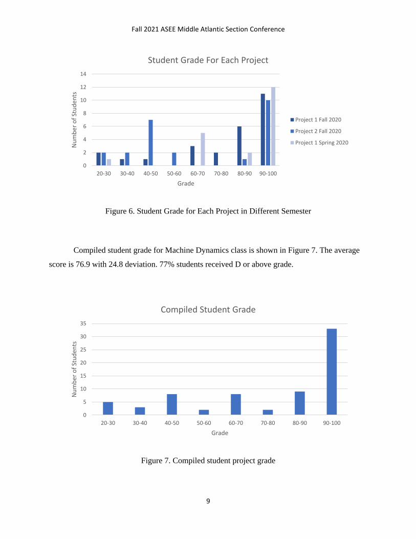
to Machine Dynamics courses starting spring 2020. The student grade is shown in Figure 6. The
average for project 1 in spring 2020 is 86.8, 95% students received D or above grade. The
average for project 1 in fall 2020 is 78.5, 85% students received D or above grade. The average
for project 2 in fall 2020 is 66.8, 54% students received D or above grade. Comparing with final
exam, project 2 covers wider scope, more complex math, software skills, and report writing.
Although more students failed project2, the project engaged students to spend more time for
understanding linkage mechanism. It improves the students’ final exam grade.
Fall 2021 ASEE Middle Atlantic Section Conference
9
Figure 6. Student Grade for Each Project in Different Semester
Compiled student grade for Machine Dynamics class is shown in Figure 7. The average
score is 76.9 with 24.8 deviation. 77% students received D or above grade.
Figure 7. Compiled student project grade
0
2
4
6
8
10
12
14
20-30 30-40 40-50 50-60 60-70 70-80 80-90 90-100
Nu
mb
er o
f St
ud
ents
Grade
Student Grade For Each Project
Project 1 Fall 2020
Project 2 Fall 2020
Project 1 Spring 2020
0
5
10
15
20
25
30
35
20-30 30-40 40-50 50-60 60-70 70-80 80-90 90-100
Nu
mb
er o
f St
ud
ents
Grade
Compiled Student Grade

Fall 2021 ASEE Middle Atlantic Section Conference
10
Figure 8 Exam Comparison
Figure 8 shows Spring 2020 and Fall 2020 student final exam grade. Spring 2020 does not
have project 2 kinetic analysis. On contrary, fall 2020 has the project 2. The student final exam
average grade increases from 82.8 to 87.6, which demonstrates the project increases the students’
understanding of linkage analysis in the fall semester.
5. Conclusion
Therefore, the following conclusions can be drawn from the research.
• The linkage analytical model in Mathcad is verified by Inventor Dynamic simulation with
negligible deviation.
• With the help of Mathcad and Inventor, sophomore students in Dynamics are able to
model and analyze linkage mechanism and verify the models with less mathematical
difficulty. It improves students understanding of linkage mechanism. The project grade
feeds to ABET MET student outcomes 1, 2, 3, and 5.
0
2
4
6
8
10
12
20-30 30-40 40-50 50-60 60-70 70-80 80-90 90-100
Nu
mb
er o
f St
ud
ents
Grade
Exam Comparison
Exam w Project 2
Exam w/o Project 2
Fall 2021 ASEE Middle Atlantic Section Conference
11
• The course project assignment grade in Machine Dynamics quantitively demonstrates
that the majority (77%) of the junior students are able to finished the project with the use
of Mathcad and Inventor. It enhances the student’s understanding for linkage mechanism
with improved final exam grade.
• Most of the above-mentioned projects are launched in online learning environment. The
software-based project suits well for online teaching and learning.
6. Future Work
Two semesters’ Dynamic course grade and three semesters’ Machine Dynamics course grade
has been used for the pilot study of implementing this project. With the support from PennState
Center for Teaching and eLearning Initiatives, data will be collected in the future for comparing
in-person and virtual delivery.
Reference
1. Dwivedi, Surendra N. "Application of whitworth quick return mechanism for high
velocity impacting press." Mechanism and Machine Theory 19, no. 1 (1984): 51-59.
2. Dresig, Hans, and Franz Holzweißig. Dynamics of machinery: theory and applications.
Springer Science & Business Media, 2010.
3. Constans, Eric, Karl Dyer, and Shraddha Sangelkar. "A New Method for Teaching The
Fourbar Linkage and its Application to Other Linkages." In 2019 ASEE Annual
Conference & Exposition. 2019.
4. Echempati, Raghu, Theodore Paul Dani, Ankita Sahu, and Nathan Marshall LeBlanc.
"Quick-return mechanism revisited." In 2013 ASEE Annual Conference & Exposition, pp.
23-1015. 2013.

Fall 2021 ASEE Middle Atlantic Section Conference
12
5. Mobasher, Amir, Abdul Jalloh, Ruben Rojas-Oviedo, Zhengtao T. Deng, and Xiaoqing
Cathy Qian. "Incorporating Matlab In Mechanical Engineering Courses." In 2002 Annual
Conference, pp. 7-655. 2002.
6. Szydlowski, Wieslaw M. "Using a rapid prototyping machine in the integrated
kinematics, dynamics, and machine design lab." In 31st Annual Frontiers in Education
Conference. Impact on Engineering and Science Education. Conference Proceedings
(Cat. No. 01CH37193), vol. 3, pp. S2E-11. IEEE, 2001.
7. Currie, Edward H., and Kevin C. Craig. "Mechatronic Mechanism Design and
Implementation Process Applied in Senior Mechanical Engineering Capstone Design."
In 2019 ASEE Annual Conference & Exposition. 2019.
8. Yu, Zhiyuan, and Jiawei Gong. "Introducing Kinematic Fundamentals of Strain Wave
Gear for Robotic Arm Joint." In 2019 ASEE Zone I Conference & Workshop. 2019.
9. Reuleaux, Franz. The kinematics of machinery: outlines of a theory of machines. Courier
Corporation, 2013.
10. Bottema, Oene, and Bernard Roth. Theoretical kinematics. Vol. 24. Courier Corporation,
1990.
11. ABET, Engineering Technology Accreditation criteria,
https://www.abet.org/accreditation/accreditation-criteria/criteria-for-accrediting-
engineering-technology-programs-2020-2021/

Fall 2021 ASEE Middle Atlantic Section Conference
13
Appendix
Complete Kinematic and Kinetic Solution in Mathcad
and CAD model Google Drive link
https://drive.google.com/drive/folders/1HFJPdUEuBvtQ7v-2_lubcJaSgTz_YsEo?usp=sharing
Course Material for Dynamics
https://drive.google.com/drive/folders/1d59oLV6TxwAm6MdxId2TZSigScFjGCOD?usp=sharing