Using Coordination Models in AutoCAD Plant 3D · Using Coordination Models in AutoCAD Plant 3D...
4
White Paper Reference: October 2015 Guide by Andy Davis 01784 419 922 www.cadline.co.uk [email protected] Page 1 of 4 Using Coordination Models in AutoCAD Plant 3D AutoCAD Plant 3D 2016 and Navisworks 2016 AutoCAD 2016 and vertical products, including AutoCAD Plant 3D, are now able to externally reference Navisworks models into drawing files as Coordination Models. In addition to providing virtual coordination for multi-disciplinary projects, Navisworks nwc and nwd files may be used as the starting point for brownfield refit jobs. Even without the original design files, if a Navisworks model is available, it is possible to define tie-in points by snapping to the geometry in the coordination model. The image above shows a Navisworks model of process piping that has been marked up ready to be extended in AutoCAD Plant 3D. Attach Coordination Model You attach a coordination model to an AutoCAD drawing in much the same way that you would attach any other external reference file.
Transcript of Using Coordination Models in AutoCAD Plant 3D · Using Coordination Models in AutoCAD Plant 3D...

White Paper Reference: October 2015
Guide by Andy Davis
01784 419 922 www.cadline.co.uk [email protected]
Page 1 of 4
Using Coordination Models in AutoCAD Plant 3D
AutoCAD Plant 3D 2016 and Navisworks 2016
AutoCAD 2016 and vertical products, including AutoCAD Plant 3D, are now able to externally reference Navisworks models into
drawing files as Coordination Models. In addition to providing virtual coordination for multi-disciplinary projects, Navisworks
nwc and nwd files may be used as the starting point for brownfield refit jobs.
Even without the original design files, if a Navisworks model is available, it is possible to define tie-in points by snapping to the
geometry in the coordination model.
The image above shows a Navisworks model of process piping that has been marked up ready to be extended in AutoCAD Plant
3D.
Attach Coordination Model
You attach a coordination model to an AutoCAD drawing in much the same way that you would attach any other external
reference file.
White Paper Reference: October 2015
Guide by Andy Davis
01784 419 922 www.cadline.co.uk [email protected]
Page 2 of 4
If the unit of measurement in the attached file differs from the units in your current drawing, the model is scaled automatically
based on the unit type in your drawing.
Below, we have referenced the coordination model into a new drawing in a Plant 3D project.
Coordination models support the standard 2D endpoint and centre object snaps. Using these snaps, we added a couple of
reference lines to locate the centre and orientation of the tie-in point for our new pipework.
From there, we remodelled the flange as a Plant 3D asset in our drawing to provide the connection point for our new pipework.
White Paper Reference: October 2015
Guide by Andy Davis
01784 419 922 www.cadline.co.uk [email protected]
Page 3 of 4
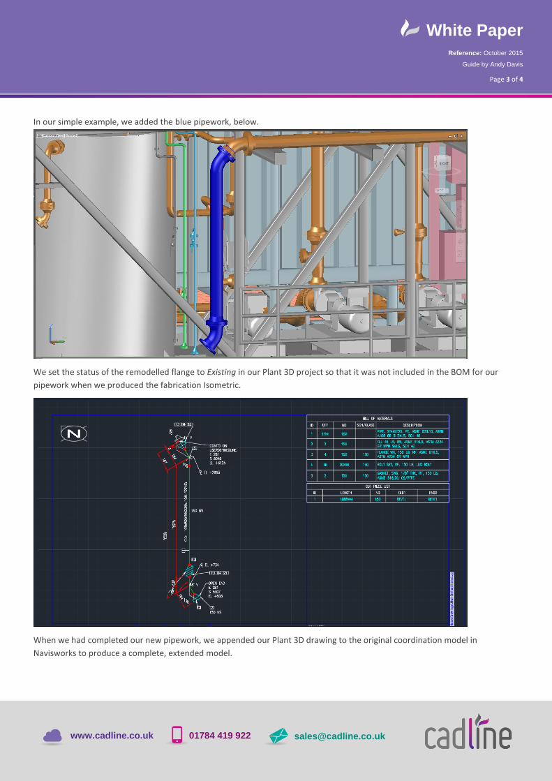
In our simple example, we added the blue pipework, below.
We set the status of the remodelled flange to Existing in our Plant 3D project so that it was not included in the BOM for our
pipework when we produced the fabrication Isometric.
When we had completed our new pipework, we appended our Plant 3D drawing to the original coordination model in
Navisworks to produce a complete, extended model.

White Paper Reference: October 2015
Guide by Andy Davis
01784 419 922 www.cadline.co.uk [email protected]
Page 4 of 4
Here we see the final model in Navisworks. We have hidden from view the remodelled flange and outline of the coordination
model from our Plant 3D drawing.