Using an Electro-Thermal Model for Vishay Siliconix Power ...
17
VISHAY SILICONIX Power MOSFETs Application Note AN842 Using an Electro-Thermal Model for Vishay Siliconix Power MOSFETs on a PSpice Platform APPLICATION NOTE Revision: 02-Apr-13 1 Document Number: 62841 For technical questions, contact: [email protected] THIS DOCUMENT IS SUBJECT TO CHANGE WITHOUT NOTICE. THE PRODUCTS DESCRIBED HEREIN AND THIS DOCUMENT ARE SUBJECT TO SPECIFIC DISCLAIMERS, SET FORTH AT www.vishay.com/doc?91000 www.vishay.com by Kandarp Pandya Vishay Siliconix offers a combined electro-thermal PSpice model for power MOSFETs. The basic PSpice model is embedded with R-C thermal model parameters. One single electrical simulation, using a combined electro-thermal PSpice model, enables users to analyze the electrical as well as thermal behavior of Vishay Siliconix power MOSFETs in a design. The simulation provides the junction temperature excursion in addition to electrical output. Application note AN841 [1] discusses the proof of concept. This document illustrates the step-by-step procedures for using an electro-thermal model on the PSpice platform. The example offers a complete walk-through, including the download, building an electrical schematic on OrCAD Capture, setting up and running the simulation, and obtaining electrical waveforms as well as thermal performance characteristics by selecting output parameters. Different options for thermal performance characteristics are discussed for specific electrical operating conditions. Vishay part SQD40N06-14L is used as an example throughout this document. STEP 1: DOWNLOAD MODEL FILES - OPTION (A) OR (B) Option (a): Locate the product information for a known part number. Go to www.vishay.com . Enter the part number SQD40N06-14L in the search box as shown in figure 1 below and hit Enter. Fig. 1
Transcript of Using an Electro-Thermal Model for Vishay Siliconix Power ...
V I S H A Y S I L I C O N I X
Power MOSFETs Application Note AN842
Using an Electro-Thermal Modelfor Vishay Siliconix Power MOSFETs on a PSpice Platform
AP
PL
ICA
TIO
N N
OT
E
Revision: 02-Apr-13 1 Document Number: 62841
For technical questions, contact: [email protected] DOCUMENT IS SUBJECT TO CHANGE WITHOUT NOTICE. THE PRODUCTS DESCRIBED HEREIN AND THIS DOCUMENT
ARE SUBJECT TO SPECIFIC DISCLAIMERS, SET FORTH AT www.vishay.com/doc?91000
www.vishay.com
by Kandarp Pandya
Vishay Siliconix offers a combined electro-thermal PSpice model for power MOSFETs. The basic PSpice model is embeddedwith R-C thermal model parameters. One single electrical simulation, using a combined electro-thermal PSpice model, enablesusers to analyze the electrical as well as thermal behavior of Vishay Siliconix power MOSFETs in a design. The simulationprovides the junction temperature excursion in addition to electrical output. Application note AN841[1] discusses the proof ofconcept.
This document illustrates the step-by-step procedures for using an electro-thermal model on the PSpice platform. The exampleoffers a complete walk-through, including the download, building an electrical schematic on OrCAD Capture, setting up andrunning the simulation, and obtaining electrical waveforms as well as thermal performance characteristics by selecting outputparameters. Different options for thermal performance characteristics are discussed for specific electrical operating conditions.
Vishay part SQD40N06-14L is used as an example throughout this document.
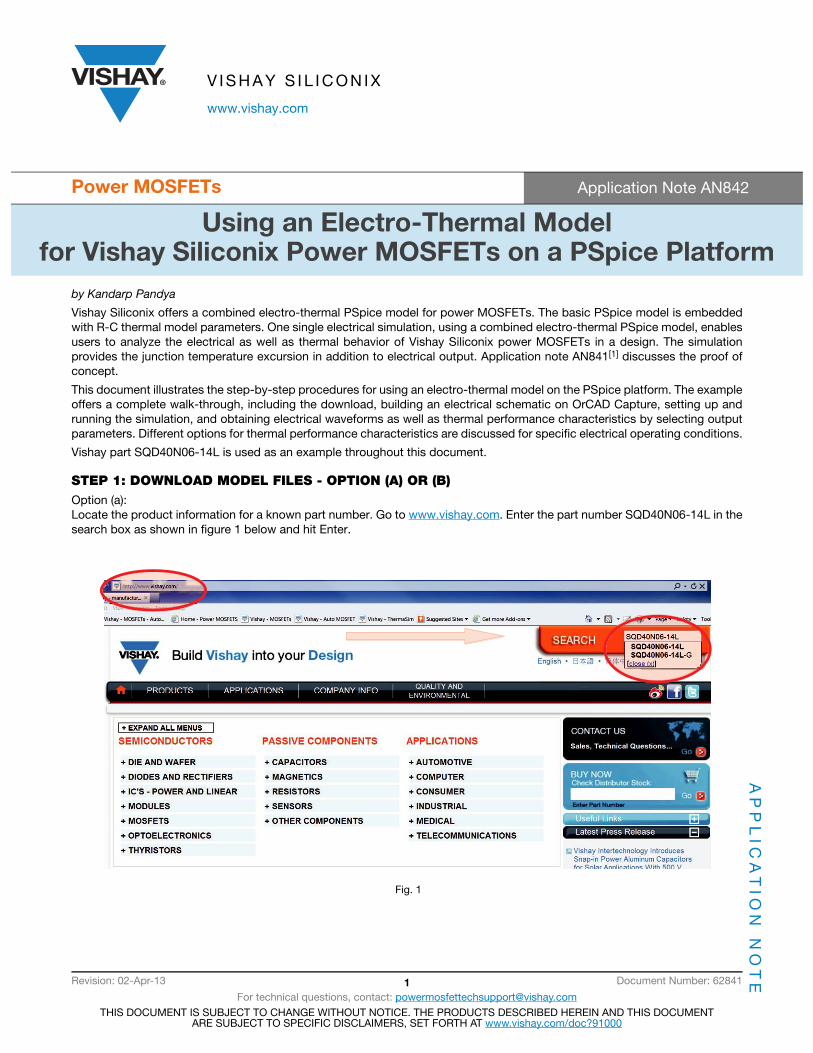
STEP 1: DOWNLOAD MODEL FILES - OPTION (A) OR (B)Option (a):Locate the product information for a known part number. Go to www.vishay.com. Enter the part number SQD40N06-14L in thesearch box as shown in figure 1 below and hit Enter.
Fig. 1
Using an Electro-Thermal Modelfor Vishay Siliconix Power MOSFETs on a PSpice Platform
AP
PL
ICA
TIO
N N
OT
EApplication Note AN842
www.vishay.com Vishay Siliconix
Revision: 02-Apr-13 2 Document Number: 62841
For technical questions, contact: [email protected] DOCUMENT IS SUBJECT TO CHANGE WITHOUT NOTICE. THE PRODUCTS DESCRIBED HEREIN AND THIS DOCUMENT
ARE SUBJECT TO SPECIFIC DISCLAIMERS, SET FORTH AT www.vishay.com/doc?91000
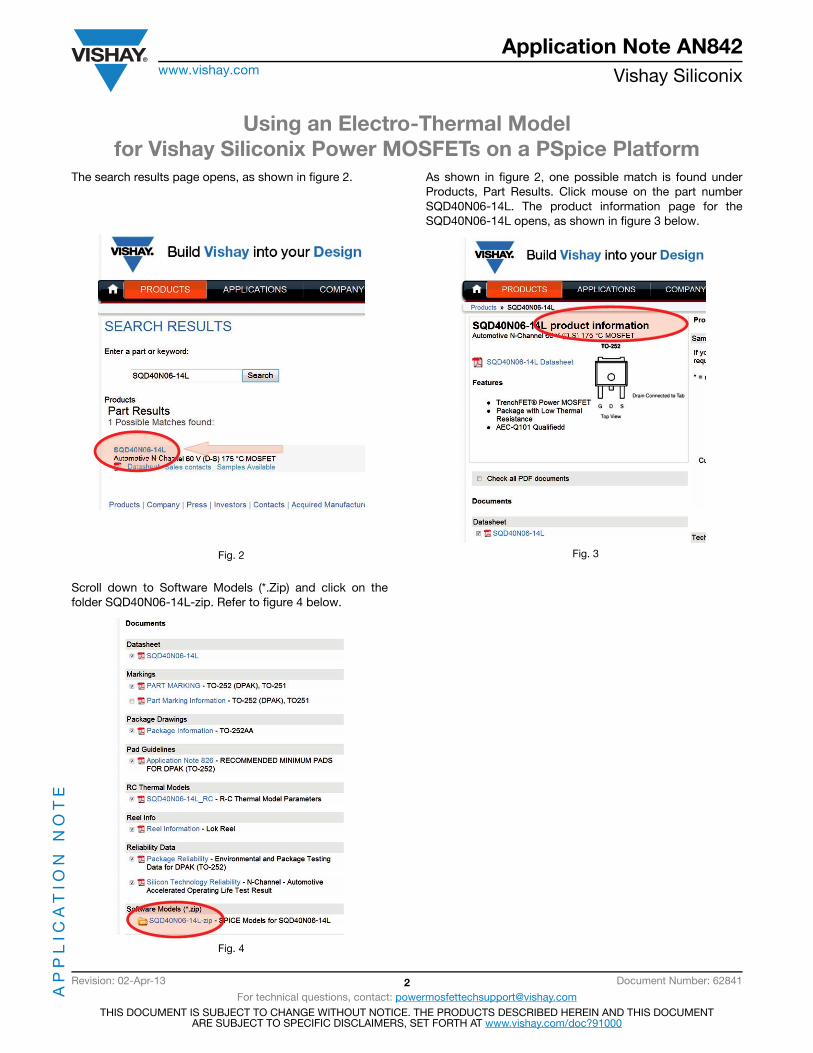
The search results page opens, as shown in figure 2.
Fig. 2
As shown in figure 2, one possible match is found underProducts, Part Results. Click mouse on the part numberSQD40N06-14L. The product information page for theSQD40N06-14L opens, as shown in figure 3 below.
Fig. 3
Scroll down to Software Models (*.Zip) and click on thefolder SQD40N06-14L-zip. Refer to figure 4 below.
Fig. 4
Using an Electro-Thermal Modelfor Vishay Siliconix Power MOSFETs on a PSpice Platform
AP
PL
ICA
TIO
N N
OT
EApplication Note AN842
www.vishay.com Vishay Siliconix
Revision: 02-Apr-13 3 Document Number: 62841
For technical questions, contact: [email protected] DOCUMENT IS SUBJECT TO CHANGE WITHOUT NOTICE. THE PRODUCTS DESCRIBED HEREIN AND THIS DOCUMENT
ARE SUBJECT TO SPECIFIC DISCLAIMERS, SET FORTH AT www.vishay.com/doc?91000
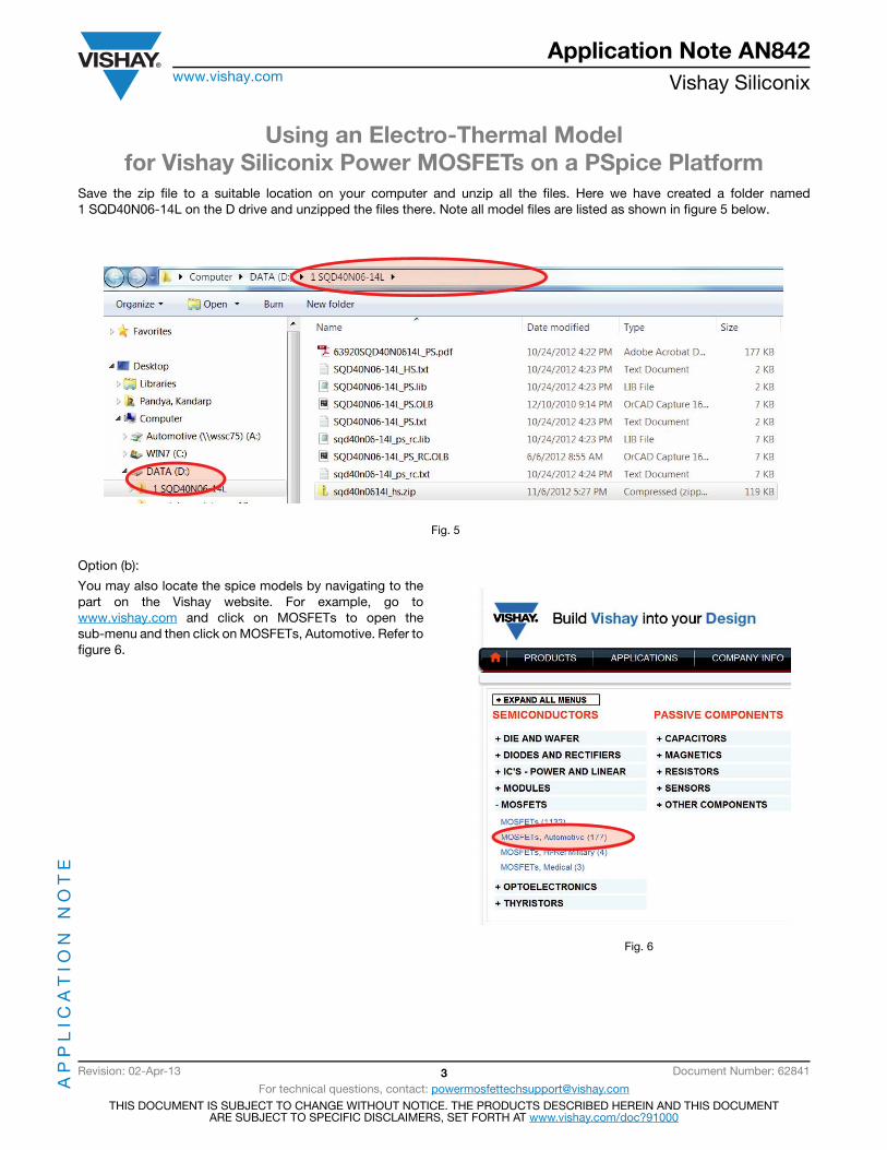
Save the zip file to a suitable location on your computer and unzip all the files. Here we have created a folder named1 SQD40N06-14L on the D drive and unzipped the files there. Note all model files are listed as shown in figure 5 below.
Fig. 5
Option (b):
You may also locate the spice models by navigating to thepart on the Vishay website. For example, go towww.vishay.com and click on MOSFETs to open thesub-menu and then click on MOSFETs, Automotive. Refer tofigure 6.
Fig. 6
Using an Electro-Thermal Modelfor Vishay Siliconix Power MOSFETs on a PSpice Platform
AP
PL
ICA
TIO
N N
OT
EApplication Note AN842
www.vishay.com Vishay Siliconix
Revision: 02-Apr-13 4 Document Number: 62841
For technical questions, contact: [email protected] DOCUMENT IS SUBJECT TO CHANGE WITHOUT NOTICE. THE PRODUCTS DESCRIBED HEREIN AND THIS DOCUMENT
ARE SUBJECT TO SPECIFIC DISCLAIMERS, SET FORTH AT www.vishay.com/doc?91000
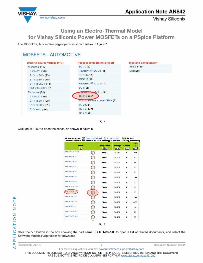
The MOSFETs, Automotive page opens as shown below in figure 7.
Fig. 7
Click on TO-252 to open the series, as shown in figure 8.
Fig. 8
Click the “i ” button in the box showing the part name SQD40N06-14L to open a list of related documents, and select theSoftware Models (*.zip) folder for download.
Using an Electro-Thermal Modelfor Vishay Siliconix Power MOSFETs on a PSpice Platform
AP
PL
ICA
TIO
N N
OT
EApplication Note AN842
www.vishay.com Vishay Siliconix
Revision: 02-Apr-13 5 Document Number: 62841
For technical questions, contact: [email protected] DOCUMENT IS SUBJECT TO CHANGE WITHOUT NOTICE. THE PRODUCTS DESCRIBED HEREIN AND THIS DOCUMENT
ARE SUBJECT TO SPECIFIC DISCLAIMERS, SET FORTH AT www.vishay.com/doc?91000
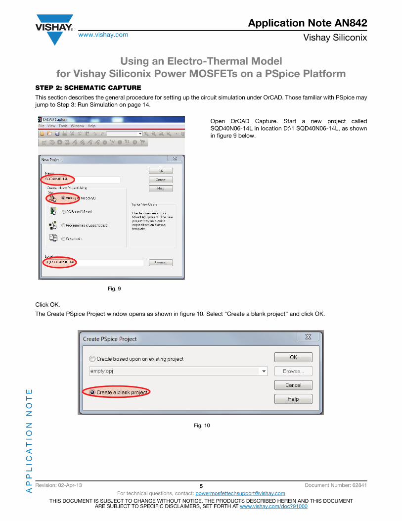
STEP 2: SCHEMATIC CAPTUREThis section describes the general procedure for setting up the circuit simulation under OrCAD. Those familiar with PSpice mayjump to Step 3: Run Simulation on page 14.
Fig. 9
Open OrCAD Capture. Start a new project calledSQD40N06-14L in location D:\1 SQD40N06-14L, as shownin figure 9 below.
Click OK.
The Create PSpice Project window opens as shown in figure 10. Select “Create a blank project” and click OK.
Fig. 10

Using an Electro-Thermal Modelfor Vishay Siliconix Power MOSFETs on a PSpice Platform
AP
PL
ICA
TIO
N N
OT
EApplication Note AN842
www.vishay.com Vishay Siliconix
Revision: 02-Apr-13 6 Document Number: 62841
For technical questions, contact: [email protected] DOCUMENT IS SUBJECT TO CHANGE WITHOUT NOTICE. THE PRODUCTS DESCRIBED HEREIN AND THIS DOCUMENT
ARE SUBJECT TO SPECIFIC DISCLAIMERS, SET FORTH AT www.vishay.com/doc?91000
The Project Manager Window and SCHEMATIC1: PAGE1 open. If necessary, rearrange the windows to display as shown infigure 11 below.
Fig. 11
Click anywhere on the schematic page.
Select the Place Part icon on the vertical tool bar on the right. The Place Part sub-window opens.
Click on the Libraries icon.
Browse to folder D:\1 SQD40N06-14L.
Select Capture Library (*.OLB) SQD40N06-14L_PS_RC.OLB.
Click Open to add the part library to the project. Refer to figure 12.
Fig. 12
Select SQD40N06-14L_PS_RC from the library listing to load the part to the Part List window. See figure 13.

Using an Electro-Thermal Modelfor Vishay Siliconix Power MOSFETs on a PSpice Platform
AP
PL
ICA
TIO
N N
OT
EApplication Note AN842
www.vishay.com Vishay Siliconix
Revision: 02-Apr-13 7 Document Number: 62841
For technical questions, contact: [email protected] DOCUMENT IS SUBJECT TO CHANGE WITHOUT NOTICE. THE PRODUCTS DESCRIBED HEREIN AND THIS DOCUMENT
ARE SUBJECT TO SPECIFIC DISCLAIMERS, SET FORTH AT www.vishay.com/doc?91000
Fig. 13
Double click SQD40N06-14L in the Part List window.
The schematic symbol is attached to the mouse cursor.
Click the mouse cursor at a suitable location on the schematic page to place the part. See figure 14.
Fig. 14
Using an Electro-Thermal Modelfor Vishay Siliconix Power MOSFETs on a PSpice Platform
AP
PL
ICA
TIO
N N
OT
EApplication Note AN842
www.vishay.com Vishay Siliconix
Revision: 02-Apr-13 8 Document Number: 62841
For technical questions, contact: [email protected] DOCUMENT IS SUBJECT TO CHANGE WITHOUT NOTICE. THE PRODUCTS DESCRIBED HEREIN AND THIS DOCUMENT
ARE SUBJECT TO SPECIFIC DISCLAIMERS, SET FORTH AT www.vishay.com/doc?91000
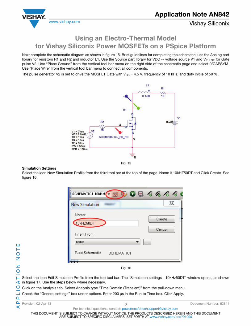
Next complete the schematic diagram as shown in figure 15. Brief guidelines for completing the schematic: use the Analog partlibrary for resistors R1 and R2 and inductor L1. Use the Source part library for VDC -- voltage source V1 and VPULSE for Gatepulse V2. Use “Place Ground” from the vertical tool bar menu on the right side of the schematic page and select 0/CAPSYM.Use "Place Wire" from the vertical tool bar menu to connect all components.
The pulse generator V2 is set to drive the MOSFET Gate with VGS = 4.5 V, frequency of 10 kHz, and duty cycle of 50 %.
Fig. 15
Simulation SettingsSelect the icon New Simulation Profile from the third tool bar at the top of the page. Name it 10kHZ50DT and Click Create. Seefigure 16.
Fig. 16
Select the icon Edit Simulation Profile from the top tool bar. The “Simulation settings - 10kHz50DT” window opens, as shownin figure 17. Use the steps below where necessary.
Click on the Analysis tab. Select Analysis type “Time Domain (Transient)” from the pull-down menu.
Check the “General settings” box under options. Enter 200 μs in the Run to Time box. Click Apply.

Using an Electro-Thermal Modelfor Vishay Siliconix Power MOSFETs on a PSpice Platform
AP
PL
ICA
TIO
N N
OT
EApplication Note AN842
www.vishay.com Vishay Siliconix
Revision: 02-Apr-13 9 Document Number: 62841
For technical questions, contact: [email protected] DOCUMENT IS SUBJECT TO CHANGE WITHOUT NOTICE. THE PRODUCTS DESCRIBED HEREIN AND THIS DOCUMENT
ARE SUBJECT TO SPECIFIC DISCLAIMERS, SET FORTH AT www.vishay.com/doc?91000
Fig. 17
Click the Configuration Files tab. Under Category, select Library. Browse to the location of the library file sqd40n06-14l_ps_rc.lib(see figure 18). Click Open and select Add as Global or Add to Design. Click Apply and OK.

Using an Electro-Thermal Modelfor Vishay Siliconix Power MOSFETs on a PSpice Platform
AP
PL
ICA
TIO
N N
OT
EApplication Note AN842
www.vishay.com Vishay Siliconix
Revision: 02-Apr-13 10 Document Number: 62841
For technical questions, contact: [email protected] DOCUMENT IS SUBJECT TO CHANGE WITHOUT NOTICE. THE PRODUCTS DESCRIBED HEREIN AND THIS DOCUMENT
ARE SUBJECT TO SPECIFIC DISCLAIMERS, SET FORTH AT www.vishay.com/doc?91000
Fig. 18
Click the Data Collection tab. Select “All” from the pull-down options for Voltages, Currents, Power, and Digital. Click Apply andOK (figure 19).
Fig. 19
Add Voltage Markers on Drain pin U1-1 and Gate in U1-2. Add Current Marker on Drain Pin U1-1 as shown in figure 15.
Using an Electro-Thermal Modelfor Vishay Siliconix Power MOSFETs on a PSpice Platform
AP
PL
ICA
TIO
N N
OT
EApplication Note AN842
www.vishay.com Vishay Siliconix
Revision: 02-Apr-13 11 Document Number: 62841
For technical questions, contact: [email protected] DOCUMENT IS SUBJECT TO CHANGE WITHOUT NOTICE. THE PRODUCTS DESCRIBED HEREIN AND THIS DOCUMENT
ARE SUBJECT TO SPECIFIC DISCLAIMERS, SET FORTH AT www.vishay.com/doc?91000
STEP 3: RUN ELECTRO-THERMAL SIMULATIONClick the Run Simulation icon, which is the green arrow on the top tool bar menu. Ignore “Undo Warning!” by clicking “Yes.”
Upon completion of the simulation, run schematic updates with colored markers, as shown in figure 18.
Simulation Results:
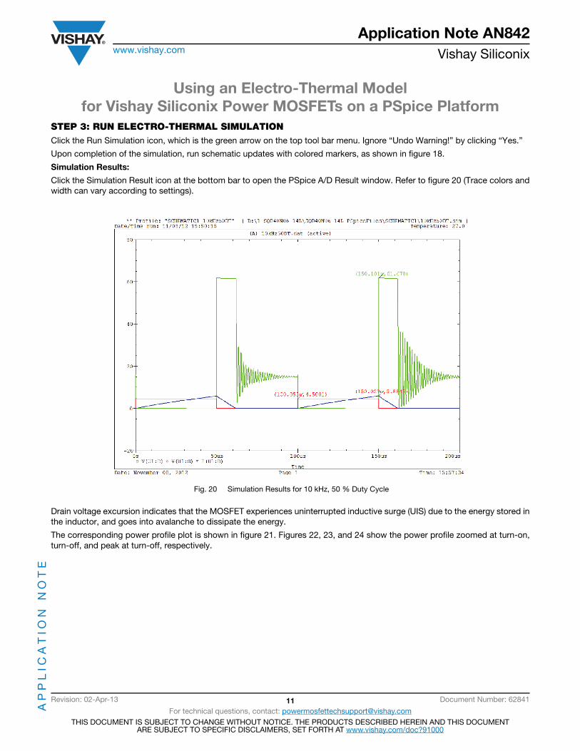
Click the Simulation Result icon at the bottom bar to open the PSpice A/D Result window. Refer to figure 20 (Trace colors andwidth can vary according to settings).
Fig. 20 Simulation Results for 10 kHz, 50 % Duty Cycle
Drain voltage excursion indicates that the MOSFET experiences uninterrupted inductive surge (UIS) due to the energy stored inthe inductor, and goes into avalanche to dissipate the energy.
The corresponding power profile plot is shown in figure 21. Figures 22, 23, and 24 show the power profile zoomed at turn-on,turn-off, and peak at turn-off, respectively.
Using an Electro-Thermal Modelfor Vishay Siliconix Power MOSFETs on a PSpice Platform
AP
PL
ICA
TIO
N N
OT
EApplication Note AN842
www.vishay.com Vishay Siliconix
Revision: 02-Apr-13 12 Document Number: 62841
For technical questions, contact: [email protected] DOCUMENT IS SUBJECT TO CHANGE WITHOUT NOTICE. THE PRODUCTS DESCRIBED HEREIN AND THIS DOCUMENT
ARE SUBJECT TO SPECIFIC DISCLAIMERS, SET FORTH AT www.vishay.com/doc?91000
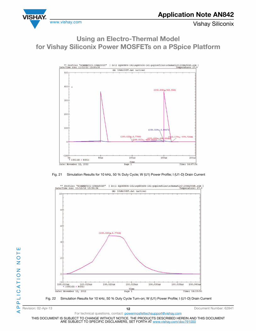
Fig. 21 Simulation Results for 10 kHz, 50 % Duty Cycle; W (U1) Power Profile; I (U1-D) Drain Current
Fig. 22 Simulation Results for 10 kHz, 50 % Duty Cycle Turn-on; W (U1) Power Profile; I (U1-D) Drain Current

Using an Electro-Thermal Modelfor Vishay Siliconix Power MOSFETs on a PSpice Platform
AP
PL
ICA
TIO
N N
OT
EApplication Note AN842
www.vishay.com Vishay Siliconix
Revision: 02-Apr-13 13 Document Number: 62841
For technical questions, contact: [email protected] DOCUMENT IS SUBJECT TO CHANGE WITHOUT NOTICE. THE PRODUCTS DESCRIBED HEREIN AND THIS DOCUMENT
ARE SUBJECT TO SPECIFIC DISCLAIMERS, SET FORTH AT www.vishay.com/doc?91000
Fig. 23 Simulation Results for 10 kHz, 50% Duty Cycle at Lower End of Turn-off; W (U1) Power Profile; I(U1-D) Drain Current.
Fig. 24 Simulation Results for 10 kHz, 50 % Duty Cycle at Upper End of Turn-off; W (U1) Power Profile; I (U1-D) Drain Current
Using an Electro-Thermal Modelfor Vishay Siliconix Power MOSFETs on a PSpice Platform
AP
PL
ICA
TIO
N N
OT
EApplication Note AN842
www.vishay.com Vishay Siliconix
Revision: 02-Apr-13 14 Document Number: 62841
For technical questions, contact: [email protected] DOCUMENT IS SUBJECT TO CHANGE WITHOUT NOTICE. THE PRODUCTS DESCRIBED HEREIN AND THIS DOCUMENT
ARE SUBJECT TO SPECIFIC DISCLAIMERS, SET FORTH AT www.vishay.com/doc?91000
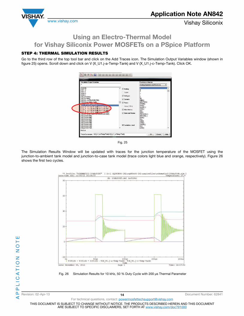
STEP 4: THERMAL SIMULATION RESULTSGo to the third row of the top tool bar and click on the Add Traces icon. The Simulation Output Variables window (shown infigure 25) opens. Scroll down and click on V (X_U1.j-a-Temp-Tank) and V (X_U1.j-c-Temp-Tank). Click OK.
Fig. 25
The Simulation Results Window will be updated with traces for the junction temperature of the MOSFET using thejunction-to-ambient tank model and junction-to-case tank model (trace colors light blue and orange, respectively). Figure 26shows the first two cycles.
Fig. 26 Simulation Results for 10 kHz, 50 % Duty Cycle with 200 μs Thermal Parameter
Using an Electro-Thermal Modelfor Vishay Siliconix Power MOSFETs on a PSpice Platform
AP
PL
ICA
TIO
N N
OT
EApplication Note AN842
www.vishay.com Vishay Siliconix
Revision: 02-Apr-13 15 Document Number: 62841
For technical questions, contact: [email protected] DOCUMENT IS SUBJECT TO CHANGE WITHOUT NOTICE. THE PRODUCTS DESCRIBED HEREIN AND THIS DOCUMENT
ARE SUBJECT TO SPECIFIC DISCLAIMERS, SET FORTH AT www.vishay.com/doc?91000
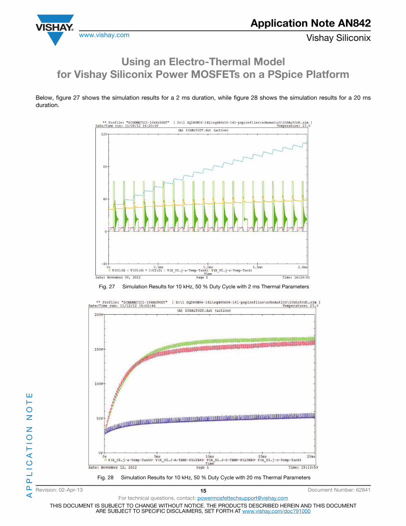
Below, figure 27 shows the simulation results for a 2 ms duration, while figure 28 shows the simulation results for a 20 msduration.
Fig. 27 Simulation Results for 10 kHz, 50 % Duty Cycle with 2 ms Thermal Parameters
Fig. 28 Simulation Results for 10 kHz, 50 % Duty Cycle with 20 ms Thermal Parameters
Using an Electro-Thermal Modelfor Vishay Siliconix Power MOSFETs on a PSpice Platform
AP
PL
ICA
TIO
N N
OT
EApplication Note AN842
www.vishay.com Vishay Siliconix
Revision: 02-Apr-13 16 Document Number: 62841
For technical questions, contact: [email protected] DOCUMENT IS SUBJECT TO CHANGE WITHOUT NOTICE. THE PRODUCTS DESCRIBED HEREIN AND THIS DOCUMENT
ARE SUBJECT TO SPECIFIC DISCLAIMERS, SET FORTH AT www.vishay.com/doc?91000
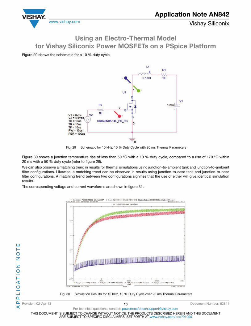
Figure 29 shows the schematic for a 10 % duty cycle.
Fig. 29 Schematic for 10 kHz, 10 % Duty Cycle with 20 ms Thermal Parameters
Figure 30 shows a junction temperature rise of less than 50 °C with a 10 % duty cycle, compared to a rise of 170 °C within20 ms with a 50 % duty cycle (refer to figure 28).
We can also observe a matching trend in results for thermal simulations using junction-to-ambient tank and junction-to-ambientfilter configurations. Likewise, a matching trend can be observed in results using junction-to-case tank and junction-to-casefilter configurations. A matching trend between two configurations signifies that the use of either will give identical simulationresults.
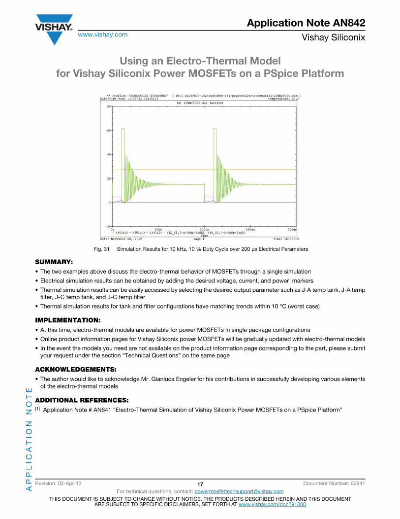
The corresponding voltage and current waveforms are shown in figure 31.
Fig. 30 Simulation Results for 10 kHz, 10 % Duty Cycle over 20 ms Thermal Parameters
Using an Electro-Thermal Modelfor Vishay Siliconix Power MOSFETs on a PSpice Platform
AP
PL
ICA
TIO
N N
OT
EApplication Note AN842
www.vishay.com Vishay Siliconix
Revision: 02-Apr-13 17 Document Number: 62841
For technical questions, contact: [email protected] DOCUMENT IS SUBJECT TO CHANGE WITHOUT NOTICE. THE PRODUCTS DESCRIBED HEREIN AND THIS DOCUMENT
ARE SUBJECT TO SPECIFIC DISCLAIMERS, SET FORTH AT www.vishay.com/doc?91000
Fig. 31 Simulation Results for 10 kHz, 10 % Duty Cycle over 200 μs Electrical Parameters
SUMMARY:• The two examples above discuss the electro-thermal behavior of MOSFETs through a single simulation
• Electrical simulation results can be obtained by adding the desired voltage, current, and power markers
• Thermal simulation results can be easily accessed by selecting the desired output parameter such as J-A temp tank, J-A tempfilter, J-C temp tank, and J-C temp filter
• Thermal simulation results for tank and filter configurations have matching trends within 10 °C (worst case)
IMPLEMENTATION:• At this time, electro-thermal models are available for power MOSFETs in single package configurations
• Online product information pages for Vishay Siliconix power MOSFETs will be gradually updated with electro-thermal models
• In the event the models you need are not available on the product information page corresponding to the part, please submityour request under the section “Technical Questions” on the same page
ACKNOWLEDGEMENTS:• The author would like to acknowledge Mr. Gianluca Engeler for his contributions in successfully developing various elements
of the electro-thermal models
ADDITIONAL REFERENCES:[1] Application Note # AN841 “Electro-Thermal Simulation of Vishay Siliconix Power MOSFETs on a PSpice Platform”