
User’s Manual - Frank's Hospital Workshop€¦ · 2 TCO2M® User’s Manual Rev. 01 25-Mar-97...
108
Model 860 March 25, 1997 Catalog No. 6590-23-01 TCO 2 M ® Transcutaneous CO 2 /O 2 Monitor User’s Manual Copyright ©1997. Novametrix Medical Systems Inc. 5 Technology Drive Wallingford, Connecticut, U.S.A. 06492 All rights reserved.
Transcript of User’s Manual - Frank's Hospital Workshop€¦ · 2 TCO2M® User’s Manual Rev. 01 25-Mar-97...

October 4, 1996
Catalog No. 6590-23-00
Model 860
March 25, 1997
Catalog No. 6590-23-01
TCO2M®
Transcutaneous CO2/O2 Monitor
User’s Manual
Copyright ©1997. Novametrix Medical Systems Inc.5 Technology Drive
Wallingford, Connecticut, U.S.A. 06492All rights reserved.


25-Mar-97 Rev. 01 TCO2M® User’s Manual iii
Revision History
04-Oct-96 Release Version Rev.00
25-Mar-97 Revision 01

Revision History
iv TCO2M® User’s Manual Rev. 01 25-Mar-97

25-Mar-97 Rev. 01 TCO2M® User’s Manual 97
16 Guarantee
Equipment manufactured or distributed by Novametrix Medical Systems Inc., is fullyguaranteed, covering materials and workmanship, for a period of one year from thedate of shipment, except for certain disposable products and products with statedguarantees other than one year. Novametrix reserves the right to perform guaranteeservice(s) at its factory, at an authorized repair station, or at the customer’sinstallation.
Novametrix’ obligations under this guarantee are limited to repairs, or atNovametrix’ option, replacement of any defective parts of our equipment, exceptfuses, batteries, and calibration gasses, without charge, if said defects occur duringnormal service.
Claims for damages during shipment must be filed promptly with the transportationcompany. All correspondence concerning the equipment must specify both the modelname and number, and the serial number as it appears on the equipment.
Improper use, mishandling, tampering with, or operation of the equipment withoutfollowing specific operating instructions will void this guarantee and releaseNovametrix from any further guarantee obligations.
Caution: Federal (U.S.A.) law restricts this device to sale, distribution, or use by oron the order of a licensed medical practitioner.
Copyright 1997. Novametrix Medical Systems Inc. 5 Technology Drive,Wallingford, Connecticut, 06492. This document contains information which isproprietary and the property of Novametrix Medical Systems Inc., and may not bereproduced, stored in a retrieval system, translated, transcribed, or transmitted, in anyform, or by any means, without prior explicit written permission from NovametrixMedical Systems Inc.
Call toll free: 1-800-243-3444
To Call Direct: (203) 265-7701
Facsimile (203) 284-0753
http://www.novametrix.com

16 Guarantee
98 TCO2M® User’s Manual Rev. 01 25-Mar-97

25-Mar-97 Rev. 01 TCO2M® User’s Manual v
Table of Contents
Revision History ...................................................................................................... iiiTable of Contents ..................................................................................................... vIntroduction ............................................................................................................... 1
About this manual ................................................................................................ 1Indications for Use ............................................................................................... 1Summary of features ............................................................................................ 2Principles of Operation ......................................................................................... 2
Oxygen .............................................................................................................. 2Carbon Dioxide ................................................................................................. 2Local Power ...................................................................................................... 3
Technical Description ........................................................................................... 3Safety ......................................................................................................................... 5
Patient Safety ....................................................................................................... 5Contraindications ................................................................................................. 6Warnings .............................................................................................................. 6Cautions ............................................................................................................... 7
Quick Start Guide ..................................................................................................... 9Connect Sensor ................................................................................................ 9Power Up ........................................................................................................ 10Calibrator Setup .............................................................................................. 10Calibration ....................................................................................................... 10Alert Limits ...................................................................................................... 10Apply to Patient ............................................................................................... 10Handling Alerts ................................................................................................ 10Removal from Patient ...................................................................................... 10Monitor Shutdown ........................................................................................... 10
System Overview .................................................................................................... 11TCO2M Monitor Front Panel .............................................................................. 11
or Power ......................................................................................................... 11Low Bat ........................................................................................................... 11AC ON ............................................................................................................. 11Two Minute Silence ......................................................................................... 12Audio key ........................................................................................................ 12Audio Icon ....................................................................................................... 12Alert Reset ...................................................................................................... 12Alert Icon ......................................................................................................... 12Softkeys .......................................................................................................... 12Event ............................................................................................................... 12Contrast ........................................................................................................... 12
TCO2M Monitor Rear Panel ............................................................................... 12Symbols ............................................................................................................. 13
Equipotentiality ............................................................................................... 13 Ground ........................................................................................................... 13

Table of Contents
vi TCO2M® User’s Manual Rev. 01 25-Mar-97
Dangerous Voltage ........................................................................................ 13 Patient Isolation ..................................................................................... 13 Attention ......................................................................................................... 13Mains Fuse ...................................................................................................... 13Mains Power ................................................................................................... 13
TCO2M Monitor Display ..................................................................................... 13Transcutaneous Sensor Overview ..................................................................... 14
Select sensor .................................................................................................. 14Connect sensor ............................................................................................... 14
TCO2M Calibrator, Model 868 ........................................................................... 14Setting up the Calibrator ................................................................................. 15Disconnecting Gas Cylinders .......................................................................... 16Connect the calibrator ..................................................................................... 16
Operating the Monitor ............................................................................................ 17TCO2M Power-up .............................................................................................. 17
Power On/Off .................................................................................................. 17AC/Battery operation ....................................................................................... 17AC Line Power ................................................................................................ 18Battery Power .................................................................................................. 18Operating on battery ....................................................................................... 18Low battery alert .............................................................................................. 18Charging the battery ........................................................................................ 18Long Term Storage ......................................................................................... 18Battery replacement ........................................................................................ 18
Monitoring CO2 and O2 Tension ........................................................................ 19Sensor Stabilization ........................................................................................ 19Carbon Dioxide and Oxygen Alerts ................................................................. 19Sensor Temperature Alerts ............................................................................. 19
PtcCO2 Display Values ...................................................................................... 19Menu Operation and Setup .................................................................................... 21
Menu Structure ................................................................................................... 21LIMIT — CO2 and O2 Alert Limits ..................................................................... 21
Set Alert Limits ................................................................................................ 22Auto Alert Limits .............................................................................................. 23Limit Alerts ...................................................................................................... 23
TRND — Real time trend displays ..................................................................... 24Real Time Trend ............................................................................................. 24Show CO2 /O2/LP ........................................................................................... 24Set Trend Time ............................................................................................... 24Set CO2/O2 scale ........................................................................................... 25Local Power(LP and LPR) .................................................................................................. 26
TRND — Trend Page (stored trend memory) displays ...................................... 27Show trend page ............................................................................................. 28Moving in trend ................................................................................................ 28Select trend page parameter ........................................................................... 29Select trend scale ............................................................................................ 29Show histogram .............................................................................................. 29Erase trend memory ........................................................................................ 30Trend Data Compression ................................................................................ 31
CAL — Sensor calibration .................................................................................. 31Calibrate sensor .............................................................................................. 31Set temperature .............................................................................................. 32

Table of Contents
25-Mar-97 Rev. 01 TCO2M® User’s Manual vii
Site Timer ........................................................................................................ 33Reset site timer ............................................................................................... 33Adjust site timer ............................................................................................... 34Last Calibration information ............................................................................ 35
DELAY — Suppress limit alerts ......................................................................... 35Set Alert Delay ................................................................................................ 35Cancel Alert Delay .......................................................................................... 36
LITE — Display brightness ................................................................................. 36AUDIO — Adjust alert volume ............................................................................ 36
Sensor Calibration .................................................................................................. 37Sensor Calibration with the TCO2M Calibrator Model 868 ................................ 37Manual Calibration of the O2 Sensor ................................................................. 39
O2 Sensor Initial Calibration ........................................................................... 39O2 Sensor Recalibration ................................................................................. 40
Apply Sensor to Patient ......................................................................................... 43Sensor Site Selection ......................................................................................... 43Sensor to Patient Application ............................................................................. 44Removing the Sensor from the Patient .............................................................. 45
Combination O2/CO2 Sensor ................................................................................. 47Sensor Identification ........................................................................................ 47Sensor Construction ........................................................................................ 47Sensor Operation ............................................................................................ 47Membrane Schedule ....................................................................................... 474474-00 Sensor Membraning Procedure ........................................................ 48Long Term Combination Sensor Storage ........................................................ 50Cleaning the Combination Sensor face ........................................................... 504474-39 Sensor Membraning Procedure ........................................................ 51
Carbon Dioxide Sensor .......................................................................................... 55CO2 Sensor Construction ............................................................................... 55CO2 Sensor Operation .................................................................................... 55Membrane Schedule ....................................................................................... 55CO2 Sensor Membraning Procedure .............................................................. 55Long Term CO2 Sensor Storage .................................................................... 57Cleaning the CO2 Sensor face ....................................................................... 57
Oxygen Sensor ....................................................................................................... 59O2 Sensor Construction .................................................................................. 59O2 Sensor Operation ...................................................................................... 59Membrane Schedule ....................................................................................... 59Cleaning and Membraning the O2 Sensor face .............................................. 59Long Term O2 Sensor Storage ....................................................................... 61
Advanced Controls and Features ......................................................................... 63Display Menu ..................................................................................................... 63
Temperature or Power Display ....................................................................... 63Limit Display .................................................................................................... 64Display Colors ................................................................................................. 64Display Units ................................................................................................... 65
System Menu ..................................................................................................... 65Serial Out ........................................................................................................ 65Set Clock ......................................................................................................... 66Site Timer (Maximum Duration) ...................................................................... 66Metabolic Correction Factor ............................................................................ 67Barometric pressure determination ................................................................. 67

Table of Contents
viii TCO2M® User’s Manual Rev. 01 25-Mar-97
Alerts Menu ........................................................................................................ 68Latch Alerts ..................................................................................................... 6810 second Alert Delay Option ......................................................................... 69Retain Alert Limits ........................................................................................... 69Red Alert Bar ................................................................................................... 69
Audio Menu ........................................................................................................ 70Allow Audio Off ................................................................................................ 70Keyclick Volume .............................................................................................. 70
Sensor Menu ...................................................................................................... 71Restoring factory defaults settings ..................................................................... 71
External Devices ..................................................................................................... 73NovaCARD ......................................................................................................... 73
NovaCARD Configuration ............................................................................... 74Using NovaCARD ........................................................................................... 74
Analog Output Module ....................................................................................... 75Connecting the Analog Output Module ........................................................... 75Calibrating an External Recorder .................................................................... 76
Printer ................................................................................................................. 77Setup Printer ................................................................................................... 77Setup TCO2M ................................................................................................. 78Types of Printouts ........................................................................................... 78Displayed Trend printout ................................................................................. 78Compressed Trend printout ............................................................................ 79Zoom Trend printout ........................................................................................ 79Stopping a printout .......................................................................................... 80Trend Printout ................................................................................................. 81Tabular Printout ............................................................................................... 85
NovaCOM .......................................................................................................... 86NovaCOM Configuration ................................................................................. 86NovaCOM Data Format .................................................................................. 86Real Time ........................................................................................................ 86Trend Dump .................................................................................................... 87Date and Time ................................................................................................. 89Clear Trends ................................................................................................... 89Exit Command ................................................................................................. 89
Flexport .............................................................................................................. 90Terminal ............................................................................................................. 90
Maintenance ............................................................................................................ 91Cleaning and Disinfecting .................................................................................. 91
Monitor ............................................................................................................ 91Sensors ........................................................................................................... 91Calibrator ......................................................................................................... 91
Battery Maintenance .......................................................................................... 92Long Term Storage ......................................................................................... 92Charging the battery ........................................................................................ 92Battery replacement ........................................................................................ 92Line Cord ......................................................................................................... 92
Fuses ................................................................................................................. 92Specifications ......................................................................................................... 95
Monitor Model 860 ............................................................................................. 95Sensors .............................................................................................................. 96Gas Calibrator Model 868 .................................................................................. 96
Guarantee ................................................................................................................ 97Accessories ............................................................................................................. 99

25-Mar-97 Rev. 01 TCO2M® User’s Manual 1
1 Introduction
The TCO2M® Transcutaneous CO2/O2 Monitor, Model 860 is designed to be an easy-to-operate stand-alone transcutaneous monitoring system. It is intended to be used inpatient monitoring environments by technically skilled clinical personnel.
About this manual
This manual is written for clinical personnel using the TCO2M® TranscutaneousCO2/O2 Monitor, Model 860, the Transcutaneous Calibrator, Model 868, and thetranscutaneous sensors and accessories intended for use with the monitor andcalibrator from Novametrix Medical Systems Inc.
This document contains information which is proprietary and the property ofNovametrix Medical Systems Inc., and may not be reproduced, stored in a retrievalsystem, translated, transcribed, or transmitted, in any form, or by any means, withoutthe prior explicit written permission of Novametrix Medical Systems Inc.
Novametrix reserves the right to change specifications without notice. TCO2M andNOVADISK are registered trademarks, and NovaCARD and NovaCOM aretrademarks of Novametrix Medical Systems Inc.
Indications for Use
The TCO2M Transcutaneous CO2/O2 Monitor, Model 860 is indicated for use as atrend monitor for CO2 and O2 tension at the skin surface for neonates and adults asan adjunct to arterial CO2 and O2 blood gas measurements. This equipment is not ablood gas device.
Regulatory review (U.S.A.) of safety and effectiveness for transcutaneous oxygenmonitors is not required at this time. However, the oxygen-monitoring portion of thisdevice has been found to be substantially equivalent to devices marketed in interstatecommerce prior to May 28, 1976.
1 Introduction Summary of features
2 TCO2M® User’s Manual Rev. 01 25-Mar-97
Summary of features
The TCO2M Transcutaneous CO2/O2 Monitor provides reliable, continuousmeasurement, displays and alerts for transcutaneous oxygen tension (PtcO2),transcutaneous carbon dioxide tension (PtcCO2) and sensor temperature. Sensorheater power is also trended and can be displayed. The monitor’s real time graphiconscreen trends along with the numeric values provide truly continuous CO2 and O2monitoring. A simple menu system with helpful messages guides the user throughsetup and alert conditions. Built-in 24-hour trend memory with graphic andhistogram displays are available for viewing of patient history. The lightweightportable monitor can operate from AC power or from its internal battery. Sensorcalibration is quick, fully automatic, barometric pressure compensated, and uses atrue two-point method for accurate calibrations. The Calibrator is completelypowered from the Monitor and the sensor can be inserted and removed from thecalibrator with a single hand. TCO2M accepts combination CO2/O2 sensors as wellas CO2 only or O2 only sensors for optimum versatility. Sensors provide superiorperformance, fast response, are rugged, reliable and can be membraned in seconds.An automatic site timer enhances patient safety.
Principles of Operation
Oxygen Transcutaneous oxygen is measured with an oxygen sensor consisting of two parts;1) a modified Clark-type polarographic electrode, a silver anode and platinumcathode, electrolyte and an oxygen permeable membrane, and 2) a heating sectionwith two precision thermistors for measuring and controlling the sensor temperature.When the sensor is subjected to oxygen, the oxygen molecules diffuse through themembrane and create an electro-chemical reaction which causes current to flowthrough the cathode. An amplifier connected to the cathode measures current flowingand converts it to a value proportional to the oxygen tension at the sensor/membraneinterface. This is PtcO2 and is displayed as a O2 value (in either mmHg or kPa asselected by the user).
Carbon Dioxide Transcutaneous carbon dioxide is measured with a sensor that utilizes a unique pHelectrode based on the Stow-Severinghaus principle. The carbon dioxide sensor iscomposed of two parts; 1) a carbon dioxide sensor consisting of a pH electrode,reference electrode, electrolyte and a carbon dioxide permeable membrane, and 2) aheating section with two precision thermistors for measuring and controlling thesensor temperature. When the sensor is subjected to carbon dioxide, the carbondioxide molecules diffuse through the membrane and react with the electrolyte. Thisreaction alters the pH of the electrolyte solution, which in turn changes the voltageacross the pH and reference sensors. Since carbon dioxide is the only gas that canaffect the pH of the electrolyte, there is a direct correlation between pH and theamount of CO2 present. This relationship is expressed by the Henderson-Hasselbach

Technical Description Introduction 1
25-Mar-97 Rev. 01 TCO2M® User’s Manual 3
equation:
An amplifier measures this voltage change and converts it to a value correspondingto the carbon dioxide tension at the sensor/membrane interface. This is PtcCO2 andis displayed as a CO2 value (in either mmHg or kPa as selected by the user).
Local Power Local Power is the measure of electrical power, measured in milli-watts (mW),required by the sensor to maintain the selected sensor temperature setting. The LocalPower value is proportional to the blood flow beneath the sensor site. Because thesensor set temperature is above blood temperature, blood flowing past the sensor siteprovides a cooling action. As blood flow (and its associated cooling action) increases,the sensor requires more power to maintain its temperature setting and the LP valueincreases. Conversely, as blood flow decreases, sensor heater power and LP alsodecrease.
Abrupt changes in PtcO2 coupled with significant LP changes may indicate reducedblood flow at the sensor site, while abrupt changes in PtcO2 unaccompanied bysignificant LP changes may indicate consistent blood flow but a change in PaO2.
Important: Sensor heater power requirements (LP) are also influenced by bodytemperature and ambient temperature changes. Body temperature changes tend to begradual over time and produce minor changes in LP. Ambient temperature changesfrom air-conditioners, patient warmers, radiant heaters, etc., can have significanteffects on the LP value. If monitoring the LP value, it may be necessary to insulatethe sensor from ambient temperature changes with a light covering such as abedsheet, or with material designed to reflect radiant heat energy.
Technical Description
Per requirements of IEC 601-1, TCO2M is classified as class I equipment, internallypowered, with type BF applied part, and IPX0.
The TCO2M Transcutaneous CO2/O2 Monitor, Model 860, contains no userserviceable parts. Refer servicing to qualified service personnel.
See “Accessories” on page 99 for listings of the Service Manual and Service Test kitfor use by technical personnel.
Transport and storage conditions: -10 to +55° C (14-131° F) < 90% relative humiditynon-condensing. Operating conditions:10-40° C (50-104° F).
pH = pKa + logHCO3
0.03 pCO2

1 Introduction Technical Description
4 TCO2M® User’s Manual Rev. 01 25-Mar-97

25-Mar-97 Rev. 01 TCO2M® User’s Manual 5
2 Safety
Patient Safety
• The location of the sensor on the patient should be changed periodically to minimize the risk of heat induced skin damage. The risk of such skin damage is dependent upon the sensor temperature, duration of application and physiological parameters including local perfusion, body temperature, and skin thickness.
• TCO2M monitor has electrically isolated inputs. Patient leakage current flowing from the instrument to ground is limited to less than 10 µA at 120 V, 60 Hz. Patient isolation is greater than 10 MΩ, 2500 V rms at 60 Hz. For maximum patient and operator safety, the following procedures are recommended;
•Keep the TCO2M and its accessories clean.
•Do not operate the TCO2M when it is wet due to spills or condensation.
•Do not touch the patient while making adjustments on the TCO2M monitor.
•Whenever possible, the TCO2M monitor should be connected to the same circuit as other equipment in use on the same patient. Outlets that are on the same circuit can be identified by your hospital’s engineering department.
• In areas where electromagnetic devices (i.e., electrocautery) are used, patient monitoring may be interrupted due to electromagnetic interference. Electomagnetic fields up to 3 V/m will not adversely affect system performance.
• The PtcCO2 display reading (CO2) is factory set to reflect the metabolic factor for pCO2 and the value is corrected only during patient monitoring—not during calibration. See “PtcCO2 Display Values” on page 19.
• Components of this product and its accessories which have patient contact are latex free.
• Connect only Novametrix supplied transcutaneous sensors and gas calibrators to the TCO2M Model 860 monitor front panel input connectors. Refer to “Accessories” on page 99 for listings and catalog numbers.

2 Safety Contraindications
6 TCO2M® User’s Manual Rev. 01 25-Mar-97
Contraindications
• In patients who are hemodynamically compromised, transcutaneous gas values may no longer reflect arterial gas values due to changes in blood flow to the tissue.
• Patients with extremely sensitive skin should be carefully evaluated prior to monitoring as sensor heat or adhesive ring application may cause skin irritation. Skin irritation due to the adhesive ring can be minimized by loosening the adhesive with alcohol or water prior to its removal from the patient.
• HALOTHANE INTERFERENCE. Halothane is the only known anesthetic gas affecting the reliability of transcutaneous oxygen (PtcO2) measurement as demonstrated in in-vitro testing of the Transcutaneous Combination O2/CO2 Sensor (PN:4474). The affect of halothane on transcutaneous oxygen measurements in-vivo has not been determined. Halothane does not affect the transcutaneous carbon dioxide (PtcCO2) measurement of the Transcutaneous Combination O2/CO2 Sensor. No known anesthetic gasses affect the performance of the Transcutaneous Oxygen Sensor (PN:6754) or the Transcutaneous Carbon Dioxide Sensor (PN:6752).
• PtcO2 levels in excess of 150 mmHg may cause drift of PtcCO2 portion of the 4474-00 Combination O2/CO2 Sensor using an 8900 Split Membrane NOVADISK. This drift is not experienced with the 4474-39 Combination O2/CO2 Sensor and 8575 NOVADISK, nor with the Transcutaneous Oxygen Sensor (PN:6754) or the Transcutaneous Carbon Dioxide Sensor (PN:6752).
Warnings
• Explosion Hazard: Do NOT use the TCO2M in the presence of flammable anesthetics. Use of this instrument in such an environment may present an explosion hazard.
• Electrical Shock Hazard: Always turn the monitor off before cleaning it. Do NOT use a damaged sensor or one with exposed electrical contacts. Do NOT remove covers or panels. Refer servicing to qualified service personnel.
• Failure of Operation: If the monitor fails to respond as described, do not use it until the situation has been corrected by qualified personnel.
• Fire Hazard: The TCO2M and its sensors should not be exposed to elevated oxygen levels at elevated pressures. Use of this instrument in such an environment may present a fire hazard.
• For installations where the integrity of the external protective earth conductor arrangement is in doubt, the equipment should be operated from its internal battery only.
WARNING: Indicates a potentially harmful condition that can lead to personal injury.

Cautions Safety 2
25-Mar-97 Rev. 01 TCO2M® User’s Manual 7
• No user serviceable parts inside. Refer servicing to qualified service personnel.
Cautions
• Federal (U.S.A.) law restricts this device to sale, distribution, or use by or on the order of a licensed medical practitioner.
• No tension should be applied to the sensor cable.
• Avoid storing the monitor and sensors at temperatures less than -10° C or greater than +55° C (<14° F or >131° F).
• Do NOT immerse the monitor or sensors in liquids.
• Do NOT sterilize the monitor or the sensors.
• Electric Shock Hazard. Always turn the monitor off before cleaning it. Do NOT use a damaged sensor or one with exposed electrical contacts. Do NOT remove covers or panels. Refer servicing to qualified service personnel.
• Connect the line cord only to a grounded hospital-grade outlet.
• For continued protection against fire hazard, replace fuses only with those of the same type and rating.
• No user serviceable parts inside. Refer servicing to qualified service personnel.
• Operate at temperatures between +10° C to +40° C (50-104° F), < 90% relative humidity (non-condensing).
CAUTION: Indicates a condition that may lead to equipment damage or malfunction.

2 Safety Cautions
8 TCO2M® User’s Manual Rev. 01 25-Mar-97

25-Mar-97 Rev. 01 TCO2M® User’s Manual 9
3 Quick Start Guide
This section summarizes and highlights the key steps and processes required toproperly configure the TCO2M® monitor for operation, connect and calibrate thesensor, apply the sensor to the patient, handle any associated alerts, and remove thesensor from the patient.
This section is an adjunct to other sections of this manual where these steps orprocesses are explained in more detail. Refer to the appropriate sections for moreinformation. Use of equipment other than mentioned here may yield different results.
Connect Sensor 1 Attach an appropriate sensor to the TCO2M’s front panel connector. Thesensor will “click” into place when properly installed.
Ensure the sensor is in good physical condition and that the NOVADISK membrane assembly is intact and clean—use an alcohol wipe if needed.
Sensor connection
Calibrator connection
Connect to TCO2M
Sensor Port

3 Quick Start Guide
10 TCO2M® User’s Manual Rev. 01 25-Mar-97
Power Up 2 Press the key to turn the TCO2M on.
AC ON illuminates if the monitor is connected to the AC line and the rear panel power switch is set to “|”. This also causes the internal battery to charge.
A battery icon appears on the display if the monitor is operating from its internal battery.
3 The base menu display appears after the power-up and self-test messages.
4 Press the (Contrast) key to adjust the display for optimum viewing.
Calibrator Setup 5 Connect the Model 868 Calibrator to the small connector on the monitor’sfront panel.
Ensure that the gas cylinders are properly installed. They are color coded to make it easy. Check that the cylinders are not empty. Both gauges should be registering pressure.
If using an O2 only sensor, the Model 868 Calibrator is not required.
Calibration 6 Place the sensor into the Calibrator’s Sensor Port.
If using an O2 only sensor, refer to the appropriate section of the manual for calibration.
7 Press the CAL softkey. Verify the calibration settings, including site timerduration and temperature are correct. Press START to begin calibration.
If calibration settings need adjustment, press SET to adjust them.
Calibration will not begin if the sensor is not yet up to operating temperature. Wait until temperature is achieved and try calibration again.
8 When the TCO2M beeps and the CALIBRATION DONE message appears,press RUN and remove the sensor from the calibrator.
Alert Limits 9 Verify the alert limits are properly set. If needed, press LIMITS to adjust.
Apply to Patient 10 Attach an adhesive ring to the sensor face, apply a drop of contact gel, andapply the sensor to a properly prepared site.
Handling Alerts 11 To temporarily silence an audible alert and to keep the red alert bar fromflashing for two minutes, press the key.
12 Once the parameter comes back within limits (or limits are widened), pressALERT RESET to clear the displayed message and flashing limit display.
Removal from Patient
13 To remove the sensor from the skin, gently peel the adhesive ring from theskin. Wiping the ring with water or alcohol will loosen the adhesive and aidremoval.
Monitor Shutdown 14 To turn the TCO2M off, press the key.

25-Mar-97 Rev. 01 TCO2M® User’s Manual 11
4 System Overview
This section provides an overview of the TCO2M Transcutaneous Monitoring Systemincluding the Model 860 Monitor, Model 868 Calibrator, and transcutaneous sensors.
TCO2M Monitor Front Panel
The TCO2M Monitor, Model 860 front panel includes dedicated function keys, menudependent “softkeys” and illuminating icon symbols. A Red Alert Bar, sensor, andModel 868 Calibrator input connections also appear on the front panel.
or Power Turn the monitor power on and off.
Low Bat Icon illuminates red when operating on battery power and 15 minutes of battery liferemain.
• A similar icon appears in the display when the monitor is running on battery power and gives a visual indication of the charge left on the battery.
AC ON Icon illuminates green when the monitor is connected to AC power and the rear panelpower switch is set to “|” (ON). Also indicates the battery is charging.
TCO2M Calibrator Model 868 connectionSensor input
Red Alert BarSample Display

4 System Overview TCO2M Monitor Rear Panel
12 TCO2M® User’s Manual Rev. 01 25-Mar-97
Two Minute Silence
Icon illuminates yellow when the audio has been temporarily silenced using the TwoMinute Silence feature.
Audio key Enable or disable audible alerts.
Audio Icon Flashes yellow to indicate an Audio Off condition in which audible limit alerts willbe prevented.
Alert Reset Acknowledge and reset alerts.
Alert Icon Flashes red to indicate an alert condition.
Softkeys Five keys that function according to the command shown above each key in thedisplay.
Event Mark a user defined “Event” in trend memory (viewed from Trend Page).
Contrast Press to vary the display’s contrast setting for optimum viewing.
TCO2M Monitor Rear Panel
1 Ground stud. Use to connect monitor’s chassis to earth ground.
2 Indicates fuse rating information for mains fuse.
3 Data Input/Output port for external peripherals.
4 Power cord receptacle and power cord retaining clip. Plug power cord intothis receptacle. Use only hospital grade three wire plugs for connection viasupplied power cord.
1 2
4 5 6
3

Symbols System Overview 4
25-Mar-97 Rev. 01 TCO2M® User’s Manual 13
5 AC Line Power (Mains) Switch. Set to “|” allows AC mains to power themonitor, set to “O” switches AC mains power off.
6 Voltage select/fuse compartment - Sets mains operating voltage and housesmains fuses.
Symbols
Equipotentiality Connection to monitor’s chassis.
Ground Protective earth ground connection.
Dangerous Voltage
High voltages present.
Patient Isolation
Identifies patient isolation connection as type BF.
Attention Consult manual for detailed information.
Mains Fuse Mains fuse rating for replacement fuses
Mains Power AC mains switch “|” ON-connection to mains; “O” OFF-disconnection from mains.
TCO2M Monitor Display
The display is arranged in different sections; parameter information for PtcCO2 andPtcO2, real time waveform display, and the menu display. A full screen trend displayis also available. TCO2M allows great flexibility in the way that data is displayed, so
250V

4 System Overview Transcutaneous Sensor Overview
14 TCO2M® User’s Manual Rev. 01 25-Mar-97
your screen may not match this one; especially if you are using a single parameter(CO2 or O2) sensor.
Transcutaneous Sensor Overview
Select sensor Select a sensor based on monitoring need and availability. Several transcutaneoussensors can be used with the TCO2M including; Combination O2/CO2 Sensor withsplit membrane NOVADISK 4474-00, Combination O2/CO2 Sensor 4474-39,Transcutaneous O2 Sensor 6754-00, and Transcutaneous CO2 Sensor 6752-00.
Ensure the selected sensor is mechanically sound; with no broken, frayed, or exposedwiring. Ensure the NOVADISK membrane assembly is intact and clean, use a alcoholwipe to clean the sensor and membrane face if necessary. Refer to the appropriatesections of this manual for specific sensor preparation instructions.
Connect sensor Connect a sensor to the TCO2M, by aligning the pins of the sensor connector withthose on the monitor’s front panel input connector and pushing the sensor connectorinto place. The sensor should “click” into place when correctly seated.
TCO2M Calibrator, Model 868
The TCO2M Calibrator, Model 868 is intended to be used with the TCO2MTranscutaneous Monitor, Model 860. The calibrator is used to expose atranscutaneous sensor to two precision gas mixtures as part of the sensor’s
Real Time Waveform Display
Trend Parameter & Display TimePtcCO2 identifier & value
PtcO2 indentifier & value
Alert Limits
Sensor Temperature Menu softkey identifiersBattery Icon

TCO2M Calibrator, Model 868 System Overview 4
25-Mar-97 Rev. 01 TCO2M® User’s Manual 15
calibration. The Monitor controls the actions of the Calibrator as well as providingpower to the Calibrator.
Setting up the Calibrator
To install calibration gas cylinders:
1 Check the cylinder part number and label color against the part number andcolor identifier on the rear panel.
2 Insert a Low Point Calibration Gas (Cat. N0. 8964) cylinder into theappropriate opening at the rear of the calibrator. Hand tighten the cylinder byrotating it in a clockwise direction until is firmly seated against the in thecalibrator, then 1/4 turn more. The cylinder should turn easily, if not, removeand try again. Do not force it.
3 Install High Point Calibration Gas (Cat. N0. 8965) cylinder in the samemanner.
4 Verify that both front panel pressure gages indicate pressures above zero.
Gas
Sensor port with cover
Connection to TCO2M
gauges
Tighten
High Point GasCat. No. 8965
(Yellow)
Low Point GasCat. No. 8964
(Orange)

4 System Overview TCO2M Calibrator, Model 868
16 TCO2M® User’s Manual Rev. 01 25-Mar-97
Disconnecting Gas Cylinders
When the front panel pressure gauge reads 0 (while a cylinder is connected) thecylinder is empty and must be replaced. Do not attempt to calibrate a sensor with anempty cylinder.
To remove a cylinder:
1 Rotate the cylinder in a counter clockwise direction until free.
2 Dispose of cylinder in accordance to local regulations.
Connect the calibrator
Connect the calibrator to the TCO2M by aligning the red dot on the calibrator cableconnector with the red dot on the monitor’s front panel calibrator input connector andpushing the calibrator connector into place. It “clicks” into place when correctlyseated.
CAUTION: Do not attempt to refill empty cylinders or to dispose of in fire.Refer to labeling on cylinder for proper handling and disposal.

25-Mar-97 Rev. 01 TCO2M® User’s Manual 17
5 Operating the Monitor
This section includes information on operating the TCO2M Transcutaneous Monitor, Model860 including power on/off and AC/Battery operation. This section also details themonitoring of oxygen and carbon dioxide tension, and the principles of sensor operation.
TCO2M Power-up
Power On/Off Press the front panel key to turn the monitor on or off. At power-up the monitor will:
• Perform a “lamp test” where the display and indicators light(AC ON icon will not light when powered by battery).
• Produce an audible “beep” indicating the audio is functional.
• Performs a self test; “MONITOR PERFORMING SELF TEST” is displayed.
• Display the base menu.
AC/Battery operation The TCO2M can be powered from the AC line (Mains) or from its internal battery. The frontpanel AC ON icon illuminates green when operating from the AC line, and remains offwhen TCO2M is being powered from its battery.
AC power (battery charging)Icon appears only when on battery powerLights green when on
Low battery alert lightswhen 15 minutes remain
Press to turn monitor on and off
Full charge (>3 hours)Half chargeNearly depleted

5 Operating the Monitor TCO2M Power-up
18 TCO2M® User’s Manual Rev. 01 25-Mar-97
AC Line Power To power TCO2M from the AC line power source:
1 Set the rear panel power switch to the “|” (ON) position.
2 Plug the line cord into the rear panel power cord receptacle and into aproperly grounded 3-wire outlet.
3 Verify the green AC ON icon illuminates.
Battery Power To power TCO2M from its internal battery:
1 Do either or both of the following;— Set the rear panel power switch to the “O” (OFF) position, or— Unplug the line cord from the rear panel power cord receptacle or ACoutlet.
2 Verify the green AC ON icon is NOT illuminated.
Operating on battery A fully charged battery will power the monitor for over three hours. While on batterypower, the display shows a battery icon that “drains” as battery charge is depleted;from a full charge , to half-charge , to nearly depleted . The monitor may notpower up on battery power if the battery is not sufficiently charged. See “Chargingthe battery” below.
Low battery alert When 15 minutes of battery life remain, the LOW BAT low battery indicatorilluminates red. If the monitor continues to be powered from its internal battery formore than 15 minutes after a low battery alert occurs, the monitor’s display blanksexcept for the message BATTERY VERY LOW PLUG IN AC POWER. All indicators(except AC ON ) illuminate and a continuous audible tone sounds. Reconnect theAC power or the monitor will automatically shut itself off.
Charging the battery To recharge the battery, plug in the line cord and set the rear panel power switch tothe (|) ON position. A discharged battery will be fully recharged within 12 hours. Themonitor may be operated, on AC power, while the battery is being recharged.
Long Term Storage If the TCO2M has not been used or connected to AC power (AC ON icon illuminated) for an extended time (e.g., 3 months or more) allow the battery to chargefor 12 hours before use.
Battery replacement The internal TCO2M battery is not user replaceable. Should replacement becomenecessary, contact qualified technical service personnel. Replace only with a batteryof the same type and rating.
NOTE: Excessive alerting reduces battery life when operating on battery power.

Monitoring CO2 and O2 Tension Operating the Monitor 5
25-Mar-97 Rev. 01 TCO2M® User’s Manual 19
Monitoring CO2 and O2 Tension
Sensor Stabilization After the properly membraned and calibrated sensor is appropriately applied to theskin, the CO2 will gradually rise from its room air value to a stabilized value. The O2value will drop from its room air value, then slowly increase to a stabilized value.Stabilization typically occurs within 10-15 minutes.
Carbon Dioxide and Oxygen Alerts
The TCO2M has audible and visual alerts for both carbon dioxide and oxygentension. Refer to “LIMIT — CO2 and O2 Alert Limits” on page 21.
Sensor Temperature Alerts
Any time the actual sensor temperature differs from the user-selected temperature bymore than 0.2° C, a temperature alert will occur. If a temperature alert occurs, thealert indicator and the red alert bar start to flash. The message center displaysTEMP > 0.2° C and audible alarm (that overrides Audio Off) sounds. The visible andaudible alarms will automatically reset if the temperature returns within the 0.2° Climits. The temperature audio is disabled for the first three minutes after the monitoris turned on—allowing the sensor to heat up without generating an alarm condition.
Do not confuse a Site Timer Expired induced sensor heater power shutdown with atemperature fault. Refer to “Site Timer” on page 33.
A temperature fault condition may occur if the sensor is damaged or if the monitorfails. The message center will display “MONITOR ERROR TEMPR. ERR-HTR OFF”and an audible alarm (that overrides Audio Off) will sound. The monitor willautomatically shut down the heater power to the sensor, thus eliminating the risk of asensor-induced heat-related skin damage. A temperature fault can only be reset byturning the monitor off and then back on.
PtcCO2 Display Values
The CO2 display reading is factory set to reflect the metabolic factor for pCO2. Thismeans that the CO2 values have been adjusted for the increased metabolic productionof CO2 and the anaerobic temperature coefficient induced by the application of aheated sensor. The CO2 value measured with a heated transcutaneous sensor issignificantly greater than the pCO2 in the arteries for the following reasons:1
• Anaerobic temperature coefficient of blood for carbon dioxide.
1. Monaco, F., McQuitty, J.C., Nickerson, B.G. Calibration of a Heated Transcutaneous CO2 Electrode to Reflect Ar-terial CO2. Am. Rev. Resp. Dis. 1983; 127:322.
WARNING: If a temperature fault occurs, the sensor shouldimmediately be removed from the patient. Contact qualified servicepersonnel before putting either the monitor or sensor back into use.!

5 Operating the Monitor PtcCO2 Display Values
20 TCO2M® User’s Manual Rev. 01 25-Mar-97
• Increased local CO2 production due to increased metabolism of heated epidermal tissue beneath the sensor.
• The arteriole-cellular CO2 difference.
The TCO2M automatically corrects the PtcCO2 during patient monitoring (not duringsensor calibration) to compensate for these metabolic factors related to thetemperature effect and CO2 production. The correction is accomplished via thefollowing formula;2
If the correction factor has been disabled, the message “OFF” (metabolic correctionfactor off) flashes beside and to the right of the displayed CO2 value. Refer to“Metabolic Correction Factor” on page 67 for details.
2. Severinghaus, J.W. Transcutaneous Blood Gas Analysis Respiratory Care 1983; 27(2): 152
pCO2(37°C) = PtcCO2 × (10 0.019 × (37-Tsensor °C)) - 4
pCO2(37° C) - PtcCO2 value in mmHg corrected to 37° C assuming a patient temp of 37° C
PtcCO2 - value of PtcCO2 in mmHg measured by the sensor

25-Mar-97 Rev. 01 TCO2M® User’s Manual 21
6 Menu Operation and Setup
The TCO2M uses a simple menu system with helpful messages to guide the userthrough setup and alert conditions. To operate the menu system, press the softkeybeneath the desired menu command. System prompts and alert messages aredisplayed in the “Message Center” above the menu commands.
Menu Structure
The TCO2M menu structure is divided into two parts; the User and Advanced menus.The User menu includes basic menu commands needed to operate the monitor on adaily basis. The Advanced menu contains setup/configuration commands that affecthow the system operates, but that are typically not used in everyday monitoring. TheUser menu commands are detailed below. The Advanced menu commands aredetailed in “Advanced Controls and Features” on page 63.
LIMIT — CO2 and O2 Alert Limits
The TCO2M has audible and visual alerts for both carbon dioxide and oxygentension. The TCO2M is very flexible in handling alerts because it provides severalalert options.
Message Center (top line)Menu commands
Softkeys
LIMIT TRND CAL MENU
6 Menu Operation and Setup LIMIT — CO2 and O2 Alert Limits
22 TCO2M® User’s Manual Rev. 01 25-Mar-97
• Alert limits can be adjusted manually or automatically with the Auto Alerts feature.
• Each individual limit may be turned off.
• Limit alerts require user action to be reset; but can be set to automatically reset.
• Alert limit settings are retained in memory and restored each time the monitor is turned on; but the monitor can be set to power up each time using default settings.
• Audible alerts are delayed 10 seconds from the occurrence of a limit alert; but the delay can be eliminated to allow instant activation.
• Audible alert volume can be adjusted.
• The audible alert and red alert bar suppressed for two or ten minutes.
• Audible alerts can be suppressed altogether via the Audio Off feature; and the Audio Off feature can itself be disabled if suppressing audible alerts is undesired.
• The red alert bar stops flashing automatically if the parameter that caused a limit alert returns within its limits but it can instead be set to continue flashing until the user presses ALERT RESET, or the red alert bar can be turned off altogether.
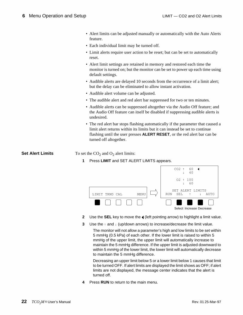
Set Alert Limits To set the CO2 and O2 alert limits:
1 Press LIMIT and SET ALERT LIMITS appears.
2 Use the SEL key to move the (left pointing arrow) to highlight a limit value.
3 Use the ↑ and ↓ (up/down arrows) to increase/decrease the limit value.
The monitor will not allow a parameter’s high and low limits to be set within 5 mmHg (0.5 kPa) of each other. If the lower limit is raised to within 5 mmHg of the upper limit, the upper limit will automatically increase to maintain the 5 mmHg difference. If the upper limit is adjusted downward to within 5 mmHg of the lower limit, the lower limit will automatically decrease to maintain the 5 mmHg difference.
Decreasing an upper limit below 5 or a lower limit below 1 causes that limit to be turned OFF. If alert limits are displayed the limit shows as OFF; if alert limits are not displayed, the message center indicates that the alert is turned off.
4 Press RUN to return to the main menu.
CO2 ↑ 60↓ 40
O2 ↑ 100↓ 60
SET ALERT LIMITSRUN SEL ↑ ↓ AUTOLIMIT TRND CAL MENU
Select Increase Decrease

LIMIT — CO2 and O2 Alert Limits Menu Operation and Setup 6
25-Mar-97 Rev. 01 TCO2M® User’s Manual 23
Auto Alert Limits Auto Alerts allow the user to bracket alert limits about the CO2 and O2 display values.
To set Auto Alert Limits:
1 Press LIMIT and SET ALERT LIMITS appears
2 Press AUTO. The alerts are bracketed about the display value.
Auto alerts are bracketed about the display value for CO2 and O2. If one or both parameters is displaying a value less than 10 mmHg (1 kPa) when AUTO is pressed, the message NOT ENOUGH DATA TO SET AUTO LIMITS is briefly displayed and that parameter’s limits are not adjusted; however, the other parameter’s limits will be adjusted.
Carbon Dioxide Auto Alert-Limit Determinations:
Oxygen Auto Alert-Limit Determinations:
Limit Alerts Definitions: Limit Alerts—audible and visible signals from the monitor, aregenerated in response to CO2 or O2 values outside the range of the Alert Limits—themaximum and minimum allowable values for CO2 or O2.
If the PtcCO2 or PtcO2 value violates an alert limit setting;
• The violated alert limit (if displayed) starts to flash. If limit values are not displayed, an ↑ or ↓ arrow flashes beside the CO2 or O2 display identifier.
• The red (bell-shaped) indicator beside the ALERT RESET key flashes.
• A message flashes in the Message Center (e.g., CO2-LOW).
If the value returns within its limits within 10 seconds (if 10 sec alert delay is on);
• The red indicator, violated limit display and alert message stop flashing.
If the limit alert lasts for more than 10 seconds (or the 10 sec alert delay is off);
PtcCO2 Display Value PtcCO2 Limit Setting
PtcCO2 ≤ 10 mmHg no change
10 mmHg < PtcCO2 < 41 mmHg PtcCO2 ± (PtcCO2/4) mmHg
PtcCO2 > 40 mmHg PtcCO2 ± 10 mmHg
PtcO2 Display Value PtcO2 Limit Setting
PtcO2 ≤ 10 mmHg no change
10 mmHg < PtcO2 < 101 mmHg PtcO2 ± 10 mmHg
PtcO2 > 100 mmHg PtcO2 ± 20 mmHg
CO2 ↑ 60↓ 40
O2 ↑ 100↓ 60
SET ALERT LIMITSRUN SEL ↑ ↓ AUTOLIMIT TRND CAL MENU

6 Menu Operation and Setup TRND — Real time trend displays
24 TCO2M® User’s Manual Rev. 01 25-Mar-97
• An audible alarm will sound and the red alert bar flashes. Two Minute Silence, Audio Off and Alert Delay will suppress the audible alert. Two Minute Silence and Alert Delay will suppress the flashing red alert bar.
If the value returns within limits after 10 seconds of alerting
• The audible alarm and red alert bar will turn off.
• The red indicator and violated limit display (value or arrow) continue to flash until the user presses the ALERT RESET key. (This allows the user to determine which limit was violated.)
TRND — Real time trend displays
Real Time Trend The TCO2M can display real time graphic trends of CO2, O2 and Local Power data.The user can easily customize the real time trends to show the most recent 10, 20 or30 minutes of CO2, O2 or Local Power data, and to change the vertical scale asneeded.
Show CO2 /O2/LP To change real time graphic trend to reflect CO2, O2, or LP data:
1 Press TRND and SELECT TREND DISPLAY appears.
2 Press CO2, O2 or LP to select the desired parameter.
The softkey for the currently displayed parameter flashes.
3 Press RUN to return to the base menu.
Set Trend Time To change real time graphic trend time scale:
1 Press TRND and SELECT TREND DISPLAY appears.
Vertical ScaleHigh End Point
Low End Point
Displayed Time Scale
Vertical ScaleScale Span Here is ∆40 torr
(Real Time Trend Display)
LIMIT TRND CAL MENU
Select a parameter to trend
SELECT TREND DISPLAYRUN FULL CO2 O2 LP

TRND — Real time trend displays Menu Operation and Setup 6
25-Mar-97 Rev. 01 TCO2M® User’s Manual 25
2 Press and hold CO2, O2 or LP until ADJUST TREND SETTINGS appears.
3 If in Step 2, you pressed CO2 or O2, now press SEL twice to highlight TIME.Press ↑ or ↓ (up/down arrows) to select a 10, 20, or 30 minute time scale.Skip to Step 5.
4 If in Step 2, you pressed LP, now press TIME repeatedly to select a 10, 20,or 30 minute time scale.
5 Press RUN to return to the base menu.
Set CO2/O2 scale To change the real time graphic trend scale for CO2 or O2:
1 Press TRND and SELECT TREND DISPLAY appears.
2 Press and hold CO2 or O2 until ADJUST TREND SETTINGS appears.
3 To change the scale, press the ↑ or ↓ (up/down arrows) to select the desireddelta—the distance between HI and LOW values.
LIMIT TRND CAL MENU
Select a parameter,
SELECT TREND DISPLAYRUN FULL CO2 O2 LP
then press & hold
REAL TIME TREND - CO2
SCALE: ∆040 torrHI/LO: 060/020TIME: 30 minutes
ADJUST TREND SETTINGSRUN SEL ↑ ↓ PREV
REAL TIME TREND - CO2
SCALE: ∆040 torrHI/LO: 060/020TIME: 30 minutes
ADJUST TREND SETTINGSRUN SEL ↑ ↓ PREV
Press twice Select time
LP = +117mW LPR = 000mWRUN SET TIME PREV
Select time
LIMIT TRND CAL MENUSELECT TREND DISPLAYRUN FULL CO2 O2 LP
Select parameterthen press and hold

6 Menu Operation and Setup TRND — Real time trend displays
26 TCO2M® User’s Manual Rev. 01 25-Mar-97
The vertical scale changes in units of 40 (e.g., 40, 80 120, etc.).The actual start and end points are determined by the HI/LO selection detailed next.
4 To change the actual HI and LOW scale values, press SEL to highlight HI/LO and then press the ↑ or ↓ (up/down arrows) to select the desired pointson the scale.
The selected scale requires a start and stop point for display on the vertical axis. These points can be adjusted here. The end points for the vertical axis will change keeping the chosen scale as the determining factor of the high and low values. For example; if the scale is set at 40, the HI/LO values will always be 40 units part, the high end point will be 40 units higher than the low point.
5 Press RUN to return to the base menu.
Local Power(LP and LPR)
Once the sensor is stabilized on the skin, the Local Power Reference (LPR) can beset. The LPR shows the amount of electrical power required by the sensor to maintainits operating temperature. The unit of power measure is the milliwatt (mW). Once set,the LPR value will not vary until a new value is set by the user (see below). Any real-time fluctuations to the LPR value (caused by changes in heater power requirements)are displayed as a plus or minus value in the Local Power (LP) display and in the realtime LP trend as values above (more power) and below (less power) the centerline(the LPR value).1
To set the local power reference:
1. For further information refer to; Peabody, J.L. Willis, M.M. et al. Reliability of Skin (tc)PO2 Electrode Heating Poweras a Continuous Noninvasive Monitor of Mean Arterial Pressure in Sick Newborns. Continuous Transcutaneous BloodGas Monitoring 1979: 127-133. Refer also to; A User’s Guide to Transcutaneous Gas Monitoring Novametrix MedicalSystems Inc., Medical Education Division, September 1983.
REAL TIME TREND - CO2
SCALE: ∆040 torrHI/LO: 060/020TIME: 30 minutes
ADJUST TREND SETTINGSRUN SEL ↑ ↓ PREV
REAL TIME TREND - CO2
SCALE: ∆040 torrHI/LO: 060/020TIME: 30 minutes
ADJUST TREND SETTINGSRUN SEL ↑ ↓ PREV
REAL TIME TREND - CO2
SCALE: ∆040 torrHI/LO: 060/020TIME: 30 minutes
ADJUST TREND SETTINGSRUN SEL ↑ ↓ PREV

TRND — Trend Page (stored trend memory) displays Menu Operation and Setup 6
25-Mar-97 Rev. 01 TCO2M® User’s Manual 27
1 Press TRND and SELECT TREND DISPLAY appears.
2 Press and hold the LP softkey until the LP and LPR values appear.
3 Press SET to set the local power reference.
4 Press RUN to return to the base menu.
TRND — Trend Page (stored trend memory) displays
The TCO2M maintains trend information for CO2, O2, and local heater power. The24-hour battery backed trend memory is continually and automatically updated everyeight seconds. Trend displays are user selectable to show any 12, 8, 4, or 2 hour, or30 minute portion of trend memory as a graphical trend or histogram. User selected“Events” are stored in trend memory and displayed. Trend memory can be erased viathe monitor startup or Trend Page menus—trend memory is not erased by a simplepower off-power on cycle.
New trend data is continually collected and enters the graph from the right—pushingolder already displayed data towards the left. (If less than 12 hours of data have beencollected, the graph will be shortened accordingly.) Points in the trend where themonitor was turned off are indicated by dotted vertical lines.
LIMIT TRND CAL MENUSELECT TREND DISPLAYRUN FULL CO2 O2 LP
Press & Hold
LP = +117mW LPR = 000mWRUN SET TIME PREV
LP = +000mW LPR = 117mWRUN SET TIME PREV
Set LP value as new LPR value
Month and Date Time
Moves Cursor Left/Right
Trend Identifier &
Values at Cursor location
Alert MessagesTrend Duration
Event marked
Power On/Off indicator
Cursor

6 Menu Operation and Setup TRND — Trend Page (stored trend memory) displays
28 TCO2M® User’s Manual Rev. 01 25-Mar-97
A cursor, the dashed vertical line flashing in the display, can be moved along the timebase to display the CO2, O2, and local power value at any point in the trend. Thecursor is controlled by left and right arrow keys. Press and hold the softkey to increasecursor speed.
Information displayed above the graph is specific to the data at the cursor. Theinformation above the graph includes; the date in the form DDMMMYY (30SEP96), thetime in 24 hour format in the form HH:MM:SS (13:30:00 = 1:30 p.m.), CO2 and O2 inmmHg or kPa as the monitor is configured, and LP in mW.
EVENT is displayed when the cursor is moved over a area in the trend where anEvent was marked by the user.
Show trend page To display the full trend page:
1 Press the TRND softkey and SELECT TREND DISPLAY appears.
2 Press FULL and the Trend Page display appears.
3 Press RUN to return to the base menu.
Moving in trend To navigate through the trend page display:
1 Display the trend page (press TRND then FULL).
2 Move the cursor by pressing the <- or -> (arrow keys) to the desired time.Press the <- (arrow left) key to move the cursor towards older data.Press the -> (arrow right) key to move the cursor towards more recent data.
Information displayed above the graph is specific to the data at the cursor—the flashing dashed vertical line in the display.
3 Press the EXPAND softkey.
Successive presses of the EXPAND key cycles through the 12, 8, 4 and 2 hour and 30 minute trend displays. Expansion occurs about the cursor.
4 Use the arrow keys to fine tune the cursor to the desired location in the trend.
The TCO2M continues uninterrupted patient monitoring while displaying trends.Alerts that occur are identified in the lower left corner of the trend page display.If no keys are pressed for 5 minutes, the base menu replaces the trend display.
LIMIT TRND CAL MENUSELECT TREND DISPLAYRUN FULL CO2 O2 LP
TREND-CO2 12Hr RUN EXPAND <- -> NEXT
older newer

TRND — Trend Page (stored trend memory) displays Menu Operation and Setup 6
25-Mar-97 Rev. 01 TCO2M® User’s Manual 29
5 Press RUN to return to the base menu.
Select trend page parameter
When first selected, the trend page will display the same parameter as displayed bythe real time trend. The user can change the trend page to display LP as well as CO2or O2 (provided the sensor in use supports those parameters).
To change to the trend page display parameter:
1 Display the trend page (press TRND then FULL).
2 Press NEXT. The available trend page parameters are listed.
3 Press the CO2, O2, or LP key to display that parameter in the trend page.
Select trend scale Each of the trend page supported parameters, CO2, O2 and LP, can be viewed usinga “half” or “full” scale display setting. Each parameter scale is independent of theothers.
To change the trend page display scale of a parameter.
1 Display the trend page and select the parameter you desire.
2 Press NEXT.
3 Press SCALE and then select either the HALF or FULL scale setting.
CO2: Half 0-60, Full 0-100. O2 and LP: Half 0-100, Full 0-200
Show histogram The histogram display provides a tabulated summary of CO2 and O2 trend data.
The histogram display reflects the currently selected graphical trend expansionsetting. For example, if the graphic display is set to 12 hours, the resulting histogramwill also reflect that 12 hours; and if the graphic display is set to 30 minutes, theresulting histogram only uses those 30 minutes as the basis for its tabulations. Thetop line of the histogram display shows the start and stop dates and times (24 hourformat) used to tabulate the data.
TREND-CO2 12Hr RUN SCALE O2 LP NEXT
TREND-O2 12Hr RUN SCALE CO2 LP NEXT
TREND-LP 12Hr RUN SCALE CO2 O2 NEXT
CO2 Displayed
O2 Displayed
LP Displayed
TREND-CO2 12Hr RUN SCALE O2 LP NEXT
TREND-CO2 HALF FULL

6 Menu Operation and Setup TRND — Trend Page (stored trend memory) displays
30 TCO2M® User’s Manual Rev. 01 25-Mar-97
CO2 and O2 data is tabulated into six categories. Each category represents a range ofpossible values. For each category, a bar graph is drawn showing the percentage ofthe total time the parameter was within the category. To the right of the bar graphs arenumerical tabulations also showing how long the parameter was within that category.(Rounding errors may keep the total from being 100%).
To view the histogram page:
1 Press the TRND softkey and SELECT TREND DISPLAY appears.
2 Press FULL and the Trend Page display appears.
3 Press NEXT twice.
4 Press HIST (histogram) and the histogram page appears.
5 Press PREV to return to the trend page display- or -Press RUN to return to the base menu.
Erase trend memory To erase the stored trends:
1 Press the TRND softkey and SELECT TREND DISPLAY appears.
2 Press FULL and the Trend Page display appears.
3 Press NEXT twice.
Tabulation Start Time/Date
Identifier &Alert Messages
Histogram Duration
Tabulation Stop Time/Date
Categories
Graphic, % time in category
% time in category
TREND-CO2 12Hr RUN ERASE HIST NEXT

CAL — Sensor calibration Menu Operation and Setup 6
25-Mar-97 Rev. 01 TCO2M® User’s Manual 31
4 Press ERASE and ERASE STORED TRENDS? appears.
5 Press YES to permanently erase the contents of the trend memory- or -Press NO to cancel the function and leave trend memory intact.
If YES, then ERASING TREND PLEASE WAIT is briefly displayed, followed briefly by TREND ERASED. The base menu then reappears.
If NO, TREND RETAINED is briefly displayed. The trend page reappears.
Trend Data Compression
CO2, O2 and LP data is stored in trend memory every eight seconds. The TCO2M candisplay any 12, 8, 4, or 2 hour or 30 minute portion of its 24 hour trend memory. Sincethe size of the trend display is a fixed width, the monitor must compress the trend datato fit onto the display—the more data present, the more it must be compressed to fitonto the display. The TCO2M trend display is approximately 200 pixels (picture-element) wide. Each horizontal pixel (data point) is equivalent to the following times;
1 data point per 8 seconds in a 30 minute trend1 data point per 32 seconds in a 2 hour trend1 data point per 64 seconds in a 4 hour trend1 data point per 128 seconds (approx. 2 minutes) in an 8 hour trend1 data point per 192 seconds (approx. 3 minutes) in an 12 hour trend
The monitor determines the trend duration and compresses that amount of data to fitthe screen—older data to the left, the most recent to the right. Because of the datacompression, data at any horizontal pixel may look like a vertical bar. The upperextent of the bar represents the maximum value and the bottom of the bar theminimum value stored during that particular compression period. The valuesdisplayed above the graph represent the minimum values stored over the compressionperiod.
CAL — Sensor calibration
The TCO2M attempts to simplify sensor calibration by combining various aspects ofsensor calibration under a single CALibration menu feature. This section details thesteps necessary to properly select and configure sensor temperature, barometricpressure, and site timer settings, as well as detailing the Last Calibration informationdisplay.
Calibrate sensor Refer to “Sensor Calibration” on page 37, to actually perform a sensor calibration.
TREND-CO2 12Hr RUN ERASE HIST NEXT
ERASE STORED TRENDS? YES NO

6 Menu Operation and Setup CAL — Sensor calibration
32 TCO2M® User’s Manual Rev. 01 25-Mar-97
Set temperature The transcutaneous sensor is heated to facilitate the diffusion of CO2 and O2 throughthe skin to the sensor. When the TCO2M is powered up, the sensor is automaticallyheated to the operating temperature that was last selected by the user. Thistemperature may be set from 37° C to 45° C in 0.5° C steps.
The actual sensor temperature is normally displayed in the base menu. Note that untilthe sensor temperature rises above 30° C, the display will show “--.-”.
Sensor calibration is based, in part, on the sensor temperature. Therefore, the sensorshould be calibrated at operating temperature. If the temperature setting is changedby more than 0.5° C, the sensor should be recalibrated at the new temperature. See“Sensor Calibration” on page 37. The recommended sensor temperatures are:
To change the temperature setting:
1 Press CAL and SENSOR CALIBRATION appears. The temperature settingis displayed.
2 If the temperature needs adjustment, press SET and CAL SETTINGSappear.
3 With the (highlight triangle) beside the TEMPERATURE setting, press the↑ or ↓ keys to change the temperature to the desired value.
4 Press RUN to return to the base menu- or -Press PREV to return to the SENSOR CALIBRATION menu.
Cat. No. Sensor Type Neonate Adult
4474 Combination O2/CO2 Sensor 44° C 44° C
6752 Carbon Dioxide Sensor 44° C 44° C6754 Oxygen Sensor 43-44° C 44-45° C
-CALIBRATION SETTINGS-
TEMPERATURE = 44.0°CSITE TIMER = 04:00BAROMETRIC = 760 mmHg
SENSOR CALIBRATIONRUN START SET INFOLIMIT TRND CAL MENU
CAL SETTINGS:TEMPERATURE = 44.0°CBAROMETRIC = 760 mmHgRESET TIMER = NOSITE TIMER = 04:00(REMAINING = 04:00)
RUN SEL ↑ ↓ PREV

CAL — Sensor calibration Menu Operation and Setup 6
25-Mar-97 Rev. 01 TCO2M® User’s Manual 33
Site Timer Because the transcutaneous sensors are heated to aid in the diffusion of CO2 and O2from the skin to the sensor, the location of the sensor on the skin must be changedperiodically to avoid heat induced damage to the skin at the sensor site. The TCO2Mhas a site timer feature to remind the user to change the sensor site.
Generally, for neonates, the sensor site should be changed every 2-4 hours whenusing a temperature of 44° C, and every 4-6 hours at a sensor temperature of 43° C.For adults, the sensor site should be changed every 4-6 hours when using atemperature of 44° C. Note that these times are guidelines only. The user shouldverify the duration for each patient.
The monitor’s site timer is automatically reset, to the user preselected duration, at theconclusion of each successful sensor calibration, and when the RESET TIMER optionis set to YES in the CAL SETTINGS menu. A SENSOR SITE TIMER IS RESET TOXX:XX message (where xx:xx is the time in hours and minutes) is briefly displayedafter calibration of the sensor. If the site timer is turned off (set to 00:00) a SENSORSITE TIMER IS OFF message is briefly displayed.
Once the site timer’s remaining time expires, the alert indicator starts to flash asdoes the red alert bar. An audible alarm will sound, overriding a disabled audible alert(Audio Off), and the message center will display S- TIMER EXPRD. The user shouldthen remove the sensor from the patient. The two minute silence procedure willsuppress the audible alert.
If the user does not reset the site timer alert within 10 minutes, the monitor willautomatically shut down the heater power to the sensor, thus eliminating the riskassociated with continued heating of the skin. If sensor heater power shutdownoccurs, the message center flashes 10 MIN SITE TIMER EXPIRED and an audiblealarm will sound overriding audio off mode if enabled. The user must then reset thesite timer in the CAL SETTINGS portion of the SENSOR CALIBRATION menu.
Reset site timer To reset the site timer to its original duration (REMAINING=SITE TIMER):
1 Press CAL and SENSOR CALIBRATION appears.
WARNING: The location of the sensor must be changed periodically toeliminate the risk of skin damage due to the heating of the skin by thesensor. Risk of such skin damage depends on sensor temperature, durationof application, and physiological parameters including local perfusion, bodytemperature and skin thickness.
!
-CALIBRATION SETTINGS-
TEMPERATURE = 44.0°CSITE TIMER = 04:00BAROMETRIC = 760 mmHg
SENSOR CALIBRATIONRUN START SET INFOLIMIT TRND CAL MENU

6 Menu Operation and Setup CAL — Sensor calibration
34 TCO2M® User’s Manual Rev. 01 25-Mar-97
2 Press SET and CAL SETTINGS appear.
3 Press SEL to move the (highlight triangle) beside the RESET TIMERsetting.
4 Press the ↑ or ↓ keys to change the setting from NO to YES.
5 Press RUN to return to the base menu- or -Press PREV to return to the SENSOR CALIBRATION menu.
Adjust site timer To adjust the site timer duration:
1 Press CAL and SENSOR CALIBRATION appears. The site timer setting isdisplayed.
2 If the site timer needs adjustment, press SET and CAL SETTINGS appear.
3 Press SEL to move the (highlight triangle) beside the SITE TIMER setting.
4 Press the ↑ or ↓ keys to change the site timer to the desired value.
5 Press RUN to return to the base menu- or -Press PREV to return to the SENSOR CALIBRATION menu.
CAL SETTINGS:TEMPERATURE = 44.0°CBAROMETRIC = 760 mmHg
RESET TIMER = YESSITE TIMER = 04:00(REMAINING = 04:00)
RUN SEL ↑ ↓ PREV
CAL SETTINGS:TEMPERATURE = 44.0°CBAROMETRIC = 760 mmHg
RESET TIMER = NOSITE TIMER = 04:00(REMAINING = 04:00)
RUN SEL ↑ ↓ PREV
-CALIBRATION SETTINGS-
TEMPERATURE = 44.0°CSITE TIMER = 04:00BAROMETRIC = 760 mmHg
SENSOR CALIBRATIONRUN START SET INFOLIMIT TRND CAL MENU
CAL SETTINGS:TEMPERATURE = 44.0°CBAROMETRIC = 760 mmHgRESET TIMER = NOSITE TIMER = 04:00(REMAINING = 04:00)
RUN SEL ↑ ↓ PREV

DELAY — Suppress limit alerts Menu Operation and Setup 6
25-Mar-97 Rev. 01 TCO2M® User’s Manual 35
Last Calibration information
Once a sensor is calibrated, the calibration information is retained memory. This LastCalibration information can be displayed and “remembered” even if the sensor isremoved or the monitor is turned off and back on. (If the TCO2M memory is reset tofactory defaults, the message UNKNOWN appears until a calibration is performed.)
To view information about the Last Calibration:
1 Press CAL and SENSOR CALIBRATION appears.
2 Press INFO and LAST CALIBRATION appears.
3 Press CAL to return to the SENSOR CALIBRATION menu.- or -Press RUN to return to the base menu.
DELAY — Suppress limit alerts
Set Alert Delay To delay for ten minutes the audible alert and flashing red alert bar associated withan alert limit violation:
1 Press MENU and SYSTEM OPTIONS appears.
2 Press DELAY.
3 The display briefly shows LIMIT ALERTS DELAYED 10 MINUTES.
4 The base menu reappears and ALERT DELAY flashes in the messagecenter.
The indicator starts flashing and the red alert bar will not flash for ten minutes; after which the will turn off and the audible alert and red alert bar will again be enabled.
LAST CALIBRATIONTime=16:26 Date=04OCT96Temp=44.0°C Bar=760 mmHgCal Duration=01:54Site Timer=04:00Sensor Type= CO2 & O2
RUN CAL
LIMIT TRND CAL MENUSYSTEM OPTIONS
RUN DELAY LITE AUDIO
LIMIT ALERTS DELAYEDFOR 10 MINUTES
ALERT DELAYLIMIT TRND CAL MENU

6 Menu Operation and Setup LITE — Display brightness
36 TCO2M® User’s Manual Rev. 01 25-Mar-97
Note that if Audio Off is in effect when DELAY is pressed, the red alert bar is suppressed for 10 minutes and the Audio Off condition is unaffected.
Cancel Alert Delay To enable the audible alert and red alert bar prior to expiration of the 10 minute AlertDelay:
1 Press the key.
The indicator turns off, ALERT DELAY is removed from the message center, and the limit alerts (audible and red alert bar) become active again.
LITE — Display brightness
To adjust the display brightness:
1 Press MENU and SYSTEM OPTIONS appears.
2 Press LITE and the displays toggles between bright and dim settings.
AUDIO — Adjust alert volume
To adjust the audible alert volume:
1 Press MENU and SYSTEM OPTIONS appears.
2 Press AUDIO and SET ALERT VOLUME appears.
3 Press the ↑ (up arrow) key to make the audible alert tone louder (07 max).- or -Press the ↓ (down arrow) key to make the audible alert tone quieter (01 min).
4 Press RUN to return to the base menu.
LIMIT TRND CAL MENUSYSTEM OPTIONS
RUN DELAY LITE AUDIO
LIMIT TRND CAL MENUSYSTEM OPTIONS
RUN DELAY LITE AUDIO
SET ALERT VOLUMERUN ↑ 04 ↓ PREV
Loud Quiet
Current volume01- Min07 - Max

25-Mar-97 Rev. 01 TCO2M® User’s Manual 37
7 Sensor Calibration
Sensor Calibration with the TCO2M Calibrator Model 868
This section describes the steps necessary to calibrate a transcutaneous sensorconnected to the TCO2M Monitor, using the TCO2M Calibrator, Model 868.
To calibrate a sensor:
1 Ensure the sensor is properly prepared and connected to the monitor, thecalibrator is connected, the monitor is on, and the sensor is at operatingtemperature.
2 Swing the Calibrator’s sensor port cover up to expose the Sensor Port.
3 Place the sensor into the Sensor Port.
4 Swing the cover piece down so as to secure the sensor in place.
5 Press the CAL softkey. The CALIBRATION SETTINGS menu appears.
Between site changes, clean the NOVADISK face (alcohol wipe) prior toplacing in the calibrator. Lotions, skin oils or other residue may influencecalibration.
Step #1 Step #2 Step #3
-CALIBRATION SETTINGS-
TEMPERATURE = 44.0°CSITE TIMER = 04:00BAROMETRIC = 760 mmHg
SENSOR CALIBRATIONRUN START SET INFOLIMIT TRND CAL MENU

7 Sensor Calibration Sensor Calibration with the TCO2M Calibrator Model 868
38 TCO2M® User’s Manual Rev. 01 25-Mar-97
6 Verify the setting for temperature and site timer are as desired and that thebarometric pressure display is correct. If so, skip ahead to Step 11.
7 Press SET and the CAL SETTINGS menu appears.
8 Use the SEL key to move the selection triangle to highlight TEMPERATURE.Use the ↑ or ↓ keys select the desired temperature.
9 Use the SEL key to move the selection triangle to highlight SITE TIMER.Use the ↑ or ↓ keys select the desired timer duration.
10 Press PREV (previous) to return to the CALIBRATION SETTINGS menu.
11 Press START. Calibration begins.
If START is not displayed, but 1pt and 2pt are, skip to “O2 Sensor Recalibration” on page 40.
The calibrator’s LOW GAS indicator lights and CALIBRATING LOW appears in the message center. Once the sensor stabilizes, the calibrator’s HIGH GAS indicator lights and CALIBRATING HIGH appears in the message center.
12 Calibration is complete when a beep sounds and CALIBRATION DONEappears.
13 Press RUN to return to the main menu.- or -Press INFO to display the just completed LAST CALIBRATION, then pressRUN.
14 Remove the sensor from the calibrator.
The sensor is now properly calibrated and may be applied to the patient.
Pressing RUN resets the site timer. The timer value is briefly displayed.
For 10 minutes after pressing RUN, limit alerts are suppressed. This allowsthe sensor to be applied to the patient and begin stabilizing without limitviolations becoming a nuisance. To enable limit alerts prior to the 10 minutedelay, press the key. The indicator turns off and alerts are enabled.
-CALIBRATION SETTINGS-
TEMPERATURE = 44.0°CSITE TIMER = 04:00BAROMETRIC = 760 mmHg
SENSOR CALIBRATIONRUN START SET INFO
CAL SETTINGS:TEMPERATURE = 44.0°CBAROMETRIC = 760 mmHgRESET TIMER = NOSITE TIMER = 04:00(REMAINING = 04:00)
RUN SEL ↑ ↓ PREV
CALIBRATION VALUES
CO2:38,76O2: 0,91760 mmHg
CALIBRATION DONE - 02:29RUN INFO
Your values maydiffer from thoseshown here.

Manual Calibration of the O2 Sensor Sensor Calibration 7
25-Mar-97 Rev. 01 TCO2M® User’s Manual 39
Manual Calibration of the O2 Sensor
The Oxygen Sensor is unique in that it can be calibrated without the use of the Model868 Calibrator by using “Zero Solution” and “Room Air”.
O2 Sensor Initial Calibration
The Oxygen Sensor 6754-00 can be calibrated using Zero Solution (Cat. No. 8231)and “Room Air” in lieu of the Model 868 Transcutaneous Calibrator.
To initially calibrate the Oxygen Sensor 6754-00 using Zero Solution and room air:
1 Ensure the Oxygen Sensor 6754-00 is properly prepared and connected tothe monitor, the monitor is turned on, and the sensor is at operatingtemperature.
2 Press the CAL softkey. The CALIBRATION SETTINGS menu appears.
3 Verify the setting for temperature and site timer are as desired and that thebarometric pressure display is correct. If so, skip ahead to Step 8.
4 Press SET and the CAL SETTINGS menu appears.
5 Use the SEL key to move the selection triangle to highlight TEMPERATURE.Use the ↑ or ↓ keys select the desired temperature.
6 Use the SEL key to move the selection triangle to highlight SITE TIMER.Use the ↑ or ↓ keys select the desired timer duration.
7 Press PREV (previous) to return to the CALIBRATION SETTINGS menu.
8 Grasp a Zero Solution dispenser (PN: 8231) with the thumb and forefinger.Hold the dispenser upright and point the tip away from yourself. Squeeze the
Between site changes, clean the NOVADISK face (alcohol wipe) prior toplacing in the calibrator. Lotions, skin oils or other residue may influencecalibration.
-CALIBRATION SETTINGS-
TEMPERATURE = 44.0°CSITE TIMER = 04:00BAROMETRIC = 760 mmHg
SENSOR CALIBRATIONRUN START SET INFOLIMIT TRND CAL MENU
-CALIBRATION SETTINGS-
TEMPERATURE = 44.0°CSITE TIMER = 04:00BAROMETRIC = 760 mmHg
SENSOR CALIBRATIONRUN START SET INFO
CAL SETTINGS:TEMPERATURE = 44.0°CBAROMETRIC = 760 mmHgRESET TIMER = NOSITE TIMER = 04:00(REMAINING = 04:00)
RUN SEL ↑ ↓ PREV

7 Sensor Calibration Manual Calibration of the O2 Sensor
40 TCO2M® User’s Manual Rev. 01 25-Mar-97
dispenser so that the ampule inside the dispenser breaks. Once opened, thedispenser has a useful life of forty-eight hours.
9 Lightly tap the bottom of the dispenser on a hard surface so that the brokenampule pieces settle to the bottom.
10 Apply a drop of zero solution to the sensor face. Ensure that the solutioncovers the sensor cathode (dark spot in the center of the sensor face).
11 Press START from the CALIBRATION SETTINGS menu.
If START is not displayed, but 1pt and 2pt are, skip to “O2 Sensor Recalibration” on page 40.
12 CALIBRATING LOW appears on the display. As soon as CALIBRATING RMAIR appears, completely remove the Zero Solution from the sensor faceusing a tissue or gauze. (Do not leave Zero Solution on the membrane forlonger than 3 minutes.)
13 Calibration is complete when a beep sounds and CALIBRATION DONEappears.
14 Press RUN to return to the main menu.- or -Press INFO to display the just completed LAST CALIBRATION, then pressRUN.
15 The sensor is now properly calibrated and may be applied to the patient.
O2 Sensor Recalibration
Once the Oxygen Sensor 6754-00 is calibrated using a two-point method (using Lowand High Gas with a gas calibrator, or using Zero Solution and room air) subsequentrecalibration of the sensor, as long as the sensor is not disconnected or the monitor
CAUTION: Zero Solution must NOT be applied directly to the sensor facewithout a NOVADISK membrane assembly in place.
Pressing RUN resets the site timer. The timer value is briefly displayed.
For 10 minutes after pressing RUN, limit alerts are suppressed. This allowsthe sensor to be applied to the patient and begin stabilizing without limitviolations becoming a nuisance. To enable limit alerts prior to the 10 minutedelay, press the key. The indicator turns off and alerts are enabled.
CALIBRATION VALUES
O2: 0,157760 mmHg
CALIBRATION DONE - 01:48RUN INFO
Your values maydiffer from thoseshown here.

Manual Calibration of the O2 Sensor Sensor Calibration 7
25-Mar-97 Rev. 01 TCO2M® User’s Manual 41
turned off, may be done using a one-point “High” calibration, again using High Gasand the calibrator or Room Air.
To recalibrate the Oxygen Sensor 6754-00 using a one-point calibration:
1 Press the CAL softkey. The CALIBRATION SETTINGS menu appears.
2 Verify the setting for temperature and site timer are as desired and that thebarometric pressure display is correct. If so, skip ahead to Step 7.
3 Press SET and the CAL SETTINGS menu appears.
4 Use the SEL key to move the selection triangle to highlight TEMPERATURE.Use the ↑ or ↓ keys select the desired temperature.
5 Use the SEL key to move the selection triangle to highlight SITE TIMER.Use the ↑ or ↓ keys select the desired timer duration.
6 Press PREV (previous) to return to the CALIBRATION SETTINGS menu.
7 From the CALIBRATION SETTINGS menu press the 1pt (one-point) key.
Pressing 2pt (two-point) starts a calibration using Zero Solution and Room Air, or if the Calibrator is connected, a Low and High Gas calibration.
8 If CALIBRATING RM AIR appears ensure the sensor is exposed to room air.If CALIBRATING HIGH appears put the sensor into the Calibrator’s SensorPort.
CAUTION: If a one-point recalibration is performed while the gas calibrator isconnected to the TCO2M, the monitor assumes the recalibration should take placein High Gas and not in room air. Therefore, if using the gas calibrator, place thesensor into the calibrator’s Sensor Port before performing a one-point recalibration.
Between site changes, clean the NOVADISK face (alcohol wipe) prior toplacing in the calibrator. Lotions, skin oils or other residue may influencecalibration.
-CALIBRATION SETTINGS-
TEMPERATURE = 44.0°CSITE TIMER = 04:00BAROMETRIC = 760 mmHg
SENSOR CALIBRATIONRUN 1pt 2pt SET INFOLIMIT TRND CAL MENU
-CALIBRATION SETTINGS-
TEMPERATURE = 44.0°CSITE TIMER = 04:00BAROMETRIC = 760 mmHg
SENSOR CALIBRATIONRUN 1pt 2pt SET INFO
CAL SETTINGS:TEMPERATURE = 44.0°CBAROMETRIC = 760 mmHgRESET TIMER = NOSITE TIMER = 04:00(REMAINING = 04:00)
RUN SEL ↑ ↓ PREV

7 Sensor Calibration Manual Calibration of the O2 Sensor
42 TCO2M® User’s Manual Rev. 01 25-Mar-97
9 Calibration is complete when a beep sounds and CALIBRATION DONEappears.
10 Press RUN to return to the main menu.- or -Press INFO to display the just completed LAST CALIBRATION, then pressRUN.
11 The O2 Sensor is now properly recalibrated and may be reapplied to thepatient.
Pressing RUN resets the site timer. The timer value is briefly displayed.
For 10 minutes after pressing RUN, limit alerts are suppressed. This allowsthe sensor to be applied to the patient and begin stabilizing without limitviolations becoming a nuisance. To enable limit alerts prior to the 10 minutedelay, press the key. The indicator turns off and alerts are enabled.
CALIBRATION VALUES
O2: 0,91760 mmHg
CALIBRATION DONE - 00:45RUN INFO
Your values maydiffer from thoseshown here.

25-Mar-97 Rev. 01 TCO2M® User’s Manual 43
8 Apply Sensor to Patient
The section details the steps necessary to select an appropriate site for monitoring;how to apply the sensor to the site; and, how to remove the sensor from the site.
Sensor Site Selection
Optimal functioning of the transcutaneous monitoring system is dependent uponcareful selection of the sensor site. Select a sensor site with good capillary blood flowwhere an airtight seal between the sensor and the skin may be maintained. Avoidareas with large amounts of fatty deposit or bony prominences which may constrictthe blood flow beneath the surface of the sensor.
For neonates, the most commonly used sensor sites are the upper chest, abdomen andinner aspect of the thigh. If the infant is laying on his side or abdomen, the back issometimes used. If the intended site is on an extremity, a restraint board may be usedto stabilize the area.
Recommended skin sites for adult monitoring are the upper part of the chest andshoulder area. Alternate sites are the inner aspect of the arm, axillary area and upperback.
The skin at the site must be properly prepared. Lotions, skin oils, residue fromadhesive rings or patches, etc., may impede the diffusion of oxygen and/or carbondioxide from the skin to the sensor, or they may keep the adhesive ring from forminga good seal around the site. Clean and degrease the skin with soap and water and thenwipe the area with an alcohol swab. If necessary shave the sensor site.
Neonate
Best 1-2Good 5-9
Good-Fair 3-4, 10-13
Pediatric/Adult
Best 1-2Good-Fair 3-4
Fair 5-6
1 2
3 4
5 6 78 9
10 11
12 13
1 2
3 4
5 6

8 Apply Sensor to Patient Sensor to Patient Application
44 TCO2M® User’s Manual Rev. 01 25-Mar-97
Sensor to Patient Application
Once the monitoring site has been selected and properly prepared, the sensor must beprepared for application to the patient. This section assumes that the sensor is readyfor application (has been remembraned and calibrated).
To apply the sensor to a patient:
1 Grasp a sensor adhesive ring PN:8285 or PN:8805 by the colored tab andpeel it away from the paper backing strip.
2 Attach the adhesive ring to a properly membraned and calibrated sensor bypressing the ring onto the NOVADISK membrane assembly.
Exercise care so that the adhesive ring does not touch the membrane (so the membrane does not get covered or torn). Removal of the sensor and adhesive ring will be easier if the colored tab is not aligned with the sensor cable.
3 Grasp the ring by the colored tab. Peel away the liner to expose theadhesive.
4 Place a drop of transcutaneous sensor contact gel, PN: 8888, onto thecenter of the sensor face.
Note that deionized water may be substituted for contact gel if the application is limited to short periods of time and at lower temperatures (e.g., 2 hours at 43.5 degrees). Using water instead of contact gel may
Tab-not aligned with cable
Do not contact membrane
Step #3
Step #4

Removing the Sensor from the Patient Apply Sensor to Patient 8
25-Mar-97 Rev. 01 TCO2M® User’s Manual 45
improve response time but the membrane/skin interface will dry out more rapidly than with the gel.
5 Press the sensor into place on a properly prepared site. Firmly press theedges of the adhesive ring to the skin, ensuring an airtight seal between theskin and sensor.
6 Optionally, secure the sensor cable with tape at an appropriate distance fromthe sensor. In some cases, a rolled gauze pad under the cable close to thesensor may help minimize sensor movement.
Removing the Sensor from the Patient
To remove the sensor from the skin:
1 Gently peel back the adhesive ring starting from the colored tab.
The adhesive may be loosened from the skin with water or alcohol prior to removal. Care should be taken not to loosen the NOVADISK membrane assembly. If the NOVADISK loosens from the sensor, the sensor must be remembraned with a new NOVADISK and recalibrated before the sensor is reapplied to the patient.
2 Wipe the face of the NOVADISK membrane clean and remove any adhesivering residue with an alcohol wipe before calibrating/or storing.
WARNING: The location of the sensor must be changed periodically to eliminate therisk of burns due to the heating of the skin by the sensor. The risk of such a burn isdependent upon sensor temperature, duration of application, and severalphysiological parameters including, local perfusion, body temperature and skinthickness. Refer to “Site Timer” on page 33 for directions on using the TCO2M sitetimer feature, and guidelines for site application times.
GauzeRoll
Tape
!

8 Apply Sensor to Patient Removing the Sensor from the Patient
46 TCO2M® User’s Manual Rev. 01 25-Mar-97

25-Mar-97 Rev. 01 TCO2M® User’s Manual 47
9 Combination O2/CO2 Sensor
The Combination O2/CO2 Sensor (part number 4474-00 or 4474-39) discussed in thissection allows the TCO2M Transcutaneous Monitor, Model 860, to monitor PtcCO2and PtcO2 levels simultaneously from a single sensor site. If using a different sensortype, refer to its specific instructions elsewhere in this manual.
Sensor Identification The Combination O2/CO2 Sensor is available in two versions. Identify which typeyou will be using as they use different, non-compatible NOVADISK membranes andpreparation procedures. The part number located on the cable identification tag nearthe cable connector identifies the sensor as a 4474-00 or 4474-39 type sensor.
(The 4474-00 sensor is a newer version with shorter stabilization after membraning.The 4474-39 sensor continues to be available so that facilities using this older sensormay benefit by maintaining only one type of sensor/membrane assembly.)
Sensor Construction The Combination O2/CO2 Sensor, consists of a silver colored connector forattachment to the monitor, a white cable assembly, and a GRAY sensor assemblycalled the sensor head. To this GRAY sensor head is attached a NOVADISK membraneassembly that forms the patient-sensor interface.
Sensor Operation A thin layer of electrolyte is placed between the NOVADISK membrane and the sensorhead. Oxygen and carbon dioxide diffuse through the skin, across the contact gellayer between the skin and the membrane, across the membrane and into theelectrolyte where they effect the electro-chemical processes of the sensor and causevalues for CO2 and O2 to be displayed. Sensor calibrations correct for small changesin the electrolyte or the stretching/distorting the membrane that may occur duringpatient application, but after about a week, heat from the sensor starts to evaporatethe electrolyte and the physical stresses on the thin membrane material require theNOVADISK to be replaced.
Membrane Schedule Proper functioning of the transcutaneous gas monitoring system is dependent uponcareful preparation and calibration of the sensor. The gray NOVADISK PremountedMembrane that connects to the sensor and forms the patient-sensor interface must bereplaced under any of the following conditions:
• If there is more than 50% air in the annulus.
• If the membrane has been damaged or the NOVADISK has loosened from the sensor.

9 Combination O2/CO2 Sensor
48 TCO2M® User’s Manual Rev. 01 25-Mar-97
• After 7 days of use or after extended periods of non-use.
4474-00 Sensor Membraning Procedure
The procedure outlines the steps necessary to apply a Presoaked Split MembraneNOVADISK Premounted Membrane assembly (8900-00) to a 4474-00 CombinationO2/CO2 Sensor.
To membrane the 4474-00 Combination sensor:
1 Peel open a Combination O2/CO2 Sensor Split Membrane NOVADISK kit,PN:8900, which includes a dark gray (darker gray than the sensor body)NOVADISK, a white capped electrolyte dispenser, and a cleaning swab.
2 Unscrew the white cap. Discard the cap and blue sealing washer. Leave theclear plastic cap and blue foam insert in place on the NOVADISK.
3 If needed, apply several drops of electrolyte onto the membrane (enoughelectrolyte to coat the membrane).
4 Place the sensor into the black sensor wrench. Unscrew the old NOVADISK
from the sensor and discard. Do not reuse the NOVADISK.
5 Rinse the sensor face with several drops of electrolyte. Allow the electrolyterinse to drip off the sensor face. Do not wipe sensor face with tissue orgauze.
If using a 4474-39 Combination O2/CO2 Sensor, refer to the following section.

Combination O2/CO2 Sensor 9
25-Mar-97 Rev. 01 TCO2M® User’s Manual 49
6 With the sensor upright, apply a generous amount electrolyte from thedispenser to the face of the sensor. Ensure that the fluid fills the annulus.
7 Invert the sensor into the NOVADISK and tighten the NOVADISK securely.Excess electrolyte will be displaced out of the NOVADISK through the smallvent hole.
8 Wipe the excess electrolyte from the sensor and NOVADISK with a tissue orgauze.
9 Remove the clear protective plastic cap and the blue foam insert from theNOVADISK. Do not use a twisting motion when removing the plastic cap.Discard the foam insert. Retain the cap to protect the membrane when thesensor is not in use.
10 Inspect the sensor face for membrane conformity and entrapped air. If theannulus is filled with more than 50% air, a new membrane must be applied.
11 Allow the sensor to stabilize at operating temperature for at least 1/2 hour toensure minimal sensor drift and optimal performance.
12 The 4474-00 sensor is now ready for calibration.
If at any time the NOVADISK assembly loosens from the sensor, the entiremembrane application procedure must be repeated using a newmembrane assembly kit.

9 Combination O2/CO2 Sensor
50 TCO2M® User’s Manual Rev. 01 25-Mar-97
Long Term Combination Sensor Storage
The Combination O2/CO2 Sensor must be stored with electrolyte in contact with thesensor face. Therefore, before storage, follow the appropriate preparation procedure(for 4474-00 or 4474-39 sensors). If the Combination O2/CO2 Sensor is allowed todry out, the cleaning procedure should be followed prior to the preparation of thesensor with a new membrane. If the sensor has not been used for an extended periodof time, the stabilization time after re-membraning may be up to 24 hours.
Cleaning the Combination Sensor face
If the Combination O2/CO2 Sensor exhibits poor O2 performance, including O2calibration errors or slow or erratic O2 response that is not corrected by applying anew NOVADISK membrane, the O2 portion (and NOT the CO2 portion) of the sensorface should be cleaned. The cleaning procedure applies to both the 4474-00 and4474-39 sensors.
To clean the O2 portion of the Combination O2/CO2 Sensor:
1 Place the sensor into the black sensor wrench. Unscrew the old NOVADISK
from the sensor and discard. Do not reuse the NOVADISK.
2 Peel open a Combination O2/CO2 Sensor NOVADISK kit, (PN: 8900 if using a4474-00 sensor, PN: 8575 if using a 4474-39 sensor) and a remove thecleaning swab.
3 Moisten the swab (it is coated with a cleaning abrasive) using only SterileWater for Injection U.S.P., deionized or distilled water. (Do not use SterileWater for Feeding or Irrigation as these may contain added impurities).
4 Rub the swab briskly across the O2 module on the sensor faceapproximately 12 times rotating the swab 90 degrees every 3 strokes. Avoidrubbing the CO2 module in order to minimize CO2 destabilization.
5 Thoroughly flush the sensor face using only Sterile Water for Injection U.S.P.,deionized or distilled water. Ensure that all debris is flushed away.
It should not be necessary to clean the sensor more frequently than once each 3to 5 weeks. The sensor may exhibit CO2 drift of more than 2 mmHg per hour for aslong as 8 hours after cleaning. The sensor may also exhibit artificially high O2readings in the presence of Nitrous Oxide for the first 24 hours of use after cleaning.
O2 CO2 Module Module
Direction ofCleaning Swab

Combination O2/CO2 Sensor 9
25-Mar-97 Rev. 01 TCO2M® User’s Manual 51
6 Dry the face of the sensor with a tissue or gauze. Ensure that the sensor facehas been thoroughly dried and is free of debris. Do not touch the sensor faceonce it has been cleaned.
7 The sensor is now ready for membrane application. Reference theappropriate membrane application procedure (4474-00 or 4474-39). Allowan extra 1 hour for stabilization of a newly cleaned sensor. (If the sensor hasnot been used for an extended period of time, the stabilization time may beup to 24 hours.)
4474-39 Sensor Membraning Procedure
The procedure outlines the steps necessary to apply a NOVADISK PremountedMembrane assembly (8575-00) to a 4474-39 Combination O2/CO2 Sensor.
To membrane the 4474-39 Combination sensor:
1 Peel open a Combination O2/CO2 Premounted Membrane NOVADISK kit,PN:8575, which includes a gray NOVADISK (same gray as the sensor body),a white capped electrolyte dispenser, and a cleaning swab.
2 Unscrew the white cap and discard. Leave the clear plastic cap and bluefoam insert in place on the NOVADISK.
3 Apply several drops of electrolyte onto the membrane in the NOVADISK
(enough to coat the membrane). Allow the electrolyte to soak the membranefor 20 minutes.
4 Place the sensor into the black sensor wrench. Unscrew the old NOVADISK
from the sensor and discard. Do not reuse the NOVADISK.
If using a 4474-00 Combination O2/CO2 Sensor, refer to the previous section.

9 Combination O2/CO2 Sensor
52 TCO2M® User’s Manual Rev. 01 25-Mar-97
5 Rinse the sensor face with several drops of electrolyte. Allow the electrolyterinse to drip off the sensor face. Do not wipe sensor face with tissue orgauze.
6 Remove excess electrolyte from the soaking NOVADISK by shaking upsidedown.
7 With the sensor upright, apply a generous amount electrolyte from thedispenser to the face of the sensor. Ensure that the fluid fills the annulus.
8 Secure the NOVADISK assembly to the sensor. Apply firm pressure from theNOVADISK to the sensor then slowly rotate the NOVADISK clockwise untilsecure.
9 Wipe the excess electrolyte from the sensor and NOVADISK with a tissue orgauze.
10 Remove the clear protective plastic cap and the blue foam insert from theNOVADISK. Do not use a twisting motion when removing the plastic cap.Discard the foam insert. Retain the cap to protect the membrane when thesensor is not in use.

Combination O2/CO2 Sensor 9
25-Mar-97 Rev. 01 TCO2M® User’s Manual 53
11 Inspect the sensor face for membrane conformity and entrapped air. If theannulus is filled with more than 50% air, a new membrane must be applied.
12 Allow the sensor to stabilize at operating temperature for at least 2 hours toensure minimal sensor drift and optimal performance.
13 The 4474-00 sensor is now ready for calibration.
If at any time the NOVADISK assembly loosens from the sensor, the entiremembrane application procedure must be repeated using a newmembrane assembly kit.

9 Combination O2/CO2 Sensor
54 TCO2M® User’s Manual Rev. 01 25-Mar-97

25-Mar-97 Rev. 01 TCO2M® User’s Manual 55
10 Carbon Dioxide Sensor
The Carbon Dioxide Sensor (6752-00) discussed in this section allows the TCO2MTranscutaneous Monitor, Model 860, to monitor PtcCO2. If using a different sensortype, refer to its specific instructions elsewhere in this manual.
CO2 Sensor Construction
The Carbon Dioxide Sensor, consists of a silver colored connector for attachment tothe monitor, a white cable assembly, and a BLUE sensor assembly called the sensorhead. To this BLUE sensor head is attached a NOVADISK membrane assembly thatforms the patient-sensor interface. The sensor part number located on theidentification tag near the cable connector.
CO2 Sensor Operation
A thin layer of electrolyte is placed between the NOVADISK membrane and the sensorhead. Carbon dioxide diffuses through the skin, across the contact gel layer betweenthe skin and the membrane, across the membrane and into the electrolyte where iteffects the electro-chemical processes of the sensor and causes a values for CO2 to bedisplayed. Sensor calibrations correct for small changes in the electrolyte or thestretching/distorting the membrane that may occur during patient application, butafter about a week, heat from the sensor starts to evaporate the electrolyte and thephysical stresses on the thin membrane material require the NOVADISK to be replaced.
Membrane Schedule Proper functioning of the transcutaneous gas monitoring system is dependent uponcareful preparation and calibration of the sensor. The blue NOVADISK PremountedMembrane that connects to the sensor and forms the patient-sensor interface must bereplaced under any of the following conditions:
• If there is more than 50% air in the annulus.
• If the membrane has been damaged or the NOVADISK has loosened from the sensor.
• After 7 days of use or after extended periods of non-use.
CO2 Sensor Membraning Procedure
The procedure outlines the steps necessary to apply a NOVADISK PremountedMembrane assembly (8383-00) to a 6752-00 Carbon Dioxide Sensor.
To membrane the 6752-00 Carbon Dioxide Sensor:
1 Peel open a CO2 Premounted Membrane NOVADISK kit, PN:8383, whichincludes a blue NOVADISK and a blue capped electrolyte dispenser.

10 Carbon Dioxide Sensor
56 TCO2M® User’s Manual Rev. 01 25-Mar-97
2 Unscrew the white cap and discard. Leave the clear plastic cap and bluefoam insert in place on the NOVADISK.
3 Apply several drops of electrolyte onto the membrane in the NOVADISK
(enough to coat the membrane). Allow the electrolyte to soak the membranefor 20 minutes.
4 Place the sensor into the black sensor wrench. Unscrew the old NOVADISK
from the sensor and discard. Do not reuse the NOVADISK.
5 Rinse the sensor face with several drops of electrolyte. Allow the electrolyterinse to drip off the sensor face. Do not wipe sensor face with tissue orgauze.
6 Remove excess electrolyte from the soaking NOVADISK by shaking upsidedown.
7 With the sensor upright, apply a generous amount electrolyte from thedispenser to the face of the sensor. Ensure that the fluid fills the annulus.

Carbon Dioxide Sensor 10
25-Mar-97 Rev. 01 TCO2M® User’s Manual 57
8 Secure the NOVADISK assembly to the sensor. Apply firm pressure from theNOVADISK to the sensor then slowly rotate the NOVADISK clockwise untilsecure.
9 Wipe the excess electrolyte from the sensor and NOVADISK with a tissue orgauze.
10 Remove the clear protective plastic cap and the blue foam insert from theNOVADISK. Do not use a twisting motion when removing the plastic cap.Discard the foam insert. Retain the cap to protect the membrane when thesensor is not in use.
11 Inspect the sensor face for membrane conformity and entrapped air. If theannulus is filled with more than 50% air, a new membrane must be applied.
12 Allow the sensor to stabilize at operating temperature for at least 1 hour toensure minimal sensor drift and optimal performance.
13 The 6752-00 sensor is now ready for calibration.
Long Term CO2 Sensor Storage
The Carbon Dioxide Sensor must be stored with electrolyte in contact with the sensorface. Therefore, before storage, follow the membrane preparation procedure. If thesensor is allowed to dry out, the cleaning procedure should be followed prior to thepreparation of the sensor with a new membrane. If the sensor has not been used foran extended period of time, the stabilization time after re-membraning may be up to24 hours.
Cleaning the CO2 Sensor face
The CO2 sensor face does not require any routine cleaning.
The sensor face should be cleaned only under the following conditions:
If at any time the NOVADISK assembly loosens from the sensor, the entiremembrane application procedure must be repeated using a newmembrane assembly kit.

10 Carbon Dioxide Sensor
58 TCO2M® User’s Manual Rev. 01 25-Mar-97
• Suspected contamination of the sensor face.
• Excessive drift of the PtcCO2 system.
• Inability to stabilize CO2 values in calibration gasses.
To clean the Carbon Dioxide Sensor:
1 Place the sensor into the black sensor wrench. Unscrew the old NOVADISK
from the sensor and discard. Do not reuse the NOVADISK.
2 Thoroughly flush the sensor face using only Sterile Water for Injection U.S.P.,deionized or distilled water. (Do not use Sterile Water for Feeding or Irrigationas these may contain added impurities.) Ensure that all debris is flushedaway.
3 Dry the face of the sensor with a tissue or gauze. Ensure that the sensor facehas been thoroughly dried and is free of debris. Do not touch the sensor faceonce it has been cleaned.
4 The sensor is now ready for membrane application. Refer to the membraneapplication procedure above. Allow an extra 1-2 hours for stabilization of anewly cleaned sensor. (If the sensor has not been used for an extendedperiod of time, the stabilization time may be up to 24 hours.)
CAUTION: Do not polish the face of the CO2 sensor. Polishing the CO2 sensor willcause permanent non-warrantied damage. (The brown coating on CO2 sensor faceshould not be removed. This coating may lighten with age or bright light but thecolor change will not effect the operation of the sensor.)

25-Mar-97 Rev. 01 TCO2M® User’s Manual 59
11 Oxygen Sensor
The Oxygen Sensor (6754-00) discussed in this section allows the TCO2MTranscutaneous Monitor, Model 860, to monitor PtcO2. If using a different sensortype, refer to its specific instructions elsewhere in this manual.
O2 Sensor Construction
The Oxygen Sensor, consists of a silver colored connector for attachment to themonitor, a white cable assembly, and a GREEN sensor assembly called the sensorhead. To this GREEN sensor head is attached a NOVADISK membrane assembly thatforms the patient-sensor interface. The sensor part number located on theidentification tag near the cable connector.
O2 Sensor Operation A thin layer of electrolyte is placed between the NOVADISK membrane and the sensorhead. Oxygen diffuses through the skin, across the contact gel layer between the skinand the membrane, across the membrane and into the electrolyte where it effects theelectro-chemical processes of the sensor and causes a value for O2 to be displayed.Sensor calibrations correct for small changes in the electrolyte or the stretching/distorting the membrane that may occur during patient application, but after about aweek, heat from the sensor starts to evaporate the electrolyte and the physical stresseson the thin membrane material require the NOVADISK to be replaced.
Membrane Schedule Proper functioning of the transcutaneous gas monitoring system is dependent uponcareful preparation and calibration of the sensor. The green NOVADISK PremountedMembrane that connects to the sensor and forms the patient-sensor interface must bereplaced under any of the following conditions:
• If there is more than 50% air in the annulus.
• If the membrane has been damaged or the NOVADISK has loosened from the sensor.
• After 7 days of use or after extended periods of non-use.
Cleaning and Membraning the O2 Sensor face
The oxygen sensing portion of the Oxygen Sensor should be cleaned prior to eachnew membrane application.
To clean the 6754-00 Oxygen Sensor:
1 Peel open a Oxygen Sensor Membrane NOVADISK kit, PN:8286, whichincludes a dark green NOVADISK, a green capped electrolyte dispenser, and

11 Oxygen Sensor
60 TCO2M® User’s Manual Rev. 01 25-Mar-97
a small white cleaning pad glued to the plastic tray. Remove and set asidethe NOVADISK and electrolyte dispenser.
2 Place the sensor into the black sensor wrench. Unscrew the old NOVADISK
from the sensor and discard. Do not reuse the NOVADISK.
3 Moisten the white cleaning material on the plastic tray using only SterileWater for Injection U.S.P., deionized or distilled water. (Do not use SterileWater for Feeding or Irrigation as these may contain added impurities.).
4 Applying light pressure, rub the face of the sensor in a circular motion on thecleaning pad for 10 seconds.
5 Thoroughly flush the sensor face clean.
6 Dry the face of the sensor with a tissue or gauze. Ensure that the sensor facehas been thoroughly dried and is free of debris. Do not touch the sensor faceonce it has been cleaned.
7 The sensor is now ready for membrane application.
The procedure below outlines the steps necessary to apply a NOVADISK PremountedMembrane assembly (8286-00) to a 6754-00 Oxygen Sensor.
To membrane the 6754-00 Oxygen Sensor:
1 Retrieve the membrane assembly and electrolyte dispenser from theOxygen Sensor Membrane NOVADISK kit, PN:8286, opened during thecleaning process (above).
2 Unscrew the white cap and discard. Leave the clear plastic cap and bluefoam insert in place on the NOVADISK.
3 With the sensor upright, apply a generous amount electrolyte from thedispenser to the face of the sensor. Ensure that the fluid fills the annulus.

Oxygen Sensor 11
25-Mar-97 Rev. 01 TCO2M® User’s Manual 61
4 Secure the NOVADISK assembly to the sensor. Apply firm pressure from theNOVADISK to the sensor then slowly rotate the NOVADISK clockwise untilsecure.
5 Wipe any excess electrolyte from the sensor and NOVADISK with a tissue orgauze.
6 Remove the clear protective plastic cap and the blue foam insert from theNOVADISK. Do not use a twisting motion when removing the plastic cap.Discard the foam insert. Retain the cap to protect the membrane when thesensor is not in use.
7 Inspect the sensor face for membrane conformity and entrapped air. If theannulus is filled with more than 50% air, a new membrane must be applied.
8 Allow the sensor to stabilize at operating temperature for 20-30 minutes toensure minimal sensor drift and optimal performance.
9 The 6754-00 Oxygen Sensor is now ready for calibration.
Long Term O2 Sensor Storage
The Oxygen sensor requires no special handling prior to long term storage.
If at any time the NOVADISK assembly loosens from the sensor, the entiremembrane application procedure must be repeated using a newmembrane assembly kit.

11 Oxygen Sensor
62 TCO2M® User’s Manual Rev. 01 25-Mar-97

25-Mar-97 Rev. 01 TCO2M® User’s Manual 63
12 Advanced Controls and Features
The TCO2M menu structure is divided into two parts; the User and Advanced menus.The User menu includes basic menu commands needed to operate the monitor on adaily basis. The Advanced menu contains setup/configuration commands that affecthow the system operates, but that are typically not used in everyday monitoring. TheUser menu commands are detailed in “Menu Operation and Setup” on page 21. TheAdvanced menu commands are detailed below.
Display Menu
The Display Menu allows configuration of display related items. To access theDISPLAY menu, press and hold the MENU softkey for three seconds.
Temperature or Power Display
When using a Combination O2/CO2 Sensor with the alert limit values displayed, thescreen only has room to display the sensor temperature or heater power value. (If thelimits are hidden or a single parameter sensor is used, then both temperature andheater power will be displayed).
DISPLAY:TEMP/PWR = Temperature
LIMITS = DisplayedCOLOR = NormalUNITS = mmHg
O2 MODE = Normal
RUN SEL ↑ ↓ NEXTLIMIT TRND CAL MENU
Move triangle selector
Press & Hold Change setting
Heater Power displayed Temperature displayed

12 Advanced Controls and Features Display Menu
64 TCO2M® User’s Manual Rev. 01 25-Mar-97
To select either temperature or power display:
1 From the base menu press and hold MENU until the DISPLAY menuappears.
2 The TEMP/PWR option should be selected, if not use the SEL key to selectit.
3 Use the ↑ and ↓ (up/down arrows) to select Temperature or Heater Power.
4 Press RUN to return to the base menu.
Limit Display The TCO2M normally displays both high and low limits for PtcCO2 and PtcO2. Ifdesired these limit values can be hidden. If a limit violation occurs while the limitsare hidden, an ↑ or ↓ (up or down arrow) flashes beside the CO2 or O2 parameterdisplay indicator (normally the violated limit would flash).
To change the limit display:
1 From the base menu press and hold MENU until the DISPLAY menuappears.
2 Press SEL to select LIMITS.
3 Use the ↑ and ↓ (up/down arrows) to select either Hidden or Displayed.
4 Press RUN to return to the base menu.
Display Colors The TCO2M display can be displayed set to one of three display formats.
1 From the base menu press and hold MENU until the DISPLAY menuappears.
2 Press SEL to select COLOR.
3 Use the ↑ and ↓ (up/down arrows) to select Normal, Blue or White.
Limits displayed Limits Hidden
Dual
SingleParameter
Display
ParameterDisplay
Limits displayed Limits Hidden
ViolatedLimit

System Menu Advanced Controls and Features 12
25-Mar-97 Rev. 01 TCO2M® User’s Manual 65
Normal - blue text on white background and white trend in blue fieldWhite - blue text on white background and blue trend in white fieldBlue - white text on blue background and white trend in blue field
4 Press RUN to return to the base menu.
Display Units The TCO2M can display PtcCO2 and PtcO2 in mmHg or kPa units.NOTE: All trend information will be erased when the display units are changed.
To change the display units:
1 From the base menu press and hold MENU until the DISPLAY menuappears.
2 Press SEL to select UNITS.
3 Use the ↑ and ↓ (up/down arrows) to select mmHg or kPa.
4 The monitor will prompt UNIT CHANGE ERASES TREND.Press CONT to continue or CANCEL to cancel.
NOTE: All trend information will be erased when the display units are changed.
5 Press RUN to return to the base menu.
System Menu
Items in the System Menu affect how the TCO2M operates. To access the SYSTEMmenu, press and hold the MENU key until the DISPLAY menu appears, then pressNEXT.
Serial Out Various devices can be connected to the rear panel connector on the TCO2M. In orderto function properly the correct device must be identified in the interfaces menu. See“External Devices” on page 73 for more information on the peripherals that can beused with the TCO2M.
To select an interface device:
1 From the base menu press and hold MENU until the DISPLAY menuappears.
SYSTEM:SERIAL OUT = UnusedSET CLOCK = AdjustSITE TIMER = 5hr MaxCO2 FACTOR = OnBAROMETRIC = Automatic
RUN SEL ↑ ↓ NEXTLIMIT TRND CAL MENU
Move triangle selector
Press & Hold Change setting
PressNext

12 Advanced Controls and Features System Menu
66 TCO2M® User’s Manual Rev. 01 25-Mar-97
2 Press NEXT to display the SYSTEM menu.
3 Press SEL to select SERIAL OUT.
4 Use the ↑ and ↓ (up/down arrows) to select a device.
5 Press RUN to return to the base menu.
Set Clock The TCO2M contains an internal real time clock for time stamping data in trendmemory. The user can adjust the date and time.
To set the time and date:
1 From the base menu press and hold MENU until the DISPLAY menuappears.
2 Press NEXT to display the SYSTEM menu.
3 Press SEL to select SET CLOCK.
4 Press the ↑ or ↓ (up/down arrow) key to display the time and date setting.
5 Edit the flashing parameter by using the ↑ or ↓ keys.Move to the next parameter by pressing SEL.
Select the hour, minutes, day, month, then year for editing by using the SEL softkey. The selected parameter will flash, adjust the value using the up/down arrow key. The time is set up in the 24 hour format, so that 2:00 p.m. would be set as 14:00. When all is correct press SET to accept the current display.
6 Press SET to accept the new time and date setting.
7 Press RUN to return to the base menu.
Site Timer (Maximum Duration)
The TCO2M has a site timer feature to remind the user to change the sensor site. Themaximum site duration can be adjusted to 5, 8, or 12 hours.
SYSTEM:SERIAL OUT = UnusedSET CLOCK = AdjustSITE TIMER = 5hr MaxCO2 FACTOR = OnBAROMETRIC = Automatic
RUN SEL ↑ ↓ NEXT
SYSTEM:SERIAL OUT = UnusedSET CLOCK = AdjustSITE TIMER = 5hr MaxCO2 FACTOR = OnBAROMETRIC = Automatic
14:32 04/OCT/96SET SEL ↑ ↓
Select Hour, Minute, Day, Month, Year
Change settingAccept
WARNING: The location of the sensor must be changed periodically toeliminate the risk of skin damage due to the heating of the skin by thesensor. Risk of such skin damage depends on sensor temperature, durationof application, and physiological parameters including local perfusion, bodytemperature and skin thickness.
!

System Menu Advanced Controls and Features 12
25-Mar-97 Rev. 01 TCO2M® User’s Manual 67
Generally, for neonates, the sensor site should be changed every 2-4 hours whenusing a temperature of 44° C, and every 4-6 hours at a sensor temperature of 43° C.For adults, the sensor site should be changed every 4-6 hours when using atemperature of 44° C. Note that these times are guidelines only. The user shouldverify the duration for each patient.
To adjust the maximum site duration:
1 From the base menu press and hold MENU until the DISPLAY menuappears.
2 Press NEXT to display the SYSTEM menu.
3 Press SEL to select SITE TIMER.
4 Use the ↑ and ↓ (up/down arrows) to select a 5, 8 or 12 hour maximumduration.
5 Press RUN to return to the base menu.
Metabolic Correction Factor
The CO2 display reading is factory set to reflect the metabolic factor for pCO2. Thevalue is corrected only during patient monitoring, not during calibration. If theptcCO2 metabolic factor feature has been disabled, “OFF” will flash to the right ofthe current CO2 value. Refer to “PtcCO2 Display Values” on page 19.
To enable or disable the PtcCO2 metabolic factor:
1 From the base menu press and hold MENU until the DISPLAY menuappears.
2 Press NEXT to display the SYSTEM menu.
3 Press SEL to select CO2 FACTOR.
4 Use the ↑ and ↓ (up/down arrows) to select ON or OFF.
5 Press RUN to return to the base menu.
Barometric pressure determination
The TCO2M normally uses its built-in sensor to automatically determine thebarometric pressure at the time of sensor calibration. The pressure compensation canbe set to automatic or manual. If set to manual, the CAL SETTINGS menu allows theuser to select a barometric pressure setting for sensor calibration.
To select automatic or manual barometric pressure determination:
FF
O
CO2 Factor ON CO2 Factor OFF

12 Advanced Controls and Features Alerts Menu
68 TCO2M® User’s Manual Rev. 01 25-Mar-97
1 From the base menu press and hold MENU until the DISPLAY menuappears.
2 Press NEXT to display the SYSTEM menu.
3 Press SEL to select BAROMETRIC.
4 Use the ↑ and ↓ (up/down arrows) to select Automatic or Manual.
Automatic sets the pressure to the nearest mmHg.
Manual allows the user to select a pressure of 560-800 mmHg, in 5 mmHg steps, from the CAL SETTINGS portion of the Calibration menu.
5 Press RUN to return to the base menu.
Alerts Menu
The Alerts Menu allows configuration of alert related items. The ALERTS menu isaccessed from the base menu by pressing and holding the MENU softkey until theDISPLAY menu appears, then pressing the NEXT softkey twice.
Latch Alerts The TCO2M will generate both audible and visual alerts when a limit alert conditionis present. When the alert condition is corrected, the monitor will stop the audiblealert and can either stop the visual alerts (Unlatched) or continue to let them flash(Latched) in which case they will only stop flashing when the key is pressed.(Note that the Red Alert Bar can be unlatched from the other visual alerts (it stopswith the audio) or latched to the visual alerts (it keeps flashing as lomng as they do).
To select Latched or Unlatched visual alerts;
1 From the main menu press and hold the MENU softkey until the DISPLAYmenu appears. Press NEXT twice to display the ALERTS menu.
2 Press SEL to select LATCHED.
3 Use the up/down arrow keys to select YES or NO as desired.
NO - visual alerts cease when the alert condition is no longer present.
YES - visual alerts continue to flash (even after the violation is corrected) until the key is pressed.
4 Press RUN to return to the base menu.
ALERTS:LATCHED = No
DELAY = 10 secLIMITS = RetainedRED BAR = Unlatched
RUN SEL ↑ ↓ NEXTLIMIT TRND CAL MENU
Move triangle selector
Press & Hold Change setting
PressNextTwice

Alerts Menu Advanced Controls and Features 12
25-Mar-97 Rev. 01 TCO2M® User’s Manual 69
10 second Alert Delay Option
The monitor can be configured so that when a limit alert occurs, the alerts (audibleand red alert bar) activate immediately or are delayed for 10 seconds. If the alerts aredelayed and during the 10 second delay the parameter returns within limits, no alertis generated. This delay option may help prevent nuisance alerts when a parameter ishovering near a limit setting.
1 From the base menu press and hold MENU until the DISPLAY menuappears.
2 Press NEXT twice to display the ALERTS menu.
3 Press SEL to select DELAY.
4 Use the ↑ and ↓ (up/down arrows) to select 10 sec or None.
5 Press RUN to return to the base menu.
Retain Alert Limits The TCO2M can power up using the monitor’s default limit settings (CO2 60-40, O2100-60), or using limit values retained from the previous monitoring session.
1 From the base menu press and hold MENU until the DISPLAY menuappears.
2 Press NEXT twice to display the ALERTS menu.
3 Press SEL to select LIMITS.
4 Use the ↑ and ↓ (up/down arrows) to select Retained or Use Default.
5 Press RUN to return to the base menu.
Red Alert Bar The red alert bar can be set to;
• Latched—where the alert bar remains flashing after the alert condition no longer exists and is only reset by pressing the key
• Unlatched—where the alert bar stops flashing without user intervention once the once the alert condition clears
• Off—where the alert bar never illuminates.
1 From the base menu press and hold MENU until the DISPLAY menuappears.
2 Press NEXT twice to display the ALERTS menu.
3 Press SEL to select RED BAR.
4 Use the ↑ and ↓ (up/down arrows) to select Unlatched, Latched, or Off.
Latched: Alert bar latched to limit alert conditions (flashes until ALERT RESET)Unlatched: Alert bar is not latched (stops flashing when alert ceases)Off: Disables the alert bar all together.
5 Press RUN to return to the base menu.

12 Advanced Controls and Features Audio Menu
70 TCO2M® User’s Manual Rev. 01 25-Mar-97
Audio Menu
The audio menu allows configuration of audio related options. The AUDIO menu isaccessed from the base menu by pressing and holding the MENU softkey for threeseconds until the DISPLAY menu appears, then pressing the NEXT softkey three times.
Allow Audio Off The Audio Off feature can be disabled if desired. If disabled, the user cannot use theAudio Off feature to permanently prevent audible alerts; instead an AUDIO OFFDISABLED message is briefly displayed. Operation of the two minute silence is notaffected.
To select the alert audio off option:
1 From the base menu press and hold MENU until the DISPLAY menuappears.
2 Press NEXT three times to display the AUDIO menu.
3 Use the ↑ and ↓ (up/down arrows) to select Allowed or Disabled.
Allowed - the will allow the audible alert to be permanently silenced.
Disabled - the audible alert cannot be permanently silenced, only the two minute silence will work.
4 Press RUN to return to the base menu.
Keyclick Volume The TCO2M can produce a “keyclick” when any of the front panel keys are pressed(except the key). The user can select the volume of this click or disable it bysetting the key click volume to 0.
To adjust the keyclick volume:
1 From the base menu press and hold MENU until the DISPLAY menuappears.
2 Press NEXT three times to display the AUDIO menu.
3 Press SEL to select KEY VOLUME.
4 Use the ↑ and ↓ (up/down arrows) to select the desired volume.
AUDIO:AUDIO OFF = AllowedKEY VOLUME = 0
SENSOR:PARAMETER = CO2 & O2
RUN SEL ↑ ↓ NEXTLIMIT TRND CAL MENU
Move triangle selector
Press & Hold Change setting
PressNext
3 times

Sensor Menu Advanced Controls and Features 12
25-Mar-97 Rev. 01 TCO2M® User’s Manual 71
Setting the keyclick volume to 0 will mute the keyclick (off), likewise setting the volume to 7 is the loudest setting. The monitor will retain the setting even when power is cycled.
5 Press RUN to return to the base menu.
Sensor Menu
The sensor menu lets you choose to use one or both parameters of a Combination O2/CO2 Sensor. (In some situations, you may only want to monitor a single parameterfrom a Combination Sensor. This feature lets you do it.) If using a single parametersensor, this menu has no effect. The SENSOR menu is accessed from the base menuby pressing and holding the MENU softkey for three seconds until the DISPLAY menuappears, then pressing the NEXT softkey three times.
To select which parameters of a Combination Sensor to monitor;
1 From the base menu press and hold MENU until the DISPLAY menuappears.
2 Press NEXT three times to display the SENSOR menu.
3 Press SEL to select PARAMETER.
4 Use the ↑ and ↓ (up/down arrows) to select CO2 & O2, CO2 only, or O2 only.
5 Press RUN to return to the base menu.
Restoring factory defaults settings
The TCO2M retains measurement parameters and system setup information in itsmemory even if the monitor is turned off. These retained settings are restored atpower up and will remain in effect until changed by the user.
To return the monitor to its factory default settings;
1 Turn the monitor off.
2 Turn the monitor on while pressing the ALERT RESET key.
AUDIO:AUDIO OFF = AllowedKEY VOLUME = 0
SENSOR:PARAMETER = CO2 & O2
RUN SEL ↑ ↓ NEXTLIMIT TRND CAL MENU
Move triangle selector
Press & Hold Change setting
PressNext
3 times

12 Advanced Controls and Features Restoring factory defaults settings
72 TCO2M® User’s Manual Rev. 01 25-Mar-97
3 The message Parameters Reset To Factory Default is briefly displayed andthe default values are restored.

25-Mar-97 Rev. 01 TCO2M® User’s Manual 73
13 External Devices
The TCO2M has a built-in RS232 data communications port. The TCO2M caninterface with the NovaCARD writer module, the Novametrix Analog OutputModule, Novametrix specified printer (DPU-411), NovaCOM (full featuredcomputer interface), Spacelabs Flexport, and supports a configurable Terminal mode.The data communications port is electrically isolated from the patient connectedcircuitry.
The TCO2M communications port must be configured for the type of device beingused. This is done in the SYSTEM menu. If none of the available devices are beingused the Unused option should be selected, this is the factory default setting. TheTCO2M does not need to be configured to operate with the analog output module.This device simply connects to the rear panel and provides a pass-through forconnecting other peripherals to the monitor.
To select an output device:
1 Press and hold the MENU key until the DISPLAY menu appears.
2 Press NEXT to display the SYSTEM menu.
3 Press ↑ or ↓ (up/down arrows) to select the desired external device type.
4 Press RUN to return to the base menu.
NovaCARD
The Novametrix NovaCARD Data Archive System allows you to copy patient trenddata and parameter values from the TCO2M to a personal computer. Once in thecomputer the data can be printed, analyzed, or made available for other programs. Fordetailed information on the NovaCARD system reference the NovaCARD ComputerArchive, Recall and Display User’s Manual Cat. No. 6066-23.
SYSTEM:SERIAL OUT = UnusedSET CLOCK = AdjustSITE TIMER = 5hr MaxCO2 FACTOR = OnBAROMETRIC = Automatic
RUN SEL ↑ ↓ NEXTLIMIT TRND CAL MENU
Press & Hold Change setting
PressNext

13 External Devices NovaCARD
74 TCO2M® User’s Manual Rev. 01 25-Mar-97
NovaCARD Configuration
The NovaCARD writer module connects to the rear panel output port of the TCO2M.Data from the monitor is downloaded to a memory card which is inserted into thewriter module. The memory card is then removed, then inserted into the readermodule which downloads the data into the personal computer. Before connecting theWriter Module to the monitor, ensure the NovaCARD INTERFACE is selected.
To configure the TCO2M for the NovaCARD interface:
1 From the base menu press and hold MENU until the DISPLAY menuappears.
2 Press NEXT to display the SYSTEM menu.
3 Use the up/down arrow softkeys to select NovaCARD.
4 Press RUN to return to the base menu.
To connect the NovaCARD writer module to the TCO2M:
1 Turn the monitor OFF.
2 Fit the module to the RS232C connector on the back of the monitor.
3 To secure the monitor, tighten the two spring loaded screws.
Using NovaCARD When the NovaCARD writer is connected and configured, a CARD softkey appears inbase menu and the options portion of the Trend Page menu.
To download data into the memory card press the CARD softkey when it is displayed.See the NovaCARD User’s Manual (Cat. No. 6066-23) for detailed information onthe operation of the NovaCARD system.
NovaCARD Writer Module
TREND-CO2 12Hr RUN ERASE HIST CARD NEXT
LIMIT TRND CAL CARD MENUCARD key in base menu
CARD key in trend menu

Analog Output Module External Devices 13
25-Mar-97 Rev. 01 TCO2M® User’s Manual 75
Analog Output Module
The TCO2M interfaces to analog instruments such as strip chart recorders through theoptional Analog Output Module, Cat No. 9622-01. The module provides analogoutput voltages and an RS232 pass-through port. This allows both analog and serialdevices to be used simultaneously.
The Analog Output Module connects to the rear panel connector on the TCO2M. Aninterface cable (Cat. No. 6888-00) is available for connection to a recorder. The cableis supplied with a DB-9 connector on one end, and is open ended at the other forcustom tailoring to the user’s needs.
The 9-pin analog output connector is described below;Pin1 O2 0-250 mmHg, 0.0-1.0VPin 2-3 Interface Ground (GNDI)Pin 4-5 CO2 0-250 mmHg, 0.0-1.0 VPin 8-9 LP -40 to +40 mW, 0.0-0.64 V
The 25-pin RS232C output connector is described below;Pin 2 RX (Receive In)Pin 3 TX (Transmit Out)Pin 6 CTS (Clear to send (input))Pin 7 GNDI (Interface ground)Pin 20 DTR (Data Transmit Ready (output))Pin 21-22 GNDI (Interface ground)Pin 24-25 VDI (Interface +5 volts)
Connecting the Analog Output Module
The TCO2M does not need to be configured for the analog output module. Simplyconnect and secure the module to the monitor’s rear panel connector to obtain analogoutput voltages for PtcCO2 and PtcO2 and LP.
To connect the analog module to the TCO2M:
1 Turn the monitor OFF.
2 Fit the module to the RS232C connector on the back of the monitor.

13 External Devices Analog Output Module
76 TCO2M® User’s Manual Rev. 01 25-Mar-97
3 Secure the module in place by tightening the two spring loaded screws.
Calibrating an External Recorder
If an external analog recorder is connected to the TCO2M via the analog outputoption, three calibration voltages can be produced to adjust the recorder for theproper range of output voltages. The TCO2M will produce a zero, half scale, and afull scale DC voltages for each of the analog outputs available.
To produce the external recorder scaling voltages:
1 From the base menu press and hold MENU until the DISPLAY menuappears.
2 Press the NEXT softkey to display the SYSTEM menu.
3 Use the up/down arrow keys to display Analog.
4 Press SEL. CALIBRATE RECORDER appears above the softkey options.
5 Press ZERO, HALF, and FULL for corresponding output voltages at theanalog output module.
When first selected, the outputs will default to ZERO, press HALF or FULL for the appropriate output scale.
6 Press RUN to return to the base menu.
Analog Output Module
SYSTEM:SERIAL OUT = AnalogSET CLOCK = AdjustSITE TIMER = 5hr MaxCO2 FACTOR = OnBAROMETRIC = Automatic
RUN SEL ↑ ↓ NEXT
SYSTEM:SERIAL OUT = AnalogSET CLOCK = AdjustSITE TIMER = 5hr MaxCO2 FACTOR = OnBAROMETRIC = AutomaticCALIBRATE RECORDER
RUN ZERO HALF FULL NEXT

Printer External Devices 13
25-Mar-97 Rev. 01 TCO2M® User’s Manual 77
Printer
The Seiko DPU-411 thermal printer (Cat. No. 5702-00 for 120 vac, 5703-00 for 220vac) can be used with the TCO2M for trend or tabular printouts. The Seiko DPU-411printer and the TCO2M must each be properly configured before they can operateproperly. Interface cable Cat.No. 6887-00 connects the two devices.
Setup Printer To configure and connect the Seiko DPU-411 thermal printer:
1 Ensure the printer is off.
2 Set the DIP switches on the bottom of the DPU-411 to the proper settings.First set of eight switches: 1-2 OFF, 3-4 ON, 5-6 OFF, 7-8 ONSecond set of six switches: 1-3 ON, 4-6 OFF.
3 Connect a printer interface cable (Cat. Nos. 6887-00 or 5861-00) betweenthe TCO2M’s RS232 connector and the printer’s upper rear panel connector.If using the 6887-00 cable, connect the printer’s external power supply to itsrear panel and the AC supply. If using the 5861-00 cable, connect the cable’spower supply connector to the printer power input connector.
4 Turn the printer ON. Refer to the Seiko Model DPU-411 documentation forspecific printer operation and maintenance instructions.
Seiko Model 411-DPU bottom
Interface Cable
Seiko Model 411-DPU Rear Panel
Printer power inputIf using 6887-00 interface cable, use printer’s external supplyIf using 5861-00 interface cable, use cable’s input connector
(top connector)

13 External Devices Printer
78 TCO2M® User’s Manual Rev. 01 25-Mar-97
Setup TCO2M To configure the TCO2M for the Printer output:
1 Press and hold the MENU key until the DISPLAY menu appears.
2 Press the NEXT softkey to display the SYSTEM menu.
3 Press ↑ or ↓ (up/down arrows) until Printer is displayed.
4 Press RUN to return to the base menu.
A PRNT (print) key appears in the base menu and the options portion of the Trend Page menu.
Types of Printouts The TCO2M can output data to the printer in several formats.
• Displayed Trend - A printout started from within Full Trend Page Display and recording only the data currently being displayed. Includes graphic and histogram data.
• Compressed Trend - A printout started from the base menu where the entire contents of trend memory are printed out according to a user defined compression setting (to provide better resolution or a shorter printout). Includes both graphic and histogram data.
• Zoom Trend - A printout started from the base menu where a user selected section of trend memory is printed out at maximum resolution. Includes both graphic and histogram data.
• Tabular Real Time - The PtcO2 and PtcCO2 values are printed once every 30 seconds and reflect the monitor’s display at the instant of printing. This is the only real-time print mode available.
Displayed Trend printout
Displayed Trend Printouts are started from within the Full Trend Page and record thecontents of the trend display. For example, if a 12 hour trend is displayed, the printoutrecords those same 12 hours; likewise, if a 30 minute trend is displayed, the printoutwill show those 30 minutes. The printout contains graphic and histogram data.
To print a Displayed Trend Printout:
1 Display the trend page (press TRND then FULL) and use the EXPAND andcursor keys to display the portion of trend memory to be printed.
2 Press NEXT twice and the PRNT key appears.
3 Press PRNT. PRINTOUT STARTED briefly appears.
TREND-CO2 12Hr RUN ERASE HIST PRNT NEXT
LIMIT TRND CAL PRNT MENUPRNT key in base menu
PRNT key in trend menu

Printer External Devices 13
25-Mar-97 Rev. 01 TCO2M® User’s Manual 79
Printing starts. It continues until completion or until terminated by the user.
Compressed Trend printout
Compressed Trend printouts, started from the base menu, record the entire contentsof trend memory. Printing is based on a user selected compression setting in order toprovide better print resolution or a shorter printout. The printout contains graphic andhistogram data.
To begin a Compressed Trend (entire trend memory) printout:
1 Press PRNT and SELECT PRINT OPTIONS appears.
2 Press TRND and PRINT TREND appears.
3 Press ALL and SELECT PRINT COMPRESSION appears.
4 From the SELECT PRINT COMPRESSION menu select NONE, 1/2, 1/4 orPAGE.
NONE: No time compression (each line is 8 seconds of trend data)1/2: Each line represents 64 seconds of trend data.1/4: Each line represents 160 seconds of trend data.PAGE: Each line represents 320 seconds of trend data.
Zoom Trend printout Zoom Trend printouts, started from the base menu, record a user selected portion oftrend memory. Printing occurs at maximum resolution and the printout containsgraphic and histogram data.
To begin a Zoom Trend (user selected portion of trend memory) printout:
1 Press PRNT and SELECT PRINT OPTIONS appears.
2 Press TRND and PRINT TREND appears.
TREND-CO2 12Hr RUN ERASE HIST PRNT NEXT
LIMIT TRND CAL PRNT MENUSELECT PRINT OPTIONSRUN TRND TAB
PRINT TRENDRUN ALL PART PREV
SELECT PRINT COMPRESSIONNONE 1/2 1/4 PAGE PREV
LIMIT TRND CAL PRNT MENUSELECT PRINT OPTIONSRUN TRND TAB

13 External Devices Printer
80 TCO2M® User’s Manual Rev. 01 25-Mar-97
3 Press PART and SET START appears.
4 Press RESET to display the trend beginning point (oldest data)- or -press the ↑ or ↓ (up/down arrows) to select a specific start time.
5 Press ENTER to accept the displayed start time. SET STOP appears.
6 Press RESET to display the trend ending point (newest data)- or -press the ↑ or ↓ (up/down arrows) to select a specific stop time.
7 Press PRINT to accept the stop time. PRINTOUT STARTED appears briefly.
Printing starts and continues until completed or until terminated by the user
Stopping a printout Trend printing stops automatically when the selected data is printed; however, youcan terminate a trend printout before it completes printing. Tabular Real Timeprinting continues until the user terminates printing.
To terminate an active printing job;
1 From the base or trend menu press PRNT and PRINT IN PROGRESSappears.
PRINT TRENDRUN ALL PART PREV
SET START - xx:xxRESET ↑ ↓ ENTER PREV
Goto beginning of Trend
Choose Start time
SET START - xx:xxRESET ↑ ↓ ENTER PREV
SET STOP - xx:xxRESET ↑ ↓ PRINT PREV
Goto end of Trend
Choose Stop time
SET STOP - xx:xxRESET ↑ ↓ PRINT PREV
PRINTOUT STARTED

Printer External Devices 13
25-Mar-97 Rev. 01 TCO2M® User’s Manual 81
2 Press STOP. TERMINATING PRINTOUT briefly appears and printing stops- or -press CONT (continue) to allow printing to continue.
Trend Printout A sample trend printout is shown below. The printout consists of the several parts.
LIMIT TRND CAL PRNT MENUPRINT IN PROGRESS
STOP CONT
PRINT IN PROGRESS: STOP CONTTrend Menu Screen
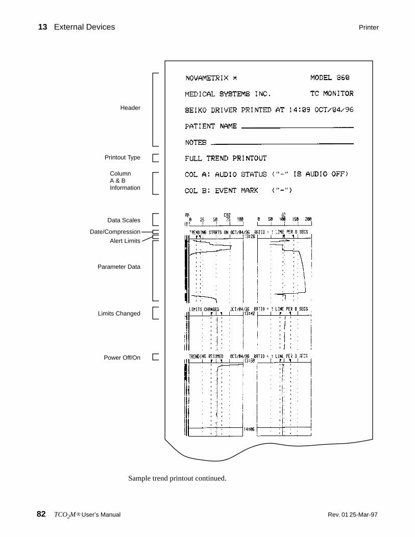
13 External Devices Printer
82 TCO2M® User’s Manual Rev. 01 25-Mar-97
Sample trend printout continued.
Header
Printout Type
ColumnA & BInformation
Data Scales
Date/Compression
Alert Limits
Parameter Data
Limits Changed
Power Off/On

Printer External Devices 13
25-Mar-97 Rev. 01 TCO2M® User’s Manual 83
Histogram Start
Total Time
Alert Limits
Data Categories
Summary Data
Oxygen
Printout Complete

13 External Devices Printer
84 TCO2M® User’s Manual Rev. 01 25-Mar-97
Header Each printout begins with a header that identifies the monitor as a Model 860Tc Monitor. The date and time of the printout is furnished by the monitor’s calendar/clock. Space is then provided to enter the patient’s name and notes.
Type of printout The trend type (Trend Display, Compressed, or Zoom) is recorded.
Audio Status and Event Marks Column A and Column B refer to the first twocolumn of the graphic trend printout. Column A represents the monitor’s audible alertstatus. A mark (black bar) in this column indicates that the audible alerts weresilenced while this data was being collected. Column B shows marks where “Events”were added to the trend memory by the user pressing the (Event) key.
Parameter Data Scales The CO2 and O2 scales are printed and dotted lines withinthe data section correspond to the major divisions shown on the scale lines. Data orlimits setting outside the scale ranges are clipped at the scale boundries.
Start Date and Compression The date of the first data point is displayed along withthe print compression ratio.
Alert Limit Settings Each parameter scale has two triangle shaped markers thatrepresent the upper and lower alert limit setting in effect when the data was collected.Dashed lines extend from these markers down into the data section of the printout. Ifthe alert limits were changed during data collection, the new alert limits will beprinted with a message indicating the alert limits were changed.
Data Section The data is graphed based on the selected compression ratio. A timestamp is placed at regular intervals and appears as a horizontal line. A TRENDING
RESUMED message shows where the monitor’s data collection was interupted whenthe the monitor was turned off and then later turned back on.
Histogram Printout O2 and CO2 histgram data is printed after the graphic trend data.
Total Collected Time Total time represented in the histogram calculations is printed.
Alert Limit Histogram A numerical and graphical display of the percentage of theTotal Collected Time each parameter spent below, within, and above the limit valuesin effect when the data was collected is printed. (Rounding errors may prevent thetotal fom equaling 100%.)
Histogram Data A numerical and graphical display of the percentage of time spentin each of the ranges listed. Histogram printout is not affected by compressionsettings. (Rounding errors may prevent the total fom equaling 100%.)
Average, Min and Max The minimum and maximum parameter values are printed.The average refers to the arithmatic mean of all readings.
End of Trend Printout This message is printed to show the printout completedsucesfully and all data is present (i.e., the printer did not run out of paper before theprintout finished, or that a partt of the printout is not torn away or missing).

Printer External Devices 13
25-Mar-97 Rev. 01 TCO2M® User’s Manual 85
Tabular Printout Tabular mode is a real-time print mode where the PtcO2 and PtcCO2 values areprinted once every 30 seconds. The printed values reflect the monitor’s display at theinstant of printing. (Stored trend cannot be reprinted in tabular mode.)
The format for tabular printouts is: “HH:MM:SS O2=XXX UNITS CO2=XXX UNITS”HH:MM:SS = time in 24 hour format (Hours:Minutes:Seconds)XXX = displayed parameter valueUNITS = torr (mmHg) or kPa.
To begin a Real Time Tabular printout:
1 From the base menu press PRNT and SELECT PRINT OPTIONS appears.
2 Press TAB (tabular). PRINTOUT STARTED briefly appears.
Printing starts and continues until terminated by the user.
Header
Time andparametersprinted every30 seconds
Type of printout
LIMIT TRND CAL PRNT MENUSELECT PRINT OPTIONSRUN TRND TAB

13 External Devices NovaCOM
86 TCO2M® User’s Manual Rev. 01 25-Mar-97
NovaCOM
The NovaCOM interface allows computer access to the monitor’s trend data via acable connection. This interface is designed to output data in formats easily read bya computer or data logging device. This provides the user the ability to “dump”information to a computer file for later analysis. The communications format is 9600baud, 8 bits, no parity, 1 stop bit and XON/XOFF handshaking.
NovaCOM Configuration
When the TCO2M is configured for NovaCOM communication, the connected device(computer or data logging device) must send the appropriate commands to themonitor in order to download the information.
To configure the TCO2M for NovaCOM1 communication:
1 From the main menu press and hold the MENU key until the DISPLAY menuappears.
2 Press the NEXT softkey to display the SYSTEM menu.
3 Use the up/down arrow softkeys until NovaCOM is displayed.
4 Press RUN to return to the main menu, or NEXT to advance to the ALERTSmenu.
NovaCOM Data Format
The following sections describe the different commands and responses of theNovaCOM interface. Unlike the printer and NovaCARD interfaces there will be nonew softkey displayed for data transmission. The connected device must request theinformation before the monitor will transmit the data.
Real Time In Real Time mode, O2 and CO2 values are continually transmitted at one secondintervals.
To enter Real Time mode, the computer must send an ASCII “1” character. Themonitor will echo back the “1” followed by a <cr><lf>, and enable real timecommunication.
The data format is: EO***C***Z**<cr><lf>where:E - Event Marker identifier, “E”= event marked, “-”= no event,O - identifier for a 3-digit ASCII O2 value to follow,C - identifier for a 3-digit ASCII CO2 value to follow,Z - identifier for a 2-digit ASCII calibration status (message) value*** - a 3-digit ASCII value,** - a 2-digit ASCII value,<cr><lf> - a carriage return, line-feed sequence.

NovaCOM External Devices 13
25-Mar-97 Rev. 01 TCO2M® User’s Manual 87
The Z** values correspond to the calibration status.
To exit Real Time mode, the computer must send an “x” or “X” character. Themonitor will echo the “x” and then stop real time communication.
Trend Dump Trend data is transmitted as a succession of records. The record size for TCO2M is 32bytes of ASCII Hexadecimal data. A record can be one of two types, an INFO recordor a DATA record. The INFO record contains monitor information such as time ofday, date, limit settings, and units. The DATA record contains event marker, audiodisable, CO2 and O2 values.
The first record sent is always an INFO record. This record reflects the oldest data inthe buffer, then records would continue being sent in chronological order from theoldest record to the newest record. In normal monitoring use, an INFO record wouldbe followed by 15 data records, followed by another INFO record and then another15 data records, etc. Turning the monitor off, or changing the limits will disrupt thissequence. When this occurs a new INFO record will be sent and indicate the time anddate, along with the current limits. At this point, unless another exception occurs, thenext INFO record will be followed by 15 DATA records.
An INFO record can be distinguished from a DATA record by the first byte of therecord. The first byte of an INFO record is FF, the first byte of a DATA record is 00-C8 (0-200 decimal), or FB (pen lift or no data available). Any other values are notapplicable. The DATA record uses 8 data points per parameter, at 8 second resolution,for a total of 64 seconds of trend data per data record.
To request trend dump, the computer must send an ASCII “6” character. The monitorechoes back the “6” character and transmits the first INFO record.
The Mode 6 data format is;
INFO record;
where;T- Trend mode identifier**-INFO byte, starting at byte 0 and ending at byte 15 (see below)
Z** where ** is:
Calibration Status
00 Sensor NOT calibrated
1X Calibrating Low
21 Calibrating High, Low done
0X Calibration Complete, Low/High
T********************************<cr><lf> byte 0
byte 31
byte -0 flag byte = FF for INFO record

13 External Devices NovaCOM
88 TCO2M® User’s Manual Rev. 01 25-Mar-97
<cr> - carriage return<lf> - line feed
DATA record;
T - Trend mode identifier**-DATA byte, starting at byte 0 and ending at byte 31 (see below)
byte-1 information type (FE-power on, FD-limit change, FC-time stamp)
byte-2 model code = 03
byte-3 compression ratio = 08 (i.e. 1 point/8 seconds)
byte-4 seconds (0-59)
byte-5 minute (0-59)
byte-6 hour (0-23)
byte-7 day (1-31)
byte-8 month (1-12)
byte-9 year (0-99)
byte-10 O2 high limit
byte-11 O2 low limit
byte-12 CO2 high limit
byte-13 CO2 low limit
byte-14 units, 00 = mmHg, 01 = kPa
byte-15 Hyperbaric mode = 01 (if 00 = not hyperbaric)
byte 16-31 Not used
T****************
****************<cr><lf>
byte 0
byte 31
byte 0-7 8 byte O2 data, range: 00-C8 Hex (0-200 decimal) (corresponds to 0-200mmHg, i.e. a value of 64 Hex that corresponds to 100 decimal will indicate an O2 value of 100mmHg).
byte 8-15 8 byte CO2 data, range: 00-C8 Hex (0-200 decimal), FB Hex (251 decimal) - no data available over period.
byte 16-23 8 byte Sensor Power data: range 00-C8H (0-200) no Penlifts

NovaCOM External Devices 13
25-Mar-97 Rev. 01 TCO2M® User’s Manual 89
<cr> - carriage return<lf> - line feed
Date and Time Date and Time mode causes the TCO2M to transmit, on request, the date and time ascalculated by the monitor’s internal calendar clock.
To request the date and time, the computer must send an ASCII “d” character. Themonitor echoes back the “d” character and sends the date and time on the same line.The Mode d data format is;
where;d - the echoed command character• - is an ASCII space characterMMM - a 3-character month (Jan, Dec),DD - a 2-digit ASCII day (01, 31),YY - the last 2-digits of the year (1990 is 90),hh - a 2-digit hour based on a 24 hour clock (00, 23),mm - a 2-digit minute,ss - a 2-digit second,<cr><lf> is a carriage return, line-feed sequence.
Clear Trends Clear Trends mode allows the user to remotely clear the TCO2M trend memory Thisaction has the same result as the monitor’s Clear Trend function in that trend memoryand the Trend Page displays are cleared.
Use this remote Clear Trends function with care as there is no way to undo the clearcommand once issued.
To clear the TCO2M trend memory, the computer must send an ASCII “c” character.The TCO2M will echo the “c” and then the trend memory will be cleared.
Exit Command To exit the NovaCOM mode, the computer must send an “x” or “X” character. TheTCO2M will echo the “x” and then stop communication. Sending a new validcommand character will start communication again.
byte 24-31 8 byte status data:bit 0 = CO2 factor 1 = Metabolic factor enabledbit 1-5 = not usedbit 6 = mute status 1 = Audio disabledbit 7 = event 1 = Event
d•MMM/DD/YY•hh:mm:ss<cr><lf>

13 External Devices Flexport
90 TCO2M® User’s Manual Rev. 01 25-Mar-97
Flexport
The TCO2M supports a flexport serial interface to the SpaceLabs PCMS monitors.Contact SpaceLabs for flexport information.
To select the SpaceLabs flexport interface;
1 From the base menu press and hold MENU until the DISPLAY menuappears.
2 Press the NEXT softkey to display the SYSTEM menu.
3 Use the up/down arrow keys to display Flexport.
4 Press RUN to return to the base menu.
Terminal
The Terminal option enables the output port to be configured as needed for alternateserial devices. When this option is selected various parameters must be set, these willbe sequenced through when the Terminal option is chosen and SEL is pressed.
Selecting and configuring the Terminal option:
1 From the main menu press and hold MENU until the DISPLAY menuappears.
2 Press the NEXT softkey to display the SYSTEM menu.
3 Use the up/down arrow keys to select Terminal. Press SEL.
4 When SELECT BAUD RATE appears use the NEXT and PREV keys to cyclethrough the available options. Press SET when the desired value isdisplayed.
The available options are: 1200, 2400, 4800, 9600.
5 When SELECT PARITY appears use the NEXT and PREV keys to cyclethrough the available options. Press SET when the desired value isdisplayed.
The available options are: none, even, odd.
6 When SELECT DATA BITS appears use the NEXT and PREV keys to cyclethrough the available options. Press SET when the desired value isdisplayed.
The available options are: 8, 7.
7 When SELECT STOP BITS appears use the NEXT and PREV keys to cyclethrough the available options. Press SET when the desired value isdisplayed. The MONITOR OPTIONS 2 menu will appear.
The available options are: 1, 2.
8 Press RUN to return to the base menu.
25-Mar-97 Rev. 01 TCO2M® User’s Manual 91
14 Maintenance
This section contains the TCO2M and accessory maintenance information.
Cleaning and Disinfecting
Monitor • Turn the monitor off and unplug the line cord from the AC mains before cleaning.
• The monitor can be cleaned and disinfected with solutions such as isopropyl alcohol 70% solution, 2% glutheralhyde solution, or bleach 10% solution, then wiped with a clean water dampened cloth to rinse and dry before use.
• Do not immerse the monitor.
• Do not attempt to sterilize the monitor.
Sensors • The sensor should be cleaned with a NOVADISK membrane in place. It can be cleaned and disinfected with solutions such as isopropyl alcohol 70% solution, 2% glutheralhyde solution, or bleach 10% solution, then wiped with a clean water dampened cloth to rinse and dry before use.
• After cleaning, ensure the selected sensor is mechanically sound; with no broken, frayed, or exposed wiring. Ensure that the connector is clean and dry with no signs of contamination or corrosion. Do not use a broken or damaged sensor or one with wet, contaminated or corroded contacts.
• Do not immerse the sensor.
• Do not attempt to sterilize the sensor.
• Refer to the appropriate section of this manual to clean and remembrane the sensor.
Calibrator • Disconnect the calibrator from the TCO2M if connected before cleaning.
• The calibrator can be cleaned and disinfected with solutions such as isopropyl alcohol 70% solution, 2% glutheralhyde solution, or bleach 10% solution, then wiped with a clean water dampened cloth to rinse and dry before use.
• Do not immerse the calibrator.
• Do not attempt to sterilize the calibrator.

14 Maintenance Battery Maintenance
92 TCO2M® User’s Manual Rev. 01 25-Mar-97
Battery Maintenance
Long Term Storage If the TCO2M has not been used or connected to AC power (AC ON icon illuminated) for an extended time (e.g., 3 months or more) allow the battery to chargefor 12 hours before use.
Charging the battery To recharge the battery, plug in the line cord and set the rear panel power switch tothe (|) ON position. A discharged battery will be fully recharged within 12 hours. Themonitor may be operated, on AC power, while the battery is being recharged.
Battery replacement The internal TCO2M battery is not user replaceable. Should replacement becomenecessary, contact qualified technical service personnel. Replace only with a batteryof the same type and rating.
Line Cord The AC power line cord shipped with monitors for North America is a HospitalGrade, SJT style cord with a 120 VAC plug. All power line cords shipped withmonitors for Europe are the European style with a 220-240 VAC plug. All other stylepower line cords, as required by the country of destination, are provided by thedistributor in that country.
Fuses
The rear panel power entry module indicates the AC (line) voltage setting for themonitor. Check that the voltage is correct before attaching the line cord and poweringthe monitor. The TCO2M can be set to operate from 100-120 VAC 50/60Hz or 200-240VAC 50/60Hz.
Refer to the following sections for fuse replacement and changing the mains voltagesetting.
1 Check that the monitor is OFF.
2 Set the rear panel power entry module switch to OFF (“O”). Remove the linecord from the power entry module (if connected).
3 Using a flat blade screwdriver, pry the fuse access door open to expose thefuse housing.
CAUTION: Replace fuses with same type and rating. Verify proper fusevalue for AC voltage setting (see table below).
AC Voltage Fuses (Slo Blo)
100-120 VAC 0.5 A 250V
200-240 VAC 250mA 250V
!

Fuses Maintenance 14
25-Mar-97 Rev. 01 TCO2M® User’s Manual 93
Note the orientation of the fuse housing (this determines the mains operating voltage).
4 Pry the fuse housing out from the power entry module.
5 Replace the blown fuse(s) with the proper type and rating.
6 Re-install the fuse housing. When positioning the housing into the powerentry module ensure that it is oriented correctly. Press the fuse housing backinto the power entry module.
7 Close the fuse access door and verify the proper mains operating voltage isdisplayed.
FUSE HOUSING
FUSE ACCESS DOOR
POWER ENTRY MODULE
FUSE HOUSING
NOTE: 5mm X 20mm fuses areinstalled toward the “back” of thefuse housing as shown
3AG TYPE 5 X 20mm TYPE
OR
115V AC OPERATING VOLTAGE

14 Maintenance Fuses
94 TCO2M® User’s Manual Rev. 01 25-Mar-97

25-Mar-97 Rev. 01 TCO2M® User’s Manual 95
15 Specifications
These specifications for the Novametrix TCO2M® Transcutaneous CO2/O2 Monitor,Model 860 are listed for informational purposes only, and are subject to changewithout notice.
Monitor Model 860
Measurement Range Carbon Dioxide 0-255 mmHg (0-25.5 kPA). Oxygen 0-800 mmHg (0-99.9 kPA).
CO2 Metabolic Correction Displayed pCO2 is compensated for metabolic factors related to the tem-perature effect and CO2 production. Refer to “PtcCO2 Display Values” on page 19.
Parameter Alerts CO2 and O2 limit alerts, audible and visible. User selectable, continuously displayed, retained in memory.
Alert Silence Two minute alert silence with LED indicator. Audio Off with LED indica-tor (user can disable if needed).
Temperature Section User selectable 37-45° C in 0.5° C increments. Can be continuously dis-played.Audible & visible alarm if actual/set temperatures differ by >0.2° C.Two fully independent thermistors monitor and control temperature.Heater power shutdown with audible & visible alarm at over-temp (45.5° C) or if thermistors differ by >0.5°.
Site Timer Automatically tracks sensor site duration, provides audible and visible alarms, automatic shutdown of heater power once timer expires. User selectable durations in 0.5 hour increments up to 5, 8, or 12 hour maxi-mum, plus off.
Local Power The power required to maintain sensor temperature is measured and dis-played. Range: 0-800 mW.User selectable power reference point allows for quick power trend analy-sis (LPR).
Real Time Trends Continuously displayed user selectable/scalable real time 10, 20, 30 minute trends of CO2, O2 or Local Power.
Trend/Histogram Memory Battery backed 24 hour trends, 8 second resolution. Trend/Histogram dis-plays 30 min, 2, 4, 8, 12 hours.
External Devices Standard RS232 serial outputs: NovaCARD, computer, printer, others. Optional Analog Module, CO2, O2 and LP.

15 Specifications Sensors
96 TCO2M® User’s Manual Rev. 01 25-Mar-97
System Power: 100-120/200-240 VAC, 50-60 Hz, 40 VA.Battery: Greater than 3 hour operation, 12 hour maximum recharge, lead-acid gel-cell.Display Type: Cold Cathode Display (CCD), 5 × 1.5 inches, W × H (12.7 × 3.8 cm). User adjustable contrast.Monitor Size: 3.3 × 9.0 × 8.0 inches, H × W × D (8.4 × 22.8 × 20 cm). Weight: 8 pounds (3.6 kg).Temperature: Operating 10-40° C (50-104° F), Storage -10-55° C (14-131° F). Relative humidity: 0-90% non-condensing.Altitude/Pressure: Automatic barometric pressure compensation. Range: 560-800 mmHg (71.9-106.6 kPa).Safety/Regulatory Approvals: UL/CUL (UL544, CSA No. 125), CSA C22.2 No. 125. TUV Product Service: Tested for compliance to European Safety Standards; IEC 601-1:1988: Amendments 1, 2, EN 60601-1:1990: A1, A2, A11, A12, A13, IEC 601-1-1: 1992: Amende-ment 1, EN 6060-1-1: 1993, IEC 601-2-23: 1993
EMC Emissions EN55011:1991, Class A. Classification for Radiated and Conducted Emis-sions
EMC Immunity EN60601-1-2:1993. Collateral standard: Electromagnetic compatibility - requirements and test. Includes; IEC801-2 Electrostatic Discharge Require-ments, IEC801-3 Radiated Electromagnetic Fields, IEC801-4 Electrical Fast Transient Burst, IEC801-5 Surge Transients.
Electomagnetic fields up to 3 V/m will not adversely affect system perfor-mance.
Sensors
Parameter Combination CO2/O2, CO2 only or O2 only
Principle of Operation Stow-Severinghaus pH/Clark-type polarographic
Response Time (t90) CO2 45 sec, O2 12 sec
Stability Better than 2 mmHg/hr
Diameter/Height 19/11 mm (0.75/0.41 in)
Gas Calibrator Model 868
Calibration System Fully automatic using a true two-point sensor calibration against known gases.
Gas Cylinders Type: PD Contents: 16 liters at 16.5 bar, 21° C (0.6 cu. ft. at 240 psig, 70° F).
Physical Size: 3.3 × 9.0 × 16.5 in., H × W × D(8.4 × 22.8 × 41.9 cm) includes cylinders. Weight: 3 lbs (1.4 kg)
Power All calibrator power provided by monitor

25-Mar-97 Rev. 01 TCO2M® User’s Manual 99
17 Accessories
Transcutaneous Monitor
6590-00 TCO2M Transcutaneous CO2/O2 Monitor, Model 860
Combinat ion O2/CO2 Sensor
4474-00 Combination O2/CO2 Sensor for use with Split Membrane NOVADISK
8900-00 Combination O2/CO2 NOVADISK Kit Pre-Soaked Split Membranes (30 per box)
Gas Cal ibrator
6633-00 Transcutaneous Gas Calibrator, Model 868
8964-00 Low Point Calibration Gas (4 cylinders per case)
8965-00 High Point Calibration Gas (4 cylinders per case)
Sensor Accessor ies
8285-00 Sensor Adhesive Rings (100 per box)
8805-00 Sensor Adhesive Rings—Large (100 per box)
8888-00 Transcutaneous Sensor Contact Gel (15 ml bottles, 6 per box)
8353-00 Contact Medium Applicator (10 bottles per box)
Carbon Dioxide Sensor
6752-00 Carbon Dioxide Sensor
8383-00 Carbon Dioxide NOVADISK Kit (24 per box)
Oxygen Sensor
6754-00 Oxygen Sensor
8286-00 Oxygen NOVADISK Kit (24 per box)
8200-00 Contact Gel, Transcutaneous Oxygen Sensor (1 tube, 60 ml)
8231-00 Zero Oxygen Calibration Solution (50 vials per box)
Serial /Analog Output & Accessor ies
5702-00 Seiko DPU-411 Thermal Printer, 120 vac (interface cable included)
5703-00 Seiko DPU-411 Thermal Printer, 220 vac (interface cable included)
300017 Seiko DPU-411 Thermal Printer Paper (5 rolls per box)
6887-00 Cable to Seiko DPU-411 Printer
5861-00 Cable, Seiko DPU-411 Printer (powers printer from TCO2M)
5334-00 Cable, Serial Output to Personal Computer (25-pin connector)
5335-00 Cable, Serial Output to Personal Computer (9-pin connector)
9622-01 Analog Module for TCO2M (includes RS232 pass-thru)
6888-00 Cable, Analog Output Module (open ended, 6 ft)

17 Accessories
100 TCO2M® User’s Manual Rev. 01 25-Mar-97
7106-10 Transport Pouch (for monitor)
7105-10 Monitor Accessory Pouch with Printer Support
7104-10 Side Accessory Pouch (included with monitor)
600026 Power Cord (included with monitor)
Mount ing Systems
140030 Wall Mount
140031 Wall Mount (less Wall Channel)
140032 Pivot Block Mount
140033 Transport Mount (without swivel head)
140034 Transport Mount (with swivel head)
140035 Countertop Mount (11 inch Base)
140036 Countertop Mount (5 inch Base)
140037 Portable Instrument Housing
Extended Warranty
Warranty Extension: an additional 1 year(s) at time of purchase(Normal Warranty: Monitor—1 year, Sensor—1 year, Calibrator—1 year)
6590-81 TCO2M Monitor, Model 860
6633-81 Model 868 Gas Calibrator
6590-82 TCO2M Monitor & Gas Calibrator & Combination Sensor
6590-83 TCO2M Monitor & Gas Calibrator & Single Parameter Sensor
6590-84 TCO2M Monitor & Single Parameter Sensor
6590-85 TCO2M Monitor & Combination Sensor
Biomedical Engineer ing Service Test Ki t and Service Manual
Service Test Kits include items and materials qualified service personnel may require to determinethe functional integrity and/or accuracy of the system.
6590-90 (Technical) Service Manual, Model 860
5435-00 Service Test kit, TCO2M Transcutaneous Monitor, Model 860
9999-96 “focus” Technical Training Seminar (1 day course)For class schedules call: 1-800-243-3444 Ext. 2565
![Polarographic Behavior and Determination of Vitamin B in ... · Polarographic Behavior and Determination... 25 Icha[12] has described the polarographic active behavior of orotic acid.](https://static.fdocuments.us/doc/165x107/606749c4ab2cc56e4a6481f6/polarographic-behavior-and-determination-of-vitamin-b-in-polarographic-behavior.jpg)