User’s Reference Manual - Frank's Hospital Workshop · in this User’s Reference manual and...
48
Tec 7 Vaporizer User’s Reference Manual
Transcript of User’s Reference Manual - Frank's Hospital Workshop · in this User’s Reference manual and...
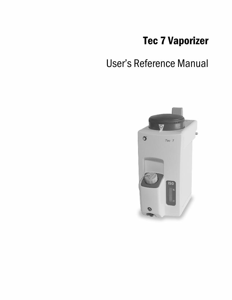
Tec 7 Vaporizer
User’s Reference Manual

User Responsibility
This Product will perform in conformity with the description thereof contained in this User’s Reference manual and accompanying labels and/or inserts, when assembled, operated, maintained, and repaired in accordance with the instructions provided. This Product must be checked periodically. A defective Product should not be used. Parts that are broken, missing, plainly worn, distorted, or contaminated should be replaced immediately. Should repair or replacement become necessary, Datex-Ohmeda recommends that a telephonic or written request for service advice be made to the nearest Datex-Ohmeda Customer Service Center. This Product or any of its parts should not be repaired other than in accordance with written instructions provided by Datex-Ohmeda and by Datex-Ohmeda trained personnel. The Product must not be altered without the prior written approval of Datex-Ohmeda. The user of this Product shall have the sole responsibility for any malfunction which results from improper use, faulty maintenance, improper repair, damage, or alteration by anyone other than Datex-Ohmeda.
wCAUTION U.S. Federal law restricts this device to sale by or on the order of a licensed medical practitioner. Outside the U.S.A, check local laws for any restriction that may apply.
Datex-Ohmeda products have unit serial numbers with coded logic which indicates a product group code. The year of manufacture and a sequential unit number for identification.
AAA A 12345
This alpha character indicates the year of productmanufacture and when the serial number wasassigned; “C” = 1999, “D” = 2000, “E” = 2001, etc. “I” and “O” are not used.
Table of Contents
1 Introduction
Precautions . . . . . . . . . . . . . . . . . . . . . . . . . . . . . . . . . . . . . . . . . . . . . . . . . . . 1-1
Symbols . . . . . . . . . . . . . . . . . . . . . . . . . . . . . . . . . . . . . . . . . . . . . . . . . . . . . . 1-2
2 Description
What is a Tec 7 Vaporizer? . . . . . . . . . . . . . . . . . . . . . . . . . . . . . . . . . . . . . . . 2-1
Components . . . . . . . . . . . . . . . . . . . . . . . . . . . . . . . . . . . . . . . . . . . . . . . . . . 2-3
Control dial . . . . . . . . . . . . . . . . . . . . . . . . . . . . . . . . . . . . . . . . . . . . . . . . 2-3
Safety interlocks . . . . . . . . . . . . . . . . . . . . . . . . . . . . . . . . . . . . . . . . . . . 2-3
Vaporizer identification label . . . . . . . . . . . . . . . . . . . . . . . . . . . . . . . . . 2-3
3 Setup and Mounting Procedure
Vaporizer mounting procedure . . . . . . . . . . . . . . . . . . . . . . . . . . . . . . . . . . . . 3-1
Mounting the vaporizer . . . . . . . . . . . . . . . . . . . . . . . . . . . . . . . . . . . . . . 3-2
Checking the vaporizer for correct mounting . . . . . . . . . . . . . . . . . . . . . . . . . 3-4
Removing the vaporizer from a manifold . . . . . . . . . . . . . . . . . . . . . . . . . . . . 3-4
4 Operating Instructions
Setting the dial . . . . . . . . . . . . . . . . . . . . . . . . . . . . . . . . . . . . . . . . . . . . . . . . 4-1
Filling and draining the vaporizer . . . . . . . . . . . . . . . . . . . . . . . . . . . . . . . . . . 4-3
Filling procedure with funnel filler . . . . . . . . . . . . . . . . . . . . . . . . . . . . . . 4-5
Draining procedure with funnel filler . . . . . . . . . . . . . . . . . . . . . . . . . . . 4-6
Filling procedure with Easy-Fil™ . . . . . . . . . . . . . . . . . . . . . . . . . . . . . . . 4-7
Draining procedure with Easy-Fil . . . . . . . . . . . . . . . . . . . . . . . . . . . . . . 4-8
Filling procedure with Quik-Fil™ . . . . . . . . . . . . . . . . . . . . . . . . . . . . . . . 4-9
Draining procedure with Quik-Fil . . . . . . . . . . . . . . . . . . . . . . . . . . . . . 4-10
1175-0013-000 i

Tec 7 Vaporizer
5 Maintenance
User maintenance . . . . . . . . . . . . . . . . . . . . . . . . . . . . . . . . . . . . . . . . . . . . . . 5-1
Maintenance intervals . . . . . . . . . . . . . . . . . . . . . . . . . . . . . . . . . . . . . . . 5-1
Cleaning . . . . . . . . . . . . . . . . . . . . . . . . . . . . . . . . . . . . . . . . . . . . . . . . . . . . . . 5-2
External cleaning . . . . . . . . . . . . . . . . . . . . . . . . . . . . . . . . . . . . . . . . . . . 5-2
Internal contamination . . . . . . . . . . . . . . . . . . . . . . . . . . . . . . . . . . . . . . 5-2
Output concentration check . . . . . . . . . . . . . . . . . . . . . . . . . . . . . . . . . . 5-2
Checking the calibration . . . . . . . . . . . . . . . . . . . . . . . . . . . . . . . . . . . . . . . . . 5-3
Analytical techniques . . . . . . . . . . . . . . . . . . . . . . . . . . . . . . . . . . . . . . . 5-4
Service Policy . . . . . . . . . . . . . . . . . . . . . . . . . . . . . . . . . . . . . . . . . . . . . . . . . . 5-5
6 Principle of Operation
Interlock mechanism . . . . . . . . . . . . . . . . . . . . . . . . . . . . . . . . . . . . . . . . . . . . 6-1
Delivery of gas/agent vapor . . . . . . . . . . . . . . . . . . . . . . . . . . . . . . . . . . . . . . 6-1
Overview . . . . . . . . . . . . . . . . . . . . . . . . . . . . . . . . . . . . . . . . . . . . . . . . . . 6-1
Bypass circuit . . . . . . . . . . . . . . . . . . . . . . . . . . . . . . . . . . . . . . . . . . . . . . 6-2
Vaporizing chamber circuit . . . . . . . . . . . . . . . . . . . . . . . . . . . . . . . . . . . 6-2
7 Specifications
Calibration . . . . . . . . . . . . . . . . . . . . . . . . . . . . . . . . . . . . . . . . . . . . . . . . . . . . 7-1
Performance . . . . . . . . . . . . . . . . . . . . . . . . . . . . . . . . . . . . . . . . . . . . . . . . . . . 7-2
Weight and dimensions . . . . . . . . . . . . . . . . . . . . . . . . . . . . . . . . . . . . . . . . . 7-2
Flow characteristics . . . . . . . . . . . . . . . . . . . . . . . . . . . . . . . . . . . . . . . . . . . . . 7-3
Effects of variables . . . . . . . . . . . . . . . . . . . . . . . . . . . . . . . . . . . . . . . . . . . . . 7-8
Anesthetic agent consumption . . . . . . . . . . . . . . . . . . . . . . . . . . . . . . . . 7-8
Barometric pressure . . . . . . . . . . . . . . . . . . . . . . . . . . . . . . . . . . . . . . . . 7-8
Ambient temperature . . . . . . . . . . . . . . . . . . . . . . . . . . . . . . . . . . . . . . . 7-9
Back pressure . . . . . . . . . . . . . . . . . . . . . . . . . . . . . . . . . . . . . . . . . . . . . 7-9
Carrier gas composition . . . . . . . . . . . . . . . . . . . . . . . . . . . . . . . . . . . . 7-10
Time out of service . . . . . . . . . . . . . . . . . . . . . . . . . . . . . . . . . . . . . . . . . 7-10
Effects of variables . . . . . . . . . . . . . . . . . . . . . . . . . . . . . . . . . . . . . . . . 7-10
Warranty
ii 1175-0013-000
1 Introduction
Precautions
wwww WARNING Do not fill the vaporizer with any agent other than the agent specified on the front label. The vaporizer is designed for that agent only. If any substance other than that specified is used, patient injury could occur.
United States (U.S.) Federal law restricts this device to sale by or on the order of a licensed medical practitioner. Outside the U.S., check local laws for any restrictions that may apply.
Do not attempt to use a vaporizer that has been dropped. A dropped vaporizer MUST be sent to the nearest Datex-Ohmeda Field Operations Unit for servicing.
Do not use malfunctioning equipment. Make all necessary repairs or have the equipment serviced by an authorized Datex-Ohmeda service center. After repair, test the equipment to ensure that it is functioning properly in accordance with the manufacturer’s published specifications.
1175-0013-000 1-1
Tec 7 Vaporizer
Important European Standard EN 740 - Anesthetic Workstations and Their Modules requires that an appropriate gas monitor is used to monitor the concentration of anesthetic agent vapor in the inspiratory gas when the vaporizer is in operation in order to provide protection against hazardous output in the event of a device malfunction.
Datex-Ohmeda strongly recommends the use of anesthesia gas monitoring with this equipment. Refer to local standards for mandatory monitoring.
Requests for servicing facilities, advice or assistance must be addressed to a local Datex-Ohmeda office.
Additional copies of this manual, can be requested from a local Datex-Ohmeda Field Operations Unit or a Datex-Ohmeda Authorized Distributor.
Datex-Ohmeda strongly recommends that you keep all relevant documentation, including this manual and accompanying labels, immediately available to all users.
Symbols
Warnings and Cautions tell you about conditions that can occur if you do not follow all instructions in this manual.
wwww WARNING Warnings tell about a condition that can cause injury to the operator or the patient.
wwww CAUTION Cautions tell about a condition that can cause damage to the equipment. Read and follow all warnings and cautions.
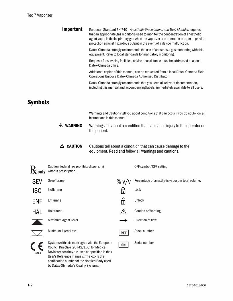
Caution: federal law prohibits dispensing without prescription.
OFF symbol/OFF setting
SEV Sevoflurane % v/v Percentage of anesthetic vapor per total volume.
ISO Isoflurane z Lock
ENF Enflurane Z Unlock
HAL Halothane w Caution or Warning
Maximum Agent Level NNNN Direction of flow
Minimum Agent Level Stock number
Systems with this mark agree with the European Council Directive (93/42/EEC) for Medical Devices when they are used as specified in their User’s Reference manuals. The xxxx is the certification number of the Notified Body used by Datex-Ohmeda's Quality Systems.
Serial number
only
1-2 1175-0013-000

1175-0013-000
What is a Te
2 Description
c 7 Vaporizer?
The Tec 7 Vaporizer is designed for use in continuous flow techniques of inhalation anesthesia. Each vaporizer is agent specific and is clearly labeled with the anesthetic agent that it is designed for.
The vaporizer is temperature, flow and pressure compensated so that its output remains relatively constant despite cooling due to evaporation, variations in inlet flow and fluctuating pressures as described in Section 7, Effects of Variables.
The vaporizer is designed to be used on Selectatec® Series Mounted Manifolds. The vaporizer can be installed on other Selectatec Manifolds but the interlock system is designed to function on Selectatec Series Mounted Manifolds only. Mounting a Tec 7 Vaporizer on a Selectatec 7 Compatibility Block is not recommended.
2-1

Tec 7 Vaporizer
2-2
Figure 2-1 • Tec 7 Vaporizer
w WARNING Improper use may result in patient injury.
This manual and its associated documentation must be studied before any attempt is made to install, operate or clean any part of the Tec 7 Vaporizer.
The performance of the anesthesia machine and vaporizer can be degraded if the machine and vaporizer are mis-matched.
Only operate the vaporizer with dry medical gases.
If a vaporizer containing agent in the sump has been inverted, connect it to a gas scavenging system, set the dial to 5% and purge the vaporizer with the carrier gas at 5 liters/minute for 5 minutes.
wwww CAUTION The vaporizer is intended to be operated in its upright position.
Turn the vaporizer to when it is not in use.
AB80
008
1175-0013-000
2 Description
1175-0013-000
Components
C
Safety
Vaporizer iden
ontrol dial A single control dial with a concentration scale calibrated in percentage of anesthetic agent vapor per total volume (% v/v) sets the desired concentration of the anesthetic agent.
A dial release in the dial assembly helps prevent accidental displacement of the control dial from the position. To select an ON setting, squeeze the dial release and simultaneously rotate the dial counter-clockwise.
The dial and dial release are designed to enable an ON setting to be selected using only one hand.
interlocks The vaporizer incorporates an interlock mechanism. This mechanism also interfaces with the Selectatec® Series Mounted Manifold to help satisfy the following criteria:• The vaporizer must be locked onto the manifold before it can be turned ON.• Only one vaporizer at a time can be turned ON when two or more vaporizers are
fitted on a Selectatec® Series Mounted Manifold.• The gas flow enters only the vaporizer that is turned ON.• Any unwanted anesthetic trace vapor is minimized after a vaporizer is turned to
.
w WARNING Earlier versions of the Selectatec Series Mounted Manifold that provide mounting positions for three vaporizers require that if only two vaporizers are fitted, then the center position must be occupied. If the center position is not occupied, the interlock that helps ensure that only one vaporizer at a time can be turned ON is ineffective.
Later versions of the Selectatec Series Mounted Manifold that provide mounting positions for three vaporizers incorporate an additional interlock that helps ensure that only one vaporizer at a time can be turned ON even if the center position is not occupied.
tificationlabel
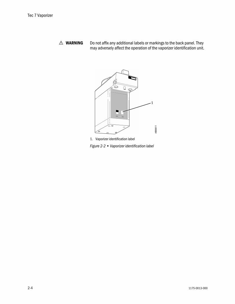
A vaporizer identification label is affixed to the back panel of the vaporizer as illustrated on Fig. 2-2.
An anesthesia system fitted with a vaporizer identification unit uses this label to identify the vaporizer type.
2-3
Tec 7 Vaporizer
2-4
w WARNING Do not affix any additional labels or markings to the back panel. They may adversely affect the operation of the vaporizer identification unit.
1. Vaporizer identification label
Figure 2-2 • Vaporizer identification label
HALOTHANE
AB80
011
1
1175-0013-000

1175-0013-000
Vaporizer mo
3 Setup and Mounting Procedure
unting procedure
The vaporizer is designed to be used on Selectatec Series Mounted Manifolds. The vaporizer can be installed on other Selectatec Manifolds but the interlock system is designed to function on Selectatec Series Mounted Manifolds only.
Mounting a Tec 7 Vaporizer on a Selectatec 7 Compatibility Block is not recommended.
wwww WARNING Do not lift or support the vaporizer by holding the control dial. Handle the vaporizer with care at all times.
Before mounting a vaporizer onto the Selectatec Series manifold, ensure that each manifold port valve O-ring is intact and that there is no foreign matter around the mating surfaces. A damaged O-ring and/or foreign matter around the mating surfaces can cause leaks.
Earlier versions of the Selectatec Series Mounted Manifold that provide mounting positions for three vaporizers require that if only two vaporizers are fitted, then the center position must be occupied. If the center position is not occupied, the interlock that helps ensure that only one vaporizer at a time can be turned ON is ineffective.
Do not use a vaporizer if the liquid level decreases below the minimum level.
Before using a vaporizer allow it to attain the ambient temperature of the location in which it has to be used.
3-1

Tec 7 Vaporizer
3-2
Mounting the
Step 1
Set the dial to .
Step 2
Unlock the locking lev
• Turn the lever cou
• Make sure the le
Step 3
Prepare the manifold.
• Remove any plugvaporizer interloc
• Verify that each mvalve O-ring is intnecessary, remoO-rings and fit oneach port valve, athe relevant anesUser’s ReferenceReplacement O-rsupplied with eac
vaporizer
Figure 3-1 • Setting the concentration dial
er.
nter-clockwise.
ver releases.
Figure 3-2 • Unlocking the locking lever
s fitted to the k block ports.
anifold port act. If
ve the existing e new O-ring to s described in thesia system Manual. ings are h vaporizer.
1. Vaporizer Interlock Block Port - ensure plugs removed2. Replace Manifold Port Valve O-ring, if necessary
Figure 3-3 • Readying the manifold
Åben
AB80
001
AB80
002
AA13
052
1
2
1175-0013-000

3 Setup and Mounting Procedure
1175-0013-000
Step 4
Install the vaporizer on
• Hold the main bovaporizer in an upwith both hands
.
• Lower the vaporizmanifold, ensurinvaporizer interlocengage correctlymanifold port val
Step 5
Lock the vaporizer ont
• Push the locking down.
• Turn it clockwise position to lock tonto the manifold
Step 6
Ensure that the vaporimounted (see instructpage).
wwww CAUTION Push the locking lever all the way down before turning it. The mechanism can be damaged if an attempt is made to turn the lever before it is pushed all the way down.
to the manifold.
dy of the right position
er onto the g that the k block ports
with the ves. Figure 3-4 • Installing the vaporizer
o the manifold.
lever all the way
to the locked he vaporizer
.
1. Locking lever
Figure 3-5 • Locking the vaporizer onto a manifold
zer is correctly ions on the next
AB80
018
AB80
004
1
1
3-3

Tec 7 Vaporizer
3-4
Checking th
Removing th
Step 1
Set the dial to .
If the dial is not compthe position the vbe released from the m
OFF
OFF
e vaporizer for correct mounting
wwww WARNING To help ensure correct operation, do not use a vaporizer that is either visibly out of line on the manifold or that can be lifted off the manifold when the locking lever is in the locked position.
If more than one vaporizer is fitted, visually check to make sure that the tops of the vaporizers are level. If the vaporizer is visibly out of line, perform steps 2 and 3 as described in Removing the vaporizer from a manifold and remount it correctly.
When the vaporizer appears to be level and the locking lever is in the locked position, attempt to lift the vaporizer straight up from the manifold. If the vaporizer can be lifted off the manifold, it is not correctly mounted. Remount the vaporizer (see Vaporizer mounting procedure).
Verify that the interlock rods are in alignment by making sure that only one vaporizer at a time can be turned ON.
Check the anesthesia system for leaks in accordance with the relevant User’s Reference Manual with the vaporizer dial turned to 0% and then repeat the check with the vaporizer dial turned to .
e vaporizer from a manifold
letely turned to aporizer cannot
anifold.
Figure 3-6 • Setting the dial
Åben
AB80
001
1175-0013-000

3 Setup and Mounting Procedure
1175-0013-000
Step 2
Unlock the locking lev
• Turn the locking lclockwise.
• Release the lockcheck that the losprings up to theposition to releasfrom the manifol
Step 3
Carefully lift the vapormanifold.
er.
ever counter-
ing lever and cking lever unlocked e the vaporizer
d.
1. Locking lever2. Dial
Figure 3-7 • Unlocking the locking lever
izer up from the
Figure 3-8 • Lifting the vaporizerAB
8000
3
Unlocked
1
2
1
2
Locked
AB80
019
3-5

Tec 7 Vaporizer
3-6
1175-0013-000

1175-0013-000
Setting the d
4 Operating Instructions
ial
wwww WARNING High percent dial settings combined with low gas flows may lead to hypoxic mixtures in the breathing circuit. Datex-Ohmeda strongly recommends the use of oxygen monitoring.
The dial release must be operated to turn the dial from the setting.
Do not turn the dial if the vaporizer is not properly locked onto the manifold.
Important European Standard EN 740 - Anesthetic Workstations and Their Modules requires that an appropriate gas monitor is used to monitor the concentration of anesthetic agent vapor in the inspiratory gas when the vaporizer is in operation in order to provide protection against hazardous output in the event of a device malfunction.
Datex-Ohmeda strongly recommends the use of anesthesia gas monitoring with this equipment. Refer to local standards for mandatory monitoring.
OFF
4-1

Tec 7 Vaporizer
4-2
Step 1
Press the dial release ain a counter-clockwisethe setting.
Note that it is not possthe vaporizer if an adja(except Tec 3) is turne
Step 2
The vaporizer should nbetween and the mark.
To avoid inadvertent dconcentrations, turn th
when the vaporize
nd turn the dial direction from
ible to turn on cent Tec series, d on.
ot be used first graduation
elivery of small e control dial to r is not in use.
Figure 4-1 • Releasing the dial
Åben
AB80
020
1175-0013-000

4 Operating Instructions
1175-0013-000
Filling and d
raining the vaporizer
wwww WARNING Do not fill the vaporizer with any agent other than the agent specified on the front label. The vaporizer is designed for that agent only. If any substance other than that specified is used, patient injury could occur.
Only fill the vaporizer when it is in an upright position. Failure to do so may result in the vaporizer being overfilled.
To avoid explosive hazards, flammable anesthetic agents such as Ether and Cyclopropane must not be used in or with this vaporizer. Only anesthetic agents that comply with the requirements for non-flammable anesthetic agents in the IEC 60601-2-13 Standard, Particular Requirements for the Safety of Anesthesia Machines, are suitable for use in the presence of this vaporizer.
As this vaporizer is not suitable for use with flammable anesthetic agents such as Ether or Cyclopropane, the use of antistatic breathing tubes and face masks is not necessary. The use of antistatic or electrically conductive breathing tubes when using high frequency electric surgery equipment may cause burns and is therefore not recommended in any application of this vaporizer.
Do not fill the vaporizer unless the control dial is in the position.
Do not turn the dial ON during filling or attempt to fill beyond the ¥ mark.
Do not drain the agent into any container other than a properly marked drug container.
Ensure that the filler cap is tightened prior to use.
4-3

Tec 7 Vaporizer
4-4
Step 1
Turn the vaporizer dial position.
OFF
When filling the Tec 7 Vaporizer, observe the following:• Periodically check the agent level. The vaporizer should be refilled at appropriate
intervals. The vaporizer is designed to function according to specification as long as there is agent visible above the mark.
• The vaporizer must be filled and used in an upright position. Small deviations from the upright position do not affect either the output or the safety of the vaporizer.
• Every two weeks, preferably when the agent level is low, drain the contents of the vaporizer into an appropriately marked container and discard the agent. Less frequent intervals may be used when the anesthetic agent does not contain additives or stabilizing agents, but the procedure must be performed at least once every year.
• The following steps should be taken for Halothane vaporizers:— Drain the vaporizer every two weeks— If Halothane is used infrequently the vaporizer should be drained after use.— The decomposition of halothane causes the release of halides, which may
corrode metal components particularly in the presence of moisture. Also a preservative added to halothane by its manufacturers to impede decomposition can leave a residue, which may cause vaporizer components to stick.
• If the vaporizer is not upright, check the agent level more frequently to avoid a misleading impression of the amount of agent in the vaporizer.
clockwise to the
Figure 4-2 • Turning the vaporizer OFF
Åben
AB80
021
1175-0013-000
4 Operating Instructions
1175-0013-000
Filling procefu
Step 1
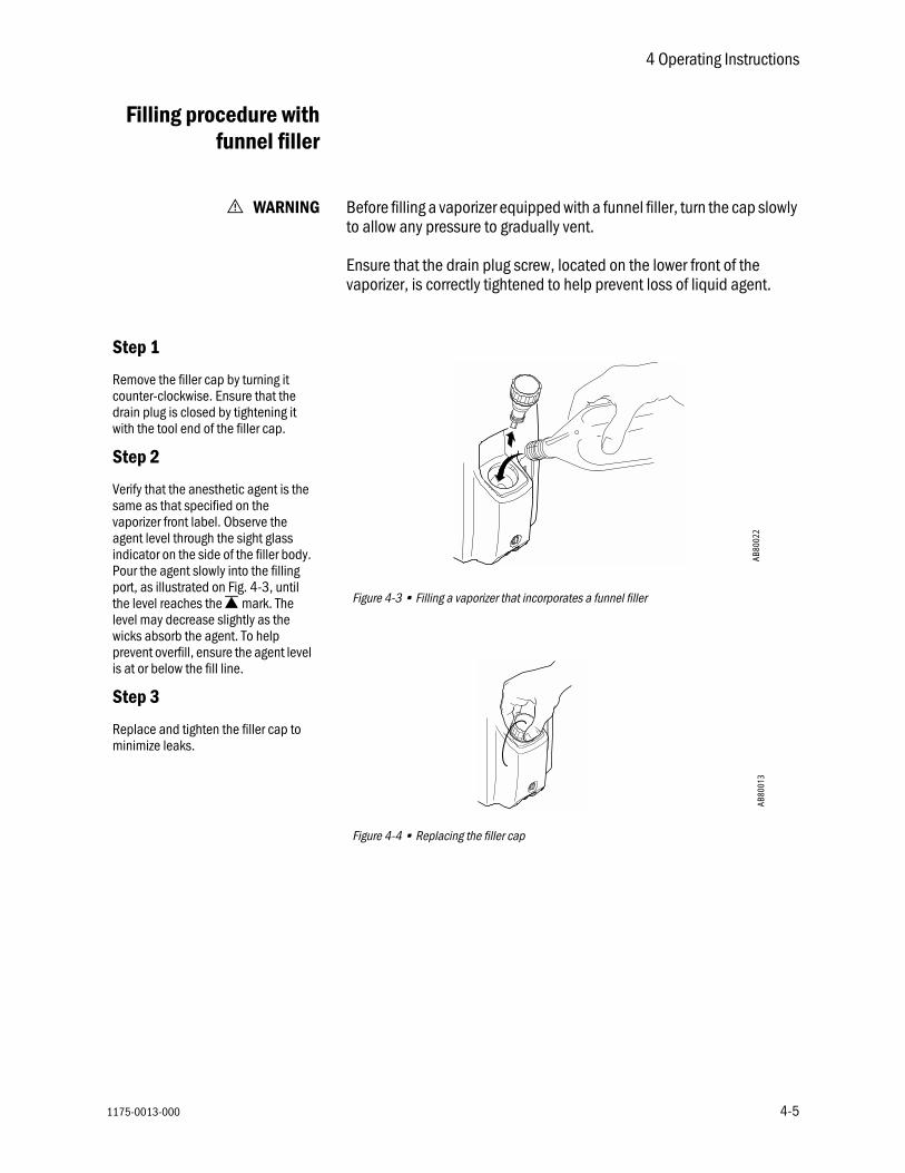
Remove the filler cap counter-clockwise. Endrain plug is closed bywith the tool end of th
Step 2
Verify that the anesthesame as that specifiedvaporizer front label. Oagent level through thindicator on the side oPour the agent slowly port, as illustrated on the level reaches the ¥
level may decrease sliwicks absorb the agenprevent overfill, ensureis at or below the fill li
Step 3
Replace and tighten thminimize leaks.
dure withnnel filler
w WARNING Before filling a vaporizer equipped with a funnel filler, turn the cap slowly to allow any pressure to gradually vent.
Ensure that the drain plug screw, located on the lower front of the vaporizer, is correctly tightened to help prevent loss of liquid agent.
by turning it sure that the tightening it
e filler cap.
Figure 4-3 • Filling a vaporizer that incorporates a funnel filler
Figure 4-4 • Replacing the filler cap
tic agent is the on the bserve the
e sight glass f the filler body. into the filling Fig. 4-3, until
mark. The ghtly as the t. To help the agent level
ne.
e filler cap to
AB80
022
AB80
013
4-5

Tec 7 Vaporizer
4-6
Draining with fu
Step 1
Remove the filler cap.end of the cap into thebelow the filling port oas illustrated in Fig. 4-
Step 2
Position a properly maunder the drain spout
Step 3
Unscrew, but do not replug to allow the vapopour from the drain spcontainer.
Step 4
After draining is compdrain plug to help min
Step 5
Replace and tighten thhelp minimize leaks.
procedurennel filler
The vaporizer must only be drained into a properly marked container.
wwww CAUTION Do not allow the container to become completely full during draining procedures.
Insert the tool drain plug n the filler body 5.
Figure 4-5 • Draining a vaporizer with a funnel filler
Figure 4-6 • Replacing the filler cap
rked container .
move, the drain rizer contents to out into the
lete, tighten the imize leaks.
e filler cap to
AB80
023
AB80
013
1175-0013-000

4 Operating Instructions
1175-0013-000
Filling with
Step 1
Align the notches on tadapter to the bottle cthe adapter onto the a
Step 2
Remove the filler cap.adapter keys with the ifiller block as illustrateInsert the bottle nozzleblock.
Step 3
Press the agent bottlevaporizer filler block. Ato flow into the vaporizmaximum level mark ¥
help prevent overfill, elevel is at or below theparticular attention tosight glass and the airflowing into the bottle
Step 4
Release the bottle whis full and the continububbles ceases.
Step 5
Remove the bottle fromfiller. Replace the fillecap on the agent bottlthe filler cap is tightenminimize leaks.
procedure Easy-Fil™
wwww WARNING Ensure that the drain plug screw, located on the lower front of the vaporizer, is correctly tightened to help prevent loss of liquid agent.
The filling system consists of three elements:• the bottle collar• the bottle adapter• the filler block
The vaporizer must only be filled using the correct agent specific filling system.
he bottle ollar and tighten gent bottle.
1. Filler cap2. Index slot3. Bottle adapter
Figure 4-7 • Filling a vaporizer with Easy-Fil
Figure 4-8 • Replacing the filler cap
Align the bottle ndex slots in the d in Fig. 4-7. into the filler
fully into the llow the liquid er until the is reached. To
nsure the agent fill line. Pay the level in the return bubbles .
en the vaporizer ous stream of
the vaporizer r cap and the e. Ensure that ed to help
1
2
3
AB80
015
AB80
013
4-7

Tec 7 Vaporizer
4-8
Draining wi
Step 1
Remove the cap from filler.
Step 2
Place the empty contaunder the drain nozzleFig. 4-9.
Step 3
Unscrew the drain pluattached to the filler cvaporizer until empty.
Step 4
After draining, tighten help minimize leaks.
Step 5
Replace and tighten thminimize leaks.
procedureth Easy-Fil
wwww CAUTION Do not allow the container to become completely full during draining procedures.
The vaporizer must only be drained into a properly marked container.
the vaporizer
Figure 4-9 • Unscrewing the drain plug
Figure 4-10 • Replacing the filler cap
iner opening as shown in
g with the tool ap. Drain the
the drain plug to
e filler cap to
AB80
014
AB80
013
1175-0013-000

4 Operating Instructions
1175-0013-000
Filling proce
Step 1
Remove the protectiveanesthetic agent bottlthat the bottle and filleare not damaged.
Step 2
Remove the filler cap. nozzle into the filler blbottle to align the bottkeys with the index sloblock as illustrated on
Step 3
Press the agent bottlevaporizer filler block. Ato flow into the vaporizmaximum level mark ¥
Pay particular attentiothe sight glass and thebubbles flowing into th
Step 4
Release the bottle whis full and the continububbles ceases. To heoverfill, ensure the agebelow the fill line.
Step 5
Remove the bottle fromfiller. Replace the fillecap on the agent bottlthe filler cap is tightenminimize leaks.
dure withQuik-Fil™
wwww WARNING Ensure that the drain plug screw, located on the lower front of the vaporizer, is correctly tightened to help prevent loss of liquid agent.
cap from the e filler, checking
r mechanism
1. Filler cap2. Index slot3. Nozzle key
Figure 4-11 • Filling a vaporizer with a Quik-Fil
Figure 4-12 • Replacing the filler cap
Insert the bottle ock. Rotate the le filler nozzle ts in the filler Fig. 4-11.
fully into the llow the liquid er until the
is reached. n to the level in air return e bottle.
en the vaporizer ous stream of lp prevent nt level is at or
the vaporizer r cap and the e. Ensure that ed to help
1
2
3
AB80
015
AB80
013
4-9

Tec 7 Vaporizer
4-10
Draining wi
Step 1
Remove the cap from filler.
Step 2
Place the empty contadrain nozzle as shownScrew bottle onto drai
Step 3
Unscrew the drain pluattached to the filler cvaporizer until empty.
Step 4
After draining, tighten help minimize leaks.
Step 5
Replace and tighten thminimize leaks.
procedureth Quik-Fil
wwww CAUTION Do not allow the container to become completely full during draining procedures.
The vaporizer must only be drained into a properly marked container.
the vaporizer
Figure 4-13 • Unscrewing the drain plug
Figure 4-14 • Replacing the filler cap
iner under the in Fig. 4-13. n spout.
g with the tool ap. Drain the
the drain plug to
e filler cap to
AB80
026
AB80
013
1175-0013-000

1175-0013-000
User mainte
Maintenanc
5 Maintenance
nance
wwww WARNING Do not modify, tamper with, or disassemble the vaporizer. Doing so can damage the unit and alter the graduation accuracy.
e intervals Prior to performing any maintenance procedures or returning to a service center for repairs, clean and disinfect the vaporizer.
Every two weeks: When the agent is low, drain the contents of the vaporizer into an appropriately marked container and discard the agent. For Halothane vaporizers check the output of anesthetic agent periodically with an agent monitor. See note below.
Note The decomposition of Halothane causes the release of halides, which may corrode metal components particularly in the presence of moisture. Also a preservative added to Halothane by its manufacturers to impede decomposition can leave a residue, which may cause vaporizer components to stick. If Halothane is used infrequently the vaporizer should be drained after use.
Three years from purchase date and every six months thereafter:
Planned safety inspections together with the anesthesia system by qualified personnel.
Inspect and perform output concentration check.
5-1

Tec 7 Vaporizer
5-2
Cleaning
Externa
Internal cont
Output conc
wwww WARNING Do not put water or any other solvent into a vaporizer. A vaporizer should be filled with the specified anesthetic agent only.
Do not immerse the vaporizer in water or any other liquid.
Do not autoclave the vaporizer.
l cleaning To clean external surfaces, use a moist cloth and neutral detergent (pH 7 to 10.5).
Never allow cleaning agents to accumulate either in the filler, the gas inlet and outlet ports or around the control dial.
amination If the vaporizer is filled or partly filled with an incorrect volatile agent or other contaminant (such as water), proceed as follows:
1. Remove the vaporizer from service immediately and label the vaporizer stating that it is contaminated. Discard all liquid.
2. Return the vaporizer to a Datex-Ohmeda Authorized Service Center stating that the vaporizer is contaminated and, if possible, the type of contaminant in the vaporizer.
entrationcheck
Connect the Tec 7 to an Anesthesia Machine.
1. Set the oxygen output of the anesthesia machine to a flow of 5± 0.5 L/min.
2. Ensure that the fresh gas output is connected to a gas scavenging system.
3. Measure the concentration at the fresh gas outlet, using an agent monitor which is calibrated to measure the specific agent.
4. Allow the readings to stabilize and check that the readings are within specified tolerances.
5. Document and maintain the test results, including the date, person performing the test, and serial number of the unit tested.
1175-0013-000

5 Maintenance
1175-0013-000
Checking th
5-3
The accuracy of the measuring equipment must be considered when obtaining the readings!
e calibration
The performance of most vaporizers that are in clinical use can be confirmed by observing patient signs and consumption of anesthetic agents. Some users may, however, wish to employ analyzers either as a routine procedure or as part of an investigation to determine whether any abnormalities of performance have developed.
To help to achieve the reliability and consistency of performance of the Tec 7 Vaporizer, Datex-Ohmeda uses closely specified test conditions, test methods and detailed protocol in conjunction with training, experience and quality auditing systems. For these reasons, the full program necessary to help to ensure that a vaporizer complies with Datex-Ohmeda specifications cannot practicably be carried out in a field situation.
The following points must be considered when any measurements are being carried out on vaporizers to assist in determining whether any abnormalities of performance have developed.
1. To predict the concentration that the vaporizer can be expected to deliver, the detailed nominal performance data and the preceding comments must be taken into account.
2. The method of test used must not be such that it bears little relation to normal conditions of clinical use.
3. Any sampling techniques used must be such as to ensure the following:
a. The sample is fully representative of the vaporizer output, which may not be ahomogeneous mixture at the vaporizer outlet.
b. The absorption of agent by any connecting tubing is negligible.
4. If a number of vaporizers are being examined at the same time the probability of all of them being consistently in error is so remote as to be negligible and the cause of any apparent error probably lies in the test method employed.
5. Consistent and reproducible analytical techniques must be used.
6. If unexpected results are obtained, it is a wise precaution to repeat the observation because the vaporizer may be more reliable than the techniques used to observe its performance.
Sevoflurane Dial Setting Min Vol% Max Vol%
1% .6 1.40
3% 2.55 3.45
5% 4.25 5.75
Enflurane, Halothane or Isoflurane Dial Setting
Min Vol% Max Vol%
1% .75 1.25
3% 2.55 3.45
5% 4.25 5.75

Tec 7 Vaporizer
5-4
Analytical t
7. If unexpected results occur, it is also worthwhile checking for sources of error such as the flowmeter, leaks or absorption by adjacent components.
8. Full account must be taken of any extraneous effects on the analyzer that may arise from changes in the carrier gas composition.
9. If the anesthetic machine on which the vaporizer is fitted is left for a period of time with no gases flowing, sensitive analyzers may detect small concentrations of agent for a short time at the machine outlet after the gas flow is turned ON with the vaporizer turned to . This is a normal machine characteristic caused by residual vapor left in the machine from previous use.
10. When the vaporizer is turned from to 0% or above after a period out of use, an increased concentration may occur that rapidly stabilizes to the set concentration within approximately 10 seconds at 5 liters/minute flow.
11. At the 0% setting it is normal for small steady concentrations to be observable on sensitive analyzers.
echniques For field checking of the state of calibration, many techniques and analyzers are available. Datex-Ohmeda would not recommend any one technique or analyzer in preference to another, but the calibration and reliability of analyzers must be realistically considered and account must be taken of errors of use.
The following method of checking can be used where special equipment is not available or where a secondary check of analyzers is desired. The characteristics of the vaporizer are such that, if the vaporizer is satisfactory at one dial setting, it should be satisfactory at all other graduations.
1. Ensure that the vaporizer is at least half full and has been at an ambient temperature of 21 ± 2° C for at least three hours.
2. With the vaporizer securely mounted, drain the vaporizer as detailed in Section 4 and, after draining, ensure that either the drain plug and the filler cap are both securely tightened or the port valve is fully closed and the locking clamp is in the up position, as appropriate.
3. Check that the control dial is turned to and then carefully and quickly pour a measured 50 milliliters of agent into the vaporizer without spilling.
4. Leave the vaporizer at a nominal temperature of 21 ± 2° C for one hour to help to ensure that the temperature has stabilized.
5. Set the flowrate to 5 liters/minute oxygen.
6. Turn the control dial to 2%, note the time and check that the flowrate is still 5 liters/minute. Readjust the flowrate as necessary.
7. Leave the vaporizer at this setting for 30 minutes. Periodically check and adjust the flowrate as necessary. Turn the vaporizer to and turn the oxygen OFF.
1175-0013-000
5 Maintenance
1175-0013-000
Service Polic
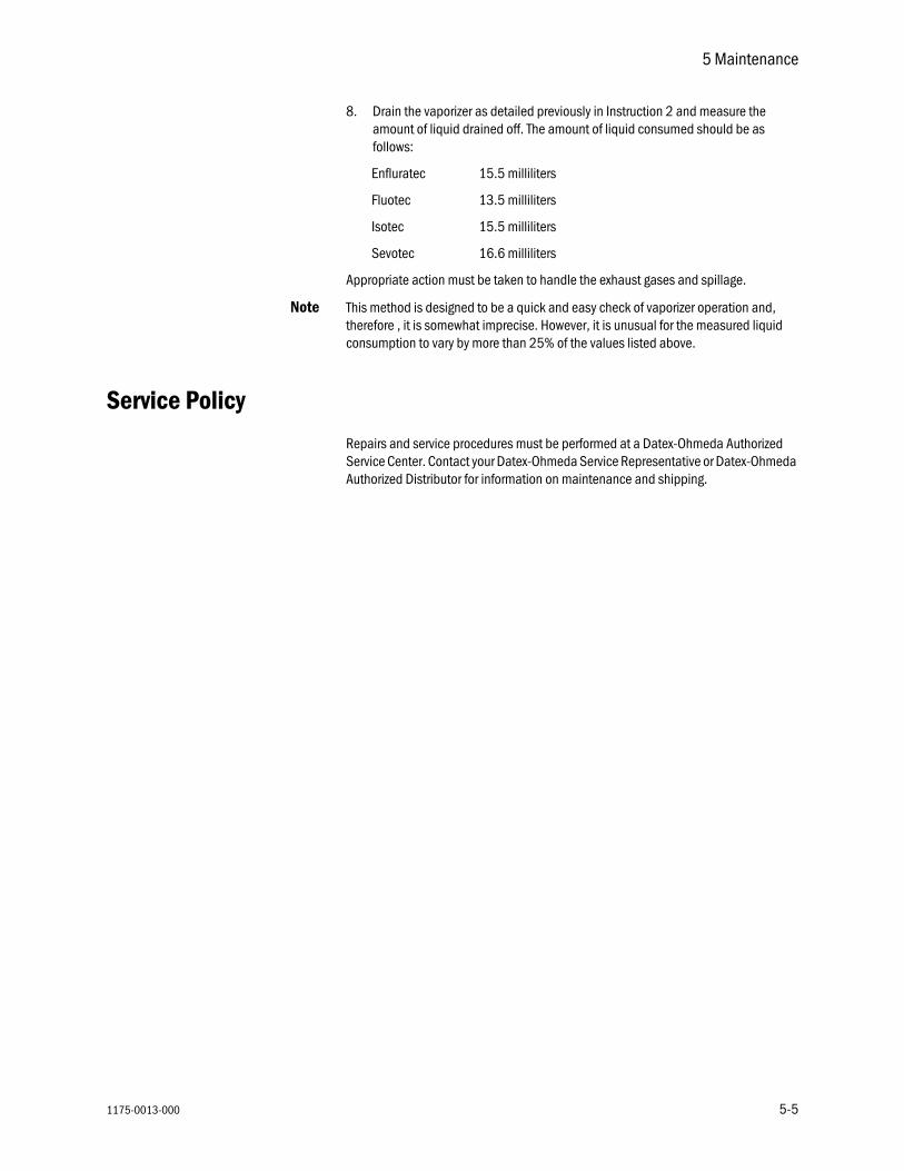
8. Drain the vaporizer as detailed previously in Instruction 2 and measure the amount of liquid drained off. The amount of liquid consumed should be as follows:
Enfluratec 15.5 milliliters
Fluotec 13.5 milliliters
Isotec 15.5 milliliters
Sevotec 16.6 milliliters
Appropriate action must be taken to handle the exhaust gases and spillage.
Note This method is designed to be a quick and easy check of vaporizer operation and, therefore , it is somewhat imprecise. However, it is unusual for the measured liquid consumption to vary by more than 25% of the values listed above.
y
Repairs and service procedures must be performed at a Datex-Ohmeda Authorized Service Center. Contact your Datex-Ohmeda Service Representative or Datex-Ohmeda Authorized Distributor for information on maintenance and shipping.
5-5

Tec 7 Vaporizer
5-6
1175-0013-000

1175-0013-000
Interlock me
Delivery of g
6 Principle of Operation
chanism
The vaporizer locking lever is interlocked with the vaporizer percentage control dial so that the control dial release, located at the rear of the dial, cannot be actuated until the vaporizer locking lever is in the locked position.
With the vaporizer locking lever in the locked position, the dial release can be pressed in toward the dial to operate the interlock mechanism, which allows the manifold port valves to open, prevents an adjacent vaporizer from being turned on, and allows the vaporizer to operate.
Turning the control dial to automatically reverses the operating sequence, which allows the dial release to move out to lock the dial in the position, closes the manifold port valves and vents the vaporizer gas connecting ports, and allows an adjacent vaporizer to be turned ON.
Turning the locking lever to the unlocked position releases the vaporizer allowing it to be removed from the manifold.
as/agent vapor
Overview The output concentration of the Tec 7 Vaporizer is regulated by the ‘variable flow-split’ method described in the following text and shown in figures 6-1 and 6-2.
A total flow of fresh gas from upstream flowmeters enters the vaporizer from the flowmeter where it is immediately split into two streams. One stream flows into the fresh gas bypass circuit and the other stream flows through the vaporizing chamber where it is enriched with the vapor of the liquid anesthetic agent.
6-1

Tec 7 Vaporizer
6-2
Bypa
Vaporizing
1
ss circuit The bypass circuit includes the gas transfer manifold and also a thermostat assembly that is located at the base of the vaporizer.
The fresh gas flows through the bypass circuit vertically downwards across the sump base through the thermostat and back up the gas transfer manifold to the common gas outlet as shown in Figure 6-1.
The thermostat deflects according to its temperature to control the resistance offered to the flow of gas through it. This deflection varies the relative proportions of gas flowing through the bypass and vaporizing chamber circuits.
1. Gas from flowmeter2. Sump base3. Thermostat4. Gas transfer manifold5. To common gas outlet6. Shut-off open7. Vaporizing chamber8. Flow control (vapor channel)9. Rotary valve
Figure 6-1 • Bypass circuit
chambercircuit
The fresh gas flow through the vaporizing chamber, as shown on Figure 6-2, flows from the flowmeter across the sump cover where it is diverted through the central cavity of the rotary valve and back through the Intermittent Positive Pressure Ventilation (IPPV) compensating assembly.
Gas now flows from the IPPV assembly down through the tubular wick assembly where it picks up anesthetic vapor and then flows across the base of the vaporizing chamber above the liquid agent.
From the base of the vaporizing chamber the gas/agent mixture flows through the sump cover to the proportional radial drug control groove of the rotary valve and then back into the sump cover where it combines with the fresh gas from the bypass circuit.
The combined total flow then flows out from the vaporizer and via the Selectatec circuitry to the anesthesia gas delivery system.
AB80
.039
52 3 4
6
7
8
9
1175-0013-000

6 Principle of Operation
1175-0013-000
1. Rotary valve2. Enriched fresh gas 3. Combined fresh ga4. Fresh gas bypass5. Fresh gas out6. Thermostat7. Vaporizing chambe8. Wick assembly9. IPPV compensating10. Sump cover11. Vapor control chan12. Shown in ON positi
11
7
8
9
10
12
outs and enriched gas out
r
assembly
nelon
Figure 6-2 • Vaporizer schematic
1
2
3
4
5
6
AB80
005
6-3

Tec 7 Vaporizer
6-4
1175-0013-000

7 Specifications
Note All specifications are nominal and subject to change without notice.
Calibration
Check the calibration certificate that is included with your Tec 7 Vaporizer.
Vaporizers are calibrated at 21°C using an oxygen carrier gas at a flow of 5 liters/minute and they are temperature, flow and pressure compensated within the specified operating range.
w WARNING The Tec 7 Vaporizer can only be calibrated at a Datex-Ohmeda Authorized Service Center.
1175-0013-000 7-1
Tec 7 Vaporizer
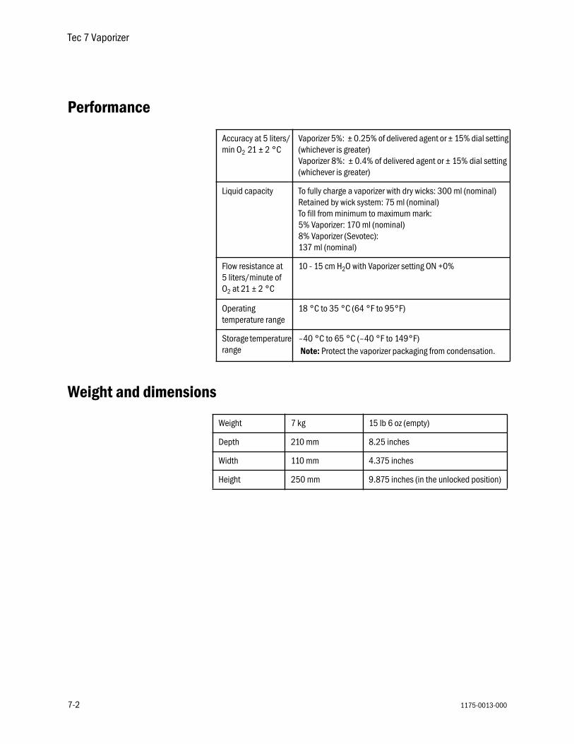
Performance
Weight and dimensions
Accuracy at 5 liters/min O2 21 ± 2 °C
Vaporizer 5%: ± 0.25% of delivered agent or ± 15% dial setting (whichever is greater)Vaporizer 8%: ± 0.4% of delivered agent or ± 15% dial setting (whichever is greater)
Liquid capacity To fully charge a vaporizer with dry wicks: 300 ml (nominal)Retained by wick system: 75 ml (nominal)To fill from minimum to maximum mark: 5% Vaporizer: 170 ml (nominal)8% Vaporizer (Sevotec):137 ml (nominal)
Flow resistance at 5 liters/minute of O2 at 21 ± 2 °C
10 - 15 cm H2O with Vaporizer setting ON +0%
Operating temperature range
18 °C to 35 °C (64 °F to 95°F)
Storage temperature range
–40 °C to 65 °C (–40 °F to 149°F) Note: Protect the vaporizer packaging from condensation.
Weight 7 kg 15 lb 6 oz (empty)
Depth 210 mm 8.25 inches
Width 110 mm 4.375 inches
Height 250 mm 9.875 inches (in the unlocked position)
7-2 1175-0013-000
7 Specifications
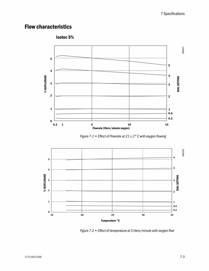
Flow characteristics
Isotec 5%
Figure 7-1 • Effect of Flowrate at 21 ± 2° C with oxygen flowing
Figure 7-2 • Effect of temperature at 5 liters/minute with oxygen flow
0
1
2
3
4
5
0.2 1 5 10 15
5
4
3
2
10.6
0.2
AB80
027
% IS
OFLU
RANE
DIAL
SET
TING
Flowrate (liters/minute oxygen)
0
1
2
3
4
5
15 20 25 30
5
4
3
2
1
0.6
0.2
35
AB80
028
% IS
OFLU
RANE
DIAL
SET
TING
Temperature °C
1175-0013-000 7-3

Tec 7 Vaporizer
Fluotec 5%
Figure 7-3 • Effect of Flowrate at 21 ± 2° C with oxygen flowing
Figure 7-4 • Effect of temperature at 5 liters/minute with oxygen flow
0
1
2
3
4
5
0.2 1 5 10 15
5
4
3
2
1
0.6
0.2
AB80
029
% H
ALOT
HAN
E
DIAL
SET
TING
Flowrate (liters/minute oxygen)
0
1
2
3
4
5
15 20 25 30
5
4
3
2
1
0.6
0.2
35
AB80
030
% H
ALOT
HAN
E
DIAL
SET
TING
Temperature °C
7-4 1175-0013-000

7 Specifications
Sevotec 5%
Figure 7-5 • Effect of Flowrate at 21 ± 2° C with oxygen flowing
Figure 7-6 • Effect of temperature at 5 liters/minute with oxygen flow
AB80
0031
1
2
3
4
5
0.2 1 5 10
5
4
3
2
1
0.6
0.2
150
% S
EVOF
LURA
NE
DIAL
SET
TING
Flowrate (liters/minute oxygen)
AB80
032
0
1
2
3
4
5
15 20 25 30
5
4
3
2
1
0.6
0.2
35
% S
EVOF
LURA
NE
DIAL
SET
TING
Temperature °C
1175-0013-000 7-5

Tec 7 Vaporizer
Enfluratec 5%
Figure 7-7 • Effect of Flowrate at 21 ± 2° C with oxygen flowing
Figure 7-8 • Effect of temperature at 5 liters/minute with oxygen flow
1
2
3
4
5
0.2 1 5 10
5
4
3
2
1
0.6
0.2
150
AB80
035
% E
NFLU
RANE
DIAL
SET
TING
Flowrate (liters/minute oxygen)
0
1
2
3
4
5
15 20 25 30
5
4
3
2
1
0.6
0.2
35
AB80
036
% E
NFLU
RANE
DIAL
SET
TING
Temperature °C
7-6 1175-0013-000

7 Specifications
Sevotec 8%
Figure 7-9 • Effect of Flowrate at 21 ± 2° C with oxygen flowing
Figure 7-10 • Effect of temperature at 5 liters/minute with oxygen flow
1
0.2 1 5 10
543
2
10.60.2
150
2
3
4
5
6
7
8
678
AB80
033
% S
EVOF
LURA
NE
DIAL
SET
TING
Flowrate (liters/minute oxygen)
1
15 20 25 30
5
4
3
2
10.60.2
350
2
3
4
5
6
7
8
6
7
8
AB80
034
% S
EVOF
LURA
NE
DIAL
SET
TING
Temperature °C
1175-0013-000 7-7
Tec 7 Vaporizer
Effects of variables
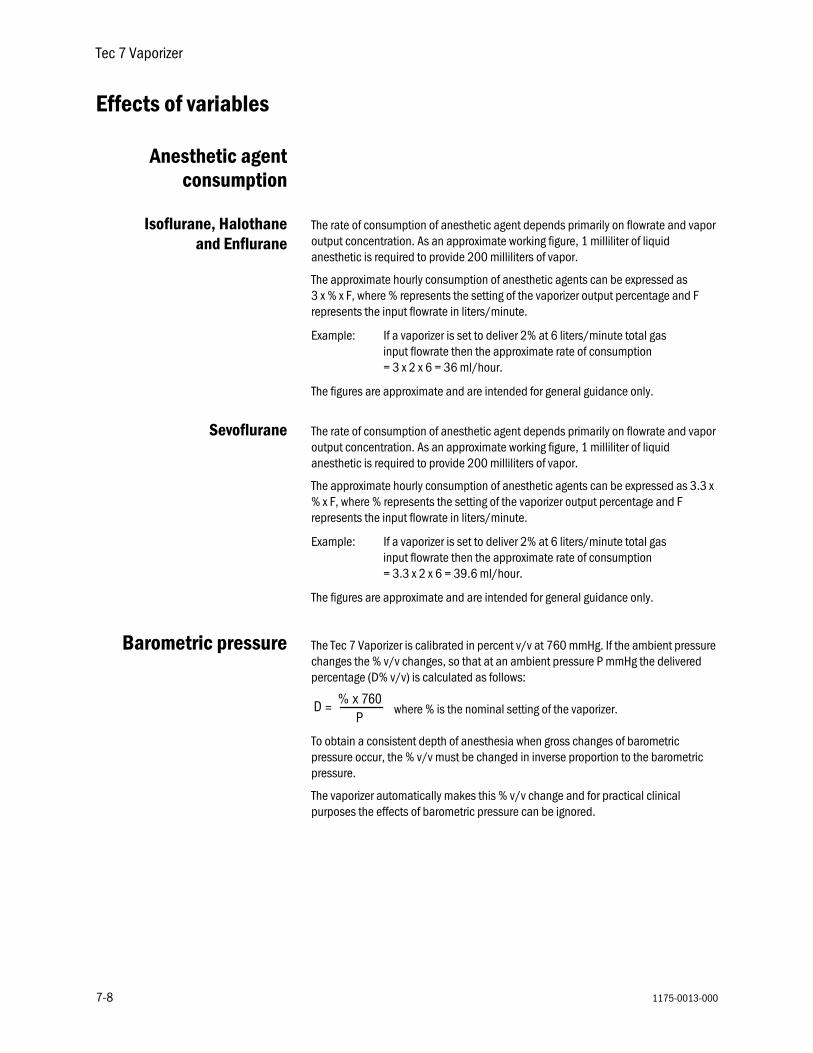
Anesthetic agentconsumption
Isoflurane, Halothaneand Enflurane
The rate of consumption of anesthetic agent depends primarily on flowrate and vapor output concentration. As an approximate working figure, 1 milliliter of liquid anesthetic is required to provide 200 milliliters of vapor.
The approximate hourly consumption of anesthetic agents can be expressed as 3 x % x F, where % represents the setting of the vaporizer output percentage and F represents the input flowrate in liters/minute.
Example: If a vaporizer is set to deliver 2% at 6 liters/minute total gas input flowrate then the approximate rate of consumption = 3 x 2 x 6 = 36 ml/hour.
The figures are approximate and are intended for general guidance only.
Sevoflurane The rate of consumption of anesthetic agent depends primarily on flowrate and vapor output concentration. As an approximate working figure, 1 milliliter of liquid anesthetic is required to provide 200 milliliters of vapor.
The approximate hourly consumption of anesthetic agents can be expressed as 3.3 x % x F, where % represents the setting of the vaporizer output percentage and F represents the input flowrate in liters/minute.
Example: If a vaporizer is set to deliver 2% at 6 liters/minute total gas input flowrate then the approximate rate of consumption = 3.3 x 2 x 6 = 39.6 ml/hour.
The figures are approximate and are intended for general guidance only.
Barometric pressure The Tec 7 Vaporizer is calibrated in percent v/v at 760 mmHg. If the ambient pressure changes the % v/v changes, so that at an ambient pressure P mmHg the delivered percentage (D% v/v) is calculated as follows:
where % is the nominal setting of the vaporizer.
To obtain a consistent depth of anesthesia when gross changes of barometric pressure occur, the % v/v must be changed in inverse proportion to the barometric pressure.
The vaporizer automatically makes this % v/v change and for practical clinical purposes the effects of barometric pressure can be ignored.
D = % x 760P
7-8 1175-0013-000

7 Specifications
Ambient temperature The effects of variation in temperature are normally negligible at commonly used combinations of dial setting and ambient temperature.
If the vaporizer temperature is above the range shown on the performance curves, the vaporizer output may be unpredictably high, particularly if the temperature of the agent approaches the agent boiling point specified by the agent manufacturer.
If the vaporizer temperature is below the range shown on the performance curves, the vaporizer output may be lower than expected.
To help avoid inaccuracies due to extreme temperatures, before using the vaporizer it must be allowed to attain a temperature within the range shown on the performance curves.
Back pressure
wwww WARNING Pressures in excess of 400 mmHg may overcome the internal pressure balance and cause a variation in output.
Steady back pressure The vaporizer cannot distinguish between pressures at the outlet due to barometric pressure and pressures in excess of barometric due to steady back pressures applied by downstream components. The equation given in the section Barometic Pressure therefore applies with the term P now being the absolute pressure at the outlet, that is, barometric pressure plus back pressure. Steady back pressure reduces the % v/v.
Currently, it is unlikely that the steady back pressure imposed by commonly used downstream components, other than some ventilators, exceeds 30 mmHg at commonly used flowrates. Back pressures as high as 30 mmHg would reduce the delivered % v/v, at 760 mmHg barometric pressure, to the following:
= 0.96 of what would otherwise be expected.
Under normal clinical circumstances effects of this magnitude can be ignored.
Fluctuating back pressure Fluctuating back pressure may be imposed on the vaporizer by downstream components and/or assisted or controlled ventilation to the patient. These fluctuating back pressures can affect the vaporizer and increase the concentration by intermittently altering the pressures, and consequently the flow distribution, within the vaporizer.
The greatest effects are observed at combinations of very low flowrates and low dial setting with large and rapid pressure fluctuations. The effects become progressively less important as the dial setting and flowrate increase and the magnitude and rate of cycling of the pressure fluctuations decrease.
760790---------790
1175-0013-000 7-9
Tec 7 Vaporizer
7-10
Carrier gas co
Time out
Effects o
mposition Small output decreases can occur when the carrier gas composition is changed from 100% oxygen.
When either air or nitrous oxide is employed as the carrier gas, the output is lowered compared to the output when oxygen is the carrier gas. This effect is the greatest (up to 20% of setting) at low flows when nitrous oxide is employed, but using nitrous oxide reduces the required inspired concentrations of volatile agent that can, depending upon the proportion, mitigate the decreases in output from the vaporizer.
wwww WARNING Only operate the vaporizer with dry medical gases.
of service If the anesthesia machine on which the vaporizer is fitted is left for a period of time with no gases flowing, small concentrations may be detected at the machine outlet immediately after the gas flow is turned ON. This is a normal machine characteristic and is caused by residual vapor left in the machine from previous use.
When the vaporizer is turned from the setting after a period out of use, a brief high concentration may occur that rapidly stabilizes to the set concentration within approximately 10 seconds at 5 liters/minute.
These phenomena are normal characteristics of vaporizers. In use the volume of vapor involved is small compared to the volume of the breathing circuit.
f variables Ambient temperature, input flowrate and duration of use can affect delivered concentration, particularly when the vaporizers are used at extremes of the usual clinical range.
Note Use of the vaporizer at high gas flows and high dial concentrations may affect the accuracy of delivered concentrations. Refer to Performance Curves in this chapter for full information.
The valve design and temperature compensation system of Tec 7 Vaporizers reduces the effects to levels such that, under most clinical conditions, their effect on vaporizer performance is not clinically significant.
1175-0013-000
Warranty
This Product is sold by Datex-Ohmeda under the warranties set forth in the following paragraphs. Such warranties are extended only with respect to the purchase of this Product directly from Datex-Ohmeda or Datex-Ohmeda’s Authorized Dealers as new merchandise and are extended to the Buyer thereof, other than for the purpose of resale.
For a period of 36 months from the date of original delivery to Buyer or to Buyer’s order, but in no event for a period of more than three years from the date of original delivery by Datex-Ohmeda to a Datex-Ohmeda Authorized Dealer, this Product, other than its expendable parts, is warranted against functional defects in materials and workmanship and to conform to the description of the Product contained in this User’s Reference Manual and accompanying labels and/or inserts, provided that the same is properly operated under the conditions of normal use, that regular periodic maintenance is performed and that replacements and repairs are made in accordance with the instructions provided. This same warranty is made for a period of thirty (30) days with respect to expendable parts. The foregoing warranties shall not apply if the Product has been repaired other than by Datex-Ohmeda or in accordance with written instructions provided by Datex-Ohmeda, or altered by anyone other than Datex-Ohmeda, or if the Product has been subject to abuse, misuse, negligence, or accident.
Datex-Ohmeda’s sole and exclusive obligation and Buyer’s sole and exclusive remedy under the above warranties is limited to repairing or replacing, free of charge, at Datex-Ohmeda’s option, a Product, which is telephonically reported to the nearest Datex-Ohmeda Customer Support Center and which, if so advised by Datex-Ohmeda, is thereafter returned with a statement of the observed deficiency, not later than seven (7) days after the expiration date of the applicable warranty, during normal business hours, transportation charges prepaid, and which, upon Datex-Ohmeda’s examination, is found not to conform with above warranties. Datex-Ohmeda shall not be otherwise liable for any damages including but not limited to incidental damages, consequential damages, or special damages.
There are no express or implied warranties which extend beyond the warranties hereinabove set forth. Datex-Ohmeda makes no warranty of merchantability or fitness for a particular purpose with respect to the product or parts thereof.

Datex-Ohmeda, Inc.PO Box 7550
Tel 608 221 1551Fax 608 222 9147www.datex-ohmeda.com
Madison WI 53707-7550USA
CCCCoooorrrrppppoooorrrraaaatttteeee OOOOffffffffiiiicccceeee
Datex-Ohmeda DivisionInstrumentarium Corp.PO Box 900FIN-00031 HelsinkiFinlandTel 358 10 394 11Fax 358 9 146 3310
NNNNoooorrrrtttthhhh AAAAmmmmeeeerrrriiiiccccaaaa
UUUUnnnniiiitttteeeedddd SSSSttttaaaatttteeeessss
CCCCuuuussssttttoooommmmeeeerrrr SSSSeeeerrrrvvvviiiicccceeee,,,, TTTTeeeecccchhhhnnnniiiiccccaaaallll SSSSuuuuppppppppoooorrrrtttt aaaannnndddd DDDDiiiissssttttrrrriiiibbbbuuuuttttiiiioooonnnn CCCCeeeennnntttteeeerrrr
Datex-Ohmeda, Inc.PO Box 7550Madison, WI 53707-7550, USATel 1 800 345 2700Fax 1 608 221 4384
EEEEqqqquuuuiiiippppmmmmeeeennnntttt SSSSeeeerrrrvvvviiiicccceeee CCCCeeeennnntttteeeerrrr
Datex-Ohmeda, Inc.1315 West Century DriveLouisville CO 80027-9560, USATel 1 800 345 2700Fax 1 303 373 1607
CCCCaaaannnnaaaaddddaaaa
Datex-Ohmeda (Canada) Inc.1093 Meyerside Drive, Unit 2Mississauga, OntarioL5T 1J6CanadaTel 1 800 268 1472Tel 1 905 565 8572Fax 1 905 565 8592
AAAAssssiiiiaaaa////PPPPaaaacccciiiiffffiiiicccc
CCCChhhhiiiinnnnaaaa
Datex-Ohmeda Pte. Ltd.Room B416, COFCO Plaza8 Jianguomennei AvenueBeijing 100005, PR ChinaTel 86 10 6526 9773Fax 86 10 6526 0653Datex-Ohmeda Pte. Ltd.Room 1708, Yunlong MansionNo. 122 Luoguo StreetChengdu 610017, PR ChinaTel 86 28 661 4424Fax 86 28 676 2703
Datex-Ohmeda Pte. Ltd.403 Huan Shi Dong RoadRoom 1602, GIE TowerGuangzhou, 510095, P R ChinaTel 86 20 8732 2521Fax 86 20 8732 2518Datex-Ohmeda Pte. Ltd.Room 2509 Lippo PlazaNo. 222 Huaihai Road (M)Shanghai 200021, P.R. ChinaTel 8621 5382 5657Fax 8621 5382 1691Datex-Ohmeda Pte. Ltd.Room 809, Truroll PlazaWusheng RoadWuhan 430033, P R ChinaTel 86 27 8571 2536Fax 86 27 8571 2655
IIIInnnnddddiiiiaaaa
Datex-Ohmeda (India) Pvt. Ltd.Block EP & GP, Sector VPlot XI-16, Salt Lake CityCalcutta 700091IndiaTel 91 33 3574002Fax 91 33 3574001
IIIInnnnddddoooonnnneeeessssiiiiaaaa
Datex-Ohmeda Pte. Ltd.Wisma Danamon Aetna Life 19th FloorJln. Jend Sudirman Kav. 45-46 Jakarta 12930, IndonesiaTel 62 21 575 0864Fax 62 21 575 0865
JJJJaaaappppaaaannnn
Datex-Ohmeda K. K.TRC Annex 9F6-1-1 HeiwajimaOhta-ku, Tokyo 143-0006JapanTel 81 3 5763 6801Fax 81 3 5763 6838Datex-Ohmeda K. K.Technical CenterTRC A Bldg. AE 4-86-1-1 HeiwajimaOhta-ku, Tokyo 143-0006JapanTel 81 3 5763 6850Fax 81 3 5763 6852
KKKKoooorrrreeeeaaaa
Datex-Ohmeda Pte. Ltd.10th Floor, Sam Sung Building36 - 1, Yoido-Dong, Youngdeungpo-KuSeoul, KoreaTel 82 2 786 7421Fax 82 2 786 7420
MMMMaaaallllaaaayyyyssssiiiiaaaa
Datex-Ohmeda Pte. Ltd.Level 2 Bangunan O'Connor13 Jalan 22346100 Petaling JayaSelangor, West MalaysiaTel 60 3 754 7872Fax 60 3 757 6948
SSSSiiiinnnnggggaaaappppoooorrrreeee
Datex-Ohmeda Pte. Ltd.152 Beach Road#12-05/07 Gateway EastSingapore 189721Tel 65 391 8618Fax 65 291 6618
TTTThhhhaaaaiiiillllaaaannnndddd
Datex-Ohmeda Pte. Ltd.12th Floor (Unit F) Grand Amarin Tower1550 New Petchburi Road, Makasan, Ra-jathevi,Bangkok 10320, ThailandTel 66 2 2071012/13Fax 66 2 207 1014
TTTTaaaaiiiiwwwwaaaannnn aaaannnndddd PPPPhhhhiiiilllliiiippppppppiiiinnnneeeessss
Datex-Ohmeda Pte. Ltd.2nd Floor, No. 85, Chien-Kuo North Road, Sec. 2Taipei, TaiwanRepublic of ChinaTel 886-2 2515-0457Fax 886-2 2501-9136
VVVViiiieeeettttnnnnaaaammmm
Datex-Ohmeda Pte. Ltd.522G Nguyen Tri Phuong St.Ho Chi Minh City, Dist. 10 VietnamTel 848 865 5875Fax 848 862 5501
AAAAuuuussssttttrrrraaaalllliiiiaaaa
Datex-Ohmeda Pty. Ltd.Units 1 & 2149 Arthur StreetP O Box 356HomebushNSW 2140AustraliaTel 61 132 229Fax 61 297 461796
EEEEuuuurrrrooooppppeeee
CCCCIIIISSSS////BBBBaaaallllttttiiiiccccssss
Datex-OhmedaRegional Head OfficePO Box 70071GR-16610 Glyfada - AthensGreeceTel +30 10 9625136-7Fax +30 10 9623687
FFFFrrrraaaannnncccceeee
Datex-Ohmeda S.A.S.ZAC de Sans-Souci1211 Chemin de la BruyèreF-69760 LimonestFranceTel 33 (0) 4 78 66 62 10Fax 33 (0) 4 78 43 26 58
GGGGeeeerrrrmmmmaaaannnnyyyy
Datex-Ohmeda GmbHDr. Alfred-Herrhausen-Allee 24D-47228 DuisburgGermanyTel 49 2065 691-0Fax 49 2065 691-236
IIIIttttaaaallllyyyy
Datex-Ohmeda S.p.A.Via Cassanese 10020090 Segrate, MilanItalyTel 39 2 21693431Fax 39 2 26926226
NNNNeeeetttthhhheeeerrrrllllaaaannnnddddssss
Datex-Ohmeda B.V.Kantemarsweg 18Post Box 223870 CA HoevelakenNetherlandsTel 31 33 253 5404Fax 31 33 253 7223
SSSSppppaaaaiiiinnnn
Datex-Ohmeda S.L.C/Manuel Tovar 2628034 MadridSpainTel 34 1 334 26 00Fax 34 1 358 12 84
UUUUnnnniiiitttteeeedddd KKKKiiiinnnnggggddddoooommmm
Datex-Ohmeda Ltd.Ohmeda House71 Great North RoadHatfield HertfordshireAL9 5EN EnglandTel 44 1707 263570Fax 44 1707 260191
LLLLaaaattttiiiinnnn AAAAmmmmeeeerrrriiiiccccaaaa,,,, CCCCaaaarrrriiiibbbbbbbbeeeeaaaannnn
Datex-Ohmeda9155 South Dadeland Blvd.Suite 1218Miami, FL 33156, USATel 1 305 670 8540Fax 1 305 670 2316
MMMMiiiiddddddddlllleeee EEEEaaaasssstttt
Datex-OhmedaRegional Head OfficePO Box 70071GR-16610 Glyfada - AthensGreeceTel +30 10 9625136-7Fax +30 10 9623687
Tec 7 vaporizerUser’s Reference Manual, English1175 0013 00006 02 A 18 05 02Printed in USA©Datex-Ohmeda, Inc. All rights reserved
The addresses listed on this cover are current as of 4/02. For any location changes, please visit our website at www.datex-ohmeda.com and click on the Contacts button.