Users manual CS 7.0 UK - twinheat.dktwinheat.dk/media/1153/users-manual-cs_70-uk.pdf13 14 15 16 17...
27
Users manual Version 7.0 STOKER PLANTS CS120i CS150i CS200i CS250i Norrevangen 7 DK-9631 Gedsted Phone +45 98645222 Fax. +45 98645244 Mail: [email protected] Web: www.twinheat.dk ®
-
Upload
dinhnguyet -
Category
Documents
-
view
216 -
download
1
Transcript of Users manual CS 7.0 UK - twinheat.dktwinheat.dk/media/1153/users-manual-cs_70-uk.pdf13 14 15 16 17...

Users manual
Version 7.0
STOKER PLANTS
CS120i CS150i CS200i CS250i
Norrevangen 7 DK-9631 Gedsted Phone +45 98645222 Fax. +45 98645244
Mail: [email protected] Web: www.twinheat.dk
®

Version 7.0 – May 2011 ©
Instructions for TWIN HEAT stoker plants type CS120i, CS200i, CS150i & CS250i
Year:
No.:
Series:
TWIN HEAT stoker plants type CS120i, CS150i & CS250i have been tested and approved according to DS/EN303-5 by “ Danish Technological Institute”
(The test institution for smaller bio heating appliances)
Wood pellets with app. 8% moisture
Wood chips with app. 25% moisture
Grains with app. 15% moisture

1
Table of contents Table of contents .................................................................................................... 1 Plant drawing .......................................................................................................... 2 Section 1- How to use a CS plant .......................................................................... 3
1.1 The display in the controller.............................................................................. 3 1.2 Menu structure.................................................................................................. 4 1.3 Adjustment of temperature ............................................................................... 4 1.4 How to choose fuel type ................................................................................... 5 1.5 O2 regulation ore manual operation ................................................................. 5 1.5.1 Adjustment of Man. Fac.................................................................................... 6 1.6 Adjustment of the fuel program “Other” ............................................................ 6 1.6.1 Start parameters ............................................................................................... 7 1.6.2 Operation (running) parameters ....................................................................... 7 1.6.3 Pause................................................................................................................ 7 1.7 Calibration of lambda probe.............................................................................. 7 1.8 Reset all ............................................................................................................ 8 1.9 Ash exhale menu .............................................................................................. 8 1.10 Blaster menu..................................................................................................... 8 1.11 Post run menu .................................................................................................. 9
Section 2- Start up and normal use....................................................................... 10 2.1 Weighing of fuel ................................................................................................ 10 2.1.1 Calibration of lambda probe.............................................................................. 10 2.2 Taking fuel forward to the burner tube.............................................................. 11 2.3 Lighting the fire ................................................................................................. 11 2.4 Soft start mode ................................................................................................. 11 2.5 Running mode .................................................................................................. 12 2.6 Pause mode...................................................................................................... 12 2.7 Stop .................................................................................................................. 13 2.8 Bypass .............................................................................................................. 13
Section 3- troubleshooting .................................................................................... 14 3.1 Error: Hot boiler ................................................................................................ 14 3.2 Low temp. ......................................................................................................... 14 3.3 Stoker stop........................................................................................................ 15 3.4 High O2............................................................................................................. 15 3.5 Lambda offs. ..................................................................................................... 15 3.6 Error: Waterpress ............................................................................................. 16 3.7 Error: Thermo ................................................................................................... 16 3.8 Error: Freq. conv............................................................................................... 16 3.9 Power cut.......................................................................................................... 16 3.10 Sprinkler system ............................................................................................... 16
Section 4- Maintenance.......................................................................................... 17 4.1 Maintenance intervals....................................................................................... 17 4.2 Maintenance of boiler ....................................................................................... 18 4.3 Maintenance of burner tube.............................................................................. 18 4.4 Maintenance of stoker ...................................................................................... 19
Section 5- Technical information .......................................................................... 20 5.1 CS120i .............................................................................................................. 20 5.2 CS150i .............................................................................................................. 21 5.3 CS250i .............................................................................................................. 22 5.4 CS200i .............................................................................................................. 23
Declaration of conformity Enclosure 1- Accessories included

Plant drawing
111098764321
181716151413
5
12
1. Boiler door 2. Door to heat exchanger – shown with aut. heat-exchanger cleaning system
3. Boiler
4. Auger for aut. ash exhale
5. Mud hole
6. Flue-gas fan
7. Water cooled burner tube
8. Stoker
9. Control panel
10. Rotary valve
11. Auger from extern fuel silo (is not included from Twin Heat)
12. Circulation pump for burner tube
13. Water pressure sensitive switch
14. Combustion fan
15. Sprinkler system (95°C)
16. Gear motor for auger and rotary valve
17. Inspection hole
18. Chain connection
2Plant drawing
Section 1- How to use a CS stoker plant
1.1 The display in the controller
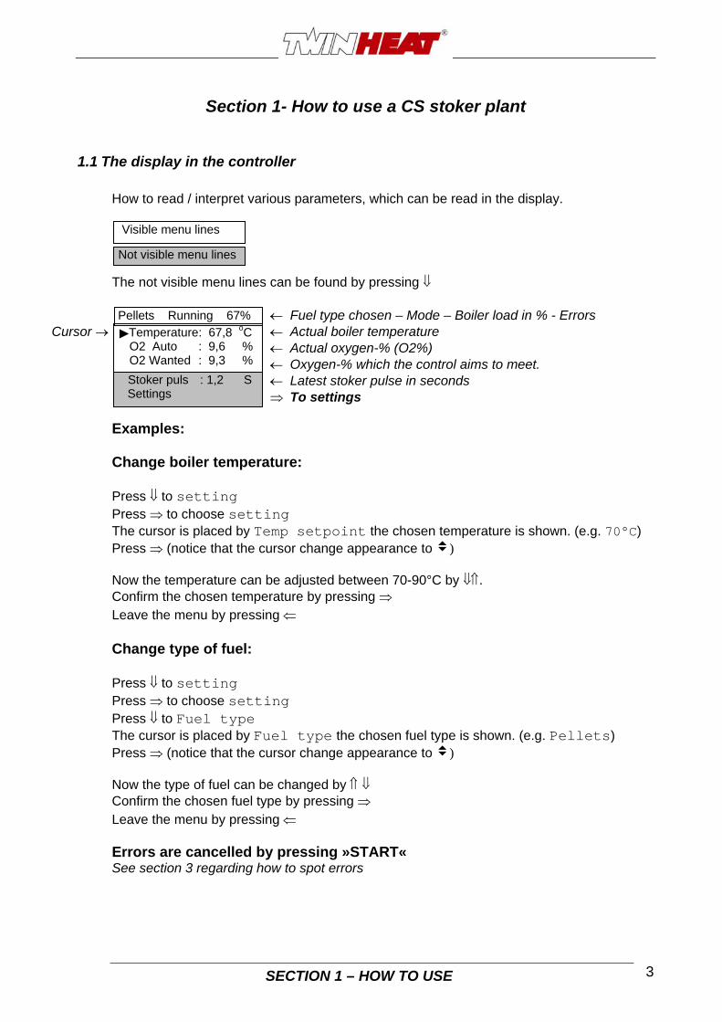
How to read / interpret various parameters, which can be read in the display. The not visible menu lines can be found by pressing Fuel type chosen – Mode – Boiler load in % - Errors
SECTION 1 – HOW TO USE 3
Cursor Actual boiler temperature Actual oxygen-% (O2%) Oxygen-% which the control aims to meet. Latest stoker pulse in seconds To settings Examples: Change boiler temperature: Press to setting Press to choose setting The cursor is placed by Temp setpoint the chosen temperature is shown. (e.g. 70°C) Press (notice that the cursor change appearance to ) Now the temperature can be adjusted between 70-90°C by . Confirm the chosen temperature by pressing Leave the menu by pressing Change type of fuel: Press to setting Press to choose setting Press to Fuel type The cursor is placed by Fuel type the chosen fuel type is shown. (e.g. Pellets) Press (notice that the cursor change appearance to ) Now the type of fuel can be changed by Confirm the chosen fuel type by pressing Leave the menu by pressing Errors are cancelled by pressing »START« See section 3 regarding how to spot errors
Not visible menu lines
Visible menu lines
Temperature : 67,8 oC
Pellets Running 67%
O2 Auto : 9,6 % O2 Wanted : 9,3 %
Stoker puls : 1,2 S Settings

1.2 Menu structure The various adjustment possibilities are looked up in searching by means of the arrows at the front of the control panel If you want to leave the menu without making any changes, press Errors are cancelled by pressing »START«
SECTION 1 – HOW TO USE 4
*Ash exhale menu**Puls time 2s Pause time 12h
*O2 regulator menu*O2 regulation YES Man. fac pel. 35%
*Other fuel menu**STARTSoft start 20m Stoker delay 5mOPERATION O2 0% 18% O2 100% 9,00% O2 pkt. 30,00% O2 proc. 5,00% Stoker puls 1,8% Stoker term 120s Factor 35%PAUSE Stoker puls 0,0% Stoker term 600s After run B. 4 Start puls 200,0%Kg/min at max. 0,88
Temp Setpoint 70C Fuel type Pel. Calibrate O2 No O2 regul. on/off...................... Other fuel............................... Stokermotor menu................. Fire starter menu Ash exhale menu...................
Password 0 Recall all No
: 67,8: 9,6: 9,3: 1,2
Pel. Running 67%
C%%S
Temperature O2 Auto O2 Wanted Stoker puls Setting....................................
*Stoker Motor menuPower setpkt 100 Error times 1 Power: 0 Times: 0
Blaster menu..........................
Weigh in menu.......................
**Settings menu***
***Blaster menu***Puls time 4s Pause time 240s Cycle time 12h **Weigh in menu***Pel. 0.00 kg/min Grain 0.00 kg/min W.ch. 0.00 kg/min Other 0.00 kg/min
Postrun 25s
1.3 Adjustment of temperature
The temperature ( boiler temperature) can be adjusted between 70 – 90°C The temperature is from factory pre-set to 70°C. Some situations – such as an under-dimensioned radiator system or hot water tank might make it desirable to adjust the boiler temperature higher than 70 º C The cursor must be placed by the line Setting Press : The adjusted temperature is shown . (e.g. 70°C) Press : The temperature can be adjusted by pressing . Confirm new setting by pressing Leave the menu by pressing

SECTION 1 – HOW TO USE 5
The water returning to the boiler must always be at least 60°C If the above is not respected the corrosion of the steel in the boiler will increase and the life expectations will be reduced
1.4 How to chose fuel type
In the settings menu under fuel type you can chose between 4 programs There are 3 fixed programs for respectively Wood pellets, Grains or Wood chips. The programs are adapted to the individual type of fuel. If you chose to use another kind of fuel than the above mentioned, you have the possibility to chose Other under fuel type. When Other has been chosen, parameters for this fuel must be adjusted. (See section 1.6 Setting) The cursor must be placed by the line Setting Press to choose setting Press to Fuel type The chosen fuel type is shown. (e.g. Pellets) Press Now the type of fuel can be changed by pressing Confirm the new setting with Leave the menu by pressing
PLEASE NOTE: Requirements when heating with grains: High flue gas temperature min. 180°C High boiler output min. 50% High boiler temperature min. 80°C
1.5 O2 regulation ore manual operation
Manual operation can be an advantage, if the fuel used is of bad quality or if e.g. the lambda probe goes defect The cursor must be placed by the line Setting Press to choose setting Press to O2 regul. On/off Press to choose O2 regulator menu Press : Now you can choose YES or NO by pressing . (YES = O2 regulation NO = Manuel operation) Confirm your choice by pressing Leave the menu by pressing Hereafter the Man. Fac. (the amount of fuel) has to be adjusted (0 – 100 %) according to the fuel chosen : pellets, grains, wood chips or other. (See next section)
SECTION 1 – HOW TO USE 6
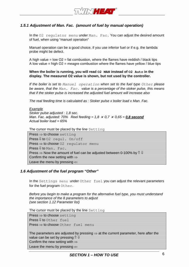
1.5.1 Adjustment of Man. Fac. (amount of fuel by manual operation)
In the O2 regulator menu under Man. Fac. You can adjust the desired amount of fuel, when using “manuel operation” Manuel operation can be a good choice, if you use inferior fuel or if e.g. the lambda probe might be defect. A high value = low O2 = fat combustion, where the flames have reddish / black tips A low value = high O2 = meagre combustion where the flames have yellow / blue tips When the boiler is running, you will read O2 MAN instead of O2 Auto in the display. The measured O2 value is shown, but not used by the controller. If the boiler is set to Manuel operation when set to the fuel type Other please be aware, that the Man. Fac. value is a percentage of the stoker pulse, this means that if the stoker pulse is increased the adjusted fuel amount will increase also The real feeding time is calculated as : Stoker pulse x boiler load x Man. Fac. Example Stoker pulse adjusted : 1,8 sec. Man. Fac. adjusted: 70% Reel feeding = 1,8 0,7 0,65 = 0,8 second Actual boiler load = 65% The cursor must be placed by the line Setting
Press to choose setting Press to O2 regul. On/off Press to choose O2 regulator menu Press to Man. Fac. Press Now the amount of fuel can be adjusted between 0-100% by Confirm the new setting with Leave the menu by pressing
1.6 Adjustment of the fuel program “Other”
In the Settings menu under Other fuel you can adjust the relevant parameters for the fuel program Other. Before you begin to make a program for the alternative fuel type, you must understand the importance of the 8 parameters to adjust (see section 1.12 Parameter list) The cursor must be placed by the line Setting
Press to choose setting Press to Other fuel Press to choose Other fuel menu The parameters are adjusted by pressing at the current parameter, here after the value can be set by pressing Confirm the new setting with Leave the menu by pressing

SECTION 1 – HOW TO USE 7
1.6.1 Start parameters
Under Start you can adjust 2 parameters for the start up of the boiler. Soft start: Defines the period for the boiler to reach 100% load, when starting up a cold boiler. Stoker delay: Defines the period where the auger is not running, when starting up a cold boiler.
1.6.2 Operation (running) parameters
Under Operation you can adjust 2 parameters for the running of the boiler. O2 means Oxygen and indicates the air surplus measured in the flue. Good fuels of dried wood, such as pellets and the like can be combusted by a small surplus of air (6 – 9 %) whereas less good fuel with higher water content or the like needs a higher surplus of air. O2 100%: Defines the oxygen % (surplus air), which the controller aims for by 100 % boiler load. Stoker term: Defines the pause time between each running period.
1.6.3 Pause
Under Pause you can adjust 4 parameters for the pause of the boiler Stoker pulse: Defines the running time for the auger per period Stoker term: Defines the pause time between each running period. After run blower: Decides how long time the fan runs after each stoker pulse. Start puls: Decides the time(fuel amount) the auger is running first time after pause
1.7 Calibration of lambda probe
If the lambda probe over time becomes less precise, it has to be calibrated. In normal atmospheric air the oxygen content is always app. 21 % (O2). This can be used as point of reference for the measurement of the oxygen content. The lambda probe should be calibrated if the oxygen content in air deviates more than ± 2% from 21%. This can only be established, when the probe is exposed to absolutely clean atmospheric air Dismount the lambda probe by removing the two bolts holding the square plate which the lambda probe is mounted in. Lift up the plate with lambda probe and place it on top of the boiler. The cursor must be placed by the line Setting
Press to choose setting Press to Calibrate O2 Press : Now you can change No to YES by pressing . Confirm the change with
Now the lambda probe is calibrated (adjusted)
SECTION 1 – HOW TO USE 8
1.8 Reset all
If you want to reset all parameters to factory settings, chose YES. Remember to re-calibrate the lambda probe as described above
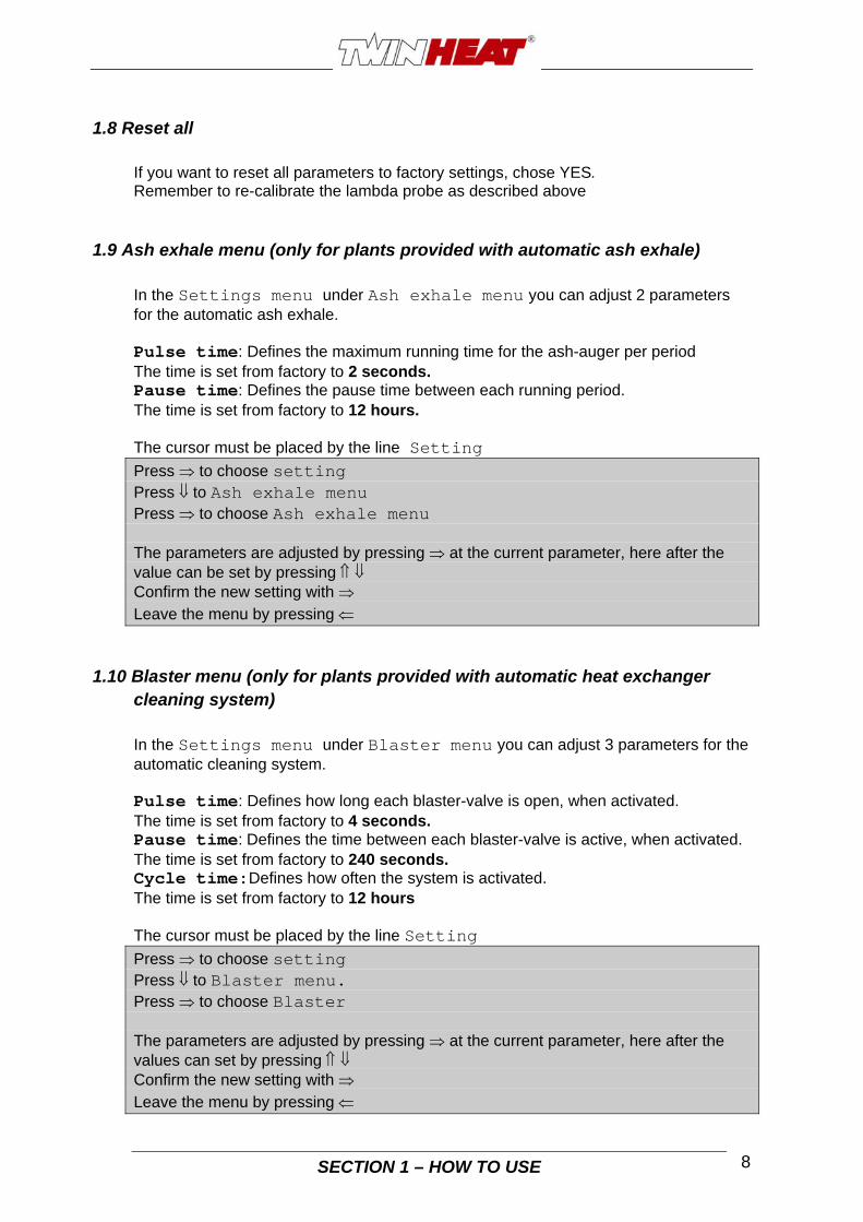
1.9 Ash exhale menu (only for plants provided with automatic ash exhale)
In the Settings menu under Ash exhale menu you can adjust 2 parameters for the automatic ash exhale. Pulse time: Defines the maximum running time for the ash-auger per period The time is set from factory to 2 seconds. Pause time: Defines the pause time between each running period. The time is set from factory to 12 hours. The cursor must be placed by the line Setting
Press to choose setting Press to Ash exhale menu Press to choose Ash exhale menu The parameters are adjusted by pressing at the current parameter, here after the value can be set by pressing Confirm the new setting with Leave the menu by pressing
1.10 Blaster menu (only for plants provided with automatic heat exchanger cleaning system)
In the Settings menu under Blaster menu you can adjust 3 parameters for the automatic cleaning system. Pulse time: Defines how long each blaster-valve is open, when activated. The time is set from factory to 4 seconds. Pause time: Defines the time between each blaster-valve is active, when activated. The time is set from factory to 240 seconds.
Cycle time:Defines how often the system is activated. The time is set from factory to 12 hours
The cursor must be placed by the line Setting
Press to choose setting Press to Blaster menu. Press to choose Blaster The parameters are adjusted by pressing at the current parameter, here after the values can set by pressing Confirm the new setting with Leave the menu by pressing

SECTION 1 – HOW TO USE 9
1.11 Post run
In the Settings menu you can adjust the Post run for the stoker auger. When boiler takes fuel in, both the stoker auger and the auger from the extern silo starts up at the same time. When the auger from extern silo stops, the stoker auger continues to run (post run) so that the stoker is emptied for fuel. The time is set from factory to 25 seconds.

SECTION 2 – START UP AND NORMAL USE 10
Section 2- Start up and normal use
2.1 Weighing of fuel Before the boiler can be started up, the amount which the auger gives for 1 minute must be weighed and keyed into the control unit. The amount must lie within the area listed in the table below. If you try to enter an amount which lies outside the area listed in the table, the control unit will write “Error in weight”. Permissible fuel amount for auger
Boiler type Auger Kg/min
CS120i 4,4 - 59 CS150i 6,7 - 60 CS250i 10,5 - 60
How to do: Dismount the flexible hose between auger and the rotating valve. Hold a bag below the auger, press start and hold it for 1 minute. Weigh the bag with fuel. Now the fuel amount per minute is known. Key in the amount in kg in the control unit Press to setting Press to choose setting Press to weigh in menu Press to choose weigh in menu Choose fuel type with Press (cursor change appearance to ) Press to key in fuel amount Press to confirm and save
2.1.1 Calibration of lambda probe The lambda probe must be calibrated before starting up the boiler for the first time. This can only be done when the probe is exposed to absolutely clean atmospheric air. (no fluegas/smoke) It is important that the power to the boiler has been switched on for min. 10 minutes before calibrating, because the probe needs to heat up. When the lambda probe is calibrated the reading “O2 Auto” in the control panel should show app. 20,9%. If the boiler already is started (the fire is lightened) the lambda probe must be dismounted as described below. Dismount the lambda probe by removing the two bolts holding the square plate which the lambda probe is mounted in. Lift up the plate with lambda probe and place it on top of the boiler. The cursor must be placed by the line Setting
Press to choose setting Press to Calibrate O2 Press : Now you can change No to YES by pressing . Confirm the change with
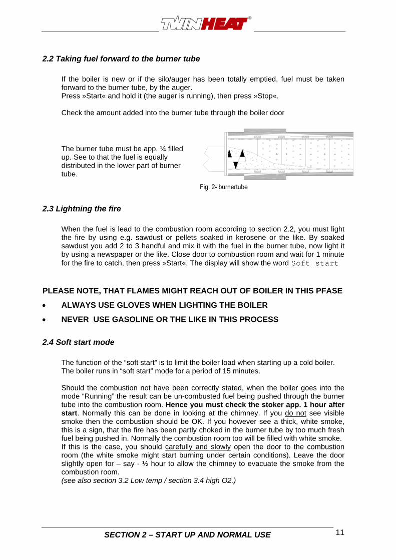
2.2 Taking fuel forward to the burner tube
If the boiler is new or if the silo/auger has been totally emptied, fuel must be taken forward to the burner tube, by the auger. Press »Start« and hold it (the auger is running), then press »Stop«. Check the amount added into the burner tube through the boiler door The burner tube must be app. ¼ filled up. See to that the fuel is equally distributed in the lower part of burner tube.
2.3 Lightning the fire
When the fuel is lead to the combustion room according to section 2.2, you must light the fire by using e.g. sawdust or pellets soaked in kerosene or the like. By soaked sawdust you add 2 to 3 handful and mix it with the fuel in the burner tube, now light it by using a newspaper or the like. Close door to combustion room and wait for 1 minute for the fire to catch, then press »Start«. The display will show the word Soft start
PLEASE NOTE, THAT FLAMES MIGHT REACH OUT OF BOILER IN THIS PFASE
ALWAYS USE GLOVES WHEN LIGHTING THE BOILER
NEVER USE GASOLINE OR THE LIKE IN THIS PROCESS
2.4 Soft start mode
The function of the “soft start” is to limit the boiler load when starting up a cold boiler. The boiler runs in “soft start” mode for a period of 15 minutes. Should the combustion not have been correctly stated, when the boiler goes into the mode “Running” the result can be un-combusted fuel being pushed through the burner tube into the combustion room. Hence you must check the stoker app. 1 hour after start. Normally this can be done in looking at the chimney. If you do not see visible smoke then the combustion should be OK. If you however see a thick, white smoke, this is a sign, that the fire has been partly choked in the burner tube by too much fresh fuel being pushed in. Normally the combustion room too will be filled with white smoke. If this is the case, you should carefully and slowly open the door to the combustion room (the white smoke might start burning under certain conditions). Leave the door slightly open for – say - ½ hour to allow the chimney to evacuate the smoke from the combustion room. (see also section 3.2 Low temp / section 3.4 high O2.)
11SECTION 2 – START UP AND NORMAL USE

SECTION 2 – START UP AND NORMAL USE 12
2.5 Running mode
Running mode means, that the controller constantly adjusts the boiler load in the area 20 to 100 % depending on the actual heat demand. The controller will constantly aim after the temperature chosen, e.g. 70 ºC. Large heat demand = High boiler load Small heat demand = Low boiler load (ore pause mode) An example of the control by the controlling unit: 1. The boiler runs stable and maintains the desired boiler temperature, say 70 ºC and the
load is shown as 45% on the display. 2. Now you use hot water for dish washing, bath or the like. 3. The controller will note, that the boiler temperature drops to under 70 ºC, as the water in
the boiler is cooled due to the hot water used. 4. The display will tell, that the load increases, as falling boiler temperature is noted. The
boiler has to work “harder” to maintain the boiler temperature.
The LOAD data in the display is showing how hard the boiler ”works”
2.6 Pause mode
If the heat demand is relatively small and the controller has reduced the load down < 20%, the boiler goes into “Pause”. During the pause the fan is started every 10 min. and runs a little, to keep the glows in the burner tube alive. The boiler will go into running mode when the boiler temperature has fallen some few degrees under the adjusted temperature. Should the boiler run in pause mode for a longer period and only start a few times a day – say in summer – the flue temperature is very low, which can cause condensation of moisture in the chimney, causing soot and corrosion in the chimney. To minimise or perhaps avoid this, you should open the bypass damper totally to avoid cooling the flue too much. (see section 2.8, bypass)
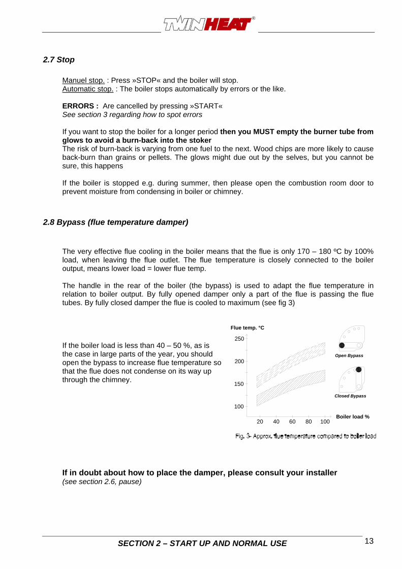
2.7 Stop
Manuel stop. : Press »STOP« and the boiler will stop. Automatic stop. : The boiler stops automatically by errors or the like. ERRORS : Are cancelled by pressing »START« See section 3 regarding how to spot errors If you want to stop the boiler for a longer period then you MUST empty the burner tube from glows to avoid a burn-back into the stoker The risk of burn-back is varying from one fuel to the next. Wood chips are more likely to cause back-burn than grains or pellets. The glows might due out by the selves, but you cannot be sure, this happens If the boiler is stopped e.g. during summer, then please open the combustion room door to prevent moisture from condensing in boiler or chimney.
2.8 Bypass (flue temperature damper)
The very effective flue cooling in the boiler means that the flue is only 170 – 180 ºC by 100% load, when leaving the flue outlet. The flue temperature is closely connected to the boiler output, means lower load = lower flue temp.
SECTION 2 – START UP AND NORMAL USE 13
The handle in the rear of the boiler (the bypass) is used to adapt the flue temperature in relation to boiler output. By fully opened damper only a part of the flue is passing the flue tubes. By fully closed damper the flue is cooled to maximum (see fig 3) If the boiler load is less than 40 – 50 %, as is the case in large parts of the year, you should open the bypass to increase flue temperature sothat the flue does not condense on its waythrough the chimney.
up
If in doubt about how to place the damper, please consult your installer (see section 2.6, pause)
150
10020 40 60 80
100
Boiler load %
Closed Bypass
200
Flue temp. °C
250
Open Bypass

Section 3- Troubleshooting Possible errors will appear in the upper line in the display.
When the problem has been solved the message can be annulled by pressuring »START«
SECTION 3 – TROUBLESHOOTING 14
Before restarting the boiler after any errors, please check, if the sprinkler has sprinkled water into the auger channel (slow moving auger, fuel is wet) If this is the case, use the auger to transport the wet fuel into the combustion room and remove it from here (Remove fuel manually from the burner tube) After removing the fuel please check that the sprinkler valve is closing tight again – See section 3.10 sprinkler
3.1 Error: Hot boiler The boiler temperature has exceeded 95 ºC and the over temperature thermostat has stopped the boiler. The produced amount of heat could not be used in the heating system. Causes:
There is no real need for heat ( typical for the summer). There might be an air pocket in the system, no water circulation. The circulation pump does not function.
When the boiler temperature has fallen below 80 – 85 ºC and the error has been corrected, reset over temp. thermostat and restart the boiler. Reset the over temp. thermostat by removing the black hood in the rear of the boiler and gently press a match or the like into the hole. Put black hood in place again. If you still see glows in the burner tube, press »START« and the boiler will restart as described in Section 2.4, soft start. In case the fire should be extinguished, the fire must be started again as described in section 2.2 “Taking fuel forward to the burner tube.”
3.2 Low temp.
The boiler stopped because the boiler temperature has fallen more then 15ºC below the adjusted value. Had the boiler temperature been set on 70 ºC an error would be announced, when the temperature has been under 55 ºC for more than 10 minutes. Causes:
No more fuel in the extern silo The auger from the extern silo is not running The fire has extinguished in the burner tube The boiler is not installed with a 3 ways mixing valve, as described in the installation
manual
Low temp. (start)
Temperature : 33,8 oC O2 Auto : 20,9 % O2 wanted : 8,0 %
SECTION 3 – TROUBLESHOOTING 15
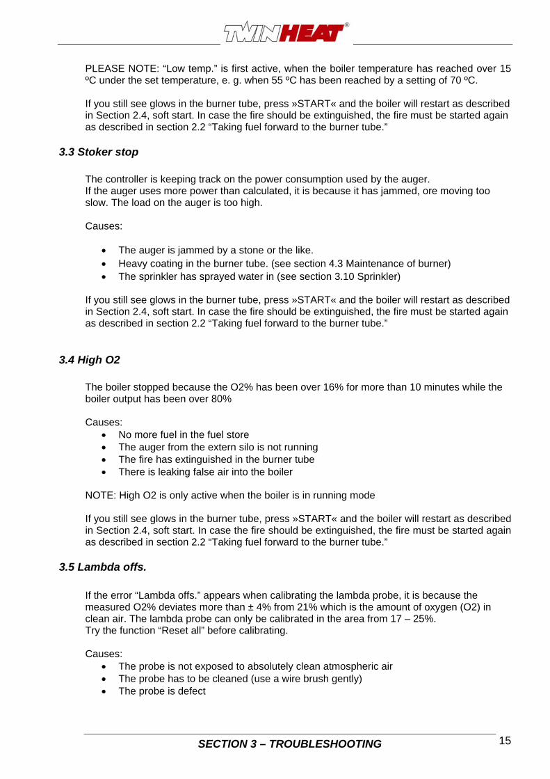
PLEASE NOTE: “Low temp.” is first active, when the boiler temperature has reached over 15 ºC under the set temperature, e. g. when 55 ºC has been reached by a setting of 70 ºC. If you still see glows in the burner tube, press »START« and the boiler will restart as described in Section 2.4, soft start. In case the fire should be extinguished, the fire must be started again as described in section 2.2 “Taking fuel forward to the burner tube.”
3.3 Stoker stop The controller is keeping track on the power consumption used by the auger. If the auger uses more power than calculated, it is because it has jammed, ore moving too slow. The load on the auger is too high. Causes:
The auger is jammed by a stone or the like. Heavy coating in the burner tube. (see section 4.3 Maintenance of burner) The sprinkler has sprayed water in (see section 3.10 Sprinkler)
If you still see glows in the burner tube, press »START« and the boiler will restart as described in Section 2.4, soft start. In case the fire should be extinguished, the fire must be started again as described in section 2.2 “Taking fuel forward to the burner tube.”
3.4 High O2
The boiler stopped because the O2% has been over 16% for more than 10 minutes while the boiler output has been over 80% Causes:
No more fuel in the fuel store The auger from the extern silo is not running The fire has extinguished in the burner tube There is leaking false air into the boiler
NOTE: High O2 is only active when the boiler is in running mode If you still see glows in the burner tube, press »START« and the boiler will restart as described in Section 2.4, soft start. In case the fire should be extinguished, the fire must be started again as described in section 2.2 “Taking fuel forward to the burner tube.”
3.5 Lambda offs.
If the error “Lambda offs.” appears when calibrating the lambda probe, it is because the measured O2% deviates more than ± 4% from 21% which is the amount of oxygen (O2) in clean air. The lambda probe can only be calibrated in the area from 17 – 25%. Try the function “Reset all” before calibrating. Causes:
The probe is not exposed to absolutely clean atmospheric air The probe has to be cleaned (use a wire brush gently) The probe is defect

SECTION 3 – TROUBLESHOOTING 16
3.6 Error: Waterpress
If the boiler is installed with a pressure sensitive switch, the error will come if the boiler-pressure is below the setting at the pressure sensitive switch.
3.7 Error: Thermo Motor protection relay for auger from extern fuel silo has switched auger-motor off. The motor is hot. Dismount grey plate under control panel and reset motor protection relay (Kxx) Check if auger is jammed or moving slowly. Plants with Twinheat Quatro silo: The micro switch placed on top of Quatro silo auger has activated. The lid on top of auger has been forced open due to compressed fuel in the auger. Open lid and clean out compressed fuel. If necessary also clean out fuel from hose between auger and rotating valve. Remember to cut the power to the auger before opening the lid. De activate motor protection relay for auger in electrical box for Quatro silo. If you still see glows in the burner tube, press »START« and the boiler will restart as described in Section 2.4, soft start. In case the fire should be extinguished, the fire must be started again as described in section 2.2 “Taking fuel forward to the burner tube.”
3.8 Error: Freq. conv.
Frequency converter for either combustion fans or flue-gas fan has gone in error mode. Dismount grey plate under control panel and read error code (Fxxx) at display. See troubleshooting in separate manual for frequency converter. If you still see glows in the burner tube, press »START« and the boiler will restart as described in Section 2.4, soft start. In case the fire should be extinguished, the fire must be started again as described in section 2.2 “Taking fuel forward to the burner tube.”
3.9 Power cut
In case of power cut, the boiler will automatically restart, though depending upon length of the power cut. Should the boiler temperature have dropped more than 15ºC during power cut, the boiler will not restart, but display the error “Low temp.”, see section 3.2 Low temp.
3.10 Sprinkler system Should the fuel back-burn into the auger channel and the temperature exceed 95 ºC the sprinkler might start and spray water under pressure down into the auger channel and put the fire out (The boiler will continue as normal, if possible.)
Causes:
The rotating valve has a leaky.
Too much draft in chimney (Draft stabiliser might be installed into chimney)
If the sprinkler system has been activated you must check that the sprinkler valve is closing tight again. Dismount the hose on the sprinkler valve and check whether it drips. Please contact your installer, should you continuously have burn-back problems
SECTION 4 - MAINTENANCE 17
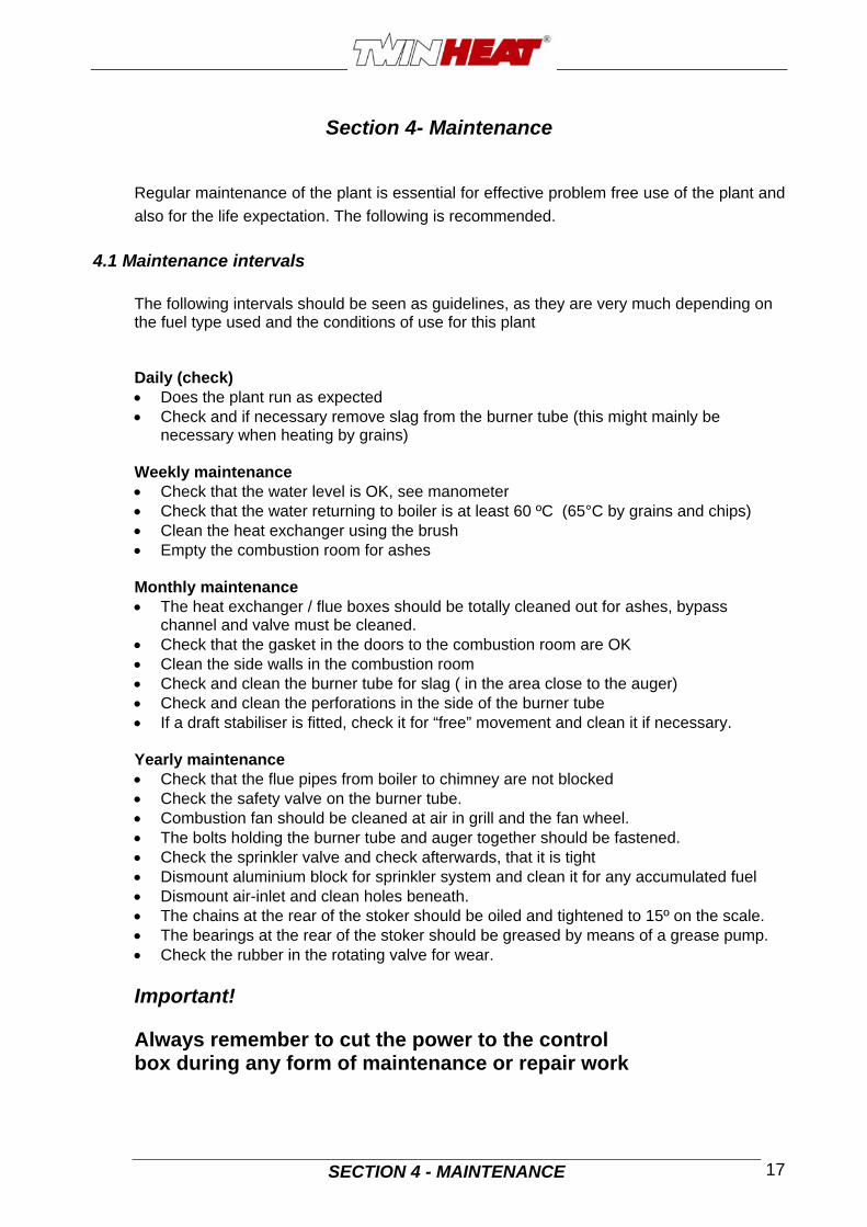
Section 4- Maintenance
Regular maintenance of the plant is essential for effective problem free use of the plant and
also for the life expectation. The following is recommended.
4.1 Maintenance intervals The following intervals should be seen as guidelines, as they are very much depending on the fuel type used and the conditions of use for this plant Daily (check) Does the plant run as expected Check and if necessary remove slag from the burner tube (this might mainly be
necessary when heating by grains) Weekly maintenance Check that the water level is OK, see manometer Check that the water returning to boiler is at least 60 ºC (65°C by grains and chips) Clean the heat exchanger using the brush Empty the combustion room for ashes Monthly maintenance The heat exchanger / flue boxes should be totally cleaned out for ashes, bypass
channel and valve must be cleaned. Check that the gasket in the doors to the combustion room are OK Clean the side walls in the combustion room Check and clean the burner tube for slag ( in the area close to the auger) Check and clean the perforations in the side of the burner tube If a draft stabiliser is fitted, check it for “free” movement and clean it if necessary. Yearly maintenance Check that the flue pipes from boiler to chimney are not blocked Check the safety valve on the burner tube. Combustion fan should be cleaned at air in grill and the fan wheel. The bolts holding the burner tube and auger together should be fastened. Check the sprinkler valve and check afterwards, that it is tight Dismount aluminium block for sprinkler system and clean it for any accumulated fuel Dismount air-inlet and clean holes beneath. The chains at the rear of the stoker should be oiled and tightened to 15º on the scale. The bearings at the rear of the stoker should be greased by means of a grease pump. Check the rubber in the rotating valve for wear. Important! Always remember to cut the power to the control box during any form of maintenance or repair work

4.2 Maintenance of boiler
The combustion room should be cleaned when an app. 2 mm thick layer is seen, as this layer insulates and prevents the water from getting full use of heat produced. The combustion room and the flue tubes are cleaned through the doors in the front of the boiler. Clean the tubes by pulling brush forth and back in each tube. Loose sod and ashes are pushed into the flue box at the rear side of the boiler.
Cleaning the tubes Flue box is cleaned by dismounting the two plates on side of it. Also clean the rectangular bypass channel, behind the damper. You should never attempt to clean a boiler, which has just been fired by hand (logs), as the heat exchanger can be covered by tar. Please wait until the stoker has “burned” the tar off again. As a guideline please control the flue temperature thermometer. If the flue temperature has increased some 30 – 40 ºC over the temperature in a newly cleaned boiler, you should clean the combustion room walls. The temperature should be read at the same load %, as it increased with boiler load.
Flue box with dismounted plates
In case the plant is stopped for a longer period, e. g. over summer, it should be totally cleaned out for ashes. It is important to leave the combustion room door slightly open to prevent condensation and corrosion.
4.3 Maintenance of burner tube
The cleaning of the holes is made by pressing a pointed object like a nail into the holes. The holes are placed with the same internal distance round the burner tube and depending on the size of burner tube in one or more rows.
SECTION 4 - MAINTENANCE 18
If the holes are blocked, there will only be an incomplete combustion of the fuel. (see fig. 4) The auger must be able to deliver the fuel into the burner tube. Heavy coating can block the fuel and finally cause a stop. The burner tube must be cleaned if a heavy coating is noted. It is very important, that the holes, which let combustion air into the burner tube are not blocked.

4.4 Maintenance of stoker
SECTION 4 - MAINTENANCE 19
The red cover at the rear of the stoker is removed. The chains must be greased by oil of grease. The chain must be tightened to 15 º (shown on the tightening devise). Both chain wheels are tightened The bearing behind the bigger chain wheel is greased by a grease pump
Chain tightener
The sprinkler valve is controlled by unscrewing the hose, where after the red hut under the valve is activated. It is very important to secure that the valve is tight after the test, as you otherwise will have water dripping into the fuel. Should the valve not be tight, you must open it and clean the contact surface and assemble it again. Sprinkler valve without hose The air-inlet on top of the stoker is cleaned by un-screwing the air-inlet and clean the oblong hole beneath the air-inlet, in the red plate.
Air-inlet The rubber in the rotating valve must be controlled visual. In case of any signs of tear and wear it must be exchanged. The rubber can be controlled by unscrewing the big hose connecting the transport auger to the valve.
Rotating valve

SECTION 5- TECHNICAL INFORMATION 20
Section 5- Technical information
5.1 CS120i
Approved fuel
Pellets Grains Wood
chips
5 – 25 mm
Miscanthus
Class - 3 - 3 -
Water content in fuel % 7,3 12,5 22,1 8,6
Nominal output kW 120 90 90 83
Minimum output kW 31 26 24 21
output sphere kW 31-120 26-90 24-90 21-83
Efficiency by nominal output % 90,1 91,3 90,3 86,7
Efficiency by minimum output % 89,5 86,3 85,6 81,6
Flue temperature by nominal output °C 163 143 134 128
Flue temperature by minimum output °C 89 86 80 83
Flue gas amount by nominal output kg/h 237 204 186 187
Flue gas amount by minimum output kg/h 102 89 79 79
Minimum temperature of water returning
(lowest acceptable) °C 60 60 60 60
Draft necessary: 20Pa
Diameter of flue outlet: Ø215mm
Amount of water in boiler: 660 litre
Water resistance by temp. difference =10°C 282 mbar
Water resistance by temp. difference =20°C 72 mbar
Adjustment span for boiler thermostat: 70-90°C
Effect consumption by nominal output,
to gear motor and fan and more.: 280W
Electrical connection 3x400V+O+PE – 16A
SECTION 5- TECHNICAL INFORMATION 21
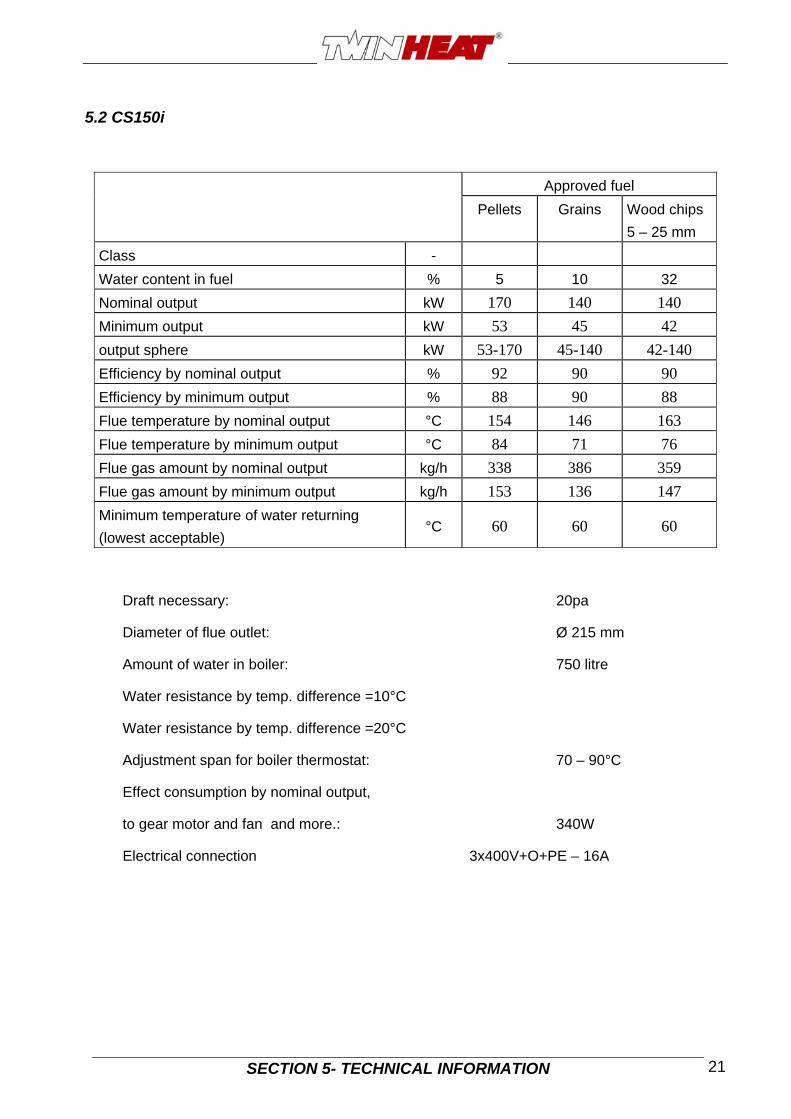
5.2 CS150i
Approved fuel
Pellets Grains Wood chips
5 – 25 mm
Class -
Water content in fuel % 5 10 32
Nominal output kW 170 140 140
Minimum output kW 53 45 42
output sphere kW 53-170 45-140 42-140
Efficiency by nominal output % 92 90 90
Efficiency by minimum output % 88 90 88
Flue temperature by nominal output °C 154 146 163
Flue temperature by minimum output °C 84 71 76
Flue gas amount by nominal output kg/h 338 386 359
Flue gas amount by minimum output kg/h 153 136 147
Minimum temperature of water returning
(lowest acceptable) °C 60 60 60
Draft necessary: 20pa
Diameter of flue outlet: Ø 215 mm
Amount of water in boiler: 750 litre
Water resistance by temp. difference =10°C
Water resistance by temp. difference =20°C
Adjustment span for boiler thermostat: 70 – 90°C
Effect consumption by nominal output,
to gear motor and fan and more.: 340W
Electrical connection 3x400V+O+PE – 16A

SECTION 5- TECHNICAL INFORMATION 22
5.3 CS250i
Approved fuel
Pellets Grains Wood chips
5 – 25 mm
Class - 3 3
Water content in fuel % 6 15 20
Nominal output kW 270 240 240
Minimum output kW 78 63 64
output sphere kW 78-270 63-240 64-240
Efficiency by nominal output % 91,1 89,2 89,4
Efficiency by minimum output % 88,2 90,7 90,1
Flue temperature by nominal output °C 175 150 162
Flue temperature by minimum output °C 95 84 84
Flue gas amount by nominal output kg/h 520 487 491
Flue gas amount by minimum output kg/h 242 161 190
Minimum temperature of water returning
(lowest acceptable) °C 60 60 60
Draft necessary: 20 Pa
Diameter of flue outlet: Ø 250 mm
Amount of water in boiler: 920 litre
Water resistance by temp. difference =10°C 97 mbar
Water resistance by temp. difference =20°C 27 mbar
Adjustment span for boiler thermostat: 70 – 90°C
Effect consumption by nominal output,
to gear motor and fan and more.: 340W
Electrical connection 3x400V+O+PE – 16A
SECTION 5- TECHNICAL INFORMATION 23
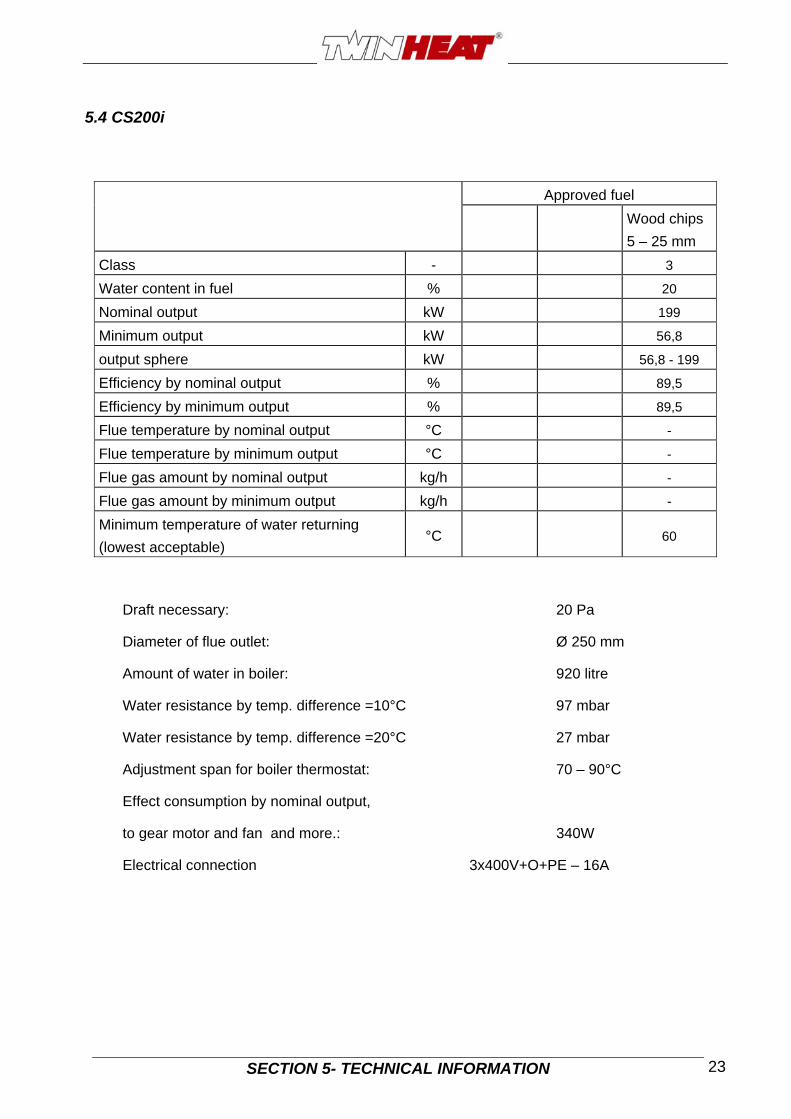
5.4 CS200i
Approved fuel
Wood chips
5 – 25 mm
Class - 3
Water content in fuel % 20
Nominal output kW 199
Minimum output kW 56,8
output sphere kW 56,8 - 199
Efficiency by nominal output % 89,5
Efficiency by minimum output % 89,5
Flue temperature by nominal output °C -
Flue temperature by minimum output °C -
Flue gas amount by nominal output kg/h -
Flue gas amount by minimum output kg/h -
Minimum temperature of water returning
(lowest acceptable) °C 60
Draft necessary: 20 Pa
Diameter of flue outlet: Ø 250 mm
Amount of water in boiler: 920 litre
Water resistance by temp. difference =10°C 97 mbar
Water resistance by temp. difference =20°C 27 mbar
Adjustment span for boiler thermostat: 70 – 90°C
Effect consumption by nominal output,
to gear motor and fan and more.: 340W
Electrical connection 3x400V+O+PE – 16A
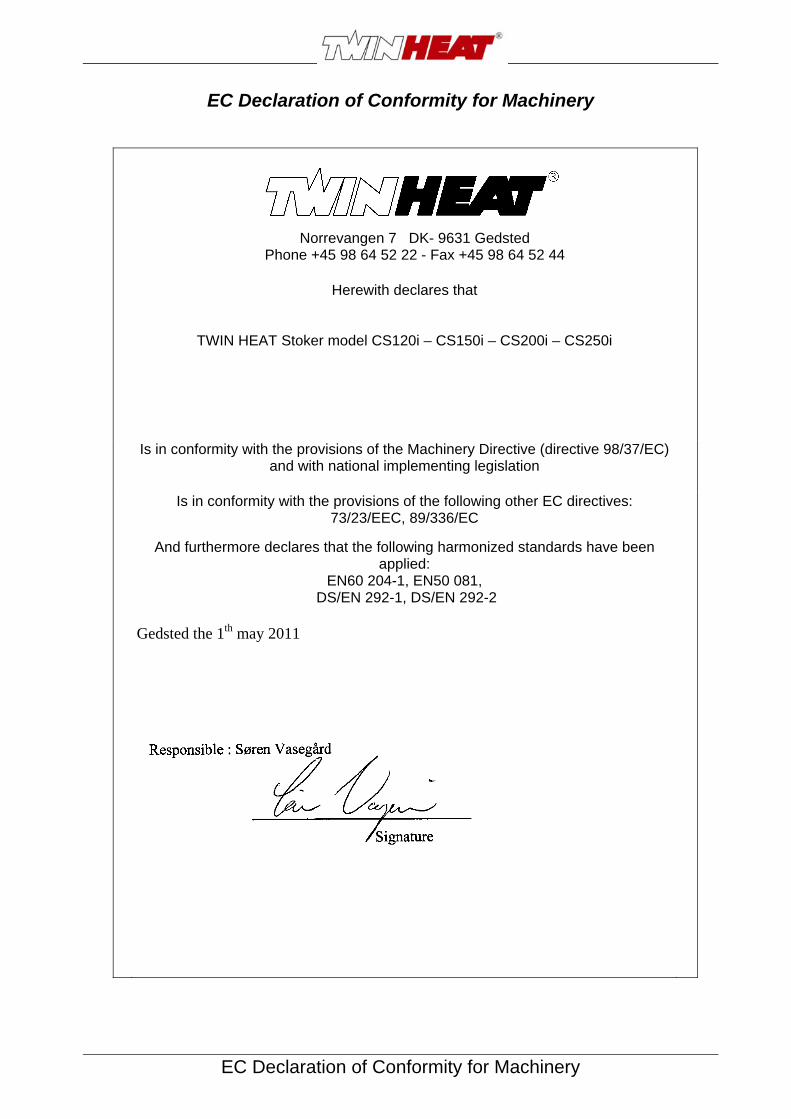
EC Declaration of Conformity for Machinery
EC Declaration of Conformity for Machinery
Norrevangen 7 DK- 9631 Gedsted Phone +45 98 64 52 22 - Fax +45 98 64 52 44
Herewith declares that
TWIN HEAT Stoker model CS120i – CS150i – CS200i – CS250i
Is in conformity with the provisions of the Machinery Directive (directive 98/37/EC) and with national implementing legislation
Is in conformity with the provisions of the following other EC directives:
73/23/EEC, 89/336/EC
And furthermore declares that the following harmonized standards have been applied:
EN60 204-1, EN50 081, DS/EN 292-1, DS/EN 292-2
Gedsted the 1th may 2011

ENCLOSURE 1
Enclosure 1 – Accessories included
Scraper (only by boilers with stoker in rear)
Cleaning brush Ø50 mm. with handle.
Poker