User’s Guide - MANMRKmanmrk.net/tutorials/basic/mbasic.pdf · User’s Guide. Warranty ......
270
Learn to Program PIC Micrcontrollers in easy to use Basic Learn to Program PIC Micrcontrollers in easy to use Basic Learn to Program PIC Micrcontrollers in easy to use Basic Learn to Program PIC Micrcontrollers in easy to use Basic Learn to Program PIC Micrcontrollers in easy to use Basic Revision 5.2 Revision 5.2 Revision 5.2 Revision 5.2 Revision 5.2 User’s Guide User’s Guide
Transcript of User’s Guide - MANMRKmanmrk.net/tutorials/basic/mbasic.pdf · User’s Guide. Warranty ......

Learn to Program PIC Micrcontrollers in easy to use BasicLearn to Program PIC Micrcontrollers in easy to use BasicLearn to Program PIC Micrcontrollers in easy to use BasicLearn to Program PIC Micrcontrollers in easy to use BasicLearn to Program PIC Micrcontrollers in easy to use Basic
R e v i s i o n 5 . 2R e v i s i o n 5 . 2R e v i s i o n 5 . 2R e v i s i o n 5 . 2R e v i s i o n 5 . 2
User’s GuideUser’s Guide


WarrantyBasic Micro warranties its products against defects in material andworkmanship for a period of 90 days. If a defect is discovered, BasicMicro will at our discretion repair, replace, or refund the purchase price of theproduct in question. Contact us at [email protected] returns will be accepted without the proper authorization.
Copyrights and TrademarksCopyright© 2001-2002 by Basic Micro, Inc. All rights reserved.PICmicro® is a trademark of Microchip Technology, Inc. Basic StampI/II and Parallax are registered trademarks of Parallax Inc. MBasic, The Atomand Basic Micro are registered trademarks of Basic Micro Inc. Othertrademarks mentioned are registered trademarks of their respectiveholders.
DisclaimerBasic Micro cannot be held responsible for any incidental, orconsequential damages resulting from use of products manufacturedor sold by Basic Micro or its distributors. No products from Basic Micro shouldbe used in any medical devices and/or medical situations. No product shouldbe used in a life support situation.
ContactsEmail: [email protected] support: [email protected]: http://www.basicmicro.com
Discussion ListA web based discussion board is maintained athttp://www.basicmicro.com
UpdatesIn our continuing effort to provide the best and most innovative products,software updates are made available by contacting us [email protected]


5
Table of ContentsTable o
f Contents
Table of Co
ntentsTable o
f Contents
Table of Co
ntentsTable o
f Contents

6
ContentsIntroduction ................................................12What is MBasic ? .............................................................................. 12This Manual .................................................................................... 12On-line Discussion Forums ................................................................ 12Updates .......................................................................................... 12Technical Support ............................................................................ 12
Basic PICmicro Setup ..................................13Which PICmicro should I use ? ........................................................... 14Basic PICmicro Schematic ................................................................. 14What Next ? .................................................................................... 15
Getting Started ............................................17Software Installation ........................................................................ 18Configuring MBasic ........................................................................... 18What is an IDE ? .............................................................................. 19Getting Familiar with the IDE ............................................................. 19Terminal Window Selection ............................................................... 21Control Characters ........................................................................... 21User Tool Bar .................................................................................. 22Config Setup Menu ........................................................................... 24First Program .................................................................................. 26Error Reporting................................................................................ 28Conclusion ...................................................................................... 29
In Circuit Debugger .....................................31ICD Setup ....................................................................................... 32USB To Serial Adapter ...................................................................... 32What is an ICD ? .............................................................................. 33Getting Familiar with the ICD Controls ................................................. 33Using the ICD .................................................................................. 35Exercise .......................................................................................... 36Debug Mode .................................................................................... 37Variable Watch Window .................................................................... 37Trouble Shooting ............................................................................. 38
The Basic’s ...................................................41Bits, Bytes, Words, Longs .................................................................. 42MSBs and LSBs ................................................................................ 42
7
RAM, EEPROM and Program Memory.................................................. 42Built-in Hardware ............................................................................. 42Hexadecimal 101 ............................................................................. 43ASCII ............................................................................................. 43Programming Practices ..................................................................... 44Optimizing ...................................................................................... 46Line Labels ...................................................................................... 47Variables ........................................................................................ 47Arrays ............................................................................................ 48Tables ............................................................................................ 49Aliases ........................................................................................... 49Variable Modifiers ............................................................................ 49Command Modifiers ......................................................................... 53Constants ....................................................................................... 56Pins................................................................................................ 57Pin Variables ................................................................................... 59
MBasic Specific’s .........................................61Stack.............................................................................................. 62Oscillator Settings ............................................................................ 62Internal RC Calibration ..................................................................... 62Memory .......................................................................................... 62Compiling ....................................................................................... 62Reserved Symbols ........................................................................... 63Device Specific Issues ...................................................................... 63
MBasic and Assembly ..................................65What is Assembly ? .......................................................................... 66Mixing Assembly and MBasic ............................................................. 66In-line Assembly .............................................................................. 66Assembly and Variables .................................................................... 67
Math .............................................................69Numerical Types .............................................................................. 70Adding and Subtracting .................................................................... 70Multiplication ................................................................................... 70Division ........................................................................................... 72Integer Math in general .................................................................... 72General Math Functions .................................................................... 73Bitwise Operators ............................................................................ 73Comparison Operators ..................................................................... 74Logical Operators ............................................................................. 74Floating Point Math .......................................................................... 75Floating Point Format ....................................................................... 75Floating Point Example Program ........................................................ 75

8
Syntax ..........................................................79ADin ............................................................................................... 80ASM {...} ........................................................................................ 82Branch............................................................................................ 83Button ............................................................................................ 85Clear .............................................................................................. 88Count ............................................................................................. 89Data (EEPROM)............................................................................... 90Debug ............................................................................................ 92Debugin .......................................................................................... 94Do...While ....................................................................................... 96DTMFout ......................................................................................... 97DTMFout2 ....................................................................................... 99End .............................................................................................. 101For...Next ...................................................................................... 102Freqout ........................................................................................ 105Gosub...Return .............................................................................. 106Goto ............................................................................................. 107High ............................................................................................. 108I2Cin ............................................................................................ 109I2Cout .......................................................................................... 112If...Then...Elseif...Else...Endif ........................................................... 116Input ............................................................................................ 120Lcdread ........................................................................................ 121Lcdwrite ....................................................................................... 123Let ............................................................................................... 127Low.............................................................................................. 128Lookdown ..................................................................................... 129Lookup ......................................................................................... 131Nap .............................................................................................. 133Output .......................................................................................... 134OWIN ........................................................................................... 135OWOUT ........................................................................................ 138Pause ........................................................................................... 141Pauseclk ....................................................................................... 142Pauseus ........................................................................................ 143PEEK...POKE .................................................................................. 144Pulsin ........................................................................................... 145Pulsout ......................................................................................... 147Pwm ............................................................................................ 148Random........................................................................................ 150RCtime ......................................................................................... 151Read ............................................................................................ 153ReadDM........................................................................................ 154ReadPM ........................................................................................ 156Repeat...Until ................................................................................ 158Reverse ........................................................................................ 159

9
Serdetect ...................................................................................... 161Serin ............................................................................................ 164Serout .......................................................................................... 170Servo ........................................................................................... 176Shiftin .......................................................................................... 178Shiftout ........................................................................................ 182Sleep ........................................................................................... 186Sound .......................................................................................... 187Sound2 ......................................................................................... 189Spmotor ....................................................................................... 190Stop ............................................................................................. 192Swap ........................................................................................... 193Toggle .......................................................................................... 194While...Wend ................................................................................ 195Write............................................................................................ 196WriteDM ....................................................................................... 199WritePM ....................................................................................... 201Xin ............................................................................................... 203Xout ............................................................................................. 207
Hardware Commands ................................211Hardware Commands ..................................................................... 212HSERIN..HSEROUT ......................................................................... 213SetHSerial .................................................................................... 214HPWM .......................................................................................... 215SETPULLUPS ................................................................................. 217
On Reset Commands .................................219On Reset Commands ...................................................................... 220
Interrupt Commands .................................223Interrupts ..................................................................................... 224Interrupt Sources ........................................................................... 225Set Interrupt Source ...................................................................... 226SETEXTINT ................................................................................... 226SETTMR0 ...................................................................................... 226SETTMR1 ...................................................................................... 227SETTMR2 ...................................................................................... 229SETCAPTURE ................................................................................ 230GETCAPTURE ................................................................................ 230SETCOMPARE ............................................................................... 231
10
BS2 Compatibility......................................235Differences ................................................................................... 236Program Storage ........................................................................... 236DATA and EEPROM ......................................................................... 236Gosub...Return .............................................................................. 236Converting Basic Stamp II Program .................................................. 236DIRS ............................................................................................ 237SERIN / SEROUT Timings................................................................ 237LCD Commands ............................................................................. 237
Trouble Shooting .......................................239My Program Won’t Run ? ................................................................ 240My Program Still Won’t Run ? .......................................................... 240Error trying to Program the PICmicro ? ............................................. 240
Reserved Words ........................................241Appendix - A ..............................................253Appendix - C ..............................................255Index ..........................................................262

11
Intro
du
ction
Intro
du
ction
Intro
du
ction
Intro
du
ction
Intro
du
ction
Introduction

12
IntroductionWelcome to the world of microcontrollers. We would like to Thank you for yourpurchase.
What is MBasic ?MBasic is an advanced programming language modeled after BASIC, creatinga cost effective and flexible way to program PIC Microcontrollers. MBasicmaintains the simplicity of Basic, but offers more power. MBasic includes asuper set of the BS2 instruction set, allowing you to easily port your current BS2applications with little effort.
This ManualThis manual in general applies to MBasic and minimal hardware. It is not inthe scope of this manual to cover any Chip specific or Peripherals features ofPICmicros. Further information can be found in the Data Sheets availablefrom Microchip.com for all PICmicros.
This manual will explain the MBasic programming language in depth . Themain purpose of this manual is to teach the general syntax. Which will giveyou, the end user, a good understanding of how to effectively use MBasic.
We will continue to update and improve this manual. All updates will be madeavailable for download from our web site athttp://www.basicmicro.com.
On-line Discussion ForumsWe maintain discussion forums at http://www.basicmicro.com in order to helpyou to connect with a wide range of related information and users. The dis-cussion forums are free and will allow you to find information and help fast.
UpdatesMBasic updates will be available to new and current customers. To receiveemail notifications of updates, join the discussion forums at http://www.basicmicro.com.
Technical SupportTechnical support is provided via e-mail and the discussion forums atwww.basicmicro.com. When technical support is required please send e-mailto [email protected] . In order to assure a proper response pleaseinclude a copy of the program you are having problems with, the hardwareyou are using, MBasic revision number, prototyping board and so on. Byincluding this information with your e-mail, you can help us answer your ques-tions quickly. Additional technical support is often provided by several experi-enced users of the discussion forums at http://www.basicmicro.com

13
Basic PICmicro SetupBasic PICm
icro Setup

14
W h i c h P I C m i c r o s h o u l d I u s e ?W h i c h P I C m i c r o s h o u l d I u s e ?W h i c h P I C m i c r o s h o u l d I u s e ?W h i c h P I C m i c r o s h o u l d I u s e ?W h i c h P I C m i c r o s h o u l d I u s e ?Doing a quick search on the internet will turn up a ton of links and projectswith sample code using the 16F84. The 16F84 has 1K of code space and68 bytes of RAM at a cost around $5.00 in small quantity. Microchip cameout with a 100% pin compatible chip that is a replacement for the 16F84.This PICmicro is a 16F628 which has 2K of code space and 224 bytes ofRAM. The 16F628 also has many hardware features and it can bepurchased for about $2.50 in small quantity. Any sample code for the 16F84will work with the 16F628. With the 16F628 you get more code space, moreram for a smaller price.
The second chip of choice, the one this manual and most of the samplecode is written for is the 16F876. This is a 28 pin, 8K program space, 384bytes of RAM PICmicro.
B a s i c P I C m i c r o S c h e m a t i cB a s i c P I C m i c r o S c h e m a t i cB a s i c P I C m i c r o S c h e m a t i cB a s i c P I C m i c r o S c h e m a t i cB a s i c P I C m i c r o S c h e m a t i cThe schematic shown is the most basic circuit for setting up a PICmicro. Thebasic circuit consist of a resonator with built in caps, 10K resistor, powerand ground. The PICmicro requires +5Volts.

15
W h a t N e x t ?W h a t N e x t ?W h a t N e x t ?W h a t N e x t ?W h a t N e x t ?You can build the circuit shown with the 16F628 or 16F876. You shoulddownload the data sheet from Microchip.com on the chip you plan on using.The best approach to experimenting with PICmicros is a developmentplatform. This will save endless hours with wiring troubles and faulty circuits.There are several “Getting Started” packages available from the BasicMicro web site. This isn’t a sales pitch this is years of experience withPICmicros. Just about 90% of the problems you will run into is bad hard-ware. Using something like the 2840 Solderless Development board andISP-PRO will dramatically reduce the amount of time you spend troubleshooting hardware. Plus save time, the PICmicro can be programmed incircuit. So for every typo, syntax error or program mistake, you won’t need toremove the PICmicro from its circuit. There will be plenty of those. Now withall that said lets get started.

16

17
Getting Started
Ge
tting Starte
dG
etting
Started
Ge
tting Starte
dG
etting
Started
Ge
tting Starte
d

18
Software InstallationMBasic software will run on 95, 98, ME, NT, 2000, and XP. DOS is notsupported.
If the software is downloaded, double click the .exe application it willautomatically unzip. Then double click the setup.exe. Follow the on screenprompts (It is not recommended to change the default directories until youfully understand the software). Once the installation is complete restart yourcomputer.
If the software is installed from the CD-ROM; insert the CD-ROM into yourcomputer. If auto-run is enabled an installer menu will appear, select yoursoftware and the installation process will begin automatically. Restart yourcomputer after the installation is complete.
Note: Explore the CD-ROM after installation, it contains sample code, datasheets and more.
Configuring MBasicIf you are using the ISP-PRO programmer the COM port will need to beconfigured. Open the System Setup Menu under Tools (Tools-> SystemSetup) Choose the COM port the ISP-PRO is attached to.
COM PortSelection

19
What is an IDE ?IDE stands for Integrated Development Environment. The IDE associatedwith MBasic software is used to perform all the tasks associated with usingPICmicros, such as Writing code, Compiling, and Programming.
Getting Familiar with the IDETake a few minutes to read through this section and familiarize yourself withthe IDE. Understanding all the features of the IDE will make it easier to useMBasic more efficiently.
File Explorer Window Build Window Program Document

20
File Explorer WindowThis window displays all the files on your computer. It is not auto updating,occasionally you may need to right click on it and select refresh.
Build WindowThe Build Window is used to display compiling information and progress ofthe program being executed. Available program memory, ram and errors willbe listed here after compiling is complete. If an error is listed simply doubleclick on it and the IDE will automatically highlight the problem line of theprogram.
Program DocumentThis is a multi document interface. You can have several programs open atonce. The IDE will only compile and deal with the current document that is infocus.
User Tool BarThis menu contains all the tasks that can be performed such as,Compile, Program and Debug.
Standard Tool BarThese are small Icons representing different shortcuts from the menu bar.Dragging the cursor over each ICON will display a small message thatexplains the function of that ICON.
Chip Selection MenuThis menu contains all the supported chip names. When programming orcreating a new file, the correct chip you are using must be selected usingthis menu.
Standard Tool Bar User Tool Bar
Chip Selection Menu

21
Terminal Window SelectionThe IDE comes with built-in RS-232 serial communication terminals muchlike Hyper Term. You can have up to 4 terminal windows running at once.The number of terminal windows connected to COM ports are also limitedby the number of COM ports your computer is equipped with.
Control CharactersThe terminal window supports several control characters for cursor position-ing. The following chart is a list of all the control characters supported. Theterminal window only supports the ASCII values. No symbols are pre-defined.
Baud Com Parity Flow Control Echo Connect
Terminal Window Selection
Name ASCII Value Description
Clear Screen 0 Clear the screen and move cursor tothe home position
Home 1 Move cursor to the upper left cornerof the screen
Move to X,Y 2 Move cursor to location specified by X,Y(i.e. 2,X,Y theses values can not begreater than 255)
Cursor Left 3 Move cursor one character left.Cursor Right 4 Move cursor one character right.Cursor Up 5 Move cursor one character up.Cursor Down 6 Move cursor one character down.Bell 7 Beep PC speaker.Backspace 8 Delete one character to the left.Tab 9 Tab to next column.Line Feed 10 Move cursor down one line.Clear Right 11 Clear entire line to the right.Clear Down 12 Clear screen contents below cursor.Carriage Return 13 Move cursor to first position of next line.

22
T e r m i n a l W i n d o w F u n c t i o n sT e r m i n a l W i n d o w F u n c t i o n sT e r m i n a l W i n d o w F u n c t i o n sT e r m i n a l W i n d o w F u n c t i o n sT e r m i n a l W i n d o w F u n c t i o n sBaudThe Baud menu sets the communication speed of the terminal window.Baud rates from 300 to 460800 bits per second are possible.
ComThe Com menu is used to select the COM port the terminal window willuse. Only the COM ports available on your computer will be shown here.
ParityThe Parity menu is used to select if the parity is used or not being used.Most setups will require No Parity.
Flow ControlThe FlowControl menu is used to select software flow control. If Flow Controlis selected, the CTS and RTS hardware lines are used to control the flow ofdata.
EchoThe Echo menu is used to display the sent character automatically. Whenthis menu is set to No Echo and a character is typed in the output screen,nothing will be displayed, only data received will be shown. If Echo isselected any character typed will be displayed.
ConnectClicking the “Connect” button connects the serial port that the terminalwindow is set to use. Once the serial port is open the connect button willdisplay “Disconnect” . As long as the serial port is open it will be unacces-sible by other programs. Once you are finished close the connection.
User Tool BarMain programming functions are available as buttons on the tool bar.
CompileThe compile function will compile the current program and check for syntaxerrors.
AssembleWill pass an assembly file to the assembler.
Compile Assemble Read Verify Erase Program Debug ConfigSetup

23
ReadThis function will only work with the available Boot Loader or ISP-PRO anda PICmicro conntected. Read will read the contents of the PIC and displaythe file in HEX format to the screen.
VerifyThe verify function will read in from the PICmicro and match the current openfile to verify they are the same.
EraseThis function will only work with the available Boot Loader or ISP-PRO anda PICmicro conntected. Erase will clear or set all the programming locationson the PICmicro to 3fff. Which is considered blank.
ProgramThe program button will compile, then program the target device. Theprogram function is one click.
DebugThe debug function will perform the same task as the Program option, butwill add special code the ICD and set the IDE to Debug mode. Debugrequires the ISP-PRO programmer our supported boot loader device.
Config SetupThe config setup menu is used to set the configuration settings on theselected PICmicro. Most problems when programming are caused due toimproper configuration settings.

24
Oscillator Mhz
Code Protect Chip Specific Options Brownout
C o n f i g S e t u p M e n uC o n f i g S e t u p M e n uC o n f i g S e t u p M e n uC o n f i g S e t u p M e n uC o n f i g S e t u p M e n uThe config setup menu will list all the specific options for a selected device.Any time before programming a target device the config setup menu shouldbe checked to ensure all the options are set correctly for the selected device.
OscillatorThe oscillator section will display all the different options available for aselected device. These options will vary from device to device. Some of thecommon options are as follows:
LowPower = Low power mode.eXTernal = External oscillator.HighSpeed = Set when oscillator is 10mhz and above.RC = Sets internal RC circuit for oscillator.
The High Speed option should be selected during the design phase.Afterwards other options can be used. To understand all the optionsavailable refer to the specific target device data sheet.

25
MhzThe mhz option is a list of available frequency the selected device canoperate within. When setting this option check the device for its maximumrange. Some parts can run up to 4mhz while others can run up to 20mhz.There is no way for the software to detect which speed part is in use, sothis must be set according to the device being used.
Code ProtectThe code protect section will display various options based on the deviceselected. Some of the more common ones are as follows:
ALL = Code Protect all of the device.1/2 = Code Protect the first half. 8K = 4K protected.1F00 to 1FFF = Code Protect location 1F00 to 1FFF.OFF = No Code Protect.
On some windowed UV erasable parts setting the code protect will ruinthem for further use. Once the code protect is set it can not be erased. Onflash parts this is not the case, they can be erase once code protected.
Chip Specific OptionsThe chip specific options will vary from device to device. The more commonoptions are as follows:
Data Protect = Code Protect the on Board EEPROM.Watch Dog Timer = Watch Dog timer on / off.Powerup Timer = Delayed program execution on / off.Write Timer = Write Timer on / off.MCLR = Set MCLR pin on / off.Low Voltage Prg= LVP on / off Set this off always.
BrownoutThe brownout option sets the brownout circuit on or off. The brownout detectis an internal circuit on some devices. This circuit detects voltage levels.When the voltage falls below a certain threshold this circuit will reset thedevice and continue to reset the device until voltage levels return to normal.This is used to prevent erratic device operation.

26
First ProgramA 16F876 is assumed for this first example. If a different chip is used replacethe reference to 16F876 to your chip type. Most of the configuration settingswill be the same.
1. Select File ->New. A file type dialog will appear. Select Mbasic file.
2. Set the Chip Selection Menu to 16F876 as shown below.
3. Click the “Config Setup” button (or menu) select “High Speed” for theoscillator type. If you are using a Basic Micro development board the factorysupplied oscillator is a 10mhz. In the config menu select “10” for the Mhzsetting. If your are using some other oscillator speed set the “Mhz” setting tothe speed in which you are using. Make sure “Low Voltage Programming”is off (or unchecked). The remaining configuration settings are defaults andwill work in most situations. Once you have completed the above steps,close the config setup menu. The config menu and header of your MBasicfile should look as shown (Provided you are using 16F876 and defaultoscillator).
CPU = 16F876MHZ = 10CONFIG 16254

27
4. Next type in the following program:
MainHigh B0Pause 200Low B0Pause 200End
5. Once you have entered the above program choose File -> Save As.Wire up an LED as shown in the circuit below to pin B0.
6. Ensure the ISP-PRO is connected, power is on and attached to thetarget device. Next click the “Program” button. This will compile your programand download it to the PICmicro. If the PICmicro was programmed success-fully no error messages should appear. If you do receive an error message

28
recheck your connections and ensure the correct COM port was selected forthe ISP-PRO.
If you have connected the LED correctly and successfully downloaded theprogram you should have a blinking LED ! Congratulations you havesuccessfully programmed your first PICmicro !
E r r o r R e p o r t i n gE r r o r R e p o r t i n gE r r o r R e p o r t i n gE r r o r R e p o r t i n gE r r o r R e p o r t i n gIn next example program we are going to intentionally produce an error. Thisnext example will demonstrate the error reporting abilities of MBasic andhow to use it. Make sure to include the intentional misspelling of the Pausecommand leaving off the “se”.
Type in the following program:
CPU = 16F876MHZ = 10CONFIG 16254
MainHigh B0Pau 200Low B0Pause 200
End
Once you have entered the example program, click “Compile”. MBasic willreport a few errors in the build window as shown.

29
By clicking on the actual error in the build window the cursor and a bluearrow will indicate at what line the error occurred.
In most cases more than one error will be reported, even when there is onlyone error. This is due to the first error causing MBasic to treat the followingvalues as garbage. Any time you get multiple errors start from the top down.
In many cases the error shown may have actually occurred on a line beforethe actual line indicated. This is because MBasic may interpret the first erroras a label and the next statement did not make sense to the compiler. Theerror reporting is a generalization of the actual error. In some cases it maytake some time to find the actual error.
C o n c l u s i o nC o n c l u s i o nC o n c l u s i o nC o n c l u s i o nC o n c l u s i o nIn most cases programming PICmicros can be that easy. However thereare many factors to each PICmicro that may make the learning processdifficult to a beginner. You must in several cases refer to the data sheet forthe specific device you are using. MBasic is not an end all stop for program-ming PICmicros. There are several hardware specific issues you may haveto learn, in order to use any given PICmicro.

30

31
In Circuit Debugger
In Circuit Debug
ger
In Circuit Debug
ger
In Circuit Debug
ger
In Circuit Debug
ger
In Circuit Debug
ger
32
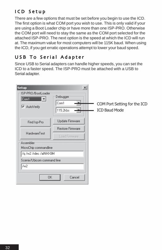
I C D S e t u pI C D S e t u pI C D S e t u pI C D S e t u pI C D S e t u pThere are a few options that must be set before you begin to use the ICD.The first option is what COM port you wish to use. This is only valid if yourare using a Boot Loader chip or have more than one ISP-PRO. Otherwisethe COM port will need to stay the same as the COM port selected for theattached ISP-PRO. The next option is the speed at which the ICD will runat. The maximum value for most computers will be 115K baud. When usingthe ICD, if you get erratic operations attempt to lower your baud speed.
U S B T o S e r i a l A d a p t e rU S B T o S e r i a l A d a p t e rU S B T o S e r i a l A d a p t e rU S B T o S e r i a l A d a p t e rU S B T o S e r i a l A d a p t e rSince USB to Serial adapters can handle higher speeds, you can set theICD to a faster speed. The ISP-PRO must be attached with a USB toSerial adapter.
COM Port Setting for the ICDICD Baud Mode

33
What is an ICD ?ICD stands for In Circuit Debugger. The ICD provides an easy way toDEBUG your code on-the-fly. With MBasic’s ICD you can watch your coderun line-by-line live as each instruction is executed by the PICmicro MCU. Inthe past ICDs have been complicated and could only be used by the mostexperienced users. With MBasic’s ICD this is no longer the case, any usercan easily learn to use the ICD built into MBasic.
Getting Familiar with the ICD Controls
Debug Tool Bar
Debug Menu

34
ConnectThe connect button is used to establish communications between the ICD /Watch Window and the target device. This is done automatically afterprogramming using the “Debug” button. A green bar will highlight the first lineof code indicating it has successfully connected. Once connection has beenestablished the button will change to “Disconnect”
Toggle Break PointIf a break point is not set on the line with the cursor, the toggle break pointwill set a break point on that line. If a break point is set it will clear it.
AnimateThe animate button will animate the displayed program line-by-line as it isexecuted on the target device. This is done with a high lighted green lineacross the screen. This mark indicates the current line of code being ex-ecuted. The marker will flow with the program as it is executed.
RunThe run button will start program execution on the target once the connec-tion is established.
ResetReset is used to restart the program currently running on the target device.Reset does not clear out any previously stored values in ram, which meansany previous values stored in variables will still be there. To clear all theRAM locations when your program starts running make sure to use aCLEAR command in the beginning of the program. This will set all variablesto zero’s each time Reset is used when running the ICD.
PauseThe pause button will pause program execution, to resume the program,click RUN or ANIMATE.
Step IntoThe step button allows you to step through the current running program line-by-line
Step OverThis allows the program to step over a routine, mainly a gosub and orfor..next loop.
Step OutStep out will allow you to step out of a gosub routine. This allows you toskip any gosub in your program and go to the next line after the routine.

35
Run To CursorClicking on any part of the displayed program will produce a blinking cursor.Using the “Run to Cursor” function will allow the program to run until thecursor is reached.
Show VariablesThe variable button if clicked, will open a small new window that displaysall the current variables used in the current program and the current values inHEX, Decimal, Binary and floating point. (Note: AutoUpdate must beenabled for these values to be updated.)
Show SFRsSFRs stands for Special Function Registers. These are the registers builtinto the PICmicro MCU. Some examples are the GIE, ADCON and so on. Ifthe SFRs button is clicked a small window will display all the current SFRsused in the current program and their status.
Show RamThe ram button if clicked, will open a small window that displays all the ramvalues in the Atom.
Show Gosub StackDisplays the gosub stack. This indicates where a program is in a gosubroutine. Useful if a program has many levels of gosubs. (Note: For ad-vanced Users.)
Set Auto UpdateThe auto update feature if checked will automatically update the SFR,Variable, RAM and Stack screens when the program is in animate mode.
Using the ICDTo best illustrate the ICD, we will setup and run a simple program. Onceyou have completed this exercise you should be able to use the ICD withany program.
Important NoteWhen using the ICD, the running program has an added delay anywherefrom .5ms to 500ms per command. The user must take this into accountwhen any timing critical commands or program functions are being de-bugged.

36
ExerciseStart the IDE, create a new file. Save the file as icd.bas. It will be referred toas such in the remainder of this section (Refer to Getting Started section forbasic setup)
CPU = 16F876MHZ = 10CONFIG 16254
Temp var ByteTemp1 Var Word
Temp1 = 0Temp = 0
MainFor temp = 1 to 20
Temp1 = Temp1 + 10Debug [DEC Temp1,13]If Temp1 = 50 then skip
NextGoto Main
SkipDebug [“OK”,13]Temp1 = 60
Goto Main

37
Once you have entered the program, save it. Make sure the target device isconnected and power is applied. Next, click the “Debug” button on the toolbar.
The program will compile, then a progress bar will appear. This indicates thetarget device is being programmed. Once this is finished the IDE will changeto debug mode. If the program did not compile, check your program forsyntax errors.
Debug Mode
After the IDE is in debug mode, a green line will appear at the beginning ofyour program. This is indicates a connection has been established. Next,click the Auto update button. Then click the Variable button, another windowwill appear. This is the variable watch window. Click the AutoUpdate buttonto enable updating of the status windows. Now click Animate.
Variable Watch Window
Variables
Hex Value Decimal Value Binary Value
CurrentLine

38
Once the program is running the variable watch window will update thestatus of each variable used in the program. It will display the values inHex, Dec, Binary and Real.
Shown is the actual program running, The ICD will show a small yellowarrow and a green bar, indicating where the program is at during execution.
Watch the flow of the program. If the program was entered correctly, afterthe variable, Temp1, equals 50, the program should jump down to the Skiplabel. The text “OK” should appear in the watch window. The programshould then return to the label Main.
Congratulations you have successfully mastered the ICD!
Important NotesWhen running debug, there is a block of code that is added to your pro-gram. This code is added to allow the IDE to gather information about theprogram being executing such as variable values, what is the currentprogram line and so on. This information is provided to the IDE after eachline is executed. Because of this, Debug is much slower than running aprogram normally. Timing sensitive programs will be affected.
When running in debug mode a PC is required to run the target device.Once you have finished using debug reprogram the target device with the“Program” button.
Trouble ShootingQ. Error: ISP-PRO not connected
A. Check power is applied and the serial cable is connected. Check toensure the correct comm port has been selected.
Q. A connection has been established, but nothing is happening ?
A. Make sure Auto Update has been checked and after the connection ismade, click “Animate”. Check your syntax.
Q. My program runs and then stops part way through the execution for noapparent reason ?
A. Commands such as SERIN, SEROUT, SHIFTIN, SHIFTOUT or anycommand that affects pins and ports on the target device will cause thisproblem if they are used to modify the I/O pins the ICD is using to talk tothe target device.

39
Q. After I’m done debugging and I disconnect thePC the PICmicro dies ?
A. Once you are finished debugging, you must reprogram the PICmicro withthe normal program button.
Q. During debug the PICmicro is real slow ?
A. When the PICmicro is programmed using debug, extra code is added.During debug the PIC’s entire RAM contents is dumped after every instruc-tion.

40

41
The Basic’s
The Basic’s

42
Bits, Bytes, Words, LongsThroughout this manual and when dealing with programming languages ingeneral, bits, bytes and words will be referred to often. The following is aquick break down:
Type Bit Size RangeBit 1 1 or 0Nib 4 0 to 15Byte 8 0 to 255SByte 8 -127 to +128Word 16 0 to 65535SWord 16 -32767 to +32768Long 32 -2147483647 to +2147483648
MSBs and LSBsAnother often referred to term is LSB or MSB. These terms mean LSB =Least significant bit, MSB = Most significant bit. A byte value of %11110000,the MSB is %1 and the LSB is %0. MSB is the first bit on the left. LSB isthe first bit on the right.
RAM, EEPROM and Program MemoryRAM is random access memory, this type of memory is used to storevariable values, and system values. RAM is also used to store the returnlocation of GOSUB statements. The more RAM available, the more vari-ables or variable arrays can be used. The 16F876 has about 300 bytes ofuser RAM available on average.
EEPROM is on chip data storage. This is commonly used to store valuesthat will remain even when the PICmicro is powered down. The EEPROMstores data in byte size. It can store 256 bytes depending on whatPICmicro is used. (Refer to the device data sheet)
Program Memory is the actual memory where your program will reside. Thesize of available program memory will limit the size of your program. Themore complicated the program will be, the more memory you will want.
Built-in HardwareBuilt-in Hardware refers to additional hardware that is independent of themain microcontroller. Examples of Built-in Hardware are Analog To Digitalconverters, Pulse Width Modulators, UARTS, Timers and so on. Built-inhardware adds pseudo multi tasking abilities to the PICmicro, because inmost cases it can be setup in your program and left to run while theprogram does other things.

43
Hexadecimal 101The hexadecimal number system, also known as "hex" and "base 16",uses 16 characters as its numbers. We normally use the characters0123456789; this is the "decimal" or "base 10" system.
Computers don’t understand decimal numbers; they "know" only two states;on/off, yes/no, high/low, 1/0. The smallest unit of information they can storeis a "bit", short for "binary digit". One bit can store one state; 1 or 0 (On orOff).
Computers count higher than 1 the same way we do; they group the digitsto make larger numbers. In base 10, 9+1=10. In base 2 (also known as"binary"), 1+1=10. (That’s "one zero", not "ten".)
Binary numbers get long in a hurry. For example, the decimal number 201 is11001001 in binary. However, if we group them in groups of four bits (11001001) then each group can have 16 possible combinations.
So, how do we represent 16 combinations with only 10 numbers avail-able? We turn to the alphabet to make up the difference. We need 6 morecharacters, so we use A-F. Using the example above, 1100 binary=12decimal="C" hex; 1001 binary=9 decimal=9 hex.
Since we are using the same characters in the various bases, we needsome way to tell them apart. Is 1101 in binary, decimal, or hex? Binary isusually represented by adding a "b" to the end or “%” to the beginning; i.e.1101b, %1101. Decimal is either a "d" or is not specified.
Hex is designated in several ways. The following all mean the same thing:$C9 and 0xC9.
Most people use the "$" form. And yes, $FB00 is the same as $0000FB00.
Also, note that hex digits mostly come in pairs. Two digits together areknown as a "byte", and are treated as a single unit.
ASCIIMBasic will automatically convert quoted text into its respective ASCIIvalues. This is useful when you are trying to work with the literal value ofcharacters.Example:
SEROUT 1,I9600,[“A”]
The above code example will transmit the ASCII value of the character inquotes.

44
Programming PracticesAs with all programming you may rewrite a program several times beforefinishing it. In the process you may not remember what you were attemptingto do with your program during one of these rewrites. This will lead to spend-ing unnecessary time trying to figure out what you were attempting to do. Thebest way around this is to use comments as you go along. This may seemtedious but after you have written a program and have not touched it inseveral weeks or just days, you will begin to appreciate the value of com-ments. Using comments in your program will help you to pick up where youleft off. When using comments have them tell you something useful that canbe easily understood. An example of this is:
time var bytetime = 0for time = 0 to 10 step 1high B0pause timelow B0nextend
The above program works but what does it do ? Take a look below.
time var byte ; Variable definition for timer LED con B0 ; Constant pointer for Pin 0
time = 0 ; Initialize timer variable
for time = 0 to 10 step 1 ; Loop to count through timer
high LED ; Set LED onpause time ; Delay for current timer valuelow LED ; Set LED off
next ; Loop end
As you can see, commenting a program is the difference between night andday. By looking at the second example it was clear that it was a smallprogram to blink an LED. By using comments, variable names and con-stants your program will be easier to follow in general. So if later in the pro-gram you decide to do more with the LED you could simply use the constantLED instead of B0. This may not be an issue in a short program, but can bevery helpful in larger programs. Imagine trying to keep track of what ten differ-ent pins do, by just using 0,2,7,12.

45
Other coding techniques such as labeling sections of code using names thatdescribe the purpose of the code can greatly increase the ease of program-ming.
;Program to flash an LED at different ratestimer var byte;bigtimer var wordLED con B0 ; Alias PIN B0 to LED
Start:gosub SlowFlashergosub FastFlashergoto ENDPROG
SlowFlasher:for timer = 0 to 100 ; Flash 100 timesToggle LED ; if LED on turn off, If LED off turn onpause 1000 ; Pause 1 secnext
return
FastFlasher:for timer = 0 to 10000 ‘ Flash 10000 timesToggle LED ‘ if LED on turn off, If LED off turn onpause 10 ‘ pause 10 msnext
return
ENDPROG:end
Note: Comments can begin with a semi colon or a single quote.

46
OptimizingMBasic software can only optimize a user’s program in the sense ofemphasizing on code reuse and avoiding redundancy. There are manyways to write a program to accomplish a task. An example of this is:
Temp var Byte
MainSerout B0, I9600,[“Hello World”]Serin B1,I9600,[Temp]
If Temp = “O” Then FishSerout B0, I9600,[“Hello World”]
FishSerin B1,I9600,[Temp]If Temp = “K” Then Main
Goto Fish
The above program sends some serial data out and waits for a specificresponse. The coding style will generate larger code size and slowerprograms. A more efficient way to write the above program is shown below:
Temp var Byte
MainGosub DoLoopGosub OutLoop
If Temp = “O” Then Gosub OutLoopIf Temp = “K” Then Gosub DoLoopGoto Main
DoLoopSerout B0, I9600,[“Hello World”]
Return
OutLoopSerin B1,I9600,[Temp]
Return
The optimizing is in the Gosub statements, if this program was to get largeryou could call the DoLoop and OutLoop labels again and again. Opposedto inserting the same SERIN / SEROUT statements all over the program.

47
Line LabelsIn order to access different sections of code you must use line labels. Unlikethe original Basic language, MBasic does not use line numbers. As an ex-ample:
Loop: goto Loop ;This line repeats infinitely
The above goto statement GOTO calls a line label LOOP, which is in frontof the GOTO statement. The above line will repeat infinitely. Line labels can notbe duplicated or used as variable names once defined as a label.
VariablesVariables are used to store temporary information in the program. They arecreated using the VAR keyword. Variables can be BITs, NIBBLEs, BYTEs,WORDs and LONGs. Before you can use a variable it must be defined.
Variable name: Variable: Size:Temp Var Byte
The above states; Temp will contain a byte (8 bits)
Variable names must start with a letter. They can contain letters, numbersand special characters. However they can not be the same name asMBaic commands, or labels used in a program. The same variable namecan not be defined twice with the Var statement. MBasic does not distin-guish between upper and lower case, so the name TVAR is equivalent toTVar. The maximum character length can be up to 1024 characters.
Some examples of defined variables:
DOG Var Bit ;0 to 1POST Var Nib ;0 to 15LOG Var Byte ;0 to 255STICK Var Word ;0 to 65535TREE Var Long ;0 to 4,294,967,295
Some Tips on assigning sizes to Variables:1. When assigning sizes to variables, keep in mind what the variable isbeing used for. Such as, storing the literal value of the letter A, which willrequire a Byte (0 to 255).2. A variable should be the smallest size to hold the largest value that willbe stored. If a variable will hold the High / Low transition of an input pin (1or 0), use a bit.
48
3. If you are storing character sized values with the SERIN command youwould use a byte sized variable. If a variable exceeds its maximum size,the excess bits will be truncated. If you were to load the binary value%11110000 into a NIB sized variable the %1111 part would be lost.
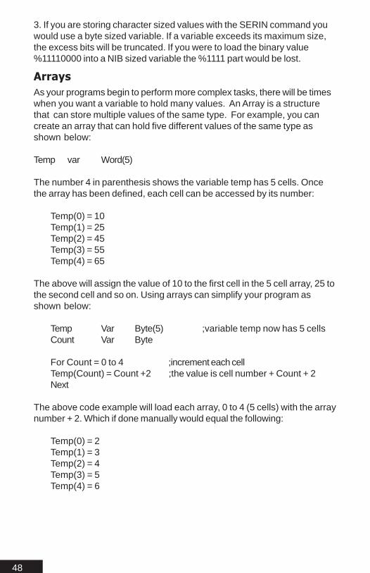
ArraysAs your programs begin to perform more complex tasks, there will be timeswhen you want a variable to hold many values. An Array is a structurethat can store multiple values of the same type. For example, you cancreate an array that can hold five different values of the same type asshown below:
Temp var Word(5)
The number 4 in parenthesis shows the variable temp has 5 cells. Oncethe array has been defined, each cell can be accessed by its number:
Temp(0) = 10Temp(1) = 25Temp(2) = 45Temp(3) = 55Temp(4) = 65
The above will assign the value of 10 to the first cell in the 5 cell array, 25 tothe second cell and so on. Using arrays can simplify your program asshown below:
Temp Var Byte(5) ;variable temp now has 5 cellsCount Var Byte
For Count = 0 to 4 ;increment each cellTemp(Count) = Count +2 ;the value is cell number + Count + 2Next
The above code example will load each array, 0 to 4 (5 cells) with the arraynumber + 2. Which if done manually would equal the following:
Temp(0) = 2Temp(1) = 3Temp(2) = 4Temp(3) = 5Temp(4) = 6

49
TablesTables are made up of constant values which can be byte, word or longsize. One example of tables would be if you had a program that sent datato a LCD screen. If your program was setup to send data to the LCD in amenu format. The menu format was made up of many different text mes-sages that would appear conditionally. Instead of copying the text stringsover and over where ever they are need in the program you could use atable as shown:
Splash ByteTable “Hello”FirstMenu ByteTable “Enter An Option”
LCDWRITE B7\B5\B6, OUTA, [str Splash\5]LCDWRITE B7\B5\B6, OUTA, [str firstmenu\15]
Since there is five characters in our first Byte table we can use the STRmodifier with a count of 5 to send out all the data in the table. In our secondtable there is 15 characters so we use a count of 15 to output all the data.The Table format is shown below:
Label TableType Data, Data, ......Data
Label is the name of the table used to call or access the table. TableTypeis the size of the table data. Tables can be ByteTable, WordTable,LongTable or FloatTable. Data is the constant values or constant expres-sion stored in the table.
AliasesAliases are alternate names for defined variables. As an example:
DOG Var Byte ;DOG is assigned as an 8 bit variable (Byte)CAT Var DOG ;CAT now points to the variable DOG
In the above example if DOG were equal to 10, any time the variable CATwas accessed it would equal 10 since it points to the same RAM location.Aliases are a good idea when you want to use a temporary variable witha name that suits its function.
Variable ModifiersVariable modifiers are used to access only parts of aliases. An examplewould be if you wrote the word value of %0111111100000001 but onlyrequired access to the high byte of the word. You would then use a modifierwith the alias as shown below:

50
Dog Var WordCat Var Dog.HighByte
If the binary value of %0111111100000001 was written to Dog, by modifyingthe alias Cat with the HighByte modifier you would only see %01111111when Cat was accessed. If the LowByte modifier was used you wouldthen see %00000001.
Another example of modifiers and aliases:
MyTimer1 var ByteMyTimer2 var MyTimer1.LowNib
MyTimer1 = %11110000 ;Mytimer1 now equals 240Mytimer2 = %1001 ;MyTimer1 now equals 249
In the above examples by using MyTimer1 with MyTimer2 you can easilyeffect the value of the aliased variable. In the case of MyTimer2 you areable to modify only the low nibble of the aliased byte. The following is abreak down of a Word and Byte sized value:
HighByte is the first 8 bits of a word from left to right and Lowbyte being theopposite.
HighNib is the first 4 bits of a byte from left to right and LowNib being thelast 4 bits.
HighByte LowByteWord Value %1100110101000101
HighNib LowNibByte Value %11001101

51
The table below shows all the different modifiers that can be used:
Modifier Create alias toLOWBIT bit 0 of variableBIT0 bit 0 of variableBIT1 bit 1 of variableBIT2 bit 2 of variableBIT3 bit 3 of variableBIT4 bit 4 of variableBIT5 bit 5 of variableBIT6 bit 6 of variableBIT7 bit 7 of variableBIT8 bit 8 of variableBIT9 bit 9 of variableBIT10 bit 10 of variableBIT11 bit 11 of variableBIT12 bit 12 of variableBIT13 bit 13 of variableBIT14 bit 14 of variableBIT15 bit 15 of variableBIT16 bit 16 of variableBIT17 bit 17 of variableBIT18 bit 18 of variableBIT19 bit 19 of variableBIT20 bit 20 of variableBIT21 bit 21 of variableBIT22 bit 22 of variableBIT23 bit 23 of variableBIT24 bit 24 of variableBIT25 bit 25 of variableBIT26 bit 26 of variableBIT27 bit 27 of variableBIT28 bit 28 of variableBIT29 bit 29 of variableBIT30 bit 30 of variableBIT31 bit 31 of variableHIGHBIT Always the highest bitLOWNIB nibble low of variable

52
NIB0 nibble 0 of variableNIB1 nibble 1 of variableNIB2 nibble 2 of variableNIB3 nibble 3 of variableNIB4 nibble 4 of variableNIB5 nibble 5 of variableNIB6 nibble 6 of variableNIB7 nibble 7 of variableHIGHNIB nibble high of variableLOWBYTE byte low of variableBYTE0 byte 0 of variableBYTE1 byte 1 of variableBYTE2 byte 2 of variableBYTE3 byte 3 of variableHIGHBYTE byte high of variableLOWWORD word low of variableWORD0 First 16 bytesWORD1 Last 16 bytesHIGHWORD word high of variable
53
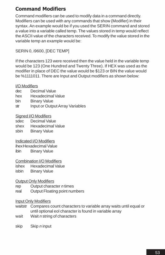
Command ModifiersCommand modifiers can be used to modify data in a command directly.Modifiers can be used with any commands that show {Modifier} in theirsyntax. An example would be if you used the SERIN command and storeda value into a variable called temp. The values stored in temp would reflectthe ASCII value of the characters received. To modify the value stored in thevariable temp an example would be:
SERIN 0, i9600, [DEC TEMP]
If the characters 123 were received then the value held in the variable tempwould be 123 (One Hundred and Twenty Three). If HEX was used as themodifier in place of DEC the value would be $123 or BIN the value wouldbe %1111011. There are Input and Output modifiers as shown below:
I/O Modifiersdec Decimal Valuehex Hexadecimal Valuebin Binary Valuestr Input or Output Array Variables
Signed I/O Modifierssdec Decimal Valueshex Hexadecimal Valuesbin Binary Value
Indicated I/O ModifiersihexHexadecimal Valueibin Binary Value
Combination I/O Modifiersishex Hexadecimal Valueisbin Binary Value
Output Only Modifiersrep Output character n timesreal Output Floating point numbers
Input Only Modifierswaitstr Compares count characters to variable array waits until equal or
until optional eol character is found in variable arraywait Wait n string of characters
skip Skip n input

54
HEX - DEC - BINConverts a value to decimal, binary or hexadecimal.
SERIN 0,i9600, [DEC TEMP]
SDEC - SHEX - SBINConverts a value to decimal, binary or hexadecimal then signs the valuewith “-” for negative or nothing for positive.
SERIN 0,i9600, [SDEC TEMP]
IHEX - IBINConverts a value to binary or hexadecimal then assigns an indicator “%” or“$”.
SEROUT 1,i9600, [IBIN TEMP] ;sends out “%11100110”
ISHEX - ISBINConverts a value to binary or hexadecimal. Assigns an indicator “%” or “$”.Then adds a sign “-” for negative numbers.
SEROUT 1,i9600, [ISBIN TEMP] ;sends out “%-11100110”
REPRepeats character n times.
SEROUT 1,i9600, [REP TEMP\10] ;sends the value in temp 10 times
STRstr var\count{\eol char} - Store values in array(var) until count charactersreceived or EOL (End of line) character received. The EOL will override thecount value if both EOL and count values are specified.
SERIN 1,i9600, [STR TEMP\10\”E”] ;stores values in an array until “E” isreceived or 10 charcaters have been received.
WAITSTRwaitstr var\count{\eol char} - Compares n characters to variable array,waiting until equal or until EOL (End of line) is found. The EOL will overridethe count value if both EOL and count values are specified. If no EOL isspecified, there is no default end of line character and the count will com-plete.

55
SERIN 1,i9600, [WAITSTR TEMP\10\”E”] ;compares values in an arrayuntil “E” is received or 10 characters have been received.
WAITwait (constant list) - Constant list can be "text" or 1,2,3,4,5(comma delim-ited). The wait modifier will wait for the specific characters.
SERIN 1,i9600, [WAIT 1,”a”,3,”c”] ;waits until 1, “a”, 3, “c” has been re-ceived.
SKIPskip count - Skip n characters received.
SERIN 1,i9600, [SKIP\10 TEMP] ;skips 10 characters before loadinganything into the variable temp.

56
ConstantsConstants are fixed values and once declared their values do not change ina program. When creating a program it can be beneficial to use constants forcertain values that don’t change. Such as the following:
Meter CON 1 ;Meter is a constant = 1
Centimeter CON 100 ;Centimeter is a constant = 100
Millimeter CON 1000 ;Millimeter is a constant = 1000
This way you can keep your program readable. Another good use of theconstant is when you have values that are based on other values:
Meter CON 1 ;Meter is a constant = 1
Centimeter CON Meter * 100 ;Centimeter is a constant = 100
Millimeter CON Centimeter * 10 ;Millimeter is a constant = 1000
In the above example “centimeter” and “millimeter” values were derived fromthe constant “meter”. There are a 100 centimeters in a meter and a 1000millimeters in a meter.
Pin names are also considered to be constants so they can be used in thefollowing way:
RedLed Con A0GreenLed Con 0
MainHigh RedLedHigh GreenLed
Goto Main
RedLed and GreenLed are now constants that point to the pin A0. Whenwriting complex programs it may be beneficial to use constant labels asshown above. One thing to consider is constants are always true so theyshould not be used in comparison expressions like below:
Tpin Con Bo
Input TpinIf Tpin = 0 Then SomeLabel

57
The previous If...Then statement will always be true since constants can notbe modified. The correct way to perform a true / false statement on a constantpin would be as shown below:
Tpin Var PortB.bit0
Input TpinIf Tpin = 0 Then SomeLabel
Tpin can no longer be a constant since we are checking the state of a pin.Since constant do not change, Tpin will need to be a variable pointing to thepin bit. Using a variable will allow the value stored in Tpin to change from 1 to0.
PinsPins are a description of an I/O pin on a microcontroller. Ports are defined as agroup of pins. Usually 8 pins make up a port (Byte). Ports that are short of afull eight pins are still accessed the same way as if there were all eight pinswhen reading or witting to the whole port. The non existent pins bits will simplybe ignored.
INPUT B1 ; Sets Pin 1 on port B as an Input
Pin names (Depending on MCU type):
A0 to A5B0 to B 7C0 to C7D0 to D7E0 to E 7
Pin names for Stamp compatibility:
A0 - A5 = 0-5B0 - B 7 = 8-15C0 - C7 = 16-23D0 - D7 = 24-31E0 - E 7 = 32-39
The above stamp compatibility pins only apply to a PICmicro controller.
Pins can be called by either name A0 or 0, B0 or 8 and so on. This wasadded to simplify compatibility with converting a stamp program and addflexibility to your programs.

58
As discussed earlier pin names are constant. Since a constant can not change,using direct pin names will not always work as might be expected. As anexample:
If A1 = 1 Then Main
The above statement will always be true since A1 is a constant. Shownbelow is the correct way to access the pin condition:
If PortA.Bit1 = 1 Then Main
The above statement PortA.Bit1 is a pointer to pin A1. Since we are nowlooking directly at A1, we can now check its condition for a true / false state-ment.
Ports can be access all at once. To do this you would treat the port name asa variable.
PORTA = $ff ;set all pins in PortA High
The above example is a little misleading. You have set all the PINS high;however without setting the pins to be outputs you haven’t done anythingyet. There are three ways to set port status. You can use the input/outputcommands which will set individual pins or you can treat the PORTs I/Oaddress as a variable using either the ports TRIS variable or the BS2 styleDIRS command.
TRISA = $00 ;set all pins in PortA to outputsDIRL = $00 ;sets all pins on PortA to outputs
There is one TRIS variable for each PORT. Note; you have to set theindividual bits OFF to make them OUTPUTS.
TRISB = $F0 ;Set PINS 0-3 to be outputs. Set PINS4-7 to be INPUTS (hex value)
Or with binary values:
TRISB = %11110000;Set PINS 0-3 to be outputs. Set PINS4-7 to be INPUTS (binary value)
The BS2 direction commands work the same as the TRIS variables exceptthey are predefined and only allow access to the first two ports (A & B).
59
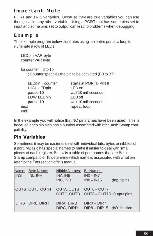
I m p o r t a n t N o t eI m p o r t a n t N o t eI m p o r t a n t N o t eI m p o r t a n t N o t eI m p o r t a n t N o t ePORT and TRIS variables. Because they are true variables you can usethem just like any other variable. Using a PORT that has some pins set toinput and some pins set to output can lead to problems when debugging.
E x a m p l eE x a m p l eE x a m p l eE x a m p l eE x a m p l eThe example program below illustrates using an entire port in a loop toilluminate a row of LEDs:
LEDpin VAR bytecounter VAR byte
for counter = 8 to 15; Counter specifies the pin to be activated (B0 to B7)
LEDpin = counter ;starts at PORTB PIN 8HIGH LEDpin ;LED onpause 10 ;wait 10 millisecondsLOW LEDpin ;LED offpause 10 ;wait 10 milliseconds
next ;repeat loopend
In the example you will notice that NO pin names have been used. This isbecause each pin also has a number associated with it for Basic Stamp com-patibility.
Pin VariablesSometimes it may be easier to deal with individual bits, bytes or nibbles ofa port. MBasic has special names to make it easier to deal with smallpieces of each register. Below is a table of port names that are BasicStamp compatible. To determine which name is associated with what pinrefer to the Pins section of this manual.
Name: Byte Name: Nibble Names: Bit Names: INS INL, INH INA, INB IN0 – IN7
INC, IND IN8 – IN15 ;Input pins
OUTS OUTL, OUTH OUTA, OUTB OUT0 – OUT7OUTC, OUTD OUT8 – OUT15 ;Output pins
DIRS DIRL, DIRH DIRA, DIRB DIR0 – DIR7DIRC, DIRD DIR8 – DIR15 ;I/O direction

60
The previous chart is for Basic Stamp compatibility only. Below is the correctport names for accessing pieces of a port in Mbasic.
MBasic does not differentiate between input or output when accessing portpins. You would simply use the port name in your command. The commandwould either access the port as an output or input depending on thecommand. An example would be as shown:
PortB = %1111111
The above statment sets all the pins on port B high. The next statementsets only B0 to B3 high:
PortB.nib0 = %1111
The following table shows the MBasic port names.
Name: Byte Name: Nibble Names: Bit Names:PORT PORTA, PORTB NIB0, NIB1 BIT0 – BIT7
PORTC, PORTDPORTE

61
MBasic Specific’s
MBasic Specific’s

62
S t a c kS t a c kS t a c kS t a c kS t a c kThe below option is for advance users only and therefore doesn’t appear inthe header file. The STACK setting is set as word size and defaults to a sizeof 20 words. This mean that the compiler uses word sizes instead of bytesizes for the stack. Rarely will the stack need to be adjusted. Setting the stackto something else other than the default is not recommend unless by an expe-rienced user. The maximum stack size available for any supported chip canbe determined by the amount of RAM available in the first bank of memory forthe chip being used.
STACK = 20
O s c i l l a t o r S e t t i n g sO s c i l l a t o r S e t t i n g sO s c i l l a t o r S e t t i n g sO s c i l l a t o r S e t t i n g sO s c i l l a t o r S e t t i n g sAll of the time sensitive instructions, use constant values, that do not changeregardless of the processor speed. When compiling a program, MBasic willautomatically adjust the timings of speed sensitive commands. This featurewill allow a program to be re-compiled for different speeds without modification.If a program is run on a faster chip than it was compiled for, all timings will be offunless the program has been re-compiled for that speed.
I n t e r n a l R C C a l i b r a t i o nI n t e r n a l R C C a l i b r a t i o nI n t e r n a l R C C a l i b r a t i o nI n t e r n a l R C C a l i b r a t i o nI n t e r n a l R C C a l i b r a t i o nTo calibrate the IntRC of a chip that has internal RC, (12C671) use the optionregister. Refer to the device data sheet for settings. Below is an example ofthe IntRC calibration register:
OSCCAL = %10000000
M e m o r yM e m o r yM e m o r yM e m o r yM e m o r yThere are no issue with MBasic and using a PICmicro MCU with more than2K. MBasic was actually designed to become more efficient beyond 1K. Thelatest trend with new micro controllers has been larger programming spaceaveraging 8K and above. MBasic was designed to take advantage of this.Since some of the more common PICmicro MCUs available are 16F87x whichrange from 4K to 8K. All bank and page switching is done automatically. Thisallows hassle free programming.
C o m p i l i n gC o m p i l i n gC o m p i l i n gC o m p i l i n gC o m p i l i n gWhen MBasic compiles a program it first takes the program and breaks itdown into pieces. It then takes these pieces and inserts the necessary as-sembly code. Once this task is complete the compiler will generate an .ASMfile. This .ASM file is then passed to MPASM which then takes the .ASM fileand converts it to the final .HEX file. This resulting .HEX file is then used toprogram the PICmicro MCU.

63
R e s e r v e d S y m b o l sR e s e r v e d S y m b o l sR e s e r v e d S y m b o l sR e s e r v e d S y m b o l sR e s e r v e d S y m b o l sWhen creating a BASIC program using MBasic there are some special con-siderations to take into account. The first, MBasic uses an underscore ‘_’ todefine some commands internally. So the use of an underscore first to define avariable or label is not allowed in a BASIC program (i.e. : _cat or _label).Command names such as SERIN cannot be defined as a variable or alabel. Please refer to the IDE help file for a list of reserved words.
D e v i c e S p e c i f i c I s s u e sD e v i c e S p e c i f i c I s s u e sD e v i c e S p e c i f i c I s s u e sD e v i c e S p e c i f i c I s s u e sD e v i c e S p e c i f i c I s s u e sRead the data sheets on each microcontroller you are using. Some deviceshave features that can interfere with normal pin operations if not setup cor-rectly. The best example is the 16F87x. The 87x PORT A defaults to analogwhich will cause erratic behavior if the port is used digitally, like blinking LEDs.In most cases MBasic will automatically set pins to digital.

64

65
MBasic and Assembly
MBasic and A
ssembly

66
W h a t i s A s s e m b l y ?W h a t i s A s s e m b l y ?W h a t i s A s s e m b l y ?W h a t i s A s s e m b l y ?W h a t i s A s s e m b l y ?Assembly language is the main programming language used to programmicrocontrollers. MBasic actually translates your Basic program into anassembly file which is then passed to an assembler to produce theresulting hex file, used for programming the microcontroller. An exampleassembly program is shown below:
movlw 10movwf Tempmovlw 50
asmloopaddwf LongTempskpncincf LongTemp+1,Fdecfsz Tempgoto asmloop
M i x i n g A s s e m b l y a n d M B a s i cM i x i n g A s s e m b l y a n d M B a s i cM i x i n g A s s e m b l y a n d M B a s i cM i x i n g A s s e m b l y a n d M B a s i cM i x i n g A s s e m b l y a n d M B a s i cAssembly language routines can be added at any time and anywhere in aMBasic program. They are passed as is, from the program and inserted di-rectly into the compiled assembly file. There are several advantages to com-bining assembly language with MBasic. For the beginner using small snip-pets can aid in learning and understanding microcontrollers better. For the pro-fessional MBasic can be used to create PAUSE, IF...THEN, SERIN, SEROUTroutines in BASIC, quicker and easier than in assembly.
I n - l i n e A s s e m b l yI n - l i n e A s s e m b l yI n - l i n e A s s e m b l yI n - l i n e A s s e m b l yI n - l i n e A s s e m b l yMBasic allow single assembly command insertion or blocks of assembly ina Basic program. An example is shown below:
temp var byte
clrf tempmain
High B0Pause 500if temp < 20 then skipLow B0
skip incf temp,f goto main
end

67
In line assembly routines can easily be called by a BASIC program byusing the following method:
CatASM{ movlw 10
movwf temp}
Return
To call the assembly routine simply use a GOSUB command. To return towhere the GOSUB command made the call use a RETURN command afterthe enclosing bracket for the ASM command. The label must be in placebefore the ASM command.
A s s e m b l y a n d V a r i a b l e sA s s e m b l y a n d V a r i a b l e sA s s e m b l y a n d V a r i a b l e sA s s e m b l y a n d V a r i a b l e sA s s e m b l y a n d V a r i a b l e sReading and writing variables that are defined in BASIC using assembly canbeen done with MBasic.A variable can be accessed from assembly that isdefined as a byte in Basic. Accessing Nib, bit, or word size variables gets alittle more complicated. It is outside the scope of this manual to describe thisprocess.

68

69
Math
Math
Math
Math
Math
Math
70
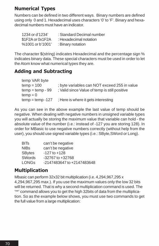
Numerical TypesNumbers can be defined in two different ways. Binary numbers are definedusing only 0 and 1. Hexadecimal uses characters ‘0’ to ‘F’. Binary and hexa-decimal numbers must have an indicator.
1234 or d’1234’ : Standard Decimal number$1F2A or 0x1F2A : Hexadecimal notation%1001 or b’1001’ : Binary notation
The character $(string) indicates Hexadecimal and the percentage sign %indicates binary data. These special characters must be used in order to letthe Atom know what numerical types they are.
Adding and Subtracting
temp VAR bytetemp = 100 ; byte variables can NOT exceed 255 in valuetemp = temp - 99 ; Valid since Value of temp is still positivetemp = 0temp = temp -127 ; Here is where it gets interesting
As you can see in the above example the last value of temp should benegative. When dealing with negative numbers in unsigned variable typesyou will actually be storing the maximum value that variable can hold - theabsolute value of the number (i.e.: instead of -127 you are storing 128). Inorder for MBasic to use negative numbers correctly (without help from theuser), you should use signed variable types (i.e.: SByte,SWord or Long).
BITs can’t be negativeNIBs can’t be negativeSBytes -127 to +128SWords -32767 to +32768LONGs -2147483647 to +2147483648
MultiplicationMbasic can perform 32x32 bit multiplication (i.e. 4,294,967,295 x4,294,967,295 max.). If you use the maximum values only the low 32 bitswill be returned. That is why a second multiplication command is used. The‘**’ command allows you to get the high 32bits of data from the multiplica-tion. So as the example below shows, you must use two commands to getthe full value from a large multiplication:

71
lowmult VAR longhighmult VAR longmiddilemult VAR long
lowmult = 4,294,967,295 * 4,294,967,295; returns the LOW 32 bits of * value = 5119617025
highmult = 4,294,967,295 * 4,294,967,295; returns the HIGH 32 bits of * value = 1844674406
middlemult = 4,294,967,295 */ 4,294,967,295; returns the MIDDLE word of * value = 7440651196
Using the */ function is equivalent to multiplying by the HIGH 16bit number +(LOW 16bit number / 65536). This allows simple fractional multiplication with-out using the floating point math system (which is significantly slower thaninteger math)
example1:temp var long ;temp needs to equal 1000 * .05
;to calculate the fraction .05 for use with the following MULM(‘*/’) function usethis formula. fraction = 0.05 * 65536 = 3276.8 ~= 3276temp = 1000 */ 3276 ;temp will equal 49
example2:temp var long ;temp needs to equal 1000 * 3.145
temp = 1000 */ 206110 ;temp = 3000 + 144 = 3144
You should note that some round off error will occur.

72
DivisionMbasic can perform 32x32 bit division (i.e. 4,294,967,295 / 4,294,967,295max.). The division command has two separate commands associated with it.The first command ‘/ ‘ will return the quotient value. Which is the actual resultfrom the divide. The second command “//”, is used to return the remainder if thereis one :
divval VAR worddivrem VAR worddivval = 65000 / 101 ; Returns the Quotient value = 643divrem = 65000 // 101 ; Returns the remainder value = 57
Integer Math in generalMbasic uses standard algebraic syntax. In Basic Stamp math: 2+2 * 5 / 10would equal 2. In Mbasic 2+2*5/10 = 3. This is because each math operatorhas a precedence. The multiply and divide operators have equal prece-dence. In the above calculation 2*5 will be calculated first (equaling 10), thenthe divide by 10 (equals 1), then the addition of 2 (equaling 3). To ensure theabove equation works as you expect you need to use parenthesis (i.e.:((2+2)*2) /2 would equal the Basic Stamp syntax.
Operator Precedence:Order: Operation:1st Not, ABS, SIN, COS, - (NEG), DCD, NCD, SQR, Random,
FNEG, INT, FLOAT, DEC2BCD, BCD2DEC2nd <, <=, =, >=, >, <>3rd And, Or, Xor4th Rev, Dig5th <<, >>6th MAX, MIN7th &, |, ̂ , !&, !|, !^8th *, **, */, /, //, FMUL, FDIV9th +, -, FADD, FSUB

73
General Math FunctionsThe following is a list of special math functions MBasic can perform.
UNARY Commandsvariable = COMMAND value
ABS Absolute valueSIN sine of value(0-255)COS cosine of value(0-255)DCD 2 to the nth power(n = value)NCD smallest power of 2 that is GREATER than value.SQR square root of value.DEC2BCD Integer to packed BCD formatBCD2DEC Packed BCD to integer.
BINARY Commandsvariable = value1 COMMAND value2
MAX smaller of the two values.MIN larger of the two values.DIG digit of value 1 at value2 position.REV reverses value2 bits of value1 starting with LSB
Bitwise OperatorsBitwise operators are commands that directly effect the bits of a value.
Bitwise operatorsvariable = value1 COMMAND value2
{!}& (AND) AND bits of value1 with {Inverted}value2variable = %01010101 & %00001111;variable equals %0101
{!}| (OR) ;value1 OR value2variable = %11110000 | %00001111;variable = %11111111
{!}^ (XOR) ;value1 XOR value2variable = %10101010 ̂ %11110000;variable equals %01011010
>> (SHIFTRIGHT) ;value1 bits shifted right value2 timesvariable = %11110000 >> 4;variable equals %1111
<< (SHIFTLEFT) ;value1 shifted left value2 timesvariable = %00001111 << 4; variable equals %11110000

74
Comparison OperatorsComparison operators are used when comparing two or more values.Examples are the IF...THEN and LOOKDOWN commands.
Logical OperatorsLogical operators are slightly different in use than comparison operators. Whenusing an IF...THEN statement that contains more than one comparison youmust combine them using a logical operator. The example below illustratesthis:
If (Variable < 100) AND (Variable > 10) Then Label
As you can see from the example if BOTH are true then the program jumpsto the label.
Logical Op. DescriptionAND Logical ANDOR Logical ORXOR Logical Exclusive ORNOT..AND Logical NANDNOT...OR Logical NORNOT..XOR Logical NXOR
= Equal<> Not Equal< LessThan> GreaterThan<= LessThan Equal>= GreaterThan or Equal
Compare Op. Description

75
Floating Point MathMbasic can perform 32x32 bit IEEE 754 Compliant Floating Point calcula-tions. 32 bit floating point math is CPU intensive since the PICmicro is onlyan 8 bit processor. Some special commands are required to handle floatingpoint math. No command can actually use floating point math in its variableor expression. You will need to do some conversion with the floating pointvalue to send it (except when using the REAL modifier) using SEROUT orreceive it using SERIN.
INT = Convert floating point number to integer numberFLOAT = Convert integer number to floating point numberFNEG = negates floating point numbersFADD = Adds two floating point numbersFSUB = Subtracts two floating point numbersFMUL = Multiplies two floating point numbersFDIV = Divides two floating point numbersFLOATTABLE = stores constant floating point data in flash
Floating Point FormatThe floating point math Mbasic uses differs some what from the normalIEEE 754 floating point standard. The differences are minor. The next sectiongives a good indicator on how they differ.
Floating Point Example Program
temp var longtemp2 var long
Fconst Con 1.12345;Stores the Microchip format floating point number 1.12345
Iconst Con INT 1.12345; Truncates the value 1.12345 to 1
Maintemp = 0 ;Stores the integer value 0 in temptemp2 = float 0 ;Stores the floating point value 0.0 in temp2
The first part of the program stores the integer number 0 in Temp and thefloating-point number 0.0 in Temp2.
temp = 1.12345
We then store the floating point number 1.12345 in Temp.
temp = fconst

76
temp2 = iconst
Fconst is a floating point constant that was defined at the begging of theprogram. So Temp is equal to 1.12345. We also defined iconst which is aninteger constant.
temp = float 1oftemp = 1.0
We now load the floating point value of 1 into Temp. As shown above, if aconstant is to be used in a floating point calculation it must be representedas a floating point number. The second case above the number is auto-matically understood to be a floating point value by the compiler because ofthe .0 extension. In the first example the float command must be usedbecause there is no way for the compiler to tell whether the constant shouldbe an integer or a floating point number
temp = temp fmul float 2ortemp = temp fmul 2.0
Next we multiply the value in Temp by a floating point number 2. The resultof Temp is now 2.0 which is a floating point number.
temp = float 567
Above we load Temp with FP (Floating Point) number 567.0. We thendivide Temp with 5.0 which is a FP number.
temp = temp fdiv float 5ortemp = temp fdiv 5.0
Temp now equals 113.4.
temp = float 123orTEMP = FLOAT 123.0
Above we load Temp with FP (Floating Point) number 123.0. We then addTemp with 123.5 which is a FP number.
temp = temp fadd float 123.5

77
ortemp = temp fadd 123.5
Temp now equals 246.5.
temp = float 123temp = temp fsub float 123.5ortemp = 123.0temp = temp fsub 123.5
Temp now is equal to 0.5. Since Temp is now equal to 0.5 we negateTemp from its self below and we end up with -0.5. Floating point math alsowill handle negative numbers.
temp = fneg temp
Important NotesAll variables that will contain a floating point number must be 32 bits(Longs).

78

79
SyntaxSyn
taxSyn
taxSyn
taxSyn
taxSyn
tax

80
A D i nA D i nA D i nA D i nA D i nADIN pin,clk,adsetup{,var}Sets up the Hardware A/D converter, and stores the value in an optionalvar.
Pin can be a constant or variable. The pin specifies which analog pinto use with the ADIN command some microcontrollers only have 2, whileothers have 8 or more (refer to the device data sheet for details)
Clk can be a constant or variable. The Clk option sets the samplingtime for the A/D conversion. There are only 4 choices for Clk 0, 1, 2, 3(0-2 are based on internal cycles) CLK option 3 is based on an internalRC divisor (refer to the device data sheet)
Adsetup can be a constant or variable. Adsetup is used to setup theADCON1 register (refer to the device data sheet for details on theADCON1 register)
Var can only be a variable. Var specifies where the conversion resultwill be stored.
ExplanationAnalog to Digital conversion allows your program to receive an analogsignal and convert it into digital values. The AD hardware can read 0 to 5volts. The ADIN command can be used to start the A/D conversion andwait for the result or it can be used to multi task by starting the hardware A/D conversion and processing the result later in the program.
The program below converts an analog input on RA0. The followingexample will output the decimal value of the conversion to the debugwindow.
temp var word ;temp is now a word sized variable
AN0 con 0 ;this sets the pin AN0 / RA0,
CLK con 2 ;CLK options are 0, 1, 2, 3 (0-2 are based on int cycles) ;CLK option 2 is based on 1/16 of the external osc speed ;the CLK slow does down the sampling time. ADSETUP con %10001110 ;sets up the ADCON1 register ;AN0 / RA0 is now analog
main ADIN AN0,CLK,ADSETUP,temp ;loads the variable temp with the sample

81
A d s e t u pA d s e t u pA d s e t u pA d s e t u pA d s e t u pADCON1 sets the A/D converter pin options. Which allows you to setsome or all of the A/D pins to analog, with several other options as shownin Table2-3. The last four bits which are 1110 in the example programshownset pin RA0 / AN0 to analog and the remainder pins to digital. Thefirst bit which is 1 in the example program is the left and right justify. 1 =Right Justified, 0 = Left Justified.
ADCON1 REGISTER SETTINGS: (Table 2-3)
A = Analog input, D = Digital I/O
Note Not all channels are available on all chips with A/D. Refer to thedevice data sheet for details.
debug[dec temp,13] ;out puts the value in temp goto main
S c h e m a t i cS c h e m a t i cS c h e m a t i cS c h e m a t i cS c h e m a t i cThe below schematic shows the configuration for the above code to workproperly. The 20K pot can be moved from RA0 / AN0 to another analog pinbut the ADSETUP value will need to be changed along with the specifiedpin.

82
A S M { . . . }A S M { . . . }A S M { . . . }A S M { . . . }A S M { . . . }ASM...{Assembly commands}In-line Assembly
E x p l a n a t i o nE x p l a n a t i o nE x p l a n a t i o nE x p l a n a t i o nE x p l a n a t i o nASM {..} instructions allow the use of assembly in MBasic. The command,when used, will tell the compiler that the code in between the two brackets isin assembly and it is to be passed directly to the assembler. These com-mands can be used as freely as needed.
E x a m p l eE x a m p l eE x a m p l eE x a m p l eE x a m p l eTemp VAR byte
LongTemp VAR word
main
ASM{
clrf LONGTEMP & 0x7Fmovlw 10 ;load W with 10movwf TEMP & 0x7F ;store 10 in Tempmovlw 50
asmloopaddwf LONGTEMP & 0x7F,f ; Add 25 to LongTempskpnc ; If Low byte of longtemp carriesincf (LONGTEMP+1) & 0x7F,F ; Increment Long Temp+1decfsz TEMP & 0x7F,f ; Loop 10 timesgoto asmloop
}debug [DEC longtemp,13] ;longtemp will increment each
loopgoto main
I m p o r t a n t N o t e sI m p o r t a n t N o t e sI m p o r t a n t N o t e sI m p o r t a n t N o t e sI m p o r t a n t N o t e sAll variables used in the in-line assembly must be either words or bytes.Also note that words are denoted by the variable name and the variablename+1 (ie:Longtemp and Longtemp+1)
It is not in the scope of this manual to teach Assembly language. The ASMcommand is strictly for advanced users that completely understand assem-bly language. No support is offered for assembly language programming.

83
BranchBRANCH index, [Label1,...LabelN]Go to the Label specified by index.
Index is a variable or constant that specifies the address to branchto.
Label1,...LabelN are labels that specify where to branch to.
ExplanationThe Branch command allows the program to jump to different locationsbased on a variable index. The BRANCH instruction can be useful tosimplify something like the following:
IF temp = 0 THEN dog ;temp =0; go to label dogIF temp = 1 THEN cat ;temp =1: go to label catIF temp = 2 THEN mouse ;temp =2: go to label mouse
BRANCH can be used to organize the above into a single statement:
BRANCH temp, [dog, cat, mouse]
The above works the same as the previous IF...THEN example. If thevalue is greater than 3 the BRANCH does nothing and the programcontinues to the next line.
ExampleIn the following example we have 5 players 0-4. We will display eachplayer in turn. As each player is displayed our variable Player isincremented. The value in Player is index to the constant list used in theBranch command.
Player var byte 'Used to hold the current player numberPlayer = 0 'Start out as first player
'The main looploop: debug ["#",dec player," "] Branch Player,[Mike,Joe,Fred,Bill,Jane]
'Fall through because there is no player #5debug ["Don’t know who this is. Lets start over.",10,13,10,13]player = 0 'Reset to first playergoto loop 'Now go do it again
'These are the branch routinesMike:

84
debug ["Mike's Turn ",13] Player = Player + 1 'Get next player
goto loop
Joe:debug ["Joe's Turn ",13]Player = Player + 1 'Get next player
goto loop
Fred:debug ["Fred's Turn ",13]Player = Player + 1 'Get next player
goto loop
Bill:debug ["Bill's Turn ",13]Player = Player + 1 'Get next player
goto loop
Jane:debug ["Jane's Turn ",13]Player = Player + 1 'Get next player
goto loop
This program shows how the BRANCH command can be used. First weassign our variable a value of 0. Then we define our labels. Since the firstposition is considered 0 and the variable index equals 0 the branch commandwill cause the program to jump to the first label in the brackets [Mike]

85
ButtonBUTTON pin, downstate, delay, rate, bytevariable, targetstate, addressDebounce, button input, perform auto-repeat, and branch to address if buttonis in target state. Button circuits may be active-low or active-high.
Pin is a variable/constant that specifies the I/O pin to use. Thispin will be made an input.
Downstate is a variable/constant (0 or 1) that specifies whichlogical state occurs when the button is pressed.
Delay is a variable/constant (0–255) that specifies how long thebutton must be pressed before auto-repeat starts. The delay ismeasured in cycles of the Button routine. Delay has two specialsettings: 0 and 255. If Delay is 0, Button performs no debounce orauto-repeat. If Delay is 255, Button performs debounce, but noauto-repeat.
Rate is a variable/constant (0–255) that specifies the number ofcycles between auto repeats. The rate is expressed in cycles of theButton routine.
Bytevariable is the work space for Button.
Targetstate is a variable/constant (0 or 1) that specifies whichstate the button should be in for a branch to occur.(0=not pressed, 1=pressed)
Address is a label that specifies where to branch if the button isin the target state.
ExplanationWhen a button is pressed or a switch flipped, the contacts make or break aconnection. During this a 1 to 20-ms burst of noise occurs as the contactsscrape and bounce against each other. The BUTTON command has afeature that prevents this noise from being interpreted as more than oneswitch action. This is called debounce.
The BUTTON command also will react to a button press the way a com-puter keyboard does. When a key is pressed, a character will appear onthe screen. If the key is held down, there is a small delay, then a rapidstream of characters appear on the screen. The BUTTON command has anauto-repeat function that can be set up to act the same way.
BUTTON was designed to be used inside a program loop. Each time cyclethrough the loop, the BUTTON command checks the state of the specifiedpin. When it first detects the DownState it debounces the switch. Then with

86
TargetState, it either branches to address based on what the TargetState isset to (TargetState = 1 then jump or TargetState = 0 then don’t).
If the connected switch stays in a down state, BUTTON will count thenumber of program loops that execute. When this count equals Delay,BUTTON will once again trigger the action specified by TargetState andaddress. After which, if the switch remains in DownState, BUTTON waitsthe Rate number of cycles between actions. There is a work spacevariable which is used by BUTTON to keep track of how many cycleshave occurred since the pin switched to TargetState or since the last auto-repeat. BUTTON will not stop program execution. In order for the BUTTONcommands delay and auto repeat functions to work properly it must beexecuted from within a program loop.
ExampleThe following program is an auto repeat example of the button command.This demonstration requires a button wired to pin 1. Using state 1 asshown in the schematic. Place a LED between pin 2 and VSS. When youclick the button you get a single led blink. Hold the button down and it autorepeats.
'The button command needs a work variable.work var bytework =0
Input B1 'Buttonoutput B2 'LEDlow B2 'Make sure our display pin is low to begin with
Loop:Button B1,1,20,2,work,1,presspause 20 'We need some delay or its too fast.
goto loop
'This is where you do your button workpress:
high B2pause 10low B2
goto loop

87
Schematic
State 0 State 1

88
ClearCLEARClear user RAM.
ExplanationThe Clear command will clear (Set to 0’s) all of the user ram. User ram is setaside space for all the variables a user program will use. If the Atom is resetusing RES / ATN, any values left in RAM will remain. To clear out the ram andset all variables to a value of 0 use the Clear command. It is a good idea touse the Clear command to create a known state after each reset. It can alsobe used any where in the program to set all variables to zero.
ExampleTemp Var ByteTemp1 Var Byte
MainTemp = Temp + 1Temp1 = Temp1 + 2
Goto Main
If the above program ran through 20 complete loops Temp would equal 20and Temp1 would equal 40. If the PICmicro was then reset using ATN / RESthe ram space for Temp and Temp1 would still equal 20 and 40. The only wayto clear this ram space is to completely power down the PICmicro, or setTemp = 0 and Temp1 = 0 at the beginning of the program, or use the Clearcommand. For a large program with several variables it would be easier touse the Clear command.
Temp Var ByteTemp1 Var Byte
Clear ;clears all variables (RAM)
MainTemp = Temp + 1Temp1 = Temp1 + 2
Goto Main
The above program will now set Temp and Temp1 to zero each time thePICmicro is reset or the program is ran.
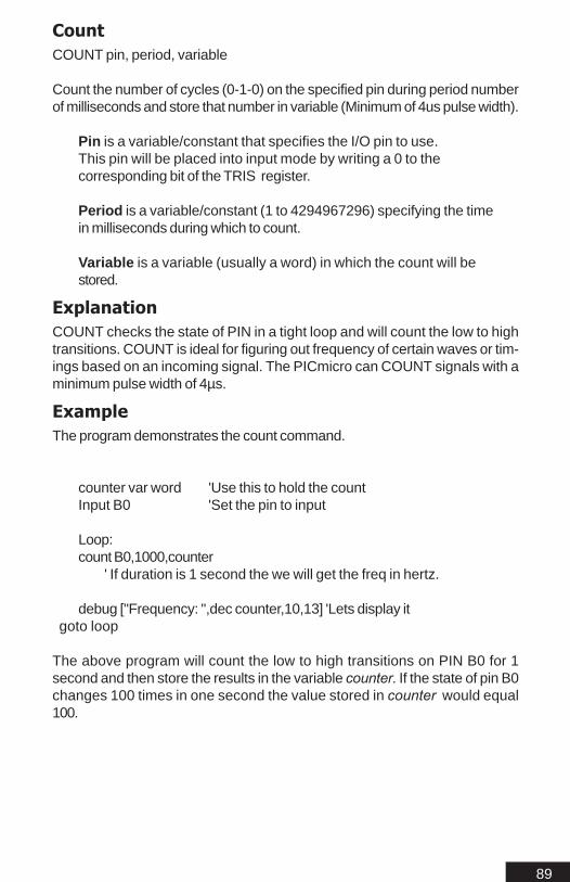
89
CountCOUNT pin, period, variable
Count the number of cycles (0-1-0) on the specified pin during period numberof milliseconds and store that number in variable (Minimum of 4us pulse width).
Pin is a variable/constant that specifies the I/O pin to use.This pin will be placed into input mode by writing a 0 to thecorresponding bit of the TRIS register.
Period is a variable/constant (1 to 4294967296) specifying the timein milliseconds during which to count.
Variable is a variable (usually a word) in which the count will bestored.
ExplanationCOUNT checks the state of PIN in a tight loop and will count the low to hightransitions. COUNT is ideal for figuring out frequency of certain waves or tim-ings based on an incoming signal. The PICmicro can COUNT signals with aminimum pulse width of 4µs.
ExampleThe program demonstrates the count command.
counter var word 'Use this to hold the countInput B0 'Set the pin to input
Loop:count B0,1000,counter
' If duration is 1 second the we will get the freq in hertz.
debug ["Frequency: ",dec counter,10,13] 'Lets display it goto loop
The above program will count the low to high transitions on PIN B0 for 1second and then store the results in the variable counter. If the state of pin B0changes 100 times in one second the value stored in counter would equal100.

90
Data (EEPROM)DATA {@address,} value, {@address,} value
Data command will pre-load the eeprom on the PICmicro during program-ming. The Data command is not a run time command.
Address is optional and specifies the first address to start at.Multiple address values can be used after each value is written.The Data command will start writing at the first location of theeeprom by default. Address must be a number.
Value are constant values that will be written to the PICmicro’s onboard eeprom. These values must be constants since the values areplaced during programming.
ExplanationThe DATA command can be used for an easy method to access the built inEEPROM of the PICmicro. When using a DATA command, all the valuesspecified will be placed in the EEPROM starting at location 0 by defaultunless an address is specified. To write or read data during run time from theinternal EEPROM, refer to the READ / WRITE or READDM / WRITEDMcommands.
ExampleDATA 10,20,”Hello”
Stores the values 10,20 and the ASCII values for “Hello” , on the internal EEPROM starting at location 0.
DATA @5, 10,20,”Hello”
Stores the values 10,20 and the ASCII values for “Hello” , on the internal EEPROM starting at location 5.
DATA @5, ”Hello”, @10, “Good Bye”
Stores the ASCII values for “Hello” , on the internal EEPROM starting at location 5 and the ASCIIvalues for “Good Bye”
This next example shows how to pre-load values into the PICmicro’s onboard EEPROM and use the READ command to read them out.
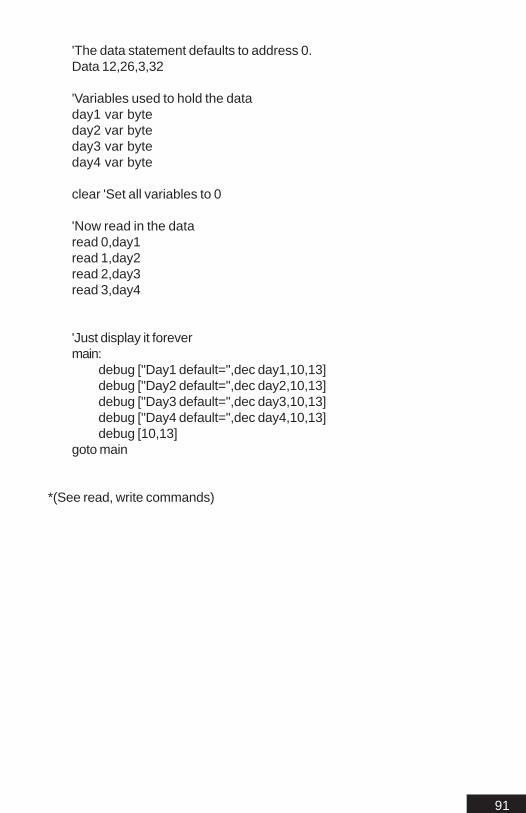
91
'The data statement defaults to address 0.Data 12,26,3,32
'Variables used to hold the dataday1 var byteday2 var byteday3 var byteday4 var byte
clear 'Set all variables to 0
'Now read in the dataread 0,day1read 1,day2read 2,day3read 3,day4
'Just display it forevermain:
debug ["Day1 default=",dec day1,10,13] debug ["Day2 default=",dec day2,10,13] debug ["Day3 default=",dec day3,10,13] debug ["Day4 default=",dec day4,10,13] debug [10,13]
goto main
*(See read, write commands)

92
DebugDEBUG [{Options} item, {{Options} item}]Sends values of specified variables or constants to the debug watchwindow.
Options are DEC, HEX, BIN or REAL. These modifiers will convertItem to DEC = Decimal, HEX = Hexadecimal, BIN = Binary digits orREAL = Value.
Item can be a constant or variable. There is no limit to the amountof items used other than program memory.
ExplanationThe DEBUG command will send any values stored in a given variable orconstant to the debug watch window. The DEBUG command is also linkedwith the IDE’s in circuit debugger (Refer to the In Circuit Debugger sectionof this manual). Variables used by themselves are automatically truncatedto character size.
Exampledog VAR byte
dog = 14
DEBUG [DEC dog,13] ;output the decimal 14 to the debug window with a carriage return
The above sample will output the decimal number 14 to the debug window.The ,13 is the decimal value of a carriage return. This is not necessary, but itmakes the data coming into the debug window easier to read. If a carriagereturn is not used the data will simply scroll across the screen line by line. IfHEX was used in place of DEC, the hexadecimal value of the number 14would have been sent E.
DEBUG ["TEMP"]
The above line of code would send the word TEMP to the debug window.
Using DebugOnce you have placed DEBUG statements in your program you will needto use the Debug button on the IDE to program the PICmicro. If you use thenormal program mode the statements will be ignored. This allows theDEBUG statements to be placed and then later ignored without removingthem and affecting your program. (Refer to the In Circuit Debugger sectionof this manual)

93
Important NoteWhen using the ICD, the running program has an added delay anywherefrom .5ms to 500ms per command. Any timing critical commands or programfunctions will be off.
Once you have placed DEBUG statements in your program you will needto use the DEBUG button on the IDE to program the PICmicro. If you usethe normal program mode the statements will be ignored.
SEE ALSO
DEBUGINIn Circuit Debugger (ICD)

94
DebuginDEBUGIN [(Options) item]Receives byte values from the IDE DEBUG window and stores them in aspecified variable on the Atom.
Options are DEC, HEX, BIN or REAL. These modifiers will convertItem to DEC = Decimal, HEX = Hexadecimal, BIN = Binary digits orREAL = Value.
Item can only be a byte variable. Stores the received byte value inthe specified variable.
ExplanationThe DEBUGIN command allows you to send data to your program on-the-fly from the IDE DEBUG Watch Window and stores them in a specifiedvariable. This can be useful for adjusting a program on the fly.
Exampledog VAR byte
DEBUG DOG ;stores byte value in DOG received from IDE DEBUG window.
The above line will simply take the value received and store in the variableDOG.
This next example demonstrates the Debugin command used with theDebug command.
'Holds age for use with the debugin command.age var byteage=0
'Our main loopmain:
debug ["Enter your age _"] 'Outputdebugin [dec age] 'Input. Load value into age variable
'Now display the resultdebug ["Wow you are ",dec age," years old",10,13,10,13]
goto main

95
Using DebuginOnce your program is ready for testing simply click the DEBUG button forprogramming. After programming is complete the Debug Watch Window willcome into focus at the bottom of your screen. See figure 2-
1. Once the window is in focus and programming is complete you will need toconnect (Refer to the In Circuit Debugger section of this manual). To senddata to the running program, click in the watch window, a cursor should ap-pear. You can now type your data in this screen and it will automatically besent to the running program.
Important NotesIf the PROGRAM button is used instead of the DEBUG button the DE-BUG and DEBUGIN statements will be ignored and not affect the runningprogram.
SEE ALSO:DEBUG

96
Do...WhileDo statements While some expression is trueRepeat a group of commands while expression is true
Expression is any combination of variables, constants, mathand logic operators
ExplanationExecute a group of commands while some expression is true. DO...WHILEwill run at least once. True can be any other value than 0.
ExampleThe below program will execute until Temp is equal to 0:
temp VAR bytetemp = 100
Dotemp = temp -1 ;program will count down from 100 to 0
While temp <> 0 ;keep going until temp is equal to 0
The above program will count down from 100 to 0. The symbol <> meansnot equal so as long as the variable temp is not equal to 0 (a true condi-tion) the program will continue to decrement the variable temp until it equals0 (a false condition).
The example requires a button tied to pin B1 with pull down resistor tied toVSS and other side of the button tied to VDD.
input B1output B2 'led tied between vss and pinB2
'The main loopMain
'Check to see if the button is downif portb.bit1 = 1 thenhigh B2 : pause 300 : low B2 'Blink the LED
'Now just waste some time until button is released'As long as B1 = 1 we will stay in this loop
dowhile B1 = 1
endif goto main

97
DTMFoutDTMFOUT pin,{ontime,offtime,}[,tone...]Generate dual-tone, multifrequency tones for DTMF (i.e., telephone "touch"tones).
Pin is a variable/constant that specifies the I/O pin to use. Thispin will be set to an output during tone generation. After tonegeneration is complete, the pin is left as an input.
Ontime is an optional entry; a variable or constant (0 to 65535)specifying a duration of the tone in milliseconds. If ontime is notspecified, DTMFout defaults to 200 ms on.
Offtime is an optional entry; a variable or constant (0 to 65535)specifying the length of silent pause after a tone (or betweentones, if multiple tones are specified). If offtime is not specified,DTMFout defaults to 50 ms off.
Tone is a variable or constant specifying the DTMF tone to send.Tones 0 through 11 correspond to the standard layout of thetelephone keypad, while 12 through 15 are the fourth-columntones used by phone test equipment and in ham-radioapplications.
0 to 9 Digits 0 - 910 = *11 = #12—15 Fourth column tones A through D
ExplanationDTMF tones are used to dial the phone or to remotely control certain radioequipment. The PICmicro is a digital controller. DTMF tones are analogwaveforms, consisting of two sine waves at different frequencies. TheDTMFout command creates and mixes two sine waves mathematically,then using the resulting stream of numbers to control the duty cycle of apulse-width modulation (PWM) routine. Presence of high-frequency noise onthe input. The output generated by the DTMFout command will need to befiltered as shown in the schematic. This filter circuit is only a starting point.Different conditions will require different types of filters.

98
Schematic
ExampleDTMFOUT B0,[1,7,3,4,4,2,5,1,7,4,4]
;Using default delaysor
DTMFOUT B0,500,200,[1,7,3,4,4,2,5,1,7,4,4];Using custom delays
The above code with an RC filter as shown above will generate tonesdirectly, to dial a number through a phone from an attached speaker.
SEE ALSO
FREQOUTDTMFOUT2SOUNDSOUND2

99
DTMFout2DTMFOUT2 pin1 \ pin2,{ontime,offtime,}[,Tone...]Uses two pins to generate dual-tone, producing a cleaner signal (i.e.,telephone "touch" tones).
Pin1 / Pin2 is a variable/constant that specifies the I/O pins touse. These pins will be set as outputs, during tone generation.After tone generation is complete, the pins are set to inputs.
Ontime is an optional entry; a variable or constant (0 to 65535)specifying a duration of the tone in milliseconds. If ontime is notspecified, DTMFout defaults to 200 ms on.
Offtime is an optional entry; a variable or constant (0 to 65535)specifying the length of silent pause after a tone (or betweentones, if multiple tones are specified). If offtime is not specified,DTMFout defaults to 50 ms off.
Tone is a variable or constant specifying the DTMF tone to send.Tones 0 through 11 correspond to the standard layout of thetelephone keypad, while 12 through 15 are the fourth-columntones used by phone test equipment and in ham-radioapplications.
0 to 9 Digits 0 - 910 = *11 = #12—15 Fourth column tones A through D
ExplanationThe DTMFOUT2 command follows the same basic format as DTMFOUT(refer to DTMFOUT), except it generates the multifrequency tones on twopins. These two pins can be tied together using a 390 ohms resistor. Thetones generated by DTMFOUT2 are cleaner and of a higher quality. TheDTMFOUT2 command is ideal in a noisy environment or where higherquality tones are desired.
Schematic

100
ExampleDTMFOUT2 B0\B1,[1,7,3,4,4,2,5,1,7,4,4]
;Using default delaysor
DTMFOUT2 B0\B1,500,200,[1,7,3,4,4,2,5,1,7,4,4];Using custom delays
The above code with an RC filter (Schematic) will generate tones directly, todial a number through a phone from an attached speaker.
SEE ALSO
FREQOUTDTMFOUTSOUNDSOUND2SOUND8

101
EndENDEnds the program.
ExplanationEND will stop the program after execution and enter low power modeindefinitely. All I/O lines will remain at their last know state.

102
For...NextFOR variable = startVal to endVal {STEP stepVal} ... NEXT
Create a repeating loop that executes the program lines between FORand NEXT, increment or decrement the variable according to stepVal, untilthe value of the variable passes the endVal.
Variable is a bit, nibble, byte, word or long variable used as acounter.
StartVal is a variable or constant that specifies the initial valueof the variable.
EndVal is a variable or constant that specifies the end value ofthe variable. When the value of the variable passes endValexecution stops and the program goes to the instruction afterNext.
StepVal is an optional variable or constant by which thevariable increases or decreases with each trip through the FOR/NEXT loop. Negative values for StepVal will decrement andPositive values will increment.
For counter = 20 to 1 step -1 ; this will decrement -1For counter = 20 to 1 ; this will over flow to 0 and count to 1
For counter = 1 to 20 step 1 ; this will increment +1For counter = 1 to 20 ; this will increment +1 (assumed)
ExplanationThe FOR...NEXT loop will allow your program to execute a series ofinstructions for a specific number of repetitions. By default, the countervariable is incremented by 1 each time through the loop. It will continue toloop until the result of the counter is outside of the range set by StartValueand EndValue.
ExampleThe following program counts down from 1 to 20 incrementing the variablecounter by one, each time the program loops :
counter VAR byte
FOR counter = 1 to 20Debug [DEC counter, 13]
NEXTEND

103
The example program will execute a tight loop until the variable counter isequal to 20.
The following program is another For...Next loop demonstration. In thefollowing program we set the Step value. The Step value allows you tospecify which direction and what value to increment by every time throughthe loop. If a Step value of -2 is used the For..Next loop will count down bya value of two each time. So if the start value is 10 and the end value is 0the loop will run 5 times.
'Just some work variablesx var bytey var word
'It all starts heremain
'Count from 1 to 5debug ["1 to 5 : Display 1 2 3 4 5",13]for x = 1 to 5debug [dec x," "]
nextdebug [13,13]
'Count down from 5 to 0debug ["5 to 0 step -1 : Display 5 4 3 2 1 0",13]for x = 5 to 0 step -1debug [dec x," "]
nextdebug [13,13]
'Count from 10 to 50 by tensdebug ["10 to 50 step 10 : Display 10 20 30 40 50",13]for y = 10 to 50 step 10debug [dec y," "]
nextdebug [13,13]
'Count from 100 to 500 by hundredsdebug ["100 to 500 step 100 : Display 100 200 300 400 500 ",13]
for y = 100 to 500 step 100debug [dec y," "]
nextdebug [13,13]
'Count down from 5000 to 1000 by thousands debug ["5000 to 1000 step -1000 : Display 5000 4000 3000 2000 1000 ",13]
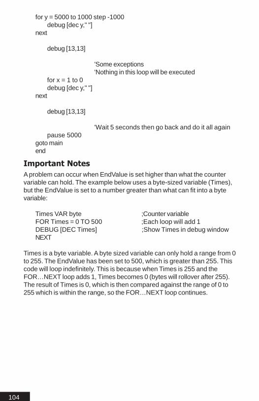
104
for y = 5000 to 1000 step -1000debug [dec y," "]
next
debug [13,13]
'Some exceptions'Nothing in this loop will be executed
for x = 1 to 0debug [dec y," "]
next
debug [13,13]
'Wait 5 seconds then go back and do it all againpause 5000
goto mainend
Important NotesA problem can occur when EndValue is set higher than what the countervariable can hold. The example below uses a byte-sized variable (Times),but the EndValue is set to a number greater than what can fit into a bytevariable:
Times VAR byte ;Counter variableFOR Times = 0 TO 500 ;Each loop will add 1DEBUG [DEC Times] ;Show Times in debug windowNEXT
Times is a byte variable. A byte sized variable can only hold a range from 0to 255. The EndValue has been set to 500, which is greater than 255. Thiscode will loop indefinitely. This is because when Times is 255 and theFOR…NEXT loop adds 1, Times becomes 0 (bytes will rollover after 255).The result of Times is 0, which is then compared against the range of 0 to255 which is within the range, so the FOR…NEXT loop continues.

105
FreqoutFREQOUT pin, duration, freq1{,freq2}Generates one or two tones for a specified duration.
Pin is a variable/constant that specifies the I/O pin to use. Thispin will be put into output mode during generation of tones andleft in that state after the instruction is completed.
Duration is a variable/constant specifying the length inmilliseconds (1 to 65535) of the tone(s).
Freq1 is a variable/constant specifying frequency in hertz (Hz, 0to 32767) of the first tone.
Freq2 is a variable/constant specifying frequency(0 to 32767 Hz) of the optional second tone
ExplanationFREQOUT generates one or two sine waves using a pulse-widthmodulation algorithm. The FREQOUT command can be used to play tonesthrough a speaker or audio amplifier. FREQOUT can also be used to playsimple songs. (See LOOKUP command)
ExampleFREQOUT B2,1000,2500
This instruction generates a 2500-Hz tone for 1 second (1000 ms) throughpin 2. To play two frequencies:
FREQOUT B2,1000,2500,3000
The frequencies mix together to form a chord. To generate a silent pause,specify frequency value(s) of 0.
Below is a simple filter schematic for use with the FREQOUT command.The filter is set from 0 to 20Khz this should be good for most songs.
Schematic

106
Gosub...ReturnGOSUB LabelStore the label after GOSUB, then go to the point in the program specifiedby Label.
Label specifies the section of the program to jump to.
ExplanationGOSUB is a close relative of the GOTO command. The GOSUB com-mand tells the program to go execute code at the beginning of the specifiedlabel. Unlike GOTO, GOSUB stores the location of the next line of codeimmediately following itself, when the program encounters a RETURNinstruction in the subroutine, it then tells the program to return to the storedlocation.
When GOSUBs are used, a RETURN statement is necessary (at the endof the subroutine) to take the program back to the instruction after the mostrecent GOSUB.
ExampleMainGOSUB Fish ;Executes subroutine named fishGoto Main
cat: ;gosub will skip this sectionHIGH B1PAUSE 10LOW B1
Fish:HIGH B0PAUSE 10LOW B0
RETURNEND
Important NotesThe only limit is available RAM, to how many GOSUBs are allowed perprogram, or how many deep. In other words, a subroutine that is thedestination of the first GOSUB can contain a GOSUB to another subroutineand so on. This is limited to four deep on the Basic Stamp. Since the stacksize is adjustable this is not the case with the MBasic.

107
GotoGOTO LabelGo to the point in the program specified by Label. (Label is a label thatspecifies where to go.)
Label specifies the section of the program to jump to.
ExplanationThe GOTO command makes a program jump to a specific label andexecute the code that starts at that location. BASIC programs are read fromleft to right / top to bottom, just like in the English language. The GOTOcommand forces the program to jump to another section of code. One usefor GOTO statements is to create endless loops.
ExampleMain
High B0Pause 200Low B0Pause 200Goto Main ;goto the label main and start execution
The above program will loop indefinitely toggling B0 from low (0 Volts) tohigh (5 Volts). With the below circuit connected to B0, the previous codewould indefinitely blink the LED.
Schematic

108
HighHIGH pinMakes the specified pin an output and sets it to high( +5 volts is High)
Pin is a variable/constant that specifies the I/O pin to use.
ExplanationThe HIGH command is used to set the designated pin to an output and to+5 volts. This allows your program to easily turn on an LED or other suchdevices.
ExampleHIGH B0 ;Makes pin 0 high
You can also assign a variable to a pin as shown below. This can helpmake writing a program much easier when trying to remember what pinsare connected to what.
led con B0
HIGH led ;Makes pin 0 high
The schematic below illustrates how to connect an LED for use with theHIGH command.
Schematic

109
I2CinI2CIN DataPin, ClockPin,{ErrLabel,}Control,{Address,} [{mods}Var,...VarN]Receives data from an I2C device (EEPROM, External A/D Converter)
DataPin is a variable or constant that specifies the I/O pin touse for SDA.
ClockPin is a variable or constant that specifies the pin that theMASTER I2C device will use to clock the bus signal. (SCL)
ErrLabel is a label that the program will jump to if the I2CIN command fails (i.e.: device is not connected).
Control is a variable or constant that specifies the I2C device’scontrol byte. The control byte consist of two parts The first four bitsare the device type (EEproms use %1010). The next three bits arethe device ID. If the address lines of the serial EEPROM (i.e. : A0,A1, A2) are grounded then the next three bits of the control bytemust be zero.(ie: %1010000). The last bit is a flag used to determine the addressing format, 1 =16bit addressing, 0 = 8bitaddressing.
Address is an optional variable or constant that specifies thestarting address to read from.
Mods are command modifiers which can be used to modify thevariable directly.
Var is a variable or constant that specifies the data being sentfrom the current bus master.
VarN is a list of variables and/or constants that specifies thedata being sent from the current bus master.
What is I2C ?I2C protocol is a form of synchronous serial communication. It only requirestwo I/O pins which can be shared between multiple I2C devices. I2C cancommunicate with peripheral chips such as EEPROM, A/D, D/A and RTC.Two lines may be used, a data clocking line and a data. Data and clocking(SCL) lines may be bussed, and appropriate chip can be selected.
ExplanationThe I2CIN command allows your program to receive data from an I2Cdevice. An example of the I2CIN command:
Read from current address:

110
I2CIN B1,B0,%10100001,[temp];stores the value of the last known address into temp
Read from a specific address:I2CIN B1,B0,%10100001,0,[temp]
;stores the value of address 0 into temp
Read a sequence of bytes:I2CIN B1,B0,%10100001,0,[temp,temp2]
;load temp with address 0 load temp2 with address 1
The I2CIN command will first transmit data and then receive data. This isdone to first establish some information such as an ID, read or write andthen an address in order to tell the I2C device what information it wants toreceive. The schematic shows the proper wiring for the example to work.
The examples illustrates how to read from a I2C serial EEPROM. Pin B1 isthe SDA pin and pin B0 is the clock pin (SCL). The next part of the I2Ccommand is the control byte. The first part of the control byte for I2C serialEEPROMs is %1010, this is the start byte. The next part is 0001 becausethe address lines of the I2C are grounded (A0,A1,A2). The last part of thecontrol byte sets the addressing mode, WORD size or not. Refer to thedevice data sheet for what addressing mode is required.
So the last bit in the control byte needs to be 1, for word addressing. Thedata sheet for the I2C devices will list if the device uses WORD sizeaddressing or not. The above explanations refer to the 24C04 I2C serialEEPROM from Microchip. (Refer to I2COUT)
Schematic

111
Example ProgramThe following program will write and read a value to an I2C serialEEPROM. Note the last bit of the control byte is 1, this is because the I2CEEPROM is a 24C01 which does not use WORD size addressing. If an24C64 were used the last bit would be a 0 for WORD size addressing.The SCL/SDA lines are pin B0/B1
CAT VAR BYTEDOG VAR BYTE
CAT = 2 ;sets CAT = 2DOG = 0 ;clears DOG = 0
Main:I2COUT B1,B0,%10100001,0,[CAT]
;writes value of 2 to address 0 of the serial eeprom
PAUSE 1000I2CIN B1,B0,%10100001,0,[DOG]
;read value of address 0 and stores it in DOG
PAUSE 1000IF DOG = 2 THEN LOOP
;make sure value was read correctly
Goto Main
Loop: ;if the LED blinks the write/read was successfulDebug [“I2C Write Was Successful”]
End

112
I2CoutI2COUT DataPin, ClockPin,{ErrLabel,}Control,{Address,} [{mods}Var,...VarN]Sends data to an I2C device (EEPROM, External A/D Converter)
DataPin is a variable or constant that specifies the I/O pin touse. (SDA)
ClockPin is a variable or constant that specifies the pin that theMASTER I2C device will use to clock the bus signals. (SCL)
ErrLabel is a label that the program will jump to if the I2CIN command fails, timeout occurs or a device is not connected.
Control is a variable or constant that specifies the I2C device’scontrol byte. The control byte consist of two parts The first four bitsare the device type (EEproms use %1010). The next three bits arethe device ID. If the address lines of the serial EEPROM (i.e. : A0,A1, A2) are grounded then the next three bits of the control bytemust be zero.(ie: %1010000). Thelast bit is a flag used to determinethe addressing format, 1 =16bit addressing, 0 = 8bit addressing.
Address is an optional variable or constant that specifies thestarting address to write the data to.
Mods are command modifiers which can be used to modify thevariable directly.
Var is a variable or constant that specifies the data being sentfrom the current bus master.
VarN is a list of variables and/or constants that specifies thedata being sent from the current bus master. This allows formultiple variables to be written to the I2C device byautomatically incrementing the last given address.
What is I2C ?I2C protocol is a form of synchronous serial communication. It only requirestwo I/O pins which can be shared between multiple I2C devices. I2C cancommunicate with peripheral chips such as EEPROM, A/D, D/A and RTC.Two lines may be used, a data clocking line and a data line. Data andclocking (SCL) lines may be bussed, and appropriate chip can be se-lected.

113
ExplanationThe I2COUT command allows your program to write data to an I2C device.To write a byte to a 24C64 I2C serial EEPROM with Pin B1 of thePICmicro connected to SDA of the I2C device and Pin B0 connected toSCL use the following code snippet:
I2COUT B1,B0,%10100001,0,[$ff];last bit of the control byte is 1 for 16bit addressing
In order to use an I2C serial EEPROM that does NOT use 16bit address-ing (24C01) you must set the last bit of the Control byte to 0.
I2COUT B1,B0,%10100000,0,[$ff];last bit is set to 0 for 8bit addressing
The I2COUT command is used in the same fashion as the I2CIN com-mand. Everything that applies to I2CIN will be the same for I2COUT.
Example ProgramWord addressing is required with the schematic below since the 24C04 isword addressing.
I2COUT B1,B0,%10100001,0,[“H”];last bit of the control byte is 1 for WORD addressing
Schematic

114
This next I2c EEPROM program demonstrates the I2Cin and I2coutcommands. This program will record the state of pin A0 over a period of timeand play it back on pin A1. It was designed for use with the 512 byteEEPROM 24C04
This program makes use of the serial port to display program status. Useone of the IDE terminal windows to display the results.
input A0 'Sensor or button to monitoroutput A1 'Led for sensor play back
address var wordlogdata var bytecbit var byte 'control bitcbit =%10100000 'Set control bits starting state
Low A1 'turn led off
'------------------------------------------------------------------------' Record section'------------------------------------------------------------------------
Debug ["Now recording Pin A0",10,13,10,13]
for address = 0 to 50
logdata = porta.bit0porta.bit1 = porta.bit0Debug ["Write to address ",dec address, |
"value=",dec logdata,10,13]
'Write the state of pinA0 to addresscbit.bit1 = address.bit8cbit.bit2 = address.bit9
'Build the control bit for addressI2cout B1,B0, outerror,cbit,address, [logdata]pause 5
next
'--------------------------------------------------------------------------' Playback section'--------------------------------------------------------------------------
playback:Debug ["Now playing back Pin 1",10,13,10,13]
for address = 0 to 50

115
'Read the recorded state of pinA0 from address
cbit.bit1 = address.bit8:cbit.bit2=address.bit9'Build the control bit for address
I2cin B1,B0, inerror,cbit,address, [logdata]
Debug ["Read from address ",dec address, |" value=",dec logdata,10,13]
porta.bit1 = logdatapause 15'A bit of a delay because we can read faster than we can write
next
goto playback 'keep displaying play back until shutdown
'-------------------------------------------------------------------' Error section'-------------------------------------------------------------------
'If we get any errors then just shut downouterror:
Debug ["We had a write error",10,13,10,13]end
inerror:Debug ["We had a read error",10,13,10,13]
end
SEE ALSO
I2CIN

116
If...Then...Elseif...Else...EndifIF Compare THEN {Gosub} LabelCompare, if true(not 0) jump to label or:
IF Compare THEN (If condition is true then jump to label)
Statements... (If not true goto elseif)
ELSEIF Compare (If true execute statements)
Statements... (If not true goto else)
Else (If nothing is true then execute statements)
Statements...
Endif (terminate after else statements ran)
The IF...THEN...ELSEIF...ELSE...ENDIF evaluates one or more conditionsand, if true, jumps to a label. If false then skip next function
Condition is a statement, such as "x = 7" that can be evaluatedas true or false.
Gosub is optional. Choosing GOSUB allows you to return tothe next line of your program after running a subroutine. Thedefault is to jump to a label.
Label is a label that specifies where to go in the event that thecondition is true.
ExplanationThe If...Then command a decision maker of sorts. There are two ways inwhich If...Then can be used. The first, test a condition and, if that condition istrue, goto or gosub to a point in the program specified by an address label.The condition that IF...THEN tests is written as a mixture of comparison andlogic operators. The comparison operators are:
= equal < less than<> not equal>= greater than or equal to> greater than <= less than or equal to
IF...THEN is essentially a true or false goto. If the statement is true then theprogram will goto the given label. If the condition is false the program willcontinue onto the next line.

117
The second use of the If...Then can conditionally execute a group of state-ments following the THEN. The statements must be followed by Elseif orElse with an Endif.
ExampleThis example illustrates how to use IF...THEN the first way described.Multiple IF...THEN statements can be used together as such:
IF Cat < 10 THEN Dog;If the variable Cat is less than 10 jump to the label Dog
You can use the IF...THEN statement to execute a group of conditions:
IF lip = 0 AND Cat < 10 THEN Dog;Both conditions must be true in order to jump to Dog
You can use the GOSUB option to simplify your program:
hat = 1IF hat = 1 THEN GOSUB Tip ;this program will loop foreverSTOP
Tip:RETURN ;send program back to the next line after the gosub
The second use of the IF...THEN statement is multiple conditionally executedstatements. This method allows several statements to be executed basedon TRUE conditions, with a closing statement execute if all is FALSE.
Hat var Byte
Hat = 1
IF hat=0 THEN ;condition is false since Hat equals 1High B1 ;skipped since condition was false
ELSEIF Hat=0 ;condition is false since Hat equals 1High B2 ;skipped since condition was false
Else ;conditionally executes if all conditions were falseHigh B3 ;executes and pin 0 is set highEndif ;closes the IF...THEN statement
Multiple conditions can be compared as shown below:
Hat var ByteHat = 1IF hat=0 THEN ;condition is false since Hat equals 1
High B1 ;skipped since condition was false

118
ELSEIF Hat=0 ;condition is false since Hat equals 1High B2 ;skipped since condition was false
ELSEIF Porta.bit0=0 ;is pin A0 true (low) ?High B3 ;skip if false
ELSEIF Porta.bit1=0 ;is pin A1 true (low) ?High B4 ;skip if false
ELSEIF Porta.bit2=0 ;is pin A2 true (low) ?High B5 ;skip if false
ELSEIF Porta.bit3=0 ;is pin A3 true (low) ?High B6 ;skip if false
Else ;conditionally executes if all conditions were falseHigh B7 ;executes and pin 10 is set highEndif ;closes the IF...THEN statement
The above program will only work if pin A0, A1, A2, A3 are set to inputs first.The program will check to see if pins A0 through A3 are set low (VSS). If allpins are not set low then execute ELSE and set pin B7 high, if any pins areset low, then execute next statement, finish comparisons, skip ELSE sinceone condition was true and exit. The ELSE is always used if you want yourprogram to do something if all comparisons are false. If you want the programto just exit if all conditions are false then omit ELSE once the group of com-mands are finished running the program will exit on the ENDIF and continueon to the next line of code. The ELSEIF is unlimited, you can use as manyneeded. The only limit to this is code size.
Important NotesA few conditions must be considered when using the IF...THEN statement.Constants can not be used with the IF...THEN statement. This is becauseconstants only have one condition and the statement will always be TRUE orFALSE. This also applies to PIN names since these are constants to. Thebelow line will always return a FALSE state:
IF B0 = 1 THEN Main
The above statement has no way of knowing that you mean the value of pin0. It assumes this is a constant. The correct way to check the condition of aPIN in the IF...THEN statement would be to access the pin and port directly asshown below:
IF portb.bit0 = 1 THEN Main
The above statement will now look directly at the condition of pin B0. Thisstatement will now change based on the condition of pin B0 (High or Low).

119
The next example of the If...Then...Else command is a little more usefulwhen testing logic and conditional executing code. To get a real good idea ofhow the If...Then...Else works run this program with the ICD and use thestep or animate option to follow the code.
y var word
y = 1
debug [10,13]main:
debug [dec y," "] 'Display the current count
'Test for 5if y=5 then gosub five
'Test for 21if y = 21 thendebug [10,13,"Have 21",10,13]
endif
'Here we will test to see how close we are to being done.if y = 50 then
debug [10,13,"All Done",10,13]debug ["However we will do it all again",10,13,10,13]y=1 'We are done reset the countergoto main
elseif y = 45debug [10,13,"5 more to go",10,13]y=y+1 'At this point lets increment the countergoto main
elsey=y+1 'At this point lets increment the countergoto main
endif
'A little subroutine testfive:
debug [10,13,"Have 5",10,13]return

120
InputINPUT pinMakes the specified pin an input
Pin is a variable or constant that specifies the I/O pin to use.
ExplanationThere are several ways to make a pin an input. When a program begins,all of the pins should be inputs. Input instructions PULSIN, SERIN willautomatically change the specified pin to input andleave it in that state.
ExampleINPUT B0 ;Make pin B0 an inputINPUT B1 ;Make pin B1 an input
You can also assign a variable to a pin as shown below for the INPUTcommand:
myswitch VAR portb.bit0;myswitch is now an alias of pin B0
MAIN:IF myswitch = 0 THEN MAIN
;check if pin B0 is low
IF myswitch = 1 THEN RUNIT;check if switch is on if so goto label RUNIT
GOTO MAIN;will continue to loop until pin 0 is high
RUNIT:HIGH B1 ;pin B1 is set high turn on a LEDPAUSE 500 ;a delay so we can see the LED onLOW B1 ;Turns the LED off
GOTO MAIN ;goes back to main loop and starts over againEND

121
LcdreadLCDREAD RegSel\Clk\RdWrPin, Nib, Address, [{mods} Var]Reads the RAM on a LCD module using the Hitachi 44780 controller orequivalent.
RegSel can be a constant or variable specifying the pin for the R/Sline of the LCD.
Clk can be a constant or variable specifying the pin for the E(Enable) line of the LCD.
RdWrPin can be a constant or variable specifying the pin for the R/W (Read / Write) line of the LCD.
Nib can be a constant or variable specifying the pins (Total of Four)for the data lines of the LCD. The LCD data port is arranged in 8bits. Only 4 bits are required 4 to 7 of the LCD. So if Portb.nib0 isselected then LCD bit 4 is connected to pin B0 on the PICmicro andLCD bit 5 is connected to pin B1 on the PICmicro and so on.
Address can be a constant or variable that specifies the addresslocation of RAM you are trying to read. Address from 0 to 127return the current character in the display memory. Address 128and above return Character RAM values.
Mods are command modifiers which can be used to modify thevariable directly.
Var is the variable where the value returned will be stored.
ExplanationAccessing the on board RAM of a LCD module is very straight forward. Ifthe LCDWRITE command is used as shown in the example below. Thecharacter in address 0 will be “H’, address 1 will be ‘e’ and so on.
Examplepause 500 ;Allows the LCD to initialize
LCDWRITE B4\B5\B6, portb.nib0, [INITLCD1, INITLCD2, TWOLINE,CLEAR, HOME, SCR,”Hello”] ;prints the word ‘Hello’ to the screen
If the above code example is executed, the on-board LCD RAM will havethe word ‘Hello’ loaded into it. To read what was printed on the LCD screen,use the LCDREAD command as shown:
character VAR byte

122
LCDREAD B4\B5\B6, portb.nib0, 0, [character] ;Character = “H”LCDREAD B4\B5\B6, portb.nib0, 1, [character] ;Character = “e”LCDREAD B4\B5\B6, portb.nib0, 2, [character] ;Character = “l”LCDREAD B4\B5\B6, portb.nib0, 3, [character] ;Character = “l”LCDREAD B4\B5\B6, portb.nib0, 4, [character] ;Character = “o”
Schematic
Important NotesWhen using the LCDREAD command the R/W pin must be connected to apin. The R/W pin is not necessary when the LCDWRITE command is usedwihtout the LCDREAD command.
SEE ALSO
LCDWRITE

123
LcdwriteLCDWRITE RegSel \ Clk {\RdWrPin}, Nib, [{mods} Exp]Sends Text to an LCD module using an Hitachi 44780 controller or equiva-lent.
RegSel is optional for LCDWRITE and can be a constant or variable specifying the pin for the R/S line of the LCD.
Clk can be a constant or variable specifying the pin for the E(Enable) line of the LCD.
RdWrPin can be a constant or variable specifying the pin for the R/W (Read / Write) line of the LCD.
Nib can be a constant or variable specifying the pins (Total of Four)for the data lines of the LCD. The LCD data port is arranged in 8bits. Only 4 bits are required 4 to 7 of the LCD. So if Portb.nib0 isselected then LCD bit 4 is connected to pin B0 on the PICmicro andLCD bit 5 is connected to pin B1 on the PICmicro and so on.
Mods are command modifiers which can be used to modify thevariable directly.
Exp can be a constant or variable that is the data to be written.
ExplanationWhen using the LCDWRITE command you will need to first initialize theLCD screen. This can be done by adding the below line to your program:
pause 500 ;Allows the LCD to initialize
LCDWRITE B4\B5\B6, portb.nib0, [INITLCD1, INITLCD2, TWOLINE,CLEAR, HOME, SCR]
;after the first initialization no more inits. will need to be sent.
The first line of code is the PAUSE statement. This is used to give the LCDenough time to power up internally. A value of 500 is often used. Thispause is not necessary on all LCD displays.
ExampleThe code below will print the character string “Hello” then “World” to the LCDdisplay.
Temp Var Byte
Pause 500 ;Allows the LCD to initialize
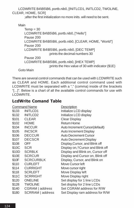
124
LCDWRITE B4\B5\B6, portb.nib0, [INITLCD1, INITLCD2, TWOLINE,CLEAR, HOME, SCR]
;after the first initialization no more inits. will need to be sent.
MainTemp = 30LCDWRITE B4\B5\B6, portb.nib0, [“Hello”]Pause 200LCDWRITE B4\B5\B6, portb.nib0, [CLEAR, HOME, “World”]Pause 200LCDWRITE B4\B5\B6, portb.nib0, [DEC TEMP]
;prints the decimal numbers 30Pause 200LCDWRITE B4\B5\B6, portb.nib0, [iHEX TEMP]
;prints the Hex value of 30 with indicator ($1E)Goto Main
There are several control commands that can be used with LCDWRITE suchas CLEAR and HOME. Each additional control command used withLCDWRITE must be separated with a “,” (comma) inside of the brackets“[...]”. Below is a chart of all the available control commands for use withLCDWRITE.
LcdWrite Comand TableCommand Name Description$133 INITLCD1 Initialize LCD display$132 INITLCD2 Initialize LCD display$101 CLEAR Clear Display$102 HOME Return Home$104 INCCUR Auto Increment Cursor(default)$105 INCSCR Auto Increment Display$106 DECCUR Auto Decrement Cursor$107 DECSCR Auto Decrement Display$108 OFF Display,Cursor, and Blink off$10C SCR Display on,†Cursor and Blink off$10D SCRBLK Display and Blink on, Cursor off$10E SCRCUR Display and Cursor on, Blink off$10F SCRCURBLK Display, Cursor, and Blink on$110 CURLEFT Move Cursor left$114 CURRIGHT Move cursor right$118 SCRLEFT Move Display left$11C SCRRIGHT Move Display right$120 ONELINE Set display for 1 line LCDs$128 TWOLINE Set display for 2 line LCDs$140 CGRAM | address Set CGRAM address for R/W$180 SCRRAM | address Set Display ram address for R/W

125
Cursor Position and Screen RamScreen ram is where the characters are stored before being printed to thescreen. To print a given character to the screen the internal cursor must bepositioned at the given location. This is normally handled automatically. Ifyou want to print to other places on the screen instead of a left to rightfashion you must first position the internal cursor at the correct screen ramlocation. If you wanted to print to the second line, first character of a 16x2LCD then you would use the following:
LCDWRITE B4\B5\B6, portb.nib0, [scrram+$40]
The above command tells the LCD to point the cursor at location 40h,which is the location of line two, first character. The “+” symbol is requiresince your adding 40h to the current location of the screen ram. You canuse the SCRRAM control command to move the cursor anywhere on or offthe LCD screen. Since all HD44780 type controllers have the same amountof ram regardless of the LCD size the internal ram is mapped out asshown below:
All values shown above are in HEX. The main controller (HD447800) issetup up for a maximum of 128 bytes of screen ram. A 2x16 display wouldonly use 32 bytes so the remainder would be off screen ram. Which canbe accessed by shifting the display left after writing to an off screen ramlocation.
Off screen ram would be as follows; 10h to 3fh would be off screen for thefirst line, then 40h for the first location of the second line on screen. Then 50hto 7fh for off screen on the second line for a two line LCD. To print in offscreen ram, move the pointer to location 10h. Then send the characters tobe printed. If you send the message “Hello” to location 10h to 15h this willbe in off screen ram. To move this message on to the screen do thefollowing:
LCDWRITE B4\B5\B6, portb.nib0, [SCRLEFT]
This will shift the display once to the left. So the first letter of the messagewill appear “H”. To move the remainder of the message onto the screenyou must shift it left 4 more times by sending the above 4 times.
0 1 2 3 4 5 6 7 8 9 a b c d e f40 41 42 43 44 45 46 47 48 49 4a 4b 4c 4d 4e 4f

126
Below is a schematic of a LCD with an Hitachi 44780 type controller foruse with LCDWRITE and using the default system settings:
Schematic

127
LetLET Var = expressionAssign a value to a variable
Var is the labeled variable
Value can be a constant or another variable or the result of anexpression.
Expression can be any (legal) combination of math operators.
ExplanationLET is an optional command; as an example Temp=2 is the same as LETTemp=2. The LET command is often used to make programming code morehuman readable.
ExampleThe statement [LET] will assign values to variables using operators asshown below:
LET Cat = 1 * Dog + Fish
OUTPUT B0 ;sets pin B0 to an outputLET B0 = 0 ;makes pin B0 low
Important NoteThe LET command can also use modifiers.

128
LowLOW pinMake the specified pin output low
Pin is a variable or constant that specifies the I/O pin to use.
ExplanationThe LOW command will make the specified pin Low (0 Volts), which willalso make the specified pin an output. Pin can be a constant (0, A0, 2, A2)or a variable that contains a pointer that directly corresponds to an avail-able pin on any given port.
ExampleHIGH A0 ;Makes pin A0 high
You can also assign a variable to a pin as shown below. This can helpmake writing a program much easier when trying to remember what pinsare connected to what.
led VAR byte
led = PortB.bit0 ; makes the variable led point to pin B0.LOW led ;Makes pin 0 Low (0 Volts)

129
LookdownLOOKDOWN value,{comparisonOp,}[value0,value1,...valueN],resultVariable
Compare a value to a list of values according to the relationship specified bythe comparison operator. Store the index number of the first value that makesthe comparison true into resultVariable. If no value in the list makes the com-parison true, resultVariable is unaffected.
Value is a variable or constant to be compared to the values inthe list.
ComparisonOp is optional and maybe one of the following:
= equal < less than<> not equal>= greater than or equal to> greater than <= less than or equal to
If no comparison operator is specified, Then MBasic defaults toequal (=).
Value0, value1... make up a list of values (constants orvariables) up to 16 bits in size.
ResultVariable is a variable in which the index number will bestored if a true comparison is found.
ExplanationLOOKDOWN works very much like the index of a book. You can search forspecific topic and return the page number. LOOKDOWN searches values in alist, and stores the item number of the first match in a variable. In other words,Lookdown compares the user value to a values in a list, the first comparison thatis true, will return the value of the index position the match was found. The indexlist starts at 0 not 1. This is because 0 is always treated as the true first numberwhen dealing with computers and microcontrollers.
Examplevalue VAR byteresult VAR nibvalue = 2LOOKDOWN value,[10,150,180,2001000,25,2],result
In the above code example we have specified a value of 2 without acomparison operator. So the default comparison will be equals. Lookdownwill search through the list searching for the first true comparison. The firsttrue comparison is 2 which is in the 6th position, so the value returned, inresult will be 6.

130
Lookdown can also index constant strings as shown below. Any spaces arealso counted as positions.
value var byteresult var byte
Mainvalue = "R"lookdown value,["See Spot Run"],resultDebug [dec result]
Goto main
The result would be 9. This is because R is in the 9th position.

131
LookupLOOKUP index, [value0, value1,...valueN], resultVariable
Look up the value specified by the index and store it in a variable. If the indexexceeds the highest index value of the items in the list, variable is unaffected.A maximum of 256 values can be included in the list.
Index is the item number (constant or variable) of the value tobe retrieved from the list of values.
Value0, value1... make up a list of values (constants orvariables) up to 16 bits in size.
ResultVariable is a variable in which the retrieved value willbe stored.
ExplanationLookup could be considered the opposite of Lookdown. Lookup retrieves anitem from a list based on the item's position (index) in the list.
Exampleindex VAR nibresult VAR byteindex = 3result = 255
LOOKUP index,[26,177,13,1,0,17,99],result
The above example will go to position 3 in the list, starting from left to right.The list starts at 0 not 1. So the returned value stored in result would be 1.
The following program uses the LOOKUP command to play “Mary had alittle lamb” using the FREQOUT command.
AH con 440*2 ;assigns a value for the note and octaveAS con 466*2 ;the note is 466*2 = A sharp second octaveBH con 494*2CH con 523*2CS con 554*2DH con 587*2DS con 622*2EH con 659*2FH con 698*2FS con 740*2GH con 784*2GS con 831*2

132
;above we assign our notes as constants with values for the FEQOUTcommand
temp var bytetemp2 var word
mainfor temp = 0 to 33
lookup temp,[CS,BH,AH,BH,CS,0,CS,0,CS,BH,0,BH,0,BH,0,CS,|EH, 0,EH,CS,BH,AH,BH,CS,0,CS,0,CS,BH,0,BH,CS,BH,AH],temp2
; the above statement must be formatted to work correctly; the “|” or symbol is used to indicate a line break, when‘ a command is too long to fit on one line.
if temp2 = 0 then finish freqout B0,500,temp2finish:nextpause 5000
goto main

133
NapNAP periodEnter sleep mode for a short period. Power consumption is reduced toabout 50 µA assuming no loads are being driven. All pins are output low.
Period is a variable or constant that determines the duration ofthe reduced power nap. The duration is (2^period) * 18 ms.(Read as "2 raised to the power of ‘period’, times 18 ms.") Periodcan range from 0 to 7, resulting in the following nap lengths:
Period 2 period Length of Nap0 - 1 18ms1 - 2 36ms2 - 4 72ms3 - 8 144ms4 - 16 288ms5 - 32 576ms6 - 64 1152ms (1.152 seconds)7 - 128 2304ms (2.304 seconds)
ExplanationNap uses the same shutdown and start-up mechanism as Sleep, withone difference. During Sleep, variations are automatically compensatedfor. As a result, longer Sleep intervals are accurate to approximately ±1percent. Nap intervals are directly controlled by the watchdog timer withoutcompensation. Variations in temperature, supply voltage, and manufactur-ing tolerance of the PICmicro you are using can cause the actual timing tovary.
One use for NAP is in a battery-powered application where some smallamounts of time are spent doing nothing. This would apply to a programthat loops endlessly, performing some task, and pausing for approximately300 ms each time through the loop. You could replace the PAUSE 300 withNAP 4, as long as the timing of the pause was not critical. The NAP 4would pause your program for about 288ms, plus put the microcontroller inlow-power mode, which would extend battery life. During wake up the I/Opins would be interrupted briefly. One method around this would be to useweak pullup / pulldown resistors such as 10K or 100K.
ExampleHigh B0 ;turns an LED on connected to pin B0NAP 4 ;Low power mode for about 288msLow B0 ;Turns LED off

134
OutputOUTPUT pinMakes the specified pin an output
Pin is a variable or constant that specifies the I/O pin to use.
ExplanationThere are several ways to make a pin an output. Commands that rely onoutput pins (SEROUT) automatically change the specified pin to output.The OUTPUT command allows your program to directly affect the state ofthe specified pin.
ExampleOUTPUT B0 ;Pin B0 is now an output (+5 volts)
Using a variable to set the pins state:
time VAR bytetime = PortB.bit0
OUTPUT time ;Pin B0 is now an output

135
OWINOWIN Pin,Mode,{NCLabel,} [{Mods} Var]Protocol used to communicate to 1-wire devices.
Pin is a variable or constant that specifies the I/O pin to use for theOne wire command.
Mode is a variable/constant/expression indicating the mode of datatransfer. Mode controls placement of reset pulses, detection ofpresence pulses, byte / bit input and normal / high speed. Theproper value for Mode will depend on the 1-wire device used.Consult the device data sheet to determine the correct Mode.See chart below:
Mode Setting 0 No Reset, Byte mode, Low speed 1 Reset before data, Byte mode, Low speed 2 Reset after data, Byte mode, Low speed 3 Reset before and after data, Byte mode, Low speed 4 No Reset, Bit mode, Low speed 5 Reset before data, Bit mode, Low speed
NCLabel is a label the program can jump to if a connection failureoccurs with the OWIN command (ie. No chip present).
Pin is a variable or constant that specifies the I/O pin to use for theOne wire command.
Mods are command modifiers which can be used to modify thevariable directly.
Var is the variable or variable array where the value(s) returned willbe stored.
Explanation1-wire protocol is a form of asynchronous serial communicationdeveloped by Dallas Semiconductor. It requires only one I/O pin. This onepin can be shared between multiple 1-wire devices. The OWIN commandallows the PICmicro to receive data from 1-wire devices.
The 1-Wire protocol synchronizes the slave devices to the master. Themaster initiates and controls all activities on the 1-Wire bus. 1-Wire usesCMOS/TTL logic levels. A resistor connects the data line of the 1-Wire busto the 5V supply of the bus master.

136
Hardware ConfigurationThe 1-Wire bus has only a single line I/O. It is important that each deviceon the bus be able to drive this single I/O line at the appropriate time. Eachdevice attached to the 1-Wire bus must have an open drain connection or3-state outputs. The DS2401 is an open drain part. The bus masterrequires a pullup resistor at the master end of the bus, with the bus mastercircuit equivalent to the one shown in for the schematic.The value of the pullup resistor should be 4.7K for short line lengths. Amulti 1-wire bus consists of a 1-Wire bus with multiple slaves attached.
Important NoteWiring of the Dallas part is important. It may seem simple but allot of issuesarise from incorrect wiring. Use the code example below to check yourwiring. The code below is a part ID check. You can also use this code toidentify any devices you may have on the bus.
Temp VAR ByteCounter VAR Byte
MainOWout B0,1,main,[$cc]
For Counter = 0 to 7OWin B0,0,[temp]Debug [hex temp,” “]
NextDebug [13]
Goto Main
The above code will print the part ID in the Debug window. To run theprogram use the ICD. Also you will notice a NCLabel is used “main”. Thislabel will keep the program in a loop until something is received from the partconnected.
ExampleTemp Var ByteCounter Var Byte
MainOwout B0,1,main,[$33];Sense Presence and call 1-Wire RomCheck routine
For Counter = 0 to 7 ;Read 8 byte Code from DS2401Owin B0,0,[temp]Debug [hex temp," "] ;If code does not match recheck

137
NextDebug [13]
Goto Main
The example works with the DS2401 which is a device that guarantees aunique id per device. These parts are ideal for security applications. The firstpart of the example Owout B0,1,main,[$33] is a rom check routine (SeeRom Functions). Every 1-wire device has a rom id. By using the rom checkroutine you can ensure there is a 1-wire device attached. This will only workwith one device attached. The next part of the code a loop to get all 8unique ID bytes from the DS2401. This key will be different for everyDS2401 part.
Rom FunctionsRead ROM $33 or $0FOnly works if a single 1-wire device is on the line.
Skip ROM $CCAddress a 1-wire device without its 64-bit ID. Only works if a single 1-wiredevice is on the line.
Search ROM $F0Read the 64-bit IDs of all 1-wire devices on the line. A process of eliminationcan be used to distinguish each unique device.
Match ROM $55Match Rom, followed by a 64-bit ID, will allow addressing of a uniquedevice on a multiple device line.
Schematic

138
OWOUTOWOUT Pin,Mode,{NCLabel,} [{Mods} Exp]Protocol used to communicate to 1-wire devices.
Pin is a variable or constant that specifies the I/O pin used for theOne wire command.
Mode is a variable/constant/expression indicating the mode of datatransfer. Mode controls placement of reset pulses, detection ofpresence pulses, byte / bit input and normal / high speed. Theproper value for Mode will depend on the 1-wire device used.Consult the device data sheet to determine the correct Mode.See chart below:
Mode Setting 0 No Reset, Byte mode, Low speed 1 Reset before data, Byte mode, Low speed 2 Reset after data, Byte mode, Low speed 3 Reset before and after data, Byte mode, Low speed 4 No Reset, Bit mode, Low speed 5 Reset before data, Bit mode, Low speed
NCLabel is a label the program can jump to if a connection failureoccurs with the OWOUT command (ie. No chip present).
Mods are command modifiers which can be used to modify thevariable directly.
Exp is a variable, variable array, constant or expression containingthe data to be sent.
Explanation1-wire protocol is a form of asynchronous serial communicationdeveloped by Dallas Semiconductor. It requires only one I/O pin. This onepin can be shared between multiple 1-wire devices. The OWOUT com-mand allows the PICmicro to send data to 1-wire devices. The OWout andOWin are tightly integrated. In most cases you will need both to talk to anyone wire part.

139
The 1-wire protocol has a very specific format. Every transaction willconsists of four parts:
1. Initialization.2. The ROM Function Command.3. Memory Function Command.4. Data
The ROM Function and Memory Function will always be 1 byte. This byteis sent LSB first. The Initialization will consists of a reset pulse which isgenerated by the master device. Which is followed by a presence pulsegenerated by any attached slave devices. The next operation is the resetpulse which is controlled by the lowest two bits of the mode (Refer toModes).
Following this Initialization is the ROM Function. The ROM Function is usedto address a specific 1-wire device. When more than one device is attachedeach will need to be address individually using the Match ROM command.
ExampleThe following example will read the temperature from a DS1820 one wiredevice. The result is displayed in Celsius with the decimal point intact. Thisis accomplished by using a long variable and the float command.
temp var wordtemp1 var wordConvert var longcounter var byte
mainOwout B0,1,main,[$cc,$44]
Waitowin B0,0,[temp]if temp = 0 then wait
Owout B0,1,main,[$cc,$be]owin B0,0,[temp.byte0,temp.byte1]Convert = float temp fdiv 2.0
Debug ["Temperature = ",real convert," C",13]goto main

140
Schematic

141
PausePAUSE millisecondsPause the program (do nothing) for the specified number of milliseconds.
Milliseconds is a variable or constant specifying the length ofthe pause in ms. Pauses may be up to a 32 bit number
ExplanationThe PAUSE command delays the execution of the program for the specifiednumber of milliseconds.
Example
flash:lOW B0PAUSE 100HIGH B0PAUSE 100
GOTO flash
This code causes pin B0 to go low for 100 ms, then high for 100 ms. Thedelays produced by PAUSE are as accurate as the ceramic resonatortime base, ±1 percent. So a statement of PAUSE 1000 would be 1 sec-ond

142
PauseclkPAUSECLK cyclesPause the program (do nothing) for the specified number clock cyclesdivided by 4.
Cycles is a variable or constant specifying the length ofthe pause. Pauses may be up to a 32 Bit number.
ExplanationThe PAUSECLK command delays the execution of the program for thespecified number of clock cycles divided by 4. Since each oscillator has avariances of 0.05% you will need to determine your own timings. This is onlynecessary if precision timing is required.
ExampleFlash:
Low B0PAUSECLK 100High B0PAUSECLK 100
Goto Flash
The above code will delay or pause for 100 internal clock cycles divided by4.

143
PauseusPAUSEUS microsecondsPause the program (do nothing) for the specified number of micro seconds.
Microseconds is a variable or constant specifying the length ofthe pause in µs. Pauses may be up to 65535 µs.
ExplanationThe PAUSE command delays the execution of the program for the specifiednumber of microseconds.
ExampleFlash:
Low B0PAUSEUS 100High B0PAUSEUS 100
Goto Flash
The above code causes pin 0 to go low for 100 µs, then high for 100 µs.
Important NotesThe delays produced by PAUSEUS may vary depending on how it isused. If the value for Pauseus is a constant its accuracy will be greater,opposed to using a variable. This is due to the time it takes to load thevalue and execute the Pauseus command. The minium time for Pauseus is1µs.

144
PEEK...POKEPEEK address, variablePOKE address, expression
Read/Write specified RAM location
Address is a variable or constant which denotes a memorylocation.
Variable is a variable name and is where the results will bestored.
Expression is any combination of variables, constants and mathoperations.
ExplanationPEEK and POKE are considered advance commands and should only beused by experienced users. The explanation of these commands are keptshort intentionally. Use of the PEEK command allows a specific address tobe read and store its value in the assigned variable . The PEEK andPOKE commands allow direct access to all of the registers, including all ofthe PORT states and their data direction registers (TRIS).
Examplestore VAR byte
PEEK B0,store:get current register status of B0 and store it in the variable store
POKE B0,store;write the value of store (PIN B0)

145
PulsinPULSIN pin, state, {TimeoutLabel,TimeoutMultiple,} VarMeasure the width of a pulse.
Pin is a variable or constant that specifies the I/O pin to use.This pin will be placed into input mode during pulsemeasurement and left in that state after the instruction finishes.
State is a variable or constant (0 or 1) that specifies whether thepulse to be measured begins with a 0-to-1 transition (1) or a1-to-0 transition (0).
TimeoutLabel is an optional label that specifies where to go if atime out occurs. The default time out value is 65,535 microseconds.
TimeoutMultiple is a variable or constant that specifies the amountof time to wait before timing out. The time out value is multiplied by65,535 microseconds which is the default value. If a value of 10 isused the command would wait 655,350 microseconds.
Var is a variable in which the pulse duration will be stored.
ExplanationPULSIN will measure the pulse width on a specified pin. If the state is zero,the width of a low pulse is measured. If the state is one, the width of a highpulse is measured. The measured width is then placed in Var. If the pulseedge never happens or the width pulse is too great to measure Var willdefault to 0. The pulse is measured in 16 bits, if a one byte Var is usedonly the lower 16 bits are used. Pulsin will timeout after 65,535 microsec-onds if the optional timeout label is not used.
PULSIN will return the pulse width in µs.
Pin State Zero,Low pulse is measured
Intial Pin StatePin State One, High pulse ismeasured after first low state

146
ExamplePULSIN B0,0,Cat
;Measure low pulse on P0 store it in the variable Cat
The following program uses Pulsin to measure the time a button is pressedas shown in the schematic. The value returned is in Pulsin units. A 10Kpullup resistor is used to keep the line high. Pulsin will wait until the linechanges state. Since the state setting is 0 Pulsin will wait until the line stateis low (0). Then begin the measurement of time while the pin state remainslow. Once the line is released and set high again Pulsin will stop countingand return a value to Var. The command will reset every 655,350 microseconds since we used the timeout label.
temp var word
Main: 'this program will loop foreverPULSIN B0,0,main,10,temp
'Measure negative pulse will time out at 655,350us.IF temp = 0 then Main 'If 0, try again.serout B1, i9600, [dec temp] 'display result.
goto Main 'repeatend
Schematic

147
PulsoutPULSOUT pin, timeOutput a pulse.
Pin is a variable or constant that specifies the I/O pin to use.This pin will be placed into output mode immediately before thepulse and left in that state after the instruction finishes.
Time is a variable or constant (0-65535) that specifies theduration of the pulse in µs.
ExplanationPULSOUT will generate a pulse on the specified pin for the given period.The pulse is generated by toggling the pin state twice. The initial state ofthe pin will determine the polarity of the pulse. The pin specified to generatethe pulse is automatically made an output.
PULSOUT will generate a pulse with a period in 1 µs increments. Theminimum pulse width is 4 µs. You can not go below this value.
ExamplePULSOUT B0,1000
;Generate a pulse for 1 millisecond long to B0
The small program below illustrates one use of the PULSOUT command:
Low B4 ;Preset Pin to LOW
main ;this program will loop foreverpulsout B4,25000 ;Pulse pin High for 25 of a millisecondpause 1000 ;Wait 1 second until repeating
goto mainend
This program will simply generate a infinite pulse on pin B4. The PULSOUTcommand has many uses. One of which can be to blink a LED for acertain duration.
Pulsout Starts
Intial Pin StatePin Left High forspecified state

148
PwmPWM pin, duty, cyclesConvert a digital value to analog output via pulse-width modulation.
Pin is a variable or constant that specifies the I/O pin to use.This pin will be placed into output mode during pulse generationthen switched to input mode when the instruction finishes.
Duty is a variable or constant (0-255) that specifies the analogoutput level (0 to +5V ).
Cycles is a variable or constant (0-65535) specifying anapproximate number of milliseconds of PWM output.
ExplanationPulse-width modulation (PWM) allows a digital device to generate ananalog voltage. To do this a pin is set to Output high (5 Volts) or Outputlow (close to 0 Volts). If you switch the pin rapidly between high and low ata given interval so that it was high half the time and low the other half. Theaverage voltage over time will be halfway between 0 and 5V which wouldbe 2.5V. This is the idea of PWM; to produce an analog voltage byoutputting a stream of digital 1‘s and 0‘s in a particular proportion. Theproportion of 1‘s to 0‘s in PWM is called the duty cycle. The duty cyclecontrols the analog voltage in a very direct way; the higher the duty cyclethe higher the voltage.
The duty cycle can range from 0 (0%) to 255 (100%). Duty is literally theproportion of 1s to 0s output by the PWM instruction. In order to convertPWM into an analog voltage we have to filter out the pulses and store theaverage voltage. A resistor and capacitor combination is typically used todo this shown in Figure 1-1.
Schematic
Figure 1-1
The capacitor will hold the voltage set by PWM after the instruction hascompleted. How long it holds the voltage will depend on how much currentis drawn, by external circuitry, and internal leakage of the capacitor. In orderto hold the voltage the program must periodically repeat the PWM instruc-tion to give the capacitor a refresh charge. The PWM command lets you setthe charging time in terms of PWM cycles.

149
After outputting PWM pulses, the pin is left in input mode. When a pin is setto input mode, the pin’s driver is effectively disconnected. If it was not, thesteady output state of the pin would change the voltage on the capacitorand undo the analog voltage.
ExampleThe PWM function is dependent on the oscillator used. The PICmicro cangenerate a clock about 1ms in length. The specified pin will be made anoutput prior to the pulse generation and will revert to an input once the pulsestops.
PWM B0,127,1000; 50% duty cycle PWM signal on B0 for 1 second
The above code snippet would give and output voltage of about 2.5 voltsfor about 1 second. You can put the PWM in a subroutine and call it whenever it is needed.
Important NotesThe term PWM or Pulse Width Modulation is loosely applied to the action ofthe PWM command. PWM is mostly done by splitting a fixed period of timeinto an on time (1) and an off time (0). Predictability you can calculate theexact frequency of the pulses and their widths are then controlled by theduty cycle. The PWM command does not work in this way. It outputs arapid sequence of on (1) / off (0) pulses in which the overall proportion overthe course of a full PWM cycle of approximately a millisecond is equal to theduty cycle. The advantage here is to quickly zero in on the desired outputvoltage. In doing so it can not produce the clean, orderly pulses that mightbe expected. This method is also used to generate pseudo-sine wavetones with the DTMFOUT and FREQOUT commands.

150
RandomVariable = RANDOM expression (Seed Value)Generate a pseudo random number. Random is a Math function.
Variable is a variable that will store the results of the randomcommand. This can be a Byte or Word sized variable dependingon the expected results.
Expression is any combination of variables, constants, mathand logic operators.
ExplanationRANDOM generates pseudorandom numbers ranging from 0 to 65535. Theterm pseudorandom is used because the RANDOM function will generatenumbers that appear random, but are actually generated by a logic opera-tion that uses the initial seed value to “tap” into a sequence of 65535numbers. If the same “seed” value is used repeatedly, then the samesequence of numbers is generated.
ExampleTemp var word
MainTemp = Random 25 ;25 is the seed valueDebug [DEC Temp] ;displays the results of temppause 200 ;delay to see the values displayedGoto Main ;repeat loop forever
The above program will generate pseudorandom numbers. Since the sameseed value is always used the numbers will have a repeating pattern. Togenerate better pseudorandom numbers you would want to change the“seed” value on the fly:
Temp var wordTemp = 25 ;start value
MainTemp = Random Temp ;seed value is now based on resultsDebug [DEC Temp,13] ;displays the results of temppause 200 ;delay to see the values displayedGoto Main ;repeat loop forever
The “seed” value is now changing each time through the loop. This willeventually produce repeating numbers if left running long enough. Themethod shown will produce the best random numbers possible.

151
RCtimeRCTIME pin, state, {TimeoutLabel,TimeoutMultiple,}, resultVariableCount time while pin remains in state—usually to measure the charge ordischarge time of a resistor and capacitor circuit. (RC)
Pin is a variable or constant that specifies the I/O pin to use.This pin will be placed into input mode and left in that statewhen the instruction finishes.
State is a variable or constant (1 or 0) that will end the RCTIMEperiod.
TimeoutLabel is an optional label that specifies where to go if atime out occurs. The default time out value is 65,535 microseconds.
TimeoutMultiple is a variable or constant that specifies the amountof time to wait before timing out. The time out value is multiplied by65,535 microseconds which is the default value. If a value of 10 isused the command would wait 655,350 microseconds.
ResultVariable is a variable in which the time measurement(0 to 65535 in µs units) will be stored.
ExplanationRCTIME can be used to measure the charge / discharge time of a resistorand capacitor circuit (RC). RCTIME can also be used as a fast stopwatchfor recording events of very short duration. This allows measuring resistanceor capacitance using R or C sensors (i.e. thermistors or capacitive humiditysensors); or respond to user input through a potentiometer. (Typically 5k to 50kpot.) The resolution of RCTIME is in 2µs increments.
How it worksWhen RCTIME starts to execute, it will start a counter. It stops this counteras soon as the specified pin is no longer in the start State (0 or 1). If pinremains in a certain state longer than 65535 timing cycles, RCTIME returns0.
In the example below if the pin never changes State a value of 0 isreturned:
LOW B0 ;Start discharge capPAUSE 10 ;Discharge for 10msRCTIME B0, 1,Cat ;Read potentiometer on B0
Figure 1-1 shows a suitable RC circuit for use with the RCTIME command.

152
The circuit shown as State 1 is preferred. This is because the logic thresholdis approximately 1.5 volts. Which means that the voltage seen by a pin willstart at 5V then fall to 1.5V before RCTIME stops. With the circuit shown forState 0, the voltage will start at 0V and rise to 1.5V, before RCTIME stops.There is more of a voltage variation in the circuit shown for STATE 1 there-fore giving a better resolution for the same basic circuit configuration.
Before RCTIME begins to execute, the capacitor will need to be put into thestate specified in the RCTIME command. A capacitor is charged when thereis a voltage difference between its two plates. When both plates are at+5Volts, the cap is considered to be discharged. This makes the input high.
ExampleThe following program shows the standard use of the RCTIME commandmeasuring an RC charge / discharge time. Use the circuit shown forRCTIME State 1. The appropriate values should be R3 = 10 k pot. and C1= 0.1 µf. Connect the circuit to Port B Pin 0 and run the program. Follow theinstruction for using DEBUG. Adjust the pot and watch the value shown inthe Watch Window change.
Temp var Word ;Temp will hold the result
MainHigh B0 ;Discharging the capPause 1 ;1 ms pauseRCTIME B0, 1, Temp ;Measuring RC charge timeDEBUG [DEC Temp,13] ;Display value
Goto Main
SchematicFigure 1-1
For use with state 1 For use with state 0

153
ReadREAD location, variableRead EEPROM location and store value in variable.
Location is a variable or constant that specifies the EEPROMaddress to read from.
Variable holds the byte value read from the EEPROM.
ExplanationThe READ statement will allow a program to read the on-chip EEPROM atthe specified address and store the result in the given variable.
READ 0,Cat;Read the value at EEPROM location 0 and store it in variable Cat
ExampleThe following method shows how the DATA command can be used to writedata to the internal EEPROM and the READ command to read it back.
DOG var byteCAT var byte
DATA "Hello","World";Set the initial value stored in eeprom at programming time
MainFOR CAT = 0 to 10 STEP 1 ;increments address 0 to 10READ CAT,DOG ;reads current address, stores result in DOGDebug [HEX dog," ",dog,13] ;Display results
NEXT
The above program will write the ASCII values of Hello World to the internalEEPROM starting at address 0. Since “Hello World” will take 10 addresslocations, a “for...next“ loop can be used to easily retrieve the data from theinternal EEPROM. The READ command is then used to load the values intothe variable DOG. As each value is loaded into DOG it is then sent out usingthe DEBUG command.
SEE ALSO
WRITEDATA

154
ReadDMreaddm address,[{mod}var,...,{mod}varN]Read EEPROM location and store value in variable or variables.
Address is a value pointing to a location in the eeprom from whichto start.
Mod is any appropriate input or output modifier
Var is any variable type
ExplanationThe ReadDM is similar to the Read command. The ReadDM statement issetup for sequential reads at a starting point from the internal eeprom. Thesereads will start at a specified address and store the result in a given variableor variables, such as an array.
ReadDM 0,[str string\11]
The above example will begin reading at address 0 from the internaleeprom. Since we specified the STR modifier and 11 bytes, the ReadDMcommand will continue to read from address 0 to 10 and store the results ineach location of the array.
ExampleThe following program illustrates the usefulness of the ReadDM andWriteDM command. We begin with an Array to store our returned data.
string var byte(12)temp var byte
mainwritedm 0,["Hello world"]readdm 0,[str string\11]
mainlpfor temp = 0 to 11Debug [string(temp),13]Next
goto mainlp
The above program will write the entire string “Hello World” to the internaleeprom. Since the string “Hello World” consist of 11 bytes the first 11 bytesof the eeprom will be written to. Then the ReadDM command is used toread the 11 bytes back. By using the STR modifier we tell the ReadDMcommand we want to read 11 bytes from the internal eeprom and storethem in our 12 byte variable array. Next we use the SEROUT command todisplay the results to a terminal window.

155
Important NotesThere are only 256 internal eeprom locations on a PIC16F876. If theReadDM or WriteDM command begins in a valid location and continuesoutside of the 256 locations it will wrap around to the beginning location.
SEE ALSO
WRITEDMSTR Modifier

156
ReadPMReadpm address,[{mod}var,...,{mod}varN]Read Flash Program memory location and store value in variable orvariables. Requires 16F87x part.
Address is a value pointing to a location in the flash program memoryfrom which to start. Requires 16F87x part.
Mod is any appropriate input or output modifier
Var is any variable type
ExplanationThe ReadPM command is similar to the ReadDM command except it readsfrom the internal program memory of a 16F87x PICmicro. The ReadPM state-ment is setup for sequential reads at a starting point from the internal programmemory. These reads will start at a specified address and store the result in agiven variable or variables, such as an array.
ReadPM 0x400,[str string\11]
The above example will begin reading at address 400h from the internalprogram memory. Since we specified the STR modifier and 11 bytes, theReadPM command will continue to read from address 400h to 410h andstore the results in each location of the array.
ExampleThe following program will write “Hello World” using the WritePM commandstarting at address 400h. Then the ReadPM command is used to read thewritten values to program memory and print the result to the debug window.
We begin with an Array to store our returned data.
string var byte(12)temp var byte
mainwritepm 0x400,["Hello world"]readpm 0x400,[str string\11]
mainlpfor temp = 0 to 11Debug [string(temp)]NextDebug [13]
goto mainlp

157
The example program will write the entire string “Hello World” to the internalprogram memory. Since the string “Hello World” consist of 11 characters, 11bytes will be written to the internal program memory starting at location400h. If you run the program once and read back the programmed hex filefrom the PICmicro at location 400h will be the values for “Hello World”.
By using the STR modifier we tell the ReadPM command we want to read11 bytes from the internal eeprom and store them in our 12 byte variablearray. Next we use the Debug command to display the results to the debugwindow.
Important NotesThe READPM and WRITEPM commands will only work with 16F87xparts. You can not write or read actual program space used for the runningprogram. You can write and read from address locations that do not containprogram data. If the ReadPM command is used to read locations of actualrunning program space, erratic results will occur.
SEE ALSO
WRITEPMSTR Modifier

158
Repeat...UntilREPEAT......UNTIL expression
Expression is any combination of variables, constants, mathand logic operators
ExplanationRepeat a group of commands until some expression is true. True beingany other value than 0.
ExampleIn the following example, the instructions between the REPEAT...UNTILcommands will execute until the variable Temp is equal to 100. With eachrun through the loop UNTIL will check the status of Temp.
Temp var byteclear
MainREPEAT ; repeat the following commands.
temp = temp + 1Debug [Dec Temp,13]
UNTIL temp = 25 ; repeating until temp is equal to 25End
Since we are looking for something to be TRUE at the UNTIL statement wewill need to use an expression. The next example shows how to check thestatus of a pin:
Temp var ByteClear
Input B0 ;sets B0 to an inputMainREPEAT ; repeat the following commands.
Debug [“False”]UNTIL PortB.bit0 = 1 ; repeating until B0 is High (+5Volts)Debug [“True”]
End

159
ReverseREVERSE pinReverse the data direction of the specified pin.
Pin is a variable or constant that specifies the I/O pin to use.This pin will be placed into the opposite of its current input/output (I/O) mode.
ExplanationReverse is a convenient way to switch the I/O direction of a pin. If a pin isset as an input, the REVERSE command, will change it to an output;REVERSE is an easy way to use Bi-State devices like Bi-Color LEDs ortwo create a Bi-State.
ExampleOUTPUT B0 ; Makes P0 an outputREVERSE B0 ;Changes P0 to an input
A good use for REVERSE would be to quickly change a pin state to aninput to effectively “remove it from the circuit”.
The term “input” really has two meanings: (1) Setting a pin to input makingit possible to detect the state of that pin. (2) Setting a pin to input alsodisconnects the output driver, which would have little effect on externalcircuitry.
The following program with the circuit shown in figure 1-1 illustrates thissecond effect. The LED will have two levels of brightness:
Low B0 ;P0 is low, sets output driver.
MainPause 300 ;300ms pauseREVERSE B0 ;Reverse B0 I/O direction to input
Goto Main ;Do forever
The above program sets B0 as an output by telling the program that B0 isset to Low (0 Volts). This will cause the circuit shown in figure 1-1 toilluminate brightly. By executing the REVERSE command, B0 is now aninput and will effect the circuit causing the LED to illuminate dimly. This isbecause the total resistance 220 + 220 = 440 ohms when B0 is an input.When B0 is set as an output and low, this bypasses the second resistorto ground and the ground is now coming from B0, so the total resistance isnow 220 ohms.

160
SchematicFigure 1-1

161
SerdetectSerdetect pin,mode,varDetect incoming baud rate. Used for auto detecting baud rates.
Pin is a variable or constant that specifies the I/O pin that will beused to receive the sync character.
Mode is the settings for Bits 13,14 and 15. Bit 13 ($2000 hex) is aflag that controls the number of data bits and parity (0=8 bits and noparity, 1=7 bits and even parity). Bit 14 ($4000 hex) controls polarity(0=noninverted, 1=inverted). Bit 15 ($8000 hex) is not used bySERIN. Constants from the below table can be used for the Mode:
IMODE = InvertedNMODE = Non InvertedIEMODE = Inverted, Even ParityNEMODE = Non Inverted, Even ParityIOMODE = Inverted, Open DrainNOMODE = Non Inverted, Open DrainIEOMODE = Inverted, Even Parity, Open DrainNEOMODE = Non Inverted, Even Parity, Open Drain
Var is a word sized variable that will hold the calculated baudmodevalue which can be used by serin and serout.
ExplanationSerdect is used to auto detect an incoming baud rate. This is ideal forapplications or products that can be used at multiple baud rates and besoftware switched. Serdetect can take the place of hard wired jumpers orswitches for changing baud rates.
In order for serdetect to calculate the bitrate a character must be received.For inverted mode the binary value of the character to send for calculatingbitrate would be %01XXXXXX. This is because Serdetect calculates one bitwidth. For inverted modes Seretect would calculate the first bit which as thestart bit, thus the need for %01XXXXXX. For non inverted modes the firstcharacter bit would be used for calculation %101XXXXX. The values in Hexfor inverted mode would be $55 and a value for non inverted would be$AA.
The serdetect command counts the period between the first 1's bit and thenext 1's bit. The time is than converted to the bit rate and IOR'd with themode. In the case of inverted mode, the first 1's bit is the start bit of thecharacter and the second 1's bit is the second LSB of the character. In thecase of non inverted mode the first 1's bit is the LSB of the Character andthe second 1's bit is the 3rd LSB of the character.

162
Example
SerBaud Var Word ;Word sized variable for Serdetect results
MainSerDetect B0, IMODE, SerBaud
;waits until a character is received $55
Serout B1, SerBaud, [“Locked in”];Transmit using the results from Serdetect
Goto Main
The program above will wait until it receives a sync byte. Once serdetecthas received the sync byte with the results it will send back out “Locked In”using the baud mode and rate calculated by serdetect.
The next program demonstrates the Serdetect, Serin, and Serout com-mands. Once the program is loaded to the PICmicro and connected to yourPC. Use one of the IDE terminal windows and set the baud to 2400 or9600. Any baud up to 57600 can be used. To start the progam send aupper case “AA” or “55”
Then program will then build a menu which will allow you select options.
bval var word 'Used to hold the auto detect baud rate.name var byte(30)cmd var byte
clear
dodetect:serdetect B0,IMODE,bval 'Lets wait for sync byteserout B1,bval, ["We have your baud rate. ",10,13]
'-----------------------------------------------------------------------'Display the menu'-----------------------------------------------------------------------
domenu:'Menu system start here.serout B1,bval,[10,13]serout B1,bval,["1: Put PICmicro to Sleep",10,13]serout B1,bval,["2: Detect Baud Rate",10,13]serout B1,bval,["3: Enter Name",10,13]serout B1,bval,["4: Display Name",10,13]
serout B1,bval,["5: Shut the PICmicro down",10,13]serout B1,bval,[10,13]serout B1,bval,["Option "]

163
'Get the menu item hereserin B0,bval,[dec1 cmd]
branch cmd,[bad,dosleep,dodetect,getname,dispname,doend]'Falls through or jumps here on 0
bad:serout B1,bval,[10,13,"Invalid Command",10,13]
goto domenu
dosleep:serout B1,bval,[10,13,"Night Night..",10,13]sleep 10 'Put the PICmicro to sleep for 10 seconds.
goto domenu
doend:serout B1,bval,[10,13,"Night Night..",10,13]
end 'Shut the PICmicro down (sleep forever)
'---------------------------------------------------------------------'Get the users name'---------------------------------------------------------------------
getname:'Ask for nameserout B1,bval,["What is your name? "]
'Read in users name here. Maximum of 30 characters or CRserin B0,bval,[str name\30\13]
'Display name until 30 characteres or end of dataserout B1,bval,["Hello ",str name \30\0]serout B1,bval,[10,13]
goto domenu
'-----------------------------------------------------------------'Display the users name'-----------------------------------------------------------------
dispname:'Display nameserout B1,bval,["Hello ",str name \30\0]serout B1,bval,[10,13]
goto domenu

164
SerinSERIN rpin{\fpin},baudmode,{plabel,}{timeout,tlabel,}[inputData]Receive asynchronous (e.g., RS-232) data.
Rpin is a variable or constant that specifies the I/O pin throughwhich the serial data will be received.
Fpin is an optional variable or constant that specifies the I/Opin to be used for flow control. This pin will switch to outputmode and remain in that state after the end of the instruction.(Caution Fpin requires the 'slash')
Baud mode is a 16-bit variable or constant that specifies serialtiming and configuration. The lower 13 bits are interpreted asthe bit period. Bit 13 ($2000 hex) is a flag that controls thenumber of data bits and parity (0=8 bits and no parity, 1=7 bitsand even parity). Bit 14 ($4000 hex) controls polarity(0=noninverted, 1=inverted). Bit 15 ($8000 hex) is not used bySERIN.
Plabel is an optional label indicating where the program shouldgo in the event of a parity error. This argument may only beprovided if baud mode indicates 7 bits, and even parity,otherwise the label is ignored.
Timeout is an optional variable/constant (0–65535) that tellsSERIN how long, in milliseconds, to wait for incoming data. Ifdata does not arrive in time, the program will jump to theaddress specified by Tlabel.
Tlabel is an optional label which must be provided along withTimeout, indicating where the program should go in the eventthat data does not arrive within the period specified by Timeout.
InputData is a list of variables and modifiers that tells SERINwhat to do with incoming data. SERIN can store data in avariable or array; interpret numeric text (decimal, binary, orhex), and store the corresponding value in a variable; wait for afixed or variable sequence of bytes; or ignore a specified numberof bytes. These actions can be combined in any order in theinputData list.

165
Inverted? Parity? Baud Rate ConstantNo No 300 N300Yes No 300 I300No Yes 300 NE300Yes Yes 300 IE300No No 1200 N1200Yes No 1200 I1200No Yes 1200 NE1200Yes Yes 1200 IE1200No No ... *N...Yes No ... *I...No Yes ... *NE...Yes Yes ... *IE...No No 57600 N57600Yes No 57600 I57600No Yes 57600 NE57600Yes Yes 57600 IE57600
SERIN Modes
* 1200, 2400, 4800, 9600, 14400, 19200, 28800, 33600, 38400, 57600
Improtant NoteThere are several modifiers for use with the SERIN / SEROUT commands.Refer to Command Modifier section of this manual.
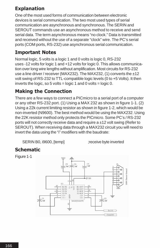
166
ExplanationOne of the most used forms of communication between electronicdevices is serial communication. The two most used types of serialcommunication are asynchronous and synchronous. The SERIN andSEROUT commands use an asynchronous method to receive and sendserial data. The term asynchronous means “no clock.” Data is transmittedand received without the use of a separate “clock” wire. The PC’s serialports (COM ports, RS-232) use asynchronous serial communication.
Important NotesNormal logic, 5 volts is a logic 1 and 0 volts is logic 0, RS-232uses -12 volts for logic 1 and +12 volts for logic 0. This allows communica-tion over long wire lengths without amplification. Most circuits for RS-232use a line driver / receiver (MAX232). The MAX232, (1) converts the ±12volt swing of RS-232 to TTL-compatible logic levels (0 to +5 Volts). It theninverts the logic, so 5 volts = logic 1 and 0 volts = logic 0.
Making the ConnectionThere are a few ways to connect a PICmicro to a serial port of a computeror any other RS-232 port. (1) Using a MAX 232 as shown in figure 1-1. (2)Using a 22k current limiting resistor as shown in figure 1-2, which would benon-inverted (N9600). The best method would be using the MAX232. Usingthe 22K resistor method only protects the PICmicro. Some PC’s / RS-232ports will not correctly receive data and require a ±12 volt swing (Refer toSEROUT). When receiving data through a MAX232 circuit you will need toinvert the data using the “i” modifiers with the baudrate:
SERIN B0, i9600, [temp] ;receive byte inverted
SchematicFigure 1-1

167
Figure 1-2
Function: DB-9 Pin Number:
Data Carrier Detect (DCD) 1Receive Data (RD) 2Transmit Data (TD) 3Data Terminal Ready (DTR) 4Signal Ground (SG) 5Data Set Ready (DSR) 6Request to Send (RTS) 7Clear to Send (CTS) 8
Some extra connections that may need to be made are DTR-DSR-DCDtied together and RTS-CTS tied together. This is only necessary if you areusing software or hardware that expects hardware handshaking.
Important NotesAsynchronous serial communication is based on precise timing. Sender andreceiver must be set for identical timing, expressed in bits per second (bps),referred to as the baud rate. The SERIN command requires a few values(Pin, Mode and Baud) that tell it the speed of the incoming serial data, thebit period, number of data and parity bits, and polarity. SERIN is able tolisten to data from 300 to 115k. The maximum recommend for 100% reliabletransmission is 57600 Baud.
Examplehello VAR bytestring VAR byte(10)goodbye VAR byte
SERIN B0,N9600,[hello];one byte at 9600 baud and store in variable hello
SERIN B0\B1,N4800,[Sbin hello];one Signed byte from serial at 4800 baud
SERIN B0,E14400,parityerror,[hello,STR string\9,IShex goodbye];receive one byte from serial at 14400 with parity.

168
;Receive one string of 9 characters;long and receive one Signed indicated (i.e.: $);hexadecimal value and store in goodbye
parityerror:;if parity error occurs in the serin command jump to this label
Debug [“error”]Goto parityerror
The previous program shows different ways the SERIN command can beused.
Serin ModifiersThe SERIN command has several modifiers for formatting incoming dataand adding functionality to the SERIN command (Refer to CommandModifiers). One of the SERIN modifiers can be configured to wait for speci-fied data before it retrieves any additional data. For example, a deviceattached to the PICMicro is known to send many different sequences ofdata, but the only data you require appears right after some unique charac-ters such as “A12”. You can modify the SERIN command to “Wait” for thesecharacters to be received before loading any values into a variable asshown:
Temp var Byte
SERIN B0, i9600, [WAIT(“A12”), temp]
The above program will wait until “A”, “1”, “2” is received in the order shown,then load the next value received value into the variable “Temp”. The datareceived by SERIN is case sensitive. If “a” was received first it would havebeen ignored. Also SERIN is looking at the ASCII values of “A”, “1”, “2”.
Once SERIN is executed the program halts until the data expected isreceived. If no serial data is received the program will halt indefinitely. In orderto limit the amount of time SERIN waits, you can use the Timeout option asshown:
SERIN B0, i9600, 1000, Timeerror, [WAIT(“A12”), temp]
Timeerror:Debug [“Error”] ;display message in watch window
Goto Timeerror ;loop forever
The above program will only wait 1000ms to receive the expected incomingdata until it will time out and jump to the specified label “Timeerror”.

169
Important NotesSome limitations of SERIN are sending or receiving data, the program can’texecute other instructions. When executing other instructions, the programcan’t send or receive data.
There is no serial buffer as on a PC. So watching data follow is important.One way to address this is to use flow control. This will set an additionalpin on the Atom for flow control. Using the circuit in figure 1-1 ties this addi-tional pin to Clear to Send (CTS), which is pin 8 on the DB-9 Male connec-tor. This will prevent the PC from sending data until SERIN is ready.
Low B1SERIN B0\B1, i9600,[WAIT(“A12”), temp]
Done:Debug [“Got it”]
Goto Done
The above program will set the pin B1, when the SERIN command isexecuted. This tells the PC “OK I’m ready”.
SEE ALSO
SEROUT

170
SeroutSEROUT tpin,baudmode,{pace,}[outputData]SEROUT tpin\fpin,baudmode,{timeout,tlabel,}[outputData]Transmit asynchronous (e.g., RS-232) data.
Tpin is a variable or constant that specifies the I/O pinthrough which the serial data will be sent.
Baudmode is a 16-bit variable or constant that specifies serialtiming and configuration. The lower 13 bits are interpreted asthe bit period. Bit 13 ($2000 hex) is a flag that controls thenumber of data bits and parity (0=8 bits and no parity, 1=7 bitsand even parity). Bit 14 ($4000 hex) controls the bit polarity(0=noninverted, 1=inverted). Bit 15 ($8000 hex) determineswhether the pin is driven to both states (0/1) or to one state andopen in the other (0=both driven, 1=open).
Pace is an optional variable or constant (0–65535) that tellsSEROUT how long in milliseconds it should pause betweentransmitting bytes.
OutputData is a list of variables, constants and modifiers thattells SEROUT how to format outgoing data. SEROUT cantransmit individual or repeating bytes; convert values intodecimal, hex or binary text representations; or transmit stringsof bytes from variable arrays.
Fpin is an optional variable or constant that specifies the I/Opin to be used for flow control (byte-by-byte handshaking). Thispin will switch to input mode and remain in that state after theinstruction is completed. (Caution Fpin requires the 'slash')
Timeout is an optional variable/constant (0–65535) used inconjunction with fpin flow control. Timeout tells Serout how longin milliseconds to wait for fpin permission to send. If permissiondoes not arrive in time, the program will continue at tlabel.
Tlabel is an optional label used with Fpin flow control andtimeout. Tlabel indicates where the program should go in theevent that permission to transmit data is not granted within theperiod specified by the Timeout command.

171
SEROUT ModesDriven? Inverted? Parity? Baud Rate ConstantYes No No 300 N300Yes Yes No 300 I300Yes No Yes 300 NE300Yes Yes Yes 300 IE300No No No 300 NO300No Yes No 300 IO300No No Yes 300 NEO300No Yes Yes 300 IEO300Yes No No ... N...Yes Yes No ... I...Yes No Yes ... NE...Yes Yes Yes ... IE...No No No ... NO...No Yes No ... IO...No No Yes ... NEO...No Yes Yes ... IEO...
* 1200, 2400, 4800, 9600, 14400, 19200, 28800, 33600, 38400, 57600
Improtant NoteThere are several modifiers for use with the SERIN / SEROUT commands.Refer to Command Modifier section of this manual.

172
Table 2-2 lists the predefined Baudmode constants available in MBasic. Asyou can see from the table there are several different baudmodes for eachactual baud rate. The following describes each baudmode modifier:
N Normal (not inverted) signalI Inverted signalE Even Parity(otherwise no parity)O Open drain(otherwise both high and low are driven)
Table 2-3 lists the command modifiers for the Output data
ExplanationOne of the most used forms of communication between electronicdevices is serial communication. The two types of serial communication areasynchronous and synchronous. The SERIN and SEROUT commands usean asynchronous method to receive and send serial data. The term asyn-chronous means “no clock.” Data is transmitted and received without theuse of a separate “clock” wire. The PC’s serial ports (COM ports, RS-232)use asynchronous serial communication.
Important NotesNormal logic, 5 volts is a logic 1 and 0 volts is logic 0, RS-232uses -12 volts for logic 1 and +12 volts for logic 0. This allows communica-tion over long wire lengths without amplification. Most circuits for RS-232use a line driver / receiver (MAX232). The MAX232, (1) converts the ±12volt swing of RS-232 to TTL-compatible logic levels (0 to +5 Volts). It theninverts the logic, so 5 volts = logic 1 and 0 volts = logic 0.
Making the ConnectionThere are a few ways to connect a PICMicro to a serial port of a computeror any other RS-232 port. (1) Using a MAX 232 as shown in figure 1-1. (2)Using a direct connection as shown in figure 1-2 which is non-inverted(N9600).The best method would be using the MAX232. Some PC’s requirea ±12 volt swing, so the direct connection may not work (Refer to SERIN).When transmitting data through a MAX232 circuit you will need to invert thedata using the “i” modifiers with the baudrate:
SEROUT B0, i9600, [“Test”] ;transmit “Test” inverted
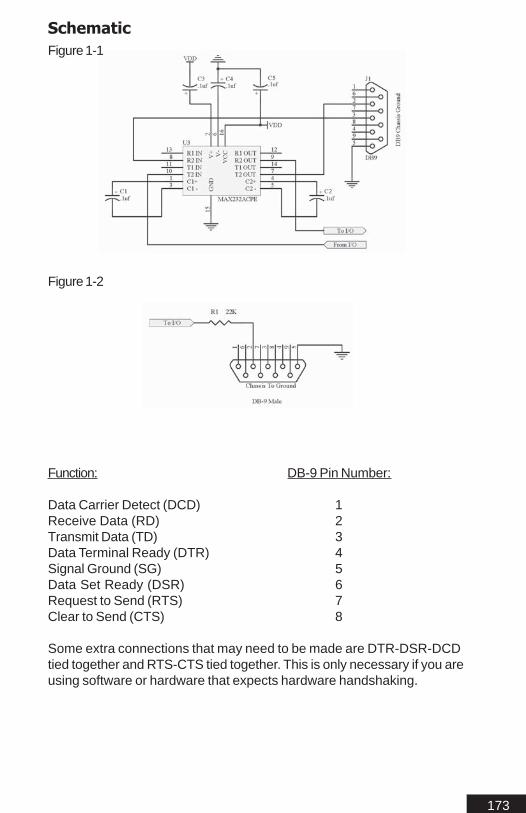
173
SchematicFigure 1-1
Figure 1-2
Function: DB-9 Pin Number:
Data Carrier Detect (DCD) 1Receive Data (RD) 2Transmit Data (TD) 3Data Terminal Ready (DTR) 4Signal Ground (SG) 5Data Set Ready (DSR) 6Request to Send (RTS) 7Clear to Send (CTS) 8
Some extra connections that may need to be made are DTR-DSR-DCDtied together and RTS-CTS tied together. This is only necessary if you areusing software or hardware that expects hardware handshaking.

174
Important NotesAsynchronous serial communication is based on precise timing. Sender andreceiver must be set for identical timing, expressed in bits per second (bps),referred to as the baudrate. The SEROUT command requires a few values(Pin, Mode and Baud) that tell it the speed to transmit the serial data, the bitperiod, number of data and parity bits, and polarity. SEROUT is able to senddata from 300 to 115k. The maximum recommend for 100% reliable transmis-sion is 57600 Baud.
Examplehello VAR bytestring VAR byte(10)goodbye VAR byte
SEROUT B0,i9600,[“Hello”];send “hello”, through the serial port at 9600 baud inverted;for use with a MAX232 or SIN / SOUT
SEROUT B0,N4800,[Sbin hello];send one Signed byte from hello, through serial at 4800baud;non-inverted, for use with a direct connection
SEROUT B0,IE14400,100,[hello,STR string\9,IShex goodbye];send one byte from serial at 14400 with parity.;Send string of bytes 9 characters;long and one Signed indicated (i.e.: $);hexadecimal value from goodbye;Pace the bytes 100ms apart;inverted, for use with a MAX232
The above code snippets illustrates different ways SEROUT can bemodified using modifiers.
Serout ModifiersThe SEROUT command can use several formatting modifiers (Refer toCommand Modifiers). An example would be the decimal modifier (DEC),which will translate the value of “8” and “2” into the ASCII codes for thecharacters “8” and “2” and then transmit them:
SEROUT B0, i9600, [ DEC 82 ]
The SEROUT command will send quoted text exactly as it appears inquotes:
SEROUT B0, i9600, [ “Result = “, DEC 10]
This will display “Result = 10”.

175
SEROUT can be configured to pause between transmitted bytes, calledpacing:
SEROUT B0, i9600, 500, [ “Slow” ]
SEROUT will transmit the word “Slow” with a 500ms delay between eachcharacter. The Pace feature is used to support devices that require morethan one stop bit. SEROUT would normally send data as fast as it can! Astop bit is simply a resting state in the driven line. Using the Pace option willadd multiple stop bits. Since some devices may require 2 or more stop bits.The Pace modifier can also be used for devices that can only process onebyte at a time, using the Pace modifier would give such a device time toprocess the byte then return to wait for another byte.
The string (STR) modifier can be useful for transmitting a string of charactersfrom a byte array variable. A string of characters is a set of characters thatare arranged in a certain order. The characters “1234” could be stored in astring with the “1”, “2” then “3” and “4”. A byte array is similar to a string inthat it contains data that is arranged in a certain order. Each of the elementsin an array is the same size. See the “Defining Arrays” section in thismanual for more information on arrays. An example that transmits 4 bytesfrom a byte array is shown below:
TempString var byte(4) ;create a 4-byte arrayTempString(0) = “T” ;set the piece 1 of the arrayTempString(1) = “E” ;set the piece 2 of the arrayTempString(2) = “S” ;set the piece 3 of the arrayTempString(3) = “T” ;set the piece 4 of the array
SEROUT B0, i9600, [ STR TempString\4 ];send 4-byte string
The use of the optional \n argument is to specify how many characters areto be sent. Otherwise it would continue until it found a byte equal to 0. Sincethe last byte of 0 in the array is not 0 it would go on forever. Another usefulmodifier is Repeat (Rep\n):
SEROUT B0, i9600, [ Rep Temp\10 ];send temp ten times
The repeat modifier will repeatedly send a byte value \n times. The numberof times its repeated is specified by \n.
SEE ALSO
SERIN

176
ServoSERVO pin, rotation{, repeat}
Pin is the pin controlling the servo
Rotation is a variable / constant that specifies the position youwant the servo to rotate. A value from -1200 to + 1200 is used with0 being center. The value -1200 being a rotation to the farthestposition in a direction and +1200 being the farthest rotation in theopposite direction. The maximum +1200 and minimum -1200 willvary based on the servo being used. Take caution not to exceedthese values.
Repeat (optional)Specifies the number of internal cycles thecommand runs(defaults to 30).
ExplanationVarious servo manufacturers use different color coding for their servos.Below is a color cross reference chart for some popular servos.
Manufacturer +5 Volts GND (Vss) I / O
Airtronics Red Black BrownFutaba J Red Black WhiteKO Propo Red Black BlueKyosho/Pulsar Red Black YellowJapan Radio(JR) Red Brown Orange
The SERVO command works by simply pulsing the I/0 pin used verysimilar to PWM. By adjusting the width and duration you can control theSERVO clockwise, counter clockwise and speed. The SERVO commandautomatically handles the calculations for you.
ExampleMain
Servo B0, -1200 ;rotate servo negativePause 200 ;give servo time to complete rotationServo B0, 1200 ;rotate servo positive
Goto Main ;repeat forever.
In the example the Servo will rotate all the way to one direction then all theway to the opposite direction. There is no exact scale for what value willmove the servo to what position. This is due to the fact that servo motorsmay vary. Use the program below with your servo connected to determinewhich value corresponds to what position:

177
Temp var WordTemp = 0
Maintemp = temp +10Servo B0, temp ;rotate servo positiveDebug [DEC Temp, 13]Pause 200 ;time to complete motion
NextGoto Main ;repeat forever.
The above example will print the value of Temp to the debug watchwindow. To work out the opposite direction change the values of temp tonegative numbers.

178
ShiftinSHIFTIN Dpin,Cpin,Mode,[result{\bits}{,result{\bits}...}]Shift data in from a synchronous-serial device.
Dpin is a variable or constant that specifies the I/O pin that willbe connected to the synchronous-serial device’s data output. Thispin‘s I/O direction will be changed to input and will remain inthat state after the instruction is completed.
Cpin is a variable or constant that specifies the I/O pin that willbe connected to the synchronous-serial device’s clock input. Thispin’s I/O direction will be changed to output.
Mode is a value (0—3) or 4 predefined symbols that tellsSHIFTIN the order in which data bits are to be arranged and therelationship of clock pulses to valid data. Here are the symbols,values, and their meanings:
MSBPRE 0 Data msb-first; sample bits before clock pulseLSBPRE 1 Data lsb-first; sample bits before clock pulseMSBPOST 2 Data msb-first; sample bits after clock pulseLSBPOST 3 Data lsb-first; sample bits after clock pulse
(Msb is most-significant bit; the highest or left most bit of a nibble, byte, orword. Lsb is the least-significant bit; the lowest or right most bit of a nibble,byte, or word.)
Result is a bit, nibble, byte, or word variable in which incomingdata bits will be stored.
Bits is an optional entry specifying how many bits (1—16) are tobe input by SHIFTIN. If no bits entry is given, SHIFTINdefaults to 16 bits.
ExplanationSHIFTIN provides an easy method of receiving data from synchronous-serial devices. Synchronous serial differs from asynchronous serial (i.e.SERIN and SEROUT) in that the timing of data bits is specified in relation-ship to pulses on a clock line. Data bits may be valid after the rising orfalling edge of the clock line. This kind of serial protocol is commonly used bycontroller peripherals like ADCs, DACs, clocks, memory devices, etc. Tradenames for synchronous-serial protocols include SPI and Microwire.
The SHIFTIN command will first set the clock pin to output and low. Thedata pin is then switched to input mode. SHIFTIN will now either generate aclock pulse then read the data pin (POSTmode) or read the data pin andgenerate a clock pulse (PRE mode). SHIFTIN will continue to generate clock
179
pulses and read the data pin for as many data bits required. Using SHIFTINwith a particular device is nothing more than matching the mode andnumber of bits to the device’s protocol. Manufacturers will generally providea timing diagram to illustrate the clock and data.
The bit argument on SHIFTIN defaults to 16 unlike the BS2. If no bit argu-ment is used 16 bits will be acquired. For example:
SHIFTIN B0, B1, LSBPRE,[dog \8]
Using the example above if %10001111 was received the first bit wouldbecome the least significant bit. MSB and LSB work like reading English.From left to right. When looking at a value MSB starts from the left to LSBending on the right. So above %1000 is the MSB of our 8 bit value. Oncethe entire 8 bits have been received in our variable DOG it would read asfollows %11110001.
ExampleThis next example show how to setup and read the time and data from aDallas 1302.
RTCCmd VAR BYTEClk CON B0Dta CON B1Reset CON B2Temp VAR BYTETemp1 VAR BYTEtimedata var byte(6)oldseconds var byteSeconds VAR timedata(0)Minutes VAR timedata(1)Hours VAR timedata(2)Date VAR timedata(3)Month VAR timedata(4)Year VAR timedata(5)
;Define registers of the DS1302
SecReg CON %00000MinReg CON %00001HrsReg CON %00010DateReg CON %00011MonReg CON %00100YrReg CON %00110CtrlReg CON %00111BrstReg CON %11111

180
Preset bytetable $00,$00,$12,$20,$03,$02
; Clear Write Protect bit in control register
Temp = $10RTCCmd = CtrlReg
GOSUB PreSetData
;Preset time registers using a byte table preset
for temp1 = 0 to 5Temp = Preset(temp1)RTCCmd = temp1GOSUB PreSetData
NEXT
Temp = $80RTCCmd = CtrlReg
GOSUB PreSetData
; read loop. Only writes to the screen if the seconds have changed; The “|” is used at the end of a line that is to long to fit on the screen; the location of the “|” may change depending where the breaks are; in the command on your screen
Loop:GOSUB ReadDataif oldseconds <> seconds then
serout B7,i38400,[0,"Time: ",dec2 (BCD2BIN Hours)|\2,":",DEC2 (BCD2BIN Minutes)\2,":",DEC2 (BCD2BIN |Seconds)\2,13,"Date: ",DEC2 (BCD2BIN Month)\2,"/",DEC2 |(BCD2BIN Date)\2,"/",DEC2 (BCD2BIN Year)\2]
endifGOTO Loop
; The PreSetData loop is used to preset the values from the Preset; bytetable so the data and time can be set. Change the values in the; table to be current
PreSetData:'Write to DS1302 RTCHIGH ResetSHIFTOUT Dta, Clk, LSBFIRST, [%0\1,RTCCmd\5,%10\2,Temp\8]LOW Reset
RETURN
ReadData:HIGH Reset
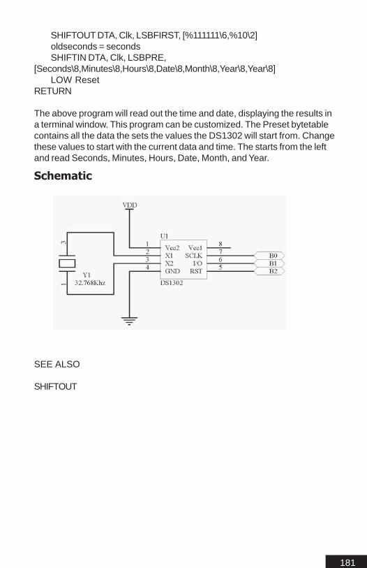
181
SHIFTOUT DTA, Clk, LSBFIRST, [%111111\6,%10\2]oldseconds = secondsSHIFTIN DTA, Clk, LSBPRE,
[Seconds\8,Minutes\8,Hours\8,Date\8,Month\8,Year\8,Year\8]LOW Reset
RETURN
The above program will read out the time and date, displaying the results ina terminal window. This program can be customized. The Preset bytetablecontains all the data the sets the values the DS1302 will start from. Changethese values to start with the current data and time. The starts from the leftand read Seconds, Minutes, Hours, Date, Month, and Year.
Schematic
SEE ALSO
SHIFTOUT

182
ShiftoutSHIFTOUT Dpin,Cpin,Mode,[data{\bits}{,data{\bits}...}]Shift data out to a synchronous-serial device.
Dpin is a variable or constant that specifies the I/O pin thatwill be connected to the synchronous-serial device’s data input.This pin’s I/O direction will be changed to output and willremain in that state after the instruction is completed.
Cpin is a variable or constant that specifies the I/O pin thatwill be connected to the synchronous-serial device’s clock input.This pin’s I/O direction will be changed to output and willremain in that state after the instruction is completed.
Mode is a value (0 or 1) or a predefined symbol that tellsSHIFTOUT the order in which data bits are to be arranged.Here are the symbols, values, and their meanings:
Symbol Value Meaning:
MSBPRE 0 Data msb-first; sample bits before clock pulseLSBPRE 1 Data lsb-first; sample bits before clock pulseMSBPOST 2 Data msb-first; sample bits after clock pulseLSBPOST 3 Data lsb-first; sample bits after clock pulse
Backwards Compatibility:
LSBFIRST 1 Data shifted out lsb-first.MSBFIRST0 Data shifted out msb-first.
(Msb is most-significant bit; the highest or left most bit of a nibble, byte, orword. Lsb is the least-significant bit; the lowest or right most bit of a nibble,byte, or word.)
Data is a variable or constant containing the data to be sent.
Bits is an optional entry specifying how many bits (1—16) are tobe output. If no bits entry is given, SHIFTOUT defaults to 16 bits.
ExplanationSHIFTOUT provides an easy method of transferring data to synchronous-serial devices. Synchronous serial differs from asynchronous serial (likeSERIN and SEROUT) in that the timing of data bits is specified in relation-ship to pulses on a clock line. Data bits may be valid after the rising orfalling edge of the clock line. This kind of serial protocol is commonly used bycontroller peripherals like ADCs, DACs, clocks, memory devices, etc. Tradenames for synchronous-serial protocols include SPI and Microwire.

183
ExampleThe below example program will send out the values 0 through 255 to the74HC595 which is a serial to parallel register. Use the schematic below tomake the proper connections.
SI CON B0 ; serial outputSCK CON B1 ; shift clockRCK CON B2 ; output latchDelay CON 100Counter VAR Byte
mainfor counter=0 to 255
gosub Out595pause 100 ;Change to in/decrease speed
nextgoto main
Out595:Shiftout SI,SCK,MSBPRE,[counter\8]
; send pattern to 74x595Pulsout RCK,8 ; latch outputs(min 8us)
Return
Schematic
SEE ALSO
SHIFTIN

184
Example of SPI communicationsSPI communication is accomplished via the SHIFTIN and SHIFTOUTcommands. Following below is a brief tutorial on using SPI devices.
SPI is a serial communication protocol. CS, SCK, SI and SO need to beconnected to I/O pins on the PICmicro. In this example we will refer to theMicrochip 25C040 shown below.
PIN DESCRIPTION:CS - Chip Select InputSO - Serial Data OutputWP - Write Protect PinVSS - GroundSI - Serial Data InputSCK - Serial Clock InputHOLD - Hold InputVCC - Supply Voltage
I m p o r t a n t N o t eI m p o r t a n t N o t eI m p o r t a n t N o t eI m p o r t a n t N o t eI m p o r t a n t N o t eIn some uses of SHIFTIN / SHIFTOUT may not work correctly withDebug.This is a timing related issue and will be addressed in a laterrelease.
E x a m p l eE x a m p l eE x a m p l eE x a m p l eE x a m p l eThe following example will detail writing and reading data to a 25c040 SPIeeprom.
temp var bytecntr var wordcntr = 0SCK con B1SO con B3SI con B2CS con B0
low SCK ;sets chip in a known statehigh CS
mainlow CSshiftout SI,SCK,MSBPRE,[0x06\8] ; sets 25c040 for a writehigh CSlow CSshiftout SI,SCK,MSBPRE,[0x02\8]shiftout SI,SCK,MSBPRE,[cntr\8] ; sends address location for write

185
shiftout SI,SCK,MSBPRE,[cntr\8] ; using the value of address as the value to be writen
high CSpause 5low CSshiftout SI,SCK,MSBPRE,[0x03\8,cntr\8] ; sets 25c040 for a readshiftin SO,SCK,MSBPOST,[temp\8] ; reads and stores results in temphigh CSserout c0,i9600,["Hello",dec temp,13]
; prints value stored in temp to terminal windowcntr = cntr + 1goto main

186
SleepSLEEP secondsPut the PICmicro into low-power sleep mode for a specified number ofseconds.
Seconds is a variable or constant (1-65535) that specifies theduration of sleep in seconds.
ExplanationSLEEP will place the PICmicro into a low power mode for the specifiedperiod of seconds. Period is 16 bits, so delays of up to 65,535 seconds (alittle over 18 hours) would be the limit. SLEEP uses the Watchdog Timer soit is independent of the oscillator frequency. Since SLEEP relies on thewatchdog timer there is a short wake up period every 1.5 seconds. The I/Opins remain in there last known state.
The SLEEP command will not affect the internal registers, allowing aprogram to continue executing upon waking up from the SLEEP period.
To achieve the lowest possible current draw during sleep you should set allpins to outputs and low.
ExampleIn the example below we can easily create a long pause when blinking anLED. Commonly the SLEEP command is used to reserve battery power.
AgainHIGH B0 ; LED on.PAUSE 1000 ; Wait 1 second.LOW B0 ; LED off.SLEEP 60 ; Sleep for 1 minute.
Goto Again
The above example will blink an LED then put the PICmicro into a oneminute sleep cycle.

187
SoundSound pin,[duration1\note1,...durationN\noteN]Generate specific note from one pin.
Pin is a variable/constant that specifies the I/O pin to use. Thispin will be set to an output during tone generation and left inthat state after the instruction is completed.
Duration is a variable/constant specifying the length inmilliseconds (1 to 65535) of the tone(s).
Note is a variable/constant specifying frequency in hertz (Hz, 0to 32767) of the first tone.
ExplanationThe sound command generates a pulse at the specified frequency. Thesound command can be used to play tones through a speaker or audioamplifier. Sound can also be used to play simple songs.
ExampleSOUND B1,[1000 \ 2500]
This instruction generates a 2500-Hz tone for 1 second (1000 ms) throughB1. To play two notes:
SOUND B1,[1000 \ 2500, 2000 \ 2500]
The above code will play two notes first one being 2500Hz for 1 secondand the second 2500Hz for 2 seconds.
The notes generated are clean without filtering. Refer to the schematic
The next program demonstrates the Sound command and should give youa better idea of what values to ue to generate certain tones.
'Variables used to hold the frequency and duration of the sound command
freq var worddur var word
main:Freq = 2500Dur = 1000
;Now play itsound B0,[dur\freq]
goto main

188
Schematic

189
Sound2Sound2 pin1\pin2,[duration1\note1\note2_1,...durationN\noteN\note2_N]Generate specific notes one on each of the two defined pins.
Pin1 \ Pin2 is a variable/constant that specifies the I/O pins touse. This pin will be set to an output during tone generation andleft in that state after the instruction is completed. The twospecified pins can be tied together as shown in the schematic
Duration is a variable/constant specifying the length inmilliseconds (1 to 65535) of the tone(s).
Note is a variable/constant specifying frequency in hertz (Hz, 0to 16000) of the tones.
ExplanationSound2 generates two pulses at the specified frequency one on each pinspecified. The sound2 command can be used to play tones through aspeaker or audio amplifier. Sound2 can also be used to play more compli-cated songs. By generating two frequencies on separate pins, a moredefined sound can be produced.
ExampleSOUND2 B1 \ B2,[1000 \ 2500 \ 3500]
The above code generates a 2500Hz tone and a 3500Hz tone for 1 second(1000 ms). The first note specified is played from the first pin specified andthe second note from the second pin specified. To play multiple notes:
SOUND2 B1 \ B2,[1000 \ 2500 \ 3500, 2000 \ 2500 \ 3500]
The above code will play two sets of notes 2500Hz and 3500Hz for 1second and the second two notes, 2500Hz and 3500Hz for 2 seconds.
The notes generated are clean without filtering. The pins should be summedtogether to produce multiple melody songs. With the sound2 command morecomplex music can be played by the PICmicro. Refer to the schematic.
Schematic

190
SpmotorSPMOTOR pin, delay, step
Pin can be a variable or constant. Pin specifies the first pin outof 4 control pins required. If B0 was used, the control pinswould then be B0, B1, B2, B3.
Delay can be a variable or constant and is a value from 0 to65365 in milliseconds. Delay controls the speed at which thestepper motor will rotate. The delay will also vary from steppermotor to stepper motor.
Step can be a variable or constant and is the number of stepsand the direction. The direction is determined by the value ofStep. Positive values being clockwise and negative numbers beingcounter clockwise. The step value can be a range from -32682to +32682
ExplanationStepper motors are precision motors which have an absolute amount of travelper step. This is ideal in situation where precise positioning is necessary. Steppermotors are commonly found in XY positioning tables. Steppers motors can bepurchased from several sources. Chances are you may have a few layingaround. They are commonly salvaged from old disk drives and laser printers.
There are two types of stepper motors. Unipolar and Bipolar. Unipolar meansone pole. This is usually a common ground between 4 coils. Unipolar steppermotors are easier controlled with minimal circuitry. Bipolar motors indicate two poles.Bipolar motors require additional circuity in order to drive them. The SPMOTORcommand does not support Bipolar motors. In most cases you can easily distin-guish between then two types. Unipolar stepper motors have 5 wires. Bipolarmotors usually have 4.
The use of the SPMOTOR command requires a simple circuit using a darlingtonarray (ULN2803A) to sink the load from the stepper motor. Some small lowpower stepper motors can be driven from the microcontroller directly. However thisis not recommended. Other circuits can be used to sink the load from the steppermotor. The ULN2803A is the most commonly used.

191
ExampleThe following program will rotate a stepper motor 1000 steps clockwise andcounter clockwise.
MainSPMOTOR B0, 10, 1000SPMOTOR B0, 10, -1000Goto Main
The SPMOTOR command can be used to drive more than one motor. To dothis you would use the SPMOTOR command more than once with newpins defined.
I m p o r t a n t N o t eI m p o r t a n t N o t eI m p o r t a n t N o t eI m p o r t a n t N o t eI m p o r t a n t N o t eThe SPMOTOR command will not work correctly when used with Debug.This is due to the serial data the PICmicro must send to keep in sync withthe IDE.
Schematic

192
StopSTOPStops program execution.
ExplanationSTOP prevents the program from executing any further instructions until it isreset. The STOP command is similar to END but it does not put the Atom intolow-power mode. The Atom draws just as much current as if it were activelyrunning program instructions. The only way to start the program again is toreset the chip.
STOP ;Stops program
ExampleStop can be used to quickly exit a loop based on a certain condition asshown in the example below:
myswitch var portb.bit0 ;myswitch is now an alias of B0
MAIN:IF myswitch = 0 THEN MAIN
;check if PORTB PIN 0 is low if so it loops
IF myswitch = 1 THEN STOPIT;check if switch is on if so goto label RUNIT
GOTO MAIN;will continue to loop until P0 is high
STOPIT:STOP
;stops program execution
The above code example is a software ON/OFF switch, when power to therest of the circuit needs to remain on but the PICmicro must be stopped.

193
SwapSWAP variable,variable
Variable is the value to be swapped
ExplanationSwap any two variable’s values with each other. If Dog = 10 and Temp = 0then by using the swap command Dog will now equal 0 and Temp will equal10.
ExampleThe below program will run once. The If..Then does a comparison, sincetemp = 0 it continues. Then the Swap command swaps the values in dogwith temp. The If..Then will now be true since temp is now equal to 10.
Dog Var ByteTemp Var Byte
Dog = 10 ;Dog equals 2Temp = 0 ;Temp equals 0
Mainif temp = 10 then ExitLoopSwap Dog, Temp ;Temp now equals 10
Goto Main
ExitLoopend

194
ToggleTOGGLE pinInvert the state of a pin.
Pin is a variable or constant that specifies the I/O pin to use.
ExplanationTOGGLE inverts the state of an I/O pin, changing 0 to 1 and 1 to 0. Thepin is automatically made an output.
ExampleThe following example will blink an LED connected to the specified I/O pin.
Low B0 ;set initial pin state
MainToggle B0 ;switch pin statePause 200
Goto Main
The above program will toggle B0 each loop. The first run will toggle the pinfrom low to high. The second time through the loop will then toggle the pinfrom high to low.
Schematic

195
While...WendWhile expression is true do the following
Expression is any combination of variables, constants, mathand logic operators
ExplanationRepeat a group of commands while some expression is true. True being anyother value than 0. Each time the group of commands are executed the WENDchecks to see if the expression is still true.
ExampleIn the following example, the instructions between the WHILE...WEND com-mands will execute until the variable Temp is less than 20. With each runthrough the loop WEND will check the status of Temp.
Temp var ByteCheck var PortB.bit0
Clear
While temp < 20 ; repeat the following commands.if check = 1 then JumpOutTemp = Temp +1
Wend ; repeating until temp is greater than 20
JumpOutEnd
The next program demonstrates the While Wend command by blinking anLED attached to pin B2 of the PICmicro. The LED will blink a total of 100times with a 500ms pause between each blink.
output B2 'Place an led on pin 2
counter var bytecounter = 0
while counter < 100Toggle B2 'Change the state of pin B2counter = counter +1pause 500
wend

196
WriteWRITE address,byteWrite a byte of data to the EEPROM.
Address is a variable or constant specifying the EEPROMaddress to write to.
Byte is a data byte to be written into EEPROM.
E x p l a n a t i o nE x p l a n a t i o nE x p l a n a t i o nE x p l a n a t i o nE x p l a n a t i o nEEPROM differs from RAM, the memory in which variables are stored, inseveral respects:
1- Writing to EEPROM takes more time than storing a value in a variable.
2- The EEPROM can accept a finite number of write cycles perbyte before it wears out, which is usually around 10 millionwrite cycles and an unlimited number of Reads. If a programfrequently writes to the same EEPROM location, it makessense to estimate how long it might take to exceed 10 millionwrites. For example, at one write per second (86,400 writes/day) it would take nearly 116 days of continuous operation toexceed 10 million.
WRITE is used to set values of on-chip EEPROM during run time. To setvalues during programming use the DATA commands.
Each write will take about 10ms to execute. Keep this in mind when usingthe WRITE command.
WRITE 6,F ;Sends the byte F to location 6 on the EEPROM
E x a m p l eE x a m p l eE x a m p l eE x a m p l eE x a m p l eThe below program writes the ASCII value of H to address 0 of the internalEEPROM on the PICmicro, then reads address 0 and if the value equals Hturns on a LED connected to B4.
DOG var bytewrite 0,”H” ;writes the ASCII value of H to address 0read 0,dog ;reads address 0 stores the value in ledonif dog = “H” then ledon
;if ledon = the ASCII value H;turn the LED on
stopledon: High B4 ;turns the LED on connected to B4end

197
The following program will demonstrates the Data, Read, and Write com-mands
'Day 1-4Data @0, 12,26,3,32
'Day 5-8Data @4,22,12,31,45
'Define some variable to use for loading the eeprom dataday1 var byteday2 var byteday3 var byteday4 var byteday5 var byteday6 var byteday7 var byteday8 var byte
clear 'Make sure we clear the variables
'-----------------------------------------------------------' Step 1' Lets load the eeprom data'-----------------------------------------------------------
read 0,day1read 1,day2read 2,day3read 3,day4read 4,day5read 5,day6read 6,day7read 7,day8
'Display the default datadebug ["Day1 default=",dec day1,10,13]debug ["Day2 default=",dec day2,10,13]debug ["Day3 default=",dec day3,10,13]debug ["Day4 default=",dec day4,10,13]debug ["Day5 default=",dec day5,10,13]debug ["Day6 default=",dec day6,10,13]debug ["Day7 default=",dec day7,10,13]debug ["Day8 default=",dec day8,10,13]debug [10,13]

198
'--------------------------------------------------------------' Step 2' Ok now lets overwrite day3 and day8 defaults.' Remember the address is 0 based'--------------------------------------------------------------
write 2,day3+1 'Add onewrite 7,day8+2 'Add two
'--------------------------------------------------------------' Step 3' Lets load the eeprom data again'--------------------------------------------------------------
read 0,day1read 1,day2read 2,day3read 3,day4read 4,day5read 5,day6read 6,day7read 7,day8
'And display it one more timedebug ["Day1 default=",dec day1,10,13]debug ["Day2 default=",dec day2,10,13]debug ["Day3 default=",dec day3,10,13]debug ["Day4 default=",dec day4,10,13]debug ["Day5 default=",dec day5,10,13]debug ["Day6 default=",dec day6,10,13]debug ["Day7 default=",dec day7,10,13]debug ["Day8 default=",dec day8,10,13]
'------------------------------------------------------------' All done. Put the PICmicro to sleep. Note the values and' restart the chip.
end
199
WriteDMwritedm address,[{mod}expression,...,{mod}expressionN]Write EEPROM locations and store value in variable.
Address is a value pointing to a location in the eeprom from whichto start.
Mod is any appropriate input or output modifier
Var is any variable type
Expression is any legitimate math expression
ExplanationThe WriteDM is similar to the Write command. The WriteDM statement is setupfor sequential writes at a starting address in the internal eeprom. These writeswill start at a specified address and will sequentially continue until the end ofthe data or eeprom range is reached.
WriteDM 0,[“Hello world”]
The above example will begin writing at address 0 to the internal eeprom.The string “Hello World” contains 11 bytes (Space included) since thestarting address is 0 the last written address will be 10.
ExampleThe following program illustrates the usefulness of the ReadDM andWriteDM command. We begin with an Array to store our returned data.
string var byte(12)
mainwritedm 0,[“Hello world”]readdm 0,[str string\11]
mainlpserout B0,i9600,[str string\11,13]
goto mainlp
The above program will write the entire string “Hello World” to the internaleeprom. Since the string “Hello World” consist of 11 bytes the first 11 bytesof the eeprom will be written to. Then the ReadDM command is used toread the 11 bytes back. By using the STR modifier we tell the ReadDMcommand we want to read 11 bytes from the internal eeprom and storethem in our 12 byte variable array. Next we use the SEROUT command todisplay the results to a terminal window.

200
Important NotesThere are only 256 internal eeprom locations on a 16F876. If the ReadDMor WriteDM command begin in a valid location and continue outside of the256 locations they will wrap around to the beginning location.
SEE ALSO
ReadDMSTR Modifier

201
WritePMWritepm address,[{mod}var,...,{mod}varN]Write Flash Program memory location. Requires 16F87x part.
Address is a value pointing to a location in the flash program memoryfrom which to start. Requires 16F87x part.
Mod is any appropriate input or output modifier
Var is any variable type
ExplanationThe WritePM command is similar to the WriteDM command except it writes tothe internal program memory of a 16F87x PICmicro. The WritePM statement issetup for sequential writes to the internal program memory. These writes willstart at a specified address.
writepm 0x400,["Hello world"]
The above example will beginwritting at address 400h to the internalprogram memory.
ExampleThe following program will write “Hello World” using the WritePM commandstarting at address 400h. Then the ReadPM command is used to read thewritten values to program memory and print the result to the debug window.
We begin with an Array to store our returned data.
string var byte(12)temp var byte
mainwritepm 0x400,["Hello world"]readpm 0x400,[str string\11]
mainlpfor temp = 0 to 11Debug [string(temp)]NextDebug [13]
goto mainlp
The example program will write the entire string “Hello World” to the internalprogram memory. Since the string “Hello World” consist of 11 characters, 11bytes will be written to the internal program memory starting at location400h. If you run the program once and read back the programmed hex file

202
from the PICmicro at location 400h will be the values for “Hello World”.
By using the STR modifier we tell the ReadPM command we want to read11 bytes from the internal eeprom and store them in our 12 byte variablearray. Next we use the Debug command to display the results to the debugwindow.
Important NotesThe READPM and WRITEPM commands will only work with 16F87xparts. You can not write or read actual program space used for the runningprogram. You can write and read from address locations that do not containprogram data. If the ReadPM command is used to read locations of actualrunning program space, erratic results will occur.
SEE ALSO
WRITEPMSTR Modifier

203
XinXIN DataPin\ZeroPin,House,{TimeoutLabel,TimeoutCount,}[{Modifier}Var]Receive X-10 data and store keycode in a variable.
DataPin is a variable/constant that specifies the I/O pin to use. Thispin will be set to an input. The DataPin should be pulled high with a4.7K resistor.
ZeroPin is a variable/constant that specifies the I/O pin to use. Thispin will be set to an input. The ZeroPin should be pulled high with a4.7K resistor. The ZeroPin is used to detect the zero crossingtimings from the X-10 device.
House is a variable/constant used to filter out data with multiplehouse settings. House is a comparison value to match if the incoming data matches a particular house code other wise the XINcommand will continue waiting. The constant labels for each housecode are as follows:
X_A X_IX_B X_JX_C X_KX_D X_LX_E X_MX_F X_NX_G X_OX_H X_P
TimeoutLabel is an optional label used to specify a place to jump toif a time out occurs.
TimeoutCount is an optional value used in conjunction with theTimeoutLabel to specify the amount of time that occurs beforejumping to the TimeoutLabel. Timeouts are based on commandsfrom the X-10 module. The value placed for TimeoutCount will waitN amount of commands received from the X-10 module before atime out will occur.
Var is a variable/constant used to store the results (KeyCode) of theXIN statement. The incoming data is the keycode which is 5 bits soa byte size variable is needed.
ExplanationXIN allows you receive signals sent through household AC wiring to X-10modules. XIN requires the use of a special module (TW523) that interfacesto the AC wiring. Other interface modules are available but the TW523 hasan input and output connection that allows you to receive and send X-10data.

204
The X-10 format is made up of digital codes imposed on a 120 kHz carrierthat is transmitted during zero crossings of the AC line. Receiving X-10commands require the controller to be synchronize to the AC line. To connectto the X-10 interface a four-conductor phone cable is required.
Example
XIN B0\B1, X_A, XError, 100, [Temp]
The above code will wait approximately 100 command cycles to find thedata corresponding to house code A until it will exit and jump to the labelXError. TimoutLabel and TimeoutCount are optional.
XIN B0\B1, X_A, [Temp]
The above code will wait indefinitely for data corresponding to house code A.Once the data is received it will be placed in the variable (Temp).
Temp Var Byte
MainXIN B0\B1, X_A, [Temp]DEBUG [BIN TEMP, 13]
Goto Main
The above code will continue to loop and receive all data for house code A anddisplay it to the debug window.
TW523The TW523 module is available from many places on the internet. Onesource is http://www.x10.com Once on the web site do a quick search forTW523. The TW523 is used to remove much of the burden in decoding theX10 data from the AC wiring. The pin outs for the TW523 module are shownbelow:
Wire No Connection1 Zero Crossing2 Common3 X-10 Receive data from TW5234 X-10 Transmit to TW523

205
Schematic
Important NotesIf the data received is a unit number you can use these constant labels todo a comparison:
Unit ConstantX_1 % 00110X_2 % 00111X_3 % 00100X_4 % 00101X_5 % 01000X_6 % 01001X_7 % 01010X_8 % 01011X_9 % 01110X_10 % 01111X_11 % 01100X_12 % 01101X_13 % 00000X_14 % 00001X_15 % 00010X_16 % 00011
X 1 0 I s s u e sX 1 0 I s s u e sX 1 0 I s s u e sX 1 0 I s s u e sX 1 0 I s s u e sInterface modules such as the TW523 and PL513 have limitations to howwell they may work in your area. During testing of the XIN and XOUTcommands we found the modules would not address some units in thesame building. This may be due to noise in the lines, or faulty electricalwiring. The interface units did not work well with filtering power strips either.
When setting up your X10 units, test them close together. The transmitterand receiver should be on the same plug if possible. This will save many

206
hair pulling hours. Once the units demonstrate they work, move the receiverunit to its target location. If it does not work in another locations it is NOTyour circuit, provided the receiver worked under the previous mentioned testconditions.

207
XoutXOUT DataPin\ZeroPin, House, [{Unit}, {Modifiers} Keycode]Transmit X-10 House code and Keycode.
DataPin is a variable/constant that specifies the I/O pin to use. Thispin will be set to an input. The DataPin should be pulled high with a4.7K resistor.
ZeroPin is a variable/constant that specifies the I/O pin to use. Thispin will be set to an input. The ZeroPin should be pulled high with a4.7K resistor. The ZeroPin is used to detect the zero crossingtimings from the X-10 device.
House is a variable/constant that corresponds to the House Codeset on the X-10 module A through P. The constant labels for eachhouse code are as follows:
X_A X_IX_B X_JX_C X_KX_D X_LX_E X_MX_F X_NX_G X_OX_H X_P
Unit is an optional variable/constant that specifies the address ofthe unit, 1 to 16. Unit codes are also considered KeyCodes.
Unit ConstantX_1 % 00110X_2 % 00111X_3 % 00100X_4 % 00101X_5 % 01000X_6 % 01001X_7 % 01010X_8 % 01011X_9 % 01110X_10 % 01111X_11 % 01100X_12 % 01101X_13 % 00000X_14 % 00001X_15 % 00010X_16 % 00011

208
KeyCode is a variable/constant that specifies the unit code or function.Multiple KeyCodes can be used in the XOUT command. Only certaincommands will work in combination such as DIM codes.
Unit ConstantX_Units_On % 10000X_Lights_On % 11000X_On % 10100X_Off % 11100X_Dim % 10010X_Bright % 11010X_Lights_Off % 10110X_Hail % 10001X_Status_On % 11011X_Status_Off % 10111X_Status_Request % 11111
ExplanationXOUT is used to control X-10 modules over AC house wiring. XOUTrequires the X-10 modules TW523 or PL513.
The XOUT command must first transmit the specified house code and unitcode in order to communicate to another X-10 device. The X-10 module withthe corresponding code will listen for its house code followed by a KeyCode(ie. dim, on or off)
The X-10 format is made up of digital codes imposed on a 120 kHz carrierthat is transmitted during zero crossings of the AC line. Sending X-10commands requires that the controller is synchronize to the AC line. The X-10format requires a strict 50 ms timing to transmit an 11-bit code representingthe command. XOUT is interfaced to the AC power-line through a devicesuch as a TW523 or PL513. To connect to the X-10 interface a four-conductor phone cable is required.
ExampleThe following code example will blink two X-10 lamp units on and off. The unitsare set to house code X_A and unit codes X_1, X_2 :
Dpin Con B2 ;Datapin is B2Zpin Con B1 ;Zeropin is B1
MainXOUT Dpin \ Zpin, X_A, [X_1, X_On, X_2, X_On] ;turn unit 1 & 2onPause 10000XOUT Dpin \ Zpin, X_A, [X_1, X_Off, X_2, X_Off] ;turn unit 1 & 2onPause 10000
Goto Main ;repeat
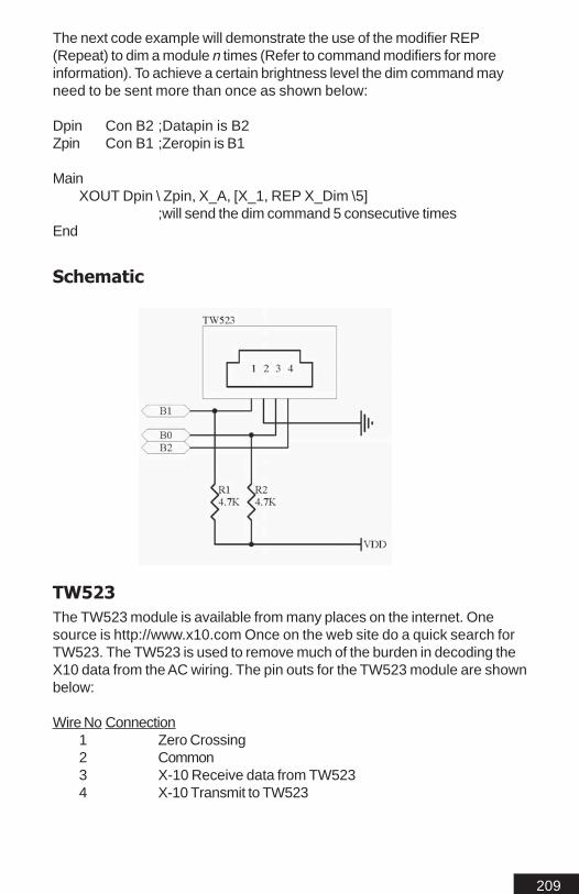
209
The next code example will demonstrate the use of the modifier REP(Repeat) to dim a module n times (Refer to command modifiers for moreinformation). To achieve a certain brightness level the dim command mayneed to be sent more than once as shown below:
Dpin Con B2 ;Datapin is B2Zpin Con B1 ;Zeropin is B1
MainXOUT Dpin \ Zpin, X_A, [X_1, REP X_Dim \5]
;will send the dim command 5 consecutive timesEnd
Schematic
TW523The TW523 module is available from many places on the internet. Onesource is http://www.x10.com Once on the web site do a quick search forTW523. The TW523 is used to remove much of the burden in decoding theX10 data from the AC wiring. The pin outs for the TW523 module are shownbelow:
Wire No Connection1 Zero Crossing2 Common3 X-10 Receive data from TW5234 X-10 Transmit to TW523

210

211
Hardw
are Com
mands
Hardw
are Com
mands
Hardw
are Com
mands
Hardw
are Com
mands
Hardw
are Com
mands
Hardware Commands

212
Hardware CommandsPICmicros have many hardware features built in. This section explains allthe available commands and ways to use the built in hardware features.Some of these commands are considered advanced and should only beused once you have obtained a clear understanding of the MBasic.
I m p o r t a n t N o t eI m p o r t a n t N o t eI m p o r t a n t N o t eI m p o r t a n t N o t eI m p o r t a n t N o t eNot all PICmicros have the same built in hardware. The following com-mands only work with PICmicros that have such hardware. To determinewether the PICmicro you are using has such hardware refer to its datasheet available from Microchip.com.
The 16F876 and 16F877 have all the built in hardware to use any one ofthe following commands.

213
HSERIN..HSEROUTSETHSERIAL modeHSERIN {label,timeout,}[InputData]HSEROUT [InputData]
Receive and Send Asynchronous RS-232 data.
label,Timeout(optional) is a label that will be jumped to if the hserinbuffer has no data available in the buffer and the timeout period hasexpired. If a timeout is not defined the hserin command will waitindefinitely while the uart receive buffer is empty.
InputData can be a list of variables and or modifiers that tellHSERIN / HSEROUT what to do when sending or receiving data.All the modifiers supported by SERIN and SEROUT are supportedby HSERIN and HSEROUT.
ExplanationThe 16F876 has a built-in UART. The UART buffer can store a maximum of94 bytes, 47 bytes input and 47 bytes output. The HSERIN UART is hardwired to pin C7 and HSEROUT is hard wired to C6. The 16F876’s UARTallows data to be received or sent while the 16F876 is executing anotherpart of your program. Once the UART is setup in software it will runindependently. The only consideration to this is the buffer size. If you receiveor transmit to much data without accessing it, the buffer will wrap aroundand begin to overwrite the first location. All data sent or received is inverted.There are no options to change this so a max232 circuit is required whenusing the 16F876 hardware serial port.
There are several available PICmicros with hardware UARTs. TheHSERIN / HSEROUT commands will work with all of them. To determinewhich PICmicros have UARTs download the respective data sheets.
ExampleThe 16F876 hardware serial port is straight forward and only requires a onetime setup command. Once this command is issued the 16F876s UART ison and will receive data without any further user code.
sethserial H9600
temp var byte
mainhserin [temp]hserout [temp]
goto main

214
The previous code snippet will simply transmit what ever was received con-tinuously.
Another example would be to setup the UART and let it run then occasionallycheck to see if a byte is received as shown below.
sethserial H9600
temp var bytemain
high b0pause 200low b0pause 200HSERIN 1000,main,[temp]if temp = “A” then loop1
goto main
loop1serout B1, i9600,[“Recevied the correct byte”]
goto main
The above program can receive a byte at any time regardless of the com-mand that is being executed. Since the incoming data has been buffered. Allwe need to do is to check this byte and some point.
SetHSerialThe sethserial command is used to setup and turn on the 16F876’s UART.This command is only required to be set once in your program. The followingis a list of all the possible bit rates HSERIN / HSEROUT will transmit orreceive at:
Baud Modes High Speed Baud Modes
H1200 H24000 H250000H2400 H26400 H312500H4800 H28800 H625000H7200 H31200 H1250000H9600 H33600H12000 H36000H14400 H38400H16800 H57600H19200 H115200H21600

215
HPWMHpwm CCPx, Period, DutyGenerate pulse-width modulation use internal hardware PWM.
CCPx is a variable or constant of 0 or 1 that specifies the PWMhardware to use. The 16F876 has two PWM’s available. The first ison pin C2 which is selected by setting a value of 1. The second is onpin C1 and is selected by using a value of 0 for CCPx.
Period is a variable or constant from 0 to 16383 that specifies theperiod of the pulse width in CLK cycles.
Duty is a variable or constant from 0 to 16383 that specifies theduty cycle of the pulse width.
ExplanationThe 16F876 has two built in Pulse Width Modulators. The actual hardwarePWM differs from the software PWM in that it can produce more accuratepulse widths. The PWM hardware can be left running while your programis performing other task. Both PWM’s can be ran at the same time. Whenboth are running they will both have the same period but different duties ifspecified (The Period is the inverse of the frequency). The frequency is howmany times from high to low. The period is the total time of one high to lowtransition. The duty is how long the pulse stays high.
ExampleIf PWM is used to generate an analog voltage. We can use this to controlthe brightness of an LED. If you wanted about 50% brightness, we wouldthen need to set PWM to about 2.5 Volts. In order to achieve this we woulduse the following:
PWM 0,16383, 8191; 50% duty cycle PWM signal using pin 10 (module 0)
The above code snippet would give and output voltage of about 2.5 voltsusing the shown schematic. Once the above command is ran in your pro-gram, PWM will continue to output until the 16F876 is shut down or yourprogram stops the PWM hardware.

216
This next example demonstrates the Hpwm and Count commands. Thisprogram can be used to give you a better understanding of what values touse for HWPM. You will need to Make sure you tie pin C2 (Hpwm output)to pin B0 (count input)
counter var long 'Used for the count command
hpwm 1,9920,4960 'Set up a 2KHz signal (approx) on pin 9'hpwm 1,8,4 'Set up a 83KHz signal (approx)
Loop:count B0,1000,counter
'Set up our counter on pin B0 for 1 second
'Display the resultsserout B1,i9600,[dec counter," Hz",10,13]
goto loop
Schematic
Important NotesThe Duty is a maximum of 10 bits. If period is set to less than 1024 (10bits)then duties accuracy will be reduced. An example would be if period is 256duty's accuracy will be 8 bits.
If Period is set higher than 1024 then Period will actually be a multiple of 4(i.e.: 1024,1028,1032 etc...)
If Period is set higher than 4096 then Period will actually be a multiple of 16(i.e.: 4096,4102,4118 etc...)

217
SETPULLUPSSETPULLUPS modeEnables or disables internal 10k pullups on pins B0 to B7
Mode is PU_OFF to disable pullups or PU_ON to enable pullups
ExplanationMost PICmicros have internal weak pullup resistor. The internal pullups willonly apply to an input state on the pin. The pullups are tied to VDD.

218

219
On Reset Co
mm
andsO
n Reset Com
mands
On Reset Co
mm
andsO
n Reset Com
mands
On Reset Co
mm
andsOn Reset Commands

220
On Reset CommandsReset commands are commands that perform an action in your programbased on how the PICmicro was reset. On Reset commands are ideal insituations where power is falling below minimum operating ranges. Thesecan be used for a proper shutdown if external circuitry is attached. ThePICmicro can also detect if a reset occurred by the ATN / RES pin.
ONPOR = Power on reset, jump to labelONBOR = Brown out reset, jump to labelONMOR = ATN / RES reset, jump to label
The syntax of the on reset commands are:
Command Label
Command being one of the three on reset commands.
Label being the label to jump to if the condition occurs.
There are three commands that allow your program to perform some actionbased on resets of the PICmicro. There are three different resets with thePICmicro. The first is the power on reset (ONPOR) which happens whenthe PICmicro is first powered up or the power was removed and restored.The second is brown out reset (ONBOR) this reset occurs when the VDDlevel of the PICmicro falls below +4.1 volts this may vary depending onoperating conditions. The ONBOR is ideal for battery applications. The thirdreset that can occur is ATN / RES reset (ONMOR) this reset conditionhappens by resetting the PICmicro using the MCLR without interruptingVDD.
ExampleThis example illustrates how to use the ON Reset command to do some-thing in your program when a reset occurs:
'Demonstrates the onreset commands
Counter var word
ONPOR startupONBOR brownoutONMOR reset
main:counter=counter + 1

221
serout B5,i9600,[".. Program Running :",dec counter,10,13]pause 1000
goto main
startup:clear;When program is powered up we need to reset all variables
serout B5,i9600,["Program started from powerdown",10,13]goto main
reset:serout B5,i9600,["Program started from reset",10,13]
goto main
brownout:serout B5,i9600,["Program started after brownout",10,13]
goto main
The above program will run normally by executing the main loop. Once areset occurs and power is restored, the PICmicro will then determined thereset condition and jump to the specified label.

222

223
Interrupt Co
mm
andsInte
rrupt Com
mands
Interrupt Co
mm
andsInte
rrupt Com
mands
Interrupt Co
mm
andsInterrupt Commands

224
InterruptsThe PICmicro has several interrupt sources. These interrupts can occur frominternal or external sources. The interrupts are consider an advanced featureof MBasic. This next section explains each command used for interrupts.
Enable {Interrupt Source}
Enable interrupt is used to turn on the interrupt system. If no interrupt is givenall interrupts setup using ONINTERRUPT are enabled. Enable interrupt canbe used to turn on specific interrupts. (Refer to Interrupt Sources)
Disable {Interrupt Source}
Disable interrupt can be used to turn off specific interrupts or all interrupts atonce. If no interrupt is given all interrupts are disabled. (Refer to InterruptSources)
ONINTERRUPT interrupt source, label
OnInterrupt is an operator used to tell your program where to go if a speci-fied interrupt occurs. Interrupt specifies what type of interrupt to act on. Labelis used to specify the place to jump to in a program if the interrupt occurs.When an interrupt occurs the label jump is performed as a gosub. Theprogram will only return to its last known place by using the Resumecommand. An example of the syntax would be as follows:
OnInterrupt ExtInt ProgIntenable ExtIntMain
Serout B2, i9600, [“Running”]Goto Main
disable ;disable all interrupts from here downProgInt
Serout B2, i9600, [“Interrupt Occured”]Resume
The above program would continuously send out “Running”. When aninterrupt occurred it would then jump to the label ProgInt. The program wouldthen execute the code. Once the Resume command was encountered itwould return to normal program operation and jump back to the nextcommand before the interrupt occurred, in this case Main. (The Resumecommand works like the Return command in a Gosub routine.). Note thatthe “disable” command is used in a position that never gets executed.When using disable(or enable) without arguments you can place it on anyline(even lines that will not be executed) in order to disable(enable) inter-rupts from that position down.

225
Interrupt SourcesEXTINT
External interrupt on B0. There are several option on how the interrupt canbe triggered with ExtInt which are list in the SetExtInt section.
RBINTOn change interrupt can occur on B4,B5,B6 or B7. This interrupt will trigger ifa pin state changes from low to high (or high to low).
TMR0INTTmr0Int interrupt occurs whenever Timer0 overflows (See SetTmr0 com-mand)
ADINTADInt interrupt occurs when A/D conversion finishes. Used in conjunctionwith the ADin command.
RCINTRCInt interrupt occurs when a byte is received by the Hardware USART(this interrupt is disabled if using HSERIN/HSEROUT).
TXINTTXInt interrupt occurs when a byte finishes transmitting from the HardwareUSART (this interrupt is disabled if using HSERIN/HSEROUT).
SSPINT(See Synchronous Serial port(coming soon))
CCP1INTCCPInt interrupt occurs on Capture/Compare/Period match
CCP2INTCCP2Int interrupt occurs on Capture/Compare/Period match
TMR1INTTmr1int interrupt occurs whenever Timer1 overflows (See SetTmr1 com-mand)
TMR2INTTmr2Int interrupt occurs whenever Timer2 overflows(See SetTmr2 command)
EEINTEEInt interrupt occurs when a byte is finished writing to the on boardEEprom.
BCLINT(See Synchronous Serial port (coming soon))

226
Set Interrupt SourceSeveral of the interrupt commands have multiple sources that will trigger theinterrupt. This next section explains how to set these different interruptsources.
SETEXTINTSetExtInt mode
SetExtInt sets the external interrupt pin to input and sets the statethat will cause an interrupt (EXTINT must be enabled)
Mode is the setting that will trigger the actual interrupt. There aretwo choices available:
EXT_H2L = Will activate when pin B0 is pulled low (from high)EXT_L2H = Will activate when pin B0 is pulled high (from low)
SETTMR0SETTMR0 mode
SETTMR0 sets Timer0 mode. Timer0 is an internal 8 bit timermodule built into the 16F876.
Mode is the setting that will trigger the actual interrupt. Thereare several options available:
TMR0INT1 Internal timer with 1:1 timingTMR0INT2 Internal timer with 1:2 timingTMR0INT4 Internal timer with 1:4 timingTMR0INT8 Internal timer with 1:8 timingTMR0INT16 Internal timer with 1:16 timingTMR0INT32 Internal timer with 1:32 timingTMR0INT64 Internal timer with 1:64 timingTMR0INT128 Internal timer with 1:128 timingTMR0INT256 Internal timer with 1:256 timingTMR0EXTL1 External counter(Low to High transition on AX3
pin)with 1:1 timing
TMR0EXTL2 External counter(Low to High transition on AX3pin) with 1:2 timing
TMR0EXTL4 External counter(Low to High transition on AX3pin) with 1:4 timing
TMR0EXTL8 External counter(Low to High transition on AX3pin) with 1:8 timing
TMR0EXTL16 External counter(Low to High transition on AX3

227
pin) with 1:16 timing
TMR0EXTL32 External counter(Low to High transition on AX3pin) with 1:32 timing
TMR0EXTL64 External counter(Low to High transition on AX3pin) with 1:64 timing
TMR0EXTL128 External counter(Low to High transition on AX3pin) with 1:128 timing
TMR0EXTL256 External counter(Low to High transition on AX3pin) with 1:256 timing
TMR0EXTH1 External counter(High to Low transition on AX3pin) with 1:1 timing
TMR0EXTH2 External counter(High to Low transition on AX3pin) with 1:2 timing
TMR0EXTH4 External counter(High to Low transition on AX3pin) with 1:4 timing
TMR0EXTH8 External counter(High to Low transition on AX3pin) with 1:8 timing
TMR0EXTH16 External counter(High to Low transition on AX3pin) with 1:16 timing
TMR0EXTH32 External counter(High to Low transition on AX3pin) with 1:32 timing
TMR0EXTH64 External counter(High to Low transition on AX3pin) with 1:64 timing
TMR0EXTH128 External counter(High to Low transition on AX3pin) with 1:128 timing
TMR0EXTH256 External counter(High to Low transition on AX3pin) with 1:256 timing
SETTMR1SETTMR1 mode
SetTmr1 sets Timer1 mode. Timer1 is an internal 16 bit timermodule built into the 16F876.

228
Mode is the setting that will trigger the actual interrupt. Thereare several options available:
TMR1OFF Disables Timer1(saves power/default onpowerup)
TMR1INT1 Internal timer with 1:1 timingsTMR1INT2 Internal timer with 1:2 timingsTMR1INT4 Internal timer with 1:4 timingsTMR1INT8 Internal timer with 1:8 timingsTMR1EXT1 External osc with 1:1 timingsTMR1EXT2 External osc with 1:2 timingsTMR1EXT4 External osc with 1:4 timingsTMR1EXT8 External osc with 1:8 timingsTMR1ASYNC1 External Asynchronous counter with 1:1 timingsTMR1ASYNC2 External Asynchronous counter with 1:2 timingsTMR1ASYNC4 External Asynchronous counter with 1:4 timingsTMR1ASYNC8 External Asynchronous counter with 1:8 timings
ExampleThis program demonstrates TMR1 by counting using timer interrupt.
counter var word
clear 'Clear all variables
SETTMR1 TMR1INT1 ' Set timer1 modeONINTERRUPT TMR1INT,mytimer
'Where do we want to go on the timer interruptEnable TMR1INT 'Turn on the interrupt
'main loop just to display the datamain
debug ["counter=",dec counter,10,13]pause 100
goto main
'This is where we go on and interrupt.mytimer:
counter = counter +1resume ' this is how we exit an interrupt

229
SETTMR2SETTMR2 mode, period
SetTmr2 sets Timer2 mode and reset period. Timer2 is an internal 8bit timer with an 8 bit period module built into the 16F876.
Mode is the setting that will trigger the actual interrupt. Thereare several options available.
Period is a reset point. Period will cause the timer reset when timerequals period. Period is a value of 0 to 255
Modes are:
TMR2OFF Disables Timer2 default on powerupTMR2PRE1POST1 1:1 prescaler and 1:1 postscalerTMR2PRE1POST2 1:1 prescaler and 1:2 postscalerTMR2PRE1POST3 1:1 prescaler and 1:3 postscalerTMR2PRE1POST4 1:1 prescaler and 1:4 postscalerTMR2PRE1POST5 1:1 prescaler and 1:5 postscalerTMR2PRE1POST6 1:1 prescaler and 1:6 postscalerTMR2PRE1POST7 1:1 prescaler and 1:7 postscalerTMR2PRE1POST8 1:1 prescaler and 1:8 postscalerTMR2PRE1POST9 1:1 prescaler and 1:9 postscalerTMR2PRE1POST10 1:1 prescaler and 1:10 postscalerTMR2PRE1POST11 1:1 prescaler and 1:11 postscalerTMR2PRE1POST12 1:1 prescaler and 1:12 postscalerTMR2PRE1POST13 1:1 prescaler and 1:13 postscalerTMR2PRE1POST14 1:1 prescaler and 1:14 postscalerTMR2PRE1POST15 1:1 prescaler and 1:15 postscalerTMR2PRE1POST16 1:1 prescaler and 1:16 postscalerTMR2PRE4POST1 1:4 prescaler and 1:1 postscalerTMR2PRE4POST2 1:4 prescaler and 1:2 postscalerTMR2PRE4POST3 1:4 prescaler and 1:3 postscalerTMR2PRE4POST4 1:4 prescaler and 1:4 postscalerTMR2PRE4POST5 1:4 prescaler and 1:5 postscalerTMR2PRE4POST6 1:4 prescaler and 1:6 postscalerTMR2PRE4POST7 1:4 prescaler and 1:7 postscalerTMR2PRE4POST8 1:4 prescaler and 1:8 postscalerTMR2PRE4POST9 1:4 prescaler and 1:9 postscalerTMR2PRE4POST10 1:4 prescaler and 1:10 postscalerTMR2PRE4POST11 1:4 prescaler and 1:11 postscalerTMR2PRE4POST12 1:4 prescaler and 1:12 postscalerTMR2PRE4POST13 1:4 prescaler and 1:13 postscalerTMR2PRE4POST14 1:4 prescaler and 1:14 postscalerTMR2PRE4POST15 1:4 prescaler and 1:15 postscalerTMR2PRE4POST16 1:4 prescaler and 1:16 postscalerTMR2PRE16POST1 1:16 prescaler and 1:1 postscaler

230
TMR2PRE16POST2 1:16 prescaler and 1:2 postscalerTMR2PRE16POST3 1:16 prescaler and 1:3 postscalerTMR2PRE16POST4 1:16 prescaler and 1:4 postscalerTMR2PRE16POST5 1:16 prescaler and 1:5 postscalerTMR2PRE16POST6 1:16 prescaler and 1:6 postscalerTMR2PRE16POST7 1:16 prescaler and 1:7 postscalerTMR2PRE16POST8 1:16 prescaler and 1:8 postscalerTMR2PRE16POST9 1:16 prescaler and 1:9 postscalerTMR2PRE16POST10 1:16 prescaler and 1:10 postscalerTMR2PRE16POST11 1:16 prescaler and 1:11 postscalerTMR2PRE16POST12 1:16 prescaler and 1:12 postscalerTMR2PRE16POST13 1:16 prescaler and 1:13 postscalerTMR2PRE16POST14 1:16 prescaler and 1:14 postscalerTMR2PRE16POST15 1:16 prescaler and 1:15 postscalerTMR2PRE16POST16 1:16 prescaler and 1:16 postscaler
SETCAPTURESETCAPTURE ccppin,mode
Ccppin specifies which module to use 0 for CCP1 on pin C2 or 1 forCCP2 on pin C1.
Mode is the setting that will trigger the actual interrupt. Thereare several options available.
CAPTUREOFF Disables Capture default on powerupCAPTURE1H2L Captures Timer1 value on High to Low transitionCAPTURE1L2H Captures Timer1 value on Low to High transitionCAPTURE4L2H Captures Timer1 value on 4th Low to High
transition
CAPTURE16L2H Captures Timer1 value on 16th Low to Hightransition
GETCAPTUREGETCAPTURE ccppin,var
Ccppin specifies which module to use 0 for CCP1 on pin C2 or 1 forCCP2 on pin C1.
Var is a word sized variable that the results of the 16 bit capturevalue will be returned to.

231
SETCOMPARESETCOMPARE ccppin,mode,compare valuCompare Value is thevalue that the comparison must match before the mode's action willoccur.
Modes are:
COMPAREOFF Disables Compare default on powerupCOMPARESETHIGH Compare sets CCPx pin high on Timer1
comparison match
COMPARESETLOW Compare sets CCPx pin low on Timer1comparison match
COMPAREINT Compare sets Interrupt(CCPxINT) andclears Timer1 on Timer1 comparisonmatch
COMPARESPECIAL Compare runs Special(ResetTimer1(CCP1) or Reset Timer1 andActivate(if A/D is enabled) A/Dconversion(CCP2) on Timer1comparison match

232
ExampleThe following code example demonstrates one way to use the interrupts togenerate a real time clock.
second var byteminute var bytehour var bytetick var byteftick var long
second = 0minute = 36hour = 11tick = 0ftick = 0tickcnt con float 1.0038677
oninterrupt tmr1int,clock
settmr1 tmr1int4
lcdwrite B4\B5,portb.nib0, [INITLCD1,INITLCD2,CLEAR,HOME,SCR]
enable tmr1intmain
goto main
Disableclock
ftick = ftick fadd tickcntif (int ftick) > 19 then
ftick = ftick fsub float 19second = second + 1if second > 59 then
second = 0minute = minute + 1if minute > 59 then
minute = 0hour = hour + 1if hour > 23 then
hour = 0endif
endifendiflcdwrite B4\B5,portb.nib0,[SCRRAM]if hour < 10 then
lcdwrite B4\B5,portb.nib0,[" "]

233
endiflcdwrite B4\B5,portb.nib0,[dec hour,":"]if minute < 10 then
lcdwrite B4\B5,portb.nib0,["0"]endiflcdwrite B4\B5,portb.nib0,[dec minute,":"]if second < 10 then
lcdwrite B4\B5,portb.nib0,["0"]endiflcdwrite B4\B5,portb.nib0,[dec second]
endifresume
Example 2The following code example demonstrates the correct way to enable anddisable interrupts. If interrupts are not disabled correctly, the interrupt routinescould get call again..and again...etc. This will cause the stack to overflow,causing a reset.
w_cnt var word 'create variablew_ctover var word 'create variable
w_cnt = 0 'initialize variablew_ctover = 0 'initialize variable
ONINTERRUPT TMR1INT, mytimer1 'Where to go on interruptSETTMR1 TMR1INT8 '1:8 internal timer interrupt
ENABLE TMR1INT 'Turn On the Interrupt
Mainloop:debug ["Count/OverFlow = ", dec w_cnt," / ",dec w_ctover , 13]
; show main counter
if w_cnt >= 65000 then; check to see if count is near overflow
w_ctover = w_ctover + 1 ; increment count overfloww_cnt = 0 ; Reset counter to zero
endifgoto mainloop
disable ; This will disable ALL interrupts from here down.

234
; This must always be used before interrupts.; If you have other code below the interrupt routine you; must re-enable interrupts.
mytimer1:w_cnt = w_cnt + 1 ; increment counter at interrupt
RESUME ; return to location before interrupt
Important NoteNo arguments are used in the example 2 program. Without arguments thiscommand becomes a compile time directive that disables interrupt process-ing until another enable command is used. This is why it can be on a linethat the program will never actually access. The same is true for enablewithout arguments.

235
BS2 Com
patibilityBS2 Compatibility

236
DifferencesMbasic is a near 99% BS2 compatible. There are however several smalldifference which are due to some command additions and syntax changes toMbasic. The Mbasic instruction set is a super set, all BS2 commands areimplemented as they would be with PBasic. Included are several other usefulcommands that make programming much simpler.
Program StorageMbasic does not use “Slots” to store programs. The PICmicro uses a flatmemory model. All program memory can be filled with one program. There isno need for storing or swapping variables. Any program code in your BS2program that deals with swapping to the next 2K program slot can beremoved. In several cases it may be easier to rewrite the program fromscratch since allot of program code on the BS2 is required to deal with thebank swapping.
DATA and EEPROMThe BS2 allows nonvolatile data storage to space that has not been used forprogram storage. When using a PICmicro only data will be read from andwritten to the internal EEPROM.
Gosub...ReturnThe Gosub...Return commands are used for subroutines. The Basic Stamp islimited to the amount of Gosubs it can use. There is no limit to the amount ofGosub commands that can be used with Mbasic. The default stack size forMbasic is 20. To use more GOSUB commands in your program you will needto increase the stack size. This can be done by adding the following line toyour program:
Stack = n
N being the stack size such as 20 or 30 and so on. Increasing the stack sizewill increase the amount of system ram Mbasic will need. Thus reducing theamount of user ram.
Converting Basic Stamp II ProgramThere are usually only minor revisions you must make to your BS2 programalthough this may not always be the case. Some issues such as the DIRSvalues being reversed with Mbasic will need to be addressed when portingprograms over. When converting your BS2 program any references to theDEBUG command will need to be removed and replaced with Mbasic Debugcommand format. Before attempting to convert a program from the BS2 makesure to read the entire manual and become familiar with Mbasic syntax first.Try some simple programs first, before porting any programs over.

237
DIRSOn the BS2 DIRS = %0000000000000000 sets all the pins to outputs andDIRS = %1111111111111111 sets all the pins to inputs. Mbasic the DIRS isreversed. On the PICmicro DIRS = %1111111111111111 would set all the pinsto outputs.
SERIN / SEROUT TimingsThe BS2sx and BS2p have a bitrate that is calculated based on a .4us clock.The BS2/2e and Mbasic have a bitrate calculated based on a 1us clock. Thismeans that bitrates calculated for the 2sx will not be correct for the 2/2e orMbasic. All values should be recalculated using the methods for the BS2 andBS2e. There are several predefined labels for the bit rate such as i9600 andn9600. These predefined handle all the calculations for you.
LCD CommandsThe LCD commands between Mbasic and BS2p are completely different.This is because the Mbasic LCD commands were written before the BS2pwas available. The Mbasic LCD command allows multiple LCD’s to beconnected to the PICmicro.

238

239
Trou
ble
Sho
otin
gTro
ub
le Sh
oo
ting
Trou
ble
Sho
otin
gTro
ub
le Sh
oo
ting
Trou
ble
Sho
otin
gTrouble Shooting

240
My Program Won’t Run ?Often problems occur when the correct syntax is used but the wrong configu-ration values have been used. Make sure you have selected the correctPICmicro, Mhz setting and config value. LVP should always be off. HighSpeed Osc should be selected.
During the compiling process the compiler only checks for syntax errors andimproper command usage. The compiler has no way to check your actualcoding and determine if it will run or not. So check your code for any problems.Sometimes it is a good idea to comment out areas of your program and runlittle pieces of it. As each piece is checked, see if it works correctly, then moveonto the next piece. Keep doing this until you come across any part of yourcode that does not work as expected.
You can also use the ICD to help debug your code. The ICD is actually thebest method when debugging code.
My Program Still Won’t Run ?Other common problems that may cause your program not to run are parts inbackwards or not installed on the correct pins specified in your basic program.Make sure to check all your connections and part orientation if your programdoes not run.
Error trying to Program the PICmicro ?If you receive an error when attempting to program the PICmicro go over thefollowing check list:
1. Does the ISP-PRO have power ?2. Is the PICmicro orientation correct in the circuit ?3. Is the serial cable a straight through used for programming ?4. Is the computer your using capable of 115K Baud ?5. If your not using a development board is your circuit correct ?

241
Reserved WordsRe
serve
d W
ord
sRe
serve
d W
ord
sRe
serve
d W
ord
sRe
serve
d W
ord
sRe
serve
d W
ord
s
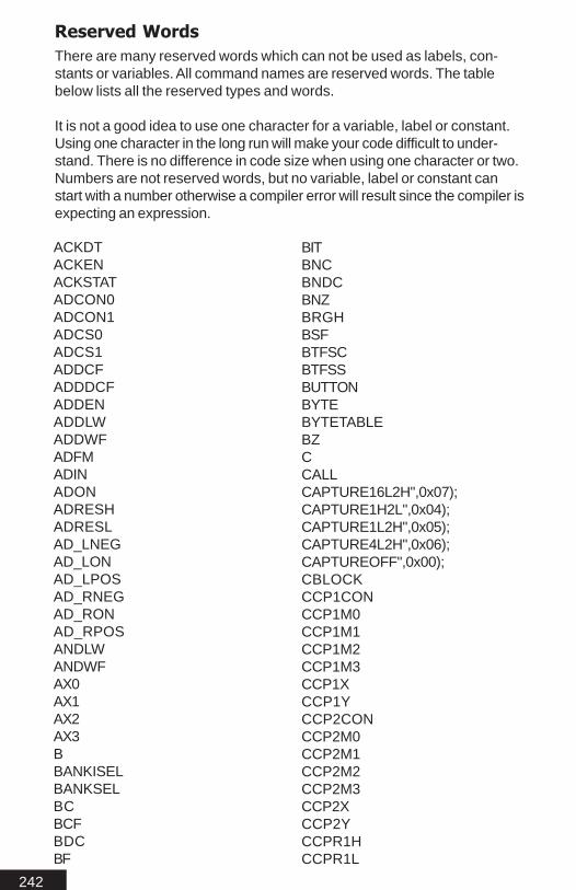
242
Reserved WordsThere are many reserved words which can not be used as labels, con-stants or variables. All command names are reserved words. The tablebelow lists all the reserved types and words.
It is not a good idea to use one character for a variable, label or constant.Using one character in the long run will make your code difficult to under-stand. There is no difference in code size when using one character or two.Numbers are not reserved words, but no variable, label or constant canstart with a number otherwise a compiler error will result since the compiler isexpecting an expression.
ACKDTACKENACKSTATADCON0ADCON1ADCS0ADCS1ADDCFADDDCFADDENADDLWADDWFADFMADINADONADRESHADRESLAD_LNEGAD_LONAD_LPOSAD_RNEGAD_RONAD_RPOSANDLWANDWFAX0AX1AX2AX3BBANKISELBANKSELBCBCFBDCBF
BITBNCBNDCBNZBRGHBSFBTFSCBTFSSBUTTONBYTEBYTETABLEBZCCALLCAPTURE16L2H",0x07);CAPTURE1H2L",0x04);CAPTURE1L2H",0x05);CAPTURE4L2H",0x06);CAPTUREOFF",0x00);CBLOCKCCP1CONCCP1M0CCP1M1CCP1M2CCP1M3CCP1XCCP1YCCP2CONCCP2M0CCP2M1CCP2M2CCP2M3CCP2XCCP2YCCPR1HCCPR1L

243
CCPR2HCCPR2LCGRAMCHS0CHS1CHS2CKECKPCLEARCLEARCLRCCLRDCCLRFCLRWCLRWDTCLRZCODECOMFCOMPAREINT",0x0A);COMPAREOFF",0x00);COMPARESETHIGH",0x08);COMPARESETLOW",0x09);COMPARESPECIAL",0x0B);CONSTANTCOUNTCRENCSRCCURLEFTCURRIGHTDDADATA_ADDRESSDBDCDEDEBUGDEBUGINDECCURDECFDECFSZDECSCRDIR0DIR1DIR10DIR11DIR12DIR13DIR14
DIR15DIR16DIR17DIR18DIR19DIR2DIR20DIR21DIR22DIR23DIR24DIR25DIR26DIR27DIR28DIR29DIR3DIR30DIR31DIR4DIR5DIR6DIR7DIR8DIR9DIRADIRBDIRCDIRDDIREDIRFDIRHDIRLDIRMDIRSDISABLEDODTDTMFOUTDTMFOUT2DWD_AEEADREECON1EECON2EEDATAELSEELSEIF
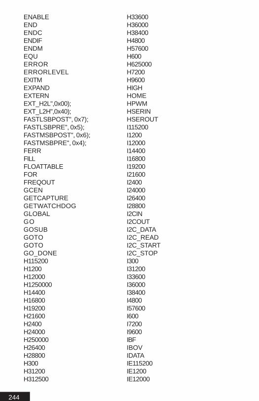
244
ENABLEENDENDCENDIFENDMEQUERRORERRORLEVELEXITMEXPANDEXTERNEXT_H2L",0x00);EXT_L2H",0x40);FASTLSBPOST", 0x7);FASTLSBPRE", 0x5);FASTMSBPOST", 0x6);FASTMSBPRE", 0x4);FERRFILLFLOATTABLEFORFREQOUTGCENGETCAPTUREGETWATCHDOGGLOBALGOGOSUBGOTOGOTOGO_DONEH115200H1200H12000H1250000H14400H16800H19200H21600H2400H24000H250000H26400H28800H300H31200H312500
H33600H36000H38400H4800H57600H600H625000H7200H9600HIGHHOMEHPWMHSERINHSEROUTI115200I1200I12000I14400I16800I19200I21600I2400I24000I26400I28800I2CINI2COUTI2C_DATAI2C_READI2C_STARTI2C_STOPI300I31200I33600I36000I38400I4800I57600I600I7200I9600IBFIBOVIDATAIE115200IE1200IE12000

245
IE14400;IE16800IE19200IE21600IE2400IE24000IE26400IE28800IE300IE31200IE33600IE36000IE38400IE4800IE57600IE600IE7200IE9600IEMODEIEO115200IEO1200IEO120000IEO14400IEO16800IEO19200IEO21600IEO2400IEO24000IEO26400IEO28800IEO300IEO31200IEO33600IEO36000IEO38400IEO4800IEO57600IEO600IEO7200IEO9600IEOMODEIFIFDEFIFNDEFIMODEIN0IN1
IN10IN11IN12IN13IN14IN15IN16IN17IN18IN19IN2IN20IN21IN22IN23IN24IN25IN26IN27IN28IN29IN3IN30IN31IN4IN5IN6IN7IN8IN9INAINBINCINCCURINCFINCFSZINCSCRINDINEINFINHINITLCD1INITLCD2INLINMINPUTINS

246
INTEDGIO115200IO1200IO12000IO14400IO16800IO19200IO21600IO2400IO24000IO26400IO28800IO300IO31200IO33600IO36000IO38400IO4800IO57600IO600IO7200IO9600IOMODEIORLWIORWFIRPLCALLLCDREADLCDWRITELGOTOLISTLOCALLONGLONGTABLELOOKDOWNLOOKUPLOWLSBFIRST", 0x1);LSBPOST", 0x3);LSBPRE", 0x1);MACROMESSGMOVFMOVFWMOVLWMOVWFMSBFIRST", 0x0);
MSBPOST", 0x2);MSBPRE", 0x0);N115200N1200N12000N14400N16800N19200N21600N2400N24000N26400N28800N300N31200N33600N36000N38400N4800N57600N600N7200N9600NAPNE115200NE1200NE12000NE14400;NE16800NE19200NE21600NE2400NE24000NE26400NE28800NE300NE31200NE33600NE36000NE38400NE4800NE57600NE600NE7200NE9600NEGFNEMODE

247
NEO115200NEO1200NEO120000NEO14400NEO16800NEO19200NEO21600NEO2400NEO24000NEO26400NEO28800NEO300NEO31200NEO33600NEO36000NEO38400NEO4800NEO57600NEO600NEO7200NEO9600NEOMODENEXTNIBNMODENO115200NO1200NO12000NO14400;NO16800NO19200NO21600NO2400NO24000NO26400NO28800NO300NO31200NO33600NO36000NO38400NO4800NO57600NO600NO7200NO9600NOEXPANDNOLIST
NOMODENOPNOT_ANOT_ADDRESSNOT_BONOT_BORNOT_DONENOT_PDNOT_PORNOT_RBPUNOT_RC8NOT_T1SYNCNOT_TONOT_TX8NOT_WNOT_WRITEOBFOERROFFONBORONELINEONELINE5X11ONINTERRUPTONMORONPOROPTIONOPTION_REGORGOUT0OUT1OUT10OUT11OUT12OUT13OUT14OUT15OUT16OUT17OUT18OUT19OUT2OUT20OUT21OUT22OUT23OUT24OUT25
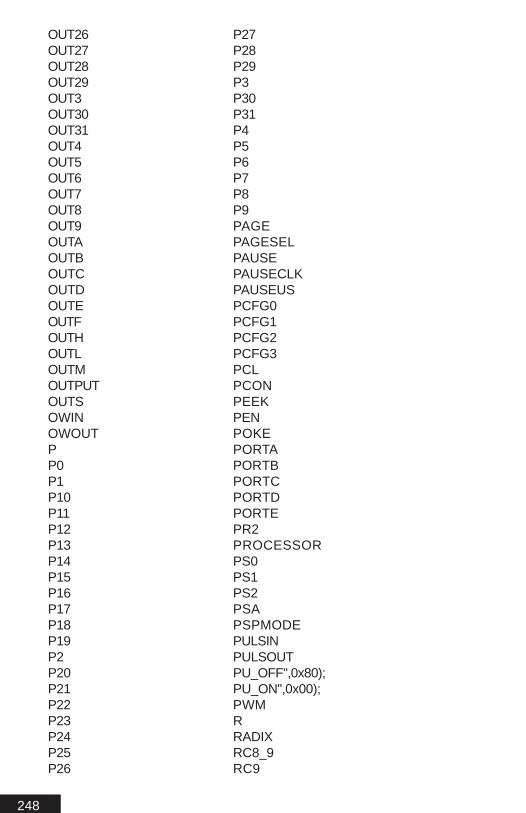
248
OUT26OUT27OUT28OUT29OUT3OUT30OUT31OUT4OUT5OUT6OUT7OUT8OUT9OUTAOUTBOUTCOUTDOUTEOUTFOUTHOUTLOUTMOUTPUTOUTSOWINOWOUTPP0P1P10P11P12P13P14P15P16P17P18P19P2P20P21P22P23P24P25P26
P27P28P29P3P30P31P4P5P6P7P8P9PAGEPAGESELPAUSEPAUSECLKPAUSEUSPCFG0PCFG1PCFG2PCFG3PCLPCONPEEKPENPOKEPORTAPORTBPORTCPORTDPORTEPR2PROCESSORPS0PS1PS2PSAPSPMODEPULSINPULSOUTPU_OFF",0x80);PU_ON",0x00);PWMRRADIXRC8_9RC9

249
RCD8RCENRCREGRCSTARCTIMERDREADREADDMREADPMREAD_WRITEREPEATRESRESETTMR1RESUMERETFIERETLWRETURNRETURNREVERSERLFRP0RP1RRFRSENRX9RX9DR_WSSBYTESCRSCRBLKSCRCURSCRCURBLKSCRLEFTSCRRAMSCRRIGHTSENSERDETECTSERINSEROUTSERVOSETSETCSETCAPTURESETCOMPARESETDCSETEXTINT
SETHSERIALSETPULLUPSSETTMR0SETTMR1SETTMR2SETZSHIFTINSHIFTOUTSKPDCSKPNCSKPNDCSKPNZSKPZSLEEPSLEEPSMPSOUNDSOUND2SPACESPBRGSPENSPMOTORSRENSSPADDSSPBUFSSPCONSSPCON2SSPENSSPM0SSPM1SSPM2SSPM3SSPOVSSPSTATSTATUSSTEPSTOPSUBCFSUBDCFSUBLWSUBTITLESUBWFSWAPSWAPFSWORDSYNCS_IN

250
S_OUTT0CST0SET1CKPS0T1CKPS1T1CONT1INSYNCT1OSCENT1SYNCT2CKPS0T2CKPS1T2CONTHENTIMEWATCHDOGTITLETMR0TMR0EXTH1",0x38);TMR0EXTH128",0x36);TMR0EXTH16",0x33);TMR0EXTH2",0x30);TMR0EXTH256",0x37);TMR0EXTH32",0x34);TMR0EXTH4",0x31);TMR0EXTH64",0x35);TMR0EXTH8",0x32);TMR0EXTL1",0x28);TMR0EXTL128",0x26);TMR0EXTL16",0x23);TMR0EXTL2",0x20);TMR0EXTL256",0x27);TMR0EXTL32",0x24);TMR0EXTL4",0x21);TMR0EXTL64",0x25);TMR0EXTL8",0x22);TMR0INT1",0x08);TMR0INT128",0x06);TMR0INT16",0x03);TMR0INT2",0x00);TMR0INT256",0x07);TMR0INT32",0x04);TMR0INT4",0x01);TMR0INT64",0x05);TMR0INT8",0x02);TMR1ASYNC1",0x0B);TMR1ASYNC2",0x1B);TMR1ASYNC4",0x2B);TMR1ASYNC8",0x3B);
TMR1CSTMR1EXT1",0x07);TMR1EXT2",0x17);TMR1EXT4",0x27);TMR1EXT8",0x37);TMR1HTMR1INT1",0x01);TMR1INT2",0x81);TMR1INT4",0x21);TMR1INT8",0x31);TMR1LTMR1OFF",0x00);TMR1ONTMR2TMR2OFF",0x00);TMR2ONTMR2PRE16POST1",0x07);TMR2PRE16POST10",0x97);TMR2PRE16POST11",0xa7);TMR2PRE16POST12",0xb7);TMR2PRE16POST13",0xc7);TMR2PRE16POST14",0xd7);TMR2PRE16POST15",0xe7);TMR2PRE16POST16",0xf7);TMR2PRE16POST2",0x17);TMR2PRE16POST3",0x27);TMR2PRE16POST4",0x37);TMR2PRE16POST5",0x47);TMR2PRE16POST6",0x57);TMR2PRE16POST7",0x67);TMR2PRE16POST8",0x77);TMR2PRE16POST9",0x87);TMR2PRE1POST1",0x04);TMR2PRE1POST10",0x94);TMR2PRE1POST11",0xa4);TMR2PRE1POST12",0xb4);TMR2PRE1POST13",0xc4);TMR2PRE1POST14",0xd4);TMR2PRE1POST15",0xe4);TMR2PRE1POST16",0xf4);TMR2PRE1POST2",0x14);TMR2PRE1POST3",0x24);TMR2PRE1POST4",0x34);TMR2PRE1POST5",0x44);TMR2PRE1POST6",0x54);TMR2PRE1POST7",0x64);TMR2PRE1POST8",0x74);

251
TMR2PRE1POST9",0x84);TMR2PRE4POST1",0x05);TMR2PRE4POST10",0x95);TMR2PRE4POST11",0xa5);TMR2PRE4POST12",0xb5);TMR2PRE4POST13",0xc5);TMR2PRE4POST14",0xd5);TMR2PRE4POST15",0xe5);TMR2PRE4POST16",0xf5);TMR2PRE4POST2",0x15);TMR2PRE4POST3",0x25);TMR2PRE4POST4",0x35);TMR2PRE4POST5",0x45);TMR2PRE4POST6",0x55);TMR2PRE4POST7",0x65);TMR2PRE4POST8",0x75);TMR2PRE4POST9",0x85);TOGGLETOUTPS0TOUTPS1TOUTPS2TOUTPS3TRISTRISATRISBTRISCTRISDTRISETRISE0TRISE1TRISE2TRMTTSTFTWOLINETX8_9TX9TX9DTXD8TXENTXREGTXSTAUAUDATAUDATA_ACSUDATA_OVRUDATA_SHRUNTIL
UPPERVARIABLEWCOLWDTPS1",0x08);WDTPS128",0x0F);WDTPS16",0x0C);WDTPS2",0x09);WDTPS32",0x0D);WDTPS4",0x0A);WDTPS64",0x0E);WDTPS8",0x0B);WENDWHILEWORDWORDTABLEWRWRENWRERRWRITEWRITEDMWRITEPMXINXORLWXORWFXOUTX_1",0x0C);X_10",0x1E);X_11",0x06);X_12",0x16);X_13",0x00);X_14",0x10);X_15",0x08);X_16",0x18);X_2",0x1C);X_3",0x04);X_4",0x14);X_5",0x02);X_6",0x12);X_7",0x0A);X_8",0x1A);X_9",0x0E);X_A",0x6);X_B",0xE);X_BrightX_C",0x2);X_D",0xA);X_Dim

252
X_E",0x1);X_F",0x9);X_G",0x5);X_H",0xD);X_HailX_I",0x7);X_J",0xF);X_K",0x3);X_L",0xB);X_Lights_OffX_Lights_OnX_M",0x0);X_N",0x8);X_O",0x4);X_OffX_OnX_P",0xC);X_Status_OffX_Status_OnX_Status_RequestX_Units_OnZ
All math functionsAny name starting with a "_"Any name starting with a number

253
Appendix - AA
ppendix - AA
ppendix - AA
ppendix - AA
ppendix - AA
ppendix - A

254
Information Sources
PICmicro Data SheetsMicrochip Technology Inc.http://www.microchip.com
MBasic SupportBasic Micro Inc.http://www.basicmicro.com

255
Appendix - CA
ppendix - CA
ppendix - CA
ppendix - CA
ppendix - CA
ppendix - C

256
ASCII Chart 0 To 255
Dec Hex Oct Bin Typed Char0 0x0 00 00000000 ^@ NUL1 0x1 01 00000001 ^A SOH2 0x2 02 00000010 ^B STX3 0x3 03 00000011 ^C ETX4 0x4 04 00000100 ^D EOT5 0x5 05 00000101 ^E ENQ6 0x6 06 00000110 ^F ACK7 0x7 07 00000111 ^G BEL8 0x8 010 00001000 ^H BS9 0x9 011 00001001 ^I HT10 0xA 012 00001010 ^J LF11 0xB 013 00001011 ^K VT12 0xC 014 00001100 ^L FF13 0xD 015 00001101 ^M CR14 0xE 016 00001110 ^N SO15 0xF 017 00001111 ^O SI16 0x10 020 00010000 ^P DLE17 0x11 021 00010001 ^Q DC118 0x12 022 00010010 ^R DC219 0x13 023 00010011 ^S DC320 0x14 024 00010100 ^T DC421 0x15 025 00010101 ^U NAK22 0x16 026 00010110 ^V SYN23 0x17 027 00010111 ^W ETB24 0x18 030 00011000 ^X CAN25 0x19 031 00011001 ^Y EM26 0x1A 032 00011010 ^Z SUB27 0x1B 033 00011011 ^[ ESC28 0x1C 034 00011100 ^\ FS29 0x1D 035 00011101 ^] GS30 0x1E 036 00011110 ^^ RS31 0x1F 037 00011111 ^_ US32 0x20 040 00100000 Space SPC33 0x21 041 00100001 ! !34 0x22 042 00100010 " "35 0x23 043 00100011 # #36 0x24 044 00100100 $ $37 0x25 045 00100101 % %38 0x26 046 00100110 & &39 0x27 047 00100111 ' '40 0x28 050 00101000 ( (41 0x29 051 00101001 ) )42 0x2A 052 00101010 * *43 0x2B 053 00101011 + +44 0x2C 054 00101100 , ,

257
Dec Hex Oct Bin Typed Char45 0x2D 055 00101101 - -46 0x2E 056 00101110 . .47 0x2F 057 00101111 / /48 0x30 060 00110000 0 049 0x31 061 00110001 1 150 0x32 062 00110010 2 251 0x33 063 00110011 3 352 0x34 064 00110100 4 453 0x35 065 00110101 5 554 0x36 066 00110110 6 655 0x37 067 00110111 7 756 0x38 070 00111000 8 857 0x39 071 00111001 9 958 0x3A 072 00111010 : :59 0x3B 073 00111011 ; ;60 0x3C 074 00111100 < <61 0x3D 075 00111101 = =62 0x3E 076 00111110 > >63 0x3F 077 00111111 ? ?64 0x40 0100 01000000 @ @65 0x41 0101 01000001 A A66 0x42 0102 01000010 B B67 0x43 0103 01000011 C C68 0x44 0104 01000100 D D69 0x45 0105 01000101 E E70 0x46 0106 01000110 F F71 0x47 0107 01000111 G G72 0x48 0110 01001000 H H73 0x49 0111 01001001 I I74 0x4A 0112 01001010 J J75 0x4B 0113 01001011 K K76 0x4C 0114 01001100 L L77 0x4D 0115 01001101 M M78 0x4E 0116 01001110 N N79 0x4F 0117 01001111 O O80 0x50 0120 01010000 P P81 0x51 0121 01010001 Q Q82 0x52 0122 01010010 R R83 0x53 0123 01010011 S S84 0x54 0124 01010100 T T85 0x55 0125 01010101 U U86 0x56 0126 01010110 V V87 0x57 0127 01010111 W W88 0x58 0130 01011000 X X89 0x59 0131 01011001 Y Y90 0x5A 0132 01011010 Z Z

258
Dec Hex Oct Bin Typed Char91 0x5B 0133 01011011 [ [92 0x5C 0134 01011100 \ \93 0x5D 0135 01011101 ] ]94 0x5E 0136 01011110 ^ ^95 0x5F 0137 01011111 _ _96 0x60 0140 01100000 ` `97 0x61 0141 01100001 a a98 0x62 0142 01100010 b b99 0x63 0143 01100011 c c100 0x64 0144 01100100 d d101 0x65 0145 01100101 e e102 0x66 0146 01100110 f f103 0x67 0147 01100111 g g104 0x68 0150 01101000 h h105 0x69 0151 01101001 i i106 0x6A 0152 01101010 j j107 0x6B 0153 01101011 k k108 0x6C 0154 01101100 l l109 0x6D 0155 01101101 m m110 0x6E 0156 01101110 n n111 0x6F 0157 01101111 o o112 0x70 0160 01110000 p p113 0x71 0161 01110001 q q114 0x72 0162 01110010 r r115 0x73 0163 01110011 s s116 0x74 0164 01110100 t t117 0x75 0165 01110101 u u118 0x76 0166 01110110 v v119 0x77 0167 01110111 w w120 0x78 0170 01111000 x x121 0x79 0171 01111001 y y122 0x7A 0172 01111010 z z123 0x7B 0173 01111011 { {124 0x7C 0174 01111100 | |125 0x7D 0175 01111101 } }126 0x7E 0176 01111110 ~ ~127 0x7F 0177 01111111 Del Del128 0x80 0200 10000000 M-^@ M-^@129 0x81 0201 10000001 M-^A M-^A130 0x82 0202 10000010 M-^B M-^B131 0x83 0203 10000011 M-^C M-^C132 0x84 0204 10000100 M-^D M-^D133 0x85 0205 10000101 M-^E M-^E134 0x86 0206 10000110 M-^F M-^F135 0x87 0207 10000111 M-^G M-^G136 0x88 0210 10001000 M-^H M-^H137 0x89 0211 10001001 M-^I M-^I

259
Dec Hex Oct Bin Typed Char138 0x8A 0212 10001010 M-^J M-^J139 0x8B 0213 10001011 M-^K M-^K140 0x8C 0214 10001100 M-^L M-^L141 0x8D 0215 10001101 M-^M M-^M142 0x8E 0216 10001110 M-^N M-^N143 0x8F 0217 10001111 M-^O M-^O144 0x90 0220 10010000 M-^P M-^P145 0x91 0221 10010001 M-^Q M-^Q146 0x92 0222 10010010 M-^R M-^R147 0x93 0223 10010011 M-^S M-^S148 0x94 0224 10010100 M-^T M-^T149 0x95 0225 10010101 M-^U M-^U150 0x96 0226 10010110 M-^V M-^V151 0x97 0227 10010111 M-^W M-^W152 0x98 0230 10011000 M-^X M-^X153 0x99 0231 10011001 M-^Y M-^Y154 0x9A 0232 10011010 M-^Z M-^Z155 0x9B 0233 10011011 M-^[ M-^[156 0x9C 0234 10011100 M-^\ M-^\157 0x9D 0235 10011101 M-^] M-^]158 0x9E 0236 10011110 M-^^ M-^^159 0x9F 0237 10011111 M-^_ M-^_160 0xA0 0240 10100000 M- M-161 0xA1 0241 10100001 M-! M-!162 0xA2 0242 10100010 M-" M-"163 0xA3 0243 10100011 M-# M-#164 0xA4 0244 10100100 M-$ M-$165 0xA5 0245 10100101 M-% M-%166 0xA6 0246 10100110 M-& M-&167 0xA7 0247 10100111 M-' M-'168 0xA8 0250 10101000 M-( M-(169 0xA9 0251 10101001 M-) M-)170 0xAA 0252 10101010 M-* M-*171 0xAB 0253 10101011 M-+ M-+172 0xAC 0254 10101100 M-, M-,173 0xAD 0255 10101101 M-- M--174 0xAE 0256 10101110 M-. M-.175 0xAF 0257 10101111 M-/ M-/176 0xB0 0260 10110000 M-0 M-0177 0xB1 0261 10110001 M-1 M-1178 0xB2 0262 10110010 M-2 M-2179 0xB3 0263 10110011 M-3 M-3180 0xB4 0264 10110100 M-4 M-4181 0xB5 0265 10110101 M-5 M-5182 0xB6 0266 10110110 M-6 M-6183 0xB7 0267 10110111 M-7 M-7184 0xB8 0270 10111000 M-8 M-8

260
Dec Hex Oct Bin Typed Char185 0xB9 0271 10111001 M-9 M-9186 0xBA 0272 10111010 M-: M-:187 0xBB 0273 10111011 M-; M-;188 0xBC 0274 10111100 M-< M-<189 0xBD 0275 10111101 M-= M-=190 0xBE 0276 10111110 M-> M->191 0xBF 0277 10111111 M-? M-?192 0xC0 0300 11000000 M-@ M-@193 0xC1 0301 11000001 M-A M-A194 0xC2 0302 11000010 M-B M-B195 0xC3 0303 11000011 M-C M-C196 0xC4 0304 11000100 M-D M-D197 0xC5 0305 11000101 M-E M-E198 0xC6 0306 11000110 M-F M-F199 0xC7 0307 11000111 M-G M-G200 0xC8 0310 11001000 M-H M-H201 0xC9 0311 11001001 M-I M-I202 0xCA 0312 11001010 M-J M-J203 0xCB 0313 11001011 M-K M-K204 0xCC 0314 11001100 M-L M-L205 0xCD 0315 11001101 M-M M-M206 0xCE 0316 11001110 M-N M-N207 0xCF 0317 11001111 M-O M-O208 0xD0 0320 11010000 M-P M-P209 0xD1 0321 11010001 M-Q M-Q210 0xD2 0322 11010010 M-R M-R211 0xD3 0323 11010011 M-S M-S212 0xD4 0324 11010100 M-T M-T213 0xD5 0325 11010101 M-U M-U214 0xD6 0326 11010110 M-V M-V215 0xD7 0327 11010111 M-W M-W216 0xD8 0330 11011000 M-X M-X217 0xD9 0331 11011001 M-Y M-Y218 0xDA 0332 11011010 M-Z M-Z219 0xDB 0333 11011011 M-[ M-[220 0xDC 0334 11011100 M-\ M-\221 0xDD 0335 11011101 M-] M-]222 0xDE 0336 11011110 M-^ M-^223 0xDF 0337 11011111 M-_ M-_224 0xE0 0340 11100000 M-` M-`225 0xE1 0341 11100001 M-a M-a226 0xE2 0342 11100010 M-b M-b227 0xE3 0343 11100011 M-c M-c228 0xE4 0344 11100100 M-d M-d229 0xE5 0345 11100101 M-e M-e230 0xE6 0346 11100110 M-f M-f231 0xE7 0347 11100111 M-g M-g

261
Dec Hex Oct Bin Typed Char232 0xE8 0350 11101000 M-h M-h233 0xE9 0351 11101001 M-i M-i234 0xEA 0352 11101010 M-j M-j235 0xEB 0353 11101011 M-k M-k236 0xEC 0354 11101100 M-l M-l237 0xED 0355 11101101 M-m M-m238 0xEE 0356 11101110 M-n M-n239 0xEF 0357 11101111 M-o M-o240 0xF0 0360 11110000 M-p M-p241 0xF1 0361 11110001 M-q M-q242 0xF2 0362 11110010 M-r M-r243 0xF3 0363 11110011 M-s M-s244 0xF4 0364 11110100 M-t M-t245 0xF5 0365 11110101 M-u M-u246 0xF6 0366 11110110 M-v M-v247 0xF7 0367 11110111 M-w M-w248 0xF8 0370 11111000 M-x M-x249 0xF9 0371 11111001 M-y M-y250 0xFA 0372 11111010 M-z M-z251 0xFB 0373 11111011 M-{ M-{252 0xFC 0374 11111100 M-| M-|253 0xFD 0375 11111101 M-} M-}254 0xFE 0376 11111110 M-~ M-~255 0xFF 0377 11111111 M-^? M-^?

262
IndexSymbols
[Let] 127
A
Adding and Subtracting 70Aliases 49Arrays 48ASCII 43ASCII Chart 256ASM 82Auto Update 35
B
bin 53Bits 42Bitwise Operators 73Branch 83Brownout 25BS2 Compatibility 235
Converting Basic Stamp II Program 236DATA and EEPROM 236Differences 236DIRS 236Gosub...Return 236LCD Commands 237Program Storage 236SERIN / SEROUT Timings 237
Build Window 20Built-in Hardware 42Button 85Bytes 42
C
Chip Specific Options 25Data Protect 25Low Voltage Prg 25MCLR 25Powerup Timer 25Watch Dog Timer 25Write Timer 25

263
Clear 88Code Protect 25Com 22Command Modifiers 53Comparison Operators 74Compile 22CON 56Configuring the ATOM software 18Connect 22Constants 56control characters 21Count 89
D
Data 90Debug 92Debugin 94dec 53DIRH 58DIRL 58DIRS 58Division 72Do...While 96DTMFout 97DTMFout2 99
E
Echo 22EEPROM 42, 90Explorer Window 20
F
First Program 26Floating Point Example Program 75Floating Point Format 75Floating Point Math 75Flow Control 22For...Next 102Freqout 105
G
General Math Functions 73GETCAPTURE 230Getting Familiar with the ICD Controls 33Gosub...Return 106Goto 107

264
H
Hardware Commands 212hex 53Hexadecimal 101 43High 108HPWM 215HSERIN 213HSEROUT 213
I
I2Cin 109I2Cout 112ibin 53IDE 19If...Then...Elseif...Else...Endif 116ihex 53In Circuit Debugger - ICD 31INH 58INL 58, 60Input 120INS 58, 60Integer Math in general 72Interrupt Sources 225Interrupts 224isbin 53ishex 53
L
Lcdread 121Lcdwrite 123Line Labels 47Logical Operators 74Longs 42Lookdown 129Lookup 131Low 128LSB 42
M
Mhz 25MSB 42Multiplication 70
N
Nap 133

265
Numerical Types 70
O
On Reset Commands 220Optimizing 46Oscillator 24
eXTernal 24HighSpeed 24LowPower 24RC 24
OUTH 58OUTL 58Output 134OUTS 58OWIN 135
Rom Functions 137OWOUT 138
P
Parity 22Pause 34, 141Pauseclk 142Pauseus 143PEEK...POKE 144Pins 57Program Document 20Program Memory 42Programming Practices 44Pulsin 145Pulsout 147Pwm 148
R
RAM 42Random 150RCtime 151Read 153ReadDM 154, 156ReadPM 156real 53rep 53Repeat...Until 158Reserved Words 241Reset 34

266
S
sbin 53sdec 53Serdetect 161SERIN
SERIN Modes 165Serin Modifiers 168
Serin 164Serout 170
SEROUT Modes 170Serout Modifiers 174
Servo 176Set Interrupt Source 226SETCAPTURE 230SETCOMPARE 231SETEXTINT 226SETPULLUPS 217SETTMR0 226shex 53Shiftin 178Shiftout 182skip 53Sleep 186Software Installation 18Sound 187Sound2 189SPI communications 184Spmotor 190Standard Tool Bar 20Step 34, 35Stop 192str 53Swap 193
T
Toggle 194Trouble Shooting 38, 239
U
User Tool Bar 20, 22Using the ICD 35
V
Variable Modifiers 49Variables 47

267
W
wait 53waitstr 53What is an ICD 33While...Wend 195Words 42Write 196WriteDM 199WritePM 201
X
Xin 203X10 Issues 205
Xout 207X10 Issues 205


© 1999-2003 Basic Micro.com ® All Rights Reserved No portion of thiswork may be reproduced without prior written consent fromBasic Micro Inc.