User's and installation guide - Eaton€¦ · 1.2 Safety symbols 1.2.1 Hazard symbols These symbols...
102
User's and installation guide Eaton 91PS/93PS UPS 8-10 kW P-164000672
Transcript of User's and installation guide - Eaton€¦ · 1.2 Safety symbols 1.2.1 Hazard symbols These symbols...

User's and installationguide
Eaton 91PS/93PS UPS 8-10 kWP-164000672
Copyright © 2018 Eaton Corporation plc. All rights reserved.This manual contains important instructions that you should follow during installation andmaintenance of the UPS and batteries. Please read all instructions before operating theequipment and save this manual for future reference.This is a product for commercial and industrial application in the second environment.Installation restrictions or additional measures may be needed to prevent disturbances.The contents of this manual are the copyright of the publisher and may not be reproduced(even extracts) without the written approval of Eaton Corporation. Every care has beentaken to ensure the accuracy of the information contained in this manual, but no liabilitycan be accepted for any errors or omission. The right to make design modifications isreserved.Unauthorized copying and lending are prohibited.
Eaton Power Quality OyAddress: Koskelontie 13
FI-02920 Espoo
FINLANDInternet: www.eaton.eu
Approvals and version history
Revision Date Description of change Approved by001 31.5.2017 First issue Otto Asunmaa002 14.7.2017 Second issue Otto Asunmaa003 7.5.2018 91PS information added Otto Asunmaa
Original instructions _X_ / Translation of the original instructions __
Eaton 91PS/93PS UPS 8-10 kW User's and installation guide
© Eaton Corporation plc 2018. All rights reserved. Revision: 003 Document ID: P-164000672 2 (102)
Contents
1 How to read this manual.......................................................................... 71.1 Safety-related signs.................................................................... 71.2 Safety symbols............................................................................7
1.2.1 Hazard symbols............................................................. 71.2.2 Prohibited action symbols..............................................71.2.3 Mandatory action symbols............................................. 8
1.3 Conventions used in this document............................................ 81.4 Glossary......................................................................................8
2 Safety instructions..................................................................................102.1 Audience................................................................................... 122.2 CE marking............................................................................... 122.3 User precautions.......................................................................122.4 Environment..............................................................................132.5 Symbols on the UPS and accessories......................................132.6 For more information.................................................................14
3 Introduction to Eaton 91PS/93PS 8-10 kW UPS....................................153.1 Looking inside the UPS system................................................ 163.2 UPS operating modes...............................................................17
3.2.1 Normal operating modes............................................. 173.2.2 Stored energy and battery mode................................. 213.2.3 Bypass mode............................................................... 233.2.4 Maintenance Bypass Switch........................................25
3.3 UPS features.............................................................................253.3.1 Advanced Battery Management.................................. 263.3.2 Powerware Hot Sync................................................... 263.3.3 Power Conditioner....................................................... 263.3.4 Frequency Converter................................................... 27
3.4 Software and connectivity features........................................... 273.4.1 User interface.............................................................. 273.4.2 Power Management Software..................................... 27
3.5 Options and accessories...........................................................283.5.1 External Maintenance Bypass Switch Panel
(accessory)......................................................................... 283.6 Battery system.......................................................................... 283.7 Basic system configurations..................................................... 29
4 UPS installation plan and unpacking......................................................304.1 Creating an installation plan......................................................30
Eaton 91PS/93PS UPS 8-10 kW User's and installation guide
© Eaton Corporation plc 2018. All rights reserved. Revision: 003 Document ID: P-164000672 3 (102)
4.2 Installation checklist.................................................................. 314.3 Site preparations.......................................................................31
4.3.1 Environmental and installation considerations.............324.3.2 UPS system power wiring preparations.......................35
4.4 Unpacking and unloading the UPS........................................... 42
5 UPS system installation......................................................................... 465.1 Steps to install the UPS............................................................ 465.2 91PS/93PS 8-10 kW UPS Single feed installation....................495.3 91PS input system field configuration.......................................495.4 Battery system installation........................................................ 51
5.4.1 Battery trip wiring......................................................... 515.5 Installing UPS external battery cabinet and battery power
cabling............................................................................................. 525.6 Installing a remote EPO switch ................................................ 535.7 Installing interface connections.................................................53
5.7.1 Installing customer input signals interface................... 545.7.2 Battery breaker wiring interface................................... 545.7.3 Relay output interface connections..............................545.7.4 Industrial Relay Card interface connections................ 555.7.5 MiniSlot interface connections..................................... 555.7.6 Installing signal interface connections in a parallel
system................................................................................ 565.8 Wiring parallel 91PS/93PS UPS systems................................. 56
5.8.1 Power wiring overview................................................. 575.8.2 Control signals overview..............................................585.8.3 Installing bypass control wiring.................................... 59
5.9 UPS system interface wiring preparation..................................62
6 Communication interfaces......................................................................636.1 MiniSlot cards........................................................................... 646.2 Intelligent Power Software........................................................ 666.3 Signal input monitoring............................................................. 676.4 General purpose relay contact..................................................676.5 Configuring relays..................................................................... 67
7 UPS operating instructions.....................................................................717.1 UPS controls and indicators......................................................71
7.1.1 Control panel............................................................... 717.1.2 Status indicators.......................................................... 727.1.3 System events............................................................. 737.1.4 Menu structure of the 91PS/93PS UPS.......................73
7.2 Signing in.................................................................................. 767.3 System control instructions....................................................... 76
Eaton 91PS/93PS UPS 8-10 kW User's and installation guide
© Eaton Corporation plc 2018. All rights reserved. Revision: 003 Document ID: P-164000672 4 (102)

7.3.1 Starting the UPS system in the double conversionmode...................................................................................76
7.3.2 Starting the UPS system in the bypass mode............. 767.3.3 Transferring from the double conversion mode to
the bypass mode................................................................ 777.3.4 Transferring from the bypass mode to the double
conversion mode................................................................ 777.3.5 Transferring from the double conversion mode to
the Energy Saver System mode.........................................787.3.6 Transferring from the Energy Saver System mode
to the double conversion mode.......................................... 787.3.7 Shutting down the UPS system and critical load......... 797.3.8 De-energizing the critical load..................................... 79
7.4 Starting a single UPS................................................................807.5 Shutting down a single UPS..................................................... 807.6 Enabling and disabling the battery charger...............................817.7 Using the Remote Emergency Power-off switch.......................817.8 Turning the UPS from the double conversion mode to the
maintenance bypass mode..............................................................827.9 Turning the UPS from the maintenance bypass mode to
the double conversion mode............................................................83
8 UPS maintenance.................................................................................. 868.1 Important safety instructions..................................................... 868.2 Performing preventive maintenance......................................... 87
8.2.1 Daily maintenance....................................................... 888.2.2 Monthly maintenance...................................................888.2.3 Periodic maintenance.................................................. 888.2.4 Annual maintenance.................................................... 888.2.5 Battery maintenance....................................................89
8.3 Recycling the used UPS or batteries........................................ 898.4 Maintenance training.................................................................90
9 Technical data........................................................................................919.1 Directives and standards.......................................................... 919.2 UPS system input..................................................................... 919.3 UPS system output................................................................... 929.4 UPS environmental specifications............................................ 939.5 Battery specification..................................................................93
10 Warranty.................................................................................................9510.1 General..................................................................................... 9510.2 Whom to contact in case of Warranty....................................... 96
Eaton 91PS/93PS UPS 8-10 kW User's and installation guide
© Eaton Corporation plc 2018. All rights reserved. Revision: 003 Document ID: P-164000672 5 (102)
11 Appendix A: Recommended secure hardening guidelines.................... 97
Eaton 91PS/93PS UPS 8-10 kW User's and installation guide
© Eaton Corporation plc 2018. All rights reserved. Revision: 003 Document ID: P-164000672 6 (102)
1 How to read this manual
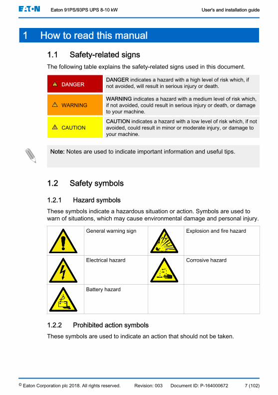
1.1 Safety-related signsThe following table explains the safety-related signs used in this document.
DANGERDANGER indicates a hazard with a high level of risk which, ifnot avoided, will result in serious injury or death.
WARNINGWARNING indicates a hazard with a medium level of risk which,if not avoided, could result in serious injury or death, or damageto your machine.
CAUTIONCAUTION indicates a hazard with a low level of risk which, if notavoided, could result in minor or moderate injury, or damage toyour machine.
Note: Notes are used to indicate important information and useful tips.
1.2 Safety symbols
1.2.1 Hazard symbolsThese symbols indicate a hazardous situation or action. Symbols are used towarn of situations, which may cause environmental damage and personal injury.
General warning sign Explosion and fire hazard
Electrical hazard Corrosive hazard
Battery hazard
1.2.2 Prohibited action symbolsThese symbols are used to indicate an action that should not be taken.
Eaton 91PS/93PS UPS 8-10 kW User's and installation guide
© Eaton Corporation plc 2018. All rights reserved. Revision: 003 Document ID: P-164000672 7 (102)

General symbol for pro-hibited action
No smoking
Limited or restricted ac-cess
1.2.3 Mandatory action symbolsThese symbols are used to indicate an action that must be taken.
General symbol for man-datory action
Disconnect from powersource
Read the manual or in-structions
1.3 Conventions used in this documentThis document uses the following type conventions:
• Bold type highlights important concepts in discussions, key terms inprocedures and menu options, or represents a command or option that youtype or enter at a prompt.
• Italic type highlights notes and new terms when they are defined.• Screen type represents information that appears on the screen or LCD.
1.4 GlossaryThis document uses the following acronyms to refer to Eaton UPS products ortheir parts.Table 1: Glossary of acronyms
ABM Advanced Battery ManagementBIB Bypass Input BreakerBIS Bypass Input SwitchEBC External Battery Cabinet
Eaton 91PS/93PS UPS 8-10 kW User's and installation guide
© Eaton Corporation plc 2018. All rights reserved. Revision: 003 Document ID: P-164000672 8 (102)
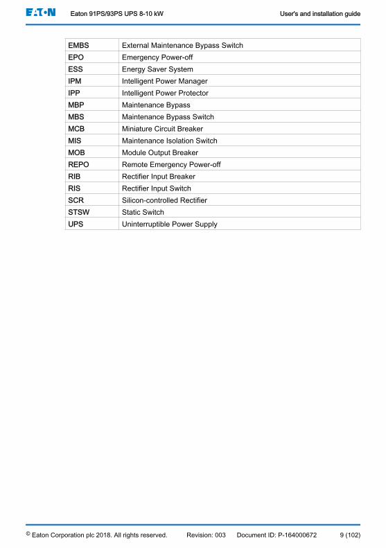
EMBS External Maintenance Bypass SwitchEPO Emergency Power-offESS Energy Saver SystemIPM Intelligent Power ManagerIPP Intelligent Power ProtectorMBP Maintenance BypassMBS Maintenance Bypass SwitchMCB Miniature Circuit BreakerMIS Maintenance Isolation SwitchMOB Module Output BreakerREPO Remote Emergency Power-offRIB Rectifier Input BreakerRIS Rectifier Input SwitchSCR Silicon-controlled RectifierSTSW Static SwitchUPS Uninterruptible Power Supply
Eaton 91PS/93PS UPS 8-10 kW User's and installation guide
© Eaton Corporation plc 2018. All rights reserved. Revision: 003 Document ID: P-164000672 9 (102)
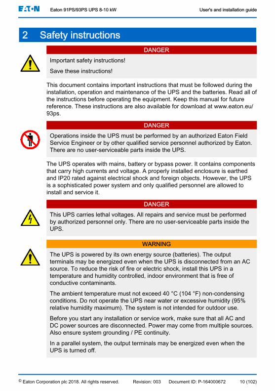
2 Safety instructionsDANGER
Important safety instructions!
Save these instructions!
This document contains important instructions that must be followed during theinstallation, operation and maintenance of the UPS and the batteries. Read all ofthe instructions before operating the equipment. Keep this manual for futurereference. These instructions are also available for download at www.eaton.eu/93ps.
DANGEROperations inside the UPS must be performed by an authorized Eaton FieldService Engineer or by other qualified service personnel authorized by Eaton.There are no user-serviceable parts inside the UPS.
The UPS operates with mains, battery or bypass power. It contains componentsthat carry high currents and voltage. A properly installed enclosure is earthedand IP20 rated against electrical shock and foreign objects. However, the UPSis a sophisticated power system and only qualified personnel are allowed toinstall and service it.
DANGERThis UPS carries lethal voltages. All repairs and service must be performedby authorized personnel only. There are no user-serviceable parts inside theUPS.
WARNINGThe UPS is powered by its own energy source (batteries). The outputterminals may be energized even when the UPS is disconnected from an ACsource. To reduce the risk of fire or electric shock, install this UPS in atemperature and humidity controlled, indoor environment that is free ofconductive contaminants.
The ambient temperature must not exceed 40 °C (104 °F) non-condensingconditions. Do not operate the UPS near water or excessive humidity (95%relative humidity maximum). The system is not intended for outdoor use.
Before you start any installation or service work, make sure that all AC andDC power sources are disconnected. Power may come from multiple sources.Also ensure system grounding / PE continuity.
In a parallel system, the output terminals may be energized even when theUPS is turned off.
Eaton 91PS/93PS UPS 8-10 kW User's and installation guide
© Eaton Corporation plc 2018. All rights reserved. Revision: 003 Document ID: P-164000672 10 (102)
WARNINGBatteries present a risk of electrical shock or burn from high short-circuitcurrent. Observe proper precautions.
Electric energy hazard. Do not attempt to alter any battery wiring orconnectors. Attempting to alter wiring can cause injury.
Do not open or mutilate batteries. Released electrolyte may be toxic and isharmful to the skin and eyes.
Batteries may contain HIGH VOLTAGES, and CORROSIVE, TOXIC andEXPLOSIVE substances. Because of the battery string the output receptaclesmay carry high voltage even when the AC supply is not connected to theUPS. Read the shutdown instructions carefully.
IMPORTANT: The battery may consist of multiple parallel strings. Make surethat you disconnect all strings before installation.
CAUTIONOnly qualified service personnel knowledgeable of batteries and the requiredprecautions are allowed to perform installation or service work on batteries.Keep unauthorized personnel away from the batteries. Before you install orreplace batteries, consider all the warnings, cautions, and notes concerningappropriate handling. Do not disconnect the batteries when the UPS is in theBattery mode.
Make sure that your replacement batteries are of the same number and typeas the battery that was originally installed in the UPS. See more accurateinstructions on the UPS.
Before you connect or disconnect battery terminals, disconnect the chargingsource by opening the corresponding battery circuit breaker.
Check if the battery is inadvertently grounded. If it is, remove the source ofthe ground. Contacting any part of a grounded battery can cause a risk ofelectric shock. If you disconnect the grounding connection before you work onthe batteries, the risk of an electric shock is less likely.
Dispose of batteries according to your local disposal requirements. Do notdispose of batteries in a fire. When exposed to flame, batteries may explode.
To reduce the risk of a fire, connect only to a circuit that has a circuit breakerthat is rated in accordance with the national and local installation rules andUPS installation instructions.
To ensure proper cooling airflow and to protect personnel from dangerousvoltages inside the unit, keep the UPS door closed and the front panelsinstalled.
Eaton 91PS/93PS UPS 8-10 kW User's and installation guide
© Eaton Corporation plc 2018. All rights reserved. Revision: 003 Document ID: P-164000672 11 (102)
Do not install or operate the UPS system close to gas or electric heatsources. Keep the operating environment within the parameters stated in thisdocument.
CAUTIONKeep the surroundings of the UPS uncluttered, clean, and free from excessmoisture.
Observe all DANGER, CAUTION, and WARNING notices affixed to the insideand outside of the equipment.
2.1 AudienceThe intended audience of this document are as follows:
• People who plan and perform the installation of the UPS• People who use the UPS
This document provides guidelines for how to check the UPS delivery and howinstall and operate the UPS.
The reader is expected to know the fundamentals of electricity, wiring, electricalcomponents and electrical schematic symbols. This document is written for aglobal reader.
CAUTIONRead this document before you start to operate or perform work on the UPS.
2.2 CE markingThe product has a CE marking in compliance with the following Europeandirectives:
• LVD Directive (Safety) 2014/35/EU• EMC Directive 2014/30/EU• RoHS Directive 2011/65/EU
Declarations of conformity with UPS harmonized standards and directives EN62040-1 (Safety), EN 62040-2 (EMC) and EN 50581 (RoHS) are available atwww.eaton.eu or by contacting your nearest Eaton office or authorized partner.
2.3 User precautionsThe only permitted user operations are as follows:
• Startup and shutdown of the UPS, excluding the commissioning startup.
Eaton 91PS/93PS UPS 8-10 kW User's and installation guide
© Eaton Corporation plc 2018. All rights reserved. Revision: 003 Document ID: P-164000672 12 (102)

• Use of the LCD control panel and the Maintenance Bypass Switch (MBS).• Use of optional connectivity modules and their software.
Follow the precautions and only perform the described operations. Any deviationfrom the instructions can be dangerous to the user or cause accidental loadloss.
DANGERDo not open any other screws in the unit than those holding the cover platesof the MiniSlots and the MBS locking plate. Failure to recognize the electricalhazards can prove fatal.
CAUTIONThe 8-10 kW models are available as a C2 UPS product in regard toemissions and C3 UPS in immunity. The UPS can be placed both inresidential and commercial or industrial environments. When included in aresidential environment, this product may cause radio interference, in whichcase you may have to take additional preventive measures.
2.4 EnvironmentThe UPS must be installed according to the recommendations in this document.Never install the UPS in an airtight room, in the presence of flammable gases, orin an environment exceeding the specifications.
Excessive amount of dust in the operating environment of the UPS may causedamage or lead to malfunction. Always protect the UPS from the outsideweather and sunshine. In order to maximize internal battery service life time, therecommended operating temperature range is from +20 ºC to +25 ºC.
WARNINGDuring charge, float charge, heavy discharge, and overcharge, hydrogen andoxygen gases are emitted from lead-acid and NiCd batteries into thesurrounding atmosphere. Explosive gas mixture may be created if thehydrogen concentration exceeds 4% by volume in air. Ensure the necessaryair flow rate for the ventilation of the UPS location.
2.5 Symbols on the UPS and accessoriesThe following are examples of symbols used on the UPS or its accessories. Thesymbols are used to alert you of important information.
Eaton 91PS/93PS UPS 8-10 kW User's and installation guide
© Eaton Corporation plc 2018. All rights reserved. Revision: 003 Document ID: P-164000672 13 (102)

RISK OF ELECTRIC SHOCK
Indicates that a risk of electric shock is present and the associatedwarning should be observed.
CAUTION: REFER TO OPERATOR'S MANUAL
Refer to your operator's manual for additional information, such asimportant operating and maintenance instructions.
This symbol indicates that you may not discard the UPS or the UPSbatteries in the trash. This product involves sealed, lead-acid batter-ies and they must be disposed of properly. For more information,contact your local recycling / reuse or hazardous waste center.
This symbol indicates that you may not discard waste electrical orelectronic equipment (WEEE) in the trash. For proper disposal, con-tact your local recycling / reuse or hazardous waste center.
2.6 For more informationAddress any inquiries about the UPS and the battery cabinet to the local officeor an agent authorized by the manufacturer. Quote the type code and the serialnumber of the equipment.
Contact your local service representative if you need help with any of thefollowing.
• scheduling initial startup• regional locations and telephone numbers• a question about any of the information in this manual• a question that this manual does not answer
Note: For more information about the installation space, safe operation andworking, see IEC 62485-2: Safety requirements for secondary batteries andbattery installations.
Eaton 91PS/93PS UPS 8-10 kW User's and installation guide
© Eaton Corporation plc 2018. All rights reserved. Revision: 003 Document ID: P-164000672 14 (102)
3 Introduction to Eaton 91PS/93PS 8-10 kW UPS
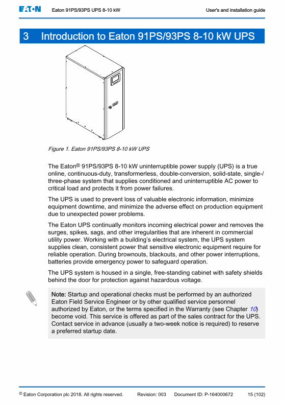
Figure 1. Eaton 91PS/93PS 8-10 kW UPS
The Eaton® 91PS/93PS 8-10 kW uninterruptible power supply (UPS) is a trueonline, continuous-duty, transformerless, double-conversion, solid-state, single-/three-phase system that supplies conditioned and uninterruptible AC power tocritical load and protects it from power failures.
The UPS is used to prevent loss of valuable electronic information, minimizeequipment downtime, and minimize the adverse effect on production equipmentdue to unexpected power problems.
The Eaton UPS continually monitors incoming electrical power and removes thesurges, spikes, sags, and other irregularities that are inherent in commercialutility power. Working with a building’s electrical system, the UPS systemsupplies clean, consistent power that sensitive electronic equipment require forreliable operation. During brownouts, blackouts, and other power interruptions,batteries provide emergency power to safeguard operation.
The UPS system is housed in a single, free-standing cabinet with safety shieldsbehind the door for protection against hazardous voltage.
Note: Startup and operational checks must be performed by an authorizedEaton Field Service Engineer or by other qualified service personnelauthorized by Eaton, or the terms specified in the Warranty (see Chapter 10)become void. This service is offered as part of the sales contract for the UPS.Contact service in advance (usually a two-week notice is required) to reservea preferred startup date.
Eaton 91PS/93PS UPS 8-10 kW User's and installation guide
© Eaton Corporation plc 2018. All rights reserved. Revision: 003 Document ID: P-164000672 15 (102)

3.1 Looking inside the UPS system
Figure 2. Looking inside the Eaton 91PS/93PS UPS 8-10 kW standard frame
1. Control panel 5. Internal battery
2. Door latch 6. Switches
3. Communications area 7. Client connections
4. Battery breaker
The static bypass line consists of a static switch and a backfeed protectionisolation device connected in series. In addition, there is a system level controlunit that constantly monitors the power delivered through the bypass line or tothe input of the UPS. Transfers to static bypass are seamless and performedautomatically by the system as needed, for example, in case of an extendedsystem overload.
Each UPS is able to operate and share the load independently, despite thestatus of the other UPSs.
The 91PS/93PS UPS 10 kW frame includes rectifier, inverter, battery converter,controls and 10 kW static bypass. In addition to the internal batteries, externalbatteries can also be connected.
WARNINGHazardous voltage can exist in the battery circuit until disconnected fromexternal battery source.
The rectifier input switch, battery breaker and internal MBS are available asstandard for all the models.
If utility power is interrupted or falls outside the parameters specified in Chapter 9, the UPS uses a backup battery supply to maintain power to the critical load
Eaton 91PS/93PS UPS 8-10 kW User's and installation guide
© Eaton Corporation plc 2018. All rights reserved. Revision: 003 Document ID: P-164000672 16 (102)
for a specified period of time or until the utility power returns. For extendedpower outages, the UPS allows you to either transfer to an alternative powersystem (such as a generator) or shut down your critical load in an orderlymanner. The UPS bypass consists of a continuous-duty static switch and abackfeed protection isolation device. All the models also include an internal fusein the bypass line. The backfeed protection and bypass fuse are located inseries with the static switch.
3.2 UPS operating modesTable 2: UPS operating modes
UPS operating mode DescriptionNormal operating modes:Double conversion mode Critical load is supplied by the inverter,
which derives its power from rectified utilityAC power. In this mode, the battery charg-er also provides charging current for thebattery, if needed.
Energy Saver System (ESS mode) Critical load is supported securely by utilitypower through the static bypass switch withdouble conversion available on-demandwith typically less than a 2 ms transitiontime, should any abnormal condition be de-tected in the utility. When operating in theESS mode, the load is protected with inher-ent surge suppression. Operating the UPSin the ESS mode increases system effi-ciency, allowing significant savings in ener-gy losses without compromising system re-liability.
Other operating modes:Stored energy mode Energy is drawn from a DC backup power
source and converted to AC power by theUPS inverter. Most commonly VRLA bat-teries are introduced to the system for thispurpose, and the mode of operation iscalled the battery mode.
Bypass mode Critical load is supported directly by utilitypower through the UPS static switch.
3.2.1 Normal operating modesDuring normal UPS operation, power for the system is derived from a utility inputsource. Unit Online is displayed on the front panel, indicating that theincoming power is within voltage and frequency acceptance windows.
Eaton 91PS/93PS UPS 8-10 kW User's and installation guide
© Eaton Corporation plc 2018. All rights reserved. Revision: 003 Document ID: P-164000672 17 (102)

3.2.1.1 Double conversion mode
Figure 3 shows the path of electrical power through the UPS system when theUPS is operating in the double conversion mode.
Figure 3. Path of current through the UPS in the double conversion mode
A Staticswitch
1 Bypass in-put
Main power flow
B Rectifier 2 Rectifier in-put
Energized
C Inverter 3 Output De-energizedD Battery con-
verter4 Battery
breakerTrickle current
E Battery Closed Open
Single-/three-phase AC input power is converted to DC using a multilevelconverter with IGBT devices to produce a regulated DC voltage to the inverter.The UPS status indicated on the display is Unit Online and the UPM statusis Active.
The battery converter derives its input from the regulated DC output of therectifier and provides regulated charge current to the battery. The battery isalways connected to the UPS and ready to support the inverter should the utilityinput become unavailable.
Eaton 91PS/93PS UPS 8-10 kW User's and installation guide
© Eaton Corporation plc 2018. All rights reserved. Revision: 003 Document ID: P-164000672 18 (102)

The inverter produces a single-/three-phase AC output to the critical load. Theinverter uses multilevel converter technology with IGBT devices and pulse-widthmodulation (PWM) to produce a regulated and filtered AC output.
If the utility AC power is interrupted or is out of specification, the UPSautomatically switches to the battery mode to support the critical load withoutinterruption. When utility power returns, the UPS returns automatically to thedouble conversion mode.
If the UPS becomes overloaded or unavailable, the UPS seamlessly switches tothe bypass mode and continues supplying the load through the static bypass.The UPS automatically returns to the double conversion mode when theabnormal condition, such as an extended time overload, is cleared and thesystem operation is restored within the specified limits.
If a UPM within the UPS suffers an internal failure, the remaining UPMscontinue to support the load in the double conversion mode. The UPS isautomatically internally redundant when the UPS is not operating at full load.However, if internal redundancy between the UPMs is not possible due to highload, the UPS switches automatically to the bypass mode and remains in thatmode until the failure is corrected and the UPS is back in operation.
In an external parallel redundant system, each UPS can be isolated from thesystem for service while the remaining UPSs support the load in the doubleconversion mode.
3.2.1.2 Energy Saver System mode
Figure 4 shows the path of electrical power through the UPS system when theUPS is operating in the Energy Saver System (ESS) mode.
Eaton 91PS/93PS UPS 8-10 kW User's and installation guide
© Eaton Corporation plc 2018. All rights reserved. Revision: 003 Document ID: P-164000672 19 (102)
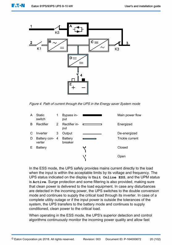
Figure 4. Path of current through the UPS in the Energy saver System mode
A Staticswitch
1 Bypass in-put
Main power flow
B Rectifier 2 Rectifier in-put
Energized
C Inverter 3 Output De-energizedD Battery con-
verter4 Battery
breakerTrickle current
E Battery Closed
Open
In the ESS mode, the UPS safely provides mains current directly to the loadwhen the input is within the acceptable limits by its voltage and frequency. TheUPS status indicated on the display is Unit Online ESS, and the UPM statusis Active. Surge protection and some filtering is also provided, making surethat clean power is delivered to the load equipment. In case any disturbancesare detected in the incoming power, the UPS switches to the double conversionmode and continues to supply the critical load through its inverter. In case of acomplete utility outage or if the input power is outside the tolerances of thesystem, the UPS transfers to the battery mode and continues to supplyconditioned, clean power to the critical load.
When operating in the ESS mode, the UPS's superior detection and controlalgorithms continuously monitor the incoming power quality and allow fast
Eaton 91PS/93PS UPS 8-10 kW User's and installation guide
© Eaton Corporation plc 2018. All rights reserved. Revision: 003 Document ID: P-164000672 20 (102)
engagement of the power converters. Typical transition time to the doubleconversion mode is less than 2 milliseconds, which is practically seamless.
When the power conditions are within acceptable limits, the UPS operates as ahigh efficiency, energy-saving system, providing surge protection for ITequipment and making sure that clean power is delivered to the facility. Theenergy saver system increases system efficiency when supplying 20...100% ofnominal load, reducing energy losses by up to 80%.
3.2.2 Stored energy and battery modeWhen running normally in the double conversion or ESS mode, the UPSautomatically transfers to supply the load from batteries or some other storedenergy source if a utility power outage occurs, or if the utility power does notconform to the specified parameters. The UPS status indicated on the display isOn Battery, and the UPM status is Active. In the battery mode, the batteryprovides emergency DC power, which is converted to regulated output power bythe inverter.
Figure 5 shows the path of electrical power through the UPS system whenoperating in the battery mode.
Eaton 91PS/93PS UPS 8-10 kW User's and installation guide
© Eaton Corporation plc 2018. All rights reserved. Revision: 003 Document ID: P-164000672 21 (102)
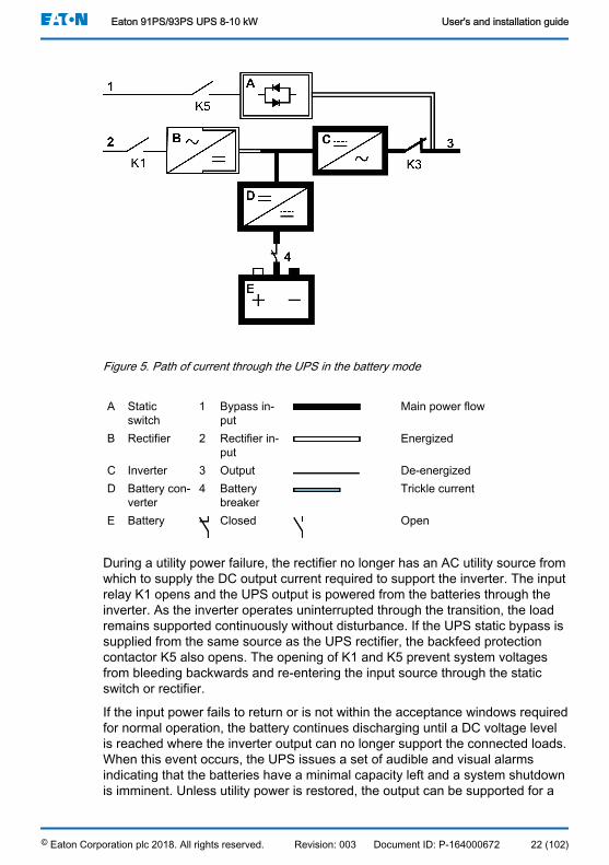
Figure 5. Path of current through the UPS in the battery mode
A Staticswitch
1 Bypass in-put
Main power flow
B Rectifier 2 Rectifier in-put
Energized
C Inverter 3 Output De-energizedD Battery con-
verter4 Battery
breakerTrickle current
E Battery Closed Open
During a utility power failure, the rectifier no longer has an AC utility source fromwhich to supply the DC output current required to support the inverter. The inputrelay K1 opens and the UPS output is powered from the batteries through theinverter. As the inverter operates uninterrupted through the transition, the loadremains supported continuously without disturbance. If the UPS static bypass issupplied from the same source as the UPS rectifier, the backfeed protectioncontactor K5 also opens. The opening of K1 and K5 prevent system voltagesfrom bleeding backwards and re-entering the input source through the staticswitch or rectifier.
If the input power fails to return or is not within the acceptance windows requiredfor normal operation, the battery continues discharging until a DC voltage levelis reached where the inverter output can no longer support the connected loads.When this event occurs, the UPS issues a set of audible and visual alarmsindicating that the batteries have a minimal capacity left and a system shutdownis imminent. Unless utility power is restored, the output can be supported for a
Eaton 91PS/93PS UPS 8-10 kW User's and installation guide
© Eaton Corporation plc 2018. All rights reserved. Revision: 003 Document ID: P-164000672 22 (102)

maximum of 2 minutes before the output of the system shuts down. If thebypass source is available, the UPS transfers to the bypass mode instead ofshutting down.
If the input power becomes available again at any time during the batterydischarge, K1 and K5 close and the UPS returns to normal operation. The UPSalso starts to recharge the batteries to restore the capacity.
3.2.3 Bypass mode
CAUTIONThe critical load is not protected while the UPS is in bypass mode.
The UPS automatically switches to the bypass mode if it detects an overload,load fault, or internal failure. The bypass source supplies the commercial ACpower to the load directly. The UPS can also be commanded to transfer to thebypass mode manually through the display. The UPS status indicated on thedisplay is On Bypass.
The UPS will return from the bypass mode back to online mode, if the condition(for example overload) that caused the transfer is cleared. If there is a conditionthat will not clear by itself (for example UPS internal failure), the UPS will remainon bypass operation.
Figure 6 shows the path of electrical power through the UPS system whenoperating in the bypass mode.
Eaton 91PS/93PS UPS 8-10 kW User's and installation guide
© Eaton Corporation plc 2018. All rights reserved. Revision: 003 Document ID: P-164000672 23 (102)

Figure 6. Path of current through the UPS in the bypass mode
A Staticswitch
1 Bypass in-put
Main power flow
B Rectifier 2 Rectifier in-put
Energized
C Inverter 3 Output De-energizedD Battery con-
verter4 Battery
breakerTrickle current
E Battery Closed Open
In the bypass mode, the output of the system is provided with single-/three-phase AC power directly from the system input. While in this mode, the output ofthe system is not protected from voltage or frequency fluctuations or poweroutages from the source. Some power line filtering and transient protection isprovided to the load, but no active power conditioning or battery support isavailable to the output of the system in the bypass mode.
The static bypass consists of a solid-state, silicon-controlled rectifier (SCR)static switch (STSW) and a backfeed protection isolation device K5. The staticswitch is rated as a continuous-duty device that is used anytime the inverter isunable to support the applied load. The static switch is wired in series with thebackfeed protection. As the static switch is an electronically-controlled device, itcan be turned on immediately to pick up the load from the inverter withoutinterruption. The backfeed protection is normally always closed, ready tosupport the static switch unless the bypass input source becomes unavailable.
Eaton 91PS/93PS UPS 8-10 kW User's and installation guide
© Eaton Corporation plc 2018. All rights reserved. Revision: 003 Document ID: P-164000672 24 (102)
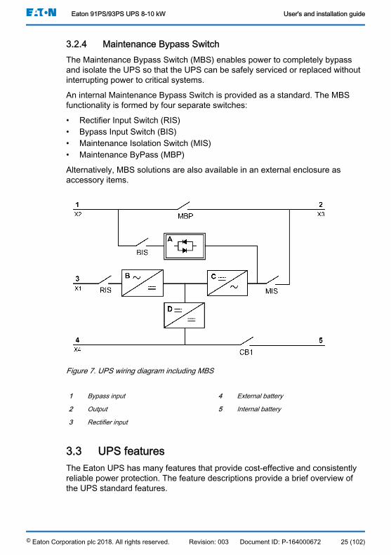
3.2.4 Maintenance Bypass SwitchThe Maintenance Bypass Switch (MBS) enables power to completely bypassand isolate the UPS so that the UPS can be safely serviced or replaced withoutinterrupting power to critical systems.
An internal Maintenance Bypass Switch is provided as a standard. The MBSfunctionality is formed by four separate switches:
• Rectifier Input Switch (RIS)• Bypass Input Switch (BIS)• Maintenance Isolation Switch (MIS)• Maintenance ByPass (MBP)
Alternatively, MBS solutions are also available in an external enclosure asaccessory items.
Figure 7. UPS wiring diagram including MBS
1 Bypass input 4 External battery
2 Output 5 Internal battery
3 Rectifier input
3.3 UPS featuresThe Eaton UPS has many features that provide cost-effective and consistentlyreliable power protection. The feature descriptions provide a brief overview ofthe UPS standard features.
Eaton 91PS/93PS UPS 8-10 kW User's and installation guide
© Eaton Corporation plc 2018. All rights reserved. Revision: 003 Document ID: P-164000672 25 (102)

3.3.1 Advanced Battery ManagementThe Advanced Battery Management technology uses sophisticated sensingcircuitry and a three-stage charging technique that extends the useful servicelife of UPS batteries while optimizing the battery recharge time. ABM alsoprotects batteries from damage caused by high current charging and inverterripple currents. Charging at high currents can overheat and damage batteries.
In the charge mode, the batteries are recharged. Charging lasts only as long asit takes to bring the battery system up to a predetermined float level. Once thislevel is reached, the UPS battery charger enters the float stage and the chargeroperates in the constant voltage mode.
The rest mode begins at the end of the charge mode; that is, after 48 hours offloat charging (user-adjustable). In the rest mode, the battery charger iscompletely turned off. The battery system receives no charge current during thisrest period of approximately 28 days (user-adjustable). During the rest mode,the open circuit battery voltage is monitored constantly, and battery charging isresumed when necessary.
3.3.2 Powerware Hot SyncThe Eaton Powerware Hot Sync technology is an algorithm that eliminates thesingle point of failure in a parallel system and therefore enhances systemreliability. The Hot Sync technology is incorporated in all Eaton 91PS/93PSUPSs, and it is utilized in both multi-module internal parallel and external parallelsystems.
The Hot Sync technology enables all UPMs to operate independently in aparallel system, even without inter-module communications. The power modulesutilizing the Hot Sync technology are completely autonomous; each modulemonitors its own output independently to remain in complete synchronizationwith the other modules. The UPM power modules share the load perfectly evenin changing capacity or load conditions.
The Powerware Hot Sync technology combines digital signal processing and anadvanced control algorithm to provide automatic load sharing and selectivetripping in a parallel UPS system. The load share control algorithms maintainsynchronization and load balance by constantly making minute adjustments tovariations in the output power requirements. The modules conform to demandand are not in conflict with each other for the load. The Powerware Hot Syncsystems are capable of paralleling for both redundancy and capacity.
3.3.3 Power ConditionerThe Power Conditioner mode is characterized by the UPS running in the doubleconversion mode without batteries connected. In the Power Conditioner mode,the UPS provides conditioned output voltage and frequency. The UPS can alsosupport high nonlinear loads without ITHD on the input. The UPS meets the
Eaton 91PS/93PS UPS 8-10 kW User's and installation guide
© Eaton Corporation plc 2018. All rights reserved. Revision: 003 Document ID: P-164000672 26 (102)

qualifications outlined in this product specification, except for the conditionsbelow.
When in the Power Conditioner mode, the UPS has the following functionalityand limitations:
1. The UPS runs in the double conversion mode.2. Because there is no battery, loss of utility power results in the UPS losing
power and shutting down.3. The UPS sustains up to -50% input voltage tolerance, unless the current
limit is reached.4. If the rectifier is turned off, the UPS attempts a transfer to the bypass
mode.5. The ESS mode is not available.
3.3.4 Frequency ConverterThe Frequency Converter mode is characterized by the UPS running without thebypass mode available. The output frequency can be configured to be differentfrom the standard input frequency (e.g. 60 Hz output, 50 Hz input). The UPScan also support high nonlinear loads without iTHD on the input. The UPSmeets the qualifications outlined in this product specification, except for theconditions below.
When in the Frequency Converter mode, the UPS has the following functionalityand limitations:
1. Operation is the same as when in the double conversion mode with nobypass available.
2. Bypass alarms are suppressed.
3.4 Software and connectivity features
3.4.1 User interfaceMiniSlot Communication Bays — there are 2 communication bays for MiniSlotconnectivity cards. MiniSlot cards are quickly installed and are hot-pluggable.See Chapter 6 for additional information.
3.4.2 Power Management SoftwareIntelligent Power software products offer tools for monitoring and managingpower devices across the network. See Chapter 6 for more information.
Eaton 91PS/93PS UPS 8-10 kW User's and installation guide
© Eaton Corporation plc 2018. All rights reserved. Revision: 003 Document ID: P-164000672 27 (102)
3.5 Options and accessoriesContact your Eaton sales representative for more information about theavailable options and accessories.
3.5.1 External Maintenance Bypass Switch Panel (accessory)The external MBS is enclosed in its own separate cabinet, which can be either awall-mounted or stand-alone cabinet depending on the MBS power rating. TheMBS wiring has two different options: two- and threeswitch configuration. Thetwo-switch model contains a maintenance isolation switch and a maintenancebypass switch. In addition to these, the three-switch model contains a bypassinput breaker. The external MBS enclosures are IP22 classified.
The two-switch model assumes that the UPS rectifier and bypass are coupledthrough dedicated breakers and separate cables from the switchgear. However,the three-switch model can be connected to the switchgear with only a singlecable, and the cable connections between the panel and UPS are runseparately.
For external MBS installation instructions, see the installation instruction shippedwith the unit.
3.6 Battery systemThe battery system provides short-term emergency backup power to safeguardoperation during brownouts, blackouts, and other power interruptions. Bydefault, UPS is configured to use VRLA batteries. If other type of batteries orother energy storage means need to be connected, consult a certified servicetechnician prior to proceeding with the installation.
The Eaton 91PS/93PS 8-10 kW UPS are equipped with internal batteries toprovide full load runtime of 5...10 minutes depending on the UPS rating. Inaddition, external battery cabinets can be introduced to the system to allowextended autonomy. Internal and external batteries can be used in parallel.
For detailed battery specifications, see Chapter 9.
Eaton 91PS/93PS UPS 8-10 kW User's and installation guide
© Eaton Corporation plc 2018. All rights reserved. Revision: 003 Document ID: P-164000672 28 (102)

3.7 Basic system configurations
UPS power ratingTable 3: UPS configurations
Description Systempower
[kW]
Static switch
[kW]
Internal battery
91PS-8(10) 8 10 Yes/No
91PS-10(10) 10 10 Yes/No
93PS-8(10) 8 10 Yes/No
93PS-10(10) 10 10 Yes/No
UPS options and accessories
The following table shows the features of 91PS/93PS 8-10 kW UPS.
Table 4: Standard UPS features
Feature 91PS/93PS 8-10 kWSmart touch screen display for system control and monitoring StandardSNMP web interface StandardInternal MBS StandardRectifier input switch RIS StandardInternal battery breaker CB1 StandardBattery start StandardIntegrated backfeed protection Standard
Additional options and accessories are also available. These include differentsoftware and connectivity options and external switchgear and powerdistribution options.
Eaton 91PS/93PS UPS 8-10 kW User's and installation guide
© Eaton Corporation plc 2018. All rights reserved. Revision: 003 Document ID: P-164000672 29 (102)

4 UPS installation plan and unpackingUse the following basic sequence of steps to install the UPS:
1. Create an installation plan for the UPS system.2. Prepare your site for the UPS system.3. Inspect and unpack the UPS cabinet.4. Unload and install the UPS cabinet and wire the system.5. Complete the installation checklist provided in Section 4.2.6. Have authorized service personnel perform the preliminary operational
checks and startup.
Note: Startup and operational checks must be performed by an authorizedEaton Field Service Engineer or by other qualified service personnelauthorized by Eaton, or the terms specified in the Warranty (see Chapter 10)become void. This service is offered as a part of the sales contract for theUPS. Contact service in advance (usually a two-week notice is required) toreserve a preferred startup date.
4.1 Creating an installation planBefore you install the UPS system, read and understand how these instructionsapply to the system that you are going to install. Use the procedures andillustrations in Section 4.3 and Chapter 5 to create a logical plan for installing thesystem.
Eaton 91PS/93PS UPS 8-10 kW User's and installation guide
© Eaton Corporation plc 2018. All rights reserved. Revision: 003 Document ID: P-164000672 30 (102)

4.2 Installation checklistAction Yes / NoAll packing materials and restraints are removed from each cabinet.Each cabinet in the UPS system is placed in its installed location.A cabinet grounding kit / mounting kit is installed between any cabinetsthat are bolted together.All conduits and cables are properly routed to the UPS and any ancillarycabinets.All power cables are properly sized and terminated.Neutral conductors are installed and bonded to ground according to therequirements.A ground conductor is properly installed.Battery cables are terminated and connected to battery connectors.Battery Shunt trip and Aux contact signal wiring is connected from theUPS to the battery breaker.LAN drops are installed.All LAN connections are completed.Air conditioning equipment is installed and operating correctly.There is adequate workspace around the UPS and other cabinets.Adequate lighting is provided around all the UPS equipment.A 230 VAC service outlet is located within 7.5 meters of the UPS equip-ment.The Remote Emergency Power-off (REPO) device is mounted in its in-stalled location and its wiring is terminated inside the UPS cabinet.If EPO is used in the NC configuration, a jumper is installed on the EPObetween pins 1 and 2.(OPTIONAL) Alarm relays and signal outputs are wired appropriately.(OPTIONAL) A remote battery disconnect control is mounted in its instal-led location and its wiring is terminated inside the UPS and battery cabi-net.(OPTIONAL) Accessories are mounted in their installed locations andtheir wiring is terminated inside the UPS cabinet.Start-up and operational checks are performed by an authorized EatonField Service Engineer.
4.3 Site preparationsFor the UPS system to operate at peak efficiency, the installation site must meetthe environmental parameters outlined in these instructions. If the UPS needs tobe operated at an altitude higher than 1,000 m, contact your servicerepresentative for important information about high altitude operation. The
Eaton 91PS/93PS UPS 8-10 kW User's and installation guide
© Eaton Corporation plc 2018. All rights reserved. Revision: 003 Document ID: P-164000672 31 (102)
operating environment must meet the height, clearance, and environmentalrequirements specified.
4.3.1 Environmental and installation considerationsThe UPS system installation requires a TN, TT or IT power distribution system(the IT distribution system shall include a neutral wire).
The UPS system installation must meet the following guidelines:
• The system must be installed on a level floor suitable for computer orelectronic equipment. The floor must be suitable for heavy weight andwheeling.
• The system must be installed in a temperature and humidity controlledindoor area that is free of conductive contaminants.
• The cabinet can be installed in line-up-and-match or standaloneconfigurations.
Failure to follow these guidelines may void your warranty.
CAUTIONDo not stack anything on top of the 91PS/93PS UPS cabinet.
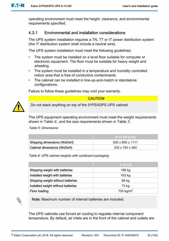
The UPS equipment operating environment must meet the weight requirementsshown in Table 6 , and the size requirements shown in Table 5 .Table 5: Dimensions
8-10 kW [mm]Shipping dimensions (WxDxH) 630 x 800 x 1111Cabinet dimensions (WxDxH) 335 x 750 x 950
Table 6: UPS cabinet weights with cardboard packaging
8-10 kWShipping weight with batteries 188 kgInstalled weight with batteries 163 kgShipping weight without batteries 98 kgInstalled weight without batteries 73 kgFloor loading 700 kg/m2
Note: Maximum number of internal batteries are included.
The UPS cabinets use forced air cooling to regulate internal componenttemperature. By default, air inlets are in the front of the cabinet and outlets are
Eaton 91PS/93PS UPS 8-10 kW User's and installation guide
© Eaton Corporation plc 2018. All rights reserved. Revision: 003 Document ID: P-164000672 32 (102)

in the back. Allow clearance in front of and behind each cabinet for proper aircirculation.
The clearance required around the UPS cabinet is shown in Table 7 .
Note: This equipment is not intended for building-in, rack-mounting or forincorporation in larger equipment.
Table 7: UPS cabinet minimum clearances
8-10 kWFrom the top of the cabinet 500 mmFrom the front of the cabinet 500 mmFrom the back of the cabinet 150 mmFrom the side of the cabinet 0 mm (500 mm)*
Note: No side clearance required if the unit can be pulled out for side ac-cess. This requires approximately 1,5 m increase to power and signal cablelengths.
• X = clearance at the back of the UPS cabinet• Y = clearance at the top of the UPS cabinetFigure 8. UPS cabinet clearances
The basic environmental requirements for the operation of the UPS system areas follows:
• Ambient temperature range: from +0 to +40 °C• Recommended operating range: from +20 to +25 °C• Maximum relative humidity: 95%, non-condensing
Eaton 91PS/93PS UPS 8-10 kW User's and installation guide
© Eaton Corporation plc 2018. All rights reserved. Revision: 003 Document ID: P-164000672 33 (102)

It is required that ventilation of the UPS room is arranged. Sufficient amount ofair cooling is needed to keep the maximum room temperature rise at the desiredlevel:
• Temperature rise of +5 °C maximum requires the airflow of 600 m3/h per 1kW of losses.
• Temperature rise of +10 °C maximum requires the airflow of 300 m3/h per 1kW of losses.
An ambient temperature from +20 °C to +25 °C is recommended to achieve along life of the UPS and batteries. The cooling air that enters the UPS must notexceed +40 °C. Avoid high ambient temperature, moisture, and humidity.
For ventilation requirements, see 91PS/93PS heat rejection in Table 8 .Table 8: Air conditioning or ventilation requirements during full load operation
Heat rejection
(BTU/h x 1,000)
Heat rejection
(kW)8 kW 1.17 0.310 kW 1.46 0.4
Battery locations and enclosures must be ventilated to maintain the hydrogenconcentration below the 4%vol safety limit. Adequate air ventilation must beprovided to locations where the UPS and batteries are located. For the 91PS/93PS UPS 8–10 kW with internal batteries, the minimum air flow is 1.5 m3/hourand the minimum free area of opening for inlet and outlet is 42 cm2 when naturalventilation is used. For larger batteries, the ventilation air flow must berecalculated.
Eaton 91PS/93PS UPS 8-10 kW User's and installation guide
© Eaton Corporation plc 2018. All rights reserved. Revision: 003 Document ID: P-164000672 34 (102)
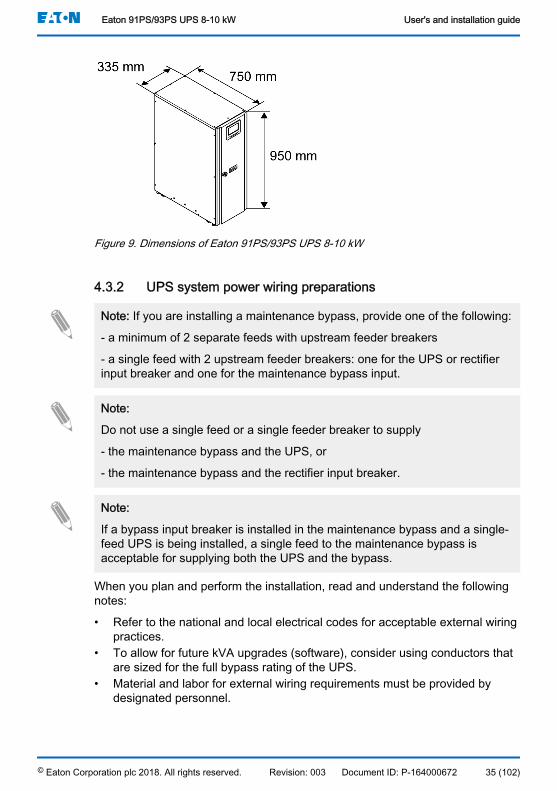
Figure 9. Dimensions of Eaton 91PS/93PS UPS 8-10 kW
4.3.2 UPS system power wiring preparations
Note: If you are installing a maintenance bypass, provide one of the following:
- a minimum of 2 separate feeds with upstream feeder breakers
- a single feed with 2 upstream feeder breakers: one for the UPS or rectifierinput breaker and one for the maintenance bypass input.
Note:
Do not use a single feed or a single feeder breaker to supply
- the maintenance bypass and the UPS, or
- the maintenance bypass and the rectifier input breaker.
Note:
If a bypass input breaker is installed in the maintenance bypass and a single-feed UPS is being installed, a single feed to the maintenance bypass isacceptable for supplying both the UPS and the bypass.
When you plan and perform the installation, read and understand the followingnotes:
• Refer to the national and local electrical codes for acceptable external wiringpractices.
• To allow for future kVA upgrades (software), consider using conductors thatare sized for the full bypass rating of the UPS.
• Material and labor for external wiring requirements must be provided bydesignated personnel.
Eaton 91PS/93PS UPS 8-10 kW User's and installation guide
© Eaton Corporation plc 2018. All rights reserved. Revision: 003 Document ID: P-164000672 35 (102)
• For external wiring, use copper cable rated for 70 °C at minimum. See theappropriate information in Tables 9 , 10 and 11 . Cable sizes are based onusing the specified breakers.
• If cables are run in an ambient temperature greater than 30 °C, highertemperature cable and/or larger size cable may be necessary.
• The bypass feed into this equipment uses four wires. The rectifier feed intothis equipment uses three or four wires. The phases must be symmetricalabout ground (from a Wye source) for proper equipment operation.
• If the load requires a neutral, a bypass source neutral must be provided. Ifthe load does not require a neutral and there is no neutral conductorconnected at the bypass input, a neutral must be installed to source starpoint.
• A readily accessible disconnect device must be incorporated in all fixed inputwiring.
WARNINGDo not disconnect the bypass neutral without disconnecting the bypassphases at the same time.
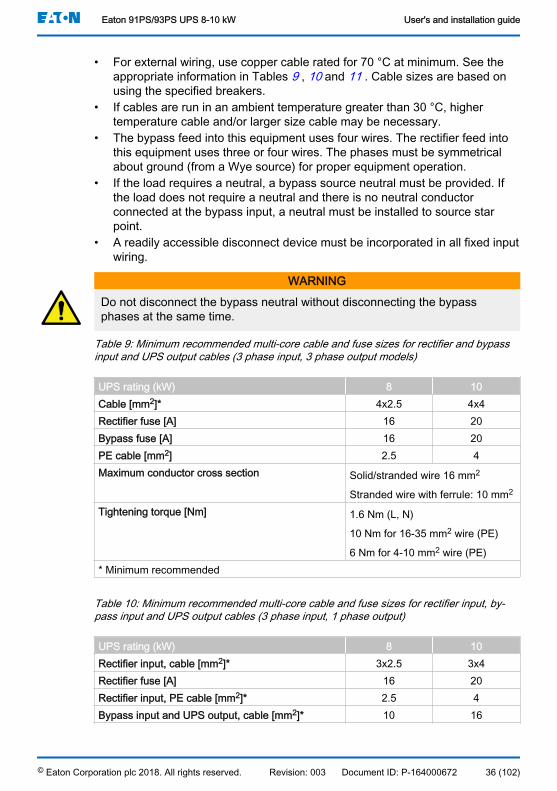
Table 9: Minimum recommended multi-core cable and fuse sizes for rectifier and bypassinput and UPS output cables (3 phase input, 3 phase output models)
UPS rating (kW) 8 10Cable [mm2]* 4x2.5 4x4Rectifier fuse [A] 16 20Bypass fuse [A] 16 20PE cable [mm2] 2.5 4Maximum conductor cross section Solid/stranded wire 16 mm2
Stranded wire with ferrule: 10 mm2
Tightening torque [Nm] 1.6 Nm (L, N)
10 Nm for 16-35 mm2 wire (PE)
6 Nm for 4-10 mm2 wire (PE)* Minimum recommended
Table 10: Minimum recommended multi-core cable and fuse sizes for rectifier input, by-pass input and UPS output cables (3 phase input, 1 phase output)
UPS rating (kW) 8 10Rectifier input, cable [mm2]* 3x2.5 3x4Rectifier fuse [A] 16 20Rectifier input, PE cable [mm2]* 2.5 4Bypass input and UPS output, cable [mm2]* 10 16
Eaton 91PS/93PS UPS 8-10 kW User's and installation guide
© Eaton Corporation plc 2018. All rights reserved. Revision: 003 Document ID: P-164000672 36 (102)
UPS rating (kW) 8 10Bypass fuse [A] 50 63Bypass input and UPS output, PE cable [mm2] 10 16Maximum conductor cross section Solid/stranded wire 50 mm2
Stranded wire with ferrule: 35 mm2
Tightening torque [Nm] 3.5 Nm (L, N)
10 Nm for 16-35 mm2 wire (PE)
6 Nm for 4-10 mm2 wire (PE)* Minimum recommended
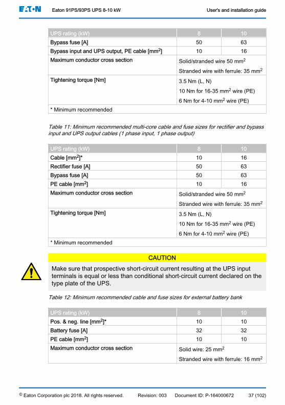
Table 11: Minimum recommended multi-core cable and fuse sizes for rectifier and bypassinput and UPS output cables (1 phase input, 1 phase output)
UPS rating (kW) 8 10Cable [mm2]* 10 16Rectifier fuse [A] 50 63Bypass fuse [A] 50 63PE cable [mm2] 10 16Maximum conductor cross section Solid/stranded wire 50 mm2
Stranded wire with ferrule: 35 mm2
Tightening torque [Nm] 3.5 Nm (L, N)
10 Nm for 16-35 mm2 wire (PE)
6 Nm for 4-10 mm2 wire (PE)* Minimum recommended
CAUTIONMake sure that prospective short-circuit current resulting at the UPS inputterminals is equal or less than conditional short-circuit current declared on thetype plate of the UPS.
Table 12: Minimum recommended cable and fuse sizes for external battery bank
UPS rating (kW) 8 10Pos. & neg. line [mm2]* 10 10Battery fuse [A] 32 32PE cable [mm2] 10 10Maximum conductor cross section Solid wire: 25 mm2
Stranded wire with ferrule: 16 mm2
Eaton 91PS/93PS UPS 8-10 kW User's and installation guide
© Eaton Corporation plc 2018. All rights reserved. Revision: 003 Document ID: P-164000672 37 (102)

UPS rating (kW) 8 10Tightening torque [Nm] 3 Nm (Pos. & Neg. line)
10 Nm for 16-35 mm2 wire (PE)
6 Nm for 4-10 mm2 wire (PE)* Minimum recommended
Note: UPS power upgrading is possible only if the sizing of the externalcables is sufficient. Alternatively, the external cabling must be upgraded aswell. Fuses are of the type gG.
Cable sizing is based on the standard IEC 60364-5-52 table B.52.2 and IEC60364-5-54 table B.54.2. Sizing is for 70 ºC rated copper cables.
When connecting external batteries to 91PS/93PS UPS, Eaton recommendsthat you use the following circuit breakers:
Type Article No Nominal batteryvoltage
12V VRLABlocks
With 91PS/93PS 8–10kW
FAZ-C32/2-DC 279143 336...432 V 28...36NZMH2-A32 281283 444–480 V 37...40
Note: Contact your Eaton sales representative for more information about thecircuit breakers, or if you need help choosing the right model for your UPSsystem.
Use the following 24 V shunt release with early-make auxiliary contact togetherwith the above circuit breaker:
Type Article NoShunt release ZP-ASA/24 248438Aux. contact ZP-IHK 286052
Table 13: Rated and maximum currents for rated power and voltage (93PS)
Rectifier input UPS output / bypass Battery
Ratedpower
[kW]
Ratedvoltage
[V]
Ratedcurrent
[A]
Maximumcurrent
[A]
Ratedcurrent
[A]
Maximumcurrent
[A]
Ratedcurrent
[A]
Maximumcurrent
[A]8 380 13 15 12 18 22 26
400 12 14 12 17 22 26415 12 14 11 16 22 26
Eaton 91PS/93PS UPS 8-10 kW User's and installation guide
© Eaton Corporation plc 2018. All rights reserved. Revision: 003 Document ID: P-164000672 38 (102)

Rectifier input UPS output / bypass Battery
Ratedpower
[kW]
Ratedvoltage
[V]
Ratedcurrent
[A]
Maximumcurrent
[A]
Ratedcurrent
[A]
Maximumcurrent
[A]
Ratedcurrent
[A]
Maximumcurrent
[A]10 380 16 19 15 22 27 33
400 15 18 14 21 27 33415 15 17 14 20 27 33
Table 14: Rated and maximum currents for rated power and voltage (91PS 3:1)
Rectifier input UPS out-put / by-
pass
Battery
Ratedpower
[kW]
Rated volt-age
[V]
Ratedcurrent
[A]
Maximumcurrent
[A]
Ratedcurrent
[A]
Ratedcurrent
[A]
Maximumcurrent
[A]8 380/220 13 15 36 22 26
400/230 12 14 35 22 26415/240 12 14 33 22 26
10 380/220 16 19 45 27 33400/230 15 18 43 27 33415/240 15 17 42 27 33
Table 15: Rated and maximum currents for rated power and voltage (91PS 1:1)
Rectifier input UPS out-put / by-
pass
Battery
Ratedpower
[kW]
Rated volt-age
[V]
Ratedcurrent
[A]
Maximumcurrent
[A]
Ratedcurrent
[A]
Ratedcurrent
[A]
Maximumcurrent
[A]8 220 38 46 36 22 26
230 37 44 35 22 26240 35 42 33 22 26
10 220 48 57 45 27 33230 46 55 43 27 33240 44 53 42 27 33
Note: 1. Maximum rectifier current calculated at the -15% voltage toleranceand 102% continuous overload.
Eaton 91PS/93PS UPS 8-10 kW User's and installation guide
© Eaton Corporation plc 2018. All rights reserved. Revision: 003 Document ID: P-164000672 39 (102)
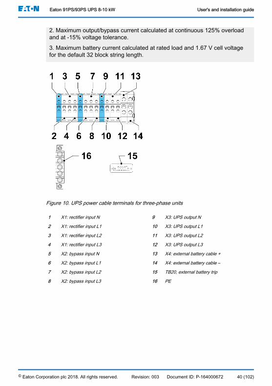
2. Maximum output/bypass current calculated at continuous 125% overloadand at -15% voltage tolerance.
3. Maximum battery current calculated at rated load and 1.67 V cell voltagefor the default 32 block string length.
Figure 10. UPS power cable terminals for three-phase units
1 X1: rectifier input N 9 X3: UPS output N
2 X1: rectifier input L1 10 X3: UPS output L1
3 X1: rectifier input L2 11 X3: UPS output L2
4 X1: rectifier input L3 12 X3: UPS output L3
5 X2: bypass input N 13 X4: external battery cable +
6 X2: bypass input L1 14 X4: external battery cable –
7 X2: bypass input L2 15 TB20, external battery trip
8 X2: bypass input L3 16 PE
Eaton 91PS/93PS UPS 8-10 kW User's and installation guide
© Eaton Corporation plc 2018. All rights reserved. Revision: 003 Document ID: P-164000672 40 (102)

Figure 11. UPS power cable terminals for single phase units
1 X1: rectifier input L1 7 X3: UPS output L
2 X1: rectifier input L2 8 X4: external battery cable +
3 X1: rectifier input L3 9 X4: external battery cable –
4 X1: bypass input N 10 PE
5 X2: bypass input L 11 TB20, external battery trip
6 X3: UPS output N
Note: External overcurrent protection is not provided by this product, but isrequired by codes. Refer to Tables 9 , 10 and 11 for wiring requirements. If alockable output disconnect is required, it must be supplied by the user.
CAUTIONTo reduce the risk of a fire, connect only to a circuit that is provided withmaximum input circuit breaker current ratings from Table 13 in accordancewith the national and local installation rules.
The line-to-line unbalanced output capability of the UPS is limited only by the fullload per phase current values for AC output to critical load shown in Table 13 .The recommended line-to-line load unbalance is 50% or less.
Source protection for the AC input to bypass must suit the characteristics of theload and take into account effects such as inrush or starting current.
Bypass input and output overcurrent protection and bypass, output andaccessory disconnect switches must be provided by the user.
Eaton 91PS/93PS UPS 8-10 kW User's and installation guide
© Eaton Corporation plc 2018. All rights reserved. Revision: 003 Document ID: P-164000672 41 (102)
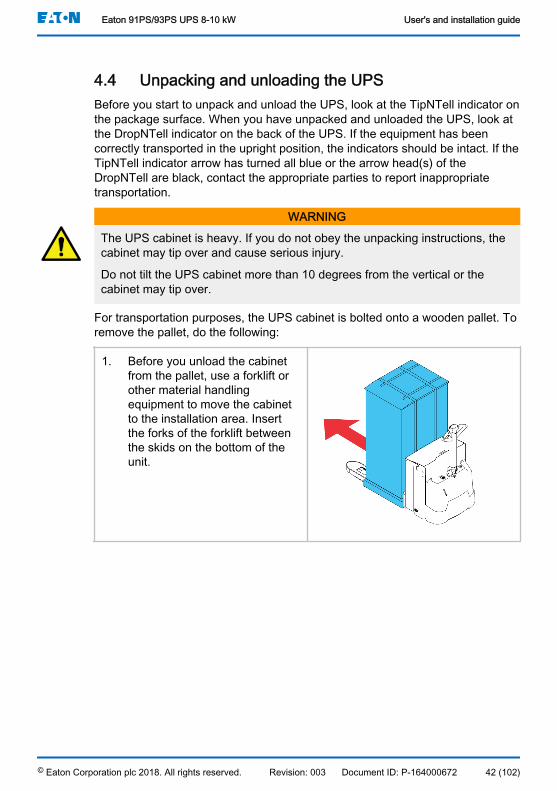
4.4 Unpacking and unloading the UPSBefore you start to unpack and unload the UPS, look at the TipNTell indicator onthe package surface. When you have unpacked and unloaded the UPS, look atthe DropNTell indicator on the back of the UPS. If the equipment has beencorrectly transported in the upright position, the indicators should be intact. If theTipNTell indicator arrow has turned all blue or the arrow head(s) of theDropNTell are black, contact the appropriate parties to report inappropriatetransportation.
WARNING
The UPS cabinet is heavy. If you do not obey the unpacking instructions, thecabinet may tip over and cause serious injury.
Do not tilt the UPS cabinet more than 10 degrees from the vertical or thecabinet may tip over.
For transportation purposes, the UPS cabinet is bolted onto a wooden pallet. Toremove the pallet, do the following:
1. Before you unload the cabinetfrom the pallet, use a forklift orother material handlingequipment to move the cabinetto the installation area. Insertthe forks of the forklift betweenthe skids on the bottom of theunit.
Eaton 91PS/93PS UPS 8-10 kW User's and installation guide
© Eaton Corporation plc 2018. All rights reserved. Revision: 003 Document ID: P-164000672 42 (102)
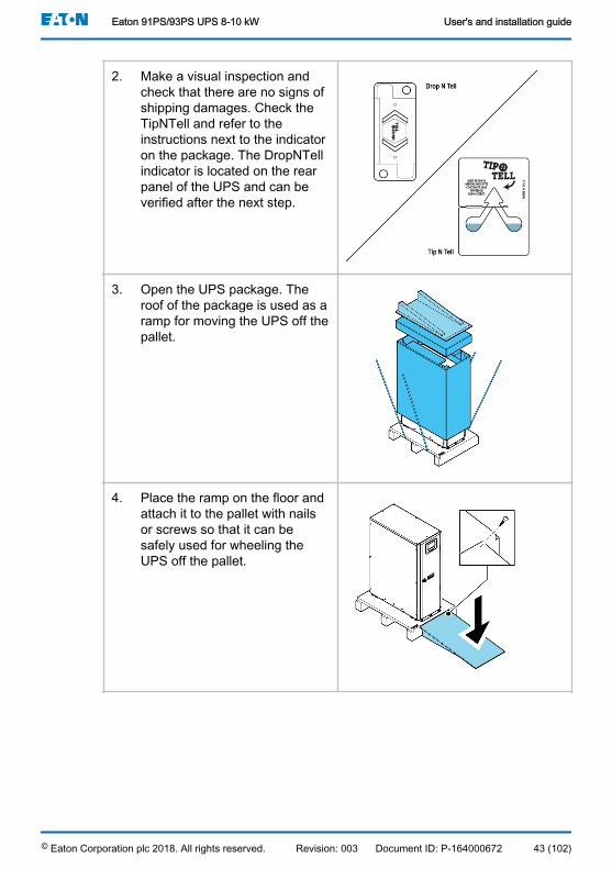
2. Make a visual inspection andcheck that there are no signs ofshipping damages. Check theTipNTell and refer to theinstructions next to the indicatoron the package. The DropNTellindicator is located on the rearpanel of the UPS and can beverified after the next step.
3. Open the UPS package. Theroof of the package is used as aramp for moving the UPS off thepallet.
4. Place the ramp on the floor andattach it to the pallet with nailsor screws so that it can besafely used for wheeling theUPS off the pallet.
Eaton 91PS/93PS UPS 8-10 kW User's and installation guide
© Eaton Corporation plc 2018. All rights reserved. Revision: 003 Document ID: P-164000672 43 (102)
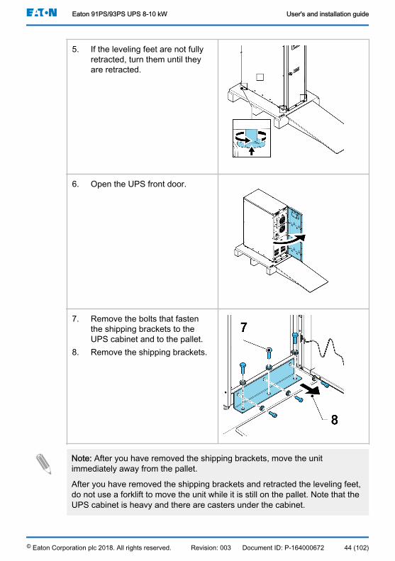
5. If the leveling feet are not fullyretracted, turn them until theyare retracted.
6. Open the UPS front door.
7. Remove the bolts that fastenthe shipping brackets to theUPS cabinet and to the pallet.
8. Remove the shipping brackets.
Note: After you have removed the shipping brackets, move the unitimmediately away from the pallet.
After you have removed the shipping brackets and retracted the leveling feet,do not use a forklift to move the unit while it is still on the pallet. Note that theUPS cabinet is heavy and there are casters under the cabinet.
Eaton 91PS/93PS UPS 8-10 kW User's and installation guide
© Eaton Corporation plc 2018. All rights reserved. Revision: 003 Document ID: P-164000672 44 (102)

9. Slowly roll the cabinet towardthe ramp edge. Be careful not topush the cabinet too much ortoo fast since it may cause thecabinet to tip over. Note that thecabinet is heavy. Make sure thatyou have enough manpower tohandle and support the unitwhile rolling it off the pallet.
10. Roll the cabinet to its finalinstallation location.
11. To secure the UPS cabinet inposition, lower the leveling feetuntil the cabinet is not resting onthe casters and the cabinet islevel.With 91PS/93PS 8-10 kW UPS,reattach the shipping bracketsto the UPS cabinet to provideextra support. There are 2options for positioning theshipping brackets: on both sidesof the unit or on the front andrear of the unit.
Note: If you remove the cabinet from its original installation location andtransfer it to a new location on a pallet, lower the leveling feet until the cabinetis not resting on the casters. In addition, attach the shipping brackets to thecabinet and the pallet.
Eaton 91PS/93PS UPS 8-10 kW User's and installation guide
© Eaton Corporation plc 2018. All rights reserved. Revision: 003 Document ID: P-164000672 45 (102)

5 UPS system installationThe operator has to supply the wiring to connect the UPS to the local powersource. The installation of the UPS must be made by a locally qualifiedelectrician. The electrical installation procedure is described in the followingsection. The installation inspection and the initial start-up of the UPS andinstalling an extra battery cabinet must be carried out by an authorized EatonField Service Engineer or by other qualified service personnel authorized byEaton.
CAUTIONTo avoid physical injury or death, or damage to the UPS or the loadequipment, follow these instructions during the UPS system installation.
CAUTIONIn case of condensed moisture inside the UPS cabinet, dry the cabinet with ablower before starting up the system.
5.1 Steps to install the UPSPower and control wiring are routed through the rear of the cabinet withconnections made to easily accessible terminals, see Figure 12 .To install and connect the power cabling of the external battery to the UPS, seeSection 5.4.
Figure 12. Gland plate and connector locations
1 Connectors 2 Gland plate
Eaton 91PS/93PS UPS 8-10 kW User's and installation guide
© Eaton Corporation plc 2018. All rights reserved. Revision: 003 Document ID: P-164000672 46 (102)
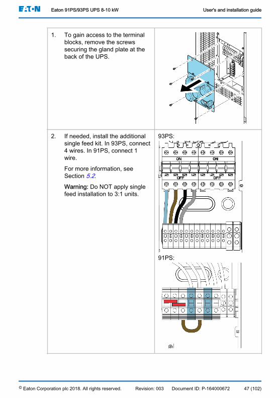
1. To gain access to the terminalblocks, remove the screwssecuring the gland plate at theback of the UPS.
2. If needed, install the additionalsingle feed kit. In 93PS, connect4 wires. In 91PS, connect 1wire.
For more information, seeSection 5.2.
Warning: Do NOT apply singlefeed installation to 3:1 units.
93PS:
91PS:
Eaton 91PS/93PS UPS 8-10 kW User's and installation guide
© Eaton Corporation plc 2018. All rights reserved. Revision: 003 Document ID: P-164000672 47 (102)
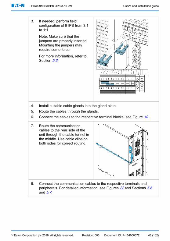
3. If needed, perform fieldconfiguration of 91PS from 3:1to 1:1.
Note: Make sure that thejumpers are properly inserted.Mounting the jumpers mayrequire some force.
For more information, refer toSection 5.3.
4. Install suitable cable glands into the gland plate.5. Route the cables through the glands.6. Connect the cables to the respective terminal blocks, see Figure 10 .
7. Route the communicationcables to the rear side of theunit through the cable tunnel inthe middle. Use cable clips onboth sides for correct routing.
8. Connect the communication cables to the respective terminals andperipherals. For detailed information, see Figures 22 and Sections 5.6and 5.7.
Eaton 91PS/93PS UPS 8-10 kW User's and installation guide
© Eaton Corporation plc 2018. All rights reserved. Revision: 003 Document ID: P-164000672 48 (102)

9. Assemble the internal batteriesinto the battery trays. Connectthe battery blocks in serieswithin the battery tray. Only usecables specified by Eaton.
10. Slide the internal battery traysinto place and mount the lockingbrackets.
11. Connect the internal batteries.
5.2 91PS/93PS 8-10 kW UPS Single feed installationAdditional single feed kits are available for the 93PS (3-phase in / 3-phase out)and 91PS 1:1 (1-phase in / 1-phase out) units. Single feed kits are included inthe UPS package.
WARNINGDo NOT apply single feed installation to 3:1 units.
5.3 91PS input system field configurationIf supported by the UPS, the input power system may be configured during theinstallation of the unit. By default, the 91PS units are shipped with configurationfor 3 phase rectifier operation. To change the rectifier input to 1 phaseoperation, follow these steps:
1. Make sure that the UPS is turned off and all the AC and DC power sourcesare disconnected.
2. Install the jumpers to the connectors X1:L1 – X1:L3.
Eaton 91PS/93PS UPS 8-10 kW User's and installation guide
© Eaton Corporation plc 2018. All rights reserved. Revision: 003 Document ID: P-164000672 49 (102)
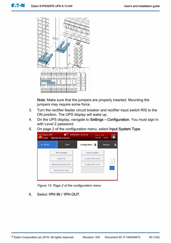
Note: Make sure that the jumpers are properly inserted. Mounting thejumpers may require some force.
3. Turn the rectifier feeder circuit breaker and rectifier input switch RIS to theON position. The UPS display will wake up.
4. On the UPS display, navigate to Settings – Configuration. You must sign inwith Level 2 password.
5. On page 2 of the configuration menu, select Input System Type.
Figure 13. Page 2 of the configuration menu
6. Select 1PH IN / 1PH OUT.
Eaton 91PS/93PS UPS 8-10 kW User's and installation guide
© Eaton Corporation plc 2018. All rights reserved. Revision: 003 Document ID: P-164000672 50 (102)

Figure 14. Input System Type window
7. Select Save to save the changes.
The UPS now functions with single phase input.
5.4 Battery system installationDANGER
This UPS may have internal batteries. The batteries are designed to deliver alarge amount of energy and an incorrect connection may lead to a shortcircuit and cause serious injuries to the personnel or damages to theequipment. In order to avoid damages to the equipment or injuries topersonnel, only commissioning personnel are allowed to perform theconnection of these batteries.
If you are installing a customer-supplied battery system, install the batterysystem according to the battery and battery system manufacturer’s instructionsand all the applicable national codes and regulations. Only qualified personnelmay install the battery system. Battery cables must be protected against currentand thermal overload, that is, the battery system must include proper fuses orbreaker with protection function. Ground the external battery cabinet to the UPS.
The default battery settings of the UPS are for 12 V VRLA batteries. If you needto use any other type of batteries, contact your Eaton representative. For thebattery specification, see Section 9.5.
5.4.1 Battery trip wiringThe 91PS/93PS 8-10 kW UPS units are always equipped with an internalbattery breaker, which affects only the UPS internal batteries. The external
Eaton 91PS/93PS UPS 8-10 kW User's and installation guide
© Eaton Corporation plc 2018. All rights reserved. Revision: 003 Document ID: P-164000672 51 (102)

battery breaker is a crucial part of the external battery cabinet or rack and mustbe placed in it. With the external battery breaker, signal cabling is important.
Both internal and external battery breakers can be tripped (switched off) byenergizing its shunt trip coil. The shunt trip coils of external battery breakers areenergized (controlled) through connector TB20. The default voltage of the shunttrip coil is 24 Vdc.
Figure 15. Battery trip wiring, TB20
A External battery breaker 3 Pin 3, AUX contact
1 Pin 1, shunt trip coil + 4 Pin 4, AUX contact return
2 Pin 2, shunt trip coil -
5.5 Installing UPS external battery cabinet and batterypower cablingThe battery cabinet type for the 91PS/93PS 8-10 kW UPS is EBC-H. The UPSuses 32 battery blocks per string.
Note: Do not connect battery strings with different battery quantity and voltagein parallel.
Power and control wiring for the EBC-H cabinets is supplied with the cabinets.The battery cabinet can be located freely of the 91PS/93PS UPS cabinet. All thewiring goes through the back wall of the UPS cabinet.
For instructions on how to install the external battery cabinet and battery powercabling, see the instruction manual provided with the external battery cabinet.Earth the external battery cabinet / customer-supplied battery system to the PEterminal 16 shown in Figure 10 .
Note: If batteries are wired outside the cabinets, follow the installationinstructions given in Section 4.3.2. See Table 9 for the recommended cableand fuse sizes.
Eaton 91PS/93PS UPS 8-10 kW User's and installation guide
© Eaton Corporation plc 2018. All rights reserved. Revision: 003 Document ID: P-164000672 52 (102)
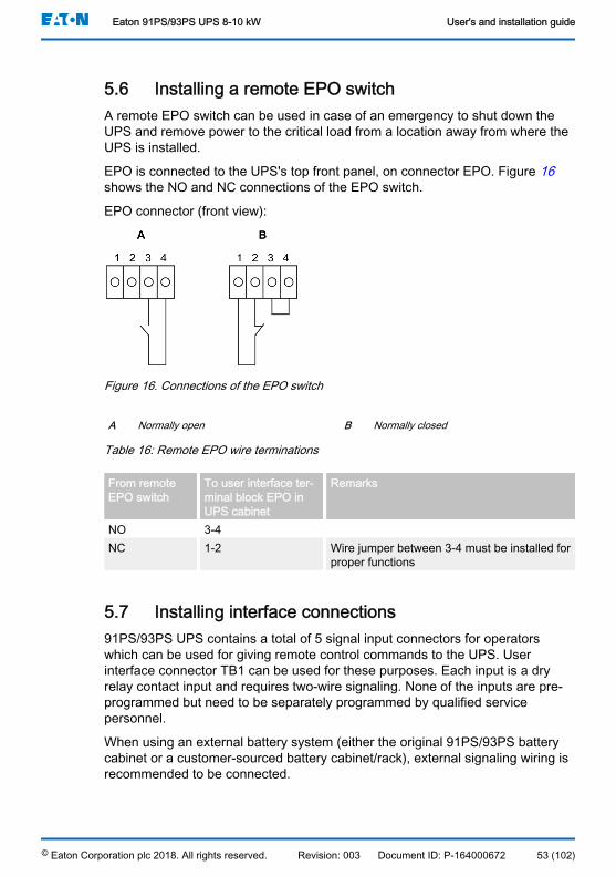
5.6 Installing a remote EPO switchA remote EPO switch can be used in case of an emergency to shut down theUPS and remove power to the critical load from a location away from where theUPS is installed.
EPO is connected to the UPS's top front panel, on connector EPO. Figure 16shows the NO and NC connections of the EPO switch.
EPO connector (front view):
Figure 16. Connections of the EPO switch
A Normally open B Normally closed
Table 16: Remote EPO wire terminations
From remoteEPO switch
To user interface ter-minal block EPO inUPS cabinet
Remarks
NO 3-4NC 1-2 Wire jumper between 3-4 must be installed for
proper functions
5.7 Installing interface connections91PS/93PS UPS contains a total of 5 signal input connectors for operatorswhich can be used for giving remote control commands to the UPS. Userinterface connector TB1 can be used for these purposes. Each input is a dryrelay contact input and requires two-wire signaling. None of the inputs are pre-programmed but need to be separately programmed by qualified servicepersonnel.
When using an external battery system (either the original 91PS/93PS batterycabinet or a customer-sourced battery cabinet/rack), external signaling wiring isrecommended to be connected.
Eaton 91PS/93PS UPS 8-10 kW User's and installation guide
© Eaton Corporation plc 2018. All rights reserved. Revision: 003 Document ID: P-164000672 53 (102)
One general alarm relay output is also on the front panel. This output is eithernormally open (NO) or normally closed (NC). The polarity selection is made witha wiring connection. By default, the general alarm relay activates when a systemalarm is active, that is, any ALARM condition is active in the system.Alternatively, it can be activated with any particular event, but this must beprogrammed separately by qualified service personnel. The alarm relay isdesigned for signal level (ELV or SELV) voltages only, not for utility use. Forhigher signaling circuit voltage requirements, please use an industrial relayadapter in the MiniSlot.
5.7.1 Installing customer input signals interfaceThese inputs are located behind the UPS door, in the top section of the UPS.See Figure 22 for the connector locations.
Tie points with strain relief for the communication cables are located on the rightand left side of the cable conduit.
Signal inputs can be configured to different functions. Normally these functionsare either informative (for example, “On Generator”) or functional (for example, aremote “Go to bypass” command).
5.7.2 Battery breaker wiring interfaceWhen using the original accessory battery cabinet from the manufacturer, thebattery breaker interface wiring is provided with the cabinet. Connecting itrequires only routing the wires from the cabinet to terminal TB20.
When using a third-party battery system, the breaker must be equipped withauxiliary signal and should have a 24 V shunt trip for remote opening of thebreaker, when needed.
Wire entry for the battery breaker signal wiring is located in the middle of theUPS cabinet. Punch holes are located on the left or right side panel, back wall orbottom plate.
See Section 5.4.1 for installation instructions.
5.7.3 Relay output interface connectionsThe general alarm relay is a dry relay signal output. The relay can be used forinforming the operators about UPS alarm conditions, for example through abuilding management system. By default, the relay is configured to activatewhen the UPS general alarm is active, that is, any event when the ALARMstatus is active. The relay can also be configured to activate by some otherevent, but this needs to be done by authorized service personnel.
Relay signal wiring can be installed only through the signal cabling canal, fromback to front, in the top section of the UPS.
Eaton 91PS/93PS UPS 8-10 kW User's and installation guide
© Eaton Corporation plc 2018. All rights reserved. Revision: 003 Document ID: P-164000672 54 (102)

Additional relay outputs are available with mini-slot cards. Relay outputs can beconfigured to be activated by various events. Configuration can be done by anauthorized Eaton Field Service Engineer or by other qualified service personnelauthorized by Eaton.
5.7.4 Industrial Relay Card interface connectionsRelays K1 through K5 are identical in function. Each output contact function canbe assigned by the user. The UPS information may also be configurable.
To install the INDRELAY-MS:
1. Check that the ancillary equipment system is turned off and all the powersources are removed. Refer to the appropriate operation manual of anyancillary equipment for shutdown instructions.
2. Install wiring from the IRC to the monitoring equipment using appropriateconduits through the cable exit opening in the IRC.
3. Connect wiring between the IRC terminal blocks and the monitoringequipment using terminations. Connect one wire to COM (Common) andanother to either NC or NO to select the Normally Open or Normally Closedoption.
4. Install the INDRELAY-MS into an open MiniSlot communication bay in theUPS cabinet.
Figure 17. Industrial Relay Card INDRELAY-MS
5.7.5 MiniSlot interface connectionsFor MiniSlot accessories and communication devices selection, see Chapter 6.For installation and setup of a MiniSlot card, please contact your Eatonrepresentative.
To install wiring to the connections:
1. If not already installed, install the LAN drops.
Eaton 91PS/93PS UPS 8-10 kW User's and installation guide
© Eaton Corporation plc 2018. All rights reserved. Revision: 003 Document ID: P-164000672 55 (102)

2. Open the front door of the UPS.3. To remove the MiniSlot cover plate, remove the 2 screws securing the
plate.4. To install the MiniSlot communication device, push it all the way in.5. Secure the MiniSlot communication device with 2 screws.6. Route and install the LAN and other cables to the appropriate MiniSlot
cards. The cable route is through the signal cable canal in the top sectionof the UPS.
7. For operator instructions, refer to the manual supplied with the MiniSlotcard.
8. When all the wiring is completed, close the front door and secure it with thelatch.
5.7.6 Installing signal interface connections in a parallel systemThe installation of the signal interface connections in a parallel system is doneby following the aforementioned instructions. Signal inputs can be paralleledbetween the units, that is, the same contact can be used for several units’ signalinput signaling. This concerns also the EPO signal.
5.8 Wiring parallel 91PS/93PS UPS systemsThe outputs of multiple 91PS/93PS UPS systems can be connected in parallel.Up to 4 units can be paralleled. The UPS static bypass power rating needs to beidentical among all the paralleled units. However, paralleled UPS cabinets canbe housed with different number of UPM power modules.
The outputs are paralleled to increase the load capacity of the power systemand for redundancy. The system is paralleled for (N+1) redundancy as long asthere is always one or more UPS online than required to support the load. Thesystem is paralleled for capacity if all UPSs in a system are required to supportthe load.
Communication between the UPSs is required for system metering and modecontrol. The system level communication and control are accomplished using aController Area Network (CAN). A pull-chain signal in each UPS, connected tothe other UPSs in parallel and tied to the bypass status relay in each UPS, isused for a secondary communication path. This arrangement ensures bypasscontrol even if the CAN bus is lost.
WARNINGDo not use the internal maintenance bypass switch in units that areconnected in a parallel configuration.
Eaton 91PS/93PS UPS 8-10 kW User's and installation guide
© Eaton Corporation plc 2018. All rights reserved. Revision: 003 Document ID: P-164000672 56 (102)
5.8.1 Power wiring overviewSee Section 4.3.2 for the recommended cable and external fuse sizes andinstallation practices.
Input feed
The input feed is defined as the power source connected to the UPS rectifier.The feed to all UPS’s inputs must be derived from the same source.
Bypass feed
The bypass feed is defined as the power source connected to the UPS bypass.The feed to all UPS’s bypass must be derived from the same source. Theshortest length of power wire from the source to the UPS must be a minimum of95% of the length of the longest wire.
Output
The neutrals of all the UPSs must be connected. The shortest length of wirefrom the source to the UPS must be a minimum of 95% of the length of thelongest wire. The measurement is with respect to where the UPS’s outputs aretied.
Dual source
The input feed and bypass feed may be separate sources. The sources mustshare a common neutral.
Battery connection
A separate battery shall be connected to each UPS, and the battery capacity foreach UPS must be identical. A common battery for all UPSs is not supported.
MOBs
Module Output Breakers (MOBs) allow the output of an UPS to be disconnectedfrom other UPSs and the system load for maintenance and service. Designconsiderations assume that each UPS has a Module Output Breaker (MOB).The breaker should also disconnect the neutral for improved safety duringmaintenance.
The MOB must have a Form “C” auxiliary contact. The N.C contact is connectedto the corresponding UPS’s input used for signal input. The N.O. contact is usedto disconnect the bypass pull-chain when the MOB is open. Figure 18 shows theprinciples of paralleled UPS systems including MOBs and outputs from UPSs.
MOB override
Users without MOBs installed can simply leave the MOB signal input disabled.The user should be aware that systems without MOB have limited maintenancecapability.
Parallel system cabling
Eaton 91PS/93PS UPS 8-10 kW User's and installation guide
© Eaton Corporation plc 2018. All rights reserved. Revision: 003 Document ID: P-164000672 57 (102)

Figure 18. Principle of paralleled UPS systems
A Bypass inputs to UPSs 1 UPS 1 7 BatteryB Outputs from UPSs 2 UPS 2 8 BatteryC Load 3 UPS 3 9 MOB1
4 UPS 4 10 MOB25 Battery 11 MOB36 Battery 12 MOB4
The required parallel system wiring length must be equal to ensureapproximately equal current sharing when in the bypass mode.
For proper operation, the following must be true: 1A+1B=2A+2B=3A+3B=4A+4B.
Any differences in wire length result in decreased capacity and improperoperation of the UPS system while in the bypass mode.
5.8.2 Control signals overview2 controls signals (External CAN Network, Bypass Pull-Chain) are required forexternal paralleling. Both of these control signals are fault-tolerant and alarmedwhen disconnected.
External CAN (ECAN)
Eaton 91PS/93PS UPS 8-10 kW User's and installation guide
© Eaton Corporation plc 2018. All rights reserved. Revision: 003 Document ID: P-164000672 58 (102)

ECAN provides means for communication between the UPS’s in a parallelsystem. When this network fails, the system continues to share load and protectthe load.
Bypass Pull-Chain
Bypass Pull-Chain is an open collector signal that goes low when the bypassstatic switch of any UPS is online. When External CAN (ECAN) is down, thepull-chain is low and the UPS is online, the UPS locks to and transfers to thebypass mode. Service can manually short this signal in some rare failure modesto force a system transfer to bypass.
Signal Inputs Actions
Each UPS has a maximum of 7 signal inputs, 5 native and one in each MiniSlotwhen using a suitable connectivity device. These inputs can be configured withaction items. The following action items affect all the UPSs in the system. Whenan action item is active on a UPS and the MOB is closed, the action item istransmitted on the ECAN to all the UPSs. All the UPSs react in the samemanner as if the action item was active on that UPS.
Wiring the EPO switch in parallel
It is recommended to use separate EPO circuits for each parallel unit.
5.8.3 Installing bypass control wiring1. During the installation, follow all the safety instructions given in this
document.2. Terminal blocks TB2, TB3 and TB4 are for external parallel control signals.3. The Phoenix Contact FRONT-MSTB 2,5/2-STF-5,08 and 2,6/4-SFT-5,08
plug components are used for cable wiring termination.
Eaton 91PS/93PS UPS 8-10 kW User's and installation guide
© Eaton Corporation plc 2018. All rights reserved. Revision: 003 Document ID: P-164000672 59 (102)
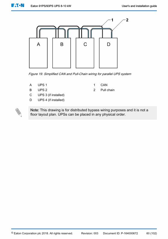
Figure 19. Simplified CAN and Pull-Chain wiring for parallel UPS system
A UPS 1 1 CANB UPS 2 2 Pull chainC UPS 3 (if installed)D UPS 4 (if installed)
Note: This drawing is for distributed bypass wiring purposes and it is not afloor layout plan. UPSs can be placed in any physical order.
Eaton 91PS/93PS UPS 8-10 kW User's and installation guide
© Eaton Corporation plc 2018. All rights reserved. Revision: 003 Document ID: P-164000672 60 (102)
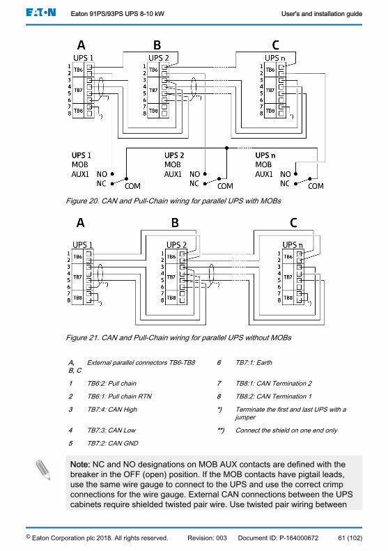
Figure 20. CAN and Pull-Chain wiring for parallel UPS with MOBs
Figure 21. CAN and Pull-Chain wiring for parallel UPS without MOBs
A,B, C
External parallel connectors TB6-TB8 6 TB7:1: Earth
1 TB6:2: Pull chain 7 TB8:1: CAN Termination 2
2 TB6:1: Pull chain RTN 8 TB8:2: CAN Termination 1
3 TB7:4: CAN High *) Terminate the first and last UPS with ajumper
4 TB7:3: CAN Low **) Connect the shield on one end only
5 TB7:2: CAN GND
Note: NC and NO designations on MOB AUX contacts are defined with thebreaker in the OFF (open) position. If the MOB contacts have pigtail leads,use the same wire gauge to connect to the UPS and use the correct crimpconnections for the wire gauge. External CAN connections between the UPScabinets require shielded twisted pair wire. Use twisted pair wiring between
Eaton 91PS/93PS UPS 8-10 kW User's and installation guide
© Eaton Corporation plc 2018. All rights reserved. Revision: 003 Document ID: P-164000672 61 (102)

the UPS and MOB AUX contacts. Always confirm contact operation prior towiring.
5.9 UPS system interface wiring preparationControl wiring for features and options should be connected at the user interfaceterminal blocks located on top front of the UPS, behind the door.
Note: Do not connect relay contacts directly to the mains-related circuits.Reinforced insulation to the mains is required.
When you are planning and performing the installation, make sure youunderstand the following notes:
• All the interface wiring is provided by the operator.• When installing internal interface wiring to MiniSlot terminals, route the wiring
through the internal opening in the MiniSlot communication bay.• All signal inputs or remote features require an isolated normally-open
contact or switch (rated at 24 VDC, 20 mA minimum) connected between thealarm input and the common terminal. All control wiring and relay and switchcontacts are supplied by the operator. Use twisted-pair wires for each alarminput and common.
• The signal inputs can be programmed to display the alarm's functionalname.
• LAN drops for use with MiniSlot cards are provided by facility planners or theoperator.
• The UPS Battery Aux and 24 VDC Shunt Trip signal wiring from the UPSmust be connected to the DC source disconnect device. See Figure 15 .
• Battery Aux and 24 VDC Shunt Trip wiring must be a minimum of 1.5 mm2.• The Remote EPO feature opens all switchgear in the UPS cabinet and
isolates power from your critical load. Local electrical codes may also requiretripping upstream protective devices to the UPS.
• The Remote EPO switch must be a dedicated switch that is not tied to anyother circuits.
• If the normally-closed (NC) Remote EPO contact is used, a jumper wire mustbe connected between pins 1 and 2 on connector EPO.
• Remote EPO wiring should be a minimum of 0.75 mm2 and a maximum of2.5 mm2.
• The distance between the Remote EPO and the UPS cannot exceed 150meters.
• Alarm relay contacts have a maximum current rating of 5 A and a switchedvoltage rating of 30 VAC (RMS) and 30 VDC.
• Alarm relay wiring must be a minimum of 0.75 mm2.
Eaton 91PS/93PS UPS 8-10 kW User's and installation guide
© Eaton Corporation plc 2018. All rights reserved. Revision: 003 Document ID: P-164000672 62 (102)

6 Communication interfacesThis section describes the communication features.
CAUTIONAll the communication interfaces are SELV circuits. When connecting to otherequipment, make sure that you maintain this characteristic.
The UPS has the following communication interfaces:
1. MiniSlot 12. MiniSlot 23. USB device (connection to computer)4. Communication cable conduit5. Emergency Power Off (EPO)6. Relay output7. USB host (connection to accessories)8. Signal inputs9. RS-232 port for service
See Figure 22 for the location of communication interfaces in 91PS/93PS UPS8–10 kW.
Eaton 91PS/93PS UPS 8-10 kW User's and installation guide
© Eaton Corporation plc 2018. All rights reserved. Revision: 003 Document ID: P-164000672 63 (102)
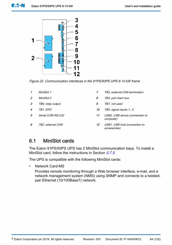
Figure 22. Communication interfaces in the 91PS/93PS UPS 8-10 kW frame
1 MiniSlot 1 7 TB3, external CAN termination
2 MiniSlot 2 8 TB4, pull chain bus
3 TB6, relay output 9 TB7, not used
4 TB1, EPO 10 TB5, signal inputs 1...5
5 Serial COM RS-232 11 USB2, USB device (connection tocomputer)
6 TB2, external CAN 12 USB1, USB host (connection toaccessories)
6.1 MiniSlot cardsThe Eaton 91PS/93PS UPS has 2 MiniSlot communication bays. To install aMiniSlot card, follow the instructions in Section 5.7.5.
The UPS is compatible with the following MiniSlot cards:
• Network Card-MSProvides remote monitoring through a Web browser interface, e-mail, and anetwork management system (NMS) using SNMP and connects to a twisted-pair Ethernet (10/100BaseT) network.
Eaton 91PS/93PS UPS 8-10 kW User's and installation guide
© Eaton Corporation plc 2018. All rights reserved. Revision: 003 Document ID: P-164000672 64 (102)

Figure 23. Network Card - MS
• PX Gateway Card (only with 93PS (3:3) UPS)Provides remote monitoring through a Web browser interface, e-mail, and anetwork management system (NMS) using SNMP and connects to a twisted-pair Ethernet (10/100BaseT) network. The card also provides directintegration of UPS information (meters and status) to a BuildingManagement System (BMS) using the Modbus RTU and TCP protocols aswell as BACnet protocols.
Figure 24. PX Gateway Card
• Industrial Relay Card-MSThe MiniSlot Industrial Relay Card provides a way of connecting the 91PS/93PS to industrial and electrical monitoring systems. It also enables a widerange of control applications by allowing up to 250 volts and 8 Amperesthrough its 5 relay connections. By connecting wires to the correspondingplaces in its terminal blocks, you can choose Normally Open or NormallyClosed setup for each output.For information on how to configure Industrial Relay Card-MS, see Section 6.5.
Eaton 91PS/93PS UPS 8-10 kW User's and installation guide
© Eaton Corporation plc 2018. All rights reserved. Revision: 003 Document ID: P-164000672 65 (102)

Figure 25. Industrial Relay Card-MS
6.2 Intelligent Power SoftwareIntelligent Power Software are productivity tools for UPS power management.These software solutions enhance the protection provided by a UPS by shuttingdown applications and operating systems, triggering disaster recoveryprocedures and migrating virtual machines in case of an extended poweroutage. They also help in reducing downtime and increasing the reliability of theUPS by alarming the operators of issues and monitoring vital meters. Thesoftware can also be used to view the usage characteristics of power equipmentacross the enterprise and use the data to optimize the use of the facilities.
Intelligent Power Software is web-based, which means that the information canbe accessed through any device that has a web browser.
On one hand, Intelligent Power Manager (IPM) is a monitoring system that canconcentrate the data and alarms of hundreds of UPS, ePDU and other devicesinto a single view. On the other hand, it provides a link to virtualization throughmanagement systems, such as VMware vCenter. This way an administratorgets a single pane of glass to manage both IT equipment and the supportinginfrastructure. IPM provides the shutdown, migration, disaster recovery and loadshedding features in virtualized environments.
Intelligent Power Protector (IPP) is a shutdown agent with basic monitoring andalarming capability. It provides automatic, graceful shutdown of computers andvirtual machines or servers powered by an Eaton UPS during a power outagethat lasts longer than your available battery runtime. Intelligent Power Protectorcan be remotely supervised and managed by the Intelligent Power Manager(IPM) application.
Eaton 91PS/93PS UPS 8-10 kW User's and installation guide
© Eaton Corporation plc 2018. All rights reserved. Revision: 003 Document ID: P-164000672 66 (102)

Intelligent Power Software is delivered on a CD with the UPS. Alternatively, youcan download it from the Eaton web page. Some of the advanced features ofIPM require a license, contact your Eaton representative for details.
6.3 Signal input monitoringThis standard feature lets you connect smoke detectors or over-temperaturealarms to your signal inputs. The user interface terminals for externalconnections are located inside the UPS. Use twisted-pair wires for each alarminput and common.
The signal inputs can be programmed to display the alarm functional name.
6.4 General purpose relay contactOne general purpose relay contact is provided as a standard feature on theUPS. An alarm contact is also provided.
You can use a normally-closed or normally-open contact. If the state of thecontact changes from the state you specify as normal, a signal is issued. Youcan connect this contact to equipment at your facility (such as a light or an alarmbell) to let you know when an alarm is active on the UPS. This feature is useful ifthe UPS is located in a remote area where the UPS horn may not be heardimmediately.
Note: Do not operate the contacts in excess of 30 VAC (RMS) and 30 VDC at5 A maximum.
6.5 Configuring relays91PS/93PS offers one native relay output. Additionally, each of the 2 MiniSlotscan be equipped with a relay card, including 5 relays. The following instructionsguide you through the relay configuration.
Currently the relay configuration can be done only using the display. The servicetool does not yet have support for nodebit functions.
The maximum voltage of the relay is 30 V. Check the voltage and currentspecifications of the other cards from the previous sections.
The process for relay configuration is as follows:
1. In the home screen of the display, click the lock icon in the top right cornerto type in the service password.
2. In the sign in window, click the password field containing the 4 dots.
Eaton 91PS/93PS UPS 8-10 kW User's and installation guide
© Eaton Corporation plc 2018. All rights reserved. Revision: 003 Document ID: P-164000672 67 (102)
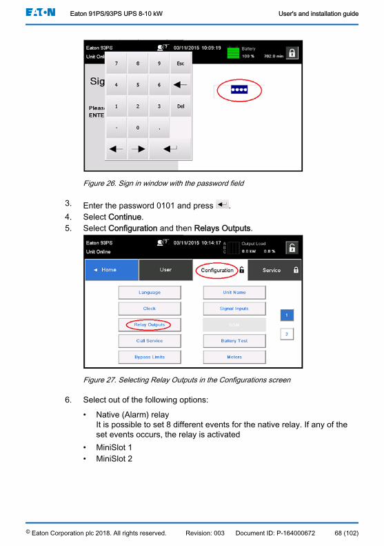
Figure 26. Sign in window with the password field
3. Enter the password 0101 and press .4. Select Continue.5. Select Configuration and then Relays Outputs.
Figure 27. Selecting Relay Outputs in the Configurations screen
6. Select out of the following options:
• Native (Alarm) relayIt is possible to set 8 different events for the native relay. If any of theset events occurs, the relay is activated
• MiniSlot 1• MiniSlot 2
Eaton 91PS/93PS UPS 8-10 kW User's and installation guide
© Eaton Corporation plc 2018. All rights reserved. Revision: 003 Document ID: P-164000672 68 (102)
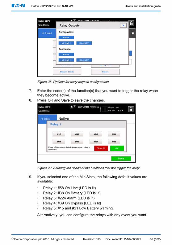
Figure 28. Options for relay outputs configuration
7. Enter the code(s) of the function(s) that you want to trigger the relay whenthey become active.
8. Press OK and Save to save the changes.
Figure 29. Entering the codes of the functions that will trigger the relay
9. If you selected one of the MiniSlots, the following default values areavailable:
• Relay 1: #58 On Line (LED is lit)• Relay 2: #38 On Battery (LED is lit)• Relay 3: #224 Alarm (LED is lit)• Relay 4: #39 On Bypass (LED is lit)• Relay 5: #15 and #21 Low Battery warning
Alternatively, you can configure the relays with any event you want.
Eaton 91PS/93PS UPS 8-10 kW User's and installation guide
© Eaton Corporation plc 2018. All rights reserved. Revision: 003 Document ID: P-164000672 69 (102)

10. You can test the relays by selecting any of the options in the test mode(see Figure 28 ).
Figure 30. Relays
1 Cable exit opening for up to 12 mm (½”)conduit
3 K1 thru K5 terminal connections for relaycontacts to operator's monitoringequipment
2 Signal input connector with voltage supply
Eaton 91PS/93PS UPS 8-10 kW User's and installation guide
© Eaton Corporation plc 2018. All rights reserved. Revision: 003 Document ID: P-164000672 70 (102)
7 UPS operating instructionsThis section describes how to operate the UPS.
CAUTIONBefore you operate the UPS, make sure that all the installation tasks arecompleted and a preliminary startup has been performed by authorizedservice personnel. The preliminary startup verifies all the electricalinterconnections to make sure that the installation was successful and thesystem operates properly.
Before you operate any of the controls, read these instructions and have athorough understanding of the UPS operation.
The UPS is configured to operate with one of the following nominal voltages:380, 400, or 415 VAC. Before you start to operate the UPS, confirm the UPSnominal voltage and frequency from the display by selecting Settings >Information. If the UPS need to be operated with another voltage orfrequency, contact your closest Eaton office or Eaton authorized partner.
Note: The UPS is not a measuring device. All the displayed measurementsare approximate values only.
7.1 UPS controls and indicators
7.1.1 Control panelThe control panel, located on the UPS front door, contains a color touch screendisplay. It is used to display the status of the UPS system and to control theoperation of the UPS.
Eaton 91PS/93PS UPS 8-10 kW User's and installation guide
© Eaton Corporation plc 2018. All rights reserved. Revision: 003 Document ID: P-164000672 71 (102)
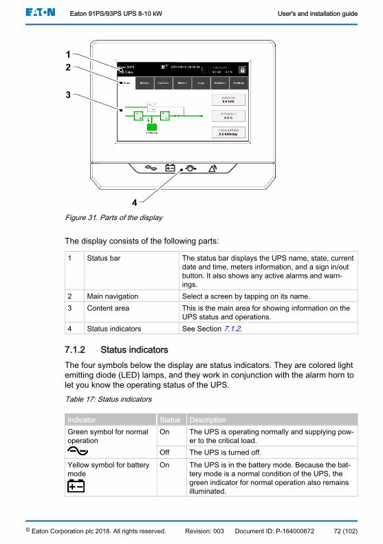
Figure 31. Parts of the display
The display consists of the following parts:
1 Status bar The status bar displays the UPS name, state, currentdate and time, meters information, and a sign in/outbutton. It also shows any active alarms and warn-ings.
2 Main navigation Select a screen by tapping on its name.3 Content area This is the main area for showing information on the
UPS status and operations.4 Status indicators See Section 7.1.2.
7.1.2 Status indicatorsThe four symbols below the display are status indicators. They are colored lightemitting diode (LED) lamps, and they work in conjunction with the alarm horn tolet you know the operating status of the UPS.Table 17: Status indicators
Indicator Status DescriptionGreen symbol for normaloperation
On The UPS is operating normally and supplying pow-er to the critical load.
Off The UPS is turned off.Yellow symbol for batterymode
On The UPS is in the battery mode. Because the bat-tery mode is a normal condition of the UPS, thegreen indicator for normal operation also remainsilluminated.
Eaton 91PS/93PS UPS 8-10 kW User's and installation guide
© Eaton Corporation plc 2018. All rights reserved. Revision: 003 Document ID: P-164000672 72 (102)
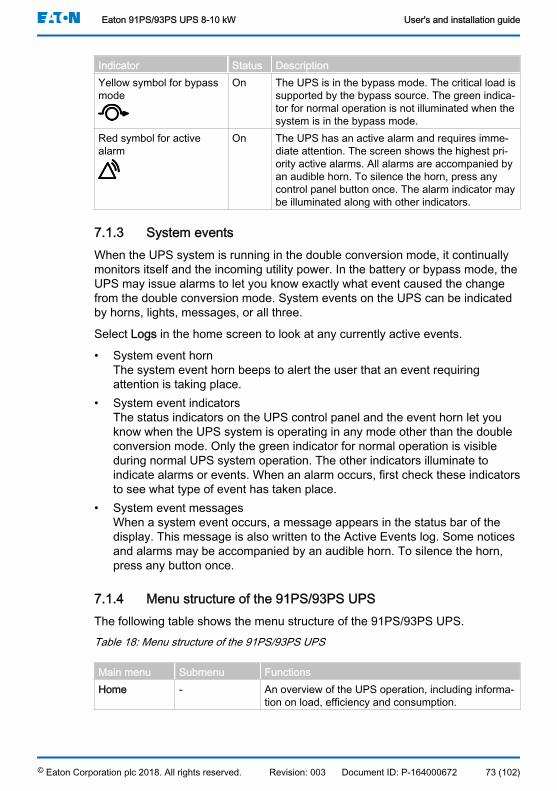
Indicator Status DescriptionYellow symbol for bypassmode
On The UPS is in the bypass mode. The critical load issupported by the bypass source. The green indica-tor for normal operation is not illuminated when thesystem is in the bypass mode.
Red symbol for activealarm
On The UPS has an active alarm and requires imme-diate attention. The screen shows the highest pri-ority active alarms. All alarms are accompanied byan audible horn. To silence the horn, press anycontrol panel button once. The alarm indicator maybe illuminated along with other indicators.
7.1.3 System eventsWhen the UPS system is running in the double conversion mode, it continuallymonitors itself and the incoming utility power. In the battery or bypass mode, theUPS may issue alarms to let you know exactly what event caused the changefrom the double conversion mode. System events on the UPS can be indicatedby horns, lights, messages, or all three.
Select Logs in the home screen to look at any currently active events.
• System event hornThe system event horn beeps to alert the user that an event requiringattention is taking place.
• System event indicatorsThe status indicators on the UPS control panel and the event horn let youknow when the UPS system is operating in any mode other than the doubleconversion mode. Only the green indicator for normal operation is visibleduring normal UPS system operation. The other indicators illuminate toindicate alarms or events. When an alarm occurs, first check these indicatorsto see what type of event has taken place.
• System event messagesWhen a system event occurs, a message appears in the status bar of thedisplay. This message is also written to the Active Events log. Some noticesand alarms may be accompanied by an audible horn. To silence the horn,press any button once.
7.1.4 Menu structure of the 91PS/93PS UPSThe following table shows the menu structure of the 91PS/93PS UPS.Table 18: Menu structure of the 91PS/93PS UPS
Main menu Submenu FunctionsHome - An overview of the UPS operation, including informa-
tion on load, efficiency and consumption.
Eaton 91PS/93PS UPS 8-10 kW User's and installation guide
© Eaton Corporation plc 2018. All rights reserved. Revision: 003 Document ID: P-164000672 73 (102)

Main menu Submenu FunctionsMeters Meters summa-
ryA summary of the UPS or system meters.
Input meters Detailed information on UPS or system input meters.Bypass meters Detailed information on UPS or system bypass me-
ters.Output meters Detailed information on UPS or system output me-
ters.
UPM PowerBattery meters Detailed information on UPS or system battery me-
ters.Controls System controls Go to bypass
Go Online
Load OffUPS controls Turn Off Charger
Run battery test
Shut down UPSEAA controls ESS:
• Enable• Disable
ABM:
• Enable• Disable• Configure
Clear logs
Clear status
Clear alarmsMimics UPS mimics An overview of the UPS operation, including informa-
tion on load, efficiency and consumption. If there isan error, an error indicator is displayed next to the af-fected part. Active events log can be opened by tap-ping the error indicator.
System over-view
System overview shows the status and meters sum-mary for each UPS.
ESS The ESS mimic screen shows the approximated con-sumption and energy savings of the ESS mode.
Logs Active events All active events are displayed.System log A log of all system events.Service log A detailed log of UPS operations.Change log A log of all changed settings and their values.
Eaton 91PS/93PS UPS 8-10 kW User's and installation guide
© Eaton Corporation plc 2018. All rights reserved. Revision: 003 Document ID: P-164000672 74 (102)
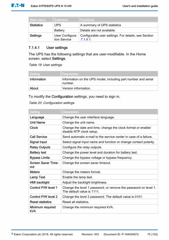
Main menu Submenu FunctionsStatistics UPS A summary of UPS statistics
Battery Details are not available.Settings User Configura-
tion ServiceConfigurable user settings. For details, see Section 7.1.4.1.
7.1.4.1 User settings
The UPS has the following settings that are user-modifiable. In the Homescreen, select Settings.Table 19: User settings
Setting DescriptionInformation Information on the UPS model, including part number and serial
number.About Version information.
To modify the Configuration settings, you need to sign in.Table 20: Configuration settings
Setting DescriptionLanguage Change the user interface language.Unit Name Change the unit name.Clock Change the date and time, change the clock format or enable/
disable NTP clock setup.Call Service Send automatic e-mail to the service center in case of a failure.Signal Input Select signal input name and function or change contact polarity.Relay Outputs Configure the relay outputs.Battery test Change the power level and duration for battery test.Bypass Limits Change the bypass voltage or bypass frequency.Screen Saver Time-out
Change the screen saver timeout.
Meters Change the meters format.Lamp Test Enable the lamp test.HMI backlight Adjust the backlight brightness.Control P/W level 1 Change the level 1 password, or remove the password on level 1.
The default value is 1111.Control P/W level 2 Change the level 2 password. The default value is 0101.Reset statistics Reset all statistics.Minimum requiredkVA
Change the minimum required kVA.
Eaton 91PS/93PS UPS 8-10 kW User's and installation guide
© Eaton Corporation plc 2018. All rights reserved. Revision: 003 Document ID: P-164000672 75 (102)

7.2 Signing inIf the level 1 password is enabled, you need to sign in.
1. Press the lock icon in the top right corner of the screen.2. Type in your password and press OK.
You are signed in.3. Press Continue to return to the previous screen.
You have 3 attempts to type in the password. If an incorrect password is givenmore than 3 times, you need to wait for 30 minutes before trying again.
To modify the user settings, you need to enter the level 2 password. For thedefault passwords, see Section 7.1.4.1.
7.3 System control instructions
7.3.1 Starting the UPS system in the double conversion modeThe UPS system can consist of a single UPS or several parallel UPSs. UPSswith their MOB open are not considered as part of the system.
To start the UPS system:
1. Make sure the UPS input and bypass (if dual feed) feeder circuit breakersare ON position.
2. Turn the mains switch RIS and the bypass switch BIS (if installed) ONposition.
3. Open the UPS front door.4. Turn the battery breaker CB1 ON position. Make sure the breakers in
external battery cabinets are ON.5. Make sure that there are no active alarms on display.6. In the home screen, press Controls.
The System controls screen appears.7. Select UPS controls (Single UPS) or System controls (UPS system).8. Press GO online button. Confirm GO online.
The UPS system is now operating in the double conversion mode. The greenstatus indicator for normal operation is lit in all the UPSs in the system.
7.3.2 Starting the UPS system in the bypass mode
CAUTIONIn the bypass mode, the critical load is not protected from mains powerinterruptions and abnormalities.
Eaton 91PS/93PS UPS 8-10 kW User's and installation guide
© Eaton Corporation plc 2018. All rights reserved. Revision: 003 Document ID: P-164000672 76 (102)

If the inverter output of the UPS is not available and the critical load needs to beenergized, perform the following procedure:
1. Make sure the UPS input and bypass (if dual feed) feeder circuit breakersare ON position.
2. In the home screen, press Controls.3. Select System controls.4. In the System controls screen, press the Go to bypass button.
Confirm your selection.
The UPS system is now operating in the bypass mode. The yellow bypassstatus LED indicator is lit.
7.3.3 Transferring from the double conversion mode to the bypassmode
CAUTIONIn the bypass mode, the critical load is not protected from mains powerinterruptions and abnormalities.
To transfer the critical load to the bypass mode, perform the followingprocedure:
1. In the home screen, press Controls.The System controls screen appears.
2. In the System controls screen, press the Go to bypass button. Confirm yourselection.The UPS system transfers to the bypass mode and the critical load isimmediately supplied by the bypass source. If the bypass source is notavailable, the power processor remains on and an alarm sounds.
Note: If bypass is not connected, is greyed out. In this case there is noalarm sound.
The UPS system is now operating in the bypass mode and the yellow bypassstatus indicator is lit. The status is shown as UPS On Bypass.
7.3.4 Transferring from the bypass mode to the double conversionmodeTo transfer the critical load to the double conversion mode, perform the followingprocedure:
1. In the home screen, press Controls.2. Select UPS controls (Single UPS) or System controls (UPS system).3. Press Go online button. Confirm your selection.
Eaton 91PS/93PS UPS 8-10 kW User's and installation guide
© Eaton Corporation plc 2018. All rights reserved. Revision: 003 Document ID: P-164000672 77 (102)

The UPS system transfers to the double conversion mode. If there is notenough UPM capacity available, the system remains in the bypass modeand an alarm sounds.
The UPS is now operating in the double conversion mode. The green statusindicator LED for normal operation is lit.
7.3.5 Transferring from the double conversion mode to the EnergySaver System mode
Note: Note that the Energy Saver System mode commands are displayedonly if enabled at the factory or by an authorized Eaton Field ServiceEngineer .
To transfer the critical load to the Energy Saver System mode:
1. In the home screen, press Controls.2. Select EAA controls.3. Select Enable ESS.
The entire UPS system transfers to the Energy Saver System mode andthe critical load is supplied by the bypass source. If the bypass source isnot available or the conditions are not correct for the ESS mode, the powermodule remains on. The green status indicator for normal operation isilluminated. The UPS status is shown as UNIT ONLINE, ESS. In SystemLog, the UPM status is shown as ESS Mode On.
7.3.6 Transferring from the Energy Saver System mode to thedouble conversion mode
Note: Note that the Energy Saver System mode commands are displayedonly if enabled at the factory or by an authorized Eaton Field ServiceEngineer.
To transfer the critical load to the double conversion mode:
1. In the home screen, press Controls.2. Select EAA controls.3. Select Disable ESS.
The UPS system transfers to the battery mode and then to the doubleconversion mode. If the power module is not available, the system remainsin the bypass mode and an alarm sounds. The green status indicator fornormal operation is illuminated. The UPS status is shown as UNITONLINE. The UPM status is shown as ACTIVE.
Eaton 91PS/93PS UPS 8-10 kW User's and installation guide
© Eaton Corporation plc 2018. All rights reserved. Revision: 003 Document ID: P-164000672 78 (102)

7.3.7 Shutting down the UPS system and critical loadTo perform maintenance or service on the critical load, shut down the power tothe load by performing the following procedure:
1. Turn off all the equipment that is powered by the UPS system.2. Select Controls on the home screen.3. Select UPS controls (Single UPS) or System controls (UPS system).4. Press the Shut Down System or Shut Down UPS from System controls or
UPS controls menu bar.5. Confirm the shut down.6. Turn the UPS input and bypass (if dual feed) feeder circuit breakers OFF
position.7. Open the UPS front door.8. Make sure that the battery breaker CB1 is on the OFF position.9. Close the UPS front door.
DANGERPower is still present inside each UPS cabinet until the upstream feedercircuit breaker is opened, and in case of a parallel system, the output isisolated or parallel units are shut down as well.
7.3.8 De-energizing the critical loadInitiate a UPS system Load Off by pressing the Load Off button in the Controls >System Controls screen. This button can be pressed to control the UPS output.The Load Off button de-energizes the critical load and shuts down the UPSsystem. The UPS system (including bypass) remains off until it is restarted.
1. Press Load Off.The shutdown screen appears, providing a choice to proceed or abort theshutdown.
2. To shut down the UPS, press YES.
Note: All power to the critical load is lost when Load Off is selected. Onlyuse this feature when you want to de-energize the critical load.
3. To cancel the shutdown, press Abort.
When Load Off is selected, the input, output, and bypass backfeed contactorsare open, the battery breaker remains closed, and all the UPSs in the systemare turned off.
To restart the UPS system, follow the procedure in Section 7.3.1 or Section 7.4.
Eaton 91PS/93PS UPS 8-10 kW User's and installation guide
© Eaton Corporation plc 2018. All rights reserved. Revision: 003 Document ID: P-164000672 79 (102)

CAUTIONDo not attempt to restart the system after Load Off until you have identifiedand cleared the cause of the shutdown.
7.4 Starting a single UPSMake sure that the load level does not exceed the single UPS capacity.
To start the UPS:
1. Close the UPS input feeder circuit breaker.2. Close the UPS bypass input feeder circuit breaker.3. Turn the mains switch RIS and the bypass switch BIS (if installed) in the
ON position.4. Open the UPS front door.5. Turn the battery breaker CB1 in the ON position. Make sure that the
breakers in the external battery cabinets are ON.6. Make sure that there are no active alarms on display.7. Close the UPS front door.8. In the home screen, press Controls.
The System controls screen appears.9. Press the UPS controls button.
In the UPS controls screen, the system status is shown as SHUTDOWN.10. In the UPS controls screen, press the GO online button. Confirm GO
online.If Auto Bypass is enabled (factory default), the critical load is immediatelysupplied by the bypass source in the bypass mode, until the inverter turnson and the UPS transfers to the double conversion mode. The yellowstatus indicator on the UPS control panel indicates that the UPS is in thebypass mode. If auto bypass is not enabled, the UPS output remains offuntil the UPS system transfers to the double conversion mode.
11. Wait for the following messages to appear sequentially on the UPS statusline:STARTINGONLINE
The UPS system is now operating in the double conversion mode and the greenstatus indicator for normal operation is illuminated.
7.5 Shutting down a single UPSA single UPS in the system can be shut down only if it is redundant. In practice,this means that a UPS is not allowed to be shut down if doing so would lead toan overload condition in the remaining UPSs in the system.
Eaton 91PS/93PS UPS 8-10 kW User's and installation guide
© Eaton Corporation plc 2018. All rights reserved. Revision: 003 Document ID: P-164000672 80 (102)

To shut down a single UPS:
1. In the home screen, press Controls.The System controls screen is displayed.
2. In the System controls screen, press UPS controls.3. In the UPS control screen, select Shut down UPS.
7.6 Enabling and disabling the battery chargerTo turn the battery charger on or off, perform the following procedure:
1. In the home screen, press Controls.The System controls screen appears.
2. In the System controls screen, press UPS controls.3. Press the Turn on / Turn off button.
7.7 Using the Remote Emergency Power-off switchA UPS emergency power-off is initiated by the EPO pushbutton switch. In caseof an emergency, you can use this switch to control the UPS output. The EPOswitch de-energizes the critical load and powers down the UPS immediatelywithout asking for verification. The UPS, including the static bypass switch,remains off until it is restarted.
CAUTIONWhen the EPO switch is activated, all power to the critical load is lost. Usethis feature only in case of emergency.
Note: The following instructions are for the EPO switch supplied by EatonCorporation. If you are using a customer-supplied EPO switch, it may notactivate in the same way. For operating instructions, see the documentationprovided with the switch.
To use the EPO switch:
1. Press the EPO pushbutton switch.The input, output, and bypass backfeed relays open, the battery breaker ordisconnect is tripped, and the power module is turned off immediately,without asking for verification.
To restart the UPS after using the EPO pushbutton, reset the EPO switch andthen follow the procedure in Section 7.3.1 or Section 7.3.2.
WARNINGDo not attempt to restart the system after using the EPO switch until theconditions for safe start-up have been confirmed.
Eaton 91PS/93PS UPS 8-10 kW User's and installation guide
© Eaton Corporation plc 2018. All rights reserved. Revision: 003 Document ID: P-164000672 81 (102)
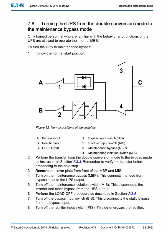
7.8 Turning the UPS from the double conversion mode tothe maintenance bypass modeOnly trained personnel who are familiar with the behavior and functions of theUPS are allowed to operate the internal MBS.
To turn the UPS to maintenance bypass:
1. Follow the normal start position:
Figure 32. Normal positions of the switches
A Bypass input 1 Bypass input switch (BIS)B Rectifier input 2 Rectifier input switch (RIS)C UPS Output 3 Maintenance bypass (MBP)
4 Maintenance isolation switch (MIS)2. Perform the transfer from the double conversion mode to the bypass mode
as instructed in Section 7.3.3. Remember to verify the transfer beforeproceeding to the next step.
3. Remove the cover plate from front of the MBP and MIS.4. Turn on the maintenance bypass (MBP). This connects the feed from
bypass input to the UPS output.5. Turn off the maintenance isolation switch (MIS). This disconnects the
inverter and static bypass from the UPS output.6. Perform the LOAD OFF procedure as described in Section 7.3.8.7. Turn off the bypass input switch (BIS). This disconnects the static bypass
from the bypass input.8. Turn off the rectifier input switch (RIS). This de-energizes the rectifier.
Eaton 91PS/93PS UPS 8-10 kW User's and installation guide
© Eaton Corporation plc 2018. All rights reserved. Revision: 003 Document ID: P-164000672 82 (102)
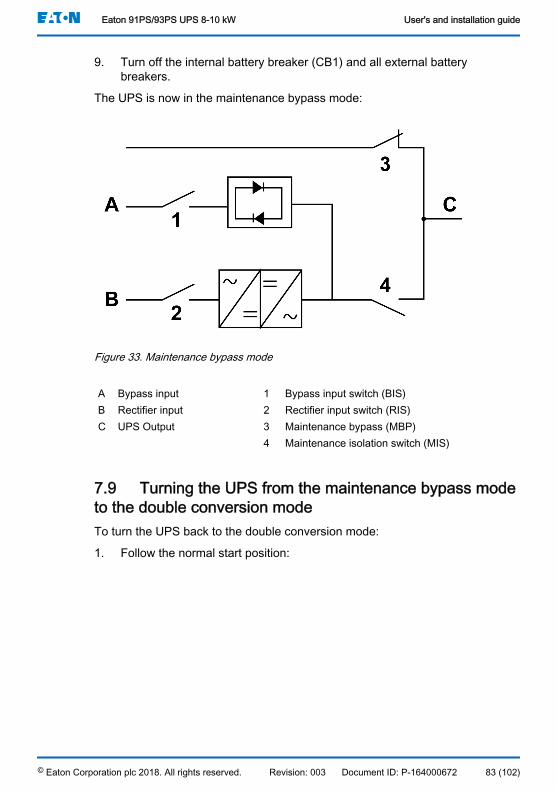
9. Turn off the internal battery breaker (CB1) and all external batterybreakers.
The UPS is now in the maintenance bypass mode:
Figure 33. Maintenance bypass mode
A Bypass input 1 Bypass input switch (BIS)B Rectifier input 2 Rectifier input switch (RIS)C UPS Output 3 Maintenance bypass (MBP)
4 Maintenance isolation switch (MIS)
7.9 Turning the UPS from the maintenance bypass modeto the double conversion modeTo turn the UPS back to the double conversion mode:
1. Follow the normal start position:
Eaton 91PS/93PS UPS 8-10 kW User's and installation guide
© Eaton Corporation plc 2018. All rights reserved. Revision: 003 Document ID: P-164000672 83 (102)

Figure 34. Maintenance bypass mode
A Bypass input 1 Bypass input switch (BIS)B Rectifier input 2 Rectifier input switch (RIS)C UPS Output 3 Maintenance bypass (MBP)
4 Maintenance isolation switch (MIS)2. Turn on the rectifier input switch (RIS). This energizes the rectifier.3. Turn on the bypass input switch (BIS). This connects the static bypass to
the bypass input.4. Turn on the internal battery breaker (CB1) and all external battery
breakers.5. Perform the UPS start-up procedure (bypass mode) in Section 7.3.2.6. Verify that there are no active alarms, and the UPS is on bypass mode.7. Turn on the maintenance isolation switch (MIS). This connects the inverter
and static bypass to the UPS output.8. Turn off the maintenance bypass (MBP). This disconnects the feed from
bypass input to the UPS output. The load is now supported by the staticbypass.
9. Install the cover plate to front of the MBP and MIS.10. Perform the transfer from the bypass mode to the double conversion mode
as described in Section 7.3.4.
The UPS is now in the double conversion mode.
Eaton 91PS/93PS UPS 8-10 kW User's and installation guide
© Eaton Corporation plc 2018. All rights reserved. Revision: 003 Document ID: P-164000672 84 (102)

Figure 35. Normal positions of the switches
A Bypass input 1 Bypass input switch (BIS)B Rectifier input 2 Rectifier input switch (RIS)C UPS Output 3 Maintenance bypass (MBP)
4 Maintenance isolation switch (MIS)
Eaton 91PS/93PS UPS 8-10 kW User's and installation guide
© Eaton Corporation plc 2018. All rights reserved. Revision: 003 Document ID: P-164000672 85 (102)
8 UPS maintenanceThe components inside the UPS cabinet are secured to a sturdy metal frame. Allrepairable parts and assemblies are located for easy removal with very littledisassembly. This design allows authorized service personnel to perform routinemaintenance and servicing quickly. Schedule periodic performance checks ofyour UPS system to keep it running properly. Regular routine checks of theoperation and system parameters enable your system to function efficiently formany trouble-free years.
8.1 Important safety instructionsRemember that your UPS system is designed to supply power EVEN WHEN ITIS DISCONNECTED FROM THE UTILITY POWER. The UPS module interiorsare unsafe until the DC power source is disconnected and the electrolyticcapacitors are discharged.
After disconnecting the utility power and the DC power, authorized servicepersonnel must wait at least 5 minutes for capacitor bleed-off before attemptinginternal access to the UPS module.
DANGERLETHAL VOLTAGE. Do not operate the UPS system without the cabinetdoors or protective panels secured. Do not make any assumptions about theelectrical state of any cabinet in the UPS system.
WARNINGAll service and maintenance work must be performed only by servicepersonnel qualified and authorized by Eaton.
CAUTIONAn additional warning label, shown in Figure 36 , must be installed at the UPSinput terminals and all the primary power isolators used to isolate the UPSunit if the UPS input is connected through external isolators that, whenopened, isolate the neutral. These warning labels can be obtained from yourlocal service representative.
Eaton 91PS/93PS UPS 8-10 kW User's and installation guide
© Eaton Corporation plc 2018. All rights reserved. Revision: 003 Document ID: P-164000672 86 (102)
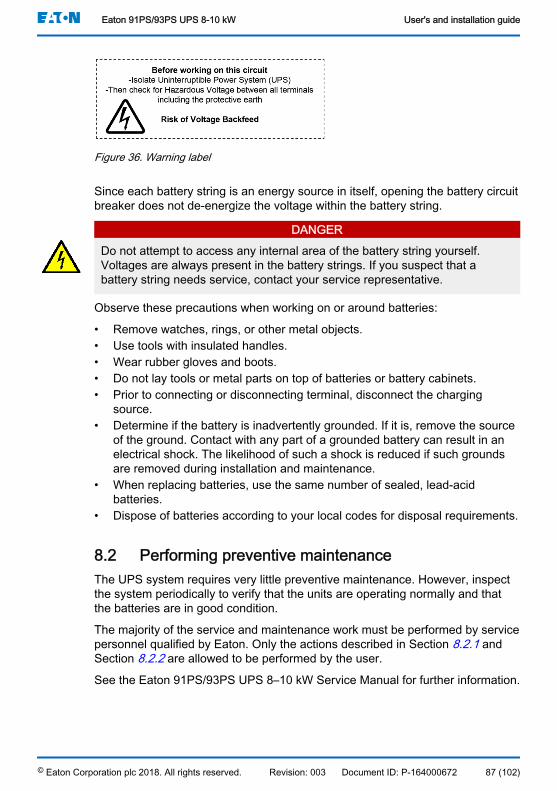
Figure 36. Warning label
Since each battery string is an energy source in itself, opening the battery circuitbreaker does not de-energize the voltage within the battery string.
DANGERDo not attempt to access any internal area of the battery string yourself.Voltages are always present in the battery strings. If you suspect that abattery string needs service, contact your service representative.
Observe these precautions when working on or around batteries:
• Remove watches, rings, or other metal objects.• Use tools with insulated handles.• Wear rubber gloves and boots.• Do not lay tools or metal parts on top of batteries or battery cabinets.• Prior to connecting or disconnecting terminal, disconnect the charging
source.• Determine if the battery is inadvertently grounded. If it is, remove the source
of the ground. Contact with any part of a grounded battery can result in anelectrical shock. The likelihood of such a shock is reduced if such groundsare removed during installation and maintenance.
• When replacing batteries, use the same number of sealed, lead-acidbatteries.
• Dispose of batteries according to your local codes for disposal requirements.
8.2 Performing preventive maintenanceThe UPS system requires very little preventive maintenance. However, inspectthe system periodically to verify that the units are operating normally and thatthe batteries are in good condition.
The majority of the service and maintenance work must be performed by servicepersonnel qualified by Eaton. Only the actions described in Section 8.2.1 andSection 8.2.2 are allowed to be performed by the user.
See the Eaton 91PS/93PS UPS 8–10 kW Service Manual for further information.
Eaton 91PS/93PS UPS 8-10 kW User's and installation guide
© Eaton Corporation plc 2018. All rights reserved. Revision: 003 Document ID: P-164000672 87 (102)
8.2.1 Daily maintenancePerform the following steps every day:
1. Check the area surrounding the UPS system. Make sure that the area isnot cluttered, allowing free access to the unit.
2. Check that the air intakes (vents on the front doors) and exhaust opening(the back of the UPS cabinet sections) are not blocked.
3. Make sure that the operating environment is within the parametersspecified in Section 4.3.1 and Chapter 9 .
4. Check that the UPS is in the normal operation mode (the green statusindicator for normal operation is illuminated). If the red alarm statusindicator is illuminated or the green status indicator for normal operation isnot illuminated, contact your service representative.
8.2.2 Monthly maintenancePerform the following steps once a month:
1. Check the system parameters on the control panel (see Section 7.1.4).2. If the optional air filters are installed, check them (located behind the front
doors) and wash or replace them, if needed. Contact your servicerepresentative for replacement filters. To replace the filters:
a. Open the UPS front door.b. Replace the filters.c. Close the UPS front door.
3. Record the check results and any corrective actions in a service log.
8.2.3 Periodic maintenanceInspect the UPS periodically to determine if components, wiring, andconnections exhibit evidence of overheating. Pay particular attention to boltedconnections. Bolted connections must be re-torqued periodically.
8.2.4 Annual maintenance
WARNINGOnly authorized personnel that are familiar with the maintenance andservicing of the UPS system are allowed to perform annual preventivemaintenance. Contact your service representative for more information aboutservice offerings.
Eaton 91PS/93PS UPS 8-10 kW User's and installation guide
© Eaton Corporation plc 2018. All rights reserved. Revision: 003 Document ID: P-164000672 88 (102)

8.2.5 Battery maintenance
WARNINGOnly authorized personnel are allowed to perform battery replacement andmaintenance. Contact your service representative for battery maintenance.
8.3 Recycling the used UPS or batteriesRemove the battery bank before disposing of the UPS or its battery cabinet.Follow the local requirements regarding battery recycling or disposal.
WARNINGOnly authorized personnel are allowed to remove the batteries due to the riskcaused by high energy and voltage.
Do not discard waste electrical or electronic equipment in the trash. For properdisposal, contact your local collecting/recycling/reuse or hazardous waste centerand follow the local legislation.
The following symbols indicate a product requiring special handling:
Figure 37. WEEE symbol (left) and battery recycling symbol
When handling waste from electrical and electronic equipment, use proper localcollecting centers that meet local legislation.
WARNINGHAZARDOUS MATERIALS.
Batteries may contain high voltages and caustic, toxic and flammablesubstances. If used improperly, batteries can injure or kill people and damageequipment.
Eaton 91PS/93PS UPS 8-10 kW User's and installation guide
© Eaton Corporation plc 2018. All rights reserved. Revision: 003 Document ID: P-164000672 89 (102)
Do not discard of unwanted batteries or battery material in the public wastedisposal system. Follow all the applicable local regulations regarding thestorage, handling and disposal of batteries and battery materials.
8.4 Maintenance trainingFor more information about training and other services, contact your Eatonrepresentative.
Eaton 91PS/93PS UPS 8-10 kW User's and installation guide
© Eaton Corporation plc 2018. All rights reserved. Revision: 003 Document ID: P-164000672 90 (102)

9 Technical dataFor a complete technical specification, contact your Eaton representative. Dueto continuous product improvement programs, specifications are subject tochange without notice.
9.1 Directives and standardsSafety IEC 62040-1: Uninterruptible power systems (UPS) - Part
1: General and safety requirements for UPS
IEC 60950-1: Information technology equipment - Safety -Part 1: General requirements (as referred through the IEC62040-1)
EMC IEC 62040-2: Uninterruptible power systems (UPS) - Part2: Electromagnetic compatibility (EMC) requirements / Ed.2
• Emissions: category C2• Immunity: category C3
Performance & tests IEC 62040-3: Uninterruptible power systems (UPS) - Part3: Method of specifying the performance and test require-ments
Environmental IEC62040-4: Uninterruptible Power Systems (UPS) - Part4: Environmental Aspects - Requirements and Reporting
IEC 62430: Environmentally conscious design for electricaland electronic products
RoHS 2011/65/EU on the restriction of the use of certain hazard-ous substances in electrical and electronic equipment
WEEE 2012/19/EU on waste electrical and electronic equipment(WEEE)
ECO Design Directive 2009/125/EC establishing a framework for the setting ofeco-design requirements for energy-related products
Batteries 2006/66/EC on batteries and accumulators and waste bat-teries and accumulators
Packaging 94/62/EC on packaging and packaging waste
9.2 UPS system inputRated input voltage 220/380 V; 230/400 V; 240/415 VVoltage tolerance, (Rectifier input) 230 V -15% / +20%Voltage tolerance, (Bypass input) 230 V -15% / +10%Rated input frequency 50 or 60 HzFrequency tolerance 40 to 72 Hz
Eaton 91PS/93PS UPS 8-10 kW User's and installation guide
© Eaton Corporation plc 2018. All rights reserved. Revision: 003 Document ID: P-164000672 91 (102)
Number of input phases (rectifier & bypass) 3 phases, N / 1 phase, NInput power factor 0.99
Rated mains input current
Maximum mains input current
See Table 13
Input current distortion at rated input cur-rent, iTHD
93PS 8 kW, 10 kW: resistive load <3%,non-linear load <5%
91PS 8 kW, 10 kW: resistive load <4%,non-linear load <6.5%
Rectifier ramp-up, rectifier start and loadstep
4 A/s (default), configurable.
Min 1A/sBackfeed protection Yes, for rectifier and bypass lines
9.3 UPS system outputNumber of output phases 3 phases, N / 1 phase, NRated output voltage 220/380 V; 230/400 V; 240/415 V, configu-
rableRated output frequency 50 or 60 Hz, user configurable
Total voltage harmonic distortion:
100 % linear load
100 % non-linear load
< 1.5%
< 3.5%
Output frequency variation +/- 0.1 Hz (free running)Slew rate 1 Hz/sOutput current See Table 13Overload capability at ambient 40 °C (inthe double conversion mode)
102 – 110 % rated power for 10 min
111 – 125 % rated power for 60 s
126 – 150 % rated power for 10 s
> 150% rated power for 300 msOverload capability at ambient 40 °C (inthe stored energy mode)
102 – 110 % rated power for 10 min
111 – 125 % rated power for 60 s
126 – 150 % rated power for 10 s
> 150% rated power for 300 msOverload capability at ambient 40 °C (inthe bypass mode)
Continuous ≤ 125% load
Transient ≤ 1000% RMS current for 20 ms
Note! Bypass fuses may limit the overloadcapability
Load power factor (rated) Nominal 1.0
Eaton 91PS/93PS UPS 8-10 kW User's and installation guide
© Eaton Corporation plc 2018. All rights reserved. Revision: 003 Document ID: P-164000672 92 (102)
Load power factor (permitted range) From 0.8 lagging to 0.8 leadingMax ambient temperature without de-rating 40 °C
9.4 UPS environmental specificationsAcoustic noise at 1 m < 54 dbA in double conversion
< 47 dBA in ESSAmbient storage temperature From -25 °C to +55 °C in the protective pack-
ageTransportation temperature 1) From -25 °C to 60 °CAmbient operating temperature range From 0 °C to +40 °C*Relative humidity range 5 to 95%, no condensation allowedMaximum service altitude 1,000 m (3,300 ft) above sea level at +40 °C
Maximum 2,000 m (6,600 ft) with 1% de-rat-ing per each additional 100 m above 1,000m.
Maximum storage time with internal bat-teries
6 months without recharge
* Maximum recommended operating and storage temperature for UPS with internal bat-teries is +25 °C. Higher storage temperature will shorten the maximum storage timewithout recharging.1) The maximum recommended operational and storage temperature with VRLA batter-ies is 25 °C.
9.5 Battery specificationBattery type VRLA, 12 VDCBattery quantity Default 32 blocks, 192 cells per battery string
External battery 28...40 blocks, 168...240 cellsper battery string
Note: Do not connect battery stringswith different battery quantity and volt-age in parallel.
Battery voltage 384 V (32 blocks), 336 V (28 blocks), 480 V(40 blocks)
Recharge profile Constant voltage, constant current charging(U-I characteristics), ABM or float charge
End of discharge voltage 1.67 VPC to 1.75 VPC, configurable or auto-matic (load adaptive)
Eaton 91PS/93PS UPS 8-10 kW User's and installation guide
© Eaton Corporation plc 2018. All rights reserved. Revision: 003 Document ID: P-164000672 93 (102)
Charge current Configurable 0...12.5 ABattery start option Yes
Eaton 91PS/93PS UPS 8-10 kW User's and installation guide
© Eaton Corporation plc 2018. All rights reserved. Revision: 003 Document ID: P-164000672 94 (102)

10 Warranty
10.1 GeneralThe product is warranted against defects in materials and workmanship for aperiod of twelve (12) months from its original date of purchase. The local officeor distributor may grant a warranty period different to the above. Please refer tolocal terms of liability as defined in the supply contract.
The UPS manufacturer is not responsible for:
• Any costs resulting from a failure if the installation, commissioning, repair,alternation, or ambient conditions of the equipment do not fulfill therequirements specified in the documentation delivered with the unit andother relevant documentation.
• Equipment subjected to misuse, negligence or accident.• Equipment comprised of materials provided or designs stipulated by the
purchaser.
The warranty is only valid if the installation inspection and initial startup of theUPS unit is carried out by an authorized Eaton Field Service Engineer or byother qualified service personnel authorized by Eaton. Service and maintenanceof the UPS shall also be performed only by an authorized Eaton Field ServiceEngineer or by other qualified service personnel authorized by Eaton. Otherwisethe warranty will be voided.
If the product fails to meet its published specifications due to a defect in materialand workmanship, covered by this warranty, the seller will repair or replace thewarranted product. Such repair or replacement will be made by Eaton or by aservice provider approved by Eaton. Repair or replacement during the warrantyperiod does not extend the original warranty. Warranty does not cover taxes,which will be due in connection with replacement or repair of the product.
Batteries are warranted against failures in material and workmanship, notagainst the normal aging and reduction of ampere-hour capacity. The productstorage environment has to meet manufacturer's specifications, failure to do thiswill cause the warranty to be voided.
Under no circumstances shall the manufacturer, its suppliers or subcontractorsbe liable for special, indirect, incidental or consequential damages, losses orpenalties.
The technical data, information and specifications are valid at the time ofprinting. The UPS manufacturer reserves the right to modifications without priornotice.
Eaton 91PS/93PS UPS 8-10 kW User's and installation guide
© Eaton Corporation plc 2018. All rights reserved. Revision: 003 Document ID: P-164000672 95 (102)

10.2 Whom to contact in case of WarrantyIn case of Warranty, or while unsure if the unit in question is covered bywarranty, contact the respective sales organization where the unit waspurchased. Have the following information available:
• Purchase order number and purchase order date• Installation date
OR• Serial number and part number of the unit (information available on the unit's
label)
Eaton 91PS/93PS UPS 8-10 kW User's and installation guide
© Eaton Corporation plc 2018. All rights reserved. Revision: 003 Document ID: P-164000672 96 (102)
11 Appendix A: Recommended secure hardeningguidelines
The UPS has been designed with cybersecurity as an important consideration.Number of cybersecurity features are now offered in the product which, ifimplemented as per the recommendations in this section, would minimize thecybersecurity risk to the UPS. The “secure configuration” or “hardening”guidelines provide information to the users to securely deploy and maintain theirproduct to adequately minimize the cybersecurity risks to their system.
Our company is committed to minimizing the cybersecurity risk in its productsand deploys cybersecurity best practices and latest cybersecurity technologiesin its products and solutions, making them more secure, reliable and competitivefor our customers. Our company also offers Cybersecurity Best Practiceswhitepapers to its customers that can be referenced at www.eaton.com/cybersecurity.Table 21: Secure configuration guidelines
Category DescriptionAsset identification and in-ventory
Keeping track of all the devices in the system is a pre-requisite for effective management of cybersecurity of asystem. Make sure that you maintain an inventory of allthe components in your system in a manner in which youuniquely identify each component. To facilitate this, theUPS supports the following identifying information: manu-facturer, type, serial number, f/w version number, and lo-cation.
Users can extract device information at locations men-tioned below:
• Product number, serial number and UPS name are lis-ted on the Information screen
• Firmware versions can be found on the About screen
Eaton 91PS/93PS UPS 8-10 kW User's and installation guide
© Eaton Corporation plc 2018. All rights reserved. Revision: 003 Document ID: P-164000672 97 (102)

Category DescriptionPhysical protection Industrial Control Protocols do not offer cryptographic pro-
tections at protocol level, at physical ports and at control-ler mode switches, leaving them exposed to cybersecurityrisk. Physical security is an important layer of defense insuch cases. The UPS is designed with the considerationthat it would be deployed and operated in a physically se-cure location.
• Physical access to the communication lines should berestricted to prevent any attempts of wiretapping orsabotage. It is a best practice to use metal conduitsfor the communication lines running from one cabinetto another cabinet.
• An attacker with unauthorized physical access to thedevice could cause serious disruption of the devicefunctionality. A combination of physical access con-trols to the location should be used, such as locks,card readers, and/or guards.
• The UPS supports the following physical access ports:RS232, USB and slots for communication cards. Ac-cess to them must be restricted.
• Do not connect an unauthorized USB device, CD/DVDor SD card for any operation (for example, firmwareupgrade, configuration change and boot applicationchange).
• Before connecting any portable device through USB,CD/DVD or SD card slot, scan the device for mal-wares and viruses.
Eaton 91PS/93PS UPS 8-10 kW User's and installation guide
© Eaton Corporation plc 2018. All rights reserved. Revision: 003 Document ID: P-164000672 98 (102)
Category DescriptionAuthorization and accesscontrol
It is extremely important to securely configure the logicalaccess mechanisms provided in the UPS to safeguard thedevice from unauthorized access. Our company recom-mends that the available access control mechanisms beused properly to ensure that access to the system is re-stricted to legitimate users only. And, such users are re-stricted to only the privilege levels necessary to completetheir job roles/functions.
• Ensure that default credentials are changed upon firstlogin. The UPS should not be commissioned for pro-duction with default credentials. It is a serious cyber-security flaw as the default credentials are publishedin the manuals.
• No password sharing - Make sure that each user getstheir own password for that desired functionality in-stead of sharing the passwords. Security monitoringfeatures of the UPS are created with the view of eachuser having their own unique password. Security con-trols will be weakened as soon as the users start shar-ing the password.
• Restrict administrative privileges - Threat actors areincreasingly focused on gaining control of legitimatecredentials, especially those associated with highlyprivileged accounts. Limit privileges to only those nee-ded for a user’s duties.
• Perform periodic account maintenance (remove un-used accounts).
• Change passwords and other system access creden-tials whenever there is a personnel change.
Access to service screen and configuration screen is ac-cess-controlled. Access to UPS features is restrictedbased on roles:
1. Configuration screen can be accessed by the Userrole.
2. Service screen can be accessed only by the Serviceengineer role.
The following are the access levels in the UPS:
• Level 1: Control password for User• Level 2: Configure password for User• Level 3: Service password for an authorized Eaton
Customer Service Engineer or qualified service per-sonnel authorized by Eaton
Users are recommended to change default passwords onfirst use of the system. The default session timeout is 10minutes.
The UPS does not enforce any account policies. Custom-ers need to enforce their account policies.
Eaton 91PS/93PS UPS 8-10 kW User's and installation guide
© Eaton Corporation plc 2018. All rights reserved. Revision: 003 Document ID: P-164000672 99 (102)
Category DescriptionLogging and event manage-ment
Best practices:
• Our company recommends that all administrative andmaintenance activities are logged.
• Ensure that logs are backed up. Retain the backupsfor a minimum of 3 months or as per the organiza-tion’s security policy.
• Perform log review at a minimum every 15 days.
The UPS supports the following logging mechanisms:
• The UPS logs all active events, alarms and notices• Configuration changes made are logged (language
change, modify UPS name, etc.)Secure maintenance Best practices:
Apply firmware updates and patches regularly.
Due to increasing cyber attacks on industrial control sys-tems, our company implements a comprehensive patchand update process for its products. Users are encour-aged to maintain a consistent process to promptly monitorfor fresh firmware updates, implement patching and up-dates as and when required or released.
Our company will upgrade the UPS firmware from time totime. If any site needs to upgrade firmware, they can con-tact the service center for upgrade.
Our company also has a robust vulnerability responseprocess. In the event of any security vulnerability gettingdiscovered in its products, our company patches the vul-nerability and releases an information bulletin through itscybersecurity web site: http://eaton.com/cybersecurity.
Conduct regular cybersecurity risk analyses of the organi-zation/system.
Our company has worked with third-party security firms toperform system audits, both as part of a specific custom-er’s deployment and within our company’s own develop-ment cycle process. Our company can provide guidanceand support to your organization’s effort to perform regularcybersecurity audits or assessments.
Plan for business continuity/cybersecurity disaster recov-ery.
It is a cybersecurity best practice for organizations to planfor business continuity. Establish an OT business continui-ty plan, periodically review and, where possible, exercisethe established continuity plans. Make sure offsite back-ups include:
• A backup of the most current configurations• Documentation of the most current user list
Eaton 91PS/93PS UPS 8-10 kW User's and installation guide
© Eaton Corporation plc 2018. All rights reserved. Revision: 003 Document ID: P-164000672 100 (102)

References:
1. Cybersecurity Considerations for Electrical Distribution Systems(WP152002EN):http://www.eaton.com/ecm/groups/public/@pub/@eaton/@corp/documents/content/pct_1603172.pdf
2. Cybersecurity Best Practices Checklist Reminder (WP910003EN):http://www.cooperindustries.com/content/dam/public/powersystems/resources/library/1100_EAS/WP910003EN.pdf
3. NIST SP 800-82 Rev 2, Guide to Industrial Control Systems (ICS) Security,May 2015.https://ics-cert.us-cert.gov/Standards-and-References
4. National Institute of Technology (NIST) Interagency “Guidelines onFirewalls and Firewall Policy, NIST Special Publication 800-41”, October2009.http://nvlpubs.nist.gov/nistpubs/Legacy/SP/nistspecialpublication800-41r1.pdf
Eaton 91PS/93PS UPS 8-10 kW User's and installation guide
© Eaton Corporation plc 2018. All rights reserved. Revision: 003 Document ID: P-164000672 101 (102)

Cop
yrig
ht ©
201
8 Ea
ton
Cor
pora
tion
plc.
All
right
s re
serv
ed. U
naut
horiz
ed c
opyi
ng a
nd le
ndin
g ar
e pr
ohib
ited.
Eaton Power Quality OyKoskelontie 13
FI-02920 Espoo, Finlandwww.eaton.eu