User’s ManualPWX750ML 3 The PWX750ML is a constant voltage (CV)/constant current (CC) automatic...
120
PWX750ML User’s Manual Regulated DC Power Supply PWX Series Search by Topic 7 Component Names 8 Preparation 11 Connecting the Power Cord 12 Turning the Power On 13 Rack Mounting 14 Load Considerations 15 Load Cables 17 Output Terminal Insulation 18 Connecting to the Output Terminals 20 Sensing 22 Basic Functions 25 Measured Value Display and Setting Display 26 Panel Operations 28 Output Operations 29 Operation Overview 30 CV Power Supply and CC Power Supply 31 Using the PWX750ML as a CV or CC Power Supply 33 Protection Functions and Alarms 34 CONFIG Settings 41 Preset Memory Function 54 Locking Panel Operations (Key lock) 56 Bleeder On/Off Feature 57 Switching from Remote Mode to Local Mode 58 Factory Default Settings (Initialization) 58 External Control 61 Overview 62 About the J1 Connector 62 Notes for Connecting External Voltage (Vext) 64 Controlling the Output Voltage 66 Controlling the Output Current 68 Controlling the Output On and Off States 70 Controlling Output Shutdown 72 Controlling the Clearing of Alarms 73 External Monitoring 74 Parallel/Series Operation 77 Master-Slave Parallel Operation 78 Series Operation 84 Maintenance 89 Calibration 90 Specifications 93 Factory Option 103 Isolated Analog Interface 104 Appendix109 PART NO.IB02299E Sep 2019
Transcript of User’s ManualPWX750ML 3 The PWX750ML is a constant voltage (CV)/constant current (CC) automatic...

PWX750ML
User’s ManualRegulated DC Power SupplyPWX Series
Search by Topic 7Component Names 8
Preparation 11Connecting the Power Cord 12
Turning the Power On 13Rack Mounting 14
Load Considerations 15Load Cables 17
Output Terminal Insulation 18Connecting to the Output Terminals 20
Sensing 22
Basic Functions 25Measured Value Display and Setting Display
26Panel Operations 28
Output Operations 29Operation Overview 30
CV Power Supply and CC Power Supply 31Using the PWX750ML as a CV or CC Power
Supply 33Protection Functions and Alarms 34
CONFIG Settings 41Preset Memory Function 54
Locking Panel Operations (Key lock) 56Bleeder On/Off Feature 57
Switching from Remote Mode to LocalMode 58
Factory Default Settings (Initialization) 58
External Control 61Overview 62
About the J1 Connector 62Notes for Connecting External Voltage
(Vext) 64Controlling the Output Voltage 66Controlling the Output Current 68
Controlling the Output On and Off States 70Controlling Output Shutdown 72
Controlling the Clearing of Alarms 73External Monitoring 74
Parallel/Series Operation 77Master-Slave Parallel Operation 78
Series Operation 84
Maintenance 89Calibration 90
Specifications 93
Factory Option 103Isolated Analog Interface 104
Appendix109
PART NO.IB02299ESep 2019
2 PWX750ML
These manuals are intended for users of the Regulated DCPower Supply and their instructors. It is assumed that thereader has knowledge about electrical aspects of regulatedDC power supplies.
Documentation Structure
Safety informationThis document contains general safety precautions for thisproduct. Keep them in mind and make sure to observethem.
User’s manual (this manual, PDF)This manual is intended for first-time users of this product. Itprovides an overview of the product and notes on usage. Italso explains how to configure the product, operate theproduct, perform maintenance on the product, specificationsthe product, and so on. To effectively use the product fea-tures, read this manual from beginning to end.We recommend that you read it thoroughly before using thisproduct for the first time.If you forget how to use the product or if a problem occurs,we recommend that you refer to this manual again.
Quick referenceThis manual explains Panel description and operationbriefly.
Communication Interface Manual (HTML,partially PDF)
This manual contains details about using commands to con-trol the product remotely. It also contains details about themultichannel function (Virtual Multi Channel Bus), whichmakes it possible to control up to 31 PWXs from a singlePC. The interface manual is written for readers with sufficientbasic knowledge of how to control power supplies using aPC.The command list is provided in PDF format.
PDF and HTML files are included in the accompanying CD-ROM. Adobe Reader is required to view the PDF files. Microsoft Internet Explorer or Google Chrome is required toview the HTML files.The newest version of the manual can be downloaded fromDownload service of Kikusui website
Firmware versions that this manual coversThis manual covers firmware versions 3.0X.When contacting us about the product, please provide us with:
The model (marked in the top section of the front panel)The firmware version (see page 13)The serial number (marked on the rear panel)
TrademarksMicrosoft, Internet Explorer, and Windows are either regis-tered trademarks or trademarks of Microsoft Corporation in theUnited States and/or other countries.Other company names and product names used in this man-ual are generally trademarks or registered trademarks of therespective companies.
CopyrightsThe contents of this manual may not be reproduced, in wholeor in part, without the prior consent of the copyright holder.The specifications of this product and the contents of this man-ual are subject to change without prior notice.© 2011 Kikusui Electronics Corporation
When you receive the product, check that all accessories areincluded and that the accessories have not been damagedduring transportation.If any of the accessories are damaged or missing, contactyour Kikusui agent or distributor.We recommend that you save all packing materials, in casethe product needs to be transported at a later date.
About the PWX750ML Manuals
Component Quantity
Power cord 1 pc.
Output terminal cover 1 set
J1 connector plug kit 1 set
Output terminal M6 bolt set 2 sets
Chassis connection wire 1 pc.
Packing list 1 pc.
Quick reference English: 1 pc.Japanese: 1 pc.
Safety information 1 pc.
CD-ROM 1 disc
Checking the Package Contents

PWX750ML 3
The PWX750ML is a constant voltage (CV)/constant current(CC) automatic crossover power supply that can output a widerange of voltage and current within rated output power.It can be controlled remotely through the standard-equippedcommunication feature.
FeaturesCommunication feature
RS232C, USB, and LAN interfaces are all installed as stan-dard.The remote interfaces comply with IEEE Std 488.2 1992and SCPI Specification 1999.0. Because the LAN interfacecomplies with the LXI standard, the construction of a highlycost-effective system is possible. If you use the multichan-nel (VMCB) function, you can construct a multichannelpower supply system in which up to 31 PWXs are controlledfrom a single PC.
Master-slave parallel operationYou can increase the PWX750ML’s output current by con-necting up to four units in parallel. You can set one unit asthe master unit, and control the remaining units as slaveunits.
Setting preset featureYou can save up to three sets of output settings (the combi-nation of the voltage value and current value). You can sim-ply select a set of output settings that you want to use ratherthan having to specify each setting every time.
Automatic output on settingYou can set the PWX750ML so that when a protection func-tion is activated and the output is turned off, output is auto-matically turned back on when the problem that caused theprotection function to be activated is fixed.
Set voltage/current limitation featureYou can apply limits to the voltage and current settings.This prevents you from setting an appropriate value by mis-take, which would cause the output to turn off.
Overcurrent protection (OCP) detection time settingYou can set a detection time, which is the amount of timethat an overcurrent must persist after the first detection ofthe overcurrent before the overcurrent protection (OCP) isactivated. By setting the detection time, you can prevent analarm from occurring when an inrush current from the EUTconnected to the output causes an excessive current to flowtemporarily.
Bleeder on/off featureYou can turn the bleeder circuit on and off. Turn the bleedercircuit off when you do not want the internal bleeder circuitto sink output current. When you connect a battery, you canprevent excessive electrical discharges by turning thebleeder circuit off.
Compatibility with other productsYou can set the command language and emulation that areused during remote control. By setting the command lan-guage, you can enable the PWX to support the proprietarycommands of other products. By selecting the emulation,you can remotely control products other than the PWX.
Isolated analog interface (factory option)You can use isolated optical signals to set and monitor theoutput voltage and current. The signal is isolated from thereference potential of this product.You can use a voltage control (0 V to 5 V or 0 V to 10 V) or acurrent control (4 mA to 20 mA).
Model Maximumoperatingcurrent
Operatingvoltage
Power
PWX750ML 28 A 0 V to 80 V 750 W
Product Overview
4 PWX750ML
When using this product, be sure to observe the “SafetyPrecautions” in the Safety information manual.
When installing this product, be sure to observe the“Precautions Concerning Installation Location” in theSafety information manual. The following precautionspertain only to this product.• When installing this product, be sure to observe the tem-
perature and humidity ranges indicated below.Operating temperature range: 0 °C to +50 °C (32 °F to 122 °F)Operating humidity range: 20 %rh to 85 %rh (no conden-sation)
• When storing this product, be sure to observe the tempera-ture and humidity ranges indicated below.
Storage temperature range: -20 °C to +70 °C (-4 °F to 158 °F)Storage humidity range: 90 %rh or less (no condensation)
• In this manual, the PWX750ML Regulated DC Power Sup-ply is referred to as the “PWX Series” or “PWX750ML.”
• The term “PC” is used to refer generally to both personalcomputers and workstations.
• The screen captures used in this manual may differ from theactual screens that appear on the PWX750ML. The screencaptures are merely examples.
• The following markings are used in this manual.
Indicates a potentially hazardous situation which, ifignored, could result in death or serious injury.
Indicates a potentially hazardous situation which, ifignored, may result in damage to the product or otherproperty.
Indicates information that you should know.
Explanation of terminology or operation principle.
Indicates a reference to detailed information.
Indicates reference to detailed information operation man-ual.
CFxx:x“CF” stands for a CONFIG parameter. The two digits afterCF indicate the CONFIG parameter number. The valueafter the colon indicates the selected setting.
SHIFT+key nameIndicates an operation that requires you to press a keywhile holding down the SHIFT key.
Indicates useful information.
Safety Precautions
Precautions ConcerningInstallation Location
Notations Used in This Manual
WARNING
CAUTION
DESCRIPTION
See
Memo
PWX750ML 5
Contents
About the PWX750ML Manuals ..................2Checking the Package Contents ................2Product Overview .......................................3Safety Precautions ......................................4Precautions Concerning Installation Location 4Notations Used in This Manual ...................4Search by Topic ...........................................7Component Names ......................................8
1 PreparationConnecting the Power Cord............................. 12Turning the Power On...................................... 13
Turning the POWER switch on ................. 13Turning the POWER switch Off................. 14
Rack Mounting ................................................. 14Load Considerations ........................................ 15Load Cables..................................................... 17Output Terminal Insulation............................... 18
When the output terminal is not grounded (floating) .................................................... 18When the output terminal is grounded ...... 19
Connecting to the Output Terminals ................ 20Sensing ............................................................ 22
Local sensing ............................................ 23Remote sensing ........................................ 23
2 Basic FunctionsMeasured Value Display and Setting Display .. 26Panel Operations ............................................. 28Output Operations............................................ 29Operation Overview ......................................... 30CV Power Supply and CC Power Supply ........ 31Using the PWX750ML as a CV or CC Power Sup-ply .................................................................... 33Protection Functions and Alarms ..................... 34
Alarm occurrence and clearing alarms...... 34Protection function activation .................... 35
CONFIG Settings ............................................. 41CONFIG parameter details ....................... 44
Preset Memory Function.................................. 54Saving settings to preset memory............. 54Recalling preset memory entries............... 55
Locking Panel Operations (Key lock) ............... 56Bleeder On/Off Feature.................................... 57Switching from Remote Mode to Local Mode .. 58Factory Default Settings (Initialization) ............ 58
3 External ControlOverview.......................................................... 62About the J1 Connector ................................... 62Notes for Connecting External Voltage (Vext) . 64Controlling the Output Voltage......................... 66
Control using an external voltage (Vext)... 66Control using an external resistance (Rext).... 67
Controlling the Output Current......................... 68Control using an external voltage (Vext)... 68Control using an external resistance (Rext).... 69
Controlling the Output On and Off States ........ 70Controlling Output Shutdown........................... 72Controlling the Clearing of Alarms ................... 73External Monitoring.......................................... 74
4 Parallel/Series OperationMaster-Slave Parallel Operation...................... 78
Features of the PWX750ML during master-slave parallel operation ............................. 78Connection (master-slave parallel operation) . 80Settings (master-slave parallel operation) 82 Starting master-slave parallel operation .. 83
Series Operation.............................................. 84Features of the PWX750ML during series op-eration....................................................... 84Connection (series operation)................... 86Settings (series operation) ........................ 87Starting series operation........................... 87
5 MaintenanceCalibration........................................................ 90
Calibration overview.................................. 90Calibration procedure................................ 91
6 Specifications
7 Factory OptionIsolated Analog Interface............................... 104
Isolated Analog Interface Connector....... 105Setup and Operation............................... 106Specifications.......................................... 107

6 PWX750ML
AppendixA Options........................................110
B Troubleshooting........................112

PWX750ML 7
Search by Topic
TroubleshootingSee “Troubleshooting” on page 112
• I want to check the accessories. →See “Checking the Package Contents” or the included packing list. p.2
• The installation space is limited, so I want to check the installation conditions.
→See the included “Safety Precautions” document, or the electronic version of the document on the CD-ROM.
–
• How do I connect the AC power supply? →“Connecting the Power Cord” p.12• What kind of load cables should I use? →“Load Cables” p.17• How do I ensure stable voltage when the
cables connected to the load are long (the distance to the load is long)?
→“Sensing”p.22
• How do I rack mount the PWX750ML? What kind of parts are needed?
→“Rack Mounting” p.14
• How do I use remote sensing to stabilize the PWX750ML?
→“Sensing” p.22
• How do I set the protection functions to prevent damage to the load?
→“Protection Functions and Alarms” p.34
• After a protection function has been acti-vated, how do I restart tests automatically when the cause of the alarm is fixed?
→“Alarm occurrence and clearing alarms”p.34
• How do I set the communication condi-tions for remote control?
→See the Communication Interface Man-ual on the CD-ROM. –
• How do I check the settings in preset memory?
→“Recalling preset memory entries” p.55
• How do I reset the PWX750ML to its fac-tory default settings?
→“Factory Default Settings (Initialization)” p.58
• How do I use the multichannel (VMCB) function to construct a multichannel power supply system?
→See the Communication Interface Man-ual on the CD-ROM. –
• How do I use the PWX750ML as a con-stant voltage power supply (CV mode)?
→“Using the PWX750ML as a CV or CC Power Supply”
p.33• How do I use the PWX750ML as a con-
stant current power supply (CC mode)?• How do I operate the PWX750ML at a
specific current? How do I save current values to the preset memory?
→“Preset Memory Function”p.54
• How do I control the output voltage with an external DC voltage?
→“Overview” p.62
• How do I monitor the output voltage and output current?
→“External Monitoring” p.74
• How do I use parallel operation to increase the current capacity?
→“Master-Slave Parallel Operation” p.78
• How do I prevent the settings from being changed?
→“Locking Panel Operations (Key lock)” p.56
• How do I clean the PWX750ML? →See the included “Safety Precautions” document, or the electronic version of the document on the CD-ROM.
–
• How do I calibrate the PWX750ML? →“Calibration” p.90
Preparation
Setup
Operation
Maintenance
8 PWX750ML
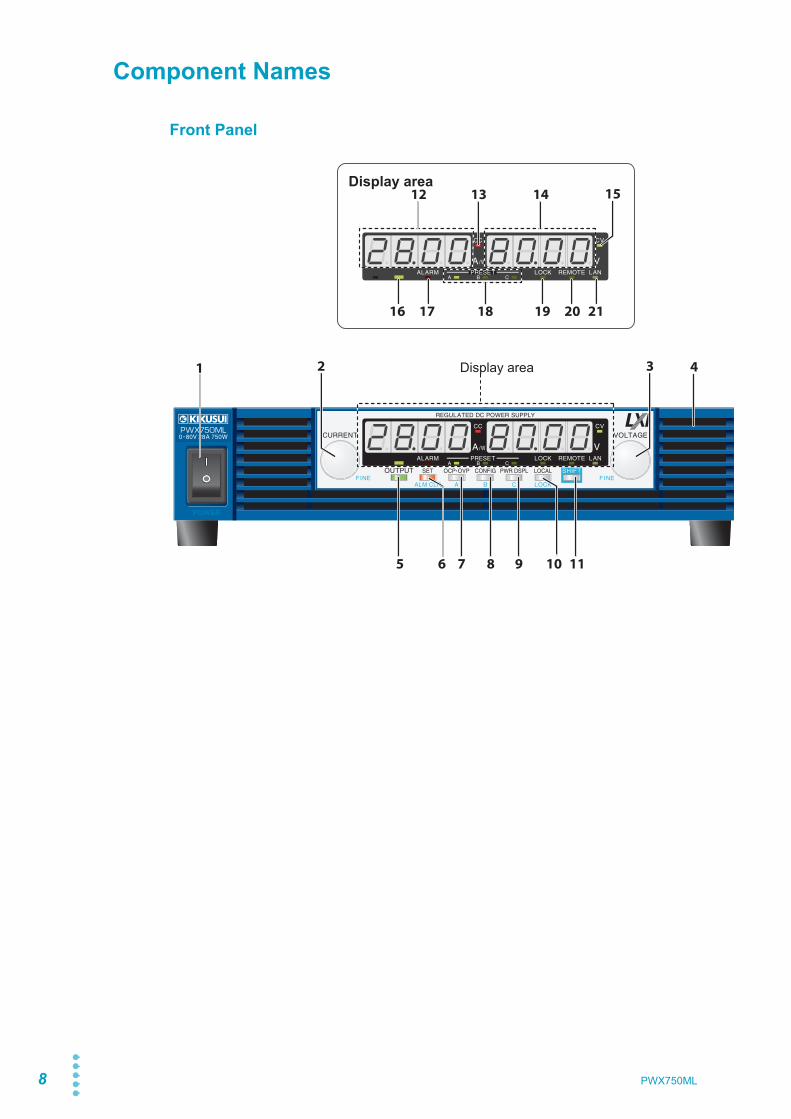
Component Names
Front Panel
Display area
5
16 17 18 19 20 21
6 7 8 9 10 11
2 3
15
41 Display area
1312 14
PWX750ML 9
No. Name Function
1 POWER switch Flip the switch to the ( ) side to turn the power on. Flip it to the ( ) side to turn the power off. p.13
2CURRENT knob Used to set the current value or select a parameter number in the CONFIG settings. p.28, p.41FINE Used to make fine current value adjustments. p.28
3VOLTAGE knob Used to set the voltage value or change the value of a CONFIG parameter. p.28, p.41FINE Used to make fine voltage value adjustments. p.28
4 Air inlet (louver) Air inlet for cooling the inside of the PWX750ML. –5 OUTPUT key Used to turn output on and off. p.29
6SET key Used to set and confirm the output voltage and output current (the key has an LED). p.26ALM CLR key Used to release protection functions that have been activated (the key has an LED). p.35
7OCP • OVP keys
Used to set and display the overcurrent protection (OCP), overvoltage protection (OVP), undervoltage limit (UVL) trip points (the key has an LED). p.36
A Used to recall and save the value of preset memory A (the key has an LED). p.54
8CONFIG key Used to configure the various operating conditions (the key has an LED). p.41B Used to recall and save the value of preset memory B (the key has an LED). p.54
9PWR DSPL key Used to display the output power on the ammeter (the key has an LED). p.26C Used to recall and save the value of preset memory C (the key has an LED). p.54
10LOCAL key Used to switch between local mode and remote mode (the key has an LED). p.58
LOCK key Used to lock the operation of all keys other than the OUTPUT key (the key has an LED). p.56
11 SHIFT key Used to enable the functions that are written in blue characters below the key. –12 Ammeter Displays the current, power, or the parameter number of a CONFIG parameter. p.26, p.4113 CC LED Lights in red during constant current mode. p.33
14 Voltmeter Displays the voltage, the value of a CONFIG parameter, or the cause of an alarm. p.26, p.34, p.41
15 CV LED Lights in green during constant voltage mode. p.33
16 OUTPUT LED Lights in green when output is turned on. Blinks orange when output is on and a pro-tection function has been activated. p.29, p.34
17 ALARM LEDLights in red when a protection function has been activated, However, does not light when a undervoltage limit (UVL) protection has been activated, Blinks red when the power limit (POWER LIMIT) has been activated.
p.34
18 PRESET LEDA: Lights in green when the memory A values are being recalled or saved.B: Lights in green when the memory B values are being recalled or saved.C: Lights in green when the memory C values are being recalled or saved.
p.54
19 LOCK LED Lights in green when the keys are locked. p.5620 REMOTE LED Lights in green during remote control. –
21 LAN LED
Lights and blinks when the LAN interface is in use.• No fault status: Lights in green.• Fault status: Lights in red.• Standby status: Lights in orange.• WEB identify status: Blinks green.
–
See
10 PWX750ML
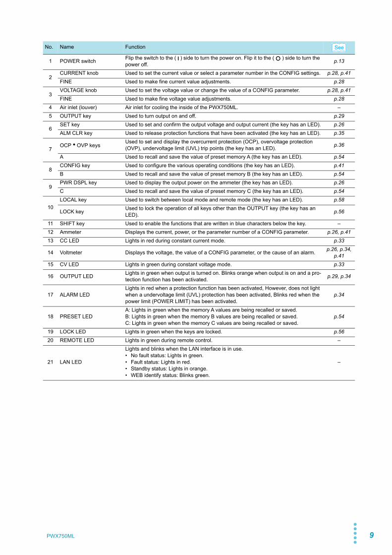
Rear Panel
No. Name Function
1 DC OUTPUT Output connector p.20
2 USB USB port for controlling the PWX750ML remotely
Interface Manual
3 RS232C RS232C port for controlling the PWX750ML remotely
4 LAN Ethernet port for controlling the PWX750ML remotely
5 Air outlet Air outlet for cooling the inside of the PWX750ML –
6 AC INPUT AC inlet p.12
7 Chassis terminal Connector for grounding the output –
8 Sensing terminal connec-tors Terminals to connect the sensing cables p.22
9 J1 External control connector p.62, p.77
10 Option slot Slot for the isolated analog interface option (factory option) p.103
63 4
7 8 9 10
2 51
See
PreparationThis chapter describes how to turn on thePWX750ML, what kind of load cables touse, and how to connect cables to the out-put connectors.For information about installing and movingthis product, see “Precautions ConcerningInstallation Location” and “Precautions toBe Taken When Moving the Product” in theSafety information manual.When using or storing this product, be sureto observe the temperature and humidityranges. For environmental conditions, seeGeneral Specifications (p.100).

12
Connecting the Power Cord
This product is a piece of equipment that conforms to IEC Overvoltage Category II (equip-ment that consumes energy supplied from a fixed installation).
1 Check that the AC power line meets the nominal input rating of the prod-uct.The product can receive a nominal line voltage in the range of 100 Vac to 240 Vac at50 Hz or 60 Hz.
2 Check that the POWER switch is turned off.
3 Connect the power cord to the AC inlet on the rear panel.
4 Insert the power plug into a grounded outlet.
WARNING Risk of electric shock.• This product is a piece of equipment that conforms to IEC Safety Class I (equipment
that has a protective conductor terminal). Be sure to earth ground the product to prevent electric shock.
• The product is grounded through the power cord ground wire. Connect the protec-tive conductor terminal to earth ground.
• Use the supplied power cord to connect to the AC line. If the supplied power cord cannot be used because the rated voltage or the plug shape is incompatible, have a qualified engi-neer replace it with an appropriate power cord that is 3 m or less in length. If obtaining a power cord is difficult, contact your Kikusui agent or distributor.
• The power cord with a plug can be used to disconnect the PWX750ML from the AC power line in an emergency. Connect the plug to an easily accessible power outlet so that the plug can be removed from the outlet at any time. Be sure to provide adequate clearance around the power outlet.
• Do not use the supplied power cord for other devices.
PWX750ML
1
Prep
arat
ion
Turning the Power On
Turning the POWER switch on
p.58 When you turn the POWER switch on for the first time after purchase, the PWX750ML startswith its factory default settings. Subsequent times that you turn the PWX750ML on, it startswith the panel settings (excluding the output on/off setting) that were in use immediatelybefore the POWER switch was turned off.
p.45 You can use the CONFIG settings (CF02) to select how the PWX750ML starts when thePOWER switch is turned on.
1 Check that the power cord is connected correctly.
p.21 2 Check that the OUTPUT terminal cover is attached.When the product is shipped from the factory, the OUTPUT terminal cover is notattached.
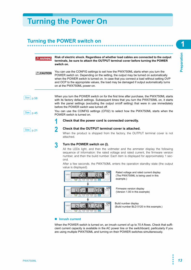
3 Turn the POWER switch on ( ).All the LEDs light, and then the voltmeter and the ammeter display the followingsequence of information: the rated voltage and rated current, the firmware versionnumber, and then the build number. Each item is displayed for approximately 1 sec-ond.After a few seconds, the PWX750ML enters the operation standby state (the outputvalue is displayed).
Inrush currentWhen the POWER switch is turned on, an inrush current of up to 70 A flows. Check that suffi-cient current capacity is available in the AC power line or the switchboard, particularly if youare using multiple PWX750ML and turning on their POWER switches simultaneously.
WARNING Risk of electric shock. Regardless of whether load cables are connected to the output terminals, be sure to attach the OUTPUT terminal cover before turning the POWER switch on.
CAUTION You can use the CONFIG settings to set how the PWX750ML starts when you turn the POWER switch on. Depending on the setting, the output may be turned on automatically when the POWER switch is turned on. In case that you connect a load without setting OVP and OCP to the appropriate values, the load may be damaged if output automatically turns on at the PWX750ML power-on.
See
See
See
Firmware version display(Version 1.00 in this example)
Rated voltage and rated current display(The PWX750ML is being used in this example.)
Build number display(Build number BLD 0120 in this example.)
PWX750ML 13
14
Rack Mounting
Turning the POWER switch Off
Flip the POWER switch to the ( ) side to turn the PWX750ML off.The PWX750ML saves the panel settings (except the output on/off setting) that were in useimmediately before the POWER switch was turned off.
p.45 You can use the CONFIG settings (CF02) to select how the PWX750ML starts when thePOWER switch is turned on.If the POWER switch is turned off immediately after the settings have been changed, the lastsettings may not be stored.
Rack Mounting
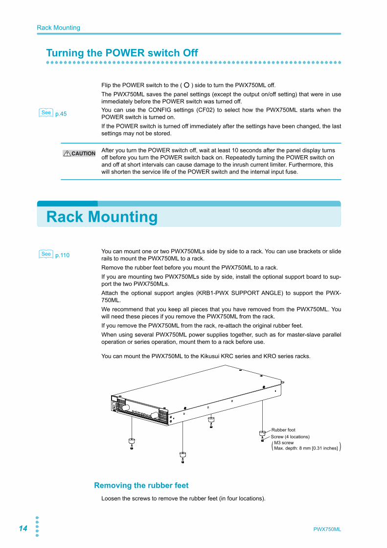
p.110 You can mount one or two PWX750MLs side by side to a rack. You can use brackets or sliderails to mount the PWX750ML to a rack.Remove the rubber feet before you mount the PWX750ML to a rack.If you are mounting two PWX750MLs side by side, install the optional support board to sup-port the two PWX750MLs.Attach the optional support angles (KRB1-PWX SUPPORT ANGLE) to support the PWX-750ML.We recommend that you keep all pieces that you have removed from the PWX750ML. Youwill need these pieces if you remove the PWX750ML from the rack.If you remove the PWX750ML from the rack, re-attach the original rubber feet.When using several PWX750ML power supplies together, such as for master-slave paralleloperation or series operation, mount them to a rack before use.
You can mount the PWX750ML to the Kikusui KRC series and KRO series racks.
Removing the rubber feetLoosen the screws to remove the rubber feet (in four locations).
See
CAUTION After you turn the POWER switch off, wait at least 10 seconds after the panel display turns off before you turn the POWER switch back on. Repeatedly turning the POWER switch on and off at short intervals can cause damage to the inrush current limiter. Furthermore, this will shorten the service life of the POWER switch and the internal input fuse.
See
Rubber footScrew (4 locations)
M3 screwMax. depth: 8 mm [0.31 inches]( )
PWX750ML

1
Prep
arat
ion
Load Considerations
Note that the output will become unstable if the following types of loads are connected.
Loads with peak current or pulse-shaped currentThe PWX750ML only indicates mean values. Even when the indicated value is less than orequal to the set constant current, the peak values may exceed the set constant current. If thishappens, the PWX750ML is instantaneously put into constant-current mode, and the outputvoltage drops.For these types of loads, you must increase the set constant current or increase the currentcapacity.
Loads that generate reverse current to the power supplyThe PWX750ML series cannot absorb reverse current from the load. Therefore, if a regener-ative load (such as an inverter, converter, or transformer) is connected, the output voltageincreases and becomes unstable. This can cause a malfunction.For these types of loads, connect a resistor (RD) as shown in the following figure to bypassthe reverse current. However, the amount of current to the load decreases by Irp.
Load current with peaks Pulse-shaped load current
Set constant currentAmmeter reading (mean value)
Set constant currentAmmeter reading (mean value)
IO
RDEO
Equivalent circuit of the PWX750ML Regenerative load
- +
0
Reverse current-IO
+IO
Irp
RD (in Ω) ≤
RD: Reverse current bypass dummy loadEO: Output voltageIrp: Maximum reverse current
EO (in V)Irp (in A)
Load
Out
put c
urre
nt
CAUTION Use a resistor with sufficient rated power for RD. If a resistor with insufficient rated power for the circuit is used, resistor RD will burn out.
PWX750ML 15
16
Load Considerations
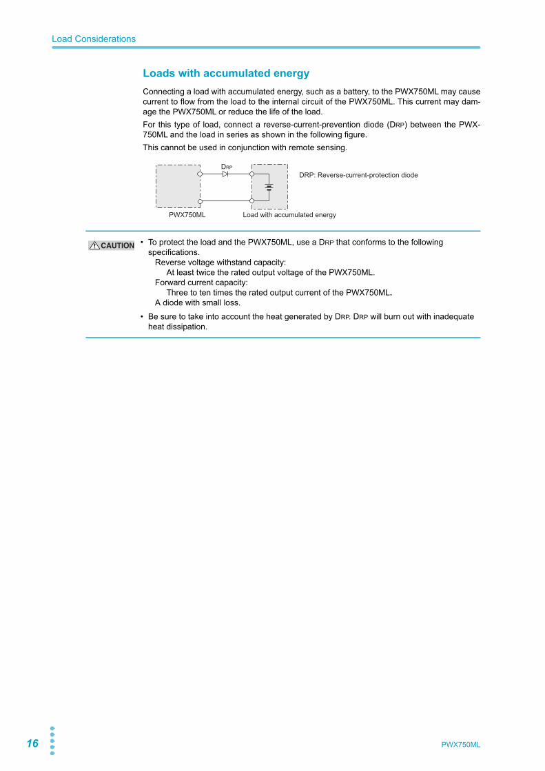
Loads with accumulated energyConnecting a load with accumulated energy, such as a battery, to the PWX750ML may causecurrent to flow from the load to the internal circuit of the PWX750ML. This current may dam-age the PWX750ML or reduce the life of the load.For this type of load, connect a reverse-current-prevention diode (DRP) between the PWX-750ML and the load in series as shown in the following figure.This cannot be used in conjunction with remote sensing.
PWX750ML Load with accumulated energy
DRP: Reverse-current-protection diodeDRP
CAUTION • To protect the load and the PWX750ML, use a DRP that conforms to the following specifications. Reverse voltage withstand capacity: At least twice the rated output voltage of the PWX750ML. Forward current capacity: Three to ten times the rated output current of the PWX750ML. A diode with small loss.
• Be sure to take into account the heat generated by DRP. DRP will burn out with inadequate heat dissipation.
PWX750ML
1
Prep
arat
ion
Load Cables
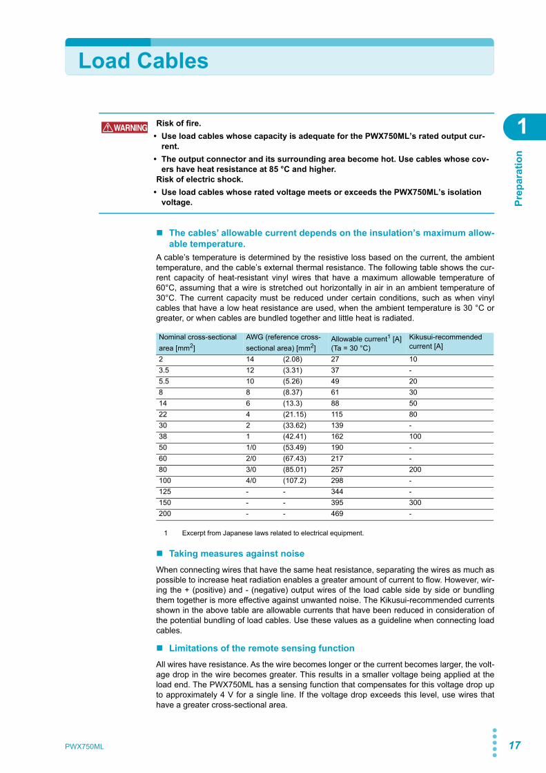
The cables’ allowable current depends on the insulation’s maximum allow-able temperature.
A cable’s temperature is determined by the resistive loss based on the current, the ambienttemperature, and the cable’s external thermal resistance. The following table shows the cur-rent capacity of heat-resistant vinyl wires that have a maximum allowable temperature of60°C, assuming that a wire is stretched out horizontally in air in an ambient temperature of30°C. The current capacity must be reduced under certain conditions, such as when vinylcables that have a low heat resistance are used, when the ambient temperature is 30 °C orgreater, or when cables are bundled together and little heat is radiated.
Taking measures against noiseWhen connecting wires that have the same heat resistance, separating the wires as much aspossible to increase heat radiation enables a greater amount of current to flow. However, wir-ing the + (positive) and - (negative) output wires of the load cable side by side or bundlingthem together is more effective against unwanted noise. The Kikusui-recommended currentsshown in the above table are allowable currents that have been reduced in consideration ofthe potential bundling of load cables. Use these values as a guideline when connecting loadcables.
Limitations of the remote sensing functionAll wires have resistance. As the wire becomes longer or the current becomes larger, the volt-age drop in the wire becomes greater. This results in a smaller voltage being applied at theload end. The PWX750ML has a sensing function that compensates for this voltage drop upto approximately 4 V for a single line. If the voltage drop exceeds this level, use wires thathave a greater cross-sectional area.
WARNING Risk of fire.• Use load cables whose capacity is adequate for the PWX750ML’s rated output cur-
rent.• The output connector and its surrounding area become hot. Use cables whose cov-
ers have heat resistance at 85 °C and higher.Risk of electric shock.
• Use load cables whose rated voltage meets or exceeds the PWX750ML’s isolation voltage.
Nominal cross-sectional area [mm2]
AWG (reference cross-sectional area) [mm2]
Allowable current1 [A](Ta = 30 °C)
1 Excerpt from Japanese laws related to electrical equipment.
Kikusui-recommended current [A]
2 14 (2.08) 27 103.5 12 (3.31) 37 -5.5 10 (5.26) 49 208 8 (8.37) 61 3014 6 (13.3) 88 5022 4 (21.15) 115 8030 2 (33.62) 139 -38 1 (42.41) 162 10050 1/0 (53.49) 190 -60 2/0 (67.43) 217 -80 3/0 (85.01) 257 200100 4/0 (107.2) 298 -125 - - 344 -150 - - 395 300200 - - 469 -
PWX750ML 17
18
Output Terminal Insulation
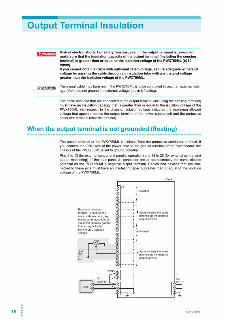
The cable and load that are connected to the output terminal (including the sensing terminal)must have an insulation capacity that is greater than or equal to the isolation voltage of thePWX750ML with respect to the chassis. Isolation voltage indicates the maximum allowedvoltage that appears across the output terminal of the power supply unit and the protectiveconductor terminal (chassis terminal).
When the output terminal is not grounded (floating)
The output terminal of the PWX750ML is isolated from the protective conductor terminal. Ifyou connect the GND wire of the power cord to the ground terminal of the switchboard, thechassis of the PWX750ML is set to ground potential.Pins 5 to 13 (for external control and parallel operation) and 18 to 25 (for external control andoutput monitoring) of the rear panel J1 connector are at approximately the same electricpotential as the PWX750ML’s negative output terminal. Cables and devices that are con-nected to these pins must have an insulation capacity greater than or equal to the isolationvoltage of the PWX750ML.
WARNING Risk of electric shock. For safety reasons, even if the output terminal is grounded, make sure that the insulation capacity of the output terminal (including the sensing terminal) is greater than or equal to the isolation voltage of the PWX750ML (±250 Vmax).If you cannot obtain a cable with sufficient rated voltage, secure adequate withstand voltage by passing the cable through an insulation tube with a withstand voltage greater than the isolation voltage of the PWX750ML.
CAUTION The signal cable may burn out. If the PWX750ML is to be controlled through an external volt-age (Vext), do not ground the external voltage (leave it floating).
+–
+
+S–S
–+–
16
1819
14
2122
20
3
56
13121110987
1
232425
ACINPUT
DCOUTPUT
J1
SENS
LN
Approximately the same potential as the negative output terminal
Approximately the same potential as the negative output terminal
Isolated
Isolated
Load
Rext
PWX
Vext
Because the output terminal is floating, the section shown on a gray background must have an insulation capacity greater than or equal to the PWX750ML isolation voltage.
PWX750ML
Output Terminal Insulation
1
Prep
arat
ion
When the output terminal is grounded
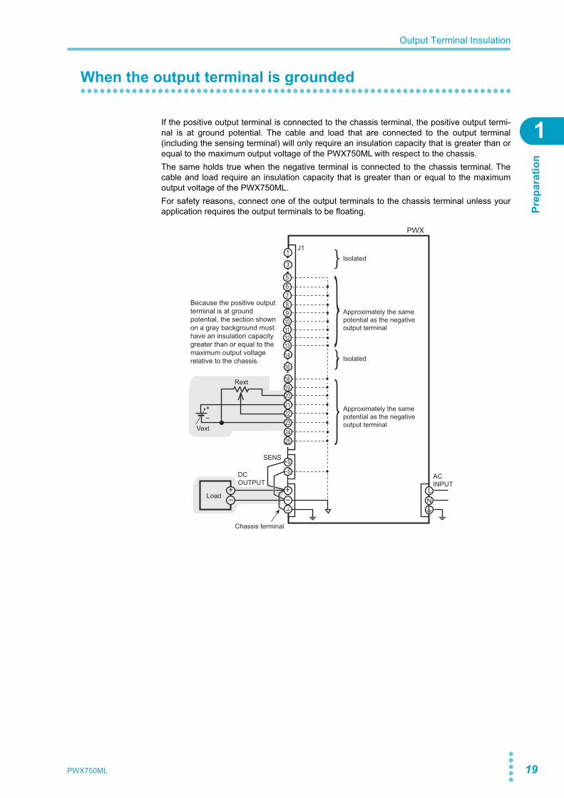
If the positive output terminal is connected to the chassis terminal, the positive output termi-nal is at ground potential. The cable and load that are connected to the output terminal(including the sensing terminal) will only require an insulation capacity that is greater than orequal to the maximum output voltage of the PWX750ML with respect to the chassis. The same holds true when the negative terminal is connected to the chassis terminal. Thecable and load require an insulation capacity that is greater than or equal to the maximumoutput voltage of the PWX750ML.For safety reasons, connect one of the output terminals to the chassis terminal unless yourapplication requires the output terminals to be floating.
+–
+
+S–S
–+–
2122
20
3
1
232425
ACINPUT
DCOUTPUT
J1
SENS
LN
Load
Rext
PWX
Vext
Because the positive output terminal is at ground potential, the section shown on a gray background must have an insulation capacity greater than or equal to the maximum output voltage relative to the chassis.
Chassis terminal
56
13121110987
16
1819
14
Approximately the same potential as the negative output terminal
Approximately the same potential as the negative output terminal
Isolated
Isolated
PWX750ML 19
20
Connecting to the Output Terminals
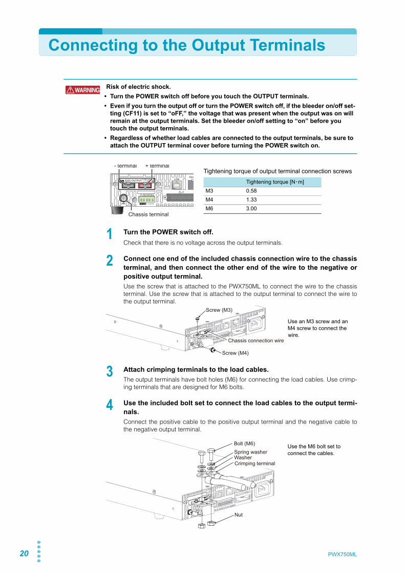
1 Turn the POWER switch off.Check that there is no voltage across the output terminals.
2 Connect one end of the included chassis connection wire to the chassisterminal, and then connect the other end of the wire to the negative orpositive output terminal.Use the screw that is attached to the PWX750ML to connect the wire to the chassisterminal. Use the screw that is attached to the output terminal to connect the wire tothe output terminal.
3 Attach crimping terminals to the load cables.The output terminals have bolt holes (M6) for connecting the load cables. Use crimp-ing terminals that are designed for M6 bolts.
4 Use the included bolt set to connect the load cables to the output termi-nals.Connect the positive cable to the positive output terminal and the negative cable tothe negative output terminal.
WARNING Risk of electric shock.• Turn the POWER switch off before you touch the OUTPUT terminals.• Even if you turn the output off or turn the POWER switch off, if the bleeder on/off set-
ting (CF11) is set to “oFF,” the voltage that was present when the output was on will remain at the output terminals. Set the bleeder on/off setting to “on” before you touch the output terminals.
• Regardless of whether load cables are connected to the output terminals, be sure to attach the OUTPUT terminal cover before turning the POWER switch on.
- terminal
Chassis terminal
+ terminalTightening torque of output terminal connection screws
Tightening torque [N・m]M3 0.58M4 1.33M6 3.00
Screw (M3)
Screw (M4)
Chassis connection wire
Use an M3 screw and an M4 screw to connect the wire.
Crimping terminal
Bolt (M6)Spring washerWasher
Nut
Use the M6 bolt set to connect the cables.
PWX750ML
Connecting to the Output Terminals
1
Prep
arat
ion
Attaching the OUTPUT terminal cover
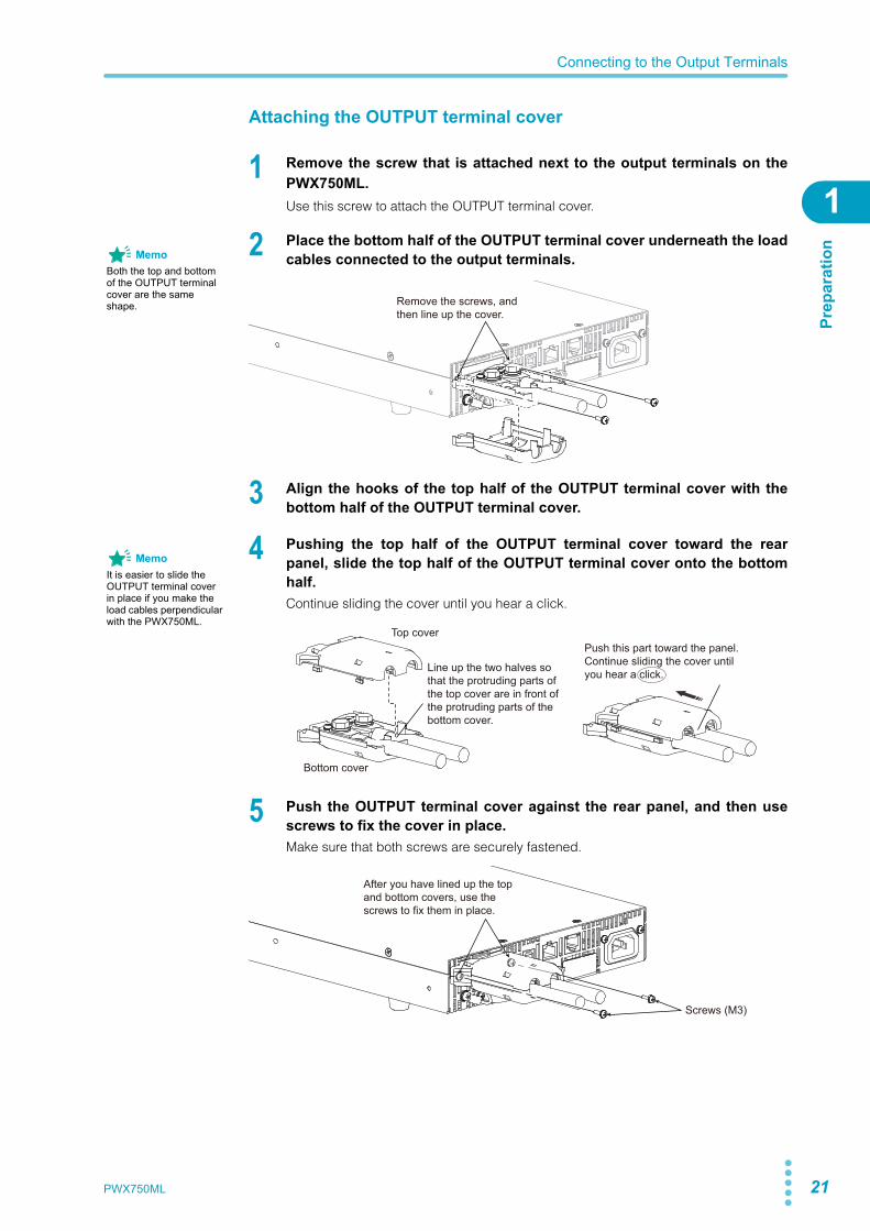
1 Remove the screw that is attached next to the output terminals on thePWX750ML.Use this screw to attach the OUTPUT terminal cover.
2 Place the bottom half of the OUTPUT terminal cover underneath the loadcables connected to the output terminals.
3 Align the hooks of the top half of the OUTPUT terminal cover with thebottom half of the OUTPUT terminal cover.
4 Pushing the top half of the OUTPUT terminal cover toward the rearpanel, slide the top half of the OUTPUT terminal cover onto the bottomhalf.Continue sliding the cover until you hear a click.
5 Push the OUTPUT terminal cover against the rear panel, and then usescrews to fix the cover in place.Make sure that both screws are securely fastened.
MemoBoth the top and bottom of the OUTPUT terminal cover are the same shape. Remove the screws, and
then line up the cover.
MemoIt is easier to slide the OUTPUT terminal cover in place if you make the load cables perpendicular with the PWX750ML.
Push this part toward the panel.Continue sliding the cover until you hear a click.
Top cover
Bottom cover
Line up the two halves so that the protruding parts of the top cover are in front of the protruding parts of the bottom cover.
After you have lined up the top and bottom covers, use the screws to fix them in place.
Screws (M3)
PWX750ML 21
22
Sensing
When the PWX750ML is shipped from the factory, terminal cover and connector are attachedto the sensing terminals. For safety reasons, when not using the sensing terminals, be sure toattach to terminal cover. If they are damaged or lost, contact your Kikusui agent or distributor.
Connecting the sensing cables
If the sensing cables come loose, the output voltage will rise several volts. To prevent voltageoutput exceeding the voltage setting, set an appropriate OVP trip point.When you are finished with remote sensing, return the PWX750ML to local sensing mode.
84-61-7305
Connector
P1-000-109
Terminal cover
WARNING Risk of electric shock and damage to internal circuits.• Never wire the sensing terminals while the POWER switch is turned on.• Use sensing cables whose rated voltage is higher than the PWX750ML’s isolation
voltage. Protect the uncovered sections of the shielded cable by using insulation tubes whose withstand voltage is greater than the PWX750ML’s isolation voltage.
• The sensing terminals are at approximately the same electric potential as the nega-tive output terminal. Insert the cables so that the wire strands do not touch the chas-sis when they stick out of the sensing terminal. Also, insert the cables so that the stripped wires do not stick out of the terminal.
• Even if you turn the output off or turn the POWER switch off, if the bleeder on/off set-ting (CF11) is set to oFF, the voltage that was present when the output was on will remain at the output terminals. Set the bleeder on/off setting to on before you touch the sensing terminals.
• Regardless of whether local sensing or remote sensing is used, be sure to attach the sensing terminal cover before turning the POWER switch on.
Strip 7 mm (0.28 inches) of the cable covering, and then insert the cable here.
Use this screw to fix the cables in place so that they do not come loose.
Local sensing jumpers
Terminal Function
-S Negative remote sensing terminal
-LSNegative local sensing terminalConnected to the negative output terminal
— Not connected
+LSPositive local sensing terminalConnected to the positive output terminal
+S Positive remote sensing terminal
Sensing cable AWG28 to AWG16
PWX750ML
Sensing
1
Prep
arat
ion
Local sensing
By factory default, the PWX750ML is set to local sensing (the rear panel sensing connector ishard wired). The sensing point during local sensing is the output terminal. This method doesnot compensate for the voltage drop in the load cable, so use this method when the load cur-rent is small or when you do not need to consider the load effect voltage.
Remote sensing
Remote sensing is a feature that stabilizes the output voltage across the load by reducing theinfluence of voltage drops and other effects caused by the load cable resistance.
p.17 You can use the PWX750ML’s remote sensing feature to compensate up to 4 V for a singleline. Select a load cable that has sufficient current capacity to prevent the voltage drop in theload cable from exceeding the compensation voltage.When you perform remote sensing, set the voltage of the sensing point (across the load) sothat it does not exceed the rated output voltage. If you are performing remote sensing withthe voltage close to the maximum output voltage, the output is limited by the maximum outputvoltage (105 % of the rated output voltage). Electrolytic capacitors may be required at thesensing point (across the load).To reduce the effect of noise, use twisted-pair wires or 2-core shielded wires. When you areusing shielded wires, connect the shield to the ground of the PWX750ML or the load.
+
–+LS
+S
-LS
-S
Output terminal
Chassis terminal
Sensing terminal
PWX
Load
Use twisted-pair wires for the load cables.Make the cables as short as possible.
See
++
––
C
+LS
+S
-LS
-S
Connect an electrolytic capacitor across the load as necessary.
Output terminal
Chassis terminal
Sensing terminal
PWX
Load
Use twisted-pair wires for the load cables.Make the cables as short as possible.
For the sensing cables, use twisted-pair wires or shielded wires.
PWX750ML 23
24
Sensing
1 Turn the POWER switch off.
2 Remove the sensing terminal cover and sensing connector from the rearpanel sensing terminals.
3 Remove the local sensing jumpers from the sensing connector.
4 Remove 7 mm of the wire covering. Connect the negative sensing cableto -S and the positive sensing cable to +S.Use cable screws to securely fix the cables in place so that they do not come loose.
5 Firmly attach the sensing terminal cover and sensing connector to therear panel sensing terminals.
6 Turn the POWER switch on.
Electrolytic capacitor to connect across the loadIf the wiring inductance component is large, the following symptoms may appear.• The PWX750ML oscillates
If the wires used to connect to the load are long, the wiring inductance and capacitancecan cause phase shifting at a level that can not be ignored. This may lead to oscillation.
• The output fluctuatesIf the load current changes drastically in a pulse-shaped pattern, the output voltage maybecome large due to the wiring’s inductance component.
You can reduce the inductance component by twisting the load cables, which stabilizes thevoltage. However, if this does not rectify the problem, connect an electrolytic capacitor acrossthe load.
Electrolytic capacitor to useCapacity: 0.1 μF to a few hundred μFWithstand voltage: At least 120 % of the rated output voltage of the PWX750ML(96 V or more)
If you are inserting a mechanical switch between the PWX750ML and theload
If you want to connect and disconnect the load using a mechanical switch that is insertedbetween the PWX750ML and the load, be sure to include switches in the sensing cables asshown in the following figure and turn on and off the load cable and the sensing cables simul-taneously. Before you turn the mechanical switch on or off, be sure to turn the OUTPUT or thePOWER switch off.
Load
S
+
–C
+
–
+S
–S
+
–
PWX750ML

Basic FunctionsThis chapter describes how to turn the out-put on and off and the basic operations thatyou can perform from the front panel.

26 PWX750ML
Measured Value Display and Setting Display
The voltage and current displays have the following two states.• Measured value display• Setting display
In addition to the voltmeter and ammeter, the PWX750ML can display the power, the set OVPor OCP, and the system configuration.
Measured value displayThe present output voltage and load current are displayed. In this situation, the SET key LEDis off.
p.33 You can change the output voltage and output current in the measured value display.
Power displayIn the measured value display, press PWR DSPL to display the output power on the amme-ter.The output power is calculated from the measured output voltage and the measured outputcurrent.When the power is being displayed, the PWR DSPL key lights. Press PWR DSPL again toturn off the LED and return to the measured value display.
Setting displayPress SET to light its LED and display the present output voltage and output current settings.Press SET again to return to the measured value display.The SET key is disabled when the instrument is being controlled externally. The settings arenot displayed even when you press the SET key.
When you recall a preset memory entry, the values stored in the preset memory entry are dis-played on the panel.
In firmware version 3.00, the character “S” that appears on the front panel display was changed.
See
Lit
Lit
PWX750ML 27
Measured Value Display and Setting Display
Bas
ic F
unct
ions
2
Overvoltage protection and overcurrent protection setting displayPress OCP•OVP to light its LED and display the present overcurrent protection and overvolt-age protection settings.
System configuration setting displayPress CONFIG to light its LED and display the present system configuration settings.
Lit
Lit
28 PWX750ML
Panel Operations
Measured value display, setting display, and set OVP/OCP displayTurn the VOLTAGE knob to change the voltage. Turn the CURRENT knob to change the cur-rent.
Press SET to switch to the setting display, and then change the output voltage and outputcurrent while you view their actual settings.
p.36 You cannot set the output voltage to a value that is 95% of the OVP trip point or higher. Youcannot set the output current to a value that is 95% of the OCP trip point or higher.The displayed current or voltage may not change even if you turn the CURRENT or VOLT-AGE knob. In this situation, the values are being changed at a finer resolution that which isbeing displayed. The display will change when the amount that you change the value byreaches the smallest display digit of the set voltage or current.
Fine adjustmentYou can change the resolution of the VOLTAGE and CURRENT knobs.Hold down SHIFT while you turn the VOLTAGE knob or CURRENT knob to make smallchanges to the value.The following table shows the resolutions that can be specified. The specified resolution maynot necessarily be applied to the actual output.
Decrease IncreaseIncrease Decrease
See
MemoWhen you set a value, it is convenient to first use normal resolution to set the value roughly and then switch to fine resolution to set it precisely.
Output Voltage Output Current
Resolution 250 mV 100 mA
Using FINE, OUT OFF 10 mV 10 mA
Using FINE, OUT ON 1 mV 1 mA
When using a communication interface
1 mV 1 mA
PWX750ML 29
2
Bas
ic F
unct
ions
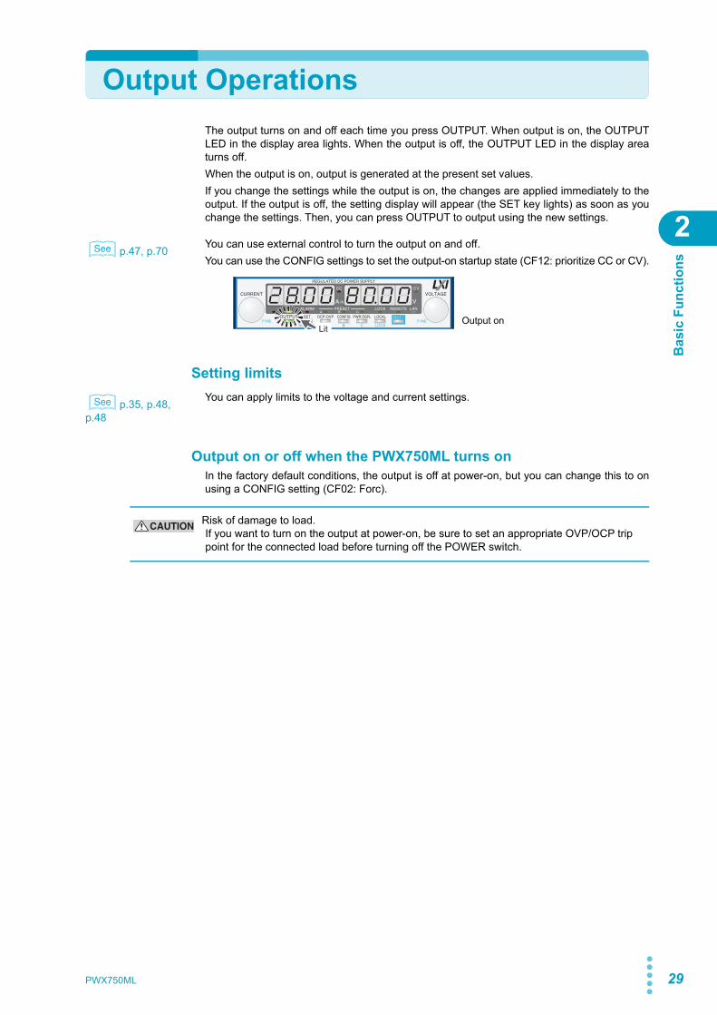
Output OperationsThe output turns on and off each time you press OUTPUT. When output is on, the OUTPUTLED in the display area lights. When the output is off, the OUTPUT LED in the display areaturns off. When the output is on, output is generated at the present set values. If you change the settings while the output is on, the changes are applied immediately to theoutput. If the output is off, the setting display will appear (the SET key lights) as soon as youchange the settings. Then, you can press OUTPUT to output using the new settings.
p.47, p.70 You can use external control to turn the output on and off.You can use the CONFIG settings to set the output-on startup state (CF12: prioritize CC or CV).
Setting limits
p.35, p.48, p.48
You can apply limits to the voltage and current settings.
Output on or off when the PWX750ML turns onIn the factory default conditions, the output is off at power-on, but you can change this to onusing a CONFIG setting (CF02: Forc).
See
LitOutput on
See
CAUTION Risk of damage to load.If you want to turn on the output at power-on, be sure to set an appropriate OVP/OCP trip point for the connected load before turning off the POWER switch.
30 PWX750ML
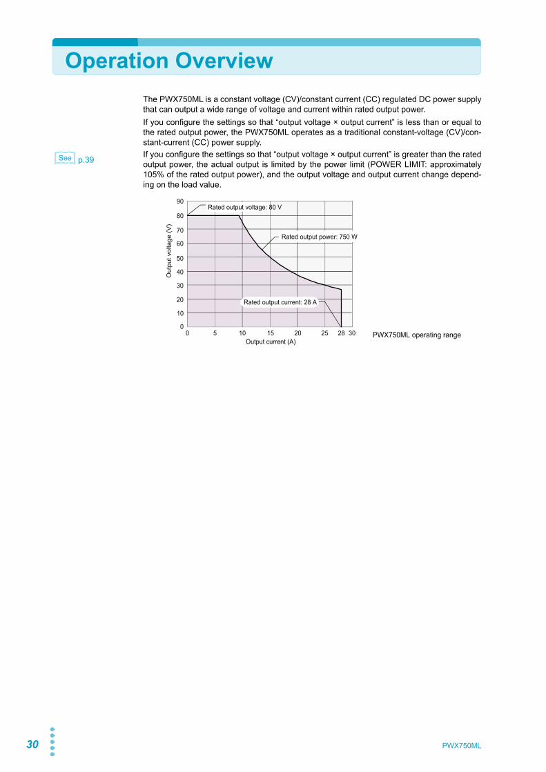
Operation OverviewThe PWX750ML is a constant voltage (CV)/constant current (CC) regulated DC power supplythat can output a wide range of voltage and current within rated output power.If you configure the settings so that “output voltage × output current” is less than or equal tothe rated output power, the PWX750ML operates as a traditional constant-voltage (CV)/con-stant-current (CC) power supply.
p.39 If you configure the settings so that “output voltage × output current” is greater than the ratedoutput power, the actual output is limited by the power limit (POWER LIMIT: approximately105% of the rated output power), and the output voltage and output current change depend-ing on the load value.
See
Output current (A)
Out
put v
olta
ge (V
)
90
80
70
60
50
40
30
20
10
00 5 10 15 20 25 28 30
Rated output current: 28 A
Rated output power: 750 W
Rated output voltage: 80 V
PWX750ML operating range

PWX750ML 31
2
Bas
ic F
unct
ions
CV Power Supply and CC Power Supply
The PWX750ML has features that enable it to function as a constant-voltage source and con-stant-current source even when the load is changed. The constant-voltage source operationis referred to as constant-voltage (CV) mode. The constant-current source operation isreferred to as constant-current (CC) mode. The operation mode is determined by the follow-ing three values.
• The set output voltage (Vs)• The set output current (Is)• The load resistance (RL)
The operation modes are described below.
The above figure shows the PWX750ML operation modes. The load resistance is denoted asRL. The resistance, which is denoted as Rc, is calculated from the set voltage and current (Rc= Vs/Is). The power supply is designed so that it operates in CV mode in area and CCmode in area . The boundary is the line defined by RL = Rc. This line represents the load atwhich the output voltage and the set voltage are equal and the output current and the set cur-rent are equal. If load resistance RL is greater than resistance Rc, the operating point is inarea , and the PWX750ML operates in CV mode (point p). In this case, the set current Isequals to the current limit.When operating in CV mode, the output voltage is maintained at the set voltage. Output cur-rent I is determined by the equation I = Vs/RL and is a current that is less than current limit Is.The actual current that flows is not necessarily equal to the specified value.For loads in which transient peak current flows, current Is must be set so that the peak valuedoes not reach the current limit.
Conversely, if load resistance RL is less than resistance Rc, the operating point is in area ,and the PWX750ML operates in CC mode (point q). In this case, set voltage Vs equals to thevoltage limit.When operating in CC mode, the output current is maintained at the set current. Output volt-age V is determined by the equation V = Is × RL and is a voltage that is less than voltage limitVs. The actual voltage that is applied is not necessarily equal to the specified value.
Crossover pointThe PWX750ML switches automatically between CV mode and CC mode according to thechanges in the load. A crossover point is the point at which the mode switches.For example, when operating in CV mode, if the load changes and the output current reachesthe current limit, the PWX750ML automatically switches to CC mode to protect the load. Like-wise, when operating in CC mode, if the output voltage reaches the voltage limit, the PWX-750ML switches to CV mode.
0 ImaxIs
Vs
Vmax
Output current Iout
Crossover point
A = CV mode area B = CC mode area
Vs = Set voltageIs = Set currentRc = Vs/Is (Ohm’s Law)RL = Load resistanceVmax = Maximum settable voltageImax = Maximum settable current
RL = RcRL > Rc
RL < Rc
p
q
A
B
Out
put
volt
age
Vou
t
AB
A
B
32 PWX750ML
CV Power Supply and CC Power Supply
CV mode and CC mode operation exampleThis section uses a power supply with a rated output voltage of 100 V and a rated output cur-rent of 10 A as an example.A load resistance (RL) of 8 Ω is connected to the output terminals of the power supply. Theoutput voltage and output current are set to 30 V and 5 A, respectively. In this case, Rc = 30V/5 A = 6 Ω. Because 8 Ω is greater than 6 Ω (RL > Rc), the power supply operates in CVmode. When you want to increase the voltage in CV mode, you can increase the voltage upto the voltage defined by the following equation: Vs = Is × RL. Substituting the values, weobtain Vs = 5 A × 8 Ω = 40 V. If you try to increase the voltage above this point, the crossoverpoint is reached, and the power supply automatically switches to CC mode. To maintain oper-ations in CV mode, increase the current limit.Next, a load resistance (RL) of 5 Ω is connected to the output terminals of the power supply.The output voltage and output current are set to 30 V and 5 A, respectively. In this case, Rc =30 V/5 A = 6 Ω. Because 5 Ω is less than 6 Ω (RL < Rc), the power supply operates in CCmode. When you want to increase the current in CC mode, you can increase the current up tothe current defined by the following equation: Is = Vs/RL. Substituting the values, we obtain Is= 30V/5Ω = 6 A. If you try to increase the current above this point, the crossover point isreached, and the power supply automatically switches to CV mode. To maintain operations inCC mode, increase the voltage limit.
PWX750ML 33
2
Bas
ic F
unct
ions
Using the PWX750ML as a CV or CC Power Supply
When using the PMX750ML as a constant-voltage power supply, the set current is the limit tothe current that can flow through the load.When using the PMX750ML as a constant-current power supply, the set voltage is the limit tothe voltage that can be applied to the load.
If the specified limit is reached, the PMX750ML automatically switches its operation mode.When the PMX750ML switches its operation mode, the lit LED in the display area (CV LED orCC LED) changes to indicate the switch.
1 Turn the POWER switch off.
p.20 2 Connect the load to the output terminals.
3 Turn the POWER switch on.If the OUTPUT LED in the display area is lit, press OUTPUT to turn the output off.
4 Press SET to change to the setting display.The SET key lights.
p.28 5 Turn the VOLTAGE knob to set the voltage.Voltage range: 0 V to 84 V
6 Turn the CURRENT knob to set the current.Current range: 0 A to 29.4 A
7 Press OUTPUT to turn output on.The SET LED turns off, and the OUTPUT LED in the display area lights. The voltageand current are generated from the output terminals. When the PMX750ML is operat-ing as a constant-voltage power supply, the CV LED in the display area lights. Whenthe PMX750ML is operating as a constant-current power supply, the CC LED lights.
Even when the output is on, you can set the voltage and current by carrying out step 5 andstep 6 while checking the actual output voltage or current.
p.26 You can set the voltage that is actually output while checking the power.
p.47 You can use the CONFIG settings to set the output-on startup state (CF12: prioritize CC orCV).Set this according to the operation mode that you are using. You can prevent overshootfrom occurring when the output is turned on by prioritizing CV when using the PWX series asa constant-voltage power supply and by prioritizing CC when using the PWX series as a con-stant-current power supply.When used as a slave device, CC is automatically prioritized. To use the PWX series as astandalone unit or master unit after using it as a slave unit, set the operation mode that youwant to use. If you do not set the operation mode, CC will be prioritized.
When the output is turned on, the internal capacitors are charged. Depending on the set cur-rent, the PMX750ML may enter CC mode for an instant.
See
See
See
See
34 PWX750ML
Protection Functions and Alarms
The PMX750ML is equipped with the following protection functions.• Overvoltage protection (OVP) • Overvoltage protection 2 (OVP2)• Overcurrent protection (OCP) • Undervoltage limit (UVL)• Overheat protection (OHP) • Fan failure protection (FAN)• Incorrect sensing connection protection (SENSE)• Low AC input protection (AC-FAIL) • Shutdown (SD)• Power limit (POWER LIMIT) • Communication monitoring (WATCHDOG)
Alarm occurrence and clearing alarms
Alarm occurrenceWhen a protection function has been activated, the PMX750ML behaves as follows.
• The output turns off.• The ALARM LED in the front panel display area lights to indicate that an alarm has
occurred. The voltmeter indicates the cause of the alarm.• The ALARM LED in the front panel display area blinks (only when the power limit has
been activated).• The OUTPUT LED in the front panel display area blinks (only when a protection function
has been activated when the output is on).If a protection function is activated when the output is on, the ALARM LED lights and theOUTPUT LED blinks in orange.If the PWX750ML is set so that output turns on automatically after the problem thatcaused the alarm is fixed (CF03: Auto), the output is turned on and the OUTPUT LEDlights automatically when the problem that caused the alarm is fixed.If the PWX750ML is set so that output remains off even after the problem is fixed (CF03:SAFE), output remains off even after the problem that caused the alarm is fixed.
• The alarm signal is generated from pin 14 of the J1 connector (when the OVP/ OVP2/OCP/ OHP/ FAN/ SEN/ AC-FAIL/ SD/ WATCHDOG has been activated).
Lit
LitBlinking (in orange)
Alarm indication when OHP has been activated
Alarm indication when OHP has been activated with the output on
When a CONFIG parameter is being displayed, only the ALARM LED turns on; the cause of alarm is not displayed. To view the cause of the alarm, exit from the CONFIG parameter dis-play.
PWX750ML 35
Protection Functions and Alarms
Bas
ic F
unct
ions
2
Clearing alarmsTo clear alarms, (press ALM CLR (SHIFT+SET); (2) set pin 5 of the J1 connector to LOW (0V to 0.5 V) or shorted; or (3) turn the PWX750ML off, fix the problem that caused the alarm,and then turn the PWX series on.If overvoltage protection 2 (OVP2) and Shutdown (SD) has been activated, turn the PWXseries off, fix the problem that caused the alarm, and then turn the PWX750ML on.
p.45 When the overheat protection (OHP), fan failure protection (FAN), or low AC input protection(AC-FAIL) protection function is activated, output is turned off. You can use the CONFIG set-tings to select how the PWX750ML will perform after the problem that caused the alarm isfixed. You can select to turn the output on automatically (CF03: Auto) or to leave the outputoff (CF03: SAFE). This parameter is the same for the OHP, FAN, and AC-FAIL alarms. You cannot set thisparameter separately for each protection function.
If an alarm still occurs even after you have corrected all the causes of alarms, the PWX-750ML may be malfunctioning. Stop using it immediately, and contact your Kikusui agent ordistributor.
For an explanation of the problems that cause the alarms, see the explanation of each pro-tection function.
Alarm signalThe alarm signal is isolated from other terminals as it is through an open collector photocou-pler.
Protection function activation
Setting limitation functions
p.48 By factory default, the voltage setting limit is set to on (CF15: ON).The maximum voltage that can be set is limited to about 95 % of the OVP trip point to preventOVP activation due to mistaken operations.If you enable the voltage setting limit when the voltage setting is higher than 95 % of the OVPtrip point, the voltage setting is retained, but the OVP trip point is changed to 105 % of thevoltage setting.The voltage setting limit (CF15) on/ off state is synchronized to undervoltage limit (UVL).
p.48 By factory default, the current setting limit is set to on (CF14: ON).The maximum current that can be set is limited to about 95 % of the OCP trip point to preventOCP activation due to mistaken operations.If you enable the current setting limit when the current setting is higher than 95 % of the OCPtrip point, the current setting is retained, but the OCP trip point is changed to 105 % of thecurrent setting.
See
16
3
J1 connector
ALM STATUS
STATUS COM
PWX750ML
Maximum voltage: 30 VMaximum current: 8 mA
See
See
36 PWX750ML
Protection Functions and Alarms
Overvoltage protection (OVP), overvoltage protection 2 (OVP2), and overcurrent protection (OCP)
The overvoltage protection (OVP) function is activated under the following conditions.• When the output terminal voltage exceeds the set voltage (OVP trip point).• When the load or the PWX750ML is malfunctioning.
p.34 The overvoltage protection 2 (OVP2) function is activated under the following conditions.• When the output terminal voltage exceeds 120 % of the rated output voltage (when a
voltage is being applied from an external source).• When the load or the PWX750ML is malfunctioning.
If OVP2 is activated, turn the POWER switch off and on.
The overcurrent protection function (OCP) is activated under the following conditions.• When the output current exceeds the set current (OCP trip point).• When the load or the PWX750ML is malfunctioning.
Set the OVP and OCP trip points to appropriate values. Immediately after you purchase thePWX750ML or immediately after a load is changed, you have to set the OVP and OCP trippoints to values that are appropriate for the load.The OVP2 trip point is fixed to 120 % of the rated output voltage.
Setting the OVP and OCP trip points and the detection time of OCP activationThe PWX750ML OVP operates according to the output terminal voltage. If you want to acti-vate the protection function according to the voltage across the load, take the voltage drop inthe load cable into consideration when you set the OVP trip point.
p.35, p.47 You can use the CONFIG settings to limit the set OVP (CF15) and the set OCP (CF14).
p.47 You can use the CONFIG settings to set the detection time of the OCP activation (CF13)
1 Press OCP•OVP.The OCP•OVP key lights, and the OVP trip point and OCP trip point are displayed inthe display area.
2 While viewing the panel display, turn the VOLTAGE knob to set the OVPtrip point or the CURRENT knob to set the OCP trip point.
OVP setting range:8.00 V to 89.60 VOCP setting range:2.80 A to 31.36 A
3 Press OCP•OVP twice to finalize the settings.The OCP•OVP key turns off, and the PWX750ML returns to the measured value dis-play
See
Lit
Alarm when OVP2 has been activated
See
See
Display example of the OVP and OCP trip point displays
Lit
OCP trip point OVP trip point
PWX750ML 37
Protection Functions and Alarms
Bas
ic F
unct
ions
2
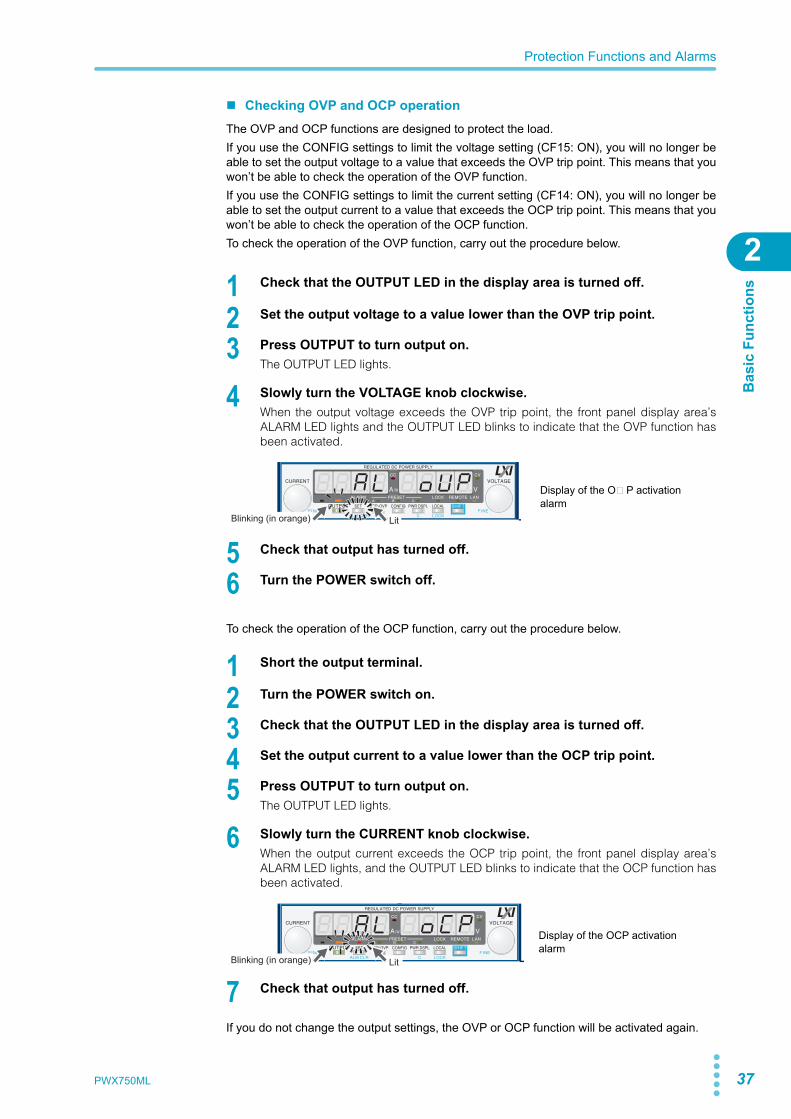
Checking OVP and OCP operationThe OVP and OCP functions are designed to protect the load.If you use the CONFIG settings to limit the voltage setting (CF15: ON), you will no longer beable to set the output voltage to a value that exceeds the OVP trip point. This means that youwon’t be able to check the operation of the OVP function.If you use the CONFIG settings to limit the current setting (CF14: ON), you will no longer beable to set the output current to a value that exceeds the OCP trip point. This means that youwon’t be able to check the operation of the OCP function.To check the operation of the OVP function, carry out the procedure below.
1 Check that the OUTPUT LED in the display area is turned off.
2 Set the output voltage to a value lower than the OVP trip point.
3 Press OUTPUT to turn output on.The OUTPUT LED lights.
4 Slowly turn the VOLTAGE knob clockwise.When the output voltage exceeds the OVP trip point, the front panel display area’sALARM LED lights and the OUTPUT LED blinks to indicate that the OVP function hasbeen activated.
5 Check that output has turned off.
6 Turn the POWER switch off.
To check the operation of the OCP function, carry out the procedure below.
1 Short the output terminal.
2 Turn the POWER switch on.
3 Check that the OUTPUT LED in the display area is turned off.
4 Set the output current to a value lower than the OCP trip point.
5 Press OUTPUT to turn output on.The OUTPUT LED lights.
6 Slowly turn the CURRENT knob clockwise.When the output current exceeds the OCP trip point, the front panel display area’sALARM LED lights, and the OUTPUT LED blinks to indicate that the OCP function hasbeen activated.
7 Check that output has turned off.
If you do not change the output settings, the OVP or OCP function will be activated again.
LitBlinking (in orange)
Display of the OVP activation alarm
LitBlinking (in orange)
Display of the OCP activation alarm
38 PWX750ML
Protection Functions and Alarms
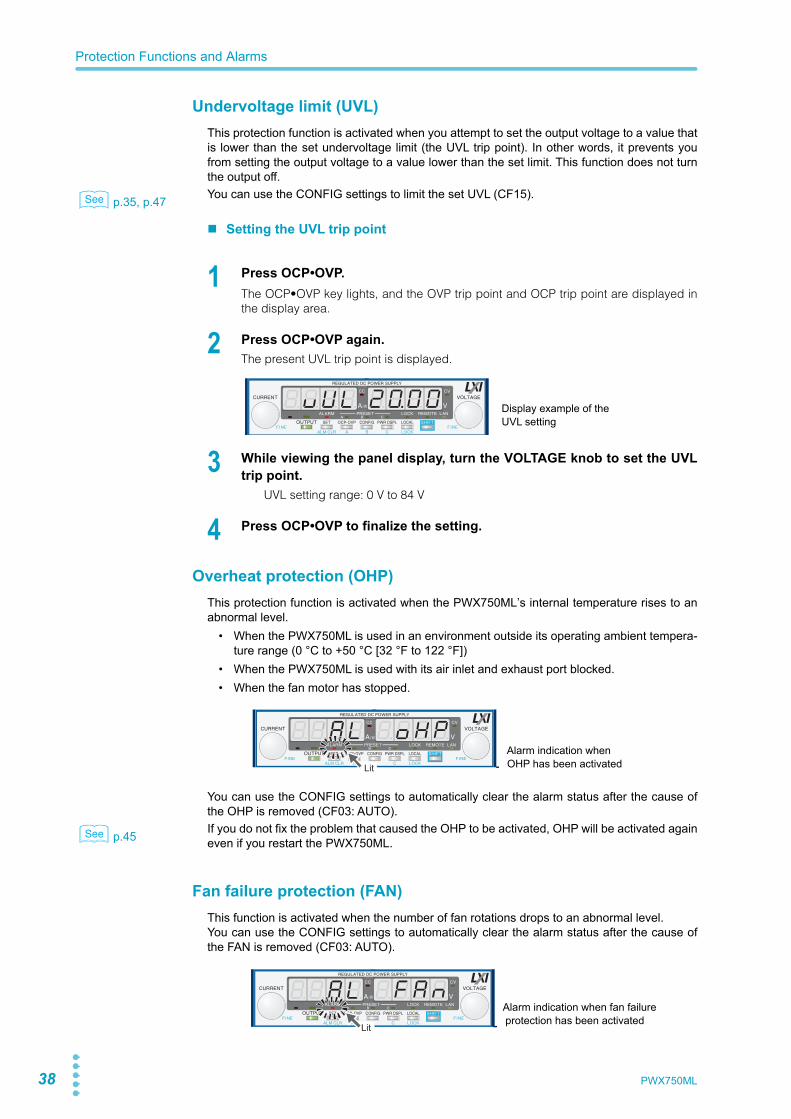
Undervoltage limit (UVL)This protection function is activated when you attempt to set the output voltage to a value thatis lower than the set undervoltage limit (the UVL trip point). In other words, it prevents youfrom setting the output voltage to a value lower than the set limit. This function does not turnthe output off.
p.35, p.47 You can use the CONFIG settings to limit the set UVL (CF15).
Setting the UVL trip point
1 Press OCP•OVP.The OCP•OVP key lights, and the OVP trip point and OCP trip point are displayed inthe display area.
2 Press OCP•OVP again.The present UVL trip point is displayed.
3 While viewing the panel display, turn the VOLTAGE knob to set the UVLtrip point.
UVL setting range: 0 V to 84 V
4 Press OCP•OVP to finalize the setting.
Overheat protection (OHP)This protection function is activated when the PWX750ML’s internal temperature rises to anabnormal level.
• When the PWX750ML is used in an environment outside its operating ambient tempera-ture range (0 °C to +50 °C [32 °F to 122 °F])
• When the PWX750ML is used with its air inlet and exhaust port blocked.• When the fan motor has stopped.
You can use the CONFIG settings to automatically clear the alarm status after the cause ofthe OHP is removed (CF03: AUTO).
p.45 If you do not fix the problem that caused the OHP to be activated, OHP will be activated againeven if you restart the PWX750ML.
Fan failure protection (FAN)This function is activated when the number of fan rotations drops to an abnormal level.You can use the CONFIG settings to automatically clear the alarm status after the cause ofthe FAN is removed (CF03: AUTO).
See
Display example of the UVL setting
Lit
Alarm indication when OHP has been activated
See
Lit
Alarm indication when fan failure protection has been activated
PWX750ML 39
Protection Functions and Alarms
Bas
ic F
unct
ions
2
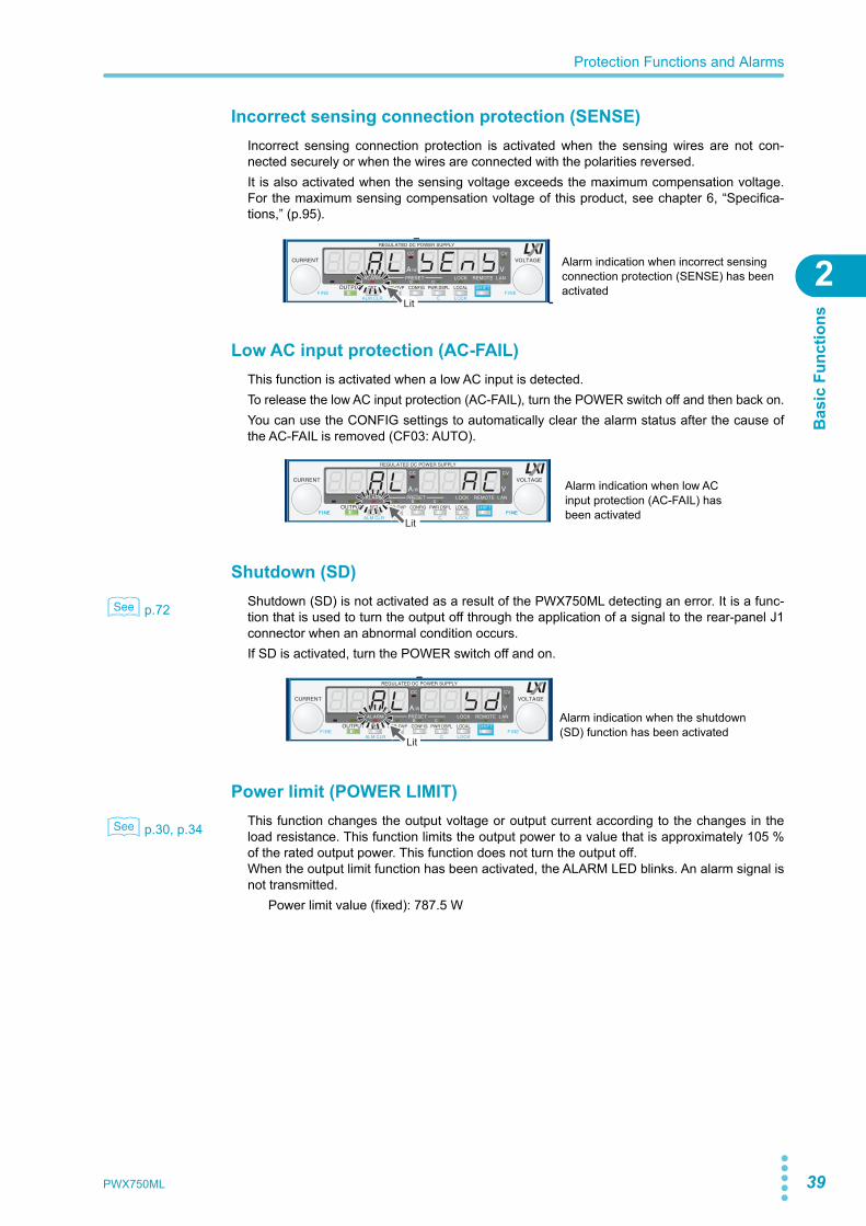
Incorrect sensing connection protection (SENSE)Incorrect sensing connection protection is activated when the sensing wires are not con-nected securely or when the wires are connected with the polarities reversed.It is also activated when the sensing voltage exceeds the maximum compensation voltage.For the maximum sensing compensation voltage of this product, see chapter 6, “Specifica-tions,” (p.95).
Low AC input protection (AC-FAIL)This function is activated when a low AC input is detected.To release the low AC input protection (AC-FAIL), turn the POWER switch off and then back on.You can use the CONFIG settings to automatically clear the alarm status after the cause ofthe AC-FAIL is removed (CF03: AUTO).
Shutdown (SD)
p.72 Shutdown (SD) is not activated as a result of the PWX750ML detecting an error. It is a func-tion that is used to turn the output off through the application of a signal to the rear-panel J1connector when an abnormal condition occurs.If SD is activated, turn the POWER switch off and on.
Power limit (POWER LIMIT)
p.30, p.34 This function changes the output voltage or output current according to the changes in theload resistance. This function limits the output power to a value that is approximately 105 %of the rated output power. This function does not turn the output off.When the output limit function has been activated, the ALARM LED blinks. An alarm signal isnot transmitted.
Power limit value (fixed): 787.5 W
Alarm indication when incorrect sensing connection protection (SENSE) has been activated
Lit
Lit
Alarm indication when low AC input protection (AC-FAIL) has been activated
See
Lit
Alarm indication when the shutdown (SD) function has been activated
See
40 PWX750ML
Protection Functions and Alarms
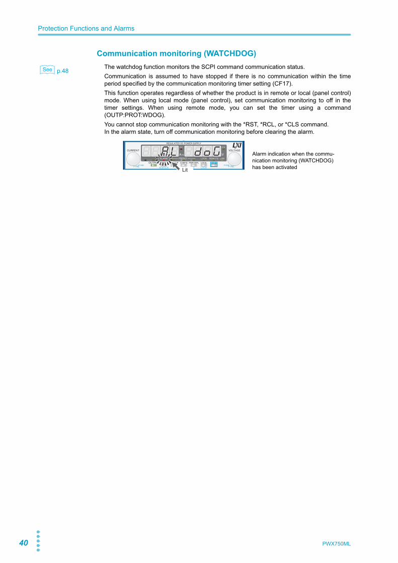
Communication monitoring (WATCHDOG)
p.48 The watchdog function monitors the SCPI command communication status.Communication is assumed to have stopped if there is no communication within the timeperiod specified by the communication monitoring timer setting (CF17).This function operates regardless of whether the product is in remote or local (panel control)mode. When using local mode (panel control), set communication monitoring to off in thetimer settings. When using remote mode, you can set the timer using a command(OUTP:PROT:WDOG).You cannot stop communication monitoring with the *RST, *RCL, or *CLS command.In the alarm state, turn off communication monitoring before clearing the alarm.
See
Lit
Alarm indication when the commu-nication monitoring (WATCHDOG) has been activated
PWX750ML 41
2
Bas
ic F
unct
ions
CONFIG SettingsUse the CONFIG settings to set the PWX750ML system configuration. You can set and dis-play the following parameters in the CONFIG settings. The CONFIG parameters are listed ina separate document (included with this manual).
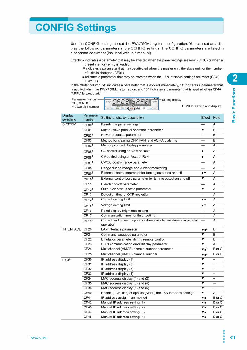
Effects: ● indicates a parameter that may be affected when the panel settings are reset (CF00) or when a preset memory entry is loaded.
▼indicates a parameter that may be affected when the master unit, the slave unit, or the number of units is changed (CF01).
■indicates a parameter that may be affected when the LAN interface settings are reset (CF40: LCi/dEF).
In the “Note” column, “A” indicates a parameter that is applied immediately, “B” indicates a parameter that is applied when the PWX750ML is turned on, and “C” indicates a parameter that is applied when CF40 “APPL” is executed.
Parameter number, CF (CONFIG) + a two-digit number
Setting display
LitCONFIG setting and display
Display switching
Parameter number Setting or display description Effect Note
SYSTEM CF001 Resets the panel settings — A
CF01 Master-slave parallel operation parameter ▼ B
CF021 Power-on status parameter — B
CF03 Method for clearing OHP, FAN, and AC-FAIL alarms — B
CF041 Memory content display parameter — A
CF051 CC control using an Vext or Rext ● A
CF061 CV control using an Vext or Rext ● A
CF071 CV/CC control range parameter — A
CF08 Range during voltage and current monitoring — A
CF091 External control parameter for turning output on and off ●▼ A
CF101 External control logic parameter for turning output on and off ▼ A
CF11 Bleeder on/off parameter — A
CF121 Output-on startup state parameter ▼ A
CF13 Detection time of OCP activation — A
CF141 Current setting limit ●▼ A
CF151 Voltage setting limit ●▼ A
CF16 Panel display brightness setting — ACF17 Communication monitor timer setting — A
CF192 Current and power display on slave units for master-slave parallel operation
— A
INTERFACE CF20 LAN interface parameter ▼■3 BCF21 Command language parameter ▼ BCF22 Emulation parameter during remote control ▼ BCF23 SCPI communication error display parameter ▼ ACF24 Multichannel (VMCB) domain number parameter ▼■3 B or CCF25 Multichannel (VMCB) channel number ▼■3 B or C
LAN4 CF30 IP address display (1) ▼ ─
CF31 IP address display (2) ▼ ─
CF32 IP address display (3) ▼ ─
CF33 IP address display (4) ▼ ─
CF34 MAC address display (1) and (2) ▼ ─
CF35 MAC address display (3) and (4) ▼ ─CF36 MAC address display (5) and (6) ▼ ─CF40 Resets (LCI/ DEF) or applies (APPL) the LAN interface settings ▼ ACF41 IP address assignment method ▼■ B or CCF42 Manual IP address setting (1) ▼■ B or CCF43 Manual IP address setting (2) ▼■ B or CCF44 Manual IP address setting (3) ▼■ B or CCF45 Manual IP address setting (4) ▼■ B or C
42 PWX750ML
CONFIG Settings
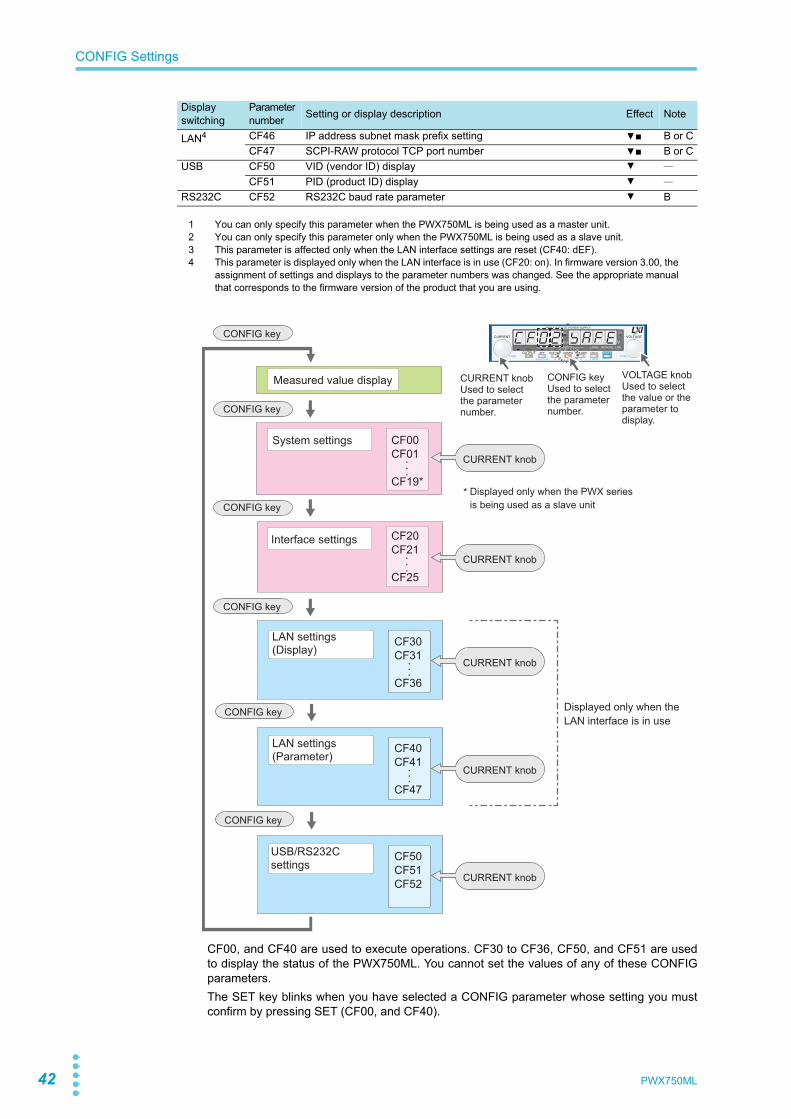
CF00, and CF40 are used to execute operations. CF30 to CF36, CF50, and CF51 are usedto display the status of the PWX750ML. You cannot set the values of any of these CONFIGparameters.The SET key blinks when you have selected a CONFIG parameter whose setting you mustconfirm by pressing SET (CF00, and CF40).
LAN4 CF46 IP address subnet mask prefix setting ▼■ B or CCF47 SCPI-RAW protocol TCP port number ▼■ B or C
USB CF50 VID (vendor ID) display ▼ ─CF51 PID (product ID) display ▼ ─
RS232C CF52 RS232C baud rate parameter ▼ B
1 You can only specify this parameter when the PWX750ML is being used as a master unit.2 You can only specify this parameter only when the PWX750ML is being used as a slave unit.3 This parameter is affected only when the LAN interface settings are reset (CF40: dEF).4 This parameter is displayed only when the LAN interface is in use (CF20: on). In firmware version 3.00, the
assignment of settings and displays to the parameter numbers was changed. See the appropriate manualthat corresponds to the firmware version of the product that you are using.
Display switching
Parameter number Setting or display description Effect Note
CONFIG key
CONFIG key
*CONFIG key
CONFIG key
Displayed only when the PWX series is being used as a slave unit
CONFIG key
CONFIG key
Displayed only when the LAN interface is in use
CF00CF01
CF19*
CF20CF21
CF25
VOLTAGE knobUsed to select the value or the parameter to display.
CONFIG keyUsed to select the parameter number.
CURRENT knobUsed to select the parameter number.
Measured value display
System settings
Interface settings
. . .. . .
LAN settings (Display)
LAN settings (Parameter)
...
CF30CF31
CF36
...
CF40CF41
CF47
CURRENT knob
CURRENT knob
CURRENT knob
CURRENT knob
USB/RS232C settings
CF50CF51CF52 CURRENT knob
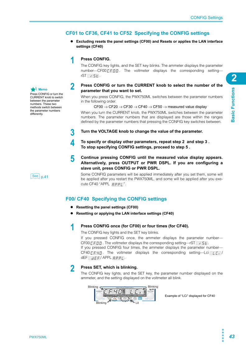
PWX750ML 43
CONFIG Settings
Bas
ic F
unct
ions
2
CF01 to CF36, CF41 to CF52 Specifying the CONFIG settings Excluding resets the panel settings (CF00) and Resets or applies the LAN interface
settings (CF40)
1 Press CONFIG.The CONFIG key lights, and the SET key blinks. The ammeter displays the parameternumber—CF00 . The voltmeter displays the corresponding setting—rST .
2 Press CONFIG or turn the CURRENT knob to select the number of theparameter that you want to set.When you press CONFIG, the PWX750ML switches between the parameter numbersin the following order.
CF00 → CF20 → CF30 → CF40 → CF50 → measured value displayWhen you turn the CURRENT knob, the PWX750ML switches between the parameternumbers. The parameter numbers that are displayed are those within the rangesdefined by the parameter numbers that pressing the CONFIG key switches between.
3 Turn the VOLTAGE knob to change the value of the parameter.
4 To specify or display other parameters, repeat step 2 and step 3 .To stop specifying CONFIG settings, proceed to step 5 .
5 Continue pressing CONFIG until the measured value display appears.Alternatively, press OUTPUT or PWR DSPL. If you are configuring aslave unit, press CONFIG or PWR DSPL.
p.41 Some CONFIG parameters will be applied immediately after you set them, some willbe applied after you restart the PWX750ML, and some will be applied after you exe-cute CF40 “APPL ”.
F00/ CF40 Specifying the CONFIG settings Resetting the panel settings (CF00) Resetting or applying the LAN interface settings (CF40)
1 Press CONFIG once (for CF00) or four times (for CF40).The CONFIG key lights and the SET key blinks.If you pressed CONFIG once, the ammeter displays the parameter number—CF00 . The voltmeter displays the corresponding setting—rST .If you pressed CONFIG four times, the ammeter displays the parameter number—CF40 . The voltmeter displays the corresponding setting—Lci /dEF / APPL .
2 Press SET, which is blinking.The CONFIG key lights, and the SET key, the parameter number displayed on theammeter, and the setting displayed on the voltmeter all blink.
MemoPress CONFIG or turn the CURRENT knob to switch between the parameter numbers. These two methods switch between the parameter numbers differently.
See
Example of “LCi” displayed for CF40
Lit
Blinking Blinking
Blinking
44 PWX750ML
CONFIG Settings
3 Press SET, which is blinking, again.While the parameter number and the setting are blinking, no new settings will beapplied until you press SET.When setting CF00, the measured value display appears.
When CF40 is set, the LAN LED lights in orange (for about 4 to 5 seconds) while thesetting is being confirmed and then turns green when it is complete. Press SET to exitthe CONFIG settings. The settings will be applied.
p.9 If the LAN LED turns red, set the settings again.
CONFIG parameter details
The CONFIG parameters are explained in detail below.
CF00 Resets the panel settings
p.41, p.58, Communication Interface Manual
Sets whether the panel settings will be reset. The following settings will be reset. When thesettings are reset, the PWX750ML settings take on the same values as they do when an*RST command is received.You can only specify this parameter when the PWX750ML is being used as a master unit.
• Output voltage• Output on/off at power-on• Output current• Constant current control using an Vext or Rext (CF05)• Overvoltage protection• Constant voltage control using an Vext or Rext (CF06)• Overcurrent protection• External control setting for turning output on and off (CF09)• Undervoltage limit• Voltage and current setting limits (CF15 and CF14)
CF01 Master-slave parallel operation parameter
p.78 Sets the total number of units (master unit and slave units) in master-slave parallel operation.Specify “SLAV” for the units that you want to use as slaves. This parameter is applied when you restart the PWX750ML.
p.41 Changing this setting may affect the settings of the master unit or the slave units that are con-nected in parallel.
MemoPress any key other than SET to cancel the confirmation of the parameter.
See
See
Value Parameter description
rSt Resets the panel settings
See
See
Value Parameter description
SLAV Use the PWX as a slave unit.
1 to 4 Set the total number of units (1 to 4; 1 indicates independent operation--factory default setting).
PWX750ML 45
CONFIG Settings
Bas
ic F
unct
ions
2
CF02 Power-on status parameter
p.13 Sets the condition that the PWX750ML will be in when the power is turned on. This setting isinvalid when you are using an external contact to turn the output off.This parameter is applied when you turn the POWER switch off and on.If you want to specify “Auto“ or “Forc“, set the method for clearing OHP, FAN, and AC-FAILalarms to “After the problem that caused an alarm to occur is fixed, the output is turned onautomatically” (CF03: Auto).You can only specify this parameter when the PWX750ML is being used as a master unit.
CF03 Method for clearing OHP, FAN, and AC-FAIL alarms
p.35 Sets the method for clearing alarms when overheat protection (OHP), fan failure protection(FAN), or low AC input protection (AC-FAIL) has been activated. You cannot set this parame-ter separately for each protection function.
p.38 When you select “Auto,” if the overheat protection function (OHP) has been activated, outputwill turn on again automatically when the internal temperature drops to a normal level. How-ever, if you do not fix the problem that caused the alarm to occur, the alarm will occur again,which will force you to clear the alarm again. The overheat protection devices have long ser-vice lives (approximately 100000 uses), but if they reach the end of their service lives, theywill stop operating. To maintain the performance of the PWX750ML for a long time, werequest that you fully understand the Auto feature and only use it when necessary.
CF04 Memory content display parameter
p.55 Sets whether to display the saved contents in the preset memory before recalling them.You can use this CONFIG parameter if you forget what settings have been saved to a presetmemory entry or if you want to view the saved settings.You can only specify this parameter when the PWX750ML is being used as a master unit.
See
Value Parameter description
SAFE The settings that were in use immediately before the POWER switch was turned off are used. The output is off (factory default setting).
Auto The settings that were in use immediately before the POWER switch was turned off are used. This includes whether output was on or off.
Forc The settings that were in use immediately before the POWER switch was turned off are used. The output is turned on.
See
See
Value Parameter description
SAFE After the problem that caused an alarm to occur is fixed, the output is not turned on automatically (factory default setting).
Auto After the problem that caused an alarm to occur is fixed, the output is turned on automatically.
See
Value Parameter description
oFF The saved contents of preset memory will be recalled without displaying them.
on The saved contents of preset memory entries will be displayed (factory default set-ting).
46 PWX750ML
CONFIG Settings
CF05 CC control using an Vext or Rext
p.44, p.55, p.66
Sets whether constant current will be controlled by an external voltage (Vext) or an externalresistance (Rext) (the J1 connector).This is set to “oFF” when the panel settings are reset(CF00) and when a preset memory entry is recalled.You can only specify this parameter when the PWX750ML is being used as a master unit.
CF06 CV control using an Vext or Rext
p.66 Selects whether constant voltage will be controlled by an external voltage (Vext) or an exter-nal resistance (Rext) (the J1 connector).This is set to “oFF” when the panel settings are reset (CF00) and when a preset memoryentry is recalled.You can only specify this parameter when the PWX750ML is being used as a master unit.
CF07 CV/CC control range parameter
p.66, p.68 Selects the range that is used when controlling constant current and constant voltage with anexternal voltage or an external resistance (the J1 connector).You can only specify this parameter when the PWX750ML is being used as a master unit.
CF08 Range during voltage and current monitoring
p.74 Selects the range during voltage and current monitoring.
CF09 External control parameter for turning output on and off
p.70 Selects whether an external contact (the J1 connector) will be used to turn output on and off.This is set to “oFF” when the panel settings are reset (CF00) and when a preset memoryentry is recalled.You can only specify this parameter when the PWX750ML is being used as a master unit.
See
Value Parameter description
oFF Control will not be performed (factory default setting).
on Control will be performed.
See
Value Parameter description
oFF Control will not be performed (factory default setting).
on Control will be performed.
See
Value Parameter description
Lo 0 V to 5 V (factory default setting)
Hi 0 V to 10 V
See
Value Parameter description
Lo 0 V to 5 V (factory default setting)
Hi 0 V to 10 V
See
Value Parameter description
oFF External control is not performed (factory default setting).
on External control is performed.
PWX750ML 47
CONFIG Settings
Bas
ic F
unct
ions
2
CF10 External control logic parameter for turning output on and off
p.70 Sets the logic that is used when an external contact (the J1 connector) is being used to turnoutput on and off. If you are not using an external contact to turn output on and off, select “Hi.”You can only specify this parameter when the PWX750ML is being used as a master unit.
CF11 Bleeder on or off
p.57 Turns the bleeder circuit on and off. You can turn the bleeder circuit off when you don’t wantcurrent to be sinked by the internal bleeder circuit, such as when you are charging a battery.Even when the output terminal is off (open) or when the set voltage is 0 V, if you turn thebleeder off, a voltage as large as a few hundred millivolts may appear at the output terminal.Depending on whether the breeder circuit is on or off, the sink current and the fall time of out-put voltage when an external voltage sources connected will vary.When using master-slave parallel operation or series operation, use the same settings on allconnected units.
CF12 Output-on startup state parameter
p.33 Sets the operation mode to be prioritized when the output is turned on. When used as a slave device, CC is automatically prioritized. To use the PWX750ML as astandalone unit or master unit after using it as a slave unit, set the operation mode that youwant to use.If you do not set the operation mode, CC will be prioritized.You can only specify this parameter when the PWX750ML is being used as a master unit.
CF13 Detection time of OCP activation
p.36 Sets the time from when an overcurrent is detected to when the output is turned off in steps of100 ms.
See
Value Parameter description
Lo Output is turned on when a LOW signal (0 V to 0.5 V) or short-circuit is received (factory default setting).
Hi Output is turned on when a HIGH signal(4.5 V to 5 V) or open-circuit is received.
See
Value Parameter description
oFF The bleeder circuit is turned off.
on The bleeder circuit is turned on (factory default setting).
See
Value Parameter description
CC CC (constant current) is prioritized.
CV CV (constant voltage) is prioritized (factory default setting).
See
Value Parameter description
0 0 ms (factory default setting)
100 to 2000 100 ms to 2000 ms
48 PWX750ML
CONFIG Settings
CF14 Current setting limit
p.35 Set whether to limit the set output current so that its value does not exceed the set overcur-rent protection (approximately 95 % of the OCP trip point). When the current setting limit isset to “oFF,” if you set the current setting limit to “on” when the set OCP is lower than the setcurrent, the current value will be maintained, and the set OCP will be changed to 105 % of thecurrent value. The parameter will also be changed if the output is on.This is set to “on” when the panel settings are reset (CF00) and when a preset memory entryis recalled.You can only specify this parameter when the PWX750ML is being used as a master unit.
CF15 Voltage setting limit
p.35 Set whether to limit the set output voltage so that its value does not exceed the set overvolt-age protection (approximately 95 % of the OVP trip point) and is not lower than the set under-voltage limit. When the voltage setting limit is set to “oFF,” if you set the voltage setting limit to“on” when the set OVP is lower than the set voltage, the voltage value will be maintained, andthe set OVP will be changed to 105 % of the voltage value. In addition, the set UVL will bechanged to match the voltage value. The parameter will also be changed if the output is on.This is set to “on” when the panel settings are reset (CF00) and when a preset memory entryis recalled.You can only specify this parameter when the PWX750ML is being used as a master unit.
CF16 Panel display brightness settingAdjusts the panel display brightness. The larger the number, the brighter the display.Even if you specify the same number, the brightness may be different between individualproducts.
The brightness is not proportional to the setting.
CF17 Communication monitor timer setting
p.40 Sets the interval for monitoring SCPI command communication.The communication monitoring function operates regardless of whether the product is inremote or local (panel control) mode.
When using local mode (panel control), be sure to specify oFF.
See
Value Parameter description
oFF The setting is not limited.
on The setting is limited (factory default setting).
See
Value Parameter description
oFF The setting is not limited.
The setting is limited (factory default setting).
MemoWhen multiple units are used side-by-side, if the brightness of the panel display is different between units, you can adjust it. Value Parameter description
1 to 7 Screen brightness (factory default setting: 7).
See
Value Parameter description
oFF Communication monitor timer is set to off (factory default setting).
1 to 3000 1 s, 3 s, 10 s, 30 s, 100 s, 300 s, 1000 s, 3000 s
PWX750ML 49
CONFIG Settings
Bas
ic F
unct
ions
2
CF19 Current and power display on slave units for master-slave parallel operation
Sets whether the current or power on slave units is displayed during master-slave paralleloperation. You can display and specify this parameter only when the PWX750ML is beingused as a slave unit.If this parameter is set so that the current or power on slave units is not displayed, the amme-ter displays “----.”
CF20 LAN interface parameterSets whether the LAN interface will be used.By setting it to “oFF,” you can disable the LAN interface function even when a LAN cable isconnected. You will also not be able to set the LAN interface parameters.Even when this is set to “on,” if the command language is set to legacy (CF21: LGCy), youcannot use the LAN interface.This parameter is applied when you turn the POWER switch off and on.
CF21 Command language parameterSets the command language that is used in remote control messages. This parameter is applied when you turn the POWER switch off and on.
CF22 Emulation parameter during remote controlSets the emulation that is used during remote control. If you have set the command languageto legacy languages, you can only select “Gen” or “PAG.”This parameter is applied when you turn the POWER switch off and on.
Value Parameter description
oFF The current or power of slave units is not displayed (factory default setting).
on The current or power of slave units is displayed.
Value Parameter description
oFF The LAN interface will be not used
on The LAN interface will be used (factory default setting).
Value Parameter description
SCPi The SCPI language will be used (factory default setting).
LGCy Legacy languages will be used.
Value Parameter description
nonE Remote control is performed using the PWX750ML commands made by Kikusui (factory default setting).
5700 Remote control is performed using the N5700/N8700 commands made by Agilent Technologies.
GEn Remote control is performed using the Genesys series commands made by TDK-Lambda.
PAG Remote control is performed using the PAG series commands made by Kikusui.
dCS Remote control is performed using the DCS series commands made by Sorensen.
50 PWX750ML
CONFIG Settings
CF23 SCPI communication error display parameterSets whether to display communication errors. This parameter is displayed and can be setonly when the SCPI language is in use.
CF24 Multichannel (VMCB) domain number parameterSet the multichannel domain number. PWXs that have the same domain number performmultichannel operations. If you do not want to use the multichannel function, set this to 0 (thisis the factory default setting).If 5700 or DCS emulation is selected, you cannot use multichannel. This parameter is appliedwhen you turn the POWER switch off and on.For details on the multichannel function, see the Communication Interface Manual on theincluded CD-ROM.
CF25 Multichannel (VMCB) channel numberSet the multichannel channel number. Specify a unique number on the network. If you do notwant to use the multichannel function, set this to 0 (this is the factory default setting).If 5700 or DCS emulation is selected, you cannot use multichannel.This parameter is applied when you turn the POWER switch off and on.For details on the multichannel function, see the Communication Interface Manual on theincluded CD-ROM.
CF30 to CF33 IP address displayThese parameters display the set IP addresses. These parameters are only displayed whenyou are using the LAN interface.To set a fixed IP address, set it from the panel (CF42 to CF45), or access the PWX through aWeb browser. When you access the PWX750ML through a Web browser, do so under condi-tions in which a DHCP server or AUTO IP can be used.For information about the Web browser interface, see the included CD-ROM.
Value Parameter description
oFF SCPI communication errors are not displayed (factory default setting)
on SCPI communication errors are displayed.
Value Parameter description
0 The multichannel function is not used (factory default setting).
1 to 254 The domain number when the multichannel function is used.
Value Parameter description
0 The PWX is used as a master unit on the multichannel network (factory default setting).
1 to 30 The PWX is used as a slave unit with this channel number on the multichannel network
Parameter number
Display Description
CF30 0 to 255 Displays the first IP address number
CF31 0 to 255 Displays the second IP address number
CF32 0 to 255 Displays the third IP address number
CF33 0 to 255 Displays the fourth IP address number
PWX750ML 51
CONFIG Settings
Bas
ic F
unct
ions
2
CF34 to CF36 MAC address displayThese parameters display the set MAC addresses.MAC addresses are set to 00.0F.CE.xx.xx.xx (where x is a hexadecimal number between 0and F).
CF40 Resetting (LCI/ DEF) or applying (APPL) the LAN interface settings
p.9、p.43 Sets whether to reset or apply the LAN interface settings.This parameter is displayed and canbe set only when the LAN interface is in use.If you select to reset the LAN interface settings (LCI/ DEF), the security password will becleared, and the PWX will be in a security-disabled state.If the LAN LED turns red, set the settings again.For details on the LAN interface settings, see the “Communication Interface Manual” on theincluded CD-ROM.
Parameter number Display Description
CF34 00.0F Displays the first and second MAC address numbers
CF35 CE.xx Displays the third and fourth MAC address numbers
CF36 xx.xx Displays the fifth and sixth MAC address numbers
CF34: 00.0F
CF36: 22.33
CF35: CE.11Display example of the MAC address “00.0F.CE.11.22.33:”
See
Value Parameter description
LCi Resets the LAN interface settings (to their factory default values)
dEF The LAN interface and multichannel (VMCB) settings are reset (to their factory default values).
APPL The LAN interface is restarted, and the CONFIG settings are applied.
52 PWX750ML
CONFIG Settings
CF41 IP address assignment methodSets the IP address assignment method. This parameter is displayed and can be set onlywhen the LAN interface is in use.Set whether to use (on: 1) or not use (off: 0) the following: DHCP server, AUTO IP function(automatic assignment), and MANUAL IP function (manual assignment).If an IP address is not assigned through a DHCP server, AUTO IP is used.To use the MANUAL IP function, set the DHCP server and AUTO IP function to off. Theaddress that is assigned by the AUTO IP function is 169.254.x.x (where x is a numberbetween 1 and 254).This parameter is applied when you turn the POWER switch off and on or when you executeAPPL with CF40.
CF42 to CF45 Manual IP address setting (MANUAL IP function)If you are not using the DHCP server or the AUTO IP function, set the IP address manually.To do so, use CF41 to set MANUAL IP to on. This parameter is displayed and can be set onlywhen the LAN interface is in use.These parameters are applied when you turn the POWER switch off and on or when you exe-cute APPL with CF40.
CF46 IP address subnet mask prefix settingIf you want to set the IP address manually (MANUAL IP function), set the subnet mask prefix.To do so, use CF41 to set MANUAL IP to on. This parameter is displayed and can be set only when the LAN interface is in use.This parameter is applied when you turn the POWER switch off and on or when you executeAPPL with CF40.
Examples: Display example when “16” is set 255.255.0.0Display example when “24” is set 255.255.255.0Display example when “31” is set 255.255.255.254
Value/ Display Parameter description
(001) DHCP: OFF, AUTO IP: OFF, MANUAL IP: ON
(010) DHCP: OFF, AUTO IP: ON, MANUAL IP: OFF
(011) DHCP: OFF, AUTO IP: ON, MANUAL IP: ON
(100) DHCP: ON, AUTO IP: OFF, MANUAL IP: OFF
(101) DHCP ON, AUTO IP: OFF, MANUAL IP: ON
(110) DHCP: ON, AUTO IP: ON, MANUAL IP: OFF (factory default setting)
(111) DHCP: ON, AUTO IP: ON, MANUAL IP: ON
Parameter number
Value Parameter description
CF42 0 to 255 Sets the first IP address number
CF43 0 to 255 Sets the second IP address number
CF44 0 to 255 Sets the third IP address number
CF45 0 to 255 Sets the fourth IP address number
Parameter number
Value Parameter description
CF46 16 to 31 Sets the subnet mask prefix
PWX750ML 53
CONFIG Settings
Bas
ic F
unct
ions
2
CF47 SCPI-RAW protocol TCP port number settingSet the TCP port number of the SCPI-RAW protocol for when the LAN interface is in use.This parameter is displayed and can be set only when the LAN interface is in use.This parameter is applied when you turn the POWER switch off and on or when you executeAPPL with CF40.TCP port number 4880, 5024 and 5044 cannot be used.
CF50 Vendor ID (VID) displayDisplays the USB vendor ID.
CF51 Product ID displayDisplays the USB product ID.
CF52 RS232C baud rate settingSets the RS232C baud rate. This parameter is applied when you restart the PWX750ML.
Value Parameter description
1000 to 9999 (except 4880, 5024, 5044)
TCP port number (factory default setting: 5025)
Display Description
0b3E 0x0B3E
Display Description
1025 0x1025
Value Parameter description
1.2 1200 bps
2.4 2400 bps
4.8 4800 bps
9.6 9600 bps
19.2 19200 bps (factory default setting)
38.4 38400 bps
57.6 57600 bps
115.2 115200 bps
54 PWX750ML
Preset Memory Function
The PWX750ML has the preset memory that stores three sets of the following settings: thevoltage, the current, the OVP, the OCP, and the UVL. You can recall the stored set from thepreset memory whenever you need.To select the preset memory that you specify for saving or recalling a set of settings, press A,B, or C key while holding down SHIFT key.The recalling will be effective at the moment when you select the preset memory. To save thepresent settings, you need to keep holding down the keys (SHIFT+A, B, or C).
Saving settings to preset memory
1 Press SET.The SET key lights, and the present voltage and current settings are displayed on thepanel.
2 While viewing the values displayed on the panel, turn the VOLTAGEknob to set the preset memory voltage and turn the CURRENT knob toset the preset memory current.
p.36 3 Press OCP•OVP.The OCP•OVP key lights, and the OVP trip point and OCP trip point are displayed inthe display area.
4 While viewing the values displayed on the panel, turn the VOLTAGEknob to set the preset memory OVP value and turn the CURRENT knobto set the preset memory OCP value.
p.38 5 Press OCP•OVP again.The present UVL trip point is displayed.
6 While viewing the value displayed on the panel, turn the VOLTAGE knobto set the preset memory UVL value.
7 Press SHIFT+the memory key (A, B, or C) to which you want to save thesettings. Hold the keys down until their LEDs turn on.The PRESET A, PRESET B, or PRESET C LED in the display area—whichever one cor-responds to the memory entry that you selected—lights to indicate that the presetmemory entry has been saved.
By following step 7 , you can save preset memory entries when the output is on and the mea-sured value display is being shown (the SET key LED is off). After you save a preset memoryentry, press SET to view the preset memory values.
See
See
PWX750ML 55
Preset Memory Function
Bas
ic F
unct
ions
2
Recalling preset memory entries
You can recall preset memory entries from the measured value display (when the SET keyLED is off) and from the setting display (when the SET key LED is lit).If the output is on, the values in the preset memory entry are applied to the output themoment that the preset memory entry is recalled (the moment that the settings are applied).
p.45 There are two methods to recall a preset memory entry. One method is to display the savedcontents for confirmation and then recall (CF04: on). The other is to recall immediately with-out displaying the contents (CF04: oFF).
When you recall a preset memory entry, the following items are set to their factory default set-tings.
p.46, p.46, p.48
• Constant current control using an Vext or Rext (CF05: oFF)• Constant voltage control using an Vext or Rext (CF06: oFF)• Output on/off control using an external contact (CF09: oFF)• Current setting limit (CF14: on)• Voltage setting limit (CF15: on)
Displaying the saved contents for confirmation and then recalling
1 Press SHIFT+the memory key (A, B, or C) from which you want to recallthe preset memory entry.The SET LED and the contents (voltage and current) of the loaded preset memory thatare shown in the display area blink. If you press another memory key, the contents ofthe corresponding memory appear blinking.
2 Check the displayed settings, and then press SET.The SET LED and the LED that corresponds to the loaded preset memory entry bothlight, and the set voltage and current are displayed on the panel.
Easily recalling a preset memory entry
1 Use the CONFIG settings to set the PWX750ML to hide the saved con-tents of preset memory entries (CF04: oFF).
2 While holding down the SHIFT key, press the appropriate memory key(A, B, or C).The LED that corresponds to the preset memory entry that you have loaded (PRESETA, B, or C) lights.If no load is connected, it will take time for the output voltage to decrease.
See
If you hold down SHIFT+the memory key (A, B, or C) from which you want to recall the pre-set memory entry, the present values in use will be saved to the preset memory entry instead.
See
MemoThis is convenient when you want to view the contents that have been saved to memory.
MemoPress OCP•OVP, CONFIG, or PWR DSPL to cancel the recall operation.
MemoThis is convenient when you know the contents that have been saved to memory.
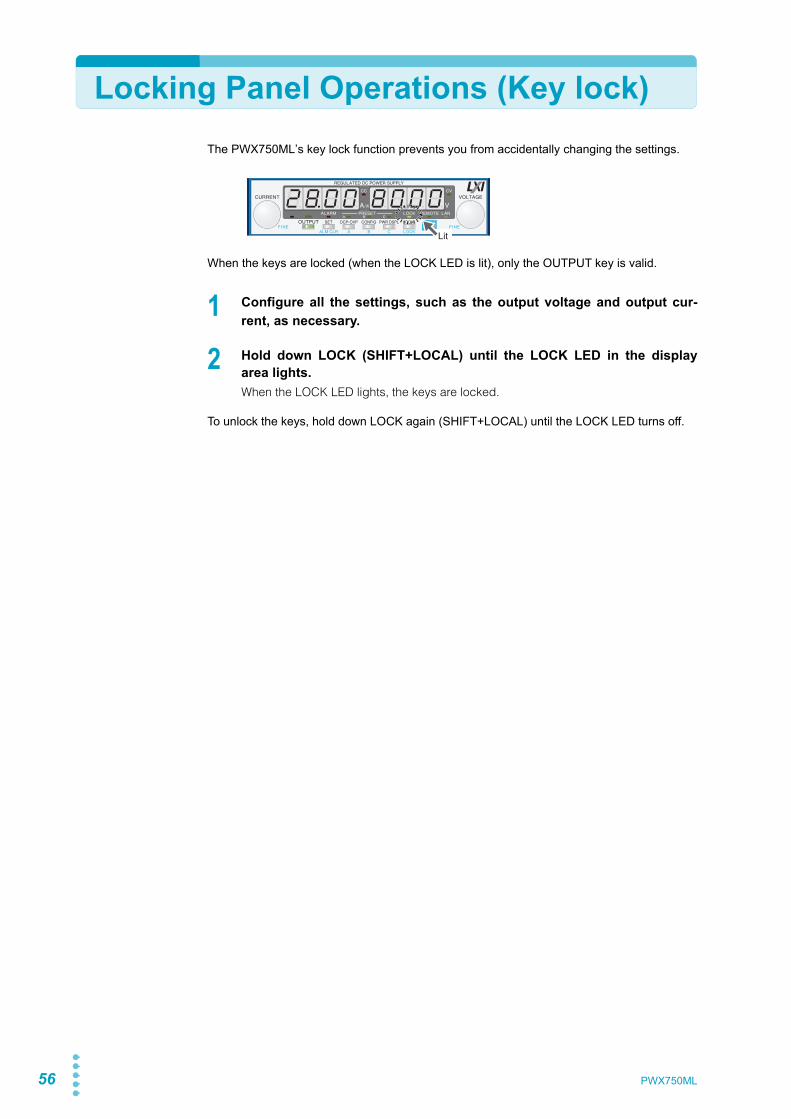
56 PWX750ML
Locking Panel Operations (Key lock)The PWX750ML’s key lock function prevents you from accidentally changing the settings.
When the keys are locked (when the LOCK LED is lit), only the OUTPUT key is valid.
1 Configure all the settings, such as the output voltage and output cur-rent, as necessary.
2 Hold down LOCK (SHIFT+LOCAL) until the LOCK LED in the displayarea lights.When the LOCK LED lights, the keys are locked.
To unlock the keys, hold down LOCK again (SHIFT+LOCAL) until the LOCK LED turns off.
Lit
PWX750ML 57
2
Bas
ic F
unct
ions
Bleeder On/Off Feature
p.47 You can turn the bleeder circuit on and off. Turn the bleeder circuit off when you do not wantthe internal bleeder circuit to sink output current. When you connect a battery, you can pre-vent excessive electrical discharges by turning the bleeder circuit off.When using master-slave parallel operation or series operation, use the same settings on allconnected units.Depending on whether the breeder circuit is on or off, the sink current and the fall time of out-put voltage when an external voltage sources connected will vary.The sink current or fall time indicated here is a standard value.
Sink current from an external voltage source when the breeder is on andoff (When the voltage from the external voltage source is larger than theset voltage)
Fall time of the output voltage when the breeder is offThis is the time period for the rated output voltage to fall from 90 % to 10 % when the out-put is changed from on to off under no load conditions.
See
WARNING Risk of electric shock. Set the bleeder on/off setting to “on” before you touch the out-put terminals. Even if you turn the output off or turn the POWER switch off, if the bleeder on/off setting is set to “oFF,” the voltage that was present when the output was on will remain at the output terminals.
Vout = Output terminal voltage
Bleeder circuit
Sink current
5 Vout1
1 Even when the breeder is on, the sink current decreases gradually at output terminalvoltages lower than this voltage. If the output terminal voltage is near 0 V, hardly any currentwill be sunk even when the breeder is on.
10 Vout 20 Vout 30 Vout 40 Vout 50 Vout 60 Vout 70 Vout 80 Vout
ON 583 mA 559 mA 510 mA 462 mA 414 mA 365 mA 317 mA 269 mA 221 mAOFF 0.1 mA 0.2 mA 0.4 mA 0.6 mA 0.8 mA 1.0 mA 1.2 mA 1.4 mA 1.6 mA
Fall time 250 seconds
58 PWX750ML
Switching from Remote Mode to Local Mode
When the PWX750ML is being controlled remotely, the REMOTE LED in the display arealights.
To switch the PWX750ML to local mode from the front panel, press LOCAL.
Factory Default Settings (Initialization)
If you hold down SHIFT+LOCAL while you turn the POWER switch on, the PWX750ML willbe reset to the factory default settings.The factory default settings are shown below.
Basic settings
Lit
Basic item Parameter description
Output voltage 0 V
Output current 105 % of the rated output current
OVP (overvoltage protection) 112 % of the rated output voltage
OCP (overcurrent protection) 112 % of the rated output current
UVL (undervoltage limit) 0 V

PWX750ML 59
Factory Default Settings (Initialization)
Bas
ic F
unct
ions
2
CONFIG settings
Param. number CONFIG parameter Parameter description
CF01 Master-slave parallel operation parameter 1 (independent operation)
CF021 Power-on status parameter SAFE (panel settings that were in use the last time the power was turned off)
CF03 Method for clearing OHP, FAN, and AC-FAIL alarms
SAFE (do not clear the alarm automatically)
CF041 Memory content display parameter ON (displayed)
CF051 CC control using an Vext or Rext OFF
CF061 CV control using an Vext or Rext OFF
CF071 CV/CC control range parameter LO (0 V to 5 V)
CF08 Range during voltage and current monitoring LO (0 V to 5 V)
CF091 External control parameter for turning output on and off
OFF
CF101 External control logic parameter for turning output on and off
LO (a LOW signal turns output on) 2
CF11 Bleeder on/off parameter ON (bleeder circuit is on)
CF121 Output-on startup state parameter CV (CV is prioritized)
CF13 Detection time of OCP activation 0 ms
CF141 Current setting limit ON (the setting is limited)
CF151 Voltage setting limit ON (the setting is limited)
CF16 Panel display brightness setting 7CF17 Communication monitor timer setting OFF (Communication monitoring timer off)
CF193 Display setting on slave units for master-slave parallel operation
OFF (not displayed on slave units)
CF20 LAN interface parameter LAN (The LAN interface will be used)CF21 Command language parameter SCPICF22 Emulation parameter during remote control NONE (PWX750ML commands)CF23 SCPI communication error display parameter OFF (not displayed)CF24 Multichannel (VMCB) domain number 0 (the multichannel function is not used)CF25 Multichannel (VMCB) channel number 0 (the PWX is used as a master unit on the multichan-
nel network)CF41 IP address assignment method
(DHCP: ON, AUTO IP: ON, MANUAL IP: OFF)CF47 SCPI-RAW protocol TCP port number 5025CF52 RS232C baud rate parameter 19.2 (kbit/s)
1 You can only specify this parameter when the PWX750ML is being used as a master unit.2 0 V to 0.5 V or shorted.3 You can only specify this parameter only when the PWX750ML is being used as a slave unit.

60 PWX750ML
This page is intentionally blank.

External Control
External ControlThis chapter explains external control andexternal monitoring using the J1 connector.
62
Overview
You can use the J1 connector on the rear panel of the PWX750ML to perform the followingtypes of external control.• Output voltage control
Controlled using an external voltage or external resistance• Output current control
Controlled using an external voltage or external resistance• Turning output on and off using an external contact• Output shutdown control using an external contact• Clearing alarms using an external contact• Monitoring operation modes
About the J1 ConnectorPlug kit 749809-9 DB25 is included for connecting to the J1 connector. The plug kit is con-structed of connector parts made by AMP.Simple pressure welding tools and contact removal tools are not included. These items mustbe purchased separately.For information about how to use these components, see the AMP catalogs.For information about how to obtain these tools or replacement parts, contact your Kikusuiagent or distributor.
Attaching the J1 cable core
To connect to the J1 connector, requires a core on the cable for connection.The core is not included. Use an appropriate core.
Recommended core: ZCAT3035-1330 EMI FILTER 250 Ohm 100 MHz by TDK
1 Unlock the snap-on core and open to split.
2 Wrap the cable twice around either half of the open core.Wrap the wire so that the distance between the core and the J1 connector is within 30mm.
3 Close the core keeping the J1 cable from being wedged in between.Check that the core is securely locked.
CAUTION When using the isolated analog interface (Option), do not apply signals to VPGM (pin 22) and IPGM (pin 21) of the J1 connector. If you do, the connected device may malfunction, or the PWX may not operate properly.
To J1 connectorCore
To connection
Unlock and open the core
30 mm
PWX750ML
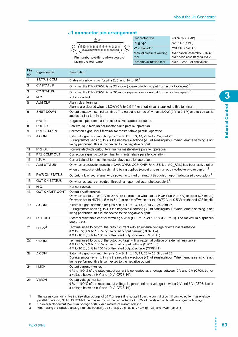
About the J1 Connector
Exte
rnal
Con
trol
3
J1 connector pin arrangementConnector type 5747461-3 (AMP)Plug type 745211-7 (AMP)Wire diameter AWG26 to AWG22Manual pressure welding tool
AMP handle assembly 58074-1AMP head assembly 58063-2
Insertion/extraction tool AMP 91232-1 or equivalent
J1
12345678910111213141516171819202122232425
Pin number positions when you are facing the rear panel
Pinno. Signal name Description
1 STATUS COM Status signal common for pins 2, 3, and 14 to 16.1
2 CV STATUS On when the PWX750ML is in CV mode (open-collector output from a photocoupler).2
3 CC STATUS On when the PWX750ML is in CC mode (open-collector output from a photocoupler).2
4 N.C. Not connected.5 ALM CLR Alarm clear terminal.
Alarms are cleared when a LOW (0 V to 0.5 V) or short-circuit is applied to this terminal.6 SHUT DOWN Output shutdown control terminal. The output is turned off when a LOW (0 V to 0.5 V) or short-circuit is
applied to this terminal.7 PRL IN- Negative input terminal for master-slave parallel operation.8 PRL IN+ Positive input terminal for master-slave parallel operation.9 PRL COMP IN Correction signal input terminal for master-slave parallel operation.10 A COM External signal common for pins 5 to 9, 11 to 13, 18, 20 to 22, 24, and 25.
During remote sensing, this is the negative electrode (-S) of sensing input. When remote sensing is not being performed, this is connected to the negative output.
11 PRL OUT+ Positive electrode output terminal for master-slave parallel operation.12 PRL COMP OUT Correction signal output terminal for master-slave parallel operation.13 I SUM Current signal terminal for master-slave parallel operation.14 ALM STATUS On when a protection function (OVP, OVP2, OCP, OHP, FAN, SEN, or AC_FAIL) has been activated or
when an output shutdown signal is being applied (output through an open-collector photocoupler).2
15 PWR ON STATUS Outputs a low level signal when power is turned on (output through an open-collector photocoupler).2
16 OUT ON STATUS On when output is on (output through an open-collector photocoupler).2
17 N.C. Not connected.18 OUT ON/OFF CONT Output on/off terminal.
On when set to LOW (0 V to 0.5 V) or shorted; off when set to HIGH (4.5 V or 5 V) or open (CF10: Lo)On when set to HIGH (4.5 V to 5 V) or open; off when set to LOW (0 V or 0.5 V) or shorted (CF10: Hi)
19 A COM External signal common for pins 5 to 9, 11 to 13, 18, 20 to 22, 24, and 25.During remote sensing, this is the negative electrode (-S) of sensing input. When remote sensing is not being performed, this is connected to the negative output.
20 REF OUT External resistance control terminal; 5.25 V (CF07: Lo) or 10.5 V (CF07: Hi). The maximum output cur-rent 2.5 mA.
21 I PGM3 Terminal used to control the output current with an external voltage or external resistance.0 V to 5 V; 0 % to 100 % of the rated output current (CF07: Lo).0 V to 10 V; 0 % to 100 % of the rated output current (CF07: Hi).
22 V PGM3 Terminal used to control the output voltage with an external voltage or external resistance.0 V to 5 V; 0 % to 100 % of the rated output voltage (CF07: Lo).0 V to 10 V; 0 % to 100 % of the rated output voltage (CF07: Hi).
23 A COM External signal common for pins 5 to 9, 11 to 13, 18, 20 to 22, 24, and 25.During remote sensing, this is the negative electrode (-S) of sensing input. When remote sensing is not being performed, this is connected to the negative output.
24 I MON Output current monitor.0 % to 100 % of the rated output current is generated as a voltage between 0 V and 5 V (CF08: Lo) or a voltage between 0 V and 10 V (CF08: Hi).
25 V MON Output voltage monitor.0 % to 100 % of the rated output voltage is generated as a voltage between 0 V and 5 V (CF08: Lo) or a voltage between 0 V and 10 V (CF08: Hi).
1 The status common is floating (isolation voltage of 60 V or less), it is isolated from the control circuit. If connected for master-slaveparallel operation, STATUS COM of the master unit will be connected to A COM of the slave unit (it will no longer be floating).
2 Open collector output:Maximum voltage of 30 V and maximum current of 8 mA.3 When using the isolated analog interface (Option), do not apply signals to VPGM (pin 22) and IPGM (pin 21) .
PWX750ML 63
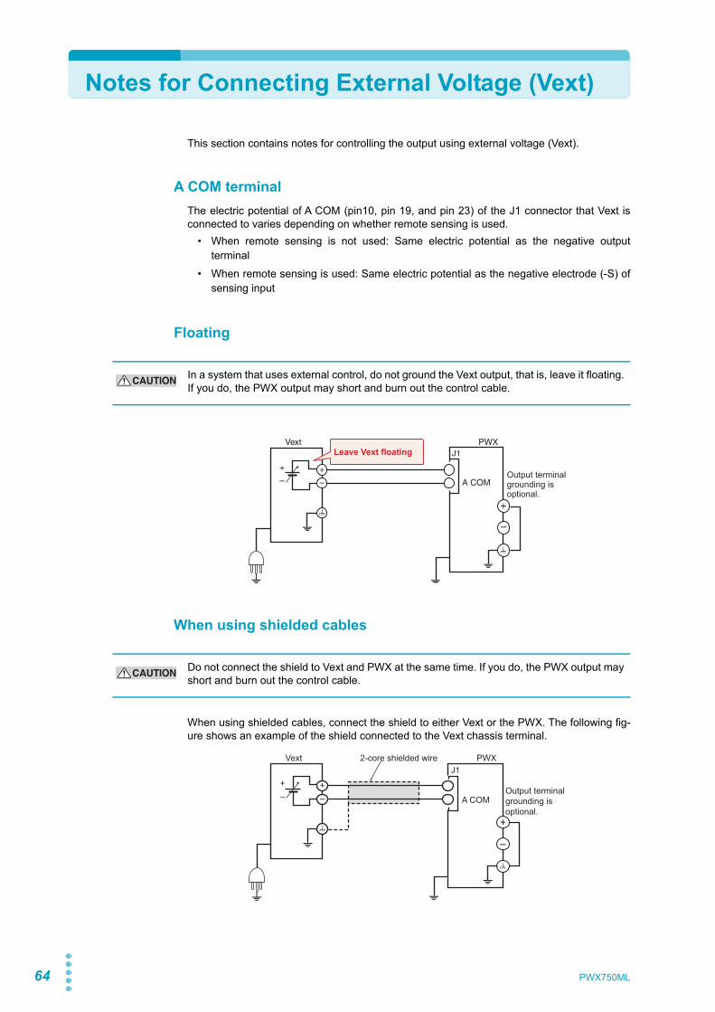
64
Notes for Connecting External Voltage (Vext)
This section contains notes for controlling the output using external voltage (Vext).
A COM terminalThe electric potential of A COM (pin10, pin 19, and pin 23) of the J1 connector that Vext isconnected to varies depending on whether remote sensing is used.
• When remote sensing is not used: Same electric potential as the negative outputterminal
• When remote sensing is used: Same electric potential as the negative electrode (-S) ofsensing input
Floating
When using shielded cables
When using shielded cables, connect the shield to either Vext or the PWX. The following fig-ure shows an example of the shield connected to the Vext chassis terminal.
CAUTION In a system that uses external control, do not ground the Vext output, that is, leave it floating. If you do, the PWX output may short and burn out the control cable.
+
+
–
+
–
–
Vext PWX
A COM
J1Leave Vext floating
Output terminal grounding is optional.
CAUTION Do not connect the shield to Vext and PWX at the same time. If you do, the PWX output may short and burn out the control cable.
+–
+–
Vext PWXJ1
2-core shielded wire
A COM
+
–
Output terminal grounding is optional.
PWX750ML

Notes for Connecting External Voltage (Vext)
Exte
rnal
Con
trol
3
System that controls multiple PWXs with multiple Vexts
When the GND (negative) terminals between each Vext is connected ([1]), the path connect-ing the A COM between each PWX is formed. If you connect the negative output terminalsbetween each PWX, an unintended current loop shown in the following figure will be created.This current loop may cause the system to malfunction or damage the devices.In a system that controls multiple PWXs with multiple Vexts, such as that shown in the follow-ing figure, we recommend that you do not connect [1] and [2]. If you need to for systematicreasons, connect either [1] or [2].
System that controls PWXs connected in parallel using a single Vext
In a system that uses a single Vext to control PWXs connected in parallel, such as that shownin the following figure, only a single PWX can be connected directly to Vext through a controlcable. Connect other PWXs through isolators.
CAUTION Connect the GND (negative) terminals between each Vext, but do not connect the negative output terminals between each PWX. Not following this rule may cause the system to mal-function or damage the devices.
Vext1
Load(EUT)
Load(EUT)
PWX(A)
PWX(B)Vext2
[2][1]
+–
+–
+–
+–
A COM
J1
A COM
J1
Even when grounding is established on the EUT side, a path at the ground potential is formed like the connection in [2], so you need to be careful.
Unintended current loop
CAUTION Connect only a single PWX directly to Vext through a control cable. Not following this rule may cause the system to malfunction or damage the devices.
Isolator
VextPWX(A)
+–
+–A COM
J1
PWX(B)
+–A COM
J1
Load(EUT)
The number of PWXs that can be connected directly is also one when using a system that controls the output through an external contact using a sequencer or the like.
PWX750ML 65
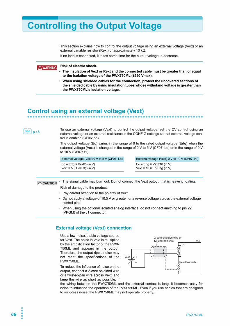
66
Controlling the Output Voltage
This section explains how to control the output voltage using an external voltage (Vext) or anexternal variable resistor (Rext) of approximately 10 kΩ.If no load is connected, it takes some time for the output voltage to decrease.
Control using an external voltage (Vext)
p.46 To use an external voltage (Vext) to control the output voltage, set the CV control using anexternal voltage or an external resistance in the CONFIG settings so that external voltage con-trol is enabled (CF06: on).The output voltage (Eo) varies in the range of 0 to the rated output voltage (Ertg) when theexternal voltage (Vext) is changed in the range of 0 V to 5 V (CF07: Lo) or in the range of 0 Vto 10 V (CF07: Hi).
External voltage (Vext) connectionUse a low-noise, stable voltage sourcefor Vext. The noise in Vext is multipliedby the amplification factor of the PWX-750ML and appears in the output.Therefore, the output ripple noise maynot meet the specifications of thePWX750ML.To reduce the influence of noise on theoutput, connect a 2-core shielded wireor a twisted-pair wire across Vext, andkeep the wire as short as possible. Ifthe wiring between the PWX750ML and the external contact is long, it becomes easy fornoise to influence the operation of the PWX750ML. Even if you use cables that are designedto suppress noise, the PWX750ML may not operate properly.
WARNING Risk of electric shock.• The insulation of Vext or Rext and the connected cable must be greater than or equal
to the isolation voltage of the PWX750ML (±250 Vmax).• When using shielded cables for the connection, protect the uncovered sections of
the shielded cable by using insulation tubes whose withstand voltage is greater than the PWX750ML’s isolation voltage.
See
External voltage (Vext) 0 V to 5 V (CF07: Lo) External voltage (Vext) 0 V to 10 V (CF07: Hi)
Eo = Ertg × Vext/5 (in V)Vext = 5 × Eo/Ertg (in V)
Eo = Ertg × Vext/10 (in V)Vext = 10 × Eo/Ertg (in V)
CAUTION • The signal cable may burn out. Do not connect the Vext output, that is, leave it floating.
Risk of damage to the product.• Pay careful attention to the polarity of Vext.• Do not apply a voltage of 10.5 V or greater, or a reverse voltage across the external voltage
control pins.• When using the optional isolated analog interface, do not connect anything to pin 22
(VPGM) of the J1 connector.
2-core shielded wire ortwisted-pair wire
Vext +– Output terminals
J122
23
PWX
PWX750ML
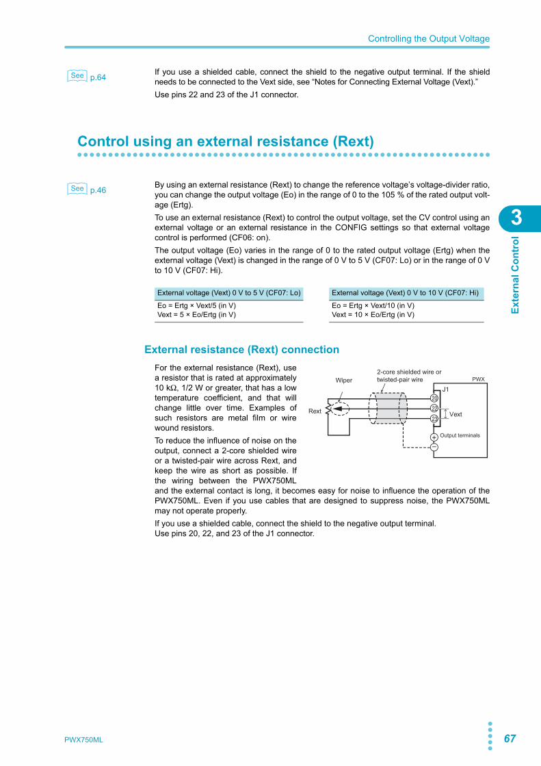
Controlling the Output Voltage
Exte
rnal
Con
trol
3
p.64 If you use a shielded cable, connect the shield to the negative output terminal. If the shieldneeds to be connected to the Vext side, see “Notes for Connecting External Voltage (Vext).”Use pins 22 and 23 of the J1 connector.
Control using an external resistance (Rext)
p.46 By using an external resistance (Rext) to change the reference voltage’s voltage-divider ratio,you can change the output voltage (Eo) in the range of 0 to the 105 % of the rated output volt-age (Ertg).To use an external resistance (Rext) to control the output voltage, set the CV control using anexternal voltage or an external resistance in the CONFIG settings so that external voltagecontrol is performed (CF06: on).The output voltage (Eo) varies in the range of 0 to the rated output voltage (Ertg) when theexternal voltage (Vext) is changed in the range of 0 V to 5 V (CF07: Lo) or in the range of 0 Vto 10 V (CF07: Hi).
External resistance (Rext) connectionFor the external resistance (Rext), usea resistor that is rated at approximately10 kΩ, 1/2 W or greater, that has a lowtemperature coefficient, and that willchange little over time. Examples ofsuch resistors are metal film or wirewound resistors.To reduce the influence of noise on theoutput, connect a 2-core shielded wireor a twisted-pair wire across Rext, andkeep the wire as short as possible. Ifthe wiring between the PWX750MLand the external contact is long, it becomes easy for noise to influence the operation of thePWX750ML. Even if you use cables that are designed to suppress noise, the PWX750MLmay not operate properly.If you use a shielded cable, connect the shield to the negative output terminal.Use pins 20, 22, and 23 of the J1 connector.
See
See
External voltage (Vext) 0 V to 5 V (CF07: Lo) External voltage (Vext) 0 V to 10 V (CF07: Hi)
Eo = Ertg × Vext/5 (in V)Vext = 5 × Eo/Ertg (in V)
Eo = Ertg × Vext/10 (in V)Vext = 10 × Eo/Ertg (in V)
2-core shielded wire ortwisted-pair wireWiper
Output terminals
J120
22
23
PWX
Rext Vext
PWX750ML 67
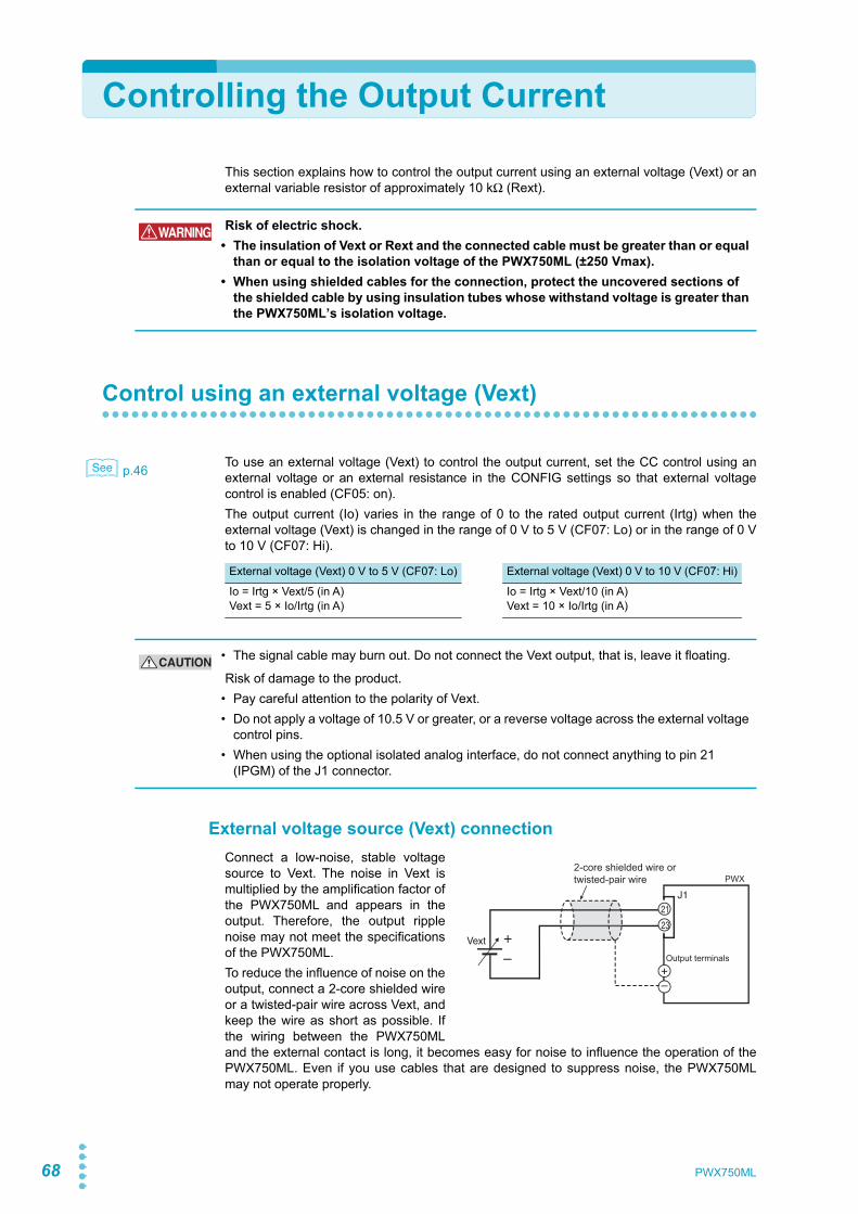
68
Controlling the Output Current
This section explains how to control the output current using an external voltage (Vext) or anexternal variable resistor of approximately 10 kΩ (Rext).
Control using an external voltage (Vext)
p.46 To use an external voltage (Vext) to control the output current, set the CC control using anexternal voltage or an external resistance in the CONFIG settings so that external voltagecontrol is enabled (CF05: on).The output current (Io) varies in the range of 0 to the rated output current (Irtg) when theexternal voltage (Vext) is changed in the range of 0 V to 5 V (CF07: Lo) or in the range of 0 Vto 10 V (CF07: Hi).
External voltage source (Vext) connectionConnect a low-noise, stable voltagesource to Vext. The noise in Vext ismultiplied by the amplification factor ofthe PWX750ML and appears in theoutput. Therefore, the output ripplenoise may not meet the specificationsof the PWX750ML.To reduce the influence of noise on theoutput, connect a 2-core shielded wireor a twisted-pair wire across Vext, andkeep the wire as short as possible. Ifthe wiring between the PWX750MLand the external contact is long, it becomes easy for noise to influence the operation of thePWX750ML. Even if you use cables that are designed to suppress noise, the PWX750MLmay not operate properly.
WARNING Risk of electric shock.• The insulation of Vext or Rext and the connected cable must be greater than or equal
than or equal to the isolation voltage of the PWX750ML (±250 Vmax).• When using shielded cables for the connection, protect the uncovered sections of
the shielded cable by using insulation tubes whose withstand voltage is greater than the PWX750ML’s isolation voltage.
See
External voltage (Vext) 0 V to 5 V (CF07: Lo) External voltage (Vext) 0 V to 10 V (CF07: Hi)
Io = Irtg × Vext/5 (in A)Vext = 5 × Io/Irtg (in A)
Io = Irtg × Vext/10 (in A)Vext = 10 × Io/Irtg (in A)
CAUTION • The signal cable may burn out. Do not connect the Vext output, that is, leave it floating.
Risk of damage to the product.• Pay careful attention to the polarity of Vext.• Do not apply a voltage of 10.5 V or greater, or a reverse voltage across the external voltage
control pins.• When using the optional isolated analog interface, do not connect anything to pin 21
(IPGM) of the J1 connector.
2-core shielded wire ortwisted-pair wire
Vext +– Output terminals
J121
23
PWX
PWX750ML

Controlling the Output Current
Exte
rnal
Con
trol
3
p.65 If you use a shielded cable, connect the shield to the negative output terminal. If the shieldneeds to be connected to the Vext side, see “System that controls multiple PWXs with multi-ple Vexts.”Use pins 21 and 23 of the J1 connector.
Control using an external resistance (Rext)
p.46 By using an external resistance (Rext) to change the reference voltage’s voltage-divider ratio,you can change the output current (Io) in the range of 0 to the 105 % of the rated output cur-rent (Irtg).To use an external resistance (Rext) to control the output current, set the CC control using anexternal voltage or an external resistance in the CONFIG settings so that external voltagecontrol is enabled (CF05: on).The output current (Io) varies in the range of 0 to the rated output current (Irtg) when theexternal voltage (Vext) is changed in the range of 0 V to 5 V (CF07: Lo) or in the range of 0 Vto 10 V (CF07: Hi).
External resistance (Rext) connectionFor Rext, use a resistor that is rated atapproximately 10 kΩ, 1/2 W or greater,that has a low temperature coefficient,and that will change little over time.Examples of such resistors are metalfilm or wire wound resistors.To reduce the influence of noise onthe output, connect a 2-core shieldedwire or a twisted-pair wire across Rext,and keep the wire as short as possi-ble. If the wiring is long, it becomeseasy for noise to influence the opera-tion of the PWX750ML. Even if you use wires that are designed to suppress noise, the PWX-750ML may not operate properly.If you use a shielded cable, connect the shield to the negative output terminal.Use pins 20, 21, and 23 of the J1 connector.
See
See
External voltage (Vext) 0 V to 5 V (CF07: Lo) External voltage (Vext) 0 V to 10 V (CF07: Hi)
Io = Irtg × Vext/5 (in A)Vext = 5 × Io/Irtg (in A)
Io = Irtg × Vext/10 (in A)Vext = 10 × Io/Irtg (in A)
2-core shielded wire ortwisted-pair wire
Output terminals
J120
21
23
PWX
Rext Vext
Wiper
PWX750ML 69
70
Controlling the Output On and Off States
This section explains how to use an external contact to control the output on and off states.
To reduce the influence of noise on the output, connect a 2-core shielded wire or a twisted-pair wire across the external contact, and keep the wire as short as possible. If the wiring islong, it becomes easy for noise to influence the operation of the PWX750ML. Even if you usewires that are designed to suppress noise, the PWX750ML may not operate properly.If you use a shielded cable, connect the shield to the negative output terminal.
p.46 To use an external contact to control the output on and off states, set the appropriate CONFIGparameter (CF09: on). Then, select the logic setting from the following two options.• Turn the output on at the falling edge of the LOW signal (CF10: Lo)
Output is turned on when a LOW (0 V to 0.5 V) or short-circuit is applied to pin 1 of the J1connector.
• Turn the output on at the rising edge of the HIGH signal (CF10: Hi)Output is turned on when a HIGH (4.5 V to 5 V) or open-circuit is applied to pin 1 of the J1connector.
Output on/off control is performed by detecting rising edges or falling edges. Because it is nota level detection, if you want to turn on the output at startup, you need to apply a signal sothat an edge is detected.
External contact, the OUTPUT key on the panel, and output on/off control using the OUTPcommand are enabled simultaneously. (For details on commands, see the CommunicationInterface Manual.)
Because output off is prioritized, if the output is turned off with an external contact, the OUT-PUT key and OUTP command are disabled.
Controlling the output on and off states (in this example, a high signal is used to turn theoutput on)
WARNING Risk of electric shock.• The insulation of the external contact (S) and the connected cable must be greater
than or equal to the isolation voltage of the PWX750ML (±250 Vmax).• When using shielded cables for the connection, protect the uncovered sections of
the shielded cable by using insulation tubes whose withstand voltage is greater than the PWX750ML’s isolation voltage.
See
On
Off
H = On
L = Off
▼
PWX750ML
Controlling the Output On and Off States
Exte
rnal
Con
trol
3
External contact connectionUse pins 18 and 19 of the J1 connector.The open-circuit voltage across pins 18and 19 is approximately 5 V. The short-cir-cuit current across pins 18 and 19 isapproximately 0.5 mA.Use external contacts that have a contactrating of 0.5 mA or more at 5 Vdc.If two or more units are floating and youare using a single external contact to turnoutput on and off for all the units, use a relay or similar device for the external contact signalto isolate the signal transmitted to each unit.
For long-distance wiringWhen you are wiring over a great distance, usea small relay and extend the coil side of therelay.
2-core shielded wire ortwisted-pair wire
Output terminals
J11819
PWX
S
S
Extend this line. Relay
PWX750ML 71
72
Controlling Output Shutdown
This section explains how to use an external contact to turn output off.
To reduce the influence of noise on the output, connect a 2-core shielded wire or a twisted-pair wire across the external contact, and keep the wire as short as possible. If the wiring islong, it becomes easy for noise to influence the operation of the PWX750ML. Even if you usewires that are designed to suppress noise, the PWX750ML may not operate properly.If you use a shielded cable, connect the shield to the negative output terminal.If you apply a LOW (0 V to 0.5 V) or short-circuit to pin 6 of the J1 connector, the output turnsoff.
To recover, set pin 6 of the J1 connector to HIGH (4.5 V to 5 V) or open the pin, and then turnthe POWER switch off and then on.
Output shutdown connectionUse pins 6 and 19 of the J1 connector.The open-circuit voltage across pins 6and 19 is approximately 5 V. The short-circuit current across pins 6 and 19 isapproximately 0.5 mA.Use external contacts that have a con-tact rating greater than or equal to 0.5mA at 5 Vdc.
If two or more units are floating, and you are using a single external contact to turn output offfor all the units, use a relay or similar device for the external contact signal to isolate the sig-nal transmitted to each unit.
For long-distance wiringWhen you are wiring over a great distance,use a small relay and extend the coil side ofthe relay.
WARNING Risk of electric shock.• The insulation of the external contact (S) and the connected cable must be greater
than or equal to the isolation voltage of the PWX750ML (±250 Vmax).• When using shielded cables for the connection, protect the uncovered sections of
the shielded cable by using insulation tubes whose withstand voltage is greater than the PWX750ML’s isolation voltage.
2-core shielded wire ortwisted-pair wire
Output terminals
J1619
PWX
S
S
Extend this line. Relay
PWX750ML
3
Exte
rnal
Con
trol
Controlling the Clearing of Alarms
This section explains how to use an external contact to clear alarms.
To reduce the influence of noise on the output, connect a 2-core shielded wire or a twisted-pair wire across the external contact, and keep the wire as short as possible. If the wiring islong, it becomes easy for noise to influence the operation of the PWX750ML. Even if you usewires that are designed to suppress noise, the PWX750ML may not operate properly.If you use a shielded cable, connect the shield to the negative output terminal.If you apply a LOW (0 V to 0.5 V) or short-circuit to pin 5 of the J1 connector, the alarms willbe cleared.
Alarm clear connectionUse pins 5 and 19 of the J1 connector.The open-circuit voltage across pins 5and 19 is approximately 5 V. The short-circuit current across pins 5 and 19 isapproximately 0.5 mA.Use external contacts that have a con-tact rating greater than or equal to 0.5mA at 5 Vdc.
If two or more units are floating, and you are using a single external contact to clear alarms,use a relay or similar device for the external contact signal to isolate the signal transmitted toeach unit.
For long-distance wiringWhen you are wiring over a great distance,use a small relay and extend the coil side ofthe relay.
WARNING Risk of electric shock.• The insulation of the external contact (S) and the connected cable must be greater
than or equal to the isolation voltage of the PWX750ML (±250 Vmax).• When using shielded cables for the connection, protect the uncovered sections of
the shielded cable by using insulation tubes whose withstand voltage is greater than the PWX750ML’s isolation voltage.
2-core shielded wire ortwisted-pair wire
Output terminals
J1519
PWX
S
S
Extend this line. Relay
PWX750ML 73
74
External Monitoring
External monitoring of the output voltage and output currentThe J1 connector has monitor outputs for the output voltage and the output current.
Monitor output ratingOutput impedance: 1 kΩ or less. Maximum output current: Approximately 10 mA.
The monitor output signals are used to monitor the DC voltage (mean value). They cannot beused to accurately monitor the AC components (such as ripple and transient response wave-form) of the actual output voltage or current.
External monitoring of the operation statusThe J1 connector has status outputs that can be used to externally monitor the operation sta-tus of the PWX750ML. The following five items make up the status outputs.The outputs are open collector outputs of photocouplers; they are isolated from the internalcircuits of the PWX750ML.The status common is floating (that is, it has an isolation voltage of less than or equal to60 V).If connected for master-slave parallel operation, STATUS COM (pin 1 of the J1 connector) ofthe master unit will be connected to A COM (pin 19 of the J1 connector) of the slave unit (itwill no longer be floating). If the positive output terminal is connected to the chassis terminalin this condition, the status common will be at an electric potential that is lower than that ofthe chassis terminal by the output voltage. Because the positive output terminal is at groundpotential, secure an insulation capacity greater than or equal to this product’s isolation volt-age relative to the chassis.
The maximum ratings of the signal terminals are as follows:Maximum voltage: 30 V. Maximum current (sink): 8 mA.
Pin no. Signal name Description10, 19, 23 A COM Remote control input common
Output monitor common25 V MON Monitor output of output voltage
0 to approx. 5 V (CF08: Lo) or 0 to approx. 10 V (CF08: Hi) for 0 to the rated output voltage
24 I MON Monitor output of output current0 to approx. 5 V (CF08: Lo) or 0 to approx. 10 V (CF08: Hi) for 0 to the rated output current
CAUTION Shorting V MON and I MON to A COM may damage the PWX750ML.
PWX750ML

External Monitoring
Exte
rnal
Con
trol
3
Pin no. Signal name Description Circuit1 STATUS COM This is the status output common.
This is the photocoupler emitter output.2 CV STATUS This is set to low level when the PWX750ML is in
constant voltage mode.This is the photocoupler open collector output.
3 CC STATUS This is set to low level when the PWX750ML is in constant current mode.This is the photocoupler open collector output.
14 ALM STATUS This is set to low level when a protection function (OVP/ OVP2/ OCP/ OHP/ FAN/ SEN/ AC-FAIL/ SD) is activated.This is the photocoupler open collector output.
15 PWR ON STATUS This is set to low level when the PWX750ML is turned on (PWR ON STATUS).This is the photocoupler open collector output.
16 OUT ON STATUS This is set to low level when the output is turned on.This is the photocoupler open collector output.
12
3
14
15
16
PWX750ML 75

76
This page is intentionally blank.
PWX750ML
Parallel/Series OperationThis chapter describes the functions ofseries operation and the master-slave par-allel operations as well as the connection,setup, and operation procedures.
Parallel/Series Operation
78 PWX750ML
Master-Slave Parallel Operation
In master-slave parallel operation, one unit is the master unit, and all other units connected inparallel are slave units. The master and slave units must all be the same model. You can con-trol the whole system by operating the master.You can use master-slave parallel operation to expand the output current (maximum outputcurrent: the rated output current of one unit × the number of units connected in parallel).
You can connect up to four units, including the master, in parallel.The difference in the output voltage and output current between the master unit and the slaveunits is within approximately 5 % of the rating.
Features of the PWX750ML during master-slave parallel operation
The features of the PWX750ML during master-slave parallel operation are as follows:
Voltage display and current displayThe voltmeter on the master unit displays the voltage. The last voltage that was set on themaster unit is displayed. The voltmeters on the slave units display “SLAV.”
p.49 The master unit’s ammeter displays the total of the currents of all the units connected in par-allel.For slave units, the current display of each slave unit can be set (CF19: OFF/ON).If the maximum output current exceeds 99.99, the maximum current is displayed as 999.9.
p.26, p.49 You can switch the display so that it shows power. The master unit’s ammeter displays thetotal of the powers of all the units connected in parallel.For slave units, the power display of each slave unit can be set (CF19: OFF/ON).
p.44 If the number of units during master-slave parallel operation that has been specified in theCONFIG settings (CF01) does not match the actual number of units connected in parallel, thecorrect current will not be displayed.
CAUTION When using the PWX750ML independently or when there are units not using parallel opera-tion, disconnect the parallel operation connections. Otherwise, the PWX750ML may not operate properly.
See
See
See
Lit
Master unit
Slave unitExample of the panel display during parallel operation(The output current is 56 A.)
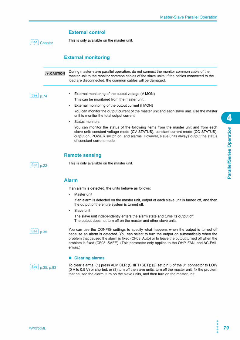
PWX750ML 79
Master-Slave Parallel Operation
Para
llel/S
erie
s O
pera
tion
4
External control
Chapter This is only available on the master unit.
External monitoring
p.74 • External monitoring of the output voltage (V MON)This can be monitored from the master unit.
• External monitoring of the output current (I MON)You can monitor the output current of the master unit and each slave unit. Use the masterunit to monitor the total output current.
• Status monitorsYou can monitor the status of the following items from the master unit and from eachslave unit: constant-voltage mode (CV STATUS), constant-current mode (CC STATUS),output on, POWER switch on, and alarms. However, slave units always output the statusof constant-current mode.
Remote sensing
p.22 This is only available on the master unit.
AlarmIf an alarm is detected, the units behave as follows:• Master unit
If an alarm is detected on the master unit, output of each slave unit is turned off, and thenthe output of the entire system is turned off.
• Slave unitThe slave unit independently enters the alarm state and turns its output off.The output does not turn off on the master and other slave units.
p.35 You can use the CONFIG settings to specify what happens when the output is turned offbecause an alarm is detected. You can select to turn the output on automatically when theproblem that caused the alarm is fixed (CF03: Auto) or to leave the output turned off when theproblem is fixed (CF03: SAFE). (This parameter only applies to the OHP, FAN, and AC-FAILerrors.)
Clearing alarms
p.35, p.83 To clear alarms, (1) press ALM CLR (SHIFT+SET); (2) set pin 5 of the J1 connector to LOW(0 V to 0.5 V) or shorted; or (3) turn off the slave units, turn off the master unit, fix the problemthat caused the alarm, turn on the slave units, and then turn on the master unit.
See
CAUTION During master-slave parallel operation, do not connect the monitor common cable of the master unit to the monitor common cables of the slave units. If the cables connected to the load are disconnected, the common cables will be damaged.
See
See
See
See

80 PWX750ML
Master-Slave Parallel Operation
Connection (master-slave parallel operation)
p.14 You can connect up to four units, including the master unit.
Connecting the signal cables (parallel operation)Use the J1 connector to make the connections for parallel operation.
p.62 The cables that are required to make the connection are not included. For details, see “ Aboutthe J1 Connector.”
p.111 If you are using the optional parallel operation signal cable (PC01, PC02, or PC03-PWX), theconnector is already assembled, so you can use it as is.If connected for master-slave parallel operation, STATUS COM (pin 1 of the J1 connector) ofthe master unit will be connected to A COM (pin 19 of the J1 connector) of the slave unit (itwill no longer be floating). If the positive output terminal is connected to the chassis terminalin this condition, the status common will be at an electric potential that is lower than that ofthe chassis terminal by the output voltage. Because the positive output terminal is at groundpotential, secure an insulation capacity greater than or equal to this product’s isolation volt-age relative to the chassis.
Example of connecting two slave units
1 Decide which PWX750ML to use as the master unit.
2 Connect the J1 connector on the rear panel of the master unit to the J1connector on the rear panel of the first slave unit.If you are using the optional parallel operation signal cable (PC01, PC02, or PC03-PWX), the connector is already assembled, so you can use it as is.
3 Connect the J1 connector on the rear panel of the first slave unit to theJ1 connector on the rear panel of the second slave unit.If you are using the optional parallel operation signal cable (PC01, PC02, or PC03-PWX), the connector is already assembled, so you can use it as is.
If you have a third slave unit, connect it in the same manner.
See
See
See
J1 J1PRL OUT+A COMPRL COMP OUTSTATUS COMOUT ON STATUSI SUM
8
97
191813
J1
11
121
10
1613
PRL IN+PRL IN–PRL COMP INA COMOUT ON/OFF CONTI SUM
PRL IN+PRL IN–PRL COMP INA COMOUT ON/OFF CONTI SUM
8
97
191813
Master unit Slave unit 1
Slave unit 2
Connections for parallel operation (two slave units)
PWX750ML 81
Master-Slave Parallel Operation
Para
llel/S
erie
s O
pera
tion
4
Connecting the load (parallel operation)
1 Turn off all the PWX750MLs that you want to connect in parallel.
2 Remove the OUTPUT terminal covers.
p.17 3 Connect the load cables to the output terminals of the master unit andthe slave units.
4 Connect the load cables of the master unit and slave units to the loadthrough a relay terminal block.Use load cables that have sufficient current capacity. Use load cables of equivalentlength and cross-sectional area to connect each power supply to the relay terminalblock, and wire the cables so that they are as short as possible (50 cm or less). Also,make the connection from the relay terminal block to the load block as short as possi-ble.Wire the J1 connector signal cables and the load cables as far apart as possible.
5 Connect the output terminals (positive or negative) of the master unitand the slave units to the chassis terminals.Connect the same polarity output terminals on the master unit and slave units.If you are using the units under floating conditions, do not connect the terminals.
WARNING Risk of electric shock. Turn the POWER switch off before you touch the OUTPUT terminals. Attach the OUTPUT terminal cover after you finish wiring the load.
CAUTION • When you connect the output terminals to the chassis terminals, be sure to connect the same polarity output terminals (positive or negative) of the master unit and the slave units to the chassis terminals. If you connect different polarity output terminals of the master unit and the slave units to the chassis terminal, the output will be grounded through the power cable’s GND wire. Not only will this make the output incorrect, it will also cause the chassis terminal cable to burn out.
• When the load cables are distributed over longer distance, the phase shifting due to wiring inductance and capacitance may go beyond the limit and result in oscillation. To prevent such oscillation, connect an electrolytic capacitor with several hundreds to several tens of thousands μF across the load.Use an electrolytic capacitor that has a withstand voltage that is at least 120 % of the prod-uct’s rated output voltage.
• Twist the positive and negative cables together, and make the connection to the load as short as possible. Oscillation may occur as a result of wiring inductance.
Relay terminal block Load
Master unit
Slave unit 1
Slave unit 2
Output terminal
Chassis terminal
Output terminal
Chassis terminal
Output terminal
Chassis terminal
Load connections for parallel operation (two slave units)(The negative side is connected to the chassis terminal in this example.)
See
82 PWX750ML
Master-Slave Parallel Operation
6 Attach the OUTPUT terminal covers.
If you have a third and fourth slave unit, connect them in the same manner.
Settings (master-slave parallel operation)
Setting the master unit, the slave units, and the number of units in parallel operation (including the master unit)
p.44 Turn the output off, and then configure the master unit (CF01: 2 to 4) and the slave units(CF01: SLAV) in master-slave parallel operation. On the master unit, set the number of unitsin master-slave parallel operation (CF01: 2 to 4).In the factory default settings, the PWX750ML is set to independent operation (CF01: 1).Turn the POWER switch off and on to enable the setting.
Be sure to set the number of units in master-slave parallel operation (CF01) to the actualnumber of units that are connected. If this parameter is incorrect, settings such as those forthe current and the overcurrent protection (OCP) cannot be set correctly, and the measuredcurrent will not be displayed correctly.
Setting the voltage and current
p.78 Use the master unit to set the voltage and current.The current that is output is the sum of the currents of the master unit and the slave units.When you set the number of units in master-slave parallel operation (CF01), the maximumoutput current (105 % of the rated output current of a single unit × the number of units in par-allel) is set. If you switch to the setting display (when the SET key is lit), this value is dis-played. The last voltage that was set on the master unit is used. When you press OUTPUT,the set voltage and current are output. You can set the voltage and current to any values.
Setting the overvoltage protection (OVP) and overcurrent protec-tion (OCP) of the master unit
p.36 When you are performing master-slave parallel operation, set the overvoltage protection(OVP) and overcurrent protection (OCP) of the master unit.When you set the number of units in master-slave parallel operation (CF01), the maximumovercurrent protection value (112 % of the rated output current of a single unit × the numberof units in parallel) is set. If you switch to the OVP/OCP setting display (when the OCP•OVPkey is lit), this value is displayed. The last overvoltage protection value that was set on themaster unit is used.
See
See
See
PWX750ML 83
Master-Slave Parallel Operation
Para
llel/S
erie
s O
pera
tion
4
CONFIG parameters that can be set on master units• CF00 Resets the panel settings• CF02 Power-on status parameter• CF04 Memory content display parameter• CF05 CC control using an Vext or Rext• CF06 CV control using an Vext or Rext• CF07 CV/CC control range parameter• CF09 External control parameter for turning output on and off• CF10 External control logic parameter for turning output on and off• CF12 Output-on startup state parameter• CF14 Current setting limit• CF15 Voltage setting limit
Starting master-slave parallel operation
Turning power on
1 Turn the master unit’s POWER switch on.
2 Turn the POWER switch of each slave unit on.
3 Operate the master unit normally.Turn output on and off from the master unit.
Turning power off
1 Turn the slave unit’s POWER switch off.
2 Turn the master unit’s POWER switch off.
CAUTION After you turn the POWER switch off, wait at least 10 seconds after the panel display turns off before you turn the POWER switch back on. Repeatedly turning the POWER switch on and off at short intervals can cause damage to the inrush current limiter. In turn, this will shorten the service life of the POWER switch, internal input fuse, and other components.
84 PWX750ML
Series Operation
You can connect up to two units in series. You cannot perform master-slave series operation.The total of the output voltages of the two units is applied to the load. The voltage settingaccuracy is the same as the accuracy of an individual unit.
Features of the PWX750ML during series operation
The features of the PWX750ML during series operation are as follows:
Voltage display and current displayThe voltage and current are displayed on unit 1 and unit 2. To calculate the total output volt-age, add the voltages of unit 1 and unit 2.
p.26 You can switch the display so that it shows power. The power is displayed on unit 1 and unit2.
External control
Chapter This is available.
External monitoring
p.74 • External monitoring of the output voltage (V MON)You can monitor the output voltage of each unit.To calculate the total output voltage, add the monitor values of the master unit and theslave unit.
• External monitoring of the output current (I MON)This can only be monitored from the master unit.
• Status monitorsYou can monitor the status of the following items from the master unit and from the slaveunit: constant-voltage mode (CV STATUS), constant-current mode (CC STATUS), outputon, POWER switch on, and alarms.
See
Lit
Lit
Unit 1
Unit 2
Example of the panel display during series operation(The output current is 28 A.)
See
WARNING During monitoring, be careful of shorts and electric shocks. When monitoring the out-put voltage or output current during master-slave series operation, the electric poten-tial of the commons of the master unit’s monitor signal and the slave unit’s monitor signal are different.
See
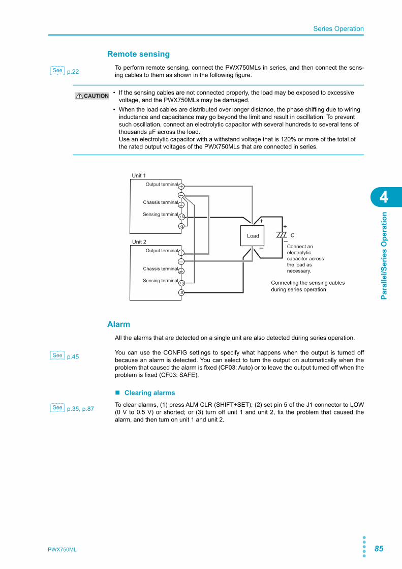
PWX750ML 85
Series Operation
Para
llel/S
erie
s O
pera
tion
4
Remote sensing
p.22 To perform remote sensing, connect the PWX750MLs in series, and then connect the sens-ing cables to them as shown in the following figure.
AlarmAll the alarms that are detected on a single unit are also detected during series operation.
p.45 You can use the CONFIG settings to specify what happens when the output is turned offbecause an alarm is detected. You can select to turn the output on automatically when theproblem that caused the alarm is fixed (CF03: Auto) or to leave the output turned off when theproblem is fixed (CF03: SAFE).
Clearing alarms
p.35, p.87 To clear alarms, (1) press ALM CLR (SHIFT+SET); (2) set pin 5 of the J1 connector to LOW(0 V to 0.5 V) or shorted; or (3) turn off unit 1 and unit 2, fix the problem that caused thealarm, and then turn on unit 1 and unit 2.
See
CAUTION • If the sensing cables are not connected properly, the load may be exposed to excessive voltage, and the PWX750MLs may be damaged.
• When the load cables are distributed over longer distance, the phase shifting due to wiring inductance and capacitance may go beyond the limit and result in oscillation. To prevent such oscillation, connect an electrolytic capacitor with several hundreds to several tens of thousands μF across the load.Use an electrolytic capacitor with a withstand voltage that is 120% or more of the total of the rated output voltages of the PWX750MLs that are connected in series.
++
––
C
Connect an electrolytic capacitor across the load as necessary.
Load
+S
-S
+S
-S
Output terminal
Chassis terminal
Sensing terminal
Unit 1
Unit 2Output terminal
Chassis terminal
Sensing terminal Connecting the sensing cables during series operation
See
See
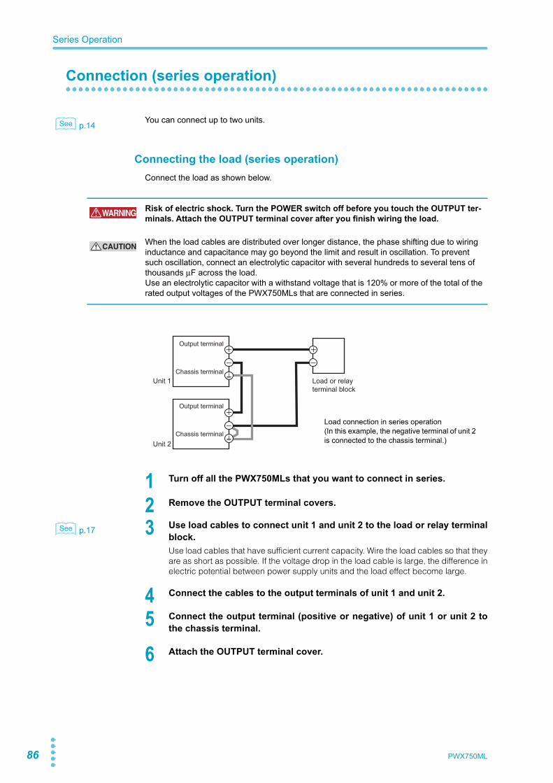
86 PWX750ML
Series Operation
Connection (series operation)
p.14 You can connect up to two units.
Connecting the load (series operation)Connect the load as shown below.
1 Turn off all the PWX750MLs that you want to connect in series.
2 Remove the OUTPUT terminal covers.
p.17 3 Use load cables to connect unit 1 and unit 2 to the load or relay terminalblock.Use load cables that have sufficient current capacity. Wire the load cables so that theyare as short as possible. If the voltage drop in the load cable is large, the difference inelectric potential between power supply units and the load effect become large.
4 Connect the cables to the output terminals of unit 1 and unit 2.
5 Connect the output terminal (positive or negative) of unit 1 or unit 2 tothe chassis terminal.
6 Attach the OUTPUT terminal cover.
See
WARNING Risk of electric shock. Turn the POWER switch off before you touch the OUTPUT ter-minals. Attach the OUTPUT terminal cover after you finish wiring the load.
CAUTION When the load cables are distributed over longer distance, the phase shifting due to wiring inductance and capacitance may go beyond the limit and result in oscillation. To prevent such oscillation, connect an electrolytic capacitor with several hundreds to several tens of thousands μF across the load.Use an electrolytic capacitor with a withstand voltage that is 120% or more of the total of the rated output voltages of the PWX750MLs that are connected in series.
Load or relay terminal block
Unit 1
Unit 2
Output terminal
Chassis terminal
Output terminal
Chassis terminal
Load connection in series operation(In this example, the negative terminal of unit 2 is connected to the chassis terminal.)
See
PWX750ML 87
Series Operation
Para
llel/S
erie
s O
pera
tion
4
Settings (series operation)
Setting the voltage and currentSet the voltage and current on each unit. The voltage that is output is the total of the voltagesof the two units. Set the current to the same value on the two units.
Setting the overvoltage protection (OVP) and overcurrent protec-tion (OCP)
p.36 In series operation, you have to set the overvoltage protection (OVP) and overcurrent protec-tion (OCP) on both units. Specify the same values on the two units.
Starting series operation
Turning the power on and offTurn the POWER switch on unit 1 and unit 2 on or off.
Turning the output on and offPress OUTPUT on unit 1 and unit 2 to turn the output on or off.
See
CAUTION After you turn the POWER switch off, wait at least 10 seconds after the fan stops before you turn the POWER switch back on. Repeatedly turning the POWER switch on and off at short intervals can cause damage to the inrush current limiter. In turn, this will shorten the service life of the POWER switch, internal input fuse, and other components.

88 PWX750ML
This page is intentionally blank.
!!!DELETE!!!
MaintenanceThis chapter explains how to perform cali-bration.
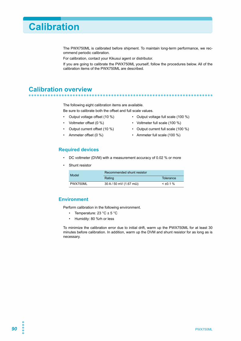
90
Calibration
The PWX750ML is calibrated before shipment. To maintain long-term performance, we rec-ommend periodic calibration.For calibration, contact your Kikusui agent or distributor.If you are going to calibrate the PWX750ML yourself, follow the procedures below. All of thecalibration items of the PWX750ML are described.
Calibration overview
The following eight calibration items are available.Be sure to calibrate both the offset and full scale values.• Output voltage offset (10 %) • Output voltage full scale (100 %)• Voltmeter offset (0 %) • Voltmeter full scale (100 %)• Output current offset (10 %) • Output current full scale (100 %)• Ammeter offset (0 %) • Ammeter full scale (100 %)
Required devices• DC voltmeter (DVM) with a measurement accuracy of 0.02 % or more
• Shunt resistor
EnvironmentPerform calibration in the following environment.
• Temperature: 23 °C ± 5 °C• Humidity: 80 %rh or less
To minimize the calibration error due to initial drift, warm up the PWX750ML for at least 30minutes before calibration. In addition, warm up the DVM and shunt resistor for as long as isnecessary.
ModelRecommended shunt resistor
Rating Tolerance
PWX750ML 30 A / 50 mV (1.67 mΩ) < ±0.1 %
PWX750ML
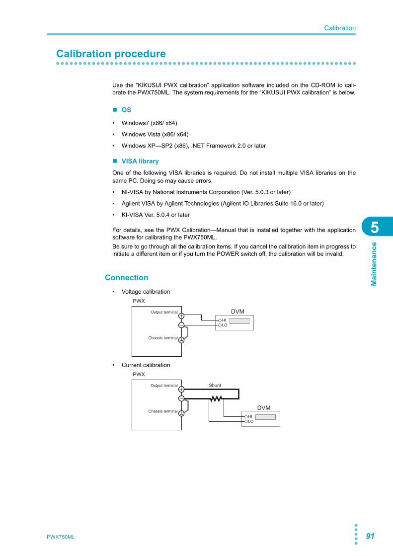
Calibration
5
Mai
nten
ance
Calibration procedure
Use the “KIKUSUI PWX calibration” application software included on the CD-ROM to cali-brate the PWX750ML. The system requirements for the “KIKUSUI PWX calibration” is below.
OS
• Windows7 (x86/ x64)
• Windows Vista (x86/ x64)
• Windows XP—SP2 (x86), .NET Framework 2.0 or later
VISA libraryOne of the following VISA libraries is required. Do not install multiple VISA libraries on thesame PC. Doing so may cause errors.
• NI-VISA by National Instruments Corporation (Ver. 5.0.3 or later)
• Agilent VISA by Agilent Technologies (Agilent IO Libraries Suite 16.0 or later)
• KI-VISA Ver. 5.0.4 or later
For details, see the PWX Calibration—Manual that is installed together with the applicationsoftware for calibrating the PWX750ML.Be sure to go through all the calibration items. If you cancel the calibration item in progress toinitiate a different item or if you turn the POWER switch off, the calibration will be invalid.
Connection• Voltage calibration
• Current calibration
DVMHILO
Output terminal
Chassis terminal
PWX
Shunt
DVMHILO
Output terminal
Chassis terminal
PWX
PWX750ML 91

92
This page is intentionally blank.
PWX750ML

SpecificationsThis chapter contains the specificationsand gives the dimensions of the PWX-750ML.

94 PWX750ML
PWX750ML
Unless specified otherwise, the specifications are for the following settings and conditions.
• Loads are pure resistive loads.
• The warm-up time is 30 minutes (with current flowing).
• After the PWX750ML has been warmed up, it must be calibrated correctly in a 23 °C ± 5 °C environment according to the procedures given in the operation manual.
• Values indicated by “TYP” are typical values. They are not guaranteed performance values.
• Values indicated by “rtg” are rated values.
• Values indicated by “rdng” are readout values.
• The PWX750ML operates over a wide range of output voltage and output current within rated outputpower. However, the current that can be output with rated output voltage and the voltage that can beoutput with rated output current are limited by the rated output power.
• The current that can be output with rated output voltage and the voltage that can be output with ratedoutput current are as follows.Maximum output current with rated output voltage = Rated output power/rated output voltage.Maximum output voltage with rated output current = Rated output power/rated output current.
• Rated load and no load are defined as follows:In constant-voltage mode (when the output current is set to a value greater than or equal to the max-imum output current with rated output voltage)
In constant-current mode (when the output voltage is set to a value greater than or equal to the max-imum output voltage with rated output current)
• The specifications of the PWX750ML apply to the rear panel output terminals.
AC input
Rated load: Refers to a resistive load that, when the rated output voltage is applied, makes the flowing current 95 % to 100 % of the maximum output current with rated output voltage.
No load: Refers to a load through which no output current flows. In other words, refers to an open load (no load being connected).
Rated load: Refers to a resistive load that, when the rated output current flows, makes the voltage drop to 95 % to 100 % of the maximum output voltage with rated output current.Including the voltage drop in the load cables, the PWX750ML output voltage must not exceed the maximum output voltage with rated output current.
No load: Refers to a resistive load that, when the rated output current flows, makes the voltage drop to 10 % of the maximum output voltage with rated output current or 1 V whichever is higher.
Nominal input rating 100 Vac to 240 Vac, 50 Hz to 60 Hz, single phase Input voltage range 85 Vac to 265 VacInput frequency range 47 Hz to 63 Hz
Current (MAX)1
1 With the rated load.
100 Vac 10.5 A200 Vac 5.25 A
Inrush current 2
2 Excludes the charge current component that flows through the capacitor of the internal EMC filtercircuit immediately after the POWER switch is turned on (for approximately 1 ms).
70 A or less
Power (MAX)3
3 For all loads, with 100 Vac input.
1100 VA
Power factor (TYP)1 0.99 (input voltage: 100 V), 0.97 (input voltage: 200 V)
Efficiency 1 74 % or greater
Output hold time 3 20 ms or greater
PWX750ML

PWX750ML 95
PWX750ML
6
Spec
ifica
tions
OutputRating Output voltage1
1 The maximum output voltage and current are limited by the maximum output power.
80 V
Output current1 28 A
Output power 750 WVoltage Setting range 0 V to 84 V
Setting accuracy ± (0.05 % of setting + 0.05 % of rtg)
Line regulation2
2 85 Vac to 135 Vac or 170 Vac to 265 Vac, fixed load
±10 mV
Load regulation3
3 The amount of change that occurs when the load is changed from no load to rated load (rated outputpower/rated output voltage) with rated output voltage. The value is measured at the sensing point.
±10 mV
Transient response4
4 The amount of time required for the output voltage to return to a value within “rated output voltage± (0.1 % + 10 mV).” The load current fluctuation is 50 % to 100 % of the maximum current with theset output voltage.
1 ms or less
Ripple noise5
5 Measured using an RC-9131C probe that conforms to the JEITA specifications. At the rated outputcurrent.
(p-p)6
6 When the measurement frequency bandwidth is 10 Hz to 20 MHz.
80 mV
(rms)7
7 When the measurement frequency bandwidth is 5 Hz to 1 MHz.
8 mV
Rise time Rated load 100 msNo load 100 ms
Fall time 8
8 When the breeder circuit on/off setting is on.
Rated load 100 msNo load 550 ms
Maximum remote sensing com-pensation voltage (single line)
4 V
Temperature coefficient (MAX)9
9 When the ambient temperature is within 0 °C and 50 °C
100 ppm/°C (during external control)
Current Setting range 0 A to 29.4 ASetting accuracy ± (0.5 % of setting + 0.1 % of rtg)Line regulation ±4.8 mALoad regulation ±10.6 mA
Ripple noise10
10 When the output voltage is 10 % to 100 % of the rating. At the rated output current.
(rms)7 65 mA
Temperature coefficient (TYP)9 100 ppm/ °C
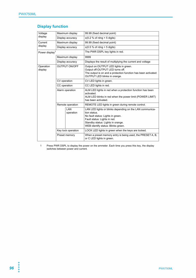
96 PWX750ML
PWX750ML
Display functionVoltagedisplay
Maximum display 99.99 (fixed decimal point)
Display accuracy ±(0.2 % of rdng + 5 digits)
Currentdisplay
Maximum display 99.99 (fixed decimal point)
Display accuracy ±(0.5 % of rdng + 5 digits)
Power display1
1 Press PWR DSPL to display the power on the ammeter. Each time you press this key, the displayswitches between power and current.
The PWR DSPL key lights in red.
Maximum display 9999
Display accuracy Displays the result of multiplying the current and voltage
Operationdisplay
OUTPUT ON/OFF Output on:OUTPUT LED lights in green.Output off:OUTPUT LED turns off.The output is on and a protection function has been activated:OUTPUT LED blinks in orange.
CV operation CV LED lights in green.
CC operation CC LED lights in red.
Alarm operation ALM LED lights in red when a protection function has been activated.ALM LED blinks in red when the power limit (POWER LIMIT) has been activated.
Remote operation REMOTE LED lights in green during remote control.
LANoperation
LAN LED lights or blinks depending on the LAN communica-tion status.No fault status: Lights in green.Fault status: Lights in red.Standby status: Lights in orange.WEB identify status: Blinks green.
Key lock operation LOCK LED lights in green when the keys are locked.
Preset memory When a preset memory entry is being used, the PRESET A, B, or C LED lights in green.

PWX750ML 97
PWX750ML
6
Spec
ifica
tions
Protection functions
Signal output
Overvoltage protection (OVP) Turns the output off, displays OVP, and lights ALM
Setting range 8 V to 89.6 V (10 % to 112 % of the rated output voltage)
Setting accuracy ±(1.5 % of rtg)
Overvoltage protection 2 (OVP2) Turns the output off, displays OVP2, and lights ALM
Value (fixed) 96 V (120 % of the rated output voltage)
Overcurrent protection (OCP) 1
1 This does not protect against the discharge current peak that is generated from the capacitors insidethe PWX750ML output section when the load is changed suddenly.
Turns the output off, displays OCP, and lights ALM
Setting range 2.8 A to 31.36 A (10 % to 112 % of the rated output current)
Setting accuracy ±(3 % of rtg)
Undervoltage limit (UVL) Cannot be set to a value less than or equal to the set voltage
Value 0 V to 84 V (0 % to 105 % of the rated output voltage)
Overheat protection (OHP) Turns the output off,2 displays OHP, and lights ALM
2 Use the CONFIG settings to specify what happens when a protection function is activated and theoutput is turned off. You can select to turn the output on automatically when the problem that causedthe alarm is fixed (CF03: Auto) or to leave the output turned off when the problem that caused thealarm is fixed (CF03:SAFE). The specified protection operation is the same for the OHP, FAN, andAC-FAIL alarms. You cannot make separate settings for the OHP, FAN, and AC-FAIL alarms.
Fan failure protection (FAN) Turns the output off,2 displays FAN, and lights ALM
Incorrect sensing connection protection (SENSE)
Turns the output off, displays SENS, and lights ALM
Low AC input protection (AC-FAIL)
Turns the output off,2 displays AC, and lights ALM
Shutdown (SD) Turns the output off, displays SD, and lights ALM
Power limit (POWER LIMIT) Lights ALM
Value (fixed) 787.5 W (approx. 105 % of the rated output power)
Communication monitoring (WATCHDOG)
Turns the output off, displays DOG, and lights ALM
Monitorsignal output1
1 J1 connector on the rear panel
Voltage monitor (VMON)
Selectable monitor voltage range: 0 V to 5 V or 0 V to 10 V
Settingaccuracy
2.5 % of rtg
Current monitor (IMON)
Selectable monitor voltage range: 0 V to 5 V or 0 V to 10 V
Settingaccuracy
2.5 % of rtg
Status signal output1,2
2 Photocoupler open collector output; maximum voltage 30 V, maximum current (sink) 8 mA; isolated from the output and control circuits;status commons are floating (withstand voltage of less than or equal to 60 V); and status signals arenot mutually isolated.
OUTON STATUS Turns on when the output is on
CV STATUS Turns on during CV operation
CC STATUS Turns on during CC operation
ALM STATUS Turns on when an alarm has been activated
PWR ON STATUS Turns on when the power is turned on
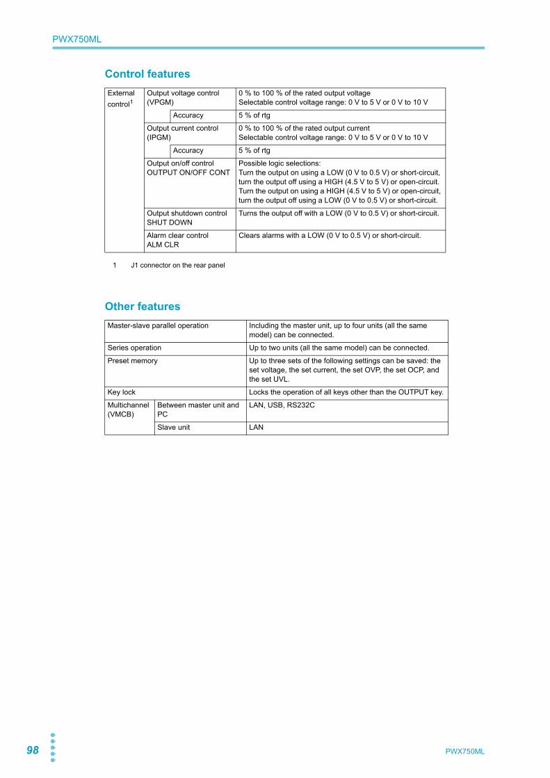
98 PWX750ML
PWX750ML
Control features
Other features
Externalcontrol1
1 J1 connector on the rear panel
Output voltage control (VPGM)
0 % to 100 % of the rated output voltageSelectable control voltage range: 0 V to 5 V or 0 V to 10 V
Accuracy 5 % of rtg
Output current control (IPGM)
0 % to 100 % of the rated output currentSelectable control voltage range: 0 V to 5 V or 0 V to 10 V
Accuracy 5 % of rtg
Output on/off controlOUTPUT ON/OFF CONT
Possible logic selections:Turn the output on using a LOW (0 V to 0.5 V) or short-circuit, turn the output off using a HIGH (4.5 V to 5 V) or open-circuit.Turn the output on using a HIGH (4.5 V to 5 V) or open-circuit, turn the output off using a LOW (0 V to 0.5 V) or short-circuit.
Output shutdown controlSHUT DOWN
Turns the output off with a LOW (0 V to 0.5 V) or short-circuit.
Alarm clear controlALM CLR
Clears alarms with a LOW (0 V to 0.5 V) or short-circuit.
Master-slave parallel operation Including the master unit, up to four units (all the same model) can be connected.
Series operation Up to two units (all the same model) can be connected.
Preset memory Up to three sets of the following settings can be saved: the set voltage, the set current, the set OVP, the set OCP, and the set UVL.
Key lock Locks the operation of all keys other than the OUTPUT key.
Multichannel (VMCB)
Between master unit and PC
LAN, USB, RS232C
Slave unit LAN

PWX750ML 99
PWX750ML
6
Spec
ifica
tions
InterfaceCommonspecifications
Software protocol IEEE Std 488.2-1992
Command language Complies with SCPI Specification 1999.0Has a compatibility mode (switchable)1 • Genesys series made by TDK-Lambda • N5700 and N8700 made by Agilent Technologies • DSC series made by Sorensen • PAG series made by Kikusui
1 This setting does not guarantee compatibility with all measuring instrument application software anddrivers.
RS232C Hardware Complies with the EIA232D specifications (excluding the con-nector)
RJ-45 connector2
2 The RD-8P/ 9P adapter cable is an option.
Baud rate:1200, 2400, 4800, 9600, 19200, 38400, 57600, and 115200 bps
Data length: 8 bits, Stop bits: 1 bit, Parity bit: None
No flow control
Program message terminator
LF during reception, CR/LF during transmission
USB Hardware Complies with the USB 2.0 specifications. Baud rate:480 Mbps (High speed).
Socket B type
Program message terminator
LF or EOM during reception, LF + EOM during transmission
Device class Complies with the USBTMC-USB488 device class specifica-tions
LAN Hardware IEEE 802.3 100Base-TX or 10Base-T EthernetComplies with LXI Specification version 1.3 Class C
IPv4, RJ-45 connector3
3 Category 5; use a straight cable.
Communicationprotocol
VXI-11, HiSLIP, or SCPI-RAW
Program message terminator
VXI-11 and HISLIP:LF or END during reception, LF + END during transmissionSCPI-RAW:LF during reception, LF during transmission
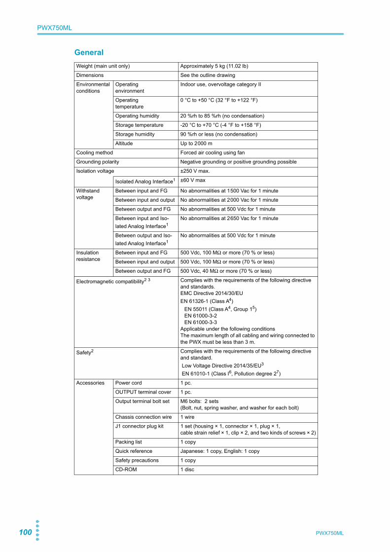
100 PWX750ML
PWX750ML
GeneralWeight (main unit only) Approximately 5 kg (11.02 lb)
Dimensions See the outline drawing
Environmental conditions
Operatingenvironment
Indoor use, overvoltage category II
Operatingtemperature
0 °C to +50 °C (32 °F to +122 °F)
Operating humidity 20 %rh to 85 %rh (no condensation)
Storage temperature -20 °C to +70 °C (-4 °F to +158 °F)
Storage humidity 90 %rh or less (no condensation)
Altitude Up to 2000 m
Cooling method Forced air cooling using fan
Grounding polarity Negative grounding or positive grounding possible
Isolation voltage ±250 V max.
Isolated Analog Interface1 ±60 V max
Withstandvoltage
Between input and FG No abnormalities at 1500 Vac for 1 minute
Between input and output No abnormalities at 2000 Vac for 1 minute
Between output and FG No abnormalities at 500 Vdc for 1 minute
Between input and Iso-lated Analog Interface1
No abnormalities at 2650 Vac for 1 minute
Between output and Iso-lated Analog Interface1
No abnormalities at 500 Vdc for 1 minute
Insulation resistance
Between input and FG 500 Vdc, 100 MΩ or more (70 % or less)
Between input and output 500 Vdc, 100 MΩ or more (70 % or less)
Between output and FG 500 Vdc, 40 MΩ or more (70 % or less)
Electromagnetic compatibility2 3 Complies with the requirements of the following directive and standards.EMC Directive 2014/30/EUEN 61326-1 (Class A4)
EN 55011 (Class A4, Group 15)EN 61000-3-2EN 61000-3-3
Applicable under the following conditionsThe maximum length of all cabling and wiring connected to the PWX must be less than 3 m.
Safety2 Complies with the requirements of the following directive and standard. Low Voltage Directive 2014/35/EU3
EN 61010-1 (Class I6, Pollution degree 27)
Accessories Power cord 1 pc.
OUTPUT terminal cover 1 pc.
Output terminal bolt set M6 bolts: 2 sets(Bolt, nut, spring washer, and washer for each bolt)
Chassis connection wire 1 wire
J1 connector plug kit 1 set (housing × 1, connector × 1, plug × 1,cable strain relief × 1, clip × 2, and two kinds of screws × 2)
Packing list 1 copy
Quick reference Japanese: 1 copy, English: 1 copy
Safety precautions 1 copy
CD-ROM 1 disc
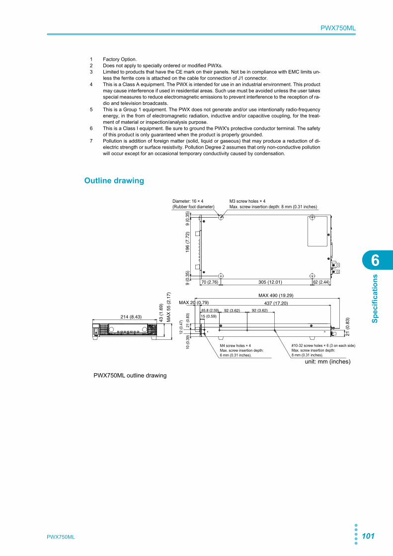
PWX750ML 101
PWX750ML
6
Spec
ifica
tions
Outline drawing
PWX750ML outline drawing
1 Factory Option.2 Does not apply to specially ordered or modified PWXs.3 Limited to products that have the CE mark on their panels. Not be in compliance with EMC limits un-
less the ferrite core is attached on the cable for connection of J1 connector. 4 This is a Class A equipment. The PWX is intended for use in an industrial environment. This product
may cause interference if used in residential areas. Such use must be avoided unless the user takesspecial measures to reduce electromagnetic emissions to prevent interference to the reception of ra-dio and television broadcasts.
5 This is a Group 1 equipment. The PWX does not generate and/or use intentionally radio-frequencyenergy, in the from of electromagnetic radiation, inductive and/or capacitive coupling, for the treat-ment of material or inspection/analysis purpose.
6 This is a Class I equipment. Be sure to ground the PWX's protective conductor terminal. The safetyof this product is only guaranteed when the product is properly grounded.
7 Pollution is addition of foreign matter (solid, liquid or gaseous) that may produce a reduction of di-electric strength or surface resistivity. Pollution Degree 2 assumes that only non-conductive pollutionwill occur except for an occasional temporary conductivity caused by condensation.
214 (8.43)
43 (
1.69
)
MA
X 5
5 (2
.17)
MAX 20 (0.79)
MAX 490 (19.29)
437 (17.20)
65.8 (2.59)
15 (0.59)
92 (3.62)
70 (2.76)
196
(7.7
2)9
(0.3
5)9
(0.3
5)
305 (12.01) 62 (2.44)
92 (3.62)
21 (
0.83
)
10 (0
.39)
12 (0
.47)
21 (0
.83)
Diameter: 16 × 4(Rubber foot diameter)
M3 screw holes × 4Max. screw insertion depth: 8 mm (0.31 inches)
M4 screw holes × 4Max. screw insertion depth: 6 mm (0.31 inches).
#10-32 screw holes × 6 (3 on each side)Max. screw insertion depth: 8 mm (0.31 inches).
unit: mm (inches)

102 PWX750ML
This page is intentionally blank.
Factory OptionThis chapter describes the isolated analoginterface, which are factory options.
Isolated Analog Interface
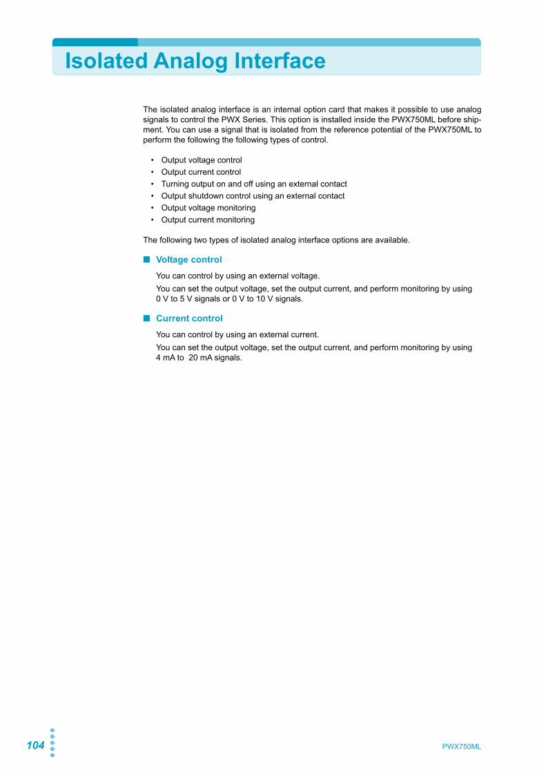
104 PWX750ML
Isolated Analog Interface
The isolated analog interface is an internal option card that makes it possible to use analogsignals to control the PWX Series. This option is installed inside the PWX750ML before ship-ment. You can use a signal that is isolated from the reference potential of the PWX750ML toperform the following the following types of control.
• Output voltage control• Output current control• Turning output on and off using an external contact• Output shutdown control using an external contact• Output voltage monitoring• Output current monitoring
The following two types of isolated analog interface options are available.
■ Voltage controlYou can control by using an external voltage.You can set the output voltage, set the output current, and perform monitoring by using 0 V to 5 V signals or 0 V to 10 V signals.
■ Current controlYou can control by using an external current.You can set the output voltage, set the output current, and perform monitoring by using 4 mA to 20 mA signals.
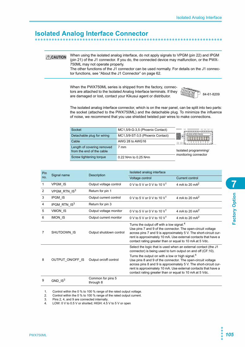
PWX750ML 105
Isolated Analog Interface
7
Fact
ory
Opt
ion
Isolated Analog Interface Connector
When the PWX750ML series is shipped from the factory, connec-tors are attached to the Isolated Analog Interface terminals. If theyare damaged or lost, contact your Kikusui agent or distributor.
The isolated analog interface connector, which is on the rear panel, can be split into two parts:the socket (attached to the PWX750ML) and the detachable plug. To minimize the influenceof noise, we recommend that you use shielded twisted pair wires to make connections.
CAUTION When using the isolated analog interface, do not apply signals to VPGM (pin 22) and IPGM (pin 21) of the J1 connector. If you do, the connected device may malfunction, or the PWX-750ML may not operate properly.The other functions of the J1 connector can be used normally. For details on the J1 connec-tor functions, see “About the J1 Connector” on page 62.
Socket MC1,5/9-G-3,5 (Phoenix Contact)
Isolated programming/monitoring connector
Detachable plug for wiring MC1,5/9-ST-3,5 (Phoenix Contact)
Cable AWG 28 to AWG16
Length of covering removed from the end of the cable
7 mm
Screw tightening torque 0.22 N•m to 0.25 N•m
84-61-8209
Pin no. Signal name Description
Isolated analog interface
Voltage control Current control
1 VPGM_IS Output voltage control 0 V to 5 V or 0 V to 10 V1 4 mA to 20 mA2
2 VPGM_RTN_IS3 Return for pin 1
3 IPGM_IS Output current control 0 V to 5 V or 0 V to 10 V1 4 mA to 20 mA2
4 IPGM_RTN_IS3 Return for pin 3
5 VMON_IS Output voltage monitor 0 V to 5 V or 0 V to 10 V1 4 mA to 20 mA2
6 IMON_IS Output current monitor 0 V to 5 V or 0 V to 10 V1 4 mA to 20 mA2
7 SHUTDOWN_IS Output shutdown control
Turns the output off with a low signal.4Use pins 7 and 9 of the connector. The open-circuit voltage across pins 7 and 9 is approximately 5 V. The short-circuit cur-rent is approximately 10 mA. Use external contacts that have a contact rating greater than or equal to 10 mA at 5 Vdc.
8 OUTPUT_ON/OFF_IS Output on/off control
Select the logic that is used when an external contact (the J1 connector) is being used to turn output on and off (CF:10).Turns the output on with a low or high signal.4Use pins 8 and 9 of the connector. The open-circuit voltage across pins 8 and 9 is approximately 5 V. The short-circuit cur-rent is approximately 10 mA. Use external contacts that have a contact rating greater than or equal to 10 mA at 5 Vdc.
9 GND_IS3 Common for pins 5 through 8
1. Control within the 0 % to 100 % range of the rated output voltage.2. Control within the 0 % to 100 % range of the rated output current.3. Pins 2, 4, and 9 are connected internally.4. LOW: 0 V to 0.5 V or shorted; HIGH: 4.5 V to 5 V or open
106 PWX750ML
Isolated Analog Interface
Setup and Operation
Using the voltage control interface
p.41 1 Use the CONFIG settings to set the following parameters.
2 Connect the external voltage source to the isolated analog interfaceconnector.Check that the voltage polarity is correct.
3 Set the applied voltage to the appropriate level.
Using the current control interface
p.41 1 Use the CONFIG settings to set the following parameters.
2 Connect the external current source to the isolated analog interface con-nector.Check that the current polarity is correct.
3 Set the applied current to the appropriate level.
CAUTION To prevent damage to the product, do not set the output voltage and output current to values that exceed the product’s ratings.
See
CONFIG parameter Setting
CF05 CC control using an external voltage or external resistance on
CF06 CV control using an external voltage or external resistance on
CF09 External control parameter for turning output on and off on
CF07 CC or CV control range Lo ( 0 V to 5 V) or Hi (0 V to 10 V)
CF08 Range during voltage and current monitoring Lo ( 0 V to 5 V) or Hi (0 V to 10 V)
CF10 External control logic parameter for turning output on and off
Lo (low level signal to turn the output on) orHi (high level signal to turn the output on)1
1. LOW: 0V to 0.5 V or shorted, HIGH: 4.5 V to 5 V or open.
See
CONFIG parameter Setting
CF05 CC control using an external voltage or external resistance on
CF06 CV control using an external voltage or external resistance on
CF09 External control parameter for turning output on and off on
CF07 CC or CV control range Hi (0 V to 10 V)
CF08 Range during voltage and current monitoring Hi (0 V to 10 V)
CF10 External control logic parameter for turning output on and off
Lo (low level signal to turn the output on) orHi (high level signal to turn the output on)1
1. LOW: 0V to 0.5 V or shorted, HIGH: 4.5 V to 5 V or open.
PWX750ML 107
Isolated Analog Interface
7
Fact
ory
Opt
ion
Specifications
Isolated external control input (Voltage control)
Isolated output voltage control (VPG-M_IS)
0 % to 100 % of the rated output voltage Selectable control voltage range: 0 V to 5 V or 0 V to 10 V
Isolated output current control (IPG-M_IS)
0 % to 100 % of the rated output current Selectable control voltage range: 0 V to 5 V or 0 V to 10 V
Isolated output control common
Accuracy ±5 % of rtg
Temperature coefficient
±100 ppm/°C
Input impedance 1 MΩ
Maximum absolute applied voltage
0 V to 15 V
Isolated output on/off control Possible logic selections:Apply a LOW (0 V to 0.5 V) or short-circuit to set the OUT ON/OFF CONT (pin 18 of the J1 connector) to LOW. Apply a HIGH (4.5 V to 5 V) or open-circuit to set the OUT ON/OFF CONT (pin 18 of the J1 connector) to HIGH.
Isolated shutdown control Apply a LOW (0 V to 0.5 V) or short-circuit to set the SHUT-DOWN (pin 6 of the J1 connector) to LOW.
Isolated monitor signal output (Voltage control)
Isolated voltage monitor (VMON_IS) 0 V to 5 V, 0 V to 10 V
Isolated current monitor (IMON_IS) 0 V to 5 V, 0 V to 10 V
Isolated monitor common
Accuracy ±4 % of rtg
Isolated external control input (Current control)
Isolated output voltage control (VPG-M_IS)
0 % to 100 % of the rated output voltage / 4 mA to 20 mA
Isolated output current control (IPG-M_IS)
0 % to 100 % of the rated output voltage / 4 mA to 20 mA
Isolated output control common
Accuracy 5 % of rtg
Temperature coefficient
±200 ppm/°C
Input impedance 50 Ω
Isolated output on/off control Possible logic selections:Apply a LOW (0 V to 0.5 V) or short-circuit to set the OUT ON/OFF CONT (pin 18 of the J1 connector) to LOW. Apply a HIGH (4.5 V to 5 V) or open-circuit to set the OUT ON/OFF CONT (pin 18 of the J1 connector) to HIGH.
Isolated shutdown control Apply a LOW (0 V to 0.5 V) or short-circuit to set the SHUT-DOWN (pin 6 of the J1 connector) to LOW.
Isolated monitor signal output (Current control)
Isolated voltage monitor (VMON_IS) 4 mA to 20 mA
Isolated current monitor (IMON_IS) 4 mA to 20 mA
Isolated monitor common
Accuracy 4 % of rtg
Load impedance 500 Ω or less

108 PWX750ML
This page is intentionally blank.

AppendixA Options
B Troubleshooting

110 PWX750ML
A Options
The PWX750ML has the following options. For information about options, contact your Kiku-sui agent or distributor.
Rack mount optionThe PWX750ML can be used with JIS millimeter racks and EIA inch racks.
Name Model Notes
Rack mount adapter KRA1-PWX HALF SINGLE Rack mount bracket andblank panel
Rack mount adapterFor installing two devices side-by-side
KRA1-PWX HALF PAIR Rack mount bracket and support board
Rack mount bracket KRB1-PWX —
Angled rack mount support angle KRB1-PWX SUPPORT ANGLE —
KRA1-PWX HALF SINGLE
462 (18.19)5 (0.20)
5 (0.20)
5 (0.20)
482 (18.98)
462 (18.19)482 (18.98)
44 (1
.73)
24.5
(0.9
6)
32 (1
.26)
6 (0
.24)
5 (0.20)
44 (1
.73)
24.5
(0.9
6)
32 (1
.26)
6 (0
.24)
Unit: mm (inches)
KRA1-PWX HALF PAIR
KRB1-PWX
KRB1-PWX SUPPORT ANGLE
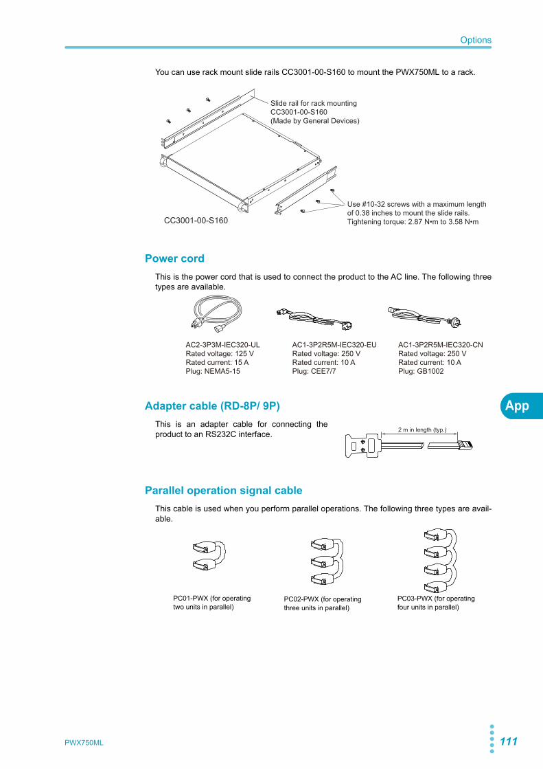
PWX750ML 111
Options
App
You can use rack mount slide rails CC3001-00-S160 to mount the PWX750ML to a rack.
Power cordThis is the power cord that is used to connect the product to the AC line. The following threetypes are available.
Adapter cable (RD-8P/ 9P)This is an adapter cable for connecting theproduct to an RS232C interface.
Parallel operation signal cableThis cable is used when you perform parallel operations. The following three types are avail-able.
Slide rail for rack mountingCC3001-00-S160(Made by General Devices)
Use #10-32 screws with a maximum length of 0.38 inches to mount the slide rails.Tightening torque: 2.87 N•m to 3.58 N•mCC3001-00-S160
AC2-3P3M-IEC320-ULRated voltage: 125 VRated current: 15 APlug: NEMA5-15
AC1-3P2R5M-IEC320-EURated voltage: 250 VRated current: 10 APlug: CEE7/7
AC1-3P2R5M-IEC320-CNRated voltage: 250 VRated current: 10 APlug: GB1002
2 m in length (typ.)
PC02-PWX (for operating three units in parallel)
PC01-PWX (for operating two units in parallel)
PC03-PWX (for operating four units in parallel)
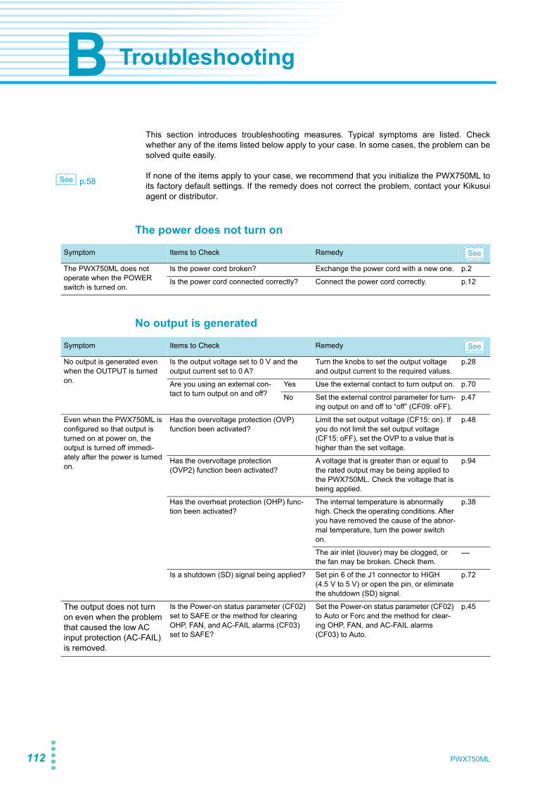
112 PWX750ML
B Troubleshooting
This section introduces troubleshooting measures. Typical symptoms are listed. Checkwhether any of the items listed below apply to your case. In some cases, the problem can besolved quite easily.
p.58 If none of the items apply to your case, we recommend that you initialize the PWX750ML toits factory default settings. If the remedy does not correct the problem, contact your Kikusuiagent or distributor.
The power does not turn on
No output is generated
See
Symptom Items to Check Remedy
The PWX750ML does not operate when the POWER switch is turned on.
Is the power cord broken? Exchange the power cord with a new one. p.2
Is the power cord connected correctly? Connect the power cord correctly. p.12
Symptom Items to Check Remedy
No output is generated even when the OUTPUT is turned on.
Is the output voltage set to 0 V and the output current set to 0 A?
Turn the knobs to set the output voltage and output current to the required values.
p.28
Are you using an external con-tact to turn output on and off?
Yes Use the external contact to turn output on. p.70
No Set the external control parameter for turn-ing output on and off to “off” (CF09: oFF).
p.47
Even when the PWX750ML is configured so that output is turned on at power on, the output is turned off immedi-ately after the power is turned on.
Has the overvoltage protection (OVP) function been activated?
Limit the set output voltage (CF15: on). If you do not limit the set output voltage (CF15: oFF), set the OVP to a value that is higher than the set voltage.
p.48
Has the overvoltage protection (OVP2) function been activated?
A voltage that is greater than or equal to the rated output may be being applied to the PWX750ML. Check the voltage that is being applied.
p.94
Has the overheat protection (OHP) func-tion been activated?
The internal temperature is abnormally high. Check the operating conditions. After you have removed the cause of the abnor-mal temperature, turn the power switch on.
p.38
The air inlet (louver) may be clogged, or the fan may be broken. Check them.
—
Is a shutdown (SD) signal being applied? Set pin 6 of the J1 connector to HIGH (4.5 V to 5 V) or open the pin, or eliminate the shutdown (SD) signal.
p.72
The output does not turn on even when the problem that caused the low AC input protection (AC-FAIL) is removed.
Is the Power-on status parameter (CF02) set to SAFE or the method for clearing OHP, FAN, and AC-FAIL alarms (CF03) set to SAFE?
Set the Power-on status parameter (CF02) to Auto or Forc and the method for clear-ing OHP, FAN, and AC-FAIL alarms (CF03) to Auto.
p.45
See
See
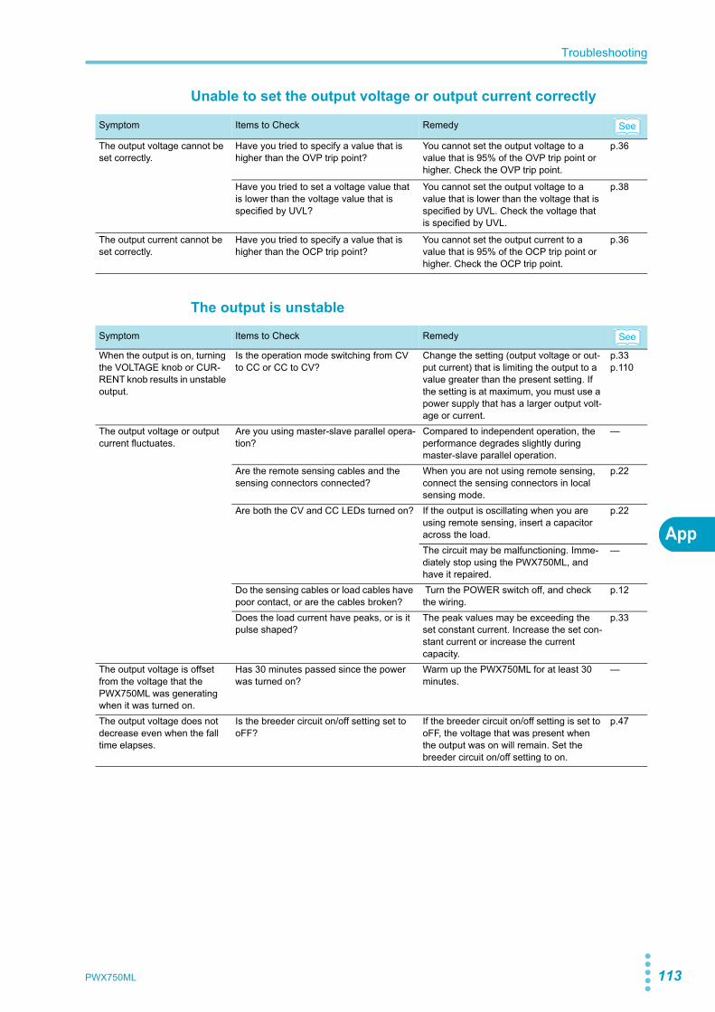
PWX750ML 113
Troubleshooting
App
Unable to set the output voltage or output current correctly
The output is unstable
Symptom Items to Check Remedy
The output voltage cannot be set correctly.
Have you tried to specify a value that is higher than the OVP trip point?
You cannot set the output voltage to a value that is 95% of the OVP trip point or higher. Check the OVP trip point.
p.36
Have you tried to set a voltage value that is lower than the voltage value that is specified by UVL?
You cannot set the output voltage to a value that is lower than the voltage that is specified by UVL. Check the voltage that is specified by UVL.
p.38
The output current cannot be set correctly.
Have you tried to specify a value that is higher than the OCP trip point?
You cannot set the output current to a value that is 95% of the OCP trip point or higher. Check the OCP trip point.
p.36
Symptom Items to Check Remedy
When the output is on, turning the VOLTAGE knob or CUR-RENT knob results in unstable output.
Is the operation mode switching from CV to CC or CC to CV?
Change the setting (output voltage or out-put current) that is limiting the output to a value greater than the present setting. If the setting is at maximum, you must use a power supply that has a larger output volt-age or current.
p.33p.110
The output voltage or output current fluctuates.
Are you using master-slave parallel opera-tion?
Compared to independent operation, the performance degrades slightly during master-slave parallel operation.
—
Are the remote sensing cables and the sensing connectors connected?
When you are not using remote sensing, connect the sensing connectors in local sensing mode.
p.22
Are both the CV and CC LEDs turned on? If the output is oscillating when you are using remote sensing, insert a capacitor across the load.
p.22
The circuit may be malfunctioning. Imme-diately stop using the PWX750ML, and have it repaired.
—
Do the sensing cables or load cables have poor contact, or are the cables broken?
Turn the POWER switch off, and check the wiring.
p.12
Does the load current have peaks, or is it pulse shaped?
The peak values may be exceeding the set constant current. Increase the set con-stant current or increase the current capacity.
p.33
The output voltage is offset from the voltage that the PWX750ML was generating when it was turned on.
Has 30 minutes passed since the power was turned on?
Warm up the PWX750ML for at least 30 minutes.
—
The output voltage does not decrease even when the fall time elapses.
Is the breeder circuit on/off setting set to oFF?
If the breeder circuit on/off setting is set to oFF, the voltage that was present when the output was on will remain. Set the breeder circuit on/off setting to on.
p.47
See
See
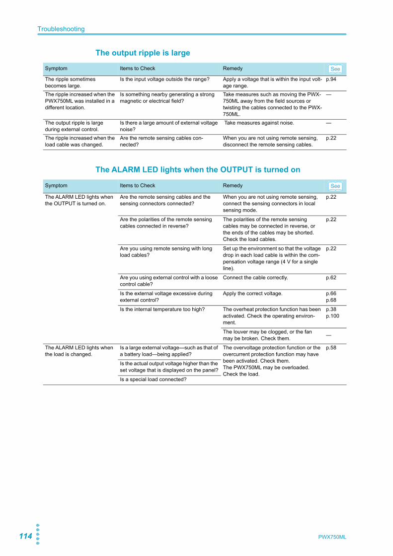
114 PWX750ML
Troubleshooting
The output ripple is large
The ALARM LED lights when the OUTPUT is turned on
Symptom Items to Check Remedy
The ripple sometimes becomes large.
Is the input voltage outside the range? Apply a voltage that is within the input volt-age range.
p.94
The ripple increased when the PWX750ML was installed in a different location.
Is something nearby generating a strong magnetic or electrical field?
Take measures such as moving the PWX-750ML away from the field sources or twisting the cables connected to the PWX-750ML.
—
The output ripple is large during external control.
Is there a large amount of external voltage noise?
Take measures against noise. —
The ripple increased when the load cable was changed.
Are the remote sensing cables con-nected?
When you are not using remote sensing, disconnect the remote sensing cables.
p.22
Symptom Items to Check Remedy
The ALARM LED lights when the OUTPUT is turned on.
Are the remote sensing cables and the sensing connectors connected?
When you are not using remote sensing, connect the sensing connectors in local sensing mode.
p.22
Are the polarities of the remote sensing cables connected in reverse?
The polarities of the remote sensing cables may be connected in reverse, or the ends of the cables may be shorted. Check the load cables.
p.22
Are you using remote sensing with long load cables?
Set up the environment so that the voltage drop in each load cable is within the com-pensation voltage range (4 V for a single line).
p.22
Are you using external control with a loose control cable?
Connect the cable correctly. p.62
Is the external voltage excessive during external control?
Apply the correct voltage. p.66p.68
Is the internal temperature too high? The overheat protection function has been activated. Check the operating environ-ment.
p.38p.100
The louver may be clogged, or the fan may be broken. Check them. —
The ALARM LED lights when the load is changed.
Is a large external voltage—such as that of a battery load—being applied?
The overvoltage protection function or the overcurrent protection function may have been activated. Check them.The PWX750ML may be overloaded. Check the load.
p.58
Is the actual output voltage higher than the set voltage that is displayed on the panel?
Is a special load connected?
See
See
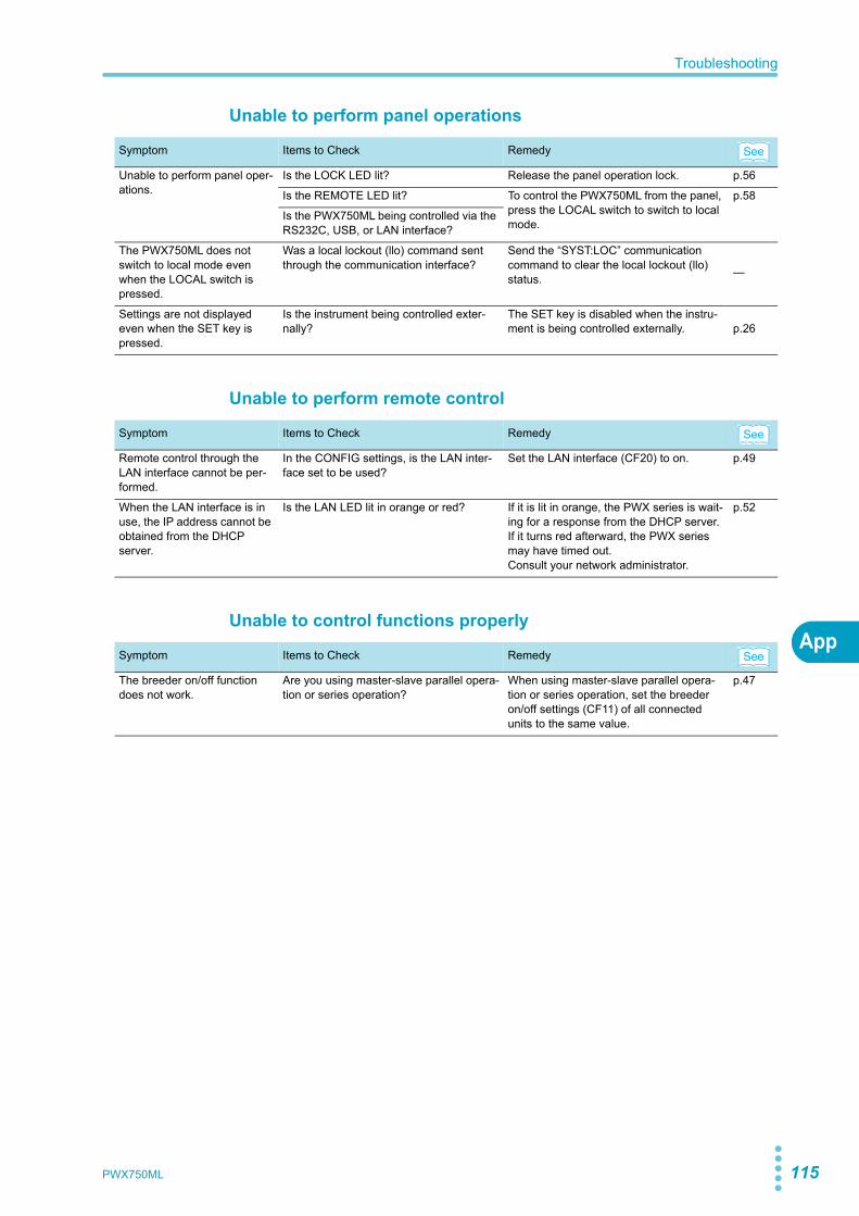
PWX750ML 115
Troubleshooting
App
Unable to perform panel operations
Unable to perform remote control
Unable to control functions properly
Symptom Items to Check Remedy
Unable to perform panel oper-ations.
Is the LOCK LED lit? Release the panel operation lock. p.56
Is the REMOTE LED lit? To control the PWX750ML from the panel, press the LOCAL switch to switch to local mode.
p.58
Is the PWX750ML being controlled via the RS232C, USB, or LAN interface?
The PWX750ML does not switch to local mode even when the LOCAL switch is pressed.
Was a local lockout (llo) command sent through the communication interface?
Send the “SYST:LOC” communication command to clear the local lockout (llo) status. —
Settings are not displayed even when the SET key is pressed.
Is the instrument being controlled exter-nally?
The SET key is disabled when the instru-ment is being controlled externally. p.26
Symptom Items to Check Remedy
Remote control through the LAN interface cannot be per-formed.
In the CONFIG settings, is the LAN inter-face set to be used?
Set the LAN interface (CF20) to on. p.49
When the LAN interface is in use, the IP address cannot be obtained from the DHCP server.
Is the LAN LED lit in orange or red? If it is lit in orange, the PWX series is wait-ing for a response from the DHCP server.If it turns red afterward, the PWX series may have timed out.Consult your network administrator.
p.52
Symptom Items to Check Remedy
The breeder on/off function does not work.
Are you using master-slave parallel opera-tion or series operation?
When using master-slave parallel opera-tion or series operation, set the breeder on/off settings (CF11) of all connected units to the same value.
p.47
See
See
See

116 PWX750ML
This page is intentionally blank.
PWX750ML 117
Aaccessories ................................................................ 2AC-FAIL ................................................................... 39alarm
clearing ......................................................... 35display .......................................................... 35
alarm occurrence ..................................................... 34alarm signal ............................................................. 35
Bbleeder on/off ........................................................... 47
CCC control ................................................................ 46CC mode .................................................................. 31command language ................................................. 49constant-current mode ............................................. 31constant-current power supply ................................. 31constant-voltage mode ............................................ 31current monitoring, range ......................................... 46current setting limit ................................................... 48CV control ................................................................ 46CV mode .................................................................. 31CV/CC control range ................................................ 46
Eemulation during remote control .............................. 49
Ffactory default settings ............................................. 59FAN .......................................................................... 38firmware version ........................................................ 2
Iinitialization .............................................................. 59IP address assignment
AUTO IP (auto) ............................................. 52MANUAL IP (manual) ................................... 52
IP address display ................................................... 50IP address prefix ...................................................... 52
Kkey lock function ...................................................... 56
LLAN interface
applying the settings ..................................... 51Resetting the LAN interface settings ............ 51SCPI-RAW ................................................... 53
LAN interface parameter .......................................... 49
MMAC address display ............................................... 51MANUAL IP setting (manual IP address) ................ 52memory contents, display ........................................ 45memory function ...................................................... 54multichannel (VMCB) ................................................. 3
channel ......................................................... 50domain ......................................................... 50
OOCP ......................................................................... 36OCP activation, detection time ................................ 47OHP ......................................................................... 38output on and off
external control ............................................. 46external control logic .................................... 47
OVP ......................................................................... 36OVP2 ....................................................................... 36
Pparallel operation ..................................................... 44POWER LIMIT ......................................................... 39power-on status ....................................................... 45product ID display .................................................... 53protection function
alarm clearance method ............................... 45fan failure protection ..................................... 38incorrect sensing connection protection ....... 39low AC input protection ................................ 39overcurrent protection .................................. 36overheat protection ...................................... 38overvoltage protection .................................. 36overvoltage protection 2 ............................... 36power limit .................................................... 39shutdown ...................................................... 39undervoltage limit ......................................... 38
Rremote sensing ........................................................ 22RS232C interface
baud rate ...................................................... 53
SSCPI communication error display .......................... 50SD ............................................................................ 39SENSE .................................................................... 39setting limit
UVL .............................................................. 38setting limits ............................................................. 35settings, reset .......................................................... 44
Index

118 PWX750ML
UUVL ..........................................................................38
Vvendor ID display ......................................................53version ........................................................................2VMCB (Virtual Multi Channel Bus)
channel ..........................................................50domain ..........................................................50
voltage monitoring, range .........................................46voltage setting limit ...................................................48


120 KES4022
KIKUSUI ELECTRONICS CORP.
www.kikusui.co.jp/en/
1-1-3 Higashiyamata, Tsuzuki-ku, Yokohama, 224-0023, JapanPhone: +81-45-482-6353Facsimile: +81-45-482-6261
If you find any misplaced or missing pages in the manuals, they will be replaced. If the manual gets lost or soiled, a new copy can be provided for a fee. In either case, please contact your Kikusui agent or distributor. At that time, inform your agent or distributor of the “Part No.” written on the front cover of this manual.Every effort has been made to ensure the accuracy of this manual. However, if you have any questions or find any errors or omissions, please contact your Kikusui agent or distributor.After you have finished reading this manual, store it so that you can use it for reference at any time.