USING THE NEW CONSTANT-CURRENT DIODES 67.pdf · USING THE NEW CONSTANT-CURRENT DIODES ... curate...
3
USING THE NEW CONSTANT-CUR RENT DIODES By DONALD E. LANCASTER Tlw . , • . w'111icmuluctor. maintain a co11 . tant curren t 01•er a 1t'i d " rm1 of termi11al 1·0/ta a11 d "l'fl""r as n�r.r high circuit impt• d a11n>. U "'"" inclu d e or•pr-currPnl Jlrotect ion, tnmsi.tor biasing, li1war ram /I gl'lwrutors, mul linear ohm met ers. A NEW type of diode is now available which works ex- actly the opposite of a zener diode. It is called a co11stc 1 1 1t-c1 1rr<'l lf diode or field-effect c1 1rrc· 1 1t-rc•g1 1- lator diode'. Unlike a zener, such a diode presents a con- stant l'1 1rr<'1 1f regardless of the tenni nal voltage o\·er a wide operating range and appears as a very higl1 circuit imped- ance. These new devic:es are quite useful for a number of electroni applieations, im:hrding o\·erl·urrent protec:tion, transistor biasing, linear ramp and stairstep generators, dif- ferential amplifiers, prel'ision n•ferenc c voltage sources, and linear-scale ohmmeters, to name a few. Ope ra! ing Prineiples The l·onstant-c1 11T<'nt diode is basieallv a field-effet tran- sistor that has its gate and souree l�c·trodes shorted to- gether. As Fig. l shows, an FET l'Ol l lWl'led this way gener- ates a nearly constant eurrent on·r a wide \'Oltage range. (A) FIELD·EFFECT TRANSISTOR WITH GATE SHORTED OR (Cl CONSTANT•CURRENT DIODE ANO SYMBOLS + PINCH-OH VOLTAGE CONSTANT·CURRENT OPERATION v.. (Bl CHARACTERISTICS LOAD + (DI BIASING FOR POSITIVE ANO NEGATIVE OUTPUT CURRENTS Fig. 1. Constant-current diodes behave like the conventional fleld-effe<I transistor but with gate-to-source short circuit. Fig. 2. The characteristics of Motorola constant-current diodes. 30 This constant-current region extends from the pinch-of f vol- tage to the forward break-o\' er ( breakdown ) voltage. In this region, the supply or circuit vol tage can vary widely with little or n o change in the current the FET al lows t o pass. Thus, to use a field-effel'I transi stor as a constant-cur- rent so1 1 1T<', we bias it in the foru:anl direction between the pinch-off \'oltage ( usually l to 8 volts ) and the forward breakdown voltage ( 2.5 to I 00 lts ) . Any cirl·uit \'oltage in this range will result in a constant drain current. The l'onstant·l'UI Tent diodes are simply field-effet tn- sistors whieh have been optimized for l'Onstant-eurrent servie by making the pinch-of f ,·oltage very low, the breakdown \'oltage \·cry high, and the dynamie impedance between these limits as high as possible. The symbol and polarity of a eonstant- eurrent diode are shown in Fig. lC, whi le Fig. 10 shows the normal biasing and polarity for both positi\'e and negati\'e power suppli es . ote that we use the diode in the forrcard diredion, unlike a zt•ner dio<le, whi eh is normally reverse-biased. The dio<le will provide a co1 1st; 1 11t current 01 1/y when it is properly bi- ased in the forward <lirecti on betwel'll the pind1-01£ and hreakdown \·oltags. The eonstant-current diode shoul<l not be connected or hias<'d in the reverse di rection . Arnila li lc Types & Appli l·ations The I N283 through .5: 314 diodes are a family of con· stant-current fi eld-effed diodes that eo\'er a 220-microampere to 4.70-milliampl•re range in 32 differe1 1t currents. Perfor- mance of se\'eral seleded <liodes i s shown i n Fig. 2. These l O toleranee u11its operate over a -5 to +200 ° C range and ha\·e a moderate t emperature coefficient that must he taken into aeemmt in prel'ision circuitry whieh must operat e o\'er a wide temperature range. laximu diode dissipati on is a healthy BOO milliwatts. The pinch-off \'oltage ranges from I to 3 \'olts. while the forward breakdown is specified at 100 volts, gi ving a 97- to 99-\·olt range of constant-l· tir- rcnt operation. Being irly new. these devices are still expensi\'e ( ahout 89 each in single quantities) , but since an experimenter can l'ome up with a workable substitute by shorting the gate-to- SOl lrl'l' leads of a far cheaper FET, it is almost certain that these <le\'ic:es will soon he priced in t he 81 to 2 range, eomparahle to ordinary zener <liodes. One source of the l 283 series is Motorola Se11 1icmu/11c- tor, Box 9.5. 5, Phoenix, Arizona 8.500 1 . Data sheets and dis- tributor lists are available. Another source for diodes of this particular type is Si/ico11i Ille. loeate<l at 1 140 \\'est E\' elyn A\'e., Sunnyle, Califoia 94086. A transistor tester whih uses a constant-current diode t o ELECTRONICS WORLD w.americanradiohistorv.com
Transcript of USING THE NEW CONSTANT-CURRENT DIODES 67.pdf · USING THE NEW CONSTANT-CURRENT DIODES ... curate...

USING THE NEW CONSTANT-CURRENT
DIODES By DONALD E. LANCASTER
Tlw . .,, • . w'111icmuluctor . ., m aintain a co11 ... tant curren t 01•er a 1t'id" rm1;w of termi11al 1 ·0/ta;w a11d "l'fl""r as n�r.r high circuit impt•da11n>.'i. U. "'"" include or•pr-currPnl Jlrotect ion, tnmsi.'>tor biasing, li1war ram /I gl'lwrutors, mul linear ohm meters.
ANEW type of diode is now available which works exactly the opposite of a zener diode. It is called a co11stc111t-c11rr<'llf diode or field-effect c11rrc·11t-rc•g11-
lator diode'. Unlike a zener, such a diode presents a constant l'11rr<'11f regardless of the tenn inal voltage o\·er a wide operating range and appears as a very higl1 circuit impedance. These new devic:es are quite useful for a number of electronic: applieations, im:hrding o\·erl·urrent protec:tion, transistor biasing, linear ram p and stairstep generators, differential amplifiers, prel'ision n•ferencc voltage sources, and l inear-scale ohmmeters, to name a few.
O pera! ing Prineiples The l·onstant-c111T<'nt diode is basieallv a field-effec:t tran
sistor that has its gate and souree c>l�c·trodes shorted together. As Fig. l shows, an FET l'OlllWl'led this way generates a nearly constant eurrent on·r a wide \'Oltage range.
(A) FIELD·EFFECT TRANSISTOR WITH GATE SHORTED
O R
( C l CONSTANT•CURRENT DIODE ANO SYMBOLS
+
PINCH-OH VOLTAGE
CONSTANT·CURRENT OPERATION
v .. ( B l CHARACTERISTICS
LOAD
+
( D I BIASING FOR POSITIVE ANO NEGATIVE OUTPUT CURRENTS
Fig. 1 . Constant-current diodes behave like the conventional fleld-effe<I transistor but with gate-to-source short circuit.
Fig. 2. The characteristics of Motorola constant-current diodes.
30
This constant-current region extends from the pinch-off voltage to the forward break-o\'er ( breakdown ) voltage. I n this region, the supply o r circuit voltage can vary widely with lit t le or no change in t he current t he FET allows to pass. Thus, to use a field-effel'I transistor as a constant-current so111T<', we bias it in the foru:anl direction between the pinch-off \'oltage ( usually l to 8 volts ) and the forward breakdown vol tage ( 2.5 to I 00 rnlts ) . Any cirl·uit \'oltage i n this range will result i n a constant drain current.
The l'onstant·l'UITent diodes are simply field-effec:t tnrnsistors whieh have been optimized for l'Onstant-eurrent servic:e by making the pinch-off ,·oltage very low, the breakdown \'oltage \·cry high, and the dynamie impedance between these limits as high as possible.
The symbol and polarity of a eonstant-eurrent diode are shown in Fig. lC, while Fig. 1 0 shows the normal biasing and polarity for both positi\'e and negati\'e power supplies . .'\ote that we use the diode in the forrcard diredion, unlike a zt•ner dio<le, whieh is normally reverse-biased. The dio<le will provide a co11st;111t current 011/y when it is properly biased in the forward <lirection betwel'll the pind1-01£ and hreakdown \·oltagt>s. The eonstant-current diode shoul<l not be connected or hias<'d in the reverse direction .
Arni la li lc Types &. Appl il·at ions The I N.5283 through L'\.5:3 1 4 diodes are a family of con·
stant-current field-effed diodes that eo\'er a 220-microampere to 4 .70-milliam pl•re range in 32 differe11t currents . Performance of se\'eral seleded <liodes is shown in Fig. 2. These l Oo/c toleranee u1 1 i ts operate over a -5.5 to +200° C range and ha\·e a moderate temperature coefficient that must he taken into aeemmt in prel'ision circuitry whieh must operate o\'er a wide temperature range. :\l aximurn diode dissipation is a healthy BOO milliwatts. The pinch-off \'oltage ranges from I to 3 \'olts. while the forward breakdown is specified at 1 00 volts, giving a 97- to 99-\·olt range of constant-l·tirrcnt operation.
Being fairly new. these devices are stil l expensi\'e ( ahout 89 each in single quantities ) , but since an experimenter can l'ome up with a workable substitute by shorting the gate-toSOllrl'l' leads of a far cheaper FET, it is almost certain that these <le\' ic:es will soon he priced in the 81 to f>2 range, eomparahle to ordinary zener <liodes.
One source of the l :'\.5283 series is Motorola Se111 icmu/11ctor, Box 9.5.5, Phoenix, Arizona 8.500 1 . Data sheets and distributor lists are available. Another source for d iodes of this particular t ype is Si/ico11i.r I lle. loeate<l at 1 1 40 \\'est E\'elyn A\'e., Sunnyrnle, California 94086.
A transistor tester whic:h uses a constant-current diode to
ELECTRONICS WORLD
www. a mericanradiohistorv.com
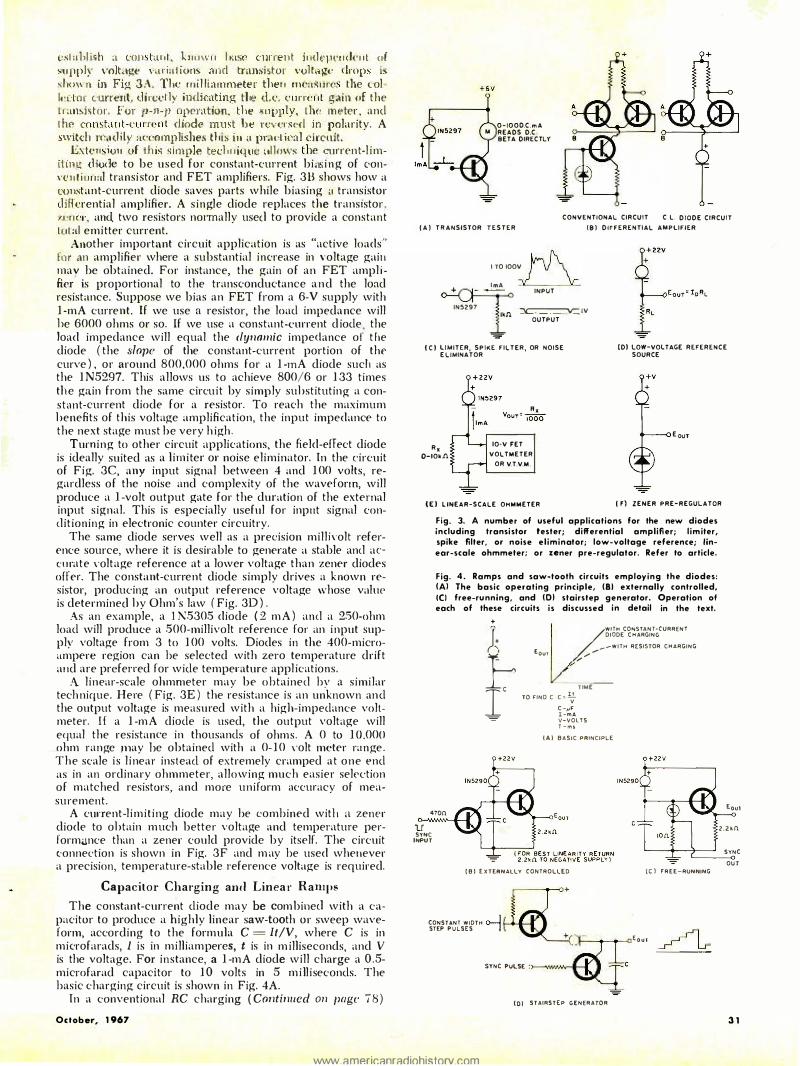
est al.ii L � h a con · t ,� n t , h 1 n w n hasf' curren t i 1 1ll epel l ( k 1 1 f uf �u pp.Ir •.:olt<.1�e v�i riat ions and transi stor vol ! ��:;i:e lrop� [s � hm,·n [n Fig; 3;\ . The mll l iamrneter then meaS 1 i 1'(;. the col lf : dCll' current, dired ly indicating the d.e. cu r ren t· gain of the r ransb tor . For r-n-p npernt!on, tbe � 1 J p1 ly, L hf: m eter , and l he cc:m�tant-<.·u m,1lt diode must Le rcvcrsc:d i n polarity. A .swikh rl'!adi ly accmnplishe.s this in n pni.N ieal circnit.
Exten ·io1 1 of t b i� s imple techn ique �il low� the urrent-l imiHng d iode to be used for constant-current bins i n g of eonve i 1 1 i 1 1n :: tl transi stor and FET amplifiers. Fig. 313 shows how a t�:mstant-current diode saves parts while biasing a transistor d i fferential amplifier. A single diode replaces the transistor. ,,1_�t wr, and two resistors no1mally use<l to provide a constant l 1 1 � i i emitter current.
A.nother important circuit application is as "active loads" frn· an amplifier where a substantial increase in voltage gain may he obtained. For instance, the gain of an FET ampl i fier �s proportional to the transconductance a n d the load resistance. Suppose we bias an FET from a 6-V supply with 1 -mA current. If we use a resistor, the load impedance will he 6000 ohms or so. If we use a constant-current diode, the load impedance will equal the dy11a111ic impedance of t he diode ( the slope of the constant-current portion of the curve ) , or around 800,000 ohms for a 1 -mA diode such as the 1 N5297. This allows us to achieve 800/6 or 1 33 times the gain from the same circuit by simply substituting a constant-current diode for a resistor. To reach the maximum benefits of this voltage amplification, the input impedance to the next stage must he very h igh .
Turning to other circuit applications, the field-effect diode is ideally suited as a l imiter or noise eliminator. In the circuit of Fig. 3C, any input signal between 4 and 1 00 volts, regardless of the noise and complexity of the waveform, will produce a I -volt output gate for the duration of the external input signal. This is especially useful for inp11t signal conditioning in electronic counter circuitry.
The same diode serves well as a precision millh·olt reference source, where it is desirable to generate a stable and accurate \'oltage reference at a lower voltage than zener diodes offer. The constant-current diode simply drives a known resistor, producing an output reference voltage whose vah1P is determine<l by Ohm's law ( Fig. 3D ) .
As an example, a l N5305 diode ( 2 m A ) and a 2.50-ohm load will produce a 500-millivolt reference for an input supply voltage from 3 to 1 00 volts. Diodes in the 400-microampere region can be selected with zero temperature drift and are preferred for wide temperature appl ications.
A l inear-scale ohmmeter may be obtained by a similar tech nique. Here ( Fig. 3E ) the resistance is an unknown an d the output voltage is measured with a high-impedance voltmeter. If a 1 -m A diode is used, the output voltage will equal the resistance in thousands of ohms. A 0 to 1 0.000 ohm range Jllay he obtained with a 0- 1 0 \·olt meter range. The scale i s l inear instead of extremely cramped at one end as in an ordinary ohmmeter, allowing much easier selection of matched resistors, and more uniform accuracy of measurement.
A current-l imit ing diode may he combined with a zener diode to obtain much better voltage and temperature perform<.1nce than a zener could provide by itself. The circuit connection is shown in Fig. 3F and m ay be used whenever a precision, temperature-stable reference voltage is required.
Capacitor Charging arnl Linea r Ramps The constant-current diode may be combined with a ca
pacitor to produce a highly linear saw-tooth or sweep waveform, according to the formula C = lt/V, where C is in microfarads, I is in milliamperes, t is in m illiseconds, and V is the voltage. For instance, a 1 -mA diode will charge a 0.5-microfarad capacitor to 1 0 volts in 5 mi ll iseconds. The basic charging circuit is shown in Fig. 4A.
In a conventional RC charging ( Co11ti1111cd 011 page 18)
Octob er, 1 967
0-1000.C.m A M READS D.C
BETA DIRECTLY
CONVENTIONAL CIRCUIT C . L. DIODE CIRCUIT ( A ) T R ANSISTOR T E S T E R ( 8 ) DIFFERENTIAL AMPLIFIER
I TO IOOV .� Im A ':! 1 � INPUT
IN5297 tkn � IV .l OUTPUT
=
( C ) LIMITER, SPl•E FILTER, OR NOISE E LIMINATOR
(D) LOW-VOLTAGE REFERENCE SOURCE
R x 0-IOldl
10-V FET VOLTMETER
OR V.T.V.M.
E ouT
( E ) LINEAR-SCALE OHMMETER ( F) ZENER PRE-REGULATOR
u
Fig. 3. A numb"' of useful applications for the new diodes including transi stor tester; differential amplifi er; l im iter, spike filter, or noise el iminator; low-voltage reference; lineor-scale ohmmeter; or zener pre-regulator. Refer lo article.
Fig. 4. Ramps and saw-tooth circuits employing the diodes: (Al The basic operating principle, (81 externally controlled, (() free-ru nning, and IOI stairstep generator. Operation of eoch of these circuits i s discussed i n detail in the text.
+ )� f 470n
/WITH C0"5TANT·CURRENT DIODE C H ARGING
- - W I T H RESISTOR CHARGING E our ,,,.,..-/ v
� TO FINO C c :: ll
v C -_-,F I -mA V-\IOL T S T - m s
I A ) BASIC PRINCIPLE
SYNC INPUT
( B ) E X T ERNALLY C O t H R O L L E D
� CONSTANT WIDTH ..... I STEP PULSES I
( C ) F R E E - RUNNING
""' '""' ' . � .... (01 STAIRST[P GENERATO R
Eou1
Z.Zkfi
SYNC
OUT
3 1
www.amP.rir.anraciiohi�torv.r.om

EN G I N EARED FOR
EXCELLEN C E: TO P-OUALITY
JI'JELJEX H EADSETS I •
Ham operators, hi-fi fans and audio engineers al l endorse famous
TELEX headsets; known for top grade performance fo r more
than 25 yea rs.
/ MAGNA-TWI N - Typifies the q u a l ity sta nda rds which have made Telex a favorite of hams. Del ivers a bsol ute max i m u m i n te l l ig ibi l ity u nder d i ffic u l t Q R M cond itions; e q u ipped with super-comfort foam c u s h ions. Rugged, moistu re-proof magnetic d rivers give excel lent sensitivity, broad response. Made of tough, h igh-impact plastic for o u tsta n d i n g d u ra b i l ity u nder h a rd usage.
TEL ESET - Lightweight, economy vers i o n o f t h e f a m o u s M a g n a - T w i n ; designed espec i a l ly for h a m req u i rements. H igh performance, shock-proof Magna-Twin drivers a t a low, low price.
r -i
\ ) \ .-M O N O S E T - F e a t h e r - l i g h t 1 . 2 oz. w e i g h t e l i m i n a t e s h e a d s e t f a t i g u e . Sound from rep lacea b l e d river i s fed d i rect l y i nto e a rs t h rough adj u stable tone a rms.
I· : , '
C O M B O - B ra n d new, h igh q u a l ity stereo headphones for the l ive ly set. Big 31/2" reprod ucers del iver deep rich bass a nd p u re sweet h i ghs. Exciting new styl ing h a s de l uxe foa m-fi l l ed vinyl earc u s h ions. Designed for comfort, ada pta b i l ity and concert-q ua l ity so und - a nyti:e '_ -�-�
f . �• "'1 ··�,: ·.··i·
·: . . . "'
.
-
-. • \ 'PJ "' SER ENATA -'
"F;r personal l iste n i n g, these Telex Serenata headphones w i l l reproduce h igh fidel ity sound e q u a l to a bout $ 1 ,000 worth of spea kers ! Con tains b u i l t - in tone control, adjustable pressure control a nd detachable cord add versat i l i ty, extra va l u e . OELE;X
7 aco u st ics A D I V I S I O N O F T H E T E L E X C O R P O R A T I O N 3054 EXCELSIOR BOULEVARD MINNtAPOLI S, MI NN. 554 16
C I RCLE N O . 83 ON R E A D E R SERVICE C A R D
�E:0 ELECTRON ICS
78
V.T.I. training leads to success as technicians, field engineers. specialists in communications, g u i d e d m i s s i l e s , c om pu t e r s , radar and automation. Basic & advanced courses in theory & laboratory. Electronic Engineering Technology and Electronic Technology curricula both available. Assoc. degree in 2 9 mos. B. S. also obtainable. G.l. approved. Graduates in all branches of electronics with maior companies. Start Febru a r y , S e p t e m b er . D o r m s . campus. High school graduate or equivalent. Write for catalog.
VALPARAISO TECHNICAL I NSTITUTE Dept. RD, Valparaiso, Indiana
1967 - Sl.25 ... .... #45 1966 - $ 1 .2L._.#29
Com plete buyers guide for virtua l ly every Hi Fi component manufactured.
Order by number from Zlff-Dovls Service Division, 595 Bro1dw1y, New York, N. Y. 10012.
Enclose a n additional 15¢ per copy for shipping a nd handling (50¢ for orders outside U.S.A.)
www.americanradiohistorv.com
Constant-Current Diodes ( Con tin ued from page 3 1 )
circui t. the ,-ol tage drop across the charging resistor changes the charging current, producing the familiar nonlinear exponential waveform. This form of nonlinearity is completely eliminated in a constant-c11rrent diode d1arging circ·uit, for the charging current remains independent of t he voltage across the diode. \\'e must, of course, stop the sweep before the diode goes out of its pinch-off region, or we .will obviously lose linearity.
A practical, externally controlled sweep circuit is shown in Fig. 4 13 . Here we have added an emitter-follower output to keep any load from disturbing the capacitor charge and have added a synehronizing transistor to diseharge the ramp upon command from a sync pulse. i\'ormally, the sync transistor is provided base current until a sweep is desired. The sync transistor is then turned off and a linear ramp is produced whieh is terminated either by limiting on t he supply voltage or by once again providing base current to the sync transistor. The beginning of the sweep will be non-linear d ue to the emitter-follower not being forwa rd-biased. This effect may be o,·ercome by routing the 2200-ohm emitter resistor to a negative voltage.
A free-running sweep is shown in Fig. 4C. Here, the capacitor charges up to the breakdown voltage of the four-layer diode which snaps "on" and discharges the capacitor. The four-layer diode then turns "off", and a new sweep begins. There are two outputs. The emitter-follmver output provides a linear, freerunning saw-tooth, while the 10-ohm output provides a sharp 10-volt synchronizing spike at the end of each ramp. A constant-current diode used in this circuit must provide less current than the holding current of the four-layer diode. Otherwise, the circuit will l a tch "on" after one cvcle. About 0.5 mA or lower current s�urces are recommended for operating most of these four-layer diodes.
If we turn the constant-current source "on" and "off", we can produce a stairstep generator with a controllable number of equal-height steps, as in Fig. 4D. Since charge equals current m ultiplied by time, the longer we leave the diode "on", the h igher each step will be, with the dwell time on the steps being determined by the "off" time between charging times. Such a circuit is most useful in transistor and tube type curve tracers and p urticularly in gray-scale generators in. dot and bar service-type generators. Obviously more elegant forms of the same circuit can be used to produce accurate voltage-to-freque11-cy converters. .A
ELECTRONICS WORLD