USER MANUAL - Ganz Security
84
USER MANUAL DR16NRT Stand Alone Type DVR SYSTEM
Transcript of USER MANUAL - Ganz Security
1
U S E R M A N U A L
DR16NRT
Stand Alone Type DVR SYSTEM
2
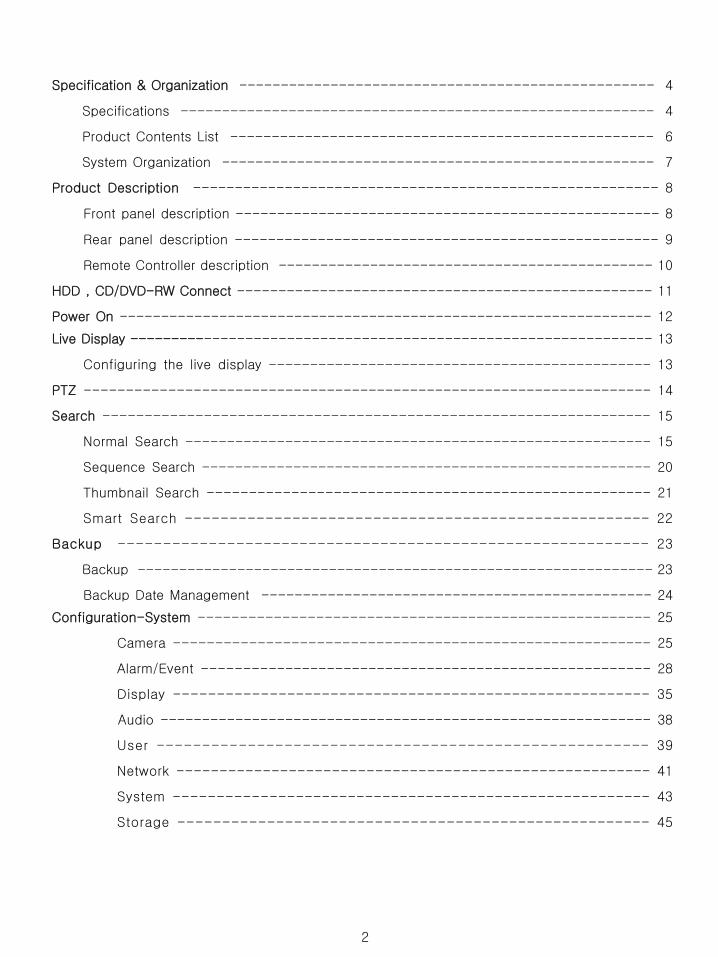
Specification & Organization --------------------------------------------------
4
Specifications ---------------------------------------------------------
4
Product Contents List ---------------------------------------------------
6
System Organization ----------------------------------------------------
7
Product Description --------------------------------------------------------
8
Front panel description ---------------------------------------------------
8
Rear panel description ---------------------------------------------------
9
Remote Controller description ---------------------------------------------
10
HDD , CD/DVD-RW Connect --------------------------------------------------
11
Power On ---------------------------------------------------------------- 12
Live Display ---------------------------------------------------------------
13
Configuring the live display ----------------------------------------------
13
PTZ
--------------------------------------------------------------------
14
Search
-----------------------------------------------------------------
15
Normal Search --------------------------------------------------------
15
Sequence Search ------------------------------------------------------
20
Thumbnail Search -----------------------------------------------------
21
Smart Search ----------------------------------------------------
22
Backup -----------------------------------------------------------
23
Backup
--------------------------------------------------------------
23
Backup Date Management -----------------------------------------------
24
Configuration-System
------------------------------------------------------
25
Camera ---------------------------------------------------------
25
Alarm/Event ------------------------------------------------------
28
Display -------------------------------------------------------
35
Audio -----------------------------------------------------------
38
User ------------------------------------------------------
39
Network -------------------------------------------------------
41
System -------------------------------------------------------
43
Storage -----------------------------------------------------
45
3
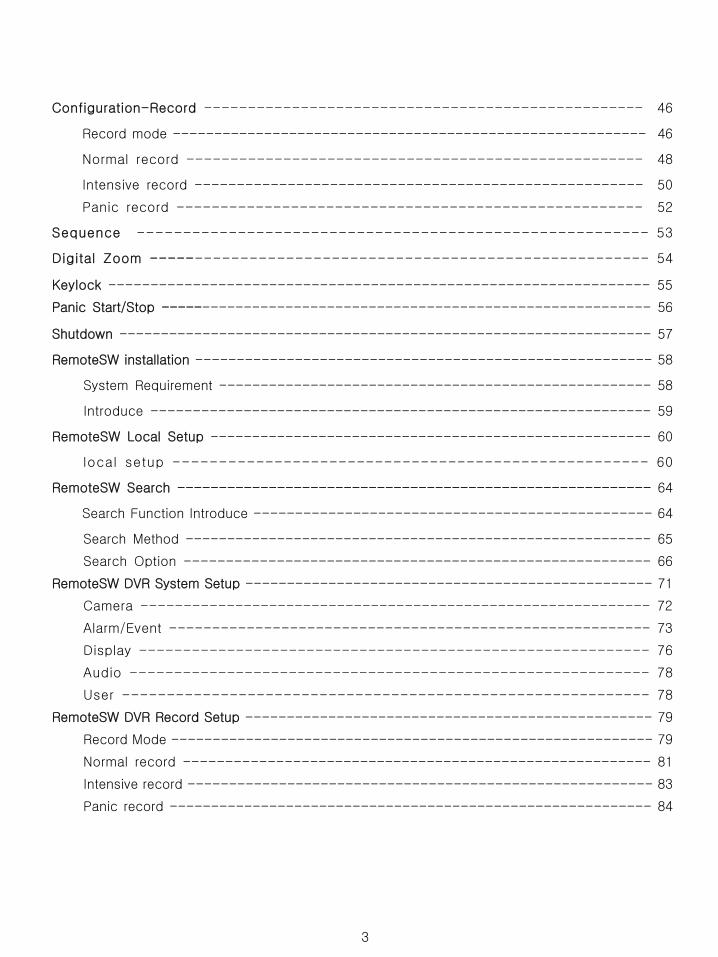
Configuration-Record --------------------------------------------------
46
Record mode ---------------------------------------------------------
46
Normal record ----------------------------------------------------
48
Intensive record -----------------------------------------------------
50
Panic record -----------------------------------------------------
52
Sequence --------------------------------------------------------
53
Digital Zoom -------------------------------------------------------
54
Keylock
---------------------------------------------------------------- 55
Panic Start/Stop -----------------------------------------------------------
56
Shutdown
---------------------------------------------------------------- 57
RemoteSW
installation
-------------------------------------------------------
58
System Requirement ----------------------------------------------------
58
Introduce ------------------------------------------------------------
59
RemoteSW
Local Setup
-----------------------------------------------------
60
local setup ---------------------------------------------------- 60
RemoteSW
Search
---------------------------------------------------------
64
Search Function Introduce
------------------------------------------------
64
Search Method --------------------------------------------------------
65
Search Option --------------------------------------------------------
66
RemoteSW
DVR System Setup
-------------------------------------------------
71
Camera ------------------------------------------------------------
72
Alarm/Event --------------------------------------------------------
73
Display ----------------------------------------------------------
76
Audio -----------------------------------------------------------
78
User ----------------------------------------------------------- 78
RemoteSW
DVR Record Setup
-------------------------------------------------
79
Record Mode ----------------------------------------------------------
79
Normal record --------------------------------------------------------
81
Intensive record --------------------------------------------------------
83
Panic record ----------------------------------------------------------
84
4
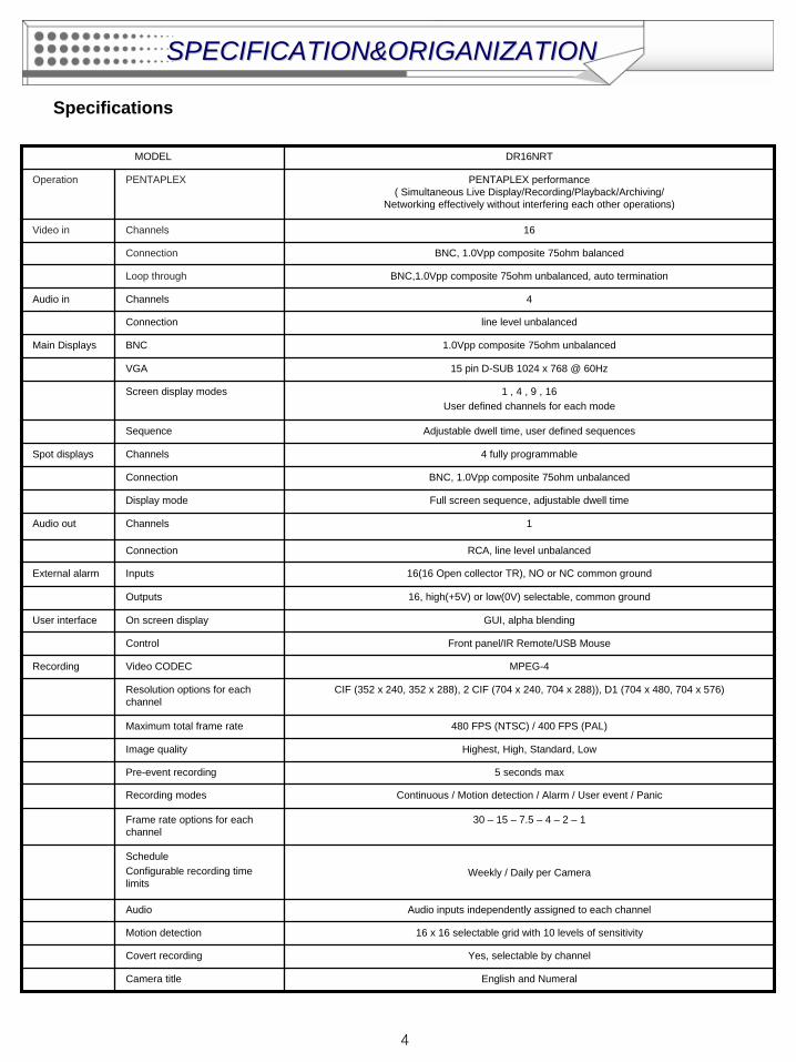
Specifications
MODEL DR16NRT
Operation PENTAPLEX PENTAPLEX performance ( Simultaneous Live Display/Recording/Playback/Archiving/
Networking effectively without interfering each other operations)
Video in Channels 16
Connection BNC, 1.0Vpp composite 75ohm balanced
Loop through BNC,1.0Vpp composite 75ohm unbalanced, auto termination
Audio in Channels 4
Connection line level unbalanced
Main Displays BNC 1.0Vpp composite 75ohm unbalanced
VGA 15 pin D-SUB 1024 x 768 @ 60Hz
Screen display modes 1 , 4 , 9 , 16 User defined channels for each mode
Sequence Adjustable dwell time, user defined sequences
Spot displays Channels 4 fully programmable
Connection BNC, 1.0Vpp composite 75ohm unbalanced
Display mode Full screen sequence, adjustable dwell time
Audio out Channels 1
Connection RCA, line level unbalanced
External alarm Inputs 16(16 Open collector TR), NO or NC common ground
Outputs 16, high(+5V) or low(0V) selectable, common ground
User interface On screen display GUI, alpha blending
Control Front panel/IR Remote/USB Mouse
Recording Video CODEC MPEG-4
Resolution options for each channel
CIF (352 x 240, 352 x 288), 2 CIF (704 x 240, 704 x 288)), D1 (704 x 480, 704 x 576)
Maximum total frame rate 480 FPS (NTSC) / 400 FPS (PAL)
Image quality Highest, High, Standard, Low
Pre-event recording 5 seconds max
Recording modes Continuous / Motion detection / Alarm / User event / Panic
Frame rate options for each channel
30 – 15 – 7.5 – 4 – 2 – 1
ScheduleConfigurable recording time limits
Weekly / Daily per Camera
Audio Audio inputs independently assigned to each channel
Motion detection 16 x 16 selectable grid with 10 levels of sensitivity
Covert recording Yes, selectable by channel
Camera title English and Numeral
SPECIFICATION&ORIGANIZATIONSPECIFICATION&ORIGANIZATION
5
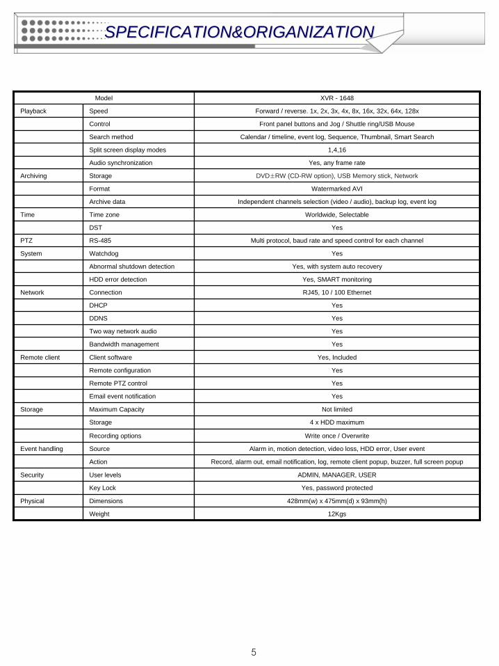
Model XVR - 1648
Playback Speed Forward / reverse. 1x, 2x, 3x, 4x, 8x, 16x, 32x, 64x, 128x
Control Front panel buttons and Jog / Shuttle ring/USB Mouse
Search method Calendar / timeline, event log, Sequence, Thumbnail, Smart Search
Split screen display modes 1,4,16
Audio synchronization Yes, any frame rate
Archiving Storage DVD±RW (CD-RW option), USB Memory stick, Network
Format Watermarked AVI
Archive data Independent channels selection (video / audio), backup log, event log
Time Time zone Worldwide, Selectable
DST Yes
PTZ RS-485 Multi protocol, baud rate and speed control for each channel
System Watchdog Yes
Abnormal shutdown detection Yes, with system auto recovery
HDD error detection Yes, SMART monitoring
Network Connection RJ45, 10 / 100 Ethernet
DHCP Yes
DDNS Yes
Two way network audio Yes
Bandwidth management Yes
Remote client Client software Yes, Included
Remote configuration Yes
Remote PTZ control Yes
Email event notification Yes
Storage Maximum Capacity Not limited
Storage 4 x HDD maximum
Recording options Write once / Overwrite
Event handling Source Alarm in, motion detection, video loss, HDD error, User event
Action Record, alarm out, email notification, log, remote client popup, buzzer, full screen popup
Security User levels ADMIN, MANAGER, USER
Key Lock Yes, password protected
Physical Dimensions 428mm(w) x 475mm(d) x 93mm(h)
Weight 12Kgs
SPECIFICATION&ORIGANIZATIONSPECIFICATION&ORIGANIZATION
6
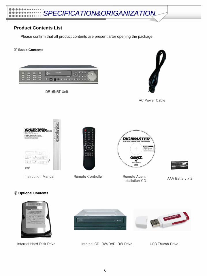
Product Contents List
Please confirm that all product contents are present after opening the package.
① Basic Contents
Remote ControllerInstruction
Manual Remote Agent Installation CD
AAA Battery x 2
AC Power Cable
② Optional Contents
Internal Hard Disk Drive Internal CD-RW/DVD-RW Drive USB Thumb Drive
DR16NRT Unit
SPECIFICATION&ORIGANIZATIONSPECIFICATION&ORIGANIZATION
7
SPECIFICATION&ORIGANIZATIONSPECIFICATION&ORIGANIZATION
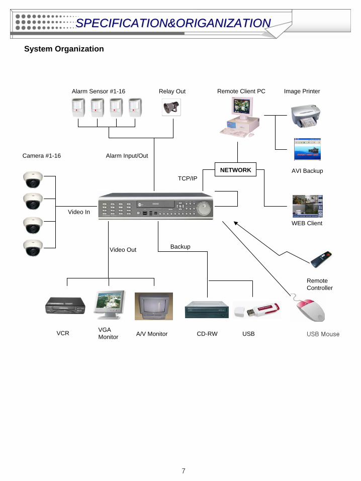
System Organization
NETWORK
Camera #1-16
Alarm Sensor #1-16 Relay Out
VCR VGA Monitor A/V Monitor
Remote Client PC Image Printer
Video In
Video Out
TCP/IP
Alarm Input/Out
Remote Controller
CD-RW
Backup
AVI Backup
WEB Client
USB USB Mouse
8
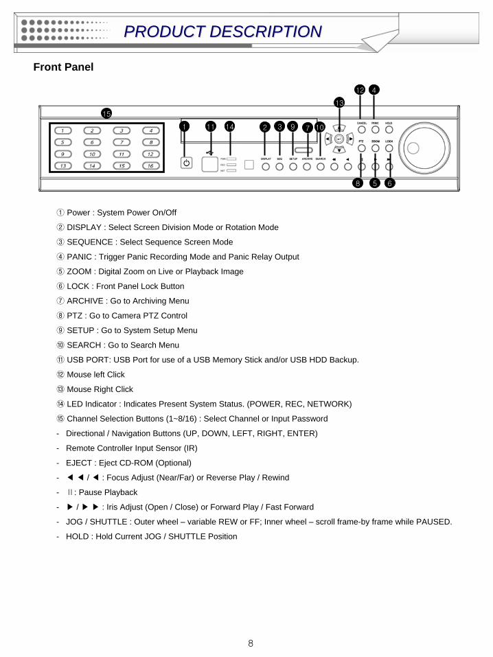
① Power : System Power On/Off
② DISPLAY : Select Screen Division Mode or Rotation Mode
③ SEQUENCE : Select Sequence Screen Mode
④ PANIC : Trigger Panic Recording Mode and Panic Relay Output
⑤ ZOOM : Digital Zoom on Live or Playback Image
⑥ LOCK : Front Panel Lock Button
⑦ ARCHIVE : Go to Archiving Menu
⑧ PTZ : Go to Camera PTZ Control
⑨ SETUP : Go to System Setup Menu
⑩ SEARCH : Go to Search Menu
⑪ USB PORT: USB Port for use of a USB Memory Stick and/or USB HDD Backup.
⑫ Mouse left Click
⑬ Mouse Right Click
⑭ LED Indicator : Indicates Present System Status. (POWER, REC, NETWORK)
⑮ Channel Selection Buttons (1~8/16) : Select Channel or Input Password
- Directional / Navigation Buttons (UP, DOWN, LEFT, RIGHT, ENTER)
- Remote Controller Input Sensor (IR)
- EJECT : Eject CD-ROM (Optional)
- ◀ ◀ / ◀ : Focus Adjust (Near/Far) or Reverse Play / Rewind
- Ⅱ: Pause Playback
- ▶ / ▶ ▶ : Iris Adjust (Open / Close) or Forward Play / Fast Forward
- JOG / SHUTTLE : Outer wheel – variable REW or FF; Inner wheel – scroll frame-by frame while PAUSED.
- HOLD : Hold Current JOG / SHUTTLE Position
Front Panel
1 2 3
4
5 6
7
8
9 1011
12
13
14
15
PRODUCT DESCRIPTIONPRODUCT DESCRIPTION
9
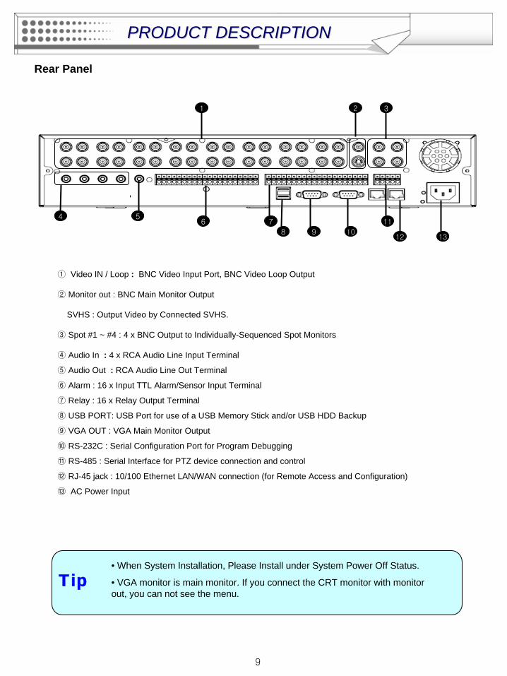
• When System Installation, Please Install under System Power Off Status.
• VGA monitor is main monitor. If you connect the CRT monitor with monitor out, you can not see the menu.
Rear Panel
Tip
1298 10
13
1 2 3
476
511
①
Video IN / Loop : BNC Video Input Port, BNC Video Loop Output
② Monitor out : BNC Main Monitor Output
SVHS : Output Video by Connected SVHS.
③ Spot #1 ~ #4 : 4 x BNC Output to Individually-Sequenced Spot Monitors
④ Audio In : 4 x RCA Audio Line Input Terminal
⑤ Audio Out : RCA Audio Line Out Terminal
⑥ Alarm : 16 x Input TTL Alarm/Sensor Input Terminal
⑦ Relay : 16 x Relay Output Terminal
⑧ USB PORT: USB Port for use of a USB Memory Stick and/or USB HDD Backup
⑨ VGA OUT : VGA Main Monitor Output
⑩ RS-232C : Serial Configuration Port for Program Debugging
⑪ RS-485 : Serial Interface for PTZ device connection and control
⑫ RJ-45 jack : 10/100 Ethernet LAN/WAN connection (for Remote Access and Configuration)
⑬
AC Power Input
PRODUCT DESCRIPTIONPRODUCT DESCRIPTION
10
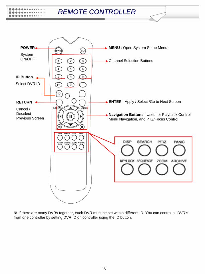
REMOTE CONTROLLERREMOTE CONTROLLER
POWER
System ON/OFF
MENU : Open System Setup Menu
RETURN
Cancel / Deselect Previous Screen
ENTER : Apply / Select /Go to Next Screen
Channel Selection Buttons
※ If there are many DVRs together, each DVR must be set with a different ID. You can control all DVR’s from one controller by setting DVR ID on controller using the ID button.
Navigation Buttons : Used for Playback Control, Menu Navigation, and PTZ/Focus Control
ID
ID Button
Select DVR ID
11
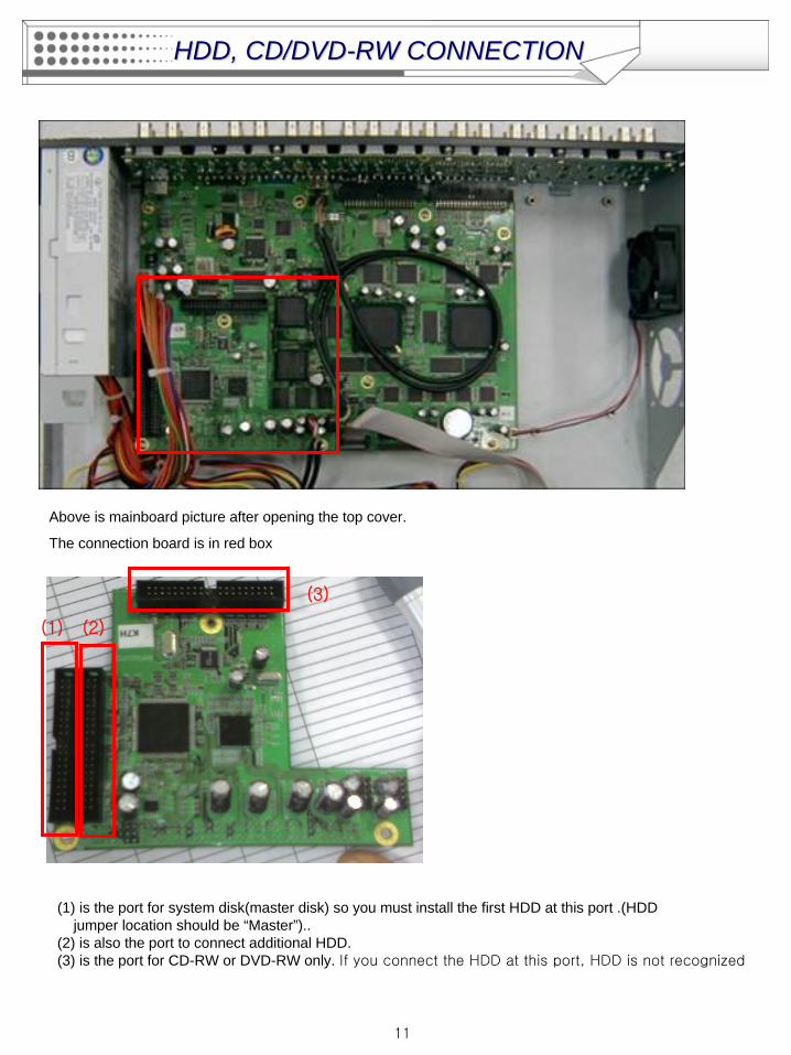
HDD, CD/DVDHDD, CD/DVD--RW CONNECTIONRW CONNECTION
Above is mainboard picture after opening the top cover.
The connection board is in red box
(1) is the port for system disk(master disk) so you must install the first HDD at this port .(HDD jumper location should be “Master”)..
(2) is also the port to connect additional HDD.(3) is the port for CD-RW or DVD-RW only. If you connect the HDD at this port, HDD is not recognized
(1) (2)
(3)
12
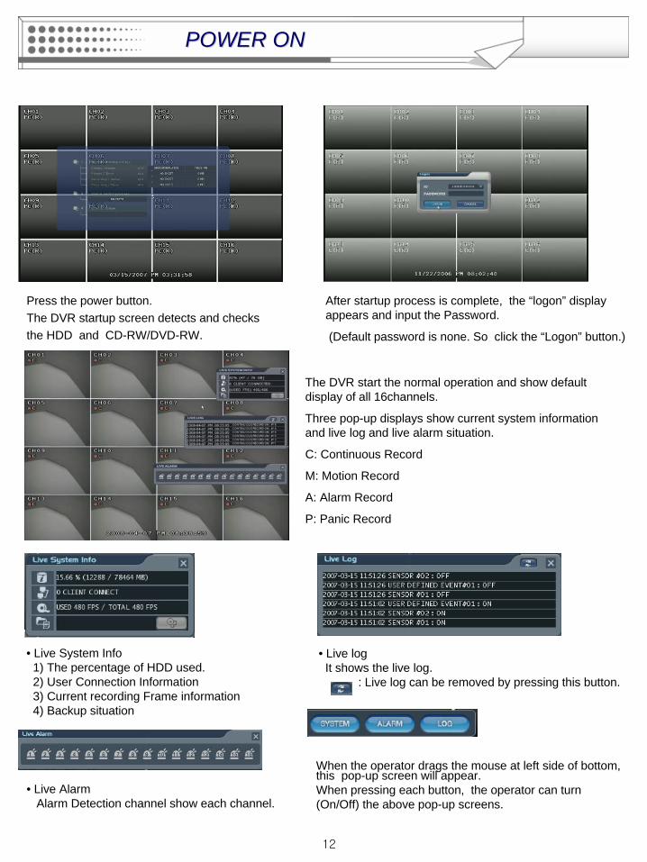
Press the power button.The DVR startup screen detects and checks the HDD and CD-RW/DVD-RW.
After startup process is complete, the “logon” display appears and input the Password.
(Default password is none. So click the “Logon” button.)
The DVR start the normal operation and show default display of all 16channels.
Three pop-up displays show current system information and live log and live alarm situation.
C: Continuous Record
M: Motion Record
A: Alarm Record
P: Panic Record
• Live System Info1) The percentage of HDD used.2) User Connection Information3) Current recording Frame information4) Backup situation
• Live logIt shows the live log.
: Live log can be removed by pressing this button.
• Live AlarmAlarm Detection channel show each channel.
When the operator drags the mouse at left side of bottom, this pop-up screen will appear.When pressing each button, the operator can turn (On/Off) the above pop-up screens.
POWER ONPOWER ON
13
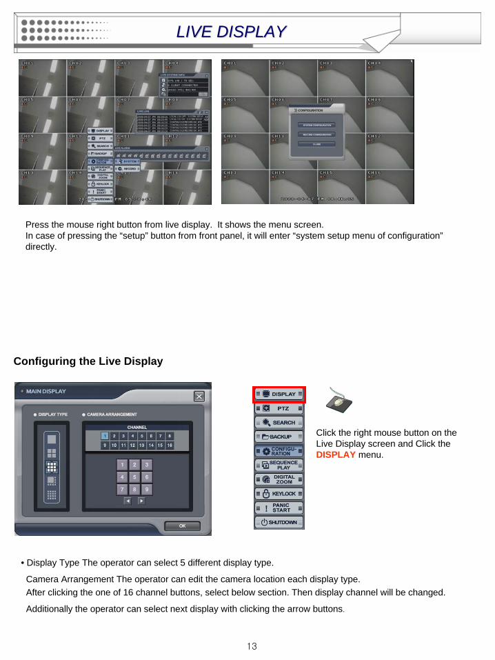
Press the mouse right button from live display. It shows the menu screen.In case of pressing the “setup” button from front panel, it will enter “system setup menu of configuration” directly.
Configuring the Live Display
Click the right mouse button on the Live Display screen and Click the DISPLAY menu.
• Display Type The operator can select 5 different display type.
Camera Arrangement The operator can edit the camera location each display type. After clicking the one of 16 channel buttons, select below section. Then display channel will be changed.
Additionally the operator can select next display with clicking the arrow buttons.
LIVE DISPLAYLIVE DISPLAY
14
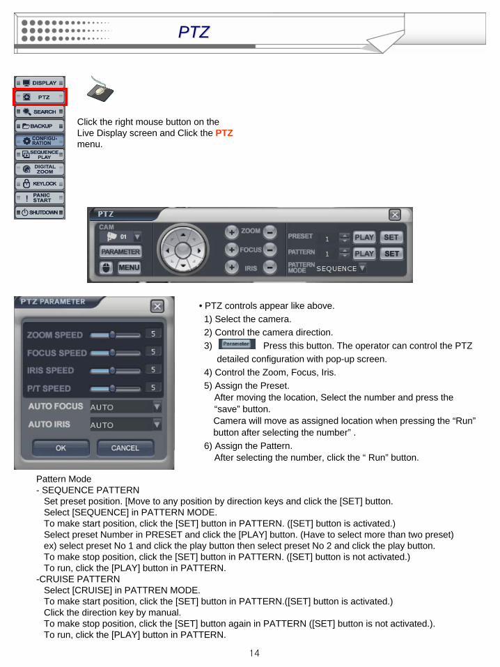
Click the right mouse button on the Live Display screen and Click the PTZ menu.
• PTZ controls appear like above. 1) Select the camera.2) Control the camera direction.3) Press this button. The operator can control the PTZ
detailed configuration with pop-up screen.4) Control the Zoom, Focus, Iris.5) Assign the Preset.
After moving the location, Select the number and press the“save” button.
Camera will move as assigned location when pressing the “Run” button after selecting the number” .6) Assign the Pattern.
After selecting the number, click the “ Run” button.
PTZPTZ
Pattern Mode- SEQUENCE PATTERN
Set preset position. [Move to any position by direction keys and click the [SET] button.Select [SEQUENCE] in PATTERN MODE.To make start position, click the [SET] button in PATTERN. ([SET] button is activated.)Select preset Number in PRESET and click the [PLAY] button. (Have to select more than two preset) ex) select preset No 1 and click the play button then select preset No 2 and click the play button. To make stop position, click the [SET] button in PATTERN. ([SET] button is not activated.)To run, click the [PLAY] button in PATTERN.
-CRUISE PATTERNSelect [CRUISE] in PATTREN MODE. To make start position, click the [SET] button in PATTERN.([SET] button is activated.)Click the direction key by manual.To make stop position, click the [SET] button again in PATTERN ([SET] button is not activated.). To run, click the [PLAY] button in PATTERN.
15
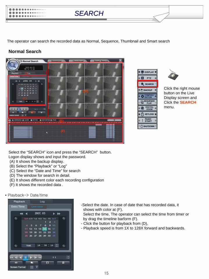
Click the right mouse button on the Live Display screen and Click the SEARCH menu.
The operator can search the recorded data as Normal, Sequence, Thumbnail and Smart search
Normal Search
(A)
(B)
(C)
(D)
(E)
(F)
Select the “SEARCH” icon and press the “SEARCH” button.Logon display shows and input the password.(A) It shows the backup display.(B) Select the “Playback” or “Log”(C) Select the “Date and Time” for search(D) The window for search in detail.(E) It shows different color each recording configuration(F) It shows the recorded data .
• Playback-> Date/time
-Select the date. In case of date that has recorded data, it shows with color at (F).Select the time, The operator can select the time from timer or by drag the timeline barform (F).
- Click the button for playback from (D),- Playback speed is from 1X to 128X forward and backwards.
SEARCHSEARCH
16
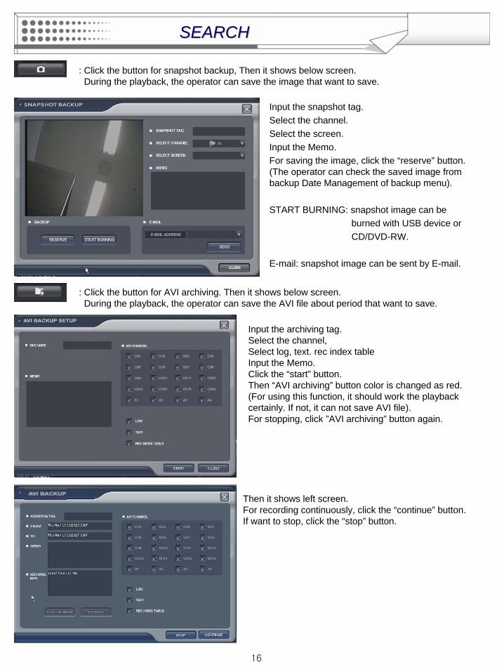
: Click the button for snapshot backup, Then it shows below screen. During the playback, the operator can save the image that want to save.
Input the snapshot tag.Select the channel.Select the screen.Input the Memo.For saving the image, click the “reserve” button.(The operator can check the saved image from backup Date Management of backup menu).
START BURNING: snapshot image can be burned with USB device or CD/DVD-RW.
E-mail: snapshot image can be sent by E-mail.
: Click the button for AVI archiving. Then it shows below screen. During the playback, the operator can save the AVI file about period that want to save.
Input the archiving tag.Select the channel,Select log, text. rec index tableInput the Memo.Click the “start” button. Then “AVI archiving” button color is changed as red.(For using this function, it should work the playback certainly. If not, it can not save AVI file).For stopping, click ”AVI archiving” button again.
Then it shows left screen.For recording continuously, click the “continue” button.If want to stop, click the “stop” button.
SEARCHSEARCH

17
It shows left screen with backup data information.How to burning and reserve is same with how to save the snapshot.(The operator can check the saved image from backup Date Management of backup menu).
: Click the button for full screen from (D). Then it shows below screen.
For returning, drag the mouse to the bottom of screen.Then appear below icon with return icon.Click the “return” button then return original screen.The operator can control the playback speed with above icon from full screen playback mode.
SEARCHSEARCH
18
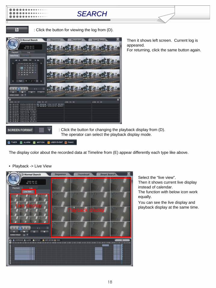
: Click the button for viewing the log from (D).
Then it shows left screen. Current log is appeared.For returning, click the same button again.
: Click the button for changing the playback display from (D).The operator can select the playback display mode.
The display color about the recorded data at Timeline from (E) appear differently each type like above.
• Playback -> Live View
Select the “live view”.Then it shows current live display instead of calendar.The function with below icon work equally.You can see the live display and playback display at the same time.
Playback displayLive display
SEARCHSEARCH
19
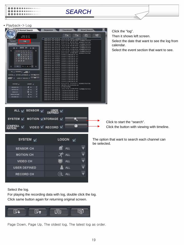
• Playback-> Log
Click the “log”.Then it shows left screen.Select the date that want to see the log from calendar.Select the event section that want to see.
Click to start the “search”.Click the button with viewing with timeline.
Select the log.For playing the recording data with log, double click the log.Click same button again for returning original screen.
The option that want to search each channel can be selected.
Page Down, Page Up, The oldest log, The latest log as order.
SEARCHSEARCH
20
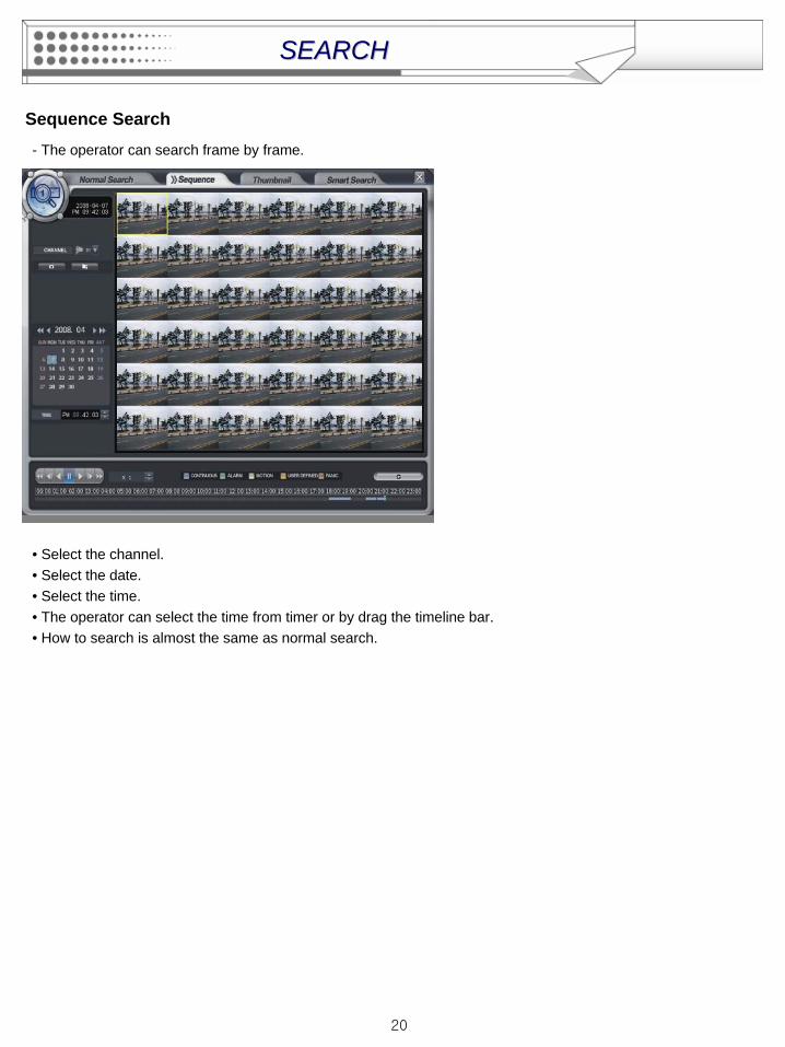
Sequence Search- The operator can search frame by frame.
• Select the channel.• Select the date.• Select the time.• The operator can select the time from timer or by drag the timeline bar.• How to search is almost the same as normal search.
SEARCHSEARCH
21
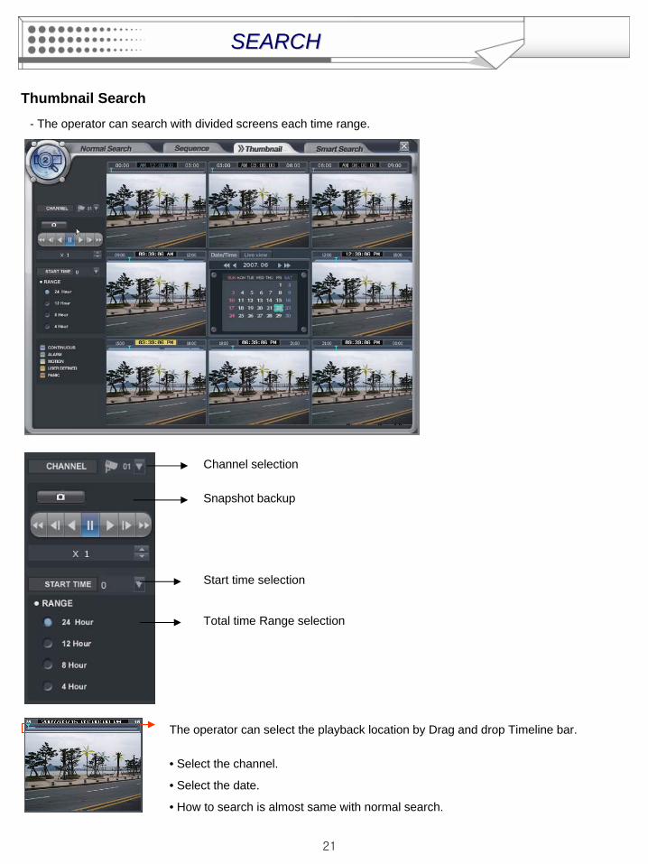
Thumbnail Search- The operator can search with divided screens each time range.
• Select the channel.
• Select the date.
• How to search is almost same with normal search.
The operator can select the playback location by Drag and drop Timeline bar.
Channel selection
Snapshot backup
Start time selection
Total time Range selection
SEARCHSEARCH
22
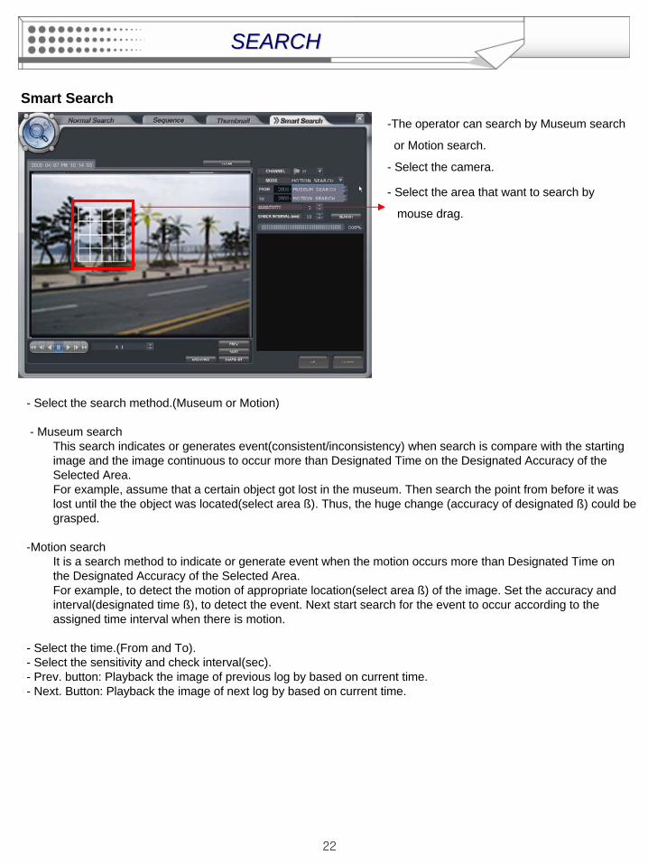
Smart Search-The operator can search by Museum search
or Motion search.
- Select the camera.
SEARCHSEARCH
- Select the search method.(Museum or Motion)
- Museum searchThis search indicates or generates event(consistent/inconsistency) when search is compare with the starting image and the image continuous to occur more than Designated Time on the Designated Accuracy of the Selected Area.For example, assume that a certain object got lost in the museum. Then search the point from before it was lost until the the object was located(select area ß). Thus, the huge change (accuracy of designated ß) could be grasped.
-Motion search It is a search method to indicate or generate event when the motion occurs more than Designated Time on the Designated Accuracy of the Selected Area. For example, to detect the motion of appropriate location(select area ß) of the image. Set the accuracy and interval(designated time ß), to detect the event. Next start search for the event to occur according to the assigned time interval when there is motion.
- Select the time.(From and To).- Select the sensitivity and check interval(sec).- Prev. button: Playback the image of previous log by based on current time.- Next. Button: Playback the image of next log by based on current time.
- Select the area that want to search by
mouse drag.
23
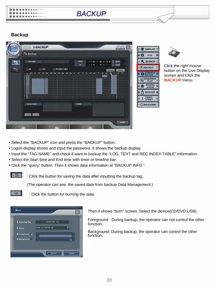
• Select the “BACKUP” icon and press the “BACKUP” button.• Logon display shows and input the password. It shows the backup display.• Input the “TAG NAME” and check if want to backup the “LOG, TEXT and REC INDEX TABLE” information.• Select the Start time and End time with timer or timeline bar.• Click the “query” button. Then it shows data information at “BACKUP INFO.”.
Click the right mouse button on the Live Display screen and Click the BACKUP menu.
: Click the button for saving the data after inputting the backup tag.
(The operator can see the saved data from backup Data Management.)
: Click the button for burning the data.
Then it shows “burn” screen. Select the device(CD/DVD,USB)
Foreground : During backup, the operator can not control the other function.
Background: During backup, the operator can control the other function.
Backup
BACKUPBACKUP
24
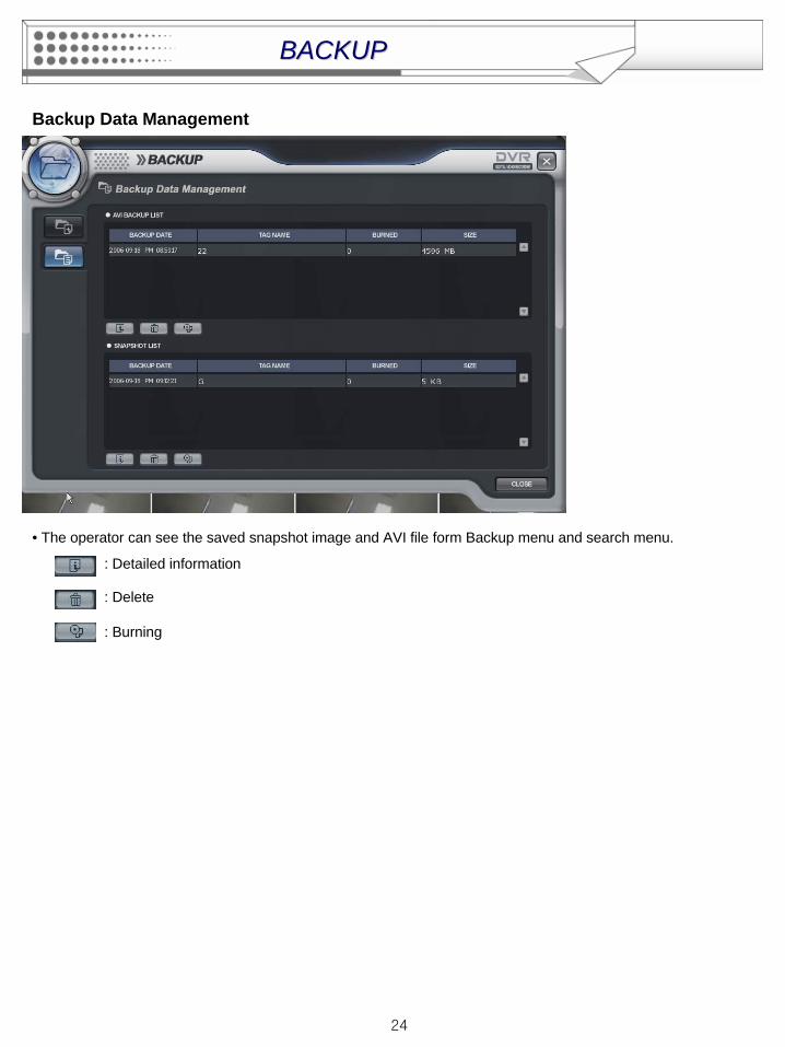
Backup Data Management
• The operator can see the saved snapshot image and AVI file form Backup menu and search menu.
: Detailed information
: Delete
: Burning
BACKUPBACKUP
25
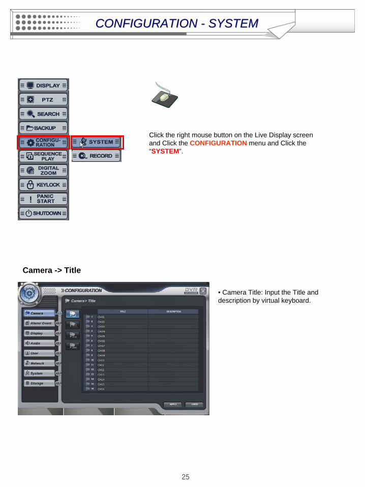
Click the right mouse button on the Live Display screen and Click the CONFIGURATION menu and Click the “SYSTEM”.
Camera -> Title
• Camera Title: Input the Title and description by virtual keyboard.
CONFIGURATION CONFIGURATION -- SYSTEMSYSTEM
26
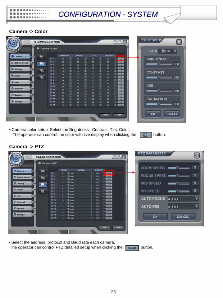
Camera -> Color
• Camera color setup: Select the Brightness, Contrast, Tint, Color.The operator can control the color with live display when clicking the button.
Camera -> PTZ
• Select the address, protocol and Baud rate each camera. The operator can control PTZ detailed setup when clicking the button.
CONFIGURATION CONFIGURATION -- SYSTEMSYSTEM
27
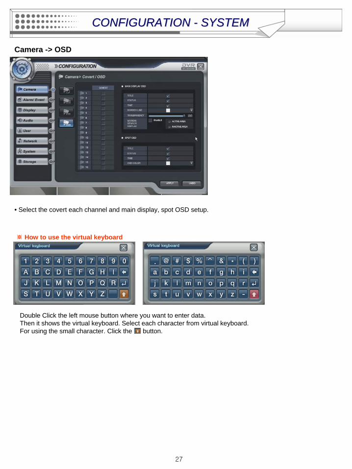
Camera -> OSD
• Select the covert each channel and main display, spot OSD setup.
※ How to use the virtual keyboard
Double Click the left mouse button where you want to enter data.Then it shows the virtual keyboard. Select each character from virtual keyboard.For using the small character. Click the button.
CONFIGURATION CONFIGURATION -- SYSTEMSYSTEM
28
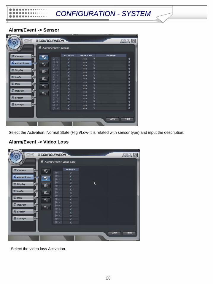
Alarm/Event -> Sensor
Select the Activation, Normal State (High/Low-It is related with sensor type) and input the description.
Alarm/Event -> Video Loss
Select the video loss Activation.
CONFIGURATION CONFIGURATION -- SYSTEMSYSTEM
29
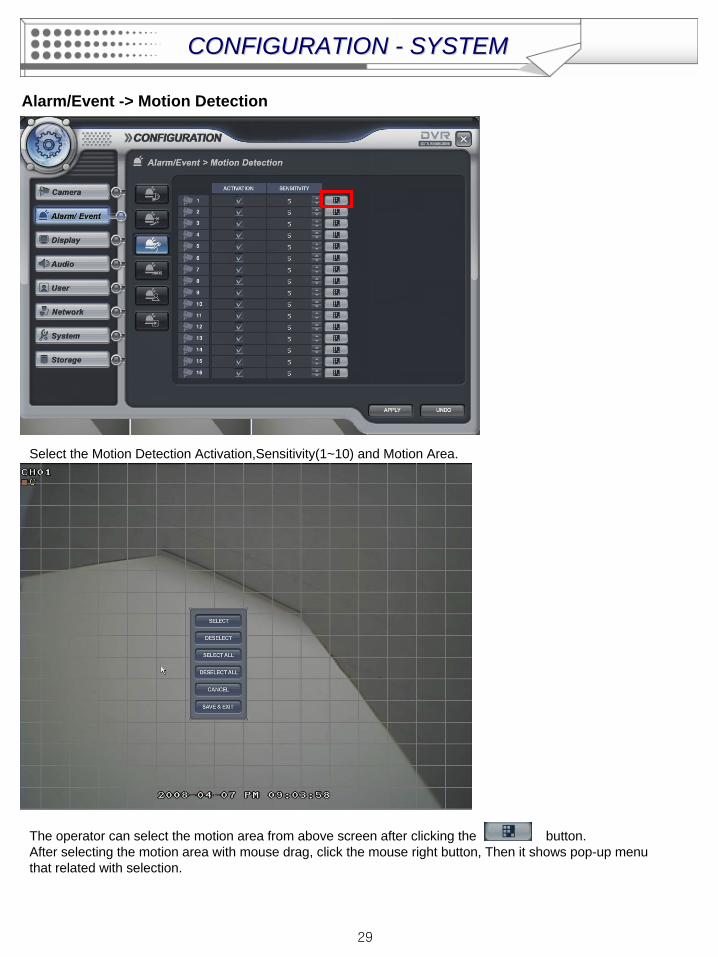
Alarm/Event -> Motion Detection
Select the Motion Detection Activation,Sensitivity(1~10) and Motion Area.
The operator can select the motion area from above screen after clicking the button.After selecting the motion area with mouse drag, click the mouse right button, Then it shows pop-up menu that related with selection.
CONFIGURATION CONFIGURATION -- SYSTEMSYSTEM
30
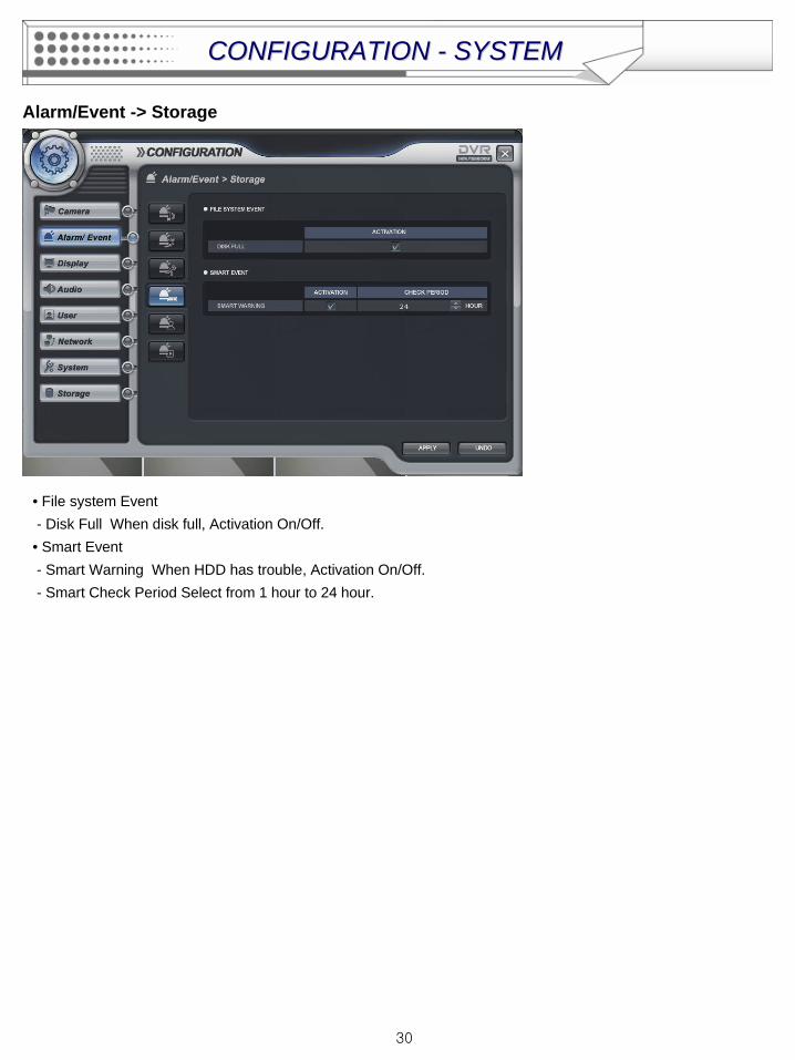
Alarm/Event -> Storage
• File system Event- Disk Full When disk full, Activation On/Off.• Smart Event - Smart Warning When HDD has trouble, Activation On/Off.- Smart Check Period Select from 1 hour to 24 hour.
CONFIGURATION CONFIGURATION -- SYSTEMSYSTEM

31
Alarm/Event -> User Defined
The operator can make the User Defined Event with current event’s mixing. When happen the over two events at the same time, the operator can setup how it work. (Mixing condition is “AND” not “OR”)
Select the Activation each channel.
Setup the detail configuration after entering the “EDITER” with clicking the button or double click the selected channel.Select the sensor, motion, Video loss, Storage Event and User defined Event as user want.After selecting it, action type can setup from Event Action Setup.
CONFIGURATION CONFIGURATION -- SYSTEMSYSTEM
32
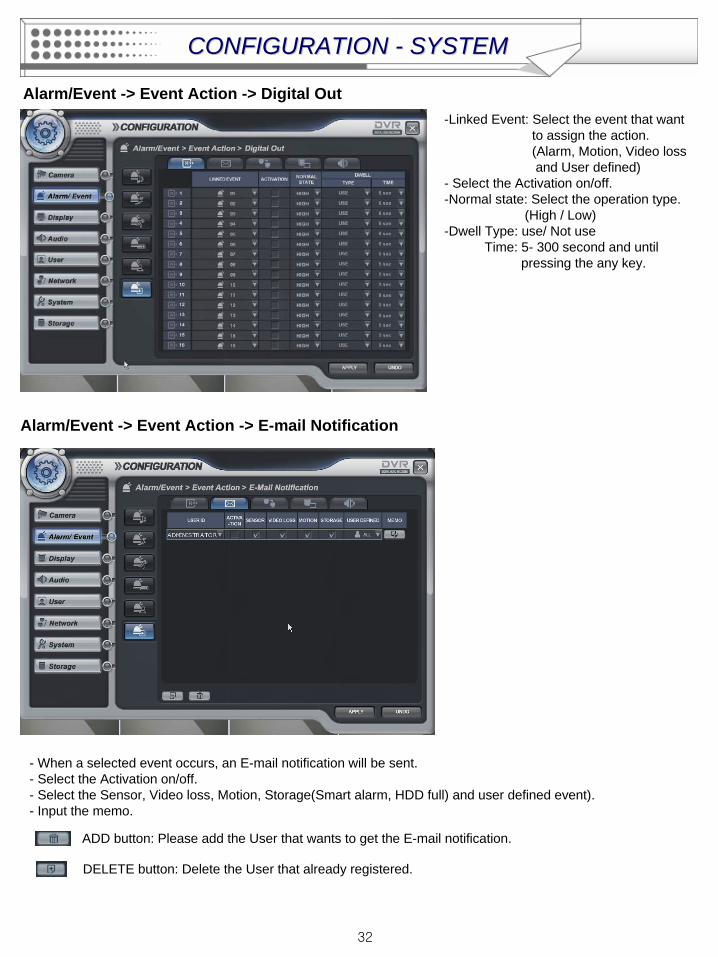
Alarm/Event -> Event Action -> Digital Out-Linked Event: Select the event that want
to assign the action.(Alarm, Motion, Video loss and User defined)
- Select the Activation on/off.-Normal state: Select the operation type.
(High / Low)-Dwell Type: use/ Not use
Time: 5- 300 second and until pressing the any key.
- When a selected event occurs, an E-mail notification will be sent.- Select the Activation on/off.- Select the Sensor, Video loss, Motion, Storage(Smart alarm, HDD full) and user defined event).- Input the memo.
Alarm/Event -> Event Action -> E-mail Notification
ADD button: Please add the User that wants to get the E-mail notification.
DELETE button: Delete the User that already registered.
CONFIGURATION CONFIGURATION -- SYSTEMSYSTEM
33
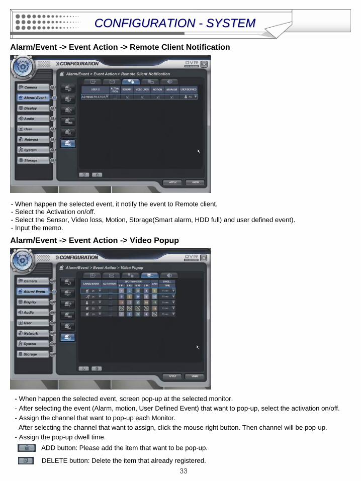
Alarm/Event -> Event Action -> Remote Client Notification
- When happen the selected event, it notify the event to Remote client.- Select the Activation on/off.- Select the Sensor, Video loss, Motion, Storage(Smart alarm, HDD full) and user defined event).- Input the memo.
CONFIGURATION CONFIGURATION -- SYSTEMSYSTEM
Alarm/Event -> Event Action -> Video Popup
- When happen the selected event, screen pop-up at the selected monitor.- After selecting the event (Alarm, motion, User Defined Event) that want to pop-up, select the activation on/off.- Assign the channel that want to pop-up each Monitor.After selecting the channel that want to assign, click the mouse right button. Then channel will be pop-up.
- Assign the pop-up dwell time.ADD button: Please add the item that want to be pop-up.
DELETE button: Delete the item that already registered.
34
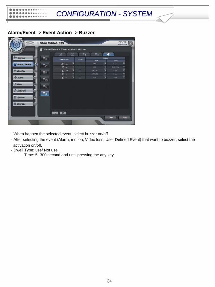
Alarm/Event -> Event Action -> Buzzer
- When happen the selected event, select buzzer on/off.- After selecting the event (Alarm, motion, Video loss, User Defined Event) that want to buzzer, select the activation on/off.
- Dwell Type: use/ Not useTime: 5- 300 second and until pressing the any key.
CONFIGURATION CONFIGURATION -- SYSTEMSYSTEM
35
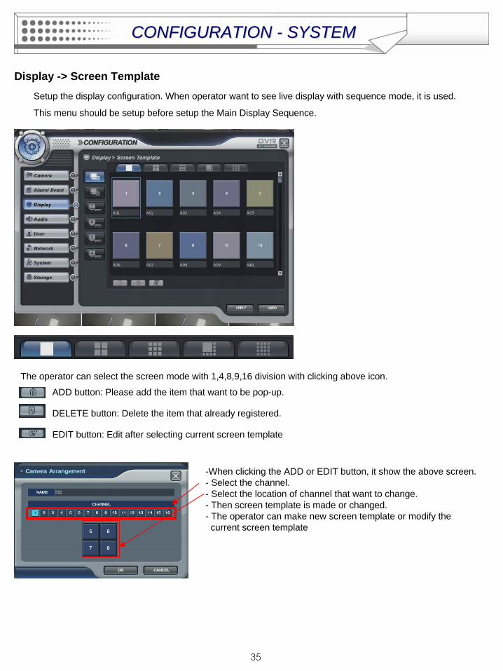
Display -> Screen TemplateSetup the display configuration. When operator want to see live display with sequence mode, it is used.
This menu should be setup before setup the Main Display Sequence.
The operator can select the screen mode with 1,4,8,9,16 division with clicking above icon.
ADD button: Please add the item that want to be pop-up.
DELETE button: Delete the item that already registered.
EDIT button: Edit after selecting current screen template
-When clicking the ADD or EDIT button, it show the above screen.- Select the channel.- Select the location of channel that want to change.- Then screen template is made or changed.- The operator can make new screen template or modify the current screen template
CONFIGURATION CONFIGURATION -- SYSTEMSYSTEM
36
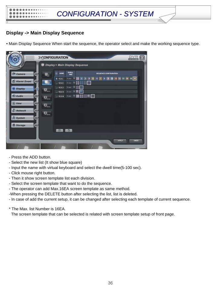
Display -> Main Display Sequence
• Main Display Sequence When start the sequence, the operator select and make the working sequence type.
- Press the ADD button.- Select the new list (It show blue square) - Input the name with virtual keyboard and select the dwell time(5-100 sec).- Click mouse right button. - Then it show screen template list each division.- Select the screen template that want to do the sequence.- The operator can add Max.16EA screen template as same method.-When pressing the DELETE button after selecting the list, list is deleted. - In case of add the current setup, it can be changed after selecting each template of current sequence.
* The Max. list Number is 16EA.The screen template that can be selected is related with screen template setup of front page.
CONFIGURATION CONFIGURATION -- SYSTEMSYSTEM
37
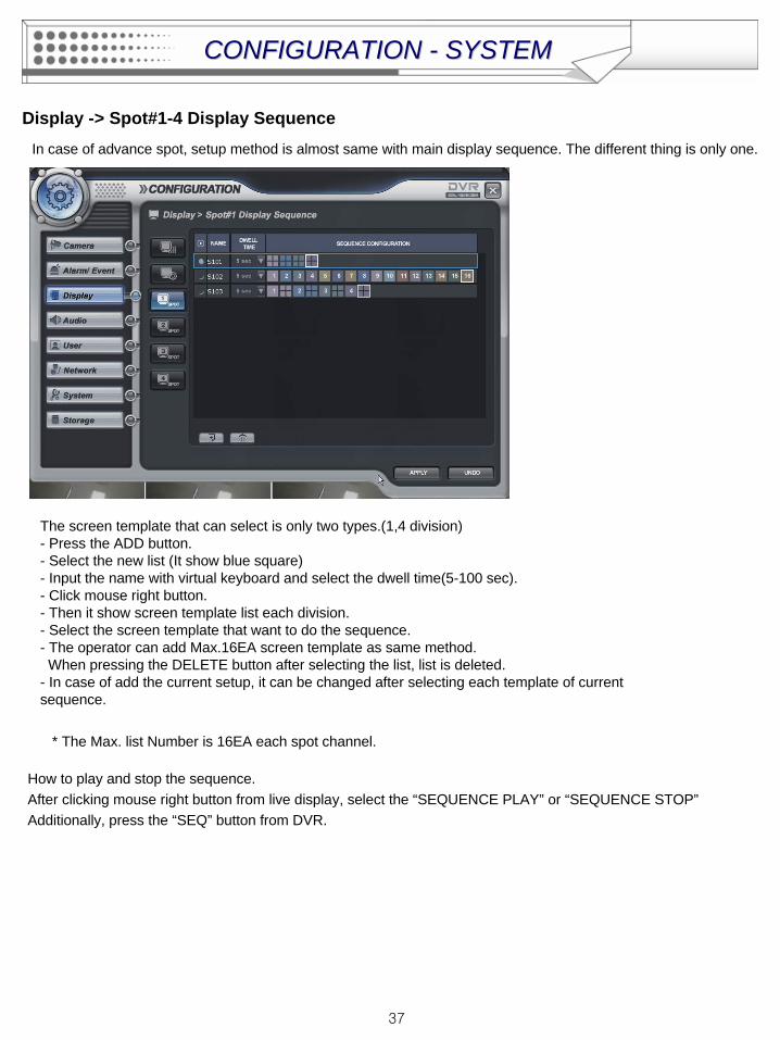
Display -> Spot#1-4 Display Sequence
The screen template that can select is only two types.(1,4 division)- Press the ADD button.- Select the new list (It show blue square) - Input the name with virtual keyboard and select the dwell time(5-100 sec).- Click mouse right button. - Then it show screen template list each division.- Select the screen template that want to do the sequence.- The operator can add Max.16EA screen template as same method.When pressing the DELETE button after selecting the list, list is deleted.
- In case of add the current setup, it can be changed after selecting each template of current sequence.
* The Max. list Number is 16EA each spot channel.
In case of advance spot, setup method is almost same with main display sequence. The different thing is only one.
How to play and stop the sequence. After clicking mouse right button from live display, select the “SEQUENCE PLAY” or “SEQUENCE STOP”Additionally, press the “SEQ” button from DVR.
CONFIGURATION CONFIGURATION -- SYSTEMSYSTEM
38
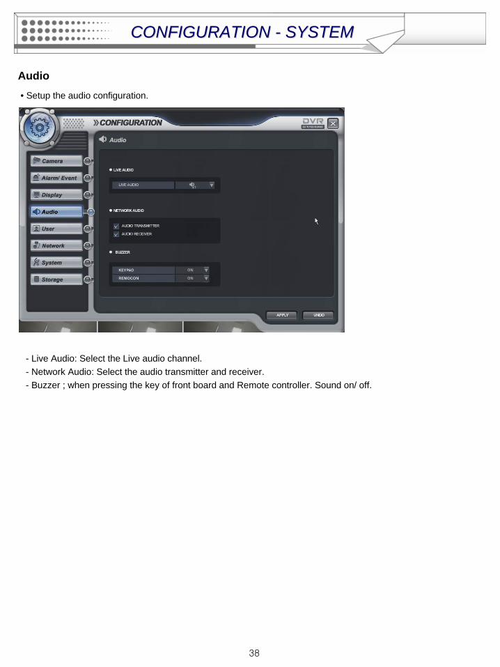
Audio• Setup the audio configuration.
- Live Audio: Select the Live audio channel.- Network Audio: Select the audio transmitter and receiver.- Buzzer ; when pressing the key of front board and Remote controller. Sound on/ off.
CONFIGURATION CONFIGURATION -- SYSTEMSYSTEM

39
User -> User group
Default user group (administrator, manager, user) can not be delete or edit.
After selecting “ADD” button, the operator can make the new user group with new authority.
When selecting “ ADD” button, it show “add group” screen.It shows the virtual keyboard when click mouse left button double for inputting the text.
After inputting the new group ID and description, click the “ok”.
Then select the User group ID.(It shows blue square).
Select the group authority and click “Apply” icon.
ADD button: Please add new group.
DELETE button: Delete user group.
EDIT button: Edit user group.
CONFIGURATION CONFIGURATION -- SYSTEMSYSTEM
40
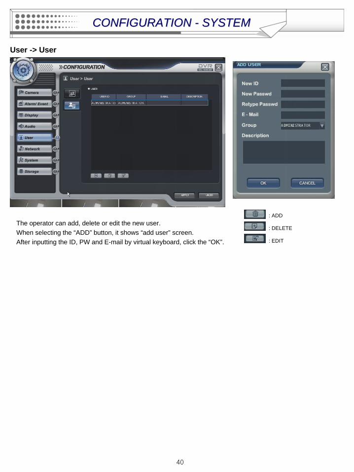
User -> User
The operator can add, delete or edit the new user.When selecting the “ADD” button, it shows “add user” screen.After inputting the ID, PW and E-mail by virtual keyboard, click the “OK”.
: ADD
: DELETE
: EDIT
CONFIGURATION CONFIGURATION -- SYSTEMSYSTEM
41
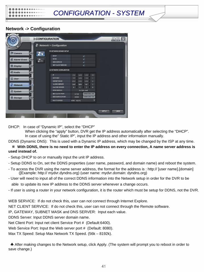
Network -> Configuration
DHCP: In case of “Dynamic IP”, select the “DHCP” When clicking the “apply” button, DVR get the IP address automatically after selecting the “DHCP”. In case of using the” Static IP”, input the IP address and other information manually.
DDNS (Dynamic DNS): This is used with a Dynamic IP address, which may be changed by the ISP at any time. ※
With DDNS, there is no need to enter the IP address on every connection, A name server address is used instead of.- Setup DHCP to on or manually input the unit IP address.- Setup DDNS to On, set the DDNS properties (user name, password, and domain name) and reboot the system. - To access the DVR using the name server address, the format for the address is : http:// [user name].[domain]
([Example: http:// mydvr.dyndns.org) (user name: mydvr.domain: dyndns.org)- User will need to input all of the correct DDNS information into the Network setup in order for the DVR to be
able to update its new IP address to the DDNS server whenever a change occurs. - If user is using a router in your network configuration, it is the router which must be setup for DDNS, not the DVR.
WEB SERVICE: If do not check this, user can not connect through Internet Explore.NET CLIENT SERVICE: If do not check this, user can not connect through the Remote software.IP, GATEWAY, SUBNET MASK and DNS SERVER: Input each value. DDNS Server: Input DDNS server domain name.Net Client Port: Input net client Service Port # (Default:6400).Web Service Port: Input the Web server port # (Default: 8080).Max TX Speed: Setup Max Network TX Speed. (56k – 8192k).
♣
After making changes to the Network setup, click Apply. (The system will prompt you to reboot in order to save change.)
CONFIGURATION CONFIGURATION -- SYSTEMSYSTEM
42
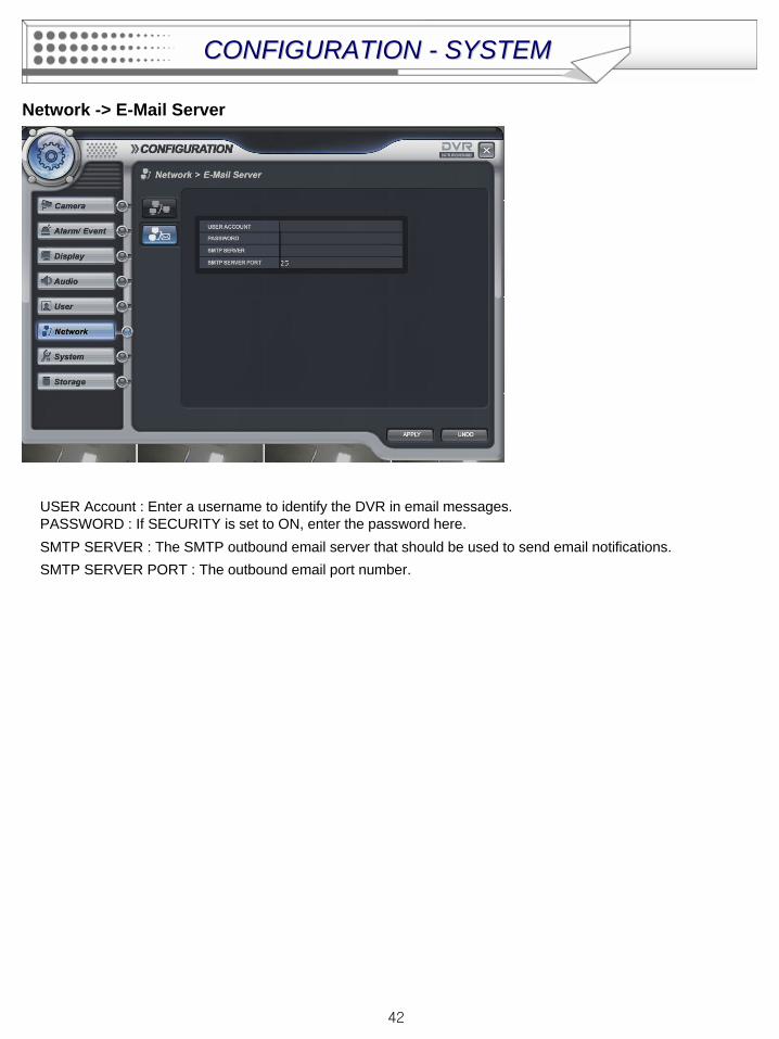
Network -> E-Mail Server
CONFIGURATION CONFIGURATION -- SYSTEMSYSTEM
USER Account : Enter a username to identify the DVR in email messages.PASSWORD : If SECURITY is set to ON, enter the password here.SMTP SERVER : The SMTP outbound email server that should be used to send email notifications.SMTP SERVER PORT : The outbound email port number.
43
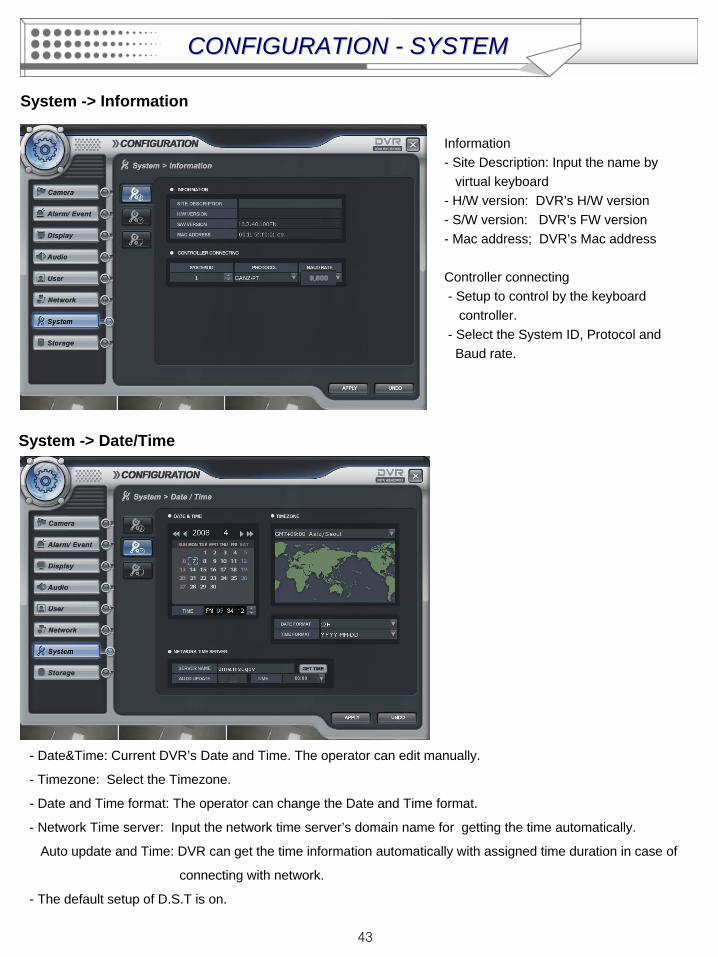
System -> Information
Information- Site Description: Input the name by
virtual keyboard- H/W version: DVR’s H/W version- S/W version: DVR’s FW version- Mac address; DVR’s Mac address
Controller connecting- Setup to control by the keyboard
controller.- Select the System ID, Protocol and Baud rate.
System -> Date/Time
- Date&Time: Current DVR’s Date and Time. The operator can edit manually.
- Timezone: Select the Timezone.
- Date and Time format: The operator can change the Date and Time format.
- Network Time server: Input the network time server’s domain name for getting the time automatically.
Auto update and Time: DVR can get the time information automatically with assigned time duration in case of
connecting with network.
- The default setup of D.S.T is on.
CONFIGURATION CONFIGURATION -- SYSTEMSYSTEM
44
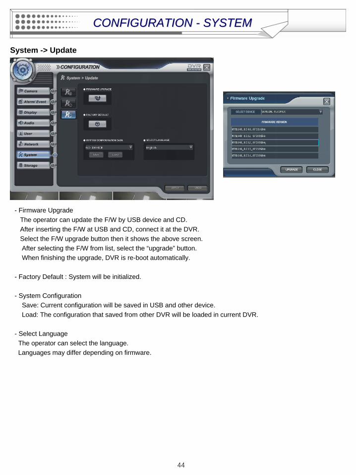
System -> Update
- Firmware Upgrade The operator can update the F/W by USB device and CD. After inserting the F/W at USB and CD, connect it at the DVR.Select the F/W upgrade button then it shows the above screen.After selecting the F/W from list, select the “upgrade” button.When finishing the upgrade, DVR is re-boot automatically.
- Factory Default : System will be initialized.
- System ConfigurationSave: Current configuration will be saved in USB and other device.Load: The configuration that saved from other DVR will be loaded in current DVR.
- Select LanguageThe operator can select the language.Languages may differ depending on firmware.
CONFIGURATION CONFIGURATION -- SYSTEMSYSTEM
45
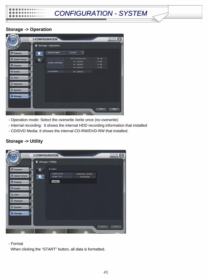
Storage -> Operation
- Operation mode: Select the overwrite /write once (no overwrite)- Internal recording: It shows the internal HDD recording information that installed - CD/DVD Media: It shows the internal CD-RW/DVD-RW that installed.
Storage -> Utility
- FormatWhen clicking the “START” button, all data is formatted.
CONFIGURATION CONFIGURATION -- SYSTEMSYSTEM
46
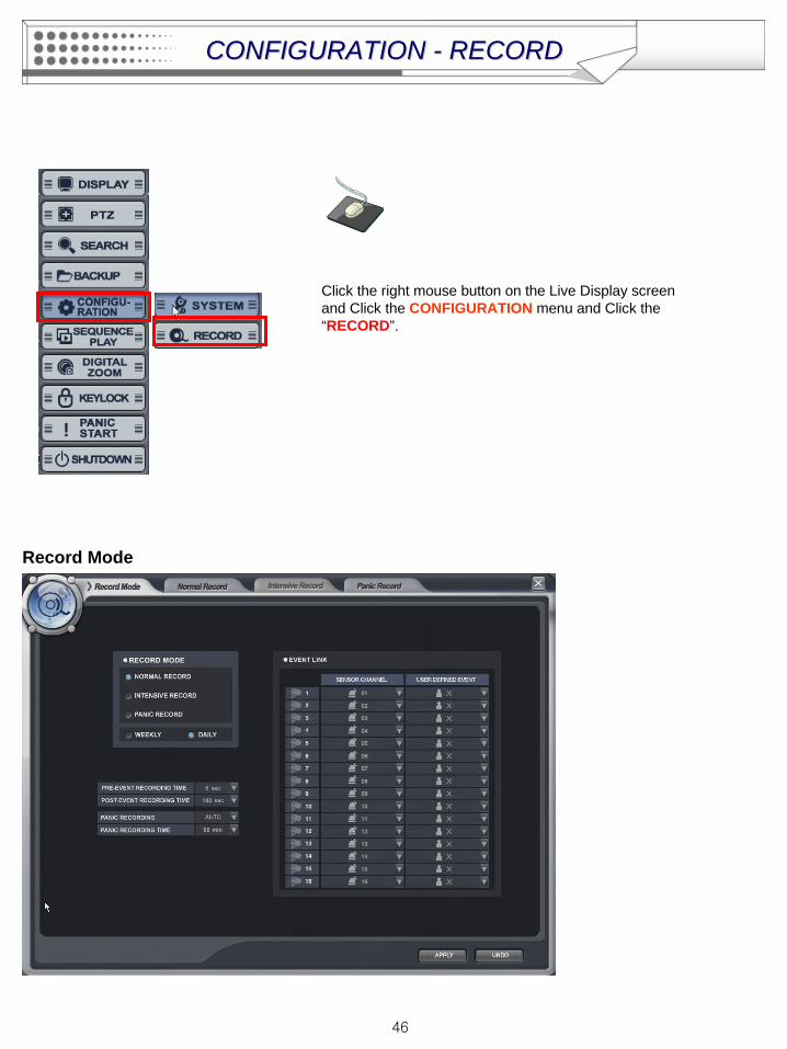
Click the right mouse button on the Live Display screen and Click the CONFIGURATION menu and Click the “RECORD”.
Record Mode
CONFIGURATION CONFIGURATION -- RECORDRECORD
47
- Record Mode
In case of selecting the “Normal Record” from record mode, The operator can not enter “Intensive Record”
setup.
Oppositely in case of selecting the “Intensive Record”, The operator can not enter “Normal Record” setup.
- Weekly/Daily
The operator can select the ‘Weekly” and “Daily” record setup from ‘Normal Record” and ‘Intensive Record”
setup.
So the DVR will record as daily and weekly setup configuration of “Normal and Intensive record” setup mode.
-Pre-Event Recording Time: When the DVR is not in continuous recording mode, this setting determines the
amount of footage that is always recorded before an event occurs. (motion
detection, alarm input etc.)
- Post- Event Recording Time : When the DVR is not in continuous recording mode, this setting determines the
amount of footage that is always recorded after an event occurs. (motion
detection, alarm input etc.)
- Panic Recording: Disable : Disables the Panic recording function
Manual: It works by pressing the Panic button from Remote controller or Front panel and sensor. Press the Panic button again to stop the panic recording.
Auto: After starting the panic recording, Panic recording will be stopped if assigned time is
passed automatically.
- Panic Recording Time: It is related with “Auto” option of Panic recording.
- Event Link: Select the sensor channel and user defined event each channel.
CONFIGURATION CONFIGURATION -- RECORDRECORD
48
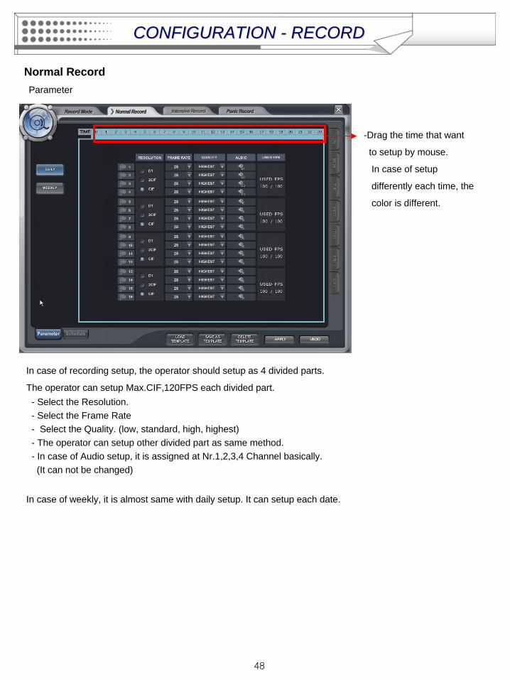
Normal RecordParameter
-Drag the time that want
to setup by mouse.
In case of setup
differently each time, the
color is different.
In case of recording setup, the operator should setup as 4 divided parts.
The operator can setup Max.CIF,120FPS each divided part.- Select the Resolution.- Select the Frame Rate- Select the Quality. (low, standard, high, highest)- The operator can setup other divided part as same method.- In case of Audio setup, it is assigned at Nr.1,2,3,4 Channel basically.(It can not be changed)
In case of weekly, it is almost same with daily setup. It can setup each date.
CONFIGURATION CONFIGURATION -- RECORDRECORD
49
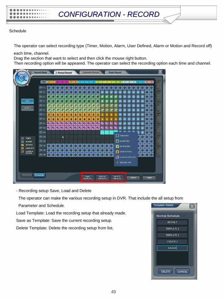
Schedule
The operator can select recording type (Timer, Motion, Alarm, User Defined, Alarm or Motion and Record off)
each time, channel.Drag the section that want to select and then click the mouse right button.Then recording option will be appeared. The operator can select the recording option each time and channel.
- Recording setup Save, Load and Delete
The operator can make the various recording setup in DVR. That include the all setup from
Parameter and Schedule.
Load Template: Load the recording setup that already made.
Save as Template: Save the current recording setup.
Delete Template: Delete the recording setup from list.
CONFIGURATION CONFIGURATION -- RECORDRECORD
50
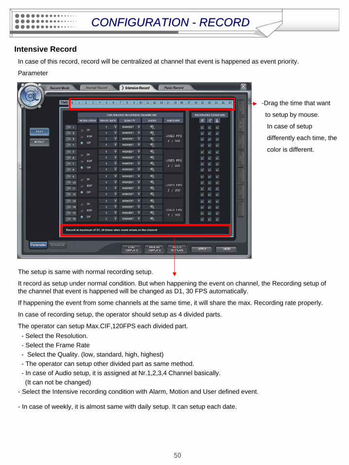
Intensive RecordIn case of this record, record will be centralized at channel that event is happened as event priority.
Parameter
-Drag the time that want
to setup by mouse.
In case of setup
differently each time, the
color is different.
The setup is same with normal recording setup.
It record as setup under normal condition. But when happening the event on channel, the Recording setup of the channel that event is happened will be changed as D1, 30 FPS automatically.
If happening the event from some channels at the same time, it will share the max. Recording rate properly.
In case of recording setup, the operator should setup as 4 divided parts.
The operator can setup Max.CIF,120FPS each divided part.- Select the Resolution.- Select the Frame Rate- Select the Quality. (low, standard, high, highest)- The operator can setup other divided part as same method.- In case of Audio setup, it is assigned at Nr.1,2,3,4 Channel basically.(It can not be changed)
- Select the Intensive recording condition with Alarm, Motion and User defined event.
- In case of weekly, it is almost same with daily setup. It can setup each date.
CONFIGURATION CONFIGURATION -- RECORDRECORD
51
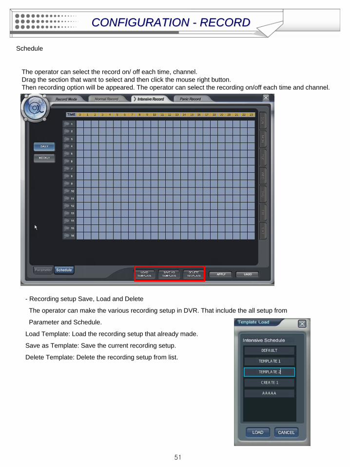
Schedule
The operator can select the record on/ off each time, channel.Drag the section that want to select and then click the mouse right button.Then recording option will be appeared. The operator can select the recording on/off each time and channel.
- Recording setup Save, Load and Delete
The operator can make the various recording setup in DVR. That include the all setup from
Parameter and Schedule.
Load Template: Load the recording setup that already made.
Save as Template: Save the current recording setup.
Delete Template: Delete the recording setup from list.
CONFIGURATION CONFIGURATION -- RECORDRECORD
52
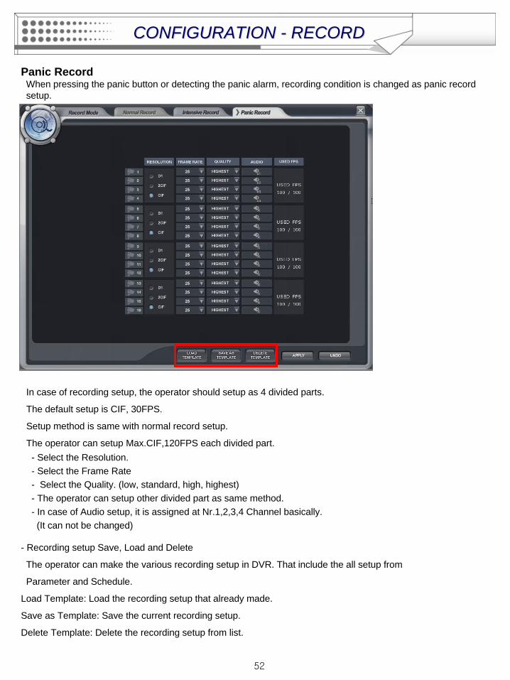
Panic RecordWhen pressing the panic button or detecting the panic alarm, recording condition is changed as panic record setup.
In case of recording setup, the operator should setup as 4 divided parts.
The default setup is CIF, 30FPS.
Setup method is same with normal record setup.
The operator can setup Max.CIF,120FPS each divided part.- Select the Resolution.- Select the Frame Rate- Select the Quality. (low, standard, high, highest)- The operator can setup other divided part as same method.- In case of Audio setup, it is assigned at Nr.1,2,3,4 Channel basically.(It can not be changed)
- Recording setup Save, Load and Delete
The operator can make the various recording setup in DVR. That include the all setup from
Parameter and Schedule.
Load Template: Load the recording setup that already made.
Save as Template: Save the current recording setup.
Delete Template: Delete the recording setup from list.
CONFIGURATION CONFIGURATION -- RECORDRECORD

53
Click the right mouse button on the Live Display screen and Click the “SEQUENCE PLAY” and “SEQUENCE STOP”.
• Select the “SEQUENCE PLAY” icon and press the “SEQ” button.Then it shows installed sequence display. (Sequence Play/Stop).It is related with “Display -> Main Display Sequence“.Please setup the Main Display Sequence firstly.
SEQUENCESEQUENCE
54
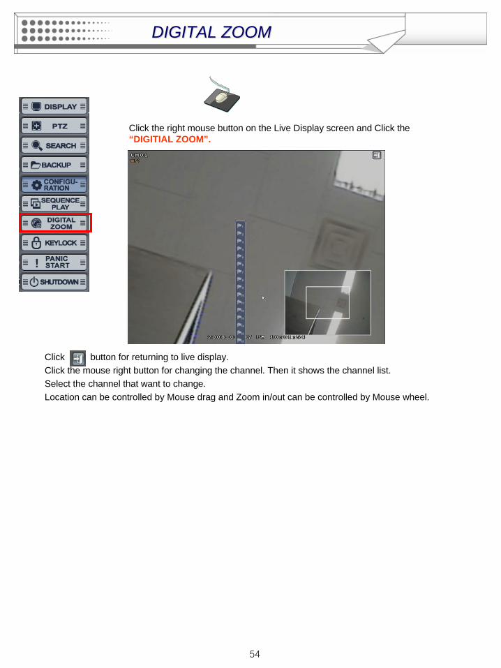
Click the right mouse button on the Live Display screen and Click the “DIGITIAL ZOOM”.
Click button for returning to live display.Click the mouse right button for changing the channel. Then it shows the channel list.Select the channel that want to change.Location can be controlled by Mouse drag and Zoom in/out can be controlled by Mouse wheel.
DIGITAL ZOOMDIGITAL ZOOM
55
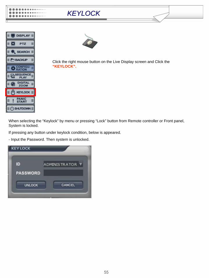
Click the right mouse button on the Live Display screen and Click the “KEYLOCK”.
When selecting the “Keylock” by menu or pressing “Lock” button from Remote controller or Front panel, System is locked.
If pressing any button under keylock condition, below is appeared.
- Input the Password. Then system is unlocked.
KEYLOCKKEYLOCK
56
Click the right mouse button on the Live Display screen and Click the “PANIC START/STOP”.
When Pressing the “PANIC START”, it start panic record.
Please press the “PANIC STOP” after stopping the panic record.
PANICPANIC
57
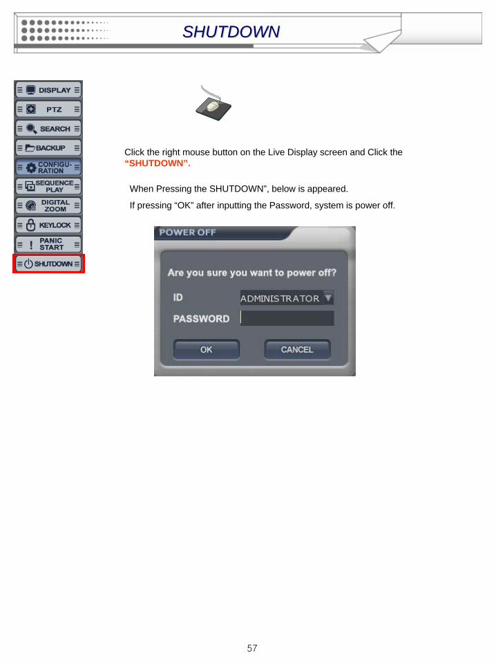
Click the right mouse button on the Live Display screen and Click the “SHUTDOWN”.
When Pressing the SHUTDOWN”, below is appeared.
If pressing “OK” after inputting the Password, system is power off.
SHUTDOWNSHUTDOWN
58
System Requirement
REMOTE SW INSTALLATION
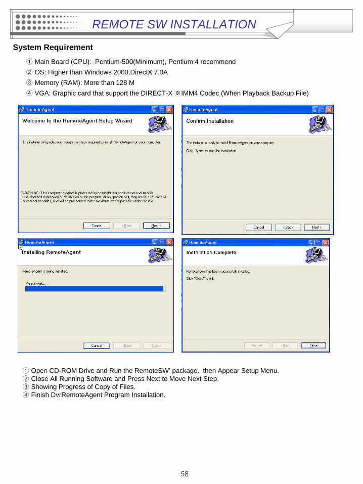
① Main Board (CPU): Pentium-500(Minimum), Pentium 4 recommend② OS: Higher than Windows 2000,DirectX 7.0A③ Memory (RAM): More than 128 M ④ VGA: Graphic card that support the DIRECT-X ※IMM4 Codec (When Playback Backup File)
① Open CD-ROM Drive and Run the RemoteSW’ package. then Appear Setup Menu.② Close All Running Software and Press Next to Move Next Step. ③ Showing Progress of Copy of Files. ④ Finish DvrRemoteAgent Program Installation.
59
Introduction
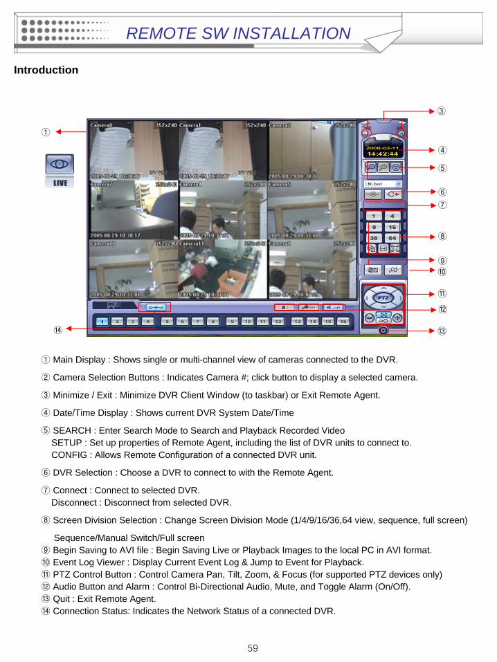
① Main Display : Shows single or multi-channel view of cameras connected to the DVR.
② Camera Selection Buttons : Indicates Camera #; click button to display a selected camera.
③ Minimize / Exit : Minimize DVR Client Window (to taskbar) or Exit Remote Agent.
④ Date/Time Display : Shows current DVR System Date/Time
⑤ SEARCH : Enter Search Mode to Search and Playback Recorded Video SETUP : Set up properties of Remote Agent, including the list of DVR units to connect to. CONFIG : Allows Remote Configuration of a connected DVR unit.
⑥ DVR Selection : Choose a DVR to connect to with the Remote Agent.
⑦ Connect : Connect to selected DVR. Disconnect : Disconnect from selected DVR.
⑧ Screen Division Selection : Change Screen Division Mode (1/4/9/16/36,64 view, sequence, full screen)
Sequence/Manual Switch/Full screen⑨ Begin Saving to AVI file : Begin Saving Live or Playback Images to the local PC in AVI format.⑩ Event Log Viewer : Display Current Event Log & Jump to Event for Playback.⑪ PTZ Control Button : Control Camera Pan, Tilt, Zoom, & Focus (for supported PTZ devices only)⑫ Audio Button and Alarm : Control Bi-Directional Audio, Mute, and Toggle Alarm (On/Off).⑬ Quit : Exit Remote Agent.⑭ Connection Status: Indicates the Network Status of a connected DVR.
③
⑤
④
⑥
⑦
⑧
⑪
⑨⑩
⑫
①
⑭ ⑬
REMOTE SW INSTALLATION
60
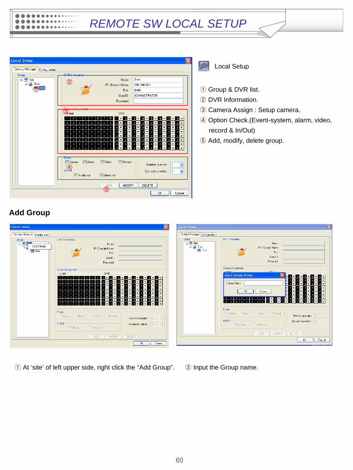
Local Setup
①
②
③
④
⑤
① Group & DVR list.② DVR Information.③ Camera Assign : Setup camera.④ Option Check.(Event-system, alarm, video,
record & In/Out)⑤ Add, modify, delete group.
Add Group
① At ‘site’ of left upper side, right click the “Add Group”. ② Input the Group name.
REMOTE SW LOCAL SETUP
61
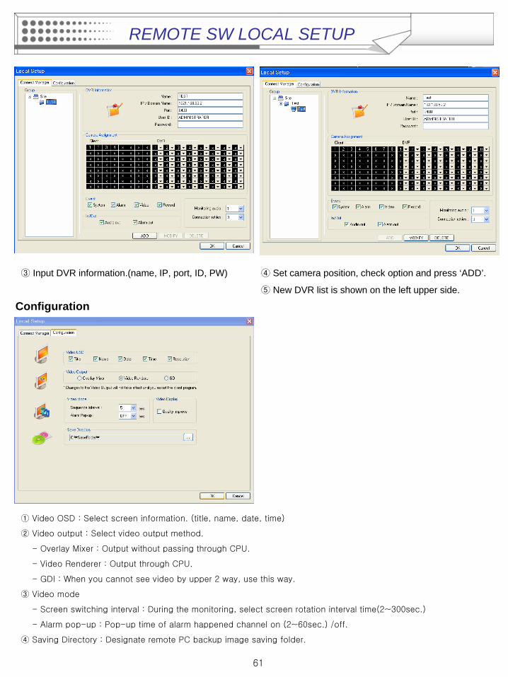
③ Input DVR information.(name, IP, port, ID, PW) ④ Set camera position, check option and press ‘ADD’.
⑤ New DVR list is shown on the left upper side.
Configuration
①
Video OSD : Select screen information. (title, name, date, time)
②
Video output : Select video output method.
-
Overlay Mixer : Output without passing through CPU.
-
Video Renderer
: Output through CPU.
-
GDI : When you cannot see video by upper 2 way, use this way.
③ Video mode
-
Screen switching interval : During the monitoring, select screen rotation interval time(2~300sec.)
-
Alarm pop-up : Pop-up time of alarm happened channel on (2~60sec.) /off.
④
Saving Directory : Designate remote PC backup image saving folder.
REMOTE SW LOCAL SETUP
62
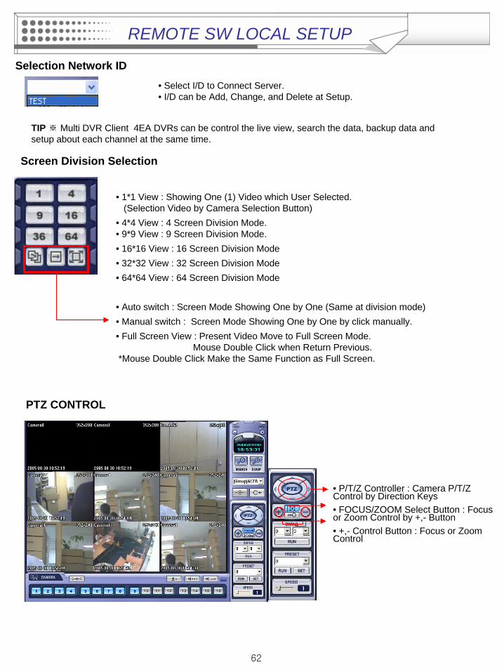
• Select I/D to Connect Server. • I/D can be Add, Change, and Delete at Setup.
• 1*1 View : Showing One (1) Video which User Selected. (Selection Video by Camera Selection Button)
• 4*4 View : 4 Screen Division Mode. • 9*9 View : 9 Screen Division Mode. • 16*16 View : 16 Screen Division Mode• 32*32 View : 32 Screen Division Mode• 64*64 View : 64 Screen Division Mode
• Auto switch : Screen Mode Showing One by One (Same at division mode)• Manual switch : Screen Mode Showing One by One by click manually.• Full Screen View : Present Video Move to Full Screen Mode.
Mouse Double Click when Return Previous. *Mouse Double Click Make the Same Function as Full Screen.
TIP ※ Multi DVR Client 4EA DVRs can be control the live view, search the data, backup data and setup about each channel at the same time.
Selection Network ID
Screen Division Selection
• P/T/Z Controller : Camera P/T/Z Control by Direction Keys• FOCUS/ZOOM Select Button : Focus or Zoom Control by +,- Button• +,- Control Button : Focus or Zoom Control
PTZ CONTROL
REMOTE SW LOCAL SETUP
63
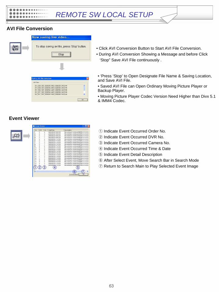
AVI File Conversion
• Click AVI Conversion Button to Start AVI File Conversion.• During AVI Conversion Showing a Message and before Click
‘Stop” Save AVI File continuously .
• ‘Press ‘Stop’ to Open Designate File Name & Saving Location, and Save AVI File.• Saved AVI File can Open Ordinary Moving Picture Player or Backup Player.• Moving Picture Player Codec Version Need Higher than Divx 5.1 & IMM4 Codec.
① Indicate Event Occurred Order No.② Indicate Event Occurred DVR No.③ Indicate Event Occurred Camera No. ④ Indicate Event Occurred Time & Date⑤ Indicate Event Detail Description⑥ After Select Event, Move Search Bar in Search Mode ⑦ Return to Search Main to Play Selected Event Image ①②③ ④ ⑤
⑥ ⑦
Event Viewer
REMOTE SW LOCAL SETUP
64
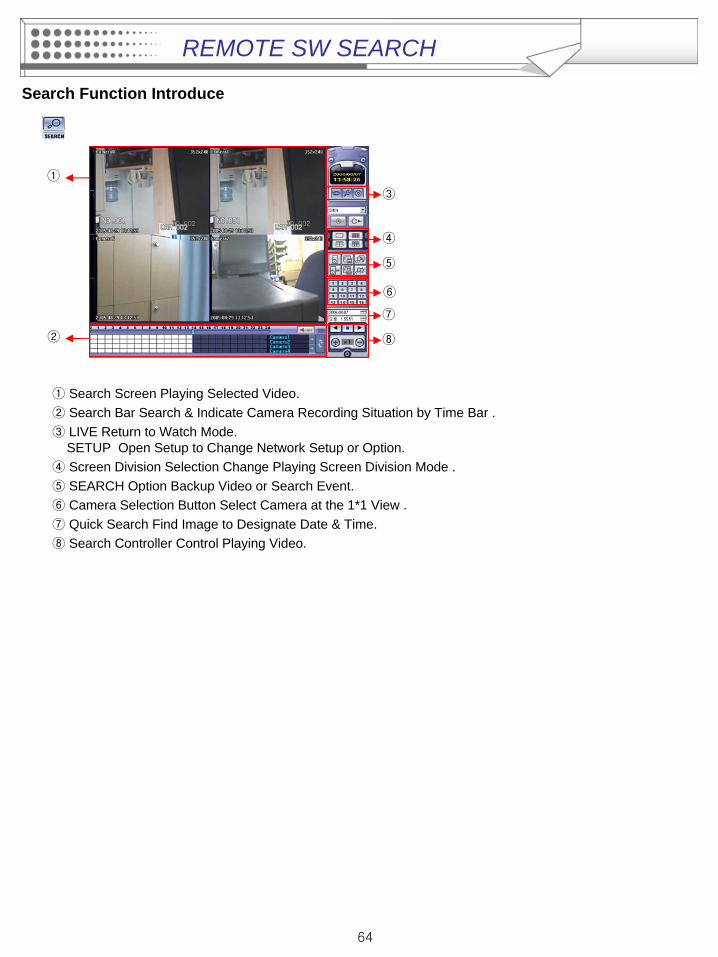
Search Function Introduce
① Search Screen Playing Selected Video.② Search Bar Search & Indicate Camera Recording Situation by Time Bar .③ LIVE Return to Watch Mode.
SETUP Open Setup to Change Network Setup or Option.④ Screen Division Selection Change Playing Screen Division Mode .⑤ SEARCH Option Backup Video or Search Event.⑥ Camera Selection Button Select Camera at the 1*1 View .⑦ Quick Search Find Image to Designate Date & Time.⑧ Search Controller Control Playing Video.
③
④
⑥
⑦
⑧②
⑤
①
REMOTE SW SEARCH
65
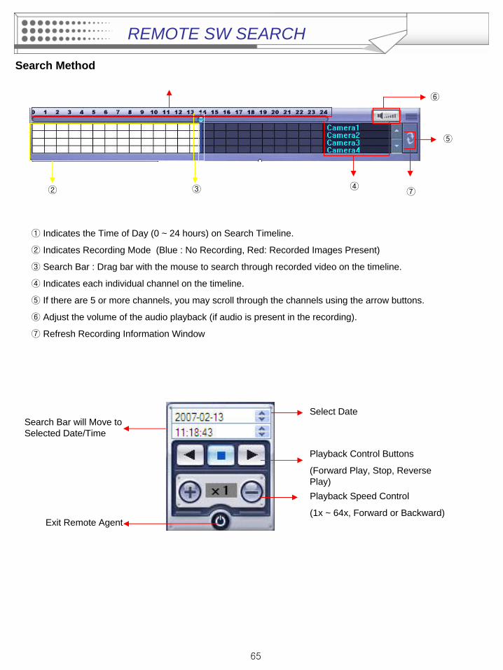
Search Method
② ③ ④
⑤
⑥
⑦
① Indicates the Time of Day (0 ~ 24 hours) on Search Timeline.
② Indicates Recording Mode (Blue : No Recording, Red: Recorded Images Present)
③ Search Bar : Drag bar with the mouse to search through recorded video on the timeline.
④ Indicates each individual channel on the timeline.
⑤ If there are 5 or more channels, you may scroll through the channels using the arrow buttons.
⑥ Adjust the volume of the audio playback (if audio is present in the recording).
⑦ Refresh Recording Information Window
Select DateSearch Bar will Move to Selected Date/Time
Playback Control Buttons
(Forward Play, Stop, Reverse Play)Playback Speed Control
(1x ~ 64x, Forward or Backward)Exit Remote Agent
REMOTE SW SEARCH
66
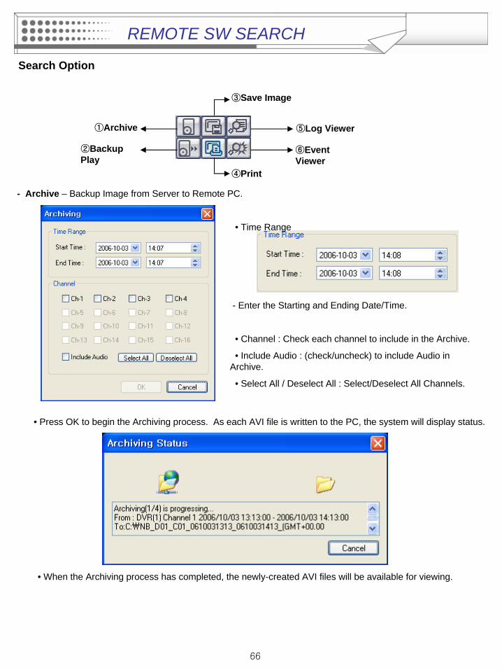
Search Option
①Archive
②Backup Play
⑤Log Viewer
⑥Event Viewer
③Save Image
④Print
- Archive – Backup Image from Server to Remote PC.
• Time Range
- Enter the Starting and Ending Date/Time.
• Channel : Check each channel to include in the Archive.
• Include Audio : (check/uncheck) to include Audio in Archive.
• Select All / Deselect All : Select/Deselect All Channels.
• Press OK to begin the Archiving process. As each AVI file is written to the PC, the system will display status.
• When the Archiving process has completed, the newly-created AVI files will be available for viewing.
REMOTE SW SEARCH
67
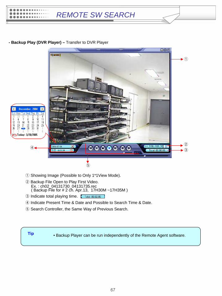
- Backup Play (DVR Player) – Transfer to DVR Player
①
②
③
⑤
④
• Backup Player can be run independently of the Remote Agent software.Tip
① Showing Image (Possible to Only 1*1View Mode).② Backup File Open to Play First Video.
Ex. : ch02_04131730_04131735.rec( Backup File for # 2 ch. Apr.13, 17H30M ~17H35M )
③ Indicate total playing time.④ Indicate Present Time & Date and Possible to Search Time & Date.⑤ Search Controller, the Same Way of Previous Search.
REMOTE SW SEARCH
68
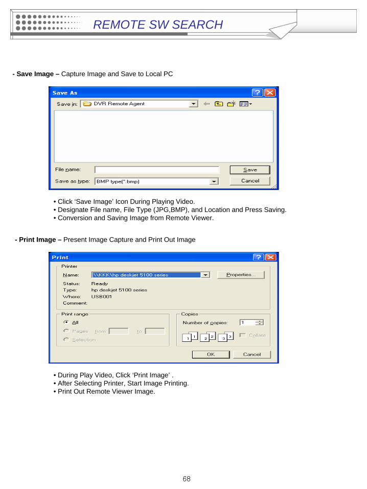
- Save Image – Capture Image and Save to Local PC
• Click ‘Save Image’ Icon During Playing Video.• Designate File name, File Type (JPG,BMP), and Location and Press Saving.• Conversion and Saving Image from Remote Viewer.
- Print Image – Present Image Capture and Print Out Image
• During Play Video, Click ‘Print Image’ .• After Selecting Printer, Start Image Printing.• Print Out Remote Viewer Image.
REMOTE SW SEARCH
69
①②
③ ④ ⑤ ⑥
⑦ ⑧ ⑨ ⑩ ⑪
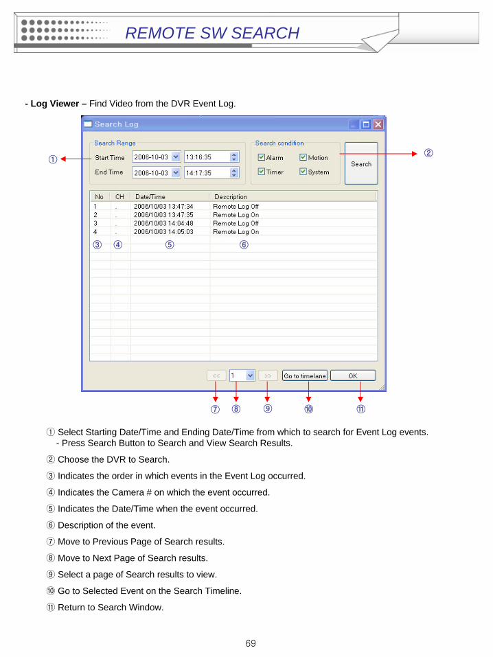
- Log Viewer – Find Video from the DVR Event Log.
① Select Starting Date/Time and Ending Date/Time from which to search for Event Log events. - Press Search Button to Search and View Search Results.
② Choose the DVR to Search.
③ Indicates the order in which events in the Event Log occurred.
④ Indicates the Camera # on which the event occurred.
⑤ Indicates the Date/Time when the event occurred.
⑥ Description of the event.
⑦ Move to Previous Page of Search results.
⑧ Move to Next Page of Search results.
⑨ Select a page of Search results to view.
⑩ Go to Selected Event on the Search Timeline.
⑪ Return to Search Window.
REMOTE SW SEARCH
70
① ② ③ ④ ⑤
⑥
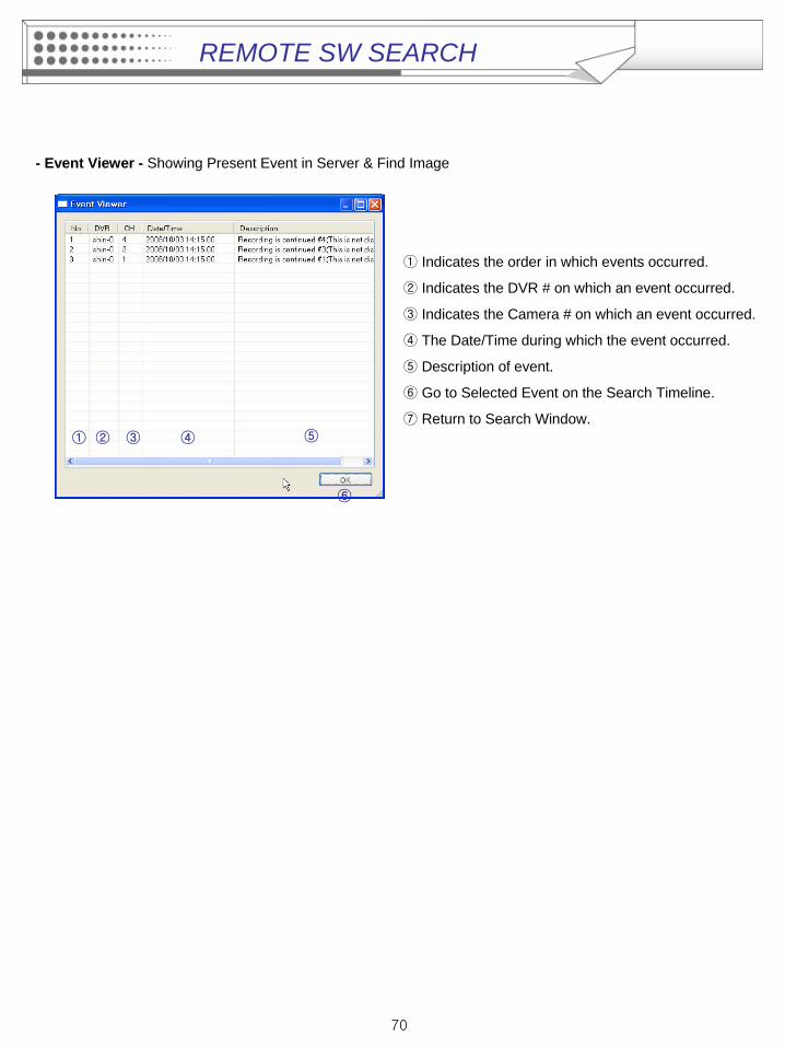
- Event Viewer - Showing Present Event in Server & Find Image
① Indicates the order in which events occurred.
② Indicates the DVR # on which an event occurred.
③ Indicates the Camera # on which an event occurred.
④ The Date/Time during which the event occurred.
⑤ Description of event.
⑥ Go to Selected Event on the Search Timeline.
⑦ Return to Search Window.
REMOTE SW SEARCH
71
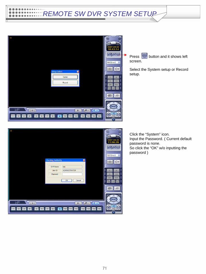
Select the System setup or Record setup.
Press button and it shows left screen.
Click the “System” icon.Input the Password. ( Current default password is none.So click the “OK” w/o inputting the password )
REMOTE SW DVR SYSTEM SETUP
72
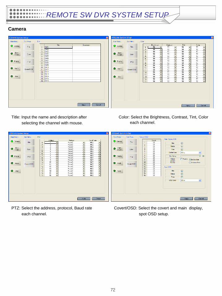
Camera
Title: Input the name and description after selecting the channel with mouse.
Color: Select the Brightness, Contrast, Tint, Color each channel.
PTZ: Select the address, protocol, Baud rate each channel.
Covert/OSD: Select the covert and main display, spot OSD setup.
REMOTE SW DVR SYSTEM SETUP
73
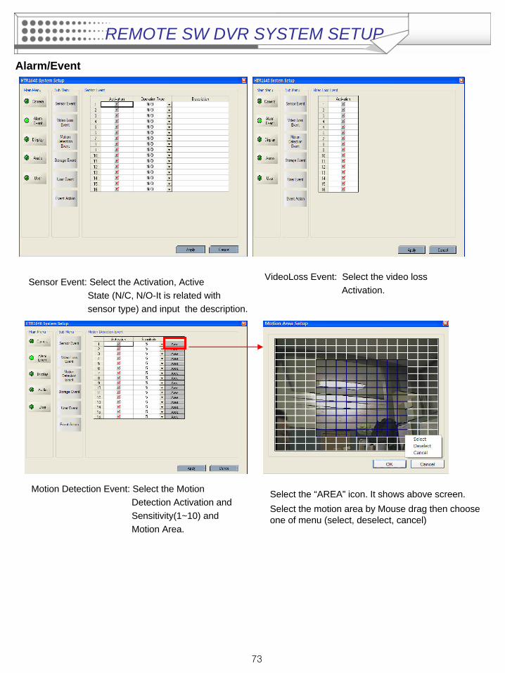
Alarm/Event
Sensor Event: Select the Activation, Active State (N/C, N/O-It is related with sensor type) and input the description.
VideoLoss Event: Select the video loss Activation.
Motion Detection Event: Select the Motion Detection Activation and Sensitivity(1~10) and Motion Area.
Select the “AREA” icon. It shows above screen.Select the motion area by Mouse drag then choose one of menu (select, deselect, cancel)
REMOTE SW DVR SYSTEM SETUP
74
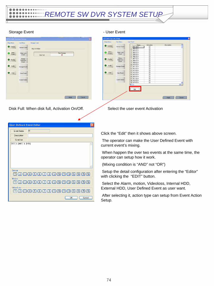
Disk Full: When disk full, Activation On/Off.
Storage Event
Select the user event Activation
- User Event
Click the “Edit” then it shows above screen.
The operator can make the User Defined Event with current event’s mixing.
When happen the over two events at the same time, the operator can setup how it work.
(Mixing condition is “AND” not “OR”)
Setup the detail configuration after entering the “Editor” with clicking the “EDIT” button.
Select the Alarm, motion, Videoloss, Internal HDD, External HDD, User Defined Event as user want.
After selecting it, action type can setup from Event Action Setup.
REMOTE SW DVR SYSTEM SETUP
75
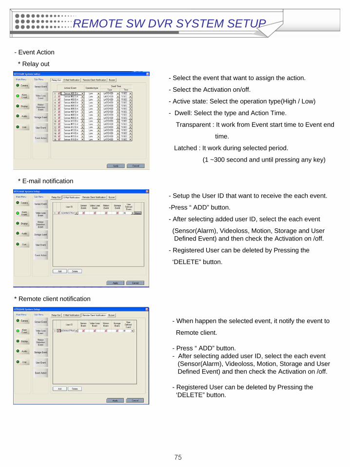
- Event Action
* Relay out
* E-mail notification
- Setup the User ID that want to receive the each event.
-Press “ ADD” button.
- After selecting added user ID, select the each event
(Sensor(Alarm), Videoloss, Motion, Storage and User Defined Event) and then check the Activation on /off.
- Registered User can be deleted by Pressing the
‘DELETE” button.
- Select the event that want to assign the action.
- Select the Activation on/off.
- Active state: Select the operation type(High / Low)
- Dwell: Select the type and Action Time.
Transparent : It work from Event start time to Event end
time.
Latched : It work during selected period.
(1 ~300 second and until pressing any key)
* Remote client notification
- When happen the selected event, it notify the event to
Remote client.
- Press “ ADD” button.- After selecting added user ID, select the each event
(Sensor(Alarm), Videoloss, Motion, Storage and User Defined Event) and then check the Activation on /off.
- Registered User can be deleted by Pressing the ‘DELETE” button.
REMOTE SW DVR SYSTEM SETUP
76
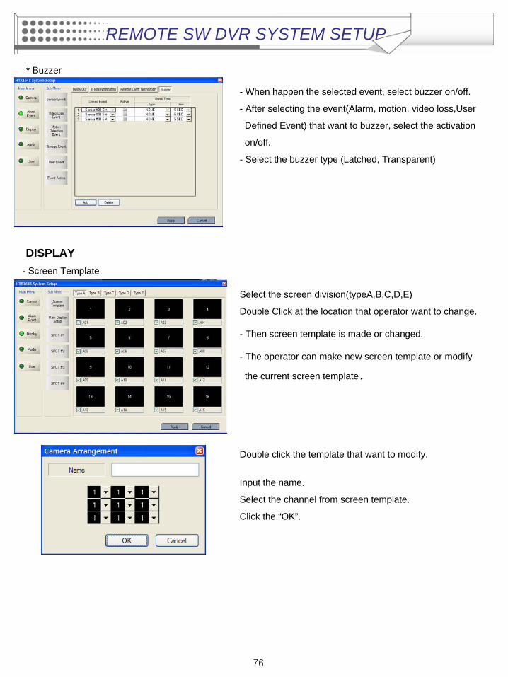
* Buzzer
- When happen the selected event, select buzzer on/off.
- After selecting the event(Alarm, motion, video loss,User
Defined Event) that want to buzzer, select the activation
on/off.
- Select the buzzer type (Latched, Transparent)
DISPLAY- Screen Template
Select the screen division(typeA,B,C,D,E)
Double Click at the location that operator want to change.
- Then screen template is made or changed.
- The operator can make new screen template or modify
the current screen template.
Double click the template that want to modify.
Input the name.
Select the channel from screen template.
Click the “OK”.
REMOTE SW DVR SYSTEM SETUP
77
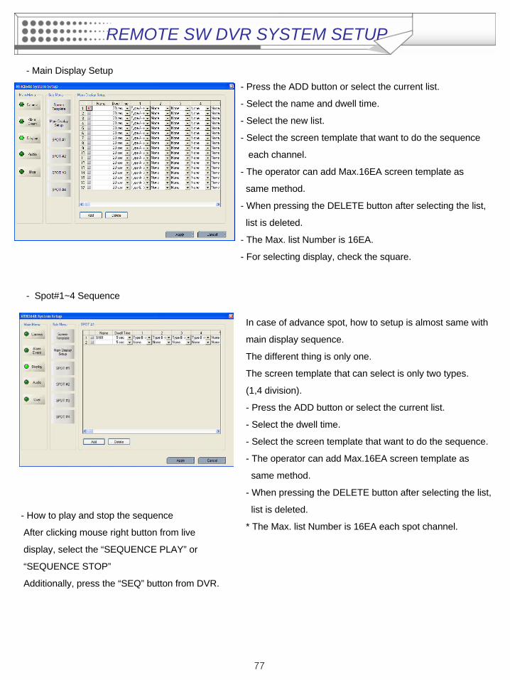
- Main Display Setup
- Press the ADD button or select the current list.
- Select the name and dwell time.
- Select the new list.
- Select the screen template that want to do the sequence
each channel.
- The operator can add Max.16EA screen template as
same method.
- When pressing the DELETE button after selecting the list,
list is deleted.
- The Max. list Number is 16EA.
- For selecting display, check the square.
- Spot#1~4 Sequence
In case of advance spot, how to setup is almost same with
main display sequence.
The different thing is only one.
The screen template that can select is only two types.
(1,4 division).
- Press the ADD button or select the current list.
- Select the dwell time.
- Select the screen template that want to do the sequence.
- The operator can add Max.16EA screen template as
same method.
- When pressing the DELETE button after selecting the list,
list is deleted.
* The Max. list Number is 16EA each spot channel.- How to play and stop the sequence
After clicking mouse right button from live
display, select the “SEQUENCE PLAY” or
“SEQUENCE STOP”
Additionally, press the “SEQ” button from DVR.
REMOTE SW DVR SYSTEM SETUP
78
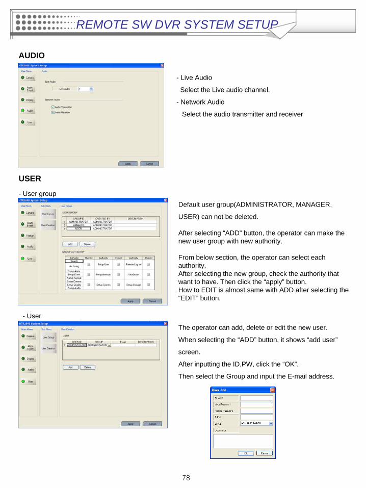
AUDIO
- Live Audio
Select the Live audio channel.
- Network Audio
Select the audio transmitter and receiver
USER
- User group
- User
Default user group(ADMINISTRATOR, MANAGER,
USER) can not be deleted.
After selecting “ADD” button, the operator can make the new user group with new authority.
From below section, the operator can select each authority. After selecting the new group, check the authority that want to have. Then click the “apply” button. How to EDIT is almost same with ADD after selecting the “EDIT” button.
The operator can add, delete or edit the new user.
When selecting the “ADD” button, it shows “add user”
screen.
After inputting the ID,PW, click the “OK”.
Then select the Group and input the E-mail address.
REMOTE SW DVR SYSTEM SETUP
79
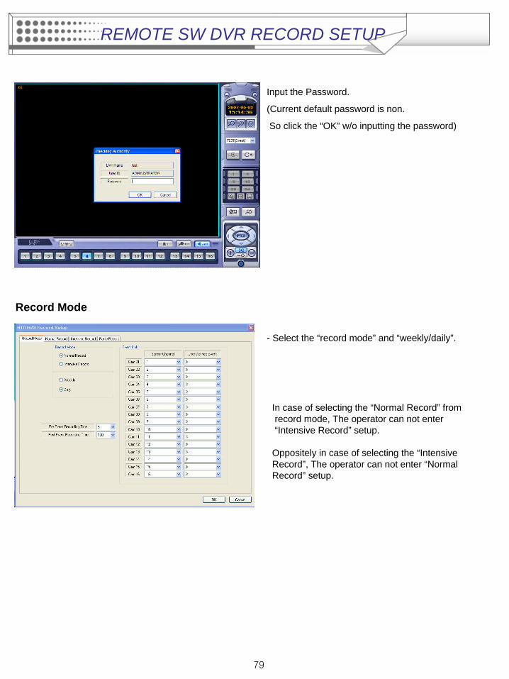
Input the Password.
(Current default password is non.
So click the “OK” w/o inputting the password)
Record Mode
- Select the “record mode” and “weekly/daily”.
In case of selecting the “Normal Record” from record mode, The operator can not enter “Intensive Record” setup.
Oppositely in case of selecting the “Intensive Record”, The operator can not enter “Normal Record” setup.
REMOTE SW DVR RECORD SETUP
80
- Weekly/DailyThe operator can select the ‘Weekly” and “Daily” record setup from ‘Normal Record” and ‘Intensive Record”setup.So the DVR will record as daily and weekly setup configuration of “Normal and Intensive record” setup mode.Pre-Event Recording Time: When the DVR is not in continuous recording mode, this setting determines the
amount of footage that is always recorded before an event occurs. (motion detection, alarm input etc.)
Post- Event Recording Time : When the DVR is not in continuous recording mode, this setting determines the amount of footage that is always recorded after an event occurs. (motion detection, alarm input etc.)
- Panic Recording: Disable : Not use the Panic recording functionManual: It work by pressing the Panic button from Remote controller or Front panel and
sensor. Press the Panic button again to stop the panic recording.Auto: After starting the panic recording, Panic recording will be stopped if assigned time is
passed automatically.- Panic Recording Time: It is related with “Auto” option of Panic recording.
- Event Link: Select the sensor channel and user defined event each channel.
REMOTE SW DVR RECORD SETUP

81
Normal Record- Select the Daily/Weekly.
- Select the Parameter/Schedule
- Click the “SET” icon. Then it shows above screen.In case of recording setup, the operator should setup as 4 divided parts.The operator can setup Max.CIF,120FPS each divided part.- Select the Resolution.- Select the Frame Rate- Select the Quality. (low, standard, high, highest)- The operator can setup other divided part as same method.- In case of Audio setup, it is assigned at Nr.1,2,3,4 Channel basically.(It can not be changed)
In case of weekly, it is almost same with daily setup.It can setup each date.
- Parameter
- Drag the time that want to setup by mouse. In case of setup differently each time, the color is different
REMOTE SW DVR RECORD SETUP

82
- Schedule
The operator can select recording type (Timer, Motion, Alarm, User Defined, Alarm or Motion and Record off) each time, channel.Drag the section that want to select and then click the mouse right button.Then recording option will be appeared. The operator can select the recording option each time and channel..
REMOTE SW DVR RECORD SETUP
83
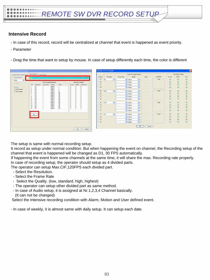
Intensive Record
- In case of this record, record will be centralized at channel that event is happened as event priority.
- Parameter
- Drag the time that want to setup by mouse. In case of setup differently each time, the color is different
The setup is same with normal recording setup.It record as setup under normal condition. But when happening the event on channel, the Recording setup of the channel that event is happened will be changed as D1, 30 FPS automatically.If happening the event from some channels at the same time, it will share the max. Recording rate properly.In case of recording setup, the operator should setup as 4 divided parts.The operator can setup Max.CIF,120FPS each divided part.- Select the Resolution.- Select the Frame Rate- Select the Quality. (low, standard, high, highest)- The operator can setup other divided part as same method.- In case of Audio setup, it is assigned at Nr.1,2,3,4 Channel basically.(It can not be changed)
Select the Intensive recording condition with Alarm, Motion and User defined event.
- In case of weekly, it is almost same with daily setup. It can setup each date.
REMOTE SW DVR RECORD SETUP
84
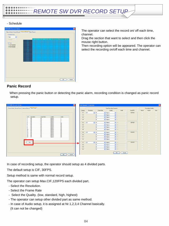
- Schedule
Panic Record
When pressing the panic button or detecting the panic alarm, recording condition is changed as panic record setup.
The operator can select the record on/ off each time, channel.Drag the section that want to select and then click the mouse right button.Then recording option will be appeared. The operator can select the recording on/off each time and channel.
In case of recording setup, the operator should setup as 4 divided parts.
The default setup is CIF, 30FPS.
Setup method is same with normal record setup.
The operator can setup Max.CIF,120FPS each divided part.- Select the Resolution.- Select the Frame Rate- Select the Quality. (low, standard, high, highest)- The operator can setup other divided part as same method.- In case of Audio setup, it is assigned at Nr.1,2,3,4 Channel basically.(It can not be changed)
REMOTE SW DVR RECORD SETUP