User Manual corpuls3 - Frank's Hospital Workshop User Manual corpuls3 viii ENG - Version 2.1 – P/N...
346
corpuls 3 User Manual
Transcript of User Manual corpuls3 - Frank's Hospital Workshop User Manual corpuls3 viii ENG - Version 2.1 – P/N...
corpuls3
User Manual

Contents User Manual corpuls3
ii ENG - Version 2.1 – P/N 04130.2

User Manual corpuls3 Contents
ENG - Version 2.1 – P/N 04130.2 iii
This user manual has been compiled to provide users with information necessary for safe and trouble-free operation, use on patients and maintenance of corpuls3. All persons dealing with use, maintenance and troubleshooting must read and implement this user manual. In addition to this user manual, the currently applicable ordinances and the generally accepted engineering principles as well as regulations for occupational health and safety and accident prevention must be complied with. The corpuls3 complies with the basic standards as specified in Annex I of the "Medical Device Directive 93/42/EC of the Commission". The corpuls3 is a medical product class IIb. In the UMDNS (Universal Medical Device Nomenclature System) the corpuls3 has the code 17-882.
GS Elektromedizinische Geräte
G. Stemple GmbH Hauswiesenstrasse 26 86916 Kaufering Germany
All rights reserved, particularly rights of reproduction and distribution, in addition to translation.
Technical modifications, errors or printing mistakes reserved.
The rights to the trademarks and registered trademarks remain with the originators and holders of the respective trademarks.
No part of the user manual may be reproduced, saved, processed, copied or circulated by means of electronic systems in any form whatsoever without the written agreement of GS Elektromedizinische Geräte G. Stemple GmbH.
Contents User Manual corpuls3
iv ENG - Version 2.1 – P/N 04130.2
Service address In case of enquiries, please contact:
Information on the authorised service and sales partners can also be found on the following website: www.corpuls.com
Address of the sales and service partner
User Manual corpuls3 Contents
ENG - Version 2.1 – P/N 04130.2 v
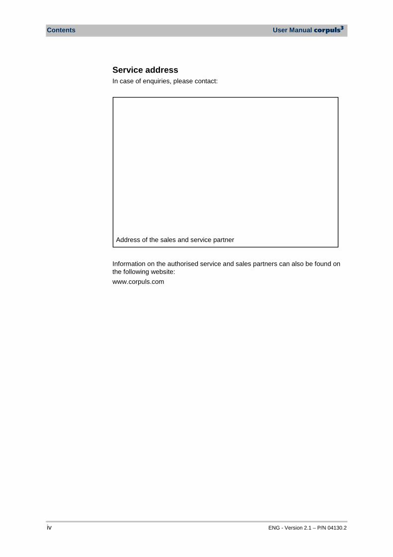
Versions of the corpuls3 user manual
Issue Date User manual version Software version
1 06/2007 ENG V1.1 – 04130.2 1.1.0
2 08/2007 ENG V1.2 – 04130.2 1.2.0
3 11/2007 ENG V1.3 – 04130.2 1.3.0
4 07/2008 ENG V1.4 – 04130.2 1.4.1
5 07/2009 ENG V1.5 – 04130.2 1.5.0
6 12/2009 ENG V1.6 – 04130.2 1.6.0
7 11/2010 ENG V1.7 – 04130.2 1.7.0
8 07/2011 ENG V1.8 – 04130.2 1.8.0
9 10/2011 ENG V1.9 – 04130.2 1.9.0
10 07/2012 ENG V2.0 – 04130.2 2.0.0
11 06/2013 ENG V2.1 – 04130.2 2.1.0
Versions of the supplements to the user manual corpuls3
Version Date Description Version user manual
Version Software
A 04/2010 Supplement of the alarm messages
EN V1.4 - 04130.2 EN V1.5 - 04130.2 EN V1.6 - 04130.2
1.4 1.5 1.6
A 06/2010 New Defibrillator Keyboard
EN V1.7 - 04130.2 1.7.0
A 03/2011 Interval Measurement NIBP
EN V1.7 - 04130.2 1.7.2
A 07/2011 NVG mode EN V1.8 – 04130.2 1.8.0

Contents User Manual corpuls3
vi ENG - Version 2.1 – P/N 04130.2
Contents
1 Safety ................................................................................................... 1 1.1 General ........................................................................................... 1 1.2 Operating Staff ................................................................................ 1
1.2.1 Restrictions of Therapeutic Functions ....................................... 1 1.2.2 Maintenance .............................................................................. 2
1.3 Information and Warning Labels on the Device .............................. 2 1.4 Warning Notices and Symbols ........................................................ 3 1.5 Special Types of Risk ..................................................................... 3
2 Intended Use ....................................................................................... 4
3 Introduction ........................................................................................ 6 3.1 Components .................................................................................... 6 3.2 Device Design ................................................................................. 8
3.2.1 Pairing (Connection Authorisation) .......................................... 10 3.2.2 Monitoring Unit ......................................................................... 12 3.2.3 Patient Box and Accessory Bag .............................................. 14 3.2.4 Defibrillator/Pacer .................................................................... 17 3.2.5 Defibrillator/Pacer SLIM ........................................................... 18 3.2.6 Brackets ................................................................................... 19
3.3 Description of the Monitoring, Diagnostic and Therapeutic Functions ....................................................................................... 20
3.3.1 Monitoring and Diagnostic Functions ....................................... 20 3.3.2 Therapeutic Functions ............................................................. 21
3.4 Alarm management ....................................................................... 23 3.4.1 Alarm Signals at the Monitoring unit ........................................ 24 3.4.2 Alarm Signals at the Patient box .............................................. 26
3.5 Energy Management ..................................................................... 27 3.5.1 Battery Operation ..................................................................... 27 3.5.2 Mains Operation ....................................................................... 29
4 General Operating Instructions ...................................................... 31 4.1 Operating and Display Elements .................................................. 31
4.1.1 Operating Elements and LEDs on the Monitoring Unit ............ 31 4.1.2 Basic Structure of the Display Pages on the
Monitoring Unit ......................................................................... 35 4.1.3 Patient Box Display .................................................................. 39 4.1.4 Control Keys and LEDs on the Patient Box ............................. 40 4.1.5 Control Key and LEDs on the Defibrillator/Pacer .................... 41 4.1.6 Control Key and LEDs on the Defibrillator/Pacer SLIM ........... 42
4.2 Switching On and Off .................................................................... 43 4.2.1 Switching On ............................................................................ 43 4.2.2 Switching Off ............................................................................ 44

User Manual corpuls3 Contents
ENG - Version 2.1 – P/N 04130.2 vii
4.3 Menu Control ................................................................................. 46 4.3.1 Softkey Context Menu.............................................................. 46 4.3.2 Parameter Context Menu and Curve Context Menu ............... 47 4.3.3 Main Menu ............................................................................... 49 4.3.4 Configuration Dialogue ............................................................ 50
4.4 Disconnecting and Connecting Modules ...................................... 51 4.4.1 Disconnecting the Monitoring Unit from the
Defibrillator/Pacer .................................................................... 51 4.4.2 Disconnecting the Patient Box from the Monitoring
Unit ........................................................................................... 52 4.4.3 Connecting the Patient Box to the Monitoring Unit .................. 53 4.4.4 Connecting the Monitoring Unit to the
Defibrillator/Pacer .................................................................... 54 4.4.5 Removing the Patient Box from the Compact Device ............. 55
4.5 Accessory Bag .............................................................................. 56 4.5.1 Fitting the Accessory Bag ........................................................ 56 4.5.2 Packing the Accessory Bag ..................................................... 57
4.6 Inserting the Device into the Brackets .......................................... 60 4.6.1 Defibrillator/Compact Device Bracket ...................................... 60 4.6.2 Monitoring Unit Bracket............................................................ 61 4.6.3 Patient Box Charging Bracket .................................................. 62
5 Operation – Therapy ........................................................................ 63 5.1 Therapy Electrodes for Defibrillation and Pacing .......................... 63
5.1.1 Types of Therapy Electrodes ................................................... 63 5.1.2 Connecting the Electrode Cable .............................................. 65 5.1.3 Removing the Shock Paddles from their Holders and
Re-inserting them ..................................................................... 66 5.2 Preparing the Patient for Defibrillation, Cardioversion and
Pacer Therapy............................................................................... 67 5.3 Defibrillation in AED Mode ............................................................ 68
5.3.1 Information on the AED Mode ................................................. 68 5.3.2 Defibrillation in AED mode with corPatch Electrodes ........... 70 5.3.3 Defibrillation in AED Mode with Shock Paddles ...................... 71
5.4 Manual Defibrillation and Cardioversion ....................................... 74 5.4.1 Information on Manual Defibrillation and
Cardioversion ........................................................................... 74 5.4.2 Manual Defibrillation with corPatch Electrodes .................... 76 5.4.3 Manual Defibrillation and Cardioversion with Shock
Paddles .................................................................................... 77 5.4.4 Manual Defibrillation and Cardioversion with Shock
Spoons ..................................................................................... 79 5.4.5 Manual Defibrillation and Cardioversion of Neonates
and Children ............................................................................. 80 5.5 External Pacer............................................................................... 81
5.5.1 Information on the External Pacer ........................................... 81 5.5.2 Preparing the pacer function .................................................... 83
Contents User Manual corpuls3
viii ENG - Version 2.1 – P/N 04130.2
5.5.3 Starting the Pacer Function ..................................................... 85 5.6 Metronome .................................................................................... 89
5.6.1 Information on the Metronome ................................................. 89 5.6.2 Starting the Metronome ........................................................... 90
5.7 CPR Feedback .............................................................................. 91 5.7.1 Information on CPR Feedback ................................................ 91 5.7.2 Preparing CPR Feedback ........................................................ 93 5.7.3 Working with CPR Feedback ................................................... 94
6 Operation – Monitoring and Diagnosis .......................................... 95 6.1 Information on Monitoring and Diagnosis ..................................... 95 6.2 ECG Monitoring............................................................................. 95
6.2.1 Information on ECG Monitoring ............................................... 95 6.2.2 ECG Lead Colour Coding ........................................................ 96 6.2.3 Preparing ECG Monitoring ....................................................... 97 6.2.4 Performing ECG Monitoring ..................................................... 98 6.2.5 Adapting the Representation of the ECG Curve .................... 100 6.2.6 Heart Rate Monitoring ............................................................ 102
6.3 Recording, Measuring, Printing and Interpreting a Diagnostic ECG........................................................................... 102
6.3.1 Information on Diagnostic ECG ............................................. 102 6.3.2 Preparing the Patient for a D-ECG ........................................ 103 6.3.3 Recording and Measuring a Diagnostic ECG ........................ 106 6.3.4 Representative Cycle ............................................................. 111
6.4 Longterm ECG ............................................................................ 113 6.4.1 Information on Longterm ECG ............................................... 113 6.4.2 Preparing Longterm ECG ...................................................... 114 6.4.3 Performing Longterm ECG .................................................... 114
6.5 Oximetry Monitoring (Option) ...................................................... 115 6.5.1 Information on Oximetry Monitoring ....................................... 115 6.5.2 Preparing Oximetry Monitoring .............................................. 117 6.5.3 Performing Oximetry Measurement ....................................... 118 6.5.4 Adjusting the Representation of the Oximetry
Parameters ............................................................................ 120 6.5.5 Monitoring Pulse Rate and Perfusion Index .......................... 120
6.6 CO2 Monitoring (option) .............................................................. 121 6.6.1 Information on CO2 Monitoring .............................................. 121 6.6.2 Preparing CO2 Monitoring ...................................................... 122 6.6.3 Performing CO2 Measurement............................................... 124 6.6.4 Adjusting the Representation of the CO2 Values ................... 125 6.6.5 Monitoring Respiratory Rate .................................................. 125
6.7 Non-invasive Blood Pressure Monitoring (option) ...................... 126 6.7.1 Information on NIBP Monitoring ............................................. 126 6.7.2 Preparing Blood Pressure Monitoring .................................... 129 6.7.3 Performing Individual Blood Pressure Measurement ............ 129
User Manual corpuls3 Contents
ENG - Version 2.1 – P/N 04130.2 ix
6.7.4 Performing Blood Pressure Interval Monitoring ..................... 131 6.8 Invasive Blood Pressure Monitoring (Option) ............................. 131
6.8.1 Information on IBP Monitoring ............................................... 131 6.8.2 Preparing Invasive Blood Pressure Monitoring ..................... 132 6.8.3 Performing Invasive Blood Pressure Monitoring ................... 134
6.9 Temperature Monitoring (Option) ................................................ 135 6.9.1 Information on Temperature Monitoring ................................ 135 6.9.2 Preparing Temperature Monitoring ........................................ 135 6.9.3 Performing Temperature Monitoring ...................................... 136
7 Configuration .................................................................................. 137 7.1 Configuring the System ............................................................... 137
7.1.1 General System Settings ....................................................... 137 7.1.2 Display Configuration ............................................................. 140 7.1.3 Printer settings ....................................................................... 143 7.1.4 Configuration of the Fax Transmission (Default User) .......... 148
7.2 Configuration of the Monitoring Functions .................................. 148 7.2.1 ECG Monitoring ..................................................................... 148 7.2.2 Oximetry ................................................................................. 150 7.2.3 CO2 ........................................................................................ 151 7.2.4 IBP ......................................................................................... 152 7.2.5 CPR Feedback ....................................................................... 154
7.3 Alarm Configuration .................................................................... 155 7.3.1 Configuring Alarm Settings .................................................... 155 7.3.2 Configuring Alarm Settings .................................................... 156 7.3.3 Setting Alarm Limits for Monitoring Functions
Manually ................................................................................. 156 7.3.4 Setting the Alarm Limits for Monitoring Functions
Automatically .......................................................................... 158 7.4 Advanced Settings (Persons Responsible for the Device) ........ 159
7.4.1 Authorisation for Persons Responsible for the Device .......... 159 7.4.2 General System Settings (Person responsible for the
device) ................................................................................... 160 7.4.3 Configuration of the Defibrillation Function (Persons
Responsible for the Device) ................................................... 163 7.4.4 Filter Settings (Persons Responsible for the Device) ............ 165 7.4.5 Alarm Configuration (Persons Responsible for the
Device) ................................................................................... 166 7.4.6 Basic Configuration of the Views (Persons
Responsible for the Device) ................................................... 168 7.4.7 Configuration of Master Data (Persons Responsible
for the Device) ........................................................................ 169 7.4.8 Configuration of Telemetry (Persons Responsible for
the Device) ............................................................................. 170 7.4.9 Bluetooth® data interface (Persons Responsible for
the Device) ............................................................................. 177

Contents User Manual corpuls3
x ENG - Version 2.1 – P/N 04130.2
7.4.10 Configuration of ECG Measurement and ECG Interpretation (Persons Responsible for the Device) ............. 179
7.4.11 Demo Mode (Persons Responsible for the Device) .............. 181 7.4.12 Data Protection Settings (Persons responsible for the
device) ................................................................................... 182 7.4.13 Configuration of the Metronome (Persons
Responsible for the Device) ................................................... 183 7.4.14 Configuration of Non-Invasive Blood Pressure
Measurement (NIBP) (Persons Responsible for the Device) ................................................................................... 184
8 Data Management .......................................................................... 186 8.1 Creating a Patient File ................................................................ 186 8.2 Event Key .................................................................................... 187 8.3 Handling Data ............................................................................. 187 8.4 Master Data ................................................................................. 188 8.5 Browser Key ................................................................................ 189
8.5.1 Protocol .................................................................................. 189 8.5.2 Mission Browser ..................................................................... 192
8.6 Analysis of the Data with corView2 ............................................. 193 8.7 Screenshot .................................................................................. 194 8.8 Telemetry (Option) ...................................................................... 194
8.8.1 Installing the SIM Card........................................................... 196 8.8.2 Starting Fax Transmission ..................................................... 196 8.8.3 Starting Live Data transmission with corpuls.web ............ 198
8.9 Bluetooth® data interface ............................................................ 199 8.9.1 Establishing and interrupting a Bluetooth® connection ......... 201
8.10 Insurance card reader (option) .................................................... 202 8.10.1 Data Transmission via Bluetooth® ......................................... 204
8.11 Insurance card reader (Option) ................................................... 204
9 Maintenance and Tests .................................................................. 206 9.1 General Information .................................................................... 206 9.2 Function Checks ......................................................................... 207
9.2.1 Function check of the Device ................................................. 208 9.2.2 Function check of the Power Supply ..................................... 213 9.2.3 Checking Accessories and Consumables ............................. 213
9.3 Automatic Self Test ..................................................................... 215 9.4 Regular Maintenance Work ........................................................ 215
9.4.1 Safety-related Checks............................................................ 215 9.4.2 Metrological Check ................................................................ 216 9.4.3 Repair and Service ................................................................ 216
9.5 Loading the Printer Paper ........................................................... 217 9.6 Changing the Battery .................................................................. 218 9.7 Cleaning, Disinfection and Sterilisation ...................................... 219

User Manual corpuls3 Contents
ENG - Version 2.1 – P/N 04130.2 xi
9.7.1 Monitoring Unit, Patient Box and Defibrillator/Pacer ............. 219 9.7.2 Shock Paddles ....................................................................... 221 9.7.3 Therapy Master Cable ........................................................... 222 9.7.4 Cables for Monitoring Functions ............................................ 222 9.7.5 Oximetry Sensor .................................................................... 222 9.7.6 CO2 Sensor ............................................................................ 223 9.7.7 NIBP Cuffs ............................................................................. 223 9.7.8 IBP Transducer Cable............................................................ 223 9.7.9 Temperature Sensor .............................................................. 223 9.7.10 Accessory Bag and Carrying Strap ........................................ 223
9.8 Approved Accessories, Spare Parts and Consumables ............. 224
10 Procedure in Case of Malfunctions .............................................. 233 10.1 Device alarms ............................................................................. 233 10.2 Troubleshooting and Corrective Actions ..................................... 250 10.3 Notifications Message Line and Information in the
Protocol ....................................................................................... 263
Appendix ........................................................................................................ 272 A Symbols ...................................................................................... 272 B Function Checklist ....................................................................... 277 C Factory Settings .......................................................................... 278 D Technical Specifications ............................................................. 286 E Biphasic Defibrillator ................................................................... 300 F Safety Information ....................................................................... 303 G ECG Analysis during Semi-automatic Defibrillation (AED
mode) .......................................................................................... 307 H corpuls3 HYPERBARIC (HBO) ................................................... 310 I Guidelines and Manufacturer’s Declaration ................................ 311 J Warranty ...................................................................................... 316 K Protection Rights and Patents .................................................... 317 L Disposal of the Device and Accessories ..................................... 318 M Note on Data Protection .............................................................. 319 N List of Illustrations ....................................................................... 320 O List of Tables ............................................................................... 325
Index 328
Contents User Manual corpuls3
xii ENG - Version 2.1 – P/N 04130.2
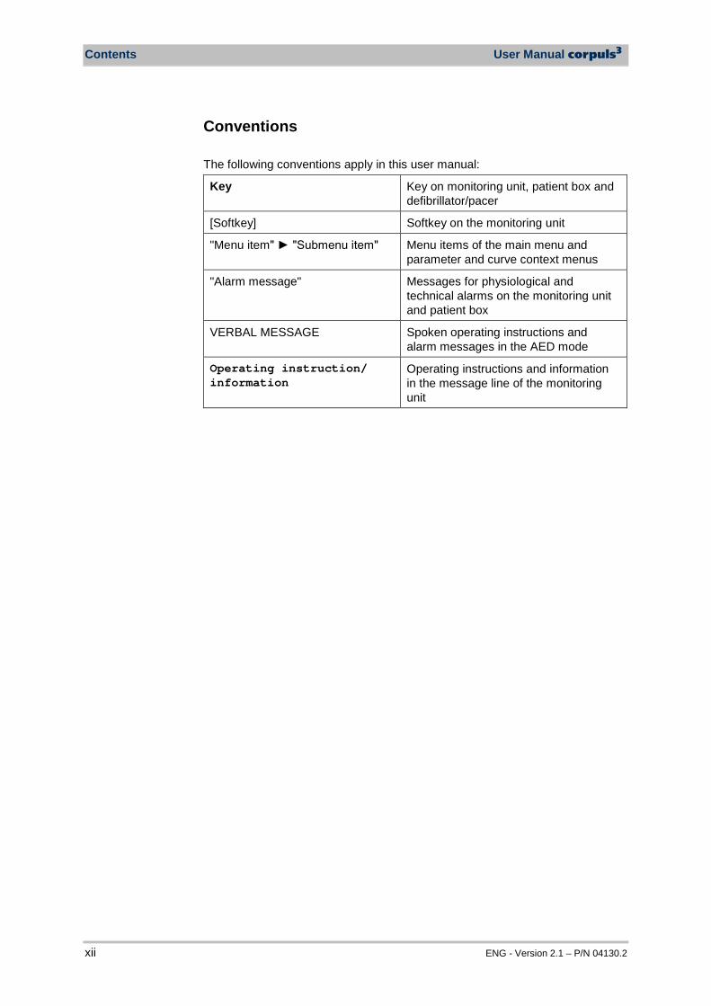
Conventions The following conventions apply in this user manual:
Key Key on monitoring unit, patient box and defibrillator/pacer
[Softkey] Softkey on the monitoring unit
"Menu item" "Submenu item" Menu items of the main menu and parameter and curve context menus
"Alarm message" Messages for physiological and technical alarms on the monitoring unit and patient box
VERBAL MESSAGE Spoken operating instructions and alarm messages in the AED mode
Operating instruction/ information
Operating instructions and information in the message line of the monitoring unit
User Manual corpuls3 Safety
ENG - Version 2.1 – P/N 04130.2 1
1 Safety
1.1 General The corpuls3 may only be operated if:
• in technically perfect condition; • used as intended (see chapter 2 Intended Use, p. 4); • the instructions of this user manual are followed.
Malfunctions must be eliminated immediately (see chapter 10 Procedure in Case of Malfunctions, page 233).
For the product variant corpuls3 HYPERBARIC please read and understand Appendix H corpuls3 HYPERBARIC (HBO).
1.2 Operating Staff The corpuls3 may only be operated by trained medical staff of for example hospitals, doctor’s offices and emergency medical services, as well as of authorities and public safety organisations. The qualified staff must be
• trained in proper handling, use and operation of the device and of the approved accessories as well as be
• trained in basic and advanced resuscitatory measures (BLS and ALS). The initial instruction and training on the device must be performed by the manufacturer or by authorised personnel.
1.2.1 Restrictions of Therapeutic Functions Use of the therapeutic functions (defibrillation, cardioversion and pacing) is restricted to qualified and authorised staff. The manufacturer recommends that persons who use the therapeutic functions of the device should take part in refresher courses regularly. The operating company/operator is responsible for offering such refresher courses.
Instructing person
Refresher courses in
therapeutic use
Hyperbaric oxygen therapy
Intended Use User Manual corpuls3
2 ENG - Version 2.1 – P/N 04130.2
1.2.2 Maintenance Maintenance work may only be performed by persons who are appropriately trained and authorised by the manufacturer. Failure to observe this will result in invalidation of claims under the warranty.
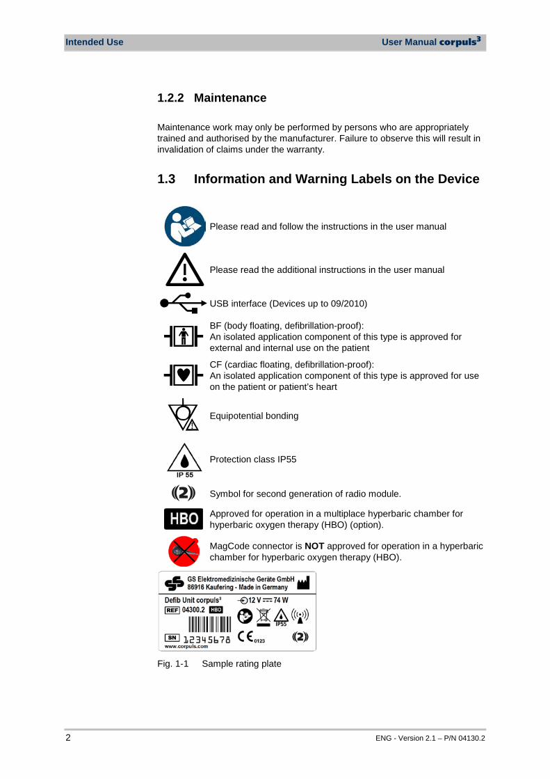
1.3 Information and Warning Labels on the Device
Please read and follow the instructions in the user manual
Please read the additional instructions in the user manual
USB interface (Devices up to 09/2010)
BF (body floating, defibrillation-proof): An isolated application component of this type is approved for external and internal use on the patient
CF (cardiac floating, defibrillation-proof): An isolated application component of this type is approved for use on the patient or patient’s heart
Equipotential bonding
Protection class IP55
2 Symbol for second generation of radio module.
Approved for operation in a multiplace hyperbaric chamber for hyperbaric oxygen therapy (HBO) (option).
MagCode connector is NOT approved for operation in a hyperbaric chamber for hyperbaric oxygen therapy (HBO).
Fig. 1-1 Sample rating plate

User Manual corpuls3 Safety
ENG - Version 2.1 – P/N 04130.2 3
1.4 Warning Notices and Symbols A number of actions during the operation of the corpuls3 carry risks for patients, users and third parties. Such actions are indicated by warning notices in this user manual. The following symbols are used:
Warning
"Warning" denotes a dangerous situation. If the warning is not heeded, extremely severe injuries or substantial material damage may occur.
Caution
"Caution" denotes a possibly dangerous situation. If not heeded, minor injuries or slight material damage may occur.
These paragraphs contain information which must be read and understood.
1.5 Special Types of Risk The defibrillator emits powerful electrical energy. Severe injuries or death may result if the defibrillator is not used in accordance with this user manual.
• Familiarise yourself with the device and this user manual. The defibrillator must not be opened. Internal components may carry high voltages.
• If a fault is suspected, have the device checked by the authorised sales and service partner and, if necessary, repaired.
The defibrillator may cause electromagnetic interference, particularly during charging and on triggering the defibrillation shock. The functioning of devices operated in the vicinity may be compromised.
• Check the effects of the defibrillator on other devices, preferably before an emergency occurs.
Electromagnetic fields of other devices may invalidate the ECG readings. ECG analysis may be impaired. It may be impossible to trigger a defibrillation shock or pacer pulse.
• Please read and follow the instructions for operation of the device in chapter 2 Intended Use, p. 4 in addition to the safety warnings during use
It is essential to read and follow the safety information in the appendix F (from page 272). .
Electric shock
EMC
Note
4 ENG - Version 2.1 – P/N 04130.2
2 Intended Use
The corpuls3 is intended • for measurement and monitoring of vital functions in addition to • defibrillation, cardioversion or cardiac pacing
of patients in the preclinical and clinical field by qualified medical staff trained in the use of the device. The following monitoring functions are available:
• ECG • diagnostic ECG
Optional:
• oximetry (SpO2, SpCO®, SpHb, SpMet®) • capnometry (CO2) • temperature (T) • non-invasive blood pressure monitoring (NIBP) • invasive blood pressure monitoring (IBP)
The corpuls3 is approved for monitoring in operating diagnostic X-ray units (e. g. computed tomography). Exempt from this is the oximetry option, because measured values might be falsified. When equipped with the HBO (hyperbaric oxygen therapy) option, the corpuls3 is approved for operation in a multiplace hyperbaric chamber up to 3 barg and an oxygen concentration of < 23%. Intended use of corpuls3 includes employment of accessories which are
• approved by the manufacturer (see chapter 9.8 Approved Accessories, Spare Parts and Consumables, p. 224) and
• appropriate for the function and patient. Use of accessories on corpuls3 which are not approved by the manufacturer is not considered to be intended use.
Warning
Defibrillation protection for patients, user and third parties cannot be guaranteed, if accessories other than those authorised by the manufacturer are used.
The therapeutic functions of defibrillation, cardioversion and pacer must only be performed with constant monitoring of the patient. Performing the therapeutic functions without eye contact with the patient is not considered to be intended use.
Intended use
User Manual corpuls3 Intended Use
ENG - Version 2.1 – P/N 04130.2 5
If monitoring functions are performed, the patient’s condition must also be regularly monitored even when the alarm function is enabled. The corpuls3 is not intended for
• operation in the vicinity of readily inflammable substances, • setup and operation under the influence of strong electromagnetic fields,
which occur in the direct vicinity of radio masts, switched-on nuclear magnetic resonance tomography units, high voltage installations and overhead power lines,
• operation in the vicinity of therapeutic radiation units (e.g. tumor treatment),
• operation in connection with a high frequency surgical device, • operation in a monoplace hyperbaric chamber (option HBO), • operation in a multiplace hyperbaric chamber with more than 3 barg
and/or more than 23 % oxygen concentration (option HBO). The pacer function must not be used near high frequency surgical devices or microwave therapy devices. Individual modules must not be used without batteries inserted. Defibrillation and cardioversion must not be performed without protective measures (see chapter 5.3.1 Information on the AED Mode, p. 68 and 5.4.1 Information on Manual Defibrillation and Cardioversion, p. 74):
• on a metal surface; • on a wet surface.
The defibrillator must only be used for defibrillation and cardioversion and must not be used as a stimulation current device or as a pacer. The pacer may only be used as a transcutaneous pacer. The pacer must not be used as an intracardial defibrillator. The corpuls3 may not be used simultaneously on two or more patients. The manufacturer cannot accept any liability for damage occurring as a result of failure to use corpuls3 as intended.
Usage other than as intended
Introduction User Manual corpuls3
6 ENG - Version 2.1 – P/N 04130.2
3 Introduction
3.1 Components corpuls3 is a portable device with a modular structure which can be used
• as a defibrillator/monitor or • as a full patient monitor in its own right.
The corpuls3 provides comprehensive monitoring, diagnostic and therapeutic functions for treatment of emergency and intensive-care patients. Especially as part of the resuscitation of emergency patients, defibrillations, cardioversions or pacer therapies can also be performed, in addition to monitoring of vital parameters. A maximum of six ECG curves can be displayed on the monitor at the same time. A 12 lead ECG function allows the user a comprehensive ECG diagnosis, which can be optionally supplemented by ECG analysis software. Further monitoring functions include oxygen saturation measurement (pulse oximetry), carbon dioxide measurement (capnometry) and temperature measurement, in addition to non-invasive and invasive blood pressure monitoring. The recorded measuring values can be displayed both numerically and as a curve. Configurable alarms draw the user’s attention to current changes in the patient’s condition. All measured values or logs can be printed out on paper. corpuls3 has extensive documentation functions for internal recording of events, alarms and logs. These can be transferred to external systems for further processing and archiving.
Monitoring, diagnostic and
therapeutic functions
Documentation function
User Manual corpuls3 Introduction
ENG - Version 2.1 – P/N 04130.2 7
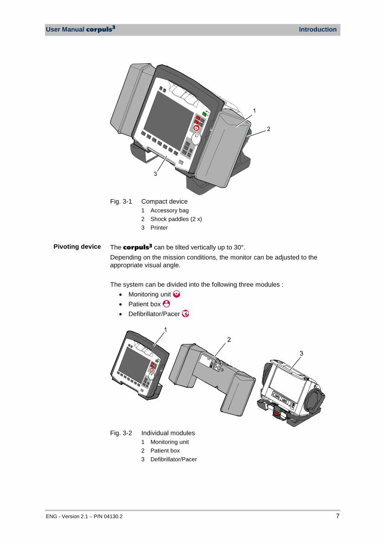
Fig. 3-1 Compact device
1 Accessory bag 2 Shock paddles (2 x) 3 Printer
The corpuls3 can be tilted vertically up to 30°. Depending on the mission conditions, the monitor can be adjusted to the appropriate visual angle. The system can be divided into the following three modules :
• Monitoring unit • Patient box • Defibrillator/Pacer
Fig. 3-2 Individual modules
1 Monitoring unit 2 Patient box 3 Defibrillator/Pacer
Pivoting device
Introduction User Manual corpuls3
8 ENG - Version 2.1 – P/N 04130.2
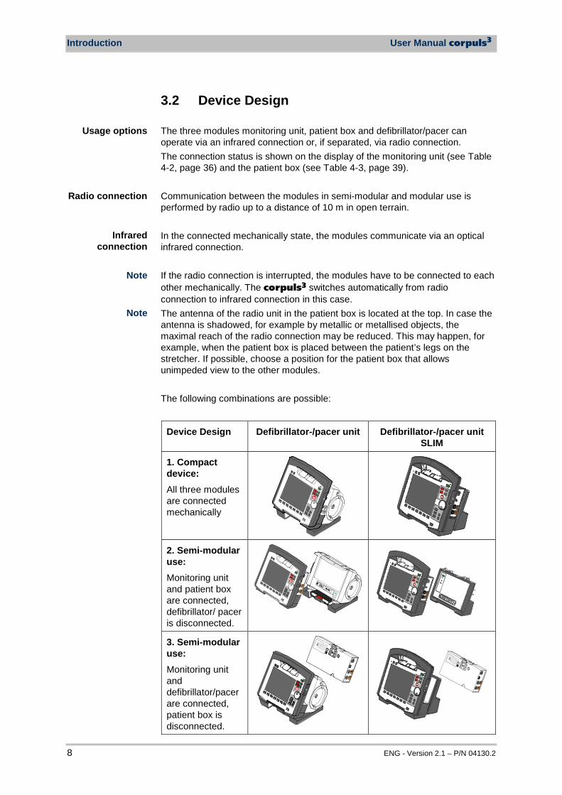
3.2 Device Design The three modules monitoring unit, patient box and defibrillator/pacer can operate via an infrared connection or, if separated, via radio connection. The connection status is shown on the display of the monitoring unit (see Table 4-2, page 36) and the patient box (see Table 4-3, page 39). Communication between the modules in semi-modular and modular use is performed by radio up to a distance of 10 m in open terrain. In the connected mechanically state, the modules communicate via an optical infrared connection.
If the radio connection is interrupted, the modules have to be connected to each other mechanically. The corpuls3 switches automatically from radio connection to infrared connection in this case. The antenna of the radio unit in the patient box is located at the top. In case the antenna is shadowed, for example by metallic or metallised objects, the maximal reach of the radio connection may be reduced. This may happen, for example, when the patient box is placed between the patient’s legs on the stretcher. If possible, choose a position for the patient box that allows unimpeded view to the other modules. The following combinations are possible:
Device Design Defibrillator-/pacer unit Defibrillator-/pacer unit SLIM
1. Compact device: All three modules are connected mechanically
2. Semi-modular use: Monitoring unit and patient box are connected, defibrillator/ pacer is disconnected.
3. Semi-modular use: Monitoring unit and defibrillator/pacer are connected, patient box is disconnected.
Usage options
Radio connection
Note
Infrared connection
Note
User Manual corpuls3 Introduction
ENG - Version 2.1 – P/N 04130.2 9
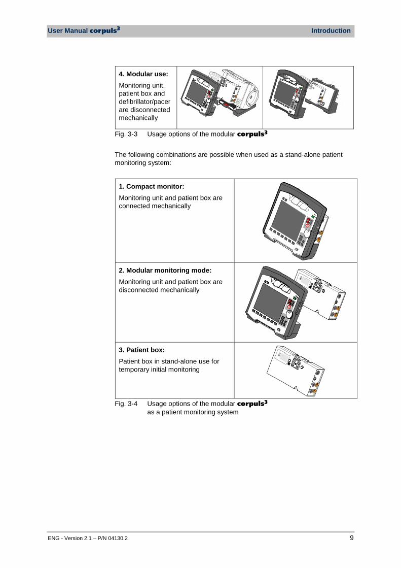
4. Modular use: Monitoring unit, patient box and defibrillator/pacer are disconnected mechanically
Fig. 3-3 Usage options of the modular corpuls3 The following combinations are possible when used as a stand-alone patient monitoring system:
1. Compact monitor: Monitoring unit and patient box are connected mechanically
2. Modular monitoring mode: Monitoring unit and patient box are disconnected mechanically
3. Patient box: Patient box in stand-alone use for temporary initial monitoring
Fig. 3-4 Usage options of the modular corpuls3
as a patient monitoring system
Introduction User Manual corpuls3
10 ENG - Version 2.1 – P/N 04130.2
3.2.1 Pairing (Connection Authorisation) The modules of the corpuls3 can be connected to form a functional unit by means of two procedures: • Pairing and • Ad-hoc connection The corpuls3 thus provides the option of substituting individual modules of one compact device for individual modules of the same type from another corpuls3. It is not possible to connect a monitoring unit to more than one patient box or one defibrillator/pacer at the same time. Pairing is a connection authorisation that enables the communication between wirelessly connected modules. An ad-hoc connection allows the use of mechanically connected modules without having to perform a pairing beforehand. For both procedures the following prerequisites apply: 1. For a pairing, monitoring unit, patient box and defibrillator/pacer have to be
equipped with radio modules of the same type (hardware version). 2. If this is not the case, if the hardware version of the radio modules is
different (1st and 2nd generation), those modules can only form an ad-hoc connection.
3. For both a pairing and for an ad-hoc connection all modules have to be equipped with an identical software version.
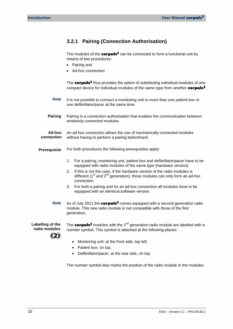
As of July 2011 the corpuls3 comes equipped with a second generation radio module. This new radio module is not compatible with those of the first generation. The corpuls3 modules with the 2nd generation radio module are labelled with a number symbol. This symbol is attached at the following places:
• Monitoring unit: at the front side, top left, • Patient box: on top, • Defibrillator/pacer: at the rear side, on top.
The number symbol also marks the position of the radio module in the modules.
Pairing
Note
Ad-hoc connection
Prerequisite
Note
Labelling of the radio modules
2
User Manual corpuls3 Introduction
ENG - Version 2.1 – P/N 04130.2 11
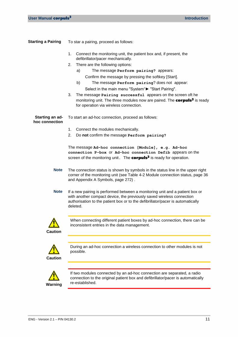
To star a pairing, proceed as follows: 1. Connect the monitoring unit, the patient box and, if present, the
defibrillator/pacer mechanically. 2. There are the following options:
a) The message Perform pairing? appears: Confirm the message by pressing the softkey [Start].
b) The message Perform pairing? does not appear: Select in the main menu "System“ "Start Pairing".
3. The message Pairing successful appears on the screen oft he monitoring unit. The three modules now are paired. The corpuls3 is ready for operation via wireless connection.
To start an ad-hoc connection, proceed as follows: 1. Connect the modules mechanically. 2. Do not confirm the message Perform pairing? The message Ad-hoc connection [Module], e.g. Ad-hoc connection P-box or Ad-hoc connection Defib appears on the screen of the monitoring unit. The corpuls3 is ready for operation. The connection status is shown by symbols in the status line in the upper right corner of the monitoring unit (see Table 4-2 Module connection status, page 36 and Appendix A Symbols, page 272) . If a new pairing is performed between a monitoring unit and a patient box or with another compact device, the previously saved wireless connection authorisation to the patient box or to the defibrillator/pacer is automatically deleted.
Caution
When connecting different patient boxes by ad-hoc connection, there can be inconsistent entries in the data management.
Caution
During an ad-hoc connection a wireless connection to other modules is not possible.
Warning
If two modules connected by an ad-hoc connection are separated, a radio connection to the original patient box and defibrillator/pacer is automatically re-established.
Note
Starting a Pairing
Starting an ad-hoc connection
Note

Introduction User Manual corpuls3
12 ENG - Version 2.1 – P/N 04130.2
3.2.2 Monitoring Unit
Fig. 3-5 Monitoring Unit
1 Display 2 Alarm and event function keys 3 Status LED power supply/charging status 4 On/Off key with operating status LED 5 Defibrillation mode function keys 6 Insurance card reader 7 Jog dial and alarm light 8 Function keys for navigation 9 Print key 10 Operating mode keys 11 Printer 12 Softkeys
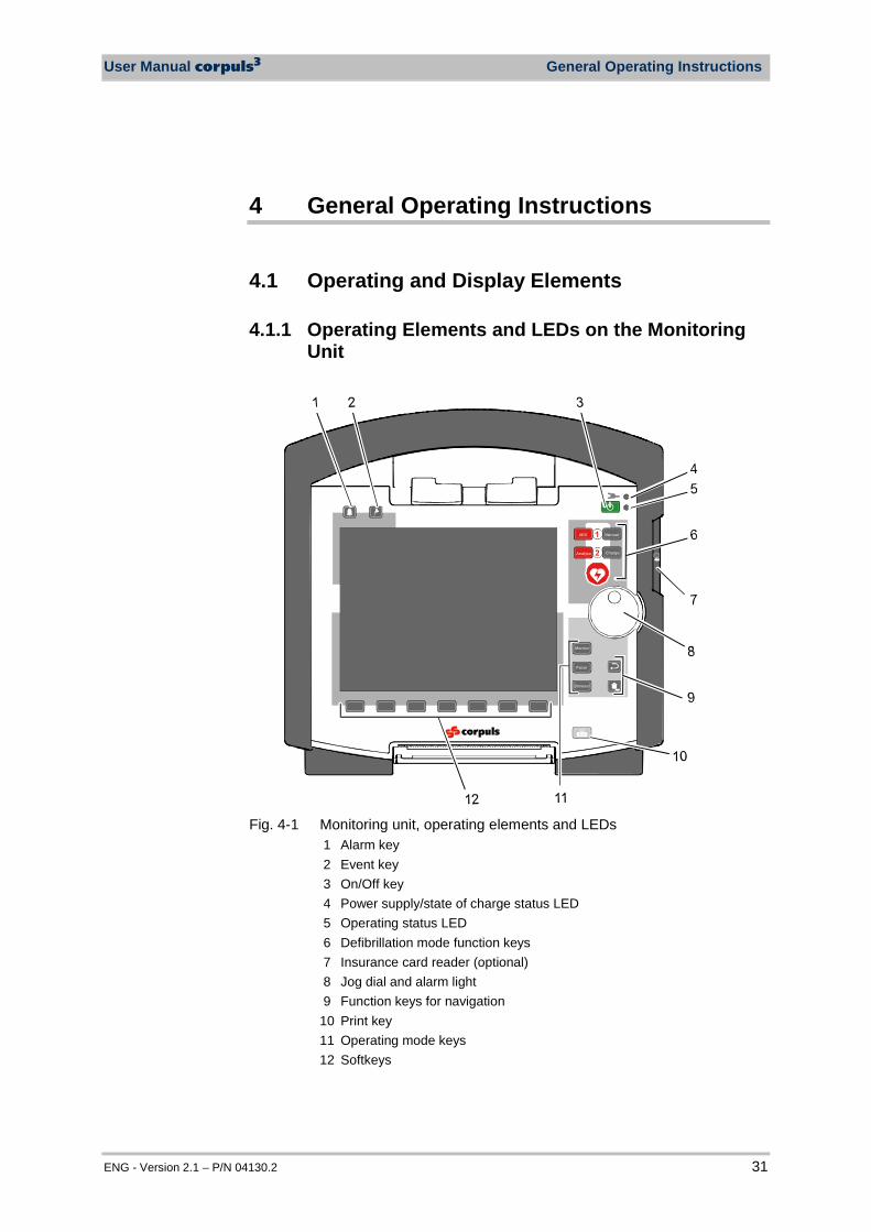
The monitoring unit is the central user interface of corpuls3. The monitoring unit comprises the display (item 1), the printer (item 11) and the insurance card reader (item 6, option), as well the jog dial (item 7), the function keys (items 2, 5, 8 and 9), the operating mode keys (item 10) and the softkeys (item 12). The jog dial is used to navigate in the main menu, the parameter and curve context menus and in the display areas on the display. An alarm light is integrated into the jog dial. The monitor, pacer and operation browser functions can be selected directly by pressing the function keys. Softkey assignment varies according to the selected function. Softkey assignments are described in the chapters dealing with the respective functions.
User Manual corpuls3 Introduction
ENG - Version 2.1 – P/N 04130.2 13
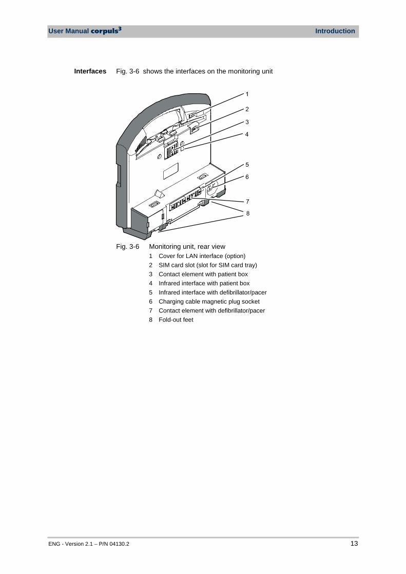
Fig. 3-6 shows the interfaces on the monitoring unit
Fig. 3-6 Monitoring unit, rear view
1 Cover for LAN interface (option) 2 SIM card slot (slot for SIM card tray) 3 Contact element with patient box 4 Infrared interface with patient box 5 Infrared interface with defibrillator/pacer 6 Charging cable magnetic plug socket 7 Contact element with defibrillator/pacer 8 Fold-out feet
Interfaces
Introduction User Manual corpuls3
14 ENG - Version 2.1 – P/N 04130.2
3.2.3 Patient Box and Accessory Bag
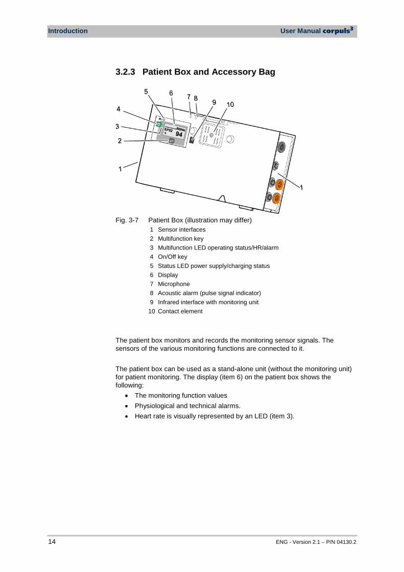
Fig. 3-7 Patient Box (illustration may differ)
1 Sensor interfaces 2 Multifunction key 3 Multifunction LED operating status/HR/alarm 4 On/Off key 5 Status LED power supply/charging status 6 Display 7 Microphone 8 Acoustic alarm (pulse signal indicator) 9 Infrared interface with monitoring unit 10 Contact element
The patient box monitors and records the monitoring sensor signals. The sensors of the various monitoring functions are connected to it. The patient box can be used as a stand-alone unit (without the monitoring unit) for patient monitoring. The display (item 6) on the patient box shows the following:
• The monitoring function values • Physiological and technical alarms. • Heart rate is visually represented by an LED (item 3).
User Manual corpuls3 Introduction
ENG - Version 2.1 – P/N 04130.2 15
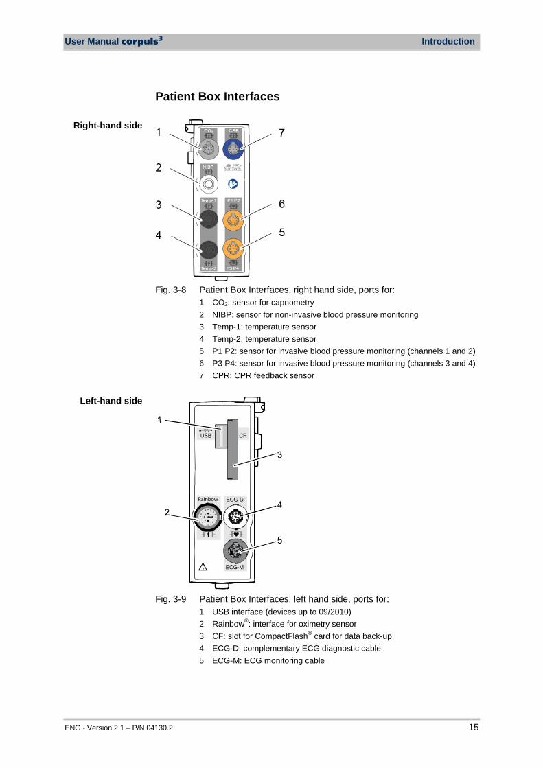
Patient Box Interfaces
Fig. 3-8 Patient Box Interfaces, right hand side, ports for:
1 CO2: sensor for capnometry 2 NIBP: sensor for non-invasive blood pressure monitoring 3 Temp-1: temperature sensor 4 Temp-2: temperature sensor 5 P1 P2: sensor for invasive blood pressure monitoring (channels 1 and 2) 6 P3 P4: sensor for invasive blood pressure monitoring (channels 3 and 4) 7 CPR: CPR feedback sensor
Rainbow
Fig. 3-9 Patient Box Interfaces, left hand side, ports for:
1 USB interface (devices up to 09/2010) 2 Rainbow®: interface for oximetry sensor 3 CF: slot for CompactFlash® card for data back-up 4 ECG-D: complementary ECG diagnostic cable 5 ECG-M: ECG monitoring cable
Right-hand side
Left-hand side
Introduction User Manual corpuls3
16 ENG - Version 2.1 – P/N 04130.2
Caution
At the moment, connecting USB devices or –cables to the USB slot is not allowed.
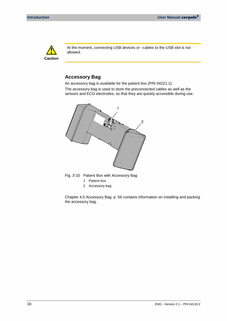
Accessory Bag An accessory bag is available for the patient box (P/N 04221.1). The accessory bag is used to store the preconnected cables as well as the sensors and ECG electrodes, so that they are quickly accessible during use.
Fig. 3-10 Patient Box with Accessory Bag
1 Patient box 2 Accessory bag
Chapter 4.5 Accessory Bag, p. 56 contains information on installing and packing the accessory bag.
User Manual corpuls3 Introduction
ENG - Version 2.1 – P/N 04130.2 17
3.2.4 Defibrillator/Pacer
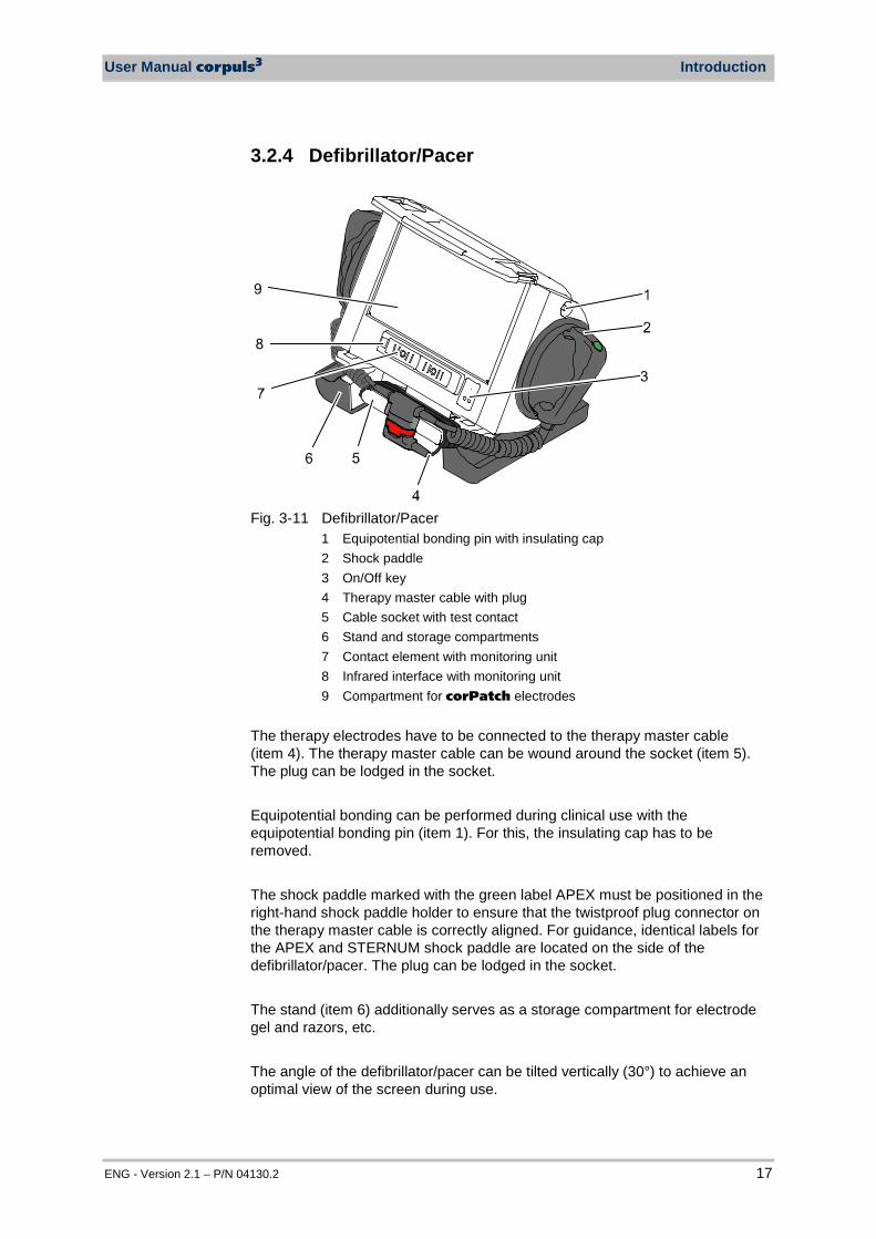
Fig. 3-11 Defibrillator/Pacer
1 Equipotential bonding pin with insulating cap 2 Shock paddle 3 On/Off key 4 Therapy master cable with plug 5 Cable socket with test contact 6 Stand and storage compartments 7 Contact element with monitoring unit 8 Infrared interface with monitoring unit 9 Compartment for corPatch electrodes
The therapy electrodes have to be connected to the therapy master cable (item 4). The therapy master cable can be wound around the socket (item 5). The plug can be lodged in the socket. Equipotential bonding can be performed during clinical use with the equipotential bonding pin (item 1). For this, the insulating cap has to be removed. The shock paddle marked with the green label APEX must be positioned in the right-hand shock paddle holder to ensure that the twistproof plug connector on the therapy master cable is correctly aligned. For guidance, identical labels for the APEX and STERNUM shock paddle are located on the side of the defibrillator/pacer. The plug can be lodged in the socket. The stand (item 6) additionally serves as a storage compartment for electrode gel and razors, etc. The angle of the defibrillator/pacer can be tilted vertically (30°) to achieve an optimal view of the screen during use.

Introduction User Manual corpuls3
18 ENG - Version 2.1 – P/N 04130.2
3.2.5 Defibrillator/Pacer SLIM The defibrillator/pacer SLIM differs from the previous defibrillator/pacer unit only in terms of form and weight. The basic functions are identical.
Fig. 3-12 Defibrillator/Schrittmacher Slim
1 Carrying handle and lock 2 Therapy socket 3 Contact element with monitoring unit 4 Infrared interface with monitoring unit 5 Equipotential bonding pin with insulating cover 6 On/Off key
The therapy electrodes have to be connected to the therapy socket (item 2). Equipotential bonding can be performed during clinical use with the equipotential bonding pin (item 5). For this, the insulating cover has to be removed.
User Manual corpuls3 Introduction
ENG - Version 2.1 – P/N 04130.2 19
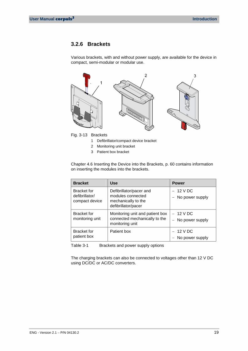
3.2.6 Brackets Various brackets, with and without power supply, are available for the device in compact, semi-modular or modular use.
Fig. 3-13 Brackets
1 Defibrillator/compact device bracket 2 Monitoring unit bracket 3 Patient box bracket
Chapter 4.6 Inserting the Device into the Brackets, p. 60 contains information on inserting the modules into the brackets.
Bracket Use Power
Bracket for defibrillator/ compact device
Defibrillator/pacer and modules connected mechanically to the defibrillator/pacer
− 12 V DC − No power supply
Bracket for monitoring unit
Monitoring unit and patient box connected mechanically to the monitoring unit
− 12 V DC − No power supply
Bracket for patient box
Patient box − 12 V DC − No power supply
Table 3-1 Brackets and power supply options The charging brackets can also be connected to voltages other than 12 V DC using DC/DC or AC/DC converters.
Introduction User Manual corpuls3
20 ENG - Version 2.1 – P/N 04130.2
3.3 Description of the Monitoring, Diagnostic and Therapeutic Functions
3.3.1 Monitoring and Diagnostic Functions The corpuls3 has the following monitoring and diagnostic functions:
• ECG • Diagnostic ECG • CPR feedback
Optional: • oximetry (SpO2, SpCO®, SpHb, SpMet®) • Capnometry (CO2) • Temperature (Temp) • Non-invasive blood pressure monitoring (NIBP) • Invasive blood pressure monitoring (IBP)
With the 4-pole ECG monitoring cable, the bipolar extremity leads according to Einthoven (I, II, III) and the unipolar extremity leads according to Goldberger (aVR, aVL, aVF) can be derived and displayed on the monitor. By combining the 4-pole ECG monitoring cable with the complementary 6-pole ECG diagnostic cable (chest wall leads according to Wilson (C1-C6)), 12 channels can be displayed simultaneously. This enables a comprehensive ECG diagnosis which can be supported by the ECG measurement HES® Light and an optional ECG analysis software. During resuscitation, the CPR feedback option monitors the current compression rate and -depth of the thorax compressions by means of the corPatch CPR sensor. Speech- and text messages signal to the user whether the quality of the thorax compressions is sufficient or can to be optimised. Besides the peripheral pulse rate (PP), oximetry measures the perfusion index (PI), the arterial oxygen saturation (SpO2) in percentage, the level of methemoglobin (SpMet®) and, depending on the used oximetry sensor, the level of carboxyhemogolobin (SpCO®) in percentage or the level of total hemoglobin (SpHb) in g/dl or mmol/l. Up to six parameter fields with digital measuring values can be configured for display. A curve field can display the oximetry plethysmogram. The capnometer, which works according to the mainstream method, measures the CO2 concentration in the patient’s expiratory breath in real time. The CO2 concentration, measured in mmHg or kPa, can be displayed on the screen as a capnogram. The corpuls3 allows use of capnometry in intubated and non-intubated patients. The patient’s respiratory rate is measured as an additional parameter. Up to two temperature values can be measured by means of temperature sensors and displayed as numerical values: body core temperature rectally and/or oesophageally and surface temperature.
ECG
Diagnostic ECG
Oximetry
Capnometry
Temperature
CPR feedback

User Manual corpuls3 Introduction
ENG - Version 2.1 – P/N 04130.2 21
The non-invasive blood pressure function (NIBP) allows blood pressure monitoring on one extremity. A selection of operating modes for adults, children and infants is available. The invasive blood pressure function (IBP) allows the invasive measurement of various different pressures as part of intensive medical care of the patient. These include, among others, arterial pressure, central venous pressure and intracranial pressure, etc. Two interfaces are available which can be assigned as single channels or as double channels, respectively. Consequently, up to four different invasive pressure measurements can be performed simultaneously. The recorded pressure values can be displayed on the screen either as numerical parameters and/or as a curve.
3.3.2 Therapeutic Functions corpuls3 provides the following therapeutic functions:
• defibrillation • cardioversion • pacing
Defibrillation and Cardioversion The defibrillator which operates with the corpuls3-specific biphasic pulse has two operating modes:
• automatic external defibrillation (AED mode) • manual defibrillation and cardioversion (manual mode)
U [V]
t [ms]
Fig. 3-14 Biphasic defibrillation pulse (qualitative representation)
Non-invasive blood pressure
(NIBP)
Invasive blood pressure (IBP)

Introduction User Manual corpuls3
22 ENG - Version 2.1 – P/N 04130.2
In AED mode, the user is assisted by an automated ECG analysis, verbal instructions (configurable) and a metronome (configurable). The defibrillation pulse is triggered by the user. The AED mode algorithm is governed by the current recommendations of the European Resuscitation Council of 2010 (ERC, see www.erc.edu). In manual defibrillation mode, the user has full freedom of action and decision-making. The metronome (configurable) is available in this mode as well. Defibrillation can be performed with corpuls3 using plate electrodes, so-called shock paddles and with disposable adhesive electrodes, so-called corPatch electrodes. There are three different options for selecting energy in manual mode:
• Softkeys The softkeys allow a choice of predefined energy settings (e.g. 50 J, 100 J, 150 J, 180 J, 200 J).
• Jog dial The jog dial allows selection of 2 J, 3 J, 4 J and 5 J and subsequently in 5 J-increments up to a maximum energy of 200 J.
• Shock paddles By short-circuiting the shock paddles, the energy can be selected by pressing the release buttons. This function allows the same energy selection as with the jog dial.
Warning
A cardioversion may lead to fibrillation or asystole. When performing a cardioversion, mind the following:
• The ECG has to be stable with a heart rate of at least 60/min. • The synchronisation status has to remain constantly on SYNC. • The QRS marks (triangles) have to mark each QRS complex. • The shock release has to be effected according to valid guidelines. • If the shock release does not take place one second after pressing
the buttons at the shock paddles or the Shock key at the monitoring unit, the shock will be released independent of the synchronisation status.
Pacing By electrical stimulation of the heart muscle, the external pacer of corpuls3 can supplement, positively influence or completely take over its function. The pacer emits pacing pulses to the patient’s heart muscle through the corPatch electrodes attached to the chest/back. With the pacer function, the FIX and DEMAND operating modes are available as well as the function OVERDRIVE. In the FIX operating mode, the heart muscle is stimulated regardless of the patient’s own heart rate. The pacer only stimulates in DEMAND mode when the patient’s own heart rate falls below the pre-set pacing frequency. The automatic R-wave recognition prevents pacing during the vulnerable phase of the heart. The OVERDRIVE function allows manual reduction of a patient’s high heart rate. The maximum pacing frequency is f ≤ 300/min.
Energy selection
FIX
DEMAND
OVERDRIVE function
Defibrillation electrodes
User Manual corpuls3 Introduction
ENG - Version 2.1 – P/N 04130.2 23
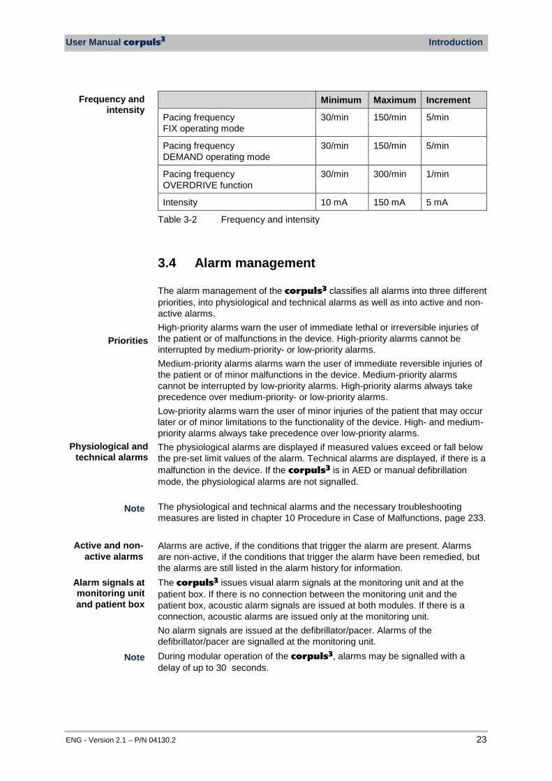
Minimum Maximum Increment
Pacing frequency FIX operating mode
30/min 150/min 5/min
Pacing frequency DEMAND operating mode
30/min 150/min 5/min
Pacing frequency OVERDRIVE function
30/min 300/min 1/min
Intensity 10 mA 150 mA 5 mA
Table 3-2 Frequency and intensity
3.4 Alarm management The alarm management of the corpuls3 classifies all alarms into three different priorities, into physiological and technical alarms as well as into active and non-active alarms. High-priority alarms warn the user of immediate lethal or irreversible injuries of the patient or of malfunctions in the device. High-priority alarms cannot be interrupted by medium-priority- or low-priority alarms. Medium-priority alarms alarms warn the user of immediate reversible injuries of the patient or of minor malfunctions in the device. Medium-priority alarms cannot be interrupted by low-priority alarms. High-priority alarms always take precedence over medium-priority- or low-priority alarms. Low-priority alarms warn the user of minor injuries of the patient that may occur later or of minor limitations to the functionality of the device. High- and medium-priority alarms always take precedence over low-priority alarms. The physiological alarms are displayed if measured values exceed or fall below the pre-set limit values of the alarm. Technical alarms are displayed, if there is a malfunction in the device. If the corpuls3 is in AED or manual defibrillation mode, the physiological alarms are not signalled. The physiological and technical alarms and the necessary troubleshooting measures are listed in chapter 10 Procedure in Case of Malfunctions, page 233. Alarms are active, if the conditions that trigger the alarm are present. Alarms are non-active, if the conditions that trigger the alarm have been remedied, but the alarms are still listed in the alarm history for information. The corpuls3 issues visual alarm signals at the monitoring unit and at the patient box. If there is no connection between the monitoring unit and the patient box, acoustic alarm signals are issued at both modules. If there is a connection, acoustic alarms are issued only at the monitoring unit. No alarm signals are issued at the defibrillator/pacer. Alarms of the defibrillator/pacer are signalled at the monitoring unit. During modular operation of the corpuls3, alarms may be signalled with a delay of up to 30 seconds.
Frequency and intensity
Physiological and technical alarms
Alarm signals at monitoring unit and patient box
Note
Priorities
Active and non-active alarms
Note

Introduction User Manual corpuls3
24 ENG - Version 2.1 – P/N 04130.2
3.4.1 Alarm Signals at the Monitoring unit Physiological and technical alarms are signalled at the monitoring unit via the status line, the vital parameter field, the jog dial and by acoustic signals. The positions of the operation- and display elements are described in chapter 4.1 Operating and Display Elements, page 31. Alarm signal in the status line
Fig. 3-15 Alarm message in the status line
− The bell symbol indicates an alarm. − The number in brackets indicates the number of active alarms
(here 4 alarms) − The number of exclamation marks indicates the priority of the alarm
(!!! – high; !!HIGH – medium; ! – low) − The colour of the status line indicates the priority of the alarm
(red – high; yellow – medium; blue – low) − The alarm is displayed as a text message together with the pre-set
limit value. Pressing the Alarm key once opens the alarm history which lists the last 8 alarms. The individual alarms can be confirmed by pressing the Alarm key again. In this case, the most recent alarm message is deleted from the status line of the monitoring unit and from the display of the patient box. In the alarm history all active and non-active alarms are displayed that have not yet been confirmed; with the alarms being sorted top-down from active (top) to non-active (bottom). Within the active and non-active alarms, the alarms are sorted by priority and then in descending order by the time of their occurrence. The alarm history can contain up to 256 alarms. Preferably these should be confirmed as soon as possible. If more than 256 un-confirmed alarms accumulate, the oldest alarm is overwritten. Certain technical alarms are displayed in red type. These alarms cannot be deleted from the status line and alarm history. Alarm signal in parameter field displayed in inverted colours:
Fig. 3-16 Inverted parameter field
− This display appears only for physiological alarms. − The parameter field can only be displayed in inverted colours when the
display of this parameter field is configured. − The parameter field remains in inverted colours for as long as the
measured value falls below or exceeds the pre-set limit value or until the alarm for this measured value is disabled. This applies regardless of whether the alarm message in the status line has been confirmed by pressing the Alarm key or not.
Note
Note
Sorting of alarm history
User Manual corpuls3 Introduction
ENG - Version 2.1 – P/N 04130.2 25
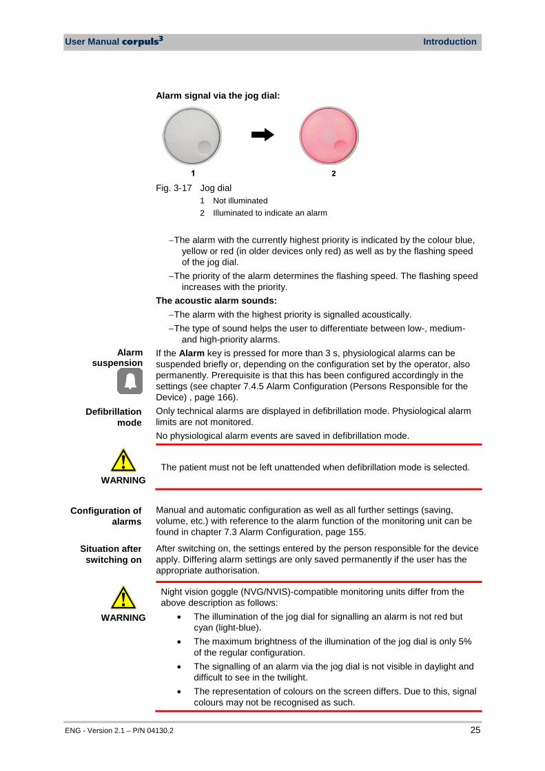
Alarm signal via the jog dial:
Fig. 3-17 Jog dial
1 Not illuminated 2 Illuminated to indicate an alarm
− The alarm with the currently highest priority is indicated by the colour blue,
yellow or red (in older devices only red) as well as by the flashing speed of the jog dial.
− The priority of the alarm determines the flashing speed. The flashing speed increases with the priority.
The acoustic alarm sounds: − The alarm with the highest priority is signalled acoustically. − The type of sound helps the user to differentiate between low-, medium-
and high-priority alarms. If the Alarm key is pressed for more than 3 s, physiological alarms can be suspended briefly or, depending on the configuration set by the operator, also permanently. Prerequisite is that this has been configured accordingly in the settings (see chapter 7.4.5 Alarm Configuration (Persons Responsible for the Device) , page 166). Only technical alarms are displayed in defibrillation mode. Physiological alarm limits are not monitored. No physiological alarm events are saved in defibrillation mode.
WARNING
The patient must not be left unattended when defibrillation mode is selected.
Manual and automatic configuration as well as all further settings (saving, volume, etc.) with reference to the alarm function of the monitoring unit can be found in chapter 7.3 Alarm Configuration, page 155.
After switching on, the settings entered by the person responsible for the device apply. Differing alarm settings are only saved permanently if the user has the appropriate authorisation.
WARNING
Night vision goggle (NVG/NVIS)-compatible monitoring units differ from the above description as follows:
• The illumination of the jog dial for signalling an alarm is not red but cyan (light-blue).
• The maximum brightness of the illumination of the jog dial is only 5% of the regular configuration.
• The signalling of an alarm via the jog dial is not visible in daylight and difficult to see in the twilight.
• The representation of colours on the screen differs. Due to this, signal colours may not be recognised as such.
Configuration of alarms
Defibrillation mode
Alarm suspension
Situation after switching on
Introduction User Manual corpuls3
26 ENG - Version 2.1 – P/N 04130.2
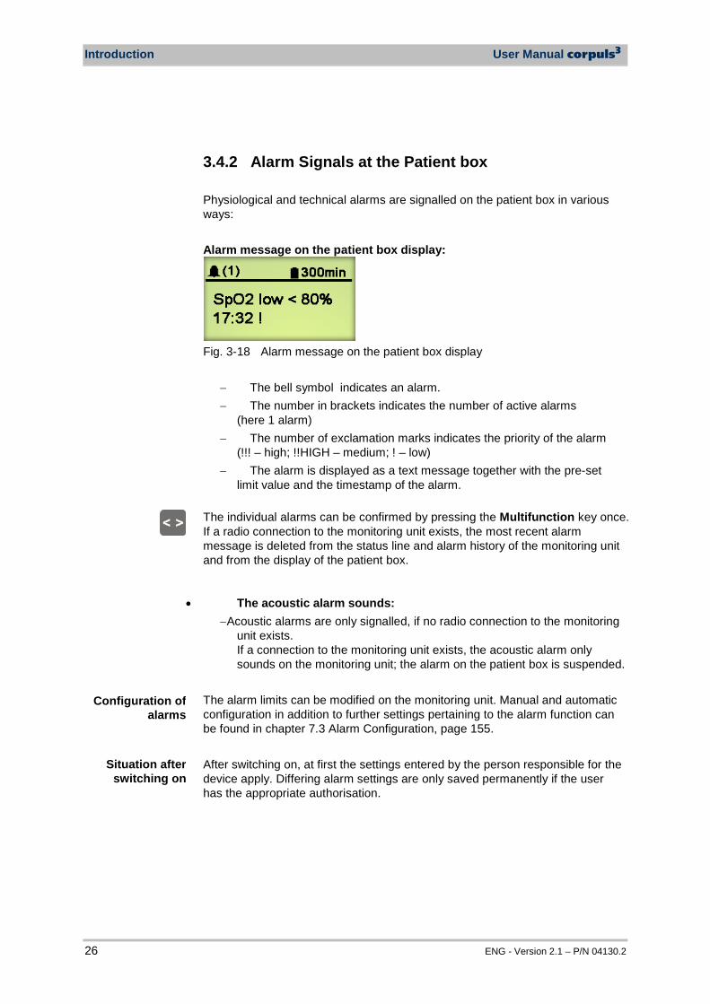
3.4.2 Alarm Signals at the Patient box Physiological and technical alarms are signalled on the patient box in various ways: Alarm message on the patient box display:
Fig. 3-18 Alarm message on the patient box display
− The bell symbol indicates an alarm. − The number in brackets indicates the number of active alarms
(here 1 alarm) − The number of exclamation marks indicates the priority of the alarm
(!!! – high; !!HIGH – medium; ! – low) − The alarm is displayed as a text message together with the pre-set
limit value and the timestamp of the alarm.
The individual alarms can be confirmed by pressing the Multifunction key once. If a radio connection to the monitoring unit exists, the most recent alarm message is deleted from the status line and alarm history of the monitoring unit and from the display of the patient box.
• The acoustic alarm sounds: − Acoustic alarms are only signalled, if no radio connection to the monitoring
unit exists. If a connection to the monitoring unit exists, the acoustic alarm only sounds on the monitoring unit; the alarm on the patient box is suspended.
The alarm limits can be modified on the monitoring unit. Manual and automatic configuration in addition to further settings pertaining to the alarm function can be found in chapter 7.3 Alarm Configuration, page 155. After switching on, at first the settings entered by the person responsible for the device apply. Differing alarm settings are only saved permanently if the user has the appropriate authorisation.
Situation after switching on
Configuration of alarms
User Manual corpuls3 Introduction
ENG - Version 2.1 – P/N 04130.2 27
3.5 Energy Management Energy management is of paramount importance owing to the modular structure of the corpuls3. The corpuls3 and the individual modules can be operated on battery alone or on 12 V DC power supply or via a separate charger (only 230 V AC).
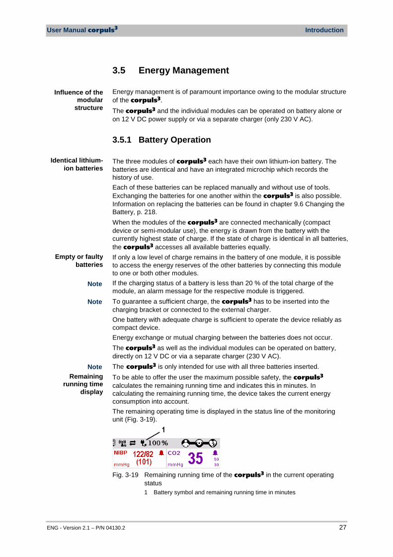
3.5.1 Battery Operation The three modules of corpuls3 each have their own lithium-ion battery. The batteries are identical and have an integrated microchip which records the history of use. Each of these batteries can be replaced manually and without use of tools. Exchanging the batteries for one another within the corpuls3 is also possible. Information on replacing the batteries can be found in chapter 9.6 Changing the Battery, p. 218. When the modules of the corpuls3 are connected mechanically (compact device or semi-modular use), the energy is drawn from the battery with the currently highest state of charge. If the state of charge is identical in all batteries, the corpuls3 accesses all available batteries equally. If only a low level of charge remains in the battery of one module, it is possible to access the energy reserves of the other batteries by connecting this module to one or both other modules. If the charging status of a battery is less than 20 % of the total charge of the module, an alarm message for the respective module is triggered. To guarantee a sufficient charge, the corpuls3 has to be inserted into the charging bracket or connected to the external charger. One battery with adequate charge is sufficient to operate the device reliably as compact device. Energy exchange or mutual charging between the batteries does not occur. The corpuls3 as well as the individual modules can be operated on battery, directly on 12 V DC or via a separate charger (230 V AC). The corpuls3 is only intended for use with all three batteries inserted. To be able to offer the user the maximum possible safety, the corpuls3 calculates the remaining running time and indicates this in minutes. In calculating the remaining running time, the device takes the current energy consumption into account. The remaining operating time is displayed in the status line of the monitoring unit (Fig. 3-19).
Fig. 3-19 Remaining running time of the corpuls3 in the current operating
status 1 Battery symbol and remaining running time in minutes
Influence of the modular
structure
Identical lithium-ion batteries
Remaining running time
display
Empty or faulty batteries
Note
Note
Note

Introduction User Manual corpuls3
28 ENG - Version 2.1 – P/N 04130.2
In case of modular use of the patient box, the remaining running time of the patient box, taking into account the current energy consumption, is displayed (Fig. 3-20).
1
Fig. 3-20 Remaining running time of the patient box
1 Battery symbol and remaining running time in minutes Alternatively, the charging status of the batteries in percent can be viewed in the system info. In the main menu, select "System" "Info". Since each module has a charging manager, it can be charged individually and independently from the other modules. Furthermore, in compact or semi-modular use, the system can also be charged by only one magnetic contact. In this case, the charging time is independent of whether only one or several modules are simultaneously charged by an external power supply. During charging, the corpuls3 system can be operated. Special maintenance of the batteries is not required. Nevertheless, charging and/or operating under extreme temperatures should be avoided as far as possible. This and extreme temperature fluctuations limit the service life of lithium-ion batteries. It is therefore recommended to charge the batteries within a temperature range from 12°C to 40°C. Periodic replacement of the batteries after 3 years is recommended.
• Compact device: approx. 7-10 hours • Patient box: approx. 4-6 hours • Monitoring unit: approx. 4 hours (at 70% background
illumination) • Defibrillator/Pacer: up to 200 shocks at 200 J
• From 0 to 80 %: approx. 1 hour • From 0 to 90 %: approx. 1.5 hours • From 0 to 100 %: approx. 2 hours
In case of a system crash of one or all modules the batteries do not have tob e removed. By keeping the On/Off key depressed for a duration of 8 sec. the individual modules can be forcibly shut down (see also chapter 4.2.2 Switching Off, p. 44). The batteries have an internal protection which could delay or interrupt the charging process at ambient temperatures of higher than 50°C.
Charging time
Operating time
Battery charging
Battery maintenance
Note
Note

User Manual corpuls3 Introduction
ENG - Version 2.1 – P/N 04130.2 29
3.5.2 Mains Operation The compact device and each individual module can be operated directly with 12 V DC. In combination with a multi-range mains charger, the compact device and the individual modules can also be connected to and operated with voltage sources of 100 V to 250 V AC. Operation with the mains charger on a source of alternating current functions regardless of whether no batteries, empty batteries or faulty batteries are used. The current charging status of the batteries is displayed on the status line of the monitoring unit (Fig. 3-21).
Fig. 3-21 Display of the current state of charge of the batteries on mains
operation 1 Symbol for mains connection and state of charge of the batteries in
percent The voltage can also be supplied by the three available charging brackets:
• compact device bracket 12 V DC (P/N 04400) • monitoring unit wall mounting bracket 12 V DC (P/N 04401) • patient box bracket 12 V DC (P/N 04402)
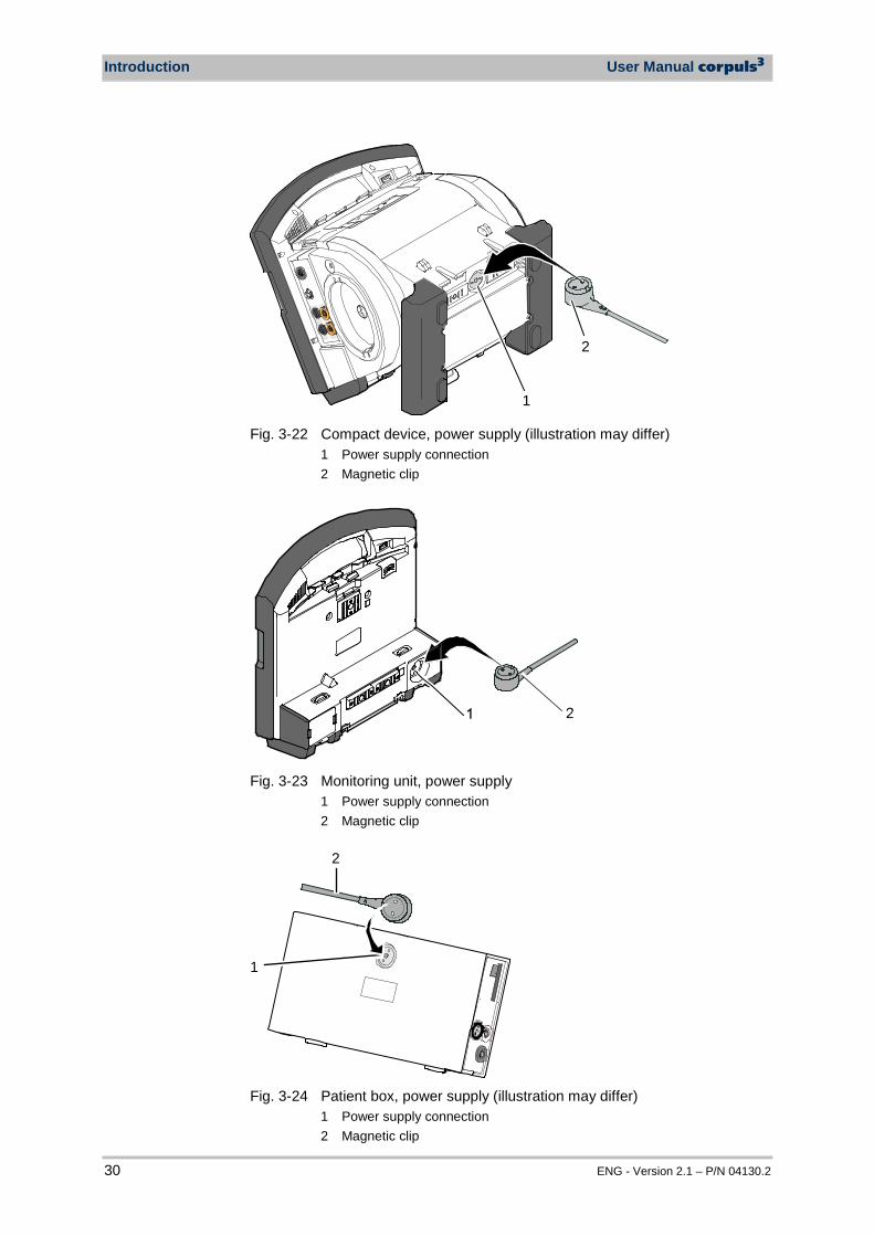
These brackets can also be connected to voltages sources other than 12 V DC via DC/DC or AC/DC converters. If batteries are present in the device, they will be charged during use. Each of the three modules has its own magnetic contact field for power supply. The flow of energy only begins when the corresponding magnetic mating component (magnetic clip or bracket supplied with voltage) is applied in the correct position (observe groove). The magnetic clip releases itself automatically if the pulling force becomes excessive. Manual release is not necessary. The connection (item 1, Fig. 3-22) on the defibrillator/pacer is used for power supply of
• the entire device in compact use, • the defibrillator/pacer and the monitoring unit in semi-modular use or • the defibrillator/pacer in modular use.
Operation with 12 V DC
Use of a mains charger
Magnetic contact field
Charging brackets
State of charge display
Charging during operation
Introduction User Manual corpuls3
30 ENG - Version 2.1 – P/N 04130.2
1
2
Fig. 3-22 Compact device, power supply (illustration may differ)
1 Power supply connection 2 Magnetic clip
Fig. 3-23 Monitoring unit, power supply
1 Power supply connection 2 Magnetic clip
1
2
Fig. 3-24 Patient box, power supply (illustration may differ)
1 Power supply connection 2 Magnetic clip
User Manual corpuls3 General Operating Instructions
ENG - Version 2.1 – P/N 04130.2 31
4 General Operating Instructions
4.1 Operating and Display Elements
4.1.1 Operating Elements and LEDs on the Monitoring Unit
AED
Analyse
Schock
Energie
Laden
AED
Analyse Charge
Manual
Monitor
Pacer
Browser
Fig. 4-1 Monitoring unit, operating elements and LEDs
1 Alarm key 2 Event key 3 On/Off key 4 Power supply/state of charge status LED 5 Operating status LED 6 Defibrillation mode function keys 7 Insurance card reader (optional) 8 Jog dial and alarm light 9 Function keys for navigation 10 Print key 11 Operating mode keys 12 Softkeys
General Operating Instructions User Manual corpuls3
32 ENG - Version 2.1 – P/N 04130.2
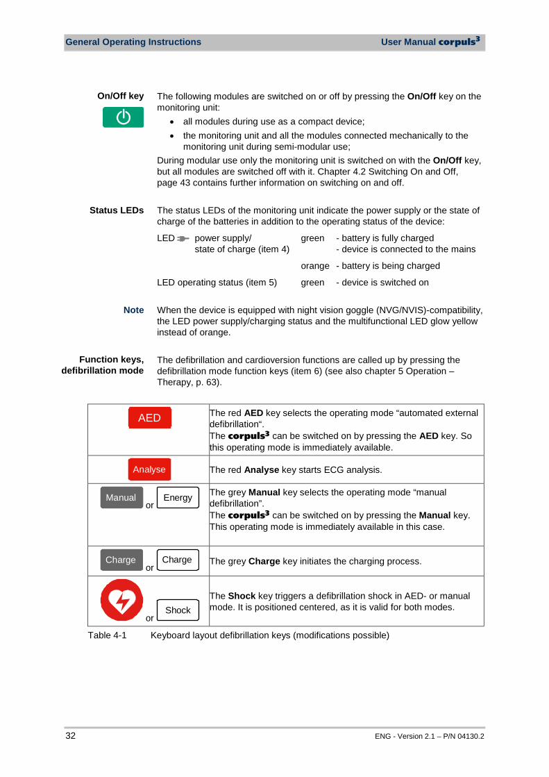
The following modules are switched on or off by pressing the On/Off key on the monitoring unit:
• all modules during use as a compact device; • the monitoring unit and all the modules connected mechanically to the
monitoring unit during semi-modular use; During modular use only the monitoring unit is switched on with the On/Off key, but all modules are switched off with it. Chapter 4.2 Switching On and Off, page 43 contains further information on switching on and off. The status LEDs of the monitoring unit indicate the power supply or the state of charge of the batteries in addition to the operating status of the device:
LED power supply/ state of charge (item 4)
green - battery is fully charged - device is connected to the mains
orange - battery is being charged
LED operating status (item 5) green - device is switched on When the device is equipped with night vision goggle (NVG/NVIS)-compatibility, the LED power supply/charging status and the multifunctional LED glow yellow instead of orange. The defibrillation and cardioversion functions are called up by pressing the defibrillation mode function keys (item 6) (see also chapter 5 Operation – Therapy, p. 63).
AED
The red AED key selects the operating mode “automated external defibrillation“. The corpuls3 can be switched on by pressing the AED key. So this operating mode is immediately available.
Analyse
The red Analyse key starts ECG analysis.
ManuellManual
or Energy
The grey Manual key selects the operating mode “manual defibrillation”. The corpuls3 can be switched on by pressing the Manual key. This operating mode is immediately available in this case.
LadenCharge
or Charge
The grey Charge key initiates the charging process.
or Shock
The Shock key triggers a defibrillation shock in AED- or manual mode. It is positioned centered, as it is valid for both modes.
Table 4-1 Keyboard layout defibrillation keys (modifications possible)
Status LEDs
Function keys, defibrillation mode
On/Off key
Note
User Manual corpuls3 General Operating Instructions
ENG - Version 2.1 – P/N 04130.2 33
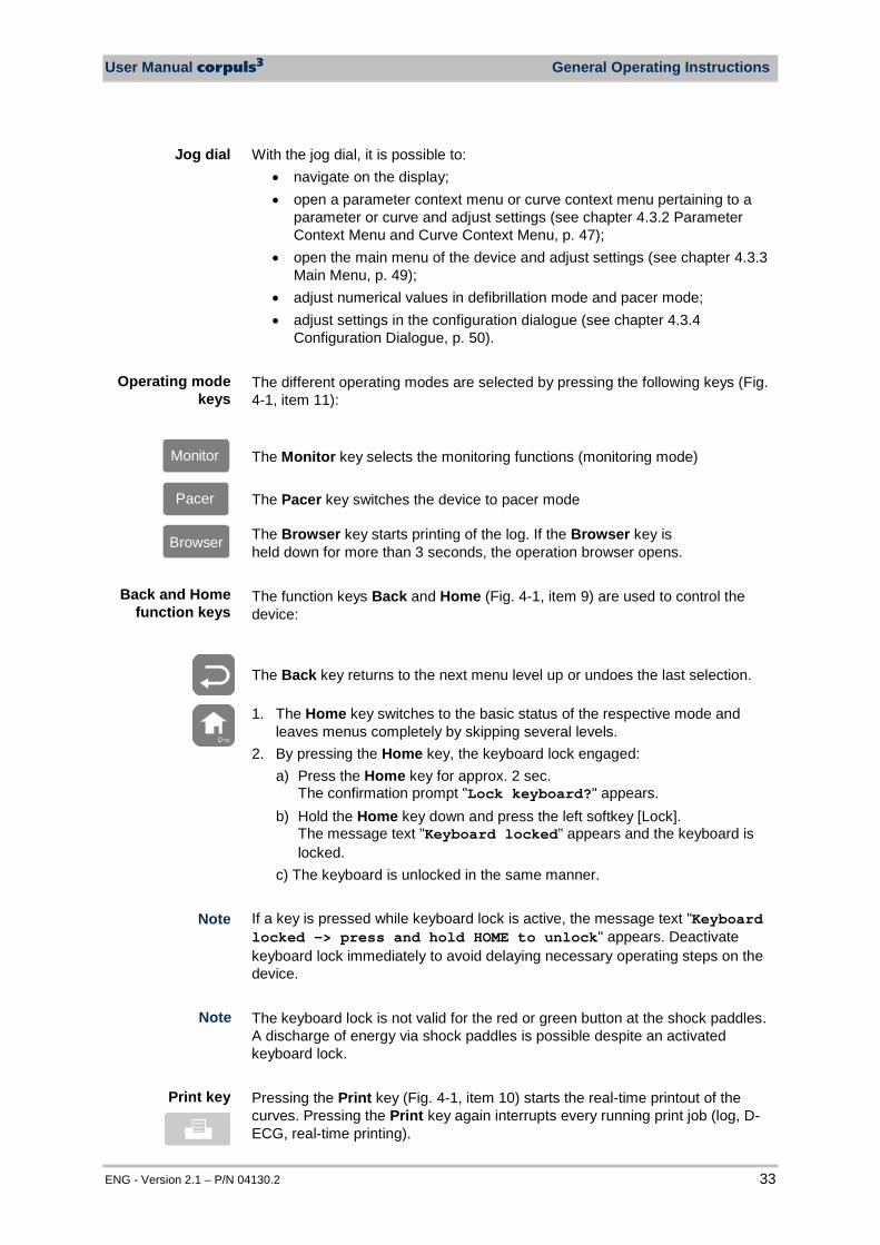
With the jog dial, it is possible to: • navigate on the display; • open a parameter context menu or curve context menu pertaining to a
parameter or curve and adjust settings (see chapter 4.3.2 Parameter Context Menu and Curve Context Menu, p. 47);
• open the main menu of the device and adjust settings (see chapter 4.3.3 Main Menu, p. 49);
• adjust numerical values in defibrillation mode and pacer mode; • adjust settings in the configuration dialogue (see chapter 4.3.4
Configuration Dialogue, p. 50). The different operating modes are selected by pressing the following keys (Fig. 4-1, item 11):
Monitor
The Monitor key selects the monitoring functions (monitoring mode)
Pacer
The Pacer key switches the device to pacer mode
Browser
The Browser key starts printing of the log. If the Browser key is held down for more than 3 seconds, the operation browser opens. The function keys Back and Home (Fig. 4-1, item 9) are used to control the device:
The Back key returns to the next menu level up or undoes the last selection.
1. The Home key switches to the basic status of the respective mode and leaves menus completely by skipping several levels.
2. By pressing the Home key, the keyboard lock engaged: a) Press the Home key for approx. 2 sec.
The confirmation prompt "Lock keyboard?" appears. b) Hold the Home key down and press the left softkey [Lock].
The message text "Keyboard locked" appears and the keyboard is locked.
c) The keyboard is unlocked in the same manner. If a key is pressed while keyboard lock is active, the message text "Keyboard locked -> press and hold HOME to unlock" appears. Deactivate keyboard lock immediately to avoid delaying necessary operating steps on the device. The keyboard lock is not valid for the red or green button at the shock paddles. A discharge of energy via shock paddles is possible despite an activated keyboard lock. Pressing the Print key (Fig. 4-1, item 10) starts the real-time printout of the curves. Pressing the Print key again interrupts every running print job (log, D-ECG, real-time printing).
Back and Home function keys
Operating mode keys
Jog dial
Print key
Note
Note
General Operating Instructions User Manual corpuls3
34 ENG - Version 2.1 – P/N 04130.2
The time span after which the printer stops automatically can be pre-set in the printer configuration. For more information see chapter 7.1.3 Printer settings, p. 143.
The softkeys (Fig. 4-1, item 12) are assigned different functions, depending on the current operating mode or selected dialogue. The current function is displayed in the softkey line.
By pressing the Alarm key (Fig. 4-1, item 1), the alarm history of all physiological and technical alarms is called up. All the alarms which have occurred appear in this list with their time of occurrence. 1. Press the Alarm key to retrieve the alarm history. 2. Press the Alarm key to confirm the alarm. 3. Repeat step 2 until all alarms have been confirmed. Severe technical alarms reported by the alarm system cannot be deleted from the alarm history and are marked in red type. Physiological alarms can be suspended for a selected time span (up to 120 sec or permanently; see chapter 7.4.5 Alarm Configuration (Persons Responsible for the Device), page 166) by pressing the Alarm key for approx. 3 sec. Technical alarms cannot be suspended. For the alarm suspension, a maximum period of 60 seconds is recommended (see also chapter 7.4.5 Alarm Configuration (Persons Responsible for the Device), p. 166). Pressing the Event key (Fig. 4-1, item 2) records a time stamp which marks the current ECG data and vital parameter values. Based on this marking, this data can subsequently be located in the data memory, viewed and assessed. If voice recording is enabled, pressing the Event key also stores a 15 second recording of the surrounding noises (5 sec. before and 10 sec. after pressing the key). Pressing the Event key appears as a “Event recorded” in the log. If the lead DE should be represented in the monitoring mode, select this via the curve context menu (see chapter 4.3.2 Parameter Context Menu and Curve Context Menu, page 47).
Softkeys
Alarm key
Event key
Note
Note
Note

User Manual corpuls3 General Operating Instructions
ENG - Version 2.1 – P/N 04130.2 35
4.1.2 Basic Structure of the Display Pages on the Monitoring Unit
The display has the following structure:
Fig. 4-2 Monitoring unit, example of basic structure of the display pages
1 Status line 2 Parameter area 3 Curve and display area 4 Message line 5 Softkey line
The colours of the parameters and curves in the illustrations of this user manual may differ from the actual display. The following data are displayed in the status line (item 1):
• Physiological and technical alarms • Patient’s name (editable) • Time and deployment time alternating every 5 seconds • Symbols for telemetry-functions • State of charge of the batteries on mains operation • Remaining running time of the device on battery operation • Connection status of the modules
Connection status Meaning
All three components are connected mechanically and communicate visually via an infrared interface.
Status line
Note
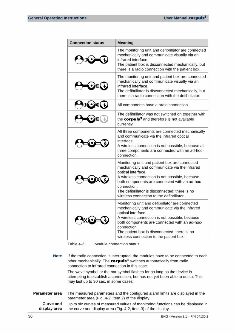
General Operating Instructions User Manual corpuls3
36 ENG - Version 2.1 – P/N 04130.2
Connection status Meaning
(((
The monitoring unit and defibrillator are connected mechanically and communicate visually via an infrared interface. The patient box is disconnected mechanically, but there is a radio connection with the patient box.
The monitoring unit and patient box are connected mechanically and communicate visually via an infrared interface. The defibrillator is disconnected mechanically, but there is a radio connection with the defibrillator.
(((
All components have a radio connection.
The defibrillator was not switched on together with the corpuls3 and therefore is not available currently.
All three components are connected mechanically and communicate via the infrared optical interface. A wireless connection is not possible, because all three components are connected with an ad-hoc-connection.
x
Monitoring unit and patient box are connected mechanically and communicate via the infrared optical interface. A wireless connection is not possible, because both components are connected with an ad-hoc-connection. The defibrillator is disconnected; there is no wireless connection to the defibrillator.
x
Monitoring unit and defibrillator are connected mechanically and communicate via the infrared optical interface. A wireless connection is not possible, because both components are connected with an ad-hoc-connection The patient box is disconnected; there is no wireless connection to the patient box.
Table 4-2 Module connection status If the radio connection is interrupted, the modules have to be connected to each other mechanically. The corpuls3 switches automatically from radio connection to infrared connection in this case. The wave symbol or the bar symbol flashes for as long as the device is attempting to establish a connection, but has not yet been able to do so. This may last up to 30 sec. in some cases. The measured parameters and the configured alarm limits are displayed in the parameter area (Fig. 4-2, item 2) of the display. Up to six curves of measured values of monitoring functions can be displayed in the curve and display area (Fig. 4-2, item 3) of the display.
Parameter area
Curve and display area
Note

User Manual corpuls3 General Operating Instructions
ENG - Version 2.1 – P/N 04130.2 37
If the device is in defibrillator or pacer mode, the parameters of the respective operating mode are displayed in the bottom half of the display. In case of a diagnostic ECG, all 12 leads are displayed simultaneously as curves. In the message line (Fig. 4-2, item 4) of the screen, additional interactions with the user interface are displayed, e.g. to enter the PIN code for the OPERATOR user level or to enter patient data). The current function assignment of the softkeys is displayed in the softkey line (Fig. 4-2, item 5). Further options of the structure of the screen page can be configured (see chapter 7.1.2 Display Configuration, p. 140).
Fig. 4-3 Screen page, example with horizontal and vertical parameter area
1 Status line 2 Parameter areas 3 Curve and display area 4 Message line 5- Softkey line
Softkey line
View configuration
Message line
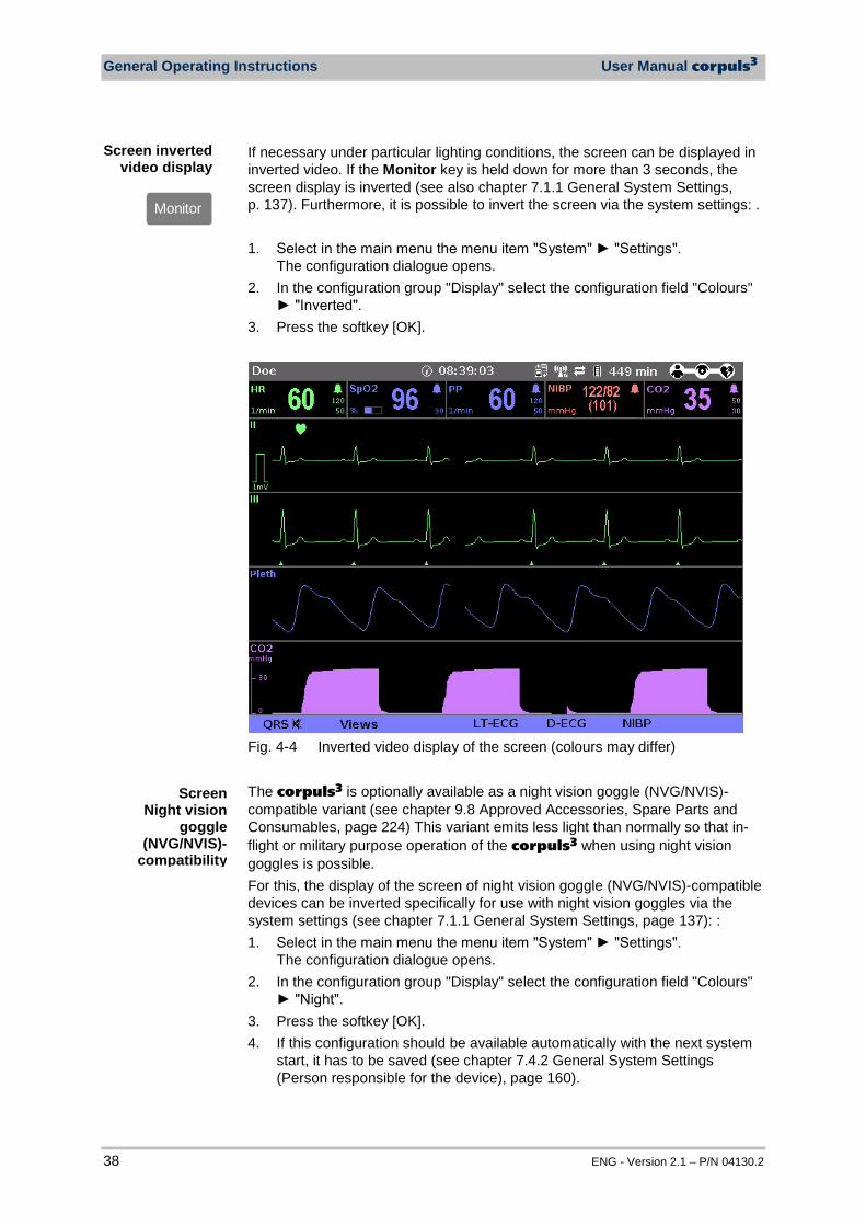
General Operating Instructions User Manual corpuls3
38 ENG - Version 2.1 – P/N 04130.2
If necessary under particular lighting conditions, the screen can be displayed in inverted video. If the Monitor key is held down for more than 3 seconds, the screen display is inverted (see also chapter 7.1.1 General System Settings, p. 137). Furthermore, it is possible to invert the screen via the system settings: . 1. Select in the main menu the menu item "System" "Settings".
The configuration dialogue opens. 2. In the configuration group "Display" select the configuration field "Colours"
"Inverted". 3. Press the softkey [OK].
Fig. 4-4 Inverted video display of the screen (colours may differ) The corpuls3 is optionally available as a night vision goggle (NVG/NVIS)-compatible variant (see chapter 9.8 Approved Accessories, Spare Parts and Consumables, page 224) This variant emits less light than normally so that in-flight or military purpose operation of the corpuls3 when using night vision goggles is possible. For this, the display of the screen of night vision goggle (NVG/NVIS)-compatible devices can be inverted specifically for use with night vision goggles via the system settings (see chapter 7.1.1 General System Settings, page 137): : 1. Select in the main menu the menu item "System" "Settings".
The configuration dialogue opens. 2. In the configuration group "Display" select the configuration field "Colours"
"Night". 3. Press the softkey [OK]. 4. If this configuration should be available automatically with the next system
start, it has to be saved (see chapter 7.4.2 General System Settings (Person responsible for the device), page 160).
Screen inverted video display
Monitor
Screen Night vision
goggle (NVG/NVIS)-
compatibility
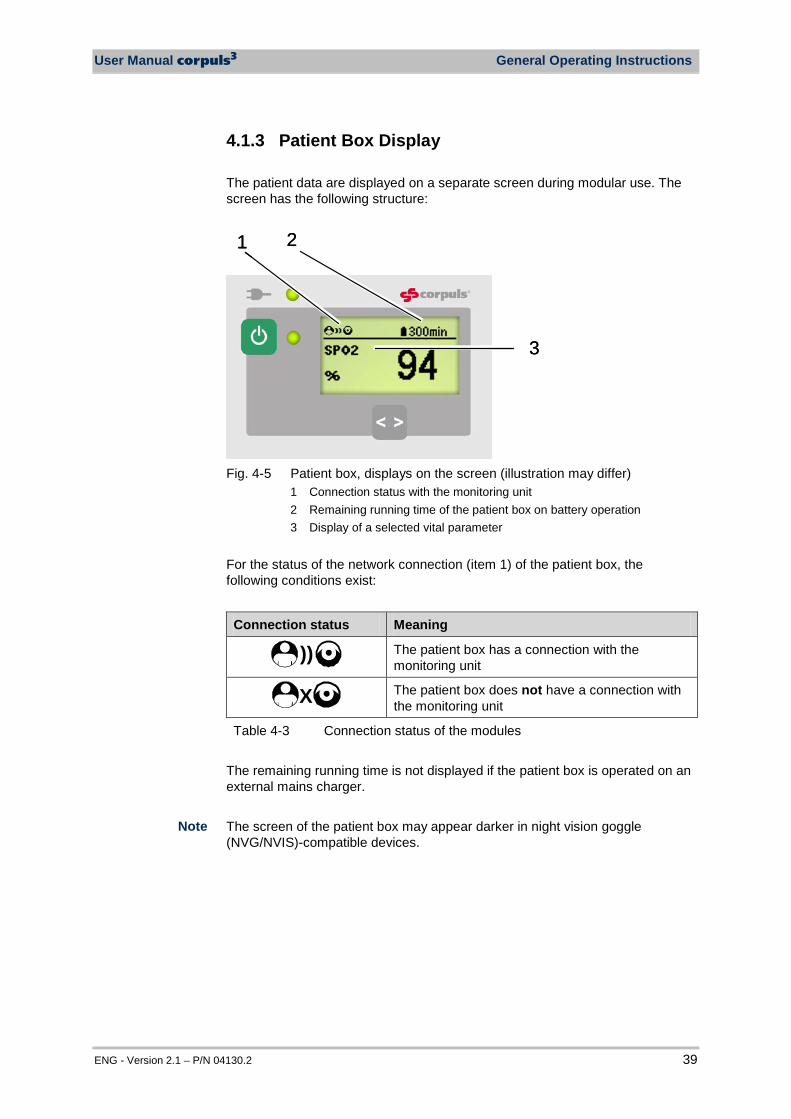
User Manual corpuls3 General Operating Instructions
ENG - Version 2.1 – P/N 04130.2 39
4.1.3 Patient Box Display The patient data are displayed on a separate screen during modular use. The screen has the following structure:
2
3
1 2
3
1
Fig. 4-5 Patient box, displays on the screen (illustration may differ)
1 Connection status with the monitoring unit 2 Remaining running time of the patient box on battery operation 3 Display of a selected vital parameter
For the status of the network connection (item 1) of the patient box, the following conditions exist:
Connection status Meaning
)) The patient box has a connection with the monitoring unit
X The patient box does not have a connection with the monitoring unit
Table 4-3 Connection status of the modules The remaining running time is not displayed if the patient box is operated on an external mains charger. The screen of the patient box may appear darker in night vision goggle (NVG/NVIS)-compatible devices.
Note
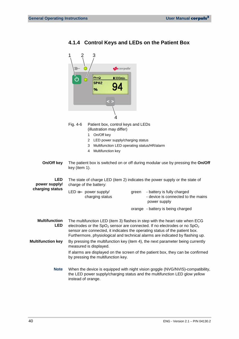
General Operating Instructions User Manual corpuls3
40 ENG - Version 2.1 – P/N 04130.2
4.1.4 Control Keys and LEDs on the Patient Box
2
4
31
Fig. 4-6 Patient box, control keys and LEDs
(illustration may differ) 1 On/Off key 2 LED power supply/charging status 3 Multifunction LED operating status/HR/alarm 4 Multifunction key
The patient box is switched on or off during modular use by pressing the On/Off key (item 1). The state of charge LED (item 2) indicates the power supply or the state of charge of the battery:
LED power supply/ charging status
green - battery is fully charged - device is connected to the mains power supply
orange - battery is being charged The multifunction LED (item 3) flashes in step with the heart rate when ECG electrodes or the SpO2 sensor are connected. If no electrodes or no SpO2 sensor are connected, it indicates the operating status of the patient box. Furthermore, physiological and technical alarms are indicated by flashing up. By pressing the multifunction key (item 4), the next parameter being currently measured is displayed. If alarms are displayed on the screen of the patient box, they can be confirmed by pressing the multifunction key. When the device is equipped with night vision goggle (NVG/NVIS)-compatibility, the LED power supply/charging status and the multifunction LED glow yellow instead of orange.
On/Off key
LED power supply/
charging status
Multifunction LED
Multifunction key
Note
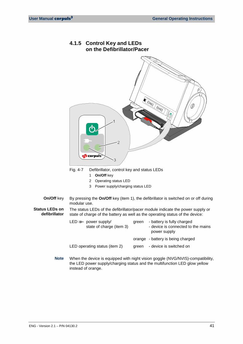
User Manual corpuls3 General Operating Instructions
ENG - Version 2.1 – P/N 04130.2 41
4.1.5 Control Key and LEDs on the Defibrillator/Pacer
Fig. 4-7 Defibrillator, control key and status LEDs
1 On/Off key 2 Operating status LED 3 Power supply/charging status LED
By pressing the On/Off key (item 1), the defibrillator is switched on or off during modular use. The status LEDs of the defibrillator/pacer module indicate the power supply or state of charge of the battery as well as the operating status of the device:
LED power supply/ state of charge (item 3)
green - battery is fully charged - device is connected to the mains power supply
orange - battery is being charged
LED operating status (item 2) green - device is switched on When the device is equipped with night vision goggle (NVG/NVIS)-compatibility, the LED power supply/charging status and the multifunction LED glow yellow instead of orange.
On/Off key
Status LEDs on defibrillator
Note
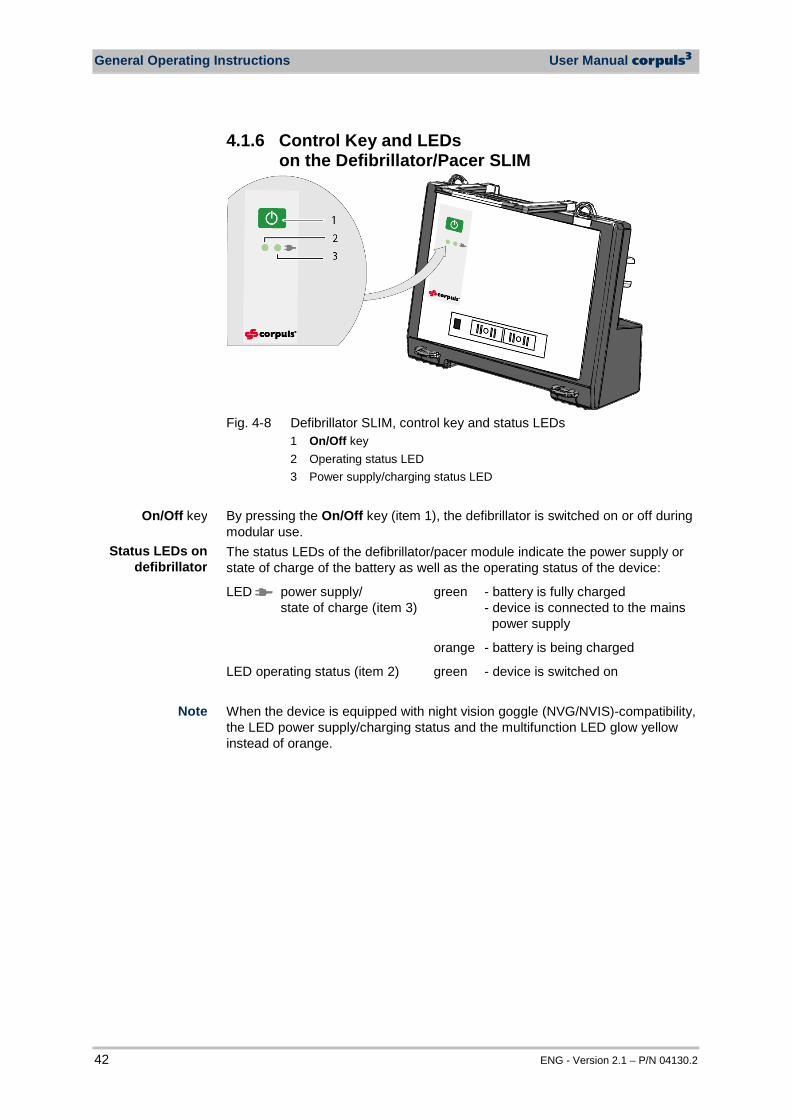
General Operating Instructions User Manual corpuls3
42 ENG - Version 2.1 – P/N 04130.2
4.1.6 Control Key and LEDs on the Defibrillator/Pacer SLIM
Fig. 4-8 Defibrillator SLIM, control key and status LEDs
1 On/Off key 2 Operating status LED 3 Power supply/charging status LED
By pressing the On/Off key (item 1), the defibrillator is switched on or off during modular use. The status LEDs of the defibrillator/pacer module indicate the power supply or state of charge of the battery as well as the operating status of the device:
LED power supply/ state of charge (item 3)
green - battery is fully charged - device is connected to the mains power supply
orange - battery is being charged
LED operating status (item 2) green - device is switched on When the device is equipped with night vision goggle (NVG/NVIS)-compatibility, the LED power supply/charging status and the multifunction LED glow yellow instead of orange.
On/Off key
Status LEDs on defibrillator
Note
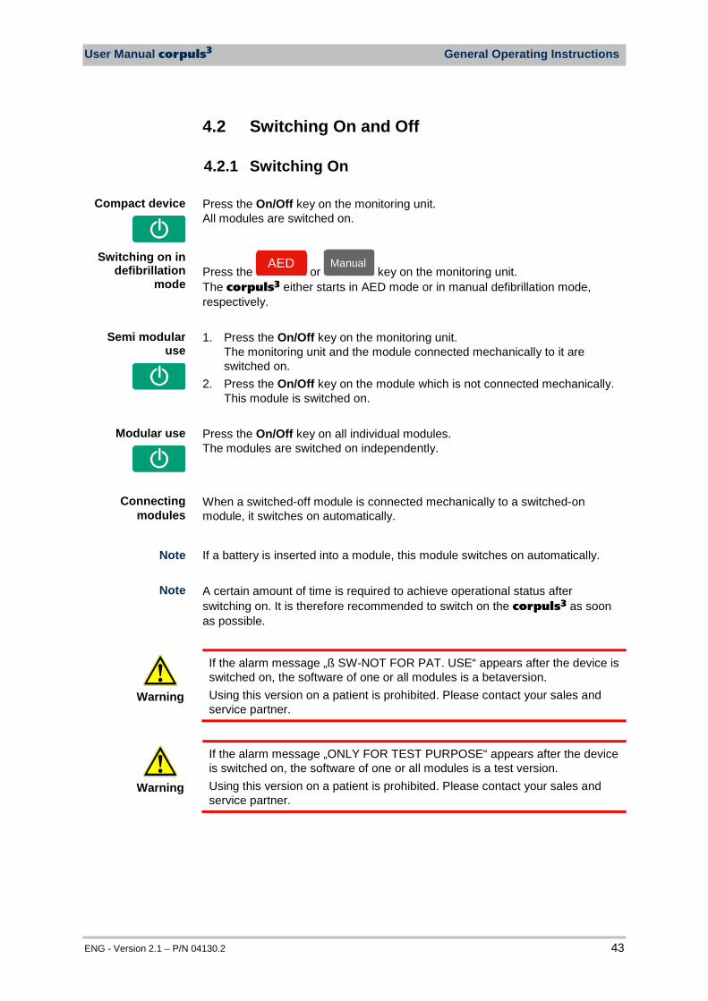
User Manual corpuls3 General Operating Instructions
ENG - Version 2.1 – P/N 04130.2 43
4.2 Switching On and Off
4.2.1 Switching On Press the On/Off key on the monitoring unit. All modules are switched on.
Press the AED
or ManuellManual
key on the monitoring unit. The corpuls3 either starts in AED mode or in manual defibrillation mode, respectively. 1. Press the On/Off key on the monitoring unit.
The monitoring unit and the module connected mechanically to it are switched on.
2. Press the On/Off key on the module which is not connected mechanically. This module is switched on.
Press the On/Off key on all individual modules. The modules are switched on independently. When a switched-off module is connected mechanically to a switched-on module, it switches on automatically.
If a battery is inserted into a module, this module switches on automatically. A certain amount of time is required to achieve operational status after switching on. It is therefore recommended to switch on the corpuls3 as soon as possible.
Warning
If the alarm message „ß SW-NOT FOR PAT. USE“ appears after the device is switched on, the software of one or all modules is a betaversion. Using this version on a patient is prohibited. Please contact your sales and service partner.
Warning
If the alarm message „ONLY FOR TEST PURPOSE“ appears after the device is switched on, the software of one or all modules is a test version. Using this version on a patient is prohibited. Please contact your sales and service partner.
Compact device
Semi modular use
Modular use
Connecting modules
Note
Switching on in defibrillation
mode
Note
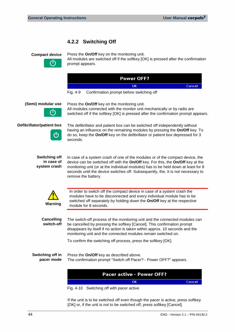
General Operating Instructions User Manual corpuls3
44 ENG - Version 2.1 – P/N 04130.2
4.2.2 Switching Off Press the On/Off key on the monitoring unit. All modules are switched off if the softkey [OK] is pressed after the confirmation prompt appears.
Fig. 4-9 Confirmation prompt before switching off Press the On/Off key on the monitoring unit. All modules connected with the monitor unit mechanically or by radio are switched off if the softkey [OK] is pressed after the confirmation prompt appears. The defibrillator and patient box can be switched off independently without having an influence on the remaining modules by pressing the On/Off key. To do so, keep the On/Off key on the defibrillator or patient box depressed for 3 seconds. In case of a system crash of one of the modules or of the compact device, the device can be switched off with the On/Off key. For this, the On/Off key at the monitoring unit (or at the individual modules) has to be held down at least for 8 seconds until the device switches off. Subsequently, the. It is not necessary to remove the battery.
Warning
In order to switch off the compact device in case of a system crash the modules have to be disconnected and every individual module has to be switched off separately by holding down the On/Off key at the respective module for 8 seconds.
The switch-off process of the monitoring unit and the connected modules can be cancelled by pressing the softkey [Cancel]. This confirmation prompt disappears by itself if no action is taken within approx. 10 seconds and the monitoring unit and the connected modules remain switched on.
To confirm the switching off process, press the softkey [OK].
Press the On/Off key as described above. The confirmation prompt “Switch off Pacer? - Power OFF?" appears.
Fig. 4-10 Switching off with pacer active If the unit is to be switched off even though the pacer is active, press softkey [OK] or, if the unit is not to be switched off, press softkey [Cancel].
Cancelling switch-off
Compact device
(Semi) modular use
Defibrillator/patient box
Switching off in case of
system crash
Switching off in pacer mode

User Manual corpuls3 General Operating Instructions
ENG - Version 2.1 – P/N 04130.2 45
If no connection with the patient box and/or defibrillator/pacer exists at the time of switching off the monitoring unit or if a timing problem exists between the modules, this is indicated to the user by the message “Check modules”:
Fig. 4-11 Warning on switching off In this case, separate the modules and check whether all modules have been shut down. If this is not the case, switch off the modules which have not been switched off by pressing the respective On/Off key.
Warnings on switching off
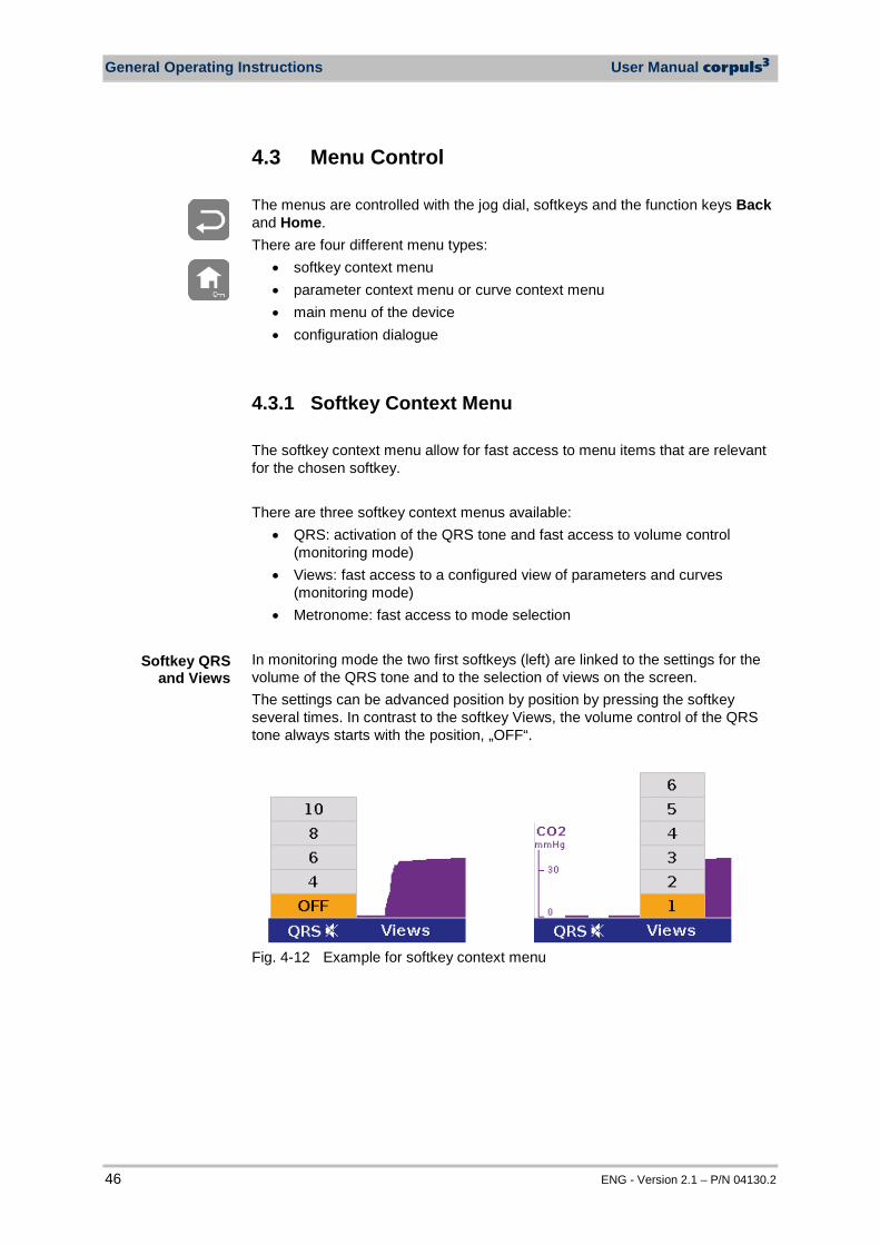
General Operating Instructions User Manual corpuls3
46 ENG - Version 2.1 – P/N 04130.2
4.3 Menu Control The menus are controlled with the jog dial, softkeys and the function keys Back and Home. There are four different menu types:
• softkey context menu • parameter context menu or curve context menu • main menu of the device • configuration dialogue
4.3.1 Softkey Context Menu The softkey context menu allow for fast access to menu items that are relevant for the chosen softkey. There are three softkey context menus available:
• QRS: activation of the QRS tone and fast access to volume control (monitoring mode)
• Views: fast access to a configured view of parameters and curves (monitoring mode)
• Metronome: fast access to mode selection In monitoring mode the two first softkeys (left) are linked to the settings for the volume of the QRS tone and to the selection of views on the screen. The settings can be advanced position by position by pressing the softkey several times. In contrast to the softkey Views, the volume control of the QRS tone always starts with the position, „OFF“.
Fig. 4-12 Example for softkey context menu
Softkey QRS and Views
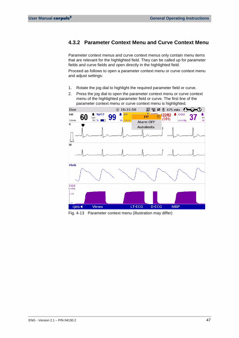
User Manual corpuls3 General Operating Instructions
ENG - Version 2.1 – P/N 04130.2 47
4.3.2 Parameter Context Menu and Curve Context Menu Parameter context menus and curve context menus only contain menu items that are relevant for the highlighted field. They can be called up for parameter fields and curve fields and open directly in the highlighted field. Proceed as follows to open a parameter context menu or curve context menu and adjust settings: 1. Rotate the jog dial to highlight the required parameter field or curve. 2. Press the jog dial to open the parameter context menu or curve context
menu of the highlighted parameter field or curve. The first line of the parameter context menu or curve context menu is highlighted.
Fig. 4-13 Parameter context menu (illustration may differ)

General Operating Instructions User Manual corpuls3
48 ENG - Version 2.1 – P/N 04130.2
Fig. 4-14 Curve context menu 3. If another value is to be assigned to the parameter field or the curve field
for display, press the jog dial and select the required parameter by rotating. 4. Press the jog dial again to confirm selection of the required parameter. 5. Select further parameters of the parameter context menu or curve context
menu by rotating the jog dial and confirm by pressing the jog dial. Press the Home key to quit the parameter context menu or curve context menu. If a new curve is selected in the curve context menu, the curves are sorted automatically in ascending order.
Note

User Manual corpuls3 General Operating Instructions
ENG - Version 2.1 – P/N 04130.2 49
4.3.3 Main Menu To select the main menu of the device and adjust settings, proceed as follows: 1. Press the jog dial to open the main menu of the device.
Fig. 4-15 Main menu 2. Select the required item in the main menu by rotating the jog dial and
confirm by pressing the jog dial. 3. Select the required menu item in the submenu by rotating the jog dial and
confirm by pressing the jog dial. 4. The corresponding configuration dialogue opens.
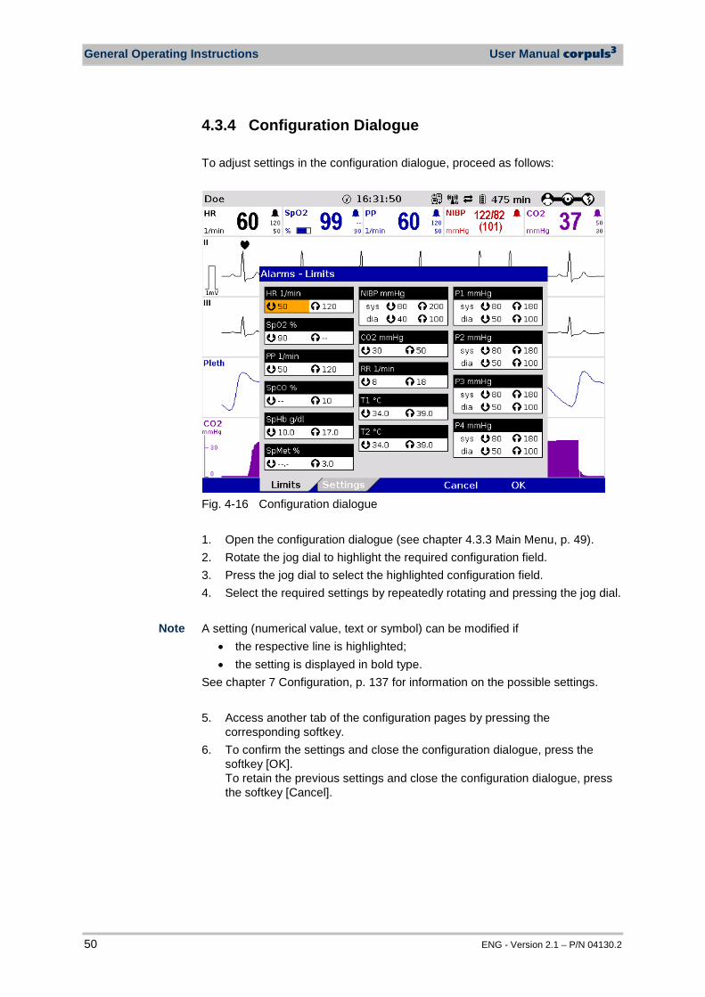
General Operating Instructions User Manual corpuls3
50 ENG - Version 2.1 – P/N 04130.2
4.3.4 Configuration Dialogue To adjust settings in the configuration dialogue, proceed as follows:
Fig. 4-16 Configuration dialogue 1. Open the configuration dialogue (see chapter 4.3.3 Main Menu, p. 49). 2. Rotate the jog dial to highlight the required configuration field. 3. Press the jog dial to select the highlighted configuration field. 4. Select the required settings by repeatedly rotating and pressing the jog dial. A setting (numerical value, text or symbol) can be modified if
• the respective line is highlighted; • the setting is displayed in bold type.
See chapter 7 Configuration, p. 137 for information on the possible settings. 5. Access another tab of the configuration pages by pressing the
corresponding softkey. 6. To confirm the settings and close the configuration dialogue, press the
softkey [OK]. To retain the previous settings and close the configuration dialogue, press the softkey [Cancel].
Note
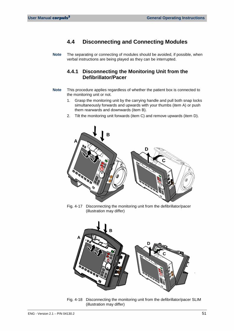
User Manual corpuls3 General Operating Instructions
ENG - Version 2.1 – P/N 04130.2 51
4.4 Disconnecting and Connecting Modules The separating or connecting of modules should be avoided, if possible, when verbal instructions are being played as they can be interrupted.
4.4.1 Disconnecting the Monitoring Unit from the Defibrillator/Pacer
This procedure applies regardless of whether the patient box is connected to the monitoring unit or not. 1. Grasp the monitoring unit by the carrying handle and pull both snap locks
simultaneously forwards and upwards with your thumbs (item A) or push them rearwards and downwards (item B).
2. Tilt the monitoring unit forwards (item C) and remove upwards (item D).
C
AB
D
Fig. 4-17 Disconnecting the monitoring unit from the defibrillator/pacer
(illustration may differ)
C
DA
B
Fig. 4-18 Disconnecting the monitoring unit from the defibrillator/pacer SLIM
(illustration may differ)
Note
Note
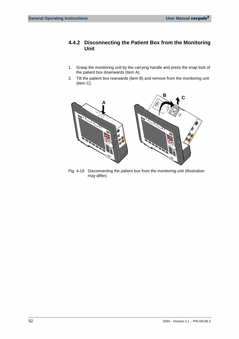
General Operating Instructions User Manual corpuls3
52 ENG - Version 2.1 – P/N 04130.2
4.4.2 Disconnecting the Patient Box from the Monitoring Unit
1. Grasp the monitoring unit by the carrying handle and press the snap lock of
the patient box downwards (item A). 2. Tilt the patient box rearwards (item B) and remove from the monitoring unit
(item C).
ACB
Fig. 4-19 Disconnecting the patient box from the monitoring unit (illustration
may differ)
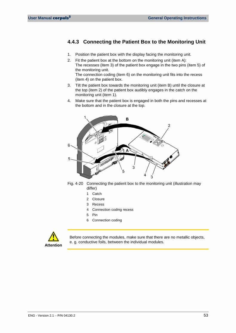
User Manual corpuls3 General Operating Instructions
ENG - Version 2.1 – P/N 04130.2 53
4.4.3 Connecting the Patient Box to the Monitoring Unit 1. Position the patient box with the display facing the monitoring unit. 2. Fit the patient box at the bottom on the monitoring unit (item A):
The recesses (item 3) of the patient box engage in the two pins (item 5) of the monitoring unit. The connection coding (item 6) on the monitoring unit fits into the recess (item 4) on the patient box.
3. Tilt the patient box towards the monitoring unit (item B) until the closure at the top (item 2) of the patient box audibly engages in the catch on the monitoring unit (item 1).
4. Make sure that the patient box is engaged in both the pins and recesses at the bottom and in the closure at the top.
Fig. 4-20 Connecting the patient box to the monitoring unit (illustration may
differ) 1 Catch 2 Closure 3 Recess 4 Connection coding recess 5 Pin 6 Connection coding
Attention
Before connecting the modules, make sure that there are no metallic objects, e. g. conductive foils, between the individual modules.
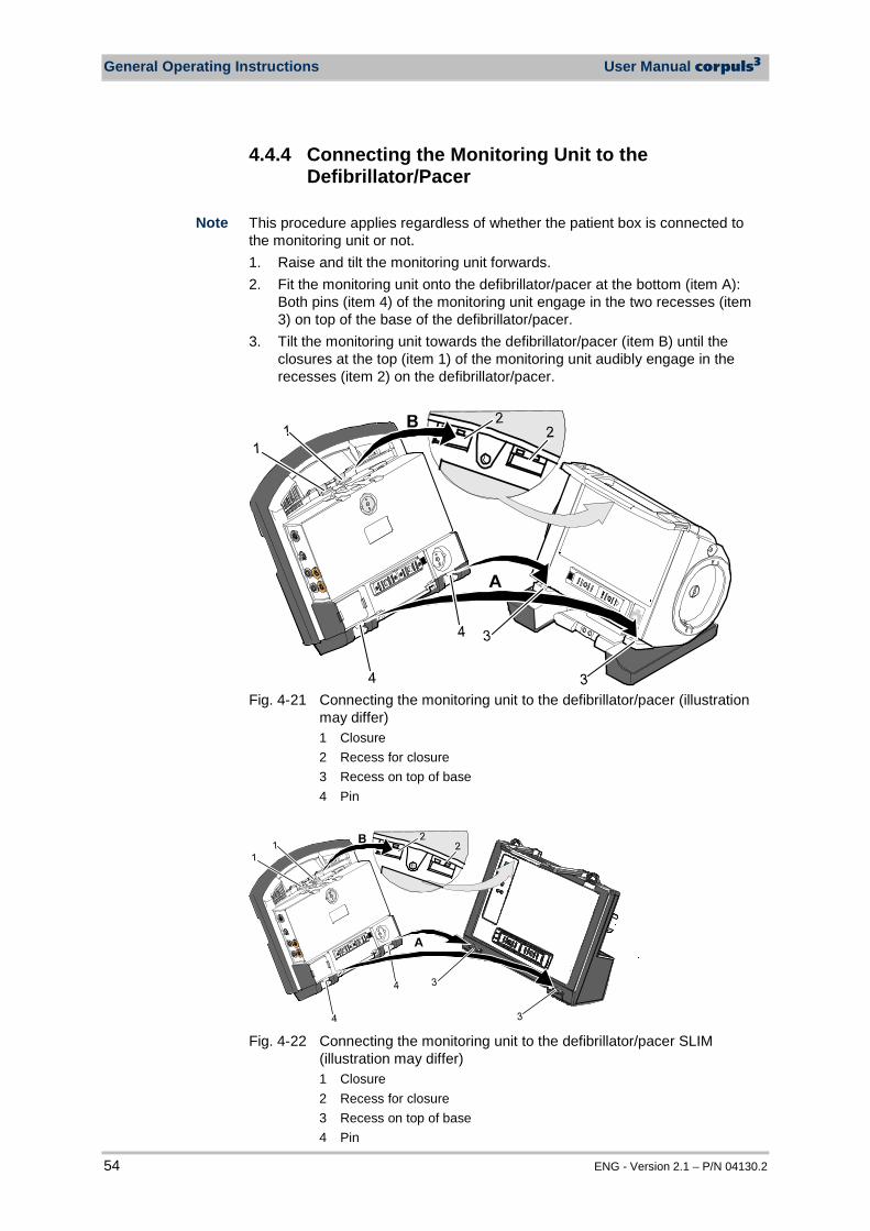
General Operating Instructions User Manual corpuls3
54 ENG - Version 2.1 – P/N 04130.2
4.4.4 Connecting the Monitoring Unit to the Defibrillator/Pacer
This procedure applies regardless of whether the patient box is connected to the monitoring unit or not. 1. Raise and tilt the monitoring unit forwards. 2. Fit the monitoring unit onto the defibrillator/pacer at the bottom (item A):
Both pins (item 4) of the monitoring unit engage in the two recesses (item 3) on top of the base of the defibrillator/pacer.
3. Tilt the monitoring unit towards the defibrillator/pacer (item B) until the closures at the top (item 1) of the monitoring unit audibly engage in the recesses (item 2) on the defibrillator/pacer.
Fig. 4-21 Connecting the monitoring unit to the defibrillator/pacer (illustration
may differ) 1 Closure 2 Recess for closure 3 Recess on top of base 4 Pin
Fig. 4-22 Connecting the monitoring unit to the defibrillator/pacer SLIM
(illustration may differ) 1 Closure 2 Recess for closure 3 Recess on top of base 4 Pin
Note
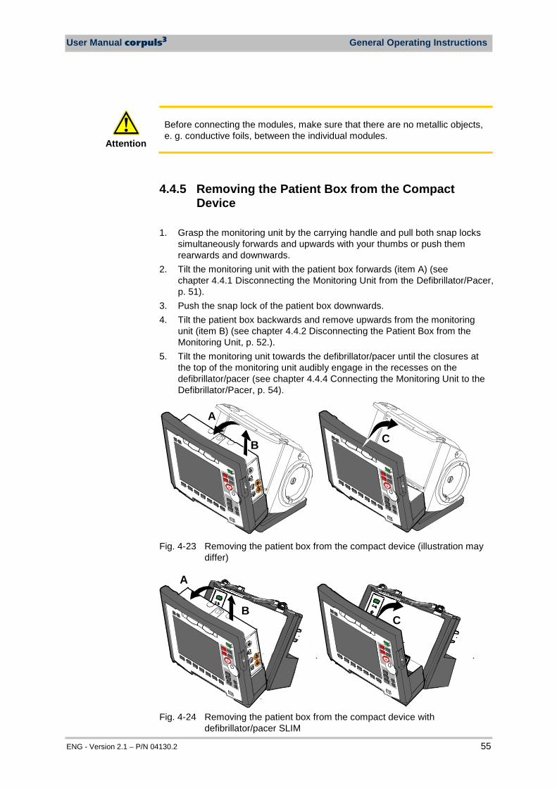
User Manual corpuls3 General Operating Instructions
ENG - Version 2.1 – P/N 04130.2 55
Attention
Before connecting the modules, make sure that there are no metallic objects, e. g. conductive foils, between the individual modules.
4.4.5 Removing the Patient Box from the Compact Device
1. Grasp the monitoring unit by the carrying handle and pull both snap locks
simultaneously forwards and upwards with your thumbs or push them rearwards and downwards.
2. Tilt the monitoring unit with the patient box forwards (item A) (see chapter 4.4.1 Disconnecting the Monitoring Unit from the Defibrillator/Pacer, p. 51).
3. Push the snap lock of the patient box downwards. 4. Tilt the patient box backwards and remove upwards from the monitoring
unit (item B) (see chapter 4.4.2 Disconnecting the Patient Box from the Monitoring Unit, p. 52.).
5. Tilt the monitoring unit towards the defibrillator/pacer until the closures at the top of the monitoring unit audibly engage in the recesses on the defibrillator/pacer (see chapter 4.4.4 Connecting the Monitoring Unit to the Defibrillator/Pacer, p. 54).
A
CB
Fig. 4-23 Removing the patient box from the compact device (illustration may
differ)
A
BC
Fig. 4-24 Removing the patient box from the compact device with
defibrillator/pacer SLIM
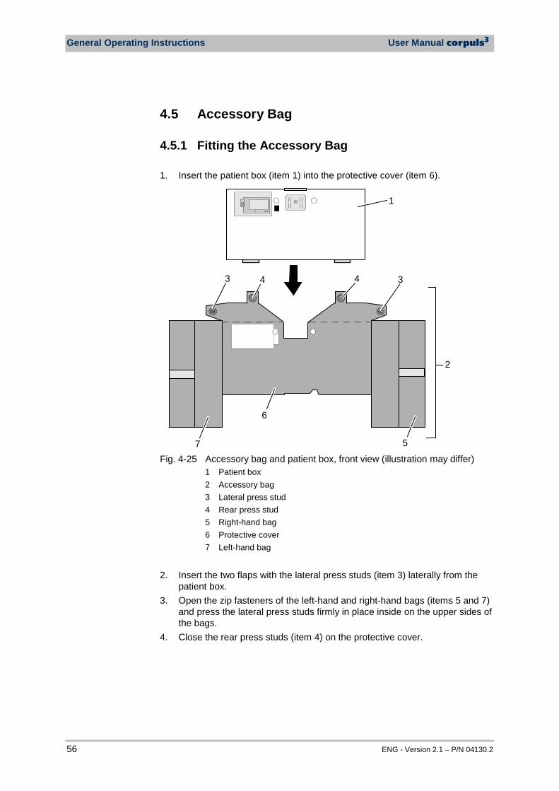
General Operating Instructions User Manual corpuls3
56 ENG - Version 2.1 – P/N 04130.2
4.5 Accessory Bag
4.5.1 Fitting the Accessory Bag 1. Insert the patient box (item 1) into the protective cover (item 6).
1
34
2
43
7
6
5 Fig. 4-25 Accessory bag and patient box, front view (illustration may differ)
1 Patient box 2 Accessory bag 3 Lateral press stud 4 Rear press stud 5 Right-hand bag 6 Protective cover 7 Left-hand bag
2. Insert the two flaps with the lateral press studs (item 3) laterally from the
patient box. 3. Open the zip fasteners of the left-hand and right-hand bags (items 5 and 7)
and press the lateral press studs firmly in place inside on the upper sides of the bags.
4. Close the rear press studs (item 4) on the protective cover.
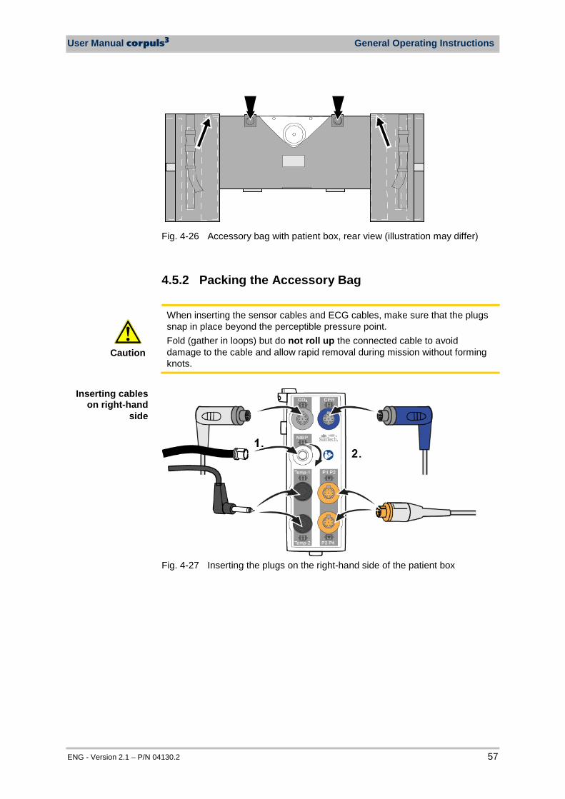
User Manual corpuls3 General Operating Instructions
ENG - Version 2.1 – P/N 04130.2 57
Fig. 4-26 Accessory bag with patient box, rear view (illustration may differ)
4.5.2 Packing the Accessory Bag
Caution
When inserting the sensor cables and ECG cables, make sure that the plugs snap in place beyond the perceptible pressure point. Fold (gather in loops) but do not roll up the connected cable to avoid damage to the cable and allow rapid removal during mission without forming knots.
Fig. 4-27 Inserting the plugs on the right-hand side of the patient box
Inserting cables on right-hand
side
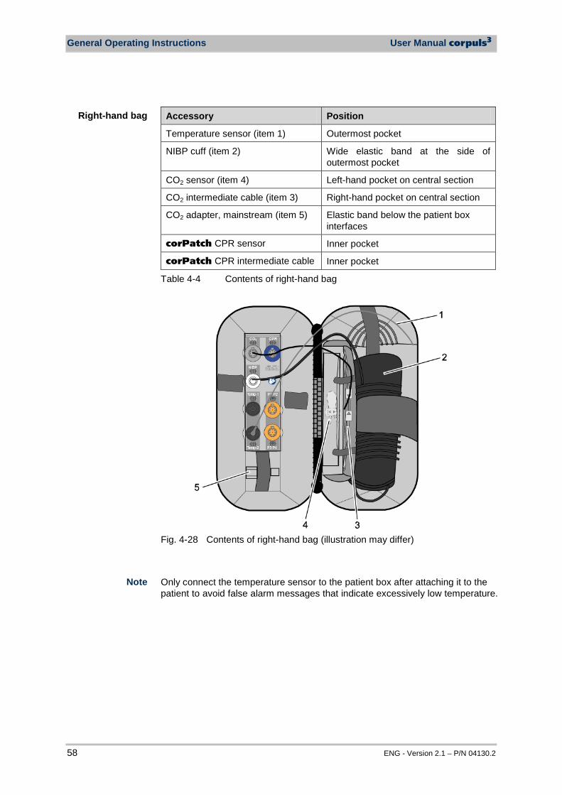
General Operating Instructions User Manual corpuls3
58 ENG - Version 2.1 – P/N 04130.2
Accessory Position
Temperature sensor (item 1) Outermost pocket
NIBP cuff (item 2) Wide elastic band at the side of outermost pocket
CO2 sensor (item 4) Left-hand pocket on central section
CO2 intermediate cable (item 3) Right-hand pocket on central section
CO2 adapter, mainstream (item 5) Elastic band below the patient box interfaces
corPatch CPR sensor Inner pocket
corPatch CPR intermediate cable Inner pocket
Table 4-4 Contents of right-hand bag
Fig. 4-28 Contents of right-hand bag (illustration may differ) Only connect the temperature sensor to the patient box after attaching it to the patient to avoid false alarm messages that indicate excessively low temperature.
Right-hand bag
Note
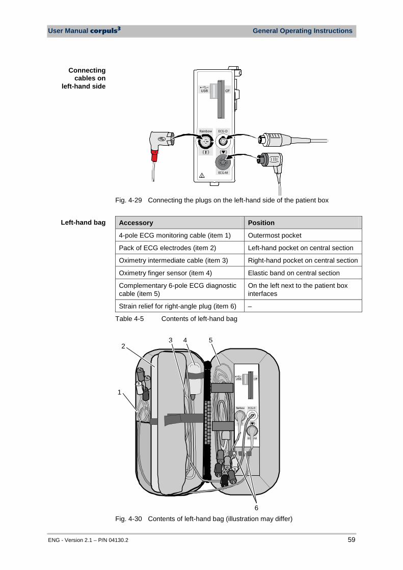
User Manual corpuls3 General Operating Instructions
ENG - Version 2.1 – P/N 04130.2 59
Rainbow ECG-D
ECG-M
Fig. 4-29 Connecting the plugs on the left-hand side of the patient box
Accessory Position
4-pole ECG monitoring cable (item 1) Outermost pocket
Pack of ECG electrodes (item 2) Left-hand pocket on central section
Oximetry intermediate cable (item 3) Right-hand pocket on central section
Oximetry finger sensor (item 4) Elastic band on central section
Complementary 6-pole ECG diagnostic cable (item 5)
On the left next to the patient box interfaces
Strain relief for right-angle plug (item 6) –
Table 4-5 Contents of left-hand bag
1
24 5
6
3
Rainbow ECG-D
Fig. 4-30 Contents of left-hand bag (illustration may differ)
Connecting cables on
left-hand side
Left-hand bag
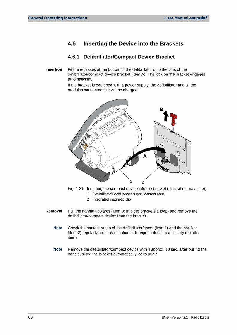
General Operating Instructions User Manual corpuls3
60 ENG - Version 2.1 – P/N 04130.2
4.6 Inserting the Device into the Brackets
4.6.1 Defibrillator/Compact Device Bracket Fit the recesses at the bottom of the defibrillator onto the pins of the defibrillator/compact device bracket (item A). The lock on the bracket engages automatically. If the bracket is equipped with a power supply, the defibrillator and all the modules connected to it will be charged.
B
A
1 2 Fig. 4-31 Inserting the compact device into the bracket (Illustration may differ)
1 Defibrillator/Pacer power supply contact area 2 Integrated magnetic clip
Pull the handle upwards (item B; in older brackets a loop) and remove the defibrillator/compact device from the bracket. Check the contact areas of the defibrillator/pacer (item 1) and the bracket (item 2) regularly for contamination or foreign material, particularly metallic items. Remove the defibrillator/compact device within approx. 10 sec. after pulling the handle, since the bracket automatically locks again.
Insertion
Removal
Note
Note
Insertion
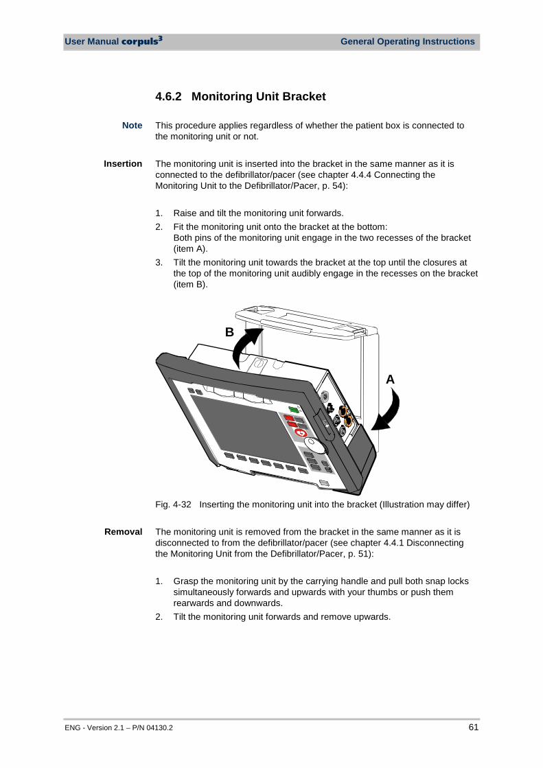
User Manual corpuls3 General Operating Instructions
ENG - Version 2.1 – P/N 04130.2 61
4.6.2 Monitoring Unit Bracket This procedure applies regardless of whether the patient box is connected to the monitoring unit or not. The monitoring unit is inserted into the bracket in the same manner as it is connected to the defibrillator/pacer (see chapter 4.4.4 Connecting the Monitoring Unit to the Defibrillator/Pacer, p. 54): 1. Raise and tilt the monitoring unit forwards. 2. Fit the monitoring unit onto the bracket at the bottom:
Both pins of the monitoring unit engage in the two recesses of the bracket (item A).
3. Tilt the monitoring unit towards the bracket at the top until the closures at the top of the monitoring unit audibly engage in the recesses on the bracket (item B).
A
B
Fig. 4-32 Inserting the monitoring unit into the bracket (Illustration may differ) The monitoring unit is removed from the bracket in the same manner as it is disconnected to from the defibrillator/pacer (see chapter 4.4.1 Disconnecting the Monitoring Unit from the Defibrillator/Pacer, p. 51): 1. Grasp the monitoring unit by the carrying handle and pull both snap locks
simultaneously forwards and upwards with your thumbs or push them rearwards and downwards.
2. Tilt the monitoring unit forwards and remove upwards.
Insertion
Removal
Note
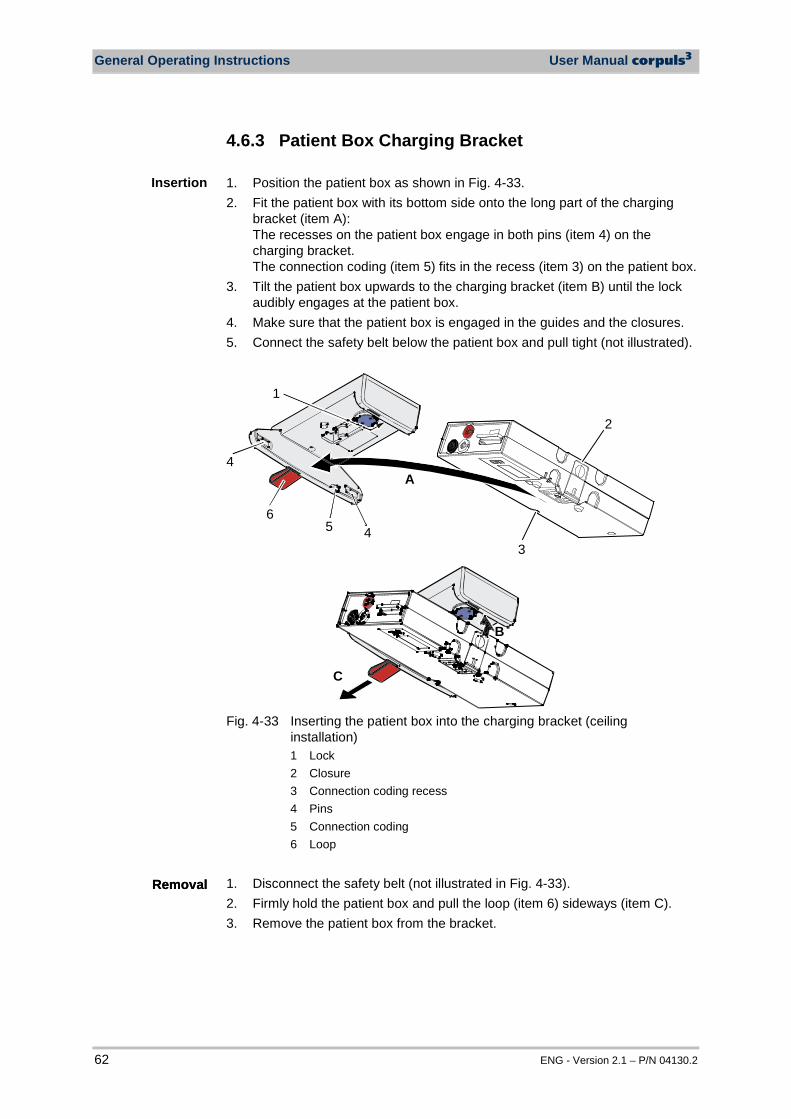
General Operating Instructions User Manual corpuls3
62 ENG - Version 2.1 – P/N 04130.2
4.6.3 Patient Box Charging Bracket 1. Position the patient box as shown in Fig. 4-33. 2. Fit the patient box with its bottom side onto the long part of the charging
bracket (item A): The recesses on the patient box engage in both pins (item 4) on the charging bracket. The connection coding (item 5) fits in the recess (item 3) on the patient box.
3. Tilt the patient box upwards to the charging bracket (item B) until the lock audibly engages at the patient box.
4. Make sure that the patient box is engaged in the guides and the closures. 5. Connect the safety belt below the patient box and pull tight (not illustrated).
1
45
2
3
6
4A
B
C
Fig. 4-33 Inserting the patient box into the charging bracket (ceiling
installation) 1 Lock 2 Closure 3 Connection coding recess 4 Pins 5 Connection coding 6 Loop
1. Disconnect the safety belt (not illustrated in Fig. 4-33). 2. Firmly hold the patient box and pull the loop (item 6) sideways (item C). 3. Remove the patient box from the bracket.
Insertion
Removal Removal
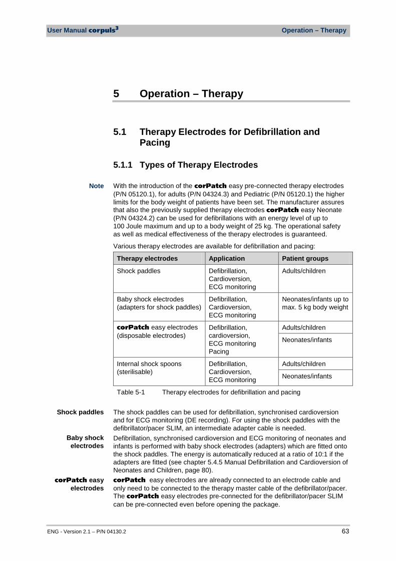
User Manual corpuls3 Operation – Therapy
ENG - Version 2.1 – P/N 04130.2 63
5 Operation – Therapy
5.1 Therapy Electrodes for Defibrillation and Pacing
5.1.1 Types of Therapy Electrodes With the introduction of the corPatch easy pre-connected therapy electrodes (P/N 05120.1), for adults (P/N 04324.3) and Pediatric (P/N 05120.1) the higher limits for the body weight of patients have been set. The manufacturer assures that also the previously supplied therapy electrodes corPatch easy Neonate (P/N 04324.2) can be used for defibrillations with an energy level of up to 100 Joule maximum and up to a body weight of 25 kg. The operational safety as well as medical effectiveness of the therapy electrodes is guaranteed.
Various therapy electrodes are available for defibrillation and pacing:
Therapy electrodes Application Patient groups
Shock paddles Defibrillation, Cardioversion, ECG monitoring
Adults/children
Baby shock electrodes (adapters for shock paddles)
Defibrillation, Cardioversion, ECG monitoring
Neonates/infants up to max. 5 kg body weight
corPatch easy electrodes (disposable electrodes)
Defibrillation, cardioversion, ECG monitoring Pacing
Adults/children
Neonates/infants
Internal shock spoons (sterilisable)
Defibrillation, Cardioversion, ECG monitoring
Adults/children
Neonates/infants
Table 5-1 Therapy electrodes for defibrillation and pacing The shock paddles can be used for defibrillation, synchronised cardioversion and for ECG monitoring (DE recording). For using the shock paddles with the defibrillator/pacer SLIM, an intermediate adapter cable is needed. Defibrillation, synchronised cardioversion and ECG monitoring of neonates and infants is performed with baby shock electrodes (adapters) which are fitted onto the shock paddles. The energy is automatically reduced at a ratio of 10:1 if the adapters are fitted (see chapter 5.4.5 Manual Defibrillation and Cardioversion of Neonates and Children, page 80). corPatch easy electrodes are already connected to an electrode cable and only need to be connected to the therapy master cable of the defibrillator/pacer. The corPatch easy electrodes pre-connected for the defibrillator/pacer SLIM can be pre-connected even before opening the package.
Shock paddles
corPatch easy electrodes
Baby shock electrodes
Note
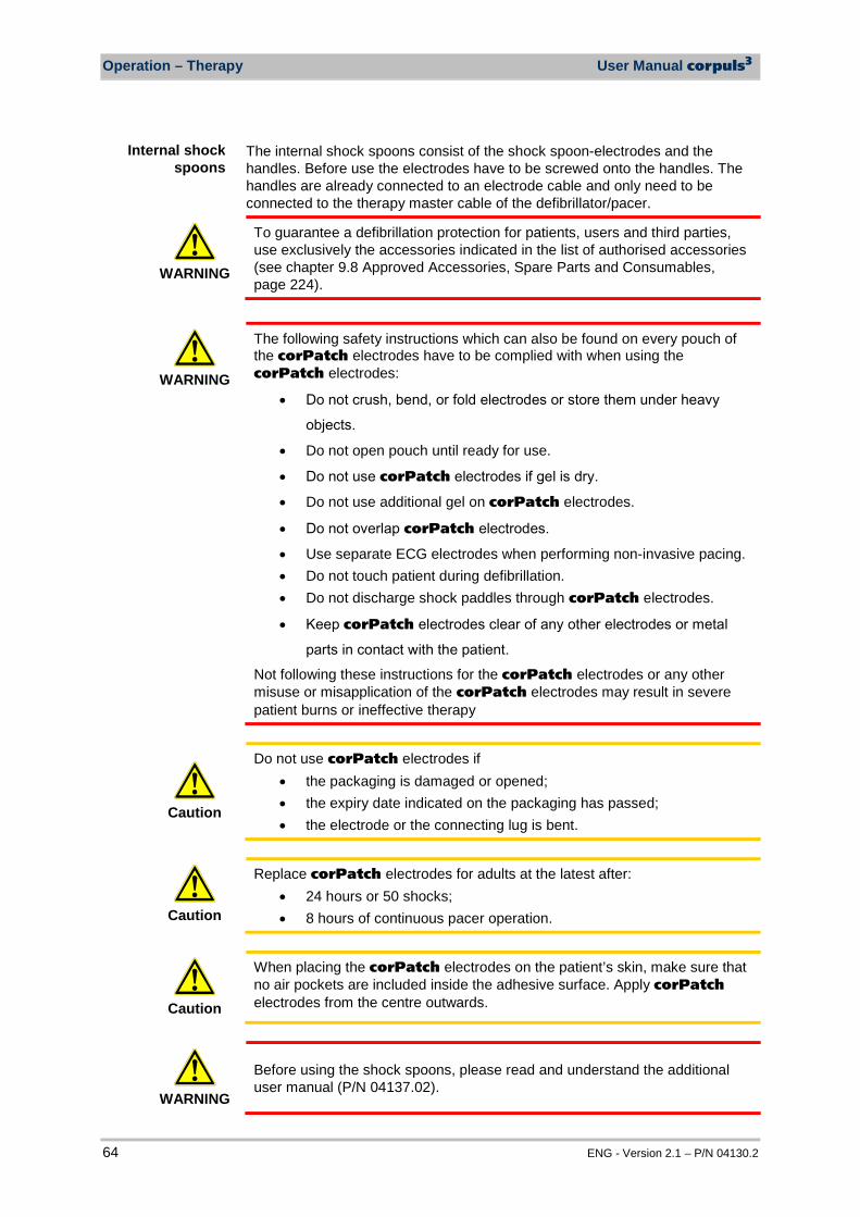
Operation – Therapy User Manual corpuls3
64 ENG - Version 2.1 – P/N 04130.2
The internal shock spoons consist of the shock spoon-electrodes and the handles. Before use the electrodes have to be screwed onto the handles. The handles are already connected to an electrode cable and only need to be connected to the therapy master cable of the defibrillator/pacer.
WARNING
To guarantee a defibrillation protection for patients, users and third parties, use exclusively the accessories indicated in the list of authorised accessories (see chapter 9.8 Approved Accessories, Spare Parts and Consumables, page 224).
WARNING
The following safety instructions which can also be found on every pouch of the corPatch electrodes have to be complied with when using the corPatch electrodes:
• Do not crush, bend, or fold electrodes or store them under heavy objects.
• Do not open pouch until ready for use.
• Do not use corPatch electrodes if gel is dry.
• Do not use additional gel on corPatch electrodes.
• Do not overlap corPatch electrodes.
• Use separate ECG electrodes when performing non-invasive pacing. • Do not touch patient during defibrillation. • Do not discharge shock paddles through corPatch electrodes.
• Keep corPatch electrodes clear of any other electrodes or metal parts in contact with the patient.
Not following these instructions for the corPatch electrodes or any other misuse or misapplication of the corPatch electrodes may result in severe patient burns or ineffective therapy
Caution
Do not use corPatch electrodes if • the packaging is damaged or opened; • the expiry date indicated on the packaging has passed; • the electrode or the connecting lug is bent.
Caution
Replace corPatch electrodes for adults at the latest after: • 24 hours or 50 shocks; • 8 hours of continuous pacer operation.
Caution
When placing the corPatch electrodes on the patient’s skin, make sure that no air pockets are included inside the adhesive surface. Apply corPatch electrodes from the centre outwards.
WARNING
Before using the shock spoons, please read and understand the additional user manual (P/N 04137.02).
Internal shock spoons

User Manual corpuls3 Operation – Therapy
ENG - Version 2.1 – P/N 04130.2 65
5.1.2 Connecting the Electrode Cable To connect the therapy electrodes, connect the corresponding plug (item 2 or item 3 in Fig 5-1) to the therapy master cable (item 1). To disconnect, pull back the red sliding sleeve at the therapy master cable and pull apart the plugs. The plug connectors are twistproof. When using the defibrillator/pacer Slim the intermediate cable (item 5) has to be connected to the therapy socket (item 4) at the rear side of the defibrillator/pacer Slim.
Type of electrode Defibrillator/pacer
Shock paddles and shock spoons Connect the plug of the shock paddles or shock spoons (item 2) to the plug of the therapy master cable (item 1) of the defibrillator/pacer. The connection must snap into place perceptibly.
corPatch easy electrodes (only P/N 04324.1 and 04324.2) Connect the plug (item 3) of the corPatch easy electrodes to the plug of the therapy master cable (item 1) of the defibrillator/ pacer. The connection must snap into place perceptibly.
3
Intermediate cable and corPatch easy electrodes (only P/N 05120.1, 05120.2 and 04324.3) Connect the plug (item 5) correctly orientated (item 1) to the therapy socket (item 4) of the defibrillator/pacer SLIM or to the therapy master cable.
Fig. 5-1 Connecting the therapy electrode cables 1 Therapy master cable with plug and red sliding sleeve 2 Plug of shock paddles and shock spoons 3 Plug of corPatch easy electrodes 4 Therapy socket 5 Plug of corPatch intermediate cable
For orientation and correct connection of the plugs, a raised nub is palpable on both the red sliding sleeve and the plug of the therapy electrodes (only P/N 04324.1 and 04324.2). When oriented correctly, the electrodes are easy to connect. For using the shock paddles with the defibrillator/pacer SLIM, an intermediate adapter cable is needed (see chapter 9.8 Approved Accessories, Spare Parts and Consumables, page 224).
Note
Note
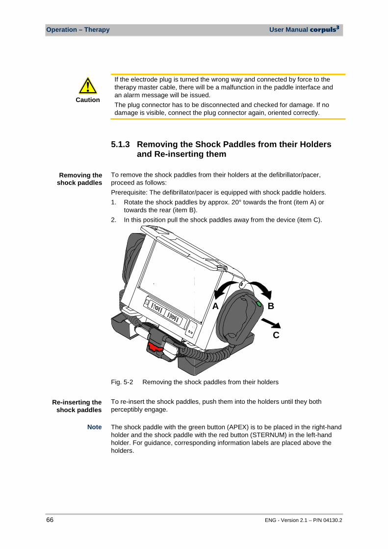
Operation – Therapy User Manual corpuls3
66 ENG - Version 2.1 – P/N 04130.2
Caution
If the electrode plug is turned the wrong way and connected by force to the therapy master cable, there will be a malfunction in the paddle interface and an alarm message will be issued. The plug connector has to be disconnected and checked for damage. If no damage is visible, connect the plug connector again, oriented correctly.
5.1.3 Removing the Shock Paddles from their Holders and Re-inserting them
To remove the shock paddles from their holders at the defibrillator/pacer, proceed as follows: Prerequisite: The defibrillator/pacer is equipped with shock paddle holders. 1. Rotate the shock paddles by approx. 20° towards the front (item A) or
towards the rear (item B). 2. In this position pull the shock paddles away from the device (item C).
A B
C
Fig. 5-2 Removing the shock paddles from their holders To re-insert the shock paddles, push them into the holders until they both perceptibly engage.
The shock paddle with the green button (APEX) is to be placed in the right-hand holder and the shock paddle with the red button (STERNUM) in the left-hand holder. For guidance, corresponding information labels are placed above the holders.
Removing the shock paddles
Re-inserting the shock paddles
Note
User Manual corpuls3 Operation – Therapy
ENG - Version 2.1 – P/N 04130.2 67
5.2 Preparing the Patient for Defibrillation, Cardioversion and Pacer Therapy
Caution
As a side effect of the defibrillation, a reddening of the skin and, in case of excessive hair, burn injuries may occur.
WARNING
Recording of the ECG with therapy electrodes or via the 4 pole ECG monitoring cable is impaired if the skin is contaminated or in case of excessive hair.
Before therapeutic measures can be performed, the patient has to be prepared: 1. Remove clothes from the patient's upper body. 2. Remove any item of jewelry that is located close to or between the two
therapy electrodes. 3. Remove excessive hair, so that the conductive areas of the therapy
electrodes can have full contact with the skin. 4. Clean and dry the skin before using therapy electrodes. With attached therapy electrodes, the patient impedance is measured by the device and displayed in inverted colours as "OK", "LOW" or "HIGH" in defibrillation mode When the impedance is too low or too high, the shock release is blocked. High impedance is displayed in case of: • excessive hair, • contaminated skin, • shock paddles not completely wetted with electrode gel, • too little contact pressure of the shock paddles, • wrong position of the corPatch electrodes, • air pockets included when attaching corPatch electrodes Low impedance is displayed in case of: • use of too much electrode gel on the shock paddles, • too little distance between the therapy electrodes, • wet patient skin, • technical problems with the electrode cable.
WARNING
On metallic and/or wet surfaces the following protective measures have to be taken during defibrillation:
• Release of the shock in semi-modular operation (only when using corPatch electrodes) with sufficient safety distance to patient;
• Placing the patient on a dry stretcher or non-conductive surface before defibrillation.
Preparing the patient
Patient impedance
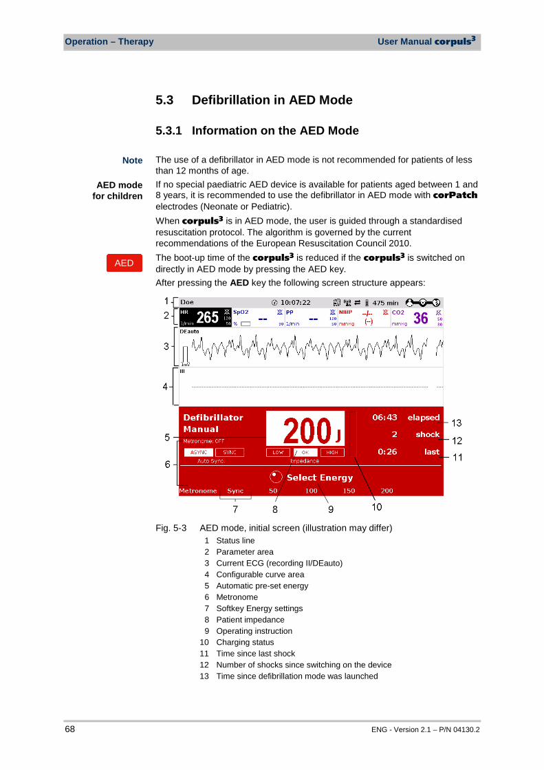
Operation – Therapy User Manual corpuls3
68 ENG - Version 2.1 – P/N 04130.2
5.3 Defibrillation in AED Mode
5.3.1 Information on the AED Mode The use of a defibrillator in AED mode is not recommended for patients of less than 12 months of age. If no special paediatric AED device is available for patients aged between 1 and 8 years, it is recommended to use the defibrillator in AED mode with corPatch electrodes (Neonate or Pediatric). When corpuls3 is in AED mode, the user is guided through a standardised resuscitation protocol. The algorithm is governed by the current recommendations of the European Resuscitation Council 2010. The boot-up time of the corpuls3 is reduced if the corpuls3 is switched on directly in AED mode by pressing the AED key. After pressing the AED key the following screen structure appears:
Fig. 5-3 AED mode, initial screen (illustration may differ)
1 Status line 2 Parameter area 3 Current ECG (recording II/DEauto) 4 Configurable curve area 5 Automatic pre-set energy 6 Metronome 7 Softkey Energy settings 8 Patient impedance 9 Operating instruction 10 Charging status 11 Time since last shock 12 Number of shocks since switching on the device 13 Time since defibrillation mode was launched
Note
AED mode for children
AED

User Manual corpuls3 Operation – Therapy
ENG - Version 2.1 – P/N 04130.2 69
The curve field in the first line of the screen is pre-set and cannot be configured. The first curve field displays the ECG recorded by the respective defibrillation electrodes, switching automatically between IIauto and DEauto: • corPatch electrodes: - DEauto recording, via the corPatch electrodes • shock paddles: - Einthoven lead IIauto,
recorded via ECG electrodes and 4-pole ECG monitoring cable or - DEauto recording, via shock paddles, if no 4-pole ECG monitoring cable is connected
The value of ECG amplitude is set to 10 mm/mV. Automatic ECG amplitude control is disabled. The following keys are available to operate the device in AED mode:
1. AED 2. Analyse 3. Shock
Fig. 5-4 AED mode function keys When using corPatch electrodes, the shock is released by pressing the Shock key at the monitoring unit. When using the shock paddles, the shock is released by pressing both buttons at the shock paddles. The charged defibrillator can be discharged internally by pressing the softkey [Cancel]. In AED mode, a configurable audio recording option is available which is disabled by default. If the audio recording option is enabled by the person responsible for the device, all surrounding noises are recorded (see chapter 7.4.3 Configuration of the Defibrillation Function (Persons Responsible for the Device) , page 163).
WARNING
In each individual case the trained user determines the progress of treatment according to medical requirements. The procedure shown here reflects the operating possibilities of the device.
WARNING
In patients with an implanted pacer placing the therapy electrodes directly above the pacer unit is contraindicated. Under certain conditions irreversible damage to the myocardium might be caused by the invasive pacer electrode. In such a case, choose the reversed position of the therapy electrodes: below the left clavicula parasternally and below the right mamilla, approx. 5th intercostal space at the level of the apex of the heart.
WARNING
In patients with an implanted pacer, it is possible that shockable ECG rhythms or arrhythmias will only be detected to a limited extent.
Audio recording
Operation – Therapy User Manual corpuls3
70 ENG - Version 2.1 – P/N 04130.2
WARNING
If the network configuration of the corpuls3 is modified during ECG analysis in AED mode (change from a wireless radio connection to a mechanical connection or vice versa), the ECG analysis will be interrupted. The ECG analysis must be restarted in this case.
WARNING
Equipment which is not defibrillation proof must be disconnected from patients during defibrillation.
WARNING
When a defibrillation is performed, all necessary ECG cables have to be connected to the patient box at all times and all electrodes have to be attached to the patient. If the 4-pole ECG monitoring cable and the complementary 6-pole diagnostic cable are not used in a defibrillation, they have to be disconnected from the patient box.
WARNING
In defibrillation mode, no physiological alarms are indicated or saved. Technical alarms are signalled acoustically and visually.
5.3.2 Defibrillation in AED mode with corPatch Electrodes
When using corPatch electrodes, the ECG is obtained and the analysis is performed via the corPatch electrodes attached to the patient (indicated as DE). An additional 4-pole ECG monitoring cable is not needed. 1. To start the AED mode, press the AED key. 2. Prepare the patient (see chapter 5.2 Preparing the Patient for Defibrillation,
Cardioversion and Pacer Therapy, page 67). 3. Check the electrode package for damage and check the expiry date. 4. Attach corPatch electrodes to the patient, as shown on the electrode
package. 5. If enabled, select the required energy level via the softkeys or the jog dial
(see chapter 7.4.3 Configuration of the Defibrillation Function (Persons Responsible for the Device) , page 163).
6. To start the ECG analysis, press the Analyse key. 7. With the message "Deliver shock" and the ready-signal, the device
indicates that the defibrillation can be performed. 8. To perform defibrillation, keep the Shock key depressed until the shock
has been delivered. 9. If the shock has been released successfully, the message Shock
performed is shown. 10. The message Shock not recommended indicates that the defibrillation
cannot be performed and that the Shock key is locked. 11. Continue with the standardised or locally valid resuscitation protocol. 12. The message Start analysis indicates that the Analyse key should be
pressed again to perform an ECG analysis.
AED
Analyse
Analyse
Performing a defibrillation
User Manual corpuls3 Operation – Therapy
ENG - Version 2.1 – P/N 04130.2 71
With the introduction of the corPatch easy pre-connected therapy electrodes (P/N 05120.1), for adults (P/N 04324.3) and Pediatric (P/N 05120.1) the higher limits for the body weight of patients have been set. The manufacturer assures that also the previously supplied therapy electrodes corPatch easy Neonate (P/N 04324.2) can be used for defibrillations with an energy level of up to 100 Joule maximum and up to a body weight of 25 kg. The operational safety as well as medical effectiveness of the therapy electrodes is guaranteed.
The CPR rhythm can be supported acoustically by activating the metronome via the softkey [Metronome]. The selected energy level is available for 30 seconds after charging. If no shock is triggered within this time span, the device discharges itself internally.
WARNING
During ECG analysis, it is essential to avoid external commotion and vibration. Keep the patient lying down calmly. Do not touch the patient. It is essential to discontinue artificial respiration during ECG analysis. This leads to false analysis results since the periodic expansion of the chest may simulate an ECG rhythm.
5.3.3 Defibrillation in AED Mode with Shock Paddles To perform a defibrillation in AED mode with shock paddles, an ECG must be obtained for analysis via the ECG electrodes and the 4-pole ECG monitoring cable. To start the AED mode, press the AED key. 1. Prepare the patient (see chapter 5.2 Preparing the Patient for Defibrillation,
Cardioversion and Pacer Therapy, page 67). 2. Place all four ECG electrodes of the 4-pole ECG monitoring cable on the
patient (see chapter 6.2 ECG Monitoring, page 95). 3. Completely wet the electrode surfaces of the shock paddles with
defibrillation electrode gel. 4. If enabled, select the required energy level via the softkeys or the jog dial
(see chapter 7.4.3 Configuration of the Defibrillation Function (Persons Responsible for the Device) , page 163).
5. To start the ECG analysis, press the Analyse key or one of the buttons at the shock paddles.
6. With the message Deliver shock and the ready-signal, the device indicates that the defibrillation can be performed.
AED
Note
Note
Analyse
Note
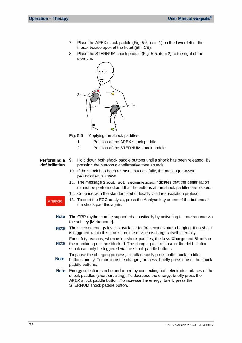
Operation – Therapy User Manual corpuls3
72 ENG - Version 2.1 – P/N 04130.2
7. Place the APEX shock paddle (Fig. 5-5, item 1) on the lower left of the thorax beside apex of the heart (5th ICS).
8. Place the STERNUM shock paddle (Fig. 5-5, item 2) to the right of the sternum.
1
2
Fig. 5-5 Applying the shock paddles
1 Position of the APEX shock paddle 2 Position of the STERNUM shock paddle
9. Hold down both shock paddle buttons until a shock has been released. By pressing the buttons a confirmative tone sounds.
10. If the shock has been released successfully, the message Shock performed is shown.
11. The message Shock not recommended indicates that the defibrillation cannot be performed and that the buttons at the shock paddles are locked.
12. Continue with the standardised or locally valid resuscitation protocol. 13. To start the ECG analysis, press the Analyse key or one of the buttons at
the shock paddles again. The CPR rhythm can be supported acoustically by activating the metronome via the softkey [Metronome]. The selected energy level is available for 30 seconds after charging. If no shock is triggered within this time span, the device discharges itself internally. For safety reasons, when using shock paddles, the keys Charge and Shock on the monitoring unit are blocked. The charging and release of the defibrillation shock can only be triggered via the shock paddle buttons. To pause the charging process, simultaneously press both shock paddle buttons briefly. To continue the charging process, briefly press one of the shock paddle buttons. Energy selection can be performed by connecting both electrode surfaces of the shock paddles (short-circuiting). To decrease the energy, briefly press the APEX shock paddle button. To increase the energy, briefly press the STERNUM shock paddle button.
Performing a defibrillation
Analyse
Note
Note
Note
Note
Note
User Manual corpuls3 Operation – Therapy
ENG - Version 2.1 – P/N 04130.2 73
WARNING
During ECG analysis, it is essential to avoid external commotion and vibration. Keep the patient lying down calmly. Do not touch the patient. It is essential to discontinue artificial respiration during ECG analysis. This leads to false analysis results since the periodic expansion of the chest may simulate an ECG rhythm.
WARNING
Make sure that no defibrillation electrode gel gets into the insulation area between the electrode surface and the handle. Only use defibrillation electrode gel intended for this purpose.
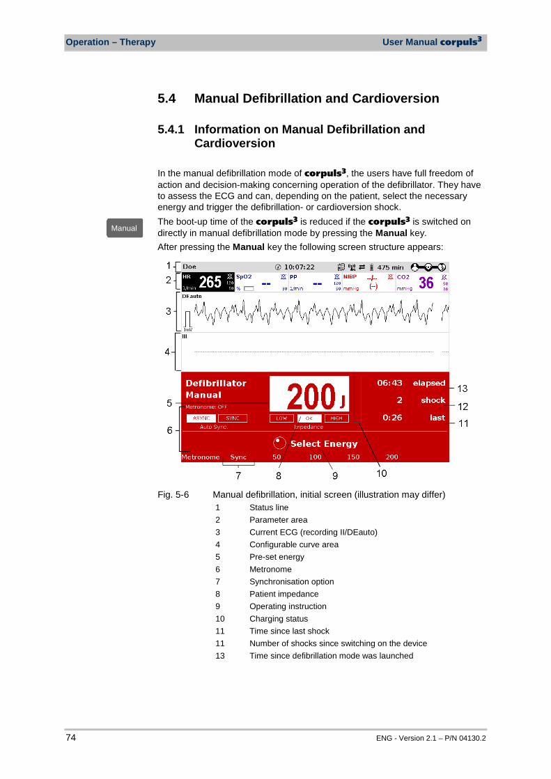
Operation – Therapy User Manual corpuls3
74 ENG - Version 2.1 – P/N 04130.2
5.4 Manual Defibrillation and Cardioversion
5.4.1 Information on Manual Defibrillation and Cardioversion
In the manual defibrillation mode of corpuls3, the users have full freedom of action and decision-making concerning operation of the defibrillator. They have to assess the ECG and can, depending on the patient, select the necessary energy and trigger the defibrillation- or cardioversion shock. The boot-up time of the corpuls3 is reduced if the corpuls3 is switched on directly in manual defibrillation mode by pressing the Manual key. After pressing the Manual key the following screen structure appears:
Fig. 5-6 Manual defibrillation, initial screen (illustration may differ)
1 Status line 2 Parameter area 3 Current ECG (recording II/DEauto) 4 Configurable curve area 5 Pre-set energy 6 Metronome 7 Synchronisation option 8 Patient impedance 9 Operating instruction 10 Charging status 11 Time since last shock 11 Number of shocks since switching on the device 13 Time since defibrillation mode was launched
ManuellManual
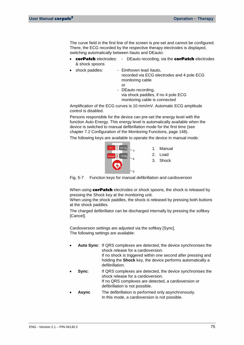
User Manual corpuls3 Operation – Therapy
ENG - Version 2.1 – P/N 04130.2 75
The curve field in the first line of the screen is pre-set and cannot be configured. There, the ECG recorded by the respective therapy electrodes is displayed, switching automatically between IIauto and DEauto: • corPatch electrodes: - DEauto recording, via the corPatch electrodes
& shock spoons • shock paddles: - Einthoven lead IIauto,
recorded via ECG electrodes and 4 pole ECG monitoring cable or - DEauto recording, via shock paddles, if no 4 pole ECG monitoring cable is connected
Amplification of the ECG curves is 10 mm/mV. Automatic ECG amplitude control is disabled. Persons responsible for the device can pre-set the energy level with the function Auto Energy. This energy level is automatically available when the device is switched to manual defibrillation mode for the first time (see chapter 7.2 Configuration of the Monitoring Functions, page 148). The following keys are available to operate the device in manual mode:
1. Manual 2. Load 3. Shock
Fig. 5-7 Function keys for manual defibrillation and cardioversion When using corPatch electrodes or shock spoons, the shock is released by pressing the Shock key at the monitoring unit. When using the shock paddles, the shock is released by pressing both buttons at the shock paddles. The charged defibrillator can be discharged internally by pressing the softkey [Cancel]. Cardioversion settings are adjusted via the softkey [Sync]. The following settings are available: • Auto Sync: If QRS complexes are detected, the device synchronises the
shock release for a cardioversion. If no shock is triggered within one second after pressing and holding the Shock key, the device performs automatically a defibrillation.
• Sync: If QRS complexes are detected, the device synchronises the shock release for a cardioversion. If no QRS complexes are detected, a cardioversion or defibrillation is not possible.
• Async The defibrillation is performed only asynchronously. In this mode, a cardioversion is not possible.
Operation – Therapy User Manual corpuls3
76 ENG - Version 2.1 – P/N 04130.2
In manual mode, a configurable audio recording option is available which is disabled by default. If the audio recording option is enabled by the person responsible for the device, all surrounding noises are recorded (see chapter 7.4.3 Configuration of the Defibrillation Function (Persons Responsible for the Device) , page 163).
WARNING
A cardioversion may lead to ventricular fibrillation or asystole. When performing a cardioversion, mind the following:
• The ECG has to be stable with a heart rate of at least 60/min. • The synchronisation status has to remain constantly on SYNC. • The QRS marks (triangles) have to mark each QRS complex. • The shock release has to be effected according to valid guidelines. • If the shock release does not take place one second after pressing
the buttons at the shock paddles or the Shock key at the monitoring unit, the shock will be released independent of the synchronisation status.
WARNING
Equipment which is not defibrillation proof must be disconnected from patients during defibrillation and cardioversion.
WARNING
When a defibrillation is performed, all necessary ECG cables have to be connected to the patient box at all times and all electrodes have to be attached to the patient. If the 4-pole ECG monitoring cable and the complementary 6-pole diagnostic cable are not used in a defibrillation, they have to be disconnected from the patient box.
WARNING
No physiological alarm events are displayed and saved in defibrillation mode. Technical alarms are indicated visually and acoustically.
5.4.2 Manual Defibrillation with corPatch Electrodes When using corPatch electrodes, the ECG is obtained via the corPatch electrodes attached to the patient (indicated as DE). Via additionally attached ECG electrodes and the 4-pole ECG monitoring cable, further leads can be displayed in the configurable second curve field (see chapter 6.2 ECG Monitoring, page 95). 1. To start the manual defibrillation mode, press the Manual key. 2. Prepare the patient (see chapter 5.2 Preparing the Patient for Defibrillation,
Cardioversion and Pacer Therapy, page 67). 3. Check the electrode package for damage and check the expiry date. 4. Attach corPatch electrodes to the patient, as shown on the electrode
package. Select the required energy level with the jog dial or via the softkeys and confirm by pressing the jog dial.
ManuellManual
Audio recording

User Manual corpuls3 Operation – Therapy
ENG - Version 2.1 – P/N 04130.2 77
5. To start the charging process, press the Charge key. The charging process takes a maximum of 5 seconds depending on the selected energy setting.
6. Wait until the message Ready for shock is displayed on the screen and the ready-signal is sounding. The device is ready for releasing a defibrillation shock.
7. Keep the Shock key depressed until the shock is delivered to perform defibrillation or cardioversion.
8. If the shock has been released successfully, the message Shock performed is shown.
9. Continue with the standardised or locally valid resuscitation protocol. With the introduction of the corPatch easy pre-connected therapy electrodes (P/N 05120.1), for adults (P/N 04324.3) and Pediatric (P/N 05120.1) the higher limits for the body weight of patients have been set. The manufacturer assures that also the previously supplied therapy electrodes corPatch easy Neonate (P/N 04324.2) can be used for defibrillations with an energy level of up to 100 Joule maximum and up to a body weight of 25 kg. The operational safety as well as medical effectiveness of the therapy electrodes is guaranteed.
The CPR rhythm can be supported acoustically by activating the metronome via the softkey [Metronome]. If the jog dial is pressed in manual defibrillation mode, the energy selection at the monitoring unit is only possible via the softkeys. Press the Manual key again, to be able to select the energy level with the jog dial. The selected energy level is available for 30 seconds after charging. If no shock is triggered within this time span, the device discharges itself internally.
5.4.3 Manual Defibrillation and Cardioversion with Shock Paddles
When using shock paddles, the ECG is obtained via the shock paddles pressed to the patient's thorax (indicated as DE). Via additionally attached ECG electrodes and the 4-pole ECG monitoring cable, further leads can be displayed in the configurable second curve field (see chapter 6.2 ECG Monitoring, page 95). Obtaining the ECG via the ECG electrodes and the 4-pole ECG monitoring cable (as explained in the following) assures a better signal quality than via the shock paddles. 1. To start the manual defibrillation mode, press the Manual key. 2. Prepare the patient (see chapter 5.2 Preparing the Patient for Defibrillation,
Cardioversion and Pacer Therapy, page 67). 3. Place all four ECG electrodes of the 4-pole ECG monitoring cable on the
patient (see chapter 6.2 ECG Monitoring, page 95). 4. Completely wet the electrode surfaces of the shock paddles with
defibrillation electrode gel.
LadenCharge
Note
Note
Note
ManuellManual
Note
Note
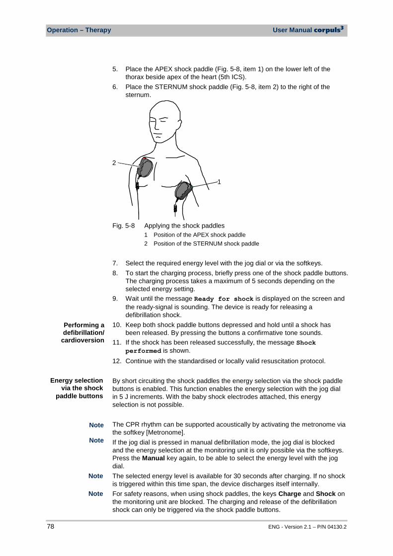
Operation – Therapy User Manual corpuls3
78 ENG - Version 2.1 – P/N 04130.2
5. Place the APEX shock paddle (Fig. 5-8, item 1) on the lower left of the thorax beside apex of the heart (5th ICS).
6. Place the STERNUM shock paddle (Fig. 5-8, item 2) to the right of the sternum.
1
2
Fig. 5-8 Applying the shock paddles
1 Position of the APEX shock paddle 2 Position of the STERNUM shock paddle
7. Select the required energy level with the jog dial or via the softkeys. 8. To start the charging process, briefly press one of the shock paddle buttons.
The charging process takes a maximum of 5 seconds depending on the selected energy setting.
9. Wait until the message Ready for shock is displayed on the screen and the ready-signal is sounding. The device is ready for releasing a defibrillation shock.
10. Keep both shock paddle buttons depressed and hold until a shock has been released. By pressing the buttons a confirmative tone sounds.
11. If the shock has been released successfully, the message Shock performed is shown.
12. Continue with the standardised or locally valid resuscitation protocol. By short circuiting the shock paddles the energy selection via the shock paddle buttons is enabled. This function enables the energy selection with the jog dial in 5 J increments. With the baby shock electrodes attached, this energy selection is not possible.
The CPR rhythm can be supported acoustically by activating the metronome via the softkey [Metronome]. If the jog dial is pressed in manual defibrillation mode, the jog dial is blocked and the energy selection at the monitoring unit is only possible via the softkeys. Press the Manual key again, to be able to select the energy level with the jog dial. The selected energy level is available for 30 seconds after charging. If no shock is triggered within this time span, the device discharges itself internally. For safety reasons, when using shock paddles, the keys Charge and Shock on the monitoring unit are blocked. The charging and release of the defibrillation shock can only be triggered via the shock paddle buttons.
Performing a defibrillation/
cardioversion
Note
Note
Note
Note
Energy selection via the shock
paddle buttons
User Manual corpuls3 Operation – Therapy
ENG - Version 2.1 – P/N 04130.2 79
The charging process can be interrupted by pressing simultaneously both shock paddle buttons briefly. Pressing one of the shock paddle buttons again, continues the charging process. Energy selection can be performed by connecting both electrode surfaces of the shock paddles (short-circuiting). To decrease the energy, briefly press the APEX shock paddle button. To increase the energy, briefly press the STERNUM shock paddle button.
WARNING
Make sure that no defibrillation electrode gel gets into the insulation area between the electrode surface and the handle. Only use defibrillation electrode gel intended for this purpose.
WARNING
Press the shock paddles firmly onto the patient’s thorax when the shock is triggered (approx. 8 kg contact pressure for adults). Keep both shock paddle buttons depressed until the shock is delivered
5.4.4 Manual Defibrillation and Cardioversion with Shock Spoons
WARNING
Before using the shock spoons, please read and understand the safety and preparation notices in the manual (P/N 04137.02).
When using shock spoons, the ECG is obtained via the shock spoons pressed to the patient's heart. It is, however, recommended to obtain the ECG via the 4-pole ECG monitoring cable (see chapter 6.2 ECG Monitoring, page 95). Obtaining the ECG via the ECG electrodes and the 4-pole ECG monitoring cable (as explained in the following) assures a better signal quality than via the shock paddles. When using shock spoons, the energy available is limited by the device to a maximum of 50 J. 1. To start the manual defibrillation mode, press the Manual key. 2. Place all four ECG electrodes of the 4-pole ECG monitoring cable on the
patient (see chapter 6.2 ECG Monitoring, page 95). 3. Screw sterile shock spoons of the correct size into the sterile shock spoon
holders. 4. Select the required energy level with the jog dial or via the softkeys and
confirm by pressing the jog dial. 5. To start the charging process, press the Charge key.
The charging process takes a maximum of 5 seconds depending on the selected energy setting.
Note
Note
ManuellManual
LadenCharge
Note
Note
Note
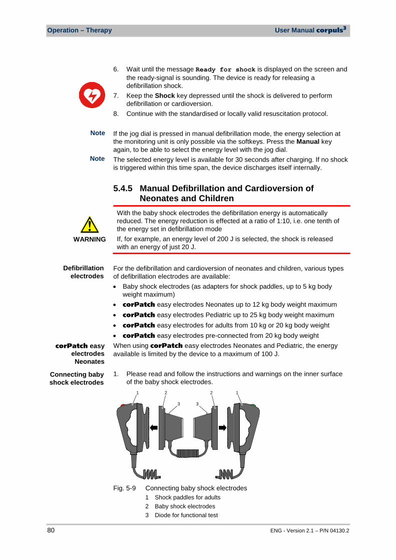
Operation – Therapy User Manual corpuls3
80 ENG - Version 2.1 – P/N 04130.2
6. Wait until the message Ready for shock is displayed on the screen and the ready-signal is sounding. The device is ready for releasing a defibrillation shock.
7. Keep the Shock key depressed until the shock is delivered to perform defibrillation or cardioversion.
8. Continue with the standardised or locally valid resuscitation protocol. If the jog dial is pressed in manual defibrillation mode, the energy selection at the monitoring unit is only possible via the softkeys. Press the Manual key again, to be able to select the energy level with the jog dial. The selected energy level is available for 30 seconds after charging. If no shock is triggered within this time span, the device discharges itself internally.
5.4.5 Manual Defibrillation and Cardioversion of Neonates and Children
WARNING
With the baby shock electrodes the defibrillation energy is automatically reduced. The energy reduction is effected at a ratio of 1:10, i.e. one tenth of the energy set in defibrillation mode If, for example, an energy level of 200 J is selected, the shock is released with an energy of just 20 J.
For the defibrillation and cardioversion of neonates and children, various types of defibrillation electrodes are available: • Baby shock electrodes (as adapters for shock paddles, up to 5 kg body
weight maximum) • corPatch easy electrodes Neonates up to 12 kg body weight maximum • corPatch easy electrodes Pediatric up to 25 kg body weight maximum • corPatch easy electrodes for adults from 10 kg or 20 kg body weight • corPatch easy electrodes pre-connected from 20 kg body weight When using corPatch easy electrodes Neonates and Pediatric, the energy available is limited by the device to a maximum of 100 J. 1. Please read and follow the instructions and warnings on the inner surface
of the baby shock electrodes. 1 2 2 1
3 3
Fig. 5-9 Connecting baby shock electrodes
1 Shock paddles for adults 2 Baby shock electrodes 3 Diode for functional test
Note
Note
Defibrillation electrodes
Connecting baby shock electrodes
corPatch easy electrodes Neonates
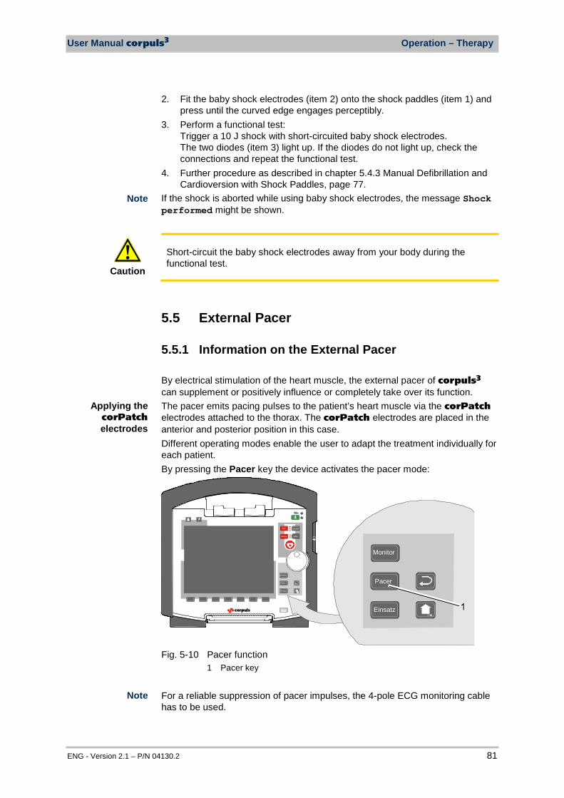
User Manual corpuls3 Operation – Therapy
ENG - Version 2.1 – P/N 04130.2 81
2. Fit the baby shock electrodes (item 2) onto the shock paddles (item 1) and press until the curved edge engages perceptibly.
3. Perform a functional test: Trigger a 10 J shock with short-circuited baby shock electrodes. The two diodes (item 3) light up. If the diodes do not light up, check the connections and repeat the functional test.
4. Further procedure as described in chapter 5.4.3 Manual Defibrillation and Cardioversion with Shock Paddles, page 77.
If the shock is aborted while using baby shock electrodes, the message Shock performed might be shown.
Caution
Short-circuit the baby shock electrodes away from your body during the functional test.
5.5 External Pacer
5.5.1 Information on the External Pacer By electrical stimulation of the heart muscle, the external pacer of corpuls3 can supplement or positively influence or completely take over its function. The pacer emits pacing pulses to the patient’s heart muscle via the corPatch electrodes attached to the thorax. The corPatch electrodes are placed in the anterior and posterior position in this case. Different operating modes enable the user to adapt the treatment individually for each patient. By pressing the Pacer key the device activates the pacer mode:
Einsatz
Monitor
Pacer
AED
Anal yse Laden
Manuell
Einsatz
Monitor
Pacer
Fig. 5-10 Pacer function
1 Pacer key For a reliable suppression of pacer impulses, the 4-pole ECG monitoring cable has to be used.
Applying the corPatch electrodes
Note
Note
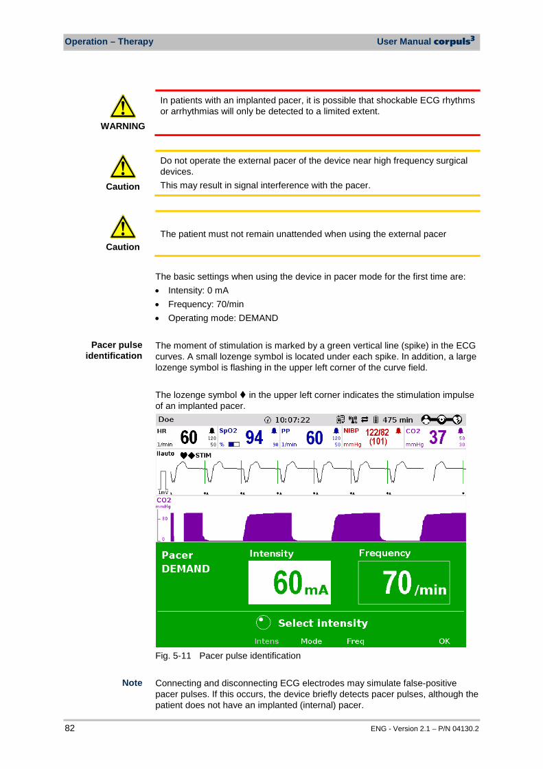
Operation – Therapy User Manual corpuls3
82 ENG - Version 2.1 – P/N 04130.2
WARNING
In patients with an implanted pacer, it is possible that shockable ECG rhythms or arrhythmias will only be detected to a limited extent.
Caution
Do not operate the external pacer of the device near high frequency surgical devices. This may result in signal interference with the pacer.
Caution
The patient must not remain unattended when using the external pacer
The basic settings when using the device in pacer mode for the first time are: • Intensity: 0 mA • Frequency: 70/min • Operating mode: DEMAND The moment of stimulation is marked by a green vertical line (spike) in the ECG curves. A small lozenge symbol is located under each spike. In addition, a large lozenge symbol is flashing in the upper left corner of the curve field. The lozenge symbol in the upper left corner indicates the stimulation impulse of an implanted pacer.
Fig. 5-11 Pacer pulse identification
Connecting and disconnecting ECG electrodes may simulate false-positive pacer pulses. If this occurs, the device briefly detects pacer pulses, although the patient does not have an implanted (internal) pacer.
Pacer pulse identification
Note
User Manual corpuls3 Operation – Therapy
ENG - Version 2.1 – P/N 04130.2 83
Pacer operation is indicated by the message “STIM” in the upper left corner of the curve field. When stimulation is performed, the message “STIM” is flashing. When “STIM” is permanently displayed, the pacer is switched on (e.g. in DEMAND mode in a frequency range in which no stimulation is necessary), but is not active (no stimulation). Only when the pacer is switched off or paused, the message “STIM” is not displayed. The pacer continues to operate in monitoring mode. If the user • presses the On/Off key or • switches to defibrillation mode while the pacer is running, a confirmation prompt appears, warning that the pacer is active. Switching off the pacer or switching to defibrillation mode can be confirmed by pressing the softkey [OK] or aborted by pressing the softkey [Cancel].
As long as the pacer is active, the corpuls3 cannot be switched off or switch to defibrillator mode without a prior confirmation prompt. The pacer can only be operated when corPatch electrodes are connected to the therapy master cable. The pacer is switched off automatically if a cable is removed while running in pacer mode.
5.5.2 Preparing the pacer function In FIX operating mode, pacing is performed with a fixed frequency, regardless of the patient’s own heart rate.
WARNING
The pacer function and the ECG recording function are compromised if adhesion of the corPatch electrodes or ECG electrodes is impaired due to contaminated skin or excessive hair.
Only use corPatch electrodes indicated in the list of approved accessories. The corPatch electrodes must no longer be used after the expiry date indicated on the packaging has passed. 1. Prepare the patient (see chapter 5.2 Preparing the Patient for Defibrillation,
Cardioversion and Pacer Therapy, page 67). 2. If necessary, prepare ECG monitoring (see chapter 6.2.3 Preparing ECG
Monitoring, page 97).
FIX Operating mode
Note
"STIM" message
Note
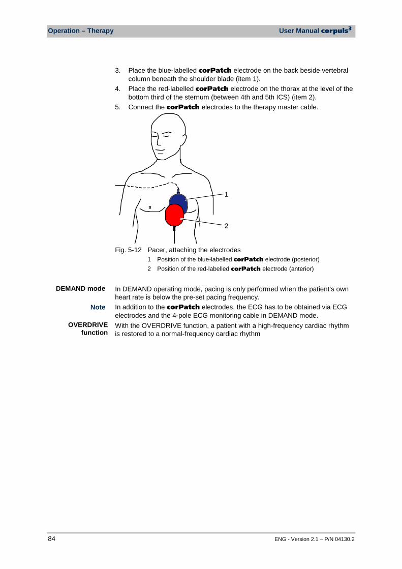
Operation – Therapy User Manual corpuls3
84 ENG - Version 2.1 – P/N 04130.2
3. Place the blue-labelled corPatch electrode on the back beside vertebral column beneath the shoulder blade (item 1).
4. Place the red-labelled corPatch electrode on the thorax at the level of the bottom third of the sternum (between 4th and 5th ICS) (item 2).
5. Connect the corPatch electrodes to the therapy master cable.
2
1
Fig. 5-12 Pacer, attaching the electrodes
1 Position of the blue-labelled corPatch electrode (posterior) 2 Position of the red-labelled corPatch electrode (anterior)
In DEMAND operating mode, pacing is only performed when the patient’s own heart rate is below the pre-set pacing frequency. In addition to the corPatch electrodes, the ECG has to be obtained via ECG electrodes and the 4-pole ECG monitoring cable in DEMAND mode. With the OVERDRIVE function, a patient with a high-frequency cardiac rhythm is restored to a normal-frequency cardiac rhythm
DEMAND mode Note
OVERDRIVE function
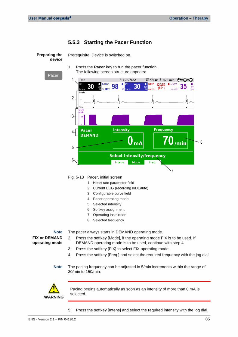
User Manual corpuls3 Operation – Therapy
ENG - Version 2.1 – P/N 04130.2 85
5.5.3 Starting the Pacer Function Prerequisite: Device is switched on. 1. Press the Pacer key to run the pacer function.
The following screen structure appears:
Fig. 5-13 Pacer, initial screen
1 Heart rate parameter field 2 Current ECG (recording II/DEauto) 3 Configurable curve field 4 Pacer operating mode 5 Selected intensity 6 Softkey assignment 7 Operating instruction 8 Selected frequency
The pacer always starts in DEMAND operating mode. 2. Press the softkey [Mode], if the operating mode FIX is to be used. If
DEMAND operating mode is to be used, continue with step 4. 3. Press the softkey [FIX] to select FIX operating mode. 4. Press the softkey [Freq.] and select the required frequency with the jog dial. The pacing frequency can be adjusted in 5/min increments within the range of 30/min to 150/min.
WARNING
Pacing begins automatically as soon as an intensity of more than 0 mA is selected.
5. Press the softkey [Intens] and select the required intensity with the jog dial.
FIX or DEMAND operating mode
Note
Preparing the device
Pacer
Note
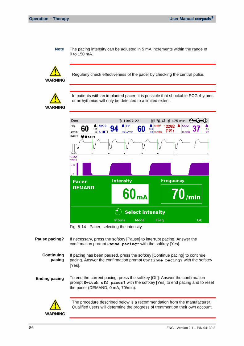
Operation – Therapy User Manual corpuls3
86 ENG - Version 2.1 – P/N 04130.2
The pacing intensity can be adjusted in 5 mA increments within the range of 0 to 150 mA.
WARNING
Regularly check effectiveness of the pacer by checking the central pulse.
WARNING
In patients with an implanted pacer, it is possible that shockable ECG rhythms or arrhythmias will only be detected to a limited extent.
Fig. 5-14 Pacer, selecting the intensity If necessary, press the softkey [Pause] to interrupt pacing. Answer the confirmation prompt Pause pacing? with the softkey [Yes]. If pacing has been paused, press the softkey [Continue pacing] to continue pacing. Answer the confirmation prompt Continue pacing? with the softkey [Yes]. To end the current pacing, press the softkey [Off]. Answer the confirmation prompt Switch off pacer? with the softkey [Yes] to end pacing and to reset the pacer (DEMAND, 0 mA, 70/min).
WARNING
The procedure described below is a recommendation from the manufacturer. Qualified users will determine the progress of treatment on their own account.
Note
Pause pacing?
Continuing pacing
Ending pacing
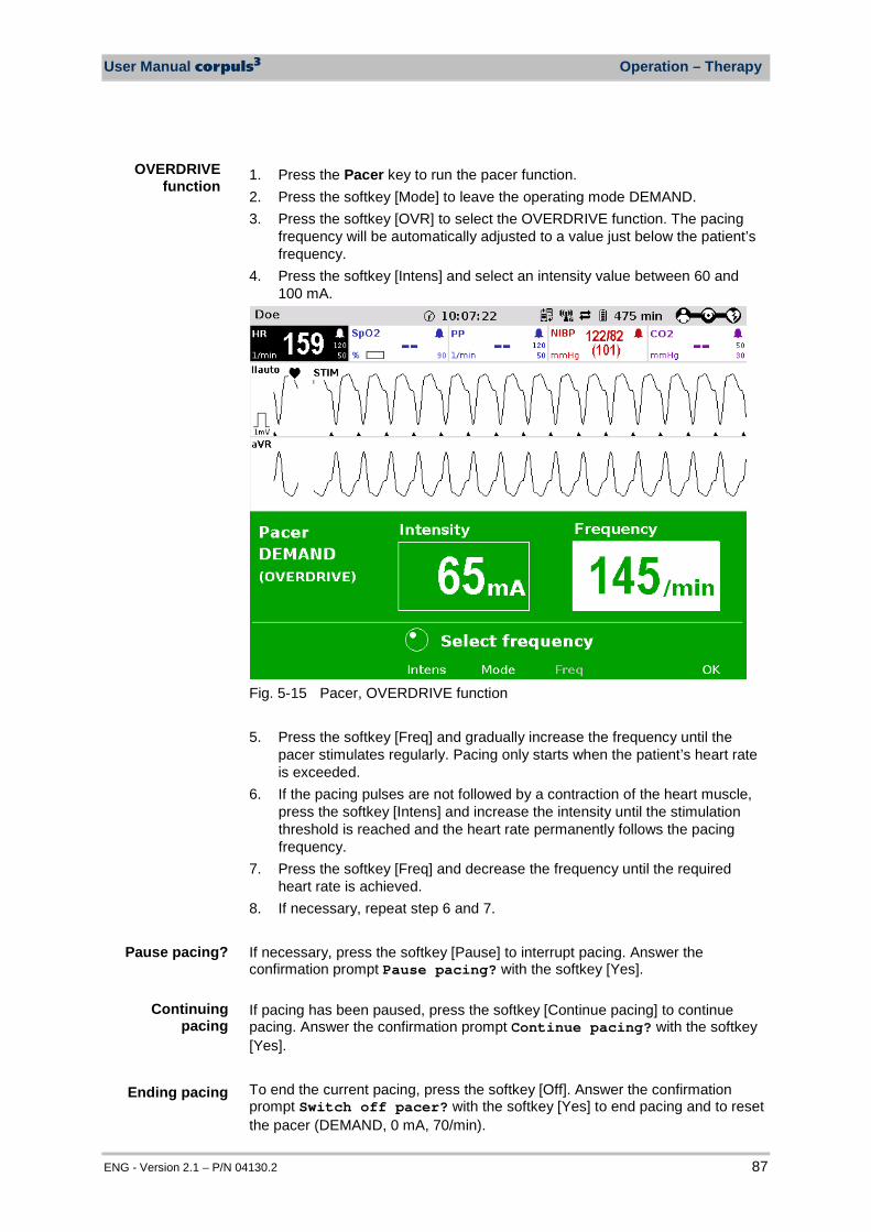
User Manual corpuls3 Operation – Therapy
ENG - Version 2.1 – P/N 04130.2 87
1. Press the Pacer key to run the pacer function. 2. Press the softkey [Mode] to leave the operating mode DEMAND. 3. Press the softkey [OVR] to select the OVERDRIVE function. The pacing
frequency will be automatically adjusted to a value just below the patient’s frequency.
4. Press the softkey [Intens] and select an intensity value between 60 and 100 mA.
Fig. 5-15 Pacer, OVERDRIVE function 5. Press the softkey [Freq] and gradually increase the frequency until the
pacer stimulates regularly. Pacing only starts when the patient’s heart rate is exceeded.
6. If the pacing pulses are not followed by a contraction of the heart muscle, press the softkey [Intens] and increase the intensity until the stimulation threshold is reached and the heart rate permanently follows the pacing frequency.
7. Press the softkey [Freq] and decrease the frequency until the required heart rate is achieved.
8. If necessary, repeat step 6 and 7. If necessary, press the softkey [Pause] to interrupt pacing. Answer the confirmation prompt Pause pacing? with the softkey [Yes]. If pacing has been paused, press the softkey [Continue pacing] to continue pacing. Answer the confirmation prompt Continue pacing? with the softkey [Yes]. To end the current pacing, press the softkey [Off]. Answer the confirmation prompt Switch off pacer? with the softkey [Yes] to end pacing and to reset the pacer (DEMAND, 0 mA, 70/min).
OVERDRIVE function
Pause pacing?
Continuing pacing
Ending pacing
Operation – Therapy User Manual corpuls3
88 ENG - Version 2.1 – P/N 04130.2
WARNING
Regularly check effectiveness of the pacer by checking the central pulse.
WARNING
If the defibrillator/pacer battery enters a low state of charge in pacer mode while the modules are being operated separately from one another, a alarm message “Battery low (Defib)“ appears on the screen. If the defibrillator/pacer battery is almost completely discharged and the defibrillator/pacer will soon switch off, the alarm message “Check pacer” appears. In both cases, immediately connect the modules mechanically or connect the defibrillator/pacer to a mains power supply.
WARNING
If the monitoring unit loses the network connection in pacer mode due to the defibrillator/pacer being out of range, this will be indicated visually and acoustically on the screen and by the alarm message “Check pacer”. Pacing will be continued, but pacer alarms and errors cannot be displayed. In this case, the modules must be brought immediately within an adequate range or reconnected mechanically.
WARNING
All four ECG electrodes of the 4-pole ECG monitoring cable must be connected to the patient. If the electrodes of the complementary 6-pole ECG diagnostic cable are to be used additionally, all six electrodes must be connected to the patient and the connector must be plugged into the patient box. No electrode must be left unattached. For safety reasons, if a defibrillation is performed with shock paddles, it is not permitted that the complementary 6-pole ECG diagnostic cable is pre-connected to the patient box and none of the electrodes are attached.
To avoid unintentional switching off of the defibrillator/pacer, the On/Off key has to be held down for at least 3 seconds for switching off. If the battery on the monitoring unit is replaced during pacer operation, the pacer has to be called up again.
Note
Note
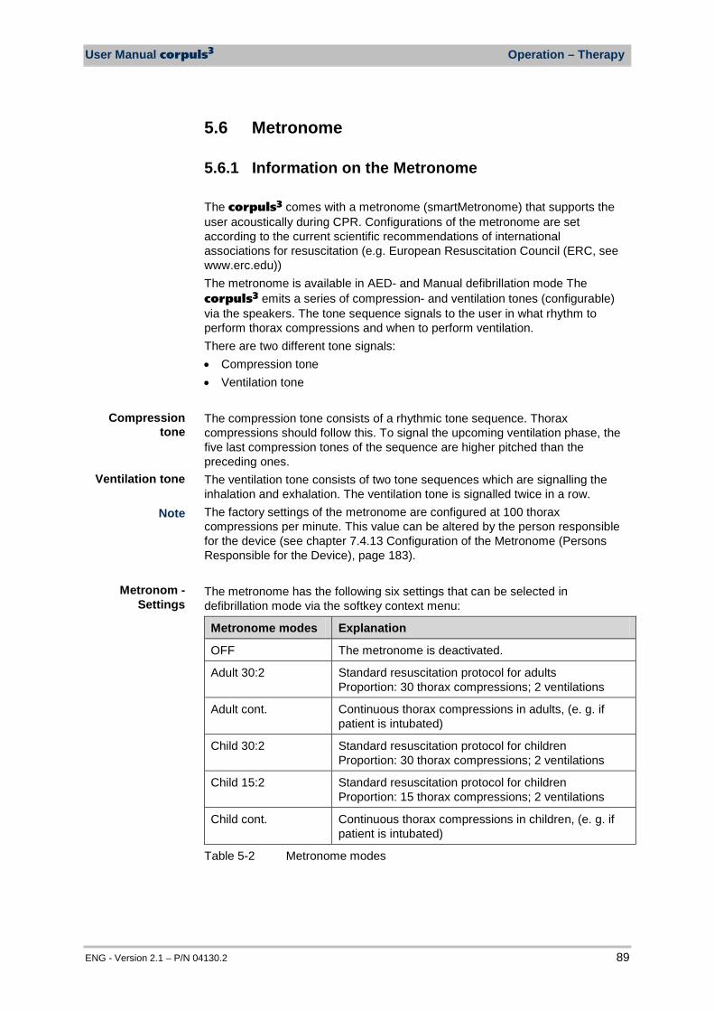
User Manual corpuls3 Operation – Therapy
ENG - Version 2.1 – P/N 04130.2 89
5.6 Metronome
5.6.1 Information on the Metronome The corpuls3 comes with a metronome (smartMetronome) that supports the user acoustically during CPR. Configurations of the metronome are set according to the current scientific recommendations of international associations for resuscitation (e.g. European Resuscitation Council (ERC, see www.erc.edu)) The metronome is available in AED- and Manual defibrillation mode The corpuls3 emits a series of compression- and ventilation tones (configurable) via the speakers. The tone sequence signals to the user in what rhythm to perform thorax compressions and when to perform ventilation. There are two different tone signals: • Compression tone • Ventilation tone
The compression tone consists of a rhythmic tone sequence. Thorax compressions should follow this. To signal the upcoming ventilation phase, the five last compression tones of the sequence are higher pitched than the preceding ones. The ventilation tone consists of two tone sequences which are signalling the inhalation and exhalation. The ventilation tone is signalled twice in a row. The factory settings of the metronome are configured at 100 thorax compressions per minute. This value can be altered by the person responsible for the device (see chapter 7.4.13 Configuration of the Metronome (Persons Responsible for the Device), page 183). The metronome has the following six settings that can be selected in defibrillation mode via the softkey context menu:
Metronome modes Explanation
OFF The metronome is deactivated.
Adult 30:2 Standard resuscitation protocol for adults Proportion: 30 thorax compressions; 2 ventilations
Adult cont. Continuous thorax compressions in adults, (e. g. if patient is intubated)
Child 30:2 Standard resuscitation protocol for children Proportion: 30 thorax compressions; 2 ventilations
Child 15:2 Standard resuscitation protocol for children Proportion: 15 thorax compressions; 2 ventilations
Child cont. Continuous thorax compressions in children, (e. g. if patient is intubated)
Table 5-2 Metronome modes
Note
Metronom - Settings
Compression tone
Ventilation tone
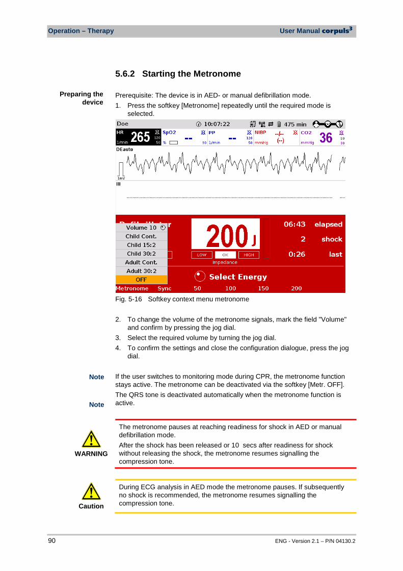
Operation – Therapy User Manual corpuls3
90 ENG - Version 2.1 – P/N 04130.2
5.6.2 Starting the Metronome Prerequisite: The device is in AED- or manual defibrillation mode. 1. Press the softkey [Metronome] repeatedly until the required mode is
selected.
Fig. 5-16 Softkey context menu metronome 2. To change the volume of the metronome signals, mark the field "Volume"
and confirm by pressing the jog dial. 3. Select the required volume by turning the jog dial. 4. To confirm the settings and close the configuration dialogue, press the jog
dial. If the user switches to monitoring mode during CPR, the metronome function stays active. The metronome can be deactivated via the softkey [Metr. OFF]. The QRS tone is deactivated automatically when the metronome function is active.
WARNING
The metronome pauses at reaching readiness for shock in AED or manual defibrillation mode. After the shock has been released or 10 secs after readiness for shock without releasing the shock, the metronome resumes signalling the compression tone.
Caution
During ECG analysis in AED mode the metronome pauses. If subsequently no shock is recommended, the metronome resumes signalling the compression tone.
Preparing the device
Note
Note
User Manual corpuls3 Operation – Therapy
ENG - Version 2.1 – P/N 04130.2 91
Caution
By selecting the pacer mode, the metronome is deactivated.
5.7 CPR Feedback
5.7.1 Information on CPR Feedback If a corPatch CPR sensor is used, the rate and depth of a thorax compression can be measured by the corpuls3. During resuscitation, the users are provided important information on the quality of the current thorax compressions, so that they can react immediately and take corresponding measures. Among the information are the display of the current rate as well as the curve progression of the current thorax compressions. Speech- and text messages signal to the user whether the quality of the thorax compressions is sufficient or can to be optimised. For this, two different speech- and text messages are available: • "Push harder" • "Good compressions" The speech- and text message "Push harder" is played, if the recommended depth of the thorax compressions has not been reached. It is repeated at an interval of 7 seconds until the recommended depth of the thorax compressions has been reached or exceeded and the speech- and text message "Good compressions" is played. Speech- and text messages will not be played, if • the resuscitation is finished, • the metronome is in ventilation phase • and during the ECG analysis in AED mode. Two different compression depths are available for the mission: • 3.5 cm to 4.5 cm (Child) • 5.0 cm to 6.0 cm (Adult) The configurations of the CPR feedback system are set according to current scientific recommendations of international associations for resuscitation (e. g. European Resuscitation Council (ERC, see www.erc.edu)). The CPR Feedback system is available in AED and manual defibrillation mode as well as in monitoring mode (configurable). The use of CPR feedback is not recommended for patients of less than 8 years of age.
Note
Note
Operation – Therapy User Manual corpuls3
92 ENG - Version 2.1 – P/N 04130.2
The CPR feedback will be available in devices as of May 2013. Older devices can be retrofitted. For further information, please contact your authorised sales and service partner.
The corPatch CPR sensor is a disposable article. The corPatch CPR sensor is covered under one or more of the following U.S.A. patents: 7,074,199; 7,108,665; 7,429,250; 8,147,433; 7,220,235.
WARNING
To guarantee a defibrillation protection for patients, users and third parties, exclusively use the accessories indicated in the list of authorised accessories.
Caution
The detection of the rate and depth of the thorax compressions can be compromised by vibrations.
Caution
Do not use corPatch CPR sensors if • the packaging is damaged or opened; • the expiry date indicated on the packaging has passed; • the sensor is damaged.
Caution
Used corPatch CPR sensors have to be replace by a new corPatch CPR sensor after 24 hours at the latest, to avoid side effects such as reddening and skin irritation.
Caution
The patient's condition has to be assessed by the users themselves, independent of the CPR feedback.
WARNING
During the phase between compressions, the user has to make sure that the pressure is completely relieved from the thorax. Otherwise, there can be false-negative feedback.
Note
Note
Note
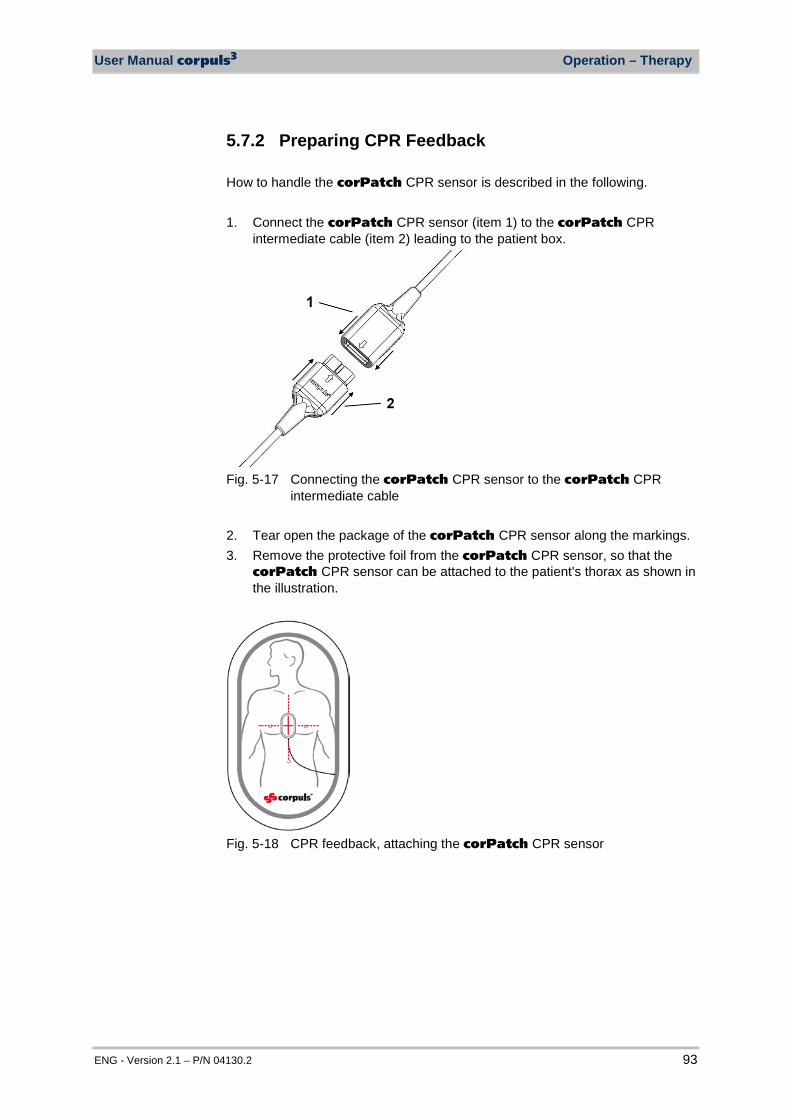
User Manual corpuls3 Operation – Therapy
ENG - Version 2.1 – P/N 04130.2 93
5.7.2 Preparing CPR Feedback How to handle the corPatch CPR sensor is described in the following. 1. Connect the corPatch CPR sensor (item 1) to the corPatch CPR
intermediate cable (item 2) leading to the patient box.
Fig. 5-17 Connecting the corPatch CPR sensor to the corPatch CPR
intermediate cable 2. Tear open the package of the corPatch CPR sensor along the markings. 3. Remove the protective foil from the corPatch CPR sensor, so that the
corPatch CPR sensor can be attached to the patient's thorax as shown in the illustration.
Fig. 5-18 CPR feedback, attaching the corPatch CPR sensor
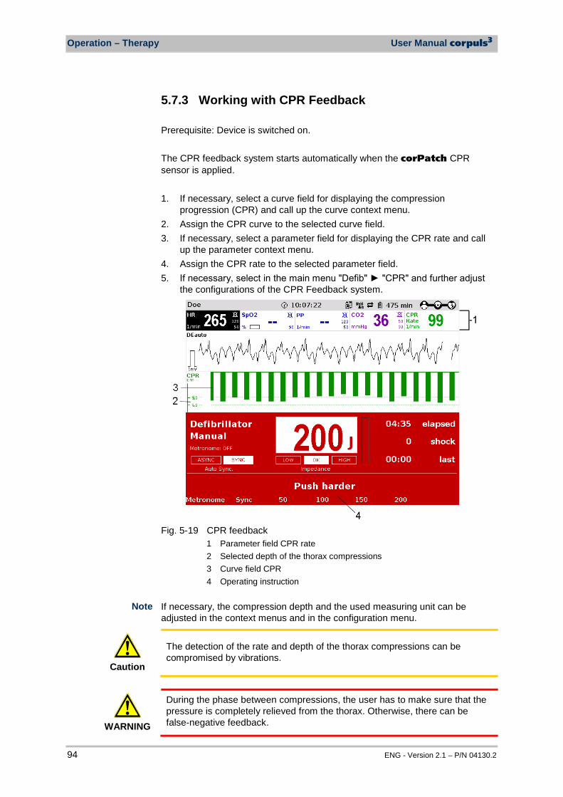
Operation – Therapy User Manual corpuls3
94 ENG - Version 2.1 – P/N 04130.2
5.7.3 Working with CPR Feedback Prerequisite: Device is switched on. The CPR feedback system starts automatically when the corPatch CPR sensor is applied. 1. If necessary, select a curve field for displaying the compression
progression (CPR) and call up the curve context menu. 2. Assign the CPR curve to the selected curve field. 3. If necessary, select a parameter field for displaying the CPR rate and call
up the parameter context menu. 4. Assign the CPR rate to the selected parameter field. 5. If necessary, select in the main menu "Defib" "CPR" and further adjust
the configurations of the CPR Feedback system.
Fig. 5-19 CPR feedback
1 Parameter field CPR rate 2 Selected depth of the thorax compressions 3 Curve field CPR 4 Operating instruction
If necessary, the compression depth and the used measuring unit can be adjusted in the context menus and in the configuration menu.
Caution
The detection of the rate and depth of the thorax compressions can be compromised by vibrations.
WARNING
During the phase between compressions, the user has to make sure that the pressure is completely relieved from the thorax. Otherwise, there can be false-negative feedback.
Note
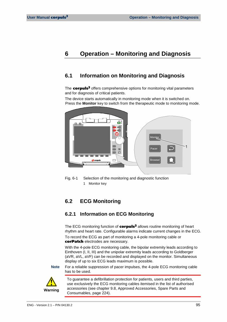
User Manual corpuls3 Operation – Monitoring and Diagnosis
ENG - Version 2.1 – P/N 04130.2 95
6 Operation – Monitoring and Diagnosis
6.1 Information on Monitoring and Diagnosis The corpuls3 offers comprehensive options for monitoring vital parameters and for diagnosis of critical patients. The device starts automatically in monitoring mode when it is switched on. Press the Monitor key to switch from the therapeutic mode to monitoring mode.
AED
Anal yse Charge
Manual
Browser
Monitor
Pacer
Browser
Monitor
Pacer
Fig. 6-1 Selection of the monitoring and diagnostic function
1 Monitor key
6.2 ECG Monitoring
6.2.1 Information on ECG Monitoring The ECG monitoring function of corpuls3 allows routine monitoring of heart rhythm and heart rate. Configurable alarms indicate current changes in the ECG. To record the ECG as part of monitoring a 4-pole monitoring cable or corPatch electrodes are necessary. With the 4-pole ECG monitoring cable, the bipolar extremity leads according to Einthoven (I, II, III) and the unipolar extremity leads according to Goldberger (aVR, aVL, aVF) can be recorded and displayed on the monitor. Simultaneous display of up to six ECG leads maximum is possible. For a reliable suppression of pacer impulses, the 4-pole ECG monitoring cable has to be used.
Warning
To guarantee a defibrillation protection for patients, users and third parties, use exclusively the ECG monitoring cables itemised in the list of authorised accessories (see chapter 9.8, Approved Accessories, Spare Parts and Consumables, page 224).
Note
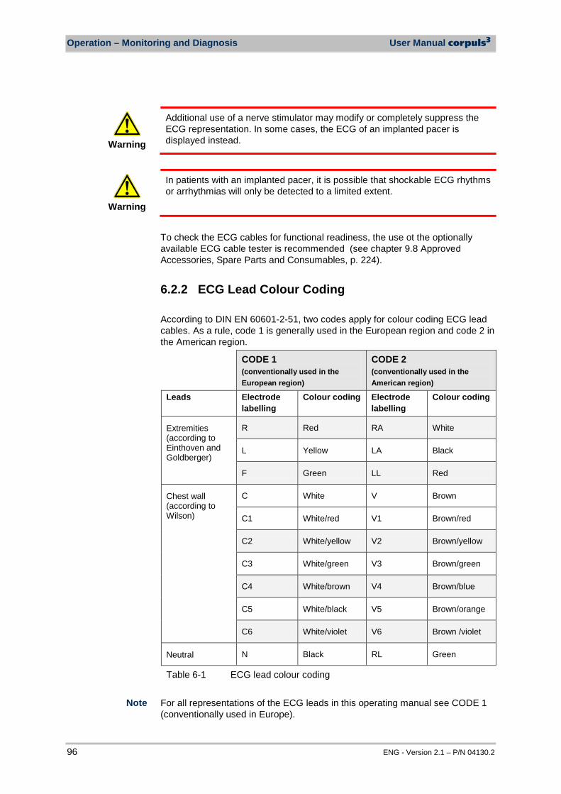
Operation – Monitoring and Diagnosis User Manual corpuls3
96 ENG - Version 2.1 – P/N 04130.2
Warning
Additional use of a nerve stimulator may modify or completely suppress the ECG representation. In some cases, the ECG of an implanted pacer is displayed instead.
Warning
In patients with an implanted pacer, it is possible that shockable ECG rhythms or arrhythmias will only be detected to a limited extent.
To check the ECG cables for functional readiness, the use ot the optionally available ECG cable tester is recommended (see chapter 9.8 Approved Accessories, Spare Parts and Consumables, p. 224).
6.2.2 ECG Lead Colour Coding According to DIN EN 60601-2-51, two codes apply for colour coding ECG lead cables. As a rule, code 1 is generally used in the European region and code 2 in the American region.
CODE 1 (conventionally used in the European region)
CODE 2 (conventionally used in the American region)
Leads Electrode labelling
Colour coding Electrode labelling
Colour coding
Extremities (according to Einthoven and Goldberger)
R Red RA White
L Yellow LA Black
F Green LL Red
Chest wall (according to Wilson)
C White V Brown
C1 White/red V1 Brown/red
C2 White/yellow V2 Brown/yellow
C3 White/green V3 Brown/green
C4 White/brown V4 Brown/blue
C5 White/black V5 Brown/orange
C6 White/violet V6 Brown /violet
Neutral N Black RL Green
Table 6-1 ECG lead colour coding For all representations of the ECG leads in this operating manual see CODE 1 (conventionally used in Europe).
Note
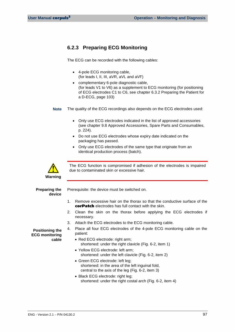
User Manual corpuls3 Operation – Monitoring and Diagnosis
ENG - Version 2.1 – P/N 04130.2 97
6.2.3 Preparing ECG Monitoring The ECG can be recorded with the following cables:
• 4-pole ECG monitoring cable, (for leads I, II, III, aVR, aVL and aVF)
• complementary 6-pole diagnostic cable, (for leads V1 to V6) as a supplement to ECG monitoring (for positioning of ECG electrodes C1 to C6, see chapter 6.3.2 Preparing the Patient for a D-ECG, page 103)
The quality of the ECG recordings also depends on the ECG electrodes used:
• Only use ECG electrodes indicated in the list of approved accessories (see chapter 9.8 Approved Accessories, Spare Parts and Consumables, p. 224).
• Do not use ECG electrodes whose expiry date indicated on the packaging has passed.
• Only use ECG electrodes of the same type that originate from an identical production process (batch).
Warning
The ECG function is compromised if adhesion of the electrodes is impaired due to contaminated skin or excessive hair.
Prerequisite: the device must be switched on.
1. Remove excessive hair on the thorax so that the conductive surface of the
corPatch electrodes has full contact with the skin. 2. Clean the skin on the thorax before applying the ECG electrodes if
necessary. 3. Attach the ECG electrodes to the ECG monitoring cable. 4. Place all four ECG electrodes of the 4-pole ECG monitoring cable on the
patient: • Red ECG electrode: right arm;
shortened: under the right clavicle (Fig. 6-2, item 1) • Yellow ECG electrode: left arm;
shortened: under the left clavicle (Fig. 6-2, item 2) • Green ECG electrode: left leg;
shortened: in the area of the left inguinal fold, central to the axis of the leg (Fig. 6-2, item 3)
• Black ECG electrode: right leg; shortened: under the right costal arch (Fig. 6-2, item 4)
Note
Positioning the ECG monitoring
cable
Preparing the device
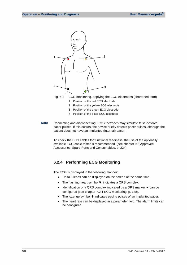
Operation – Monitoring and Diagnosis User Manual corpuls3
98 ENG - Version 2.1 – P/N 04130.2
4
1 2
3
Fig. 6-2 ECG monitoring, applying the ECG electrodes (shortened form)
1 Position of the red ECG electrode 2 Position of the yellow ECG electrode 3 Position of the green ECG electrode 4 Position of the black ECG electrode
Connecting and disconnecting ECG electrodes may simulate false-positive pacer pulses. If this occurs, the device briefly detects pacer pulses, although the patient does not have an implanted (internal) pacer. To check the ECG cables for functional readiness, the use ot the optionally available ECG cable tester is recommended (see chapter 9.8 Approved Accessories, Spare Parts and Consumables, p. 224).
6.2.4 Performing ECG Monitoring The ECG is displayed in the following manner:
• Up to 6 leads can be displayed on the screen at the same time.
• The flashing heart symbol ♥ indicates a QRS complex. • Identification of a QRS complex indicated by a QRS marker can be
configured (see chapter 7.2.1 ECG Monitoring, p. 148). • The lozenge symbol indicates pacing pulses of an implanted pacer. • The heart rate can be displayed in a parameter field. The alarm limits can
be configured.
Note
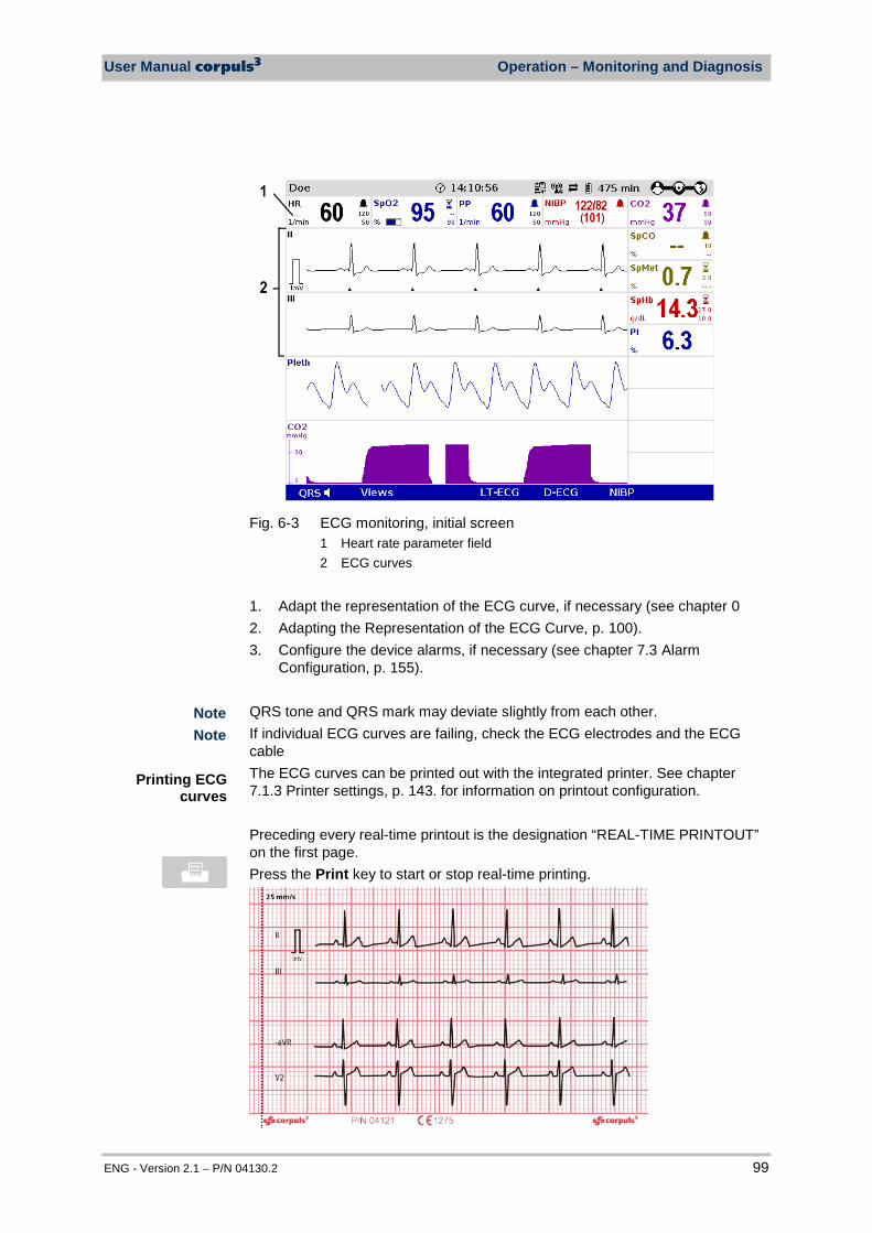
User Manual corpuls3 Operation – Monitoring and Diagnosis
ENG - Version 2.1 – P/N 04130.2 99
Fig. 6-3 ECG monitoring, initial screen
1 Heart rate parameter field 2 ECG curves
1. Adapt the representation of the ECG curve, if necessary (see chapter 0 2. Adapting the Representation of the ECG Curve, p. 100). 3. Configure the device alarms, if necessary (see chapter 7.3 Alarm
Configuration, p. 155). QRS tone and QRS mark may deviate slightly from each other. If individual ECG curves are failing, check the ECG electrodes and the ECG cable The ECG curves can be printed out with the integrated printer. See chapter 7.1.3 Printer settings, p. 143. for information on printout configuration. Preceding every real-time printout is the designation “REAL-TIME PRINTOUT” on the first page. Press the Print key to start or stop real-time printing.
Printing ECG curves
Note Note
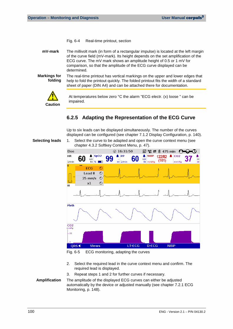
Operation – Monitoring and Diagnosis User Manual corpuls3
100 ENG - Version 2.1 – P/N 04130.2
Fig. 6-4 Real-time printout, section The millivolt mark (in form of a rectangular impulse) is located at the left margin of the curve field (mV-mark). Its height depends on the set amplification of the ECG curve. The mV mark shows an amplitude height of 0.5 or 1 mV for comparison, so that the amplitude of the ECG curve displayed can be determined. The real-time printout has vertical markings on the upper and lower edges that help to fold the printout quickly. The folded printout fits the width of a standard sheet of paper (DIN A4) and can be attached there for documentation.
Caution
At temperatures below zero °C the alarm "ECG electr. (x) loose " can be impaired.
6.2.5 Adapting the Representation of the ECG Curve Up to six leads can be displayed simultaneously. The number of the curves displayed can be configured (see chapter 7.1.2 Display Configuration, p. 140). 1. Select the curve to be adapted and open the curve context menu (see
chapter 4.3.2 Softkey Context Menu, p. 47).
Fig. 6-5 ECG monitoring, adapting the curves
2. Select the required lead in the curve context menu and confirm. The
required lead is displayed. 3. Repeat steps 1 and 2 for further curves if necessary. The amplitude of the displayed ECG curves can either be adjusted automatically by the device or adjusted manually (see chapter 7.2.1 ECG Monitoring, p. 148).
Selecting leads
Amplification
Markings for folding
mV-mark

User Manual corpuls3 Operation – Monitoring and Diagnosis
ENG - Version 2.1 – P/N 04130.2 101
With automatic adjustment, the device selects the amplification so that the ECG curve with the greatest amplitude overwrites 50% of the area available on the screen. Consequently, individual, greater ECG swings can be displayed. With manual adjustment, the amplification affecting the amplitude display can be selected (x 0.25 / x 0.5 / x 1 / x 2). The millivolt mark (in form of a rectangular impulse) is located at the left margin of the curve field (mV-mark). Its height depends on the set amplification of the ECG curve. The mV mark shows an amplitude height of 0.5 or 1 mV for comparison, so that the amplitude of the ECG curve displayed can be determined. The millivolt mark is also shown on the paper printout on the left besides the ECG curve. The selected amplification applies to all ECG curves displayed. 1. Select the ECG curve and open the curve context menu 2. Select the required amplification in the curve context menu and confirm.
The ECG curve will be displayed with the required amplification. Once the selection has been made, the program leaves the curve context menu automatically.
The sweep speed of the screen representation can be selected for the configured ECG curves. The following sweep speeds can be set:
• 12.5 mm/s • 25 mm/s • 50 mm/s
The selected sweep speed applies to all ECG curves displayed. 1. Select the ECG curve and open the curve context menu. 2. Select the required sweep speed in the curve context menu and confirm.
The program quits the curve context menu automatically and the ECG curve is displayed with the required sweep speed.
The device adjusts the ECG filters automatically. The filters can be modified manually if necessary for displaying the ECG curve. The standard setting of the ECG filters in monitoring mode is 0.5 - 25 Hz. The quality of the ECG depends among other factors on the ECG filter settings. See chapter 7.4.4 Filter Settings (Persons Responsible for the Device), p. 165 for information on the filter settings. See chapter 10 Procedure in Case of Malfunctions, page 233 for instructions on improving the ECG quality.
Note
Sweep speed
Note
ECG filter
mV-mark

Operation – Monitoring and Diagnosis User Manual corpuls3
102 ENG - Version 2.1 – P/N 04130.2
6.2.6 Heart Rate Monitoring In addition to the ECG curves, the heart rate is evaluated and displayed on the screen when monitoring the ECG. 1. To display the heart rate, select the parameter field and open the
parameter context menu (see chapter 4.3.2 Parameter Context Menu and Curve Context Menu, p. 47).
2. Select heart rate in the parameter context menu and confirm. The heart rate is displayed in the parameter field.
3. By means of the parameter context menu for the heart rate, the VT/VF alarm can be enabled "VT/VF alarm ON" or disabled "VT/VF alarm OFF".
Fig. 6-6 Heart rate parameter field
1 Current heart rate in 1/min 2 Symbol for switched-on alarms 3 Upper alarm limit 4 Lower alarm limit
6.3 Recording, Measuring, Printing and Interpreting a Diagnostic ECG
6.3.1 Information on Diagnostic ECG Based on a 12 lead ECG, HES® Light performs a ECG measurement of the diagnostic ECG. On the printout, the results are clearly arranged in tables that can help with interpretation and diagnosis during a mission. Optionally, HES® Light can be complemented by an extendend version of HES®. The corpuls3 then issues a therapy suggestion based on the results of the „corpuls S“ or "STEMI" therapy algorithms . With these, the user can make early on tactical decisions as to which hospital to send the patient to or what emergency measures to perform immediately. In cooperation with internationally renowned cardiologists, HES® has been developed and refined continuously since 1968. A large number of leading medical equipment manufacturers integrate this algorithm into their medical products. HES® Light and HES® identify a „Representative cycle“ from the diagnostic ECG. From this representative cycle the measurement tables are compiled which are necessary for an ECG interpretation (see chapter 6.3.4, Representative , Seite 111). The representative cycle can be printed out with the diagnostic ECG (see chapter 7.1.3 Printer settings, page 143).
Hannover ECG System
HES®
Representative Cycle
User Manual corpuls3 Operation – Monitoring and Diagnosis
ENG - Version 2.1 – P/N 04130.2 103
AMI: Anterior Myocardial Infarction IMI: Inferior Myocardial Infarction PCI: Percutaneous Coronary Intervention HES®: Hannover ECG System STEMI:ST-Elevation Myocardial Infarction NSTEMI: Non-ST-Elevation Myocardial Infarction With the complementary 6-pole ECG diagnostic cable, the six unipolar thoracic wall leads according to Wilson (C1-C6) can be recorded. In combination with the ECG monitoring cable, 12 leads can be displayed simultaneously. The display shows a complete preview of all 12 leads which can be printed on paper with the internal printer of the corpuls3. The format and duration of the printout can be configured in size and length (see chapter 7.1.3 Printer settings, page 143). To check the ECG cables for functional readiness, the use ot the optionally available ECG cable tester is recommended (see chapter 9.8 Approved Accessories, Spare Parts and Consumables, p. 224).
Caution
The preview of the D-ECG on the monitor serves only to check the individual ECG leads, the signal quality and possible arrhythmias. A diagnosis of the D-ECG must be based on the printout of the D-ECG.
Warning
The user/physician is always responsible for correct diagnosis and therapy.
Warning
Additional use of a nerve stimulator may modify or completely suppress the ECG representation. In some cases, the ECG of an implanted pacer is displayed instead.
6.3.2 Preparing the Patient for a D-ECG The diagnostic ECG is recorded with the following cables:
• 4-pole ECG monitoring cable, (for the leads I, II, III, aVR, aVL, aVF) and
• 6-pole complementary ECG diagnostic cable, (for leads V1 to V6)
1. Remove excessive hair so that the conductive surface of the therapy
electrodes has full contact with the skin. 2. Clean and dry the skin before applying the ECG electrodes. 3. Place all four ECG electrodes of the 4-pole ECG monitoring cable on the
patient:
Abbreviations for ECG Measurement/ EKG Interpretation
Note
Positioning the ECG monitoring
cable
Preparing the patient
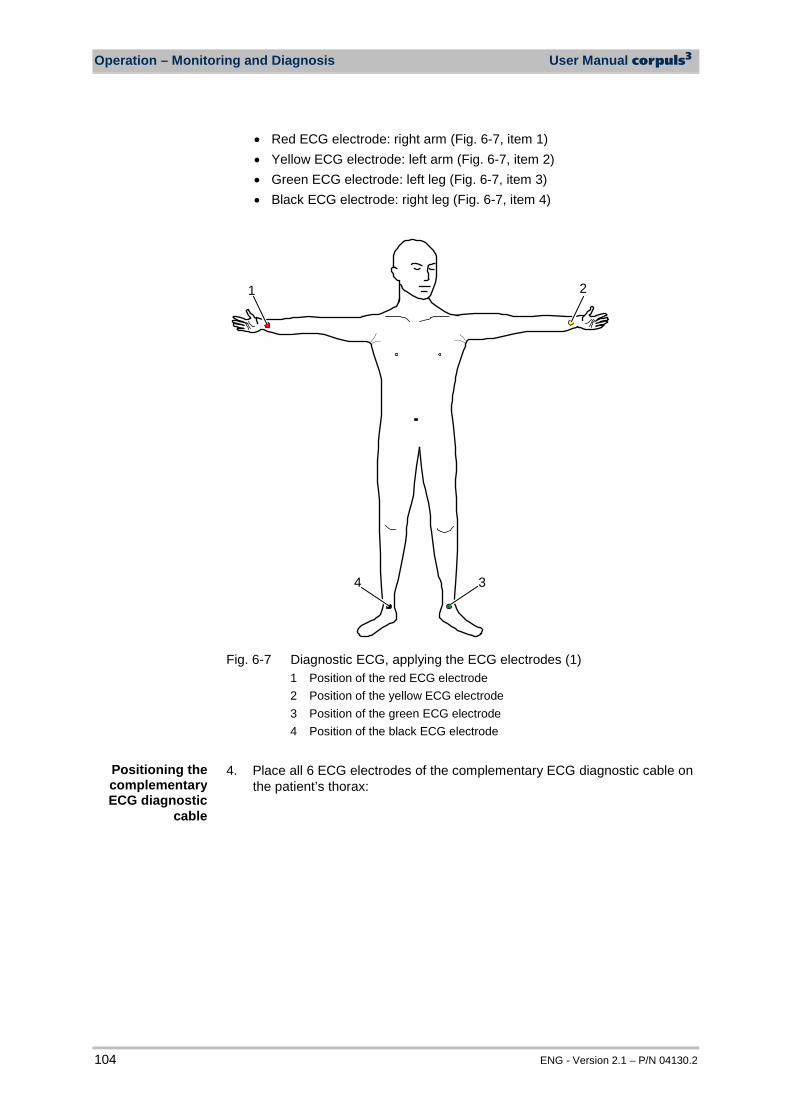
Operation – Monitoring and Diagnosis User Manual corpuls3
104 ENG - Version 2.1 – P/N 04130.2
• Red ECG electrode: right arm (Fig. 6-7, item 1) • Yellow ECG electrode: left arm (Fig. 6-7, item 2) • Green ECG electrode: left leg (Fig. 6-7, item 3) • Black ECG electrode: right leg (Fig. 6-7, item 4)
21
34
Fig. 6-7 Diagnostic ECG, applying the ECG electrodes (1)
1 Position of the red ECG electrode 2 Position of the yellow ECG electrode 3 Position of the green ECG electrode 4 Position of the black ECG electrode
4. Place all 6 ECG electrodes of the complementary ECG diagnostic cable on
the patient’s thorax: Positioning the complementary ECG diagnostic
cable
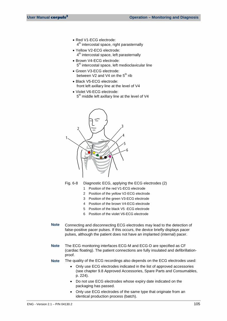
User Manual corpuls3 Operation – Monitoring and Diagnosis
ENG - Version 2.1 – P/N 04130.2 105
• Red V1-ECG electrode: 4th intercostal space, right parasternally
• Yellow V2-ECG electrode: 4th intercostal space, left parasternally
• Brown V4-ECG electrode: 5th intercostal space, left medioclavicular line
• Green V3-ECG electrode: between V2 and V4 on the 5th rib
• Black V5-ECG electrode: front left axillary line at the level of V4
• Violet V6-ECG electrode: 5th middle left axillary line at the level of V4
3
56
41
2
Fig. 6-8 Diagnostic ECG, applying the ECG electrodes (2)
1 Position of the red V1-ECG electrode 2 Position of the yellow V2-ECG electrode 3 Position of the green V3-ECG electrode 4 Position of the brown V4-ECG electrode 5 Position of the black V5 -ECG electrode 6 Position of the violet V6-ECG electrode
Connecting and disconnecting ECG electrodes may lead to the detection of false-positive pacer pulses. If this occurs, the device briefly displays pacer pulses, although the patient does not have an implanted (internal) pacer. The ECG monitoring interfaces ECG-M and ECG-D are specified as CF (cardiac floating). The patient connections are fully insulated and defibrillation-proof. The quality of the ECG recordings also depends on the ECG electrodes used:
• Only use ECG electrodes indicated in the list of approved accessories (see chapter 9.8 Approved Accessories, Spare Parts and Consumables, p. 224).
• Do not use ECG electrodes whose expiry date indicated on the packaging has passed.
• Only use ECG electrodes of the same type that originate from an identical production process (batch).
Note
Note
Note
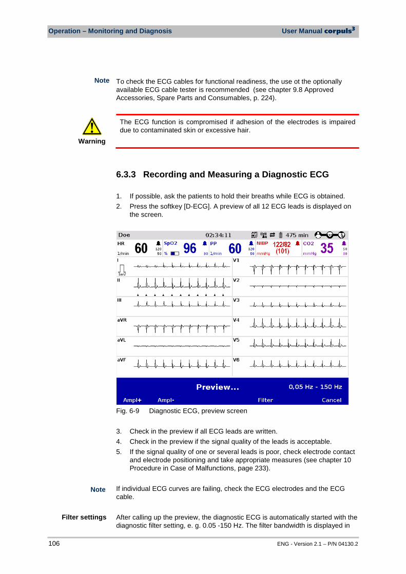
Operation – Monitoring and Diagnosis User Manual corpuls3
106 ENG - Version 2.1 – P/N 04130.2
To check the ECG cables for functional readiness, the use ot the optionally available ECG cable tester is recommended (see chapter 9.8 Approved Accessories, Spare Parts and Consumables, p. 224).
Warning
The ECG function is compromised if adhesion of the electrodes is impaired due to contaminated skin or excessive hair.
6.3.3 Recording and Measuring a Diagnostic ECG 1. If possible, ask the patients to hold their breaths while ECG is obtained. 2. Press the softkey [D-ECG]. A preview of all 12 ECG leads is displayed on
the screen.
Fig. 6-9 Diagnostic ECG, preview screen 3. Check in the preview if all ECG leads are written. 4. Check in the preview if the signal quality of the leads is acceptable. 5. If the signal quality of one or several leads is poor, check electrode contact
and electrode positioning and take appropriate measures (see chapter 10 Procedure in Case of Malfunctions, page 233).
If individual ECG curves are failing, check the ECG electrodes and the ECG cable. After calling up the preview, the diagnostic ECG is automatically started with the diagnostic filter setting, e. g. 0.05 -150 Hz. The filter bandwidth is displayed in
Filter settings
Note
Note
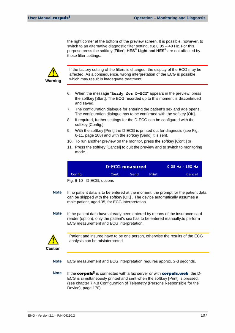
User Manual corpuls3 Operation – Monitoring and Diagnosis
ENG - Version 2.1 – P/N 04130.2 107
the right corner at the bottom of the preview screen. It is possible, however, to switch to an alternative diagnostic filter setting, e.g.0.05 – 40 Hz. For this purpose press the softkey [Filter]. HES® Light and HES® are not affected by these filter settings.
Warning
If the factory setting of the filters is changed, the display of the ECG may be affected. As a consequence, wrong interpretation of the ECG is possible, which may result in inadequate treatment.
6. When the message "Ready for D-ECG" appears in the preview, press
the softkey [Start]. The ECG recorded up to this moment is discontinued and saved.
7. The configuration dialogue for entering the patient’s sex and age opens. The configuration dialogue has to be confirmed with the softkey [OK].
8. If required, further settings for the D-ECG can be configured with the softkey [Config.].
9. With the softkey [Print] the D-ECG is printed out for diagnosis (see Fig. 6-11, page 108) and with the softkey [Send] it is sent.
10. To run another preview on the monitor, press the softkey [Cont.] or 11. Press the softkey [Cancel] to quit the preview and to switch to monitoring
mode.
Fig. 6-10 D-ECG, options If no patient data is to be entered at the moment, the prompt for the patient data can be skipped with the softkey [OK] . The device automatically assumes a male patient, aged 35, for ECG interpretation. If the patient data have already been entered by means of the insurance card reader (option), only the patient's sex has to be entered manually.to perform ECG measurement and ECG interpretation.
Caution
Patient and insuree have to be one person, otherwise the results of the ECG analysis can be misinterpreted.
ECG measurement and ECG interpretation requires approx. 2-3 seconds. If the corpuls3 is connected with a fax server or with corpuls.web, the D-ECG is simultaneously printed and sent when the softkey [Print] is pressed. (see chapter 7.4.8 Configuration of Telemetry (Persons Responsible for the Device), page 170).
Note
Note
Note
Note
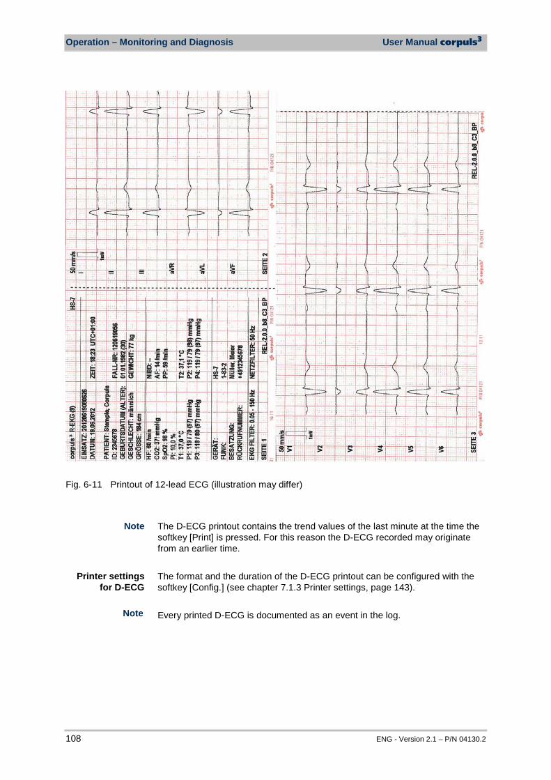
Operation – Monitoring and Diagnosis User Manual corpuls3
108 ENG - Version 2.1 – P/N 04130.2
Fig. 6-11 Printout of 12-lead ECG (illustration may differ)
The D-ECG printout contains the trend values of the last minute at the time the softkey [Print] is pressed. For this reason the D-ECG recorded may originate from an earlier time. The format and the duration of the D-ECG printout can be configured with the softkey [Config.] (see chapter 7.1.3 Printer settings, page 143). Every printed D-ECG is documented as an event in the log.
Note
Note
Printer settings for D-ECG
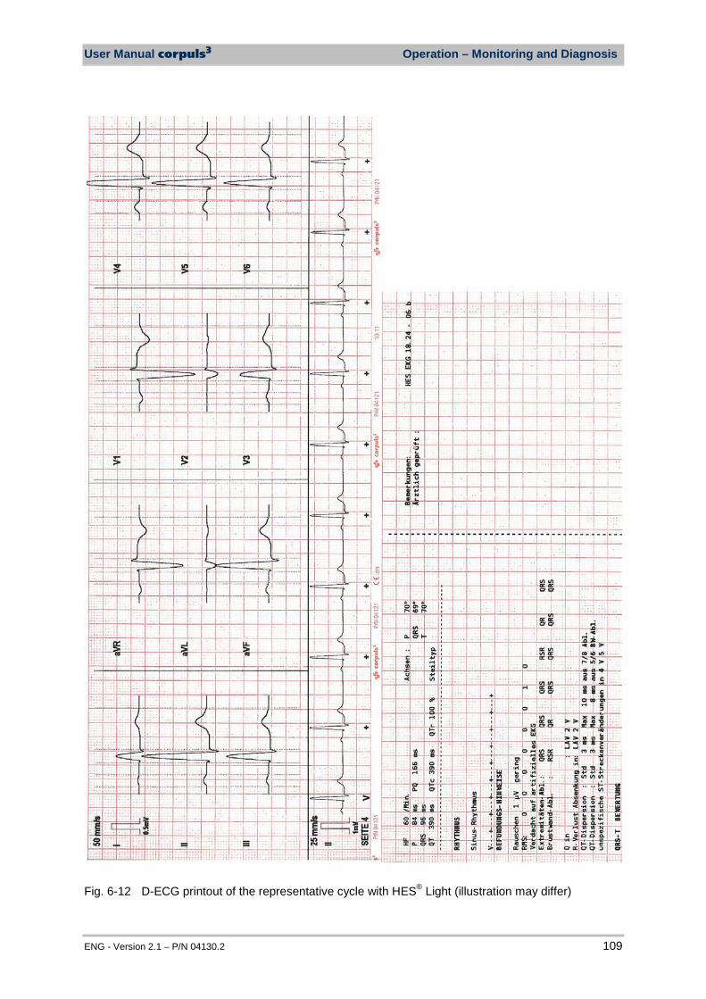
User Manual corpuls3 Operation – Monitoring and Diagnosis
ENG - Version 2.1 – P/N 04130.2 109
Fig. 6-12 D-ECG printout of the representative cycle with HES® Light (illustration may differ)

Operation – Monitoring and Diagnosis User Manual corpuls3
110 ENG - Version 2.1 – P/N 04130.2
Fig. 6-13 D-ECG printout with ECG analysis and ECG interpretation HES® (option) (illustration may differ)
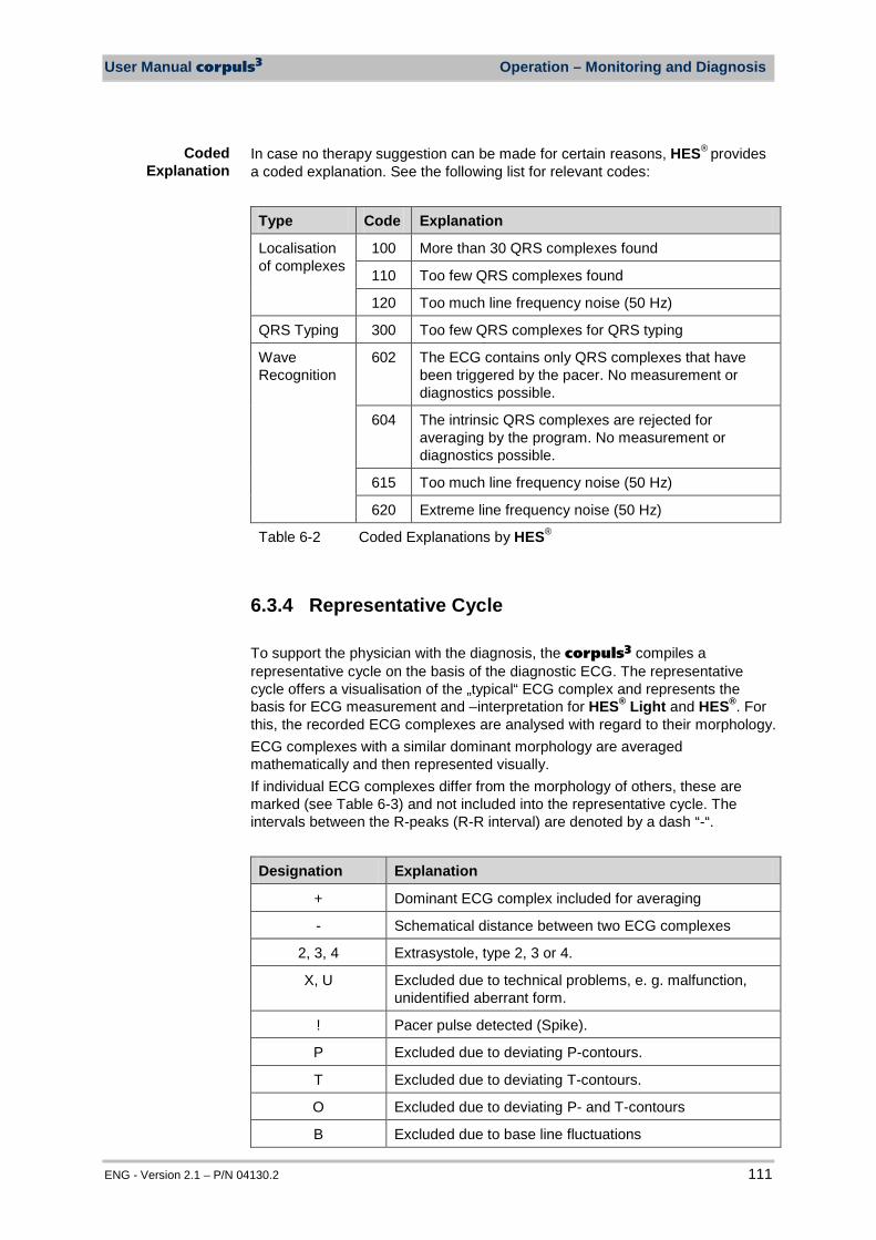
User Manual corpuls3 Operation – Monitoring and Diagnosis
ENG - Version 2.1 – P/N 04130.2 111
In case no therapy suggestion can be made for certain reasons, HES® provides a coded explanation. See the following list for relevant codes:
Type Code Explanation
Localisation of complexes
100 More than 30 QRS complexes found
110 Too few QRS complexes found
120 Too much line frequency noise (50 Hz)
QRS Typing 300 Too few QRS complexes for QRS typing
Wave Recognition
602 The ECG contains only QRS complexes that have been triggered by the pacer. No measurement or diagnostics possible.
604 The intrinsic QRS complexes are rejected for averaging by the program. No measurement or diagnostics possible.
615 Too much line frequency noise (50 Hz)
620 Extreme line frequency noise (50 Hz)
Table 6-2 Coded Explanations by HES®
6.3.4 Representative Cycle To support the physician with the diagnosis, the corpuls3 compiles a representative cycle on the basis of the diagnostic ECG. The representative cycle offers a visualisation of the „typical“ ECG complex and represents the basis for ECG measurement and –interpretation for HES® Light and HES®. For this, the recorded ECG complexes are analysed with regard to their morphology. ECG complexes with a similar dominant morphology are averaged mathematically and then represented visually. If individual ECG complexes differ from the morphology of others, these are marked (see Table 6-3) and not included into the representative cycle. The intervals between the R-peaks (R-R interval) are denoted by a dash “-“.
Designation Explanation
+ Dominant ECG complex included for averaging
- Schematical distance between two ECG complexes
2, 3, 4 Extrasystole, type 2, 3 or 4.
X, U Excluded due to technical problems, e. g. malfunction, unidentified aberrant form.
! Pacer pulse detected (Spike).
P Excluded due to deviating P-contours.
T Excluded due to deviating T-contours.
O Excluded due to deviating P- and T-contours
B Excluded due to base line fluctuations
Coded Explanation
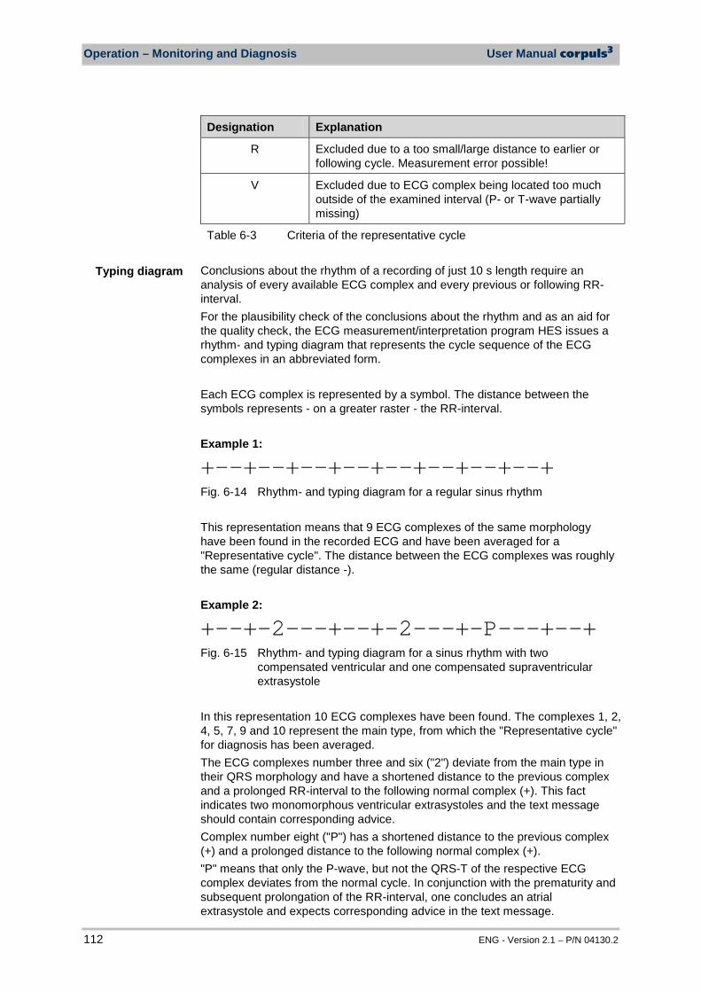
Operation – Monitoring and Diagnosis User Manual corpuls3
112 ENG - Version 2.1 – P/N 04130.2
Designation Explanation
R Excluded due to a too small/large distance to earlier or following cycle. Measurement error possible!
V Excluded due to ECG complex being located too much outside of the examined interval (P- or T-wave partially missing)
Table 6-3 Criteria of the representative cycle Conclusions about the rhythm of a recording of just 10 s length require an analysis of every available ECG complex and every previous or following RR-interval. For the plausibility check of the conclusions about the rhythm and as an aid for the quality check, the ECG measurement/interpretation program HES issues a rhythm- and typing diagram that represents the cycle sequence of the ECG complexes in an abbreviated form. Each ECG complex is represented by a symbol. The distance between the symbols represents - on a greater raster - the RR-interval. Example 1:
+--+--+--+--+--+--+--+--+ Fig. 6-14 Rhythm- and typing diagram for a regular sinus rhythm This representation means that 9 ECG complexes of the same morphology have been found in the recorded ECG and have been averaged for a "Representative cycle". The distance between the ECG complexes was roughly the same (regular distance -). Example 2:
+--+-2---+--+-2---+-P---+--+ Fig. 6-15 Rhythm- and typing diagram for a sinus rhythm with two
compensated ventricular and one compensated supraventricular extrasystole
In this representation 10 ECG complexes have been found. The complexes 1, 2, 4, 5, 7, 9 and 10 represent the main type, from which the "Representative cycle" for diagnosis has been averaged. The ECG complexes number three and six ("2") deviate from the main type in their QRS morphology and have a shortened distance to the previous complex and a prolonged RR-interval to the following normal complex (+). This fact indicates two monomorphous ventricular extrasystoles and the text message should contain corresponding advice. Complex number eight ("P") has a shortened distance to the previous complex (+) and a prolonged distance to the following normal complex (+). "P" means that only the P-wave, but not the QRS-T of the respective ECG complex deviates from the normal cycle. In conjunction with the prematurity and subsequent prolongation of the RR-interval, one concludes an atrial extrasystole and expects corresponding advice in the text message.
Typing diagram
User Manual corpuls3 Operation – Monitoring and Diagnosis
ENG - Version 2.1 – P/N 04130.2 113
In general, a visual check of the rhythm- and typing diagram as well as a check of the fiducials should be integral part of the quality check of the computerised ECG evaluation. For further information, the HES ECG manual is available in German and English. The manual can be obtained from your authorised sales and servicepartners
WARNING
Every ECG printout must be checked by a doctor and only becomes medical evidence with the signature of the doctor.
6.4 Longterm ECG
6.4.1 Information on Longterm ECG With the longterm ECG function of the corpuls3, the user is able to monitor the ECG lead II over the whole course of the mission, either during the mission or afterwards. This allows an evaluation of the quantity of cardiac dysrhythmias or the detection and printout of infrequent dysrhythmias.
There are two views for the longterm ECG:
• View with monitoring function of the current mission or • View in the longterm ECG browser.
Both views have a curve area showing lead IIauto or DEauto as a cascade over four curve fields. The area above the cascade shows the time specification of the point in time currently selected, the zoom specification in mm/s and the timeline.
The longterm ECG with monitoring function displays a horizontal parameter area and one curve field of the current patient monitoring. The parameter area shows as a default HR, SpO2, PP, NIBP and CO2 , the curv field lead II. These settings can be configured via the respective context menu.
In the longterm ECG browser that can be opened via the operation browser (see chapter 8.5.2 Mission Browser, page 192), longterm ECGs from already finished missions can be opened and printed out. The area above the longterm ECG shows the mission data, patient data and total length of the selected mission.
The time specification refers to the beginning of the cascade. The yellow bar on the timeline can be moved with the jog dial. The required resolution of the longterm ECG can be selected via the zoom function.
Views of the longterm ECG
Cascade
Note
Note
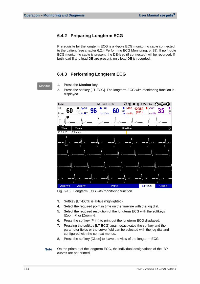
Operation – Monitoring and Diagnosis User Manual corpuls3
114 ENG - Version 2.1 – P/N 04130.2
6.4.2 Preparing Longterm ECG Prerequisite for the longterm ECG is a 4-pole ECG monitoring cable connected to the patient (see chapter 6.2.4 Performing ECG Monitoring, p. 98). If no 4-pole ECG monitoring cable is present, the DE-lead (if connected) will be recorded. If both lead II and lead DE are present, only lead DE is recorded.
6.4.3 Performing Longterm ECG 1. Press the Monitor key. 2. Press the softkey [LT-ECG]. The longterm ECG with monitoring function is
displayed.
Fig. 6-16 Longterm ECG with monitoring function 3. Softkey [LT-ECG] is aktive (highlighted). 4. Select the required point in time on the timeline with the jog dial. 5. Select the required resolution of the longterm ECG with the softkeys
[Zoom +] or [Zoom -]. 6. Press the softkey [Print] to print out the longterm ECG displayed. 7. Pressing the softkey [LT-ECG] again deactivates the softkey and the
parameter fields or the curve field can be selected with the jog dial and configured with the context menus.
8. Press the softkey [Close] to leave the view of the longterm ECG. On the printout of the longterm ECG, the individual designations of the IBP curves are not printed.
Monitor
Note
User Manual corpuls3 Operation – Monitoring and Diagnosis
ENG - Version 2.1 – P/N 04130.2 115
6.5 Oximetry Monitoring (Option)
6.5.1 Information on Oximetry Monitoring Oximetry is a non-invasive monitoring method for continuous measurement of the arterial oxygen saturation (SpO2), the level of methemoglobin (SpMet) and, depending on the used oximetry sensor (see chapter 9.8 Approved Accessories, Spare Parts and Consumables, page 224), the level of carboxyhemogolobin (SpCO) or the level of total hemoglobin (SpHb) in the blood. The specific reduction in the absorbance of oxygenated and deoxygenated hemoglobin is measured with light of different wavelengths by means of a photo sensor. Comparison of the values yields the respective SpO2-, SpCO- and SpMet values as percentage and, depending the configuration, the SpHb value in g/dl or mmol/l. Additionally, the oximetry measures the peripheral pulse rate (PP) per minute and the perfusion index (PI) in percentage. The vital parameters SpMet, SpCO and SpHb of the oximetry option are only available for corpuls3 devices that have been delivered after 07/2011. Devices delivered before 07/2011 can be retrofitted. Six parameter fields for display of the numerical measurement values can be configured. The oximetry plethysmogram (pleth) can be displayed in a curve field. The signal intensity is a quality criterion for the capturing of measurement values .The signal intensity is measured and displayed as a horizontal bar in the parameter field SpO2 (see p. 118 Fig. 6-19, item 1).
Warning
Increased SpHb value: SpHb values above normal tend to increase the level of SpO2. The level of increase corresponds approximately to the amount of SpHb that is present.
Warning
Increased SpMet value: The SpO2 value may be decreased by levels of SpMet of up to approximately 10% to 15%. At higher levels of SpMet the SpO2 value may tend to read in the low to mid 80s. When elevated levels of SpMet are suspected, a blood sample should be analyzed (CO-Oximetry).
Warning
The alarm limits must be verified every time the oximeter is used to ensure that these are appropriate for the patient currently being monitored.
Warning
If the accuracy of the oximetry measurement does not seem plausible (e.g. due to influences of movement, bright sunlight, Xenon OP lamps or due to photodynamic therapy with bilirubin lamps) check first of all whether there is any acute change in the patient’s vital signs. Subsequently check whether the pulse oximeter works correctly. Refer to the list of approved accessories (see chapter 9.8 Approved Accessories, Spare Parts and Consumables, page 224) for a light shield ensuring interference-free measurement.
Note
Operation – Monitoring and Diagnosis User Manual corpuls3
116 ENG - Version 2.1 – P/N 04130.2
Warning
The oximeter may not be operated in the vicinity of ionising (radioactive) radiation, because the measured values might be falsified.
Caution
Refer to the list of approved accessories (see chapter 9.8 Approved Accessories, Spare Parts and Consumables, p. 224) for approved sensors from the company Masimo. Sensors from other manufacturers are not supported by the device and are not permissible.
The license agreement allows an extension of the available oximetry measuring options which can be activated by a service technician. Older Masimo SET oximetry sensors can only be used in connection with an adapter cable (see chapter 9.8 Approved Accessories, Spare Parts and Consumables, p. 224). Simultaneous measurement of SpCO and SpHb is not possible, due to different sensor types. A low confidence of the measured value is indicated by a question mark instead of the bell symbol in the upper right corner of the parameter field. After connecting the oximetry sensor the oximeter calibrates automatically. This procedure may take up to 120 seconds for the SpO2 measurement, during which an hourglass symbol is displayed in the upper right corner of the parameter field.
It is recommended to connect SpHb sensors to the corpuls3 only if needed, to avoid premature expiration of the sensor.
See the manufacturer’s operating manual for further information on the sensors. These manuals must be read carefully before use. The oximeter is covered under one or more of the following U.S.A. patents: 5,758,644, 6,011,986, 6,699,194, 7,215,986, 7,254,433, 7,530,955 and other applicable patents listed at: www.masimo.com/patents.htm Purchase or possession of this Masimo Rainbow SET® Oximeter confers no express or implied licence to use the device with any non-approved sensors or cables that would fall, alone or in combination with this device, under any patent in reference to this device.
Note
Note
No implied license
Note
Note
Note
Note
Note
Note

User Manual corpuls3 Operation – Monitoring and Diagnosis
ENG - Version 2.1 – P/N 04130.2 117
6.5.2 Preparing Oximetry Monitoring Handling of a oximetry finger sensor is described below.
Warning
Please read and understand the warning notices of the oximetry sensor manufacturer.
Warning
Do not place the oximetry sensor on the same limb as an NIBP cuff for non-invasive blood pressure monitoring, a catheter or an intravascular access. This may invalidate the measuring results.
1. Connect the oximetry sensor to the intermediate cable to the patient box.
3
1
2
Fig. 6-17 Connecting the oximetry sensor on to the intermediate cable 2. Attach the oximetry sensor to a finger according to the manufacturer’s
instructions.
Fig. 6-18 Oximetry monitoring, attaching the oximetry sensor
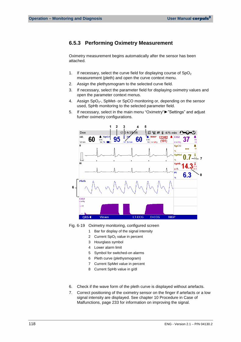
Operation – Monitoring and Diagnosis User Manual corpuls3
118 ENG - Version 2.1 – P/N 04130.2
6.5.3 Performing Oximetry Measurement Oximetry measurement begins automatically after the sensor has been attached. 1. If necessary, select the curve field for displaying course of SpO2
measurement (pleth) and open the curve context menu. 2. Assign the plethysmogram to the selected curve field. 3. If necessary, select the parameter field for displaying oximetry values and
open the parameter context menus. 4. Assign SpO2-, SpMet- or SpCO monitoring or, depending on the sensor
used, SpHb monitoring to the selected parameter field. 5. If necessary, select in the main menu “Oximetry””Settings” and adjust
further oximetry configurations.
Fig. 6-19 Oximetry monitoring, configured screen
1 Bar for display of the signal intensity 2 Current SpO2 value in percent 3 Hourglass symbol 4 Lower alarm limit 5 Symbol for switched-on alarms 6 Pleth curve (plethysmogram) 7 Current SpMet value in percent 8 Current SpHb value in g/dl
6. Check if the wave form of the pleth curve is displayed without artefacts. 7. Correct positioning of the oximetry sensor on the finger if artefacts or a low
signal intensity are displayed. See chapter 10 Procedure in Case of Malfunctions, page 233 for information on improving the signal.
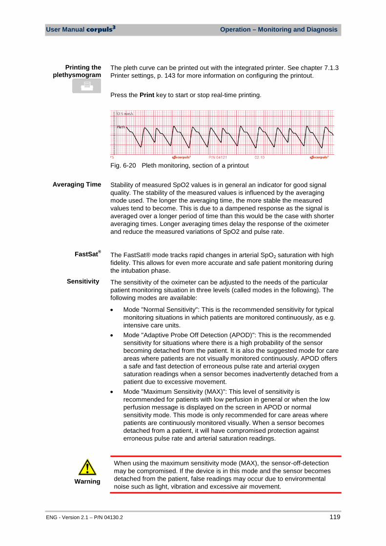
User Manual corpuls3 Operation – Monitoring and Diagnosis
ENG - Version 2.1 – P/N 04130.2 119
The pleth curve can be printed out with the integrated printer. See chapter 7.1.3 Printer settings, p. 143 for more information on configuring the printout. Press the Print key to start or stop real-time printing.
Fig. 6-20 Pleth monitoring, section of a printout Stability of measured SpO2 values is in general an indicator for good signal quality. The stability of the measured values is influenced by the averaging mode used. The longer the averaging time, the more stable the measured values tend to become. This is due to a dampened response as the signal is averaged over a longer period of time than this would be the case with shorter averaging times. Longer averaging times delay the response of the oximeter and reduce the measured variations of SpO2 and pulse rate.
The FastSat® mode tracks rapid changes in arterial SpO2 saturation with high fidelity. This allows for even more accurate and safe patient monitoring during the intubation phase.
The sensitivity of the oximeter can be adjusted to the needs of the particular patient monitoring situation in three levels (called modes in the following). The following modes are available:
• Mode "Normal Sensitivity": This is the recommended sensitivity for typical monitoring situations in which patients are monitored continuously, as e.g. intensive care units.
• Mode "Adaptive Probe Off Detection (APOD)": This is the recommended sensitivity for situations where there is a high probability of the sensor becoming detached from the patient. It is also the suggested mode for care areas where patients are not visually monitored continuously. APOD offers a safe and fast detection of erroneous pulse rate and arterial oxygen saturation readings when a sensor becomes inadvertently detached from a patient due to excessive movement.
• Mode "Maximum Sensitivity (MAX)": This level of sensitivity is recommended for patients with low perfusion in general or when the low perfusion message is displayed on the screen in APOD or normal sensitivity mode. This mode is only recommended for care areas where patients are continuously monitored visually. When a sensor becomes detached from a patient, it will have compromised protection against erroneous pulse rate and arterial saturation readings.
Warning
When using the maximum sensitivity mode (MAX), the sensor-off-detection may be compromised. If the device is in this mode and the sensor becomes detached from the patient, false readings may occur due to environmental noise such as light, vibration and excessive air movement.
Printing the plethysmogram
Averaging Time
Sensitivity
FastSat®
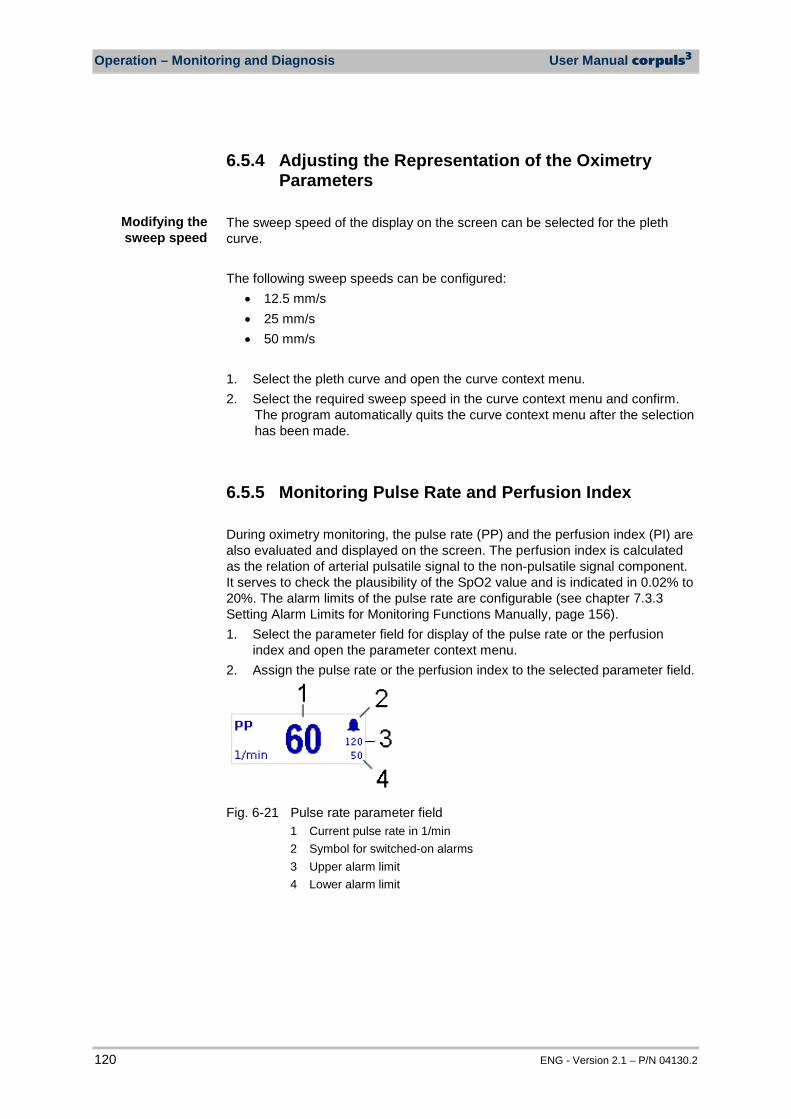
Operation – Monitoring and Diagnosis User Manual corpuls3
120 ENG - Version 2.1 – P/N 04130.2
6.5.4 Adjusting the Representation of the Oximetry Parameters
The sweep speed of the display on the screen can be selected for the pleth curve. The following sweep speeds can be configured:
• 12.5 mm/s • 25 mm/s • 50 mm/s
1. Select the pleth curve and open the curve context menu. 2. Select the required sweep speed in the curve context menu and confirm.
The program automatically quits the curve context menu after the selection has been made.
6.5.5 Monitoring Pulse Rate and Perfusion Index During oximetry monitoring, the pulse rate (PP) and the perfusion index (PI) are also evaluated and displayed on the screen. The perfusion index is calculated as the relation of arterial pulsatile signal to the non-pulsatile signal component. It serves to check the plausibility of the SpO2 value and is indicated in 0.02% to 20%. The alarm limits of the pulse rate are configurable (see chapter 7.3.3 Setting Alarm Limits for Monitoring Functions Manually, page 156). 1. Select the parameter field for display of the pulse rate or the perfusion
index and open the parameter context menu. 2. Assign the pulse rate or the perfusion index to the selected parameter field.
Fig. 6-21 Pulse rate parameter field
1 Current pulse rate in 1/min 2 Symbol for switched-on alarms 3 Upper alarm limit 4 Lower alarm limit
Modifying the sweep speed
User Manual corpuls3 Operation – Monitoring and Diagnosis
ENG - Version 2.1 – P/N 04130.2 121
6.6 CO2 Monitoring (option)
6.6.1 Information on CO2 Monitoring CO2 monitoring allows recording of the end-expiratory, end-tidal CO2 concentration (EtCO2) and provides information on ventilation, haemodynamics and metabolism in both intubated and non-intubated patients.
The semi-quantitative measurement method uses infrared technology and is based on the assumption that there is no CO2 present in the patient’s inspiratory respiratory gas.
Due to a condensation-repellent nano-coating in the disposable adapter, the capONE measurement system from the manufacturer NIHON KOHDEN does not require a warm-up phase and is therefore ready for measurement in 5 seconds maximum.
The capnometer, which operates according to the mainstream method, measures the CO2 concentration in the patient’s expiratory breath in real time. The CO2 concentration, measured in mmHg or kPa, can be displayed on the screen as a capnogram in a curve field.
The corpuls3 allows use of capnometry in intubated and non-intubated patients. The patient’s respiratory rate (RR) is measured as a further parameter.
Warning
Do not perform CO2 monitoring near high frequency surgical devices. This may result in signal loss so that the patient can no longer be monitored.
Warning
The capnometer in corpuls3 is an additional function for intensive monitoring. Other vital parameters and clinical symptoms must be minded when using the capnometer on the patient.
The capnometry option is only available for patients aged 3 years or more or from 10 kg body weight and up. See the manufacturer’s operating manual for further information.
Caution
Only use sensors and adapters indicated in the list of approved accessories (see chapter 9.8 Approved Accessories, Spare Parts and Consumables, p. 224).
Note
Note
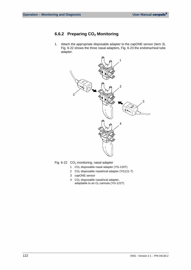
Operation – Monitoring and Diagnosis User Manual corpuls3
122 ENG - Version 2.1 – P/N 04130.2
6.6.2 Preparing CO2 Monitoring 1. Attach the appropriate disposable adapter to the capONE sensor (item 3).
Fig. 6-22 shows the three nasal adapters, Fig. 6-23 the endotracheal tube adapter.
Fig. 6-22 CO2 monitoring, nasal adapter
1 CO2 disposable nasal adapter (YG-120T) 2 CO2 disposable nasal/oral adapter (YG121-T) 3 capONE sensor 4 CO2 disposable nasal/oral adapter,
adaptable to an O2 cannula (YG-122T)
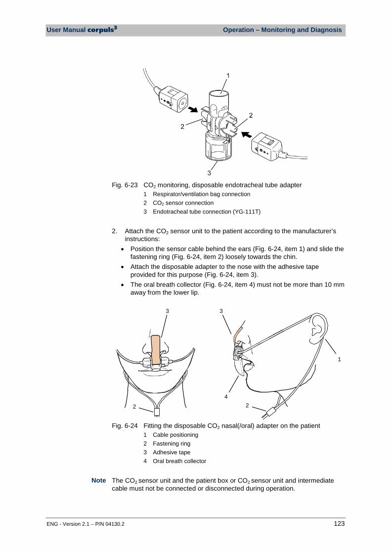
User Manual corpuls3 Operation – Monitoring and Diagnosis
ENG - Version 2.1 – P/N 04130.2 123
Fig. 6-23 CO2 monitoring, disposable endotracheal tube adapter
1 Respirator/ventilation bag connection 2 CO2 sensor connection 3 Endotracheal tube connection (YG-111T)
2. Attach the CO2 sensor unit to the patient according to the manufacturer’s
instructions: • Position the sensor cable behind the ears (Fig. 6-24, item 1) and slide the
fastening ring (Fig. 6-24, item 2) loosely towards the chin. • Attach the disposable adapter to the nose with the adhesive tape
provided for this purpose (Fig. 6-24, item 3). • The oral breath collector (Fig. 6-24, item 4) must not be more than 10 mm
away from the lower lip.
3
4
1
3
22
Fig. 6-24 Fitting the disposable CO2 nasal(/oral) adapter on the patient
1 Cable positioning 2 Fastening ring 3 Adhesive tape 4 Oral breath collector
The CO2 sensor unit and the patient box or CO2 sensor unit and intermediate cable must not be connected or disconnected during operation.
Note
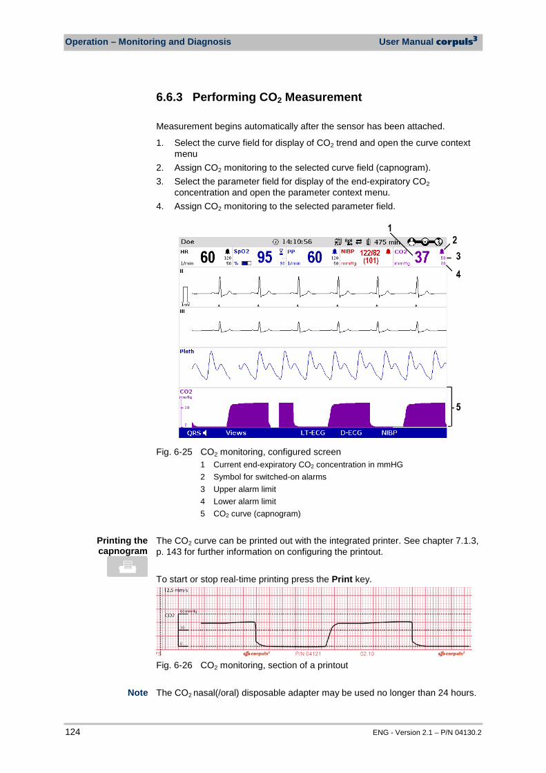
Operation – Monitoring and Diagnosis User Manual corpuls3
124 ENG - Version 2.1 – P/N 04130.2
6.6.3 Performing CO2 Measurement Measurement begins automatically after the sensor has been attached.
1. Select the curve field for display of CO2 trend and open the curve context menu
2. Assign CO2 monitoring to the selected curve field (capnogram). 3. Select the parameter field for display of the end-expiratory CO2
concentration and open the parameter context menu. 4. Assign CO2 monitoring to the selected parameter field.
Fig. 6-25 CO2 monitoring, configured screen
1 Current end-expiratory CO2 concentration in mmHG 2 Symbol for switched-on alarms 3 Upper alarm limit 4 Lower alarm limit 5 CO2 curve (capnogram)
The CO2 curve can be printed out with the integrated printer. See chapter 7.1.3, p. 143 for further information on configuring the printout. To start or stop real-time printing press the Print key.
Fig. 6-26 CO2 monitoring, section of a printout The CO2 nasal(/oral) disposable adapter may be used no longer than 24 hours.
Printing the capnogram
Note
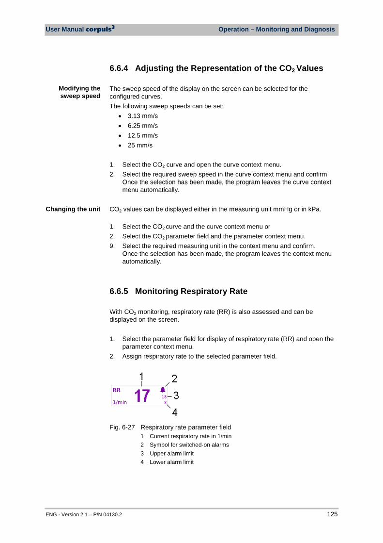
User Manual corpuls3 Operation – Monitoring and Diagnosis
ENG - Version 2.1 – P/N 04130.2 125
6.6.4 Adjusting the Representation of the CO2 Values The sweep speed of the display on the screen can be selected for the configured curves. The following sweep speeds can be set:
• 3.13 mm/s • 6.25 mm/s • 12.5 mm/s • 25 mm/s
1. Select the CO2 curve and open the curve context menu. 2. Select the required sweep speed in the curve context menu and confirm
Once the selection has been made, the program leaves the curve context menu automatically.
CO2 values can be displayed either in the measuring unit mmHg or in kPa. 1. Select the CO2 curve and the curve context menu or 2. Select the CO2 parameter field and the parameter context menu. 9. Select the required measuring unit in the context menu and confirm.
Once the selection has been made, the program leaves the context menu automatically.
6.6.5 Monitoring Respiratory Rate With CO2 monitoring, respiratory rate (RR) is also assessed and can be displayed on the screen. 1. Select the parameter field for display of respiratory rate (RR) and open the
parameter context menu. 2. Assign respiratory rate to the selected parameter field.
Fig. 6-27 Respiratory rate parameter field
1 Current respiratory rate in 1/min 2 Symbol for switched-on alarms 3 Upper alarm limit 4 Lower alarm limit
Modifying the sweep speed
Changing the unit
Operation – Monitoring and Diagnosis User Manual corpuls3
126 ENG - Version 2.1 – P/N 04130.2
6.7 Non-invasive Blood Pressure Monitoring (option)
6.7.1 Information on NIBP Monitoring Non-invasive blood pressure monitoring (NIBP) is used for routine monitoring of the blood pressure on an extremity. The pressure of a pulse wave in the blood is measured with the oscillometry method. The systolic, diastolic and mean blood pressure values are recorded as measured values and displayed on the screen as a numerical value in mmHg. By configuring automatic intervals, continuous automatic monitoring is possible. A selection of predetermined settings (initial pressure) for adults, children and neonates is available. Blood pressure measurements determined with this device are equivalent to those obtained by a trained observer using the cuff/stethoscope auscultation method, within the limits prescribed by the AAMI SP10:2002(R)2008, EN1060-4:2004 and ISO 81060-2:2009. For paediatric and adult patient populations, blood pressure measurements made with this device are equivalent to those obtained by trained observers using the cuff/stethoscope auscultatory method within the limits prescribed by ANSI/AAMI SP10:2002(R)2008 (mean error difference of ± 5 mmHg or less, standard deviation of 8 mmHg or less) as well as EN1060-4:2004 and ISO 81060-2:2009.
Warning
The device is designed to function in the presence of a normal ECG sinus rhythm. There are some physical conditions (i.e. bundle branch block, arrhythmias, atrial fibrillation, ventricular fibrillation, pacers, etc) that may limit the ability of the non-invasive blood pressure measurement module to obtain an accurate reading.
The NIBP technology integrated in corpuls3 is an OEM module from Sun Tech Medical Inc., Morrisville, NC, USA. Further information: www.suntechmed.com.
The blood pressure monitoring system consists of the blood pressure cuff and the connecting hose which connects the cuff to the interface at the patient box.
Warning
Delayed onset of action of emergency drugs may occur during administration if the blood pressure cuff is placed on an extremity into which an intravascular access has already been inserted. In this case, the blood pressure cuff should be used on another extremity, if possible.
Caution
Microwave radiation in the immediate vicinity may interfere with the function of the device.
Note
Note
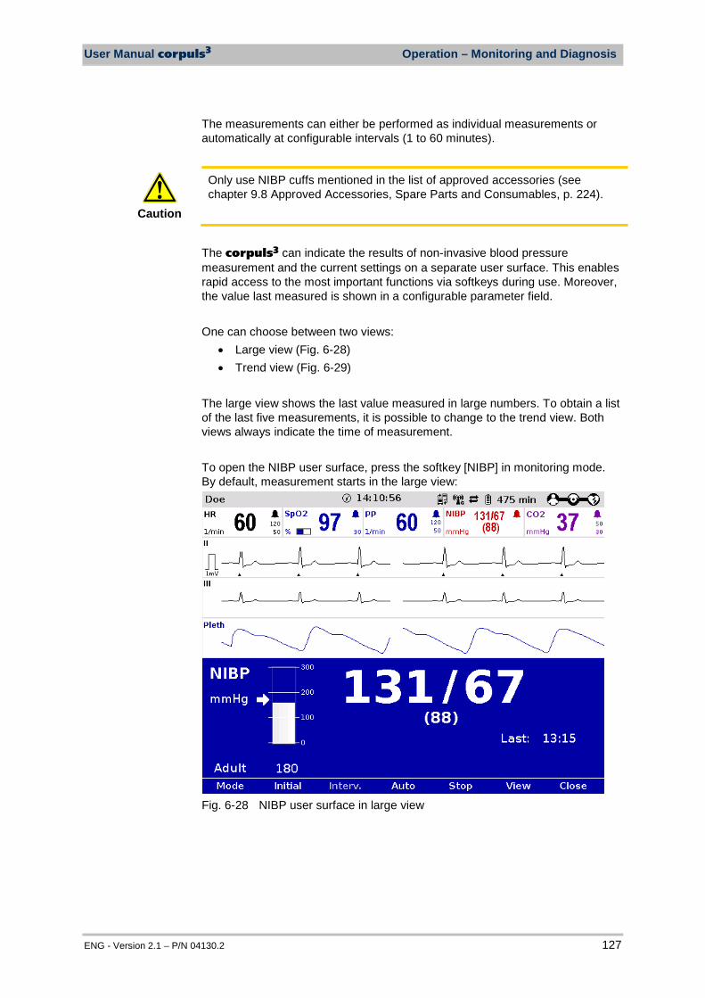
User Manual corpuls3 Operation – Monitoring and Diagnosis
ENG - Version 2.1 – P/N 04130.2 127
The measurements can either be performed as individual measurements or automatically at configurable intervals (1 to 60 minutes).
Caution
Only use NIBP cuffs mentioned in the list of approved accessories (see chapter 9.8 Approved Accessories, Spare Parts and Consumables, p. 224).
The corpuls3 can indicate the results of non-invasive blood pressure measurement and the current settings on a separate user surface. This enables rapid access to the most important functions via softkeys during use. Moreover, the value last measured is shown in a configurable parameter field. One can choose between two views:
• Large view (Fig. 6-28) • Trend view (Fig. 6-29)
The large view shows the last value measured in large numbers. To obtain a list of the last five measurements, it is possible to change to the trend view. Both views always indicate the time of measurement. To open the NIBP user surface, press the softkey [NIBP] in monitoring mode. By default, measurement starts in the large view:
Fig. 6-28 NIBP user surface in large view
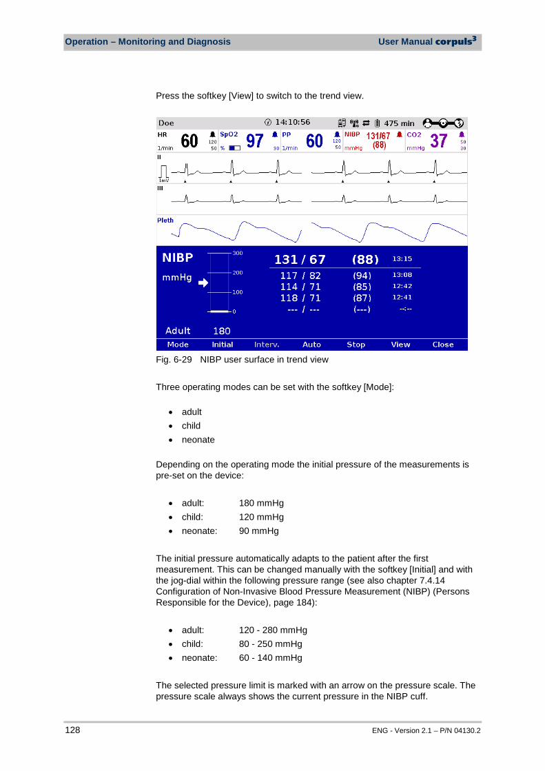
Operation – Monitoring and Diagnosis User Manual corpuls3
128 ENG - Version 2.1 – P/N 04130.2
Press the softkey [View] to switch to the trend view.
Fig. 6-29 NIBP user surface in trend view Three operating modes can be set with the softkey [Mode]:
• adult • child • neonate
Depending on the operating mode the initial pressure of the measurements is pre-set on the device:
• adult: 180 mmHg • child: 120 mmHg • neonate: 90 mmHg
The initial pressure automatically adapts to the patient after the first measurement. This can be changed manually with the softkey [Initial] and with the jog-dial within the following pressure range (see also chapter 7.4.14 Configuration of Non-Invasive Blood Pressure Measurement (NIBP) (Persons Responsible for the Device), page 184):
• adult: 120 - 280 mmHg • child: 80 - 250 mmHg • neonate: 60 - 140 mmHg
The selected pressure limit is marked with an arrow on the pressure scale. The pressure scale always shows the current pressure in the NIBP cuff.
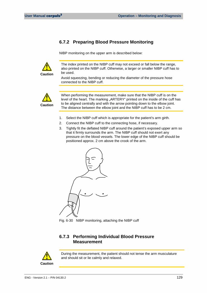
User Manual corpuls3 Operation – Monitoring and Diagnosis
ENG - Version 2.1 – P/N 04130.2 129
6.7.2 Preparing Blood Pressure Monitoring NIBP monitoring on the upper arm is described below:
Caution
The index printed on the NIBP cuff may not exceed or fall below the range, also printed on the NIBP cuff. Otherwise, a larger or smaller NIBP cuff has to be used. Avoid squeezing, bending or reducing the diameter of the pressure hose connected to the NIBP cuff.
Caution
When performing the measurement, make sure that the NIBP cuff is on the level of the heart. The marking „ARTERY“ printed on the inside of the cuff has to be aligned centrally and with the arrow pointing down to the elbow joint. The distance between the elbow joint and the NIBP cuff has to be 2 cm.
1. Select the NIBP cuff which is appropriate for the patient’s arm girth. 2. Connect the NIBP cuff to the connecting hose, if necessary. 3. Tightly fit the deflated NIBP cuff around the patient’s exposed upper arm so
that it firmly surrounds the arm. The NIBP cuff should not exert any pressure on the blood vessels. The lower edge of the NIBP cuff should be positioned approx. 2 cm above the crook of the arm.
Fig. 6-30 NIBP monitoring, attaching the NIBP cuff
6.7.3 Performing Individual Blood Pressure Measurement
Caution
During the measurement, the patient should not tense the arm musculature and should sit or lie calmly and relaxed.
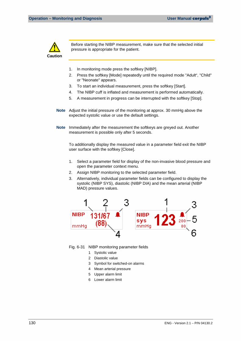
Operation – Monitoring and Diagnosis User Manual corpuls3
130 ENG - Version 2.1 – P/N 04130.2
Caution
Before starting the NIBP measurement, make sure that the selected initial pressure is appropriate for the patient.
1. In monitoring mode press the softkey [NIBP]. 2. Press the softkey [Mode] repeatedly until the required mode "Adult“, "Child"
or "Neonate" appears. 3. To start an individual measurement, press the softkey [Start]. 4. The NIBP cuff is inflated and measurement is performed automatically. 5. A measurement in progress can be interrupted with the softkey [Stop]. Adjust the initial pressure of the monitoring at approx. 30 mmHg above the expected systolic value or use the default settings. Immediately after the measurement the softkeys are greyed out. Another measurement is possible only after 5 seconds. To additionally display the measured value in a parameter field exit the NIBP user surface with the softkey [Close]. 1. Select a parameter field for display of the non-invasive blood pressure and
open the parameter context menu. 2. Assign NIBP monitoring to the selected parameter field. 3. Alternatively, individual parameter fields can be configured to display the
systolic (NIBP SYS), diastolic (NIBP DIA) and the mean arterial (NIBP MAD) pressure values.
Fig. 6-31 NIBP monitoring parameter fields
1 Systolic value 2 Diastolic value 3 Symbol for switched-on alarms 4 Mean arterial pressure 5 Upper alarm limit 6 Lower alarm limit
Note
Note
User Manual corpuls3 Operation – Monitoring and Diagnosis
ENG - Version 2.1 – P/N 04130.2 131
6.7.4 Performing Blood Pressure Interval Monitoring
Warning
Make sure that the blood circulation is not impaired in the extremity to which the NIBP cuff is attached.
Set the time value for interval monitoring (see chapter 7.4.14 Configuration of Non-Invasive Blood Pressure Measurement (NIBP) (Persons Responsible for the Device), page 184). This pre-configured value is shown by default on the NIBP user surface and can be changed by pressing the softkey [Interv.]. 1. In monitoring mode press the softkey [NIBP]. 2. Press the softkey [Mode] repeatedly until the required mode "Adult“, "Child"
or "Neonate" appears. 3. Press the softkey [Auto]. The softkey [Auto] remains selected. 4. Change the interval with the softkey [Interv.] or leave at default value. 5. To start an interval measurement press the softkey [Start] .
As soon as the interval measurement has been started, a clock symbol alternates with the alarm symbol in the upper right corner of the NIBP parameter field. The clock symbol indicates that the interval measurement is active and that an automatic measurement is being prepared Above the softkey [Auto], a countdown shows the remaining time until the next interval measurement.
6. To quit the interval measurement, press the softkey [Auto]. A measurement in progress can be interrupted with the softkey [Stop].
If the NIBP measurement is interrupted, the inscription above the softkey [Auto] shows four dashes instead. The pressure in the NIBP cuff is then released immediately. Open the NIBP user surface to see if interval measurement is active. During the interval measurement it is now possible to perform an individual measurement manually at any time between two automatic interval measurements by pressing the softkey [Start].
6.8 Invasive Blood Pressure Monitoring (Option)
6.8.1 Information on IBP Monitoring With the IBP function, various pressures can be measured within the context of intensive medical care. This includes, among others, arterial pressure, central venous pressure or intracranial pressure. Two interfaces are available which can be assigned as single channels or as double channels, respectively. For usage as a double channel, an IBP_Y-adapter cable is needed (in preparation). Consequently, up to four different invasive pressure measurements can be performed simultaneously. The recorded pressure values can be displayed on the screen either as numerical parameters and/or as an evolution curve.
Note
Note Note
Note
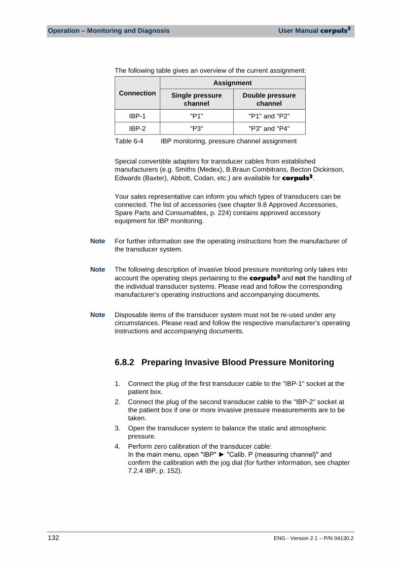
Operation – Monitoring and Diagnosis User Manual corpuls3
132 ENG - Version 2.1 – P/N 04130.2
The following table gives an overview of the current assignment:
Connection Assignment
Single pressure channel
Double pressure channel
IBP-1 "P1" "P1" and "P2"
IBP-2 "P3" "P3" and "P4"
Table 6-4 IBP monitoring, pressure channel assignment Special convertible adapters for transducer cables from established manufacturers (e.g. Smiths (Medex), B.Braun Combitrans, Becton Dickinson, Edwards (Baxter), Abbott, Codan, etc.) are available for corpuls3. Your sales representative can inform you which types of transducers can be connected. The list of accessories (see chapter 9.8 Approved Accessories, Spare Parts and Consumables, p. 224) contains approved accessory equipment for IBP monitoring. For further information see the operating instructions from the manufacturer of the transducer system. The following description of invasive blood pressure monitoring only takes into account the operating steps pertaining to the corpuls3 and not the handling of the individual transducer systems. Please read and follow the corresponding manufacturer’s operating instructions and accompanying documents. Disposable items of the transducer system must not be re-used under any circumstances. Please read and follow the respective manufacturer’s operating instructions and accompanying documents.
6.8.2 Preparing Invasive Blood Pressure Monitoring 1. Connect the plug of the first transducer cable to the "IBP-1" socket at the
patient box. 2. Connect the plug of the second transducer cable to the "IBP-2" socket at
the patient box if one or more invasive pressure measurements are to be taken.
3. Open the transducer system to balance the static and atmospheric pressure.
4. Perform zero calibration of the transducer cable: In the main menu, open "IBP" "Calib. P measuring channel" and confirm the calibration with the jog dial (for further information, see chapter 7.2.4 IBP, p. 152).
Note
Note
Note
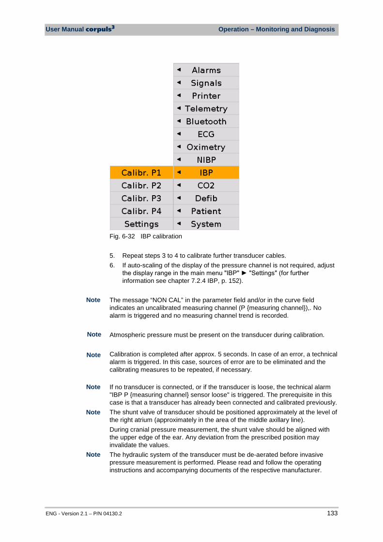
User Manual corpuls3 Operation – Monitoring and Diagnosis
ENG - Version 2.1 – P/N 04130.2 133
Fig. 6-32 IBP calibration 5. Repeat steps 3 to 4 to calibrate further transducer cables. 6. If auto-scaling of the display of the pressure channel is not required, adjust
the display range in the main menu "IBP" "Settings" (for further information see chapter 7.2.4 IBP, p. 152).
The message “NON CAL” in the parameter field and/or in the curve field indicates an uncalibrated measuring channel (P measuring channel),. No alarm is triggered and no measuring channel trend is recorded. Atmospheric pressure must be present on the transducer during calibration. Calibration is completed after approx. 5 seconds. In case of an error, a technical alarm is triggered. In this case, sources of error are to be eliminated and the calibrating measures to be repeated, if necessary. If no transducer is connected, or if the transducer is loose, the technical alarm "IBP P measuring channel sensor loose" is triggered. The prerequisite in this case is that a transducer has already been connected and calibrated previously. The shunt valve of transducer should be positioned approximately at the level of the right atrium (approximately in the area of the middle axillary line). During cranial pressure measurement, the shunt valve should be aligned with the upper edge of the ear. Any deviation from the prescribed position may invalidate the values. The hydraulic system of the transducer must be de-aerated before invasive pressure measurement is performed. Please read and follow the operating instructions and accompanying documents of the respective manufacturer.
Note
Note
Note
Note
Note
Note
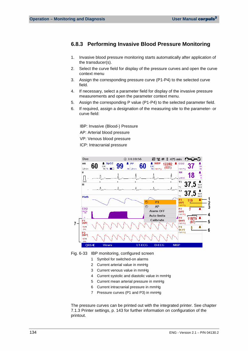
Operation – Monitoring and Diagnosis User Manual corpuls3
134 ENG - Version 2.1 – P/N 04130.2
6.8.3 Performing Invasive Blood Pressure Monitoring 1. Invasive blood pressure monitoring starts automatically after application of
the transducer(s). 2. Select the curve field for display of the pressure curves and open the curve
context menu 3. Assign the corresponding pressure curve (P1-P4) to the selected curve
field. 4. If necessary, select a parameter field for display of the invasive pressure
measurements and open the parameter context menu. 5. Assign the corresponding P value (P1-P4) to the selected parameter field. 6. If required, assign a designation of the measuring site to the parameter- or
curve field: IBP: Invasive (Blood-) Pressure AP: Arterial blood pressure VP: Venous blood pressure ICP: Intracranial pressure
Fig. 6-33 IBP monitoring, configured screen
1 Symbol for switched-on alarms 2 Current arterial value in mmHg 3 Current venous value in mmHg 4 Current systolic and diastolic value in mmHg 5 Current mean arterial pressure in mmHg 6 Current intracranial pressure in mmHg 7 Pressure curves (P1 and P3) in mmHg
The pressure curves can be printed out with the integrated printer. See chapter 7.1.3 Printer settings, p. 143 for further information on configuration of the printout.

User Manual corpuls3 Operation – Monitoring and Diagnosis
ENG - Version 2.1 – P/N 04130.2 135
Press the Print key to start or stop real-time printing
Fig. 6-34 IBP monitoring, section of a printout
Invasive blood pressure curve P1
6.9 Temperature Monitoring (Option)
6.9.1 Information on Temperature Monitoring Temperature monitoring enables continuous measurement and monitoring of the body core temperature (e.g. in a hypothermic patient) or the surface temperature of the skin (e.g. following therapeutic hypothermia in the post-resuscitation phase). Up to two temperature values can be measured by means of temperature sensors and displayed as numerical values: body core temperature rectally and/or oesophageally and surface temperature.
Caution
Only use YSI sensors of the series 400 or sensors compatible with those,as indicated in the list of approved accessories (see chapter 9.8 Approved Accessories, Spare Parts and Consumables, p. 224). Proof of biocompatibility according to ISO 10993-1 is required.
The measurement range lies between 12.0°C and 50.0°C. The temperature is displayed in °C. Temperature values outside the measurement range are indicated as "--.-". For further information please read the operating instructions of the temperature sensor’s manufacturer.
6.9.2 Preparing Temperature Monitoring 1. Connect the plug of the first temperature sensor to the "Temp-1" socket at
the patient box. 2. Connect the plug of the second temperature sensor to the "Temp-2" socket
at the patient box, if a second temperature is to be measured. 3. Insert the temperature sensor rectally or oesophageally or attach to the
skin and if necessary, secure with tape. Use a protective sheath if necessary.
Note
Temperature

Operation – Monitoring and Diagnosis User Manual corpuls3
136 ENG - Version 2.1 – P/N 04130.2
6.9.3 Performing Temperature Monitoring Monitoring starts automatically after the sensor has been attached. 1. Select the parameter field for display of the first temperature value and
open the parameter context menu. 2. Assign T1 monitoring to the selected parameter field.
Fig. 6-35 Temperature monitoring parameter field
1 Current temperature value in °C 2 Symbol for switched-on alarms 3 Upper alarm limit 4 Lower alarm limit
3. If measurement of a second temperature value is necessary, select the parameter field of the second temperature value and open the parameter context menu.
4. Assign T2 monitoring to the selected parameter field.

User Manual corpuls3 Configuration
ENG - Version 2.1 – P/N 04130.2 137
7 Configuration
Various different settings of the corpuls3 can be configured: • System settings • Monitoring functions (ECG, Oximetry, CO2, NIBP, IBP) • Alarms • Advanced settings (for persons responsible for the device)
The corpuls3 has user administration. Certain settings are therefore only acessible for users with a higher authorisation level (such as persons responsible for the device or service technicians). For default users, certain configuration fields are greyed out and cannot be selected. Permanent saving of changes in the configuration can only be performed with the corresponding authorisation. If modifications made are not saved in the system settings (see chapter 7.4.2 General System Settings (Person responsible for the device), p. 160), all the adjustments will be lost when the corpuls3 is switched off. The corpuls3 always starts in the default user mode. The configuration dialogues are opened with the jog dial by navigating in the main menu (see chapter 4.3.3 Main Menu, p. 49). The settings are selected and confirmed with the jog dial (see chapter 4.1.1 Operating Elements and LEDs on the Monitoring Unit, p. 31).
7.1 Configuring the System
7.1.1 General System Settings The following general system settings can be configured:
• Time/Date • Screen settings/Display • Manual event • Master data
Note
Note
Note
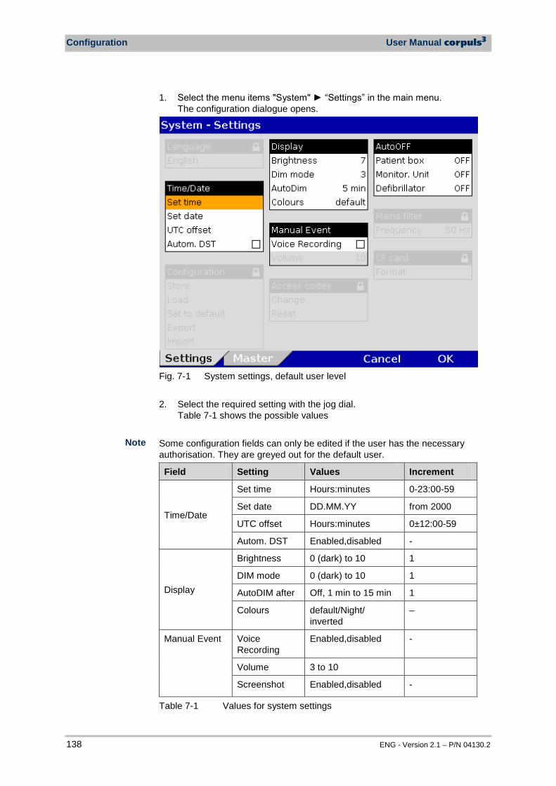
Configuration User Manual corpuls3
138 ENG - Version 2.1 – P/N 04130.2
1. Select the menu items "System" “Settings” in the main menu. The configuration dialogue opens.
Fig. 7-1 System settings, default user level 2. Select the required setting with the jog dial.
Table 7-1 shows the possible values Some configuration fields can only be edited if the user has the necessary authorisation. They are greyed out for the default user.
Field Setting Values Increment
Time/Date
Set time Hours:minutes 0-23:00-59
Set date DD.MM.YY from 2000
UTC offset Hours:minutes 0±12:00-59
Autom. DST Enabled,disabled -
Display
Brightness 0 (dark) to 10 1
DIM mode 0 (dark) to 10 1
AutoDIM after Off, 1 min to 15 min 1
Colours default/Night/ inverted
–
Manual Event Voice Recording
Enabled,disabled -
Volume 3 to 10
Screenshot Enabled,disabled -
Table 7-1 Values for system settings
Note

User Manual corpuls3 Configuration
ENG - Version 2.1 – P/N 04130.2 139
The following settings are possible for the display: • brightness level of the backlit display (not in night mode) • dimmed brightness level for energy saving (not in night mode) • time interval after which the display switches from normal to dimmed in
the absence of operating actions or alarms (not in night mode) • normal, night or inverted video display on the screen
The corpuls3 never switches to AutoDIM (energy saving) mode in defibrillation-, pacer- or nightvision mode. If the audio recording option is enabled, a 15 second recording of the surrounding sounds can be saved additionally by pressing the Event key (5 s before and 10 s after pressing the key). The audio recording appears as manual event in the protocol. Furthermore, if the screenshot option is enabled, a picture file of an event can be saved by pressing the Event key. The audio recording and the screenshots can be played and viewed with the software corView2 (see chapter 8.6 Analysis of the Data with corView2, page 193).
The UTC offset (time zone) and the automatic daylight saving time (DST) have to be configured before setting the time. The UTC and time are printed on the protocol. For the UTC offset and the time, the unchanged minutes also have to be confirmed with the jog dial. Only then the changed hour is saved with the softkey [OK]. 3. To confirm the settings and close the configuration dialogue, press the
softkey [OK]. To retain the previous settings and close the configuration dialogue, press the softkey [Cancel].
Via the configuration page “Master” the master data can be edited (see chapter 8.4 Master Data, p. 188)
Display
Note
Note
Audio recording and screenshots
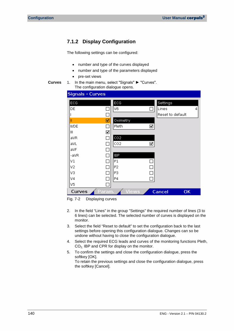
Configuration User Manual corpuls3
140 ENG - Version 2.1 – P/N 04130.2
7.1.2 Display Configuration The following settings can be configured:
• number and type of the curves displayed • number and type of the parameters displayed • pre-set views
1. In the main menu, select "Signals" "Curves". The configuration dialogue opens.
Fig. 7-2 Displaying curves 2. In the field “Lines” in the group "Settings" the required number of lines (3 to
6 lines) can be selected. The selected number of curves is displayed on the monitor.
3. Select the field “Reset to default” to set the configuration back to the last settings before opening this configuration dialogue. Changes can so be undone without having to close the configuration dialogue.
4. Select the required ECG leads and curves of the monitoring functions Pleth, CO2, IBP and CPR for display on the monitor.
5. To confirm the settings and close the configuration dialogue, press the softkey [OK]. To retain the previous settings and close the configuration dialogue, press the softkey [Cancel].
Curves
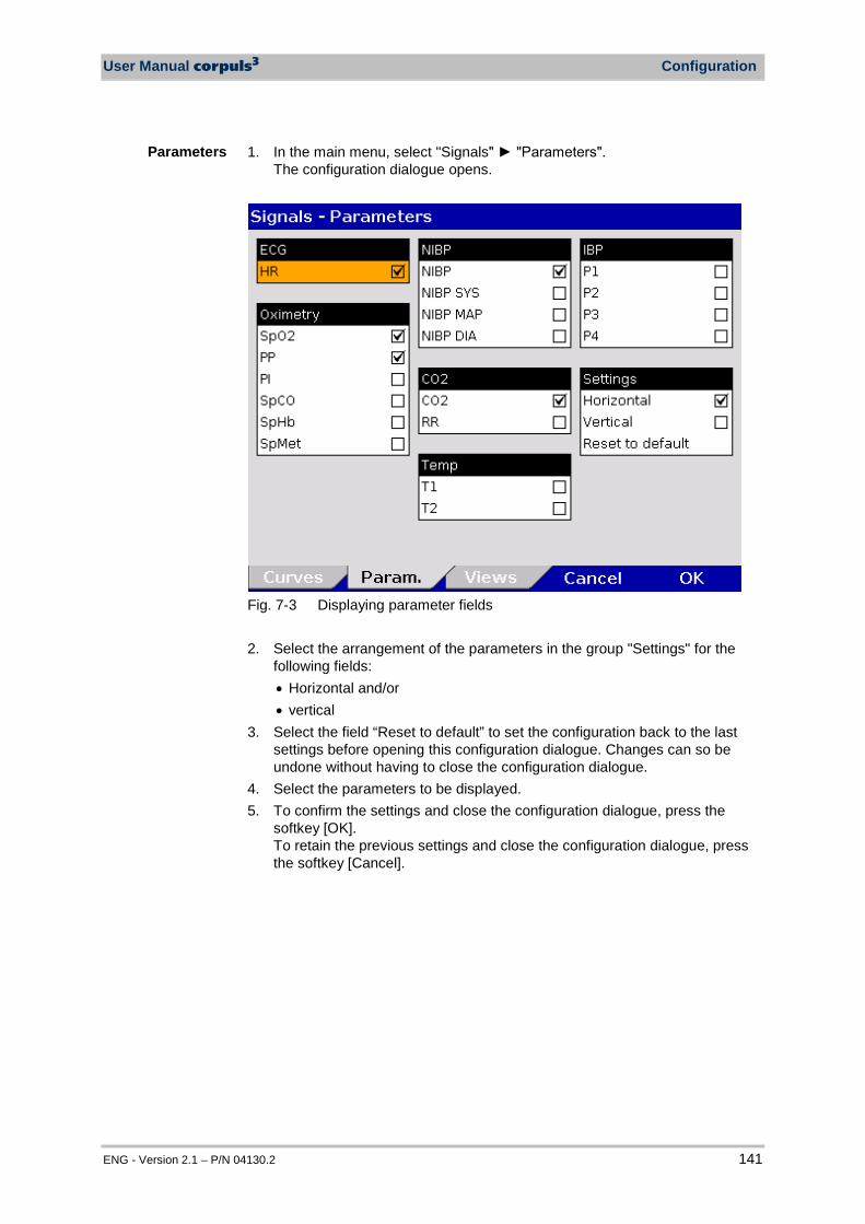
User Manual corpuls3 Configuration
ENG - Version 2.1 – P/N 04130.2 141
1. In the main menu, select "Signals" "Parameters". The configuration dialogue opens.
Fig. 7-3 Displaying parameter fields 2. Select the arrangement of the parameters in the group "Settings" for the
following fields: • Horizontal and/or • vertical
3. Select the field “Reset to default” to set the configuration back to the last settings before opening this configuration dialogue. Changes can so be undone without having to close the configuration dialogue.
4. Select the parameters to be displayed. 5. To confirm the settings and close the configuration dialogue, press the
softkey [OK]. To retain the previous settings and close the configuration dialogue, press the softkey [Cancel].
Parameters
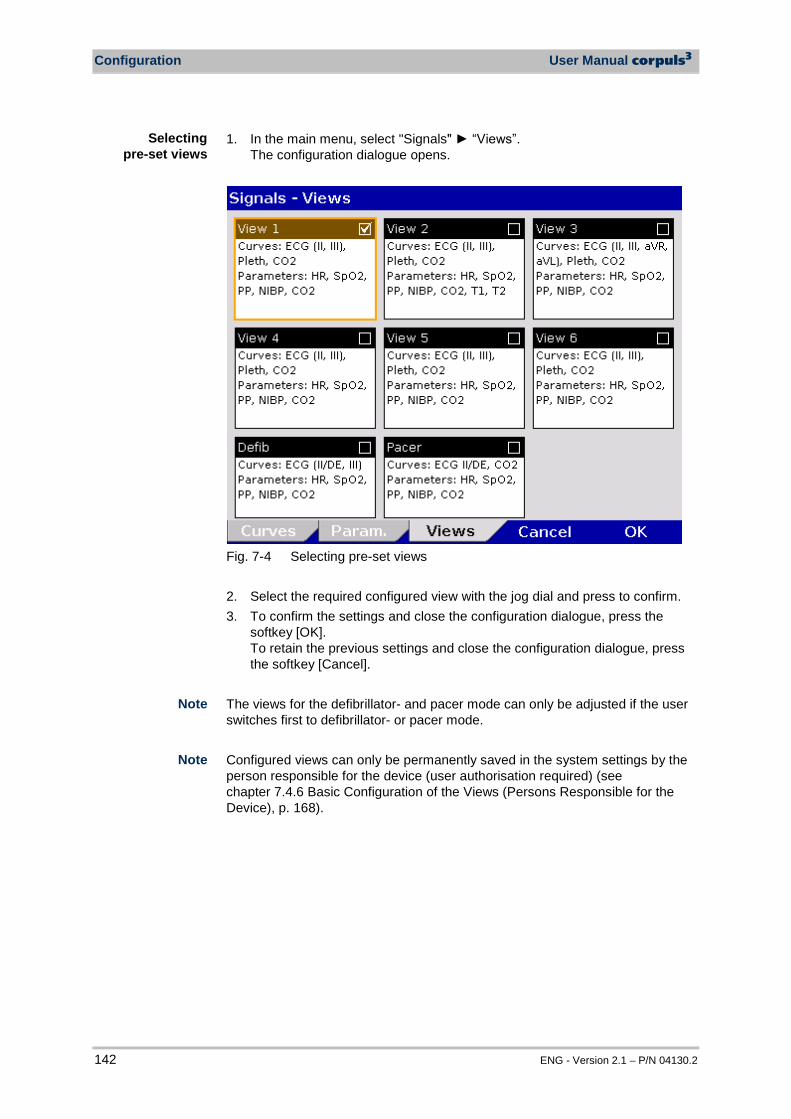
Configuration User Manual corpuls3
142 ENG - Version 2.1 – P/N 04130.2
1. In the main menu, select "Signals" “Views”. The configuration dialogue opens.
Fig. 7-4 Selecting pre-set views 2. Select the required configured view with the jog dial and press to confirm. 3. To confirm the settings and close the configuration dialogue, press the
softkey [OK]. To retain the previous settings and close the configuration dialogue, press the softkey [Cancel].
The views for the defibrillator- and pacer mode can only be adjusted if the user switches first to defibrillator- or pacer mode. Configured views can only be permanently saved in the system settings by the person responsible for the device (user authorisation required) (see chapter 7.4.6 Basic Configuration of the Views (Persons Responsible for the Device), p. 168).
Selecting pre-set views
Note
Note
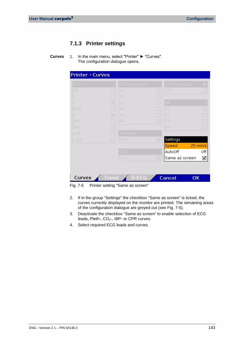
User Manual corpuls3 Configuration
ENG - Version 2.1 – P/N 04130.2 143
7.1.3 Printer settings 1. In the main menu, select "Printer" "Curves".
The configuration dialogue opens.
Fig. 7-5 Printer setting "Same as screen" 2. If in the group “Settings” the checkbox “Same as screen” is ticked, the
curves currently displayed on the monitor are printed. The remaining areas of the configuration dialogue are greyed out (see Fig. 7-5).
3. Deactivate the checkbox “Same as screen” to enable selection of ECG leads, Pleth-, CO2-, IBP- or CPR curves.
4. Select required ECG leads and curves.
Curves
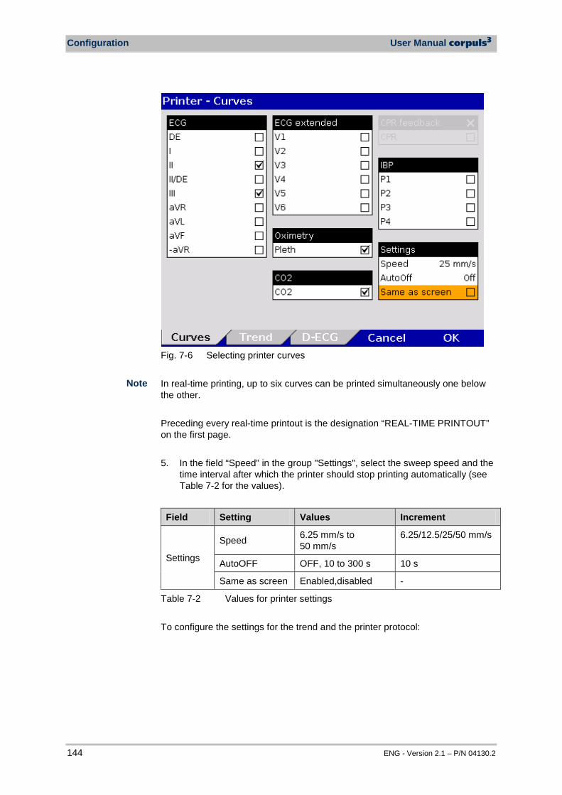
Configuration User Manual corpuls3
144 ENG - Version 2.1 – P/N 04130.2
Fig. 7-6 Selecting printer curves In real-time printing, up to six curves can be printed simultaneously one below the other. Preceding every real-time printout is the designation “REAL-TIME PRINTOUT” on the first page. 5. In the field “Speed” in the group "Settings", select the sweep speed and the
time interval after which the printer should stop printing automatically (see Table 7-2 for the values).
Field Setting Values Increment
Settings
Speed 6.25 mm/s to 50 mm/s
6.25/12.5/25/50 mm/s
AutoOFF OFF, 10 to 300 s 10 s
Same as screen Enabled,disabled -
Table 7-2 Values for printer settings To configure the settings for the trend and the printer protocol:
Note
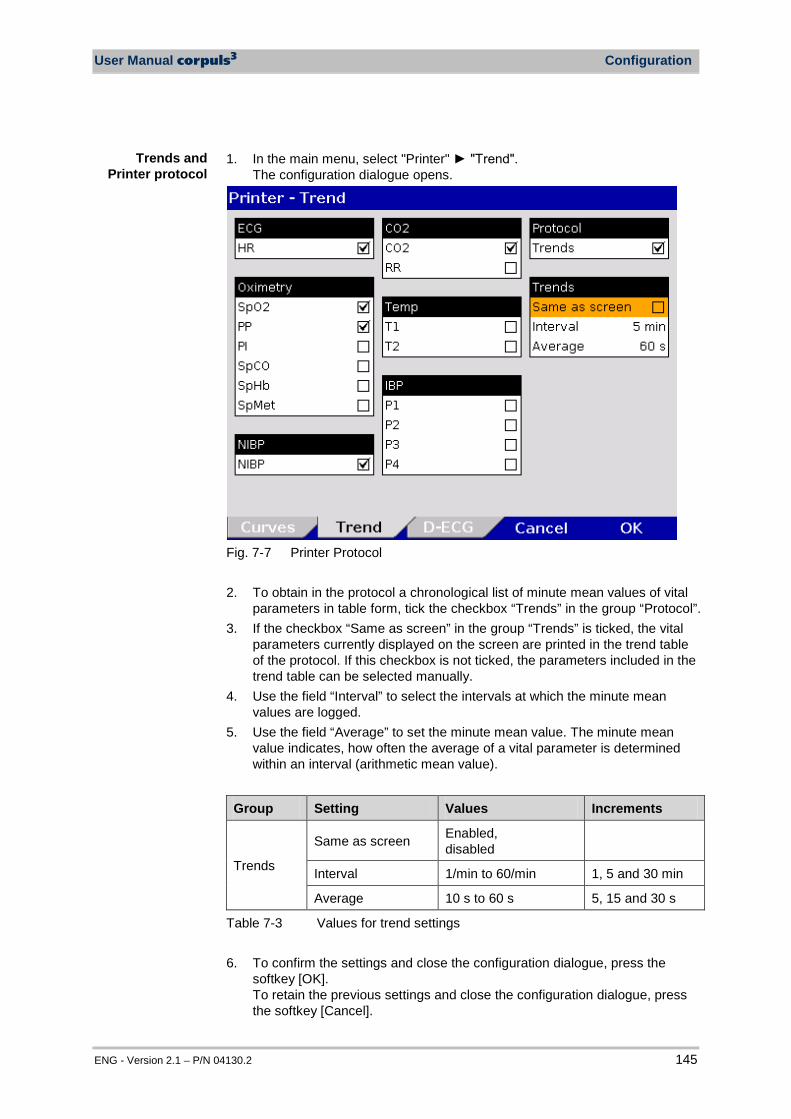
User Manual corpuls3 Configuration
ENG - Version 2.1 – P/N 04130.2 145
1. In the main menu, select "Printer" "Trend".
The configuration dialogue opens.
Fig. 7-7 Printer Protocol
2. To obtain in the protocol a chronological list of minute mean values of vital
parameters in table form, tick the checkbox “Trends” in the group “Protocol”. 3. If the checkbox “Same as screen” in the group “Trends” is ticked, the vital
parameters currently displayed on the screen are printed in the trend table of the protocol. If this checkbox is not ticked, the parameters included in the trend table can be selected manually.
4. Use the field “Interval” to select the intervals at which the minute mean values are logged.
5. Use the field “Average” to set the minute mean value. The minute mean value indicates, how often the average of a vital parameter is determined within an interval (arithmetic mean value).
Group Setting Values Increments
Trends
Same as screen Enabled, disabled
Interval 1/min to 60/min 1, 5 and 30 min
Average 10 s to 60 s 5, 15 and 30 s
Table 7-3 Values for trend settings 6. To confirm the settings and close the configuration dialogue, press the
softkey [OK]. To retain the previous settings and close the configuration dialogue, press the softkey [Cancel].
Trends and Printer protocol
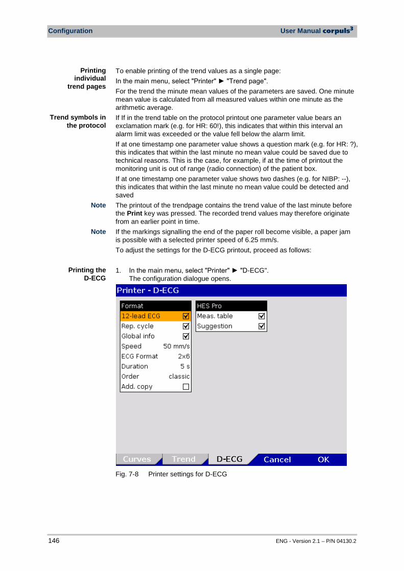
Configuration User Manual corpuls3
146 ENG - Version 2.1 – P/N 04130.2
To enable printing of the trend values as a single page: In the main menu, select "Printer" "Trend page". For the trend the minute mean values of the parameters are saved. One minute mean value is calculated from all measured values within one minute as the arithmetic average. If If in the trend table on the protocol printout one parameter value bears an exclamation mark (e.g. for HR: 60!), this indicates that within this interval an alarm limit was exceeded or the value fell below the alarm limit. If at one timestamp one parameter value shows a question mark (e.g. for HR: ?), this indicates that within the last minute no mean value could be saved due to technical reasons. This is the case, for example, if at the time of printout the monitoring unit is out of range (radio connection) of the patient box. If at one timestamp one parameter value shows two dashes (e.g. for NIBP: --), this indicates that within the last minute no mean value could be detected and saved The printout of the trendpage contains the trend value of the last minute before the Print key was pressed. The recorded trend values may therefore originate from an earlier point in time. If the markings signalling the end of the paper roll become visible, a paper jam is possible with a selected printer speed of 6.25 mm/s. To adjust the settings for the D-ECG printout, proceed as follows: 1. In the main menu, select "Printer" "D-ECG".
The configuration dialogue opens.
Fig. 7-8 Printer settings for D-ECG
Note
Trend symbols in the protocol
Printing individual
trend pages
Note
Printing the D-ECG
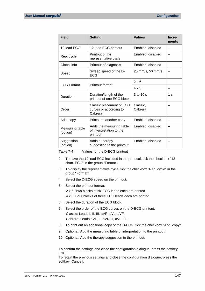
User Manual corpuls3 Configuration
ENG - Version 2.1 – P/N 04130.2 147
Field Setting Values Incre-ments
12-lead ECG 12-lead ECG printout Enabled, disabled –
Rep. cycle Printout of the representative cycle
Enabled, disabled –
Global info Printout of diagnosis Enabled, disabled –
Speed Sweep speed of the D-ECG
25 mm/s, 50 mm/s –
ECG Format Printout format 2 x 6 –
4 x 3 –
Duration Duration/length of the printout of one ECG block
3 to 10 s 1 s
Order Classic placement of ECG curves or according to Cabrera
Classic, Cabrera
–
Add. copy Prints out another copy Enabled, disabled –
Measuring table (option)
Adds the measuring table of interpretation to the printout
Enabled, disabled –
Suggestion (option)
Adds a therapy suggestion to the printout
Enabled, disabled –
Table 7-4 Values for the D-ECG printout
2. To have the 12 lead ECG included in the protocol, tick the checkbox "12-chan. ECG" in the group "Format".
3. To display the representative cycle, tick the checkbox "Rep. cycle" in the group "Format".
4. Select the D-ECG speed on the printout.
5. Select the printout format: 2 x 6: Two blocks of six ECG leads each are printed. 4 x 3: Four blocks of three ECG leads each are printed.
6. Select the duration of the ECG block.
7. Select the order of the ECG curves on the D-ECG printout: Classic: Leads I, II, III, aVR, aVL, aVF. Cabrera: Leads aVL, I, -aVR, II, aVF, III.
8. To print out an additional copy of the D-ECG, tick the checkbox "Add. copy".
9. Optional: Add the measuring table of interpretation to the printout.
10. Optional: Add the therapy suggestion to the printout.
To confirm the settings and close the configuration dialogue, press the softkey [OK]. To retain the previous settings and close the configuration dialogue, press the softkey [Cancel].
Configuration User Manual corpuls3
148 ENG - Version 2.1 – P/N 04130.2
7.1.4 Configuration of the Fax Transmission (Default User)
The following settings can be configured by the default user for transmitting a fax:
• Enabling and disabling of the GSM connection (aircraft mode) • Selection of the sweep speed for the representation of the D-ECG on the
fax machine.
7.2 Configuration of the Monitoring Functions The settings of the following monitoring functions can be configured:
• ECG • SpO2 • SpMet • SpCO • SpHb • PP • PI • CO2 • NIBP • IBP • CPR feedback
7.2.1 ECG Monitoring The following settings can be selected:
• ECG Display • Dynamic QRS Tone (optional) • Filters (see chapter 7.4.4 Filter Settings (Persons Responsible for the
Device), p. 165)
Settings for Fax Transmission
(optional)
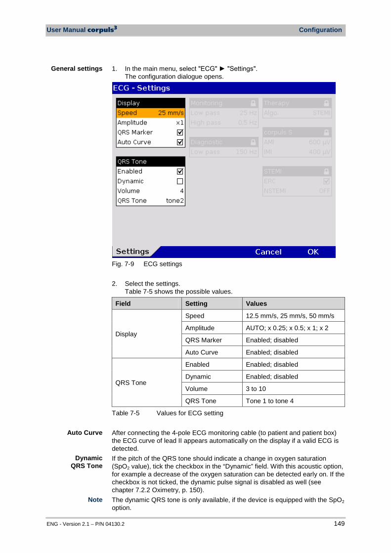
User Manual corpuls3 Configuration
ENG - Version 2.1 – P/N 04130.2 149
1. In the main menu, select "ECG" "Settings". The configuration dialogue opens.
Fig. 7-9 ECG settings
2. Select the settings.
Table 7-5 shows the possible values.
Field Setting Values
Display
Speed 12.5 mm/s, 25 mm/s, 50 mm/s
Amplitude AUTO; x 0.25; x 0.5; x 1; x 2
QRS Marker Enabled; disabled
Auto Curve Enabled; disabled
QRS Tone
Enabled Enabled; disabled
Dynamic Enabled; disabled
Volume 3 to 10
QRS Tone Tone 1 to tone 4
Table 7-5 Values for ECG setting After connecting the 4-pole ECG monitoring cable (to patient and patient box) the ECG curve of lead II appears automatically on the display if a valid ECG is detected. If the pitch of the QRS tone should indicate a change in oxygen saturation (SpO2 value), tick the checkbox in the “Dynamic” field. With this acoustic option, for example a decrease of the oxygen saturation can be detected early on. If the checkbox is not ticked, the dynamic pulse signal is disabled as well (see chapter 7.2.2 Oximetry, p. 150). The dynamic QRS tone is only available, if the device is equipped with the SpO2 option.
General settings
Dynamic QRS Tone
Auto Curve
Note
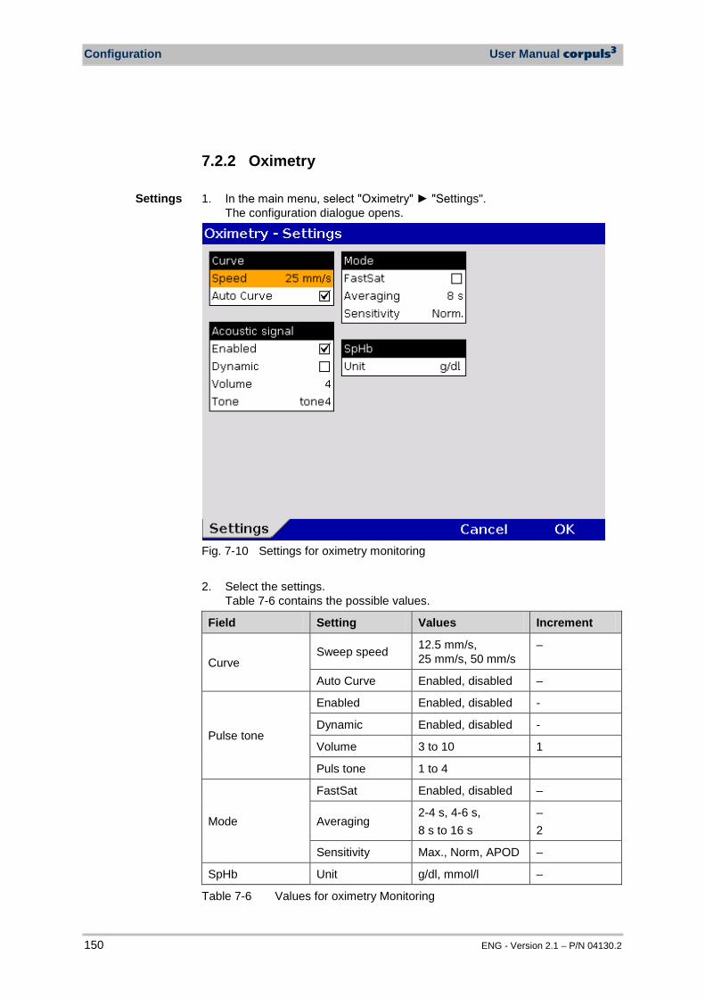
Configuration User Manual corpuls3
150 ENG - Version 2.1 – P/N 04130.2
7.2.2 Oximetry 1. In the main menu, select "Oximetry" "Settings".
The configuration dialogue opens.
Fig. 7-10 Settings for oximetry monitoring 2. Select the settings.
Table 7-6 contains the possible values.
Field Setting Values Increment
Curve Sweep speed 12.5 mm/s,
25 mm/s, 50 mm/s –
Auto Curve Enabled, disabled –
Pulse tone
Enabled Enabled, disabled -
Dynamic Enabled, disabled -
Volume 3 to 10 1
Puls tone 1 to 4
Mode
FastSat Enabled, disabled –
Averaging 2-4 s, 4-6 s, 8 s to 16 s
– 2
Sensitivity Max., Norm, APOD –
SpHb Unit g/dl, mmol/l –
Table 7-6 Values for oximetry Monitoring
Settings
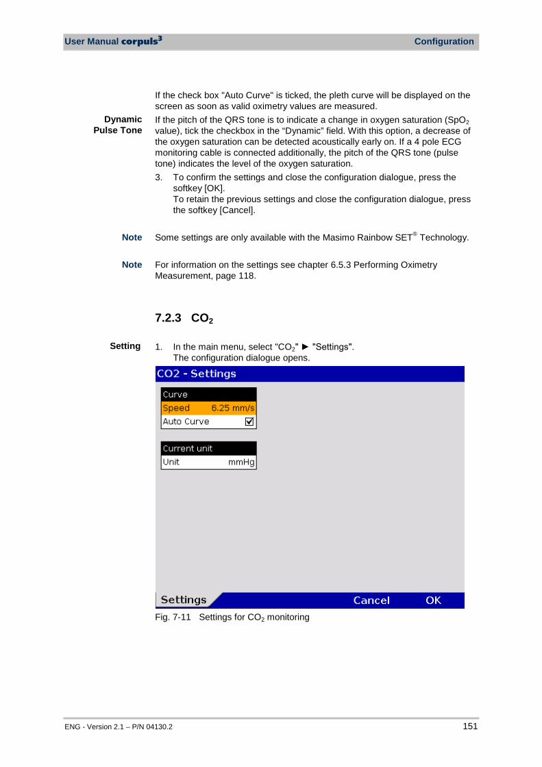
User Manual corpuls3 Configuration
ENG - Version 2.1 – P/N 04130.2 151
If the check box "Auto Curve" is ticked, the pleth curve will be displayed on the screen as soon as valid oximetry values are measured. If the pitch of the QRS tone is to indicate a change in oxygen saturation (SpO2 value), tick the checkbox in the “Dynamic” field. With this option, a decrease of the oxygen saturation can be detected acoustically early on. If a 4 pole ECG monitoring cable is connected additionally, the pitch of the QRS tone (pulse tone) indicates the level of the oxygen saturation. 3. To confirm the settings and close the configuration dialogue, press the
softkey [OK]. To retain the previous settings and close the configuration dialogue, press the softkey [Cancel].
Some settings are only available with the Masimo Rainbow SET® Technology. For information on the settings see chapter 6.5.3 Performing Oximetry Measurement, page 118.
7.2.3 CO2 1. In the main menu, select "CO2" "Settings".
The configuration dialogue opens.
Fig. 7-11 Settings for CO2 monitoring
Setting
Dynamic Pulse Tone
Note
Note

Configuration User Manual corpuls3
152 ENG - Version 2.1 – P/N 04130.2
2. Select the settings. Table 7-7 contains the possible values.
Field Setting Values
Curve Sweep speed 3.13 mm/s, 6.25 mm/s,
12.5 mm/s
Auto Curve Enabled, disabled
Current unit Unit mmHg, kPa
Table 7-7 CO2 monitoring values If the check box "Auto Curve" is ticked, the CO2 curve will be displayed on the screen as soon as valid CO2 values are measured. 3. To confirm the settings and close the configuration dialogue, press the
softkey [OK]. To retain the previous settings and close the configuration dialogue, press the softkey [Cancel].
7.2.4 IBP 1. In the main menu, select IBP" "Settings".
The configuration dialogue opens.
Fig. 7-12 Settings for IBP monitoring
Setting

User Manual corpuls3 Configuration
ENG - Version 2.1 – P/N 04130.2 153
2. Select the settings. Table 7-8 contains the possible values.
Field Setting Values
General Sweep speed 12.5 mm/s, 25 mm/s, 50 mm/s
P Display Scale
Auto; 0 to 30; 0 to 60; 0 to 120; 0 to 180; 0 to 300 -10 to 10; -20 to 20; -30 to 30; -40 to 40; -50 to 50
Auto Curve Enabled, disabled
Table 7-8 Values for IBP monitoring Depending on the measurement site (e.g. arterial, central venous, intracranial) the printing area must be scaled accordingly. If the check box "Auto Curve" is ticked, the IBP curve will be displayed on the screen as soon as the IBP sensor is connected to the patient box and the corresponding measuring channel is calibrated. The function "Auto Curve" does not work for negative pressure values.
In the main menu, select "IBP" "Calib. P measuring channel" of the respective pressure channel. 1. Calibration is performed automatically. In case the calibration cannot be
performed correctly, the alarm “IBP calibration error“ appears. The IBP channel can be calibrated directly in the context menu of the pertaining parameter field. After calibration of the channel, the IBP curve is displayed automatically (Auto Curve).
Calibrating
Scaling
Auto Curve
Note
Note
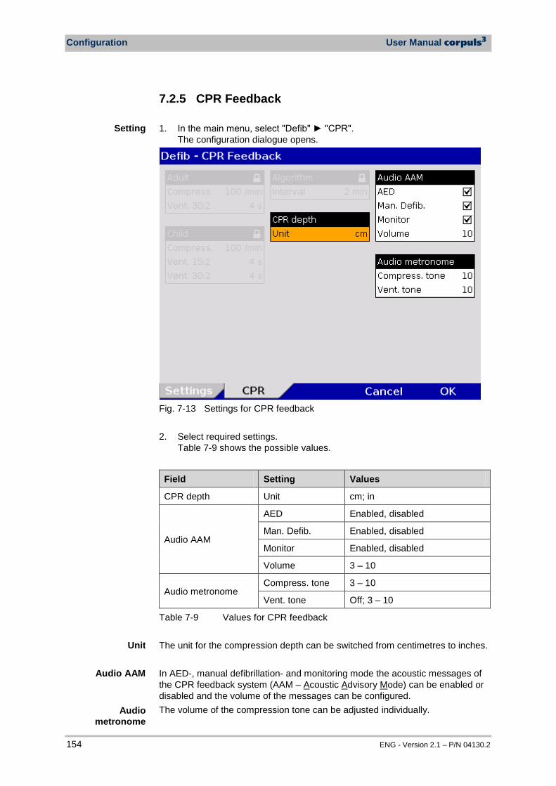
Configuration User Manual corpuls3
154 ENG - Version 2.1 – P/N 04130.2
7.2.5 CPR Feedback 1. In the main menu, select "Defib" "CPR".
The configuration dialogue opens.
Fig. 7-13 Settings for CPR feedback 2. Select required settings.
Table 7-9 shows the possible values.
Field Setting Values
CPR depth Unit cm; in
Audio AAM
AED Enabled, disabled
Man. Defib. Enabled, disabled
Monitor Enabled, disabled
Volume 3 – 10
Audio metronome Compress. tone 3 – 10
Vent. tone Off; 3 – 10
Table 7-9 Values for CPR feedback The unit for the compression depth can be switched from centimetres to inches. In AED-, manual defibrillation- and monitoring mode the acoustic messages of the CPR feedback system (AAM – Acoustic Advisory Mode) can be enabled or disabled and the volume of the messages can be configured. The volume of the compression tone can be adjusted individually.
Setting
Audio metronome
Unit
Audio AAM

User Manual corpuls3 Configuration
ENG - Version 2.1 – P/N 04130.2 155
7.3 Alarm Configuration
7.3.1 Configuring Alarm Settings 1. In the main menu, select the menu items "Alarm" "Settings".
The configuration dialogue opens.
Fig. 7-14 Alarm settings 2. Select the required setting with the jog dial.
The alarm for the occurrence of a ventricular tachykardia (VT) or a ventricular fibrillation (VF) can be disabled.
VT/VF Valur
Alarm enabled, disabled
Table 7-10 Settings for the VT/VF alarm 3. To confirm the settings and close the configuration dialogue, press the
softkey [OK]. To retain the previous settings and close the configuration dialogue, press the softkey [Cancel].
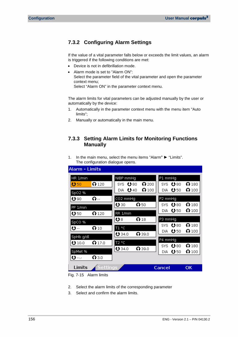
Configuration User Manual corpuls3
156 ENG - Version 2.1 – P/N 04130.2
7.3.2 Configuring Alarm Settings If the value of a vital parameter falls below or exceeds the limit values, an alarm is triggered if the following conditions are met: • Device is not in defibrillation mode. • Alarm mode is set to "Alarm ON":
Select the parameter field of the vital parameter and open the parameter context menu; Select “Alarm ON” in the parameter context menu.
The alarm limits for vital parameters can be adjusted manually by the user or automatically by the device: 1. Automatically in the parameter context menu with the menu item "Auto
limits"; 2. Manually or automatically in the main menu.
7.3.3 Setting Alarm Limits for Monitoring Functions Manually
1. In the main menu, select the menu items "Alarm" “Limits”.
The configuration dialogue opens.
Fig. 7-15 Alarm limits 2. Select the alarm limits of the corresponding parameter 3. Select and confirm the alarm limits.

User Manual corpuls3 Configuration
ENG - Version 2.1 – P/N 04130.2 157
The actually available value range indicated in Table 7-11 depends on the selected upper and lower limit values, as the upper and lower limits may not overlap.
Function Lower limit Upper limit Increment
HR 1/min --; 25 to 100 --; 70 to 250 5
SpO2 % --; 65 to 98 --; 90 to 99 1
PP 1/min --; 25 to 100 --; 70 to 235 5
SpCO % --; 0 to 99 --; 1 to 99 1
SpHb g/dl --; 5.0 to 12.0 --; 10 to 22 0,1
SpHb mmol/l --; 3.1 to 7.4 --; 6.2 to 13.7 0,1
SpMet % --; 0.1 to 99.5 --; 1 to 99.5 0.1 (0-2) 0.5 (2-100)
NIBP mmHg SYS --; 50 to 150 --; 100 to 250 5
NIBP mmHg DIA --; 10 to 80 --; 50 to 120 5
CO2 mmHg --; 10 to 50 --; 15 to 60 1
CO2 kPa --; 1.3 to 6.7 --; 2.0 to 8.0 0.1
RR 1/min --; 5 to 40 --; 15 to 80 1
T1 °C --,- ; 30 to 40 *) --,- ; 35 to 42 *
) 0.1
T2 °C --,- ; 30 to 40 --,- ; 35 to 42 0.1
P1 to P4 mmHg SYS --; -50 to 200 --; 0 to 300 1 (- 50 to 30) 5 (30 to 300) P1 to P4 mmHg DIA --; -50 to 200 --; 0 to 300
Table 7-11 Values for alarm limits *) For temperature measurements on the body surface, the limit values must be adjusted
accordingly. 4. To confirm the settings and close the configuration dialogue, press the
softkey [OK]. To retain the previous settings and close the configuration dialogue, press the softkey [Cancel].
Note
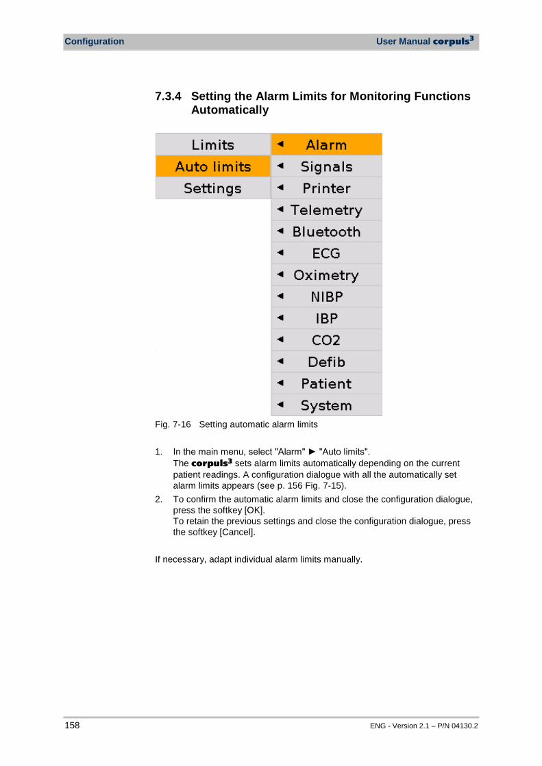
Configuration User Manual corpuls3
158 ENG - Version 2.1 – P/N 04130.2
7.3.4 Setting the Alarm Limits for Monitoring Functions Automatically
Fig. 7-16 Setting automatic alarm limits 1. In the main menu, select "Alarm" "Auto limits".
The corpuls3 sets alarm limits automatically depending on the current patient readings. A configuration dialogue with all the automatically set alarm limits appears (see p. 156 Fig. 7-15).
2. To confirm the automatic alarm limits and close the configuration dialogue, press the softkey [OK]. To retain the previous settings and close the configuration dialogue, press the softkey [Cancel].
If necessary, adapt individual alarm limits manually.
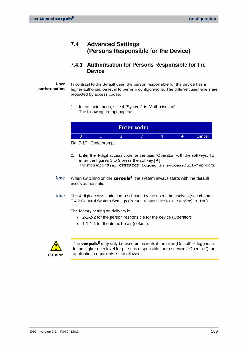
User Manual corpuls3 Configuration
ENG - Version 2.1 – P/N 04130.2 159
7.4 Advanced Settings (Persons Responsible for the Device)
7.4.1 Authorisation for Persons Responsible for the Device
In contrast to the default user, the person responsible for the device has a higher authorisation level to perform configurations. The different user levels are protected by access codes. 1. In the main menu, select "System" "Authorisation".
The following prompt appears:
Fig. 7-17 Code prompt 2. Enter the 4-digit access code for the user "Operator" with the softkeys. To
enter the figures 5 to 9 press the softkey [] The message "User OPERATOR logged in successfully" appears.
When switching on the corpuls3, the system always starts with the default user’s authorisation. The 4-digit access code can be chosen by the users themselves (see chapter 7.4.2 General System Settings (Person responsible for the device), p. 160). The factory setting on delivery is:
• 2-2-2-2 for the person responsible for the device (Operator); • 1-1-1-1 for the default user (default).
Caution
The corpuls3 may only be used on patients if the user „Default“ is logged in. In the higher user level for persons responsible for the device („Operator“) the application on patients is not allowed.
User authorisation
Note
Note
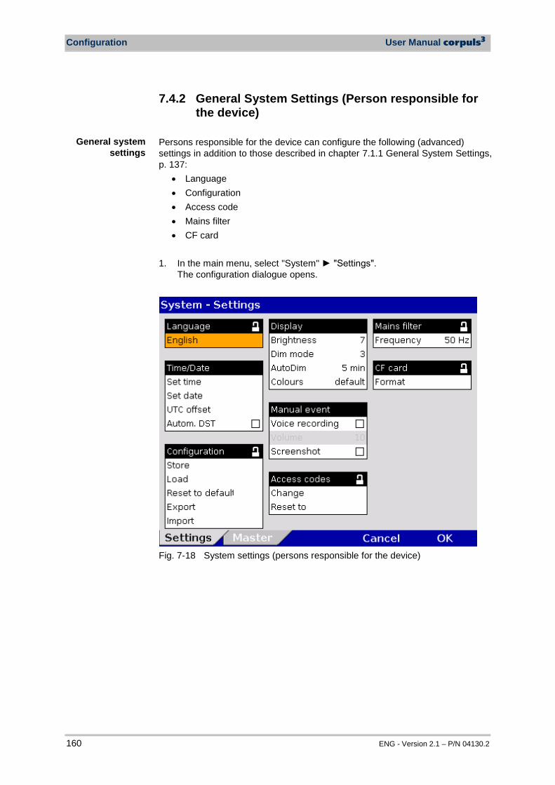
Configuration User Manual corpuls3
160 ENG - Version 2.1 – P/N 04130.2
7.4.2 General System Settings (Person responsible for the device)
Persons responsible for the device can configure the following (advanced) settings in addition to those described in chapter 7.1.1 General System Settings, p. 137:
• Language • Configuration • Access code • Mains filter • CF card
1. In the main menu, select "System" "Settings". The configuration dialogue opens.
Fig. 7-18 System settings (persons responsible for the device)
General system settings
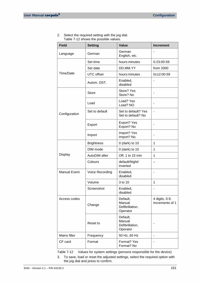
User Manual corpuls3 Configuration
ENG - Version 2.1 – P/N 04130.2 161
2. Select the required setting with the jog dial. Table 7-12 shows the possible values.
Field Setting Value Increment
Language German German English, etc.
-
Time/Date
Set time hours:minutes 0-23:00-59
Set date DD.MM.YY from 2000
UTC offset hours:minutes 0±12:00-59
Autom. DST. Enabled, disabled
-
Configuration
Store Store? Yes Store? No -
Load Load? Yes Load? NO -
Set to default Set to default? Yes Set to default? No
-
Export Export? Yes Export? No -
Import Import? Yes Import? No -
Display
Brightness 0 (dark) to 10 1
DIM mode 0 (dark) to 10 1
AutoDIM after Off, 1 to 15 min 1
Colours default/Night/ inverted
–
Manual Event Voice Recording Enabled, disabled
-
Volume 3 to 10 1
Screenshot Enabled, disabled
-
Access codes
Change
Default, Manual Defibrillation, Operator
4 digits, 0-9, Increments of 1
Reset to
Default, Manual Defibrillation, Operator
-
Mains filter Frequency 50 Hz, 60 Hz -
CF card Format Format? Yes Format? No
-
Table 7-12 Values for system settings (persons responsible for the device) 3. To save, load or reset the adjusted settings, select the required option with
the jog dial and press to confirm.
Configuration User Manual corpuls3
162 ENG - Version 2.1 – P/N 04130.2
All the settings configured, except date and time, must be saved if they are to be available the next time the corpuls3 is switched on. The "Load" function allows a reset to the last version saved while device is running. So the device does not have to be switched off to undo temporary changes to the settings. With the "Set to default" function, the corpuls3 is reset to the factory settings (see also Appendix C Factory Settings, p. 278). The function "Export" allows the export of the configuration settings that were saved last onto the CF card. So, configurations once defined can be transferred to another corpuls3. Settings for GSM/GPRS, the internal phonebook, IP address, access codes and some master data (see also chapter 8.4 Master Data, page 188) are not exported. In case of a software update all saved configurations remain unchanged. The configuration settings exported and saved on a CF card can be imported onto another corpuls3 with the function "Import". After importing the configuration settings, the corpuls3 has to be restarted in order for the new configuration to take effect. 4. To store, load or reset the changes in the configuration, select them with
the jog dial and confirm. The person responsible for the device (Operator) can manually change the access codes for the - default user (Default), - restricted access use of the of the manual defibrillator (Manual defibrillation) and - for the person responsible for the device (Operator). For this purpose, a 4-digit access code has to be selected and repeated. It is recommended to change the access codes for the person responsible for the device (Operator) and – if appropriate – for restricted access use of manual defibrillation (Manual defibrillation) on commissioning the device. The person responsible for the device can reset the access codes for the default user (Default), the “manual defibrillation“ user (Manual defibrillation) and for the person responsible for the device (Operator) to the factory settings. For this purpose, a confirmation prompt must be confirmed with the softkey [OK]. If the operator access code is no longer known, the authorised corpuls sales and service partner can reset the access codes to factory settings.(see also Appendix C Factory Settings, p. 278). The function „Format“ allows the user to format the CF inserted in the device. After formatting, a reboot is recommended.
Saving the configuration
Loading configuration
Resetting the configuration
Changing the access codes
Resetting access codes
Note
Exporting the configuration
Importing the configuration
Formatting the CF card
User Manual corpuls3 Configuration
ENG - Version 2.1 – P/N 04130.2 163
7.4.3 Configuration of the Defibrillation Function (Persons Responsible for the Device)
Persons responsible for the device can configure further defibrillation function settings in addition to those described in chapter 5.3.1 Information on the AED Mode, page 68 and chapter 5.4.1 Information on Manual Defibrillation and Cardioversion, page 74. The general use of manual defibrillation can be restricted by an access code. If this option is enabled, the user needs to enter the access code (see chapter 7.4.2 General System Settings (Person responsible for the device), p. 160), to be able to defibrillate manually.
Warning
The access code for the manual defibrillation mode must always be known to authorised users. If not, the patient can only be defibrillated in the AED mode with the corresponding energy restrictions.
When accessed for the first time, the manual defibrillation mode and the AED mode can be used with an automatically pre-set energy level. If the energy level is then changed during the mission, the new energy level remains available when the manual defibrillation mode ies accessed again. Different energy levels can be pre-set for use in adults and children. In AED mode, manual energy selection can be enabled by de-selecting the checkbox "Locked" So the user of the corpuls3 has the same energy selection range as in manual defibrillation mode. The ECG analysis is performed with the algorithm of the AED mode. In AED and manual defibrillation mode, audio recording can be enabled. If this option is enabled, all surrounding noises are recorded while the device is in the corresponding mode. After the mission, the audio files are available on the CF card. The AED mode can be supplemented with a voice recording option. If this option is enabled, all surrounding noises that occur while the device is in AED mode will be recorded. If the corpuls3 is to be used exclusively as a compact device or in semi-modular mode (monitoring unit and defibrillator/pacer unit connected, patient box separated, see Fig. 3-3), the person responsible for the device can configure a disconnection signal. In this case, if the monitoring unit is disconnected from the defibrillator/pacer unit, after a pre-set amount of time, an acoustic signal is given. The disconnection signal may under certain conditions render the verbal instructions given in the AED mode unintellegible.
Manual defibrillation
mode
Recording in AED mode
Auto Energy
Disconnection signal
Note
Audio recording
Manual energy selection in AED
mode
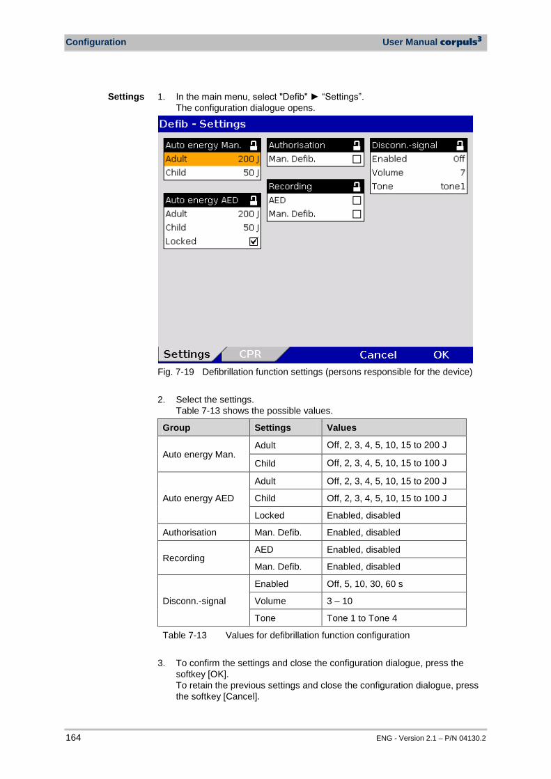
Configuration User Manual corpuls3
164 ENG - Version 2.1 – P/N 04130.2
1. In the main menu, select "Defib" “Settings”. The configuration dialogue opens.
Fig. 7-19 Defibrillation function settings (persons responsible for the device) 2. Select the settings.
Table 7-13 shows the possible values.
Group Settings Values
Auto energy Man. Adult Off, 2, 3, 4, 5, 10, 15 to 200 J
Child Off, 2, 3, 4, 5, 10, 15 to 100 J
Auto energy AED
Adult Off, 2, 3, 4, 5, 10, 15 to 200 J
Child Off, 2, 3, 4, 5, 10, 15 to 100 J
Locked Enabled, disabled
Authorisation Man. Defib. Enabled, disabled
Recording AED Enabled, disabled
Man. Defib. Enabled, disabled
Disconn.-signal
Enabled Off, 5, 10, 30, 60 s
Volume 3 – 10
Tone Tone 1 to Tone 4
Table 7-13 Values for defibrillation function configuration 3. To confirm the settings and close the configuration dialogue, press the
softkey [OK]. To retain the previous settings and close the configuration dialogue, press the softkey [Cancel].
Settings
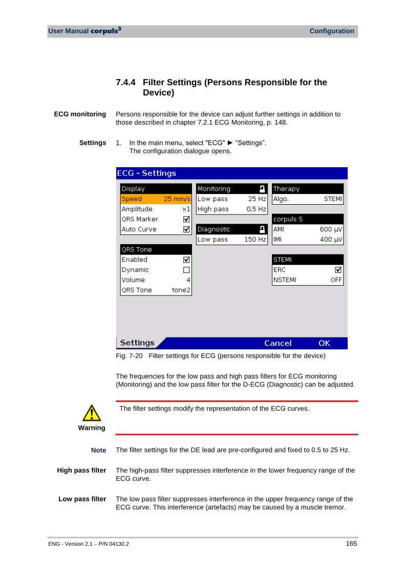
User Manual corpuls3 Configuration
ENG - Version 2.1 – P/N 04130.2 165
7.4.4 Filter Settings (Persons Responsible for the Device)
Persons responsible for the device can adjust further settings in addition to those described in chapter 7.2.1 ECG Monitoring, p. 148. 1. In the main menu, select "ECG" “Settings”.
The configuration dialogue opens.
Fig. 7-20 Filter settings for ECG (persons responsible for the device) The frequencies for the low pass and high pass filters for ECG monitoring (Monitoring) and the low pass filter for the D-ECG (Diagnostic) can be adjusted.
Warning
The filter settings modify the representation of the ECG curves.
The filter settings for the DE lead are pre-configured and fixed to 0.5 to 25 Hz. The high-pass filter suppresses interference in the lower frequency range of the ECG curve. The low pass filter suppresses interference in the upper frequency range of the ECG curve. This interference (artefacts) may be caused by a muscle tremor.
High pass filter
ECG monitoring
Low pass filter
Settings
Note

Configuration User Manual corpuls3
166 ENG - Version 2.1 – P/N 04130.2
The filter value of the high pass filter corresponds to the lower limit frequency of the filter. The filter value of the low pass filter corresponds to the upper limit frequency of the filter. 2. Select the settings.
Table 7-14 contains the possible values.
Fields Settings Values
Monitoring Low pass 25 Hz; 40 Hz; 150 Hz
High pass 0.5 Hz; 0.25 Hz; 0.12 Hz; 0.05 Hz
Diagnostic Low pass 40 Hz; 150 Hz
Table 7-14 Filter setting for monitoring ECG, diagnostic ECG (persons responsible for the device)
For information pertaining to the configuration of ECG measurement and ECG interpretation, see chapter 7.4.10 Configuration of ECG Measurement and ECG Interpretation (Persons Responsible for the Device), page 179.
7.4.5 Alarm Configuration (Persons Responsible for the Device)
In addition to the settings described in chapter 7.3.1 Configuring Alarm Settings, p. 155, persons responsible for the device can configure the following settings in the alarm configuration:
• create an event in the protocol in case of alarms • configure the settings for alarm suspension (15-120 s or permanently)
Alarm settings
Note
Note
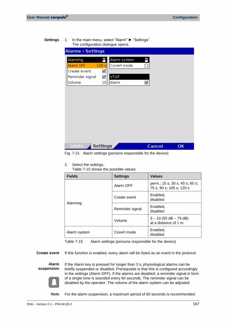
User Manual corpuls3 Configuration
ENG - Version 2.1 – P/N 04130.2 167
1. In the main menu, select "Alarm" “Settings”. The configuration dialogue opens.
Fig. 7-21 Alarm settings (persons responsible for the device) 2. Select the settings.
Table 7-15 shows the possible values.
Fields Settings Values
Alarming
Alarm OFF perm.; 15 s; 30 s; 45 s; 60 s; 75 s, 90 s; 105 s; 120 s
Create event Enabled, disabled
Reminder signal Enabled, disabled
Volume 3 – 10 (55 dB – 79 dB) at a distance of 1 m.
Alarm system Covert mode Enabled, disabled
Table 7-15 Alarm settings (persons responsible for the device) If this function is enabled, every alarm will be listed as an event in the protocol. If the Alarm key is pressed for longer than 3 s, physiological alarms can be briefly suspended or disabled. Prerequisite is that this is configured accordingly in the settings (Alarm OFF). If the alarms are disabled, a reminder signal in form of a single tone is sounded every 60 seconds. The reminder signal can be disabled by the operator. The volume of the alarm system can be adjusted. For the alarm suspension, a maximum period of 60 seconds is recommended.
Settings
Create event
Alarm suspension
Note
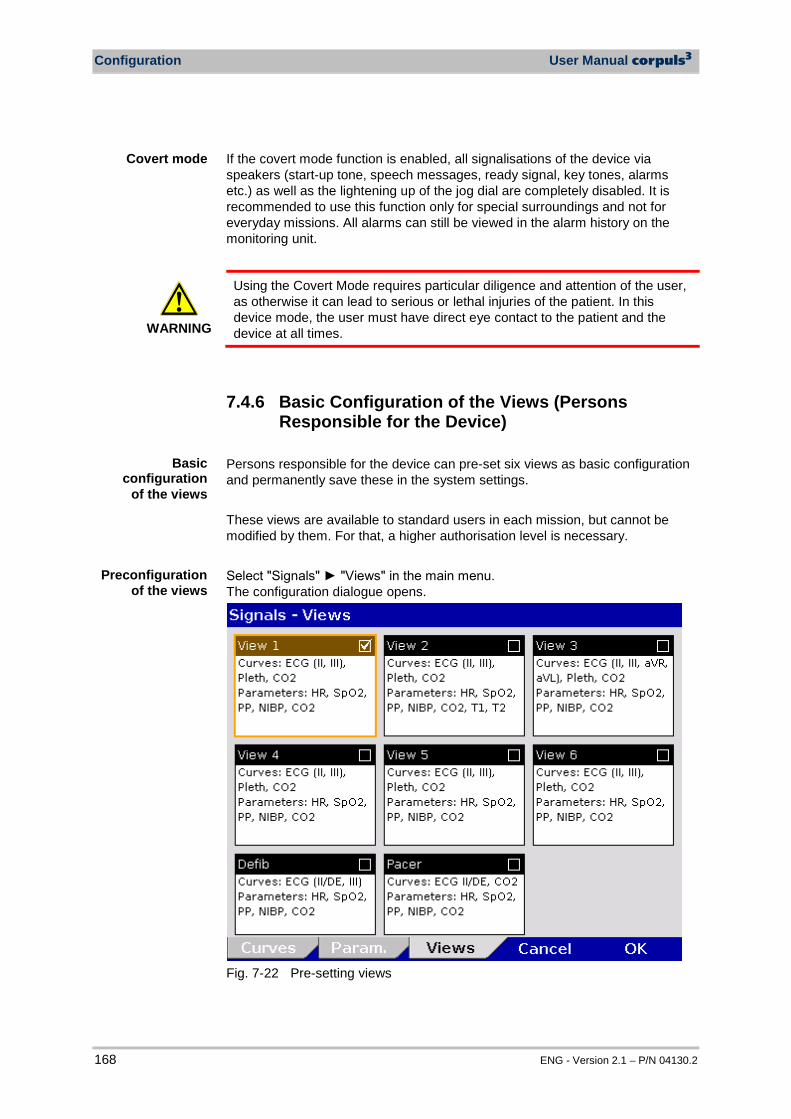
Configuration User Manual corpuls3
168 ENG - Version 2.1 – P/N 04130.2
If the covert mode function is enabled, all signalisations of the device via speakers (start-up tone, speech messages, ready signal, key tones, alarms etc.) as well as the lightening up of the jog dial are completely disabled. It is recommended to use this function only for special surroundings and not for everyday missions. All alarms can still be viewed in the alarm history on the monitoring unit.
WARNING
Using the Covert Mode requires particular diligence and attention of the user, as otherwise it can lead to serious or lethal injuries of the patient. In this device mode, the user must have direct eye contact to the patient and the device at all times.
7.4.6 Basic Configuration of the Views (Persons Responsible for the Device)
Persons responsible for the device can pre-set six views as basic configuration and permanently save these in the system settings. These views are available to standard users in each mission, but cannot be modified by them. For that, a higher authorisation level is necessary. Select "Signals" "Views" in the main menu. The configuration dialogue opens.
Fig. 7-22 Pre-setting views
Preconfigurationof the views
Basic configuration
of the views
Covert mode
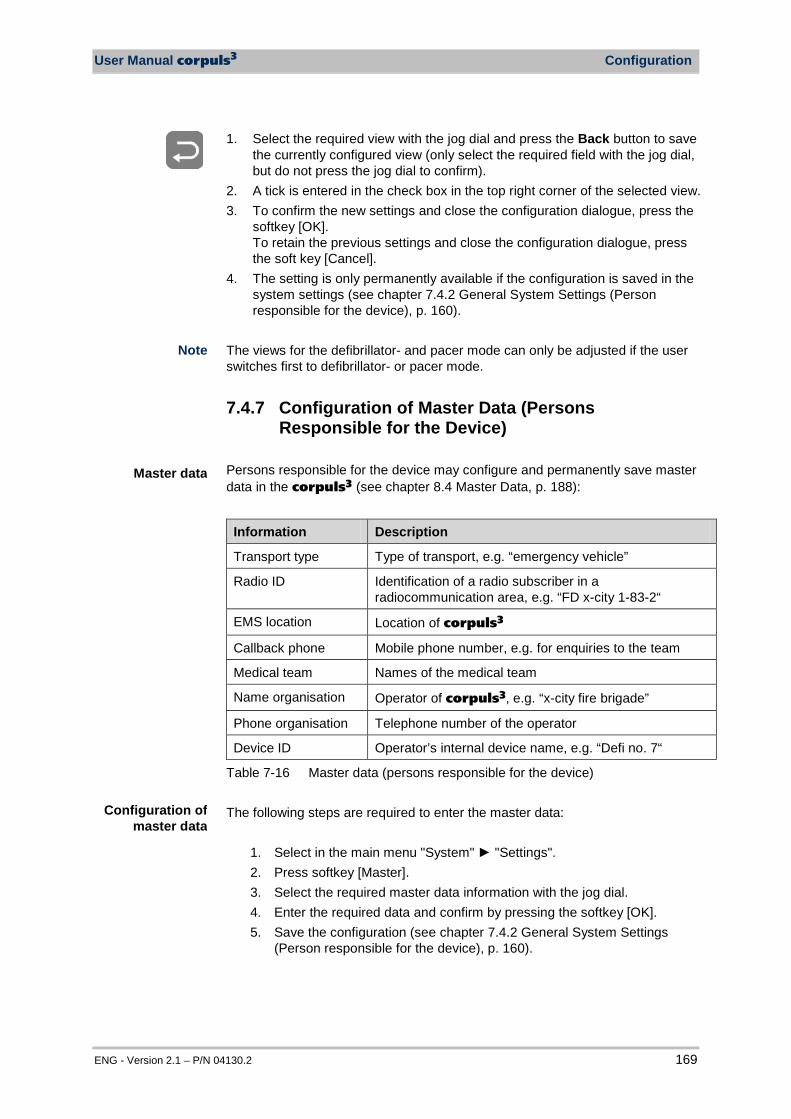
User Manual corpuls3 Configuration
ENG - Version 2.1 – P/N 04130.2 169
1. Select the required view with the jog dial and press the Back button to save the currently configured view (only select the required field with the jog dial, but do not press the jog dial to confirm).
2. A tick is entered in the check box in the top right corner of the selected view. 3. To confirm the new settings and close the configuration dialogue, press the
softkey [OK]. To retain the previous settings and close the configuration dialogue, press the soft key [Cancel].
4. The setting is only permanently available if the configuration is saved in the system settings (see chapter 7.4.2 General System Settings (Person responsible for the device), p. 160).
The views for the defibrillator- and pacer mode can only be adjusted if the user switches first to defibrillator- or pacer mode.
7.4.7 Configuration of Master Data (Persons Responsible for the Device)
Persons responsible for the device may configure and permanently save master data in the corpuls3 (see chapter 8.4 Master Data, p. 188):
Information Description
Transport type Type of transport, e.g. “emergency vehicle”
Radio ID Identification of a radio subscriber in a radiocommunication area, e.g. “FD x-city 1-83-2“
EMS location Location of corpuls3
Callback phone Mobile phone number, e.g. for enquiries to the team
Medical team Names of the medical team
Name organisation Operator of corpuls3, e.g. “x-city fire brigade”
Phone organisation Telephone number of the operator
Device ID Operator’s internal device name, e.g. “Defi no. 7“
Table 7-16 Master data (persons responsible for the device) The following steps are required to enter the master data:
1. Select in the main menu "System" "Settings". 2. Press softkey [Master]. 3. Select the required master data information with the jog dial. 4. Enter the required data and confirm by pressing the softkey [OK]. 5. Save the configuration (see chapter 7.4.2 General System Settings
(Person responsible for the device), p. 160).
Master data
Configuration of master data
Note
Configuration User Manual corpuls3
170 ENG - Version 2.1 – P/N 04130.2
Fig. 7-23 Entering master data (persons responsible for the device) The standard user can modify some of these master data during the mission, but cannot permanently save these changes (see chapter 8.4 Master Data, p. 188).
7.4.8 Configuration of Telemetry (Persons Responsible for the Device)
The following abbreviations are used in the context of telemetry: APN: Access Point Name cWEB: corpuls.web server DHCP: Dynamic Host Configuration Protocol DNS: Domain Name System GSM: Global System for Mobile Communications GPRS: General Packet Radio Service IP: Internet Protocol LAN: Local Area Network PIN: Personal Identification Number PUK: Personal Unblocking Key SIM: Subscriber Identity Module TCP: Transmission Control Protocol UDP: User Datagram Protocol
Abbreviations Telemetry

User Manual corpuls3 Configuration
ENG - Version 2.1 – P/N 04130.2 171
Persons responsible for the device can configure the options as follows:
• Data transmission (Telemetry), • Fax transmission, • Save the connections to fax recipients as short code, • Copy saved connections to fax recipients from the SIM card into the
internal memory or vice versa, • LAN-data interface (optional)
In the main menu, select "Telemetry" "Settings". The configuration dialogue opens.
Fig. 7-24 Telemetry settings (Persons responsible for the device)
The possible values for configuration are shown in Table 7-17:
Group Field Setting Value
GSM Active (aircraft mode off)
Enable or disable aircraft mode
Enabled, disabled
PIN Code number Numbers from 0-9
Phonebook Memory location internal, SIM
GPRS APN Access point to the data net
Numbers, symbols and letters,
User User name Numbers, symbols and letters,
Password Authentication (user –definable combination)
Numbers, symbols and letters,
Configuration Telemetry
(Option)
Telemetry settings

Configuration User Manual corpuls3
172 ENG - Version 2.1 – P/N 04130.2
Group Field Setting Value
GSM Active (aircraft mode off)
Enable or disable aircraft mode
Enabled, disabled
PIN Code number Numbers from 0-9
Phonebook Memory location internal, SIM
D-ECG Fax
Speed D-ECG speed at fax transmission
25 mm/s; 50 mm/s
Server Address
Network address of the server
Numbers, symbols and letters,
TCP Port Network protocol Numbers from 0-9
corpuls.web
TCP d. port Network protocol Numbers from 0-9
UDP d. port Network protocol Numbers from 0-9
Connection Procedure when the connection to the server is initiated
Manual, Startup
Reconnect Number of repeated attempts to establish connection
OFF; 3; 5; 10; Infinite
Interface Procedure how the connection to the server is initiated
LAN, GPRS
D-ECG Auto upload
Automated sending of a D-ECG to the CWEB AUTO Address in the phonebook
Enabled, disabled
LAN Interface
DHCP Enable or disable automatic assignment
Enabled, disabled
IP Address Network address of the corpuls3
Numbers from 0-9
Network mask
Network mask of the corpuls3
Numbers from 0-9
Default gateway
Network address of the default gateway
Numbers from 0-9
DNS-Server prim.
Preferred network address of the Domain Name System
Numbers from 0-9
DNS-Server sec.
Alternative network address of the Domain Name System
Numbers from 0-9
Table 7-17 Configuration values, telemetry
In the group „GSM“ the following fields can be configured e.g. for fax transmission:
Configuration GSM modem
User Manual corpuls3 Configuration
ENG - Version 2.1 – P/N 04130.2 173
1. Enter the 4-digit PIN and confirm. The PIN is assigned to you by your mobile communication provider.
2. Select the memory location of the phonebook: • „SIM“ for saving the phonebook on the SIM card or • „internal“ for saving the phonebook in the corpuls3.
When the aircraft mode is enabled, the GSM function is disabled Certain types of SIM card require the storage of the phonebook in the internal memory of the corpuls3. Using the phonebook on the SIM card is not always supported. To find out if your SIM card can store the phonebook, please contact your mobile communications provider for further information. The maximum length of the PIN is four digits. If a wrong PIN has been entered and transmission has been attempted three times in a row, the SIM card will be locked. Fax transmission is then no longer possible. In that case, the SIM card can only be unlocked by inserting it into an external mobile phone and entering the PUK there. Using a double SIM card (depending on your mobile communications provider also called twin SIM card, dual SIM or multi SIM card), is only possible if other user devices with the pertaining SIM cards are off. So it is not possible to operate several SIM cards of one mobile communications contract at the same time. The operator of the device has to make sure beforehand that the operation of the SIM card used in the corpuls3 cannot be interrupted. In the group „GPRS“ the following fields can be configured for data transmission:
1. Enter the APN (Access point name) and confirm. The respective valid APN is assigned by your mobile communication provider. 2. For the log-in to the data net via GPRS, enter the user (user name) and
confirm. 3. Enter password and confirm.
The log-in with user name for access to the data service is only designated for a few mobile communication networks (for information please contact your mobile communication provider). In the group „Fax“ the following fields can be configured for the D-ECG and the connection to the fax server : 1. Select the speed for the D-ECG transmission (25 mm/s or 50 mm/s) and
confirm. The standard user can change the speed setting during the mission.
Configuration GPRS connection
Note
Note
Note
Note
Note
Note
Fax configuration
Note
Configuration User Manual corpuls3
174 ENG - Version 2.1 – P/N 04130.2
2. For a D-ECG transmission to a fax server, tick the checkbox "Fax server". If this field is not enabled, the D-ECG will be sent to a fax machine selected in the phone book.
3. Enter the network address of the server (IP address or domain) and confirm.
4. Enter the TCP port and confirm. In the group „corpuls.web“ the following fields can be configured for connection to the corpuls.web server: 1. Enter the standard TCP port and confirm. 2. Enter the standard UDP port and confirm. 3. To configure the method of establishing a connection:
a) Select „Manual“ in the field "Connections", to start the connection manually via the main menu.
b) Select „Startup“ in the field "Connections" if the connection should be established automatically while the corpuls3 is booting. For this setting, a phone book entry CWEB Auto has to be created.
Select the required setting with the jog dial and confirm. 4. In the field „Reconnect“ can be determined if and how often the corpuls3
should automatically reconnect if the connection has been broken (e. g. if the GSM net is not available). Select the required setting and confirm.
5. Select, if the connection to corpuls.web should be established via GPRS (option) or via LAN (option).
If the checkbox "Auto upload" in the group "D-ECG" is ticked and a connection is established, the recorded D-ECG is automatically sent to a corpuls.web server by pressing the softkey [Print]. It is not necessary to press the softkey [Send] as well. In the group „LAN interface“ (optional) the network configurations can be assigned automatically via a DHCP server or entered manually. For a manual configuration the checkbox of the field "DHCP" has to be disabled. Manual network configuration: 1. Enter the network address of the corpuls3 (IP address) and confirm. 2. Enter the network mask (IP address) of the network and confirm. 3. Enter the default gateway (IP address) of the network and confirm. 4. Enter the primary DNS server (IP address) and confirm. 5. If available, enter the secondary DNS server (IP address) and confirm. The settings described in the following have to be saved in the system settings in the group „Configuration“ in order to be available permanently.
Note
LAN interface configuration
Symbol IP address
assigned
Automatic Upload of D-ECG
Configuration corpuls.web
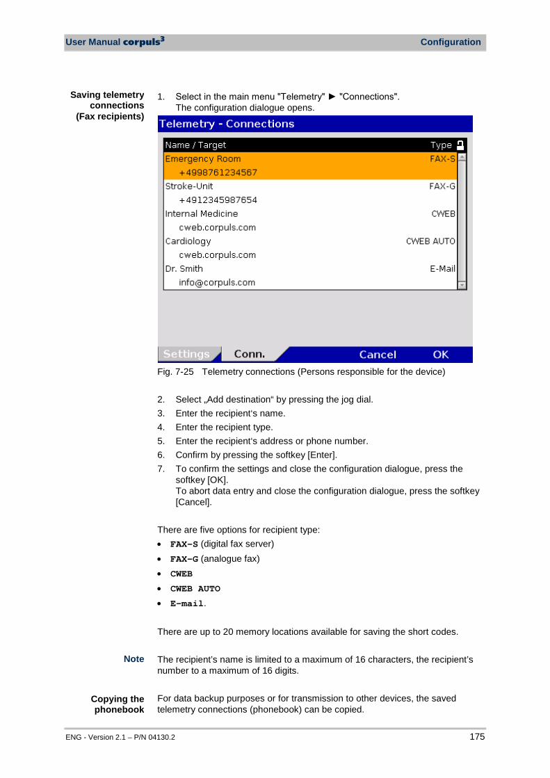
User Manual corpuls3 Configuration
ENG - Version 2.1 – P/N 04130.2 175
1. Select in the main menu "Telemetry" "Connections". The configuration dialogue opens.
Fig. 7-25 Telemetry connections (Persons responsible for the device)
2. Select „Add destination“ by pressing the jog dial. 3. Enter the recipient‘s name. 4. Enter the recipient type. 5. Enter the recipient‘s address or phone number. 6. Confirm by pressing the softkey [Enter]. 7. To confirm the settings and close the configuration dialogue, press the
softkey [OK]. To abort data entry and close the configuration dialogue, press the softkey [Cancel].
There are five options for recipient type: • FAX-S (digital fax server) • FAX-G (analogue fax) • CWEB • CWEB AUTO • E-mail. There are up to 20 memory locations available for saving the short codes. The recipient’s name is limited to a maximum of 16 characters, the recipient’s number to a maximum of 16 digits.
For data backup purposes or for transmission to other devices, the saved telemetry connections (phonebook) can be copied.
Saving telemetry connections
(Fax recipients)
Note
Copying the phonebook

Configuration User Manual corpuls3
176 ENG - Version 2.1 – P/N 04130.2
1. Select in the main menu "Telemetry" "Conn. SIM -> Intern" to copy data from the SIM card into the internal memory of the corpuls3.
2. The connection data are copied by selecting the menu item with the jog dial.
Into the opposite direction: 1. Select in the main menu "Telemetry" "Conn. Intern -> SIM " to copy data
from the internal memory to the SIM card. 2. The connection data are copied by selecting the menu item with the jog dial. The telemetry connections already saved on the target memory are all overwritten. When the phonebook is copied, only phone numbers are transferred. As of software version 2.0.0, e-mail- and server addresses can be transferred via the import-/export function. Saving telemetry connections (phonebook) on the SIM card is not always supported. Certain SIM card types require the saving of the phonebook in the internal memory of the corpuls3. For information regarding the operation of telemetry functions see chapter 8.8 Telemetry (Option), p. 194.
Note
Note
Note
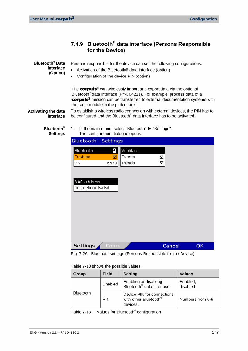
User Manual corpuls3 Configuration
ENG - Version 2.1 – P/N 04130.2 177
7.4.9 Bluetooth® data interface (Persons Responsible for the Device)
Persons responsible for the device can set the following configurations: • Activation of the Bluetooth® data interface (option) • Configuration of the device PIN (option) The corpuls3 can wirelessly import and export data via the optional Bluetooth® data interface (P/N. 04211). For example, process data of a corpuls3 mission can be transferred to external documentation systems with the radio module in the patient box. To establish a wireless radio connection with external devices, the PIN has to be configured and the Bluetooth® data interface has to be activated. 1. In the main menu, select "Bluetooth" "Settings".
The configuration dialogue opens.
Fig. 7-26 Bluetooth settings (Persons Responsible for the Device)
Table 7-18 shows the possible values.
Group Field Setting Values
Bluetooth
Enabled Enabling or disabling Bluetooth® data interface
Enabled, disabled
PIN Device PIN for connections with other Bluetooth® devices.
Numbers from 0-9
Table 7-18 Values for Bluetooth® configuration
Activating the data interface
Bluetooth® Data interface (Option)
Bluetooth®
Settings
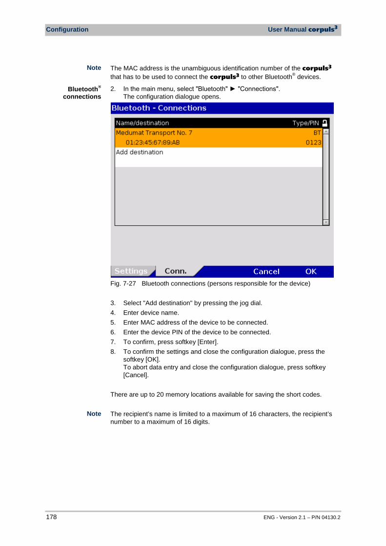
Configuration User Manual corpuls3
178 ENG - Version 2.1 – P/N 04130.2
The MAC address is the unambiguous identification number of the corpuls3 that has to be used to connect the corpuls3 to other Bluetooth® devices.
2. In the main menu, select "Bluetooth" "Connections". The configuration dialogue opens.
Fig. 7-27 Bluetooth connections (persons responsible for the device) 3. Select "Add destination" by pressing the jog dial. 4. Enter device name. 5. Enter MAC address of the device to be connected. 6. Enter the device PIN of the device to be connected. 7. To confirm, press softkey [Enter]. 8. To confirm the settings and close the configuration dialogue, press the
softkey [OK]. To abort data entry and close the configuration dialogue, press softkey [Cancel].
There are up to 20 memory locations available for saving the short codes. The recipient’s name is limited to a maximum of 16 characters, the recipient’s number to a maximum of 16 digits.
Note
Note
Bluetooth®
connections
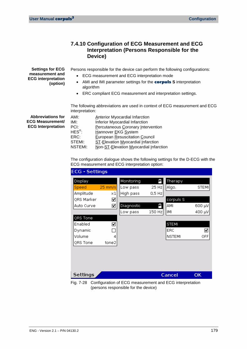
User Manual corpuls3 Configuration
ENG - Version 2.1 – P/N 04130.2 179
7.4.10 Configuration of ECG Measurement and ECG Interpretation (Persons Responsible for the Device)
Persons responsible for the device can perform the following configurations:
• ECG measurement and ECG interpretation mode • AMI and IMI parameter settings for the corpuls S interpretation
algorithm • ERC compliant ECG measurement and interpretation settings.
The following abbreviations are used in context of ECG measurement and ECG interpretation: AMI: Anterior Myocardial Infarction IMI: Inferior Myocardial Infarction PCI: Percutaneous Coronary Intervention HES®: Hannover EKG System ERC: European Resuscitation Council STEMI: ST-Elevation Myocardial Infarction NSTEMI: Non-ST-Elevation Myocardial Infarction The configuration dialogue shows the following settings for the D-ECG with the ECG measurement and ECG interpretation option:
Fig. 7-28 Configuration of ECG measurement and ECG interpretation
(persons responsible for the device)
Settings for ECG measurement and
ECG interpretation (option)
Abbreviations for ECG Measurement/ ECG Interpretation
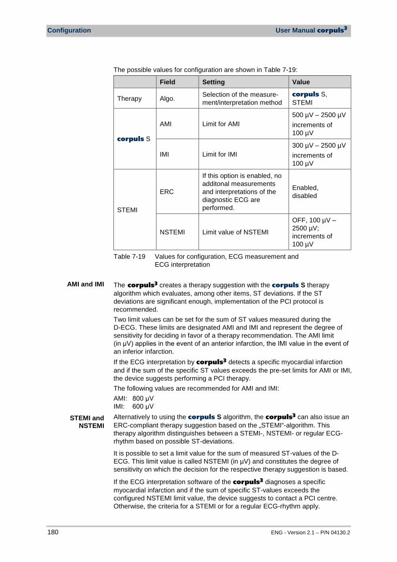
Configuration User Manual corpuls3
180 ENG - Version 2.1 – P/N 04130.2
The possible values for configuration are shown in Table 7-19:
Field Setting Value
Therapy Algo. Selection of the measure-ment/interpretation method
corpuls S, STEMI
corpuls S
AMI Limit for AMI 500 µV – 2500 µV increments of 100 µV
IMI Limit for IMI 300 µV – 2500 µV increments of 100 µV
STEMI
ERC
If this option is enabled, no additonal measurements and interpretations of the diagnostic ECG are performed.
Enabled, disabled
NSTEMI Limit value of NSTEMI
OFF, 100 µV – 2500 µV; increments of 100 µV
Table 7-19 Values for configuration, ECG measurement and ECG interpretation
The corpuls3 creates a therapy suggestion with the corpuls S therapy algorithm which evaluates, among other items, ST deviations. If the ST deviations are significant enough, implementation of the PCI protocol is recommended. Two limit values can be set for the sum of ST values measured during the D-ECG. These limits are designated AMI and IMI and represent the degree of sensitivity for deciding in favor of a therapy recommendation. The AMI limit (in μV) applies in the event of an anterior infarction, the IMI value in the event of an inferior infarction. If the ECG interpretation by corpuls3 detects a specific myocardial infarction and if the sum of the specific ST values exceeds the pre-set limits for AMI or IMI, the device suggests performing a PCI therapy. The following values are recommended for AMI and IMI: AMI: 800 μV IMI: 600 μV Alternatively to using the corpuls S algorithm, the corpuls3 can also issue an ERC-compliant therapy suggestion based on the „STEMI“-algorithm. This therapy algorithm distinguishes between a STEMI-, NSTEMI- or regular ECG-rhythm based on possible ST-deviations.
It is possible to set a limit value for the sum of measured ST-values of the D-ECG. This limit value is called NSTEMI (in µV) and constitutes the degree of sensitivity on which the decision for the respective therapy suggestion is based.
If the ECG interpretation software of the corpuls3 diagnoses a specific myocardial infarction and if the sum of specific ST-values exceeds the configured NSTEMI limit value, the device suggests to contact a PCI centre. Otherwise, the criteria for a STEMI or for a regular ECG-rhythm apply.
AMI and IMI
STEMI and NSTEMI
User Manual corpuls3 Configuration
ENG - Version 2.1 – P/N 04130.2 181
If the checkbox at the field "ERC" is deactivated, additional measurements and interpretations of the D-ECG are performed besides the one based on the "STEMI"-algorithm. This include checking for the presence of the Wolff-Parkinson-White (WPW) syndrome, of intraventricular excitation propagation disorders, of an implanted pacer, of QRS intervals longer than 120 ms and of a left branch bundle block.
The ERC guidelines recommend the use of the "STEMI"-algorithm for measurement and interpretation of a D-ECG.
A licence is required for the use of the ECG measurement and ECG interpretation options. Please contact your authorised service and sales partner to obtain this licence. Information on the installed version of the ECG measurement and ECG interpretation program can be found in the system info. It is listed in the “Options” field in the line “ECG interpretation”.
Fig. 7-29 ECG measurement and ECG interpretation version in system info
7.4.11 Demo Mode (Persons Responsible for the Device)
The person responsible for the device can activate the demo mode for training purposes. This mode shows curves and parameters and demonstrates all functions and possible configurations. 1. Select in the main menu "System" "Demo". 2. In the message line the text "DEMO mode on" appears. 3. The display shows curves and parameters from the internal memory. To deactivate the demo mode, the corpuls3 has to be switched off and on again. Alternatively, select again in the main menu "System" "Demo"
Note
Note
Demonstration at trainings
Activating the
demo mode
Note
ERC
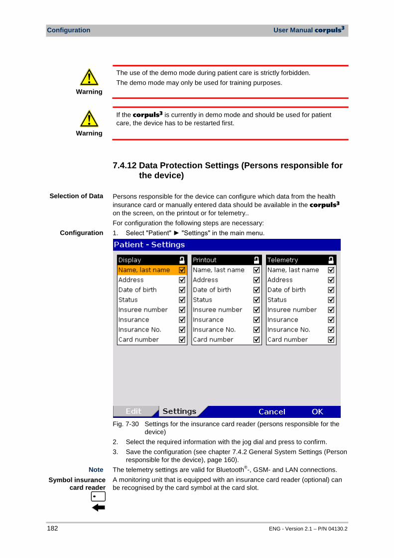
Configuration User Manual corpuls3
182 ENG - Version 2.1 – P/N 04130.2
Warning
The use of the demo mode during patient care is strictly forbidden. The demo mode may only be used for training purposes.
Warning
If the corpuls3 is currently in demo mode and should be used for patient care, the device has to be restarted first.
7.4.12 Data Protection Settings (Persons responsible for the device)
Persons responsible for the device can configure which data from the health insurance card or manually entered data should be available in the corpuls3
on the screen, on the printout or for telemetry.. For configuration the following steps are necessary: 1. Select "Patient" "Settings" in the main menu.
Fig. 7-30 Settings for the insurance card reader (persons responsible for the
device) 2. Select the required information with the jog dial and press to confirm. 3. Save the configuration (see chapter 7.4.2 General System Settings (Person
responsible for the device), page 160). The telemetry settings are valid for Bluetooth®-, GSM- and LAN connections. A monitoring unit that is equipped with an insurance card reader (optional) can be recognised by the card symbol at the card slot.
Selection of Data
Configuration
Symbol insurance card reader
Note
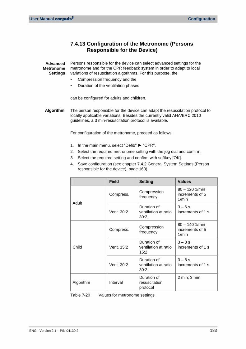
User Manual corpuls3 Configuration
ENG - Version 2.1 – P/N 04130.2 183
7.4.13 Configuration of the Metronome (Persons Responsible for the Device)
Persons responsible for the device can select advanced settings for the metronome and for the CPR feedback system in order to adapt to local variations of resuscitation algorithms. For this purpose, the • Compression frequency and the • Duration of the ventilation phases can be configured for adults and children. The person responsible for the device can adapt the resuscitation protocol to locally applicable variations. Besides the currently valid AHA/ERC 2010 guidelines, a 3 min-resuscitation protocol is available. For configuration of the metronome, proceed as follows: 1. In the main menu, select "Defib" "CPR". 2. Select the required metronome setting with the jog dial and confirm. 3. Select the required setting and confirm with softkey [OK]. 4. Save configuration (see chapter 7.4.2 General System Settings (Person
responsible for the device), page 160).
Field Setting Values
Adult
Compress. Compression frequency
80 – 120 1/min increments of 5 1/min
Vent. 30:2 Duration of ventilation at ratio 30:2
3 – 6 s increments of 1 s
Child
Compress. Compression frequency
80 – 140 1/min increments of 5 1/min
Vent. 15:2 Duration of ventilation at ratio 15:2
3 – 8 s increments of 1 s
Vent. 30:2 Duration of ventilation at ratio 30:2
3 – 8 s increments of 1 s
Algorithm Interval Duration of resuscitation protocol
2 min; 3 min
Table 7-20 Values for metronome settings
Advanced Metronome
Settings
Algorithm
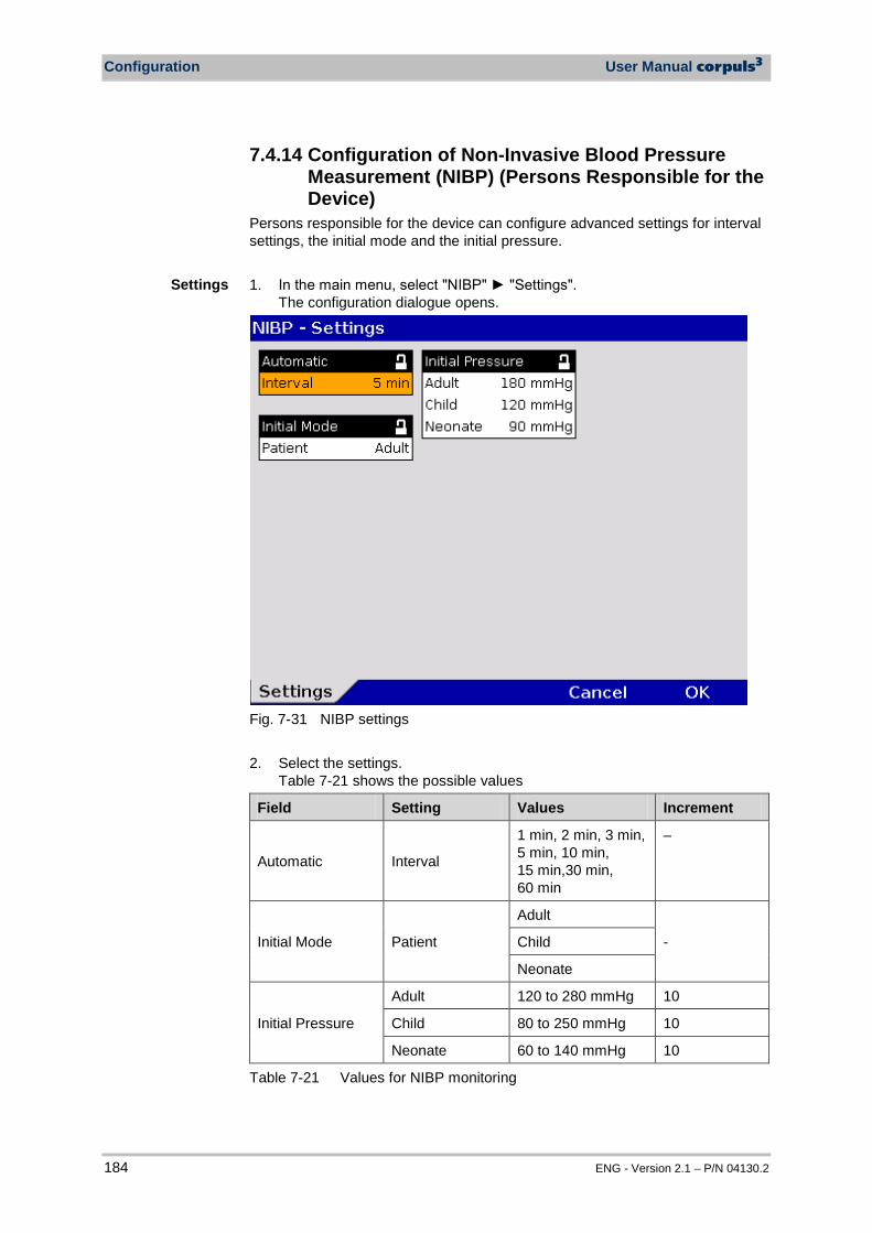
Configuration User Manual corpuls3
184 ENG - Version 2.1 – P/N 04130.2
7.4.14 Configuration of Non-Invasive Blood Pressure Measurement (NIBP) (Persons Responsible for the Device)
Persons responsible for the device can configure advanced settings for interval settings, the initial mode and the initial pressure. 1. In the main menu, select "NIBP" "Settings".
The configuration dialogue opens.
Fig. 7-31 NIBP settings 2. Select the settings.
Table 7-21 shows the possible values
Field Setting Values Increment
Automatic Interval
1 min, 2 min, 3 min, 5 min, 10 min, 15 min,30 min, 60 min
–
Initial Mode Patient
Adult
- Child
Neonate
Initial Pressure
Adult 120 to 280 mmHg 10
Child 80 to 250 mmHg 10
Neonate 60 to 140 mmHg 10
Table 7-21 Values for NIBP monitoring
Settings
User Manual corpuls3 Configuration
ENG - Version 2.1 – P/N 04130.2 185
3. To confirm the settings and close the configuration dialogue, press the softkey [OK]. To retain the previous settings and close the configuration dialogue, press the softkey [Cancel].
NIBP monitoring is performed in the mode that was last selected: "Adult", "Child" or "Neonate". The interval selected in the NIBP settings is pre-set on the NIBP user surface when the softkey [Auto] is pressed. When the softkey [Interv.] is pressed, the interval changes to the next option. For further information on maintenance and tests of the corpuls3 that goes beyond the scope of this user manual, please contact the service technicians of an authorised corpuls sales and service partner.
Note
Note
Test menu

Data Management User Manual corpuls3
186 ENG - Version 2.1 – P/N 04130.2
8 Data Management
8.1 Creating a Patient File A new data record is automatically created each time the corpuls3 is switched on (new mission). An unambiguous mission number is generated, which is printed in the first line on the first page of each printout. In addition, the time and date are automatically logged. For as long as the corpuls3 is in use, all the saved data will be assigned to this mission and saved on the CompactFlash® card (see chapter 8.3 Handling Data, p. 187). The entered data can be modified or completed during the mission. Changes made to the data set are marked in the protocol printout. For entering changes, select "Patient" “Edit Data” in the main menu.
Fig. 8-1 Entering patient data The age of the patient is automatically calculated when the date of birth is entered and cannot be edited. If no date of birth is entered, the age can be edited.
The information pertaining to the insurance card can only be imported via the insurance card reader and cannot be edited.
Switching the device on/off
Note
Note
User Manual corpuls3 Data Management
ENG - Version 2.1 – P/N 04130.2 187
8.2 Event Key The corpuls3 has an event key located in the top left-hand corner of the monitoring unit. When the Event key is pressed, a time stamp is saved which marks the current ECG data and parameter values. On the basis of this marking, this data can be located, viewed and assessed in the data memory. If the audio recording option is enabled, a 15 second recording of the surrounding sounds can be saved additionally by pressing the Event key (5 s before and 10 s after pressing the key). The audio recording appears as manual event in the protocol. Furthermore, by enabling the screenshot option, a screen copy at the time of the event can be saved as a picture file. The audio recordings and screenshots can be played and viewed with the software corView2 (see chapter 8.6 Analysis of the Data with corView2, page 193).
8.3 Handling Data The CompactFlash® card of the patient box is the central memory location for all recorded data. Insert the CompactFlash® card with the corpuls3 label (incl. memory capacity) facing towards the user and following the direction of the arrows into the card slot at the left-hand side (seen from the front) of the patient box. If necessary, remove the accessory bag. If the CompactFlash® card is full (1000 missions or more) or not inserted into the patient box, the corpuls3 cannot record either a long-term ECG or a diagnostic ECG. Consequently, these data are missing when a log is created. The current date and time of the mission have to be deposited in the corpuls3
to enable a later allocation of mission data.
Caution
Make sure that only an original corpuls3 CompactFlash® card (P/N 04236.3) with sufficient memory capacity is used (minimum 50 MB, if voice recording is disabled). Using other CompactFlash® cards may result in safety-critical system malfunctions or the voiding of warranty.
Save the contents of the CompactFlash® card to a PC at regular intervals on external storage media. If the alarm message “CF-card error” is displayed, the data should be saved on a computer. Then, the CF card must be re-formatted (see chapter 7.4.2 General System Settings (Person responsible for the device)page 160).
Caution
Never insert or remove the CompactFlash® during the mission. This may result in system errors. Only insert or remove the CompactFlash® card when the patient box is switched off.
Note
Note
Note
Note
Audio recording and screenshots
Data Management User Manual corpuls3
188 ENG - Version 2.1 – P/N 04130.2
8.4 Master Data Persons responsible for the device can configure and save master data (see chapter 7.4.7 Configuration of Master Data (Persons Responsible for the Device), p. 169. These master data are partly contained in the D-ECG printout. If a D-ECG is transmitted to the hospital by fax (optional), this D-ECG can be identified unambiguously by means of these master data. Some of these master data can be modified by the standard user:
Information Explanation
Transport type Type of transport, e.g. “emergency vehicle)”
Radio ID Identification of a radio subscriber in a radiocommunication area, e.g. “FD x-city 1-83-2“
Location Location of the rescue vehicle
Callback phone Mobile phone number, e.g. for enquiries to the team
Medical team Names of the medical team
Table 8-1 Master data These modifications are not saved and only apply to the current mission. After the corpuls3 has been switched off, the master data, originally configured by the person responsible for the device, apply once again. The following stages are required to modify the master data:
1. Select in the main menu "System" "Settings". 2. Press softkey [Master] 3. Select the required master data information with the jog dial. 4. Enter the required information and confirm by pressing the softkey
[Enter]. 5. Confirm by pressing the softkey [OK].
Changing master data
Master data
Note
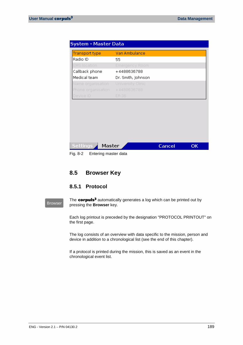
User Manual corpuls3 Data Management
ENG - Version 2.1 – P/N 04130.2 189
Fig. 8-2 Entering master data
8.5 Browser Key
8.5.1 Protocol The corpuls3 automatically generates a log which can be printed out by pressing the Browser key. Each log printout is preceded by the designation "PROTOCOL PRINTOUT" on the first page. The log consists of an overview with data specific to the mission, person and device in addition to a chronological list (see the end of this chapter). If a protocol is printed during the mission, this is saved as an event in the chronological event list.
Browser
Data Management User Manual corpuls3
190 ENG - Version 2.1 – P/N 04130.2
The log overview contains the following data:
Data Explanation
Mission Mission number; generated automatically when switching on the device
Printout Time of protocol printout
Mission start Date and time at switch-on of the device
UTC Universal Time Coordinated
Patient Family name, first name Can be edited via the main menu "Patient" "Edit Data“
Patient ID Identification number Can be edited via the main menu "Patient" "Edit Data“
Case Number Intra-hospital identification number Can be edited via the main menu "Patient" "Edit Data" or via an optional barcode scanner.
Date of Birth and Age
Can be edited via the main menu "Patient" "Edit Data“. The age is calculated automatically when the date of birth of the patient is entered.
Sex Can be edited via the main menu "Patient" "Edit Data“
Weight Can be edited via the main menu "Patient" "Edit Data“
Height Can be edited via the main menu "Patient" "Edit Data“
Vital parameters Trend values of the last minute before the protocol printout (minute mean values)
Device Identification number of the device
Radio Radio call name of the team
Medical team Names of the medical team
Callback phone Mobile phone number, e.g. for enquiries to the team
Filter Filter settings for ECG and mains filter
Software version Current software version (e.g. REL-2.0.0_C3_BP)
Table 8-2 Log overview The entries in the chronological list all have the same structure and contain the time stamp, the precise designation and the ECG no. of the event. The event ID does not contain any data which is relevant for the user. This data is included for service purposes.
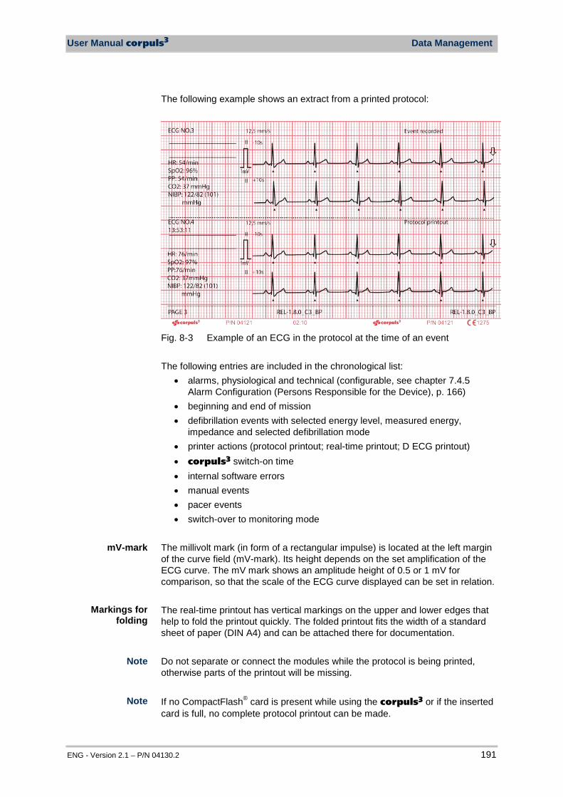
User Manual corpuls3 Data Management
ENG - Version 2.1 – P/N 04130.2 191
The following example shows an extract from a printed protocol:
Fig. 8-3 Example of an ECG in the protocol at the time of an event The following entries are included in the chronological list:
• alarms, physiological and technical (configurable, see chapter 7.4.5 Alarm Configuration (Persons Responsible for the Device), p. 166)
• beginning and end of mission • defibrillation events with selected energy level, measured energy,
impedance and selected defibrillation mode • printer actions (protocol printout; real-time printout; D ECG printout) • corpuls3 switch-on time • internal software errors • manual events • pacer events • switch-over to monitoring mode
The millivolt mark (in form of a rectangular impulse) is located at the left margin of the curve field (mV-mark). Its height depends on the set amplification of the ECG curve. The mV mark shows an amplitude height of 0.5 or 1 mV for comparison, so that the scale of the ECG curve displayed can be set in relation. The real-time printout has vertical markings on the upper and lower edges that help to fold the printout quickly. The folded printout fits the width of a standard sheet of paper (DIN A4) and can be attached there for documentation.
Do not separate or connect the modules while the protocol is being printed, otherwise parts of the printout will be missing. If no CompactFlash® card is present while using the corpuls3 or if the inserted card is full, no complete protocol printout can be made.
Note
Note
Markings for folding
mV-mark
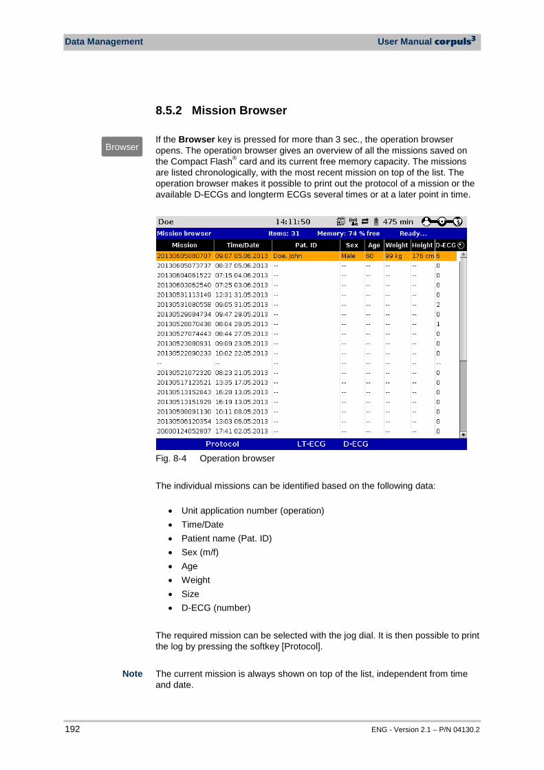
Data Management User Manual corpuls3
192 ENG - Version 2.1 – P/N 04130.2
8.5.2 Mission Browser If the Browser key is pressed for more than 3 sec., the operation browser opens. The operation browser gives an overview of all the missions saved on the Compact Flash® card and its current free memory capacity. The missions are listed chronologically, with the most recent mission on top of the list. The operation browser makes it possible to print out the protocol of a mission or the available D-ECGs and longterm ECGs several times or at a later point in time.
Fig. 8-4 Operation browser The individual missions can be identified based on the following data:
• Unit application number (operation) • Time/Date • Patient name (Pat. ID) • Sex (m/f) • Age • Weight • Size • D-ECG (number)
The required mission can be selected with the jog dial. It is then possible to print the log by pressing the softkey [Protocol]. The current mission is always shown on top of the list, independent from time and date.
Browser
Note
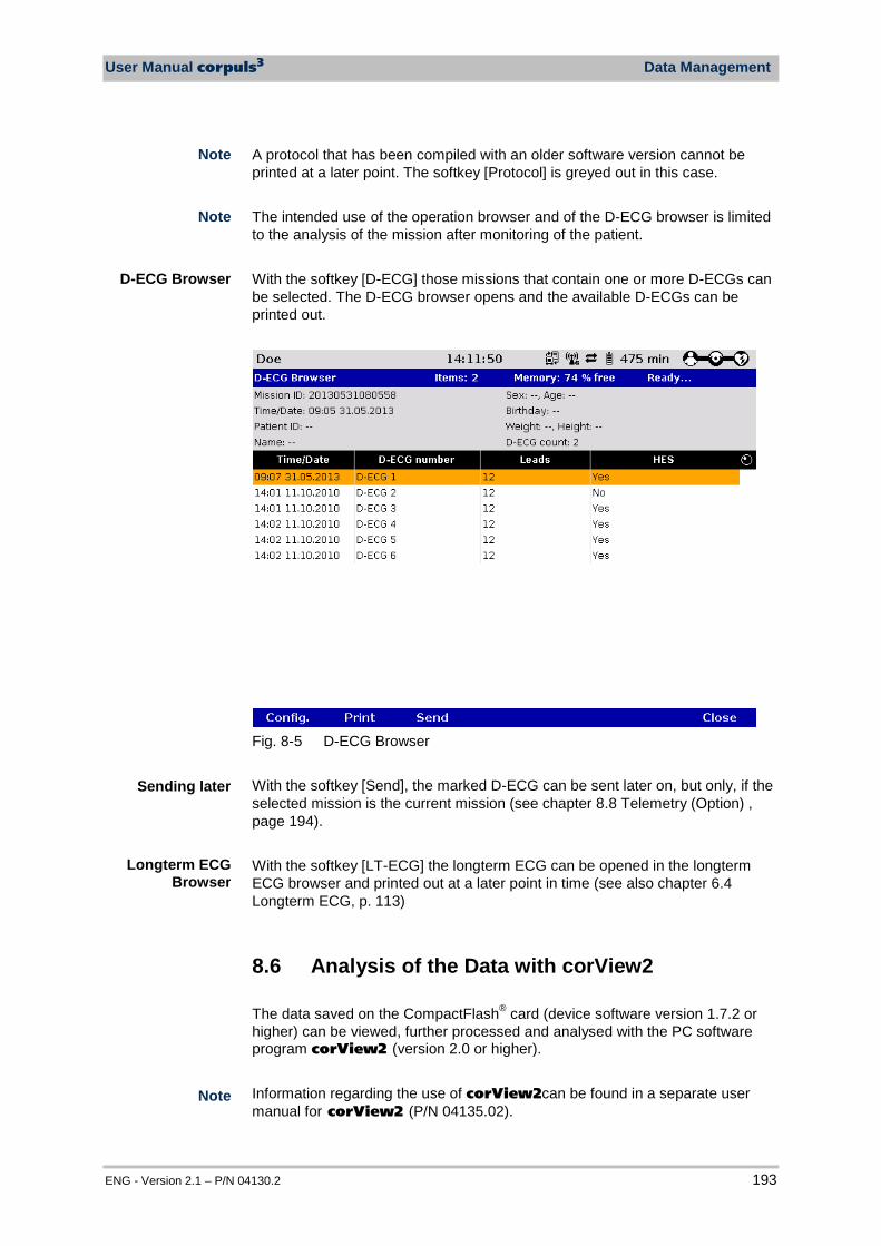
User Manual corpuls3 Data Management
ENG - Version 2.1 – P/N 04130.2 193
A protocol that has been compiled with an older software version cannot be printed at a later point. The softkey [Protocol] is greyed out in this case. The intended use of the operation browser and of the D-ECG browser is limited to the analysis of the mission after monitoring of the patient. With the softkey [D-ECG] those missions that contain one or more D-ECGs can be selected. The D-ECG browser opens and the available D-ECGs can be printed out.
Fig. 8-5 D-ECG Browser With the softkey [Send], the marked D-ECG can be sent later on, but only, if the selected mission is the current mission (see chapter 8.8 Telemetry (Option) , page 194). With the softkey [LT-ECG] the longterm ECG can be opened in the longterm ECG browser and printed out at a later point in time (see also chapter 6.4 Longterm ECG, p. 113)
8.6 Analysis of the Data with corView2 The data saved on the CompactFlash® card (device software version 1.7.2 or higher) can be viewed, further processed and analysed with the PC software program corView2 (version 2.0 or higher). Information regarding the use of corView2can be found in a separate user manual for corView2 (P/N 04135.02).
D-ECG Browser
Note
Note
Longterm ECG Browser
Note
Sending later
Data Management User Manual corpuls3
194 ENG - Version 2.1 – P/N 04130.2
Information regarding data protection can be found in Appendix M Note on Data Protection, page 319 For the analysis of data that have been saved with the software version 1.7.1 or lower of the corpuls3, the PC application corpuls.net in the corresponding version is needed.
8.7 Screenshot If the key Print is pressed for more than 3 secs, a.screenshot is printed out. It shows the contents of the display at the time of printout and the following further information:
• Date and time of the screenshot printout • Unit application number (mission) • User level • Serial number of the monitoring unit • Software version of the corpuls3 • Charging status of the batteries in percent (in this order: patient box,
monitoring unit, defibrillator/pacer) In addition to the printout of the screen copy, a screenshot is saved on the CF card. The screenshot can be viewed with the software corView2 (see chapter 8.6 Analysis of the Data with corView2, page 193).
8.8 Telemetry (Option) The following abbreviations are used in the context of telemetry: APN: Access Point Name cWEB: corpuls.web server DHCP: Dynamic Host Configuration Protocol DNS: Domain Name System GSM: Global System for Mobile Communications GPRS: General Packet Radio Service IP: Internet Protocol LAN: Local Area Network PIN: Personal Identification Number PUK: Personal Unblocking Key SIM: Subscriber Identity Module TCP: Transmission Control Protocol UDP: User Datagram Protocol Information regarding data protection can be found in Appendix M Note on Data Protection, page 319 The corpuls3 offers various possibilities for transmitting data via telemetry: • Fax transmission • Live data transmission • Data transmission to external systems via Bluetooth®data interface (option).
Printing a Screenshot
Note
Data transmission
Abbreviations Telemetry
Note
Note
Note
User Manual corpuls3 Data Management
ENG - Version 2.1 – P/N 04130.2 195
The corpuls3 can send a complete report of a 12 lead ECG recording (diagnostic ECG) to any fax machine, fax server, to an e-mail address or the corpuls.web server via the optionally available GSM modem or the LAN interface. When the aircraft mode is enabled, the GSM function is disabled. Saving changes to the basic configuration permanently is reserved to the person responsible for the device (see chapter 7.4.8 Configuration of Telemetry (Persons Responsible for the Device), p. 170). The representation of the curves (sweep speed) for fax transmission of the D-ECG can be set in the telemetry settings at 25 mm/sec. or 50 mm/sec. If the GSM modem has sufficient reception intensity, this is indicated by the symbol „GSM connection” in the status line of the corpuls3.
When the fax transmission is started, the symbol “fax connection“ appears in the status line. Via the GSM modem (option) or the LAN interface (option) the corpuls3 can send the following date live, almost in real time, to a data server:
• Patient- and master data, • curves and parametera, • D-ECGs and events.
By means of the PC software corpuls.web (option), the server can be accessed from any place via internet and the data can be viewed live. If the corpuls3 is connected to a server, the status symbol „Live data transmission“ is displayed in the status line. If a connection via the Bluetooth® data interface is established to external systems (as e.g. a Tablet-PC for documentation) the status symbol „Bluetooth® connection“is displayed in the status line. Depending on the status there are additional markings of the above described symbols for telemetry connections. A detailed description can be found in Appendix A Symbols, page 272. In case that these connection are not available or not active, the status symbols are greyed out.
GPRS connection
Symbol
fax connection
Fax transmission
Symbol Bluetooth® data
interface
Symbol Live data
transmission
Note
Live data transmission
Note
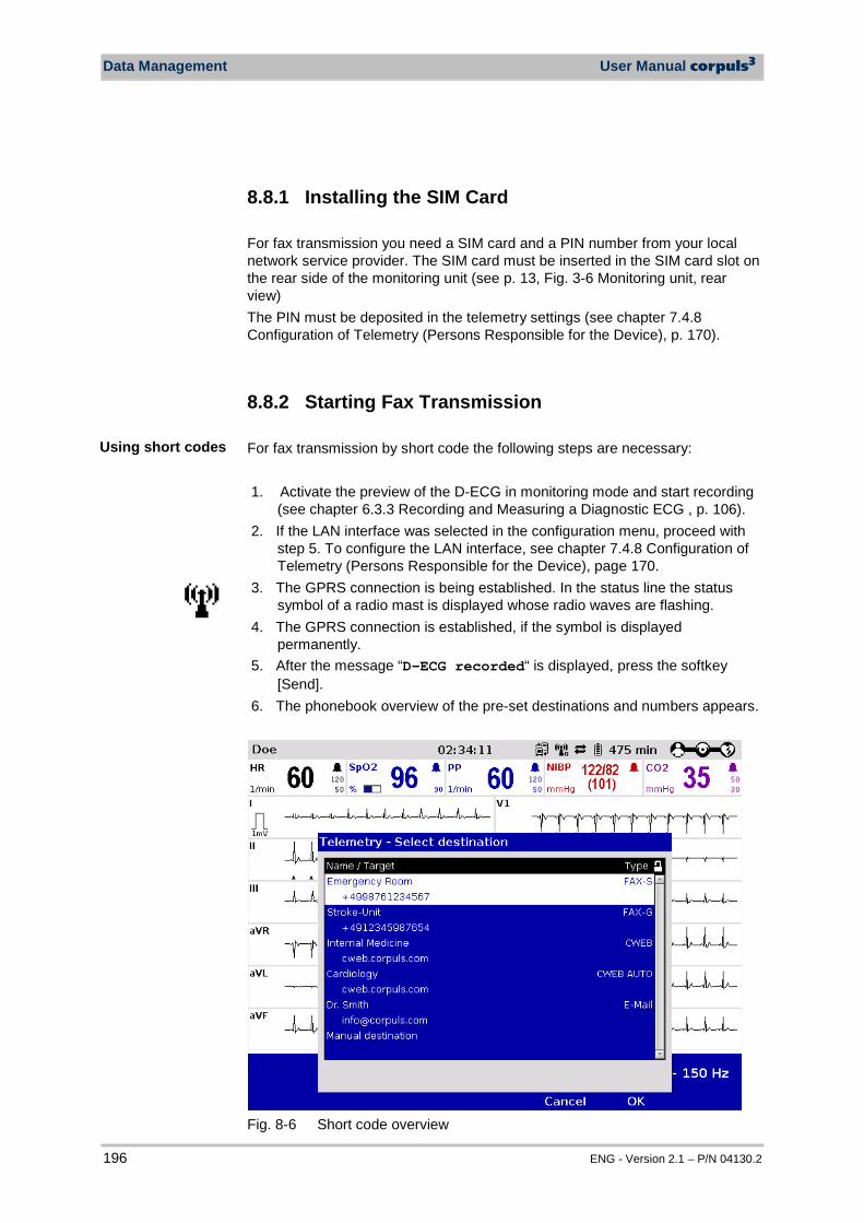
Data Management User Manual corpuls3
196 ENG - Version 2.1 – P/N 04130.2
8.8.1 Installing the SIM Card
For fax transmission you need a SIM card and a PIN number from your local network service provider. The SIM card must be inserted in the SIM card slot on the rear side of the monitoring unit (see p. 13, Fig. 3-6 Monitoring unit, rear view) The PIN must be deposited in the telemetry settings (see chapter 7.4.8 Configuration of Telemetry (Persons Responsible for the Device), p. 170).
8.8.2 Starting Fax Transmission
For fax transmission by short code the following steps are necessary: 1. Activate the preview of the D-ECG in monitoring mode and start recording
(see chapter 6.3.3 Recording and Measuring a Diagnostic ECG , p. 106). 2. If the LAN interface was selected in the configuration menu, proceed with
step 5. To configure the LAN interface, see chapter 7.4.8 Configuration of Telemetry (Persons Responsible for the Device), page 170.
3. The GPRS connection is being established. In the status line the status symbol of a radio mast is displayed whose radio waves are flashing.
4. The GPRS connection is established, if the symbol is displayed permanently.
5. After the message “D-ECG recorded“ is displayed, press the softkey [Send].
6. The phonebook overview of the pre-set destinations and numbers appears.
Fig. 8-6 Short code overview
Using short codes
User Manual corpuls3 Data Management
ENG - Version 2.1 – P/N 04130.2 197
7. Select a destination with the jog dial and confirm by pressing the jog dial. 8. The connection is being established. In the status line the status symbol of
a flashing fax machine is displayed. 9. By pressing the softkey [Cancel] the monitoring mode for patient monitoring
can be called up again. The fax transmission is carried out in the background.
10. When the fax transmission starts, the symbol is displayed permanently. As soon as the fax transmission is finished, this is indicated by the confirmation tick on the fax symbol.
For sending the fax to a manually entered destination, proceed as follows: 1. Activate the preview of the D-ECG in monitoring mode and start recording. 2. If the LAN interface was selected in the configuration menu, proceed with
step 5. To configure the LAN interface, see chapter 7.4.8 Configuration of Telemetry (Persons Responsible for the Device), page 170.
3. The GPRS connection is being established. In the status line the status symbol of a radio mast is displayed whose radio waves are flashing.
4. The GPRS connection is established, if the symbol is displayed permanently.
5. After the message “D-ECG recorded“ is displayed in the message line, press the softkey [Send].
6. Select the destination “Manual destination” in the phonebook and confirm. 7. Enter the destination/number with the jog dial and confirm by pressing the
softkey [Enter]. 8. Select the fax machine type of the recipient. 9. After confirming with the jog dial, the connection will be established.
Additionally displayed in the status line is a flashing symbol of a fax machine.
10. By pressing the softkey [Cancel] the monitoring mode for patient monitoring can be called up again. The fax transmission is carried out in the background.
11. When the fax transmission starts, the symbol is displayed permanently. As soon as the fax transmission is finished, this is indicated by the confirmation tick on the fax symbol.
If the fax transmission is interrupted for technical reasons (e.g. insufficient reception quality or interruption of the radio connection) the alarm message “Fax transmission failed“ is displayed. In case of malfunctions see also chapter 10.2 Troubleshooting and Corrective Actions, page 250, and Appendix A Symbols, page 272. To abort the current fax transmission, select „Telemetry“ „Abort Fax“ with the jog dial in the main menu. The protocol records status messages of the fax transmission as event. For information on possible events see chapter 10.3 Notifications Message Line and Information in the Protocol, page 263.
Entering the destination
manually
Fax transmission successful
Aborting fax transmission
Fax transmission
failed
Data Management User Manual corpuls3
198 ENG - Version 2.1 – P/N 04130.2
Via the mission browser, D-ECGs from the current mission can be sent again, see chapter 8.5.2 Mission Browser, page 192. Depending on the volume of data and the signal level, it may take a few minutes to send the fax. If the D-ECG has been successfully sent to the fax server, the connection will be closed. In the protocol printout the event D-ECG fax sent appears. Before sending the ECG to a fax machine, the patient data should be entered. So, the faxes received at the location of the fax recipient can be clearly assigned to the patient treated. In areas near national borders the mobile communications networks may overlap, so it may be necessary to enter the international area code as well to be able to contact the fax recipient. In this case, adapt to your country-specific settings (e.g. “+49 9876 54321“ or “0049 9876 54321“). At locations where radio signals are shadowed for technical reasons (e.g. inside a flat), low signal levels may occur in mobile phone reception. In this case, select a better position for the monitoring unit, e.g. near a window.
8.8.3 Starting Live Data transmission with corpuls.web
To carry out a live data transmission proceed as follows: 1. Select „Telemetry“ „Connect“ in the main menu. 2. If the LAN interface was selected in the configuration menu, proceed with
step 5. To configure the LAN interface, see chapter 7.4.8 Configuration of Telemetry (Persons Responsible for the Device), page 170.
3. The GPRS connection is being established. In the status line the status symbol of a radio mast is displayed whose radio waves are flashing.
4. When the GPRS connection has been established (radio mast symbol shows a „G“ at the bottom right), the user has to log in to the corpuls.web server. Additionally displayed in the status line is a flashing symbol of a corpuls3 with a server.
5. The data connection between the corpuls.web server and the corpuls3 is fully established, as soon as the symbol is displayed permanently and has two additional arrows. Now all data mentioned above are transferred live.
6. To abort the current live data transmission select „Telemetry“ „Disconnect“ with the jog dial in the main menu.
During the live data transmission all therapeutic and monitoring functions of the corpuls3 can be used without limitations. The observer of the live data using the PC program corpuls.web on the other side can see the same parameters and curves that are currently displayed on the connected corpuls3.
Note
Note
Note
Note
Live data transmission
Note
Note
Note
User Manual corpuls3 Data Management
ENG - Version 2.1 – P/N 04130.2 199
If the user of the corpuls3 records a D-ECG, it is transferred live to the server and can immediately be reviewed via the PC program corpuls.web. The observer on the other side is informed when the D-ECG is being transferred.
If the connection could not be established or if the live data transmission was aborted, this is being signaled via diverse symbols and alarms in the status line.
The protocol records status messages of the live data transmission as event (e.g. “Server unreachable”). For a list of possible events see chapter 10.3 Notifications Message Line and Information in the Protocol, p. 263. In case of malfunctions see also chapter 10.2 Troubleshooting and Corrective Actions, from page 250 and Appendix A Symbols, page 272.
Depending on the settings on the corpuls.web server, the system time set on the corpuls3 is synchronised by the corpuls.web server before the transmission of mission data. The time change is logged in the mission protocol of the corpuls3. If the connection is interrupted during data transmission, the D-ECG may nevertheless have been transferred completely. The accuracy of the transferred data is guaranteed in this case as well. Via the mission browser, D-ECGs from the current mission can be sent again, see chapter 8.5.2 Mission Browser, page 192. The duration of establishing a connection may vary according to network quality. Under certain conditions data transmission may be interrupted due to low signal strength of the mobile communications network. Before starting a live data transmission, the patient data should be entered. So, the data received on the other side can be clearly assigned to the patient treated at the location. At locations where radio signals are shadowed for technical reasons (e.g. inside a flat), low signal levels may occur in mobile phone reception. In this case, select a better position for the monitoring unit, e.g. near a window.
8.9 Bluetooth® data interface
The corpuls3 can wirelessly import and export data via the optional Bluetooth® data interface (P/N. 04211). For example, with the radio module in the patient box process data of a corpuls3 mission can be transferred to external documentation systems (e.g. a tablet PC) but data also be received from other systems (e. g. Weinmann Medumat Transport).
To establish a wireless radio connection with external devices, the PIN has to be configured and the Bluetooth® data interface has to be activated. This
Live transmission of D-ECGs
Note
Note
Note
Note
Note
Note
Note
Activating the data interface
Bluetooth® data interface (option)

Data Management User Manual corpuls3
200 ENG - Version 2.1 – P/N 04130.2
configuration can only be changed by the person responsible for the device who can activate this option permanently (see chapter 7.4.9 Bluetooth® data interface (Persons Responsible for the Device) , page 177). If the Bluetooth® data interface is activated, the corpuls3 can receive automatically an connection authorisation for a connection with an external documentation system, if this system has the same PIN. This procedure is also called „Pairing“. The following settings can be selected: • Events • Trends 1. In the main menu, select "Bluetooth" "Settings".
The configuration dialogue opens.
Fig. 8-7 Bluetooth settings 2. Selecting required settings.
Table 8-3 shows the possible values.
Field Setting Values
MAC address -- --
Ventilator Events Enabled,
disabled
Trends Enabled, disabled
Table 8-3 Values for Bluetooth settings
Connection authorisation
(Pairing)
General settings
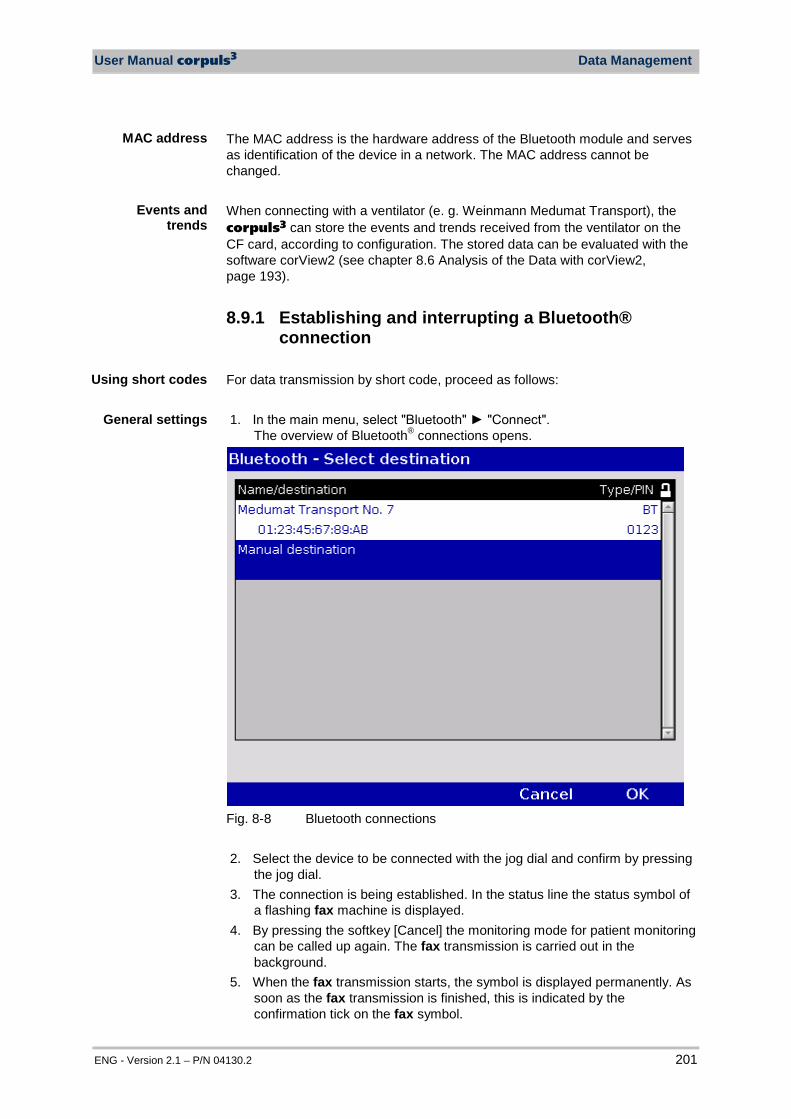
User Manual corpuls3 Data Management
ENG - Version 2.1 – P/N 04130.2 201
The MAC address is the hardware address of the Bluetooth module and serves as identification of the device in a network. The MAC address cannot be changed. When connecting with a ventilator (e. g. Weinmann Medumat Transport), the corpuls3 can store the events and trends received from the ventilator on the CF card, according to configuration. The stored data can be evaluated with the software corView2 (see chapter 8.6 Analysis of the Data with corView2, page 193).
8.9.1 Establishing and interrupting a Bluetooth® connection
For data transmission by short code, proceed as follows: 1. In the main menu, select "Bluetooth" "Connect".
The overview of Bluetooth® connections opens.
Fig. 8-8 Bluetooth connections
2. Select the device to be connected with the jog dial and confirm by pressing
the jog dial. 3. The connection is being established. In the status line the status symbol of
a flashing fax machine is displayed. 4. By pressing the softkey [Cancel] the monitoring mode for patient monitoring
can be called up again. The fax transmission is carried out in the background.
5. When the fax transmission starts, the symbol is displayed permanently. As soon as the fax transmission is finished, this is indicated by the confirmation tick on the fax symbol.
Events and trends
Using short codes
General settings
MAC address
Data Management User Manual corpuls3
202 ENG - Version 2.1 – P/N 04130.2
If a connection to an external documentation system has been established via the Bluetooth® data interface, the symbol for „Bluetooth® connection“ is displayed in the status line. Depending on the status there are additional markings of the above described symbols for telemetry connections. A detailed description can be found in Appendix A Symbols, page 272.
If the Bluetooth® connection is interrupted for technical reasons (e.g. insufficient reception quality or interruption of the radio connection) the alarm message “BT connection failed“ is displayed. In case of malfunctions see also chapter 10.2 Troubleshooting and Corrective Actions, page 250. To abort the current Bluetooth® connection, select „Bluetooth“ „Disconnect“ with the jog dial in the main menu. The protocol records status messages of the Bluetooth® connection as event. For information on possible events see chapter 10.3 Notifications Message Line and Information in the Protocol, page 263.
8.10 Insurance card reader (option) The insurance card reader allows to read out the patient data stored on the insurance cardof the patient so that they are available to the data management in the corpuls3. The patient data can be completed or changed during the mission by manually entering information. Persons responsible for the device can configure and save permanently which patient data from the insurance card should be available in the corpuls3 (see chapter 7.4.12 Data Protection Settings (Persons responsible for the device) , page 182). 1. Insert the insurance card (with the chip oriented towards the front of the
monitoring unit) into the insurance card reader on the right-hand side of the monitoring unit
Interrupting a Bluetooth® connection
Bluetooth® connection failed
Symbol Bluetooth® Data
interface
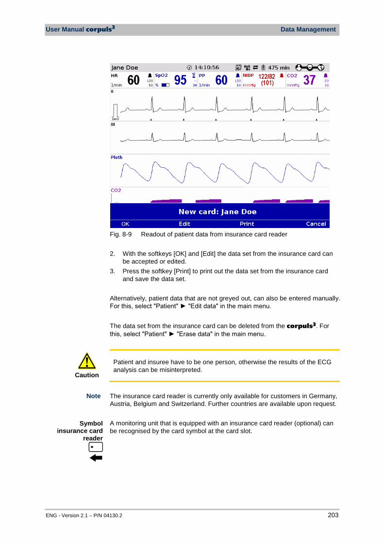
User Manual corpuls3 Data Management
ENG - Version 2.1 – P/N 04130.2 203
Fig. 8-9 Readout of patient data from insurance card reader 2. With the softkeys [OK] and [Edit] the data set from the insurance card can
be accepted or edited. 3. Press the softkey [Print] to print out the data set from the insurance card
and save the data set. Alternatively, patient data that are not greyed out, can also be entered manually. For this, select "Patient" "Edit data" in the main menu. The data set from the insurance card can be deleted from the corpuls3. For this, select "Patient" "Erase data" in the main menu.
Caution
Patient and insuree have to be one person, otherwise the results of the ECG analysis can be misinterpreted.
The insurance card reader is currently only available for customers in Germany, Austria, Belgium and Switzerland. Further countries are available upon request. A monitoring unit that is equipped with an insurance card reader (optional) can be recognised by the card symbol at the card slot.
Symbol insurance card
reader
Note
Data Management User Manual corpuls3
204 ENG - Version 2.1 – P/N 04130.2
8.10.1 Data Transmission via Bluetooth®
The corpuls3 can import and export data by radio via the optionally available bluetooth data interface (P/N. 04211) With the radio module in the patient box the user can transfer for example the process data of the corpuls3 to external documentation systems (as e.g. a tablet PC).
To establish a wireless connection to external devices, the PIN number has to be configured and the Bluetooth® data interface has to be activated. This configuration can only be changed by the person responsible for the device who can activate this option permanently (see chapter 7.4.8 Configuration of Telemetry (Persons Responsible for the Device), p. 170) If the data interface is activated, the corpuls3 can receive automatically an connection authorisation for a connection with an external documentation system, if this system has the same PIN. This procedure is also called „Pairing“. If a connection to an external documentation system has been established via the Bluetooth® data interface, the symbol for „Bluetooth® connection“ is displayed in the status line. Depending on the status there are additional markings of the above described symbols for telemetry connections. A detailed description can be found in Appendix A Symbols, page 272.
8.11 Insurance card reader (Option) The insurance card reader allows to read out the patient data stored on the insurance card of the patient so that they are available to the data management in the corpuls3. The patient data can be completed or changed during the mission by manually entering information. Persons responsible for the device can configure and save permanently which data sets from the insurance card should be available in the corpuls3 (see chapter 7.4.12 Data Protection Settings (Persons responsible for the device), page 182). 1. Insert the insurance card (with the chip oriented towards the user) into the
insurance card reader on the right-hand side of the monitoring unit.
Activation of the data interface
Bluetooth®data interface (option)
Symbol Bluetooth®
data interface
Connection authorisation
(Pairing)
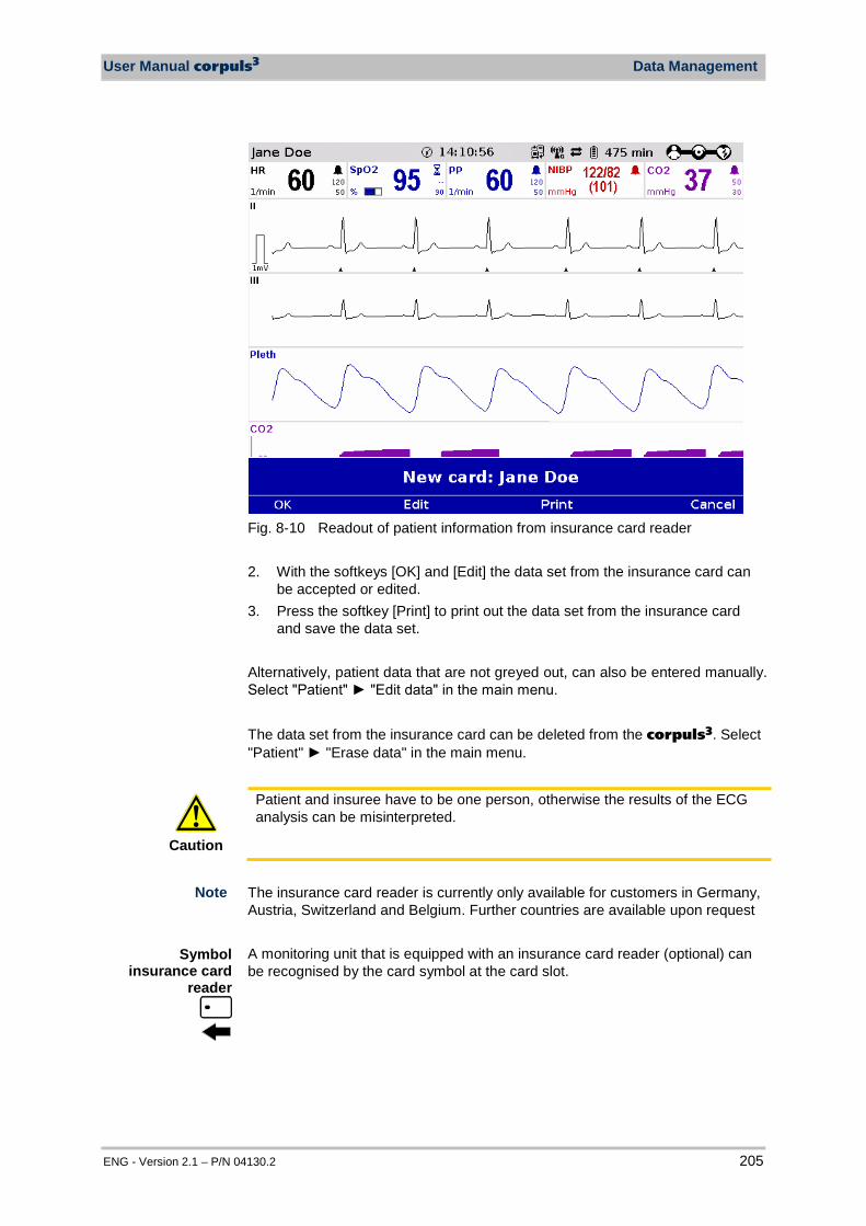
User Manual corpuls3 Data Management
ENG - Version 2.1 – P/N 04130.2 205
Fig. 8-10 Readout of patient information from insurance card reader 2. With the softkeys [OK] and [Edit] the data set from the insurance card can
be accepted or edited. 3. Press the softkey [Print] to print out the data set from the insurance card
and save the data set. Alternatively, patient data that are not greyed out, can also be entered manually. Select "Patient" "Edit data" in the main menu. The data set from the insurance card can be deleted from the corpuls3. Select "Patient" "Erase data" in the main menu.
Caution
Patient and insuree have to be one person, otherwise the results of the ECG analysis can be misinterpreted.
The insurance card reader is currently only available for customers in Germany, Austria, Switzerland and Belgium. Further countries are available upon request A monitoring unit that is equipped with an insurance card reader (optional) can be recognised by the card symbol at the card slot.
Symbol insurance card
reader
Note

Maintenance and tests User Manual corpuls3
206 ENG - Version 2.1 – P/N 04130.2
9 Maintenance and Tests
9.1 General Information Regular maintenance and testing guarantee permanent functional and operational readiness of the corpuls3. Therefore, make sure that the device and the accessories are in good working condition before each mission by performing a full function and visual check on the corpuls3. This way, electrical and mechanical malfunctions may be either prevented or detected early on and eliminated quickly. If difficulties occur during the visual and function check, see chapter 10 Procedure in Case of Malfunctions, page 233 for specific measures to take. Please follow these directions.
Warning
If the malfunction cannot be remedied with these measures, please inform customer service. In extreme cases, it may be necessary to take the corpuls3 out of commission.
For guidance, a checklist for standardised testing of the corpuls3 is included in the appendix of this user manual. The following schedule for maintenance and tests shows recommended intervals for performing checks. Compliance with legal regulations relating to safety and metrological checks must be guaranteed. Furthermore, it is recommended to schedule regular function checks at the location of the corpuls3 (rescue equipment, location, hospital, etc.) to guarantee full operational readiness at all times. For further information on maintenance and testing of the corpuls3 that go beyond the contents of this user manual, contact the service technicians of an authorised sales and service partner.
Function Check
Regular checks
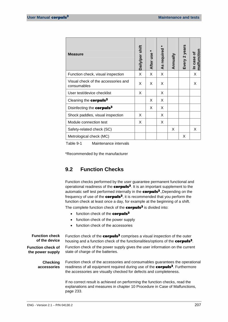
User Manual corpuls3 Maintenance and tests
ENG - Version 2.1 – P/N 04130.2 207
Measure
Dai
ly/p
er s
hift
Afte
r use
*
As
requ
ired
*
Ann
ually
Eve
ry 2
yea
rs
In c
ase
of
mal
func
tion
Function check, visual inspection X X X X
Visual check of the accessories and consumables X X X X
User test/device checklist X X
Cleaning the corpuls3 X X
Disinfecting the corpuls3 X X
Shock paddles, visual inspection X X
Module connection test X X
Safety-related check (SC) X X
Metrological check (MC) X
Table 9-1 Maintenance intervals *Recommended by the manufacturer
9.2 Function Checks Function checks performed by the user guarantee permanent functional and operational readiness of the corpuls3. It is an important supplement to the automatic self test performed internally in the corpuls3.,Depending on the frequency of use of the corpuls3, it is recommended that you perform the function check at least once a day, for example at the beginning of a shift. The complete function check of the corpuls3 is divided into:
• function check of the corpuls3 • function check of the power supply • function check of the accessories
Function check of the corpuls3 comprises a visual inspection of the outer housing and a function check of the functionalities/options of the corpuls3. Function check of the power supply gives the user information on the current state of charge of the batteries. Function check of the accessories and consumables guarantees the operational readiness of all equipment required during use of the corpuls3. Furthermore the accessories are visually checked for defects and completeness. If no correct result is achieved on performing the function checks, read the explanations and measures in chapter 10 Procedure in Case of Malfunctions, page 233.
Function check of the device
Function check of the power supply
Checking accessories

Maintenance and tests User Manual corpuls3
208 ENG - Version 2.1 – P/N 04130.2
9.2.1 Function check of the Device
For a function check of the compact device, all the modules of the corpuls3 must be connected mechanically. The mechanical connections have to be heard to click into place. The following measures must be taken:
Functional test
Description Measures by the user Correct result
Switch-on Start of functional test
Press the On/Off key The start logo appears
Internal self test
The corpuls3 performs a test of the internal functions
None The jog dial briefly illuminates at the beginning. The display is illuminated. Curve and parameter fields
are displayed. The state of charge of the
batteries is displayed in percent or in minutes remaining running time. Sufficient state of charge
present. Connection status of the
modules is displayed.
Connection test of the modules
Function check of the network
Separation of all modules Re-connecting all modules
In the status line the connection status changes from bar symbol to wave symbol In the status line the
connection status changes from wave symbol to bar symbol No errror message is issued
Visual check of the corpuls3
Detection of alterations on the corpuls3
Check the complete corpuls3 for alterations
No objections
Defibrillator/ pacer
Visual check of the device and accessories of the defibrillator/pacer
Remove shock paddles. Completely unwind the
therapy master cable from the socket. Inspect shock paddles and
therapy master cable for damage. Check packaging of
corPatch electrodes, verification of the expiry date. Check if replacement
electrodes are present.
Shock paddles and therapy master cable are undamaged. Packaging of corPatch
electrodes is undamaged and replacement available. Expiry date of corPatch
electrodes has not passed. All in all, no damage is
detectable.
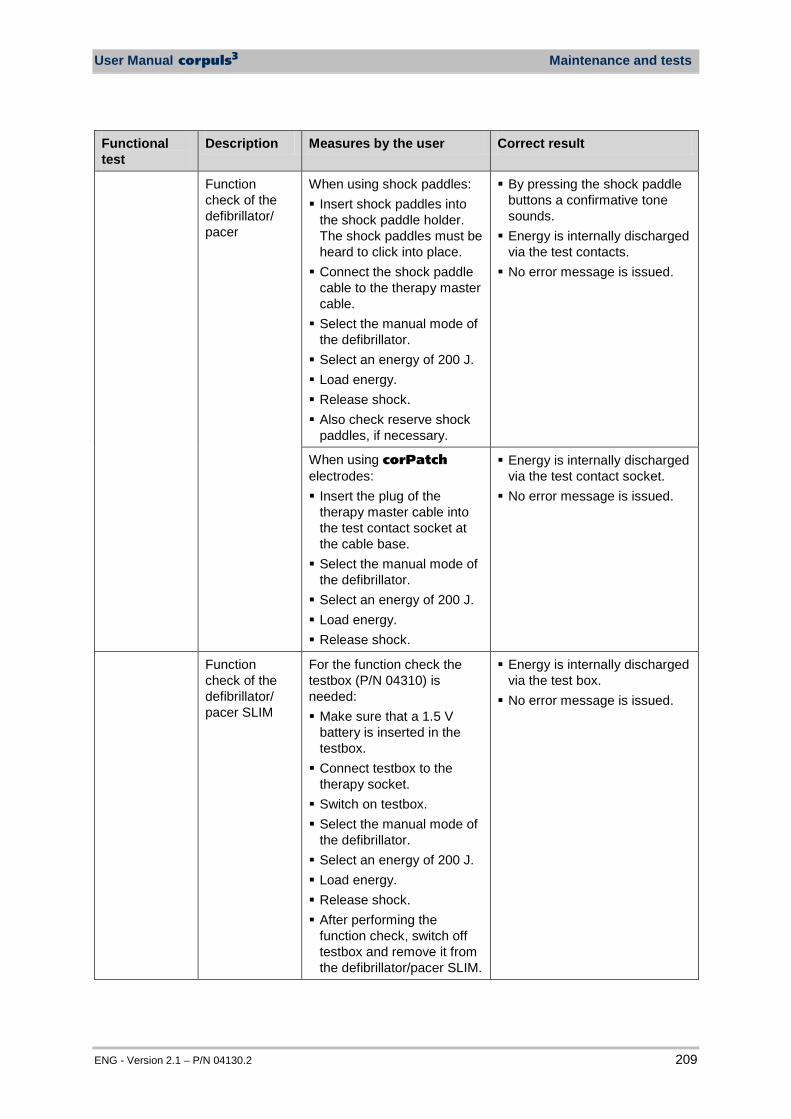
User Manual corpuls3 Maintenance and tests
ENG - Version 2.1 – P/N 04130.2 209
Functional test
Description Measures by the user Correct result
Function check of the defibrillator/ pacer
When using shock paddles: Insert shock paddles into
the shock paddle holder. The shock paddles must be heard to click into place. Connect the shock paddle
cable to the therapy master cable. Select the manual mode of
the defibrillator. Select an energy of 200 J. Load energy. Release shock. Also check reserve shock
paddles, if necessary.
By pressing the shock paddle buttons a confirmative tone sounds. Energy is internally discharged
via the test contacts. No error message is issued.
When using corPatch electrodes: Insert the plug of the
therapy master cable into the test contact socket at the cable base. Select the manual mode of
the defibrillator. Select an energy of 200 J. Load energy. Release shock.
Energy is internally discharged via the test contact socket. No error message is issued.
Function check of the defibrillator/ pacer SLIM
For the function check the testbox (P/N 04310) is needed: Make sure that a 1.5 V
battery is inserted in the testbox. Connect testbox to the
therapy socket. Switch on testbox. Select the manual mode of
the defibrillator. Select an energy of 200 J. Load energy. Release shock. After performing the
function check, switch off testbox and remove it from the defibrillator/pacer SLIM.
Energy is internally discharged via the test box. No error message is issued.
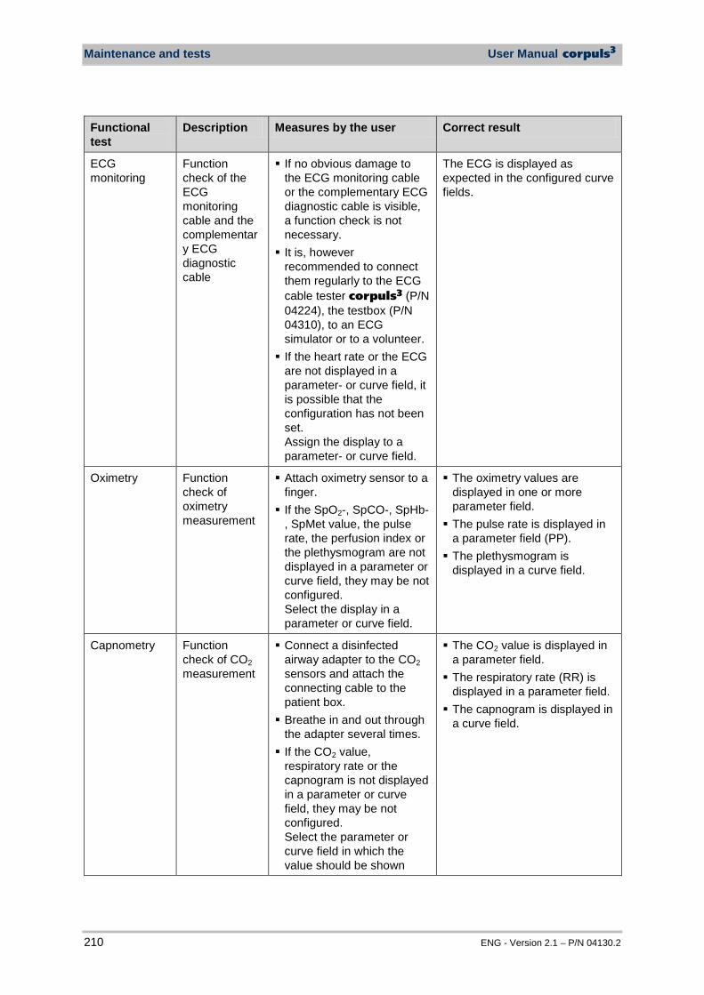
Maintenance and tests User Manual corpuls3
210 ENG - Version 2.1 – P/N 04130.2
Functional test
Description Measures by the user Correct result
ECG monitoring
Function check of the ECG monitoring cable and the complementary ECG diagnostic cable
If no obvious damage to the ECG monitoring cable or the complementary ECG diagnostic cable is visible, a function check is not necessary. It is, however
recommended to connect them regularly to the ECG cable tester corpuls3 (P/N 04224), the testbox (P/N 04310), to an ECG simulator or to a volunteer. If the heart rate or the ECG
are not displayed in a parameter- or curve field, it is possible that the configuration has not been set. Assign the display to a parameter- or curve field.
The ECG is displayed as expected in the configured curve fields.
Oximetry Function check of oximetry measurement
Attach oximetry sensor to a finger. If the SpO2-, SpCO-, SpHb-
, SpMet value, the pulse rate, the perfusion index or the plethysmogram are not displayed in a parameter or curve field, they may be not configured. Select the display in a parameter or curve field.
The oximetry values are displayed in one or more parameter field. The pulse rate is displayed in
a parameter field (PP). The plethysmogram is
displayed in a curve field.
Capnometry Function check of CO2 measurement
Connect a disinfected airway adapter to the CO2 sensors and attach the connecting cable to the patient box. Breathe in and out through
the adapter several times. If the CO2 value,
respiratory rate or the capnogram is not displayed in a parameter or curve field, they may be not configured. Select the parameter or curve field in which the value should be shown
The CO2 value is displayed in a parameter field. The respiratory rate (RR) is
displayed in a parameter field. The capnogram is displayed in
a curve field.
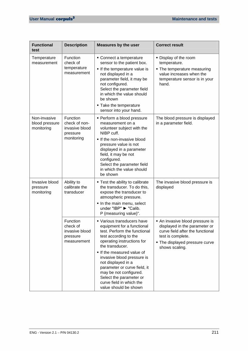
User Manual corpuls3 Maintenance and tests
ENG - Version 2.1 – P/N 04130.2 211
Functional test
Description Measures by the user Correct result
Temperature measurement
Function check of temperature measurement
Connect a temperature sensor to the patient box. If the temperature value is
not displayed in a parameter field, it may be not configured. Select the parameter field in which the value should be shown Take the temperature
sensor into your hand.
Display of the room temperature. The temperature measuring
value increases when the temperature sensor is in your hand.
Non-invasive blood pressure monitoring
Function check of non-invasive blood pressure monitoring
Perform a blood pressure measurement on a volunteer subject with the NIBP cuff. If the non-invasive blood
pressure value is not displayed in a parameter field, it may be not configured. Select the parameter field in which the value should be shown
The blood pressure is displayed in a parameter field.
Invasive blood pressure monitoring
Ability to calibrate the transducer
Test the ability to calibrate the transducer. To do this, expose the transducer to atmospheric pressure. In the main menu, select
under "IBP" "Calib. P measuring value".
The invasive blood pressure is displayed
Function check of invasive blood pressure measurement
Various transducers have equipment for a functional test. Perform the functional test according to the operating instructions for the transducer. If the measured value of
invasive blood pressure is not displayed in a parameter or curve field, it may be not configured. Select the parameter or curve field in which the value should be shown
An invasive blood pressure is displayed in the parameter or curve field after the functional test is complete. The displayed pressure curve
shows scaling.
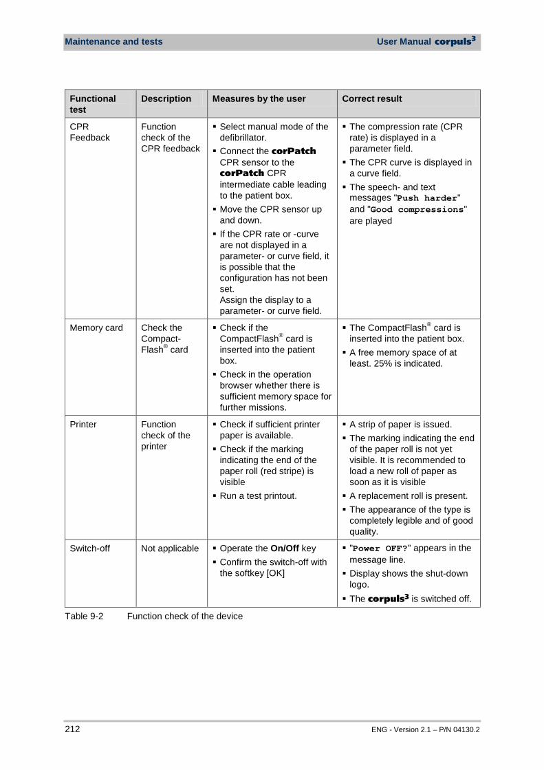
Maintenance and tests User Manual corpuls3
212 ENG - Version 2.1 – P/N 04130.2
Functional test
Description Measures by the user Correct result
CPR Feedback
Function check of the CPR feedback
Select manual mode of the defibrillator. Connect the corPatch
CPR sensor to the corPatch CPR intermediate cable leading to the patient box. Move the CPR sensor up
and down. If the CPR rate or -curve
are not displayed in a parameter- or curve field, it is possible that the configuration has not been set. Assign the display to a parameter- or curve field.
The compression rate (CPR rate) is displayed in a parameter field. The CPR curve is displayed in
a curve field. The speech- and text
messages "Push harder" and "Good compressions" are played
Memory card Check the Compact-Flash® card
Check if the CompactFlash® card is inserted into the patient box. Check in the operation
browser whether there is sufficient memory space for further missions.
The CompactFlash® card is inserted into the patient box. A free memory space of at
least. 25% is indicated.
Printer Function check of the printer
Check if sufficient printer paper is available. Check if the marking
indicating the end of the paper roll (red stripe) is visible Run a test printout.
A strip of paper is issued. The marking indicating the end
of the paper roll is not yet visible. It is recommended to load a new roll of paper as soon as it is visible A replacement roll is present. The appearance of the type is
completely legible and of good quality.
Switch-off Not applicable Operate the On/Off key Confirm the switch-off with
the softkey [OK]
"Power OFF?" appears in the message line. Display shows the shut-down
logo. The corpuls3 is switched off.
Table 9-2 Function check of the device
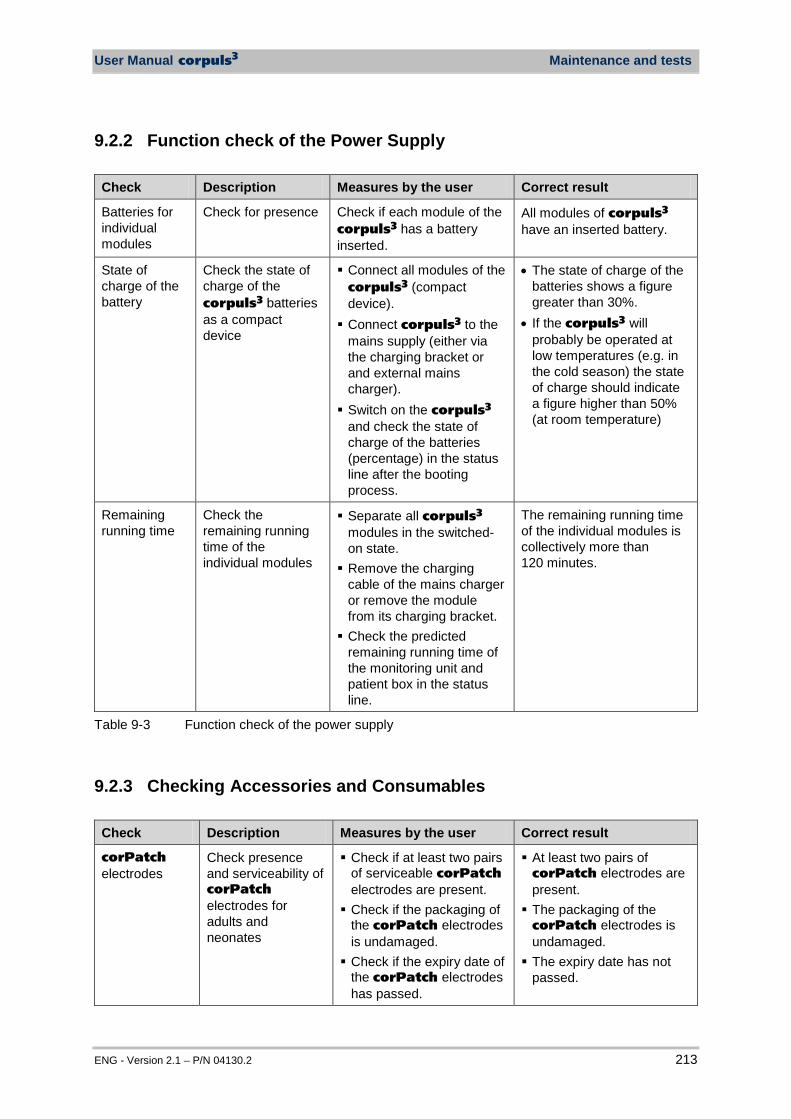
User Manual corpuls3 Maintenance and tests
ENG - Version 2.1 – P/N 04130.2 213
9.2.2 Function check of the Power Supply
Check Description Measures by the user Correct result
Batteries for individual modules
Check for presence Check if each module of the corpuls3 has a battery inserted.
All modules of corpuls3 have an inserted battery.
State of charge of the battery
Check the state of charge of the corpuls3 batteries as a compact device
Connect all modules of the corpuls3 (compact device). Connect corpuls3 to the
mains supply (either via the charging bracket or and external mains charger). Switch on the corpuls3
and check the state of charge of the batteries (percentage) in the status line after the booting process.
• The state of charge of the batteries shows a figure greater than 30%.
• If the corpuls3 will probably be operated at low temperatures (e.g. in the cold season) the state of charge should indicate a figure higher than 50% (at room temperature)
Remaining running time
Check the remaining running time of the individual modules
Separate all corpuls3 modules in the switched-on state. Remove the charging
cable of the mains charger or remove the module from its charging bracket. Check the predicted
remaining running time of the monitoring unit and patient box in the status line.
The remaining running time of the individual modules is collectively more than 120 minutes.
Table 9-3 Function check of the power supply
9.2.3 Checking Accessories and Consumables
Check Description Measures by the user Correct result
corPatch electrodes
Check presence and serviceability of corPatch electrodes for adults and neonates
Check if at least two pairs of serviceable corPatch electrodes are present. Check if the packaging of
the corPatch electrodes is undamaged. Check if the expiry date of
the corPatch electrodes has passed.
At least two pairs of corPatch electrodes are present. The packaging of the
corPatch electrodes is undamaged. The expiry date has not
passed.
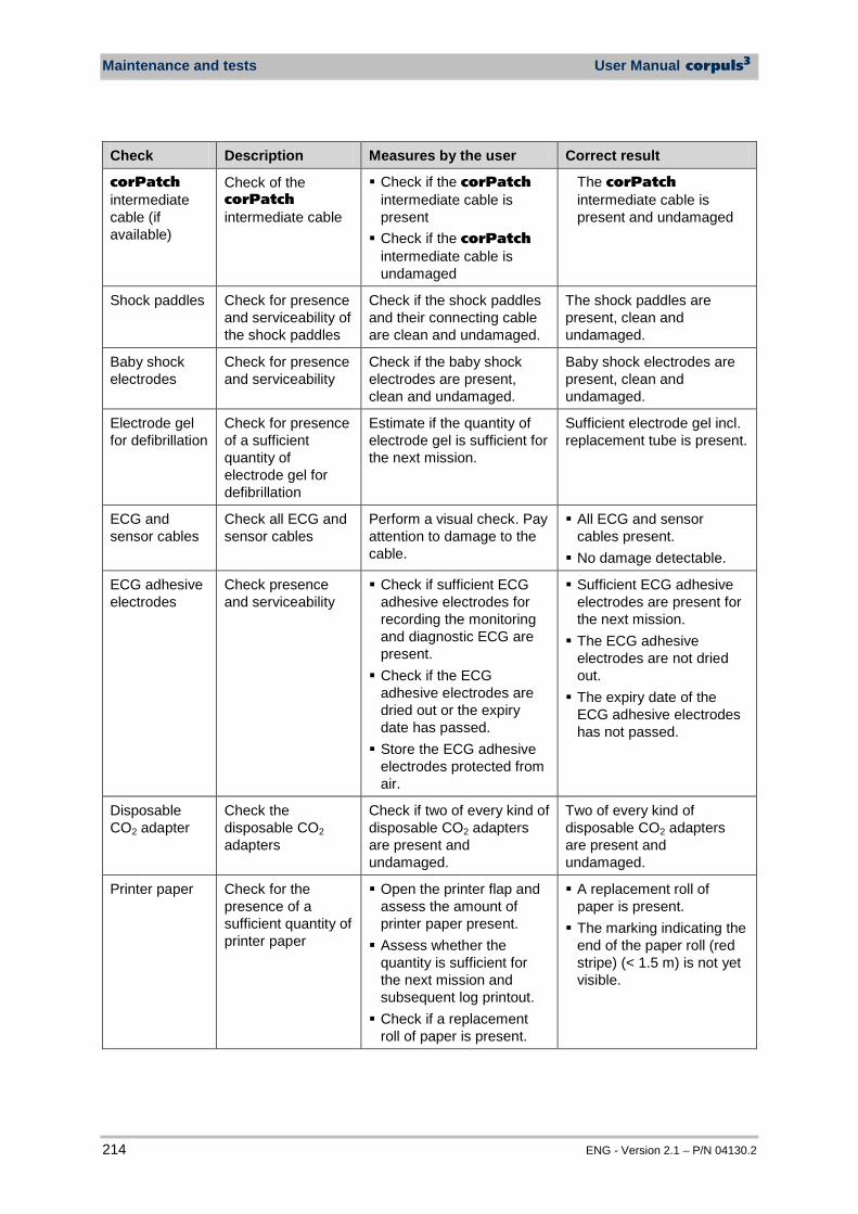
Maintenance and tests User Manual corpuls3
214 ENG - Version 2.1 – P/N 04130.2
Check Description Measures by the user Correct result
corPatch intermediate cable (if available)
Check of the corPatch intermediate cable
Check if the corPatch intermediate cable is present Check if the corPatch
intermediate cable is undamaged
The corPatch intermediate cable is present and undamaged
Shock paddles Check for presence and serviceability of the shock paddles
Check if the shock paddles and their connecting cable are clean and undamaged.
The shock paddles are present, clean and undamaged.
Baby shock electrodes
Check for presence and serviceability
Check if the baby shock electrodes are present, clean and undamaged.
Baby shock electrodes are present, clean and undamaged.
Electrode gel for defibrillation
Check for presence of a sufficient quantity of electrode gel for defibrillation
Estimate if the quantity of electrode gel is sufficient for the next mission.
Sufficient electrode gel incl. replacement tube is present.
ECG and sensor cables
Check all ECG and sensor cables
Perform a visual check. Pay attention to damage to the cable.
All ECG and sensor cables present. No damage detectable.
ECG adhesive electrodes
Check presence and serviceability
Check if sufficient ECG adhesive electrodes for recording the monitoring and diagnostic ECG are present. Check if the ECG
adhesive electrodes are dried out or the expiry date has passed. Store the ECG adhesive
electrodes protected from air.
Sufficient ECG adhesive electrodes are present for the next mission. The ECG adhesive
electrodes are not dried out. The expiry date of the
ECG adhesive electrodes has not passed.
Disposable CO2 adapter
Check the disposable CO2 adapters
Check if two of every kind of disposable CO2 adapters are present and undamaged.
Two of every kind of disposable CO2 adapters are present and undamaged.
Printer paper Check for the presence of a sufficient quantity of printer paper
Open the printer flap and assess the amount of printer paper present. Assess whether the
quantity is sufficient for the next mission and subsequent log printout. Check if a replacement
roll of paper is present.
A replacement roll of paper is present. The marking indicating the
end of the paper roll (red stripe) (< 1.5 m) is not yet visible.

User Manual corpuls3 Maintenance and tests
ENG - Version 2.1 – P/N 04130.2 215
Check Description Measures by the user Correct result
corPatch CPR sensors
Check for presence and functionality of corPatch CPR sensors.
Check if at least two pairs of functional corPatch CPR sensors are present. Check if the packages of
the corPatch CPR sensors are intact. Check if the expiry date of
the corPatch CPR sensors has passed.
At least two pairs of functional corPatch CPR sensors are present. The packages of the
corPatch CPR sensors are intact. The expiry date of the
corPatch CPR sensors has not passed.
Table 9-4 Checking accessories and consumables
9.3 Automatic Self Test The corpuls3 performs a complete system check each time it is switched on. This internal automatic self test checks the system components. If error messages appear during automatic self test, these are displayed in the status line and listed in the event history. These error messages can be confirmed by pressing the Alarm key.
9.4 Regular Maintenance Work
9.4.1 Safety-related Checks Pursuant to § 6 MPBetreibV (Medical Device Operators’ Ordinance, applicable to the Federal Republic of Germany), operators must ensure that their devices are subject to regular safety checks. Violations of this regulation may have consequences under penal law. Pursuant to § 6 sect. 4 MPBetreibV, the safety checks are only considered as performed and consequently valid if performed by the manufacturers themselves or by a specialist company according to the manufacturer’s indications. The corpuls3 has to be subject to a safety check every 12 months. The scope of this check is based on the corresponding test regulation and checklist.
Self test
Maintenance and tests User Manual corpuls3
216 ENG - Version 2.1 – P/N 04130.2
9.4.2 Metrological Check Pursuant to § 11 MPBetreibV (Medical Device Operators’ Ordinance, applicable to the Federal Republic of Germany), it is mandatory to perform metrological checks every 2 years on the non-invasive blood pressure (NIBP) and temperature measurement functions.
For all further measurement functions included in the corpuls3 (ECG, Oximetry, CO2, IBP), regular metrological checks are recommended.
If a malfunction is suspected, it is mandatory to perform metrological checks.
In states outside Germany, the national regulations or those based on EC directives concerning the scope and timely performance of metrological checks.
Caution
Metrological checks may only be performed by authorised personnel with calibrated measuring devices, measurement standards and simulators.
9.4.3 Repair and Service Any inspection, maintenance and cleaning tasks other than those listed in chapter 9.2 Function Checks, p. 207 may only be performed by authorised technicians.
Warning
The defibrillator must not be opened. Inside components may carry high voltages. Failure to observe this may result in severe injuries or death. Have the corpuls3 tested and repaired if necessary by an authorised sales and service partner if a defect is suspected.
Repair and service may only be performed by authorised sales and service partners. If technical repairs are not performed by trained technicians instructed by the manufacturer, this many result in damage to the corpuls3 and loss of any claim under the warranty of GS Elektromedizinische Geräte G. Stemple GmbH. To avoid transport damage when dispatching devices, care should be taken to ensure they are suitably packed. Ideally, the original packaging should be used. Packaging instructions and guidelines are available on request from GS Elektromedizinische Geräte G. Stemple GmbH.
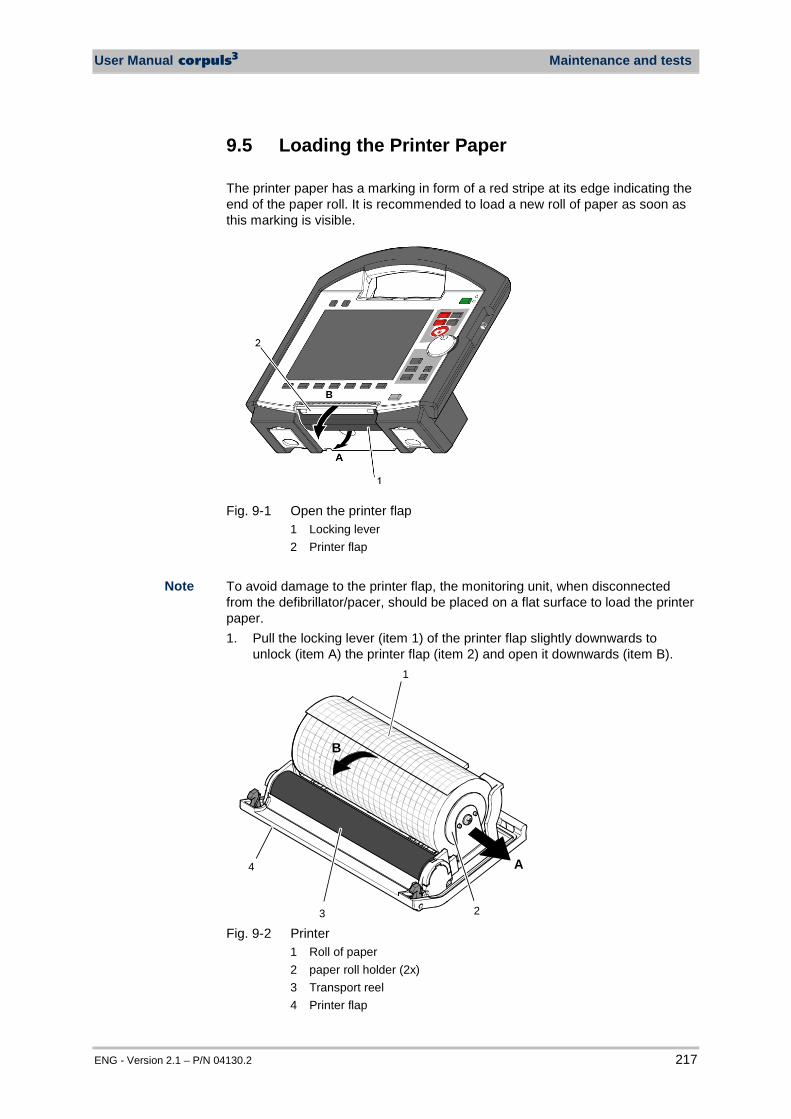
User Manual corpuls3 Maintenance and tests
ENG - Version 2.1 – P/N 04130.2 217
9.5 Loading the Printer Paper The printer paper has a marking in form of a red stripe at its edge indicating the end of the paper roll. It is recommended to load a new roll of paper as soon as this marking is visible.
Fig. 9-1 Open the printer flap
1 Locking lever 2 Printer flap
To avoid damage to the printer flap, the monitoring unit, when disconnected from the defibrillator/pacer, should be placed on a flat surface to load the printer paper. 1. Pull the locking lever (item 1) of the printer flap slightly downwards to
unlock (item A) the printer flap (item 2) and open it downwards (item B). 1
23
4 A
B
Fig. 9-2 Printer
1 Roll of paper 2 paper roll holder (2x) 3 Transport reel 4 Printer flap
Note
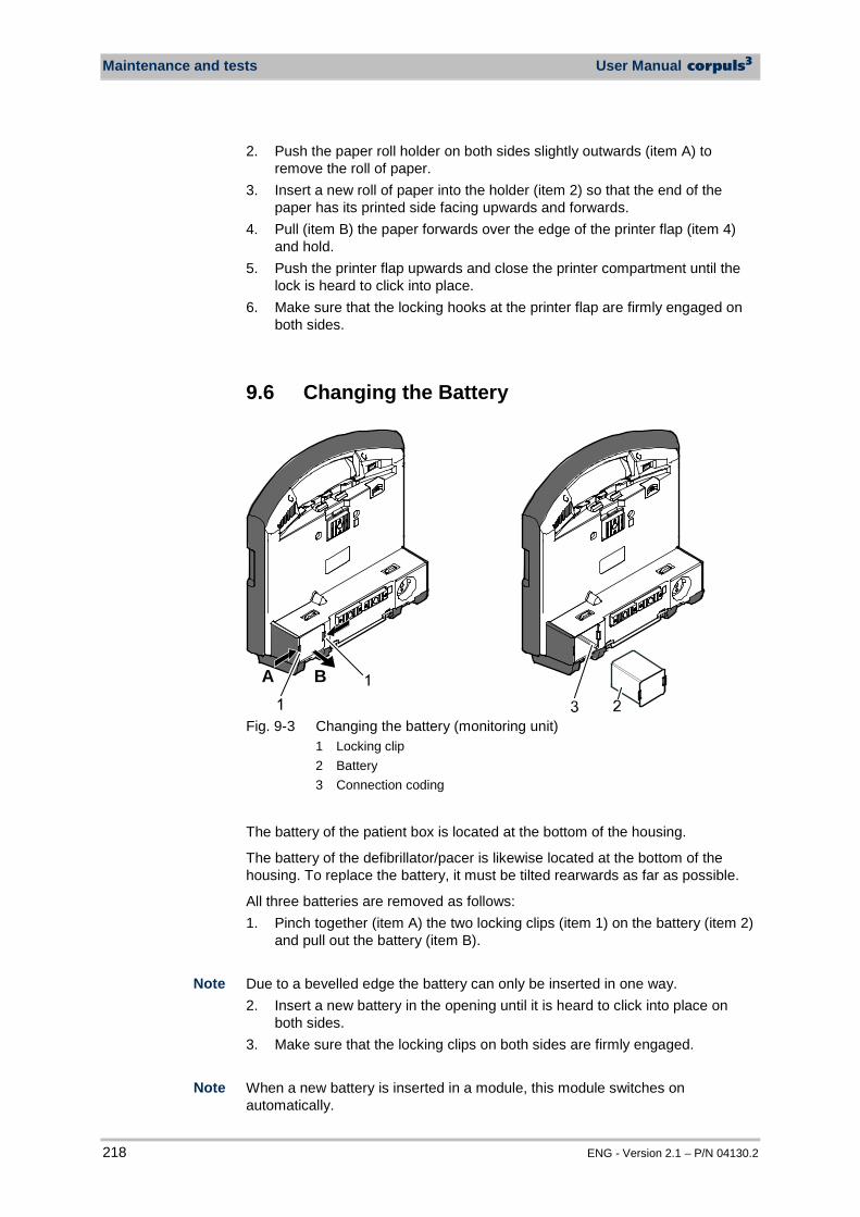
Maintenance and tests User Manual corpuls3
218 ENG - Version 2.1 – P/N 04130.2
2. Push the paper roll holder on both sides slightly outwards (item A) to remove the roll of paper.
3. Insert a new roll of paper into the holder (item 2) so that the end of the paper has its printed side facing upwards and forwards.
4. Pull (item B) the paper forwards over the edge of the printer flap (item 4) and hold.
5. Push the printer flap upwards and close the printer compartment until the lock is heard to click into place.
6. Make sure that the locking hooks at the printer flap are firmly engaged on both sides.
9.6 Changing the Battery
A B
Fig. 9-3 Changing the battery (monitoring unit)
1 Locking clip 2 Battery 3 Connection coding
The battery of the patient box is located at the bottom of the housing.
The battery of the defibrillator/pacer is likewise located at the bottom of the housing. To replace the battery, it must be tilted rearwards as far as possible.
All three batteries are removed as follows: 1. Pinch together (item A) the two locking clips (item 1) on the battery (item 2)
and pull out the battery (item B). Due to a bevelled edge the battery can only be inserted in one way. 2. Insert a new battery in the opening until it is heard to click into place on
both sides. 3. Make sure that the locking clips on both sides are firmly engaged. When a new battery is inserted in a module, this module switches on automatically.
Note
Note
User Manual corpuls3 Maintenance and tests
ENG - Version 2.1 – P/N 04130.2 219
For changing the battery on the patient box first switch it off and then change the battery within approx. 30 seconds. Under certain circumstances, the set time/date may be lost. The rechargeable battery is easier to remove if the respective module is held facing the floor.
9.7 Cleaning, Disinfection and Sterilisation
Warning
The modules of the corpuls3 and the accessories must not be sterilised in an autoclave, under pressure or with gas, unless expressly indicated.
Warning
The modules of the corpuls3 must never be immersed in a cleaning or disinfecting liquid; sterilised with hot water, steam or gas. The cables and shock electrodes of the corpuls3 must never be immersed in a cleaning or disinfecting liquid.
The manufacturer recommends solely the use of cleaning products and disinfectants itemised in the current list of the Robert Koch-Institut (RKI). See the RKI Web site: www.rki.de/EN/ for further information.
9.7.1 Monitoring Unit, Patient Box and Defibrillator/Pacer
Prerequisite: the modules are switched off and disconnected from the power supply. 1. Separate the compact device into the three modules. 2. Unplug all the cables on the patient box. 3. Remove the patient box from the accessory bag. 4. Disconnect the shock paddles from the therapy master cable and remove
from the defibrillator holders. 5. Clean the corpuls3:
Rub the external surfaces of the three modules with a paper towel. Disinfect the corpuls3: Wipe the device with an authorised disinfectant. Make sure the disinfectant has had sufficient contact time with the surface.
1. Separate the device into the three modules. 2. Wipe the infrared interface of the monitoring unit with a cloth.
Disinfectants
Cleaning/ disinfecting
the corpuls3
Cleaning/ disinfecting
the corpuls3
Note
Note
Note

Maintenance and tests User Manual corpuls3
220 ENG - Version 2.1 – P/N 04130.2
Fig. 9-4 Monitoring unit, infrared interface
1 Infrared interface 3. Unplug all the cables on the patient box. 4. Remove the patient box from the accessory bag. 5. Wipe the infrared interface of the patient box with a cloth.
Fig. 9-5 Patient box, infrared interface
1 Infrared interface 1. Wipe the infrared interface of the defibrillator/pacer with a cloth.
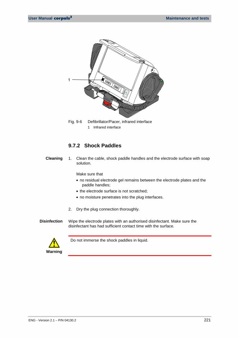
User Manual corpuls3 Maintenance and tests
ENG - Version 2.1 – P/N 04130.2 221
Fig. 9-6 Defibrillator/Pacer, infrared interface
1 Infrared interface
9.7.2 Shock Paddles 1. Clean the cable, shock paddle handles and the electrode surface with soap
solution. Make sure that • no residual electrode gel remains between the electrode plates and the
paddle handles; • the electrode surface is not scratched; • no moisture penetrates into the plug interfaces.
2. Dry the plug connection thoroughly. Wipe the electrode plates with an authorised disinfectant. Make sure the disinfectant has had sufficient contact time with the surface.
Warning
Do not immerse the shock paddles in liquid.
Cleaning
Disinfection
Maintenance and tests User Manual corpuls3
222 ENG - Version 2.1 – P/N 04130.2
9.7.3 Therapy Master Cable 1. Clean the therapy master cable with soap solution.
Prevent moisture entering the plug connector. 3. Dry the plug connection thoroughly. Disinfect the therapy master cable with a disinfectant itemised in the current disinfectant list of the RKI.
9.7.4 Cables for Monitoring Functions 1. Clean the following cables with soap solution:
• ECG monitoring cable • Complementary ECG diagnostic cable • corPatch CPR intermediate cable • CO2 intermediate cable • Oximetry intermediate cable Prevent moisture entering the plug connector.
4. Dry the plug connections thoroughly. Clean the cables mentioned above with one of the disinfectants included in the current list of disinfectants of the RKI.
9.7.5 Oximetry Sensor
Caution
Do not immerse oximetry sensors and cables in liquids. No liquid must enter the sensor components or plugs.
Please read and follow the operating instructions from the Masimo company enclosed with the oximetry sensors. 1. Disinfect the oximetry sensors and oximetry cables with one of the
disinfectants included in the current list of disinfectants of the RKI. 2. Let dry the oximetry sensors and oximetry cables thoroughly.
Cleaning
Disinfection
Cleaning
Disinfection
Cleaning
Disinfection
User Manual corpuls3 Maintenance and tests
ENG - Version 2.1 – P/N 04130.2 223
9.7.6 CO2 Sensor
Caution
Never apply liquid directly to the sensors.
1. Moisten a soft cloth with an alcohol-based cleaning solution. 2. Wipe the surface with the cloth. Avoid scratches on the surface of the CO2 sensors. Measurement can be impaired and/or rendered impossible by a scratched surface.
9.7.7 NIBP Cuffs Clean the connecting hose and NIBP cuff with soap solution. Disinfect the NIBP cuff with one of the disinfectants itemised in the current list of disinfectants of the RKI.
9.7.8 IBP Transducer Cable Please read and follow the manufacturer’s operating instructions enclosed with the IBP transducer.
9.7.9 Temperature Sensor Please read and follow the operating instructions from the YSI company enclosed with the temperature sensor.
9.7.10 Accessory Bag and Carrying Strap Roughly clean the accessory bag and carrying belt. Put both in a disinfectant solution. Subsequently wash the accessory bag and carrying belt in the washing machine (30 °C) using a laundry net and detergent for delicates. Do not use the spin cycle. If possible, allow to air dry.
Cleaning
Disinfection
Cleaning Disinfection Sterilisation
Cleaning Disinfection Sterilisation
Cleaning
Note
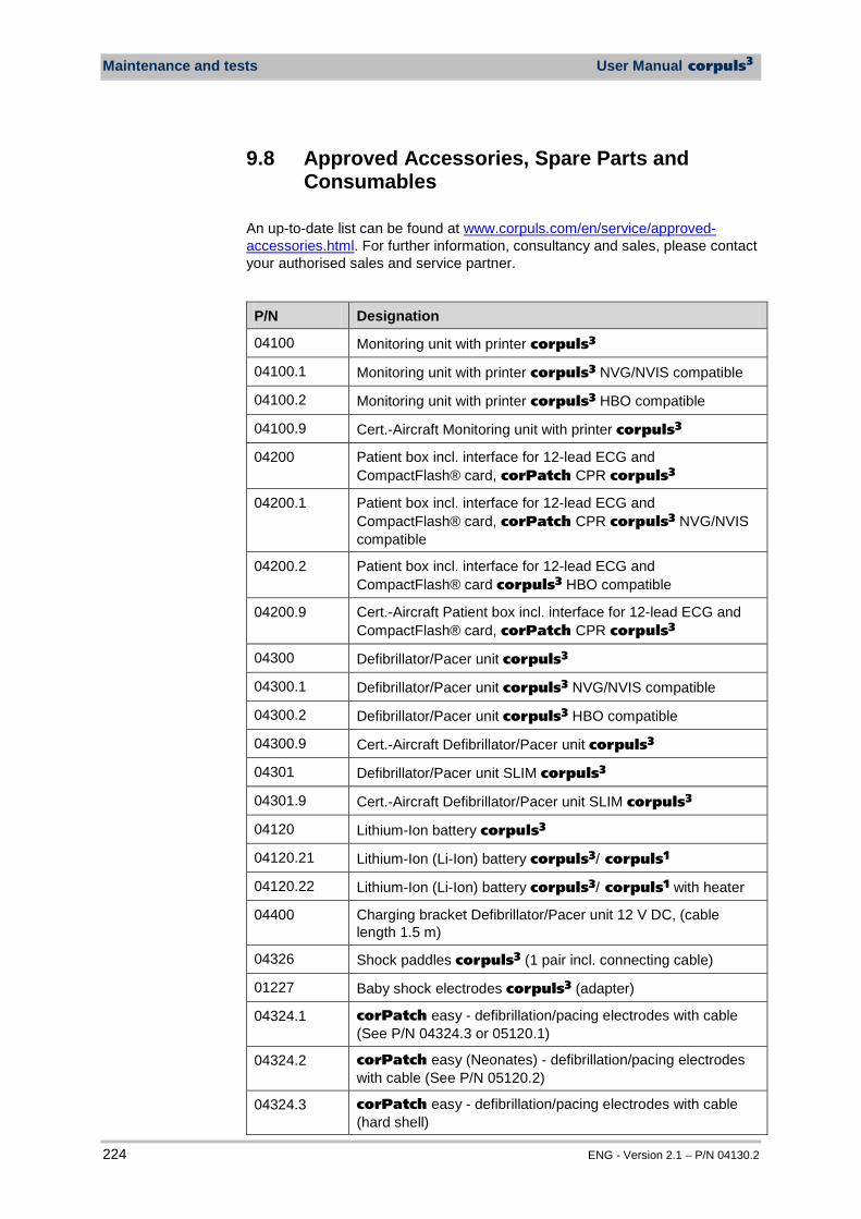
Maintenance and tests User Manual corpuls3
224 ENG - Version 2.1 – P/N 04130.2
9.8 Approved Accessories, Spare Parts and Consumables
An up-to-date list can be found at www.corpuls.com/en/service/approved-accessories.html. For further information, consultancy and sales, please contact your authorised sales and service partner.
P/N Designation
04100 Monitoring unit with printer corpuls3
04100.1 Monitoring unit with printer corpuls3 NVG/NVIS compatible
04100.2 Monitoring unit with printer corpuls3 HBO compatible
04100.9 Cert.-Aircraft Monitoring unit with printer corpuls3
04200 Patient box incl. interface for 12-lead ECG and CompactFlash® card, corPatch CPR corpuls3
04200.1 Patient box incl. interface for 12-lead ECG and CompactFlash® card, corPatch CPR corpuls3 NVG/NVIS compatible
04200.2 Patient box incl. interface for 12-lead ECG and CompactFlash® card corpuls3 HBO compatible
04200.9 Cert.-Aircraft Patient box incl. interface for 12-lead ECG and CompactFlash® card, corPatch CPR corpuls3
04300 Defibrillator/Pacer unit corpuls3
04300.1 Defibrillator/Pacer unit corpuls3 NVG/NVIS compatible
04300.2 Defibrillator/Pacer unit corpuls3 HBO compatible
04300.9 Cert.-Aircraft Defibrillator/Pacer unit corpuls3
04301 Defibrillator/Pacer unit SLIM corpuls3
04301.9 Cert.-Aircraft Defibrillator/Pacer unit SLIM corpuls3
04120 Lithium-Ion battery corpuls3
04120.21 Lithium-Ion (Li-Ion) battery corpuls3/ corpuls1
04120.22 Lithium-Ion (Li-Ion) battery corpuls3/ corpuls1 with heater
04400 Charging bracket Defibrillator/Pacer unit 12 V DC, (cable length 1.5 m)
04326 Shock paddles corpuls3 (1 pair incl. connecting cable)
01227 Baby shock electrodes corpuls3 (adapter)
04324.1 corPatch easy - defibrillation/pacing electrodes with cable (See P/N 04324.3 or 05120.1)
04324.2 corPatch easy (Neonates) - defibrillation/pacing electrodes with cable (See P/N 05120.2)
04324.3 corPatch easy - defibrillation/pacing electrodes with cable (hard shell)
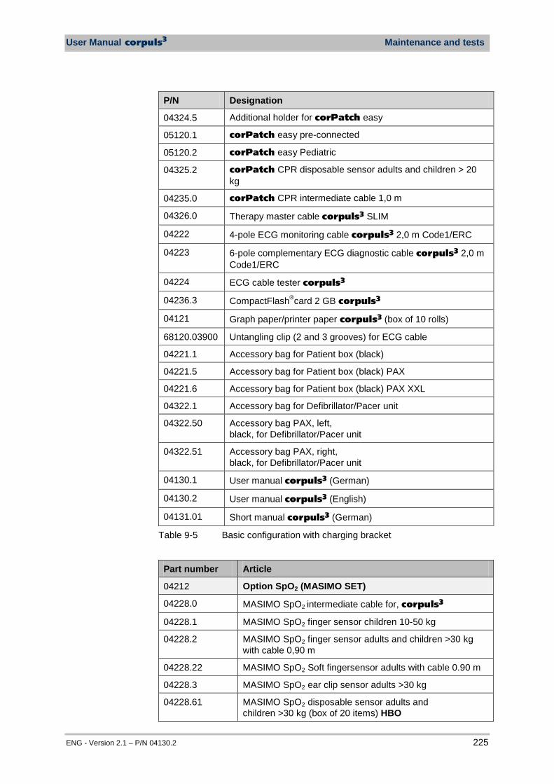
User Manual corpuls3 Maintenance and tests
ENG - Version 2.1 – P/N 04130.2 225
P/N Designation
04324.5 Additional holder for corPatch easy
05120.1 corPatch easy pre-connected
05120.2 corPatch easy Pediatric
04325.2 corPatch CPR disposable sensor adults and children > 20 kg
04235.0 corPatch CPR intermediate cable 1,0 m
04326.0 Therapy master cable corpuls3 SLIM
04222 4-pole ECG monitoring cable corpuls3 2,0 m Code1/ERC
04223 6-pole complementary ECG diagnostic cable corpuls3 2,0 m Code1/ERC
04224 ECG cable tester corpuls3
04236.3 CompactFlash®card 2 GB corpuls3
04121 Graph paper/printer paper corpuls3 (box of 10 rolls)
68120.03900 Untangling clip (2 and 3 grooves) for ECG cable
04221.1 Accessory bag for Patient box (black)
04221.5 Accessory bag for Patient box (black) PAX
04221.6 Accessory bag for Patient box (black) PAX XXL
04322.1 Accessory bag for Defibrillator/Pacer unit
04322.50 Accessory bag PAX, left, black, for Defibrillator/Pacer unit
04322.51 Accessory bag PAX, right, black, for Defibrillator/Pacer unit
04130.1 User manual corpuls3 (German)
04130.2 User manual corpuls3 (English)
04131.01 Short manual corpuls3 (German)
Table 9-5 Basic configuration with charging bracket
Part number Article
04212 Option SpO2 (MASIMO SET)
04228.0 MASIMO SpO2 intermediate cable for, corpuls3
04228.1 MASIMO SpO2 finger sensor children 10-50 kg
04228.2 MASIMO SpO2 finger sensor adults and children >30 kg with cable 0,90 m
04228.22 MASIMO SpO2 Soft fingersensor adults with cable 0.90 m
04228.3 MASIMO SpO2 ear clip sensor adults >30 kg
04228.61 MASIMO SpO2 disposable sensor adults and children >30 kg (box of 20 items) HBO
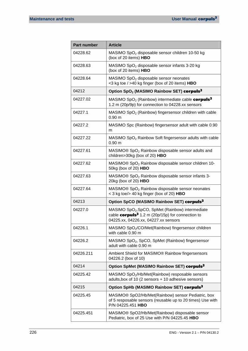
Maintenance and tests User Manual corpuls3
226 ENG - Version 2.1 – P/N 04130.2
Part number Article
04228.62 MASIMO SpO2 disposable sensor children 10-50 kg (box of 20 items) HBO
04228.63 MASIMO SpO2 disposable sensor infants 3-20 kg (box of 20 items) HBO
04228.64 MASIMO SpO2 disposable sensor neonates <3 kg toe / >40 kg finger (box of 20 items) HBO
04212 Option SpO2 (MASIMO Rainbow SET) corpuls3
04227.02 MASIMO SpO2 (Rainbow) intermediate cable corpuls3 1.2 m (20p/9p) for connection to 04228.xx sensors
04227.1 MASIMO SpO2 (Rainbow) fingersensor children with cable 0.90 m
04227.2 MASIMO Spc (Rainbow) fingersensor adult with cable 0.90 m
04227.22 MASIMO SpO2 Rainbow Soft fingersensor adults with cable 0.90 m
04227.61 MASIMO® SpO2 Rainbow disposable sensor adults and children>30kg (box of 20) HBO
04227.62 MASIMO® SpO2 Rainbow disposable sensor children 10-50kg (box of 20) HBO
04227.63 MASIMO® SpO2 Rainbow disposable sensor infants 3-20kg (box of 20) HBO
04227.64 MASIMO® SpO2 Rainbow disposable sensor neonates < 3 kg toe/> 40 kg finger (box of 20) HBO
04213 Option SpCO (MASIMO Rainbow SET) corpuls3
04227.0 MASIMO SpO2,SpCO, SpMet (Rainbow) intermediate cable corpuls3 1.2 m (20p/15p) for connection to 04225.xx, 04226.xx, 04227.xx sensors
04226.1 MASIMO SpO2/CO/Met(Rainbow) fingersensor children with cable 0.90 m
04226.2 MASIMO SpO2, SpCO, SpMet (Rainbow) fingersensor adult with cable 0.90 m
04226.211 Ambient Shield for MASIMO® Rainbow fingersensors 04226.2 (box of 10)
04214 Option SpMet (MASIMO Rainbow SET) corpuls3
04225.42 MASIMO SpO2/Hb/Met(Rainbow) resposable sensors adults,box of 10 (2 sensors + 10 adhesive sensors)
04215 Option SpHb (MASIMO Rainbow SET) corpuls3
04225.45 MASIMO® SpO2/Hb/Met(Rainbow) sensor Pediatric, box of 5 resposable sensors (reusable up to 20 times) Use with P/N 04225.451 HBO
04225.451 MASIMO® SpO2/Hb/Met(Rainbow) disposable sensor Pediatric, box of 25 Use with P/N 04225.45 HBO
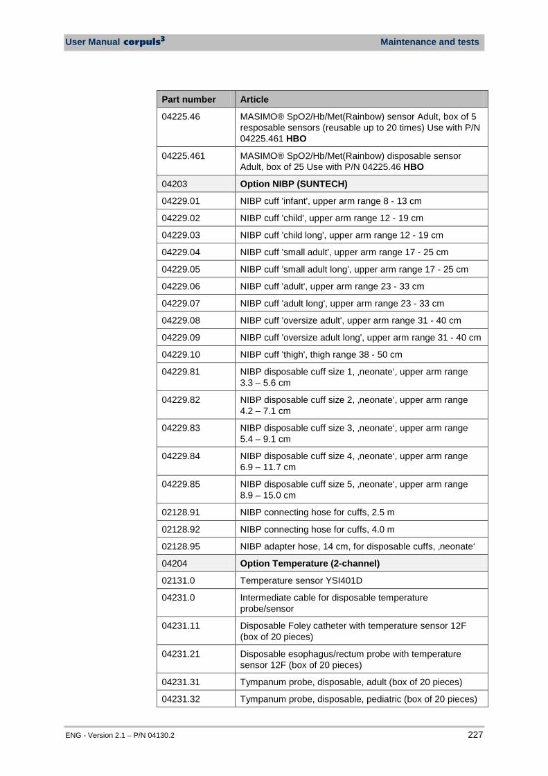
User Manual corpuls3 Maintenance and tests
ENG - Version 2.1 – P/N 04130.2 227
Part number Article
04225.46 MASIMO® SpO2/Hb/Met(Rainbow) sensor Adult, box of 5 resposable sensors (reusable up to 20 times) Use with P/N 04225.461 HBO
04225.461 MASIMO® SpO2/Hb/Met(Rainbow) disposable sensor Adult, box of 25 Use with P/N 04225.46 HBO
04203 Option NIBP (SUNTECH)
04229.01 NIBP cuff 'infant', upper arm range 8 - 13 cm
04229.02 NIBP cuff 'child', upper arm range 12 - 19 cm
04229.03 NIBP cuff 'child long', upper arm range 12 - 19 cm
04229.04 NIBP cuff 'small adult', upper arm range 17 - 25 cm
04229.05 NIBP cuff 'small adult long', upper arm range 17 - 25 cm
04229.06 NIBP cuff 'adult', upper arm range 23 - 33 cm
04229.07 NIBP cuff 'adult long', upper arm range 23 - 33 cm
04229.08 NIBP cuff 'oversize adult', upper arm range 31 - 40 cm
04229.09 NIBP cuff 'oversize adult long', upper arm range 31 - 40 cm
04229.10 NIBP cuff 'thigh', thigh range 38 - 50 cm
04229.81 NIBP disposable cuff size 1, ‚neonate‘, upper arm range 3.3 – 5.6 cm
04229.82 NIBP disposable cuff size 2, ‚neonate‘, upper arm range 4.2 – 7.1 cm
04229.83 NIBP disposable cuff size 3, ‚neonate‘, upper arm range 5.4 – 9.1 cm
04229.84 NIBP disposable cuff size 4, ‚neonate‘, upper arm range 6.9 – 11.7 cm
04229.85 NIBP disposable cuff size 5, ‚neonate‘, upper arm range 8.9 – 15.0 cm
02128.91 NIBP connecting hose for cuffs, 2.5 m
02128.92 NIBP connecting hose for cuffs, 4.0 m
02128.95 NIBP adapter hose, 14 cm, for disposable cuffs, ‚neonate‘
04204 Option Temperature (2-channel)
02131.0 Temperature sensor YSI401D
04231.0 Intermediate cable for disposable temperature probe/sensor
04231.11 Disposable Foley catheter with temperature sensor 12F (box of 20 pieces)
04231.21 Disposable esophagus/rectum probe with temperature sensor 12F (box of 20 pieces)
04231.31 Tympanum probe, disposable, adult (box of 20 pieces)
04231.32 Tympanum probe, disposable, pediatric (box of 20 pieces)
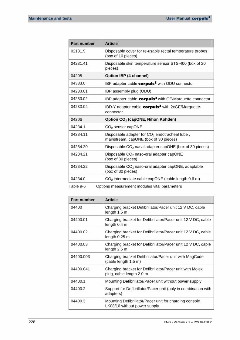
Maintenance and tests User Manual corpuls3
228 ENG - Version 2.1 – P/N 04130.2
Part number Article
02131.9 Disposable cover for re-usable rectal temperature probes (box of 10 pieces)
04231.41 Disposable skin temperature sensor STS-400 (box of 20 pieces)
04205 Option IBP (4-channel)
04333.0 IBP adapter cable corpuls3 with ODU connector
04233.01 IBP assembly plug (ODU)
04233.02 IBP adapter cable corpuls3 with GE/Marquette connector
04233.04 IBD-Y adapter cable corpuls3 with 2xGE/Marquette- connector
04206 Option CO2 (capONE, Nihon Kohden)
04234.1 CO2 sensor capONE
04234.11 Disposable adapter for CO2 endotracheal tube , mainstream, capONE (box of 30 pieces)
04234.20 Disposable CO2 nasal adapter capONE (box of 30 pieces)
04234.21 Disposable CO2 naso-oral adapter capONE (box of 30 pieces)
04234.22 Disposable CO2 naso-oral adapter capONE, adaptable (box of 30 pieces)
04234.0 CO2 intermediate cable capONE (cable length 0.6 m)
Table 9-6 Options measurement modules vital parameters
Part number Article
04400 Charging bracket Defibrillator/Pacer unit 12 V DC, cable length 1.5 m
04400.01 Charging bracket for Defibrillator/Pacer unit 12 V DC, cable length 0.4 m
04400.02 Charging bracket for Defibrillator/Pacer unit 12 V DC, cable length 0.25 m
04400.03 Charging bracket for Defibrillator/Pacer unit 12 V DC, cable length 2.5 m
04400.003 Charging bracket Defibrillator/Pacer unit with MagCode (cable length 1.5 m)
04400.041 Charging bracket for Defibrillator/Pacer unit with Molex plug, cable length 2.0 m
04400.1 Mounting Defibrillator/Pacer unit without power supply
04400.2 Support for Defibrillator/Pacer unit (only in combination with adapters)
04400.3 Mounting Defibrillator/Pacer unit for charging console LK08/16 without power supply
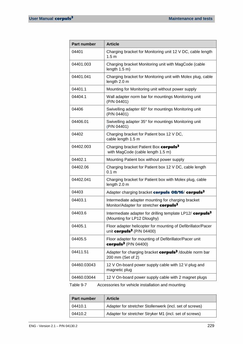
User Manual corpuls3 Maintenance and tests
ENG - Version 2.1 – P/N 04130.2 229
Part number Article
04401 Charging bracket for Monitoring unit 12 V DC, cable length 1.5 m
04401.003 Charging bracket Monitoring unit with MagCode (cable length 1.5 m)
04401.041 Charging bracket for Monitoring unit with Molex plug, cable length 2.0 m
04401.1 Mounting for Monitoring unit without power supply
04404.1 Wall adapter norm bar for mountings Monitoring unit (P/N 04401)
04406 Swivelling adapter 60° for mountings Monitoring unit (P/N 04401)
04406.01 Swivelling adapter 35° for mountings Monitoring unit (P/N 04401)
04402 Charging bracket for Patient box 12 V DC, cable length 1.5 m
04402.003 Charging bracket Patient Box corpuls3 with MagCode (cable length 1.5 m)
04402.1 Mounting Patient box without power supply
04402.06 Charging bracket for Patient box 12 V DC, cable length 0.1 m
04402.041 Charging bracket for Patient box with Molex plug, cable length 2.0 m
04403 Adapter charging bracket corpuls 08/16/ corpuls3
04403.1 Intermediate adapter mounting for charging bracket Monitor/Adapter for stretcher corpuls3
04403.6 Intermediate adapter for drilling template LP12/ corpuls3 (Mounting for LP12 Dloughy)
04405.1 Floor adapter helicopter for mounting of Defibrillator/Pacer unit corpuls3 (P/N 04400)
04405.5 Floor adapter for mounting of Defibrillator/Pacer unit corpuls3 (P/N 04400)
04411.51 Adapter for charging bracket corpuls3 /double norm bar 200 mm (Set of 2)
04460.03043 12 V On-board power supply cable with 12 V-plug and magnetic plug
04460.03044 12 V On-board power supply cable with 2 magnet plugs
Table 9-7 Accessories for vehicle installation and mounting
Part number Article
04410.1 Adapter for stretcher Stollenwerk (incl. set of screws)
04410.2 Adapter for stretcher Stryker M1 (incl. set of screws)

Maintenance and tests User Manual corpuls3
230 ENG - Version 2.1 – P/N 04130.2
Part number Article
04410.21 Adapter for stretcher Stryker M1 – head part (incl. set of screws)
04410.3 Adapter for stretcher Kartsana (incl. set of screws)
04412.2 Adapter (detachable) for stretcher Ø19/22mm/side rail (incl. set of screws)
Table 9-8 Accessories for stretcher, adapter
Part number Article
04411.1 Adapter for norm bar (incl. set of screws)
04411.2 Adapter for clinic bed/norm bar (incl. set of screws)
04411.4 Screwing adapter for norm bar
04411.5 Adapter for charging bracket corpuls3/double norm bar 10" (set of 2)
04411.62 Adapter for clinic bed 180 mm (incl. set of screws)
Table 9-9 Accessories for clinic beds/norm bar, adapter
Part number Article
04501.120 Mains charger corpuls3 with corpuls magnetic plug (120 W)
04500.1201 Mains charger corpuls3 with Molex/PE plug (120 W)
04520.10 Line cord 1.8 m bent shock-proof plug/power-connector for mains charger corpuls3 and corpuls 08/16
04520.20 Line cord 1.8 m U.S. pwr-coupler for mains charger corpuls3 and corpuls 08/16
04520.31 Line cord 2.5 m bent GB-plug for mains charger corpuls3
Table 9-10 Accessories for charging and power supply
Part number Article
70710.01100 Protective foil for display corpuls3
01126.1 Disposable ECG electrode, adults and children Ø35 mm (box of 50 items)
01239 Elektrode gel, 100 g
Table 9-11 Further consumables
Part number Article
01227 Baby electrode adapter
04327.0 Shock paddle holder corpuls3 (1 pair incl. connecting cable)
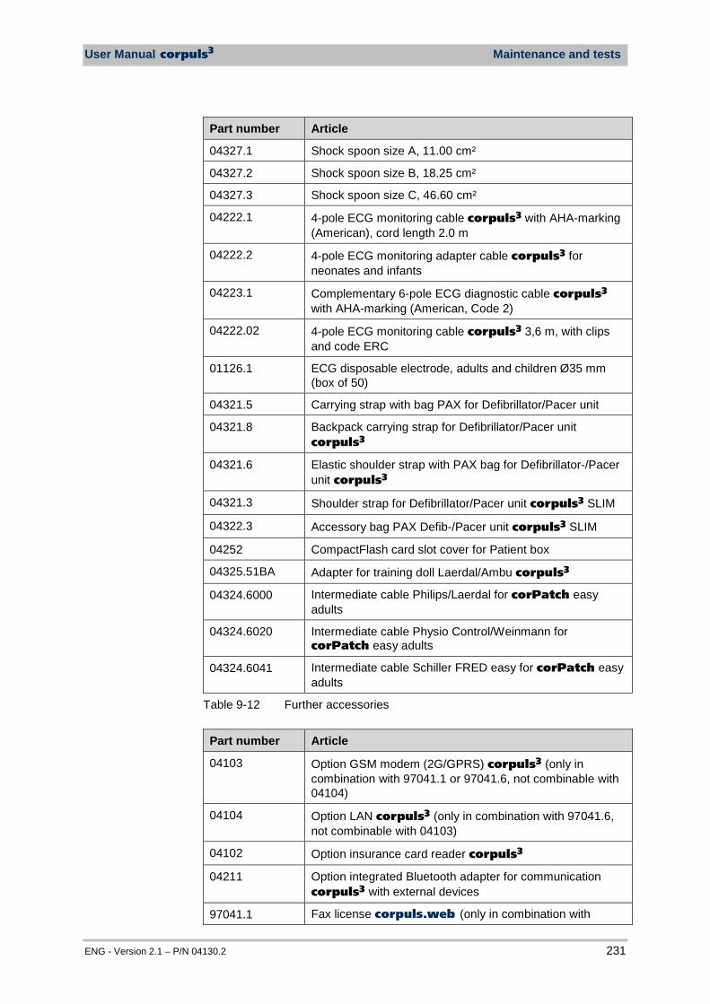
User Manual corpuls3 Maintenance and tests
ENG - Version 2.1 – P/N 04130.2 231
Part number Article
04327.1 Shock spoon size A, 11.00 cm²
04327.2 Shock spoon size B, 18.25 cm²
04327.3 Shock spoon size C, 46.60 cm²
04222.1 4-pole ECG monitoring cable corpuls3 with AHA-marking (American), cord length 2.0 m
04222.2 4-pole ECG monitoring adapter cable corpuls3 for neonates and infants
04223.1 Complementary 6-pole ECG diagnostic cable corpuls3 with AHA-marking (American, Code 2)
04222.02 4-pole ECG monitoring cable corpuls3 3,6 m, with clips and code ERC
01126.1 ECG disposable electrode, adults and children Ø35 mm (box of 50)
04321.5 Carrying strap with bag PAX for Defibrillator/Pacer unit
04321.8 Backpack carrying strap for Defibrillator/Pacer unit corpuls3
04321.6 Elastic shoulder strap with PAX bag for Defibrillator-/Pacer unit corpuls3
04321.3 Shoulder strap for Defibrillator/Pacer unit corpuls3 SLIM
04322.3 Accessory bag PAX Defib-/Pacer unit corpuls3 SLIM
04252 CompactFlash card slot cover for Patient box
04325.51BA Adapter for training doll Laerdal/Ambu corpuls3
04324.6000 Intermediate cable Philips/Laerdal for corPatch easy adults
04324.6020 Intermediate cable Physio Control/Weinmann for corPatch easy adults
04324.6041 Intermediate cable Schiller FRED easy for corPatch easy adults
Table 9-12 Further accessories
Part number Article
04103 Option GSM modem (2G/GPRS) corpuls3 (only in combination with 97041.1 or 97041.6, not combinable with 04104)
04104 Option LAN corpuls3 (only in combination with 97041.6, not combinable with 04103)
04102 Option insurance card reader corpuls3
04211 Option integrated Bluetooth adapter for communication corpuls3 with external devices
97041.1 Fax license corpuls.web (only in combination with
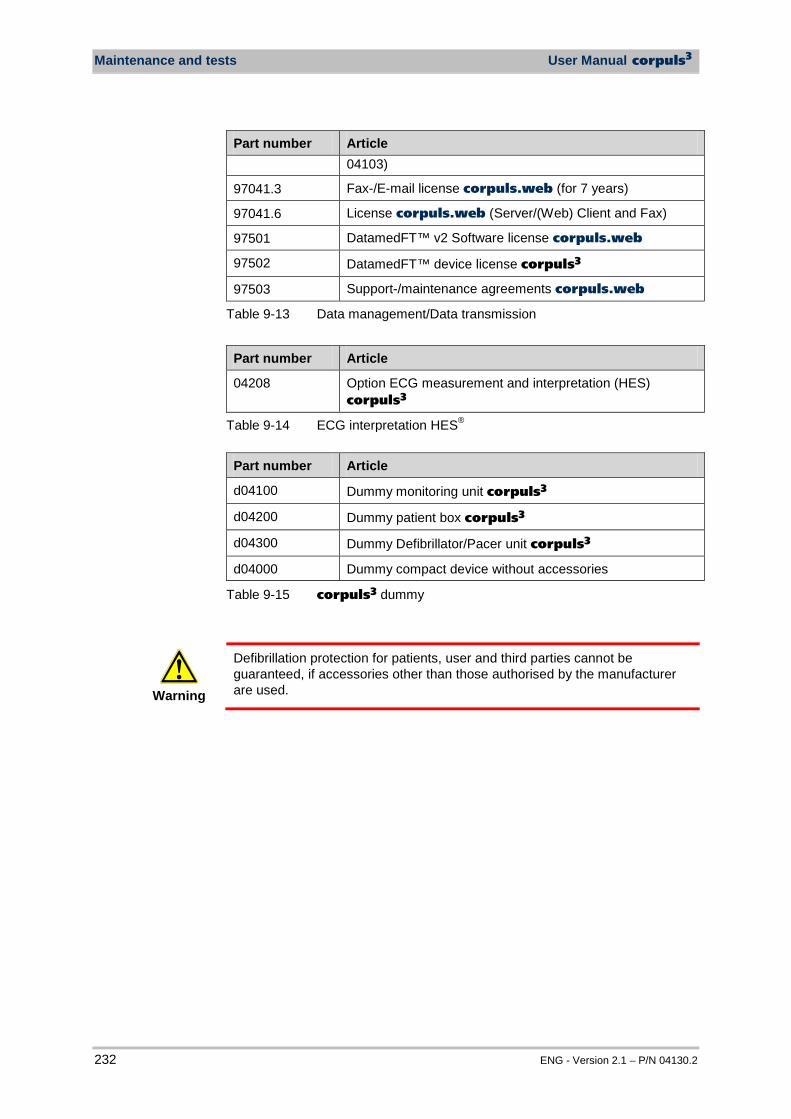
Maintenance and tests User Manual corpuls3
232 ENG - Version 2.1 – P/N 04130.2
Part number Article 04103)
97041.3 Fax-/E-mail license corpuls.web (for 7 years)
97041.6 License corpuls.web (Server/(Web) Client and Fax)
97501 DatamedFT™ v2 Software license corpuls.web
97502 DatamedFT™ device license corpuls3
97503 Support-/maintenance agreements corpuls.web
Table 9-13 Data management/Data transmission
Part number Article
04208 Option ECG measurement and interpretation (HES) corpuls3
Table 9-14 ECG interpretation HES®
Part number Article
d04100 Dummy monitoring unit corpuls3
d04200 Dummy patient box corpuls3
d04300 Dummy Defibrillator/Pacer unit corpuls3
d04000 Dummy compact device without accessories
Table 9-15 corpuls3 dummy
Warning
Defibrillation protection for patients, user and third parties cannot be guaranteed, if accessories other than those authorised by the manufacturer are used.

User Manual corpuls3 Procedure in case of malfunctions
ENG - Version 2.1 – P/N 04130.2 233
10 Procedure in Case of Malfunctions
10.1 Device alarms
The following table lists all alarms of the device with their priority and describes the cause of the malfunction as well as how to eliminate it.
Alarm message Priority Explanation/Measure
Battery low (Defib) Battery low (Monitor) Battery low (P-Box)
High priority The state of charge of the battery is now less than 20% of the total charge of the module indicated. Connect the respective module to a power supply as
soon as possible.
Battery temperature high (Defib) Battery temp. high (Monitor) Battery temp. high (P-Box)
Medium priority The battery charging process lead to a great increase of temperature inside the battery (> 60°C). The corpuls3 or the respective module was
possibly exposed to high temperatures. See appendix D Technische Daten, page 5. Interrupt charging process by disconnecting the
corpuls3 from the mains power or from charger. If necessary, let the corpuls3 cool down or bring
device to a cooler environment. Contact authorised sales and service partners, if
necessary.
BT connected: [DEVICE]
Medium priority The connection to another Bluetooth® device has been established. "Device" stands for a ventilator (e. g. Weinmann
Medumat Transport) or another input device (e. g. a tablet PC).
BT connection failed Medium priority The connection to another Bluetooth® device has failed. Check the Bluetooth® connections.
BT disconnected: [DEVICE]
Medium priority The connection to another Bluetooth® device has been interrupted. "Device" stands for a ventilator (e. g. Weinmann
Medumat Transport) or another input device (e. g. a tablet PC).
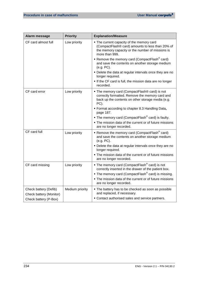
Procedure in case of malfunctions User Manual corpuls3
234 ENG - Version 2.1 – P/N 04130.2
Alarm message Priority Explanation/Measure
CF card almost full Low priority The current capacity of the memory card (CompactFlash® card) amounts to less than 20% of the memory capacity or the number of missions is more than 999. Remove the memory card (CompactFlash® card)
and save the contents on another storage medium (e.g. PC). Delete the data at regular intervals once they are no
longer required. If the CF card is full, the mission data are no longer
recorded.
CF card error Low priority The memory card (CompactFlash® card) is not correctly formatted. Remove the memory card and back up the contents on other storage media (e.g. PC). Format according to chapter 8.3 Handling Data,
page 187. The memory card (CompactFlash® card) is faulty. The mission data of the current or of future missions
are no longer recorded. CF card full Low priority Remove the memory card (CompactFlash® card)
and save the contents on another storage medium (e.g. PC). Delete the data at regular intervals once they are no
longer required. The mission data of the current or of future missions
are no longer recorded.
CF card missing Low priority The memory card (CompactFlash® card) is not correctly inserted in the drawer of the patient box. The memory card (CompactFlash® card) is missing. The mission data of the current or of future missions
are no longer recorded.
Check battery (Defib) Check battery (Monitor) Check battery (P-Box)
Medium priority The battery has to be checked as soon as possible and replaced, if necessary. Contact authorised sales and service partners.
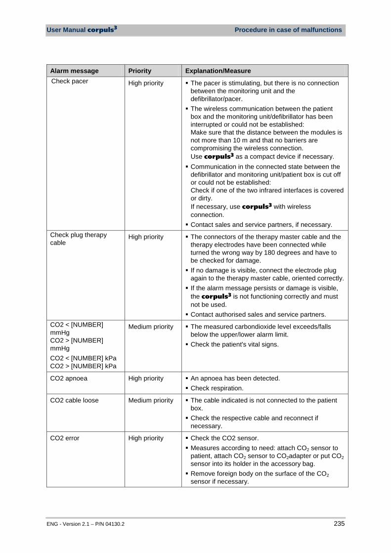
User Manual corpuls3 Procedure in case of malfunctions
ENG - Version 2.1 – P/N 04130.2 235
Alarm message Priority Explanation/Measure Check pacer High priority The pacer is stimulating, but there is no connection
between the monitoring unit and the defibrillator/pacer. The wireless communication between the patient
box and the monitoring unit/defibrillator has been interrupted or could not be established: Make sure that the distance between the modules is not more than 10 m and that no barriers are compromising the wireless connection. Use corpuls3 as a compact device if necessary. Communication in the connected state between the
defibrillator and monitoring unit/patient box is cut off or could not be established: Check if one of the two infrared interfaces is covered or dirty. If necessary, use corpuls3 with wireless connection. Contact sales and service partners, if necessary.
Check plug therapy cable
High priority The connectors of the therapy master cable and the therapy electrodes have been connected while turned the wrong way by 180 degrees and have to be checked for damage. If no damage is visible, connect the electrode plug
again to the therapy master cable, oriented correctly. If the alarm message persists or damage is visible,
the corpuls3 is not functioning correctly and must not be used. Contact authorised sales and service partners.
CO2 < [NUMBER] mmHg CO2 > [NUMBER] mmHg CO2 < [NUMBER] kPa CO2 > [NUMBER] kPa
Medium priority The measured carbondioxide level exceeds/falls below the upper/lower alarm limit. Check the patient's vital signs.
CO2 apnoea High priority An apnoea has been detected. Check respiration.
CO2 cable loose Medium priority The cable indicated is not connected to the patient box. Check the respective cable and reconnect if
necessary.
CO2 error High priority Check the CO2 sensor. Measures according to need: attach CO2 sensor to
patient, attach CO2 sensor to CO2adapter or put CO2 sensor into its holder in the accessory bag. Remove foreign body on the surface of the CO2
sensor if necessary.

Procedure in case of malfunctions User Manual corpuls3
236 ENG - Version 2.1 – P/N 04130.2
Alarm message Priority Explanation/Measure
Connect therapy electrodes
High priority Connect the corPatch electrodes or shock paddles to the therapy master cable of the corpuls3. If the alarm message persists, connect immediately
the reserve corPatch electrodes. CPR cable loose CPR cable loose (P-Box)
Medium priority The cable indicated is not connected to the patient box. Check the respective cable and reconnect if
necessary. CPR sensor activ. CPR sen. activ.(P-Box)
Medium priority The sensor has been activated.
CPR sensor expired CPR sen. exp. (P-Box)
Medium priority The sensor is expired and has to be exchanged with a new one.
CPR sensor loose CPR sensor loose (P-Box)
Medium priority The sensor indicated has come loose from the intermediate cable. Check the sensor and reconnect if necessary.
CPR sensor not activated CPR n. activ.(P-Box)
Medium priority The sensor has not been activated. For correct use, the sensor has to be activated.
CPR sensor-NOT FOR PAT. USE CPR-NO PAT. USE (P-Box)
Medium priority Using this sensor on a patient is prohibited. Contact authorised sales and service partners.
D-ECG transfer to server failed
Low priority Connection to server or to patient box is interrupted. Restart connection. Repeat recording and transmission of D-ECG.
Defective Oxi adhesive sensor Def. Oxi adhes. sensor (P-Box)
Medium priority The adhesive sensor is defective or has expired. The sensor LED's have to be aligned directly over
each other at the measuring site.
Defective Oxi cable Medium priority The intermediate cable is defect or not connected correctly. Disconnect intermediate cable and connect again. If the sensor LED does not flash, the intermediate
cable has to be exchanged.
Defective Oxi sensor Defect. Oxi sen. (P-Box)
Medium priority The sensor is defect or not connected correctly. Disconnect sensor and connect again. If the sensor LED does not flash, the sensor has to
be exchanged. Defib temperature high (X)
High priority „X“ stands for a failure number from 1 to 2. The defibrillator was very frequently charged within a
short period. Avoid too frequent internal discharges.
Defibrillator alarm High priority The corpuls3 still functions correctly, but should however be checked by a service technician as soon as possible. Contact authorised sales and service partners.
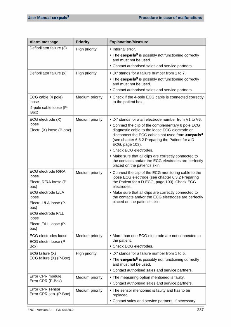
User Manual corpuls3 Procedure in case of malfunctions
ENG - Version 2.1 – P/N 04130.2 237
Alarm message Priority Explanation/Measure Defibrillator failure (3) High priority Internal error.
The corpuls3 is possibly not functioning correctly and must not be used. Contact authorised sales and service partners.
Defibrillator failure (x) High priority „X“ stands for a failure number from 1 to 7. The corpuls3 is possibly not functioning correctly
and must not be used. Contact authorised sales and service partners.
ECG cable (4 pole) loose 4-pole cable loose (P-Box)
Medium priority Check if the 4-pole ECG cable is connected correctly to the patient box.
ECG electrode (X) loose Electr. (X) loose (P-box)
Medium priority „X“ stands for a an electrode number from V1 to V6. Connect the clip of the complementary 6 pole ECG
diagnostic cable to the loose ECG electrode or disconnect the ECG cables not used from corpuls3 (see chapter 6.3.2 Preparing the Patient for a D-ECG, page 103). Check ECG electrodes. Make sure that all clips are correctly connected to
the contacts and/or the ECG electrodes are perfectly placed on the patient’s skin.
ECG electrode R/RA loose Electr. R/RA loose (P-box) ECG electrode L/LA loose Electr. L/LA loose (P-box) ECG electrode F/LL loose Electr. F/LL loose (P-box)
Medium priority Connect the clip of the ECG monitoring cable to the loose ECG electrode (see chapter 6.3.2 Preparing the Patient for a D-ECG, page 103). Check ECG electrodes. Make sure that all clips are correctly connected to
the contacts and/or the ECG electrodes are perfectly placed on the patient’s skin.
ECG electrodes loose ECG electr. loose (P-Box)
Medium priority More than one ECG electrode are not connected to the patient. Check ECG electrodes.
ECG failure (X) ECG failure (X) (P-Box)
High priority „X“ stands for a failure number from 1 to 5. The corpuls3 is possibly not functioning correctly
and must not be used. Contact authorised sales and service partners.
Error CPR module Error CPR (P-Box)
Medium priority The measuring option mentioned is faulty. Contact authorised sales and service partners.
Error CPR sensor Error CPR sen. (P-Box)
Medium priority The sensor mentioned is faulty and has to be replaced. Contact sales and service partners, if necessary.

Procedure in case of malfunctions User Manual corpuls3
238 ENG - Version 2.1 – P/N 04130.2
Alarm message Priority Explanation/Measure Error GSM module Low priority The GSM module is faulty.
Contact authorised sales and service partners.
Error IBP module Medium priority The measuring option mentioned is faulty. Contact authorised sales and service partners.
Error insurance card Low priority The insurance card was not recognised or could not be read. Take the insurance card out of the corpuls3 and
check if it was inserted with the chip oriented towards the front. Only German, Austrian and Swiss insurance cards
and Belgian ID-cards are supported. The reading process may take up to 10 seconds.
Error NIBP hardware NIBP HW error (P-box)
Medium priority Wait up to 20 secs. to start measurement. The softkeys are greyed out as long as the selection is not available. If the patient is not in a critical condition, restart the
corpuls3. Check if the patient as a palpable pulse.
Error T1/T2 Medium priority The measuring channel mentioned is defect. Contact authorised sales and service partners.
Fax connection busy Low priority The fax machine of the recipient is busy. Try to repeat fax transmission at a later time.
Fax connection not possible
Low priority Possibly a wrong fax number has been dialled. Repeat dialing.
Fax transmission failed Low priority Fax transmission was not successful. Repeat procedure Contact authorised sales and service partners, if
necessary.
GPRS authorization failed
Low priority No GPRS service available for this SIM card. Wrong APN configured or connection with the GSM
network aborted. Repeat attempt to establish connection.
GPRS link error Low priority The APN is not configured or has not been saved. Configure APN anew and save configuration. Contact your mobile communications provider for the
respective current APN. GSM network not avail. Low priority The reception quality is too low. No connection to
the mobile communications network can be established. If possible, select a location with better reception. If necessary, repeat procedure at a later time.
HR < [NUMBER]/min HR > [NUMBER]/min
High priority The measured heart rate exceeds/falls below the upper/lower alarm limit. Check the patient's vital signs.

User Manual corpuls3 Procedure in case of malfunctions
ENG - Version 2.1 – P/N 04130.2 239
Alarm message Priority Explanation/Measure HW conflict [MODULE] Low priority The wireless connection authorisation (Pairing) has
failed. Due to different hardware versions the modules
used can only be used as compact device with an ad-hoc connection. Contact sales and service partners, if necessary.
IBP (X) sensor loose (X) sensor loose (P-Box)
Medium priority „X“ stands for an IBP sensor P1 to P4 The sensor indicated is not correctly connected to
the transducer system or intermediate cable. The sensor is being calibrated. Check the respective sensor and secure again if
necessary. IBP calibration error Medium priority The calibration of the invasive pressure channel has
failed. Repeat calibration.
IBP P1 cable loose IBP P2 cable loose IBP P3 cable loose IBP P4 cable loose
Medium priority The cable indicated is not connected to the patient box while the device tries to calibrate the respective pressure channel. Check the respective cable and reconnect if
necessary. Insurance card reader n. a.
Low priority The insurance card reader could not be initialised. If the patient's condition is not critical, re-start the
corpuls3. If the alarm message persists, contact authorised
sales and service partners. Invalid Oxi adhesive sensor Inv. adh. Oxi sen. (P-Box)
Medium priority The adhesive sensor is defective or has expired. The sensor LED's have to be aligned directly over
each other at the measuring site.
Invalid Oxi cable Invalid Oxi cable (P-Box)
Medium priority A wrong intermediate cable is used. The intermediate cable has to be replaced by a
correct one. Invalid Oxi sensor Inval. Oxi sen. (P-Box)
Medium priority A wrong sensor is used. The sensor has to be replaced by a correct one.
Invalid user settings Inval. settings (P-Box)
Medium priority The loaded settings do not correspond to the imported settings. The corpuls3 uses factory settings.
Low confidence (X) Low conf. (X) (P-Box)
Low priority "X" stands for the vital parameters PI, PP, SpCO, SpHb, SpMet or SpO2. PI measurement is not possible. Make sure that the correct sensor is used. Check if the sensor is functional. If necessary, replace sensor.

Procedure in case of malfunctions User Manual corpuls3
240 ENG - Version 2.1 – P/N 04130.2
Alarm message Priority Explanation/Measure Low perfusion (X) Low perf. (X) (P-Box)
Low priority "X" stands for the vital parameters SpCO, SpHb or SpMet. The measured signal is too weak. Make sure that the patient lies calmly during the
measurement and that there is no commotion caused by the vehicle. Select another measuring site.
Module restarts High priority Alarm message shown on the display of the patient box or the monitoring unit. The respective module restarts due to a software
error. Monitor N/A (not available)
High priority Check if the module is switched on. Wireless communication between the defibrillator
and monitoring unit/patient box is cut off or could not be established. Make sure that the distance between the modules
does not exceed 10 m and that no obstacles impair the connection. Use corpuls3 as a compact device if necessary. Communication in the connected state between the
defibrillator and monitoring unit/patient box is cut off or could not be established Check if one of the two infrared interfaces is covered
or heavily soiled. NIBP automeasurement failed NIBP automeas. failed (P-Box)
Medium priority Perform manual measurement. If the error persists, contact sales and service
partner.
NIBP cuff overpressure NIBP cuff overpr. (P-Box)
Medium priority Make sure that the patient does not lie on the hose or on the cuff. Make sure that the correct cuff size is used. Make sure that the hose is not bent or pinched. Make sure that the cuff is attached correctly.
NIBP DIA < [NUMBER] mmHg NIBP DIA > [NUMBER] mmHg
Medium priority The measured diastolic blood pressure exceeds or falls below the upper/lower alarm limit. Check the patient's vital signs.
NIBP inflating impossible NIBP no inflation (P-Box)
Medium priority Make sure that the hose is not bent or pinched. Make sure that the patient does not lie on the hose
or on the cuff. Make sure that the cuff is attached correctly.
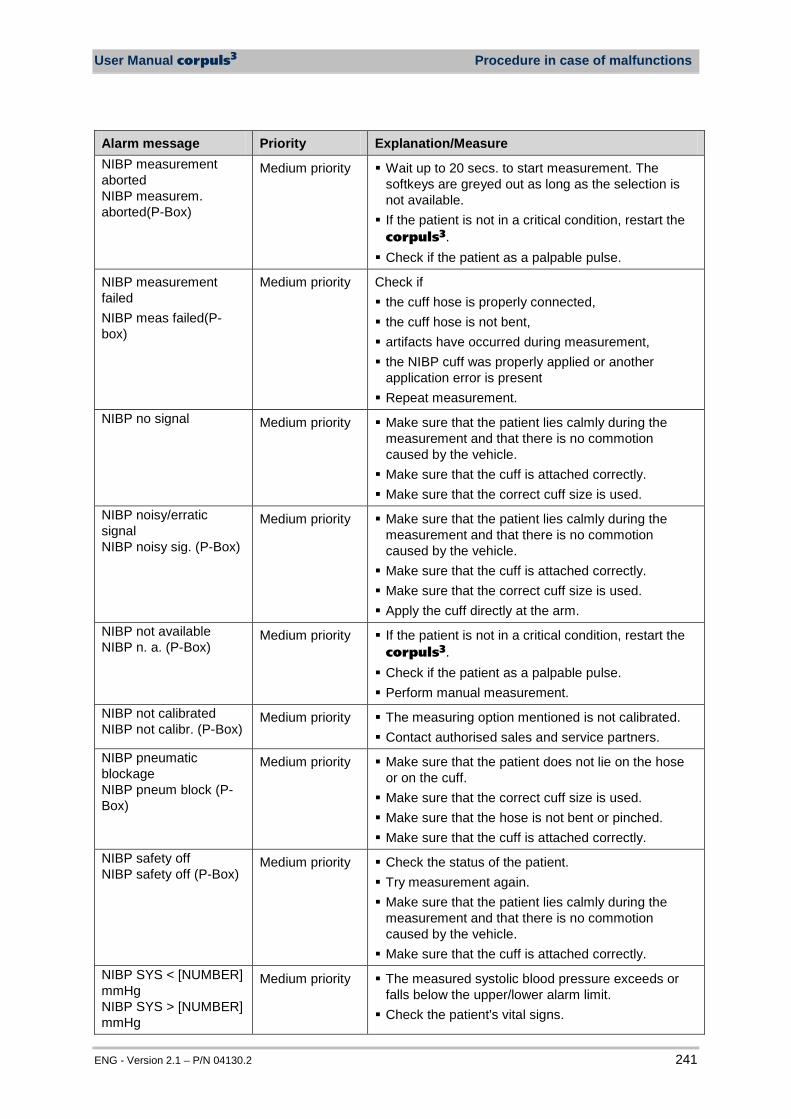
User Manual corpuls3 Procedure in case of malfunctions
ENG - Version 2.1 – P/N 04130.2 241
Alarm message Priority Explanation/Measure NIBP measurement aborted NIBP measurem. aborted(P-Box)
Medium priority Wait up to 20 secs. to start measurement. The softkeys are greyed out as long as the selection is not available. If the patient is not in a critical condition, restart the
corpuls3. Check if the patient as a palpable pulse.
NIBP measurement failed NIBP meas failed(P-box)
Medium priority Check if the cuff hose is properly connected, the cuff hose is not bent, artifacts have occurred during measurement, the NIBP cuff was properly applied or another
application error is present Repeat measurement.
NIBP no signal Medium priority Make sure that the patient lies calmly during the measurement and that there is no commotion caused by the vehicle. Make sure that the cuff is attached correctly. Make sure that the correct cuff size is used.
NIBP noisy/erratic signal NIBP noisy sig. (P-Box)
Medium priority Make sure that the patient lies calmly during the measurement and that there is no commotion caused by the vehicle. Make sure that the cuff is attached correctly. Make sure that the correct cuff size is used. Apply the cuff directly at the arm.
NIBP not available NIBP n. a. (P-Box)
Medium priority If the patient is not in a critical condition, restart the corpuls3. Check if the patient as a palpable pulse. Perform manual measurement.
NIBP not calibrated NIBP not calibr. (P-Box)
Medium priority The measuring option mentioned is not calibrated. Contact authorised sales and service partners.
NIBP pneumatic blockage NIBP pneum block (P-Box)
Medium priority Make sure that the patient does not lie on the hose or on the cuff. Make sure that the correct cuff size is used. Make sure that the hose is not bent or pinched. Make sure that the cuff is attached correctly.
NIBP safety off NIBP safety off (P-Box)
Medium priority Check the status of the patient. Try measurement again. Make sure that the patient lies calmly during the
measurement and that there is no commotion caused by the vehicle. Make sure that the cuff is attached correctly.
NIBP SYS < [NUMBER] mmHg NIBP SYS > [NUMBER] mmHg
Medium priority The measured systolic blood pressure exceeds or falls below the upper/lower alarm limit. Check the patient's vital signs.
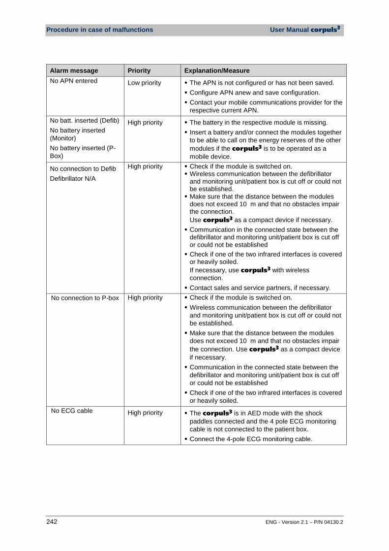
Procedure in case of malfunctions User Manual corpuls3
242 ENG - Version 2.1 – P/N 04130.2
Alarm message Priority Explanation/Measure No APN entered Low priority The APN is not configured or has not been saved.
Configure APN anew and save configuration. Contact your mobile communications provider for the
respective current APN. No batt. inserted (Defib) No battery inserted (Monitor) No battery inserted (P-Box)
High priority The battery in the respective module is missing. Insert a battery and/or connect the modules together
to be able to call on the energy reserves of the other modules if the corpuls3 is to be operated as a mobile device.
No connection to Defib Defibrillator N/A
High priority Check if the module is switched on. Wireless communication between the defibrillator
and monitoring unit/patient box is cut off or could not be established. Make sure that the distance between the modules
does not exceed 10 m and that no obstacles impair the connection. Use corpuls3 as a compact device if necessary. Communication in the connected state between the
defibrillator and monitoring unit/patient box is cut off or could not be established Check if one of the two infrared interfaces is covered
or heavily soiled. If necessary, use corpuls3 with wireless connection. Contact sales and service partners, if necessary.
No connection to P-box High priority Check if the module is switched on. Wireless communication between the defibrillator
and monitoring unit/patient box is cut off or could not be established. Make sure that the distance between the modules
does not exceed 10 m and that no obstacles impair the connection. Use corpuls3 as a compact device if necessary. Communication in the connected state between the
defibrillator and monitoring unit/patient box is cut off or could not be established Check if one of the two infrared interfaces is covered
or heavily soiled. No ECG cable High priority The corpuls3 is in AED mode with the shock
paddles connected and the 4 pole ECG monitoring cable is not connected to the patient box. Connect the 4-pole ECG monitoring cable.
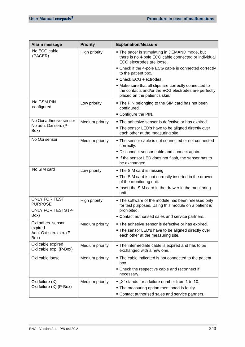
User Manual corpuls3 Procedure in case of malfunctions
ENG - Version 2.1 – P/N 04130.2 243
Alarm message Priority Explanation/Measure No ECG cable (PACER)
High priority The pacer is stimulating in DEMAND mode, but there is no 4-pole ECG cable connected or individual ECG electrodes are loose. Check if the 4-pole ECG cable is connected correctly
to the patient box. Check ECG electrodes. Make sure that all clips are correctly connected to
the contacts and/or the ECG electrodes are perfectly placed on the patient’s skin.
No GSM PIN configured
Low priority The PIN belonging to the SIM card has not been configured. Configure the PIN.
No Oxi adhesive sensor No adh. Oxi sen. (P-Box)
Medium priority The adhesive sensor is defective or has expired. The sensor LED's have to be aligned directly over
each other at the measuring site. No Oxi sensor Medium priority The sensor cable is not connected or not connected
correctly. Disconnect sensor cable and connect again. If the sensor LED does not flash, the sensor has to
be exchanged. No SIM card Low priority The SIM card is missing.
The SIM card is not correctly inserted in the drawer of the monitoring unit. Insert the SIM card in the drawer in the monitoring
unit. ONLY FOR TEST PURPOSE ONLY FOR TESTS (P-Box)
High priority The software of the module has been released only for test purposes. Using this module on a patient is prohibited. Contact authorised sales and service partners.
Oxi adhes. sensor expired Adh. Oxi sen. exp. (P-Box)
Medium priority The adhesive sensor is defective or has expired. The sensor LED's have to be aligned directly over
each other at the measuring site.
Oxi cable expired Oxi cable exp. (P-Box)
Medium priority The intermediate cable is expired and has to be exchanged with a new one.
Oxi cable loose Medium priority The cable indicated is not connected to the patient box. Check the respective cable and reconnect if
necessary.
Oxi failure (X) Oxi failure (X) (P-Box)
Medium priority „X“ stands for a failure number from 1 to 10. The measuring option mentioned is faulty. Contact authorised sales and service partners.

Procedure in case of malfunctions User Manual corpuls3
244 ENG - Version 2.1 – P/N 04130.2
Alarm message Priority Explanation/Measure Oxi sensor expired Oxi sen. exp. (P-Box)
Medium priority The sensor is expired and has to be exchanged with a new one.
Oxi sensor loose Medium priority The sensor indicated has come loose from the measuring site at the body or from the intermediate cable. Check the respective sensor and reconnect if
necessary. Oxi: Calibrating Oxi: Calibrating (P-Box)
Low priority After attaching the sensor, the oximeter calibrates automatically. This process, indicated by an hourglass symbol in the upper right corner of the parameter field, can take up to 120 s for SpCO-, SpHb- and SpMet measurement.
Oxi: Check connection to P-box Oxi: Check conn. (P-Box)
Medium priority The sensor- or intermediate cable is not connected or not connected correctly. Disconnect sensor- or intermediate cable and
connect again. If the sensor LED does not flash, the intermediate
cable has to be exchanged. Oxi: Demo tool Oxi: Demo tool (P-Box)
Medium priority For demonstration purposes, a demo sensor has been connected. For measurement of patient data, the sensor has to
be exchanged for a real sensor. Oxi: Interference Medium priority Too strong ambient light on the patient (sensor).
The light source has to be removed or reduced. Protect sensor from light. Attach sensor at another site.
Oxi: Low perfusion Oxi: Low perf. (P-Box)
Medium priority The measured signal is too weak. Make sure that the patient lies calmly during the
measurement and that there is no commotion caused by the vehicle. Select another measuring site.
Oxi: SpO2 only mode Oxi: SpO2 only (P-Box)
Medium priority If the calibration of the parameters SpCO, SpMet and SpHb is not possible, the corpuls3 switches to SpO2-only mode. By disconnecting and re-connecting the sensor at
the measuring site, calibration is started anew. P(X) < [NUMBER] mmHg P(X) > [NUMBER] mmHg
Medium priority "X" stands for the invasive pressure channel 1-4. The measured pressure exceeds or falls below the
upper/lower alarm limit. Check the patient's vital signs.
Pacer circuit open High priority Make sure that all cables and connecting plugs are connected correctly. Make sure that the corPatch electrodes are placed
correctly.
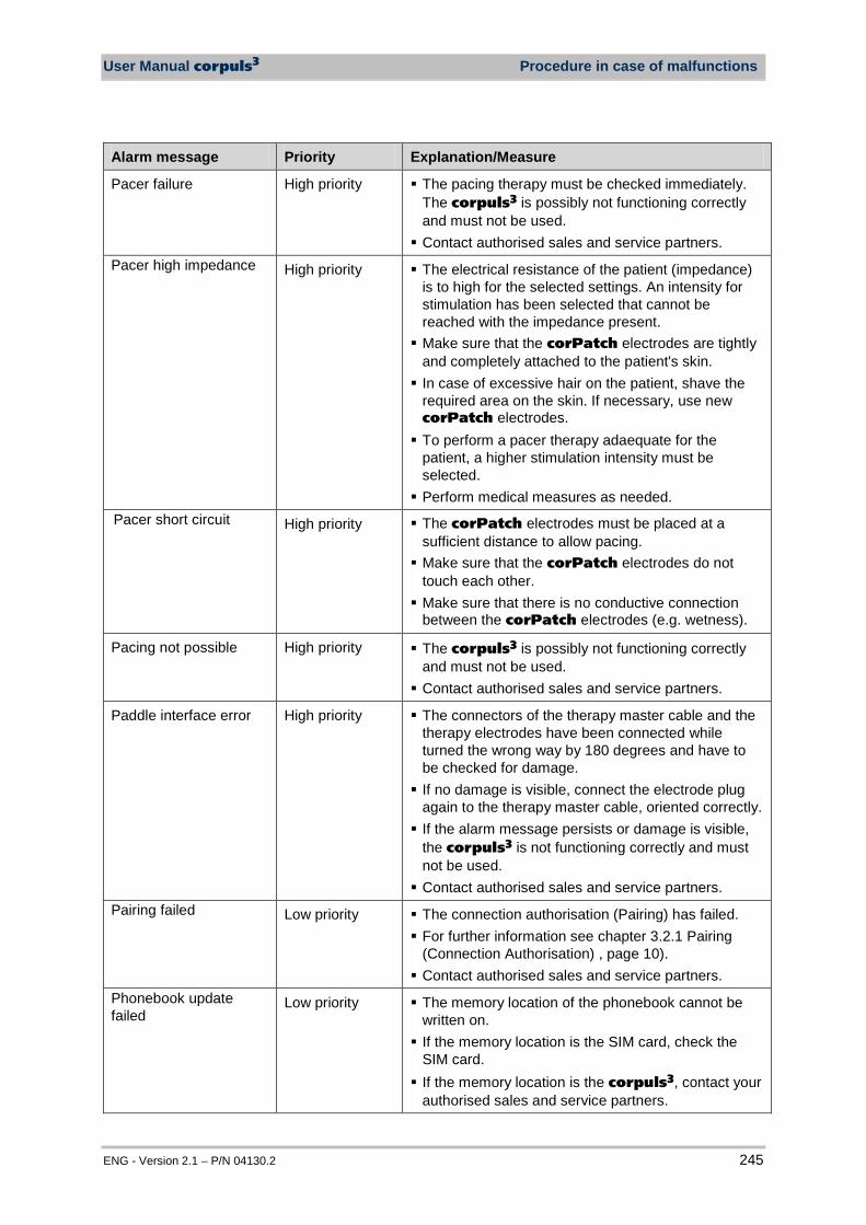
User Manual corpuls3 Procedure in case of malfunctions
ENG - Version 2.1 – P/N 04130.2 245
Alarm message Priority Explanation/Measure
Pacer failure High priority The pacing therapy must be checked immediately. The corpuls3 is possibly not functioning correctly and must not be used. Contact authorised sales and service partners.
Pacer high impedance High priority The electrical resistance of the patient (impedance) is to high for the selected settings. An intensity for stimulation has been selected that cannot be reached with the impedance present. Make sure that the corPatch electrodes are tightly
and completely attached to the patient's skin. In case of excessive hair on the patient, shave the
required area on the skin. If necessary, use new corPatch electrodes. To perform a pacer therapy adaequate for the
patient, a higher stimulation intensity must be selected. Perform medical measures as needed.
Pacer short circuit High priority The corPatch electrodes must be placed at a sufficient distance to allow pacing. Make sure that the corPatch electrodes do not
touch each other. Make sure that there is no conductive connection
between the corPatch electrodes (e.g. wetness).
Pacing not possible High priority The corpuls3 is possibly not functioning correctly and must not be used. Contact authorised sales and service partners.
Paddle interface error High priority The connectors of the therapy master cable and the therapy electrodes have been connected while turned the wrong way by 180 degrees and have to be checked for damage. If no damage is visible, connect the electrode plug
again to the therapy master cable, oriented correctly. If the alarm message persists or damage is visible,
the corpuls3 is not functioning correctly and must not be used. Contact authorised sales and service partners.
Pairing failed Low priority The connection authorisation (Pairing) has failed. For further information see chapter 3.2.1 Pairing
(Connection Authorisation) , page 10). Contact authorised sales and service partners.
Phonebook update failed
Low priority The memory location of the phonebook cannot be written on. If the memory location is the SIM card, check the
SIM card. If the memory location is the corpuls3, contact your
authorised sales and service partners.
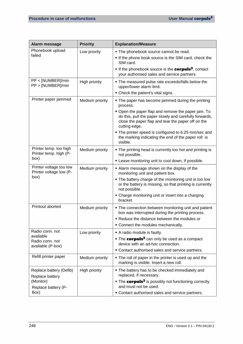
Procedure in case of malfunctions User Manual corpuls3
246 ENG - Version 2.1 – P/N 04130.2
Alarm message Priority Explanation/Measure Phonebook upload failed
Low priority The phonebook source cannot be read. If the phone book source is the SIM card, check the
SIM card. If the phonebook source is the corpuls3, contact
your authorised sales and service partners. PP < [NUMBER]/min PP > [NUMBER]/min
High priority The measured pulse rate exceeds/falls below the upper/lower alarm limit. Check the patient's vital signs.
Printer paper jammed Medium priority The paper has become jammed during the printing process. Open the paper flap and remove the paper jam. To
do this, pull the paper slowly and carefully forwards, close the paper flap and tear the paper off on the cutting edge. The printer speed is configured to 6.25 mm/sec and
the marking indicating the end of the paper roll is visible.
Printer temp. too high Printer temp. high (P-box)
Medium priority The printing head is currently too hot and printing is not possible. Leave monitoring unit to cool down, if possible.
Printer voltage too low Printer voltage low (P-box)
Medium priority Alarm message shown on the display of the monitoring unit and patient box. The battery charge of the monitoring unit is too low
or the battery is missing, so that printing is currently not possible. Charge monitoring unit or insert into a charging
bracket. Printout aborted Medium priority The connection between monitoring unit and patient
box was interrupted during the printing process. Reduce the distance between the modules or Connect the modules mechanically.
Radio conn. not available Radio conn. not available (P-box)
Low priority A radio module is faulty. The corpuls3 can only be used as a compact
device with an ad-hoc connection. Contact authorised sales and service partners.
Refill printer paper Medium priority The roll of paper in the printer is used up and the marking is visible. Insert a new roll.
Replace battery (Defib) Replace battery (Monitor) Replace battery (P-Box)
High priority The battery has to be checked immediately and replaced, if necessary. The corpuls3 is possibly not functioning correctly
and must not be used. Contact authorised sales and service partners.
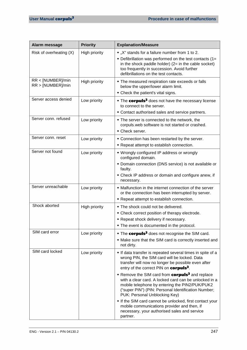
User Manual corpuls3 Procedure in case of malfunctions
ENG - Version 2.1 – P/N 04130.2 247
Alarm message Priority Explanation/Measure
Risk of overheating (X) High priority „X“ stands for a failure number from 1 to 2. Defibrillation was performed on the test contacts (1=
in the shock paddle holder) (2= in the cable socket) too frequently in succession. Avoid further defibrillations on the test contacts.
RR < [NUMBER]/min RR > [NUMBER]/min
High priority The measured respiration rate exceeds or falls below the upper/lower alarm limit. Check the patient's vital signs.
Server access denied Low priority The corpuls3 does not have the necessary license to connect to the server. Contact authorised sales and service partners.
Server conn. refused Low priority The server is connected to the network, the corpuls.web software is not started or crashed. Check server.
Server conn. reset Low priority Connection has been restarted by the server. Repeat attempt to establish connection.
Server not found Low priority Wrongly configured IP address or wrongly configured domain. Domain connection (DNS service) is not available or
faulty. Check IP address or domain and configure anew, if
necessary. Server unreachable Low priority Malfunction in the internet connection of the server
or the connection has been interrupted by server. Repeat attempt to establish connection.
Shock aborted High priority The shock could not be delivered. Check correct position of therapy electrode. Repeat shock delivery if necessary. The event is documented in the protocol.
SIM card error Low priority The corpuls3 does not recognise the SIM card. Make sure that the SIM card is correctly inserted and
not dirty. SIM card locked Low priority If data transfer is repeated several times in spite of a
wrong PIN, the SIM card will be locked. Data transfer will now no longer be possible even after entry of the correct PIN on corpuls3. Remove the SIM card from corpuls3 and replace
with a clear card. A locked card can be unlocked in a mobile telephone by entering the PIN2/PUK/PUK2 (“super PIN”) (PIN: Personal Identification Number; PUK: Personal Unblocking Key) If the SIM card cannot be unlocked, first contact your
mobile communications provider and then, if necessary, your authorised sales and service partner.
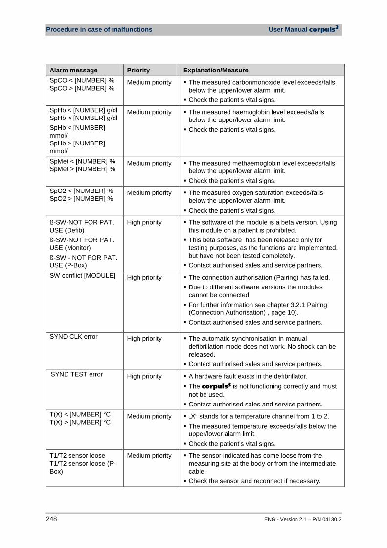
Procedure in case of malfunctions User Manual corpuls3
248 ENG - Version 2.1 – P/N 04130.2
Alarm message Priority Explanation/Measure SpCO < [NUMBER] % SpCO > [NUMBER] %
Medium priority The measured carbonmonoxide level exceeds/falls below the upper/lower alarm limit. Check the patient's vital signs.
SpHb < [NUMBER] g/dl SpHb > [NUMBER] g/dl SpHb < [NUMBER] mmol/l SpHb > [NUMBER] mmol/l
Medium priority The measured haemoglobin level exceeds/falls below the upper/lower alarm limit. Check the patient's vital signs.
SpMet < [NUMBER] % SpMet > [NUMBER] %
Medium priority The measured methaemoglobin level exceeds/falls below the upper/lower alarm limit. Check the patient's vital signs.
SpO2 < [NUMBER] % SpO2 > [NUMBER] %
Medium priority The measured oxygen saturation exceeds/falls below the upper/lower alarm limit. Check the patient's vital signs.
ß-SW-NOT FOR PAT. USE (Defib) ß-SW-NOT FOR PAT. USE (Monitor) ß-SW - NOT FOR PAT. USE (P-Box)
High priority The software of the module is a beta version. Using this module on a patient is prohibited. This beta software has been released only for
testing purposes, as the functions are implemented, but have not been tested completely. Contact authorised sales and service partners.
SW conflict [MODULE] High priority The connection authorisation (Pairing) has failed. Due to different software versions the modules
cannot be connected. For further information see chapter 3.2.1 Pairing
(Connection Authorisation) , page 10). Contact authorised sales and service partners.
SYND CLK error High priority The automatic synchronisation in manual defibrillation mode does not work. No shock can be released. Contact authorised sales and service partners.
SYND TEST error High priority A hardware fault exists in the defibrillator. The corpuls3 is not functioning correctly and must
not be used. Contact authorised sales and service partners.
T(X) < [NUMBER] °C T(X) > [NUMBER] °C
Medium priority „X“ stands for a temperature channel from 1 to 2. The measured temperature exceeds/falls below the
upper/lower alarm limit. Check the patient's vital signs.
T1/T2 sensor loose T1/T2 sensor loose (P-Box)
Medium priority The sensor indicated has come loose from the measuring site at the body or from the intermediate cable. Check the sensor and reconnect if necessary.
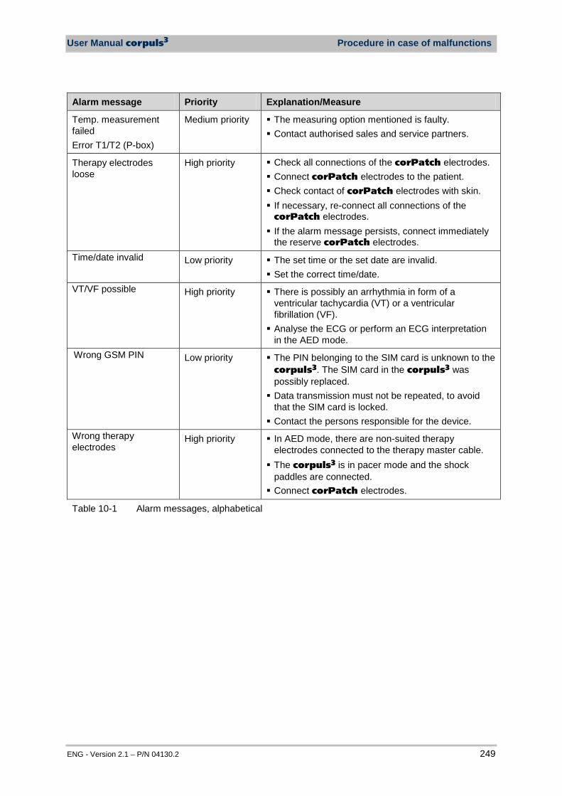
User Manual corpuls3 Procedure in case of malfunctions
ENG - Version 2.1 – P/N 04130.2 249
Alarm message Priority Explanation/Measure
Temp. measurement failed Error T1/T2 (P-box)
Medium priority The measuring option mentioned is faulty. Contact authorised sales and service partners.
Therapy electrodes loose
High priority Check all connections of the corPatch electrodes. Connect corPatch electrodes to the patient. Check contact of corPatch electrodes with skin. If necessary, re-connect all connections of the
corPatch electrodes. If the alarm message persists, connect immediately
the reserve corPatch electrodes. Time/date invalid Low priority The set time or the set date are invalid.
Set the correct time/date. VT/VF possible High priority There is possibly an arrhythmia in form of a
ventricular tachycardia (VT) or a ventricular fibrillation (VF). Analyse the ECG or perform an ECG interpretation
in the AED mode. Wrong GSM PIN Low priority The PIN belonging to the SIM card is unknown to the
corpuls3. The SIM card in the corpuls3 was possibly replaced. Data transmission must not be repeated, to avoid
that the SIM card is locked. Contact the persons responsible for the device.
Wrong therapy electrodes
High priority In AED mode, there are non-suited therapy electrodes connected to the therapy master cable. The corpuls3 is in pacer mode and the shock
paddles are connected. Connect corPatch electrodes.
Table 10-1 Alarm messages, alphabetical

Procedure in case of malfunctions User Manual corpuls3
250 ENG - Version 2.1 – P/N 04130.2
10.2 Troubleshooting and Corrective Actions
Malfunction Possible cause Measure
The loudspeaker of the monitoring unit is too faint or inaudible.
The loudspeaker volume has been selected too low.
Set the volume to a readily audible value (see chapter 7.3 Alarm Configuration, p. 155).
The opening of the loudspeaker is dirty
Clean the opening of the loudspeaker
The loudspeaker of the monitoring unit is buzzing in modular or semi-modular use.
The disconnection signal of the defibrillator/pacer unit is activated.
For information on the disconnection signal see chapter 7.4.3 Configuration of the Defibrillation Function (Persons Responsible for the Device), page 163.
The acoustic signal transmitter of the patient box is too faint or inaudible.
The acoustic signal transmitter volume has been selected too low.
Set the volume to a readily audible value (see chapter 7.3 Alarm Configuration, p. 155).
The opening of the acoustic signal transmitter is dirty.
Clean the opening of the acoustic signal transmitter.
The time is incorrectly displayed.
The time is not correctly set.
Set the time correctly (see chapter 7.1.1 General System Settings, p. 137). The permanent setting can only be made
by persons responsible for the device.
The date is incorrectly displayed.
The date is not correctly set.
Correctly set the date (see chapter 7.4.2 General System Settings (Person responsible for the device), p. 160).
Time/date invalid A date before the release of the current software was entered
Enter the date correctly (see chapter 7.4.2 General System Settings (Person responsible for the device), p. 160)
Functions such as D-ECG, LT-ECG and NIBP not available (greyed softkeys).
Internal error. Switch off the corpuls3 and restart. If the error persists, contact sales and
service partners.
Patient box and/or defibrillator/pacer are/is switched off.
Switch on patient box and/or defibrillator/pacer.
LT-ECG not available No CompactFlash® card inserted
Insert CompactFlash® card correctly
No original CompactFlash®
card inserted. Only use original corpuls3-CompactFlash® cards.
The CompactFlash® card is full.
Delete the data on the CompactFlash® card and re-insert.
corpuls3 starts with a black screen and the headline „corpuls3 Software Update Mode“
The jog dial was pressed during switching on or is blocked.
Make sure that the jog dial can be turned and is not blocked Switch off the corpuls3 by pressing the
On/Off key for at least 8 sec. and restart
Configuration export failed
The configuration was not saved.
The configuration has to be saved before exporting.
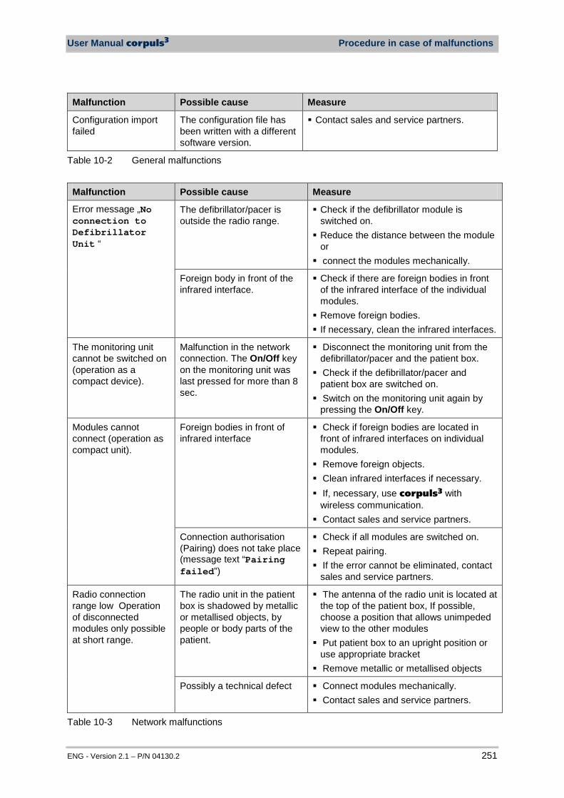
User Manual corpuls3 Procedure in case of malfunctions
ENG - Version 2.1 – P/N 04130.2 251
Malfunction Possible cause Measure
Configuration import failed
The configuration file has been written with a different software version.
Contact sales and service partners.
Table 10-2 General malfunctions
Malfunction Possible cause Measure
Error message „No connection to Defibrillator Unit “
The defibrillator/pacer is outside the radio range.
Check if the defibrillator module is switched on. Reduce the distance between the module
or connect the modules mechanically.
Foreign body in front of the infrared interface.
Check if there are foreign bodies in front of the infrared interface of the individual modules. Remove foreign bodies. If necessary, clean the infrared interfaces.
The monitoring unit cannot be switched on (operation as a compact device).
Malfunction in the network connection. The On/Off key on the monitoring unit was last pressed for more than 8 sec.
Disconnect the monitoring unit from the defibrillator/pacer and the patient box. Check if the defibrillator/pacer and
patient box are switched on. Switch on the monitoring unit again by
pressing the On/Off key.
Modules cannot connect (operation as compact unit).
Foreign bodies in front of infrared interface
Check if foreign bodies are located in front of infrared interfaces on individual modules. Remove foreign objects. Clean infrared interfaces if necessary. If, necessary, use corpuls3 with
wireless communication. Contact sales and service partners.
Connection authorisation (Pairing) does not take place (message text “Pairing failed”)
Check if all modules are switched on. Repeat pairing. If the error cannot be eliminated, contact
sales and service partners.
Radio connection range low Operation of disconnected modules only possible at short range.
The radio unit in the patient box is shadowed by metallic or metallised objects, by people or body parts of the patient.
The antenna of the radio unit is located at the top of the patient box, If possible, choose a position that allows unimpeded view to the other modules Put patient box to an upright position or
use appropriate bracket Remove metallic or metallised objects
Possibly a technical defect Connect modules mechanically. Contact sales and service partners.
Table 10-3 Network malfunctions
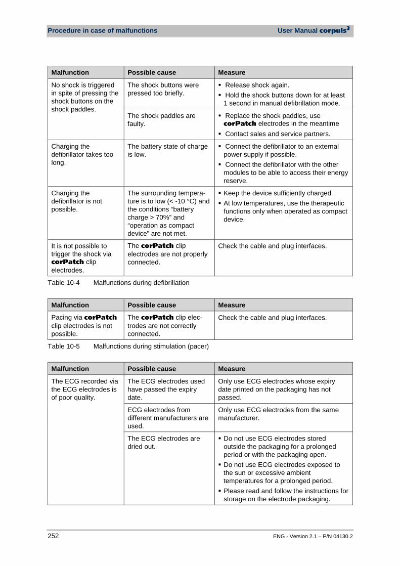
Procedure in case of malfunctions User Manual corpuls3
252 ENG - Version 2.1 – P/N 04130.2
Malfunction Possible cause Measure
No shock is triggered in spite of pressing the shock buttons on the shock paddles.
The shock buttons were pressed too briefly.
Release shock again. Hold the shock buttons down for at least
1 second in manual defibrillation mode.
The shock paddles are faulty.
Replace the shock paddles, use corPatch electrodes in the meantime Contact sales and service partners.
Charging the defibrillator takes too long.
The battery state of charge is low.
Connect the defibrillator to an external power supply if possible. Connect the defibrillator with the other
modules to be able to access their energy reserve.
Charging the defibrillator is not possible.
The surrounding tempera-ture is to low (< -10 °C) and the conditions “battery charge > 70%” and “operation as compact device” are not met.
Keep the device sufficiently charged. At low temperatures, use the therapeutic
functions only when operated as compact device.
It is not possible to trigger the shock via corPatch clip electrodes.
The corPatch clip electrodes are not properly connected.
Check the cable and plug interfaces.
Table 10-4 Malfunctions during defibrillation
Malfunction Possible cause Measure
Pacing via corPatch clip electrodes is not possible.
The corPatch clip elec-trodes are not correctly connected.
Check the cable and plug interfaces.
Table 10-5 Malfunctions during stimulation (pacer)
Malfunction Possible cause Measure
The ECG recorded via the ECG electrodes is of poor quality.
The ECG electrodes used have passed the expiry date.
Only use ECG electrodes whose expiry date printed on the packaging has not passed.
ECG electrodes from different manufacturers are used.
Only use ECG electrodes from the same manufacturer.
The ECG electrodes are dried out.
Do not use ECG electrodes stored outside the packaging for a prolonged period or with the packaging open. Do not use ECG electrodes exposed to
the sun or excessive ambient temperatures for a prolonged period. Please read and follow the instructions for
storage on the electrode packaging.
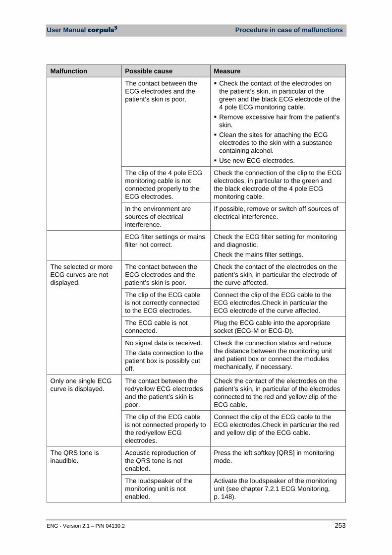
User Manual corpuls3 Procedure in case of malfunctions
ENG - Version 2.1 – P/N 04130.2 253
Malfunction Possible cause Measure
The contact between the ECG electrodes and the patient’s skin is poor.
Check the contact of the electrodes on the patient’s skin, in particular of the green and the black ECG electrode of the 4 pole ECG monitoring cable. Remove excessive hair from the patient’s
skin. Clean the sites for attaching the ECG
electrodes to the skin with a substance containing alcohol. Use new ECG electrodes.
The clip of the 4 pole ECG monitoring cable is not connected properly to the ECG electrodes.
Check the connection of the clip to the ECG electrodes, in particular to the green and the black electrode of the 4 pole ECG monitoring cable.
In the environment are sources of electrical interference.
If possible, remove or switch off sources of electrical interference.
ECG filter settings or mains filter not correct.
Check the ECG filter setting for monitoring and diagnostic. Check the mains filter settings.
The selected or more ECG curves are not displayed.
The contact between the ECG electrodes and the patient’s skin is poor.
Check the contact of the electrodes on the patient’s skin, in particular the electrode of the curve affected.
The clip of the ECG cable is not correctly connected to the ECG electrodes.
Connect the clip of the ECG cable to the ECG electrodes.Check in particular the ECG electrode of the curve affected.
The ECG cable is not connected.
Plug the ECG cable into the appropriate socket (ECG-M or ECG-D).
No signal data is received. The data connection to the patient box is possibly cut off.
Check the connection status and reduce the distance between the monitoring unit and patient box or connect the modules mechanically, if necessary.
Only one single ECG curve is displayed.
The contact between the red/yellow ECG electrodes and the patient’s skin is poor.
Check the contact of the electrodes on the patient’s skin, in particular of the electrodes connected to the red and yellow clip of the ECG cable.
The clip of the ECG cable is not connected properly to the red/yellow ECG electrodes.
Connect the clip of the ECG cable to the ECG electrodes.Check in particular the red and yellow clip of the ECG cable.
The QRS tone is inaudible.
Acoustic reproduction of the QRS tone is not enabled.
Press the left softkey [QRS] in monitoring mode.
The loudspeaker of the monitoring unit is not enabled.
Activate the loudspeaker of the monitoring unit (see chapter 7.2.1 ECG Monitoring, p. 148).
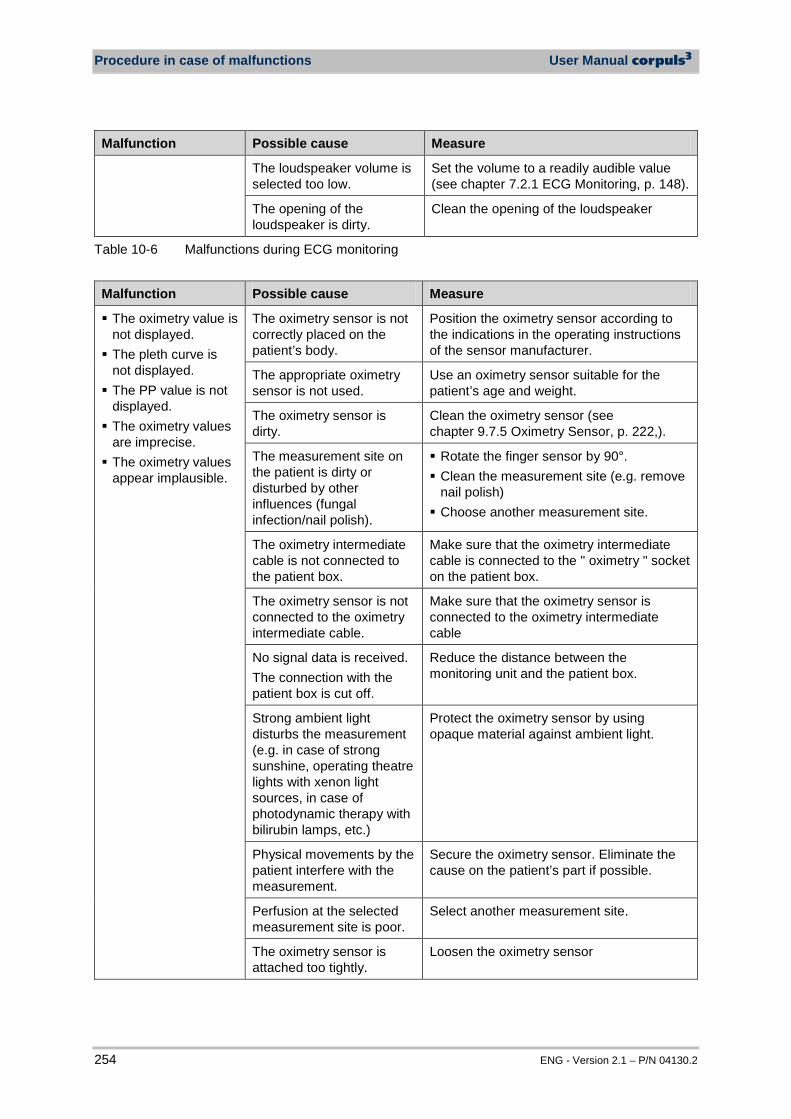
Procedure in case of malfunctions User Manual corpuls3
254 ENG - Version 2.1 – P/N 04130.2
Malfunction Possible cause Measure
The loudspeaker volume is selected too low.
Set the volume to a readily audible value (see chapter 7.2.1 ECG Monitoring, p. 148).
The opening of the loudspeaker is dirty.
Clean the opening of the loudspeaker
Table 10-6 Malfunctions during ECG monitoring
Malfunction Possible cause Measure
The oximetry value is not displayed. The pleth curve is
not displayed. The PP value is not
displayed. The oximetry values
are imprecise. The oximetry values
appear implausible.
The oximetry sensor is not correctly placed on the patient’s body.
Position the oximetry sensor according to the indications in the operating instructions of the sensor manufacturer.
The appropriate oximetry sensor is not used.
Use an oximetry sensor suitable for the patient’s age and weight.
The oximetry sensor is dirty.
Clean the oximetry sensor (see chapter 9.7.5 Oximetry Sensor, p. 222,).
The measurement site on the patient is dirty or disturbed by other influences (fungal infection/nail polish).
Rotate the finger sensor by 90°. Clean the measurement site (e.g. remove
nail polish) Choose another measurement site.
The oximetry intermediate cable is not connected to the patient box.
Make sure that the oximetry intermediate cable is connected to the " oximetry " socket on the patient box.
The oximetry sensor is not connected to the oximetry intermediate cable.
Make sure that the oximetry sensor is connected to the oximetry intermediate cable
No signal data is received. The connection with the patient box is cut off.
Reduce the distance between the monitoring unit and the patient box.
Strong ambient light disturbs the measurement (e.g. in case of strong sunshine, operating theatre lights with xenon light sources, in case of photodynamic therapy with bilirubin lamps, etc.)
Protect the oximetry sensor by using opaque material against ambient light.
Physical movements by the patient interfere with the measurement.
Secure the oximetry sensor. Eliminate the cause on the patient’s part if possible.
Perfusion at the selected measurement site is poor.
Select another measurement site.
The oximetry sensor is attached too tightly.
Loosen the oximetry sensor
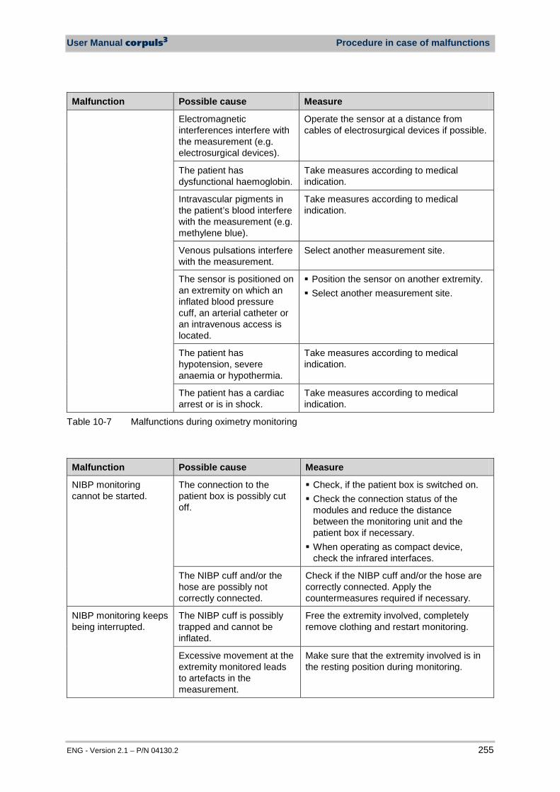
User Manual corpuls3 Procedure in case of malfunctions
ENG - Version 2.1 – P/N 04130.2 255
Malfunction Possible cause Measure
Electromagnetic interferences interfere with the measurement (e.g. electrosurgical devices).
Operate the sensor at a distance from cables of electrosurgical devices if possible.
The patient has dysfunctional haemoglobin.
Take measures according to medical indication.
Intravascular pigments in the patient’s blood interfere with the measurement (e.g. methylene blue).
Take measures according to medical indication.
Venous pulsations interfere with the measurement.
Select another measurement site.
The sensor is positioned on an extremity on which an inflated blood pressure cuff, an arterial catheter or an intravenous access is located.
Position the sensor on another extremity. Select another measurement site.
The patient has hypotension, severe anaemia or hypothermia.
Take measures according to medical indication.
The patient has a cardiac arrest or is in shock.
Take measures according to medical indication.
Table 10-7 Malfunctions during oximetry monitoring
Malfunction Possible cause Measure
NIBP monitoring cannot be started.
The connection to the patient box is possibly cut off.
Check, if the patient box is switched on. Check the connection status of the
modules and reduce the distance between the monitoring unit and the patient box if necessary. When operating as compact device,
check the infrared interfaces.
The NIBP cuff and/or the hose are possibly not correctly connected.
Check if the NIBP cuff and/or the hose are correctly connected. Apply the countermeasures required if necessary.
NIBP monitoring keeps being interrupted.
The NIBP cuff is possibly trapped and cannot be inflated.
Free the extremity involved, completely remove clothing and restart monitoring.
Excessive movement at the extremity monitored leads to artefacts in the measurement.
Make sure that the extremity involved is in the resting position during monitoring.

Procedure in case of malfunctions User Manual corpuls3
256 ENG - Version 2.1 – P/N 04130.2
Malfunction Possible cause Measure
The NIBP measurement values do not seem plausible.
Too large/too small NIBP cuffs are being used.
Use the correct NIBP cuff size.
The NIBP cuff cannot be completely inflated.
The NIBP cuff or the hose system are possibly damaged.
Use a new NIBP cuff.
The connection between the NIBP cuff and the patient box is possibly cut off.
Check the connecting hose between the NIBP cuff and the patient box. Replace the hose if necessary.
The connecting hose of the NIBP cuff becomes loose from the patient box
The closure of the plug has not been closed properly
Check the plug closure Exchange the plug if defect. Use a new
connecting hose.
The closure opens when the connecting hose is moved
For those cases, a fixing ring is available as spare part. Contact your authorised service and sales partner.
Table 10-8 Malfunctions during NIBP monitoring
Malfunction Troubleshooting Explanation/corrective action
The CO2 value is not displayed. The CO2 curve is not
displayed. The RR value is not
displayed.
The CO2 sensor is not correctly positioned on the airway adapter.
Position the CO2 sensor according to the indications in the operating instructions of the manufacturer of the sensor and airway adapter.
The CO2 sensor and/or airway adapter is dirty.
Clean the CO2 sensor and airway adapter (see chapter 9.7.6 CO2 Sensor, p. 223).
The CO2 intermediate cable is not connected to the patient box.
Make sure that the CO2 intermediate cable is connected to the "CO2" socket on the patient box.
The CO2 sensor is not connected to the CO2 intermediate cable.
Make sure that the CO2 sensor is connected to the CO2 intermediate cable.
No signal data is received. The connection to the patient box is possibly cut off.
Check, if the patient box is switched on. Check the connection status and reduce
the distance between the monitoring unit and patient box if necessary. When operating as compact device,
check the infrared interfaces.
The CO2 curve is inter-rupted sporadically for a short time by a dashed line.
Self calibration of the CO2 module
The CO2 module performs a calibration. No measures necessary
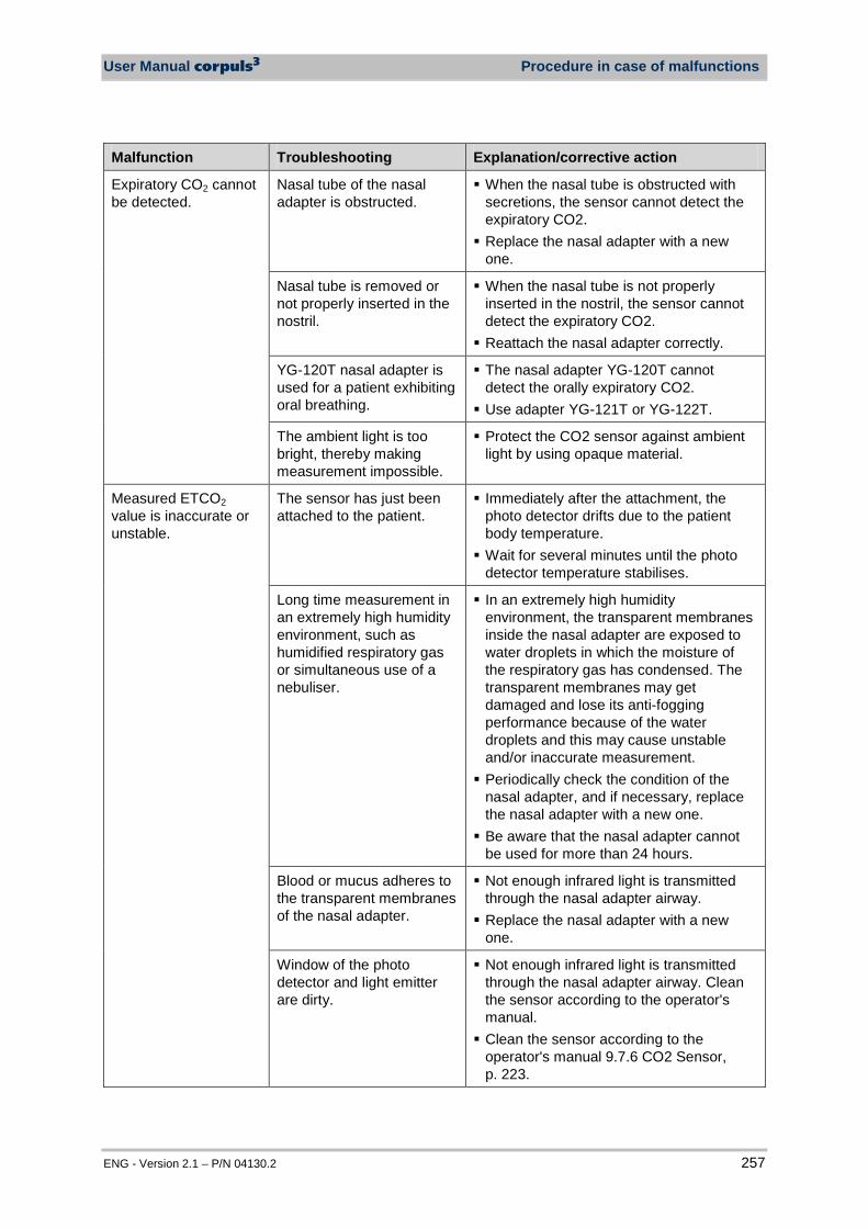
User Manual corpuls3 Procedure in case of malfunctions
ENG - Version 2.1 – P/N 04130.2 257
Malfunction Troubleshooting Explanation/corrective action
Expiratory CO2 cannot be detected.
Nasal tube of the nasal adapter is obstructed.
When the nasal tube is obstructed with secretions, the sensor cannot detect the expiratory CO2. Replace the nasal adapter with a new
one.
Nasal tube is removed or not properly inserted in the nostril.
When the nasal tube is not properly inserted in the nostril, the sensor cannot detect the expiratory CO2. Reattach the nasal adapter correctly.
YG-120T nasal adapter is used for a patient exhibiting oral breathing.
The nasal adapter YG-120T cannot detect the orally expiratory CO2. Use adapter YG-121T or YG-122T.
The ambient light is too bright, thereby making measurement impossible.
Protect the CO2 sensor against ambient light by using opaque material.
Measured ETCO2 value is inaccurate or unstable.
The sensor has just been attached to the patient.
Immediately after the attachment, the photo detector drifts due to the patient body temperature. Wait for several minutes until the photo
detector temperature stabilises.
Long time measurement in an extremely high humidity environment, such as humidified respiratory gas or simultaneous use of a nebuliser.
In an extremely high humidity environment, the transparent membranes inside the nasal adapter are exposed to water droplets in which the moisture of the respiratory gas has condensed. The transparent membranes may get damaged and lose its anti-fogging performance because of the water droplets and this may cause unstable and/or inaccurate measurement. Periodically check the condition of the
nasal adapter, and if necessary, replace the nasal adapter with a new one. Be aware that the nasal adapter cannot
be used for more than 24 hours.
Blood or mucus adheres to the transparent membranes of the nasal adapter.
Not enough infrared light is transmitted through the nasal adapter airway. Replace the nasal adapter with a new
one.
Window of the photo detector and light emitter are dirty.
Not enough infrared light is transmitted through the nasal adapter airway. Clean the sensor according to the operator's manual. Clean the sensor according to the
operator's manual 9.7.6 CO2 Sensor, p. 223.
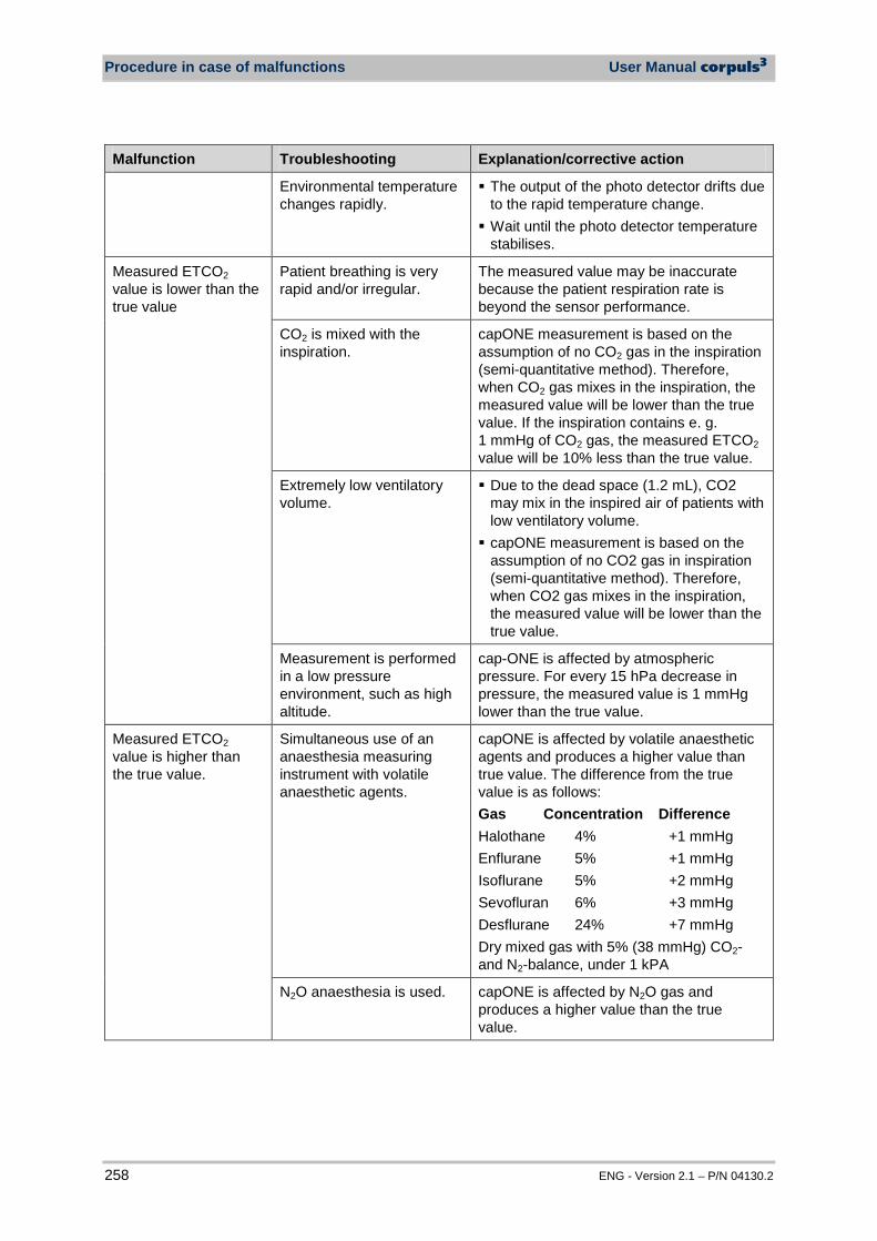
Procedure in case of malfunctions User Manual corpuls3
258 ENG - Version 2.1 – P/N 04130.2
Malfunction Troubleshooting Explanation/corrective action
Environmental temperature changes rapidly.
The output of the photo detector drifts due to the rapid temperature change. Wait until the photo detector temperature
stabilises.
Measured ETCO2 value is lower than the true value
Patient breathing is very rapid and/or irregular.
The measured value may be inaccurate because the patient respiration rate is beyond the sensor performance.
CO2 is mixed with the inspiration.
capONE measurement is based on the assumption of no CO2 gas in the inspiration (semi-quantitative method). Therefore, when CO2 gas mixes in the inspiration, the measured value will be lower than the true value. If the inspiration contains e. g. 1 mmHg of CO2 gas, the measured ETCO2 value will be 10% less than the true value.
Extremely low ventilatory volume.
Due to the dead space (1.2 mL), CO2 may mix in the inspired air of patients with low ventilatory volume. capONE measurement is based on the
assumption of no CO2 gas in inspiration (semi-quantitative method). Therefore, when CO2 gas mixes in the inspiration, the measured value will be lower than the true value.
Measurement is performed in a low pressure environment, such as high altitude.
cap-ONE is affected by atmospheric pressure. For every 15 hPa decrease in pressure, the measured value is 1 mmHg lower than the true value.
Measured ETCO2 value is higher than the true value.
Simultaneous use of an anaesthesia measuring instrument with volatile anaesthetic agents.
capONE is affected by volatile anaesthetic agents and produces a higher value than true value. The difference from the true value is as follows: Gas Concentration Difference Halothane 4% +1 mmHg Enflurane 5% +1 mmHg Isoflurane 5% +2 mmHg Sevofluran 6% +3 mmHg Desflurane 24% +7 mmHg Dry mixed gas with 5% (38 mmHg) CO2- and N2-balance, under 1 kPA
N2O anaesthesia is used. capONE is affected by N2O gas and produces a higher value than the true value.
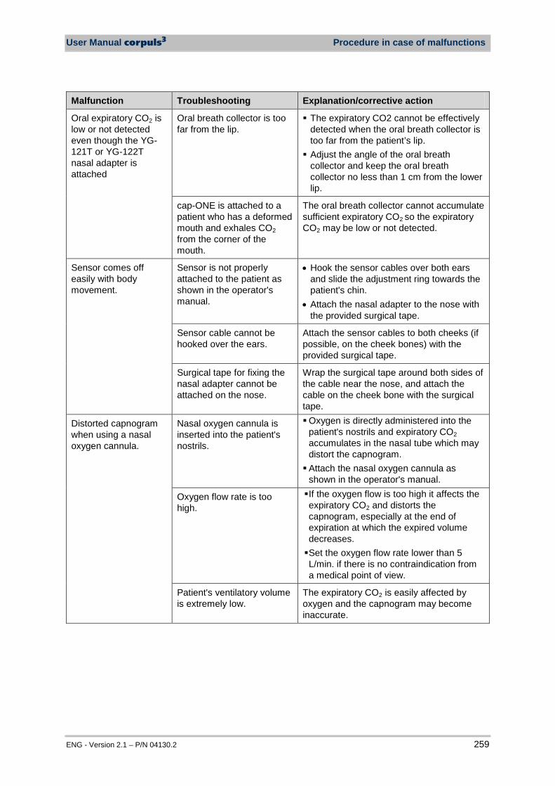
User Manual corpuls3 Procedure in case of malfunctions
ENG - Version 2.1 – P/N 04130.2 259
Malfunction Troubleshooting Explanation/corrective action
Oral expiratory CO2 is low or not detected even though the YG-121T or YG-122T nasal adapter is attached
Oral breath collector is too far from the lip.
The expiratory CO2 cannot be effectively detected when the oral breath collector is too far from the patient’s lip. Adjust the angle of the oral breath
collector and keep the oral breath collector no less than 1 cm from the lower lip.
cap-ONE is attached to a patient who has a deformed mouth and exhales CO2 from the corner of the mouth.
The oral breath collector cannot accumulate sufficient expiratory CO2 so the expiratory CO2 may be low or not detected.
Sensor comes off easily with body movement.
Sensor is not properly attached to the patient as shown in the operator's manual.
• Hook the sensor cables over both ears and slide the adjustment ring towards the patient's chin.
• Attach the nasal adapter to the nose with the provided surgical tape.
Sensor cable cannot be hooked over the ears.
Attach the sensor cables to both cheeks (if possible, on the cheek bones) with the provided surgical tape.
Surgical tape for fixing the nasal adapter cannot be attached on the nose.
Wrap the surgical tape around both sides of the cable near the nose, and attach the cable on the cheek bone with the surgical tape.
Distorted capnogram when using a nasal oxygen cannula.
Nasal oxygen cannula is inserted into the patient's nostrils.
Oxygen is directly administered into the patient's nostrils and expiratory CO2 accumulates in the nasal tube which may distort the capnogram. Attach the nasal oxygen cannula as
shown in the operator's manual.
Oxygen flow rate is too high.
If the oxygen flow is too high it affects the expiratory CO2 and distorts the capnogram, especially at the end of expiration at which the expired volume decreases. Set the oxygen flow rate lower than 5 L/min. if there is no contraindication from a medical point of view.
Patient's ventilatory volume is extremely low.
The expiratory CO2 is easily affected by oxygen and the capnogram may become inaccurate.

Procedure in case of malfunctions User Manual corpuls3
260 ENG - Version 2.1 – P/N 04130.2
Malfunction Troubleshooting Explanation/corrective action
A nasal oxygen cannula not authorised by Nihon-Kohden is used.
If oxygen is administered from an undesirable direction via a non-authorised O2 cannula it may affect the expiratory CO2. Use an authorised nasal oxygen cannula (e.g. oxygen cannula “V923”, Nihon-Kohden, P/N MKD-02-capONE). For further authorised oxygen cannulae contakt the manufacturer Nihon-Kohden (www.nihonkohden.com) or an corpuls sales and service partner.
Nasal oxygen cannula comes off easily
Nasal oxygen cannula is not attached to the patient.
The oxygen cannula must be attached with surgical tape for stable measurement.
A nasal oxygen cannula not authorised by Nihon-Kohden is used.
The nasal oxygen cannula might not be firmly attached to the nasal adapter.
Use an authorised nasal oxygen cannula (e.g. oxygen cannula “V923”, Nihon-Kohden, P/N MKD-02-capONE). For further authorised oxygen cannulae contakt the manufacturer Nihon-Kohden (www.nihonkohden.com) or an corpuls sales and service partner.
Table 10-9 Malfunctions during CO2 monitoring
Malfunction Possible cause Measure
The temperature value is not displayed.
The temperature sensor is not connected to the patient box.
Make sure that the plug of the temperature sensor is connected to one of the two sockets "Temp1" or "Temp2".
No signal data is received. The connection to the patient box is possibly cut off.
Check the connection status and reduce the distance between the monitoring unit and the patient box if necessary. If this error occurs when operating as compact device, check the infrared interfaces. If necessary, contact sales and service partners.
The temperature value appears implausible.
The temperature sensor is faulty.
Replace the temperature sensor with a new one.
Table 10-10 Malfunctions during temperature monitoring
Malfunction Possible cause Measure The invasive pressure values are not displayed. The invasive pressure curve is not displayed.
The pressure recorder (transducer) cable is not connected to the patient box.
Make sure that the cable of the pressure recorder is connected to one of the two sockets "IBP1" or "IBP2".
No signal data is received. The connection to the patient box is possibly cut off.
Check the connection status and reduce the distance between the monitoring unit and patient box if necessary.
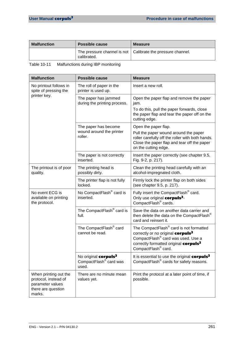
User Manual corpuls3 Procedure in case of malfunctions
ENG - Version 2.1 – P/N 04130.2 261
Malfunction Possible cause Measure
The pressure channel is not calibrated.
Calibrate the pressure channel.
Table 10-11 Malfunctions during IBP monitoring
Malfunction Possible cause Measure
No printout follows in spite of pressing the printer key.
The roll of paper in the printer is used up.
Insert a new roll.
The paper has jammed during the printing process.
Open the paper flap and remove the paper jam. To do this, pull the paper forwards, close the paper flap and tear the paper off on the cutting edge.
The paper has become wound around the printer roller.
Open the paper flap. Pull the paper wound around the paper roller carefully off the roller with both hands. Close the paper flap and tear off the paper on the cutting edge.
The paper is not correctly inserted.
Insert the paper correctly (see chapter 9.5, Fig. 9-2, p. 217).
The printout is of poor quality.
The printing head is possibly dirty.
Clean the printing head carefully with an alcohol-impregnated cloth.
The printer flap is not fully locked.
Firmly lock the printer flap on both sides (see chapter 9.5, p. 217).
No event ECG is available on printing the protocol.
No CompactFlash® card is inserted.
Fully insert the CompactFlash® card. Only use original corpuls3-CompactFlash® cards.
The CompactFlash® card is full.
Save the data on another data carrier and then delete the data on the CompactFlash® card and reinsert it.
The CompactFlash® card cannot be read.
The CompactFlash® card is not formatted correctly or no original corpuls3 CompactFlash® card was used. Use a correctly formatted original corpuls3 CompactFlash® card.
No original corpuls3 CompactFlash® card was used.
It is essential to use the original corpuls3 CompactFlash® cards for safety reasons.
When printing out the protocol, instead of parameter values there are question marks.
There are no minute mean values yet.
Print the protocol at a later point of time, if possible.
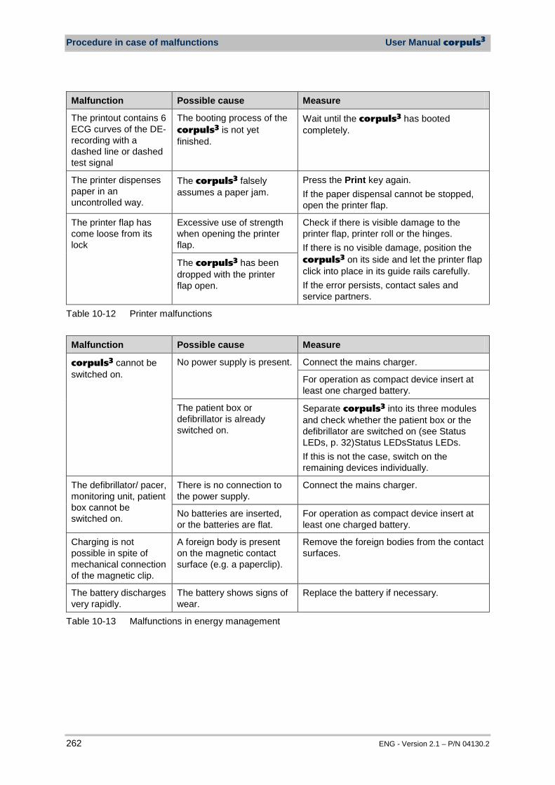
Procedure in case of malfunctions User Manual corpuls3
262 ENG - Version 2.1 – P/N 04130.2
Malfunction Possible cause Measure
The printout contains 6 ECG curves of the DE-recording with a dashed line or dashed test signal
The booting process of the corpuls3 is not yet finished.
Wait until the corpuls3 has booted completely.
The printer dispenses paper in an uncontrolled way.
The corpuls3 falsely assumes a paper jam.
Press the Print key again. If the paper dispensal cannot be stopped, open the printer flap.
The printer flap has come loose from its lock
Excessive use of strength when opening the printer flap.
Check if there is visible damage to the printer flap, printer roll or the hinges. If there is no visible damage, position the corpuls3 on its side and let the printer flap click into place in its guide rails carefully. If the error persists, contact sales and service partners.
The corpuls3 has been dropped with the printer flap open.
Table 10-12 Printer malfunctions
Malfunction Possible cause Measure
corpuls3 cannot be switched on.
No power supply is present. Connect the mains charger.
For operation as compact device insert at least one charged battery.
The patient box or defibrillator is already switched on.
Separate corpuls3 into its three modules and check whether the patient box or the defibrillator are switched on (see Status LEDs, p. 32)Status LEDsStatus LEDs. If this is not the case, switch on the remaining devices individually.
The defibrillator/ pacer, monitoring unit, patient box cannot be switched on.
There is no connection to the power supply.
Connect the mains charger.
No batteries are inserted, or the batteries are flat.
For operation as compact device insert at least one charged battery.
Charging is not possible in spite of mechanical connection of the magnetic clip.
A foreign body is present on the magnetic contact surface (e.g. a paperclip).
Remove the foreign bodies from the contact surfaces.
The battery discharges very rapidly.
The battery shows signs of wear.
Replace the battery if necessary.
Table 10-13 Malfunctions in energy management
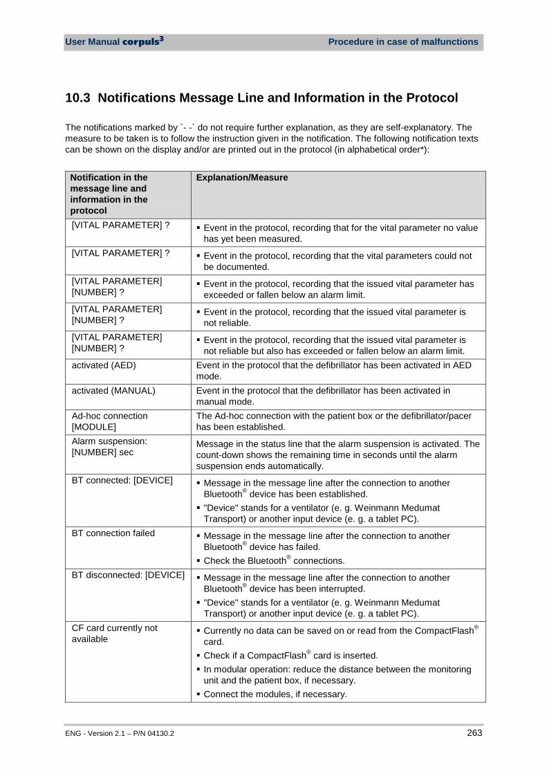
User Manual corpuls3 Procedure in case of malfunctions
ENG - Version 2.1 – P/N 04130.2 263
10.3 Notifications Message Line and Information in the Protocol
The notifications marked by `- -` do not require further explanation, as they are self-explanatory. The measure to be taken is to follow the instruction given in the notification. The following notification texts can be shown on the display and/or are printed out in the protocol (in alphabetical order*): Notification in the message line and information in the protocol
Explanation/Measure
[VITAL PARAMETER] ? Event in the protocol, recording that for the vital parameter no value has yet been measured.
[VITAL PARAMETER] ? Event in the protocol, recording that the vital parameters could not be documented.
[VITAL PARAMETER] [NUMBER] ?
Event in the protocol, recording that the issued vital parameter has exceeded or fallen below an alarm limit.
[VITAL PARAMETER] [NUMBER] ?
Event in the protocol, recording that the issued vital parameter is not reliable.
[VITAL PARAMETER] [NUMBER] ?
Event in the protocol, recording that the issued vital parameter is not reliable but also has exceeded or fallen below an alarm limit.
activated (AED) Event in the protocol that the defibrillator has been activated in AED mode.
activated (MANUAL) Event in the protocol that the defibrillator has been activated in manual mode.
Ad-hoc connection [MODULE]
The Ad-hoc connection with the patient box or the defibrillator/pacer has been established.
Alarm suspension: [NUMBER] sec
Message in the status line that the alarm suspension is activated. The count-down shows the remaining time in seconds until the alarm suspension ends automatically.
BT connected: [DEVICE] Message in the message line after the connection to another Bluetooth® device has been established. "Device" stands for a ventilator (e. g. Weinmann Medumat
Transport) or another input device (e. g. a tablet PC). BT connection failed Message in the message line after the connection to another
Bluetooth® device has failed. Check the Bluetooth® connections.
BT disconnected: [DEVICE] Message in the message line after the connection to another Bluetooth® device has been interrupted. "Device" stands for a ventilator (e. g. Weinmann Medumat
Transport) or another input device (e. g. a tablet PC). CF card currently not available
Currently no data can be saved on or read from the CompactFlash® card. Check if a CompactFlash® card is inserted. In modular operation: reduce the distance between the monitoring
unit and the patient box, if necessary. Connect the modules, if necessary.
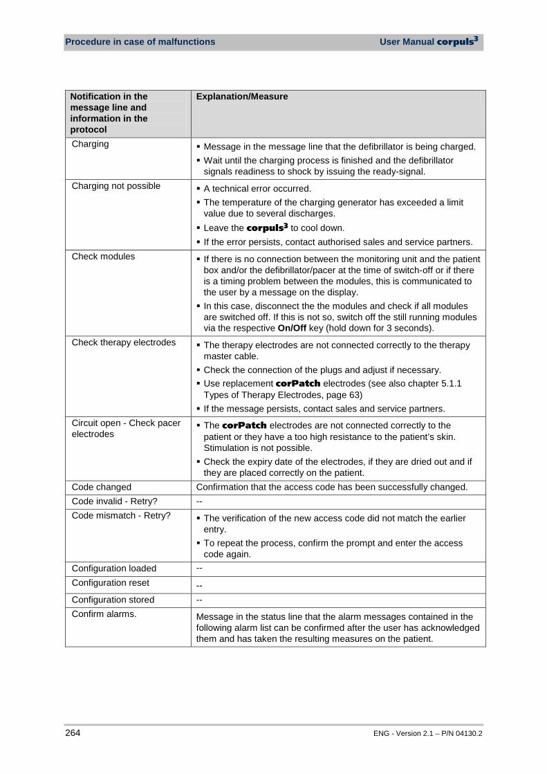
Procedure in case of malfunctions User Manual corpuls3
264 ENG - Version 2.1 – P/N 04130.2
Notification in the message line and information in the protocol
Explanation/Measure
Charging Message in the message line that the defibrillator is being charged. Wait until the charging process is finished and the defibrillator
signals readiness to shock by issuing the ready-signal. Charging not possible A technical error occurred.
The temperature of the charging generator has exceeded a limit value due to several discharges. Leave the corpuls3 to cool down. If the error persists, contact authorised sales and service partners.
Check modules If there is no connection between the monitoring unit and the patient box and/or the defibrillator/pacer at the time of switch-off or if there is a timing problem between the modules, this is communicated to the user by a message on the display. In this case, disconnect the the modules and check if all modules
are switched off. If this is not so, switch off the still running modules via the respective On/Off key (hold down for 3 seconds).
Check therapy electrodes The therapy electrodes are not connected correctly to the therapy master cable. Check the connection of the plugs and adjust if necessary. Use replacement corPatch electrodes (see also chapter 5.1.1
Types of Therapy Electrodes, page 63) If the message persists, contact sales and service partners.
Circuit open - Check pacer electrodes
The corPatch electrodes are not connected correctly to the patient or they have a too high resistance to the patient’s skin. Stimulation is not possible. Check the expiry date of the electrodes, if they are dried out and if
they are placed correctly on the patient. Code changed Confirmation that the access code has been successfully changed. Code invalid - Retry? -- Code mismatch - Retry? The verification of the new access code did not match the earlier
entry. To repeat the process, confirm the prompt and enter the access
code again. Configuration loaded -- Configuration reset -- Configuration stored -- Confirm alarms. Message in the status line that the alarm messages contained in the
following alarm list can be confirmed after the user has acknowledged them and has taken the resulting measures on the patient.
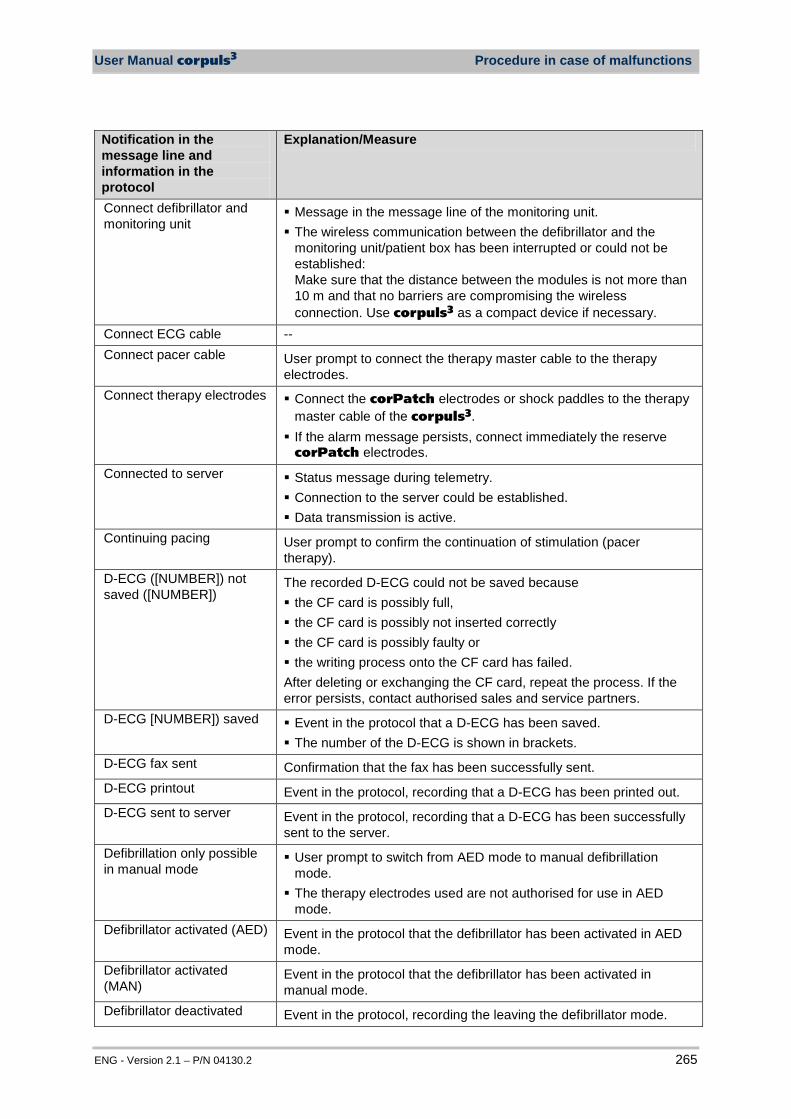
User Manual corpuls3 Procedure in case of malfunctions
ENG - Version 2.1 – P/N 04130.2 265
Notification in the message line and information in the protocol
Explanation/Measure
Connect defibrillator and monitoring unit
Message in the message line of the monitoring unit. The wireless communication between the defibrillator and the
monitoring unit/patient box has been interrupted or could not be established: Make sure that the distance between the modules is not more than 10 m and that no barriers are compromising the wireless connection. Use corpuls3 as a compact device if necessary.
Connect ECG cable -- Connect pacer cable User prompt to connect the therapy master cable to the therapy
electrodes. Connect therapy electrodes Connect the corPatch electrodes or shock paddles to the therapy
master cable of the corpuls3. If the alarm message persists, connect immediately the reserve
corPatch electrodes. Connected to server Status message during telemetry.
Connection to the server could be established. Data transmission is active.
Continuing pacing User prompt to confirm the continuation of stimulation (pacer therapy).
D-ECG ([NUMBER]) not saved ([NUMBER])
The recorded D-ECG could not be saved because the CF card is possibly full, the CF card is possibly not inserted correctly the CF card is possibly faulty or the writing process onto the CF card has failed. After deleting or exchanging the CF card, repeat the process. If the error persists, contact authorised sales and service partners.
D-ECG [NUMBER]) saved Event in the protocol that a D-ECG has been saved. The number of the D-ECG is shown in brackets.
D-ECG fax sent Confirmation that the fax has been successfully sent. D-ECG printout Event in the protocol, recording that a D-ECG has been printed out. D-ECG sent to server Event in the protocol, recording that a D-ECG has been successfully
sent to the server. Defibrillation only possible in manual mode
User prompt to switch from AED mode to manual defibrillation mode. The therapy electrodes used are not authorised for use in AED
mode. Defibrillator activated (AED) Event in the protocol that the defibrillator has been activated in AED
mode. Defibrillator activated (MAN)
Event in the protocol that the defibrillator has been activated in manual mode.
Defibrillator deactivated Event in the protocol, recording the leaving the defibrillator mode.

Procedure in case of malfunctions User Manual corpuls3
266 ENG - Version 2.1 – P/N 04130.2
Notification in the message line and information in the protocol
Explanation/Measure
Defibrillator powered on Event in the protocol, recording the switching on of the defibrillator/pacer.
Demo mode off The DEMO mode has been switched off. Demo mode on The DEMO mode has been switched on.
Check if curves and parameters are displayed. Disconnect defibrillator and monitoring unit
Message in the message line of the monitoring unit. Communication in the connected state between the defibrillator and
monitoring unit/patient box is cut off or could not be established: Check if one of the two infrared interfaces is covered or dirty.
Do not touch or move patient
The ECG analysis is being performed. Do not touch or move patient. Follow the instructions on the display.
ECG analysis result; >>> Shock not recommended ECG analysis result; >>> Shock recommended
Event in the protocol, recording the result of the ECG analysis.
ECG analysis started Event in the protocol, recording that an ECG analysis has been performed in AED mode.
Energy selection [NUMBER] J
Event in the protocol, recording the energy selected.
Enter code: [NUMBER] [NUMBER] [NUMBER] [NUMBER]
User prompt to enter the access code.
Enter new code: [NUMBER] [NUMBER] [NUMBER] [NUMBER]
User prompt to enter a new access code.
Error in device (BIM) The corpuls3 is not functioning correctly and must not be used. Contact authorised sales and service partners.
Error in device (DEFI) The corpuls3 is not functioning correctly and must not be used. Contact authorised sales and service partners.
Error in device (MAN-BIM) The corpuls3 is not functioning correctly and must not be used. Contact authorised sales and service partners.
Error in device (PIF) The corpuls3 is not functioning correctly and must not be used. Contact authorised sales and service partners.
Event recorded -- Failure HES data transmission
An error occurred during data transmission of the ECG measuring and interpretation software HES®. Data transmission was not successful. Repeat procedure If the data transmission fails repeatedly, contact authorised sales
and service partners.
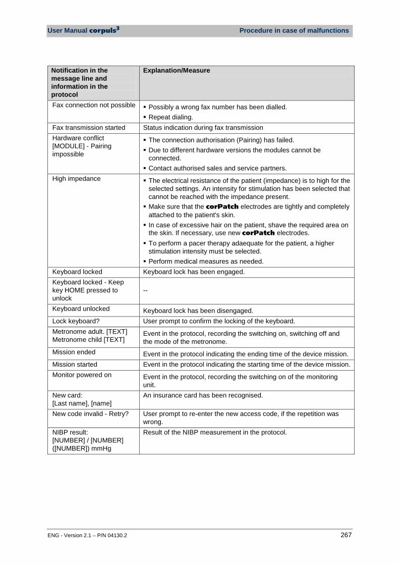
User Manual corpuls3 Procedure in case of malfunctions
ENG - Version 2.1 – P/N 04130.2 267
Notification in the message line and information in the protocol
Explanation/Measure
Fax connection not possible Possibly a wrong fax number has been dialled. Repeat dialing.
Fax transmission started Status indication during fax transmission Hardware conflict [MODULE] - Pairing impossible
The connection authorisation (Pairing) has failed. Due to different hardware versions the modules cannot be
connected. Contact authorised sales and service partners.
High impedance The electrical resistance of the patient (impedance) is to high for the selected settings. An intensity for stimulation has been selected that cannot be reached with the impedance present. Make sure that the corPatch electrodes are tightly and completely
attached to the patient's skin. In case of excessive hair on the patient, shave the required area on
the skin. If necessary, use new corPatch electrodes. To perform a pacer therapy adaequate for the patient, a higher
stimulation intensity must be selected. Perform medical measures as needed.
Keyboard locked Keyboard lock has been engaged. Keyboard locked - Keep key HOME pressed to unlock
--
Keyboard unlocked Keyboard lock has been disengaged. Lock keyboard? User prompt to confirm the locking of the keyboard. Metronome adult. [TEXT] Metronome child [TEXT]
Event in the protocol, recording the switching on, switching off and the mode of the metronome.
Mission ended Event in the protocol indicating the ending time of the device mission. Mission started Event in the protocol indicating the starting time of the device mission. Monitor powered on Event in the protocol, recording the switching on of the monitoring
unit. New card: [Last name], [name]
An insurance card has been recognised.
New code invalid - Retry? User prompt to re-enter the new access code, if the repetition was wrong.
NIBP result: [NUMBER] / [NUMBER] ([NUMBER]) mmHg
Result of the NIBP measurement in the protocol.
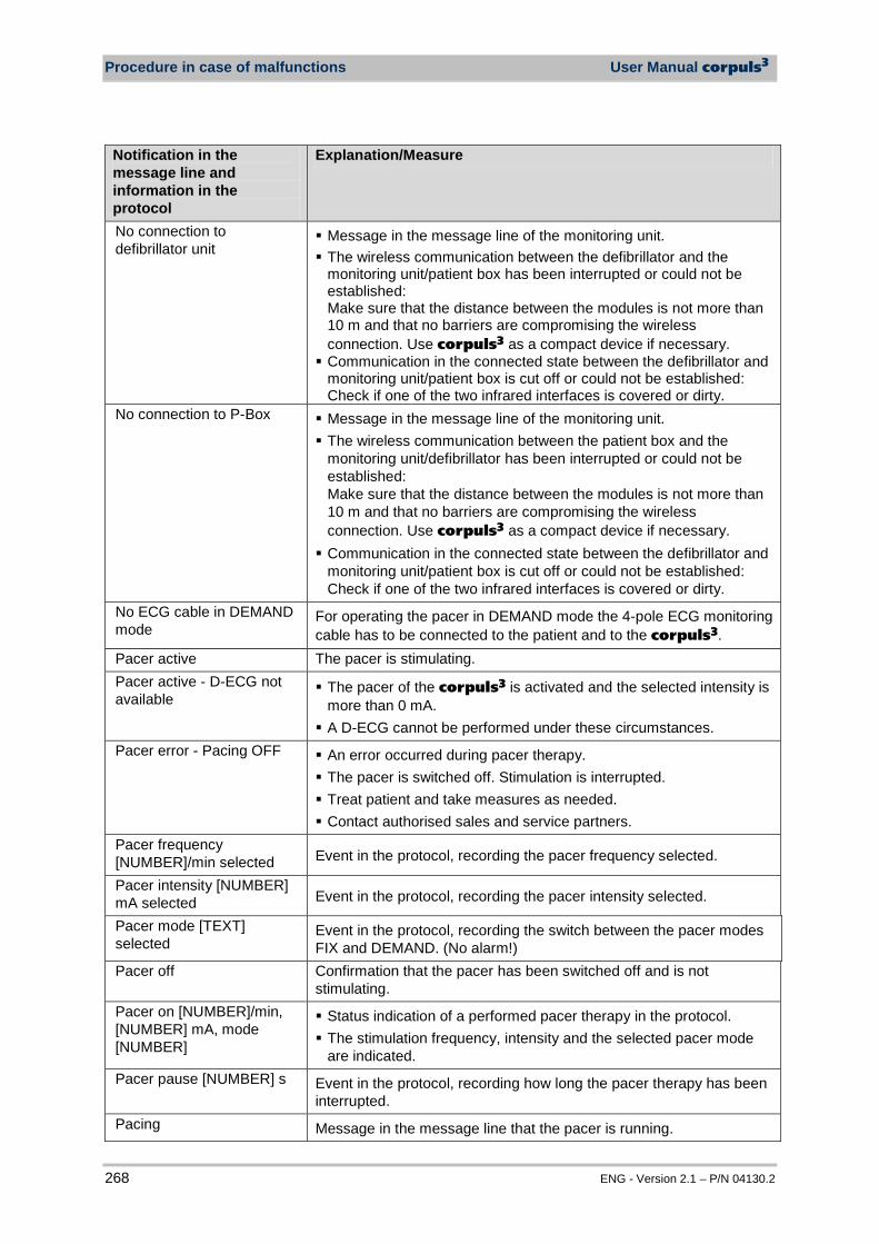
Procedure in case of malfunctions User Manual corpuls3
268 ENG - Version 2.1 – P/N 04130.2
Notification in the message line and information in the protocol
Explanation/Measure
No connection to defibrillator unit
Message in the message line of the monitoring unit. The wireless communication between the defibrillator and the
monitoring unit/patient box has been interrupted or could not be established: Make sure that the distance between the modules is not more than 10 m and that no barriers are compromising the wireless connection. Use corpuls3 as a compact device if necessary. Communication in the connected state between the defibrillator and
monitoring unit/patient box is cut off or could not be established: Check if one of the two infrared interfaces is covered or dirty.
No connection to P-Box Message in the message line of the monitoring unit. The wireless communication between the patient box and the
monitoring unit/defibrillator has been interrupted or could not be established: Make sure that the distance between the modules is not more than 10 m and that no barriers are compromising the wireless connection. Use corpuls3 as a compact device if necessary. Communication in the connected state between the defibrillator and
monitoring unit/patient box is cut off or could not be established: Check if one of the two infrared interfaces is covered or dirty.
No ECG cable in DEMAND mode
For operating the pacer in DEMAND mode the 4-pole ECG monitoring cable has to be connected to the patient and to the corpuls3.
Pacer active The pacer is stimulating. Pacer active - D-ECG not available
The pacer of the corpuls3 is activated and the selected intensity is more than 0 mA. A D-ECG cannot be performed under these circumstances.
Pacer error - Pacing OFF An error occurred during pacer therapy. The pacer is switched off. Stimulation is interrupted. Treat patient and take measures as needed. Contact authorised sales and service partners.
Pacer frequency [NUMBER]/min selected Event in the protocol, recording the pacer frequency selected.
Pacer intensity [NUMBER] mA selected Event in the protocol, recording the pacer intensity selected.
Pacer mode [TEXT] selected
Event in the protocol, recording the switch between the pacer modes FIX and DEMAND. (No alarm!)
Pacer off Confirmation that the pacer has been switched off and is not stimulating.
Pacer on [NUMBER]/min, [NUMBER] mA, mode [NUMBER]
Status indication of a performed pacer therapy in the protocol. The stimulation frequency, intensity and the selected pacer mode
are indicated. Pacer pause [NUMBER] s Event in the protocol, recording how long the pacer therapy has been
interrupted. Pacing Message in the message line that the pacer is running.
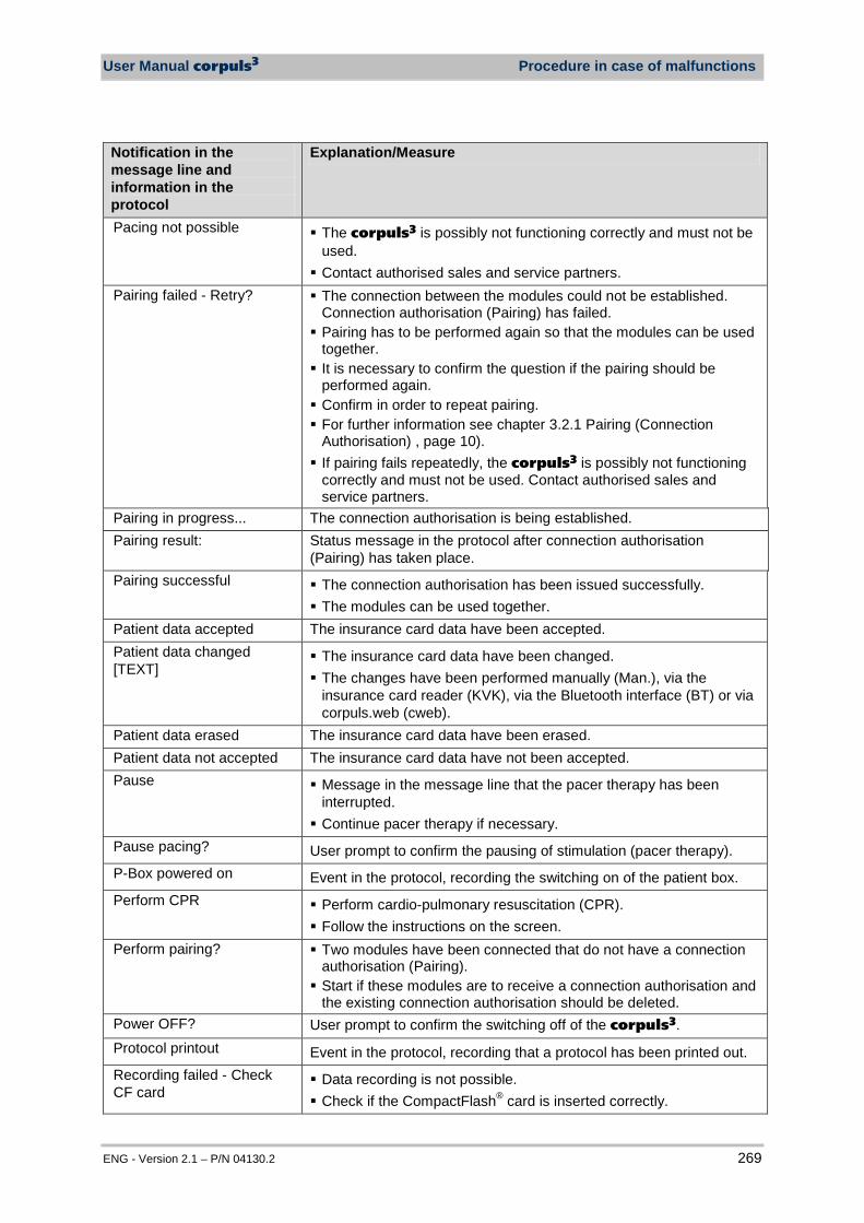
User Manual corpuls3 Procedure in case of malfunctions
ENG - Version 2.1 – P/N 04130.2 269
Notification in the message line and information in the protocol
Explanation/Measure
Pacing not possible The corpuls3 is possibly not functioning correctly and must not be used. Contact authorised sales and service partners.
Pairing failed - Retry? The connection between the modules could not be established. Connection authorisation (Pairing) has failed. Pairing has to be performed again so that the modules can be used
together. It is necessary to confirm the question if the pairing should be
performed again. Confirm in order to repeat pairing. For further information see chapter 3.2.1 Pairing (Connection
Authorisation) , page 10). If pairing fails repeatedly, the corpuls3 is possibly not functioning
correctly and must not be used. Contact authorised sales and service partners.
Pairing in progress... The connection authorisation is being established. Pairing result: Status message in the protocol after connection authorisation
(Pairing) has taken place. Pairing successful The connection authorisation has been issued successfully.
The modules can be used together. Patient data accepted The insurance card data have been accepted. Patient data changed [TEXT]
The insurance card data have been changed. The changes have been performed manually (Man.), via the
insurance card reader (KVK), via the Bluetooth interface (BT) or via corpuls.web (cweb).
Patient data erased The insurance card data have been erased. Patient data not accepted The insurance card data have not been accepted. Pause Message in the message line that the pacer therapy has been
interrupted. Continue pacer therapy if necessary.
Pause pacing? User prompt to confirm the pausing of stimulation (pacer therapy). P-Box powered on Event in the protocol, recording the switching on of the patient box. Perform CPR Perform cardio-pulmonary resuscitation (CPR).
Follow the instructions on the screen. Perform pairing? Two modules have been connected that do not have a connection
authorisation (Pairing). Start if these modules are to receive a connection authorisation and
the existing connection authorisation should be deleted. Power OFF? User prompt to confirm the switching off of the corpuls3. Protocol printout Event in the protocol, recording that a protocol has been printed out. Recording failed - Check CF card
Data recording is not possible. Check if the CompactFlash® card is inserted correctly.
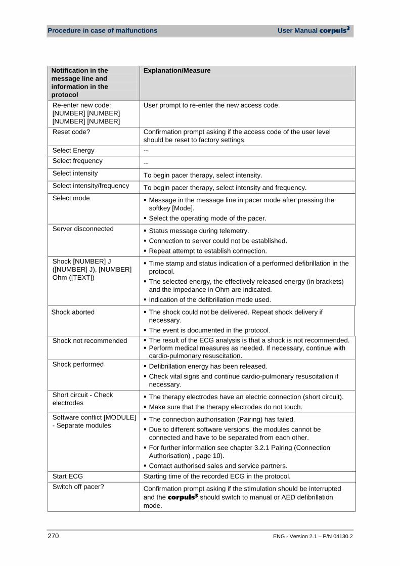
Procedure in case of malfunctions User Manual corpuls3
270 ENG - Version 2.1 – P/N 04130.2
Notification in the message line and information in the protocol
Explanation/Measure
Re-enter new code: [NUMBER] [NUMBER] [NUMBER] [NUMBER]
User prompt to re-enter the new access code.
Reset code? Confirmation prompt asking if the access code of the user level should be reset to factory settings.
Select Energy -- Select frequency -- Select intensity To begin pacer therapy, select intensity. Select intensity/frequency To begin pacer therapy, select intensity and frequency. Select mode Message in the message line in pacer mode after pressing the
softkey [Mode]. Select the operating mode of the pacer.
Server disconnected Status message during telemetry. Connection to server could not be established. Repeat attempt to establish connection.
Shock [NUMBER] J ([NUMBER] J), [NUMBER] Ohm ([TEXT])
Time stamp and status indication of a performed defibrillation in the protocol. The selected energy, the effectively released energy (in brackets)
and the impedance in Ohm are indicated. Indication of the defibrillation mode used.
Shock aborted The shock could not be delivered. Repeat shock delivery if necessary. The event is documented in the protocol.
Shock not recommended The result of the ECG analysis is that a shock is not recommended. Perform medical measures as needed. If necessary, continue with
cardio-pulmonary resuscitation. Shock performed Defibrillation energy has been released.
Check vital signs and continue cardio-pulmonary resuscitation if necessary.
Short circuit - Check electrodes
The therapy electrodes have an electric connection (short circuit). Make sure that the therapy electrodes do not touch.
Software conflict [MODULE] - Separate modules
The connection authorisation (Pairing) has failed. Due to different software versions, the modules cannot be
connected and have to be separated from each other. For further information see chapter 3.2.1 Pairing (Connection
Authorisation) , page 10). Contact authorised sales and service partners.
Start ECG Starting time of the recorded ECG in the protocol. Switch off pacer? Confirmation prompt asking if the stimulation should be interrupted
and the corpuls3 should switch to manual or AED defibrillation mode.
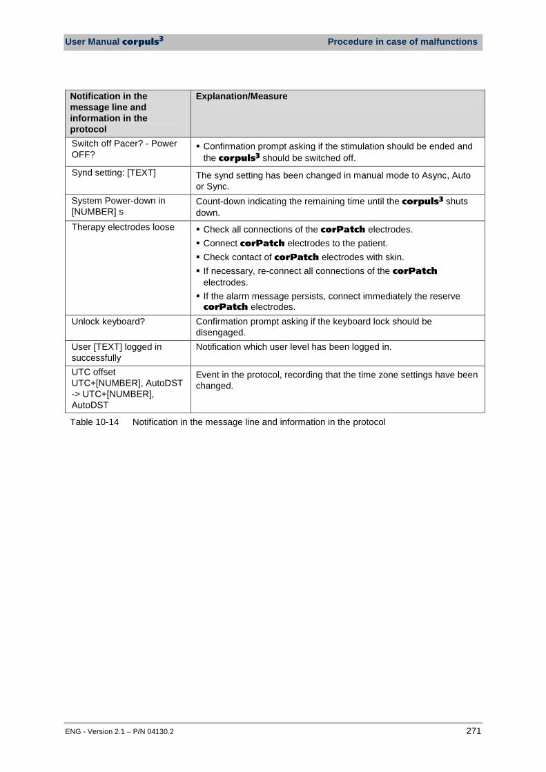
User Manual corpuls3 Procedure in case of malfunctions
ENG - Version 2.1 – P/N 04130.2 271
Notification in the message line and information in the protocol
Explanation/Measure
Switch off Pacer? - Power OFF?
Confirmation prompt asking if the stimulation should be ended and the corpuls3 should be switched off.
Synd setting: [TEXT] The synd setting has been changed in manual mode to Async, Auto or Sync.
System Power-down in [NUMBER] s
Count-down indicating the remaining time until the corpuls3 shuts down.
Therapy electrodes loose Check all connections of the corPatch electrodes. Connect corPatch electrodes to the patient. Check contact of corPatch electrodes with skin. If necessary, re-connect all connections of the corPatch
electrodes. If the alarm message persists, connect immediately the reserve
corPatch electrodes. Unlock keyboard? Confirmation prompt asking if the keyboard lock should be
disengaged. User [TEXT] logged in successfully
Notification which user level has been logged in.
UTC offset UTC+[NUMBER], AutoDST -> UTC+[NUMBER], AutoDST
Event in the protocol, recording that the time zone settings have been changed.
Table 10-14 Notification in the message line and information in the protocol

Appendix User Manual corpuls3
272 ENG - Version 2.1 – P/N 04130.2
Appendix
A Symbols
Please read and follow the operating instructions
Please read and follow the operating instructions
Please read the additional instructions in the user manual
USB port (in preparation)
BF (body floating, defibrillation-proof) An insulated application component of this type is authorised for external and internal use on the patient
CF (cardiac floating, defibrillation-proof) An insulated application component of this type is authorised for use directly on or in the patient’s heart
Equipotential bonding
Protection class IP55
APEX Marking for positioning the shock paddles on the patient and on corpuls3
STERNUM Marking for positioning the shock paddles on the patient and on corpuls3
LED: corpuls3 or module is charging on external power supply
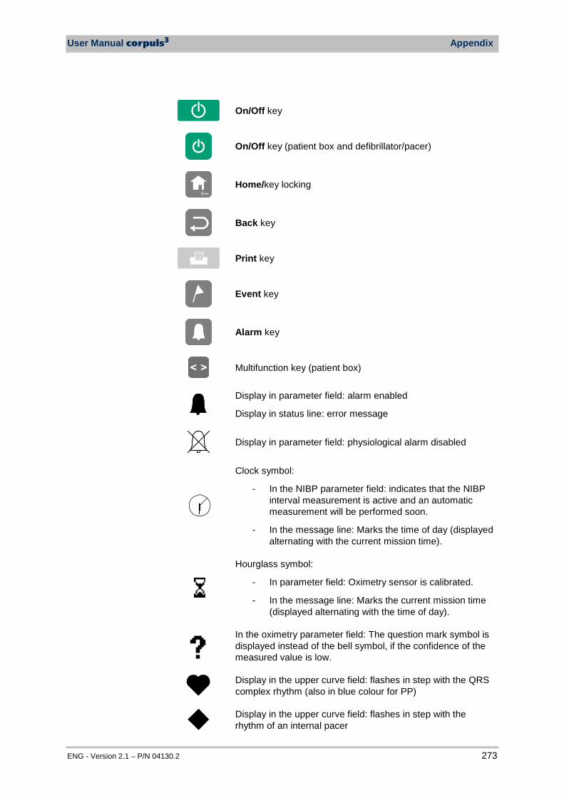
User Manual corpuls3 Appendix
ENG - Version 2.1 – P/N 04130.2 273
On/Off key
On/Off key (patient box and defibrillator/pacer)
Home/key locking
Back key
Print key
Event key
Alarm key
Multifunction key (patient box)
Display in parameter field: alarm enabled
Display in status line: error message
Display in parameter field: physiological alarm disabled
Clock symbol:
- In the NIBP parameter field: indicates that the NIBP interval measurement is active and an automatic measurement will be performed soon.
- In the message line: Marks the time of day (displayed alternating with the current mission time).
Hourglass symbol:
- In parameter field: Oximetry sensor is calibrated.
- In the message line: Marks the current mission time (displayed alternating with the time of day).
In the oximetry parameter field: The question mark symbol is displayed instead of the bell symbol, if the confidence of the measured value is low.
Display in the upper curve field: flashes in step with the QRS complex rhythm (also in blue colour for PP)
Display in the upper curve field: flashes in step with the rhythm of an internal pacer
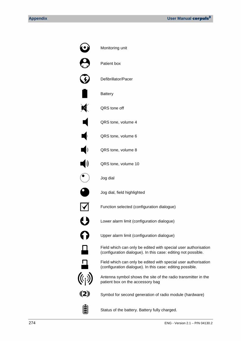
Appendix User Manual corpuls3
274 ENG - Version 2.1 – P/N 04130.2
Monitoring unit
Patient box
Defibrillator/Pacer
Battery
QRS tone off
QRS tone, volume 4
)
QRS tone, volume 6
))
QRS tone, volume 8
))) QRS tone, volume 10
Jog dial
Jog dial, field highlighted
Function selected (configuration dialogue)
Lower alarm limit (configuration dialogue)
Upper alarm limit (configuration dialogue)
Field which can only be edited with special user authorisation (configuration dialogue). In this case: editing not possible.
Field which can only be edited with special user authorisation (configuration dialogue). In this case: editing possible.
Antenna symbol shows the site of the radio transmitter in the patient box on the accessory bag
2 Symbol for second generation of radio module (hardware)
Status of the battery. Battery fully charged.
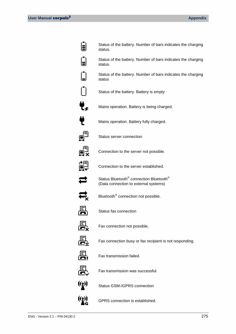
User Manual corpuls3 Appendix
ENG - Version 2.1 – P/N 04130.2 275
Status of the battery. Number of bars indicates the charging status.
Status of the battery. Number of bars indicates the charging status.
Status of the battery. Number of bars indicates the charging status
Status of the battery. Battery is empty
Mains operation. Battery is being charged.
Mains operation. Battery fully charged.
Status server connection
Connection to the server not possible.
Connection to the server established.
Status Bluetooth® connection Bluetooth® (Data connection to external systems)
Bluetooth® connection not possible.
Status fax connection
Fax connection not possible.
Fax connection busy or fax recipient is not responding.
Fax transmission failed.
Fax transmission was successful.
Status GSM-/GPRS connection
GPRS connection is established.
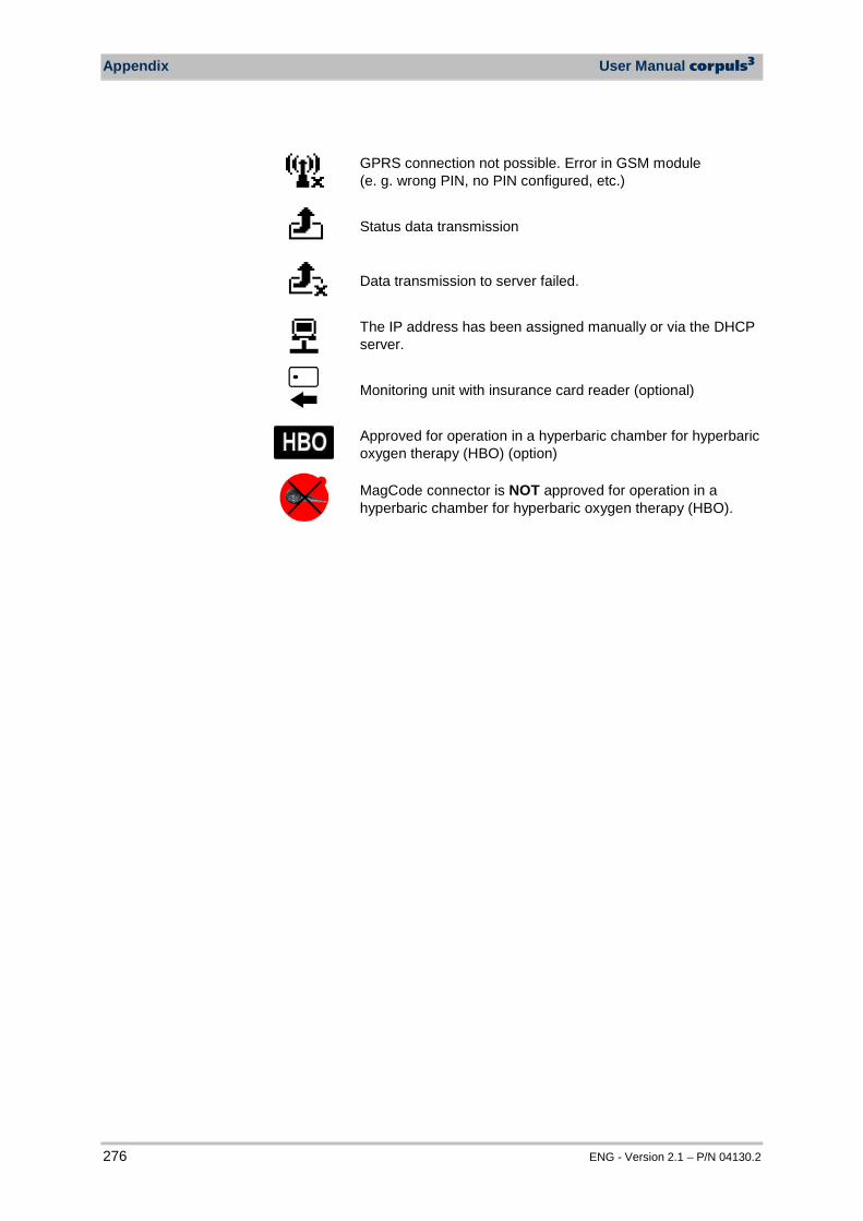
Appendix User Manual corpuls3
276 ENG - Version 2.1 – P/N 04130.2
GPRS connection not possible. Error in GSM module (e. g. wrong PIN, no PIN configured, etc.)
Status data transmission
Data transmission to server failed.
The IP address has been assigned manually or via the DHCP server.
Monitoring unit with insurance card reader (optional)
Approved for operation in a hyperbaric chamber for hyperbaric oxygen therapy (HBO) (option)
MagCode connector is NOT approved for operation in a hyperbaric chamber for hyperbaric oxygen therapy (HBO).
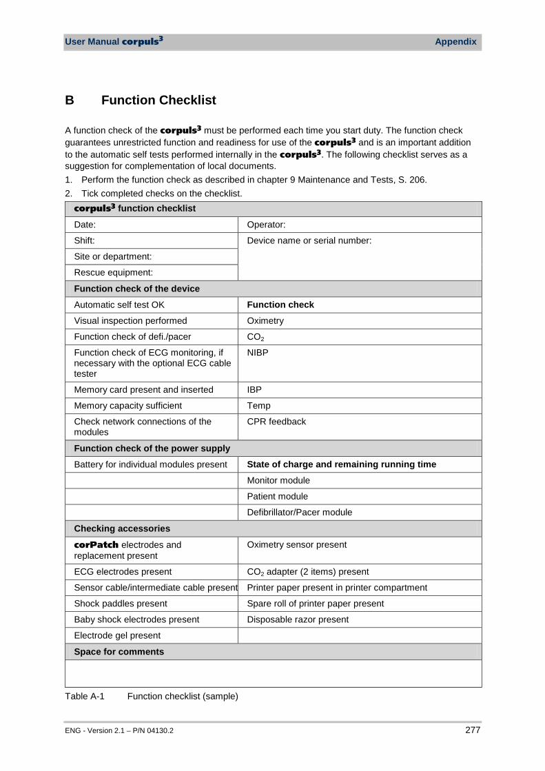
User Manual corpuls3 Appendix
ENG - Version 2.1 – P/N 04130.2 277
B Function Checklist
A function check of the corpuls3 must be performed each time you start duty. The function check guarantees unrestricted function and readiness for use of the corpuls3 and is an important addition to the automatic self tests performed internally in the corpuls3. The following checklist serves as a suggestion for complementation of local documents. 1. Perform the function check as described in chapter 9 Maintenance and Tests, S. 206. 2. Tick completed checks on the checklist.
corpuls3 function checklist
Date: Operator:
Shift: Device name or serial number:
Site or department:
Rescue equipment:
Function check of the device
Automatic self test OK Function check
Visual inspection performed Oximetry
Function check of defi./pacer CO2
Function check of ECG monitoring, if necessary with the optional ECG cable tester
NIBP
Memory card present and inserted IBP
Memory capacity sufficient Temp
Check network connections of the modules
CPR feedback
Function check of the power supply
Battery for individual modules present State of charge and remaining running time
Monitor module
Patient module
Defibrillator/Pacer module
Checking accessories
corPatch electrodes and replacement present
Oximetry sensor present
ECG electrodes present CO2 adapter (2 items) present
Sensor cable/intermediate cable present Printer paper present in printer compartment
Shock paddles present Spare roll of printer paper present
Baby shock electrodes present Disposable razor present
Electrode gel present
Space for comments
Table A-1 Function checklist (sample)
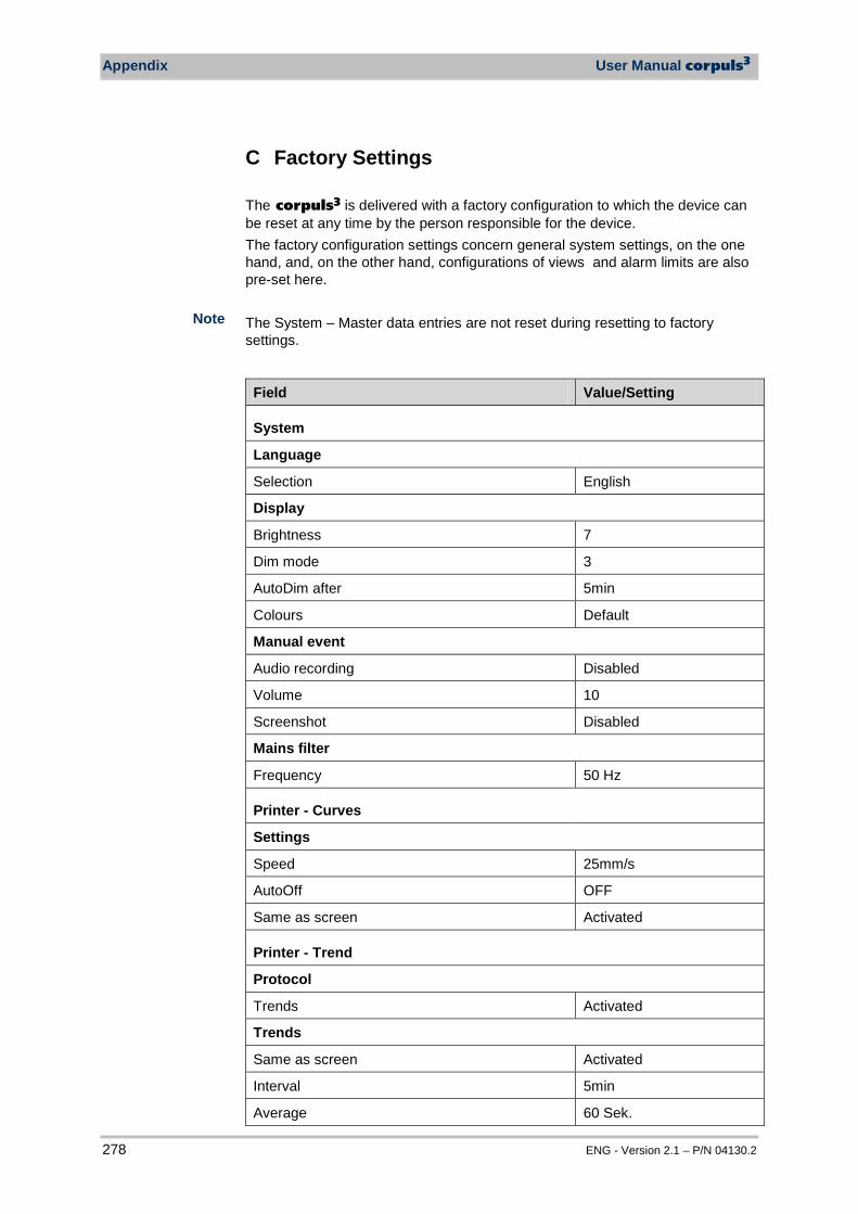
Appendix User Manual corpuls3
278 ENG - Version 2.1 – P/N 04130.2
C Factory Settings The corpuls3 is delivered with a factory configuration to which the device can be reset at any time by the person responsible for the device. The factory configuration settings concern general system settings, on the one hand, and, on the other hand, configurations of views and alarm limits are also pre-set here. The System – Master data entries are not reset during resetting to factory settings.
Field Value/Setting
System
Language
Selection English
Display
Brightness 7
Dim mode 3
AutoDim after 5min
Colours Default
Manual event
Audio recording Disabled
Volume 10
Screenshot Disabled
Mains filter
Frequency 50 Hz
Printer - Curves
Settings
Speed 25mm/s
AutoOff OFF
Same as screen Activated
Printer - Trend
Protocol
Trends Activated
Trends
Same as screen Activated
Interval 5min
Average 60 Sek.
Note
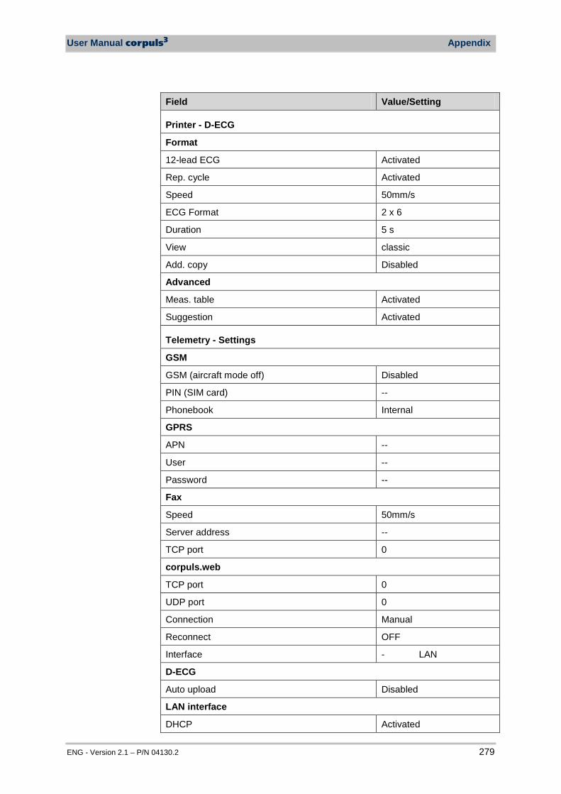
User Manual corpuls3 Appendix
ENG - Version 2.1 – P/N 04130.2 279
Field Value/Setting
Printer - D-ECG
Format
12-lead ECG Activated
Rep. cycle Activated
Speed 50mm/s
ECG Format 2 x 6
Duration 5 s
View classic
Add. copy Disabled
Advanced
Meas. table Activated
Suggestion Activated
Telemetry - Settings
GSM
GSM (aircraft mode off) Disabled
PIN (SIM card) --
Phonebook Internal
GPRS
APN --
User --
Password --
Fax
Speed 50mm/s
Server address --
TCP port 0
corpuls.web
TCP port 0
UDP port 0
Connection Manual
Reconnect OFF
Interface - LAN
D-ECG
Auto upload Disabled
LAN interface
DHCP Activated
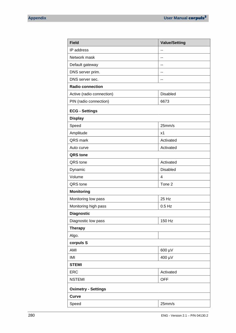
Appendix User Manual corpuls3
280 ENG - Version 2.1 – P/N 04130.2
Field Value/Setting
IP address --
Network mask --
Default gateway --
DNS server prim. --
DNS server sec. --
Radio connection
Active (radio connection) Disabled
PIN (radio connection) 6673
ECG - Settings
Display
Speed 25mm/s
Amplitude x1
QRS mark Activated
Auto curve Activated
QRS tone
QRS tone Activated
Dynamic Disabled
Volume 4
QRS tone Tone 2
Monitoring
Monitoring low pass 25 Hz
Monitoring high pass 0.5 Hz
Diagnostic
Diagnostic low pass 150 Hz
Therapy
Algo.
corpuls S
AMI 600 µV
IMI 400 µV
STEMI
ERC Activated
NSTEMI OFF
Oximetry - Settings
Curve
Speed 25mm/s
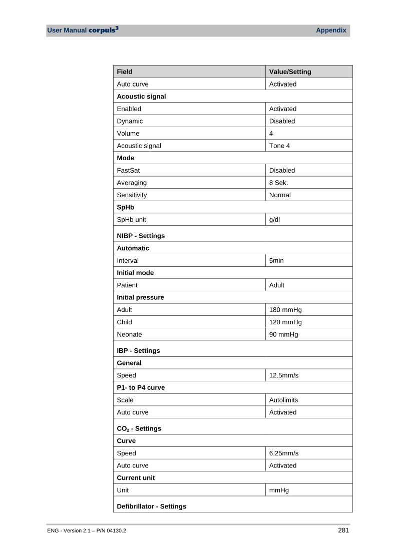
User Manual corpuls3 Appendix
ENG - Version 2.1 – P/N 04130.2 281
Field Value/Setting
Auto curve Activated
Acoustic signal
Enabled Activated
Dynamic Disabled
Volume 4
Acoustic signal Tone 4
Mode
FastSat Disabled
Averaging 8 Sek.
Sensitivity Normal
SpHb
SpHb unit g/dl
NIBP - Settings
Automatic
Interval 5min
Initial mode
Patient Adult
Initial pressure
Adult 180 mmHg
Child 120 mmHg
Neonate 90 mmHg
IBP - Settings
General
Speed 12.5mm/s
P1- to P4 curve
Scale Autolimits
Auto curve Activated
CO2 - Settings
Curve
Speed 6.25mm/s
Auto curve Activated
Current unit
Unit mmHg
Defibrillator - Settings
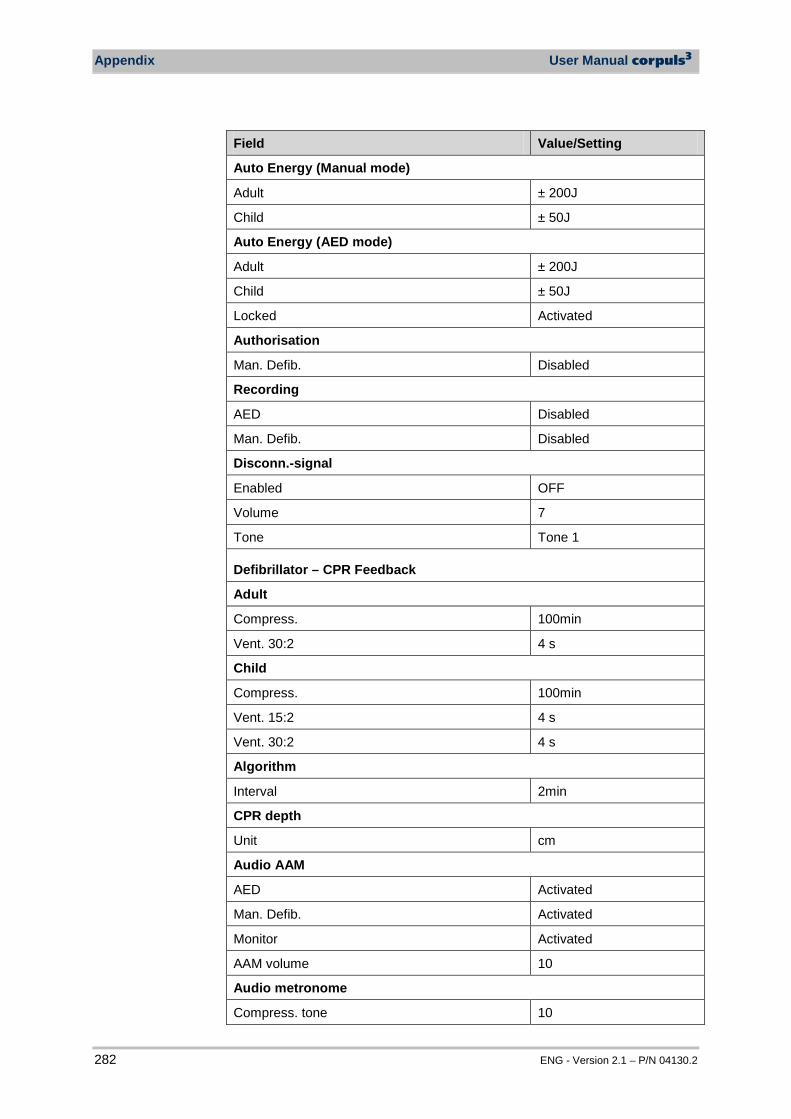
Appendix User Manual corpuls3
282 ENG - Version 2.1 – P/N 04130.2
Field Value/Setting
Auto Energy (Manual mode)
Adult ± 200J
Child ± 50J
Auto Energy (AED mode)
Adult ± 200J
Child ± 50J
Locked Activated
Authorisation
Man. Defib. Disabled
Recording
AED Disabled
Man. Defib. Disabled
Disconn.-signal
Enabled OFF
Volume 7
Tone Tone 1
Defibrillator – CPR Feedback
Adult
Compress. 100min
Vent. 30:2 4 s
Child
Compress. 100min
Vent. 15:2 4 s
Vent. 30:2 4 s
Algorithm
Interval 2min
CPR depth
Unit cm
Audio AAM
AED Activated
Man. Defib. Activated
Monitor Activated
AAM volume 10
Audio metronome
Compress. tone 10
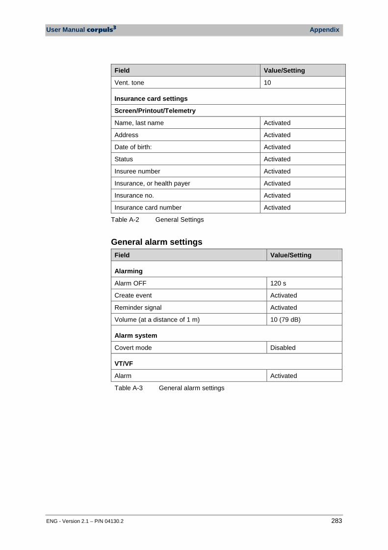
User Manual corpuls3 Appendix
ENG - Version 2.1 – P/N 04130.2 283
Field Value/Setting
Vent. tone 10
Insurance card settings
Screen/Printout/Telemetry
Name, last name Activated
Address Activated
Date of birth: Activated
Status Activated
Insuree number Activated
Insurance, or health payer Activated
Insurance no. Activated
Insurance card number Activated
Table A-2 General Settings
General alarm settings Field Value/Setting
Alarming
Alarm OFF 120 s
Create event Activated
Reminder signal Activated
Volume (at a distance of 1 m) 10 (79 dB)
Alarm system
Covert mode Disabled
VT/VF
Alarm Activated
Table A-3 General alarm settings
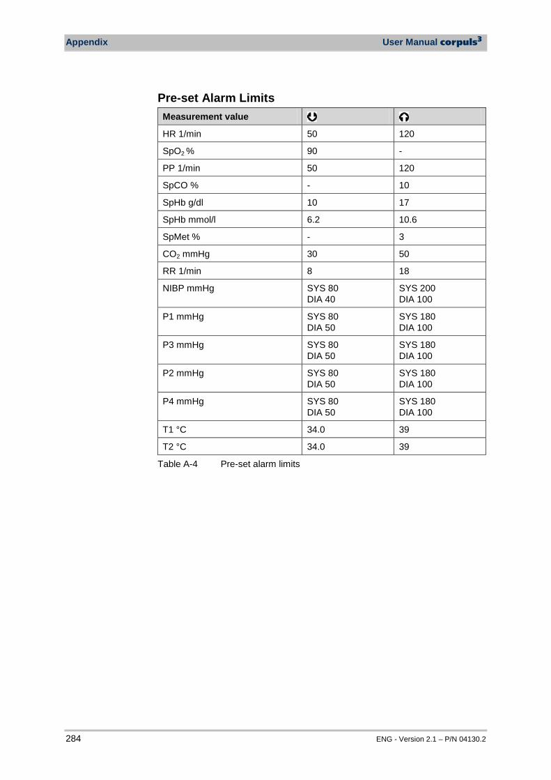
Appendix User Manual corpuls3
284 ENG - Version 2.1 – P/N 04130.2
Pre-set Alarm Limits Measurement value HR 1/min 50 120
SpO2 % 90 -
PP 1/min 50 120
SpCO % - 10
SpHb g/dl 10 17
SpHb mmol/l 6.2 10.6
SpMet % - 3
CO2 mmHg 30 50
RR 1/min 8 18
NIBP mmHg SYS 80 DIA 40
SYS 200 DIA 100
P1 mmHg SYS 80 DIA 50
SYS 180 DIA 100
P3 mmHg SYS 80 DIA 50
SYS 180 DIA 100
P2 mmHg SYS 80 DIA 50
SYS 180 DIA 100
P4 mmHg SYS 80 DIA 50
SYS 180 DIA 100
T1 °C 34.0 39
T2 °C 34.0 39
Table A-4 Pre-set alarm limits
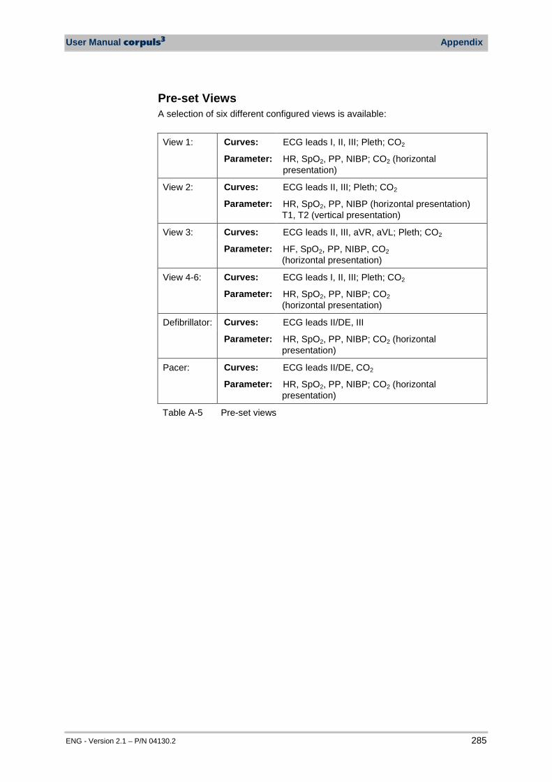
User Manual corpuls3 Appendix
ENG - Version 2.1 – P/N 04130.2 285
Pre-set Views A selection of six different configured views is available:
View 1: Curves: ECG leads I, II, III; Pleth; CO2
Parameter: HR, SpO2, PP, NIBP; CO2 (horizontal presentation)
View 2: Curves: ECG leads II, III; Pleth; CO2
Parameter: HR, SpO2, PP, NIBP (horizontal presentation) T1, T2 (vertical presentation)
View 3: Curves: ECG leads II, III, aVR, aVL; Pleth; CO2
Parameter: HF, SpO2, PP, NIBP, CO2 (horizontal presentation)
View 4-6: Curves: ECG leads I, II, III; Pleth; CO2
Parameter: HR, SpO2, PP, NIBP; CO2 (horizontal presentation)
Defibrillator: Curves: ECG leads II/DE, III
Parameter: HR, SpO2, PP, NIBP; CO2 (horizontal presentation)
Pacer: Curves: ECG leads II/DE, CO2
Parameter: HR, SpO2, PP, NIBP; CO2 (horizontal presentation)
Table A-5 Pre-set views
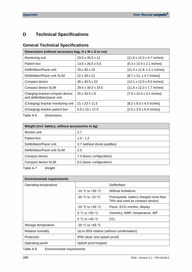
Appendix User Manual corpuls3
286 ENG - Version 2.1 – P/N 04130.2
D Technical Specifications
General Technical Specifications Dimensions (without accessory bag, H x W x D in cm)
Monitoring unit 29.5 x 30.5 x 12 [11.6 x 12.0 x 4.7 inches]
Patient box 13.5 x 26.5 x 5.5 [5.3 x 10.4 x 2.1 inches]
Defibrillator/Pacer unit 29 x 30 x 19 [11.4 x 11.8. x 2.1 inches]
Defibrillator/Pacer unit SLIM 22 x 28 x 12 [8.7 x 11, x 4.7 inches]
Compact device 36 x 30.5 x 23 [14.1 x 12.0 x 9.0 inches]
Compact device SLIM 29.6 x 30.5 x 19.5 [11,6 x 12,0 x 7,7 inches]
Charging bracket compact device and defibrillator/pacer unit
20 x 26.5 x 8 [7.9 x 10.4 x 3.1 inches]
(Charging) bracket monitoring unit 21 x 23 x 11.5 [8.2 x 9.0 x 4.5 inches]
(Charging) bracket patient box 6.5 x 10 x 17.5 [2.5 x 3.9 x 6.9 inches]
Table A-6 Dimensions
Weight (incl. battery, without accessories in kg)
Monitor unit 2.7
Patient box 1.0 - 1.3
Defibrillator/Pacer unit 3.7 (without shock paddles)
Defibrillator/Pacer unit SLIM 2.3
Compact device 7.4 (basic configuration)
Compact device SLIM 6.0 (basic configuration)
Table A-7 Weight
Environmental requirements
Operating temperature Defibrillator
-10 °C to +55 °C: Without limitations
-20 °C to -10 °C: Prerequisite: battery charged more than 70% and used as compact device)
-20 °C to +55 °C: Pacer, ECG monitor, display
0 °C to +55 °C: Oximetry, NIBP, temperature, IBP
0 °C to +45 °C: CO2
Storage temperature -20 °C to +65 °C
Relative humidity Up to 95% relative (without condensation)
Protection IP55 (dust- and splash proof)
Operating panel Splash proof keypad
Table A-8 Environmental requirements
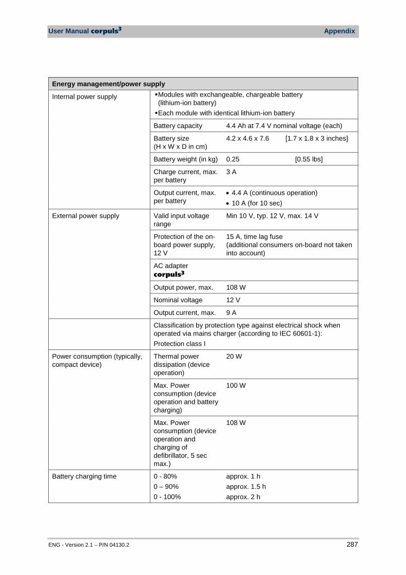
User Manual corpuls3 Appendix
ENG - Version 2.1 – P/N 04130.2 287
Energy management/power supply
Internal power supply Modules with exchangeable, chargeable battery (lithium-ion battery) Each module with identical lithium-ion battery
Battery capacity 4.4 Ah at 7.4 V nominal voltage (each)
Battery size (H x W x D in cm)
4.2 x 4.6 x 7.6 [1.7 x 1.8 x 3 inches]
Battery weight (in kg) 0.25 [0.55 lbs]
Charge current, max. per battery
3 A
Output current, max. per battery
• 4.4 A (continuous operation) • 10 A (for 10 sec)
External power supply Valid input voltage range
Min 10 V, typ. 12 V, max. 14 V
Protection of the on-board power supply, 12 V
15 A, time lag fuse (additional consumers on-board not taken into account)
AC adapter corpuls3
Output power, max. 108 W
Nominal voltage 12 V
Output current, max. 9 A
Classification by protection type against electrical shock when operated via mains charger (according to IEC 60601-1): Protection class I
Power consumption (typically, compact device)
Thermal power dissipation (device operation)
20 W
Max. Power consumption (device operation and battery charging)
100 W
Max. Power consumption (device operation and charging of defibrillator, 5 sec max.)
108 W
Battery charging time 0 - 80% 0 – 90% 0 - 100%
approx. 1 h approx. 1.5 h approx. 2 h
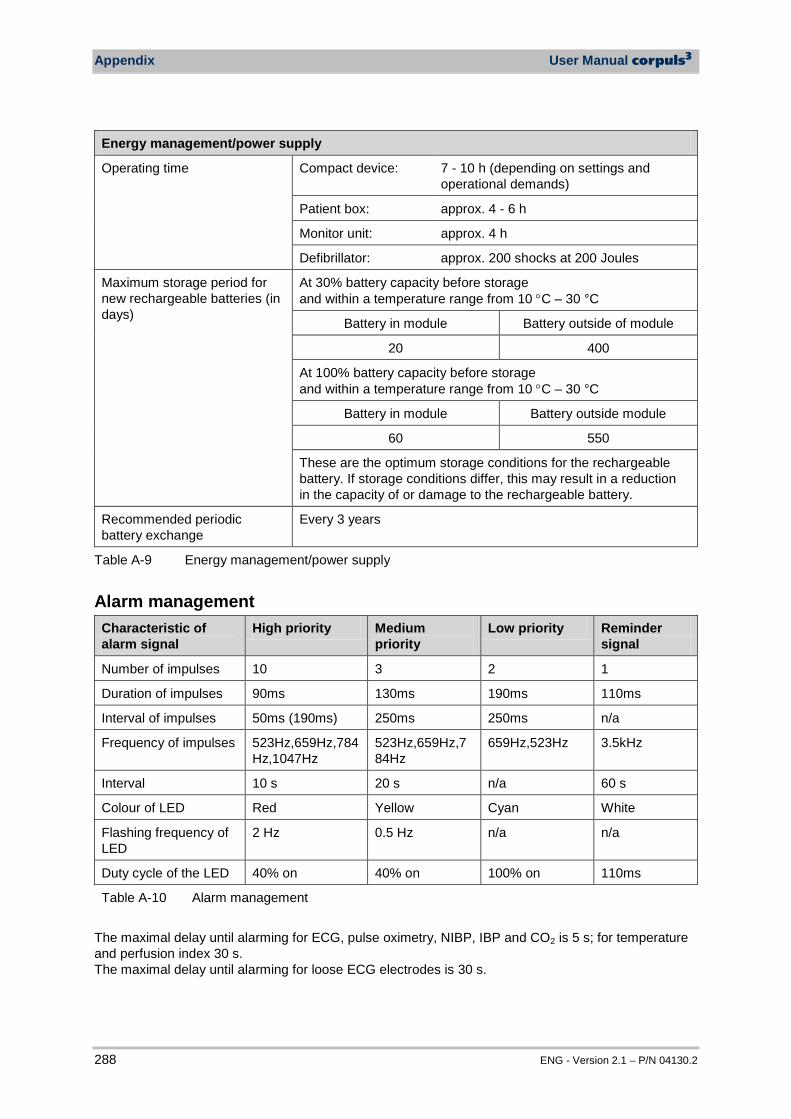
Appendix User Manual corpuls3
288 ENG - Version 2.1 – P/N 04130.2
Energy management/power supply
Operating time Compact device: 7 - 10 h (depending on settings and operational demands)
Patient box: approx. 4 - 6 h
Monitor unit: approx. 4 h
Defibrillator: approx. 200 shocks at 200 Joules
Maximum storage period for new rechargeable batteries (in days)
At 30% battery capacity before storage and within a temperature range from 10 °C – 30 °C
Battery in module Battery outside of module
20 400
At 100% battery capacity before storage and within a temperature range from 10 °C – 30 °C
Battery in module Battery outside module
60 550
These are the optimum storage conditions for the rechargeable battery. If storage conditions differ, this may result in a reduction in the capacity of or damage to the rechargeable battery.
Recommended periodic battery exchange
Every 3 years
Table A-9 Energy management/power supply
Alarm management Characteristic of alarm signal
High priority Medium priority
Low priority Reminder signal
Number of impulses 10 3 2 1
Duration of impulses 90ms 130ms 190ms 110ms
Interval of impulses 50ms (190ms) 250ms 250ms n/a
Frequency of impulses 523Hz,659Hz,784Hz,1047Hz
523Hz,659Hz,784Hz
659Hz,523Hz 3.5kHz
Interval 10 s 20 s n/a 60 s
Colour of LED Red Yellow Cyan White
Flashing frequency of LED
2 Hz 0.5 Hz n/a n/a
Duty cycle of the LED 40% on 40% on 100% on 110ms
Table A-10 Alarm management
The maximal delay until alarming for ECG, pulse oximetry, NIBP, IBP and CO2 is 5 s; for temperature and perfusion index 30 s. The maximal delay until alarming for loose ECG electrodes is 30 s.
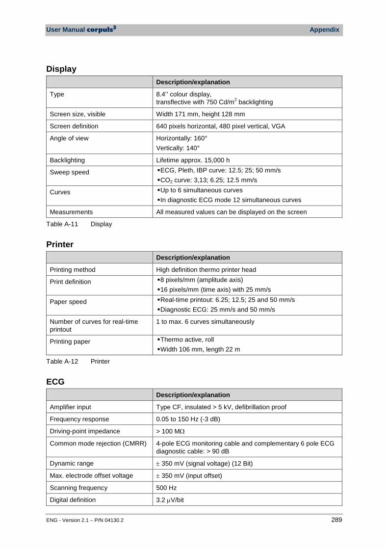
User Manual corpuls3 Appendix
ENG - Version 2.1 – P/N 04130.2 289
Display Description/explanation
Type 8.4’’ colour display, transflective with 750 Cd/m2 backlighting
Screen size, visible Width 171 mm, height 128 mm
Screen definition 640 pixels horizontal, 480 pixel vertical, VGA
Angle of view Horizontally: 160° Vertically: 140°
Backlighting Lifetime approx. 15,000 h
Sweep speed ECG, Pleth, IBP curve: 12.5; 25; 50 mm/s CO2 curve: 3,13; 6.25; 12.5 mm/s
Curves Up to 6 simultaneous curves In diagnostic ECG mode 12 simultaneous curves
Measurements All measured values can be displayed on the screen
Table A-11 Display
Printer Description/explanation
Printing method High definition thermo printer head
Print definition 8 pixels/mm (amplitude axis) 16 pixels/mm (time axis) with 25 mm/s
Paper speed Real-time printout: 6.25; 12.5; 25 and 50 mm/s Diagnostic ECG: 25 mm/s and 50 mm/s
Number of curves for real-time printout
1 to max. 6 curves simultaneously
Printing paper Thermo active, roll Width 106 mm, length 22 m
Table A-12 Printer
ECG Description/explanation
Amplifier input Type CF, insulated > 5 kV, defibrillation proof
Frequency response 0.05 to 150 Hz (-3 dB)
Driving-point impedance > 100 MΩ
Common mode rejection (CMRR) 4-pole ECG monitoring cable and complementary 6 pole ECG diagnostic cable: > 90 dB
Dynamic range ± 350 mV (signal voltage) (12 Bit)
Max. electrode offset voltage ± 350 mV (input offset)
Scanning frequency 500 Hz
Digital definition 3.2 µV/bit
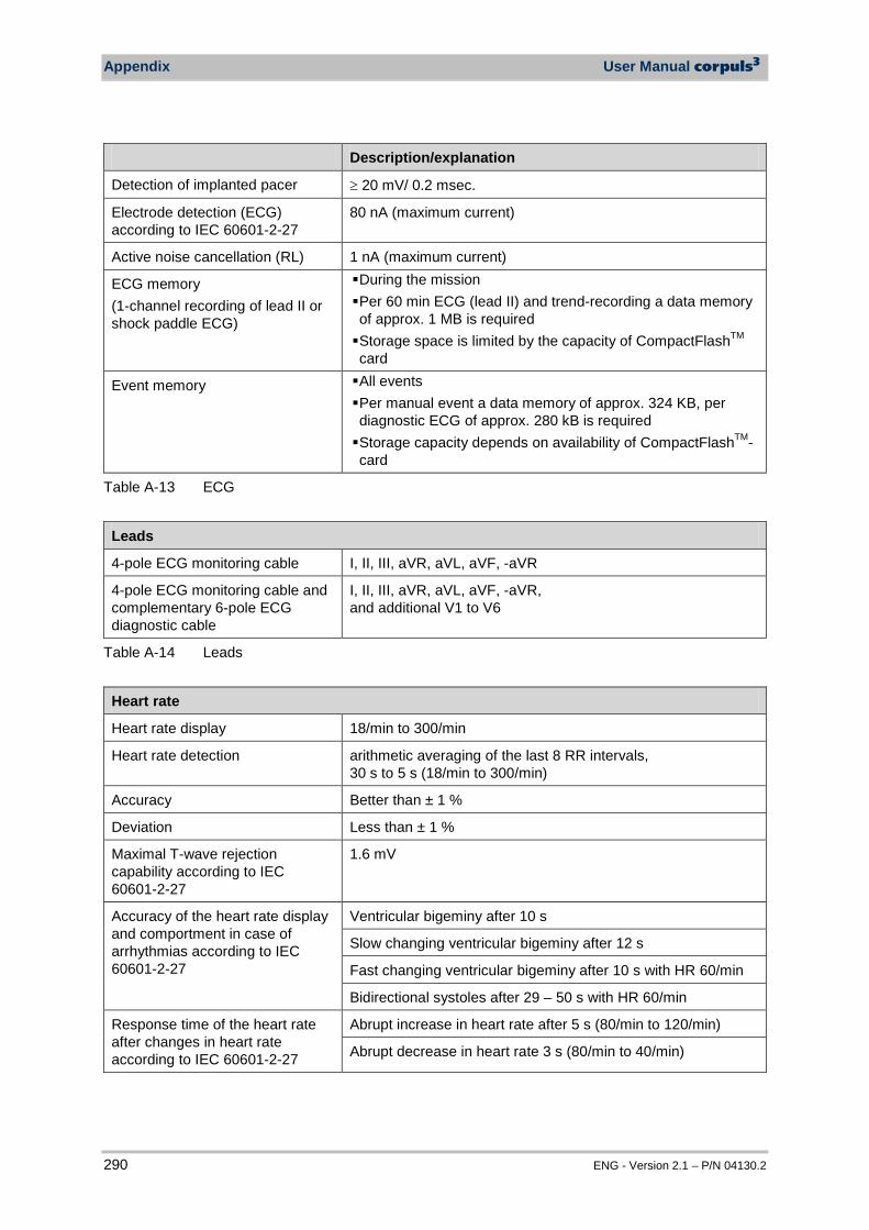
Appendix User Manual corpuls3
290 ENG - Version 2.1 – P/N 04130.2
Description/explanation
Detection of implanted pacer ≥ 20 mV/ 0.2 msec.
Electrode detection (ECG) according to IEC 60601-2-27
80 nA (maximum current)
Active noise cancellation (RL) 1 nA (maximum current)
ECG memory (1-channel recording of lead II or shock paddle ECG)
During the mission Per 60 min ECG (lead II) and trend-recording a data memory of approx. 1 MB is required Storage space is limited by the capacity of CompactFlashTM
card
Event memory All events Per manual event a data memory of approx. 324 KB, per diagnostic ECG of approx. 280 kB is required Storage capacity depends on availability of CompactFlashTM-card
Table A-13 ECG
Leads
4-pole ECG monitoring cable I, II, III, aVR, aVL, aVF, -aVR
4-pole ECG monitoring cable and complementary 6-pole ECG diagnostic cable
I, II, III, aVR, aVL, aVF, -aVR, and additional V1 to V6
Table A-14 Leads
Heart rate
Heart rate display 18/min to 300/min
Heart rate detection arithmetic averaging of the last 8 RR intervals, 30 s to 5 s (18/min to 300/min)
Accuracy Better than ± 1 %
Deviation Less than ± 1 %
Maximal T-wave rejection capability according to IEC 60601-2-27
1.6 mV
Accuracy of the heart rate display and comportment in case of arrhythmias according to IEC 60601-2-27
Ventricular bigeminy after 10 s
Slow changing ventricular bigeminy after 12 s
Fast changing ventricular bigeminy after 10 s with HR 60/min
Bidirectional systoles after 29 – 50 s with HR 60/min
Response time of the heart rate after changes in heart rate according to IEC 60601-2-27
Abrupt increase in heart rate after 5 s (80/min to 120/min)
Abrupt decrease in heart rate 3 s (80/min to 40/min)
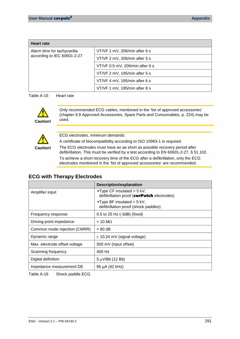
User Manual corpuls3 Appendix
ENG - Version 2.1 – P/N 04130.2 291
Heart rate
Alarm time for tachycardia according to IEC 60601-2-27
VT/VF 1 mV, 206/min after 6 s
VT/VF 2 mV, 206/min after 5 s
VT/VF 0.5 mV, 206/min after 6 s
VT/VF 2 mV, 195/min after 5 s
VT/VF 4 mV, 195/min after 6 s
VT/VF 1 mV, 195/min after 8 s
Table A-15 Heart rate
Caution!
Only recommended ECG cables, mentioned in the ‘list of approved accessories’ (chapter 9.8 Approved Accessories, Spare Parts and Consumables, p. 224) may be used.
Caution!
ECG electrodes, minimum demands: A certificate of biocompatibility according to ISO 10993-1 is required. The ECG electrodes must have an as short as possible recovery period after defibrillation. This must be verified by a test according to EN 60601-2-27, § 51.102. To achieve a short recovery time of the ECG after a defibrillation, only the ECG electrodes mentioned in the ‘list of approved accessories’ are recommended.
ECG with Therapy Electrodes Description/explanation
Amplifier input Type CF insulated > 5 kV, defibrillation proof (corPatch electrodes) Type BF insulated > 5 kV, defibrillation proof (shock paddles)
Frequency response 0.5 to 25 Hz (-3dB) (fixed)
Driving-point impedance > 10 MΩ
Common mode rejection (CMRR) > 80 dB
Dynamic range ± 10.24 mV (signal voltage)
Max. electrode offset voltage 500 mV (input offset)
Scanning frequency 400 Hz
Digital definition 5 µV/Bit (12 Bit)
Impedance measurement DE 85 µA (42 kHz)
Table A-16 Shock paddle ECG
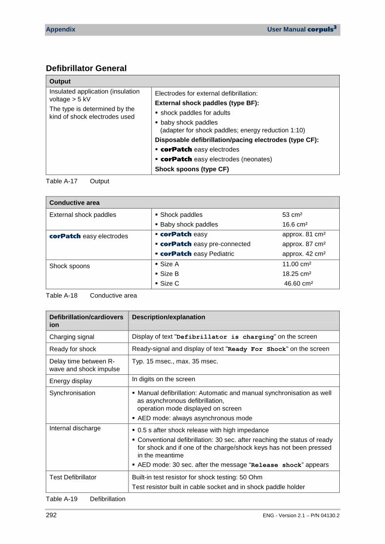
Appendix User Manual corpuls3
292 ENG - Version 2.1 – P/N 04130.2
Defibrillator General Output Insulated application (insulation voltage > 5 kV The type is determined by the kind of shock electrodes used
Electrodes for external defibrillation: External shock paddles (type BF): shock paddles for adults baby shock paddles
(adapter for shock paddles; energy reduction 1:10) Disposable defibrillation/pacing electrodes (type CF): corPatch easy electrodes corPatch easy electrodes (neonates) Shock spoons (type CF)
Table A-17 Output
Conductive area
External shock paddles Shock paddles 53 cm² Baby shock paddles 16.6 cm²
corPatch easy electrodes corPatch easy approx. 81 cm² corPatch easy pre-connected approx. 87 cm² corPatch easy Pediatric approx. 42 cm²
Shock spoons Size A 11.00 cm² Size B 18.25 cm² Size C 46.60 cm²
Table A-18 Conductive area
Defibrillation/cardioversion
Description/explanation
Charging signal Display of text "Defibrillator is charging" on the screen
Ready for shock Ready-signal and display of text "Ready For Shock" on the screen
Delay time between R-wave and shock impulse
Typ. 15 msec., max. 35 msec.
Energy display In digits on the screen
Synchronisation Manual defibrillation: Automatic and manual synchronisation as well as asynchronous defibrillation, operation mode displayed on screen AED mode: always asynchronous mode
Internal discharge 0.5 s after shock release with high impedance Conventional defibrillation: 30 sec. after reaching the status of ready
for shock and if one of the charge/shock keys has not been pressed in the meantime AED mode: 30 sec. after the message “Release shock” appears
Test Defibrillator Built-in test resistor for shock testing: 50 Ohm Test resistor built in cable socket and in shock paddle holder
Table A-19 Defibrillation
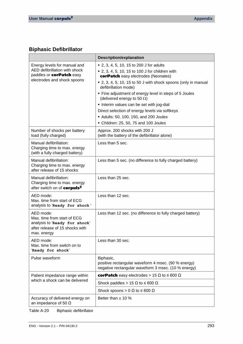
User Manual corpuls3 Appendix
ENG - Version 2.1 – P/N 04130.2 293
Biphasic Defibrillator Description/explanation
Energy levels for manual and AED defibrillation with shock paddles or corPatch easy electrodes and shock spoons
2, 3, 4, 5, 10, 15 to 200 J for adults 2, 3, 4, 5, 10, 15 to 100 J for children with corPatch easy electrodes (Neonates) 2, 3, 4, 5, 10, 15 to 50 J with shock spoons (only in manual
defibrillation mode) Fine adjustment of energy level in steps of 5 Joules
(delivered energy to 50 Ω) Interim values can be set with jog-dial Direct selection of energy levels via softkeys Adults: 50, 100, 150, and 200 Joules Children: 25, 50, 75 and 100 Joules
Number of shocks per battery load (fully charged)
Approx. 200 shocks with 200 J (with the battery of the defibrillator alone)
Manual defibrillation: Charging time to max. energy (with a fully charged battery)
Less than 5 sec.
Manual defibrillation: Charging time to max. energy after release of 15 shocks
Less than 5 sec. (no difference to fully charged battery)
Manual defibrillation: Charging time to max. energy after switch on of corpuls3
Less than 25 sec.
AED mode: Max. time from start of ECG analysis to ‘Ready for shock ‘
Less than 12 sec.
AED mode: Max. time from start of ECG analysis to ‘Ready for shock’ after release of 15 shocks with max. energy
Less than 12 sec. (no difference to fully charged battery)
AED mode: Max. time from switch on to ‘Ready for shock’
Less than 30 sec.
Pulse waveform Biphasic, positive rectangular waveform 4 msec. (90 % energy) negative rectangular waveform 3 msec. (10 % energy)
Patient impedance range within which a shock can be delivered
corPatch easy electrodes > 15 Ω to ≤ 600 Ω
Shock paddles > 15 Ω to ≤ 600 Ω
Shock spoons > 0 Ω to ≤ 600 Ω
Accuracy of delivered energy on an impedance of 50 Ω
Better than ± 10 %
Table A-20 Biphasic defibrillator
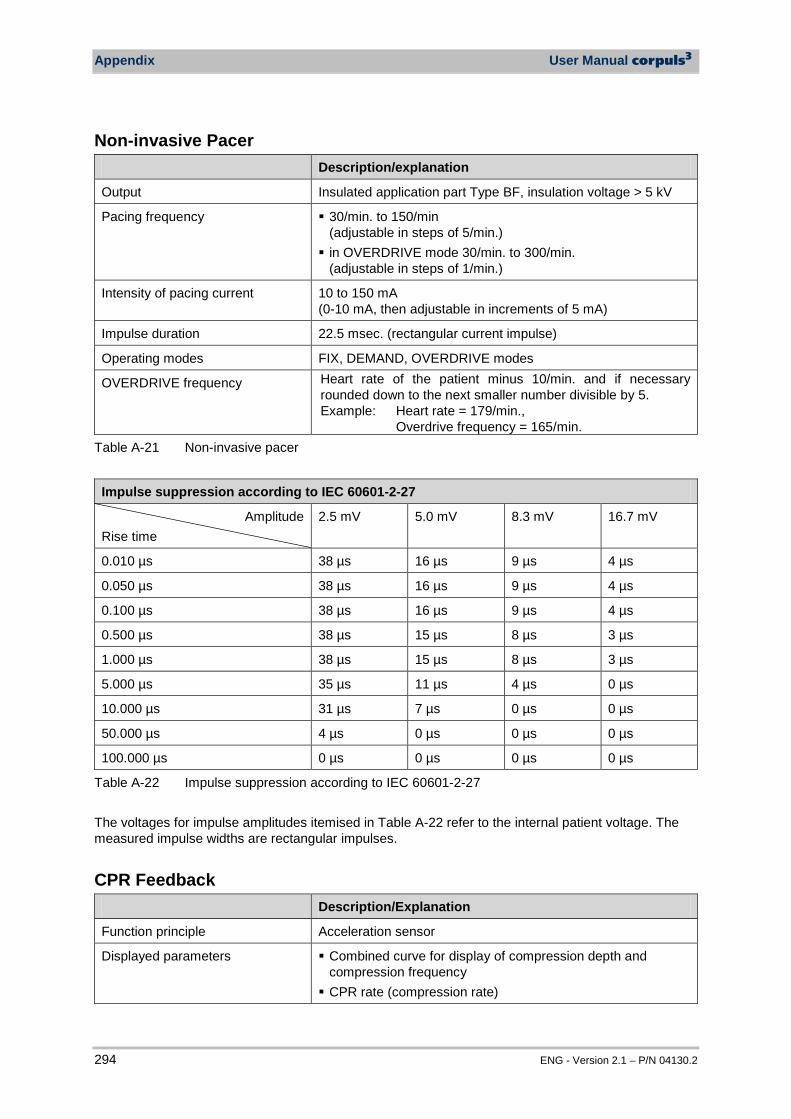
Appendix User Manual corpuls3
294 ENG - Version 2.1 – P/N 04130.2
Non-invasive Pacer Description/explanation
Output Insulated application part Type BF, insulation voltage > 5 kV
Pacing frequency 30/min. to 150/min (adjustable in steps of 5/min.) in OVERDRIVE mode 30/min. to 300/min.
(adjustable in steps of 1/min.)
Intensity of pacing current 10 to 150 mA (0-10 mA, then adjustable in increments of 5 mA)
Impulse duration 22.5 msec. (rectangular current impulse)
Operating modes FIX, DEMAND, OVERDRIVE modes
OVERDRIVE frequency Heart rate of the patient minus 10/min. and if necessary rounded down to the next smaller number divisible by 5. Example: Heart rate = 179/min., Overdrive frequency = 165/min.
Table A-21 Non-invasive pacer
Impulse suppression according to IEC 60601-2-27
Amplitude Rise time
2.5 mV 5.0 mV 8.3 mV 16.7 mV
0.010 µs 38 µs 16 µs 9 µs 4 µs
0.050 µs 38 µs 16 µs 9 µs 4 µs
0.100 µs 38 µs 16 µs 9 µs 4 µs
0.500 µs 38 µs 15 µs 8 µs 3 µs
1.000 µs 38 µs 15 µs 8 µs 3 µs
5.000 µs 35 µs 11 µs 4 µs 0 µs
10.000 µs 31 µs 7 µs 0 µs 0 µs
50.000 µs 4 µs 0 µs 0 µs 0 µs
100.000 µs 0 µs 0 µs 0 µs 0 µs
Table A-22 Impulse suppression according to IEC 60601-2-27
The voltages for impulse amplitudes itemised in Table A-22 refer to the internal patient voltage. The measured impulse widths are rectangular impulses.
CPR Feedback Description/Explanation
Function principle Acceleration sensor
Displayed parameters Combined curve for display of compression depth and compression frequency CPR rate (compression rate)
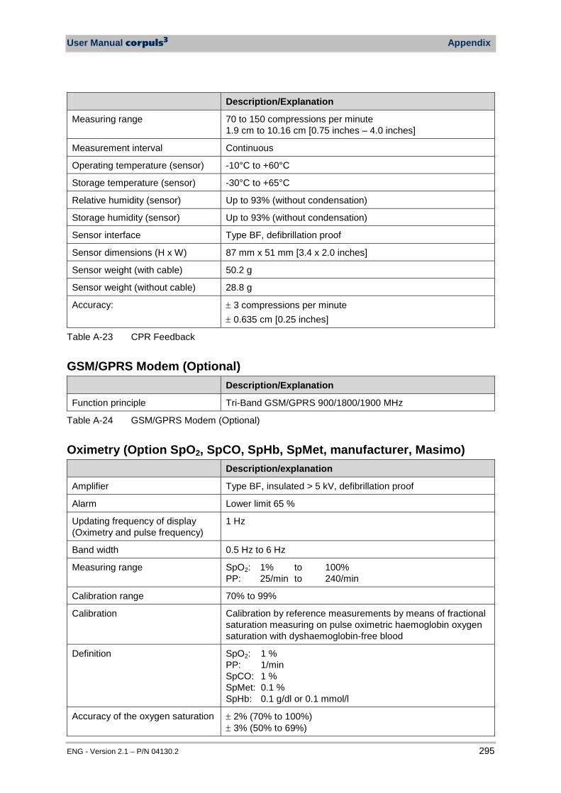
User Manual corpuls3 Appendix
ENG - Version 2.1 – P/N 04130.2 295
Description/Explanation
Measuring range 70 to 150 compressions per minute 1.9 cm to 10.16 cm [0.75 inches – 4.0 inches]
Measurement interval Continuous
Operating temperature (sensor) -10°C to +60°C
Storage temperature (sensor) -30°C to +65°C
Relative humidity (sensor) Up to 93% (without condensation)
Storage humidity (sensor) Up to 93% (without condensation)
Sensor interface Type BF, defibrillation proof
Sensor dimensions (H x W) 87 mm x 51 mm [3.4 x 2.0 inches]
Sensor weight (with cable) 50.2 g
Sensor weight (without cable) 28.8 g
Accuracy: ± 3 compressions per minute ± 0.635 cm [0.25 inches]
Table A-23 CPR Feedback
GSM/GPRS Modem (Optional) Description/Explanation
Function principle Tri-Band GSM/GPRS 900/1800/1900 MHz
Table A-24 GSM/GPRS Modem (Optional)
Oximetry (Option SpO2, SpCO, SpHb, SpMet, manufacturer, Masimo) Description/explanation
Amplifier Type BF, insulated > 5 kV, defibrillation proof
Alarm Lower limit 65 %
Updating frequency of display (Oximetry and pulse frequency)
1 Hz
Band width 0.5 Hz to 6 Hz
Measuring range SpO2: 1% to 100% PP: 25/min to 240/min
Calibration range 70% to 99%
Calibration Calibration by reference measurements by means of fractional saturation measuring on pulse oximetric haemoglobin oxygen saturation with dyshaemoglobin-free blood
Definition SpO2: 1 % PP: 1/min SpCO: 1 % SpMet: 0.1 % SpHb: 0.1 g/dl or 0.1 mmol/l
Accuracy of the oxygen saturation ± 2% (70% to 100%) ± 3% (50% to 69%)
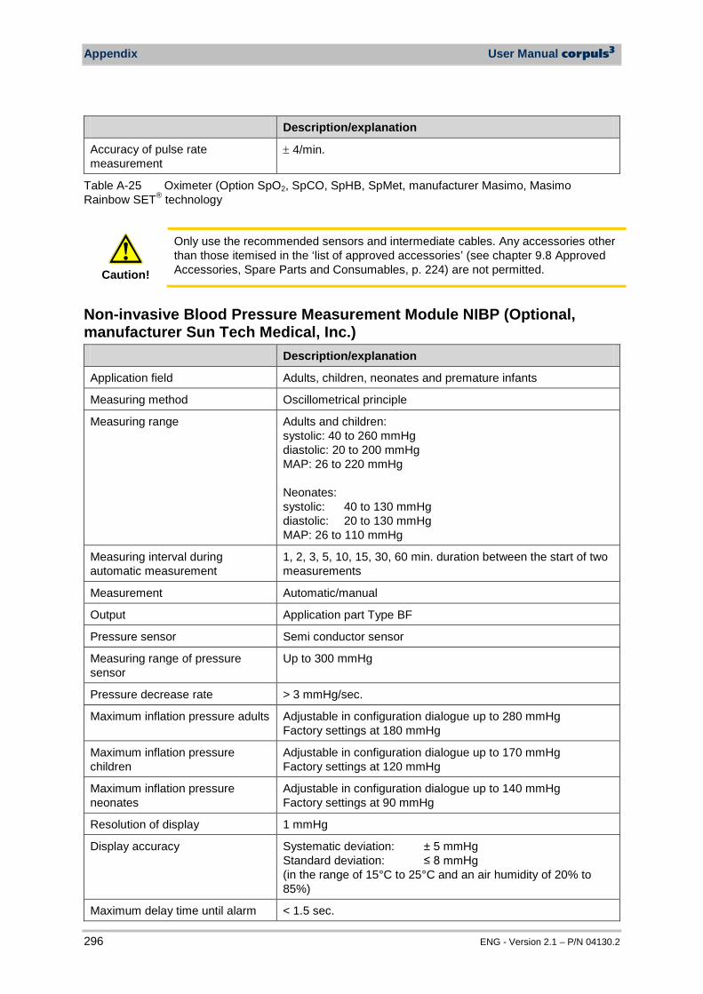
Appendix User Manual corpuls3
296 ENG - Version 2.1 – P/N 04130.2
Description/explanation
Accuracy of pulse rate measurement
± 4/min.
Table A-25 Oximeter (Option SpO2, SpCO, SpHB, SpMet, manufacturer Masimo, Masimo Rainbow SET® technology
Caution!
Only use the recommended sensors and intermediate cables. Any accessories other than those itemised in the ‘list of approved accessories’ (see chapter 9.8 Approved Accessories, Spare Parts and Consumables, p. 224) are not permitted.
Non-invasive Blood Pressure Measurement Module NIBP (Optional, manufacturer Sun Tech Medical, Inc.) Description/explanation
Application field Adults, children, neonates and premature infants
Measuring method Oscillometrical principle
Measuring range Adults and children: systolic: 40 to 260 mmHg diastolic: 20 to 200 mmHg MAP: 26 to 220 mmHg Neonates: systolic: 40 to 130 mmHg diastolic: 20 to 130 mmHg MAP: 26 to 110 mmHg
Measuring interval during automatic measurement
1, 2, 3, 5, 10, 15, 30, 60 min. duration between the start of two measurements
Measurement Automatic/manual
Output Application part Type BF
Pressure sensor Semi conductor sensor
Measuring range of pressure sensor
Up to 300 mmHg
Pressure decrease rate > 3 mmHg/sec.
Maximum inflation pressure adults Adjustable in configuration dialogue up to 280 mmHg Factory settings at 180 mmHg
Maximum inflation pressure children
Adjustable in configuration dialogue up to 170 mmHg Factory settings at 120 mmHg
Maximum inflation pressure neonates
Adjustable in configuration dialogue up to 140 mmHg Factory settings at 90 mmHg
Resolution of display 1 mmHg
Display accuracy
Systematic deviation: ± 5 mmHg Standard deviation: ≤ 8 mmHg (in the range of 15°C to 25°C and an air humidity of 20% to 85%)
Maximum delay time until alarm < 1.5 sec.
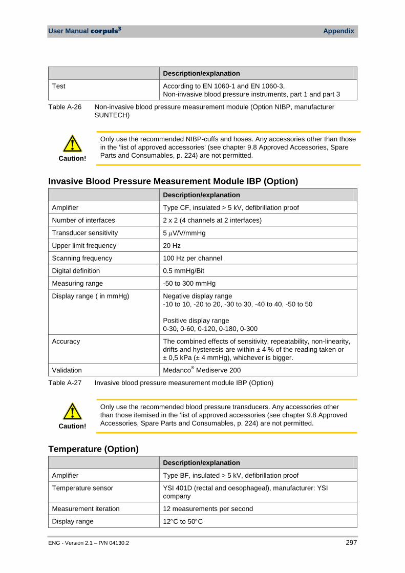
User Manual corpuls3 Appendix
ENG - Version 2.1 – P/N 04130.2 297
Description/explanation
Test According to EN 1060-1 and EN 1060-3, Non-invasive blood pressure instruments, part 1 and part 3
Table A-26 Non-invasive blood pressure measurement module (Option NIBP, manufacturer SUNTECH)
Caution!
Only use the recommended NIBP-cuffs and hoses. Any accessories other than those in the ‘list of approved accessories’ (see chapter 9.8 Approved Accessories, Spare Parts and Consumables, p. 224) are not permitted.
Invasive Blood Pressure Measurement Module IBP (Option) Description/explanation
Amplifier Type CF, insulated > 5 kV, defibrillation proof
Number of interfaces 2 x 2 (4 channels at 2 interfaces)
Transducer sensitivity 5 µV/V/mmHg
Upper limit frequency 20 Hz
Scanning frequency 100 Hz per channel
Digital definition 0.5 mmHg/Bit
Measuring range -50 to 300 mmHg
Display range ( in mmHg) Negative display range -10 to 10, -20 to 20, -30 to 30, -40 to 40, -50 to 50 Positive display range 0-30, 0-60, 0-120, 0-180, 0-300
Accuracy The combined effects of sensitivity, repeatability, non-linearity, drifts and hysteresis are within ± 4 % of the reading taken or ± 0,5 kPa (± 4 mmHg), whichever is bigger.
Validation Medanco® Mediserve 200
Table A-27 Invasive blood pressure measurement module IBP (Option)
Caution!
Only use the recommended blood pressure transducers. Any accessories other than those itemised in the ‘list of approved accessories (see chapter 9.8 Approved Accessories, Spare Parts and Consumables, p. 224) are not permitted.
Temperature (Option) Description/explanation
Amplifier Type BF, insulated > 5 kV, defibrillation proof
Temperature sensor YSI 401D (rectal and oesophageal), manufacturer: YSI company
Measurement iteration 12 measurements per second
Display range 12°C to 50°C
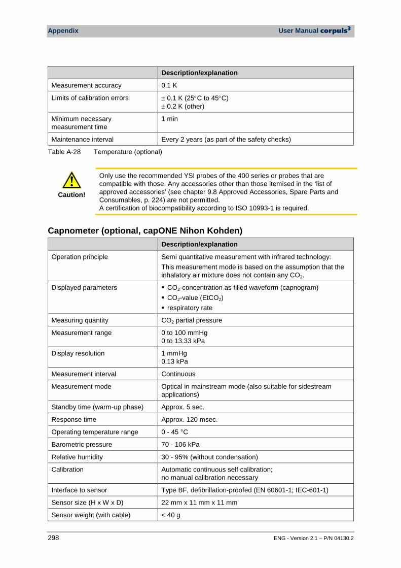
Appendix User Manual corpuls3
298 ENG - Version 2.1 – P/N 04130.2
Description/explanation
Measurement accuracy 0.1 K
Limits of calibration errors ± 0.1 K (25°C to 45°C) ± 0.2 K (other)
Minimum necessary measurement time
1 min
Maintenance interval Every 2 years (as part of the safety checks)
Table A-28 Temperature (optional)
Caution!
Only use the recommended YSI probes of the 400 series or probes that are compatible with those. Any accessories other than those itemised in the ‘list of approved accessories’ (see chapter 9.8 Approved Accessories, Spare Parts and Consumables, p. 224) are not permitted. A certification of biocompatibility according to ISO 10993-1 is required.
Capnometer (optional, capONE Nihon Kohden) Description/explanation
Operation principle Semi quantitative measurement with infrared technology: This measurement mode is based on the assumption that the inhalatory air mixture does not contain any CO2.
Displayed parameters CO2-concentration as filled waveform (capnogram) CO2-value (EtCO2) respiratory rate
Measuring quantity CO2 partial pressure
Measurement range 0 to 100 mmHg 0 to 13.33 kPa
Display resolution 1 mmHg 0.13 kPa
Measurement interval Continuous
Measurement mode Optical in mainstream mode (also suitable for sidestream applications)
Standby time (warm-up phase) Approx. 5 sec.
Response time Approx. 120 msec.
Operating temperature range 0 - 45 °C
Barometric pressure 70 - 106 kPa
Relative humidity 30 - 95% (without condensation)
Calibration Automatic continuous self calibration; no manual calibration necessary
Interface to sensor Type BF, defibrillation-proofed (EN 60601-1; IEC-601-1)
Sensor size (H x W x D) 22 mm x 11 mm x 11 mm
Sensor weight (with cable) < 40 g
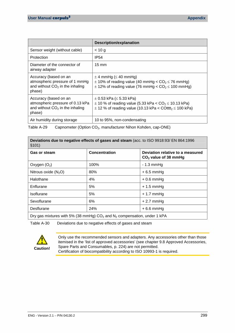
User Manual corpuls3 Appendix
ENG - Version 2.1 – P/N 04130.2 299
Description/explanation
Sensor weight (without cable) < 10 g
Protection IP54
Diameter of the connector of airway adapter
15 mm
Accuracy (based on an atmospheric pressure of 1 mmHg and without CO2 in the inhaling phase)
± 4 mmHg (≤ 40 mmHg) ± 10% of reading value (40 mmHg < CO2 ≤ 76 mmHg) ± 12% of reading value (76 mmHg < CO2 ≤ 100 mmHg)
Accuracy (based on an atmospheric pressure of 0.13 kPa and without CO2 in the inhaling phase)
± 0.53 kPa (≤ 5.33 kPa) ± 10 % of reading value (5.33 kPa < CO2 ≤ 10.13 kPa) ± 12 % of reading value (10.13 kPa < COtttt2 ≤ 100 kPa)
Air humidity during storage 10 to 95%, non-condensating
Table A-29 Capnometer (Option CO2, manufacturer Nihon Kohden, cap-ONE)
Deviations due to negative effects of gases and steam (acc. to ISO 9918:93/ EN 864:1996 §101)
Gas or steam Concentration Deviation relative to a measured CO2 value of 38 mmHg
Oxygen (O2) 100% - 1.3 mmHg
Nitrous oxide (N2O) 80% + 6.5 mmHg
Halothane 4% + 0.6 mmHg
Enflurane 5% + 1.5 mmHg
Isoflurane 5% + 1.7 mmHg
Sevoflurane 6% + 2.7 mmHg
Desflurane 24% + 6.6 mmHg
Dry gas mixtures with 5% (38 mmHg) CO2 and N2 compensation, under 1 kPA
Table A-30 Deviations due to negative effects of gases and steam
Caution!
Only use the recommended sensors and adapters. Any accessories other than those itemised in the ‘list of approved accessories’ (see chapter 9.8 Approved Accessories, Spare Parts and Consumables, p. 224) are not permitted. Certification of biocompatibility according to ISO 10993-1 is required.
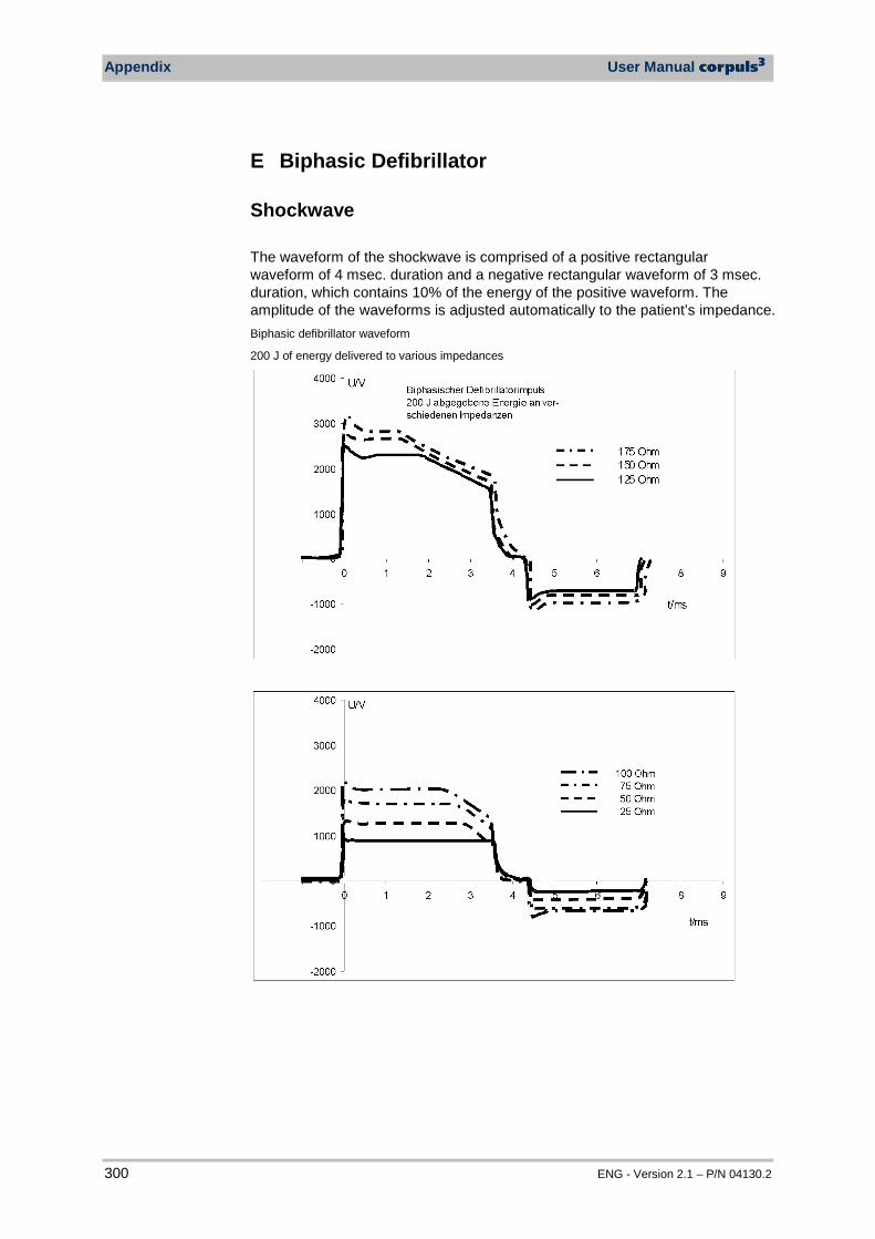
Appendix User Manual corpuls3
300 ENG - Version 2.1 – P/N 04130.2
E Biphasic Defibrillator
Shockwave The waveform of the shockwave is comprised of a positive rectangular waveform of 4 msec. duration and a negative rectangular waveform of 3 msec. duration, which contains 10% of the energy of the positive waveform. The amplitude of the waveforms is adjusted automatically to the patient’s impedance. Biphasic defibrillator waveform
200 J of energy delivered to various impedances
User Manual corpuls3 Appendix
ENG - Version 2.1 – P/N 04130.2 301
Shock Release Synchronisation Manual defibrillation and cardioversion are automatically performed synchronously. If no R-waves are detected in the ECG (e.g. in case of fibrillation), a shock will immediately be delivered asynchronously when the shock button is pressed (shock release). Further information regarding manual defibrillation and cardioversion can be found in chapter 5.4 Manual Defibrillation and Cardioversion, page 74.
Warning
A cardioversion may lead to fibrillation or asystole. When performing a cardioversion,mind the following:
• The ECG has to be stable with a heart rate of at least 60/min. • The synchronisation status has to remain constantly on SYNC. • The QRS marks (triangles) have to mark each QRS complex. • The shock release has to be effected according to valid guidelines. • If the shock release does not take place one second after pressing
the buttons at the shock paddles or the Shock key at the monitoring unit, the shock will be released independent of the synchronisation status.
Protective Function of the Safety Shock Paddles Every safety shock paddle possesses a protective electrode between the handle and the application electrode surface. The protective electrodes of both shock paddles are connected to one another inside corpuls3. Consequently, during defibrillation with wet or dirty shock paddles, no dangerous current can flow from one electrode over the body of the user to another electrode, since this current is diverted by the protective electrodes.
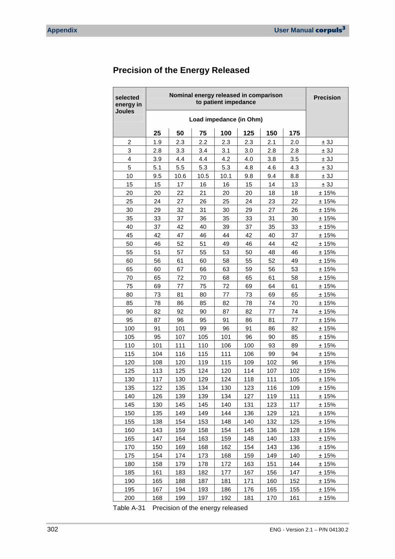
Appendix User Manual corpuls3
302 ENG - Version 2.1 – P/N 04130.2
Precision of the Energy Released selected energy in Joules
Nominal energy released in comparison to patient impedance
Precision
Load impedance (in Ohm)
25 50 75 100 125 150 175 2 1.9 2.3 2.2 2.3 2.3 2.1 2.0 ± 3J 3 2.8 3.3 3.4 3.1 3.0 2.8 2.8 ± 3J 4 3.9 4.4 4.4 4.2 4.0 3.8 3.5 ± 3J 5 5.1 5.5 5.3 5.3 4.8 4.6 4.3 ± 3J 10 9.5 10.6 10.5 10.1 9.8 9.4 8.8 ± 3J 15 15 17 16 16 15 14 13 ± 3J 20 20 22 21 20 20 18 18 ± 15% 25 24 27 26 25 24 23 22 ± 15% 30 29 32 31 30 29 27 26 ± 15% 35 33 37 36 35 33 31 30 ± 15% 40 37 42 40 39 37 35 33 ± 15% 45 42 47 46 44 42 40 37 ± 15% 50 46 52 51 49 46 44 42 ± 15% 55 51 57 55 53 50 48 46 ± 15% 60 56 61 60 58 55 52 49 ± 15% 65 60 67 66 63 59 56 53 ± 15% 70 65 72 70 68 65 61 58 ± 15% 75 69 77 75 72 69 64 61 ± 15% 80 73 81 80 77 73 69 65 ± 15% 85 78 86 85 82 78 74 70 ± 15% 90 82 92 90 87 82 77 74 ± 15% 95 87 96 95 91 86 81 77 ± 15%
100 91 101 99 96 91 86 82 ± 15% 105 95 107 105 101 96 90 85 ± 15% 110 101 111 110 106 100 93 89 ± 15% 115 104 116 115 111 106 99 94 ± 15% 120 108 120 119 115 109 102 96 ± 15% 125 113 125 124 120 114 107 102 ± 15% 130 117 130 129 124 118 111 105 ± 15% 135 122 135 134 130 123 116 109 ± 15% 140 126 139 139 134 127 119 111 ± 15% 145 130 145 145 140 131 123 117 ± 15% 150 135 149 149 144 136 129 121 ± 15% 155 138 154 153 148 140 132 125 ± 15% 160 143 159 158 154 145 136 128 ± 15% 165 147 164 163 159 148 140 133 ± 15% 170 150 169 168 162 154 143 136 ± 15% 175 154 174 173 168 159 149 140 ± 15% 180 158 179 178 172 163 151 144 ± 15% 185 161 183 182 177 167 156 147 ± 15% 190 165 188 187 181 171 160 152 ± 15% 195 167 194 193 186 176 165 155 ± 15% 200 168 199 197 192 181 170 161 ± 15%
Table A-31 Precision of the energy released
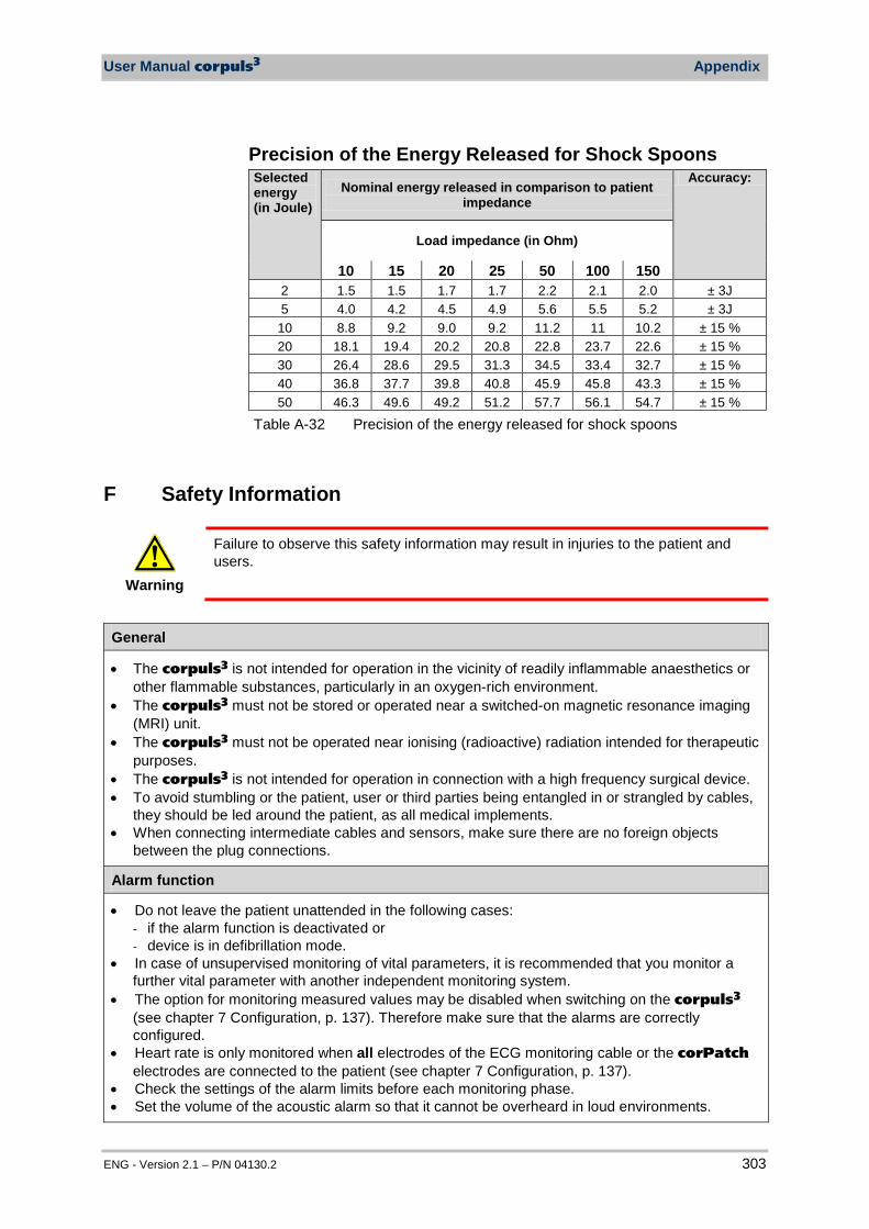
User Manual corpuls3 Appendix
ENG - Version 2.1 – P/N 04130.2 303
Precision of the Energy Released for Shock Spoons Selected energy (in Joule)
Nominal energy released in comparison to patient impedance
Accuracy:
Load impedance (in Ohm)
10 15 20 25 50 100 150 2 1.5 1.5 1.7 1.7 2.2 2.1 2.0 ± 3J 5 4.0 4.2 4.5 4.9 5.6 5.5 5.2 ± 3J 10 8.8 9.2 9.0 9.2 11.2 11 10.2 ± 15 % 20 18.1 19.4 20.2 20.8 22.8 23.7 22.6 ± 15 % 30 26.4 28.6 29.5 31.3 34.5 33.4 32.7 ± 15 % 40 36.8 37.7 39.8 40.8 45.9 45.8 43.3 ± 15 % 50 46.3 49.6 49.2 51.2 57.7 56.1 54.7 ± 15 %
Table A-32 Precision of the energy released for shock spoons
F Safety Information
Warning
Failure to observe this safety information may result in injuries to the patient and users.
General
• The corpuls3 is not intended for operation in the vicinity of readily inflammable anaesthetics or other flammable substances, particularly in an oxygen-rich environment.
• The corpuls3 must not be stored or operated near a switched-on magnetic resonance imaging (MRI) unit.
• The corpuls3 must not be operated near ionising (radioactive) radiation intended for therapeutic purposes.
• The corpuls3 is not intended for operation in connection with a high frequency surgical device. • To avoid stumbling or the patient, user or third parties being entangled in or strangled by cables,
they should be led around the patient, as all medical implements. • When connecting intermediate cables and sensors, make sure there are no foreign objects
between the plug connections.
Alarm function
• Do not leave the patient unattended in the following cases: - if the alarm function is deactivated or - device is in defibrillation mode.
• In case of unsupervised monitoring of vital parameters, it is recommended that you monitor a further vital parameter with another independent monitoring system.
• The option for monitoring measured values may be disabled when switching on the corpuls3 (see chapter 7 Configuration, p. 137). Therefore make sure that the alarms are correctly configured.
• Heart rate is only monitored when all electrodes of the ECG monitoring cable or the corPatch electrodes are connected to the patient (see chapter 7 Configuration, p. 137).
• Check the settings of the alarm limits before each monitoring phase. • Set the volume of the acoustic alarm so that it cannot be overheard in loud environments.
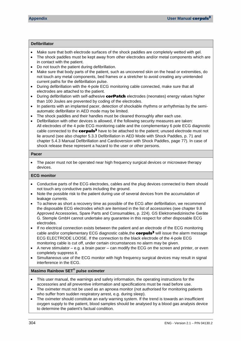
Appendix User Manual corpuls3
304 ENG - Version 2.1 – P/N 04130.2
Defibrillator
• Make sure that both electrode surfaces of the shock paddles are completely wetted with gel. • The shock paddles must be kept away from other electrodes and/or metal components which are
in contact with the patient. • Do not touch the patient during defibrillation. • Make sure that body parts of the patient, such as uncovered skin on the head or extremities, do
not touch any metal components, bed frames or a stretcher to avoid creating any unintended current paths for the defibrillation pulse.
• During defibrillation with the 4-pole ECG monitoring cable connected, make sure that all electrodes are attached to the patient.
• During defibrillation with self-adhesive corPatch electrodes (neonates) energy values higher than 100 Joules are prevented by coding of the electrodes.
• In patients with an implanted pacer, detection of shockable rhythms or arrhythmias by the semi-automatic defibrillator in AED mode may be limited.
• The shock paddles and their handles must be cleaned thoroughly after each use. • Defibrillation with other devices is allowed, if the following security measures are taken:
All electrodes of the 4 pole ECG monitoring cable and the complementary 6 pole ECG diagnostic cable connected to the corpuls3 have to be attached to the patient; unused electrode must not lie around (see also chapter 5.3.3 Defibrillation in AED Mode with Shock Paddles, p. 71 and chapter 5.4.3 Manual Defibrillation and Cardioversion with Shock Paddles, page 77). In case of shock release these represent a hazard to the user or other persons.
Pacer
• The pacer must not be operated near high frequency surgical devices or microwave therapy devices.
ECG monitor
• Conductive parts of the ECG electrodes, cables and the plug devices connected to them should not touch any conductive parts including the ground.
• Note the possible risk to the patient during use of several devices from the accumulation of leakage currents.
• To achieve as short a recovery time as possible of the ECG after defibrillation, we recommend the disposable ECG electrodes which are itemised in the list of accessories (see chapter 9.8 Approved Accessories, Spare Parts and Consumables, p. 224). GS Elektromedizinische Geräte G. Stemple GmbH cannot undertake any guarantee in this respect for other disposable ECG electrodes.
• If no electrical connection exists between the patient and an electrode of the ECG monitoring cable and/or complementary ECG diagnostic cable,the corpuls3 will issue the alarm message ECG ELECTRODE LOOSE. If the connection to the black electrode of the 4-pole ECG monitoring cable is cut off, under certain circumstances no alarm may be given.
• A nerve stimulator – e.g. a brain pacer – can modify the ECG on the screen and printer, or even completely suppress it.
• Simultaneous use of the ECG monitor with high frequency surgical devices may result in signal interference in the ECG.
Masimo Rainbow SET® pulse oximeter
• This user manual, the warnings and safety information, the operating instructions for the accessories and all preventive information and specifications must be read before use.
• The oximeter must not be used as an apnoea monitor (not authorised for monitoring patients who suffer from sudden respiratory arrest, e.g. during sleep).
• The oximeter should constitute an early warning system. If the trend is towards an insufficient oxygen supply to the patient, blood samples should be analysed by a blood gas analysis device to determine the patient’s factual condition.
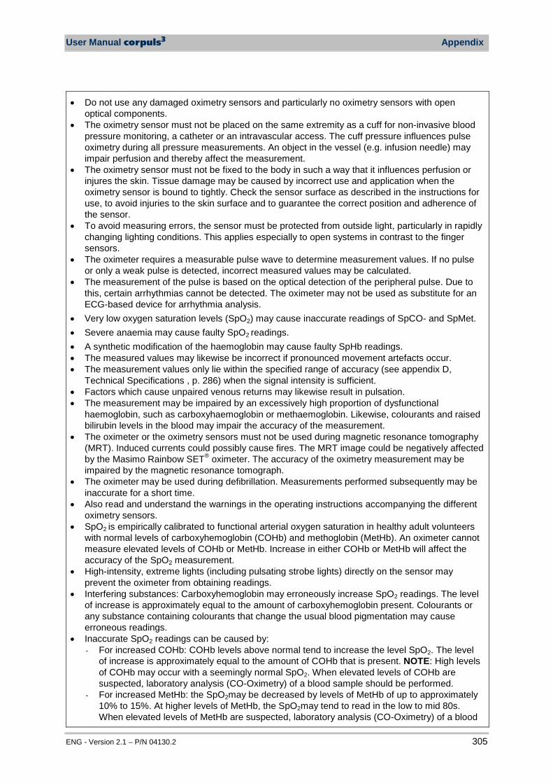
User Manual corpuls3 Appendix
ENG - Version 2.1 – P/N 04130.2 305
• Do not use any damaged oximetry sensors and particularly no oximetry sensors with open optical components.
• The oximetry sensor must not be placed on the same extremity as a cuff for non-invasive blood pressure monitoring, a catheter or an intravascular access. The cuff pressure influences pulse oximetry during all pressure measurements. An object in the vessel (e.g. infusion needle) may impair perfusion and thereby affect the measurement.
• The oximetry sensor must not be fixed to the body in such a way that it influences perfusion or injures the skin. Tissue damage may be caused by incorrect use and application when the oximetry sensor is bound to tightly. Check the sensor surface as described in the instructions for use, to avoid injuries to the skin surface and to guarantee the correct position and adherence of the sensor.
• To avoid measuring errors, the sensor must be protected from outside light, particularly in rapidly changing lighting conditions. This applies especially to open systems in contrast to the finger sensors.
• The oximeter requires a measurable pulse wave to determine measurement values. If no pulse or only a weak pulse is detected, incorrect measured values may be calculated.
• The measurement of the pulse is based on the optical detection of the peripheral pulse. Due to this, certain arrhythmias cannot be detected. The oximeter may not be used as substitute for an ECG-based device for arrhythmia analysis.
• Very low oxygen saturation levels (SpO2) may cause inaccurate readings of SpCO- and SpMet. • Severe anaemia may cause faulty SpO2 readings. • A synthetic modification of the haemoglobin may cause faulty SpHb readings. • The measured values may likewise be incorrect if pronounced movement artefacts occur. • The measurement values only lie within the specified range of accuracy (see appendix D,
Technical Specifications , p. 286) when the signal intensity is sufficient. • Factors which cause unpaired venous returns may likewise result in pulsation. • The measurement may be impaired by an excessively high proportion of dysfunctional
haemoglobin, such as carboxyhaemoglobin or methaemoglobin. Likewise, colourants and raised bilirubin levels in the blood may impair the accuracy of the measurement.
• The oximeter or the oximetry sensors must not be used during magnetic resonance tomography (MRT). Induced currents could possibly cause fires. The MRT image could be negatively affected by the Masimo Rainbow SET® oximeter. The accuracy of the oximetry measurement may be impaired by the magnetic resonance tomograph.
• The oximeter may be used during defibrillation. Measurements performed subsequently may be inaccurate for a short time.
• Also read and understand the warnings in the operating instructions accompanying the different oximetry sensors.
• SpO2 is empirically calibrated to functional arterial oxygen saturation in healthy adult volunteers with normal levels of carboxyhemoglobin (COHb) and methoglobin (MetHb). An oximeter cannot measure elevated levels of COHb or MetHb. Increase in either COHb or MetHb will affect the accuracy of the SpO2 measurement.
• High-intensity, extreme lights (including pulsating strobe lights) directly on the sensor may prevent the oximeter from obtaining readings.
• Interfering substances: Carboxyhemoglobin may erroneously increase SpO2 readings. The level of increase is approximately equal to the amount of carboxyhemoglobin present. Colourants or any substance containing colourants that change the usual blood pigmentation may cause erroneous readings.
• Inaccurate SpO2 readings can be caused by: - For increased COHb: COHb levels above normal tend to increase the level SpO2. The level
of increase is approximately equal to the amount of COHb that is present. NOTE: High levels of COHb may occur with a seemingly normal SpO2. When elevated levels of COHb are suspected, laboratory analysis (CO-Oximetry) of a blood sample should be performed.
- For increased MetHb: the SpO2may be decreased by levels of MetHb of up to approximately 10% to 15%. At higher levels of MetHb, the SpO2may tend to read in the low to mid 80s. When elevated levels of MetHb are suspected, laboratory analysis (CO-Oximetry) of a blood

Appendix User Manual corpuls3
306 ENG - Version 2.1 – P/N 04130.2
sample should be performed. • A functional tester cannot be utilized to assess the accuracy of the oximeter or any sensors. • Elevated levels of methemoglobin (MetHb) will lead to inaccurate SpO2 and SpCO
measurements. • Elevated levels of carboxyhemoglobin (COHb) will lead to inaccurate SpO2 measurements. • Elevated levels of total bilurubin may lead to inaccurate SpO2, SpMet, SpCO and SpHb
measurements. • Very low arterial oxygen saturation (SpO2) levels may cause inaccurate SpCO and SpMet
measurements. • Severe anemia may cause erroneous SpO2 readings • Hemoglobin synthesis disorders may cause erroneous SpHb readings. • If using oximetry during full body irradiation, keep the sensor out of the radiation field. If the
sensor is exposed to the radiation, the reading might be inaccurate or the device might read zero for the duration of the active radiation period.
• Additional information specification to Masimo sensors, including information about parameter/measurement performance during motion and low perfusion, may be found in the sensor’s Directions for Use (DFU)
• The oximeter may not be operated in the vicinity of ionising (radioactive) radiation, as this may falsify the readings.
capOne capnometer, Nihon Kohden
• The capnometer in the corpuls3 is an additional function for intensive monitoring. Consequently, the vital parameters and clinical symptoms must be monitored during use of the capnometer on the patient.
• The sensor may only be used in conjunction with the approved CO2 airway adapters (see chapter 9.8 Approved Accessories, Spare Parts and Consumables, p. 224).
• Do not use damaged sensors, e.g. sensors with exposed electrical contacts.
Non-invasive blood pressure monitoring
• Avoid squeezing or reducing the diameter of the pressure hose to the cuff. • When using the device for a longer time, check the limb of the patient on which non-invasive
blood pressure monitoring is performed for impairment of the blood circulation. • When selecting the initial pressure, care should be taken that it is markedly above (approx. 30
mmHg) the expected systolic blood pressure. In case of doubt, a somewhat higher initial pressure is preferred.
Invasive blood pressure monitoring
• Monitoring with two or more transducers: if two or more blood pressure transducers are connected to the corpuls3 for monitoring, these must all be connected to the patient. If one of the transducers is not connected to the patient and lies open or hangs free, this may provide unintended current paths during defibrillation. Use transducers with specified isolation (5 kV DC).
• Carefully read and follow the operating instructions of the transducers you are using. • If non-invasive blood pressure monitoring is also performed on the same limb during invasive
blood pressure monitoring, the non-invasive monitoring will negatively affect the measurement results of the invasive measurement.
• Per connection socket at the patient box two transducer ports are merged. These are not isolated from each other (P1 and P2, P3 and P4).
• Invasive blood pressure measurement is not protected against high frequency surgical devices or microwave therapy devices.
Temperature measurement
• Carefully read and follow the operating instructions of the temperature sensor that you are using.
Table A-33 Safety information
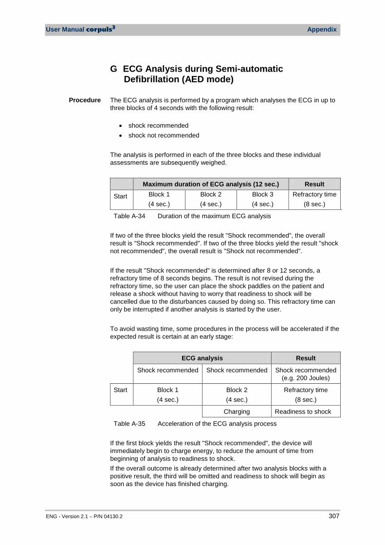
User Manual corpuls3 Appendix
ENG - Version 2.1 – P/N 04130.2 307
G ECG Analysis during Semi-automatic Defibrillation (AED mode)
The ECG analysis is performed by a program which analyses the ECG in up to three blocks of 4 seconds with the following result:
• shock recommended • shock not recommended
The analysis is performed in each of the three blocks and these individual assessments are subsequently weighed.
Maximum duration of ECG analysis (12 sec.) Result
Start Block 1 (4 sec.)
Block 2 (4 sec.)
Block 3 (4 sec.)
Refractory time (8 sec.)
Table A-34 Duration of the maximum ECG analysis If two of the three blocks yield the result "Shock recommended", the overall result is "Shock recommended". If two of the three blocks yield the result "shock not recommended", the overall result is "Shock not recommended".
If the result "Shock recommended" is determined after 8 or 12 seconds, a refractory time of 8 seconds begins. The result is not revised during the refractory time, so the user can place the shock paddles on the patient and release a shock without having to worry that readiness to shock will be cancelled due to the disturbances caused by doing so. This refractory time can only be interrupted if another analysis is started by the user. To avoid wasting time, some procedures in the process will be accelerated if the expected result is certain at an early stage:
ECG analysis Result
Shock recommended Shock recommended Shock recommended (e.g. 200 Joules)
Start Block 1 (4 sec.)
Block 2 (4 sec.)
Refractory time (8 sec.)
Charging Readiness to shock
Table A-35 Acceleration of the ECG analysis process If the first block yields the result "Shock recommended", the device will immediately begin to charge energy, to reduce the amount of time from beginning of analysis to readiness to shock. If the overall outcome is already determined after two analysis blocks with a positive result, the third will be omitted and readiness to shock will begin as soon as the device has finished charging.
Procedure
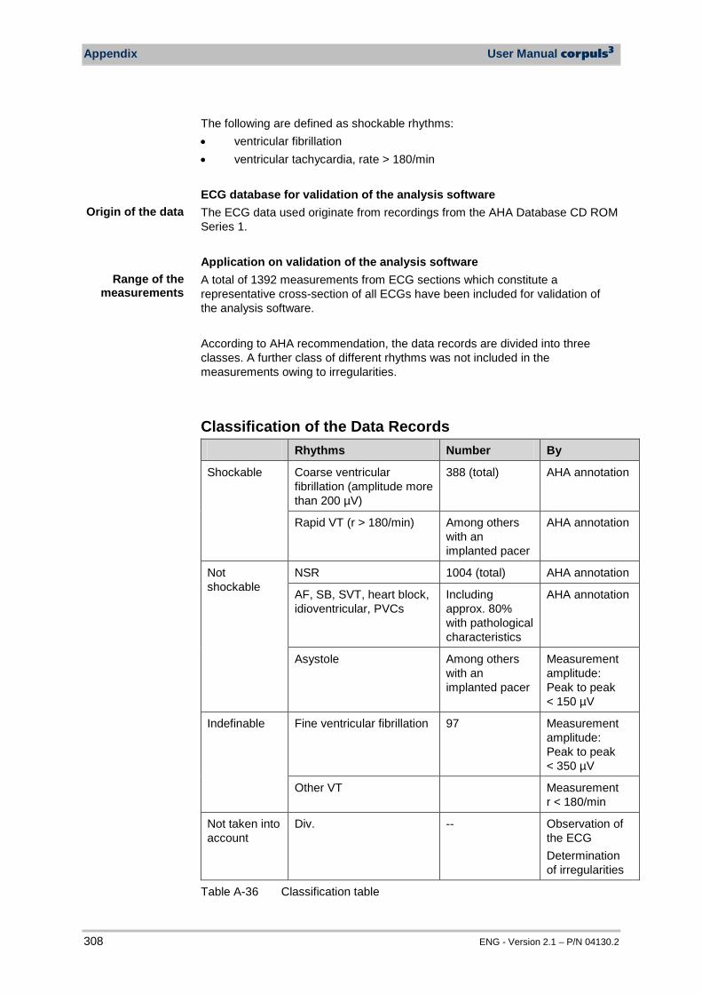
Appendix User Manual corpuls3
308 ENG - Version 2.1 – P/N 04130.2
The following are defined as shockable rhythms: • ventricular fibrillation • ventricular tachycardia, rate > 180/min ECG database for validation of the analysis software The ECG data used originate from recordings from the AHA Database CD ROM Series 1. Application on validation of the analysis software A total of 1392 measurements from ECG sections which constitute a representative cross-section of all ECGs have been included for validation of the analysis software. According to AHA recommendation, the data records are divided into three classes. A further class of different rhythms was not included in the measurements owing to irregularities.
Classification of the Data Records Rhythms Number By
Shockable Coarse ventricular fibrillation (amplitude more than 200 µV)
388 (total) AHA annotation
Rapid VT (r > 180/min) Among others with an implanted pacer
AHA annotation
Not shockable
NSR 1004 (total) AHA annotation
AF, SB, SVT, heart block, idioventricular, PVCs
Including approx. 80% with pathological characteristics
AHA annotation
Asystole Among others with an implanted pacer
Measurement amplitude: Peak to peak < 150 µV
Indefinable Fine ventricular fibrillation 97 Measurement amplitude: Peak to peak < 350 µV
Other VT Measurement r < 180/min
Not taken into account
Div. -- Observation of the ECG Determination of irregularities
Table A-36 Classification table
Origin of the data
Range of the
measurements
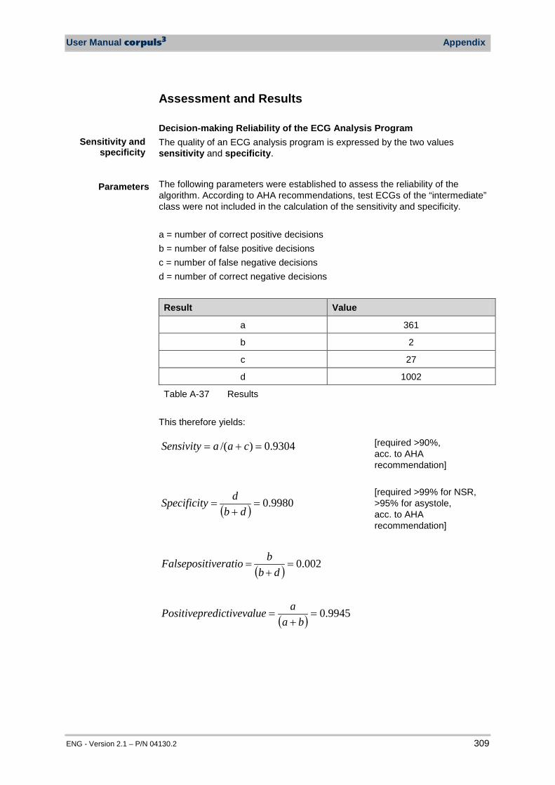
User Manual corpuls3 Appendix
ENG - Version 2.1 – P/N 04130.2 309
Assessment and Results Decision-making Reliability of the ECG Analysis Program The quality of an ECG analysis program is expressed by the two values sensitivity and specificity.
The following parameters were established to assess the reliability of the algorithm. According to AHA recommendations, test ECGs of the “intermediate” class were not included in the calculation of the sensitivity and specificity. a = number of correct positive decisions b = number of false positive decisions c = number of false negative decisions d = number of correct negative decisions
Result Value
a 361
b 2
c 27
d 1002
Table A-37 Results This therefore yields:
9304.0)/( =+= caaSensivity [required >90%, acc. to AHA recommendation]
( ) 9980.0=+
=db
dySpecificit [required >99% for NSR, >95% for asystole, acc. to AHA recommendation]
( ) 002.0=+
=db
biveratioFalseposit
( ) 9945.0=+
=ba
alueedictivevaPositivepr
Parameters
Sensitivity and specificity

Appendix User Manual corpuls3
310 ENG - Version 2.1 – P/N 04130.2
H corpuls3 HYPERBARIC (HBO) The product variant corpuls3 HYPERBARIC is approved for operation in a multiplace hyperbaric chamber during hyperbaric oxygen therapy (HBO) up to an overpressure of 3 barg and a maximum oxygen concentration of 23% (Certificate No. 77492-11, Germanischer Lloyd SE, Hamburg). For further information that go beyond this appendix, please contact the manufacturer or their authorised sales and service partners. When the door of the hyperbaric chamber is closed, the reach of the wireless connection towards modules outside the chamber is reduced.
Caution
There can be changes in the measured values of non-invasive blood pressure measurement (option) during the build-up and decrease of pressure inside the pressure chamber. Do not perform NIBP measurements during the diving phases.
Caution
The can be changes in the measured values of CO2 monitoring (option), because the CO2 partial pressures are changing under pressure.
Warning
Charging the monitoring unit and the patient box inside the pressure chamber is only allowed via the charging bracket for monitoring unit, P/N, 04401. The use of MagCode connectors and charging brackets with integrated MagCode is forbidden for charging the monitoring unit, the patient box and the defibrillator/pacer. The red cover over the magnetic contact fields may not be removed.
Warning
When administering oxygen via inhalation mask or nasal cannula or when using a ventilation bag with reservoir, make sure that no oxygen accumulates above the corPatch electrodes. When defibrillation is imminent, the oxygen supply has to be shut off.
Warning
The use of swivelling adapters (swivelling adapter 35 °, P/N 04406.01 and swivelling adapter 60 °, P/N 04406) is forbidden inside the pressure chamber.
Warning
The protection of the power supply for the charging bracket for the monitoring unit, P/N 04401 has to be minimum 6 A and maximum 10 A.
Warning
To guarantee safe operation of the device in a hyperbaric chamber, exclusively use the materials itemised in the list of accessories approved for operation in hyperbaric chamber (see chapter 9.8 Approved Accessories, Spare Parts and Consumables, page 224). Modules, batteries and accessories without HBO certificate may not be used in combination with HBO certified modules, batteries and accessories.
Operation in hyperbaric chamber
up to 3 barg and 23% oxygen
Note
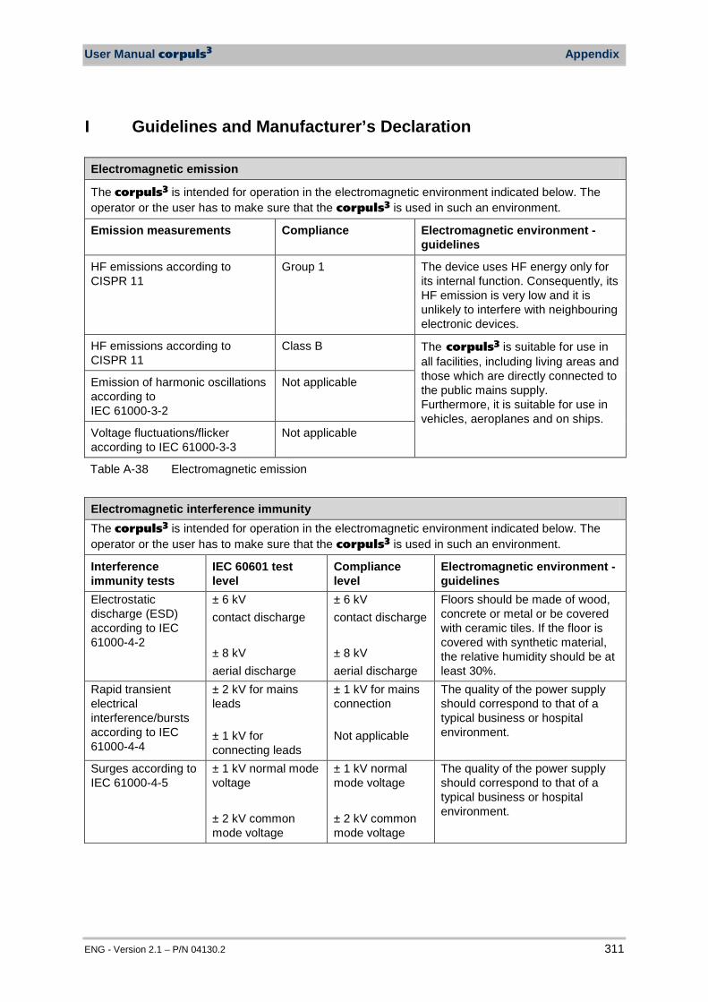
User Manual corpuls3 Appendix
ENG - Version 2.1 – P/N 04130.2 311
I Guidelines and Manufacturer’s Declaration
Electromagnetic emission
The corpuls3 is intended for operation in the electromagnetic environment indicated below. The operator or the user has to make sure that the corpuls3 is used in such an environment.
Emission measurements Compliance Electromagnetic environment - guidelines
HF emissions according to CISPR 11
Group 1 The device uses HF energy only for its internal function. Consequently, its HF emission is very low and it is unlikely to interfere with neighbouring electronic devices.
HF emissions according to CISPR 11
Class B The corpuls3 is suitable for use in all facilities, including living areas and those which are directly connected to the public mains supply. Furthermore, it is suitable for use in vehicles, aeroplanes and on ships.
Emission of harmonic oscillations according to IEC 61000-3-2
Not applicable
Voltage fluctuations/flicker according to IEC 61000-3-3
Not applicable
Table A-38 Electromagnetic emission
Electromagnetic interference immunity The corpuls3 is intended for operation in the electromagnetic environment indicated below. The operator or the user has to make sure that the corpuls3 is used in such an environment.
Interference immunity tests
IEC 60601 test level
Compliance level
Electromagnetic environment - guidelines
Electrostatic discharge (ESD) according to IEC 61000-4-2
± 6 kV contact discharge ± 8 kV aerial discharge
± 6 kV contact discharge ± 8 kV aerial discharge
Floors should be made of wood, concrete or metal or be covered with ceramic tiles. If the floor is covered with synthetic material, the relative humidity should be at least 30%.
Rapid transient electrical interference/bursts according to IEC 61000-4-4
± 2 kV for mains leads ± 1 kV for connecting leads
± 1 kV for mains connection Not applicable
The quality of the power supply should correspond to that of a typical business or hospital environment.
Surges according to IEC 61000-4-5
± 1 kV normal mode voltage ± 2 kV common mode voltage
± 1 kV normal mode voltage ± 2 kV common mode voltage
The quality of the power supply should correspond to that of a typical business or hospital environment.
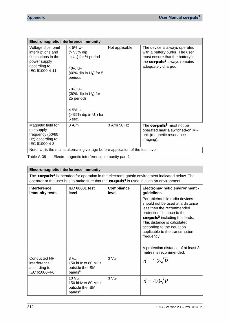
Appendix User Manual corpuls3
312 ENG - Version 2.1 – P/N 04130.2
Electromagnetic interference immunity Voltage dips, brief interruptions and fluctuations in the power supply according to IEC 61000-4-11
< 5% UT (> 95% dip in UT) for ½ period 40% UT (60% dip in UT) for 5 periods 70% UT (30% dip in UT) for 25 periods < 5% UT (> 95% dip in UT) for 5 sec.
Not applicable The device is always operated with a battery buffer. The user must ensure that the battery in the corpuls3 always remains adequately charged.
Magnetic field for the supply frequency (50/60 Hz) according to IEC 61000-4-8
3 A/m 3 A/m 50 Hz The corpuls3 must not be operated near a switched-on MRI unit (magnetic resonance imaging).
Note: UT is the mains alternating voltage before application of the test level
Table A-39 Electromagnetic interference immunity part 1
Electromagnetic interference immunity The corpuls3 is intended for operation in the electromagnetic environment indicated below. The operator or the user has to make sure that the corpuls3 is used in such an environment.
Interference immunity tests
IEC 60601 test level
Compliance level
Electromagnetic environment - guidelines
Portable/mobile radio devices should not be used at a distance less than the recommended protection distance to the corpuls3 including the leads. This distance is calculated according to the equation applicable to the transmission frequency. A protection distance of at least 3 metres is recommended.
Conducted HF interference according to IEC 61000-4-6
3 Veff 150 kHz to 80 MHz outside the ISM bandsa
3 Veff Pd 2.1=
10 Veff 150 kHz to 80 MHz outside the ISM bandsa
3 Veff Pd 0.4=
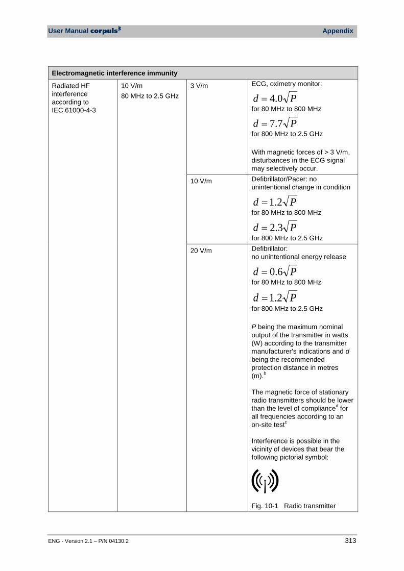
User Manual corpuls3 Appendix
ENG - Version 2.1 – P/N 04130.2 313
Electromagnetic interference immunity
Radiated HF interference according to IEC 61000-4-3
10 V/m 80 MHz to 2.5 GHz
3 V/m
ECG, oximetry monitor:
Pd 0.4= for 80 MHz to 800 MHz
Pd 7.7= for 800 MHz to 2.5 GHz With magnetic forces of > 3 V/m, disturbances in the ECG signal may selectively occur.
10 V/m
Defibrillator/Pacer: no unintentional change in condition
Pd 2.1= for 80 MHz to 800 MHz
Pd 3.2= for 800 MHz to 2.5 GHz
20 V/m Defibrillator: no unintentional energy release
Pd 6.0= for 80 MHz to 800 MHz
Pd 2.1= for 800 MHz to 2.5 GHz P being the maximum nominal output of the transmitter in watts (W) according to the transmitter manufacturer’s indications and d being the recommended protection distance in metres (m).b The magnetic force of stationary radio transmitters should be lower than the level of complianced for all frequencies according to an on-site testc Interference is possible in the vicinity of devices that bear the following pictorial symbol:
Fig. 10-1 Radio transmitter

Appendix User Manual corpuls3
314 ENG - Version 2.1 – P/N 04130.2
Electromagnetic interference immunity
Comment 1: At 80 MHz and 800 MHz, the higher frequency range applies
Comment 2: These guidelines may not be applicable in all cases. Dissipation of electromagnetic variables is influenced by absorption and reflection of the buildings, objects and people. a The ISM frequency bands (for industrial, scientific and medical applications between 150 kHz and 80 MHz)
are 6.765 MHz to 6.795 MHz; 13.553 MHz to 13.567 MHz; 26.957 MHz to 27.283 MHz and 40.66 MHz to 40.70 MHz.
b The compliance levels in the ISM frequency bands between 150 kHz and 80 MHz and in the frequency range of 80 MHz and 2.5 GHz are intended to reduce the likelihood that portable/mobile communication devices will be able to cause interference if they are unintentionally brought into the patient area. For this reason, the additional factor 10/3 is applied in calculating the recommended protection distances in these frequency ranges.
c The magnetic force of stationary transmitters, such as base stations of mobile telephones and mobile terrestrial radio devices, amateur radio stations, AM and FM radio and television transmitter can theoretically not be determined in advance. To establish the electromagnetic environment with regard to stationary transmitters, a study of the location should be considered. If the measured magnetic force at the location at which the corpuls3 is used exceeds the above mentioned compliance level, the corpuls3 must be observed to verify function as intended. If unusual performance characteristics are observed, additional measures may be required, such as a modified orientation or another location for the corpuls3.
d The magnetic force must be less than 3 V/m above the frequency range of 150 kHz to 80 MHz.
Table A-40 Electromagnetic interference immunity part 2
Recommended protection distances between portable/mobile HF communication devices and the corpuls3
The corpuls3 is intended for operation in an electromagnetic environment in which radiated HF interference is controlled. The operator or the user of the corpuls3 can help to prevent electromagnetic interference by keeping minimum distances between portable/mobile HF communication devices (transmitters) and the corpuls3, as recommended below according to the maximum output of the communication device.
Nominal output of the
transmitter in W
Protection distance according to transmission frequency in m
150 kHz to 80 MHz outside the ISM bands
150 kHz to 80 MHz in the ISM bands
When used as a monitor
80 MHz to 800 MHz
800 MHz to 2.5 GHz
Pd 2.1= Pd 0.4= Pd 0.4= Pd 7.7= 0.01 0.12 0.40 0.40 0.77
0.1 0.38 1.3 1.3 2.4
1 1.2 4.0 4.0 7.7
10 3.8 13 13 24
100 12 40 40 77
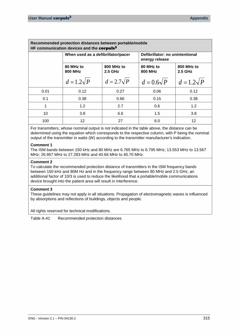
User Manual corpuls3 Appendix
ENG - Version 2.1 – P/N 04130.2 315
Recommended protection distances between portable/mobile HF communication devices and the corpuls3 When used as a defibrillator/pacer Defibrillator: no unintentional
energy release
80 MHz to 800 MHz
800 MHz to 2.5 GHz
80 MHz to 800 MHz
800 MHz to 2.5 GHz
Pd 2.1= Pd 7.2= Pd 6.0= Pd 2.1= 0.01 0.12 0.27 0.06 0.12
0.1 0.38 0.66 0.15 0.38
1 1.2 2.7 0.6 1.2
10 3.8 6.6 1.5 3.8
100 12 27 6.0 12
For transmitters, whose nominal output is not indicated in the table above, the distance can be determined using the equation which corresponds to the respective column, with P being the nominal output of the transmitter in watts (W) according to the transmitter manufacturer’s indication.
Comment 1 The ISM bands between 150 kHz and 80 MHz are 6.765 MHz to 6.795 MHz; 13.553 MHz to 13.567 MHz; 26.957 MHz to 27.283 MHz and 40.66 MHz to 40.70 MHz.
Comment 2 To calculate the recommended protection distance of transmitters in the ISM frequency bands between 150 kHz and 80M Hz and in the frequency range between 80 MHz and 2.5 GHz, an additional factor of 10/3 is used to reduce the likelihood that a portable/mobile communications device brought into the patient area will result in interference.
Comment 3 These guidelines may not apply in all situations. Propagation of electromagnetic waves is influenced by absorptions and reflections of buildings, objects and people. All rights reserved for technical modifications.
Table A-41 Recommended protection distances

Appendix User Manual corpuls3
316 ENG - Version 2.1 – P/N 04130.2
J Warranty The manufacturer offers, in addition to the valid statutory warranty regulations applicable in Germany, a limited manufacturer’s warranty against material- and manufacturing defects.The scope of the warranty can be viewed in the respective guarantee conditions of the relevant sales and service partners. This warranty concludingly regulates the legal relationship between the purchaser and GS. Further damage claims are excluded, insofar as liability is not regulated by law. Excepted from the warranty are wear parts, errors and damages that are the result of improper handling, faulty storage or installation and extraneous causes, such as transport damage, damage caused by impact, reparations and changes carried out by a non-authorised third party. The claim under the warranty shall be void as well if accessories are used that were not purchased from GS or an authorised sales partner. Software support (except updates) are not covered under the warranty. In case of a defect and further warranty and guarantee handling please contact your authorised sales and service partner or the manufacturer. The manufacturer shall only accept liability for user and operating safety of the device if maintenance, safety checks, repairs, additions and new settings were performed by the manufacturers themselves or persons specifically authorised by the manufacturer. Additionally, the general terms and conditions of the company GS Elektromedizinische Geräte G. Stemple GmbH shall apply in the current version until further amendment. The general terms and conditions are available at GS Elektromedizinische Geräte G. Stemple GmbH upon request.
User Manual corpuls3 Appendix
ENG - Version 2.1 – P/N 04130.2 317
K Protection Rights and Patents The corpuls3 and some of its accessories are protected by patents either applied for and/or already granted. Consequently, possession or purchase of this device does not automatically confer licence to use this device with spare parts or accessories (cables, sensors, etc.) which, alone or in combination with this device, infringe applicable patents for this device or patents of individual components which are used with this device. It is therefore not permitted to, for example: • dismantle parts of the corpuls3 and use them for other purposes; • replicate components or accessories. Goods are mentioned in this user manual without any mention of any existing patents, samples or trademarks. The corpuls® is a registered trademark of GS Elektromedizinische Geräte G. Stemple GmbH.
® is a registered trademark of GS Elektromedizinische Geräte G. Stemple
GmbH.
Appendix User Manual corpuls3
318 ENG - Version 2.1 – P/N 04130.2
L Disposal of the Device and Accessories To further preservation and protection of the environment, avoidance of pollution and recycling of raw materials, the European Commission issued a directive decreeing that electrical and electronic devices have to be taken back and correctly disposed of or recycled by the manufacturer.,Devices marked with this symbol therefore may not be disposed of in the normal waste within the European Union. The same is true for disposable consumables, such as e.g. electrodes. Please ask your local authorities, your sales and service partner or the manufacture for information on correct disposal. Information on Disposal of Packaging The packaging of our devices is an integral part of our product. The packaging has been especially developed for our product and therefore in general is optimally suited for shipping. In case you have to ship your device within or after the guarantee period to our service team, the original packaging is the best protection from transport damage. Keep the original packaging for as long as you have the device in your possession! If, however, you want to dispose of the packaging or if it is an external packaging used by us, you may dispose of it by means of your regional institutions (recovered paper container, recycling centre, paper collection etc).
Recommendation of the
manufacturer

User Manual corpuls3 Appendix
ENG - Version 2.1 – P/N 04130.2 319
M Note on Data Protection During the operation of the corpuls3, personalised data for service provision and patient care is being saved or transferred in encrypted form under strict adherence to the directives 95/46/EC (Data protection), 2002/58/EC (Data protection for electronic communication) as well as other relevant directives, ordinances and legislation.

Appendix User Manual corpuls3
320 ENG - Version 2.1 – P/N 04130.2
N List of Illustrations Fig. 1-1 Sample rating plate .................................................................... 2 Fig. 3-1 Compact device ......................................................................... 7 Fig. 3-2 Individual modules ..................................................................... 7
Fig. 3-3 Usage options of the modular corpuls3 .................................. 9
Fig. 3-4 Usage options of the modular corpuls3 as a patient monitoring system ...................................................................... 9
Fig. 3-5 Monitoring Unit ......................................................................... 12 Fig. 3-6 Monitoring unit, rear view ......................................................... 13 Fig. 3-7 Patient Box (illustration may differ) .......................................... 14 Fig. 3-8 Patient Box Interfaces, right hand side, ports for: .................... 15 Fig. 3-9 Patient Box Interfaces, left hand side, ports for: ...................... 15 Fig. 3-10 Patient Box with Accessory Bag .............................................. 16 Fig. 3-11 Defibrillator/Pacer .................................................................... 17 Fig. 3-12 Defibrillator/Schrittmacher Slim ............................................... 18 Fig. 3-13 Brackets ................................................................................... 19 Fig. 3-14 Biphasic defibrillation pulse (qualitative
representation) ......................................................................... 21 Fig. 3-15 Alarm message in the status line ............................................. 24 Fig. 3-16 Inverted parameter field ........................................................... 24 Fig. 3-17 Jog dial ..................................................................................... 25 Fig. 3-18 Alarm message on the patient box display .............................. 26
Fig. 3-19 Remaining running time of the corpuls3 in the current operating status ........................................................... 27
Fig. 3-20 Remaining running time of the patient box .............................. 28 Fig. 3-21 Display of the current state of charge of the batteries
on mains operation .................................................................. 29 Fig. 3-22 Compact device, power supply (illustration may differ) ........... 30 Fig. 3-23 Monitoring unit, power supply .................................................. 30 Fig. 3-24 Patient box, power supply (illustration may differ) ................... 30 Fig. 4-1 Monitoring unit, operating elements and LEDs ........................ 31 Fig. 4-2 Monitoring unit, example of basic structure of the
display pages ........................................................................... 35 Fig. 4-3 Screen page, example with horizontal and vertical
parameter area ........................................................................ 37 Fig. 4-4 Inverted video display of the screen (colours may
differ) ........................................................................................ 38 Fig. 4-5 Patient box, displays on the screen (illustration may
differ) ........................................................................................ 39 Fig. 4-6 Patient box, control keys and LEDs (illustration may
differ) ........................................................................................ 40 Fig. 4-7 Defibrillator, control key and status LEDs ................................ 41 Fig. 4-8 Defibrillator SLIM, control key and status LEDs ...................... 42 Fig. 4-9 Confirmation prompt before switching off ................................ 44 Fig. 4-10 Switching off with pacer active ................................................. 44
User Manual corpuls3 Appendix
ENG - Version 2.1 – P/N 04130.2 321
Fig. 4-11 Warning on switching off .......................................................... 45 Fig. 4-12 Example for softkey context menu ........................................... 46 Fig. 4-13 Parameter context menu (illustration may differ) ..................... 47 Fig. 4-14 Curve context menu ................................................................. 48 Fig. 4-15 Main menu ............................................................................... 49 Fig. 4-16 Configuration dialogue ............................................................. 50 Fig. 4-17 Disconnecting the monitoring unit from the
defibrillator/pacer (illustration may differ) ................................. 51 Fig. 4-18 Disconnecting the monitoring unit from the
defibrillator/pacer SLIM (illustration may differ) ....................... 51 Fig. 4-19 Disconnecting the patient box from the monitoring unit
(illustration may differ).............................................................. 52 Fig. 4-20 Connecting the patient box to the monitoring unit
(illustration may differ).............................................................. 53 Fig. 4-21 Connecting the monitoring unit to the
defibrillator/pacer (illustration may differ) ................................. 54 Fig. 4-22 Connecting the monitoring unit to the
defibrillator/pacer SLIM (illustration may differ) ....................... 54 Fig. 4-23 Removing the patient box from the compact device
(illustration may differ).............................................................. 55 Fig. 4-24 Removing the patient box from the compact device
with defibrillator/pacer SLIM .................................................... 55 Fig. 4-25 Accessory bag and patient box, front view (illustration
may differ) ................................................................................ 56 Fig. 4-26 Accessory bag with patient box, rear view (illustration
may differ) ................................................................................ 57 Fig. 4-27 Inserting the plugs on the right-hand side of the
patient box ............................................................................... 57 Fig. 4-28 Contents of right-hand bag (illustration may differ) .................. 58 Fig. 4-29 Connecting the plugs on the left-hand side of the
patient box ............................................................................... 59 Fig. 4-30 Contents of left-hand bag (illustration may differ) .................... 59 Fig. 4-31 Inserting the compact device into the bracket
(Illustration may differ) ............................................................. 60 Fig. 4-32 Inserting the monitoring unit into the bracket
(Illustration may differ) ............................................................. 61 Fig. 4-33 Inserting the patient box into the charging bracket
(ceiling installation) .................................................................. 62 Fig. 5-1 Connecting the therapy electrode cables ................................ 65 Fig. 5-2 Removing the shock paddles from their holders ..................... 66 Fig. 5-3 AED mode, initial screen (illustration may differ) ..................... 68 Fig. 5-4 AED mode function keys ......................................................... 69 Fig. 5-5 Applying the shock paddles ..................................................... 72 Fig. 5-7 Function keys for manual defibrillation and
cardioversion ............................................................................ 75 Fig. 5-8 Applying the shock paddles ..................................................... 78 Fig. 5-9 Connecting baby shock electrodes .......................................... 80 Fig. 5-10 Pacer function .......................................................................... 81 Fig. 5-11 Pacer pulse identification ......................................................... 82

Appendix User Manual corpuls3
322 ENG - Version 2.1 – P/N 04130.2
Fig. 5-12 Pacer, attaching the electrodes ............................................... 84 Fig. 5-13 Pacer, initial screen .................................................................. 85 Fig. 5-14 Pacer, selecting the intensity ................................................... 86 Fig. 5-15 Pacer, OVERDRIVE function ................................................... 87 Fig. 5-16 Softkey context menu metronome ........................................... 90 Fig. 5-17 Connecting the corPatch CPR sensor to the
corPatch CPR intermediate cable ........................................ 93 Fig. 5-18 CPR feedback, attaching the corPatch CPR sensor ............ 93 Fig. 5-19 CPR feedback .......................................................................... 94 Fig. 6-1 Selection of the monitoring and diagnostic function ................ 95 Fig. 6-2 ECG monitoring, applying the ECG electrodes
(shortened form) ...................................................................... 98 Fig. 6-3 ECG monitoring, initial screen ................................................. 99 Fig. 6-4 Real-time printout, section ..................................................... 100 Fig. 6-5 ECG monitoring, adapting the curves .................................... 100 Fig. 6-6 Heart rate parameter field ...................................................... 102 Fig. 6-7 Diagnostic ECG, applying the ECG electrodes (1) ................ 104 Fig. 6-8 Diagnostic ECG, applying the ECG electrodes (2) ................ 105 Fig. 6-9 Diagnostic ECG, preview screen ........................................... 106 Fig. 6-10 D-ECG, options ...................................................................... 107 Fig. 6-11 Printout of 12-lead ECG (illustration may differ) .................... 108 Fig. 6-12 D-ECG printout of the representative cycle with HES®
Light (illustration may differ) ................................................... 109 Fig. 6-13 D-ECG printout with ECG analysis and ECG
interpretation HES® (option) (illustration may differ) .............. 110 Fig. 6-14 Rhythm- and typing diagram for a regular sinus
rhythm .................................................................................... 112 Fig. 6-15 Rhythm- and typing diagram for a sinus rhythm with
two compensated ventricular and one compensated supraventricular extrasystole ................................................. 112
Fig. 6-16 Longterm ECG with monitoring function ................................ 114 Fig. 6-17 Connecting the oximetry sensor on to the intermediate
cable....................................................................................... 117 Fig. 6-18 Oximetry monitoring, attaching the oximetry sensor ............. 117 Fig. 6-19 Oximetry monitoring, configured screen ................................ 118 Fig. 6-20 Pleth monitoring, section of a printout ................................... 119 Fig. 6-21 Pulse rate parameter field ...................................................... 120 Fig. 6-22 CO2 monitoring, nasal adapter ............................................... 122 Fig. 6-23 CO2 monitoring, disposable endotracheal tube
adapter ................................................................................... 123 Fig. 6-24 Fitting the disposable CO2 nasal(/oral) adapter on the
patient .................................................................................... 123 Fig. 6-25 CO2 monitoring, configured screen ........................................ 124 Fig. 6-26 CO2 monitoring, section of a printout ..................................... 124 Fig. 6-27 Respiratory rate parameter field ............................................ 125 Fig. 6-28 NIBP user surface in large view ............................................. 127 Fig. 6-29 NIBP user surface in trend view ............................................ 128
User Manual corpuls3 Appendix
ENG - Version 2.1 – P/N 04130.2 323
Fig. 6-30 NIBP monitoring, attaching the NIBP cuff .............................. 129 Fig. 6-31 NIBP monitoring parameter fields .......................................... 130 Fig. 6-32 IBP calibration ........................................................................ 133 Fig. 6-33 IBP monitoring, configured screen ......................................... 134 Fig. 6-34 IBP monitoring, section of a printout ...................................... 135 Fig. 6-35 Temperature monitoring parameter field ............................... 136 Fig. 7-1 System settings, default user level ........................................ 138 Fig. 7-2 Displaying curves ................................................................... 140 Fig. 7-3 Displaying parameter fields ................................................... 141 Fig. 7-4 Selecting pre-set views .......................................................... 142 Fig. 7-5 Printer setting "Same as screen" ........................................... 143 Fig. 7-6 Selecting printer curves ......................................................... 144 Fig. 7-7 Printer Protocol ...................................................................... 145 Fig. 7-8 Printer settings for D-ECG ..................................................... 146 Fig. 7-9 ECG settings .......................................................................... 149 Fig. 7-10 Settings for oximetry monitoring ............................................ 150 Fig. 7-11 Settings for CO2 monitoring ................................................... 151 Fig. 7-12 Settings for IBP monitoring .................................................... 152 Fig. 7-13 Settings for CPR feedback .................................................... 154 Fig. 7-14 Alarm settings ........................................................................ 155 Fig. 7-15 Alarm limits ............................................................................ 156 Fig. 7-16 Setting automatic alarm limits ................................................ 158 Fig. 7-17 Code prompt .......................................................................... 159 Fig. 7-18 System settings (persons responsible for the device) ........... 160 Fig. 7-19 Defibrillation function settings (persons responsible for
the device) ............................................................................. 164 Fig. 7-20 Filter settings for ECG (persons responsible for the
device) ................................................................................... 165 Fig. 7-21 Alarm settings (persons responsible for the device) .............. 167 Fig. 7-22 Pre-setting views .................................................................... 168 Fig. 7-23 Entering master data (persons responsible for the
device) ................................................................................... 170 Fig. 7-24 Telemetry settings (Persons responsible for the
device) ................................................................................... 171 Fig. 7-25 Telemetry connections (Persons responsible for the
device) ................................................................................... 175 Fig. 7-26 Bluetooth settings (Persons Responsible for the
Device) ................................................................................... 177 Fig. 7-27 Bluetooth connections (persons responsible for the
device) ................................................................................... 178 Fig. 7-28 Configuration of ECG measurement and ECG
interpretation (persons responsible for the device) .............. 179 Fig. 7-29 ECG measurement and ECG interpretation version in
system info ............................................................................. 181 Fig. 7-30 Settings for the insurance card reader (persons
responsible for the device) ..................................................... 182 Fig. 7-31 NIBP settings ......................................................................... 184
Appendix User Manual corpuls3
324 ENG - Version 2.1 – P/N 04130.2
Fig. 8-1 Entering patient data .............................................................. 186 Fig. 8-2 Entering master data.............................................................. 189 Fig. 8-3 Example of an ECG in the protocol at the time of an
event ...................................................................................... 191 Fig. 8-4 Operation browser ................................................................. 192 Fig. 8-5 D-ECG Browser ..................................................................... 193 Fig. 8-6 Short code overview .............................................................. 196 Fig. 8-7 Bluetooth settings .................................................................. 200 Fig. 8-9 Readout of patient data from insurance card reader ............. 203 Fig. 8-10 Readout of patient information from insurance card
reader ..................................................................................... 205 Fig. 9-1 Open the printer flap .............................................................. 217 Fig. 9-2 Printer..................................................................................... 217 Fig. 9-3 Changing the battery (monitoring unit) .................................. 218 Fig. 9-4 Monitoring unit, infrared interface .......................................... 220 Fig. 9-5 Patient box, infrared interface ................................................ 220 Fig. 9-6 Defibrillator/Pacer, infrared interface ..................................... 221 Fig. 10-1 Radio transmitter .................................................................... 313

User Manual corpuls3 Appendix
ENG - Version 2.1 – P/N 04130.2 325
O List of Tables Table 3-1 Brackets and power supply options ......................................... 19 Table 3-2 Frequency and intensity ........................................................... 23 Table 4-1 Keyboard layout defibrillation keys (modifications
possible) ................................................................................... 32 Table 4-2 Module connection status ........................................................ 36 Table 4-3 Connection status of the modules ........................................... 39 Table 4-4 Contents of right-hand bag ...................................................... 58 Table 4-5 Contents of left-hand bag ........................................................ 59 Table 5-1 Therapy electrodes for defibrillation and pacing ...................... 63 Table 5-2 Metronome modes ................................................................... 89 Table 6-1 ECG lead colour coding ........................................................... 96 Table 6-2 Coded Explanations by HES® ................................................ 111 Table 6-3 Criteria of the representative cycle ........................................ 112 Table 6-4 IBP monitoring, pressure channel assignment ...................... 132 Table 7-1 Values for system settings ..................................................... 138 Table 7-2 Values for printer settings ...................................................... 144 Table 7-3 Values for trend settings ........................................................ 145 Table 7-4 Values for the D-ECG printout ............................................... 147 Table 7-5 Values for ECG setting .......................................................... 149 Table 7-6 Values for oximetry Monitoring .............................................. 150 Table 7-7 CO2 monitoring values ........................................................... 152 Table 7-8 Values for IBP monitoring ...................................................... 153 Table 7-9 Values for CPR feedback ...................................................... 154 Table 7-10 Settings for the VT/VF alarm ................................................. 155 Table 7-11 Values for alarm limits............................................................ 157 Table 7-12 Values for system settings (persons responsible for
the device) ............................................................................. 161 Table 7-13 Values for defibrillation function configuration ....................... 164 Table 7-14 Filter setting for monitoring ECG, diagnostic ECG
(persons responsible for the device) ...................................... 166 Table 7-15 Alarm settings (persons responsible for the device) .............. 167 Table 7-16 Master data (persons responsible for the device) ................. 169 Table 7-17 Configuration values, telemetry ............................................. 172 Table 7-18 Values for Bluetooth® configuration ....................................... 177 Table 7-19 Values for configuration, ECG measurement and
ECG interpretation ................................................................. 180 Table 7-20 Values for metronome settings .............................................. 183 Table 7-21 Values for NIBP monitoring ................................................... 184 Table 8-1 Master data ............................................................................ 188 Table 8-2 Log overview .......................................................................... 190 Table 8-3 Values for Bluetooth settings ................................................. 200 Table 9-1 Maintenance intervals ............................................................ 207 Table 9-2 Function check of the device ................................................. 212 Table 9-3 Function check of the power supply ...................................... 213
Appendix User Manual corpuls3
326 ENG - Version 2.1 – P/N 04130.2
Table 9-4 Checking accessories and consumables............................... 215 Table 9-5 Basic configuration with charging bracket ............................. 225 Table 9-6 Options measurement modules vital parameters .................. 228 Table 9-7 Accessories for vehicle installation and mounting ................. 229 Table 9-8 Accessories for stretcher, adapter ......................................... 230 Table 9-9 Accessories for clinic beds/norm bar, adapter ....................... 230 Table 9-10 Accessories for charging and power supply .......................... 230 Table 9-11 Further consumables ............................................................. 230 Table 9-12 Further accessories ............................................................... 231 Table 9-13 Data management/Data transmission ................................... 232 Table 9-14 ECG interpretation HES® ....................................................... 232
Table 9-15 corpuls3 dummy.................................................................. 232 Table 10-1 Alarm messages, alphabetical ............................................... 249 Table 10-2 General malfunctions ............................................................. 251 Table 10-3 Network malfunctions............................................................. 251 Table 10-4 Malfunctions during defibrillation ........................................... 252 Table 10-5 Malfunctions during stimulation (pacer) ................................. 252 Table 10-6 Malfunctions during ECG monitoring ..................................... 254 Table 10-7 Malfunctions during oximetry monitoring ............................... 255 Table 10-8 Malfunctions during NIBP monitoring .................................... 256 Table 10-9 Malfunctions during CO2 monitoring ...................................... 260 Table 10-10 Malfunctions during temperature monitoring ......................... 260 Table 10-11 Malfunctions during IBP monitoring ....................................... 261 Table 10-12 Printer malfunctions ............................................................... 262 Table 10-13 Malfunctions in energy management ..................................... 262 Table 10-14 Notification in the message line and information in the
protocol .................................................................................. 271 Table A-1 Function checklist (sample) ................................................... 277 Table A-2 General Settings .................................................................... 283 Table A-3 General alarm settings ........................................................... 283 Table A-4 Pre-set alarm limits ................................................................ 284 Table A-5 Pre-set views ......................................................................... 285 Table A-6 Dimensions ............................................................................ 286 Table A-7 Weight .................................................................................... 286 Table A-8 Environmental requirements .................................................. 286 Table A-9 Energy management/power supply ....................................... 288 Table A-10 Alarm management ................................................................ 288 Table A-11 Display ................................................................................... 289 Table A-12 Printer..................................................................................... 289 Table A-13 ECG ....................................................................................... 290 Table A-14 Leads ..................................................................................... 290 Table A-15 Heart rate ............................................................................... 291 Table A-16 Shock paddle ECG ................................................................ 291 Table A-17 Output .................................................................................... 292 Table A-18 Conductive area ..................................................................... 292
User Manual corpuls3 Appendix
ENG - Version 2.1 – P/N 04130.2 327
Table A-19 Defibrillation ........................................................................... 292 Table A-20 Biphasic defibrillator ............................................................... 293 Table A-21 Non-invasive pacer ................................................................ 294 Table A-22 Impulse suppression according to IEC 60601-2-27 ............... 294 Table A-23 CPR Feedback ....................................................................... 295 Table A-24 GSM/GPRS Modem (Optional) .............................................. 295 Table A-25 Oximeter (Option SpO2, SpCO, SpHB, SpMet,
manufacturer Masimo, Masimo Rainbow SET® technology .............................................................................. 296
Table A-26 Non-invasive blood pressure measurement module (Option NIBP, manufacturer SUNTECH) ............................... 297
Table A-27 Invasive blood pressure measurement module IBP (Option) .................................................................................. 297
Table A-28 Temperature (optional) .......................................................... 298 Table A-29 Capnometer (Option CO2, manufacturer Nihon
Kohden, cap-ONE) ................................................................. 299 Table A-30 Deviations due to negative effects of gases and steam ........ 299 Table A-31 Precision of the energy released ........................................... 302 Table A-32 Precision of the energy released for shock spoons ............... 303 Table A-33 Safety information .................................................................. 306 Table A-34 Duration of the maximum ECG analysis ................................ 307 Table A-35 Acceleration of the ECG analysis process............................. 307 Table A-36 Classification table ................................................................. 308 Table A-37 Results ................................................................................... 309 Table A-38 Electromagnetic emission ...................................................... 311 Table A-39 Electromagnetic interference immunity part 1 ....................... 312 Table A-40 Electromagnetic interference immunity part 2 ....................... 314 Table A-41 Recommended protection distances ..................................... 315

328 ENG - Version 2.1 – P/N 04130.2
Index
A Accessories ................................................. 224 Accessory bag
packing ....................................................... 57 Accessory bag ............................................... 16
installation .................................................. 56 Accessory bag
cleaning .................................................... 223 Ad-hoc connection
see connection authorisation ..................... 10 AED mode
Information ................................................. 68 malfunctions ............................................. 252 with corPatch electrodes ............................ 70
AED Mode with Shock Paddles .................................... 71
Alarm limits automatic setting ...................................... 158 manual setting .......................................... 156
Alarm management, technical specifications ..................................................................... 288 Alarm suspension .......................................... 25 AMI
see ECG measurement/interpretation ..... 103 APN
Configuration .................................... 170, 194 Auto Curve
CO2........................................................... 152 ECG ......................................................... 149 IBP ........................................................... 153 Oximetry ................................................... 151
Auto Energy ................................................. 163
B Baby-Schockelektroden ................................. 80
anschließen ................................................ 80 Basic structure of the screen pages .............. 35 Basic structure of the screen pages .............. 38 Batteries
charging ..................................................... 28 maintenance............................................... 28 remaining running time display .................. 27
Battery Operation .......................................... 27 Bereitton
siehe Defibrillation ...................................... 77 Beta-Software, Beta-Version ................. 43, 248 Biphasic defibrillator .................................... 300
technical specifications ............................ 293 Blood pressure monitoring, invasive (IBP)
information ............................................... 131 performance ............................................. 134
preparation .............................................. 132 Blood pressure monitoring, non-invasive (NIBP)
information ............................................... 126 malfunctions ............................................ 255 performing individual measurement ........ 129 performing interval monitoring ................. 131 preparation .............................................. 129
Body temperature ......................................... 20 Bracket
compact device ......................................... 60 monitoring unit ........................................... 61 patient box ................................................. 62
Brackets ........................................................ 19
C Cables for monitoring functions
cleaning ................................................... 222 disinfection .............................................. 222
Capnometer, technical specifications ......... 298 Capnometry .................................................. 20 Cardioversion ................................................ 21 Changing the unit of CO2 monitoring ......... 125 Check
accessories ............................................. 213 complete device ...................................... 208 consumables ........................................... 213 power supply ........................................... 213
Checklist function check ......................................... 277
Checks ........................................................ 207 Classification
UMDNS ....................................................... iii Cleaning .............................................. 219, 223
accessory bag and carrying belt ............. 223 cables for monitoring functions ............... 222 CO2 sensor ............................................. 223 defibrillator ............................................... 219 disinfection .............................................. 222 IBP transducer cable ............................... 223 master cable ............................................ 222 monitoring unit ......................................... 219 NIBP cuffs ............................................... 223 oximetry sensor ....................................... 222 patient box ............................................... 219 shock paddle ........................................... 221
CO2 monitoring adjusting representation of the CO2 values ................................................................. 125 changing the unit ..................................... 125 information ............................................... 121 malfunctions ............................................ 256

ENG - Version 2.1 – P/N 04130.2 329
monitoring respiratory rate ....................... 125 performing CO2 measurement ................. 124 preparation ............................................... 122
CO2 sensor, cleaning ................................... 223 Compact device ............................................... 7
brackets – insertion/removal ...................... 60 CompactFlash® card .................................... 186 Configuration ............................................... 137 Configuration dialogue ................................... 50 Connection authorisation
Ad-hoc connection ..................................... 10 Pairing ........................................................ 10
Consumables defibrillator................................................ 224 printer paper ............................................. 230
Control menu .......................................................... 46
Conventions ................................................... xii corPatch electrodes
AED mode .................................................. 70 manual defibrillation ................................... 76
corpuls.web Configuration ............................................ 174
CPR Feedback technical specifications ............................ 294 Using .......................................................... 94
Curve context menu ...................................... 47 cWEB
Configuration ............................................ 170 see Telemetry .......................................... 194
D Data
Analysis .................................................... 193 Processing ............................................... 193
Data archiving .............................................. 187 Data management ....................................... 186
insurance card reader .............................. 202 Insurance card reader .............................. 204
Data transmission see Telemetry .......................................... 194
Data transmission see Telemetry .......................................... 199
Data Transmission see Telemetry .......................................... 204
Datenschnittstelle Konfiguration ............................................ 177
D-ECG additional printout ..................................... 193
D-ECG Browser ........................................... 193 Defibrillation ........................................... 21, 301
Bereitton ..................................................... 77 Ready for shock ...................... 292, 293, 307 Release shock ......................................... 209 Release shock ......................................... 307 Schockbereitschaft ..................................... 77
Defibrillation automatic (AED)
see AED mode .......................................... 74 Defibrillation automatic (AED) see AED mode ...................................................................... 68 Defibrillation, manual
malfunctions ............................................ 252 with corPatch electrodes ........................... 76 with shock paddles .................................... 77 with shock spoons ..................................... 79
Defibrillator accessories ............................................. 224 cleaning ................................................... 219 components ................................................. 6 consumables ........................................... 224 spares ...................................................... 224 switching off ............................................... 44 switching on ............................................... 43 technical specifications ............................ 292
Defibrillator, biphasic................................... 300 technical specifications ............................ 293
Defibrillator/Pacer ......................................... 17 control key ................................................. 41 LEDs .......................................................... 41
Defibrillator/Pacer SLIM control key ................................................. 42 LEDs .......................................................... 42
Diagnostic ECG ............................................ 20 information ............................................... 102 preparation .............................................. 103 Recording ................................................ 106
Dimensions ................................................. 286 Disconnection signal ................................... 163 Disinfectants ............................................... 219 Disinfection ................................................. 219
cables for monitoring functions ............... 222 IBP transducer cable ............................... 223 NIBP cuffs ............................................... 223 oximetry sensor ....................................... 222 shock paddle ........................................... 221 temperature sensor ................................. 223
Display, technical specifications ................. 289 Disposal ...................................................... 318
Packaging ................................................ 318 Dynamic QRS/pulse tone
see QRS tone, dynamic .......................... 151
E ECG .............................................................. 20
diagnosis ................................................. 102 ECG cable tester ................. 96, 98, 103, 106 ECG cable tester ..................................... 277 ECG filter settings ................................... 101 Filter settings ........................................... 165 Longterm ECG ........................................ 113 Monitoring .................................................. 95 technical specifications ............................ 289 with therapy electrodes ........................... 291
ECG analysis .............................................. 307
330 ENG - Version 2.1 – P/N 04130.2
ECG cable tester .................... 96, 98, 103, 106 ECG cable tester ......................................... 277 ECG filter settings ........................................ 101 ECG measurement
corpuls S ............................................... 102 STEMI ...................................................... 102
ECG measurement/interpretation HES .......................................................... 103 NSTEMI .................................................... 103 STEMI ...................................................... 103
ECG measurement/interpretation AMI ........................................................... 103 IMI ............................................................ 103 PCI ........................................................... 103
ECG measurement/interpretation codes ........................................................ 111
ECG monitoring adaptation of the ECG plot ....................... 100 information ................................................. 95 malfunctions ............................................. 252 performing monitoring ................................ 98 preparation ................................................. 97 printing ECG plots ...................................... 99
EKG EKG-Kabeltester ...................................... 225
EKG-Kabeltester .......................................... 225 Electrodes
Connecting the cable ................................. 65 Electrodes
Defibrillation electrodes .............................. 63 End of paper roll .................................. 146, 214 End or paper roll .......................................... 212 Energy management ..................................... 27
lithium-ion battery ............................... 27, 287 malfunctions ............................................. 262 technical specifications ............................ 287
Energy selection ............................................ 22 Energy selection, automatic
see Auto Energy ...................................... 163 see Auto Energy ...................................... 163
Entering patient data ................................... 204 Environmental requirements ....................... 286 Event key ..................................................... 187 External pacer
technical specifications ............................ 294
F Factory settings ........................................... 278 Fax Server
Configuration ............................................ 173 Fax transmission
see Telemetry .......................................... 194 Fax transmission
Configuration ............................................ 172 Filter settings ....................................... 101, 165 Folding ................................................. 100, 191 Function check
check of accessories ............................... 207 check of the device .................................. 207 check of the power supply ....................... 207
G General terms and conditions ..................... 316 GPRS
Configuration ........................................... 173 GSM modem
technical specifications ............................ 295
H Heart rate monitoring .................................. 102 HES
ECG measurement/interpretation ........... 103
I IBP transducer cable
cleaning ................................................... 223 disinfection .............................................. 223 sterilisation .............................................. 223
IMI see ECG measurement/interpretation ..... 103
Information labels ............................................ 2 Insurance card reader ......................... 202, 204 Interfaces
monitoring unit ........................................... 13 patient box ................................................. 15
Invasive blood pressure (IBP) ....................... 21 Invasive blood pressure monitoring (IBP)
malfunctions ............................................ 260 Inverted video display ................................... 38
L LAN interface
configuration ............................................ 174 Lithium-ion battery ........................................ 27 Lithium-Ion Battery ...................................... 287 Live data transmission
see Telemetry .......................................... 194 see Telemetry .......................................... 198
Loading printer paper .................................. 217 Longterm ECG ............................................ 113
performing ............................................... 114 preparing ................................................. 114
Longterm ECG browser .............................. 113 LT-ECG Browser ......................................... 193
M Main menu .................................................... 49 Mains operation ............................................ 29 Maintenance ............................................... 215
general indications .................................. 206 schedule .................................................. 206
Malfunctions ................................................ 233 Manufacturer ............................................... 334

ENG - Version 2.1 – P/N 04130.2 331
Marking paper roll ............... 146, 212, 214, 217 Master cable
cleaning .................................................... 222 disinfection ............................................... 222
Master data .................................................. 188 configuration............................................. 169
Menu types .................................................... 46 configuration dialogue ................................ 50 curve context menu .................................... 47 main menu ................................................. 49 parameter context menu ............................ 47
Menu, control ................................................. 46 Metronome
Settings ...................................................... 89 Starting ....................................................... 90
Millivolt mark ............................... 100, 101, 191 Minute mean values ............................ 145, 190 Modules ........................................................... 7
connection .................................................. 51 disconnection ............................................. 51 radio connection ............................... 8, 26, 36 usage options ............................................... 8
Monitoreinheit Konfiguration der Alarme ........................... 25
Monitoring blood pressure ................................. 126, 131 CO2........................................................... 121 ECG ........................................................... 95 Oximetry ................................................... 115 temperature .............................................. 135
Monitoring functions ...................................... 20 alarms ............................. 303, 304, 306, 311
Monitoring pulse rate and perfusion index, Oximetry monitoring .................................... 120 Monitoring respiratory rate........................... 125 Monitoring unit
Alarm signals.............................................. 24 Monitoring unit ............................................... 12
interfaces .................................................... 13 Monitoring unit
power supply .............................................. 30 Monitoring unit
operating elements .................................... 31 Monitoring unit
LEDs .......................................................... 31 Monitoring unit
basic structure of the screen pages ........... 35 Monitoring unit
disconnection from defibrillator/pacer ........ 51 Monitoring unit
connection to defibrillator/pacer ................. 54 Monitoring unit
bracket – insertion/removal ........................ 61 Monitoring unit
cleaning .................................................... 219 mV-mark ..................................... 100, 101, 191
N Network
connection ................................................. 39 troubleshooting ........................................ 251
NIBP cuffs cleaning ................................................... 223 disinfection .............................................. 223
NIBP, Technical specifications ................... 296 Non-invasive blood pressure (NIBP) ............ 21 NSTEMI
ECG measurement/interpretation ........... 103
O Operating
disconnection and connection of modules 51 Operating and display elements ................... 31 Operating instructions ................................... 31 Operation
automatic defibrillation ......................... 68, 74 general instructions ................................... 31 monitoring and diagnostic functions .......... 95 Therapy ..................................................... 63
Oximetry ........................................................ 20 oximetry -Monitoring
malfunctions ............................................ 254 Oximetry monitoring .................................... 115
performing Oximetry measurement ......... 118 preparation .............................................. 117
Oximetry -monitoring information ............................................... 115
Oximetry monitoring Averaging time ........................................ 119
Oximetry monitoring FastSat® ................................................. 119
Oximetry monitoring Sensitivity ................................................ 119
Oximetry monitoring adjusting display of the oximetry parameters ................................................................. 120
Oximetry -Monitoring monitoring pulse rate and perfusion index ................................................................. 120
Oximetry sensor cleaning ................................................... 222 disinfection .............................................. 222
oximetry, technical specifications ............... 295
P Pacer ............................................................. 22
malfunctions ............................................ 252 Pacer therapy ................................................ 82 Pacer, external
Starting pacer function .............................. 85 Pacer, external
Information ................................................ 81 Preparing pacer function ........................... 83
332 ENG - Version 2.1 – P/N 04130.2
Pacer, external technical specifications ............................ 294
Pairing see connection authorisation ..................... 10
Papierendmarkierung .................................. 246 Parameter context menu ............................... 47 Patents......................................................... 317 Patient box ..................................................... 14
Alarm signals.............................................. 26 bracket – insertion/removal ........................ 62 cleaning .................................................... 219 connection to the monitoring unit ............... 53 control keys ................................................ 40 disconnection from the monitoring unit ...... 52 display ........................................................ 39 interfaces .................................................... 15 LEDs .......................................................... 40 power supply .............................................. 30 removal from the compact device .............. 55
Patient box screen ......................................... 39 Patient data, entry ....................................... 186 Patienten-Daten anlegen ............................. 202 PCI
see ECG measurement/interpretation ..... 103 Power supply ................................................. 30 Printer .......................................................... 217
malfunctions ............................................. 261 technical specifications ............................ 289
Printer paper empty ............ 146, 212, 214, 217 Printing the protocol ..................................... 189 Pulse tone, dynamic .................................... 151
Q QRS
QRS mark ................................................ 280 QRS Marker ............................................. 149 QRS Tone ................................................ 149 QRS tone, dynamic .......................... 149, 151 QRS-Ton .................................................. 280
Qualified staff ................................................... 1
R Radio connection
see modules ............................................. 251 Ready for shock
see Defibrillation ..................... 292, 293, 307 Real-time printing ........................................ 144 Real-time printout .................................. 99, 289 Recycling ..................................................... 318 Refractory time ............................................ 307 Regular checks ............................................ 206 Release shock
see Defibrillation ...................................... 307 Release shock
see defibrillation ....................................... 209 Remaining running time display, batteries .... 27
Representative Cycle .................................. 111 Reset
Reset configuration ......................... 161, 162 Reset to default ............................... 161, 162
S Safety
defibrillator ................................................... 3 general......................................................... 1 maintenance ................................................ 2 operating staff .............................................. 1 safety information .................................... 303
Schockbereitschaft siehe Defibrillation ..................................... 77
Screen Night .......................................................... 38 see Inverted video display ......................... 38
Screenshot .................................................. 194 Self test ....................................................... 215 Service address .............................................. iv Settings
alarms ...................................................... 137 monitoring functions ................................ 137 system settings ........................................ 137
Shock paddle cleaning ................................................... 221 disinfection .............................................. 221 sterilisation .............................................. 221
Shock paddles AED Mode ................................................. 71 manual defibrillation .................................. 77 Removing from holders ............................. 66
Shock spoons manual defibrillation .................................. 79
SIM card ...................................................... 196 Spares ......................................................... 224 Special types of risks ...................................... 3 STEMI
ECG measurement/interpretation ........... 103 Sterilisation ................................................. 219
IBP transducer cable ............................... 223 temperature sensor ................................. 223
Switching off .................................................. 44 Switching on .................................................. 43 Symbols .................................................. 3, 272
T TCP
Configuration ................................... 170, 194 Technical specifications
Alarm management ................................. 288 battery...................................................... 287 capnometer ............................................. 298 CPR Feedback ........................................ 294 defibrillator ............................................... 292 ECG ......................................................... 289
ENG - Version 2.1 – P/N 04130.2 333
ECG with therapy electrodes ................... 291 energy management ................................ 287 GSM modem ............................................ 295 NIBP ......................................................... 296 oximetry .................................................... 295 power supply ............................................ 287
Technical Specifications display ...................................................... 289 printer ....................................................... 289
Telemetrie Verbindungen ........................................... 178
Telemetry Configuration ............................................ 170 Data transmission .................................... 194 Live data transmission ............................. 194
Telemetry APN .......................................................... 170
Telemetry cWEB ....................................................... 170
Telemetry TCP .......................................................... 170
Telemetry UDP .......................................................... 170
Telemetry Connections ............................................. 175
Telemetry ..................................................... 176 Telemetry ..................................................... 176 Telemetry ..................................................... 193 Telemetry ..................................................... 194 Telemetry
APN .......................................................... 194 Telemetry
TCP .......................................................... 194 Telemetry
UDP .......................................................... 194 Telemetry
Fax transmission ...................................... 194 Telemetry
Settings .................................................... 195 Telemetry
Live data transmission ............................. 198 Telemetry
Data transmission .................................... 199 Telemetry
Data Transmission ................................... 204 Temperature monitoring
information ............................................... 135 malfunctions ............................................. 260 performing temperature monitoring ......... 136 preparation ............................................... 135
Temperature sensor cleaning ................................................... 223 disinfection .............................................. 223 sterilisation .............................................. 223
Test software, Test version ........................... 43 Tests, general information .......................... 206 Therapeutic functions.................................... 21 Therapy electrodes ....................................... 63 Trademarks ................................................. 317 Trend ........................................................... 147 Trouble shooting and remedying malfunctions
during oximetry monitoring ...................... 254 Troubleshooting
network .................................................... 251 Troubleshooting and remedying malfunctions
during CO2 monitoring ............................. 256 during defibrillation .................................. 252 during IBP monitoring .............................. 260 during pacing ........................................... 252 during temperature monitoring ................ 260 general malfunctions ....................... 250, 251 printer ...................................................... 261
Troubleshooting and remedying malfunctions during ECG monitoring ............................... 252 Troubleshooting and remedying malfunctions in energy management ............................... 262
U UDP
Configuration ................................... 170, 194 UMDNS
see Classification ........................................ iii Use .................................................................. 4 User and operating safety ........................... 316
V Ventricular fibrillation................................... 155 Ventricular tachykardia ............................... 155 Views........................................... 140, 278, 285 Visual and functional checks ...................... 206 VT/VF-Alarm ............................................... 155
W Warning labels ................................................ 2 Warning notices and symbols ......................... 3 Warranty ..................................................... 316 Warranty regulations ................................... 316 Weight ......................................................... 286
GS Elektromedizinische Geräte
G. Stemple GmbH Hauswiesenstrasse 26
86916 Kaufering Germany
Tel.: +49-8191-65722-0 Fax: +49-8191-65722-22
Web site: www.corpuls.com