User Guide Zirconia Oxygen Probe - ABB Ltd · We are an established world force in the design and...
44
Zirconia Oxygen Probe ZFG2 Series User Guide IM/ZFG2_9
Transcript of User Guide Zirconia Oxygen Probe - ABB Ltd · We are an established world force in the design and...

Zirconia Oxygen Probe
ZFG2 Series
User GuideIM/ZFG2_9

ABB
The Company
We are an established world force in the design and manufacture of instrumentation for industrialprocess control, flow measurement, gas and liquid analysis and environmental applications.
As a part of ABB, a world leader in process automation technology, we offer customersapplication expertise, service and support worldwide.
We are committed to teamwork, high quality manufacturing, advanced technology and unrivalledservice and support.
The quality, accuracy and performance of the Company’s products result from over 100 yearsexperience, combined with a continuous program of innovative design and development toincorporate the latest technology.
The UKAS Calibration Laboratory No. 0255 is just one of the ten flow calibration plants operatedby the Company and is indicative of our dedication to quality and accuracy.
Health and SafetyTo ensure that our products are safe and without risk to health, the following points must be noted:
1. The relevant sections of these instructions must be read carefully before proceeding.
2. Warning labels on containers and packages must be observed.
3. Installation, operation, maintenance and servicing must only be carried out by suitably trained personnel and in accordance with theinformation given.
4. Normal safety precautions must be taken to avoid the possibility of an accident occurring when operating in conditions of high pressure and/or temperature.
5. Chemicals must be stored away from heat, protected from temperature extremes and powders kept dry. Normal safe handling proceduresmust be used.
6. When disposing of chemicals ensure that no two chemicals are mixed.
Safety advice concerning the use of the equipment described in this manual or any relevant hazard data sheets (where applicable) may beobtained from the Company address on the back cover, together with servicing and spares information.
EN ISO 9001:2000
Cert. No. Q 05907
EN 29001 (ISO 9001)
Lenno, Italy – Cert. No. 9/90A
0255
Warning – Refer to the manual for instructions
Caution – Risk of electric shock
Protective earth (ground) terminal
Earth (ground) terminal
Direct current supply only
Alternating current supply only
Both direct and alternating current supply
The equipment is protectedthrough double insulation
Electrical Safety
This equipment complies with the requirements of CEI/IEC 61010-1:2001-2 'Safety Requirements for Electrical Equipment forMeasurement, Control and Laboratory Use'. If the equipment is used in a manner NOT specified by the Company, the protectionprovided by the equipment may be impaired.
Symbols
One or more of the following symbols may appear on the equipment labelling:
Information in this manual is intended only to assist our customers in the efficient operation of our equipment. Use of this manual forany other purpose is specifically prohibited and its contents are not to be reproduced in full or part without prior approval of theTechnical Publications Department.
Stonehouse, U.K.

1
Section Page
WARNINGS AND INSTALLATION NOTES ........................... 2
1 INTRODUCTION .............................................................. 31.1 Principle of Operation ............................................. 3
2 PREPARATION ................................................................ 52.1 Checking the Code Number ................................... 52.2 Accessories Check ................................................. 5
2.2.1 Test Gas Connector Kit ............................... 52.2.2 Probe Flanges ............................................. 62.2.3 Mounting Plates .......................................... 72.2.4 Mounting Adapters
(0.4 m Probes only) ..................................... 7
3 INSTALLATION ................................................................ 83.1 Siting ...................................................................... 83.2 Mounting ................................................................ 9
3.2.1 0.4 m Probe(Flange 'Standard' Mounting) ...................... 9
3.2.2 1.0 m, 1.5 m and 2.0 m Probes .................. 93.2.3 0.4 m Probe
(21/2 in. Male Bush NPT Mounting) ............ 103.2.4 0.4 m Probe
(Z-LT Adapter Plate Mounting) ................... 10
4 CONNECTIONS ............................................................. 114.1 Conduit and Cable Details .................................... 114.2 Probe Connections – General ............................... 11
4.2.1 Accessing Probe Terminals ........................ 114.2.2 Probe Connections .................................... 12
4.3 Pipe Connections ................................................. 144.3.1 External Reference Air Connection ............ 144.3.2 Vent Connection ........................................ 144.3.3 Test Gas Inlet Connection .......................... 14
5 OPERATION ................................................................... 155.1 Preparation ........................................................... 15
6 CALIBRATION ............................................................... 15
7 FAULT FINDING ............................................................. 157.1 In Situ Probe Testing ............................................. 157.2 Bench Testing ....................................................... 16
Section Page
8 DISMANTLING AND REASSEMBLY............................. 178.1 Tools Required ...................................................... 178.2 Replacing the Ceramic
Filter (all Probes) ................................................... 178.3 Removing the Zirconia
Cell (all Probes) ..................................................... 178.4 Fitting the Zirconia Cell (all Probes) ....................... 188.5 Removing the Inner Assembly
(all Probes) ............................................................ 198.6 Removing the Thermocouple/Electrode
Lead Assembly (0.4 m Probes) ............................. 208.7 Fitting the Thermocouple/Electrode
Lead Assembly (0.4 m Probes) ............................. 218.8 Replacing the Heater
Assembly (0.4 m Probes) ...................................... 228.9 Adjusting the Length of the Inner Assembly
(all Probes) ............................................................ 238.10 Removing the Thermocouple/Electrode Lead
Assembly (1.0 m, 1.5 m and 2.0 m Probes) .......... 248.11 Re-assembling the Thermocouple/Electrode Lead
Components (1.0 m, 1.5 m and 2.0 m Probes) .... 258.12 Fitting the Thermocouple/Electrode Lead
Assembly (1.0 m, 1.5 m and 2.0 m Probes) .......... 278.13 Replacing the Heater Assembly
(1.0 m, 1.5 m and 2.0 m Probes) .......................... 288.14 Replacing the Connection Plate
(1.0 m, 1.5 m and 2.0 m Probes) .......................... 298.15 Refitting the Inner Assembly and
Aligning the Heater (all Probes) ............................. 30
9 SPECIFICATION ............................................................ 31
10 SPARES LIST ................................................................. 3210.1 0.4 m Probe Spares .............................................. 3210.2 1.0 m, 1.5 m and 2.0 m Probe Spares ................. 3410.3 Conduit Assemblies .............................................. 36
10.3.1 Single Entry ............................................... 3610.3.2 Double Entry .............................................. 36
10.4 Pump and Regulator Units forExternal Reference Air Supply ............................... 36
10.5 Filter Deflector ....................................................... 36
APPENDICES ...................................................................... 37A1 Removing a Welded Cell ....................................... 37A2 Flow Through Sample Chamber (0.4 m Probes) ... 38A3 Probe Checking Using the Nernst Equation .......... 38
CONTENTS
2
Warnings.• Handle the probe with care and do not subject it to hammer blows or other sharp shocks. The probe inners have
fragile ceramic components that are easily damaged.• Remove the probe from the flue prior to cleaning the flue with a high pressure water hose or steam cleaning
equipment. Thermal shock will break the zirconia cell.• When starting a gas-fired boiler from cold, be aware that the condensation that results may be sufficient to damage the
probe by thermal shock.
Installation Notes.• If a deflector plate is required for use with a 0.4 m probe, use the 'Standard 0.4m Probe Adaptor Plate' shown in Fig. 2.8
together with the 'Long Probe to 0.4 m Probe Adaptor Plate' shown in Fig. 2.11.• The test gas pipes are of small bore in order to prevent flue gases breathing in and out of them when the flue pressure
fluctuates with load changes. To prevent blockage caused by the drop-out of contaminants from the flue gas at acid dew-point temperatures, the test gas inlet must be blanked off and leaktight. If the probe is to be permanently connected tothe test gas supply pipework, it is essential to:– fit a high quality, corrosion resistant (stainless steel), solenoid valve, manually operated valve or non-return valve (that
is leaktight even at zero back-pressure) in the pipework as close to the test gas inlet valve as possible.– keep the valve closed when the calibration system is not in use.
WARNINGS AND INSTALLATION NOTES
3
Thermocouple Leads
Electrode Lead
Reference Air
Thermocouple
Heater Zirconia Cell
Flame ArresterInner Electrode(Measuring)
Outer Electrode(Reference)
FlueGas
Electrode Contact
Porous Ceramic Filter
1 INTRODUCTION
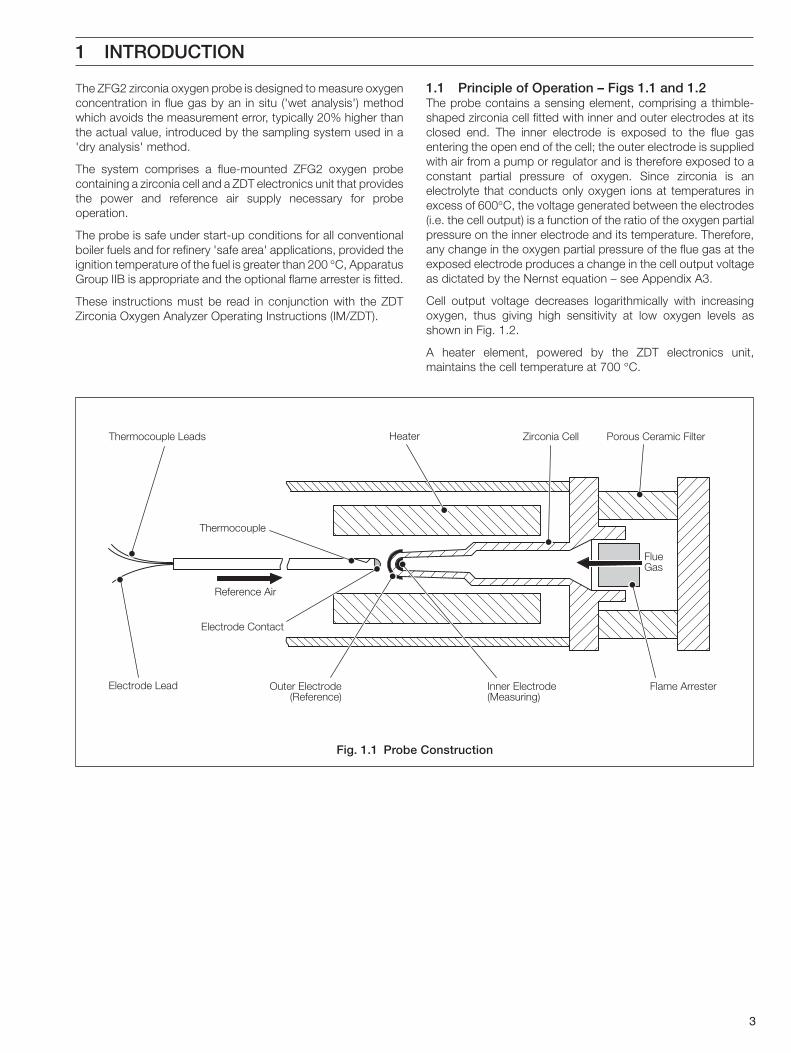
The ZFG2 zirconia oxygen probe is designed to measure oxygenconcentration in flue gas by an in situ ('wet analysis') methodwhich avoids the measurement error, typically 20% higher thanthe actual value, introduced by the sampling system used in a'dry analysis' method.
The system comprises a flue-mounted ZFG2 oxygen probecontaining a zirconia cell and a ZDT electronics unit that providesthe power and reference air supply necessary for probeoperation.
The probe is safe under start-up conditions for all conventionalboiler fuels and for refinery 'safe area' applications, provided theignition temperature of the fuel is greater than 200 °C, ApparatusGroup IIB is appropriate and the optional flame arrester is fitted.
These instructions must be read in conjunction with the ZDTZirconia Oxygen Analyzer Operating Instructions (IM/ZDT).
1.1 Principle of Operation – Figs 1.1 and 1.2The probe contains a sensing element, comprising a thimble-shaped zirconia cell fitted with inner and outer electrodes at itsclosed end. The inner electrode is exposed to the flue gasentering the open end of the cell; the outer electrode is suppliedwith air from a pump or regulator and is therefore exposed to aconstant partial pressure of oxygen. Since zirconia is anelectrolyte that conducts only oxygen ions at temperatures inexcess of 600°C, the voltage generated between the electrodes(i.e. the cell output) is a function of the ratio of the oxygen partialpressure on the inner electrode and its temperature. Therefore,any change in the oxygen partial pressure of the flue gas at theexposed electrode produces a change in the cell output voltageas dictated by the Nernst equation – see Appendix A3.
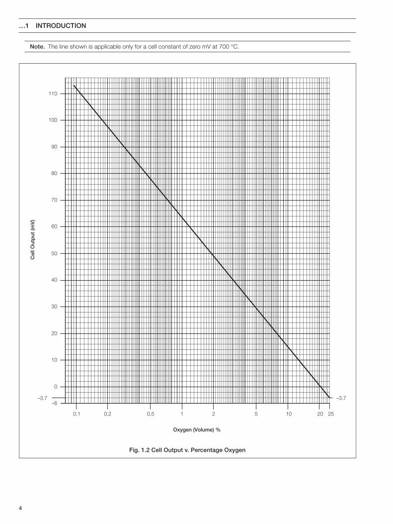
Cell output voltage decreases logarithmically with increasingoxygen, thus giving high sensitivity at low oxygen levels asshown in Fig. 1.2.
A heater element, powered by the ZDT electronics unit,maintains the cell temperature at 700 °C.
Fig. 1.1 Probe Construction
4
Cel
l Out
put
(mV
)
Oxygen (Volume) %
0.1 0.2 0.5 1 2 5 10 20 25
–3.7–6
–3.7
0
10
20
30
40
50
60
70
80
90
100
110
…1 INTRODUCTION
Note. The line shown is applicable only for a cell constant of zero mV at 700 °C.
Fig. 1.2 Cell Output v. Percentage Oxygen
5
Identification Label
edoCstigiD
4,3,2,1 5 6 7 8 9 01 11 21 31
cisaBepyT
rebmuN
noitresnIhtgneL
egnalFepyT
tiudnoC
lleCemalF
retserrAecnerefeR
riAgnitnuoM
ylbmessAetalPyrtnEepyT
ffO.oN htgneL
2GFZainocriZnegyxO
eborP
1 m4.0 1 DTS 1 mm02 0 enoN 0 enoN 1 lleCdradnatS 0 enoN 1 lanretnI 0 enoN
2 m0.1 2 NID 2 1/2 .niTPN
1 .dtSenO 1 m6 2 hguorhT-wolFlleC
1 emalFretserrA
2 lanretxE 1 dradnatS)seborpm4.0(
3 m5.1 3 ISNA 2 .dtSowT 2 m01 3 -seRtsaFlleCecnop
2 gnol(dradnatS)seborp
4 m0.2 4 SIJ 3 56PIenO
5 231ledoM 4 56PIowT
9 laicepS
2GFZ 2 1 1 2 1 1 1 1 2
eborpnegyxoainocriZ2GFZ
m0.1–htgnelnoitresnI
dradnats–epytegnalF
mm02–epytyrtnetiudnoC
owt–stiudnocforebmuN
m6–htgneltiudnoC
dradnats–epytlleC
dettifretserraemalF
)tiudnocnihtiw(gnibutriaecnereferlanretnI
etalpgnitnuomdradnatS
2 PREPARATION
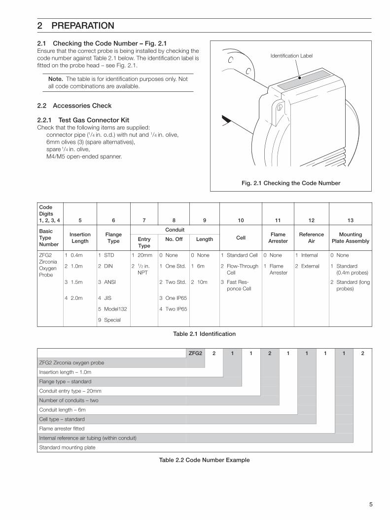
2.1 Checking the Code Number – Fig. 2.1Ensure that the correct probe is being installed by checking thecode number against Table 2.1 below. The identification label isfitted on the probe head – see Fig. 2.1.
Note. The table is for identification purposes only. Notall code combinations are available.
2.2 Accessories Check
2.2.1 Test Gas Connector KitCheck that the following items are supplied:
connector pipe (1/4 in. o.d.) with nut and 1/4 in. olive,6mm olives (3) (spare alternatives),spare 1/4 in. olive,M4/M5 open-ended spanner.
Fig. 2.1 Checking the Code Number
Table 2.1 Identification
Table 2.2 Code Number Example
6
…2 PREPARATION
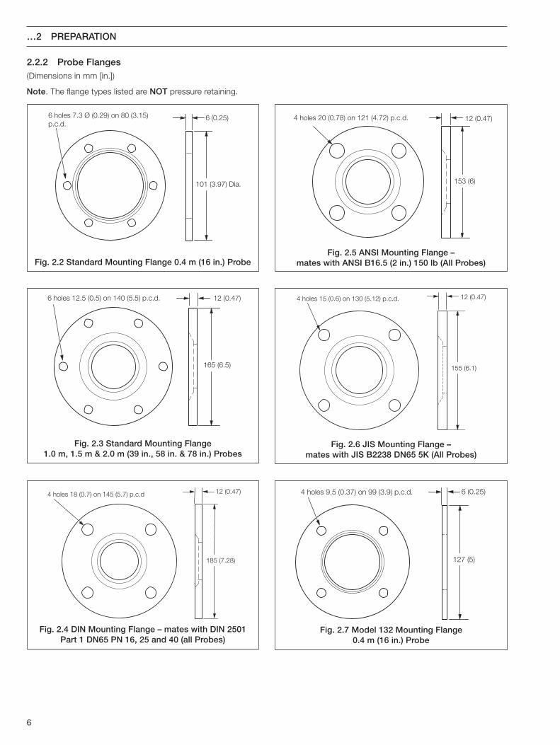
2.2.2 Probe Flanges
6 holes 7.3 Ø (0.29) on 80 (3.15)p.c.d.
101 (3.97) Dia.
6 (0.25)
6 holes 12.5 (0.5) on 140 (5.5) p.c.d.
165 (6.5)
12 (0.47)
12 (0.47)
185 (7.28)
4 holes 18 (0.7) on 145 (5.7) p.c.d
12 (0.47)
153 (6)
4 holes 20 (0.78) on 121 (4.72) p.c.d.
12 (0.47)
155 (6.1)
4 holes 15 (0.6) on 130 (5.12) p.c.d.
6 (0.25)
127 (5)
4 holes 9.5 (0.37) on 99 (3.9) p.c.d.
(Dimensions in mm [in.])
Note. The flange types listed are NOT pressure retaining.
Fig. 2.2 Standard Mounting Flange 0.4 m (16 in.) ProbeFig. 2.5 ANSI Mounting Flange –
mates with ANSI B16.5 (2 in.) 150 lb (All Probes)
Fig. 2.3 Standard Mounting Flange1.0 m, 1.5 m & 2.0 m (39 in., 58 in. & 78 in.) Probes
Fig. 2.4 DIN Mounting Flange – mates with DIN 2501Part 1 DN65 PN 16, 25 and 40 (all Probes)
Fig. 2.6 JIS Mounting Flange –mates with JIS B2238 DN65 5K (All Probes)
Fig. 2.7 Model 132 Mounting Flange0.4 m (16 in.) Probe
7
Six M6 studs equispacedon 80 p.c.d.
160
160
7
16
All dimensions in mm
Six holes tappedM6 on 80 p.c.d.
All dimensions in mm
4210
21/2 in. NPT
106Dia.
Six M10 studs equispaced on 140 p.c.d.
203
20
203
32
All dimensions in mm
Six 12 dia. holes to clearZ-LT probe fixing studs
Six holes tappedM6 on 80 p.c.d.
165Dia.
All dimensions in mm
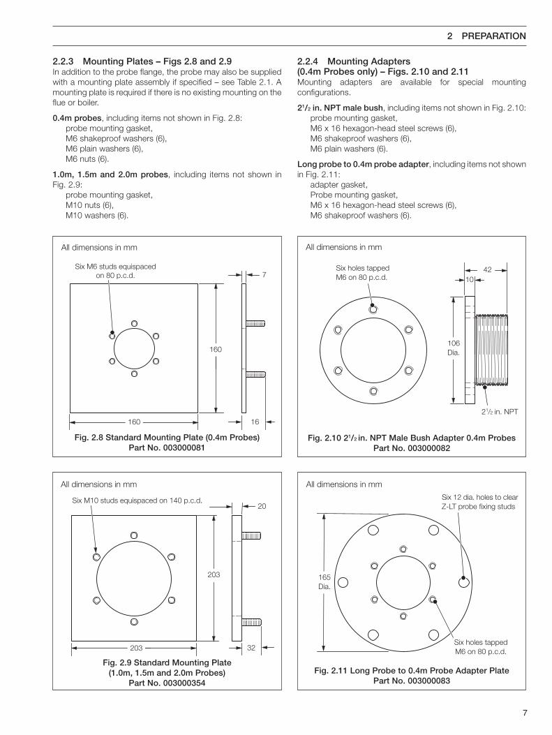
2.2.3 Mounting Plates – Figs 2.8 and 2.9In addition to the probe flange, the probe may also be suppliedwith a mounting plate assembly if specified – see Table 2.1. Amounting plate is required if there is no existing mounting on theflue or boiler.
0.4m probes, including items not shown in Fig. 2.8:probe mounting gasket,M6 shakeproof washers (6),M6 plain washers (6),M6 nuts (6).
1.0m, 1.5m and 2.0m probes, including items not shown inFig. 2.9:
probe mounting gasket,M10 nuts (6),M10 washers (6).
2.2.4 Mounting Adapters(0.4m Probes only) – Figs. 2.10 and 2.11Mounting adapters are available for special mountingconfigurations.
21/2 in. NPT male bush, including items not shown in Fig. 2.10:probe mounting gasket,M6 x 16 hexagon-head steel screws (6),M6 shakeproof washers (6),M6 plain washers (6).
Long probe to 0.4m probe adapter, including items not shownin Fig. 2.11:
adapter gasket,Probe mounting gasket,M6 x 16 hexagon-head steel screws (6),M6 shakeproof washers (6).
Fig. 2.8 Standard Mounting Plate (0.4m Probes)Part No. 003000081
Fig. 2.9 Standard Mounting Plate(1.0m, 1.5m and 2.0m Probes)
Part No. 003000354
Fig. 2.10 21/2 in. NPT Male Bush Adapter 0.4m ProbesPart No. 003000082
Fig. 2.11 Long Probe to 0.4m Probe Adapter PlatePart No. 003000083
2 PREPARATION
8
ecnerefeRgnibuT/elbaC noitpircseD
elbactuptuolleC htaehsCVPllarevohtiwdiarbreppocniwteulbdnaderpudial2.0/61
elbacelpuocomrehT )4.ontrapSB(485CEINIDdnaKepyt7394SBlAiN/rCiN
elbacretaeH 2ecnadepmipoolxaM.m001nurxaM Ω
gnibutriA 1/4 x.d.oni 1/8 001(ebutCVPronolyn,leetssselniatsni ° )xamtneibmaC
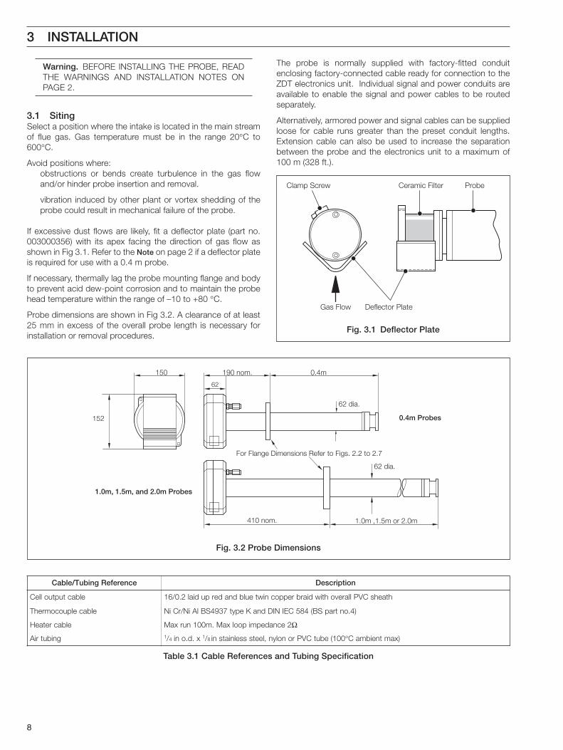
150
152
190 nom. 0.4m
62
For Flange Dimensions Refer to Figs. 2.2 to 2.7
0.4m Probes
62 dia.
62 dia.
410 nom. 1.0m ,1.5m or 2.0m
1.0m, 1.5m, and 2.0m Probes
Clamp Screw
Deflector PlateGas Flow
Ceramic Filter Probe
Fig. 3.1 Deflector Plate
Fig. 3.2 Probe Dimensions
Table 3.1 Cable References and Tubing Specification
Warning. BEFORE INSTALLING THE PROBE, READTHE WARNINGS AND INSTALLATION NOTES ONPAGE 2.
3.1 SitingSelect a position where the intake is located in the main streamof flue gas. Gas temperature must be in the range 20°C to600°C.
Avoid positions where:obstructions or bends create turbulence in the gas flowand/or hinder probe insertion and removal.
vibration induced by other plant or vortex shedding of theprobe could result in mechanical failure of the probe.
If excessive dust flows are likely, fit a deflector plate (part no.003000356) with its apex facing the direction of gas flow asshown in Fig 3.1. Refer to the Note on page 2 if a deflector plateis required for use with a 0.4 m probe.
If necessary, thermally lag the probe mounting flange and bodyto prevent acid dew-point corrosion and to maintain the probehead temperature within the range of –10 to +80 °C.
Probe dimensions are shown in Fig 3.2. A clearance of at least25 mm in excess of the overall probe length is necessary forinstallation or removal procedures.
The probe is normally supplied with factory-fitted conduitenclosing factory-connected cable ready for connection to theZDT electronics unit. Individual signal and power conduits areavailable to enable the signal and power cables to be routedseparately.
Alternatively, armored power and signal cables can be suppliedloose for cable runs greater than the preset conduit lengths.Extension cable can also be used to increase the separationbetween the probe and the electronics unit to a maximum of100 m (328 ft.).
3 INSTALLATION
9
12
3
4
4
3
21
3 INSTALLATION…
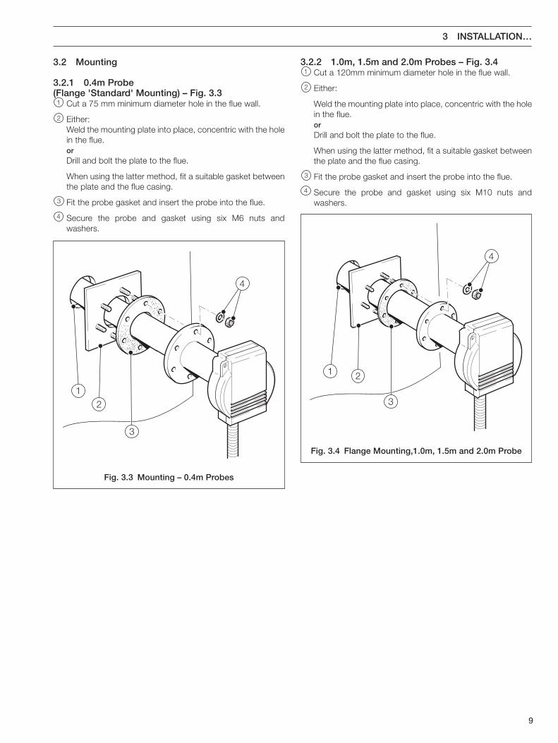
3.2 Mounting
3.2.1 0.4m Probe(Flange 'Standard' Mounting) – Fig. 3.31 Cut a 75 mm minimum diameter hole in the flue wall.
2 Either:Weld the mounting plate into place, concentric with the holein the flue.orDrill and bolt the plate to the flue.
When using the latter method, fit a suitable gasket betweenthe plate and the flue casing.
3 Fit the probe gasket and insert the probe into the flue.
4 Secure the probe and gasket using six M6 nuts andwashers.
3.2.2 1.0m, 1.5m and 2.0m Probes – Fig. 3.41 Cut a 120mm minimum diameter hole in the flue wall.
2 Either:
Weld the mounting plate into place, concentric with the holein the flue.orDrill and bolt the plate to the flue.
When using the latter method, fit a suitable gasket betweenthe plate and the flue casing.
3 Fit the probe gasket and insert the probe into the flue.
4 Secure the probe and gasket using six M10 nuts andwashers.
Fig. 3.3 Mounting – 0.4m Probes
Fig. 3.4 Flange Mounting,1.0m, 1.5m and 2.0m Probe

10
21
3
3
24
5
1
…3 INSTALLATION
3.2.3 0.4m Probe(21/2 in. Male Bush NPT Mounting) – Fig. 3.5
Note. The following procedure applies where a 21/2 in.NPT female fitting is already installed in the flue.
1 Apply anti-seize compound (e.g. Rocol J166 or similar) tothe thread on the male bush mounting adapter. Screw theadapter into the existing flue fitting. Tighten by inserting twoM6 screws into opposite holes in the adapter and using a baras a lever – see Caution.
Caution. Do not use the probe body as a lever totighten the male bush.
2 Fit the probe gasket over the probe and insert the probethrough the adapter into the flue.
3 Secure the probe and gasket using six M6 screws andwashers.
3.2.4 0.4m Probe(Z-LT Adapter Plate Mounting) – Fig. 3.6
Note. The following procedure applies where anexisting Z-LT or long ZFG installation is to bereplaced by a 0.4 m ZFG2 probe.
1 Locate the Z-LT adapter gasket on the existing Z-LTmounting plate.
2 Locate the Z-LT adapter plate on the gasket.
3 Secure the gasket and plate with six M10 nuts and washers.
4 Fit the probe gasket over the probe end. Insert the probe intothe flue.
5 Secure the probe and gasket using six M6 screws andwashers.
Fig. 3.5 Male Bush Mounting, 0.4m Probe
Fig. 3.6 Z-LT Adapter Plate Mounting
11
ConnectionsCover
4
1
2
3
4
4 CONNECTIONS
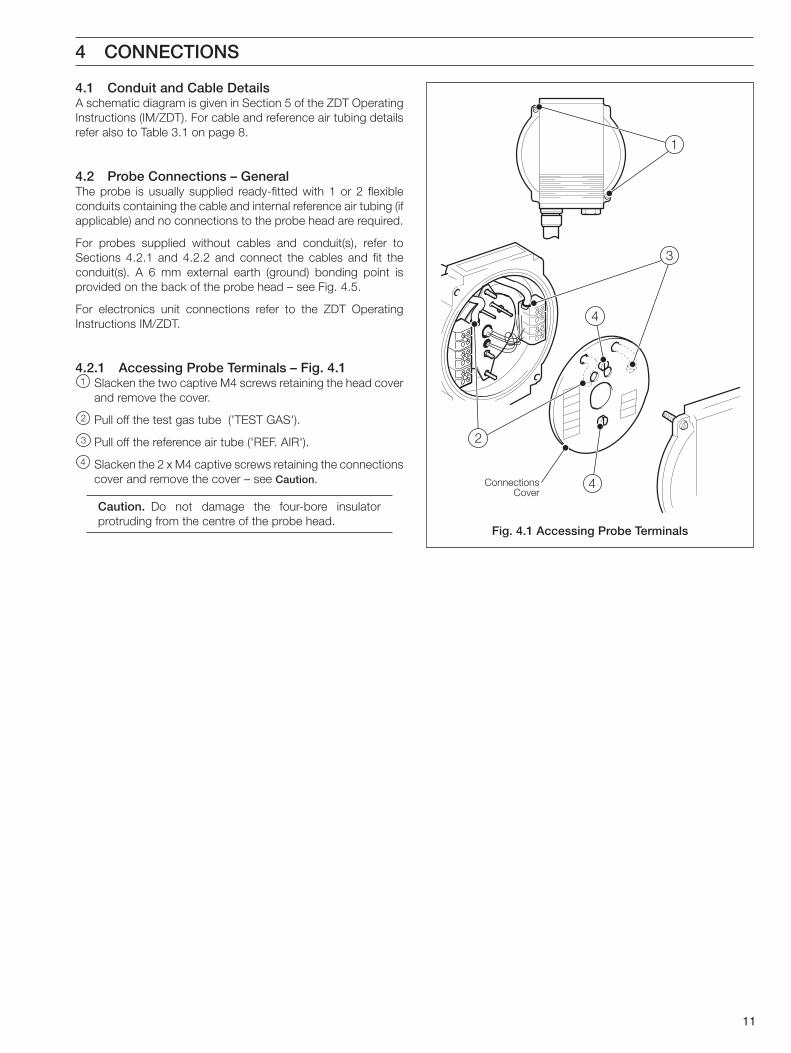
4.1 Conduit and Cable DetailsA schematic diagram is given in Section 5 of the ZDT OperatingInstructions (IM/ZDT). For cable and reference air tubing detailsrefer also to Table 3.1 on page 8.
4.2 Probe Connections – GeneralThe probe is usually supplied ready-fitted with 1 or 2 flexibleconduits containing the cable and internal reference air tubing (ifapplicable) and no connections to the probe head are required.
For probes supplied without cables and conduit(s), refer toSections 4.2.1 and 4.2.2 and connect the cables and fit theconduit(s). A 6 mm external earth (ground) bonding point isprovided on the back of the probe head – see Fig. 4.5.
For electronics unit connections refer to the ZDT OperatingInstructions IM/ZDT.
4.2.1 Accessing Probe Terminals – Fig. 4.11 Slacken the two captive M4 screws retaining the head cover
and remove the cover.
2 Pull off the test gas tube ('TEST GAS').
3 Pull off the reference air tube ('REF. AIR').
4 Slacken the 2 x M4 captive screws retaining the connectionscover and remove the cover – see Caution.
Caution. Do not damage the four-bore insulatorprotruding from the centre of the probe head.
Fig. 4.1 Accessing Probe Terminals
12
…4 CONNECTIONS
Fig. 4.2 Probe Connections
SCREEN
CELL–VE
CELL+VE
SCREEN
T/C–VE
T/C+VE
EARTH
HEATER
HEATER
Blue
Red
Blue
White Blue
Brown
Green/Yellow
Optional External Reference Air Connection
2
34
SCREEN
CELL–VE
CELL+VE
SCREEN
T/C–VE
T/C+VE
EARTH
HEATER
HEATER
Blue
Red
Blue
White Blue
Brown
Green/Yellow
Power Signal
A – Single Conduit (Power and Signal Cables)
B – Double Conduit
Optional External Reference Air Connection
5
1
2
1
34
5
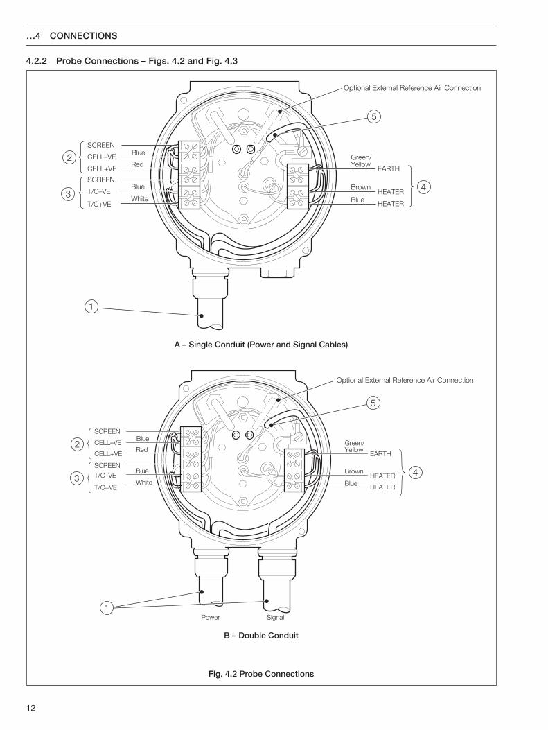
4.2.2 Probe Connections – Figs. 4.2 and Fig. 4.3
13
6
7
8 9
…4.2.2 Probe Connections – Figs. 4.2 and Fig. 4.3When making connections, ensure that the cables and referenceair tubing are routed correctly as shown in Fig. 4.2A (singleconduit) or Fig. 4.2B (double conduit).
1 Fit suitable cable gland(s) or conduit fitting(s) into the head(1/2 in. NPT or 20mm as applicable).
2 Make cell connections:Red – 'CELL +VE'Blue – 'CELL –VE'Screen – 'SCREEN'.
3 Make thermocouple connections:White – 'T/C +VE'Blue – 'T/C –VE'Screen* – 'SCREEN'. * If applicable.
4 Make heater connections:Brown* – 'HEATER'Blue* – 'HEATER' *polarity unimportant.Green/Yellow – 'EARTH'.
5 Internal reference air connection only – route the reference airtubing as shown but do not connect yet.
Note. For external reference air connection refer toSection 4.3.1.
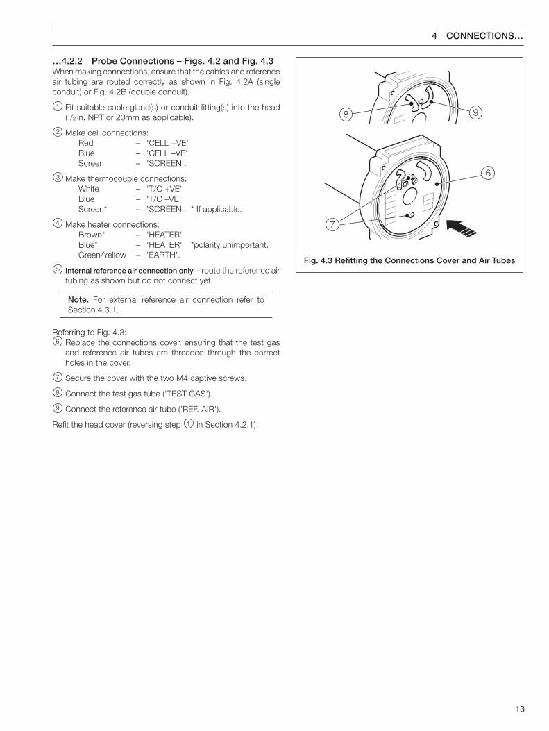
Referring to Fig. 4.3:6 Replace the connections cover, ensuring that the test gas
and reference air tubes are threaded through the correctholes in the cover.
7 Secure the cover with the two M4 captive screws.
8 Connect the test gas tube ('TEST GAS').
9 Connect the reference air tube ('REF. AIR').
Refit the head cover (reversing step 1 in Section 4.2.1).
Fig. 4.3 Refitting the Connections Cover and Air Tubes
4 CONNECTIONS…
14
Vent
ExternalReference
Air Inlet
Test GasInlet
BlankingPlug
External Earth(Ground) Bonding
Point (M6 Threaded)
Bung
A – Internal Reference Air
B – External Reference Air
External Earth(Ground) Bonding
Point (M6 Threaded)
Vent
Test GasInlet
BlankingPlug
Fig. 4.4 Air Connections
…4 CONNECTIONS
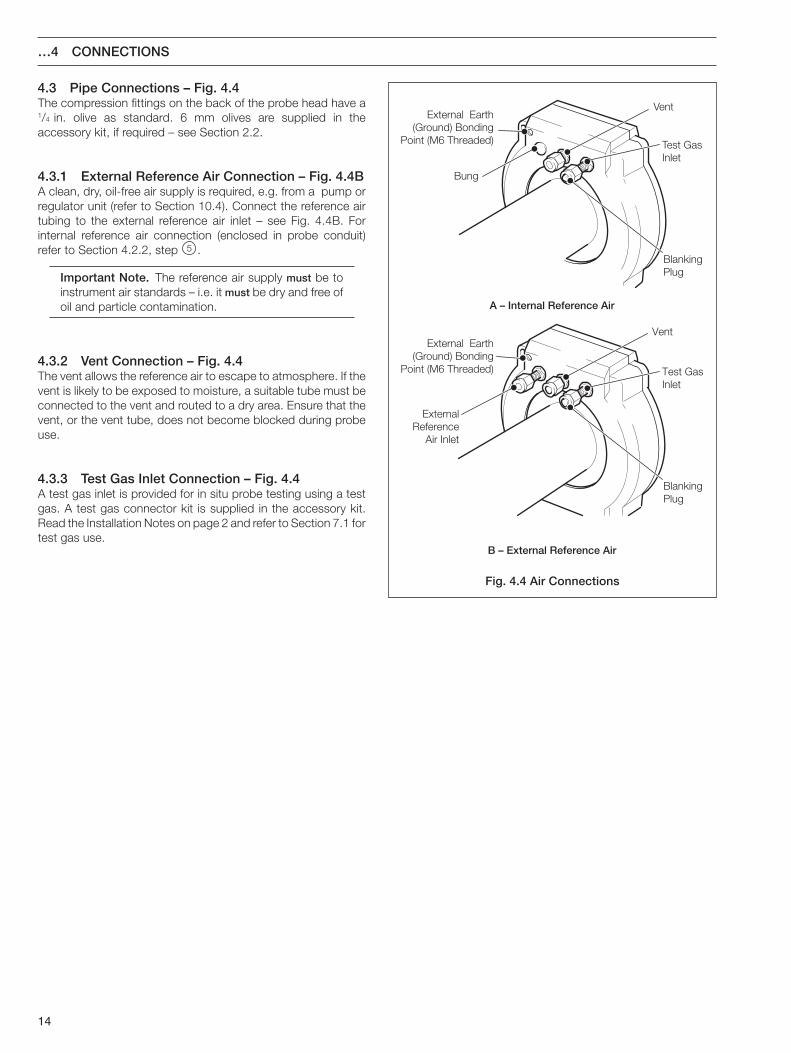
4.3 Pipe Connections – Fig. 4.4The compression fittings on the back of the probe head have a1/4 in. olive as standard. 6 mm olives are supplied in theaccessory kit, if required – see Section 2.2.
4.3.1 External Reference Air Connection – Fig. 4.4BA clean, dry, oil-free air supply is required, e.g. from a pump orregulator unit (refer to Section 10.4). Connect the reference airtubing to the external reference air inlet – see Fig. 4.4B. Forinternal reference air connection (enclosed in probe conduit)refer to Section 4.2.2, step 5 .
Important Note. The reference air supply must be toinstrument air standards – i.e. it must be dry and free ofoil and particle contamination.
4.3.2 Vent Connection – Fig. 4.4The vent allows the reference air to escape to atmosphere. If thevent is likely to be exposed to moisture, a suitable tube must beconnected to the vent and routed to a dry area. Ensure that thevent, or the vent tube, does not become blocked during probeuse.
4.3.3 Test Gas Inlet Connection – Fig. 4.4A test gas inlet is provided for in situ probe testing using a testgas. A test gas connector kit is supplied in the accessory kit.Read the Installation Notes on page 2 and refer to Section 7.1 fortest gas use.
15
System fault finding procedures are detailed in the ZDTOperating Instructions, IM/ZDT. Where a fault is traced to theprobe, it may be possible to identify and rectify the fault. Afterany rectification, the system must be recalibrated as detailed inIM/ZDT to maintain the stated accuracies.
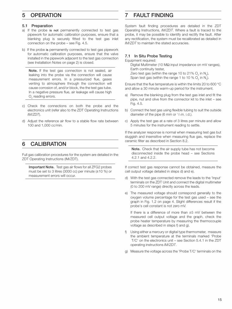
7.1 In Situ Probe TestingEquipment required:
Digital Multimeter (10 MΩ input impedance on mV ranges),Earth continuity tester,Zero test gas (within the range 10 to 21% O2 in N2),Span test gas (within the range 1 to 10 % O2 in N2).
Ensure that the flue temperature is within the limits 20 to 600 °Cand allow a 30 minute warm-up period for the instrument.
a) Remove the blanking plug from the test gas inlet and fit thepipe, nut and olive from the connector kit to the inlet – seeFig. 4.5.
b) Connect the test gas using flexible tubing to suit the outsidediameter of the pipe (6 mm or 1/4 in. i.d.).
c) Apply the test gas at a rate of 3 litres per minute and allow5 minutes for the instrument reading to settle.
If the analyzer response is normal when measuring test gas butsluggish and insensitive when measuring flue gas, replace theceramic filter as described in Section 8.2.
Note. Check that the air supply tube has not becomedisconnected inside the probe head – see Sections4.2.1 and 4.2.2.
If correct test gas response cannot be obtained, measure thecell output voltage detailed in steps d) and e).
d) With the test gas connected remove the leads to the 'Input'terminals on the ZDT Unit and connect the digital multimeter(0 to 200 mV range) directly across the leads.
e) The measured voltage should correspond generally to theoxygen volume percentage for the test gas used – see thegraph in Fig. 1.2 on page 4. Slight differences result if theprobe's cell constant is not zero mV.
If there is a difference of more than ±5 mV between themeasured cell output voltage and the graph, check theprobe heater temperature by measuring the thermocouplevoltage as described in steps f) and g).
f) Using either a mercury or digital type thermometer, measurethe ambient temperature at the terminals marked 'Probe T/C' on the electronics unit – see Section 5.4.1 in the ZDToperating instructions IM/ZDT.
g) Measure the voltage across the 'Probe T/C' terminals on the
6 CALIBRATION
5.1 Preparationa) If the probe is not permanently connected to test gas
pipework for automatic calibration purposes, ensure that ablanking plug is securely fitted to the test gas inletconnection on the probe – see Fig. 4.5.
b) If the probe is permanently connected to test gas pipeworkfor automatic calibration purposes, ensure that the valveinstalled in the pipework adjacent to the test gas connection(see Installation Notes on page 2) is closed.
Note. If the test gas connection is not sealed, airleaking into the probe via the connection will causemeasurement errors. In a pressurized flue, gasesventing to atmosphere through the connection willcause corrosion of, and/or block, the the test gas tube.In a negative pressure flue, air leakage will cause highO2 reading errors.
c) Check the connections on both the probe and theelectronics unit (refer also to the ZDT Operating InstructionsIM/ZDT).
d) Adjust the reference air flow to a stable flow rate between100 and 1,000 cc/min.
5 OPERATION
Full gas calibration procedures for the system are detailed in theZDT Operating Instructions (IM/ZDT).
Important Note. Test gas air flows for all ZFG2 probesmust be set to 3 litres (3000 cc) per minute (±10 %) ormeasurement errors will occur.
7 FAULT FINDING
16
If the thermocouple appears to be faulty the thermocouple/electrode lead assembly must be replaced as described inSection 8.6 (0.4 m probes) or Section 8.10 (other probes). If thethermocouple appears to be in order continue from step i).
i) Switch off the AC supply, disconnect the heater 'H' leadsfrom their terminals on the ZDT Unit, and measure theresistance across these leads at the probe terminal head andat the cable ends.
The correct heater resistance is 28 to 31Ω for 0.4 m probes and26 to 29 Ω for 1.0 m, 1.5 m and 2.0 m probes.
If the resistance is incorrect, check the heater wiring and, ifnecessary, replace the heater assembly as described in Section8.8 (0.4m probes) or 8.13 (other probes).
7.2 Bench TestingWhen the fault has been rectified, the probe must be benchtested before fitting into the flue.
a) Connect the probe heater and thermocouple cables to theelectronics unit.
b) Connect the reference air supply tube .
c) Connect a digital voltmeter directly across the cell outputleads after removing them from the 'PROBE CELL' terminalson the ZDT Unit.
Allow the probe to operate in air for about 20 minutes in order toachieve temperature stability.
Periodically check the reading on the digital voltmeter after theinitial temperature stabilizing time has expired.
The reading should settle at the cell constant of typically0V ±2 mV for a new cell.
When the cell attains its constant (typically after 1 hour), apply atest gas and measure the cell output as described in Section7.1, steps and a) to d). Otherwise, the tests detailed in Section7.1 must be carried out whilst the probe is still on the bench.
Note. The cell can take up to three hours to settle fullyat its constant.
If the cell responds correctly to the test gas the probe can berefitted into the flue. For full probe calibration details refer to theZDT operating instructions, IM/ZDT.
tneibmA(.pmeT ° )C
stlovilliMtneibmA
(.pmeT ° )CstlovilliM
0594847464
601.72741.72881.72922.72
72.72
5242322212
821.82861.82902.82942.82
92.82
5444342414
113.72253.72493.72534.72674.72
0291817161
33.8273.8214.82
154.82194.82
0493837363
725.72855.72995.72936.72
86.72
5141312111
135.82175.82116.82156.82196.82
5343332313
127.72267.72308.82348.82488.82
019876
137.82177.82118.82158.82
98.82
0392827262
529.72669.72600.82740.82780.82
543210
39.8279.82
900.92940.92980.92821.92
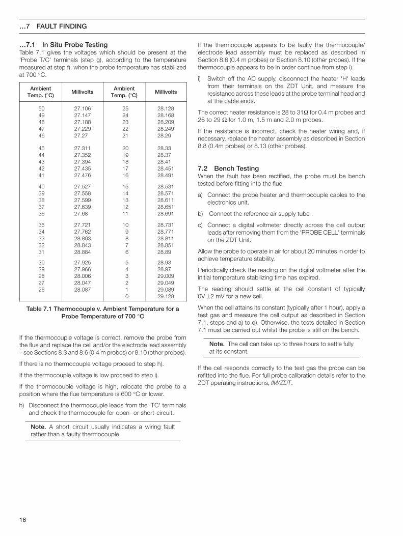
Table 7.1 Thermocouple v. Ambient Temperature for aProbe Temperature of 700 °C
…7.1 In Situ Probe TestingTable 7.1 gives the voltages which should be present at the'Probe T/C' terminals (step g), according to the temperaturemeasured at step f), when the probe temperature has stabilizedat 700 °C.
…7 FAULT FINDING
If the thermocouple voltage is correct, remove the probe fromthe flue and replace the cell and/or the electrode lead assembly– see Sections 8.3 and 8.6 (0.4 m probes) or 8.10 (other probes).
If there is no thermocouple voltage proceed to step h).
If the thermocouple voltage is low proceed to step i).
If the thermocouple voltage is high, relocate the probe to aposition where the flue temperature is 600 °C or lower.
h) Disconnect the thermocouple leads from the 'TC' terminalsand check the thermocouple for open- or short-circuit.
Note. A short circuit usually indicates a wiring faultrather than a faulty thermocouple.
17
2 to 3mm
Cell Mount
3
2
2
1
Cell Mount
2
1
8 DISMANTLING AND REASSEMBLY
Before dismantling the probe, thoroughly clean the outersurfaces with non-abrasive materials to prevent contaminationof the inner assemblies.
8.1 Tools RequiredM3 open ended spanner,M4 open ended spanner (supplied),0 to 5 Nm torque driver fitted with a hexagon (Allen) M4,wrench, or alternatively, M4 Allen key,Small, flat-bladed (terminal) screwdriver,Medium, flat-bladed screwdriver.
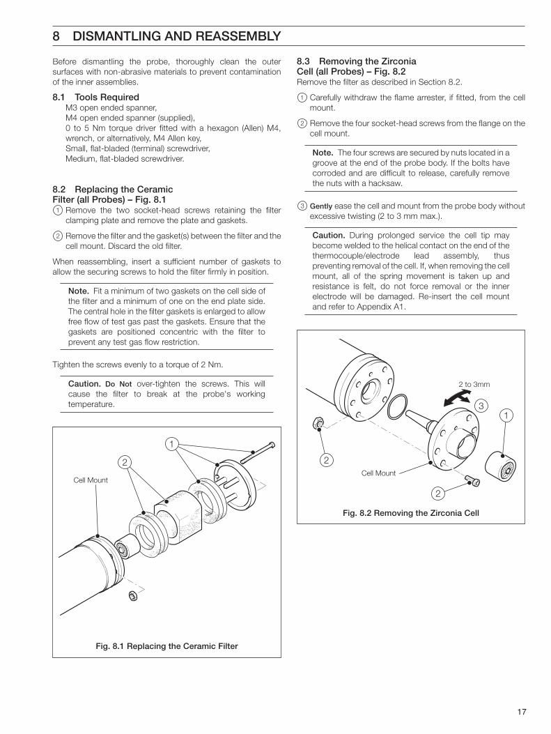
8.2 Replacing the CeramicFilter (all Probes) – Fig. 8.11 Remove the two socket-head screws retaining the filter
clamping plate and remove the plate and gaskets.
2 Remove the filter and the gasket(s) between the filter and thecell mount. Discard the old filter.
When reassembling, insert a sufficient number of gaskets toallow the securing screws to hold the filter firmly in position.
Note. Fit a minimum of two gaskets on the cell side ofthe filter and a minimum of one on the end plate side.The central hole in the filter gaskets is enlarged to allowfree flow of test gas past the gaskets. Ensure that thegaskets are positioned concentric with the filter toprevent any test gas flow restriction.
Tighten the screws evenly to a torque of 2 Nm.
Caution. Do Not over-tighten the screws. This willcause the filter to break at the probe's workingtemperature.
8.3 Removing the ZirconiaCell (all Probes) – Fig. 8.2Remove the filter as described in Section 8.2.
1 Carefully withdraw the flame arrester, if fitted, from the cellmount.
2 Remove the four socket-head screws from the flange on thecell mount.
Note. The four screws are secured by nuts located in agroove at the end of the probe body. If the bolts havecorroded and are difficult to release, carefully removethe nuts with a hacksaw.
3 Gently ease the cell and mount from the probe body withoutexcessive twisting (2 to 3 mm max.).
Caution. During prolonged service the cell tip maybecome welded to the helical contact on the end of thethermocouple/electrode lead assembly, thuspreventing removal of the cell. If, when removing the cellmount, all of the spring movement is taken up andresistance is felt, do not force removal or the innerelectrode will be damaged. Re-insert the cell mountand refer to Appendix A1.
Fig. 8.1 Replacing the Ceramic Filter
Fig. 8.2 Removing the Zirconia Cell
18
2 to 3mm
FemaleThread
4
6
3
2
5
5
1
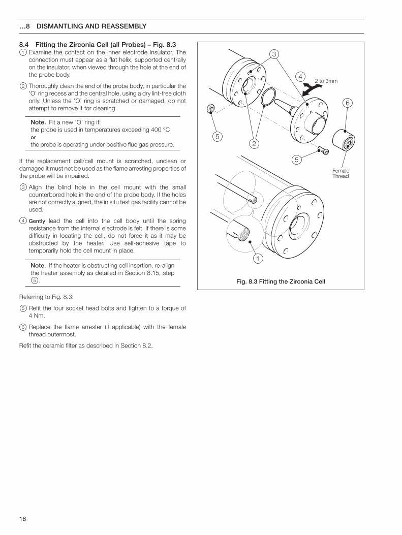
8.4 Fitting the Zirconia Cell (all Probes) – Fig. 8.31 Examine the contact on the inner electrode insulator. The
connection must appear as a flat helix, supported centrallyon the insulator, when viewed through the hole at the end ofthe probe body.
2 Thoroughly clean the end of the probe body, in particular the'O' ring recess and the central hole, using a dry lint-free clothonly. Unless the 'O' ring is scratched or damaged, do notattempt to remove it for cleaning.
Note. Fit a new 'O' ring if:the probe is used in temperatures exceeding 400 °Corthe probe is operating under positive flue gas pressure.
If the replacement cell/cell mount is scratched, unclean ordamaged it must not be used as the flame arresting properties ofthe probe will be impaired.
3 Align the blind hole in the cell mount with the smallcounterbored hole in the end of the probe body. If the holesare not correctly aligned, the in situ test gas facility cannot beused.
4 Gently lead the cell into the cell body until the springresistance from the internal electrode is felt. If there is somedifficulty in locating the cell, do not force it as it may beobstructed by the heater. Use self-adhesive tape totemporarily hold the cell mount in place.
Note. If the heater is obstructing cell insertion, re-alignthe heater assembly as detailed in Section 8.15, step
5 .
Referring to Fig. 8.3:
5 Refit the four socket head bolts and tighten to a torque of4 Nm.
6 Replace the flame arrester (if applicable) with the femalethread outermost.
Refit the ceramic filter as described in Section 8.2.
Fig. 8.3 Fitting the Zirconia Cell
…8 DISMANTLING AND REASSEMBLY
19
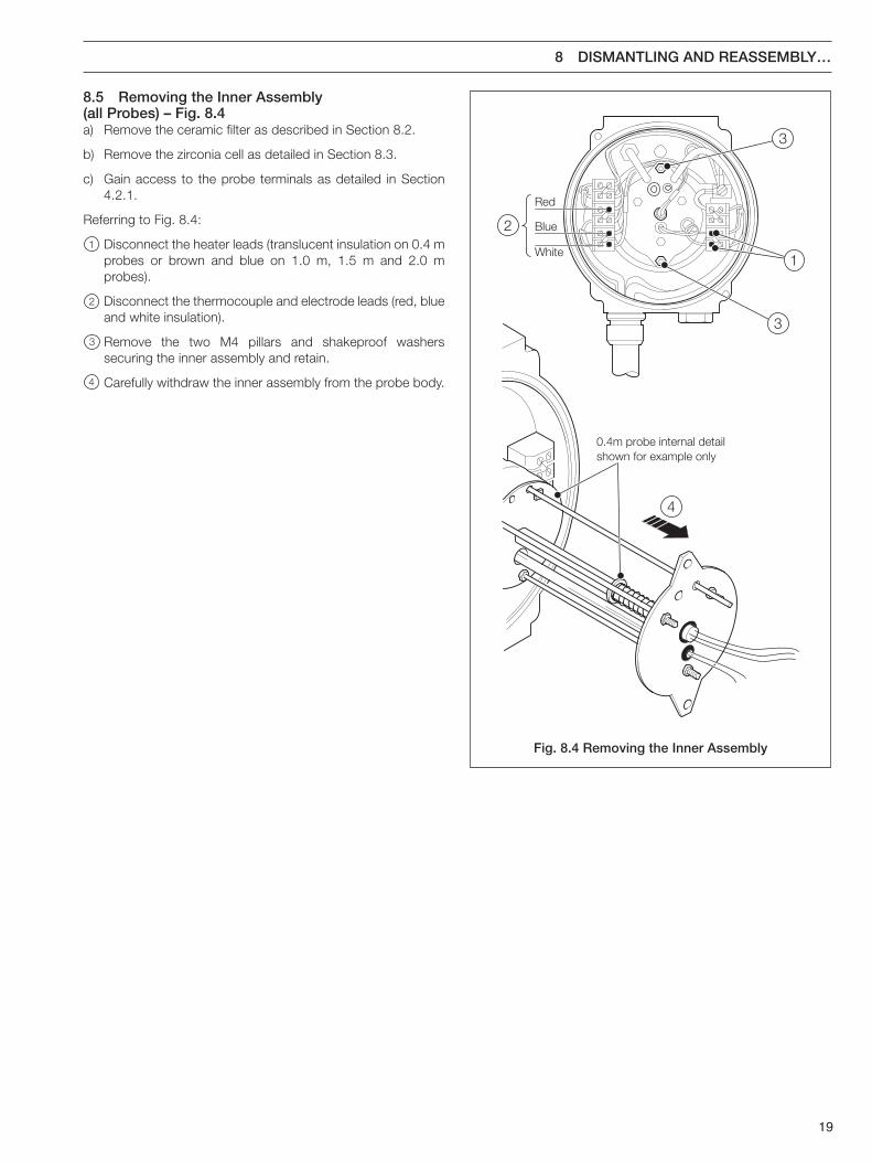
Fig. 8.4 Removing the Inner Assembly
0.4m probe internal detailshown for example only
Red
Blue
White
2
4
3
3
1
8.5 Removing the Inner Assembly(all Probes) – Fig. 8.4a) Remove the ceramic filter as described in Section 8.2.
b) Remove the zirconia cell as detailed in Section 8.3.
c) Gain access to the probe terminals as detailed in Section4.2.1.
Referring to Fig. 8.4:
1 Disconnect the heater leads (translucent insulation on 0.4 mprobes or brown and blue on 1.0 m, 1.5 m and 2.0 mprobes).
2 Disconnect the thermocouple and electrode leads (red, blueand white insulation).
3 Remove the two M4 pillars and shakeproof washerssecuring the inner assembly and retain.
4 Carefully withdraw the inner assembly from the probe body.
8 DISMANTLING AND REASSEMBLY…

20
Inner AssemblyMounting Plate
1
2
Baffle Plate
5
3
4
8.6 Removing the Thermocouple/Electrode LeadAssembly (0.4m Probes) – Fig. 8.5Remove the inner assembly as detailed in Section 8.5.
Caution. The thermocouple/electrode lead assemblyis fragile. Take extreme care not to damage theassembly during dismantling and reassembly.
Referring to Fig. 8.5:
1 Remove the rubber 'O' ring from the electrode insulator andallow the thermocouple/electrode assembly to slide throughthe inner assembly mounting plate under spring pressure.
2 Slide the thermocouple/electrode lead assembly towardsthe heater.
3 Pull the electrode leads through the mounting plate (from theunderside of the plate).
4 Remove the spring, washer and rubber 'O' ring fromelectrode assembly and retain.
5 Slide the thermocouple/electrode lead assembly through thebaffle plates and withdraw from the heater end.
Fig. 8.5 Removing theThermocouple/Electrode Lead Assembly
…8 DISMANTLING AND REASSEMBLY
21
8 DISMANTLING AND REASSEMBLY…
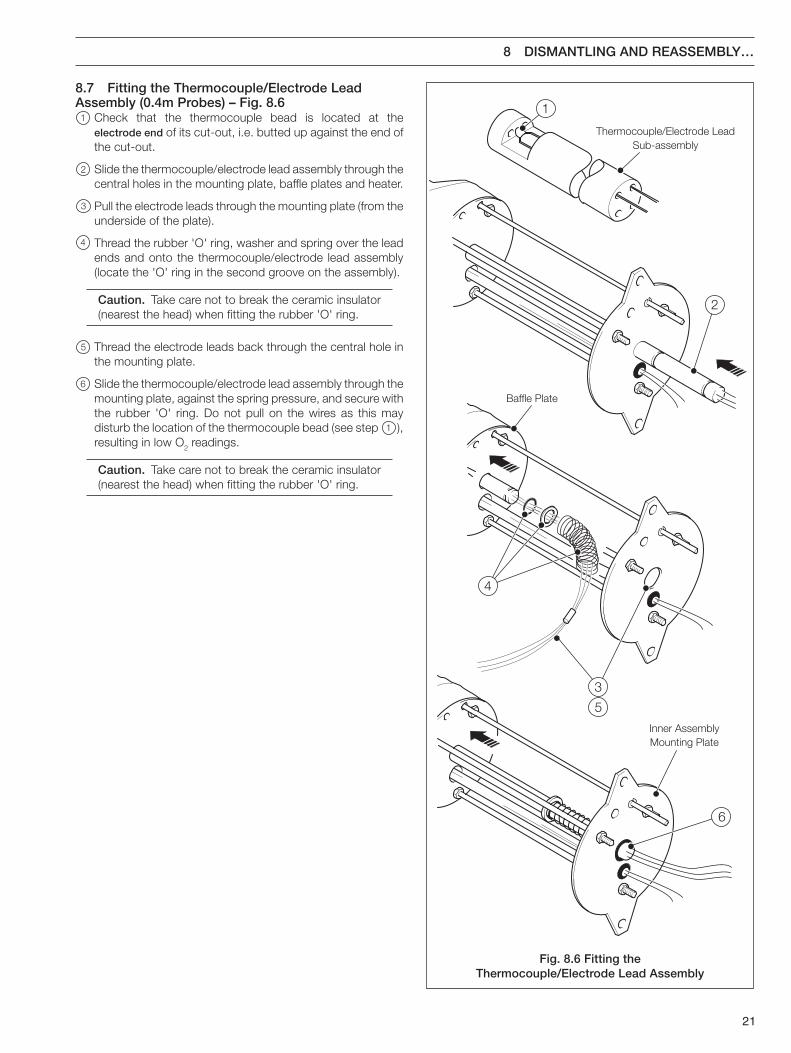
8.7 Fitting the Thermocouple/Electrode LeadAssembly (0.4m Probes) – Fig. 8.61 Check that the thermocouple bead is located at the
electrode end of its cut-out, i.e. butted up against the end ofthe cut-out.
2 Slide the thermocouple/electrode lead assembly through thecentral holes in the mounting plate, baffle plates and heater.
3 Pull the electrode leads through the mounting plate (from theunderside of the plate).
4 Thread the rubber 'O' ring, washer and spring over the leadends and onto the thermocouple/electrode lead assembly(locate the 'O' ring in the second groove on the assembly).
Caution. Take care not to break the ceramic insulator(nearest the head) when fitting the rubber 'O' ring.
5 Thread the electrode leads back through the central hole inthe mounting plate.
6 Slide the thermocouple/electrode lead assembly through themounting plate, against the spring pressure, and secure withthe rubber 'O' ring. Do not pull on the wires as this maydisturb the location of the thermocouple bead (see step 1 ),resulting in low O2 readings.
Caution. Take care not to break the ceramic insulator(nearest the head) when fitting the rubber 'O' ring.
Inner AssemblyMounting Plate
6
Baffle Plate
5
3
4
Thermocouple/Electrode LeadSub-assembly
1
2
Fig. 8.6 Fitting theThermocouple/Electrode Lead Assembly
22
Heater CarrierPlate
Baffle Plates
Thermocouple/Electrode LeadAssembly Mounting Plate
2 16
3
1
6
5
23
4
…8 DISMANTLING AND REASSEMBLY
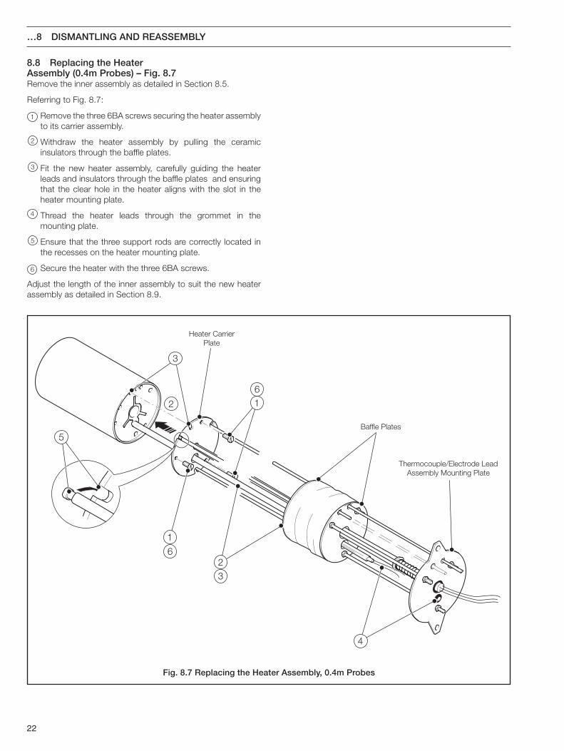
8.8 Replacing the HeaterAssembly (0.4m Probes) – Fig. 8.7Remove the inner assembly as detailed in Section 8.5.
Referring to Fig. 8.7:
1 Remove the three 6BA screws securing the heater assemblyto its carrier assembly.
2 Withdraw the heater assembly by pulling the ceramicinsulators through the baffle plates.
3 Fit the new heater assembly, carefully guiding the heaterleads and insulators through the baffle plates and ensuringthat the clear hole in the heater aligns with the slot in theheater mounting plate.
4 Thread the heater leads through the grommet in themounting plate.
5 Ensure that the three support rods are correctly located inthe recesses on the heater mounting plate.
6 Secure the heater with the three 6BA screws.
Adjust the length of the inner assembly to suit the new heaterassembly as detailed in Section 8.9.
Fig. 8.7 Replacing the Heater Assembly, 0.4m Probes
23
Baffle Plates
Thermocouple/Electrode LeadAssembly Mounting Plate
1
2
3
2
1
3
8 DISMANTLING AND REASSEMBLY…
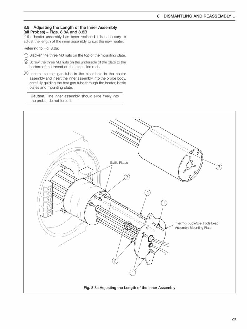
8.9 Adjusting the Length of the Inner Assembly(all Probes) – Figs. 8.8A and 8.8BIf the heater assembly has been replaced it is necessary toadjust the length of the inner assembly to suit the new heater.
Referring to Fig. 8.8a:
1 Slacken the three M3 nuts on the top of the mounting plate.
2 Screw the three M3 nuts on the underside of the plate to thebottom of the thread on the extension rods.
3 Locate the test gas tube in the clear hole in the heaterassembly and insert the inner assembly into the probe body,carefully guiding the test gas tube through the heater, baffleplates and mounting plate.
Caution. The inner assembly should slide freely intothe probe; do not force it.
Fig. 8.8a Adjusting the Length of the Inner Assembly
24
5
7
8
6
9
8
10
4
6
…8 DISMANTLING AND REASSEMBLY
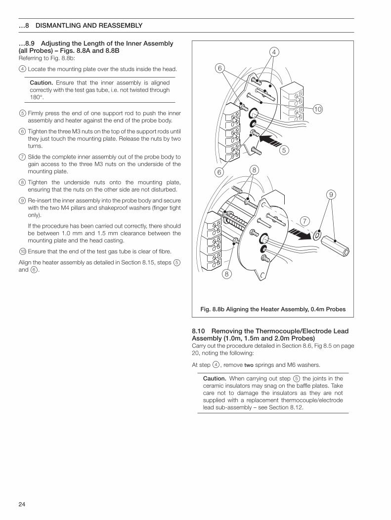
…8.9 Adjusting the Length of the Inner Assembly(all Probes) – Figs. 8.8A and 8.8BReferring to Fig. 8.8b:
4 Locate the mounting plate over the studs inside the head.
Caution. Ensure that the inner assembly is alignedcorrectly with the test gas tube, i.e. not twisted through180°.
5 Firmly press the end of one support rod to push the innerassembly and heater against the end of the probe body.
6 Tighten the three M3 nuts on the top of the support rods untilthey just touch the mounting plate. Release the nuts by twoturns.
7 Slide the complete inner assembly out of the probe body togain access to the three M3 nuts on the underside of themounting plate.
8 Tighten the underside nuts onto the mounting plate,ensuring that the nuts on the other side are not disturbed.
9 Re-insert the inner assembly into the probe body and securewith the two M4 pillars and shakeproof washers (finger tightonly).
If the procedure has been carried out correctly, there shouldbe between 1.0 mm and 1.5 mm clearance between themounting plate and the head casting.
10 Ensure that the end of the test gas tube is clear of fibre.
Align the heater assembly as detailed in Section 8.15, steps 5
and 6 .
Fig. 8.8b Aligning the Heater Assembly, 0.4m Probes
8.10 Removing the Thermocouple/Electrode LeadAssembly (1.0m, 1.5m and 2.0m Probes)Carry out the procedure detailed in Section 8.6, Fig 8.5 on page20, noting the following:
At step 4 , remove two springs and M6 washers.
Caution. When carrying out step 5 the joints in theceramic insulators may snag on the baffle plates. Takecare not to damage the insulators as they are notsupplied with a replacement thermocouple/electrodelead sub-assembly – see Section 8.12.
25
1
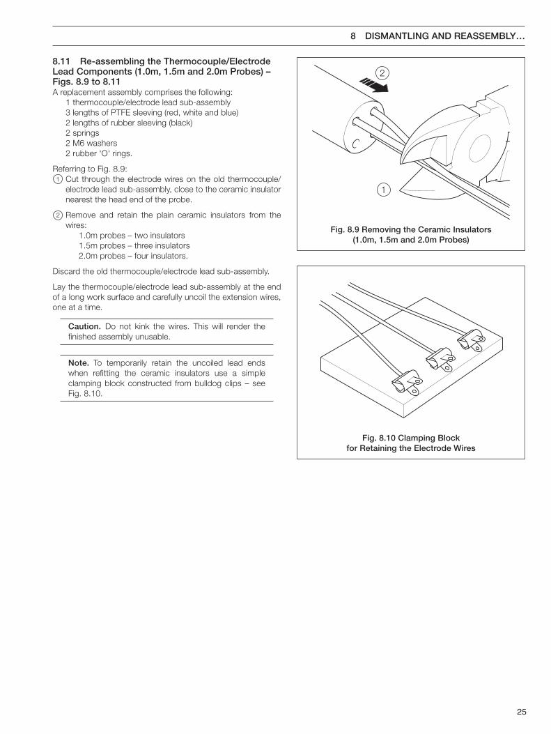
28.11 Re-assembling the Thermocouple/ElectrodeLead Components (1.0m, 1.5m and 2.0m Probes) –Figs. 8.9 to 8.11A replacement assembly comprises the following:
1 thermocouple/electrode lead sub-assembly3 lengths of PTFE sleeving (red, white and blue)2 lengths of rubber sleeving (black)2 springs2 M6 washers2 rubber 'O' rings.
Referring to Fig. 8.9:1 Cut through the electrode wires on the old thermocouple/
electrode lead sub-assembly, close to the ceramic insulatornearest the head end of the probe.
2 Remove and retain the plain ceramic insulators from thewires:
1.0m probes – two insulators1.5m probes – three insulators2.0m probes – four insulators.
Discard the old thermocouple/electrode lead sub-assembly.
Lay the thermocouple/electrode lead sub-assembly at the endof a long work surface and carefully uncoil the extension wires,one at a time.
Caution. Do not kink the wires. This will render thefinished assembly unusable.
Note. To temporarily retain the uncoiled lead endswhen refitting the ceramic insulators use a simpleclamping block constructed from bulldog clips – seeFig. 8.10.
Fig. 8.9 Removing the Ceramic Insulators(1.0m, 1.5m and 2.0m Probes)
Fig. 8.10 Clamping Blockfor Retaining the Electrode Wires
8 DISMANTLING AND REASSEMBLY…
26
Red(Electrode)
White(Thermocouple +ve)
Blue(Thermocouple –ve)
Thermocouple/Electrode LeadSub-Assembly
Self-adhesive Tape
3
4
5
6
7
Fig. 8.11 Re-assembling the Thermocouple/Electrode Lead Components (1.0m, 1.5m and 2.0m Probes)
…8 DISMANTLING AND REASSEMBLY
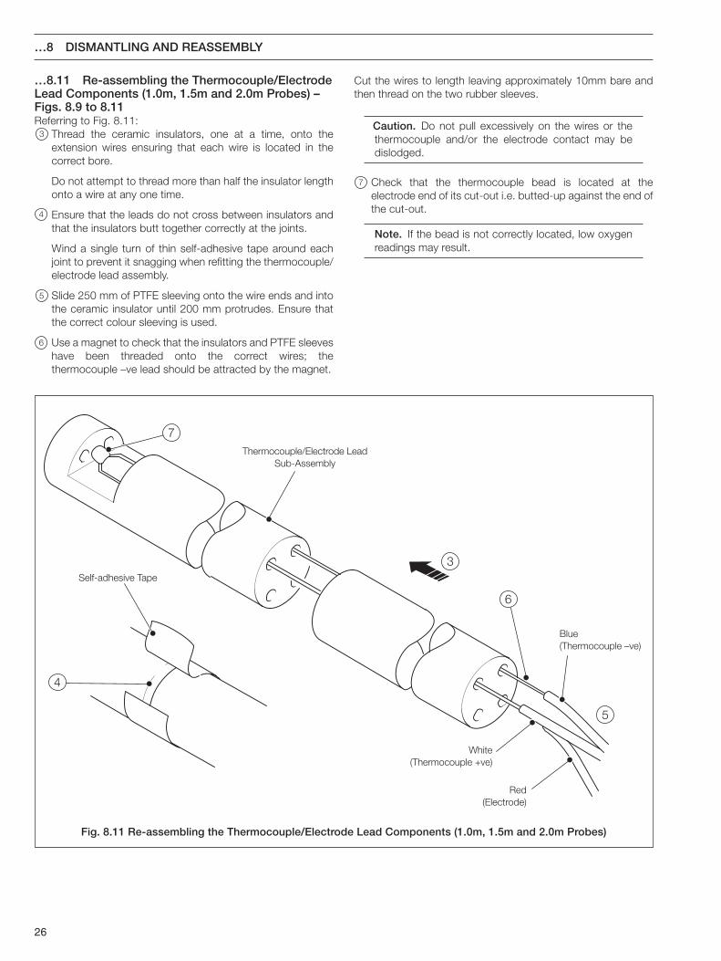
Cut the wires to length leaving approximately 10mm bare andthen thread on the two rubber sleeves.
Caution. Do not pull excessively on the wires or thethermocouple and/or the electrode contact may bedislodged.
7 Check that the thermocouple bead is located at theelectrode end of its cut-out i.e. butted-up against the end ofthe cut-out.
Note. If the bead is not correctly located, low oxygenreadings may result.
…8.11 Re-assembling the Thermocouple/ElectrodeLead Components (1.0m, 1.5m and 2.0m Probes) –Figs. 8.9 to 8.11Referring to Fig. 8.11:
3 Thread the ceramic insulators, one at a time, onto theextension wires ensuring that each wire is located in thecorrect bore.
Do not attempt to thread more than half the insulator lengthonto a wire at any one time.
4 Ensure that the leads do not cross between insulators andthat the insulators butt together correctly at the joints.
Wind a single turn of thin self-adhesive tape around eachjoint to prevent it snagging when refitting the thermocouple/electrode lead assembly.
5 Slide 250 mm of PTFE sleeving onto the wire ends and intothe ceramic insulator until 200 mm protrudes. Ensure thatthe correct colour sleeving is used.
6 Use a magnet to check that the insulators and PTFE sleeveshave been threaded onto the correct wires; thethermocouple –ve lead should be attracted by the magnet.
27
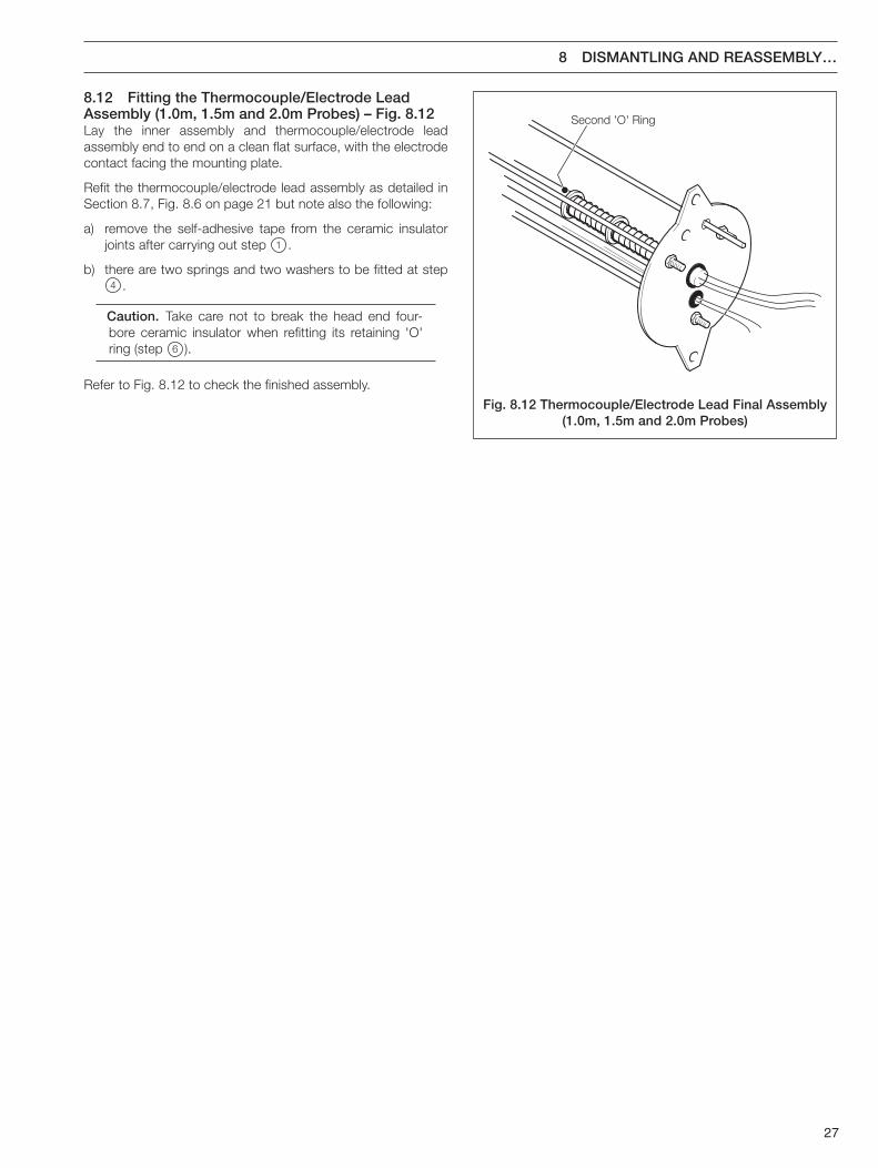
Second 'O' Ring
8 DISMANTLING AND REASSEMBLY…
8.12 Fitting the Thermocouple/Electrode LeadAssembly (1.0m, 1.5m and 2.0m Probes) – Fig. 8.12Lay the inner assembly and thermocouple/electrode leadassembly end to end on a clean flat surface, with the electrodecontact facing the mounting plate.
Refit the thermocouple/electrode lead assembly as detailed inSection 8.7, Fig. 8.6 on page 21 but note also the following:
a) remove the self-adhesive tape from the ceramic insulatorjoints after carrying out step 1 .
b) there are two springs and two washers to be fitted at step4 .
Caution. Take care not to break the head end four-bore ceramic insulator when refitting its retaining 'O'ring (step 6 ).
Refer to Fig. 8.12 to check the finished assembly.
Fig. 8.12 Thermocouple/Electrode Lead Final Assembly(1.0m, 1.5m and 2.0m Probes)
28
Heater MountingPlate
1
4
5
6
7
3 8
2 9
4
7
3 8
2 9
6
8
…8 DISMANTLING AND REASSEMBLY
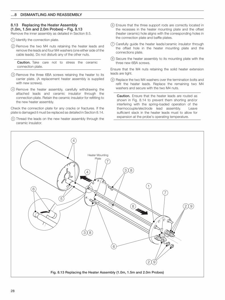
8.13 Replacing the Heater Assembly(1.0m, 1.5m and 2.0m Probes) – Fig. 8.13Remove the inner assembly as detailed in Section 8.5.
1 Identify the connection plate.
2 Remove the two M4 nuts retaining the heater leads andremove the leads and four M4 washers (one either side of thecable leads). Do not disturb any of the other nuts.
Caution. Take care not to stress the ceramicconnection plate.
3 Remove the three 6BA screws retaining the heater to itscarrier plate. (A replacement heater assembly is suppliedwith new screws).
4 Remove the heater assembly, carefully withdrawing theattached leads and ceramic insulator through theconnection plate. Retain the ceramic insulator for refitting tothe new heater assembly.
Check the connection plate for any cracks or fractures. If theplate is damaged it must be replaced as detailed in Section 8.14.
5 Thread the leads on the new heater assembly through theceramic insulator.
6 Ensure that the three support rods are correctly located inthe recesses in the heater mounting plate and the offset(heater ceramic) hole aligns with the corresponding holes inthe connection plate and baffle plates.
7 Carefully guide the heater leads/ceramic insulator throughthe offset hole in the heater mounting plate and theconnections plate.
8 Secure the heater assembly to its mounting plate with thethree new 6BA screws.
Ensure that the M4 nuts retaining the solid heater extensionleads are tight.
9 Replace the two M4 washers over the termination bolts andrefit the heater leads. Replace the remaining two M4washers and secure with the two M4 nuts.
Caution. Ensure that the heater leads are routed asshown in Fig. 8.14 to prevent them shorting and/orinterfering with the spring-loaded operation of thethermocouple/electrode lead assembly. Leavesufficient slack in the heater leads must to allow forexpansion at the probe's operating temperature.
Fig. 8.13 Replacing the Heater Assembly (1.0m, 1.5m and 2.0m Probes)

29
Heater MountingPlate
ConnectionPlate
TerminalBolts
1
2
3 4
5
1
5
8 DISMANTLING AND REASSEMBLY…
8.14 Replacing the Connection Plate(1.0m, 1.5m and 2.0m Probes) – Figs. 8.14 and 8.15Remove the heater assembly as detailed in Section 8.13, steps1 to 4 .
1 Remove the two M4 nuts retaining the solid heater extensionwires and remove the wires and four M4 washers.
2 Remove the three stainless steel wire twists from theextension rods (heater side of the connection plate) andretain.
3 Disengage the extension rods from the heater mountingplate.
4 Slide the connection plate off the extension rods taking carenot to lose the six M3 washers on the rods.
5 Remove the two M4 nuts retaining the terminal bolts to theconnection plate and remove the bolts, spacers and four M4washers.
To fit a new connection plate, reverse the above procedure.Ensure that all connections are tight. Refer to Fig. 8.15 to checkthe finished assembly.
Caution. When refitting the bolts onto the newconnection plate, (reversing step 5 ) they should movefreely once tightened against the spacers. Do not toover tighten the retaining nuts in order to grip theconnection plate.
Fig. 8.14 Replacing the Connection Plate (1.0m, 1.5m and 2.0m Probes)
Fig. 8.15 Connection Plate Final Assembly(1.0m, 1.5m and 2.0m Probes)
30
2
3
1
4 6
5
…8 DISMANTLING AND REASSEMBLY
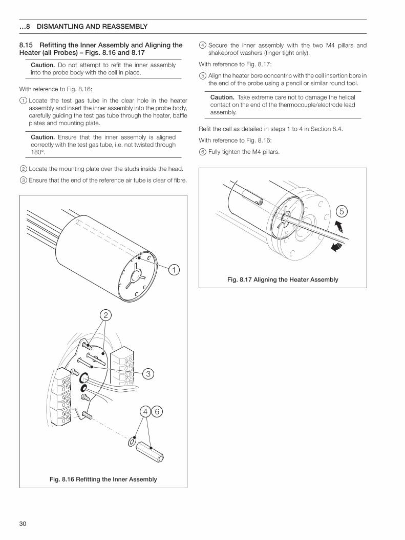
8.15 Refitting the Inner Assembly and Aligning theHeater (all Probes) – Figs. 8.16 and 8.17
Caution. Do not attempt to refit the inner assemblyinto the probe body with the cell in place.
With reference to Fig. 8.16:
1 Locate the test gas tube in the clear hole in the heaterassembly and insert the inner assembly into the probe body,carefully guiding the test gas tube through the heater, baffleplates and mounting plate.
Caution. Ensure that the inner assembly is alignedcorrectly with the test gas tube, i.e. not twisted through180°.
2 Locate the mounting plate over the studs inside the head.
3 Ensure that the end of the reference air tube is clear of fibre.
4 Secure the inner assembly with the two M4 pillars andshakeproof washers (finger tight only).
With reference to Fig. 8.17:
5 Align the heater bore concentric with the cell insertion bore inthe end of the probe using a pencil or similar round tool.
Caution. Take extreme care not to damage the helicalcontact on the end of the thermocouple/electrode leadassembly.
Refit the cell as detailed in steps 1 to 4 in Section 8.4.
With reference to Fig. 8.16:
6 Fully tighten the M4 pillars.
Fig. 8.16 Refitting the Inner Assembly
Fig. 8.17 Aligning the Heater Assembly
31
9 SPECIFICATION
Environmental DataProcess gas (flue) temperature
20 to 600 ºC (68 to 1112 ºF)
Pressure
Suitable for all normal positive or negative flue pressures
Response rate
Standard cell < 40 s to 63 % of step change < 1 minute to 90 % ofstep change (typical)
Fast response cell For typically <12 s to t90 the fast responseadaptor must be used*
Reference gas
Clean, oil-free air. Flow rate 150 to 1000 cc/minute
Environmental protection
Meets requirements of IP65 and NEMA 4X (hosedown)
Probe head IP65 rated.
Standard conduit Intermittent wetting permitted(providing the conduit(s) hangdownwards).
IP65 conduit Once installed in a dry flue duct, allexposed parts of the probe have fullIP65 protection.
* The fast response cell is not fitted with a ceramic filter or flamearrestor. Do not use on dusty applications or on applicationswhere the hot cell could ignite flammable gas mixtures in the flue.
Calibration DataCalibration (in situ)
One point using clean air
Two point using certified test gas and air
Test Gas Facility
Type In situ (checks may be made withprobe installed in operational flueduct).
Connections 1/4 in. or 6 mm o.d. compressionfitting (both olive sizes supplied).1/4 in. o.d. copper stub pipe (alsosupplied).
Gas ratio (betweentest gas O2 and thesample gas surroundingthe probe) ≤ 20:1.
Test gas flow requirement 3,000 cc/min. ±10 %.
Mechanical DataConstruction
316 stainless steel and ceramic
Dimensions
See page 6
Weight
0.4m (16 in.) – 6kg (13.2lb) [including 6m (20 ft) cable]1.0m (39 in.) – 10.8kg (23.7lb) [including 6m (20 ft) cable]1.5m (58 in.) – 11.6kg (25.5lb) [including 6m (20 ft) cable]2.0m (78 in.) – 12.5kg (27.5lb) [including 6m (20 ft) cable]
ERA Citation of suitability for gas-fired installations where GroupIIB equipment is applicable.
Insertion lengths
0.4, 1.0, 1.5 or 2.0m (16, 39, 58 or 78 in.) standard
Specials up to 4.0m (156 in.) max.
Flange options
Note. The Flange types listed are NOT pressure retaining.
0.4m (16 in.)ZFG2 Standard6.0 ±0.4 mm thick x 101.0 ±1 mm dia.6 holes 7.3 mm dia. equispaced on 80.0 ±0.2 mm PCD
1.0, 1.5 and 2.0 m (39, 58 and 78 in.) ZFG2 Standard12.0 ±1 mm thick x 165.0 ±0.2 mm dia.6 holes 12.5 ±0.5 mm dia. equispaced on 140 mm PCD
Rosemount/Westinghouse Model 132 equivalent6.0 ±0.4 mm thick x 127.0 ±1 mm dia.4 holes 9.5 (0.375 in.) dia. equispaced on 99.0 ±0.2 mm PCD
ANSI B 16.5 (2 in.) 150 lb12.0 ±1 mm thick x 185.0 ±0.5 mm dia.4 holes 18 mm dia. equispaced on 145.0 ±0.2 mm PCD
DIN 2501 Part 1 DN65 PN 16, 25 and 4012.0 ±1 mm thick x 153 ±0.5 mm dia.4 holes 20.0 ±0.2 mm equispaced on 121.0 ±0.2 mm PCD
JIS B 2238 DN65 5K12.0 ±1 mm thick x 155.0 ±0.5 mm dia.4 holes 15 equispaced on 130.0 ±0.2 mm PCD
Cable length
10m or 6m (32 or 20 ft) fitted
Maximum distance between probe and electronics unit69 m (224 ft) using EXFG/0194 and EXFG/0195 cables
Electrical DataCell constant
0 V ±2 mV
Cell output load
>10MΩ.
Heater temperature
700 ºC 3 ºC (973 ºK)
Heater rating
0.4 m probe <100 VA at 50 to 55 V AC
1.0 m, 1.5 m and 2.0 m probes <120 VA at 50 to 55 V AC
Heater resistance
0.4 m probe 28 to 31Ω.
1.0 m, 1.5 m and 2.0 m probes 26 to 29Ω.
Thermocouple
NiCr/NiAl Pt. 4 BS4937 Part 4 Type K
External earth bonding
6 mm female thread
32
12
34
56
78
910
1112
1314
1516
1718
1920
21
2425
26
2728
29
3233
30 (21)
31
3435
3637
38
3940
41
38
4243
4546
44
2223
21
48
49
50
51
52
53
52
5455
47
10 SPARES LIST
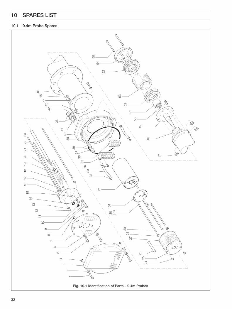
10.1 0.4m Probe Spares
Fig. 10.1 Identification of Parts – 0.4m Probes

33
10 SPARES LIST…
Sp
ares
Lis
t fo
r 0.
4m P
r ob
es –
Fig
. 10.
1
Ref
.It
emP
art.
No
.
1M
4 x
20 c
hees
ehea
d sc
rew
......
......
......
......
......
......
......
....J
/022
7/68
1
2M
4 pl
ain
was
her .
......
......
......
......
......
......
......
......
......
......
..B72
98
3H
ead
cove
r....
......
......
......
......
......
......
......
......
......
......
......
.ZFG
2/01
20
4'O
' rin
g...
......
......
......
......
......
......
......
......
......
......
......
......
..J/0
211/
001
5M
4 x
8 pa
nhea
d sc
rew
......
......
......
......
......
......
......
......
.....B
5700
6M
4 pl
ain
was
her .
......
......
......
......
......
......
......
......
......
......
..B72
98
7C
onne
ctio
ns c
over
......
......
......
......
......
......
......
......
......
......
ZFG
2/01
31
8'O
' rin
g...
......
......
......
......
......
......
......
......
......
......
......
......
..J/0
211/
001
9M
4 pi
llar.
......
......
......
......
......
......
......
......
......
......
......
......
...B
1074
0
10M
4 sh
akep
roof
was
her.
......
......
......
......
......
......
......
......
....B
7503
11G
rom
met
......
......
......
......
......
......
......
......
......
......
......
......
..B10
722
12M
3 fu
ll nu
t....
......
......
......
......
......
......
......
......
......
......
......
...B
7067
13M
3 sh
akep
roof
was
her.
......
......
......
......
......
......
......
......
....B
6421
14'O
' rin
g...
......
......
......
......
......
......
......
......
......
......
......
......
..B10
093
15'E
' clip
......
......
......
......
......
......
......
......
......
......
......
......
......
B10
744
16In
ner
asse
mbl
y m
ount
ing
plat
e...
......
......
......
......
......
......
..ZFG
2/01
60
17R
efer
ence
air
pipe
......
......
......
......
......
......
......
......
......
......
.ZFG
2/01
84
18S
prin
g...
......
......
......
......
......
......
......
......
......
......
......
......
....B
1072
3
19M
6 pl
ain
was
her .
......
......
......
......
......
......
......
......
......
......
..B92
83
20'O
' rin
g...
......
......
......
......
......
......
......
......
......
......
......
......
..B10
093
21C
ompl
ete
heat
er a
ssem
bly
com
pris
ing:
......
......
......
......
....Z
FG2/
0035
Hea
ter
Hea
ter
cera
mic
insu
lato
rH
ead
end
heat
er c
eram
ic in
sula
tor
6BA
x 1 /
4 in
. che
eseh
ead
scre
ws
Cle
ar s
leev
ing
Bla
ck r
ubbe
r sl
eevi
ngC
lear
hea
tshr
ink
slee
ving
22E
xten
sion
rod
s (h
ead)
......
......
......
......
......
......
......
......
......
.ZFG
2/01
49
23C
ompl
ete
ther
moc
oupl
e/el
ectr
ode
lead
ass
embl
y....
......
...ZF
G2/
0036
24M
3 fu
ll nu
t....
......
......
......
......
......
......
......
......
......
......
......
...B
7067
25B
affle
pla
te...
......
......
......
......
......
......
......
......
......
......
......
...ZF
G2/
0156
26P
illars
......
......
......
......
......
......
......
......
......
......
......
......
......
..ZFG
2/01
62
27C
eram
ic fi
bre
baffl
e...
......
......
......
......
......
......
......
......
......
..ZFG
2/01
64
28M
3 fu
ll nu
t....
......
......
......
......
......
......
......
......
......
......
......
...B
7067
29E
xten
sion
rod
s (h
eate
r)...
......
......
......
......
......
......
......
......
..ZFG
2/01
53
Ref
. It
emP
art.
No
.
306B
A x
1 /4 in
. scr
ew...
......
......
......
......
......
......
......
......
......
...00
2018
219
31H
eate
r m
ount
ing
plat
e...
......
......
......
......
......
......
......
......
...ZF
G2/
0158
32'O
' rin
g...
......
......
......
......
......
......
......
......
......
......
......
......
..B10
093
33Tu
bing
......
......
......
......
......
......
......
......
......
......
......
......
......
2336
BX2
0100
6
34M
3 x
16 c
hees
ehea
d sc
rew
......
......
......
......
......
......
......
....B
6417
356-
way
term
inal
blo
ck...
......
......
......
......
......
......
......
......
......
B92
55
364-
way
term
inal
blo
ck...
......
......
......
......
......
......
......
......
......
B92
54
37S
ealin
g rin
g...
......
......
......
......
......
......
......
......
......
......
......
..ZFG
2/01
47
38U
nion
ass
embl
y (in
clud
ing
coup
ling
nut,
oliv
e &
bla
nkin
g pl
ug).
......
......
......
......
......
......
......
......
......
.B10
721
Nip
ple.
......
......
......
......
......
......
......
......
......
......
......
......
B10
719
39H
ead
base
:
20m
m c
ondu
it en
trie
s....
......
......
......
......
......
......
......
...ZF
G2/
0118
1 /2 in
. NP
T co
ndui
t ent
ries
......
......
......
......
......
......
......
.ZFG
2/01
19
40S
eria
l num
ber
plat
e...
......
......
......
......
......
......
......
......
......
..003
0000
911 /
8 in
. sel
f-ta
ppin
g sc
rew
......
......
......
......
......
......
......
...B
6220
41M
10 p
lain
was
her.
......
......
......
......
......
......
......
......
......
......
B10
717
42M
ale
adap
tor
unio
n...
......
......
......
......
......
......
......
......
......
..B10
720
43B
lank
ing
plug
......
......
......
......
......
......
......
......
......
......
......
..B10
734
44M
4 lo
ckin
g w
ashe
r....
......
......
......
......
......
......
......
......
......
..B75
03
45M
4 x
16 s
ocke
t hea
d sc
rew
......
......
......
......
......
......
......
....B
7295
46P
robe
bod
y:S
tand
ard
flang
e...
......
......
......
......
......
......
......
......
......
.ZFG
2/01
95A
NS
I fla
nge
......
......
......
......
......
......
......
......
......
......
....Z
FG2/
0196
JIS
flan
ge...
......
......
......
......
......
......
......
......
......
......
....Z
FG2/
0197
DIN
......
......
......
......
......
......
......
......
......
......
......
......
.....Z
FG2/
0198
Mod
el 1
32...
......
......
......
......
......
......
......
......
......
......
...ZF
G2/
0199
47M
4 fu
ll nu
t....
......
......
......
......
......
......
......
......
......
......
......
...B
8690
48S
tain
less
ste
el 'O
' rin
g...
......
......
......
......
......
......
......
......
...00
2310
036
49C
ell a
ssem
bly
......
......
......
......
......
......
......
......
......
......
......
.003
0001
05S
P
50M
4 x
10 s
ocke
t hea
d sc
rew
......
......
......
......
......
......
......
....B
9760
51Fl
ame
arre
ster
......
......
......
......
......
......
......
......
......
......
......
.003
0000
87
52Fi
lter
gask
et...
......
......
......
......
......
......
......
......
......
......
......
.003
0000
94
53C
eram
ic fi
lter .
......
......
......
......
......
......
......
......
......
......
......
.003
0003
45
54Fi
lter
clam
p as
sem
bly
......
......
......
......
......
......
......
......
......
.003
0003
46
55M
4 x
58 s
ocke
t hea
d sc
rew
......
......
......
......
......
......
......
....0
0210
1115
34
2829
3031
3233
3229
30
32
3536
37
34
3839
4041
4445
4647
4048
4950
5152
5354
55
56
4243
57
5855
5960
6162
63
12
34
56
78
910
1112
1314
1516
1718
1920
21 22
23
24
26
2725
64
6566
6768
69
70
69
71
72
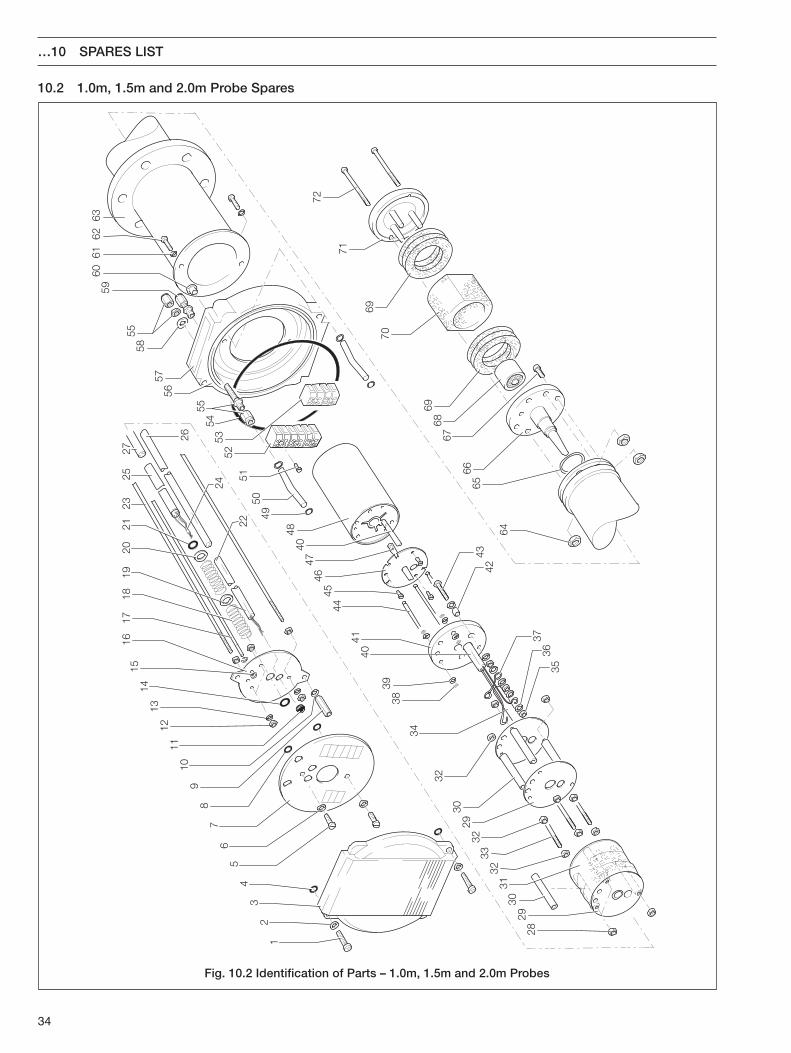
…10 SPARES LIST
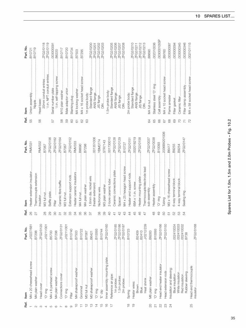
10.2 1.0m, 1.5m and 2.0m Probe Spares
Fig. 10.2 Identification of Parts – 1.0m, 1.5m and 2.0m Probes
35
10 SPARES LIST…
Sp
ares
Lis
t fo
r 1.
0m, 1
.5m
and
2.0
m P
r ob
es –
Fig
. 10.
2
Ref
.It
emP
art.
No
.
1M
4 x
20 c
hees
ehea
d sc
rew
......
......
......
......
J/02
27/6
81
2M
4 pl
ain
was
her.
......
......
......
......
......
......
.....B
7298
3H
ead
cove
r ....
......
......
......
......
......
......
......
...ZF
G2/
0120
4'O
' rin
g...
......
......
......
......
......
......
......
......
...J/
0211
/001
5M
4 x
8 pa
nhea
d sc
rew
......
......
......
......
......
..B57
00
6M
4 pl
ain
was
her.
......
......
......
......
......
......
.....B
7298
7C
onne
ctio
ns c
over
......
......
......
......
......
......
..ZFG
2/01
31
8'O
' rin
g...
......
......
......
......
......
......
......
......
...J/
0211
/001
9P
illar
......
......
......
......
......
......
......
......
......
B10
740
10M
4 sh
akep
roof
was
her.
......
......
......
......
......
.B75
03
11G
rom
met
......
......
......
......
......
......
......
......
....B
1072
2
12M
3 fu
ll nu
t....
......
......
......
......
......
......
......
.....B
7067
13M
3 sh
akep
roof
was
her.
......
......
......
......
......
.B64
21
14'O
' rin
g...
......
......
......
......
......
......
......
......
...B
1009
3
15'E
' clip
......
......
......
......
......
......
......
......
......
B10
744
16In
ner
asse
mbl
y m
ount
ing
plat
e...
......
......
.....Z
FG2/
0160
17R
efer
ence
air
pipe
:1m
pro
bes
......
......
......
......
......
......
......
..ZFG
2/01
851.
5m p
robe
s...
......
......
......
......
......
......
..ZFG
2/01
862m
pro
bes
......
......
......
......
......
......
......
..ZFG
2/01
87
18S
prin
g...
......
......
......
......
......
......
......
......
...B
1072
3
19H
eate
r w
ires:
Bro
wn.
......
......
......
......
......
......
......
......
..B24
09B
lue
......
......
......
......
......
......
......
......
......
B24
10H
eat s
hrin
k...
......
......
......
......
......
......
....J
/021
2/23
9
20M
6 pl
ain
was
her.
......
......
......
......
......
......
.....B
9283
21'O
' rin
g...
......
......
......
......
......
......
......
......
...B
1009
3
22H
ead
end
heat
er in
sula
tor.
......
......
......
......
..ZFG
2/01
66
23H
ead
exte
nsio
n ro
ds...
......
......
......
......
......
..ZFG
2/01
50
24In
sula
tion
and
slee
ving
:B
lue
insu
latio
n...
......
......
......
......
......
.....0
0241
0034
Whi
te in
sula
tion
......
......
......
......
......
......
0024
1003
3R
ed in
sula
tion
......
......
......
......
......
......
...00
2410
032
Rub
ber
slee
ving
......
......
......
......
......
......
B73
8
25H
ead
end
ther
moc
oupl
ein
sula
tor.
......
......
......
......
......
......
......
......
.....Z
FG2/
0168
Ref
.It
emP
art.
No
.
26H
eate
r ex
tens
ion
insu
lato
r ....
......
......
.....R
MV
331
27Th
erm
ocou
ple
exte
nsio
nin
sula
tor.
......
......
......
......
......
......
......
.....R
MV
332
28M
3 fu
ll nu
t....
......
......
......
......
......
......
.....B
7067
29B
affle
pla
te...
......
......
......
......
......
......
.....Z
FG2/
0156
30P
illar
......
......
......
......
......
......
......
......
ZFG
2/01
62
31C
eram
ic fi
bre
baffl
e...
......
......
......
......
....Z
FG2/
0164
32M
3 fu
ll nu
t....
......
......
......
......
......
......
.....B
7067
33E
xten
sion
sup
port
rods
......
......
......
......
.ZFG
2/01
52
34H
eate
r ce
ram
ic in
sula
tors
......
......
......
...R
MV
333
35M
4 fu
ll nu
t....
......
......
......
......
......
......
.....B
8690
36M
4 pl
ain
was
her .
......
......
......
......
......
....B
7298
371.
6mm
dia
. nic
kel w
ire(h
eate
r ex
tens
ion)
......
......
......
......
......
...00
1351
006
38N
ichr
ome
wire
......
......
......
......
......
......
...Y
BM
0774
39M
3 pl
ain
was
her.
......
......
......
......
......
....S
TR71
43
402-
bore
cer
amic
tube
......
......
......
......
.....0
0173
0010
41C
eram
ic c
onne
ctio
ns p
late
......
......
......
.ZFG
2/01
28
42S
pace
r...
......
......
......
......
......
......
......
...ZF
G2/
0129
43M
4 x
25 h
exag
on h
ead
scre
w...
......
......
B10
727
44H
eate
r en
d su
ppor
t rod
s....
......
......
......
.ZFG
2/01
51
456B
A x
1 /4 in
. scr
ew...
......
......
......
......
......
0020
1821
9
46H
eate
r m
ount
ing
plat
e...
......
......
......
.....Z
FG2/
0158
47Th
erm
ocou
ple/
elec
trod
e le
adsu
b-as
sem
bly
......
......
......
......
......
......
...ZF
G2/
0037
48H
eate
r as
sem
bly.
......
......
......
......
......
....Z
FG2/
0038
49'O
' rin
g...
......
......
......
......
......
......
......
...B
1009
3
50Tu
bing
......
......
......
......
......
......
......
......
2336
BX2
0100
6
51M
3 x
16 c
hees
ehea
d sc
rew
......
......
......
B64
17
526-
way
term
inal
blo
ck...
......
......
......
......
..B92
55
534-
way
term
inal
blo
ck...
......
......
......
......
..B92
54
54S
ealin
g rin
g...
......
......
......
......
......
......
....Z
FG2/
0147
Ref
.It
emP
art.
No
.
55U
nion
ass
embl
y....
......
......
......
......
......
.....B
1072
1N
ippl
e...
......
......
......
......
......
......
......
..B10
719
56H
ead
base
:20
mm
con
duit
entr
ies
......
......
......
.....Z
FG2/
0118
1 /2 in
. NP
T co
ndui
t ent
ries.
......
......
.....Z
FG2/
0119
57S
eria
l num
ber
plat
e...
......
......
......
......
......
0030
0009
11 /
8 in
. sel
f-ta
ppin
g sc
rew
......
......
......
..B62
20
58M
10 p
lain
was
her.
......
......
......
......
......
.....B
1071
7
59M
ale
adap
tor
unio
n...
......
......
......
......
......
B10
720
60B
lank
ing
plug
......
......
......
......
......
......
......
B10
734
61M
4 lo
ckin
g w
ashe
r....
......
......
......
......
......
B75
03
62M
4 x
16 s
ocke
t hea
d sc
rew
......
......
......
..B72
95
631m
pro
be b
ody:
Sta
ndar
d fla
nge
......
......
......
......
......
..ZFG
2/02
00A
NS
I fla
nge.
......
......
......
......
......
......
..ZFG
2/02
01JI
S fl
ange
......
......
......
......
......
......
......
ZFG
2/02
02D
IN...
......
......
......
......
......
......
......
......
ZFG
2/02
03
1.5m
pro
be b
ody:
Sta
ndar
d fla
nge
......
......
......
......
......
..ZFG
2/02
05A
NS
I fla
nge.
......
......
......
......
......
......
..ZFG
2/02
06JI
S fl
ange
......
......
......
......
......
......
......
ZFG
2/02
07D
IN...
......
......
......
......
......
......
......
......
ZFG
2/02
08
2m p
robe
bod
y:S
tand
ard
flang
e...
......
......
......
......
.....Z
FG2/
0210
AN
SI f
lang
e....
......
......
......
......
......
.....Z
FG2/
0211
JIS
flan
ge...
......
......
......
......
......
......
...ZF
G2/
0212
DIN
......
......
......
......
......
......
......
......
...ZF
G2/
0213
64M
4 fu
ll nu
t ....
......
......
......
......
......
......
......
.B86
90
65S
tain
less
ste
el 'O
' rin
g...
......
......
......
......
..002
3100
36
66C
ell a
ssem
bly.
......
......
......
......
......
......
.....0
0300
0105
SP
67M
4 x
10 s
ocke
t hea
d sc
rew
......
......
......
..B97
60
68Fl
ame
arre
ster
......
......
......
......
......
......
.....0
0300
0087
69Fi
lter
gask
et...
......
......
......
......
......
......
......
0030
0009
4
70C
eram
ic fi
lter.
......
......
......
......
......
......
......
0030
0034
5
71Fi
lter
clam
p as
sem
bly.
......
......
......
......
.....0
0300
0346
72M
4 x
58 s
ocke
t hea
d sc
rew
......
......
......
..002
1011
15
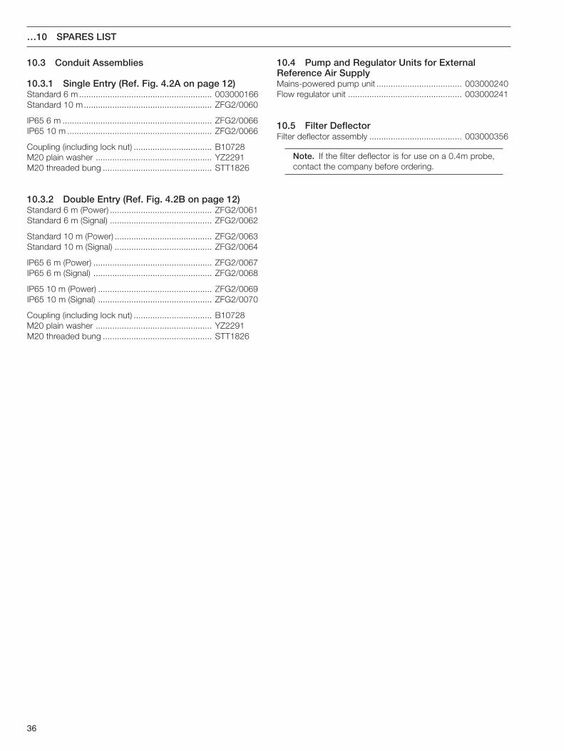
36
…10 SPARES LIST
10.3 Conduit Assemblies
10.3.1 Single Entry (Ref. Fig. 4.2A on page 12)Standard 6 m ........................................................ 003000166Standard 10 m...................................................... ZFG2/0060
IP65 6 m ............................................................... ZFG2/0066IP65 10 m ............................................................. ZFG2/0066
Coupling (including lock nut) ................................. B10728M20 plain washer ................................................. YZ2291M20 threaded bung .............................................. STT1826
10.3.2 Double Entry (Ref. Fig. 4.2B on page 12)Standard 6 m (Power) ........................................... ZFG2/0061Standard 6 m (Signal) ........................................... ZFG2/0062
Standard 10 m (Power) ......................................... ZFG2/0063Standard 10 m (Signal) ......................................... ZFG2/0064
IP65 6 m (Power) .................................................. ZFG2/0067IP65 6 m (Signal) .................................................. ZFG2/0068
IP65 10 m (Power) ................................................ ZFG2/0069IP65 10 m (Signal) ................................................ ZFG2/0070
Coupling (including lock nut) ................................. B10728M20 plain washer ................................................. YZ2291M20 threaded bung .............................................. STT1826
10.4 Pump and Regulator Units for ExternalReference Air SupplyMains-powered pump unit .................................... 003000240Flow regulator unit ................................................ 003000241
10.5 Filter DeflectorFilter deflector assembly ....................................... 003000356
Note. If the filter deflector is for use on a 0.4m probe,contact the company before ordering.
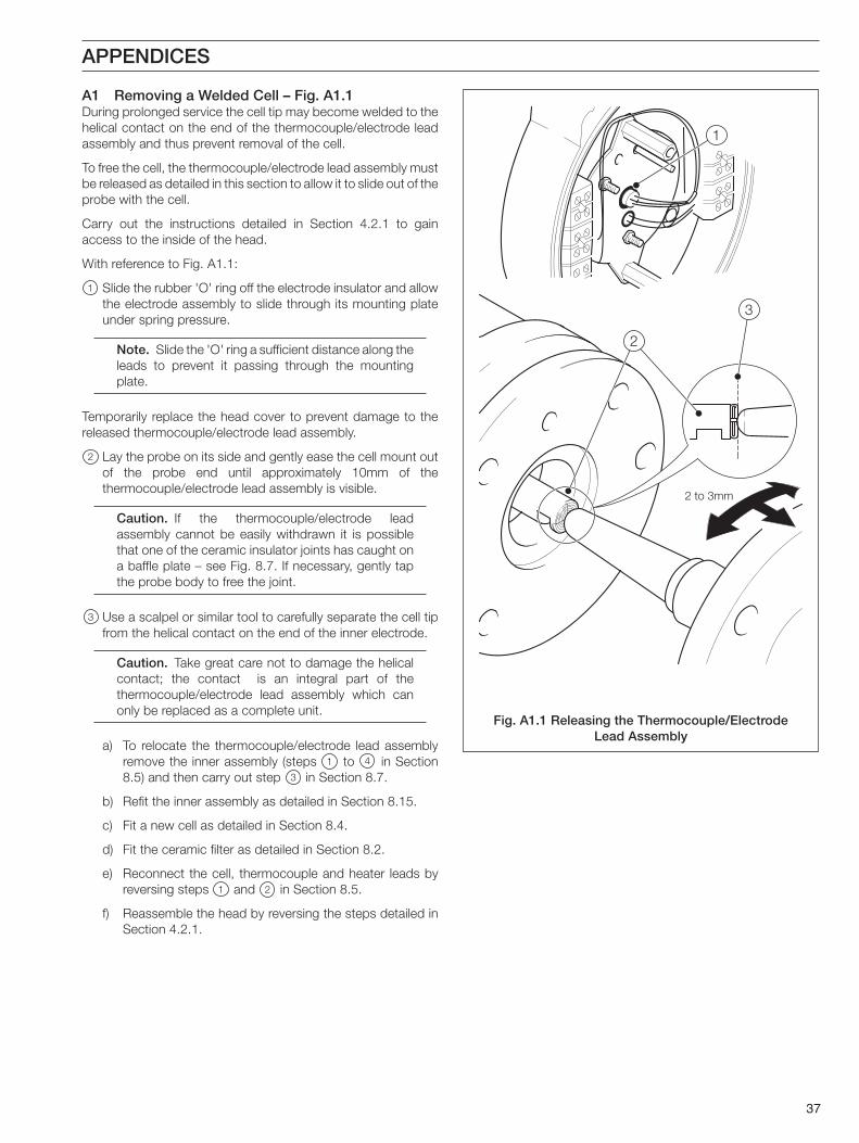
37
2 to 3mm
3
2
1
APPENDICES
A1 Removing a Welded Cell – Fig. A1.1During prolonged service the cell tip may become welded to thehelical contact on the end of the thermocouple/electrode leadassembly and thus prevent removal of the cell.
To free the cell, the thermocouple/electrode lead assembly mustbe released as detailed in this section to allow it to slide out of theprobe with the cell.
Carry out the instructions detailed in Section 4.2.1 to gainaccess to the inside of the head.
With reference to Fig. A1.1:
1 Slide the rubber 'O' ring off the electrode insulator and allowthe electrode assembly to slide through its mounting plateunder spring pressure.
Note. Slide the 'O' ring a sufficient distance along theleads to prevent it passing through the mountingplate.
Temporarily replace the head cover to prevent damage to thereleased thermocouple/electrode lead assembly.
2 Lay the probe on its side and gently ease the cell mount outof the probe end until approximately 10mm of thethermocouple/electrode lead assembly is visible.
Caution. If the thermocouple/electrode leadassembly cannot be easily withdrawn it is possiblethat one of the ceramic insulator joints has caught ona baffle plate – see Fig. 8.7. If necessary, gently tapthe probe body to free the joint.
3 Use a scalpel or similar tool to carefully separate the cell tipfrom the helical contact on the end of the inner electrode.
Caution. Take great care not to damage the helicalcontact; the contact is an integral part of thethermocouple/electrode lead assembly which canonly be replaced as a complete unit.
a) To relocate the thermocouple/electrode lead assemblyremove the inner assembly (steps 1 to 4 in Section8.5) and then carry out step 3 in Section 8.7.
b) Refit the inner assembly as detailed in Section 8.15.
c) Fit a new cell as detailed in Section 8.4.
d) Fit the ceramic filter as detailed in Section 8.2.
e) Reconnect the cell, thermocouple and heater leads byreversing steps 1 and 2 in Section 8.5.
f) Reassemble the head by reversing the steps detailed inSection 4.2.1.
Fig. A1.1 Releasing the Thermocouple/ElectrodeLead Assembly
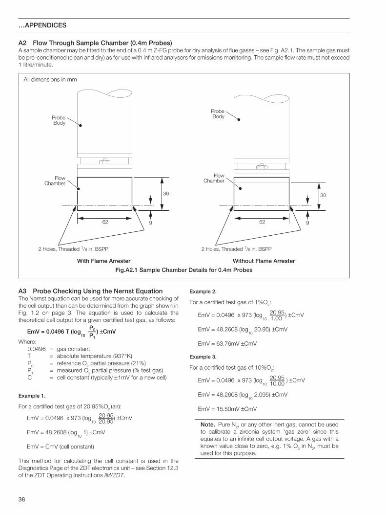
38
ProbeBody
62 9
36
FlowChamber
2 Holes, Threaded 1/8 in. BSPP
With Flame Arrester
ProbeBody
62 9
30
FlowChamber
2 Holes, Threaded 1/8 in. BSPP
Without Flame Arrester
All dimensions in mm
…APPENDICES
A2 Flow Through Sample Chamber (0.4m Probes)A sample chamber may be fitted to the end of a 0.4 m Z-FG probe for dry analysis of flue gases – see Fig. A2.1. The sample gas mustbe pre-conditioned (clean and dry) as for use with infrared analysers for emissions monitoring. The sample flow rate must not exceed1 litre/minute.
A3 Probe Checking Using the Nernst EquationThe Nernst equation can be used for more accurate checking ofthe cell output than can be determined from the graph shown inFig. 1.2 on page 3. The equation is used to calculate thetheoretical cell output for a given certified test gas, as follows:
EmV = 0.0496 T (log10
) ±CmVP0
P1Where:
0.0496 = gas constantT = absolute temperature (937°K)P0 = reference O2 partial pressure (21%)P1 = measured O2 partial pressure (% test gas)C = cell constant (typically ±1mV for a new cell)
Example 1.
For a certified test gas of 20.95%O2 (air):
20.95EmV = 0.0496 x 973 (log10
) ±CmV
EmV = 48.2608 (log10
1) ±CmV
EmV = CmV (cell constant)
20.95
This method for calculating the cell constant is used in theDiagnostics Page of the ZDT electronics unit – see Section 12.3of the ZDT Operating Instructions IM/ZDT.
Example 2.
For a certified test gas of 1%O2:
20.95EmV = 0.0496 x 973 (log10
) ±CmV
EmV = 48.2608 (log10
20.95) ±CmV
EmV = 63.76mV ±CmV
1.00
Example 3.
For a certified test gas of 10%O2:
20.95EmV = 0.0496 x 973 (log10
) ±CmV
EmV = 48.2608 (log10
2.095) ±CmV
EmV = 15.50mV ±CmV
10.00
Note. Pure N2, or any other inert gas, cannot be usedto calibrate a zirconia system 'gas zero' since thisequates to an infinite cell output voltage. A gas with aknown value close to zero, e.g. 1% O2 in N2, must beused for this purpose.
Fig.A2.1 Sample Chamber Details for 0.4m Probes

39
NOTES

40
…NOTES

PRODUCTS & CUSTOMER SUPPORT
ProductsAutomation Systems
• for the following industries:– Chemical & Pharmaceutical– Food & Beverage– Manufacturing– Metals and Minerals– Oil, Gas & Petrochemical– Pulp and Paper
Drives and Motors• AC and DC Drives, AC and DC Machines, AC Motors to 1kV• Drive Systems• Force Measurement• Servo Drives
Controllers & Recorders• Single and Multi-loop Controllers• Circular Chart and Strip Chart Recorders• Paperless Recorders• Process Indicators
Flexible Automation• Industrial Robots and Robot Systems
Flow Measurement• Electromagnetic Flowmeters• Mass Flow Meters• Turbine Flowmeters• Flow Elements
Marine Systems & Turbochargers• Electrical Systems• Marine Equipment• Offshore Retrofit and Refurbishment
Process Analytics• Process Gas Analysis• Systems Integration
Transmitters• Pressure• Temperature• Level• Interface Modules
Valves, Actuators and Positioners• Control Valves• Actuators• Positioners
Water, Gas & Industrial Analytics Instrumentation• pH, Conductivity, and Dissolved Oxygen Transmitters and
Sensors• Ammonia, Nitrate, Phosphate, Silica, Sodium, Chloride,
Fluoride, Dissolved Oxygen and Hydrazine Analyzers.• Zirconia Oxygen Analyzers, Katharometers, Hydrogen Purity
and Purge-gas Monitors, Thermal Conductivity.
Customer Support
We provide a comprehensive after sales service via a WorldwideService Organization. Contact one of the following offices fordetails on your nearest Service and Repair Centre.
United KingdomABB LimitedTel: +44 (0)1453 826661Fax: +44 (0)1453 829671
United States of AmericaABB Inc.Tel: +1 775 850 4800Fax: +1 775 850 4808
Client Warranty
Prior to installation, the equipment referred to in this manual mustbe stored in a clean, dry environment, in accordance with theCompany's published specification.
Periodic checks must be made on the equipment's condition. Inthe event of a failure under warranty, the following documentationmust be provided as substantiation:
1. A listing evidencing process operation and alarm logs at time offailure.
2. Copies of all storage, installation, operating and maintenancerecords relating to the alleged faulty unit.

ABB LimitedOldends Lane, StonehouseGloucestershireGL10 3TAUKTel: +44 (0)1453 826661Fax: +44 (0)1453 829671
ABB Inc.Analytical Instruments9716 S. Virginia St., Ste. EReno, Nevada 89521USATel: +1 775 850 4800Fax: +1 775 850 4808
ABB has Sales & Customer Supportexpertise in over 100 countries worldwide
www.abb.com
The Company’s policy is one of continuous productimprovement and the right is reserved to modify the
information contained herein without notice.
Printed in UK (10.07)
© ABB 2007
IM/Z
FG2
Issu
e 9