User Guide Millicell ERS-2 - Pàgines de la...
26
User Guide Millicell ® ERS-2 Electrical Resistance System
Transcript of User Guide Millicell ERS-2 - Pàgines de la...

User Guide
Millicell® ERS-2Electrical Resistance System
00108103_Rev1016.indd 25 10/20/2016 8:23:01 AM

NoticeThe information in this document is subject to change without notice and should not be construed as a commitment by EMD Millipore Corporation (“Millipore”) or an affiliate. Neither EMD Millipore Corporation nor any of its affiliates assumes responsibility for any errors that may appear in this document.
The M logo, Millipore, Millicell, Millex, Stericup, Steriflip, and Milli-Q are registered trademarks of Merck KGaA, Darmstadt, Germany. Biopore, Isopore, and MF-Millipore are trademarks of Merck KGaA, Darmstadt, Germany. All trademarks of third parties are the property of their respective owners.
© 2016 EMD Millipore Corporation. Billerica, MA, U.S.A. All rights reserved.
00108103, Rev. 10/16
Made in U.S.A. EMD Millipore Corporation Billerica, MA 01821
For research use only. Not for use in diagnostic procedures.
C
00108103_Rev1016.indd 26 10/20/2016 8:23:01 AM

ContentsIntroduction .................................................................................................................. 1
The Millicell® ERS-2 System and Its Components ............................................. 2
Symbols Used in this User Guide ............................................................................ 3
Installation .................................................................................................................... 3
Testing the System ...................................................................................................... 4
Meter Functionality Check .............................................................................. 4
Equilibrating the Electrode for Voltage Measurements .......................... 5
Electrode Functionality Check ........................................................................ 6
Measuring Cell Resistance and Voltage ............................................................... 6
Sterilizing or Sanitizing/Disinfecting the Electrode ................................. 6
Measuring Cell Resistance ............................................................................... 7
How to Determine Blank Resistance............................................................. 8
Resistance Calculations .................................................................................... 8
Example Application ........................................................................................10
Measuring Voltage ...........................................................................................11
Maintaining and Storing the System ..................................................................12
Meter ...................................................................................................................12
Changing the Battery ......................................................................................12
Electrode Storage .............................................................................................13
Electrode Cleaning ...........................................................................................13
Troubleshooting .........................................................................................................14
Specifications .............................................................................................................18
Regulatory Compliance ...........................................................................................18
Ordering Information ...............................................................................................19
Technical Assistance .................................................................................................22
Manufacturer .............................................................................................................22
Standard Warranty ...................................................................................................22
00108103_Rev1016.indd 27 10/20/2016 8:23:01 AM
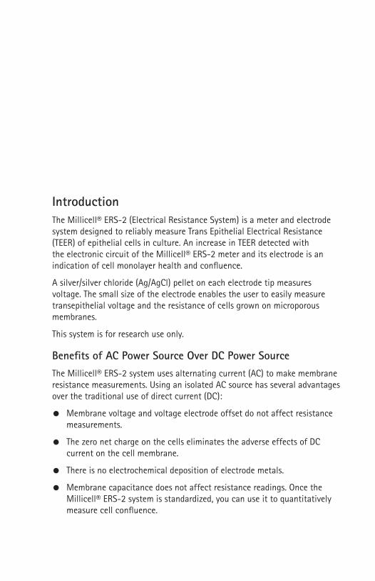
IntroductionThe Millicell® ERS-2 (Electrical Resistance System) is a meter and electrode system designed to reliably measure Trans Epithelial Electrical Resistance (TEER) of epithelial cells in culture. An increase in TEER detected with the electronic circuit of the Millicell® ERS-2 meter and its electrode is an indication of cell monolayer health and confluence.
A silver/silver chloride (Ag/AgCl) pellet on each electrode tip measures voltage. The small size of the electrode enables the user to easily measure transepithelial voltage and the resistance of cells grown on microporous membranes.
This system is for research use only.
Benefits of AC Power Source Over DC Power SourceThe Millicell® ERS-2 system uses alternating current (AC) to make membrane resistance measurements. Using an isolated AC source has several advantages over the traditional use of direct current (DC):
Membrane voltage and voltage electrode offset do not affect resistance measurements.
The zero net charge on the cells eliminates the adverse effects of DC current on the cell membrane.
There is no electrochemical deposition of electrode metals.
Membrane capacitance does not affect resistance readings. Once the Millicell® ERS-2 system is standardized, you can use it to quantitatively measure cell confluence.
00108103_Rev1016.indd 1 10/20/2016 8:22:55 AM

2 www.millipore.com
The Millicell® ERS-2 System and Its ComponentsThe Millicell® ERS-2 system consists of a meter, STX01 electrode, STX04 1,000 Ω test electrode, and battery charger.
Ohm
Millicell ERS-2
Epithelial Volt-Ohm Meter
PowerI
O
Millivolts
Output
Input
RAdj
MILLIPORE
R
TM
TM
Analog output
Digital LCD display
Mode Switch
Input Port
R Adj Calibration
Power Switch
STX01 Electrode STX04 Test Electrode
The MeterThe unit measures 18.4 cm × 10.8 cm × 5.8 cm and includes an internal rechargeable 6 V NiMH 2,700 mAh battery pack with an external 12 V DC battery charger, equipped with an AC power cord. An analog output port allows output of analog data to a recording device.
The ElectrodeThe electrode is connected to a wire with a telephone-type plug at its end. This plug connects to the Input port at the front of the meter during use.
00108103_Rev1016.indd 2 10/20/2016 8:22:56 AM

Millicell® ERS-2 Electrical Resistance System User Guide 3
Symbols Used in this User GuideThe following symbols are used throughout this user guide and/or on product labels, and the user shall abide by indicated requirements:
Symbol Definition
YWarning alerts you to actions that may cause personal injury or pose a physical threat.
iRead the documentation
hCatalogue number
fSerial number
MManufacturer
CCE conformity marking. Reference Declaration of Conformity for specific directives.Do not discard with common solid waste at end of life. Segregate with other waste electrical and electronic equipment (WEEE) and send to an appropriate facility for recycling. For information on recycling electrical and electronic products in the European Union, please visit www.millipore.com/weee.
InstallationAt least 24 hours before intended use, unpack the system, install the supplied power cord, and plug cord into AC wall outlet. Charge the battery overnight. DO NOT try to use the system while the battery is charging. When not in use, the meter should be powered off and disconnected from the charger, as continuous charging may shorten battery life.NOTE: The Millicell® ERS-2 meter is designed to operate on battery power
only, and should hold a charge for 8–10 hours. ALWAYS disconnect the meter from the AC wall charger before using it. Leaving the meter plugged in during use causes undesirable electrical noise, and may result in unstable readings.
00108103_Rev1016.indd 3 10/20/2016 8:22:57 AM

4 www.millipore.com
Testing the SystemThe Millicell® ERS-2 meter and electrode should be tested periodically to ensure proper operation. Test the system when you first receive it, at the beginning of a series of measurements, and as needed during the course of the measurements to confirm stability.
Prior to each use, the following functionality checks should be performed: Meter functionality check (for resistance and voltage measurements) Electrode functionality check (for voltage measurements only)
Meter Functionality Check1. Disconnect the Millicell® ERS-2 meter from the charger.
2. Connect the STX04 test electrode (electrode with the short wire) to the meter by inserting the plug at the end of the flexible electrode cable into the INPUT port on the meter.
3. Turn the POWER switch On and set the MODE switch to Ohms (Ω).
4. The meter should display 1000 Ω. If not, adjust the R Adj screw with a small flathead screwdriver (not included) until the meter shows a reading of 1000 Ω.
Ohm
Millicell ERS-2
Epithelial Volt-Ohm Meter
PowerI
O
Millivolts
Output
Input
RAdj
MILLIPORE
R
I000
TM
00108103_Rev1016.indd 4 10/20/2016 8:22:57 AM

Millicell® ERS-2 Electrical Resistance System User Guide 5
Equilibrating the Electrode for Voltage MeasurementsWhen the Millicell® ERS-2 system is used for resistance measurements only, the electrode can be used directly out of dry storage without any equilibration. The unit’s design compensates for any asymmetry of measurement.
For voltage measurement, the STX01 electrode needs to be equilibrated to eliminate any offset before use.
To equilibrate, prepare an electrolyte solution similar to the one you will use when taking measurements, or use phosphate buffered saline (PBS), 0.15 M sodium chloride (NaCl), or 0.1 M potassium chloride (KCl).
1. Disconnect the Millicell® ERS-2 meter from the charger.
2. Connect the STX01 electrode to the meter by inserting the plug at the end of the flexible electrode cable into the INPUT port on the meter.
3. With the POWER switch Off, and the MODE switch in the Ohms position, immerse the electrode in the electrolyte solution. When the voltage electrode pairs are connected to the instrument with the instrument power off, they are shorted together internally, and this allows the probes to equilibrate. During this equilibration, the asymmetrical potential difference across the two voltage electrodes is reduced and the inter-electrode DC potential will be a few millivolts or less and quite stable. The following table lists the recommended equilibration time.
If the electrode has... Then soak it in solution for...never been tested for voltage drift
24 hours
been stored dry 24 hoursbeen stored in solution 2 hours
4. Perform the “Electrode Functionality Check” on the next page.
00108103_Rev1016.indd 5 10/20/2016 8:22:57 AM

6 www.millipore.com
Electrode Functionality Check(for voltage measurements only)1. Set the MODE switch to Millivolts and disconnect the meter from the
charger.
2. Insert the equilibrated electrode into a cell culture insert containing culture media or electrolyte solution.
3. Turn the power on.
4. The meter should display a steady voltage reading of the trans-membrane potential, indicating that the electrode is ready for voltage measurements.
5. If the reading of the culture media is unstable or greater than 20 mV, equilibrate the electrode again for 12–24 hours while attached to the meter. The POWER switch should be Off and the MODE switch on Ohms.
6. Repeat steps 1–4. If the reading remains unstable, or greater than 20 mV, refer to “Troubleshooting”.
Measuring Cell Resistance and VoltageSet up the laminar flow hood with the following:
Fully charged Millicell® ERS-2 system STX04 test electrode STX01 or STX03 electrode (for Millicell® 6, 12, and 24-well inserts/
plates), or STX00 electrode (required for Millicell®-96 cell culture plates), equilibrated if being used to measure voltage
Millicell® culture plate insert without cells (control) Millicell® culture plate insert with cells 70% ethanol solution Small flathead screwdriver
NOTE: When the system is not in use, turn off the POWER switch.Use aseptic technique to maintain culture sterility.
Sterilizing or Sanitizing/Disinfecting the ElectrodeThe Millicell® ERS-2 electrode is supplied non-sterile. To sterilize, use standard sterilizing gas mixtures. To sanitize/disinfect, use a low temperature chemical sanitizing/disinfecting solution such as ethanol, isopropanol, or 5% sodium hypochlorite.
Sterilize or sanitize/disinfect the electrode immediately before use if the cultures will be returned to the incubator.
00108103_Rev1016.indd 6 10/20/2016 8:22:57 AM
Millicell® ERS-2 Electrical Resistance System User Guide 7
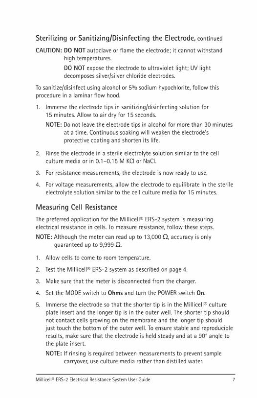
CAUTION: DO NOT autoclave or flame the electrode; it cannot withstand high temperatures. DO NOT expose the electrode to ultraviolet light; UV light decomposes silver/silver chloride electrodes.
To sanitize/disinfect using alcohol or 5% sodium hypochlorite, follow this procedure in a laminar flow hood.
1. Immerse the electrode tips in sanitizing/disinfecting solution for 15 minutes. Allow to air dry for 15 seconds.NOTE: Do not leave the electrode tips in alcohol for more than 30 minutes
at a time. Continuous soaking will weaken the electrode’s protective coating and shorten its life.
2. Rinse the electrode in a sterile electrolyte solution similar to the cell culture media or in 0.1–0.15 M KCl or NaCl.
3. For resistance measurements, the electrode is now ready to use.
4. For voltage measurements, allow the electrode to equilibrate in the sterile electrolyte solution similar to the cell culture media for 15 minutes.
Measuring Cell ResistanceThe preferred application for the Millicell® ERS-2 system is measuring electrical resistance in cells. To measure resistance, follow these steps.NOTE: Although the meter can read up to 13,000 Ω, accuracy is only
guaranteed up to 9,999 Ω.
1. Allow cells to come to room temperature.
2. Test the Millicell® ERS-2 system as described on page 4.
3. Make sure that the meter is disconnected from the charger.
4. Set the MODE switch to Ohms and turn the POWER switch On.
5. Immerse the electrode so that the shorter tip is in the Millicell® culture plate insert and the longer tip is in the outer well. The shorter tip should not contact cells growing on the membrane and the longer tip should just touch the bottom of the outer well. To ensure stable and reproducible results, make sure that the electrode is held steady and at a 90° angle to the plate insert.NOTE: If rinsing is required between measurements to prevent sample
carryover, use culture media rather than distilled water.
Sterilizing or Sanitizing/Disinfecting the Electrode, continued
00108103_Rev1016.indd 7 10/20/2016 8:22:57 AM

8 www.millipore.com
Ohm
Millicell ERS-2Epithelial Volt-Ohm Meter
Power
I
OMillivolts
Output
InputRAdj
MILLIPORE
R
l l 0 0
6. Record the resistance.
How to Determine Blank Resistance1. Add electrolyte to a blank cup (i.e., the cell culture insert without cells).
2. Measure the resistance across the blank cup as in step 5 of the previous section.
Resistance Calculations
Tissue Resistance
To obtain true tissue resistance, subtract the resistance reading across the blank cup from the resistance reading across the tissue (cell culture insert with cells).
Unit Area Resistance
The resistance is inversely proportional to the area of the tissue. The larger the membrane, the lower the resistance. NOTE: Resistance readings for 24 mm or larger diameter inserts should not
be converted to unit area resistance because the STX electrode cannot deliver a uniform current density over the relatively large area of membrane. This is not a problem with smaller inserts because of the relatively smaller area of membrane compared to the electrode. See table on next page for diameters of Millicell® cell culture inserts and plates.
Measuring Cell Resistance, continued
00108103_Rev1016.indd 8 10/20/2016 8:22:58 AM

Millicell® ERS-2 Electrical Resistance System User Guide 9
To achieve consistency across different plate formats (excluding 24 mm or larger diameter inserts), the product of the resistance and the area is typically calculated and reported. This value is independent of the area of the membrane used.
The unit area resistance is obtained by multiplying the meter reading by the effective surface area of the filter membrane. The unit of measure is Ωcm2. Effective membrane areas for Millicell® cell culture inserts and plates are listed in the table below.
Unit Area Resistance = Resistance (Ω) × Effective Membrane Area (cm2)
Unit Area = 1 cm2
The unit area resistance is independent of the area of the membrane used and may be used to compare data obtained from 12 mm or smaller inserts.
Millicell® Cell Culture Insert and Plate Effective Membrane AreaProduct Well Diameter (mm) Membrane Area (cm2)
6-well standing insert 30 4.224-well standing insert 12 0.66-well hanging insert 24 4.512-well hanging insert 12 1.124-well hanging insert 6.5 0.324-well plate ~ 10 0.7
96-well plate ~ 4 0.11
Resistance Calculations, continued
00108103_Rev1016.indd 9 10/20/2016 8:22:58 AM

10 www.millipore.com
Example ApplicationThe following is an example of a typical Millicell® ERS-2 application. It is not a technically complete experimental protocol.
Culture Cells
Seed cells onto 22 of 24 properly prepared, 24-well Millicell®-CM culture plate inserts, leaving the other two Millicell® culture plate inserts blank. Grow cells to confluency, according to standard protocol.
Measure and Calculate Resistance
1. Sterilize or sanitize/disinfect the electrode according to instructions on pages 6–7.
2. Allow the samples to come to room temperature.
3. Measure the resistance of the two blanks (i.e., Millicell®-CM inserts without cells).
4. Measure cell resistance in the 22 sample wells (i.e., Millicell®-CM inserts with cell monolayers).
5. Repeat step 3.
6. Average the resistance measurements of the two blanks and arrive at a value. For example: Rblank = 180 Ω
7. Subtract this blank resistance from the sample-well resistance measurement. Suppose a typical sample reading is 320 Ω. Then: Rsample – Rblank = Rcell monolayer
320 Ω – 180 Ω = 140 Ω
The resistance of the cell monolayer in this example is 140 Ω. However, you still need to correct for the area covered by the cell monolayer.
8. To correct for the area covered by the cell monolayer, calculate the product of the resistance and the area. Multiply the area of effective membrane diameter on the Millicell® culture plate insert by the resistance found in the experiments: 140 Ω × 0.6 cm2 = 84 Ωcm2
NOTE: The 24-well Millicell®-CM insert has an effective membrane area of 0.6 cm2.
This value, 84 Ω cm2, is independent of the area of membrane used.
00108103_Rev1016.indd 10 10/20/2016 8:22:58 AM

Millicell® ERS-2 Electrical Resistance System User Guide 11
Measuring VoltageFollow these steps to measure voltage.
1. Allow the cells to come to room temperature.
2. Test the Millicell® ERS-2 system as described on page 4. Make sure that the electrode has been equilibrated and tested according to the procedures on pages 5–6.
3. Disconnect the meter from the charger. Set the MODE switch to Millivolts and turn the POWER switch On.
4. Immerse the electrode so that the shorter tip is in the Millicell® culture plate insert and the longer tip is in the outer well. The shorter tip should not contact cells growing on the membrane, but the longer tip should just touch the bottom of the outer well. To ensure stable and reproducible results, make sure that the electrode is held steady and at a 90° angle to the plate insert.
Ohm
Millicell ERS-2Epithelial Volt-Ohm Meter
Power
I
OMillivolts
Output
InputRAdj
MILLIPORE
R
l.l
5. Record the voltage. Subtract the voltage of the culture media alone (step 4, Electrode Functionality Check) to obtain the true voltage value of the cultured cell monolayer.NOTE: If rinsing is required between measurements to prevent sample
carryover, use culture media rather than distilled water.
In voltage mode, if the meter reading is positive, it means that the basal side of the cellular tissue (the side adhering to the culture insert filter) is positive relative to the apical side (exposed). Conversely, if the meter is reading negative, it means that the basal side is negative relative to the apical side.
00108103_Rev1016.indd 11 10/20/2016 8:22:58 AM

12 www.millipore.com
Maintaining and Storing the System
MeterCharge the batteries monthly or when BATT appears in the digital display.When not in use, the meter should be powered off and disconnected from the charger, as continuous charging may shorten battery life.NOTE: Always power the meter off when charging the battery.
The meter should hold a charge for approximately 8 hours. It will shut off automatically when the battery runs low to avoid damage to the instrument. When the battery charge is low, BATT appears in the digital display. To avoid automatic shut-off, recharge the battery when the BATT warning is displayed.CAUTION: To prevent corrosion, do not splash or spill saline solution or
culture media on the meter.To prevent the digital LCD display from darkening, do not leave the meter in direct sunlight for long periods of time.
Changing the BatteryThe Millicell® ERS-2 meter is equipped with a 6 V 2,700 mAh rechargeable NiMH battery pack which can be charged for approximately 500 cycles. The battery pack may be charged at any time in the discharge cycle and can be charged continuously without damage, using the supplied charger.CAUTION: To prevent battery damage, use ONLY the supplied charger.
The battery life is about 1 to 2 years, depending on use. NiMH batteries discharge even if they are not in use. To prevent battery damage from self discharge, charge the battery pack monthly.
To change the battery:
1. Using a #1 Phillips screwdriver, remove the four screws from the Millicell® ERS-2 case and separate instrument cover from base.
2. The battery pack is mounted to the base by a metal cover. Remove the two screws and lift battery cover and battery out.
3. Remove battery pack from cover.
4. Note the position of the battery pack connector and wire color code, so that the correct polarity can be maintained with the new battery pack. Disconnect the small plastic connector from the circuit board by pulling it straight out from the circuit board.CAUTION: Connecting the battery connector with the polarity reversed
may result in personal or equipment damage.
00108103_Rev1016.indd 12 10/20/2016 8:22:58 AM

Millicell® ERS-2 Electrical Resistance System User Guide 13
5. Place new battery pack in battery cover and resecure to base.
6. To reconnect battery pack wire to circuit board, line up the connector of the battery pack so that the protruding ledge faces the tab (locking guide) on the circuit board. Push the connector straight down over the pins on the board. Do not force the connector; if aligned properly, it should click into place with little effort.
7. Reassemble the instrument cover and base.
8. Charge the new battery for at least 12 hours.
9. Dispose of old battery in accordance with local regulations.
Electrode Storage Short-term storage (overnight): Immerse the electrode tip in electrolyte
solution. Keep the electrode cable plugged into the electrode port on the meter so that the system is internally short-circuited and electrode symmetry (equilibration) is maintained.
Long-term storage: Rinse the electrode with Milli-Q® water or equivalent and store dry and in the dark. Do not allow electrode to dry without first rinsing with Milli-Q® water to remove salts and proteins.
Electrode CleaningWith repeated use, the electrode surface can become coated with protein or other foreign materials. This build-up can degrade the performance of the system. After every use, rinse the electrodes with Milli-Q® water and store them as indicated above. Periodically clean the electrodes with Tergazyme® detergent (Alconox, Inc.® cat. no. 1304) as follows:
1. Rinse the electrodes with Milli-Q® water and dry them.
2. Make a 1% solution of Tergazyme® detergent and suspend the electrode tips in the solution with the exposed electrode surfaces fully immersed. If desired, brush the electrode surfaces with a soft brush (e.g., tooth brush).
If the electrode is... Then soak it in solution for...not cleaned routinely 12 hoursis on a weekly cleaning schedule 30–60 minutesis cleaned daily 5 minutes
Changing the Battery, continued
00108103_Rev1016.indd 13 10/20/2016 8:22:58 AM

14 www.millipore.com
3. Rinse well with Milli-Q® water. Store as detailed in Electrode Storage section.
Sanding (only when measuring voltage)
4. Lightly rub the voltage electrodes (the two silver pellets on the inner surfaces near the electrode tips) with 600-grade ultrafine sandpaper (provided) or an ink eraser. Do not sand the silver pellets on the outside of the electrode tips.CAUTION: Only a very thin surface layer of the pellet should be removed.
Repeated rubbing will eventually remove the Ag/AgCl pellet.
When rubbing no longer improves the voltage readings, the electrode should be replaced.
TroubleshootingMost of the time, system problems are related to the electrode rather than the meter itself. However, if the meter does fail, it is most often due to switch failure caused by corrosion from accidental spillage of saline solution or culture media on the meter. If functional testing indicates acceptable performance, and the meter has not been exposed to salt solutions, then the meter is working correctly.
When the electrode fails, the most common symptom is an unstable or unusually high reading. The following qualitative method may be helpful in determining whether or not the electrode is functional:
Check the resistance of a well filled with electrolyte and across a blank culture insert filled with electrolyte. The resistance of electrolyte alone should be less than 50 Ω and stable if the electrode is kept stationary. The resistance of the blank insert is normally in the 80 to 200 Ω range, depending on the brand and size.
When the meter displays a lower than expected resistance, but is stable and reproducible, the most likely cause is the cell culture, not the electrode or the meter.
During normal use, it may helpful to write down the resistance range of each particular type of blank insert with the specific culture media used. If the electrode is subsequently suspected of having a problem, a comparison of current readings with past readings on the same blank insert and culture media may assist in determining if the electrode is functioning properly.
Electrode Cleaning, continued
00108103_Rev1016.indd 14 10/20/2016 8:22:58 AM

Millicell® ERS-2 Electrical Resistance System User Guide 15
Symptom Cause Corrective ActionMeter will not power on when disconnected from charger
OR
Meter runs briefly, then powers off
Batteries are discharged or insufficiently charged
The meter will power down automatically when the batteries are depleted. Power off the meter, connect it to the battery charger, and charge for at least 12 hours. A full charge may require up to 24 hours. For reliability, the meter should be charged each evening (with the power off) before use the next day.
Batteries are defective Replace the battery pack or contact Technical Service.
Meter will not charge when connected to charger
Insecure connection at power input jack on meter
Verify that the battery charger is securely connected at the meter power input jack.
Defective charger Using a volt meter, verify correct output voltage at the charger connector. If the volt meter reading is not close to +12 V DC at the center conductor on the connector, replace the battery charger. If the battery charger is working and the unit does not power up, contact Technical Service.
Meter reading is unstable when power is turned on
Meter is connected to charger
Disconnect the meter from the charger.
Low battery charge Recharge battery for 12 hours, then perform “Meter Functionality Check”.
Failure to achieve specified test values during “Meter Functionality Check”
Low battery charge Recharge battery for 12 hours and repeat “Meter Functionality Check”. If readings are still not as specified, contact Technical Service.
Intermittent meter reading
Loose or broken electrode connector or cable
Replace the electrode.
Malfunctioning system Call Technical Service.
Unstable resistance or voltage reading, (voltage drift) during use
Meter is connected to charger
Disconnect the meter from the charger.
Electrode not immersed in culture media solution
Make sure both tips are immersed in solution. NOTE: When the meter is in voltage mode, it is normal for the display to be unstable when the electrode is not immersed in solution.
Troubleshooting, continued
00108103_Rev1016.indd 15 10/20/2016 8:22:58 AM

16 www.millipore.com
Symptom Cause Corrective ActionUnstable resistance or voltage reading, (voltage drift) during use, continued
Electrode position not stable
Hold electrode in a fixed position at a 90° angle to the plate insert. Hand held electrodes must be kept as motionless as possible during a measurement.
VOLTAGE ONLY: Electrode not equilibrated
Condition the electrode as outlined in “Equilibrating the Electrode”.
Dirty electrode tips Clean the electrode as outlined in the “Electrode Cleaning” section.
Electrode is old or broken Replace the electrode. If “Meter Functionality Check” indicates that meter is functional, electrode may be broken or have exceeded its normal lifetime of 1 to 2 years.
RESISTANCE ONLY: Meter is malfunctioning
Verify a reading of 1,000 Ω with the test electrode. Adjust if required. If adjustment cannot be made, call Technical Service.
Electrode and cable too close to strong electromagnetic radiation
Move the system to a different area.
Meter connected to a recording device via the output jack
Remove the connection to the recording device.
Slow response in resistance or voltage reading
Measurement conditions need to be optimized
Make sure electrode is fully wetted and the solution is at room temperature. Make sure there are no bubbles under the Millicell® culture plate insert. Take measurements with electrode tips completely immersed in solution.
VOLTAGE ONLY: Electrode not equilibrated
Condition the electrode as outlined in “Equilibrating the Electrode”.
Dirty electrode tips Clean electrode as outlined in “Electrode Cleaning”. After use, make sure electrode is rinsed with Milli-Q® water before it dries.
Troubleshooting, continued
00108103_Rev1016.indd 16 10/20/2016 8:22:58 AM

Millicell® ERS-2 Electrical Resistance System User Guide 17
Symptom Cause Corrective ActionResistance reading is lower than expected
Meter is malfunctioning Perform “Meter Functionality Check”.
Cell culture contaminated
Re-culture cells.
Cells have not formed tight junctions, or are not confluent
Allow cells to grow longer.
Resistance reading is higher than expected
Meter is malfunctioning Perform “Meter Functionality Check”.
Electrode contacts have a buildup of protein or other foreign material
Clean the electrode as outlined in “Electrode Cleaning”.
Electrode broken Replace the electrode.
Voltage reading higher than 20 mV during “Electrode Functionality Check”
Meter is connected to charger
Disconnect the meter from the charger.
Low battery charge Recharge battery for 12 hours.
Electrode not equilibrated Condition the electrode as outlined in “Equilibrating the Electrode”.
Dirty electrode tips Clean the electrode as outlined in “Electrode Cleaning”.
Conductive contamination between electrodes
Inspect the inter-electrode surface areas for material which could form a conductive bridge between the inner and outer electrodes. If the material cannot be removed, replace the electrode.
Corrosion on electrode conductive traces
Inspect the embedded copper circuit traces that run from the electrode tip and up the handle. If any black discoloration is observed at the tip, replace the electrode.
Troubleshooting, continued
00108103_Rev1016.indd 17 10/20/2016 8:22:58 AM

18 www.millipore.com
Specifications
Millicell® ERS-2 MeterMembrane voltage range ± 200.0 mV Voltage measurement 0.1 mVResistance range 0 to 9,999 ΩResistance resolution 1 ΩAC square-wave current ± 10 µA nominal at 12.5 HzPower Internal 6 V NiMH 2,700 mAh battery with
external 12 V DC supply for rechargingNominal battery run time ~ 8 hours*Analog output Millivolt mode: 1 mV = 10 mV
Ohm mode: 1 Ω = 1 mVEnvironmental range 50–100 °F (10–38 °C)
0–90% non-condensing relative humidityDimensions 7.25 × 4.25 × 2.3 in. (18.4 × 10.8 × 5.8 cm)Weight 3 lb (1.4 kg)
* When the battery power level falls below a minimum threshold, the meter automatically powers off. A fully charged battery will provide about 8 hours of running time.
Regulatory ComplianceThis product is in conformity with the following standards:
Safety: EN 61010-1: 2001 (Eqv: IEC 61010-1:2001)EMC: EN 61326-1: 2006 (Eqv: IEC 61326-1:2005)
EN 61326-2-3: 2006 (Eqv: IEC 61326-2-3:2006)and therefore meets the provisions of European LV Directive 2006/95/EC and European EMC Directive 2004/108/EC.
00108103_Rev1016.indd 18 10/20/2016 8:22:59 AM

Millicell® ERS-2 Electrical Resistance System User Guide 19
Ordering InformationThis section lists catalogue numbers for the Millicell® ERS-2 system and other Millicell® products. See the Technical Assistance section for contact information. You can purchase these products online at www.millipore.com/products.
Millicell® ERS-2 System and ComponentsProduct Description Cat. No. Qty/Pk
Millicell® ERS-2 system (includes meter, battery, STX01 electrode, 1,000 Ω test electrode, battery charger)
MERS00002 1
Replacement electrode MERSSTX01 1 pair
Adjustable electrode MERSSTX03 1 pair
Electrode for Millicell®-96 well plate MERSSTX00 1 pair
Replacement 1,000 Ω test electrode MERSSTX04 1
Replacement Battery MERSBAT01 1
Other Millicell® Products
Millicell® Single-well Standing InsertsMembrane Pore Size Device Size Qty/Pk Cat. No.
Organotypic insert** Biopore™ (Polytetrafluoroethylene, PTFE)
0.4 µm 6-well 50 PICM0RG50
HA insert MF-Millipore™ (Mixed cellulose esters)
0.45 µm24-well6-well
5050
PIHA01250PIHA03050
CM insert** Biopore™ (PTFE) 0.4 µm
24-well6-well
5050
PICM01250PICM03050
PCF insert Isopore™ (Polycarbonate, PCF)
0.4 µm3 µm8 µm12 µm0.4 µm
24-well24-well24-well24-well6-well
5050505050
PIHP01250PITP01250PI8P01250PIXP01250PIHP03050
** For adherent cells, this membrane needs to be coated with a extracellular matrix.
00108103_Rev1016.indd 19 10/20/2016 8:22:59 AM

20 www.millipore.com
Millicell® Single-well Hanging InsertsMembrane Pore Size Device Size Qty/Pk Cat. No.
PET Insert (Polyethylene terephthalate, PET)
0.4 µm1 µm3 µm5 µm8 µm
6-well 48 MCHT06H48MCRP06H48MCSP06H48MCMP06H48MCEP06H48
0.4 µm1 µm3 µm5 µm8 µm
12-well 48 MCHT12H48MCRP12H48MCSP12H48MCMP12H48MCEP12H48
0.4 µm1 µm3 µm5 µm8 µm
24-well 48 MCHT24H48MCRP24H48MCSP24H48MCMP24H48MCEP24H488
Millicell®-24 Well Cell Culture Insert Plate Assemblies
DescriptionSystem Components
Membrane (Pore size) Qty/Pk Cat. No.
Millicell®-24 cell culture insert plates
24-well cell culture plate, single-well feeder tray, 24-well receiver plate, lid
PCF (0.4 µm)PET (1 µm)PCF (3 µm)PCF (5 µm)PCF (8 µm)
1 PSHT010R1PSRP010R1PSST010R1PSMT010R1PSET010R1
24-well cell culture plate, 24-well receiver plate, lid
PCF (3 µm)PCF (5 µm)PCF (8 µm)
5 PSST010R5PSMT010R5PSET010R5
24-well cell culture plate, single-well feeder tray, lid
PCF (0.4 µm)PET (1 µm)
5 PSHT010R5PSRP010R5
24-well receiver plate, lid N/A 5 PSMW010R5
Single-well feeder tray, lid N/A 5 PSSW010R5
Ordering Information, continued
00108103_Rev1016.indd 20 10/20/2016 8:22:59 AM

Millicell® ERS-2 Electrical Resistance System User Guide 21
Millicell®-96 Well Cell Culture Insert Plate Assemblies
DescriptionSystem Components
Membrane (Pore size) Qty/Pk Cat. No.
Millicell®-96 cell culture insert plates
96-well cell culture plate, single well feeder tray, 96-well receiver plate, lid
PCF (0.4 µm)PET (1 µm)
1 PSHT004R1PSRP004R1
96-well cell culture plate, 96-well receiver plate, lid
PCF (0.4 µm) 5 PSHT004S5
96-well cell culture plate, single-well feeder tray, lid
PCF (0.4 µm)PET (1 µm)
5 PSHT004R5PSRP004R5
96-well receiver plate, lid N/A 5 MACAC0RS5
AccessoriesDescription Qty/Pk Cat. No.Stericup®-GP filter unit, 150 mL, PES membrane 12 SCGPU01RE
Sterile Millex®-GP 33 mm filter unit, PES membrane 50 SLGP033RS
Steriflip®-GP filter unit, PES membrane 25 SCGP00525
Ordering Information, continued
00108103_Rev1016.indd 21 10/20/2016 8:22:59 AM

22 www.millipore.com
Technical AssistanceFor more information, contact the office nearest you. In the U.S., call 1-800-645-5476. Outside the U.S., go to our web site at www.millipore.com/offices for up-to-date worldwide contact information. You can also visit the tech service page on our web site at www.millipore.com/techservice.
Manufacturer
MEMD Millipore Corporation Billerica, MA 01821 U.S.A.
Standard WarrantyThe applicable warranty for the products listed in this publication may be found at www.millipore.com/terms (“Conditions of Sale”).
NOTE: The warranty for electrodes and batteries is 30 days from date of receipt.
00108103_Rev1016.indd 22 10/20/2016 8:22:59 AM

00108103_Rev1016.indd 24 10/20/2016 8:22:59 AM