
User Guide 250mm Multipoint Strip Chart Recorder · 250mm Multipoint Strip Chart Recorder SR250B...
60
250mm Multipoint Strip Chart Recorder SR250B User Guide IM/SR250B_4
Transcript of User Guide 250mm Multipoint Strip Chart Recorder · 250mm Multipoint Strip Chart Recorder SR250B...

250mm Multipoint Strip Chart Recorder
SR250B
User GuideIM/SR250B_4

ABB
The Company
We are an established world force in the design and manufacture of instrumentation for industrialprocess control, flow measurement, gas and liquid analysis and environmental applications.
As a part of ABB, a world leader in process automation technology, we offer customersapplication expertise, service and support worldwide.
We are committed to teamwork, high quality manufacturing, advanced technology and unrivalledservice and support.
The quality, accuracy and performance of the Company’s products result from over 100 yearsexperience, combined with a continuous program of innovative design and development toincorporate the latest technology.
The UKAS Calibration Laboratory No. 0255 is just one of the ten flow calibration plants operatedby the Company, and is indicative of our dedication to quality and accuracy.
Electrical Safety
This equipment complies with the requirements of CEI/IEC 61010-1:2001-2 'Safety Requirements for Electrical Equipment forMeasurement, Control and Laboratory Use'. If the equipment is used in a manner NOT specified by the Company, the protectionprovided by the equipment may be impaired.
Symbols
One or more of the following symbols may appear on the equipment labelling:
Health and SafetyTo ensure that our products are safe and without risk to health, the following points must be noted:
1. The relevant sections of these instructions must be read carefully before proceeding.
2. Warning labels on containers and packages must be observed.
3. Installation, operation, maintenance and servicing must only be carried out by suitably trained personnel and in accordance with theinformation given.
4. Normal safety precautions must be taken to avoid the possibility of an accident occurring when operating in conditions of high pressure and/or temperature.
5. Chemicals must be stored away from heat, protected from temperature extremes and powders kept dry. Normal safe handling proceduresmust be used.
6. When disposing of chemicals ensure that no two chemicals are mixed.
Safety advice concerning the use of the equipment described in this manual or any relevant hazard data sheets (where applicable) may beobtained from the Company address on the back cover, together with servicing and spares information.
Warning – Refer to the manual for instructions
Caution – Risk of electric shock
Protective earth (ground) terminal
Earth (ground) terminal
Direct current supply only
Alternating current supply only
Both direct and alternating current supply
The equipment is protectedthrough double insulation
Information in this manual is intended only to assist our customers in the efficient operation of our equipment. Use of this manual forany other purpose is specifically prohibited and its contents are not to be reproduced in full or part without prior approval of theTechnical Publications Department.
EN ISO 9001:2000
Cert. No. Q05907
EN 29001 (ISO 9001)
Lenno, Italy – Cert. No. 9/90A
0255
Stonehouse, U.K.

FRONT PANEL KEYS
A1 Input Type :Linear Elec Lo/Hi :20.0 DP
Up/Down Key
Adjustsparameter values
Flashing promptprecedesadjustable parameters
:RTD:THC:Ω:V:mA:mV
Frame 1
Page 1 Page 2
Advance tonext page
Frame 2
Advance tonext frame
Frame 1
Frame 2
or
Select
PenLift/Lower Key
Lifts/lowers pen on alternate operations
Hash Key
Star Key
Multi-function keys.The function is dependent upon the framedisplayed (e.g. Print, Edit, Acknowledge etc.)
Operator Message PRINT *Start of batch 47H350 EDIT #
Adjust
A1 Input Type :Linear Elec Lo/Hi :20.0 DP
Side Scroll Key
Down Scroll Key
Flashing prompt identifies page selectedCursor
Moves betweenpages in menus
and…
betweenparametersin a frame
Date :Fri :26 :Jan :96Time :14 :00
Input Set Up Input Copy
Line Filter Input Adjust

EDITING TEXT
Repeat and until the message is complete.
Enter the EDIT mode using the key
Press the key to exit the EDIT mode.
1
4 2 3
5
cde^_`a
Enter the character using the key3
Edit Tag:a WXYZ[\]^_`abcdefghijk EXIT #
Flashing
b
Flashing
b
Select character using the and keys2
Edit Tag: WXYZ[\]^_`abcdefghijk EXIT #
Flashing
a
Flashing
a
bcd]^_`

1
GETTING STARTED
This Multipoint Chart Recorder provides accurate and reliable recording of up to 12 process signals on a 250mm wide chart. In-builttext printing capabilities give clear annotation on the chart of time, date, scales and other process information.
The simplicity of chart and pen replacement and the clear display of process status make the instrument easy to operate.
The recorder is designed for panel mounting and provides complete dust and water protection on the front face, making it suitablefor use in very harsh environments.
The instrument can be configured for a wide range of input types and chart speeds and is ideal for most industrial recordingapplications.
This manual is divided into four Sections containing all the information required to install, configure and operate themultipoint chart recorder.
Symbol Identification and Contents of Sections
CHARTS AND PENS• Chart Loading• Fitting the Pen Capsule
OPERATION• Viewing Data• Chart Speed Selection
CONFIGURATION• Security• Input Configuration• Alarm Configuration• Chart Set Up
INSTALLATION• Mounting• Electrical Connection
Accessories
Quick Reference Guide(IM/SR250–Q)
Roll Chart Pen Capsule
Mounting ClampsOptional Terminal CompartmentExtension and Cable Grommets
Shunt Resistor(one per channel)

2
CONTENTS
Front and Back Fold-outs
Operator Level Overview
ConfigurationLevel Overview
Editing Text
Front PanelKeys
Section Page
GETTING STARTED .............................................................. 1
1 CHARTS AND PENS .................................................... 31.1 Loading a Chart ................................................. 31.2 Fitting the Pen Capsule ...................................... 6
2 OPERATION ................................................................. 72.1 Introduction ........................................................ 7
2.1.1 Operator Level Pages ............................. 72.1.2 Operating Displays ................................. 72.1.3 Warning Messages ................................. 7
2.2 Instrument Start-up ............................................ 82.3 Viewing the Measured Values ............................. 82.4 Viewing the Date and Time ................................ 92.5 Selecting the Chart Speed ................................. 92.6 Operator Messages .......................................... 102.7 Using 'Easy View' ............................................. 102.8 Viewing and Acknowledging Alarms ................. 11
2.8.1 Process Alarms................................... 112.8.2 Real-time Alarms ................................ 112.8.3 Instrument Alarms............................... 112.8.4 Alarm Acknowledgement .................... 12
2.9 Security Access................................................ 132.10 Process Review Page ....................................... 132.11 Chart Format .................................................... 14
3 CONFIGURATION .......................................................... 153.1 Introduction – Fig. 3.1 ......................................... 15
3.1.1 Entering Changes ................................. 153.1.2 Security Access – Fig. 3.2 .................... 15
3.2 Analog Inputs ...................................................... 163.2.1 Input Set Up Page ................................ 163.2.2 Input Copy Page .................................. 213.2.3 Line Filter Page ..................................... 213.2.4 Input Adjust Page ................................. 22
Section Page3.3 Alarm Configuration .......................................... 24
3.3.1 Process Alarms Page ........................... 243.3.2 Real Time Alarms Page ........................ 263.3.3 Alarm Acknowledge Page .................... 273.3.4 Power Failure Page............................... 29
3.4 Chart Level ....................................................... 303.4.1 Chart Control Page ............................... 303.4.2 Pen Alignment Page ............................. 35
3.5 Output Modules ............................................... 363.6 Operator Set Up ............................................... 37
3.6.1 Operator Contents Page ...................... 373.6.2 Security Page ....................................... 38
4 INSTALLATION ........................................................... 394.1 Siting ................................................................ 394.2 Mounting .......................................................... 404.3 Access to Terminals and Connections ............. 424.4 Electrical Connections ...................................... 434.5 Analog Input Connections ................................ 45
4.5.1 Current and Voltage .............................. 454.5.2 Thermocouple ...................................... 454.5.3 Resistance Thermometer (RTD) ............ 454.5.4 Accessing the Analog Input Links ....... 464.5.5 Setting Analog Input links ................... 464.5.6 Transmitter Power Supply
Connections ....................................... 474.6 Digital Input Connections ................................. 474.7 Relay Output Connections ............................... 474.8 Power Supply Connections .............................. 47
4.8.1 AC Mains Connections – Fig. 4.13 ..... 474.8.2 24V AC/DC Supply Connections ........ 47
5 SPARES LIST ............................................................. 485.1 Consumables ...................................................... 48
INDEX .................................................................................. 49

3
1 CHARTS AND PENS
1.1 Loading a Chart
Warning.• Channel values and text messages are not recorded during chart reloading and therefore cannot be printed when the
chart reload is complete.
• All alarms and relays operate normally during chart reload.
• Do not operate the instrument without the chart cassette fitted.
Chart loading is a four-step procedure:a) Select the Chart Page .............................................................................................. This page – see Fig. 1.1
b) Start automatic rewind of the old chart ........................................................ Page 4
c) Load the new chart ...................................................................................... Page 5 – see Fig. 1.2
d) Advance the chart to an appropriate time line (if required) ........................... Page 4
Fig. 1.1 Selecting the Chart Page
Security Access Code:1234
SR250/2001 Iss 1
Press the key to access the Chart Page.
107.6
1
OPERATOR LEVEL
Alarm Acknowledge Page
A1 °CBoiler 1 Temperature
107.6
OPERATOR LEVEL
Chart Page
Press the key untilSecurity Access Code isdisplayed
Only displayed if alarms presentInvalid code
Valid code
Select the security access code using the and keys (0 to 9999, default = 0 ).2
A1 °C Boiler 1 Temperature
3

4
…1 CHARTS AND PENS
…1.1 Loading a Chart – Fig. 1.2
Select the Chart Page – see Fig. 1.1, previous page.
Start Chart ReloadTo load a chart, select 'Yes' using the key.
Press the key to start automatic rewind.
If the motor continues to drive when the chart paper isrewound, press the (STOP) key.
Warning. Do not press the key whilst the chartis winding. This action cancels automatic rewind and onlymanual rewind is available.
To pause the rewind press the key.
To abort the rewind and continue recording, press the key while 'REWINDING PAUSED' is displayed.
Load a New ChartRemove the old chart and load new chart paper– see Fig. 1.2.
If necessary, press the key until any remaining chart isrewound.
Refit the chart cassette then press the key to take up anyslack in the chart and resume recording.
Completion
HOME: Press the key to go directly to the Operating Page.
or
ALIGN: Press the key to start time alignment.
Time AlignmentThe chart can be advanced to ensure that the time is printed onmajor time lines (1 hour graduations).Recording stops and the print head moves from side to side onthe chart to enable precise adjustment onto a time line.
Press the key to advance the chart to a time line.
Press the key to resume recording.
•1 The 'ALIGN' facility is displayed only if Time Alignment is enabled – see Section 3.4.1/ Chart Control Page/ Time Alignment.
REWIND COMPLETE MORE *
LOAD :25m CHART
REWINDING PAUSED RESUME *
ABORT #
Automatic Rewind Complete(frame is advanced automatically)
Start Chart Reload ?
OPERATOR LEVELChart Page
•1
YES
LoadChart
NO
CHART REWINDING PAUSE *
25% Complete STOP #
25m Chart Loaded HOME *
24.8m Remaining ALIGN #
Top ofChart Page
Operating Page
YesNo
or
Time Alignment ADV *
EXIT #

5
1 CHARTS AND PENS…
…1.1 Loading a Chart – Fig. 1.2
Fig. 1.2 Loading a Roll Chart
Press the catches on both sides and open the door
…lift the display panel…
…press the lower catch…
1
2
3
Ensure spindle islocated correctly
Pull chart outunder the top roller
8
9
Remove the spindle from the old chartand insert into the new chart roll
Fit the spindle into thecassette, ensuring thegearwheel fits againstthe chart
6
7
Feed thechart underthe bar onthe lowerroller
Wrap the chart around the cassette
Feed the chart underthe guidebar
10
12
11
Pull through approximately50mm of chart
Use the thumbwheelto tighten the chart
Chart Routing
50 mm
14
13
… and remove thechart cassette
5
…lift the upper catch…4
Note. The chart paper is suitable for operation within the following environmental limits:0°C to 40°C at 15 to 80% RH40°C to 50°C at 25 to 80% RH

6
…1 CHARTS AND PENS
Fig. 1.3 Fitting the Pen Capsule
1.2 Fitting the Pen Capsule – Fig.1.3a) Switch on the power supply.
b) Fit a new capsule as shown in Fig. 1.3.
Notes.• After fitting a new capsule the ink flow takes a short time to achieve full color density.
• More ink is used if the input signal being recorded changes rapidly. To prolong the life of the pen capsule do not select aninput range which is oversensitive. If the input signal is noisy, use the digital filter to reduce the effect of the noise – seeSection 3.2.1/ Input Set Up Page/ Filter Time.
• Two types of pen capsule are available, standard and high temperature. The high temperature capsule is designed for useby recorders operating at ambient temperatures consistently above 30°C (86°F).
PEN LIFT ACTIVATED
Activate the pen lift(raise the pens)
Open the door
Close the display panel
Lift the display panel
De-activate the pen lift(lower the pens)
PEN LIFT DE-ACTIVATED
Press the lower catch
Remove/replace the pen capsule
Close the door
1 2
3
4
5
6
7
8
Note. Some resistance may be felt as the spring clip locates in the capsule.

7
2.1.2 Operating Displays – Fig. 2.2In the normal, day-to-day mode of the instrument, channel information is displayed seqentially (autoscroll active).
Channel 1
Advanceto next page
InterruptAuto-scroll by
pressing any key
Advanceto next channelChannel 2
Channel X
ChannelIdentifier
MeasuredValue
Units ProcessAlarmActive
ChannelTag
InstrumentAlarmActive
A1107.6 °C Boiler 1 Temperature
!
Auto-scroll
2 OPERATION
2.1 Introduction – Figs. 2.1 to 2.3
2.1.1 Operator Level Pages – Fig. 2.1An overview of the operator level pages is contained on the Back Fold-out.
2.1.3 Warning Messages – Fig. 2.3Warning messages provide instrument status and input warnings.
Fig. 2.1 Operating Level Pages
Fig. 2.2 Operating Displays
Fig. 2.3 Warning Messages
A1 FAILED °C ! Boiler 1 Temperature
Channel input out of limits.• Check input source• Check input configuration (Section 3)• Check the electrical connections (Section 4)
Less than 200mm of chart remains.This display 'flashes' with the operating display.
Replace the chart as detailed in Section 1.1
PAPER OUT !
OPERATINGDISPLAYS
SECURITYACCESS
CHARTPAGE
PROCESSREVIEW PAGE
If no alarms presentIf Process Review OFF
– see Section 3.6.1
ALARMPAGES

8
…2 OPERATION
2.2 Instrument Start-up – Fig 2.4On power-up the instrument carries out an automatic test of the CPU, RAM and Configuration. On completion a 'PASS' or 'FAIL'message is displayed. If a 'FAIL' message occurs press the key to acknowledge the error and proceed as Table 2.1
Input A1Channel 1 measured value, units and channel tag.
Input A2Channel 2 measured value, units and channel tag.
Input A3Channel 3 measured value, units and channel tag.
Input XXChannel X measured value, units and channel tag.
A1107.6 °C Boiler 1 Temperature
A2 99.3 °C Boiler 2 Temperature
A3138.2 °C Boiler 3 Temperature
XX217.3 °C Boiler X Temperature
Date Tue 18 Mar 97 PRINT *Time 15:53:16 ADJ #
CPU:Pass CONFIGURATION:TEST
RAM:Pass
Initialization Frame (recording stopped).Lower line shows Software version
'ACK' is only displayed following aconfiguration failure
CPU:Pass CONFIGURATION:FAIL ACK *
RAM:Pass
SR250B MULTIPOINT RECORDER2001 Issue 1
egasseM noitcA
liaF:UPCnoitasinagroecivreslacolehttcatnoC
liaF:MAR
liaF:GIFNOC
.pudnanwodrewoP.rorreehtraelcot*KCAsserP
.noitarugifnoctnemurtsniehtkcehcdeyalpsidllitsegassemfI.noitasinagroecivreslacolehttcatnocdeyalpsidllitsegassemfI
Fig. 2.4 Power-up Displays
Table 2.1 Start-up Error Messages
2.3 Viewing the Measured ValuesIn the normal, day-to-day mode of the instrument, information for each channel is displayed seqentially (autoscroll active).Press any key to interrupt the autoscroll sequence. To return to autoscroll, press the key.

9
2 OPERATION…
2.4 Viewing the Date and TimePress any key to interrupt the autoscroll sequence.
Press the key to select the Date/Time frame.
Date/TimeThe current date and time are displayed.
Press the key to print the date and time on the chart.Press the key to access the adjustment frame.
Adjusting the Date and TimeUse the and keys to adjust each parameter.
Press the key to advance to the next parameter.Press the key to exit the adjustment frame.
Date :Wed :26 :Jan :00Time :14:00 EXIT #
Date Thur 27 Jan 00 PRINT *Time 15:53:16 ADJ #
A1 107.6 °CBoiler 1 Temperature
XX 217.3 °CBoiler X Temperature
Chart Speed:CS1: 20mm/hr ENTER *Remaining Chart 20.0 m ADV #
•1
A1 107.6 °CBoiler 1 Temperature
XX 217.3 °CBoiler X Temperature
Date Tue 24 Jan 00 PRINT *Time 15:53:16 ADJ #
Chart Speed:CS1: 20mm/hr ENTER *Remaining Chart 20.0 m ADV #
CS0
CS1
CS2
CS3
Chart Speed:CS1: 20mm/hr ENTER *Remaining Chart 20.0 m ADV #
Operator Message PRINT *Start of batch 47H35 EDIT #
•2
•1 The 'Print' facility is available only if enabled – see Section 3.6.1/Operator Contents Page/ Operator Printing Enable.
2.5 Selecting the Chart Speed
Press the key to select the Chart Speed frame.
Chart Speed and Remaining ChartThe chart speed and length of chart remaining are displayed.
Use the and keys to select a preset chart speed.The chart speeds are set up in the Configuration Level – seeSection 3.4.1/ Setting the Chart Speed.Press the key to enter the selection.
Note. If CS0 is selected, ‘Chart Stopped’ is printed on thechart, with the date and time. If another chart speed isselected and set to 0mm/hr, then 0mm/h is printed.
Chart AdvanceIf required, the chart can be wound forward to create aseparation space, e.g. between batches.
Press and hold the key to advance the chart.
•2 The 'Advance' facility is available only if enabled – see Section 3.4.1/Chart Control Page/ Paper Advance, and does not operateduring text printing.

10
…2 OPERATION
Press the key to access the Operator Message frame.
Operator MessageThe operator message is displayed.Press the key to print the displayed message on the chart.
Press the key to edit the message – see Front Fold-out.
2.6 Operator Messages
Chart Speed:CS1: 20mm/hr ENTER *Remaining Chart 20.0 m ADV #
Date Thur 27 JAN 00 PRINT *Time 15:53:16 ADJ #
A1 107.6 °CBoiler 1 Temperature
XX 217.3 °CBoiler X Temperature
Operator Message PRINT *Start of batch 47H350 EDIT #
•1
•1 The 'Print' facility is available only if enabled – see Section 3.6.1/Operator Contents Page/ Operator Printing Enable.
2.7 Using 'Easy View' – Fig. 2.5''Easy View' allows the operator to view the most recently printed area of the chart. To use the 'Easy View' facility, the autoscrollsequence must first be interrupted by pressing any key. With autoscroll interrupted, press the key. The chart is wound forward fora short distance and returns automatically to its original position a few seconds later. Channel values and text messages are bufferedduring 'Easy View' and are printed out when recording is resumed. To return to autoscroll, press the key.
Fig 2.5 Using 'Easy View'
COMMANDER SR250
COMMANDER SR250
Notes.• The 'Easy View' facility can be disabled – see Section 3.4.1/ Chart Control Page/ Easy View.
• 'Easy View' operates only when autoscroll is inactive – press any key to interrupt autscroll. Press the key toreturn to autoscroll.
• 'Easy View' operates only at chart speeds of 120mm/h or less.
• 'Easy View' operates only in the Operator Page.

11
2 OPERATION…
2.8 Viewing and Acknowledging AlarmsIndividual alarms are viewed in the Alarm Acknowledge Page. This page is displayed only when active or unacknowledged alarms arepresent.
There are 3 types of alarm – Process, Real Time and Instrument.
2.8.1 Process AlarmsProcess alarms can be assigned to any analog input and are activated when a pre-defined trip level is exceeded– see Section 3.3.1/ Process Alarms Page. Up to 24 alarms can be configured (PaA to PaZ excluding I and O).
There are five types of alarm state:
2.8.2 Real-time AlarmsFour real-time alarms can be configured to activate at a pre-defined time – see Section 3.3.2/ Real Time Alarms Page. These alarmscan be configured to activate on an hourly or daily basis.
2.8.3 Instrument AlarmsInstrument alarms are generated to indicate a failure (or impending failure) within the instrument system, e.g. Paper out, Paper low.
RT1 Active START OF BATCH
AlarmIdent
AlarmStatus
AlarmTag
PAPER OUT
Alarm Tag
Process AlarmActive
InstrumentAlarmActiveA1107.6 °C
Boiler 1 Temperature!
PaA 200.0 A1 Active ACK * HIGH TEMPERATURE G-ACK #
AlarmIdent
TripValue
Source AlarmStatus
AlarmAcknowledge
Global AlarmAcknowledge
AlarmTag
etatSyalpsiDmralA
degdelwonkcAnoitidnoCmralA
tneserPsetoN
evitcA oN seY –
dehctaL oN oN *.'dehctaL'ottessiepytegdelwonkcaehtfiylnO
kcanU oN oN *.'lamroN'ottessiepytegdelwonkcaehtfiylnO
glnkcA seY seY –
raelC seY oN .evitcanisemocebtiemitehttadeyalpsidsimralaehtfiylnO
epyTegdelwonkcA/egaPegdelwonkcAmralA/3.3.3noitceSeeS*

12
!02 Chart Paper Low :1.0 Hours Remaining
RT1 Active START OF BATCH
OPERATOR LEVELAlarm Acknowledge Page
!01 Power Recovered at : ACK *12 Dec 99 10:30:00
PaA 150.0 A1 Active ACK * BOILER 1 TEMP HIGH G-ACK #
•1
•2
•3
RT1RT2RT3RT4
PaA
PaZ
…2 OPERATION
2.8.4 Alarm Acknowledgement
•1 If there are no active process alarms the display shows the first active real-time or instrument alarm.
•2 If there are no active real-time alarms, the display either shows any active instrument alarms or reverts to the Alarm AcknowledgePage.
•3 This frame is not displayed if 'Power Failure Indication' is set to 'Off' – see Section 3.3.4/ Power Failure Page/ Power FailureIndication.
Press the key to access the Alarm Acknowledge Page.
Process AlarmsPress the key to display the first active or latched processalarm.
Press the key to acknowledge the displayed alarm orpress to acknowledge all active or latched processalarms. The alarm status changes to 'Acknlg' or 'Clear'.
Press or to display successive active or latchedprocess alarms, if any.
Real-time AlarmsPress the key to display the first active real-time alarm.
Note. Real-time alarms cannot be acknowledged.
Press or to display successive active or latched real-time alarms, if any.
Instrument AlarmsPress the key to display the first or successive activeinstrument alarm.
Power Up following Power FailurePress the key to acknowledge the alarm.
Chart Paper LowLess than 5 hours chart running time remaining.Replace the chart – see Section 1.1/ Loading a Chart.
If there are no alarms the display returns to the top of theAlarm Acknowledge Page.

13
2 OPERATION…
2.9 Security Access – Fig. 2.6Entry into the Process Review Page is protected by a Security Access Code. The code is set in Section 3.6.2/ Security Page.
Fig. 2.6 Security Access
Select the security access codeusing the and keys (0 to9999, default = 0).
1
2
3
Security Access Code:0
SR250/2001 Iss 1
OPERATOR LEVEL
Alarm Acknowledge Page
A1 °C Boiler 1 Temperature
107.6
OPERATOR LEVEL
Chart Page
Only displayed if any alarms are present
Invalid code
Valid code
Press the key to accessthe Process Review Page.
OPERATOR LEVEL
Process Review Page
Press the key untilSecurity Access Code isdisplayed
A1 °C Boiler 1 Temperature107.6
2.10 Process Review PageThe chart can be advanced (cue) or rewound (review) to examine a specific occurrence.
This page can be disabled – see Section 3.6.1/ Operator Contents Page/ Process Review Page.
REVIEW HOME * CUE
OPERATOR LEVELProcess Review Page
REVIEW HOME *
CUE ActiveHalt - Trace EndHalt - Time Out
Enter the Level 2 Security Password and advance to theProcess Review Page – see Fig. 2.6
Press the key to access the page.
Cue/ReviewPress the and keys to stop recording and cue/reviewthe chart.
' '– Cue/Review not active.Active – Cue/Review active.Halt - Trace End – The chart is wound further
than the last recordedinformation.
Halt - Time Out – Use of the Cue/Reviewfacility is not recommendedfor long periods. The facilityautomatically times out afterapproximately 5 minutes ofcontinuous operation.
Press the key to return to the top of the Process ReviewPage.Press the (HOME) key to return to the top of OperatingPage 1.
•1 When Cue/Review is terminated, the chart is wound forward approximately 10mm and the current date and time is printed.Channel data is not buffered during Cue/Review and cannot be printed when recording is resumed.
14
…2 OPERATION
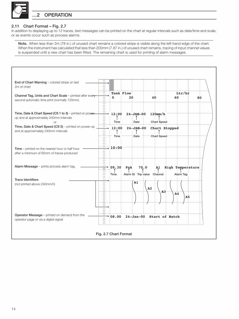
2.11 Chart Format – Fig. 2.7In addition to displaying up to 12 traces, text messages can be printed on the chart at regular intervals such as date/time and scale,or as events occur such as process alarms.
Note. When less than 2m (78 in.) of unused chart remains a colored stripe is visible along the left-hand edge of the chart.When the instrument has calculated that less than 200mm (7.87 in.) of unused chart remains, tracing of input channel valuesis suspended until a new chart has been fitted. The remaining chart is used for printing of alarm messages.
Fig. 2.7 Chart Format
A1
A3A4
10:00��
0 20 40 60
A5
80
A2
08.00 24-Jan-00 Start of Batch
09.30 PaA 70.0 A1 High Temperature
Time Alarm ID Trip value Channel Alarm Tag
Tank Flow Ltr/hr
End of Chart Warning – colored stripe on last2m of chart
Channel Tag, Units and Chart Scale – printed after everysecond automatic time print (normally 120mm)
Time, Date & Chart Speed (CS 1 to 3) – printed on power-up and at approximately 240mm intervals
orTime, Date & Chart Speed (CS 0) – printed on power-upand at approximately 240mm intervals
Time – printed on the nearest hour or half hourafter a minimum of 60mm of traces produced
Alarm Message – prints process alarm tag.
Trace Identifiers(not printed above 240mm/h)
Operator Message – printed on demand from theoperator page or via a digital signal
12:00��24–JAN–00��Chart Stopped
Time Date Chart Speed
12:00��24–JAN–00��120mm/h
Time Date Chart Speed

15
3 CONFIGURATION
3.1 Introduction – Fig. 3.1This Section contains information on the Configuration level programming of the SR250. An overview of the Configuration Level pagesis contained on the Back Fold-out. Configuration can also be achieved via a computer using the PC configurator package.
3.1.1 Entering ChangesTags and messages are entered at set parameters within the Configuration Level pages – see Front Fold-out.Changes to parameter values are saved automatically by advancing to the next frame.
Fig. 3.1 Configuration Level Overview
Fig. 3.2 Accessing the Configuration Level
1
2
3
4
Security Access Code:0
SR250/2001 Iss 1
OPERATOR LEVEL
Alarm Acknowledge Page
Select the Security Access Code usingthe and keys.
Only displayed if any alarms are present
Press the key to advance to the ConfigurationLevel selection frame.Refer to the rear fold-out for the contents of eachlevel.
SELECT LEVEL /
OperatorAnalog inputsAlarmsChartOutput ModulesOperator Set-up
Press the key repeatedly untilthe Security Page is displayed.
OPERATOR LEVEL
Chart PagePress the key to advance to the Chart Page.
Invalid code
Valid code
A1 °C Boiler 1 Temperature
107.6
107.6A1 °C
Boiler 1 Temperature
3.1.2 Security Access – Fig. 3.2
SELECT LEVEL /
Operator
Analog inputs
Alarms
Chart
Output Modules
Operator Set-up
Analog Inputs Level Alarms Level Chart Level Output Modules Level Operator Setup Level

16
epyTtupnItupnIekaMsnoitcennoC
tnuhStiFrotsiseR
teSskniL
tupnItceleSepyT
teSreziraeniL
lacirtcelEteSegnaR
gnireenignEteSegnaR
ecnerefeRegaP 44/34 44 54 71 71 71 81
DTR ✓ ✗ dradnatS ✓ ✓ — ✓
C/T ✓ ✗ dradnatS ✓ ✓ — ✓
Ω ✓ ✗ dradnatS ✓ ✓* ✓ ✓
V ✓ ✗ egatloV ✓ ✓* ✓ ✓
Am ✓ ✓ dradnatS ✓ ✓* ✓ ✓
Vm ✓ ✗ dradnatS ✓ ✓* ✓ ✓
FFO — — — ✓ — — —
✓* erudecorplanoitpO=
…3 CONFIGURATION
Table 3.1 Input Set Up Requirements
3.2 Analog Inputs
3.2.1 Input Set Up PageTo set up the analog inputs, carry out the appropriate procedures detailed in Table 3.1.
Where two or more channels use the same set up data, the Channel Copy facility can be used to configure multiple channelssimultaneously – see Section 3.2.2/ Input Copy Page.

17
3 CONFIGURATION…
…3.2.1 Input Set Up Page
•1 This frame is not displayed if input type RTD or T/C are selected.
A1 Input Type :mA :Linear
Elec Lo/Hi : 4.0 :20.0 DP #
A1 Input Type :mA :Linear
Elec Lo/Hi : 4.0 :20.0 DP #
A1 Input Type :mA :Linear
Elec Lo/Hi : 4.0 :20.0 DP #
A1 Input Type :mA :Linear
Elec Lo/Hi : 4. :20.0 DP #
Input Set Up Input Copy
Line Filter Input Adjust
A1 Input Type :mA :Power 5/2
Elec Lo/Hi : 4.0 :20.0 DP #
:RTD
:T/C
:Ω:V
:mA
:mV
:Off
:Power 5/2
:Power 3/2
:SqRoot
:Pt100
:Type N
:Type B
:Type E
:Type L
:Type J
:Type T
:Type S
:Type R
:Type K
:Linear
A1
A2
A3
B6
•1
Table 3.2 – Limits of Electrical Ranges
Input Type mV V mA Ω
Min. Value
Max. Value
–2000 –20 –100 0
2000 20 100 8000
Min. Span 2.5 0.25 0.25 10
Engineering (Display) Range
°C or °F
Press the key to select 'Input Set Up' from the AnalogInputs menu.
Press the key to access the page.
Input Set Up
Channel SelectionSelect the channel to be set.
Press the key to advance to the next parameter.
Input TypeSelect the Input Type required.('Off' is not applicable to channel A1).
Note. For thermocouple applications using an external fixedcold junction, select 'mV' input type.
Press the key to advance to the next parameter.
Linearizer TypeSelect the Linearizer Type required.
Press the key to advance to the next parameter.
Electrical Input Range Low and High – Table 3.2
Press the key to set the number of decimal places,(low and high values are set simultaneously).
Set the minimum (Lo) value of the electrical input signalwithin limits – see Table 3.2.
Press the key to advance to the next parameter.
Set the maximum (Hi) value of the electrical input signalwithin limits – see Table 3.2.
Press the key to set the next channel.Press the key to advance to the next frame.

18
…3 CONFIGURATION
…3.2.1 Input Set Up Page
Table 3.3 – Limits of Engineering Ranges
THC /RTDType
°C °F
Min. Max.Min.Span Min. Max.
Min.Span
Type B –18 1800 710 0 3272 1278
Type E –100 900 45 –148 1652 81
Type J –100 900 50 –148 1652 90
Type K –100 1300 65 –148 2372 117
Type L –100 900 50 –148 1652 90
Type N –200 1300 90 –328 2372 162
Type R & S –18 1700 320 0 3092 576
Type T –250 300 60 –418 572 108
Pt100 –200 600 25 –328 111 45
Power 5/2
Power 3/2
SqRoot
Linear
–9999 to +9999
Engineering
Range
250 Bar
50 Bar
Electrical
Range
20mA
4 mA
A1 Eng Lo/Hi :500 :250.0 DP * Eng Units bar EDIT #
A1 Eng Lo/Hi :50.0 :250.0 DP * Eng Units bar EDIT #
A1 Eng Lo/Hi :50.0 :250.0 DP * Eng Units bar EDIT #
A1 Eng Lo/Hi :50.0 :250.0 DP * Eng Units bar EDIT #
A1
A2
A3
B6
Channel Tag
Engineering (Display) Range
Channel SelectionSelect the channel to be set up.
Press the key to advance to the next parameter.
Engineering Range Low and High Values – Table 3.3
Press the key to set the number of decimal places.(Low and high values are set simultaneously).
Enter the values which represent the minimum andmaximum process input signal, within the limits specified inTable 3.3. The values set will also define the upper and lowerlimits of the chart scale.
Example – for an input range of 4.0 to 20.0 mA, representinga pressure range of 50 to 250 bar, set the'Eng Lo' value to 50.0 and the 'Eng Hi' value to 250.0
Press the key to advance to the next parameter.
Engineering UnitsPress the key to set the engineering units of thedisplayed value. e.g. °C, l/h, bar.
Units of up to six characters can be set – see Front Fold-out.
Press the key to set the next channel.
Press the key to advance to the next frame.

19
A1 Broken Sensor Drive :UPSCALE
Fault Detect Level : 10%
A1 Broken Sensor Drive :UPSCALE
Fault Detect Level : 10%
A1 Channel Tag
System Pressure EDIT #
A1 Channel Tag
System Pressure EDIT #
A1 Broken Sensor Drive :UPSCALE
Fault Detect Level : 10%
A1
A2
A3
B6
A1 Broken Sensor Drive :UPSCALE
Fault Detect Level : 10%
A1
A2
A3
B6
UPSCALE
NONE
DOWNSCALE
A1 Channel Tag
System Pressure EDIT #
Filter Time
3 CONFIGURATION…
…3.2.1 Input Set Up Page
Channel Tag
Channel SelectionSelect the channel to be set up.
Press to enter a description of the quantity beingmeasured, e.g. system pressure.Up to twenty characters can be used – see Front Fold-out.
Press the key to set up the next channel.Press the key to advance to the next frame.
Broken Sensor DriveIn the event of a fault being detected on the input, therecorder can be set to drive upscale, downscale or in thedirection of the failure.
Select the channel to be set up.
Press the key to advance to the next parameter.
Select the direction required:UPSCALE – Channel value driven beyond Full Scale.NONE – Channel value driven indirection of
failure.DOWNSCALE – Channel value driven below zero.Press the key to advance to the next parameter.
Fault Detection LevelA fault tolerance level can be set to allow for deviations aboveor below the input span.
Set the value required, between 0 and 100% of the displayrange in 1% increments (default setting = 10%).
Example – setting the fault detection level to 10% on aninput range of 50 to 250 bar causes a fault to be detectedbelow 30 and above 270 bar. The resulting 'Analog InputFailure' signal can be assigned to an alarm– see Section 3.3.3/ Alarm Acknowledge Page/ Table 3.4.
Press the key to set up the next channel.Press the key to advance to the next frame.

20
…3 CONFIGURATION
…3.2.1 Input Set Up Page
A1 Filter Time : 10 Sec Scale Print : Yes TEST #
A1 Filter Time : 10 Sec Scale Print : Yes TEST #
A1 Filter Time : 10 Sec Scale Print : Yes TEST #A1
A2
A3
B6
A1 Filter Time : 10 Sec
Scale Print : Yes TEST #
Yes
No
Filter Time
Channel SelectionSelect the channel to be set up.
Press the key to advance to the next parameter.
Filter TimeThe input filter averages the process variable input valuesover the time period set.Enter the time required (5 to 60 seconds or 'Off').
Press the key to advance to the next parameter.
Scale PrintSelect 'Yes' to enable scale printing on the chart. The scaleis set up automatically from the engineering ranges.Press the key to print a test sample of the scale.
Press the key to set the next channel.Press the key to return to the Analog Inputs menu.

21
3 CONFIGURATION…
3.2.2 Input Copy PageThe Input Copy facility allows the configuration data and channel tag for any channel to be copied to any other analog input channel.
Press the key to select 'Input Copy' from the AnalogInputs menu.
Press the key to access the page.
Copying the Configuration
Copy Source ChannelSelect the channel configuration to be copied.
Press the key to advance to the next parameter.
Copy Destination ChannelSelect the channel to which the configuration is to be copied(or the lowest channel number in a range).
Press the key to advance to the next parameter.
Select the highest channel number to which theconfiguration is to be copied.
Press the key to activate the copy sequence.
The 'Active' frame is displayed for a short time whilst thecopy sequence is carried out.
Press the key to return to Analog Inputs menu.
3.2.3 Line Filter PageThe Line Filter is used to reject mains frequency pick-up on the input lines.
Press the key to select 'Line Filter' from the Analog Inputsmenu.
Press the key to access the page.
Line Filter Frequency
Select the rejection frequency required, 50 or 60 Hz.
Press the key to return to Analog Inputs menu.
Copy Config From: A1 To: A2 : A6 COPY #
Copy Config From: A1 To: A2 : A6 COPY #
Copy Config From: A1 To: A2 : A6 COPY #
Input Set Up Input Copy
Line Filter Input Adjust
Copy Config From: A1
To: A2 : A6 COPY #
Copy
Active
Copy
Complete
A1
B6
A2
B6
A2
B6
Line Filter Frequency :
Line Filter Frequency : 50Hz
Input Set Up Input Copy
Line Filter Input Adjust
50Hz
60Hz

22
…3 CONFIGURATION
3.2.4 Input Adjust Page
Notes.• Enables fine tuning of the displayed value and calibration of the input.
• System offset errors – removed using Offset Adjustment.
• System scale errors – removed using Span Adjustment.
• Offset/Span Adjustment – used when carrying out a spot calibration.
• Analog inputs do not require re-calibrating when the input type or range is changed.
• Reset – removes any previously programmed offset or scale adjustment settings.
Calibrationa) Switch off the power supply to the instrument.
b) Remove the analog input to be adjusted and connect an accurate signal source, suitable for simulation over the entire input range.
Note. For thermocouple inputs, connect the millivolt source using appropriate compensating cable – see Section 4.5, Table4.1 For 2-lead resistance thermometers, connect the resistance box at the sensor end of the leads or the resistance mustbe added to the calibration values.
c) Switch on the power supply to the instrument.
d) Select the spot calibration point. As a general rule use:
Offset Adjustment for a spot calibration at < 50% of engineering range span.
Span Adjustment for a spot calibration at > 50% of engineering range span.
Fine TuningUse the Offset and Span adjustments to tune the instrument until the required value is displayed.
A1 100.0° C RESET *Offset: +1.6 Span Adj X:1.0000
A1 98.4° C RESET *Offset: +0.0 Span Adj X:1.0000
Span Adjustment
225°C
EngineeringRange
250.0°C
50.0°C
OffsetAdjustment
Offset AdjustmentEngineeringRange
100°C
250.0°C
50.0°C
OffsetAdjustment
A1 228° C RESET *Offset: +1.6 Span Adj X:1.0000
A1 225° C RESET *Offset: +1.6 Span Adj X:0.9868

23
A1 1000 °C RESET *Offset : +1 Span Adj X:1.0050
A1 800° C RESET *Offset : +1 Span Adj X:1.0050
A1 200° C RESET *Offset : +1 Span Adj X:1.0000
A1 994° C RESET *Offset : 0 Span Adj X:1.0000
A1 1000 °C RESET * Offset : +1 Span Adj X:1.0050
Input Set Up Input Copy
Line Filter Input Adjust
A1
A2
A3
B6
3 CONFIGURATION…
…3.2.4 Input Adjust Page
Press the key to select 'Input Adjust' from the AnalogInputs menu.
Press the key to access the page.
Input Adjust
Channel SelectionSelect the channel to be adjusted (A1 to B6 depending onthe number of inputs fitted).
On entry the default is 'A1'.
Resetting the Input SignalPress the key to reset the input offset and input spanreadings to their nominal values.
Electrical and resistance thermometer inputApply an input signal corresponding to the spot calibrationrequired.For RTD inputs, use resistance values obtained fromstandard tables.
Thermocouple inputa) Measure the ambient temperature at the output
terminals of the input signal source.b) Using thermocouple tables, look up the millivolt
equivalent of this temperature (1), and of the spotcalibration temperature (2).
c) Subtract (1) from (2) and set the input signal source tothis value.
Press the key to advance to the next parameter.
Offset AdjustmentApply the input value corresponding to the spot calibrationpoint and adjust the display to read the spot calibrationpoint.
Example – If the display range is 0°C to 1000°C and a spotcalibration is required at 200°C, set the input sourceequivalent to 200°C and adjust the display to read 200°C.
Press the key to advance to the next parameter.
Span AdjustmentApply the input value corresponding to the spot calibrationpoint and adjust the display to read the spot calibrationpoint.Example – If the display range is 0°C to 1000°C and a spotcalibration is required at 800°C, set the input sourceequivalent to 800°C and adjust the display to read 800°C.
Press the key to set up the next channel.Press the key to return to the Analog Inputs menu.
24
…3 CONFIGURATION
3.3 Alarm Configuration
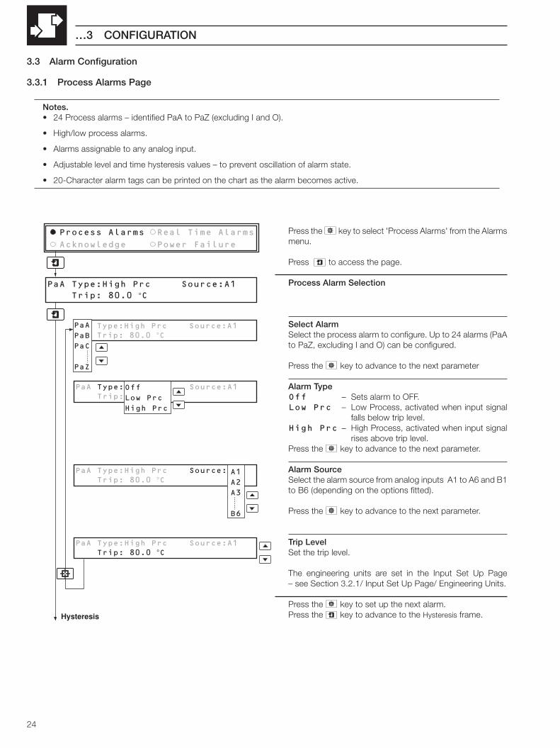
3.3.1 Process Alarms Page
Notes.• 24 Process alarms – identified PaA to PaZ (excluding I and O).
• High/low process alarms.
• Alarms assignable to any analog input.
• Adjustable level and time hysteresis values – to prevent oscillation of alarm state.
• 20-Character alarm tags can be printed on the chart as the alarm becomes active.
Press the key to select 'Process Alarms' from the Alarmsmenu.
Press to access the page.
Process Alarm Selection
Select AlarmSelect the process alarm to configure. Up to 24 alarms (PaAto PaZ, excluding I and O) can be configured.
Press the key to advance to the next parameter
Alarm TypeOff – Sets alarm to OFF.Low Prc – Low Process, activated when input signal
falls below trip level.High Prc – High Process, activated when input signal
rises above trip level.Press the key to advance to the next parameter.
Alarm SourceSelect the alarm source from analog inputs A1 to A6 and B1to B6 (depending on the options fitted).
Press the key to advance to the next parameter.
Trip LevelSet the trip level.
The engineering units are set in the Input Set Up Page– see Section 3.2.1/ Input Set Up Page/ Engineering Units.
Press the key to set up the next alarm.Press the key to advance to the Hysteresis frame.Hysteresis
PaA Type:High PRC Source:A1 Trip: 80.0 'C
PaA Type:High Prc Source:A1 Trip: 80.0 °C
PaA Type:High Prc Source:A1 Trip: 80.0 °C
Process Alarms Real Time Alarms
Acknowledge Power Failure
Off
Low Prc
High Prc
PaA Type:High Prc Source:A1 Trip: 80.0 °C
A1
A2
A3
B6
PaA Type:High Prc Source:A1 Trip: 80.0 °C
PaA
PaB
PaC
PaZ

25
3 CONFIGURATION…
…3.3.1 Process Alarms Page
Hysteresis
Select AlarmSelect the alarm to configure.Press the key to advance to the next parameter.
Setting the Hysteresis ValueSet the hysteresis value in engineering units. The alarm isactivated at the trip level but is only de-activated after thesignal has moved into the safe region by an amount equal tothe hysteresis value.
Use the key to advance to the next parameter.
Setting the Time Hysteresis ValueSet the hysteresis value between 0 and 9999 seconds.The alarm is activated when the input signal has been in analarm condition continously for a time greater than the 'TimeHysteresis' value.The alarm is de-activated as soon as the input signal movesinto the safe region – the time hysteresis value has no effectduring alarm de-activation.
Press the key to set up the next alarm.Press the key to advance to the next frame.
Process Alarm TagSelect the alarm to configure.
Set an alarm description of up to 20 characters – see FrontFold-out.
Press the key to set up the next alarm.Press the key to return to the Alarms menu.
High Process
Low Process
Process Variable
Hysteresis
Hysteresis
Trip Point
Alarm OnAlarm Off
Alarm OnAlarm Off
Output AlarmTrip Point
Alarm On
Alarm OffTime in seconds (s)
TimerStarted
TimerReset
TimerStarted
HysteresisTime
Elapsed
TimerReset
40 00
70 130
Time Hysteresis Status
Time hysteresis set to 70s, with a high process alarm
PaA Process Alarm Tag Alarm A On EDIT #
PaA Hysteresis : 20.0 °C Time Hysteresis : 10 Sec
PaA Hysteresis : 20.0 °C Time Hysteresis : 10 Sec
PaA Hysteresis : 20.0 °C Time Hysteresis : 10 Sec
PaA Hysteresis : 20.0 °C Time Hysteresis : 10 Sec
PaA Process Alarm Tag
EDIT #
PaA
PaB
PaZ
PaA
PaB
PaZ

26
RT1 Real Time Alarm Tag START OF BATCH 1 EDIT #
RT1 Real Time Alarm Tag START OF BATCH 1 EDIT #
RT1 Real Time Alarm Tag
START OF BATCH 1 EDIT #
RT1 Sun Mon Tue Wed Thu Fri Sat :Off: On: On: On: On: On:Off
RT1 Sun Mon Tue Wed Thu Fri Sat :Off: On: On: On: On: On:Off
Process Alarms Real Time Alarms
Acknowledge Power Failure
RT1 Sun Mon Tue Wed Thu Fri Sat : On: On: On: On: On: On:OffOn
Off
RT1 Alarm On Time : 12:00 Alarm Duration:120:00
RT1 Alarm On Time : 12:00 Alarm Duration:120:00
RT1 Alarm On Time : 12:00 Alarm Duration:120:00
RT1 Alarm On Time : 12:00 Alarm Duration:120:00
RT1
RT2
RT3
RT4
RT1
RT2
RT3
RT4
RT1
RT2
RT3
RT4
…3 CONFIGURATION
Press the key to select 'Real Time Alarms' from theAlarms menu.
Press the key to access the page.
Real Time Alarms
Alarm To ConfigureUp to four alarms (RT1 to RT4) can be configured, each withassigned 'On' days, 'On' time and duration.Press the key to advance to the next parameter.
Alarm On DaysSelect which days the alarm is required to be active.Press the key to move between days.Press the key to set up the next alarm.Press the key to advance to the next frame.
Alarm On Time and DurationThe last alarm to be configured is displayed.
Select AlarmSelect the alarm to configure.
Press the key to advance to the next parameter.
Alarm On TimeSet the alarm on time between 00:00 and 23:59.Alternatively, hours can be set to ** allowing the alarm to beactivated at a specific minute each hour.Example – to activate the alarm at 15 minutes past each hourset to **:15
Press the key to advance to the next parameter.Alarm DurationSet the alarm duration between 00:00 and 167:59 (hr:min)
Press the key to set up the next alarm.Press the key to advance to the next frame.
Real Time Alarm TagThe last alarm to be configured is displayed.
Select AlarmPress the and keys to select Alarm Tag to edit.
Real Time Alarm TagPress the key to enter an alarm description of up to 20characters – see Front Fold-out.Press the and keys to set up the next alarm.Press the key to return to the Alarms menu.
3.3.2 Real Time Alarms Page
Notes.• Four programmable real-time alarms.
• Programmable start times and durations.

27
3 CONFIGURATION…
3.3.3 Alarm Acknowledge Page
Notes.• Three operator acknowledge options for Process alarms.
• Global alarm acknowledgement – from internal or external digital source.
Acknowledge Type: Normal Source: None
Acknowledge Type: Normal Source: None
Process Alarms Real Time Alarms
Acknowledge Power Failure
Latch
Normal
None
Acknowledge Type: Normal Source: NoneSee
Table 3.4
Press the key to select 'Acknowledge' from the Alarmsmenu.
Alarm Acknowledge
Acknowledge TypeSelect the type of alarm acknowledge facility required:Latch – Alarm condition is latched and the alarm state
remains active until acknowledged in theOperator Level Alarm Ack Page and the alarmcondition is cleared.
Normal – Alarm state remains active until the conditionis removed. Acknowledge facility available.
None – Alarm state remains active until the conditionis removed. Acknowledge facility notavailable.
Press the key to advance to the next parameter.
Global Acknowledge SourceSelect the source to be used to acknowledge all alarms – seeTable 3.4.
Press the key to return to the Alarms menu.
28
…3 CONFIGURATION
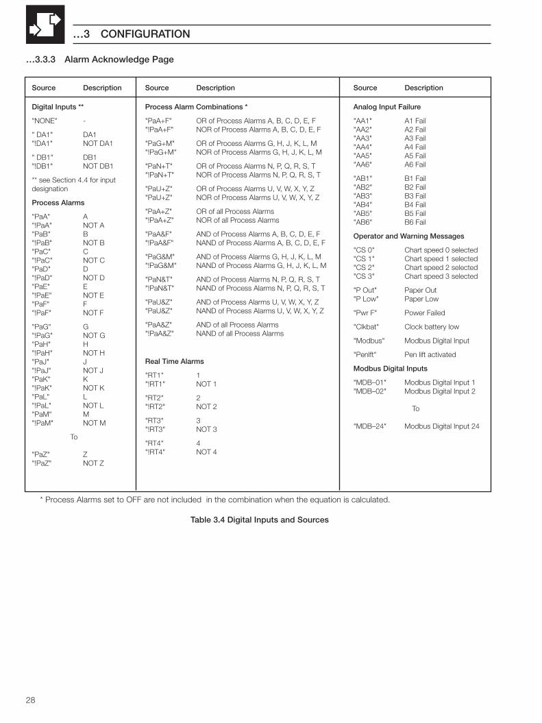
…3.3.3 Alarm Acknowledge Page
Source Description
Process Alarm Combinations *
"PaA+F" OR of Process Alarms A, B, C, D, E, F"!PaA+F" NOR of Process Alarms A, B, C, D, E, F
"PaG+M" OR of Process Alarms G, H, J, K, L, M"!PaG+M" NOR of Process Alarms G, H, J, K, L, M
"PaN+T" OR of Process Alarms N, P, Q, R, S, T"!PaN+T" NOR of Process Alarms N, P, Q, R, S, T
"PaU+Z" OR of Process Alarms U, V, W, X, Y, Z"PaU+Z" NOR of Process Alarms U, V, W, X, Y, Z
"PaA+Z" OR of all Process Alarms"!PaA+Z" NOR of all Process Alarms
"PaA&F" AND of Process Alarms A, B, C, D, E, F"!PaA&F" NAND of Process Alarms A, B, C, D, E, F
"PaG&M" AND of Process Alarms G, H, J, K, L, M"!PaG&M" NAND of Process Alarms G, H, J, K, L, M
"PaN&T" AND of Process Alarms N, P, Q, R, S, T"!PaN&T" NAND of Process Alarms N, P, Q, R, S, T
"PaU&Z" AND of Process Alarms U, V, W, X, Y, Z"PaU&Z" NAND of Process Alarms U, V, W, X, Y, Z
"PaA&Z" AND of all Process Alarms"!PaA&Z" NAND of all Process Alarms
Real Time Alarms
"RT1" 1"!RT1" NOT 1
"RT2" 2"!RT2" NOT 2
"RT3" 3"!RT3" NOT 3
"RT4" 4"!RT4" NOT 4
Source Description
Digital Inputs **
"NONE" -
" DA1" DA1"!DA1" NOT DA1
" DB1" DB1"!DB1" NOT DB1
** see Section 4.4 for inputdesignation
Process Alarms
"PaA" A"!PaA" NOT A"PaB" B"!PaB" NOT B"PaC" C"!PaC" NOT C"PaD" D"!PaD" NOT D"PaE" E"!PaE" NOT E"PaF" F"!PaF" NOT F
"PaG" G"!PaG" NOT G"PaH" H"!PaH" NOT H"PaJ" J"!PaJ" NOT J"PaK" K"!PaK" NOT K"PaL" L"!PaL" NOT L"PaM" M"!PaM" NOT M
To
"PaZ" Z"!PaZ" NOT Z
Source Description
Analog Input Failure
"AA1" A1 Fail"AA2" A2 Fail"AA3" A3 Fail"AA4" A4 Fail"AA5" A5 Fail"AA6" A6 Fail
"AB1" B1 Fail"AB2" B2 Fail"AB3" B3 Fail"AB4" B4 Fail"AB5" B5 Fail"AB6" B6 Fail
Operator and Warning Messages
"CS 0" Chart speed 0 selected"CS 1" Chart speed 1 selected"CS 2" Chart speed 2 selected"CS 3" Chart speed 3 selected
"P Out" Paper Out"P Low" Paper Low
"Pwr F" Power Failed
"Clkbat" Clock battery low
"Modbus" Modbus Digital Input
"Penlft" Pen lift activated
Modbus Digital Inputs
"MDB–01" Modbus Digital Input 1"MDB–02" Modbus Digital Input 2
To
"MDB–24" Modbus Digital Input 24
* Process Alarms set to OFF are not included in the combination when the equation is calculated.
Table 3.4 Digital Inputs and Sources

29
Process Alarms Real Time Alarms
Acknowledge Power Failure
Power Failure Indication :Off
Power Failure Indication :Off
On
Off
3 CONFIGURATION…
3.3.4 Power Failure PageThis page allows the power failure indication to be displayed in the Operator Pages.
Press the key to select 'Power Failure' from the Alarmsmenu.
Power Failure Indication
Select 'On' to enable display of the Power Failure alarm in theAlarm Acknowledge Page and an instrument alarm in theOperating Page.
Press the key to return to the Alarms menu.

30
…3 CONFIGURATION
3.4 Chart Level
3.4.1 Chart Control Page
Notes.• Set up to three independent chart speeds (plus chart speed 0 – stopped) – selectable from the Operating Level or by
digital signal.
• Enable/disable automatic printing of text, enable/disable alarm printing.
• Selectable text print speed, fast or slow.
• Auto pen-drop – returns the pen capsule to an operating state after a 5 minute delay to ensure recording is notinadvertently left disabled.
• 'Easy View' feature – allows quick access of latest printed information.
• 'Time Alignment' feature – allows easy adjustment to the time line.
Table 3.5 Text Printing Options
A1
A3A2
12:00�24–NOV–99�120mm/h
09.30 PaA High Temp.
09.30 PaA High Temp.
A – Continuous trace,no text
B – Continuous trace,text over-writes trace
C – Continuous trace,text breaks trace
E – Dotted trace, no text
D – Dotted trace,text breaks trace
Fig 3.3 Examples of Text /Trace Printing
edoMtnirP)h/mm(deepStrahC
042ot0 005ot142 0051ot105
–A ecartsuounitnoCtxeToN
FFO:tnirpotuAFFO:tnirpmralA
FFO:tnirpotuAFFO:tnirpmralA
––
–B secartsuounitnoCecartsetirwrevotxeT
wolS:deepstnirP –– ––
–C ecartsuounitnoCecartskaerbtxeT
tsaF:deepstnirP tsaF:deepstnirP ––
–D ecartdettoDecartskaerbtxeT
–– –– tsaF:deepstnirP
–E ecartdettoDtxeToN
–– ––FFO:tnirpotuAFFO:tnirpmralA

31
3 CONFIGURATION…
…3.4.1 Chart Control Page
Example.If a chart speed of 120mm/hr is required when digital input DA1 is active, and at all other times, the required chart speed is20mm/hr:
• Set chart speed 1 to 20mm/hr
• Set chart speed 1 source to '!DA1' (NOT DA1)
• Set chart speed 2 to 120mm/hr
• Set chart speed 2 source to 'DA1'
Select chart speed 1 and start recording. When DA1 becomes active the chart speed changes to 120 mm/hr. When DA1 becomesinactive the chart speed returns to 20mm/hr.
CS1 Chart Speed : 20mm/h
Source
CS1 Chart Speed : 20mm/h
Source : None
CS1 Chart Speed : 20mm/h
Source : None
CS1 Chart Speed : 20mm/h
Source : None
Chart Control Pen Alignment
CS0
CS1CS2
CS3
Text Printing
SeeTable 3.4
Press the key to select 'Chart Control' from the Chartmenu.
Press the key to access the page.
Chart Control Page
Selecting the Chart SpeedSelect a chart speed (CS0,CS1,CS2 or CS3).(Chart speed CS0 is preset to 0mm/h and 'Chart Stopped' isprinted on the chart with the Date and Time).
Press the key to advance to the next parameter.
Setting the Chart SpeedSet a speed between 0 and 1500mm/hr.
Note. If the selected chart speed (other than CS0) is set to0mm/hr, then '0mm/h' is printed with the date and time.
Press the key to advance to the next parameter.
Chart Speed SourceSelect the source required to initiate a change to the chartspeed set above – see Section 3.3.3/ Table 3.4.
Press the key to advance to the Text Printing frame.

32
…3 CONFIGURATION
…3.4.1 Chart Control Page
Text Printing
Auto PrintSelect the Auto Print mode required:ON – Enables automatic printing of time/date, chart
speeds, scales and channel Identifiers.OFF – Disables automatic printing.
Press the key to advance to the next parameter.
Alarm PrintSelect 'On' to enable the printing of alarm messages.
Press the key to advance to the next parameter.
Alarm and Operator Message Print SpeedWith chart speeds ≤240mm/h the selections have thefollowing effect:
Fast – Interrupts chart traces to print alarms or operatormessage.
Slow – Prints alarms or operator message during charttraces.
Print speed options:
The print speed for messages in autoprint (i.e. Time, Date,Scales, Chart speed change and Trace Identifiers) ispredefined and cannot be selected, i.e.
Slow ≤ 240mm/HFast > 240mm/H
Trace identifiers are not printed at speeds >240mm/h
Press the key to advance to the Chart Cassette Typeframe.
Auto Print :On Alarm Print:Off
Print Speed:Slow
Auto Print :On Alarm Print:Off
Print Speed:Slow
Auto Print :ON Alarm Print:OFF
Print Speed:Slow
Auto Print :ON Alarm Print:OFF
Print Speed:SlowFast
Slow
Chart Cassette Type
On
Off
On
Off
Parameter to PrintChart Speed (mm/h)
Process Alarms Slow/Fast
FastReal Time Alarms
Scales (Test Print) Fast
Operator Message
1 to 240 241 to 1500
Slow/Fast
Slow/Fast

33
3 CONFIGURATION…
…3.4.1 Chart Control Page
Chart SettingsThe Chart type, length and number of divisions is displayed.
Chart LengthEnter the required chart length in 1m increments. For rollchart cassettes, the standard length is 25m.
Press the key to advance to the next parameter.
Chart DivisionsSelect the number of divisions on the chart width.
Press the key to advance to the next frame.
Chart Functions
Time AlignmentAfter loading a new chart, the Time Alignment functionenables the chart to be advanced to a time line beforecommencing recording.
Select 'Enabled' to display the Time Alignment function inthe Chart Page – see Section 1.1/ Time Alignment.
Press the key to advance to the next parameter.
'Easy View''Easy View' winds the chart forward a small distance to allowthe latest information to be viewed. The chart is thenreturned automatically to the recording position where anybuffered data is printed.
Select 'Enabled' to display the 'Easy View' function in theOperator Page – see Section 2.7.
Note. 'Easy View' only operates with chart speeds of≤120mm/h.
Press the key to advance to the Chart Speed Select frame.
Chart-Type :Roll Chart Length :25m Divisions :80
Chart-Type :Roll Chart
Length :25m Divisions :80
Chart-Type :Roll Chart Length :25m Divisions :5080
100
120
140
150
Time Alignment : Enabled
Easy View : Enabled
Time Alignment : EnabledEasy View : Enabled
Time Alignment :Enabled
Easy View :Disabled
Enabled
Disabled
Enabled
Disabled
Chart Speed Select

34
…3 CONFIGURATION
…3.4.1 Chart Control Page
Chart Speed Select :EnabledPaper Advance :Enable
Chart Speed Select :EnabledPaper Advance :Enabled
Chart Speed Select :Enabled
Paper Advance :Enabled
Pen Lift :EnabledAuto Pen Drop :Enabled
Pen Lift : Enabled
Auto Pen Drop : Enabled
Pen Lift :Enabled
Auto Pen Drop :Enabled
Enabled
Disabled
Enabled
Disabled
Enabled
Disabled
Enabled
Disabled
Chart Settings
Chart Speed SelectSelect 'Enabled' to allow the chart speed to be selected inthe operator pages.
Press the key to advance to the next parameter.
Paper AdvanceSelect 'Enabled' to allow the chart to be wound forwardmanually in the operator pages.
Press the key to advance to the next frame.
Pen Lift/Drop Settings
Pen LiftSelect 'Enabled' to allow use of the key on the front panel(Pen lift).
Press the key to advance to the next parameter.
Auto Pen DropThe Auto Pen Drop facility returns the pen capsule to anoperating state approximately five minutes after the pen lifthas been activated.
Select 'Enabled' to activate the Auto Pen Drop facility.
Press the key to return to the Chart menu.

35
3 CONFIGURATION…
3.4.2 Pen Alignment Page
Notes.• Allows accurate adjustment of pen position on the chart.
• Can be used to remove the effect of inconsistencies in chart manufacture.
Press the key to select 'Pen Alignment' from the Chartmenu.
Press the key to access the page.
Pen Alignment SettingsOn accessing the Pen Alignment Page…
…is displayed momentarily.
Set Pen ZeroWhen the Pen Alignment Page is selected the chart isadvanced at 'fast' speed and the magenta pen marks thechart at its zero position.
Use the and keys to adjust the pen to the zeroposition. A 'Set Zero' displacement figure between –10 and+10 is displayed.
Press the key to advance to the next parameter.
Set Pen SpanThe chart continues to advance at 'fast' speed and the penmoves to its full scale position.
Use the and keys to adjust the pen to the full scaleposition. A 'Set Span' displacement figure between –10 and+10 is displayed.
Press the key to return to the Chart menu…
…is displayed momentarily and the time that recording wasstopped is printed on the chart.
Press the key to return to the Chart menu.
Pen AlignmentSet Zero : +7 Set Span : +9
Pen AlignmentSet Zero : +7 Set Span : +9
Pen Alignment
Set Zero : +7 Set Span : +9
Chart Control Pen Alignment
Recording Stopped
Recording Restarted

36
…3 CONFIGURATION
3.5 Output Modules
Notes.• Module types – 3 Relay, 6 Relay, Transmitter PSU or Modbus serial communications.
• Automatic detection of module type fitted.
• Programmable sources and polarity of relay outputs.
Pos'n E(6Rly) Pos'n F(None) Pos'n G(MBus)
Pos'n E(6Rly) Pos'n F(None) Pos'n G(MBus)
(None)
(3Rly)
(6Rly)
(Txps)(MBus)
E1 Relay O/P- Source: PaA Polarity:Positive
E1 Relay O/P- Source: PaA Polarity:PositiveE1
E6
E1 Relay O/P- Source: PaA Polarity:Positive
E1 Relay O/P- Source: PaA Polarity:PositivePositive
Negative
SeeTable 3.4
Select Module PositionPress the key to select the module to be configured.
The type of module fitted in each position is displayedautomatically:None – No module fitted (No configuration required).3Rly – 3-relay outputs.6Rly – 6-relay outputs.Txps – Transmitter PSU (No configuration required).MBus – Modbus serial communications
– see IM/SR250–MOD
Press the key to configure the module selected .
Relay Output Module
Select Relay OutputSelect the relay output to be configured (1 to 3 or 1 to 6,depending on the module fitted).
Press the key to advance to the next parameter.
Select Output SourceSelect the source which activates the relay output– see Section 3.3.3/ Table 3.4.
Press the key to advance to the next parameter.
Select Output PolarityThe relay output can be set to energize for either an active orin-active digital signal:Positive – If source is active, relay is energized.Negative – If source is inactive, relay is energized.
Press the key to set up the next relay output.Press the key to return to the Modules menu.
37
3 CONFIGURATION…
3.6 Operator Set Up
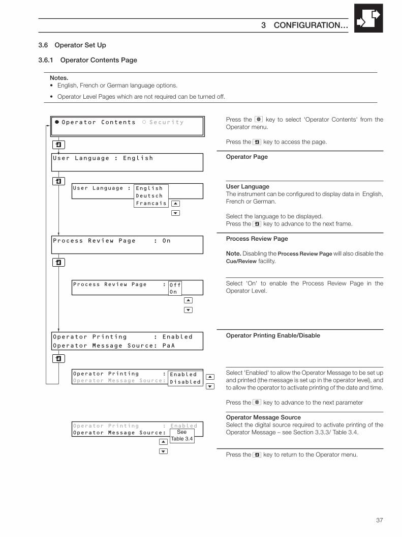
3.6.1 Operator Contents Page
Notes.• English, French or German language options.
• Operator Level Pages which are not required can be turned off.
Press the key to select 'Operator Contents' from theOperator menu.
Press the key to access the page.
Operator Page
User LanguageThe instrument can be configured to display data in English,French or German.
Select the language to be displayed.Press the key to advance to the next frame.
Process Review Page
Note. Disabling the Process Review Page will also disable theCue/Review facility.
Select 'On' to enable the Process Review Page in theOperator Level.
Operator Printing Enable/Disable
Select 'Enabled' to allow the Operator Message to be set upand printed (the message is set up in the operator level), andto allow the operator to activate printing of the date and time.
Press the key to advance to the next parameter
Operator Message SourceSelect the digital source required to activate printing of theOperator Message – see Section 3.3.3/ Table 3.4.
Press the key to return to the Operator menu.
User Language : English
User Language : English
Operator Contents Security
Operator Printing : EnabledOperator Message Source: PaA
English
Deutsch
Francais
Operator Printing : Enabled
Operator Message Source: PaA
Operator Printing : EnabledOperator Message Source: PaA
Enabled
Disabled
SeeTable 3.4
Process Review Page : On
Process Review Page : ONOffOn

38
…3 CONFIGURATION
3.6.2 Security PageThis page is used to set the security codes for access to chart loading and configuration functions.
Press the key to select 'Security' from the Operatormenu.
Press the key to access the page.
Set Level 1 Security CodeThe Level 1 Security Code allows access to the Chart Page.
Set the code to any number between 0000 and 9999.(Setting 0000 disables the security and allows unrestrictedaccess to Level 1).
Press the key to advance to the next parameter.
Set Level 2 Security CodeThe Level 2 Security Code allows access to the Chart Pageand the Process Review Page.
Set the code to any number between 0000 and 9999.(Setting 0000 disables the security and allows unrestrictedaccess to Levels 1 and 2).
Press the key to advance to the next frame.
Set Configuration Level Security CodeThe Configuration Security Code allows access to Level 1,Level 2 and the Configuration Level.
Set the code to any number between 0000 and 9999.(Setting 0000 disables the security and allows unrestrictedaccess to all levels).
Press the key to return to the Operator menu.
Level 1 Security Code 4321
Level 2 Security Code 0001
Level 1 Security Code 0001
Level 2 Security Code 0002
Operator Contents Security
Configuration Security Code 0003
Configuration Security Code 1234
Level 1 Security Code 4321
Level 2 Security Code 6789
Fig. 3.4 Security Codes
SECURITYACCESS CODE
CHARTPAGE
No Setting (0000)
Level 1 Security Code
Level 2 Security Code
Configuration LevelSecurity Code
PROCESS REVIEWPAGE
CONFIGURATIONLEVEL

39
4 INSTALLATION
Fig. 4.2 Environmental Requirements
EC Directive 89/336/EECIn order to meet the requirements of the EC Directive 89/336/EEC for EMC regulations, this product must not be used in anon-industrial environment.
CleaningClean the front panel only, using warm water and a mild detergent.
Warning. Before making any connections, ensure that the power supply, any powered control circuits and highcommon mode voltages connected to the instrument are switched off.
4.1 Siting – Figs. 4.1 and 4.2
A – Close to Sensor
B – At Eye-level Location
C – Avoid Vibration
SensorCOMMANDER PR250
Keep tominimumdistance
COMMANDER PR250
COMMANDER PR250
Fig. 4.1 General Requirements
A – Within Temperature Limits
B – Within Humidity Limits
D – Use Screened Cable
C – Environmental Limits
+COMMANDER PR250
0 to 95% RH
15 to 80% RH (0 to 40°C)
COMMANDER PR250
25 to 80% RH (40 to 50°C)
COMMANDER PR250
IP65 frontIP40 rear (with extension)IP20 rear (without extension)
0ºC32ºFMin.
50ºC122ºFMax.
COMMANDER PR250
Warning. Select a location away fromstrong electrical and magnetic fields. If this isnot possible, particularly in applications wheremobile communications equipment isexpected to be used, screened cables withinearthed metal conduit must be used.

40
…4 INSTALLATION
4.2 Mounting – Figs. 4.3 and 4.4
Fig. 4.3 Overall Dimensions
Dimensions in mm (in.)
24.15(0.95)
220.35 (8.67)
COMMANDER PR250
147(5.78)
326.8(12.87)
Panel Cut-out
30 (1.2)
302.8+0.8–0.0
(5.43 )+0.03–0.0
138 +0.8–0.0
(11.92 )+0.03–0.0
153.4(6.03)
230 (9.0)
39.80(1.57)*
*terminal compartment extension
Note. Maximum mountingangle 30° from vertical.

41
4 INSTALLATION…
…4.2 Mounting – Figs. 4.3 and 4.4
Note. For IP65 protection, a minimum panel thickness of 3mm (0.12 in.) is recommended.
Fig. 4.4 Mounting
Warning. The clamp must fit flat on the instrument casing. If the clamp is bowed,the securing screw is overtight and sealing problems may occur.
4 Remove the panel clamps
5 Insert the instrumentinto the panel cut-out
Cut a hole in the panel(see Fig. 4.3 for dimensions)
1
Lift the retaining screws and removethe panel clamp anchors
Refit the panel clamps to the case, ensuring that the panelclamp anchors are located correctly in their slots
6
7 Secure the instrument by tightening thepanel clamp retaining screws
Loosen the retaining screwon each panel clamp2
3
Note. The portable case is supplied with the panel hole already cut, otherwise the fittingprocedure is the same.

42
…4 INSTALLATION
4.3 Access to Terminals and Connections – Fig. 4.5
Fig. 4.5 Access to Terminals
Note. The terminal compartment extension used for anchoring cable conduits is an optional fitting.
Remove screws
Remove the backplate
Relay Outputs, Hybrid or 2-wireTransmitter DC Power Supply (E, F or G)
Power Supply
Standard AnalogInput Connector
Earth (Ground)Stud
AC Power SupplyEarth (Ground) Stud
1
2
Optional AnalogInput Connector

43
Warnings.• The instrument is not fitted with a switch therefore a disconnecting device such as a switch or circuit breaker conforming
to local safety standards must be fitted to the final installation. It must be fitted in close proximity to the instrument withineasy reach of the operator and must be marked clearly as the disconnection device for the instrument.
• Remove all power from supply, relay and any powered control circuits and high common mode voltages before accessingor making any connections.
• Use cable appropriate for the load currents. The terminals accept cables up to 14AWG (2.5mm2).
• The instrument conforms to Mains Power Input Insulation Category II. All other inputs and outputs conform to Category II.
• All connections to secondary circuits must have basic insulation.
• After installation, there must be no access to live parts e.g. terminals.
• Terminals for external circuits are for use only with equipment with no accessible live parts.
• If the instrument is used in a manner not specified by the Company, the protection provided by the equipment may beimpaired.
• All equipment connected to the instrument's terminals must comply with local safety standards (IEC 60950, EN601010-1).
Notes.• Always route signal leads and power cables separately, preferably in earthed (grounded) metal conduit.
• It is strongly recommended that screened cable is used for signal inputs and relay connections. Connect the screen to theearth (ground stud) – see Fig. 4.6.
• Replacement of the internal battery (Varta type CR1/2AACD or Saft LS3CNA 3.6V lithium cell) must be carried out by anapproved technician only.
4.4 Electrical Connections – Fig 4.6
4 INSTALLATION…

44
…4 INSTALLATION
...4.4 Electrical Connections – Fig. 4.6
Warning. The AC power supply earth (ground) cable must be connected to the earth (ground) stud .
Fig. 4.6 Electrical Connections
Instrument viewed from
A B E F G H Power Supply(Section 4.8 )
LN
+–
+24V0V
LineNeutral
24V a.c./d.c.
+–
2-wire TransmitterPower Supply (45mA)
H
85V min.to 265V max. AC
12345678
2-wire Transmitter Power Supply(Section 4.5.6)
E, F or G
+24V
0V
+24V
0V
1234567891011121314151617181920
+–3rd lead RTD+–3rd lead RTD+–3rd lead RTD+–3rd lead RTD+–3rd lead RTD+–3rd lead RTDDigital Input DA1 or DB10V
Analog Input(Section 4.5 )
A or B
A1A2A3A4A5A6A7A8A9A10A11A12A13A14A15A16A17A18A19A20
Analog Input A1
Analog Input A2
Analog Input A3
Analog Input A4
Analog Input A5
Analog Input A6
Relay Output(Section 4.7 )
NCNOCNCNOCNCNOC
NCNOCNCNOCNCNOC
Relay 1
Relay 2
Relay 3
Relay 4
Relay 5
Relay 6
E or F
1234567891011121314151617181920
AC Power SupplyEarth (Ground) Stud

45
4.5 Analog Input Connections – Fig. 4.7
4.5.2 Thermocouple – Fig. 4.7Use the correct compensating cable between the thermocoupleand the terminals – see Table 4.1.
Automatic cold junction compensation (ACJC) is incorporatedbut an independent cold (reference) junction may be used.
4.5.3 Resistance Thermometer (RTD) – Fig. 4.7On applications requiring long leads it is preferable to use a3-lead resistance thermometer.
If 2-lead resistance thermometers are used, each input must becalibrated to take account of the lead resistance.
4.5.1 Current and Voltage – Fig 4.7
Warning.• To avoid damage to multi–channel instruments,
highcommon mode voltages up to 250V r.m.s. max.must be present on all channels, or not at all.
• The maximum channel–to–channel voltage(between any two channels) must not exceed 12.5Vor permanent damage to the instruments inputcircuitry may occur. To prevent such damage link thenegative terminals on all inputs. For applicationswhere the available 12.5V isolation is required, thislink should not be fitted.
Fig. 4.7 Analog Input Connections
Note. Refer also to Fig. 4.6 for terminal numbers.Warning. Under no circumstances mustthe spare input terminal be linked to the negative.
elpuocomrehTfoepyT
elbaCgnitasnepmoC
3481SB 1.69CMISNA 41734NID 03.oNtraP7394SB
+ – esaC + – esaC + – esaC + – esaC
)K(lA-iN/rC-iN nworB eulB deR wolleY deR wolleY deR neerG neerG neerG etihW neerG *)E(iN-uC/rC-iN –– –– –– teloiV etihW teloiV *)N(lisiN/lisirciN egnarO eulB egnarO egnarO deR egnarO –– kniP etihW kniP *
)SdnaR(hR-tP/tP etihW eulB neerG kcalB deR neerG deR etihW etihW egnarO etihW egnarO *)B(hR-tP/hR-tP –– – – yerG etihW yerG *
)T(iN-uC/uC etihW eulB eulB eulB deR eulB deR nworB nworB nworB etihW nworB *)J(noC/eF wolleY eulB kcalB etihW deR kcalB deR eulB eulB kcalB etihW kcalB *
* stiucricefasyllacisnirtnirofeulBesaC
)01734NID(noC/eF –– ––01734NID
––der/eulB eulB eulB
Table 4.1 Thermocouple Compensating Cable
+–
A – Voltage
+
–
10Ω Resistorsupplied inaccessory pack– see Note.
B – Current C – Thermocouple
Each lead must be of equalresistance and less than 10Ω
D – 3-lead RTD
SleevedLink
E – 2-lead RTD(and resistance)
+–3rdLead
WhiteRedRed
+–3rdLead
WhiteRed
+
–
See Fig. 4.9 forposition of inputlink
4 INSTALLATION…

46
…4 INSTALLATION
4.5.4 Accessing the Analog Input Links – Fig. 4.8To gain access to the analog input links the chassis must be removed.
Fig. 4.8 Removing the Chassis
4.5.5 Setting Analog Input links – Fig. 4.9The analog inputs must be set up for the input type required.
Warning. Static electricity can seriously damage components. Wear anearth strap and/or use an anti-static bench when dismantling the instrument.
3 Set link positions forinput types required
Remove the tie-bar1
2 Remove the Input PCB
Standardi.e. mV
mAΩTHCRTD
Voltage
2
Fig. 4.9 Selecting the Analog Input Type
Open the door
…and liftthe display
Press thelower catch…
Lift the upper catch…
…and remove thechart unit
Remove the chassis1
2
3
4
5
6

47
Notes.• The maximum total combined current flowing
through the relays is 36A. The maximumindividual relay current is 5A.
• The polarity is set in the Configuration Level – seeSection 3.5/ Output Modules/ Output Polarity.
/ x x x 3 xx
24V AC/DCSupply
Code LabelFuse+–
AC or DC
Terminal Block H
345
/ x x x 2 xx
ACSupply
Code LabelLineNeutral
FuseTerminal Block H
123
85V min. – 265V max.50/60 Hz
Fig 4.10 Transmitter Power Supply
+
–
+
–
+–
2-wire Transmitter Power Supply(24V DC, 45mA max.)Analog Input
10Ω Shunt
Tx
Fig. 4.11 Digital Input
Input State
Dxx active!Dxx in-active
Switch Input(volt-free)
or
or
5V
0V
Logic Input(TTL)
Logic State
Dxx in-active!Dxx active
4.5.6 Transmitter Power SupplyConnections – Fig. 4.10
Note. The power supply board provides a 24V supplycapable of driving two 2-wire transmitters. Twoadditional 24V power supplies are provided on thetransmitter power supply module boards, each ofwhich is capable of driving two 2-wire transmitters.
Digital Output
CommonLoad
Fig. 4.12 Output Connections
Warning.Use fuse rating – 1A (max.) type T
Fig. 4.13 AC Mains
Warning.Use fuse rating – 3A (max.) type T
Fig. 4.14 24V AC/DC Supply
4.6 Digital Input Connections – Fig 4.11A digital input is provided on each input board.
4.7 Relay Output Connections – Fig. 4.12
4.8 Power Supply Connections
4.8.1 AC Mains Connections – Fig. 4.13
4.8.2 24V AC/DC Supply Connections – Fig. 4.14
4 INSTALLATION…

48
5.1 Consumables
Item Part No.
Roll Chart80 division PR250–9007R100 division PR250–9006R120 division PR250–9008R140 division PR250–9009R150 division PR250–9010R
Pen Capsule
Six color PR100–0211Six color (high temperature) PR100–0230
5 SPARES LIST

49
A
A.C. Mains.........................................46Alarms
Acknowledging ......... 11, 12, 27, 28Configuring ............................. 24, 26Hysteresis .....................................25Instrument Alarm .................... 11, 12Message Print Speed ....................32Print ...............................................32Process ......................................... 11Real-time ................................ 11, 26State .............................................. 11Tag ................................................25Type ..............................................24
Analog Inputs ....................................16Adjusting .......................................22Calibrating .....................................22Configuring ....................................16Connections ........................... 43, 44Copying .........................................21Electrical Input Range ...................17Engineering (Display) Range ........18Engineering Display Value ............18Engineering Units ..........................18Fine Tuning ...................................22Input Filter .....................................20Input Type .............................. 17, 45Line Filter ......................................21Links ..............................................45Offset Adjustment ................... 22, 23Span Adjustment ...........................22
Auto Print ..........................................32Autoscroll ............................................7
B
Broken Sensor Drive .........................19
C
CalibrationAnalog Inputs ................................22
ChartAutomatic rewind ............................4Control Page .................................30Divisions ........................................33Format ...........................................14Length ...................................... 9, 33Settings .........................................33Speed
Selecting ...................................34Setting .......................................31Source .......................................31
Time Alignment ........................ 4, 33Clock
Setting .............................................9Viewing ............................................9
…C
ConfigurationAlarms ...........................................24Analog Inputs ................................17Chart .............................................31Operator Page ..............................37Output Modules .............................36Overview – See Back Fold-out
Configuration Level Security Code ...38Connections ........................ 42, 43, 46Cue and Review ................................13Cue/Review
Enabling ........................................37Operating ......................................13
D
D.C. Supply Connections ..................46Date and Time Setting ........................9Digital Input Connections ..................46
E
Easy View .................................. 10, 33Electrical Connections
AC Mains.......................................46Current and Voltage ......................44DC Supply .....................................46Digital Input ...................................46Power Supply ................................46Relay Output .................................46Resistance Thermometer (RTD) ...44Thermocouple ...............................44Transmitter Power Supply .............46
Error MessagesChart Paper Low ...........................12Power Failure ................................12Start-up ...........................................8
F
Fault Detection Level ........................19Filters
Input Filter .....................................20Mains/Line Filter ............................21
I
Inputs – See Analog InputsInstrument Alarms ...................... 11, 12
L
Language Selection ..........................37Linearizer Type ..................................17
M
Mounting ...........................................40
O
Operating Displays ..............................7Operator Level Overview – See Back
Fold-outOperator Messages ..........................10Operator Printing ...............................37Output Modules .................................36
P
Paper Advance ..................................34Pen
Alignment ......................................35Capsule Fitting ................................6Lift/Drop.........................................34Span ..............................................35Zero ...............................................35
Power Failure Page ..........................29Power Supply Connections ...............46Power-up Displays ..............................8Process Alarms
Acknowledging ..............................12Alarm Tag ......................................25Trip Level .......................................24
Process Review ......................... 13, 37
R
Real Time AlarmsAcknowledging ..............................12Configuring ....................................26Viewing .......................................... 11
Relay Output Connections ................46Relay Output Module ........................36Resistance Thermometer (RTD) 17, 44
S
Scale Print .........................................20Security Access
Entering Security Codes ... 3, 13, 15Set Up – See ConfigurationSiting .................................................39
T
Terminals and Connections ...............42Text Printing ......................................32Thermocouple ...................................44Time Alignment ............................ 4, 33Time and Date Setting ........................9Transmitter Power Supply .................46
V
ViewingDate and Time.................................9Measured Values ............................8
W
Warning Messages .............................7
INDEX

50
NOTES

51
NOTES...

52
...NOTES

OPERATOR LEVEL OVERVIEW
If no alarms present
* Only displayed if enabled– see Section 3.6.1/Operator Page/Process Review Frame
CHARTPAGE
• Channel reading, tag & units • Remaining chart• System date & time • Operator message• Chart speed
000.0OPERATING DISPLAYS (Section 2.1)
Operator LevelAlarm Acknowledge Page
• Displays all active alarms.• Individual/global process alarm acknowledge
ALARM PAGES (Section 2.8)
• Protected access to:Chart pageConfiguration level
Security Access Code : 1234
SR250/2000 Iss 1
SECURITY ACCESS (Section 2.9)
• Chart reload • Time line advance• Automatic/manual rewind • Advance chart
OPERATOR LEVELChart Page
CHART PAGE (Section 1.1)
OPERATOR LEVELProcess Review Page
PROCESS REVIEW PAGE (Section 2.10)
• Cue and Review
Select level /
• Analog input configuration • Chart control• Alarm configuration • Operator Set-up• Output module configuration
CONFIGURATION (see overleaf)
ALARMPAGES
OPERATINGDISPLAYS
SECURITYACCESS
* PROCESSREVIEW PAGE

Operator Contents Security
SELECT LEVEL /
OperatorAnalog inputsAlarmsChartOutput ModulesOperator Set-up
Process Alarms Real Time Alarms
Acknowledge Power Failure
Pos'n E(6Rly) Pos'n F(3Rly) Pos'n G(MBus)
Input Set Up Input Copy
Line Filter Input Adjust
Chart Control Pen Alignment
• Input typeLinearizer typeElectrical limitsEngineering limits/unitsChannel tagPen action onchannel failureInput signal filter
• Process alarmsType, source,Trip level, hysteresisAlarm tag
• Acknowledge type,source
• Chart speed set-upText printing controlChart typeChart advance controlEasy view enable
• User language set-upOperator messagecontrol
• Power supply filter
• Copy input configuration
• Channel offsetChannel span adjust
• Pen lift/drop controlPen alignmentPen zero/span
• Real-time alarmsAlarm 'on' day, timeAlarm durationAlarm tag
• Power failure
• Relay outputsSource, polarity
• MODBUS (optional)
• Security Code set-up
(Section 3.2)
(Section 3.3)
(Section 3.4)
(Section 3.5)
(Section 3.6)
CONFIGURATION LEVEL OVERVIEW

PRODUCTS & CUSTOMER SUPPORT
ProductsAutomation Systems
• for the following industries:– Chemical & Pharmaceutical– Food & Beverage– Manufacturing– Metals and Minerals– Oil, Gas & Petrochemical– Pulp and Paper
Drives and Motors• AC and DC Drives, AC and DC Machines, AC Motors to 1kV• Drive Systems• Force Measurement• Servo Drives
Controllers & Recorders• Single and Multi-loop Controllers• Circular Chart and Strip Chart Recorders• Paperless Recorders• Process Indicators
Flexible Automation• Industrial Robots and Robot Systems
Flow Measurement• Electromagnetic Flowmeters• Mass Flow Meters• Turbine Flowmeters• Flow Elements
Marine Systems & Turbochargers• Electrical Systems• Marine Equipment• Offshore Retrofit and Refurbishment
Process Analytics• Process Gas Analysis• Systems Integration
Transmitters• Pressure• Temperature• Level• Interface Modules
Valves, Actuators and Positioners• Control Valves• Actuators• Positioners
Water, Gas & Industrial Analytics Instrumentation• pH, Conductivity and Dissolved Oxygen Transmitters and Sensors• Ammonia, Nitrate, Phosphate, Silica, Sodium, Chloride, Fluoride,
Dissolved Oxygen and Hydrazine Analyzers• Zirconia Oxygen Analyzers, Katharometers, Hydrogen Purity and
Purge-gas Monitors, Thermal Conductivity
Customer Support
We provide a comprehensive after sales service via a WorldwideService Organization. Contact one of the following offices fordetails on your nearest Service and Repair Centre.
United KingdomABB LimitedTel: +44 (0)1480 475321Fax:+44 (0)1480 217948
United States of AmericaABB Inc.Tel: +1 215 674 6000Fax:+1 215 674 7183
Client Warranty
Prior to installation, the equipment referred to in this manual mustbe stored in a clean, dry environment, in accordance with theCompany's published specification.
Periodic checks must be made on the equipment's condition. Inthe event of a failure under warranty, the following documentationmust be provided as substantiation:
1. A listing evidencing process operation and alarm logs at time offailure.
2. Copies of all storage, installation, operating and maintenancerecords relating to the alleged faulty unit.

IM/S
R25
0BIs
sue
4
The Company’s policy is one of continuous productimprovement and the right is reserved to modify the
information contained herein without notice.
Printed in UK (03.06)
© ABB 2006
ABB has Sales & Customer Supportexpertise in over 100 countries worldwide
www.abb.com
ABB Inc.125 E. County Line RoadWarminsterPA 18974USATel: +1 215 674 6000Fax: +1 215 674 7183
ABB LimitedHoward Road, St NeotsCambridgeshirePE19 8EUUKTel: +44 (0)1480 475321Fax: +44 (0)1480 217948