
COMMANDER CR100 User Guide Multipoint Chart Recorder · PDF file ·...
36
User Guide COMMANDER CR100 Multipoint Chart Recorder COMMANDER CR100 654.65
Transcript of COMMANDER CR100 User Guide Multipoint Chart Recorder · PDF file ·...

User GuideCOMMANDER CR100Multipoint Chart Recorder
COMMANDER CR100
654.65

ABB
Note.Clarification of an instruction or additional information.
Information.Further reference for more detailed information ortechnical details.
Although Warning hazards are related to personal injury, and Caution hazards are associated with equipment or property damage,it must be understood that operation of damaged equipment could, under certain operational conditions, result in degradedprocess system performance leading to personal injury or death. Therefore, comply fully with all Warning and Caution notices.
Information in this manual is intended only to assist our customers in the efficient operation of our equipment. Use of this manualfor any other purpose is specifically prohibited and its contents are not to be reproduced in full or part without prior approval of theMarketing Communications Department.
The Company
We are an established world force in the design and manufacture of instrumentation forindustrial process control, flow measurement, gas and liquid analysis and environmentalapplications.
As a part of ABB, a world leader in process automation technology, we offer customersapplication expertise, service and support worldwide.
We are committed to teamwork, high quality manufacturing, advanced technology andunrivalled service and support.
The quality, accuracy and performance of the Company’s products result from over 100 yearsexperience, combined with a continuous program of innovative design and development toincorporate the latest technology.
The NAMAS Calibration Laboratory (No. 0255) is just one of ten flow calibration plantsoperated by the Company, and is indicative of our dedication to quality and accuracy.
BS EN ISO 9001
Cert. No. Q5907
Stonehouse, U.K.
EN 29001 (ISO 9001)
Lenno, Italy – Cert. No. 9/90A
Use of Instructions
Warning.An instruction that draws attention to the risk of injury ordeath.
Caution.An instruction that draws attention to the risk of damage tothe product, process or surroundings.
Health and SafetyTo ensure that our products are safe and without risk to health, the following points must be noted:
1. The relevant sections of these instructions must be read carefully before proceeding.
2. Warning labels on containers and packages must be observed.
3. Installation, operation, maintenance and servicing must only be carried out by suitably trained personnel and in accordance with theinformation given.
4. Normal safety precautions must be taken to avoid the possibility of an accident occurring when operating in conditions of high pressureand/or temperature.
5. Chemicals must be stored away from heat, protected from temperature extremes and powders kept dry. Normal safe handling proceduresmust be used.
6. When disposing of chemicals ensure that no two chemicals are mixed.
Safety advice concerning the use of the equipment described in this manual or any relevant hazard data sheets (where applicable) may beobtained from the Company address on the back cover, together with servicing and spares information.
REGISTERE
D
0255

1
GETTING STARTED
Symbol Identification and Section Contents
This manual is divided into 5 sections which contain all theinformation needed to install, configure, commission andoperate the Recorder. Each section is identified clearly by asymbol as shown below.
PageFRONT PANEL, PENS AND CHARTS 3• Function Keys 3
• LED Alarms and Indicators 5
• Error Messages 6• Charts and Pens 7
OPERATOR MODE 11• Operator Menus for
— Auto Scroll Mode 11— Manual Scroll Mode 12
SET UP MODE 13• Alarm Trip Points 14
• Chart Speed 15
• Offset Adjustment 16
• Pen Calibration 16
CONFIGURATION MODE 17• LEVEL 3
— Input 1 Configuration 18
— Alarm Setting 20
— Hardware Configuration 22
— Input 2 Configuration 23
• LEVEL 4— Ranges and Passwords 24
INSTALLATION 27• Siting 27
• Mounting 28
• Electrical Connections 29
8
123&
CONTENTS
1 FRONT PANEL, PENS & CHARTS ................................ 21.1 Introduction ............................................................. 21.2 Use of Function Keys .............................................. 31.3 LED Alarms and Indicators ..................................... 41.4 Error Messages ...................................................... 51.5 Fitting Charts & Pens .............................................. 6
1.5.1 Removing/Refitting a Chart Unit .................. 61.5.2 Fitting a Fanfold Chart ................................. 71.5.3 Fitting a Roll Chart ....................................... 81.5.4 Fitting a Pen Cartridge ................................ 9
2 OPERATOR MODE ....................................................... 102.1 Introduction ........................................................... 102.2 Operating Page (Level 1) – Auto Scroll Mode ...... 102.3 Operating Page (Level 1) – Manual Scroll Mode .. 11
3 SET UP MODE 123.1 Introduction ........................................................... 123.2 Set Up Level (Level 2) .......................................... 13
4 CONFIGURATION MODE............................................. 164.1 Introduction ....................................................... 164.2 Input, Hardware & Alarms Configuration (Level 3) 17
4.2.1 Input 1 Configuration ................................. 174.2.2 Alarms Configuration ................................. 194.2.3 Hardware Configuration ............................ 214.2.4 Input 2 Configuration .................................. 22
4.3 Ranges and Passwords (Level 4) ......................... 23
5 INSTALLATION .......................................................... 265.1 Siting .................................................................. 265.2 Mounting ............................................................... 275.3 Electrical Connections .......................................... 285.4 Relays, Arc Suppression and Output .................... 28
5.4.1 Relay Contact Ratings............................... 285.4.2 Arc Suppression Capacitors ...................... 285.4.3 Retransmission Analog Output .................. 28
5.5 Spares and Consumables .................................... 28
CUSTOMER SETUP LOG .................................................. 31
CUSTOMER CONFIGURATION LOG ................................ 32

2
Information.
Pages 31 and 32 of this manual show all the frames in the programming levels. Space is provided on the page for writing theprogrammed setting or selection for each frame.
1.1 Introduction – Fig. 1.1The Instrument front panel display, function keys and LED indicators are shown in Fig. 1.1.
Fig. 1.1 Front Panel Display, Function Keys and Indicators
1 FRONT PANEL, PENS & CHARTS
Alarm LEDs
Channel 2 LED 888888A1
A2
A3
A4
1
2
Function Keys
Raise Lower ParameterAdvance
Multi-functionKey
Pen-lift Chart SpeedSelection
Channel 1 LED

3
Fig. 1.2 Use of Function Keys
1.2 Use of Function Keys – Fig. 1.2
1 FRONT PANEL, PENS & CHARTS…
A – Raise and Lower Keys
+
–Use to change/set a parameter value…
or…
100.0 100.1
99.9
…move between levels
LEVEL1
LEVEL2
B – Parameter Advance Key
Frame 1(top of level)
Frame 2
Use to advance to the nextframe within a level…
LEVEL1
2145.3
LEVELx 2145.3 240.2 SPEEd COdE
Press andhold
or…
…select the top (LEVEL) framefrom within a level
Note. This key also stores any changes made in the previous frame
C – Multi-function Key
CodE
0
Use to view a parameter setting or selection…
A_6000
…select individual characters in a frame
or…
D – Pen Lift Key
Lifts/lowers pens on alternate operations
E – Chart Speed Selection Key
Selects one of the pre-configured chart speeds

4
Fig. 1.3 LED Alarms and Indicators
…1 FRONT PANEL, PENS & CHARTS
1.3 LED Alarms and Indicators – Fig. 1.3
Alarm 1Alarm 2Alarm 3Alarm 4
Channel 2 LED 888888A1
A2
A3
A4
1
2
Channel 1 LED
LED Status
All Alarm LEDs (and one or both channel identification LEDs in 2-pen instruments) flashing• Recorder is in the configuration mode – see section 4
Alarm LEDs A1, A2, A3 and A4• Flashing – the associated alarm is active (off when inactive)• Lit constantly – the associated alarm is an active latch alarm which has been acknowledged
Channel Identification LED's 1 or 2• Indicates to which channel the display information is applicable
(channel identification LED's are applicable only to 2-pen instruments)

5
* 2-pen recorder only.
Display Error/Action
Calibration ErrorTurn main power off and on again(if the error persists contact theService Organization).
Configuration ErrorThe configuration and/or setup datafor the instrument is corrupted. Turnmain power off and on again (if thee r ro r pe rs i s t s check theconfiguration/setup settings).
A to D Converter FaultThe analog to digital converter isnot communicating correctly forinput 1.
A to D Converter FaultThe analog to digital converter isnot communicating correctly forinput 2.
Process Variable Over/UnderRange
Press the key.
Press the key.
Turn power off and on again.If the error persists contactthe Service Organization.
Turn power off and on again.If the error persists contactthe Service Organization.
Restore valid input.
To Clear Display
CAL.Err
CFG.Err
A.d1.Err
A.d2.Err
9999
*
1 FRONT PANEL, PENS & CHARTS…
1.4 Error Messages

6
1
2
34
56
7Fig. 1.4 Fitting the Chart Unit
…1 FRONT PANEL, PENS & CHARTS
1.5 Fitting Charts & Pens
1.5.1 Removing/Refitting a Chart Unit – Fig. 1.4
Operate the key to lift the pen(s). Referring to Fig. 1.4:
1 Open the door.
Note. Items 2 and 3 must be carried out simultaneously.
2 Press the chart latch and…
3 Using the chart grip, swing the chart unit outwards and upwards through 90°.
4 Pull to remove the chart unit from the chassis.
Note. Before refitting the chart unit check that the pen(s) are raised. If not, press the key.
5 To refit the chart unit, hold it with the front horizontal and locate the fulcrum pins in the slots in the chassis side plates.
6 Swing down the chart unit.
7 Press on the bottom of the unit until it latches into place.
Close the door. Press the key to lower the pen(s).

7
8 9
7
5
6
7
8 9
1
2
3
4
5
Fig. 1.5 Fitting a Fanfold Chart
1 FRONT PANEL, PENS & CHARTS…
…1.5 Fitting Charts & Pens
1.5.2 Fitting a Fanfold Chart – Fig. 1.5
Remove the chart unit and the used chart from the tray – seeSection 1.5.1. Referring to Fig. 1.5:
1 With the spring flap held open, place the new chart in thefeed tray and close the flap.
2 Ensure that as the paper is withdrawn the perforated slotsare to the left and the printed side outwards.
3 Feed the paper over the first tie rod and under the second.
4 Hinge back the window moulding.
5 Feed the paper over the top roller, ensuring that the holesengage correctly with the drive pegs.
6 Pass the end of the paper behind the window moulding.
7 Feed the paper into the tray, arranging the folds so that thebrown dots are visible on the external folded edges at thefront of the tray.
8 Close the window moulding.
9 Advance the chart to the correct time line.
If the instrument is already operating, refit the chart unit. If theinstrument is being set up for the first time, fit the pen cartridge– see Section 1.5.4.

8
Fig. 1.6 Fitting a Roll Chart
…1 FRONT PANEL, PENS & CHARTS
…1.5 Fitting Charts & Pens
1.5.3 Fitting a Roll Chart – Fig. 1.6
Remove the chart unit – see Section 1.5.1.Referring to Fig. 1.6:
1 To remove a used chart, lay the chart unit face downwardsand release the rewind roller latches on each side.
Note. During item 2 retain the spring clip which willbe found inside the roll.
2 Remove the rewind roller and discard the used roll. Refitthe roller and secure the latches.
3 To fit a new chart, release the feed spindle latches on eachside.
4 Lift the spindle away.
5 Insert the spindle into the new chart roll and refit thespindle to the chart unit.
6 Secure the latches at each end.
7 Draw off about 200mm (8 in.) of paper from the chart. Passthe paper over the tie bar and round the drive roller.
8 Feed the tapered end of the chart onto the rewind roller,wind on two turns and secure with the spring clip retainedat 2.
9 Take up the slack by rotating the thumbwheel.
0 Ensure that the holes along the edge of the paper arecorrectly engaged with the pegs on the drive rollerassembly.
! Advance the chart to the correct time line using thethumbwheel.
If the instrument is already operating, refit the chart unit. Ifthe instrument is being set up for the first time, fit the pencartridge – see Section 1.5.4.
5
5
6
Tie bar Driveroller
Rewindroller
7
9 11
8
10
4
1
2
3
Spindle

9
Fig. 1.7 Fitting a Pen Cartridge
1 FRONT PANEL, PENS & CHARTS…
…1.5 Fitting Charts & Pens
1.5.4 Fitting a Pen Cartridge – Fig. 1.7Ensure that the instrument is switched on and operate the key to raise the pens. Referring to Fig. 1.7:
1 Pull the used pen(s) (if fitted) gently from the assemblies and discard.
2 Remove the air vent cover(s) from the new pen(s).
3 Carefully twist and pull the cap(s) from the fibre tip(s).
4 Push each new pen into the appropriate clip assembly.
No. 1 (red) pen in the bottom position.
No. 2 (green) pen in the top position.
Pull gently on each pen to ensure that it is engaged in the clip.
Press the key to lower the pens. Close the door.
1
4
2
3

10
Process Variable 1Normally displayed in engineering units.
To view the process variable in electrical units, press the key.
Global Alarm Acknowledge (latch alarm only)
UN-ACK – alarm unacknowledged
ACK. – alarm acknowledged
(see Section 4.2.2 for alarm configuration).
Process Variable 2Normally displayed in engineering units.
To view the process variable in electrical units, press the key.
Global Alarm Acknowledge (latch alarm only)
UN-ACK – alarm unacknowledged
ACK. – alarm acknowledged
Chart SpeedOnly displayed when chart speed is set to StOP or FASt.
To view the Chart Speed (mm/hr) press the key.
2 OPERATOR MODE
2145.3
UN-ACK•1
•2
1
2
UN-ACK•1
240.2
•3
StOP
to ManualScroll Mode
to ManualScroll Mode
to ManualScroll Mode
2.1 IntroductionOperator Mode (Level 1) is the normal day-to-day mode of the Recorder.Frames displayed in Level 1 are determined by the functions which are selected during configuration of the instrument – seeSection 4.
Note. Only the operating frames relevant to the configured functions are displayed in Operator Mode.
The two indicator functions are:• Auto Scroll Mode – This page
• Manual Scroll Mode – Page 11
2.2 Operating Page (Level 1) – Auto Scroll Mode
•1 Displayed only if there is an active latch alarm.•2 Not displayed in single-pen instruments.•3 Auto Scroll loop if the chart speed is set to 'Normal'.
Notes.
a) To exit Auto Scroll Mode from any frame in the Auto Scroll loop, press the key. The display remains in this frame untilthe key is pressed again.
b) Instrument starts up in Auto Scroll Mode at Power-on or when the key is pressed at LEVEL1.
c) Press the key anywhere in the page to select pre-configured chart speed.
d) Single-pen instruments default to Auto Scroll Mode when the chart speed is set to StOP or FASt.
11
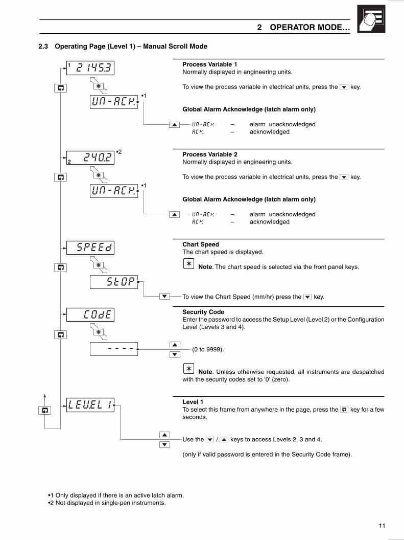
2.3 Operating Page (Level 1) – Manual Scroll Mode
Process Variable 1Normally displayed in engineering units.
To view the process variable in electrical units, press the key.
Global Alarm Acknowledge (latch alarm only)
UN-ACK. – alarm unacknowledgedACK. – acknowledged
Process Variable 2Normally displayed in engineering units.
To view the process variable in electrical units, press the key.
Global Alarm Acknowledge (latch alarm only)
UN-ACK. – alarm unacknowledgedACK. – acknowledged
Chart SpeedThe chart speed is displayed.
Note. The chart speed is selected via the front panel keys.
To view the Chart Speed (mm/hr) press the key.
Security CodeEnter the password to access the Setup Level (Level 2) or the ConfigurationLevel (Levels 3 and 4).
(0 to 9999).
Note. Unless otherwise requested, all instruments are despatchedwith the security codes set to '0' (zero).
Level 1To select this frame from anywhere in the page, press the key for a fewseconds.
Use the / keys to access Levels 2, 3 and 4.
(only if valid password is entered in the Security Code frame).
2 OPERATOR MODE…
•1 Only displayed if there is an active latch alarm.•2 Not displayed in single-pen instruments.
2145.3
UN-ACK•1
•2
1
2
UN-ACK•1
240.2
SPEEd
StOP
COdE
----
LEVEL1

12
Fig. 3.1 Accessing the Setup Level (Level 2)
8
LEVEL2
A1 xxx
A1 HYS
A2 xxx
A2 HYS
A3 xxx
A3 HYS
A4 xxx
A4 HYS
NSPEEd
FSPEEd
0AdJ1
Level 2 – Set Up Level
Alarm 1 Trip Point
Alarm 1 Hysteresis Value
Alarm 2 Trip Point
Alarm 2 Hysteresis Value
Alarm 3 Trip Point
Alarm 3 Hysteresis Value
Alarm 4 Trip Point
Alarm 4 Hysteresis Value
Normal Chart Speed
Fast Chart Speed
Input 1 Offset Adjustment
Input 2 Offset Adjustment
Pen 1 Calibration
Pen 2 Calibration
LEVEL1Level 1Operating Level
Security Code COdE x
CorrectPassword
0AdJ2
PEN.CAL1
PEN.CAL2
3.1 IntroductionTo access the Set Up Level (Level 2) the correct password must be entered in the security code frame in Level 1 – see Fig. 3.1
Notes.
1) Alarm frames are visible only if the alarm is configured – see Section 4.2
2) All frames pertaining to Input 2 are not displayed on Single-pen Instruments.
3) Alarm Hysteresis frames are only displayed if the Custom Hysteresissetting is selected – see Section 4.2.
3 SET UP MODE
2
2
1
3
3
3
3
13
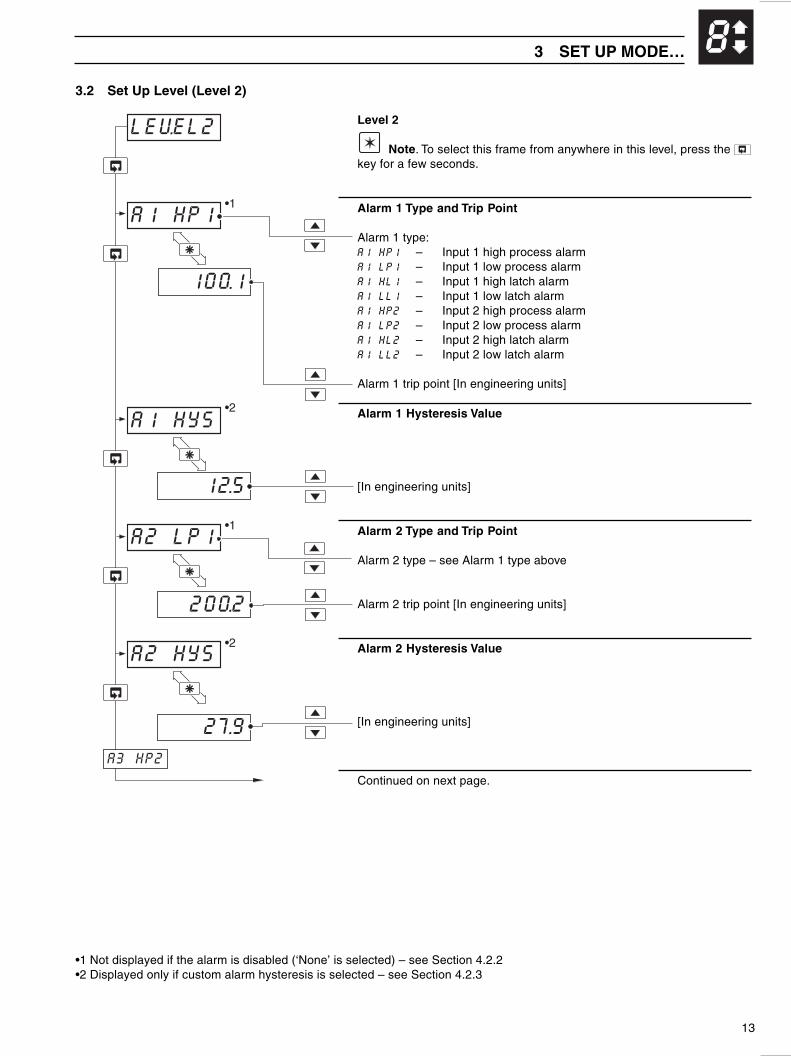
83.2 Set Up Level (Level 2)
LEVEL2
A1 HP1
100.1
A1 HYS
12.5
A2 LP1
200.2
A2 HYS
27.9
A3 HP2
•1
•2
•2
•1
Level 2
Note. To select this frame from anywhere in this level, press the key for a few seconds.
Alarm 1 Type and Trip Point
Alarm 1 type:A1 HP1 – Input 1 high process alarmA1 LP1 – Input 1 low process alarmA1 HL1 – Input 1 high latch alarmA1 LL1 – Input 1 low latch alarmA1 HP2 – Input 2 high process alarmA1 LP2 – Input 2 low process alarmA1 HL2 – Input 2 high latch alarmA1 LL2 – Input 2 low latch alarm
Alarm 1 trip point [In engineering units]
Alarm 1 Hysteresis Value
[In engineering units]
Alarm 2 Type and Trip Point
Alarm 2 type – see Alarm 1 type above
Alarm 2 trip point [In engineering units]
Alarm 2 Hysteresis Value
[In engineering units]
Continued on next page.
•1 Not displayed if the alarm is disabled (‘None’ is selected) – see Section 4.2.2•2 Displayed only if custom alarm hysteresis is selected – see Section 4.2.3
3 SET UP MODE…

14
Alarm 3 Type and Trip Point
Alarm 3 type – see Alarm 1 type.
Alarm 3 trip point [In engineering units]
Alarm 3 Hysteresis Value
[In engineering units]
Alarm 4 Type and Trip Point
Alarm 4 type – see Alarm 1 type.
Alarm 4 trip point [In engineering units]
Alarm 4 Hysteresis Value
[In engineering units]
Normal Chart SpeedNormal chart speed is set to 20mm/hr at the factory.
[0 to 1500 mm/hr]
Continued on next page.
300.3
34.6
20.0
F.SPEEd
A3 HP2
A3 HYS
A4 LP2
25.6
A4 HYS
20
N.SPEEd
•1
•1
•2
•2
…3.2 Set Up Level (Level 2)
•1 Not displayed if the alarm is disabled (‘None’ is selected) – see Section 4.2.2•2 Displayed only if custom alarm hysteresis is selected – see Section 4.2.3
…3 SET UP MODE8

15
1500
1.0
F..SPEEd
0AdJ
1.0
0AdJ
1
2
SEt P.L
PEN.CAL
SEt P.H
1
SEt P.L
PEN.CAL
SEt P.H
2
1
1
2
2
LEVEL 2
…3.2 Set Up Level (Level 2)
Fast Chart SpeedFast chart speed is set to 1500 mm/hr at the factory.
[0 to 1500 mm/hr]
Input 1 Offset AdjustmentAn offset can be applied to process variable Input 1 to enable spotcalibration or the removal of system errors.
[± 10% of Engineering Range]
Input 2 Offset AdjustmentAn offset can be applied to process variable Input 2 to enable spotcalibration or the removal of system errors.
[± 10% of Engineering Range]
Pen 1 Calibration
Set Pen 1 Low
Press the or keys to adjust the pen to zero scale position on thechart.
Set Pen 1 High
Press the or keys to adjust the pen to full scale position on the chart.
Pen 2 Calibration
Set Pen 2 LowPress the key to set Pen 2 zero.
Press the or keys to adjust the pen to zero scale position on thechart.
Set Pen 2 HighPress the key to set Pen 2 High.
Press the or keys to adjust the pen to full scale position on the chart.
Return to top of Level 2.
3 SET UP MODE… 8

16
4 CONFIGURATION MODE
4.1 IntroductionThe Configuration Mode comprises two levels (3 and 4) as shown in Fig. 4.1.
Note.When in the configuration level:
• All Alarm l.e.d.s (and one or both Channel Identification l.e.d.s on 2-pen instruments) flash.• All relays are turned OFF.• The analog output reverts to 'Retransmission Low' (4mA) output level.
Fig. 4.1 Configuration Levels
Note.All frames/selections relating to Input 2/Pen 2 are not applicable to single-pen instruments.
LEVEL3
LEVEL4
ENG HI
ENG LO
PEN HI
PEN LO
ENG HI
ENG LO
PEN HI
PEN LO
rEt HI
rEt LO
2
12
12
2
2
2
1
1
1
1
12
12
Level 4
Input 1 Engineering Range High
Input 1 Engineering Range Low
Pen 1 Range High
Pen 1 Range Low
Input 2 Engineering Range High
Input 2 Engineering Range Low
Pen 2 Range High
Pen 2 Range Low
Retransmission Range High
Retransmission Range Low
Setup Password (Level 2 access)
Configuration Password (Levels 3 & 4 access)
Input 1Configuration
HardwareConfiguration
Input 2Configuration
E 000012
F 000012
G 000012
H 000012
A K.C001
J 101012
P K.C002
K 101012
L 101012
N 101012
r K.C002
S K.C002
t K.C002
b K.C001
C K.C001
d K.C001
S_PASS12
C_PASS12
Level 3
Alarm Types

17
4 CONFIGURATION MODE…
4.2 Input, Hardware & Alarms Configuration (Level 3)
4.2.1 Input 1 Configuration
Level 3
Note. To select to this frame from anywhere in this level, press the key for a few seconds.
'ABCD' SettingsThe first character (A, b, C or d) identifies the parameter to be changed. Thecurrent setting is indicated by a flashing letter. Parameter options are shownin Fig. 4.2
A = Input type and range configurationb = Temperature unitsC = Number of decimal pointsd = Analog input filter
Notes.1) When changing to a temperature input type (codes b to P), the full
operating range of the thermocouple or RTD (see Table 4.1) is enteredin Level 4 Engineering Range High/Low and Pen Range High/Low – seeSection 4.3. For voltage or current input types (codes 1 to 7) the valuesremain unchanged.
2) In the event of a fault being detected on the input, the 'Broken SensorDrive' action is dependent on the input type:
Thermocouple and RTD – UpscalemA, mV and Volt – Downscale
3) For custom settings contact the local distributor.
Continued on page 19
LEVEL312
A KC001
b KC001
C KC001
d KC001
E 000012
Table 4.1 Analog Input ranges
elpuocomrehT egnaR °C egnaR °F )gnidaerfo%(ycaruccA
B 0081ot81– 0723ot0 ro%52.0 ±2° 002evoba(C ° )CE 009ot001– 0561ot041– ro%52.0 ± 5.0 °CJ 009ot001– 0561ot041– ro%52.0 ± 5.0 °CK 0031ot001– 0532ot041– ro%52.0 ± 5.0 °CN 0031ot002– 0532ot523– ro%52.0 ± 5.0 °CR 0071ot81– 0003ot0 ro%52.0 ±1° 003evoba(C ° )C
S 0071ot81– 0003ot0 ro%52.0 ±1° 002evoba(C ° )C
T 003ot052– 055ot004– ro%52.0 ± 5.0 °C
DTR egnaRmumixaM °C egnaRmumixaM °F gnidaeRfoycaruccA001tP 006ot002– 0011ot523– ro%52.0 ± 5.0 °C
stupnIraeniL egnaR gnidaeRfoycaruccAspmailliM 02ot0 ro%52.0 ±2µAspmailliM 02ot4 ro%52.0 ±2µA
stloV 5ot0 ro%52.0 ± Vm2stloV 5ot1 ro%52.0 ± Vm2
stlovilliM 05ot0 ro%52.0 ± 02 µV
stupnItooRerauqS egnaR gnidaeRfoycaruccAspmailliM 02ot4 %52.0 ±2µA
.etoN004wolebdeetnaraugtonsiycaruccaecnamrofreP ° 257(C ° SdnaR,Bsepytrof)F
.selpuocomreht001,munitalperiw-3,DTR Ω 004ot0foegnarhtiw)157CEI(dradnats06734NIDrep Ω.
07TepyT:orezwolebnaps.niM ° 621(C ° )F501NepyT ° 981(C ° )F
485CEI01734NIDsdradnatsCHT157CEI06734NIDsdradnatsDTR

18
Fig. 4.2 Input 1 Configuration
A KC00A – Input Type and Range Configuration (Input 1)
b KC00b – Temperature Units
Display Temperature Units
C Degrees C*F Degrees F*0 No temperature units
* Temperature inputs only
Display
b THC Type BE THC Type EJ THC Type JK THC Type KN THC Type Nr THC Type RS THC Type St THC Type TP PT100 RTD
Display
1 0 to 20 mA2 4 to 20 mA3 0 to 5 V4 1 to 5 V6 0 to 50 mV7 4 to 20 mA (square root linearizer)U Custom Configuration
C – Process VariableDisplay Decimal PlacesC KC00
Display
0 xxxxx1 xxxx . x2 xxx . xx3 xx . xxx4 x . xxxx
d – Analog Input Filterd KC00
Display
0 0 seconds1 1 second2 2 seconds5 5 secondsA 10 secondsb 20 secondsC 40 secondsd 60 seconds
…4 CONFIGURATION MODE

19
Fig. 4.3 Alarm Action
4 CONFIGURATION MODE…
'EFGH' SettingsThe first character (E, F, G or H) identifies the parameter to be changed. Thecurrent setting is indicated by a flashing letter. Parameter options are shownin Fig. 4.4.
E = Alarm 1 typeF = Alarm 2 typeG = Alarm 3 typeH = Alarm 4 type
Note. For custom settings contact your local Service Organization.
Continued on page 20.
Information.For latch alarms the relay remains de-energized until acknowledged in Level 1 (or by a digital input).
E 000012
J 101012
F 000012
G 000012
H 000012
Trip point
Alarm on
Alarm off
Alarm on
Alarm off
High Process
Low Process
Hysteresis
Hysteresis
ProcessVariable
4.2.2 Alarms Configuration
Note. Relays assigned to alarms are de-energized in the alarm state.

20
…4 CONFIGURATION MODE
Fig. 4.4 Alarm Type Settings
Note. Alarm types relating to Input 2 are not applicable for single-pen instruments.
H 0000H – Alarm 4 Type
Display
0 None1 Input 1 High Process2 Input 1 Low Process3 Input 1 High Latch4 Input 1 Low Latch
5 Input 2 High Process6 Input 2 Low Process7 Input 2 High Latch8 Input 2 Low Latch
12 G 0000
G – Alarm 3 Type
Display
0 None1 Input 1 High Process2 Input 1 Low Process3 Input 1 High Latch4 Input 1 Low Latch
5 Input 2 High Process6 Input 2 Low Process7 Input 2 High Latch8 Input 2 Low Latch
12
E 0000E – Alarm 1 Type
Display
0 None1 Input 1 High Process2 Input 1 Low Process3 Input 1 High Latch4 Input 1 Low Latch
5 Input 2 High Process6 Input 2 Low Process7 Input 2 High Latch8 Input 2 Low Latch
12 F 0000
F – Alarm 2 Type
Display
0 None1 Input 1 High Process2 Input 1 Low Process3 Input 1 High Latch4 Input 1 Low Latch
5 Input 2 High Process6 Input 2 Low Process7 Input 2 High Latch8 Input 2 Low Latch
12

21
4 CONFIGURATION MODE…
4.2.3 Hardware Configuration
'JKLN' SettingsThe first character (J, K, L or N) identifies the parameter to be changed. Thecurrent setting is indicated by a flashing letter. Parameter options are shownin Fig. 4.5.
J = Hardware configurationK = Digital input functionsL = Relay sources configurationN = Alarm hysteresis
Note. For custom settings contact the local distributor.
Continued on next page.
Note. Alarm relays are logical 'OR' configured
J 101012
P KC002
K 101012
L 101012
N 101012
K 1010K – Digital Input Functions
Display Alarm Ack Chart Fast Chart StopSource Source Source
0 None None None1 Dig 1 None None2 None Dig 1 None3 None None Dig 14 Dig 1 Dig 2 None5 None Dig 1 Dig 26 Dig 1 None Dig 2
12
L 1010L – Relay SourcesConfiguration
Display Relay 1 Source Relay 2 Source
1 Alarm 1 Alarms 2, 3 OR 4
2 Alarms 1 OR 2 Alarms 3 OR 4
3 Alarms 1 OR 3 Alarms 2 OR 4
4 Alarms 1, 2 OR 3 Alarms 4
12 N 1010
n – Alarm Hysteresis
Display Hysteresis
0 None1 0.1 %2 0.2 %3 0.5 %4 1.0 %5 2.0 %6 5.0 %U Custom
12
Freq. Analog Retrans Source
50Hz 60Hz
1 A Input 12 b Input 2
U Custom
J 1010J – HardwareConfiguration
12
In engineering units
As percentage ofengineering range
Fig. 4.5 Hardware Configuration
22
P KC002
LEVEL312
r KC002
S KC002
t KC002
…4 CONFIGURATION MODE
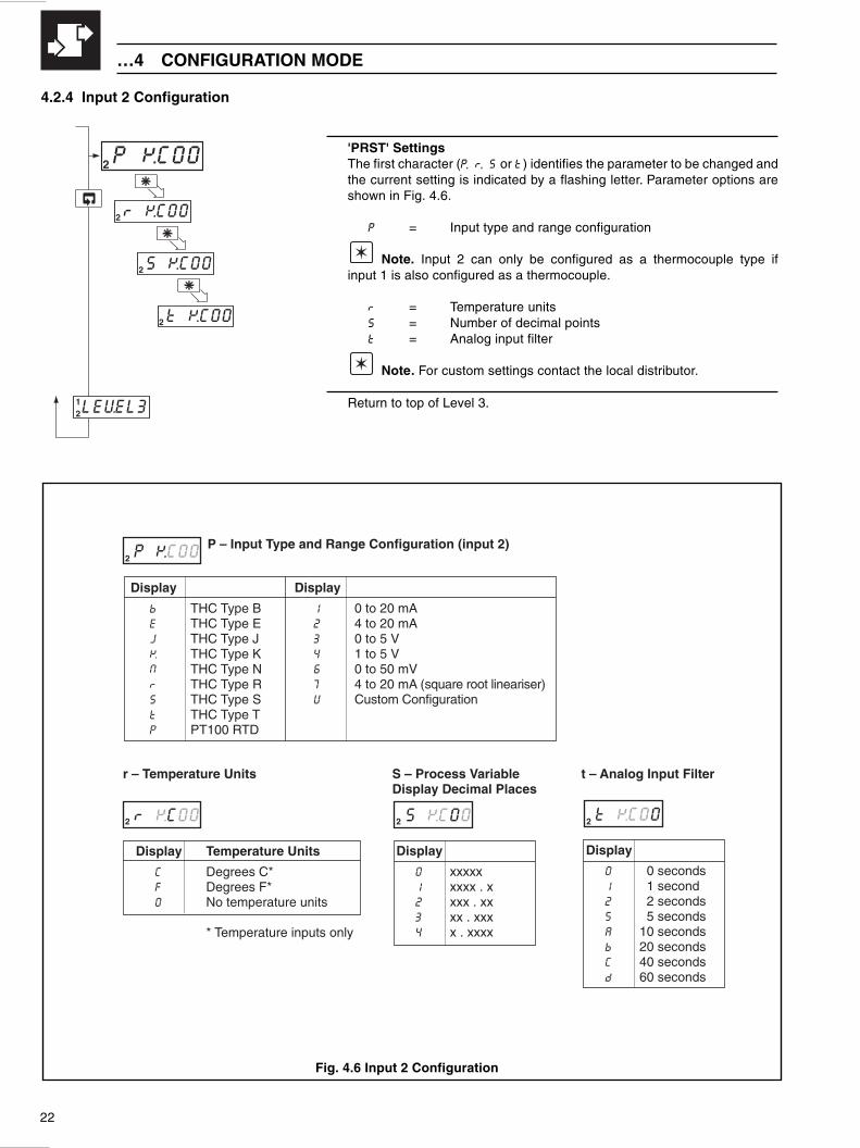
4.2.4 Input 2 Configuration
'PRST' SettingsThe first character (P, r, S or t) identifies the parameter to be changed andthe current setting is indicated by a flashing letter. Parameter options areshown in Fig. 4.6.
P = Input type and range configuration
Note. Input 2 can only be configured as a thermocouple type ifinput 1 is also configured as a thermocouple.
r = Temperature unitsS = Number of decimal pointst = Analog input filter
Note. For custom settings contact the local distributor.
Return to top of Level 3.
Fig. 4.6 Input 2 Configuration
P KC00P – Input Type and Range Configuration (input 2)
Display
b THC Type BE THC Type EJ THC Type JK THC Type KN THC Type Nr THC Type RS THC Type St THC Type TP PT100 RTD
Display
1 0 to 20 mA2 4 to 20 mA3 0 to 5 V4 1 to 5 V6 0 to 50 mV7 4 to 20 mA (square root lineariser)U Custom Configuration
2
t – Analog Input Filter
t KC00
Display
0 0 seconds1 1 second2 2 seconds5 5 secondsA 10 secondsb 20 secondsC 40 secondsd 60 seconds
2 r KC00
r – Temperature Units
Display Temperature Units
C Degrees C*F Degrees F*0 No temperature units
* Temperature inputs only
S – Process VariableDisplay Decimal Places
S KC00
Display
0 xxxxx1 xxxx . x2 xxx . xx3 xx . xxx4 x . xxxx
2 2

23
4 CONFIGURATION MODE…
4.3 Ranges and Passwords (Level 4)
Level 4
Note. To select this frame from anywhere in this level, press the key for a few seconds.
Engineering (Display) Range
Input 1 High
[–9999 to 99999]
Input 1 Low
[–9999 to 99999]
Pen 1 Range High
Note. The pen range can be set to a value greater or less than theengineering range, to suit the chart range markings.
[–9999 to 99999]
Pen 1 Range Low
[–9999 to 99999]
Continued on pages 24 and 25.
ENG HI
LEVEL412
ENG HI1
ENG LO1
100.11
0.01
PEN HI1
100.01
PEN LO1
0.01
2
rEt HI12
Single-pen Instruments
Two-pen Instruments

24
rEt HI
2
12
ENG HI2
100.12
ENG LO2
0.02
PEN HI2
100.0
PEN LO2
0.02
…4 CONFIGURATION MODE
…4.3 Ranges and Passwords (Level 4)
Note. Settings relating to Input 2 are not applicable for single-pen instruments.
Engineering (Display) Range
Input 2 High
[–9999 to 99999]
Input 2 Low
[–9999 to 99999]
Pen 2 Range High
Note. The pen range can be set to a value greater or less than theengineering range, to suit the chart range markings.
[–9999 to 99999]
Pen 2 Range Low
[–9999 to 99999]
Continued on next page.

25
4 CONFIGURATION MODE…
…4.3 Ranges and Passwords (Level 4)
Retransmission RangeThe retransmission range defines the engineering range to beretransmitted – see Section 4.2 Code J for source selection.
High (20mA output)
[–9999 to 99999 (in engineering units)]
Low (4mA output)
[–9999 to 99999 (in engineering units)]
Set Up Level PasswordSet the password to enable access to the Setup Level (level 2).
[0 to 9999]
Note. Unless otherwise requested, all instruments are despatchedwith passwords set to ‘0’ (zero).
Configuration Level PasswordSet the password to enable access to the Configuration Level (levels 3 and 4).
[0 to 9999]
Note. Unless otherwise requested, all instruments are despatchedwith passwords set to ‘0’ (zero).
Return to top of page.
rEt HI12
100.012
0.012
S_PASS12
•1
rEt LO12
•1
012
LEVEL412
C_PASS12
012

26
Fig. 5.1 General Requirements
Fig. 5.2 Environmental Requirements
5 INSTALLATION
EC Directive 89/336/EEC
In order to meet the requirements of the EC Directive89/336/EEC for EMC regulations, this product must not beused in a non-industrial environment.
SensorMinimum
A – Close to Sensor
B – At Eye-level Location
C – Avoid Vibration
A – Within Temperature Limits
0 to 95% RH
0 to 80% RH
50°CMax.
0°CMin.
+
IP65/NEMA3 Front
IP20 Rear
B – Within Humidity Limits
Caution. Select a location away from strongelectrical and magnetic fields. If these cannot beavoided, particularly in applications where ‘walkie-talkies’ are expected to be used, screened cableswithin earthed metal conduit must be used.
C – Use Screened Cable
D – Environmental Limits
5.1 Siting – Figs. 5.1 and 5.2

27
Fig. 5.4 Mounting
5 INSTALLATION…
5.2 Mounting – Figs. 5.3 and 5.4
Information. A minimum mounting panel thickness of 3mm is recommended.
Fig. 5.3 Overall Dimensions
144 (5.67)219 (8.62)
234 (9.21)
144(5.67) Panel
Cut-out
30 (1.2)
Dimensions in mm (in.)
(5.43 )+0.03–0.0
138 +0.8–0.0
(5.43 )+0.03–0.0
138 +0.8–0.0
24(0.94)
4
5
6
2
3
30°max.
1
1 Cut a hole in the panel (see Fig. 5.3 for dimensions).
2 Loosen the retaining screw on each panel clamp.
3 Lift the retaining screws and remove the panel clampanchors. Remove the panel clamps.
4 Insert the instrument into the panel cut-out.
5 Refit the panel clamps to the case, ensuring that the panelclamp anchors are located correctly in their slots.
6 Secure the instrument by tightening the panel clampretaining screws.
Caution. The clamp must fit flat against theinstrument case. If the clamp is bowed, the securingscrew is too tight and sealing problems may occur.

28
…5 INSTALLATION
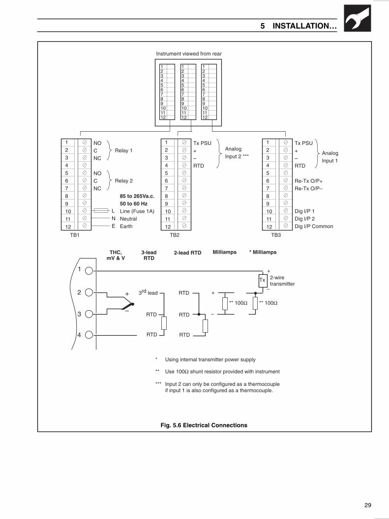
5.3 Electrical Connections – Fig. 5.6 (opposite)
Warning. Before making any connections,ensure that the power supply, any powered control circuitsand high common mode voltages are switched off.
Note. If it is not possible to avoid strong electricaland magnetic fields, screened cables within earthed metalconduit must be used.
5.4 Relays, Arc Suppression and Output
5.4.1 Relay Contact RatingsRelay contacts are rated at:
115/230V AC at 5A (non-inductive)
250V DC 25W max.
5.4.2 Arc Suppression Capacitors – Fig 5.5Arc suppression components are fitted across both relays. Ifthese contacts are used to operate external relays, thecapacitor leakage current may be sufficient to prevent theexternal relay from de-energizing. If so, switch off the powersupply and external alarm circuits. Identify the relay moduleand remove it. Cut the links to the suppression circuit and refitthe module.
Relay 1 RELY1
RELY2
RL1
RL2
NO
NC
Relay 2NO
NC
Fig. 5.5 Location of Arc Suppression Capacitor Links
5.4.3 Retransmission Analog OutputMax. load 15V (750Ω at 20mA)
Isolation 500V from I/Ps
5.5 Spares and Consumables
* Supplied as standard
strahClloR
egnaR lanoitanretnI aciremAhtroN
05+/05– G7747/L001P 0111-001CPK
001+/05– G4847/L001P –
01/0 G2047/L001P 3201-001CPK
41/0 G36471/L001P 7401-001CPK
02/0 G4047/L001P 0801-001CPK
05/0 G1047/L001P 2301-001CPK
06/0 G9647/L001P 8111-001CPK
07/0 G00471/L001P –
57/0 G78471/L001P –
08/0 G2347/L001P –
*001/0 G0047/L001P 7301-001CPK
051/0 G4147/L001P 9301-001CPK
002/0 G0247/L001P 0401-001CPK
003/0 G5147/L001P 2401-001CPK
005/0 G5647/L001P 3401-001CPK
008/0 G64471/L001P 5401-001CPK
0001/0 G6747/L001P 2701-001CPK
0021/0 G1647/L001P 4701-001CPK
0041/0 G48471/L001P –
0061/0 G88471/L001P –
0061/008 G09471/L001P –
strahCdlofnaF
egnaR lanoitanretnI aciremAhtroN
05+/05– X7747/L001P 2408-001CPK
001+/05– X4847/L001P –
01/0 X2047/L001P 0108-001CPK
41/0 X36471/L001P 2308-001CPK
02/0 X4047/L001P 8008-001CPK
05/0 X1047/L001P –
06/0 X9647/L001P –
07/0 K00471/L001P –
57/0 X78471/L001P –
08/0 X2347/L001P –
*001/0 X0047/L001P 4308-001CPK
051/0 X4147/L001P 0508-001CPK
002/0 X0247/L001P 1508-001CPK
003/0 X5147/L001P 3508-001CPK
005/0 — 8508-001CPK
008/0 X64471/L001P 4608-001CPK
0001/0 X6747/L001P 7308-001CPK
0021/0 X1647/L001P 9308-001CPK
0041/0 X48471/L001P –
0061/008 X09471/L001P –
29
5 INSTALLATION…
NO
C
NC
NO
C
NC
Relay 1
Relay 2
Instrument viewed from rear
123456789101112
123456789101112
123456789101112
L
N
E
85 to 265Va.c.50 to 60 HzLine (Fuse 1A)
Neutral
Earth
1
2
3
4
5
6
7
8
9
10
11
12
TB1
1
2
3
4
5
6
7
8
9
10
11
12
TB2
Tx PSU
+
–
RTD
Analog
Input 2 ***
1
2
3
4
5
6
7
8
9
10
11
12
TB3
Tx PSU
+
–
RTD
Re-Tx O/P+
Re-Tx O/P–
Dig I/P 1
Dig I/P 2
Dig I/P Common
Analog
Input 1
THC,mV & V
RTD
3-leadRTD
Milliamps
1
2
3
4
* Milliamps2-lead RTD
* Using internal transmitter power supply
** Use 100Ω shunt resistor provided with instrument
*** Input 2 can only be configured as a thermocoupleif input 1 is also configured as a thermocouple.
–
+
–
+
** 100Ω
3rd lead
RTD
2-wiretransmitter
** 100Ω
–
+
Tx
RTD
RTD
RTD
Fig. 5.6 Electrical Connections

30
…5 INSTALLATION
…5.5 Spares and ConsumablessuoenallecsiM
noitpircseD rebmuNtraP
tinutrahclloR 1200/001RC
tinutrahcdlofnaF 2200/001RC
nep1-etalpeludomrotoM 1/3000/001RC
nep2-etalpeludomrotoM 2/3000/001RC
ylbmessa-busegairracneP 9700/M001P
eldnipsegairracneP 6510/M001P
ylbmessarotomevirdtrahC 2700/M001P
ylbmessa-busdioneloS 4000/001RC
kcappmalclenaP 0200/001RC
etalpgniknalblanimreT 6200/001RC
ylbmessaeludomrotoM 1000/001RC
tlebevirD 4939B
yaw21kcolblanimreT 9000/001RC
yalpsidhtiwylbmessarooD 6100/001RC
ylbmessa-busrooderapS 8100/001RC
nep1-ylbmessaesaC 1/5100/001RC
nep2-ylbmessaesaC 2/5100/001RC
ylbmessaelbacnobbiR 3100/001RC
revocBCPyalpsiD 2100/001RC
kcapriaperrevocyalpsiD 5200/001RC
teksaglenaP 6810/001RP
)etihw(teksagrooD 7010/001RS
revocsniamroflebaL 7000/001RC
revoc'lanimreTeviLregnaD' 8000/001RC
yalrevotnorF 1100/001RC
launamnoitcurtsnI 001RC/MI
seibmessABCP
draobyalerrewoP 1081/001RC
draobyalpsiD 4081/001RC
nep1-kcapecivresdraobO/I 1/0011/001RC
nep2-kcapecivresdraobO/I 2/0011/001RC
nep1-kcapecivresdraobniaM 1/1011/001RC
nep2-kcapecivresdraobniaM 2/1011/001RC
)3fokcap(sneP
deR 5901/L001P
neerG 6500/M001P

31
LEVEL1
CodE x
LEVEL2
A1 xxx
A1 HYS
A2 xxx
A2 HYS
A3 xxx
A3 HYS
A4 xxx
A4 HYS
N.SPEEd
F.SPEEd
OAdJ
OAdJ
1
2
Instrument Serial Number :
Product Code : CR10_/_ _ _ _ _ _
8CUSTOMER SETUP LOG

32
LEVEL3
LEVEL4
ENG HI
ENG LO
PEN HI
PEN LO
ENG HI
ENG LO
PEN HI
PEN LO
rEt HI
rEt LO
S_PASS
2
Instrument Serial Number :
Product Code : CR10_/_ _ _ _ _ _
12
12
12
2
2
2
1
1
1
1
12
A K.C00
E 0000
J 1010
P K.C00
12
12
12
1
2
A_ B_ C_ D_
E_ F_ G_ H_
J_ K_ L_ N_
P_ r_ S_ t_
C_PASS12
CUSTOMER CONFIGURATION LOG

PRODUCTS & CUSTOMER SUPPORT
ProductsAutomation Systems
• for the following industries:– Chemical & Pharmaceutical– Food & Beverage– Manufacturing– Metals and Minerals– Oil, Gas & Petrochemical– Pulp and Paper
Drives and Motors• AC and DC Drives, AC and DC Machines, AC motors to 1kV• Drive systems• Force Measurement• Servo Drives
Controllers & Recorders• Single and Multi-loop Controllers• Circular Chart , Strip Chart and Paperless Recorders• Paperless Recorders• Process Indicators
Flexible Automation• Industrial Robots and Robot Systems
Flow Measurement• Electromagnetic Magnetic Flowmeters• Mass Flow Meters• Turbine Flowmeters• Wedge Flow Elements
Marine Systems & Turbochargers• Electrical Systems• Marine Equipment• Offshore Retrofit and Referbishment
Process Analytics• Process Gas Analysis• Systems Integration
Transmitters• Pressure• Temperature• Level• Interface Modules
Valves, Actuators and Positioners• Control Valves• Actuators• Positioners
Water, Gas & Industrial Analytics Instrumentation• pH, conductivity, and dissolved oxygen transmitters and
sensors• ammonia, nitrate, phosphate, silica, sodium, chloride,
fluoride, dissolved oxygen and hydrazine analyzers.• Zirconia oxygen analyzers, katharometers, hydrogen purity
and purge-gas monitors, thermal conductivity.
Customer SupportWe provide a comprehensive after sales service via ourWorldwide Service Organization. Contact one of the followingoffices for details on your nearest Service and Repair Centre.
United KingdomABB LimitedTel: +44 (0)1480 475321Fax: +44 (0)1480 217948
United States of AmericaABB Inc.Tel: +1 215-674-6000Fax: +1 215-674-7183
Client Warranty
Prior to installation, the equipment referred to in this manualmust be stored in a clean, dry environment, in accordance withthe Company's published specification. Periodic checks must bemade on the equipment's condition.
In the event of a failure under warranty, the followingdocumentation must be provided as substantiation:
1. A listing evidencing process operation and alarm logs at timeof failure.
2. Copies of operating and maintenance records relating to thealleged faulty unit.

IM/C
R10
0Is
sue
2
ABB LimitedHoward Road, St NeotsCambridgeshirePE19 8EUUKTel: +44 (0)1480 475321Fax: +44 (0)1480 217948
ABB Inc.125 E. County Line RoadWarminsterPA 18974USATel: +1 215 674 6000Fax: +1 215 674 7183
ABB has Sales & Customer Supportexpertise in over 100 countries worldwide
www.abb.com
The Company’s policy is one of continuous productimprovement and the right is reserved to modify the
information contained herein without notice.
Printed in UK (10.02)
© ABB 2002