U.S. Aimy Defense Ammunition Center and School - apps.dtic.mil
22
U.S. Aimy Defense Ammunition Center and School Final Report No. r; - iN,, DEC ; G %-j09 2 i. EVT 47-87-2 u De MIL-STD-1660 TEST of PA116 120MM TANK AMMUNITION on a STANDARD 40" x 44" METAL PALLET WITH ADAP- TOR ASSEMBLY r ,r.:-, ,N S'T.Vu- cr c.'le-: . Prepared for: I)istribution Unlimited U.S. Army Armament Munitions and Chemical Command AITN: SMCAR-ESK Rock Island, IL 61299-7300 IIII_ _ _ _ _ _ __I_ US ARMY ARMAMENT MUNITIONS EVALUATION DIVISION CHEMICAL COMMAND US ARMYI OFFENSE AMM N ON10 SAVANNA, ILLINOIS 61074-963? CENE ANC SCCC 89 13 19
Transcript of U.S. Aimy Defense Ammunition Center and School - apps.dtic.mil

U.S. Aimy Defense AmmunitionCenter and School
Final Report No. r; -
iN,, DEC ; G %-j09 2 i.
EVT 47-87-2u De
MIL-STD-1660 TEST of PA116120MM TANK AMMUNITION
on a STANDARD 40" x 44"METAL PALLET WITH ADAP-
TOR ASSEMBLY
r ,r.:-, ,N S'T.Vu- cr c. 'le-: .
Prepared for: I)istribution UnlimitedU.S. Army Armament Munitions
and Chemical CommandAITN: SMCAR-ESKRock Island, IL 61299-7300
IIII_ _ _ _ _ _ __I_ US ARMYARMAMENTMUNITIONS
EVALUATION DIVISION CHEMICAL COMMAND
US ARMYI OFFENSE AMM N ON10SAVANNA, ILLINOIS 61074-963? CENE ANC SCCC
89 13 19

~DIS CLAIMEk OIE
THIS DOCUMENT IS BEST
QUALITY AVAILABLE. THE COPY
FURNISHED TO DTIC CONTAINEDA SIGNIFICANT NUMBER OF
PAGES WHICH DO NOT
REPRODUCE LEGIBLY.

AVAILABILITY NOTICE
A copy of this report is furnished each attendee on automatic Jistribution.
Additional copies or authority for reprinting may be obtained by written re-
quest from Director, U.S. Army Defense Ammunition Center and School.
ATTN: SMCAC-DEV, Savanna, IL 61074-9639.
DISTRIBUTION INSTRUCTIONS
Destroy this report when no longer needed. Do not retlrn.
Citation of trade names in this report does not constitute an official endorse-
ment.
The information contained herein will not be used for advertising purposes.

UNCLASSIFIEDSECURITY CLASSIFICATION OF TH'S PAGE
Form ApprovedREPORT DOCUMENTATION PAGE OMB No. 0704-0188
la REPORT SECURITY CLASS,R:CAT;ON 1b RESTRICTIVE MARKINGS
UNCIASSIFIED2a SECURITY CLASSIFICATION AUTH4ORITy 3 DISTRIBUTION, AVAILABILITY OF REPORT
2b DECLASSIFICATION/DOWNGRADiNG SCHEDULE
4 PERFORMING ORGANIZATION REPORT NUMBER(S) 5 MONITORING ORGANIZATION REPORT NUMBER(S)
EVT-A 7- C7-2 16a NAME OF PERFORMING ORGANIZATION 16b OFFICE SYMBOL 7a NAME OF MONITORING ORGANIZATION
U.S. Army Defense Ammunition (If applicable)
Center and School SMCAC-DEV Projact Manager-Ammunition Looistics6c. ADDRESS (City, State, and ZIP Code) 7b ADDRESS (City, State, and ZIP Code)
ATTN: SMCAC-DE ATTN: A-ICPM-AL
Savanna, !L 1074-963n Picatinny Arsenal, NJ 07806-5001
8a. NAME OF FUNDING SPONSORING l8b OFFICE SYMBOL 9 PROCUREMENT INSTRUMENT IDENTIFICATION NLMBERORGANIZATION (If applicable)
8c. ADDRESS(City, State, and ZIP Code) 10 "71URCE OF FUNDING NUMBERS
PROGRAM IPROJECT ITASK IWORK UNITELEMENT NO N O. NOACCE SSION NO.
11. TITLE (Include Security Classification)
MIL-STD-1660 Test of PAIi6 120mm. Tank Ammunition on a Standard 40" by 44" Metal Pallet
With Adaptor Assembly12. PERSONAL AUTHOR(S)
William Meyer13a. TYPE OF REPORT 13b TIME COVERED 14 DATE OF REPORT (Year, Month, Day) 115 PAGE COUNT
F INAL FROM July 88TOLAug 88 1988 October 4 j2116. SUPPLEMENTARY NOTATION
17. COSATI CODES 18. SUBJECT TERMS (Con*inue on reverse if necessary and identify by block number)FIELD GROUP T SUB-GROUP ,MIL-STD-1660 r tank ammunition
'-Metal pallets, PA116 -
120mm19. ABSTRACT (Continue on reverse if necessary and idenify by block numbeF<
The U.S. Army Defense Ammunition Center and School (USADACS) was tasked by ProjectManger-Ammunition Logistics (PM-AMMOLOG) to develo an adaptor assembly, for the standard40rIby 44'<metal pallet for unitization of the 120mm tank ammunition. The objective ofthis project was to replace the specially designed (single commodity) currently fielded120mm metal pallet with a less expensive multipurpose standard metal pallet. MIL-STD-1660tests were conducted on a series of three standard metal pallets with 120mm metal adaptorsduring the months of July and August, 1988, with all three pallets passing MIL-STD-1660tests. All pallets had minor metal/weld cracks which was expected. All pallets wereserviceable, stackable, and safe to remain in the transportation cycle after testing.The general condition of the standard metal pallets with adaptors was superior to thecurrently fielded 120mm metal pallet. It is therefore recommended that the standard40" by 44" metal pallet with adaptors replace the currently fielded pallet.
20 DISTRIBUTION /AVAILABILITY OF ABSTRACT 121 ABSTRACT SECURITY CLASSIFICATION(3UNCLASSIFIEDAJNLIMITED 0 SAME AS RPT 0 DTIC USERS UNCLASSIFIED
22as. NAME OF RESPONSIBLE INDIVIDUAL 122b TELEPHONE (Include Area Code) 22c. OFFICE SYMBOLTHOMAS J. MICIIELS, Chief, Evaluation :1visiod AV 585-8080I SMCAC-DEV
DD Form 1473, JUN 86 Previous editions are obsolete. SECURITY CLASSIFICATION OF THIS PAGE
UNCLASSIFIEDi

U.S. ARMY DEFENSE AMMUNITION CENTER AND SCHOOL
Evaluation Division
Savanna, IL 61074-9639
REPORT NO. EVT 47-87-2
AB(LE it, %CONTENTS
PART PAGE NO.
1. INTRODUCTION ......................... 1-1
A . Background .. .. .. .. .. .. .. .. .. .. .... .. 1-1
B . A uthority .. .... .. ... .. .. ... .. .... .. ..1-1
C . O bjective .. ... ... .. ... ... .. ... ... .. ..1-1
2. ATTENDEES ............................ 2-1
3. TEST PROCEDURES ....................... 3-1
4. TEST EQUIPMENT ..................... 4-1
5. TEST RESULTS .......................... 5-1
6. CONCLUSIONS AND RECOMMENDATIONS ........ 6-1
7. PHOTOGRAPHS ......................... 7-1
ii

PART I
A. INTRODUCTION.
Tile U.S. Army Defense Ammunition Center and School (USADACS) wastasked by PM-AMMOLOG to develop and test a special adaptor assemblyto be used on the standard 40"x44" metal pallet for the purpose of unitizingPAl16 containers for 120mm tank anmmo, The objective of this programwas to reduce cost, while improving the overall quality of the unitizedload.
B. AUTHORITY.
This test was conducted in accordance with mission responsibilitiesdelegated by U.S. Almy Armancnt, Munitions and Chemical Command(AMCCOM) and AR 740-1.
C. OBJECTIVE.
The test objective was to detem-ine if an adaptor assembly could be placedon a standard 40"x44" pallet for the purpose of unitizing 120mm tank am-munition and pass MIL-STD-1660 design criteria for ammunition unitloads.
...... 1
- - -- ----- -
1-1
l

PART 2
ATTENDEES
Mr. William Meyer U.S. Army Defense AmmunitionTest Engineer Center and SchoolAV 585-8090 ATTN: SMCAC-DEVComm (815) 273-8090 Savanna, IL 61074-9639
Mr. Bill Matthews General Defense Corporation,Tactical Systems Division
1011 Ninth Street NorthSt. Petersburg, FL 33716
Mr. 'Jince Gentile Project Manager-Tank Main Armament SystemsATTN: AMCPM-TMA
Mr. Lenny Frelich Project Manager-Ammunition LogisticsATTN: AMCPM-ALPicatinny Arsenal, NJ 07806-5000
Mr. Cecil Doub ORDNANCE rISSILE AND MUNITIONS CENTERand School
Mr. Jim Kistner ATTN: ATSK-Z-MSMAV 746-9177 Redstone Arsenal, AL 358
Mr. Mark REHMSTEDT U.S. Army Armament, Munitionsand Chemical Command
Mr. David Piskorik ATTN: SMCAR-ESKAV 793-4564 Rock Island, IL 61299-7300
2-1
PART 3
Test Procedures
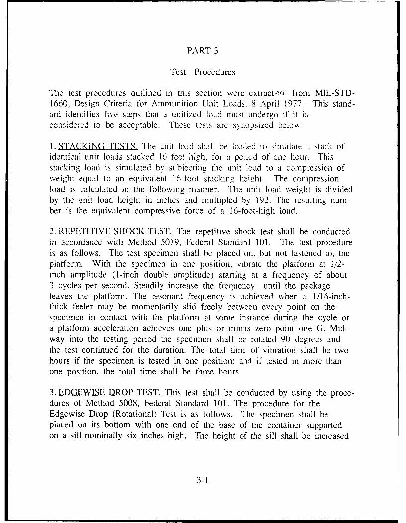
The test procedures outlined in this section were extract eci from MiL-STD-1660, Design Criteria for Ammunition Unit Loads, 8 April 1977. This stand-ard identifies five steps that a unitized load must undergo if it isconside red to be acceptable. These tests are synopsized below:
1. STACKING TESTS. The unit load shall be loaded to simalate a stack ofidentical unit loads stacked 16 feet high, for a period of one hour. Thisstacking load is simulated by subjecting the unit load to a compression ofweight equal to an equivalent 16-foot stacking height. The compressionload is calculated in the following manner. The unit load weight is dividedby the i.nit load height in inches and multipled by 192. The resulting num-ber is the equivalent compressive force of a 16-foot-high load.
2. REPETITIVF SHOCK TEST. The repetitive shock test shall be conductedin accordance with Method 5019, Federal Standard 101. The test procedureis as follows. The test specimen shall be placed on, but not fastened to, theplatfo.rm. With the specimen in one position, vibrate the platform at 1/2-inch amplitude (1-inch double amplitude) starting at a frequency of about3 cycles per second. Steadily increase the frequency until the packageleaves the platform. The resonant frequency is achieved when a 1/16-inch-thick feeler may be momentarily slid freely between every point on thespecimen in contact with the platform at some instance during the cycle ora platform acceleration achieves one plus or minus zero point one G. Mid-way into the testing period the specimen shall be rotated 90 degree s andthe test continued for the duration. The total time of vibration shall be twohours if the specimen is tested in one position: and if tested in more thanone position, the total time shall be three hours.
3. EDGEWISE DROP TEST, This test shall be conducted by using the proce-dures of Method 5008, Federal Standard 101. The procedure for theEdgewise Drop (Rotational) Test is as follows. The specimen shall bepiaced on its bottom with one end of the base of the container supportedon a sill nominally six inches high. The height of the sill shall be increased
3-1

if necessary to ensure that there will be no support for the base between theends of the container when dropping takes place, but should not be highenough to cause the container to slide on the supports when the droppedend is raised for the drops. The unsupported end of the container shallthen be raised and allowed to fall freely to the concrete, pavement, orsimilar underlying surface from a prescribed height. Unless otherwisespecified, the height of drop for level A protection shall conform to the fol-lowing tabulation.
GROSS WT. DIMENSIONS ON HEIGHT OF DROP
NOT EXCEEDING ANY EDGE LEVEL A PROTECTION
POUNDS INCHES INCHES
600 72 36
3,000 No Limit 24
No Limit No Limit 12
4. IMPACT TEST. This test shall be conducted by using the procedure ofMethod 5023, Incline-Impact Test of Federal Standard 101. The procedurefor the Incline-Impact Test is as follows. The specimen shall be placed onthe carriage with the surface or edge which is to be impacted projecting a:least 2 inches beyond the front end of the carriage. The cariage shall bebrought to a predetermined position on the incline and released. If it isdesired to concentrate the impact on any particular position on the con-tainer, a 4x4-inch optional timber may be attached to the bumper in thedesired position before the test. No part of the timber shall be struck bythe carriage. The position of the container on the carriage and the sequencein which surfaces and edges are subjected to impacts may be at the optionof the testing activity and will depend upon the objective of the tests.When the test is to determine satisfactory requirements for a container orpack, unless otherwise specified, the specimen shall be subjected to one im-pact on each surface that has each dimension less than 9.5 feet. Unlessotherwise specified, the velocity at time of impact shall be 7 feet per second.
3-2

5. MECHANICAL HANDIING WITH ATI'ACHMENTS. This test shall beconducted in accordance with Method 5011, federal Si.ndard 101 Sub-Part6.3, Hoisting With Slings. Attach slings to the four hoisting arrangements.The length of the slings shafl be such th:-t, when lifting, they form anglesbetween 20 and 25 degrees with a horizontal plane. Lift the specimen clearof the floor and hold it suspended for not less than two minutes. Observefor any indications of inadequacies in this specimen. Record observationsand let the specimen down. Repeat the previous procedure using three,two, alternate two, and one sling
3-3

PART 4
T EST -EQLLLPM N T
L .S IlI:C \ihI U9 Ib
h. IO A :dapt )r 40 Ih '.
CO -% I I 1:c LI Scr 10n S' ic n' -''11. R.
h. Platform: 00 inches b\h 60) fincc
Co.m.npr,,on Llmlt- 50,0() 00 1Id
3. TRANSPORlTATION SIMIULATOR.
b Capacity: 6.0(K) pound palice
c. 1/2-inch AmplitUde
d. Speed: 50 to 3000 cpml
P. Pltformi: 5 foot bv 8 foot
4. INCLINEID RAMP,
a. Manur-,acturer: ConbUr Inclinle
b. Impact Tester0 10 P-~ro "ft Ifl0It!f
d. 12 Foot Inclifle
4-1

Pallet 1 lI~ ICe\LIIt'
I o 1 'OI IiLiLtllC 1 uiiitited takof 10 (feet. Thell hne and durI!,- eom1-prN~oi \N oed t 1e oii'k a b C but IretLIrI)Qd i(o al taIUt1 C0111 11-1U-
tiOEii after til st7 .
Durine11- th11e I 111minutes Of 1lok tr~~ee C1rUo IetI I 11he \ Iibra:ttioknI
table \k s L s et at 18 ) 1-1)u11.
At thle enid of 90 inI'utes. eeaio l 1/wl eLTK k ee ded--
at the bell end of' the pa Ilet onl the !)kl!p i e 11p as t I el A c fi ee rter run1 -
ner tseli
At the end ofI an additional 9(0 n iinut es . ev i dd itijonA 1 i teAXl~cid
stress cracks were also noted.
During the four 24" edoewise rotational drops, less then 1/2" deck warp-ing perpendicular to the skids was nioted, with no chankgeS no0tet to the pal-let durinp2 slinin-z and Incline planle Impact rests.
At the conclusion of MIL-STD- 1660 tests the bottom row of projectilesw cis removed with no container or projectile damnag-e observed.
End of test pallet examination indicated metal and w-Id stress cracksranging from .42" to 1.10" on the pallet deck, with the average length ofeach weld estimated to be 5.5".
Therefore, the worst cracks nioted in this area were approximately 20percent of the total weld with no structural failures occuring.
Weld/metal cracks were also noted of the skid supports, and rangedfrom .17" to .88" with no structural or weld failures occurring.
5-I

IDeek HtIt I I U s j)C IeI (I ICUlaII1-1 11 IL. Nk I ,v.> .) it te 'c
bIl t ail(. .t. 11 a t Iei h!) I I ll of Ih id I I L . ' I "e Ii C )1), >
tC i l e a lt I I,1&&L O C I ir1'2d t te f Ie ti I: I I;
Pal let Ii Ie Rem t 1
I e a C I I\ eoIi e se I1* Iv 1
Lix tr9 ~ te 1 1, I~ 1 1
erack 111C Cv' ete ut
XI U o0)iclu"ts i i.t to r- lK k : I.)
dIE'~~~ >I't 11 t' CWt~j~CiIQ \~Qit2 I
,a Th" P ro Cr. 'ie ru t uie>, we re wii! I reIVe 11
10tc * pallet exaittuatkon ildctieatd de~tV \ -ld it):eh
Rtl Ii;; I4 I~ t) W.~ ith Skid support ci ec,auiu Irn..with nlo 'a IIu res, oted.
The de ck !'Iatns a t th e ccn d of tall te "t.s was 'I) it 1,Le hn) en
pallet and0.16 at the hell enld of' the pallet.
Pallet III Test ResuKt
Pallet .11 was compressed to 10.500 poundIs. with 110auae&U r i
TIhe first 90 m111intes Onl the low frequency vibration w&) at 193 >mat 50 minutes into this cycle lower adaptor pin failure was noted wherec it -
tachment to the metal pallet takes place. Iis Pinl faLulur Wa0, the re'ot~ IWquality control probk~ms by the man1~uf'acturer dueI to in1complete and Hi U-
proper welding of the pinl.
The second 90 mlinutes Of lOW Irequen1c\ Vibration1 perpendicula- to theskids was at 215 rpmn with no weld cracks noted at test con1cIlsil m1.
The 'our 24" edgewise rotational drops werL conducted withe't inci-dent, as well as incline plane and slinging tests.
At the conclusion of testing, the bottom row of rounds was removedwith no container or round damage observed.
Erid of test pallet examination indicated several minor pallet duckmetal/weld cracks of 0.52" to 0.96" with skid support cracks ranging from0.11" to 0.59'', with this pallet showing the least amount of damage of thethree pallets tested.
Pallet deck flatness at test conclusion was 0.2'1" at the base end and 0.25"at the bell end of the pallet.
5-3

PART 6
Conclusions
Both the currently fielded and the standard pallet meet or exceed MIL-STD-1660 requirements, but based on the superior mechanical strength and
durability of he standard pallet it is highly recommended that tl'e stand-ard pallet replace the currently fielded metal pallet for the 120mrr tank am-
munition.
Other advantages of the standard pa!let include:
Cost savings on a per pallet basis.
Simpler design with less welds.
Cuned (rounded) skids for sliding across unimproved surfaces.
Elevated lower support structure for the containers, providinggreater protection to the containers during rough material handlingconditions
Multi-reusable pallets for other commodities.
Additional skid strength in the lateral and longitudinal directionsproviding increased durability during rough terrain material han-dling operations.
During MIL-STD-1660 testing, each pallet reacted differently, on the lowfrequency vibration table with speed changes and adjustments required tomaintain the required 1/16" clearance; this is due in part to the followingvariables:
Strap tension and uniform tension between straps.
* Deck flatness in the longitudinal and lateral directions.
* Workmanship, including clearance between mating parts, and weldquality.
* Skid warping in the longitudinal and lateral direction.
Skid and deck damage during material handling before testing.
6-1

A disadvantage of the standard metal pallet over the current fieldedmetal pallet is the increased weight due to the addition of the lower adap-tor assembley on the standard pallet.
All pallets tested showed minor metal/stress cracking at points of con-tact with the skids and top deck assembly, from extremely small almostnon detectable to the more obvious metal/stress cracks. These cracks andthe degree vary from pallet to pallet depending on the geometry of the pal-let being tested and how well critical points are being utifornly loaded.and is common to all pallets tested to date, regardless of the design con-figuration. Minor metal cracking is acceptable during M:,.--S: -1660 testin,as long as structural failure does not occur and the pallet, after testing i:still serviceable, stackable, and safe to remain in the transportation cycle.
RECOMMENDATIONS
The following changes are recommended on production pallets to fur-ther enhance the quality and durability of the standard pallet.
Full welds the entire length of all mating parts on production pallets.
The reinforcing dimple on the skid support shifted inward to removemetal stress at the leading edge of the support.
Tighter quality control measures be taken during the assembly ofmating parts to avoid high spots in the pallet deck.
Deck flatness tolerances be included in the production drawings forboth the longitudinal and lateral directions.
Increased diameter of the lower support pins which mate with the
pallet deck.
6-2

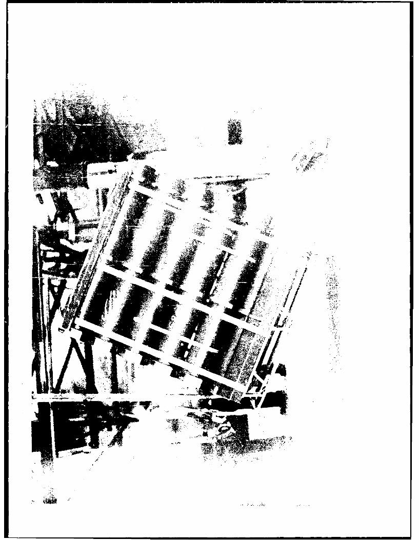
PART 7
PHOTOG RAPHS
7-1

L-J
L±J
'AA t
.. ... .... .

Lw
L)l
LL
0'

.1 ''hi p
fl'>;- a
T
F* --
*

MEW.
Li