TO - apps.dtic.mil · Navy snti-aircraft machiile guns from September 1, 1939 to date, to summarize...
58
UNCLASSIFIED AD NUMBER CLASSIFICATION CHANGES TO: FROM: LIMITATION CHANGES TO: FROM: AUTHORITY THIS PAGE IS UNCLASSIFIED AD222046 UNCLASSIFIED CONFIDENTIAL Approved for public release; distribution is unlimited. Distribution authorized to U.S. Gov't. agencies and their contractors; Administrative/Operational Use; FEB 1946. Other requests shall be referred to Naval Proving Ground, Dahlgren, VA. 28 Feb 1958, DoDD 5200.10; USNSWC ltr, 8 Sep 1976
Transcript of TO - apps.dtic.mil · Navy snti-aircraft machiile guns from September 1, 1939 to date, to summarize...

UNCLASSIFIED
AD NUMBER
CLASSIFICATION CHANGESTO:FROM:
LIMITATION CHANGESTO:
FROM:
AUTHORITY
THIS PAGE IS UNCLASSIFIED
AD222046
UNCLASSIFIED
CONFIDENTIAL
Approved for public release; distribution isunlimited.
Distribution authorized to U.S. Gov't. agenciesand their contractors;Administrative/Operational Use; FEB 1946. Otherrequests shall be referred to Naval ProvingGround, Dahlgren, VA.
28 Feb 1958, DoDD 5200.10; USNSWC ltr, 8 Sep1976

iH!3 R~PORT HAS BEEN DELIMI7ED
AND CLtARED FOR PUBLIC REL~9E
UNDER DCh' DiRECTIVE 5200.20 AND
NO RESTniCTlONS ARE IMPOSED UFON
r rs usE P.No n 1 sctosuru:.
DISTRIBUTION STATE~ENT A
APPROVED FQR PUBLIC RELEASE;
DISTRIBUTION UNLIMITED,
'·

UNCLASSIFIED
$eß %»duc3d
a '■ the
m\\) SERVK ES [1., KNiCAL INFORMATO AGENCY ARLINGTON HALL STATION ARLINGTON 12, VIRGINIA
''*%,
w* ^:
'M!-f": ■
OT^CIilGoIFIED DOD DIR 5200,9 y
*.■■,:..•&**-&
v«;iB»sK*ts»(i'ri^-'-r,w,v-;i.ii:l,,rtS:*> , n-vi/w&siwavi:"!
1
>Ü ll ^b iuxl ö Ö i 1 I E il
i^

"NOTICE: When Government or other drawings, specifications or
other data are used for any purpose other than in connection with
a definitely related Government procurement operation, the U.S.
Government thereby incurs no responsibility, nor any obligation
whatsoever; and the fact that the Government may have formulated,
furnished, or in any way supplied the said drawings, specifications
or other data is not to be regarded by implication or otherwise as
in any manner licensing the holder or any other person or corpora-
tion, or conveying any rights or permission to manufacture, use or
sell any patented invention that may in any way be related thereto/
't

?!• y'm, ^k' Stmmm
LlJ
a» ^^»4»,
L-™
U. S. »AVAL PROVING GROUND OAHLGREN, VIRGINIA
REPORT NO. 1-46
0
S v*
o
W 0
^ >
NITION FOR U. S. NAVY ANTI-AIRCRAFT HA
HS, SYNOPSIS OF DEVELOPMENTS DURING WO
WAR 11 AND SUGGESTED FIELDS FOR FURTHE
IMPROVEMENTS.
CHINE
RLD R
•a
• ,^"
OEG 9
i \ c w- rv A
CD
February I9«*6 OÄ 09
CONFIDENTIAL ^i
5^ ^
.Li mm^

ü. S. HAVAL PROVJNG GROUND DAHLGREN. VIRGINIA
REPORT NO. 1-46
AMMUNITION FOR U. S. NAVY AHTI-AIRCRAFT MACHINE
GUNS, SYNOPSIS OF DEVELOPMENTS DURING WORLD
WAR II AND SUGGESTED FIELDS FOR FURTHER
IMPROVEMENTS.
APPROVED:
D^CfcU HE0R,CK
mifaWJN, U. S. NAVY
COMMANDING OFFICER.
*'
Pag« i
mm^ ^ ■

The object of this report is to sunrnarize the develop- ments in amunition for U. 3. Navy snti-aircraft machiile guns from September 1, 1939 to date, to summarize the present status of such ammunition, ana to suggest fields for further improvement. The components covered are cartridge cases ana primers, propellents, projectiles, tracers, fuzes, pro- jectile fillers, and assembled rounds for the 20mm/7ü Caliber, lVlü/7^ ualiber and 40mm/60 Caliber.
ABSTRACT
-V Various changes hove been made during World War II in
the design and materials of ammunition components for U. S. Navy anti-aircraft machine guns in order to improve per- formances and reduce hazards. This report summarizes the history of such changes. Other desiraole improvements have not as yet been achieved. Suggested fields for improvement are incorporated in this report.
/\
Page ii

■ ■ -■■■■■ ■■■■■ ■ ■ ■•-•
CONTENTS
Page
I. CARTRIDGE CASES aND PRIMERS 1
II. PR0PELLAUT3 8
III. PROJECTILES W
IV. TRACERS 27
FUZES ^^ V.
VI. PROJECTILE FILLERS ^
VII. ASSEMBLED ROUNDS 4?
Page ill
emimm

I* CARTRIDGE CASES AND PRIMERS
A.- 20mm/70 Caliber A. A. Gun
1. Short History of Initial Development, and Subsequent Developments, Changes and Improvements
la) General
When the 20mm A. A. gun was introduced into this country late in 1940, quantities of Swiss ammunition accompanied the gun. The cartridge case of this Swiss ammunition was brass, wax-coated, and contain- ed two small flash holes in the base. The anvil on which the primer would strike was an integral part of the cartridge case.
(b) Mark 2 Case
The first official. Wavy cartridge case to be used was the brass Mark 2 case (Buord Ammunition Dwg. #294336 dated 3 April 1941). This design was very similar to that originally furnished by the Swiss. The Mark 2 case had a double flash hole and a pro- jection within the primer hole which acted as an anvil for the primer charge. With minor improve- ments taking place through the war years, large quantities of Mark 2 cases were produced and used, particularly in the early phases of the war. When assembled into complete rounds, it was necessary to grease the case prior to firing if satisfactory automatic operation were to be obtained. This pro- cedure is a change from the Swiss practice of using a wax similar to beeswax for lubricating the case.
(c) Mark 30 Primer
The Mark 2 case employed the Mark 30 percussion primer (Buord Ammunition Dwg. #294312 dated 3 April 1941). The Mark 30 primer was essentially of the same design as the primer in the Swiss ammunition; it did not employ an anvil, since, as stated above, the anvil was integral with the Mark 2 case.
(d) Mark 3 Case, Mark 4 Case
It was recognized very early that the Mark 2 case could and should be improved. The difficult job.of fabrication of the anvil and double flash holes in the base of the case prevented productioh output
- 1 -
from reeeblng täe levels desired, m 1943t the Kerk 3 o&se (Buora Ammunition '„vtg. ,/330872 deted 16 uaauary 1943) and til© iwerk 4 case (Buord Amnu- nition Dwg. $289272 datea 1 July 1943i were produced. mch case had a larger, single flash hole and e cylindrical primer hole with a flat base. These cases are identical except that the Mark 3 case i- made of steel, and the Mark 4 case of brass. The Mark 3 steel case was developed curing this period because of the relative scarcity of brass. Some difficulty was encountered in the production of a steel case which would not split or which would otherwise be satisfactory. The present Mark 3 case is relatively free of defects, but still exhibits a higher percentage of longitudinal splits and primer blowouts than the Mark 4 brass case.
[e] Mark 31 Primer
The Mark 3 and Mark 4 cases employ the Mark 31 primer (Buord Ammunition Dwg. ^3^8903 dated July 1943) which is similar to the Mark 30 primer except that the anvil is part of the primers and a primer charge termed FA90a is used, for reasons of safety during manufacture, instead of the fulminate of mercury employed in the Mark 30 primer. Like the Mark 30, the Mark 31 primer is pushed into, and crimped by, the case.
2. Service jjeficiencies of 20inm A.A. Cases and Primers
(a) All 2ömiri A. A. Gases presently require grease lubri- cation to insure satisfactory automatic fire. This requirement makes cleanliness of ammunition of prime importance, because dirt, sand, etc. will foul the gun mechanism and tnereby reduce gun efficiency. A project is presently underway to lubricate the case with a graphite suspension lacquer, thus eliminating the greasing operation.
(b) Although not of serious concern, a rather high percentage of Mark 3 steel cases split at the mouth during firing. This longitudinal split is usually about one inch (1") long.
(c) An appreciable number of instances of primer leak- age or primer blowouts has been noticed with tne Mark 3 case. A project is presently underway which provides for a grooved primer hole, allowing the fired primer to mold itself in the groove, pre- venting leakage.
- 2 -

3. Adequacy of x-resent Design of 20mm A. A. Ceaes ^aq 13151 in most respects tne present design of the 20mm
case ana primer is adequate to insure proper performance of ammunition. However, with the present design of case and primer it is necessary to crimp the case around the primer to prevent loose primers and primer blowouts. Change in the design of the case might eliminate the need for this crimping operation.
4. Adeouacy of Present Effective Specifications
[a) Existing specifications applicable to the ballistic testing of 2ümm cases and primers at the NPG are:
(1) Gases - O.S. 20 dated 18 January 1944 and O.S. 1317 dated 11 May 1943.
(2j Primers - 0.3. 1413 dated 13 November 1943.
(bj One hundred llüüj samples are taken from each lot of 50,000 cases or primers for ballistic tests at the Naval Proving Ground, Forty (40] cases are fired at proof charge and the balance at service charge. The sample primers are fired in service charge rounds. No caae or primer must exhibit any defect after firing, except some allowance is made for longitudinal splits in Mark 3 steel cases, Retests of cases and primers generally provide for twice the number of original samples. These quantities of samples and tests are considered adequate for proof.
5. Suggested Fields for Improvement
It is suggested that:
(a) Research be continued to eliminate the greasing of 20mm rounds. Previous efforts to accomplish this have been generally unsuccessful.
(b) Investigation be continued toward the elimination of Mark 3 steel case defects with regard to splits and primer leakage.
(c) Redesign of Mark 3 and Mark 4 cartridge cases for' elimination of loose or blown nxxt primers be investi- gated further.
- 3 -

I. CARTRIDGE CASES iSh FhlMMRS
B. - 1V10/75 Cöliber Gun
1. History of Initial Lievelopments and Subsequent Changes
By January 1939 the cartridge case end primer for the I'.'l gun had been developed to the present condition. The case is Mark 1 (brass) case (Buord Ammunition Dwg. #163673 dated 8 August 1933) end the primer is Mark 19 Mods. 0, 1, 2 and 3 (Buord Ammunition Dwg. #281726 dated 28 January 1941). The Mark 19, Mods. 0, 1, 2 and 3 essentially the seme, the modification symbol being simply a means of identifying the various manufacturers.
2. Suggested Fields for Improvement
Since the 1?1 gun is obsolete, it is suggested that no further investigation of IVl primers and cases be undertaken.
- 4 -
-■ • V

I' CARTRIDGE CASH'S A1*L PRIAIEHS
C. - 40m/60 Caliber A. A. Gun
1. Short History of Initial Development ana Subse- quent Developments. Changes end Improvements
(a) General
The bulk of tiie ammunition furnisiied for the 40mm A. A. gun when it was introduced into the United States in 1941 was of British origin. The cartridge case was brass with a tapped hole in the base to receive a threaded primer.
( b) Marie 1 Case
The first Navy 40mm cartridge case to be used was the brass Mark 1 case (BuOrd Ammunition Dwg. #294432 dated 7 May 1941) which was similar to the case of British design. This case and its modifi- cations employed a screw-type primer, inserted into a tapped primer hole in the base of the case. This feature resulted in an extremely effective case, free from primer leakage troubles.
(c) Mark 21 Primer
The Mark 21 screw-type primer (BuOra- Ammunition Dwg. #299430 dated 14 May 1941) was used with the Mark 1 case. It was discovered that the Mark 21 Mod. 0 or 1 primer was dangerous, because the construction did not completely prevent premature firing of the 40mm round as it was catapulted into the gun chamber. Preventive measures were taken, with the result that at present the Mark 21 Mod. 3 primer is used with the Mark 1 case.
(d) Mark 2. Mark } Case
In the interim between the realization of the danger of the Mark 21 Mods. 0 and 1 primer, and development of the Mark 21 Mods. 2 and 3 primer, the Marks 2 and 3 oases were developed. These cases are identical except that the Mark 2 is brass and the Mark 3 is steel. The primer hole of each is cylindrical, and uses the push-fit Mark 22 primer. The method of inserting the Mark 22 primer (BuOrd Ammunition Dwg. #328952 dated 3 August 1942) into the Mark 2 case (BuOrd Ammunition Dwg. #329377
- 5 -
-•
2.
aated 28 January 1943) and Mark 3 omae (Buora Amunition Dwg. ^330825 dated 9 January 1943) proved time-conserving and quite successful, exospt tnat there resulted a relatively high percentage of primer blowouts and primer leakage with the Mark 2 case, as compared vvith the Mark 1 case. As a solution, the Mark 2 Mod. 1 case was developed, with a longer primer hole. V,ith this case the Mark 22 Mod, 1 primer which had a longer, tapered head than the Mark 22 Mod. 0 primer was used.
\e} Mark 22 Primer
The Mark 22 and the Mark 22 Mod. 1 primers ere derived from the I'.'IO primer Mark 19. The primer is simple, rugged, efficient and relatively safe. As stated above, the Mark 22 Mod, 1 primer has s tapered head which is longer than the cylindrical head of the Mark 22 Mod. 0 primer. This change was intended to reduce the frequency of primer blowout and leakage, and has succeeded in this respect.
Service Deficiencies of 40ram Cases and Primers
la)
lb)
lc)
Id)
3.
icnovm to the Maval Proving Ground
The Mark 1 case functions quite satisfactorily, but considerable time is required for inserting the screw-type primer.
The Mark 2 Mod. 0 case involv, s a rather large percentage of primer leakage and blowout occurrences.
In isoleted instances, the base of the Mark 3 case separates from the remainder of the ease. This transverse split occurs about 1" to 3" from the case base.
There is the possibility that time of storage of primers, particularly the Mark 21 type, may adversely affect the stability of the primer.
Adequacy of Present Design of 40mm Cases end Primers
The Mark 2 Mod. 1 case and the Mark 3 case, when used with the Mark 22 Mod. 1 primer, provide reliable, effective and easy-to~assemble combinations.
- 6 -

4, Adequacy of Present Effective Speoiflctstioas
(a) Existing specificeticns applicable to tiie ballistic testing of 4Öiüi cases and primers at tue NPG ar©s
{1} Gases - O.S. 20 dated 18 January 1944 and O.S. 1502 dated 18 January 1944.
(b)
ic)
(2) Primers - O.S, 3092 dated 23 August 1943 and O.S. 1407 dated 29 July 1943-
Sixteen (loj samples are selected from each lot of 20,000 komm cases for ballistic tests. Twelve (12) cases are fired at service charge and four (4) cases are fireu at proof charge. A complete post- firing examination is given the cases, and any seriously ctefective case is cause for rejection of the lot it represents, .any operational failures attributable to the cartridge case is also cause for rejection. At the end of the war, the percent- age of rejections of cases failing ballistic tests was very low.
Primers are given a ballistic and/o for lots in production and surveill samples from each lot of 20,000 are ballistic test, and five (5) primer lot are selected for catapult test, test is entirely a test for normal while the catapult test consists of dummy round, assembled with the tes 110) times in a 40mm mechanism with removed, and then firing the primer manner.
catapult test '■0) ance. Forty (^
selected for i from each fifth The ballistic
functioning, catapulting a
t primers, +fm firing pin in the normal
■i
Suggested Fields for Improvement
It is suggested that:
(a) Investigation be continued to determine the effect of surveillance on stability of Mark 21 and Mark 22 primers.
(b) Research be conducted to eliminate the defects peculiar to the Mark 3 (steel) case. These cases are fairly reliable but exhibit a higher percentage of base separations than GO brass cases.
- 7 -

11. imi'KLLkfJTS
k* - 'HJmm/70 öeliber A. A. Gun
1. oliort History of Initial i/evelopoient and Subsequent Developments, Clianges, Iniprovements
(a) General
The powder received witü tlie 2öMTI Oerlikon anti- aircraft gun v*hen it was introaucea into tlie United States was a flake powder, single base, high nitro« cellulose, containing diphenylamine and a coating of centralite. The first American powder designed for the 20mia A.A. gun was buPont 1MR powder #4356. The manufacturing formula was 100 parts of nitro- cellulose, 1 port potassium sulphate and 0.6 part of diphenylamine. The characteristics and composi- tion of the powder are given here:
Nitration 13.15^ : DNT (coating) 6.04^
Diphenylamine 0.55% Potassium Sulphate 0.68|£ Total Volatiles 1.59% Web O'.'Olo
This was replaced soon by DuPont IMR powder #4831, a similar formula which was adopted for general use and has been used for all production lots. The changes from #4350 are indicated by the following data on IMR 4831:
98% of nitrocellulose (13.15% N) 1% of Potassium Sulphate 1% of Diphenylamine Surface coating - Dinitrotoluene to give
desired ballistics. Approximately 7 parts per 100 parts base grain.
Lot Ivl/A 183, manufactured at Memphis for the British Purchasing Commission under the above formula, was chosen as the British Master Standard Powder. The service charge requirea to give 2725 ft/sec. at 7Ü0F, was carefully determined in a number of guns. This charge was used also as a temporary standard for Wavy proauction lots. Later, extensive firings were conducted with lots I.l/A 183, DSZ-2 and CDZ-27 to determine a service charge for 2725 ft/sec. at ,90oF, and to select a master standard powder on the
:?
- 8 -
basis of best velocity uniformity. DSZ.-2 (SPDW- 3025) was selected es tile new master stanaard powder as a result of these firings. The service charge weight of aPDN-3025 was determined to be 423 grains. In July 1942 the service velocity of the 20mm A. A. gun was changed to 2740 ft/sec; the service charge weight of SPDN-3025 for this velo- city was calculated to be 42? grains.
(b) Development of Test Procedure
Essentially, the method of aeterraining the service charge of a production lot of powder has remained unchanged from the original scheme. This consisted first of establishing a velocity of the day by firing a certain number of service rounds of master standard powder; then a velocity vs. weight of charge curve was obtained by. firing 10 rounds of the proauction lot at estimated service charge, 5 rounds at 100 ft/sec. below service, and 5 rounds at 50 to 100 ft/sec. over service. The service charge was determined by picking the point where tne curve (a faired straight line) passed the velocity of the day. This procedure of matching the service charge of a master powder, was used in preference to the usual method (in other cali- bers), of determining a service charge for a defi- nite service velocity by one firing in a new gun; this was done because it was recognized there were variations from gun to gun and variations from day to day in the same gun. Thus, what lias come to be known as a "Matched Powder" procedure has always been standard practice in proving 20mm powder.
(c) Charge Determination for HE and HET Projectiles
From the beginning, charge aeterminations were fired with Mark 3, 123 gram projectiles, either inert or HE loaded. However, a complication arose in assigning powder charges for the assembly of Service ammunition, because of the difference in weight between the Mark 3 HE projectile (123 grams) and the Mark 4, HET projectile (119 grams). If the same weight of charge were assigned to both projectiles the velocity of the HET projectile would be considerably higher. In consideration of this, separate charge determinations were made for each projectile so as to obtain the same velocity on all rounds. This arrangement quickly
■
\
- 9 -
proved to be unsatisi'&ctory. The muzzle energy of tiie comparatively lignt txiuT projectile was consider- ably lees than tnat of the iLE: projectile. This factor was of considerable importance to tne functioning of the gun in automatic operation, as the muzzle energy directly affects the amount and length of the blowback of tne recoiling &oH, Lesser energy associated with the light projectile interfered with the gun operation end caused failures to latch back and failures to eject tne fired cartridge. This effect was aggravated by the service procedure of loading magazines with alternate HE and, hi;T projectiles. A good part of the energy of^the'HET round was used up in absorb- ing the greater recoil of the preceding HE round, thus furtner reducing the recoil of the HET. The result of this experience was to assign the weight of charge determined for the HE projectile to both types of projectiles. In the interest of obtaining better gun operation, a difference in velocity and resulting range between the two types of projectile was tolerated. Even with this increasec velocity the muzzle energy of the HET projectile remained appreciably lower than that of the HE projectile, finally in June 1942 it was decided that the de- sign of all 20ram A. A. projectiles be so modifiea as to make all projectiles 123 grams.
(dj Automaticity Test
These difficulties of gun operation were reflected in the powder proof specifications and procedures • by the inclusion of an automaticity or automatic functioning, test. The service weight of charge having been determined, five service rounds were loaded witn HE projectiles and five more with HET projectiles. These were loaded into a magazine so that they would be fired in alternate fashion, HE HET, HE, HET, etc. Firing was conducted in a medium-worn barrel equipped with new barrel springs in order to insure a severe test. In the event of failure of the gun to operate satisfactorily during this test a similar ten-round alternate HE and HET burst was firea using the master standard uowder. If this operated satisfactorily, the test powder was rejected; if it in turn failed, the automaticity test was repeated with the test powder under less severe conditions. This automaticity test was continued using alternate Mark 3 and Mark 4 pro- jectiles on all production lots of powder until all
- 10 -

farimuiiition containing torÄ 4 projectiles hea been eApCIiü'-U. At tiljLS 11QÖ tii6 t c S t WbS Qooil'lcci by substituting tne new Mark 7, I2j gram iuiT projectile ror the ola MarK 4, 119 gram ixüT projectile. Several nundrea lots of powder were testeo over tne period of a year unaer the new conaitions. ivo lot failed, even when fired in a gun worn considerably beyona the service life. Accoraingly, tne speci- fications were altered to abolish this automaticity test.
:
Iej Pressure . . ■ . , .. „ -:;..
During the earliest firings with 2ömni A. A. powders attempts were made to measure the chamber pressure. The measuring arrangement necessitated firing in a special, single-fire mechanism. Results were erratic, as the methods used involved a plunger piercing the cartridge case and then crushing a copper disc. The accuracy of results was questionable, ana in addition it was felt that measurements in a single- fire mechanism did not accurately reflect the conditions existent in the automatic weapon. It was decided to discontinue attempts to measure chamber pressures in this fashion. At the same time it was demonstrated, by repeated firings with- out any gun casualties, that the cartridge case could be completely filled with powder and fired without causing pressures beyond the strength of the gun. This full load of approximately 490 grains was considerably higher than the service charge weight of approximately 420 to 440 grains. Hence, it was considered safe to operate the gun, without danger of excessive pressures from the propellent powder.
U) Bolt Recoil
During 1942 a method was developed for measuring the bolt recoil of individual rounds in a burst. Such measurements were incorporated into the powder proof specifications as a substitute for pressure measurements. The requirement specified was that a ten round burst of each test lot of powder at the determined weight of charge give an average recoil which must not vary more than plus 5mm or minus 3in.m from the average recoil of a group of service rounds of master standard powder fired at the same time. During this check of bolt recoils velocities were measured on all rounds, thus
- 11 -

obtäißing & checK on charge determination
tlie accuracy iic original
(g) Change of Service Velocity
The introduction of the Merk 3 and Marie 4 cartridge case to replace the Mark 2 in 1943 affected the muzzle velocities of all 2ömi A. A. rounds. Because of the increased flash hole area, velocities were increased 25-30 ft/sec. At this time no adjustment
in the service charge of the Master Powder (SPDN-3025) so as to retain the muzzle velocity. Instead, the service
was made Standard 2740 f/s velocity charge grains
was raised to 2770 ft/sec, and the service of SPDN-3025 remained unchanged at 427
2. Service Deficiencies
The major deficiency of the 2ümm A. A. powder as it is now constituted is that it produces an objection- able amount of smoke. It is not too apparent when a single gun is firing, but there have been a number of complaints from the fleet to the effect that under battle conditions, when several 20mm A. A. guns in close proximity are operating, the cloud of smoke produced is often sufficiently dense to obscure the target. Omission of potassium sulphate from the powder reduced the smoke only slightly and introduced undesirable flashing characteristics.
3. Adequacy of Present Design
Except for the undesirable smoke characteristics, the present formula and design of smokeless powder are adequate.
4. Adequacy of Present Effective Specif.loatlons
(a) The specifications currently in effect for the proof of 20mm smokeless powder are;
BuOrd Itr S78/20mm (Pro) dated 19 Jen. 1942, BuOrd Itr S89/20rrim (Proä) dated 27 Jan. 1942. BuOrd Itr S78/20mra (Pr6a) dated 9 July 1942. BuOrd Itr 378-1(51) (Pr6a) dated 2? July 1942. BuOrd memo to Chief of Ordnance, War Dept.
EW16/S78-1(51) dated If iaig. 1942. BuOrd Itr NP9/S78(Re2d) dated 19 Aug. 1943. BuOrd Itr NP9/S78(Re2d) dated 26 April 1944. BuOrd Itr NP9/S78(Re2d) dated 16 Sept. 1944. BuOrd Itr S78(20rnm)(Re2a) dated 11 Aug. 1945.
— 12 -
(b) Tiies« specifia&tions appear to be adtquete to produce toe ciesireii belllstie properties. Moreover, test döte over tiie pest year end e iitlf irmicete that the specification concerning bolt recoil is unnecessary, inasmuch as no lot of powder during that period of time has failea to match the recoil of the Master Standard Powder within the specifi- cation limitD.
■
Suggested Fielas for Improvement I I
It is suggested that:
(a) Further investigation of powders of different chemical compositions be made in an attempt to achieve the ideal of a flashless, smokeless round.
(b) The recoil check be eliminated from the powder proof specifications.
i (c) The various directives which comprise the specifi-
cations for proof of 20mm powder be combined in one Ordnance Specification.
- 13 -

8. - 1710/7> Caliber Gun
1* §ä2£LJ-L4ä-t^ry^^rinitial Jevelopment and L^bsequent Devel'jyments. Cüangesr Tmproveiaentfi
By 1 September 1939 the smokeless powder for the UM gun had been developed to its present form. A repre- sentative composition is as follows:
Nitrocellulose 89::/o Dinitrotoluene 10% Diphenylamine 1.00^ Web thickness V0315
The physical condition of the powder was and remains a single-perforated grain, graphite coated. There have been no changes, in the formula of manufacture of the powder. New specifications regarding-uniformity of velocity and pressure became effective in August 1943; the cnange increased the maximum allowable mean variations of velocity and pressure from 0.625% to 1% and from 3.125% to 5$ respectively. Until May 1944 test lots of powder were proved by the "New Gun" method, calculating a service charge for a 2700 f/s velocity in a new gun. This method was superseded by the "Matched Powder" method in May 1944.
2. Service Deficiencies
1V1 powder gives rise to consistent and very large flashing. Hounds assembled with this type of powder also copper the barrel within 100 rounds, when lead foil or powdered lead is not added to the charge,
3. Adequacy of Present Design and Speciricationa
Except as regards flashing the present design produces a powder väth the desired ballistic properties. The specifications are adequate to insure achieving the desired properties.
4. Suggested Fields for Improvement
In view of the fact that the 1V1 gun is obsolete, it is suggested that no further investigation of powder for this gun be undertaken
- 14
■
C. - 40iiiia/o0 Caliber A.A. Gun
1. Short History of Initial Development and SiibseQüent Developments. Changes, Improveinents
(a) Geneial
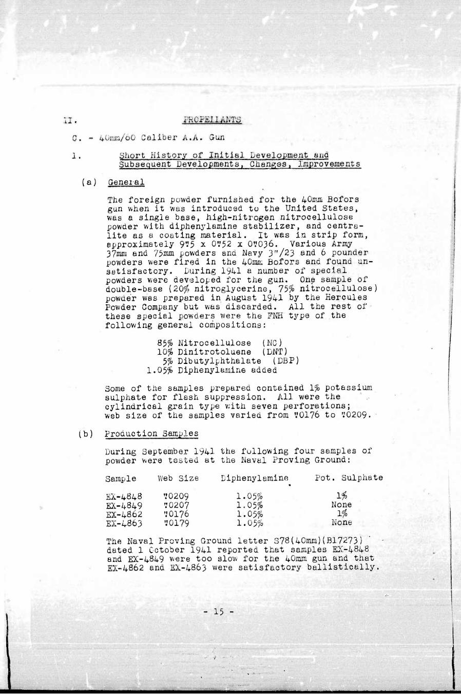
The foreign powder furnistied for tiie feQmm Bofors gun when it was introduced to the United States, was a single base, high-nitrogen nitrocellulose powder with diphenylemine stabilizer, and centra- lite as a coating material. It was in strip form, approximately 9'.f5 x OV52 x OVO36. Various Army 37mm end 75mm powders and Navy 3,,/23 and 6 pounder powders were fired in the 40mm Bofors and found un- satisfactory. During 1941 a number of special powders were developed for the gun. One sample of double-base {20% nitroglycerine, 75% nitrocellulose) powder was prepared in August 1941 by the Hercules Powder Company but was discarded. All the rest of these special powders were the FMH type of the following general compositions:
8$% Nitrocellulose (NG) 10% Dinitrotoluene (DM) 5% Dibutylphthalate (DBF)
1.05% Diphenylamine added
Some of the samples prepared contained 1% potassium sulphate for flash suppression. All were the ' .. cylindrical grain type with seven perforations; web size of the samples varied from ,.,0176 to '.'0209.
(b) Production Samples
During September 1941 the fullowing four samples of powder were tested at the Naval Proving Ground:
Sample Web Size Diphenylamine Pot. Sulphate
EA-4848 '.'0209 1.05% 1$ EX-4849 70207 1.05% None EX-4862 '.'0176 1.05% 1% EX-4863 '.'0179 1.05% None
The Naval Proving Ground letter S78(40mm) {B17273) ' - dated 1 October 1941 reported that samples EK-4848 and EX-4849 were too slow for the 40mm gun and that EX-4862 and EX-4863 were satisfactory ballistically.
- 15 -
i^^MBBB

Subsequent tests öt the Army rroving Grouna inaicfatea tuet iÄ-4862 was too fast, accordingly, later experi- mental samples were made witii web size of about ?0195j which slowed üown the powder. The formula used in the manufacture of lot RKU-1, the first production lot made specifically for the U. S. Wavy was as follows:
Nitrocellulose 82,y$ Linitrotoluene 10,00 Dibutylphthalate 5.00 l-otassium Sulphate 1.00 Diphenylamine 1.05 Wob Size V0185
This formula has been used for all subsequent 40mm powder production, with slight modification in the web size.
(c) Development of Proof Procedure
Proof of powder was conducted, in accordance with O.P. 366 and Chapter 10 of the Proof Regulations of the Waval Proving Ground. The service velocity of the gun was established as 2890 f/s,the service jxessure limits as 17.5 tons/sq,ln, minimum and 19.5 tons/sq, in. maximum. The specifications for uniformity limits were .625^ of the mean velocity and 3,125% of the mean pressure. These uniformity limits were changed by BuOrd letter NP9/S78(Re2d) dated 19 August 1943 to become .6$ of the mean velocity and 5% of the mean pressure. The latter specifications are currently in effect. Originally the determin- ation of service charge was accomplished by firing a Charge vs. Velocity curve in a new 40mm gun and picking off the service charge at 2890 f/s. This was known as the "New Gun" method. This was super- seded in 1943 by the "Matched Powder" method wherein service rounds of a carefully calibrated Master Standard Powder (SPDN-3804) were fired to establish a service velocity and pressure, against which the service charge and pressure of the test lot of powder were calculated.
(d) Effect of Various Components on Smokeless Powder
The introduction of the Mark 11 tracer, which in- creased the weight of projectile from 1.97 to 1.985 pounds, and of the Mark 3 (steel) cartridge case, with greater wall thickness, which decreased the
- 16 -
mmm—^m^mamamm^^—~i—wm*^mmmmm^^^^mm^m^^^^^^^—^^m—mm—^mm^m^—^mm—^—^^mmm^—mrymmam
I
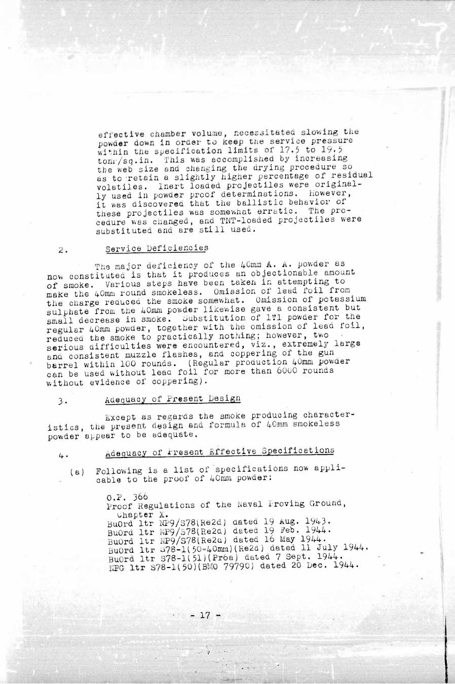
effective chamber volume, neces3itateä slovving the powder down In oraer to Keep tne service pressure wltMn the specification limits of 17.5 to 19» 5 tom/sq.in. This was accomplished by increasing the web size and changing the drying procedure so as to -retain a slightly higher percentage of residual volatiles. inert loaded projectiles were original- ly used in powder proof determinations, however, it was discovered that the ballistic behavior of these projectiles was somewhat erratic. The pro- cedure was changed, and TNT-loaded projectiles were substituted and are still used.
2. Service Deficiencies
The major deficiency of the 4ömm A. A. powder as now constitatea is that it produces an objectionable amount of smoke. Various steps have been taken in attempting to make the'40mm round smokeless. Omission of lead foil from the charge reduced the smoke somewhat. Omission of potassium suluhate from the 40mm powder likewise gave a consistent but small decrease in smoke. Substitution of 1V1 powder for the regular 40mm powder, together with the omission of lean foil, reducea the smoke to practically nothing; however, two • serious difficulties were encountered, viz., extremely large and consistent muzzle flashes, and coppering of the gun berrel within 100 rounds. (Regular production 40mm powaer can be used without lead foil for more than 6000 rounds without evidence of coppering).
3. Aaeouacy of Present Design
Except as regards the smoke producing character- istics, the present design and formula of 40rom smokeless powder appear to be adequate.
4. Adecuacy of n-esent Effective Specifications
(a) Following is a list of specifications now appli- cable to the proof of 40mm powder:
O.P. 366 Proof Regulations of the I^aval Proving Ground,
uhapter X. BuOrd Itr NP9/378(Re2dj dated 19 Aug. 1943. BuOrd Itr KP9/378iRe2cl) dated 19 Feb. 1944. BuOrd Itr WP9/S78lRe2d) dated 16 May 1944. BuOrd Itr J78-li5Ü=40mm)(Re2d) dated 11 July 1944. BuOrd Itr 378-1i51HProa) dated 7 Sept. 1944. KPG Itr S78-1150HBMO 79790) dated 20 Dec. 1944.
17 -

I^^^H^W
BuOrd Itr l<P9/378(Pr68~l; üüted 12 Feb. 194$. ßuurd Itr iWio/S7#ii^#Ä*lJ detea 16 ?eb. 1945. BuOrd Itr S78-l(51i(Re2a) oated 5 May 1945.
(bj These specifications appear to be adequate, except that specifications for lots of siaoiceless powder to be used witb A.?, projectiles sboulcl be clarified.
5, Suggested Fielas for improvement
it is suggested tbat;
(a) Investigation of powders of new chemical compositions be inaugurated in order to find a flasdless, smoke- less round.
(bj Specifications for powder lots destined for use with A.P. projectiles be clarified.
(cj The miscellaneous directives comprising the specifi- cations for proof of 4ümm powder be combined into an Ordnance Specification.
- 18 -

^■^H
III. mOZECTILMS :
A« - 20mm/7Q Caliber Ä. A. Gun
x • Short History of Initial Development and Subsequent Developments. Changes and Improvementa
(a) mi Projectile
The early stages of experimental woric with 2ümm projectiles were conducted using lend-lease ammuni- tion obtained from the National Fireworks Company, which wes at that time loading ammunition for the British. In January 1942 the British indicated that the incorporation of an incendiary element greatly improved the destructive effects especially against aircraft. Tests at the Proving Ground corroborated British findings. British methods of loading the incendiary consisted of inserting a small amount of black powder between the incendiary mix, which was the first increment of loading, and the second increment of tetryl. This method was quite complicated and was not readily adapted to production loading. Further experimenting was conducted in an effort to simplify the above pro- ceclure. It was determined that the black powder was unnecessary for propagation. Final loading of incendiary type ammunition using projectiles designated Mark 3 was as follows:
First Increment: Incendiary mix (64 grain pellet) consisting of Magnesium, Aluminum, Barium Nitrate, Paraf- fin and Graphite.
Seoond Increment:
(b) PentoUte Loading
Tetryl pellets grains total»
(2 or 3) - 128
In June 194?<, experiments were conducted to determine the suitability of Pentolite as a projectile filler for the HE type projectile. At this time there were a number of gang pelleting machines available for loading of Pentolite, Although test results with Pentolite were comparable to the standard tetryl loading, this filler was never adopted for production loading.
19 -
mmmmmmm
,..........,.
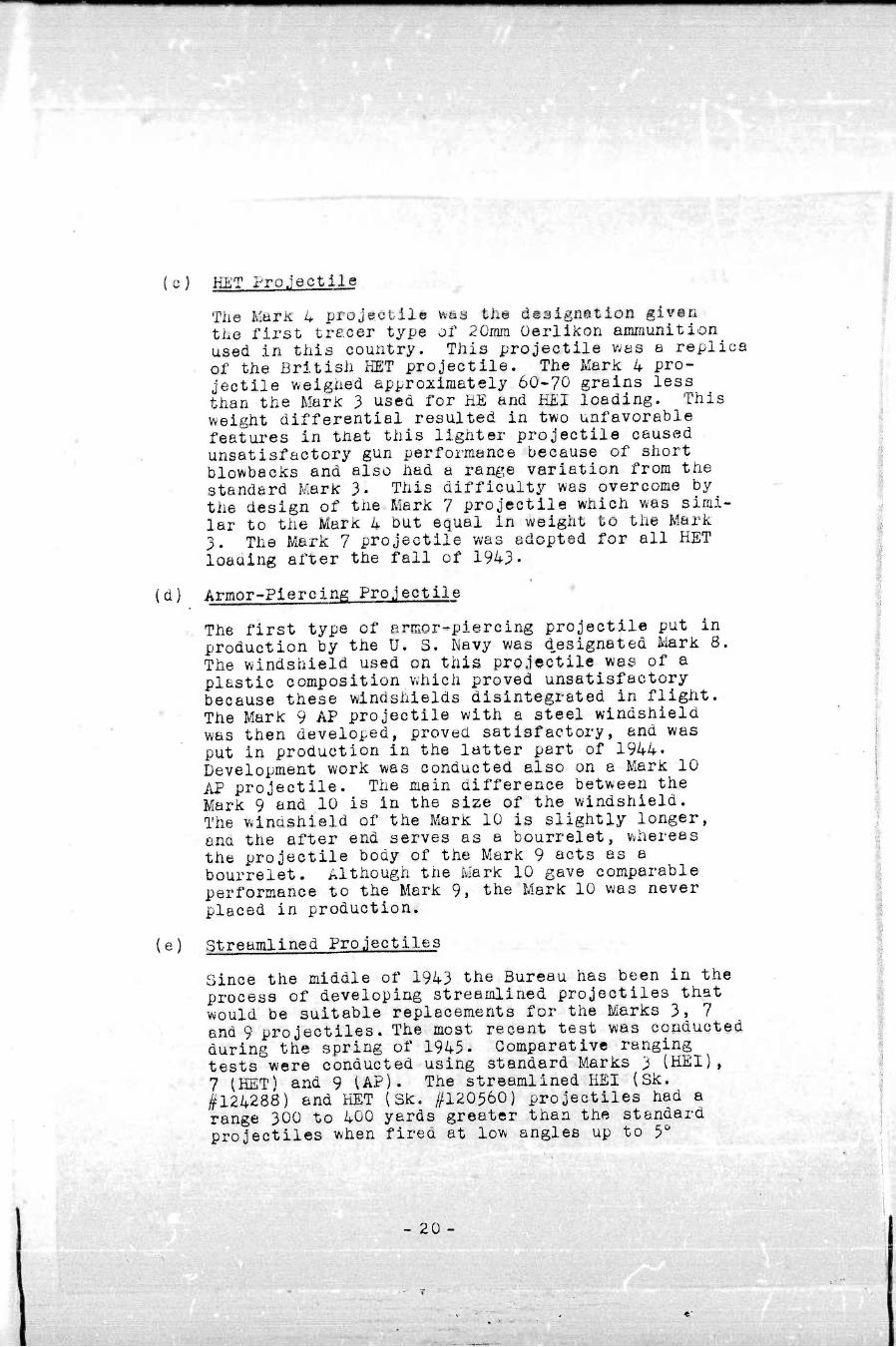
(o) HET Projectile
The Marlt 4 projeetile was the dsaignation giv©n the first trecer type of 20iwn Oerliicon amiriunition used in this country. This projectile was a replica of the British HET projectile. The Mark 4 pro- jectile weighed approximately 60-70 grains less than the Marie 3 used for HE and MEJ loading. This weight differential resulted in two unfavorable features in tnat this lighter projectile caused unsatisfactory gun performance because of short blowbacks and also had a range variation from the standard Mark 3. This difficulty was overcome by the design of the Mark 7 projectile which was simi- lar to the Mark 4 but equal in weight to the Mark 3. The Mark 7 projectile was adopted for all HET loaaing after the fall of 1943.
(d) Armnr-Piercing Projectile
The first type of anaor-plercing projectile put in production by the U. S. Navy was designated Mark 8. The- windshield used on this projectile was of a plastic composition which proved unsatisfactory because these windshields disintegrated in flight. The Mark 9 AP projectile with a steel windshield was then developed, proved satisfactory, and was put in production in the latter part of 1944. Development work was conducted also on a Mark 10 AP projectile. The main difference between the Mark 9 and 10 is in the size of the windshield. The windshield of the Mark 10 is slightly longer, and the after end serves as a bourrelet, whereas the projectile body of the Mark 9 acts as a bourrelet. Although tne Mark 10 gave comparable performance to the Mark 9, the Mark 10 was never placed in production.
(e) Streamlined Projectiles
Since the middle of 1943 the Bureau has been in the process of developing streamlined projectiles that would be suitable replacements for the Marks 3» 7 end 9 projectiles. The most recent test was conducted during the spring of 1945. Comparative ranging tests were conducted using standard Marks 3 (HEX), 7 (HET) and 9 UP). The streamlined HEX (Sk. ^124288) and HET (Sk. //120560) projectiles had a range 300 to 400 yards greater than the standard projectiles when fired at low angles up to 5°
- 20 -

elevation. The streamlined AP (Sic. ^140676} also had a greater range th'an the fcark 9 projectile, but Jaad a significantly larger range dispersion. Present development of the experimental AP projectile is being conducted so as to improve the stability factor.
2. Service Deficiencies
The major service deficiency of present production 20inra A. A. and A. P. projectiles is the short effective range of the projectiles. This condition can be overcome to a considerable degree by the introduction of the new stream- lined projectiles. However, before this substitution can be made for all types of projectile, the streamlined A.P pro- jectile must be further developed to improve the stability factor, because in its present state the projectile has an unsatisfactory range dispersion.
3. Adequacy of Present Design
The design of the 20mra projectile now in use is inadequate because the external contours of the projectile are such as to cause a shortened range. The projectile has already been iredesigned in this respect, and the new stream- lined design represents a definite improvement. In addition the tracer cgvity of the present Mark 7 projectile is larger than necessary for the amount of tracer pyrotechnic used; this necessitates insertion of a certain amount of inert material iii the tracer cavity, which practice is considered objectionable.
4. Adequacy of Present Effective Specifications
la) A. A, Projectiles
O.S. 2337 (Minor Caliber Projectiles) and BuOrd Drawings Nos. 294290 and 329164, for the Mark 3 and Mark 7 projectiles respectively, constitute the present effective specifications for 20mm explosive- loaded A.A. projectiles. These specifications are adequate to insure the proper performance of the projectiles within the limitations of the present design.
(b) A. P. Projectiles
O.Sc 2806 (Minor Galioer Projectiles) and BuOrd Drawing No. 42360I, for the Mark 9 projectile, constitute the present effective specifications for the 20mm A.P. projectile, O.S. 2806 is inadequate
- 21
**•*

wmmm^mmmmmmmmmmmmmmmm^mtmmmm^mmmmmmmmmmmmmmmmmmmmmmmmmmmmm^mmmmmmmam
and. is in the process of being revised, Kecommen- dationa regarding this revision have previously- been submitted to the Bureau by the Proving Ground,
5. Suggested .Fields for Improvement
It is suggested that;
(aj The present Mark 3, I^ark 7, and Mark 9 projectiles be replaced by corresponding projectiles of stream' line design.
(b) Tracer cavity of the Mark 7 projectile or its streamlined replacement be redesigned so as to eliminate the necessity for placing inert material
p
- 22 -
;
V.
in the tracer cavity,
(c) O.Ss 2806 be revised.

III. PROJii.CTILJL'3
B - I'.»1/75 Caliber Gim
1' History of Developments. Changes and Improvements
(a) General
During the development of 1V10 ammunition two (2) types of projectiles Mark 1 and Mark 2 were uti- lized. Both projectiles were designed with an integral tracer. The Mark 2 was designed with greater wall thickness in the tracer cavity to with- stand greater pyrotechnic consolidating pressures. Although the I'.'IO gun was one of the most common small caliber A.A. guns at the time of the entry of the United States into World Vvar II, the per- formance of the ammunition for this gun was unsatis- factory because of high percentages of tracer duds and premature explosions, iiarly in 1942 the I^aval Ordnance Laboratory was directed to improve the tracer action, a project to be carried on with the development of the self-destruction feature.
(b) Redesign of Tracer Cavity
Experiments revealed that available pyrotechnics at this time required very high consolidation pressures to result in satisfactory performance. Since the tracer cavity walls of the Mark 1 was too thin to withstand these high consolidating pressures it was decided to redesign the Mark 1 projectile increasing this wall thickness. This design resulted in the Mark 2 projectile,
ifJ Mark 2 Projectile
Numerous tests were conducted in the Mark 2 pro- jectile utilizing the standard I'.'IO, U. S. Rubber Company and Triumph Explosive pyrotechnics, in- corporating various loading techniques. As mentioned previously, the high loading pressures resulted in the best tracer Performance. However, it was found that the maximum pressures obtainable using the Mark 2 projectile was 70,000 p.s.i. Pressures higher than this resulted in excessive swelling of the tracer stock, which in turn causea tracer duds, blowouts, and prematures.
- 23 -
■•'
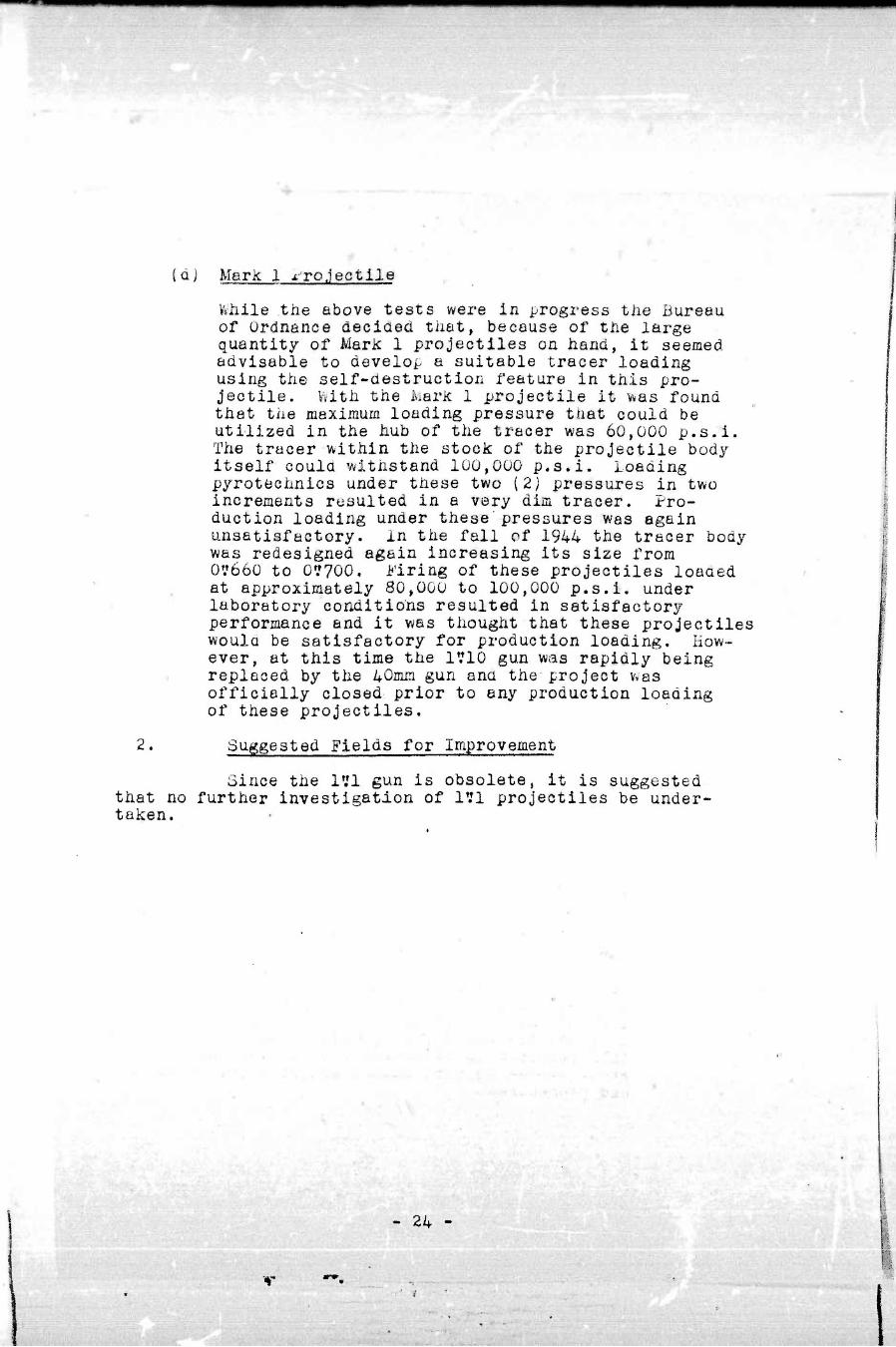
(dj Mark 1 .t-rojectile
Wiiile tiie above tests were In progress tiie Bureau of Ordnance deciüed tiiat, because of the large quantity of Mark 1 projectiles on hand, it seemed advisable to develop a suitable tracer loading using the self-destruction feature in this pro- jectile. With the Marie 1 projectile it was found that the maximum loading pressure that could be utilized in the hub of the tracer was 60,000 p.s.i. The tracer within the stock of the projectile body itself could withstand 100,000 p.s.i. Loading pyrotechnics under these two (2j pressures in two increments resulted in a very dim tracer. Pro- duction loading under these'pressures was again unsatisfactory, in the fall of 1944 the tracer body was redesigned again increasing its size from 0V660 to 0V700, i-'iring of these projectiles loaaed at approximately 80,000 to 100,000 p.s.i. under laboratory conditions resulted in satisfactory performance and it was thought that these projectiles woula be satisfactory for production loading. How- ever, at this time the 1V10 gun was rapidly being replaced by the 40mm gun and the project was officially closed prior to any production loading of these projectiles.
2. Suggested Fields for Improvement
Since the lyl gun is obsolete, it is suggested that no further investigation of 151 projectiles be under- taken.
- 24 ~
T

m- PROJ£GTII£S
C. - 40mm/60 Caliber A.A. Gun
1' Short History of Initial DevelopiEent end Subsequent Developments. Changes end Improvements
(a) General
Preliminary testing of 40mm ammunition was started in early 1941 in conjunction with tests on the Bofors gun itself. Early experimentation was con- ducted using British ammunition and by September of that year testing of projectiles, designated Marie 1, manufactured in this country was initiated. The Mark 1 projectile was comparable to the British ammunition used during initial tests.
(b) Mark 2 Projectile
In the latter part of 1943 the pilot lot of Mark 2 projectiles was tested at the Proving Ground. This projectile differed from the Mark 1 only in minor manufacturing changes. Shortly thereafter all pro- duction of high explosive type projectiles was con- centrated on the Mark 2 projectile.
(c) Mark 3 Projectile
The Mark 1 and Mark 2 projectiles are designed so as to accommodate a threaded fuze on the forward end and either a threaded tracer or a base plug in the after end, according to the type ammunition desired. Because of the great demand for non-traced type of ammunition in the latter part of 1944, it was decided to design a projectile with a solid base thereby eliminating the necessity of a base plug and facilitating loading. The pilot lot of Mark 3 (solid base) projectiles was tested at the Proving Ground in the early part of 1945. Because of the rapid changes in service demands to dark tracer« and delay ignition tracer at this time the Mark 3 was never put in production.
U) A.P. Projectile
The armor-piercing type projectile used by the Navy is an Army design manufactured for the Navy to Navy specifications. This type projectile, designated ' M81A1, consists of a solid slug with steel windshield
- 25 -

-■■■■■■ ■ ■ > -
attached, resulting in an overall projectile length slightly leas than the explc live loaaea projectiles. The base of the A.P, projectile is designed to accoEMOüate an integral tracer. Rhen no tracer is desired the cavity is filled with a wooden plug.
2« Service Deficiencies
At the present time the only service deficiency reported is an occasional unsatisfactory windshield crimp on the A.P. M81A1 projectile. In tests at the Naval Proving Ground the windshield crimping has been considered satis- factory, but there have been occasional complaints from the service about thrown windshields.
3. Adequacy of Present Design and Present Effective Specifications
(a) A.A. Projectiles
Present design and effective specifications for 40mm A.A. projectiles are given in BuOrd Drawings Nos. 328536 (Mark 2 Proj.) and 393SO (Mark 3 Proj.), and O.S. 2337 (Minor Caliber Projectiles). The design and specifications are adequate.
(b) A.P. Projectiles
Present design and effective specifications for 40mm armor-piercing projectiles are given in Army Ordnance Dept. Drawing 75-2-321 (M81A1 Proj.) and 0.3. 2806. This Ordnance Specification is consider- ed inadequate and is currently under revision by the Bureau. Recommendations regarding this revision have previously been submitted to the Bureau by the Proving Ground.
4. Suggested Fields for Improvement
It is suggested that 0,S. 2806 be revised.
- 26 -
immm
IV, TRACERS
A. - 20nm/70 Caliber A. A. G un
I. Short History of Initial Development and Subsequent Developments. Changes and Improvements
(a) General
Initial testing of traced ammunition was conducted using igniters and pyrotechnics developed by the British. At the end of 1942 the Bureau of Ordnance received reports from the fleet that this type of traced ammunition gave too much muzzle flash and too bright a streaJc upon firing. During night firing this light created a double hazard in that it silhouetted the firing ship and blinded the gunners after a few seconds of firing. As a result of the undesirable characteristics of this type 20mm tracer the Bureau directed that a tracer be developed having a dark igniter that would not give more than a faint streak of light until the pro- jectile reached a distance of 75 to 125 yards from the gun, at which point the tracer could be picked up and followed by the gunner. In addition the Bureau directed that substitute materials be found for the critical materials, chlorinated rubber and shellac, that were constituents of the standard tracer,
(b) Original Tracer Composition
The original 20ma tracer consisted of strontium nitrate and magnesium as a base, with shellac as a binder, beeswax as a lubricant and chlorinated rubber as a color intensifier. It was thought that a satis- factory mixture could-be made by replacing the chlorinated natural rubber with similarly processed synthetic rubber, while at the same time replacing or eliminating the shellac. Several attempts were made, but the resulting mixtures were unsatisfactory either because of insufficient light, too much smoke, or failures to ignite. Additional experiments using Vinsol resin and hydrofol glyceride resulted also in unsatisfactory performance.
(c) Development of R-131 Pyrotechnic
Experiments with a Swedish mixture that used strontium tartrate produced a satisfactorily burning tracer, but was not suitable for production loading because of the
- 27 -

impossibility of forming the mixture into firm pellets. In addition this mixture wets not suf- ficiently sensitive to flame. The pyrotecnnic finally adopted for production loading in delayed ignition tracers was designated R-131, Tills mixture was made up by adding strontium tar träte to a basic strontium nitrate-magnesium mixture. Ilexaehloro- benzene was included to enricli tiie color. Stearic acid replaced tne beeswax as a binder, eliminating the necessity of preparing the mixture hot, and in addition making it possible to pellet the mixture. The charcoal improved the ignitability of the mixture. Composition and precentages by weight of the R-131 pyrotechnic are listed below:
Magnesium - 31.8% Strontium Nitrate - 30.9 Strontium Tartrate - 27.3 Hexachlorobenzene - 4.6 Charcoal - 0.9 Steario Acid - 4.5
(d) Dark Ignition Tracer
Development of the dark ignition igniter proceeded from British mixtures which made use of potassium dinitrophenate as a fuel, barium peroxide as an oxidizing agent and bakelite varnish as a binder. Because this mixture required insertion of another mixture between it and the pyrotechnic to effect ignition of the latter, it was considered unsatis- factory. Mixtures containing barium peroxide and antimony sulfide were found to give a much faster rate of burning than the British mix and subsequent mixtures tested. Friction sensitivity caused a great deal of trouble in handling the barium peroxide-antimony sulfide mixture but was greatly decreased by the additioi? of a small amount of graphite. To give the slight streaking effect described heretofore required the addition of a small percentage of magnesium. The composition of the igniter, designated D.I.-149F, adopted for service use is listed below:
Barium Peroxide - 78.4$ Antimony Sulfide - 18,4 Magnesium - 2.2 Graphite - 1.0
Subsequent specification written to cover this type of ammunition specified that the total burning
- 28 -

time of tiie daric-ignition tracer should be from 3.5 to 4.5 seconds. Tiie average burning time of tiie standard tracer when loaded in the Mark 7 projectile is approximately 6 seconds. To satisfy the dark- ignition tracer requirements it was necessary to load approximately 3 grams of an inert material so as to decrease the burning time.
2. Service Deficiencies
The only service deficiency of the 20mm tracer is tne blinding effect of the original bright-streaking tracer on the gunner during night firing. This has been overcome by the substitution of the dark ignition tracer.
3. Adequacy of Present Design and Present Effective Specification
The design and formula of the dark ignition tracer which has superseded the original bright-streaking tracer, together with mahufacturing and testing specifications are included in O.S. 3425. These specifications and design are considered adequate.
s
- 29 -

IV. THACSHS
B. - 40miü/60 Caliber Gun
1. Snort History of Initial Development and Subsequent Developments. Ohanges and Improvements
(a) General
The tracer for 40inm high explosive projectiles differs from other U. S. Navy tracers in that it is required to inaugurate the self-destruction of the projectile after a prescribed time of flight. The tracer originally selected for the H,E. projectile assembly was of British design and was designated the Marie 8. This type tracer differed from standard Navy tracers in that it was sealed from contact with the" flame of the propellent, ignition being ac- complished by a percussion primer cap through set- back forces when the gun was fired.
(b) Mark 8 Tracer
Very unsatisfactory performance resulted during the testing of the Mark 8 tracers mainly because of the high percentage of prematures. This type tracer had additional disadvantages in that its compli- cated construction was not readily adaptable to mass production methods, and because of the hazard to personnel and equipment associated with the tracer parts expelled as the projectile left the gun muzzle. Tests revealed that it was possible for the lead sealing discs to penetrate 1/8" steel plate at a distance of 60 feet from tc* gun muzzle.
(c) Mark 10 Tracer
In tne fall of 1942 the Mark 8 tracer was redesigned increasing the wall thickness in an effort to elimi- nate the high percentage of prematures. This new tracer was designated Mark 10. Although the Mark 10 was a definite improvement over the Mark 3 from the standpoint of performance and subsequently was used in the assembly of several million rounds of of service ammunition, it still retained the basic principles and consequently the disadvantages of the Mark 8.
Id) Mark 11 Tracer
Because of these disadvantages, the development of a direct ignition tracer was initiated early in 1943
- 30 -

Tals tracer, designated Marie 11 was äUCü simpler in design tlian its predecessors. THe Mark 11 tracer is sealed witü a brass disc wtiicii disintegrates on trJie explosion of tiie propellent charge. After rupturing of this disc the starter mixture is ignited which in turn burns through and ignites the pyrotechnic mixture. After a prescribed burning time the pro- jectile is exploded through a small thermal relay containing black powder located in the base of the tracer body. Some difficulty was encountered during initial loadings of the Marie 11 tracer body because of inconsistent burning times, and some prematures and tracer duds. After successive experiments using various loading pressures and multi-shaped loading rams it was found that tracer performance was greatly improved under pyrotechnic loading pressures of 9.0,000 to 110,000 p.s.i., and using a stepped-face ram which increased the ignition surface.
(e) Special „Types of Mark 11 Tracer
After attaining satisfactory results using the Mark 11 tracer body there was a demand from the fleet for "special" tracers as outlined below:
Dark-Ignition Tracer 7 should burn dark for a distance of about 200 yards after which tracer should burn normally to self-destruction with a minimum self-destruction time of ten (10) seconds.
Dark Tracer - should burn so as to be Invisible from any point of observation during night firing having a minimum time to self-destruction of ten (10) seconds.
Daylight Tracer - having visibility in bright day- light of at least seven (7) seconds with the un- aided eye and a minimum self-destruction time of ten (10) seconds.
Development of these three types of tracers was conducted simultaneously by the Naval Ordnance Laboratory and production loading plants. Experi- ments were conducted using various types of igniter and pyrotechnic mixtures, loading pressures and rams.
(1) Dark Tracer
By the spring of 1944 the Naval Ordnance Laboratory developed what appeared to be a
>_a__.^_-^^MB_H-^^^MB_B_i^^^^^MH_a__Baai^^H_BBMBBaaaHMH

satlsractary igniter and pyröteckale Mixture that Would cieet tue dark tracer requirements. Pro- duction loading of eleven (11) lots using tais iriixture resulted in very unsatisfactory results because of nign percentage of duds. Early in 1945 a satisfactory mixture was developed for the dark tracer tnat could be successfully loaded by trie production plants. The ingredients used in type and its designation are Jisted below:
Igniter (D.I.-152) - Barium Peroxide, Selenium and Grapnite.
Pyrotecnnic (D.T.-226B) - Barium Peroxide, Antimony Sulfide, Aspiialtum and Graphite.
(2) Delayed-Ignitlon Tracer
In 1945 a satisfactory mixture, suitable for production loading, was developed for tiie delayed- ignitlon tracer. Tue ingredients and designation are listed as follows:
Igniter (D.I.-1$2) - Barium Peroxide, Selenium, and Grapiiite.
Pyrotechnic (R-132) - Strontium Nitrate, Strontium Tarträte. Magnesium, Carnauba Wax and Charcoal
(3) Daylight Tracer
* Development of a satisfactory tracer having long visibility in bright daylight has been unsuccess- ful up to the present time. Experiments have been conducted using Mark 11 tracer bodies with an enlarged bore and a special long tracer body (BuOrd Sk. #140046) loaded with various types of tracer mixtures in an effort to increase tne brightness qualities of the tracer. Although the demand for 40mra ammunition is now restricted to training and practice uses the Bureau of Ordnance has directed the Naval Ordnance Labora- tory to continue development work on a tracer that will give visibility in bright daylight for approximately seven (7) seconds and burning time of twelve (12) to fourteen (14) seconds.
(f) Mark 14 Tracer
Early in 1945, the service requested a traced, non- self-destroying type of ammunition to be used for
- 32 -
bambardiBent attacks. Ta meat t-üe immediate dejoaMs tiie self-destruotion feature was eliminated by filling tlie tracer relay cavity in tne standard i:ark 11 tracer body with an inert material ratner tban tlie normal hlaok powder charge. However, tills did not result in 100% non-self-destruction performance, apparently because of leakage around the relay body. To remedy this situation, tne Mark 11 tracer body was redesigned to the extent of eliminating the relay and making tne base of tne tracer body solid. This new tracer body was designated Mark 14 and was used in UI type (HEIT - no SD) ammunition assemblies after March 1945.
2. Service Deficiencies
Tne deficiencies encountered in the service use of the 40mm tracer are that the tracer is not visible for a sufficiently long time during bright daylight and the burning times of the dark tracer and delayed ignition tracers are too short.
3. Adequacy of Present Design and Present Effective Specifications
Design and specifications for the Mark 11 Tracer are furnished in BuOrd Drawings Nos. 423429 and 423430 and O.S, 2978. üxcept as noted in paragraph 2, above, tne design and specifications are adequate. BuOrd Drawing No. 440297 establishes the design of the Mark 14 tracer. Tnere is no Ordnance Specification available for this tracer.
4. Suggested Fields for Improvement
It is suggested that:
(a) Development work on a tracer for visibility in bright daylight be continued.
(b) An Ordnance Specification be prepared for the Mark 14 tracer.
(c) Primary consideration in future development be given to a universal day and night dark-ignition tracer wherein the pyrotechnic (or several pyro- tecnnics in succession) burns dimly or invisibly to the point of changeover from igniter to pyrotechnic, but progressively brightens during flight.
- 33 -

v. FüZüB»
A. - 20ism/70 Caliber AÄ Gua
1- Süort History of Initial Development.
Tue antiaircraft model of 20Mn kA Oerlik-on tvn« gun, ruount amunition and accessories was adopted by lH U.S. Navy in 1941. Production was started on guns and
r^L^Än'^L^f t0f^i^ -d clrawi^ffu^isned oy ureat öiitaln, wüicli country iiad previously adonted f-h-f«
gun as a Naval weapon. As late as 1940, the British were using a rotor type percussion fuze armed by centrl^ugaf ^n^tarid
Hempl0ying a pluilger and strilc^ fo^ed inwSd on
^TlatiTTt?*^ ^UZe ad0pted ^ the U-S- Navy was that u. a.later Britisii design known as the "254" or "H F ?*/»
T^f fuze' fa TAll PiartS ?nCl WaS m™h 3i2^lerrinHcoEnst2r^ction Itlä iTLlLf ^h air-c?luilin ^P6» i^ action being Initi-
2' Subsequent Changes. Developments and fegy^ehtg
(a) General
The MarK 26 fuze (and Mods.) was used exclusively on ammunition for the 20^ AA gun throughout World !?f Jn^i Ai.thoügl1 two M0(is- üave been added to the «ndgt? i' he' fUZe ÜaS not been c^nged radically ?Se actS^fthff^ ^^^^ slmPle construction. in?t? hrV0 .Ule fuze was first believed to be initiated by heat resulting from compression of air in a channel above the detonator but later this tha?r?hr«.??rtially fi^ded, and it is considered that the action is primarily that of a shocking ^'orce which causes a direct disturbing action on the detonator. This fuze is an exception to the cardinal safe "^^ IfÄ^ tliat fe^be ''*etona?orinal safe.' The design incorporating a detonator perma- nently in line with the booster was accepted in The ^f^f the/u5e Ma^ 26 because of the relatively small amount of explosive filler in a 20mm proiectile resulting in relatively slight danger to personnel' in case of a premature, and because the detonator contains straight azide and tetry: instead £f supersensitive azide priming mixture. This design permitted maintenance of the necessary rate of production of vast quantities of ammunition and kept down the cost. The fuze is abnormal in one
- 34 -
«;■■ ,■■■, ;;;■■'.■ :-.'-:T^:i,,,i...'
other respect viz., the shape. The flat nose has been recognized as being detrimental to the best ballistics and preliminary tests have been conducted using a fuze with a streamlined body designated 6-G,
(b) Marie Zb Mod. 0
After the ballistic requirements were established, early experiments were directed toward increasing the sensitivity and percentage performance. Various modifications and loadings were tested, one of which later was developed into the Mods. 1 and 2 type. The design originally started out as the double detonator type in which the explosive charge was increased. A firing pin type also was tried but was discarded in favor of the double detonator type. Close cooperation was maintained with the British Technical Mission which did proof testing and development work of lend-lease ammunition at their range in this country. Pro- duction of the Mod. 0 fuze was discontinued in favor of the Mods. 1 and 2. The Mod. 0 fuze consisted of five parts as follows:
1. Body 2. Closing disc (spun into the nose of the body) 3. Rear disc (forms open channel to detonator) 4. Detonator (lead azide and tetryl) 5. Magazine
(c) Mark 26 Mods. 1 and 2
In the interest of simplification, experimental bodies of machined brass stock with a solid nose were manufactured and tested and found to be satisfactory. This fuze with other changes (.magazine with intermediate charge and fuze with no rear disc) was later designated Mod. 2. In the same period the Mod. 1 fuze which differs only in material (zinc die cast body instead of brass) was developed. The Mods. 1 and 2 consist of four parts as following:
1. Body (solid-nose type) 2. Detonator (lead azide and tetryl) 3. Magazine 4. Magazine charge (tetryl)
- 35 -

■ ■■-- ■ ■■ ■■ ■ .' ■■ ,:■ .,.. .;;.... ..; ■
The Mod. 1 Is by far the most common type now in service. Since September 1944 this nas been the only standard design under manufacture.
3. Servioe Deficiencies Known to tiie Proving Ground
The overall performance of tue Mark 26 Mod. 1 fuze is considered very satisfactory, the percentage of any malfunctionings being very low.
4» Adequacy of Present Design
The Mark 26 Mod. 1 fuze as presently designed is considered satisfactory in that is has resulted in very good performance when fired against targets within 1000 yards range.
5. Adequacy of Present Effective Specifications
O.S. 2347 dated 2 August 1945 SPECIFIGATIONS FOR THE MANUFACTURE, ASSEMBLY. LOADING MD INSPECTION OF POINT DETONATING FCJZS MARK 26 MOD. 1 is presently adequate.
6» Suggested Fields for Improvements
It is suggested that further research be conducted using the streamlined fuze bodies mentioned in paragraph 2 (a) to obtain optimum characteristics in regard to functioning, sensitivity and safety.
- 36 -

-r--'-0-r.:. ■-.:,- ... .-.;.. . , :., . ■, . . - . : .. . .. , .... ..
f, FUZES
B. - 1710/75 Caliber Gun
1. aMr:&_Jiistory of Initial Development and Subsequent DeveIopraentsf cnan^es and Improvements
(a) Mark 12 Fuzes
In January 1939 the fuze used for I'/IO ammunition was tile Mark 12, Mods. 2 and 3. Production of the Mark 12 Mod. 2 fuze by the Naval Gun Factory and Pollak Manufacturing Company was started early in 1938. Mods. 2 and 3 differed only in the manu- facturers of the inert parts. They contained additional safecy features to prevent occasional prematures in the bore or close outside, which had been encountared in the use of the Mark 12 Mods. 0 and 1 fuzjs. The firing pin was first "eared" to prevent its moving back against the detonator until imract and later a thin washer was placed between the forward part of the firing pin and the nose. On impact, both the "ears" and the washer must be deformed,
(b) Mark 34 Mod. 0
Because of the simplicity and the highly satisfactory performance of the 40mm point-detonating fuze Mark 27 Mod. 1, this design for the most part was copied in making a new fuze for the IVIO gun. The one important difference is the method employed to secure the rotor in the unarmed position. This is the only fuze in the U.S. Navy which employs the sliding setback block and shear wire feature for this purpose. The Mark 34 fuze superseded the Mark 12 type design. Production of Mark 34 fuzes was started in early 1943 by Triumph Explosives, Incorporated, Several contractors supplied inert parts and other contracts were let for loading and assembly, but production was terminated in 1944.
(c) Mark 34 Mod. 1 (
The Mod. 1 employs "hour-glass" firing pin detents. This type is more bore-safe than the earlier cylindrical type but, although the design and testing was completed, the manufacture and loading of the Mark 34 type fuzes was discontined prior to the production of any of the Mod. 1 variety.
- 37 -

-..- ■■■■-:•■ ;• •;■.: v: •••■ ■ ■■. ■■■ ■ ■ ■■ ■■ ■ ■■ ■■..■,.■■■/.■.■ ■■ .....:■.,.■.„
2* Service Defiöienoies Known to the Proving Ground
(a) Mark 12 Fuzea
The most serious deficiency of these fuzes is the relatively high percentage of prematures. Consider- able quantities of these fuzes are on hand in the Mod. 2 and 3 versions but data gathered during World War II was meager due to the program of replacing mo guns by 40mm guns. Because of this and since a superior fuze has been developed in the form of the Mark 34, deficiencies are of small consequence exceot for evaluating the fuzes aready on hand,
(b) Mark 34 Fuzes
Because of the replacement of the lyio gun by the 40mm gua and because of the recent introduction of this fuze into the Naval Service, data on its per- formance liicewise is meager. As noted previously the Mod. 1 type never got into production. However because of the similarity with the Mark 27 fuze and* the parallelism between Mods., it is assumed that tne performance and likewise the deficiencies are similar.
3. Adequacy of Present Design
Inasmuch as the 1V10 gun is becoming obsolete and in view of sizeable quantities of useable fuzes on hand, this item does not merit further consideration.
4* Adequacy of Present Effective Specifications
(a) Nos. and Titles
(1) O.S. No, 1001 ORDNANCE SPECIFICATION TO GOVERN THE MANUFACTURE, INSPECTION AND TESTING OF DETONATING FUZE MARK XII-2 REV. (B), dated '11 March 1938.
(2) O.S. No, 2870 SPECIFICATIONS FOR THE MANU- FACTURE, LOADING AND INSPECTION OF POINT DETONATING FUZE MARK 34 dated 24 May 1943
- 38 -
(b) Cofltmeats
Since production iias been stopped on bo tu Marie 12 and Mlc. 34 fuzes for sometime past and since no future production is anticipated^ no specifi» cations are presently in use. If commencement of production sJaould again be planned, tiie speeifi=- cations süould be reviewed and modernized, especially O.S. No, 1001.
5. Suggestions
It is suggested that the 1V10 gun (and ammunition including fuzes) be declared obsolete as the production and installation of 40mm gun permits.
•
- 39 -
lW«fc* '■

fi FITZES
G. - 40a3m/60 Caliber Gun
1. Short History of Initial Develöpinent
The Bofors 40inm gun and ammunition of Swedish mänufaoture were first tested for the U.S. Navy at tiae Proving Ground in September 1940. Upon serious consideration of tlie adoption of tills gun by the U.S. Navy, firing tests of American designs of ammunition components were conducted in September 1941 under orders of the Bureau of Ordnance, The fuze tested (in several variations) was designated Marie 27. The Marie 27 fuze is of the point detonating type designed to function on impact with the target. This fuze meets the cardinal Navy requirement of being "detonator safe" and contains two independent safety features to prevent prematures. These first fuzes employed a die-cast aluminum body. Such a body was practically new in fuze design but represented one of many features of the fuze designed by the Naval Ordnance Laboratory aimed at permitting mass production of a fuze simple but safe. The original foreign fuze furnished the basic design but was so complex that it did not lend itself to mass production with the critical shortage of machine tools. The need for a fuze was urgent, and fortunately the redesign was accomplished rapidly and was so satisfactory that the Mark 27, with but normal development improvements and with but only one change major enough to rate a new Mod. number, was used exclusively on 40mm ammunition throughout World War II. The estimated unit cost with the original complicated design was $1.25. The fuze designed by NOL cost 7.1 cents to make when it first went Into production. Mass production, design changes and improvement in technique made possible a reduction in unit cost to 37 cents by April 1945. Much of the early work in solving production problems was done by Triumph Explosives, Incorporated, Various experimental modifications have been tested and rejected. Among these, the most notable were a fuze with delay action and another with a detonator from a Mark 26 Mod. 1 fuze {20mm) substituted for the firing pin and hammer.
2. Subsequent Developments, Changes and Improvements
(a) General
Although considerable work has been done during development in determining the optimum dimensional and physical characteristics, there have been no radical departures from the original American design.
40 -

Tiie one important modification made whicn was assigned tiie designation "Mod. 1M was tue adoption of "Hourglass" detents to make the fuze more consistently bore-safe. The feature was Jointly developed by t^e National Defense Researoh Gounoil and tue Naval Ordnance Laboratory. Testing was oofflmenoed in June 1943 and the design was officially approved in February 1944, with a conversion in production to tiie Mod. 1 following shortly. The general arrangement drawing for the fuze (BuOrd Dwg. No. 300423) was prepared in July 1941 and the extent of changes is shown by the list of revisions on it and on the detail drawings,
(b) Sensitivity
The sensitivity of the early Marie 27 fuzes was compared with that of the Mark 12 fuze (IVl) as a norm and found to compare favorably. However, when production expanded and parts were made by several contractors and assembled at several plants frequent poor functioning occurred and considerable testing was done on various schemes, loading methods, and material proposed to improve performance. Two items which were found to critically affect sensitivity were the shape or sharpness of the firing pin and the assembly of the booster pellet as regards density. Rigid requirements were included in the specifications designating that the firing pin have a sharp edge at the intersection of the flat end of the point and the conical surface and that the dense or hard end of the booster pellet be placed away from the booster lead-in. The value of an insensitive round (TNT loaded but plugged) was investigated and although it was conceded to have some superiority in damaging aircraft engines, the Proving Ground recommended against its use on the basis of the decreased value of the weapon because of the greatly reduced effective target area. The sensitivity for earth, water, heavy armor, newsprint and chipboard at -various obliquity and velocities was determined.
(c) Safety
An alarming number of prematures, some in the bore, occurred early in the testing and service use of the Mark 27 fuze. A 40inm premature has been defined by the Bureau of Ordnance as "a high or low order detonation of the projectile In the gun barrel".
- 41 -
. , , ■■ .
or, in service use, "at any point in flight within 400 yards of tile muzzle of the gunM. The fuze was investigated but it was found that the majority of prematures were initiated by the traoer or by a defect in the projectile itself» However, it was also found that the fuze was not as safe as had been supposed, since the cylindrical type firing pin detents were found to contribute almost nothing to the safety of the fuze as demonstrated by 80% prematures just inside the muzzle when firing fuzes with prearmed rotors. This condition led to the adoption of setback loclcing hourglass detents which keep the firing pin locked while in the bore, and for that distance beyond the muzzle of the gun that the velocity is increasing. They release the firing pin when set back has decayed to the point where the centrifugal force of the detents dominates, which occurs between 12 and 18 inches beyond the muzzle of the gun.
3» Service Deficiencies Known to the Proving Ground
The overall performance of the Mark 27 Mod. 1 fuze of recent production, including functioning, sensitivity, and safety, is very good. Although the percentage is low, prematures are still a hazard. It appears that they are not the result of inadequate design but of faulty components and assembly and can be held to a minimum by constant vigilance of the loading plants.
4. Adequacy of Present Design
The Mark 27 Mod. 1 fuze has proved adequate as a Point detonating läse.. However, with the advent of larger, heavier, and more heavily armored enemy aircraft it appears that a fuze with delay action is desirable or better still that an explosive semi-armor piercing or armor piercing projectile be used, which projectile will require a base detonating fuze.
5. Adequacy of Present Effective Specifications
O.S. 2958, Rev. B, dated August 2, 1945 - SPE OHIO ATI ONS FOR THE MANUFACTURE, ASSEMBLY, LOADING AND INSPECTION OF 40MM. DETONATION FUZE MK. 27 represents a recent rewrite and together with the drawings and applicable
- 42 -

^^^^^^H
:.\^:.[,:,^,.-:;-:,,.■■:.. , ...
specifications listed, is presently adequate. One oiiang© suggested for clarification of tue title is the addition of the word "POINT" preceding "DETONATING" to designate type and the Inclusion of information to show which Mods, are covered by O.S. 295S.
6. Suggested Fields for Improvement
It is suggested that the possibilities of a base detonating fuze be investigated.
- 43 -

YI. PROJECTILE FILDSRS
A. - 20tm/70 Caliber Guri
Tue History of the development of tue types of projectile fillers used in tue 20inm projectile is covered in Chapter III. Existing specifications for Assembled Rounds, listed in Chapter VII, adequately cover the loading of this size projectile. In the latter part of World War II all high explosive type ammunition, with the exception of that loaded with the dark ignition tracer, was loaded incorporating the incendiary pellet. As recommended in Chapter III, future experimentation with this size projectile should be conducted in an endeavor to include an incendiary pellet in the dark- ignition type projectile thereby increasing the lethal effects and standardizing loading procedures.
Uk -

'mmmmmmmmmmm mmmm^mmmmmm^^mmm
3, ~ 1V10/75 Caliber Gun
la toe period from 1939 until tue time 1?10 aumranition was no longer loaded, all iiigh explosive loading was witii explosive "D". Considerable difficulty was en- countered witii prematures during tue above period, but as explained in Chapter I?, the cause of this malfunctioning was not associated with the projectile bursting charge, but was caused primarily by excessive tracer consolidating pressure which often cracked the projectiles. As this type ammunition Is now obsolete no further comment in regard to design or specifications is applicable.
- 45 -
G. - 40inffi/60 Caliber Gun
1. TNT losdliq:
Initial loading of 40mni projectiles in this country used a high, explosive charge of TNT. Because of the fact that a practically direct hit was required when using this size ammunition to do any appreciable damage it was decided to experiment with the possibility of incorporating an Incendiary element within the projectile and thereby increasing the destructive qualities, especially when striking inflammable objects such as gasoline tanks and pipe lines.
2. TNT ~ Incendiary loading
With this objective of increasing the destructive quality in mind, extensive tests were conducted: first, to decide the proper position within the projectile to place the incendiary mix, whieJi was of the same composition as that used in 20mm ammunition; and second, to determine the optimum amount of incendiary material to be incorporated. Initial placement of the Incendiary mix in the center of the TNT charge as a core resulted in poor self-destruction flashes. Loading the incendiary mix as the first increment next to the tracer relay resulted in poor self-destruction performance also. The method finally adopted for production loading early in 1943 and the one that gave the most satisfactory results consisted of an incendiary ring pellet with a TNT core placed in the middle of the TNT charge. In early 1945 the loading technique was changed again substituting a solid pellet for the incendiary ring pellet to facilitate loading. This change was accomplished with no adverse results. The weight of the incendiary pellet adopted was approximately 18 grams.
3s Specifications
Existing specifications listed under Chapter VII covering the loading of all types of 40mm ammunition, are considered adequate.
- 46 -

wmm
v
I
VIZ* ASSEMBIED HOUNDS
!• Types of Assembled Rounds '■'■"■L- " rr""n ULL M.-II:II[IJIII.ILL.I...IIII---II ■ in. i.i.
following is a list of tJie various types of ammunition covered witiiin fcJiis report, together with complete identification information:
20mm/70 Caliber Gun s
Lot Symbol Type and Loading Assembly Projectile Color
5^ m White %* ttS-T Slate Gray
-r1 m Black ^ AP-T Black with White Band ff BL-T Green with Yellow Band „ BL-P Or ten,
Slate Gray with Red Band 2H HE-D1
HE - High Explosive AP - Armor Piercing HE-I - High Explosive Incendiary BL - Blind Loaded
T - Tracer p . Plugged (no tracer) DI - Delayed Ignition Tracer
- 47 -
•^

40iam/6Q Caliber Gun
Lot Symbol
UA UB UC UD
UE
UF
UG ÜH m UK ÜL
m
Type and Loading Assembly
HE-P HE-T Atr AP-T
BL-T
BL-P
Hi-I-T HE«SD(DT) ks-i«p HE-I-SD(DT) Hl-I-T (no SD)
HE-I-T-DI-SD
Pro j. Body
Green Green Black Black
Red
Red
Green Green Green Green Green with
White Black Band
Green
Color of Fuze Band
Green Wäite
White Band on Windshield White
Red
White Blaok Red Black
(Dummy Fuze) (Dummy Fuze)
Yellow
Fuze Nose
Green Green
Red
Red
Red Green Red Red Red
Red
BL - Blind loaded P - Plugged (no tracer) SD - Self-destroying DT - Dark Tracer
(non-luminous) DI - Delayed Ignition Tracer
HE - High Explosive HEI - High Explosive, Incendiary
T - Tracer (standard) AP - Armor Piercing
Lot Symbol
YA YB
l?10/75 Caliber Gun
Type of Loading
AA - Explosive MDn
AA-SD - Explosive "D"
AA - Anti-Aircraft SD - Self-destroying
- 48 -

2- Me^uacy of Present Effective opeüirications
fa) Nos. and Tit IRS
fnni1?^1?? ^ aJiBt of Preseßt day specif!oatlons applicable to tue loading of ZOmi and UOmm ammu- are listed^06 1?10 iS n0W obsolete no specifications
mm/70 Caliber Gun 0*S' No> Title
2806 Armor Piercing Projectiles (Minor Caliber) . Also applicable to 40mm ammunition.
2923 Loading, Assembly, Inspection and Padcin* of 20mm A.A. H.E., K.E.I, and H.E.T. Cartridges.
3425 Loading, Assembly, Inspection and Paoicing of Tracer#A* H*E,T' ^tiräges with DarK: Ignition
40mm/60 Caliber Gun
2990 Loading, Assembly, Inspection and Packing of 40mm A.A. (H.E.T. & H.E.I.T.) Cartridge with Tracer Mark 11 and Mods.
(b) Comments
After revision of O.S. 2806, which is in progress existing specifications for 20imn ammunition will ' be adequate. At present there are no specifjcations covering 40mm ammunition loaded with either the dark-ignition type tracer (UK) or the delayed- ignition type tracer (UM). After issue of speci- 7o™ a <S?Vet"fftg theBe tvvo tyPea of tracers the 40inm specifications will be considered adequate7
^ Suggested Fields for Improvement
(a) In subsequent development of 20mm and 40mm ammu- : ?n l} is suSgested that efforts be made to
standardize the identification colors. Because of the^obsolescence of various types of straight HE innnH*6!^ e ^^ 0l: various types of assembled rounds will eventually be reduced by two in the
- 49 -
■*

case of the 20inm snd tJaree in the 40iiim, Tills will still leave quite a large number of types of ammunition but witJi a standardization sucii as "Red" projectile color for incendiary loading for both 20mm and 40mm, much of the present confusion should be eliminated.
Cb| It is suggested that Ordnance Specifications be prepared to cover 40mm ammunition with Dark-ignition tracer (UK) and Delayed-ignition tracer (UM),
- 50 -
-■ ^