
%URWKHU 0LG 6HULHV $& *HDUPRWRUV 5HGXFHUV 02725 …
8
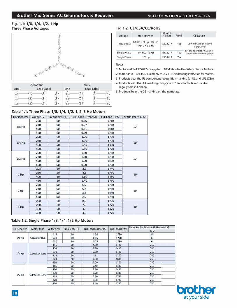
%URWKHU 0LG 6HULHV $& *HDUPRWRUV 5HGXFHUV 02725 :,5,1* 6&+(0$7,&6 1 4 7 8 5 2 9 6 3 )LJ +S 7KUHH 3KDVH 9ROWDJHV 7DEOH 7KUHH 3KDVH +S 0RWRUV 208/230V 460V Line Lead Label Line Lead Label L1 1 7 4 L1 1 7 4 L2 2 8 5 L2 2 8 5 L3 3 9 6 L3 3 9 6 )LJ 8/&6$&(5R+6 Voltage Horsepower UL/cUL File No. RoHS CE Details Three Phase 1/8 Hp, 1/4 Hp, 1/2 Hp 1 Hp, 2 Hp, 3 Hp E172017 Yes Low Voltage Directive 73/23/EEC EN Standards: EN60034-1 (Regulations on motors in general) Single Phase 1/4 Hp, 1/2 Hp E172017 Yes Single Phase 1/8 Hp E153713 Yes Notes: 1. Motors in File E172017 comply to UL1004 Standard for Safety Electric Motors. 2. Motors in UL File E153713 comply to UL2111 Overheating Protection for Motors. 3. Products bear the UL component recognition marking for UL and cUL (CSA). 4. Products with the cUL marking comply with CSA standards and can be legally sold in Canada. 5. Products bear the CE marking on the namplate. 7DEOH 6LQJOH 3KDVH +S 0RWRUV
Transcript of %URWKHU 0LG 6HULHV $& *HDUPRWRUV 5HGXFHUV 02725 …
1
4
7
85
2
96
3
208/230V 460VLine Lead Label Line Lead Label
L1 1 7 4 L1 1 7 4
L2 2 8 5 L2 2 8 5
L3 3 9 6 L3 3 9 6
Voltage HorsepowerUL/cUL File No. RoHS CE Details
Three Phase 1/8 Hp, 1/4 Hp, 1/2 Hp
1 Hp, 2 Hp, 3 Hp E172017 Yes Low Voltage Directive
73/23/EECEN Standards: EN60034-1(Regulations on motors in general) Single Phase 1/4 Hp, 1/2 Hp E172017 Yes
Single Phase 1/8 Hp E153713 Yes
Notes:
1. Motors in File E172017 comply to UL1004 Standard for Safety Electric Motors.
2. Motors in UL File E153713 comply to UL2111 Overheating Protection for Motors.
3. Products bear the UL component recognition marking for UL and cUL (CSA).
4. Products with the cUL marking comply with CSA standards and can belegally sold in Canada.
5. Products bear the CE marking on the namplate.

Brother Mid Series AC Gearmotors & Reducers M O T O R W I R I N G S C H E M AT I C S
11
Fig 1.9 1/4 and 1/2 Hp Capacitor Start Models
Fig. 1.5: 1/8 Hp Single Phase Voltages
Wire Color Code 115V Color Code 220V, 230V1 Blue Brown2 Black Black3 Grey Grey
1
2
3
Fig. 1.7: 1/4, 1/2 Hp Single Phase Voltage 115V
v y
u
AC
FW
Red Brown
Black Blue
FW
REV
REV
x
v
u
AC
Red
Black
BlueFW
REV
x
Fig. 1.6: Capacitors for 1/8 Hp Single Phase
10
4
h4.3
t
d
|
w
1/8 Hp Single Phase Motor CapacitorsPart No. mFd Volts* W h t d lC24M220V 24 220V * 2.28 1.46 0.93 1.52 0.28C6.0M440V 6 440V ** 2.28 1.61 1.14 1.73 0.28* 220V Capacitors are for operation with 115V Motors
FW
REVAC
To reverse, connect x with v instead of u. To reverse, switch y and x as shown by dotted lines.
Notes:
1.These are capacitor start gearmotors using a govenor switch to cut-out the starting capacitor.
2. For specific dimensions please consult Brother. Drawings are also available at www.BrotherGearmotors.com
G3 H2 F3
** 440V Capacitors are for operation with 220V or 230V motors.

10
3
1
4
6
8
7
12
2
5
911
FieldSpring PinArmatureFan AssemblySpring 1Spring 2Lock Washer/NutKeyFan CoverFan Cover ScrewBushingHex BoltGap
1
2
3
4
5
6
7
89
10
12
11
:
1119
3
4
6
8
7
2
10
512
FieldSpring PinArmatureFan AssemblySpring 1Spring 2Lock Washer/NutKeyHex BoltFan CoverFan Cover ScrewBushing
Gap
1
2
3
4
5
6
7
89
10
12
11
:
C
B
A
Release Handle
Term BoxBrake Wiring
Dim(in) Hp 1\8 1\4 1\2 1 2 3
A 6.14 6.14 6.14 6.14 7.09 8.35 8.35B 3.27 3.27 3.27 3.27 4.02 4.88 4.88C 0.32 0 0 0 0.08 0.24 0.24
Note: Manual Brake release is optional and must be specified on your order.

1
Field Armature Friction Disk Spring 1 Spring 2Croun nutKey Hexagon socket head boltBrake coverO-ring Brake coverSetscrew
Gap
1
2
3
4
5
6
7
8
9
10
11
123 4 5
6
7
8
9
1011
Field Armature Friction Disk Spring 1 Spring 2Croun nutKey Hexagon socket head boltBrake coverO-ring Brake cover fixing screw Oil seal V-seal Fan Hexagon socket headlocking screw Fan cover Fan cover fixing screwGap
1
2
3
4
5
6
7
8
9
10
11
12
13
14
15
16
17
1233 4 56 7 17
12
13
14
15
10118 9
16

Type 115V, 220V, 230V Single Phase * 115V, 220V, 230V Single Phase * 208/230V Three Phase (B2, J2, V2) *1/8 Hp 1/4, 1/2 Hp 1/8, 1/4, 1/2 and 1, 2, 3 Hp
460V Three Phase (B2, J2, V2) *1/8, 1/4, 1/2 and 1, 2, 3 Hp
460V Three Phase (B4, J4, V4) *1/8, 1/4, 1/2 and 1, 2, 3 Hp
M: Motor Br: Brake S: Reversing switch C: Capacitor MS: Magnetic switch Z:
* For wiring with an Inverter, see page 17
Surge Suppressor
AC
MS
SC
ZRECTIFIER
M
Br
AC
MS
S
Z
M
BrRECTIFIER
AC MS
SC M
BrRECTIFIER
AC MS
S
M
BrRECTIFIER
AC
MS SC M
BrRECTIFIER
AC
MS S
M
BrRECTIFIER
AC
Switc
hing
(2)
AC
Switc
hing
(1)
DC
Switc
hing
Nor
mal
Res
pons
eN
orm
al R
espo
nse
Fast
Res
pons
e
R5
36
46
200 150
(white)
(yellow)
(Input)
(black)(red)
(blue)
(Output)
(blue)
56
1010
1.02
4.52.5
(x)
fi urge Suppressor
OP-ERZV10D471 (200V)
115V use A100-D90 Rectifier220-230V use A200-D90 Rectifier
115V use A100-D90 Rectifier220-230V use A200-D90 Rectifier
115V use A100-D90 Rectifier220-230V use A200-D90 Rectifier
115V use A100-D90 Rectifier220-230V use A200-D90 Rectifier
(a) A200-D90 (200VAC Input, 90VDC Output) (x=17 mm)(b) A100-D90 (100VAC Input, 90VDC Output) (x=17 mm)(c) A400-D180 (400VAC Input, 180VDC Output) (x=19.5 mm)
OP-ERZV10D911 (400V)
(a)
(b)
(c)
Rectifier Dimensions (mm) Surge Suppressor Dimensions (mm)
115V use A100-D90 Rectifier220-230V use A200-D90 Rectifier
115V use A100-D90 Rectifier220-230V use A200-D90 Rectifier
Motor
white
yellow
Fwd
Fwd
Powe
r Sou
rce R
S
T
Rev
Rev Byellowyellow
blue
blackred
blue
RectifierA200-D90
(A100-D45)
T1 T7 T4
T2 T8 T5
T6T9T3
Motor
white yellow
Fwd
Fwd
Powe
r Sou
rce R
S
T
RevRev
Bblueblue
blue
blackred
blue
RectifierA200-D90
(A100-D45)
T1 T7 T4
T2 T8 T5
T6T9T3
Motor
white yellow
Fwd
Powe
r Sou
rce R
S
T
Rev
Bblueblue
blue
blackred
blue
RectifierA200-D90
(A100-D45)
T1 T7 T4
T2 T8 T5
T6T9T3
Motor
white yellow
Fwd
Powe
r Sou
rce R
S
T
Rev
RectifierA400-D180
T1 T7 T4
T2 T8 T5
T6T9T3
FwdRev
Byellowyellow
blue
blackred
blue
Motor
whiteyellow
Fwd
Powe
r Sou
rce R
S
T
RevRectifier
A400-D180
T1 T7 T4
T2 T8 T5
T6T9T3Fwd
Rev
Byellowyellow
blue blackred
blue
Motor
white
yellow
yellowyellow
Fwd
Powe
r Sou
rce R
S
T
Rev
B
blue
blackred
blue
RectifierA400-D180
T1 T7 T4
T2 T8 T5
T6T9T3

Single Phase1/8 Hp 1/4 HpDim
N1 (1/8 Hp 3 Ø only) — —N (motor) 3.09 3.29N (Brakemotor) 3.44 3.96M 4.61 4.61
Single Phase1/8 Hp 1/4 HpDim
N1 (1/8 Hp 3 Ø only) — —N (motor) 3.09 3.29N (Brakemotor) 3.44 3.96M 4.61 4.61
Single PhaseDim 1/2 Hp
N (motor) 3.98N (Brakemotor) 4.25M 4.80
Single PhaseDim 1/2 Hp
N (motor)N (Brakemotor)
3.15Applicable Code Φ.31 -Φ.47
A N
M
"W" Box to 3 "W" Box to Hp
Dim 1/8 Hp 1/4 Hp 1/2 Hp 1 Hp 2 Hp 3 Hp
A 4.27 4.27 4.51 4.98 5.41 5.41N (motor) 1.87 3.07 3.27 3.70 4.35 4.35N (Brakemotor) 3.90 5.04 5.55 6.44 n/a n/a
Dim 1/8 Hp 1/4 Hp 1/2 Hp 1 Hp 2 Hp 3 Hp
A 4.27 4.27 4.51 4.98 5.41 5.41N (motor) 1.87 3.07 3.27 3.70 4.35 4.35N (Brakemotor) 3.90 5.04 5.55 6.44 n/a n/a
3.984.254.80
Dim 1 Hp 2 Hp 3 Hp
A 5.22 5.50 5.93N (motor) 3.87 4.66 4.70N (Brakemotor) 6.33 - -
1 Hp 2 Hp 3 Hp
5.22 5.50 5.933.87 4.66 4.703.27 5.65 5.69
IP-44 IP-65
N
Dim 1 Hp 2 Hp 3 Hp
A 5.22 5.50 5.93N (motor) 3.87 4.66 4.70N (Brakemotor) 6.33 - -
1 Hp 2 Hp 3 Hp
5.22 5.50 5.933.87 4.66 4.703.27 5.65 5.69
IP-44 IP-65
4.06
A N N
3.151.10
Applicable Code Φ.31 -Φ.471.10
4.061.15
1.15Applicable Code Φ.31 -Φ.47Applicable Code Φ.31 -Φ.47

Brother AC Gearmotors T- B O X P O S I T I O N O P T I O N C O D E S
16
Fig 1.24A: Directing the Position of the Terminal Box or Lead Wires
G3, H2: 1/8, 1/4 Hp G3, H2: 1/2, 1, 2, 3 Hp
Box
Flat surfaceof fan cover
Flat surfaceof fan cover
Box
Standard T3 Standard T3
T(upper) T(upper)
TZ TZ
T(left) T(left)
T9 T9
T(lower) T(lower)
T6 T6
output sidemotor-tail side
Fig 1.24B: Directing the Position of the Terminal Box or Lead Wires
F3: 1/8, 1/4 Hp F3: 1/2, 1, 2, 3 Hp
Flat surface of fan cover
StandardBox BoxFlat surface of fan cover
Standard
Standard T6 Standard T6
T(right) T(right)
T3 T3
T(upper) T(upper)
TZ TZ
T(left) T(left)
T9 T9
Notes:
1. Please select the “X” at the end of the gearmotor part number and indicate the position code per the applicable chart.
2. If the standard box position is desired or acceptable, there is no need to make any designation.
3. The position of the 1/8 and 1/4 Hp models cannot be rotated in the field in 90 degree increments. Positioning at 90 degree increments is achieved in the factory by position of the tapped mounting holes. Please be careful and specify prior to shipment.
Loadside
Anti-loadside

Torque (%)
200
180
160
140
120
100
80
60
40
20
05 0
Frequency (Hz)
10 15 20 25 30 35 40 45 50 55 60 65 70 75 80 85 90 95 100 105 110 115 120
Range of Continuous use (Use within this range.)
Border line restricted by inverter side
1/8, 1/4, 1/2, 2Hp
1Hp
3Hp
(Allowable torque incatalogue at 60Hz)
Border line restricted by gear head side
Note: If the input power is 115V 1 phase, use Rectifier A100-D90. If the input power is 220/230V 1 phase, use rectifier A200-D90. (Input power to the brake is 90vdc)
Cautionary Notes for Use with a VFD:
1. In general operation from 5~120 Hz ia allowed if the torque capacity can be handled.
2. In applications requiring operation above 60 hz, vibration and noise will increase. The life of the oil seal will also be reduced due to increased circumferential velocity.
3. In low speed operations the effect of the cooling fan decreases. Be sure to check the motor temperature rise remains below allowable limits. The surface temperature of the motor should not exceed 176 oF (80 oC).
4. The torque characteristics of the motor differ according to the VFD brand and type used. The above speed/torque curves were generated using a commercially availableVolts/Hertz VFD. You should test the brand you use to confirm the performance.
5. When using a brake equipped motor, be sure to bypass the VFD and power the rectifier on the input side. Powering the rectifier using the output wires from the VFD to themotor will result in motor and/or brake failure.
6. When operating a VFD at 400~480V a repetitive surge voltage may arise and weaken the insulation of the motor causing premature failure. There are two ways to supresssurge voltage…
A. Output Reactor: may be effective if the lead wires are reletively short. Install it on the inverter output side. B. Output Filter: install it near the inverter output side.
The remedies A and B may be effective. However, we recommend you consult the inverter manufacturer for more detailed recommendations as the inverter settings, leadlength, etc effect the recommendation.
Motor
Brake
Rectifier(Note 1)
InverterVFD
yellow
white blue
blue
UVX
blackred
blue
blueMS
hp1-V511hp1- V032
Motor
Brake
RectifierA200-D90
InverterVFD
yellow
white blue
blue
UVX
blackred
blue
blueMS
208/
230V esahP 3
Motor
Brake
InverterVFD
yellow
white
white
blue
blue
UVX
blackred
blue
blue
MS
460V
esahP 3
115V-1phor
220/230V-1ph
Rectifier(Note 1)
Motor
Brake
InverterVFD
yellow
white blue
blue
UVX
blackred
blue
blue MS
hp1-V511hp1- V032
Rectifier(Note 1)
Z
Motor
Brake
RectifierA200-D90
InverterVFD
yellow
white blue
blue
UVX
blackred
blue
blue MS
208/
230V esahP 3
Z
MS
Motor
Brake
InverterVFD
yellow
white
blue
UVX
blackred
blue
blueblue MS
460V
esahP 3
Rectifier(Note 1)
Z115V-1ph
or220/230V-1ph
Motor
Brake
InverterVFD
yellow
yellowyellow
blueUVX
blackred
blue
MS
460V
esahP 3
RectifierA400-D180
MS: Magnetic Switch (not supplied by Brother) Z : Surge Suppressor. (See Figure 1.16B)
Motor
Brake
InverterVFD
yellow
yellowyellow
blue
UVX
blackred
blueblue
MS
460V
esahP 3
RectifierA400-D180


![3UHPLHU +RPH 6HULHV o [ n 6L]H · 2019. 3. 27. · 3uhplhu +rph 6hulhv o [ n 6l]h 6txduh )hhw 7zr %hgurrpv 2qh %dwk 0dwhuldo sdfndjh sulfh t 176 p northeastern log homes . 32'-01](https://static.fdocuments.us/doc/165x107/60c6f97ee202fa5ec90145aa/3uhplhu-rph-6hulhv-o-n-6lh-2019-3-27-3uhplhu-rph-6hulhv-o-n-6lh-6txduh.jpg)


