Upward Flame Spread on Wooden Surface Products ... · Upward Flame Spread on Wooden Surface...
12
Upward Flame Spread on Wooden Surface Products: Experiments and Numerical Modelling MATTI KOKKALA, DJEBAR BAROUDI and WILLIAM J. PARKER1 VTT Building Technology, Fire Technology P.O. Box 1803 FIN-02044 VTT, Finland ABSTRACT A series of upward flame spread tests on different wood products was carried out on 2.4 m and 7.2 m high wall assemblies. The ignition source was a 1.2 m wide and 0.1 m deep propane diffusion burner applied usually at a rate of 100 kW. The measurements included gas and surface temperatures, heat fluxes to the specimen, rate of heat release, etc. After an initial growing fire, a period of decay was observed until the lower parts of the wall started to burn through. If the rear side of the board was insulated, a second phase of increased flame spread was observed, whereas in the case of a conducting substrate the intensity of the fire remained low. A thermal flame spread model was successfully applied to simulate the rate of heat release as a function of time. KEYWORDS: upward flame spread, heat release, wood products, experiments, thermal model INTRODUCTION In a room fire the first item ignited is typically a piece of furniture, a waste basket, an electrical appliance, a heating device, etc. standing on the floor. If the item is close to a wall which is covered with a combustible material, the lining may ignite and start spreading the fire. Upward flame spread is especially significant, if the flames from the ignition source are impinging on the linings. The time-scale of the development of fire depends both on the size of the ignition source and the properties of the wall linings. At a later phase, a hot smoke layer may be developed under the ceiling speeding up the fire development by radiative feedback to the wall surface. ' Present address: 13135 Dairymaid Dr., Germantown, MD 20874, USA FIRE SAFETY SCIENCE-PROCEEDINGS OF THE FIFTH INTERNATIONAL SYMPOSIUM, pp 309-320 Copyright © International Association for Fire Safety Science
Transcript of Upward Flame Spread on Wooden Surface Products ... · Upward Flame Spread on Wooden Surface...
Upward Flame Spread on Wooden Surface Products: Experiments and Numerical Modelling
MATTI KOKKALA, DJEBAR BAROUDI and WILLIAM J. PARKER1 VTT Building Technology, Fire Technology P.O. Box 1803 FIN-02044 VTT, Finland
ABSTRACT
A series of upward flame spread tests on different wood products was carried out on 2.4 m and 7.2 m high wall assemblies. The ignition source was a 1.2 m wide and 0.1 m deep propane diffusion burner applied usually at a rate of 100 kW. The measurements included gas and surface temperatures, heat fluxes to the specimen, rate of heat release, etc. After an initial growing fire, a period of decay was observed until the lower parts of the wall started to burn through. If the rear side of the board was insulated, a second phase of increased flame spread was observed, whereas in the case of a conducting substrate the intensity of the fire remained low. A thermal flame spread model was successfully applied to simulate the rate of heat release as a function of time.
KEYWORDS: upward flame spread, heat release, wood products, experiments, thermal model
INTRODUCTION
In a room fire the first item ignited is typically a piece of furniture, a waste basket, an electrical appliance, a heating device, etc. standing on the floor. If the item is close to a wall which is covered with a combustible material, the lining may ignite and start spreading the fire. Upward flame spread is especially significant, if the flames from the ignition source are impinging on the linings. The time-scale of the development of fire depends both on the size of the ignition source and the properties of the wall linings. At a later phase, a hot smoke layer may be developed under the ceiling speeding up the fire development by radiative feedback to the wall surface.
' Present address: 13135 Dairymaid Dr., Germantown, MD 20874, USA
FIRE SAFETY SCIENCE-PROCEEDINGS OF THE FIFTH INTERNATIONAL SYMPOSIUM, pp 309-320
Copyright © International Association for Fire Safety Science

During the last 10 - 15 years a number of groups have studied upward or concurrent flame spread on flat walls. Detailed experiments have been carried out in both small and large scale. Theoretical models of various levels of complexity have been developed. The work that is closest to our aims is that in which so called thermal models of flame spread have been developed. A recent text-book treatise of the subject has been given by Thomas [I].
The term 'thermal upward flame spread model' refers to a model in which all the reaction chemistry is simplified by assuming the surface to be ignited at a given ignition temperature and by taking into account the flame as a source of heat towards the surface. Saito et al. [2] described the upward spread by a one-dimensional differential equation
where x, is the distance of the ignition front from the base of the fire, xfis the flame height and .c ,, is a characteristic time taken as the time to ignition t , under an appropriate heat flux.
Thomas and Karlsson [3] showed that eq. (1) can be solved analytically, if the flame length xf is assumed to depend linearly on the rate of heat release per unit width of the wall, xf = KQ, and if the rate of heat release per unit area is assumed to decay exponentially as a function of time.
By using the assumptions of Thomas and Karlsson, Baroudi and Kokkala [4] showed that the flame spread behaviour can be described as a phase plane of t , 1 t , and Kg;, , where q;, and t, are the maximum rate of heat release per unit area and the decay time. Further studies on the thermal model - both analytical and numerical - have been carried out, e.g., by Karlsson [5 61, Hasemi et al. [7], and Grant and Drysdale [S]. Karlsson has applied the model to describe fire growth in a standard roodcomer test with combustible linings. Grant and Drysdale have revised the basic equation to take into account the burnout of thin layers of combustible material. Simultaneous to the work based on eq. (I), Delichatsios et al. have pursued another kind of thermal model with more detailed physics included [9,10]. Numerous other significant pieces of work should be referred to, but due to space limitations are omitted here.
In this work we have studied the upward flame spread along a wall initiated by a flaming ignition source. We have simplified the hazard scenario described above by using a gas burner against the wall. The burner was too deep to be regarded as a line burner, but long enough for the scenario to be regarded as two-dimensional to simplify the subsequent analysis of test results.
This work was part of a larger project with an aim to investigate the fire safety of wood products in larger buildings. The goal of this work was to develop a model to evaluate the potential for fire growth in high open spaces. This allowed us to neglect the effects of the upper layer radiation, and to run the tests without external radiation. Our main interest has been to determine the development of the rate of heat release as a function of time, whereas in related earlier experimental projects, measurements have been done mainly to trace the location of the pyrolysis front or the mass loss rate [l 1, 121. In standard tests like the roodcomer test the f ~ e development is highly influenced by the room effects.

EXPERIMENTAL ARRANGEMENT
The test set-up is schematically shown in figure 1. Tests were made both on 2.4 m high and 7.5 m high walls. The lower system was equipped with instrumentation for the measurement of rate of heat release essentially as in the standard furniture calorimeter. All the comparisons of experimental and calculated results are made with the tests on the lower wall. The performance of the products on the higher wall are only briefly referred to.
The product to be studied was mounted as a standard size (1.2 m wide) wall board on a vertical wood-framed sample holder. The backing of the board was either a 50 mm thick mineral wool or a 10 mm thick calcium silicate board. The assembly was located under a 3 m x 3 m gas col- lection hood.
The propane burner was a 1.2 m x 0.1 m and 0.1 m high sand-filled diffusion burner constructed in the same way as the square burners in the standard roomicomer tests. The burner output was in the range of 40 kW - 300 kW, i.e. 33 - 250 kWIm. This was kept constant with automatic control based on mass flow measurement in the feed line.
The measurements comprised temperatures in the -SMOKEPRO- gas phase close to the surface, surface DUCTION & temperatures temperatures behind on the the board, board. and Heat the flux surface gauges
(...... ...----....--
,' 1 were mounted flush to the surface at various
,,,' -........ ..- ...--- ,'
heights along the centre line of the specimen. ,,,' Heat flux emitted out of the wall was also
I' GAS COLLEC- measured with a similar gauge. Close to the top
of the specimen a rake of bi-directional probes was used to measure the flow velocity distribution in the wall plume. At the inlet of the exhaust duct the temperature was measured to
TESTSPECIMEN enable the evaluation of the convective heat 1 .2m x 2 . 4 m output. Farther in the duct the concentration of CO was measured for the purpose of estimating the CO yield in the fire. The standard instrumentation was also used to measure the
(maw. 300 kw) total heat release rate by oxygen consumption.
FIGURE. 1. Schematic picture of the upward flame spread test arrangement.
TEST PROGRAMME
A description of the products in each of the seven tests is given in table 1. In addition tests were run on a noncombustible calcium silicate board to characterise the burner flame. The peak heat release rate and the time to ignition at 25 kW/m2 for each of the products was determined

in the Cone calorimeter. The Cone calorimeter samples were cut from the board subsequently installed to the large-scale test. The small and the large-scale specimens were kept together under the same conditions until the Cone calorimeter specimen was put into a vapour-tight plastic bag only a few minutes before the commencement of the large-scale test. The measured rate of heat release per unit area as a function of time in the Cone calorimeter tests at irradiance levels of 25 kw/m2 are shown in figure 2.
TABLE 1. Test programme on the 2.4 m high wall assembly. The time to ignition and the peak rate of heat release are from Cone calorimeter tests with the same specimen composition. All the other tests were run with a burner heat release rate of 100 kW, except in test T1002 the burner RHR was 70 kW.
A detailed report [13] of the tests is also available with tabulation of all the test data as a function of time. Photographs are also presented in that report to illustrate the fire behaviour. The tabulated data in electronic form is available from the authors at request.
IGNITION SOURCE CHARACTERISTICS
One of the key assumptions in the thermal flame spread models is how the flame height xf is expressed as a function of rate of heat release. Figure 3 shows the flame height on a non- combustible wall as a function of burner output. A straight line fit appears to be the best possible choice, i.e., we can with good reason assume that the exponent n = 1. From the slope of the flame height fit we get K = 5.8 x 10 '~ m 2 k w or as rate of heat release per unit area of
flame E" = 166 kw/m2. By fixing the exponent to 213, i.e. x, = K Q ' ~ ' ~ + B , we get
K=0.043 m113/k~213, which is almost identical to that suggested by Delichatsios [14]. The constant B = -0.27 m.

The flame heat flux varied substantially as a function of height. With a burner output of 100 kW (83kW/m), the heat flux at a height of 250 mm above the surface was about 45 k ~ l m ~ as measured with a Schmidt-Boelter type gauge. At a height of 645 mm, the heat flux was already slightly below 20 kw/m2. By increasing the burner output to 300 kW, the maximum heat flux increased only to about 50 k w h 2 and decreased down to less than 20 kw/m2 at a height of 1450 mm.
t 0 TEST
, 0 120 240 360 480 600 0 103 2M) XO
TIME (s) BURNER RHR (kW)
FIGURE 2. Measured rate of heat relea- FIGURE 3. Flame height as a functi- se per unit area as a function of time in the on of heat release rate for the 1.2 m wi- Cone calorimeter tests for irradiance levels de and 0.1 m deep propane diffusion of 25 kw/m2. See table 1 for product iden- burner against a noncombustible wall. tification.
THE MATHEMATICAL AND NUMERICAL FLAME SPREAD MODEL
The thermal flame spread model of eq. (1) is valid only if X , > X, . When the flame height starts to fall below the pyrolysis height during a flame recession period, the pyrolysis height will be constrained to follow the flame height. They will continue to be equal until the flame height begins to rise again. The pyrolysis cannot be maintained above the flame heated region but will be fully supported within it.
We shall use the flame spread model in the same way as Karlsson [5, 61 to predict the rate of heat release of the propagating fire. The positions of the pyrolysis front or the flame tip are only of secondary importance to us. They are effective parameters, which may be fitted in a way to result in an agreement with experiments.
The input data to our calculations is obtained by running Cone calorimeter tests at various heat flux levels. Because the flux level above the pyrolysis front varies as a function of time, we do not know a priori, which flux level is to be used. The flame height is calculated by integrating the rate of heat release of the product over the burning surface. The time constant (time to ignition) and the rate of heat release may, in principle, be taken at different levels of exposure, because the preheating flux and the flux to the burning surface may be different.
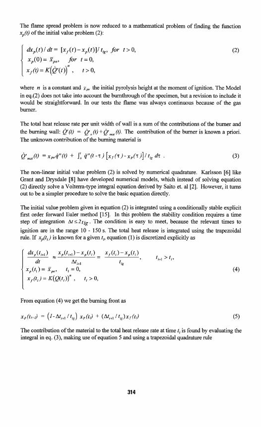
The flame spread problem is now reduced to a mathematical problem of finding the function x,(t) of the initial value problem (2):
I dxp ( t ) / dt = [ x f ( t ) - xp ( t ) ] l t,g, for t > 0,
xp(0)=Xpo, for t = 0 ,
x = ~ ( t ) , t > 0,
where n is a constant and y,, the initial pyrolysis height at the moment of ignition. The Model in eq.(2) does not take into account the burnthrough of the specimen, but a revision to include it would be straightforward. In our tests the flame was always continuous because of the gas burner.
The total heat release rate per unit width of wall is a sum of the contributions of the burner and the burning wall: Q'(Q = Q " (Q + Qfma, (t). The contribution of the burner is known a priori. The unknown contribution of the burning material is
The non-linear initial value problem (2) is solved by numerical quadrature. Karlsson [6] like Grant and Drysdale [8] have developed numerical models, which instead of solving equation (2) directly solve a Volterra-type integral equation derived by Saito et. a1 [2]. However, it turns out to be a simpler procedure to solve the basic equation directly.
The initial value problem given in equation (2) is integrated using a conditionally stable explicit first order forward Euler method [15]. In this problem the stability condition requires a time step of integration At <2t ig . The condition is easy to meet, because the relevant times to
ignition are in the range 10 - 150 s. The total heat release is integrated using the trapezoidal rule. If xp(t,) is known for a given ti, equation (I) is discretized explicitly as
From equation (4) we get the burning front as
The contribution of the material to the total heat release rate at time ti is found by evaluating the integral in eq. (3), making use of equation 5 and using a trapezoidal quadrature rule

where the time interval fiom T = t, = 0 to z k = t , is discretized into k - I intervals such that
T, = ti + (n - 1) h and the time step size h = T, - T,.,. The weights are w, = h, except for
n = 1 and n = k where we use w, = W2. The contribution of the burner is evaluated as e ; ( t i ) .
The origin of time is the moment when the wall behind the burner flame is ignited. Ideally, the burner flame and the wall flame would be similar, and we could assume the surface behind the burner flame to be ignited instantaneously. In practice, the burner flame is of different thickness and we have to estimate the initial pyrolysis height independently. At time t = t, = 0 we have x,(O) = X p (0) > 0. Consequently, the initial flame height is calculated as
The delay of ignition of the wall is taken into account as a shift of time after the numerical calculation has been completed.
The flame height for the next time step is given by
Equation (9) accounts for the coincidence of the flame and pyrolysis heights during periods when the flame is receding.
The numerical procedure was verified by comparing against a known analytical solution.
COMPARISON OF CALCULATIONS WITH EXPERIMENTAL DATA
After a few rounds of trial and error, the next assumptions were fixed for later calculations.
a) The initial pyrolysis height was taken as 40 % of the measured flame height, i.e. 0.2 m for the 100 kW and 0.14 m for the 70 kW burner heat release rates.
b) The flame height depends on Q' linearly with K = 6.5 x 10" m 2 k w (E" = 154 k ~ / m ? . This value is close to that of the burner flame only, but it is only about 65% of the value for the wall flames of burning particle board.
c) The initial ignition is assumed to take place at the same time of ignition as ignition would occur in the Cone calorimeter at an irradiance of 50 kw/m2. This level is close to the maximum heat flux measured behind the continuous flame close to the base of fire. The time to ignition is

used as a shift of the time scale in the calculated heat release rate curves when comparing them with experiments.
d) The time constant t,, in the model is taken as the time to ignition measured in the Cone calorimeter at an irradiance of 25 kw/m2 as the time when the rate of heat release per unit area reached 50 kw/m2. These times to ignition are very close to those observed in the tests. With the values taken at the irradiance level of 50 kw/m2 the calculated fire spread rate turned out to be too fast.
500
400
5 300 Y g 200 x
100
0 8 , J 0 5 10 15 20 0 5 10 15 20
TlME (mln) TlME (rn~n)
FIGURE 4. Measured and calculated FIGURE 5. Measured and calculated rates of heat release as a function of time rates of heat release as a function of ti- in the test T25 1 1 : particle board on mine- me in the test T1002: particle board on ral wool; burner output 100 kW. mineral wool; burner output 70 kW.
300 400
300
S S Y Y 200 K Kc
100 I K
100
0 0 0 5 10 15 0 5 10
TIME (min) TIME (min)
FIGURE 6. Measured and calculated FIGURE 7. Measured and calculated rates of heat release as a function of time rates of heat release as a function of ti- in the test T2312: particle board on cal- me in the test T0412: porous fibre board cium silicate board; burner output on mineral wool; burner output 100 kW. 100 kW.

e) The rate of heat release from the Cone is also taken at a level of 25 kw/m2. A heat flux of this order was measured behind the wall flame above the tips of the thicker burner flame. Heat flux levels of the same order have been found also by Hasemi et a1 [7]. Because much of the spreading took place behind the burner flame, we expected a higher flux level to be more appropriate. However, in the wall tests the rate of heat release per unit area was of the order of that in the Cone calorimeter at the lower irradiance level. The use of the heat release data from the 50 kw/m2 would require the flame length coefficient K to be forced unrealistically low.
Examples of the calculated and measured rate of heat release curves are shown in figures 4 - 7. For the particle board on mineral wool (figures 4 and 5) the model is able to predict the first peak of heat release rate with very good accuracy. The effect of changing the burner output (70 kW or 100 kW) is predicted very well. The model was not able to predict the second peak in this case.
Except for rise in the beginning, there is excellent agreement between the calculated and measured curves in figure 6 for particle board using calcium silicate board as a backing. There is no second peak for either the calculated or measured curves. While the full scale tests exhibited a second peak for particle board with a mineral wool backing there was none when calcium silicate board was used. We may note that the Cone calorimeter data for the two cases do not differ so much, but the process of flame spread in this region is sensitive to even small variations in the heat release data as pointed out by Hasemi et al. [7].
At the end of the tests after about 13 min the hot gases were penetrating to the back of the board causing the rear side also to participate to the burning. Due to the tight attachment of the board to the supporting studs, the contribution of the back side was not significant until pieces of the board started to fall.
In the case of the porous fibre board (figure 7) the model is able to reproduce the measured heat release rate curve with good accuracy, although the first peak is slightly out of phase. In the test there was a slight down turn after the second peak. Then there was a much larger third peak due to the early burn through in the test which was not accounted for in the model.
The calculated flame lengths were systematically shorter than the 50 % intermittency flame height in the tests. The reason for that is that the flame length coefficient has been taken to correspond to a value measured for the burner flame which is thicker than the flame from the burning surface.
DISCUSSION
In the large scale tests we have shown that the upward flame spread in a charring material like wood proceeds in two phases. (1) After ignition the flame spreads first but it stops after a few minutes. Then the rate of heat release begins to decrease. (2) Once the heat wave reaches the rear surface, the insulation causes the interior temperatures to increase and the rate of heat release per unit area increases again making the flame spread further up the wall. For some products the second peak flame height was even higher than the first. The rate of heat release curves for the wall resemble the familiar rate of heat release curves obtained in the Cone

calorimeter tests, where the phenomenon is described and quantitatively modelled by Parker [16]. The peaks are here slightly flattened due to the different phases of burning at different locations on the wall.
One pair of tests was made where the only difference was in the substrate behind the wall board. With an insulating substrate we observed the characteristic two-phase flame spread discussed above. When the substrate was a calcium silicate board, the fire growth for the first few minutes was similar to that of the test with insulating substrate. However, no second peak of the rate of heat release was ever observed.
In the tests on the 7.5 m high wall, as reported in ref. [13], the flame spread proceeded in several phases. High above the burner the spread became very slow and the fire so small that the burnout front and the pyrolysis front were not far apart. For example, in the case of the particle board it took some 40 minutes before the flames reached the upper edge at a height of 7.5 m. At the upper parts the fire was no longer spreading as a horizontal front but rather as a triangular one.
The results of the model calculations are very promising. However, further work is needed to systematically study the sensitivity of the results on the input parameters. With different parameter combinations one might, e.g., be able to use the Cone calorimeter data taken at an irradiance level other than 25 kw/m2. For this work data was also recorded at an irradiance level of 50 kw/m2, but that is apparently too high a level for our purposes. An intermediate level like 35 kw/m2 might be worth trying, because the measured heat fluxes behind the spreading flame were of that order. For practical applications, e.g., with bigger initial fires the appropriate levels may be different.
The model might be further improved by making rate of heat release measurements in the Cone calorimeter at different incident fluxes to establish an effective heat of gasification function that could be used to calculate the local rate of heat release in a flux field that varies with height.
In this work, like in several others, the thermal flame spread models prove to be successful in repeating the experimental results. However, no blind calculation tests have been done to predict a completely new type of scenario before running a single reference test. The critical parameter in the prediction is the initial surface area ignited, because the subsequent spread rate is highly dependent on the initial rate of heat release.
We have applied a linear flame height correlation, because the measurements with our burner supported this assumption. The numerical model described here can be used with any flame length correlation with equal ease. The theoretical models result in a non-linear dependence, and therefore more large-scale studies are needed to determine the flame heights of deep diffusion burners close to a wall. In some scenarios, the area first ignited may be a high and narrow stripe on the wall. In this case, the lateral spread close to the ignition source may be significant. Coupling of lateral spread to our model has not been done, but there are no special conceptual difficulties.
The model described here does not include a burnout front, because it was not needed to explain our tests on 2.4 m high walls. It is, however, rather straightforward to add the option in the future.
CONCLUSIONS
The large-scale tests with a diffusion burner against a wall have shown that the upward flame spread on a vertical combustible surface depends not only on the product but also on the thermal properties of the substrate. For particle board and wood panels on an insulating substrate the flame spreads upward, retreats and then spreads upward again. In a high space, where there is no thermal feedback from the upper smoke layer, the flame spread becomes very slow high above the initial ignition source. The fire will probably die out on its own if the initial ignition source is removed or burns out. It is therefore quite possible that wood products in high rooms do not create as large a hazard as they do in smaller rooms with the assumption that the contents of the building do not provide too big an ignition source.
In these tests the experimental results showed that the flame height of a gas burner against a wall was represented slightly better by a linear function of the RHR than by a function with a 213-power dependence on RHR.
The numerical flame spread model has proven to be able to account for the rate of heat release as a function of time with reasonable accuracy. The model can be directly applied to estimate the potential for flashover due to a fire spreading on a wall. By adding a wall plume model, it can be further developed into a sub-model for general purpose zone models.
ACKNOWLEDGEMENT
The work was funded by Suomen Puututkimus Oy, TEKES (Technology Development Centre).
The authors would like to thank Dr. Esko Mikkola for useful suggestions, observations and comments before, during and after the experimental project. The assistance of Mr. Matti Immonen, Mr. Hemmo Juutilainen, Mr. Petri Manner and several others of the VTT staff are gratefully acknowledged.
REFERENCES
1. Thomas, P. H., The growth of f ~ e - from ignition to full involvement, in. C. Cox (ed.), Combustion Fundamentals of Fire, Academic Press, London, 1995, pp. 273-328.
2. Saito, K., Quintiere, J. Q. and Williams, F. A. Upward turbulent flame spread., Fire Safety Science - Proceedings of the First Int'l Symposium. Gaithersburg, 7 - 11 Oct 1985. New York, 1985, Hem. Publ. Corp. pp. 75 - 86.
3. Thomas, P. H. and Karlsson, B. On upward flame spread. Lund, Sweden 1991, Lund University, Dept. of Fire Safety Eng., SE-LUTVDG/TVBB-3058,22 p.
4. Baroudi, D. and Kokkala, M., Analysis of upward flame spread, Espoo 1992, Technical Research Centre of Finland, VTT Publications 89,49 p.
5. Karlsson, B., Modelling fire growth on combustible lining materials in enclosures, Lund, Sweden 1992, Lund University, Dept. of Fire Safety Engineering, TVBB-1009, 201 p. (Ph.D. thesis).
6. Karlsson, B., Models for calculating flame spread on wall lining materials and the resulting heat release rate in the room, Fire Safety Journal, 24, 1994, pp. 365 - 386.
7. Hasemi, Y., Yoshida, M., Yasui, N., and Parker, W.J., Upward flame spread along a vertical solid for transient local heat release, Fire Safety Science - Proc. of Fourth Int ' I Symposium, Ottawa, Ontario, Canada, 13-17 June 1994, Ed. T. Kashiwagi, IAFSS, Boston, MA, USA, pp. 385-396.
8. Grant, G. and Drysdale, D., Numerical modelling of early flame spread in warehouse fires, Fire Safety Journal, 24, 1995,247-278.
9. Delichatsios, M.M., Mathews, M.K., and Delichatsios, M.A., An upward flame spread and growth simulation, Fire Safety Science - Proc. of Third Int ' I Symposium, Edinburgh, UK, 8 - 12 July 1991, Ed. G. Cox and B. Langford, Elsevier Applied Science, 1991, pp. 207-216.
10. Delichatsios, M.A. and Chen, Y., Flame spread on charring materials: numerical predictions and critical conditions, Fire Safety Science - Proc. of Fourth Int'l Symposium, Ottawa, Ontario, Canada, 13-17 June 1994, Ed. T. Kashiwagi, IAFSS, Boston, MA, USA, pp. 457- 468.
11. Hasemi, Y., Yoshida, M., Nohara, A., and Nakabayashi, T., Unsteady-state upward flame spreading velocity along vertical combustible solid and influence of external radiation on the flame spread, Fire Safety Science - Proc. of Third Int'l Symposium, Edinburgh, UK, 8 - 12 July 1991, Ed. G. Cox and B. Langford, Elsevier Applied Science, 1991, pp. 197-206.
12. Delichatsios, M.M., Wu, P., Delichatsios, M.A., Lougheed, G.D., Crampton, G.P., Qian, C., Ishida, H., and Saito, K., Effect of external radiant heat flux on upward fire spread: measurements on plywood and numerical predictions, Fire Safety Science - Proc. of Fourth Int'l Symposium, Ottawa, Canada, 13-17 June 1994, Ed. T. Kashiwagi, IAFSS, Boston, MA, USA, pp. 421-432.
13. Kokkala, M., Parker, W.J., Mikkola, E., Immonen, M., Juutilainen, H., and Manner, P., Large-scale upward flame spread tests on wood products, VTT Research Notes, in print.
14. Delichatsios, M. A. Critical conditions for sustained burning and flame propagation on vertical charring walls. New York, NY, USA 1983, The American Society of Mechanical Engineers, Paper 83- WAIHT-64,6 p.
15. Scheid, F., Analyse nume'rique, cours et probl2mes, Serie Schaum, deuxikme tirage, McGraw - Hill, Paris, 1987,423 p.
16. Parker, W.J., Prediction of the Heat Release Rate of Wood (Ph.D. dissertation). The George Washington Univ., Washington DC, USA, 1988.