Upgrading the Keck AO wavefront controllers · One print or electronic copy may be made for ......
12
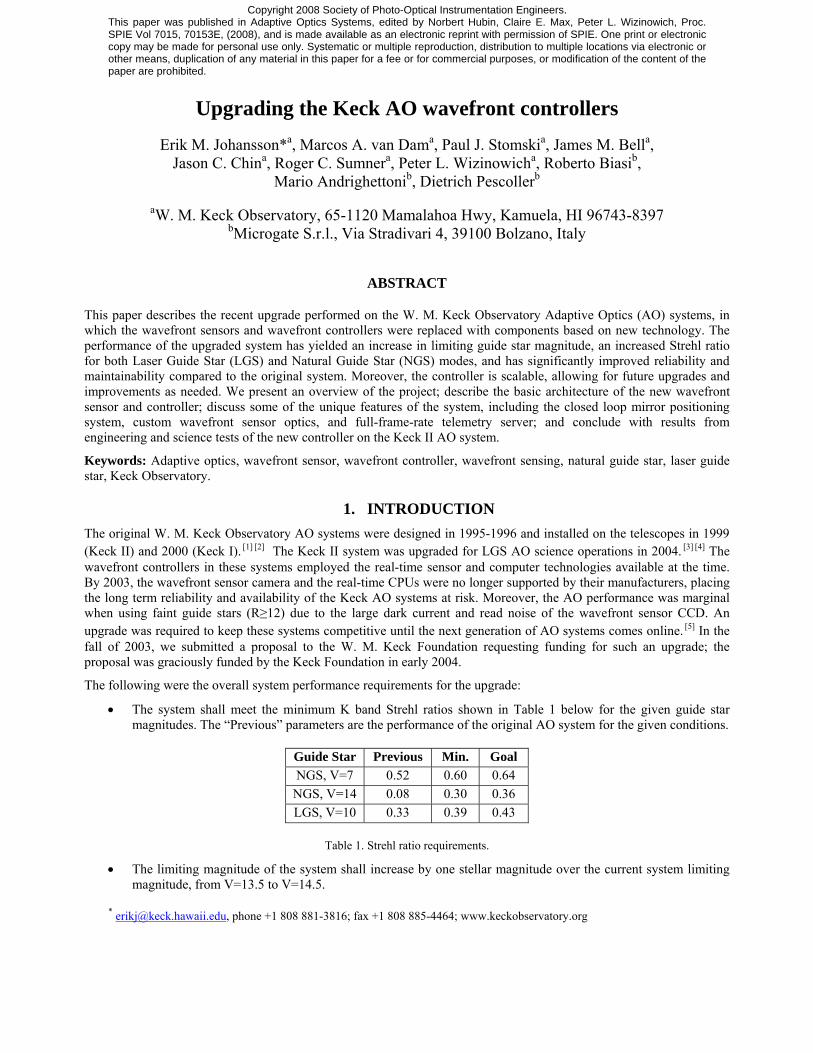
Copyright 2008 Society of Photo-Optical Instrumentation Engineers. This paper was published in Adaptive Optics Systems, edited by Norbert Hubin, Claire E. Max, Peter L. Wizinowich, Proc. SPIE Vol 7015, 70153E, (2008), and is made available as an electronic reprint with permission of SPIE. One print or electronic copy may be made for personal use only. Systematic or multiple reproduction, distribution to multiple locations via electronic or other means, duplication of any material in this paper for a fee or for commercial purposes, or modification of the content of the paper are prohibited. Upgrading the Keck AO wavefront controllers Erik M. Johansson* a , Marcos A. van Dam a , Paul J. Stomski a , James M. Bell a , Jason C. Chin a , Roger C. Sumner a , Peter L. Wizinowich a , Roberto Biasi b , Mario Andrighettoni b , Dietrich Pescoller b a W. M. Keck Observatory, 65-1120 Mamalahoa Hwy, Kamuela, HI 96743-8397 b Microgate S.r.l., Via Stradivari 4, 39100 Bolzano, Italy ABSTRACT This paper describes the recent upgrade performed on the W. M. Keck Observatory Adaptive Optics (AO) systems, in which the wavefront sensors and wavefront controllers were replaced with components based on new technology. The performance of the upgraded system has yielded an increase in limiting guide star magnitude, an increased Strehl ratio for both Laser Guide Star (LGS) and Natural Guide Star (NGS) modes, and has significantly improved reliability and maintainability compared to the original system. Moreover, the controller is scalable, allowing for future upgrades and improvements as needed. We present an overview of the project; describe the basic architecture of the new wavefront sensor and controller; discuss some of the unique features of the system, including the closed loop mirror positioning system, custom wavefront sensor optics, and full-frame-rate telemetry server; and conclude with results from engineering and science tests of the new controller on the Keck II AO system. Keywords: Adaptive optics, wavefront sensor, wavefront controller, wavefront sensing, natural guide star, laser guide star, Keck Observatory. 1. INTRODUCTION The original W. M. Keck Observatory AO systems were designed in 1995-1996 and installed on the telescopes in 1999 (Keck II) and 2000 (Keck I). [1] [2] The Keck II system was upgraded for LGS AO science operations in 2004. [3] [4] The wavefront controllers in these systems employed the real-time sensor and computer technologies available at the time. By 2003, the wavefront sensor camera and the real-time CPUs were no longer supported by their manufacturers, placing the long term reliability and availability of the Keck AO systems at risk. Moreover, the AO performance was marginal when using faint guide stars (R≥12) due to the large dark current and read noise of the wavefront sensor CCD. An upgrade was required to keep these systems competitive until the next generation of AO systems comes online. [5] In the fall of 2003, we submitted a proposal to the W. M. Keck Foundation requesting funding for such an upgrade; the proposal was graciously funded by the Keck Foundation in early 2004. The following were the overall system performance requirements for the upgrade: • The system shall meet the minimum K band Strehl ratios shown in Table 1 below for the given guide star magnitudes. The “Previous” parameters are the performance of the original AO system for the given conditions. Guide Star Previous Min. Goal NGS, V=7 0.52 0.60 0.64 NGS, V=14 0.08 0.30 0.36 LGS, V=10 0.33 0.39 0.43 Table 1. Strehl ratio requirements. • The limiting magnitude of the system shall increase by one stellar magnitude over the current system limiting magnitude, from V=13.5 to V=14.5. * [email protected] , phone +1 808 881-3816; fax +1 808 885-4464; www.keckobservatory.org
Transcript of Upgrading the Keck AO wavefront controllers · One print or electronic copy may be made for ......
Copyright 2008 Society of Photo-Optical Instrumentation Engineers. This paper was published in Adaptive Optics Systems, edited by Norbert Hubin, Claire E. Max, Peter L. Wizinowich, Proc. SPIE Vol 7015, 70153E, (2008), and is made available as an electronic reprint with permission of SPIE. One print or electronic copy may be made for personal use only. Systematic or multiple reproduction, distribution to multiple locations via electronic or other means, duplication of any material in this paper for a fee or for commercial purposes, or modification of the content of the paper are prohibited.
Upgrading the Keck AO wavefront controllers
Erik M. Johansson*a, Marcos A. van Dama, Paul J. Stomskia, James M. Bella,
Jason C. China, Roger C. Sumnera, Peter L. Wizinowicha, Roberto Biasib, Mario Andrighettonib, Dietrich Pescollerb
aW. M. Keck Observatory, 65-1120 Mamalahoa Hwy, Kamuela, HI 96743-8397
bMicrogate S.r.l., Via Stradivari 4, 39100 Bolzano, Italy
ABSTRACT
This paper describes the recent upgrade performed on the W. M. Keck Observatory Adaptive Optics (AO) systems, in which the wavefront sensors and wavefront controllers were replaced with components based on new technology. The performance of the upgraded system has yielded an increase in limiting guide star magnitude, an increased Strehl ratio for both Laser Guide Star (LGS) and Natural Guide Star (NGS) modes, and has significantly improved reliability and maintainability compared to the original system. Moreover, the controller is scalable, allowing for future upgrades and improvements as needed. We present an overview of the project; describe the basic architecture of the new wavefront sensor and controller; discuss some of the unique features of the system, including the closed loop mirror positioning system, custom wavefront sensor optics, and full-frame-rate telemetry server; and conclude with results from engineering and science tests of the new controller on the Keck II AO system.
Keywords: Adaptive optics, wavefront sensor, wavefront controller, wavefront sensing, natural guide star, laser guide star, Keck Observatory.
1. INTRODUCTION The original W. M. Keck Observatory AO systems were designed in 1995-1996 and installed on the telescopes in 1999 (Keck II) and 2000 (Keck I). [1] [2] The Keck II system was upgraded for LGS AO science operations in 2004. [3] [4] The wavefront controllers in these systems employed the real-time sensor and computer technologies available at the time. By 2003, the wavefront sensor camera and the real-time CPUs were no longer supported by their manufacturers, placing the long term reliability and availability of the Keck AO systems at risk. Moreover, the AO performance was marginal when using faint guide stars (R≥12) due to the large dark current and read noise of the wavefront sensor CCD. An upgrade was required to keep these systems competitive until the next generation of AO systems comes online. [5] In the fall of 2003, we submitted a proposal to the W. M. Keck Foundation requesting funding for such an upgrade; the proposal was graciously funded by the Keck Foundation in early 2004.
The following were the overall system performance requirements for the upgrade:
• The system shall meet the minimum K band Strehl ratios shown in Table 1 below for the given guide star magnitudes. The “Previous” parameters are the performance of the original AO system for the given conditions.
Guide Star Previous Min. Goal NGS, V=7 0.52 0.60 0.64
NGS, V=14 0.08 0.30 0.36 LGS, V=10 0.33 0.39 0.43
Table 1. Strehl ratio requirements.
• The limiting magnitude of the system shall increase by one stellar magnitude over the current system limiting magnitude, from V=13.5 to V=14.5.
* [email protected], phone +1 808 881-3816; fax +1 808 885-4464; www.keckobservatory.org
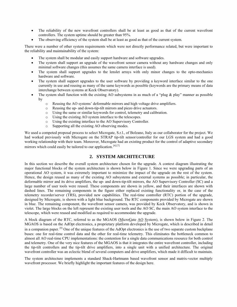
• The reliability of the new wavefront controllers shall be at least as good as that of the current wavefront controllers. The system uptime should be greater than 95%.
• The observing efficiency of the system shall be at least as good as that of the current system.
There were a number of other system requirements which were not directly performance related, but were important to the reliability and maintainability of the system:
• The system shall be modular and easily support hardware and software upgrades. • The system shall support an upgrade of the wavefront sensor camera without any hardware changes and only
minimal software changes (this assumes the same camera interface is used). • The system shall support upgrades to the lenslet arrays with only minor changes to the opto-mechanics
hardware and software. • The system shall support upgrades to the user software by providing a keyword interface similar to the one
currently in use and reusing as many of the same keywords as possible (keywords are the primary means of data interchange between systems at Keck Observatory).
• The system shall function with the existing AO subsystems in as much of a “plug & play” manner as possible by
o Reusing the AO systems’ deformable mirrors and high voltage drive amplifiers. o Reusing the up- and down-tip-tilt mirrors and piezo drive actuators. o Using the same or similar keywords for control, telemetry and calibration. o Using the existing AO system interface to the telescopes. o Using the existing interface to the AO Supervisory Controller. o Supporting all the existing AO observing modes.
We used a competed proposal process to select Microgate, S.r.l., of Bolzano, Italy as our collaborator for the project. We had worked previously with Microgate on the STRAP tip-tilt sensor/controller for our LGS system and had a good working relationship with their team. Moreover, Microgate had an existing product for the control of adaptive secondary mirrors which could easily be tailored to our application. [6] [7]
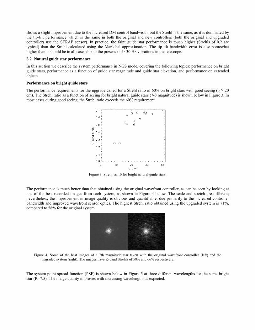
2. SYSTEM ARCHITECTURE In this section we describe the overall system architecture chosen for the upgrade. A context diagram illustrating the major functional blocks of the system architecture is shown below in Figure 1. Since we were upgrading parts of an operational AO system, it was extremely important to minimize the impact of the upgrade on the rest of the system. Hence, the design reused as many of the existing AO subsystems and external systems as possible; in particular, the deformable mirror and its drive amplifiers, the up- and down-tip-tilt mirrors, the AO Supervisory Controller (SC) and a large number of user tools were reused. These components are shown in yellow, and their interfaces are shown with dashed lines. The remaining components in the figure either replaced existing functionality or, in the case of the telemetry recorder/server (TRS), provided new capabilities. The real-time controller (RTC) portion of the upgrade, designed by Microgate, is shown with a light blue background. The RTC components provided by Microgate are shown in blue. The remaining component, the wavefront sensor camera, was provided by Keck Observatory, and is shown in violet. The large blocks on the left represent the existing user tools and the AO SC, the main AO system interface to the telescope, which were reused and modified as required to accommodate the upgrade.
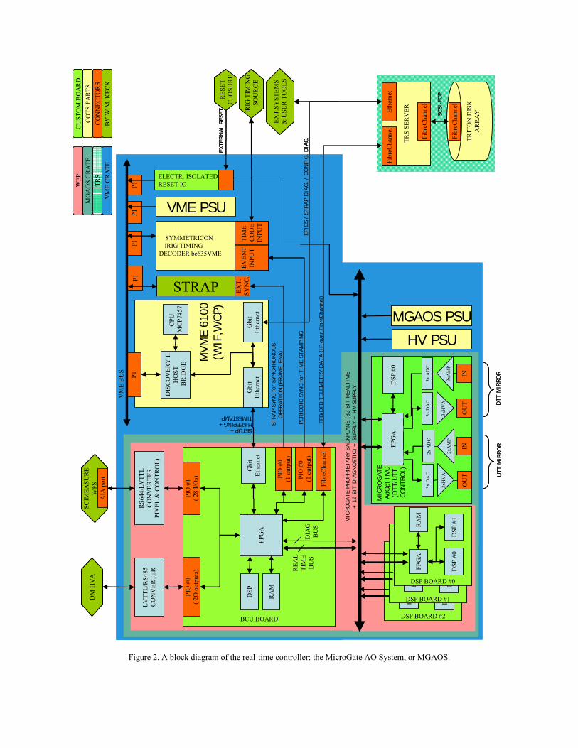
A block diagram of the RTC, referred to as the MGAOS (MicroGate AO System), is shown below in Figure 2. The MGAOS is based on the AdOpt electronics, a proprietary platform developed by Microgate, which is described in detail in a companion paper. [8] One of the unique features of the AdOpt electronics is the use of two separate custom backplane buses: one for real-time control data and the other for real-time telemetry. This eliminates the bottleneck common to almost all AO real-time CPU implementations: the contention for a single data communications resource for both control and telemetry. One of the very nice features of the MGAOS is that it integrates the entire wavefront controller, including the tip-tilt controllers and the tip-tilt drive amplifiers, into a single unit with a unified architecture. The original wavefront controller was an eclectic blend of several computers and drive amplifiers, which made it difficult to maintain.
The system architecture implements a standard Shack-Hartmann based wavefront sensor and matrix-vector multiply wavefront processor. We briefly highlight the important features of the design here.
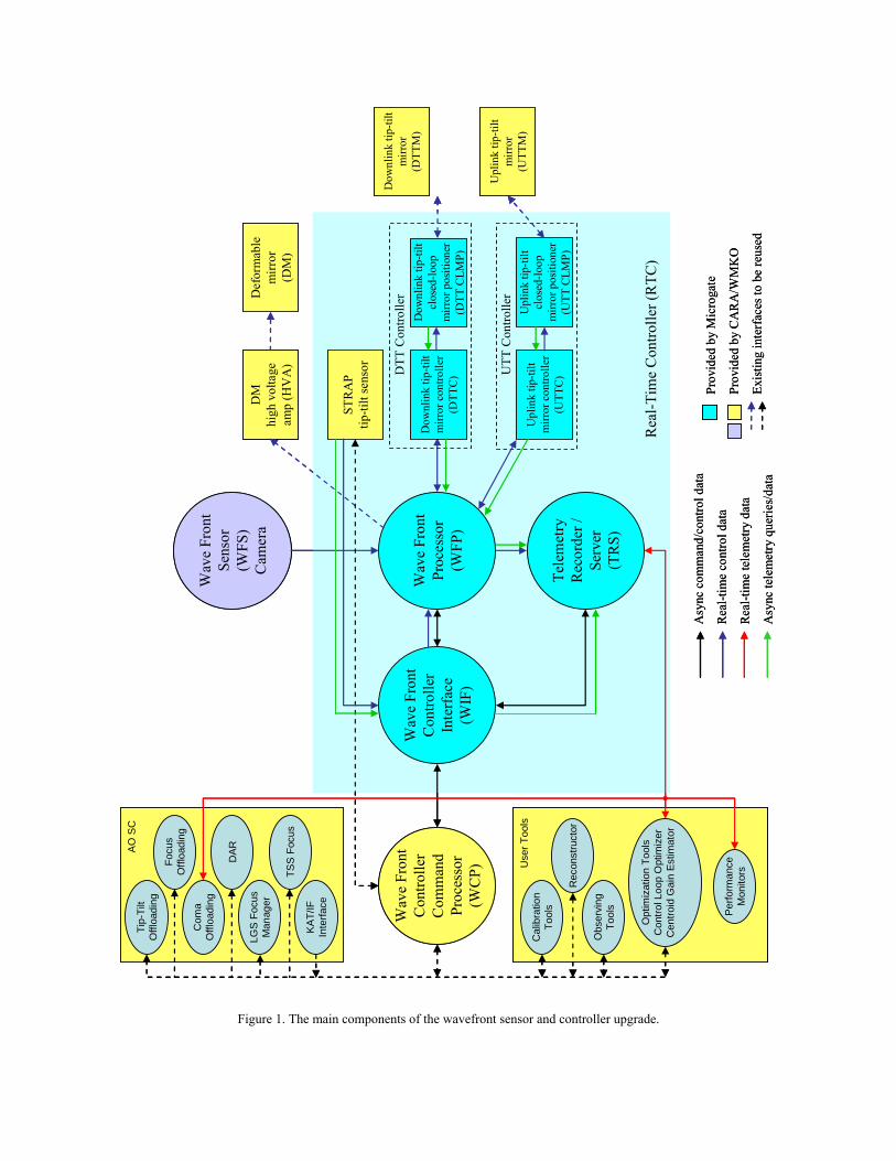
Figure 1. The main components of the wavefront sensor and controller upgrade.
Wav
e Fr
ont
Con
trolle
rIn
terf
ace
(WIF
)
Wav
e Fr
ont
Proc
esso
r(W
FP)
Wav
e Fr
ont
Con
trolle
rC
omm
and
Proc
esso
r(W
CP)
Tele
met
ryR
ecor
der /
Serv
er(T
RS)
Wav
e Fr
ont
Sens
or(W
FS)
Cam
era
DM
high
vol
tage
amp
(HV
A)
Rea
l-Tim
e C
ontro
ller (
RTC
)
Upl
ink
tip-ti
ltm
irror
con
trolle
r(U
TTC
)
STR
AP
tip-ti
lt se
nsor
Upl
ink
tip-ti
ltcl
osed
-loop
mirr
or p
ositi
oner
(UTT
CLM
P)
Dow
nlin
k tip
-tilt
clos
ed-lo
opm
irror
pos
ition
er(D
TT C
LMP)
Dow
nlin
k tip
-tilt
mirr
or(D
TTM
)
Upl
ink
tip-ti
ltm
irror
(UTT
M)
Def
orm
able
mirr
or(D
M)
Dow
nlin
k tip
-tilt
mirr
or c
ontro
ller
(DTT
C) U
TT C
ontro
ller
DTT
Con
trolle
r
Asy
ncco
mm
and/
cont
rol d
ata
Rea
l-tim
e co
ntro
l dat
a
Rea
l-tim
e te
lem
etry
dat
a
Asy
ncte
lem
etry
que
ries/
data
Prov
ided
by
Mic
roga
te
Prov
ided
by
CA
RA
/WM
KO
Exis
ting
inte
rfac
es to
be
reus
ed
Dow
nlin
k tip
-tilt
mirr
or(D
TTM
)
Upl
ink
tip-ti
ltm
irror
(UTT
M)
Cal
ibra
tion
Tool
s
Rec
onst
ruct
or
Obs
ervi
ngTo
ols Pe
rform
ance
Mon
itors
Opt
imiz
atio
n To
ols
Con
trol L
oop
Opt
imiz
erC
entro
id G
ain
Estim
ator
Use
r Too
ls
Tip-
Tilt
Offl
oadi
ngFo
cus
Offl
oadi
ngC
oma
Offl
oadi
ng
DAR
LGS
Focu
sM
anag
er
TSS
Foc
us
KA
T/IF
Inte
rface
AO
SC
Wav
e Fr
ont
Con
trolle
rIn
terf
ace
(WIF
)
Wav
e Fr
ont
Proc
esso
r(W
FP)
Wav
e Fr
ont
Con
trolle
rC
omm
and
Proc
esso
r(W
CP)
Tele
met
ryR
ecor
der /
Serv
er(T
RS)
Wav
e Fr
ont
Sens
or(W
FS)
Cam
era
DM
high
vol
tage
amp
(HV
A)
Rea
l-Tim
e C
ontro
ller (
RTC
)
Upl
ink
tip-ti
ltm
irror
con
trolle
r(U
TTC
)
STR
AP
tip-ti
lt se
nsor
Upl
ink
tip-ti
ltcl
osed
-loop
mirr
or p
ositi
oner
(UTT
CLM
P)
Dow
nlin
k tip
-tilt
clos
ed-lo
opm
irror
pos
ition
er(D
TT C
LMP)
Def
orm
able
mirr
or(D
M)
Dow
nlin
k tip
-tilt
mirr
or c
ontro
ller
(DTT
C)
Prov
ided
by
Mic
roga
te
Prov
ided
by
CA
RA
/WM
KO
Exis
ting
inte
rfac
es to
be
reus
ed
UTT
Con
trolle
r
DTT
Con
trolle
r
Asy
ncco
mm
and/
cont
rol d
ata
Rea
l-tim
e co
ntro
l dat
a
Rea
l-tim
e te
lem
etry
dat
a
Asy
ncte
lem
etry
que
ries/
data
Cal
ibra
tion
Tool
s
Rec
onst
ruct
or
Obs
ervi
ngTo
ols Pe
rform
ance
Mon
itors
Opt
imiz
atio
n To
ols
Con
trol L
oop
Opt
imiz
erC
entro
id G
ain
Estim
ator
Use
r Too
ls
Tip-
Tilt
Offl
oadi
ngFo
cus
Offl
oadi
ngC
oma
Offl
oadi
ng
DAR
TSS
Foc
us
LGS
Focu
sM
anag
er
KA
T/IF
Inte
rface
AO
SC
P1
BCU BOARD
P1P1
MVM
E 61
00(W
IF,W
CP)
P1P1
VM
E B
US
STRAP
CPU
M
CP7
457
TRIT
ON
DIS
KA
RR
AY
EXT.
SYST
EMS
& U
SER
TO
OLS
SYMMETRICON IRIG TIMING
DECODER bc635VMETI
ME
CO
DE
INPU
T
IRIG
TIM
ING
SOU
RC
E
EVEN
TIN
PUT
CO
TS P
AR
TSC
ON
NEC
TOR
SB
Y W
.M. K
ECK
CU
STO
M B
OA
RD
PIO
#0
(1 o
utpu
t)
PERIO
DIC
SYN
C for
TIM
E ST
AMPI
NG
VME PSU
DIS
CO
VER
Y II
HO
STB
RID
GE
Fibr
eCha
nnel
RA
M
DSP
1
RA
M
DSP
1
DSP BOARD #2
FPG
A
DSP
0
RA
M
DSP
1
DSP BOARD #1
FPG
A
DSP
0
RA
M
DSP
1
DSP BOARD #0
FPG
A
DSP
#0
RA
M
DSP
#1MIC
RO
GATE
PR
OPR
IETA
RY
BACKP
LAN
E (3
2 BI
T REA
LTIM
E +
16
BIT
DIA
GN
OST
IC)
+ S
UPP
LY +
HV
SUPP
LY
DSP
Gbi
tEt
hern
et
PIO
#0
( 2O
out
puts
)PI
O #
1( 2
8 I/O
s)
DM
HV
A
RS6
44/L
VTT
LC
ON
VER
TER
PIX
EL &
CO
NTR
OL)
LVTT
L/R
S485
CO
NV
ERTE
R
SCIM
EASU
RE
WFS
AIA
por
t
RA
M
Gbi
tEt
hern
et
REA
LTI
ME
BU
S
ELECTR. ISOLATEDRESET IC
RES
ETC
LOSU
RE
SETUP + H.KEEPING + TIMESTAMP
Fibr
eCha
nnel
EXT.
SYN
C.
PIO
#0
(1 o
utpu
t)
FPG
A
DIA
G
BU
S
STR
AP S
YNC f
orSY
NCH
RO
NO
US
OPE
RAT
ION
(FR
AME_
ENA)
FPG
A
OU
TIN
3x D
AC UTT
MIR
RO
R
DSP
#0
3xH
VA
2x
AM
P
2x A
DC
OU
TIN
3x D
AC DTT
MIR
RO
R
3xH
VA
3x
AM
P
3x A
DC
HV PSU
TRS
SER
VER
Fibr
eCha
nnel
Ethe
rnet
Fibr
eCha
nnel
FFB/
DFB
TEL
EMET
RY D
ATA (
IP o
ver
Fibr
eCha
nnel
)
EPIC
S /
STRAP
DIA
G. /
CO
NFI
G. D
IAG
.
SCSI
-FCP
MIC
RO
GAT
E Ad
Opt
HVC
(D
TT/U
TT
CON
TRO
L)
Gbi
tEt
hern
et
MG
AO
S C
RA
TETR
SV
ME
CR
ATE
WFP
MGAOS PSU
EXTE
RN
AL R
ESET
Figure 2. A block diagram of the real-time controller: the MicroGate AO System, or MGAOS.
Wavefront sensor camera (WFS): The wavefront sensor camera is based on a SciMeasure “Little Joe” camera controller with an e2v CCD-39 chip. When running at low frame rates for faint guide stars, where the read noise and dark current are critical, we see approximately 4-4.5 electrons of read noise and negligible dark current. This compares quite favorably to the 7+ electrons of read noise and large dark current in our original wavefront sensor. The dark current is suppressed in the Little Joe camera due to unique method of inversion clocking the CCD that is used.
Custom lenslet array optics: The lenslet arrays for the wavefront sensor were custom made by Advanced Microoptics Systems GmbH (AMμS) of Germany. They feature three separate arrays of 100x100 lenslets having a pitch of 200 μm on a single fused silica substrate (27.6 mm x 76.5 mm x 2 mm); each array has a different focal length. We selected focal lengths of 2.4 mm, 3.1 mm, and 4.9 mm for the arrays to achieve to plate scales of 0.75”, 1.2”, and 1.5” per pixel, respectively, in the wavefront sensor. The lenslets met stringent requirements on variation in focal length, fill factor, perpendicularity and rotation, transmitted wavefront, and pitch error. The lenslet substrates are mounted on motorized stages to allow for automated alignment of the wavefront sensor and selection of the plate scale based on the imaging application. The new lenslets were a large improvement over the ones used in the original wavefront sensor, which came from a plastic lenslet array sampler and had numerous defects and large spot center offsets.
Wavefront processor (WFP): The WFP is distributed across several boards in the MGAOS. The Basic Computational Unit (BCU) board is both the front- and back-end of the processing pipeline, which implements the interface to the WFS camera, performs the pixel processing and centroid computations, formats the data for the deformable mirror (DM) and implements the DM interface. The three DSP boards implement the matrix-vector multiply and the 3rd order servo control law for the DM. The BCU and DSP boards are based on the Analog Devices Tiger Sharc TS101 DSP chip. The centroid computation is overlapped with the CCD readout and has negligible latency. The latency from the time the last pixel is read from the camera until the DM commands begin to be written is approximately 81 μsec. For comparison, the original wavefront controller had a latency of 1349 μsec! Moreover, the new wavefront controller is capable of keeping up with the fastest frame rate of the WFS camera, which is 2406 Hz, compared to a maximum CPU-limited frame rate of 670 Hz for the original controller.
Uplink and downlink tip-tilt controllers (DTT, UTT): The DTT and UTT controllers each consist of two cascaded controllers: a tip-tilt mirror controller that corrects for the tilt disturbance caused by the atmosphere, and a closed-loop mirror positioning system (CLMP) that moves the mirror to the position commanded by the atmospheric controller using strain-gauge feedback from the piezo actuators. The DTT and UTT controllers are implemented on the MGAOS High Voltage Controller board (HVC), which is also based on the Analog Devices Tiger Sharc TS101 DSP chip. The DTT controller may use either the WFS or the STRAP tip-tilt sensor (System for Tip-tilt Removal with Avalanche Photo-diodes) for input. The UTT controller, which stabilizes the laser, uses only the WFS for input. If STRAP is used, it may run asynchronously based on the selected integration time, or it may be synchronized with the WFS camera. The atmospheric controllers run at the frame rates selected by the user for the WFS camera or STRAP, while the CLMP controllers run at very high speed (60 kHz). The high-speed of the CLMP controllers allows them to precisely control the mirror position based on the strain gauge feedback, thereby compensating for hysteresis in the piezo actuators, and to compensate for natural resonances in the mirror dynamics. The HVC board also incorporates the high-voltage drive amplifiers for the tip-tilt piezo actuators, completely integrating the tip-tilt control functions into one nice package.
The telemetry recorder/server (TRS): The TRS receives and records real time streams of data from the wavefront processor via a high-speed Fibre Channel interface. With the exception of raw wavefront sensor CCD frames, which are stored at a maximum decimated rate of 100 Hz, all telemetry is recorded at the full frame rate of the WFP. A timestamp synchronized with IRIG time and having a resolution of 100 ns is generated by the Symmetricom timing board and is bundled with each frame of telemetry stored by the TRS. All configuration parameter data are stored in the TRS as well. The TRS is also a server, permitting near-real-time post-processing of telemetry data via queries.
The TRS is implemented using a Sun X4100 server and a Triton16FA RAID disk array supporting raw storage of up to 6.4 TB, which can accommodate up to a week’s worth of data. The telemetry storage is implemented using an open-source PostgreSQL database which permits both the real-time storage of the telemetry streams and near-real-time querying using standard SQL constructs. The SQL query capability is very powerful, allowing the user to recall data based on timestamps or particular values in the telemetry stream. It is quite simple to reconstruct a timeline showing the loop states for all the controllers and the precise timestamps when the loops change state. The user can then extract the desired telemetry streams based on these timestamps. This has already proven to be an extremely useful debugging and troubleshooting tool. The system optimization tool uses the TRS to extract data and perform power spectral analysis to
help tune the controllers for maximum performance. We also use the TRS in near-real time to estimate the current seeing conditions. Finally, Keck researchers are using TRS data to design point spread function estimation techniques based on telemetry data.
Software features: The WFP also supports several important software features: the option of denominator-free centroiding, a separate centroid gain coefficient for each subaperture to account for spot-size variations, fully programmable 3rd order PID servo control laws for the DM and tip-tilt controllers, tip-tilt mirror disturbance functions that allow the user to simulate disturbance inputs to the controllers and test them in closed-loop mode, and an integrated tip-tilt chopper that moves the downlink-tip-tilt mirror in any of three different chop patterns repeatedly at a user selected chop rate.
Scalable architecture: The MGAOS is designed with a very nice modular and scalable architecture in both hardware and software. It is quite compact and fits easily into a standard 6U VME crate. The MGAOS resides in its own sub-crate and takes up approximately half of the space in the VME crate. It is relatively simple to add additional DSP boards to the MGAOS to increase processing power. The other half of the VME crate is occupied by the MVME6100 host CPU, the STRAP VME electronics, and the Symmetricom timing board. Both the VME crate and the MGAOS sub-crate have additional slots available for expansion. The WFP software supports a larger format CCD using the same SciMeasure controller interface, with only trivial software changes. Also, Microgate is working on an upgrade so that multiple BCU boards can be used simultaneously in the MGAOS. The system will then be able to support additional WFS cameras; for example, a CCD-based tip-tilt sensor could easily be added.
3. PERFORMANCE RESULTS In this section we present performance results from the upgraded AO system on the Keck II telescope. Although both telescopes received the same upgrade described in this paper, only Keck II AO has a facility class IR science camera and LGS AO capability (Keck I AO is currently being upgraded to provide LGS capability).
3.1 Error budgets
We have not yet produced a rigorous error budget for the upgraded controller based on detailed measurements. However, we present estimated error budgets for the NGS bright star, LGS bright star, and LGS faint star cases based on the typical Strehl performance for the new controller. We use the control loop analysis method derived by van Dam, et al. [2] A comparison of error budgets for the original and upgraded controller under good seeing conditions is shown in Table 2 below, using data from van Dam, et al., for the original wavefront controller. [2] [4] The average measured Strehl is also shown in the table.
System Original Upgrade Original Upgrade Original UpgradeAtmospheric fitting 128 128 128 128 128 128Telescope fitting 66 66 66 66 66 66Camera 113 50 50 50 50 50DM bandwidth 103 38 157 120 157 120DM measurement 17 29 142 152 142 152TT bandwidth 75 100 109 109 243 243TT measurement 9 25 23 23 349 349LGS focus error 0 0 36 36 36 36Focal anisoplanatism 0 0 164 164 164 164LGS high-order error 0 0 80 80 80 80Miscellaneous 125 125 125 125 125 125Total wavefront error 256 228 361 351 547 540K-band Strehl (est) 0.58 0.66 0.34 0.37 0.09 0.09Avg. K-band Strehl (meas) 0.50 0.60 0.35 0.40 0.15 0.20
NGS (R=8) LGS (R=10) LGS (R=18)
Table 2. Error budgets for the original AO system and for the upgraded system under good seeing conditions, for NGS
bright star mode (R=8), LGS bright star mode (R=10), and LGS faint star mode (R=18). Except for Strehl, all numbers are in nm RMS of wavefront error.
Note that the primary improvements are in DM bandwidth error and tip-tilt bandwidth error, due to the increased bandwidth of the new controllers. A slight increase in the DM measurement error is shown as a result of running at a much faster frame rate compared to the original controller. We see a significant improvement in Strehl for the NGS bright star case and a modest improvement for the LGS bright star case. The wavefront error for the LGS faint star case
shows a slight improvement due to the increased DM control bandwidth, but the Strehl is the same, as it is dominated by the tip-tilt performance which is the same in both the original and new controllers (both the original and upgraded controllers use the STRAP sensor). In practice, the faint guide star performance is much higher (Strehls of 0.2 are typical) than the Strehl calculated using the Maréchal approximation. The tip-tilt bandwidth error is also somewhat higher than it should be in all cases due to the presence of ~30 Hz vibrations in the telescope.
3.2 Natural guide star performance
In this section we describe the system performance in NGS mode, covering the following topics: performance on bright guide stars, performance as a function of guide star magnitude and guide star elevation, and performance on extended objects.
Performance on bright guide stars
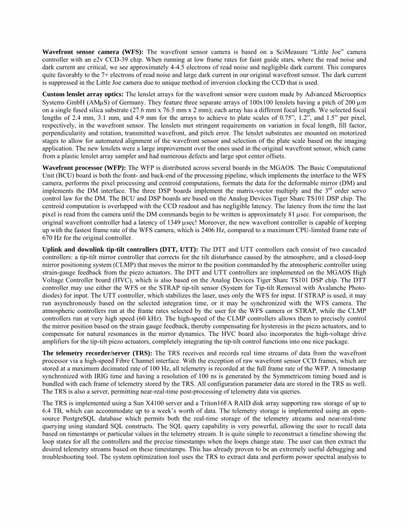
The performance requirements for the upgrade called for a Strehl ratio of 60% on bright stars with good seeing (r0 ≥ 20 cm). The Strehl ratio as a function of seeing for bright natural guide stars (7-8 magnitude) is shown below in Figure 3. In most cases during good seeing, the Strehl ratio exceeds the 60% requirement.
Figure 3. Strehl vs. r0 for bright natural guide stars.
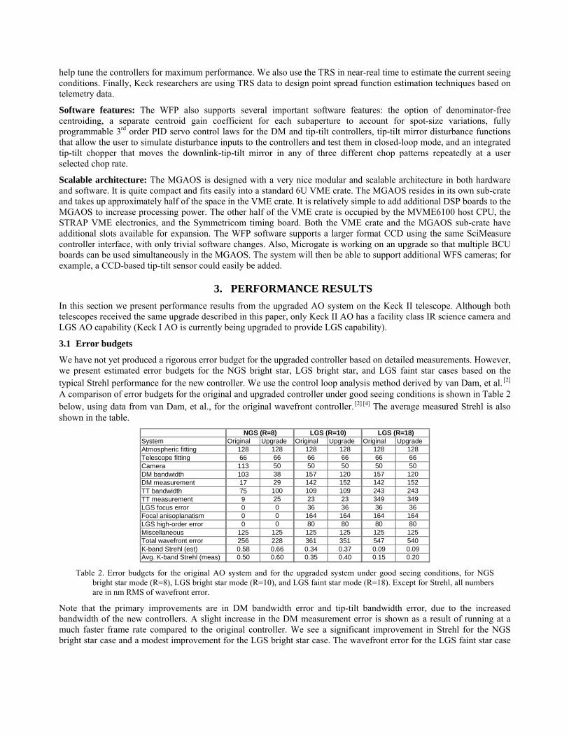
The performance is much better than that obtained using the original wavefront controller, as can be seen by looking at one of the best recorded images from each system, as shown in Figure 4 below. The scale and stretch are different; nevertheless, the improvement in image quality is obvious and quantifiable, due primarily to the increased controller bandwidth and improved wavefront sensor optics. The highest Strehl ratio obtained using the upgraded system is 71%, compared to 58% for the original system.
Figure 4. Some of the best images of a 7th magnitude star taken with the original wavefront controller (left) and the
upgraded system (right). The images have K-band Strehls of 58% and 66% respectively.
The system point spread function (PSF) is shown below in Figure 5 at three different wavelengths for the same bright star (R=7.5). The image quality improves with increasing wavelength, as expected.
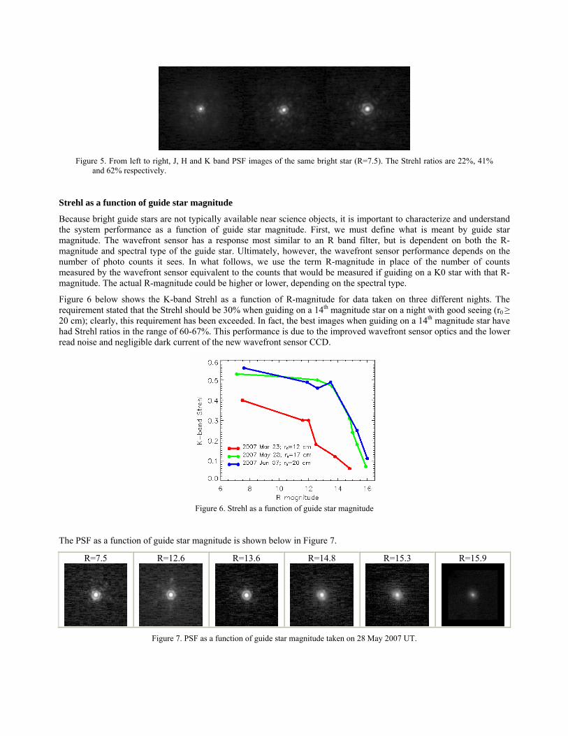
Figure 5. From left to right, J, H and K band PSF images of the same bright star (R=7.5). The Strehl ratios are 22%, 41%
and 62% respectively.
Strehl as a function of guide star magnitude
Because bright guide stars are not typically available near science objects, it is important to characterize and understand the system performance as a function of guide star magnitude. First, we must define what is meant by guide star magnitude. The wavefront sensor has a response most similar to an R band filter, but is dependent on both the R-magnitude and spectral type of the guide star. Ultimately, however, the wavefront sensor performance depends on the number of photo counts it sees. In what follows, we use the term R-magnitude in place of the number of counts measured by the wavefront sensor equivalent to the counts that would be measured if guiding on a K0 star with that R-magnitude. The actual R-magnitude could be higher or lower, depending on the spectral type.
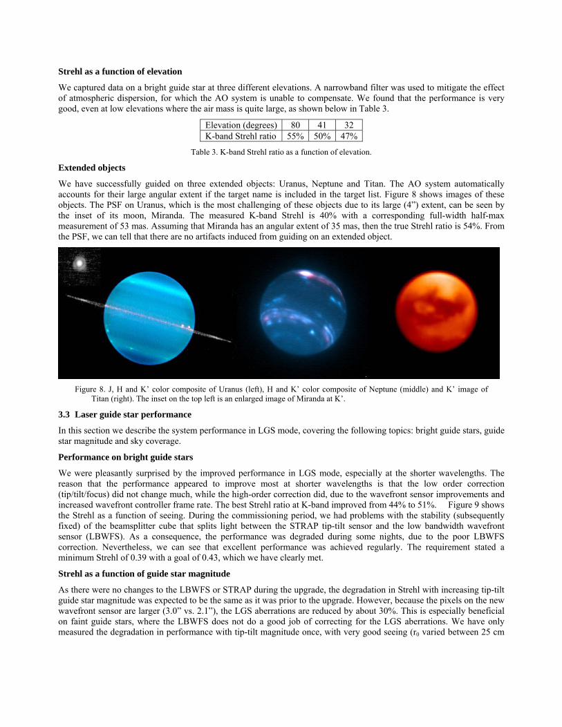
Figure 6 below shows the K-band Strehl as a function of R-magnitude for data taken on three different nights. The requirement stated that the Strehl should be 30% when guiding on a 14th magnitude star on a night with good seeing (r0 ≥ 20 cm); clearly, this requirement has been exceeded. In fact, the best images when guiding on a 14th magnitude star have had Strehl ratios in the range of 60-67%. This performance is due to the improved wavefront sensor optics and the lower read noise and negligible dark current of the new wavefront sensor CCD.
Figure 6. Strehl as a function of guide star magnitude
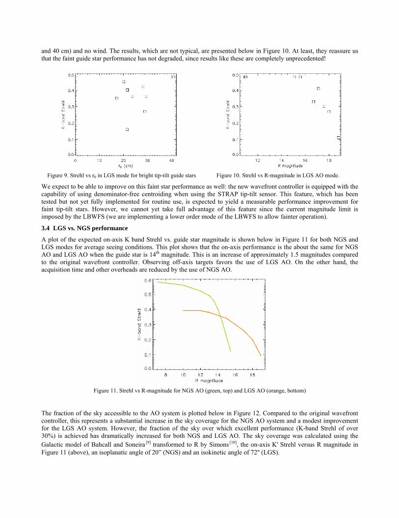
The PSF as a function of guide star magnitude is shown below in Figure 7.
R=7.5
R=12.6
R=13.6
R=14.8
R=15.3
R=15.9
Figure 7. PSF as a function of guide star magnitude taken on 28 May 2007 UT.
Strehl as a function of elevation
We captured data on a bright guide star at three different elevations. A narrowband filter was used to mitigate the effect of atmospheric dispersion, for which the AO system is unable to compensate. We found that the performance is very good, even at low elevations where the air mass is quite large, as shown below in Table 3.
Elevation (degrees) 80 41 32 K-band Strehl ratio 55% 50% 47%
Table 3. K-band Strehl ratio as a function of elevation.
Extended objects
We have successfully guided on three extended objects: Uranus, Neptune and Titan. The AO system automatically accounts for their large angular extent if the target name is included in the target list. Figure 8 shows images of these objects. The PSF on Uranus, which is the most challenging of these objects due to its large (4”) extent, can be seen by the inset of its moon, Miranda. The measured K-band Strehl is 40% with a corresponding full-width half-max measurement of 53 mas. Assuming that Miranda has an angular extent of 35 mas, then the true Strehl ratio is 54%. From the PSF, we can tell that there are no artifacts induced from guiding on an extended object.
Figure 8. J, H and K’ color composite of Uranus (left), H and K’ color composite of Neptune (middle) and K’ image of
Titan (right). The inset on the top left is an enlarged image of Miranda at K’.
3.3 Laser guide star performance
In this section we describe the system performance in LGS mode, covering the following topics: bright guide stars, guide star magnitude and sky coverage.
Performance on bright guide stars
We were pleasantly surprised by the improved performance in LGS mode, especially at the shorter wavelengths. The reason that the performance appeared to improve most at shorter wavelengths is that the low order correction (tip/tilt/focus) did not change much, while the high-order correction did, due to the wavefront sensor improvements and increased wavefront controller frame rate. The best Strehl ratio at K-band improved from 44% to 51%. Figure 9 shows the Strehl as a function of seeing. During the commissioning period, we had problems with the stability (subsequently fixed) of the beamsplitter cube that splits light between the STRAP tip-tilt sensor and the low bandwidth wavefront sensor (LBWFS). As a consequence, the performance was degraded during some nights, due to the poor LBWFS correction. Nevertheless, we can see that excellent performance was achieved regularly. The requirement stated a minimum Strehl of 0.39 with a goal of 0.43, which we have clearly met.
Strehl as a function of guide star magnitude
As there were no changes to the LBWFS or STRAP during the upgrade, the degradation in Strehl with increasing tip-tilt guide star magnitude was expected to be the same as it was prior to the upgrade. However, because the pixels on the new wavefront sensor are larger (3.0” vs. 2.1”), the LGS aberrations are reduced by about 30%. This is especially beneficial on faint guide stars, where the LBWFS does not do a good job of correcting for the LGS aberrations. We have only measured the degradation in performance with tip-tilt magnitude once, with very good seeing (r0 varied between 25 cm
and 40 cm) and no wind. The results, which are not typical, are presented below in Figure 10. At least, they reassure us that the faint guide star performance has not degraded, since results like these are completely unprecedented!
Figure 9. Strehl vs r0 in LGS mode for bright tip-tilt guide stars Figure 10. Strehl vs R-magnitude in LGS AO mode.
We expect to be able to improve on this faint star performance as well: the new wavefront controller is equipped with the capability of using denominator-free centroiding when using the STRAP tip-tilt sensor. This feature, which has been tested but not yet fully implemented for routine use, is expected to yield a measurable performance improvement for faint tip-tilt stars. However, we cannot yet take full advantage of this feature since the current magnitude limit is imposed by the LBWFS (we are implementing a lower order mode of the LBWFS to allow fainter operation).
3.4 LGS vs. NGS performance
A plot of the expected on-axis K band Strehl vs. guide star magnitude is shown below in Figure 11 for both NGS and LGS modes for average seeing conditions. This plot shows that the on-axis performance is the about the same for NGS AO and LGS AO when the guide star is 14th magnitude. This is an increase of approximately 1.5 magnitudes compared to the original wavefront controller. Observing off-axis targets favors the use of LGS AO. On the other hand, the acquisition time and other overheads are reduced by the use of NGS AO.
Figure 11. Strehl vs R-magnitude for NGS AO (green, top) and LGS AO (orange, bottom)
The fraction of the sky accessible to the AO system is plotted below in Figure 12. Compared to the original wavefront controller, this represents a substantial increase in the sky coverage for the NGS AO system and a modest improvement for the LGS AO system. However, the fraction of the sky over which excellent performance (K-band Strehl of over 30%) is achieved has dramatically increased for both NGS and LGS AO. The sky coverage was calculated using the Galactic model of Bahcall and Soneira [9] [10] transformed to R by Simons , the on-axis K' Strehl versus R magnitude in Figure 11 (above), an isoplanatic angle of 20” (NGS) and an isokinetic angle of 72'' (LGS).
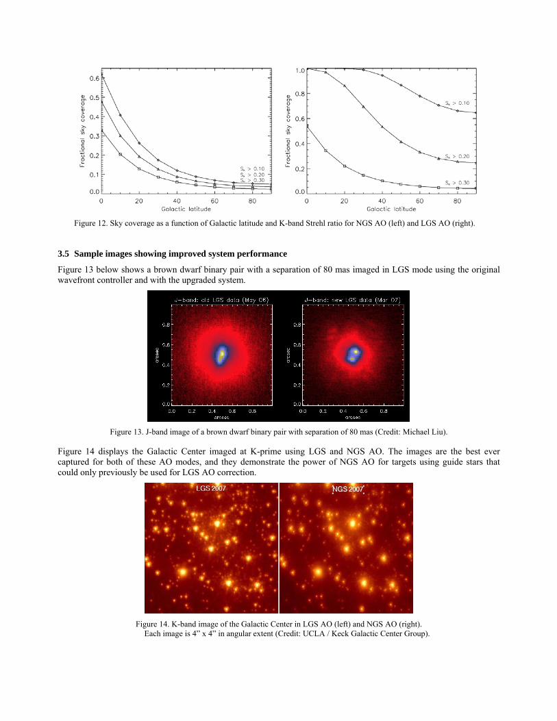
Figure 12. Sky coverage as a function of Galactic latitude and K-band Strehl ratio for NGS AO (left) and LGS AO (right).
3.5 Sample images showing improved system performance
Figure 13 below shows a brown dwarf binary pair with a separation of 80 mas imaged in LGS mode using the original wavefront controller and with the upgraded system.
Figure 13. J-band image of a brown dwarf binary pair with separation of 80 mas (Credit: Michael Liu).
Figure 14 displays the Galactic Center imaged at K-prime using LGS and NGS AO. The images are the best ever captured for both of these AO modes, and they demonstrate the power of NGS AO for targets using guide stars that could only previously be used for LGS AO correction.
Figure 14. K-band image of the Galactic Center in LGS AO (left) and NGS AO (right).
Each image is 4” x 4” in angular extent (Credit: UCLA / Keck Galactic Center Group).
4. CONCLUSIONS The upgrade of the wavefront sensors and controllers on the Keck AO systems has been very successful. The new architecture is robust, maintainable and scalable, and will keep the Keck AO systems competitive until the next generation of AO systems comes online. The initial performance from the systems has been excellent. The NGS and LGS bright guide star Strehl records have been greatly surpassed, going from 58% (NGS) and 44% (LGS) for the original wavefront controller to 71% (NGS) and 51% (LGS) for the upgraded system. In addition, we have excellent results using faint natural guide stars, with diffraction-limited images when guiding on 15th magnitude stars and partial corrections for stars up to one magnitude fainter. As a result, the faintest guide star for which NGS performance achieves comparable performance to LGS AO is now 14th magnitude. The system has been transitioned to the Keck AO Operations Group for routine science use and maintenance. There are still a few minor AO system upgrades to be made, so we expect to see additional small improvements in performance over time as these upgrades are implemented.
ACKNOWLEDGEMENTS
A project of this magnitude would not be possible without the contributions of many talented people. We would like to thank Doug Summers, Liz Chock, Jon Chock, and Steve Doyle for their help in integration and testing of the system. Thanks to Patrick Fry, Andrea Ghez, Mike Liu, Jessica Lu, Jim Lyke, Imke de Pater, Emily Schaller, Larry Sromovsky and Shelley Wright for help with the data reduction and analysis presented here. Thanks also to Randy Campbell and Jim Lyke for help with the data collection on engineering nights.
The data presented herein were obtained at the W. M. Keck Observatory, which is operated as a scientific partnership among the California Institute of Technology, the University of California, and the National Aeronautics and Space Administration. The Observatory was made possible by the generous financial support of the W. M. Keck Foundation. The upgrade to the Keck AO systems described in this paper was also supported by the W. M. Keck Foundation. The authors wish to recognize and acknowledge the very significant cultural role and reverence that the summit of Mauna Kea has always had within the indigenous Hawaiian community. We are most fortunate to have the opportunity to conduct observations from this mountain.
REFERENCES
[1] Wizinowich, P. L., et al., “First Light Adaptive Optics Images from the Keck II Telescope: A New Era of High Angular Resolution Imagery”, Publications of the Astronomical Society of the Pacific, 112: 315-319, March 2000.
[2] van Dam, M. A., Le Mignant, D., and Macintosh, B. A., “Performance of the Keck Observatory adaptive-optics system”, Applied Optics, Vol. 43, No. 29, pp. 5458-5467, 10 October 2004.
[3] Wizinowich, P. L., et al., “The W. M. Keck Observatory Laser Guide Star Adaptive Optics System: Overview”, Publications of the Astronomical Society of the Pacific, 118: 297-309, February 2006.
[4] van Dam, M. A., et al., “The W. M. Keck Observatory Laser Guide Star Adaptive Optics System: Performance Characterization”, Publications of the Astronomical Society of the Pacific, 118: 310-318, February 2006.
[5] Wizinowich, P. L., et al., “W.M. Keck Observatory’s Next Generation Adaptive Optics Facility”, in Adaptive Optics Systems, N. Hubin, C. Max, and P. Wizinowich, eds., Proc. SPIE 7015, (2008).
[6] Biasi, R., et al., “Control electronics for an adaptive secondary mirror”, in Adaptive Optical System Technologies, D. Bonaccini, R. Tyson, eds., Proc. SPIE 3353, 1193-1201 (1998).
[7] Biasi, R., et al., “Dedicated flexible electronics for adaptive secondary control”, in Advancements in Adaptive Optics, D. Bonaccini Calia, B. Ellerbroek, R. Ragazzoni, eds., Proc. SPIE 5490, 1502-1513 (2004).
[8] Biasi, R., et al., “AdOpt electronics: a flexible hardware and software platform for adaptive optics computing and control”, in Adaptive Optics Systems, N. Hubin, C. Max, and P. Wizinowich, eds., Proc. SPIE 7015, (2008).
[9] Bahcall, J., Soneira, R., “Predicted star counts in selected fields and photometric bands Applications to galactic structure, the disk luminosity function, and the detection of a massive halo”, Astrophysical Journal Supplement Series, vol. 47, Dec. 1981, p. 357-403.
[10] Simons, D., “Longitudinally averaged R-band field star counts across the entire sky”, internal Gemini Observatory project report, August 1995.
[11] Campbell, R. D., et al., “AO operations at the W. M. Keck Observatory”, in Observatory Operations: Strategies, Processes, and Systems, R. Brissenden and D. Silva, eds., Proc. SPIE 7016, (2008).