Elite User Manual 2 - Microgate - Home · Elite User Manual 2.4 10 December 2009 Page 1...
61
IPICO SPORTS ELITE READER USER MANUAL
Transcript of Elite User Manual 2 - Microgate - Home · Elite User Manual 2.4 10 December 2009 Page 1...

IPICO SPORTS ELITE READER
USER MANUAL
Elite User Manual 2.4 10 December 2009
Page 1
NOTIFICATIONS AND ADVISEMENT
FCC Identification – VHYIP3911A
This device complies with Part 15 of the Federal Communications Commission rules indicating that
the operation of the IPICO Sports Elite Reader is subject to the two following conditions:
1. The device may not cause harmful interference.
2. The device must accept any interference received, including interference that may cause
undesired operation.
PRECAUTIONS FOR USE
It is recommended that the following operational concerns be addressed before operation of the
reader for the first time and before operation of the reader after a significant period of disuse.
1. Fully charge the reader’s internal battery before the first use of the reader.
2. Fully charge the reader’s internal battery before events.
3. The reader’s internal battery should be fully charged every two months in the case that
the reader unit has not been recently used. This should be done so that the battery is
maintained in correct and working order.
REVISION HISTORY
VERSION DATE PURPOSE Draft 1.0 15/09/2006 Creation
Draft 1.1 27/10/2006 Editing and enhancement
Draft 1.2 22/11/2006 Editing and enhancement, added mat configurations
Draft 1.3 05/04/2007 Added reader communication section, modified mat
configuration, specifications and installation sections
Draft 1.4 11/04/2007 Removed RX color-coding, added inch and foot
dimensions, new front place, additional diagrams
Draft 1.5 18/04/2007 Modified mat configuration, added 6-meter mat line,
added information (summary of facilities)
Draft 1.6 10/07/2007
Added external +12-volt pin polarity on front plate
Added external loud buzzer picture
Added reader data protocol, command port sections
Change on NTP, Version, First Seen/Last Seen, XML
Removed Dimi start/stop function
Added battery management appendix
Add optional accessories appendix
Draft 1.7 19/07/2007
Added FCC Part 15 information
Added port layout summary
Modified Webmin explanations
Issued Version 1.00 01/09/2007 Updated precautions
Issued Version 2.3 01/22/2008
Updated reader images
Modified Webmin interface explanation
Added additional notes on functionality

Elite User Manual 2.4 10 December 2009
Page 2
TABLE OF CONTENTS
1 INTRODUCTION 4
2 SUMMARY OF CAPABILITIES / FEATURES 4
3 READER HARDWARE INTERFACE 5
3.1 Front Panel 5
3.1.1 Receiver Modules 6
3.1.2 Delta Module 7
3.1.3 Transmitter Module 9
3.1.4 Power Supply Module 11
3.1.5 Unit Top Panel 12
3.1.6 Unit Bottom Panel 13
4 MATS 14
4.1 Mat Overview 14
4.2 Mat Configurations 15
4.2.1 2.5 M Mat Setups 15
4.2.2 5 M Mat Setups 16
4.2.3 Mat Layout Instructions 17
4.2.4 Connecting Mats 18
5 TAG PRODUCTS 19
5.1 IPICO Sports Shoe Tag (Sportag) 19
5.2 IPICO Sports Multi-sport Tag 19
6 READER COMMUNICATION 20
6.1 Network Communication Configuration 20
6.1.1 Microsoft Windows XP 20
6.1.2 Microsoft Windows Vista 22
6.2 Webmin 25
6.2.1. Advanced Setup 27
6.2.2 Delete STK History Files 27
6.2.3 Download History Files 28
6.2.4 Delta FTP (File Transfer Protocol) 29
6.2.5 G.P.R.S. (General Packet Radio Service) 30
6.2.6 Network Configuration 31
6.2.7 OpenVPN Configuration 33
6.2.8 Start / Stop 33
6.2.9 System Time 34
6.2.10 Time Synchronization 35
6.2.11 Time Zone Setup 36
Elite User Manual 2.4 10 December 2009
Page 3
6.2.12 Upgrade 36
6.2.13 Version 37
6.3 Telnet 38
6.3.1 Installing Microsoft Telnet (Microsoft Windows Vista) 38
6.3.2 Running Microsoft Telnet (Microsoft Windows XP and Vista) 40
6.3.2.(A) IPICO Sports Elite Reader Maintenance (“9998”) Port 41
6.3.2.(B) IPICO Sports Elite Reader Console (“9999”, Control) Port 41
6.3.2.(C) IPICO Sports Elite Reader “10000” (Raw Streaming) Port 45
6.3.2.(D) IPICO Sports Elite Reader “10200” (First-Seen, Last-Seen) Port 46
6.3.2.(E) IPICO Sports Elite Reader “10201” (X.M.L.) Port 47
6.4 F.T.P. (File Transfer Protocol) 49
7 USE OF THE SYSTEM 52
7.1 System Setup Notes 52
7.2 Reader / Timing Mat Setup 53
7.3 Reader Startup And Operation 53
APPENDIX A TAG DATA FORMATS 54
APPENDIX B INTERNAL READER BATTERY MANAGEMENT 56
APPENDIX C READER SPECIFICATIONS 57
APPENDIX D TROUBLESHOOTING 59
APPENDIX E OPTIONAL ACCESSORIES 60

Elite User Manual 2.4 10 December 2009
Page 4
1 INTRODUCTION
The purpose of this document is to detail the functional parts, functions, operations and capabilities
of the IPICO Sports Elite Reader. Please note that the following capabilities, functions and
operations can be affected by setup environment. It is recommended that users fully read this
manual in order to obtain optimal system performance.
2 SUMMARY OF CAPABILITIES / FEATURES
The IPICO Sports Elite Reader has the following capabilities and features:
� Ability to drive 4 reading mats (2 meters x 1 meter each), equivalent to an 8 meter timing
line for one reader or 4 meters with a second 4 meter line for backup. With 2 readers, a 16
meter timing line is possible
� Data is stored on an internal CF (Compact Flash) card with a battery backup
� Ethernet port (RJ45) allows for communication between a reader and computer or
computer network (including wireless Ethernet communications)
� Internal power supply by battery for mobile applications
� External power supply provides 12 Volts DC or 110-220 Volts AC (50-60 Hz)
� External connectors for supplementary power supply by battery
� External connector for a fast charging solution (3 hour charge, only can be used with IPICO
Sports Fast Charger – Product Code IP0904)
� Input connectors for date-time stamp devices (can be used with an acoustic coupler for gun
starts)
� Battery management components: audible warnings (beeps) on low voltage or incorrect
input polarity and battery level indicator (analog dial)
� One On/Off rotary switch for simple operation
� LEDs and internal buzzer for notification of tag read/detection
� Optional inputs for external buzzer hardware (Product Code IP2911)
� DSPs to increase detection of tags in electromagnetically intense environments
� Internal automatic radio-frequency tuning
� Durable aluminum/plywood road case
� Venting for reader to adjust to ambient temperature in warmer climates

Elite User Manual 2.4 10 December 2009
Page 5
3 READER HARDWARE INTERFACE
FIGURE 1 – DIAGRAM OF ELITE READER INTERFACE
1. Receiver Module 9. On/Off Rotary Switch
2. Receiver Module 10. Battery Condition Indicator
3. External Buzzer Connector 11. IPICO Fast Charger Connector
4. Delta Module 12. 12 Volt Battery Connector
5. Ethernet (RJ45) Connector 13. TX A Transmitter (Green)
6. Manual Tune Switch 14. TX A Transmitter (Blue)
7. Transmitter Module 15. TX B Transmitter (Red)
8. Power Supply Module 16. TX B Transmitter (Yellow)
3.1 FRONT PANEL
All cable connections required for operation of the Elite Reader are located on the above-pictured
front panel. Figure 1 shows a photograph of the front panel of the reader. Descriptions of each
1
1
2 3 4 6 7 8
9
10
11 12 16
15
14
13
5

Elite User Manual 2.4 10 December 2009
Page 6
portion of the faceplate will be done in detail in the following pages. The reader’s front panel is
powder-coated Zinc annealed steel.
3.1.1 RECEIVER MODULES
The IPICO Sports Elite Reader has 2 dual-channel Receiver modules. These units collect tag data
from the Receive (RX) loops in the connected mats. As tags are read, the modules emit audible read
signals.
FIGURE 2 – DIAGRAM OF RECEIVER MODULES
1. Fault Indicator 4. Receiver (RX) B Socket
2. Receiver Unit Power Indicator 5. Tag Read Indicators (A,B, Tag)
3. Receiver (RX) A Socket
1. Fault Indicator
This indicator’s LED light will only appear when there are communication issues in the receiver.
2. Receiver Unit Power Indicator
This indicator’s LED will light up when the reader is powered. This LED indicates that the receiver
unit has power.
3. Receiver (RX) A Socket
Connection for the small, round connector (BNC connector) of the timing mats. While it does not
matter which connector is connected to which receiver socket, it is advised that mat order be kept
consistent.
4. Receiver (RX) B Socket
Connection for the small, round connector (BNC connector) of the timing mats. While it does not
matter which connector is connected to which receiver socket, it is advised that mat order be kept
consistent.
1
2
3
4
5
Elite User Manual 2.4 10 December 2009
Page 7
5. Tag Read Indicators (A,B,TAG)
The receiver modules have three tag read indicator LEDs. The A and B LEDs represent the RX A, and
RX B sockets. The TAG indicator lights when the receiver is sending information to the Delta module.
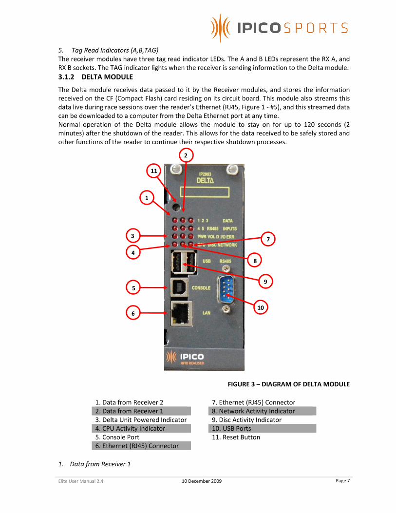
3.1.2 DELTA MODULE
The Delta module receives data passed to it by the Receiver modules, and stores the information
received on the CF (Compact Flash) card residing on its circuit board. This module also streams this
data live during race sessions over the reader’s Ethernet (RJ45, Figure 1 - #5), and this streamed data
can be downloaded to a computer from the Delta Ethernet port at any time.
Normal operation of the Delta module allows the module to stay on for up to 120 seconds (2
minutes) after the shutdown of the reader. This allows for the data received to be safely stored and
other functions of the reader to continue their respective shutdown processes.
FIGURE 3 – DIAGRAM OF DELTA MODULE
1. Data from Receiver 2 7. Ethernet (RJ45) Connector
2. Data from Receiver 1 8. Network Activity Indicator
3. Delta Unit Powered Indicator 9. Disc Activity Indicator
4. CPU Activity Indicator 10. USB Ports
5. Console Port 11. Reset Button
6. Ethernet (RJ45) Connector
1. Data from Receiver 1
2
1
3
4
5
6
7
8
9
10
11

Elite User Manual 2.4 10 December 2009
Page 8
This LED indicates that data is being received from Receiver (RX) 1 (the left-most Receiver).
2. Data from Receiver 2
This LED indicates that data is being received from Receiver (RX) 2 (the right-most Receiver).
3. Delta Unit Powered Indicator This indicator will be lit when the Delta is powered.
4. CPU Activity Indicator
The flashing of this indicator’s LED indicates that the Delta’s microprocessor is processing data, and
is operating.
5. Console Port
This port is for maintenance purposes only. It is not accessible by the user, and should only be used
by IPICO Sports technical staff, unless otherwise indicated.
6. Ethernet (RJ45) Connector
The Ethernet Connector allows for the reader to be joined to a network or computer via networking
cables. To network the reader to a specific computer, please use the cross-over cable (CAT-6) cable
packed with the reader.
7. Network Activity Indicator
This indicator’s LED will flash when network activity is being processed by the reader.
8. Disc Activity Indicator
The Disc Activity LED will be lit when the reader is accessing its internal CF (Compact Flash) card
memory.
9. USB Ports
Currently inactive, these ports serve as platforms for future expansion of functionality including USB
memory key logging and other functions to be added.
10. RS485 Input Port
Though currently inactive as well, this port is again planned for future expansion of hardware and
software capabilities.
11. Reset Button
Pressing this button will cause the Delta Module to completely reset, rendering the module
unresponsive to user commands during startup time (approx. 1-2 mins.).

Elite User Manual 2.4 10 December 2009
Page 9
3.1.3 TRANSMITTER MODULE
The reader’s Transmitter module provides power to the mats in order to create the different
frequency radio fields used to power and read IPICO Sports tags.
FIGURE 4 – DIAGRAM OF TRANSMITTER MODULE
1. Antenna Power Off Switch 5. Battery Level Indicator
2. Manual Tuning Switch 6. Transmitter (TX) B Tuning Status
3. Transmitter (TX) A Tuning Status 7. CPU Activity Indicator
4. Transmitter Power Indicator 8. Transmitter Console Port
1. Antenna Power Off Switch
The Antenna Power Off switch disables power routing to the timing mats, and discontinues the
reader’s ability to obtain tag reads. When the antenna power is off, a continuous tone is heard to
indicate that this switch has been pressed. To re-enable power routing to the timing mats, simply
press it; the tone will cease and the mats will regain power.
2. Manual Tuning Switch
Pressing this switch begins the reader’s mat tuning process, a process that takes place every 5 (five)
minutes. If timing mats are connected to the reader at the time of startup, the reader will
1
2
3
4
5
6
7
8

Elite User Manual 2.4 10 December 2009
Page 10
automatically tune to the given mat state. However, if mats are added after powering the reader, a
rapid series of “beeps” will be heard. This indicates that the reader’s tuning process has recognized
that new mats need to be tuned. Press the Manual Tuning Switch to tune the reader to the current
mat state.
3. Transmitter (TX) A Tuning Status
The A channel of the Transmitter (TX A) supports two mats, the red and green mats (Figure 1- #13,
#15) as seen in the lower left-hand corner of the reader’s main interface (Figure 1). If the mats in the
red or green Transmitter connectors (Figure 1 - #13, #15) are detuned, this LED will flash and the
transmitter will emit an audible detuned signal. See information on the Manual Tuning Switch in the
above figure (Figure 4 - # 2).
4. Transmitter Power Indicator
This indicator will be lit when the reader is powered to indicate that the Transmitter module is also
powered.
5. Battery Level Indicator
The three LEDs comprising the Battery Level Indicator, marked “L,” (Low) “M,” (Medium) and “H,”
(High) indicate the voltage level being supplied to the Transmitter unit. As this voltage is managed
by the Power Supply Module (see below), the voltage indicators should always remain in either the
“M” (Medium) or “H” (High) range.
6. Transmitter (TX) B Tuning Status
The B channel of the Transmitter (TX B) supports two mats, the blue and yellow mats (Figure 1- #14,
#16) as seen in the lower left-hand corner of the reader’s main interface (Figure 1). If the mats in the
blue or yellow Transmitter connectors (Figure 1 - #14, #16) are detuned, this LED will flash and the
transmitter will emit an audible detuned signal. See information on the Manual Tuning Switch in the
above figure (Figure 4 - # 2).
7. CPU Activity Indicator
This LED indicates that the microprocessor located on the Transmitter module is working correctly.
When operating, this LED will flash at half-second intervals.
8. Transmitter Console Port
This port is for maintenance purposes only. It is not accessible by the user, and should only be used
by IPICO Sports technical staff, unless otherwise indicated.
Elite User Manual 2.4 10 December 2009
Page 11
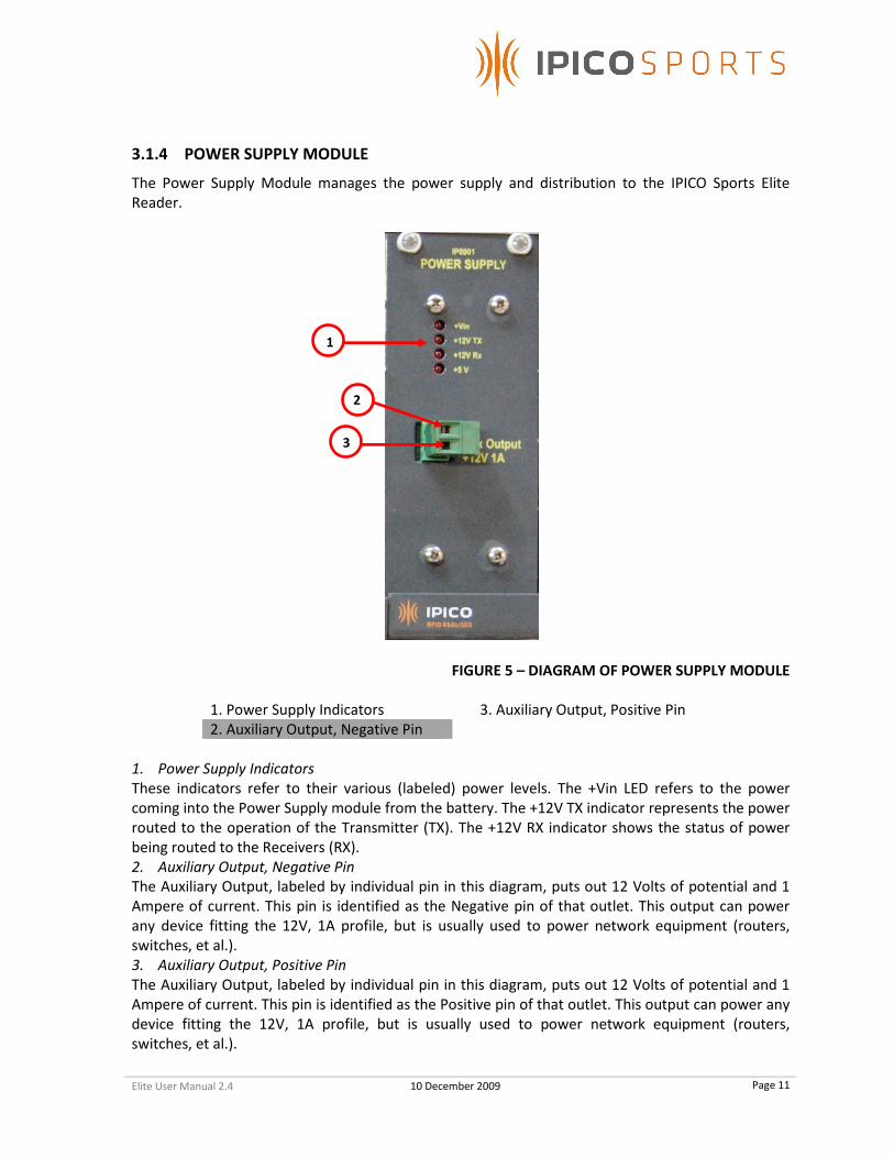
3.1.4 POWER SUPPLY MODULE
The Power Supply Module manages the power supply and distribution to the IPICO Sports Elite
Reader.
FIGURE 5 – DIAGRAM OF POWER SUPPLY MODULE
1. Power Supply Indicators 3. Auxiliary Output, Positive Pin
2. Auxiliary Output, Negative Pin
1. Power Supply Indicators
These indicators refer to their various (labeled) power levels. The +Vin LED refers to the power
coming into the Power Supply module from the battery. The +12V TX indicator represents the power
routed to the operation of the Transmitter (TX). The +12V RX indicator shows the status of power
being routed to the Receivers (RX).
2. Auxiliary Output, Negative Pin
The Auxiliary Output, labeled by individual pin in this diagram, puts out 12 Volts of potential and 1
Ampere of current. This pin is identified as the Negative pin of that outlet. This output can power
any device fitting the 12V, 1A profile, but is usually used to power network equipment (routers,
switches, et al.).
3. Auxiliary Output, Positive Pin
The Auxiliary Output, labeled by individual pin in this diagram, puts out 12 Volts of potential and 1
Ampere of current. This pin is identified as the Positive pin of that outlet. This output can power any
device fitting the 12V, 1A profile, but is usually used to power network equipment (routers,
switches, et al.).
1
2
3
Elite User Manual 2.4 10 December 2009
Page 12
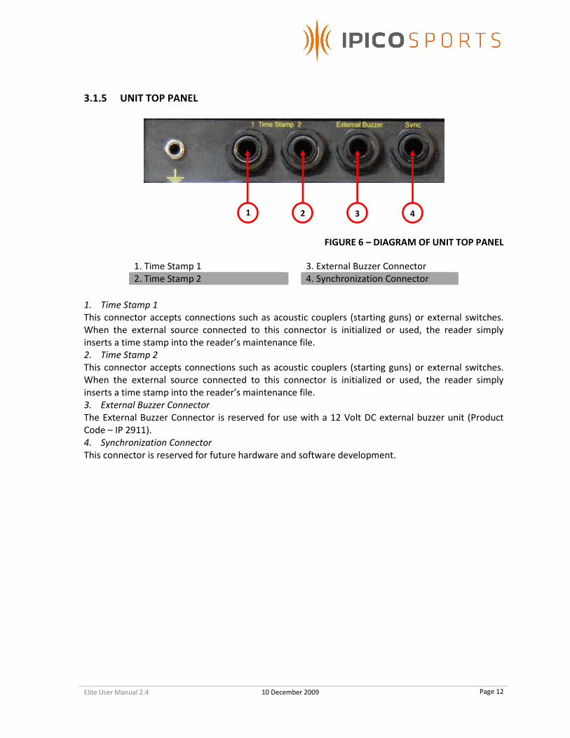
3.1.5 UNIT TOP PANEL
FIGURE 6 – DIAGRAM OF UNIT TOP PANEL
1. Time Stamp 1 3. External Buzzer Connector
2. Time Stamp 2 4. Synchronization Connector
1. Time Stamp 1
This connector accepts connections such as acoustic couplers (starting guns) or external switches.
When the external source connected to this connector is initialized or used, the reader simply
inserts a time stamp into the reader’s maintenance file.
2. Time Stamp 2
This connector accepts connections such as acoustic couplers (starting guns) or external switches.
When the external source connected to this connector is initialized or used, the reader simply
inserts a time stamp into the reader’s maintenance file.
3. External Buzzer Connector
The External Buzzer Connector is reserved for use with a 12 Volt DC external buzzer unit (Product
Code – IP 2911).
4. Synchronization Connector
This connector is reserved for future hardware and software development.
1 2 3 4

Elite User Manual 2.4 10 December 2009
Page 13
3.1.6 UNIT BOTTOM PANEL
FIGURE 7 – DIAGRAM OF UNIT BOTTOM PANEL
1. TX A Transmitter (Green) 6. TX B Transmitter (Yellow)
2. TX B Transmitter (Blue) 7. Venting Grate
3. Battery Condition Indicator 8. 12 Volt Battery Connector
4. On / Off Rotary Switch 9. IPICO Fast Charger Connector
5. TX A Transmitter (Red)
1. TX A Transmitter (Green)
These transmitter inputs (Figure 7, #1,2,5,6) correspond with their listed, color-coded timing mat.
2. TX B Transmitter (Blue)
These transmitter inputs (Figure 7, #1,2,5,6) correspond with their listed, color-coded timing mat.
3. Battery Condition Indicator
This analog gauge reports the condition of the reader’s internal battery through a three-color
system. If the needle rests in the green region, this indicates a safe operational charge; yellow
indicates a diminished battery charge; red indicates that the battery is low. NOTE: Some reader units
may have a digital readout in the place of the analog gauge pictured above.
4. On / Off Rotary Switch
Rotating this switch between the “On” and “Off” positions turns reader on and off, respectively.
5. TX A Transmitter (Red)
These transmitter inputs (Figure 7, #1,2,5,6) correspond with their listed, color-coded timing mat.
6. TX B Transmitter (Yellow)
These transmitter inputs (Figure 7, #1,2,5,6) correspond with their listed, color-coded timing mat.
7. Venting Grate
Due to the reader’s ability to adjust to ambient temperature without the use of internal fans, this
venting grate allows for air to circulate in and out of the reader unit.
8. 12 Volt Battery Connector
This battery connector allows for an external 12 Volt battery (automotive, et al.) to be connected.
1 2 3 4
5 67
8 9

Elite User Manual 2.4 10 December 2009
Page 14
9. IPICO Fast Charger Connector
This connector allows for the IPICO Sports Fast Charger (IP0904) to be used with the reader.
4 MATS
4.1 MAT OVERVIEW IPICO Sports timing mats come in two different sizes: 2.5 meter and 5 meter. The IPICO Sports Elite
Reader can be used with four (4) 2.5 meter mats or two (2) 5 meter mats.
FIGURE 8 – 2.5 METER MATS IN MAT BAGS
FIGURE 9 – 2.5 METER MAT WITH BAG OPEN
FIGURE 10 – 2.5 METER MAT UNPACKED

Elite User Manual 2.4 10 December 2009
Page 15
4.2 MAT CONFIGURATIONS
NOTE: The following diagrams and pictures take into account the best practices used in
order to operate the IPICO Sports Elite Reader at optimal performance. While other mat
configurations may be used, the diagrams and pictures below will take into account the
most common and most effective formats.
4.2.1 2.5 M MAT SETUPS
FIGURE 12 – 2.5 M MAT SETUP (MATS IN PARALLEL)
FIGURE 13 – 2.5 M MAT SETUP (MATS IN SERIES)
Elite User Manual 2.4 10 December 2009
Page 16
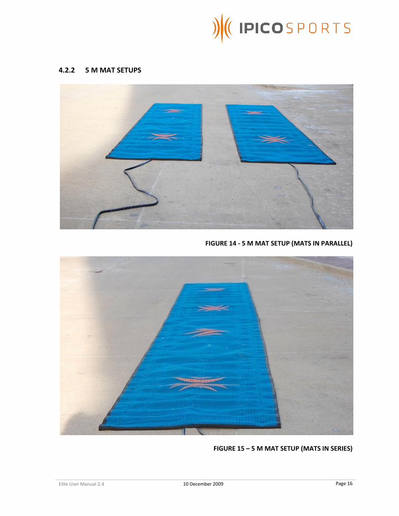
4.2.2 5 M MAT SETUPS
FIGURE 14 - 5 M MAT SETUP (MATS IN PARALLEL)
FIGURE 15 – 5 M MAT SETUP (MATS IN SERIES)

Elite User Manual 2.4 10 December 2009
Page 17
4.2.3 MAT LAYOUT INSTRUCTIONS
IPICO Sports timing mats come two different lengths (as pictured above), the 2.5-meter and 5-meter
types. While these mats are differentiated by color at the reader level, the mat colors also
correspond with their individual cable lengths.
MAT COLOR
2.5 M CABLE LENGTH
5 M CABLE LENGTH
GREEN 10 M 10 M
BLUE 10 M 10 M
RED 5 M
YELLOW 5 M
Considering the cable lengths listed above, it is important to layout the mats in a specific cable
length-oriented order. Thus with either setup, it is recommended that the user lay out the blue and
green mats first in order to create a timing line of optimal size.
Also, in order to account for participant safety and proper timing mat functionality, mat cables must
be tucked underneath the mats and run down the underlying center of any mats in series as the
following diagram illustrates, given a timing line that resembles Figure 16. FAILURE TO PLACE MAT
CABLES SQUARELY UNDER THE CENTER OF EACH MAT WILL ADVERSELY IMPACT PERFORMANCE
OF THE MATS TO A DRAMATIC DEGREE.
FIGURE 16 – 2.5 M MAT SETUP AND CABLE ORIENTATION
FIGURE 17 – 5 M MAT SETUP AND CABLE ORIENTATION
When using IPICO Sports Timing mats, it is also important to note that the mats should overlap
thirty (30) centimeters or approximately one (1) foot. This ensures that there are no disruptive
irregularities in the radio-frequency field created by the antenna mats.

Elite User Manual 2.4 10 December 2009
Page 18
FIGURE 18 – MAT OVERLAP
4.2.4 CONNECTING MATS
FIGURE 19 – CONNECTING MATS TO THE RECEIVERS
FIGURE 20 – CONNECTING MATS TO THE TRANSMITTERS
To connect timing mats to the IPICO Sports Elite Reader, follow the steps listed below and illustrated
above in Figure :
1. Connect the smaller, round BNC connection (Bayonet Neill Concelman) to the appropriate
receiver (RX) connector. In the pictured example, a “yellow” 2.5-meter mat is used, thus, the
appropriate receiver connector is the “RX B” connector on the second (right-most) receiver
(Figure 1, item 2).
2. With the larger gray connector in hand, locate the corresponding, color-coded transmitter
(TX) connector. Again, because the example uses a “yellow” 2.5-meter mat, the appropriate
connection is that of the yellow-colored “TX B” connection (Figure 1, item 16).
3. Repeat these steps for all mats which are desired to be connected.

Elite User Manual 2.4 10 December 2009
Page 19
5 TAG PRODUCTS
NOTE: The following two items are the only tag products that work with the IPICO Sports
Elite Reader system.
5.1 IPICO SPORTS SHOE TAG (SPORTAG)
The IPICO Sports Shoe tag (Sportag) is used for normal road-race
applications. These tags feature Dual-Frequency (125 kHz / 6.8 mHz)
compatibility, and are globally compliant with spectrum specifications.
5.2 IPICO SPORTS MULTI-SPORT TAG
The IPICO Sports Multi-sport tag is recommended for use with multi-
stage, multi-sport events. Fabrifoam® straps can be ordered from IPICO
Sports in order to allow the participant to easily attach the Multi-sport
tag. These tags feature Dual-Frequency (125 kHz / 6.8 mHz)
compatibility, and are globally compliant with spectrum specifications.

Elite User Manual 2.4 10 December 2009
Page 20
6 READER COMMUNICATION
NOTE: To connect directly to an IPICO Sports Elite Reader, the use of the orange crossover
cable provided or a compatible alternative (CAT 5E, CAT 6 crossover cabling) is required.
6.1 NETWORK COMMUNICATION CONFIGURATION In order to communicate with the IPICO Sports Elite Reader, the interfacing device (computer, et al.)
must have its network configuration corrected such that it is on a network consistent with the IPICO
Sports Elite Reader system. The following subsections will detail settings changes necessary for
network operation in both the Microsoft Windows XP and Vista environments.
6.1.1 MICROSOFT WINDOWS XP
FIGURE – WINDOWS XP START MENU
To access the Control Panel, where Microsoft Windows XP network settings reside, navigate to the
“Start Menu” in the lower left-hand corner of the Microsoft Windows XP screen, on the taskbar.
Clicking the “Start” button will reveal the above-pictured menu. Navigate to the “Settings” entry,
highlighting it. This will reveal a sub-menu, at the top of which is the “Control Panel” option. Click
this option, and the Microsoft Windows XP Control Panel will appear.
CLASSIC VIEW CATEGORY VIEW
FIGURE 21 – “NETWORK CONNECTIONS” ICONS
When Microsoft XP Windows Control Panel has been opened, navigate to either of the two above-
pictured icons. Click on the appropriate icon to enter the “Network Connections” screen.

Elite User Manual 2.4 10 December 2009
Page 21
FIGURE 22 – “LOCAL AREA CONNECTION” ICON
When at the “Network Connections” screen, locate an icon similar to the above-pictured “Local Area
Connection” icon. Double-click on the icon to launch the “Local Area Connection Properties”
window.
STEP 1 – CLICK ON“PROPERTIES” STEP 2 – HIGHLIGHT “INTERNET PROTOCOL
(TCP/IP)” AND CLICK “PROPERTIES”

Elite User Manual 2.4 10 December 2009
Page 22
6.1.2 WINDOWS VISTA
WINDOWS VISTA CLASSIC WINDOWS VISTA AERO
STEP 3 – CLICK “USE THE FOLLOWING IP
ADDRESS” AND SPECIFY THE ADDRESSES AS
LISTED, CLICKING “OK” TO EXIT AND SAVE

Elite User Manual 2.4 10 December 2009
Page 23
To access the desired network settings, navigate to the Microsoft Windows Vista Control Panel by
either method pictured above (Microsoft Windows Vista Classic and Aero pictured). Once at the
Control Panel, find and select the “Network Sharing Center” option.
FIGURE 23 – MICROSOFT WINDOWS VISTA NETWORK AND SHARING CENTER ICON
To open the Microsoft Windows Vista Network and Sharing Center, double click the Network and
Sharing Center icon, launching the following screen:

Elite User Manual 2.4 10 December 2009
Page 24
FIGURE – MICROSOFT WINDOWS VISTA NETWORK AND SHARING CENTER
On the left-hand side of the Network and Sharing Center window, a list of links enumerates the
various functions of the Microsoft Vista Network and Sharing Center. Find the link labeled “Manage
Network Connections,” and click on it.
FIGURE 24 – “MANAGE NETWORK CONNECTIONS” SCREEN
On this screen, a connection entitled “Local Area Connection” (or some variant) will appear. Right-
click the “Local Area Connection” icon and select the “Properties” option from the resulting context
menu.
After clicking “OK” in the “Local Area Connection Properties” window, the IP (Internet Protocol)
address of the computer being used to connect to the IPICO Sports Elite Reader has been changed.
STEP 1 – FIND “INTERNET PROTOCOL
VERSION 4,” HIGHLIGHT IT AND CLICK ON
“PROPERTIES”
STEP 2 – SELECT “USE THE FOLLOWING IP
ADDRESS” AND CLICK “OK” TO EXIT AND
SAVE.
Elite User Manual 2.4 10 December 2009
Page 25
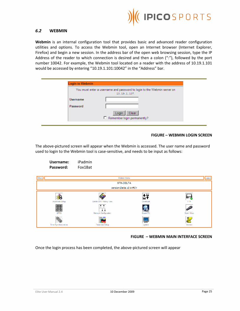
6.2 WEBMIN
Webmin is an internal configuration tool that provides basic and advanced reader configuration
utilities and options. To access the Webmin tool, open an Internet browser (Internet Explorer,
Firefox) and begin a new session. In the address bar of the open web browsing session, type the IP
Address of the reader to which connection is desired and then a colon (“:”), followed by the port
number 10042. For example, the Webmin tool located on a reader with the address of 10.19.1.101
would be accessed by entering “10.19.1.101:10042” in the “Address” bar.
FIGURE – WEBMIN LOGIN SCREEN
The above-pictured screen will appear when the Webmin is accessed. The user name and password
used to login to the Webmin tool is case-sensitive, and needs to be input as follows:
Username: iPadmin
Password: Fox1Bat
FIGURE – WEBMIN MAIN INTERFACE SCREEN
Once the login process has been completed, the above-pictured screen will appear

Elite User Manual 2.4 10 December 2009
Page 26
WEBMIN ICONS
Allows for the settings changes for the Delta
shutdown grace period (default 120
seconds) and for the reader’s FS-LS timeout.
Provides an interface by which the reader’s
stored data files can be disposed.
Allows for download of reader history and
maintenance log files through SCP; use of
FTP is advocated. May be removed,
forthcoming.
This interface provides a link to the reader’s
FTP.
Displays and changes values relevant to a
user’s GPRS modem settings.
Allows for the reader’s networking settings
(IP, DHCP client or server status, et al.) to be
altered.
Sets and saves OpenVPN access parameters.
Provides users with start/stop and restart
control of the reader’s Delta module
(diagram #4).
Allows for the reader’s system time to be
changed.
Provides access to the reader’s NTP
(Network Time Protocol) settings forNTP
server status for time sync.
Allows for reader’s system time zone to be
changed.
Provides an interface for upgrading the
operating system version for the reader.
Reports the current operating process
versions.
FIGURE – DIAGRAM OF WEBMIN ICONS AND FUNCTIONS

Elite User Manual 2.4 10 December 2009
Page 27
6.2.1 ADVANCED SETUP
FIGURE – ADVANCED SETUP SCREEN
1. Power-Out Timeout
The setting of this value determines the amount of time that the Delta will use to shut down its
processes after the reader unit has been turned off by rotary switch (Fig. 1, 9). The Delta of the
reader unit will remain on during this timeout, and shut down only when the set time for time-out is
reached. The default value is 120 seconds. To save any changes made to this setting, click the “Save”
button located in the lower left-hand corner of the screen.
2. Last Seen Timeout
The Last Seen Timeout setting determines the amount of time between each “First Seen” and “Last
Seen” read on reader port 10200 (the First-Seen,Last-Seen port). The default value is 5 seconds. To
save any changes made to this setting, click the “Save” button located in the lower left-hand corner
of the screen.
3. Return to Index Link
Clicking on this link will return the user to the index screen of the Webmin application. If changes
have not been saved, this link will return to the main screen without saving changes. To save any
changes made to the values listed on the “Advanced Setup” screen, click the “Save” button located
in the lower left-hand corner of the screen.
6.2.2 DELETE STK HISTORY FILES
FIGURE – DELETE STK HISTORY FILES SCREEN
1. File Deletion Checkboxes
The files listed at the left-hand side of the “Delete STK History Files” screen are the files located on
the reader that are available for deletion. To delete a file, check the box located to the left of the file
name for which deletion is intended. Repeat this process for all files desired for deletion. Once
finished selecting files, click on the “Delete Selected Files” button located in the lower left-hand
corner of the screen.
1
2
3
1
2

Elite User Manual 2.4 10 December 2009
Page 28
2. Return to Index Link
Clicking on this link will return the user to the index screen of the Webmin application. If changes
have not been saved, this link will return to the main screen without deleting any files. To delete the
intended files listed on the “Delete STK History Files” screen, click the “Delete Selected Files” button
located in the lower left-hand corner of the screen.
6.2.3 DOWNLOAD HISTORY FILES
FIGURE – DOWNLOAD HISTORY FILES SCREEN
1. File to Download “…” button
Clicking on this button will launch an additional window (Figure 17) through which the user can
select the file for which download is desired. This method uses SCP (Session Control Protocol) and is
slower than the use of the FTP (File Transfer Protocol) method used by the Elite Reader. This feature
is included for backwards compatibility with previous operating system versions. This feature may
be removed in forthcoming versions.
FIGURE – “CHOOSE FILE” DIALOG
To select a file to download, simply click on the icon located to the left of the item desired. This will
add the file to the text field to the right of the “OK” button. Once the desired file has been selected,
click the “OK” button, the user will return to the main “Download History Files” screen (Figure 16),
and the “File to Download” field will be populated with the selected file. All reader files available for
download are located in this repository.
2. “Download” button
Once the “File to Download” field has been populated according to the above-described manner,
clicking this button will request the file from the reader for download.
1
2

Elite User Manual 2.4 10 December 2009
Page 29
6.2.4 DELTA FTP (FILE TRANSFER PROTOCOL)
FIGURE – DELTA FTP (FILE TRANSFER PROTOCOL) SCREEN
1. FTP (File Transfer Protocol) Link
Clicking the link located on the “Delta FTP” screen will send the user to the FTP (File Transfer
Protocol) archive located on the reader. All reader files available for download are located in this
repository.
FIGURE – ELITE READER FTP (FILE TRANSFER PROTOCOL) SCREEN
The above-pictured screen (Figure 19) lists all files and directories available for download from the
reader. To save a given file, right-click on the file for which download is desired and select the “Save
Target As..,” “Save Link As..” options, or a variation thereof. These options and the above-pictured
screen may appear different depending on the Internet browser in use with the IPICO Sports Elite
Reader.
1

Elite User Manual 2.4 10 December 2009
Page 30
6.2.5 GPRS (GENERAL PACKET RADIO SERVICE)
1. Carrier Profile
The IPICO Sports Elite Reader supports the following G.P.R.S. (General Packet Radio Service)
providers:
A1 (Austria)
Aon (Austria)
Orange (France)
Vodafone (New Zealand)
AT&T (United States)
Use this drill-down menu to select your G.P.R.S. (General Packet Radio Service) provider.
2. Username
Depending upon the preferences of your chosen carrier, you may be required to provide a network
username in order to use your G.P.R.S. (General Packet Radio Service) subscription. Please verify all
necessary network details with your service provider.
3. Password
Depending upon the preferences of your chosen carrier, you may be required to provide a network
password in order to use your G.P.R.S. (General Packet Radio Service) subscription. Please verify all
necessary network details with your service provider.
4. P.I.N. (Personal Identification Number)
Depending upon the preferences of your chosen carrier, you may be required to provide a network
access P.I.N. (personal identification number) in order to use your G.P.R.S. (General Packet Radio
Service) subscription. Please verify all necessary network details with your service provider.
5. A.P.N. (Access Point Name)
Depending upon the preferences of your chosen carrier, you may be required to provide a network
A.P.N. (access point name) in order to use your G.P.R.S. (General Packet Radio Service) subscription.
Please verify all necessary network details with your service provider.
6. Number
Depending upon the preferences of your chosen carrier, you may be required to provide a specific
network number in order to use your G.P.R.S. (General Packet Radio Service) subscription. Please
verify all necessary network details with your service provider.
7. Custom Configuration Settings
If any of the above settings have been customized in order to operate your G.P.R.S. (General Packet
Radio Service) device, it is recommended that you save these details. Checking the checkbox to the
right will save details to the name listed in the text box at right when “Save” is clicked.
1
2
3
4
5 6
7 8
9
Elite User Manual 2.4 10 December 2009
Page 31
8. “Load Delta with Profile” Option
Once the correct carrier profile data has been entered or selected, checking the “Load Delta with
Profile” box will immediately load the profile onto the Delta module, enabling the G.P.R.S. (General
Packet Radio Service) device to be used with your chosen network details.
9. “Save” button
Clicking the “Save” button will store all and put into place all network details chosen.
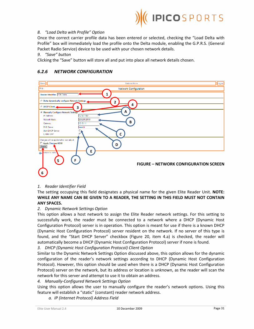
6.2.6 NETWORK CONFIGURATION
FIGURE – NETWORK CONFIGURATION SCREEN
1. Reader Identifier Field
The setting occupying this field designates a physical name for the given Elite Reader Unit. NOTE:
WHILE ANY NAME CAN BE GIVEN TO A READER, THE SETTING IN THIS FIELD MUST NOT CONTAIN
ANY SPACES.
2. Dynamic Network Settings Option
This option allows a host network to assign the Elite Reader network settings. For this setting to
successfully work, the reader must be connected to a network where a DHCP (Dynamic Host
Configuration Protocol) server is in operation. This option is meant for use if there is a known DHCP
(Dynamic Host Configuration Protocol) server resident on the network. If no server of this type is
found, and the “Start DHCP Server” checkbox (Figure 20, item 4.a) is checked, the reader will
automatically become a DHCP (Dynamic Host Configuration Protocol) server if none is found.
3. DHCP (Dynamic Host Configuration Protocol) Client Option
Similar to the Dynamic Network Settings Option discussed above, this option allows for the dynamic
configuration of the reader’s network settings according to DHCP (Dynamic Host Configuration
Protocol). However, this option should be used when there is a DHCP (Dynamic Host Configuration
Protocol) server on the network, but its address or location is unknown, as the reader will scan the
network for this server and attempt to use it to obtain an address.
4. Manually-Configured Network Settings Option
Using this option allows the user to manually configure the reader’s network options. Using this
feature will establish a “static” (constant) reader network address.
a. IP (Internet Protocol) Address Field
1
E
F 5
6
2
3 4
A
B
C
D
Elite User Manual 2.4 10 December 2009
Page 32
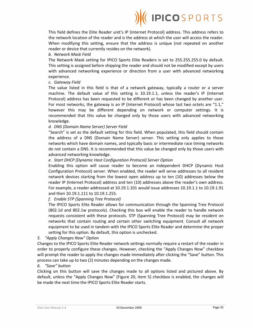
This field defines the Elite Reader unit’s IP (Internet Protocol) address. This address refers to
the network location of the reader and is the address at which the user will access the reader.
When modifying this setting, ensure that the address is unique (not repeated on another
reader or device that currently resides on the network).
b. Network Mask Field
The Network Mask setting for IPICO Sports Elite Readers is set to 255.255.255.0 by default.
This setting is assigned before shipping the reader and should not be modified except by users
with advanced networking experience or direction from a user with advanced networking
experience.
c. Gateway Field
The value listed in this field is that of a network gateway, typically a router or a server
machine. The default value of this setting is 10.19.1.1, unless the reader’s IP (Internet
Protocol) address has been requested to be different or has been changed by another user.
For most networks, the gateway is an IP (Internet Protocol) whose last two octets are “1.1,”
however this may be different depending on network or computer settings. It is
recommended that this value be changed only by those users with advanced networking
knowledge.
d. DNS (Domain Name Server) Server Field
“Search” is set as the default setting for this field. When populated, this field should contain
the address of a DNS (Domain Name Server) server. This setting only applies to those
networks which have domain names, and typically basic or intermediate race timing networks
do not contain a DNS. It is recommended that this value be changed only by those users with
advanced networking knowledge.
e. Start DHCP (Dynamic Host Configuration Protocol) Server Option
Enabling this option will cause reader to become an independent DHCP (Dynamic Host
Configuration Protocol) server. When enabled, the reader will serve addresses to all resident
network devices starting from the lowest open address up to ten (10) addresses below the
reader IP (Internet Protocol) address and ten (10) addresses above the reader’s own address.
For example, a reader addressed at 10.19.1.101 would issue addresses 10.19.1.1 to 10.19.1.91
and then 10.19.1.111 to 10.19.1.255.
f. Enable STP (Spanning Tree Protocol)
The IPICO Sports Elite Reader allows for communication through the Spanning Tree Protocol
(802.1d and 802.1w protocols). Checking this box will enable the reader to handle network
requests consistent with these protocols. STP (Spanning Tree Protocol) may be resident on
networks that contain routing and certain other switching equipment. Consult all network
equipment to be used in tandem with the IPICO Sports Elite Reader and determine the proper
setting for this option. By default, this option is unchecked.
5. “Apply Changes Now” Option
Changes to the IPICO Sports Elite Reader network settings normally require a restart of the reader in
order to properly configure these changes. However, checking the “Apply Changes Now” checkbox
will prompt the reader to apply the changes made immediately after clicking the “Save” button. This
process can take up to two (2) minutes depending on the changes made.
6. “Save” button
Clicking on this button will save the changes made to all options listed and pictured above. By
default, unless the “Apply Changes Now” (Figure 20, item 5) checkbox is enabled, the changes will
be made the next time the IPICO Sports Elite Reader starts.

Elite User Manual 2.4 10 December 2009
Page 33
6.2.7 OPENVPN CONFIGURATION
1. OpenVPN (Virtual Private Network) Status
The two radio buttons, labeled “enabled” and “disabled,” control the operating status of the Elite
Reader’s OpenVPN (Virtual Private Network) services. To start services, click the “enabled” radio
button, and click the “Submit” button (Diagram #2) to enact this change. To disable services, click
the “disabled” button to end OpenVPN (Virtual Private Network) services.
2. “Submit” button
To enact the changes specified in the description of diagram #1, click the “Submit” button.
3. “URL of OpenVPN config. pack” option
In order to use the IPICO Sports OpenVPN (Virtual Private Network) server, a URL for a configuration
packet must be obtained from IPICO Sports, and can be claimed by contacting technical/customer
support.
4. “Skip MD5check” option
All client configuration packages will come with an “MD5” (Message diagram algorithm 5)
checksum, a mathematic summation of all the package’s contents used for verification purposes. If
the “MD5” (Message diagram algorithm 5) check fails, the package will not install. This is used for
security and integrity verification purposes and is not recommended to be skipped.
5. “Install” button
Clicking the “Install” button will install the client package located at the provided URL (Universal
Resource Locator) with the accompanying “MD5” (Message diagram algorithm 5) checksum.
6.2.8 START / STOP
FIGURE – START / STOP SCREEN
*STK – SPORTS TIME KEEPING
1. Stop STK-DELTA Option
Selecting this option and clicking the “Execute” button (Figure 21, item 4) will cause the Delta
module of the IPICO Sports Elite Reader to stop all of its processes while remaining on.
2. Start STK-DELTA Option
1*
2*
3
4
1
2
3
4
5 6
Elite User Manual 2.4 10 December 2009
Page 34
Selecting this option and clicking the “Execute” button (Figure 21, item 4) will restart all of the
functions of the Delta module.
3. Power Off Option
Selecting the “Power Off” option and clicking the “Execute” button (Figure 21, item 4) will remove
power from the Delta module and stop all of its functions accordingly. When power is removed from
the Delta module, the only way to restart it is to turn the “On / Off” rotary switch (Figure 1, item 9)
to the left, or “Off” position and then turn it back to the right, or “On” position.
4. Execute button
Clicking this button will enact the option selected. By default the “Stop STK-Delta” option is selected.
6.2.9 SYSTEM TIME
FIGURE – SYSTEM TIME SCREEN
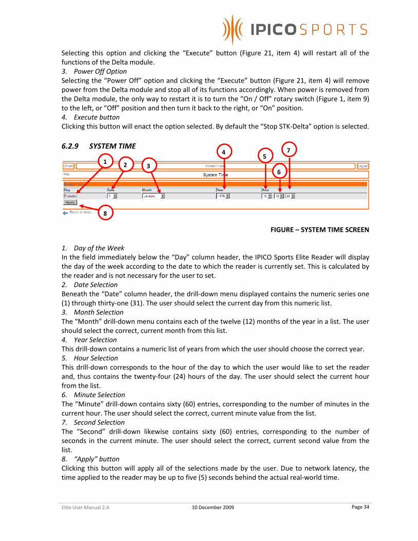
1. Day of the Week
In the field immediately below the “Day” column header, the IPICO Sports Elite Reader will display
the day of the week according to the date to which the reader is currently set. This is calculated by
the reader and is not necessary for the user to set.
2. Date Selection
Beneath the “Date” column header, the drill-down menu displayed contains the numeric series one
(1) through thirty-one (31). The user should select the current day from this numeric list.
3. Month Selection
The “Month” drill-down menu contains each of the twelve (12) months of the year in a list. The user
should select the correct, current month from this list.
4. Year Selection
This drill-down contains a numeric list of years from which the user should choose the correct year.
5. Hour Selection
This drill-down corresponds to the hour of the day to which the user would like to set the reader
and, thus contains the twenty-four (24) hours of the day. The user should select the current hour
from the list.
6. Minute Selection
The “Minute” drill-down contains sixty (60) entries, corresponding to the number of minutes in the
current hour. The user should select the correct, current minute value from the list.
7. Second Selection
The “Second” drill-down likewise contains sixty (60) entries, corresponding to the number of
seconds in the current minute. The user should select the correct, current second value from the
list.
8. “Apply” button
Clicking this button will apply all of the selections made by the user. Due to network latency, the
time applied to the reader may be up to five (5) seconds behind the actual real-world time.
1 2 3
4 5
6
7
8

Elite User Manual 2.4 10 December 2009
Page 35
6.2.10 TIME SYNCHRONIZATION
FIGURE – TIME SYNCHRONIZATION SCREEN
1. Master Time Server Section (“This is a Master Timeserver”)
All settings listed under this section imply that the IPICO Sports Elite Reader for which these settings
are being configured is a master time server. As a master time server, the IPICO Sports Elite Reader
will act as a common time source for all readers on the network if their settings are set to be slave
settings.
a. Own Time is Configured Manually Option
Selecting this option will cause the IPICO Sports Elite Reader to refer to its current internal
time as the time source by which all slave readers will be synchronized.
b. Synchronize Own Time to Internet Timeservers
Selecting this option will cause the IPICO Sports Elite Reader to attempt to access a list of
Internet time servers in order to set its internal time such that the new time will serve as the
common time source amongst all slave readers. NOTE: TO USE THIS FEATURE, THE IPICO
SPORTS ELITE READER MUST HAVE ACCESS TO AN INTERNET CONNECTION.
2. Slave Time Server Section (“This is a Slave”)
All settings listed under this section imply that the IPICO Sports Elite Reader for which these settings
are being configured is a slave reader. As a slave reader, the IPICO Sports Elite Reader will acquire a
time from a time source that is acting as a master time server.
a. Synchronize Time to Internet Timeservers
Selecting this option will cause the reader to refer to a list of Internet time servers in order to
set its internal time. The time acquired through this method by the IPICO Sports Elite Reader
will not be broadcast to other readers, as this setting configures the reader as a slave
machine. NOTE: TO USE THIS FEATURE, THE IPICO SPORTS ELITE READER MUST HAVE ACCESS
TO AN INTERNET CONNECTION.
b. Synchronize Time To a Delta Master Timeserver
If an IPICO Sports Elite Reader resident on the network is a master time server, this setting will
allow this IPICO Sports Elite Reader to reference the reader set up as the master time server
as its time source. NOTE: TO USE THIS FEATURE, AN IPICO SPORTS ELITE READER MUST BE
SET UP AS A MASTER TIME SERVER AND BE RESIDENT ON THE SAME NETWORK AS THE
READER SET TO BE A SLAVE.
3. Delta Master / NTP (Network Time Protocol) Server – IP (Internet Protocol) Address Field
When a Delta has been set as a master time server, the user should input the IP (Internet Protocol)
address of the master time server Delta into this field. This will allow the slave readers to use the
1
AB
2A
B
34
5

Elite User Manual 2.4 10 December 2009
Page 36
master time serving Delta as their time source. Likewise, if there is an Internet time server whose
use is desired, input the IP (Internet Protocol) address of the desired time server into the field. This
will cause the reader to refer to the listed time server for its internal time.
4. Disable Automatic Time Synchronization Option
If automatic time synchronization is not desired, a user may disable the feature completely by
selecting this option. This will cause the reader to ignore all time synchronization settings, and will
instruct the IPICO Sports Elite Reader to use its own internal time independent of any other systems.
5. “Save” button
Clicking on this button saves all changes made to the time synchronization settings.
6.2.11 TIME ZONE SETUP
FIGURE – TIME ZONE SETUP SCREEN
1. Current Time
This portion of the screen displays the reader’s current internal time in full format, including the
current time zone to which the reader is set.
2. Time Zone Selection
The Time Zone Selection drill-down menu contains a list of standard time zones in the format of
“Continent/(City/Country).” The user should select the correct pairing (or the closest geographical
pairing) that will set the reader to the desired time zone.
3. “Save” button
Clicking on this button will save and implement the settings change.
6.2.12 UPGRADE
FIGURE – UPGRADE SCREEN
1. Upgrade URL (Universal Resource Locator) Field
The Upgrade URL (Universal Resource Locator) Field accepts the FTP (File Transfer Protocol) location
of IPICO Sports Elite Reader operating system tarball (.tar.gz / .tar) files. These files can be provided
to the end user upon request.
2. Md5 (Message-Digest Algorithm 5) Checksum Field
To ensure the security and the integrity of the operating system file selected, the IPICO Sports Elite
Reader upgrade process requires a secure analysis key (checksum) that corresponds to each
1
2
3
1
23
Elite User Manual 2.4 10 December 2009
Page 37
individual operating system version file. When operating system files are provided by IPICO Sports,
the Md5 (Message-Digest Algorithm 5) checksum will accompany the provision of the file.
3. “Upgrade” Button
When the upgrade information is correctly entered, clicking the “Upgrade” button will prompt the
reader to attempt to download the upgrade file listed in the Upgrade URL (Universal Resource
Locator) Field and compare the internally-calculated Md5 (Message-Digest Algorithm 5) checksum
with the value provided in the checksum field (Figure 24, item 2).
6.2.13 VERSION
FIGURE – VERSION SCREEN
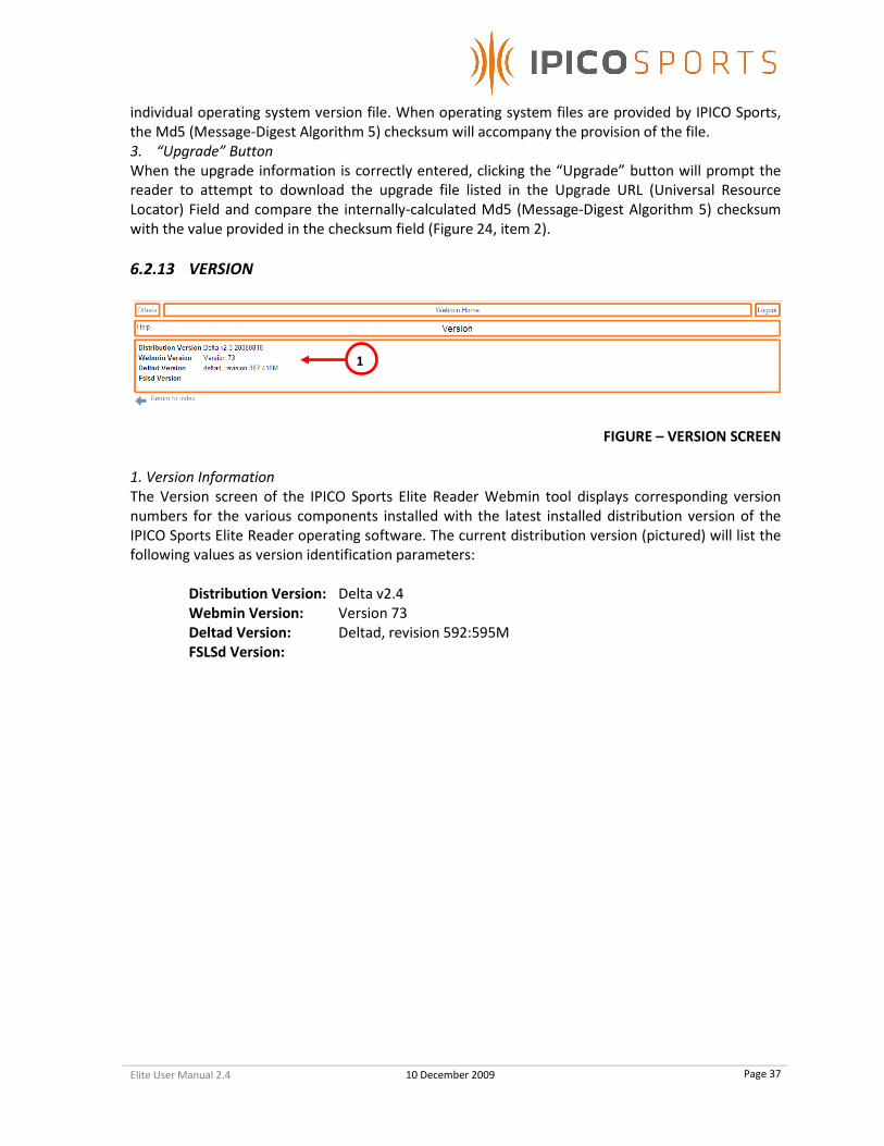
1. Version Information
The Version screen of the IPICO Sports Elite Reader Webmin tool displays corresponding version
numbers for the various components installed with the latest installed distribution version of the
IPICO Sports Elite Reader operating software. The current distribution version (pictured) will list the
following values as version identification parameters:
Distribution Version: Delta v2.4
Webmin Version: Version 73
Deltad Version: Deltad, revision 592:595M
FSLSd Version:
1

Elite User Manual 2.4 10 December 2009
Page 38
6.3 TELNET
NOTE: Telnet is a program that is provided with all versions of Microsoft
Windows up to Windows XP. In the Windows Vista environment, Telnet is not a
native component, but it can be downloaded as an optional service addition.
The download process is covered below. Alternatively, other Telnet clients can
be used in conjunction with the IPICO Sports Elite Reader, but only can be
supported on a case-by-case basis.
6.3.1 INSTALLING MICROSOFT TELNET (MICROSOFT WINDOWS VISTA)
Microsoft Telnet is a program that allows for direct visual streaming of data over an Ethernet (TCP)
connection. It is not necessary for operation of the IPICO Sports Elite Reader, but is recommended
for troubleshooting purposes. The Microsoft Telnet program is not an integrated part of Microsoft
Windows Vista, but can be added on as a service, free of charge. Following the steps listed and
pictured below will install Microsoft Telnet on a Microsoft Windows Vista machine.
WINDOWS VISTA CLASSIC WINDOWS VISTA AERO
FIGURE – WINDOWS VISTA START MENU NAVIGATION
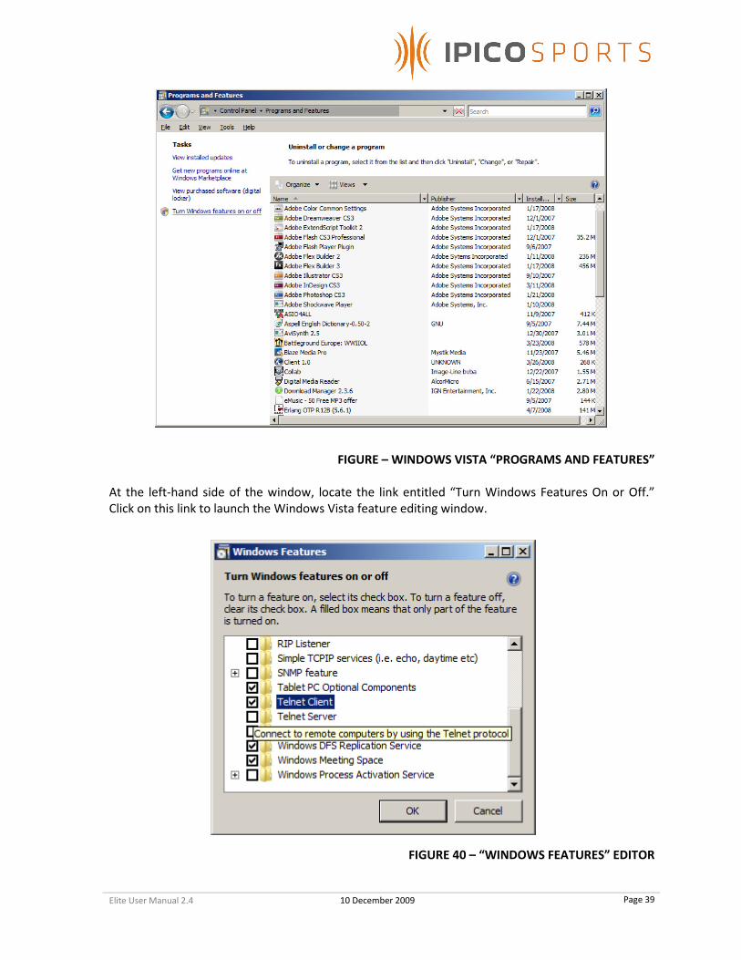
Navigate to the option entitled “Programs and Features” in the Windows Vista Aero menu or, if
using the Windows Vista Classic format, select the “Programs and Features” item from the resulting
“Control Panel” window.
Elite User Manual 2.4 10 December 2009
Page 39
FIGURE – WINDOWS VISTA “PROGRAMS AND FEATURES”
At the left-hand side of the window, locate the link entitled “Turn Windows Features On or Off.”
Click on this link to launch the Windows Vista feature editing window.
FIGURE 40 – “WINDOWS FEATURES” EDITOR

Elite User Manual 2.4 10 December 2009
Page 40
As pictured above, locate the “Telnet Client” entry, click on the checkbox located to its left and click
on the “OK” button to begin the installation of the Microsoft Telnet Client application.
6.3.2 RUNNING MICROSOFT TELNET (MICROSOFT WINDOWS XP AND VISTA)
To run Microsoft Telnet, navigate to the “Start” button, located in the lower left-hand corner of the
Windows XP screen, on the taskbar, and click it, revealing the Windows XP Start Menu. Find and
click on the “Run” option.
FIGURE – MICROSOFT WINDOWS XP START MENU
Clicking on the “Run” option will result in the appearance of the “Run” option’s screen, pictured
below. Once the “Run” option screen appears, type the word “Telnet” into the field contained on
the “Run” option screen.
FIGURE 41 – “RUN” OPTION SCREEN
Once “Telnet” has been entered into the “Open:” Field, click the “OK” button. This will open the
Microsoft Telnet window, pictured below.

Elite User Manual 2.4 10 December 2009
Page 41
FIGURE – MICROSOFT TELNET WINDOW
6.3.2.(A) IPICO SPORTS ELITE READER MAINTENANCE (“9998”) PORT
To access the reader through the Microsoft Telnet Application, ensure that the IPICO Sports Elite
Reader is powered and that the Delta module is also powered, and has completed start-up. Once
the IPICO Sports Elite Reader is ready for communication, connect to the reader from a computer
using the orange “crossover” cable provided with the reader (or another compatible “crossover”
cable). Once connected, type the following into the Microsoft Telnet window: “open” (followed by a
space), the IP (Internet Protocol) address of the reader (labeled on the front panel of the Delta
module) followed by another space, “9998”. Once these parameters have been entered, the string
entered into the Microsoft Telnet window should look like the following (using reader address
10.19.1.101 as an example):
The “9998” (“Maintenance”) port displays maintenance records such as reader tuning reports and
commands sent between the Delta module and other modules (i.e. the Receiver modules, et al.).
This data is logged to the infod.log file resident on the CF (Compact Flash) card on the Delta module
and can be downloaded via the reader’s anonymous FTP (File Transfer Protocol) service.

Elite User Manual 2.4 10 December 2009
Page 42
6.3.2.(B) IPICO SPORTS ELITE READER CONSOLE (“9999,” CONTROL) PORT
The IPICO Sports Elite Reader “9999,” or “Control” port, is a conduit for directly configuring reader
settings via several commands (listed and explained below). To open the port, enter the string
pictured in the following figure. It should look like the following (using reader address 10.19.1.101 as
an example):
FIGURE 42 – MICROSOFT TELNET WINDOW WITH INFORMATION ENTERED
Once connected, the cursor may move to the upper right-hand corner of the window, or the cursor
may not move. Key the word “help” into the Microsoft Telnet window to cause the following
command menu to display.
FIGURE 43 – TELNET CONTROL PORT HELP MENU
1
2
3
4
5
6
7

Elite User Manual 2.4 10 December 2009
Page 43
The port, “9999,” to which connection is being attempted is the Telnet reader settings and
configuration port. As seen above, this port offers seven (7) features.
1. Set Date
The “9999” (Control) port allows the user to set the time using a formatted string that is detailed in
the “command” line below the “function” heading. The format of the string is as follows:
setdate.yymmddHH:MM:SS
For example, to set the IPICO Sports Elite Reader clock to 3:30 PM on Wednesday, November 12,
2008, the string would be formatted as follows:
setdate.08111215:30:30
Once the correct string has been entered, simply pressing the “Enter” or “Return” keyboard key will
send the command to the reader, prompting the reader to reply with
date.Wed Nov 12 15:30:30 [Time Zone Extension] 2008
2. Get Date
The IPICO Sports Elite Reader also allows the user to retrieve the date through the control (“9999”)
port. This is done by entering the “getdate” command, exactly as previously typed. Once “getdate”
has been entered, and the “Enter” or “Return” keyboard key has been pressed, the reader will
respond with the current, internal reader date and time as follows (assuming the date to be
Wednesday, November 12, 2008 at 4:00 PM):
date.Wed Nov 12 16:00:00 [Time Zone Extension] 2008
3. Insert Marker
The IPICO Sports Elite Reader “9999” (control) port also allows for a user to insert text (ASCII)
markers into all timing record files. As an example, to insert a marker “New Race” into a file, the
following string format would need to be typed into the console window:
insert_marker.New Race
With which the reader will be prompted to respond:
marker_inserted

Elite User Manual 2.4 10 December 2009
Page 44
4. Clear History Files
The “9999” (control) port of the IPICO Sports Elite Reader also allows the user to perform a one-
command complete clearing of the reader history files. This is done by entering the command:
clear_history
To which the reader will respond:
history_cleared
5. IPX Set-Date
The “IPX Set-Date” command allows the user to set the date and time of the IPICO Sports Elite
Reader through the IPICO IP-X protocol. This feature is available to the user, though it is
recommended and reserved for programmatic use.
6. IPX Get-Date
The “IPX Get-Date” command allows a user to retrieve the reader’s internal date and time using the
IPICO IP-X protocol. Similar to the “IPX Set-Date” command, the “IPX Get-Date” command is
intended and reserved for programmatic use.
7. Replay
The Replay feature of the IPICO Sports Elite Reader (Operating System version 2.3) allows tag record
files to be “replayed” at various speeds and from various points within each of these files. To see the
instructional commands for the “Replay” function, type “replay_usage” into the “9999” port window
within Microsoft Telnet. The IPICO Sports Elite Reader will respond with the “Replay” syntax help
file.

Elite User Manual 2.4 10 December 2009
Page 45
The list that results from typing in the command “replay_usage” explains the use of replay and all of
its various functionalities. The elements of the “replay_start” function are as follows:
File A selection of the file with which to start replay
DateTime A selection of the date and time after which to start the replay
Speed A setting through which the replay can be sped up or slowed down
Port A configuration option specifying the port on which the replay will occur
The format of replay’s usage is then as follows if the file ttyS0.log is wished to be replayed after
today (29 August, 2008) at 1:09 PM, on port 13000 at no delay:
replay_start file.ttyS0 port.13000 datetime.080829130900
Once the command typed is satisfactory, hit the “Enter” key to start the replay. The stream will then
begin on port 13000. To view the stream, have a second Microsoft Telnet window open, and access
the streaming port by typing (assuming example the IP [Internet Protocol] address to which
connection is desired is still 10.19.1.101)
Once connected on the port, the replay stream will start. At “no delay” (the default “Speed” option),
the reader will replay all data at a high speed. Adjust the given speed element (As listed in the
“replay_usage” command) to suit different circumstances.
6.3.2.(C) IPICO SPORTS ELITE READER “10000” (RAW STREAMING) PORT
The IPICO Sports Elite Reader has options for three (3) other port connections specifically saved for
the purpose of streaming separate data formats. The “10000,” or “Raw Streaming” port streams tag
read records for every tag read successfully made by the IPICO Sports Elite Reader.
To connect to the streaming port, open a Microsoft Telnet session window (method prescribed in
section 6.3.2) and type the word “open” followed by a space, then the IP (Internet Protocol) address
of the reader followed by another space proceeded by the number “10000,” as pictured below:

Elite User Manual 2.4 10 December 2009
Page 46
FIGURE – TELNET PORT “10000” SYNTAX
FIGURE 44 – “RAW STREAMING,” “10000” PORT EXAMPLE
6.3.2.(D) IPICO SPORTS ELITE READER “10200” (FIRST-SEEN, LAST-SEEN) PORT
The IPICO Sports Elite Reader allows for truncated “FS,LS” (“First-Seen, Last-Seen”) data to be
streamed live from the reader unit. This data only records and outputs the first time a tag is
recorded by the reader unit and the last time that a tag is recorded by a reader unit. The time
between these record reports is, by default, five (5) seconds, but this timeout can be changed in the
Webmin client (see 6.2.1).
To connect to the streaming port, open a Microsoft Telnet session window (method prescribed in
section 6.3.2) and type the word “open” followed by a space, then the IP (Internet Protocol) address
of the reader followed by another space proceeded by the number “10200,” as pictured below:

Elite User Manual 2.4 10 December 2009
Page 47
FIGURE – TELNET PORT “10200” SYNTAX
The output of the “10200,” or “First-Seen, Last-Seen” port is similar to that of the “10000” (“Raw
Streaming”) port pictured in section 6.3.2.(B). However, to clarify the record type, and “FS” is
appended to the thirty-six (36) character string when the record is a “First-Seen” tag record and an
“LS” is appended to the thirty-six (36) character string when the record is a “Last-Seen” tag record.
FIGURE 45 – “FIRST-SEEN, LAST-SEEN,” “10200” PORT EXAMPLE
This data format is most helpful in determining true event starting time and event ending time. For
starting lines, it is recommended that the “LS” (“Last-Seen”) time is used. For finish lines and split
locations, the “FS” (“First-Seen”) data type is recommended.
6.3.2.(E) IPICO SPORTS ELITE READER “10201” (X.M.L. [EXTENSIBLE MARKUP LANGUAGE]) PORT
The IPICO Sports Elite Reader also accommodates the X.M.L. (Extensible Markup Language) data
organization format. The “10201,” or “X.M.L.” port, streams the “FS,LS” (“First-Seen, Last-Seen,”
“10200”) data type of “First-Seen” and “Last-Seen” records in a pre-formatted X.M.L. (Extensible
Markup Language) stream.
To connect to the streaming port, open a Microsoft Telnet session window (method prescribed in
section 6.3.2) and type the word “open” followed by a space, then the IP (Internet Protocol) address
of the reader followed by another space proceeded by the number “10201,” as pictured below:

Elite User Manual 2.4 10 December 2009
Page 48
FIGURE – TELNET PORT “10201” SYNTAX
FIGURE 46 – “X.M.L.,” “10201” PORT EXAMPLE

Elite User Manual 2.4 10 December 2009
Page 49
6.4 F.T.P. (FILE TRANSFER PROTOCOL)
The IPICO Sports Elite Reader contains a five hundred and twelve (512) M.B. (Megabyte) Compact
Flash (C.F.) card for internal tag record storage. Two (2) methods exist for accessing this internal
memory for file download before, after, or during an event. The first of these methods is outlined in
section 6.2.4 (access through Webmin). The second option for reader access is through the IPICO
Sports Elite Reader F.T.P. (File Transfer Protocol) port. While the Webmin allows access to this port,
direct access can be obtained by opening an Internet browser (Internet Explorer, FireFox, Opera, et
al.) and typing “ftp://” followed by the reader address (in this example, 10.19.1.101).
FIGURE 47 – F.T.P. (FILE TRANSFER PROTOCOL) ACCESS SYNTAX
Once the correct information has been entered, hit the “Enter” or “Return” keyboard key to open an
F.T.P. (File Transfer Protocol) session with the IPICO Sports Elite Reader. Depending on the selected
browser, the file list returned by the reader may appear differently, cosmetically, however, the list
remains the same from browser to browser. The file list returned by the reader will look like the
below-pictured F.T.P. (File Transfer Protocol) session:
FIGURE 48 – F.T.P. (FILE TRANSFER PROTOCOL) SESSION SCREEN
Each of the files listed in this file list view contain information specific to certain functions of the
reader. The tag record files and their appropriate contents are delineated below:
FILE NAME FILE CONTENTS
FS_LS.log Log file of all output on the “10200,”
“FS,LS” port.
ttyS0.log Log file of all output from IPICO Sports
Elite Reader, receiver 1 (left-most)
ttyS1.log Log file of all output from IPICO Sports
Elite Reader, receiver 2 (right-most)
Elite User Manual 2.4 10 December 2009
Page 50
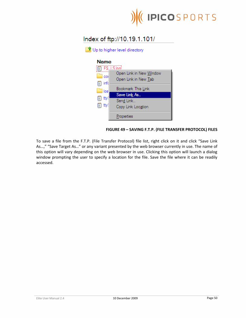
FIGURE 49 – SAVING F.T.P. (FILE TRANSFER PROTOCOL) FILES
To save a file from the F.T.P. (File Transfer Protocol) file list, right click on it and click “Save Link
As…,” “Save Target As…” or any variant presented by the web browser currently in use. The name of
this option will vary depending on the web browser in use. Clicking this option will launch a dialog
window prompting the user to specify a location for the file. Save the file where it can be readily
accessed.
Elite User Manual 2.4 10 December 2009
Page 51
7 USE OF THE SYSTEM
This section is intended to prepare a user of the IPICO Sports Elite Reader to use the system for the
first time.
7.1 SYSTEM SETUP NOTES
1. It is recommended that the user fully charge the internal battery of the IPICO Sports Elite
Reader before first use, and before every use.
2. The IPICO Sports Elite Reader internal battery has varying charging times depending on the
charging solution selected for the reader (the following times refer to charge cycle times
while the reader is not powered). Using an IPICO Sports Fast Charger (IP-0904), the charge
cycle is approximately three (3) hours. Using an IPICO Sports Mains Power Supply unit (IP-
0903), the charge cycle is approximately nine (9) hours.
7.2 READER / TIMING MAT SETUP
To ensure that the operating environment for the IPICO Sports Elite Reader, the following
recommendations and precautions should govern the process for implementation of reader units at
course sites.
1. Using the mat configuration rules (4.2), unroll the timing mats in any configuration desired,
while observing color-coded configuration.
2. Timing mats should always be placed .5 m (2 ft.) away from any large objects that could be
considered conductive (metals, et al.). This will ensure that the radio field produced by the
timing mats will operate as desired.
3. Some environments are composed of materials that are inhibitive to radio frequency field
operation.
4. Once completely finished with setup, switch on the IPICO Sports Elite Reader system using
the system’s rotary switch (Figure 1, item 9).
7.3 READER STARTUP AND OPERATION
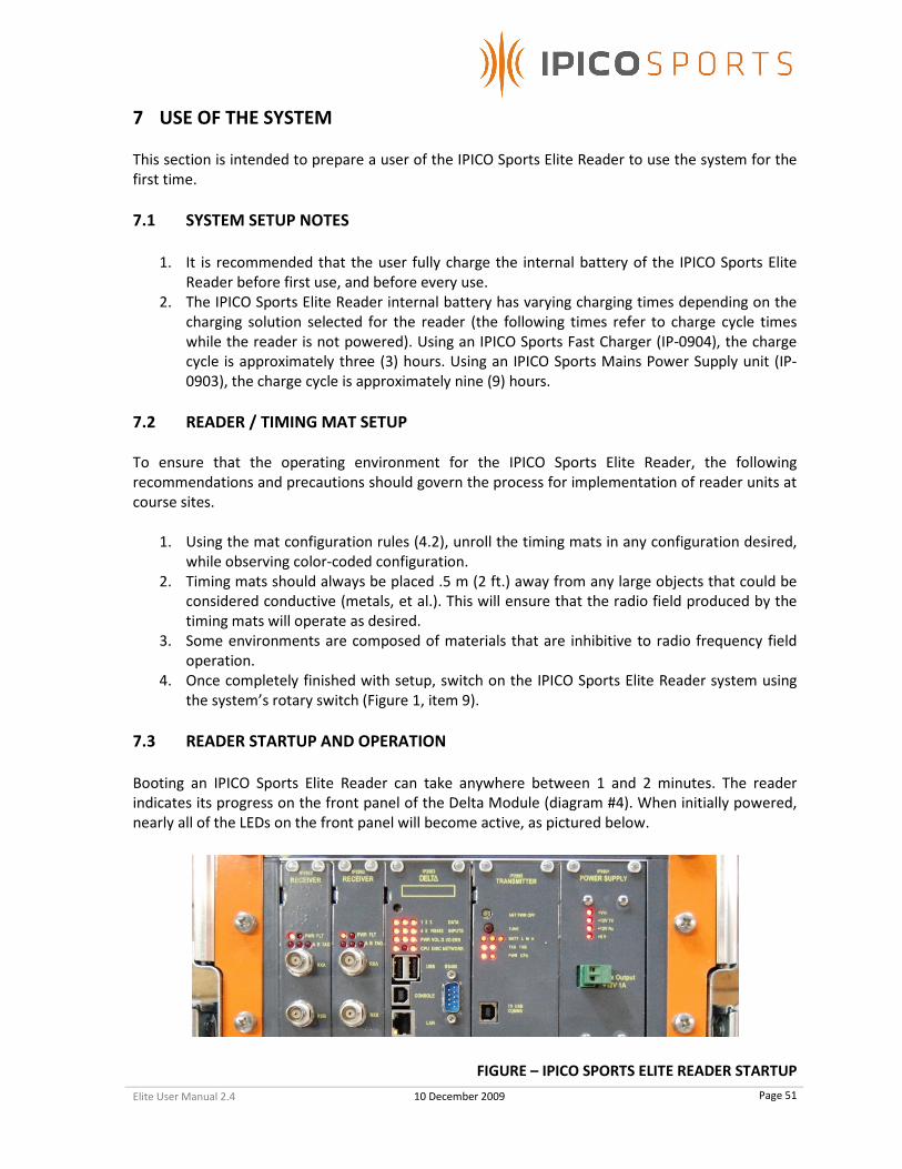
Booting an IPICO Sports Elite Reader can take anywhere between 1 and 2 minutes. The reader
indicates its progress on the front panel of the Delta Module (diagram #4). When initially powered,
nearly all of the LEDs on the front panel will become active, as pictured below.
FIGURE – IPICO SPORTS ELITE READER STARTUP
Elite User Manual 2.4 10 December 2009
Page 52
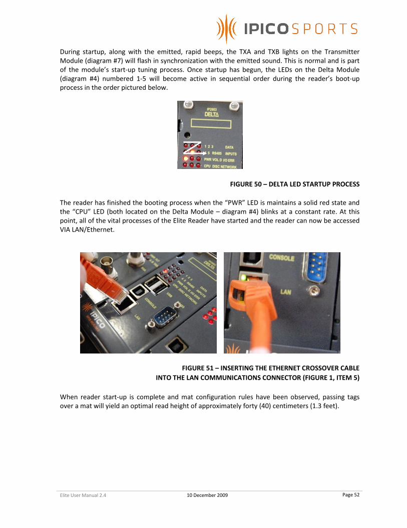
During startup, along with the emitted, rapid beeps, the TXA and TXB lights on the Transmitter
Module (diagram #7) will flash in synchronization with the emitted sound. This is normal and is part
of the module’s start-up tuning process. Once startup has begun, the LEDs on the Delta Module
(diagram #4) numbered 1-5 will become active in sequential order during the reader’s boot-up
process in the order pictured below.
FIGURE 50 – DELTA LED STARTUP PROCESS
The reader has finished the booting process when the “PWR” LED is maintains a solid red state and
the “CPU” LED (both located on the Delta Module – diagram #4) blinks at a constant rate. At this
point, all of the vital processes of the Elite Reader have started and the reader can now be accessed
VIA LAN/Ethernet.
FIGURE 51 – INSERTING THE ETHERNET CROSSOVER CABLE
INTO THE LAN COMMUNICATIONS CONNECTOR (FIGURE 1, ITEM 5)
When reader start-up is complete and mat configuration rules have been observed, passing tags
over a mat will yield an optimal read height of approximately forty (40) centimeters (1.3 feet).
Elite User Manual 2.4 10 December 2009
Page 53
APPENDIX A – TAG DATA FORMATS
The IPICO Sports Elite Reader outputs different, but related, data formats. While more advanced
documentation exists (available upon request), the information contained in this section provides an
suitable intermediate background in the IPICO Sports Elite Reader IP-X protocol.
A.1 IP-X PROTOCOL: TAG RECORDS
Tag data records generated by the IPICO Sports Elite Reader are designated in the tag streaming files
as those records that have a prefix (opening two [2] characters) of “aa.” However, there are two
distinctly different formats of tag records. The first of these records is a thirty-six (36) character
string resident in the ttyS0 and ttyS1 log files. The anatomy of this string is as follows:
aa000580017164f000010809271129024084
1. “aa” – Tag Record Designation 4. “00…0001” – Receiver / IRQ ID
2. “0580017164f0” – Tag ID 5. “LRC” Checksum
3. “08092711290240” – Date/ Time
1. Tag Record Designation
The prefix of “aa” defines that the record being generated is that of a singular tag read.
2. Tag ID
The IPICO Sports Sportag ID, “0580017164f0.” This identification number is always a twelve (12)
character string starting with “058.” The Sportag production series identification number “0017,”
merely indicates the series of which this tag is a member.
3. Date / Time
In the example tag string, the date (read from left to right) of “080927” (the first six [6] characters)
shows the date to be September 29, 2008. The next eight (8) characters, “11290240” represent the
time of day at which the tag was read by the IPICO Sports Elite Reader unit. The time string given in
the example reads that this tag was “seen” by the reader at 11:29:02 (HH:MM:SS format). The
additional two (2) characters, “40,” are represented as hexadecimal digits representing the true
“100th
”s place. Decoded, the full time reads 11:29:02.64 (HH:MM:SS.MS format).
4. Receiver / IRQ (Interrupt Request) ID
Mainly for programmatic use, this pair of ID numbers (represented as “01” and “0001,” respectively)
indicates the Receiver on which the tag was read (“01” – the left-most receiver) and the ID, where
applicable, assigned to an interrupt request.
5. “LRC” (Longitudinal Redundancy Check) Checksum
To ensure that the contents of the tag record are valid, the IPICO Sports Elite Reader performs
mathematical verification of the contents of the tag record string. The IPICO Sports Elite Reader
reports this “LRC” (Longitudinal Redundancy Check) checksum as the last two (2) characters.
3 5 2 1
4

Elite User Manual 2.4 10 December 2009
Page 54
The second tag record format, the “First-Seen, Last-Seen” tag record, does not change the internal
makeup of the tag record, however the record will have “First-Seen” (“FS”) or “Last-Seen” (“LS”)
status appended to it, making the tag record string thirty eight (38) characters.
aa000580017164f000010809271129024084FS
1. “aa” – Tag Record Designation 4. “00…0001” – Receiver / IRQ ID
2. “0580017164f0” – Tag ID 5. “LRC” Checksum
3. “08092711290240” – Date/ Time 6. “FS” (“First-Seen”) Designation
1. Tag Record Designation
The prefix of “aa” defines that the record being generated is that of a singular tag read.
2. Tag ID
The IPICO Sports Sportag ID, “0580017164f0.” This identification number is always a twelve (12)
character string starting with “058.” The Sportag production series identification number “0017,”
merely indicates the series of which this tag is a member.
3. Date / Time
In the example tag string, the date (read from left to right) of “080927” (the first six [6] characters)
shows the date to be September 29, 2008. The next eight (8) characters, “11290240” represent the
time of day at which the tag was read by the IPICO Sports Elite Reader unit. The time string given in
the example reads that this tag was “seen” by the reader at 11:29:02 (HH:MM:SS format). The
additional two (2) characters, “40,” are represented as hexadecimal digits representing the true
“100th
”s place. Decoded, the full time reads 11:29:02.64 (HH:MM:SS.MS format).
4. Receiver / IRQ (Interrupt Request) ID
Mainly for programmatic use, this pair of ID numbers (represented as “01” and “0001,” respectively)
indicates the Receiver on which the tag was read (“01” – the left-most receiver) and the ID, where
applicable, assigned to an interrupt request.
5. “LRC” (Longitudinal Redundancy Check) Checksum
To ensure that the contents of the tag record are valid, the IPICO Sports Elite Reader performs
mathematical verification of the contents of the tag record string. The IPICO Sports Elite Reader
reports this “LRC” (Longitudinal Redundancy Check) checksum as the last two (2) characters.
6. “FS” (“First-Seen”) Designation
The “First-Seen” Designation given to the sample tag data indicates that this tag read was the first
read of the specific tag in question (“0580017164f0”) that the reader has seen. If the tag data were
appended with “LS” (“Last-Seen”), it would indicate that the record was the last time at which the
sample tag (“0580017164f0”) was last seen.
3 5 2 1
4
6

Elite User Manual 2.4 10 December 2009
Page 55
A.2 IP-X PROTOCOL: DATE-TIME FORMAT
The IPICO Sports Elite Reader also uses another record type to differentiate Date-Time functions and
notifications from tag record notifications. Prefixed with “ab” instead of simply “aa,” these records
report the reader’s internal time and date and are recorded in ttyS0.log, ttyS1.log and FS_LS.log.
ab010a2c0811180212153062f102a9
1. “ab010a2c” – Date-Time record Designation 3. “f102a9” – “LRC” Checksum
2. “0811180212153062” – Date-Time value
1. Date-Time record Designation
The “ab010a2c” leading the string signifies the record type, in this case a reader report record “ab,”
that is a timestamp “a2c.”
2. Date-Time value
The Date-Time value “0811180212153062” represents different portions of the reader’s internal
date and time. The “081118” represents that the IPICO Sports Elite Reader’s internal time listed in
the order of YYMMDD. Thus, it is November 18, 2008. The “02” proceeding the date signifies that
the day of the week is the second (2nd
) day, or Tuesday. “12153062” represents the IPICO Sports
Elite Reader internal time. In this case, the string is formatted HHMMSS(MS). Thus, the time of day is
12:15:30 P.M. The “62” represents the reader’s resolution to the hundredth of a second, and is
encoded as a hexadecimal number. When translated to decimal format, the time reads 12:15:30.98.
Thus, the internal reader time and date is Tuesday, November 18,2008 at a time of 12:15:30.98 P.M.
3. “LRC” (Longitudinal Redundancy Check) Checksum
To ensure that the contents of records are valid, the IPICO Sports Elite Reader performs
mathematical verification of the contents of the timestamp record string.
1 2
3

Elite User Manual 2.4 10 December 2009
Page 56
APPENDIX B – INTERNAL READER BATTERY MANAGEMENT
PRECAUTIONS
It is recommended that the following operational concerns be addressed before operation of the
reader for the first time and before operation of the reader after a significant period of disuse.
1. Fully charge the reader’s internal battery before the first use of the reader.
2. Fully charge the reader’s internal battery before events.
3. The reader’s internal battery should be fully charged every two months in the case that
the reader unit has not been recently used. This should be done so that the battery is
maintained in correct and working order.
4. Should an external battery be connected to the Elite Reader after the battery alert is
tripped (a long, continuous audible noise), this alert will continue to sound. This is
normal, and the reader will continue operation, but the alert will still be tripped.
TYPICAL CHARGING CHARACTERISTICS
TYPICAL CHARGE CYCLE 9 hours (Mains Charger, IP-0903)
3 hours (Fast Charger, IP-0904)

Elite User Manual 2.4 10 December 2009
Page 57
APPENDIX C – READER SPECIFICATIONS
� Reader power consumption: 6Amps
� External power supply: 12Vdc, 6Amps
� Battery:
� Characteristics: 12V, 17Ah, 6Kg
� Time life: 4 years
� Autonomy: 2.5h when fully charged
� Charge time: 9h with 12Vdc/ 6Amps charger. 3h with IPICO fast charge charger.
� Weight: 18Kg
� Dimensions: 285mm H x 325mm W x 370mm L (112in H x 128in W x 146in L).
� Temperature rates (mats and reader): 0°C to 50°C
� IP protection:
� Reader open: IP21
� Reader closed: IP54
� Mats: IP68
� Warranty 1 year

Elite User Manual 2.4 10 December 2009
Page 58
APPENDIX D – TROUBLESHOOTING
STARTUP
RECEIVER MODULES
� When the unit powers on, if the Receivers’ “PWR” LEDs are not lit, this may indicate that the
module is not seated correctly in the reader. To re-seat the module, simply unscrew it, take
it out, and carefully slide it back in. This will re-connect all the pins on the card with those
internal to the reader.
DELTA MODULE
� If the Delta does not boot or the LEDs of the Delta module seem to periodically “flash,” the
Delta module’s rechargeable AAA batteries need to be replaced or recharged. To do this,
unscrew the screws connecting the Delta to the reader casing and carefully remove the
Delta module. There are three AAA batteries onboard the Delta and, to ensure that all
batteries are charged fully, remove all three and charge or replace them. This needs to be
done periodically, recharging them every four (4) to six (6) weeks is recommended. This can
be done by powering the IPICO Sports Elite Reader and allowing the unit to run for an hour. � The Delta Module also has a startup failure notification condition. If the Delta Module fails
to start after five (5) tries, the unit will switch off the receiver (Rx) tag read indicator, and
the user will not hear any audible signals from the receiver module. This behavior will only
occur with the External Buzzer (IP-2911) removed. If this failsafe should trigger, pressing the
small, grey reset button (Figure 3, Item 11). If the non-start condition persists, contact IPICO
Sports.
TRANSMITTER MODULE
� When booting the reader, the Transmitter module may emit a constant beep, indicating that
the reader’s mat connections, the TX connections, are out of tune. The reader may attempt
to tune when turned on, indicating this state. To tune the reader, press the “Tune” switch
on the front of the Transmitter module to tune the reader, rather than waiting for the
tuning process to be executed every five minutes. After connecting mats, the readers will
likely need to be retuned using the same process.
� If the reader is tuned, but continues to emit a constant beeping and the TXA and TXB LEDs
on the front panel of the Transmitter module are still flashing (alternating rapidly), the
antenna power may have been turned off. To turn this process back on, locate the button
labeled “ANT PWR OFF,” located on the Transmitter module. After pressing this button, the
reader should stop beeping, and antenna power should be restored.
NETWORK CONNECTIVITY
� Attempting to connect to the reader during its booting process will not be successful. As the
reader boots, the LEDs on the front of the Delta module will move in succession through the
lights marked “1,” “2,” “3,” “4,” and “5.” These indicate the progress of the startup of the
Delta. The Delta is fully started and functional when the “CPU” light is blinking at a near-
constant pace. This ensures that all processes have occurred and that the Delta is fully
initialized.
Elite User Manual 2.4 10 December 2009
Page 59
� If the “LAN” port located on the Delta module does not have a green light or an orange light
showing, this could be a sign of a potentially more complicated problem, and IPICO Sports
should be contacted.
� If the Delta has fully started up and network connectivity is still absent, ensure that the
computer being used to access the reader is correctly configured. The IP address of the
reader may be different from the IP address of your computer, and they may not be a part
of the same network family. To configure your network connection, follow the steps
outlined in 6.1.1 (Microsoft Windows XP) or 6.1.2 (Microsoft Windows Vista). � If network connection difficulties persist, restart the Delta module by finding the recessed
button located above the “1,” “2,” and “3” LEDs on the front panel. After pushing the
button, the lights on the Delta should light up, and the module will restart. The reader, in its
entirety, can also be restarted to help solve network connection issues. To do this, turn the
reader power knob to the “Off” position, and allow the Delta to completely shut down (all
LEDs are off). Then turn the reader back on and wait for the modules to complete their
various start processes.
DATA STREAMING
� If data streams (ports 10000, 10200, 10201) are unresponsive, restart the Delta module
according to the process described above. After a full restart, the streaming ports should
perform normally. This can also be the case with the input port (9999).
� If trouble with data streaming continues, restart the system by turning the power knob into
the “Off” position. Allow all of the modules to complete their shutdown process (wait for
the Delta module LEDs to go out). This process may take a couple of minutes.
EQUIPMENT SETUP
� During race day testing, it is important that the data files on the reader are being constantly
augmented with data. During pre-race setup, once the readers are fully initialized, ensure
that these files are accepting contemporary data. Use the reader’s FTP functionality by
opening a web browser or FTP client and navigating to your reader’s IP address. For
example, if a reader’s address is 10.19.1.101, the FTP portion of the reader can be accessed
by opening a web browser and typing “ftp://10.19.1.101” into the Address bar. If using an
FTP client, use the IP address as the FTP address.

Elite User Manual 2.4
APPENDIX E
FIELD STRENGTH METER (IP
USB REGISTRATION READER (IP
FAST CHARGER (IP-09
10 December 2009
APPENDIX E – OPTIONAL ACCESSORIES
FIELD STRENGTH METER (IP-3908) BATTERY TEST TAG (
USB REGISTRATION READER (IP-3490) EXTERNAL BUZZER (IP
0904) MAINS POWER SUPPLY (IP
Page 60
BATTERY TEST TAG (IP-3907)
EXTERNAL BUZZER (IP-2911)
MAINS POWER SUPPLY (IP-0903)