Untitled - Northeast Utilities
141
Transcript of Untitled - Northeast Utilities


INFORMATION
AND
REQUIREMENTS
FOR
ELECTRIC SUPPLY
BELOW 600 VOLTS
This publication supersedes similar publications previously issued by
the Northeast Utilities System.

2009 EDITION
INTRODUCTION
This booklet is published for the benefit of our customers, architects, engineers, employees and contractors to provide a convenient reference. Design or construction should not be undertaken until complete information is obtained from us. Such information and assistance is available from our New Service technicians, Customer Support, Meters and Service, or Clearing Desk groups who should be contacted a minimum of 20 days before starting work.. See page 1 for locations of our area work centers and phone numbers to contact us at. We supply electricity subject to our Rules and Regulations, Terms and Conditions,* policies and procedures, rate schedules,* and industry standards—all of which are made a part of these requirements. These requirements are not included in this booklet because they change from time to time. They are available upon request. Legal restrictions, changes in the art, judgment and safety require this booklet to be revised from time to time, and we reserve the right to make such revisions. THE REQUIREMENTS COVERED BY THIS MANUAL ARE INTENDED TO ENSURE THAT ALL ELECTRIC SERVICE REQUESTS ARE ADDRESSED IN A SAFE, TIMELY, AND APPROPRIATE MANNER. IT IS INTENDED FOR USE BY:
CONTRACTORS ENGINEERS
MUNICIPAL INSPECTORS BUILDERS
ARCHITECTS CUSTOMERS
OUR EMPLOYEES *Available on our website at www.wmeco.com

WESTERN MASSACHUSETTS REGION Cities and Towns We Serve
* DISTRICT AREA WORK CENTERS

TABLE OF CONTENTS Company Offices ................................................................................... 1 Definitions ............................................................................................. 4
SECTION 1: General ......................................................................... 8 A. Safety - The First Priority ............................................................... 8 B. Request for Electric Service ........................................................... 9 C. Approvals ..................................................................................... 10 D. Temporary Service........................................................................ 10 E. Residential Cut and Reconnect Policy .......................................... 10 F. Our Equipment on Private Property.............................................. 12 G. Safe Access to Installation............................................................ 12 H. Service Changes............................................................................ 14 I. Inspections .................................................................................... 14 J. Employee's Identification.............................................................. 14 K. Theft of Electric Service............................................................... 14
SECTION 2: Types of Electric Service ....................................... 15 A. Request for Electric Service Checklist.......................................... 15 B. Line Extensions and Residential Developments ........................... 16 C. Primary Service ............................................................................ 16 D. Types of Secondary Service ......................................................... 16
SECTION 3: Character of Supply (480 Volts and Below) ........... 23 A. Supply Characteristics .................................................................. 23 B. Unusual Conditions....................................................................... 24 C. Two-Phase Supply ........................................................................ 24 D. Three-Phase, 3-Wire Delta Supply ............................................... 24
SECTION 4: Our Service Facilities ............................................... 25 A. General ......................................................................................... 25 B. Service Location ........................................................................... 25 C. Number of Services ..................................................................... 26 D. Disconnecting a Service at Your Request..................................... 26 F. Removal of Electric Service at Your Request............................... 26
SECTION 5: Your Service Facilities.............................................. 27 A. Service Location ........................................................................... 27 B. Service Equipment........................................................................ 27 C. Service Entrance Conductors........................................................ 28 D. Pole Mounted Service Equipment and Metering (Special
Installation)................................................................................... 28 E. Identification................................................................................. 28

SECTION 6: Third Party Communication Companies' Attachments to WMECO Distribution System Facilities ........ 29
A. Scope ............................................................................................ 29 B. General ......................................................................................... 29 C. Protection Issues ........................................................................... 30 D. Metering ....................................................................................... 32 E. Grounding..................................................................................... 32 F. Pole Mounted Equipment ............................................................. 33
SECTION 7: Meter Installation ..................................................... 36 A. General ......................................................................................... 36 B. Standard Meter Installations ......................................................... 37 C. Meter Locations............................................................................ 37 D. Meter Equipment Mounting and Supports.................................... 40 E. Grounding..................................................................................... 40 F. Cover Plates.................................................................................. 41 G. Meter and Equipment Seals .......................................................... 41 H. Self-Contained Single-Phase Meter Installations.......................... 41 I. Self-Contained Three-Phase Meter Installations........................... 44 J. Instrument (Current and Voltage) Transformer Installations ........ 45 K. Extended Metering Options .......................................................... 48
SECTION 8: Your Utilization Equipment..................................... 53 A. General ......................................................................................... 53 B. Motor Installations........................................................................ 53 C. Motor Starting Current ................................................................. 54 D. Motor Protective Devices ............................................................. 54 E. Power Factor................................................................................. 55 F. System Disturbances..................................................................... 55
SECTION 9: Your Alternate Electric Energy Sources ................ 56 A. Non-parallel Generation (Standby or Emergency)........................ 56 B. Parallel Generation ....................................................................... 56 C. Uninterruptible Power Supply (UPS) ........................................... 58
SECTION 10: Illustrations ............................................................. 61 Figure 1 Temporary Electric Service Conduit System ................... 62 Figure 1 Notes ................................................................................ 63 Figure 2 Conduit Service: House End ........................................... 64 Figure 3 Conduit Service: Supply End .......................................... 65 Figure 4 Temporary Service from Overhead System...................... 66 Figure 4 Notes ................................................................................ 67 Figure 5 Overhead Service ............................................................. 69 Figure 6 Overhead Service Entrance Facilities............................... 70

Figure 7 Service Mast..................................................................... 71 Figure 8 Special Service Attachment.............................................. 72 Figure 9 Trenching Requirements .................................................. 73 Figure 10 Self-Contained Meter Socket Sequence and Mounting
Arrangement..................................................................... 74 Figure 11 Sequence of Meter and Service Equipment for Self- Contained 208Y/120v Network Services and 480Y/277v Services ......................................................... 75 Figure 12 Sequence of Meter and Service Equipment For Three- Phase Self-Contained 208Y/120v Network Services and 480Y/277v Services (Cold Sequence) ....................... 76 Figure 13 Meter Installation-Private Property Pole Your Conductors Overhead.............................................. 77 Figure 14 Meter Installation—Private Property Pole Your Conductors Underground ........................................ 78 Figure 15 Permanent Pedestal Service – Site Built .......................... 79 Figure 16 Manufactured Pedestal Service ........................................ 80 Figure 17 Single-Phase Self Contained Metering Connections...................................................................... 81 Figure 18 Modular Meter Panels for Group Metering Single-Phase 120/240v or 120/208v Three Phase 208/120v Network Three-Phase............................. 83 Figure 19 Single-Phase Self Contained Metering to Multiple Mobile homes up to six meters .......................... 84 Figure 20 Self-Contained Outdoor Meter Socket Installation- Multi-Position (up to six meters)...................................... 85 Figure 21 Three-Phase Self Contained Metering Connections......... 86 Figure 22 Outdoor Instrument Transformer Meter Socket with Test Switch............................................................... 87 Figure 23 Instrument Transformer Connections ............................... 88 Figure 24 Combination Main Switch and Instrument Transformer Enclosure..................................................... 89 Figure 25 Instrument Transformer Installation................................. 90 Figure 25 Notes ................................................................................ 91 Figure 26 Telephone AMR Equipment Diagram.............................. 92 Figure 27 Meter Interface Enclosure ................................................ 93 Figure 28 Cell Site Metering Pedestal .............................................. 94 Figure 29 Typical Remote Communications Power Site .................. 95 Figure 30 Typical Transfer Switch Installation In Conjunction with your Auxiliary Supply ..................... 96 Figure 31 Mobile Command Center State Wide Temp Serv. ........... 97 Figure 32 Cold Sequence Metering .................................................. 98 Figure 33 Hot Sequence Metering .................................................... 99

SECTION 11: Approved Meter Equipment Requirements ........ 100 General Requirements.................................................................101-103 Commercial Requirements................................................................. 104 Single-Phase Residential/Commercial ........................................105-109 100 Amp - 200 Amp Meter Pedestals Single-Phase .....................................................110-111 Residential/Commercial 200 Amp – 320 Amp Single-Phase Residential/Commercial ........................................111-112 Meter Socket w/Disconnect - 100 Amp- 320 Amp Three-Phase Commercial ...........................................................113-115 200 Amp - 320 Amp Group Metering Single-Phase ........................................................... 116 Residential/Commercial 100 Amp-200 Amp Group Metering Three Phase ............................................................ 117 208Y/120, 100 Amp-200 Amp. Group Metering Three Phase ............................................................ 118 480Y/277, 100 Amp – 200 Amp. Pre-wired Single-Phase Instrument Transformer .............................. 118 Rated Sockets with Test Switch Pre-wired Three-Phase Instrument Transformer ............................... 118 Rated Sockets with Test Switch Combination Circuit Breaker and Instrument ................................... 119 Transformer Enclosure 120/240 Volt and 208Y120 Volt Bar Type Combination Circuit Breaker and Instrument ................................... 120 Transformer Enclosure 480Y/277 Volt Bar Type Combination Circuit Breaker and Instrument ................................... 121 Transformer Enclosure 480Y/277 Volt Window Type

Combination Fused Entrance Switch and Instrument ....................... 122 Transformer Enclosure 120/240 Volt and 208Y/120 Volt Bar Type Combination Fused Entrance Switch and Instrument ....................... 122 Transformer Enclosure 480Y/277 Volt Bar Type Instrument Transformer Mounting Equipment in ............................. 123 Sealable Enclosure SECTION 12: Index Index .................................................................................................. 124

- 1 -
MASSACHUSETTS AREA WORK CENTER LOCATIONS
East Springfield Office Greenfield Office 300 Cadwell Drive 215 Shelburne Road East Springfield, MA 01104 Greenfield, MA
01301 Hadley Office Pittsfield Office 55 Russell Street 333 West Street Hadley, MA 01035 Pittsfield, MA 01201 Call our CUSTOMER SERVICE CENTER anytime 24 HOURS A DAY 7 DAYS A WEEK at 1-800-286-2000 TO SUBMIT A REQUEST FOR ELECTRIC SERVICE CONTACT OUR CLEARING DESK AT: WMECO Clearing Desk: 1-800-880-2433 Internet: www.wmeco.com By Fax: 1-800-842-4115 WMECO Regulations for Distributed Generation: http://www.wmeco.com/residential/understandbill/ratesrules/ distribgenrequirements.aspx?sec=aw

- 2 -
Additional Phone Numbers: ________________________________________________________________________________________________________________________________________________________________________________________________________________________________________________________________________________________________________________________________________________________________________________________________________________________________________________________________________________________________

- 3 -
Cities, Towns District Cities, Towns District and Places Office and Places Office Agawam Springfield Middlefield
(east) Greenfield
Amherst Hadley Middlefield (west)
Pittsfield
Ashfield Greenfield Millers Falls Greenfield Becket Pittsfield Montague Greenfield Bernardston Greenfield Montgomery Hadley Blandford Pittsfield New Ashford Pittsfield Buckland Greenfield North Leverett Greenfield Cheshire Pittsfield Northfield Greenfield Chester Greenfield Otis Pittsfield Chesterfield Greenfield Pelham Hadley Colrain Greenfield Peru Pittsfield Conway Greenfield Pittsfield Pittsfield Cummington Greenfield Plainfield Greenfield Dalton Pittsfield Richmond Pittsfield Deerfield Greenfield Russell Hadley Easthampton Hadley Sandisfield Pittsfield Erving Greenfield Savoy Pittsfield Feeding Hills Springfield Shatuckville Greenfield Gill Greenfield Shelburne Greenfield Granville Springfield Shelburne Falls Greenfield Greenfield Greenfield South Deerfield Greenfield Griswoldville Greenfield Southampton Hadley Hadley Hadley Southwick Springfield Hancock Pittsfield Springfield Springfield Hatfield Hadley Sunderland Hadley Hinsdale Pittsfield Tolland Pittsfield Huntington Hadley Turners Falls Greenfield Indian Orchard Springfield Tyringham Pittsfield Lake Pleasant Greenfield Washington Pittsfield Lanesboro Pittsfield West
Springfield Springfield
Lee Pittsfield Westhampton Hadley Lenoxdale Pittsfield Whately Hadley Leverett (part) Greenfield Windsor (part) Pittsfield Leverett (part) Hadley Windsor (part) Greenfield Leyden Greenfield Windsor Ponds Greenfield Longmeadow Springfield Woronoco Hadley Ludlow Springfield Worthington Greenfield Lyonsville Greenfield

- 4 -
DEFINITIONS
For additional definitions, refer to Section 100 of the National Electrical Code. AMR: Automatic Meter Reading Approved Equipment: Published list of metering equipment approved
by WMECO for use by electrical contractors. Clearing Desk: This is the central point of contact for all construction
related service requests. Code(s): The latest revision of the National Electrical Code and/or
applicable state or local codes and ordinances. Conduit System: Our electrical distribution facilities installed
underground, in electrical grade Schedule 40 PVC conduit.
Instrument Transformer Installations: A service requiring potential
transformers and/or current transformers. Labeled: Equipment or material to which a label, symbol, or other
identifying mark of an organization has been attached and that is acceptable to the authority having jurisdiction and concerned with product evaluation, that maintains periodic inspection of production of labeled equipment or materials, and by whose labeling the manufacturer indicates compliance with appropriate standards or performance in a specified manner.
Listed: Equipment, materials, or services included in a list published
by an organization and concerned with evaluation or products or services, that maintains periodic inspection of production of listed equipment or materials or periodic evaluation of services, and whose listing states that either the equipment, material, or services meets identified standards or has been tested and found suitable for a specified purpose.
Metering Sequence: Cold Sequence: main disconnect required before meter. Hot Sequence: no main disconnect before meter.

- 5 -
Network: A distribution system which connects the secondary of multiple distribution transformers for supplying power to a customer’s service. These are special systems generally located in downtown areas of cities.
Primary/High Voltage Service: Above 600 volts (this booklet does
not cover these services). Self-Contained: A meter capable of measuring the entire amperage of
the electric service without the use of current and /or voltage transformers.
Service: The conductors and equipment for delivery of electric
energy from our distribution (supply system) to the service point.
Secondary Service: 600 volts or below (the rules of this booklet
apply) Service Drop: WMECO overhead service conductors run between our
facilities and your structure. Service Entrance Capacity: This is the rating of the service entrance
equipment. Service Equipment: Consists of the necessary equipment, usually
made up of the main control or circuit breaker, and/or fuses and their accessories, that is intended to constitute the main control and means of cutoff of the supply.
Service Lateral: The underground service conductors and conduit
starting: 1. at the street main; or 2. at the top of a riser on a pole or other structure; or 3. from a transformer; to the first connection of the
service in a terminal box, meter box or other enclosure.
Service Location: This is the approved point of attachment of our
service drop or the approved point of entry of our service lateral to the customers building.
Service Point: The point of connection between the facilities of the
serving utility and the premises wiring.

- 6 -
Slip Meter Riser: (Slip Joint) for use in electrical service entrance applications with incoming service conduit diameters ranging from 3" to 4". It should comply with NEC 300-5 which requires protection for buried cables in areas subject to ground frost.
Spoils: - The soil removed from an excavation. Suitable Backfill: Shall not contain ashes, cinders, shell, frozen
material, loose debris or stones larger than 2" in maximum dimension
Underground Manhole System: Our electrical distribution facilities
installed in the ground in manholes, vault, duct banks, pads, etc.
Us-We-Our: Western Massachusetts Electric Company You-Your: The person or entity responsible for paying our bill or their
agents who are responsible for work being done. Work Request Number: The seven digit number used to track all the
service work requested by customers, electricians, contractors, etc. Please have this number available when making inquiries to the Clearing Desk.

- 7 -
Introduction
This booklet is published for the benefit of our customers, architects, engineers and contractors to provide a convenient reference. However, design or construction should not be undertaken until complete information is obtained from us. Such information and assistance is available from our New Service, Business Solutions Executives, Meters and Service or Clearing Desk Departments. See page 1 for location of our offices. We supply electricity subject to our Rules and Regulations listed in this booklet and Terms and Conditions, policies and procedures, rate schedules, and industry standards – all of which are made a part of these requirements. These requirements are not included in this booklet but are available upon request or available on our website www.wmeco.com Legal restrictions, changes in the art, judgment and safety require this booklet to be revised from time to time and we reserve the right to make such revisions. We endeavor to deliver electricity adequately and reliably. We do not guarantee a continuous supply and do not assume liability for direct or consequential loss or damage to persons or property due to the supply delivered, or as a result of any interruption or variation in the supply. Momentary interruptions can occur due to the normal operation of our system's protective devices. Please be aware, failure to comply with our requirements, applicable codes, or orders of an enforcement authority can result in our refusal to energize the service or in the disconnection of an existing service.

- 8 -
SECTION 1: General WMECO is dedicated to making safety its top priority. While the items listed below require particular attention, customer safety and the safety of employees will always be our first concern. A. Safety - The First Priority
1. Any contact with our wires may cause serious injury or death. Treat all downed, hanging or burning wires as though they are “LIVE” - energized - and stay away from them. Do not regard any covering on our wires as insulation.
2. Report any downed, hanging or burning wires to WMECO at
1-800-286-2000 or the police or fire department. 3. Massachusetts State law requires contacting “DIG SAFE”
three (3) full working days prior to doing any excavation, digging holes, or driving posts regardless of whether it is within the street or on private property. Obtain information by calling 1-888-344-7233
4. Equipment such as ladders, scaffolding, etc., regardless of
what they’re made of can become electrified if brought in contact with wires. Use extra caution when installing siding, painting, cleaning gutters or performing any work near our facilities. It is recommended that you call to have any WMECO facilities covered before starting any work.
5. Removal or relocation of existing WMECO overhead or
underground service equipment is prohibited. Contact WMECO if removal or relocation is necessary.
6. Do not enter or open existing electrical structures such as hand
holes, transformer pads or switch vaults. Call WMECO at 1-800-262-2000 and ask for the Electric Service Designer in the project area.
7. Equipment such as cranes, backhoes, etc., shall never be
operated closer than 10 ft. from our overhead distribution conductors. Refer to OSHA limit of approach regulations.

SECTION 1: GENERAL
- 9 -
8. Swimming pools and spas must not be installed beneath our overhead facilities or above our underground facilities in accordance with code.
9. Proper installation of generators is essential to avoid electrical
source feeding back into our lines and endangering unsuspecting utility workers. Contact WMECO prior to connecting to your system.
10. Antennas, banners, customer lighting, signs or similar
customer equipment shall not be attached to our poles. B. Request for Electric Service
1. Our Request for Electric Service procedure is meant to do the following:
a. Provide methods for responding to and processing your
request for electric service. b. Encourage you to contact us, a minimum of 20 days in
advance, to allow for proper planning by both you and us. c. Provide you with information which will:
• designate the service location, new or relocation • specify the type and character of supply that is
available • specify location and requirements for our metering
equipment • advise you of advance charges, if any • advise you of any special requirements • provide you with an estimated completion date.
2. A request for electric service must be submitted for any service
to be installed; new, changed, removed or installed temporarily. A request for electric service can be submitted via phone, Internet, or Fax in a “Request for Electric Service Form”. The request should be: (a) submitted at the earliest possible date and, (b) filled out as completely as possible including load data. WMECO is not responsible for making service requests to others: i.e., telephone, cable TV, gas, water and for coordinating their activities.

SECTION 1: GENERAL
- 10 -
C. Approvals
1. We will not energize a service until it is approved by the local inspecting authority and it also meets our requirements as outlined in this book.
D. Temporary Service
1. Where practical; Temporary Service may be provided with the customer paying all estimated installation and removal costs. For a temporary 120/240 volt, 100 ampere service of limited length (10 feet for underground and 125 feet maximum for overhead), on private property where suitable distribution facilities already exist adjacent to the site standard charges will apply. These charges are in addition to the regular rate applicable to the use of energy. Please see page 22, Item 4, for customer responsibilities and illustrations on pages 62 and 63 or pages 66 and 67.
E. Residential Cut and Reconnect Policy Restricted to Two-Wire
120 Volt or Three-Wire 120/240 volt Single-Phase Overhead Residential Services of 400 Amps or Less
POLICY: The Western Massachusetts Electric Company (the Company) will permit electrical contractors and electricians (herein jointly called electricians), licensed by the State of Massachusetts, to cut and reconnect residential services at the weather head in order to expedite work requested by customers. Failure to follow the steps contained within the policy may result in additional corrective work and expense for the electrician. The electrician will be billed for any corrective work performed by the Company. The electrician shall be responsible for obtaining the appropriate permits from the local municipal authority. Homeowners are not authorized to cut and reconnect electric services. To participate in this program an electrician must hold an E or A license issued by the State of Massachusetts or work in the capacity of Electrical Apprentice under the direct supervision of a licensed electrician of an E or A licensee. Under this condition physical work may be performed; however, the permit must be obtained by the licensee who is responsible for the work at the location.

SECTION 1: GENERAL
- 11 -
The electrician, his/her employees, and those under his/her control shall perform all work as independent contractors and shall not be deemed to be employees or agents of the Company for any purpose whatsoever. The Company shall not be liable for direct, indirect, or consequential damages of any kind whether resulting from injuries to persons or property or otherwise arising out of the electricians work. PROCEDURE: The Electrician: 1. Must contact the Company a minimum of 20 days prior to starting
work to avoid possible code violations or noncompliance of Company requirements. Notify/submit to the Company a request for electric service via phone, Internet or Fax. Please advise us if this work involves Cut and Reconnect. If the service is complex requiring poles to be set or primary cable(s) to be installed then a minimum two months notice prior to starting work is required.
2. Shall obtain Company approval of the service/meter location prior
to starting work. 3. Shall cut the drip loop at the house, on the line side, immediately
adjacent to the Company’s existing connectors. 4. Shall replace/repair the service entrance cable/meter box up to the
first disconnecting device. 5. Shall connect the replaced or repaired service entrance cable/meter
box to the live ends of the Company’s service drop using properly sized connectors.
Our preferred connector types are as follows:
Phase/Hot Leg Neutral Properly Insulated Parallel Groove Connector Bare Parallel Groove Connector Properly Insulated Plier-applied Wedge Connector Bare Plier-applied Wedge Connector Insulated Compression Sleeves Bare Compression Sleeves

SECTION 1: GENERAL
- 12 -
Connectors must be approved for use with the type (copper/ aluminum) of conductors being installed. Insulation Piercing connectors are not acceptable.
6. Shall install Company approved jumpers and optically clear meter socket cover(s) to avoid damage to the meter socket, ensure public safety and provide access for visual inspection, do not write on the plastic covers with markers. Covers and jumpers are available at any company area work center or from a new service technician.
7. Shall leave the old meter, tagged with the customer’s name, address
and date removed, in close proximity to the new meter socket or deliver it to our local company. In no case shall the old electric meter be reinstalled.
8. Shall be responsible for obtaining municipal
inspection/approval and will advise the Company within one business day of completing Steps 1-7 above.
The Company: For service upgrades, the Company reserves the right to install a meter after ten business days unless notified of a building code violation by the Local Municipal Authority Installation of a meter does not supersede the requirements of an inspection approval by the Local Municipal Authority F. Our Equipment on Private Property All our equipment located on your premises, such as poles, conductors, meters, current transformers, auxiliary metering equipment, transformers, ducts, etc., shall remain our property and may be removed or abandoned by us in the event such equipment is no longer needed. G. Safe Access to Installation We require the right (at all reasonable times or during an emergency situation) to enter your premises to erect, remove, operate, or maintain our facilities and to read and test our meters. The access area must be clear of obstacles and capable of carrying heavy vehicles and equipment if they are required. We are not responsible for restoring trees, shrubs and/or grass if we cause damage because of inadequate access.

SECTION 1: GENERAL
- 13 -
Warning and Clearance Diagram

SECTION 1: GENERAL
- 14 -
H. Service Changes When changes or alterations are made to your service equipment, the service entrance and meter installations must conform to both our requirements and the local inspecting authority. I. Inspections Our inspection of your service facilities or wiring is not an approval of conformance to applicable codes. The purpose of our inspection is to ensure that our requirements are met with respect to; line, load, and ground connections, the meter installation; and that the installation is in conformance with this booklet. J. Employee's Identification All Company employees carry photo identification which they will present on request. K. Theft of Electric Service Massachusetts General Law Chapter 164, Section 127, prohibits theft of electricity. Theft of electrical service is defined as taking, or acceptance, of electric service without the knowledge or consent of the Company. This includes any method or device used by any person or persons which prevents an electric meter from duly registering the quantity of electricity supplied by the Company. Theft of electric service is unlawful, unsafe and can result in serious injuries, electrocution, fires, explosions and death! Where there is evidence of meter tampering and/or the diversion of electric service, such person or persons responsible shall be liable for criminal prosecution under the penalty of all applicable laws. All lost revenue, intended or unintended, is subject to recovery by the Company. To report suspected meter tampering, or diversion of electrical service, please report it to WMECO’s confidential (no need to identify yourself) energy theft hotline at 1-800-286-5350.

- 15 -
SECTION 2: Types of Electric Service A. Request for Electric Service Checklist When we receive the Request for Electric Service we will determine, based upon your location, the type of service to be offered, the voltage characteristics available and the maximum amperage available for the proposed load. Reminder Lists for Upgrades and New Services Have you: • Contacted our Clearing Desk to submit a “Request for Electric Service”
via phone, internet, or fax and received a Work Request confirmation number, at least 20 days prior to starting your work.
• Provide us with a existing meter number (if applicable) • Discussed the routing and location of the service with a new service
technician, before starting work. • Confirmed that service locations and meter locations meet requirements of
this booklet. • Received an approved meter location • Received approval for custom, combination or instrument transformer
metering equipment • Obtained all local permits, including environmental permits, etc. • Obtained a utility easement if required • Paid all applicable charges, if required • Coordinated with other utilities • Notified Dig Safe at 1-888-344-7233 • Installed an approved meter socket with optically clear cover • Installed all your service entrance equipment. Note: services will not be
energized nor meters set unless all load side service entrance disconnects or main breakers are connected to the load side of the meter socket(s).
• Permanently marked the inside of each meter socket, load disconnect and matching outside meter cover with its unique identification.
• Established a safe work space in front of each meter location – 3’ in front of and 2’ off center on both sides.
• For a conduit system, install UL listed slip joint, sweeps, 3 inch or greater schedule 40 PVC from the meter trough(s) to the pole, hand hole or manhole and ¼” pulling line or MULETAPE ®
• Discussed the need for steel sweeps in the conduit system (if applicable) and where steel sweep(s) are required, installed proper ground connections.
• Called the local inspecting authority for inspection/approval.

SECTION 2: TYPES OF ELECTRIC SERVICE
- 16 -
B. Line Extensions and Residential Developments You should consult with us at a very early date about any situation that will require a single or three-phase line extension along a town road, state highway, or into new residential developments, commercial complexes, industrial parks or environmentally sensitive areas. Under certain circumstances, customer charges or additional customer responsibilities will apply. In addition, we have special policies for line extensions into new residential developments. Also see on the WMECO web site Line Extension Policies B-1, B-2 or B-3. (WMECO’s web site is www.wmeco.com) C. Primary Service Requirements for primary service (over 600 volts) are not included in this booklet. To provide such service, we need early and detailed consultation with you. D. Types of Secondary Service 1. Overhead Service from Overhead System (Limited to 400 amps or less) a. We will attach our service drop to the structure at the
approved location (see Section 10. Figure 5, page 69) which is accessible to our lineman and high enough to provide adequate ground clearance. The minimum clearance requirements are:
• Twelve feet (12') above finished grade, sidewalks,
residential driveways and commercial areas not subject to truck traffic and located more than 25 feet in any direction from a swimming pool, swimming area, or diving platform.
• Sixteen feet (16') over town roads or streets, alleys,
parking lots or other areas subject to truck traffic.
• Eighteen feet (18’) over state highways.

SECTION 2: TYPES OF ELECTRIC SERVICE
- 17 -
b. Your service entrance conductors or cable shall be terminated with an approved detachable weather head and be safely accessible from a ladder on the ground.
c. The location of your weather head shall be positioned to
permit the installation of our service drop below the weather head. A minimum of 20 inches of conductor must extend from the weather head to make a connection to the service drop with a proper drip loop. See Fig. 6, Page 70.
d. The location of the weather head is not to exceed twenty
feet (20’) above the finished ground level without consulting WMECO beforehand.
e. You are responsible for providing adequate tree trimming
and/or tree removals for your service on private property.
2. Service Lateral from Overhead System or from Conduit System
Note: Be sure to consult with a New Service Technician well in advance of commencing construction for a conduit service over 200 feet long.
2A. Customer’s Service Responsibilities You will be responsible for the following:
a. Providing a trench, concrete hand holes, the transformer pad, any related products, conduit and backfill that will provide a minimum cover of 24 inches above the conduit and which will run from our facilities at the curb line to the designated service location outside the foundation. The designated location shall be in direct line of sight of WMECO’s distribution facilities. You must consult with the company for any installations that may not conform to this requirement. The conduit shall be electrical grade Schedule 40 PVC (minimum size of 3 inches or consult a WMECO new serviced technician for size). Install caution tape in the trench backfill above the conduit. (See Figure 2, page 64), (Figure 3A & B, page 65) and Figure 9, page 73)
SECTION 2: TYPES OF ELECTRIC SERVICE
- 18 -
b. Providing and installing conduit from the metering equipment to the trench conduit. For above grade metering equipment installations a slip joint will be required. This slip joint shall be securely fastened to the building with at least two clamps. Consult WMECO for minimum slip joint size of 3 inches. See Fig. 2, page 64)
c. Providing and installing an electrical grade Schedule 40
PVC (90 degree) sweep (or steel, if required by us) with a 24 inch minimum radius. See (Figure 2, page 64)
d. Providing and installing an electrical grade Schedule 40
PVC (90 degree) sweep (or steel, if required by us) and conduit with cap at the riser pole if supply will be from our overhead system. The sweep shall have a minimum 24 inch radius (See Figure 3B, page 65).
e. Installing an ¼ inch diameter pulling line or MULETAPE
® from the meter socket to the end of the conduit at our facilities (transformer pad, temporary dead-end, hand hole or riser pole). (See Figure 3A and B, page 65).
Note: The end of the conduit at our facilities shall be capped and left accessible
f. Providing and installing the ground assembly, if a steel
sweep, is used at the customer’s service entrance or at the pole location. The ground assembly shall consist of a ground clamp suitable for direct burial, no. 6 bare copper wire, a ground rod connector and a five-eighth inch by eight foot ground rod. (See Figure 2, page 64 and figure 3B page 65)
g. Backfilling the trench before we install the cable and
exercise care to avoid damaging the conduit. (See Figure 9, page 73).
h. Routing for your trench as straight as possible from the
point of termination on the building to our facilities. The total of all bends shall not exceed 225 degrees.
i. Coordinating with other utilities such as telephone, cable
TV, water and gas.

SECTION 2: TYPES OF ELECTRIC SERVICE
- 19 -
2B. WMECO Service Responsibilities:
a. Residential Service. We will furnish the cable, install it in your conduit and terminate it at your meter socket, main switch, trough, duct box or other suitable device either outside or immediately adjacent to the wall entrance. We will maintain the cable; the customer will maintain the conduit and the seal between the foundation wall and the conduit.
b. Commercial/Industrial Services to Service Entrance
Capacity of 400 Amps Total or Less. We will furnish the cable, install it in your conduit and terminate it at your meter socket, main switch, trough, duct box or other suitable device either outside or immediately adjacent to the wall entrance. We will maintain the cable; the customer will maintain the conduit and the seal between the foundation wall and the conduit.
c. Commercial/Industrial/Residential Services to Service
Entrance Capacity of Over 400 Amps Total. You will design, furnish, install, own and maintain at your expense the complete secondary system, including all service conduit and conductors. For three phase services, the maximum size underground service conductor WMECO will accept is 500 MCM copper or 750 mcm aluminum... For single phase services, the maximum size underground service conductor WMECO will accept is 500 MCM copper or aluminum. In addition from single or three phase padmount transformer installations the company will provide the connectors between the customer’s conductors and the secondary bushings of the company-owned transformer. The customer will loosely make up all connections to the transformers to ensure proper conductor length with the company making the final connection. Under no circumstances will the customer use the secondary bushings of the transformer as a pulling point.
SECTION 2: TYPES OF ELECTRIC SERVICE
- 20 -
3. Service Lateral from Underground Manhole System Note: Please contact WMECO prior to commencing work. a. The underground manhole system in the public way will
be furnished, installed, owned and maintained by us. b. Your service shall include approved conduit, schedule 40
PVC 3 inch or larger, from the service entrance point to the curb line. You will furnish, install, own and maintain this conduit.
c. We will install our conductors in your conduit. We will
furnish, install and own the seal between your conduit and our conductors. We will maintain this seal at your request but will not be responsible for damage due to a leaking seal. You will furnish, install, own and maintain the seal between your conduit and the wall.
d. Duct Box Where required by the Company, a steel duct box is to be
provided and installed by the Customer. It is to be rigidly and permanently secured immediately adjacent to the wall entrance of the conduit, at a designated location inside the building. It will contain the incoming duct(s) and the splices which are to be made by the Company between the WMECO service lateral conductors and the customer service-entrance wiring.
e. Duct Box Sizes The size will be determined by the number of sets of
service-entrance conductors to be contained within the box and by the rating of the largest switch or circuit breaker. The following sizes are based on the use of copper conductors.
NOTE: When aluminum service-entrance conductors are
installed, the duct box shall be the next largest size over that specified for copper conductors.

SECTION 2: TYPES OF ELECTRIC SERVICE
- 21 -
3-Phase Size in Inches 1-Phase Amperes Amperes
---------- A -12 x 12 x 12 deep Up to 100
100 - 200 B - 12 x 18 x 12 deep 200 400 C - 18 x 24 x 18 deep 400
--------- D - 24 x 30 x 18 deep 600 600 E - 24 x 30 x 24deep 800 800 F - 30 x 36 x 24 deep 1000
1000 G - 36 x 42 x 24 deep 1200 1200-2000 H - 42 x 48 x 24 deep 1600
Rating of Largest Switch Service Entrance Equipment or Circuit Breaker Supplied from Duct Box
Amperes-Phase Duct Box Size 1 2 3 4 or more Up to 100 - 1 A A A B C 100-200 - 3 B B C C D 400 - 3 C C * * * 600 - 1 D D * * * 800 - 1 E E * * * 800 - 3 F F * * * 1000 - 1 F F * * * 1000 - 3 G G * * * 1200 - 1 G G * * * 1200 - 3 H H * * * 1600 - 1 H H * * * 1600-1200 - 3 H H * * * NOTE: * Denotes “Consult Company for size box.”
f. Duct boxes are to be mounted horizontally and so located that the duct(s) into the box shall be in a corner to allow for the most practical means for forming the conductors in the box and make the splices.
The Customer’s service-entrance conductors into the box are to be kept clear of the incoming supply duct(s).

SECTION 2: TYPES OF ELECTRIC SERVICE
- 22 -
4. Temporary Service You will be responsible for: a. Supplying and maintaining suitable service entrance
equipment (weatherproofed, if required); and b. Payment in advance, of the cost of connecting and
disconnecting this service. This includes the cost of installation and removal of any poles, wires, transformers, meter equipment, or other facilities. These charges are in addition to the regular rate applicable to the use of energy.
c. Requirements for temporary service are shown by
(Figure 1 on pages 62 and 63, for underground and Figure 4 on page 66 and 67) for overhead.

- 23 -
SECTION 3: Character of Supply, (480 volts and below) A. Supply Characteristics 1. We will supply alternating current with a nominal frequency of
60 Hertz (cycles per second) and a nominal voltage as described in item 3 below.
2. If you desire a new service or an increase in capacity, you
should contact us before purchasing any equipment or beginning any electric construction. We will designate the voltage and phase characteristics which will be available.
3. Normally, one of the following will be supplied:
Nominal Voltage
Phase Wires Comments
120/240 1 3 a, b, c, d
120/208 1 3 c, e
208Y/120 3 4 f, g, h
480Y/277 3 4 f, g, h
a. In general, only single-phase service will be supplied to
residential loads. b. Campgrounds and mobile home park services must be
120/240 volts c. The maximum single-phase service from an overhead
distribution system is 400 amps, including the total rated capacity for multiple main switches.
d. Single-Phase services over 400 amps and up to 800 amps
maximum must be fed from a padmount transformer. The largest single-phase service allowed is 800 amps.
e. Three phase supply is not normally available for single
family housing. For large residential complexes, which may require a three-phase service to the building, individual residential customers will be served only with single-phase 120/208 volts.

SECTION 3: CHARACTER OF SUPPLY
- 24 -
f. The maximum three-phase service allowed from an overhead distribution system is 400 amps, including the total rated capacity for multiple main switches.
g. The largest standard three-phase underground service
WMECO can provide with one transformer is 3000 amps; 2500 Kva, at 277/480 or 1000 Kva at 120/208. Please consult early with WMECO for all services over 3000 amps.
h. Three-phase service is normally available for supply loads
of 75 Kva or larger only. 4. We cannot, and will not, guarantee to maintain the voltage
level of these nominal values under all conditions; however, voltage will normally be maintained within reasonable limits and as specified by the regulatory authority. We recommend the use of suitable voltage regulating devices where equipment sensitive to voltage variations is in use. (See Section 8, page 55, paragraph F).
5. The voltage rating of your equipment must be compatible with
the nominal voltage which we supply. (See Section 3, Item A3, page 23)
B. Unusual Conditions We may refuse to supply electric services to loads which have characteristics which might adversely affect the supply to other customers, such as harmonic distortion, voltage fluctuations, noise or low power factor. C. Two-Phase Supply We no longer offer 2-phase supply. If your present service is 2-phase, consult us before making any changes or additions. D. Three-Phase, 3-Wire Delta Supply We no longer offer 3-phase, 3-wire, delta supply. If your present service is 3-phase, 3-wire delta supply, consult us before making any changes or additions.

- 25 -
SECTION 4: Our Service Facilities A. General 1. We or our agents shall install all facilities which we will own,
operate, and maintain. We or our agents shall perform all work on our poles and equipment except as noted in Section 5, paragraph D, page 28.
2. You may be required to contribute to the cost of installing
service facilities. Where we assume responsibility for future operation and maintenance, we shall hold title of ownership to such facilities.
3. Service installations involving special conditions due to size of
load, physical limitations, rate application, environmental considerations or other special requirements of the customer will be subject to joint study and agreement with us.
4. All connections or the disconnections between our facilities
and your facilities will, in general, be made by us or our agents. However, in case of single-phase residential services, qualified electricians will be permitted to cut and reconnect such services in compliance with our existing policies (See Section 1, item E, page 10 for details).
B. Service Location We will designate the location for new, relocated or upgraded services. A request for electric service must be submitted prior to starting your work. It can now be submitted by phone, Internet or fax. See page 1 for contact information and phone numbers.

SECTION 4: OUR SERVICE FACILITIES
- 26 -
C. Number of Services 1. Normally, only one service will be installed to a single
building or structure. 2. Where more than one service is installed to a building or
structure it will be by written approval of the local inspecting authority. Such services shall not be interconnected.
3. Each service will be separately metered and will be billed as
serving a separate customer under the appropriate rate. D. Disconnecting a Service at Your Request We will temporarily disconnect your service to allow you to perform maintenance, construction, or tree-trimming. We will require sufficient advance notice to schedule the work. There may be a charge for this service. E. Relocating a Service at Your Request We will designate the service location for all relocated services. We will require sufficient advance notice to schedule the work. There may be a charge for this service. F. Removal of Electric Service at Your Request 1. Building Demolition We will remove all electrical services, meters and metering
equipment, after receipt of written request (per State Law) and promptly confirm in writing to the customer of record and/or the owner of the property that the services, meters and metering equipment have been removed. Note; the building owner is responsible for WMECO’s gaining safe access to the structure to remove all of our electrical facilities.
2. Other than Demolition If the service, meters and metering equipment must be
removed from a building or structure where no demolition is to take place, written request is required from the customer of record and/or the owner of the property. We will require sufficient advance notice. No written confirmation will be furnished unless requested.

- 27 -
SECTION 5: Your Service Facilities A. Service Location We will designate the location for a new service or change of service, which will be on the front or the side of the building. The front of the building is considered to be the side adjacent to our distribution facilities. It is your responsibility to submit a request for electric service and obtain this information before the work is started. B. Service Equipment 1. The service equipment must be properly rated for interrupting
duty and ground fault. Upon request, we will furnish the information necessary to select proper equipment. Higher than usual interrupting capacity is required for service equipment protection devices when supplied from a network system or transformation greater than or equal to 100 kVA capacity. Contact us for detailed requirements.
2. Service equipment shall be installed on the load side of the
self-contained meters up to 240 volts. The following exceptions are installations where the main disconnect will be installed on the line side of the meter.
a. All 480/277 volt or 480 volt delta services. b. All 3 phase 120/208 volt network services. c. For services fed from a WMECO network system,
contact us for detailed requirements, such as R type fuses, 100,000 amp fault current rating, and rejection clips.
3. A Network service may require you to furnish a cable limiter
cabinet.. Consult with us in such instances. 4. There shall be no more than 6 disconnects per service grouped
in any one location. See Figure 19, page 84 and Figure 20, page 85 and MEC 230-71 (a).

SECTION 5: YOUR SERVICE FACILITIES
- 28 -
C. Service Entrance Conductors 1. Where a main switch or circuit breaker constitutes the service
equipment for a residential single-phase installation, the minimum ampacity of the service entrance conductors and socket meter trough shall be at least equal to the rating of the main circuit breaker or the largest main fuse which can be installed in the service equipment.
2. For a single-phase installation to an individual customer where
more than one switch or circuit breaker is permitted as the service equipment the socket-meter trough shall be a minimum of 100 amperes.
3. For multiple-occupancy buildings, where up to six individual
switches or circuit breakers function as the disconnecting means, the service entrance conductors must have adequate ampacity for the load as determined by applying the methods and rules set forth in the Mass Electrical Code (MEC).
4. Metered and unmetered conductors shall not be contained
in the same raceway or conduit. 5. Metered conductors from more than one meter shall not be
contained in the same raceway or conduit. D. Pole Mounted Service Equipment and Permanent Pedestal
Service Metering (Special Installation) Service equipment and metering is permitted only on private property secondary poles as shown by Figure 13 page 77 and Figure 14 on page 78 respectively. With the exception of the pole and meter, all facilities beyond this service point will be furnished, installed, owned and maintained by the customer. Only one meter will be allowed on a private property pole. Consultation with us is required. Service equipment and metering will not be installed on poles in the public way. E. Identification The contractor or electrician shall post their name, address, and telephone number at each installation to facilitate contacting the proper person.

- 29 -
SECTION 6: Third Party Communication Companies' Attachments to WMECO Distribution System Facilities A. Scope This section addresses the requirements for the attachment of third party company equipment to WMECO distribution system facilities.. These devices, both pole mounted and pad mounted, are powered by 120 volt AC as their normal power source and are equipped with auxiliary power sources, either batteries or generators, utilized when the normal source is not available. This does not address the installation of communication antennas installed on or near transmission structures. Such installations are covered in a separate guideline entitled, “NU General Guidelines for Communication Antennas Proposed on or near Electric Transmission Structures”. All Third Parties who propose to install generation and operate in parallel with the WMECO distribution system must follow a formal procedure by submitting an application to start the process, and by complying with WMECO’s interconnect policy. Also see Section 9, Item D, page 58, Distributed Generation. B. General 1. A Request for Electric Service shall be made for each
installation prior to starting of your work. 2. WMECO, telephone, and third party company representatives
should agree on the particular location of this equipment. Remote or enclosed metered sites and access roads to these sites must be accessible for meter reading.
3. Installations shall be in compliance with the National
Electrical Safety Code (NESC). This equipment shall be inspected by the municipal inspection authority unless otherwise agreed to by the local authority having jurisdiction or laws governed by the WMECO Massachusetts Department of Public Utilities.
SECTION 6: THIRD PARTY COMMUNICATIONS
- 30 -
4. Requests for installation of equipment on WMECO property shall be directed to the NU Manager of Real Estate Operations. Please call (860) 665-6173 or write to the Real Estate Department, Northeast Utilities, 107 Selden Street, Berlin, CT 06037.
C. Protection Issues Third party company equipment utilizing generators, batteries, inverters or rectifiers are possible devices of back feed into the WMECO distribution system. All steps to prevent any and all back feeds shall be taken: 1. No equipment shall be connected to the WMECO distribution
system without prior approval and testing by our personnel to ensure that back feed will not occur. Equipment with permanently connected generators and inverters shall have an automatic, positive, and fail safe method to prevent back feed. Equipment which demonstrates back feed capability must be modified by the third party company prior to connection to the WMECO distribution system. This restriction applies to both new and existing installations.
2. A break-before-make switch or cable removal before
connection to portable generators is required. 3. The third party company requesting service may have more
than one design of backup supply furnished by either the same or several suppliers. The specifications for each model shall be submitted to our Protection and Controls Engineering Department, to determine if back feed could occur and if so, what protective devices shall be required. This equipment shall be approved by a specific model designation. This model approval shall be determined by specific test required and witnessed by NU System Engineering and Test Department personnel. The tests shall be performed by the third party company at their expense. Any modifications to previously approved models which may permit back feed must be reported by the third party company to NU.
See pages 34 and 35 for those devices which have been
approved.

SECTION 6: THIRD PARTY COMMUNICATIONS
- 31 -
4. The third party company is responsible for protecting its
equipment from faults or abnormal voltages within its facilities and on the WMECO property. WMECO shall not be held responsible for damaging fault currents or voltages to the third party company's equipment.
5. WMECO shall be held harmless for damages to third party
Company’s equipment resulting from transients due to lightning strikes, load swings, faults, capacitor switching, system switching, etc.
6. WMECO may reduce its voltage level up to an additional 5%
during times of system capacity emergency or during designated test periods. The third party company may wish to ensure that this action will cause no adverse effect on its equipment or operation.
7. The interconnection of the third party company's facilities with
the WMECO distribution system shall not cause any reduction in the quality of service being provided to our customers. The third party company shall adhere to IEEE Standard 519 for harmonics. The introduction of harmonics, frequencies, flicker, etc. shall not be permitted and the third party company's equipment shall be disconnected until corrected.
8. WMECO recommends that the third party company install
suitable surge arresters on both the source-side and load-side of its system.
9. The third party company shall ensure that any over current
protective device on its system coordinates with WMECO primary and/or secondary protective devices. Each third party company shall submit its over current characteristics to NU System Engineering for review and approval.

SECTION 6: THIRD PARTY COMMUNICATIONS
- 32 -
D. Metering 1. Services to power supplies shall be metered with a demand
meter, unless the service meets the requirements for unmetered services.
2. Pad mounted meter units shall not be installed below the 5 foot
level without the approval of the Meter Department. 3. All pole mounted installations and the orientation of the meter
socket must be approved by WMECO prior to installation. 4. Meters shall not be installed on poles unless the control unit
itself is also installed on the pole. The meter location for pole mounted control units shall be at the 5 ft. level.
5. An approved lever operated manual bypass is required on
sockets. 100 amp sockets may be supplied with non-locking jaws. Sockets greater than 100 amps must be supplied with locking jaws.
6. Grounds shall not be installed in meter sockets. 7. A minimum 3 inch conduit with slip joint is required when the
service is underground. E. Grounding 1. The control cabinets and messengers on the pole shall be
grounded and bonded to the WMECO grounds and messengers.
2. This bonding shall be an irreversible connection and made at
the time of installation by the third party company. The attachment point of the bond to the utility pole ground shall be no higher than the communication gain level.
3. If our primary supply circuit is delta or uni-grounded
connected, the bonding shall be to the secondary ground, and not to the primary equipment/arrester ground. Do not bond to utility grounds on any pole where transformers, arresters, or any other primary equipment is installed.
SECTION 6: THIRD PARTY COMMUNICATIONS
- 33 -
F. Pole Mounted Equipment The NESC requirements for clearance heights above ground shall be followed. The 1997 NESC requirement for effectively grounded equipment cases is 15 feet minimum over roads and areas subject to vehicular traffic and 11 feet over ways subject to pedestrians and restricted vehicular traffic. There is an exception for effectively grounded equipment cases such as control boxes which allows the equipment to be mounted at a lower level for accessibility “provided such cases do not unduly obstruct a walkway". In addition to the above requirements, the following restrictions apply: 1. WMECO, telephone and third party company representatives
should agree on the particular location of this equipment. 2. Equipment exceeding 2 feet in height shall only be installed on
poles that can be accessed by aerial device vehicles. 3. Equipment exceeding 16 inches in width shall not be installed
on riser poles.

SECTION 6: THIRD PARTY COMMUNICATIONS
- 34 -
MANF.
MODEL
Various Various - Pole mounted Rectifier and battery only, with 120 Vac input. With Break-before-make switch for portable generator connection. Typically existing units.
Alpha LE-2 - Natural gas only, pad mounted generator and power supply - 1350 W/15 Amps and 2200 W/20 Amps. With break-before-make plug-receptacle for portable generator connection.
Alpha LE-2G - Natural gas or propane, pad mounted generator and power supply - 1350 W/15 Amps and 2200 W/20 Amps. With break-before-make plug-receptacle for portable generator connection.
Alpha CE6 - Low profile pad mounted power supply with separate pad mounted generator - 1350 W/15 Amps and 220 W/20 Amps. With break-before-make plug-receptacle for portable generator connection.
Alpha
CE7 - Pole or pad mounted unit with separate pad mounted generator - 1350 W/15 Amps and 2200 W/20 Amps. With break-before-make plug-receptacle for portable generator connection.
Alpha XM6015: Pole or pad mounted, battery/inverter only, 120 Vac input, 60 Vac/15 Amps output. With break-before-make plug-receptacle for portable generator connection.
Letro ZTT
XM9015: Pole or pad mounted, battery/inverter only, 120 Vac input, 90 Vac/15 Amps output. With break-before-make plug-receptacle for portable generator connection.
Lectro ZTT Z3615-X21 CT1: Pole or pad-mounted, battery/inverter only, 120 Vac input, 60 Vac/15 Amps output. With break-before-make plug-receptacle for portable generator connection.

SECTION 6: THIRD PARTY COMMUNICATIONS
- 35 -
MANF.
MODEL Ascension Tech.
SS01-MP-300W, 120/240V: Single phase inverter.
Trace Eng.
ST1000, ST1500, ST2000, ST2500 – 1000W, 1500W, 2000W, 2500W Single Phase 120/240V inverters
Advance Energy
GC 1000 – 1000W 120/240 Single Phase inverter CG-1000-SA- 1000W 120/240 Single Phase inverter MM-3000 – 3000W 120/240 Single Phase inverter MM-5000 – 5000W 120/240 Single Phase inverter
Capstone Turbine
330 MicroTurbine – 30W, 480V, Three Phase Micro Turbine C60 MicroTurbine – 60W, 480 V, Three Phase Micro Turbine
SMA America
SWR - 2500U – 2500W 208/240V Single Phase Inverter SWR – 1800U – 1800W, 120V Single Phase Inverter
Plug Power
SUIPCM 059622 – 6500W, 240V Single Phase Fuel Cell Inverter MP – 5000 – 5000W, 120V Single Phase Inverter
Schweitzer SEL – 351A00H24552XX – Utility Interacting Relay, Single Phase and Three Phase
Beckwith Electric
M-3410, M3410-A, M-3520 – Intertie/Generator Protection relay
Xantrex Tech.
SW4024 Series 2, SW4048 Series 2, Series 5548 Series 2 – (All with Grid Tie interface accessory) – 4000W, 5500W, 120V Single Phase Inverters
Tecogen, Inc.
CM-60, CM-75 – 60Kw, 75Kw, 460V or 230/208V Cogeneration Systems
Beacon Power
M5 – 5kW, 120V Single Phase Power Conversion System
Fronius, USA
IG 2000 – 2kW, 3kW, 240V Single Phase Inverter IG 2500 – 2.5kV, 208V Single Phase Inverter

- 36 -
SECTION 7: Meter Installation A. General 1. UNDER NO CIRCUMSTANCES WILL ELECTRICITY
BE SUPPLIED WITHOUT BEING METERED OR OTHERWISE ACCOUNTED FOR UNDER SPECIAL WRITTEN ARRANGEMENTS MADE WITH WMECO.
2. You will furnish, install, own, and maintain the meter socket
and the instrument transformer enclosure if required. 3. WMECO will furnish, own, and maintain all metering
equipment. 4. Single residential houses must have and display a unique street
number to avoid billing errors. 5. For all meter installations, each house, store, office, apartment,
or area serviced must be permanently marked on the door with its unique identification. This unique identification must be permanently marked on the inside and outside of the associated meter socket and load disconnect before the meter will be installed, to avoid billing errors.
6. All self-contained meter sockets shall have ring less covers
and factory installed lever-operated bypasses *. (See Section 11, Approved Metering Equipment).
7. Primary metering and totalized metering is not a customer
option. Under special conditions if approved by the Manager of Meter Engineering/Meter Reading it may be allowed.
8. The meter socket shall not be used as a junction box.
9. WMECO will not allow any customer owned equipment to be
installed between your meter socket and our meter.

SECTION 7: METER INSTALLATION
- 37 -
10. When requesting a new or upgraded commercial service and or an additional meter, the customer or their contractor will be required to submit a one line schematic diagram showing the service entrance, the customer’s main switch and the proposed meter location.
11. For customers planning to install generation – residential
customers planning to install over 10KW and all commercial customers planning to install generation – each must submit a schematic diagram showing the service entrance, the customer’s main switch, the existing or proposed meter trough(s) and how the generator will be tied in so that WMECO can order the correct meter.
B. Standard Meter Installations 1. The two types of standard metering installations are:
• self-contained • instrument transformer
2. The type of meter installation is determined by the voltage,
phase, and total name plate rating of the associated disconnect(s). Refer to Section 7, Table A on page Error! Bookmark not defined..
C. Meter Locations 1. WMECO WILL DESIGNATE METER LOCATIONS
FOR NEW OR CHANGED INSTALLATIONS.
• All residential meters shall be located outdoors on the front or front side corner of the house. The front of the house is considered to be the side adjacent to our distribution facilities.
• Commercial meters shall normally be located outdoors.
Any deviation from this requires pre-installation approval from the WMECO Meter Service Department.

SECTION 7: METER INSTALLATION
- 38 -
• Meters shall be grouped so as to keep the number of metering points to a minimum.
• Instrument transformer enclosures may be located indoors
in a suitable area readily accessible to WMECO. • Other specific exceptions may be approved. For example,
grouped metering may be located indoors, in a suitable area accessible to WMECO, only if there is no acceptable outside metering location.
• If after a review by WMECO it is deemed outside meter
trough(s) are not possible to install then remote meter disconnect(s) will have to be installed on the inside meter trough(s) at an additional cost to the customer.
2. You will maintain at and directly in front of each meter
location, a clear, safe work space, and a suitable approach to it. Such work space shall be at least 4 feet wide, shall extend out from the meter at least 3 feet, and up to a height of at least 6 feet. In addition, the meter socket must be located at least 3 feet measured horizontally from a gas meter, regulator or propane cylinder.
3. Private property pole-mounted meters are permitted. This is a
special installation. Early and detailed consultation with us is required. (See Figure 13, page 787 for a conduit system and Figure 14, page 798 for overhead)
4. Private property metering pedestals for conduit service may be
permitted. This is a special installation. Early and detailed consultation with us is required. (See Figure 15 page 79, and Figure 16 page 80).
5. In areas where meter equipment is subject to vehicular traffic,
doors, etc. you will be required to install additional protection, such as bollards.

SECTION 7: METER INSTALLATION
- 39 -
Warning and Clearance Diagram
SECTION 7: METER INSTALLATION
- 40 -
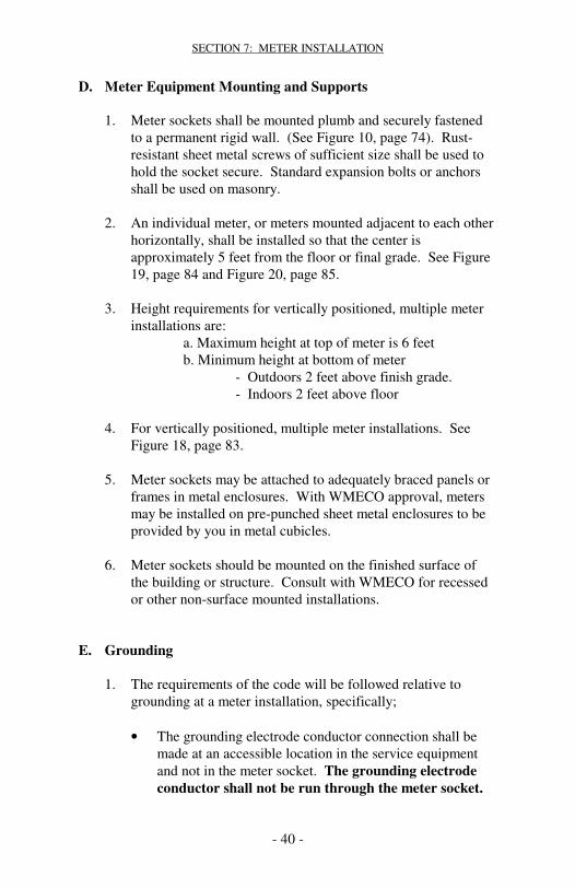
D. Meter Equipment Mounting and Supports 1. Meter sockets shall be mounted plumb and securely fastened
to a permanent rigid wall. (See Figure 10, page 74). Rust-resistant sheet metal screws of sufficient size shall be used to hold the socket secure. Standard expansion bolts or anchors shall be used on masonry.
2. An individual meter, or meters mounted adjacent to each other
horizontally, shall be installed so that the center is approximately 5 feet from the floor or final grade. See Figure 19, page 84 and Figure 20, page 85.
3. Height requirements for vertically positioned, multiple meter
installations are: a. Maximum height at top of meter is 6 feet b. Minimum height at bottom of meter - Outdoors 2 feet above finish grade. - Indoors 2 feet above floor 4. For vertically positioned, multiple meter installations. See
Figure 18, page 83.
5. Meter sockets may be attached to adequately braced panels or frames in metal enclosures. With WMECO approval, meters may be installed on pre-punched sheet metal enclosures to be provided by you in metal cubicles.
6. Meter sockets should be mounted on the finished surface of
the building or structure. Consult with WMECO for recessed or other non-surface mounted installations.
E. Grounding 1. The requirements of the code will be followed relative to
grounding at a meter installation, specifically;
• The grounding electrode conductor connection shall be made at an accessible location in the service equipment and not in the meter socket. The grounding electrode conductor shall not be run through the meter socket.

SECTION 7: METER INSTALLATION
- 41 -
• The service entrance installation shall have the neutral or identified phase conductor which is grounded.
• To avoid corrosion problems, we strongly recommend the use of copper for the system grounding conductor.
• Copper and aluminum shall never be in physical contact with each other. Where electrical connection is necessary, use special devices designed for this purpose.
• The system grounding conductor shall not be connected to any part of a gas or fuel oil system.
• The meter socket shall not be used as a grounding point. F. Cover Plates After the meter socket has been installed, it is the contractor’s responsibility to protect the interior of the socket by installation of an approved optically clear cover obtained from us. G. Meter and Equipment Seals 1. All meters and all points of access to unmetered wiring, i.e.
wiring troughs, on your premises shall have sealing provisions. All disconnecting switches over 400 amps must have locking provisions for WMECO.
2. The breaking of our seals, connecting, disconnecting or
tampering with our metering equipment by unauthorized persons is strictly prohibited. The law provides penalties for theft of electricity.
3. If it becomes necessary to gain access to any of this sealed
equipment, you shall contact us and receive permission to do so. At that time, we will make arrangements to reseal the installation.
H. Self-Contained Single-Phase Meter Installations Refer to Section 7 Item B, page 37, and Table A, page Error! Bookmark not defined., for services where this type of meter installation is required.
SECTION 7: METER INSTALLATION
- 42 -
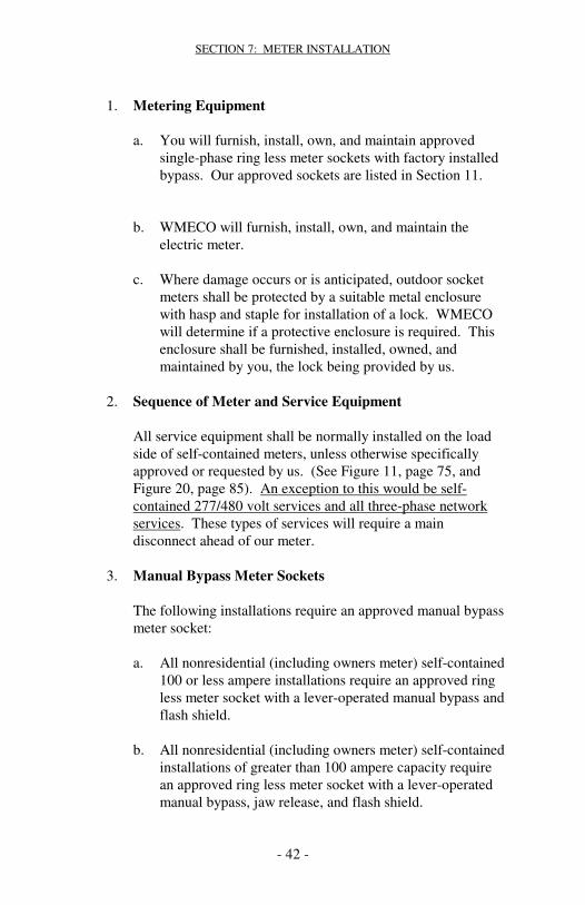
1. Metering Equipment
a. You will furnish, install, own, and maintain approved single-phase ring less meter sockets with factory installed bypass. Our approved sockets are listed in Section 11.
b. WMECO will furnish, install, own, and maintain the electric meter.
c. Where damage occurs or is anticipated, outdoor socket
meters shall be protected by a suitable metal enclosure with hasp and staple for installation of a lock. WMECO will determine if a protective enclosure is required. This enclosure shall be furnished, installed, owned, and maintained by you, the lock being provided by us.
2. Sequence of Meter and Service Equipment All service equipment shall be normally installed on the load
side of self-contained meters, unless otherwise specifically approved or requested by us. (See Figure 11, page 75, and Figure 20, page 85). An exception to this would be self-contained 277/480 volt services and all three-phase network services. These types of services will require a main disconnect ahead of our meter.
3. Manual Bypass Meter Sockets The following installations require an approved manual bypass
meter socket: a. All nonresidential (including owners meter) self-contained
100 or less ampere installations require an approved ring less meter socket with a lever-operated manual bypass and flash shield.
b. All nonresidential (including owners meter) self-contained
installations of greater than 100 ampere capacity require an approved ring less meter socket with a lever-operated manual bypass, jaw release, and flash shield.

SECTION 7: METER INSTALLATION
- 43 -
c. All self-contained installations of greater than 200 ampere
capacity require an approved ring less meter socket with a lever-operated manual bypass, jaw release, and flash shield.
d. All self-contained installations serving an apartment
common laundry room(s), hallway(s), or stairwell(s) (owner’s loop) require manual bypass sockets specified by 3.a., 3.b or 3.c.
4. Meter Socket Connections Line-side conductors are always connected to the top terminals
of meter sockets and the load side conductors to the bottom terminals. Standard connections for single-phase and three wire network socket meter installations are shown in Figure 17, page 81.
5. Grouped Metering Custom-made installations and modular panels may be used
for groups of meters, such as in apartment houses. Prints of these arrangements must be submitted to us and approved by us prior to installation. (See Figure 17, page 81). As an alternative, you may furnish, install, own, and maintain suitable pre-bused or a pre-conducted wiring trough with sealing provisions to feed multiple installations of meter sockets. See Figure 18, page 83, and Figure 20, page 85.)
6. Existing Controlled Water Heaters Only For services with existing controlled water heating it may be
necessary to install load control equipment on the water heater. Contact our local office for special instructions. This is not available for new accounts.

SECTION 7: METER INSTALLATION
- 44 -
7. Metering for Mobile Homes, Campgrounds, and Marinas a. Mobile home metering facilities shall be provided by the
owner on permanent supports not physically attached to the home. The supports shall be adequate for one or more meter installations and shall be set at a 4 foot minimum depth. They shall be galvanized steel in concrete. (See Figure 19, page 84.)
b. We will not provide individual metered services to
locations in campgrounds and marinas used for transient purposes.
I. Self-Contained Three-Phase Meter Installations Refer to Section 7.B., page 37, and Table A, page Error! Bookmark not defined., for services where this type of meter installation is required. 1. Meter Equipment a. You shall furnish, install, own, and maintain approved,
three-phase ring less sockets with factory-installed lever-operated bypass and jaw release, complete with flash shield and sealing provision for all three-phase self-contained installations shown in Section 7, Table A, page Error! Bookmark not defined.. Refer to Section 11 for Approved Meter Sockets.
b. We will furnish, install, own, and maintain the electric
meter. c. Where damage occurs or is anticipated, outdoor socket
meters shall be protected by a suitable metal enclosure with hasp and staple for installation of a lock. We will determine if a protective enclosure is required the box shall be furnished, installed, owned, and maintained by you, and the lock will be provided by us.

SECTION 7: METER INSTALLATION
- 45 -
2. Sequence of Meter and Service Equipment All service equipment shall be normally installed on the load
side of the self-contained meters, unless otherwise specifically approved or requested by us. (See Figure 11, page 75, Figure 18, page 83, and Figure 20, page 85.) The following exceptions are installations where the main disconnect will be installed on the line side of the meter.
a. All 480 volt services. b. All new 3 phase services fed from a WMECO network
system. Contact us for detailed requirements, such as R type fuses, 100,000 amp fault current rating, and rejection clips.
c. Meter Socket Connections Line side conductors are always connected to the top
terminals of meter sockets and the load-side conductors to the bottom terminals. Connections for a three-phase socket meter installations are shown in Figure 21, page 846.
J. Instrument (Current and Voltage) Transformer Installations Refer to Section 7.B., page 37, and Table A, page Error!
Bookmark not defined., for services where this type of meter installation is required.
1. Every installation which may require instrument
transformers shall be referred to us for approval before work is started.
2. The service will not be energized until the metering has been
inspected and approved by WMECO.

SECTION 7: METER INSTALLATION
- 46 -
3. Metering Mounting Equipment - Cabinet/Conduit/Socket It will be your responsibility:
• To furnish, install, own and maintain a sealable metal enclosure approved by us for the instrument transformers. Current and voltage (when required) transformers shall be installed in the same compartment. All meters and all points of access to unmetered wiring on your premises shall have sealing provisions. All disconnecting switches over 400 amps must have locking provisions for WMECO. This enclosure may be:
(1) An individual cabinet for instrument transformers
only; (2) A combined entrance switch and current and voltage
transformers enclosure (see Figures 24, page 89 and Figure 25, page 90); or
(3) A separate compartment in metal-enclosed switch gear
built from your prints, which we have previously approved. Wiring in the instrument transformer enclosure shall be limited to that pertinent to the meter installation.
• To furnish, install, own, and maintain an approved, pre-
wired combination meter socket and test switch. Entry through the hub opening at the top of the meter socket is not allowed. See Section 11 for approved equipment. (See Figures 22, 24 and 25, pages 87, 89 and 90).
• To furnish, install, own and maintain approved conduit of
specified size, minimum 1-1/2 inch, between the instrument transformer enclosures and the combination meter socket. The conduit must be continuous from the instrument transformer enclosure to the side or bottom of the meter socket test switch enclosure. The conduit must be a minimum of 6 inches and a maximum of 50 feet in length. When PVC conduit is used you shall install a

SECTION 7: METER INSTALLATION
- 47 -
separate equipment grounding conductor in this conduit according to the Code. (See Figures 22, 24 and 25, pages 87, 89 and 90.)
4. Meter, Instrument Transformers, Test Switch, Wiring-Installation
a. WMECO shall:
• Furnish, install, own, and maintain the primary conductors for the voltage transformer connections.
• Maintain the test switch and instrument transformers. • Furnish, install, own, and maintain the electric meter. • Provide, for you to install, the current and voltage
transformers. • Furnish, install, own, and maintain the secondary
conductors between the instrument transformers and the test switch.
b. It will be your responsibility to:
• Pick up the instrument transformers from WMECO. The nearest office location is listed on page 1.
• Provide adequate support and clearance for the current and voltage transformers, and service conductors.
• Install current transformers. The secondary shorting devices on each transformer must be left in the closed position. (See Figure 23, page 88.)
• Connect line conductors to the current transformers so that the polarity mark on the current transformer is on the line side. Use approved connectors for all primary connections to current transformers (See Figure 23, page 88.)
• On 277/480 volt service, install the voltage transformers and current transformers. (See Figure 23, page 88.)
c. The connection of your equipment to or before the
meter or to or before the secondary of the instrument transformers is prohibited. Any exceptions to this requirement must be approved by the local Meter Department.

SECTION 7: METER INSTALLATION
- 48 -
5. Sequence of Meter and Service Equipment a. For instrument transformer installations, you will furnish,
install, own, and maintain a main switch or circuit breaker, for your load only, to be located on the line side of the instrument transformers except as noted below in 5.b. or 5.c (See Figure 25, page 90). This is referred to as cold sequence which means that the main disconnect is located on the line side of the current transformers.
b. For all other installations, we may grant an exception to the sequence requirement if at least: • The power transformer(s) supplying your load will be
used to supply only your load now and in the future as determined by us.
• In accordance with our standards we furnish, install, own and maintain a primary supply load break device ahead of the power transformer(s) which will allow interrupting the supply to your load without affecting the supply to other customers' loads. In spot network installations, network protectors may be used for this purpose.
• Your installation conforms to all Code requirements. Consult with us early in your planning stage so that we
can determine if your proposed installation qualifies for the exception.
K. Extended Metering Options These options are available for customers with instrument
transformer installations over 400 amps only. There are four options that the customer or Account Executive can request. The request forms are found on the NU external web page at the following address: www.wmeco.com. Select the “WMECO Metering Services” option to access the WMECO-Request Transaction Form.
1. Option #1 - Phone Automatic Meter Reading Metering This provides us the ability to remotely obtain hourly usage
through a dedicated telephone line. The customer shall

SECTION 7: METER INSTALLATION
- 49 -
provide a dedicated, analog, direct dial telephone line with a RJ11 jack to within 2”- 6” of the meter socket. (See Figure 26, page 92).
WMECO will own, install and maintain the phone AMR meter(s) and meter interface enclosure for an agreed upon fee. The phone line(s) have to be in working order with an assigned telephone number before the phone AMR meter(s) are installed.
This option allows the customer to choose their billing cycle or
specific monthly billing date, purchase their own “read only” software to access our phone AMR meter(s) for their own purposes, obtain optional “load pulse” output supplied at a reduced fee and eliminate the need for a meter reader to visit their site to read the meter.
2. Option #2 - Load Pulse Outputs for Customer Equipment This load pulse output from the billing meter provides real
time analog customer load information. The customer may use this real time energy output for interfacing with their own energy monitoring or management systems.
WMECO will own, install and maintain the load pulse
meter(s) and meter interface enclosure for an agreed upon fee. The real time load pulse output provides a change of state contact closure for a specific amount of KWH’s. (See Figure 27, page 93).
3. Option #3 - Special Request Metering The customer may request the installation of a particular meter
and/or communication device(s). The meter and/or communication device(s) shall meet all applicable industry standards. Any device(s) installed on our meter can not interfere with the operation of the meter. Any meter and/or communication device(s) approved for installation by us shall be owned, controlled and maintained by WMECO. WMECO will work with the customer to integrate new product(s) into their operations. The customer shall bear all costs associated with the new product(s) approval process as well as the

SECTION 7: METER INSTALLATION
- 50 -
WMECO installation, ownership and maintenance of the meter and/or communication device(s).
4. Option #4 - Recording Meter The customer may request the installation of a recording meter
to capture hourly interval data collected each month by the meter reader. The customer shall pay the cost for WMECO to install this recording meter. The customer may choose different methods of receiving this data and each method will have its own fee.

SECTION 7: METER INSTALLATION
- 51 -
Supply Characteristics
Type of Metering Self-Contained Instrument Transformer
Nominal Voltage Phase Wire 120/240 1 3 120/208 1 3 208Y/120 3 4 480Y/277 3 4
Total Name Plate Rating of Disconnect(s) Reference Figure 400 amps Pg. 40 Pg. 80 and less Sec. H No. 17 200 amps Pg. 40 Pg. 80 and less Sec. H No. 17 400 amps Pg. 43 Pg. 85 Sec. I No. 21 400 amps and Pg. 43 Pg. 85 less Par. I No. 21
Total Name Plate Rating of Disconnect(s) Reference Figure Over 400 Pg. 44 Pg. 87, 88, 89 amps Sec. J No. 23,24,25 Not Available Over 400 Pg. 44 Pg. 82 and 85 amps Sec. J No. 18 and 21 Over 400 amps Pg. 44 Pg. 87,88,89 Sec. J No. 23,24,25
TABLE A

SECTION 7: METER INSTALLATION
- 52 -
SECTION 8: YOUR UTILIZATION EQUIPMENT
- 53 -
SECTION 8: Your Utilization Equipment A. General 1. We reserve the right to disconnect your supply, upon proper
notice when your equipment interferes with the operation of any components of our system or the electric supply to others. You must consult with us in advance of making any commitments for large motors, welders, x-ray machines, elevators or other equipment which may have a high instantaneous electric demand.
2. The operation of equipment having a relatively high load of
short duration, such as welding equipment, x-ray machines, elevators, and compressor motors, may make it necessary for us to install special or larger than usual facilities in order to render satisfactory supply. In such cases, you shall pay an additional charge, over and above the regular rate, based on the cost of the additional facilities required.
3. All loads shall be electrically balanced. On three-phase
supply, single-phase loads shall be as evenly divided as possible between each of the phases. On single-phase supply, the load should be evenly divided between the two energized conductors and the neutral.
B. Motor Installations 1. For most satisfactory operation, motors over ¾ horsepower in
size should not be operated on 120 volt systems. 2. You should consult with us to determine if three-phase is
available before starting work on purchasing utilization equipment. Three-phase supply is not normally provided for residential use or for commercial and industrial use where all motors are smaller than 7-1/2 horsepower. Exceptions may be made where three-phase is available from existing secondary distribution facilities or where the total load justified three-phase.

SECTION 8: YOUR UTILIZATION EQUIPMENT
- 54 -
3. Motors should be rated 208 volts for use on a 208 volt system. Motors rated at 230 volts may not operate satisfactorily on a 208 volt system.
C. Motor Starting Current 1. The starting current of a motor is much greater than the normal
running current. The magnitude differs with the motor size and type. While this starting current exists for only a short time, the frequency with which it occurs is a major cause of supply disturbances.
2. Before installing single-phase motors over 3 horsepower or
three phase motors over 20 horsepower, consult us for assurance of adequate supply.
3. The maximum locked-rotor current anticipated shall be the
sum of the starting currents of all motors which are started simultaneously.
4. We will specify motor starting limitations. When required,
reduced voltage starters or other devices must be furnished, installed, owned, and maintained by you.
D. Motor Protective Devices 1. All motors shall be controlled and protected from damage that
could be caused by continuous operation under abnormal conditions such as single phasing. We are not responsible for equipment damage. You should consider installing a single phasing protection device on each three-phase motor.
2. There are advantages to incorporating timed under-voltage
relays for motors on certain applications. Due to the normal, rapid reclosure of our supply circuit breakers, many manual restarts can be avoided by delaying the opening of the motor contactor. Conversely, some devices or processes require disconnection immediately upon loss of voltage in order to protect the operation involved.
SECTION 8: YOUR UTILIZATION EQUIPMENT
- 55 -
E. Power Factor Where any equipment having low power factor characteristics is installed, it is to your advantage to furnish, install, own, and maintain corrective equipment which will result in an overall power factor approaching unity. Customers installing capacitors to improve the power factor of their loads should contact us so advice may be given regarding supply system characteristics and essential coordination details. This will improve your voltage regulation and reduce the size of the attendant electrical equipment. F. System Disturbances 1. Certain electronic equipment, such as computers and
microprocessors, and some manufacturing processes, are extremely sensitive to and can be damaged by disturbances which are inherent in all supply systems. Therefore, it is your responsibility to furnish, install, own, and maintain equipment needed to protect your operations. (See Section 8, paragraph C, page 54.)
2. Secondary lightning (surge) arresters, if desired, will be
furnished, owned, installed and maintained by you on the load side of your protective devices.

- 56 -
SECTION 9: Your Alternate Electric Energy Sources A. Non-parallel Generation (Standby or Emergency) When you have emergency generation, an adequately sized double-throw disconnecting device must be provided by you to open all ungrounded conductors from the normal supply before connection is made to the emergency supply, in accordance with the requirements of the code. (See Figure 30, page 96.) B. Parallel Generation 1. Subject to certain requirements, we will permit parallel
operation of your generating equipment with our system. Automatic prevention of any feed into our de-energized system must be provided by you. Synchronizing may be required..
2. Standby or emergency generation, that runs in parallel with the WMECO system, when returning to normal operation within the first few seconds after the end of an interruption has similar requirements as for parallel generation.
3. You must contact us early in the planning process and
receive written approval to install generation. Please visit our web site to view the guidelines and requirements for interconnection of any non-utility generation. Contact information is also available on the web site. http://www.wmeco.com/residential/understandbill/ratesrules/distribgenrequirements.aspx?sec=aw

SECTION 9: YOUR ALTERNATE ELECTRIC ENERGY SOURCES
- 57 -
The following must be submitted to WMECO prior to construction. Please note that specific application requirements may vary depending on size, type and location of generation.
• Completed Application • Request for Electric Service, if required for a new service or a
change or upgrade of your existing service. • Complete set of electrical installation drawings including the
following: • One line diagram showing:
1. Generation unit interconnection 2. Utility revenue metering
• Relay control diagram, including: 1. Relay types 2. Settings 3. Manufacturer & Catalog Number(s)
• Generator electrical specifications or inverter specifications
Depending on the nature of the installation the following may also
be required:
• Utility grade under voltage and overvoltage protective relays.
• Under/over-frequency relay(s) • An external disconnect switch. • Static capacitors to provide no load VAR requirements.
Prior to interconnection with WMECO system:
• Customer must submit to WMECO a Certificate on Completion signed by the local wiring inspector.
• WMECO shall witness-test the operation of all WMECO required protective equipment.
Notes: 1. Installation on WMECO "network" type distribution system, if
allowed, will have additional protection requirements. 2. Installation must conform to all local, state and federal codes
and regulations.

SECTION 9: YOUR ALTERNATE ELECTRIC ENERGY SOURCES
- 58 -
C. Uninterruptible Power Supply (UPS) If you decide that a UPS is required at your facility, you will install, own, operate and maintain any such equipment. Automatic prevention of any feed into our supply must be provided by you. You must contact us early in the planning process and receive written approval.
D. Distributed Generation (DG) 1. Subject to certain requirements, we will permit parallel
operation of your generating equipment with our system. For the safety of our field personnel automatic prevention of any feed into our de-energized system must be provided by you.
2. You must contact us early in the planning process by filling out and submitting the appropriate Interconnection Application. In addition to the application, it is strongly recommended that you or your contractor supply WMECO with a one line diagram showing our feed, our metering and your interconnect point, before receiving written approval to install the generation. Any missing information, job scope changes or an interconnect point that does not meet with WMECO’s approval will result in delays to your project. Please visit our web site to view the guidelines and requirements for interconnection of any non-utility generation. Contact information is available on the web site at: http://www.wmeco.com/residential/understandbill/ratesrules/distribgenrequirements.aspx?sec=aw
3. In addition to the requirements found on WMECO’s web site the following general rules will also apply
a. WMECO will not allow the generation feed to be interconnected in the meter trough, at the lugs or jaws of the meter.
b. Generation must either be tied in at the customer’s main panel, in a junction box or some other approved location on the load side of the customer’s meter trough.
c. Installation must conform to all local, state and federal codes and regulations.
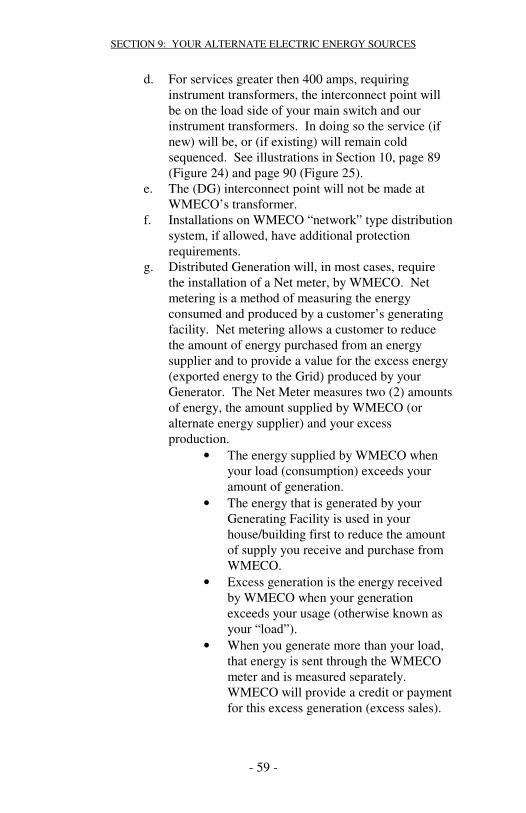
SECTION 9: YOUR ALTERNATE ELECTRIC ENERGY SOURCES
- 59 -
d. For services greater then 400 amps, requiring instrument transformers, the interconnect point will be on the load side of your main switch and our instrument transformers. In doing so the service (if new) will be, or (if existing) will remain cold sequenced. See illustrations in Section 10, page 89 (Figure 24) and page 90 (Figure 25).
e. The (DG) interconnect point will not be made at WMECO’s transformer.
f. Installations on WMECO “network” type distribution system, if allowed, have additional protection requirements.
g. Distributed Generation will, in most cases, require the installation of a Net meter, by WMECO. Net metering is a method of measuring the energy consumed and produced by a customer’s generating facility. Net metering allows a customer to reduce the amount of energy purchased from an energy supplier and to provide a value for the excess energy (exported energy to the Grid) produced by your Generator. The Net Meter measures two (2) amounts of energy, the amount supplied by WMECO (or alternate energy supplier) and your excess production.
• The energy supplied by WMECO when your load (consumption) exceeds your amount of generation.
• The energy that is generated by your Generating Facility is used in your house/building first to reduce the amount of supply you receive and purchase from WMECO.
• Excess generation is the energy received by WMECO when your generation exceeds your usage (otherwise known as your “load”).
• When you generate more than your load, that energy is sent through the WMECO meter and is measured separately. WMECO will provide a credit or payment for this excess generation (excess sales).

SECTION 9: YOUR ALTERNATE ELECTRIC ENERGY SOURCES
- 60 -
h. Other customers with Distributed Generation may qualify for bidirectional metering. The meter records energy consumed and energy exported. In which case, the customer pays for all energy used and is compensated for excess or sales of electricity exported to the distribution system.
i. For customers planning to install generation, both residential customers planning to install over 10KW of generation and all commercial customers planning to install generation – must submit a sketch showing the customer’s service entrance, their main switch, any existing or proposed meter(s) and how the generator will be tied in so that we can order the correct meter.

SECTION 10: FIGURES
- 61 -
SECTION 10
Illustrations
WMECO Thanks
And Greatly Appreciates Considerable Effort for These Illustrations DAVE BENEDETTO

SECTION 10: FIGURES
- 62 -
FIGURE 1Temporary Electric Service Conduit System
12’’
Numbersrefer toitems onfollowingpage
Approx.5 ft.
7
11
12
10
13Caution tape supplied and installed by you
10 65
4
10 ft. max.
9
8
1
23
24’’ min/ 36” max
7 ft.
10 ft. min.
3 ft.
FIGURE 1Temporary Electric Service Conduit System
12’’
Numbersrefer toitems onfollowingpage
Approx.5 ft.
7
11
12
10
1313Caution tape supplied and installed by you
10 65
4
10 ft. max.
9
8
1
23
24’’ min/ 36” max
7 ft.
10 ft. min.
3 ft.

SECTION 10: FIGURES
- 63 -
FIGURE 1 NOTES
Temporary Electric Service, Conduit System
We will install our conductors for a temporary electric service that is erected by you and meets the requirements listed below:
1. Location of temporary service timber is to be specified by us.2. The timber is to be structural grade fir or pine with cross
section not less than nominal solid 6” x 6” or two 2” x 8” spiked together on 8” centers.
3. The temporary service timber is to be at least 10 ft. long.4. The temporary service timber is to be set a min. of 3 ft. in firm
ground with well-tamped backfill.5. There is to be no excavation near the temporary service
timber which might reduce its stability.6. Service cable by us. 7. Approved by-pass meter socket is to be installed
approximately 5 ft. above ground.8. Outdoor type service equipment rated in accordance with
MEC Sections 230-79 and 230-90 is to be installed on load side of meter socket and within 12” of approved meter socket. Install ground fault interrupter protection.
9. Ground in accordance with code.10. Electrical grade Schedule 40 PVC conduit supplied and
installed by you. All conduit will be listed and labeled for Direct Buried and above ground use.
11. Pipe strap or clamp.12. Minimum 3” slip joint required.13. You will provide and install the caution tape which meets the
requirements of the MEC. This tape shall be red with the a printed warning message printed in black;
As an example;
“Caution - Electrical Line Buried Below”
FIGURE 1 NOTESTemporary Electric Service, Conduit System
We will install our conductors for a temporary electric service that is erected by you and meets the requirements listed below:
1. Location of temporary service timber is to be specified by us.2. The timber is to be structural grade fir or pine with cross
section not less than nominal solid 6” x 6” or two 2” x 8” spiked together on 8” centers.
3. The temporary service timber is to be at least 10 ft. long.4. The temporary service timber is to be set a min. of 3 ft. in firm
ground with well-tamped backfill.5. There is to be no excavation near the temporary service
timber which might reduce its stability.6. Service cable by us. 7. Approved by-pass meter socket is to be installed
approximately 5 ft. above ground.8. Outdoor type service equipment rated in accordance with
MEC Sections 230-79 and 230-90 is to be installed on load side of meter socket and within 12” of approved meter socket. Install ground fault interrupter protection.
9. Ground in accordance with code.10. Electrical grade Schedule 40 PVC conduit supplied and
installed by you. All conduit will be listed and labeled for Direct Buried and above ground use.
11. Pipe strap or clamp.12. Minimum 3” slip joint required.13. You will provide and install the caution tape which meets the
requirements of the MEC. This tape shall be red with the a printed warning message printed in black;
As an example;
“Caution - Electrical Line Buried Below”

SECTION 10: FIGURES
- 64 -
FIGURE 2Conduit Service: House End
Grounding by you required when using galvanizedsteel bend.
Set socket plumb
Meter by us
Approx.5 ft.
Slip joint
One clamp
90 degree bend, 24 “ min.radius, electrical gradeSchedule 40 PVC, orgalvanized steel bend ifrequired by WMECO.
24” min/ 36” max
12”
Caution tape supplied andinstalled by you.
3 “ min. electrical gradeSchedule 40 PVC conduit
Finish grade
All material, except asnoted, plus trench andsuitable backfill to befurnished by you.
Compact soil to prevent settlementand strain on socket.
Line
Manuallever
operatedby-pass
16”min.
22”min.22”min.
Load
Load
Install lineside conduitinto bottomleft KO only

SECTION 10: FIGURES
- 65 -
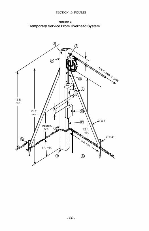
SECTION 10: FIGURES
- 66 -
FIGURE 4Temporary Service From Overhead System`
16 ft.min.
6 ft. min.
2” x 4”
4 ft. min.
6
5
8
2
7
12”
125 ft. max. to pole
12 ft.min.
2” x 4”
9
10
11
1Approx.
5 ft.
12”20 ft.min.
4
3

SECTION 10: FIGURES
- 67 -
FIGURE 4 NOTES
Temporary Service From Overhead
We will deadend our service drop for temporary electric service on a pole or timber which is to be erected by you and is to meet the requirements listed below;
1. Location of temporary service pole is to be specified by us such that the service span does not exceed 125 feet measured from our pole to your pole. If the service drop will not be transferred to a permanent location there will be additional charges.
2. If a timber is used, it is to be structural grade fir or pine with cross section not less than nominal 6” x 6”.
3. The temporary service pole is to be 20 feet minimum. Additional length may be required in order to provide service drop clearance of 16 feet min. over the road and driveway and 12 feet minimum over other areas.
4. The temporary service pole is to be set a minimum of 4 feet in in firm ground and well compacted backfill.
5. The temporary service pole is to be adequately braced to support at its top both a man on a ladder and a service drop tension of 600 pounds. A minimum of two, 2” x 4” braces at right angles to each other, with one in line with the service drop, are to be installed. Braces are to be well spiked flat against the side of the pole at least 12 ft. above ground and to solidly driven 2” x 4” stakes 3 ft. minimum located a minimum 6 ft. from the service pole.
6. There is to be no excavation near the temporary service pole or its braces which might reduce its stability.
Approved electric service is to be installed to meet the following requirements and to be in accordance with the code(s).
7. A weatherhead is to be installed approximately 12” from top of pole and 14 ft. minimum above ground.
8. Service entrance conductors are to be a minimum 3-wire no. 2 aluminum, securely fastened to the pole.
9. An approved meter socket is to be installed approximately 5 ft. above ground on the side nearest our pole.
10. Outdoor type service equipment rated in accordance with the MEC is to be installed on load side of meter socket within 12” there of. Ground fault interrupter protection shall also be installed.
11. Ground in accordance with MEC. The grounding conductor electrode connection shall be made at an accessible location in the service equipment and not in the meter socket.
FIGURE 4 NOTESTemporary Service From Overhead
FIGURE 4 NOTESTemporary Service From Overhead
We will deadend our service drop for temporary electric service on a pole or timber which is to be erected by you and is to meet the requirements listed below;
1. Location of temporary service pole is to be specified by us such that the service span does not exceed 125 feet measured from our pole to your pole. If the service drop will not be transferred to a permanent location there will be additional charges.
2. If a timber is used, it is to be structural grade fir or pine with cross section not less than nominal 6” x 6”.
3. The temporary service pole is to be 20 feet minimum. Additional length may be required in order to provide service drop clearance of 16 feet min. over the road and driveway and 12 feet minimum over other areas.
4. The temporary service pole is to be set a minimum of 4 feet in in firm ground and well compacted backfill.
5. The temporary service pole is to be adequately braced to support at its top both a man on a ladder and a service drop tension of 600 pounds. A minimum of two, 2” x 4” braces at right angles to each other, with one in line with the service drop, are to be installed. Braces are to be well spiked flat against the side of the pole at least 12 ft. above ground and to solidly driven 2” x 4” stakes 3 ft. minimum located a minimum 6 ft. from the service pole.
6. There is to be no excavation near the temporary service pole or its braces which might reduce its stability.
Approved electric service is to be installed to meet the following requirements and to be in accordance with the code(s).
7. A weatherhead is to be installed approximately 12” from top of pole and 14 ft. minimum above ground.
8. Service entrance conductors are to be a minimum 3-wire no. 2 aluminum, securely fastened to the pole.
9. An approved meter socket is to be installed approximately 5 ft. above ground on the side nearest our pole.
10. Outdoor type service equipment rated in accordance with the MEC is to be installed on load side of meter socket within 12” there of. Ground fault interrupter protection shall also be installed.
11. Ground in accordance with MEC. The grounding conductor electrode connection shall be made at an accessible location in the service equipment and not in the meter socket.

SECTION 10: FIGURES
- 68 -

SECTION 10: FIGURES
- 69 -
FIGURE 5
Overhead Service
All facilities beyond this servicepoint, except the meter, shall befurnished, installed, owned andmaintained by you.
16 ft.min.
Outdoormeter socketsee Figure 6 for detail
Road or Street Surface
Service drop furnished, installedowned and maintained by WMECO
Detail 1
UNACCEPTABLE
Service point located above buildingextension as represented in Detail 1is not acceptable because the servicepoint cannot be directly reached froma ladder placed on the ground.

SECTION 10: FIGURES
- 70 -
FIGURE 6
Overhead Service Entrance Facilities
To ground in accordancewith code.
Service equipment, 100 amp orlarger recommended
12 ft.min.
Gas meter, regulator or
propane cylinders3 ft.min.
clearance
Approx.5 ft.
Note:A. Electrical contractor must mark stud location for WMECO service
wire holder on homes with vinyl or aluminum siding.B. For service attachment points exceeding 20 ft. in height contact us.
10 ft.min. Approved outdoor meter socket.
Code approved conductors inconduit or service entrance cable.
All facilities except meter beyond this service point furnished, installed, owned and maintained by you.
Allow sufficient conductor(20”) to form drip loops.
Approved weatherhead.
Approved connectors furnished, installed by WMECO except as allowed for in the “Residential Cut andReconnect Policy”
Service drop furnished, installed, owned and maintained by WMECO
Clevis.
2 ft. min.Clearance to nearest
wall
FIGURE 6Overhead Service Entrance Facilities
To ground in accordancewith code.
Service equipment, 100 amp orlarger recommended
12 ft.min.
Gas meter, regulator or
propane cylinders3 ft.min.
clearance
Approx.5 ft.
Note:A. Electrical contractor must mark stud location for WMECO service
wire holder on homes with vinyl or aluminum siding.B. For service attachment points exceeding 20 ft. in height contact us.
10 ft.min. Approved outdoor meter socket.
Code approved conductors inconduit or service entrance cable.
All facilities except meter beyond this service point furnished, installed, owned and maintained by you.
Allow sufficient conductor(20”) to form drip loops.
Approved weatherhead.
Approved connectors furnished, installed by WMECO except as allowed for in the “Residential Cut andReconnect Policy”
Service drop furnished, installed, owned and maintained by WMECO
Clevis.
2 ft. min.Clearance to nearest
wall
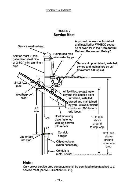
SECTION 10: FIGURES
- 71 -
FIGURE 7Service Mast
Service weatherhead
Reinforced typewireholder by you.
Approved connectors furnishedand installed by WMECO except as allowed for in the “Residential Cut and Reconnect Policy”
Service drop furnished, installed, owned and maintained by us.(maximum 1/0 triplex)
All facilities, except meter,beyond this service point
furnished, installed,owned and maintainedby you. Allow sufficientconductor (20”) to formdrip loops.
2-1/2 ft.max.
4 ft.min.
Weatherproofcollar
Service mast 2” min.galvanized steel pipeor 2-1/2 “ min. aluminumpipe
10 ft. min.above ground
to drip loop.
12 ft. min.above ground
to service drop
Lag or boltinto stud.
Conduithanger.
Offset reducer(when necessary)
Conduit tometer socket
Roof mountingplate fastenedwith lag screwsinto rafters.
Note:Only power service drop conductors shall be permitted to be attached to aservice mast (per MEC Section 230-28).

SECTION 10: FIGURES
- 72 -
FIGURE 8Special Service Attachments
Bearingplate
Clevis for servicecable attachmentfurnished by us,installed by you.
Notes:
A. Required for masonry and metal buildingsB. May be required for large and/or long services.C. The clevis or house knob shall be mounted below
the weather head per Mass electric code.
Section 10: FIGURES
WallStud
Lag type House Knobfor service cableattachmentfurnished by us,installed by you.
FIGURE 8Special Service Attachments
BearingplateBearingplateBearingplate
Clevis for servicecable attachmentfurnished by us,installed by you.
Notes:
A. Required for masonry and metal buildingsB. May be required for large and/or long services.C. The clevis or house knob shall be mounted below
the weather head per Mass electric code.
Section 10: FIGURES
WallStudWallStudWallStud
Lag type House Knobfor service cableattachmentfurnished by us,installed by you.

SECTION 10: FIGURES
- 73 -
FIGURE 9Trenching Requirements
12”
24” min/36” max
3” min. conduit
Suitablebackfill
Caution tapesupplied and
installed by youConduitdepth
24”
Spoil
Notes:
A. OSHA standards require that spoil shall be placed 24” from edge of trench.
B. Suitable backfill shall not contain ash, cinder, shell, frozen material, loose debris or stones larger than 2” max. dimension.
C. All Electrical grade Schedule 40 PVC conduit will be listed and labeled for Direct Buried and above ground use.
D. Horizontal Clearance - shall be 12 inches minimum or more as necessary to permit access for maintenance of either facility without damage to the other. This includes private wiring. Fuel (Gas and Oil) and Water Lines shall be no closer than 18 inches in all directions.Vertical Crossing Clearance - shall be so constructed and supported that upper facility will not transfer harmful load onto there lower facility. There shall be adequate vertical clearance to permit access for maintenance of either facility without damage to the other. In general, 12 inches is considered adequate separation, but the parties involved may agree to a lesser separation. Fuel (Gas and Oil) and WaterLines shall be no closer than 18 inches in all directions.
E. You will provide and install the caution tape which meets therequirements of the MEC. This tape shall be red with a continuous printed warning message printed in black;
As an Example;
“Caution - Electric Line Buried Below”

SECTION 10: FIGURES
- 74 -
FIGURE 10
Self-Contained Meter Socket Sequence andMounting Arrangement
1. Weatherproof joint with removable or non-removable hub.2. Socket shall be mounted plumb. On clapboard shingle siding, socket
shall be located on the high point of two clapboards.3. Slip joint for conduit service.
Notes:A. All network and 480/277 volt services will require a main disconnect
ahead of the meter (cold sequence).B. Self-contained meter sockets are required for:
• Single-phase 120/240 volt, 400 amp service entrance capacity or less.
• Single-phase 120/208 volt, 200 amp service entrance capacity or less.
• Three-phase 400 amp service entrance capacity or less.
C. All equipment (except meter) furnished, installed, owned and maintained by you.
D. Ground at service equipment in accordance with MEC Article 250. The grounding electrode conductor connection shall be made at an accessible location in the service equipment and not in the meter socket. The grounding electrode shall not be run through the meter socket.
Conduit ServiceOverheadService
LINELINE
16”
22”
Line To load
To loadTo load
Approx.5 ft.
1
2
3
FIGURE 10Self-Contained Meter Socket Sequence and
Mounting Arrangement
1. Weatherproof joint with removable or non-removable hub.2. Socket shall be mounted plumb. On clapboard shingle siding, socket
shall be located on the high point of two clapboards.3. Slip joint for conduit service.
Notes:A. All network and 480/277 volt services will require a main disconnect
ahead of the meter (cold sequence).B. Self-contained meter sockets are required for:
• Single-phase 120/240 volt, 400 amp service entrance capacity or less.
• Single-phase 120/208 volt, 200 amp service entrance capacity or less.
• Three-phase 400 amp service entrance capacity or less.
C. All equipment (except meter) furnished, installed, owned and maintained by you.
D. Ground at service equipment in accordance with MEC Article 250. The grounding electrode conductor connection shall be made at an accessible location in the service equipment and not in the meter socket. The grounding electrode shall not be run through the meter socket.
Conduit ServiceOverheadService
LINELINE
16”
22”
Line To load
To loadTo load
Approx.5 ft.
1
2
3

SECTION 10: FIGURES
- 75 -
FIGURE 11Sequence of meter and service equipment for
self-contained 208Y/120v Network services and 480Y/277v services
(Cold Sequence - Refer to page 25 B)
Note:
A. All wiring beyond the service point installed, owned and maintained by you.B. An approved lever operated manual bypass with jaw release and flash shield
is required.C. Maintain clearances as specified in Section 7.C.2.D. Line side disconnect must be adjacent to the meter socket and accessible to
WMECO at all times..
BREAKERor
FUSED
If fed from over head
If fed from under ground(requires slip joint)
Line side disconnect withover current protection Approved meter
socket
Single Position
To load

SECTION 10: FIGURES
- 76 -
FIGURE 12Sequence of meter and service equipment for three-phase self-contained 208Y/120v Network services and 480Y/277v services
(Cold Sequence)
1. Wiring trough with suitable connectors for us to terminate our conductors. Sealing provisions are required.
2. Line side disconnect with over current protection, 400 amps or less.3. Weatherproof joints.4. Approved meter socket.5. Line, if supply is overhead and total ampacity is 400 amps or less.6. Line, if supply is conduit system.
Notes:A. Each area serviced must be permanently marked on the door with its unique,
permanent identification. This unique identification must be permanently marked on the associated meter socket, on meter socket cover and inside load center before the meter will be installed.
B. An approved lever operated manual bypass with jaw release and flash shield is required.
C. Maintain clearances as specified in Section 7.C.2.D. Line side disconnect must be adjacent to the meter socket and accessible to
WMECO at all times.
Conductors and connectors by you.
Multi-Position up to six meters
BREAKERor
FUSED
BREAKERor
FUSED
BREAKERor
FUSED
1
2
4
6
5
Finish grade
6 “min.
Approx.5 ft.
3
Conductors and connectors by you.
Multi-Position up to six meters
BREAKERor
FUSED
BREAKERor
FUSED
BREAKERor
FUSED
1
2
44
66
5
Finish grade
6 “min.
Approx.5 ft.
33

SECTION 10: FIGURES
- 77 -
FIGURE 13
Meter Installation-Private Property PoleYour Conductors Overhead
Notes:A. Only one meter to be installed on poleB. Ground at service equipment in accordance with MEC Article 250. The
grounding electrode conductor connection shall be made at an accessible location in the service equipment and not in the meter socket. The grounding electrode conductor shall not be run through the meter socket.
C. All three-phase 208y/120 Volt network and 480/277 volt services will require a main disconnect ahead of the meter (Cold Sequence).
D. The customer is responsible for relocating their equipment if the pole is replaced.
With the exception of pole and meter,all facilities beyond this service pointfurnished, installed, owned andmaintained by you. Allow 20” for driploop.
Service drop furnished, installed, owned and maintained by WMECO.
To Load
Approved conduit,:steel or electricalgrade Schedule 40 PVC.
Approved outdoor meter socket.
6” min.
Service equipment, 100 ampor larger recommended.
Approx.5 ft.
Ground,See Note
B
Pole furnished, installed, ownedand maintained by WMECO with acontribution by you.
Driven groundrod
FIGURE 13Meter Installation-Private Property Pole
Your Conductors Overhead
Notes:A. Only one meter to be installed on poleB. Ground at service equipment in accordance with MEC Article 250. The
grounding electrode conductor connection shall be made at an accessible location in the service equipment and not in the meter socket. The grounding electrode conductor shall not be run through the meter socket.
C. All three-phase 208y/120 Volt network and 480/277 volt services will require a main disconnect ahead of the meter (Cold Sequence).
D. The customer is responsible for relocating their equipment if the pole is replaced.
With the exception of pole and meter,all facilities beyond this service pointfurnished, installed, owned andmaintained by you. Allow 20” for driploop.
Service drop furnished, installed, owned and maintained by WMECO.
To Load
Approved conduit,:steel or electricalgrade Schedule 40 PVC.
Approved outdoor meter socket.
6” min.
Service equipment, 100 ampor larger recommended.
Approx.5 ft.
Ground,See Note
B
Pole furnished, installed, ownedand maintained by WMECO with acontribution by you.
Driven groundrod

SECTION 10: FIGURES
- 78 -
FIGURE 14Meter Installation-Private Property Pole
Your Conductors Underground
Notes:A. Only one meter to be installed on pole.B. Ground at service equipment in accordance with MEC Article 250. The
grounding electrode conductor connection shall be made at an accessible location in the service equipment and not in the meter socket. The grounding electrode conductor shall not be run through the meter socket.
C. All three-phase 208Y/120 volt network and 480/277 volt services will require a main disconnect ahead of the meter (Cold Sequence).
D. The customer is responsible for relocating their equipment if the pole isreplaced.
Service drop furnished, installed, owned and maintained by WMECO.
With the exception of pole and meter,all facilities beyond this service pointfurnished, installed, owned andmaintained by you. Allow 20” for driploop.
Approved outdoor meter socket.
Service equipment, 100 ampor larger recommended.
Pole furnished, installed, ownedand maintained by WMECO with acontribution by you.
Approved Conduit:steel or electricalgrade Schedule 40 PVC.
6” min.
Approx.5 ft.
Ground,See Note
B
Driven groundrod 12”
Caution tapesupplied and
installed by you
Finished grade
To your load

SECTION 10: FIGURES
- 79 -
FIGURE 15Permanent Pedestal Service - Site Built
(Manufactured Meter Pedestals May Be Used - Refer To Approval List)
Approx.5 ft.
Approved metersocket/combinationmeter socket withmain disconnect.
ServiceEquipment
3” min.slip joint
Footing - 4 ft. min. set in concrete from base of hole to just above finished grade
3” min. electrical gradeSchedule 40 PVC
conduit with 24” of cover
12”
Caution tape supplied and installed by
you
12”
90 degree bend24” min. radiuselectrical gradeSchedule 40 PVC
You provide, ownand maintainapproved conduit,service conductors and main disconnectfrom load side ofmeter
Ground inaccordance withcode.
Serviceconductorsby WMECO
One clamp
Min. 3/4” pressure treated plywood
Min. 3” galvanized pipe with end caps or3” galvanized steel ‘U’ channel for supports
Line sideconduit -Left sideonly
End cap1½” galvanized
steel ‘U’ channel

SECTION 10: FIGURES
- 80 -
FRONT REAR
CustomerLoad
Footing - 4 ft.min. set in concrete frombase of hole
to just above finished grade
3” min. electrical grade Schedule 40 PVC conduit cast
integral with concretewith 24” min./ 36” max.
of cover
FIGURE 16Manufactured Pedestal Service
(Typical)
Approx.5 ft.
Caution tape supplied and
installed by you
Serviceconductorsby WMECO
12”
Ground inaccordance with code.
Customer’sDisconnect

SECTION 10: FIGURES
- 81 -
FIGURE 17Single-Phase: Self-Contained Metering Connections
(Typical)
Notes:A. An approved lever operated manual bypass is required on sockets for all
commercial/industrial and residential services, 100 amp may be supplied with non-locking jaws, greater than 100 amp must be supplied with lockingjaw.
B. When the fifth terminal kit is used, install a No. 12 copper conductor, with white insulation, between the fifth jaw in the 9 o’clock position and the neutral lug/bar.
C. For the Underground manhole areas of Springfield, Greenfield andPittsfield: Any new or upgraded service (200 amps or less) in these cities, must have a 5 terminal meter socket installed even if 120/240V service.
D. A five terminal meter socket is acceptable for a 120/240 volt service.
LINE LINE
NN
Load120/240V
Single-phase, 3-wire4 terminal meter socket
400 amp or less
Load120/208V
Single-phase, 3-wire5 terminal meter socket
200 amp or less

SECTION 10: FIGURES
- 82 -
Warning and Clearance Diagram

SECTION 10: FIGURES
- 83 -
1. Service load disconnects may be located above, below or beside meter.2. Individual meter sockets with individual barriers between meter positions
as well as provisions for seals and barrel locks.3. Single-phase 120/208 volt Network, Three-phase 208/120 volt Network
and Three-phase 480/277 volt services shall be cold sequenced.Notes:A. For 480/277v group metering installations consult your local WMECO
office.B. Sketch of meter panel arrangements must be submitted to WMECO for
approval prior to layout and installation of equipment.C. Each store, office. apartment or area serviced must be permanently marked on
the door with its unique, permanent identification. This unique identification must be permanently marked on the associated meter socket, on meter socket cover and inside load center before the meter will be installed.
D. Ground at service equipment in accordance with MEC Article 250. The grounding electrode conductor connection shall be made at an accessible location in the service equipment and not in the meter socket. The grounding electrode conductor shall not be run through the meter socket.
E. Maximum height at top of meter is 6 ft.F. Minimum height at bottom of meter is 2 ft. above floor or finish grade.G. An approved lever operated manual bypass is required on sockets for all
services.H. Meter panels must be protected by barriers if there is a potential for damage by
vehicles.
FIGURE 18Modular Meter Panels for Group Metering Single-Phase 120/240v or 120/208v Three-Phase 208/120v Network Three-Phase 480/277v
ON
OFF
Disconnect withover current protectionFloor or Finish grade
2 ft.min.
6 ft.max.
1
2
3
Approved group metering with
individual barriers
ON
OFF
Disconnect withover current protectionFloor or Finish grade
2 ft.min.
6 ft.max.
111
222
333
Approved group metering with
individual barriers

SECTION 10: FIGURES
- 84 -
FIGURE 19Single-Phase: Self-Contained Metering
to Multiple Mobile Homes up to six meters
1. Painted 3/4” exterior plywood meter board.2. Upper edge trimmed to prevent seepage into laminations.3. Pre-bussed, gang meter sockets marked inside and on cover of socket with
mobile home identification. All new mobile homes intended as a dwelling unit will be supplied with 120/240 volts. (Per MEC Section 550-21).
4. Minimum 6 “ space between meter socket and service equipment.5. Suitable support to be galvanized steel in concrete.6. Weatherproof joint.7. Service equipment 200 amp or less for each mobile home marked with
mobile home identification.8. Electrical grade Schedule 40 PVC, or galvanized steel conduit. Refer to us
for size. Service may be overhead or underground in conduit. Total installed service entrance capacity shall not exceed 400 amp if fed from an overhead service.
9. UL listed slip joint with one clamp.
Notes:Ground at service equipment in accordance with MEC Article 250. The grounding electrode conductor connection shall be made at an accessible location in the service equipment and not in the meter socket. The grounding electrode conductor shall not be run through the meter socket. Grounding in the center wireway is permissible.
2 3
4 ft. min.
Approx.5 ft.
6” min.
1
4
987 65
Finish grade
FIGURE 19Single-Phase: Self-Contained Metering
to Multiple Mobile Homes up to six meters
1. Painted 3/4” exterior plywood meter board.2. Upper edge trimmed to prevent seepage into laminations.3. Pre-bussed, gang meter sockets marked inside and on cover of socket with
mobile home identification. All new mobile homes intended as a dwelling unit will be supplied with 120/240 volts. (Per MEC Section 550-21).
4. Minimum 6 “ space between meter socket and service equipment.5. Suitable support to be galvanized steel in concrete.6. Weatherproof joint.7. Service equipment 200 amp or less for each mobile home marked with
mobile home identification.8. Electrical grade Schedule 40 PVC, or galvanized steel conduit. Refer to us
for size. Service may be overhead or underground in conduit. Total installed service entrance capacity shall not exceed 400 amp if fed from an overhead service.
9. UL listed slip joint with one clamp.
Notes:Ground at service equipment in accordance with MEC Article 250. The grounding electrode conductor connection shall be made at an accessible location in the service equipment and not in the meter socket. The grounding electrode conductor shall not be run through the meter socket. Grounding in the center wireway is permissible.
2 3
4 ft. min.
Approx.5 ft.
6” min.
1
4
99887 655
Finish grade

SECTION 10: FIGURES
- 85 -
FIGURE 20Self-Contained Outdoor Meter Socket Installation-
Multi-Position Up To Six Meters
Conductors and connectors by you.
1. Wiring trough with suitable connectors for us to terminate our conductors. Sealing provisions are required.
2. Combination meter socket and disconnect is acceptable.3. Service equipment, 400 amp or less.4. Weatherproof joints.5. Line, if supply is overhead and total ampacity is 400 amps or less.6. Line, if supply is conduit system.
Notes:
A. Each store, office, apartment or area serviced must be permanently marked on the door with its unique, permanent identification. This unique identification must be permanently marked on the associated meter socket, on meter socket cover and inside load center before the meter will be installed.
B. An approved lever operated manual bypass with jaw release and flash shield is required for meter sockets greater than 100 amp. An approved lever operated bypass, non jaw release, with flash shield may be used on a 100 amp meter socket.
C. Maintain clearances as specified in Section 7.C.2.
5
BREAKERor
FUSED
BREAKERor
FUSED
BREAKERor
FUSED
1
2
3
4
6Finish grade
6 “min.
Approx.5 ft.
BREAKERor
FUSED

SECTION 10: FIGURES
- 86 -
FIGURE 21Three -Phase: Self-Contained Metering Connections
Notes:
A. Ground at service equipment in accordance with MEC Article 250. The grounding electrode conductor connection shall be made at anaccessible location in the service equipment and not in the meter socket. The grounding electrode conductor shall not be run through the meter socket.
B. All three-phase network and 480/277 volt services will require a main disconnect with over current protection ahead of the meter (ColdSequence).
1. An approved lever operated manual bypass with jaw release and flash shield.
LINE
Load208/120v
or480/277v
Three-phase, 4-wire7 terminal meter socket
400 amp or less
1
N
1
LINE
Load208/120v
or480/277v
Three-phase, 4-wire7 terminal meter socket
400 amp or less
11
N
1

SECTION 10: FIGURES
- 87 -
FIGURE 22Outdoor Instrument Transformer Meter
Socket with Test Switch
1. Approved pre-wired meter socket with test switch.2. Electrical grade Schedule 40 PVC, galvanized steel conduit to be minimum
of 1-1/2” diameter, minimum length 6”, maximum length 50 ft. If PVC, provideand install an equipment grounding conductor (No. 10 wire or larger). Conduitis to be installed in the bottom or side of meter socket only - no top feed is allowed.
3. Weatherproof joint.
Notes:A. Consult WMECO before starting design of any job where an instrument
transformer installation is required.B. See Figure 25 for meter and service equipment sequence.
1
2
3
Approx.5 ft.
Finish grade
FIGURE 22Outdoor Instrument Transformer Meter
Socket with Test Switch
1. Approved pre-wired meter socket with test switch.2. Electrical grade Schedule 40 PVC, galvanized steel conduit to be minimum
of 1-1/2” diameter, minimum length 6”, maximum length 50 ft. If PVC, provideand install an equipment grounding conductor (No. 10 wire or larger). Conduitis to be installed in the bottom or side of meter socket only - no top feed is allowed.
3. Weatherproof joint.
Notes:A. Consult WMECO before starting design of any job where an instrument
transformer installation is required.B. See Figure 25 for meter and service equipment sequence.
11
22
33
Approx.5 ft.
Finish grade

SECTION 10: FIGURES
- 88 -
FIGURE 23
Instrument Transformer Connections
120/240vSingle-phase, 3-wire
6 TerminalMeter Socket
3
1
2L1 L2
3
NLINE
LOAD
CT CT
1. Instrument transformer enclosure.2. Current transformers to be installed
with white dot polarity mark on the line side.
3. Suitable individual neutral and equipment grounding connectorsfor #10 AWG wire.
4. Mounting provisions required for Voltage transformers.
VT=Voltage TransformerCT=Current Transformer
N
480/277vThree-phase, 4-wire
13 TerminalMeter Socket
1
2
O-A O-B O-C
3
LINE
LOAD
CT CTCT
VT VTVT208/120vThree-phase, 4-wire
13 TerminalMeter Socket
LINEN
O-A O-B O-C
LOAD
CTCTCT
4
Notes:A.Instrument transformers are required for the following:
• All single-phase 120/240 volt over 400 amp service entrance capacity.• All three-phase 4 wire over 400 ampere capacity
B.Where multiple conductors or a single conductor over 500 kcmil is used, refer to list of approved instrument transformer mounting equipment in Section 11.
C.Install a grounding connector and neutral connector in the Instrument Transformer enclosure.
FIGURE 23Instrument Transformer Connections
120/240vSingle-phase, 3-wire
6 TerminalMeter Socket
33
11
22L1 L2
33
NLINE
LOAD
CT CT
1. Instrument transformer enclosure.2. Current transformers to be installed
with white dot polarity mark on the line side.
3. Suitable individual neutral and equipment grounding connectorsfor #10 AWG wire.
4. Mounting provisions required for Voltage transformers.
VT=Voltage TransformerCT=Current Transformer
N
480/277vThree-phase, 4-wire
13 TerminalMeter Socket
11
22
O-AO-A O-BO-B O-CO-C
33
LINE
LOAD
CT CTCT
VT VTVT208/120vThree-phase, 4-wire
13 TerminalMeter Socket
LINEN
O-A O-B O-C
LOAD
CTCTCT
4208/120vThree-phase, 4-wire
13 TerminalMeter Socket
LINEN
O-AO-A O-BO-B O-CO-C
LOAD
CTCTCT
44
Notes:A.Instrument transformers are required for the following:
• All single-phase 120/240 volt over 400 amp service entrance capacity.• All three-phase 4 wire over 400 ampere capacity
B.Where multiple conductors or a single conductor over 500 kcmil is used, refer to list of approved instrument transformer mounting equipment in Section 11.
C.Install a grounding connector and neutral connector in the Instrument Transformer enclosure.

SECTION 10: FIGURES
- 89 -
FIGURE 24
Combination Main Switch and Instrument Transformer Enclosure
1. If located outdoors, enclosure shall be of weatherproof design.2. Electrical grade Schedule 40 PVC or galvanized steel conduit 1-1/2” min.
diameter, 6 “ min. length and 50 ft. max. length. If PVC, provide and install an equipment grounding conductor (No. 10 wire or larger).
3. Approved pre-wired meter socket with test switch.4. Must have a locking provision for the main breaker and instrument
transformer enclosure.
Notes:A. Consult WMECO before starting design on any job where an instrument
transformer installation is required.B. You will provide the combination main disconnect and instrument transformer
enclosure, conduit for meter wiring, primary connectors for instrument transformers and approved pre-wired combination meter socket with test switch.
C. Instrument transformers provided by us and installed by you.D. If 480/277 volt equipment is installed, provisions must be supplied for mounting
voltage transformers in the same compartment as the current transformers.E. Conduit must be continuous from the instrument transformer compartment to
the test switch compartment.
Line
OFF
ON
Load
MainSwitch
INSTRUMENTTRANSFORMERCOMPARTMENT
ServiceGround
6” Min.
50 ft. Max.
1
2
3
4
Finish grade
FIGURE 24Combination Main Switch and Instrument
Transformer Enclosure
1. If located outdoors, enclosure shall be of weatherproof design.2. Electrical grade Schedule 40 PVC or galvanized steel conduit 1-1/2” min.
diameter, 6 “ min. length and 50 ft. max. length. If PVC, provide and install an equipment grounding conductor (No. 10 wire or larger).
3. Approved pre-wired meter socket with test switch.4. Must have a locking provision for the main breaker and instrument
transformer enclosure.
Notes:A. Consult WMECO before starting design on any job where an instrument
transformer installation is required.B. You will provide the combination main disconnect and instrument transformer
enclosure, conduit for meter wiring, primary connectors for instrument transformers and approved pre-wired combination meter socket with test switch.
C. Instrument transformers provided by us and installed by you.D. If 480/277 volt equipment is installed, provisions must be supplied for mounting
voltage transformers in the same compartment as the current transformers.E. Conduit must be continuous from the instrument transformer compartment to
the test switch compartment.
Line
OFF
ON
Load
MainSwitch
INSTRUMENTTRANSFORMERCOMPARTMENT
ServiceGround
6” Min.
50 ft. Max.
1
2
3
4
Finish grade
Line
OFF
ON
Load
MainSwitch
INSTRUMENTTRANSFORMERCOMPARTMENT
ServiceGround
6” Min.
50 ft. Max.
1
2
3
4
Finish grade

SECTION 10: FIGURES
- 90 -
Instrument Transformer Enclosure Requirements:
SERVICE SIZE CURRENT VOLTAGENOMINAL VOLTAGE WIDTH HEIGHT DEPTH TRANSFORMER TRANSFORMER
Minimum size enclosure with current transformers only (Max. 800 amp):120/240 36” 36” 10” 2 ea --
208Y/120 36” 36” 10” 3 ea --Minimum size enclosure with current and voltage transformers; mounting provisions are required for voltage transformers (Max. 1200 amp):
480Y/277 48” 48” 10” 3 ea 3 ea
ON
OFFLine
Service ground
25 ft.max.
6” min.50 ft.max.
1
2
3
LoadApprox.
5 ft.
Instrumenttransformer
enclosure
FIGURE 25Instrument Transformer Installation
Instrument Transformer Enclosure Requirements:
SERVICE SIZE CURRENT VOLTAGENOMINAL VOLTAGE WIDTH HEIGHT DEPTH TRANSFORMER TRANSFORMER
Minimum size enclosure with current transformers only (Max. 800 amp):120/240 36” 36” 10” 2 ea --
208Y/120 36” 36” 10” 3 ea --Minimum size enclosure with current and voltage transformers; mounting provisions are required for voltage transformers (Max. 1200 amp):
480Y/277 48” 48” 10” 3 ea 3 ea
ON
OFFLine
Service ground
25 ft.max.
6” min.50 ft.max.
1
2
3
LoadApprox.
5 ft.
Instrumenttransformer
enclosure
ON
OFFLineLine
Service ground
25 ft.max.
6” min.50 ft.max.
11
22
33
LoadLoadApprox.
5 ft.
Instrumenttransformer
enclosure
FIGURE 25Instrument Transformer Installation
FIGURE 25Instrument Transformer Installation

SECTION 10: FIGURES
- 91 -
FIGURE 25
Instrument Transformer Installation
1. Electrical grade Schedule 40 PVC or galvanized steel conduit 1-1/2”min. diameter, 6 “ min. length and 50 ft. max. length. If PVC, provideand install an equipment grounding conductor (No. 10 wire or larger).
2. Approved pre-wired meter socket with test switch located outdoors.
3. Must have barrel lock sealing devices for main disconnect and instrumenttransformer enclosure.
Notes:A. CONSULT WMECO BEFORE STARTING DESIGN ON ANY JOB WHERE
ANY INSTRUMENT TRANSFORMER INSTALLATION IS REQUIRED.
B. You will provide the instrument transformer enclosure, conduit for meterwiring, primary connectors for instrument transformers, and approved combination meter socket with test switch.
C. Ground at service equipment in accordance with MEC Article 250. The grounding electrode conductor connection shall be made at a accessiblelocation in the service equipment and not in the meter socket. The grounding electrode conductors shall not be run through the meter socket.
D. Install a grounding connector and neutral connector in the instrument transformer enclosure.
E. Maintain clearances as specified in Section 7.C.2.
F. Instrument transformers provided by WMECO and installed by you.
G. Enclosure to have hinged doors and provisions for seal and padlock and 3/4” plywood backing for mounting transformers. If located outdoors, enclosure shall be of weatherproof design.
FIGURE 25Instrument Transformer Installation
1. Electrical grade Schedule 40 PVC or galvanized steel conduit 1-1/2”min. diameter, 6 “ min. length and 50 ft. max. length. If PVC, provideand install an equipment grounding conductor (No. 10 wire or larger).
2. Approved pre-wired meter socket with test switch located outdoors.
3. Must have barrel lock sealing devices for main disconnect and instrumenttransformer enclosure.
Notes:A. CONSULT WMECO BEFORE STARTING DESIGN ON ANY JOB WHERE
ANY INSTRUMENT TRANSFORMER INSTALLATION IS REQUIRED.
B. You will provide the instrument transformer enclosure, conduit for meterwiring, primary connectors for instrument transformers, and approved combination meter socket with test switch.
C. Ground at service equipment in accordance with MEC Article 250. The grounding electrode conductor connection shall be made at a accessiblelocation in the service equipment and not in the meter socket. The grounding electrode conductors shall not be run through the meter socket.
D. Install a grounding connector and neutral connector in the instrument transformer enclosure.
E. Maintain clearances as specified in Section 7.C.2.
F. Instrument transformers provided by WMECO and installed by you.
G. Enclosure to have hinged doors and provisions for seal and padlock and 3/4” plywood backing for mounting transformers. If located outdoors, enclosure shall be of weatherproof design.

SECTION 10: FIGURES
- 92 -
FIGURE 26Telephone AMR Equipment Diagram
8”W x 8”H x 4” Enclosure suppliedand installed by WMECO.
WMECOsurge
suppressor
CustomerRJ11jack
Conduit1” min. diameter
2” - 6” length Customerdedicatedphone line
FIGURE 26Telephone AMR Equipment Diagram
8”W x 8”H x 4” Enclosure suppliedand installed by WMECO.
WMECOsurge
suppressor
CustomerRJ11jack
Conduit1” min. diameter
2” - 6” length Customerdedicatedphone line

SECTION 10: FIGURES
- 93 -
Figure 27
Meter Interface Enclosure
NOTE:A. For PULSES ONLY and NO Phone AMR, there will ONLY be an LPOP. B. For Phone AMR ONLY and NO pulses supplied, there will ONLY be a
Surge Suppresser & RJ11 jack.
NU(Supplied and installed)
Surge suppressor
Customer/supplier(Supplied and installed)
RJ11 phone jack
98 765 432
UtilityMeter
CustomerMeterSocket
METER INTERFACE ENCLOSURE(NU Supplied and installed)
(8"Wx8"Hx4"D)
(For Phone AMR and/or Load Pulse output options)
NU (Supplied and installed)LOAD PULSE OUTPUT PROTECTOR (LPOP)
TELEPHONE LINESURGE
SUPPRESSER
TO P
RO
TEC
TE
D E
QU
IPM
EN
T
TO GROUND
TO T
ELE
PH
ON
E L
INE
Load Pulse Output ValuesKe value = __________kWh/pulse
••••••••••••••••••••••••••Max In Volt.…..30vAC,38vDCInput Current Limit…....70maMax Pulse rate...12 Pulses/sec
ME
TE
R
CU
STO
ME
R
APTECH, INC FEB ‘98
KG
YKG
Y
Customer/supplier phone line
RJ11
NU Supplied Wires
Customer/supplier(Supplied and installed)
Cable
Figure 27Meter Interface Enclosure
NOTE:A. For PULSES ONLY and NO Phone AMR, there will ONLY be an LPOP. B. For Phone AMR ONLY and NO pulses supplied, there will ONLY be a
Surge Suppresser & RJ11 jack.
NU(Supplied and installed)
Surge suppressor
Customer/supplier(Supplied and installed)
RJ11 phone jack
98 765 432
UtilityMeter
CustomerMeterSocket
METER INTERFACE ENCLOSURE(NU Supplied and installed)
(8"Wx8"Hx4"D)
(For Phone AMR and/or Load Pulse output options)
NU (Supplied and installed)LOAD PULSE OUTPUT PROTECTOR (LPOP)
TELEPHONE LINESURGE
SUPPRESSER
TO P
RO
TEC
TE
D E
QU
IPM
EN
T
TO GROUND
TO T
ELE
PH
ON
E L
INE
Load Pulse Output ValuesKe value = __________kWh/pulse
••••••••••••••••••••••••••Max In Volt.…..30vAC,38vDCInput Current Limit…....70maMax Pulse rate...12 Pulses/sec
Load Pulse Output ValuesKe value = __________kWh/pulse
••••••••••••••••••••••••••Max In Volt.…..30vAC,38vDCInput Current Limit…....70maMax Pulse rate...12 Pulses/sec
ME
TE
R
CU
STO
ME
R
APTECH, INC FEB ‘98
KG
YKG
YKG
YKG
Y
Customer/supplier phone line
RJ11
NU Supplied Wires
Customer/supplier(Supplied and installed)
Cable

SECTION 10: FIGURES
- 94 -
Figure 28
Cell Site Metering Pedestal
4 ft. min. set inconcrete from base
of hole to just above ground
Serviceconductors
90 degree bend 24 in.min. radius electrical
grade Schedule 40 PVC
Two doubled - 4 X 8 sheetsof 3/4” Marine plywood
painted or sealed
End cap to protect plywood
Min. 3 in. galvanized
steel pipe with end cap or 3 in.galvanized steel
‘U’ channel.
1 ½ “ Galvanizedsteel ‘U’ channel
All hardwareused will begalvanized.
All unused metersto be barrel locked
by us
3” minslip joint
6 ft.max
2 ft.min
UNIT ‘A’SNET
UNIT ‘B’MCI
UNIT ‘C’ATT
UNIT ‘E’COX
UNI ‘D’
All metersmust beproperlyidentified‘Unit #’
12 in.
Main Disconnect *
XXX AMP
120/240 v PH 3 W
UNI ‘D’
DWG#042700DDB
1 clamp
3 in. min. electricalgrade Schedule 40PVC conduit with24 in./ 36 in. of cover 12”
Caution tapesupplied andinstalled by you
Note:A. Utilizing a main disconnect is the preferred installation to allow for additional
meters beyond six. B. Metering pedestal must be protected by barriers if there is a potential for
damage by vehicles..
1. Individual meter sockets with individual barriers as well as provisions for seals and barrel locks.
2. Single-phase 120/208 volt Network, Three-phase 208/120 volt Networkand Three-phase 480/277 volt services shall be cold sequenced.
Approved group metering with
individual barriers
1 2
Figure 28Cell Site Metering Pedestal
4 ft. min. set inconcrete from base
of hole to just above ground
Serviceconductors
90 degree bend 24 in.min. radius electrical
grade Schedule 40 PVC
Two doubled - 4 X 8 sheetsof 3/4” Marine plywood
painted or sealed
End cap to protect plywood
Min. 3 in. galvanized
steel pipe with end cap or 3 in.galvanized steel
‘U’ channel.
1 ½ “ Galvanizedsteel ‘U’ channel
All hardwareused will begalvanized.
All unused metersto be barrel locked
by us
3” minslip joint
6 ft.max
2 ft.min
UNIT ‘A’SNET
UNIT ‘B’MCI
UNIT ‘C’ATT
UNIT ‘E’COX
UNI ‘D’
All metersmust beproperlyidentified‘Unit #’
12 in.
Main Disconnect *
XXX AMP
120/240 v PH 3 W
XXX AMP
120/240 v PH 3 W
UNI ‘D’
DWG#042700DDB
1 clamp
3 in. min. electricalgrade Schedule 40PVC conduit with24 in./ 36 in. of cover 12”
Caution tapesupplied andinstalled by you
Note:A. Utilizing a main disconnect is the preferred installation to allow for additional
meters beyond six. B. Metering pedestal must be protected by barriers if there is a potential for
damage by vehicles..
1. Individual meter sockets with individual barriers as well as provisions for seals and barrel locks.
2. Single-phase 120/208 volt Network, Three-phase 208/120 volt Networkand Three-phase 480/277 volt services shall be cold sequenced.
Approved group metering with
individual barriers
111 222

SECTION 10: FIGURES
- 95 -
WMECO Approvedlever operated
by-pass 200 AmpMeter Socket
Structural concretepad on 3” – 6”
gravel base
3” Diametersteel conduitcast integralwith the pad
Driven ground
rod
FIGURE 29Typical Remote Communications Power Site
Note:A. A slip joint is not required provided that the steel conduit is integral with
the concrete pad. B. Blueprints/Design must be submitted to WMECO for approval prior to
installation.

SECTION 10: FIGURES
- 96 -
FIGURE 30Typical Transfer Switch Installation
In Conjunction With Your Auxiliary Supply
Consult your local authority for proper wiring procedures.
ApprovedMeter Socket
Transfer Switch DisconnectingMeans
TO UTILITY SUPPLY
Ground in accordancewith MEC at
service disconnecting means
100 amp or largerrecommended
Auxiliary supplyfrom generator
LOAD

SECTION 10: FIGURES
- 97 -
FIGURE 31Mobile Command Center
Temporary Service Specifications
Note:
The voltage character of the utility feed may be either 120/240 volt or 120/208 volt single phase. All mobile unit electrical equipment must be designed to accept either of these two possible voltage options.
1. Utility requirements vary as to who supplies service feed conductors. The customer should determine from the local utility who has the responsibility for supplying the service feed conductors.
2. Check that vehicle generator is off before switching to on positon.
Servicefeed
conductorsby utility
3” Minimumelectrical grade
schedule 40 PVC conduitdesignatedlocation bycustomer
Slip jointfor expansion
Clamp
Service point, permanent connections by host utility
Transition box - feed1Ph 120/240(208) V[with hinged cover and lockable hasp]
Servicedisconnectingmeans sized appropriately
Approved 200 amp meter socket
w/manual lever operated by-pass
Example offeed option
Load Center
OFF
ON
8 ft. drivenground rod
Grounding electrodeconductor
Nema 3R typeoutlets to supplymobile command
center heavy duty flexible cable
inter-connections
All equipment used is to be listed and Nema 3R rated.
The mounting framewill be of suitableconstruction material,braced and anchoredappropriately to support all electrical equipment mounted on its surface. In addition, the customeris responsible for purchasing and installing all electrical equipment with the exception of themeter, the service lateralconductors and the permanent connectionsat the service point.
1
2
Section 10: FIGURES
FIGURE 31Mobile Command Center
Temporary Service Specifications
Note:
The voltage character of the utility feed may be either 120/240 volt or 120/208 volt single phase. All mobile unit electrical equipment must be designed to accept either of these two possible voltage options.
1. Utility requirements vary as to who supplies service feed conductors. The customer should determine from the local utility who has the responsibility for supplying the service feed conductors.
2. Check that vehicle generator is off before switching to on positon.
Servicefeed
conductorsby utility
3” Minimumelectrical grade
schedule 40 PVC conduitdesignatedlocation bycustomer
Slip jointfor expansion
Clamp
Service point, permanent connections by host utility
Transition box - feed1Ph 120/240(208) V[with hinged cover and lockable hasp]
Servicedisconnectingmeans sized appropriately
Approved 200 amp meter socket
w/manual lever operated by-pass
Example offeed option
Load Center
OFF
ON
OFF
ON
8 ft. drivenground rod
Grounding electrodeconductor
Nema 3R typeoutlets to supplymobile command
center heavy duty flexible cable
inter-connections
All equipment used is to be listed and Nema 3R rated.
The mounting framewill be of suitableconstruction material,braced and anchoredappropriately to support all electrical equipment mounted on its surface. In addition, the customeris responsible for purchasing and installing all electrical equipment with the exception of themeter, the service lateralconductors and the permanent connectionsat the service point.
11
22
Section 10: FIGURES

SECTION 10: FIGURES
- 98 -
Figure 32

SECTION 11: APPROVED METERING EQUIPMENT
- 99 -
FIGURE 33
SECTION 11: APPROVED METERING EQUIPMENT
- 100 -
SECTION 11
Approved Metering Equipment Requirements

SECTION 11: APPROVED METERING EQUIPMENT
- 101 -
Prepared by The 2009 Metering Equipment
Approval Committee
Henry J. Cosker Meter Operations Coordinator- Berlin, CT David D. Benedetto Meter Operations Coordinator- Berlin, CT Edward H. Lafayette Meter & Service Supervisor - Hadley, MA Daniel Dileonardo Meter & Service Supervisor - Hartford, CT Kevin E. Ward Training and Methods Coordinator - Newington, CT
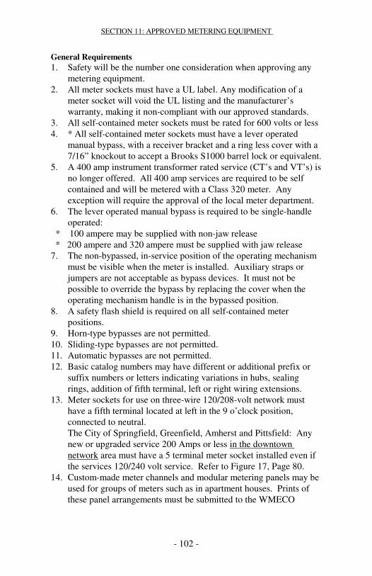
SECTION 11: APPROVED METERING EQUIPMENT
- 102 -
General Requirements 1. Safety will be the number one consideration when approving any
metering equipment. 2. All meter sockets must have a UL label. Any modification of a
meter socket will void the UL listing and the manufacturer’s warranty, making it non-compliant with our approved standards.
3. All self-contained meter sockets must be rated for 600 volts or less 4. * All self-contained meter sockets must have a lever operated
manual bypass, with a receiver bracket and a ring less cover with a 7/16” knockout to accept a Brooks S1000 barrel lock or equivalent.
5. A 400 amp instrument transformer rated service (CT’s and VT’s) is no longer offered. All 400 amp services are required to be self contained and will be metered with a Class 320 meter. Any exception will require the approval of the local meter department.
6. The lever operated manual bypass is required to be single-handle operated:
* 100 ampere may be supplied with non-jaw release * 200 ampere and 320 ampere must be supplied with jaw release 7. The non-bypassed, in-service position of the operating mechanism
must be visible when the meter is installed. Auxiliary straps or jumpers are not acceptable as bypass devices. It must not be possible to override the bypass by replacing the cover when the operating mechanism handle is in the bypassed position.
8. A safety flash shield is required on all self-contained meter positions.
9. Horn-type bypasses are not permitted. 10. Sliding-type bypasses are not permitted. 11. Automatic bypasses are not permitted. 12. Basic catalog numbers may have different or additional prefix or
suffix numbers or letters indicating variations in hubs, sealing rings, addition of fifth terminal, left or right wiring extensions.
13. Meter sockets for use on three-wire 120/208-volt network must have a fifth terminal located at left in the 9 o’clock position, connected to neutral. The City of Springfield, Greenfield, Amherst and Pittsfield: Any new or upgraded service 200 Amps or less in the downtown network area must have a 5 terminal meter socket installed even if the services 120/240 volt service. Refer to Figure 17, Page 80.
14. Custom-made meter channels and modular metering panels may be used for groups of meters such as in apartment houses. Prints of these panel arrangements must be submitted to the WMECO

SECTION 11: APPROVED METERING EQUIPMENT
- 103 -
District Meter Service Supervisor, and the Company’s approval obtained prior to installation. Line side panels must be sealable.
15. All underground residential single position sockets must be a minimum 16”W x 22”H x 5”D, 200 amp, ring less with line side lugs capable of accepting 350 KCMIL conductors with lever operated jaw release bypass. Sockets will also have a minimum 3-inch knockout to accept a 3-inch slip joint. If a service run is greater than 200 feet contact your local WMECO office. The bottom left side knockout is for line conductors only. Line conductors are on the left side so they won’t interfere with the bypass handle.
16. All group metering units must have sealing provisions and meet minimum and maximum height requirements. a. Maximum height (top of meter) is 72 inches. b. Minimum height above floor 24 inches (bottom of meter)
indoor, 24 inches (bottom of meter) from finished grade outdoor.
c. All meter positions must have individual covers, and barriers between each meter position.
d. * All meter positions must have lever operated manual bypass. e. Each meter position must have a receiver bracket and ring less
cover with a 7/16” knockout to accept a Brooks S1000 barrel lock or equivalent.
17. All OH/UG 320-amp meter sockets must have 4-inch knockouts, jaw release lever operated manual bypass, with a receiver bracket and a ring less cover with a 7/16” knockout to accept a Brooks S1000 barrel lock or equivalent.
18. All underground hubs or knockouts must be a minimum of 3 inches diameter.
19. Hot sequence metering (6 socket positions or less) is required for single-phase 120/240-volt service.*
20. New equipment from manufacturers not listed in this book will be considered for approval. Samples must be submitted to the Metering Equipment Approval Committee.
21. All meter sockets and switchgear must be properly identified with approved catalog numbers listed in this book.
* Hot Sequence no main disconnect before meter
SECTION 11: APPROVED METERING EQUIPMENT
- 104 -
Requirements for Commercial Metering
1. Cold sequence metering is required for all self-contained 480 volt services and all three-phase services fed from a WMECO secondary distribution network grid. Line side disconnect must be adjacent to meter socket and accessible to WMECO at all times. See Section 5.B.3 page 27**
2. Custom-built meter centers must have individual utility approval prior to installation.
3. Three-phase four-wire self-contained commercial group metering must have barriers between meter positions.
4. Self contained 480/277 volt group metering must have individual disconnects before each meter position. **
5. A 400 amp instrument transformer rated service (CT’s and VT’s) is no longer offered. All 400 amp services are to be self-contained and will be a metered with a Class 320 meter. Any exception will require the approval of the local meter department.
6. Custom-built switchgear with instrument transformer enclosures must have individual utility approval prior to installation. Check with WMECO for available fault current before ordering equipment. A print of the switchgear must be supplied to the appropriate district meter supervisor.
7. All 480/277 volt switchgear with instrument transformer enclosures must have: • Provisions for mounting current transformers and voltage
transformers in the same compartment with hinged sealable doors.
• 600 amp - 1600 amp Bar Type current transformers • 2000 amp-3000 amp Window Type current transformers.
8. All instrument transformer sealable enclosures for 480/277 volt three-phase four-wire wye services must use 48" W x 48” H x 10”D enclosure***
9. Neutral bus and grounding connections must be available in instrument transformers enclosure.
10. Combination circuit breaker and instrument transformer enclosures must have barrel lock sealing devices for Main Breaker and instrument transformer enclosure.
11. All Main Breakers or Disconnects must have provisions to be locked in the OFF position.
* Hot sequence no main disconnect before meter ** Cold sequence main disconnect required before metering *** All instrument transformers enclosures require hinged doors

SECTION 11: APPROVED METERING EQUIPMENT
- 105 -
SINGLE-PHASE • RESIDENTIAL/COMMERCIAL • OUTDOOR All Installations require a lever-operated bypass with flash shield
Three-Wire 120/240 Volt and Three-Wire 120/208 Volt - 100 Ampere Number of Type of Manufacturer Positions Service Ring less Cooper B-Line 1 OH EL12L41GR1N 2-6 OH/UG HEC10432CGR1N / HEC10436CGR1N (Horz) Cutler Hammer 1 OH UBT-H4203B-CH 1 OH UBT-H4213B-CH 1 OH UTB-C4213B-CH 1 OH UBGT-H4203B-CH (5 Terminal) 1 OH UBGT-H4213B-CH (5 Terminal) Durham 1 OH UBT-H4203B 1 OH UBT-H4213B 1 OH UBT-C4213B 1 OH UBT-H4203B (5 Terminal) 1 OH UBT-H4213B (5 Terminal) L&G/Siemens 1 OH 40605-O1NU Midwest Electric 1 OH UBT-H4203B-MEP 1 OH UBT-H4213B-MEP 1 OH UBGT-H4203B-MEP (5 Terminal) 1 OH UBGT-H4213B-MEP (5 Terminal) Milbank 1 OH U2272-RL-5T9-BL 2-6 OH/UG U2752-X-5T9 / 2-6 OH/UG U2756-X-5T9 (Horz) 2-3 OH U5112-X-BL / U5113-X-BL (Vert)
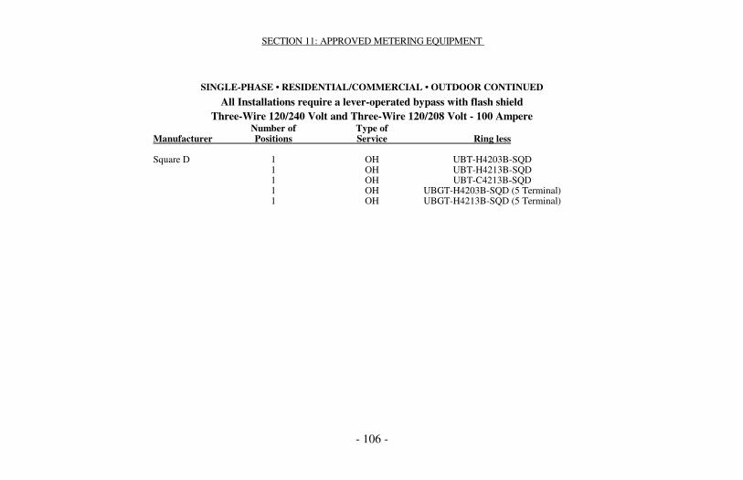
SECTION 11: APPROVED METERING EQUIPMENT
- 106 -
SINGLE-PHASE • RESIDENTIAL/COMMERCIAL • OUTDOOR CONTINUED
All Installations require a lever-operated bypass with flash shield Three-Wire 120/240 Volt and Three-Wire 120/208 Volt - 100 Ampere
Number of Type of Manufacturer Positions Service Ring less Square D 1 OH UBT-H4203B-SQD 1 OH UBT-H4213B-SQD 1 OH UBT-C4213B-SQD 1 OH UBGT-H4203B-SQD (5 Terminal) 1 OH UBGT-H4213B-SQD (5 Terminal)

SECTION 11: APPROVED METERING EQUIPMENT
- 107 -
SINGLE-PHASE • RESIDENTIAL/COMMERCIAL • OUTDOOR
All Installations require a lever-operated bypass with flash shield Three-Wire 120/240 Volt and Three-Wire 120/208 Volt - 200 Ampere
Number of Type of Manufacturer Positions Service Ring less Cooper B-Line 1 OH/UG EL20L45GR1N 1 OH EL20L41GR1N 2-6 OH/UG HEL20432CGR1N / 2-6 OH/UG HEL20436CGR1N (Horz) Cutler Hammer 1 OH UBT-H4203B-CH / 1 OH UBTE4203BCH 1 OH UBGT-H4203B-CH (5 Terminal) 1 OH UBGTE4203BCH (5 Terminal) 1 OH UBGT-H4213B-CH (5 Terminal) 1 OH UBGTE4213BCH (5 Terminal) 1 UG 1007994A-CH / 1 UG 1007994EACH 2-6 OH/UG UBGT-2H42353U / 2-6 OH/UG UBGT-6H42393UU-CH (5 Terminal) 1 UG 1007995A-CH / 1 UG 1007995EACH (5 Terminal) Durham 1 OH UBT-H4203B 1 OH UBT-H4213B 1 OH UBGT-H4203B (5 Terminal) 1 OH UBGT-H4213B (5 Terminal) 1 UG 1007994A 2-6 OH/UG UBGT-2H42353U /
2-6 OH/UG UBGT-6H42393UU (5 Terminal) 1 UG 1007995A (5 Terminal)

SECTION 11: APPROVED METERING EQUIPMENT
- 108 -
SINGLE-PHASE • RESIDENTIAL/COMMERCIAL • OUTDOOR - CONTINUED
All Installations require a lever-operated bypass with flash shield Three-Wire 120/240 Volt and Three-Wire 120/208 Volt - 200 Ampere
Number of Type of Manufacturer Positions Service Ring less L & G/Siemens 1 OH 40005-OBNU / 40005-01NU 1 OH/UG 48805-OBNU 1 OH S/40405-0BNU / S40405-01NU 1 OH 40405-01NU 1 OH/UG 40405X-023NU Midwest Electric 1 OH UBT-H4203B-MEP 1 OH UBT-H4213B-MEP 1 OH UBGT-H4203B-MEP (5 Terminal) 1 OH UBGT-H4213B- MEP (5 Terminal) 1 UG 1007994A-MEP 1 UG 1007995A- MEP (5 Terminal) 2-6 OH/UG UBGT-2H42353U/ 2-6 OH/UG UBGT-6H42393UU-MEP (5 Terminal) Milbank 1 OH U9800-RRL-QG-BL 1 UG U4721-O-BL 2-6 OH/UG U2872-XT-5T9 / U2876-XT-5T9 Murray 1 OH RH173CRJNU 1 OH/UG RH178CRJNU

SECTION 11: APPROVED METERING EQUIPMENT
- 109 -
SINGLE-PHASE • RESIDENTIAL/COMMERCIAL • OUTDOOR • CONTINUED
All Installations require a lever-operated bypass with flash shield Three-Wire 120/240 Volt and Three-Wire 120/208 Volt - 200 Ampere
Number of Type of Manufacturer Positions Service Ring less Square D 1 OH UBT-H4203B-SQD 1 OH UBT-H4213B-SQD 1 OH UBGT-H4203B-SQD (5 Terminal) 1 OH UBGT-H4213B-SQD (5 Terminal) 1 UG 1007994A-SQD 1 UG 1007995A-SQD (5 Terminals) 2-6 OH/UG UBGT-2H42353U 2-6 OH/UG UBGT-6H42393UU-SQD (5 Terminal)

SECTION 11: APPROVED METERING EQUIPMENT
- 110 -
METER PEDESTALS
SINGLE PHASE • RESIDENTIAL / COMMERCIAL • OUTDOOR All Installations Require Lever-Operated Bypass with Flash Shield
Three wire 120/240 volt – three wire 120-208 volt requires a 5th jaw in the nine o’clock position Manufacturer Number of Type of Ring less Positions Service 200 Ampere Milbank 1 UG U4322-0-BL 2 UG U4323-0-BL
SINGLE-PHASE • RESIDENTIAL/COMMERCIAL • OUTDOOR All Installations require a lever-operated bypass with flash shield
Three-Wire 120/240 Volt and three wire 120/208 volt with 5th jaw in nine o’clock position Number of Type of Manufacturer Positions Service Ring less 320 Ampere: Cooper B-Line 1 OH/UG EL32T45GR1N Cutler Hammer 1 OH UBT-H4300T-CH / UBTE4300TCH 1 OH UBT-H4309T-CH / UBTE4309TCH 1 OH/UG 1008068-CH / 1008068ECH 1 OH UBTE4300TCH + MSL5T 1 OH UBTE4309TCH + MSL5T Durham 1 OH UBT-H4300T 1 OH UBT-H4309T 1 OH/UG 1008068 L & G/Siemens 1 OH S9804-9144 1 OH/UG S9804-9146 1 OH/UG 44704-01NU 1 OH 47704-01NU

SECTION 11: APPROVED METERING EQUIPMENT
- 111 -
METER PEDESTALS CONTINUED SINGLE-PHASE • RESIDENTIAL/COMMERCIAL • OUTDOOR
All Installations require a lever-operated bypass with flash shield Three-Wire 120/240 Volt Only
Number of Type of Manufacturer Positions Service Ring less 320 Ampere: Combination Meter Sockets and Disconnect Devices - 120/240 Volt Only Midwest Electric 1 OH UBT-H4300T-MEP 1 OH/UG 1008068-MEP
1 OH UBT-H4309T-MEP Milbank 1 OH/UG U4778-X-BL Murray 1 OH RK173AHJNU 1 OH/UG RK178AHJNU Square D 1 OH UBT-H4300T-SQD 1 OH/UG 1008068-SQD 1 OH UBT-H4309T-SQD
SINGLE-PHASE • RESIDENTIAL/COMMERCIAL • OUTDOOR Combination Meter Sockets and Disconnect Devices
All Installations require a lever-operated bypass with flash shield Three-Wire 120/240 Volt and three wire 120/208 volt with 5th jaw in nine o’clock position
Number of Type of Manufacturer Positions Service Ring less 100 Ampere Cooper B-Line 1 OH ECCB10L24A3GR1N Milbank 1 OH U3741-XL-100

SECTION 11: APPROVED METERING EQUIPMENT
- 112 -
SINGLE-PHASE • RESIDENTIAL/COMMERCIAL • OUTDOOR Combination Meter Sockets and Disconnect Devices
All Installations require a lever-operated bypass with flash shield Three-Wire 120/240 Volt and three wire 120/208 volt with 5th jaw in nine o’clock position
Number of Type of Manufacturer Positions Service Ring less 200 Ampere Cooper B-Line 1 OH/UG ELCB20L24A5GR1N 2-6 OH/UG VELMP20432LGRST5K9 (vertical) 2-6 OH/UG VELMP20436LGRST5K9 (vertical) Cutler Hammer 1 OH CMBXB200BTS 1 OH CMBX1212B200BTS 1 OH CMBX3242B200BTS Milbank 1 OH U3791N-RXL-200-BL 1 OH/UG U5140-200-BL 2-6 OH/UG U4372-XT-5T9 2-6 OH/UG U4376-XT-5T9 Siemens 1 OH/UG MM0202L1200RLC 2-6 OH/UG SP4212RJL 2-6 OH/UG SP6612RJL 320 Ampere Cooper B-Line 1 OH/UG ELCB32C24A5GR1N Milbank 1 OH/UG U4835-X-2\200-BL Siemens 1 OH/UG MC0408B1400RLTM 1 OH/UG MC0816B1400RLTM 1 OH/UG MC0816B1350RLTM 1 OH/UG MM0404L1400RLM 1 OH/UG JA0408B1400RLTM 1 OH/UG JA0816B1400RLTM

SECTION 11: APPROVED METERING EQUIPMENT
- 113 -
THREE-PHASE • COMMERCIAL • OUTDOOR Must Have Jaw Release Lever-Operated Bypass with Flash Shield
208Y/120-480Y/277 WYE 480Y/277 volt and three-phase 208Y/120 volt network services require main disconnect before meter (cold sequence)
Check with WMECO for available fault current before ordering equipment No. of Type of Four-Wire—Three-Phase Manufacturer Positions Service 7 Terminals 200 Ampere: Cooper B-Line 1 OH EL20L71GR1N 1 OH EL20L75GR1N Cutler Hammer 1 OH UBT-H7203B or T-CH 1 OH UBTE7203BCH 1 OH UBT-H7213B or T-CH 1 OH UBTE7203TCH 1 UG 1007996A-CH / 1007996ECH 1 OH UBTE7213BCH / UBTE7213TCH Durham 1 OH UBT-H7203B or T 1 OH UBT-H7213B or T 1 UG 1007996A L & G/Siemens 1 OH 40007-01NU / 40407-01NU 1 OH/UG 48807-02NU 2-6 OH/UG 40407X-023NU Midwest Electric 1 OH UBT-H7203B or T-MEP 1 OH UBT-H7213B or T-MEP 1 UG 1007996A-MEP Milbank 1 OH U9700-RRL-QG-BL 1 UG 4910-0-BL Murray 1 OH RH173GRJNU 1 OH/UG RH178GRJNU

SECTION 11: APPROVED METERING EQUIPMENT
- 114 -
THREE-PHASE • COMMERCIAL • OUTDOOR CON’T. Must Have Jaw Release Lever-Operated Bypass with Flash Shield
208Y/120-480Y/277 WYE 480Y/277 volt and three-phase 208Y/120 volt network services require main disconnect before meter (cold sequence)
Check with WMECO for available fault current before ordering equipment No. of Type of Four-Wire—Three-Phase Manufacturer Positions Service 7 Terminals 200 Ampere: Square D 1 OH UBT-H7203B or T-SQD 1 OH UBT-H7213B or T-SQD 1 UG 1007996A-SQD 320 Ampere: Cooper B-Line 1 OH/UG EL32T75GR1N Cutler Hammer 1 OH UBT-H7300T-CH / UBTE7300TCH 1 OH/UG 1008069-CH / 1008069ECH Durham 1 OH UBT-H7300T 1 OH/UG 1008069 L & G/Siemens 1 OH S/9804-9145 1 OH S/47707-01NU 1 OH/UG S/9804-9147 Midwest Electric 1 OH UBT-H7300T-MEP 1 OH/UG 1008069-MEP 1 OH/UG U4911-X-BL Murray 1 OH RK173GHJNU 1 OH/UG RK178GHJNU Square D 1 OH UBT-H7300T-SQD 1 OH/UG 1008069-SQD
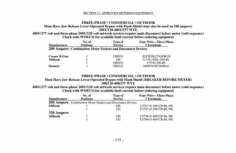
SECTION 11: APPROVED METERING EQUIPMENT
- 115 -
THREE-PHASE • COMMERCIAL • OUTDOOR Must Have Jaw Release Lever-Operated Bypass with Flash Shield (may also be used on 100 ampere)
208Y/120-480Y/277 WYE 480Y/277 volt and three-phase 208Y/120 volt network services require main disconnect before meter (cold sequence)
Check with WMECO for available fault current before ordering equipment No. of Type of Four-Wire—Three-Phase Manufacturer Positions Service 7 Terminals 200 Ampere: Combination Meter Sockets and Disconnect Devices Cooper B-Line 1 OH/UG ELCB20L27A5GR1N Milbank 1 OH U3781-RXL-200-BL 1 OH/UG U5750-200-BL Siemens 1 OH/UG MM0303B3200RLC
THREE-PHASE • COMMERCIAL • OUTDOOR Must Have Jaw Release Lever-Operated Bypass with Flash Shield (BREAKER BEFORE METER)
208/120-480/277 WYE 480Y/277 volt and three-phase 208Y/120 volt network services require main disconnect before meter (cold sequence)
Check with WMECO for available fault current before ordering equipment No. of Type of Four-Wire—Three-Phase Manufacturer Positions Service 7 Terminals 200 Ampere: Combination Meter Sockets and Disconnect Devices Milbank 1 OH U5767-X-200-CB-BL-NE 1 UG U5787-O-200-CB-BL-NE 320 Ampere Milbank 1 OH U5796-X-400-CB-BL-NE 1 UG U5796-O-400-CB-BL-NE

SECTION 11: APPROVED METERING EQUIPMENT
- 116 -
GROUP METERING • SINGLE-PHASE • RESIDENTIAL/COMMERCIAL Three-Wire 120/240 Volt and Three-Wire 120/208 Volt
100-Amp Lever-Operated Bypass—200-Amp Lever-Operated Jaw Release Bypass with Flash Shield Refer to General Requirements for Height Restrictions
For 120/208 Volt – Requires the 5th Terminal in the 9:00 O’clock position
Series or Ampere Rating Manufacturer Number Type 100 200 320 Indoor Outdoor Cutler Hammer 35MM Ring less Yes Yes Yes Yes Yes GE Meter Mod III Ring less Yes Yes Yes Yes Yes Murray DL Ring less Yes Yes Yes Yes Yes Siemens W1MM Ring less Yes Yes Yes Yes Yes W2MM Ring less Yes Yes Yes Yes Yes Square D EZM Ring less Yes Yes Yes Yes Yes MPL Meter PAK Ring less Yes Yes No Yes Yes Refer to General Requirements for Height Restrictions. * Combination meter socket and disconnect device.

SECTION 11: APPROVED METERING EQUIPMENT
- 117 -
GROUP METERING • THREE-PHASE 208Y/120 Volts
208Y/120 Volts, 100-Amp Lever-Operated Bypass—200-Amp Lever-Operated Jaw Release Bypass with Flash Shield Refer to General Requirements for Height Restrictions. Must have Barriers between Meter Positions
Series or Ampere Rating Manufacturer Number Type 100 200 320 Indoor Outdoor Bypass Cooper B-Line HEL20732CGR1N Ring less Yes Yes No Yes Yes Yes HEL20736CGR1N Cutler Hammer 37MM Ring less Yes Yes Yes Yes Yes Yes CCMS Ring less Yes Yes Yes Yes No Yes General Electric Meter Mod III Ring less Yes Yes Yes Yes Yes Yes Milbank U2732-XT Ring less Yes Yes No Yes Yes Yes U2736-XT Ring less Yes Yes No Yes Yes Yes Murray DL Ring less Yes Yes Yes Yes Yes Yes Siemens ITE W3MM Ring less Yes Yes Yes Yes Yes Yes Square D EZM Ring less Yes Yes Yes Yes Yes Yes
GROUP METERING BARRIERS
Manufacturer Catalog Number Cutler Hammer 37MMBK General Electric TMBR3 Siemens Contact your local Siemens Representative Square D MML200BAR

SECTION 11: APPROVED METERING EQUIPMENT
- 118 -
GROUP METERING • THREE-PHASE 480Y/277, 100-Amp Lever-Operated Bypass—200-Amp Lever-Operated Jaw Release Bypass with Flash Shield
Refer to General Requirements for Height Restrictions, Meter Positions Must be Cold Sequence Disconnect Breakers before each Meter Position. Troughs must have barriers between meter positions.
Series or Ampere Rating Manufacturer Number Type 100 200 320 Indoor Outdoor Bypass Cutler Hammer PRL-C/CCMS Ring less Yes Yes Yes Yes Yes* Yes Siemens MMS Ring less Yes Yes Yes Yes No Yes RSE-Sierra CUSTOM Ring less Yes Yes Yes Yes No Yes *Note: NEMA 3R Outdoor Cabinet with Split Door (Top and Bottom Doors) for Meter Access
Prewired Instrument Transformer-Rated Sockets with Plated Test Switch Manufacturer 6 TERMINAL Single Phase Cooper B-Line SW02062S1GR1N Milbank UC7478-0-81-NOE Siemens 9837-0901 Manufacturer 8 TERMINAL 3 Phase 3 Wire Milbank UC7444-O-141-NOE Siemens 9837-0902 Manufacturer 13 TERMINAL 3 Phase 4 Wire Cooper B-Line SW02132S1GR1N Milbank UC7445-O-311-NOE Siemens 9837-0903
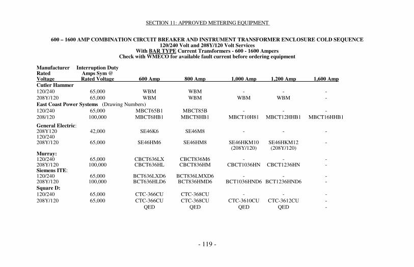
SECTION 11: APPROVED METERING EQUIPMENT
- 119 -
600 – 1600 AMP COMBINATION CIRCUIT BREAKER AND INSTRUMENT TRANSFORMER ENCLOSURE COLD SEQUENCE 120/240 Volt and 208Y/120 Volt Services
With BAR TYPE Current Transformers - 600 - 1600 Ampers Check with WMECO for available fault current before ordering equipment
Manufacturer Interruption Duty Rated Amps Sym @ Voltage Rated Voltage 600 Amp 800 Amp 1,000 Amp 1,200 Amp 1,600 Amp Cutler Hammer 120/240 65,000 WBM WBM - - - 208Y/120 65,000 WBM WBM WBM WBM - East Coast Power Systems (Drawing Numbers) 120/240 65,000 MBCT65B1 MBCT85B - - - 208/120 100,000 MBCT6HB1 MBCT8HB1 MBCT10H81 MBCT12HHB1 MBCT16HHB1
General Electric: 208Y120 42,000 SE46K6 SE46M8 - - - 120/240 208Y/120 65,000 SE46HM6 SE46HM8 SE46HKM10 SE46HKM12 - (208Y/120) (208Y/120) Murray: 120/240 65,000 CBCT636LX CBCT836M6 - - - 208Y/120 100,000 CBCT636HL CBCT836HM CBCT1036HN CBCT1236HN - Siemens ITE: 120/240 65,000 BCT636LXD6 BCT836LMXD6 - - - 208Y/120 100,000 BCT636HLD6 BCT836HMD6 BCT1036HND6 BCT1236HND6 - Square D: 120/240 65,000 CTC-366CU CTC-368CU - - - 208Y/120 65,000 CTC-366CU CTC-368CU CTC-3610CU CTC-3612CU - QED QED QED QED -

SECTION 11: APPROVED METERING EQUIPMENT
- 120 -
600 – 1600 AMP COMBINATION CIRCUIT BREAKER AND INSTRUMENT TRANSFORMER ENCLOSURE
480Y/277 Volt Services, Cold Sequence BAR TYPE Current Transformers and Voltage Transformers must be installed in the same compartment Check with WMECO for available fault current before ordering equipment
Manufactures Interruption Duty Rated Amps Sym @ Voltage Rated Voltage 600 Amp 800 Amp 1,000 Amp 1,200 Amp 1,600 Amp Cutler Hammer 480Y/277 65,000 WBM WBM WBM WBM PRL-C 480Y/277 65,000 PRL-C PRL-C PRL-C PRL-C PRL-C East Coast Power Systems * 480Y/277 35,000 MBCT65B1 - - - - 480Y/277 50,000 MBCT6HB1 MBCT8HB1 MBCT10H81 MBCT1081HB1 MBCT1016HB1 480Y/277 65,000 MBCT6HB1 MBCT8HB1 MBCT10H81 MBCT1081HB1 MBCT1016HB1 General Electric 480Y/277 30,000 SE46K6PT SE46M8PT SE46KM10PT SE46KM12PT - 480Y/277 35,000 SE46HM6PT SE46HM8PT SE46HKM10PT SE46HKM12PT - 480Y/277 As Specified Spectra Series Spectra Series Spectra Series Spectra Series - AV I, II, III & V AV I, II, III & V AV I, II, III & V AV I, II, III & V RSE-Serria 480Y/277 As Specified SB SB SB SB SB 480Y/277 As Specified Custom Custom Custom Custom Custom Square D 480Y/277 65,000 CTC-366CU CTC-368CU CTC-3610CU CTC-3612CU - QED QED QED QED
2000 / 3000 AMPERE COMBINATION CIRCUIT BREAKER AND INSTRUMENT

SECTION 11: APPROVED METERING EQUIPMENT
- 121 -
TRANSFORMER ENCLOSURE 480Y/277 Volt Services, Cold Sequence WINDOW TYPE Current Transformers and Voltage Transformers must be installed in the same
compartment - 2000 - 3000 Amp Switches Check with WMECO for available fault current before ordering equipment
Manufacturer Interruption Duty Rated Amps Sym @ Voltage Rated Voltage 2000/3000 Amp Cutler Hammer 480Y/277 As Specified PRL-C General Electric 480Y/277 As Specified Spectra Series AV I, II, III & V Siemens 480Y/277 As Specified SB Square D: 480Y/277 As Specified QED Series 480 volt services must have integral mounting provisions in the instrument transformer compartment for current transformer and voltage transformers.
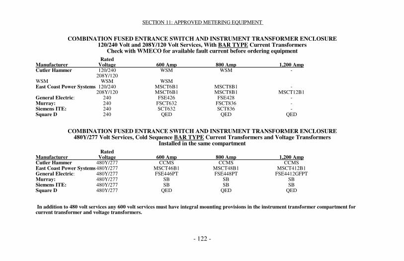
SECTION 11: APPROVED METERING EQUIPMENT
- 122 -
COMBINATION FUSED ENTRANCE SWITCH AND INSTRUMENT TRANSFORMER ENCLOSURE 120/240 Volt and 208Y/120 Volt Services, With BAR TYPE Current Transformers
Check with WMECO for available fault current before ordering equipment Rated Manufacturer Voltage 600 Amp 800 Amp 1,200 Amp Cutler Hammer 120/240 WSM WSM - 208Y/120 WSM WSM WSM East Coast Power Systems 120/240 MSCT6B1 MSCT8B1 - 208Y/120 MSCT6B1 MSCT8B1 MSCT12B1 General Electric: 240 FSE426 FSE428 - Murray: 240 FSCT632 FSCT836 - Siemens ITE: 240 SCT632 SCT836 - Square D 240 QED QED QED
COMBINATION FUSED ENTRANCE SWITCH AND INSTRUMENT TRANSFORMER ENCLOSURE 480Y/277 Volt Services, Cold Sequence BAR TYPE Current Transformers and Voltage Transformers
Installed in the same compartment Rated Manufacturer Voltage 600 Amp 800 Amp 1,200 Amp Cutler Hammer 480Y/277 CCMS CCMS CCMS East Coast Power Systems 480Y/277 MSCT46B1 MSCT48B1 MSCT412B1 General Electric: 480Y/277 FSE446PT FSE448PT FSE4412GFPT Murray: 480Y/277 SB SB SB Siemens ITE: 480Y/277 SB SB SB Square D 480Y/277 QED QED QED In addition to 480 volt services any 600 volt services must have integral mounting provisions in the instrument transformer compartment for current transformer and voltage transformers.

SECTION 11: APPROVED METERING EQUIPMENT
- 123 -
INSTRUMENT TRANSFORMER MOUNTING EQUIPMENT IN SEALABLE ENCLOSURE
WITH HINGED DOORS For use when Parallel Phase conductors are used or when Phase Conductors are larger than 500 KC MIL
Bar Type Current Transformers Only Cabinets for use on 480Y/277 volt services must have provisions for mounting CT’s and VT’s
Manufacturer Rated Voltage Series or Number Dimensions Service Size Cooper B-Line 208Y/120 363612DDHRTCT1N 36”Wx36”Hx12”D 400 & 800 Amps 208Y/120- 484814DDHRTCT1N 48”Wx48”Hx14”D 800 Amp 480Y/277 East Coast Power 280Y/120 CTN800 36”W x 36”H x 12”D 400 & 800 Amps Systems 280Y/120- CTN1200 48”W x 48”H x 10”D 800 & 1200 Amp 480Y/277 Milbank 280Y/120 S1855-O 36”W x 36”H x 12”D 400 & 800 Amps 280Y/120- S1856-O 48”W x 48”H x 12”D 800 & 1200 Amp 480Y/277 Hoffman 280Y/120 A800NECT 36”W x 36”H x 12”D 400 & 800 Amps 280Y/120- A1200NECT 48”W x 48”H x 12”D 800 & 1200 Amp 480Y/277

SECTION 11: APPROVED METERING EQUIPMENT
- 124 -

- 125 -
SECTION 12: INDEX Page
A
Access ..................................................................................................12 AMR (Definitions) .................................................................................4 Antennas.................................................................................................9 Approvals .............................................................................................10
B
Banners...................................................................................................9
C
Campgrounds ......................................................................................23 Checklist
New Services....................................................................................15 Clearance..............................................................................................16 Clearing Desk (Definition) .....................................................................4 Codes (Definition)..................................................................................4 Conduit System (Definition) ..................................................................4 Connections (Meter Socket) .................................................................45 Connections (to our facilities) ..............................................................25 Cost of Service Facilities......................................................................25 Cover Plates .........................................................................................41 Current Transformers ...........................................................................45 Cut and Reconnect ...............................................................................10
D
Damage to Meters ................................................................................42 Definitions..............................................................................................4 Demolition............................................................................................26 Digging...................................................................................................8 Disconnecting.......................................................................................26 Disconnecting Service..........................................................................26 Duct Box ..............................................................................................20 Duct Box Sizes.....................................................................................20
E
Emergency Generation .........................................................................56 Employee's Identification .....................................................................14 Extended Metering Options..................................................................48

- 126 -
F
Frequency See Hertz.............................................................................23
G
Grounding ............................................................................................40 Grouped Metering ................................................................................43
H
Hertz.....................................................................................................23
I
Identification Contractor Electrician ......................................................................28 Employee..........................................................................................14
Inspections............................................................................................14 Instrument Transformers ......................................................................45
L
Lateral (Definition) ................................................................................5 Limiter..................................................................................................27 Load Pulse Outputs ..............................................................................49 Location
Service..............................................................................................25 Weatherhead.....................................................................................17
M
Marinas.................................................................................................44 Meter(s)
Grouped............................................................................................43 Installations ......................................................................................37 Locations ..........................................................................................37 Panels ...............................................................................................40 Sequence ..........................................................................................42 Sequence (Definition).........................................................................4
Metering Transformers See Instrument Transformers ..........................45 Mobile Homes......................................................................................44 Motors ..................................................................................................53
N
Number of Services ..............................................................................25

- 127 -
O
Office Locations.....................................................................................1 Our (Definition)......................................................................................6 Our Service Facilities ...........................................................................25 Overhead Service from Overhead System............................................16
P
Parallel Generation...............................................................................56 Phone Automatic Meter Reading Metering..........................................48 Pole Mounted Service Equipment and Metering..................................28 Power Factor ........................................................................................55 Primary Service ....................................................................................16 Private Property....................................................................................12
R
Recording Meter...................................................................................50 Removal of Service at Your Request ...................................................26 Request for Electric Service ...................................................................9 Residential Cut and Reconnect Policy..................................................10
S
Safety - The First Priority.......................................................................8 Self-Contained Single-Phase Meter Installations .................................41 Self-Contained Three-Phase Meter Installations ..................................44 Sequence of Meter and Service Equipment
Single-Phase .....................................................................................42 Three-Phase......................................................................................42
Service (Definition) Network..............................................................................................5 Primary...............................................................................................5 Secondary...........................................................................................5
Service Changes ...................................................................................14 Service Drop (Definition).......................................................................5 Service Equipment ...............................................................................27 Service Facilities (Ours).......................................................................25 Service Facilities (Yours).....................................................................27 Service Lateral (Definition)....................................................................5 Service Location...................................................................................25 Service Location (Definition).................................................................5 Slip Meter Riser (Definition) .................................................................6 Special Request Metering.....................................................................49 Suitable Backfill (Definition) .................................................................6
- 128 -
Supply Characteristics..........................................................................23 Swimming Pools.....................................................................................9
T
Temporary Service ...............................................................................10 Theft of Electric Service ......................................................................14 Third Party Communication Companies' Attachments to WMECO
Distribution Facilities .......................................................................29 Tree Trimming .....................................................................................17 Two-Phase Supply................................................................................24 Types of Secondary Service .................................................................16
U
Underground Manhole System (Definition) ...........................................6 Uninterruptible Power Supply..............................................................58 Unusual Conditions ..............................................................................24
V
Voltage, Nominal .................................................................................23
W
We (Definition) ......................................................................................6 Wiring Trough......................................................................................43
X
X-Ray Equipment.................................................................................53
Y
You (Definition).....................................................................................6 Your (Definition)....................................................................................6

- 129 -
NOTES:

- 130 -
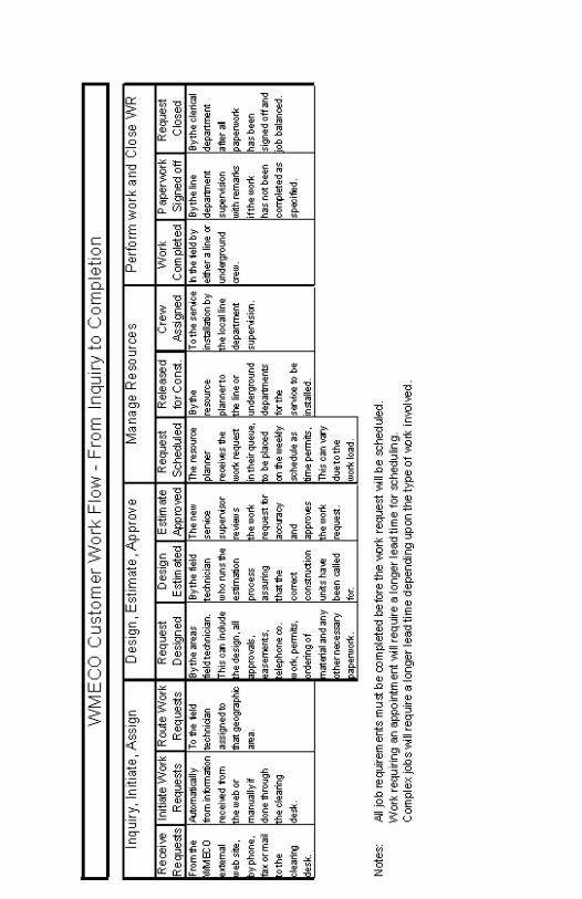
- 131 -

- 132 -
��������������������������������������������
������������� ��� ��� ��� �� �������� �������� �������� �������������������������������� ������� ������ ���� ��������������� � ������� ������ ���� ��������������� � ������� ������ ���� ��������������� � ������� ������ ���� ��������������� � �����! "�#���# ������ �$��! "�#���# ������ �$��! "�#���# ������ �$��! "�#���# ������ �$���%%�%%�%%�%%��%��%��%��%���������������� ����&�'�(��������� �$�&�'�(��������� �$�&�'�(��������� �$�&�'�(��������� �$��%%�%%�%%�%%�������������)�)�)�)����*#���#��$�+ + + ,+ � ���,���*#���#��$�+ + + ,+ � ���,���*#���#��$�+ + + ,+ � ���,���*#���#��$�+ + + ,+ � ���,��� ����


![(UNTITLED) []...Title (UNTITLED) Subject (UNTITLED)](https://static.fdocuments.us/doc/165x107/5e75d9c1b01cbe739756294f/-untitled-title-untitled-subject-untitled.jpg)


![Untitled-1 [vpspaces.com]vpspaces.com/wp-content/uploads/2014/09/grandeur-brochure.pdf · HALDIRAM'S OMAXE CITY HONDA PLANT movie theatres and other utilities. Utilities IGI Airport](https://static.fdocuments.us/doc/165x107/5b1b08d27f8b9a32258e251a/untitled-1-haldirams-omaxe-city-honda-plant-movie-theatres-and-other-utilities.jpg)