Unlock Ironcadgsg
368
Getting Started Guide
Transcript of Unlock Ironcadgsg

7/30/2019 Unlock Ironcadgsg
http://slidepdf.com/reader/full/unlock-ironcadgsg 1/367
Getting Started Guide

7/30/2019 Unlock Ironcadgsg
http://slidepdf.com/reader/full/unlock-ironcadgsg 2/367
Copyright © 1995 - 2011 IronCAD
Copyright © 1995 ‐ 2011 IronCAD, LLC All rights reserved.
Partial Copyright © 2011 CAXA Technology, Co., Ltd.
IRONCAD, INOVATE, IRONCAD DRAFT, TeamVault, InnovationSuite, SmartSnap, SmartRender,
SmartDimension, IntelliShape,
TriBall,
SmartMotion,
IronTool,
Design
Flow,
Direct
Face
Modeling,
Hyper
‐
operability, SmartPaint, SmartUpdate, SmartBehavior, IntelliFace, IntelliSurface, e‐Engineering, and
IronCAD the Next Industrial Revolution, are registered trademarks of IronCAD or its Licensor.
CAXA DRAFT is copyrighted by CAXA Technology Co., LTD
CAXA, CAXA DRAFT, and CAXA DRAFT MECHANICAL are registered trademarks of CAXA Technology Co.,
LTD or its Licensor.
ACIS, SAT, and InterOp are registered trademarks of Spatial Technology, Inc.
Parasolid © 2011 Siemens Industry Software Limited. All Rights Reserved.
D‐CubedTM 2D DCM, 3D DCM, CDM © 2011 Siemens Industry Software Limited. All Rights Reserved.
Granite is a registered trademark of PTC, Inc.
OpenHSF and HOOPS are trademarks of Tech Soft 3D.
SentinelLM is a trademark of SafeNet Inc.
Adobe Illustrator,
Adobe
Acrobat,
Adobe
3D
PDF,
Adobe
2D
PDF,
and
Postscript
are
trademarks
of
Adobe
Systems Inc.
Microsoft®, MS‐DOS, Windows, Windows NT, Visual Basic®, Windows 2000, Windows XP, Windows 98,
Vista, Window 7, Visual Basic for Applications and Excel are registered trademarks or trademarks of
Microsoft Corporation in the United States and/or other countries.
TIFF is a trademark of Aldus Corporation, an Adobe Company.
AutoCAD, DXF, DWG, and 3D Studio are registered trademarks of Autodesk, Inc.
"TEIGHA", the TEIGHA logo, "Open Design Alliance", and the Open Design Alliance logo are trademarks of
the Open Design Alliance in the United States and/or other countries. DWG is the native and proprietary
file format for AutoCAD® and a trademark of Autodesk, Inc. The Open Design Alliance is not associated
with Autodesk.
TARGA is a registered trademark of Truevision, Inc.

7/30/2019 Unlock Ironcadgsg
http://slidepdf.com/reader/full/unlock-ironcadgsg 3/367
Copyright © 1995 - 2011 IronCAD
Apple and Macintosh are registered trademarks of Apple Computer Corporation.
The Graphic Interchange Format is the copyrighted property of CompuServe Incorporated. GIF is a service
mark of CompuServe Incorporated.
The Kodak Photo Access CD is the copyrighted property of, and Kodak is a registered trademark of Eastman
Kodak Company.
Libtiff is the copyrighted property of Sam Leffler and SGI: ©1988‐1995 Sam Leffler; ©1991‐1995 SGI.
Netpbm is the copyrighted property of its individual authors.
This software is based, in part, on the work of the Independent JPEG Group.
IronCAD acknowledges the School of Architecture Property and Planning, University of Auckland, as the
source of many of the image scans contained in the IRONCAD™ image library. IronCAD also acknowledges
the following
sources
for
software
included
with
IRONCAD:
qvlib VRML reader ‐ SGI.
NETPBM Library ‐ Jef Poskanzer, et al.
Zlib ‐ the general purpose compression library is courtesy of Jean‐loup Gailly and Mark Adler.
libpng ‐ the PNG image file format library is courtesy of its contributing authors and Group 42, Inc.
Yafray is copyrighted ©2001 by Alejandro Conty Estévez and Alfredo de Greef and is licensed under the
LGPL license.
IRONCAD Advanced Rendering Add‐in is free software: you can redistribute it and/or modify it under
the terms of the GNU General Public License as published by the Free Software Foundation, either version 3 of the License, or (at your option) any later version.
This Add‐in is distributed in the hope that it will be useful, but WITHOUT ANY WARRANTY; without
even the implied warranty of MERCHANTABILITY or FITNESS FOR A PARTICULAR PURPOSE. See the
GNU General Public License for more details.
A copy of the GNU General Public License and the Lesser GPL can be found in the ReadMe Folder. If
not, see <http://www.gnu.org/licenses/>.
To obtain the source code for the Advanced Rendering Add-in which is a derivativework of Yafray, please
contact IronCAD support for details.
A portion
of
IRONCAD
uses
OpenEXR
which
is
Copyrighted
(c)
2002
by
Industrial
Light
&
Magic,
a division
of Lucas Digital Ltd. LLC All rights reserved. Additional license information can be found in the ReadMe
folder under OpenEXRLicense.txt
A portion of IRONCAD use Radiance software (http://radsite.lbl.gov/) developed by the Lawrence Berkeley
National Laboratory (http://www.lbl.gov/)." Additional license information can be found in the ReadMe
folder under RadianceLicense.txt.

7/30/2019 Unlock Ironcadgsg
http://slidepdf.com/reader/full/unlock-ironcadgsg 4/367
Copyright © 1995 - 2011 IronCAD
Additional designations used by manufacturers and sellers to distinguish their products and all other
products or name brands are registered trademarks or trademarks of their respective holders.
Use, duplication or disclosure by the U.S. Government Departments and Agencies are as set forth in
DFARS252.227‐7013.

7/30/2019 Unlock Ironcadgsg
http://slidepdf.com/reader/full/unlock-ironcadgsg 5/367
IRONCAD | Design Project Phases 1
The IRONCAD Getting Started Guide
IRONCAD is a computer aided design (CAD) system using 3D solid modeling techniques to build
a representation of an object, a design, a building or whatever you can conceive. This model
can be as crude or as precise as you need. IRONCAD can be used as a very quick conceptualmodeler to establish the early impact of a design or as a precise detail modeling system.
Traditional 2D drawings are created by taking snapshots of the 3D models, in this way IRONCAD
keeps both model and drawing in step.
IRONCAD was the one of the first systems to bring full 3D design visualization, drawing creation
and animation into the mainstream of desktop computing. IRONCAD uses drag-and-drop solid
modeling to provide the easiest part design/drawing environment available, whilst offering the
same level of performance and compatibility found in higher-cost 3D applications.

7/30/2019 Unlock Ironcadgsg
http://slidepdf.com/reader/full/unlock-ironcadgsg 6/367
IRONCAD | Design Project Phases 2
TABLE OF CONTENTS
1. Design Project Phases _______________________________________________________ 8
1.1. Building the part _____________________________________________________________ 8
1.2. Assembling multiple parts _____________________________________________________ 8
1.3. Creating a 2D drawing of the part _______________________________________________ 8
1.4. Rendering the part ___________________________________________________________ 8
1.5. Communicating the part _______________________________________________________ 8
2. Distinct Environments _______________________________________________________ 9
2.1. 3D Scenes __________________________________________________________________ 9
2.2. 2D Drawings ________________________________________________________________ 9
2.3. History Based not History Bound ________________________________________________ 9
3. IRONCAD – Quick Start Guide ________________________________________________ 10
3.1. Starting IRONCAD ___________________________________________________________ 10
3.2. Creating Your First 3D Model in IRONCAD ________________________________________ 11
3.2.1. Creating a 3D Scene Document ____________________________________________________ 11
3.2.2. Using Drag & Drop in the Scene ___________________________________________________ 14
3.2.3. Resize Using Precise Values _______________________________________________________ 17
3.2.4. SmartSnap ____________________________________________________________________ 23
3.2.5. Using the TriBall ________________________________________________________________ 29
3.3. Communicating the Part ______________________________________________________ 32
3.3.1. Creating a 2D drawing ___________________________________________________________ 33
3.3.2. Creating a Photo-Realistic Rendering _______________________________________________ 45
3.3.3. Exporting the 3D model __________________________________________________________ 54
3.4. Working with Assemblies to Complete the Design _________________________________ 56
3.4.1. Designing an Assembly __________________________________________________________ 57
3.4.2. Working with Boolean Operations _________________________________________________ 69
3.4.3. Using Intelligent Features ________________________________________________________ 72
3.4.4. Using an Existing Intelligent Hole for the Basis of a New Hole ___________________________ 73
3.4.5. Creating Sketch Based Features ___________________________________________________ 79
3.4.6. Working with Blends/Chamfers ___________________________________________________ 85 3.4.7. Positioning with Constraints ______________________________________________________ 88
3.4.8. Adding Draft ___________________________________________________________________ 95
3.4.9. Handling Errors in Feature Creation ________________________________________________ 98
3.4.10. Creating Configurations of Different States __________________________________________ 99
3.4.11. Creating Exploded Assembly Drawings _____________________________________________ 103
4. Using 2D Sketches in Part Design ____________________________________________ 112

7/30/2019 Unlock Ironcadgsg
http://slidepdf.com/reader/full/unlock-ironcadgsg 7/367
IRONCAD | Design Project Phases 3
4.1. Shape Handles vs. Sizebox Handles ____________________________________________ 113
4.1.1. Positioning of Features and Faces using Shape Handles _______________________________ 113
4.2. Using the Basic 2D Editing tools _______________________________________________ 117
4.2.1. Creating the Flywheel using a Spin IntelliShape ______________________________________ 118
4.3. Creating Precise Sketches ____________________________________________________ 127 4.3.1. Positioning Lines Using Endpoint Position Dimensions ________________________________ 127
4.3.2. Accurately Positioning Lines Using Curve Dimensions _________________________________ 129
4.3.3. Curve Handles ________________________________________________________________ 130
4.3.4. Changing the Orientation of Endpoint Dimensions ___________________________________ 133
4.3.5. Positioning Multiple Lines Simultaneously __________________________________________ 134
4.3.6. Finishing the Spin IntelliShape ____________________________________________________ 136
4.4. Editing the Cross-section of an Existing IntelliShape _______________________________ 139
4.4.1. Setup the Part for Editing the Sketch: ______________________________________________ 139
4.4.2. Using the Offset Command ______________________________________________________ 141
4.5. Using 2D Constraints ________________________________________________________ 146 4.5.1. Adding Dimensional constraints __________________________________________________ 146
4.5.2. Adding Geometry Constraints ____________________________________________________ 150
4.5.3. Making changes predictable _____________________________________________________ 152
4.5.4. How Constraints Affect the Behavior of Shape Handles _______________________________ 157
4.5.5. Precise Model Changes Using Shape Handles _______________________________________ 157
4.5.6. Overlapping Geometry Errors ____________________________________________________ 158
4.5.7. Adding Full Design Intent to the Flywheel __________________________________________ 159
4.6. Drag-and-Drop IntelliShape Modeling vs. 2D Cross-section Modeling _________________ 165
4.6.1. Remove of the Sketch Center Bore ________________________________________________ 165
4.7. Setting Part and IntelliShape Names and Color ___________________________________ 168 4.7.1. Changing the color of the part ___________________________________________________ 170
4.8. Using the Advance Shapes Catalog ____________________________________________ 172
4.9. Saving the part ____________________________________________________________ 174
4.10. Working with Multiple Parts in a Single File ____________________________________ 175
4.10.1. Creating the Crankshaft _________________________________________________________ 175
4.10.2. Adding the Shaft ______________________________________________________________ 179
4.10.3. Creating the Crank Arm _________________________________________________________ 185
4.10.4. Creating Tangent Lines _________________________________________________________ 191
4.10.5. Creating Tangency and Concentric Constraints ______________________________________ 192
4.11. Parametric Constraints with Expressions _______________________________________ 197
4.11.1. Parametrically Control the Crank Arm _____________________________________________ 197
4.12. Creating an Assembly ______________________________________________________ 202
4.12.1. Making an Assembly from Existing Components _____________________________________ 202
4.13. TriBall and Linked Components ______________________________________________ 204

7/30/2019 Unlock Ironcadgsg
http://slidepdf.com/reader/full/unlock-ironcadgsg 8/367
IRONCAD | Design Project Phases 4
4.13.1. Using the TriBall to Create Linked Shapes __________________________________________ 204
4.14. Adding Intelligence Using Parameters _________________________________________ 209
4.14.1. Parameter Table Format ________________________________________________________ 210
4.14.2. Adding Control to the Tooth Form ________________________________________________ 211
4.14.3. Adding User Defined Parameters _________________________________________________ 213
4.14.4. Establishing the Angle between the Teeth __________________________________________ 215
4.14.5. Relating the Diameter to the Number of Teeth ______________________________________ 216
4.15. Design Variations _________________________________________________________ 218
4.15.1. Adding Top Level Parameters ____________________________________________________ 219
4.15.2. Applying Design Variations Intelligence ____________________________________________ 221
4.15.3. Testing the Design Variations ____________________________________________________ 223
5. The IRONCAD TriBall ______________________________________________________ 229
5.1. Anatomy of the TriBall ______________________________________________________ 229
5.1.1. TriBall Zone 1 _________________________________________________________________ 231
5.1.2. TriBall Zone 2 _________________________________________________________________ 231 5.1.3. TriBall Zone 3 _________________________________________________________________ 233
5.1.4. Repositioning the TriBall ________________________________________________________ 234
5.2. Practical Examples using the TriBall ____________________________________________ 235
5.3. Using the TriBall’s Orientation Handles to position parts ___________________________ 236
5.4. Using the TriBall’s center point to position parts _________________________________ 236
5.5. Temporarily constraining (declaring) an axis of the TriBall __________________________ 237
5.6. Parallel to Edge command ___________________________________________________ 238
5.7. Perpendicular to Face command ______________________________________________ 238
5.8. Drag-and-Drop method of repositioning the TriBall _______________________________ 239
5.9. To Point command _________________________________________________________ 239
5.10. Aligning the Dovetail component _____________________________________________ 240
5.11. The TriBall Reverse command _______________________________________________ 242
5.12. Point to Point command ____________________________________________________ 242
5.13. To Center Point command __________________________________________________ 245
5.14. Using the TriBall’s ‘Copy in Plane’ option ______________________________________ 246
5.15. Using the TriBall to create linked copies _______________________________________ 249
5.16. Orientating using existing faces to ‘snap to’ ____________________________________ 251
5.17. Using increment snapping with the TriBall _____________________________________ 252
5.18. Creating a Radial Array Pattern with the TriBall _________________________________ 253

7/30/2019 Unlock Ironcadgsg
http://slidepdf.com/reader/full/unlock-ironcadgsg 9/367
IRONCAD | Design Project Phases 5
6. IRONCAD Drawing Creation ________________________________________________ 256
6.1. Basic Drawing Creation ______________________________________________________ 258
6.1.1. Creating the Standard Views _____________________________________________________ 258
6.1.2. Changing the View Scale and Rendering options _____________________________________ 260
6.1.3. Moving Views _________________________________________________________________ 262
6.1.4. Creating a Datum Reference Frame _______________________________________________ 262
6.1.5. Adding SmartDimension’s _______________________________________________________ 264
6.1.6. Modifying Individual Dimensions _________________________________________________ 270
6.1.7. Adding a Feature Control Frame (Geometric Tolerance) _______________________________ 272
6.1.8. Creating center lines ___________________________________________________________ 274
6.1.9. Creating Reference Curves ______________________________________________________ 275
6.1.10. Multi-Sheet Drawings and Supplementary Views ____________________________________ 278
6.1.11. Adding a Detail View ___________________________________________________________ 282
6.1.12. Creating an Auxiliary View _______________________________________________________ 283
6.1.13. Orientating center marks ________________________________________________________ 285
6.1.14. Creating a Hole Table ___________________________________________________________ 286
6.1.15. Using the Sheet Drawing tools ___________________________________________________ 288
6.1.16. Styles and Layers ______________________________________________________________ 290
6.1.17. Adding a Layer ________________________________________________________________ 291
6.2. Part/Drawing associativity ___________________________________________________ 293
6.3. Exporting the Drawing ______________________________________________________ 294
7. IRONCAD sheet metal application ___________________________________________ 297
7.1. Sheet metal stock __________________________________________________________ 298
7.2. Adding a bend with stock ____________________________________________________ 299
7.2.1. Changing a bends angle _________________________________________________________ 300
7.2.2. Re-orientating length handles ____________________________________________________ 302
7.3. Adding bends with combined stock ____________________________________________ 304
7.3.1. Bend ________________________________________________________________________ 304
7.3.2. Out Bend ____________________________________________________________________ 304
7.3.3. In Bend ______________________________________________________________________ 304
7.4. Adding a Bend Relief ________________________________________________________ 306
7.5. Adding standard punch features ______________________________________________ 310
7.6. Adding round corners – Vertex Fillets __________________________________________ 313
7.7. Re-using existing features via the catalog _______________________________________ 313
7.8. Adding a cluster of holes ____________________________________________________ 314
7.9. Manipulating features with the TriBall _________________________________________ 314
7.10. Using the Miter tool _______________________________________________________ 315
7.11. Using standard catalog items in the sheet metal design process ____________________ 316

7/30/2019 Unlock Ironcadgsg
http://slidepdf.com/reader/full/unlock-ironcadgsg 10/367
IRONCAD | Design Project Phases 6
7.12. Unfolding the part _________________________________________________________ 318
7.13. Creating a 2D drawing of the sheet metal part __________________________________ 319
7.14. Defining custom punch shapes _______________________________________________ 321
8. IRONCAD Surface Modeling ________________________________________________ 325
8.1. Creating 3D Curves _________________________________________________________ 325
8.2. Create Surfaces from Solids __________________________________________________ 332
8.3. Creating Surfaces __________________________________________________________ 332
8.3.1. The Sweep Surface _____________________________________________________________ 332
8.3.2. Mesh Surface _________________________________________________________________ 334
8.3.3. Patch Surface _________________________________________________________________ 334
8.3.4. Ruled Surface _________________________________________________________________ 335
9. Photorealistic Rendering ___________________________________________________ 338
9.1. Adding realism to the screen display ___________________________________________ 338
9.1.1. The Scene Background __________________________________________________________ 338
9.2. Basic Rendering ____________________________________________________________ 341
9.2.1. Scene Exposure _______________________________________________________________ 341
9.3. Applying a Surface from a catalog _____________________________________________ 342
9.4. Modifying a surface texture __________________________________________________ 342
9.5. Saving a Surface Texture to a catalog __________________________________________ 343
9.6. Setting a material property with a surface texture ________________________________ 343
9.7. Changing the finish of individual surfaces _______________________________________ 344
9.8. Adding more realism with HDRI background lighting ______________________________ 345
9.9. Adding discrete lights _______________________________________________________ 345
9.10. Finishing the scene ________________________________________________________ 346
9.11. Adding a decal ____________________________________________________________ 347
9.12. Completing the rendering ___________________________________________________ 348
9.13. Poster sized images ________________________________________________________ 349
9.13.1. Ensure what you see is what you get ______________________________________________ 349
10. Animating with IRONCAD ______________________________________________ 352
10.1. Fundamental control of animation segments ___________________________________ 352
10.1.1. Length, Height and Width _______________________________________________________ 352
10.1.2. Key _________________________________________________________________________ 352
10.1.3. TriBall _______________________________________________________________________ 352

7/30/2019 Unlock Ironcadgsg
http://slidepdf.com/reader/full/unlock-ironcadgsg 11/367
IRONCAD | Design Project Phases 7
10.2. Animating the I-beam tool arrangement _______________________________________ 353
10.2.1. Opening the Top Plate __________________________________________________________ 353
10.2.2. Opening the Bottom Plate _______________________________________________________ 355
10.2.3. Animating the Guide Pins _______________________________________________________ 356
10.2.4. Adding a new animation segment to an existing animation path ________________________ 357
10.3. The SmartMotion Editor ____________________________________________________ 359
10.4. Changing the start point of an animation segment _______________________________ 359
10.5. Creating a dynamic cut-away section. _________________________________________ 360
10.6. Exporting the animation ____________________________________________________ 362
7/30/2019 Unlock Ironcadgsg
http://slidepdf.com/reader/full/unlock-ironcadgsg 12/367
IRONCAD | Design Project Phases 8
1. DESIGN PROJECT PHASES
Within IRONCAD, there are five potential phases to any design project that you may
encounter:
1.1. Building the part
First, create the part from IntelliShapes (IRONCAD’s term for Features with
Intelligence). Choose from appropriate shapes in the catalogs or create 2D profiles to
be extended into custom 3D shapes.
1.2. Assembling multiple parts
To reflect the product structure or when it is desirable to manipulate multiple parts as
one, join them as an assembly. While this option facilitates manipulating several
objects simultaneously, each component of the assembly retains its individuality. In
addition, Assembly Features which are cut operations that affect parts within assembly
can be applied.
1.3. Creating a 2D drawing of the part
To communicate the design to many different departments of the company, it is
essential to be able to create a 2D drawing of the 3D part/assembly. Simply choose
the appropriate drawing size and drop the required views of the 3D model onto it.
Alternative views, dimensions, annotation as well as other 2D drawing elements can
then associate to the 3D model so that any changes to the model will be automatically
reflected in the 2D drawing.
1.4. Rendering the part
As an additional communication tool, add colors and textures, lighting effects, bumps,
reflections, and transparency to provide photo-realistic part renderings for inclusion in
brochures, web sites, or simply to help communicate the idea graphically to other
people.
1.5. Communicating the part
Finally, the part can be communicated to other companies with ease. IRONCAD
provides extensive translation features for exporting your part to other software
packages as well as providing many communication tools such as views and viewable
packages that can be sent to the design chain for feedback.

7/30/2019 Unlock Ironcadgsg
http://slidepdf.com/reader/full/unlock-ironcadgsg 13/367
IRONCAD | Distinct Environments 9
Of course, not all projects will require all six of the above phases. Your job may be complete
after the building and rendering phases for example.
2. DISTINCT ENVIRONMENTS
IRONCAD provides similar, but functionally different, user interfaces for completing a design
project: the 3D scene and the 2D drawing. In addition, IRONCAD offers unique modeling
environments to fit the design task at hand.
2.1. 3D Scenes
3D part design takes place in a scene. Scenes are composed of single or multiple
parts/assemblies, created using the ACIS or Parasolid modeling kernel (and even a
mixture that we can discuss in an advance lesson). They are saved as documents with
an ‘.ics’ extension.
2.2. 2D Drawings
Creation of 2D drawing views of 3D parts/assemblies takes place in the drawing
environment. Drawings contain associative views of existing 3D parts/assemblies, and
any additional annotations required to fully describe them. They are saved as
documents with an .icd or .exb extension (depending on the drawing environment
used).
2.3. History Based not History Bound
In addition to the two environments, IRONCAD uses a technique known as history
based modeling in the 3D Scene. Each shape (or feature) of the design is recorded as
an individual item and can be modified at will. However, unlike the vast majority of 3D
design packages, IRONCAD does not suffer from limitations imposed by the order in
which these features are created - in other words IRONCAD is not 'history bound'.
For example, you might want to stretch a feature created at the early stages of the
design to match the size of a feature added towards the end of the design – this is a
very simple operation in IRONCAD, however in most other systems a feature can only
'see' features presented before it in the history tree. This rigid structure can also
provide a unique design process and is also offer as an optional design model in
IRONCAD called Structured Parts. Simply toggle the design type to create parts in
either design mode that fits your specific design task at hand.

7/30/2019 Unlock Ironcadgsg
http://slidepdf.com/reader/full/unlock-ironcadgsg 14/367
IRONCAD | IRONCAD – Quick Start Guide 10
3. IRONCAD – Q UICK START GUIDE
The concepts of IRONCAD are very quickly adopted. This section will introduce the basic
functions of IRONCAD so that you can be productive in a matter of a few hours. The topics
covered will be:• Creating a concept 3D model
• Re-sizing the features to reflect desired dimensions
• Adding a few detail features
• Creating a photorealistic rendering
• Adding chamfers and blends
• Creating a detail drawing
• Building an assembly and detailing it.
This quick start guide will introduce the concepts of IRONCAD’s unique drag and dropmodeling. After the initial part has been modeled and a range of communication tools
explored, it will be used to design a tooling assembly creating a range of parts through to a
fully exploded and detailed assembly.
3.1. Starting IRONCAD
From the Windows Program group, navigate to the IRONCAD group and start
IRONCAD.
If you have installed the system as part of a trial, IRONCAD will present a splash screen
telling you how many days you have left of your trial and will open a web page to point
you to a number of resources available from the IRONCAD web site. You will also see a
check box that hides the trial license splash screen until the end of the trial. Clicking
this will speed up the starting procedure, however it will also hide the number of days
left of the trial (which can be seen in the Application Title bar for future reference).
After starting IRONCAD, the opening screen of IRONCAD displays four options:
• Create a new Scene Document
A Scene Document is the IRONCAD 3D design environment. This is where
designs from a nut to a complete battleship are produced.
• Create a new Drawing Document

7/30/2019 Unlock Ironcadgsg
http://slidepdf.com/reader/full/unlock-ironcadgsg 15/367
IRONCAD | IRONCAD – Quick Start Guide 11
Communicating designs by 2D drawings will remain a requirement for a while
to come. In IRONCAD, 2D drawings are created either by creating a 'free' 2D
geometry or by taking snapshots of an existing 3D model. In the latter case,
IRONCAD maintains the links between the model and the drawing ensuring that
the drawing and the 3D model keep in step with one another.
• Create a new CAXA Draft Document
For those who are familiar with AutoCAD, drawings can be produced in a
familiar environment. As with the standard IRONCAD drafting tool, views are
created from the 3D model and links are maintained so that the drawing always
remains in step with the 3D design.
• Open an Existing Document
A bit self explanatory really!
As with all sections of the guide the amount of detail provided by the text will reduce
as the sections progress. Hopefully this will provide a clear introduction that does not
repeat itself unnecessarily and hence speed through the key areas of IRONCAD.
3.2. Creating Your First 3D Model in IRONCAD
In this section, we will create a model that represents the IRONCAD I-beam icon. The
process will introduce:
• Creating a 3D Scene document• Drag and Drop conceptual modeling
• Resizing to precise dimensions
• SmartSnap
• The TriBall
The whole process will be covered in 23 steps. The model can be produced in less than
2 minutes by an IRONCAD user familiar with these techniques. This tutorial should take
20 minutes including reading the text and becoming familiar with the concepts.
3.2.1. Creating a 3D Scene Document
1. Select ‘Create a New Scene Document’
IRONCAD will display a panel of pre-defined scene templates. Select to the
Metric tab.
7/30/2019 Unlock Ironcadgsg
http://slidepdf.com/reader/full/unlock-ironcadgsg 16/367
IRONCAD | IRONCAD – Quick Start Guide 12
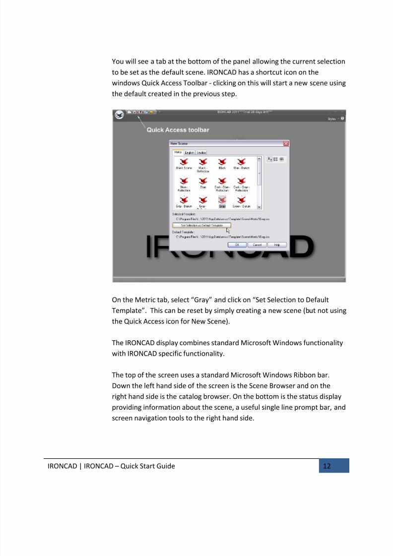
You will see a tab at the bottom of the panel allowing the current selection
to be set as the default scene. IRONCAD has a shortcut icon on the
windows Quick Access Toolbar - clicking on this will start a new scene using
the default created in the previous step.
On the Metric tab, select “Gray” and click on “Set Selection to Default
Template”. This can be reset by simply creating a new scene (but not using
the Quick Access icon for New Scene).
The IRONCAD display combines standard Microsoft Windows functionality
with IRONCAD specific functionality.
The top of the screen uses a standard Microsoft Windows Ribbon bar.
Down the left hand side of the screen is the Scene Browser and on the
right hand side is the catalog browser. On the bottom is the status display
providing information about the scene, a useful single line prompt bar, and
screen navigation tools to the right hand side.
7/30/2019 Unlock Ironcadgsg
http://slidepdf.com/reader/full/unlock-ironcadgsg 17/367
IRONCAD | IRONCAD – Quick Start Guide 13
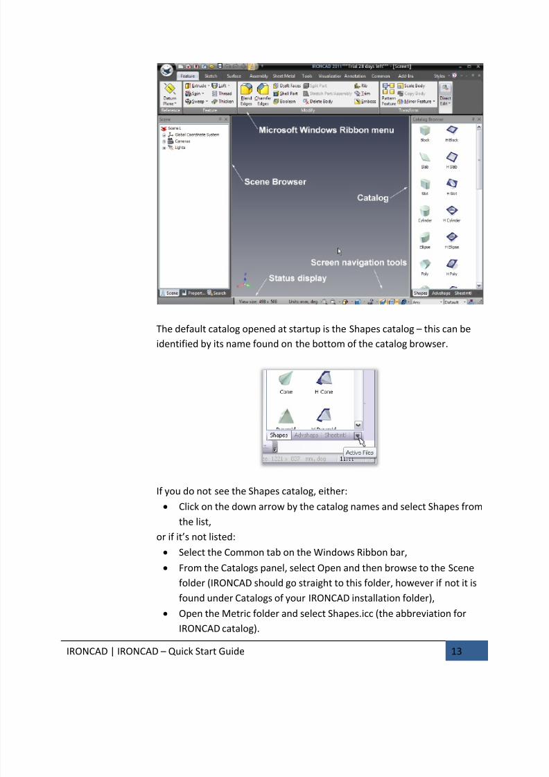
The default catalog opened at startup is the Shapes catalog – this can be
identified by its name found on the bottom of the catalog browser.
If you do not see the Shapes catalog, either:
• Click on the down arrow by the catalog names and select Shapes from
the list,
or if it’s not listed:
• Select the Common tab on the Windows Ribbon bar,
• From the Catalogs panel, select Open and then browse to the Scene
folder (IRONCAD should go straight to this folder, however if not it is
found under Catalogs of your IRONCAD installation folder),
• Open the Metric folder and select Shapes.icc (the abbreviation for
IRONCAD catalog).
7/30/2019 Unlock Ironcadgsg
http://slidepdf.com/reader/full/unlock-ironcadgsg 18/367
IRONCAD | IRONCAD – Quick Start Guide 14
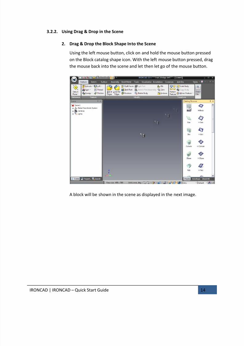
3.2.2. Using Drag & Drop in the Scene
2. Drag & Drop the Block Shape Into the Scene
Using the left mouse button, click on and hold the mouse button pressed
on the Block catalog shape icon. With the left mouse button pressed, dragthe mouse back into the scene and let then let go of the mouse button.
A block will be shown in the scene as displayed in the next image.
7/30/2019 Unlock Ironcadgsg
http://slidepdf.com/reader/full/unlock-ironcadgsg 19/367
IRONCAD | IRONCAD – Quick Start Guide 15
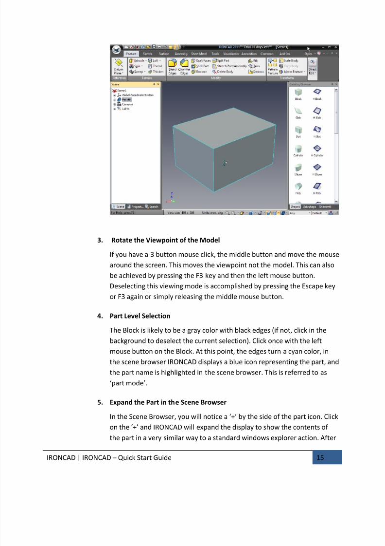
3. Rotate the Viewpoint of the Model
If you have a 3 button mouse click, the middle button and move the mouse
around the screen. This moves the viewpoint not the model. This can also
be achieved by pressing the F3 key and then the left mouse button.
Deselecting this viewing mode is accomplished by pressing the Escape keyor F3 again or simply releasing the middle mouse button.
4. Part Level Selection
The Block is likely to be a gray color with black edges (if not, click in the
background to deselect the current selection). Click once with the left
mouse button on the Block. At this point, the edges turn a cyan color, in
the scene browser IRONCAD displays a blue icon representing the part, and
the part name is highlighted in the scene browser. This is referred to as
‘part mode’.
5. Expand the Part in the Scene Browser
In the Scene Browser, you will notice a ‘+’ by the side of the part icon. Click
on the ‘+’ and IRONCAD will expand the display to show the contents of
the part in a very similar way to a standard windows explorer action. After
7/30/2019 Unlock Ironcadgsg
http://slidepdf.com/reader/full/unlock-ironcadgsg 20/367
IRONCAD | IRONCAD – Quick Start Guide 16
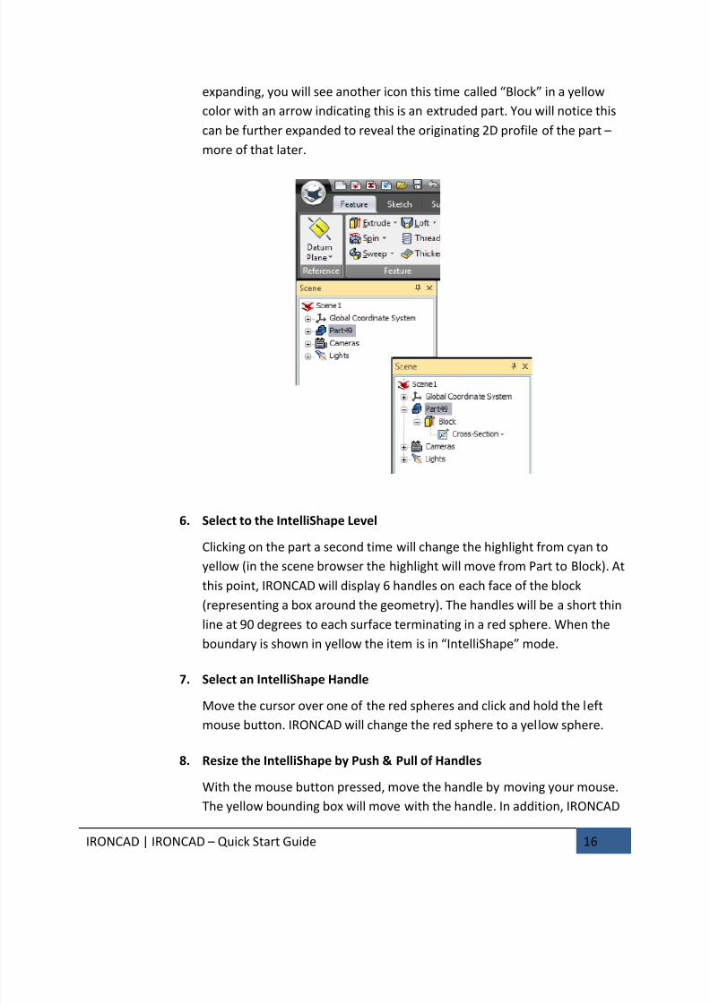
expanding, you will see another icon this time called “Block” in a yellow
color with an arrow indicating this is an extruded part. You will notice this
can be further expanded to reveal the originating 2D profile of the part –
more of that later.
6. Select to the IntelliShape Level
Clicking on the part a second time will change the highlight from cyan to
yellow (in the scene browser the highlight will move from Part to Block). At
this point, IRONCAD will display 6 handles on each face of the block
(representing a box around the geometry). The handles will be a short thin
line at 90 degrees to each surface terminating in a red sphere. When the
boundary is shown in yellow the item is in “IntelliShape” mode.
7. Select an IntelliShape Handle
Move the cursor over one of the red spheres and click and hold the leftmouse button. IRONCAD will change the red sphere to a yellow sphere.
8. Resize the IntelliShape by Push & Pull of Handles
With the mouse button pressed, move the handle by moving your mouse.
The yellow bounding box will move with the handle. In addition, IRONCAD
7/30/2019 Unlock Ironcadgsg
http://slidepdf.com/reader/full/unlock-ironcadgsg 21/367
IRONCAD | IRONCAD – Quick Start Guide 17
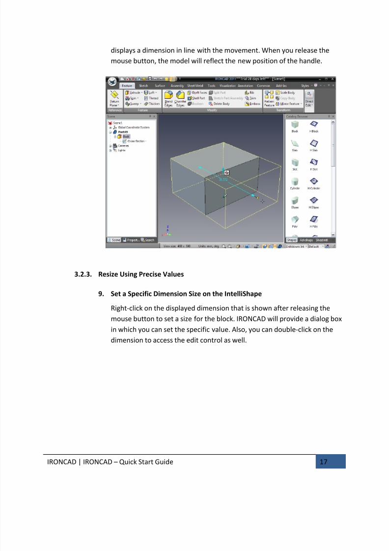
displays a dimension in line with the movement. When you release the
mouse button, the model will reflect the new position of the handle.
3.2.3. Resize Using Precise Values
9. Set a Specific Dimension Size on the IntelliShape
Right-click on the displayed dimension that is shown after releasing the
mouse button to set a size for the block. IRONCAD will provide a dialog box
in which you can set the specific value. Also, you can double-click on the
dimension to access the edit control as well.
7/30/2019 Unlock Ironcadgsg
http://slidepdf.com/reader/full/unlock-ironcadgsg 22/367
IRONCAD | IRONCAD – Quick Start Guide 18
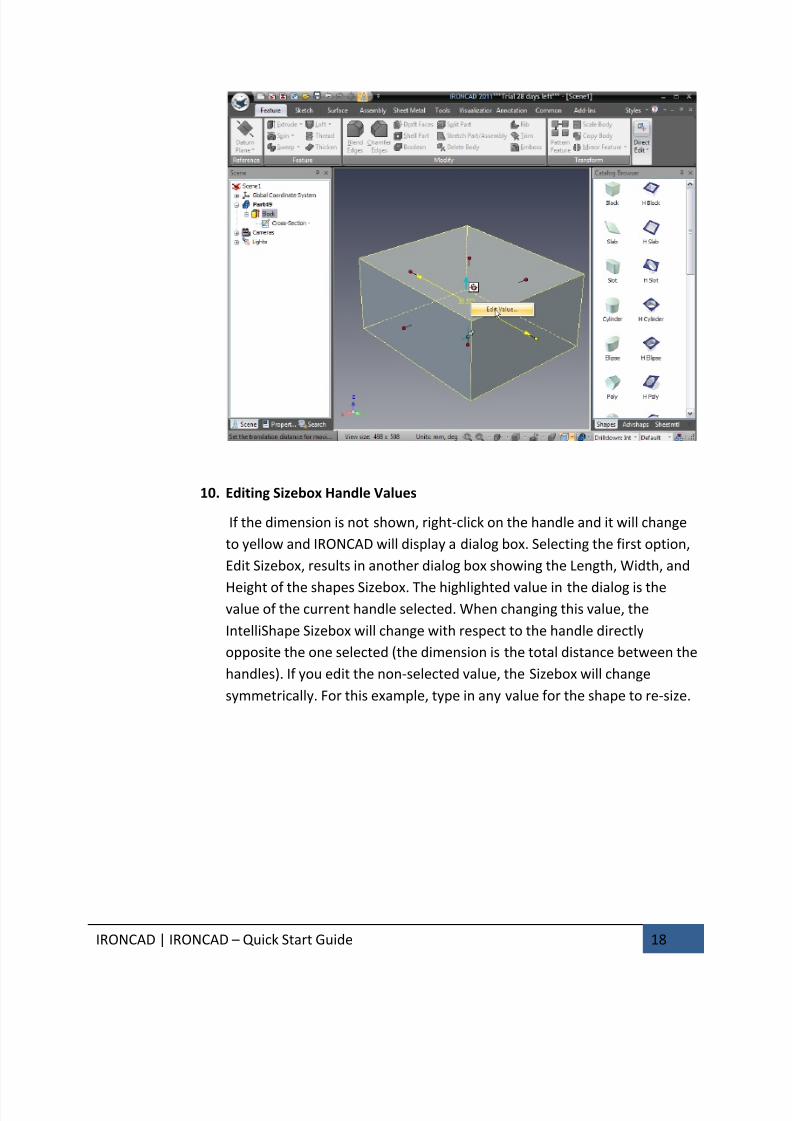
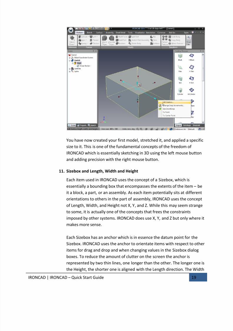
10. Editing Sizebox Handle Values
If the dimension is not shown, right-click on the handle and it will change
to yellow and IRONCAD will display a dialog box. Selecting the first option,
Edit Sizebox, results in another dialog box showing the Length, Width, and
Height of the shapes Sizebox. The highlighted value in the dialog is thevalue of the current handle selected. When changing this value, the
IntelliShape Sizebox will change with respect to the handle directly
opposite the one selected (the dimension is the total distance between the
handles). If you edit the non-selected value, the Sizebox will change
symmetrically. For this example, type in any value for the shape to re-size.
7/30/2019 Unlock Ironcadgsg
http://slidepdf.com/reader/full/unlock-ironcadgsg 23/367
IRONCAD | IRONCAD – Quick Start Guide 19
You have now created your first model, stretched it, and applied a specific
size to it. This is one of the fundamental concepts of the freedom of
IRONCAD which is essentially sketching in 3D using the left mouse button
and adding precision with the right mouse button.
11. Sizebox and Length, Width and Height
Each item used in IRONCAD uses the concept of a Sizebox, which is
essentially a bounding box that encompasses the extents of the item – be
it a block, a part, or an assembly. As each item potentially sits at different
orientations to others in the part of assembly, IRONCAD uses the concept
of Length, Width, and Height not X, Y, and Z. While this may seem strange
to some, it is actually one of the concepts that frees the constraints
imposed by other systems. IRONCAD does use X, Y, and Z but only where it
makes more sense.
Each Sizebox has an anchor which is in essence the datum point for the
Sizebox. IRONCAD uses the anchor to orientate items with respect to other
items for drag and drop and when changing values in the Sizebox dialog
boxes. To reduce the amount of clutter on the screen the anchor is
represented by two thin lines, one longer than the other. The longer one is
the Height, the shorter one is aligned with the Length direction. The Width

7/30/2019 Unlock Ironcadgsg
http://slidepdf.com/reader/full/unlock-ironcadgsg 24/367
IRONCAD | IRONCAD – Quick Start Guide 20
direction follows the left hand rule or right-hand (depending on your
region):
Back to the model, re-select the handle used previously with the rightmouse button and select “Edit Sizebox”. Set each value to 50. IRONCAD
will change the block into a 50mm cube. You will notice:
• The selected handle moves with respect to its opposing handle,
• The other two handles will change the Sizebox symmetrically about
the center to adjust the size.
12. Adding Additional Features to the Block
From the catalog, using the left mouse button, drag an H Cylinder onto the
existing block. IRONCAD will cut a hole into the block where you drop theitem and show the Sizebox handles. The cylinder is added to the structure
in the scene browser – its icon being a white extrusion suggesting a hole.
The name H Cylinder is the name of the catalog entry and this name can be
changed to help identify the feature later in the design if needed by
clicking twice on the name (not a double click).
7/30/2019 Unlock Ironcadgsg
http://slidepdf.com/reader/full/unlock-ironcadgsg 25/367
IRONCAD | IRONCAD – Quick Start Guide 21
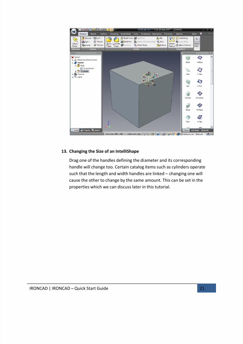
13. Changing the Size of an IntelliShape
Drag one of the handles defining the diameter and its corresponding
handle will change too. Certain catalog items such as cylinders operate
such that the length and width handles are linked – changing one will
cause the other to change by the same amount. This can be set in theproperties which we can discuss later in this tutorial.

7/30/2019 Unlock Ironcadgsg
http://slidepdf.com/reader/full/unlock-ironcadgsg 26/367
IRONCAD | IRONCAD – Quick Start Guide 22
14. Cruising Shapes by Drag and Drop
With the hole highlighted at the IntelliShape level, click and hold the left
mouse button when the mouse pointer is over any of the surfaces of the
hole and drag the hole over other faces of the block – this is referred to by
some as cruising. Letting go, the mouse button will move the H Cylinder tothat face.
7/30/2019 Unlock Ironcadgsg
http://slidepdf.com/reader/full/unlock-ironcadgsg 27/367
IRONCAD | IRONCAD – Quick Start Guide 23
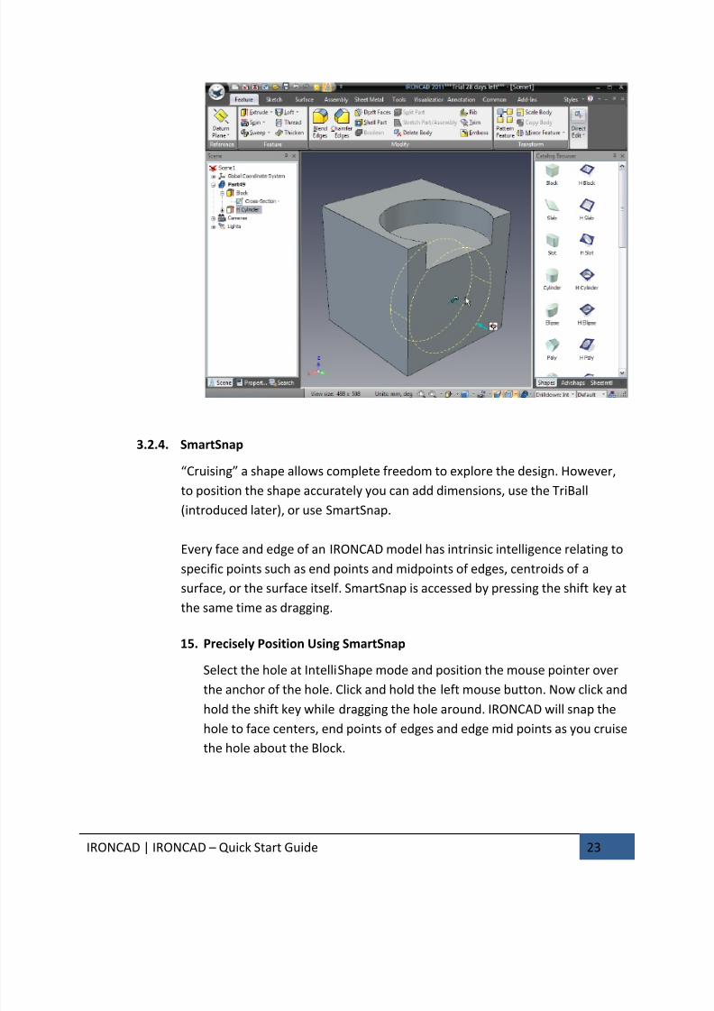
3.2.4. SmartSnap
“Cruising” a shape allows complete freedom to explore the design. However,
to position the shape accurately you can add dimensions, use the TriBall
(introduced later), or use SmartSnap.
Every face and edge of an IRONCAD model has intrinsic intelligence relating to
specific points such as end points and midpoints of edges, centroids of a
surface, or the surface itself. SmartSnap is accessed by pressing the shift key at
the same time as dragging.
15. Precisely Position Using SmartSnap
Select the hole at IntelliShape mode and position the mouse pointer over
the anchor of the hole. Click and hold the left mouse button. Now click and
hold the shift key while dragging the hole around. IRONCAD will snap thehole to face centers, end points of edges and edge mid points as you cruise
the hole about the Block.

7/30/2019 Unlock Ironcadgsg
http://slidepdf.com/reader/full/unlock-ironcadgsg 28/367
IRONCAD | IRONCAD – Quick Start Guide 24
Take note of the graphics feedback and how the hole snaps in position.
Use the functionality to snap the hole to one of the edges of the block.
Release the mouse first and then the Shift key to maintain the snap.
Drag the hole so that it cuts all the way across the face and by one of the
methods used above set the diameter to 30mm so the model looks like theimage below.
7/30/2019 Unlock Ironcadgsg
http://slidepdf.com/reader/full/unlock-ironcadgsg 29/367
IRONCAD | IRONCAD – Quick Start Guide 25
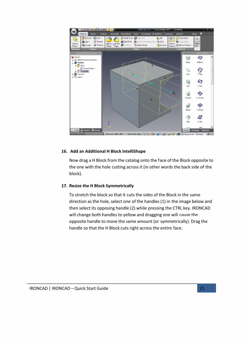
16. Add an Additional H Block IntelliShape
Now drag a H Block from the catalog onto the face of the Block opposite to
the one with the hole cutting across it (in other words the back side of the
block).
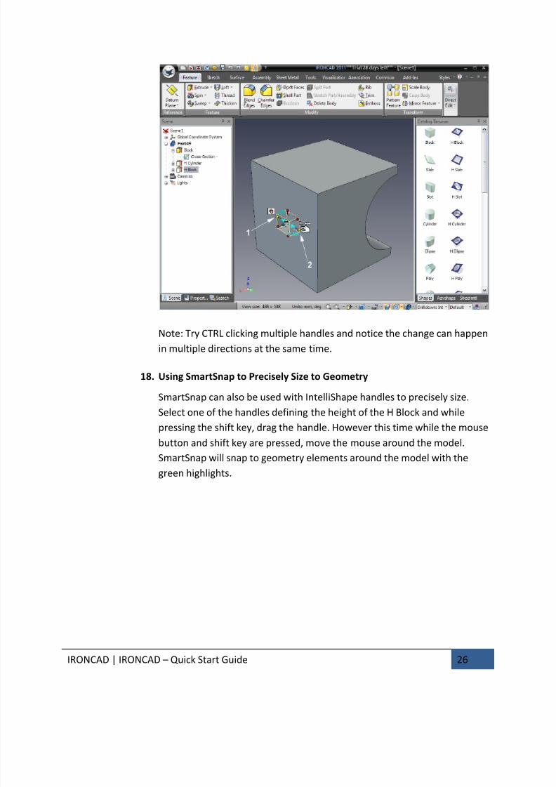
17. Resize the H Block Symmetrically
To stretch the block so that it cuts the sides of the Block in the same
direction as the hole, select one of the handles (1) in the image below and
then select its opposing handle (2) while pressing the CTRL key. IRONCAD
will change both handles to yellow and dragging one will cause the
opposite handle to move the same amount (or symmetrically). Drag the
handle so that the H Block cuts right across the entire face.
7/30/2019 Unlock Ironcadgsg
http://slidepdf.com/reader/full/unlock-ironcadgsg 30/367
IRONCAD | IRONCAD – Quick Start Guide 26
Note: Try CTRL clicking multiple handles and notice the change can happen
in multiple directions at the same time.
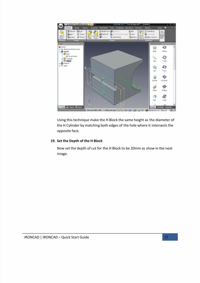
18. Using SmartSnap to Precisely Size to Geometry
SmartSnap can also be used with IntelliShape handles to precisely size.
Select one of the handles defining the height of the H Block and whilepressing the shift key, drag the handle. However this time while the mouse
button and shift key are pressed, move the mouse around the model.
SmartSnap will snap to geometry elements around the model with the
green highlights.
7/30/2019 Unlock Ironcadgsg
http://slidepdf.com/reader/full/unlock-ironcadgsg 31/367
IRONCAD | IRONCAD – Quick Start Guide 27
Using this technique make the H Block the same height as the diameter of
the H Cylinder by matching both edges of the hole where it intersects the
opposite face.
19. Set the Depth of the H Block
Now set the depth of cut for the H Block to be 20mm as show in the nextimage.

7/30/2019 Unlock Ironcadgsg
http://slidepdf.com/reader/full/unlock-ironcadgsg 32/367
IRONCAD | IRONCAD – Quick Start Guide 28
20. Add a hole to the Center of the Top Face
On the top face, shown in the next image, add a hole to the center of the
face and set its diameter to 10mm and depth 15mm.
7/30/2019 Unlock Ironcadgsg
http://slidepdf.com/reader/full/unlock-ironcadgsg 33/367
IRONCAD | IRONCAD – Quick Start Guide 29
3.2.5. Using the TriBall
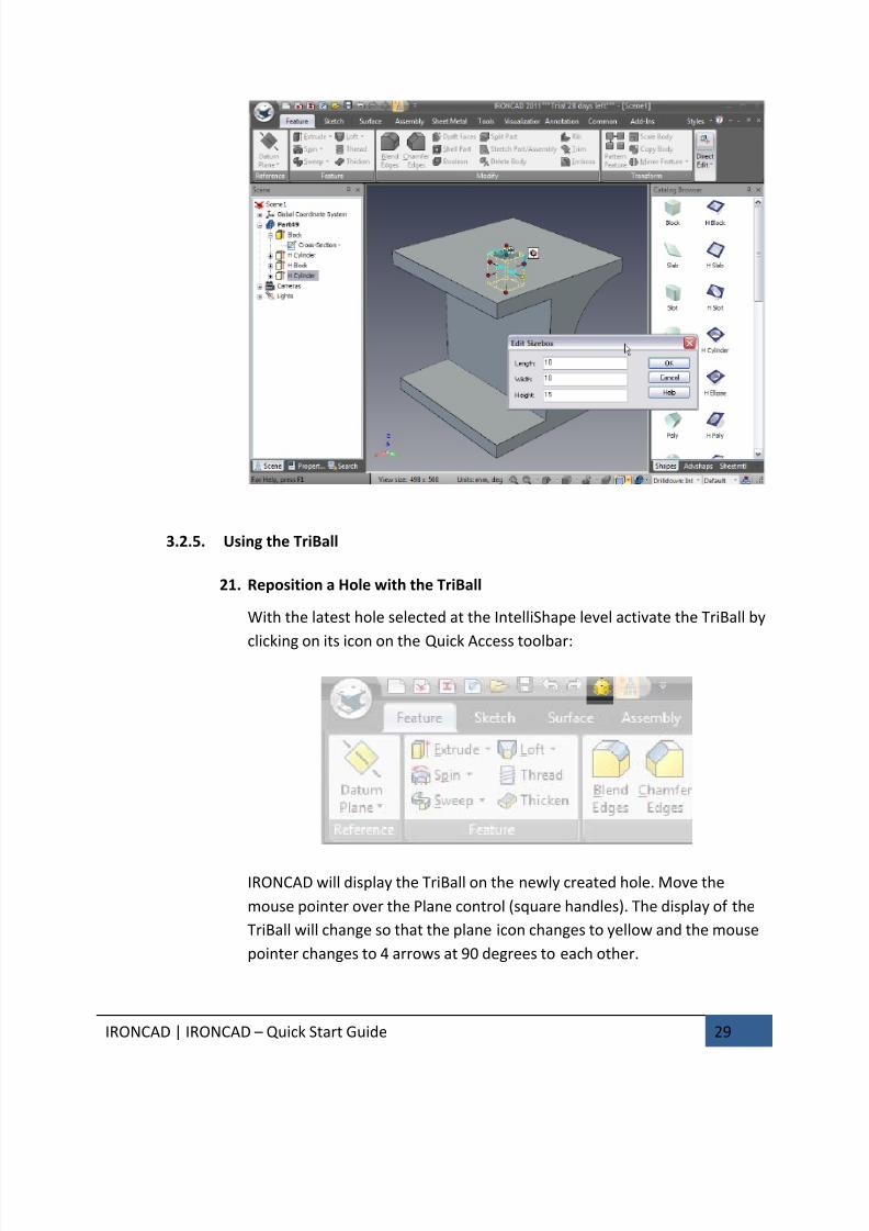
21. Reposition a Hole with the TriBall
With the latest hole selected at the IntelliShape level activate the TriBall by
clicking on its icon on the Quick Access toolbar:
IRONCAD will display the TriBall on the newly created hole. Move the
mouse pointer over the Plane control (square handles). The display of the
TriBall will change so that the plane icon changes to yellow and the mouse
pointer changes to 4 arrows at 90 degrees to each other.
7/30/2019 Unlock Ironcadgsg
http://slidepdf.com/reader/full/unlock-ironcadgsg 34/367
IRONCAD | IRONCAD – Quick Start Guide 30
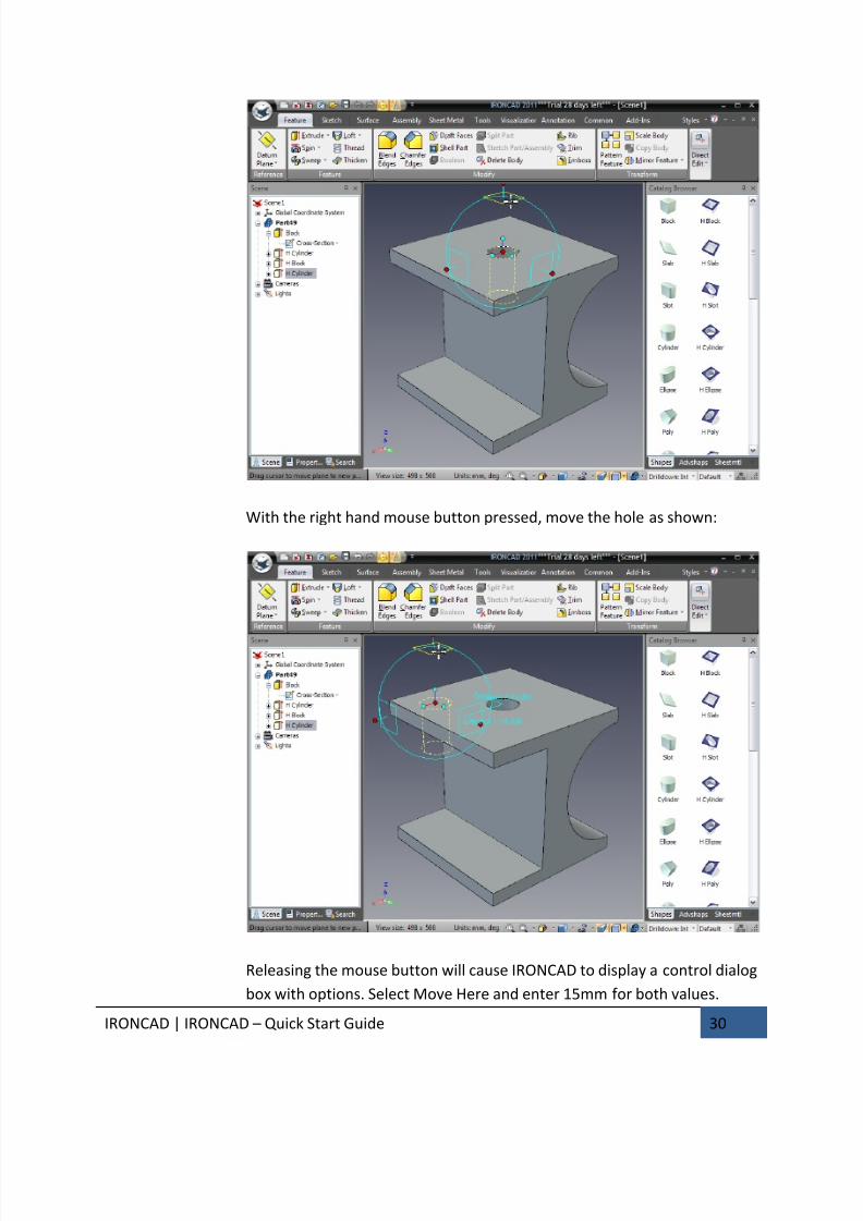
With the right hand mouse button pressed, move the hole as shown:
Releasing the mouse button will cause IRONCAD to display a control dialog
box with options. Select Move Here and enter 15mm for both values.
7/30/2019 Unlock Ironcadgsg
http://slidepdf.com/reader/full/unlock-ironcadgsg 35/367
IRONCAD | IRONCAD – Quick Start Guide 31
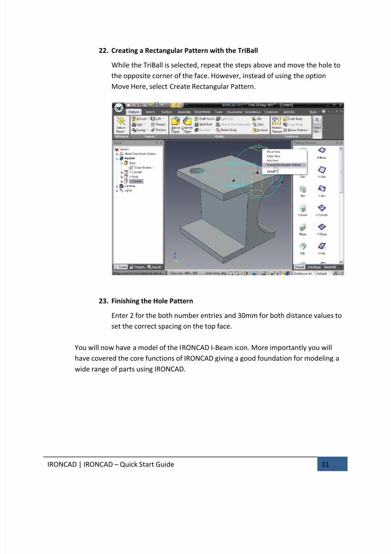
22. Creating a Rectangular Pattern with the TriBall
While the TriBall is selected, repeat the steps above and move the hole to
the opposite corner of the face. However, instead of using the option
Move Here, select Create Rectangular Pattern.
23. Finishing the Hole Pattern
Enter 2 for the both number entries and 30mm for both distance values to
set the correct spacing on the top face.
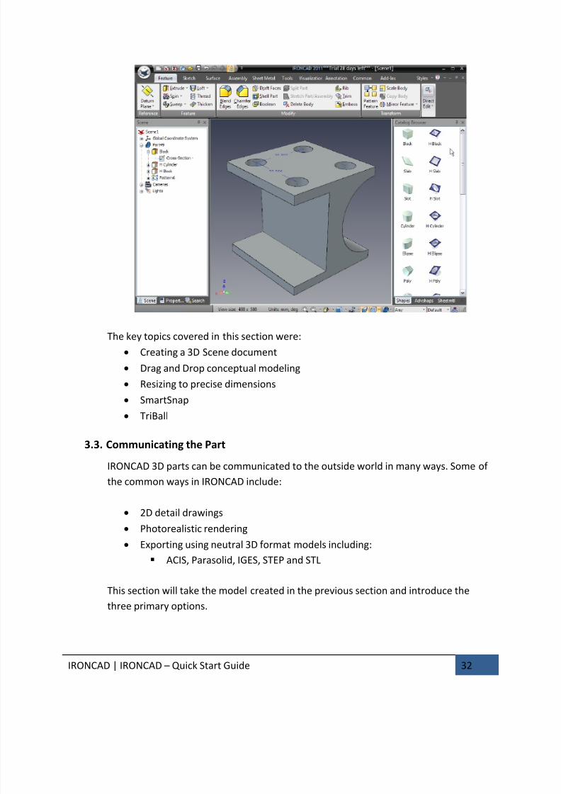
You will now have a model of the IRONCAD I-Beam icon. More importantly you will
have covered the core functions of IRONCAD giving a good foundation for modeling a
wide range of parts using IRONCAD.
7/30/2019 Unlock Ironcadgsg
http://slidepdf.com/reader/full/unlock-ironcadgsg 36/367
IRONCAD | IRONCAD – Quick Start Guide 32
The key topics covered in this section were:
• Creating a 3D Scene document
• Drag and Drop conceptual modeling
• Resizing to precise dimensions
• SmartSnap
• TriBall
3.3. Communicating the Part
IRONCAD 3D parts can be communicated to the outside world in many ways. Some of
the common ways in IRONCAD include:
• 2D detail drawings
• Photorealistic rendering
• Exporting using neutral 3D format models including:
ACIS, Parasolid, IGES, STEP and STL
This section will take the model created in the previous section and introduce the
three primary options.
7/30/2019 Unlock Ironcadgsg
http://slidepdf.com/reader/full/unlock-ironcadgsg 37/367
IRONCAD | IRONCAD – Quick Start Guide 33
3.3.1. Creating a 2D drawing
This section introduces the IRONCAD embedded drafting system used to create
detail drawings from the 3D models created in the scene environment.
Users create Views which are standard views, sections and detail views thatare essentially snapshots of the model. IRONCAD maintains links between the
3D model and the 2D drawing. Any changes to the model are automatically
reflected in the detail drawing. In addition, IRONCAD possess the functionality
to update the model from the drawing environment that will be covered by a
later section of this guide.
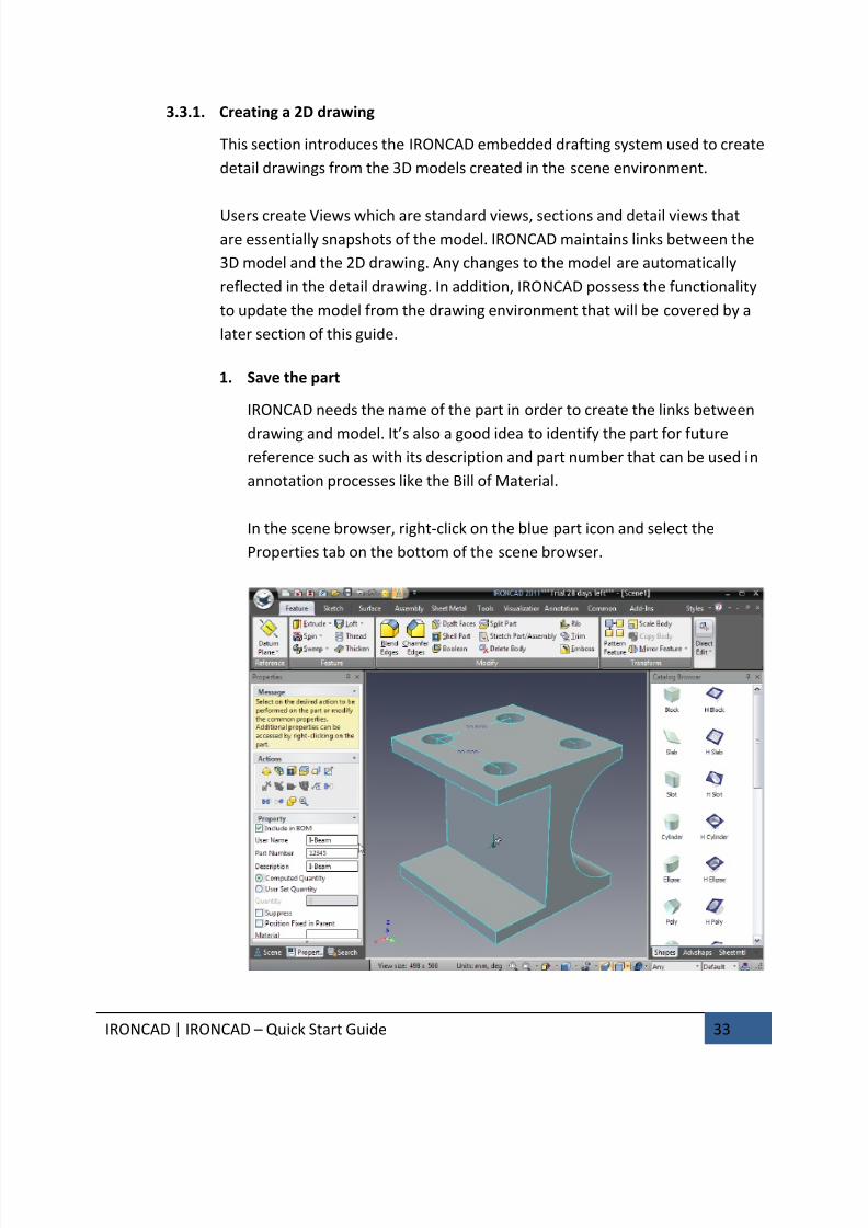
1. Save the part
IRONCAD needs the name of the part in order to create the links between
drawing and model. It’s also a good idea to identify the part for future
reference such as with its description and part number that can be used in
annotation processes like the Bill of Material.
In the scene browser, right-click on the blue part icon and select the
Properties tab on the bottom of the scene browser.

7/30/2019 Unlock Ironcadgsg
http://slidepdf.com/reader/full/unlock-ironcadgsg 38/367
IRONCAD | IRONCAD – Quick Start Guide 34
Enter I-Beam into the Description box and type 12345 in the Part Number
box. You can optionally change the User Name to I-Beam as well.
Click the Save icon on the Quick Access Ribbon Toolbar and give the part a
recognizable name (i.e. I-Beam).
To help identify the part in the working window session, IRONCAD will add
the part name to the main window title bar.
2. Default Save Location
IRONCAD will, by default, save the part to the IRONCAD folder created in
My Documents (this can be changed in the Tools/Options/Directories).
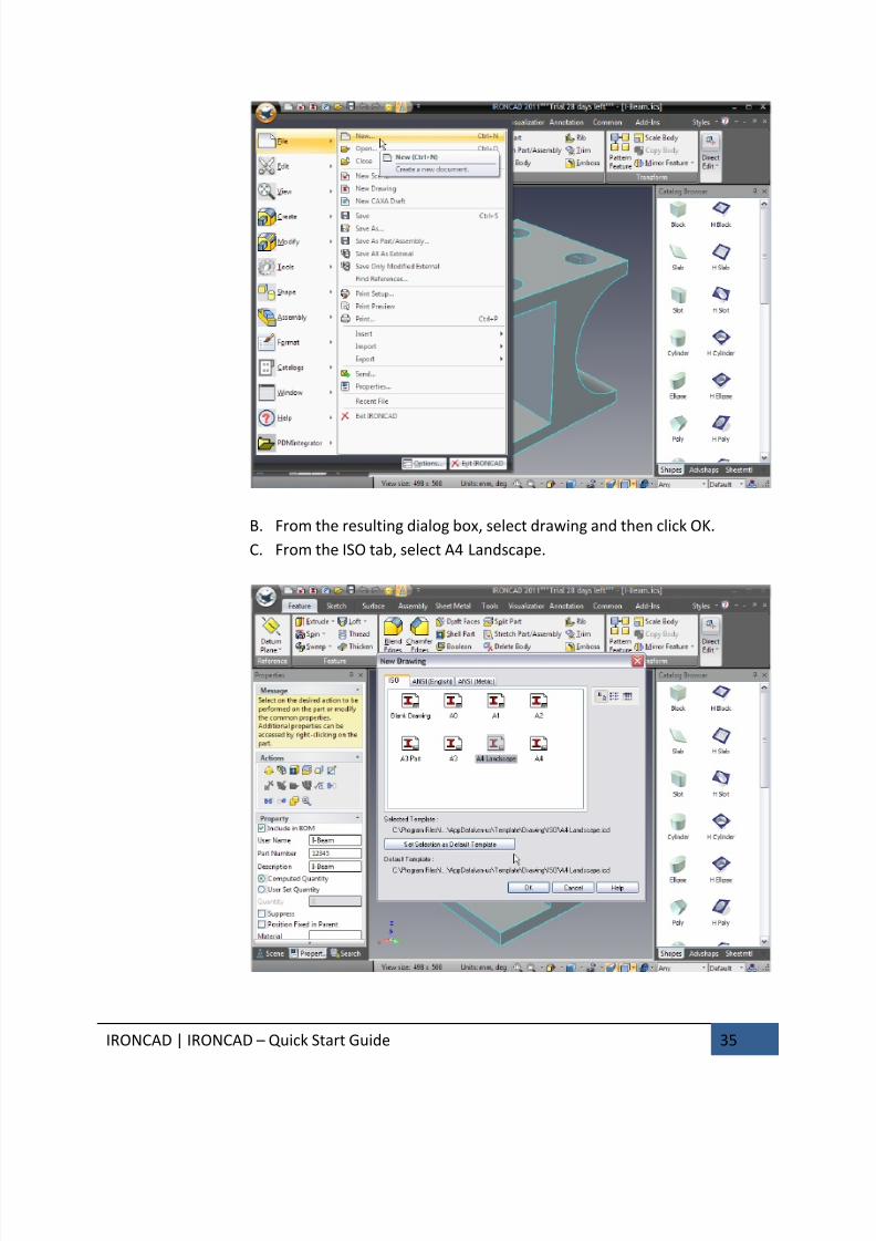
3. Create a New A4 Drawing
A. To create a new drawing, from the Windows Home button select:File>New.
7/30/2019 Unlock Ironcadgsg
http://slidepdf.com/reader/full/unlock-ironcadgsg 39/367
IRONCAD | IRONCAD – Quick Start Guide 35
B. From the resulting dialog box, select drawing and then click OK.
C. From the ISO tab, select A4 Landscape.
7/30/2019 Unlock Ironcadgsg
http://slidepdf.com/reader/full/unlock-ironcadgsg 40/367
IRONCAD | IRONCAD – Quick Start Guide 36
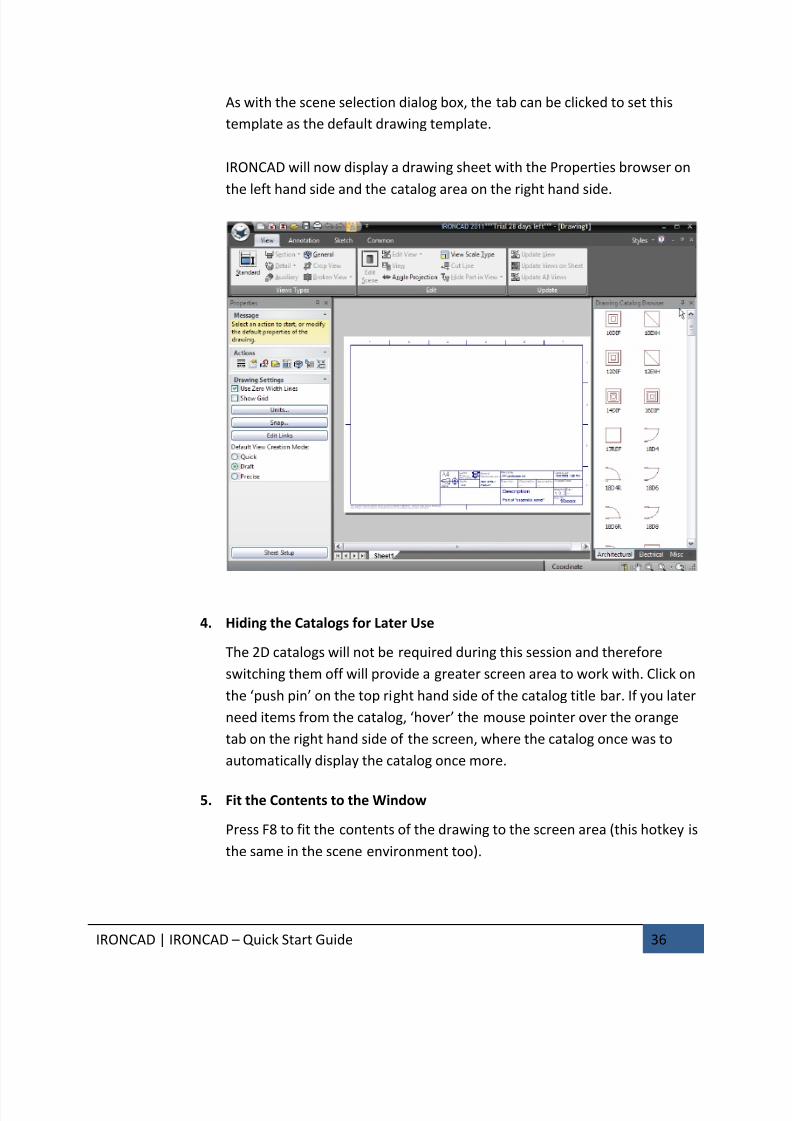
As with the scene selection dialog box, the tab can be clicked to set this
template as the default drawing template.
IRONCAD will now display a drawing sheet with the Properties browser on
the left hand side and the catalog area on the right hand side.
4. Hiding the Catalogs for Later Use
The 2D catalogs will not be required during this session and therefore
switching them off will provide a greater screen area to work with. Click on
the ‘push pin’ on the top right hand side of the catalog title bar. If you later
need items from the catalog, ‘hover’ the mouse pointer over the orange
tab on the right hand side of the screen, where the catalog once was to
automatically display the catalog once more.
5. Fit the Contents to the Window
Press F8 to fit the contents of the drawing to the screen area (this hotkey is
the same in the scene environment too).
7/30/2019 Unlock Ironcadgsg
http://slidepdf.com/reader/full/unlock-ironcadgsg 41/367
IRONCAD | IRONCAD – Quick Start Guide 37
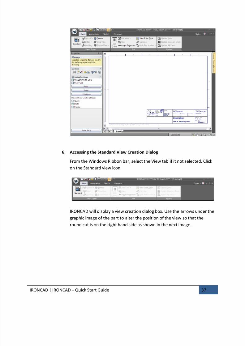
6. Accessing the Standard View Creation Dialog
From the Windows Ribbon bar, select the View tab if it not selected. Click
on the Standard view icon.
IRONCAD will display a view creation dialog box. Use the arrows under the
graphic image of the part to alter the position of the view so that the
round cut is on the right hand side as shown in the next image.
7/30/2019 Unlock Ironcadgsg
http://slidepdf.com/reader/full/unlock-ironcadgsg 42/367
IRONCAD | IRONCAD – Quick Start Guide 38
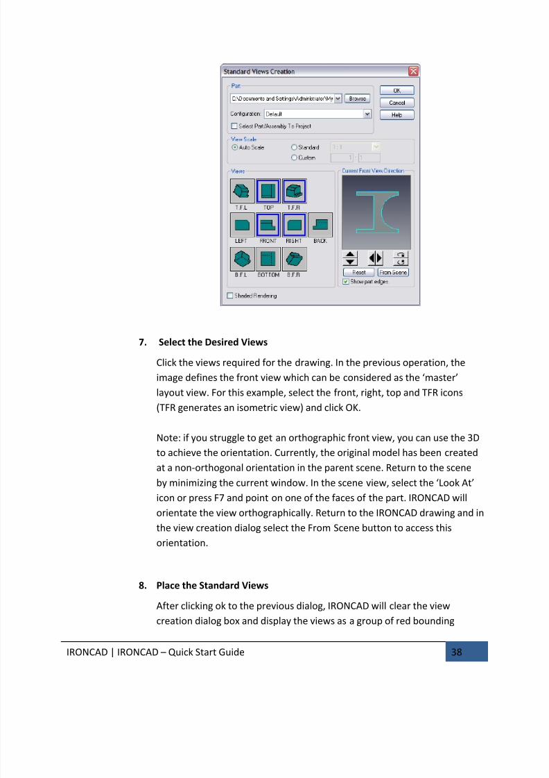
7. Select the Desired Views
Click the views required for the drawing. In the previous operation, the
image defines the front view which can be considered as the ‘master’
layout view. For this example, select the front, right, top and TFR icons
(TFR generates an isometric view) and click OK.
Note: if you struggle to get an orthographic front view, you can use the 3D
to achieve the orientation. Currently, the original model has been created
at a non-orthogonal orientation in the parent scene. Return to the scene
by minimizing the current window. In the scene view, select the ‘Look At’
icon or press F7 and point on one of the faces of the part. IRONCAD will
orientate the view orthographically. Return to the IRONCAD drawing and in
the view creation dialog select the From Scene button to access this
orientation.
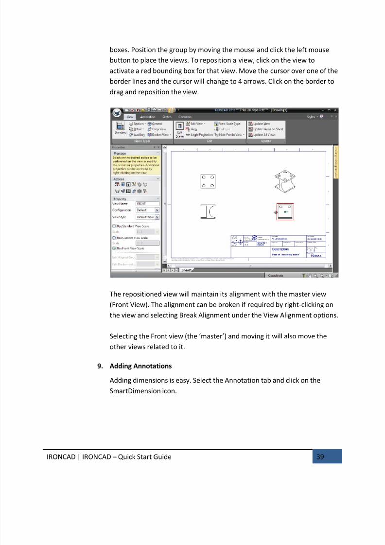
8. Place the Standard Views
After clicking ok to the previous dialog, IRONCAD will clear the view
creation dialog box and display the views as a group of red bounding
7/30/2019 Unlock Ironcadgsg
http://slidepdf.com/reader/full/unlock-ironcadgsg 43/367
IRONCAD | IRONCAD – Quick Start Guide 39
boxes. Position the group by moving the mouse and click the left mouse
button to place the views. To reposition a view, click on the view to
activate a red bounding box for that view. Move the cursor over one of the
border lines and the cursor will change to 4 arrows. Click on the border to
drag and reposition the view.
The repositioned view will maintain its alignment with the master view
(Front View). The alignment can be broken if required by right-clicking on
the view and selecting Break Alignment under the View Alignment options.
Selecting the Front view (the ‘master’) and moving it will also move the
other views related to it.
9. Adding Annotations
Adding dimensions is easy. Select the Annotation tab and click on theSmartDimension icon.
7/30/2019 Unlock Ironcadgsg
http://slidepdf.com/reader/full/unlock-ironcadgsg 44/367
IRONCAD | IRONCAD – Quick Start Guide 40
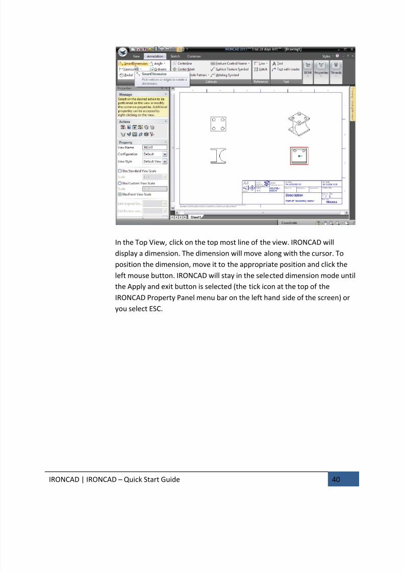
In the Top View, click on the top most line of the view. IRONCAD will
display a dimension. The dimension will move along with the cursor. To
position the dimension, move it to the appropriate position and click the
left mouse button. IRONCAD will stay in the selected dimension mode until
the Apply and exit button is selected (the tick icon at the top of the
IRONCAD Property Panel menu bar on the left hand side of the screen) oryou select ESC.
7/30/2019 Unlock Ironcadgsg
http://slidepdf.com/reader/full/unlock-ironcadgsg 45/367
IRONCAD | IRONCAD – Quick Start Guide 41
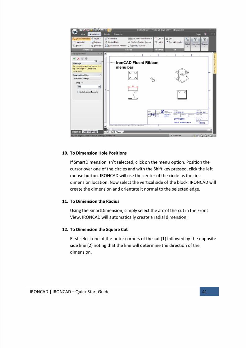
10. To Dimension Hole Positions
If SmartDimension isn’t selected, click on the menu option. Position the
cursor over one of the circles and with the Shift key pressed, click the left
mouse button. IRONCAD will use the center of the circle as the first
dimension location. Now select the vertical side of the block. IRONCAD willcreate the dimension and orientate it normal to the selected edge.
11. To Dimension the Radius
Using the SmartDimension, simply select the arc of the cut in the Front
View. IRONCAD will automatically create a radial dimension.
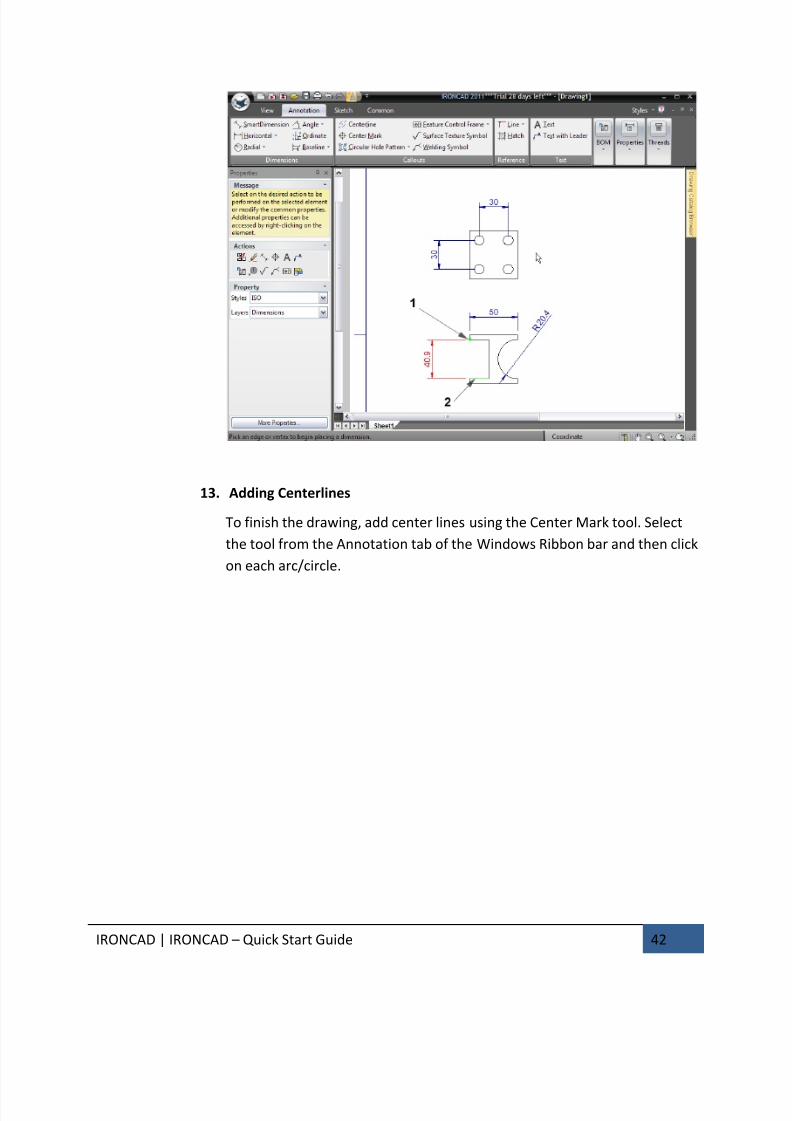
12. To Dimension the Square Cut
First select one of the outer corners of the cut (1) followed by the opposite
side line (2) noting that the line will determine the direction of the
dimension.
7/30/2019 Unlock Ironcadgsg
http://slidepdf.com/reader/full/unlock-ironcadgsg 46/367
7/30/2019 Unlock Ironcadgsg
http://slidepdf.com/reader/full/unlock-ironcadgsg 47/367
IRONCAD | IRONCAD – Quick Start Guide 43
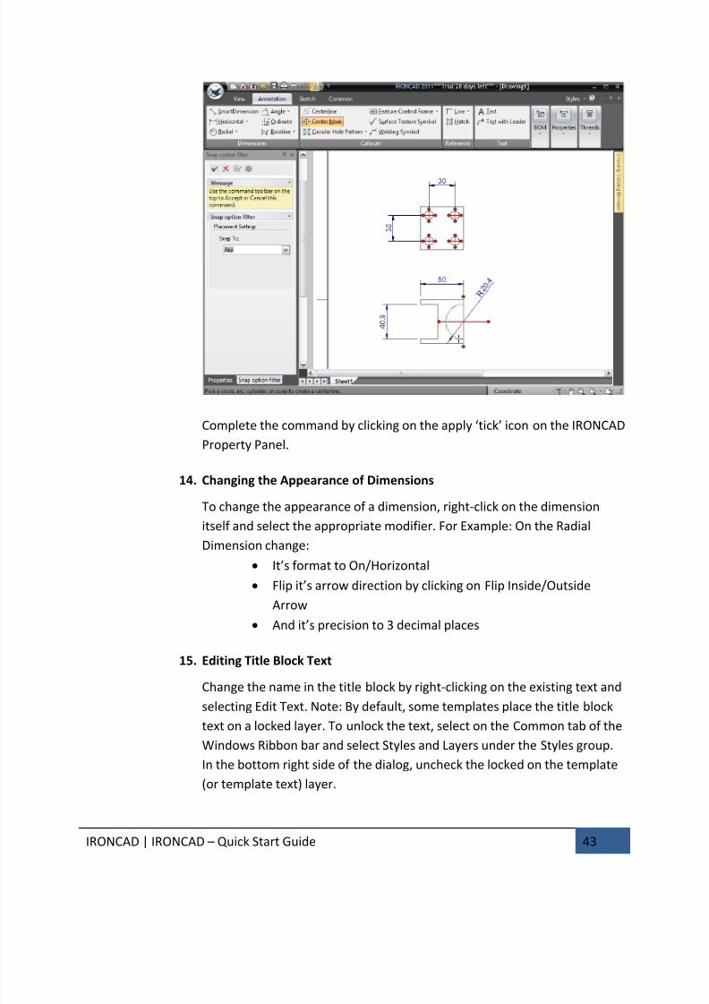
Complete the command by clicking on the apply ‘tick’ icon on the IRONCAD
Property Panel.
14. Changing the Appearance of Dimensions
To change the appearance of a dimension, right-click on the dimension
itself and select the appropriate modifier. For Example: On the RadialDimension change:
• It’s format to On/Horizontal
• Flip it’s arrow direction by clicking on Flip Inside/Outside
Arrow
• And it’s precision to 3 decimal places
15. Editing Title Block Text
Change the name in the title block by right-clicking on the existing text and
selecting Edit Text. Note: By default, some templates place the title block
text on a locked layer. To unlock the text, select on the Common tab of the
Windows Ribbon bar and select Styles and Layers under the Styles group.
In the bottom right side of the dialog, uncheck the locked on the template
(or template text) layer.
7/30/2019 Unlock Ironcadgsg
http://slidepdf.com/reader/full/unlock-ironcadgsg 48/367
IRONCAD | IRONCAD – Quick Start Guide 44
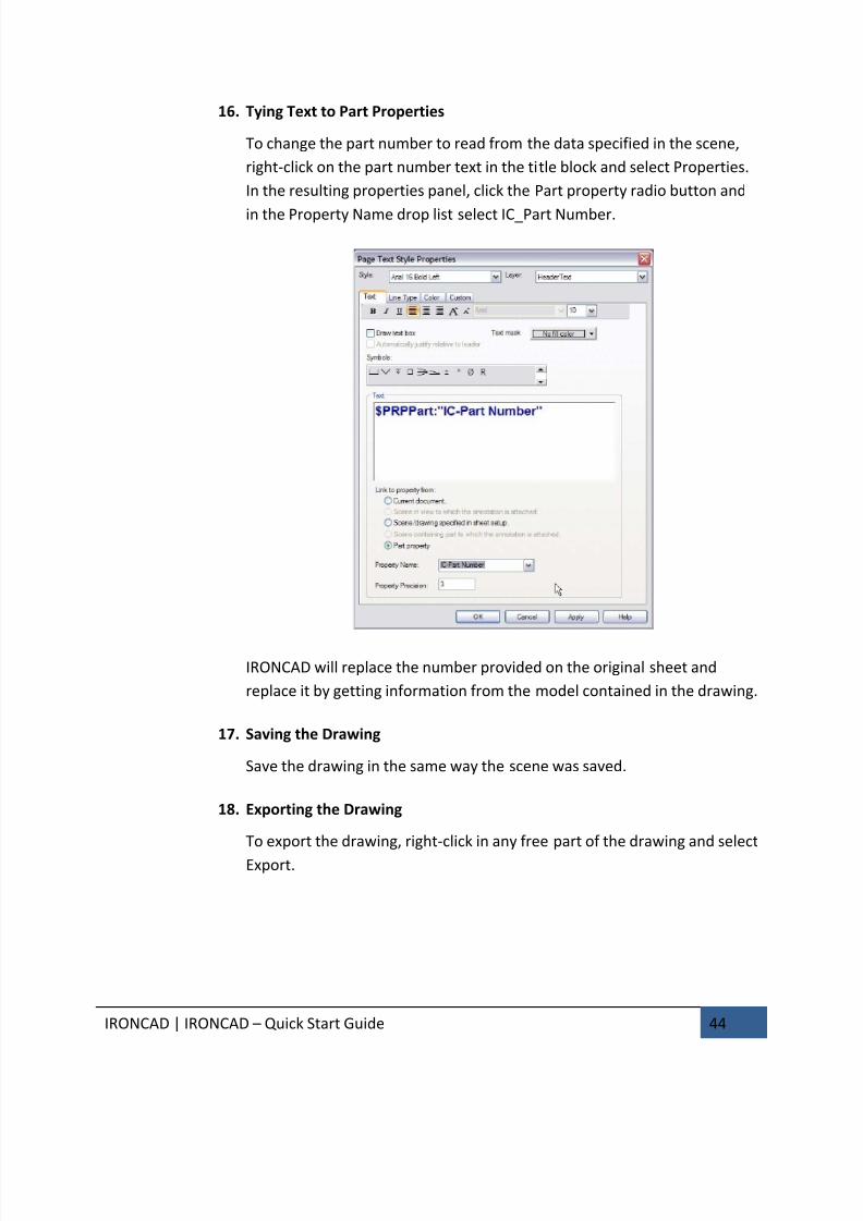
16. Tying Text to Part Properties
To change the part number to read from the data specified in the scene,
right-click on the part number text in the title block and select Properties.
In the resulting properties panel, click the Part property radio button and
in the Property Name drop list select IC_Part Number.
IRONCAD will replace the number provided on the original sheet and
replace it by getting information from the model contained in the drawing.
17. Saving the Drawing
Save the drawing in the same way the scene was saved.
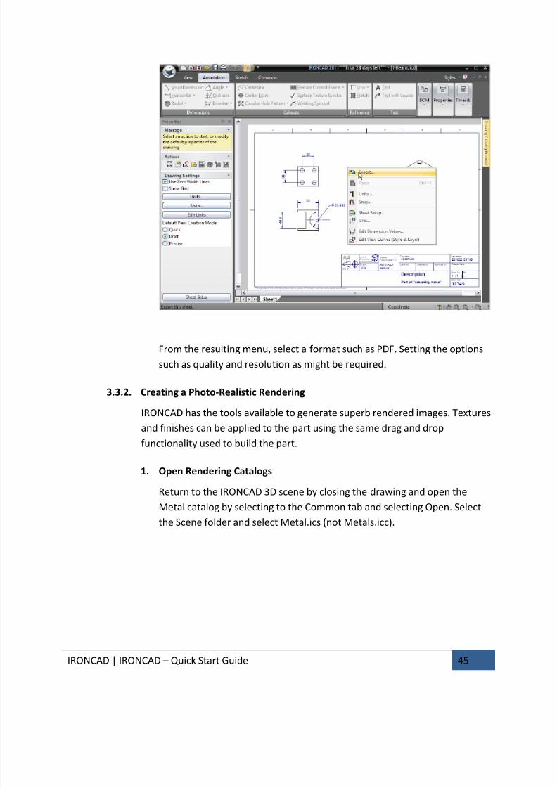
18. Exporting the Drawing
To export the drawing, right-click in any free part of the drawing and select
Export.
7/30/2019 Unlock Ironcadgsg
http://slidepdf.com/reader/full/unlock-ironcadgsg 49/367
IRONCAD | IRONCAD – Quick Start Guide 45
From the resulting menu, select a format such as PDF. Setting the options
such as quality and resolution as might be required.
3.3.2. Creating a Photo-Realistic Rendering
IRONCAD has the tools available to generate superb rendered images. Texturesand finishes can be applied to the part using the same drag and drop
functionality used to build the part.
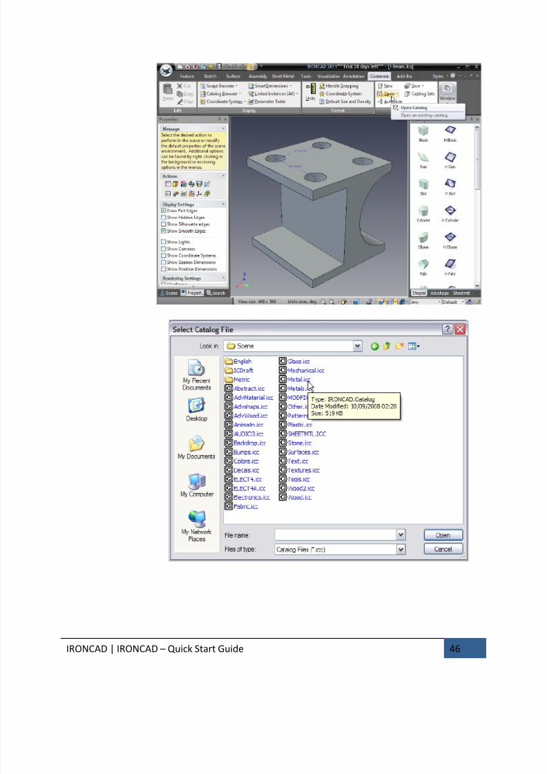
1. Open Rendering Catalogs
Return to the IRONCAD 3D scene by closing the drawing and open the
Metal catalog by selecting to the Common tab and selecting Open. Select
the Scene folder and select Metal.ics (not Metals.icc).
7/30/2019 Unlock Ironcadgsg
http://slidepdf.com/reader/full/unlock-ironcadgsg 50/367
IRONCAD | IRONCAD – Quick Start Guide 46
7/30/2019 Unlock Ironcadgsg
http://slidepdf.com/reader/full/unlock-ironcadgsg 51/367
IRONCAD | IRONCAD – Quick Start Guide 47
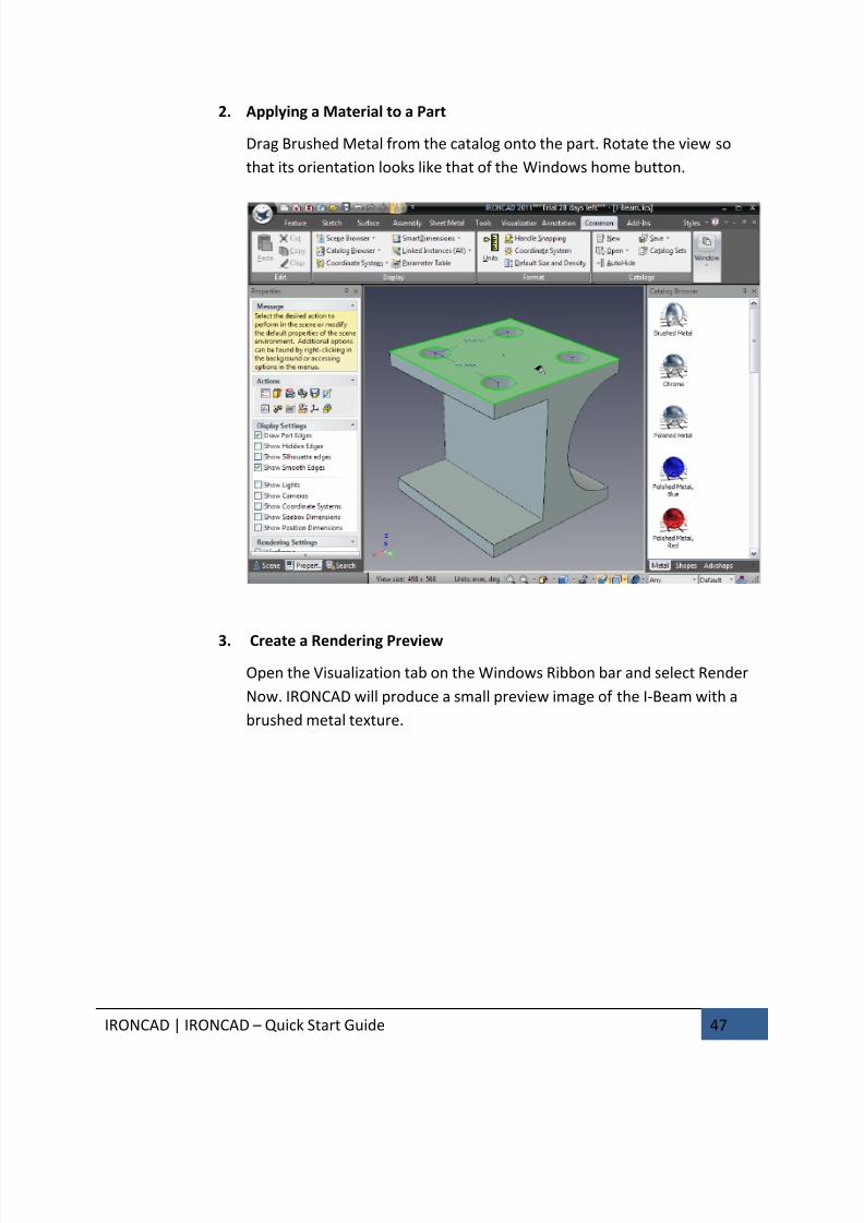
2. Applying a Material to a Part
Drag Brushed Metal from the catalog onto the part. Rotate the view so
that its orientation looks like that of the Windows home button.
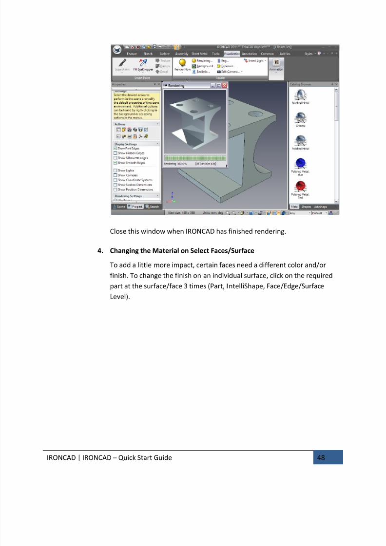
3. Create a Rendering Preview
Open the Visualization tab on the Windows Ribbon bar and select Render
Now. IRONCAD will produce a small preview image of the I-Beam with a
brushed metal texture.
7/30/2019 Unlock Ironcadgsg
http://slidepdf.com/reader/full/unlock-ironcadgsg 52/367
IRONCAD | IRONCAD – Quick Start Guide 48
Close this window when IRONCAD has finished rendering.
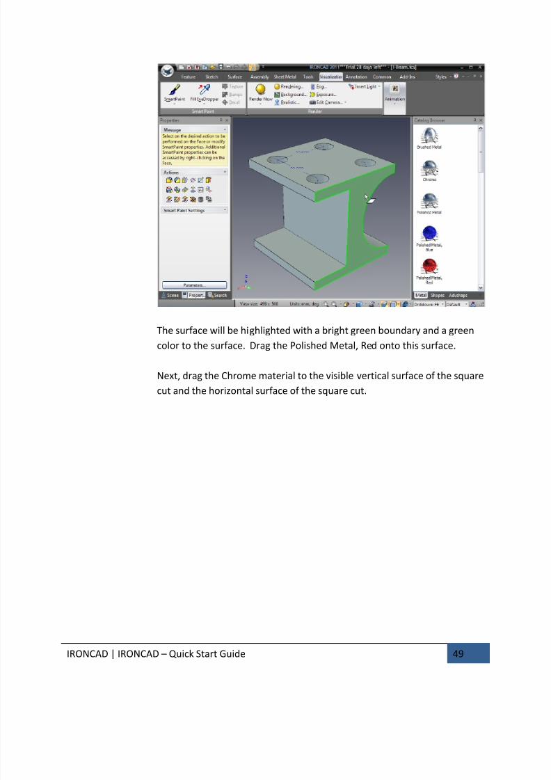
4. Changing the Material on Select Faces/Surface
To add a little more impact, certain faces need a different color and/or
finish. To change the finish on an individual surface, click on the required
part at the surface/face 3 times (Part, IntelliShape, Face/Edge/SurfaceLevel).
7/30/2019 Unlock Ironcadgsg
http://slidepdf.com/reader/full/unlock-ironcadgsg 53/367
7/30/2019 Unlock Ironcadgsg
http://slidepdf.com/reader/full/unlock-ironcadgsg 54/367
IRONCAD | IRONCAD – Quick Start Guide 50
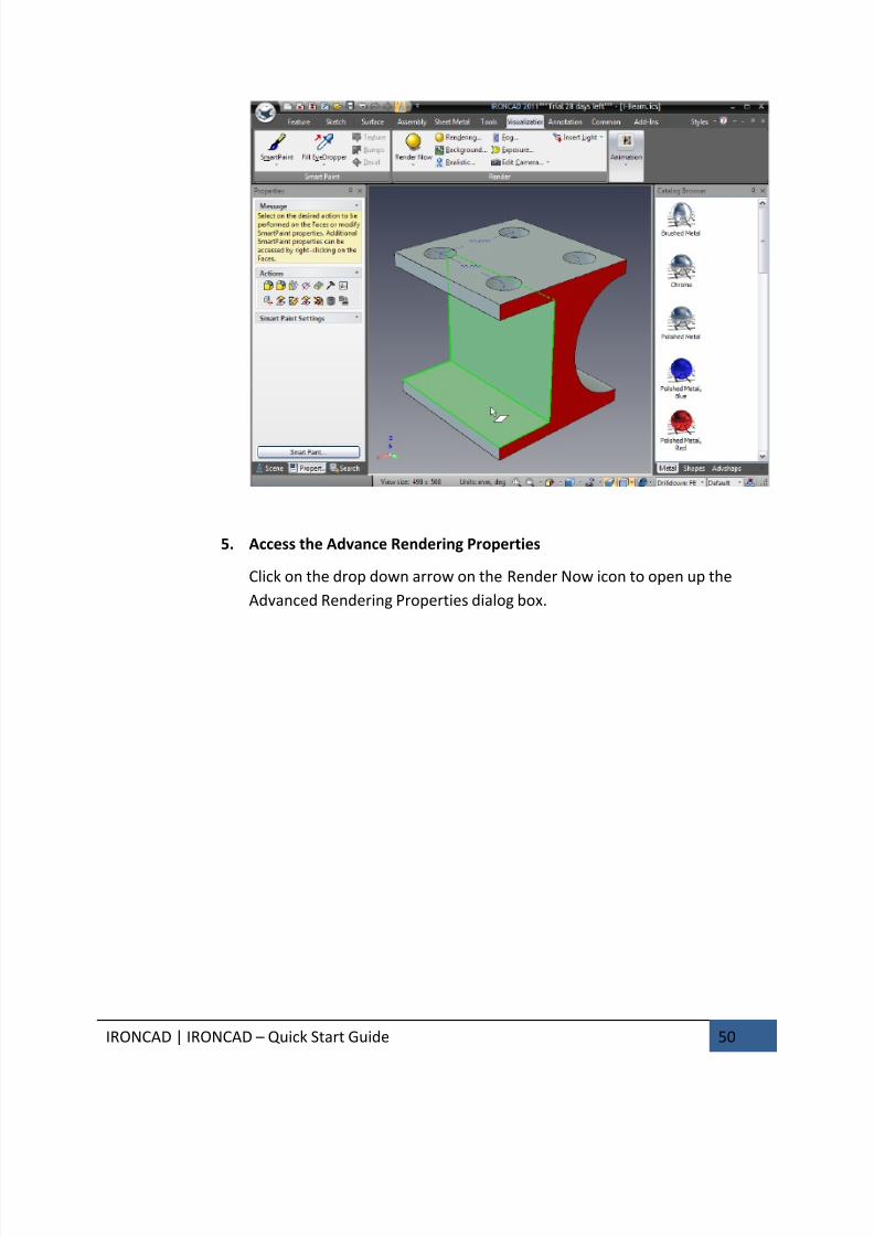
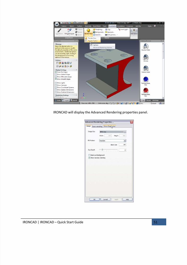
5. Access the Advance Rendering Properties
Click on the drop down arrow on the Render Now icon to open up the
Advanced Rendering Properties dialog box.
7/30/2019 Unlock Ironcadgsg
http://slidepdf.com/reader/full/unlock-ironcadgsg 55/367
IRONCAD | IRONCAD – Quick Start Guide 51
IRONCAD will display the Advanced Rendering properties panel.

7/30/2019 Unlock Ironcadgsg
http://slidepdf.com/reader/full/unlock-ironcadgsg 56/367
IRONCAD | IRONCAD – Quick Start Guide 52
6. Change the Advance Rendering Settings
On the Image tab:
• Change the Image Size to full Window using the drop down, and
• Set the Fill Pattern to Spiral using the drop down options
On the Super-sampling tab:
• Change the Quality setting to High (this provides high definition to the
edges)
On the Global Illumination tab:
• Set the Type to Background Illumination and Quality to High
Click OK
7. Set the Scene to Use Perspective
Make sure the scene is displayed with perspective applied on the bottom
right tool bar. Realistic rendering perform better using this setting since
this is more realistic. Orthographic renderings may take a longer to render
depending on the setting.
8. Render with the New Advance Setting
On the Render Options icon drop down select Render Now. IRONCAD will
proceed to produce a photo realistic image of the I-Beam.
7/30/2019 Unlock Ironcadgsg
http://slidepdf.com/reader/full/unlock-ironcadgsg 57/367
IRONCAD | IRONCAD – Quick Start Guide 53
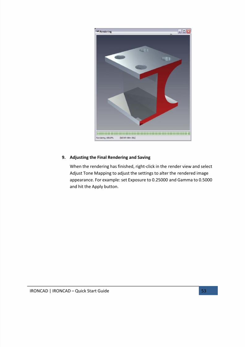
9. Adjusting the Final Rendering and Saving
When the rendering has finished, right-click in the render view and select
Adjust Tone Mapping to adjust the settings to alter the rendered image
appearance. For example: set Exposure to 0.25000 and Gamma to 0.5000
and hit the Apply button.
7/30/2019 Unlock Ironcadgsg
http://slidepdf.com/reader/full/unlock-ironcadgsg 58/367
IRONCAD | IRONCAD – Quick Start Guide 54
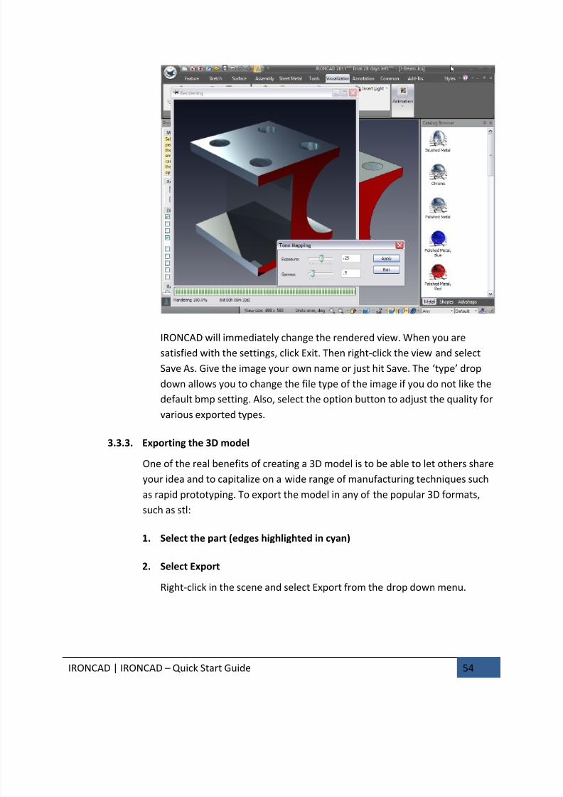
IRONCAD will immediately change the rendered view. When you are
satisfied with the settings, click Exit. Then right-click the view and select
Save As. Give the image your own name or just hit Save. The ‘type’ drop
down allows you to change the file type of the image if you do not like the
default bmp setting. Also, select the option button to adjust the quality for
various exported types.
3.3.3. Exporting the 3D model
One of the real benefits of creating a 3D model is to be able to let others share
your idea and to capitalize on a wide range of manufacturing techniques such
as rapid prototyping. To export the model in any of the popular 3D formats,
such as stl:
1. Select the part (edges highlighted in cyan)
2. Select Export
Right-click in the scene and select Export from the drop down menu.
7/30/2019 Unlock Ironcadgsg
http://slidepdf.com/reader/full/unlock-ironcadgsg 59/367
IRONCAD | IRONCAD – Quick Start Guide 55
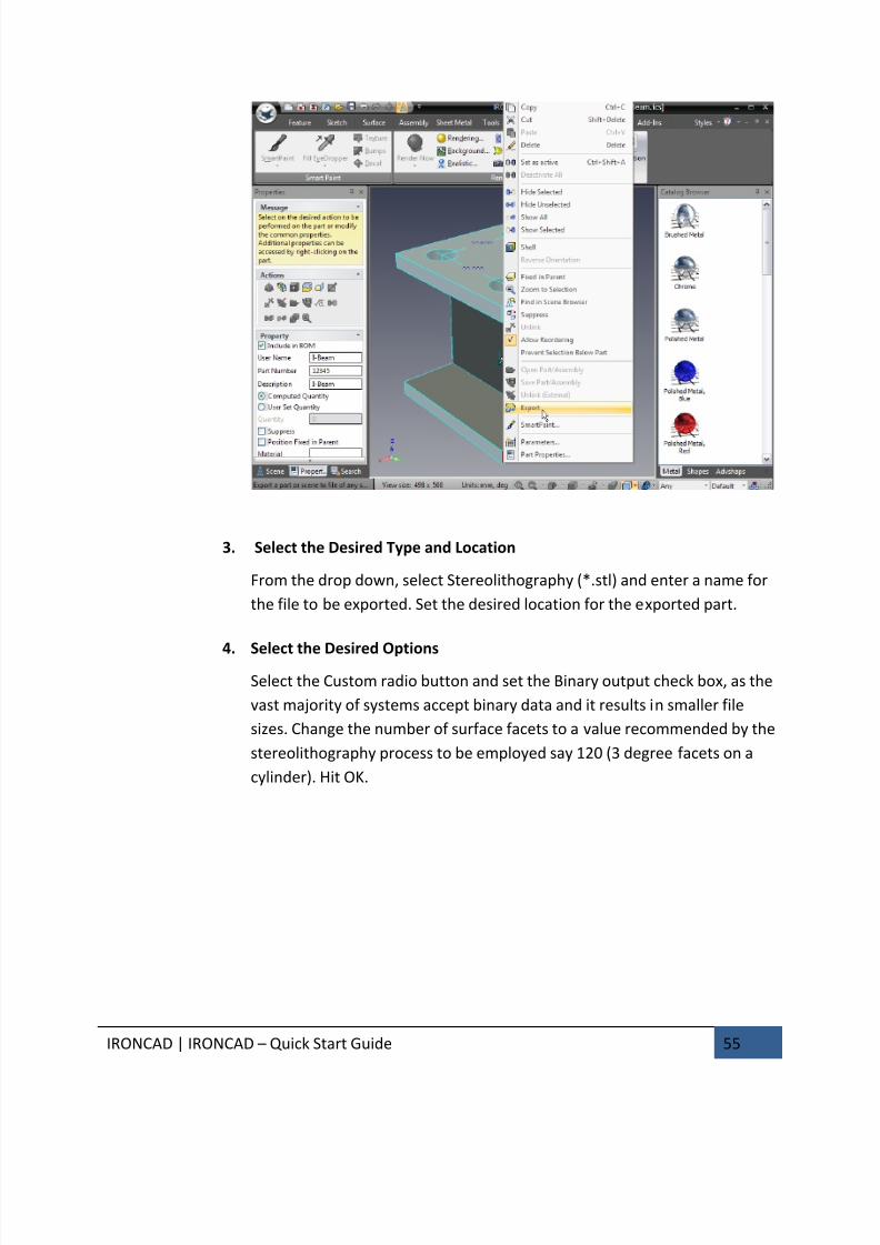
3. Select the Desired Type and Location
From the drop down, select Stereolithography (*.stl) and enter a name for
the file to be exported. Set the desired location for the exported part.
4.
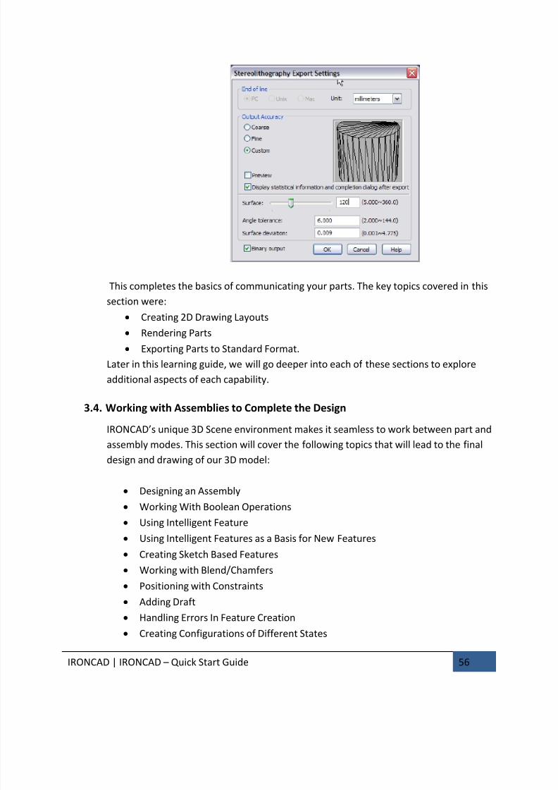
Select the Desired Options
Select the Custom radio button and set the Binary output check box, as the
vast majority of systems accept binary data and it results in smaller file
sizes. Change the number of surface facets to a value recommended by the
stereolithography process to be employed say 120 (3 degree facets on a
cylinder). Hit OK.
7/30/2019 Unlock Ironcadgsg
http://slidepdf.com/reader/full/unlock-ironcadgsg 60/367
IRONCAD | IRONCAD – Quick Start Guide 56
This completes the basics of communicating your parts. The key topics covered in this
section were:
• Creating 2D Drawing Layouts
• Rendering Parts
• Exporting Parts to Standard Format.
Later in this learning guide, we will go deeper into each of these sections to explore
additional aspects of each capability.
3.4. Working with Assemblies to Complete the Design
IRONCAD’s unique 3D Scene environment makes it seamless to work between part and
assembly modes. This section will cover the following topics that will lead to the final
design and drawing of our 3D model:
• Designing an Assembly
• Working With Boolean Operations
• Using Intelligent Feature
• Using Intelligent Features as a Basis for New Features
• Creating Sketch Based Features• Working with Blend/Chamfers
• Positioning with Constraints
• Adding Draft
• Handling Errors In Feature Creation
• Creating Configurations of Different States
7/30/2019 Unlock Ironcadgsg
http://slidepdf.com/reader/full/unlock-ironcadgsg 61/367
IRONCAD | IRONCAD – Quick Start Guide 57
• Creating Exploded Assembly Drawings
This section will take the model created in the previous section introduce these
primary sections to result in a completed design of our model.
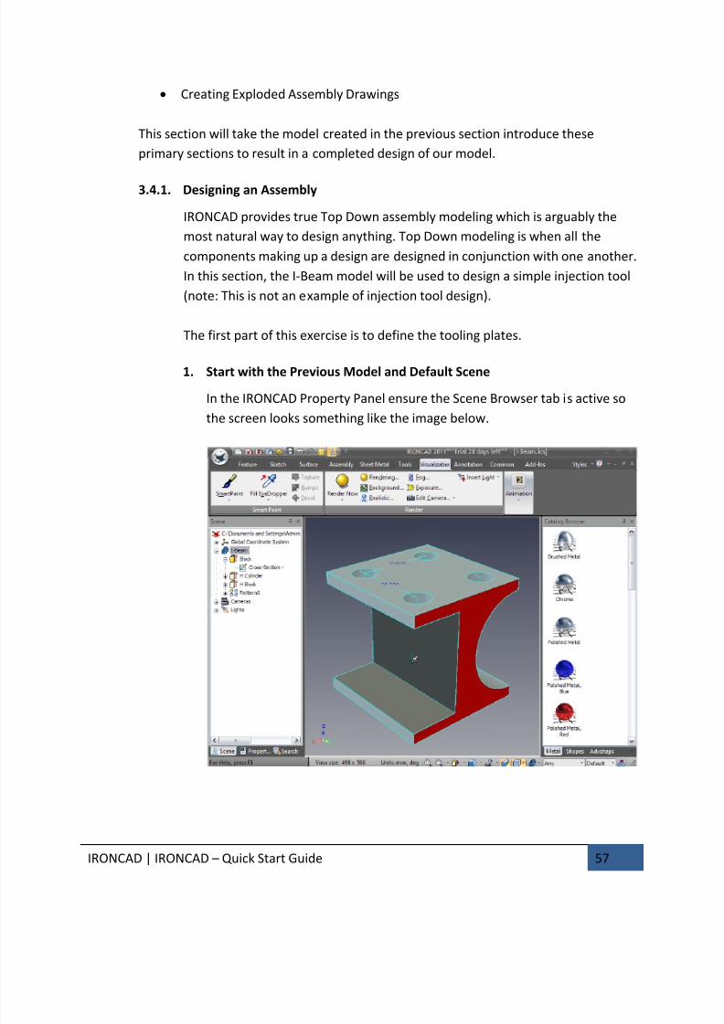
3.4.1. Designing an Assembly
IRONCAD provides true Top Down assembly modeling which is arguably the
most natural way to design anything. Top Down modeling is when all the
components making up a design are designed in conjunction with one another.
In this section, the I-Beam model will be used to design a simple injection tool
(note: This is not an example of injection tool design).
The first part of this exercise is to define the tooling plates.
1. Start with the Previous Model and Default Scene
In the IRONCAD Property Panel ensure the Scene Browser tab is active so
the screen looks something like the image below.
7/30/2019 Unlock Ironcadgsg
http://slidepdf.com/reader/full/unlock-ironcadgsg 62/367
IRONCAD | IRONCAD – Quick Start Guide 58
2. Copy the I-Beam
Right-click on the I-Beam model and select Copy from the drop down menu
3. Paste the I-Beam and Repeat
Right-click again and select Paste. A second I-Beam part will be shown in
the Scene Browser. Repeat the last operation so that the Scene Browser
shows 3 I-Beam parts.
4. Using Suppress to Hide
In the Scene Browser, right-click on the first I-Beam part and select
Suppress from the drop down menu. The blue icon will be replaced by a
white wire frame icon.
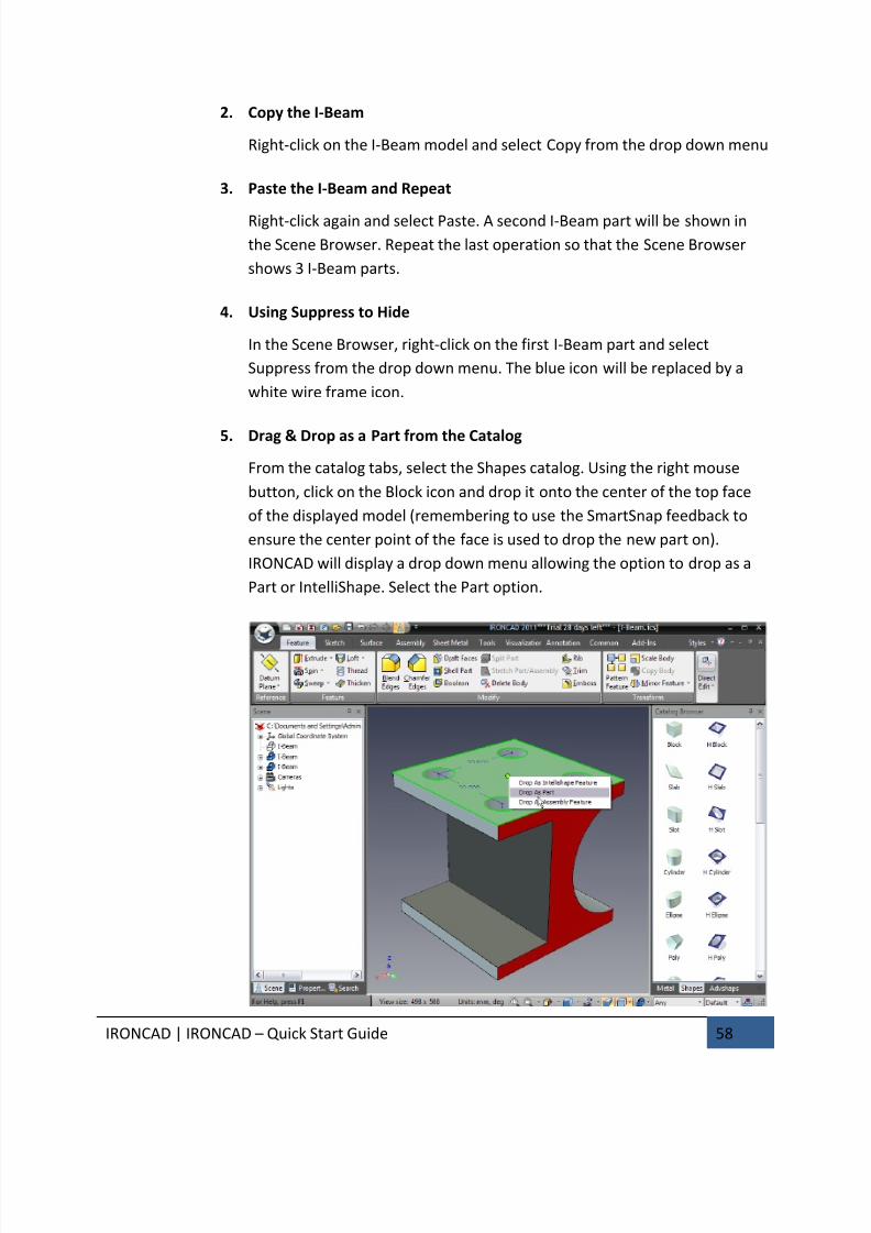
5. Drag & Drop as a Part from the Catalog
From the catalog tabs, select the Shapes catalog. Using the right mouse
button, click on the Block icon and drop it onto the center of the top face
of the displayed model (remembering to use the SmartSnap feedback to
ensure the center point of the face is used to drop the new part on).
IRONCAD will display a drop down menu allowing the option to drop as a
Part or IntelliShape. Select the Part option.
7/30/2019 Unlock Ironcadgsg
http://slidepdf.com/reader/full/unlock-ironcadgsg 63/367
IRONCAD | IRONCAD – Quick Start Guide 59
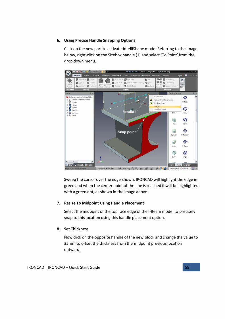
6. Using Precise Handle Snapping Options
Click on the new part to activate IntelliShape mode. Referring to the image
below, right-click on the Sizebox handle (1) and select ‘To Point’ from thedrop down menu.
Sweep the cursor over the edge shown. IRONCAD will highlight the edge in
green and when the center point of the line is reached it will be highlighted
with a green dot, as shown in the image above.
7. Resize To Midpoint Using Handle Placement
Select the midpoint of the top face edge of the I-Beam model to precisely
snap to this location using this handle placement option.
8. Set Thickness
Now click on the opposite handle of the new block and change the value to
35mm to offset the thickness from the midpoint previous location
outward.
7/30/2019 Unlock Ironcadgsg
http://slidepdf.com/reader/full/unlock-ironcadgsg 64/367
IRONCAD | IRONCAD – Quick Start Guide 60
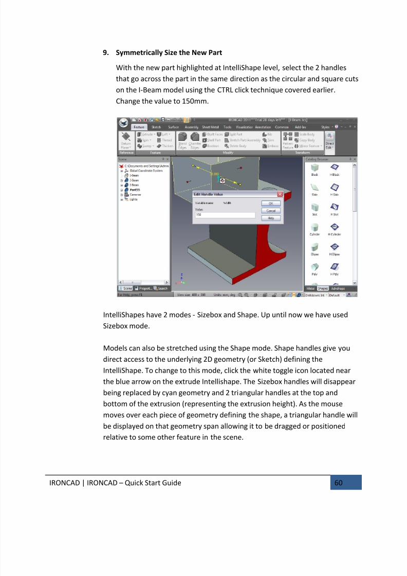
9. Symmetrically Size the New Part
With the new part highlighted at IntelliShape level, select the 2 handles
that go across the part in the same direction as the circular and square cuts
on the I-Beam model using the CTRL click technique covered earlier.
Change the value to 150mm.
IntelliShapes have 2 modes - Sizebox and Shape. Up until now we have used
Sizebox mode.
Models can also be stretched using the Shape mode. Shape handles give you
direct access to the underlying 2D geometry (or Sketch) defining the
IntelliShape. To change to this mode, click the white toggle icon located near
the blue arrow on the extrude Intellishape. The Sizebox handles will disappear
being replaced by cyan geometry and 2 triangular handles at the top and
bottom of the extrusion (representing the extrusion height). As the mousemoves over each piece of geometry defining the shape, a triangular handle will
be displayed on that geometry span allowing it to be dragged or positioned
relative to some other feature in the scene.
7/30/2019 Unlock Ironcadgsg
http://slidepdf.com/reader/full/unlock-ironcadgsg 65/367
IRONCAD | IRONCAD – Quick Start Guide 61
10. Fit the Contents to the Scene
If necessary, press F8 to fit the scene window to the models.
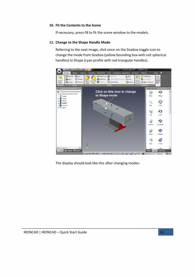
11. Change to the Shape Handle Mode
Referring to the next image, click once on the Sizebox toggle icon to
change the mode from Sizebox (yellow bounding box with red spherical
handles) to Shape (cyan profile with red triangular handles).
The display should look like this after changing modes:
7/30/2019 Unlock Ironcadgsg
http://slidepdf.com/reader/full/unlock-ironcadgsg 66/367
IRONCAD | IRONCAD – Quick Start Guide 62
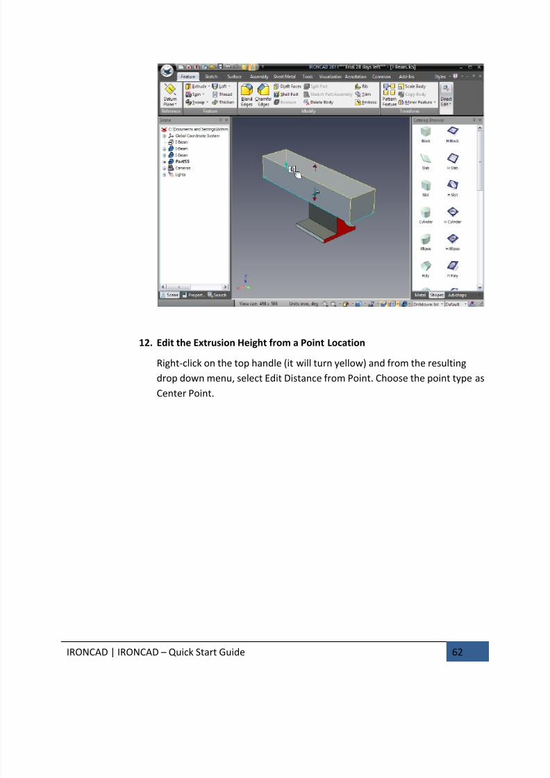
12. Edit the Extrusion Height from a Point Location
Right-click on the top handle (it will turn yellow) and from the resulting
drop down menu, select Edit Distance from Point. Choose the point type as
Center Point.
7/30/2019 Unlock Ironcadgsg
http://slidepdf.com/reader/full/unlock-ironcadgsg 67/367
IRONCAD | IRONCAD – Quick Start Guide 63
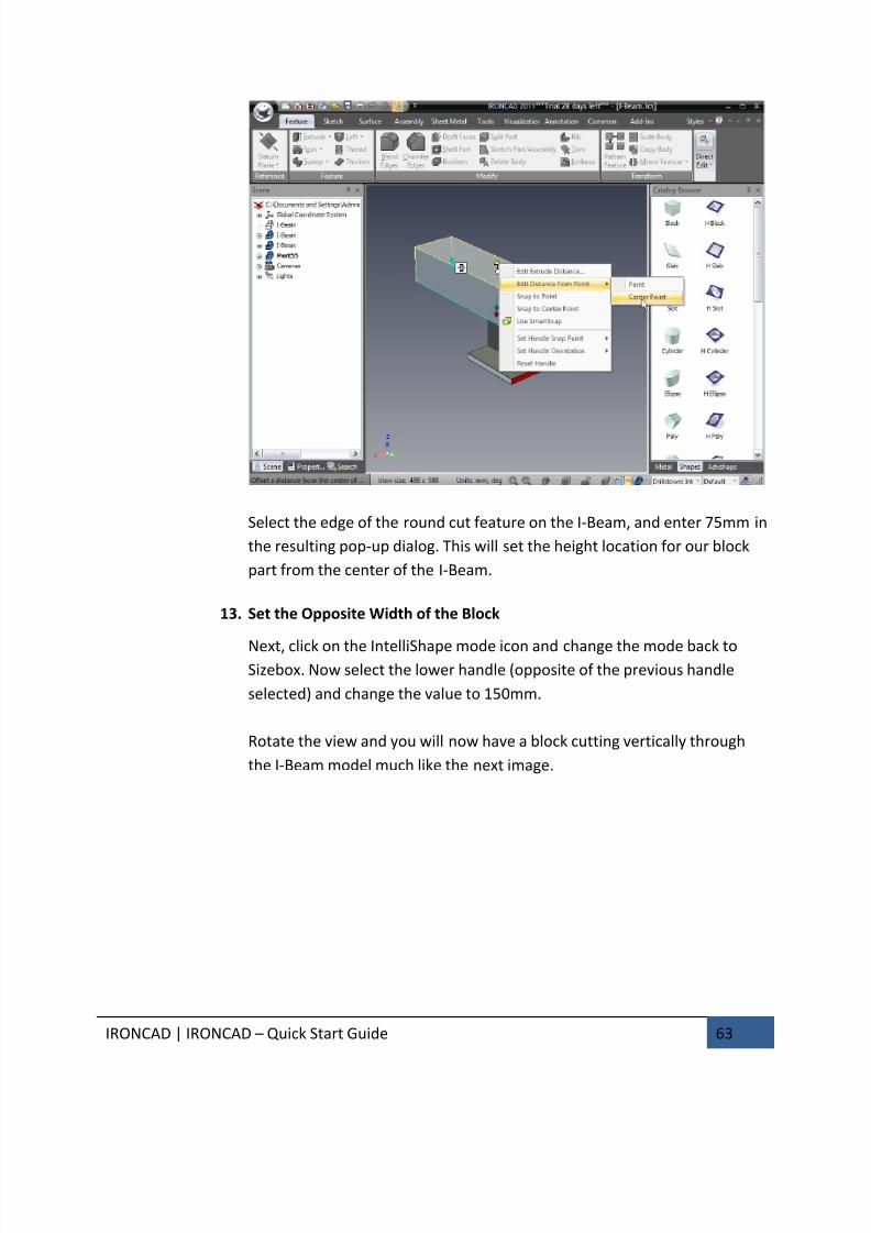
Select the edge of the round cut feature on the I-Beam, and enter 75mm in
the resulting pop-up dialog. This will set the height location for our block
part from the center of the I-Beam.
13. Set the Opposite Width of the Block
Next, click on the IntelliShape mode icon and change the mode back toSizebox. Now select the lower handle (opposite of the previous handle
selected) and change the value to 150mm.
Rotate the view and you will now have a block cutting vertically through
the I-Beam model much like the next image.
7/30/2019 Unlock Ironcadgsg
http://slidepdf.com/reader/full/unlock-ironcadgsg 68/367
IRONCAD | IRONCAD – Quick Start Guide 64
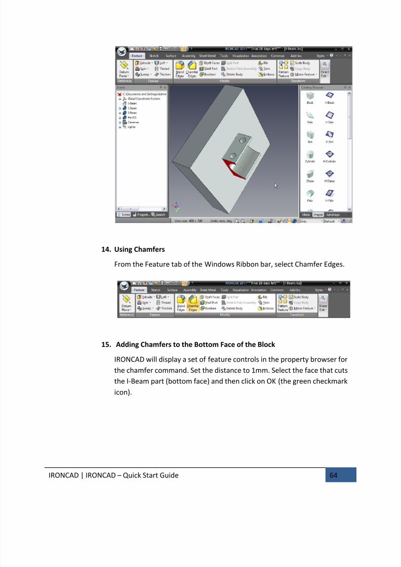
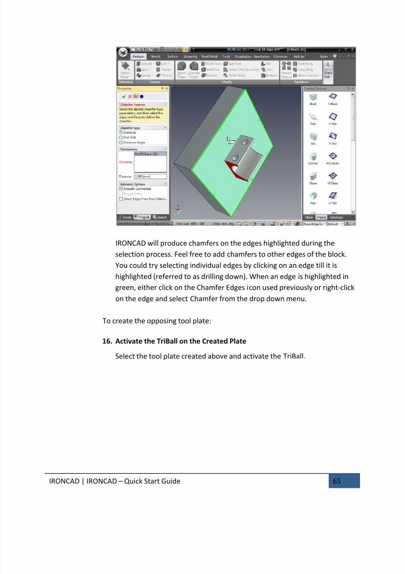
14. Using Chamfers
From the Feature tab of the Windows Ribbon bar, select Chamfer Edges.
15. Adding Chamfers to the Bottom Face of the Block
IRONCAD will display a set of feature controls in the property browser for
the chamfer command. Set the distance to 1mm. Select the face that cuts
the I-Beam part (bottom face) and then click on OK (the green checkmark
icon).
7/30/2019 Unlock Ironcadgsg
http://slidepdf.com/reader/full/unlock-ironcadgsg 69/367
IRONCAD | IRONCAD – Quick Start Guide 65
IRONCAD will produce chamfers on the edges highlighted during the
selection process. Feel free to add chamfers to other edges of the block.
You could try selecting individual edges by clicking on an edge till it is
highlighted (referred to as drilling down). When an edge is highlighted in
green, either click on the Chamfer Edges icon used previously or right-click
on the edge and select Chamfer from the drop down menu.
To create the opposing tool plate:
16. Activate the TriBall on the Created Plate
Select the tool plate created above and activate the TriBall.
7/30/2019 Unlock Ironcadgsg
http://slidepdf.com/reader/full/unlock-ironcadgsg 70/367
IRONCAD | IRONCAD – Quick Start Guide 66
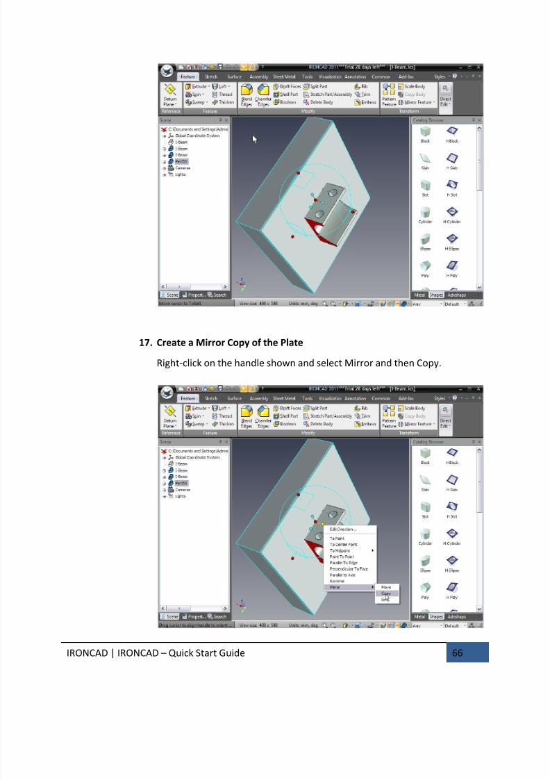
17. Create a Mirror Copy of the Plate
Right-click on the handle shown and select Mirror and then Copy.
7/30/2019 Unlock Ironcadgsg
http://slidepdf.com/reader/full/unlock-ironcadgsg 71/367
IRONCAD | IRONCAD – Quick Start Guide 67
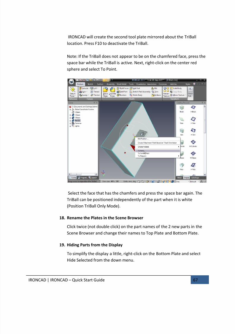
IRONCAD will create the second tool plate mirrored about the TriBall
location. Press F10 to deactivate the TriBall.
Note: If the TriBall does not appear to be on the chamfered face, press thespace bar while the TriBall is active. Next, right-click on the center red
sphere and select To Point.
Select the face that has the chamfers and press the space bar again. The
TriBall can be positioned independently of the part when it is white
(Position TriBall Only Mode).
18. Rename the Plates in the Scene Browser
Click twice (not double click) on the part names of the 2 new parts in the
Scene Browser and change their names to Top Plate and Bottom Plate.
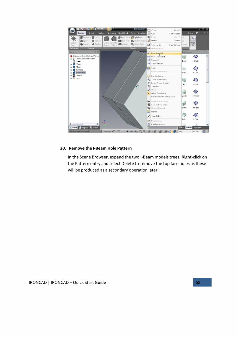
19. Hiding Parts from the Display
To simplify the display a little, right-click on the Bottom Plate and select
Hide Selected from the down menu.
7/30/2019 Unlock Ironcadgsg
http://slidepdf.com/reader/full/unlock-ironcadgsg 72/367
IRONCAD | IRONCAD – Quick Start Guide 68
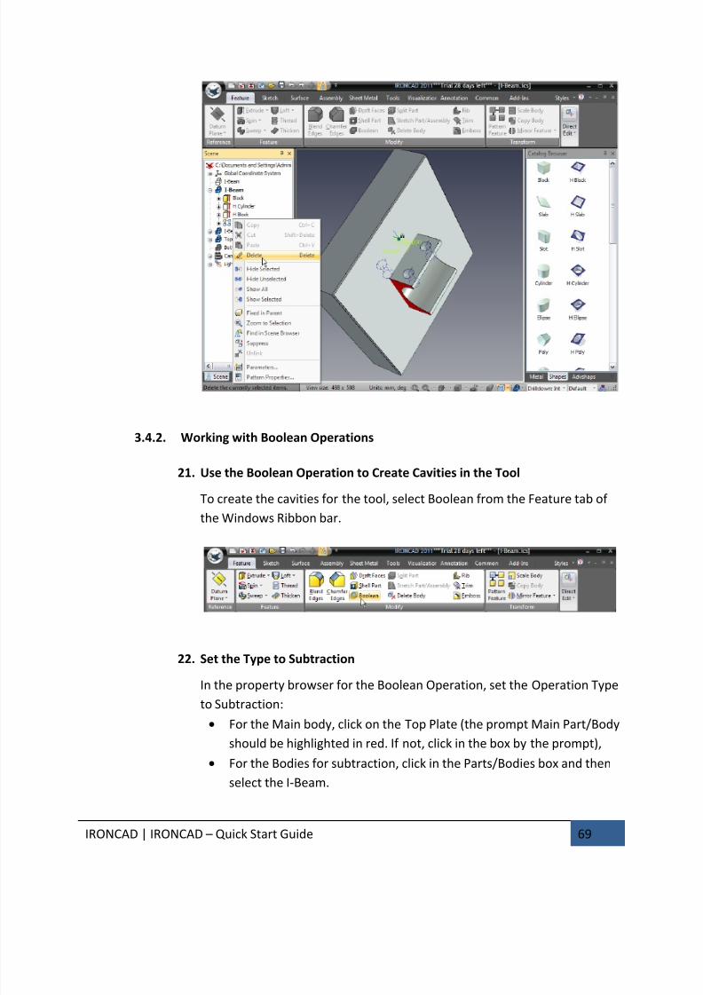
20. Remove the I-Beam Hole Pattern
In the Scene Browser, expand the two I-Beam models trees. Right-click on
the Pattern entry and select Delete to remove the top face holes as these
will be produced as a secondary operation later.
7/30/2019 Unlock Ironcadgsg
http://slidepdf.com/reader/full/unlock-ironcadgsg 73/367
IRONCAD | IRONCAD – Quick Start Guide 69
3.4.2. Working with Boolean Operations
21. Use the Boolean Operation to Create Cavities in the Tool
To create the cavities for the tool, select Boolean from the Feature tab of
the Windows Ribbon bar.
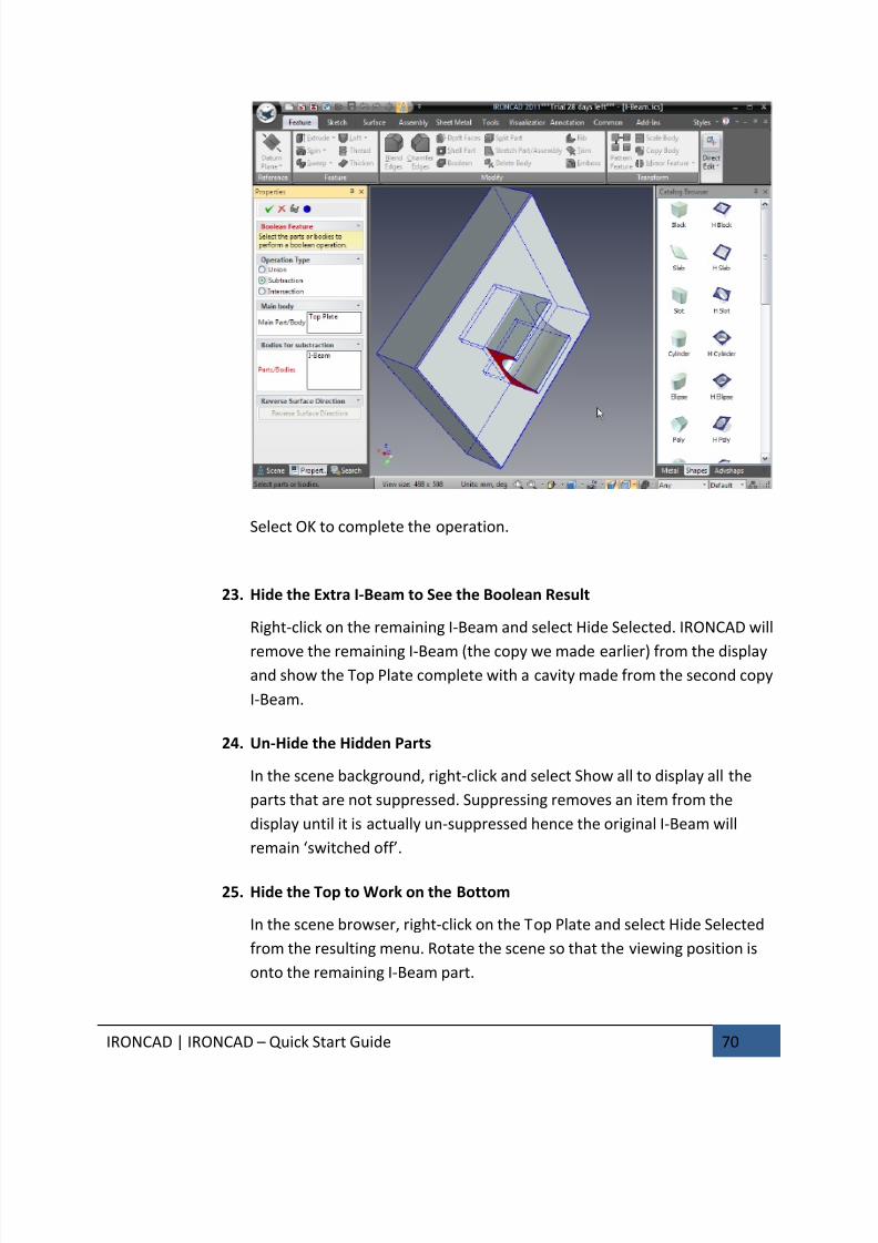
22. Set the Type to Subtraction
In the property browser for the Boolean Operation, set the Operation Type
to Subtraction:
• For the Main body, click on the Top Plate (the prompt Main Part/Body
should be highlighted in red. If not, click in the box by the prompt),
• For the Bodies for subtraction, click in the Parts/Bodies box and then
select the I-Beam.
7/30/2019 Unlock Ironcadgsg
http://slidepdf.com/reader/full/unlock-ironcadgsg 74/367
IRONCAD | IRONCAD – Quick Start Guide 70
Select OK to complete the operation.
23. Hide the Extra I-Beam to See the Boolean Result
Right-click on the remaining I-Beam and select Hide Selected. IRONCAD will
remove the remaining I-Beam (the copy we made earlier) from the displayand show the Top Plate complete with a cavity made from the second copy
I-Beam.
24. Un-Hide the Hidden Parts
In the scene background, right-click and select Show all to display all the
parts that are not suppressed. Suppressing removes an item from the
display until it is actually un-suppressed hence the original I-Beam will
remain ‘switched off’.
25. Hide the Top to Work on the Bottom
In the scene browser, right-click on the Top Plate and select Hide Selected
from the resulting menu. Rotate the scene so that the viewing position is
onto the remaining I-Beam part.
7/30/2019 Unlock Ironcadgsg
http://slidepdf.com/reader/full/unlock-ironcadgsg 75/367
IRONCAD | IRONCAD – Quick Start Guide 71
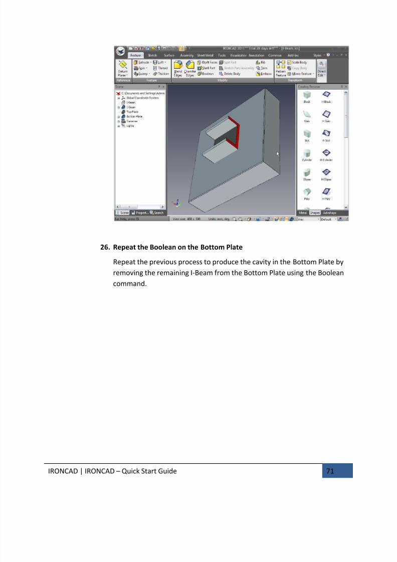
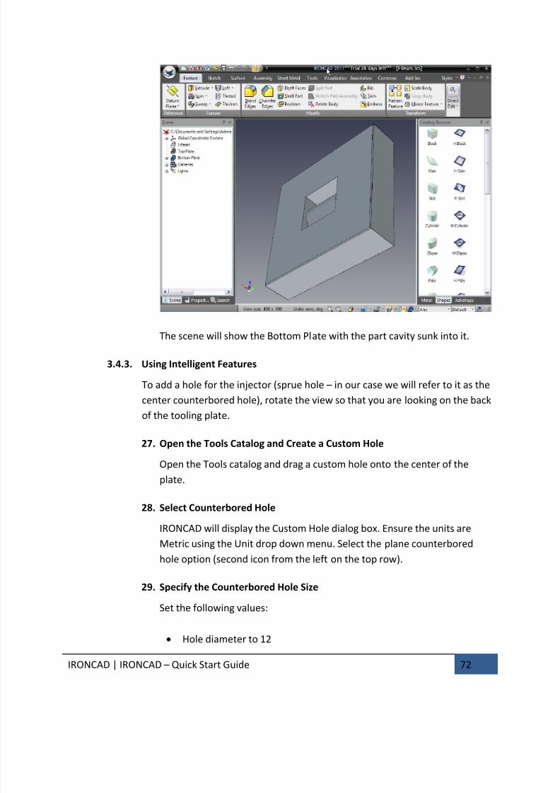
26. Repeat the Boolean on the Bottom Plate
Repeat the previous process to produce the cavity in the Bottom Plate by
removing the remaining I-Beam from the Bottom Plate using the Boolean
command.
7/30/2019 Unlock Ironcadgsg
http://slidepdf.com/reader/full/unlock-ironcadgsg 76/367
IRONCAD | IRONCAD – Quick Start Guide 72
The scene will show the Bottom Plate with the part cavity sunk into it.
3.4.3. Using Intelligent Features
To add a hole for the injector (sprue hole – in our case we will refer to it as the
center counterbored hole), rotate the view so that you are looking on the back
of the tooling plate.
27. Open the Tools Catalog and Create a Custom Hole
Open the Tools catalog and drag a custom hole onto the center of the
plate.
28. Select Counterbored Hole
IRONCAD will display the Custom Hole dialog box. Ensure the units are
Metric using the Unit drop down menu. Select the plane counterbored
hole option (second icon from the left on the top row).
29. Specify the Counterbored Hole Size
Set the following values:
• Hole diameter to 12
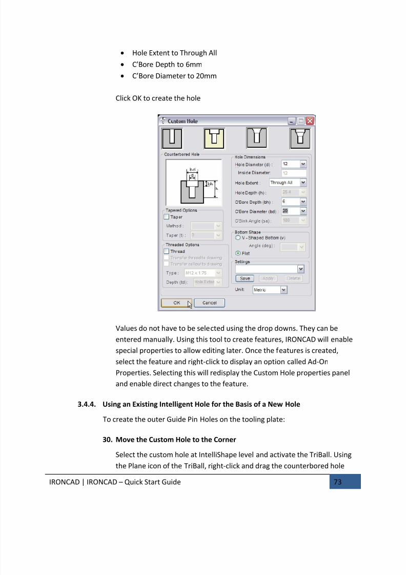
7/30/2019 Unlock Ironcadgsg
http://slidepdf.com/reader/full/unlock-ironcadgsg 77/367

7/30/2019 Unlock Ironcadgsg
http://slidepdf.com/reader/full/unlock-ironcadgsg 78/367
IRONCAD | IRONCAD – Quick Start Guide 74
towards a corner of the plate and use the copy function with a value of 55
for both distances.
31. Select the Newly Create Hole for Copy
Deactivate the TriBall. Select the newly create hole and activate the TriBallagain.
32. Deactivate the TriBall to Position it Only
With the TriBall active on the newly created hole, press the spacebar so
that the TriBall can be repositioned. The TriBall will turn from cyan to
white.

7/30/2019 Unlock Ironcadgsg
http://slidepdf.com/reader/full/unlock-ironcadgsg 79/367
IRONCAD | IRONCAD – Quick Start Guide 75
33. Reposition to the Center of the Counterbored Hole
Right-click on the center red sphere and select To Center Point. Select one
of the edges of the center counterbored hole.
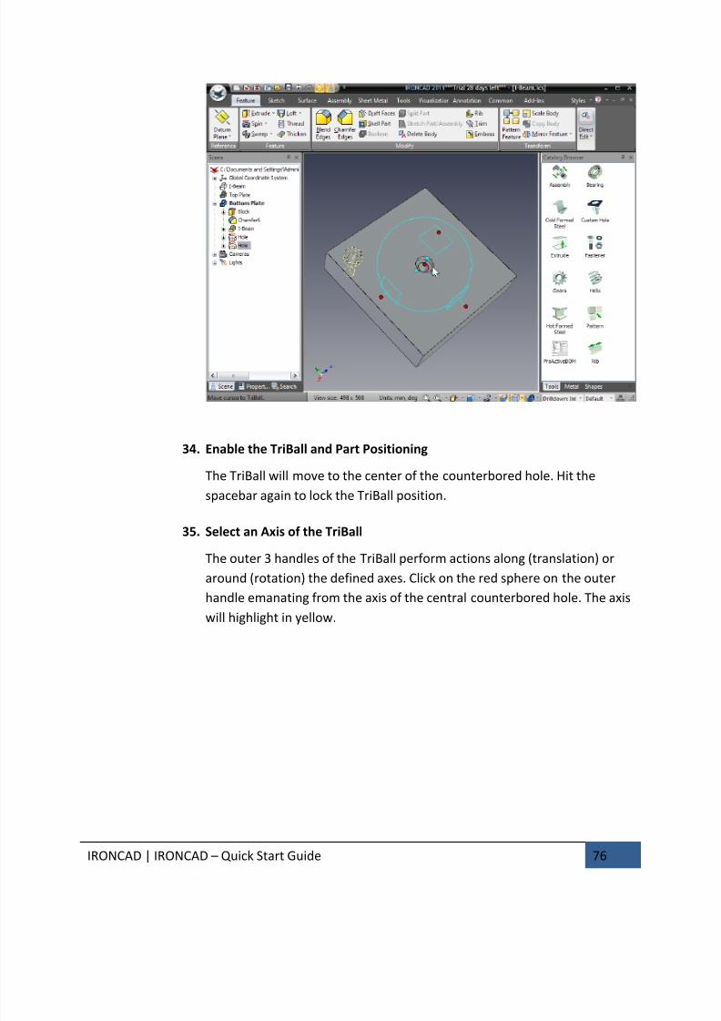
7/30/2019 Unlock Ironcadgsg
http://slidepdf.com/reader/full/unlock-ironcadgsg 80/367
IRONCAD | IRONCAD – Quick Start Guide 76
34. Enable the TriBall and Part Positioning
The TriBall will move to the center of the counterbored hole. Hit the
spacebar again to lock the TriBall position.
35. Select an Axis of the TriBall
The outer 3 handles of the TriBall perform actions along (translation) or
around (rotation) the defined axes. Click on the red sphere on the outer
handle emanating from the axis of the central counterbored hole. The axis
will highlight in yellow.

7/30/2019 Unlock Ironcadgsg
http://slidepdf.com/reader/full/unlock-ironcadgsg 81/367
IRONCAD | IRONCAD – Quick Start Guide 77
36. Rotate About the Selected Axis
Move the mouse pointer inside the TriBall circle. The mouse pointer
changes to a clenched fist with an arrow around the wrist as shown in the
previous image. Right-click and drag the mouse around the axis a short
amount and release the mouse button. IRONCAD will display a small dropdown menu.
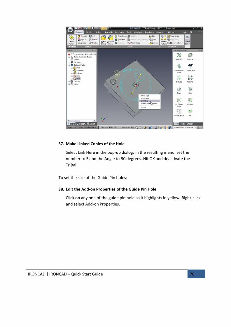
7/30/2019 Unlock Ironcadgsg
http://slidepdf.com/reader/full/unlock-ironcadgsg 82/367
IRONCAD | IRONCAD – Quick Start Guide 78
37. Make Linked Copies of the Hole
Select Link Here in the pop-up dialog. In the resulting menu, set the
number to 3 and the Angle to 90 degrees. Hit OK and deactivate the
TriBall.
To set the size of the Guide Pin holes:
38. Edit the Add-on Properties of the Guide Pin Hole
Click on any one of the guide pin hole so it highlights in yellow. Right-click
and select Add-on Properties.
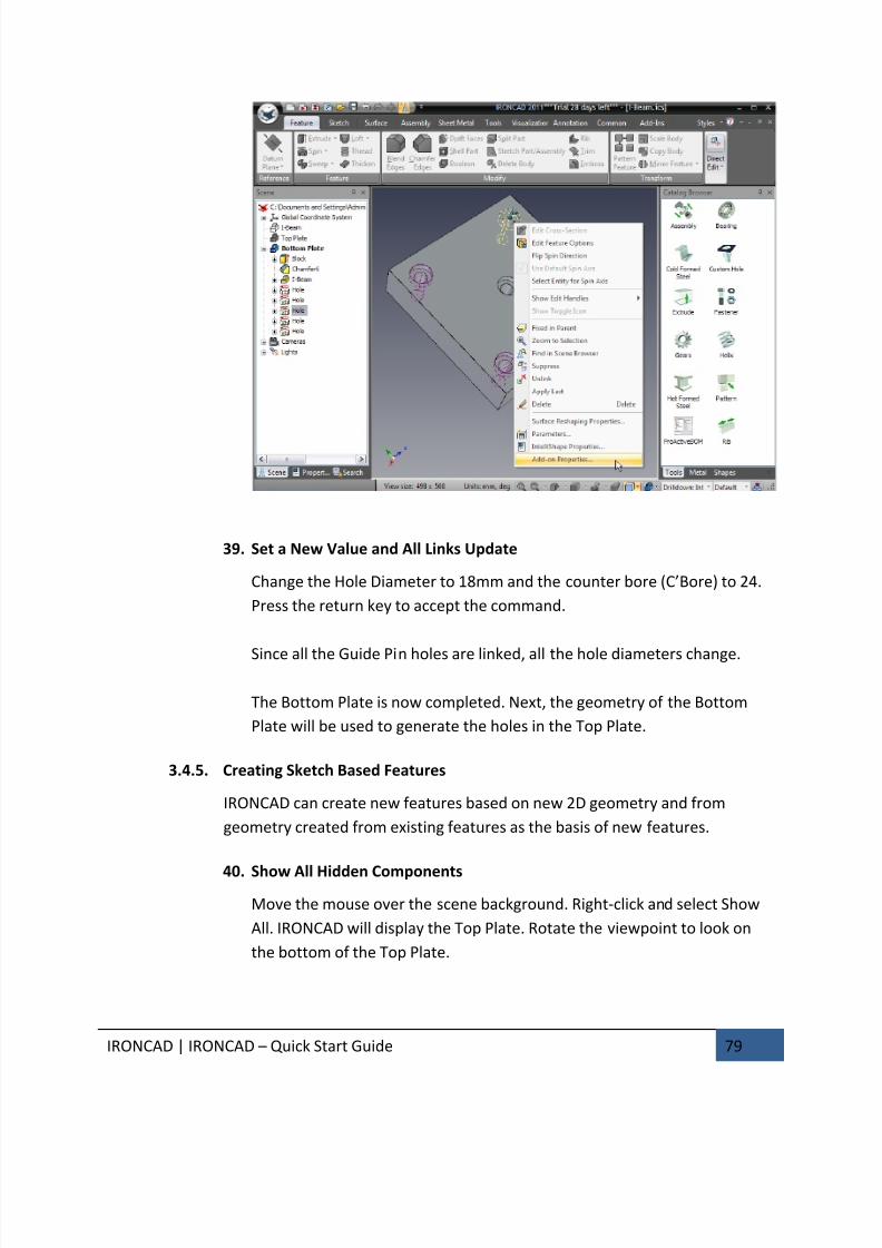
7/30/2019 Unlock Ironcadgsg
http://slidepdf.com/reader/full/unlock-ironcadgsg 83/367
IRONCAD | IRONCAD – Quick Start Guide 79
39. Set a New Value and All Links Update
Change the Hole Diameter to 18mm and the counter bore (C’Bore) to 24.
Press the return key to accept the command.
Since all the Guide Pin holes are linked, all the hole diameters change.
The Bottom Plate is now completed. Next, the geometry of the Bottom
Plate will be used to generate the holes in the Top Plate.
3.4.5. Creating Sketch Based Features
IRONCAD can create new features based on new 2D geometry and from
geometry created from existing features as the basis of new features.
40. Show All Hidden Components
Move the mouse over the scene background. Right-click and select Show
All. IRONCAD will display the Top Plate. Rotate the viewpoint to look on
the bottom of the Top Plate.
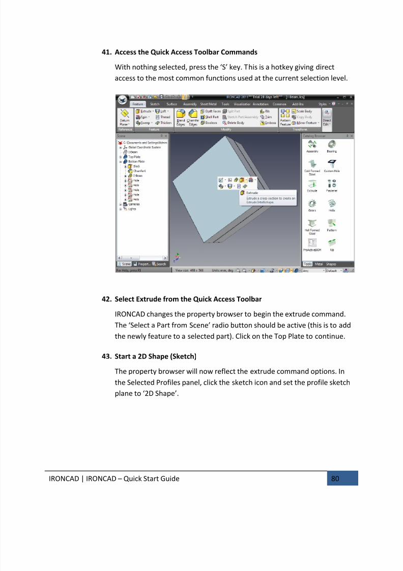
7/30/2019 Unlock Ironcadgsg
http://slidepdf.com/reader/full/unlock-ironcadgsg 84/367
IRONCAD | IRONCAD – Quick Start Guide 80
41. Access the Quick Access Toolbar Commands
With nothing selected, press the ‘S’ key. This is a hotkey giving direct
access to the most common functions used at the current selection level.
42. Select Extrude from the Quick Access Toolbar
IRONCAD changes the property browser to begin the extrude command.
The ‘Select a Part from Scene’ radio button should be active (this is to add
the newly feature to a selected part). Click on the Top Plate to continue.
43. Start a 2D Shape (Sketch)
The property browser will now reflect the extrude command options. In
the Selected Profiles panel, click the sketch icon and set the profile sketch
plane to ‘2D Shape’.
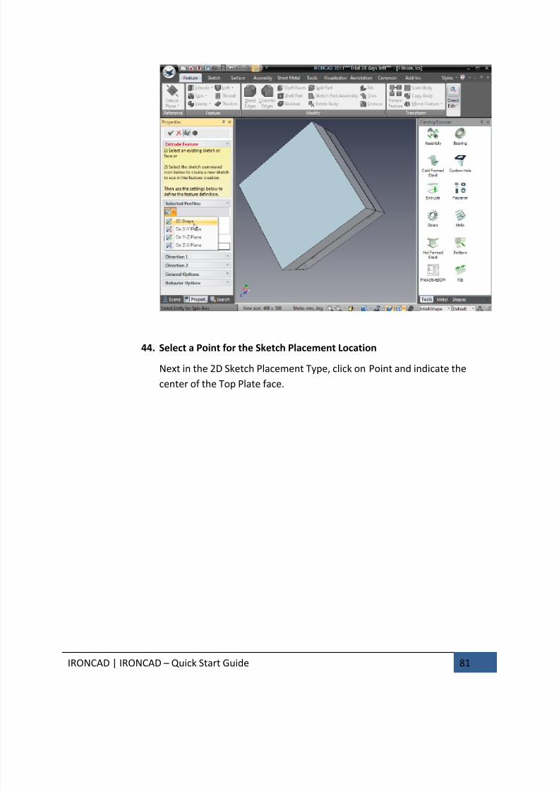
7/30/2019 Unlock Ironcadgsg
http://slidepdf.com/reader/full/unlock-ironcadgsg 85/367
IRONCAD | IRONCAD – Quick Start Guide 81
44. Select a Point for the Sketch Placement Location
Next in the 2D Sketch Placement Type, click on Point and indicate the
center of the Top Plate face.
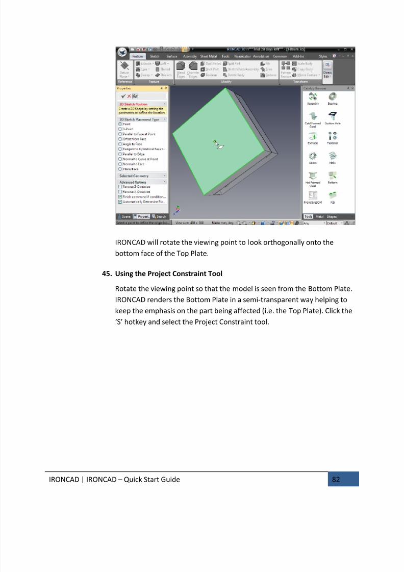
7/30/2019 Unlock Ironcadgsg
http://slidepdf.com/reader/full/unlock-ironcadgsg 86/367
IRONCAD | IRONCAD – Quick Start Guide 82
IRONCAD will rotate the viewing point to look orthogonally onto the
bottom face of the Top Plate.
45. Using the Project Constraint Tool
Rotate the viewing point so that the model is seen from the Bottom Plate.
IRONCAD renders the Bottom Plate in a semi-transparent way helping tokeep the emphasis on the part being affected (i.e. the Top Plate). Click the
‘S’ hotkey and select the Project Constraint tool.
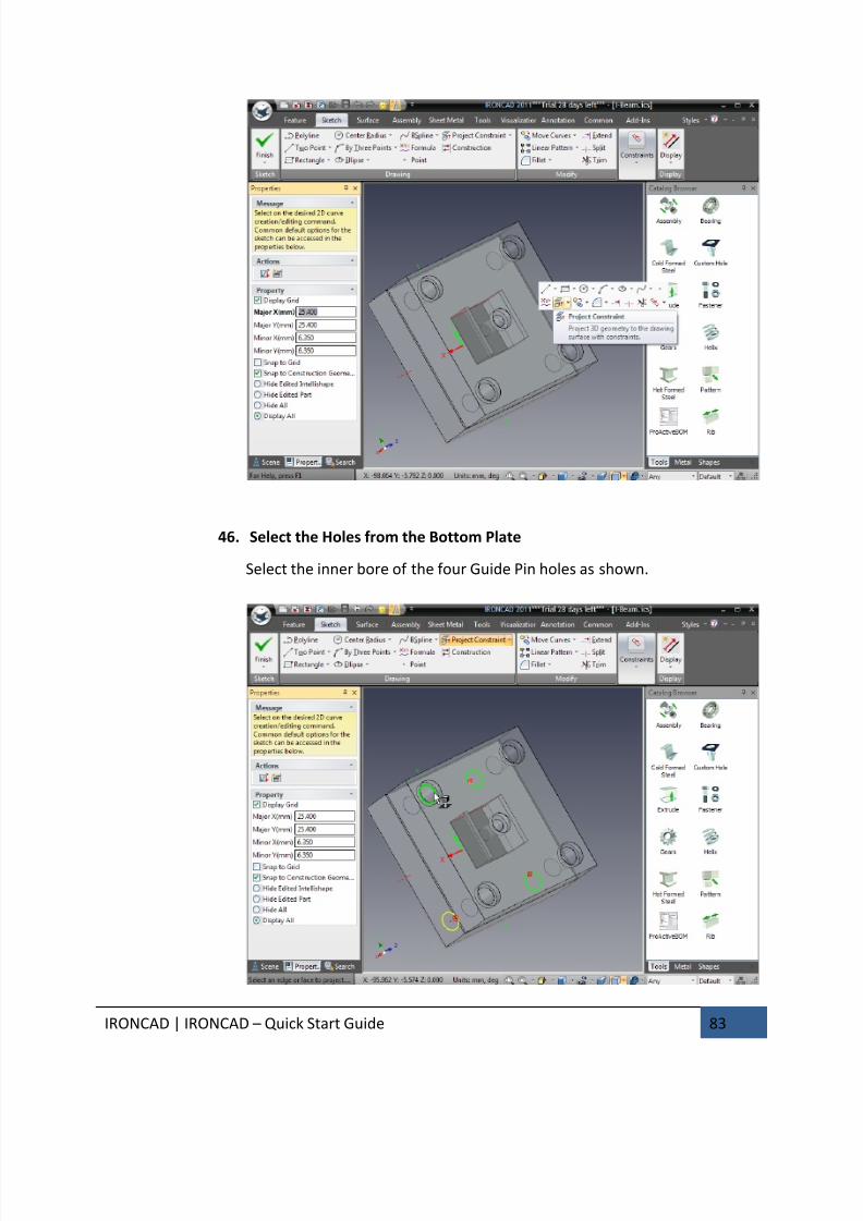
7/30/2019 Unlock Ironcadgsg
http://slidepdf.com/reader/full/unlock-ironcadgsg 87/367
IRONCAD | IRONCAD – Quick Start Guide 83
46. Select the Holes from the Bottom Plate
Select the inner bore of the four Guide Pin holes as shown.
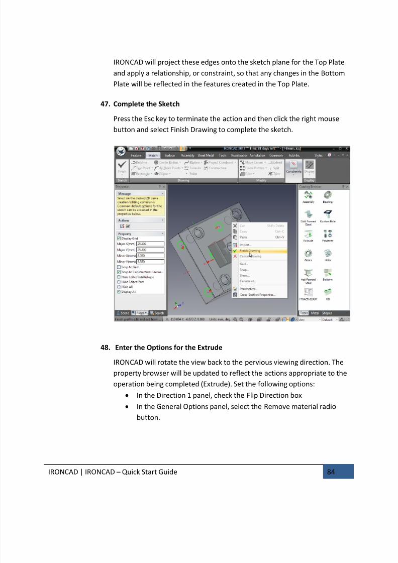
7/30/2019 Unlock Ironcadgsg
http://slidepdf.com/reader/full/unlock-ironcadgsg 88/367
IRONCAD | IRONCAD – Quick Start Guide 84
IRONCAD will project these edges onto the sketch plane for the Top Plate
and apply a relationship, or constraint, so that any changes in the Bottom
Plate will be reflected in the features created in the Top Plate.
47. Complete the Sketch
Press the Esc key to terminate the action and then click the right mouse
button and select Finish Drawing to complete the sketch.
48. Enter the Options for the Extrude
IRONCAD will rotate the view back to the pervious viewing direction. The
property browser will be updated to reflect the actions appropriate to the
operation being completed (Extrude). Set the following options:
• In the Direction 1 panel, check the Flip Direction box• In the General Options panel, select the Remove material radio
button.
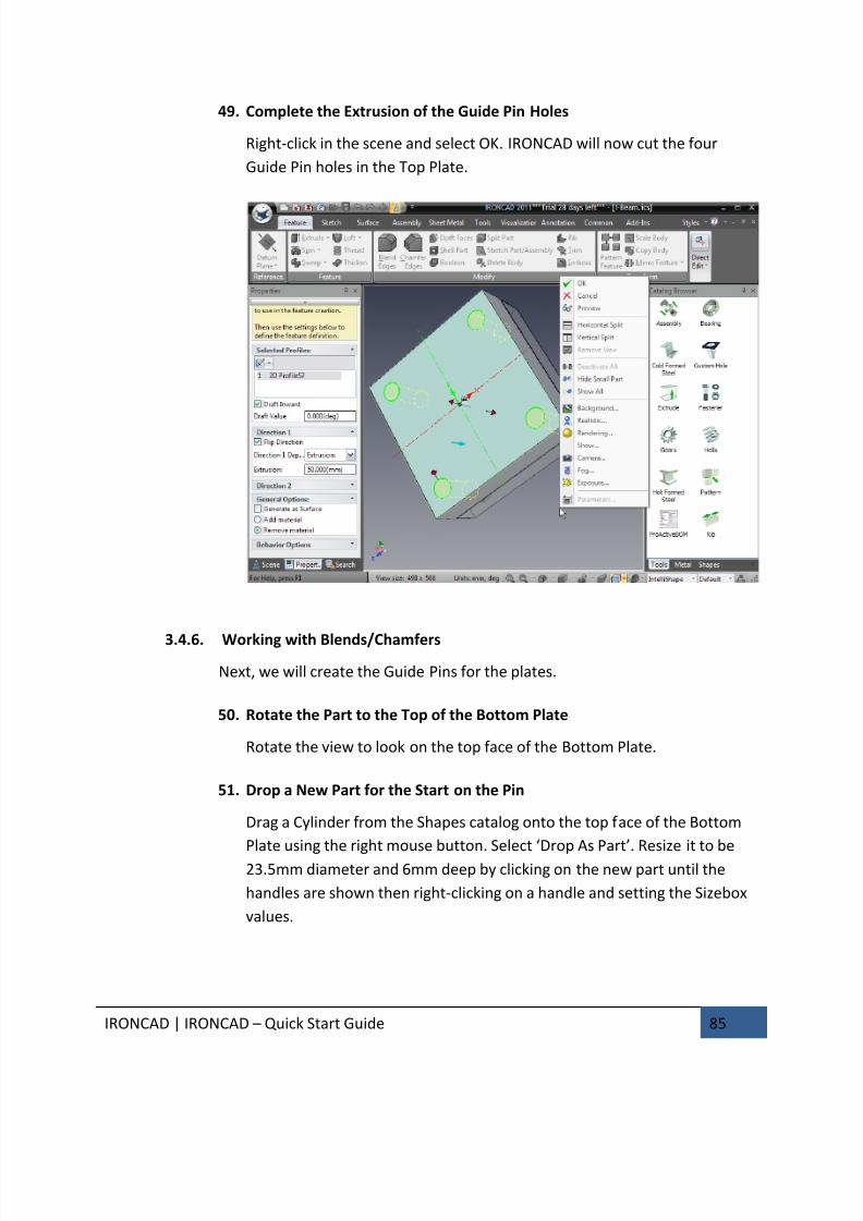
7/30/2019 Unlock Ironcadgsg
http://slidepdf.com/reader/full/unlock-ironcadgsg 89/367
IRONCAD | IRONCAD – Quick Start Guide 85
49. Complete the Extrusion of the Guide Pin Holes
Right-click in the scene and select OK. IRONCAD will now cut the four
Guide Pin holes in the Top Plate.
3.4.6. Working with Blends/Chamfers
Next, we will create the Guide Pins for the plates.
50. Rotate the Part to the Top of the Bottom Plate
Rotate the view to look on the top face of the Bottom Plate.
51. Drop a New Part for the Start on the Pin
Drag a Cylinder from the Shapes catalog onto the top face of the Bottom
Plate using the right mouse button. Select ‘Drop As Part’. Resize it to be
23.5mm diameter and 6mm deep by clicking on the new part until the
handles are shown then right-clicking on a handle and setting the Sizebox
values.
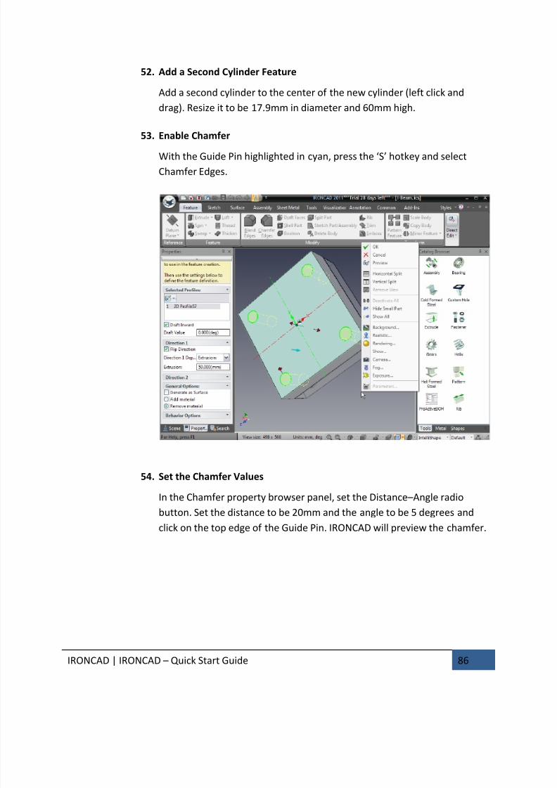
7/30/2019 Unlock Ironcadgsg
http://slidepdf.com/reader/full/unlock-ironcadgsg 90/367
IRONCAD | IRONCAD – Quick Start Guide 86
52. Add a Second Cylinder Feature
Add a second cylinder to the center of the new cylinder (left click and
drag). Resize it to be 17.9mm in diameter and 60mm high.
53. Enable Chamfer
With the Guide Pin highlighted in cyan, press the ‘S’ hotkey and select
Chamfer Edges.
54. Set the Chamfer Values
In the Chamfer property browser panel, set the Distance–Angle radio
button. Set the distance to be 20mm and the angle to be 5 degrees and
click on the top edge of the Guide Pin. IRONCAD will preview the chamfer.

7/30/2019 Unlock Ironcadgsg
http://slidepdf.com/reader/full/unlock-ironcadgsg 91/367
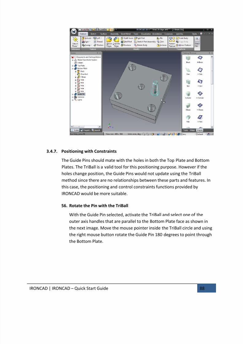
7/30/2019 Unlock Ironcadgsg
http://slidepdf.com/reader/full/unlock-ironcadgsg 92/367
IRONCAD | IRONCAD – Quick Start Guide 88
3.4.7. Positioning with Constraints
The Guide Pins should mate with the holes in both the Top Plate and Bottom
Plates. The TriBall is a valid tool for this positioning purpose. However if the
holes change position, the Guide Pins would not update using the TriBall
method since there are no relationships between these parts and features. Inthis case, the positioning and control constraints functions provided by
IRONCAD would be more suitable.
56. Rotate the Pin with the TriBall
With the Guide Pin selected, activate the TriBall and select one of the
outer axis handles that are parallel to the Bottom Plate face as shown in
the next image. Move the mouse pointer inside the TriBall circle and using
the right mouse button rotate the Guide Pin 180 degrees to point through
the Bottom Plate.

7/30/2019 Unlock Ironcadgsg
http://slidepdf.com/reader/full/unlock-ironcadgsg 93/367
IRONCAD | IRONCAD – Quick Start Guide 89
57. Create 3 Link Copies of the Pin
While the TriBall axis is active, right-click on the active handle outside of
the TriBall and drag the Guide Pin a short distance and release the mouse
button.
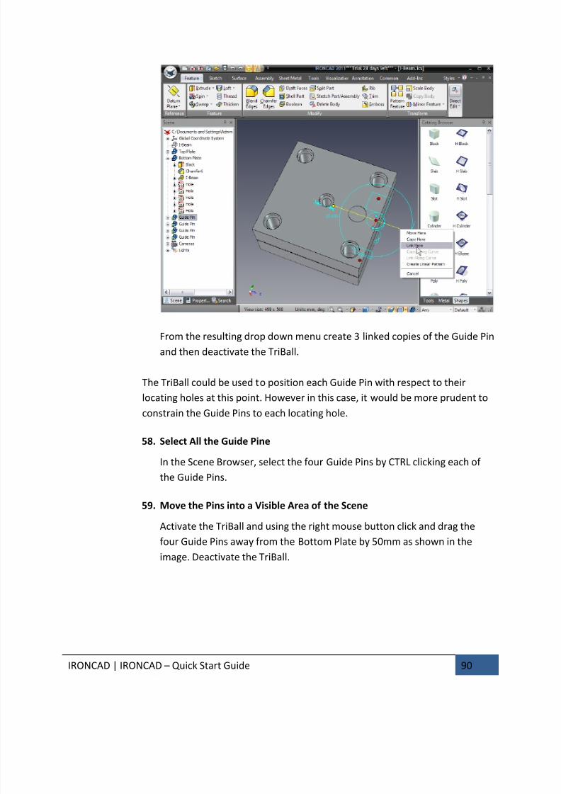
7/30/2019 Unlock Ironcadgsg
http://slidepdf.com/reader/full/unlock-ironcadgsg 94/367
IRONCAD | IRONCAD – Quick Start Guide 90
From the resulting drop down menu create 3 linked copies of the Guide Pin
and then deactivate the TriBall.
The TriBall could be used to position each Guide Pin with respect to their
locating holes at this point. However in this case, it would be more prudent to
constrain the Guide Pins to each locating hole.
58. Select All the Guide Pine
In the Scene Browser, select the four Guide Pins by CTRL clicking each of
the Guide Pins.
59. Move the Pins into a Visible Area of the Scene
Activate the TriBall and using the right mouse button click and drag the
four Guide Pins away from the Bottom Plate by 50mm as shown in the
image. Deactivate the TriBall.
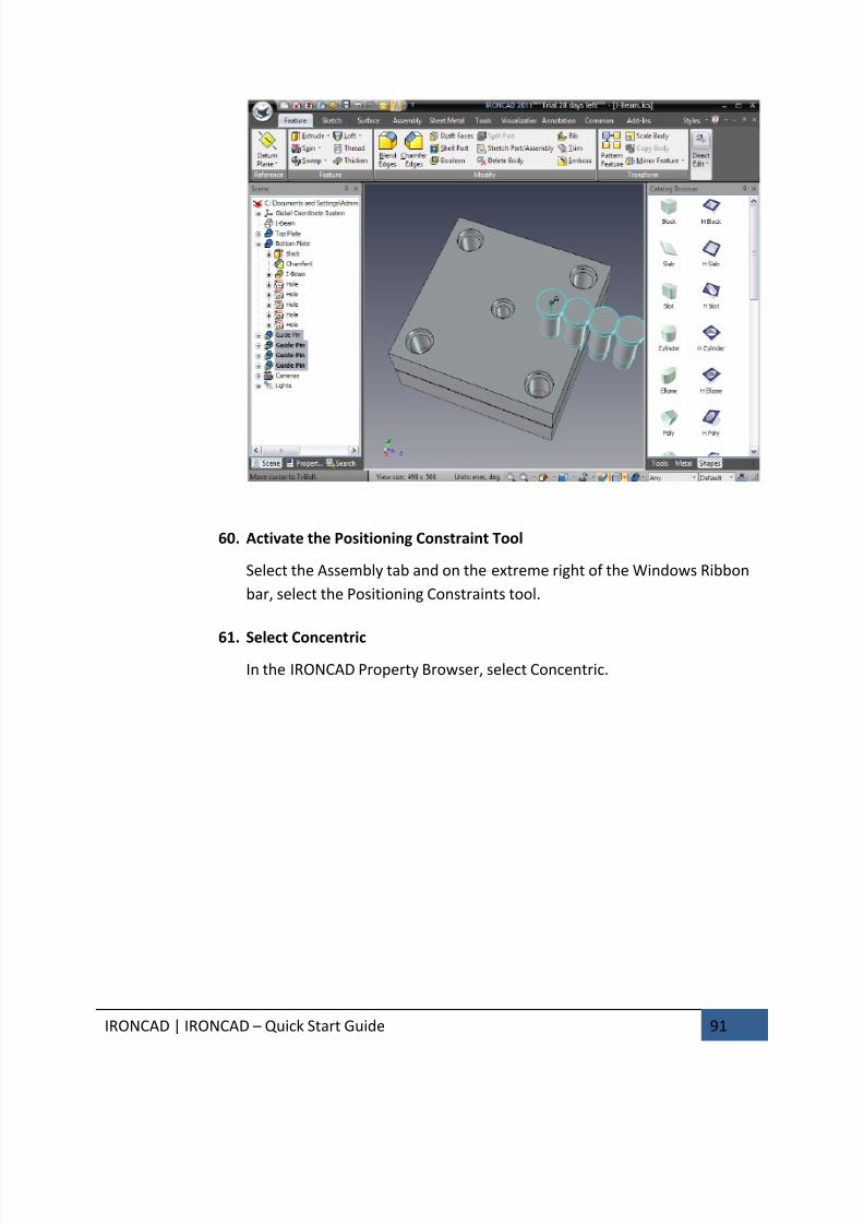
7/30/2019 Unlock Ironcadgsg
http://slidepdf.com/reader/full/unlock-ironcadgsg 95/367

7/30/2019 Unlock Ironcadgsg
http://slidepdf.com/reader/full/unlock-ironcadgsg 96/367
IRONCAD | IRONCAD – Quick Start Guide 92
62. Position the Guide Pin to a Hole
Click on the 15.9mm portion of one of the Guide Pins. Then click on the
bore of one of the Guide Pin holes. IRONCAD will snap the selected Guide
Pin to its mating hole concentrically.
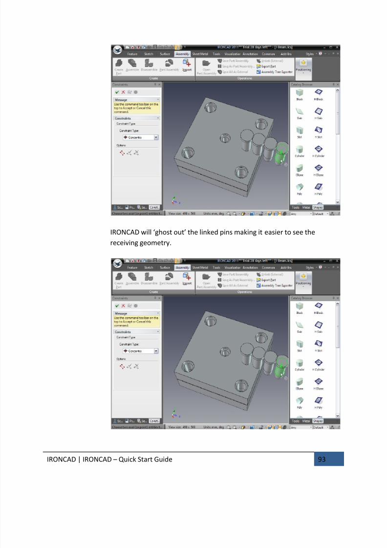
7/30/2019 Unlock Ironcadgsg
http://slidepdf.com/reader/full/unlock-ironcadgsg 97/367
IRONCAD | IRONCAD – Quick Start Guide 93
IRONCAD will ‘ghost out’ the linked pins making it easier to see the
receiving geometry.

7/30/2019 Unlock Ironcadgsg
http://slidepdf.com/reader/full/unlock-ironcadgsg 98/367
IRONCAD | IRONCAD – Quick Start Guide 94
63. Accept and Repeat to All Pins
Click the left mouse button to accept the constraint positioning (Right-click
would cancel the current positioning). Repeat the process for the
remaining Guide Pins. When all Guide Pins are constrained, click the Apply
and Exit icon (the green tick at the top of the Property Browser).
In the real world, dowels would be used to ensure the tool is assembled in
the right orientation. This design will use an offset Guide Pin.
64. Select a Guide Pin Hole
In the scene browser, expand the feature tree of the Bottom Plate and
select one of the Guide Pin holes that have a green arrow on its icon (the
green arrow indicates the hole is linked).
IRONCAD will highlight the selected hole in yellow and any liked copies of
the hole will be highlighted in purple.
65. Reposition a Hole Using the TriBall
Activate the TriBall and move the hole towards the center of the plate
using the Plane function of the TriBall. It doesn’t matter that the TriBall
shows over the Counterbored (Sprue) hole. Move the hole 10mm in both
directions.
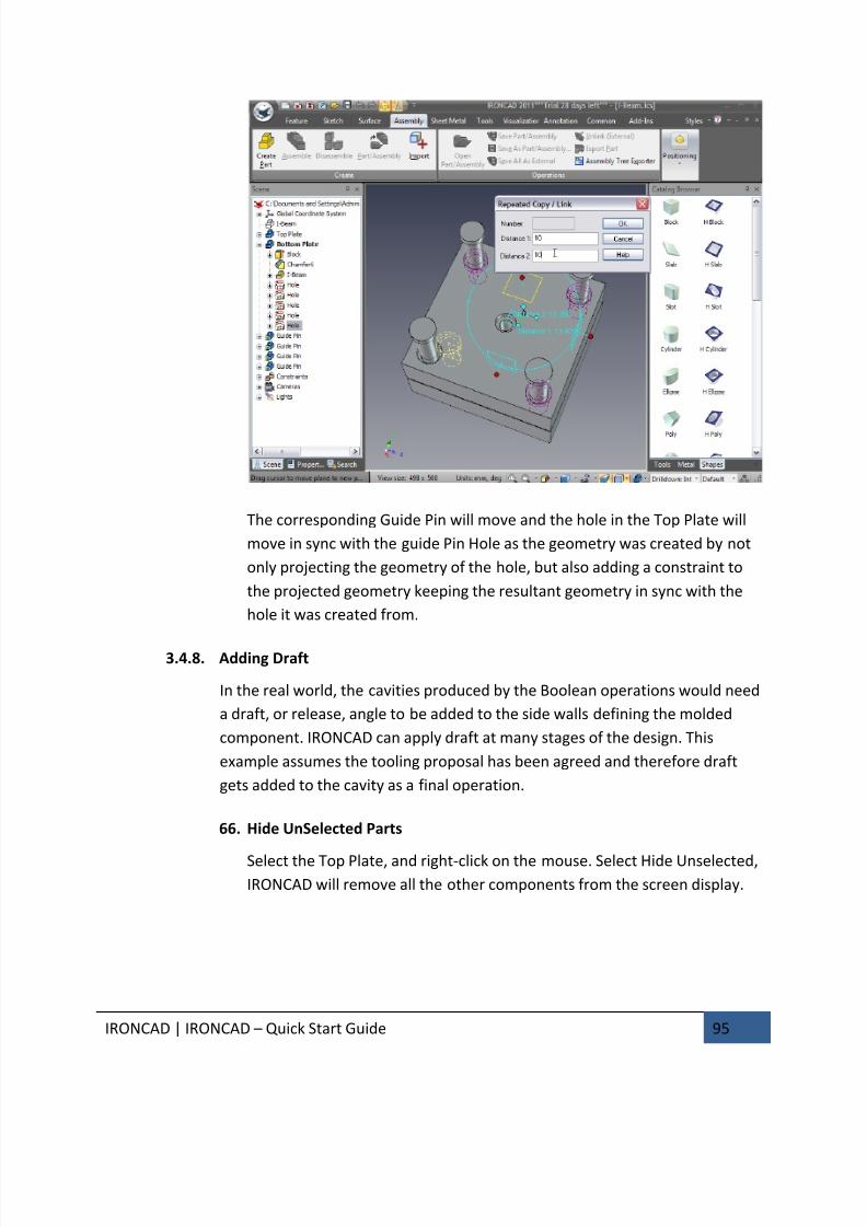
7/30/2019 Unlock Ironcadgsg
http://slidepdf.com/reader/full/unlock-ironcadgsg 99/367
IRONCAD | IRONCAD – Quick Start Guide 95
The corresponding Guide Pin will move and the hole in the Top Plate will
move in sync with the guide Pin Hole as the geometry was created by not
only projecting the geometry of the hole, but also adding a constraint to
the projected geometry keeping the resultant geometry in sync with the
hole it was created from.
3.4.8. Adding Draft
In the real world, the cavities produced by the Boolean operations would need
a draft, or release, angle to be added to the side walls defining the molded
component. IRONCAD can apply draft at many stages of the design. This
example assumes the tooling proposal has been agreed and therefore draft
gets added to the cavity as a final operation.
66. Hide UnSelected Parts
Select the Top Plate, and right-click on the mouse. Select Hide Unselected,IRONCAD will remove all the other components from the screen display.

7/30/2019 Unlock Ironcadgsg
http://slidepdf.com/reader/full/unlock-ironcadgsg 100/367
IRONCAD | IRONCAD – Quick Start Guide 96
67. Zoom in to the Cavity
Zoom into the cavity using the camera tools. Notice that some of the
surfaces will have inherited the color of the I-Beam when it was removed
from the plate using the Boolean operation earlier.
68. Select Draft Faces
Switch to the Feature tab on the Windows Ribbon bar and select the
option, Draft Faces.
69. Set the Draft Options and Neutral Plane
IRONCAD will change the Property Browser to the Draft Feature panel. Set
Draft Type to Neutral Plane and select the face at the bottom of the pocket
as shown in the next image.
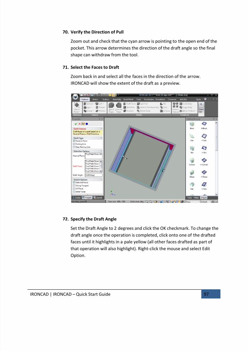
7/30/2019 Unlock Ironcadgsg
http://slidepdf.com/reader/full/unlock-ironcadgsg 101/367
IRONCAD | IRONCAD – Quick Start Guide 97
70. Verify the Direction of Pull
Zoom out and check that the cyan arrow is pointing to the open end of the
pocket. This arrow determines the direction of the draft angle so the final
shape can withdraw from the tool.
71. Select the Faces to Draft
Zoom back in and select all the faces in the direction of the arrow.
IRONCAD will show the extent of the draft as a preview.
72. Specify the Draft Angle
Set the Draft Angle to 2 degrees and click the OK checkmark. To change the
draft angle once the operation is completed, click onto one of the drafted
faces until it highlights in a pale yellow (all other faces drafted as part of
that operation will also highlight). Right-click the mouse and select Edit
Option.
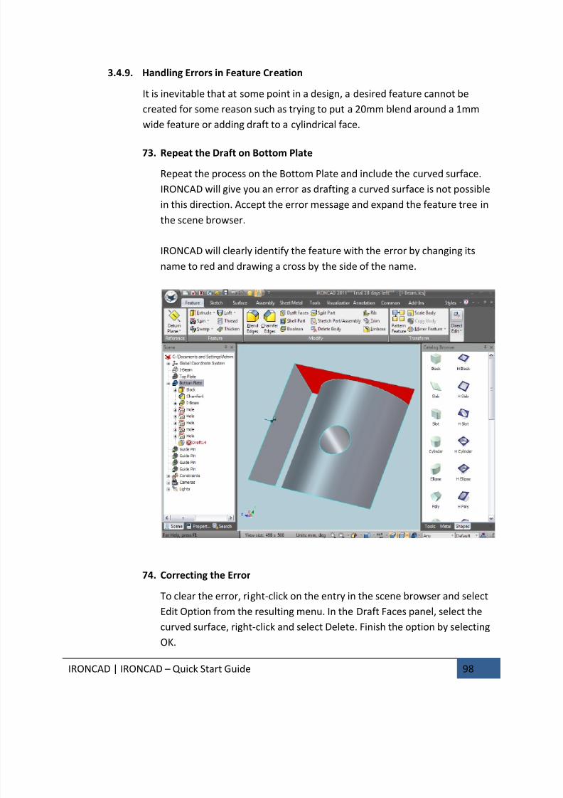
7/30/2019 Unlock Ironcadgsg
http://slidepdf.com/reader/full/unlock-ironcadgsg 102/367
IRONCAD | IRONCAD – Quick Start Guide 98
3.4.9. Handling Errors in Feature Creation
It is inevitable that at some point in a design, a desired feature cannot be
created for some reason such as trying to put a 20mm blend around a 1mm
wide feature or adding draft to a cylindrical face.
73. Repeat the Draft on Bottom Plate
Repeat the process on the Bottom Plate and include the curved surface.
IRONCAD will give you an error as drafting a curved surface is not possible
in this direction. Accept the error message and expand the feature tree in
the scene browser.
IRONCAD will clearly identify the feature with the error by changing its
name to red and drawing a cross by the side of the name.
74. Correcting the Error
To clear the error, right-click on the entry in the scene browser and select
Edit Option from the resulting menu. In the Draft Faces panel, select the
curved surface, right-click and select Delete. Finish the option by selecting
OK.
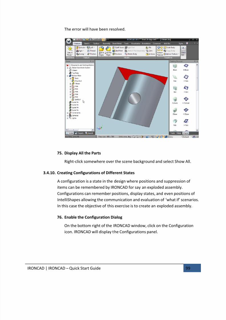
7/30/2019 Unlock Ironcadgsg
http://slidepdf.com/reader/full/unlock-ironcadgsg 103/367
IRONCAD | IRONCAD – Quick Start Guide 99
The error will have been resolved.
75. Display All the Parts
Right-click somewhere over the scene background and select Show All.
3.4.10. Creating Configurations of Different States
A configuration is a state in the design where positions and suppression of
items can be remembered by IRONCAD for say an exploded assembly.
Configurations can remember positions, display states, and even positions of
IntelliShapes allowing the communication and evaluation of ‘what if’ scenarios.
In this case the objective of this exercise is to create an exploded assembly.
76. Enable the Configuration Dialog
On the bottom right of the IRONCAD window, click on the Configuration
icon. IRONCAD will display the Configurations panel.
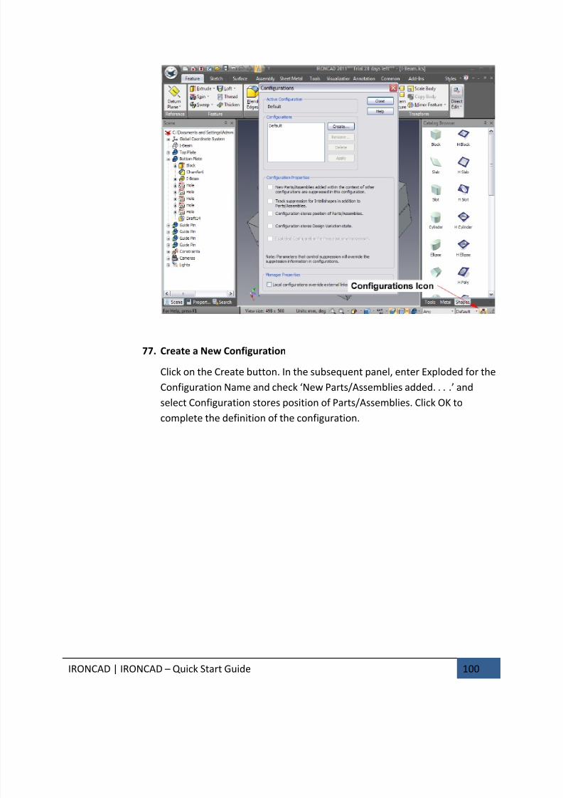
7/30/2019 Unlock Ironcadgsg
http://slidepdf.com/reader/full/unlock-ironcadgsg 104/367
IRONCAD | IRONCAD – Quick Start Guide 100
77. Create a New Configuration
Click on the Create button. In the subsequent panel, enter Exploded for the
Configuration Name and check ‘New Parts/Assemblies added. . . .’ and
select Configuration stores position of Parts/Assemblies. Click OK to
complete the definition of the configuration.

7/30/2019 Unlock Ironcadgsg
http://slidepdf.com/reader/full/unlock-ironcadgsg 105/367
IRONCAD | IRONCAD – Quick Start Guide 101
IRONCAD will update the Configurations panel with the new configuration
setting. It will also change the name of the active configuration on the
status bar by the configurations icon.
78. Reposition the Top Plate
Select the Top Plate at part mode (highlighted with cyan edges) andactivate the TriBall. Move the Top Plate away from the Bottom Plate by
150mm as shown.
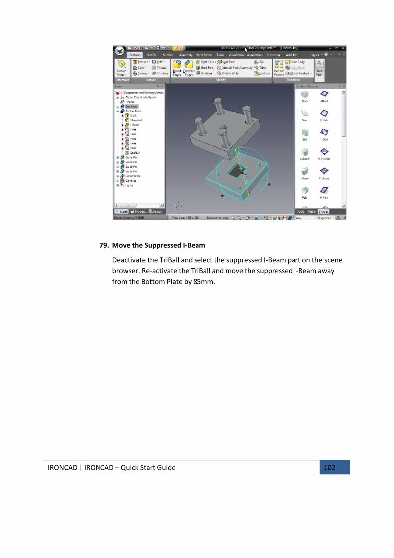
7/30/2019 Unlock Ironcadgsg
http://slidepdf.com/reader/full/unlock-ironcadgsg 106/367
IRONCAD | IRONCAD – Quick Start Guide 102
79. Move the Suppressed I-Beam
Deactivate the TriBall and select the suppressed I-Beam part on the scene
browser. Re-activate the TriBall and move the suppressed I-Beam away
from the Bottom Plate by 85mm.
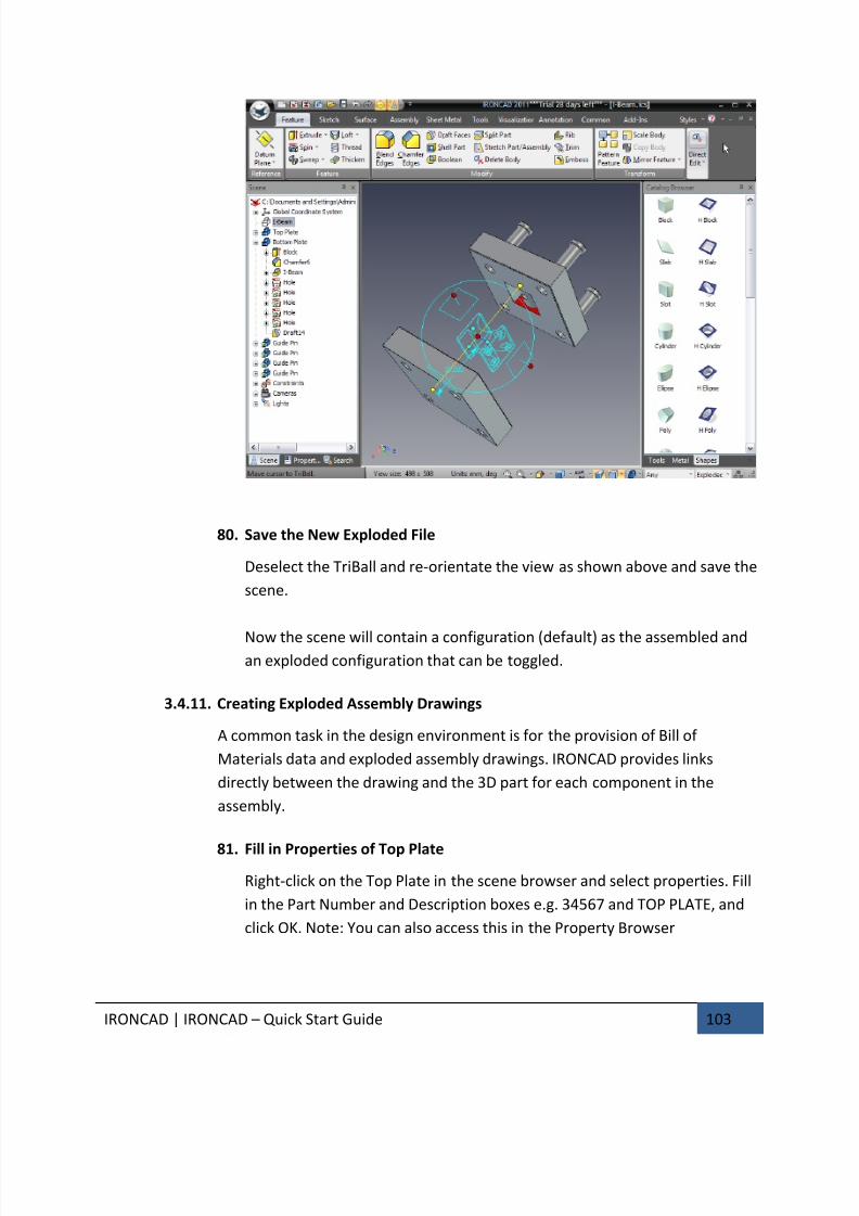
7/30/2019 Unlock Ironcadgsg
http://slidepdf.com/reader/full/unlock-ironcadgsg 107/367
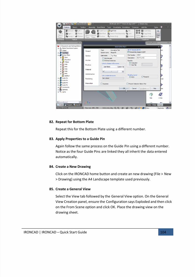
7/30/2019 Unlock Ironcadgsg
http://slidepdf.com/reader/full/unlock-ironcadgsg 108/367
IRONCAD | IRONCAD – Quick Start Guide 104
82. Repeat for Bottom Plate
Repeat this for the Bottom Plate using a different number.
83. Apply Properties to a Guide Pin
Again follow the same process on the Guide Pin using a different number.
Notice as the four Guide Pins are linked they all inherit the data entered
automatically.
84. Create a New Drawing
Click on the IRONCAD home button and create an new drawing (File > New
> Drawing) using the A4 Landscape template used previously.
85. Create a General View
Select the View tab followed by the General View option. On the General
View Creation panel, ensure the Configuration says Exploded and then click
on the From Scene option and click OK. Place the drawing view on the
drawing sheet.
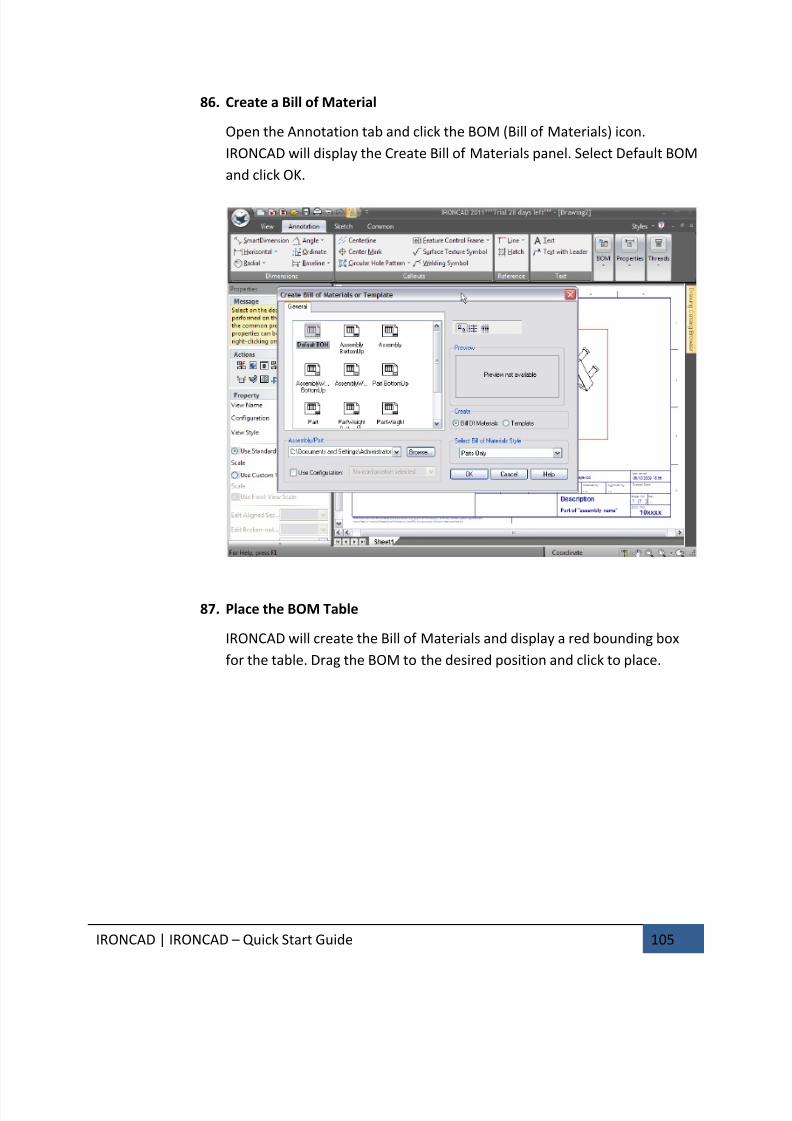
7/30/2019 Unlock Ironcadgsg
http://slidepdf.com/reader/full/unlock-ironcadgsg 109/367
IRONCAD | IRONCAD – Quick Start Guide 105
86. Create a Bill of Material
Open the Annotation tab and click the BOM (Bill of Materials) icon.
IRONCAD will display the Create Bill of Materials panel. Select Default BOM
and click OK.
87. Place the BOM Table
IRONCAD will create the Bill of Materials and display a red bounding box
for the table. Drag the BOM to the desired position and click to place.
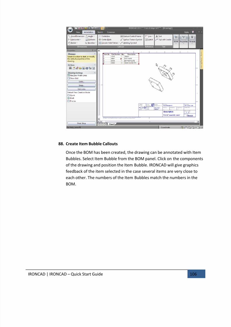
7/30/2019 Unlock Ironcadgsg
http://slidepdf.com/reader/full/unlock-ironcadgsg 110/367
IRONCAD | IRONCAD – Quick Start Guide 106
88. Create Item Bubble Callouts
Once the BOM has been created, the drawing can be annotated with Item
Bubbles. Select Item Bubble from the BOM panel. Click on the components
of the drawing and position the Item Bubble. IRONCAD will give graphics
feedback of the item selected in the case several items are very close toeach other. The numbers of the Item Bubbles match the numbers in the
BOM.
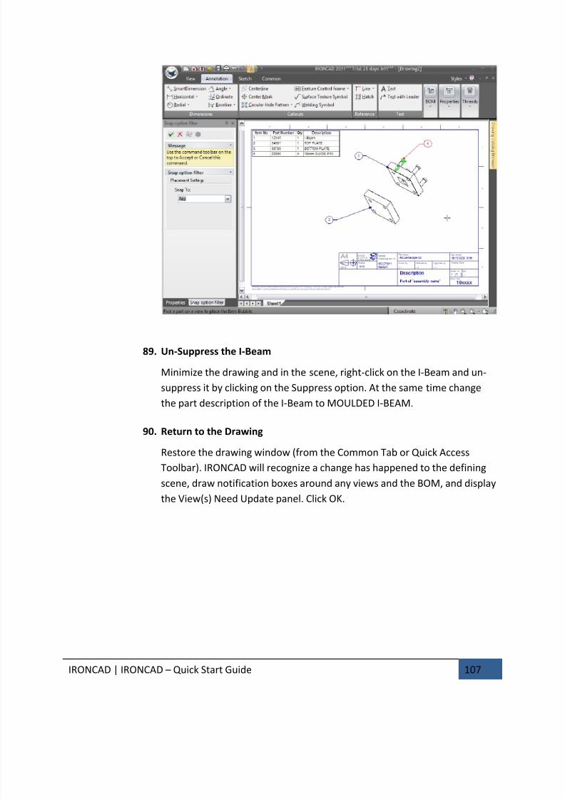
7/30/2019 Unlock Ironcadgsg
http://slidepdf.com/reader/full/unlock-ironcadgsg 111/367
IRONCAD | IRONCAD – Quick Start Guide 107
89. Un-Suppress the I-Beam
Minimize the drawing and in the scene, right-click on the I-Beam and un-
suppress it by clicking on the Suppress option. At the same time change
the part description of the I-Beam to MOULDED I-BEAM.
90. Return to the Drawing
Restore the drawing window (from the Common Tab or Quick Access
Toolbar). IRONCAD will recognize a change has happened to the defining
scene, draw notification boxes around any views and the BOM, and display
the View(s) Need Update panel. Click OK.
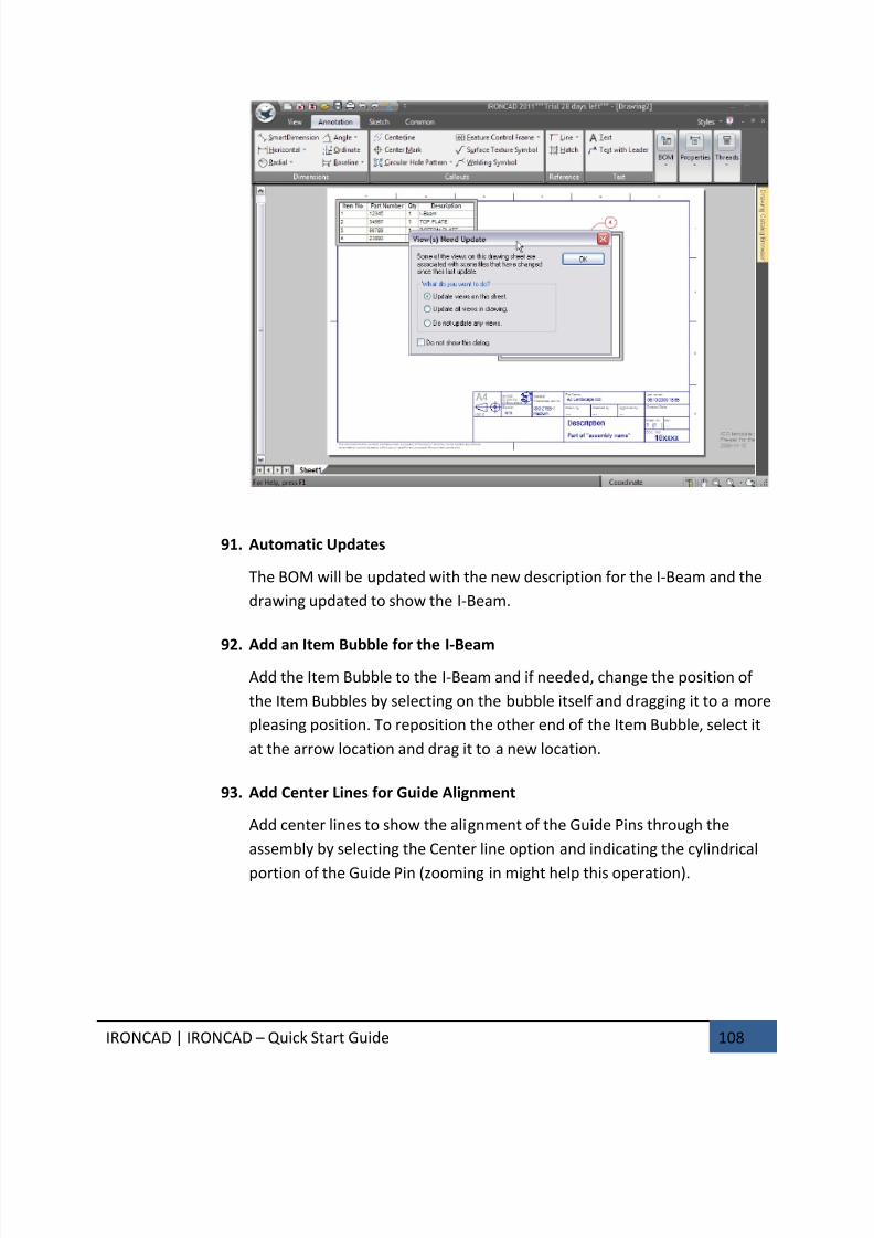
7/30/2019 Unlock Ironcadgsg
http://slidepdf.com/reader/full/unlock-ironcadgsg 112/367
IRONCAD | IRONCAD – Quick Start Guide 108
91. Automatic Updates
The BOM will be updated with the new description for the I-Beam and the
drawing updated to show the I-Beam.
92. Add an Item Bubble for the I-Beam
Add the Item Bubble to the I-Beam and if needed, change the position of
the Item Bubbles by selecting on the bubble itself and dragging it to a more
pleasing position. To reposition the other end of the Item Bubble, select it
at the arrow location and drag it to a new location.
93. Add Center Lines for Guide Alignment
Add center lines to show the alignment of the Guide Pins through the
assembly by selecting the Center line option and indicating the cylindrical
portion of the Guide Pin (zooming in might help this operation).
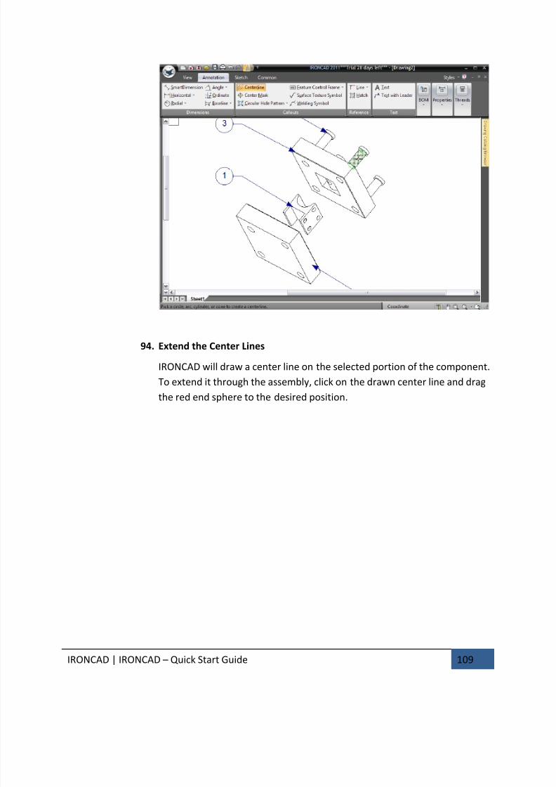
7/30/2019 Unlock Ironcadgsg
http://slidepdf.com/reader/full/unlock-ironcadgsg 113/367
IRONCAD | IRONCAD – Quick Start Guide 109
94. Extend the Center Lines
IRONCAD will draw a center line on the selected portion of the component.
To extend it through the assembly, click on the drawn center line and drag
the red end sphere to the desired position.
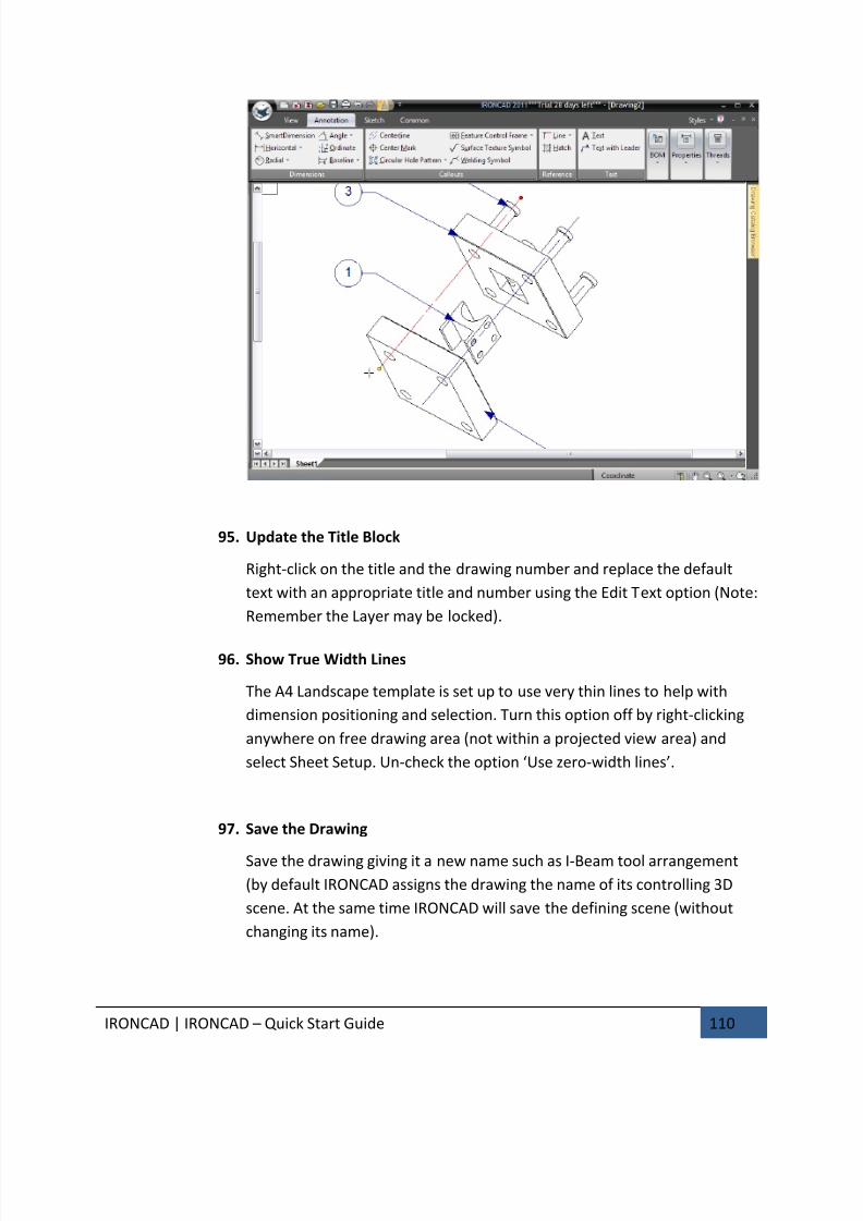
7/30/2019 Unlock Ironcadgsg
http://slidepdf.com/reader/full/unlock-ironcadgsg 114/367
IRONCAD | IRONCAD – Quick Start Guide 110
95. Update the Title Block
Right-click on the title and the drawing number and replace the default
text with an appropriate title and number using the Edit Text option (Note:
Remember the Layer may be locked).
96. Show True Width Lines
The A4 Landscape template is set up to use very thin lines to help with
dimension positioning and selection. Turn this option off by right-clicking
anywhere on free drawing area (not within a projected view area) and
select Sheet Setup. Un-check the option ‘Use zero-width lines’.
97. Save the Drawing
Save the drawing giving it a new name such as I-Beam tool arrangement
(by default IRONCAD assigns the drawing the name of its controlling 3D
scene. At the same time IRONCAD will save the defining scene (without
changing its name).

7/30/2019 Unlock Ironcadgsg
http://slidepdf.com/reader/full/unlock-ironcadgsg 115/367
IRONCAD | IRONCAD – Quick Start Guide 111
This completes the section of the Quick Start Guide. The key topics covered in
this section include:
• Designing an Assembly
• Working With Boolean Operations
• Using Intelligent Feature
• Using Intelligent Features as a Basis for New Features
• Creating Sketch Based Features
• Working with Blends/Chamfers
• Positioning with Constraints
• Adding Draft
• Handling Errors In Feature Creation
• Creating Configurations of Different States
• Creating Exploded Assembly Drawings
This concludes our first quick pass introduction to IRONCAD. Hopefully this Quick Start
Guide has provided you with an overall first introduction to the design process in
IRONCAD as well as some of the fundamental features of the application. This Chapter
focused on:
• Creating a concept 3D model
• Re-sizing the features to reflect desired dimensions
• Adding a few detail features
• Creating a photorealistic rendering
• Adding chamfers and blends
• Creating a detail drawing
• Building an assembly and detailing it.
Feel free to expand on your tooling part to gain a better understanding of the
IRONCAD design process. In the next chapters, we will expand on some of the concepts
covered in this section to give you a greater depth of the capabilities.

7/30/2019 Unlock Ironcadgsg
http://slidepdf.com/reader/full/unlock-ironcadgsg 116/367
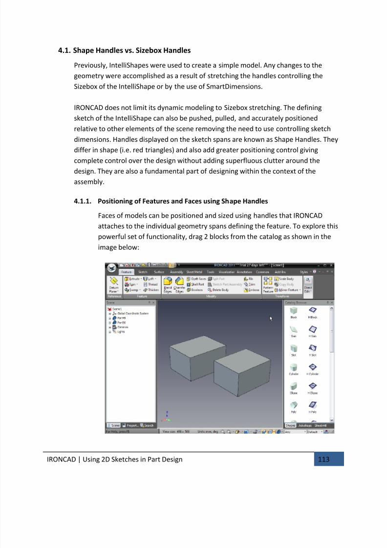
7/30/2019 Unlock Ironcadgsg
http://slidepdf.com/reader/full/unlock-ironcadgsg 117/367
IRONCAD | Using 2D Sketches in Part Design 113
4.1. Shape Handles vs. Sizebox Handles
Previously, IntelliShapes were used to create a simple model. Any changes to the
geometry were accomplished as a result of stretching the handles controlling the
Sizebox of the IntelliShape or by the use of SmartDimensions.
IRONCAD does not limit its dynamic modeling to Sizebox stretching. The defining
sketch of the IntelliShape can also be pushed, pulled, and accurately positioned
relative to other elements of the scene removing the need to use controlling sketch
dimensions. Handles displayed on the sketch spans are known as Shape Handles. They
differ in shape (i.e. red triangles) and also add greater positioning control giving
complete control over the design without adding superfluous clutter around the
design. They are also a fundamental part of designing within the context of the
assembly.
4.1.1. Positioning of Features and Faces using Shape Handles
Faces of models can be positioned and sized using handles that IRONCAD
attaches to the individual geometry spans defining the feature. To explore this
powerful set of functionality, drag 2 blocks from the catalog as shown in the
image below:
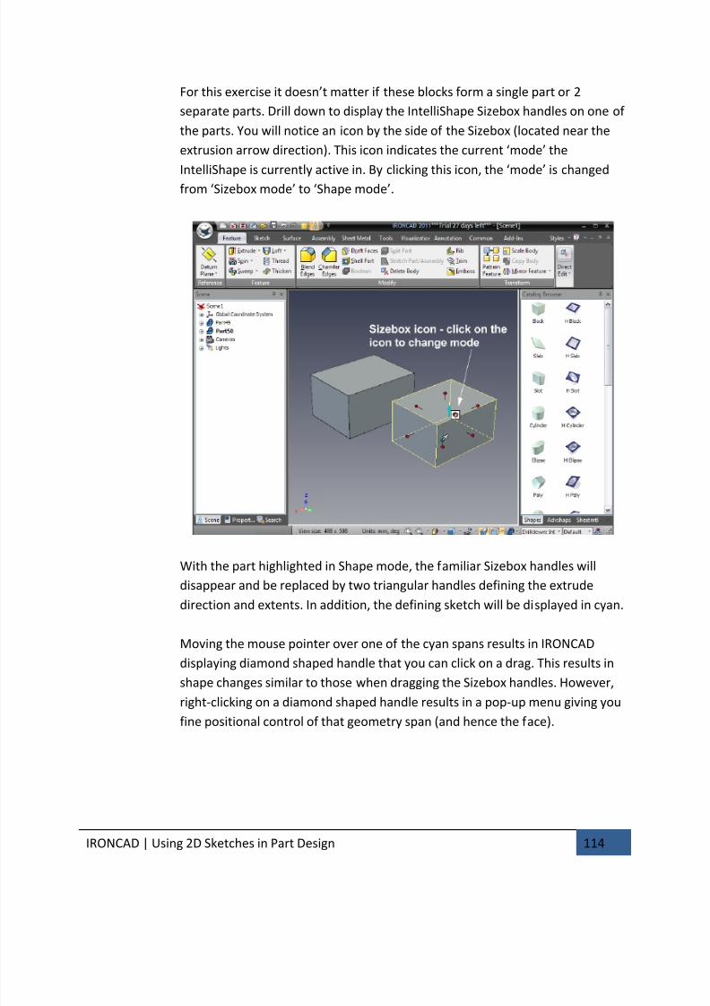
7/30/2019 Unlock Ironcadgsg
http://slidepdf.com/reader/full/unlock-ironcadgsg 118/367
IRONCAD | Using 2D Sketches in Part Design 114
For this exercise it doesn’t matter if these blocks form a single part or 2
separate parts. Drill down to display the IntelliShape Sizebox handles on one of
the parts. You will notice an icon by the side of the Sizebox (located near the
extrusion arrow direction). This icon indicates the current ‘mode’ the
IntelliShape is currently active in. By clicking this icon, the ‘mode’ is changedfrom ‘Sizebox mode’ to ‘Shape mode’.
With the part highlighted in Shape mode, the familiar Sizebox handles will
disappear and be replaced by two triangular handles defining the extrude
direction and extents. In addition, the defining sketch will be displayed in cyan.
Moving the mouse pointer over one of the cyan spans results in IRONCAD
displaying diamond shaped handle that you can click on a drag. This results in
shape changes similar to those when dragging the Sizebox handles. However,
right-clicking on a diamond shaped handle results in a pop-up menu giving youfine positional control of that geometry span (and hence the face).
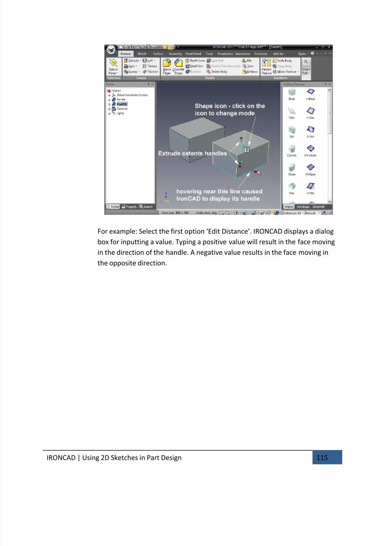
7/30/2019 Unlock Ironcadgsg
http://slidepdf.com/reader/full/unlock-ironcadgsg 119/367
IRONCAD | Using 2D Sketches in Part Design 115
For example: Select the first option ‘Edit Distance’. IRONCAD displays a dialog
box for inputting a value. Typing a positive value will result in the face moving
in the direction of the handle. A negative value results in the face moving in
the opposite direction.
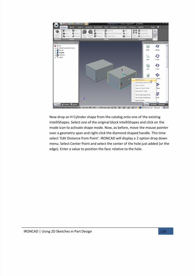
7/30/2019 Unlock Ironcadgsg
http://slidepdf.com/reader/full/unlock-ironcadgsg 120/367
IRONCAD | Using 2D Sketches in Part Design 116
Now drop an H Cylinder shape from the catalog onto one of the existing
IntelliShapes. Select one of the original block IntelliShapes and click on the
mode icon to activate shape mode. Now, as before, move the mouse pointer
over a geometry span and right-click the diamond shaped handle. This time
select ‘Edit Distance from Point’. IRONCAD will display a 2 option drop down
menu. Select Center Point and select the center of the hole just added (or theedge). Enter a value to position the face relative to the hole.
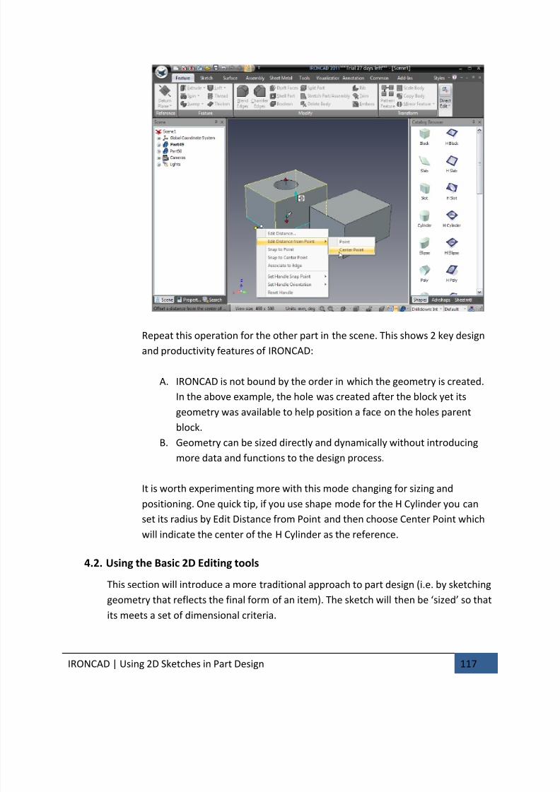
7/30/2019 Unlock Ironcadgsg
http://slidepdf.com/reader/full/unlock-ironcadgsg 121/367
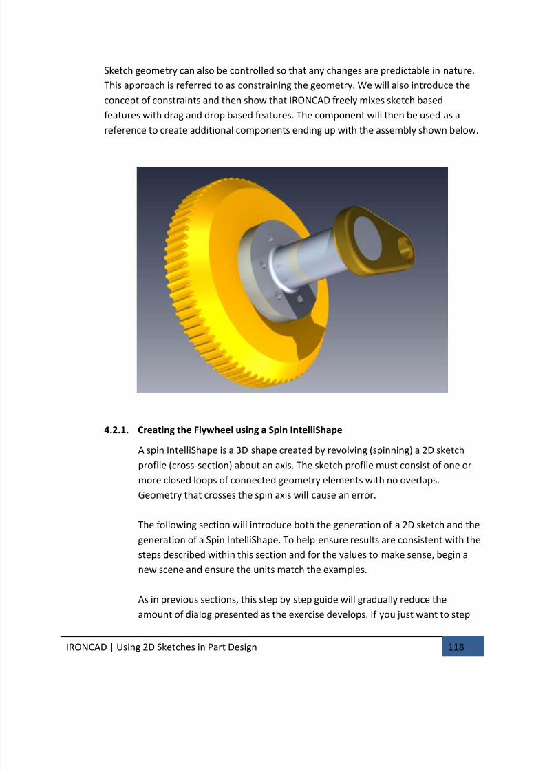
7/30/2019 Unlock Ironcadgsg
http://slidepdf.com/reader/full/unlock-ironcadgsg 122/367
IRONCAD | Using 2D Sketches in Part Design 118
Sketch geometry can also be controlled so that any changes are predictable in nature.
This approach is referred to as constraining the geometry. We will also introduce the
concept of constraints and then show that IRONCAD freely mixes sketch based
features with drag and drop based features. The component will then be used as a
reference to create additional components ending up with the assembly shown below.
4.2.1. Creating the Flywheel using a Spin IntelliShape
A spin IntelliShape is a 3D shape created by revolving (spinning) a 2D sketch
profile (cross-section) about an axis. The sketch profile must consist of one or
more closed loops of connected geometry elements with no overlaps.
Geometry that crosses the spin axis will cause an error.
The following section will introduce both the generation of a 2D sketch and the
generation of a Spin IntelliShape. To help ensure results are consistent with thesteps described within this section and for the values to make sense, begin a
new scene and ensure the units match the examples.
As in previous sections, this step by step guide will gradually reduce the
amount of dialog presented as the exercise develops. If you just want to step
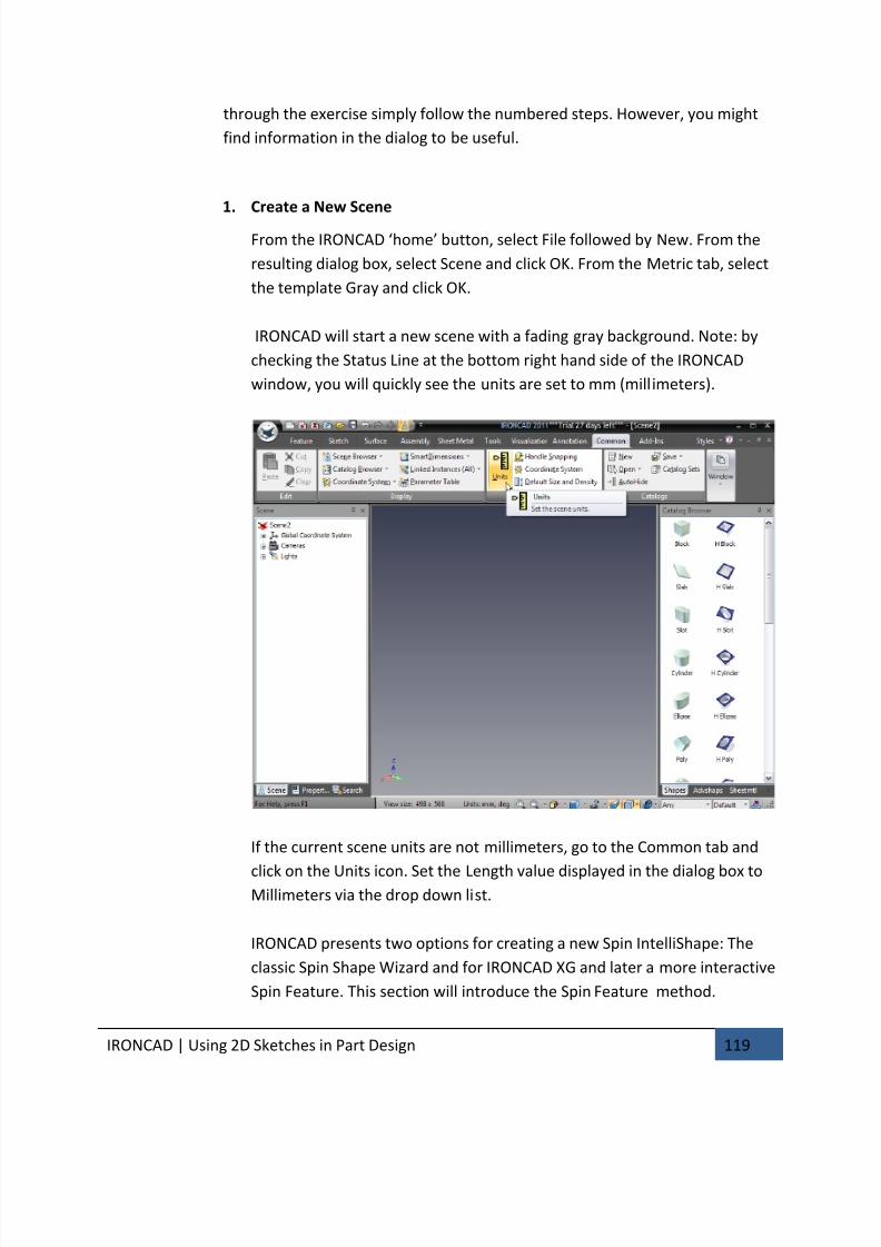
7/30/2019 Unlock Ironcadgsg
http://slidepdf.com/reader/full/unlock-ironcadgsg 123/367
IRONCAD | Using 2D Sketches in Part Design 119
through the exercise simply follow the numbered steps. However, you might
find information in the dialog to be useful.
1. Create a New Scene
From the IRONCAD ‘home’ button, select File followed by New. From the
resulting dialog box, select Scene and click OK. From the Metric tab, select
the template Gray and click OK.
IRONCAD will start a new scene with a fading gray background. Note: by
checking the Status Line at the bottom right hand side of the IRONCAD
window, you will quickly see the units are set to mm (millimeters).
If the current scene units are not millimeters, go to the Common tab and
click on the Units icon. Set the Length value displayed in the dialog box toMillimeters via the drop down list.
IRONCAD presents two options for creating a new Spin IntelliShape: The
classic Spin Shape Wizard and for IRONCAD XG and later a more interactive
Spin Feature. This section will introduce the Spin Feature method.
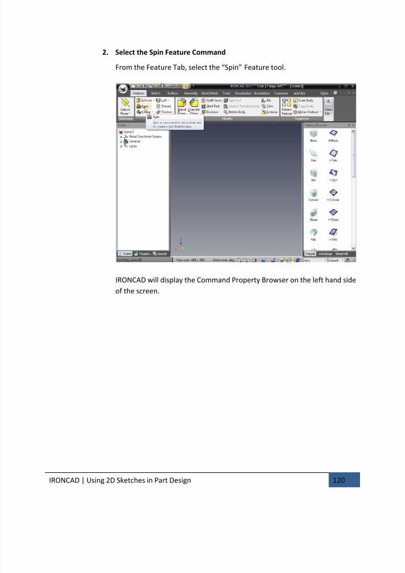
7/30/2019 Unlock Ironcadgsg
http://slidepdf.com/reader/full/unlock-ironcadgsg 124/367
IRONCAD | Using 2D Sketches in Part Design 120
2. Select the Spin Feature Command
From the Feature Tab, select the “Spin” Feature tool.
IRONCAD will display the Command Property Browser on the left hand side
of the screen.
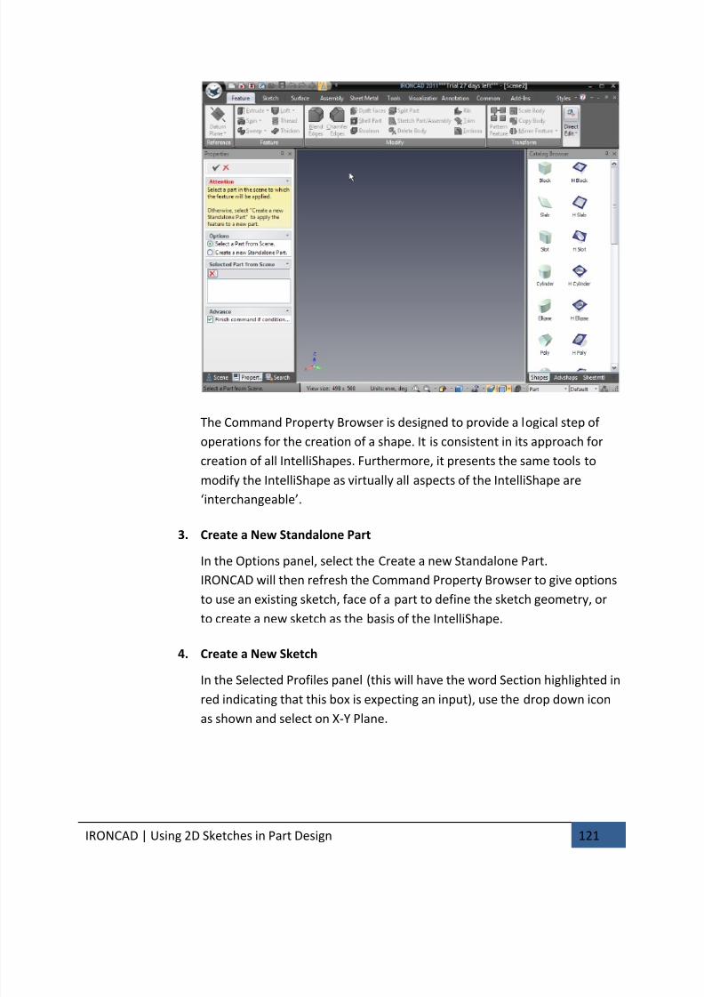
7/30/2019 Unlock Ironcadgsg
http://slidepdf.com/reader/full/unlock-ironcadgsg 125/367
IRONCAD | Using 2D Sketches in Part Design 121
The Command Property Browser is designed to provide a logical step of
operations for the creation of a shape. It is consistent in its approach for
creation of all IntelliShapes. Furthermore, it presents the same tools to
modify the IntelliShape as virtually all aspects of the IntelliShape are
‘interchangeable’.
3. Create a New Standalone Part
In the Options panel, select the Create a new Standalone Part.
IRONCAD will then refresh the Command Property Browser to give options
to use an existing sketch, face of a part to define the sketch geometry, or
to create a new sketch as the basis of the IntelliShape.
4. Create a New Sketch
In the Selected Profiles panel (this will have the word Section highlighted in
red indicating that this box is expecting an input), use the drop down iconas shown and select on X-Y Plane.
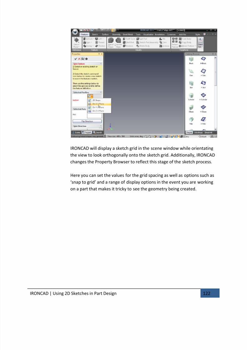
7/30/2019 Unlock Ironcadgsg
http://slidepdf.com/reader/full/unlock-ironcadgsg 126/367
IRONCAD | Using 2D Sketches in Part Design 122
IRONCAD will display a sketch grid in the scene window while orientating
the view to look orthogonally onto the sketch grid. Additionally, IRONCAD
changes the Property Browser to reflect this stage of the sketch process.
Here you can set the values for the grid spacing as well as options such as
‘snap to grid’ and a range of display options in the event you are workingon a part that makes it tricky to see the geometry being created.
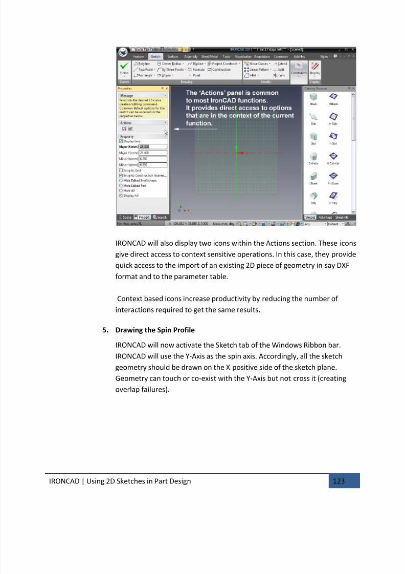
7/30/2019 Unlock Ironcadgsg
http://slidepdf.com/reader/full/unlock-ironcadgsg 127/367
IRONCAD | Using 2D Sketches in Part Design 123
IRONCAD will also display two icons within the Actions section. These icons
give direct access to context sensitive operations. In this case, they provide
quick access to the import of an existing 2D piece of geometry in say DXF
format and to the parameter table.
Context based icons increase productivity by reducing the number of interactions required to get the same results.
5. Drawing the Spin Profile
IRONCAD will now activate the Sketch tab of the Windows Ribbon bar.
IRONCAD will use the Y-Axis as the spin axis. Accordingly, all the sketch
geometry should be drawn on the X positive side of the sketch plane.
Geometry can touch or co-exist with the Y-Axis but not cross it (creating
overlap failures).
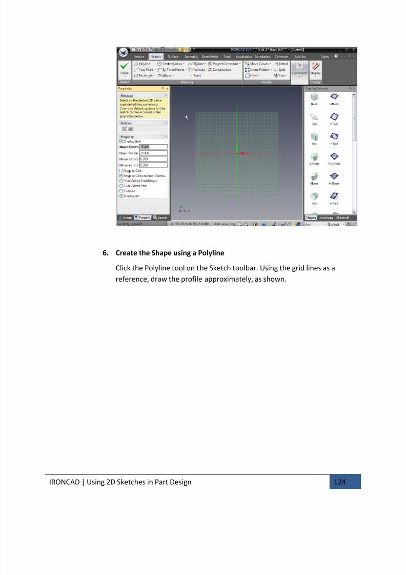
7/30/2019 Unlock Ironcadgsg
http://slidepdf.com/reader/full/unlock-ironcadgsg 128/367
IRONCAD | Using 2D Sketches in Part Design 124
6. Create the Shape using a Polyline
Click the Polyline tool on the Sketch toolbar. Using the grid lines as a
reference, draw the profile approximately, as shown.

7/30/2019 Unlock Ironcadgsg
http://slidepdf.com/reader/full/unlock-ironcadgsg 129/367
IRONCAD | Using 2D Sketches in Part Design 125
As you move the cursor between clicks, notice the snapping behavior and
feedback lines that indicate geometric relationships such as horizontal,
vertical, perpendicular, parallel, or tangent line conditions. Take advantage
of this behavior to create the horizontal and vertical lines, as shown. To
end the Polyline command, press the Esc key or click the Polyline tool
again.
If you made a mistake and any line is not aligned, as shown, just drag its
endpoint until it snaps into the desired alignment.
It is worth experimenting with modifying the profile by dragging lines and
vertices (dragging requires you to click on the item (i.e. vertex or line)
using the left mouse button and holding the mouse button down while you
move the mouse around the screen). You will notice that a vertex moves
freely when you drag it:
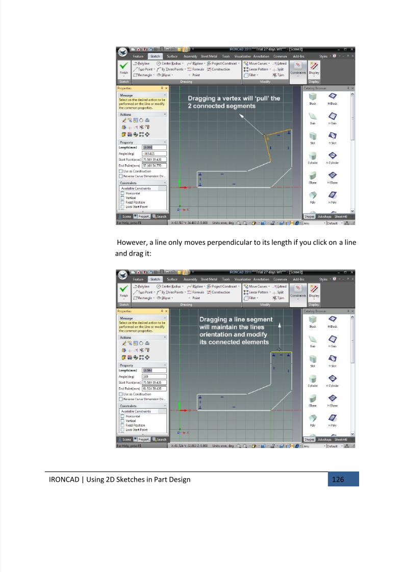
7/30/2019 Unlock Ironcadgsg
http://slidepdf.com/reader/full/unlock-ironcadgsg 130/367
IRONCAD | Using 2D Sketches in Part Design 126
However, a line only moves perpendicular to its length if you click on a line
and drag it:
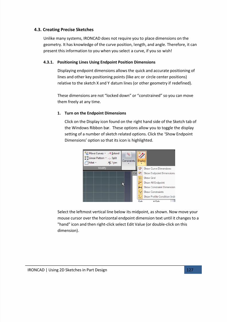
7/30/2019 Unlock Ironcadgsg
http://slidepdf.com/reader/full/unlock-ironcadgsg 131/367
IRONCAD | Using 2D Sketches in Part Design 127
4.3. Creating Precise Sketches
Unlike many systems, IRONCAD does not require you to place dimensions on the
geometry. It has knowledge of the curve position, length, and angle. Therefore, it can
present this information to you when you select a curve, if you so wish!
4.3.1. Positioning Lines Using Endpoint Position Dimensions
Displaying endpoint dimensions allows the quick and accurate positioning of
lines and other key positioning points (like arc or circle center positions)
relative to the sketch X and Y datum lines (or other geometry if redefined).
These dimensions are not “locked down” or “constrained” so you can move
them freely at any time.
1. Turn on the Endpoint Dimensions
Click on the Display icon found on the right hand side of the Sketch tab of
the Windows Ribbon bar. These options allow you to toggle the display
setting of a number of sketch related options. Click the ‘Show Endpoint
Dimensions’ option so that its icon is highlighted.
Select the leftmost vertical line below its midpoint, as shown. Now move your
mouse cursor over the horizontal endpoint dimension text until it changes to a
"hand" icon and then right-click select Edit Value (or double-click on thisdimension).
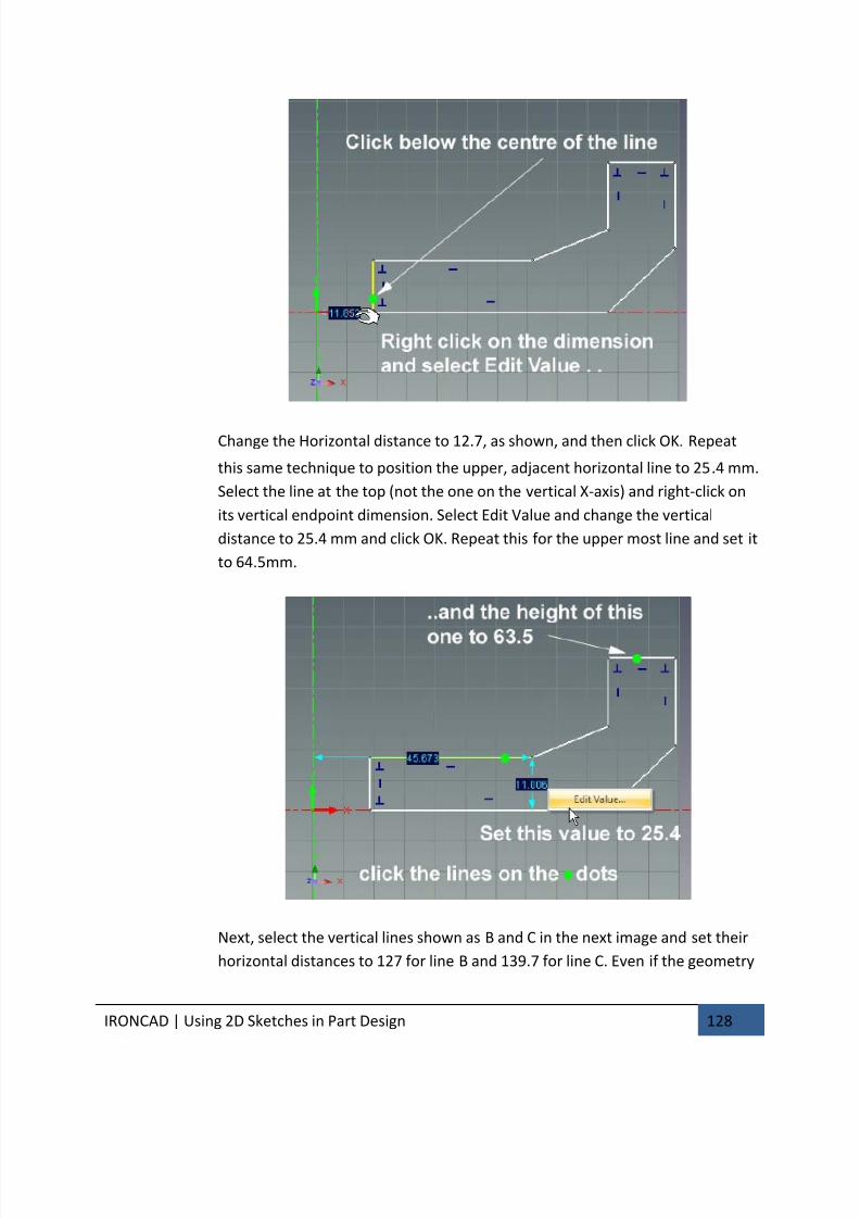
7/30/2019 Unlock Ironcadgsg
http://slidepdf.com/reader/full/unlock-ironcadgsg 132/367
IRONCAD | Using 2D Sketches in Part Design 128
Change the Horizontal distance to 12.7, as shown, and then click OK. Repeat
this same technique to position the upper, adjacent horizontal line to 25.4 mm.
Select the line at the top (not the one on the vertical X-axis) and right-click on
its vertical endpoint dimension. Select Edit Value and change the vertical
distance to 25.4 mm and click OK. Repeat this for the upper most line and set it
to 64.5mm.
Next, select the vertical lines shown as B and C in the next image and set their
horizontal distances to 127 for line B and 139.7 for line C. Even if the geometry
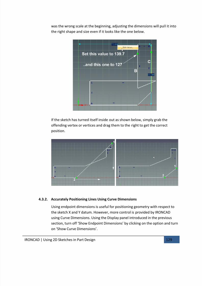
7/30/2019 Unlock Ironcadgsg
http://slidepdf.com/reader/full/unlock-ironcadgsg 133/367
IRONCAD | Using 2D Sketches in Part Design 129
was the wrong scale at the beginning, adjusting the dimensions will pull it into
the right shape and size even if it looks like the one below.
If the sketch has turned itself inside out as shown below, simply grab the
offending vertex or vertices and drag them to the right to get the correct
position.
4.3.2.
Accurately Positioning Lines Using Curve Dimensions
Using endpoint dimensions is useful for positioning geometry with respect to
the sketch X and Y datum. However, more control is provided by IRONCAD
using Curve Dimensions. Using the Display panel introduced in the previous
section, turn off ‘Show Endpoint Dimensions’ by clicking on the option and turn
on ‘Show Curve Dimensions’.
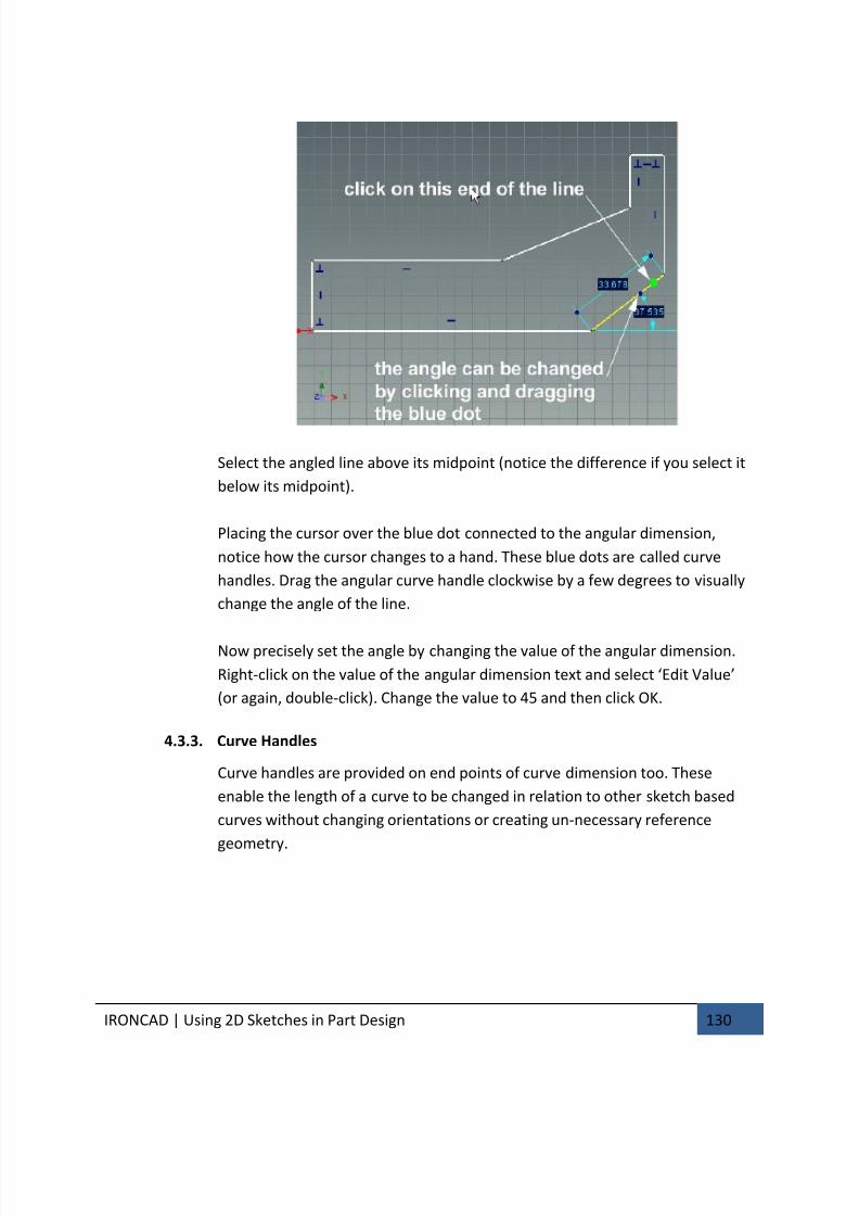
7/30/2019 Unlock Ironcadgsg
http://slidepdf.com/reader/full/unlock-ironcadgsg 134/367
IRONCAD | Using 2D Sketches in Part Design 130
Select the angled line above its midpoint (notice the difference if you select it
below its midpoint).
Placing the cursor over the blue dot connected to the angular dimension,
notice how the cursor changes to a hand. These blue dots are called curve
handles. Drag the angular curve handle clockwise by a few degrees to visually
change the angle of the line.
Now precisely set the angle by changing the value of the angular dimension.
Right-click on the value of the angular dimension text and select ‘Edit Value’
(or again, double-click). Change the value to 45 and then click OK.
4.3.3. Curve Handles
Curve handles are provided on end points of curve dimension too. These
enable the length of a curve to be changed in relation to other sketch based
curves without changing orientations or creating un-necessary reference
geometry.
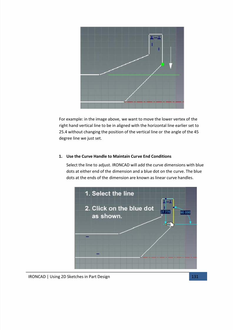
7/30/2019 Unlock Ironcadgsg
http://slidepdf.com/reader/full/unlock-ironcadgsg 135/367
IRONCAD | Using 2D Sketches in Part Design 131
For example: in the image above, we want to move the lower vertex of the
right hand vertical line to be in aligned with the horizontal line earlier set to
25.4 without changing the position of the vertical line or the angle of the 45
degree line we just set.
1. Use the Curve Handle to Maintain Curve End Conditions
Select the line to adjust. IRONCAD will add the curve dimensions with blue
dots at either end of the dimension and a blue dot on the curve. The bluedots at the ends of the dimension are known as linear curve handles.

7/30/2019 Unlock Ironcadgsg
http://slidepdf.com/reader/full/unlock-ironcadgsg 136/367
IRONCAD | Using 2D Sketches in Part Design 132
Click on the lower linear curve handle and drag it over to the line we set at
25.4 or over the vertex as shown, and release.
The line will extend until its lower point is in line with the 25.4 line used as
a reference without altering the angular relationship of the vertical line
and the 45 degree line.
Now adjust the uppermost angular line to also lie at 45 degrees, as shown
next without worrying about its length.
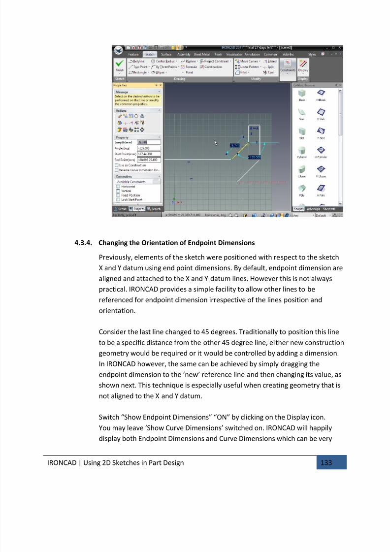
7/30/2019 Unlock Ironcadgsg
http://slidepdf.com/reader/full/unlock-ironcadgsg 137/367
IRONCAD | Using 2D Sketches in Part Design 133
4.3.4. Changing the Orientation of Endpoint Dimensions
Previously, elements of the sketch were positioned with respect to the sketch
X and Y datum using end point dimensions. By default, endpoint dimension are
aligned and attached to the X and Y datum lines. However this is not always
practical. IRONCAD provides a simple facility to allow other lines to bereferenced for endpoint dimension irrespective of the lines position and
orientation.
Consider the last line changed to 45 degrees. Traditionally to position this line
to be a specific distance from the other 45 degree line, either new construction
geometry would be required or it would be controlled by adding a dimension.
In IRONCAD however, the same can be achieved by simply dragging the
endpoint dimension to the ‘new’ reference line and then changing its value, as
shown next. This technique is especially useful when creating geometry that isnot aligned to the X and Y datum.
Switch “Show Endpoint Dimensions” “ON” by clicking on the Display icon.
You may leave ‘Show Curve Dimensions’ switched on. IRONCAD will happily
display both Endpoint Dimensions and Curve Dimensions which can be very
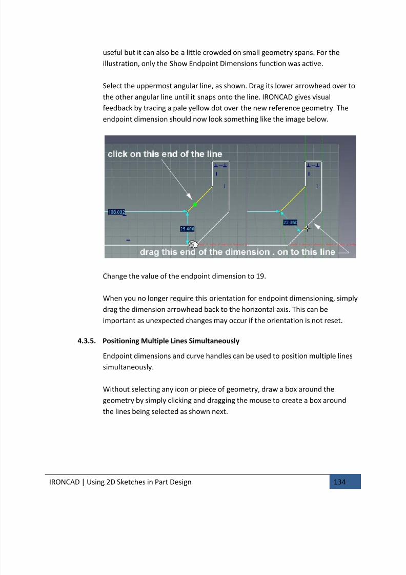
7/30/2019 Unlock Ironcadgsg
http://slidepdf.com/reader/full/unlock-ironcadgsg 138/367
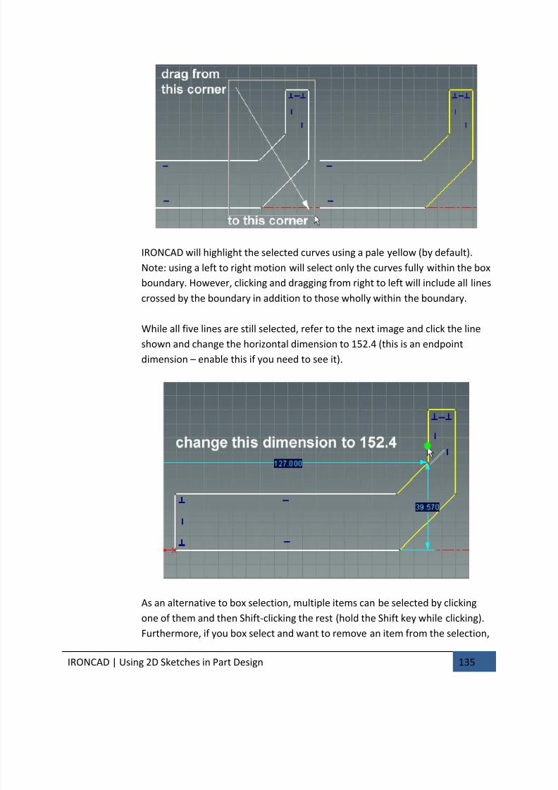
7/30/2019 Unlock Ironcadgsg
http://slidepdf.com/reader/full/unlock-ironcadgsg 139/367
IRONCAD | Using 2D Sketches in Part Design 135
IRONCAD will highlight the selected curves using a pale yellow (by default).
Note: using a left to right motion will select only the curves fully within the box
boundary. However, clicking and dragging from right to left will include all lines
crossed by the boundary in addition to those wholly within the boundary.
While all five lines are still selected, refer to the next image and click the line
shown and change the horizontal dimension to 152.4 (this is an endpoint
dimension – enable this if you need to see it).
As an alternative to box selection, multiple items can be selected by clicking
one of them and then Shift-clicking the rest (hold the Shift key while clicking).
Furthermore, if you box select and want to remove an item from the selection,
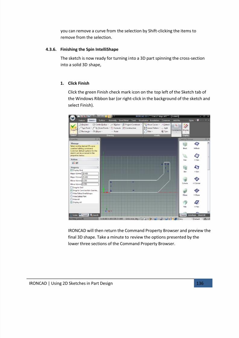
7/30/2019 Unlock Ironcadgsg
http://slidepdf.com/reader/full/unlock-ironcadgsg 140/367
IRONCAD | Using 2D Sketches in Part Design 136
you can remove a curve from the selection by Shift-clicking the items to
remove from the selection.
4.3.6. Finishing the Spin IntelliShape
The sketch is now ready for turning into a 3D part spinning the cross-sectioninto a solid 3D shape,
1. Click Finish
Click the green Finish check mark icon on the top left of the Sketch tab of
the Windows Ribbon bar (or right-click in the background of the sketch and
select Finish).
IRONCAD will then return the Command Property Browser and preview the
final 3D shape. Take a minute to review the options presented by thelower three sections of the Command Property Browser.
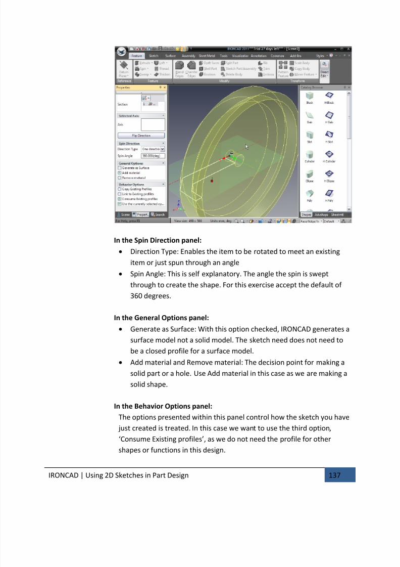
7/30/2019 Unlock Ironcadgsg
http://slidepdf.com/reader/full/unlock-ironcadgsg 141/367
IRONCAD | Using 2D Sketches in Part Design 137
In the Spin Direction panel:
• Direction Type: Enables the item to be rotated to meet an existing
item or just spun through an angle
• Spin Angle: This is self explanatory. The angle the spin is swept
through to create the shape. For this exercise accept the default of
360 degrees.
In the General Options panel:
• Generate as Surface: With this option checked, IRONCAD generates a
surface model not a solid model. The sketch need does not need to
be a closed profile for a surface model.
• Add material and Remove material: The decision point for making a
solid part or a hole. Use Add material in this case as we are making a
solid shape.
In the Behavior Options panel:
The options presented within this panel control how the sketch you have
just created is treated. In this case we want to use the third option,
‘Consume Existing profiles’, as we do not need the profile for other
shapes or functions in this design.
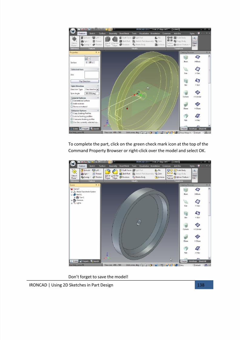
7/30/2019 Unlock Ironcadgsg
http://slidepdf.com/reader/full/unlock-ironcadgsg 142/367
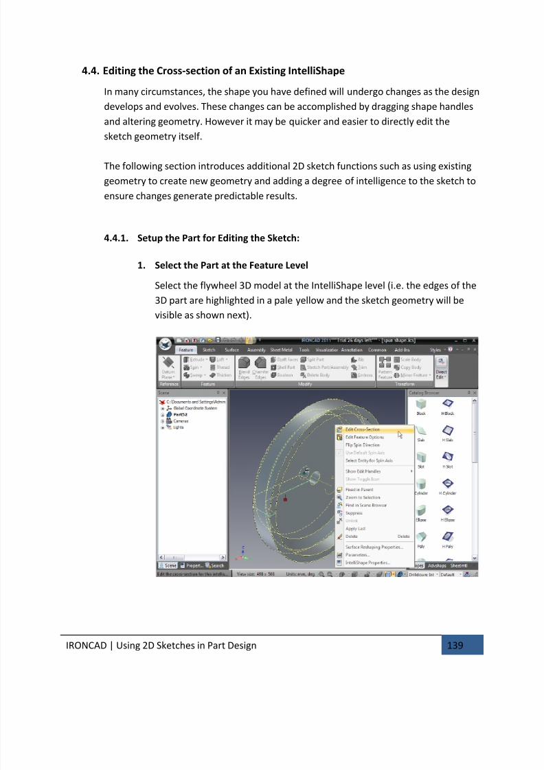
7/30/2019 Unlock Ironcadgsg
http://slidepdf.com/reader/full/unlock-ironcadgsg 143/367
IRONCAD | Using 2D Sketches in Part Design 139
4.4. Editing the Cross-section of an Existing IntelliShape
In many circumstances, the shape you have defined will undergo changes as the design
develops and evolves. These changes can be accomplished by dragging shape handles
and altering geometry. However it may be quicker and easier to directly edit the
sketch geometry itself.
The following section introduces additional 2D sketch functions such as using existing
geometry to create new geometry and adding a degree of intelligence to the sketch to
ensure changes generate predictable results.
4.4.1. Setup the Part for Editing the Sketch:
1.
Select the Part at the Feature LevelSelect the flywheel 3D model at the IntelliShape level (i.e. the edges of the
3D part are highlighted in a pale yellow and the sketch geometry will be
visible as shown next).
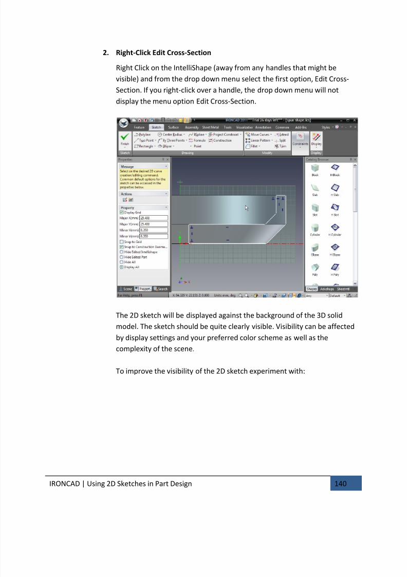
7/30/2019 Unlock Ironcadgsg
http://slidepdf.com/reader/full/unlock-ironcadgsg 144/367
IRONCAD | Using 2D Sketches in Part Design 140
2. Right-Click Edit Cross-Section
Right Click on the IntelliShape (away from any handles that might be
visible) and from the drop down menu select the first option, Edit Cross-
Section. If you right-click over a handle, the drop down menu will not
display the menu option Edit Cross-Section.
The 2D sketch will be displayed against the background of the 3D solid
model. The sketch should be quite clearly visible. Visibility can be affected
by display settings and your preferred color scheme as well as the
complexity of the scene.
To improve the visibility of the 2D sketch experiment with:
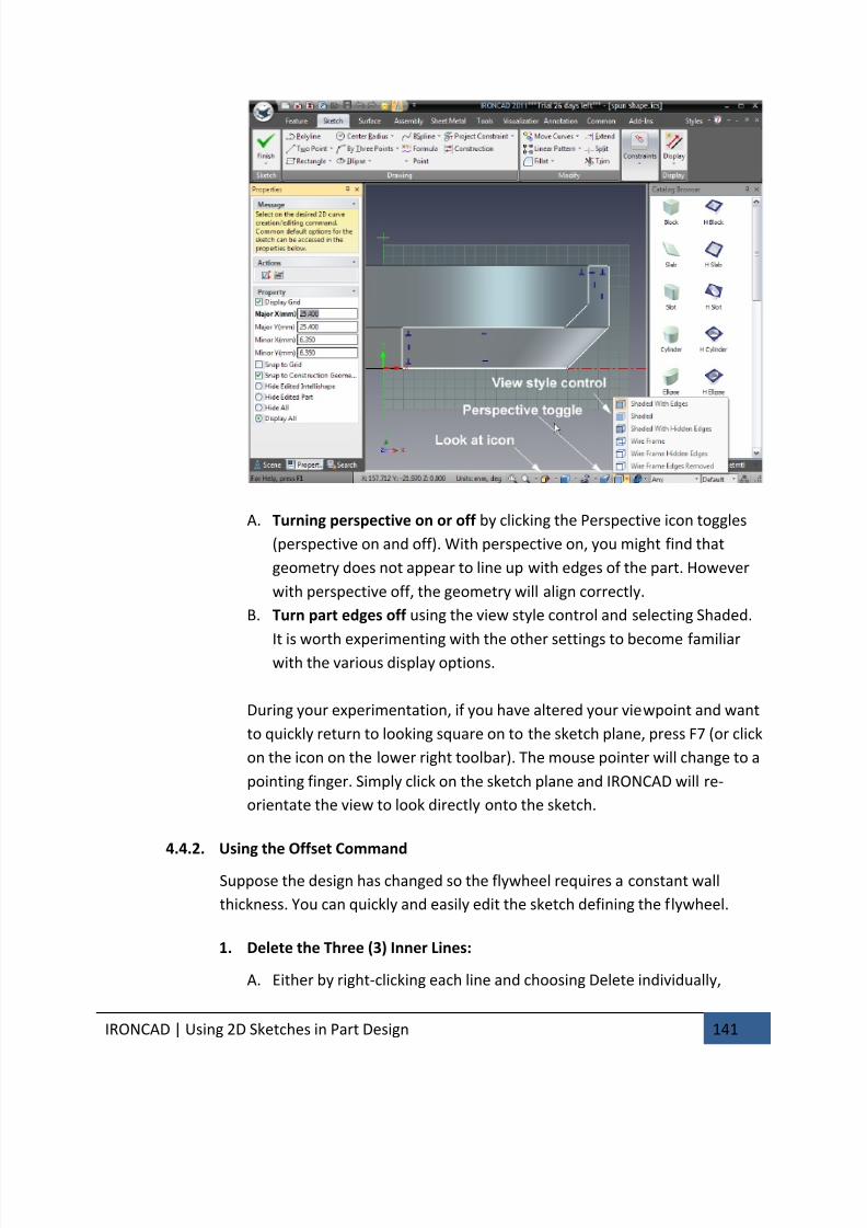
7/30/2019 Unlock Ironcadgsg
http://slidepdf.com/reader/full/unlock-ironcadgsg 145/367
IRONCAD | Using 2D Sketches in Part Design 141
A. Turning perspective on or off by clicking the Perspective icon toggles
(perspective on and off). With perspective on, you might find that
geometry does not appear to line up with edges of the part. However
with perspective off, the geometry will align correctly.
B. Turn part edges off using the view style control and selecting Shaded.
It is worth experimenting with the other settings to become familiarwith the various display options.
During your experimentation, if you have altered your viewpoint and want
to quickly return to looking square on to the sketch plane, press F7 (or click
on the icon on the lower right toolbar). The mouse pointer will change to a
pointing finger. Simply click on the sketch plane and IRONCAD will re-
orientate the view to look directly onto the sketch.
4.4.2. Using the Offset Command
Suppose the design has changed so the flywheel requires a constant wall
thickness. You can quickly and easily edit the sketch defining the flywheel.
1. Delete the Three (3) Inner Lines:
A. Either by right-clicking each line and choosing Delete individually,
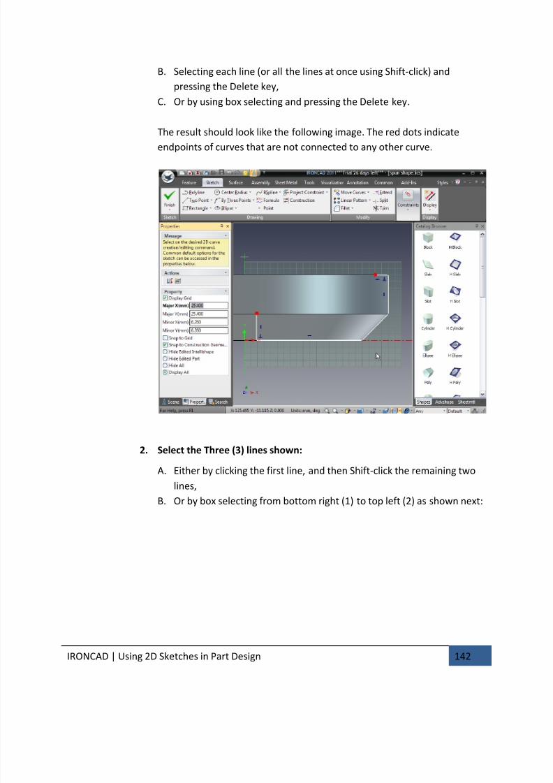
7/30/2019 Unlock Ironcadgsg
http://slidepdf.com/reader/full/unlock-ironcadgsg 146/367
IRONCAD | Using 2D Sketches in Part Design 142
B. Selecting each line (or all the lines at once using Shift-click) and
pressing the Delete key,
C. Or by using box selecting and pressing the Delete key.
The result should look like the following image. The red dots indicateendpoints of curves that are not connected to any other curve.
2. Select the Three (3) lines shown:
A. Either by clicking the first line, and then Shift-click the remaining two
lines,
B. Or by box selecting from bottom right (1) to top left (2) as shown next:

7/30/2019 Unlock Ironcadgsg
http://slidepdf.com/reader/full/unlock-ironcadgsg 147/367
IRONCAD | Using 2D Sketches in Part Design 143
3. Start the Offset Command to Offset the Selected Curves
From the Actions panel on the Command Property Browser, select Offset
Curves.
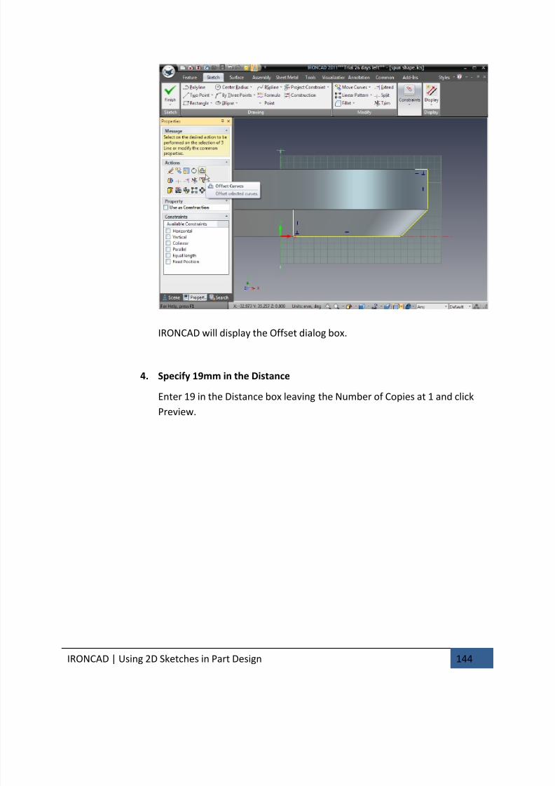
7/30/2019 Unlock Ironcadgsg
http://slidepdf.com/reader/full/unlock-ironcadgsg 148/367
IRONCAD | Using 2D Sketches in Part Design 144
IRONCAD will display the Offset dialog box.
4. Specify 19mm in the Distance
Enter 19 in the Distance box leaving the Number of Copies at 1 and click
Preview.
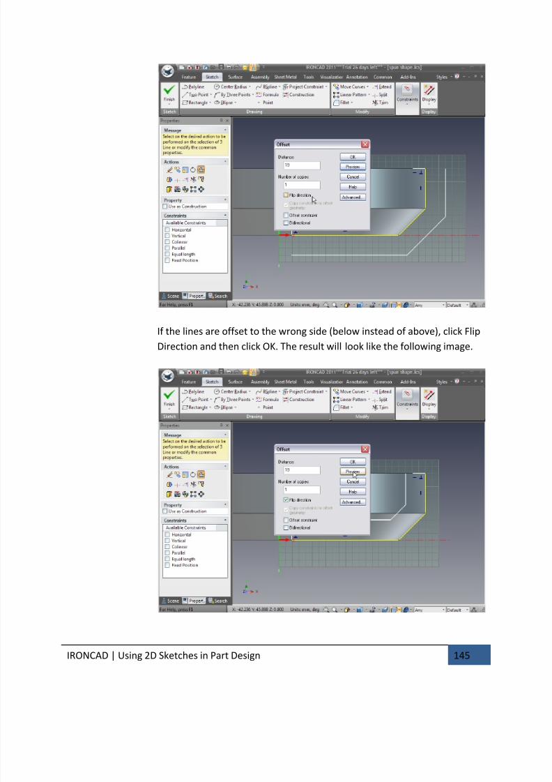
7/30/2019 Unlock Ironcadgsg
http://slidepdf.com/reader/full/unlock-ironcadgsg 149/367
IRONCAD | Using 2D Sketches in Part Design 145
If the lines are offset to the wrong side (below instead of above), click Flip
Direction and then click OK. The result will look like the following image.

7/30/2019 Unlock Ironcadgsg
http://slidepdf.com/reader/full/unlock-ironcadgsg 150/367
IRONCAD | Using 2D Sketches in Part Design 146
5. Connect the Disconnected Curves
Finally reconnect the line endpoints by dragging the red dots of the top
right horizontal line and the bottom left vertical line to their endpoints of
the offset geometry.
6. Finish the Sketch
Right-click and select the green check mark to finish the drawing.
4.5. Using 2D Constraints
Up to this point, we have used IRONCAD’s freedom to easily create and modify shapes
without too much concern about the outcome. This freedom is especially useful when
you’re in the conceptual design phase. However, there are times when you want to
tightly control the design and enforce precise geometrical relationships and
dimensions were this is sometimes referred to as ‘design intent’.
IRONCAD provides the tools to operate in this manner using specific curve dimensions
and geometric constraints. This includes adding relationships between elements of
your design often referred to as parametric design. You can enforce as much or as little
“design intent” control, as desired.
This section will introduce the use of constraints to control design intent.
4.5.1. Adding Dimensional constraints
With Spin IntelliShapes, it can be advantageous to ‘open’ up the shape to get a
clear view of the sketch profile. This is useful for editing the sketch and for
dragging shape handles in the context of an assembly.
1. Select the Flywheel Shape at the IntelliShape Level
2. Pull the Spin Handle
Grab the Spin Angle handle, as shown, and drag it approximately 100
degrees (alternately you can right-click on the handle, select Edit Value and
enter an exact value for the extent of the spin angle).
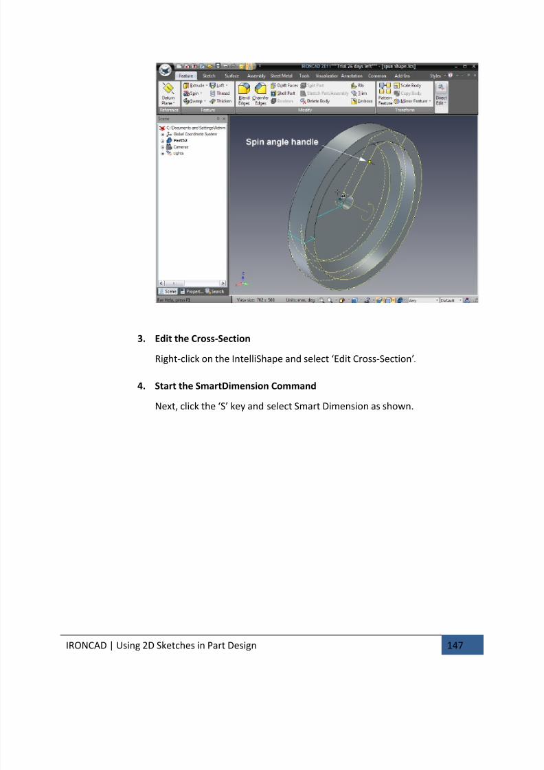
7/30/2019 Unlock Ironcadgsg
http://slidepdf.com/reader/full/unlock-ironcadgsg 151/367
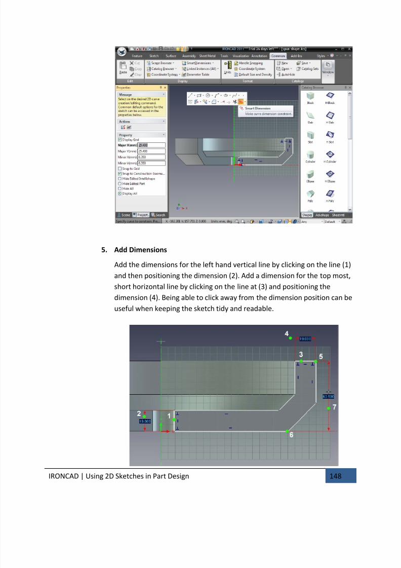
7/30/2019 Unlock Ironcadgsg
http://slidepdf.com/reader/full/unlock-ironcadgsg 152/367
IRONCAD | Using 2D Sketches in Part Design 148
5. Add Dimensions
Add the dimensions for the left hand vertical line by clicking on the line (1)
and then positioning the dimension (2). Add a dimension for the top most,
short horizontal line by clicking on the line at (3) and positioning the
dimension (4). Being able to click away from the dimension position can beuseful when keeping the sketch tidy and readable.
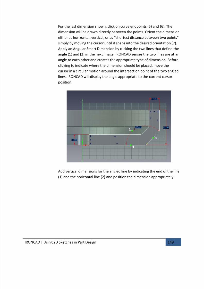
7/30/2019 Unlock Ironcadgsg
http://slidepdf.com/reader/full/unlock-ironcadgsg 153/367
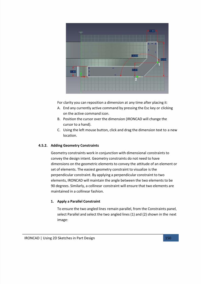
7/30/2019 Unlock Ironcadgsg
http://slidepdf.com/reader/full/unlock-ironcadgsg 154/367
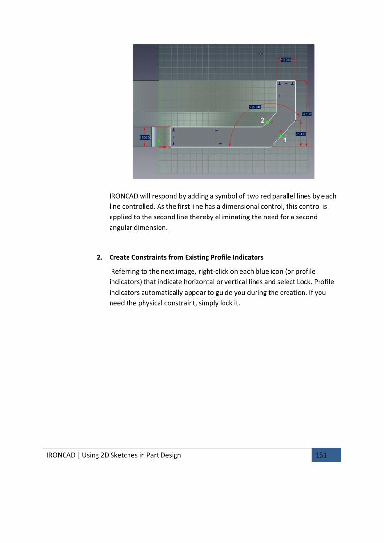
7/30/2019 Unlock Ironcadgsg
http://slidepdf.com/reader/full/unlock-ironcadgsg 155/367

7/30/2019 Unlock Ironcadgsg
http://slidepdf.com/reader/full/unlock-ironcadgsg 156/367
IRONCAD | Using 2D Sketches in Part Design 152
4.5.3. Making changes predictable
At this point, the sketch will still be shown as a collection of white curves and
should resemble the previous image. Modifying dimensions at this point will
change the curve. However, the changes may result in some unforeseen
results as the profile is not fully constrained. For example, changing the
horizontal 19mm dimension, which side should IRONCAD move?
1. Modify Dimensions to See the Affect
To modify the value of an existing dimension, simply right-click on the
dimension text and select Edit (or double-click). Use this technique to
change the dimensions to the values shown.
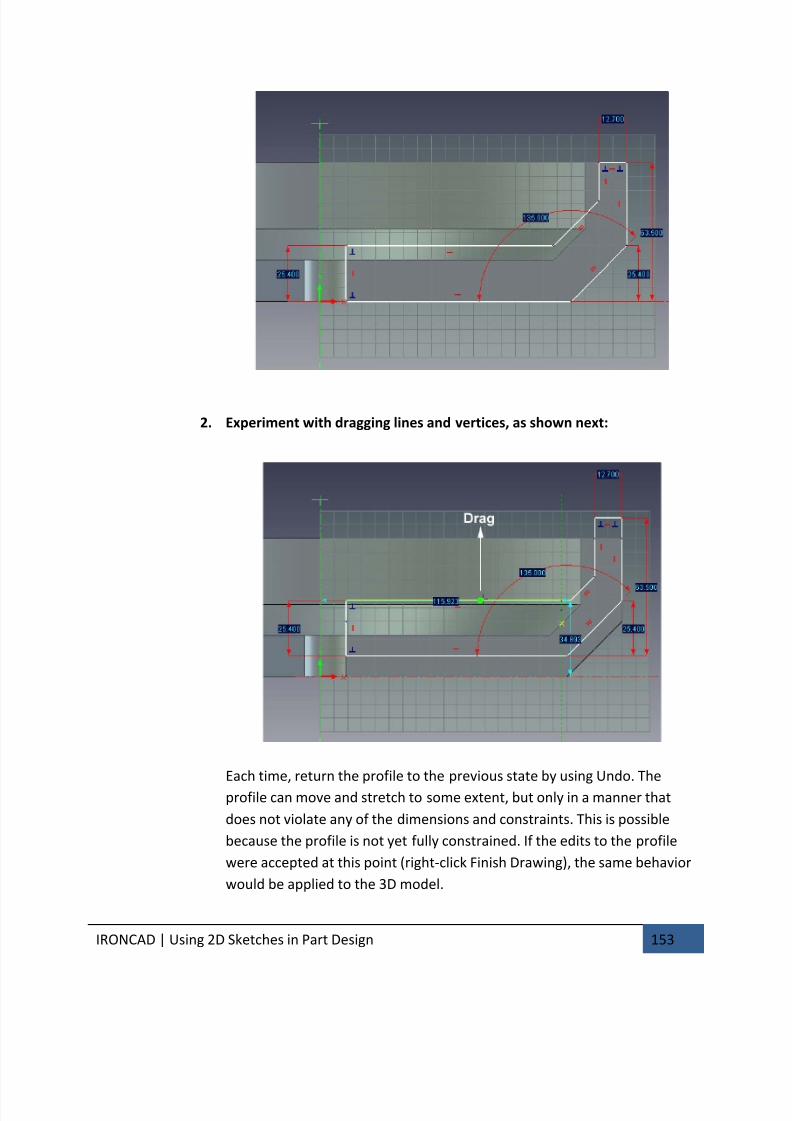
7/30/2019 Unlock Ironcadgsg
http://slidepdf.com/reader/full/unlock-ironcadgsg 157/367
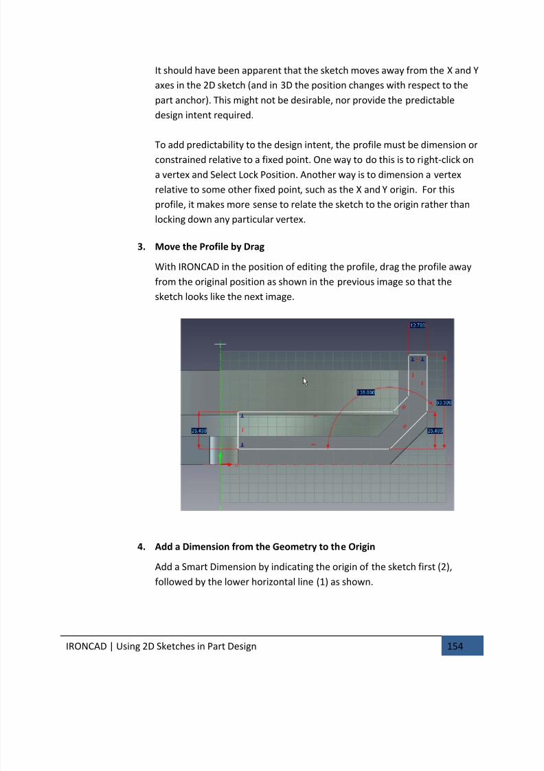
7/30/2019 Unlock Ironcadgsg
http://slidepdf.com/reader/full/unlock-ironcadgsg 158/367
IRONCAD | Using 2D Sketches in Part Design 154
It should have been apparent that the sketch moves away from the X and Y
axes in the 2D sketch (and in 3D the position changes with respect to the
part anchor). This might not be desirable, nor provide the predictable
design intent required.
To add predictability to the design intent, the profile must be dimension or
constrained relative to a fixed point. One way to do this is to right-click on
a vertex and Select Lock Position. Another way is to dimension a vertex
relative to some other fixed point, such as the X and Y origin. For this
profile, it makes more sense to relate the sketch to the origin rather than
locking down any particular vertex.
3. Move the Profile by Drag
With IRONCAD in the position of editing the profile, drag the profile awayfrom the original position as shown in the previous image so that the
sketch looks like the next image.
4. Add a Dimension from the Geometry to the Origin
Add a Smart Dimension by indicating the origin of the sketch first (2),
followed by the lower horizontal line (1) as shown.
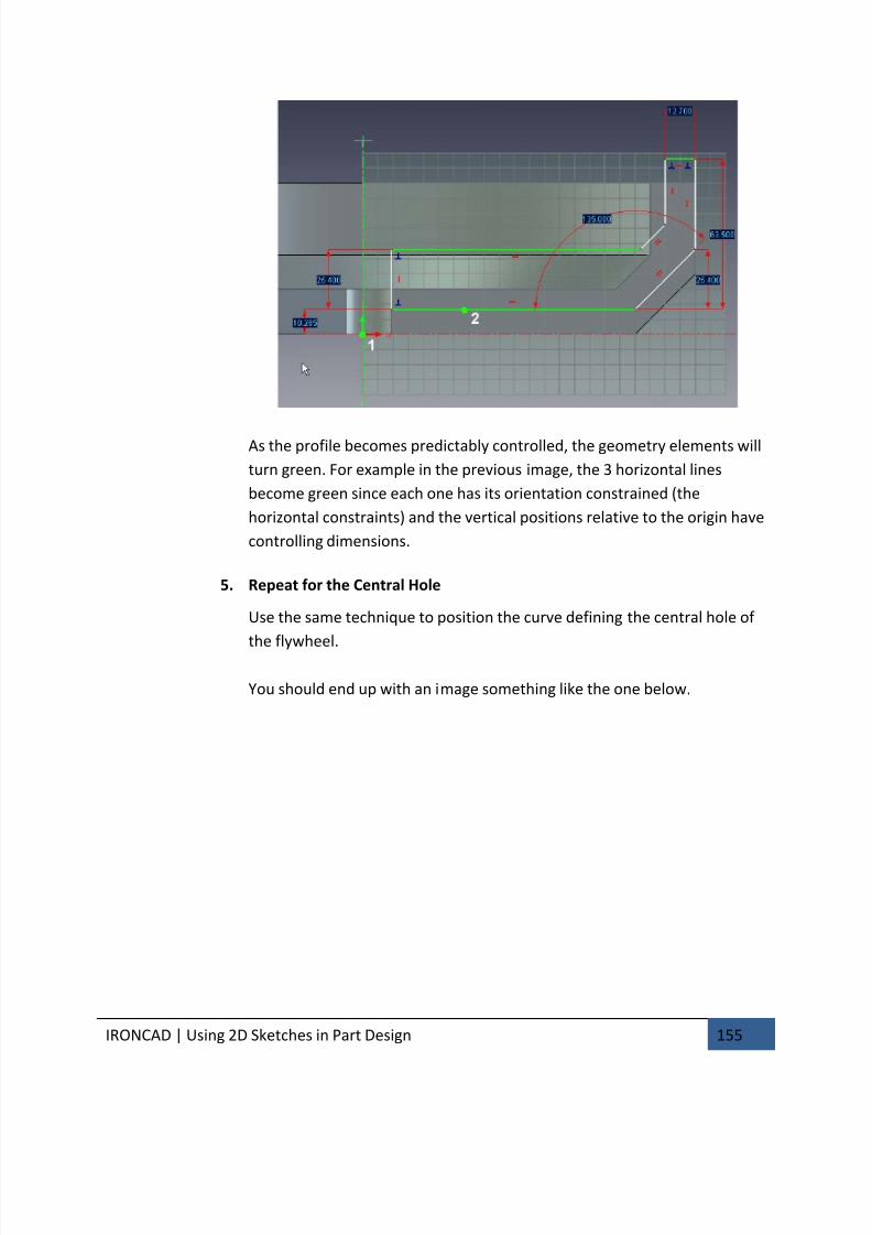
7/30/2019 Unlock Ironcadgsg
http://slidepdf.com/reader/full/unlock-ironcadgsg 159/367
IRONCAD | Using 2D Sketches in Part Design 155
As the profile becomes predictably controlled, the geometry elements will
turn green. For example in the previous image, the 3 horizontal lines
become green since each one has its orientation constrained (the
horizontal constraints) and the vertical positions relative to the origin have
controlling dimensions.
5. Repeat for the Central Hole
Use the same technique to position the curve defining the central hole of
the flywheel.
You should end up with an image something like the one below.
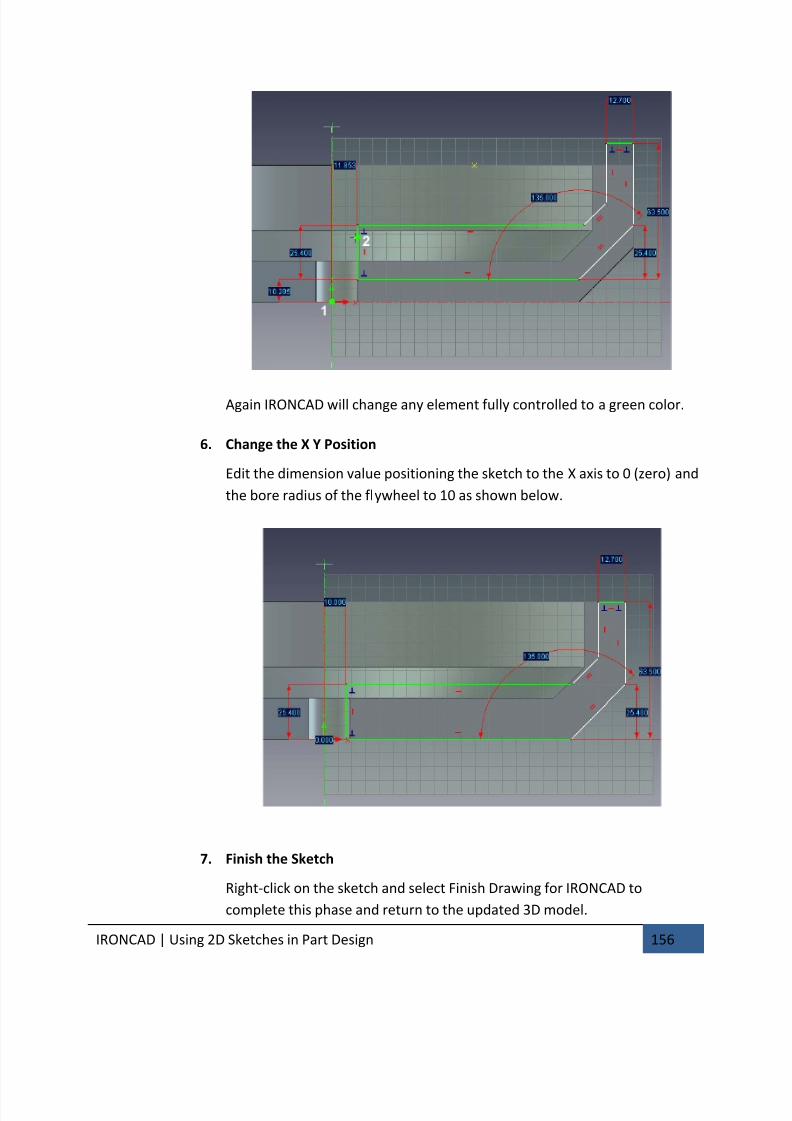
7/30/2019 Unlock Ironcadgsg
http://slidepdf.com/reader/full/unlock-ironcadgsg 160/367
IRONCAD | Using 2D Sketches in Part Design 156
Again IRONCAD will change any element fully controlled to a green color.
6. Change the X Y Position
Edit the dimension value positioning the sketch to the X axis to 0 (zero) and
the bore radius of the flywheel to 10 as shown below.
7. Finish the Sketch
Right-click on the sketch and select Finish Drawing for IRONCAD to
complete this phase and return to the updated 3D model.
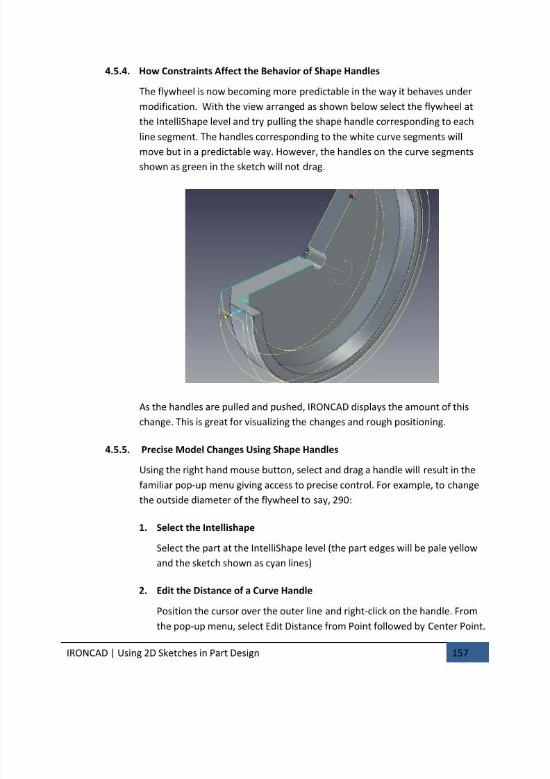
7/30/2019 Unlock Ironcadgsg
http://slidepdf.com/reader/full/unlock-ironcadgsg 161/367

7/30/2019 Unlock Ironcadgsg
http://slidepdf.com/reader/full/unlock-ironcadgsg 162/367

7/30/2019 Unlock Ironcadgsg
http://slidepdf.com/reader/full/unlock-ironcadgsg 163/367
IRONCAD | Using 2D Sketches in Part Design 159
In this example, the inner rim wall has been pulled inward causing the inner
angled face to invert. The first clue is the most obvious one, IRONCAD displays
an error message detailing the part identity and the feature that has failed. The
second clue given that a problem exists, lies in the model. It doesn’t vanish
from the screen, just resorts to the bounding solid geometry with no features.
The third clue lies in the geometry where the offending items will have been
turned to magenta to help in rapidly identifying the cause of the failure.
Even if the geometry has failed, IRONCAD recognizes the model. The error canbe reversed using the Undo command or any of the offending elements
repositioned.
4.5.7. Adding Full Design Intent to the Flywheel
To remove the possibility of geometrical issues and make the shape completely
predictable, the model needs to have the sketch geometry fully constrained.
1. Edit the Cross-section
Select the part at the IntelliShape level, right-click and select Edit Cross-Section. IRONCAD will re-orientate the view to look directly onto the
sketch.
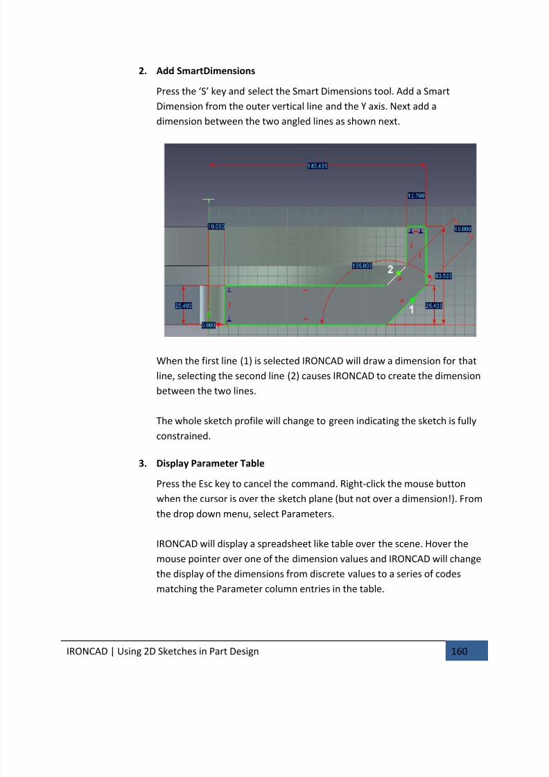
7/30/2019 Unlock Ironcadgsg
http://slidepdf.com/reader/full/unlock-ironcadgsg 164/367
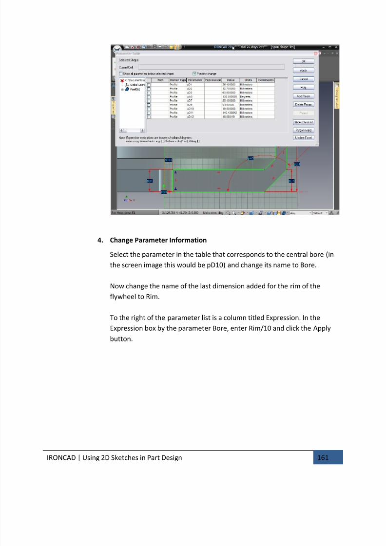
7/30/2019 Unlock Ironcadgsg
http://slidepdf.com/reader/full/unlock-ironcadgsg 165/367
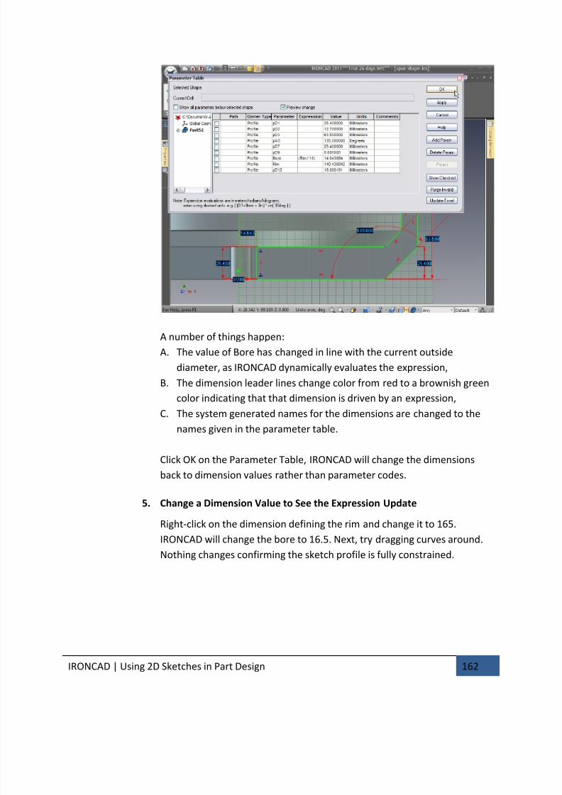
7/30/2019 Unlock Ironcadgsg
http://slidepdf.com/reader/full/unlock-ironcadgsg 166/367
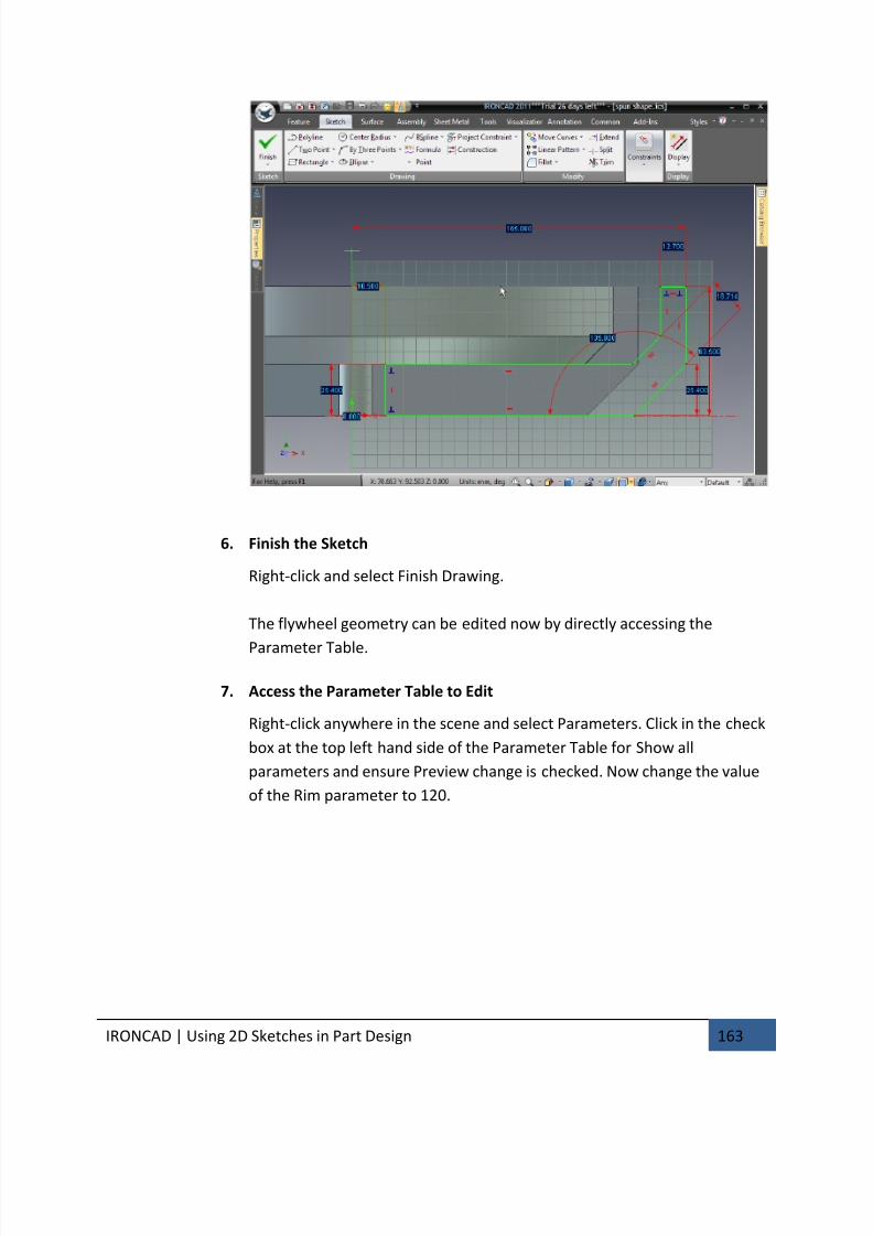
7/30/2019 Unlock Ironcadgsg
http://slidepdf.com/reader/full/unlock-ironcadgsg 167/367
IRONCAD | Using 2D Sketches in Part Design 163
6. Finish the Sketch
Right-click and select Finish Drawing.
The flywheel geometry can be edited now by directly accessing the
Parameter Table.
7. Access the Parameter Table to Edit
Right-click anywhere in the scene and select Parameters. Click in the check
box at the top left hand side of the Parameter Table for Show all
parameters and ensure Preview change is checked. Now change the value
of the Rim parameter to 120.
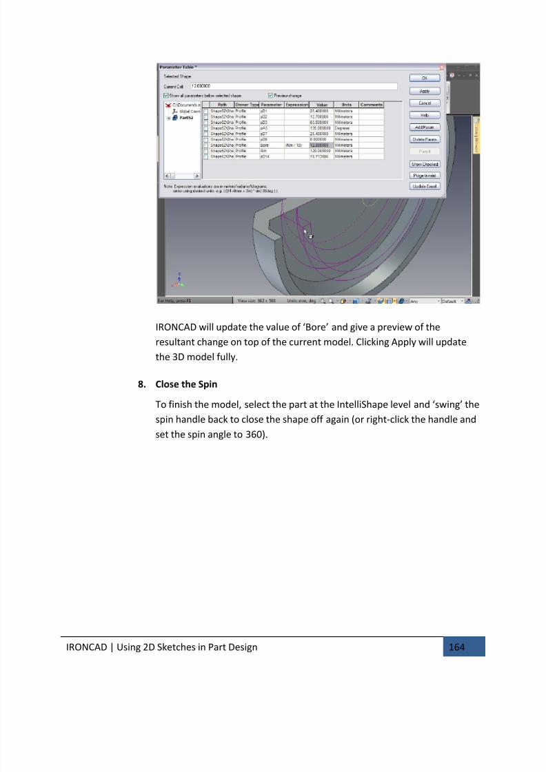
7/30/2019 Unlock Ironcadgsg
http://slidepdf.com/reader/full/unlock-ironcadgsg 168/367
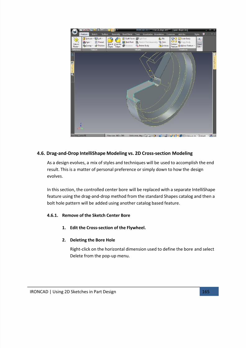
7/30/2019 Unlock Ironcadgsg
http://slidepdf.com/reader/full/unlock-ironcadgsg 169/367
IRONCAD | Using 2D Sketches in Part Design 165
4.6. Drag-and-Drop IntelliShape Modeling vs. 2D Cross-section Modeling
As a design evolves, a mix of styles and techniques will be used to accomplish the end
result. This is a matter of personal preference or simply down to how the design
evolves.
In this section, the controlled center bore will be replaced with a separate IntelliShape
feature using the drag-and-drop method from the standard Shapes catalog and then a
bolt hole pattern will be added using another catalog based feature.
4.6.1. Remove of the Sketch Center Bore
1. Edit the Cross-section of the Flywheel.
2. Deleting the Bore Hole
Right-click on the horizontal dimension used to define the bore and select
Delete from the pop-up menu.
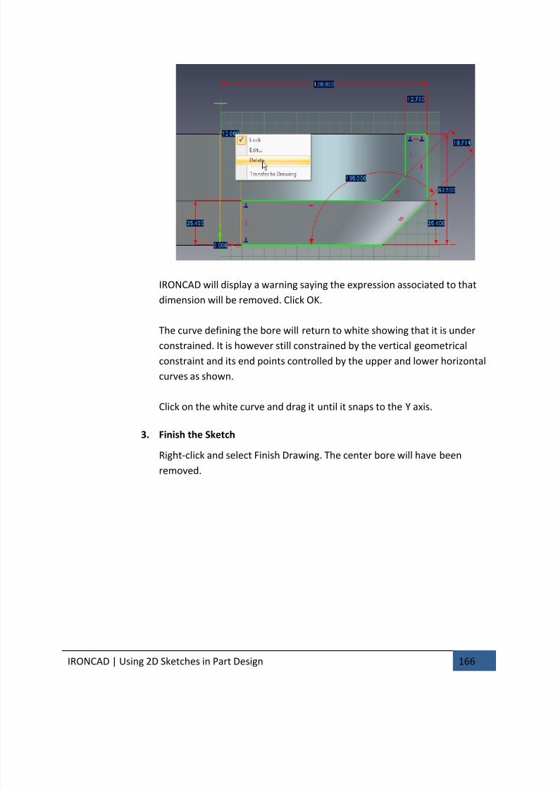
7/30/2019 Unlock Ironcadgsg
http://slidepdf.com/reader/full/unlock-ironcadgsg 170/367
IRONCAD | Using 2D Sketches in Part Design 166
IRONCAD will display a warning saying the expression associated to that
dimension will be removed. Click OK.
The curve defining the bore will return to white showing that it is under
constrained. It is however still constrained by the vertical geometrical
constraint and its end points controlled by the upper and lower horizontal
curves as shown.
Click on the white curve and drag it until it snaps to the Y axis.
3. Finish the Sketch
Right-click and select Finish Drawing. The center bore will have been
removed.
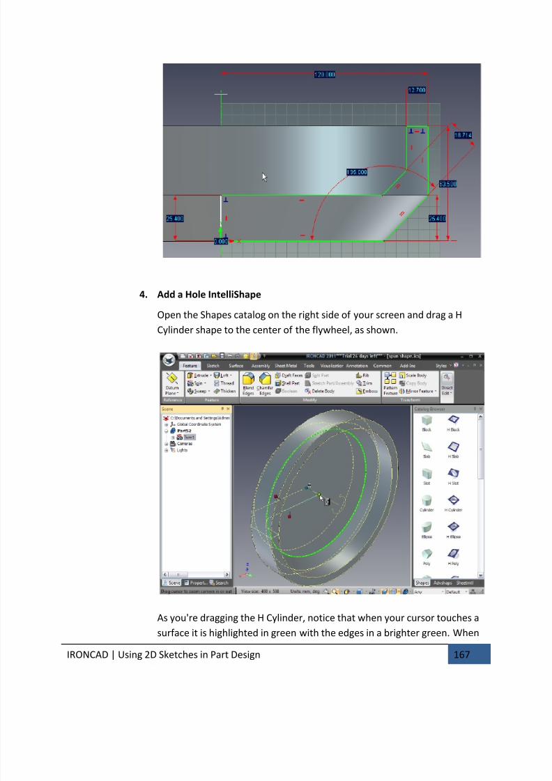
7/30/2019 Unlock Ironcadgsg
http://slidepdf.com/reader/full/unlock-ironcadgsg 171/367
IRONCAD | Using 2D Sketches in Part Design 167
4. Add a Hole IntelliShape
Open the Shapes catalog on the right side of your screen and drag a H
Cylinder shape to the center of the flywheel, as shown.
As you're dragging the H Cylinder, notice that when your cursor touches a
surface it is highlighted in green with the edges in a brighter green. When
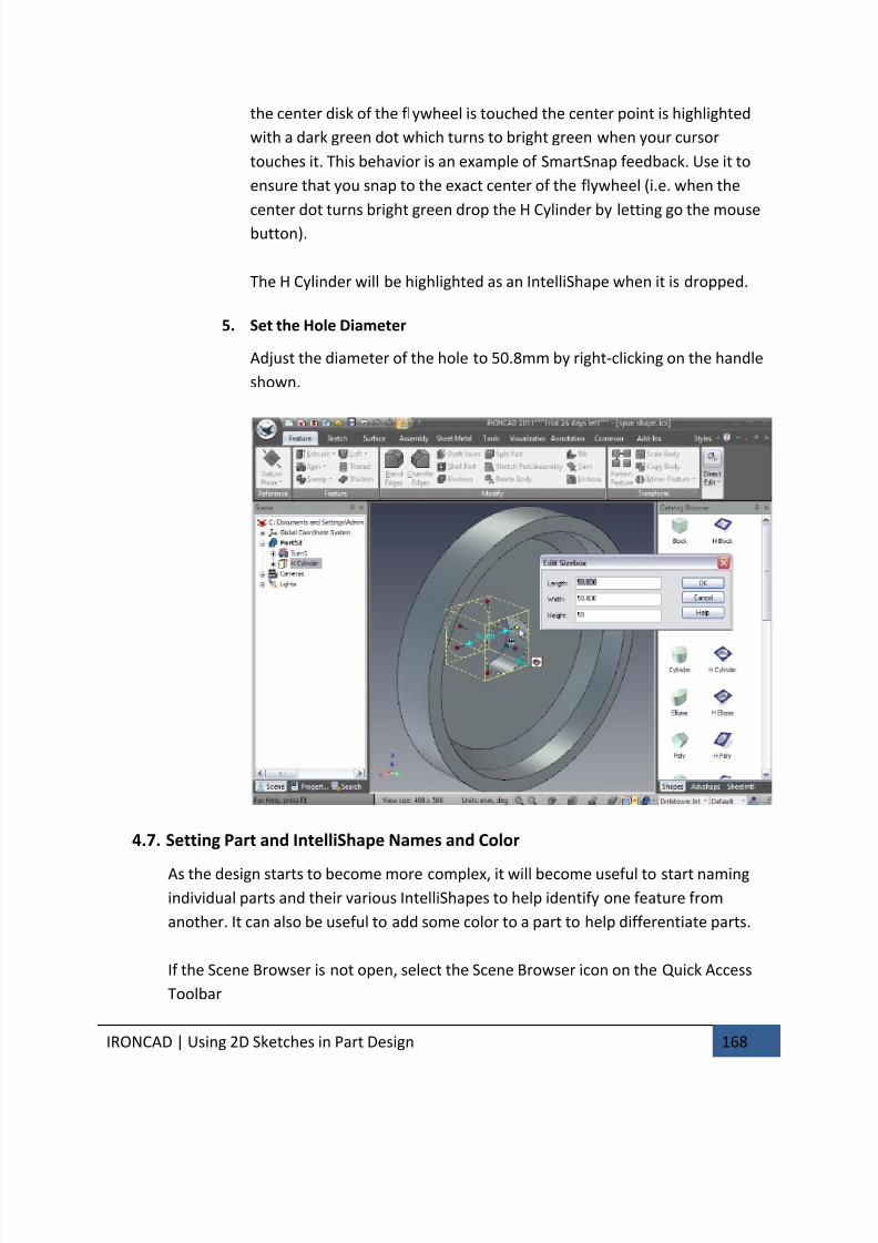
7/30/2019 Unlock Ironcadgsg
http://slidepdf.com/reader/full/unlock-ironcadgsg 172/367
IRONCAD | Using 2D Sketches in Part Design 168
the center disk of the flywheel is touched the center point is highlighted
with a dark green dot which turns to bright green when your cursor
touches it. This behavior is an example of SmartSnap feedback. Use it to
ensure that you snap to the exact center of the flywheel (i.e. when the
center dot turns bright green drop the H Cylinder by letting go the mousebutton).
The H Cylinder will be highlighted as an IntelliShape when it is dropped.
5. Set the Hole Diameter
Adjust the diameter of the hole to 50.8mm by right-clicking on the handle
shown.
4.7. Setting Part and IntelliShape Names and Color
As the design starts to become more complex, it will become useful to start naming
individual parts and their various IntelliShapes to help identify one feature from
another. It can also be useful to add some color to a part to help differentiate parts.
If the Scene Browser is not open, select the Scene Browser icon on the Quick Access
Toolbar
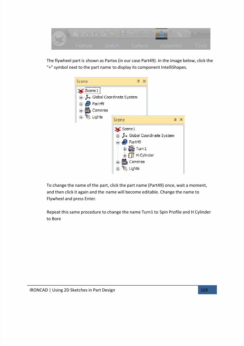
7/30/2019 Unlock Ironcadgsg
http://slidepdf.com/reader/full/unlock-ironcadgsg 173/367
IRONCAD | Using 2D Sketches in Part Design 169
The flywheel part is shown as Partxx (in our case Part49). In the image below, click the"+" symbol next to the part name to display its component IntelliShapes.
To change the name of the part, click the part name (Part49) once, wait a moment,
and then click it again and the name will become editable. Change the name to
Flywheel and press Enter.
Repeat this same procedure to change the name Turn1 to Spin Profile and H Cylinder
to Bore
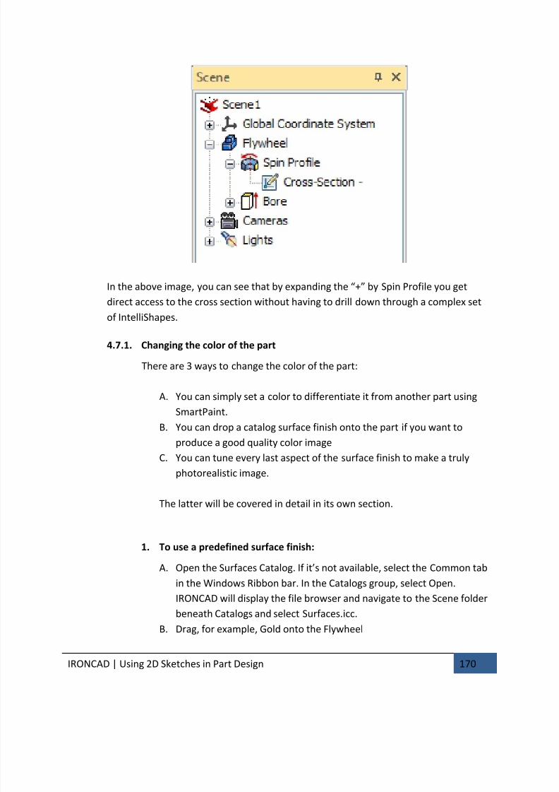
7/30/2019 Unlock Ironcadgsg
http://slidepdf.com/reader/full/unlock-ironcadgsg 174/367
IRONCAD | Using 2D Sketches in Part Design 170
In the above image, you can see that by expanding the “+” by Spin Profile you get
direct access to the cross section without having to drill down through a complex set
of IntelliShapes.
4.7.1. Changing the color of the part
There are 3 ways to change the color of the part:
A. You can simply set a color to differentiate it from another part using
SmartPaint.B. You can drop a catalog surface finish onto the part if you want to
produce a good quality color image
C. You can tune every last aspect of the surface finish to make a truly
photorealistic image.
The latter will be covered in detail in its own section.
1. To use a predefined surface finish:
A. Open the Surfaces Catalog. If it’s not available, select the Common tab
in the Windows Ribbon bar. In the Catalogs group, select Open.
IRONCAD will display the file browser and navigate to the Scene folder
beneath Catalogs and select Surfaces.icc.
B. Drag, for example, Gold onto the Flywheel
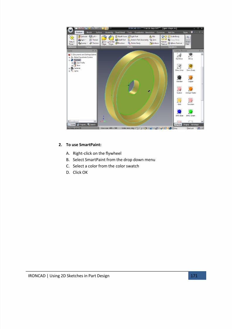
7/30/2019 Unlock Ironcadgsg
http://slidepdf.com/reader/full/unlock-ironcadgsg 175/367
IRONCAD | Using 2D Sketches in Part Design 171
2. To use SmartPaint:
A. Right-click on the flywheel
B. Select SmartPaint from the drop down menu
C. Select a color from the color swatch
D. Click OK
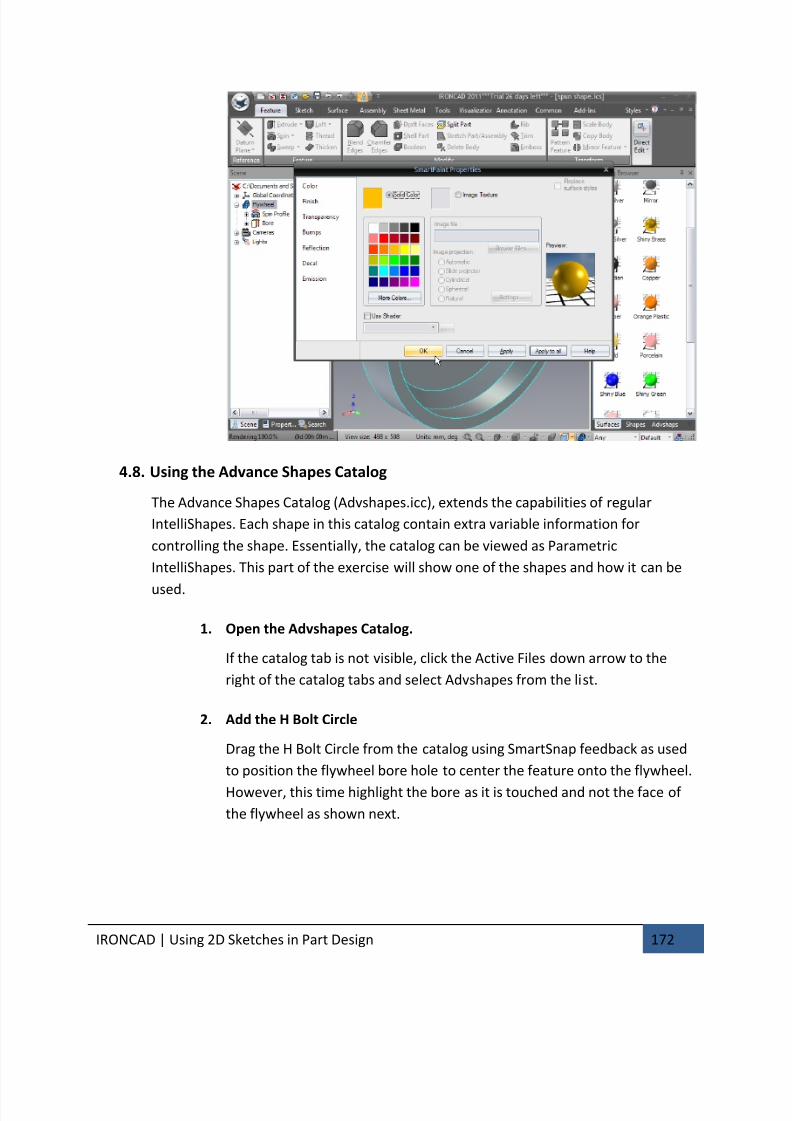
7/30/2019 Unlock Ironcadgsg
http://slidepdf.com/reader/full/unlock-ironcadgsg 176/367
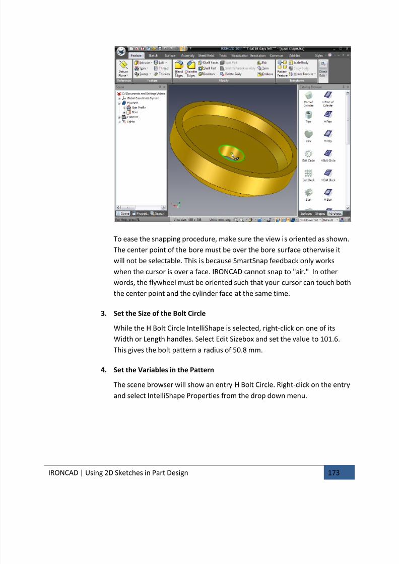
7/30/2019 Unlock Ironcadgsg
http://slidepdf.com/reader/full/unlock-ironcadgsg 177/367
IRONCAD | Using 2D Sketches in Part Design 173
To ease the snapping procedure, make sure the view is oriented as shown.
The center point of the bore must be over the bore surface otherwise it
will not be selectable. This is because SmartSnap feedback only works
when the cursor is over a face. IRONCAD cannot snap to "air." In other
words, the flywheel must be oriented such that your cursor can touch both
the center point and the cylinder face at the same time.
3. Set the Size of the Bolt Circle
While the H Bolt Circle IntelliShape is selected, right-click on one of its
Width or Length handles. Select Edit Sizebox and set the value to 101.6.
This gives the bolt pattern a radius of 50.8 mm.
4. Set the Variables in the Pattern
The scene browser will show an entry H Bolt Circle. Right-click on the entry
and select IntelliShape Properties from the drop down menu.
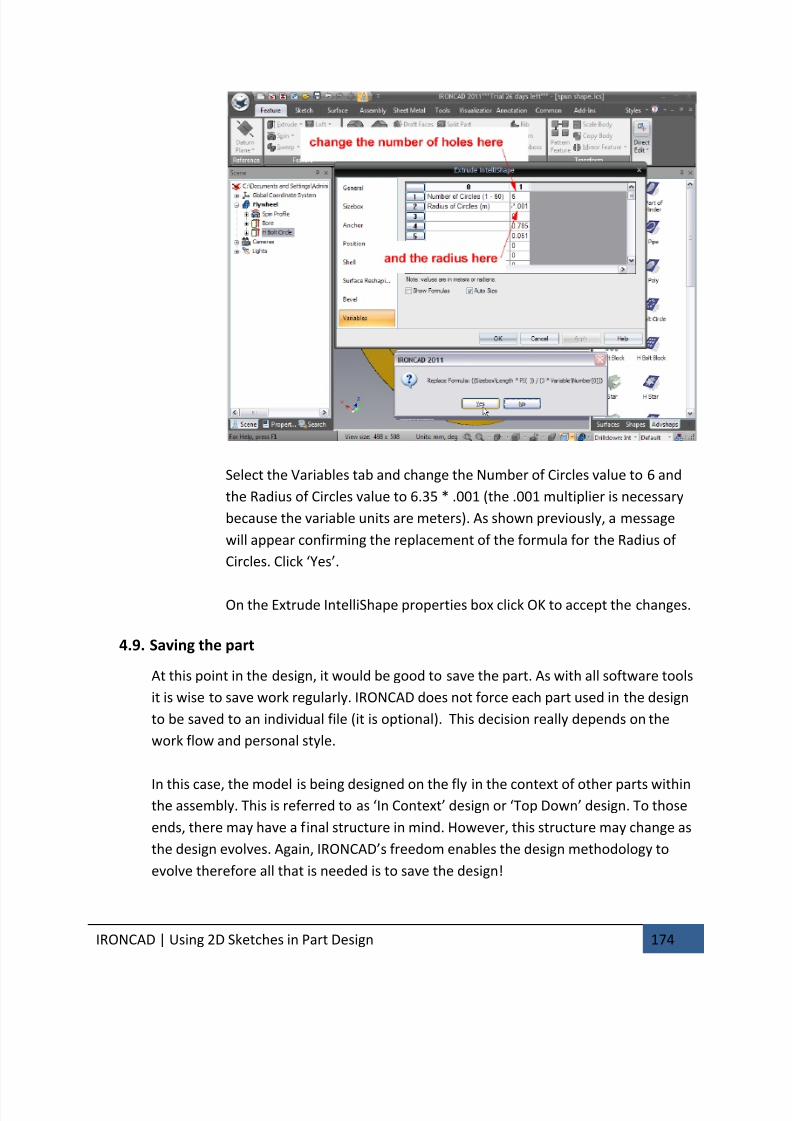
7/30/2019 Unlock Ironcadgsg
http://slidepdf.com/reader/full/unlock-ironcadgsg 178/367
IRONCAD | Using 2D Sketches in Part Design 174
Select the Variables tab and change the Number of Circles value to 6 and
the Radius of Circles value to 6.35 * .001 (the .001 multiplier is necessary
because the variable units are meters). As shown previously, a message
will appear confirming the replacement of the formula for the Radius of
Circles. Click ‘Yes’.
On the Extrude IntelliShape properties box click OK to accept the changes.
4.9. Saving the part
At this point in the design, it would be good to save the part. As with all software tools
it is wise to save work regularly. IRONCAD does not force each part used in the design
to be saved to an individual file (it is optional). This decision really depends on the
work flow and personal style.
In this case, the model is being designed on the fly in the context of other parts withinthe assembly. This is referred to as ‘In Context’ design or ‘Top Down’ design. To those
ends, there may have a final structure in mind. However, this structure may change as
the design evolves. Again, IRONCAD’s freedom enables the design methodology to
evolve therefore all that is needed is to save the design!
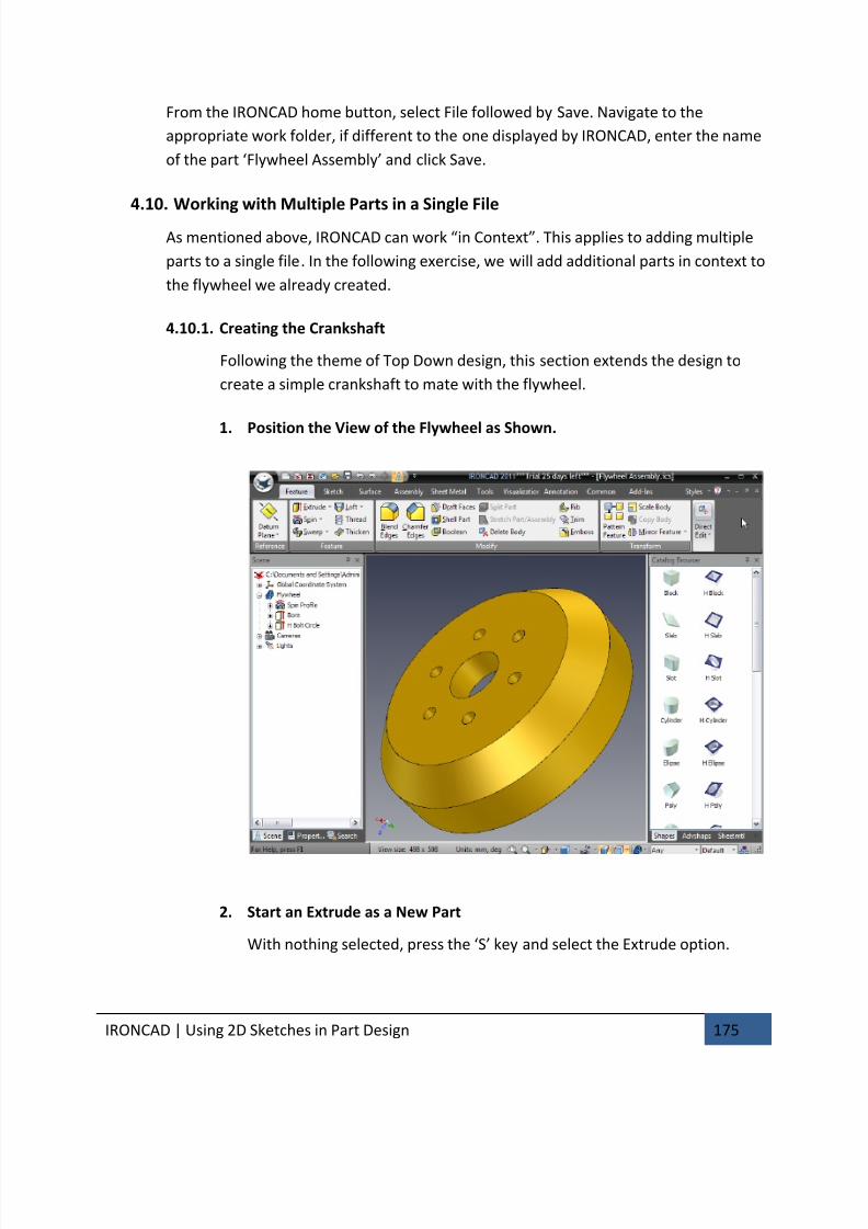
7/30/2019 Unlock Ironcadgsg
http://slidepdf.com/reader/full/unlock-ironcadgsg 179/367
IRONCAD | Using 2D Sketches in Part Design 175
From the IRONCAD home button, select File followed by Save. Navigate to the
appropriate work folder, if different to the one displayed by IRONCAD, enter the name
of the part ‘Flywheel Assembly’ and click Save.
4.10. Working with Multiple Parts in a Single File
As mentioned above, IRONCAD can work “in Context”. This applies to adding multiple
parts to a single file. In the following exercise, we will add additional parts in context to
the flywheel we already created.
4.10.1. Creating the Crankshaft
Following the theme of Top Down design, this section extends the design to
create a simple crankshaft to mate with the flywheel.
1. Position the View of the Flywheel as Shown.
2. Start an Extrude as a New Part
With nothing selected, press the ‘S’ key and select the Extrude option.
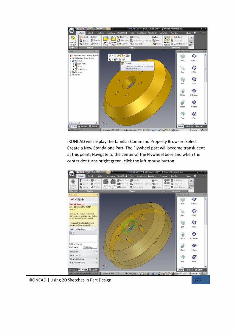
7/30/2019 Unlock Ironcadgsg
http://slidepdf.com/reader/full/unlock-ironcadgsg 180/367
IRONCAD | Using 2D Sketches in Part Design 176
IRONCAD will display the familiar Command Property Browser. Select
Create a New Standalone Part. The Flywheel part will become translucent
at this point. Navigate to the center of the Flywheel bore and when the
center dot turns bright green, click the left mouse button.
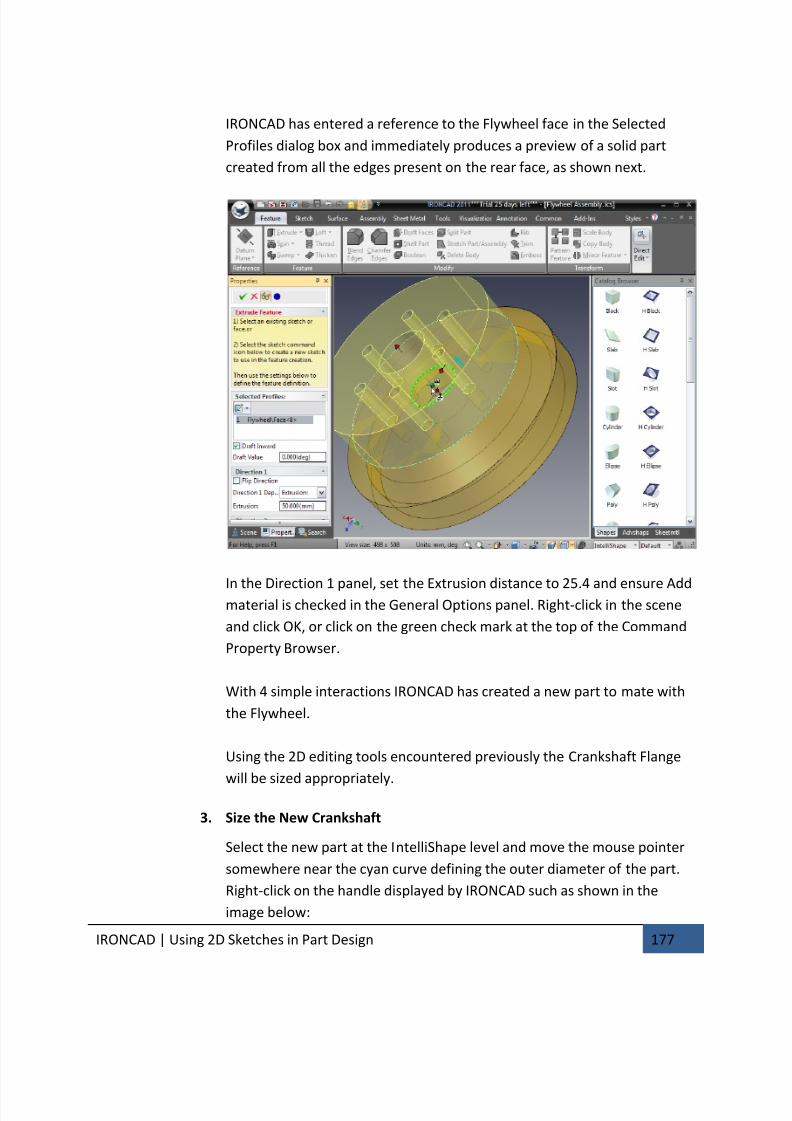
7/30/2019 Unlock Ironcadgsg
http://slidepdf.com/reader/full/unlock-ironcadgsg 181/367
IRONCAD | Using 2D Sketches in Part Design 177
IRONCAD has entered a reference to the Flywheel face in the Selected
Profiles dialog box and immediately produces a preview of a solid part
created from all the edges present on the rear face, as shown next.
In the Direction 1 panel, set the Extrusion distance to 25.4 and ensure Addmaterial is checked in the General Options panel. Right-click in the scene
and click OK, or click on the green check mark at the top of the Command
Property Browser.
With 4 simple interactions IRONCAD has created a new part to mate with
the Flywheel.
Using the 2D editing tools encountered previously the Crankshaft Flange
will be sized appropriately.
3. Size the New Crankshaft
Select the new part at the IntelliShape level and move the mouse pointer
somewhere near the cyan curve defining the outer diameter of the part.
Right-click on the handle displayed by IRONCAD such as shown in the
image below:
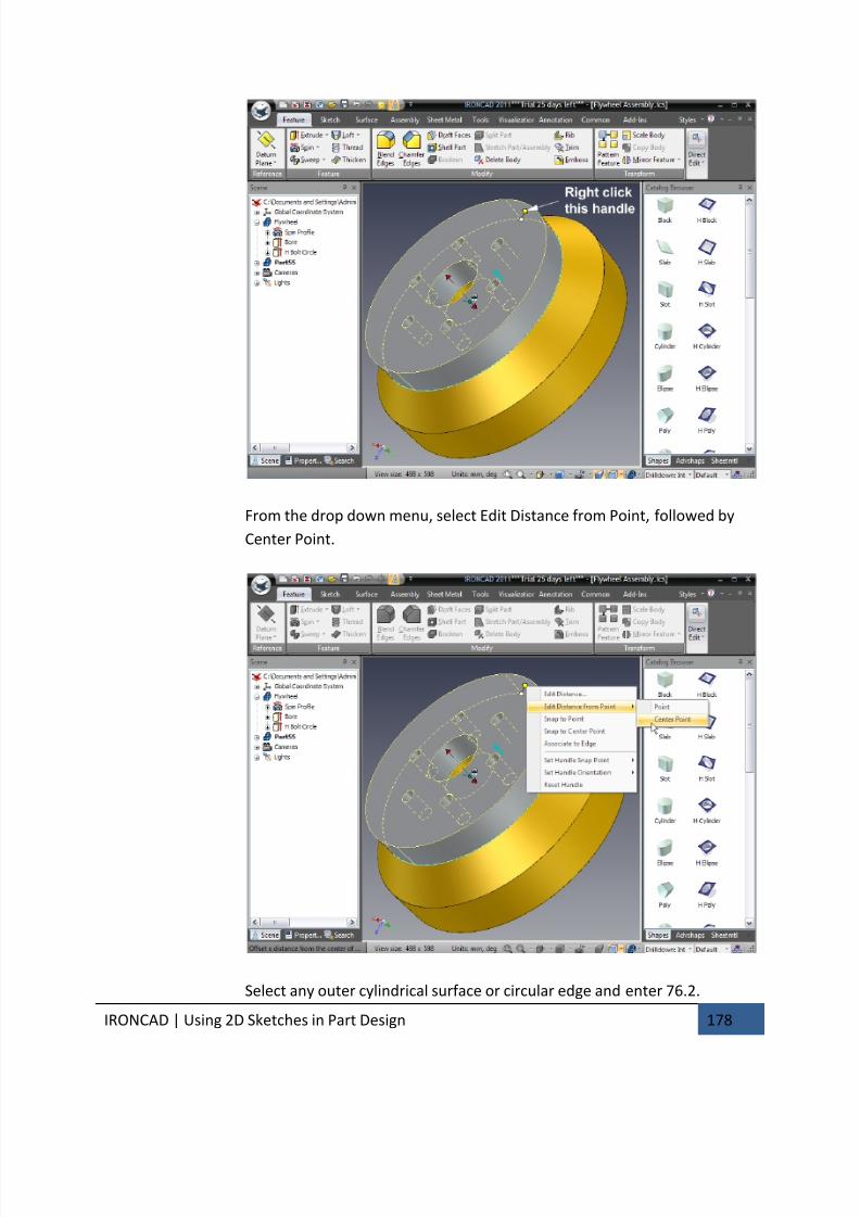
7/30/2019 Unlock Ironcadgsg
http://slidepdf.com/reader/full/unlock-ironcadgsg 182/367
IRONCAD | Using 2D Sketches in Part Design 178
From the drop down menu, select Edit Distance from Point, followed by
Center Point.
Select any outer cylindrical surface or circular edge and enter 76.2.
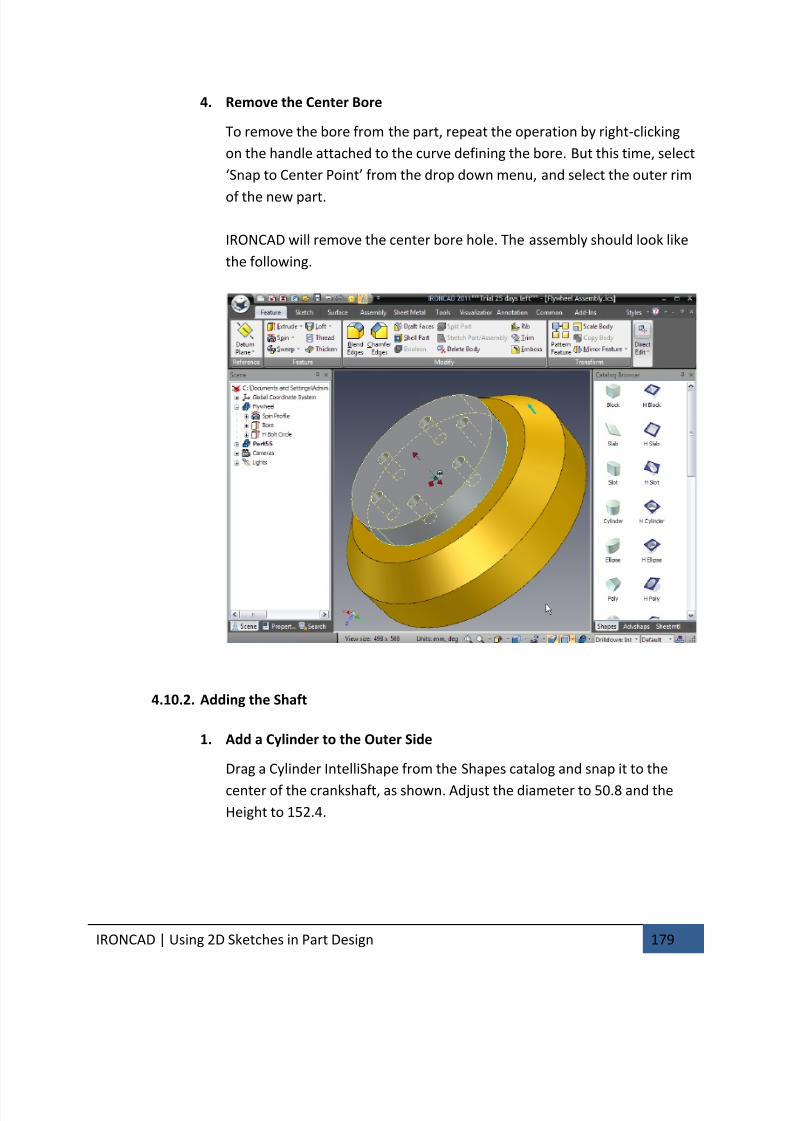
7/30/2019 Unlock Ironcadgsg
http://slidepdf.com/reader/full/unlock-ironcadgsg 183/367
IRONCAD | Using 2D Sketches in Part Design 179
4. Remove the Center Bore
To remove the bore from the part, repeat the operation by right-clicking
on the handle attached to the curve defining the bore. But this time, select
‘Snap to Center Point’ from the drop down menu, and select the outer rim
of the new part.
IRONCAD will remove the center bore hole. The assembly should look like
the following.
4.10.2. Adding the Shaft
1. Add a Cylinder to the Outer Side
Drag a Cylinder IntelliShape from the Shapes catalog and snap it to the
center of the crankshaft, as shown. Adjust the diameter to 50.8 and the
Height to 152.4.
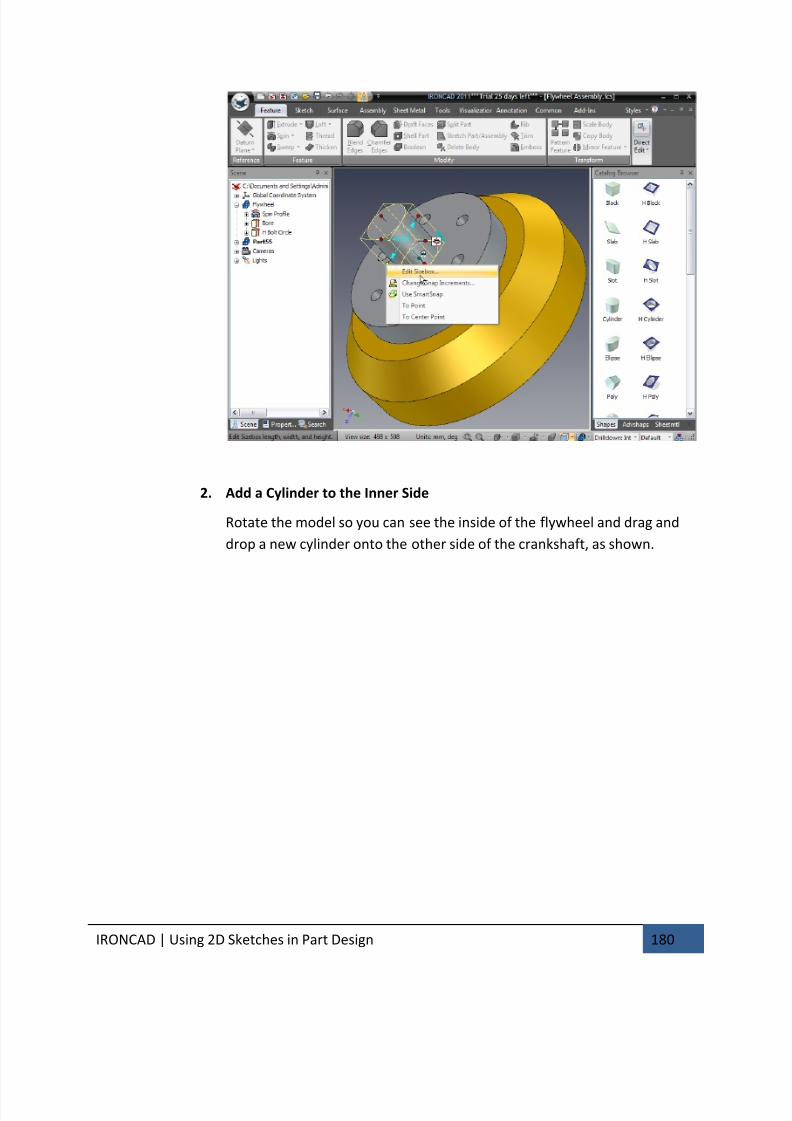
7/30/2019 Unlock Ironcadgsg
http://slidepdf.com/reader/full/unlock-ironcadgsg 184/367
IRONCAD | Using 2D Sketches in Part Design 180
2. Add a Cylinder to the Inner Side
Rotate the model so you can see the inside of the flywheel and drag and
drop a new cylinder onto the other side of the crankshaft, as shown.
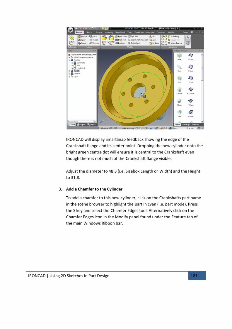
7/30/2019 Unlock Ironcadgsg
http://slidepdf.com/reader/full/unlock-ironcadgsg 185/367
IRONCAD | Using 2D Sketches in Part Design 181
IRONCAD will display SmartSnap feedback showing the edge of the
Crankshaft flange and its center point. Dropping the new cylinder onto the
bright green centre dot will ensure it is central to the Crankshaft even
though there is not much of the Crankshaft flange visible.
Adjust the diameter to 48.3 (i.e. Sizebox Length or Width) and the Heightto 31.8.
3. Add a Chamfer to the Cylinder
To add a chamfer to this new cylinder, click on the Crankshafts part name
in the scene browser to highlight the part in cyan (i.e. part mode). Press
the S key and select the Chamfer Edges tool. Alternatively click on the
Chamfer Edges icon in the Modify panel found under the Feature tab of
the main Windows Ribbon bar.
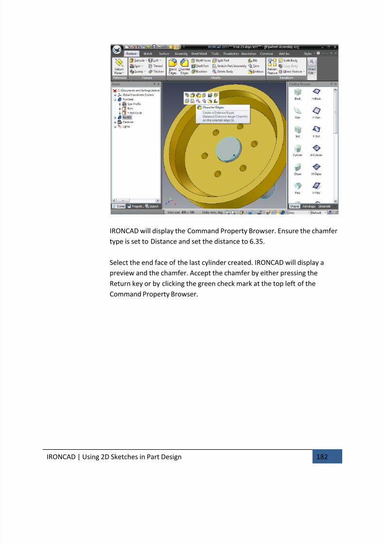
7/30/2019 Unlock Ironcadgsg
http://slidepdf.com/reader/full/unlock-ironcadgsg 186/367
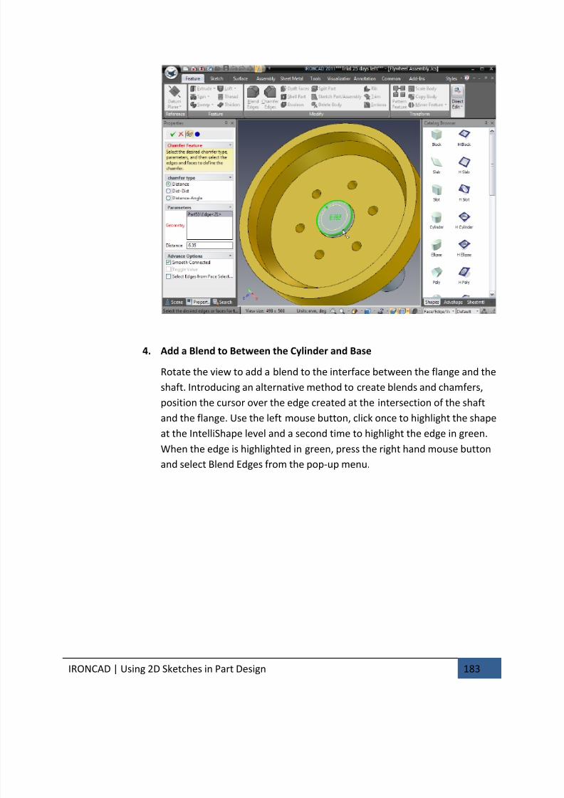
7/30/2019 Unlock Ironcadgsg
http://slidepdf.com/reader/full/unlock-ironcadgsg 187/367
IRONCAD | Using 2D Sketches in Part Design 183
4. Add a Blend to Between the Cylinder and Base
Rotate the view to add a blend to the interface between the flange and the
shaft. Introducing an alternative method to create blends and chamfers,
position the cursor over the edge created at the intersection of the shaft
and the flange. Use the left mouse button, click once to highlight the shapeat the IntelliShape level and a second time to highlight the edge in green.
When the edge is highlighted in green, press the right hand mouse button
and select Blend Edges from the pop-up menu.
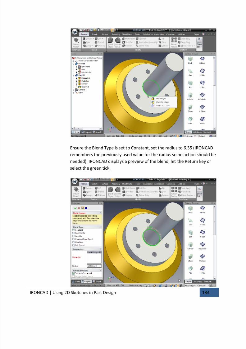
7/30/2019 Unlock Ironcadgsg
http://slidepdf.com/reader/full/unlock-ironcadgsg 188/367
IRONCAD | Using 2D Sketches in Part Design 184
Ensure the Blend Type is set to Constant, set the radius to 6.35 (IRONCAD
remembers the previously used value for the radius so no action should be
needed). IRONCAD displays a preview of the blend, hit the Return key or
select the green tick.
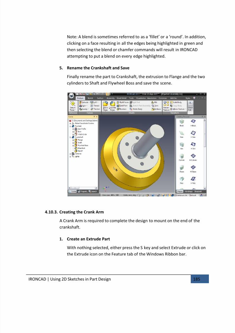
7/30/2019 Unlock Ironcadgsg
http://slidepdf.com/reader/full/unlock-ironcadgsg 189/367
IRONCAD | Using 2D Sketches in Part Design 185
Note: A blend is sometimes referred to as a ‘fillet’ or a ‘round’. In addition,
clicking on a face resulting in all the edges being highlighted in green and
then selecting the blend or chamfer commands will result in IRONCAD
attempting to put a blend on every edge highlighted.
5. Rename the Crankshaft and Save
Finally rename the part to Crankshaft, the extrusion to Flange and the two
cylinders to Shaft and Flywheel Boss and save the scene.
4.10.3. Creating the Crank Arm
A Crank Arm is required to complete the design to mount on the end of the
crankshaft.
1. Create an Extrude Part
With nothing selected, either press the S key and select Extrude or click on
the Extrude icon on the Feature tab of the Windows Ribbon bar.
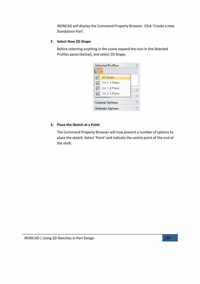
7/30/2019 Unlock Ironcadgsg
http://slidepdf.com/reader/full/unlock-ironcadgsg 190/367
IRONCAD | Using 2D Sketches in Part Design 186
IRONCAD will display the Command Property Browser. Click ‘Create a new
Standalone Part’.
2. Select New 2D Shape
Before selecting anything in the scene expand the icon in the SelectedProfiles panel (below), and select 2D Shape.
3. Place the Sketch at a Point
The Command Property Browser will now present a number of options to
place the sketch. Select ‘Point’ and indicate the centre point of the end of
the shaft.
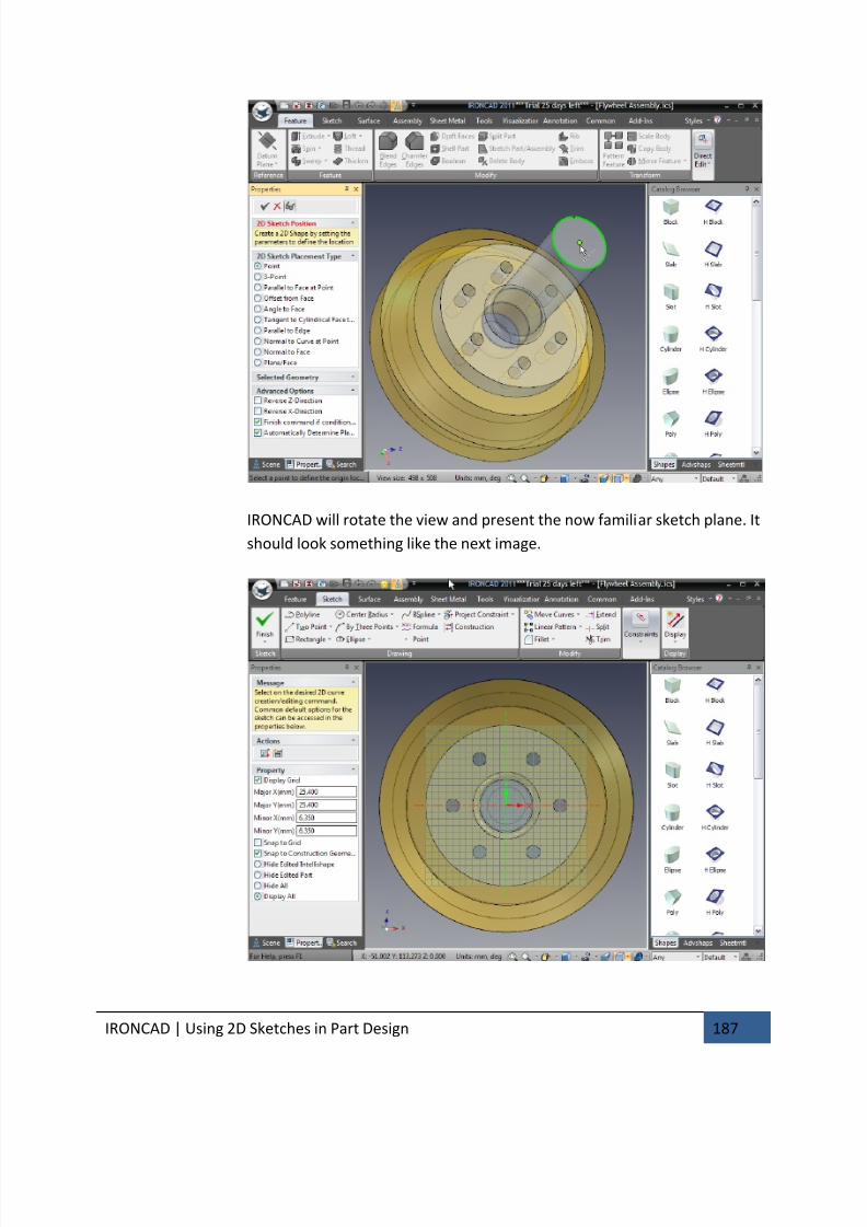
7/30/2019 Unlock Ironcadgsg
http://slidepdf.com/reader/full/unlock-ironcadgsg 191/367
IRONCAD | Using 2D Sketches in Part Design 187
IRONCAD will rotate the view and present the now familiar sketch plane. It
should look something like the next image.
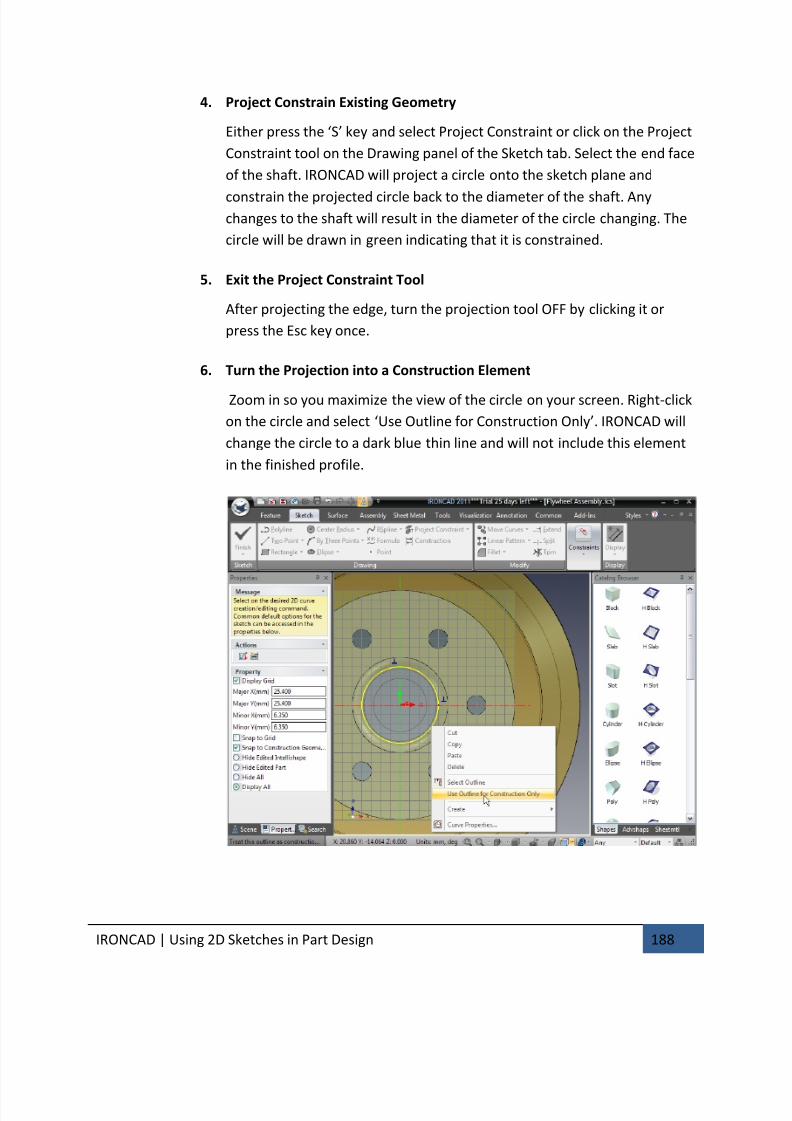
7/30/2019 Unlock Ironcadgsg
http://slidepdf.com/reader/full/unlock-ironcadgsg 192/367
IRONCAD | Using 2D Sketches in Part Design 188
4. Project Constrain Existing Geometry
Either press the ‘S’ key and select Project Constraint or click on the Project
Constraint tool on the Drawing panel of the Sketch tab. Select the end face
of the shaft. IRONCAD will project a circle onto the sketch plane and
constrain the projected circle back to the diameter of the shaft. Anychanges to the shaft will result in the diameter of the circle changing. The
circle will be drawn in green indicating that it is constrained.
5. Exit the Project Constraint Tool
After projecting the edge, turn the projection tool OFF by clicking it or
press the Esc key once.
6. Turn the Projection into a Construction Element
Zoom in so you maximize the view of the circle on your screen. Right-click
on the circle and select ‘Use Outline for Construction Only’. IRONCAD will
change the circle to a dark blue thin line and will not include this element
in the finished profile.
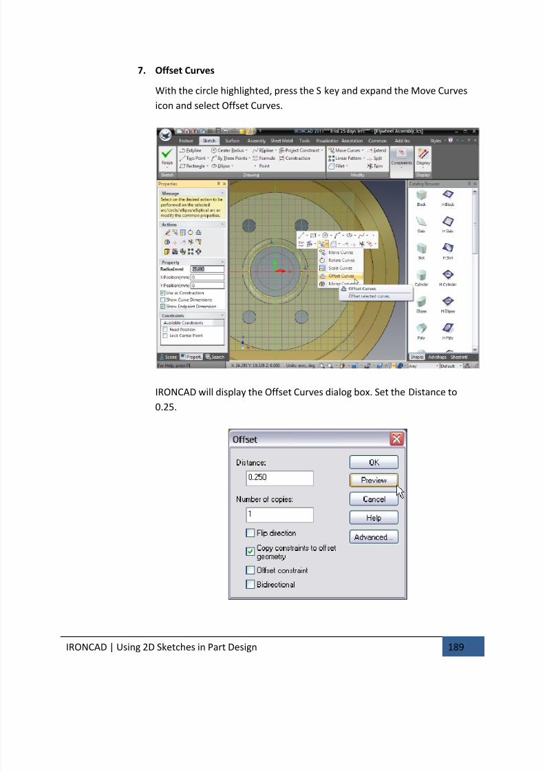
7/30/2019 Unlock Ironcadgsg
http://slidepdf.com/reader/full/unlock-ironcadgsg 193/367
IRONCAD | Using 2D Sketches in Part Design 189
7. Offset Curves
With the circle highlighted, press the S key and expand the Move Curves
icon and select Offset Curves.
IRONCAD will display the Offset Curves dialog box. Set the Distance to
0.25.
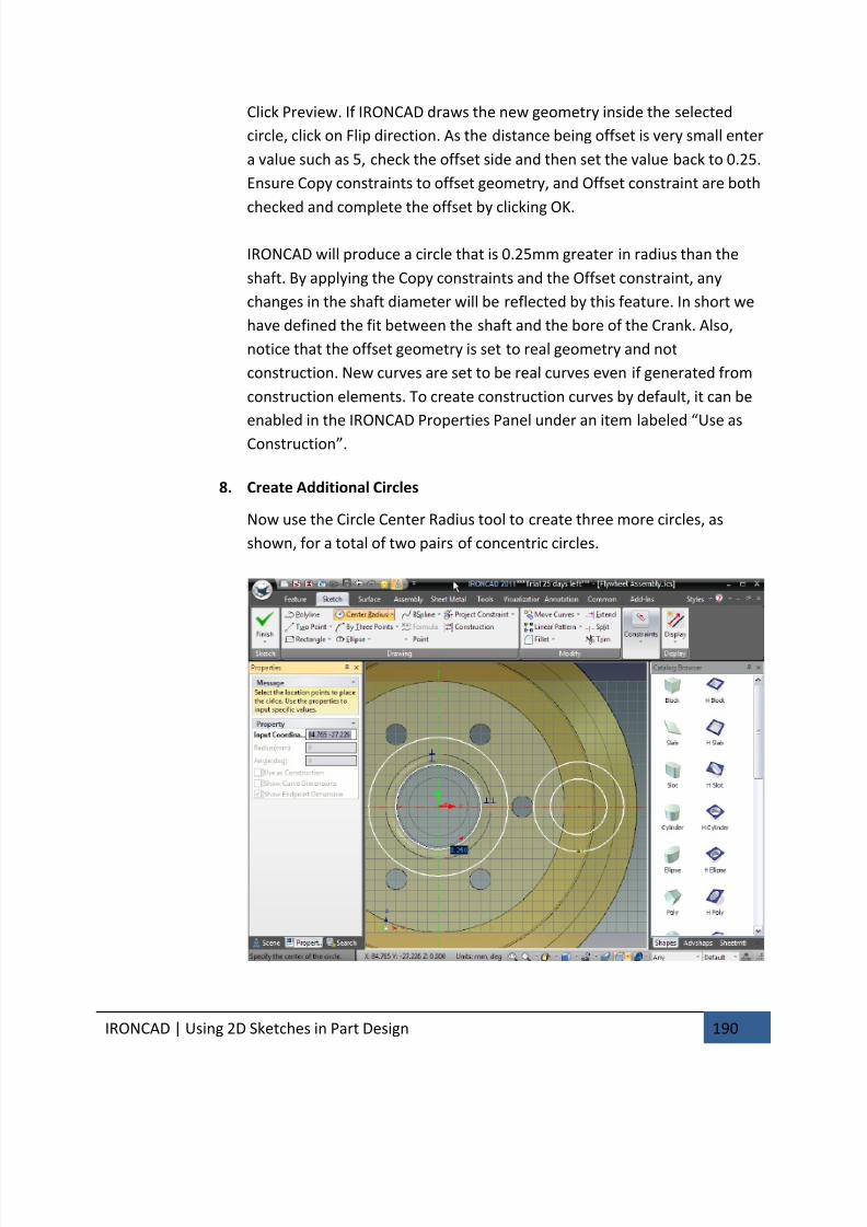
7/30/2019 Unlock Ironcadgsg
http://slidepdf.com/reader/full/unlock-ironcadgsg 194/367
IRONCAD | Using 2D Sketches in Part Design 190
Click Preview. If IRONCAD draws the new geometry inside the selected
circle, click on Flip direction. As the distance being offset is very small enter
a value such as 5, check the offset side and then set the value back to 0.25.
Ensure Copy constraints to offset geometry, and Offset constraint are both
checked and complete the offset by clicking OK.
IRONCAD will produce a circle that is 0.25mm greater in radius than the
shaft. By applying the Copy constraints and the Offset constraint, any
changes in the shaft diameter will be reflected by this feature. In short we
have defined the fit between the shaft and the bore of the Crank. Also,
notice that the offset geometry is set to real geometry and not
construction. New curves are set to be real curves even if generated from
construction elements. To create construction curves by default, it can be
enabled in the IRONCAD Properties Panel under an item labeled “Use as
Construction”.
8. Create Additional Circles
Now use the Circle Center Radius tool to create three more circles, as
shown, for a total of two pairs of concentric circles.
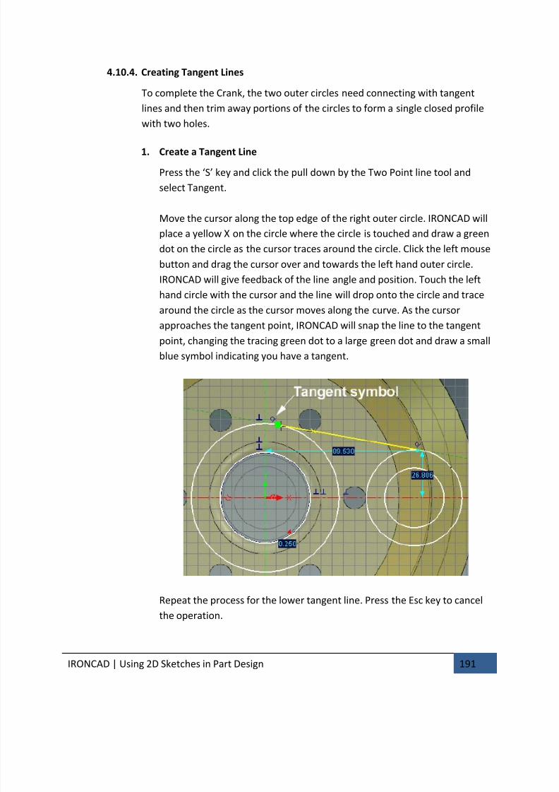
7/30/2019 Unlock Ironcadgsg
http://slidepdf.com/reader/full/unlock-ironcadgsg 195/367
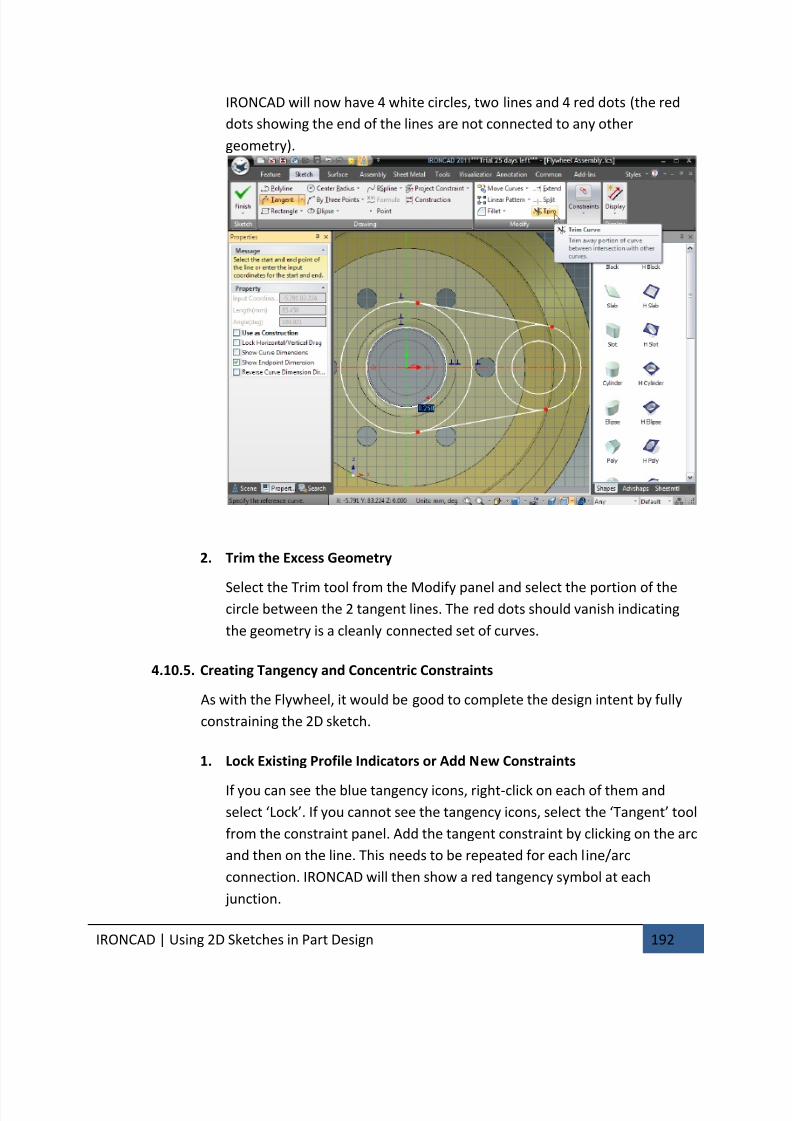
7/30/2019 Unlock Ironcadgsg
http://slidepdf.com/reader/full/unlock-ironcadgsg 196/367
IRONCAD | Using 2D Sketches in Part Design 192
IRONCAD will now have 4 white circles, two lines and 4 red dots (the red
dots showing the end of the lines are not connected to any other
geometry).
2. Trim the Excess Geometry
Select the Trim tool from the Modify panel and select the portion of thecircle between the 2 tangent lines. The red dots should vanish indicating
the geometry is a cleanly connected set of curves.
4.10.5. Creating Tangency and Concentric Constraints
As with the Flywheel, it would be good to complete the design intent by fully
constraining the 2D sketch.
1. Lock Existing Profile Indicators or Add New Constraints
If you can see the blue tangency icons, right-click on each of them and
select ‘Lock’. If you cannot see the tangency icons, select the ‘Tangent’ tool
from the constraint panel. Add the tangent constraint by clicking on the arc
and then on the line. This needs to be repeated for each line/arc
connection. IRONCAD will then show a red tangency symbol at each
junction.
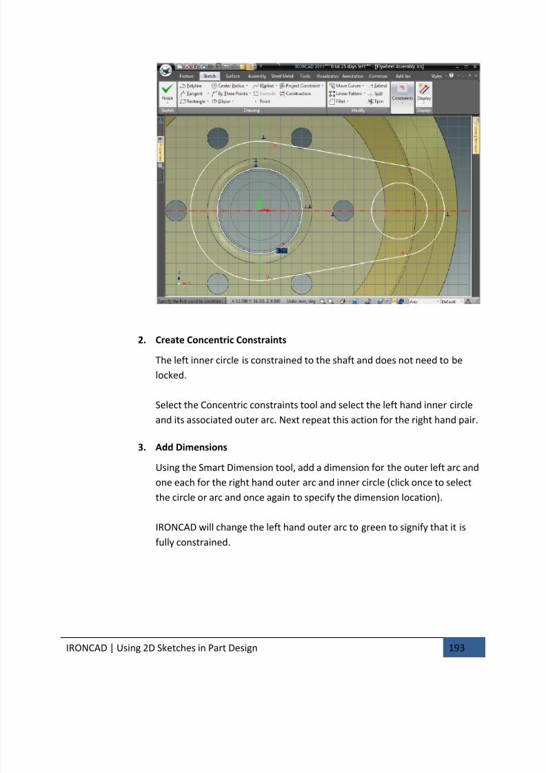
7/30/2019 Unlock Ironcadgsg
http://slidepdf.com/reader/full/unlock-ironcadgsg 197/367
IRONCAD | Using 2D Sketches in Part Design 193
2. Create Concentric Constraints
The left inner circle is constrained to the shaft and does not need to be
locked.
Select the Concentric constraints tool and select the left hand inner circleand its associated outer arc. Next repeat this action for the right hand pair.
3. Add Dimensions
Using the Smart Dimension tool, add a dimension for the outer left arc and
one each for the right hand outer arc and inner circle (click once to select
the circle or arc and once again to specify the dimension location).
IRONCAD will change the left hand outer arc to green to signify that it is
fully constrained.
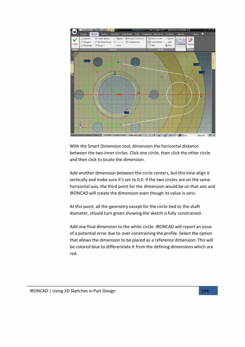
7/30/2019 Unlock Ironcadgsg
http://slidepdf.com/reader/full/unlock-ironcadgsg 198/367
IRONCAD | Using 2D Sketches in Part Design 194
.
With the Smart Dimension tool, dimension the horizontal distance
between the two inner circles. Click one circle, then click the other circle
and then click to locate the dimension.
Add another dimension between the circle centers, but this time align it
vertically and make sure it’s set to 0.0. If the two circles are on the same
horizontal axis, the third point for the dimension would be on that axis and
IRONCAD will create the dimension even though its value is zero.
At this point, all the geometry except for the circle tied to the shaft
diameter, should turn green showing the sketch is fully constrained.
Add one final dimension to the white circle. IRONCAD will report an issue
of a potential error due to over constraining the profile. Select the option
that allows the dimension to be placed as a reference dimension. This will
be colored blue to differentiate it from the defining dimensions which are
red.
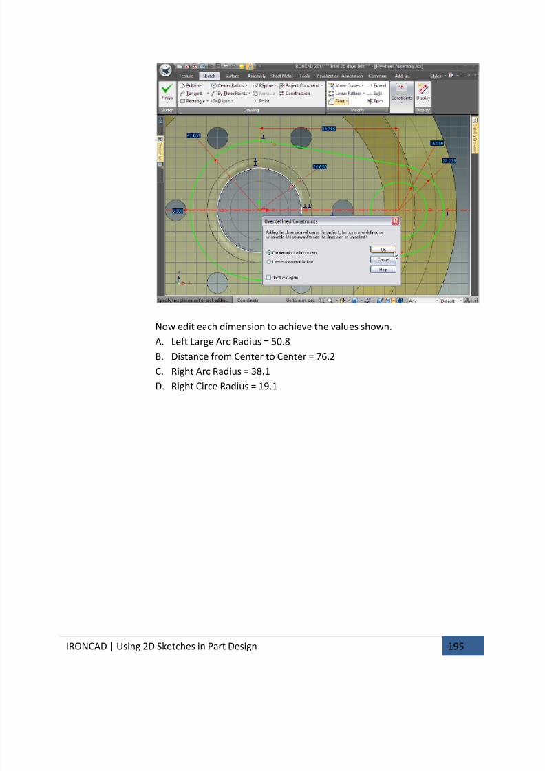
7/30/2019 Unlock Ironcadgsg
http://slidepdf.com/reader/full/unlock-ironcadgsg 199/367
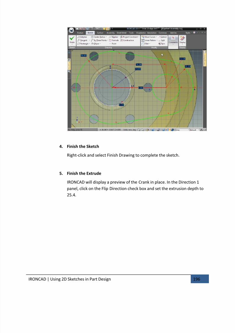
7/30/2019 Unlock Ironcadgsg
http://slidepdf.com/reader/full/unlock-ironcadgsg 200/367
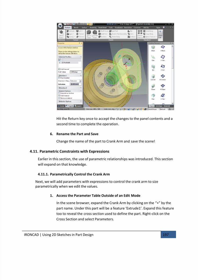
7/30/2019 Unlock Ironcadgsg
http://slidepdf.com/reader/full/unlock-ironcadgsg 201/367
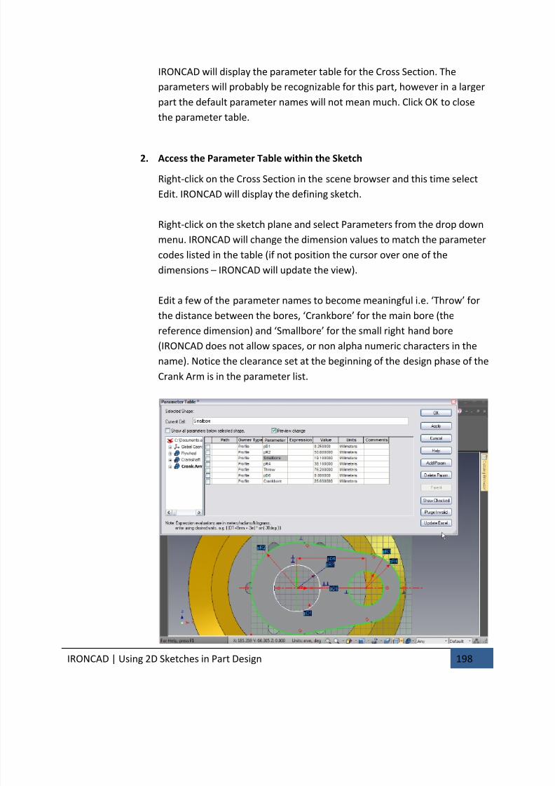
7/30/2019 Unlock Ironcadgsg
http://slidepdf.com/reader/full/unlock-ironcadgsg 202/367
IRONCAD | Using 2D Sketches in Part Design 198
IRONCAD will display the parameter table for the Cross Section. The
parameters will probably be recognizable for this part, however in a larger
part the default parameter names will not mean much. Click OK to close
the parameter table.
2. Access the Parameter Table within the Sketch
Right-click on the Cross Section in the scene browser and this time select
Edit. IRONCAD will display the defining sketch.
Right-click on the sketch plane and select Parameters from the drop down
menu. IRONCAD will change the dimension values to match the parameter
codes listed in the table (if not position the cursor over one of the
dimensions – IRONCAD will update the view).
Edit a few of the parameter names to become meaningful i.e. ‘Throw’ for
the distance between the bores, ‘Crankbore’ for the main bore (the
reference dimension) and ‘Smallbore’ for the small right hand bore
(IRONCAD does not allow spaces, or non alpha numeric characters in the
name). Notice the clearance set at the beginning of the design phase of the
Crank Arm is in the parameter list.
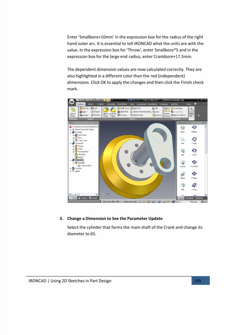
7/30/2019 Unlock Ironcadgsg
http://slidepdf.com/reader/full/unlock-ironcadgsg 203/367
IRONCAD | Using 2D Sketches in Part Design 199
Enter ‘Smallbore+10mm’ in the expression box for the radius of the right
hand outer arc. It is essential to tell IRONCAD what the units are with the
value. In the expression box for ‘Throw’, enter Smallbore*5 and in the
expression box for the large end radius, enter Crankbore+17.5mm.
The dependent dimension values are now calculated correctly. They are
also highlighted in a different color than the red (independent)
dimensions. Click OK to apply the changes and then click the Finish check
mark.
3. Change a Dimension to See the Parameter Update
Select the cylinder that forms the main shaft of the Crank and change its
diameter to 65.
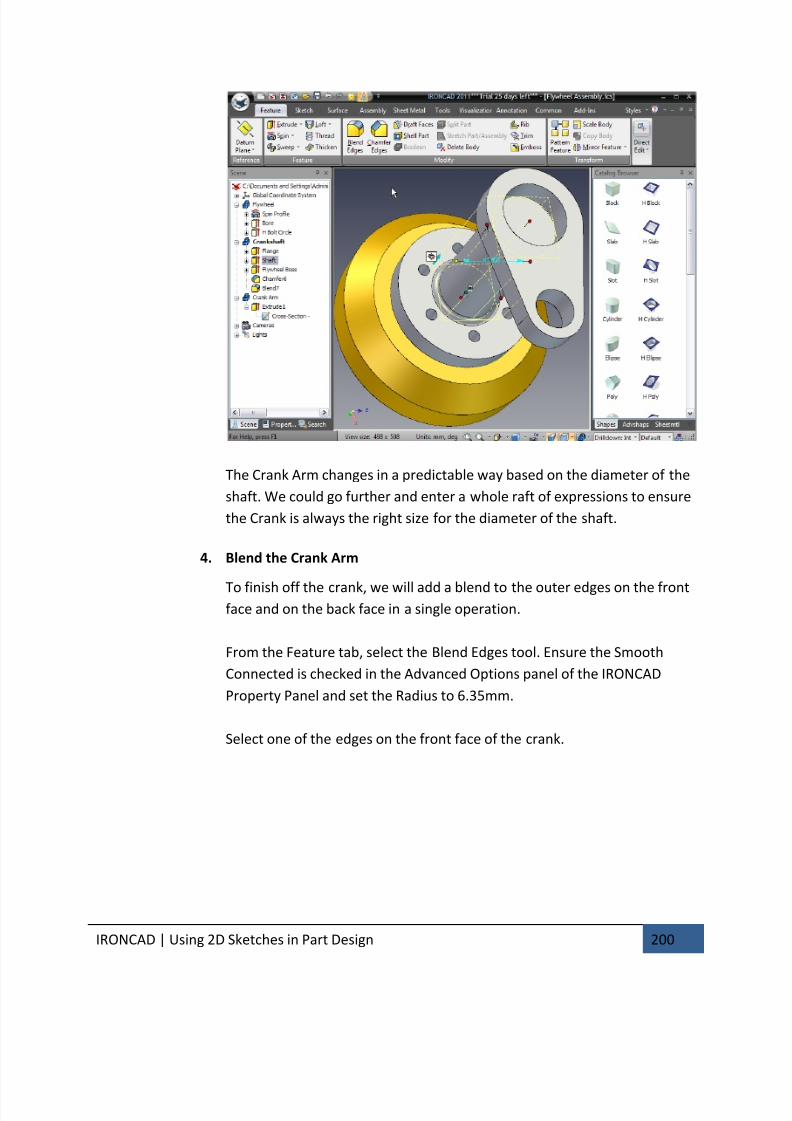
7/30/2019 Unlock Ironcadgsg
http://slidepdf.com/reader/full/unlock-ironcadgsg 204/367
IRONCAD | Using 2D Sketches in Part Design 200
The Crank Arm changes in a predictable way based on the diameter of the
shaft. We could go further and enter a whole raft of expressions to ensure
the Crank is always the right size for the diameter of the shaft.
4. Blend the Crank Arm
To finish off the crank, we will add a blend to the outer edges on the frontface and on the back face in a single operation.
From the Feature tab, select the Blend Edges tool. Ensure the Smooth
Connected is checked in the Advanced Options panel of the IRONCAD
Property Panel and set the Radius to 6.35mm.
Select one of the edges on the front face of the crank.
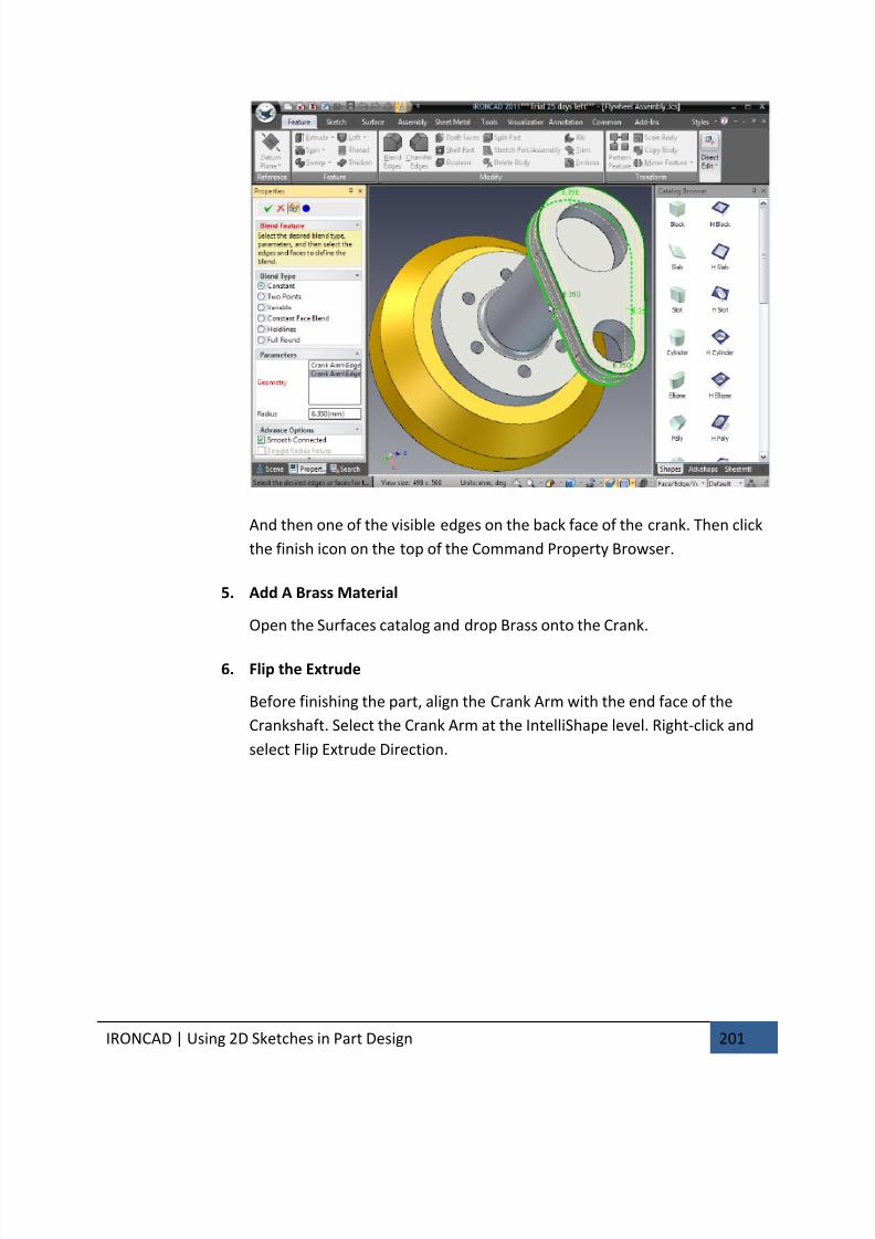
7/30/2019 Unlock Ironcadgsg
http://slidepdf.com/reader/full/unlock-ironcadgsg 205/367
IRONCAD | Using 2D Sketches in Part Design 201
And then one of the visible edges on the back face of the crank. Then click
the finish icon on the top of the Command Property Browser.
5. Add A Brass Material
Open the Surfaces catalog and drop Brass onto the Crank.
6. Flip the Extrude
Before finishing the part, align the Crank Arm with the end face of the
Crankshaft. Select the Crank Arm at the IntelliShape level. Right-click and
select Flip Extrude Direction.
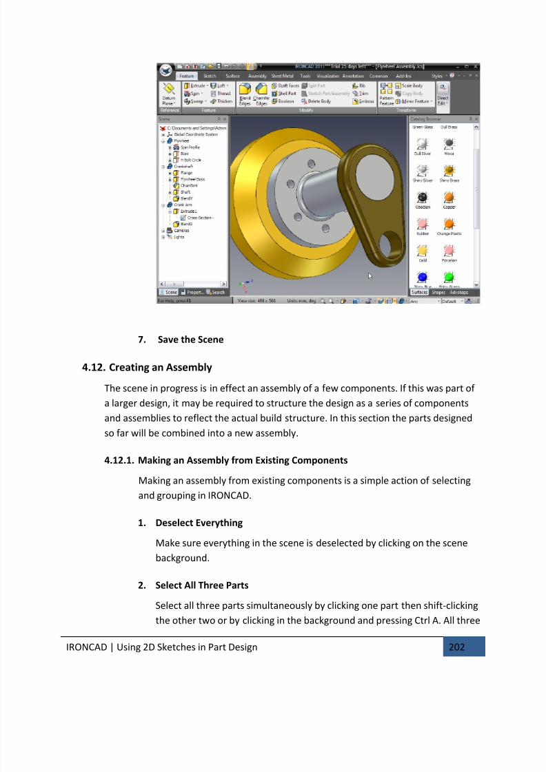
7/30/2019 Unlock Ironcadgsg
http://slidepdf.com/reader/full/unlock-ironcadgsg 206/367
IRONCAD | Using 2D Sketches in Part Design 202
7. Save the Scene
4.12. Creating an Assembly
The scene in progress is in effect an assembly of a few components. If this was part of
a larger design, it may be required to structure the design as a series of componentsand assemblies to reflect the actual build structure. In this section the parts designed
so far will be combined into a new assembly.
4.12.1. Making an Assembly from Existing Components
Making an assembly from existing components is a simple action of selecting
and grouping in IRONCAD.
1. Deselect Everything
Make sure everything in the scene is deselected by clicking on the scene
background.
2. Select All Three Parts
Select all three parts simultaneously by clicking one part then shift-clicking
the other two or by clicking in the background and pressing Ctrl A. All three
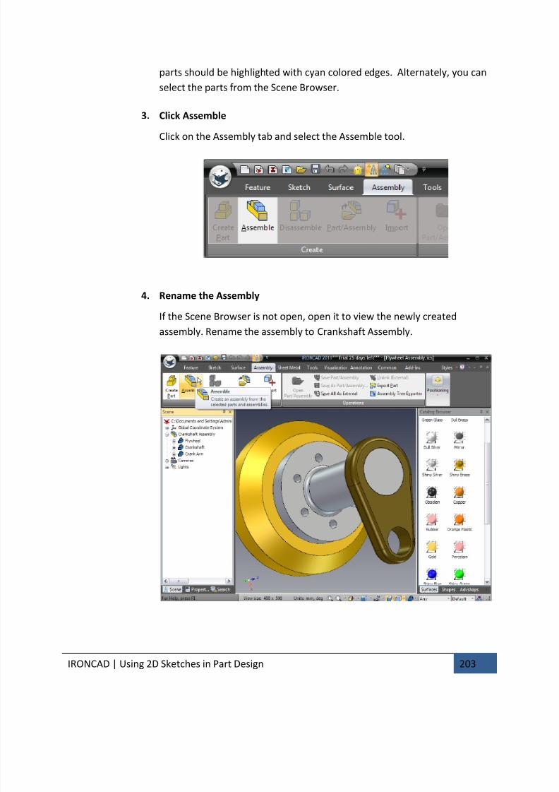
7/30/2019 Unlock Ironcadgsg
http://slidepdf.com/reader/full/unlock-ironcadgsg 207/367
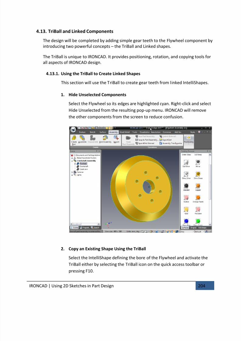
7/30/2019 Unlock Ironcadgsg
http://slidepdf.com/reader/full/unlock-ironcadgsg 208/367
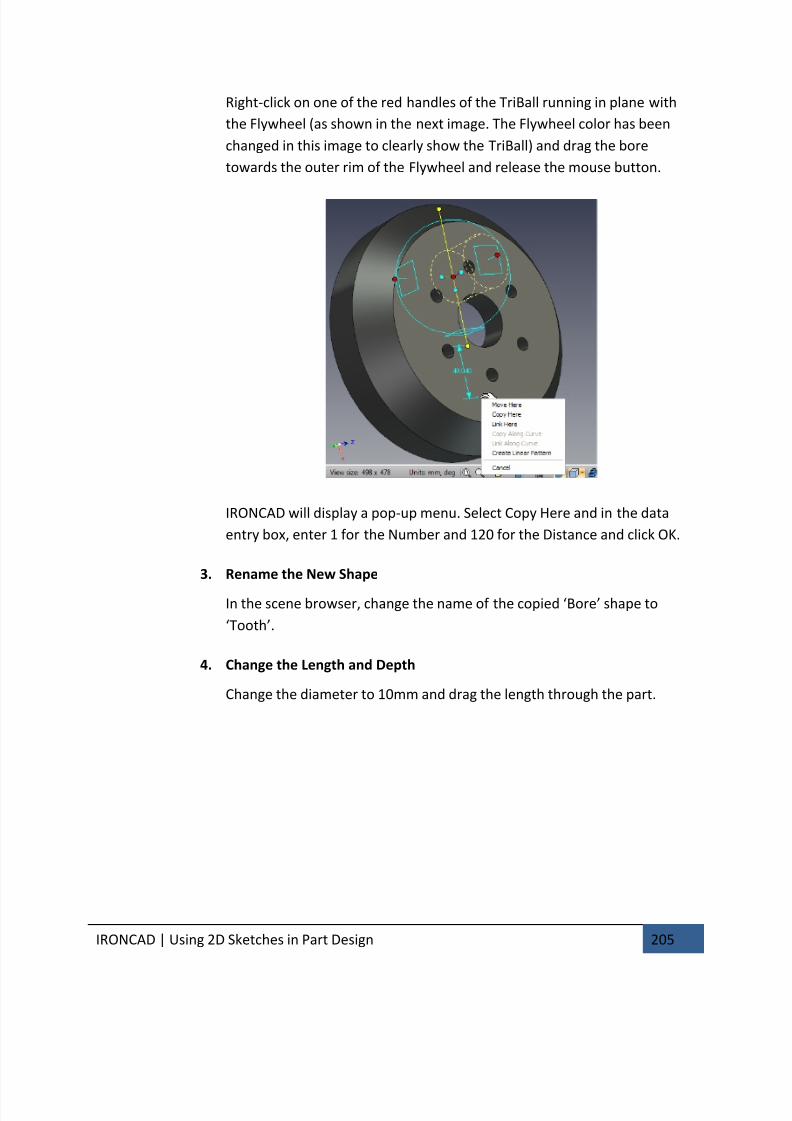
7/30/2019 Unlock Ironcadgsg
http://slidepdf.com/reader/full/unlock-ironcadgsg 209/367
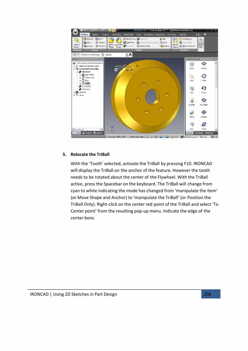
7/30/2019 Unlock Ironcadgsg
http://slidepdf.com/reader/full/unlock-ironcadgsg 210/367
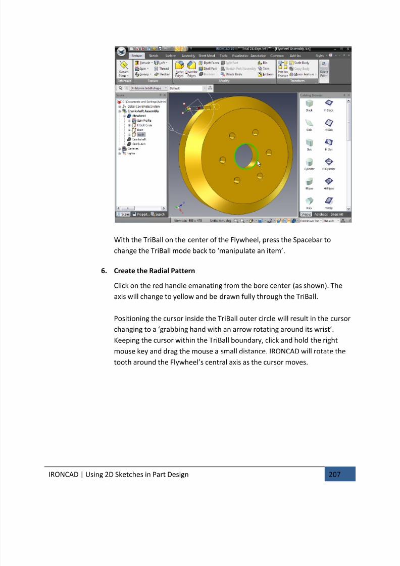
7/30/2019 Unlock Ironcadgsg
http://slidepdf.com/reader/full/unlock-ironcadgsg 211/367
IRONCAD | Using 2D Sketches in Part Design 207
With the TriBall on the center of the Flywheel, press the Spacebar to
change the TriBall mode back to ‘manipulate an item’.
6. Create the Radial Pattern
Click on the red handle emanating from the bore center (as shown). The
axis will change to yellow and be drawn fully through the TriBall.
Positioning the cursor inside the TriBall outer circle will result in the cursor
changing to a ‘grabbing hand with an arrow rotating around its wrist’.
Keeping the cursor within the TriBall boundary, click and hold the right
mouse key and drag the mouse a small distance. IRONCAD will rotate the
tooth around the Flywheel’s central axis as the cursor moves.
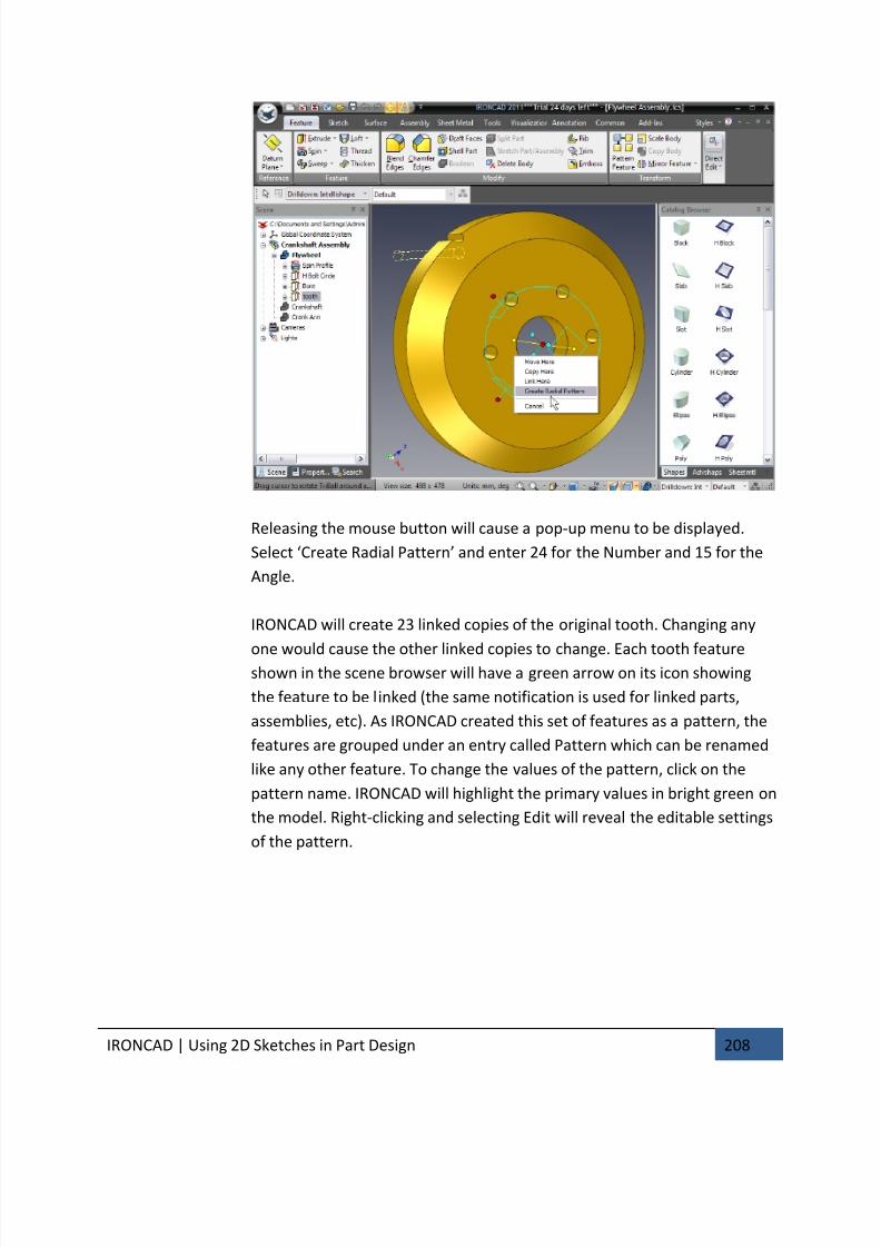
7/30/2019 Unlock Ironcadgsg
http://slidepdf.com/reader/full/unlock-ironcadgsg 212/367
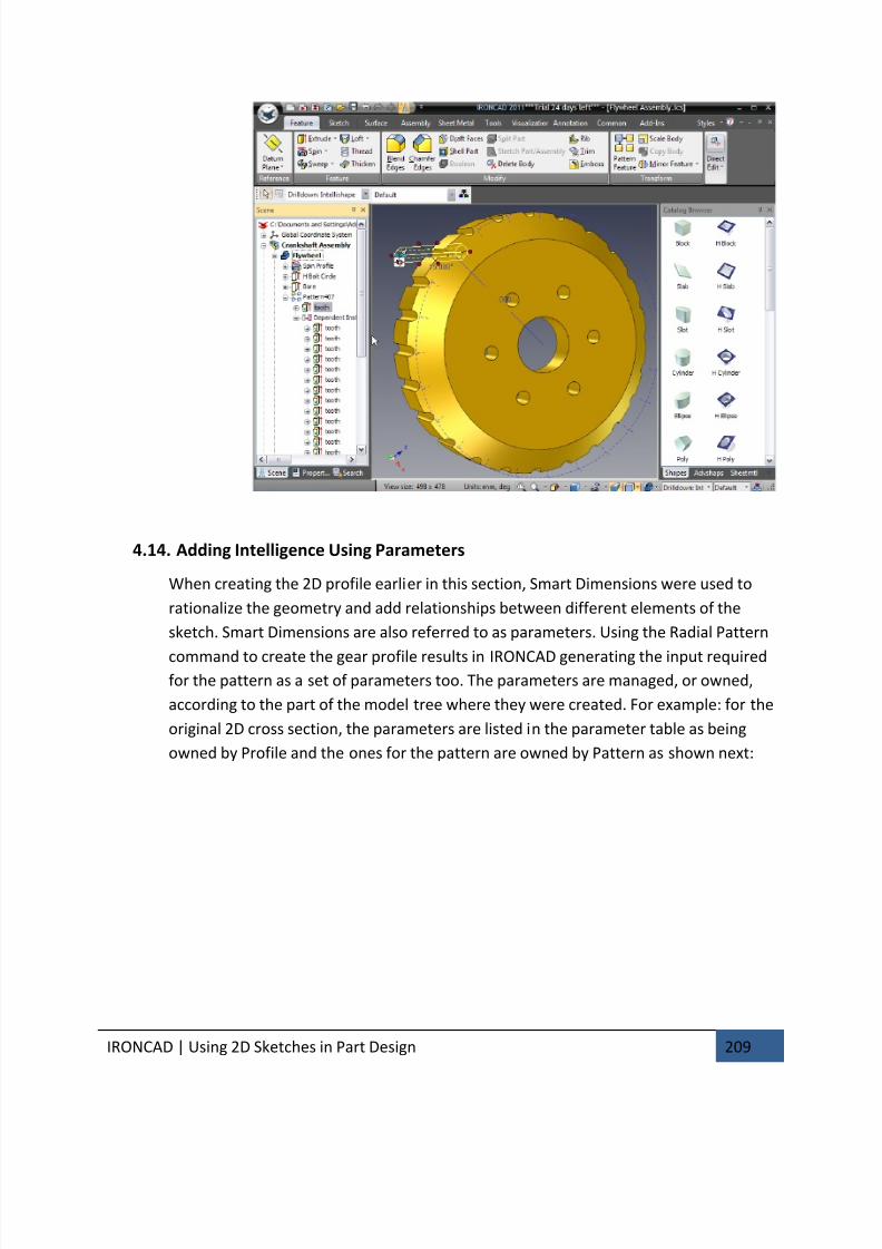
7/30/2019 Unlock Ironcadgsg
http://slidepdf.com/reader/full/unlock-ironcadgsg 213/367
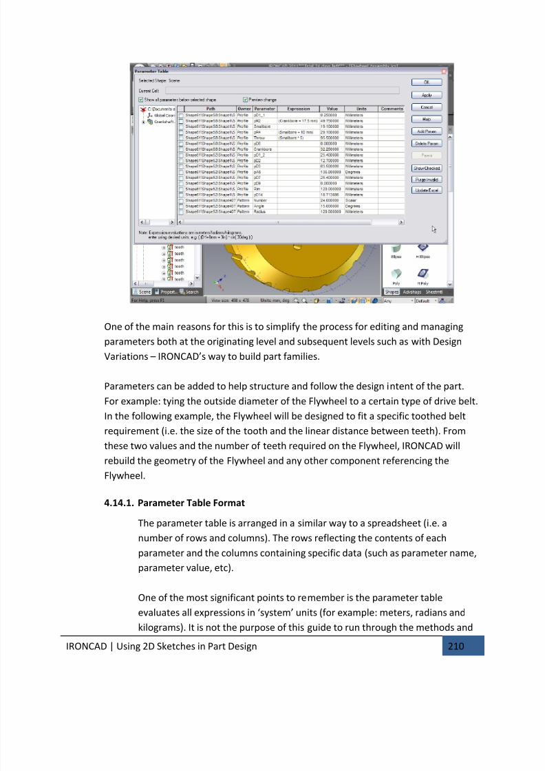
7/30/2019 Unlock Ironcadgsg
http://slidepdf.com/reader/full/unlock-ironcadgsg 214/367

7/30/2019 Unlock Ironcadgsg
http://slidepdf.com/reader/full/unlock-ironcadgsg 215/367
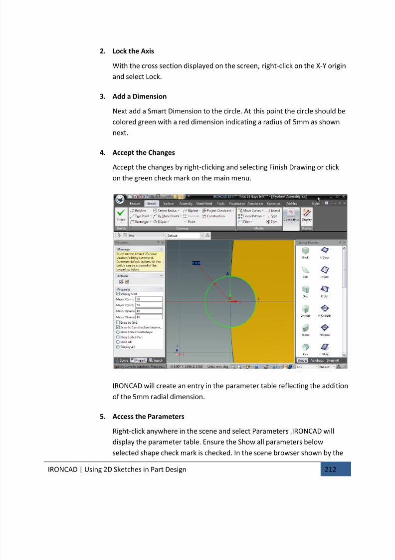
7/30/2019 Unlock Ironcadgsg
http://slidepdf.com/reader/full/unlock-ironcadgsg 216/367
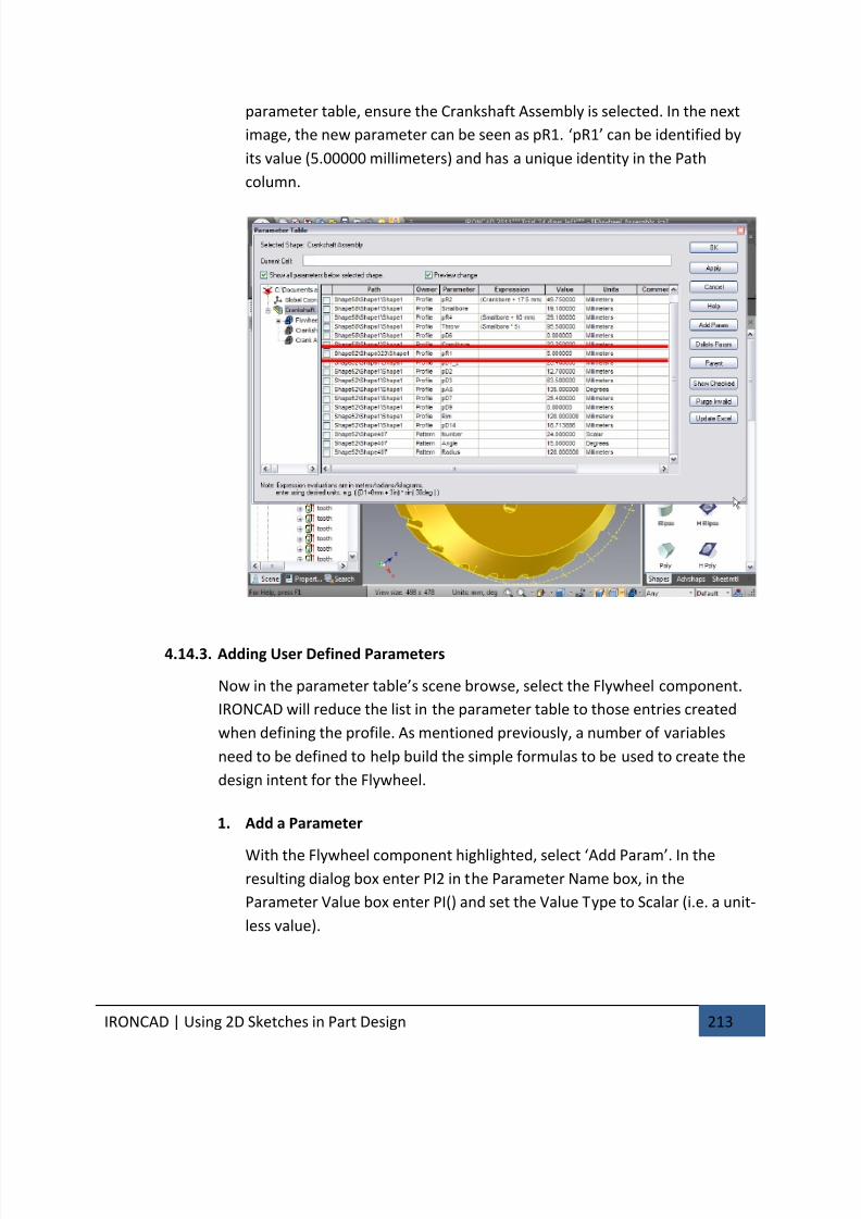
7/30/2019 Unlock Ironcadgsg
http://slidepdf.com/reader/full/unlock-ironcadgsg 217/367
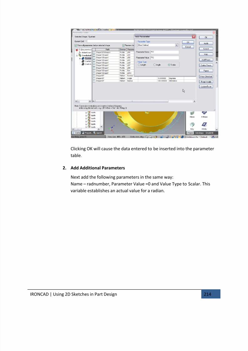
7/30/2019 Unlock Ironcadgsg
http://slidepdf.com/reader/full/unlock-ironcadgsg 218/367
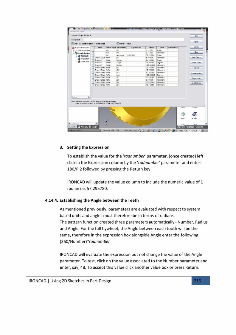
7/30/2019 Unlock Ironcadgsg
http://slidepdf.com/reader/full/unlock-ironcadgsg 219/367
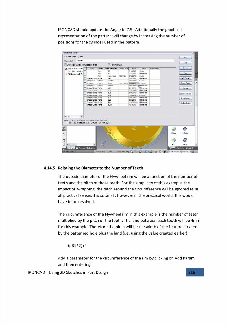
7/30/2019 Unlock Ironcadgsg
http://slidepdf.com/reader/full/unlock-ironcadgsg 220/367
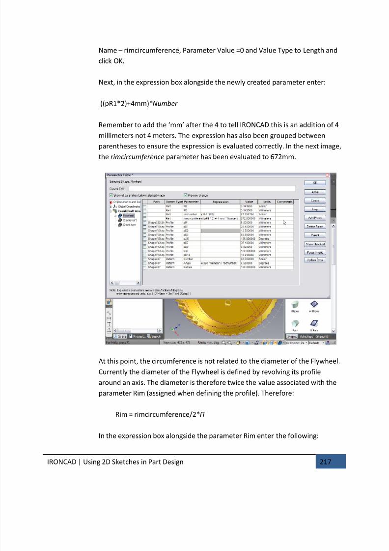
7/30/2019 Unlock Ironcadgsg
http://slidepdf.com/reader/full/unlock-ironcadgsg 221/367
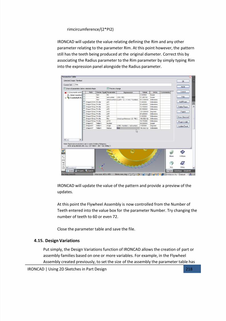
7/30/2019 Unlock Ironcadgsg
http://slidepdf.com/reader/full/unlock-ironcadgsg 222/367
IRONCAD | Using 2D Sketches in Part Design 218
rimcircumference/(2*PI2)
IRONCAD will update the value relating defining the Rim and any other
parameter relating to the parameter Rim. At this point however, the pattern
still has the teeth being produced at the original diameter. Correct this byassociating the Radius parameter to the Rim parameter by simply typing Rim
into the expression panel alongside the Radius parameter.
IRONCAD will update the value of the pattern and provide a preview of the
updates.
At this point the Flywheel Assembly is now controlled from the Number of
Teeth entered into the value box for the parameter Number. Try changing the
number of teeth to 60 or even 72.
Close the parameter table and save the file.
4.15. Design Variations
Put simply, the Design Variations function of IRONCAD allows the creation of part or
assembly families based on one or more variables. For example, in the Flywheel
Assembly created previously, to set the size of the assembly the parameter table has

7/30/2019 Unlock Ironcadgsg
http://slidepdf.com/reader/full/unlock-ironcadgsg 223/367
IRONCAD | Using 2D Sketches in Part Design 219
to be accessed and the parameter changed. This assumes a certain level of knowledge
and leaves the model open to other changes by design or by error.
Design Variations provides a higher level of automation by presenting predictable
model variants yet still allowing a degree of flexibility. In the Flywheel Assembly, thewhole assembly is built based on a set of parameters feeding from the parameter
Number which was automatically created as a result of adding the pattern of teeth. In
a typical supply situation, a company may offer standard variants directly from its
catalog. Design Variations provides the functionality to pre-define these variants. It
goes one stage further and allows the user to define custom scenarios too.
Working from the top level in the part structure, Design Variations hide all the
controlling parameters and relationships from the novice or non-expert user of
IRONCAD. As with most things, it’s easier to explain with an example using the
Flywheel Assembly saved at the previous session.
4.15.1. Adding Top Level Parameters
Top level parameter is necessary to control Design Variations and serves as an
easy way to define the driving parameters for a design.
1. Add Top Level Parameters
With the Crankshaft Assembly selected, right-click on the Crankshaft
Assembly and select parameters from the menu. Ensure the ‘Show allparameters below selected shape’ check box is not ticked.
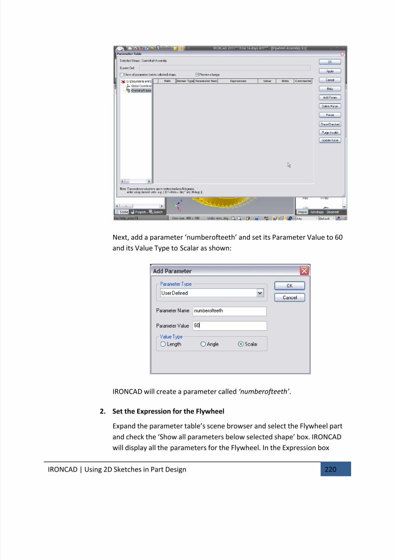
7/30/2019 Unlock Ironcadgsg
http://slidepdf.com/reader/full/unlock-ironcadgsg 224/367
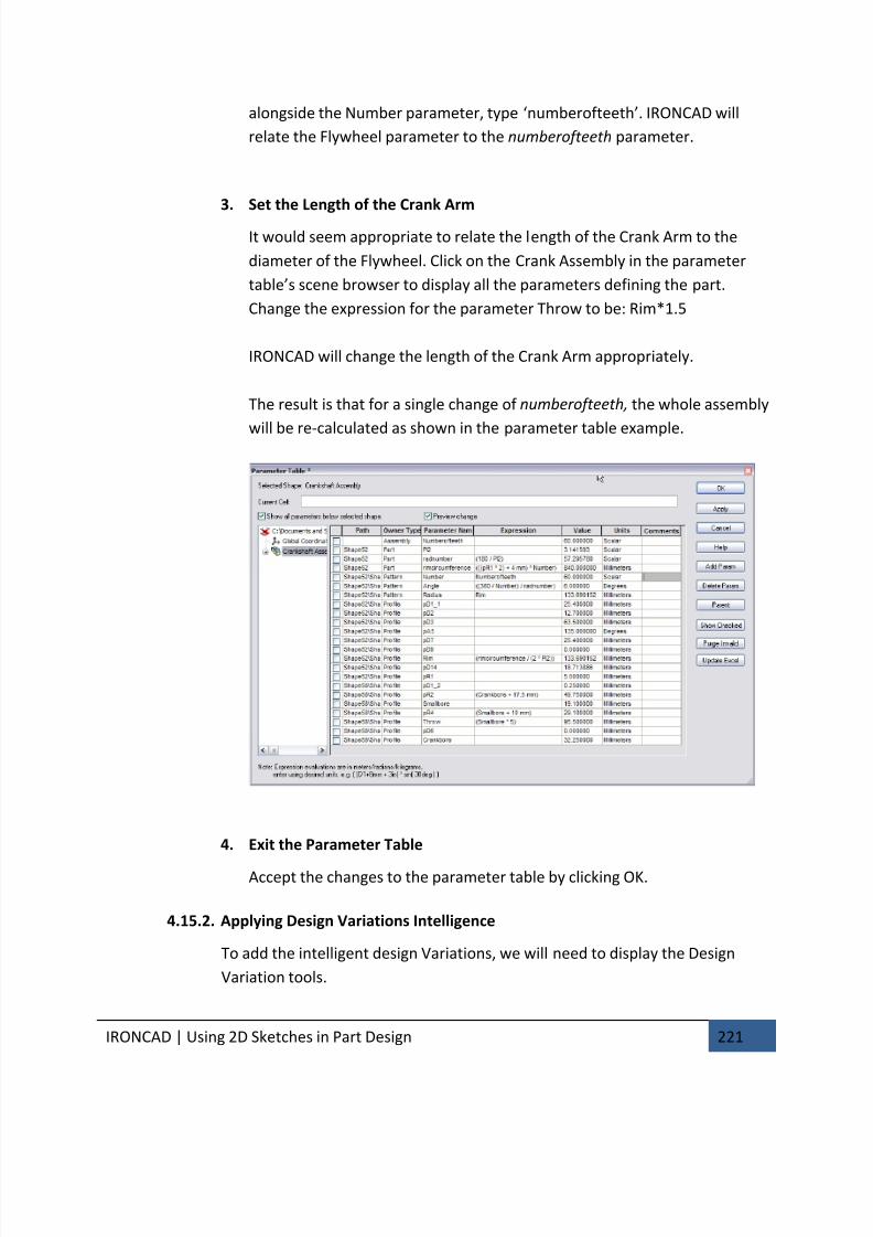
7/30/2019 Unlock Ironcadgsg
http://slidepdf.com/reader/full/unlock-ironcadgsg 225/367
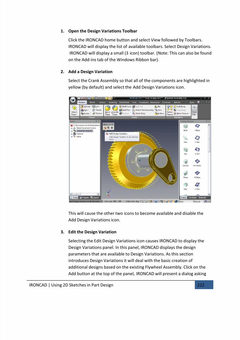
7/30/2019 Unlock Ironcadgsg
http://slidepdf.com/reader/full/unlock-ironcadgsg 226/367
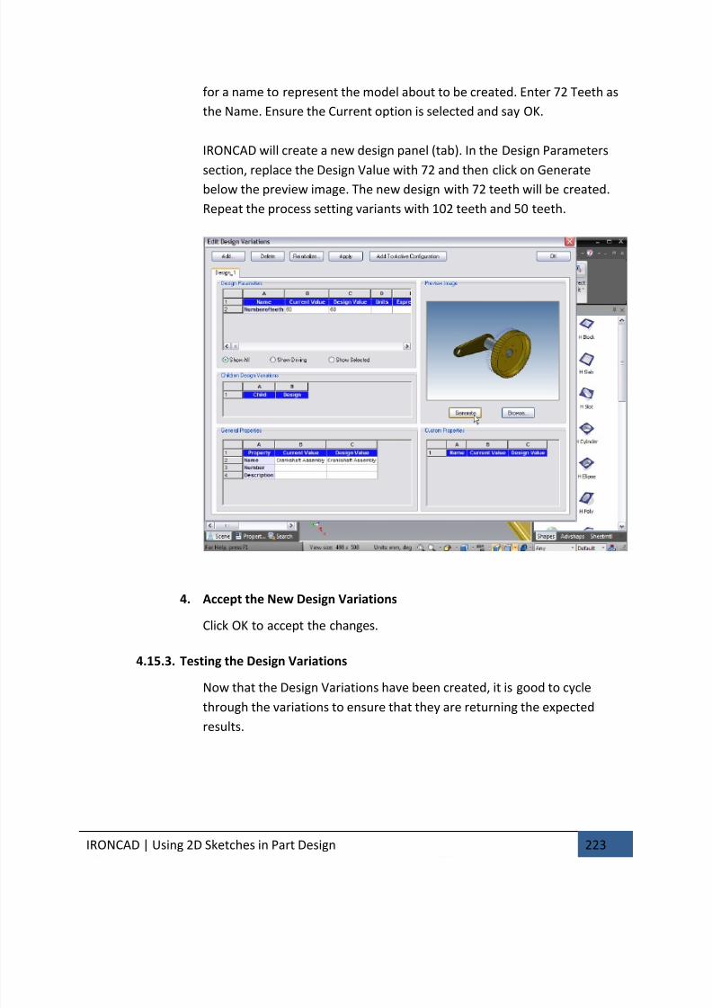
7/30/2019 Unlock Ironcadgsg
http://slidepdf.com/reader/full/unlock-ironcadgsg 227/367
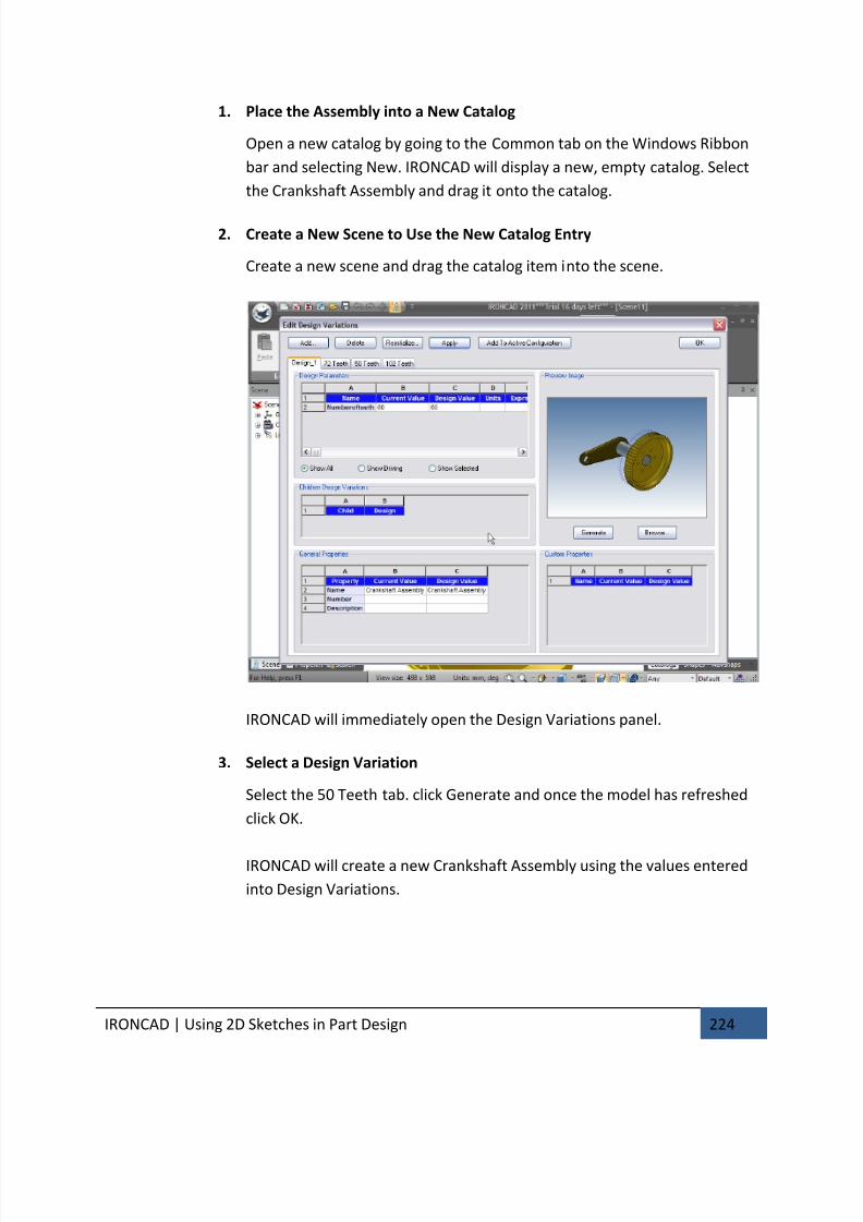
7/30/2019 Unlock Ironcadgsg
http://slidepdf.com/reader/full/unlock-ironcadgsg 228/367
IRONCAD | Using 2D Sketches in Part Design 224
1. Place the Assembly into a New Catalog
Open a new catalog by going to the Common tab on the Windows Ribbon
bar and selecting New. IRONCAD will display a new, empty catalog. Select
the Crankshaft Assembly and drag it onto the catalog.
2. Create a New Scene to Use the New Catalog Entry
Create a new scene and drag the catalog item into the scene.
IRONCAD will immediately open the Design Variations panel.
3. Select a Design Variation
Select the 50 Teeth tab. click Generate and once the model has refreshed
click OK.
IRONCAD will create a new Crankshaft Assembly using the values entered
into Design Variations.
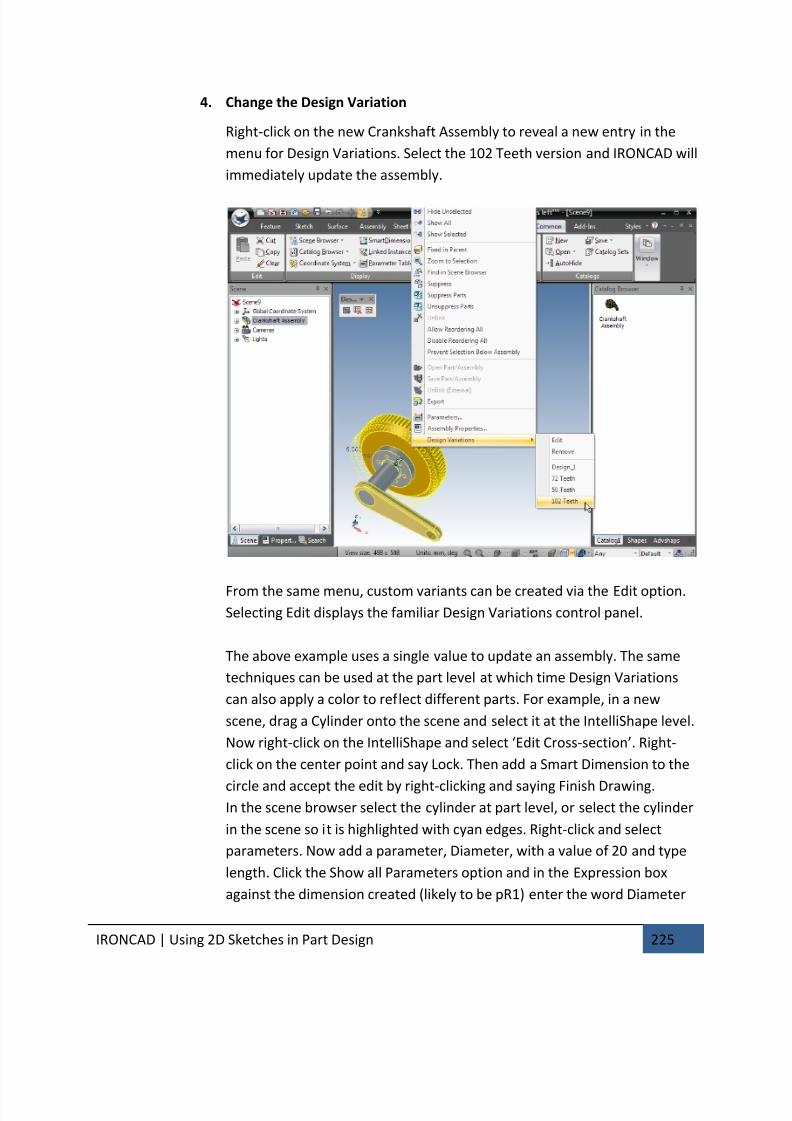
7/30/2019 Unlock Ironcadgsg
http://slidepdf.com/reader/full/unlock-ironcadgsg 229/367
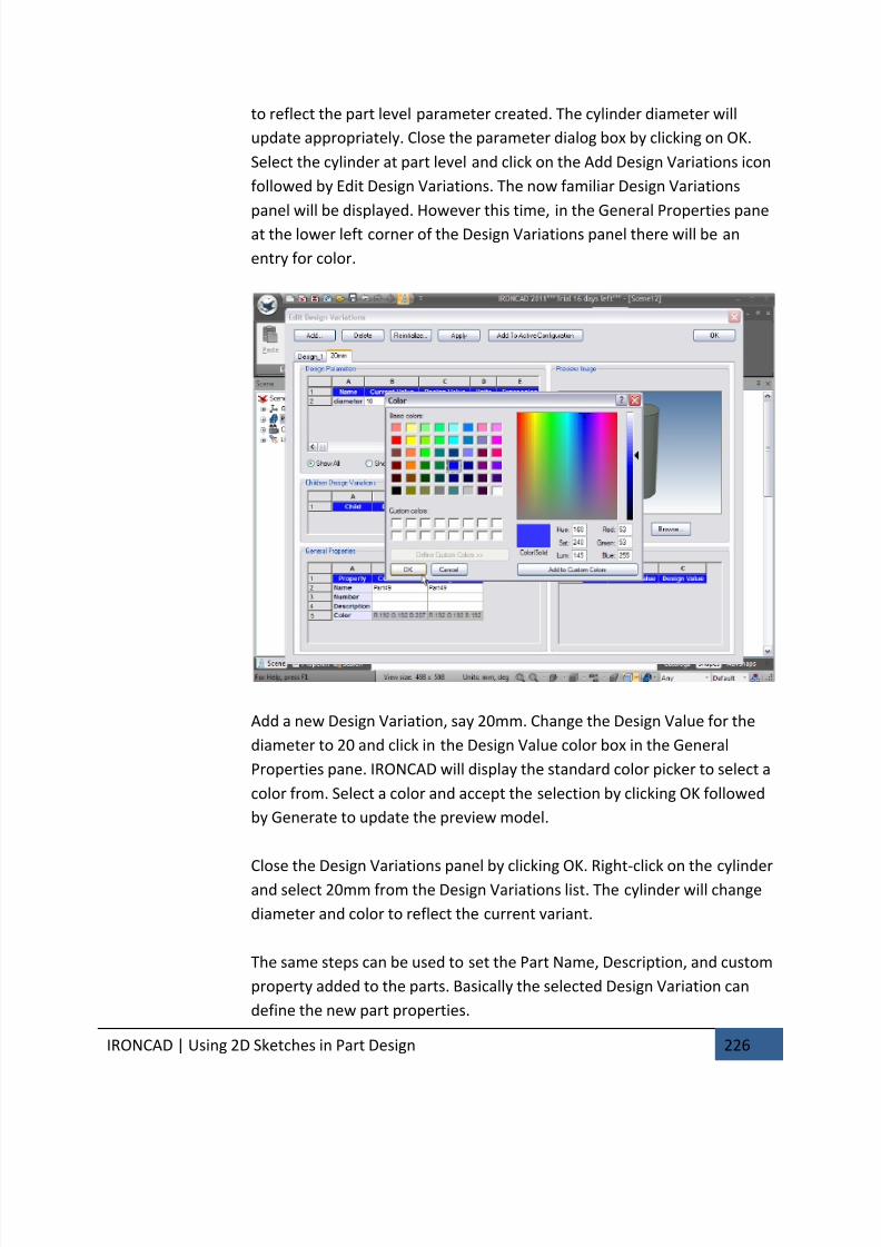
7/30/2019 Unlock Ironcadgsg
http://slidepdf.com/reader/full/unlock-ironcadgsg 230/367

7/30/2019 Unlock Ironcadgsg
http://slidepdf.com/reader/full/unlock-ironcadgsg 231/367

7/30/2019 Unlock Ironcadgsg
http://slidepdf.com/reader/full/unlock-ironcadgsg 232/367

7/30/2019 Unlock Ironcadgsg
http://slidepdf.com/reader/full/unlock-ironcadgsg 233/367

7/30/2019 Unlock Ironcadgsg
http://slidepdf.com/reader/full/unlock-ironcadgsg 234/367
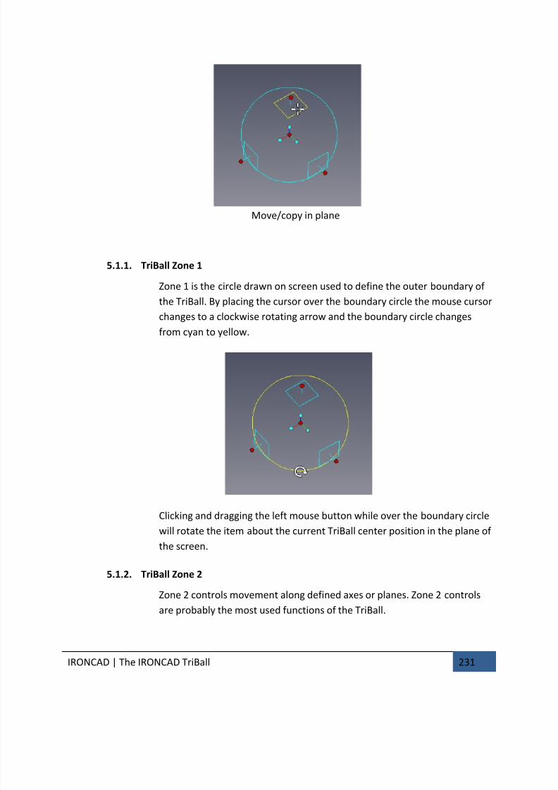
7/30/2019 Unlock Ironcadgsg
http://slidepdf.com/reader/full/unlock-ironcadgsg 235/367
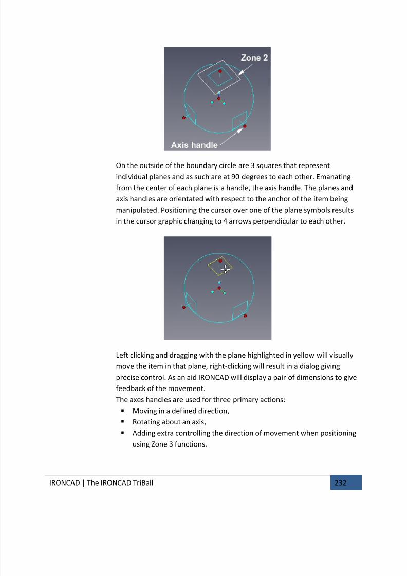
7/30/2019 Unlock Ironcadgsg
http://slidepdf.com/reader/full/unlock-ironcadgsg 236/367
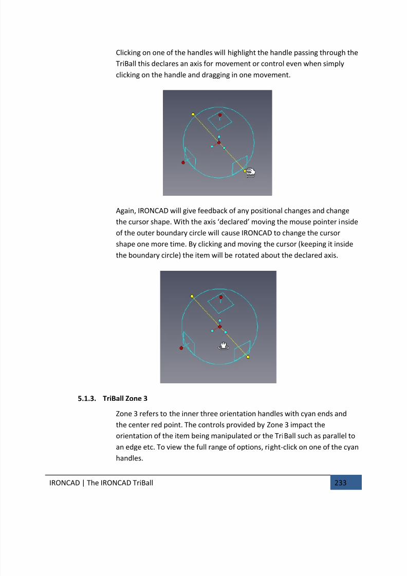
7/30/2019 Unlock Ironcadgsg
http://slidepdf.com/reader/full/unlock-ironcadgsg 237/367
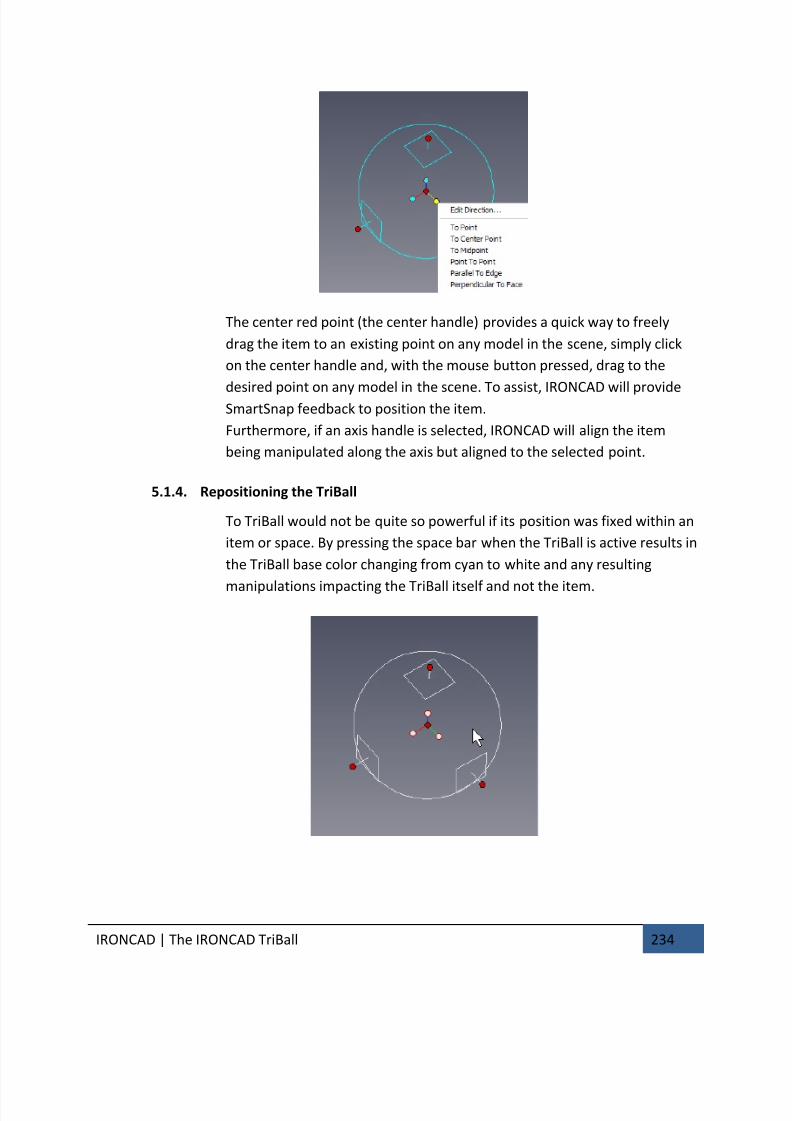
7/30/2019 Unlock Ironcadgsg
http://slidepdf.com/reader/full/unlock-ironcadgsg 238/367
IRONCAD | The IRONCAD TriBall 234
The center red point (the center handle) provides a quick way to freely
drag the item to an existing point on any model in the scene, simply click
on the center handle and, with the mouse button pressed, drag to the
desired point on any model in the scene. To assist, IRONCAD will provideSmartSnap feedback to position the item.
Furthermore, if an axis handle is selected, IRONCAD will align the item
being manipulated along the axis but aligned to the selected point.
5.1.4. Repositioning the TriBall
To TriBall would not be quite so powerful if its position was fixed within an
item or space. By pressing the space bar when the TriBall is active results in
the TriBall base color changing from cyan to white and any resulting
manipulations impacting the TriBall itself and not the item.

7/30/2019 Unlock Ironcadgsg
http://slidepdf.com/reader/full/unlock-ironcadgsg 239/367
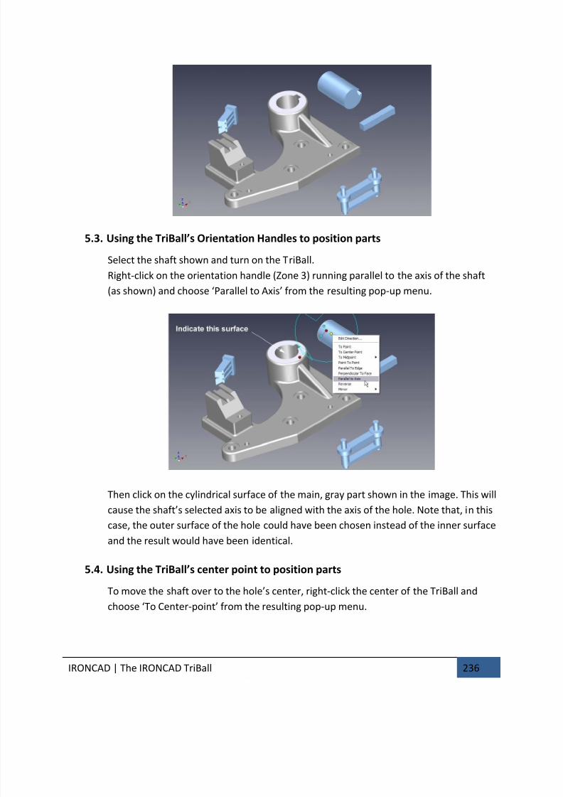
7/30/2019 Unlock Ironcadgsg
http://slidepdf.com/reader/full/unlock-ironcadgsg 240/367
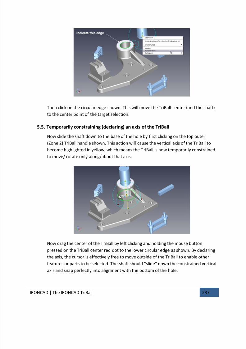
7/30/2019 Unlock Ironcadgsg
http://slidepdf.com/reader/full/unlock-ironcadgsg 241/367
IRONCAD | The IRONCAD TriBall 237
Then click on the circular edge shown. This will move the TriBall center (and the shaft)
to the center point of the target selection.
5.5. Temporarily constraining (declaring) an axis of the TriBall
Now slide the shaft down to the base of the hole by first clicking on the top outer
(Zone 2) TriBall handle shown. This action will cause the vertical axis of the TriBall to
become highlighted in yellow, which means the TriBall is now temporarily constrained
to move/ rotate only along/about that axis.
Now drag the center of the TriBall by left clicking and holding the mouse buttonpressed on the TriBall center red dot to the lower circular edge as shown. By declaring
the axis, the cursor is effectively free to move outside of the TriBall to enable other
features or parts to be selected. The shaft should “slide” down the constrained vertical
axis and snap perfectly into alignment with the bottom of the hole.
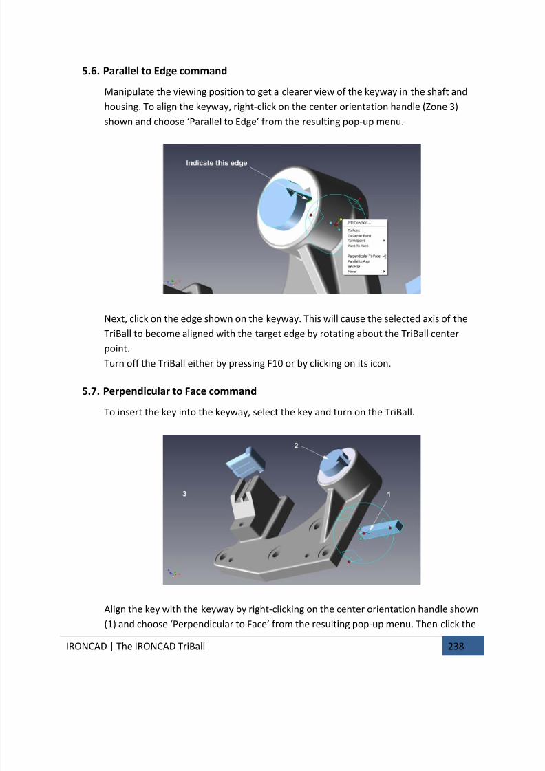
7/30/2019 Unlock Ironcadgsg
http://slidepdf.com/reader/full/unlock-ironcadgsg 242/367

7/30/2019 Unlock Ironcadgsg
http://slidepdf.com/reader/full/unlock-ironcadgsg 243/367
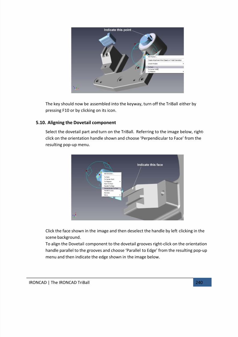
7/30/2019 Unlock Ironcadgsg
http://slidepdf.com/reader/full/unlock-ironcadgsg 244/367
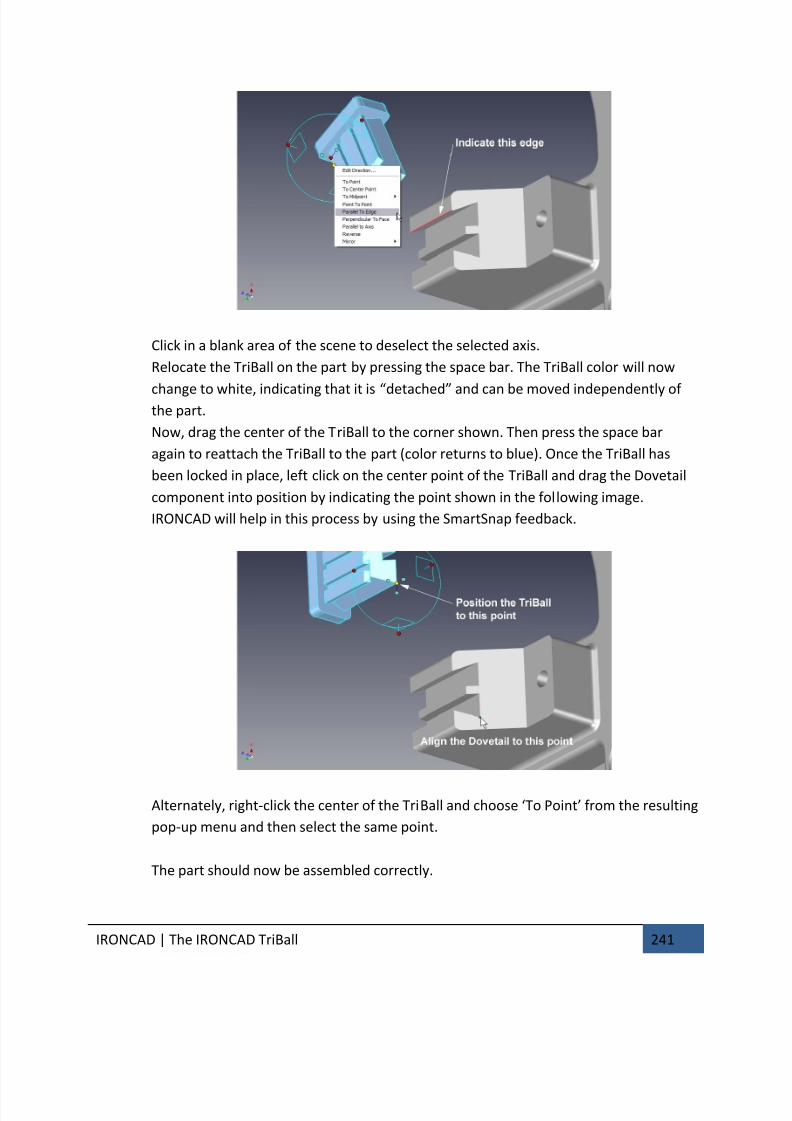
7/30/2019 Unlock Ironcadgsg
http://slidepdf.com/reader/full/unlock-ironcadgsg 245/367
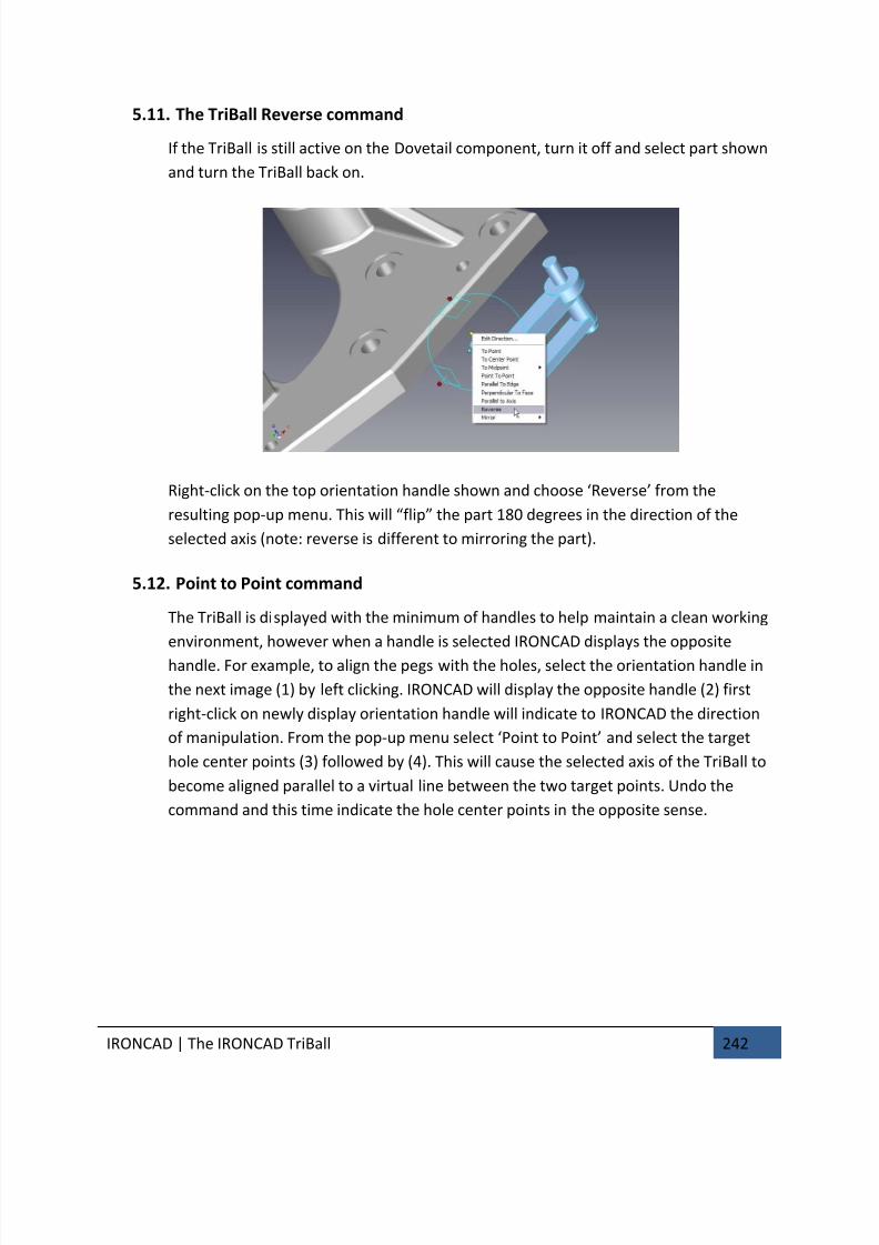
7/30/2019 Unlock Ironcadgsg
http://slidepdf.com/reader/full/unlock-ironcadgsg 246/367
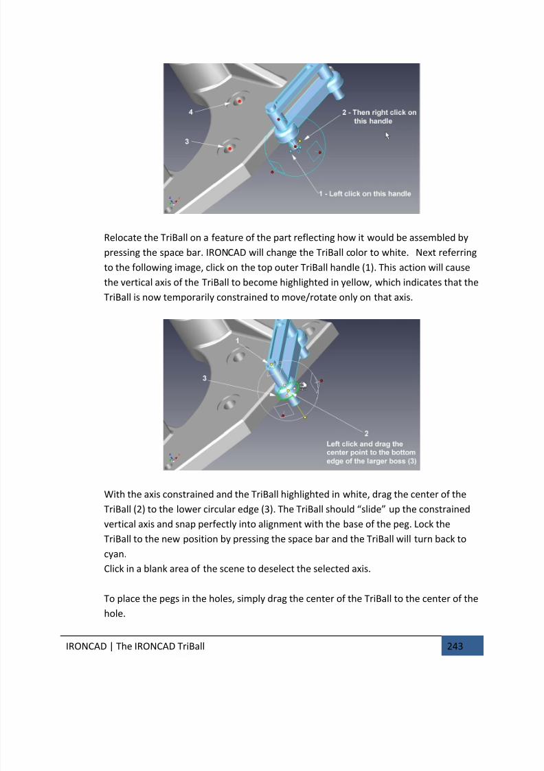
7/30/2019 Unlock Ironcadgsg
http://slidepdf.com/reader/full/unlock-ironcadgsg 247/367
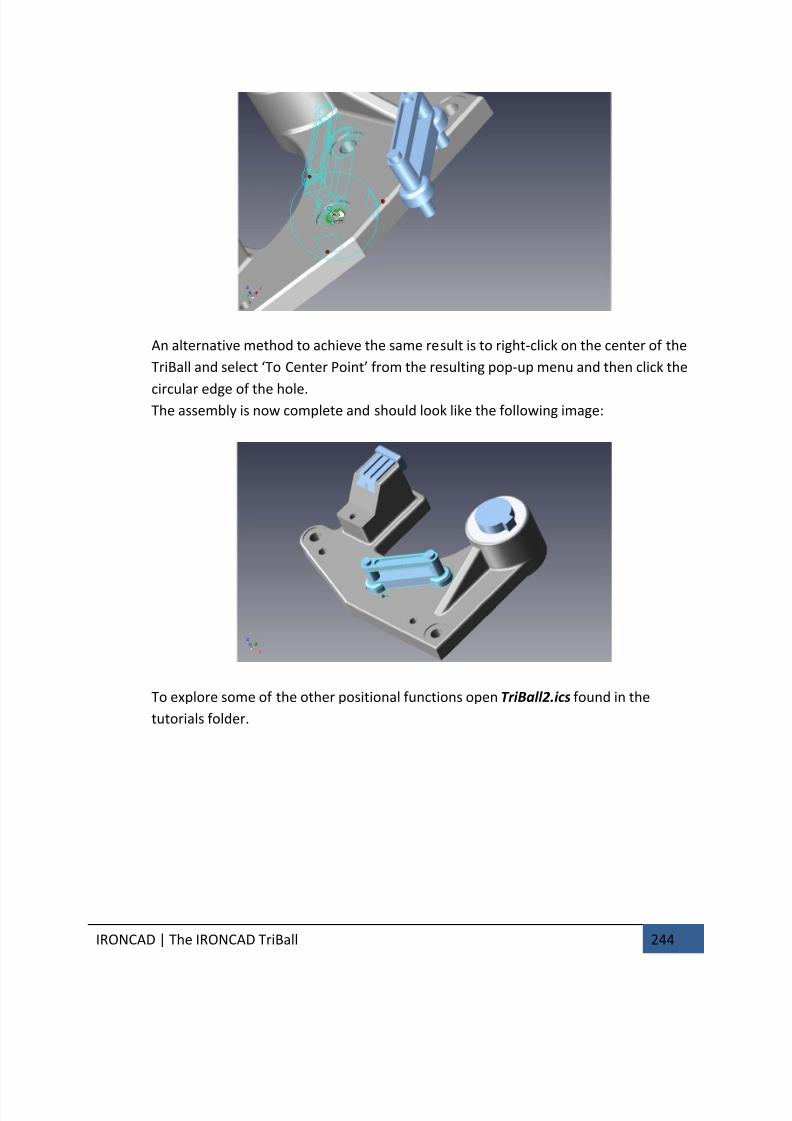
7/30/2019 Unlock Ironcadgsg
http://slidepdf.com/reader/full/unlock-ironcadgsg 248/367
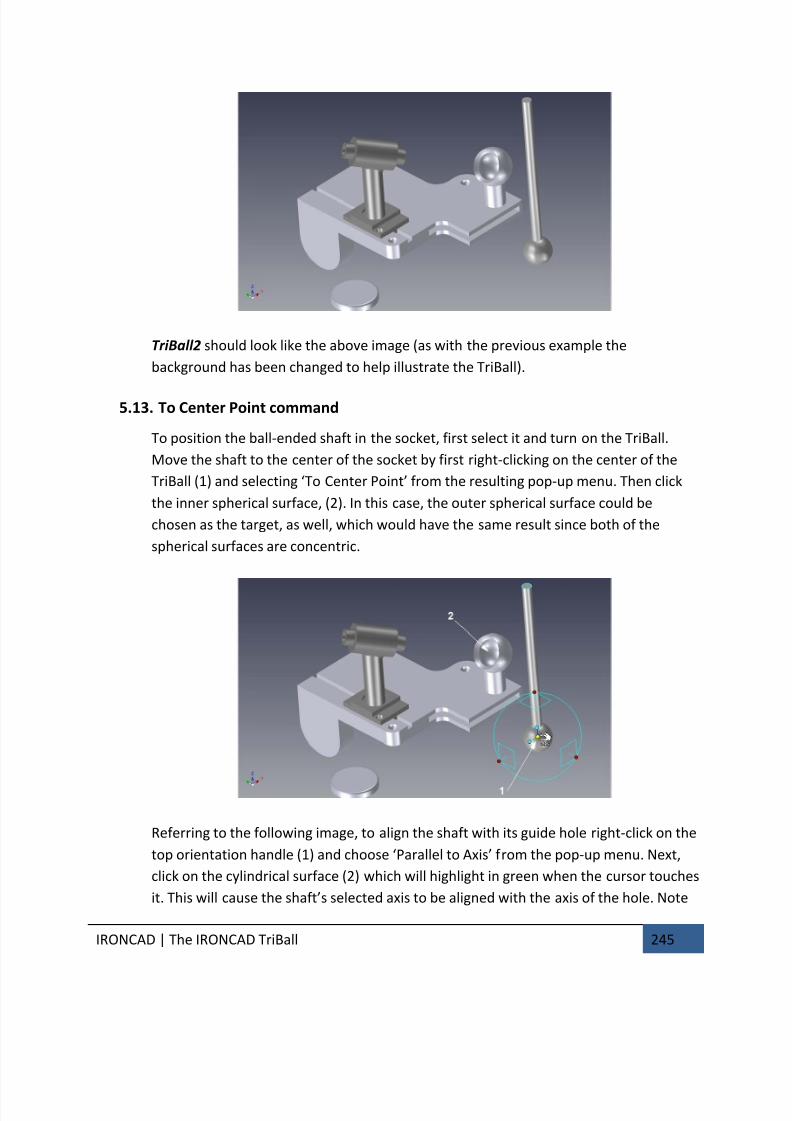
7/30/2019 Unlock Ironcadgsg
http://slidepdf.com/reader/full/unlock-ironcadgsg 249/367

7/30/2019 Unlock Ironcadgsg
http://slidepdf.com/reader/full/unlock-ironcadgsg 250/367
IRONCAD | The IRONCAD TriBall 246
that there are several other co-axial cylindrical surfaces that could be used for the
target selection which would have the same result.
Deselect the TriBall.
5.14. Using the TriBall’s ‘Copy in Plane’ option
Using the TriBall, IRONCAD can modify features of imported geometry.
For example, the base part of TriBall2.ics is an imported part i.e. the part does not
comprise any IntelliShapes or features. This can be seen by expanding the part in the
scene browser, the structure shows Shape 15 only. Zoom into the part as shown in the
following image and change the Selection Filter to ‘Face by auto-feature’
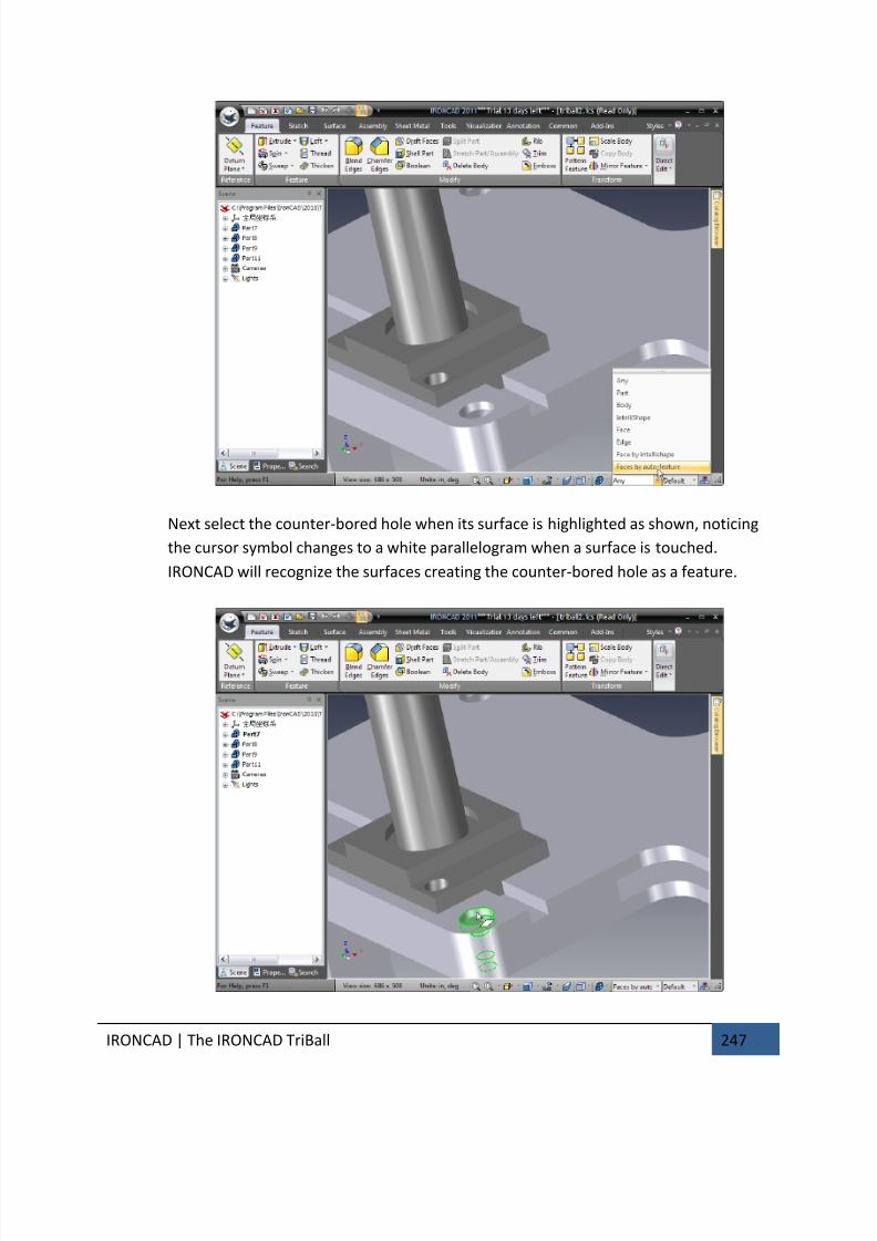
7/30/2019 Unlock Ironcadgsg
http://slidepdf.com/reader/full/unlock-ironcadgsg 251/367
IRONCAD | The IRONCAD TriBall 247
Next select the counter-bored hole when its surface is highlighted as shown, noticing
the cursor symbol changes to a white parallelogram when a surface is touched.
IRONCAD will recognize the surfaces creating the counter-bored hole as a feature.
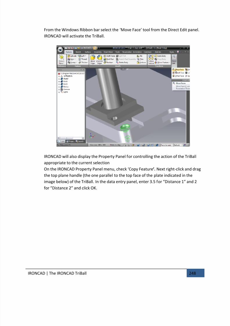
7/30/2019 Unlock Ironcadgsg
http://slidepdf.com/reader/full/unlock-ironcadgsg 252/367
IRONCAD | The IRONCAD TriBall 248
From the Windows Ribbon bar select the ‘Move Face’ tool from the Direct Edit panel.
IRONCAD will activate the TriBall.
IRONCAD will also display the Property Panel for controlling the action of the TriBall
appropriate to the current selection
On the IRONCAD Property Panel menu, check ‘Copy Feature’. Next right-click and drag
the top plane handle (the one parallel to the top face of the plate indicated in the
image below) of the TriBall. In the data entry panel, enter 3.5 for “Distance 1” and 2
for “Distance 2” and click OK.
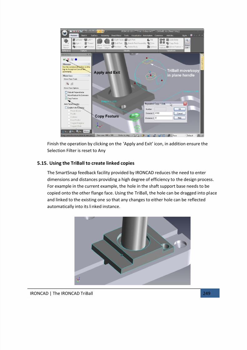
7/30/2019 Unlock Ironcadgsg
http://slidepdf.com/reader/full/unlock-ironcadgsg 253/367
IRONCAD | The IRONCAD TriBall 249
Finish the operation by clicking on the ‘Apply and Exit’ icon, in addition ensure the
Selection Filter is reset to Any
5.15. Using the TriBall to create linked copies
The SmartSnap feedback facility provided by IRONCAD reduces the need to enter
dimensions and distances providing a high degree of efficiency to the design process.
For example in the current example, the hole in the shaft support base needs to be
copied onto the other flange face. Using the TriBall, the hole can be dragged into place
and linked to the existing one so that any changes to either hole can be reflected
automatically into its linked instance.
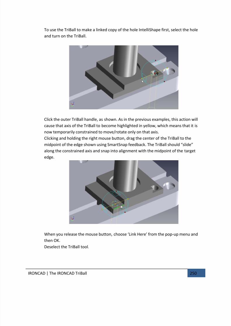
7/30/2019 Unlock Ironcadgsg
http://slidepdf.com/reader/full/unlock-ironcadgsg 254/367
IRONCAD | The IRONCAD TriBall 250
To use the TriBall to make a linked copy of the hole IntelliShape first, select the hole
and turn on the TriBall.
Click the outer TriBall handle, as shown. As in the previous examples, this action will
cause that axis of the TriBall to become highlighted in yellow, which means that it is
now temporarily constrained to move/rotate only on that axis.
Clicking and holding the right mouse button, drag the center of the TriBall to the
midpoint of the edge shown using SmartSnap feedback. The TriBall should “slide”
along the constrained axis and snap into alignment with the midpoint of the target
edge.
When you release the mouse button, choose ‘Link Here’ from the pop-up menu and
then OK.
Deselect the TriBall tool.
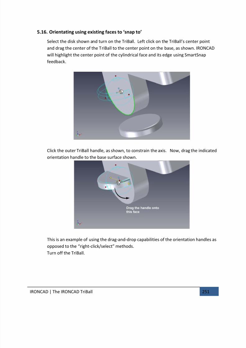
7/30/2019 Unlock Ironcadgsg
http://slidepdf.com/reader/full/unlock-ironcadgsg 255/367
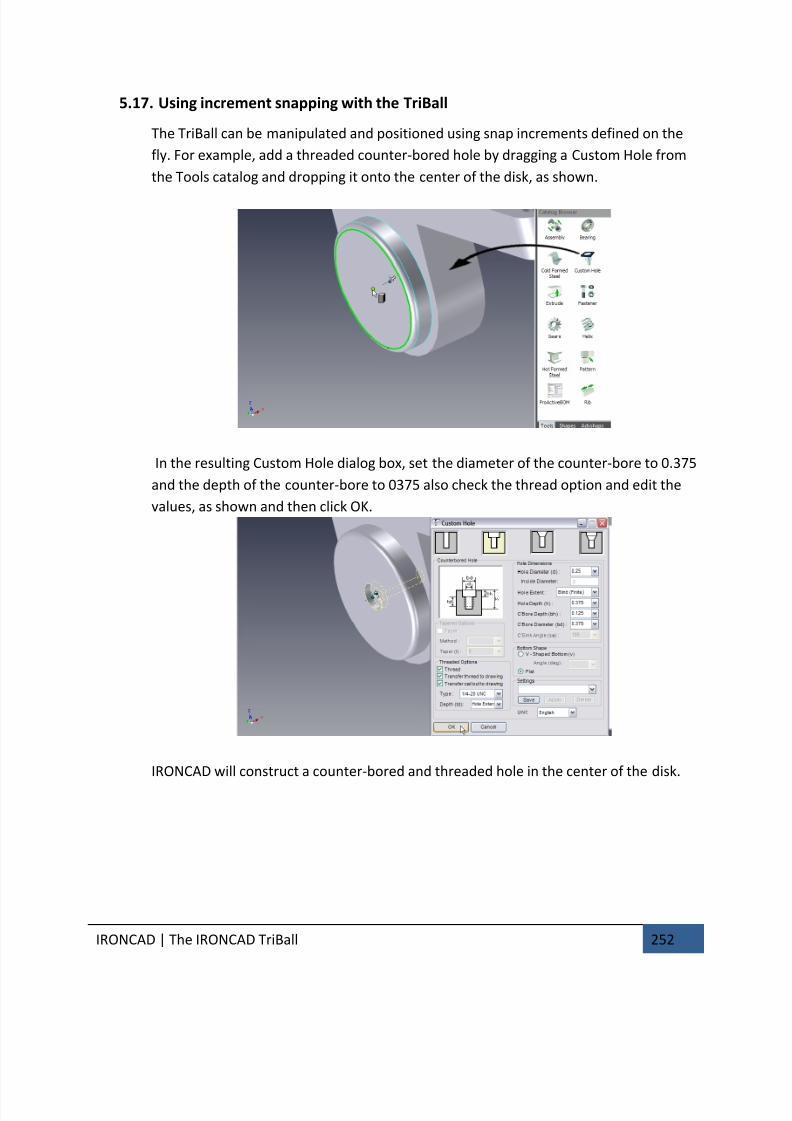
7/30/2019 Unlock Ironcadgsg
http://slidepdf.com/reader/full/unlock-ironcadgsg 256/367
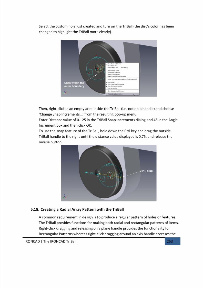
7/30/2019 Unlock Ironcadgsg
http://slidepdf.com/reader/full/unlock-ironcadgsg 257/367
IRONCAD | The IRONCAD TriBall 253
Select the custom hole just created and turn on the TriBall (the disc’s color has been
changed to highlight the TriBall more clearly).
Then, right-click in an empty area inside the TriBall (i.e. not on a handle) and choose
‘Change Snap Increments...’ from the resulting pop-up menu.
Enter Distance value of 0.125 in the TriBall Snap Increments dialog and 45 in the Angle
Increment box and then click OK.
To use the snap feature of the TriBall, hold down the Ctrl key and drag the outside
TriBall handle to the right until the distance value displayed is 0.75, and release the
mouse button.
5.18. Creating a Radial Array Pattern with the TriBall
A common requirement in design is to produce a regular pattern of holes or features.
The TriBall provides functions for making both radial and rectangular patterns of items.
Right-click dragging and releasing on a plane handle provides the functionality for
Rectangular Patterns whereas right-click dragging around an axis handle accesses the
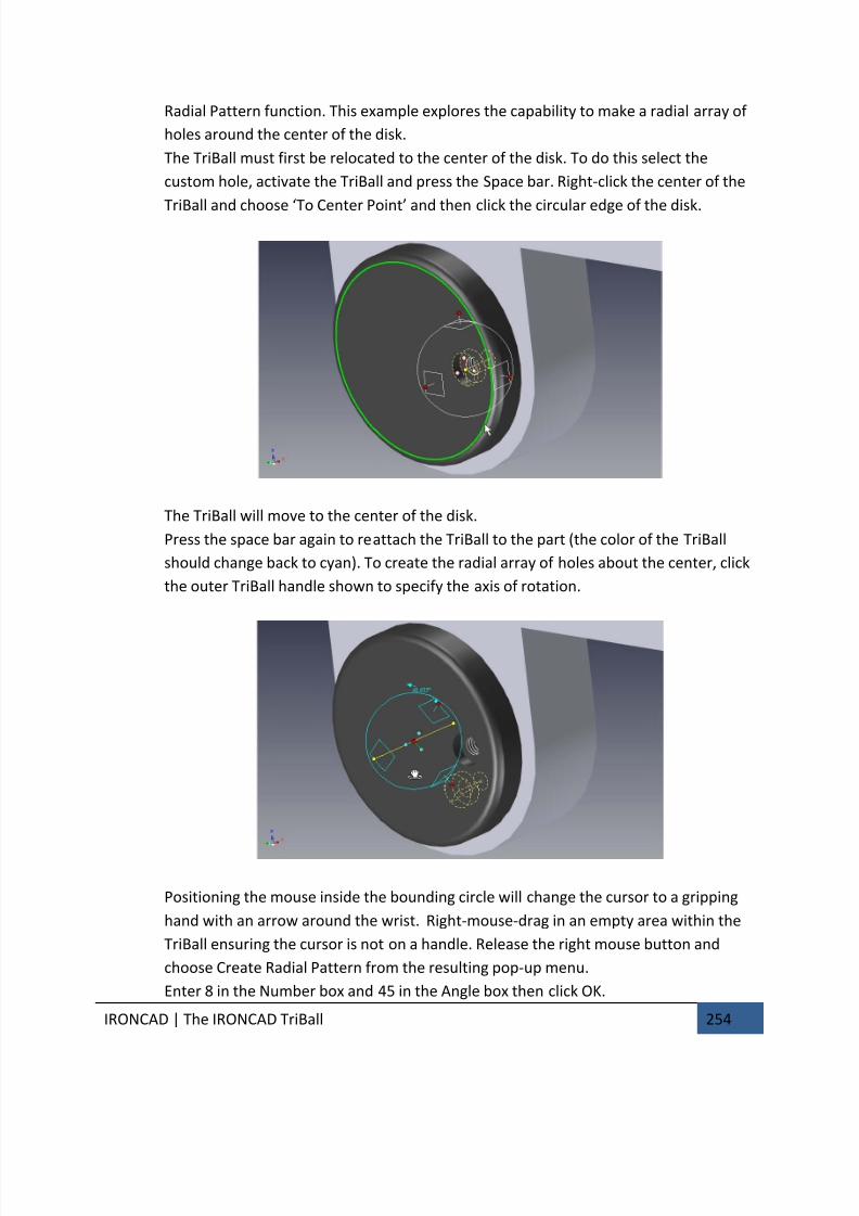
7/30/2019 Unlock Ironcadgsg
http://slidepdf.com/reader/full/unlock-ironcadgsg 258/367
IRONCAD | The IRONCAD TriBall 254
Radial Pattern function. This example explores the capability to make a radial array of
holes around the center of the disk.
The TriBall must first be relocated to the center of the disk. To do this select the
custom hole, activate the TriBall and press the Space bar. Right-click the center of the
TriBall and choose ‘To Center Point’ and then click the circular edge of the disk.
The TriBall will move to the center of the disk.
Press the space bar again to reattach the TriBall to the part (the color of the TriBall
should change back to cyan). To create the radial array of holes about the center, click
the outer TriBall handle shown to specify the axis of rotation.
Positioning the mouse inside the bounding circle will change the cursor to a gripping
hand with an arrow around the wrist. Right-mouse-drag in an empty area within the
TriBall ensuring the cursor is not on a handle. Release the right mouse button and
choose Create Radial Pattern from the resulting pop-up menu.
Enter 8 in the Number box and 45 in the Angle box then click OK.
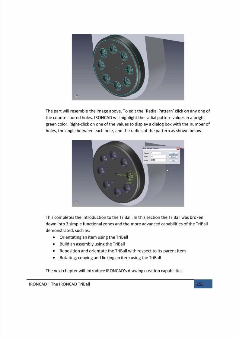
7/30/2019 Unlock Ironcadgsg
http://slidepdf.com/reader/full/unlock-ironcadgsg 259/367
IRONCAD | The IRONCAD TriBall 255
The part will resemble the image above. To edit the ‘Radial Pattern’ click on any one of
the counter-bored holes. IRONCAD will highlight the radial pattern values in a brightgreen color. Right-click on one of the values to display a dialog box with the number of
holes, the angle between each hole, and the radius of the pattern as shown below.
This completes the introduction to the TriBall. In this section the TriBall was broken
down into 3 simple functional zones and the more advanced capabilities of the TriBall
demonstrated, such as:
• Orientating an item using the TriBall• Build an assembly using the TriBall
• Reposition and orientate the TriBall with respect to its parent item
• Rotating, copying and linking an item using the TriBall
The next chapter will introduce IRONCAD’s drawing creation capabilities.

7/30/2019 Unlock Ironcadgsg
http://slidepdf.com/reader/full/unlock-ironcadgsg 260/367
IRONCAD | IRONCAD Drawing Creation 256
6. IRONCAD DRAWING CREATION
IRONCAD provides a wealth of tools to create 2D drawings from existing 3D models or
directly into the 2D drawing space for drawings such as schematics.
The fundamentals of an IRONCAD drawing are:
1. Create a 3D scene,
2. Save the part with a known name
3. Create a drawing using a pre-defined drawing boarder (template)
4. Add views and dimensions
IRONCAD maintains the relationships between the 3D scene and the drawing hence the
essential step of giving the scene a name and saving it. Without this the drawing cannot
hold a pointer to the drawing. From this simple standpoint all views, sections, detail viewsetc. are created.
Drawings can be of single parts or assemblies. They can be single or multi-sheet drawings.
This chapter explores some common functions of drawing creation and introduces some of
the more advanced features of IRONCAD's drawing creation capabilities later on. Although
the chapter can be read in isolation from other chapters, it assumes a basic knowledge of
the IRONCAD drawing creation concepts (introduced in the Quick Start section). The basis
for the tutorial section is the scene file drawingpart.ics located in the tutorials folder of the
IRONCAD installation folder usually:
Program Files\IRONCAD\201x\Tutorials\en-us (201x represents the version of IRONCAD)

7/30/2019 Unlock Ironcadgsg
http://slidepdf.com/reader/full/unlock-ironcadgsg 261/367
IRONCAD | IRONCAD Drawing Creation 257
Topics covered in this chapter:
• Creating Standard Views
• Changing the View Scale and Rendering Options
• Moving Views
• Datums, Dimensioning & Tolerancing• Centerlines and Reference Curves
• Section, Detail, Auxiliary, and General Views
• Multi-Sheet Drawings
• Hole Table
• Sheet Drawing Tools
• Styles and Layers
• Part/Drawing Associativity
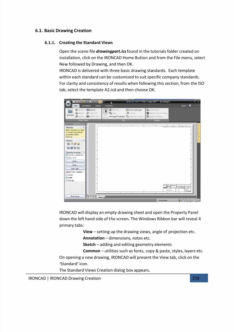
7/30/2019 Unlock Ironcadgsg
http://slidepdf.com/reader/full/unlock-ironcadgsg 262/367
IRONCAD | IRONCAD Drawing Creation 258
6.1. Basic Drawing Creation
6.1.1. Creating the Standard Views
Open the scene file drawingpart.ics found in the tutorials folder created on
installation, click on the IRONCAD Home Button and from the File menu, selectNew followed by Drawing, and then OK.
IRONCAD is delivered with three basic drawing standards. Each template
within each standard can be customized to suit specific company standards.
For clarity and consistency of results when following this section, from the ISO
tab, select the template A2.icd and then choose OK.
IRONCAD will display an empty drawing sheet and open the Property Panel
down the left hand side of the screen. The Windows Ribbon bar will reveal 4
primary tabs:
View – setting up the drawing views, angle of projection etc.Annotation – dimensions, notes etc.
Sketch – adding and editing geometry elements
Common – utilities such as fonts, copy & paste, styles, layers etc.
On opening a new drawing, IRONCAD will present the View tab, click on the
‘Standard’ icon.
The Standard Views Creation dialog box appears.
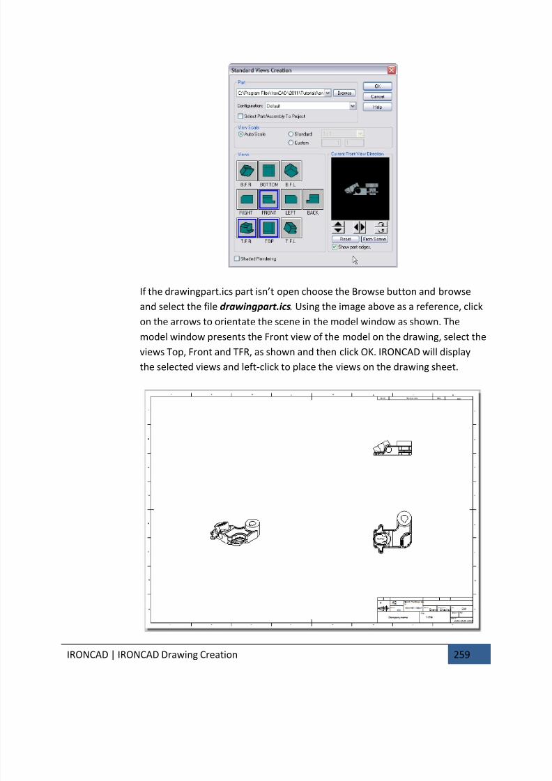
7/30/2019 Unlock Ironcadgsg
http://slidepdf.com/reader/full/unlock-ironcadgsg 263/367

7/30/2019 Unlock Ironcadgsg
http://slidepdf.com/reader/full/unlock-ironcadgsg 264/367
IRONCAD | IRONCAD Drawing Creation 260
6.1.2. Changing the View Scale and Rendering options
Right-click on the isometric view (the T.F.R. view) and choose Properties, and
then change the scale to 1:2 by selecting the Standard option and use the drop
down to select the scale. Also, change the view name to ISOMETRIC and
activate the check boxes Name and Scale and select OK.
The name and scale should now appear below the view. Right-click on the
isometric view and choose Shaded Rendering. If Shaded Rendering is not
available for selection, check the mode used for creating the view by selecting
‘Properties’ and then in the View Quality section set the option for ‘Quick
(Raster Based)’ or Draft (Facet Based).
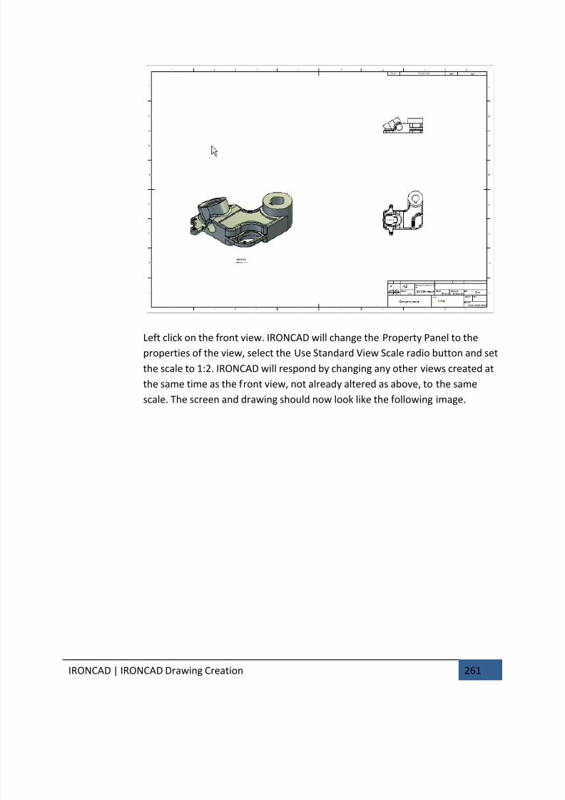
7/30/2019 Unlock Ironcadgsg
http://slidepdf.com/reader/full/unlock-ironcadgsg 265/367
IRONCAD | IRONCAD Drawing Creation 261
Left click on the front view. IRONCAD will change the Property Panel to the
properties of the view, select the Use Standard View Scale radio button and set
the scale to 1:2. IRONCAD will respond by changing any other views created at
the same time as the front view, not already altered as above, to the same
scale. The screen and drawing should now look like the following image.
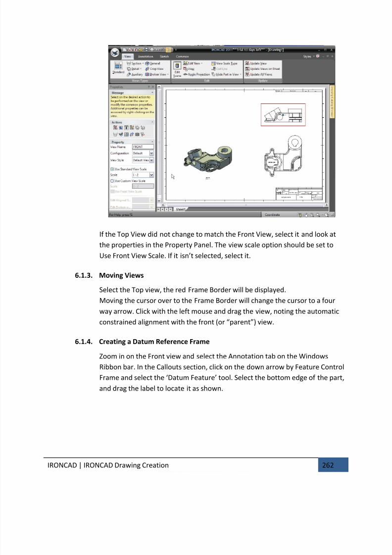
7/30/2019 Unlock Ironcadgsg
http://slidepdf.com/reader/full/unlock-ironcadgsg 266/367
IRONCAD | IRONCAD Drawing Creation 262
If the Top View did not change to match the Front View, select it and look at
the properties in the Property Panel. The view scale option should be set to
Use Front View Scale. If it isn’t selected, select it.
6.1.3. Moving Views
Select the Top view, the red Frame Border will be displayed.Moving the cursor over to the Frame Border will change the cursor to a four
way arrow. Click with the left mouse and drag the view, noting the automatic
constrained alignment with the front (or “parent”) view.
6.1.4. Creating a Datum Reference Frame
Zoom in on the Front view and select the Annotation tab on the Windows
Ribbon bar. In the Callouts section, click on the down arrow by Feature Control
Frame and select the ‘Datum Feature’ tool. Select the bottom edge of the part,
and drag the label to locate it as shown.
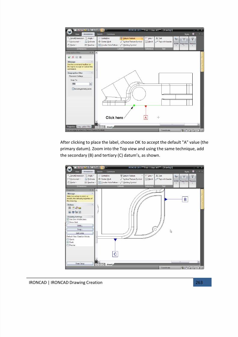
7/30/2019 Unlock Ironcadgsg
http://slidepdf.com/reader/full/unlock-ironcadgsg 267/367
IRONCAD | IRONCAD Drawing Creation 263
After clicking to place the label, choose OK to accept the default "A" value (the
primary datum). Zoom into the Top view and using the same technique, add
the secondary (B) and tertiary (C) datum’s, as shown.
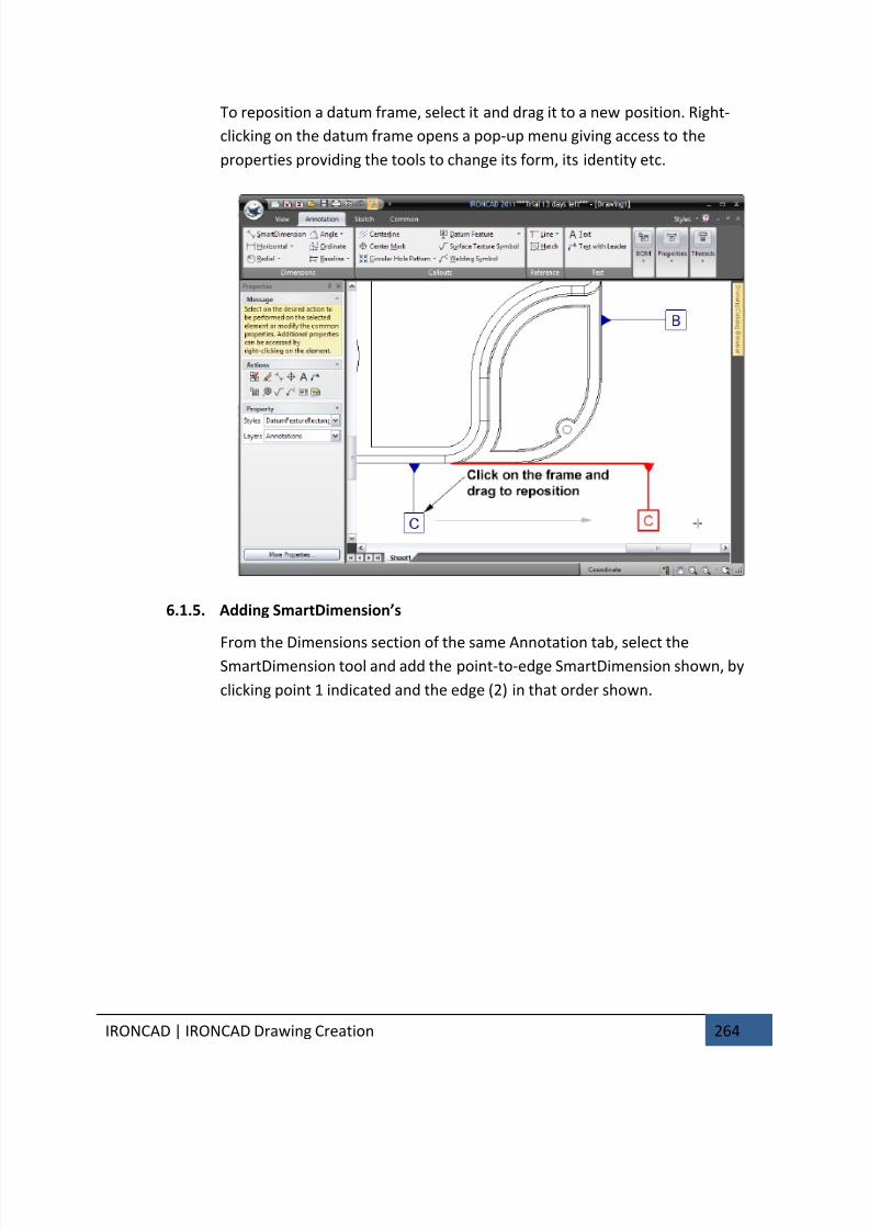
7/30/2019 Unlock Ironcadgsg
http://slidepdf.com/reader/full/unlock-ironcadgsg 268/367
IRONCAD | IRONCAD Drawing Creation 264
To reposition a datum frame, select it and drag it to a new position. Right-
clicking on the datum frame opens a pop-up menu giving access to the
properties providing the tools to change its form, its identity etc.
6.1.5. Adding SmartDimension’s
From the Dimensions section of the same Annotation tab, select theSmartDimension tool and add the point-to-edge SmartDimension shown, by
clicking point 1 indicated and the edge (2) in that order shown.
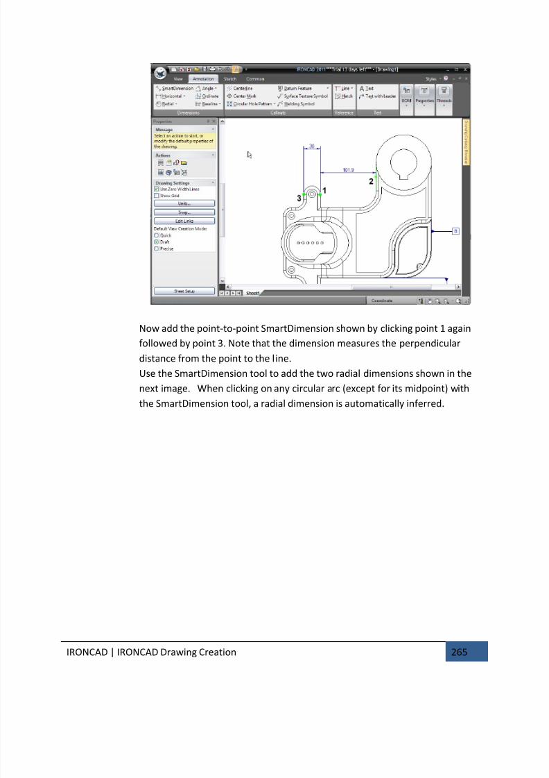
7/30/2019 Unlock Ironcadgsg
http://slidepdf.com/reader/full/unlock-ironcadgsg 269/367
IRONCAD | IRONCAD Drawing Creation 265
Now add the point-to-point SmartDimension shown by clicking point 1 again
followed by point 3. Note that the dimension measures the perpendicular
distance from the point to the line.
Use the SmartDimension tool to add the two radial dimensions shown in the
next image. When clicking on any circular arc (except for its midpoint) with
the SmartDimension tool, a radial dimension is automatically inferred.
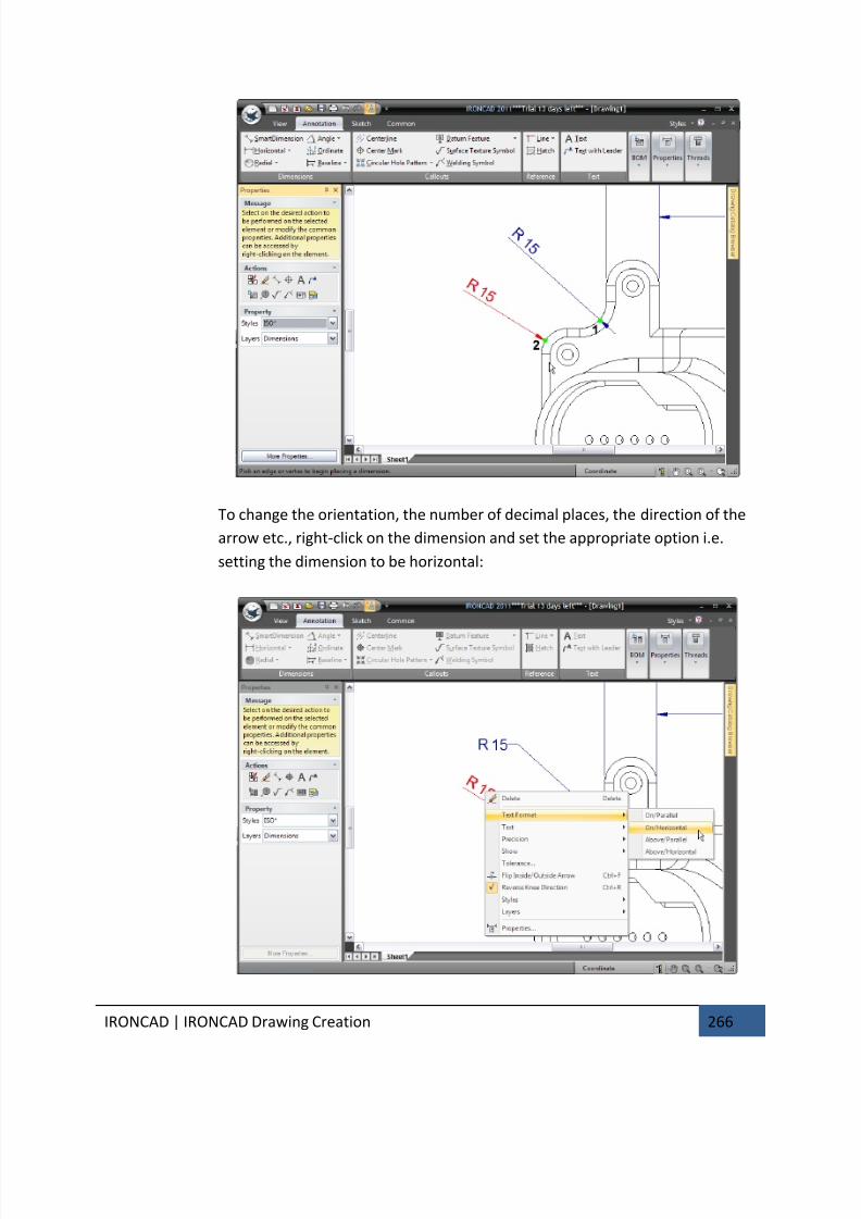
7/30/2019 Unlock Ironcadgsg
http://slidepdf.com/reader/full/unlock-ironcadgsg 270/367
IRONCAD | IRONCAD Drawing Creation 266
To change the orientation, the number of decimal places, the direction of the
arrow etc., right-click on the dimension and set the appropriate option i.e.
setting the dimension to be horizontal:
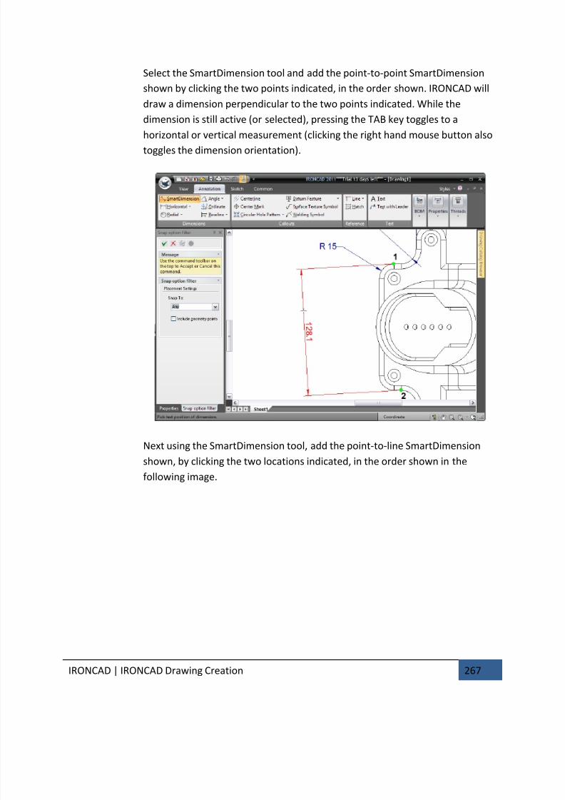
7/30/2019 Unlock Ironcadgsg
http://slidepdf.com/reader/full/unlock-ironcadgsg 271/367
IRONCAD | IRONCAD Drawing Creation 267
Select the SmartDimension tool and add the point-to-point SmartDimension
shown by clicking the two points indicated, in the order shown. IRONCAD will
draw a dimension perpendicular to the two points indicated. While the
dimension is still active (or selected), pressing the TAB key toggles to a
horizontal or vertical measurement (clicking the right hand mouse button alsotoggles the dimension orientation).
Next using the SmartDimension tool, add the point-to-line SmartDimension
shown, by clicking the two locations indicated, in the order shown in the
following image.
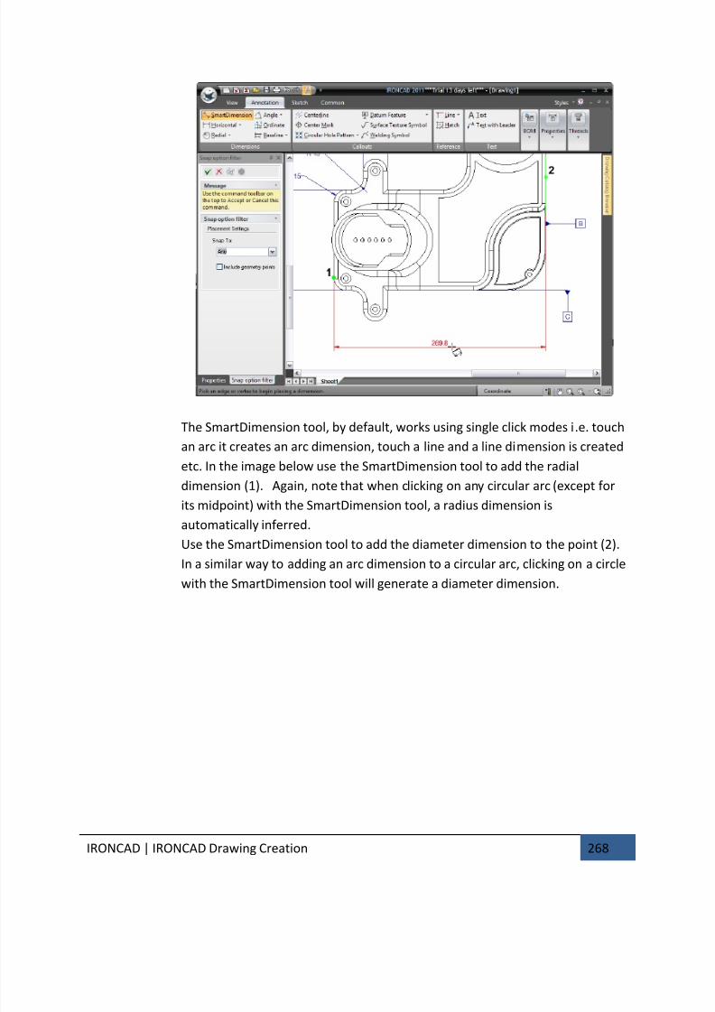
7/30/2019 Unlock Ironcadgsg
http://slidepdf.com/reader/full/unlock-ironcadgsg 272/367
IRONCAD | IRONCAD Drawing Creation 268
The SmartDimension tool, by default, works using single click modes i.e. touch
an arc it creates an arc dimension, touch a line and a line dimension is created
etc. In the image below use the SmartDimension tool to add the radial
dimension (1). Again, note that when clicking on any circular arc (except for
its midpoint) with the SmartDimension tool, a radius dimension is
automatically inferred.
Use the SmartDimension tool to add the diameter dimension to the point (2).
In a similar way to adding an arc dimension to a circular arc, clicking on a circle
with the SmartDimension tool will generate a diameter dimension.
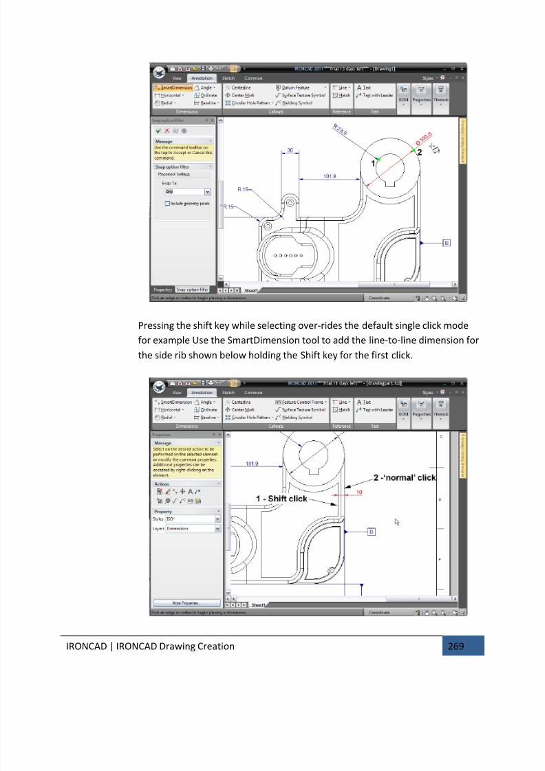
7/30/2019 Unlock Ironcadgsg
http://slidepdf.com/reader/full/unlock-ironcadgsg 273/367
IRONCAD | IRONCAD Drawing Creation 269
Pressing the shift key while selecting over-rides the default single click mode
for example Use the SmartDimension tool to add the line-to-line dimension for
the side rib shown below holding the Shift key for the first click.
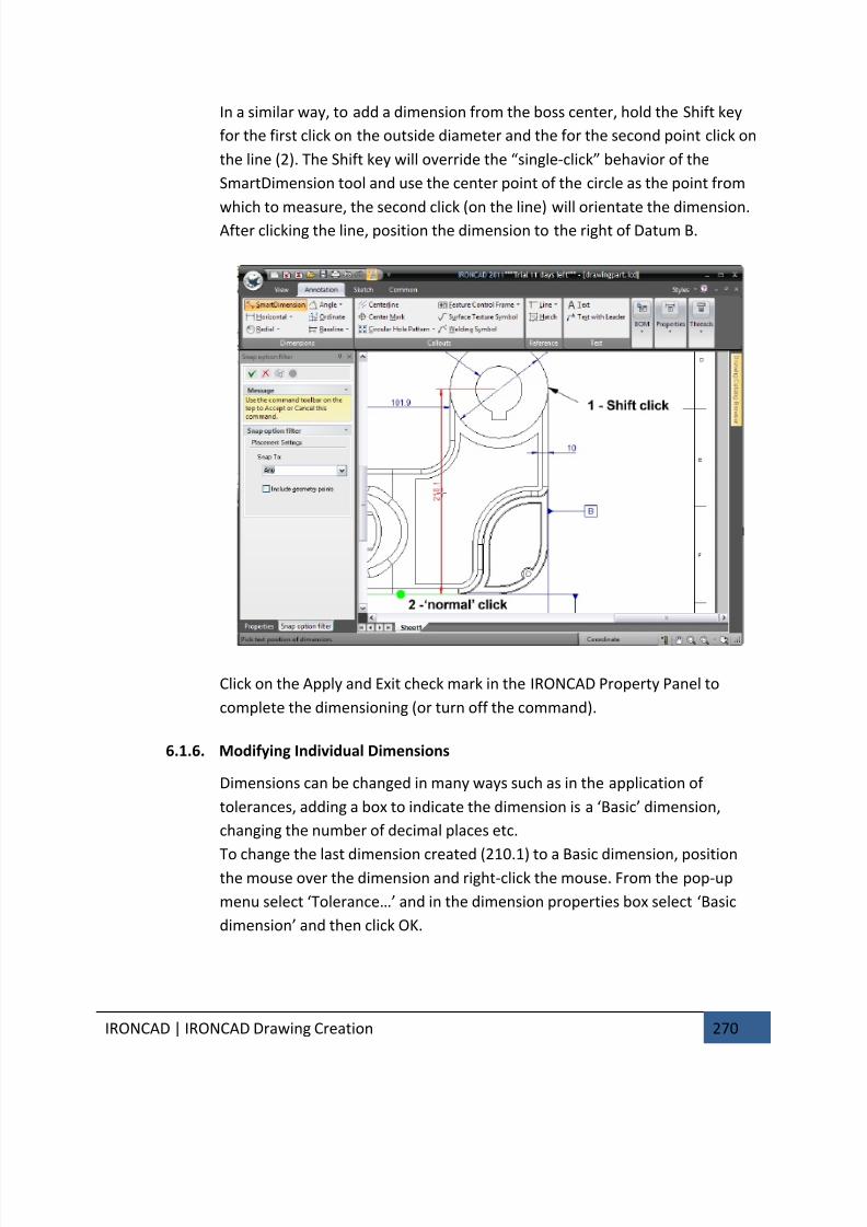
7/30/2019 Unlock Ironcadgsg
http://slidepdf.com/reader/full/unlock-ironcadgsg 274/367
IRONCAD | IRONCAD Drawing Creation 270
In a similar way, to add a dimension from the boss center, hold the Shift key
for the first click on the outside diameter and the for the second point click on
the line (2). The Shift key will override the “single-click” behavior of the
SmartDimension tool and use the center point of the circle as the point from
which to measure, the second click (on the line) will orientate the dimension.After clicking the line, position the dimension to the right of Datum B.
Click on the Apply and Exit check mark in the IRONCAD Property Panel to
complete the dimensioning (or turn off the command).
6.1.6. Modifying Individual Dimensions
Dimensions can be changed in many ways such as in the application of
tolerances, adding a box to indicate the dimension is a ‘Basic’ dimension,
changing the number of decimal places etc.
To change the last dimension created (210.1) to a Basic dimension, positionthe mouse over the dimension and right-click the mouse. From the pop-up
menu select ‘Tolerance…’ and in the dimension properties box select ‘Basic
dimension’ and then click OK.
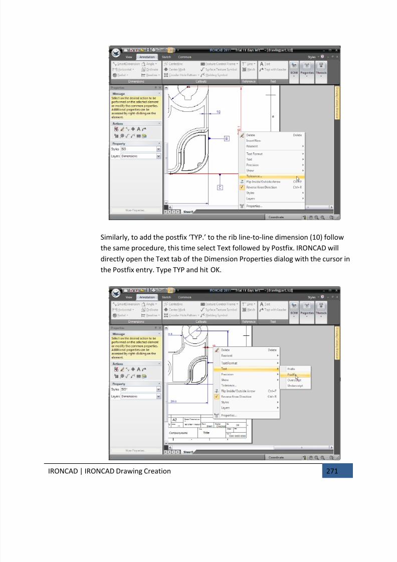
7/30/2019 Unlock Ironcadgsg
http://slidepdf.com/reader/full/unlock-ironcadgsg 275/367
IRONCAD | IRONCAD Drawing Creation 271
Similarly, to add the postfix ‘TYP.’ to the rib line-to-line dimension (10) follow
the same procedure, this time select Text followed by Postfix. IRONCAD will
directly open the Text tab of the Dimension Properties dialog with the cursor in
the Postfix entry. Type TYP and hit OK.
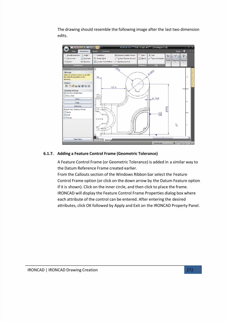
7/30/2019 Unlock Ironcadgsg
http://slidepdf.com/reader/full/unlock-ironcadgsg 276/367
IRONCAD | IRONCAD Drawing Creation 272
The drawing should resemble the following image after the last two dimension
edits.
6.1.7. Adding a Feature Control Frame (Geometric Tolerance)
A Feature Control Frame (or Geometric Tolerance) is added in a similar way to
the Datum Reference Frame created earlier.From the Callouts section of the Windows Ribbon bar select the Feature
Control Frame option (or click on the down arrow by the Datum Feature option
if it is shown). Click on the inner circle, and then click to place the frame.
IRONCAD will display the Feature Control Frame Properties dialog box where
each attribute of the control can be entered. After entering the desired
attributes, click OK followed by Apply and Exit on the IRONCAD Property Panel.
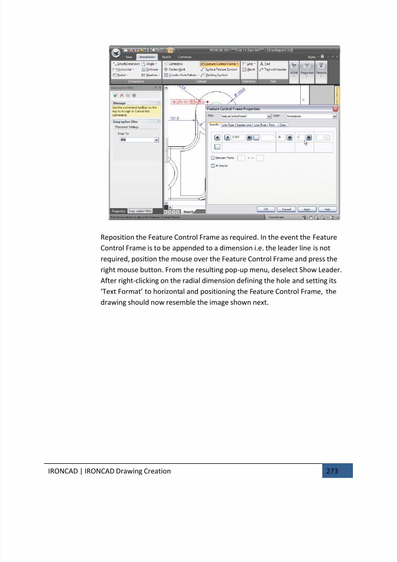
7/30/2019 Unlock Ironcadgsg
http://slidepdf.com/reader/full/unlock-ironcadgsg 277/367
IRONCAD | IRONCAD Drawing Creation 273
Reposition the Feature Control Frame as required. In the event the Feature
Control Frame is to be appended to a dimension i.e. the leader line is not
required, position the mouse over the Feature Control Frame and press the
right mouse button. From the resulting pop-up menu, deselect Show Leader.
After right-clicking on the radial dimension defining the hole and setting its
‘Text Format’ to horizontal and positioning the Feature Control Frame, the
drawing should now resemble the image shown next.
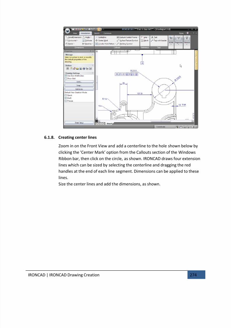
7/30/2019 Unlock Ironcadgsg
http://slidepdf.com/reader/full/unlock-ironcadgsg 278/367
IRONCAD | IRONCAD Drawing Creation 274
6.1.8. Creating center lines
Zoom in on the Front View and add a centerline to the hole shown below by
clicking the ‘Center Mark’ option from the Callouts section of the Windows
Ribbon bar, then click on the circle, as shown. IRONCAD draws four extension
lines which can be sized by selecting the centerline and dragging the red
handles at the end of each line segment. Dimensions can be applied to theselines.
Size the center lines and add the dimensions, as shown.
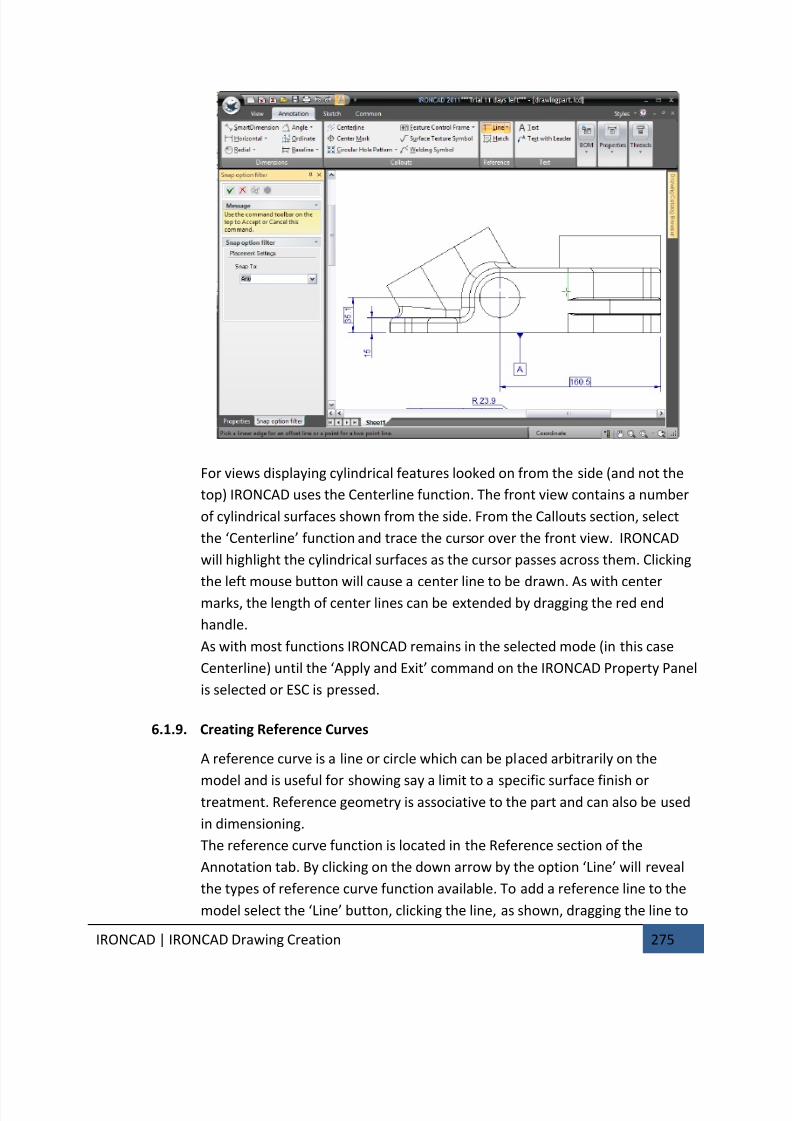
7/30/2019 Unlock Ironcadgsg
http://slidepdf.com/reader/full/unlock-ironcadgsg 279/367
IRONCAD | IRONCAD Drawing Creation 275
For views displaying cylindrical features looked on from the side (and not the
top) IRONCAD uses the Centerline function. The front view contains a number
of cylindrical surfaces shown from the side. From the Callouts section, select
the ‘Centerline’ function and trace the cursor over the front view. IRONCAD
will highlight the cylindrical surfaces as the cursor passes across them. Clicking
the left mouse button will cause a center line to be drawn. As with center
marks, the length of center lines can be extended by dragging the red end
handle.
As with most functions IRONCAD remains in the selected mode (in this case
Centerline) until the ‘Apply and Exit’ command on the IRONCAD Property Panel
is selected or ESC is pressed.
6.1.9. Creating Reference Curves
A reference curve is a line or circle which can be placed arbitrarily on the
model and is useful for showing say a limit to a specific surface finish ortreatment. Reference geometry is associative to the part and can also be used
in dimensioning.
The reference curve function is located in the Reference section of the
Annotation tab. By clicking on the down arrow by the option ‘Line’ will reveal
the types of reference curve function available. To add a reference line to the
model select the ‘Line’ button, clicking the line, as shown, dragging the line to
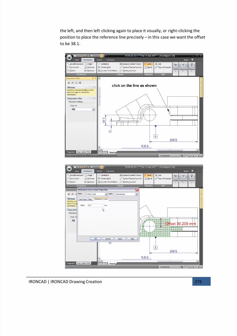
7/30/2019 Unlock Ironcadgsg
http://slidepdf.com/reader/full/unlock-ironcadgsg 280/367
IRONCAD | IRONCAD Drawing Creation 276
the left, and then left clicking again to place it visually, or right-clicking the
position to place the reference line precisely – in this case we want the offset
to be 38.1.

7/30/2019 Unlock Ironcadgsg
http://slidepdf.com/reader/full/unlock-ironcadgsg 281/367
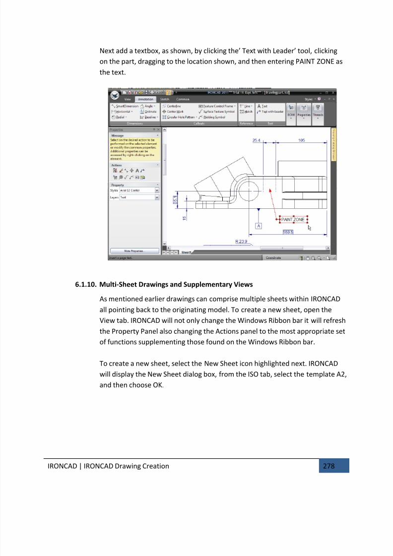
7/30/2019 Unlock Ironcadgsg
http://slidepdf.com/reader/full/unlock-ironcadgsg 282/367
IRONCAD | IRONCAD Drawing Creation 278
Next add a textbox, as shown, by clicking the’ Text with Leader’ tool, clicking
on the part, dragging to the location shown, and then entering PAINT ZONE as
the text.
6.1.10. Multi-Sheet Drawings and Supplementary Views
As mentioned earlier drawings can comprise multiple sheets within IRONCAD
all pointing back to the originating model. To create a new sheet, open the
View tab. IRONCAD will not only change the Windows Ribbon bar it will refresh
the Property Panel also changing the Actions panel to the most appropriate set
of functions supplementing those found on the Windows Ribbon bar.
To create a new sheet, select the New Sheet icon highlighted next. IRONCAD
will display the New Sheet dialog box, from the ISO tab, select the template A2,
and then choose OK.
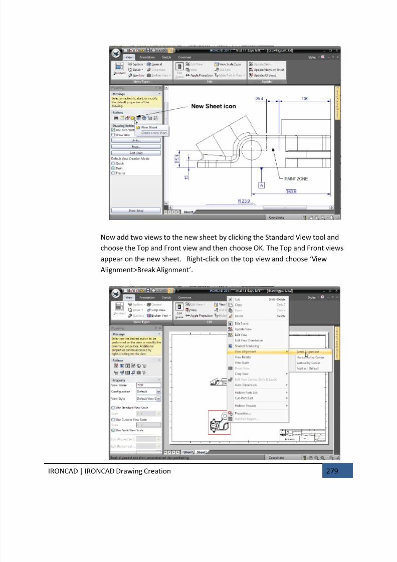
7/30/2019 Unlock Ironcadgsg
http://slidepdf.com/reader/full/unlock-ironcadgsg 283/367
IRONCAD | IRONCAD Drawing Creation 279
Now add two views to the new sheet by clicking the Standard View tool and
choose the Top and Front view and then choose OK. The Top and Front views
appear on the new sheet. Right-click on the top view and choose ‘View
Alignment>Break Alignment’.
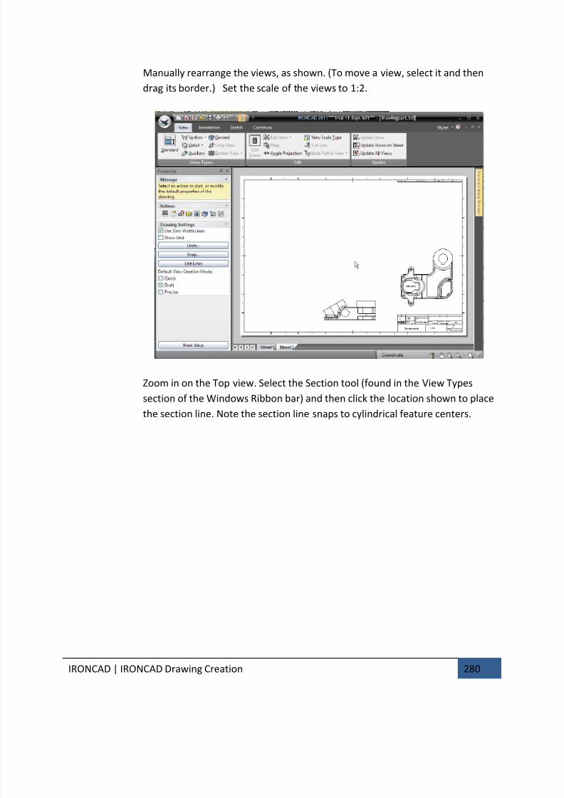
7/30/2019 Unlock Ironcadgsg
http://slidepdf.com/reader/full/unlock-ironcadgsg 284/367
IRONCAD | IRONCAD Drawing Creation 280
Manually rearrange the views, as shown. (To move a view, select it and then
drag its border.) Set the scale of the views to 1:2.
Zoom in on the Top view. Select the Section tool (found in the View Types
section of the Windows Ribbon bar) and then click the location shown to place
the section line. Note the section line snaps to cylindrical feature centers.
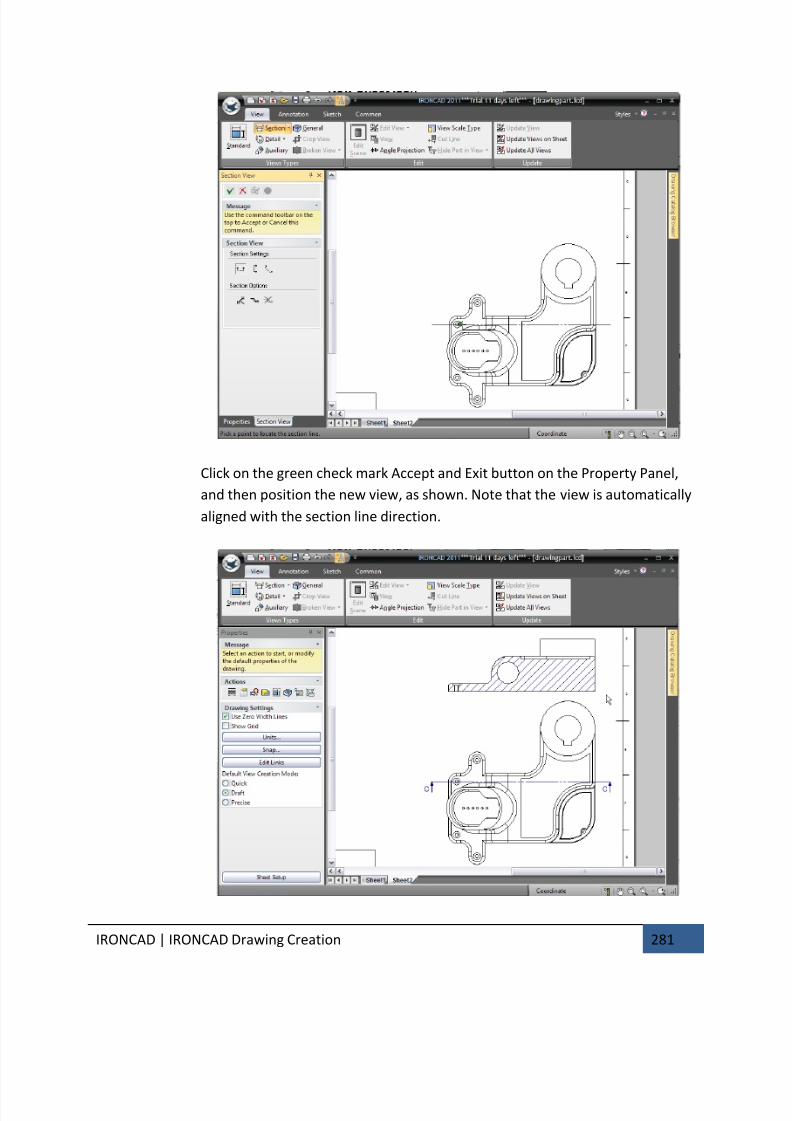
7/30/2019 Unlock Ironcadgsg
http://slidepdf.com/reader/full/unlock-ironcadgsg 285/367
IRONCAD | IRONCAD Drawing Creation 281
Click on the green check mark Accept and Exit button on the Property Panel,
and then position the new view, as shown. Note that the view is automatically
aligned with the section line direction.
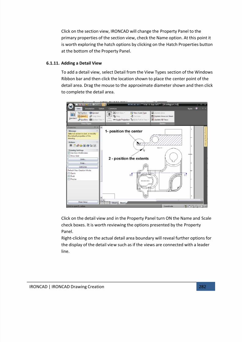
7/30/2019 Unlock Ironcadgsg
http://slidepdf.com/reader/full/unlock-ironcadgsg 286/367
IRONCAD | IRONCAD Drawing Creation 282
Click on the section view, IRONCAD will change the Property Panel to the
primary properties of the section view, check the Name option. At this point it
is worth exploring the hatch options by clicking on the Hatch Properties button
at the bottom of the Property Panel.
6.1.11. Adding a Detail View
To add a detail view, select Detail from the View Types section of the Windows
Ribbon bar and then click the location shown to place the center point of the
detail area. Drag the mouse to the approximate diameter shown and then click
to complete the detail area.
Click on the detail view and in the Property Panel turn ON the Name and Scale
check boxes. It is worth reviewing the options presented by the Property
Panel.
Right-clicking on the actual detail area boundary will reveal further options forthe display of the detail view such as if the views are connected with a leader
line.
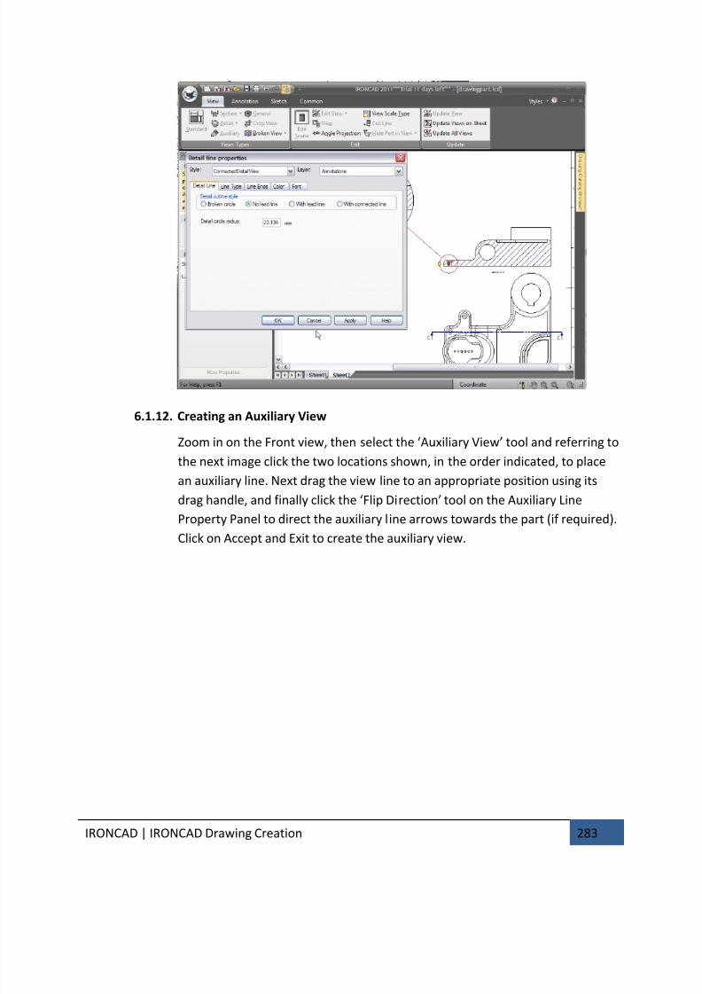
7/30/2019 Unlock Ironcadgsg
http://slidepdf.com/reader/full/unlock-ironcadgsg 287/367
IRONCAD | IRONCAD Drawing Creation 283
6.1.12. Creating an Auxiliary View
Zoom in on the Front view, then select the ‘Auxiliary View’ tool and referring to
the next image click the two locations shown, in the order indicated, to place
an auxiliary line. Next drag the view line to an appropriate position using its
drag handle, and finally click the ‘Flip Direction’ tool on the Auxiliary Line
Property Panel to direct the auxiliary line arrows towards the part (if required).Click on Accept and Exit to create the auxiliary view.
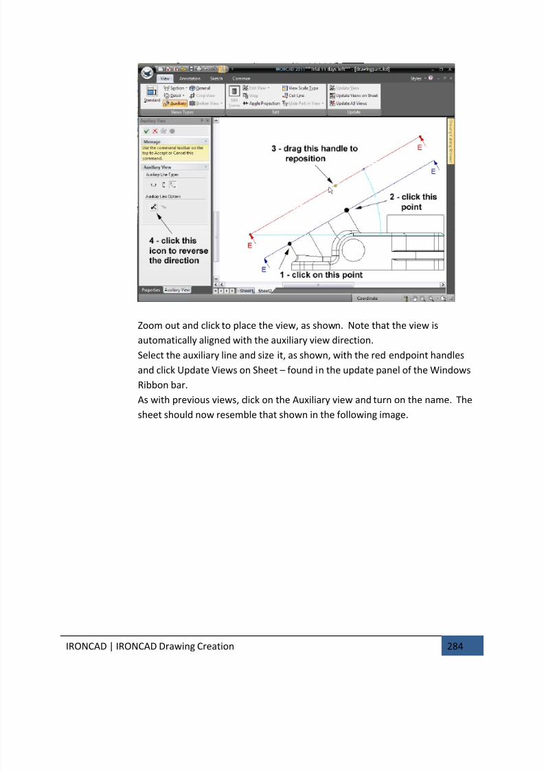
7/30/2019 Unlock Ironcadgsg
http://slidepdf.com/reader/full/unlock-ironcadgsg 288/367
IRONCAD | IRONCAD Drawing Creation 284
Zoom out and click to place the view, as shown. Note that the view is
automatically aligned with the auxiliary view direction.
Select the auxiliary line and size it, as shown, with the red endpoint handles
and click Update Views on Sheet – found in the update panel of the Windows
Ribbon bar.
As with previous views, click on the Auxiliary view and turn on the name. The
sheet should now resemble that shown in the following image.
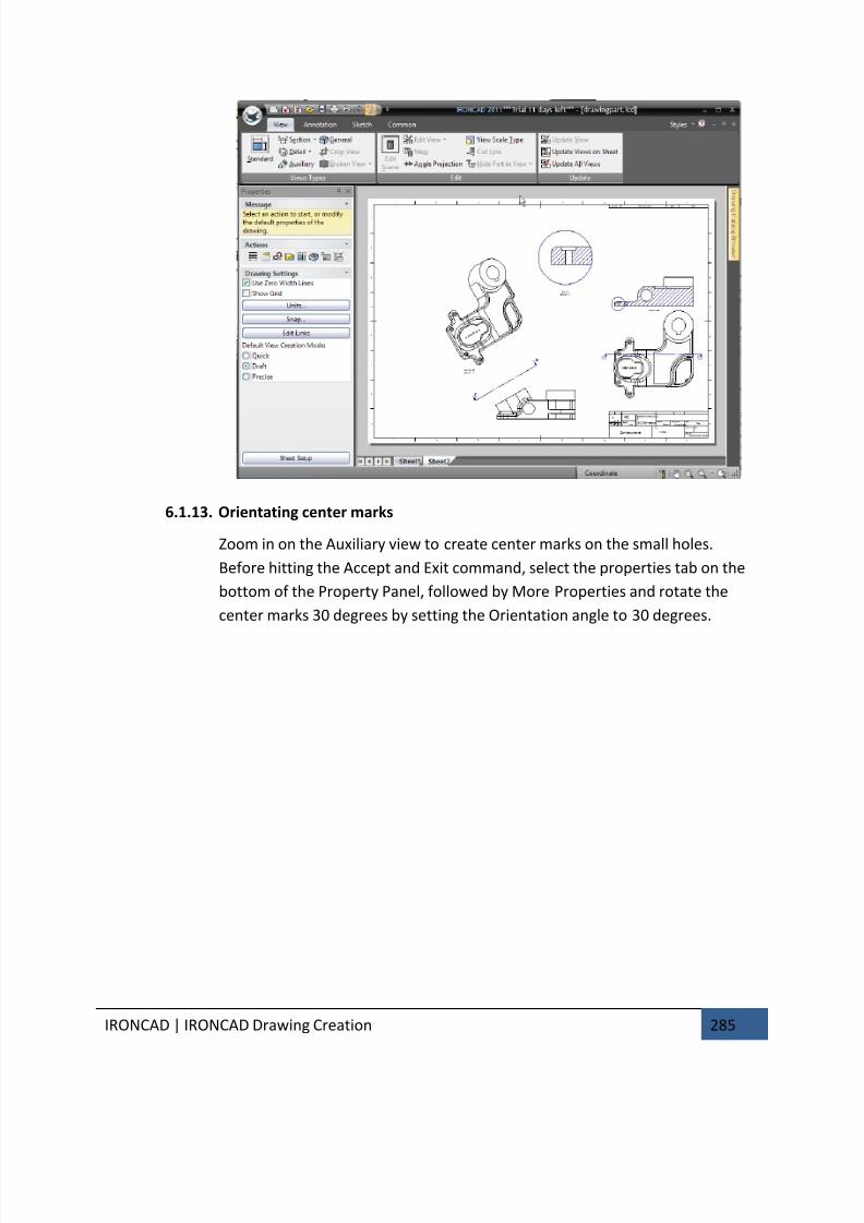
7/30/2019 Unlock Ironcadgsg
http://slidepdf.com/reader/full/unlock-ironcadgsg 289/367
IRONCAD | IRONCAD Drawing Creation 285
6.1.13. Orientating center marks
Zoom in on the Auxiliary view to create center marks on the small holes.
Before hitting the Accept and Exit command, select the properties tab on the
bottom of the Property Panel, followed by More Properties and rotate the
center marks 30 degrees by setting the Orientation angle to 30 degrees.
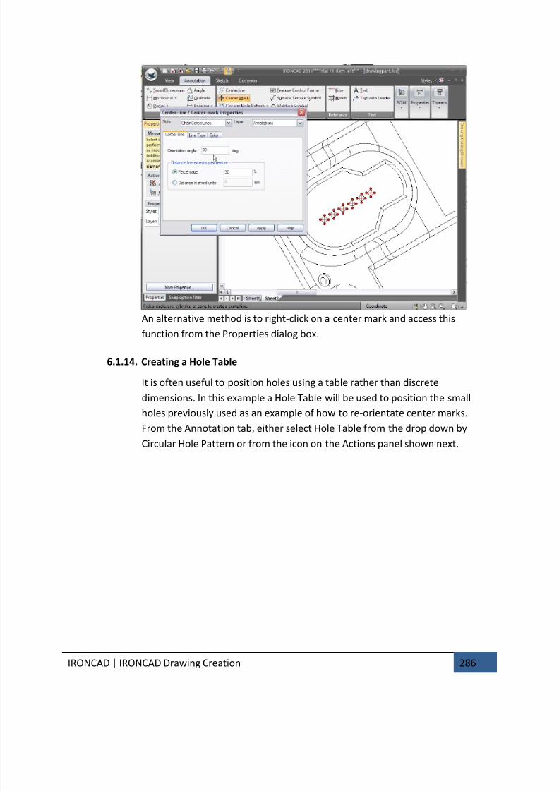
7/30/2019 Unlock Ironcadgsg
http://slidepdf.com/reader/full/unlock-ironcadgsg 290/367
IRONCAD | IRONCAD Drawing Creation 286
An alternative method is to right-click on a center mark and access this
function from the Properties dialog box.
6.1.14. Creating a Hole Table
It is often useful to position holes using a table rather than discrete
dimensions. In this example a Hole Table will be used to position the small
holes previously used as an example of how to re-orientate center marks.From the Annotation tab, either select Hole Table from the drop down by
Circular Hole Pattern or from the icon on the Actions panel shown next.

7/30/2019 Unlock Ironcadgsg
http://slidepdf.com/reader/full/unlock-ironcadgsg 291/367
IRONCAD | IRONCAD Drawing Creation 287
IRONCAD will produce an empty hole table, place the Hole Table anywhere on
the sheet. The hole table can be repositioned later.
IRONCAD needs to know the X and Y direction for the hole table, click the
centerlines of the first hole to define the X and Y axes for the Hole Table
zooming in if necessary.
Now click each of the remaining holes to be included in the Hole Table, the
cursor will highlight the hole before selecting it. After selecting the last hole
hit the Esc key.
Zoom out and position the Hole Table in a more appropriate place. If the Hole
Table axes point the wrong way, reverse them by right-clicking on the X-Y
origin symbols and choosing the appropriate action. Additionally the hole
labels can be repositioned for clarity by clicking on each label and dragging it to
a clearer position Modify the display using the properties of the Hole Table so
that the view resembles the next image.
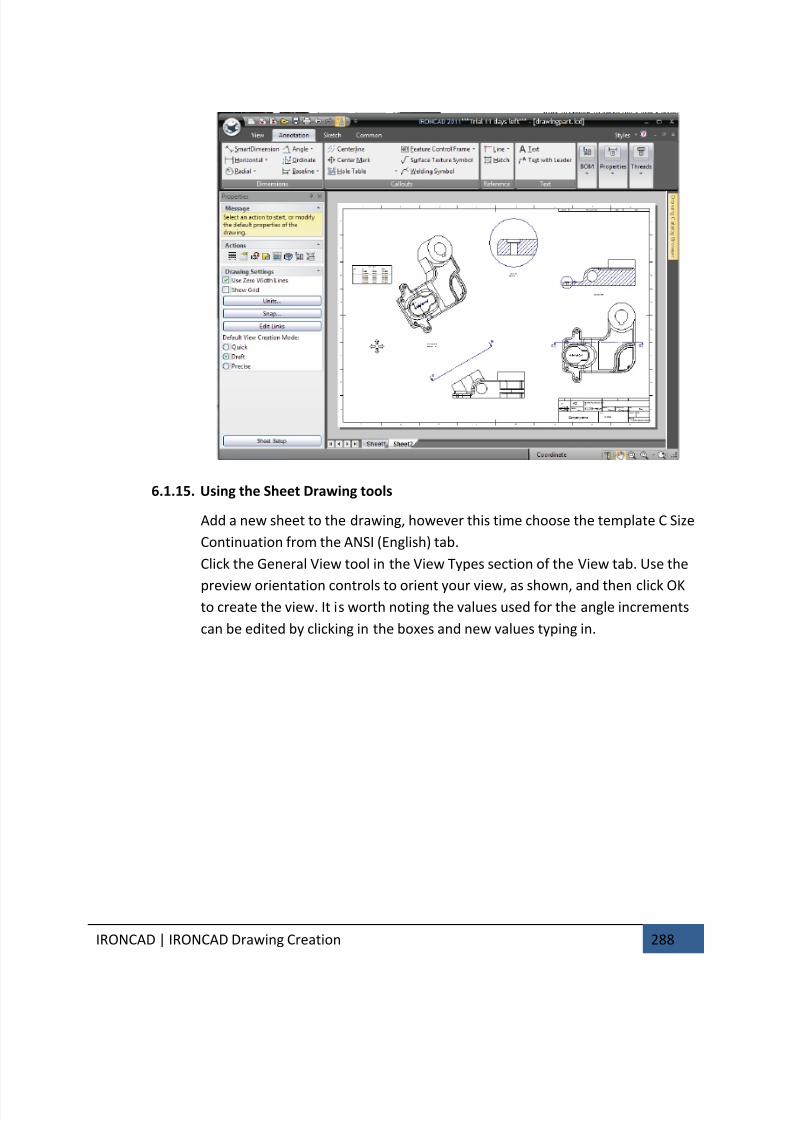
7/30/2019 Unlock Ironcadgsg
http://slidepdf.com/reader/full/unlock-ironcadgsg 292/367
IRONCAD | IRONCAD Drawing Creation 288
6.1.15. Using the Sheet Drawing tools
Add a new sheet to the drawing, however this time choose the template C Size
Continuation from the ANSI (English) tab.
Click the General View tool in the View Types section of the View tab. Use the
preview orientation controls to orient your view, as shown, and then click OKto create the view. It is worth noting the values used for the angle increments
can be edited by clicking in the boxes and new values typing in.
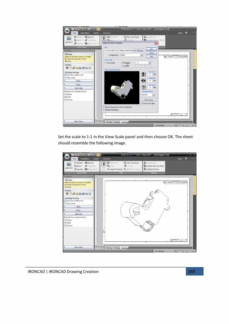
7/30/2019 Unlock Ironcadgsg
http://slidepdf.com/reader/full/unlock-ironcadgsg 293/367
IRONCAD | IRONCAD Drawing Creation 289
Set the scale to 1:1 in the View Scale panel and then choose OK. The sheet
should resemble the following image.
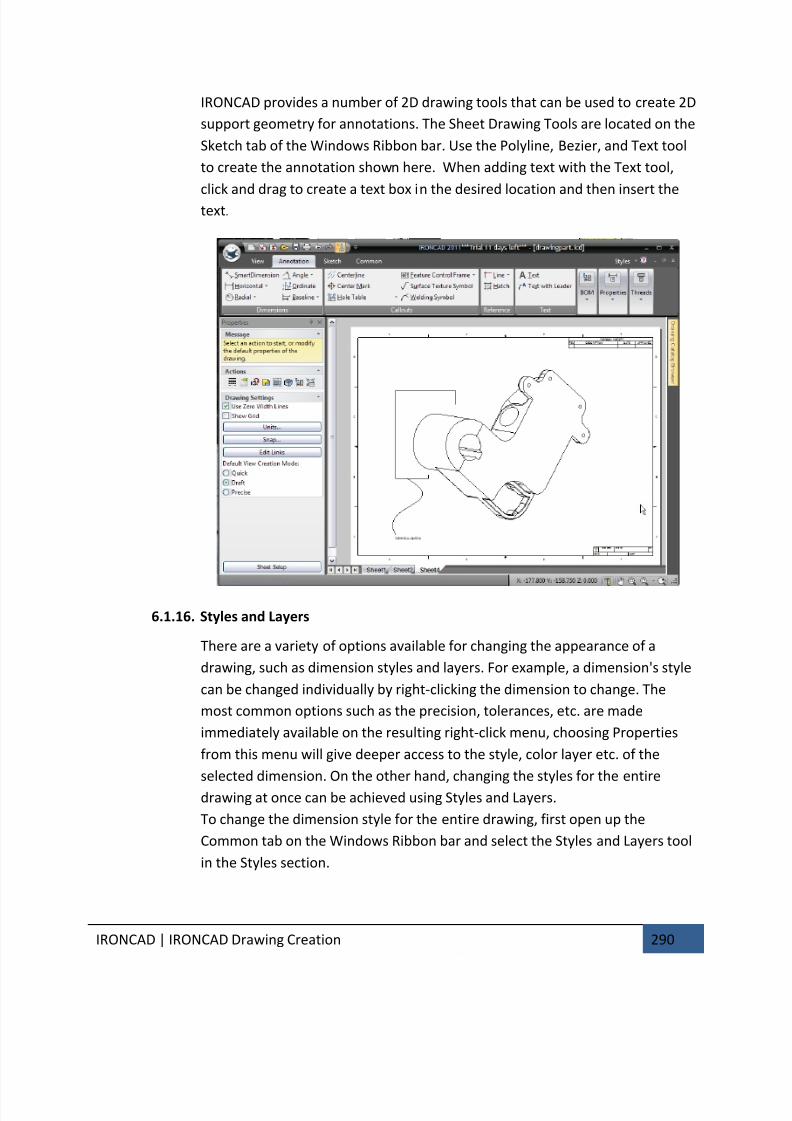
7/30/2019 Unlock Ironcadgsg
http://slidepdf.com/reader/full/unlock-ironcadgsg 294/367
IRONCAD | IRONCAD Drawing Creation 290
IRONCAD provides a number of 2D drawing tools that can be used to create 2D
support geometry for annotations. The Sheet Drawing Tools are located on the
Sketch tab of the Windows Ribbon bar. Use the Polyline, Bezier, and Text tool
to create the annotation shown here. When adding text with the Text tool,
click and drag to create a text box in the desired location and then insert thetext.
6.1.16. Styles and Layers
There are a variety of options available for changing the appearance of a
drawing, such as dimension styles and layers. For example, a dimension's style
can be changed individually by right-clicking the dimension to change. The
most common options such as the precision, tolerances, etc. are made
immediately available on the resulting right-click menu, choosing Properties
from this menu will give deeper access to the style, color layer etc. of the
selected dimension. On the other hand, changing the styles for the entire
drawing at once can be achieved using Styles and Layers.
To change the dimension style for the entire drawing, first open up the
Common tab on the Windows Ribbon bar and select the Styles and Layers tool
in the Styles section.
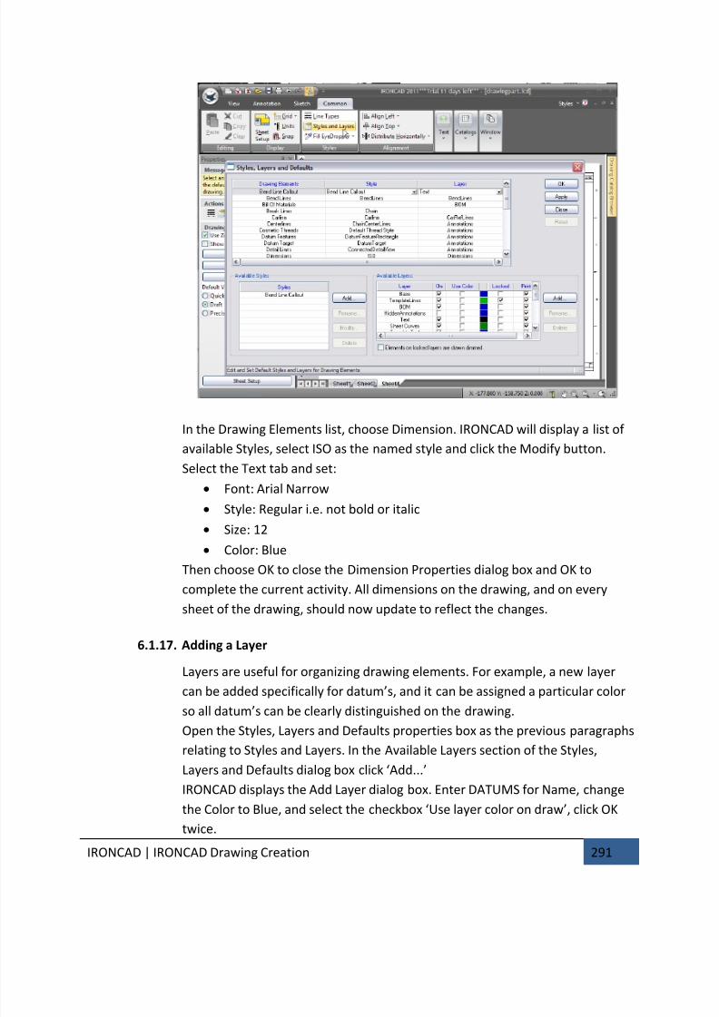
7/30/2019 Unlock Ironcadgsg
http://slidepdf.com/reader/full/unlock-ironcadgsg 295/367
IRONCAD | IRONCAD Drawing Creation 291
In the Drawing Elements list, choose Dimension. IRONCAD will display a list of
available Styles, select ISO as the named style and click the Modify button.
Select the Text tab and set:
• Font: Arial Narrow
• Style: Regular i.e. not bold or italic
• Size: 12
• Color: Blue
Then choose OK to close the Dimension Properties dialog box and OK to
complete the current activity. All dimensions on the drawing, and on every
sheet of the drawing, should now update to reflect the changes.
6.1.17. Adding a Layer
Layers are useful for organizing drawing elements. For example, a new layer
can be added specifically for datum’s, and it can be assigned a particular color
so all datum’s can be clearly distinguished on the drawing.Open the Styles, Layers and Defaults properties box as the previous paragraphs
relating to Styles and Layers. In the Available Layers section of the Styles,
Layers and Defaults dialog box click ‘Add...’
IRONCAD displays the Add Layer dialog box. Enter DATUMS for Name, change
the Color to Blue, and select the checkbox ‘Use layer color on draw’, click OK
twice.
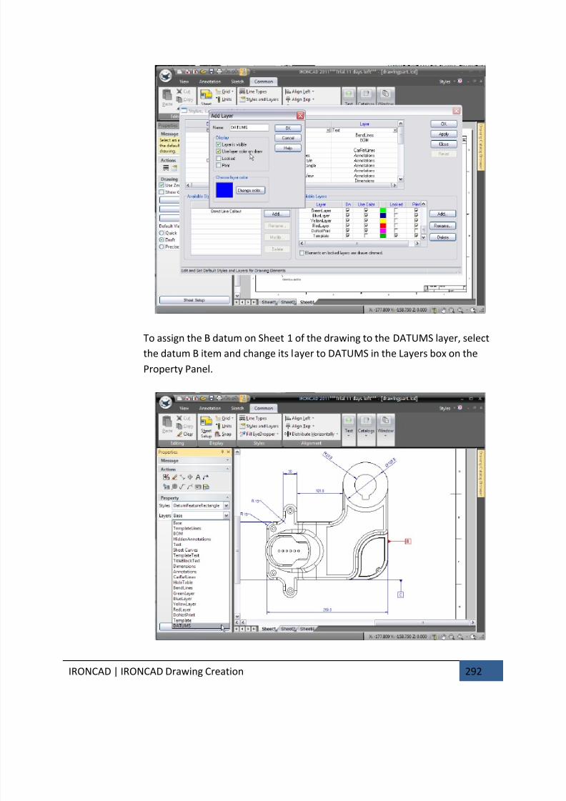
7/30/2019 Unlock Ironcadgsg
http://slidepdf.com/reader/full/unlock-ironcadgsg 296/367
IRONCAD | IRONCAD Drawing Creation 292
To assign the B datum on Sheet 1 of the drawing to the DATUMS layer, select
the datum B item and change its layer to DATUMS in the Layers box on the
Property Panel.
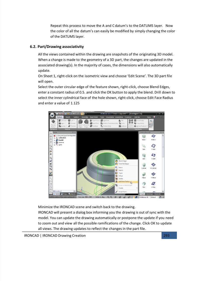
7/30/2019 Unlock Ironcadgsg
http://slidepdf.com/reader/full/unlock-ironcadgsg 297/367
IRONCAD | IRONCAD Drawing Creation 293
Repeat this process to move the A and C datum’s to the DATUMS layer. Now
the color of all the datum’s can easily be modified by simply changing the color
of the DATUMS layer.
6.2. Part/Drawing associativity
All the views contained within the drawing are snapshots of the originating 3D model.
When a change is made to the geometry of a 3D part, the changes are updated in the
associated drawing(s). In the majority of cases, the dimensions will also automatically
update.
On Sheet 1, right-click on the isometric view and choose ‘Edit Scene’. The 3D part file
will open.
Select the outer circular edge of the feature shown, right-click, choose Blend Edges,
enter a constant radius of 0.5, and click the OK button to apply the blend. Drill down to
select the inner cylindrical face of the hole shown, right-click, choose Edit Face Radiusand enter a value of 1.125
Minimize the IRONCAD scene and switch back to the drawing.
IRONCAD will present a dialog box informing you the drawing is out of sync with the
model. You can update the drawing automatically or postpone the update if you need
to zoom out and view all the possible ramifications of the change. Click OK to update
all views. The drawing updates to reflect the changes in the part file.
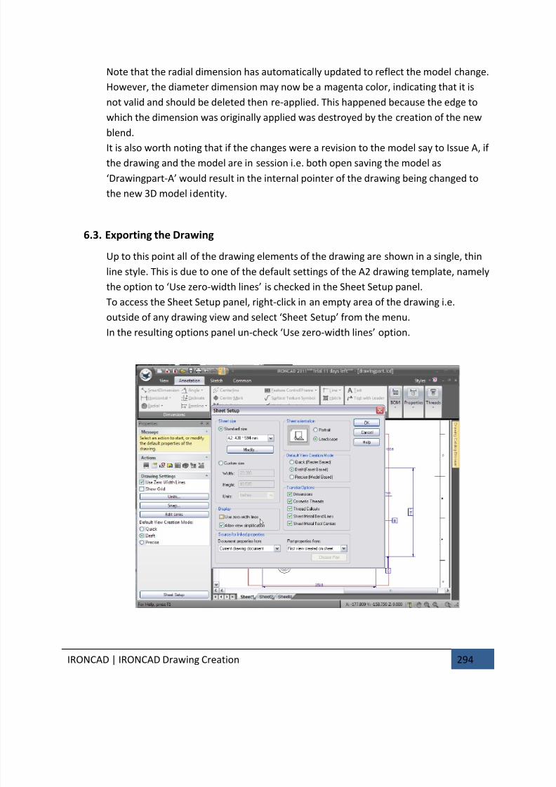
7/30/2019 Unlock Ironcadgsg
http://slidepdf.com/reader/full/unlock-ironcadgsg 298/367
IRONCAD | IRONCAD Drawing Creation 294
Note that the radial dimension has automatically updated to reflect the model change.
However, the diameter dimension may now be a magenta color, indicating that it is
not valid and should be deleted then re-applied. This happened because the edge to
which the dimension was originally applied was destroyed by the creation of the new
blend.It is also worth noting that if the changes were a revision to the model say to Issue A, if
the drawing and the model are in session i.e. both open saving the model as
‘Drawingpart-A’ would result in the internal pointer of the drawing being changed to
the new 3D model identity.
6.3. Exporting the Drawing
Up to this point all of the drawing elements of the drawing are shown in a single, thin
line style. This is due to one of the default settings of the A2 drawing template, namelythe option to ‘Use zero-width lines’ is checked in the Sheet Setup panel.
To access the Sheet Setup panel, right-click in an empty area of the drawing i.e.
outside of any drawing view and select ‘Sheet Setup’ from the menu.
In the resulting options panel un-check ‘Use zero-width lines’ option.
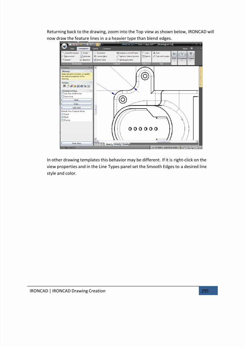
7/30/2019 Unlock Ironcadgsg
http://slidepdf.com/reader/full/unlock-ironcadgsg 299/367
IRONCAD | IRONCAD Drawing Creation 295
Returning back to the drawing, zoom into the Top view as shown below, IRONCAD will
now draw the feature lines in a a heavier type than blend edges.
In other drawing templates this behavior may be different. If it is right-click on the
view properties and in the Line Types panel set the Smooth Edges to a desired line
style and color.
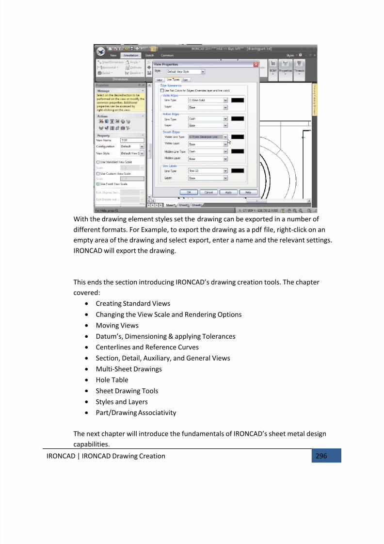
7/30/2019 Unlock Ironcadgsg
http://slidepdf.com/reader/full/unlock-ironcadgsg 300/367
IRONCAD | IRONCAD Drawing Creation 296
With the drawing element styles set the drawing can be exported in a number of
different formats. For Example, to export the drawing as a pdf file, right-click on an
empty area of the drawing and select export, enter a name and the relevant settings.
IRONCAD will export the drawing.
This ends the section introducing IRONCAD’s drawing creation tools. The chapter
covered:
• Creating Standard Views
• Changing the View Scale and Rendering Options
• Moving Views
• Datum’s, Dimensioning & applying Tolerances
• Centerlines and Reference Curves
• Section, Detail, Auxiliary, and General Views
• Multi-Sheet Drawings
• Hole Table• Sheet Drawing Tools
• Styles and Layers
• Part/Drawing Associativity
The next chapter will introduce the fundamentals of IRONCAD’s sheet metal design
capabilities.
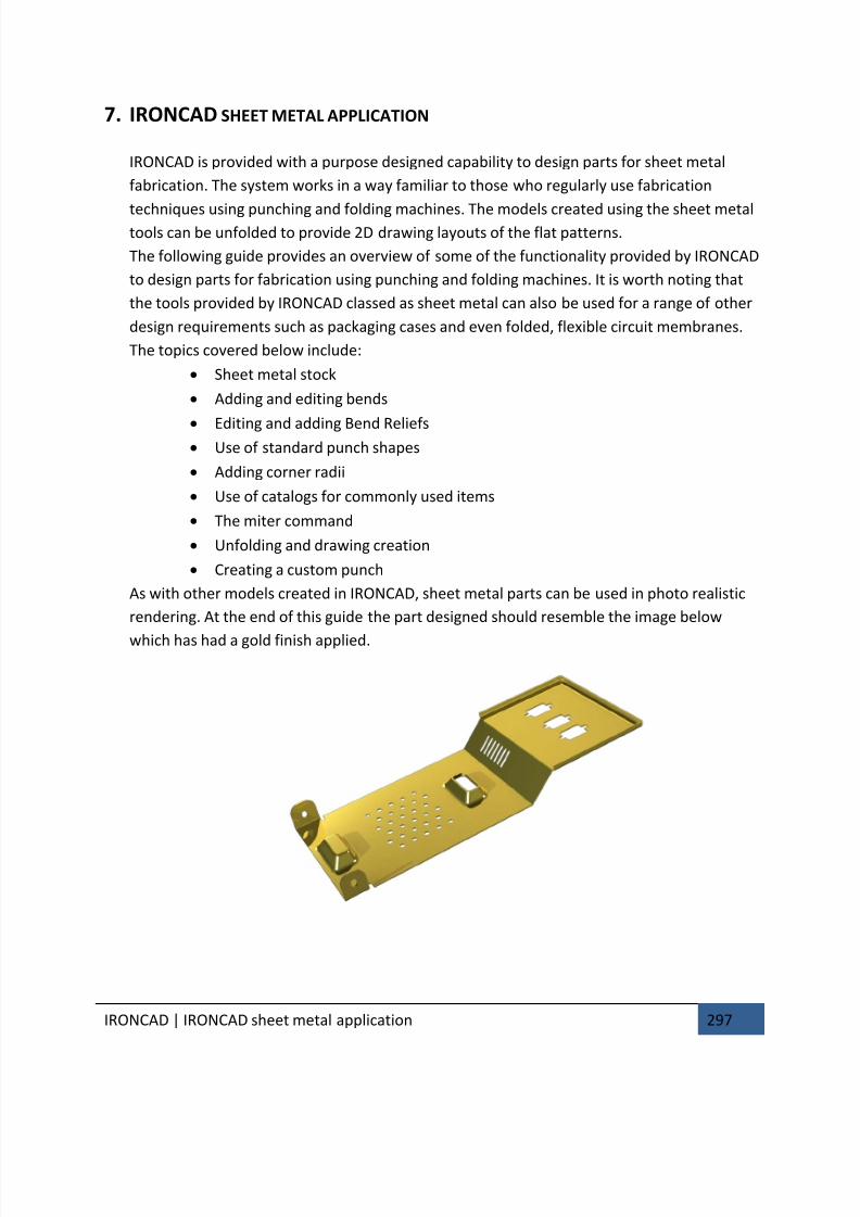
7/30/2019 Unlock Ironcadgsg
http://slidepdf.com/reader/full/unlock-ironcadgsg 301/367
IRONCAD | IRONCAD sheet metal application 297
7. IRONCAD SHEET METAL APPLICATION
IRONCAD is provided with a purpose designed capability to design parts for sheet metal
fabrication. The system works in a way familiar to those who regularly use fabrication
techniques using punching and folding machines. The models created using the sheet metaltools can be unfolded to provide 2D drawing layouts of the flat patterns.
The following guide provides an overview of some of the functionality provided by IRONCAD
to design parts for fabrication using punching and folding machines. It is worth noting that
the tools provided by IRONCAD classed as sheet metal can also be used for a range of other
design requirements such as packaging cases and even folded, flexible circuit membranes.
The topics covered below include:
• Sheet metal stock
• Adding and editing bends
• Editing and adding Bend Reliefs• Use of standard punch shapes
• Adding corner radii
• Use of catalogs for commonly used items
• The miter command
• Unfolding and drawing creation
• Creating a custom punch
As with other models created in IRONCAD, sheet metal parts can be used in photo realistic
rendering. At the end of this guide the part designed should resemble the image below
which has had a gold finish applied.
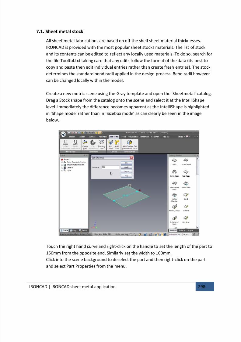
7/30/2019 Unlock Ironcadgsg
http://slidepdf.com/reader/full/unlock-ironcadgsg 302/367
IRONCAD | IRONCAD sheet metal application 298
7.1. Sheet metal stock
All sheet metal fabrications are based on off the shelf sheet material thicknesses.
IRONCAD is provided with the most popular sheet stocks materials. The list of stock
and its contents can be edited to reflect any locally used materials. To do so, search for
the file Tooltbl.txt taking care that any edits follow the format of the data (its best to
copy and paste then edit individual entries rather than create fresh entries). The stock
determines the standard bend radii applied in the design process. Bend radii however
can be changed locally within the model.
Create a new metric scene using the Gray template and open the ‘Sheetmetal’ catalog.
Drag a Stock shape from the catalog onto the scene and select it at the IntelliShape
level. Immediately the difference becomes apparent as the IntelliShape is highlighted
in ‘Shape mode’ rather than in ‘Sizebox mode’ as can clearly be seen in the image
below.
Touch the right hand curve and right-click on the handle to set the length of the part to
150mm from the opposite end. Similarly set the width to 100mm.
Click into the scene background to deselect the part and then right-click on the part
and select Part Properties from the menu.

7/30/2019 Unlock Ironcadgsg
http://slidepdf.com/reader/full/unlock-ironcadgsg 303/367
IRONCAD | IRONCAD sheet metal application 299
In the Sheet Metal Part properties box a dedicated tab is provided to control all
aspects of the standard part functions such as bend radius, bend calculation parameter
(k-factor) and a button for selecting new stock material. For this example the default
Aluminum 5052 – 18 will be used.
7.2. Adding a bend with stock
IRONCAD provides a number of options for adding a bend, some of which will be used
within this guide. Zoom into the model to get a clearer view of the right hand end of
the stock part as shown below.
Drag an ‘Out Bend w/Stock’ shape onto the top edge of the stock as shown. Indicating
the top edge of the stock will cause the bend to be upwards, the bottom edge wouldcause the bend to go downwards.
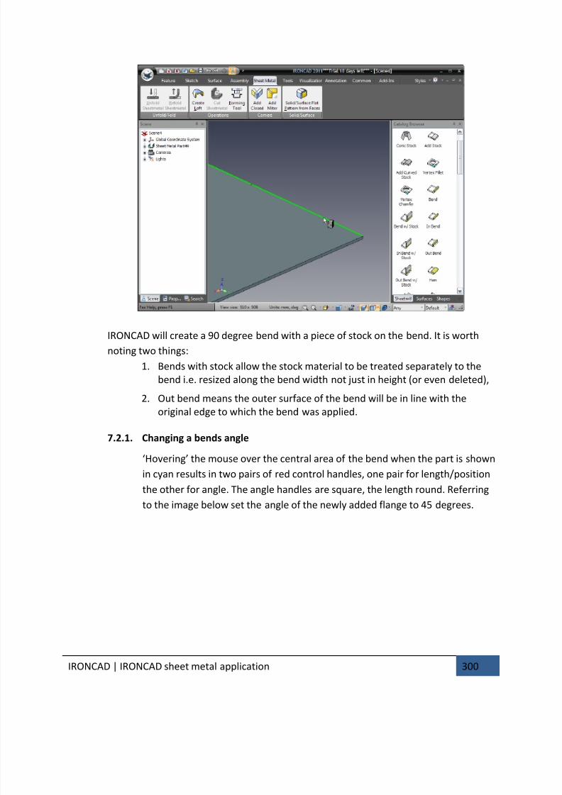
7/30/2019 Unlock Ironcadgsg
http://slidepdf.com/reader/full/unlock-ironcadgsg 304/367
IRONCAD | IRONCAD sheet metal application 300
IRONCAD will create a 90 degree bend with a piece of stock on the bend. It is worth
noting two things:
1. Bends with stock allow the stock material to be treated separately to the
bend i.e. resized along the bend width not just in height (or even deleted),
2. Out bend means the outer surface of the bend will be in line with the
original edge to which the bend was applied.
7.2.1. Changing a bends angle
‘Hovering’ the mouse over the central area of the bend when the part is shown
in cyan results in two pairs of red control handles, one pair for length/position
the other for angle. The angle handles are square, the length round. Referring
to the image below set the angle of the newly added flange to 45 degrees.
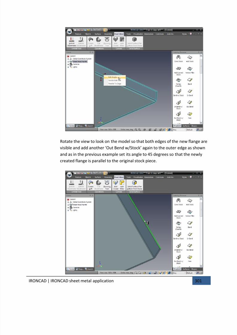
7/30/2019 Unlock Ironcadgsg
http://slidepdf.com/reader/full/unlock-ironcadgsg 305/367
IRONCAD | IRONCAD sheet metal application 301
Rotate the view to look on the model so that both edges of the new flange are
visible and add another ‘Out Bend w/Stock’ again to the outer edge as shown
and as in the previous example set its angle to 45 degrees so that the newly
created flange is parallel to the original stock piece.
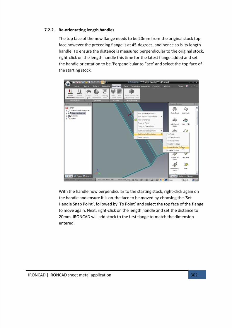
7/30/2019 Unlock Ironcadgsg
http://slidepdf.com/reader/full/unlock-ironcadgsg 306/367
IRONCAD | IRONCAD sheet metal application 302
7.2.2. Re-orientating length handles
The top face of the new flange needs to be 20mm from the original stock top
face however the preceding flange is at 45 degrees, and hence so is its length
handle. To ensure the distance is measured perpendicular to the original stock,
right-click on the length handle this time for the latest flange added and setthe handle orientation to be ‘Perpendicular to Face’ and select the top face of
the starting stock.
With the handle now perpendicular to the starting stock, right-click again on
the handle and ensure it is on the face to be moved by choosing the ‘Set
Handle Snap Point’, followed by ‘To Point’ and select the top face of the flange
to move again. Next, right-click on the length handle and set the distance to
20mm. IRONCAD will add stock to the first flange to match the dimension
entered.
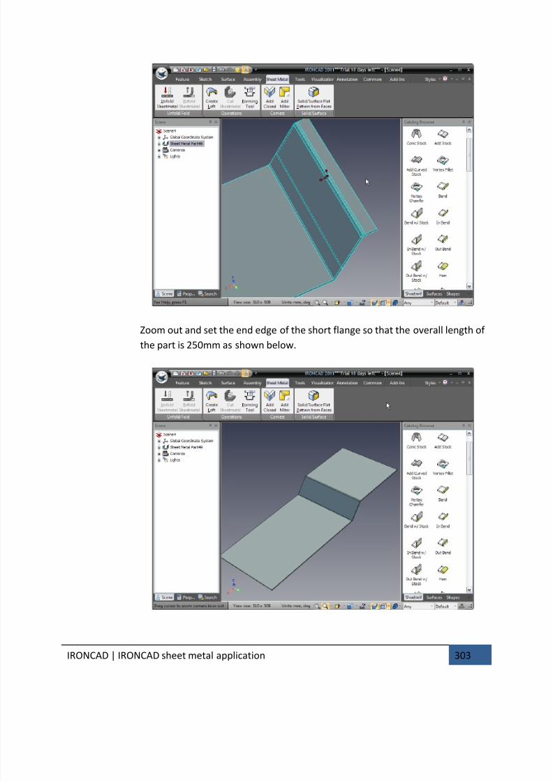
7/30/2019 Unlock Ironcadgsg
http://slidepdf.com/reader/full/unlock-ironcadgsg 307/367
IRONCAD | IRONCAD sheet metal application 303
Zoom out and set the end edge of the short flange so that the overall length of
the part is 250mm as shown below.

7/30/2019 Unlock Ironcadgsg
http://slidepdf.com/reader/full/unlock-ironcadgsg 308/367
IRONCAD | IRONCAD sheet metal application 304
7.3. Adding bends with combined stock
Previously the bends added had a separate stock shape added, these shapes add
flexibility to the stock. However there are circumstances where the stock applied with
the bend needs to be related to the bend. These shapes are identified in the catalog as
simply In Bend, Out Bend and Bend.
7.3.1. Bend
A Bend is an item where the actual bend portion is added onto the parent
stock and the attached stock simply added to the bend. The position of the
flange is determined by the size of the bend radius.
7.3.2. Out Bend
In this case the outer face of the added flange will be created in line with the
edge to which the bend is added.
7.3.3. In Bend
An In Bend is one where the inner face of the added flange is aligned with the
edge to which the bend is added.
In the following example the controlling size is from the width of the original stock
onto which the flanges are to be added i.e. the part will have to fit inside something, in
which case the appropriate type of bend would be an ‘Out Bend’. Add an ‘Out Bend’
shape from the catalog to the edge shown in the following image.
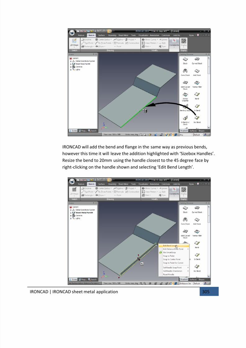
7/30/2019 Unlock Ironcadgsg
http://slidepdf.com/reader/full/unlock-ironcadgsg 309/367
IRONCAD | IRONCAD sheet metal application 305
IRONCAD will add the bend and flange in the same way as previous bends,
however this time it will leave the addition highlighted with ‘Sizebox Handles’.
Resize the bend to 20mm using the handle closest to the 45 degree face by
right-clicking on the handle shown and selecting ‘Edit Bend Length’.
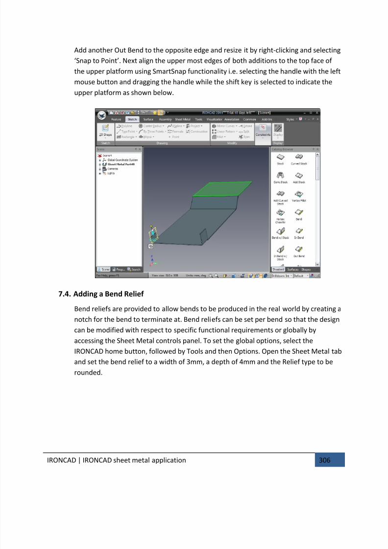
7/30/2019 Unlock Ironcadgsg
http://slidepdf.com/reader/full/unlock-ironcadgsg 310/367
IRONCAD | IRONCAD sheet metal application 306
Add another Out Bend to the opposite edge and resize it by right-clicking and selecting
‘Snap to Point’. Next align the upper most edges of both additions to the top face of
the upper platform using SmartSnap functionality i.e. selecting the handle with the left
mouse button and dragging the handle while the shift key is selected to indicate the
upper platform as shown below.
7.4. Adding a Bend Relief
Bend reliefs are provided to allow bends to be produced in the real world by creating a
notch for the bend to terminate at. Bend reliefs can be set per bend so that the design
can be modified with respect to specific functional requirements or globally by
accessing the Sheet Metal controls panel. To set the global options, select the
IRONCAD home button, followed by Tools and then Options. Open the Sheet Metal tab
and set the bend relief to a width of 3mm, a depth of 4mm and the Relief type to be
rounded.

7/30/2019 Unlock Ironcadgsg
http://slidepdf.com/reader/full/unlock-ironcadgsg 311/367
IRONCAD | IRONCAD sheet metal application 307
These settings will be applied to NEW sheet metal parts created from this point on.
Zoom into one of the new tabs created and select it at the IntelliShape level. IRONCAD
will display the tabs controlling handles for length angle height etc. and a mode button
very similar to the ‘Sizebox/Shape’ mode button of standard IntelliShapes. Click the
mode button to activate the bend relief handles/button.
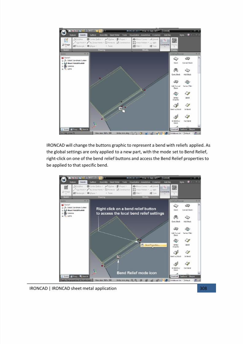
7/30/2019 Unlock Ironcadgsg
http://slidepdf.com/reader/full/unlock-ironcadgsg 312/367
IRONCAD | IRONCAD sheet metal application 308
IRONCAD will change the buttons graphic to represent a bend with reliefs applied. As
the global settings are only applied to a new part, with the mode set to Bend Relief,
right-click on one of the bend relief buttons and access the Bend Relief properties to
be applied to that specific bend.
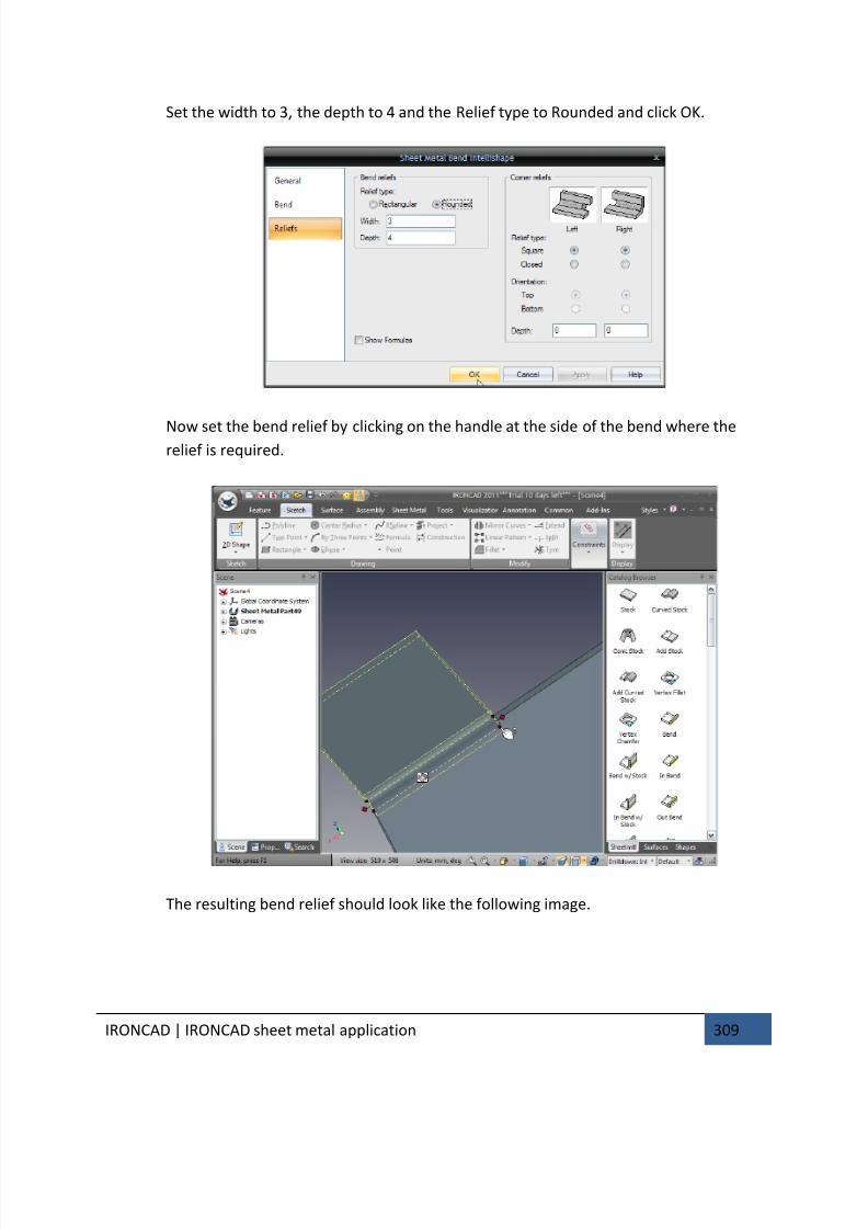
7/30/2019 Unlock Ironcadgsg
http://slidepdf.com/reader/full/unlock-ironcadgsg 313/367
IRONCAD | IRONCAD sheet metal application 309
Set the width to 3, the depth to 4 and the Relief type to Rounded and click OK.
Now set the bend relief by clicking on the handle at the side of the bend where therelief is required.
The resulting bend relief should look like the following image.
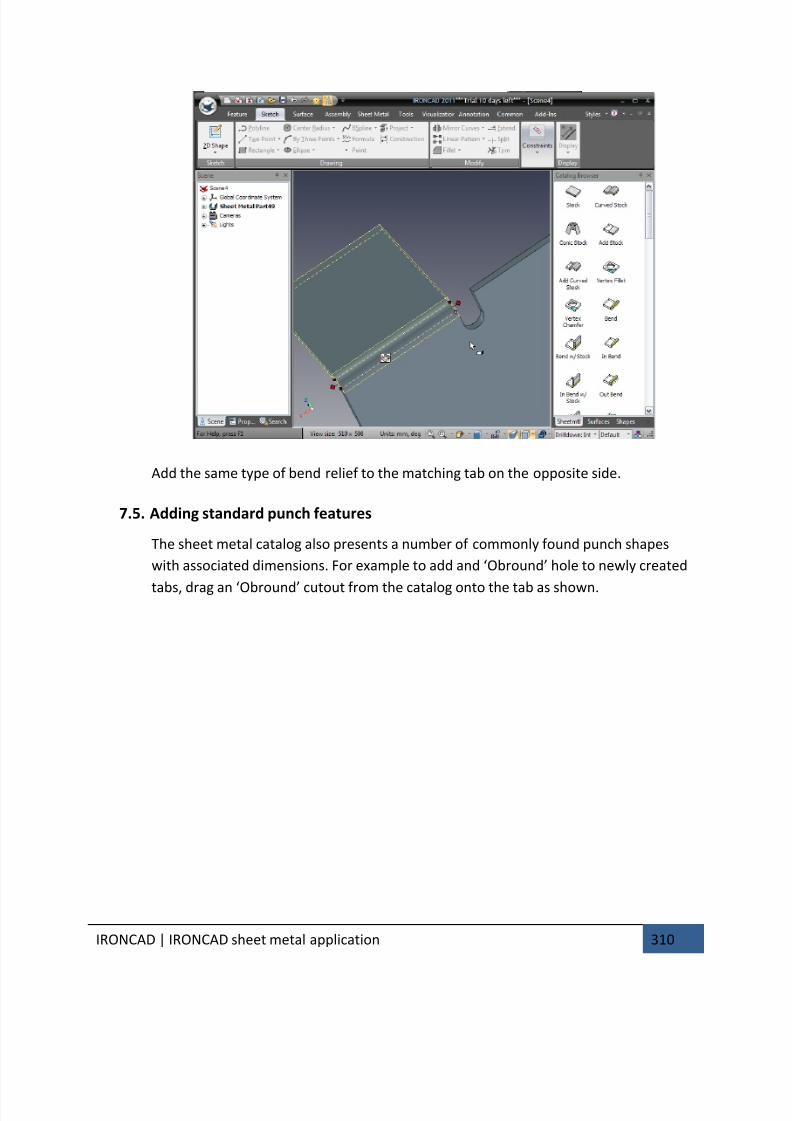
7/30/2019 Unlock Ironcadgsg
http://slidepdf.com/reader/full/unlock-ironcadgsg 314/367
IRONCAD | IRONCAD sheet metal application 310
Add the same type of bend relief to the matching tab on the opposite side.
7.5. Adding standard punch features
The sheet metal catalog also presents a number of commonly found punch shapes
with associated dimensions. For example to add and ‘Obround’ hole to newly created
tabs, drag an ‘Obround’ cutout from the catalog onto the tab as shown.
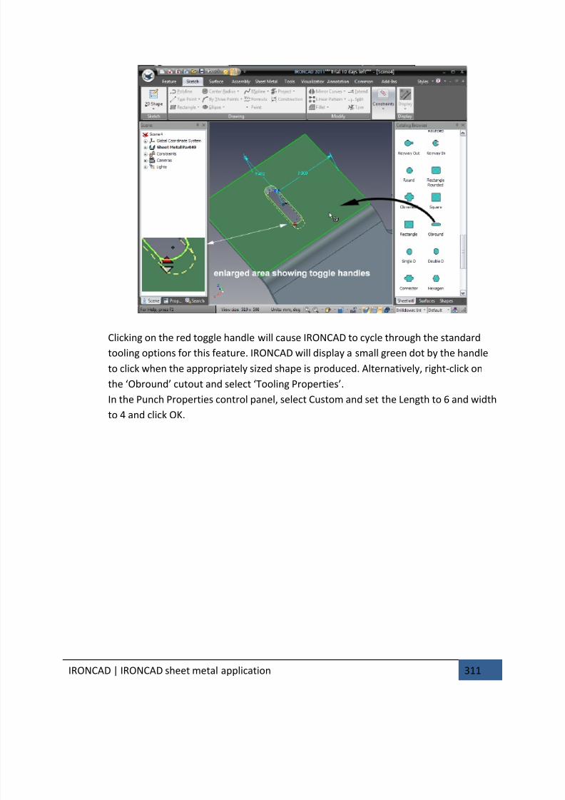
7/30/2019 Unlock Ironcadgsg
http://slidepdf.com/reader/full/unlock-ironcadgsg 315/367
IRONCAD | IRONCAD sheet metal application 311
Clicking on the red toggle handle will cause IRONCAD to cycle through the standard
tooling options for this feature. IRONCAD will display a small green dot by the handle
to click when the appropriately sized shape is produced. Alternatively, right-click on
the ‘Obround’ cutout and select ‘Tooling Properties’.
In the Punch Properties control panel, select Custom and set the Length to 6 and width
to 4 and click OK.
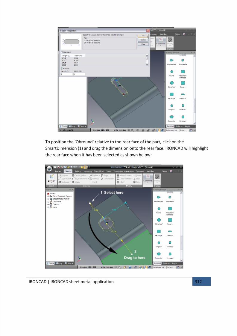
7/30/2019 Unlock Ironcadgsg
http://slidepdf.com/reader/full/unlock-ironcadgsg 316/367
IRONCAD | IRONCAD sheet metal application 312
To position the ‘Obround’ relative to the rear face of the part, click on the
SmartDimension (1) and drag the dimension onto the rear face. IRONCAD will highlight
the rear face when it has been selected as shown below:
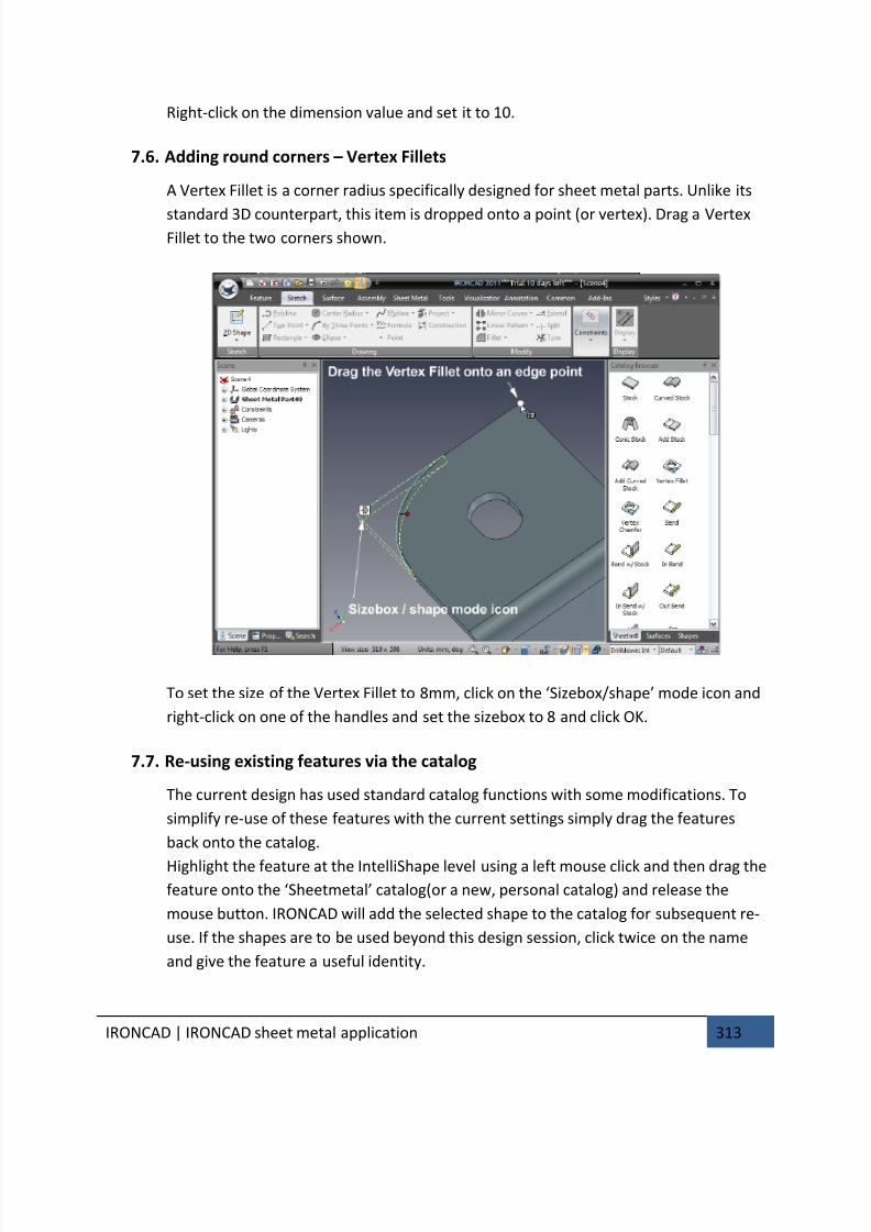
7/30/2019 Unlock Ironcadgsg
http://slidepdf.com/reader/full/unlock-ironcadgsg 317/367
IRONCAD | IRONCAD sheet metal application 313
Right-click on the dimension value and set it to 10.
7.6. Adding round corners – Vertex Fillets
A Vertex Fillet is a corner radius specifically designed for sheet metal parts. Unlike its
standard 3D counterpart, this item is dropped onto a point (or vertex). Drag a VertexFillet to the two corners shown.
To set the size of the Vertex Fillet to 8mm, click on the ‘Sizebox/shape’ mode icon and
right-click on one of the handles and set the sizebox to 8 and click OK.
7.7. Re-using existing features via the catalog
The current design has used standard catalog functions with some modifications. To
simplify re-use of these features with the current settings simply drag the features
back onto the catalog.
Highlight the feature at the IntelliShape level using a left mouse click and then drag the
feature onto the ‘Sheetmetal’ catalog(or a new, personal catalog) and release the
mouse button. IRONCAD will add the selected shape to the catalog for subsequent re-
use. If the shapes are to be used beyond this design session, click twice on the name
and give the feature a useful identity.
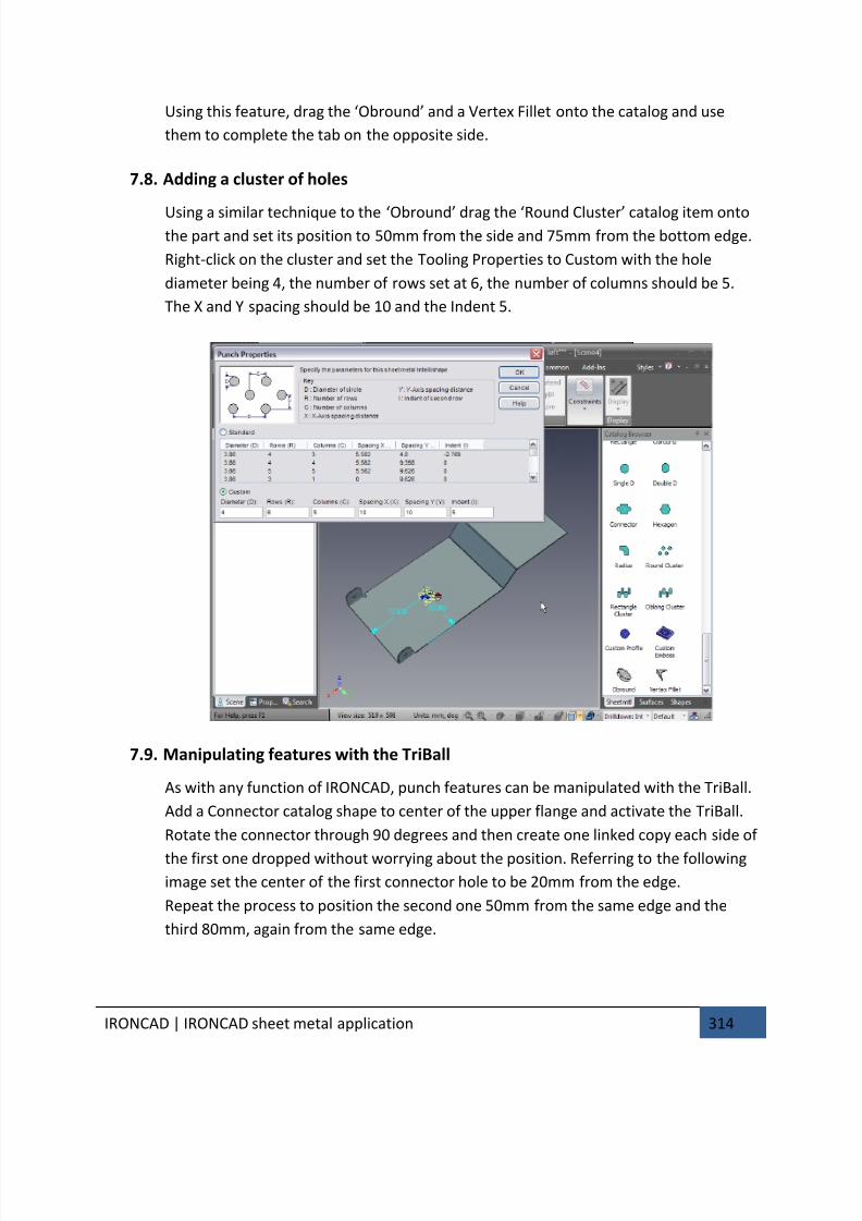
7/30/2019 Unlock Ironcadgsg
http://slidepdf.com/reader/full/unlock-ironcadgsg 318/367
IRONCAD | IRONCAD sheet metal application 314
Using this feature, drag the ‘Obround’ and a Vertex Fillet onto the catalog and use
them to complete the tab on the opposite side.
7.8. Adding a cluster of holes
Using a similar technique to the ‘Obround’ drag the ‘Round Cluster’ catalog item ontothe part and set its position to 50mm from the side and 75mm from the bottom edge.
Right-click on the cluster and set the Tooling Properties to Custom with the hole
diameter being 4, the number of rows set at 6, the number of columns should be 5.
The X and Y spacing should be 10 and the Indent 5.
7.9. Manipulating features with the TriBall
As with any function of IRONCAD, punch features can be manipulated with the TriBall.
Add a Connector catalog shape to center of the upper flange and activate the TriBall.
Rotate the connector through 90 degrees and then create one linked copy each side of
the first one dropped without worrying about the position. Referring to the following
image set the center of the first connector hole to be 20mm from the edge.
Repeat the process to position the second one 50mm from the same edge and the
third 80mm, again from the same edge.
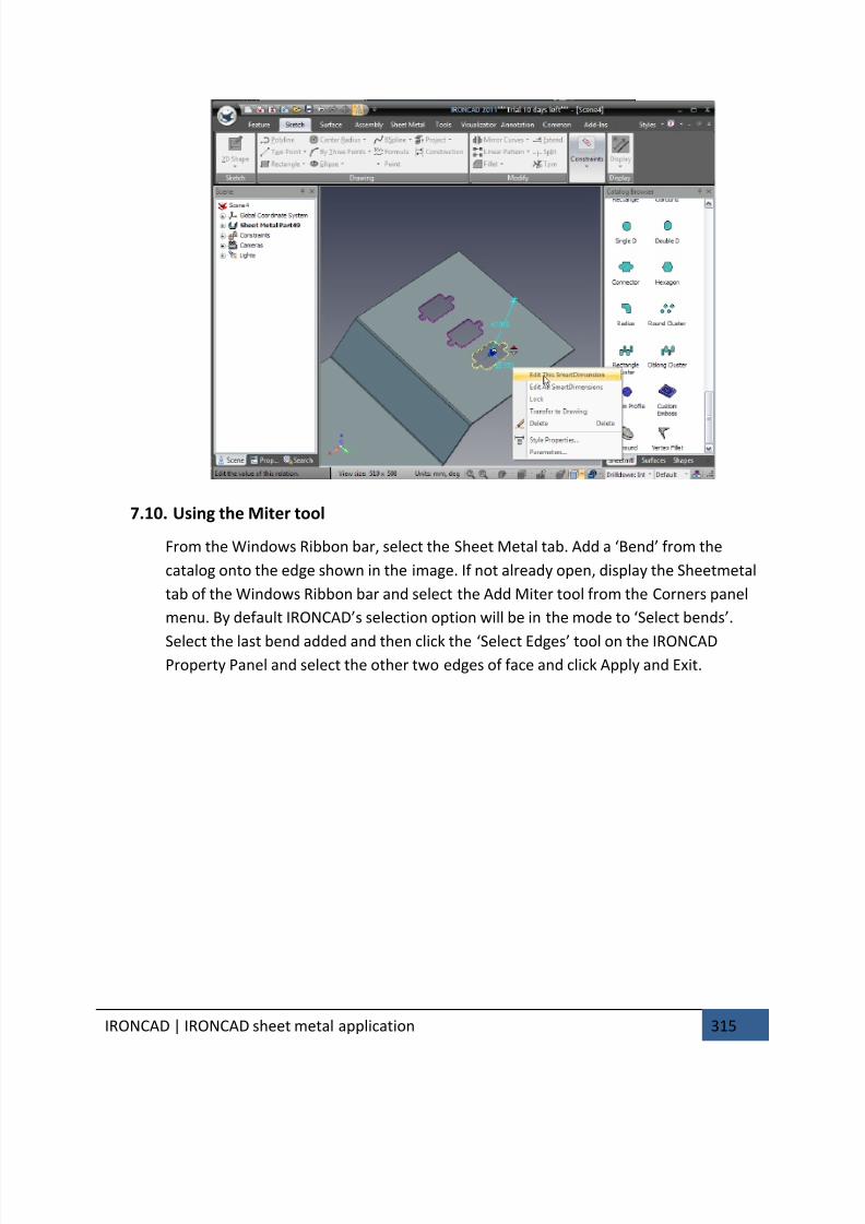
7/30/2019 Unlock Ironcadgsg
http://slidepdf.com/reader/full/unlock-ironcadgsg 319/367
IRONCAD | IRONCAD sheet metal application 315
7.10. Using the Miter tool
From the Windows Ribbon bar, select the Sheet Metal tab. Add a ‘Bend’ from the
catalog onto the edge shown in the image. If not already open, display the Sheetmetal
tab of the Windows Ribbon bar and select the Add Miter tool from the Corners panel
menu. By default IRONCAD’s selection option will be in the mode to ‘Select bends’.
Select the last bend added and then click the ‘Select Edges’ tool on the IRONCADProperty Panel and select the other two edges of face and click Apply and Exit.
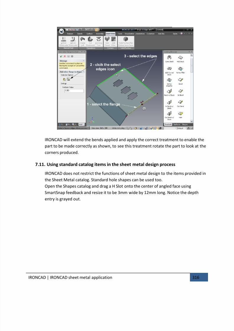
7/30/2019 Unlock Ironcadgsg
http://slidepdf.com/reader/full/unlock-ironcadgsg 320/367
IRONCAD | IRONCAD sheet metal application 316
IRONCAD will extend the bends applied and apply the correct treatment to enable the
part to be made correctly as shown, to see this treatment rotate the part to look at the
corners produced.
7.11. Using standard catalog items in the sheet metal design process
IRONCAD does not restrict the functions of sheet metal design to the items provided inthe Sheet Metal catalog. Standard hole shapes can be used too.
Open the Shapes catalog and drag a H Slot onto the center of angled face using
SmartSnap feedback and resize it to be 3mm wide by 12mm long. Notice the depth
entry is grayed out.
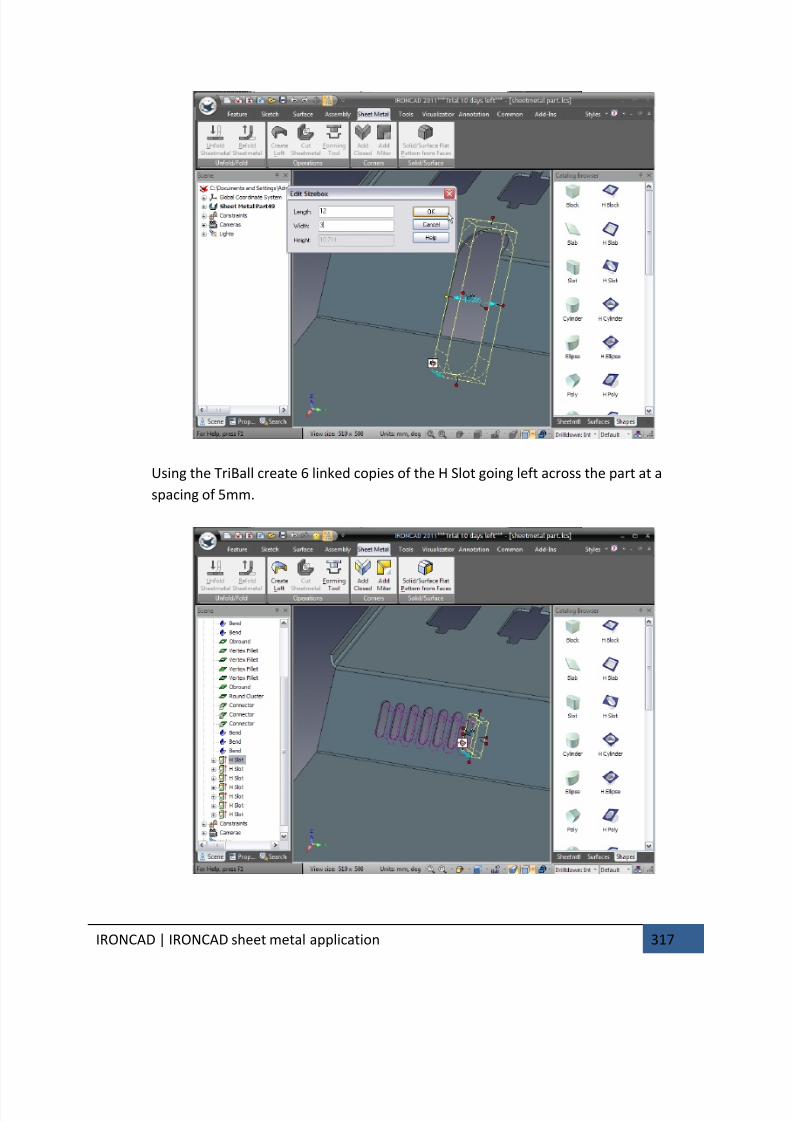
7/30/2019 Unlock Ironcadgsg
http://slidepdf.com/reader/full/unlock-ironcadgsg 321/367
IRONCAD | IRONCAD sheet metal application 317
Using the TriBall create 6 linked copies of the H Slot going left across the part at a
spacing of 5mm.
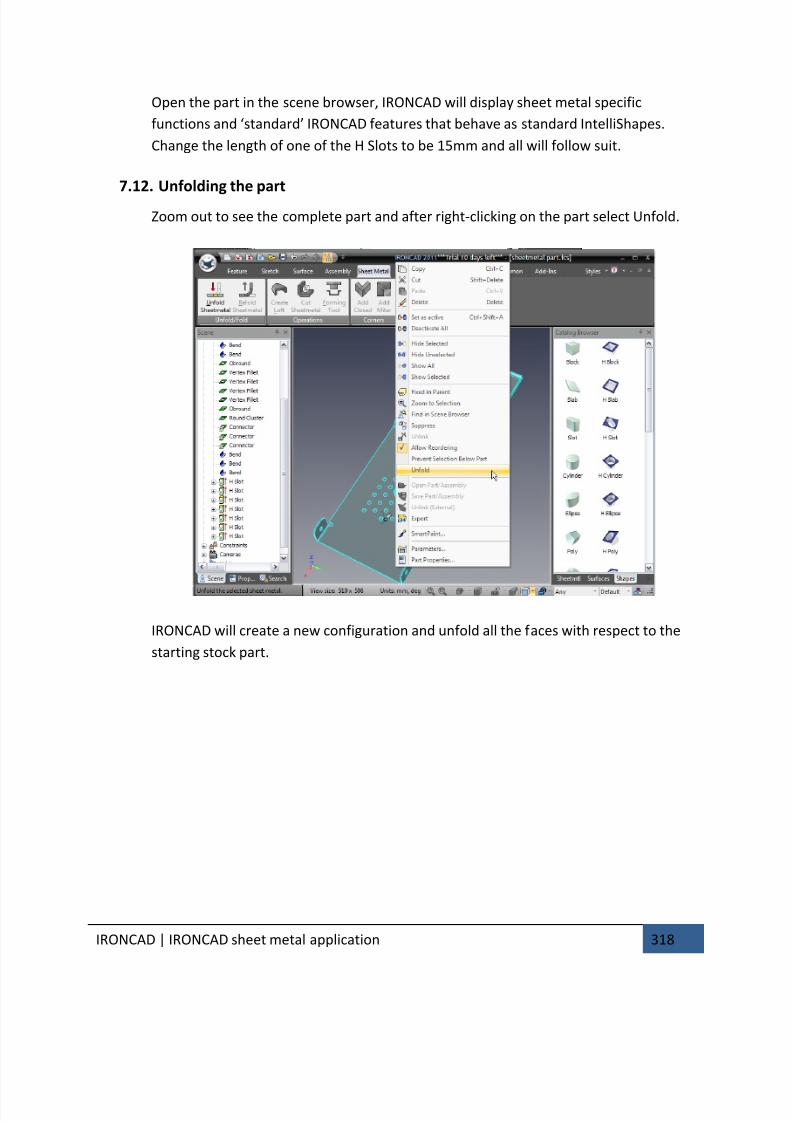
7/30/2019 Unlock Ironcadgsg
http://slidepdf.com/reader/full/unlock-ironcadgsg 322/367
IRONCAD | IRONCAD sheet metal application 318
Open the part in the scene browser, IRONCAD will display sheet metal specific
functions and ‘standard’ IRONCAD features that behave as standard IntelliShapes.
Change the length of one of the H Slots to be 15mm and all will follow suit.
7.12. Unfolding the part
Zoom out to see the complete part and after right-clicking on the part select Unfold.
IRONCAD will create a new configuration and unfold all the faces with respect to the
starting stock part.
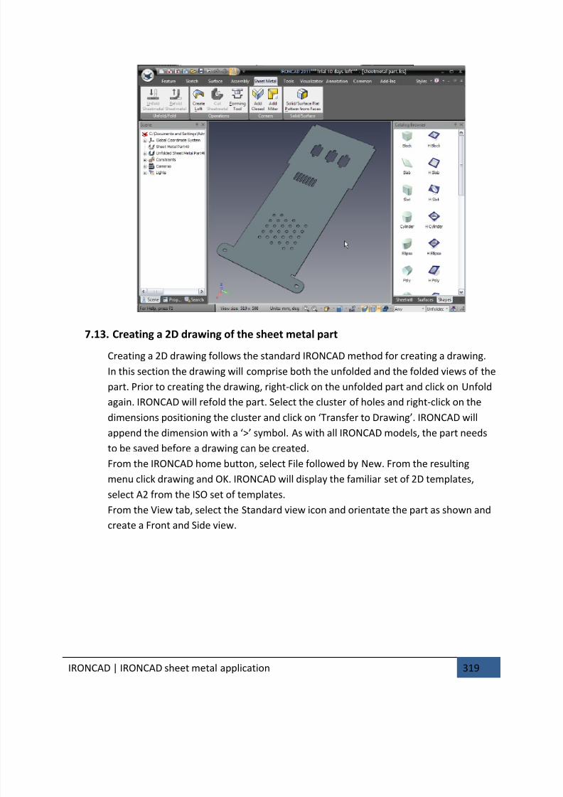
7/30/2019 Unlock Ironcadgsg
http://slidepdf.com/reader/full/unlock-ironcadgsg 323/367
IRONCAD | IRONCAD sheet metal application 319
7.13. Creating a 2D drawing of the sheet metal part
Creating a 2D drawing follows the standard IRONCAD method for creating a drawing.
In this section the drawing will comprise both the unfolded and the folded views of the
part. Prior to creating the drawing, right-click on the unfolded part and click on Unfold
again. IRONCAD will refold the part. Select the cluster of holes and right-click on the
dimensions positioning the cluster and click on ‘Transfer to Drawing’. IRONCAD willappend the dimension with a ‘>’ symbol. As with all IRONCAD models, the part needs
to be saved before a drawing can be created.
From the IRONCAD home button, select File followed by New. From the resulting
menu click drawing and OK. IRONCAD will display the familiar set of 2D templates,
select A2 from the ISO set of templates.
From the View tab, select the Standard view icon and orientate the part as shown and
create a Front and Side view.
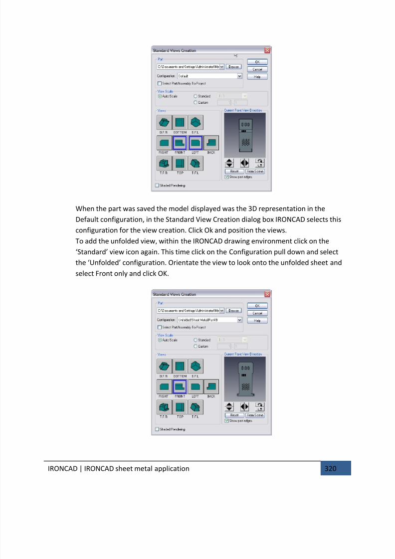
7/30/2019 Unlock Ironcadgsg
http://slidepdf.com/reader/full/unlock-ironcadgsg 324/367
IRONCAD | IRONCAD sheet metal application 320
When the part was saved the model displayed was the 3D representation in the
Default configuration, in the Standard View Creation dialog box IRONCAD selects this
configuration for the view creation. Click Ok and position the views.
To add the unfolded view, within the IRONCAD drawing environment click on the
‘Standard’ view icon again. This time click on the Configuration pull down and select
the ‘Unfolded’ configuration. Orientate the view to look onto the unfolded sheet and
select Front only and click OK.
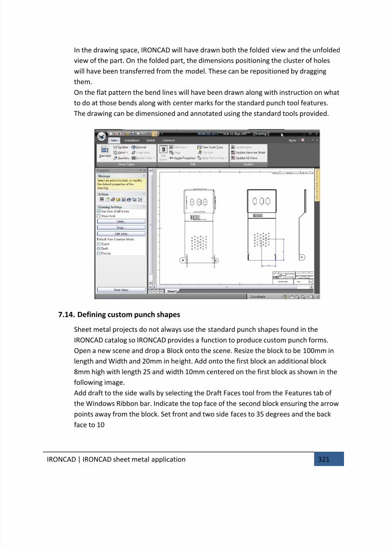
7/30/2019 Unlock Ironcadgsg
http://slidepdf.com/reader/full/unlock-ironcadgsg 325/367
IRONCAD | IRONCAD sheet metal application 321
In the drawing space, IRONCAD will have drawn both the folded view and the unfolded
view of the part. On the folded part, the dimensions positioning the cluster of holes
will have been transferred from the model. These can be repositioned by dragging
them.
On the flat pattern the bend lines will have been drawn along with instruction on whatto do at those bends along with center marks for the standard punch tool features.
The drawing can be dimensioned and annotated using the standard tools provided.
7.14. Defining custom punch shapes
Sheet metal projects do not always use the standard punch shapes found in the
IRONCAD catalog so IRONCAD provides a function to produce custom punch forms.
Open a new scene and drop a Block onto the scene. Resize the block to be 100mm in
length and Width and 20mm in height. Add onto the first block an additional block
8mm high with length 25 and width 10mm centered on the first block as shown in the
following image.Add draft to the side walls by selecting the Draft Faces tool from the Features tab of
the Windows Ribbon bar. Indicate the top face of the second block ensuring the arrow
points away from the block. Set front and two side faces to 35 degrees and the back
face to 10
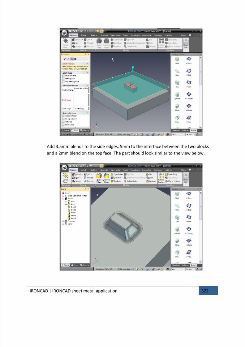
7/30/2019 Unlock Ironcadgsg
http://slidepdf.com/reader/full/unlock-ironcadgsg 326/367
IRONCAD | IRONCAD sheet metal application 322
Add 3.5mm blends to the side edges, 5mm to the interface between the two blocks
and a 2mm blend on the top face. The part should look similar to the view below.

7/30/2019 Unlock Ironcadgsg
http://slidepdf.com/reader/full/unlock-ironcadgsg 327/367
IRONCAD | IRONCAD sheet metal application 323
Open the Sheet Metal tab and select the Forming Tool option. For the Stopping Face
indicate the top face of the first block. This in essence is the face that will stop against
the part and click OK. IRONCAD will change the front face to cyan and add an entry to
the part tree in the scene browser.
Open the Common tab on the Windows Ribbon bar and select ‘New’ from the Catalogs
panel. IRONCAD will open a new catalog.
Click on the forming tool and drag it to the new catalog and click twice on the name in
the catalog and change its name to Forming Punch.
In the scene browser, remove the 2mm blend from the top face of the punch. Next,
right-click on the Forming Tool entry in the tree and select ‘Edit Tool option’. If the
word Face is not already highlighted in red, click in the ‘Faces to Remove’ panel and
select the top face of the second block and click OK.
IRONCAD will highlight this face in yellow. Drag this tool onto the catalog and rename
it ‘Cutting Punch’.
Minimize or close the scene defining the punches and open the sheet metal part.
Rotate the view to look on the back of the part. From the new catalog, drag the
Forming Punch onto the part below the cluster of holes and the Cutting Punch above
the cluster of the holes. IRONCAD will create a raised section with a closed top face at
the bottom of the part and a similar form above the cluster, however this one will have
a hole cut through. After changing the color of the part the scene should resemble the
next image.
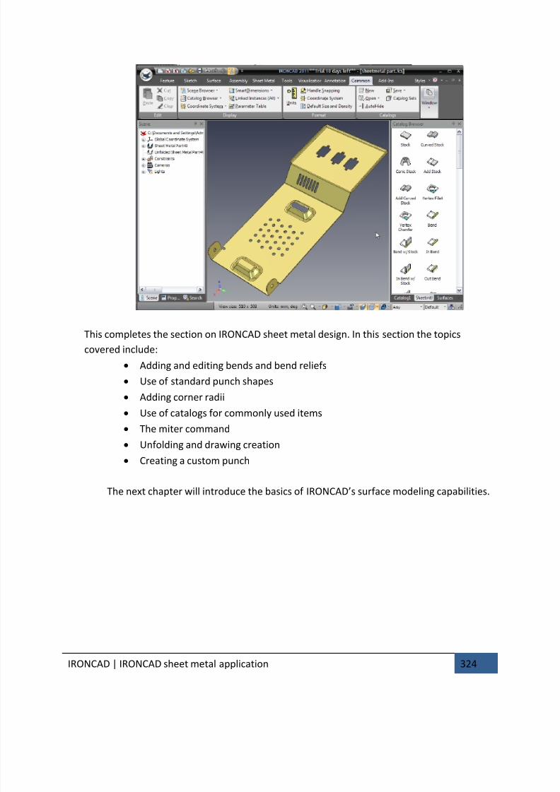
7/30/2019 Unlock Ironcadgsg
http://slidepdf.com/reader/full/unlock-ironcadgsg 328/367
IRONCAD | IRONCAD sheet metal application 324
This completes the section on IRONCAD sheet metal design. In this section the topics
covered include:
• Adding and editing bends and bend reliefs
• Use of standard punch shapes
• Adding corner radii
• Use of catalogs for commonly used items• The miter command
• Unfolding and drawing creation
• Creating a custom punch
The next chapter will introduce the basics of IRONCAD’s surface modeling capabilities.

7/30/2019 Unlock Ironcadgsg
http://slidepdf.com/reader/full/unlock-ironcadgsg 329/367
IRONCAD | IRONCAD Surface Modeling 325
8. IRONCAD SURFACE MODELING
This chapter introduces some of IRONCAD’s Surface Modeling functionality and 3D curve
creation capabilities. The chapter covers the use of surface modeling to create a Solid
Model of a faucet, the topics covered are: • Creation of 3D Curves from points,
• Creating Surfaces from Solids
• Create Sweep, Mesh, Edge and Ruled Surfaces
The Ruled Surface section closes the surface model into a fully bounded model that
IRONCAD will recognize as a solid part.
At the end of the section the part should resemble the following:
8.1. Creating 3D Curves
From the IRONCAD home button select File, New and select Scene. In the Metric tab,
select the template labeled Gray and click OK.
From the Shapes catalog, drag a Slot onto the scene.
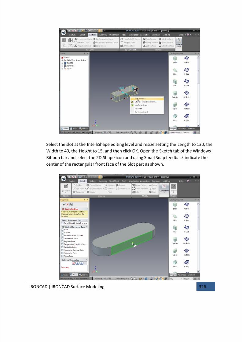
7/30/2019 Unlock Ironcadgsg
http://slidepdf.com/reader/full/unlock-ironcadgsg 330/367
IRONCAD | IRONCAD Surface Modeling 326
Select the slot at the IntelliShape editing level and resize setting the Length to 130, the
Width to 40, the Height to 15, and then click OK. Open the Sketch tab of the Windows
Ribbon bar and select the 2D Shape icon and using SmartSnap feedback indicate the
center of the rectangular front face of the Slot part as shown.
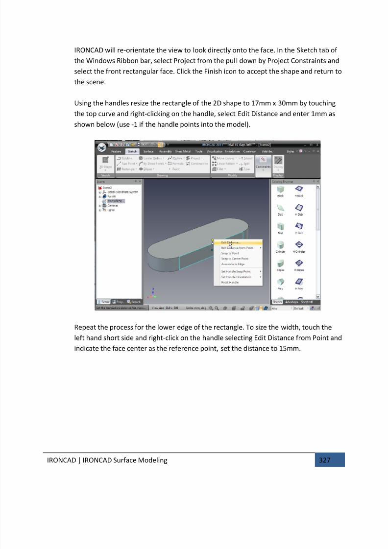
7/30/2019 Unlock Ironcadgsg
http://slidepdf.com/reader/full/unlock-ironcadgsg 331/367
IRONCAD | IRONCAD Surface Modeling 327
IRONCAD will re-orientate the view to look directly onto the face. In the Sketch tab of
the Windows Ribbon bar, select Project from the pull down by Project Constraints and
select the front rectangular face. Click the Finish icon to accept the shape and return to
the scene.
Using the handles resize the rectangle of the 2D shape to 17mm x 30mm by touching
the top curve and right-clicking on the handle, select Edit Distance and enter 1mm as
shown below (use -1 if the handle points into the model).
Repeat the process for the lower edge of the rectangle. To size the width, touch the
left hand short side and right-click on the handle selecting Edit Distance from Point and
indicate the face center as the reference point, set the distance to 15mm.
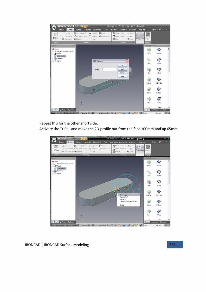
7/30/2019 Unlock Ironcadgsg
http://slidepdf.com/reader/full/unlock-ironcadgsg 332/367
IRONCAD | IRONCAD Surface Modeling 328
Repeat this for the other short side.
Activate the TriBall and move the 2D profile out from the face 100mm and up 65mm.
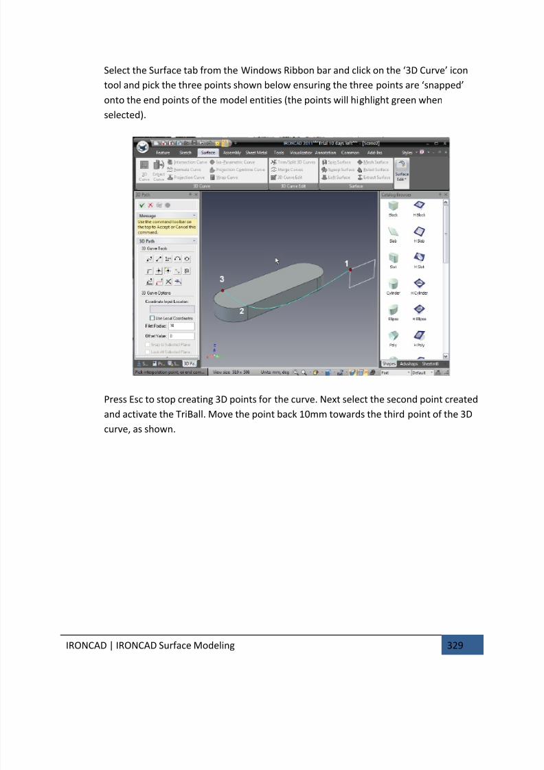
7/30/2019 Unlock Ironcadgsg
http://slidepdf.com/reader/full/unlock-ironcadgsg 333/367
IRONCAD | IRONCAD Surface Modeling 329
Select the Surface tab from the Windows Ribbon bar and click on the ‘3D Curve’ icon
tool and pick the three points shown below ensuring the three points are ‘snapped’
onto the end points of the model entities (the points will highlight green when
selected).
Press Esc to stop creating 3D points for the curve. Next select the second point created
and activate the TriBall. Move the point back 10mm towards the third point of the 3D
curve, as shown.
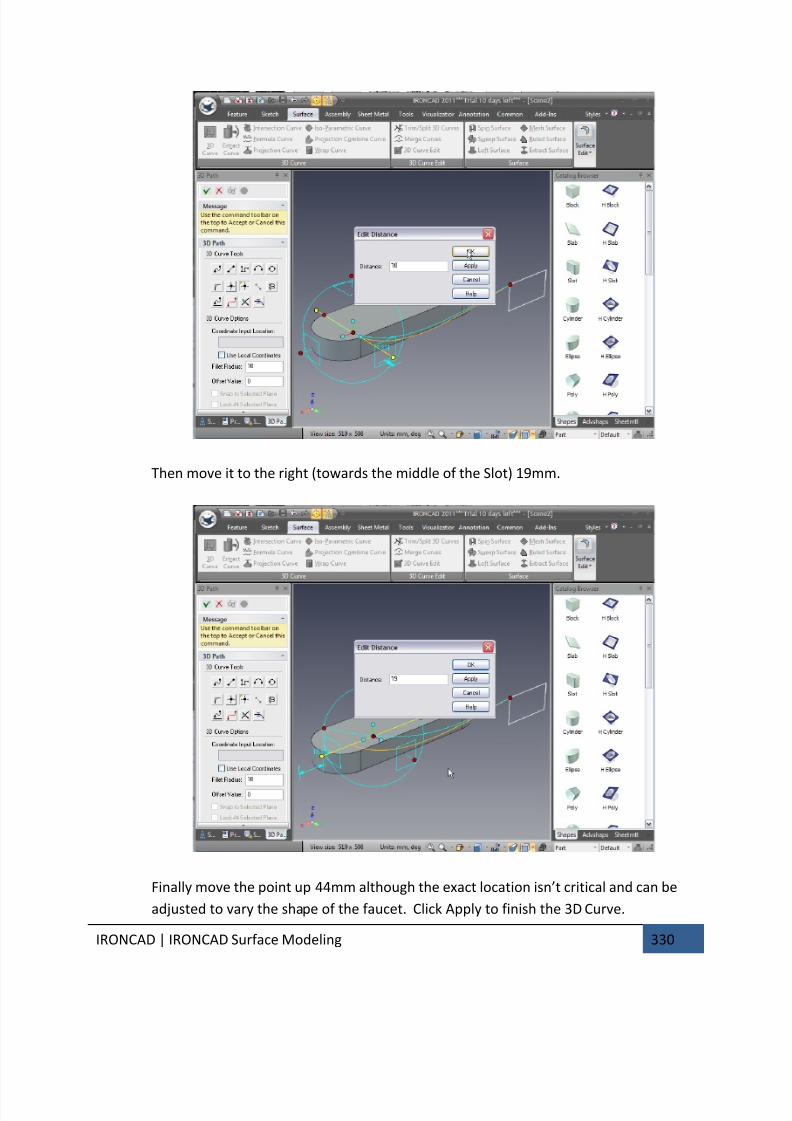
7/30/2019 Unlock Ironcadgsg
http://slidepdf.com/reader/full/unlock-ironcadgsg 334/367
IRONCAD | IRONCAD Surface Modeling 330
Then move it to the right (towards the middle of the Slot) 19mm.
Finally move the point up 44mm although the exact location isn’t critical and can be
adjusted to vary the shape of the faucet. Click Apply to finish the 3D Curve.
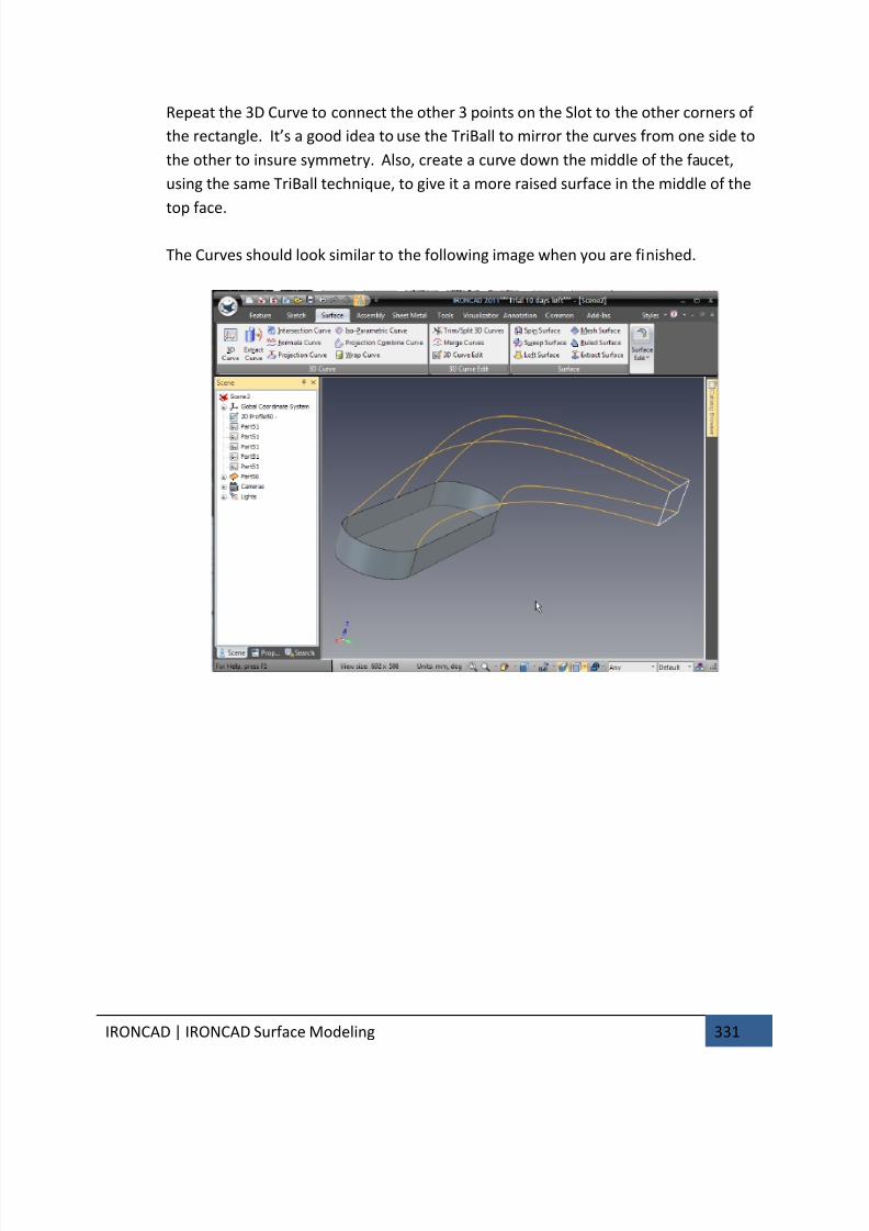
7/30/2019 Unlock Ironcadgsg
http://slidepdf.com/reader/full/unlock-ironcadgsg 335/367
IRONCAD | IRONCAD Surface Modeling 331
Repeat the 3D Curve to connect the other 3 points on the Slot to the other corners of
the rectangle. It’s a good idea to use the TriBall to mirror the curves from one side to
the other to insure symmetry. Also, create a curve down the middle of the faucet,
using the same TriBall technique, to give it a more raised surface in the middle of the
top face.
The Curves should look similar to the following image when you are finished.
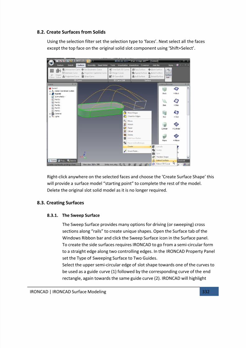
7/30/2019 Unlock Ironcadgsg
http://slidepdf.com/reader/full/unlock-ironcadgsg 336/367
IRONCAD | IRONCAD Surface Modeling 332
8.2. Create Surfaces from Solids
Using the selection filter set the selection type to ‘faces’. Next select all the faces
except the top face on the original solid slot component using ‘Shift+Select’.
Right-click anywhere on the selected faces and choose the ‘Create Surface Shape’ this
will provide a surface model “starting point” to complete the rest of the model.Delete the original slot solid model as it is no longer required.
8.3. Creating Surfaces
8.3.1. The Sweep Surface
The Sweep Surface provides many options for driving (or sweeping) cross
sections along “rails” to create unique shapes. Open the Surface tab of the
Windows Ribbon bar and click the Sweep Surface icon in the Surface panel.
To create the side surfaces requires IRONCAD to go from a semi-circular form
to a straight edge along two controlling edges. In the IRONCAD Property Panel
set the Type of Sweeping Surface to Two Guides.
Select the upper semi-circular edge of slot shape towards one of the curves to
be used as a guide curve (1) followed by the corresponding curve of the end
rectangle, again towards the same guide curve (2). IRONCAD will highlight
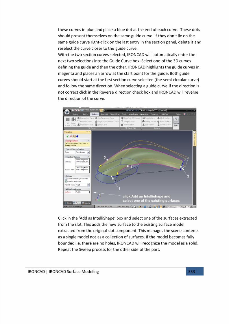
7/30/2019 Unlock Ironcadgsg
http://slidepdf.com/reader/full/unlock-ironcadgsg 337/367
IRONCAD | IRONCAD Surface Modeling 333
these curves in blue and place a blue dot at the end of each curve. These dots
should present themselves on the same guide curve. If they don’t lie on the
same guide curve right-click on the last entry in the section panel, delete it and
reselect the curve closer to the guide curve.
With the two section curves selected, IRONCAD will automatically enter thenext two selections into the Guide Curve box. Select one of the 3D curves
defining the guide and then the other. IRONCAD highlights the guide curves in
magenta and places an arrow at the start point for the guide. Both guide
curves should start at the first section curve selected (the semi-circular curve)
and follow the same direction. When selecting a guide curve if the direction is
not correct click in the Reverse direction check box and IRONCAD will reverse
the direction of the curve.
Click in the ‘Add as IntelliShape’ box and select one of the surfaces extracted
from the slot. This adds the new surface to the existing surface model
extracted from the original slot component. This manages the scene contents
as a single model not as a collection of surfaces. If the model becomes fully
bounded i.e. there are no holes, IRONCAD will recognize the model as a solid.
Repeat the Sweep process for the other side of the part.
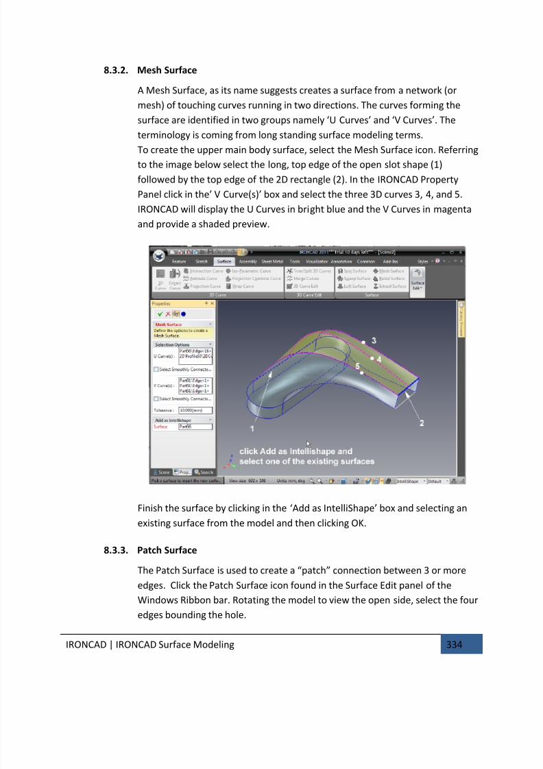
7/30/2019 Unlock Ironcadgsg
http://slidepdf.com/reader/full/unlock-ironcadgsg 338/367
IRONCAD | IRONCAD Surface Modeling 334
8.3.2. Mesh Surface
A Mesh Surface, as its name suggests creates a surface from a network (or
mesh) of touching curves running in two directions. The curves forming the
surface are identified in two groups namely ‘U Curves’ and ‘V Curves’. The
terminology is coming from long standing surface modeling terms.To create the upper main body surface, select the Mesh Surface icon. Referring
to the image below select the long, top edge of the open slot shape (1)
followed by the top edge of the 2D rectangle (2). In the IRONCAD Property
Panel click in the’ V Curve(s)’ box and select the three 3D curves 3, 4, and 5.
IRONCAD will display the U Curves in bright blue and the V Curves in magenta
and provide a shaded preview.
Finish the surface by clicking in the ‘Add as IntelliShape’ box and selecting an
existing surface from the model and then clicking OK.
8.3.3. Patch Surface
The Patch Surface is used to create a “patch” connection between 3 or more
edges. Click the Patch Surface icon found in the Surface Edit panel of the
Windows Ribbon bar. Rotating the model to view the open side, select the four
edges bounding the hole.
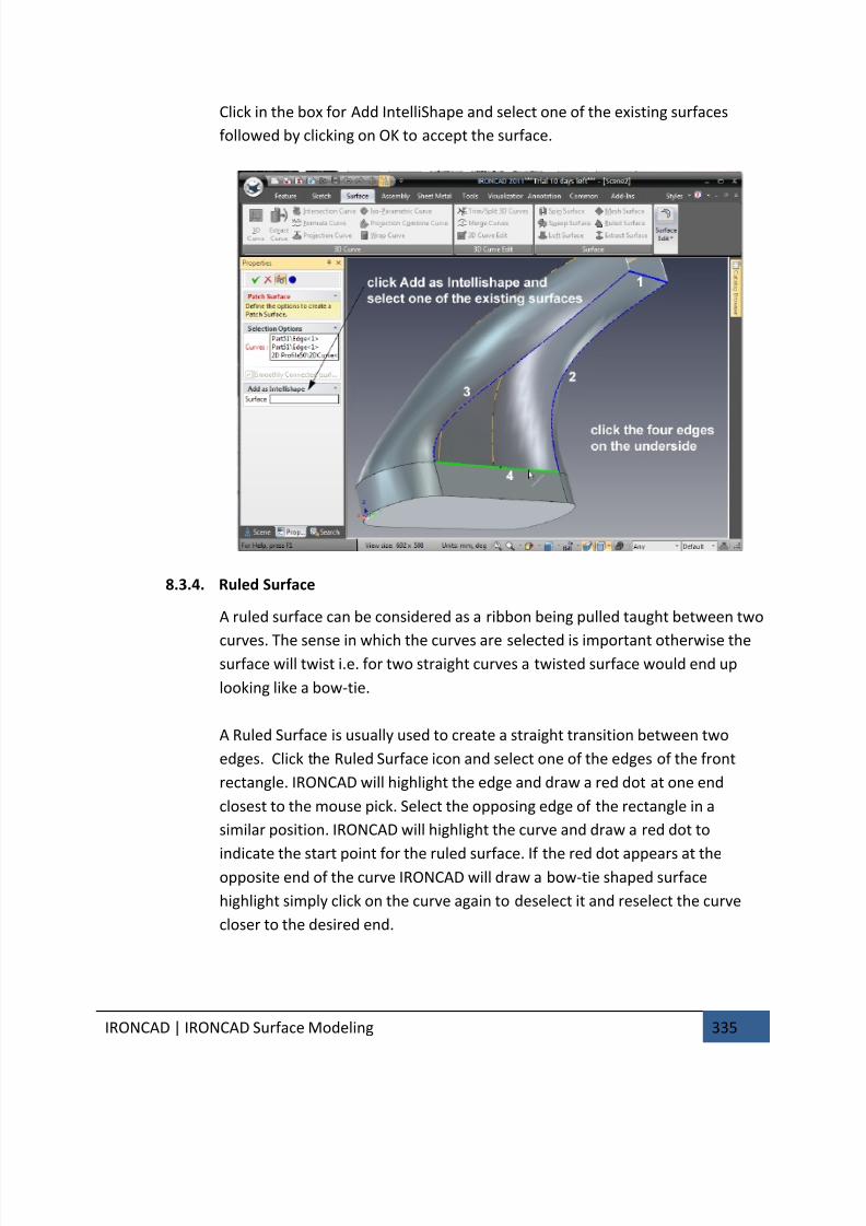
7/30/2019 Unlock Ironcadgsg
http://slidepdf.com/reader/full/unlock-ironcadgsg 339/367
IRONCAD | IRONCAD Surface Modeling 335
Click in the box for Add IntelliShape and select one of the existing surfaces
followed by clicking on OK to accept the surface.
8.3.4. Ruled Surface
A ruled surface can be considered as a ribbon being pulled taught between two
curves. The sense in which the curves are selected is important otherwise thesurface will twist i.e. for two straight curves a twisted surface would end up
looking like a bow-tie.
A Ruled Surface is usually used to create a straight transition between two
edges. Click the Ruled Surface icon and select one of the edges of the front
rectangle. IRONCAD will highlight the edge and draw a red dot at one end
closest to the mouse pick. Select the opposing edge of the rectangle in a
similar position. IRONCAD will highlight the curve and draw a red dot to
indicate the start point for the ruled surface. If the red dot appears at theopposite end of the curve IRONCAD will draw a bow-tie shaped surface
highlight simply click on the curve again to deselect it and reselect the curve
closer to the desired end.
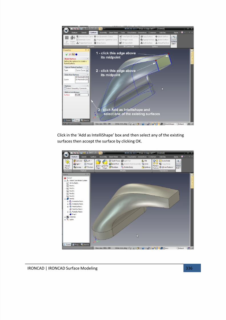
7/30/2019 Unlock Ironcadgsg
http://slidepdf.com/reader/full/unlock-ironcadgsg 340/367
IRONCAD | IRONCAD Surface Modeling 336
Click in the ‘Add as IntelliShape’ box and then select any of the existing
surfaces then accept the surface by clicking OK.

7/30/2019 Unlock Ironcadgsg
http://slidepdf.com/reader/full/unlock-ironcadgsg 341/367
IRONCAD | IRONCAD Surface Modeling 337
The model is now completely closed and automatically converts to a solid model.
Experiment by adding more features to finish the design or by editing a surface such as the
top mesh surface. Right-clicking on the central, long curve and selecting edit curve will
provide access to the points defining the curve.
This chapter introduced some of IRONCAD’s Surface Modeling functionality and 3D curve
creation. The chapter covered the use of surface modeling to add a degree of control and
form to a simple component resulting in the creation of an editable Solid Model of a faucet,
the topics covered are:
• Creation of 3D Curves from points
• Creating Surfaces from Solids
• Create Sweep, Mesh, Edge and Ruled Surfaces to curves and surface edges
The next chapter will provide insight into the photo-realistic rendering aspects of IRONCAD.

7/30/2019 Unlock Ironcadgsg
http://slidepdf.com/reader/full/unlock-ironcadgsg 342/367
IRONCAD | Photorealistic Rendering 338
9. PHOTOREALISTIC RENDERING
Communicating a design with finished 3D models and detail drawings is only part of the
process for IRONCAD users.
Prior to finishing a design there are many steps in the communication chain to expose thedesign to a wider audience to enable this audience to become stakeholders in the design.
Photorealistic rendering opens up other opportunities such as providing early product
visualizations for marketing materials, animations to help with production processes or
even just having some fun with the design.
IRONCAD is provided with integrated photorealistic rendering and animation tools and just
like the rest of IRONCAD design tools these can be simply dragged from the catalog onto the
part enabling very rapid results.
This section will:
• Introduce simple drag and drop rendering techniques• Creating screen based images for use with standard screen capture tools
• Creation of high quality renderings for everyday use to large format poster
style renderings. Animation will be covered in a separate section
This section will be based on the design created in the Quick Start section of the manual.
9.1. Adding realism to the screen display
IRONCAD was one of the first products to use a clean working environment, reducing
clutter on the screen to help every user to concentrate on the job at hand and not
navigate around a multitude of menus. The display is so clean that screen captures oftensuffice for discussion documents or quick idea communications. IRONCAD has added a
number of features to lift that quality to a higher level. Not only does this add a touch of
realism, it adds professionalism to these quick captures helping to instill a culture of
quality.
All aspects of the screen display can be set. This section will introduce changes to the
scene background and cover adding shadows and reflections to the scene background
and the part display.
9.1.1. The Scene Background
The IRONCAD scene background is based on an image either repeated or not.
For example if the object being designed can be shown in the context of an
existing photograph or product screenshot – this can be used as the scene
background.
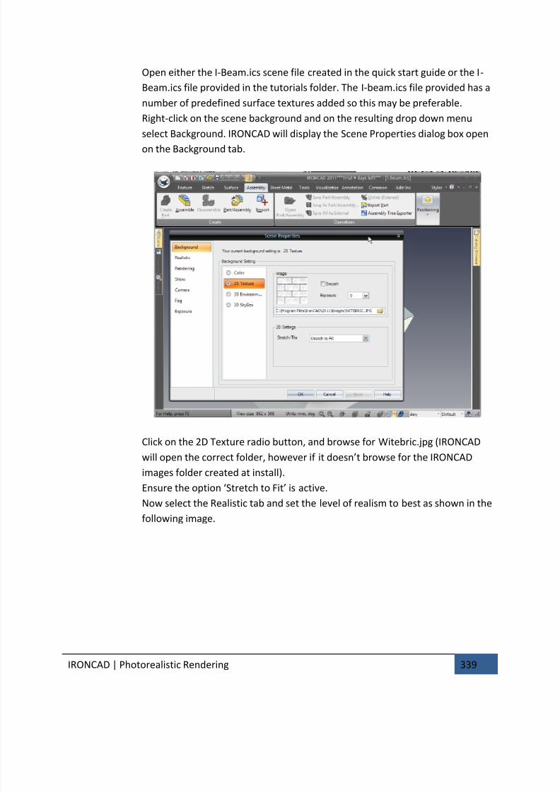
7/30/2019 Unlock Ironcadgsg
http://slidepdf.com/reader/full/unlock-ironcadgsg 343/367
IRONCAD | Photorealistic Rendering 339
Open either the I-Beam.ics scene file created in the quick start guide or the I-
Beam.ics file provided in the tutorials folder. The I-beam.ics file provided has a
number of predefined surface textures added so this may be preferable.
Right-click on the scene background and on the resulting drop down menu
select Background. IRONCAD will display the Scene Properties dialog box openon the Background tab.
Click on the 2D Texture radio button, and browse for Witebric.jpg (IRONCAD
will open the correct folder, however if it doesn’t browse for the IRONCAD
images folder created at install).
Ensure the option ‘Stretch to Fit’ is active.
Now select the Realistic tab and set the level of realism to best as shown in the
following image.
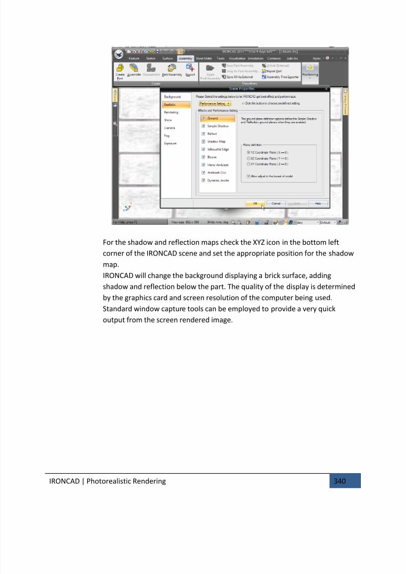
7/30/2019 Unlock Ironcadgsg
http://slidepdf.com/reader/full/unlock-ironcadgsg 344/367
IRONCAD | Photorealistic Rendering 340
For the shadow and reflection maps check the XYZ icon in the bottom left
corner of the IRONCAD scene and set the appropriate position for the shadow
map.
IRONCAD will change the background displaying a brick surface, adding
shadow and reflection below the part. The quality of the display is determined
by the graphics card and screen resolution of the computer being used.
Standard window capture tools can be employed to provide a very quick
output from the screen rendered image.
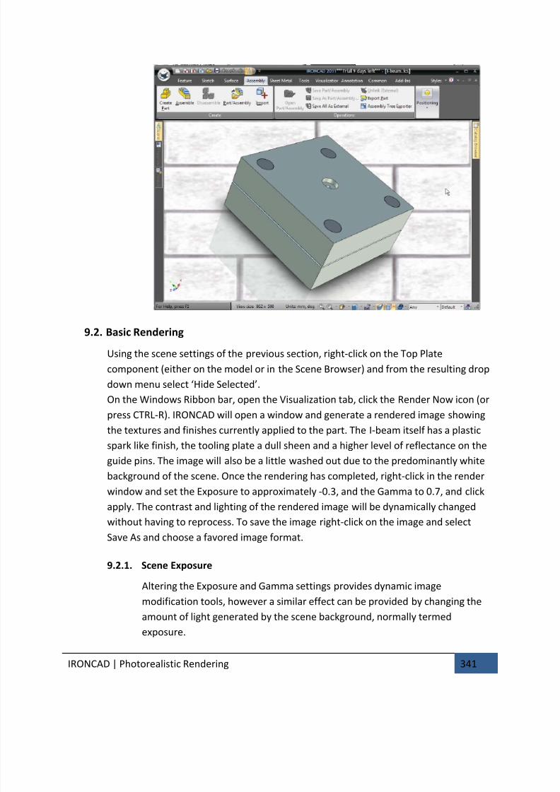
7/30/2019 Unlock Ironcadgsg
http://slidepdf.com/reader/full/unlock-ironcadgsg 345/367
IRONCAD | Photorealistic Rendering 341
9.2. Basic Rendering
Using the scene settings of the previous section, right-click on the Top Plate
component (either on the model or in the Scene Browser) and from the resulting drop
down menu select ‘Hide Selected’.
On the Windows Ribbon bar, open the Visualization tab, click the Render Now icon (or
press CTRL-R). IRONCAD will open a window and generate a rendered image showingthe textures and finishes currently applied to the part. The I-beam itself has a plastic
spark like finish, the tooling plate a dull sheen and a higher level of reflectance on the
guide pins. The image will also be a little washed out due to the predominantly white
background of the scene. Once the rendering has completed, right-click in the render
window and set the Exposure to approximately -0.3, and the Gamma to 0.7, and click
apply. The contrast and lighting of the rendered image will be dynamically changed
without having to reprocess. To save the image right-click on the image and select
Save As and choose a favored image format.
9.2.1. Scene Exposure
Altering the Exposure and Gamma settings provides dynamic image
modification tools, however a similar effect can be provided by changing the
amount of light generated by the scene background, normally termed
exposure.
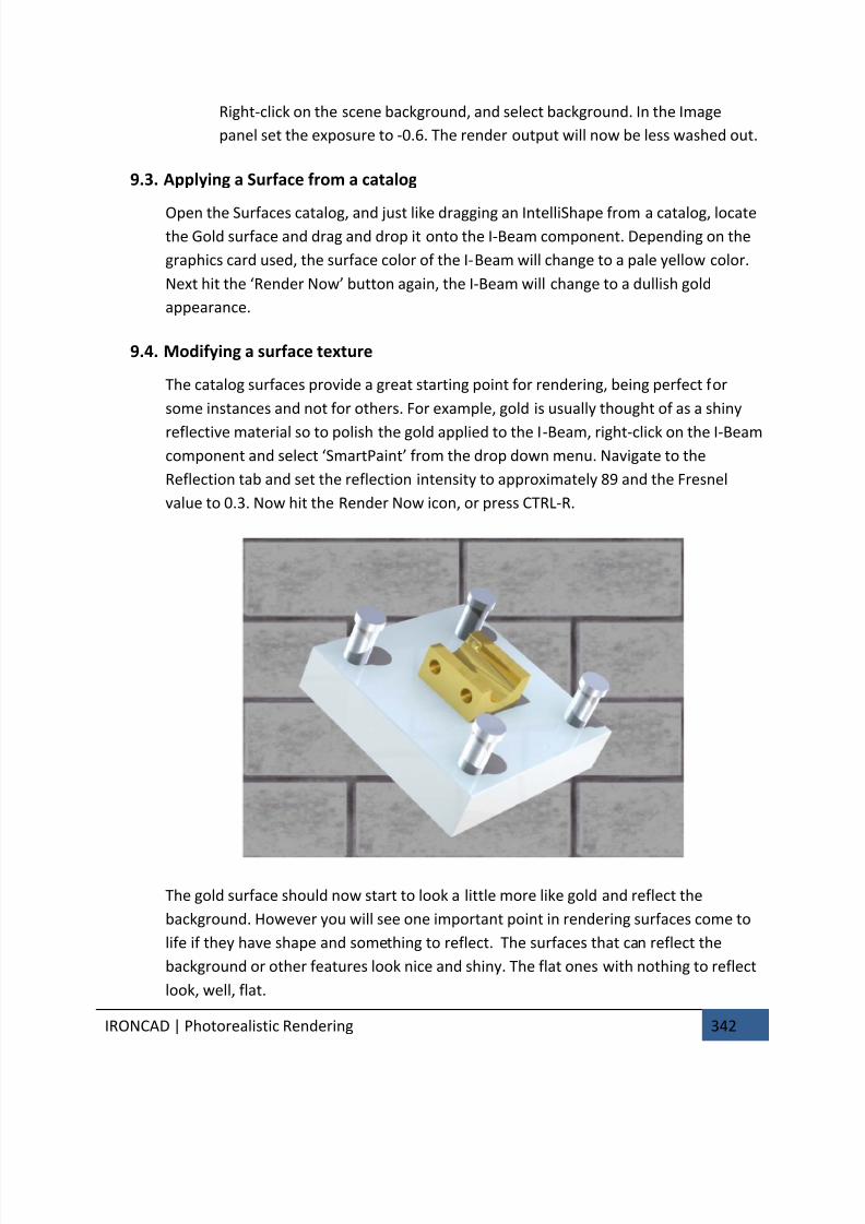
7/30/2019 Unlock Ironcadgsg
http://slidepdf.com/reader/full/unlock-ironcadgsg 346/367
IRONCAD | Photorealistic Rendering 342
Right-click on the scene background, and select background. In the Image
panel set the exposure to -0.6. The render output will now be less washed out.
9.3. Applying a Surface from a catalog
Open the Surfaces catalog, and just like dragging an IntelliShape from a catalog, locatethe Gold surface and drag and drop it onto the I-Beam component. Depending on the
graphics card used, the surface color of the I-Beam will change to a pale yellow color.
Next hit the ‘Render Now’ button again, the I-Beam will change to a dullish gold
appearance.
9.4. Modifying a surface texture
The catalog surfaces provide a great starting point for rendering, being perfect for
some instances and not for others. For example, gold is usually thought of as a shiny
reflective material so to polish the gold applied to the I-Beam, right-click on the I-Beam
component and select ‘SmartPaint’ from the drop down menu. Navigate to the
Reflection tab and set the reflection intensity to approximately 89 and the Fresnel
value to 0.3. Now hit the Render Now icon, or press CTRL-R.
The gold surface should now start to look a little more like gold and reflect the
background. However you will see one important point in rendering surfaces come to
life if they have shape and something to reflect. The surfaces that can reflect the
background or other features look nice and shiny. The flat ones with nothing to reflect
look, well, flat.

7/30/2019 Unlock Ironcadgsg
http://slidepdf.com/reader/full/unlock-ironcadgsg 347/367
IRONCAD | Photorealistic Rendering 343
To add a little ‘life’ to the I-Beam, right-click on the I-Beam, select ‘SmartPaint’ and
open the Finish tab.
Select the lower left red sphere icon in the Preferred Finishes section, in the Diffuse
BRDF drop down select ‘Ashikhmin’ and set the shine value to 1. In the Specular BRDF
section, again use ‘Ashikhmin’ setting the ‘Aniso U’ and ‘Aniso V’ values to 0.2 leavingthe ‘Rotate’ value to its currently set value.
(BRDF is short for Bidirectional Reflectance Distribution Function and is a method to
calculate how light is reflected from an opaque surface.)
Render the scene by pressing CTRL-R the resulting image will show the gold
component to be a lot more lifelike. If you are not convinced add some blends to the
crisp edges of the I-Beam and re render the scene.
9.5. Saving a Surface Texture to a catalog
To use the surface textures again, simply add them to the Surfaces catalog or a newcatalog.
At the left hand end of the Visualization Windows menu tab is the Fill Eye Dropper,
select the Eye Dropper, click on the gold I-Beam and left click on the catalog. IRONCAD
will create an icon representing the surface texture. To set a name, click on the icon
twice (not a double click) to highlight the icons current name. A new name can now be
entered.
9.6. Setting a material property with a surface texture
The surface texture may be aligned to the physical properties of a material and not justto its surface treatment. To those ends, setting the material of a part can also be
carried over to a catalog surface texture.
Right-click the I-Beam component and from the drop down menu select Part
Properties. Open the Material tab and in the Mass Density box enter 19300 – if the
units are kg/m3
or 19.3 if the units are g/cm3. Enter Gold in the Material box, and click
OK.
Repeating exactly the same procedure to add the surface texture to the catalog, click
on the Fill Eye Dropper, and select the gold I-Beam and then this time use the right
mouse button to drop the surface texture onto the catalog. IRONCAD will respond byprompting SmartPaint or SmartPaint and Material. This time select SmartPaint and
Material. Each time this surface texture is added to a part its material will be changed
to gold as well as its finish.
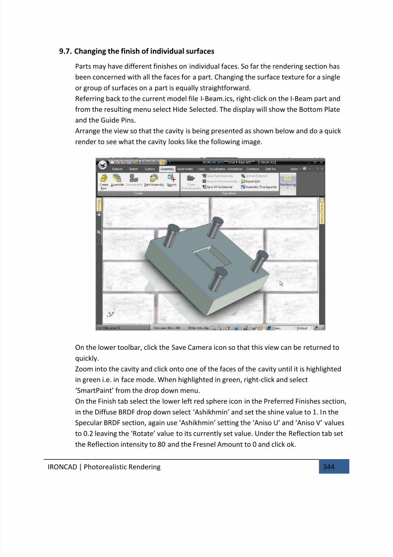
7/30/2019 Unlock Ironcadgsg
http://slidepdf.com/reader/full/unlock-ironcadgsg 348/367
IRONCAD | Photorealistic Rendering 344
9.7. Changing the finish of individual surfaces
Parts may have different finishes on individual faces. So far the rendering section has
been concerned with all the faces for a part. Changing the surface texture for a single
or group of surfaces on a part is equally straightforward.
Referring back to the current model file I-Beam.ics, right-click on the I-Beam part and
from the resulting menu select Hide Selected. The display will show the Bottom Plate
and the Guide Pins.
Arrange the view so that the cavity is being presented as shown below and do a quick
render to see what the cavity looks like the following image.
On the lower toolbar, click the Save Camera icon so that this view can be returned to
quickly.
Zoom into the cavity and click onto one of the faces of the cavity until it is highlighted
in green i.e. in face mode. When highlighted in green, right-click and select
‘SmartPaint’ from the drop down menu.On the Finish tab select the lower left red sphere icon in the Preferred Finishes section,
in the Diffuse BRDF drop down select ‘Ashikhmin’ and set the shine value to 1. In the
Specular BRDF section, again use ‘Ashikhmin’ setting the ‘Aniso U’ and ‘Aniso V’ values
to 0.2 leaving the ‘Rotate’ value to its currently set value. Under the Reflection tab set
the Reflection intensity to 80 and the Fresnel Amount to 0 and click ok.

7/30/2019 Unlock Ironcadgsg
http://slidepdf.com/reader/full/unlock-ironcadgsg 349/367
IRONCAD | Photorealistic Rendering 345
With the surface still highlighted in green, select the Fill Eye Dropper and click on the
surface. IRONCAD will change the Fill Eye Dropper to the Apply Eye Dropper. Touch on
all the surfaces comprising the cavity being careful to watch the surface highlight
before clicking the mouse button. Press the Esc key to cancel the operation when
completed. On the camera controls tool panel, click ‘Restore Camera’ to reset theview to the previously saved view and render the scene.
The cavity will appear polished. To see this even more add a 3mm blend to all the
internal cavity edges and render the scene.
9.8. Adding more realism with HDRI background lighting
The scene so far has been lit with the standard scene lights and with the background
image. This limits the realism that can be achieved. IRONCAD can use High Dynamic
Range Images (HDRI). These images convey not just the color of each pixel, but also
the light intensity. Using HDRI enables the scene to be rendered more realistically.The first part of this final process is to change the background. IRONCAD is provided
with a range of HDRI files. To use them, right-click on the scene background and select
the Background tab. Next, set the ‘3D Environ. . .’ radio button. In the Image panel,
browse to the Images folder and open a folder called ‘EnvironmentImages’. Within
that folder select ‘StudioEnvironments’ and select ‘ThreeLightSoft.hdr’ and click Open.
Back in the Image panel check the Smooth option and set the Exposure to -0.6 leaving
everything else untouched. Render the scene to see the progress being made.
9.9. Adding discrete lightsThe IRONCAD scene can be lit by a multitude of light types all delivering different
results. Lights can be colored, can be different intensities and can have properties set
controlling the fall off and the type of shadows they cast. Arguably the most popular is
the Spot Light. However in this example the Point Source light will be used. A Spot
Light creates a directional light whereas a point source light creates a light spreading in
all directions.
To create a point source light first click on Insert Light on the Visualization tab, and
then click on the center of one of the Guide Pins. Choose Point Light from the resulting
menu.IRONCAD will report that lights are currently not shown and ask if you want to make
them visible for editing. For this example say no. The resulting displayed scene will be
brightened.
In the Scene Browser expand the Lights group and right-click on the ‘PtLight’ entry and
select Light Properties... from the menu.
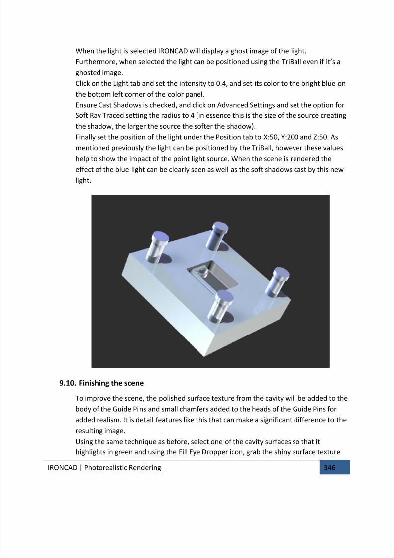
7/30/2019 Unlock Ironcadgsg
http://slidepdf.com/reader/full/unlock-ironcadgsg 350/367
IRONCAD | Photorealistic Rendering 346
When the light is selected IRONCAD will display a ghost image of the light.
Furthermore, when selected the light can be positioned using the TriBall even if it’s a
ghosted image.
Click on the Light tab and set the intensity to 0.4, and set its color to the bright blue on
the bottom left corner of the color panel.Ensure Cast Shadows is checked, and click on Advanced Settings and set the option for
Soft Ray Traced setting the radius to 4 (in essence this is the size of the source creating
the shadow, the larger the source the softer the shadow).
Finally set the position of the light under the Position tab to X:50, Y:200 and Z:50. As
mentioned previously the light can be positioned by the TriBall, however these values
help to show the impact of the point light source. When the scene is rendered the
effect of the blue light can be clearly seen as well as the soft shadows cast by this new
light.
9.10. Finishing the scene
To improve the scene, the polished surface texture from the cavity will be added to the
body of the Guide Pins and small chamfers added to the heads of the Guide Pins for
added realism. It is detail features like this that can make a significant difference to the
resulting image.
Using the same technique as before, select one of the cavity surfaces so that it
highlights in green and using the Fill Eye Dropper icon, grab the shiny surface texture

7/30/2019 Unlock Ironcadgsg
http://slidepdf.com/reader/full/unlock-ironcadgsg 351/367
IRONCAD | Photorealistic Rendering 347
and drop it onto the body section of one of the Guide Pins. The body section will be
updated as IRONCAD is in ‘face mode’ from the selection of the cavity surface. Press
the Esc key to cancel the Apply Eye Dropper command.
To add the chamfers to the head of the Guide Pin move the mouse pointer over the
cylindrical surface of one of the Guide Pins heads. The icon alongside the cursor willchange to a diamond shape indicating that the selection, if made at that point would
be a surface. Select the surface. IRONCAD will highlight the surface green with brighter
green edges. Right-click and select Chamfer Edges from the resulting menu. Set the
value to 1mm and click OK. IRONCAD will add chamfers to all the Guide Pin heads and
change the body surface texture as the Guide Pins are linked.
9.11. Adding a decal
Select one of the side faces of the Bottom Plate at surface level (green highlight), right-
click and select SmartPaint. Open the Decal tab and set the Decal from selected imageradio button. Browse to the Images folder of the IRONCAD installation (i.e. Program
Files/IRONCAD/IRONCAD/2011/Images) and select lcd5.tif.
The image will represent a component identity tag.
The Decal icon will activate on the Visualization tab. Select the icon and IRONCAD to
display a white projection box for the decal. Right-click and say ‘Fit to model’ IRONCAD
will reduce the size of the projection guide to a more manageable level. Now open the
Settings option and using the rotation set the rotation to 90 degrees and the width to
50 and click OK. Click on the Decal icon to turn the positioning tool off and render the
scene.
The decal should appear as shown in the partial image below.

7/30/2019 Unlock Ironcadgsg
http://slidepdf.com/reader/full/unlock-ironcadgsg 352/367
IRONCAD | Photorealistic Rendering 348
If it doesn’t investigate positioning the decal using the TriBall
9.12. Completing the rendering
To complete the render setup and take advantage of IRONCAD’s power, select the
background option on the Visualization tab and set Exposure to -2. Before hitting
Render Now, click on the drop down arrow on the Render Icon and set the Render
Options as follows:
Super Sampling – High
Global Illumination – Type: Full Illumination
Quality: Higher
Power: 0.4
Enable Photons: Check
Now set the render off, it will take a little longer with these settings as IRONCAD has to
do a lot more work. The image below has an added black base plate with low
reflection intensity and a small amount of reflection blur added.
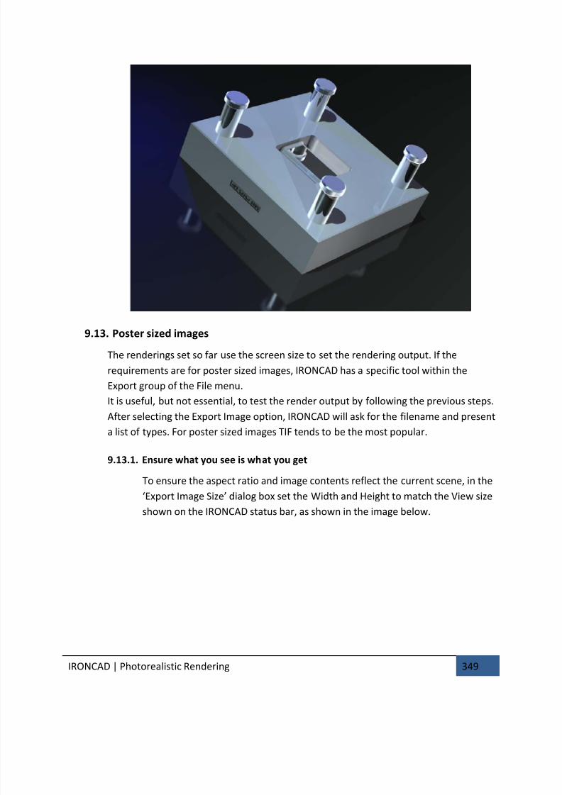
7/30/2019 Unlock Ironcadgsg
http://slidepdf.com/reader/full/unlock-ironcadgsg 353/367
IRONCAD | Photorealistic Rendering 349
9.13. Poster sized images
The renderings set so far use the screen size to set the rendering output. If the
requirements are for poster sized images, IRONCAD has a specific tool within the
Export group of the File menu.
It is useful, but not essential, to test the render output by following the previous steps.
After selecting the Export Image option, IRONCAD will ask for the filename and presenta list of types. For poster sized images TIF tends to be the most popular.
9.13.1. Ensure what you see is what you get
To ensure the aspect ratio and image contents reflect the current scene, in the
‘Export Image Size’ dialog box set the Width and Height to match the View size
shown on the IRONCAD status bar, as shown in the image below.
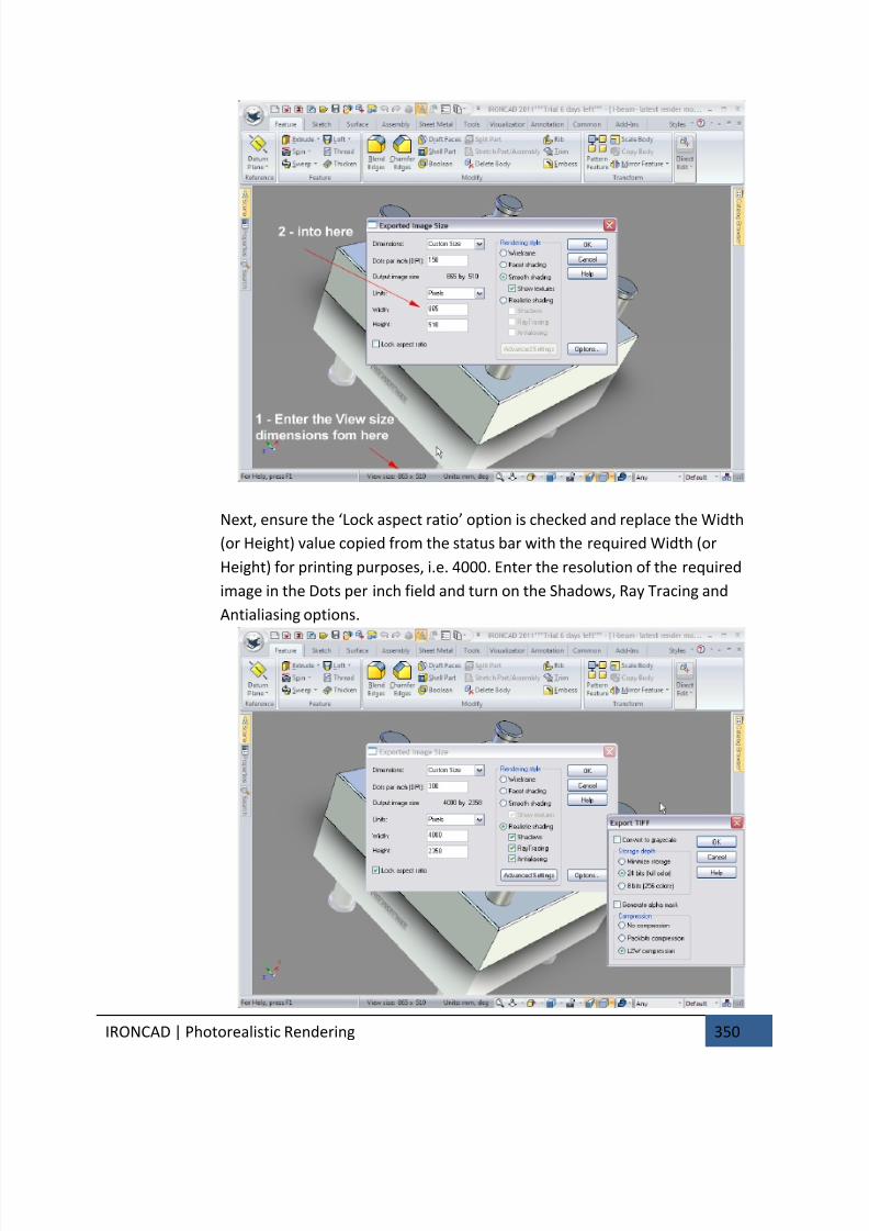
7/30/2019 Unlock Ironcadgsg
http://slidepdf.com/reader/full/unlock-ironcadgsg 354/367
IRONCAD | Photorealistic Rendering 350
Next, ensure the ‘Lock aspect ratio’ option is checked and replace the Width
(or Height) value copied from the status bar with the required Width (or
Height) for printing purposes, i.e. 4000. Enter the resolution of the required
image in the Dots per inch field and turn on the Shadows, Ray Tracing and
Antialiasing options.

7/30/2019 Unlock Ironcadgsg
http://slidepdf.com/reader/full/unlock-ironcadgsg 355/367
IRONCAD | Photorealistic Rendering 351
The Advanced Settings will be the same as the previous screen based render
export. Finally set the desired Options such as color mode (8 or 24 bits) and set
the Alpha mask option if the output required just contains the model and not
the model and background.Clicking OK will export the image. Be aware that this process does not use
multi-threading so IRONCAD will be un-available during image export.
This completes the section introducing IRONCAD’s photorealistic rendering capabilities. It is
well worth experimenting with surfaces, textures and materials to build custom libraries of
parts. Using the assembly created early on in the Getting Started Guide this section
introduced the basics of:
• Simple drag and drop rendering techniques
• Creating screen based images for use with standard screen capture tools
• Creation of high quality renderings for everyday use to large format poster
style renderings
The next chapter will complete the Getting Started Guide by introducing the techniques for
creating an animation of the I-Beam assembly used in this section.

7/30/2019 Unlock Ironcadgsg
http://slidepdf.com/reader/full/unlock-ironcadgsg 356/367
IRONCAD | Animating with IRONCAD 352
10. ANIMATING WITH IRONCAD
Extending the built in communication capabilities, IRONCAD has a wealth of tools to create
animations to communicate the design.
Animation can be great fun. This section introduces some of the core techniques and termsto provide a foundation on which to build. The chapter will show how to:
• Apply a SmartMotion directly from the catalog
• Edit the dropped SmartMotion so that it performs the relevant moves
• Add an addition segment to an existing path
• Change the start point of an animation segment
• Produce a dynamic, cut-away section in a model
For simplicity, the I-beam assembly used in the rendering section will again be used. Start by
opening I-beam.ics saved previously or found in the tutorials section and in addition openthe animation catalog.
In IRONCAD animations are broken down into segments and combined in a sequence using
IRONCAD’s segment editor called the ‘SmartMotions editor’.
10.1. Fundamental control of animation segments
10.1.1. Length, Height and Width
IRONCAD uses the Length, Height and Width notation to apply and control the
animation. So before applying an animation segment check the orientation of the part, or feature anchor.
10.1.2. Key
A simple animation such as a linear move has a start point and a stop point.
These two control points are known as keys. The orientation of the part,
assembly or feature at each key can be different with IRONCAD performing the
calculations for the position of the model as it moves from one key position to
the other. Keys can be added and manipulated to obtain some great results.
10.1.3. TriBall
The TriBall can be used to position a key in the sequence.
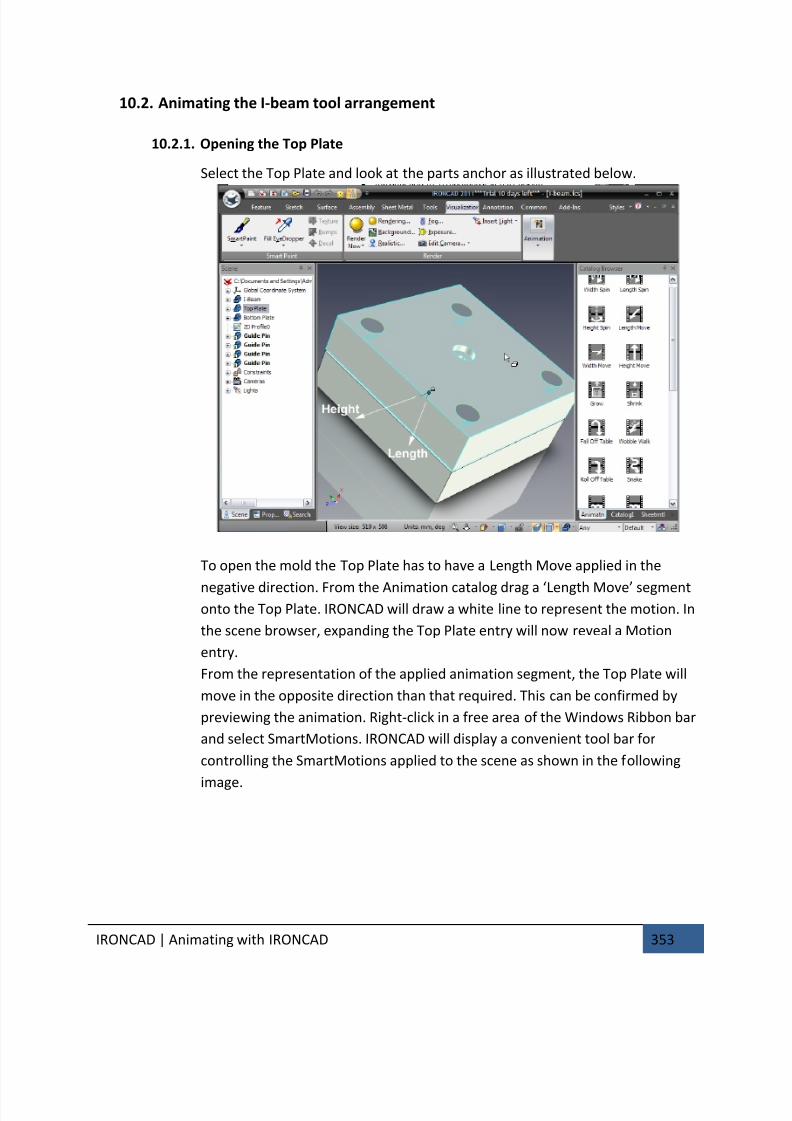
7/30/2019 Unlock Ironcadgsg
http://slidepdf.com/reader/full/unlock-ironcadgsg 357/367
IRONCAD | Animating with IRONCAD 353
10.2. Animating the I-beam tool arrangement
10.2.1. Opening the Top Plate
Select the Top Plate and look at the parts anchor as illustrated below.
To open the mold the Top Plate has to have a Length Move applied in the
negative direction. From the Animation catalog drag a ‘Length Move’ segmentonto the Top Plate. IRONCAD will draw a white line to represent the motion. In
the scene browser, expanding the Top Plate entry will now reveal a Motion
entry.
From the representation of the applied animation segment, the Top Plate will
move in the opposite direction than that required. This can be confirmed by
previewing the animation. Right-click in a free area of the Windows Ribbon bar
and select SmartMotions. IRONCAD will display a convenient tool bar for
controlling the SmartMotions applied to the scene as shown in the following
image.
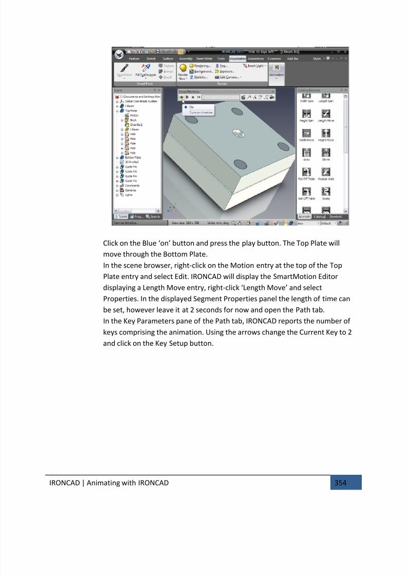
7/30/2019 Unlock Ironcadgsg
http://slidepdf.com/reader/full/unlock-ironcadgsg 358/367
IRONCAD | Animating with IRONCAD 354
Click on the Blue ‘on’ button and press the play button. The Top Plate will
move through the Bottom Plate.
In the scene browser, right-click on the Motion entry at the top of the Top
Plate entry and select Edit. IRONCAD will display the SmartMotion Editor
displaying a Length Move entry, right-click ‘Length Move’ and select
Properties. In the displayed Segment Properties panel the length of time can
be set, however leave it at 2 seconds for now and open the Path tab.
In the Key Parameters pane of the Path tab, IRONCAD reports the number of
keys comprising the animation. Using the arrows change the Current Key to 2
and click on the Key Setup button.
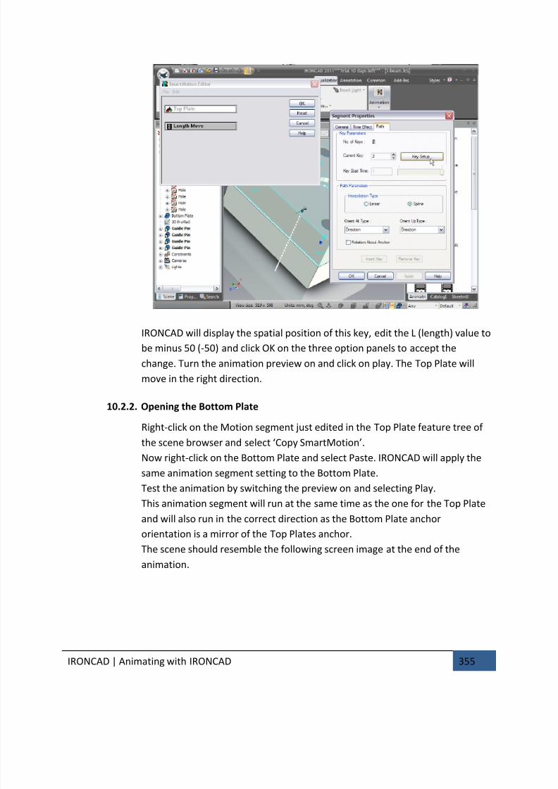
7/30/2019 Unlock Ironcadgsg
http://slidepdf.com/reader/full/unlock-ironcadgsg 359/367
IRONCAD | Animating with IRONCAD 355
IRONCAD will display the spatial position of this key, edit the L (length) value to
be minus 50 (-50) and click OK on the three option panels to accept the
change. Turn the animation preview on and click on play. The Top Plate will
move in the right direction.
10.2.2. Opening the Bottom Plate
Right-click on the Motion segment just edited in the Top Plate feature tree of
the scene browser and select ‘Copy SmartMotion’.
Now right-click on the Bottom Plate and select Paste. IRONCAD will apply the
same animation segment setting to the Bottom Plate.
Test the animation by switching the preview on and selecting Play.
This animation segment will run at the same time as the one for the Top Plate
and will also run in the correct direction as the Bottom Plate anchor
orientation is a mirror of the Top Plates anchor.
The scene should resemble the following screen image at the end of theanimation.
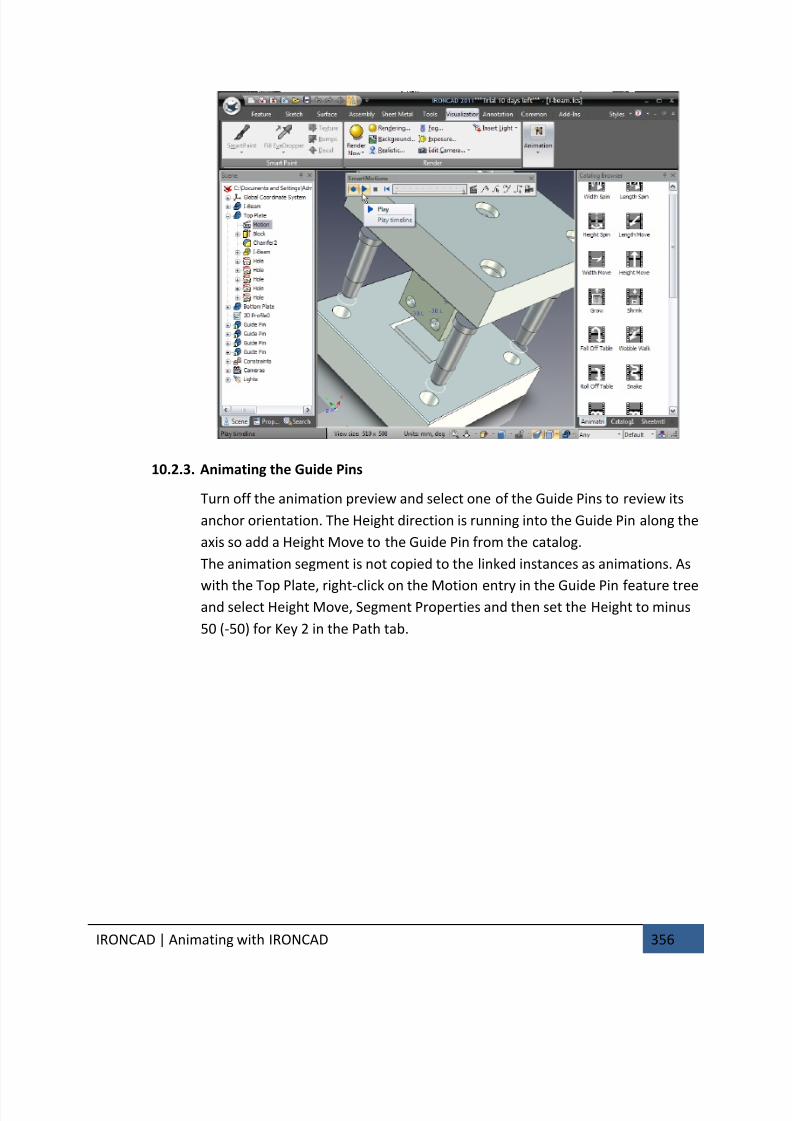
7/30/2019 Unlock Ironcadgsg
http://slidepdf.com/reader/full/unlock-ironcadgsg 360/367
IRONCAD | Animating with IRONCAD 356
10.2.3. Animating the Guide Pins
Turn off the animation preview and select one of the Guide Pins to review its
anchor orientation. The Height direction is running into the Guide Pin along the
axis so add a Height Move to the Guide Pin from the catalog.
The animation segment is not copied to the linked instances as animations. As
with the Top Plate, right-click on the Motion entry in the Guide Pin feature treeand select Height Move, Segment Properties and then set the Height to minus
50 (-50) for Key 2 in the Path tab.
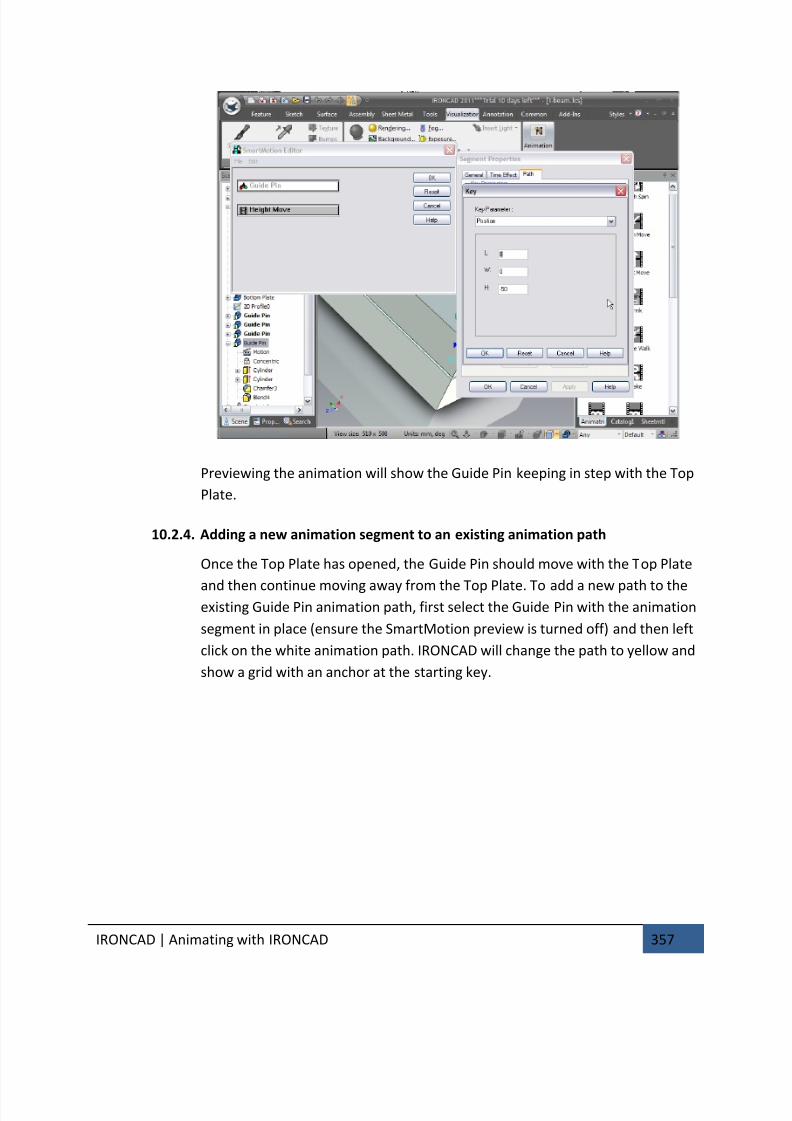
7/30/2019 Unlock Ironcadgsg
http://slidepdf.com/reader/full/unlock-ironcadgsg 361/367
IRONCAD | Animating with IRONCAD 357
Previewing the animation will show the Guide Pin keeping in step with the Top
Plate.
10.2.4. Adding a new animation segment to an existing animation path
Once the Top Plate has opened, the Guide Pin should move with the Top Plate
and then continue moving away from the Top Plate. To add a new path to theexisting Guide Pin animation path, first select the Guide Pin with the animation
segment in place (ensure the SmartMotion preview is turned off) and then left
click on the white animation path. IRONCAD will change the path to yellow and
show a grid with an anchor at the starting key.
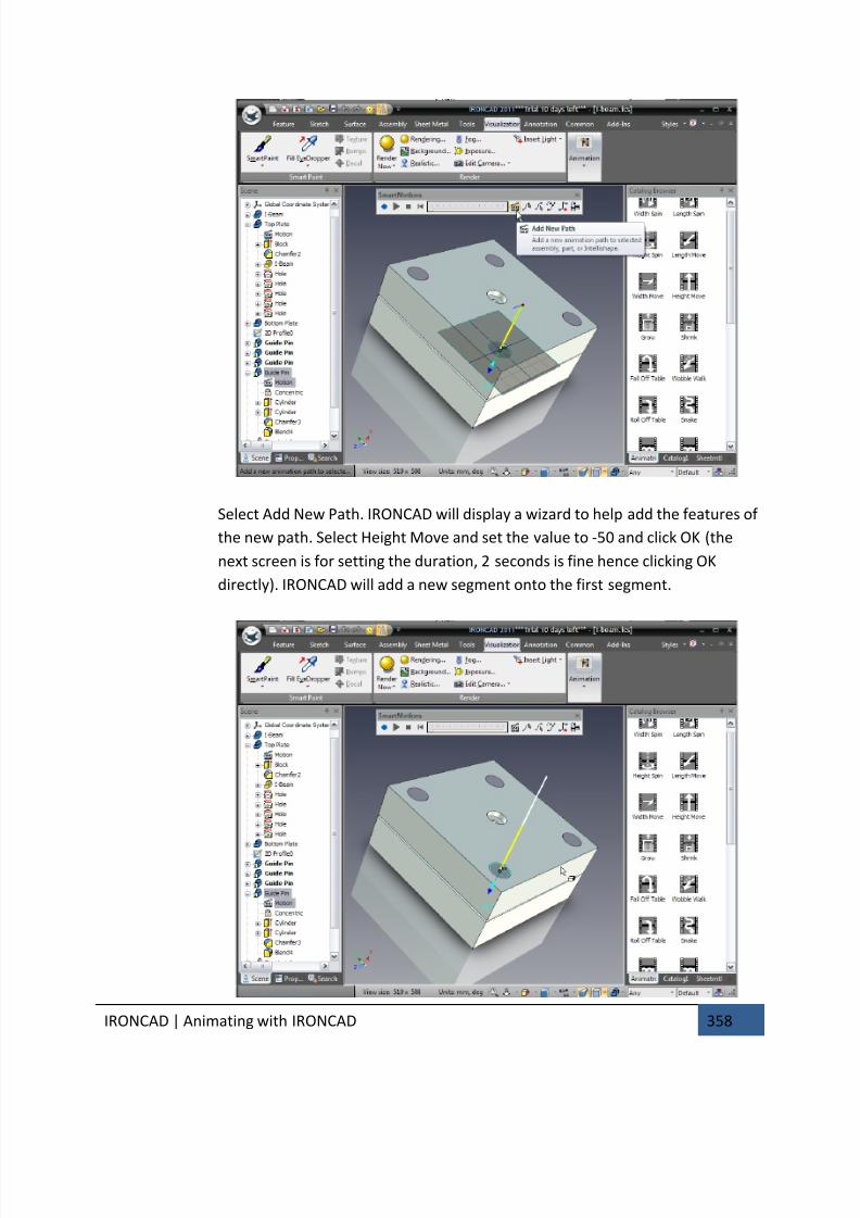
7/30/2019 Unlock Ironcadgsg
http://slidepdf.com/reader/full/unlock-ironcadgsg 362/367
IRONCAD | Animating with IRONCAD 358
Select Add New Path. IRONCAD will display a wizard to help add the features of
the new path. Select Height Move and set the value to -50 and click OK (the
next screen is for setting the duration, 2 seconds is fine hence clicking OK
directly). IRONCAD will add a new segment onto the first segment.
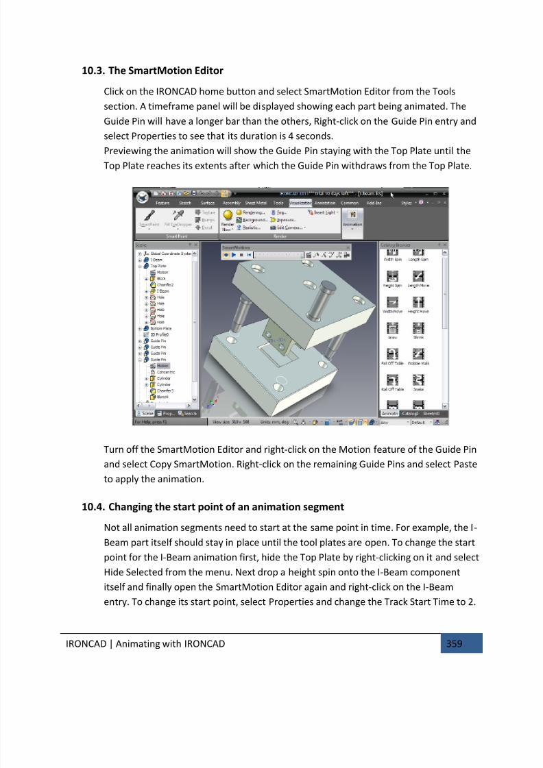
7/30/2019 Unlock Ironcadgsg
http://slidepdf.com/reader/full/unlock-ironcadgsg 363/367
IRONCAD | Animating with IRONCAD 359
10.3. The SmartMotion Editor
Click on the IRONCAD home button and select SmartMotion Editor from the Tools
section. A timeframe panel will be displayed showing each part being animated. The
Guide Pin will have a longer bar than the others, Right-click on the Guide Pin entry and
select Properties to see that its duration is 4 seconds.
Previewing the animation will show the Guide Pin staying with the Top Plate until the
Top Plate reaches its extents after which the Guide Pin withdraws from the Top Plate.
Turn off the SmartMotion Editor and right-click on the Motion feature of the Guide Pin
and select Copy SmartMotion. Right-click on the remaining Guide Pins and select Paste
to apply the animation.
10.4. Changing the start point of an animation segment
Not all animation segments need to start at the same point in time. For example, the I-
Beam part itself should stay in place until the tool plates are open. To change the start
point for the I-Beam animation first, hide the Top Plate by right-clicking on it and select
Hide Selected from the menu. Next drop a height spin onto the I-Beam component
itself and finally open the SmartMotion Editor again and right-click on the I-Beam
entry. To change its start point, select Properties and change the Track Start Time to 2.
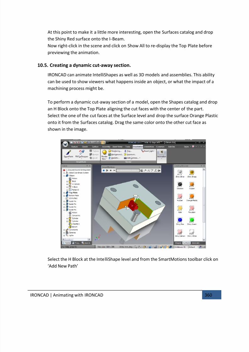
7/30/2019 Unlock Ironcadgsg
http://slidepdf.com/reader/full/unlock-ironcadgsg 364/367
IRONCAD | Animating with IRONCAD 360
At this point to make it a little more interesting, open the Surfaces catalog and drop
the Shiny Red surface onto the I-Beam.
Now right-click in the scene and click on Show All to re-display the Top Plate before
previewing the animation.
10.5. Creating a dynamic cut-away section.
IRONCAD can animate IntelliShapes as well as 3D models and assemblies. This ability
can be used to show viewers what happens inside an object, or what the impact of a
machining process might be.
To perform a dynamic cut-away section of a model, open the Shapes catalog and drop
an H Block onto the Top Plate aligning the cut faces with the center of the part.
Select the one of the cut faces at the Surface level and drop the surface Orange Plastic
onto it from the Surfaces catalog. Drag the same color onto the other cut face asshown in the image.
Select the H Block at the IntelliShape level and from the SmartMotions toolbar click on
‘Add New Path’
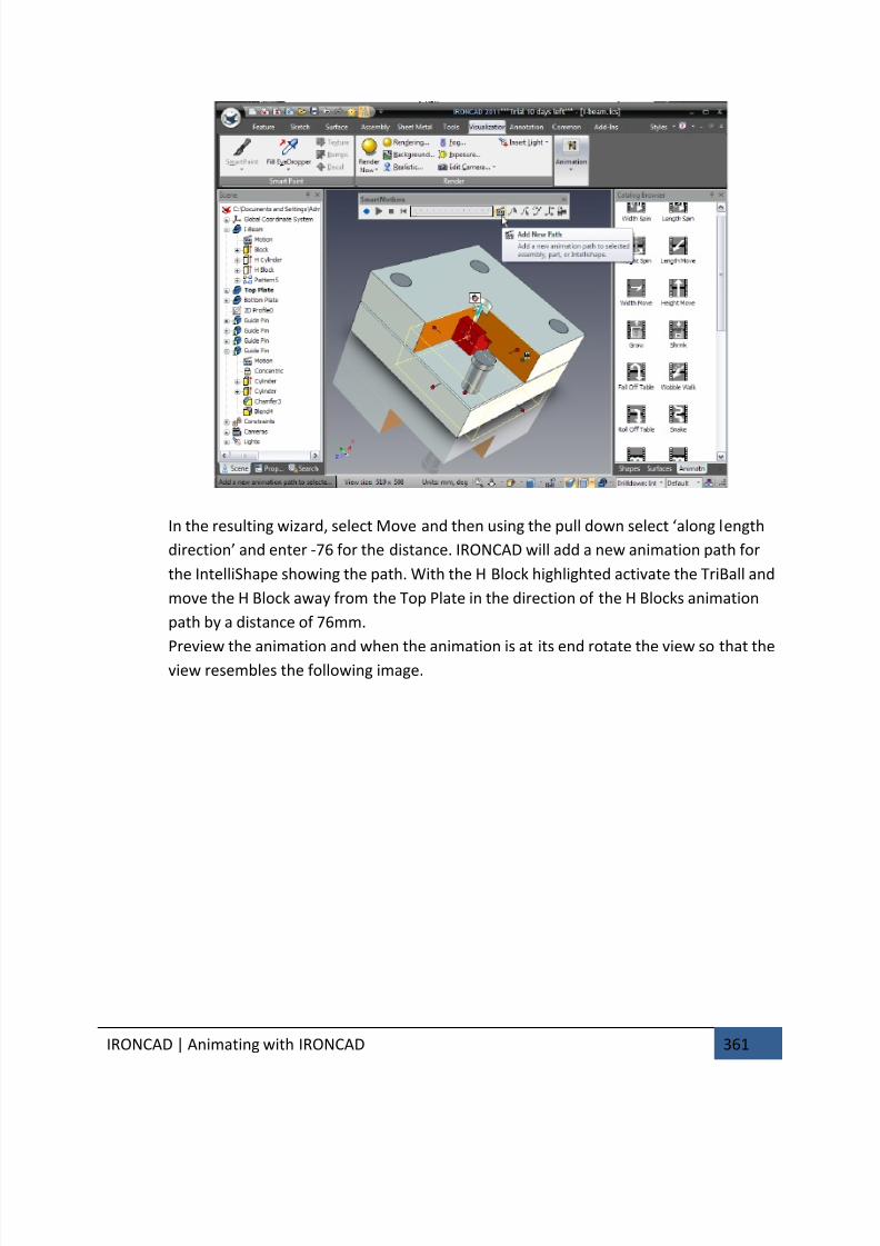
7/30/2019 Unlock Ironcadgsg
http://slidepdf.com/reader/full/unlock-ironcadgsg 365/367
IRONCAD | Animating with IRONCAD 361
In the resulting wizard, select Move and then using the pull down select ‘along length
direction’ and enter -76 for the distance. IRONCAD will add a new animation path for
the IntelliShape showing the path. With the H Block highlighted activate the TriBall and
move the H Block away from the Top Plate in the direction of the H Blocks animation
path by a distance of 76mm.
Preview the animation and when the animation is at its end rotate the view so that the
view resembles the following image.
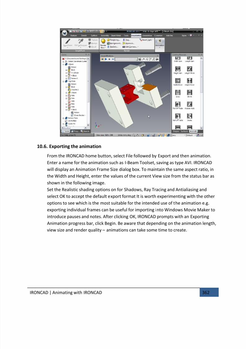
7/30/2019 Unlock Ironcadgsg
http://slidepdf.com/reader/full/unlock-ironcadgsg 366/367
IRONCAD | Animating with IRONCAD 362
10.6. Exporting the animation
From the IRONCAD home button, select File followed by Export and then animation.
Enter a name for the animation such as I-Beam Toolset, saving as type AVI. IRONCAD
will display an Animation Frame Size dialog box. To maintain the same aspect ratio, in
the Width and Height, enter the values of the current View size from the status bar as
shown in the following image.Set the Realistic shading options on for Shadows, Ray Tracing and Antialiasing and
select OK to accept the default export format It is worth experimenting with the other
options to see which is the most suitable for the intended use of the animation e.g.
exporting individual frames can be useful for importing into Windows Movie Maker to
introduce pauses and notes. After clicking OK, IRONCAD prompts with an Exporting
Animation progress bar, click Begin. Be aware that depending on the animation length,
view size and render quality – animations can take some time to create.
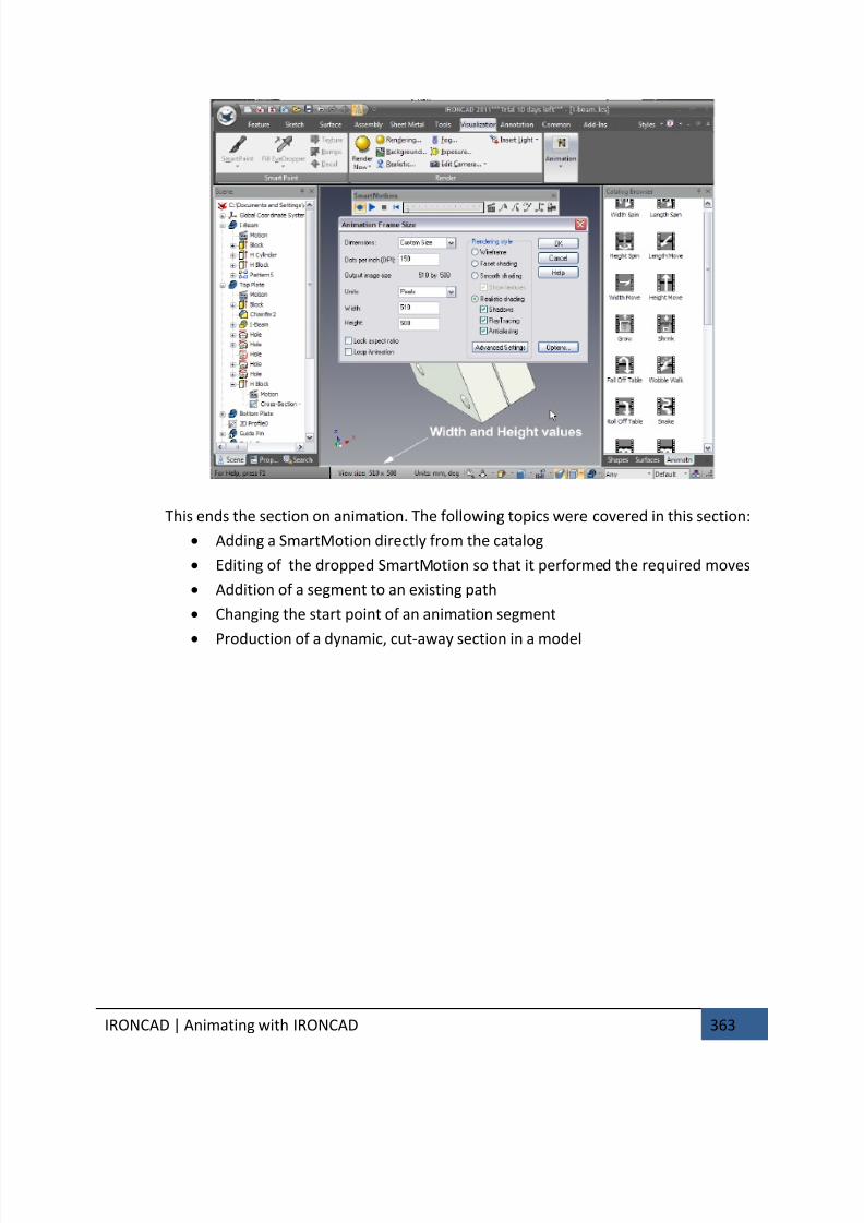
7/30/2019 Unlock Ironcadgsg
http://slidepdf.com/reader/full/unlock-ironcadgsg 367/367
This ends the section on animation. The following topics were covered in this section:
• Adding a SmartMotion directly from the catalog
• Editing of the dropped SmartMotion so that it performed the required moves
• Addition of a segment to an existing path
• Changing the start point of an animation segment
• Production of a dynamic, cut-away section in a model