UNITED STATES DEPARTMENT OF LABOR MINE … underground silo filled, the material continued to back...
61
MAI-2010-13/14 UNITED STATES DEPARTMENT OF LABOR MINE SAFETY AND HEALTH ADMINISTRATION Metal and Nonmetal Mine Safety and Health REPORT OF INVESTIGATION Underground Metal Mine (Gold) Fatal Falling Material Accident August 12, 2010 Meikle Mine Barrick Goldstrike Mines Inc. Carlin, Eureka County, Nevada Mine I.D. No. 26-02246 Investigators Stephen A. Cain Supervisory Mine Safety and Health Inspector Jesse Martinez Mine Safety and Health Inspector Terence M. Taylor, P.E. Senior Civil Engineer James M. Kelly, P.E. Civil Engineer Thomas D. Barkand Electrical Engineer Steve M. Powroznik Mine Safety and Health Specialist Originating Office Mine Safety and Health Administration Western District 991 Nut Tree Road, Second Floor Vacaville, California 95687 Wyatt Andrews, District Manager
Transcript of UNITED STATES DEPARTMENT OF LABOR MINE … underground silo filled, the material continued to back...

MAI-2010-13/14
UNITED STATES DEPARTMENT OF LABOR
MINE SAFETY AND HEALTH ADMINISTRATION Metal and Nonmetal Mine Safety and Health
REPORT OF INVESTIGATION
Underground Metal Mine (Gold)
Fatal Falling Material Accident
August 12, 2010
Meikle Mine Barrick Goldstrike Mines Inc.
Carlin, Eureka County, Nevada Mine I.D. No. 26-02246
Investigators
Stephen A. Cain
Supervisory Mine Safety and Health Inspector
Jesse Martinez Mine Safety and Health Inspector
Terence M. Taylor, P.E. Senior Civil Engineer
James M. Kelly, P.E.
Civil Engineer
Thomas D. Barkand Electrical Engineer
Steve M. Powroznik
Mine Safety and Health Specialist
Originating Office Mine Safety and Health Administration
Western District 991 Nut Tree Road, Second Floor
Vacaville, California 95687 Wyatt Andrews, District Manager

Table of Contents
OVERVIEW GENERAL INFORMATION DESCRIPTION OF THE ACCIDENT Page 1 INVESTIGATION OF THE ACCIDENT Page 3 DISCUSSION Page 4 CONCLUSION Page 23 ENFORCEMENT ACTIONS Page 23 APPENDICES
A. Persons Who Participated in the Investigation B. Tables C. Figures of Aggregate Delivery System D. Photos E. Victim Data Sheet


OVERVIEW On August 12, 2010, Daniel Noel, leadman, age 47, and Joel Schorr, fixed maintenance technician, age 38, were killed while attempting to locate and free an obstruction in a 24-inch diameter aggregate delivery pipe in a ventilation shaft. The pipe conveyed crushed aggregate material from the surface of the mine to an underground batch plant. The batch plant produced a cement rock fill (“CRF”) that is used as backfill in the mine. This pipe traveled down one side of the 16-foot diameter shaft to a drop rock box silo at the 860 level. The miners were above the 820 foot level when the obstructed pipe failed catastrophically. The accident occurred because management did not have adequate policies and procedures that provided for the safe operation, inspection, maintenance, and training regarding the aggregate pipe delivery system. Management failed to ensure that the pipe, its support system, and electrical system were maintained in a safe condition to protect all persons who could be exposed to a hazard from any failure of the system. Management failed to ensure that the 24-inch pipe, brackets, bolted connections, and bearing plates were maintained in a safe condition. Additionally, management failed to maintain the electrical sensors and alarm systems and ensure that these systems could not be by-passed. A broom handle was used to wedge the electrical control panel reset button so the aggregate delivery system would continue to operate and not trip out.

1
GENERAL INFORMATION
Meikle Mine, a multi-level underground gold mine, owned and operated by Barrick Goldstrike Mines, Incorporated (Barrick) is located 27 miles north of Carlin, Elko County, Nevada. The principal operating officials are Aaron Regent, chief executive officer; Randy Buffington, general manager; Nigel Bain, mine manager; and Thomas A. Bassier, safety and health manager. The mine normally operated two, 12-hour shifts a day, seven days a week. A total of 574 persons are employed with 564 miners working underground. Gold bearing ore is drilled and blasted in open stopes. Broken material is transported from the stopes on haulage trucks to ore chutes, crushed, and hoisted to the surface. Depending on its grade, the ore is either milled or hauled to a cyanide leach pad for processing. The milled or leached products are sent to the plant refinery for removal of impurities and pouring into dore` bars. These bars are transported to refineries off site for final processing prior to sale to customers. The last regular inspection of this operation was completed on June 21, 2010. An inspection, started July 26, 2010, was being conducted when the accident occurred.
DESCRIPTION OF THE ACCIDENT On the day prior to the accident (day shift - August 11, 2010), Orie Noble, surface aggregate operator, had replaced Timothy Thornley, surface aggregate operator, who was attending a training class that morning. Noble observed that the aggregate material was dry. He requested that the aggregate stock pile be watered. A water truck was used twice to suppress the dust. Noble reported that he loaded aggregates with a front-end loader into the grizzly (surface hopper) for about 3½ hours before the aggregate electrical system tripped out and a red warning light came on at the feed grizzly on the surface (figure 6). Electrical records indicated the aggregate delivery system shut down at approximately 12:58 p.m. Noble thought an electrical acoustic sensor was faulty, causing the shutdown. Noble checked the feed belt conveyor and the surface transfer box located above the three aggregate delivery pipes. He found the transfer box full and the belt conveyor overflowing with aggregate. Records of the electrical system showed that Noble had dumped 84 bucket loads of aggregate into the system prior to the shut down. Mitch Roberts, batch plant operator, started his shift at 7:00 a.m. on August 11, 2010, at the underground batch plant. Roberts stated the aggregate silo was not full at the beginning of the shift but became full during the shift. Roberts said the lens on the monitoring camera near the aggregate silo was fogging which made seeing the silo level difficult. Therefore, he could not determine how much material was in the silo. Roberts estimated he loaded 15 trucks out of the batch plant. He was operating the batch plant when the aggregate delivery pipe clogged. After the underground silo filled, the material continued to back up in the aggregate delivery pipe until it reached the surface. Noble contacted the batch plant underground at approximately 1:00 p.m. soon after the aggregate system stopped operating. Noble spoke with Charles Taylor, batch plant operator,

2
who replaced Roberts as the batch plant operator shortly after the aggregate pipe clogged. Taylor informed Noble it had been a slow day with only two trucks hauling about 20 batches out. Noble went underground to the 860 rock box and noticed the rock box and chute were full of aggregate (figure 7). He returned to the surface and met with Richard Nunn, leadman, and Thornley. Noble told them the aggregate pipe was full. Nunn assigned Noble to another task underground and instructed Thornley to begin working to unplug the system. Ted Suthers, toplander, was at the collar of the shaft loading supply materials to be sent underground. He observed the aggregate pipe system was plugged all the way to the surface and that material was overflowing at the rock transfer box on the surface. Suthers stated the electrical button switch to the aggregate feed system for the pipe had been reset several times during the shift. He saw Noble go to the control panel several times during the day shift prior to the accident. Suthers stated he had observed a broom handle wedged between the wall and the reset control panel. Taylor continued to load trucks underground and the silo level was moving down, but the aggregate in the pipe would not flow. Thornley cleaned up around the belt conveyor on the surface. He went underground and used an air lance to clear material in the chute leading out from the 860 rock box. Three access doors were located on the chute, two on the lower end and one on the upper end. Thornley observed a solid column of material between the bottom of the 24-inch pipe going into the rock box and the inside of the rock box. Since the day shift was nearly over, Thornley did not attempt to unbolt the latch door on the rock box and clear this column of material. Daniel Noel (victim) started his shift at 7:00 p.m. on August 11, 2010. He met with Nunn and Thornley. They told Noel that the pipe was plugged; they tried to unplug it, but could not clear the blockage. Nunn informed Noel that the underground batch plant was still operating because there was enough aggregate in the underground storage silo. Noel called Ken Anderson, batch plant operator, and told him the aggregate silo was full so he would have enough material to operate. At approximately 8:00 p.m., Noel assigned Matt Inama, backfill operator, to clean up the surface area of the aggregate delivery system, while John Conklin, jammer operator, and Noel attempted to unplug the system underground. Inama observed the light flashing on the panel at the surface, indicating a plug at the 860 level. He went underground and observed the aggregate material in the 860 level rock box. Noel and Conklin went underground to the 860 level and looked into the lower chute door below the rock box and saw that it was clear of material. Conklin looked at the upper chute door and saw that material was built up in the rock box and the pipe was full. Using an air lance, Conklin attempted to break up the clog. Conklin was able to clear out some of the material in the rock box and was able to establish air space between the clogged material in the pipe and the dead bed below in the rock box. Joel Schorr (victim) started his shift at 7:00 p.m. on August 11, 2010. Schorr was working underground when he was contacted around midnight by Noel to accompany him to the ventilation shaft to clear the plugged aggregate pipe. Schorr contacted David Johnson, hoist operator, and told Johnson that he and Noel needed to go into the shaft to check the plugged pipe. At 12:49 a.m., Noel and Schorr boarded the top of the hoist conveyance from the 1225

3
level. Observing a remote camera, Johnson saw the men board the top of the conveyance carrying a short-handle axe. Both men were observed wearing full body harness fall protection. As the conveyance approached the 860 level, the speed was slowed to 50 feet per minute. They started hitting the aggregate pipe just above the rock box and worked their way up the pipe. Conklin, who was positioned on top of the rock box, observed the material start to fall and flow as Noel and Schorr worked their way up the shaft. Conklin described the activity of striking the pipe as tapping on it, rather than beating. Conklin said they stopped 15 feet above him and then made two more short moves with the conveyance, at which point he could not see them. At approximately 1:10 a.m., Conklin stated there was a sudden large surge of material coming down the pipe. He immediately shut the door on top of the rock box, but the material overwhelmed the box and the door blew open. Conklin turned his back to the falling pipes and debris and made his way down the steps to get help. Schorr and Noel were fatally struck by the falling pipe and aggregate. Johnson had been monitoring pressures on the hoist hydraulics. One of the men used the bell cord to signal when to start and stop the conveyance. Johnson started and stopped the conveyance 4 or 5 times and had slowed the travel speed down to 26 feet per minute. The last elevation he recalled was 820 feet. He stated the hoist had been running about 820 psi when the pressure on the hoist suddenly spiked to 3,000 psi and the hoist drum was ripped from its mounts. The needle on the hoist’s controller indicated the elevation of the conveyance was above the 860 level. At approximately 1:00 a.m., Anderson heard a noise and could see rock fly out of the transfer box at the 860 level on the control room video monitor. The monitor then went dead. Immediately after the accident occurred, the mine operator started an extensive rescue and recovery operation. The Mine Safety and Health Administration (MSHA) was notified of the accident at 2:13 a.m. on August 12, 2010, by a telephone call from Thomas Bassier, manager safety and health, to MSHA's emergency call center. Rodney Gust, staff assistant, was notified at 2:26 a.m. An order was issued under the provisions of Section 103(j) and later modified to section 103(k) of the Mine Act to ensure the safety of miners. Personnel from MSHA were dispatched to the mine and arrived at 4:30 a.m. on August 12, 2010. A command center was established at the mine to coordinate efforts with the mine rescue teams. Rescue teams began searching the areas in and around the ventilation shaft for any signs of the two miners. A camera was dropped down the ventilation shaft but neither miner was discovered. Rescue teams broke through a bulkhead at the 1330 level and encountered a log jam of pipes, brackets, clamps, and aggregate. Efforts to rescue and or recover the two miners were hampered by the amount of material that had been destroyed and the condition of the ventilation shaft. After extensive efforts to locate the miners, they were recovered on August 18, 2010.
INVESTIGATION OF THE ACCIDENT
An accident investigation was started on August 18, 2010, after both miners were recovered. MSHA’s accident investigation team traveled to the mine. The team conducted a physical inspection of the accident scene, interviewed employees, and reviewed conditions and work procedures relevant to the accident. MSHA conducted the investigation with the assistance of mine management and employees and the state of Nevada Division of Mine Inspection.

4
DISCUSSION
Location of the Accident The accident occurred underground in the ventilation shaft in the vicinity of the 820 level. Ventilation Shaft The ventilation shaft is reinforced concrete lined, has an inside diameter of 16 feet, and extends to a depth of 1330 feet (figure 1). The shaft housed the service and supply cage and served as an exhaust ventilation shaft. Placed in the shaft were utility conduits, electrical cable brackets, and the aggregate delivery system, which consisted of two 12-inch-diameter vertical pipes and one 24-inch-diameter vertical pipe. One 12-inch pipe was located on the north side of the 24-inch pipe and the other was located on the south side. Aggregate Delivery System Aggregate material was trucked from the surface crushing facility to a stock pile area near the surface elevation of the ventilation shaft. The aggregate was minus 3-inch-diameter material and included fines (photo 1). This material was used to make backfill concrete to fill in the stopes underground after they were mined. A front-end loader moved the material up a ramp to a feed hopper (figure 6 and photo 2). This hopper fed a short 28-inch wide belt conveyor that dumped the material into a transfer box (hopper) located over the edge of the shaft at the surface. From the transfer box, three knife gates directed the material into one of the three aggregate delivery pipes. The center 24-inch diameter pipe was used most frequently. The inlet for the center pipe had an 18-inch diameter. A flow expander section transitioned the upper 18-inch diameter pipe to a 24-inch-diameter pipe. This expander was located near the top of the shaft; therefore, the majority of the pipe was 24-inch diameter. The aggregate fell down the pipe to a rock box, an 8-foot diameter steel silo, located with its bottom at the 860 level. The bottom of the rock box was full of aggregate which acted as an impact zone (dead bed) for the falling aggregate material (figure 7). A 4-foot by 4-foot square shaped discharge chute, located on the side of the rock box, limited the depth of the dead bed (figure 7 and photo 3). Once the rock impacted the bottom of the rock box, it flowed out the side chute. Using gravity flow, the rectangular-shaped chute, oriented on an approximate 45 degree angle, directed the material away from the shaft and toward the batch plant. A transfer box, with two knife gates that could be operated to direct the aggregate into one of two chutes, was located at the bottom of the chute. Each chute emptied into one of two storage silos. These two chutes were 32-inch diameter circular excavations through the rock mass that led to the silos. The chute leading to the aggregate silo was 89 feet long and constructed on a 49 degree inclination. The material entered the silos at the 925 level of the mine. The silos were shotcrete-lined with a steel hopper at the bottom. One of the silos, termed the sand silo, was no longer in use. All of the material was directed into only one active aggregate silo. This silo was 14 feet in diameter and 138 feet high. The underground batch plant operator would pull material from this silo to be mixed with cement, fly ash, and water in the backfill process. The batch plant is operated at the 1090 level of the mine. One batch of

5
backfill consists of 20,000 pounds of aggregate, 700 pounds of fly ash, 100 pounds of cement, and 100 gallons of water. Each haul truck can carry two batches of material. 24-Inch Aggregate Pipeline The ½-inch thick, 24-inch diameter pipe involved in the accident was manufactured by CF Ultra Tech. This Ultra 600 pipe, which is induction-hardened, has a hard inner surface tapering to a tough, ductile outer surface. In the hardening process, the raw pipe is heated above 1,550°F, then the inside diameter is rapidly quenched with a treated coolant. This procedure alters the microstructure. As the distance from the inner pipe wall increases, the effect of the quench is progressively less and the ductility increases to the outer surface. The inner surface has abrasion resistance while the outer surface has impact resistance. The inner surface is hardened to 600 Brinell (328,000 psi) and the outer surface has a strength equivalent to 250 Brinell (120,000 psi). Due to the proprietary chemical composition, the investigators were not provided any additional information regarding the pipe. CF Ultra Tech literature indicates that brittleness through hardness is detrimental if the pipe cannot withstand normal handling methods during installation or maintenance and that brittle material can shatter. The literature does not recommend butt welding of the hardened pipe. CF Ultra Tech stated that pounding on the pipe could cause denting on the outside surface and cracking on the inner hardened surface. The crack can propagate from the brittle inner surface through the ductile outer surface. A representative from this company indicated that beating on a pipe could break the pipe, and pipes in the concrete industry have reportedly failed from being beaten with hammers. The pipe had a 23-inch inside diameter and a weighed 125.5 pounds per linear foot. Four types of 24-inch pipes, distinguishable either by length or number of wear bands, were installed in the shaft. The majority of the pipes (27 total) were Type 1. They were 20 feet long and had one 29-inch long, ½-inch thick wear band positioned near the top of the pipe. Type 1A pipes (12 total) were also 20 feet long, but they had a second wear band, 12-inches long and ½-inch thick positioned near the bottom. Types 2 and 3 pipe (one section of each) were 16 and 13 feet long, respectively, and both had a single 29-inch-long, ½-inch-thick wear band. The Type 3 pipe was the bottom pipe in the system and was equipped with a slot opening for installation of a flow monitoring sensor located just above the rock box. The pipes were connected together with E-Ring, Victaulic Style 31 couplings that mounted over flange plates welded to the ends of the pipe (photo 6). All of the pipes were equipped with a pair of lifting lugs/eyes welded to the pipe to facilitate installation. Although the date of the final installation of the pipe is not known, as-built drawing notes were made on February 26, 2002. One note indicated there were misalignment problems with the retrofit. The top five new brackets did not match the pipe wear bands nor did the top regular bracket. To solve this problem, split wear bands at the five new brackets and the top bracket were welded to the pipe. According to the manufacturer, butt welding is not recommended for hardened pipe. Joseph Martinez, welder, indicated that he never pre-heated or post-heated the welds when working on the pipes. Welding was conducted when a pipe section needed to be shortened to make it fit in the aggregate system. This was accomplished by removing the spool end flange weld with air-

6
arcing and sliding down the end flange (i.e. ring for the coupling attachment). The pipe was cut and the flange slipped to the burned end and re-welded in place. Martinez recalled he shortened a pipe section down to 16 feet and another time he shortened a pipe by ½ inch. However, investigators found at least two sets of pipe spools at the evidence yard that had been welded together, indicating that no Victaulic coupling was used (photo 7). 24-Inch Aggregate Pipeline Support System Dynatec designed the 24-inch diameter aggregate delivery pipeline support system in 2001. The system was designed based on the AISC Steel Construction Manual ASD method1. The pipe support system used a combination of 41 existing wall brackets and 12 new brackets. Four of the existing wall brackets were bearing brackets. The existing brackets supported all three pipes (the two original 12-inch pipes and the new 24-inch pipe). The new brackets only supported the middle 24-inch pipe (figure 2). Reportedly, management changed the aggregate delivery pipe to a 24-inch-diameter pipe because the original 14-inch pipe was clogging. Brackets The three types of brackets used to support the 24-inch aggregate line were bearing brackets, original brackets, and new brackets. The new brackets were given that name because they were not part of the original pipe system installed between 1994 and 1995. These brackets were added in the 2001 design at certain locations within the shaft to provide additional support for the 24-inch pipeline. According to Dynatec, in the original 1994-1995 design, the four bearing brackets were designed to carry approximately 200 feet of loaded pipe each, which included two 12-inch and one 14-inch diameter pipe. The bearing set brackets were added for extra security in the design. The bearing brackets were also referred to as master sets. These brackets were 16-inch deep I-beams installed in pockets (block-outs) left open in the concrete shaft lining. In addition to receiving support at the ends of the bearing brackets from the shaft liner, the ends of the beams were also bolted into the shaft lining with 1½-inch diameter rock anchors. Grout was added to fill in the pocket and encase the ends of the beam into the shaft lining. Eight vertical plate stiffeners were located on each side of the beam to support its web and top flange. The original brackets were 6-foot 5-inch long tubes, specified as Grade 50. The tube cross section was 8-inch by 4-inch by ½-inch. Plates were welded to the ends of the tube and the plates were attached to the wall with anchor bolts. A stiffened angle was welded to the front of the tube and three clamp brackets were bolted down to the top of the stiffened angle. The clamp brackets were for the three pipes. The spacing between the centerline of each clamp bracket and the adjacent clamp bracket was 26 inches. The new brackets were 8-inch by 6-inch by ½-inch tubes measuring 39 inches long. Plates were welded to the ends of the tube and each was connected to the shaft wall with 1-inch diameter, 16-inch long rock anchor bolts. A 6-inch stiffened angle that served as a shelf to support the clamp bracket was welded to the front of the tube. The clamp bracket and angle shelf were connected using two tie-down bolts. Unlike the bearing and original brackets, the new brackets only supported the center pipe.
1 AISC = American Institute of Steel Construction, ASD = Allowable Stress Design

7
Clamp Brackets and Clamps The clamp brackets encompassed the back half (closest to the shaft wall) of the pipe. At all locations except the four bearing brackets, the clamp brackets were 4 inches high and consisted of a top plate, bottom plate, vertical plate, two end plates, and five intermediate stiffeners (figure 3). The end plates were drilled to accommodate a single ¾-inch diameter bolt in each end. These two bolt locations were located opposite of each other on each side of the pipe. These were the locations where the clamp would be bolted to the clamp bracket. The clamp brackets were attached to the tube and bearing brackets via two, ¾-inch diameter A325 high strength tie-down bolts that went through slotted holes in the bottom plate at the back of the clamp bracket. The welded angles on the front of the tube brackets also had slotted holes that were oriented perpendicular to the clamp bracket slots. The holes were slotted to accommodate misalignment. When the 24-inch aggregate line was installed, Neal House, shaft crew lead miner, indicated the shaft crew had to enlarge (by burning with a torch) some of the slotted bolt holes on the clamp brackets to align the clamp bracket with the tube brackets (photo 8). The bearing clamp brackets were similar to the regular clamp brackets except they were 8 inches high (figure 4). In addition, each end plate had two bolt holes; i.e. a total of four bolts were attaching the 8-inch high clamp to the clamp bracket. The clamps encompassed the front half of the pipe. The clamps were long plates, ½ inches thick and curved to match the curvature of the pipe wear bands. The clamps had a 90 degree bend at each end (i.e. flange). These bends created a straight face parallel to the end plates on the clamp brackets. The straight face at each side was drilled out to 13/16 inches in diameter to accommodate a bolt for the 49 regular brackets and two bolt holes for the 4 bearing bracket locations. The clamps were 4 inches high for the 49 regular brackets and 8 inches high for the 4 bearing brackets. Dynatec states that there was supposed to be a gap between the clamps and clamp brackets when the clamps were bolted to the brackets. Based on the dimensions on Dynatec drawing E718-323-04-D-412 and considering the inside radii of the clamp and clamp bracket, this gap would have been 3/8 inches prior to tightening. Some miners interviewed concurred there were gaps, while others indicated the surface of the clamp was bolted flush against the surface of the clamp bracket. Some miners indicated washers were being used on the clamp bolts, while others did not. However, Dynatec drawing E514B-323-04-D-400 indicated the bolted connections were supposed to be installed with a flat washer. Only a few flat washers were found in the evidence yard. Reportedly in September 2007, several of the clamps broke and some were bent. One of the clamps was a bearing clamp. Twelve clamps were replaced at that time. Starting approximately one third of the way down from the top, the pipe string dropped a maximum (at its bottom) of about 7 inches. On September 24, 2007, Ted Chidester, supervisor of shaft maintenance, ordered 20 new clamps, but reportedly they were too small for the pipe. In early 2010, reportedly the ground shifted and Michael Gill, shaft crew supervisor, ordered 12 new clamps but stated they were too small. One of the clamps ordered was for a bearing bracket location. Brian Christmann, shaft crew lead miner, stated the clamps currently in the yard were too small. They may have been fabricated for a 24-inch pipe without the wear band.
8
Investigators were given a stock clamp that measured 0.63 inches too long. However, the center-to-center bolt hole spacing was only 28¾ inches on the stock clamp, compared to the design drawing dimension of 30 inches (figure 3). The inside depth of the stock bracket was 16 1/16 inches compared to the drawing dimension of 15¼ inches. The replacement clamps in 2007 and 2010 were ordered from CarWil Engineered Wear Solutions (Carwill), located in Winnemucca, Nevada. Kristen Carrier, owner, told investigators that in 2007 management ordered 20 single clamps, and in 2010 they ordered 20 single clamps and 4 double clamps. The double clamps were the bearing clamps. Both orders were built as per samples (rather than drawings) provided by Barrick. CarWil no longer has the sample sent to them in 2007, but they do still have the sample sent for the 2010 order. This sample consists of a clamp that has one of the flanges broken off. The replacement clamps consist of A36 rolled plate that is cold bent to form the 90 degree flanges. Reportedly, there was no heating involved with the bending process. Although some miners indicated that the clamps were too small, Carrier said Carwill was not notified the clamps were improperly sized and none were returned. Carrier stated when the original pipe support system was installed in 2001, CarWil was asked by management to bid on the clamps; however, they did not get the contract. Bearing Plates The 2001 design specified that two, 4-inch by 10- inch by ¾-inch plates were to be welded to the outside of the wear band at each top bracket (figure 5). The plates were curved to match the outside curvature of the wear bands. These bearing plates were to be field welded using 5/16-inch fillet welds on the two vertical edges of the plates. At the four bearing locations, the fillet welds were also to be placed along the top edge of the plates. The plates were to be welded to the pipe wear band just above the location of the clamp. The plates were to be positioned 180⁰ apart on the sides of the pipe and would rest above the bolted connection of the clamp to clamp bracket on each side of the pipe. Therefore, the clear distance between the plate edges should have been 29.3 inches along the outer perimeter of the pipe. The plates would prevent the pipe from slipping down (even if the clamps and clamp brackets provided no frictional resistance) and would transfer the vertical pipe loads (i.e. self weight and aggregate weight) to the clamps and clamp brackets. Dynatec personnel told the investigators the two field installed plates were to be welded to the pipe sleeves and together with the clamps were designed to transfer the load to the brackets. The bearing plates were not part of the 1994 design of the original 14-inch diameter center pipe, but were added to the 2001 design when the pipe size was increased to 24-inch diameter. Investigators inspected the pipe debris at the evidence yard and found no bearing plates welded to the pipe sections, nor any loose or detached ones. House stated Lauren Roberts, former Barrick project engineer, told him the bearing plates were extra and not needed. According to House, he did not contact Dynatec to confirm whether bearing plates were needed or not. House had told Chidester the bearing plates were not needed, so Chidester informed his crew that the plates could be removed. However, Chidester stated in 2007 he had three bearing plates installed on the aggregate line at each of the four bearing set locations. The plates were 6 inches wide, 3 inches high and ½ inch thick. Reportedly, the plates were welded only across the top.
9
Table 1 in Appendix B contains a description of the bearing plate weld observations made on the wear bands of the pipe remnants found in the evidence yard. As indicated in the table, of the 44 pipe remnants found containing a section or sections of wear band, 22 pieces had no signs of welds and the remaining 22 pieces had minimal sporadic weld remnants that had been torched off, arced, or flattened (photos 9-13). On many of the pipe sections found, the plate weld remnants were not spaced at 180 degree intervals (photo 14). Therefore, it is likely that even when the plates were on the pipe, they were not preventing shear loading on the clamp bolts. Aside from the pieces listed in the table, an additional 28 short segments/pieces (i.e. less than 13’ long) of pipe were found that did not have any wear bands. By not having critical bearing plates at each clamp location to properly transfer the vertical loading, pipe support had to rely on clamp friction alone. Hoist Drum Failure and Cage Damage Failure of the aggregate piping system subjected the hoist to heavy loads when it was impacted by the falling pipes and aggregate. Loads on the top of the conveyance stressed the hoist ropes and caused the ropes to rip the drum out of its support pillow blocks. The two hoist ropes on the drum were 1 5/8-inch diameter. Each hoist pillow block was 4 5/8 inches wide and 2⅛inch thick anchored with four 1-inch diameter bolts, measuring 6½ inches long. Specifically, the left side pillow block (as viewed looking from the hoist operator’s booth) sheared through itself. The two bolts holding the block remnant were still intact and the other two anchor bolts stripped out and failed. On the right side, the pillow block was intact, but all four of the bolts failed, releasing the block. One nut was wedged in the mounting bracket. The bracket was slightly bent and one bolt was on the floor by the wall. Overall, the right side of the drum moved further toward the building wall closest to the shaft (photo 4). The hoist, ropes, structures and all supporting components did not have any role in the cause of the accident. The cage was severely damaged as a result of the accident. The primary impact to the top of the cage appeared to be the side that would have been farthest from the pipes (photo 5). A severe bow was noted in the floor of the cage on the side opposite the pipes. The cage and attachments did not have any role in the cause of the accident. Ventilation Shaft Inspections The shaft crew was responsible for shaft maintenance, inspection, and providing supplies to the mine. Shaft inspections were conducted on seven day intervals. The inspection of the aggregate delivery system included looking for: loose, missing or broken bolts; broken clamps and brackets; loose or broken Victaulic couplings; and checking the pipe for worn out pipe spools. The inspection records from January through August of 2010 were mostly complete. On August 1, 2010, Henry Garcia, supply crewman, inspected the shaft and found one clamp bolt missing. Reportedly, House replaced the bolt. He told investigators some of the bolts and clamps had broken on the 24-inch line in the past year.

10
The most recent inspection was on August 8, 2010, four days before the accident. A report filed by Rene De la Garza, shaft maintenance, revealed two of the brace brackets had a bolt and a nut missing for the 24-inch aggregate pipe. Through interviews, investigators determined the brace brackets were the bolts between the clamp and the clamp bracket and that neither location had been repaired before the accident. They also determined the two locations were not consecutive and were positioned approximately one fourth of the way down the pipe string. De la Garza reported the condition to Brian Christmann, leadman, who was filling in as the shaft crew lead miner at the time. Christmann told De la Garza the two bolts did not need to be replaced because the entire pipe string would be replaced soon. Christmann told investigators he believed this condition was not a problem provided the broken bolts were not at one of the bearing bracket locations or were not in consecutive supports. The failed bolts exacerbated the loads on adjacent brackets and clamps, which had to account for the lack of support at the failed locations. Previously, management used ultrasound to measure pipe wall thicknesses and identify pieces that either needed to be changed out or rotated to extend pipe life. The wear patterns in the pipes were not uniform. For example, ultrasound test results taken October 8, 2006, showed it was possible for the pipe wall thickness to be eroded from its original of 0.5-inch thickness down to 0.108 inches at one location, whereas another measurement taken at the same depth, but 90⁰ around the perimeter had a thickness of 0.387 inches. This large disparity was likely a result of the swirling pattern of the rock, as it dropped and flowed down the pipe system, which was not aligned perfectly vertical. To survey each pipe spool, an ultrasound technician would take four readings around the circumference at the top of the spool and four readings around the circumference at the bottom of the spool. Reportedly, most of the pipe wear occurs in the lower one third of the string. Shaft Crew Maintenance No standard operating procedure was in place for persons to conduct repairs to the system. However, investigators did obtain written work procedures for removing pipe in the ventilation shaft. Due to abrasion from the aggregate, the 24-inch diameter pipe spool sections reportedly have a design life of about one year. To change the pipe, two workers ride in the cage and one rides on top of the conveyance. The person on top attaches the chain falls to the bracket above the pipe section being changed out and then attaches the ends of the chain to the lifting eye lugs welded to the two sides of the pipe. The eyes are located 180° apart. The pipe clamp is removed and the Victaulic couplings are unbolted. The detached section is then pulled into the hoist cage and secured. The worn pipe sections (as many as two) are removed and brought to the surface. The new pipe sections are loaded onto the conveyance and brought down the shaft. The new pipe sections are first secured by the chain falls and swung into position. The Victaulic couplings are secured followed by the clamp. When sections of the pipe are removed, the sections above the removed piece have been known to slide down. When leaks were discovered, the worn pipe section would be temporarily banded by conveyor belting. The belting was wrapped with No. 9 wire to hold it into place until the pipe spool could be scheduled for replacement. Between January and June, 2010, five references were made in the Shaft Inspection Records book regarding holes in the 24-inch aggregate pipe.

11
At the time of the failure, there was one section of worn through 24-inch pipe that was first identified on June 27, 2010. This section had been wrapped with conveyor belting. The belt patch, measuring 24 inches by 28 inches by 7/16 inches thick, was recovered in the debris at the bottom of the shaft (photo 15). Interviews with management and miners indicated when older sections of pipe were reused, the bearing plates were removed. Specifically, the bearing plates were either torched or pried off with a bar. Christmann stated he has been trained to remove the bearing plate using a scaling bar or torch, although most came off with a scaling bar. Martinez stated he removed the bearing plates from pipes with a cutting torch and estimates he did this on 10 to 20 spools. The shaft crew replaced the lowest 16 pipe sections on July 15, 2007. About a year prior to the accident, the bottom 22 pipe spools were replaced. Plans were being made to replace the 24-inch aggregate line with an in-kind line in early to mid 2011. House wanted to have the pipe system re-aligned when replaced. Installation of Clamp Bolts and Clamp Bracket Bolts The two impact wrenches used for installing the bolts for the clamps and clamp brackets were Milwaukee and DeWalt brands. Both were found in the equipment cabinet adjacent to the shaft. Neither have torque adjustments. House stated no specifications were provided for re-torquing the bolts. Bolt Type Grade Nominal Size
(inches) Proof Load (psi)
Minimum Yield Strength (psi)
Minimum Tensile Strength (psi)
A325 5 ¾ 85,000 92,000 120,000 The equation, T=(KDP)/12, is used to relate bolt torque to desired clamp load. Where T=torque (ft-lbs), D=nominal bolt diameter (inches), P=desired clamp load tension (lbs), K=torque coefficient (dimensionless). Using D=0.75 and K=0.2 for plain, as-received condition, slightly oily. Substituting these values, the expression becomes: P=80T. The maximum torque output values provided on the manufacturers’ websites were: Drill Manufacturer & Model
Impact Wrench Size (inches)
Maximum Torque Output (ft-lbs)
Bolt Tension @ Max. Torque Output: P=80T (lbs)
Bolt Proof Load (lbs)
Dewalt DW297 ¾ 434 34,700 28,400 Milwaukee 9075-20 ¾ 380 30,400 28,400 Both wrenches were ¾-inch drive and could deliver enough torque to tension the bolts beyond their proof load, meaning the drills were powerful enough to yield (permanently stretch) the bolts upon installation. The desired clamp load is typically 75% of the proof load. This translates to 21,300 pounds of tension for the ¾ inch A325 bolts (Grade 5). This same clamping value was also provided to investigators by Dynatec following the accident. The

12
torque required to achieve this clamp force is 266 ft-lbs (using the standard equation of P=80T). Both wrenches were able to provide well in excess of the required clamping force. The original 2001 design did not specify a bolt tightening requirement, but drawing general notes on Dynatec drawing E718-323-04-D-411 revision 1, indicated “use bearing type connections” and “fabrication and erection to AISC specification for structural steel buildings, allowable stress design, 1989.” Further, a note on drawing E514B-323-04-D-400 indicates “Use friction-type connections on all adjustable connection points (slotted holes). Use bearing-type connections on all other structural steel.” By over-tightening, the bolts were permanently stretching and did not have the reserve shear capacity needed to hold the full pipe in place via friction and the bending action on the bolts due to the 3/8-inch gap. In addition, the bolt tightening likely yielded the clamps. Earthquakes and Significant Blasts Related to Pipe Slipping In September 2007, all the sections of 24-inch pipe below number 13 (down from the collar) needed to be raised back into place. Reportedly, the 24-inch pipe sections had slipped down a maximum of approximately seven inches to one foot. Seismic (blast) activity was recorded on September 12, 2007, by the Seismology Lab at the University of Nevada Reno, which measured a magnitude 3.51, centered 0.61 miles from the shaft. On February 21, 2008, a magnitude 6.0 event occurred in Wells, Nevada, approximately 79.5 miles from the site. This size earthquake is considered strong and can be destructive in areas up to about 100 miles wide. Reportedly, the Wells earthquake caused several 24-inch pipe sections to slip down approximately 7 to 8 inches. These sections had to be raised back into place and re-attached. No seismic events were recorded in the area on the night of the accident. Plugging of the 24-inch Aggregate Pipe To determine where the pipe was plugged, the pipe was sounded with an axe or double jack hammer starting at the 860 level and working up. According to statements of the shaft crew, there was a distinct sound difference between a full pipe and an empty pipe. Once the clog location was identified, the miners would hit the pipe until the material started to flow again. Plugs were typically found in the lower one third of the pipe string. On the night of the accident, it is unknown if striking the pipe caused the pipe to shatter at a worn-thin location or if hitting the pipe triggered a surge loading on the pipe support system by freeing the column of aggregate. Another means of breaking up a clog was by installing an air vibrator onto the outside of the pipe. When the clog was in the lower part of the pipe, the air hose was run from the 860 level and when the clog was in the upper part of the pipe, the air hose was run down the shaft from the surface. Using the air vibrator created more work than hammering because air hoses had to be strung to the installed location. When the vibrator was used, the crew set it up and moved out of the shaft before it was turned on. Air cannons, located on the chutes leading

13
between the rock box and the aggregate silo, could be activated to break up a clog in that portion of the system. The grizzly over the surface feed hopper was equipped with a water spray system and the stockpiles of aggregate stored near the shaft were sometimes sprayed by a water truck to control dust (figure 6). Wetting the material, specifically the finer material in the aggregate, can make the aggregate delivery system more susceptible to clogging. The wet material could cause mud to clump at the bottom of the surface bin and eventually work its way into the aggregate delivery pipe. Conklin stated the material in the rock box at the 860 level on the night of the accident appeared to contain a lot of moisture. During the shift prior to the accident, as the material backed up in the pipe, it packed as a result of the moisture, the loading from the material constantly falling, and the sheer weight of the material above. This packing caused the material to bridge and plug. Eventually the pipe filled to the surface and backed up onto the feed conveyor belt, causing it to overflow and bog down. Freeing this packed material at the bottom transferred the vertical loading of the 838-foot-tall column of aggregate from the rock box structure to the pipe support system of clamps, clamp brackets and wall brackets. This transfer occurred through the process of bridging. Through internal bridging, the material was held in place by the friction along the pipe wall and a continuous series of earthen arches that develop in the packed internal material. While Chidester was the supervisor of the ventilation shaft from 2004 to 2009, he was not aware of any instances when the pipe was plugged full from the 860 level to the surface. However, Mitch Roberts indicated he was aware of an instance six months prior to the accident when the whole system was full, but not clogged. Backfill Materials System Failure Crushed aggregate was fed into the surface hopper by means of a front-end loader. The aggregate feeds onto the belt conveyor and discharged into a small transfer chute. An ultrasonic level sensor mounted above the surface aggregate conveyor would detect crushed aggregate on the belt conveyor. Each pipe had an acoustic sensor mounted on the pipe at the 860 level just above the rock box to detect material movement in the pipe. The 860 Rock Box transfer chute also had two acoustic sensors, one mounted at the upper end and the other at the lower end of the rock box chute. The surface belt conveyor was set to feed aggregate at a rate of about 220 tons/hour. Any system fault would stop the conveyor. If the conveyor was running and material was detected on the belt, the pipe and chute acoustic sensors were enabled to detect material movement in the appropriate pipe and 860 chute. If one of the acoustic sensors (pipe sensor or top chute or bottom chute sensor) did not detect material movement 15 seconds after material was detected by the ultrasonic level sensor on the surface conveyor belt, the “System Plugged” alarm would latch. All three acoustic sensors had
14
to detect material movement and each would have provided a contact closure to the PLC to prevent the “System Plugged” alarm. The 15 seconds of time delay was necessary because the material required at least 7.3 seconds to free fall to the 860 feet level from the surface. The “System Plugged” alarm could be reset three times and then will remain latched in the fault state for 28 minutes before allowing another reset. The time between the three consecutive resets was not monitored and could be seconds, days, or years. The first fault detected on a shift could latch the fault state and keep the backfill conveyor out of service for 28 minutes. The reset button was mounted on the surface Backfill Panel at the Ventilation Shaft collar. Tripping and Resetting the Aggregate Delivery System When the pipe is plugged, a sensor located on the 24-inch pipe above the rock box will shut down the aggregate delivery system. When the system is down, the green light above the grizzly at the surface will shift to red to tell the front-end loader operator to stop feeding the feed bin. The system can be reset at the surface. However, if it is genuinely plugged, the system will shut off again in approximately 30 seconds. An operator is allowed a second reset, but after that the system shuts down for 28 minutes. After shutting the system down, pushing the reset button again will not re-energize the conveyor. The only way to override the protective monitors/sensors was to keep the reset button continuously depressed. There are eight sensors: one acoustical sensor located on each of the three aggregate delivery pipes above the rock box, two on the chute below the 860 level rock box (one at the upper end and one at the lower end), a tilt switch at the surface transfer box, a belt motion failure sensor installed on the tail pulley of the 28-inch aggregate belt conveyor, and an ultrasonic level sensor located above the aggregate belt feeding the surface transfer box. The Milltronix sensor detected aggregate on the belt conveyor and enabled the acoustic sensors below. Due to dust build-up, there have been times when the camera lenses observing the silo became too dirty to monitor the level. If the aggregate silo is full, material will back up into the chute connecting the 925 to 860 levels. The acoustical sensor in the chute at the 860 level feeding this lower chute is the first sensor that will detect that the system is filling from the bottom up. There had been problems with the plugged chute acoustical sensors not detecting aggregate movement due to an accumulation of debris inside the chute. Kevin Writer, electrician, stated he was aware of five or six nuisance trips of the plugged pipe or chute sensors that occurred in the three month period prior to the accident. Surface operators had been told many times not to reset the system until the cause of the shutdown was determined. Several miners stated they were aware of one other instance when the pipe plugged all the way to the surface in the past five years. Backfill Control System Sensor Testing The backfill electrical control and power system was damaged as a result of the accident. The backfill control system could not be safely energized and tested in situ. Therefore, the critical system safety sensors and control units were recovered and bench tested at the mine. Every sensor and monitor tested was determined to be operational.

15
Acoustic Monitor Testing: The acoustic monitors consisted of a Siemens Sitrans CU 02 control unit and a Siemens Sitrans AS 100-ST acoustic sensor. The surface backfill material transfer system monitored the Relay 1, normally closed (N.C.) contact of the control unit. An alarm bell was used as a vibration source for the acoustic sensor bench test. The lower rock box acoustic sensor (7MH75601AC01) and control unit were bench tested together and were determined to be operational. The rock detection high alarm actuated at approximately 14% of full scale causing the normally closed contact on relay 1 to close after a one second delay. The upper rock box chute acoustic sensor (7MH75601AA01) and control unit (PBD/UN060229) were bench tested together and found to be operational. The rock detection high alarm activated at approximately 16% of full scale after a one second delay. The center aggregate pipe control unit (PBD/V5020215) was tested with a new acoustic sensor because the original center pipe acoustic sensor was not recovered after the accident. The center aggregate pipe control unit was operational. The rock detection high level alarm activated at approximately 57% of full scale after a two second delay. The control units for the two 12-inch diameter aggregate delivery pipes were tested with new acoustic sensors and were determined to be operational. Aggregate level Monitor Testing: The aggregate level monitor consisted of a Siemens Milltronics Miniranger Plus control unit (PBD/T7080998) and a Milltronics XPS-10 Ultrasonic Transducer (1121202). The normally closed contact Relay 1 (RL1) of the control unit provided the level monitor input to the surface material transfer system programmable logic controller (PLC). The aggregate level monitor was bench tested and found to be operational. The control unit settings and bench testing provide the following operating parameters. The aggregate level monitor indicated an empty conveyor if the aggregate on the conveyor was less than ½ inch high. The level monitor would indicate the belt is full if the aggregate material was 3 inches to 14.2 inches high. Material height exceeding 14.2 inches was in the blanking zone and subject to error. Tilt Sensor Test: A Ramsey tilt probe sensor was installed in the surface transfer box to detect an overfilled condition. The tilt probe sensor was hung vertically from two series connected “s” hooks in the surface transfer box. A ¾-inch diameter pipe 15.5 inches long was threaded into the bottom end of the tilt probe sensor. The total length of the tilt probe sensor with attached pipe was 24 inches. The switch contact is closed in the vertical position. When bench tested, the switch contact opened at approximately an 18 degree angle from vertical and re-closed when the angle was reduced to approximately 14 degrees. The specifications for the tilt switch stated that the contacts open at 15 degrees or more from vertical position. A 15 degree angle correlated to an arc swing deflection at the lowest end of the pipe of 6.4 inches. Zero Speed Sensor Test; A belt slip switch was installed on the tail pulley of the 28-inch wide surface belt conveyor. The operation of the zero speed sensor was tested by passing a piece of steel material back and forth in front of the sensor. The sensor was determined to be operational.

16
Backfill Control System Failure The programming logic for the surface backfill material transfer system (PLC6FILL.RSS) was analyzed. The logic analysis determined the system failure monitoring would be disabled if the alarm reset button contact (plc input I:8.0/4) would fail in the closed position or if the reset button was depressed and held in continuously. Every safety monitor and safety sensor which had been bench tested and determined to be operational would be disabled and would not cause the surface belt conveyor to stop. The only action that would cause the surface belt conveyor to stop running is the release of the reset button (open the button contact) or a fault in the belt conveyor motor variable frequency drive. The Fuji Electric AF-300E$ variable frequency drive was energized and the electronic fault log was reviewed. The last protective fault was an overvoltage fault which was preceded by three electronic thermal overload faults. The protective faults are not time or date stamped but most likely occurred when the belt conveyor was overloaded with aggregate from the plugging of the aggregate system on August 11, 2010. Jamming the Reset Button When interviewed, Suthers stated he was asked to be on the look-out on the day shift (August 11, 2010) before the accident because another employee had wedged a broom handle against the electrical control panel reset button and he wanted to be alerted if a supervisor was approaching. The broom handle was being used to wedge the panel reset button so the aggregate delivery system would continue to operate and not trip out. Suthers stated he could see the broom handle from his work station at the top of the ventilation shaft. When the system was found to be full, Suthers realized that wedging the broom handle had allowed the aggregate system to become completely full. The electrical PLC records indicated the panel reset button was pushed at 12:58 p.m. and pushed again 30 seconds later. The aggregate system operated for another 30 minutes before shutting down. Investigators did discover a modified broom handle hidden near the instrument panel reset button. The end of the broom handle had been shaped with a notch of the correct size to allow it to be used to jam the panel reset button. Investigators positioned the broom handle and found it to fit perfectly when wedged between an electrical junction box and the instrument panel reset button. Aggregate Status After Failure The feed bin at the surface was full. The 28-inch belt conveyor at the surface leading to the transfer box was full and overflowing (figure 6 and photo 16). The transfer box at the surface had three outlets. The center one for the 24-inch diameter pipe was open, while the two openings for the two 12-inch diameter pipes were closed. After the 24-inch pipe had fallen away, most of the material drained out of the transfer box except the materials above the two blocked off side pipes. Locks were found on the control panel at the surface for the two 12-inch diameter pipes. The lock-out date was June 22, 2010. The rock box (dead bed) at the

17
860 level of the vertical aggregate pipes was mostly full of material except the material that slid out of the side chute leading to the silos. At the 860 level, the bottom spool of 24-inch diameter pipe was driven approximately seven feet into the rock box (photo 27). The pipe was still completely full of aggregate. Both bottom spools of the 12-inch diameter pipes were driven into the rock box. The chute between the rock box and the lower transfer box was empty as was the transfer box. Some residual aggregate was found on the blocked-off side of the transfer box. The right side knife gate in the transfer box was open and the left one was closed. This was consistent with the aggregate flowing toward the coarse aggregate silo, rather than the abandoned sand silo. The aggregate remaining in the silo was measured by management to be 90 feet below the top of the silo, amounting to 48 feet of material. Management calculated that when the system was full, the volume of material in the coarse aggregate silo, the conduit leading to the silo, the rock box chute, the rock box silo, the 24-inch diameter aggregate line, the surface transfer hopper, the feed conveyor, and the aggregate hopper was 34,760 cubic feet. Using 100 pounds per cubic foot material density, 1,738 tons of aggregate was in the system when full. Video Inspection of Ventilation Shaft Post-Failure After the accident, debris was hung up in the shaft at various levels, including near the 809 level, 860 level, 925 level, and at the bottom of the shaft at the 1330 level. Due to the potential for falling debris and loose wall bracket structural components, all of the post-accident inspection of the shaft was conducted using downhole video. A high definition camera survey was conducted starting at the top of the shaft and working down to the drop box at the 860 level. The shaft collar, which is at surface elevation 5,526 feet, was taken as the zero elevation point for the shaft survey. During the camera surveys, the wire rope had elastic stretch, which was most pronounced at greater depths and therefore affected the depth readings. The survey was still able to be accurately tracked by using known reference points, such as bearing set locations and new bracket locations. Detailed observations are included in Appendix B. Both of the 12-inch diameter pipes were still attached to the wall brackets at the upper elevations in the shaft. As the camera survey progressed down, the locations where each of the pipes was no longer attached were noted. At drawing elevation 468 feet down the shaft, the north 12-inch-diameter pipe2 had 17 sections that had been intentionally removed prior to the accident. During the accident, the right side (south) 12-inch-diameter pipe had been pulled off the wall starting at drawing elevation 738 feet down the shaft. The following conditions were observed: six brackets (5 original and 1 new) were pulled from the wall; 12 clamp brackets were either completely detached from the brackets or the brackets were pulled from the wall, 7 clamp brackets were partially detached or tilted down; and for the brackets still attached to the wall, all of the clamps failed, of which 10 were pulled off the brackets due to both bolts failing, but the clamp bracket was still present, 28 became detached due to bolt failure on one side3, and 6 clamps were broken/fractured4.
2 left side as viewed facing the pipes and shaft wall 3 27 found on video and one observed in evidence yard 4 Five found on video and one found in evidence yard

18
Wall Anchor Bolts, Wall Brackets, Clamp Brackets, Clamps, and Pipe Sections at Evidence Yard Four 1-inch diameter anchor bolts were found in the evidence yard. These bolts had a wedge tip that is used to penetrate a resin cartridge. Two of the bolts were 12 inches long and two were 17.5 inches long. The bolts were wavy in shape with multiple bends that occurred as they were pulling out of the shaft liner. Two original brackets and one new bracket found in the debris were pulled from the shaft, but three original brackets no longer attached to the shaft wall were unaccounted for. One of the brackets unaccounted for was observed in the down-hole video still wedged in the shaft at the 860 level. The original brackets were readily distinguishable since they were equipped to hold all three aggregate pipes. The new brackets only held the center pipe. The two original brackets recovered were labeled by investigators as OB1 and OB2 (photo 29). They were 4-inch by 8-inch rectangular tubes measuring 75.75 inches long. The new bracket was labeled as NB1. The triangular stiffener on the 5x5x7/16 angle, attached to the front of OB1 near the center pipe, was buckled. This likely occurred from the rotation of the clamp bracket when the pipe system was falling away from its supports. The clamp bracket for the center pipe was no longer attached to OB1. There were signs of impact as a result of the pipe string failure on both sides of the bracket. The impact marks were on the clamp brackets for the two 12-inch diameter pipes. All eight wall anchor bolts had broken off. The two triangular stiffeners for the five-inch angle attached to the front of OB2 were slightly buckled. The clamp bracket for the center pipe was no longer attached to OB2. Like OB1, this bracket had impact marks on the clamp brackets for the two 12-inch diameter pipes. All eight wall anchor bolts had broken off. The new bracket NB1 was a 6-inch by 8-inch rectangular tube measuring 45 inches long (photo 30). A 6x6x½ stiffened angle was welded to the front of the tube. The angle was bent down and one outer stiffener was buckled. Thirteen single clamps (straps) and 2 bearing clamps were found in the debris, of which one bearing strap was still attached to the clamp bracket (photos 31 and 32). The straps were ½-inch thick. One of the single straps was torn. The downhole video showed that 20 straps should have been in the debris. Fifteen were accounted for and five are missing. Six clamp brackets were found for the single clamps and one clamp bracket was found for a double bolt bearing clamp (photos 33 and 34). Both bolts in the end of the bearing strap still attached to the clamp bracket were A325. Of the clamp brackets found, four of them had oversized, burned out slots to accommodate poor fit-up in the shaft. The worst example of oversized holes was on the recovered piece labeled CB-2. The holes were so oversized that a bolt head would fit through the hole. A large washer would have been necessary for these holes to prevent pull-through. The slots were used to bolt (i.e., tie down) the clamp brackets to the brackets.

19
As a rough approximation, the cumulative length of the 72 pieces of the semi-intact 24-inch diameter pipe sections in the evidence yard was calculated to be 616 feet (photo 35). The total pipe length should have been 838 feet. Except for the three pieces, approximately 20 feet long, and still hung up at the 860 level, investigators could not account for 162 feet of pipe. The inherent brittleness of pipe and the tremendous energy involved with the impact of the pipes on the shaft sets, top of the conveyance, and debris at the shaft bottom caused the pipe to shatter into small shards. The multitudes of small shards in the evidence yard were the remnants of the missing 162-foot-length of pipe (photo 36). Metallurgical Examination of Pipe Shards and Bolts Matco Services, Inc. (Matco) was contracted by MSHA to conduct metallurgical testing and examination of pipes shards, broken bolts, and a new bolt taken from the mine. Matco was requested to: perform Rockwell hardness testing and take thickness measurements of eight pipe shards and one additional piece of folded metal, originally thought to be a pipe shard labeled as S9; conduct a visual examination of the pipe shard fracture surfaces; perform Rockwell hardness testing and fracture surface examination of the four broken bolts; and conduct a tensile test of the new A325 bolt. The following is a summary of Matco findings: The pipe fracture surfaces were visually examined using an optical stereomicroscope and no
fracture initiation sites were observed. Hardness testing was conducted on the pipe shards to compare the actual hardness with
the product specifications. The induction hardening is supposed to have a pipe inner hardness of 600 Brinell, while the outer surface is at 250 Brinell. Of the eight shards, the outer surface Brinell reading varied from 221 to 259. There was a greater variance of the Brinell readings on the inner surface. The readings ranged from 239 to 621 Brinell for the thinnest to thickest pieces, respectively. This variability is a function of how much of the hardened surface had already been worn away by rock abrasion.
Shard 8 was the thickest shard evaluated with a thickness of 0.449 inches, as compared to
a new pipe thickness of 0.5 inches. This piece was considered the “control” piece as it was relatively unworn. The inside surface Brinell value was measured to be 620.7, which compared well to the 600 specified. Considering the inside was worn off approximately 0.05 inches, the original inside hardness may have been above 620.7 Brinell.
Untempered martensite was found in the transverse cross section of Shards 4 and 8, which
indicates that the pipes were not tempered after austenitizing and quenching. The fracture surfaces of the four bolts were evaluated and it was found that one had failed
as a result of bending tensile overload, two as a result of tensile shear overload, and the fourth bolt had failed as a result of low cycle bending fatigue.
A full-size tensile test was performed on the new bolt and it was found to be consistent with
the required strength of an A325 bolt.

20
Shard 9 was determined not to be a piece of Ultra 600 pipe and was apparently from some other shaft or conveyance component.
Failure Analysis The Dynatec design was based on an assumed aggregate density of 100 pounds per cubic foot. This density was used to evaluate the various possible failure modes. The following failure modes (with the pipe full of aggregate) were analyzed and ruled out as a possible cause of failure: 1. Pipe burst due to internal pressure from the aggregate and assuming 50% erosion of the
wall.
2. Pipe buckling of a single 20 foot length or double length (40 foot long assuming the clamp above has failed) and using an assumed pipe wall thickness having 80% erosion loss.
3. Wall anchor bolts for the master set, existing bracket, and new bracket locations were
strong enough to hold up a 40-foot-long string of full pipe, assuming the clamp above had failed.
4. The bearing stiffeners on the new and existing bracket beams were strong enough not to
buckle when the pipe was full of material and it was assumed that a clamp had failed, so the length of pipe needing supported was 40 feet.
5. The bearing beam stiffeners at the master set locations were strong enough to hold up a
200-foot long string of full pipe. This analysis conservatively ignored the help of all the other brackets in between the master set locations.
6. Torsion of the I-beam at the master set location was evaluated and determined not to be a
possible failure mode for a 20-foot length of full pipe and only slightly overstressed for a 40-foot long pipe, assuming that a clamp above had failed.
7. Clamp bolt shear only was acceptable for a 20-foot length of full pipe and for a 40-foot
length of pipe, assuming that a clamp above had failed. 8. If bearing plates had been installed on the outside of the pipe at the master set locations
using an E70 electrode and a 5/16 inch fillet weld on the both 4-inch sides and along the 10-inch top width of the plate, the plates would have supported a 200-foot length of pipe.
The following modes of failure (with the pipe full of aggregate) were analyzed and found to be potential failure modes:
1. The clamping friction on the pipe, using an assumed clamp load greater than or equal to the
bolt proof load, was adequate to hold up a 20-foot length of full pipe, but not a 40-foot length of pipe, which may have been present at two locations along the pipe string where broken clamp bolts were not replaced prior to the accident.
21
2. When the preload tension was provided to the clamp bolt using the full torque available in the shaft crew’s Milwaukee and Dewalt impact wrenches, the clamp bolts were overloaded from the combined effects of preload tension and shear from the full pipe friction loading.
3. The Dynatec preload on the clamp bolts only required that the AISC specification be
followed. In correspondence with Dynatec after the accident, they indicated the bolts could be tensioned to 21,300 pounds. This is the loading equivalent to 75% of the bolt proof load. When this loading was combined with the effects of the shear from full pipe friction loading and bending on the bolt shank, the bolts were loaded well beyond their allowable stress level. Bolt bending stress would have been present as the clamp reaction was being applied to a bolt that had a 3/8-inch gap between the relatively flexible clamp and the stiffened clamp bracket.
4. The clamp bracket tie-down bolts were also nearing overload from the upward prying forces
on the bolts, which would have been present due to the teeter-totter effect of the clamp bracket wanting to pivot about the edge of the stiffened angle shelf on the front of each bracket tube/beam. If the 20-foot length of pipe was full and the tie-down bolts were shifted to the edge of the slotted hole, the clamp bracket tie-down bolts for the existing brackets were overloaded. However, if the bolts were centered in the slotted hole, they were adequate to hold up a 20-foot length of full pipe. Even if the bolts were centered in the slotted hole, they were overloaded if they were supporting a 40-foot-long string of full pipe, as was present on the day of the accident.
5. The clamp bracket tie-down bolts for the new and master set brackets were overloaded if a
40-foot length of pipe was full and the tie-down bolts were shifted to the edge of the slotted hole. The bolts were adequate if they were centered or even shifted to the edge and only holding up a 20-foot length of full pipe.
6. The clamp bolts in the clamp flanges were eccentric to the tensile force in the main part of
the clamp. When the bolts were tightened by the impact wrenches, the bending stress in the flanges would have been large enough to yield the clamps. Six clamps were found to have failed in this manner.
7. While no analyses suggested pipe failure from hammer impact, the pipe manufacturer
reported they are aware of pipes being shattered in the cement industry when workers pound on them.
Therefore, the four most likely modes of failure were clamp bolt failures, clamp failures near the flanges, clamp bracket tie-down bolt failures, or pipe shatter due to hammer impact. The metallurgical examination conducted by MATCO further validated two of these failure modes. The examination of the fracture surface of two of the failed bolts showed they had failed as a result of combined tension and shear overload, which is the loading condition applied to the clamp bolts. Another one of the bolts showed evidence of a tensile bending failure, which would have been consistent with the loading of the clamp bracket tie-down bolts.

22
Training Daniel Noel, victim, had 21 years and 31 weeks of mining experience of which 7 years were at this mine. Joel Schorr, victim, had three years and ten weeks of mining experience of which all were at this mine. Both Noel and Schorr had received training in accordance with 30 CFR Part 48; however, no records indicated they received specific task training on the maintenance or repair of the 24-inch diameter aggregate line, including using the air vibrator to remotely unclog a plug in the aggregate system. The general ventilation shaft inspection training they received covered what items to inspect including: pipes, shaft guides, brackets, structural steel, debris, cage, and scaling.
ROOT CAUSE ANALYSIS
A root cause analysis was conducted and the following root causes were identified:
Root Cause: Management failed to establish policies and procedures to ensure that safety defects to the aggregate pipe system and the aggregate pipe electrical system were corrected in a timely manner to prevent the creation of hazards to persons. No procedures or polices were in place to ensure that installation of critical bolts was being adhered to in accordance with the manufacturer’s and design requirements. The electrical system was by-passed. Corrective Action: Management removed all systems from the shaft and built a new aggregate delivery system through a borehole eliminating the hazard. Policies and procedures have been established for the safe operation of the system and all persons have been trained regarding these policies and procedures. Root Cause: Management failed to establish policies and procedures to ensure that persons could safely unplug the aggregate pipe system. No task training was provided for either miner involved in the accident to identify a risk assessment to determine potential hazards and to establish safe work procedures prior to performing the task. Corrective Action: Management removed all systems from the shaft and constructed a new aggregate delivery system via a borehole eliminating the hazard. Policies and procedures have been established for the safe operation of the system and all persons have been trained regarding these policies and procedures. Root Cause: Management policies, procedures, and controls were inadequate. Management failed to establish and pursue a systematic procedure of inspection and maintenance of the shaft. Corrective Action: Management removed all systems from the shaft and constructed a new aggregate delivery system via a borehole eliminating the hazard. Policies and procedures have been established for the safe operation of the system and all persons have been trained regarding these policies and procedures.
23
CONCLUSION
The accident occurred because management did not have any policies and procedures that provided for the safe operation, inspection, maintenance, and training regarding the aggregate pipe delivery system. Management failed to ensure that the pipe, its support system, and electrical system were maintained in a safe condition to protect all persons who could be exposed to a hazard from any failure of a system. Management failed to ensure that the 24-inch pipe, brackets, bolts, nuts, and bearing plates were maintained in a safe condition. Additionally, management failed to maintain the electrical sensors and alarm systems and ensure that these systems could not be by-passed. A broom handle was used to wedge the electrical control panel reset button so the aggregate delivery system would continue to operate and not trip out allowing the pipe to fill and plug.
ENFORCEMENT ACTIONS
Issued to Barrick Goldstrike Mines, Incorporated
Order No: 8564614 was issued on August 12, 2010, under the provisions of Section 103(j) of the Mine Act. This order was subsequently modified to Section 103(k).
An accident occurred at this operation at approximately 1:50 a.m. Two miners were working on the ventilation shaft cage and contact was lost with these two miners. This order is being issued under Section 103(j) of the Mine Safety and Health Act of 1977 to prevent the destruction of any evidence which would assist in the investigating the cause of this accident. It prohibits all activity in the area of the vent shaft until MSHA has determined that it is safe to resume normal mining operations in this area.
This Order was terminated on December 13, 2010. Conditions that contributed to the accident no longer existed. Citation No: 6398236 was issued on June 21, 2011, under the provisions of Section 104(d) of the Mine Act, for a violation of 57.14100(b):
Two miners were killed at this mine on August 12, 2010, while working from the top of a conveyance in a 16-foot diameter ventilation shaft. The miners were attempting to locate and clear a blockage in a 24-inch diameter aggregate delivery pipe near the 820-foot level of the shaft. The aggregate pipe delivery system failed catastrophically and the 24 inch diameter pipe came loose from the shaft wall, striking the miners. Safety defects were present in the system that made continued operations hazardous. The defects included two missing clamp bolts, missing bearing plates, a worn out pipe section, and over tightened clamp bolts. Management failed to take the system out of service, tag it, or mark it to prohibit further use until the defects were corrected. Management engaged in aggravated conduct constituting more than ordinary negligence by failing to take the necessary actions knowing that there were safety defects present. This violation is an unwarrantable failure to comply with a mandatory standard.

24
This citation was terminated on June 21, 2011, after management removed all systems from the shaft and constructed a new aggregate delivery system via a borehole eliminating the hazard. Order No: 6398239 was issued on June 21, 2011, under the provisions of Section 104(d) of the Mine Act, for a violation of 48.7(c):
Two miners were killed at this mine on August 12, 2010, while working from the top of a conveyance in a 16-foot diameter ventilation shaft. The miners were attempting to locate and clear a blockage in a 24-inch diameter aggregate delivery pipe near the 820-foot level of the shaft. The aggregate pipe delivery system failed catastrophically and the pipe came loose from the shaft wall, striking the miners. Management failed to ensure that the two miners had received task training instructions regarding all safety aspects and safe operating procedures prior to working on the aggregate pipe delivery system. Management engaged in aggravated conduct constituting more than ordinary negligence by failing to take the necessary actions to ensure that the two miners were trained. This violation is an unwarrantable failure to comply with a mandatory standard.
This order was terminated on June 21, 2011, after management removed all systems from the shaft and constructed a new aggregate delivery system via a borehole eliminating the hazard. Order No: 6398241 was issued on June 21, 2011, under the provisions of Section 104(d) of the Mine Act, for a violation of 57.19120:
Two miners were killed at this mine on August 12, 2010, while working from the top of a conveyance in a 16-foot diameter ventilation shaft. The miners were attempting to locate and clear a blockage in a 24-inch diameter aggregate delivery pipe near the 820-foot level of the shaft. The aggregate pipe delivery system failed catastrophically and the pipe came loose from the shaft wall, striking the miners. On August 8, 2010, during a shaft examination, the examiner noted two bolts and nuts were missing on the clamps used to hold the 24-inch pipe in place. On June 27, 2010, during a shaft examination, the examiner noted that a patch had been placed on the aggregate delivery pipe. Management failed to replace these missing bolts and nuts or to replace the damaged pipe. Management also failed to remove/prevent other work in the shaft until the bolts, nuts, or damaged pipe could be replaced. Management engaged in aggravated conduct constituting more than ordinary negligence by allowing work in the shaft with the damaged aggregate pipe delivery system present and by failing to develop and follow a systematic procedure of testing and maintenance of the aggregate delivery system. This violation is an unwarrantable failure to comply with a mandatory standard.
This order was terminated on June 21, 2011, after management removed all systems from the shaft and constructed a new aggregate delivery system via a borehole eliminating the hazard. Order No: 6398243 was issued on June 21, 2011, under the provisions of Section 104(d) of the Mine Act, for a violation of 57.14100(b):
Two miners were killed at this mine on August 12, 2010, while working from the top of a conveyance in a 16-foot diameter ventilation shaft. The miners were attempting to

25
locate and clear a blockage in a 24-inch diameter aggregate delivery pipe near the 820-foot level of the shaft. The aggregate pipe delivery system (system) failed catastrophically and the pipe came loose from the shaft wall, striking the miners. The gravel aggregate silo high level alarm, high high level alarm, and the ultra sonic level sensors were not functional which permitted the gravel aggregate silo to be overfilled with aggregate. A defect in the aggregate pipe delivery electrical control system permitted critical safety system sensors to be defeated by manually depressing and then holding continuous pressure to the reset button on the backfill control panel at the collar. Management failed to correct the defects in a timely manner creating a condition that caused the system to overfill and pose a hazard to miners. Management engaged in aggravated conduct constituting more than ordinary negligence by failing to take the necessary actions knowing that there were safety defects present. This violation is an unwarrantable failure to comply with a mandatory standard.
This order was terminated on June 21, 2011, after management removed all systems from the shaft and constructed a new aggregate delivery system via a borehole eliminating the hazard.
Order No : 6398244 was issued on June 21, 2011, under the provisions of Section 104(d) of the Mine Act, for a violation of 57.14205:
Two miners were killed at this mine on August 12, 2010, while working from the top of a conveyance in a 16-foot diameter ventilation shaft. The miners were attempting to locate and clear a blockage in a 24-inch diameter aggregate delivery pipe near the 820-foot level of the shaft. The aggregate pipe delivery system (system) failed catastrophically and the pipe came loose from the shaft wall, striking the miners. The bolts being used to support the pipe bands were over torqued and stressed beyond their proof load capacity, which is the capacity at which permanent stretch takes place. A Milwaukee ¾” impact wrench with a peak torque of 380 ft-lbs, and a DeWalt ¾” impact wrench with a peak torque of 434 ft-lbs were used to install nuts on the A325 ¾” bolts only intended to be torqued to achieve 75% of their proof load, which was 266 ft-lbs. Both impact wrenches were operated until refusal when installing the nuts. Over tightening the nuts permanently deformed and overstressed the bolts. In this situation, the bolts did not have the additional shear capacity to carry the frictional forces associated with a full pipe loading condition. Additionally, many bearing plates were missing on the system. If these bearing plates had been present, the bolts would not have had to resist this additional shear force. Management engaged in aggravated conduct constituting more than ordinary negligence by failing to ensure that proper bolt torque values were achieved on nut installation. This violation is an unwarrantable failure to comply with a mandatory standard.
This order was terminated on June 21, 2011, after management removed all systems from the shaft and constructed a new aggregate delivery system via a borehole eliminating the hazard.
Approved By: _______________________________ ____________________ Wyatt Andrews Date District Manager
APPENDIX A Persons Participating in the Investigation Barrick Goldstrike Mines Inc.
Nigel Bain………………………………..……Mine Manager Mike Owsley………………………………….Mine Superintendent Don Dwyer……………………………………General Supervisor Tim Kilbreath…………………………………Manager Safety and Health Bruce Huber……………………………..…..Senior Director Safety and Health Daniel Gackle…………………………………Incident Commander Thomas Bassier……………………………..Manager Safety and Health Colt Nelson…………………………….……..Senior Safety and Health Coordinator
Ogletree, Deakins, Nash, Smoak & Stewart, P.C. William K. Doran……………………….….. Attorney for Barrick Goldstrike Mines, Inc Margaret S. Lopez…………………….…… Attorney for Barrick Goldstrike Mines, Inc. Anthony J. Marcavage.......................Attorney for Barrick Goldstrike Mines, Inc.
State of Nevada Mine Safety and Training Section
Edward M. Tomany…………………….….Chief Administrative Officer/Mine Inspector Mike Martindale……………………………..Mine Inspector
Elko County Sheriff and Coroner
William Webb…………………………………Coroner Nicholas S. Czegledi……………..………..Sergeant/Deputy Coroner
Mine Safety and Health Administration
Stephen A. Cain.............................. Supervisory Mine Inspector Jesse Martinez………………………….…..Mine Inspector Steve M. Powroznik…………………..…..Mine Safety and Health Specialist Thomas D. Barkand.........................P.E. Electrical Engineer Terence M. Taylor………………….………P.E. Senior Civil Engineer James Kelly.....................................P.E. Civil Engineer

Appendix B - Tables Table 1 – Bearing Plate Weld Observations on Pipe Remnants with Wear Bands found in the Evidence Yard5 Pipe Label Average Length NDT Minimal
Thickness (inches)
Bearing Plate Weld Observations
1-4 8’ 0.419 2 sporadic minimal weld remnants 1A-2 18’8” 0.329 2 welds flattened off on each wear
band 1-7 6’3” 0.407 Torched welds both sides 1-8 3’6” 0.296 No signs of welds
1A-3 2’6” 0.444 No signs of welds 1A-4 18’ 0.417 Torched welds both ends, welds
gouged out and flat 3 7’ 0.267 Minimal welds at both plate
locations. Weld appears to have been cut by a torch
1-6 7’6” 0.310 No signs of welds 5 4’6” 0.260 Minimal weld looks to have been
gouged 1A-5 8’6” 0.370 Minimal weld with arc marks 1A-6 3’ 0.336 Sporadic welds 1A-7 4’ 0.366 Minimal weld with arc marks 1A-8 18’9” 0.361 Minimal weld and flattened off at
both ends 13 5’6” 0.356 Minimal weld – mostly removed 1-5 9’8” 0.376 No signs of welds 17 4’4” 0.247 Minimal weld with arc marks
1-12 3’ 0.334 No signs of welds 1-13 3’4” 0.460 Minimal weld and flattened off 21 13’ 0.473 No signs of welds
1A-18 16’4” 0.443 No signs of welds 1-5 9’6” 0.376 No signs of welds 1-14 6’4” 0.470 No signs of welds 1-16 9’8” 0.227 Minimal welds 1A-9 11’8” 0.358 No signs of welds 1-17 5’6” 0.254 No signs of welds
1A-10 5’4” 0.396 Minimal weld and flattened off 25 10’2” 0.279 No signs of welds
1A-11 20’ 0.354 No signs of welds 1A-12 8’4” 0.356 No signs of welds
5 Pipes were labeled with a 1- if they were type 1, and 1A- if they were type 1A, and no prefix if it was not clear whether it was a type 1, 1A, 2, or 3

4 4’6” 0.393 Piece of weld on one side of plate location, but none on other. Same condition at other plate location
1-18 4’2” 0.343 Minimal weld remnants 1A-13 6’ 0.326 Minimal weld remnants 1A-14 17’6” 0.222 Minimal weld remnants
1-2 4’8” 0.357 Minimal weld with arc marks 1A-1 3’ 0.381 No signs of welds 1-20 10’2” 0.295 No signs of welds
1A-17 19’ 0.396 No signs of welds 1-19 6’6” 0.332 No signs of welds
1A-16 5’2” 0.175 Minimal weld remnants 1A-15 18’ 0.366 No signs of welds 1-21 20’ 0.335 No signs of welds 1-3 2’10” 0.418 No signs of welds 1-22 15’6” 0.335 Minimal weld remnants and flattened 31 12’10” 0.401 No signs of welds
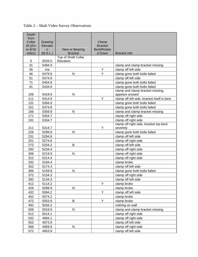
Table 2 – Shaft Video Survey Observations
Depth from
Collar (ft.)(from 8/19 video)
Drawing Elevatio
n (M.S.L.)
New or Bearing Bracket
Clamp Bracket
Bent/Rotated Down Bracket info
0 5526.0 Top of Shaft Collar Elevation
31 5494.9 clamp and clamp bracket missing 36 n/a Y clamp off left side 46 5479.9 N Y clamp gone both bolts failed 51 5474.9 clamp off left side 71 5454.9 clamp gone both bolts failed 91 5434.9 clamp gone both bolts failed
106 5419.9 N clamp and clamp bracket missing, appears unused
111 5414.9 Y clamp off left side, bracket itself is bent 131 5394.9 clamp gone both bolts failed 151 5374.8 clamp gone both bolts failed 166 5359.9 N clamp and clamp bracket missing 171 5354.7 clamp off right side 191 5334.7 clamp off right side
211 5314.7 Y clamp off right side, bracket top bent severely
226 5299.9 N clamp gone both bolts failed 231 5294.6 clamp off left side 251 5274.6 clamp off right side 272 5254.2 B clamp off left side 292 5234.4 clamp off right side 306 5219.9 N clamp off right side 312 5214.4 clamp off right side 332 5194.4 clamp broke 352 5174.3 clamp off left side 366 5159.9 N clamp gone both bolts failed 372 5154.3 clamp off right side 392 5134.3 clamp off left side 412 5114.2 Y clamp broke 426 5099.9 N clamp broke 432 5094.2 Y clamp off left side 452 5074.2 clamp broke 472 5053.9 B Y clamp broke 492 5034.2 nothing on wall 506 5019.9 N clamp and clamp bracket missing 512 5014.1 clamp off right side 532 4994.1 clamp off right side 552 4973.9 clamp off left side 566 4959.9 N clamp off right side 572 4953.9 clamp off left side

592 4933.9 clamp off right side 612 4913.9 clamp off left side
626 4899.9 N clamp off right side 632 4893.8 clamp gone both bolts failed 652 4873.8 clamp off left side 673 4853.4 B clamp gone both bolts failed 692 4833.6 clamp off left side 706 4819.9 N clamp off right side 712 4813.6 clamp gone both bolts failed 727 4798.5 clamp and clamp bracket missing 747 4778.5 nothing on wall 762 4763.9 N nothing on wall 767 4758.5 nothing on wall 787 4738.4 nothing on wall 808 4719.0 B clamp and clamp bracket missing 828 4698.3 nothing on wall
838 4688.0 Top of Rock Box Elevation

Appendix C - Figures Some of these figures are excerpts from larger technical drawings prepared by Dynatec, and therefore the information conveyed by the figures may be incomplete and may require supplementation by additional data or information to be correctly understood or interpreted.

Figure 1 – Dynatec drawing showing plan view of Meikle ventilation and supply shaft. The three aggregate delivery pipes and support bracket are shown on the right side of the figure.
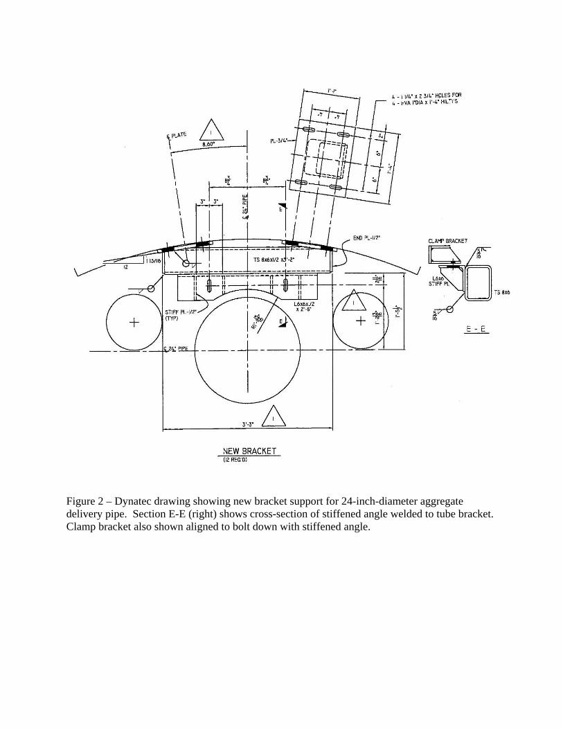
Figure 2 – Dynatec drawing showing new bracket support for 24-inch-diameter aggregate delivery pipe. Section E-E (right) shows cross-section of stiffened angle welded to tube bracket. Clamp bracket also shown aligned to bolt down with stiffened angle.

Figure 3 – Dynatec drawing showing typical clamp bracket and clamp assembly. Clamp bracket has slotted holes to accommodate alignment. Clamp is attached to clamp bracket with a single ¾-inch, A325 bolt on each side.

Figure 4 - Dynatec drawing showing bearing clamp bracket and clamp assembly. Clamp bracket has slotted holes to accommodate alignment. Clamp is attached to clamp bracket with two ¾ inch, A325 bolts on each side.

Figure 5 - Dynatec drawing showing two, ¾-inch-thick bearing plates to be field welded to the pipe sleeve at each clamp bracket location.

SURFACE AGGREGATE DELIVERY SYSTEM
Figure 6 - Drawing showing the surface aggregate delivery system.
CONTROL PANEL
The 3 Aggregate Pipes. 24-inch is middle pipe.
FEED RAMP
Conveyor Belt
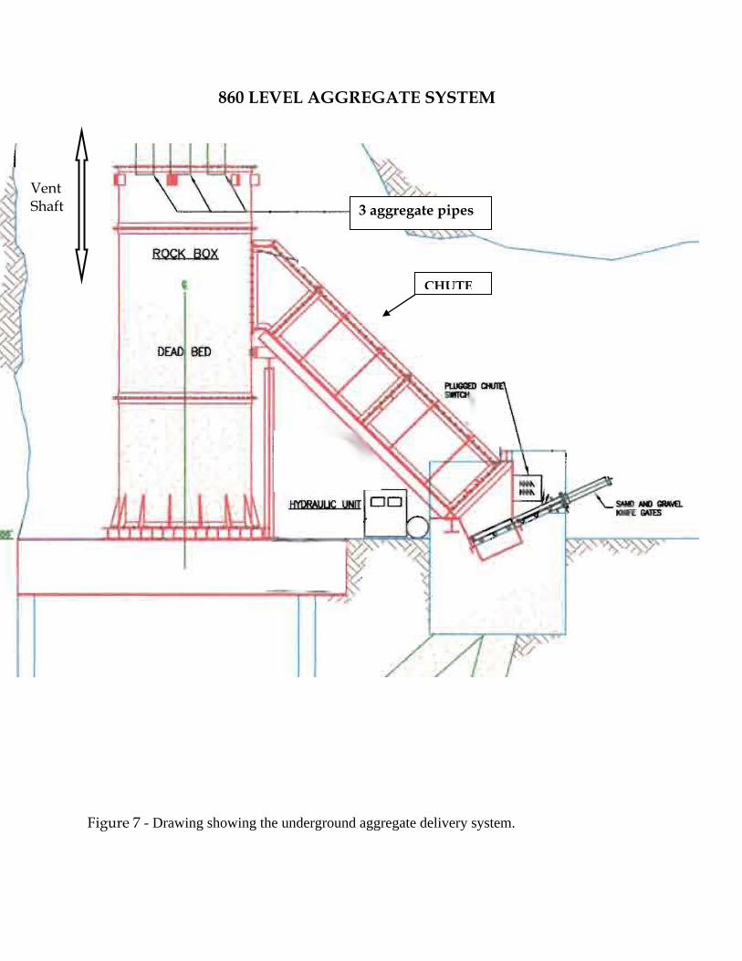
860 LEVEL AGGREGATE SYSTEM
Figure 7 - Drawing showing the underground aggregate delivery system.
CHUTE
3 aggregate pipes
Vent Shaft

Appendix D – Photos
Photo 1 – Minus 3-inch aggregate and fines at surface stockpile near top of ventilation shaft.
Photo 2 – Surface feed grizzly and hopper adjacent to top of ventilation shaft. Note stop and go operation lights above the hopper.
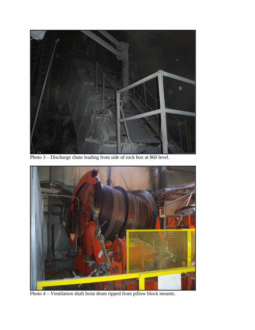
Photo 3 – Discharge chute leading from side of rock box at 860 level.
Photo 4 – Ventilation shaft hoist drum ripped from pillow block mounts.
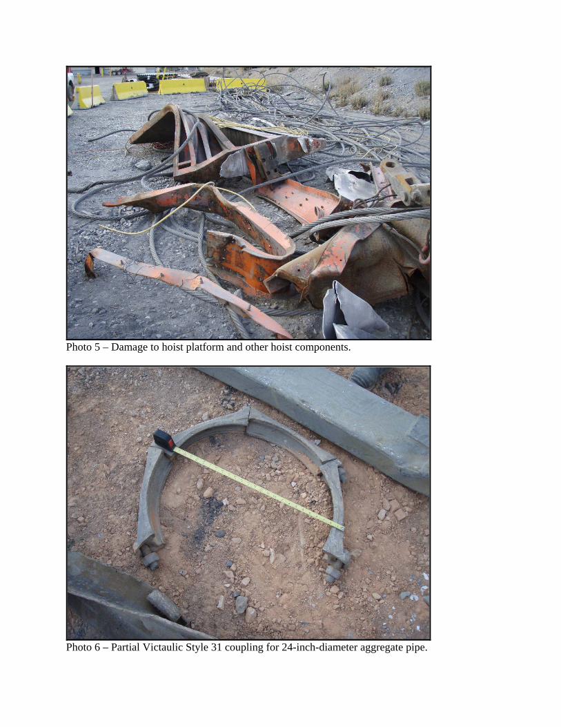
Photo 5 – Damage to hoist platform and other hoist components.
Photo 6 – Partial Victaulic Style 31 coupling for 24-inch-diameter aggregate pipe.

Photo 7 – Two pipe spools welded together in lieu of using a Victualic coupling.
Photo 8 – Slotted hole for A325 bolt used to attach clamp bracket to bracket. Slot was burned out and was larger than the bolt head. This connection would have required a large washer.

Photo 9 - Minimal bearing plate weld remnant traced in white chalk. Some of weld had been removed.
Photo 10 - Minimal bearing plate weld remnant traced in white chalk.

Photo 11 - Minimal bearing plate weld remnant traced in white chalk. Some of weld had been removed.
Photo 12 – Minimal bearing plate weld remnant traced in white chalk.

Photo 13 – Minimal bearing plate weld remnant traced in white chalk
Photo 14 – Weld remnants show the two bearing plates were not installed 180 degrees apart.

Photo 15 – A 24-inch by 28-inch conveyor belt piece used to patch the 24-inch-diameter aggregate pipe.
Photo 16 – The 28-inch-wide surface feed conveyor belt overflowing with aggregate.
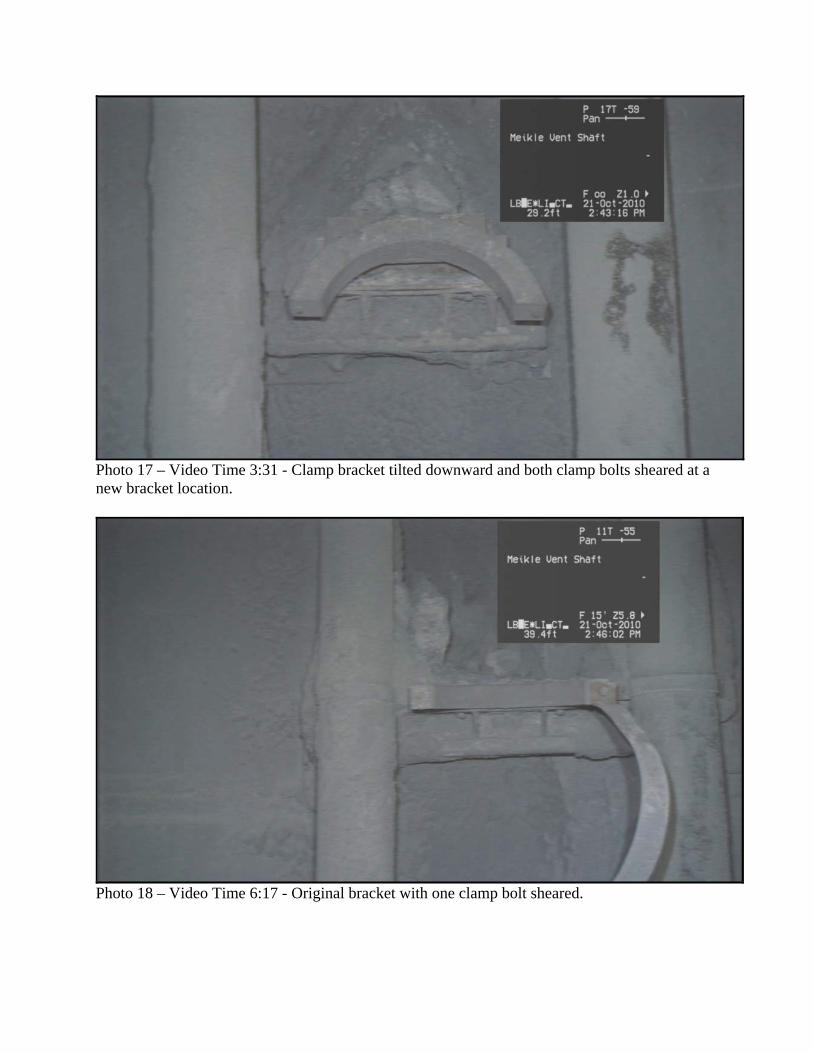
Photo 17 – Video Time 3:31 - Clamp bracket tilted downward and both clamp bolts sheared at a new bracket location.
Photo 18 – Video Time 6:17 - Original bracket with one clamp bolt sheared.

Photo 19 - Video Time 26:26 - Original bracket with one clamp bolt sheared.
P Photo 20 – Video Time 33:07 – Both bearing clamp bolts on the left side failed at a location 272 feet from the collar.

Photo 21 – Video Time 1:05:33 - Sheared clamp at an original bracket location. The clamp bracket was also tilted down.
Photo 22 – Video Time 1:09:56 - Clamp sheared at a new bracket location.
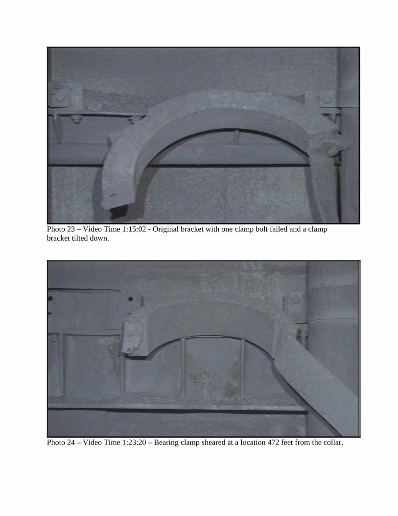
Photo 23 – Video Time 1:15:02 - Original bracket with one clamp bolt failed and a clamp bracket tilted down.
Photo 24 – Video Time 1:23:20 – Bearing clamp sheared at a location 472 feet from the collar.

Photo 25 – Video Time 1:57:03 - Single clamp bolt sheared at a new bracket location.
Photo 26 – Video Time 2:25:22 - Lowest bearing bracket with buckled stiffener where a 12-inch diameter pipe was previously attached. The bracket was at shaft elevation 807.
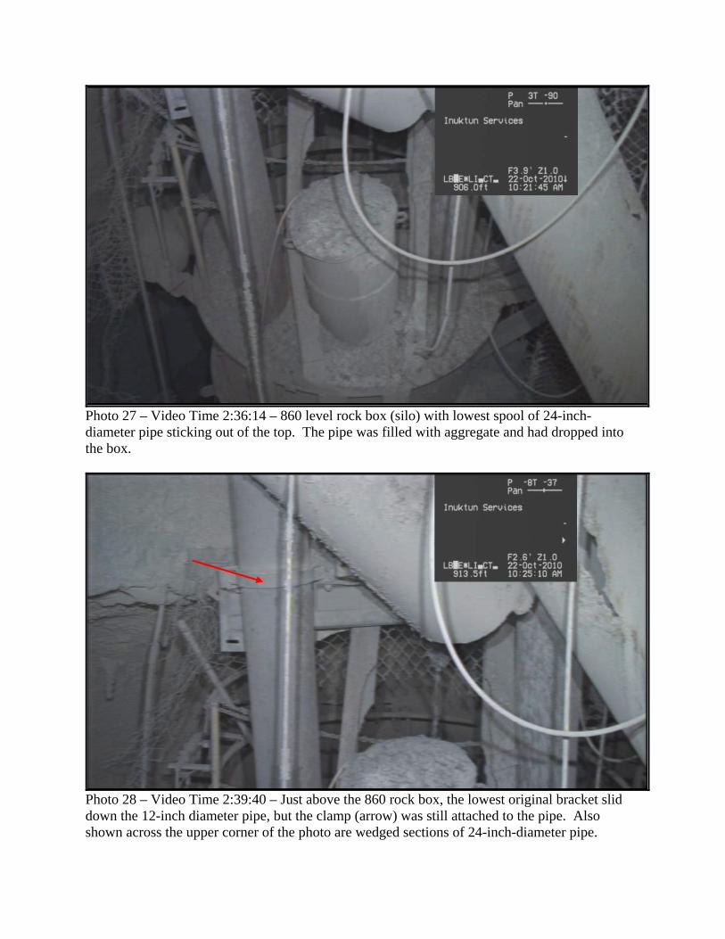
Photo 27 – Video Time 2:36:14 – 860 level rock box (silo) with lowest spool of 24-inch-diameter pipe sticking out of the top. The pipe was filled with aggregate and had dropped into the box.
Photo 28 – Video Time 2:39:40 – Just above the 860 rock box, the lowest original bracket slid down the 12-inch diameter pipe, but the clamp (arrow) was still attached to the pipe. Also shown across the upper corner of the photo are wedged sections of 24-inch-diameter pipe.
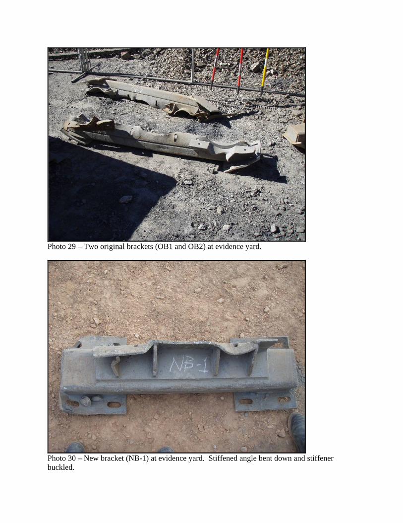
Photo 29 – Two original brackets (OB1 and OB2) at evidence yard.
Photo 30 – New bracket (NB-1) at evidence yard. Stiffened angle bent down and stiffener buckled.
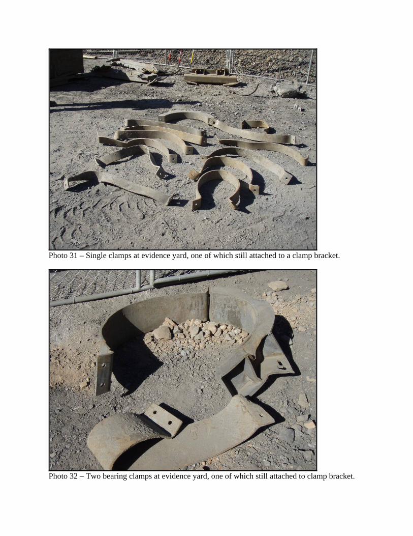
Photo 31 – Single clamps at evidence yard, one of which still attached to a clamp bracket.
Photo 32 – Two bearing clamps at evidence yard, one of which still attached to clamp bracket.
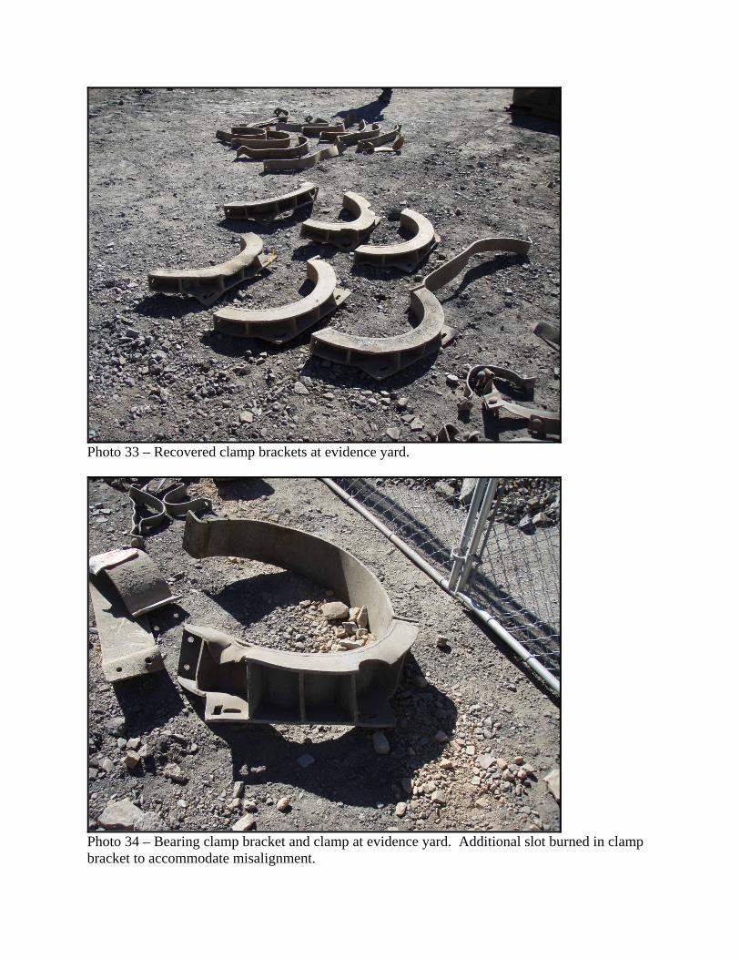
Photo 33 – Recovered clamp brackets at evidence yard.
Photo 34 – Bearing clamp bracket and clamp at evidence yard. Additional slot burned in clamp bracket to accommodate misalignment.

Photo 35 – Recovered 24-inch-diameter partial pipe spools at evidence yard.
Photo 36 – Pipe shards from 24-inch-diameter aggregate pipe at evidence yard
Appendix E – Victim Data Sheet