UNITED STATES ARMY AVIATION PLANNING MANUAL81).pdf · united states army aviation planning .er...
384
ni* r-jXL&i Copy 2 t-7s ./ o (¿» FM 101-20 FIELO MANUAL UNITED STATES ARMY AVIATION PLANNING .er MANUAL RETURN TO THE ARMY LIBRARY ROOM 1A518 PENTAGON WASHINGTON, D. C. 20310 ‘ HEADQUARTERS, DEPARTMENT OF THf ARMY x AUGUST 1981
Transcript of UNITED STATES ARMY AVIATION PLANNING MANUAL81).pdf · united states army aviation planning .er...
ni* r-jXL&i
Copy 2 t-7s ./
o (¿» FM 101-20
FIELO MANUAL
UNITED STATES ARMY
AVIATION PLANNING
.er
MANUAL
RETURN TO THE ARMY LIBRARY ROOM 1A518 PENTAGON WASHINGTON, D. C. 20310
‘ HEADQUARTERS, DEPARTMENT OF THf ARMY x AUGUST 1981

1
¿ V-
é
%
%
i hi
f
■4,
#
á

FM 101-20
I \ %- \
/
f
► »
I
FOREWORD
This manual is published in accor- dance with the provisions of AR 95-70 and contains official U.S. Army aviation factors data in a single-source document to be used as a planning guide ONLY. Hie factors, when used with other Army program documents (e.g., Army Materiel Plan and Materiel Annex Part II to 5 Year Force Structure and U.S. Army Aircraft Standard Avionics/Surveillance Configuration, 5 Year Plan Requirement), will assist commanders, planners, and programners in establishing a basis for operational, logistical, materiel, personnel,estimates, and the cost requirements for combat readiness of all types and models of Army aircraft. In the event such Army program documents, as mentioned above, indicate later revision, such revisions will take precedence. The data may be used in the preparation of estimates by major commands (theater, field army, or equivalent) but will not be used as a basis of reporting cost or other data.
These planning factors were developed from diversified operational and logis- tical statistical data and were obtained from various Department of the Army staff offices and other Army agencies having primary responsibilities for the specific mission activities or related functions.
This manual is published in looseleaf form to facilitate insertion of revi- sions, changes, and/or additions. Each set of published planning factors will oe revised on an 18-month cycle to ensure current and accurate data, as
well as provide additional factors of interest. ' TSAR00M is responsible for coordinating pertinent planning factors with the appropriate Army staff agency.
Users of this manual are encouraged to submit recommended changes or com- ments to improve the manual. Comments must be submitted on DA Form 2028, Recom- mended Changes to Publications and Blank Forms. Reasons should be provided for each comment to ensure understanding and full evaluation. Comments should be forwarded directly to Commander, U.S. Army Troop Support and Aviation Materiel Readiness Command, Directorate For Plans and Systems Analysis, ATTN: DRSTS-B, 4300 Goodfellow Boulevard, St. Louis, MO 63120.
Distribution of this Department of the Army publication to Active Army, National Guard, and United States Army Reserve units is by formula distribution and pinpoint distribution methods. Other DOD agencies should request copies required from the Adjutant General, Washington, D.C. Under provisions of Army Regulation 310-1, Military Publica- tions, normal publications supply channels should be followed.
Requests from agencies outside of DOD will be forwarded to The Adjutant General, Washington, D.C. 20315.
t
Abbreviations used in this manual are listed in AR 310-50 (Standard abbrevia- tions) or Military Standard 12C (Non standard abbreviations).
i/(ii blank.
à

\
i 4

* FM 101-20
FIELD MANUAL
NO. 101-20
HEADQUARTERS DEPARTMENT OF THE ARMY
Washington, D. C. ,15 August 1981
UNITED STATES ARMY
AVIATION PLANNING MANUAL
>
8
Table of Contents
Forward Designation of Army Aircraft. Aircraft Type Classification....
Chapter 1. OPERATIONS Section I. Aircraft authorization
II. Flying hour program III. Replacement Factors (Attrition)..
IV Standard aircraft characteristics.
Page i iv viii
1-1 1-11 1-13 1-14
Chater 2. LOGISTICS AND MATERIEL Section I. Maximum allowable operating time (MAOT) (major components) 2-1
II. Aircraft equipment 2-2 HI. Ferrying and shipping 2-146 IV. Tools 2-152 V. Inspections 2-159
VI. Fuel and oil 2-161 VII. Maintenance man-hours 2-165
VIII. Maintenance categories 2-173 IX. Survival Equipment 2-174
Chapter 3. PERSONNEL REQUIREMENTS Section I. Officer/warrant officer aviation personnel requirements 3-1
II. Enlisted aviation maintenance personnel requirements 3-2
Chapter 4. COSTS Section I. Army aircraft unit prices 4-1
II. Aircraft unit flying hour costs 4-3 III. Avionics cost 4-3 IV. Armament cost 4-3
Chapter 5. RESEARCH AND DEVELOPMENT OF MATERIEL 5-1
APPENDIX A REFERENCES
INDEX
^/*Th-3rg^manual supersedes EM 101-20, 3 January 1979
A-l
Index-1
iii

FM 101-20
in
DESIGNATION OF ARMY AIRCRAFT (ROTARY WING)
PRE- POPULAR NAME FERREO ANO TYPE
COMBAT ACCEPT SUBST
FOLLOW-ON AIRCRAFT
COBRA
AH-IS TH-1G
ATTACK HELICOPTER
UH-1B UH-1C UH-1M
YAH-64A
CHINOOK
CH-47A/B/C YCH-47D
CARGO TRANSPORT HELICOPTER
TARHE
CH-54A/B
CARGO TRANSPORT HELICOPTER
CAYUSE
OH-6A
KIOWA
OH-58A/C
çQ3 € LIGHT OBSERVATION HELICOPTER
IROQUOIS
UH-1H
UH-1V lb UH1B UH-60A
UTILITY HELICOPTER
OSAGE
TH-55A OFF THE SHELF
TRAINER HELICOPTER
1
AV 010094
¡V

r FM t01-20
DESIGNATION OF ARMY ARICRAFT (ROTARY WING) CONT’D.
PRE- FERRED
POPULAR NAME AND TYPE
COMBAT ACCEPT SUBST
FOLLOW-ON AIRCRAFT
BLACK HAWK
UH-60A UH-1H
UTILITY HELICOPTER
AAH
YAH-64A
ATTACK HELICOPTER
IROQUOIS
UH-1C/M
UTILITY HELICOPTER
COBRA
AH-1S UH-1B UH-1C UH-1M
YAH-64A
. ATTACK HELICOPTER
A
V
FM 101-20 1
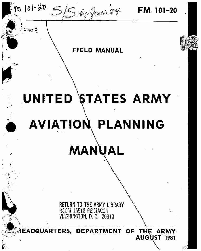
DESIGNATION OF ARMY AIRCRAFT (FIXED WING) (Cent.)
PRE POPULAR NAME FERREO AND TYPE
COMBAT ACCEPT SUBST
FOLLOW-ON AIRCRAFT
SFMINOI C
U-8F
um ITY AIRPl ANL
COURIER
U 10A
UTILITY AIRPLANE
UTE
U-21A/G RU-21A D/H
UTILITY AIRPLANE
MOHAWK
OV-1B/C/D RV-1D
OBSERVATION/SURVEIL- LANCE AIRPLANE
MESCALERO
T-41B OFF THE SHELF
TRAINER AIRPLANE
COCHISE
T-42A OFF THE SHELF
TRAINER AIRPLANE
<1
AV 010095
VI
L
FM 101-20
CHAPTER 1
OPERATIONS
Section I AIRCRAFT AUTHORIZATIONS
Aircraft authorizations are listed by TOE unit izations for specific areas or commands. The authorizations. The current Major Item Analysis Basis of Issue (BOI) authorizations are updated (Data Sheets) contains details concerning author- to comply with the ARCSAIII evaluation.
1-1

1-1. Basis of Issue -- Aircraft Authorization Per Unit.
UNIT TOE TOTAL ACFT LOH AH-1 UH-1 UH-60 CH-47 CH-64 OV-1 U-21 NOTE
ARMORED DIVISION Combat Aviation Battalion
Attack Helicopter Co (2) Cbt Spt Avn Co Division Aviation Co Trans Acft Maint Co
Armored Cavalry Sqdn Air Cavalry Troop
RECAP RECAP
RECAP
17 17-86 17-387 57-57 17-87 55-424 17-106 17-108
161 136
72 16 46
2 26 26
66 56 24
32
10 10
51 42 42
9 9
29 22
6
14 2 7 7
16 16
16
INFANTRY DIVISION (MECH) Combat Aviation Battalion
Attack Helicopter Co (2) Cbt Spt Avn Co Divison Aviation Co. Trans Acft Maint Co
Armored Cavalry Sqdn Air Cavalry Troop
RECAP RECAP
RECAP
37 17-85 17-387 57-57 17-87 55-424 17-105 17-108
161 135
72 15 46
2 26 26
66 56 24
32
10 10
51 42 42
9 9
29 22
6
14 2 7 7
16 16
16
INFANTRY DIVISION Combat Aviation Battalion
Cbt Spt Avn Co (2) Avn Gen Spt Co Attack Helicopter Co Trans Acft Maint Co
Air Cavalry Sqdn HHT, Air Cav Sqdn Air Cavalry Troop (3)
RECAP RECAP
RECAP
7 57-55 57-57 67-58 17-387 55-89 17-205 17-206 17-208
196 114 30 46 36
2 82
4 78
70 40
28 12
30
30
48 21
21
27
27
48 23
18 3 2
25 4
21
30 30 30
AIRBORNE DIVISION Combat Aviation Battalion
Cbt Spt Avn Co (21 Avn Gen Spt Co Attack Helicopter Co Trans Acft Maint Co
Air Cavalry Sqdn HHT, Air Cav Sqdn Air Cavalry Troop
RECAP RECAP
RECAP
57 67-55 67-67 57-58 17-387 56-89 17-275 17-276 17-278
212 130 46 46
.36 2
82 4
78
70 40
28 12
30
30
48 21
21
27
27
94 69 46 18 3 2
25 4
21
Ji
PM 101-20

FM 101-20
DESIGNATION OF ARMY AIRCRAFT (FIXED WING) CONT’D.
PRE- FERRED
POPULAR NAME AND TYPE
COMBAT ACCEPT SUBST
FOLLOW-ON AIRCRAFT
AERO COMMANDER
U-9C
UTILITY AIRCRAFT
HURON
C-12A/C RU-21J
T] C-12D
CARGO AIRCRAFT
UV-18A
TWIN OTTER
o TJ
UTILITY STOL AIRCRAFT
U-1A
OTTER
UTILITY AIRCRAFT
ÜTÜ ”
U-21F RU-21B.C
UTILITY AIRCRAFT
Source: TSARCOM-DRSTS-MT
vll

FM 101-20 1
Army Aircraft Type Classification/Reclassification (TC/R) Schedule (Rotary Wing)
TYPE, MODEL
SERIES (IMS)
Rotary Wing
AH-1G (TH-1G)
AH-1S CH-47A
CH-47B
CH-47C
CH-54A
CH-54B
OH-6 A
OH-58A
UH-1B
UH-1H
UH-1M
TH-5SA
TH-1G
OH-58C
EH-1H
YCH-47D
UH-60A UH-1V
EH-1X
YAH-64A
EH-60A
CURRENT
TYPE
TCC-LCC
S-A
S-A
S-B S-B
S-A
S-B S-B
S-A
S-A
S-B
S-A
SB S-A
S-A D
L-(U)
D
S-A S-A
S-A
S-A
PROPOSED
TCC-LCC
C-S
C-S
C-S
C-S
C-S
C-S
C-S
C-S
C-S
C-S
C-S
C-S
S-A
S-B
FY-Qtr
of Actual/
Proposed TCC-Lcc
88-1
81- 3 83- 1 84- 3
88-4
90-4
86-4
86-4
80-4
82- 4 834 844
79-1
79-3
79-2
REPLACEMENT
SYSTEM
AH-1S
YAH-64A
CH-47D CH-47D CH-47D
OH-58C
UH-60A
*
Vlll i
r FM 101-20
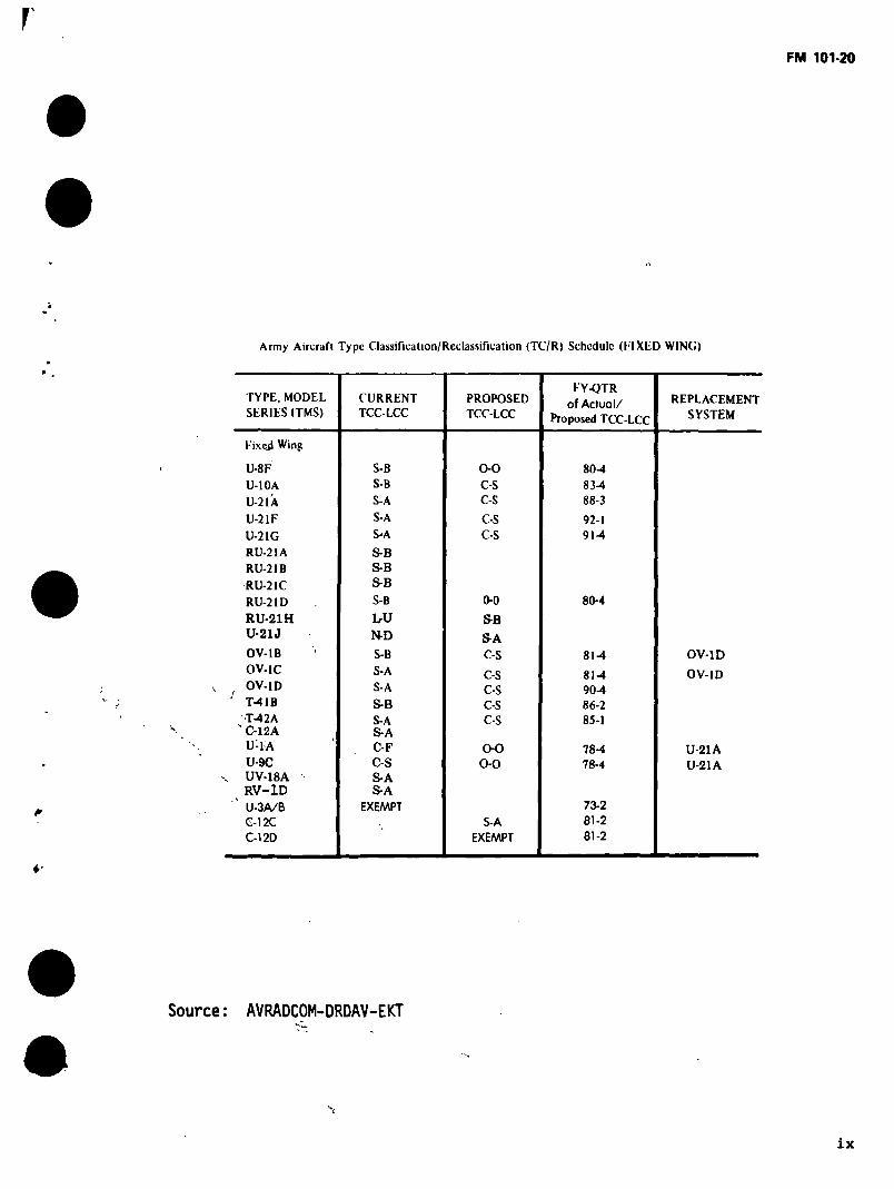
Army Aircraft Type Classification/Reclassification (TC/R) Schedule (FIXIiD WING)
TYPE, MODEL
SERIES (TMS)
Fixed Wing
U-8F
U-10A
U-21A
U-21F
U-21G
RU-21A
RU-21B
RÜ-21C
RU-21D
RU-21H U-21J
OV-1B
OV-1C
OV-1D
T-41B
T-42A s C-12A
U-1A
U-9C UV-18A RV-1D
' U-3A/B C-12C
C-12D
CURRENT TCC-LCC
S-B
S-B
S-A
S-A
S-A
S-B S-B
S-B
S-B
LrU N-D
S-B
S-A
S-A
S-B
S-A S-A C-F
C-S
S-A S-A
EXEMPT
PROPOSED TCC-LCC
0-0 C-S C-S
C-S
C-S
0-0
SB
SA C-S
C-S
C-S C-S
C-S
0-0 0-0
S-A
EXEMPT
FY-QTR
of Actual/ Proposed TCC-LCC
80-4
83-4
88-3
92-1 91-4
80-4
81-4
81-4
90-4 86-2 85-1
78-4
78-4
73-2
81-2
81-2
REPLACEMENT SYSTEM
OV-ID
OV-1D
U-21A
U-21A
6-
Source: AVRADCOM-DRDAV-EKT
ix

FM 101-20
1
LEGEND:
TCC - Type Classification Code
C - Contingency
E - Exempt
L - Limited Procurement
N - Perpetuate only until type classified
O - Obsolete
S - Standard
LCC - Logistic Control Code
A - Items/Systems acceptable for the intended mission
B - Items/Systems acceptable for the intended mission which normally are being replaced through modernization
D - Items/Systems undergoing development which have not qualified for type classification
F - Mission Essential Contingency Items /
N - Exempt
0 - Obsolete item
S - Contingency items other than Mission Essential Contingency Items that are suitable for training
T - Items classified as Limited Procurement to provide quantities for test
U - All items type classified for Limited Procurement
*
4
X
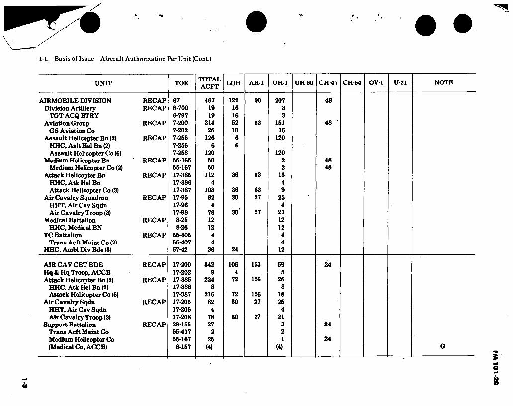
1-1. Basis of Issue - Aircraft Authorization Per Unit (Cont.)
UNIT TOE TOTAL ACFT LOH AH-1 UH-1 UH-60 CH-47 CH-54 OV-1 U-21 NOTE
AIRMOBILE DIVISION RECAP Division Artillery RECAP
TGTACQBTRY Aviation Group RECAP
GS Aviation Co Assault Helicopter Bn (2) RECAP
HHC, Aslt Hel Bn (2) Assault Helicopter Co (6)
Medium Helicopter Bn RECAP Medium Helicopter Co (2)
Attack Helicopter Bn RECAP HHC, Atk Hel Bn Attack Helicopter Co (3)
Air Cavalry Squadron RECAP HHT, Air Cav Sqdn Air Cavalry Troop (3)
Medical Battalion RECAP HHC, Medical BN
TC Battalion RECAP Trans Acft Maint Co (2)
HHC, Ambl Div Bde (3)
67 6-700 6- 797 7- 200 7-202 7-256 7-256 7-258 55-165 55-167 17-385 17-386 17-387 17-95 17-96 17-98 8-25 8-26
55-405 55-407 67-42
467 19 19
314 26
126 6
120 50 50
112 4
108 82
4 78 12 12
4 4
36
122 16 16 52 10 6 6
36
36 30
30*
24
90
63
63
63 27
27
207 3 3
151 16
120
120 2 2
13 4 9
25 4
21 12 12 4 4
12
48
48
48 48
AIR CAV CBT BDE RECAP Hq & Hq Troop, ACCB Attack Helicopter Bn (2) RECAP
HHC, Atk Hel Bn (2) Attack Helicopter Co (6)
Air Cavalry Sqdn RECAP HHT, Air Cav Sqdn Air Cavalry Troop (3)
Support Battalion RECAP Trans Acft Maint Co Medium Helicopter Co (Medical Co, ACCB)
17-200 17-202 17-385 17-386 17-387 17-205 17-206 17-208 29-155 55-417 55-167 8-157
342 9
224 8
216 82 4
78 27
2 25
(4)
106 4
72
72 30
30
153
126
126 27
27
59 5
26 8
18 25 4
21 3 2 1
(4)
24
24
24
FM 1
01-2
0
1-4
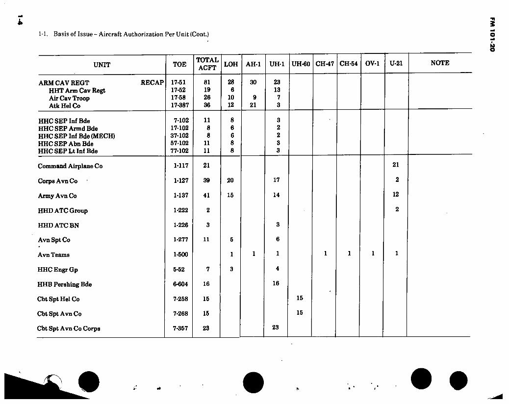
1-1. Basis of Issue -- Aircraft Authorization Per Unit (Cont.)
UNIT
ARM CAV REGT HHT Arm Cav Regt Air Cav Troop Atk Hel Co
HHCSEP Inf Bde HHC SEP Armd Bde HHC SEP Inf Bde (MECH) HHC SEP Abn Bde HHC SEP Lt Inf Bde
Command Airplane Co
Corps Avn Co
Army Avn Co
HHDATC Group
HHDATCBN
Avn Spt Co
Avn Teams
HHCEngrGp
HHB Pershing Bde
Cbt Spt Hel Co
Cbt Spt Avn Co
Cbt Spt Avn Co Corps
RECAP
TOE
17-51 17-52 17-58 17-387
7-102 17-102 37-102 57-102 77-102
1-117
1-127
1-137
1-222
1-226
1-277
1-500
5- 52
6- 604
7- 258
7-268
7-357
TOTAL ACFT
81 19 26 36
11 8 8
11 11
21
39
41
2
3
11
7
16
15
15
23
LOH
28 6
10 12
8 6 6 8 8
20
15
AH-1
30
9 21
UH-1
23 13
7 3
3 2 2 3 3
17
14
3
6
1
4
16
UH-60 CH-47 CH-54 OV-1 U-21 NOTE
15
15
21
2
12
2
23
»
FM 1
01-2
0
1-5
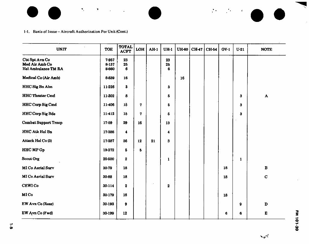
1-1. Basis of Issue -- Aircraft Authorization Per Unit (Cont.)
UNIT TOE TOTAL ACFT
LOH AH-1 UH-1 UH-60 CH-47 CH-54 OV-1 U-21 NOTE
Cbt Spt Avn Co Med Air Amb Co Hel Ambulance TM RA
Medical Co (Air Amb)
HHC Sig Bn Abn
HHC Theater Cmd
HHC Corp Sig Cmd
HHC Corp Sig Bde
Combat Support Troop
HHC Atk Hel Bn
Attack Hel Co (3)
HHCMPGp
Scout Org
MI Co Aerial Surv
MI Co Aerial Surv
CEWICo
MI Co
EW Avn Co (Rear)
EW A^vn Co (Fwd)
7- 957 8- 137 8-660
8-839
11-226
11-302
11-406
11-412
17-59
17-386
17-387
19- 272
20- 500
30-79
30-88
30-114
30-179
30-193
30-199
23 26
6
16
3
8
15
15
29
4
36
5
2
18
18
2
18
9
12
7
7
16
12
5
21
23 25
6
3
5
5
5
13
4
3
16
18
18
18
3
3
3
9
6
B
C
D
E
FM 1
01
-20

1-6
1-1. Basis of Issue -- Aircraft Authorization Per Unit (Cont.).
UNIT TOE TOTAL ACFT LOH AH-1 UH-1 UH-60 CH-47 CH-54 OV-1 U-21 NOTE
MI Det Aer Surv MI Det Aer Surv Svc Co Abn SF Gp ASA Div Spt Co ASA Bde Spt Co ASA Avn Co (Rear) ASA Avn Co (Fwd) HHCOPCOCEWI BN Medium Helicopter Co Heavy Helicopter Co Trans Acft Maint Co HHC Acft Maint Depot Division (Training) TM II Division (Training) TM IJ
30-550 30- 600 31- 127 32- 57 32-64 32-93 32-99 34-166 55-167 55-259 55-459 55-466 97-500 97-500
6 6 6 3 2 9
12 3
25 1 2 2
(2)
3 2
3 1
2 2
(2)
6 6
24
9 6
(1)
B B
F F D E F
G G
NOTES: A/ 1 EA U-21 & 2 EA C-12 Acft
B/OV-lDAcft
Ç/ 12 EA OV-1B & 6 EA OV-1C
D/ 4 EA RU-21A, 3 EA RU-21B & 2 EA RU-21C
E/ RV-1D & RU-21H Acft
FV EH-1 Acft
G/ Augmentation
Source: TSARCOM-DRSTS-SPME
t
FM 1
01
-20
f FM 101-20
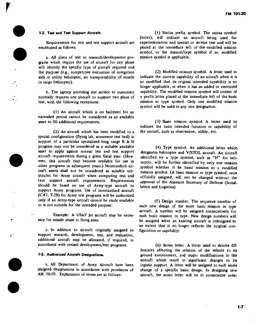
1-2. Test and Test Support Aircraft.
Requirements for test and test support aircraft are established as follows:
a. All plans of test or research/development pro- grams which require the use of aircraft for any phase will identify the specific type of aircraft required and the purpose (e.g., competitive evaluation of navigation aids in utility helicopter, air transportability of missile in cargo helicopter).
b. The agency providing test service to customers normally requires one aircraft to support two plans of test, with the following exceptions:
(1) An aircraft which is on bailment for an extended period cannot be considered as an available asset to fill additional requirements.
(2) An aircraft which has been modified to a special configuration (flying lab, armament test bed) in support of a particular specialized long range R & D program may not be considered as a suitable available asset to apply against normal test and test support aircraft requirements during á given fiscal year. (How- ever, this aircraft may become available for use in other programs in subsequent years.) Nonstandard air- craft assets shall not be considered as suitable sub- stitutes for Army aircraft when computing test and test support aircraft requirements. Requirements should be based on use of Army-type aircraft to support Army programs. Use of nonstandard aircraft (C-47, T-28) for Army test programs will be authorized only if an Army-type aircraft cannot be made available or is not suitable for the intended purpose.
Example: A USAF jet aircraft may be neces- sary for missile chase at firing sites.
c. In addition to aircraft originally assigned to support research, development, test, and evaluation, additional aircraft may be allocated, if required, in accordance with revised development/test programs.
1-3. Authorized Aircraft Designations.
a. All Department of Army Aircraft have been assigned designations in accordance with provisions of AR 70-50. Explanation of terms are as follows:
(1) Status prefix symbol. The status symbol (letter), will indicate an aircraft being used for experimentation and special or service test and will be placed at the immediate left of the modified mission symbol, or the mission/type symbol if no modified mission symbol is applicable.
(2) Modified mission symbol. A letter used to indicate the current capability of an aircraft when it is so modified that its original intended capability is no longer applicable, or when it has an added or restricted capability. The modified mission symbol will consist of a prefix letter placed at the immediate left of the basic mission or type symbol. Only one modified mission symbol will be used in any one designation.
(3) Basic mission symbol. A letter used to indicate the basic intended function or capability of the aircraft, such as observation, utility, etc.
(4) Type symbol. An additional letter which designates helicopter and V/STOL aircraft. An aircraft identified by a type symbol, such as “H” for heli- copter, will be further identified by only one mission symbol whether it be basic mission or a modified mission symbol. (A basic mission or type symbol, once officially assigned, will not be changed without the approval of the Assistant Secretary of Defense (Instal- lation and Logistics).
(5) Design number. The sequence number of each new design of the same basic mission or type aircraft. A number will be assigned consecutively for each basic mission or type. New design numbers will be assigned when an existing aircraft is redesigned to an extent that it no longer reflects the original con- figuration or capability.
(6) Series letter. A letter used to denote dif- ferences affecting the relation of the vehicle to its ground environment, and major modifications to the aircraft which result in significant changes to its logistic support. A letter will be assigned to each series change of a specific basic design. In designing new aircraft, the series letter will be in consecutive order
1-7

FM 101-20 1 starting with the letter “A.” To avoid confusion, the letters “I” and “O” will not be used as series symbols. (Examples of series symbol change would be installa- tion of different engines, propellers, extra fuel tank, etc.)
(7) Complete designation. The complete designation shall consist of items (1) through (6) as applicable, in the order shown. A dash (-) will be inserted between the basic mission/type symbol and the design number.
EXAMPLE: Y U H - 1 H
Status Prefix Symbol (Prototype) « I Basic Mission Symbol (Utility Mission) < -I Type Symbol (Helicopter Type) « Design Number (No. Type Helicopter) * —^ Series Letter (1st Series) « — ■ ■
b. Status prefix symbols (classification letters) are as follows:
LETTER TITLE DESCRIPTION
G
J
N
X
Permanently Grounded
Special Test, Temporary
Special Test, Permanent
Experimental
An aircraft permanently grounded, used for ground instruction and training.
Aircraft on special test programs by authorized organizations or on bailment contract having a special test configuration or whose installed property has been temporarily removed to accommodate the test. At completion of the test, the vehicle will be returned either to its original configuration or to standard operational configuration.
Aircraft on special test programs by authorized activities or on bail- ment contract, whose confíguration is so drastically changed that return of aircraft to its original configuration or conversion to standard operational configuration is beyond practicable or economical limits.
Aircraft in a developmental, experimental stage where basic mission symbol and de- sign number have been designated but not established as a standard vehicle.
1-8

FM 101-20
LETTER TITLE DESCRIPTION
Prototype
Planning
Aircraft procured in limited quantities to develop the potentialities of the design.
Designations used for identification purpose during the planning or pre- development stage.
c. Modified missions symbols (prefix letters) are as follows:
LETTER TITLE DESCRIPTION
Attack
C
E
Cargo/ Transport
Special Electronic Installation
Q
R
Drone
Reconnaissance
U
Trainer
Utility
Staff
Aircraft modified to search out, attack, and destroy enemy land or sea targets, using conventional or special weapons. Also used for interdiction and close air support mission.
Aircraft modified for carrying cargo and/or passengers.
Aircraft equipped with electronic devices for employment in one or more of the following missions.
(1) Electronic countermeasures (2) Airborne early warning radar (3) Airborne command control including
communications relay (4) Tactical data communications link for
all nonautonomous modes of flight.
Aircraft modified to be controlled from a point outside the aircraft.
Aircraft modified and permanently equipped for photographic and/or electronic reconnaissance missions.
Aircraft modified and equipped for training purposes.
Aircraft having small payload, modified to perform miscellaneous missions such as carrying cargo or passengers, and towing targets.
Aircraft modified to provide accommo- dations such as chairs, tables, lounge, and berths for the transportation of staff personnel.
d. Basic mission and type symbols are as follows:
LETTER TITLE DESCRIPTION
Attack Aircraft designed to search out, attack, and destroy enemy land or sea targets, using conventional or special weapons. Also used for interdiction and close air support missions.
1-9

FM 101-20
LETTER TITLE DESCRIPTION
C
H
0
R
T
U
X
Cargo/ Transport
Helicopter
Observation
Reconnaissance
Trainer
Utility
VTOL and STOL
Research
Aircraft designed for carrying cargo and/or passengers.
A rotary-wing aircraft designed with the capability of flight in any plane; e.g., horizontal, vertical, or diagonal.
Aircraft designed to observe (through visual or other means) and report tactical information concerning composition and disposition of enemy forces, troops, and supplies in an active combat area.
Aircraft designed to perform reconnaissance missions.
Aircraft designed for training personnel in the operation of aircraft and/or related equipment, and having provisions for instructor personnel.
Aircraft used for miscellaneous missions such as carrying cargo and/or passengers, towing targets, etc. These aircraft include those having a small payload.
Aircraft designed for vertical takeoff or landing with no takeoff or landing roll, or aircraft capable of takeoff and landing in a minimum prescribed distance.
Aircraft designed for testing config- urations of radical nature. These aircraft are not normally intended for use as tactical aircraft.
e. Application for a special aircraft designa- f. A complete listing of model designations tion or cancellation of a previously authorized assigned to military aircraft is contained in Army designation may be accomplished by addressing AR 70-50.
the request CDR, US Army Materiel Development and Readiness Command, ATTN: DRCDE-D, Alexandria, VA 22333. Application for statua prefix symbol “J” (Special Test, Temporary) will be forwarded to CDR, USATSARCOM, ATTN: DRSTS-X(2), St. Louis, MO 63120, providing complete identification, purpose/ justification and length of time required.
1-10

FM 101-20
Section II. FLYING HOUR PROGRAM
The flying hour program can be calculated by taking the average inventory for the command and multiplying it by the annual flying hour rate for the particular aircraft.
Example :
FORSCOM OV-1 - Fiscal Year 1979 Àverage number of aircraft 21
Annual flying hour rate 240 21 X 240 = 5040 hours
Source: DCSOPS-DAMO
1-4. Basic Annual Flying Hour Planning Factors
a. A Worldwide Flying Hour Program is developed annually by the Department of the Army for use in budget preparation and in planning for logistical sup- port of aircraft. It is used as a basis for management of the entire aircraft inventory and is not applicable to the operation of a single aircraft or to the aircraft of any specific aviation unit or activity.
b. The flying hour program for each major com- mand is published annually in Chapter V, Section 4 of the Department of the Army Program and Budget Guidance Document. This document lists flying hour guidance in bulk flying hours for each type of aircraft assigned to the major commands. Factors considered in development of command flying hour programs include: the projected aircraft inventory, mission requirements of the command, aviator availability.
budgetary limitations, logistical considerations and other variables which may affect aircraft utilization within the commands. The DA Flying Hour Program is not expressed in flying hour rates. An additional factor to be considered in development of command flying hour programs is the aviator training requirement of the new aircrew training manuals (TCl-134 series) as prescribed by AR 95-1.
c. The basic flying hour planning factors con- tained below are, suitable for use in intermediate and long range planning at any level of command. Two points of rationale used in the development of these factors should be considered in planning applications; these are:
(1) Aircraft assigned to TOE units are intended to meet combat requirements. In a peacetime situation or noncombat environment, utilization of these aircraft should be restricted to only that flying time necessary to provide adequate training for aviation units and other units which are supported by aviation units.
(2) Indirect support aircraft are assigned to TDA units and must meet specific administrative, training, or RDTE requirements. Utilization of indirect support aircraft, except training and training support aircraft assigned to the aviation training base and RDTE aircraft, must meet or exceed the planning factors shown, to justify retention in the aircraft inventory at every level of command. Utilization of training base aircraft is determined by the student training rate approved or programmed for the year under consideration. Utilization of RDTE aircraft is basically determined by the requirements of the RDTE programs supported.
1-11

FM 101-20
o
1 -5. Table of Basic Flying Hour Planning Factors AJ
TYPE AIRCRAFT
TOE PEACETIME
(WORLDWIDE) ENVIRONMENT
AVG MONAVG YR
TOE ACTIVE
COMBAT ENVIRONMENT
AVG MON AVG YR
INDIRECT SUPPORT
AIRCRAFT (WORLDWIDE) ALL ENVIRONMENT^/
AVG MON AVG YR U-21 A, F, G OV-1 B, C, D/RV-1D
OH-6 A OH-58 A UH-1 B/M UH-1H AH-1 G, S, CH-47 A, B, C CH-54 A, B C12 U-8F RU-21 A.B.C.D, H,J EH-1H/EH-1X UH-60A
35 20
20 20 20 25 20 20 15 50 35 35
25 25
420 240
240 240 240 300 240 240 180 600 420 420
300 300
74 58
68 68 55 79 65 58 43 74 74 74
79 76
888 696
816 816 660 948 780 696 516 888 888 888
948 912
35 25
25 25 25 25 25 25 25 50 35 35
25 35
420 300
300 300 300 300 300 300 300 600 420 420
300 420
-lAll factors include operational readiness float aircraft.
JL/Does not include training and training support aircraft assigned to the training base, RDTE (test and test support) aircraft, or aircraft type classified contingency.
Source: DCSOPS-DAMO-RQD
1-12

1-13 i
1-6. Replacement Factors, World-Wide Monthly Rates.
AIRCRAFT SYSTEMS
Airplane:
OV-1 RV-1 T-41 T-42 U-8F U-21 C-12A RU-21
Helicopter:
TH-1 TH-55 CH-47 CH-54 OH-6 OH-58 A/C UH-1/EH-1H/EH-1X AH-1G/S UH-60A YAH-64A
WORLD-WIDE PEACETIME FACTORS
77
.0007
.0008
.oooo iy
.0028
.0012
.00001/
.00001/
.0005
.0008
.00001/
.00001/
.0006
.0006
.0004
.0005
78
.0007
.00001/
.0008
.00001/
.0028
.0008
.00011/
.00011/
.0017
.0011
.0005
.00001/
.0008
.0007
.0005
.0017
.0004
79
.0007
.00001/
.0008
.00001/
.0000 2/ .0008 .00011/ .00011/
.0017
.0011
.0005
.00001/
.0008
.0007
.0005
.0017
.0004
80
.0007
.00001/
.0008
.00001/
.0000 2/
.0008 .00011/ .00011/
.0017
.0011
.0005 .00001/ .0008 .0007 .0005 .0017 .0004 .0005
81
.0007
.00001/
.0008
.00001/
.0000 2/
.0012
.00011/ .00011/
.0017
.0011
.0005 .00001/ .0008 .0007 .0005 .0017 .0004 .0005
_1/ No positive predictors are available for low density MDS fleets that have experienced very few losses.
2/ System being phased out.
NOTE: Aircraft type classified contingeny not included on chart and new average with unestablished factors are not included on chart.
' REFERENCES: SB710-M AR700-5
Source : DALO-AV
M
Sectio
n III.
RE
PL
AC
EM
EN
T F
AC
TO
RS (A
TT
RIT
ION
)

FM 101-20
Comments:
To arrive at average peacetime operational inventory, (standard aircraft only), the following categories were not considered:
a. Combat inventory and losses
b. Maintenance trainers
c. Depot inventory
d. Aircraft in transit
e. Losses due to natural phenomena
f. Losses due to obsolescence
Section IV. STANDARD AIRCRAFT CHARACTERISTICS
Standard aircraft characteristic data contained herein will change as modifications or additions and
deletions of aircraft components or equipment are made.
1-14

r
FM 101-20
Figure 1-1. AH-1G and TH-1G
n C0* p
W N
Figure 1-1A. AH-IS (EGAS)
1-16
FM 101-20
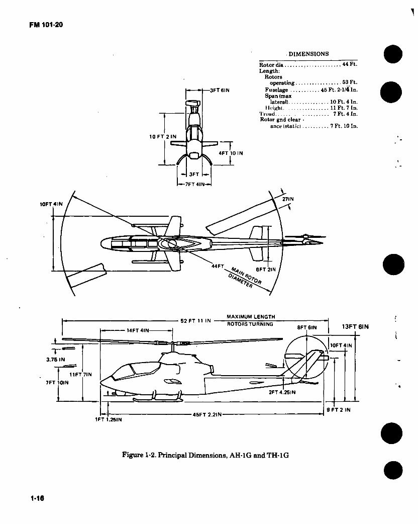
DIMENSIONS
3FT6IN
Rotor día 44 Ft. Length:
Rotors operating
Fuselage 45 Ft. 2-1/4 In. Span (max
lateral) 10 Ft. 4 In. I k'ighl 11 Ft. 7 In.
Tread 7 Ft. 4 In. Rotor gnd clear -
anee (static) 7 Ft. 10 In.
10 FT 2 IN
/°\ 1 4FT 10 IN
10FT4IN
3FT
■—7FT4IN-H
27IN
a.
u. £ \ 44 FT 6FT 2IN
O, 70
*4
MAXIMUM LENGTH
3.75 IN
7FT 10IN
13FT 61N 52 FT 11 IN
ROTORS TURNING 8FT6IN
14FT4IN
10FT4IN
»a» i 11 FT 7IN
=á 2FT4.25IN
45FT 2.2IN 9 FT 2 IN
1FT 1.2SIN
Figure 1-2. Principed Dimensions, AH-1G and TH-1G
1-16

1 -7. AH-1G/TH-1G * (Hueycobra) Characteristics.
ENGINE MISSION AND DESCRIPTION WEIGHTS
No. and Model
Mfr Engine Spec. No Type
Reduction Gear Ratio
Tail Pipe
Augmentation
.... (1) T53-L-13B
Lycoming 104.33 Free Power Turbine
0.3115
Fixed Area
None
ENGINE RATING
SEA LEVEL STD SHP
Military 1400
Normal
RPM MIN
6600 30
1250 6600 Cont.
TECHNICAL PUBLICATIONS
AIRFRAME:
TM 55-1500-339-S TM55-1620-22-PM TM55-1520-221-10 & CL TM55-1520-221-23 TM55-1520-221-23P TM55-1520-221-PM TM55-1520-221-MTF TM55-1500-220-PMD
ENGINE: TM55-2840-229-24 TM55-2840-229-23P
Mfr’s Model: BeU 209
The primary missions of this aircraft arethoseof an armed tactical helicopter capable of delivering weapons fire, low altitude high speed flight, search and target acquisition, reconnaissance by fire, multiple weapons fire support, and troop helicopter support. The aircraft is capable of performing these missions from prepared or unprepared areas, under day and night VFR conditions within a temperature range of —25I,F to +125°F.
The gas turbine powered “Hueycobra” is of compact design featuring tandem seating to give both pilot and gunner nearly unlimited visibility. Both crew stations have flight controfand fire control systems permitting flexibility in division of functions under all normal and emergency situations.
A mission designed fuselage coupled with the 540 rotor system gives a low vibration level plus increased maneuverability and speed. Four wing stores stations and an integral chin turret provide a high degree of armament versatility with the capa- bility of quickly changing a wide combination of weapons to match the desired mission. Reliability and'maintainability are ensured through the use of many UH-1 parts which have been combat proven.
Other features include a crashworthy fuel system with closed circuit refueling capability, and a tractor tailrotor system.
DEVELOPMENT
Date of contract First flight (Similar aircraft) First acft delivered
FEATURES
Advanced flexible gun turret Armor protection for crew and
critical components. Hardpoints for rockets, and
external stores on wings. Stability Control Augmentation
System (SAS) eliminates stabi- lizer bar and provides a stable gun platform.
4 April 1966 . 7 September 1965 18 September 1966
PERSONNEL
Light Scout Heavy Scout or Hog Mission
Pilot 1 Gunner 1
Ferry Mission Pilot 1 Copilot 1
LOADING
Empty
LB.
5809 (C)
Combat Clean Light Scout Heavy Scout Hog
Max. Takeoff Max. Landing
(C) Calculated
8521 (C) 9500 (C) 9500 (O 9500 (C) 9500 9500
FUEL AND OIL
Fuel: Grade JP-4/5 Spec MIL-T-5624 No. tanks 2 Location Fuselage
Q‘y 26 2 gal OU:
Spec M1L-L-7808/ M1L-L-23699
No. tanks 1 Location Fuselage Qty 3.4 gal
AVIONICS/ARMAMENT
Refer to Chapter 2.
UNIT PRICE/NSN
AH-1G, NSN 1520-00999-5821 LINE K29660, UNIT PRICE: Refer to Table 4-1.
*TH-1G. Addition of Instructor Flight Controls and Instrument Panel converts the AH-1G to the TH-1G.

1-18
1-8. Loading and Pertomance — Typical Mission AH-1G and TH-1G
CONDITIONS MISSION I LIGHT SCOUT
MISSION II HEAVY SCOUT
MISSION III HOG
MISSION IV
FERRY (CLEAN)
TAKEOFF WEIGHT (lb)
Fuel at 6.5 Ibs/gal (Grade JP-4) (lb)
Payload (lb)
Takeoff Power Loading Ob SHP)
Disk Loading Ob sq ft)
Autorotation Speed (Min R/D) (kn)
Takeoff Ground Run at SL (ft)
Takeoff to Clear 50 ft (ft)
Vertical Rate of Climb at SL .(fpm)
Maximum Rate of Climb at SL .... .(fpm)
Speed for Max R/C at SL (kn)
Time: SL to 5000 ft (min)
Time: SL to 10,000 ft (min)
Service Ceiling (100 fpm) (ft)
Absolute Hovering Ceiling (ft)
COMBAT RANGE (nmi)
Average Cruise Speed (kn)
Cruising Altitude (Initial) . (ft)
Cruising Altitude (Final) . . (ft)
Total Mission Time -O“)
COMBAT RADIUS (nmi)
Average Cruise Speed * (kn)
Cruising Altitude (Outbound)(Min/Max) .(ft)
Cruising Altitude (Inbound) (ft)
Total Mission Time .(hr)
9171
1572
1792
8.34
6.04
65
105
267
1330
64
3.7
8.3
12450
141.1
133
6350/9800
10000 2.4
9500
1277
2416
8.64
6.25
65
- 127
344
1230
65
4.0
9.2
11420
95.3
125
5350/7250
10000 1.8
9500 1025
2668
8.64
6.25
65
127
344
1230
65
4.0
9.2
11420
70.1
125
5600/7200
10000 1.4
7671
1672
192
6.97
5.05
65
0 0
1210 1860
60
2.7
5.6
18200
10650
371.1
141
10000 10000
2.7
FM
10
1-2
0
1-19 i
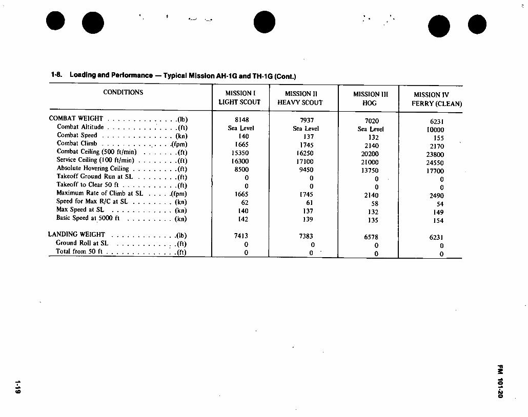
1 -8. Loading and Performance — Typical Mission AH-1G and TH-1G (Cont.)
CONDITIONS MISSION I
LIGHT SCOUT MISSION II
HEAVY SCOUT MISSION III
HOG MISSION IV
FERRY (CLEAN)
COMBAT WEIGHT Combat Altitude Combat Speed Combat Climb Combat Ceiling (500 ft/min) . Service Ceiling (100 ft/min) . . Absolute Hovering Ceiling . . . Takeoff Ground Run at SL . . Takeoff to Clear 50 ft Maximum Rate of Climb at SL Speed for Max R/C at SL . . . Max Speed at SL Basic Speed at 5000 ft . . . .
• Ob) • -(ft) • (kn) .(fpm) • (ft) . .(ft) • -(ft) - -(ft) • (ft) .(fpm) • (kn) ■ (kn) • (kn)
LANDING WEIGHT Ground Roll at SL Total from 50 ft .
(lb)
• (ft) (ft)
8148 Sea Level
140 1665
15350 16300 8500
0 0
1665 62
140 142
7413 0 0
7937 Sea Level
137 1745
16250 17100 9450
0 0
1745 61
137 139
7383 0 0
7020 Sea Level
132 2140
20200 21000 13750
0 0
2140 58
132 135
6578 0 0
6231 10000
155 2170
23800 24550 17700
0 0
2490 54
149 154
6231 0 0
FM 101-20
FM 101-20
DIMENSIONS
10FT9IN
3 FT 6 IN
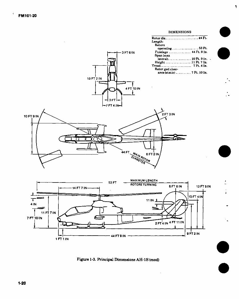
Rotor dia 44 Ft. Length:
Rotors operating 53 Ft.
Fuselage 44 Ft. 9 In. Span (max
lateral) 10 Ft. 9 In. Height 11 Ft. 7 In.
Tread 7 Ft. 4 In. Rotor gnd clear-
ance (static) 7 Ft. 10 In.
10 FT 2 IN
4 FT 10 IN
3 FT
—7 FT 4 IN-1
2 FT 3 IN
era
y i 44 FT
FT IN Oi 70 ^4* *7
MAXIMUM LENGTH
7 FT 10 IN
13 FT 5 IN
53 FT ROTORS TURNING
8 FT 6 IN 14 FT 7 IN
10 FT 4 N 11 IN ♦ 7^ 4 IN
'J 11 FT 7 N
2 FT 4 IN 4 FT 11 IN
Í
9 FT 2 IN 44 FT 9 IN
1 FT 1 IN
Figure 1-3. Principal Dimensions AH-1S (mod)
1-20

1-21 4
1-9. AH-1S (MOD) Characteristics
ENGINE
No. and Model (i) T53-L-703
Mfr Lycoming Engine Spec. No 104.43 Type Free Power Turbine Reduction Gear Ratio 0.3115 Tail Pipe Fixed Area Augmentation None
ENGINE RATINGS
SEA
LEVEL
STD SHP
Military 1485
Normal 1300
RPM
6600
6600
MIN
30
Cont,
TECHNICAL PUBLICATIONS
AIRFRAME:
TM55-1500-339-S TM55-1500-220-PM TM55-1520-234-10 & CL TM55-1520-234-23 TM55-1520-234-MTF TM55-1520-234-23P TM55-1520-234-PMD
ENGINE: TM 55-2840-229-24 TM55-2840-247-23P
MISSION AND DESCRIPTION
Mfr’s Model: Bell 209 The primary mission of this aircraft is anti-armor: providing a stable airborne platform for the tube launched, optically tracked, wire guided missile (TOW) helicopter support. The aircraft is capable of performing this mission from prepared or unprepared areas, under day and night VFR conditions within a temperature range of —25°Fto +125°F.
The gas turbine powered “Cobra TOW" is of compact design featuring tandem seating to give both pilot and gunner nearly unlimited visibility. Both crew stations have flight control and fire control systems permitting flexibility in division of functions under all normal and emergency situations.
A mission designed fuselage coupled with the 540 rotor system gives a low vibration level plus increased maneuverability and speed. Four wing stores stations and an integral chin turret provide a high degree of armament versatility with the capability of quickly changing a wide combination of weapons to match the desired mission. Reliability and maintainability are ensured through the use of many UH-1 parts which have been combat proven.
Other features include a crashworthy fuel system with closed circuit refueling capability, and a tractor tailrotor system, TOW missile sub- system and helmet sight fire control subsystem.
DEVELOPMENT
Development Contract. Production contract..., First Prod. Del
. May 1974
. Dec. 1974
. Mav 1976
FEATURES
Advanced flexible gun turret Armor protection for crew and
critical components. Hardpoints for rockets, and
external stores on wings. Stability Control Augmenta-1
tion System (SAS) elimin- ates stabilizer bar and pro- vides a stable gun platform.
Helmet Sight Subsystem TOW Missile Subsystem
NOTE: Remainder of AH-1Q Models to be converted to AH-1S Models by December 1978,
PERSONNEL
Anti-Armor Mission Pilot Co-Pilot/Gunner ..
Ferry Mission Pilot Copilot
WEIGHTS
LOADING
Empt\ Combat Clean Scout Light Anti-Armor Heavy Anti-Armor Max Takeoff Max Landing
(C) Calculated
LB.
6.479 (Cl
9.364 10.000 9.639 9,975
10.000 10.000
(C) (Cl (C) (C)
FUEL AND OIL
Fuel: Grade JP-4/5 Spec MIL-T-5624 No. tanks 2 Location Fuselage Qty 262 gal.
Oil: Spec MIL-L-7808/
MIL-L-23699 No. tanks 1 Location Fuselage Q‘y 3.4 gal.
AVIONICS / ARMAMENT
Refer to chapter 2,
UNIT PRICE/NSN
NSN 1520-00504-9112 Lin K29694
UNIT PRICE: Refer to Table 4-1.
FM 1
01-2
0
FM 101-20
DIMENSIONS
10 FT 8 IN
3 FT 6 IN.
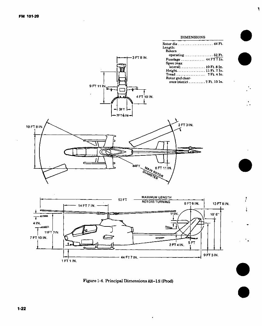
Rotor dia 44 Ft. Length:
. Rotors operating 53 Ft.
Fuselage 44 FT 7 In. Span (max
lateral) 10 Ft. 8 In. Height 11 Ft. 7 In. Tread 7 Ft. 4 In. Rotor gnd clear-
ance (static) 7 Ft. 10 In. 9 FT 11 IN. □ -e-
4 FT 10 IN
— 3FT
7FT4IN—I
> 2FT3IN.
a n n
44FT Ha.. 6 FT 11 IN 0/
MAXIMUM LENGTH
11 FT 7IN
7 FT 10 IN.
13FT6IN. 53 FT
ROTORS TURNING 8 FT 6 IN 14 FT 7 IN.
11 N 10’ 6"
I ^ 4 IN.
y / y 5 FT
5=2 2 FT 4 IN.
9 FT 3 IN. 44 FT 7 IN
1 FT 1 IN.
Figure 1-4. Principal Dimensions AH-IS (Prod)
1-22
1-23
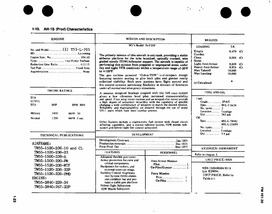
1-10. AH-1S (Prod) Characteristics
ENGINE MISSION AND DESCRIPTION
Mfr’s Model: Bell 209
No. and Model Mfr Engine Spec. No Type Reduction Gear Ratio Tail Pipe Augmentation
(1) T53-L-703 Lycoming 104.43
. I ree Power Turbine 0.3115 l ixed Area None
ENGINE RATINGS
SEA LEVEL STD SUP RPM MIN
Military 1400 6600 30
Normal 1250 6600 Cont.
The primary mission of this aircraft is anti-tank, providing a stable airborne platform for the tube launched, optically tracked, wire guided missile (TOW) helicopter support. The aircraft is capable of performing this mission from prepared or unprepared areas, under day and night VFR conditions within a temperature range of -25°F to -H25°F. The gas turbine powered "Cobra-TOW” is of compact design featuring tandem seating to give both pilot and gunner nearly unlimited visibility. Both crew stations have flight control and fire control systems permitting flexibility in division of functions under all normal and emergency situations.
A mission designed fuselage coupled with the 540 rotor system gives a low vibration level plus increased maneuverability and speed. Eour wing stores stations and an integral chin turret provide a high degree of armament versatility with the capability of quickly changing a wide combination of weapons to match the desired mission. Reliability and maintainability ire ensured through the use of many UH-I parts which have been combat proven.
TECHNICAL PUBLICATIONS
AIRFRAME: TM55-1520-236-10 and CL TM55-1520-236-23 TM55-1500-339-S TM55-1500-220-PM TM55-1520-236-NrTF TM55-1520-236-23P ™55-l 520-236-PMD
ENGINE: TM55-2840-229-24 TM55-2840-247-23P
Other features include a crashworthy fuel system with closed circuit refueling capability, and a tractor tailrotor system, TOW missile sub- system and helmet sight fire control subsystem.
DEVELOPMENT
Development Contract Jan 1975 Production contract Dec 1975 First Prod. Del Mar 1977
IEATURES
Advanced flexible gun turret. Armor protection for crew and
critical components. Hardpoints for rockets, and
external stores on wings. Stability Control Augmenta-
tion System (SAS) elimin- ates stabilizer bar and pro- vides a stable gun platform.
Helmet Sight Subsystem TOW Missile Subsystem
PERSONNEL
Anti-Armor Mission Pilot 1
Co-Pilot/Gunner 1
Ferry Mission Pilot 1 Co-Pilot 1
WEIGHTS
LOADING
Empty Combat Clean Scout Light Anti-Armor Heavy Anti-Armor Max Takeoff Max Landing
LB.
6,479 (C)
9.364 (C)
9.639 9.975
10.000 10.000
(Cl (Cl
(c) Calculated
FUEL AND OIL
Fuel: Grade JP-4/5 Spec MIL-T-5624 No. tanks 2 Location Fuselage Oty 262 gal.
Oil: Spec M1L-L-7B08/
MIL-L-23699 No. tanks I Location Fuselage Oty 3.4 gal.
AVIONICS/ ARMAMENT
Refer to chapter 2.
UNIT PRICE/NSN
NSN 1520-00504-9112 Lin K29694, UNIT PRICE: Refer to Table4-1.
FM 101-20

1-24
1-11. Loadingand Performance — Typical Mission AH-1S (MOD) and (PROD)
CONDITIONS MISSION I
SCOUT
MISSION II LIGHT
ANTI-ARMOR
MISSION III HEAVY
ANTI-ARMOR
MISSION IV FERRY
(CLEAN)
TAKEOFF WEIGHT (lb) Fuel at 6.5 Ibs/gal (Grade JP-4) (lb) Payload . (lb) Takeoff Power Loading (lb SHP) Disk Loading (lb sq ft) Ai'.torotation Speed (Min R/D) (kn) Takeoff Ground Run at SL (ft) Takeoff to Clear 50 ft (ft) Vertical Rate of Climb at SL (fpm) Maximum Rate of Climb at SL (fpm) Speed for Max R/C at SL (kn) Time: SL to 5000 ft (min) Time: SL to 10,000 ft (min) Service Geling (100 fpm) (ft) Absolute Hovering Ceiling (ft)
COMBAT RANGE (nmi) Average Cruise Speed (kn) Cruising Altitude (Initial) (ft) Cruising Altitude (Final) (ft) Total Mission Time (hr)
COMBAT RADIUS (nmi) Average Cruise Speed (kn) Cruising Altitude (Outbound) (Min/Max)..(ft) Cruising Altitude (Inbound) (ft) Total Mission Time (hr)
10,000 1,287 3961 7.75 6.58
65 0 0
320 1,620
64 3.1 8.6
12,200 11,600
9,639 1,684 3216 7.47 6.34
65 0 0
610 1,740
65 2.8 5.7
14,800 8,000
9,975 1,684 3432 7.73 6.56
65 0 0
335 1,640
65 3.0 6.1
12,300 3,800
9,364 1,684 2875 7.25 6.16
65 0 0
850 1,850
60 2.7 5.4
15.000 10,200
320 130
10.000 10,000
2.6
1.4 2.1 2.0 2.4
4
FM 101-20

'HM
H (H
NI
L t Id
ZI—
I
FM 101-20
O
9 FT 11.7 IN.
-10 FT 8.2 IN.—j
i 1— 3 FT 6.0 IN.
“-o—
4 FT 10.4 IN.
□ 3 FT 0.0 IN.
-7 FT0.0 INrl
6 FT 11.14 IN. ^-10 FT 8.68 IN.-,
2 FT 7 58 IN—I
2.81 IN.-I —
30 IN
r
F 44 FT DIA
6 FT 10.7 \N\
—1 Li FT 9.38 IN.
-53 FT 0.5 IN 11.5 IN
14 FT 7.6 IN
Ok 8 FT 6 IN
S=i
IN FT O
37 IN FT
FT 1.9 IN. -c GROUND LINE AT MAX GROSS WEIGHT
44 FT 7.0 IN.
5 FT 0.3 IN.
-45 FT 8.0 IN.
Figure 1-5. Principal dimensions AH-IS (EGAS)
1-25
10 F
T 6
.1
IN —
I
13 F
T 6
.3 I
N.

(—12 F
T 1
.1
IN.
r7F
T 1
0.1
INrt
\
FM 101-20
—10 FT 8.2 IN.-j
J [- 3 FT 6.0 IN.
5
9 FT 11.7 IN.
GQ “'S
4 FT 10.4 IN.
1 □ —(H ^ )
3 FT 0.0 IN.
1*7 FT0.0 INrl
6 FT 11.14 IN - 30 IN -1 FT 68 IN
2 FT
2.81 IN.—I -—
IN 58 r
IN FT
44 FT DIA :-1 FT 9.38 IN.
53 FT 0.5 IN 11.5 N.
14 FT 7.6 IN
8 FT 6 IN
2 FT 4.2 IN. O
3 FT 8.37 IN.
FT 1.9 IN GROUND LINE AT MAX GROSS WEIGHT
44 FT 7 0 IN. 5 FT 0.3 IN
-45 FT 8.0 IN
Figure 1-5. Principal dimensions AH-IS (Modernized)
1-26
10 F
T 6
.1
IN —
I
13 F
T 6
.3 I
N.

1-27
1
1-12 AH-1S (EGAS) Characteristics
No. and Model
ENGINE MISSION AND DESCRIPTION
Mfr’s Model: Bell 209
(1) T53-L-703 Mfr Engine Spec. No Type Reduction Gear Ratio Tail Pipe Augmentation
Lycoming 104.43 Eree Power Turbine 0.3115 Eixed Area None
The primary mission of this aircraft is anti-armor, providing a stable airborne platform for the tube launched, optically tracked, wire guided missile (TOW) helicopter support. The aircraft is capable of performing this mission from prepared or unprepared areas, under day and night YFR conditions within a temperature range of—25"Fto+l 25°F.
ENGINE RATINGS
The gas turbine powered “Cobra TOW” is of compact design fj. during tandem seating to give both pilot and gunner nearly unlimited visibility. Both crew stations have flight control and fire control systems permitting flexibility in division of functions under all normal and emergency situations.
SEA LEVEL STD SH.r RPM MIN
Military 1400 6600 30
Normal 1250 6600 Com.
A mission designed fuselage coupled with the 540 rotor system gives a low vibration level plus increased maneuverability and speed. Four wing stores stations and an integral chin turret provide a high degree of armament versatility with the capability of quickly changing a wide combination of weapons to match the desired mission. Reliability and maintainability are ensured through the use of many UH-1 parts which have been combat proven.
The AH-IS (EGAS) has a crashworthy fuel system with closed circuit refueling capability, and a tractor tailrotor system.
TECHNICAL PUBLICATIONS
AIRFRAME: TM55-1520-236-10 & CL TM55-1520-236-23 TM55-1520-236-MTF TM55-1520-236-23P TM55-1520-236-PMD
ENGINE: TM55-2840-229-24 TM55-2840-247-23P
DEVELOPMENT
Development contract Production contract .. First Prod. Del
FEATURES 1f Armor protection for crew and
critical components. Hardpoints for rockets, and
external stores on wings. Stability Control Augmenta-
tion System (SAS) elimin- ates stabilizer bar and pro- vides a stable gun platform.
Helmet Sight Subsystem TOW Missile Subsystem
Jan 1977 Jun 1977 Sep 1978
PERSONNEL
Anti-Armor Mission Pilot 1
Co-Pilot/Gunner 1
Ferry Mission Pilot 1 Co-Pilot 1
XM138 RMS XM97E1 Turret Subsystem 10 KVA Alternator
WEIGHTS
LOADING
Empty Combat Clean Scout Light Anti-Armor Heavy Anti-Armor Max Takeoff Max Landing
LB.
6,580 (C)
9.541 (C) 10.000 (C) 9.661 (C) 9,987 (C)
10.000 10,000
(c) Calculated
FUEL AND OIL
Fuel: Grade JP-4/5 Spec MIL-T-5624 No. tanks 2 Location Fuselage Qty 262 gal.
Oil: Spec MIL-L-7808/
MIL-L-23699 No. tanks 1 Location Fuselage Qty 3.4 gal.
AVIONICS/ARMAMENT
Refer to chapter 2.
UNIT PRICE/NSN
NSN 1520-00504-9112 Lin K29694,
UNIT PRICE: Refer to Table 4-1.
NOTE: _lJ AH-IS (ECAS) was initially fielded without the XM138 rocket management subsystem (RMS). Field retrofit began during June 1980.
FM 1
01-2
0
1-2
8
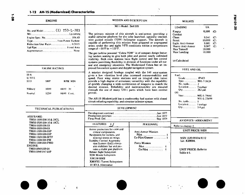
1-12 AH-1S (Modernized) Characteristics
ENGINE MISSION AND DKSCRIPTION WKIGHTS
No. and Model (1) T53-L-703 Mfr Lycoming
Kngine Spec. No 104.43
Type I-ree Power Turbine
Reduction Gear Ratio 0.31 15
Tail Pipe I i\ed Area
Augmentation None
KNGINK RATINGS
SI A LI VH.
STD
Military
Normal
SHP
1400
1250
RPM MIN
6600 30
6600 (ont.
TECHNICAL PUBLICATIONS
AIRFRAME: TM55-1520- TM55-1520- TM55-1520- TM55-1520- TM55-1520- TM55 1520- TM55-1520- TM55-1500- TM55-1500-
ENGINE: TM55-2840 TM55-2840
236-10 &;0CL -239-10 & 10CL -236-23 -239-23 -236-23P -239-23P 236-MTF 220-PM 220-PMD
229-24 247-23P
Mfr’s Model: Bell 209
The primary mission of this aircraft is anti-armor, providing a stable airborne platform for the tube launched, optically tracked, wire guided missile (TOW) helicopter support. The aircraft is capable of performing this mission from prepared or unprepared areas, under day and ipght VFR conditions within a temperature range of — 25°F to +125°F.
The gas turbine powered ‘‘Cobra TOW” is of compact design featur- ing tandem seating to give both pilot and gunner nearly unlimited visibility. Both crew stations have flight control and fire control systems permitting flexibility in division of functions under all nor- mal and emergency situations. The Modernized Cobra has an im- proved fire control system and doppler navigation system.
A mission designed fuselage coupled with the 540 rotor system gives a low vibration level plus increased maneuverability and speed. Four wing stores stations and an integral chin turret provide a high degree of armament versatility with the capability of quickly changing a wide combination of weapons to match the desired mission. Reliability and maintainability are ensured through the use of many UH-1 parts which have been combat proven.
The AH-1S (Modernized) has a crashworthy fuel system with closed circuit refueling capability, and a tractor tailrotor system.
DEVELOPMENT
Development contract Production contract . . First Prod. Del
. Jan 1977 . Jun 1977 . Sep 1978
FEATURES u Armor protection for crew and
critical components. Hardpoints for rockets, and
external stores on wings. Stability Control Augmenta-
tion System (SAS) elimin- ates stabilizer bar and pro- vides a stable gun platform.
Helmet Sight Subsystem TOW Missile Subsystem
XM138 RMS
XM97E1 Turret Subsystem 10 KVA Alternator
PERSONNEL
Anti-Armor Mission Pilot 1
Co-Pilot/Gunner 1
Ferry Mission Pilot Co-Pilot . •
LOADING
Empty Combat Clean Scout Light Anti-Armor Heavy Anti-Armor Max Takeoff Max Landing
(c) Calculated
LB.
6,598 (C)
9.541 10.000 9,661 9.987
10.000 10.000
(C) (Cl (Cl (Cl
FUEL AND OIL
Fuel. Grade JP-4/5 Spec MIL-T-5624 No. tanks 2 Location Fuselage Oty 262 gal.
Oil: Spec MIL-L-7808/
MIL-L-23699 No. tanks I Location Fuselage Oty 3.4 gal.
AVIONICS/ ARMAMENT
Refer to chapter 2.
UNIT PRICE/NSN
NSN 1520-00504-9112 Lin K29694,
UNIT PRICE: Refer to Table 4-1.
FM
101-20

1-2
9
t
1-13. Loading and Performance — Typical Mission AH-1S (EGAS and MODERNIZED)
(CONDITIONS MISSION I
SCOUT
MISSION II LIGHT
ANTI-ARMOR
MISSION HI HEAVY
ANTI-ARMOR
MISSION IV FERRY
(CLEAN)
TAKEOFF WEIGHT (lb) Fuel at 6.5 Ibs/gal (Grade JP-4) (lb) Payload (lb) Takeoff Power Loading (lb SHP) Disk Loading (Ibsqft) Autorotation Speed (Min R/D) (kn) Takeoff Ground Run at SL (ft) Takeoff to Clear 50 ft (ft) Vertical Rate of Climb at SL (fpm) Maximum Rate of Climb at SL (fpm) Speed for Max R/C at SL (kn) 'Hme: SL to 5000 ft (min) Time: SL to 10,000 ft (min) Service Celing (100 fpm) (ft) Absolute Hovering Ceiling (ft)
COMBAT RANGE (nmi) Average Cruise Speed (kn) Cruising Altitude (Initial) (ft) Cruising Altitude (Final) (ft) Total Mission Time (hr)
COMBAT RADIUS (nmi) Average Cruise Speed (kn) Cruising Altitude (Outbound) (Min/Max)..(ft) Cruising Altitude (Inbound) (ft) Total Mission Time (hr)
10,000 1,101 3,461 7.75 6.58
65 0 0
320 1,620
64 3.1 8.6
12,200 11,600
9,661 1,684 3,081 7.47 6.34
65 0 0
610 1,740
65 2.8 5.7
14,800 8,000
9,987 1,532 3,407
7.73 6.56
65 0 0
335 1,640
65 3.0 6.1
12,300 3,800
1.4 2.1
9,541 1,684 2,961 7.25 6.16
65 0 0
850 1,850
60 2.7 5.4
15.000 10,200
320 130
10.000 10,000
2.6
2.0 2.4
FM
101
-20
g
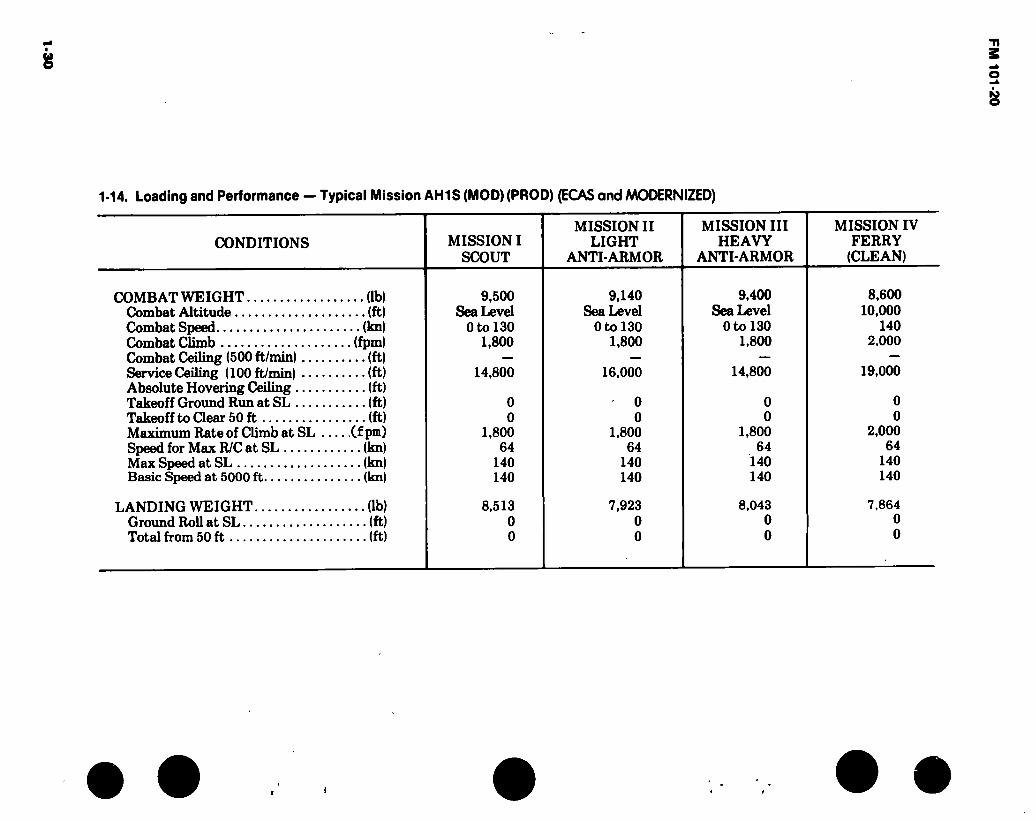
1-14. Loading and Performance — Typical Mission AH1S (MOD) (PROD) (EGAS and MODERNIZED)
CONDITIONS MISSION I SCOUT
MISSION II LIGHT
ANTI-ARMOR
MISSION III HEAVY
ANTI-ARMOR
MISSION IV FERRY
(CLEAN)
COMBAT WEIGHT (lb) Combat Altitude (ft) Combat Speed (kn) Combat Climb (fpm) Combat Ceiling (500 ft/min) (ft) Service Ceiling (100 ft/min) (ft) Absolute Hovering Ceiling (ft) Takeoff Ground Run at SL (ft) Takeoff to Clear 50 ft (ft) Maximum Rate of Climb at SL (fpm) Speed for Max R/C at SL (kn) Max Speed at SL (kn) Basic Speed at 5000 ft (kn)
LANDING WEIGHT. Ground Roll at SL.., Total from 50 ft
(lb) .(ft) .(ft)
9,500 Sea Level
Oto 130 1,800
14,800
0 0
1,800 64
140 140
8,513 0 0
9,140 Sea Level
Oto 130 1,800
16,000
0 0
1,800 64
140 140
7,923 0 0
9,400 Sea Level
Oto 130 1,800
14,800
0 0
1,800 64
140 140
8,043 0 0
8,600 10,000
140 2,000
19,000
0 0
2,000 64
140 140
7,864 0 0
I
FM
10
1-2
0

FM 101-20
1-15. Performance Notes, AH-1G (Cobra - TOW)
LIGHT SCOUT MISSION - Armed Tactical Helicopter — Radius Start engine; warm-up, takeoff, and climb on course at normal power to 6350 feet initial cruise altitude. Maintain 55-feet-per-minute rate of climb at cruise speed to an altitude of 9800 feet. Descend to sea level and fire rockets during a period of ten (10) minutes combat at normal power. Climb on course to 10,000 feet at normal power and return to home base at cruise speed. Range free allowances are two (2) minutes of normal power for warm-up and takeoff, ten (10) minutes of combat time at normal power, plus ten percent of initial fuel for landing and reserve.
HEAVY SCOUT MISSION - Armed Tactical Helicopter — Radius Start engine, warmup, takeoff, and climb on course at normal power to 5350 feet initial cruise altitude. Maintain 41.6 feet-per-minute rate of climb at cruise speed to an altitude of 7250 feet. Descend to sea level and fire rockets during a period of ten (10) minutes combat at normal power. Climb on. course to 10,000 feet at normal power and return to home base at cruise speed. Range free allowances are two (2) minutes of normal power for warm-up and takeoff, ten (10) minutes of combat time at normal power, plus ten percent of initial fuel for landing and reserve.
HOG MISSION - Armed Tactical Helicopter - Radius Start engine, warm-up, takeoff, and climb on course at normal power to 5600 feet initial cruise altitude. Maintain 50-feet-per-minute rate of climb at cruise speed to an altitude of 7200 feet. Descend to sea level
and Tire rockets during a period of ten (10) minutes combat at normal power. Climb on course to 10,000 feet at normal power and return to home base at cruise speed. Range free allowances are two (2) minutes of normal power for warm-up and takeoff, ten (10) minutes of combat time at normal power, plus ten percent of initial fuel for landing and reserve.
FERRY MISSION - Clean (Without Auxiliary Tanks) — Range Start engine, warm-up, takeoff, and climb on course at normal power to 10,000 feet initial cruise altitude. Fly out at cruise speeds until ninety percent of initial fuel is consumed and land at remote base. Range free allowance include two (2) minutes at normal rated power for warm-up and takeoff, and ten percent of initial fuel for landing and reserve.
GENERAL NOTES: a. Cruise speed as used above denotes airspeed
for long-range operation and is the greater of the two speeds at which ninety-nine percent of the maximum miles per pound of fuel are attainable at the momentary weight and altitude.
b. Data do not include ground effect.
PERFORMANCE BASIS: a. Power required is based upon “Engineering
Phase B Flight-Test Data”.
b. Power available and fuel flow are based on Lycoming Model Specification No. 104.33, and includes particle separators and filters.
NOTE: Performance Notes Not Available for AH-lSModels.
Source: TSARCOM-DRCPM-CO
1-31
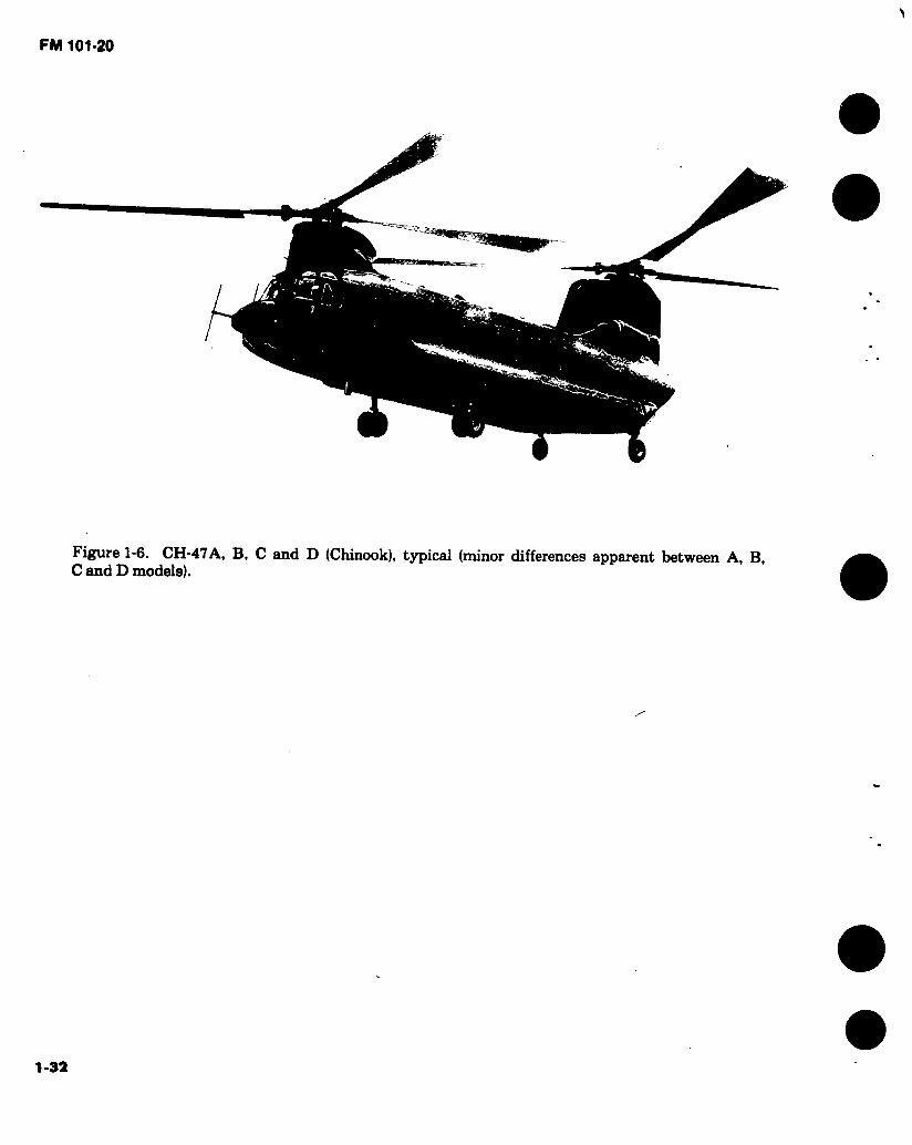
Figure 1-6. CH-47A, B, C and D (Chinook), typical (minor differences apparent between A, B, C and D models).
1-32
FM 101-20
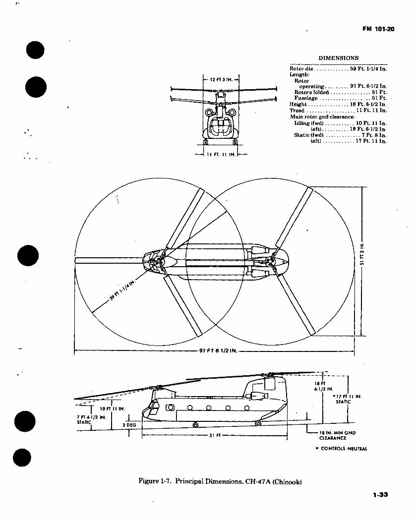
DIMENSIONS
— 12 FT 5 IN.—
'S
*
Rotor dia 59 Ft. 1-1/4 In. Length:
Rotor operating 97 Ft. 6-1/2 In.
Rotors folded 51 Ft. Fuselage 51 Ft.
Height 18 Ft. 6-1/2 In. Tread 11 Ft. 11 In. Main rotor gnd clearance:
Idling (fwd) 10 Ft. 11 In. (aft) 18 Ft. 6-1/2 In-
Static (fwd) 7 Ft. 8 In. (aft) 17 Ft. 11 In.
—I 11 FT. 11 IN. -—
t
97 FT 6 1/2 IN.
18 FT
6-1/2 IN.
17 FT 11 IN. STATIC
© Q Q Q Q 10FT II IN
7 FT 4-1/2 IN. STATIC
2 DEG
51 FT 18 IN. MIN GND CLEARANCE
• CONTROLS NEUTRAL
Figure 1-7. Principal Dimensions, CH-47A (Chinook)
1-33
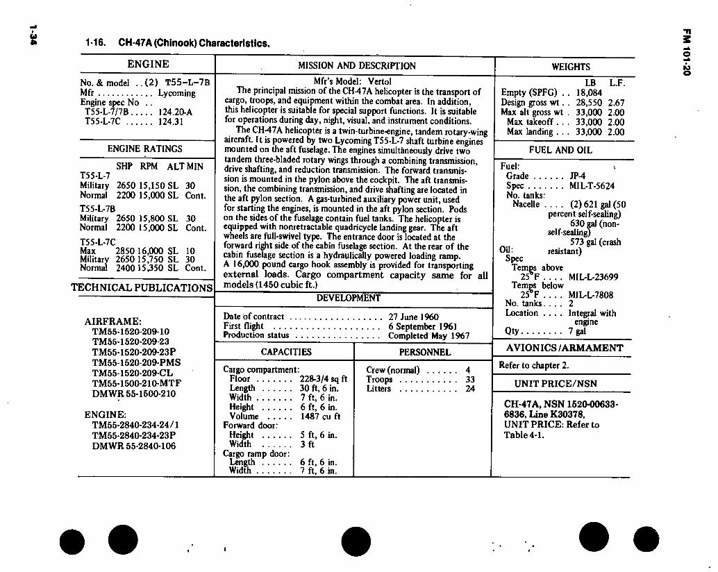
1-34 1-16. CH-47A (Chinook) Characteristics.
ENGINE MISSION AND DESCRIPTION WEIGHTS
No. & model ..(2) T55-L-7B Mfr Lycoming Engine spec No .. T55-L-7/7B 124.20-A T55-L-7C 124.31
ENGINE RATINGS
SHP RPM ALT MIN T55-L-7 Military 2650 15,150 SL 30 Normal 2200 15,000 SL Cont.
T55-L-7B Military 2650 15,800 SL 30 Normal 2200 15,000 SL Cont.
T55-L-7C Max 2850 16,000 SL 10 MUitary 2650 15,750 SL 30 Normal 240015,350 SL Cont.
TECHNICAL PUBLICATIONS
AIRFRAME: TM55-1520-209-10 TM55-1520-209-23 TM55-1520-209-23P TM55-1520-209-PMS TM55-1520-209-CL TM55-1500-210-MTF DMWR 55-1500-210
ENGINE: TM55-2840-234-24/1 TM55-2840-234-23P DMWR 55-2840-106
Mfr’s Model: Vertol The principal mission of the CH-47A helicopter is the transport of
cargo, troops, and equipment within the combat area. In addition, this helicopter is suitable for special support functions. It is suitable for operations during day, night, visual, and instrument conditions.
The CH47A helicopter is a twin-turbine-engine, tandem rotary-wing aircraft. It is powered by two Lycoming T55-L-7 shaft turbine engines mounted on the aft fuselage. The engines simultaneously drive two tandem three-bladed rotary wings through a combining transmission, drive shafting, and reduction transmission. The forward transmis- sion is mounted in the pylon above the cockpit. The aft transmis- sion, the combining transmission, and drive shafting are located in the aft pylon section. A gas-turbined auxiliary power unit, used for starting the engines, is mounted in the aft pylon section. Pods on the sides of the fuselage contain fuel tanks. The helicopter is equipped with nonretractable quadricycle landing gear. The aft wheels are full-swivel type. The entrance door is located at the forward right side of the cabin fuselage section. At the rear of the cabin fuselage section is a hydraulically powered loading ramp. A 16,000 pound cargo hook assembly is provided for transporting external loads. Cargo compartment capacity same for all models (1450 cubic ft.)
DEVELOPMENT
Date of contract . First flight . . . . Production status
27 June 1960 6 September 1961 Completed May 1967
CAPACITIES
Cargo compartment: Floor 228-3/4 sq ft Length 30 ft, 6 in. Width 7 ft, 6 in. Height 6 ft, 6 in. Volume 1487 cu ft
Forward door: Height 5 ft, 6 in. Width 3 ft
Cargo ramp door: Length 6 ft, 6 in. Width 7 ft, 6 in.
PERSONNEL
Crew (normal) 4 Troops 33 Litters 24
Empty (SPFG) . Design gross wt. Max alt gross wt
Max takeoff. . Max landing . .
LB 18,084 28,550 33.000 33.000 33.000
L.F.
2.67 2.00 2.00 2.00
FUEL AND OIL
Fuel: * Grade JP-4 Spec MIL-T-5624 No. tanks:
Nacelle (2)621 gal (50 percent self-sealing)
630 gal (non-
Oil: Spec
Temps above 25 r
Temps below 25ÇF
No. tanks.... Location ....
Qty
573 gal (crash resistant)
MIL-L-23699
MIDL-7808 2 Integral with
engine 7 gal
AVIONICS /ARMAMENT
Refer to chapter 2.
UNIT PRICE/NSN
CH-47A, NSN1520-00633- 6836, Line K30378, UNIT PRICE: Refer to Table 4-1.
i
FM 101-20
FM 101-20
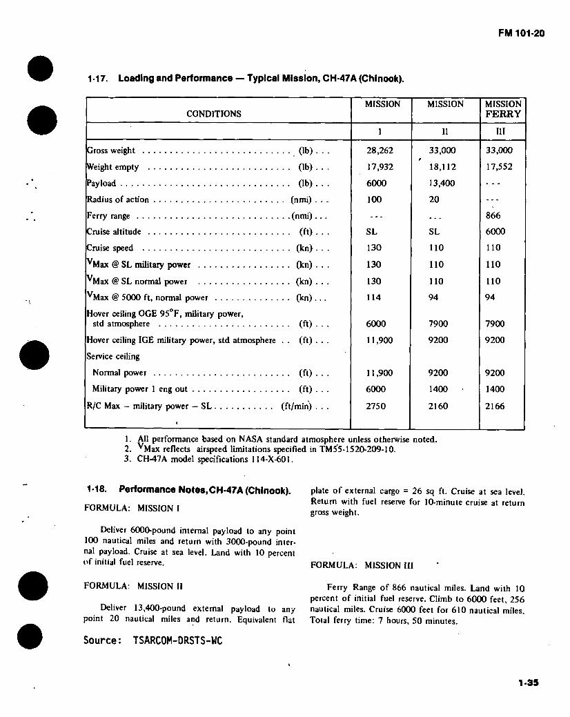
1-17. Loading and Performance — Typical Mission, CH-47A (Chinook).
CONDITIONS MISSION MISSION MISSION
FERRY
I II III
Gross weight (lb)
Weight empty (lb)
Payload (lb)
Radius of action (nmi) .
Ferry range (nmi) .
Cruise altitude (ft)
Cruise speed (kn)
^Max @ SL military power (kn)
^Max @ SL normal power (kn)
^Max @ 5000 ft, normal power (kn) .
Hover ceiling OGE 95°F, military power, std atmosphere (ft)
Hover ceiling IGE military power, std atmosphere . . (ft)
Service ceiling
Normal power (ft)
Military power 1 eng out (ft)
R/C Max - military power — SL (ft/min) ,
28,262
17,932
6000
100
SL
130
130
130
114
6000
11.900
11.900
6000
2750
33,000
18,112
13,400
20
SL
110
110
110
94
7900
9200
9200
1400
2160
33,000
17,552
866
6000
110
110
110
94
7900
9200
9200
1400
2166
1. All performance based on NASA standard atmosphere unless otherwise noted. 2. ^Max reflects airspeed limitations specified in TM55-1520-209-10. 3. CH-47A model specifications 114-X-601.
1-18. Performance Notes,CH-47A (Chinook).
FORMULA: MISSION I
Deliver 6000-pound internal payload to any point 100 nautical miles and return with 3000-pound inter- nal payload. Cruise at sea level. Land with 10 percent of initial fuel reserve.
FORMULA: MISSION II
Deliver 13,400-pound external payload to any point 20 nautical miles and return. Equivalent flat
plate of external cargo = 26 sq ft. Cruise at sea level. Return with fuel reserve for 10-minute cruise at return gross weight.
FORMULA: MISSION III
Ferry Range of 866 nautical miles. Land with 10 percent of initial fuel reserve. Climb to 6000 feet, 256 nautical miles. Cruise 6000 feet for 610 nautical miles. Total ferry time: 7 hours, 50 minutes.
Source: TSARCOM-DRSTS-WC
1-35

FM 101-20
DIMENSIONS
—12 FT 5 IN.-
h 110 FT 6 IN
Rotor dia 60 Ft. Length:
Rotors operating 98 Ft. 10-1/2 In.
Rotors folded 50 Ft. 9 In. Fuselage 50 Ft. 9 In.
Height (overall 18 Ft. 11-1/2 In. Tread 11 Ft. 11 In. Rotor ground clearance:
Static fwd 7 Ft. 4-3/4 In. Idling fwd 10 Ft. 11 In.
2 E
«p
98 FT 10-1/2 IN
18 FT 11-1/2 IN. I i
G3 Q Q Q O 10 FT 11 IN.
1°56
50 FT 9 IN
— 18IN.MINGND CLEARANCE
Figure 1-8. Principal Dimensions, CH-47B and C (Chinook)
1-36

1-3
7
1-19. CH-47B (Chinook) Characteristics.
ENGINE MISSION AND DESCRIPTION
No. & Model .... (2) T55-L-7C Mfr Lycoming Engine spec No. T55-L-7C 124.31
Engine /rotor gear ratio 65.93:1
ENGINE RATINGS
SHP RPM ALT MIN Maximum 2850 16000 SL 10 Military 2650 15750 SL 30 Normal 2400 15350 SL Cont
TECHNICAL PUBLICATION
AIRFRAME: TM55-1520-227-10/1 TM55-1520-227-23 TM55-1520-227-PM TM55-1520-227-PMS TM55-1520-227-CL-1 TM55-1500-210-MTF TM55-1520-209-23P DMWR 55-1500-210
ENGINE: TM55-2840-234-24/1 TM55-2840-234-23P DMWR 55-284Ö-106
Mfr’s Model: Vertol The principal mission of the CH-47B helicopter is to provide air
transportation for troops and cargo. The aircraft can also be utilized for rescue of personnel.
The CH-47B is a large tandem rotor helicopter with built-in accomodations for 24 litter patients and 2 attendants or.33 troops and troop commander. The helicopter is equipped with an unobstructed 30-foot long cargo compartment with straight-in rear loading and has a capacity of over 450 cubic feet. Other features include an external cargo hook of 10-ton capacity and a winch system for loading an auxiliary power unit which powers the utility hydraulic system, thus eliminating the requirement for external ground power sources; stability system provided through Vertol SAS; and provisions for utilizing collapsible fuel tanks to increase the fuel capacity by 2000 gallons. The complete helicopter is designed for operations in temperatures ranging from - 25° F to +125°F.
DEVELOPMENT Date of contract First flight Production status
CAPACITIES
Cargo compartment: Floor 228-3/4 sq ft Length 30 ft, 6 in. Width 7 ft, 6 in. Height 6 ft, 6 in. Volume 1487 cu ft Forward door: Height 5 ft, 6 in.
June 1966 October 1966 Completed February 1968
PERSONNEL
Crew 4 Litters 24
or Troops 33
WEIGHTS
LB L.F.
Empty *19,153 Basic *19,194 Design 33,000 3.00 Combat *21,734 Max alternate
gross weight ... 40,000 2.54 Normal takeoff .. 33,000 3.00 Alternate takeoff. 40,000 2.54 Max landing 40,000 2.54
*For basic mission.
FUEL AND OIL
Fuel: Grade JP-4 Spec MIL-T-5624 No. tanks:
Fuselage (2) 621 gal 566 gal
(crash resistant) OU:
Engine contained oil supply Spec
Temps above 25°F MIL-L-23699
Temps below 25°F MIL-L-7808
Qty 7 gal
AVIONICS / ARMAMENT
Refer to chapter 2.
Width 3 ft Cargo ramp door: Height 6 ft, 6 in. Width 7 ft, 6 in.
UNIT PRICE/NSN
CH-47B, NSN 1520-00990-2941 LINE K30383, UNIT PRICE: Refer to Table 4-1.
FM 101-20

1-20. Loading and Performance — Typical Mission,CH-47B (Chinook)
CONDITIONS
Estimated gross weight Payload guaranteed (outbound) Payload guaranteed (inbound) Payload estimated (outbound) Payload estimated (inbound)
Vmax at SL/STD, military power Max cruise speed at SL/STD,
normal power. Guaranteed Estimated
V-Cruise (best range) at SL/STD V-Cruise (best range) at 5000 F Max rate-of-climb at SL/STD military
power Vertical rate-of-climb at SL/STD,
maximum power Service ceiling at normal power Service ceiling, single engine at military
power Guaranteed Estimated
Hover ceiling, OGE at STD temperature maximum power
Hover ceiling, 1GE at STD temperature maximum power, 10 ft wheel height .
Radius of action Guaranteed Estimated
Ferry range
BASIC MISSION
I
BASIC MISSION
(DESIGN GW) II
PRIMARY MISSION
III
EXTERNAL PAYLOAD MISSION
IV
MAXIMUM FERRY
MISSION V
Ob) Ob) Ob) (lb) Ob)
(kn)
30,900 33,000 40,000 40,000 40,000 6,000 3.000 7.000 3,500
1682/
9,000 4,500
1652/
15,900 7,935
145 i'
18,800 0 1381/2/
1,075
US2/
(kn). (kn). (kn). (kn).
166 145 138
150 163 144 134
142 134 114
132-1/ 100-3^ 100
142 134 114
(ft/min). 2,4402/ 2,2002/ 1,520-2/ 1,440 1,520
(ft/min), ... (ft).
2,300.2/ 1,800-2^ 18,000 16,200
60 9,550
60 8,950
60 9,550
• (ft). • (ft)-
• (ft).
• (ft)-
(nmi). (nmi). (nmi).
6,000 6,050
12,850
16,300
100 100
3,650
10,650
14,200
100
700-2'
7,400
95
700-2'
7,400
20
700-2'
7,400
1,090
i
FM
I 01-20
1-3
9
s
1-20. Loading and Performance — Typical Mission, CH-47B (Chinook) (CONT).
NOTES:
Mvith external payload equivalent to 26 Sq. Ft. drag area.
■^Transmission limit.
■2/Mission cruise speed.
The above table reflects performance capability only. For approved operational limits which consider all pertinent factors, see TM55-1520-227-10/1
For Mission I the helicopter shall be capable of hovering at 6000 ft. for ten minutes at 95° F, OGE at the gross weight required for the accomplishment of Mission I (guaranteed). The Mission I gross weight includes an outbound payload of 6000 lb., return payload of 3000 lb., and fuel for a radius of 100 nmi.
During Mission HI the helicopter shall be capable of hovering out-of-ground effect at sea level standard, maximum power and at a gross weight of 39,500 pounds (guaranteed).
FM 101-20
FM 101-20
1-21. Performance Notes, CH-47B (Chinook).
FORMULA: RADIUS MISSIONS I & II
Warm up, take off, climb on course to 5000 feet at normal power, cruise out at long range speeds to remote base, land, and unload cargo. Without refueling, warm up, take off, climb on course to 5000 feet at norma) power, and return at long range speeds. Range- free allowances are 2 minutes of normal power for each warmup and takeoff, plus 10 percent of initial fuel for reserve.
FORMULA: RADIUS MISSION HI
Warm up, take off, cruise out at long range speeds at sea level to remote base, land, and unload outbound cargo, load inbound cargo. Without refueling, warm up, take off, return at long range speeds at sea level, land, and unload cargo. Range-free allowances are 2 minutes of normal power for each warmup and takeoff, plus 10 percent of initial fuel for reserve.
FORMULA: RADIUS MISSION IV
Warm up, take off, cruise out at 10Q knots at sea level, with external cargo to remote base, detach cargo, and land. Without refueling, warm up, take off, and return at long range speeds at sea level. Range-free allowances are 2 minutes of normal power for each warmup and takeoff, plus 10 minutes of cruise fuel for reserve.
FORMULA: RANGE MISSIONS I & II
Warm up, take off, climb on course to 5000 feet at normal power, cruise out at long range speeds until 90 percent of initial fuel is consumed, land, and unload cargo. Range-free allowances are 2 minutes of normal power for warmup and takeoff, plus 10 percent of initial fuel for reserve.
FORMULA: RANGE MISSION III
Warm up, take off, cruise out at long range speeds at sea level until 90 percent of initial fuel is consumed, land, and unload cargo. Range-free allowances are 2 minutes of normal power for warmup and takeoff, plus 10 percent of initial fuel for reserve.
FORMULA: RANGE MISSION IV
Warm up, take off, cruise out at 100 knots at sea level with external cargo until 10 minutes of cruise fuel remains, detach cargo, and land. Range-free allowances are 2 minutes of normal power for warmup and takeoff, plus 10 minutes of cruise fuel for reserve.
FORMULA: RANGE MISSION V
Warm up, take off, climb on course to optimum cruise altitude at cruise speed, cruise out at long range speeds until 90 percent of initial fuel is consumed. Range-free allowances are 2 minutes of normal power for warmup and takeoff, plus 10 percent of initial fuel for reserve.
PERFORMANCE REFERENCES
Vertol Report 114-P-J-602. Detail Specifications for the Model CH-47B Helicopter.
Boeing-Vertol Report 114-AD-601. Estimated Performance Capability of CH-47B and CH-47C Heli- copters.
Lycoming Model Specification 124.31, T55-L-7C Shaft Turbine Engine.
Source: TSARCOM-DRSTS-WC
1-40
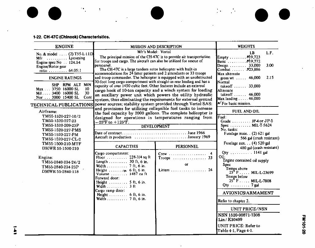
1-41
1-22. CH-47C (Chinook) Characteristics.
ENGINE
No. & model .... (2) T55-L1 ID Mfr Lycoming Engine spec No .. 124.54 Engine/Rotor gear
ratio 64.05:1
ENGINE RATINGS
SHP RPM ALT MIN Max ... 3750 16000 SL 10 Mil... . 3400 16000 SL 30 Nor ... 3000 15400 SL Cont
TECHNICAL PUBLICATIONS
Airframe: TM55-1520-227-10/2 TM55-1520-227-23 TM55-1520-209-23P TM55-1520-227-PMS TM55-1520-227-PM TM55-1520-227-CL-2 TM55-1500-210-MTF DMWR 55-1500-210
Engine: TM55-2840-234-24/2 TM55-2840-234-23P DMWR 55-2840-118
MISSION AND DESCRIPTION
Mfr’s Model: Vertol
The principal mission of the CH47C is to provide air transportation for troops and cargo. The aircraft can also be utilized for rescue of personnel.
The CH-47C is a large tandem rotor helicopter with built-in accommodations for 24 litter patients and 2 attendants or 33 troops and troop commander. The helicopter is equipped with an unobstructed 30-foot long cargo compartment with straight-in rear loading and has a capacity of over 1450 cubic feet. Other features include an external cargo hook of 10-ton capacity and a winch system for loading an auxiliary power unit which powers the utility hydraulic system, thus eliminating the requirements for external ground power sources; stability system provided through Vertol SAS; and provisions for utilizing collapsible fuel tanks to increase the fuel capacity by 2000 gallons. The complete helicopter is designed for operations in temperatures ranging from —25°F to +125°F.
DEVELOPMENT
Date of contract Aircraft in production
CAPACITIES
Cargo compartment: Floor 228-3/4 sq ft Length 30 ft, 6 in. Width 7 ft, 6 in. Height 6 ft, 6 in. Volume 1487 cu ft Forward door: Height 5 ft, 6 in. Width 3 ft
Crew . Troops
Litters
Cargo ramp door: Height 6 ft, 6 in. Width 7 ft, 6 in.
June 1966 January 1969
PERSONNEL
or
4 33
24
WEIGHTS
LB L.F. Empty M9,723 Basic -il 9,772 Design 33,000 3.00 Combat -523,886 Max alternate
gross wt 46,000 2.15 Normal
takeoff 33,000 Alternate
takeoff 46,000 Max landing 46,000
For basic mission.
FUEL AND OIL
Fuel: Grade JP-4or JP-5 Spec MIL-T-5624 No. tanks:
Fuselage main.. (2) 621 gal 566 gal (crash resistant)
Fuselage aux... (4) 520 gal 480 gal (crash resistant)
Qty 1141 gal Oil:
Engine contained oil supply Spec
Temps above 256 F MIL-L-23699
Temps below 25i> F MIL-L-7808
Qty 7 gal
AVIONICS/ARMAMENT
Refer to chapter 2.
UNIT PRICE/NSN
NSN 1520-00871-7308 Lin / K30499
UNIT PRICE: Refer to Table 4-1, Page 4-1.
FM
101-20

1*42
1-23. Loading and Performance — Typical Mission, CH-47C (Chinook).
CONDITIONS
Gross weight
Payload guaranteed (outbound) Payload guaranteed (inbound)
Payload estimated (outbound) Payload estimated (inbound)
Vmax at SL/STD, military power .... Max cruise speed at SL/STD normal power
Guaranteed Estimated
V-Cruise (best range) at SL/STD V-Cruise (best range) at 5000 ft/STD . . Rate-of-climb at SL/STD military
power Vertical rate-of-climb at SL/STD maximum
power Service ceiling at normal power Service ceiling, STD temp, single engine
at military power Guaranteed Estimated
Hover ceiling, OGE at STD temperature, max power
Hover ceiling IGE at STD temperature, maximum power, 10 ft. wheel height
Radius of action, Guaranteed Estimated
Ferry range
BASIC MISSION
I
BASIC MISSION
(DESIGN GW) II
PRIMARY
MISSION III
EXTERNAL PAYLOAD
MISSION IW
MAXIMUM
FERRY MISSION
V
. . .(lb)
. . .(lb)
. . .(lb)
. . .(lb)
. . .(lb)
. . (kn)
. . (kn)
. . (kn)
. . (kn)
. . (kn)
(ft/min)
(ft/min)
• • -(ft)
.(ft)
.(ft)
• (ft)
.(nmi)
.(nmi)
.(nmi)
39,200?/
12,000 6,000
13,300 6,650
156^
156*/ 141 136
2,045^
1,2202/ 10,200*/
4,000 4,5002' 5/
9,600
12,750
100 100
33,000
' 7,350 3,675
1642/
155 1642/ 140 138
2,8802/
2,5853/ 15,0000/
9,5502/
14,750
15,000
100
46,000
19,750 9,875
123*/
123*/ 123*/ 111*/
1,3802/
8,000*/
7,600
100
46,000
23,300 0 1003/
IOO5/ 1003/ 100s/
1,2602/
8,000*/
7,600
20
46,000
123*/
123*/ 123*/ 111*/
1,3802/
8,000*/
7,600
1,226
FM 101-20

1-4
3
• *
1-23. Loading and Performance — Typical Mission, CH-47C (Chinook) (CONT).
NOTES:
U With External Payload Equivalent to 26 FT2 Drag Area (Troop Seats Incl.) 2/ Hover Gross Weight at 6000 ft/95°F at 245 RPM. 2/ Transmission Limit.
y Structural Envelope, y Mission Cruise Speed (Outbound). y Current Hydraulic System Limit. v At 230 RPM.
5/ With 12000 LB Payload.
For Mission I the helicopter shall be capable of hovering at 6000 ft for 10 minutes at 95°F, OGE at gross weight required for accomplishment of Mission I (guaranteed). The Mission I gross weight includes an outbound payload of 12,000 lb., return payload of 6000 lb., and fuel for a radius of
During Mission III the helicopter shall be capable of hovering out-of-ground effect at SL/STD, maximum power, and a gross weight of 43,000 pounds
(guaranteed).
100 nmi.
FM 101-20
1-24. Performance Notes, CH-47C (Chinook).
FORMULA: RADIUS MISSIONS I & II
Warm up, take off, climb on course to 5000 feet at normal power, cruise out at long range speeds to remote base, land, and unload cargo. Without refueling, warm up, take off, climb on course to 5000 feet at normal power, and return at long range speeds. Range- free allowances are 2 minutes of normal power for each warmup and takeoff, plus 10 percent of initial fuel for reserve.
FORMULA: RADIUS MISSION III
Warm up, take off, cruise out at long range speeds at sea level to remote base, land, and unload outbound cargo, load inbound cargo. Without refueling, warm up, take off, return at long range speeds at sea level, land and unload cargo. Range-free allowances are 2 minutes of normal power for each warmup and takeoff, plus 10 percent of initial fuel for reserve.
FORMULA: RADIUS MISSION IV
Warm up, take off, cruise out at 100 knots at sea level with external cargo to remote base, detach cargo, and land. Without refueling, warm up, take off, and return at long range speeds at sea level. Range-free allowances are 2 minutes of normal power for each warmup and takeoff, plus 10 minutes of cruise fuel for reserve.
FORMULA: RANGE MISSIONS I & II
Warm up, take off, climb on course to 5000 feet at normal power, cruise out at long range speeds until 90 percent of initial fuel is consumed, land, and
unload cargo. Range-free allowances are 2 minutes of normal power for warmup and takeoff, plus 10 percent of initial fuel for reserve.
FORMULA: RANGE MISSION III
Warm up, take off, cruise out at long range speeds at sea level until 90 percent of initial fuel is consumed, land, and unload cargo. Range-free allowances are 2 minutes of normal power for warmup and takeoff, plus 10 percent of initial fuel for reserve.
FORMULA: RANGE MISSION IV
Warm up, take off, cruise out at 100 knots at sea level with external cargo until 10 minutes of cruise fuel remains, detach cargo, and land. Range-free allowances are 2 minutes of normal power for warmup and takeoff, plus 10 minutes of cruise fuel for reserve.
FORMULA: RANGE MISSION V
Warm up, take off, climb on course to optimum cruise altitude at cruise speed, and cruise out at long range speeds until 90 percent of initial fuel is con- sumed. Range-free allowances are 2 minutes of normal power for warmup and takeoff, plus 10 percent of initial fuel for reserve.
PERFORMANCE REFERENCES
Vertol Report 114-PJ-7003, Detail Specification for The CH-47C Helicopter.
Lycoming Report 124.38,T55-L-11A Engine Speci- fication.
Boeing-Vertol Report 114-AD-601, Estimated Performance Capabilities of CH-47B and CH-47C Heli- copters.
Source: TSARCOM-DRSTS-WC
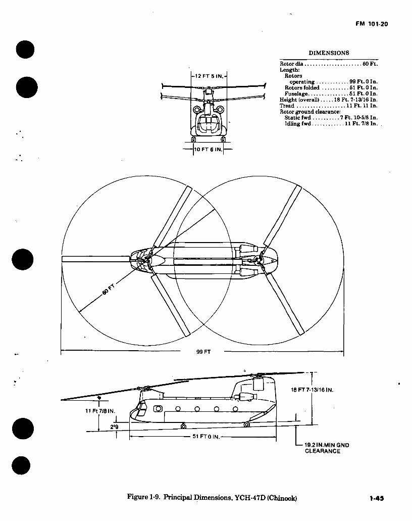
FM 101-20
DIMENSIONS
*-12 FT 5 IN.
h HlO FT 6 IN
Rotor dia 60 Ft. Length:
Rotors operating 99 Ft. 0 In.
Rotors folded 51 Ft. 0 In. Fuselage 51 Ft. 0 In.
Height (overall) 18 Ft. 7-13/16 In. Tread 11 Ft. 11 In. Rotor ground clearance:
Static fwd 7 Ft. 10-5/8 In. Idling fwd 11 Ft. 7/8 In.
t
99 FT
18 FT 7-13/16 IN.
&
G3 Q Q 0 Q
51 FT0 IN.
I—19.2IN.MINGND CLEARANCE
1-9. Principal Dimensions, YCH-47D (Chinook) 1-45

fe D-2ÍL VGIH)^(CMnootO Clhisiiracdoirtsílles.
ENGINE
No. and Model Mfg Engine Spec. No Type Reduction Great Ratio Tail Pipe Augmentation
MISSION AND DESCRIPTION
(2)T55-L-712 .. Lycoming 124.53 . Turboshaft 66.96
The essential characteristic for the YCH-47D is a mini- mum lift 15,000 lbs external cargo at 4000’, 95°, HOGE with a 200-500 fpm VROC and a 30 NM radius.
The CH-47 is a medium lift tandem rotor helicopter pow- ered by 2 turbo shaft engines. The helicopter has a 30 ft long cargo compartment with straight-in rear loading with accomodations for 24 lifters and 2 attendants or 33
ENGINE RATINGS
combat equipped troops and troop commander. The heli- copter is designed for operations in temperatures ranging from -25° to +125°. The YCH-47D has 3 hooks for trans-
WEIGHTS
LOADING LB. Empty 22784 Basic — Design 33000 Combat
Clean — Light Scout — Heavy Scout — Hog —
Max. Takeoff 50000 Max. Landing 50000
SEA LEVEL STD SHP Emergency 4500 Maximum 3750 Interme- diate 3400 Maximum Continuous 3000
RPM »
MIN 16000 30 16000 10
16000 30
16000 -
TECHNICAL PUBLICATIONS
Airframe:
TM55-1520-240-10 and 10CL TM55-1520-240-23 TM55-1520-240-23P TM55-1520-240-MTF TM55-1520-240-PM
Engine: «
portation of loads externally. The center hook has a capacity of 28,000 lb and the forward and aft hooks each have a 20,000 lb capacity. External loads can be handled separately or rigged for multipoint hook up to improve load stability and increase allowable cruise speed.
DEVELOPMENT
Date of Contact...
First acft delivered
FEATURES
Cargo Compartment: Length 30 ft 2 in Width 7 ft 6 in Height 6 ft 6 in
Forward Door: Height 5 ft 6 in Width 3 ft 0 in
Cargo Ramp Door: Height 6 ft 6 in Width 7 ft 7 in
4 Jun 76
PERSONNEL
Crew 3 Litters 24 (Plus 2 attendants)
or Troops 33 (Plus troop commander)
(C) Calculated ° For Basic Mission
FUEL AND OIL
Fuel: Grade JP-4 Spec MIL-T-5624 No. tanks 6 Location Fuselage Qty 1042 Gal
Oil: (Engine) Spec ... MIL-L-23699/7808 No. tanks 1/Eng Location Internal Qty 3.75 Galea
AVIONICS/ARMAMENT
Refer to Chapter 2.
UNIT PRICE/NSN
TM55-2840-234-24/1 TM55-2840-234-23P DMS3R55-2840-118
APU: ‘ Solar T-62T-2B Operations:
Day, night, VMC, IMC
1520-01-088-3669
• •
OS-
MU
rad
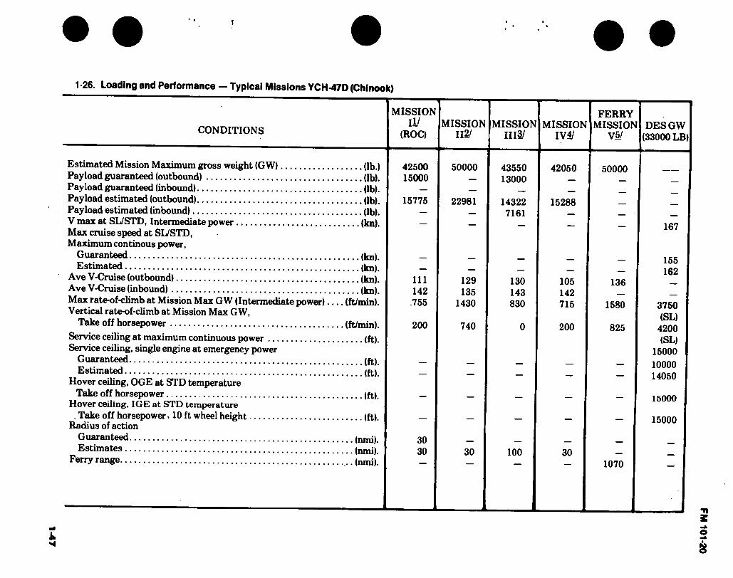
1-4
7
1 -26. Loading and Performance — Typical Missions YCH-47D (Chinook)
CONDITIONS
MISSION II/
(ROC) MISSION
112/ MISSION
1113/ MISSION
IVi/
FERRY MISSION
V5/ DES GW
(33000 LB)
Estimated Mission Maximum gross weight (GW) (lb.) Payload guaranteed (outbound) (lb). Payload guaranteed (inbound) (lb). Payload estimated (outbound) (lb). Payload estimated (inbound) (lb). V max at SL/STD, Intermediate power (lm) Max cruise speed at SL/STD, Maximum continous power,
Guaranteed (lm). Estimated (lm)
Ave V-Cruise (outbound) (lm). Ave V-Cruise (inbound) (kn). Max rate-of-climb at Mission Max GW (Intermediate power) (ft/min). Vertical rate-of-climb at Mission Max GW,
Take off horsepower (ft/min). Service ceiling at maximum continuous power (ft). Service ceiling, single engine at emergency power
Guaranteed (ft). Estimated (ft)
Hover ceiling, OGE at STD temperature Take off horsepower (ft).
Hover ceiling, IGE at STD temperature . Take off horsepower. 10 ft wheel height (ft).
Radius of action Guaranteed (nmi). Estimates (nmi);
Ferry range ...(nmi).
42500 15000
15775
111 142
.755
200
30 30
50000
22981
43550 13000
14322 7161
129 135
1430
740
130 143 830
42050
15288
50000
105 142 715
200
136
1580
825
30 100 30 1070
167
155 162
3750 (SL)
4200 (SL)
15000 10000 14050
15000
15000
FM 101-20

FM 101-20
1-26. Loading and Performance — Typical Missions, YCH-47D (Chinook) Cont’d.
NOTES: \j Ambient Conditions: 4000 ft/95"F. External load provides a drag area of 50 sq ft and download of 0.8% GW. This is the Required Operational Capability (ROC) Mission.
21 Ambient conditions: SL/STD. External load provides a drag area of 50 sq ft and download of 0.8% GW.
_2/ Ambient conditions: 4000 ft/95"F.
4/ Ambient conditions: 4000 ft/95"F. External load provides a drag area of 75 sq ft and download of 1.87% GW.
5/ Ambient conditions: Standard atmosphere. Additional ferry fuel is carried in 5 internally mounted auxiliary 600 gal tanks.
Reference: Boeing Vertol Report 145-PJ-7103 Revision D, Detail Specification for Model YCH-47D Helicopter.
1

FM 101-20
1-27. Performance Notes, YCH-47D (Chinook)
Formula: Radius Mission I, II and IV Warm up, take-off, hover, acquire external load, climb vertically at maximum power and cruise outbound at long range speed to drop zone. Hover at drop zone to unload cargo and cruise inbound at long range speed. Range free allowances are 2 minutes of mavimnm continuous power for warm up and take-off, 2 minutes total hover-out-of-ground-effect, 1 minute vertical climb (200 fpm) and 30 minutes reserve at long range cruise speed. This is the Required Operational Capability (ROC) mission profile.
Formula: Radius Mission III Load cargo internally, warm up, take-off, hover-out-of-ground-effect and cruise outbound to landing zone at long range speed. Land and exchange cargo (inbound load equals Vt outbound load), warm up, takeoff, hover- out-of ground effect and cruise inbound at long range speed. Range free allowances are 2 minutes of mavimnm continuous power for each warm up, takeoff and hover plus 30 minutes reserve at long range cruise speed.
Formula: Ferry Mission V Warm up and takeoff at sea level and cruise climb to 8000 ft. Cruise at 8000 ft at long range speed to landing zone. Range free allowances are warm up and takeoff, 2 minutes at maximum continuous power and a reserve of 10% of initial fuel.
Source: AVRADC0M-DRCPM-CH47M-T
1-49

FM 101-20
Figure 1-10. CH-54A and B (Tarhe), typical (minor differences apparent between A and B models)
1-50

FM 101-20
©/-(©) 25 FT 3 IN
□ 19 FT 9 IN.
DIMENSIONS
Main rotor dia 72 Ft. Length (rotors
operating) 88 Ft. 6 In. Length (fuselage) 70 Ft. 3 In. Height (static) 26 Ft. 5 In. Width (cockpit) 7 Ft. 1 In. Tread 19 Ft. 9 In. Gnd clearance:
Main rotor (idling) 16 Ft. 8 In. Tail rotor 9’ 4”
3 FT low IN.
»
88 FT SIN
72 FT
16 FT B IN.
IIDUNG) 16 FT
9 FT 4 IN.
1 70 FT 3 IN.
Figure 1-11. Principal Dimensions, CH-54A (Tarhe)
1-51
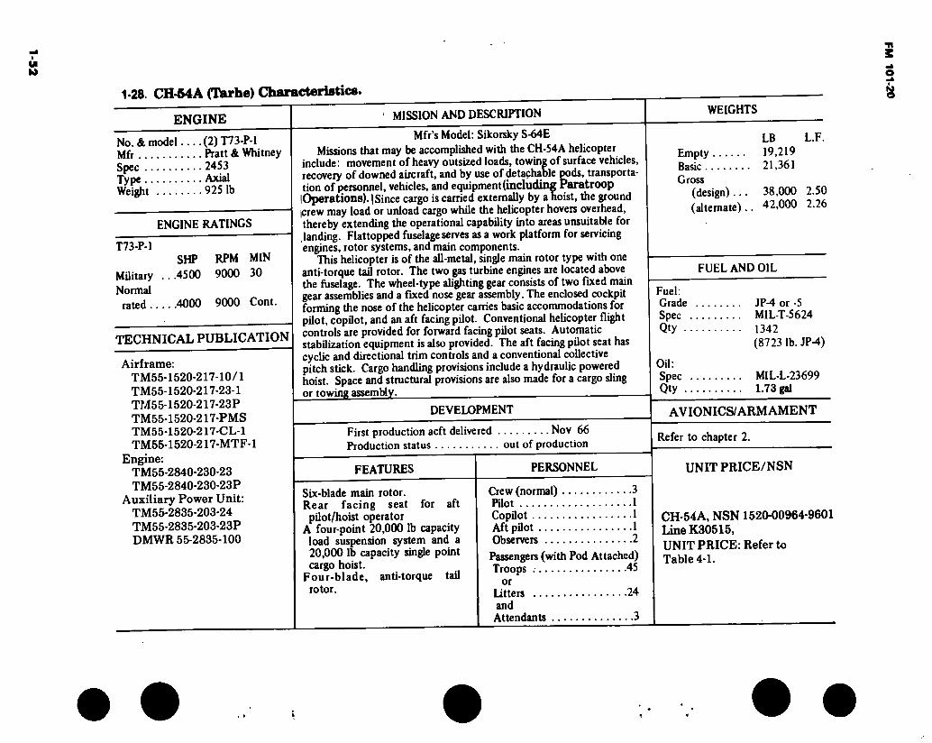
CC
I
1-28. CH-MA (Tarhe) Characteristics.
ENGINE MISSION AND DESCRIPTION
No. & model (2) T73-P-1 Mfr Pratt & Whitney Spec 2453 Type Axial Weight 9251b
ENGINE RATINGS
T73-P-1 S HP RPM MIN
MUitary ...4500 9000 30 Normal
rated 4000 9000 Cont.
TECHNICAL PUBLICATION
Airframe: TM55-1520-217-10/1 TM55-1520-217-23-1 TM55-1520-217-23P TM55-1520-217-PMS TM55-1520-217-CL-1 TM55-1520-217-MTF-l
Engine: TM55-2840-230-23 TM55-2840-230-23P
Auxiliary Power Unit: TM55-2835-203-24 TM55-2835-203-23P DMWR 55-2835-100
Mfr’s Model: Sikorsky S-64E
Missions that may be accomplished with the CH-54A helicopter include: movement of heavy outsized loads, towing of surface vehicles, recovery of downed aircraft, and by use of detachable pods, transporta- tion of personnel, vehicles, and equipment (including Paratroop lOperations). I Since cargo is carried externally by a hoist, the ground icrew may load or unload cargo while the helicopter hovers overhead, thereby extending the operational capability into areas unsuitable for landing. Flattopped fuselage serves as a work platform for servicing engines, rotor systems, and main components.
This helicopter is of the all-metal, single main rotor type with one anti-torque tail rotor. The two gas turbine engines are located above the fuselage. The wheel-type alighting gear consists of two fixed main gear assemblies and a fixed nose gear assembly. The enclosed cockpit forming the nose of the helicopter carries basic accommodations for pilot, copilot, and an aft facing pilot. Conventional helicopter flight controls are provided for forward facing pilot seats. Automatic stabilization equipment is also provided. The aft facing pilot seat has cyclic and directional trim controls and a conventional collective pitch stick. Cargo handling provisions include a hydraulic powered hoist. Space and structural provisions are also made for a cargo sling or towing assembly.
DEVELOPMENT
First production acft delivered Nov 66 Production status out of production
FEATURES
Six-blade main rotor. Rear facing seat for aft pilot/hoist operator
A four-point 20,000 lb capacity load suspension system and a 20,000 lb capacity single point cargo hoist.
Four-blade, anti-torque tail rotor.
PERSONNEL
Crew (normal) 3 Pilot 1 Copilot 1 Aft pilot 1 Observers 2
Passengers (with Pod Attached) Troops 45
or Litters 24 and Attendants 3
Empty Basic Gross
(design)... (alternate)..
FUEL AND OIL
Fuel: Grade JP-4 or -5 Spec MIL-T-5624 Qty 1342
(8723 lb. JP-4)
LB L.F. 19,219 21,361
38.000 2.50 42.000 2.26
Oil: Spec MIL-L-23699 Qty 1.73 gal
AVIONICS/ARMAMENT
Refer to chapter 2.
UNIT PRICE/NSN
CH-54A, NSN 1520-00964-9601 Line K30515, UNIT PRICE: Refer to Table 4-1.
FM 101-2
0
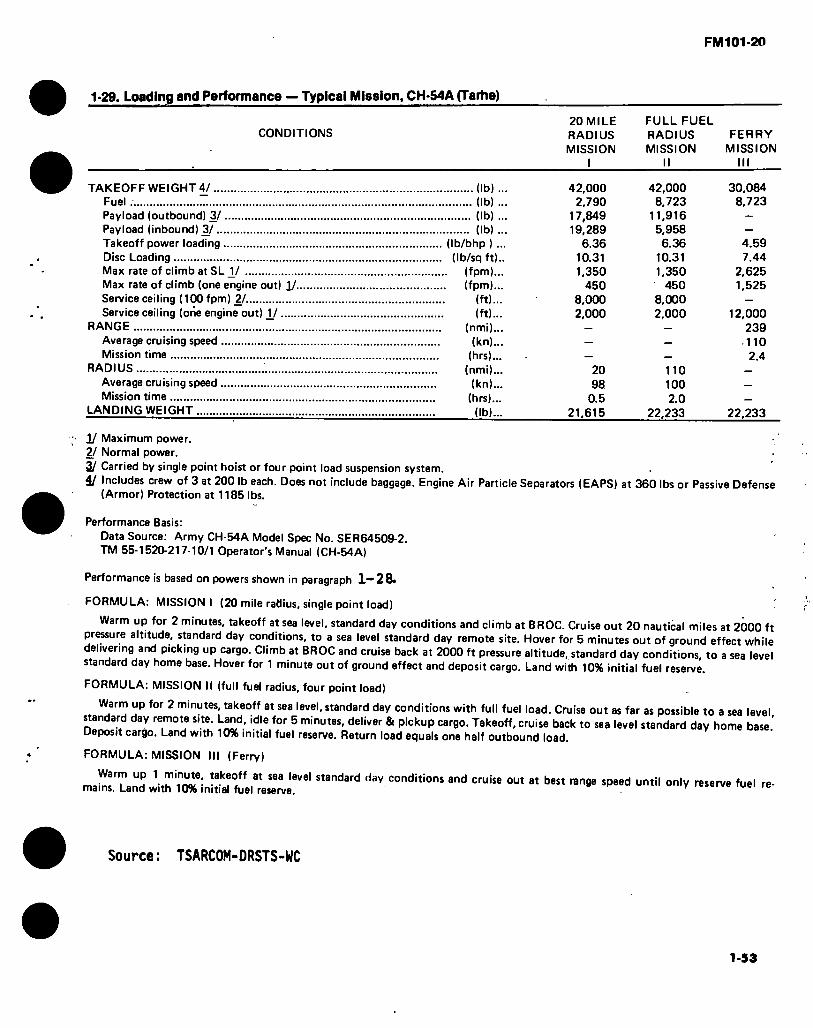
FM101-20
1-29. Loading and Performance — Typical Mission, CH-54A (Tarhe)
CONDITIONS 20 MILE FULL FUEL RADIUS RADIUS FERRY MISSION MISSION MISSION
I II III
TAKEOFF WEIGHT 4/ (lb) .. Fuel (lb) .. Payload (outbound) 3/ (lb) ... Payload (inbound) 3/ (lb) ... Takeoff power loading (Ib/bhp ) ... Disc Loading (Ib/sq ft).. Max rate of climb at SL V (fpm)... Max rate of climb (one engine out) 1/ (fpm)... Service ceiling (100 fpm) 2/ Service ceiling (one engine out) V .
RANGE Average cruising speed Mission time
RADIUS Average cruising speed Mission time
LANDING WEIGHT
(ft)... (ft)...
(nmi)... (kn)...
(hrs)... (nmi)... (kn)...
(hrs)...
(lb)...
42,000 2,790
17,849 19,289
6.36 10.31 1,350
450 8,000 2,000
20 98
0.5 21,615
42,000 8,723
11,916 5,958 6.36
10.31 1,350
450 8,000 2,000
110 100 2.0
22,233
30,084 8,723
4.59 7.44
2,625 1,525
12,000 239 110 2.4
22,233
1/ Maximum power. 2/ Normal power. 3/ Carried by single point hoist or four point load suspension system.
4/ Includes crew of 3 at 200 lb each. Does not include baggage. Engine Air Particle Separators (EAPS) at 360 lbs or Passive Defense (Armor) Protection at 1185 lbs.
Performance Basis: Data Source: Army CH-54A Model Spec No. SER64509-2. TM 55-1520-217-10/1 Operator's Manual (CH-54A)
Performance is based on powers shown in paragraph 1—28.
FORMULA: MISSION I (20 mile radius, single point load)
Warm up for 2 minutes, takeoff at sea level, standard day conditions and climb at BROC. Cruise out 20 nautical miles at 2000 ft pressure altitude, standard day conditions, to a sea level standard day remote site. Hover for 5 minutes out of ground effect while delivering and picking up cargo. Climb at BROC and cruise back at 2000 ft pressure altitude, standard day conditions, to a sea level standard day home base. Hover for 1 minute out of ground effect and deposit cargo. Land with 10% initial fuel resen/e.
FORMULA: MISSION II (full fuel radius, four point load)
Warm up for 2 minutes, takeoff at sea level, standard day conditions with full fuel load. Cruise out as far as possible to a sea level standard day remote site. Land, idle for 5 minutes, deliver & pickup cargo. Takeoff, cruise back to sea level standard day home base. Deposit cargo. Land with 10% initial fuel reserve. Return load equals one half outbound load.
FORMULA: MISSION III (Ferry)
ma^.Taïïv:tr1rín^^fuffe.8^eVe, daV C0"diti°"S a"d at best range speed until only reserve fuel re-
Source: TSARCOM-DRSTS-WC
1-53

FM 101-20
DIMENSIONS
21 FT 10 IN
VH©
□ S
-Ht FT 7 IN
-19 FT 9 IN.
Main rotor dia 72 Ft. 3 In. Length:
Rotors operating 88 Ft. 6 In.
Fuselage 70 Ft. 3 In. Height (static) 25 Ft. 4 In. Width (cockpit) 7 Ft. 1 In. Tread 21 Ft. 10 In. Gnd clearance:
Main rotor (idling) 15 Ft. 8 In. Tail rotor 9 Ft. 4 In.
3 FT 10-1/2 IN
o
88 FT 6 IN.
72 FT 2 IN.
3 IN
FT3IN O STATIC DROP
■'j RETRACTED
9 FT 4 IN. I CLEARANCE AT GROSS WEIGHT 9 FT 3 IN. t
6FT6IN.
I EXTENDED | 9 FT 4 IN
2FT6IN.
13 FT 6 IN.
25 FT 4 IN.
Figure 1-12. Principal Dimensions, CH-54B (Tarhe)
1-54

1-5
5
1-30. CH-54B (Tarhe) Characteristics.
ENGINE MISSION AND DESCRIPTION WEIGHTS No. & model (2)T73-P-700 Mfr Pratt & Whitney Spec 2456 Type Axial Weight 935 lbs
ENGINE RATINGS
SHP RPM MIN Military 4800 9000 30 Normal
rated 4430 9000 Cont.
TECHNICAL PUBLICATION
Airframe: TM55-1520-217-10/2 TM55-1520-217-23/2 TM55-1520-217-23P TM55-1520-217-PMS TM55-1520-217-CL-2 TM55-1520-217-MTF-2
Engine: TM55-2840-230-23 TM55-2840-230-23P
Auxiliary Power Unit:
Mfr’s Model: Sikorsky S-64F
Missions that may be accomplished with the CH-54B helicopter include: movement of heavy outside loads, towing of surface vehicles, recovery of downed aircraft, and by use of detachable pods, transportation of personnel, ve- hicles, and equipment (including paratroop operations). Since cargo is carried externally by a hoist, the ground crew may load or unload cargo while the heli- copter hovers overhead, thereby extending operational capability into areas un- suitable for landing. The flat top of the fuselage serves as a work platform for maintenance and servicing of the engines, rotor systems and other components of the power train system.
The CH-54B is an all-metal single, main rotor type helicopter with one anti- torque tail rotor. It is powered by two gas turbine engines located above the fu- selage. The wheel type landing gear consists of two fixed main gear assemblies and single fixed, fully swiveling nose gear assembly. The fuselage and landing gear are constructed and assembled in a crane configuration. The enclosed cockpit forming the nose of the aircraft has basic accommodations for pilot, co- pilot, aft-facing pilot and two observers. Conventional helicopter flight controls are provided for the pilot and co-pilot. The aft-facing pilot has electrically oper- ated cyclic and directional trim controls and a conventional collective pitch control. An automatic flight control system (AFCS) is also provided. Cargo han- dling capabilities consist of a removable single point hydraulic powered four point load suspension system. Provisions are also made for installation of a tow- ing kit.
Empty Basic Gross (Design)..
FUEL AND OIL (USABLE)
Fuel: Grade jp^ 0r -5 Spec MIL-T-5624
Q‘y 1342 (8723 lb. JP-4)
Oil: Spec MIL-L-23699 Qty 1.73 gal
AVIONICS/ARMAMENT
LB L.F. 19,864 22,386 47,000 2.0
DEVELOPMENT First flight First production aircraft delivered Production status
FEATURES
Refer to chapter 2.
June 1969 Dec 1969 .... Out of production.
PERSONNEL
UNIT PRICE/NSN
TM55-2835-203-24 TM55-2835-203-23P DMWR 55-2835-100
Six-blade main rotor. Aft-facing pilot/hoist operator. 25.000 lb. capacity four point
load suspension system. 25.000 lb. capacity single
point hoist. Four-blade anti-torque tail rotor.
Crew (normal) 3 Pilot 1 Co-pilot 1
Aft-pilot 1 Observers 2 Passengers (with pod attached)
Troops 45 Litters 24 Attendants 3
CH-54B, NSN 1520-00113- 5776 Line K30515, UNIT PRICE: Refer to Table 4-1.
FM 101-20
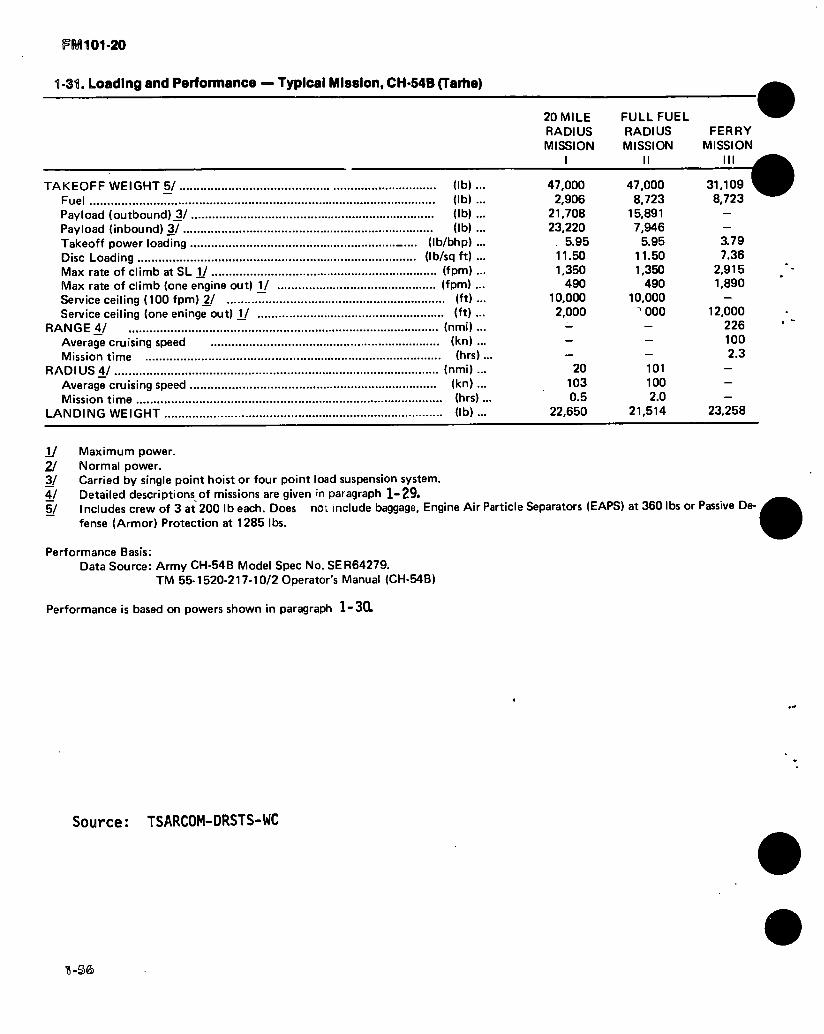
FRÆ101-20
1-31. Loading and Performance — Typical Mission, CH-54B (Tarhe)
TAKEOFF WEIGHT 5/ (lb)... Fuel (lb) ... Payload (outbound),3/ (lb) ... Payload (inbound) 3/ (lb) ... Takeoff power loading (Ib/bhp) ... Disc Loading (Ib/sq ft) ... Max rate of climb at SL 1/ (fpm) ... Max rate of climb (one engine out) V (fpm) ... Service ceiling (100 fpm) £/ (ft) ... Service ceiling (one eninge out) V (ft) ...
RANGE 4/ (nmi) ... Average cruising speed (kn) ... Mission time (brs)...
RADIUS 4/ (nmi) ... Average cruising speed (kn)... Mission time (brs)...
LANDING WEIGHT (lb) ...
20 MILE RADIUS MISSION
I
FULL FUEL RADIUS MISSION
II
47.000 2,906
21,708 23,220
5.95 11.50 1,350
490 10.000 2,000
20 103 0.5
22,650
47.000 8,723
15,891 7,946
5.95 11.50 1,350
490 10.000
"000
101 100 2.0
21,514
FERRY MISSION
III
31,109 8,723
3.79 7.36
2,915 1,890
12,000 226 100 2.3
23,258
1/ Maximum power. 2/ Normal power. 3/ Carried by single point hoist or four point load suspension system. 4/ Detailed descriptions of missions are given in paragraph 1-29. 5/ Includes crew of 3 at 200 lb each. Does not include baggage. Engine Air Particle Separators (EAPS) at 360 lbs or Passive De-
fense (Armor) Protection at 1285 lbs.
Performance Basis: Data Source: Army CH-54B Model Spec No. SER64279.
TM 55-1520-217-10/2 Operator's Manual (CH-54B)
Performance is based on powers shown in paragraph 1-3CL
Source: TSARCOM-DRSTS-WC
D-S&

FM 101-20
Figure 1-13. CH-54A and B (Tarhe), Typical, with Universal Military Pod
&
5»
0 o
u 0
(GJ
DIMENSIONS
Length 28 Ft. 1 In. Width 9 Ft. 6 In. Height (Wheels up) 7 Ft. 8 In. Weight:
Empty 3020 pounds Max Load 20,000 pounds
Figure 1-14. Universal Military Pod
1-37

IFRfl Df-D-g®
ll.gg. yifalwoiroall RÍIIIQQCI; P’oá ©lnl.i41Â oiniä i (¡TQInnlO]).
Ths universal military pod is a semimonocoque structure with a rear loading split dcor-ramp extending the Ml width ahd height of the pod. The split-door construction permits both sides to be opened independently, and reduces the proba- bility of jamming. This arrangement permits easier exit in case of an emergency. Two forward doors, one on each side of the pod, are jettisonable and can be opened from both inside and outside. Each door has a secure locking device to prevent inadvertent opening in flight. Four windows, two on each side, are installed using a rubber push-out type seal and can be removed from both the inside and outside of the pod. A nonstructural panel with a push-out type window is in the forward bulk-head. The window is removable from inside the pod. Additional design features follow:
a. Floor loading is 334 pounds per square foot at any location. In the vehicular tread area the magiirmm allowable floor loading is 1500 Ibs/sq. ft. The floor is reinforced to accommodate equip ment as heavy as a 155 Howitzer. Cargo fittings are flush with the floor and have a load capacity of 5000 pounds each. The spacing of the fittings is a standard 20-inch grid pattern.
b. Pod is attached to helicopter load leveler sys- tem. Two rubber strips are attached to the top of the pod, running full width, to prevent chafing be- tween the top of the pod and the bottom of the helicopter. When the pod carries troops (passen- gers) or litter patients, safety provisions require the insertion of screw actuated pins in the pri- mary adapter fittings. This will prevent jettison- ing of the load. The primary missions for the pod are to carry a maximum of 45 troops (passengers) or 24 litter patients and to transport general cargo such as missiles, vehicles, weapons, and general supplies.
c. Pod has a conventional four wheel system with pneumatic tires and may be towed at speeds up to 5 miles per hour on level ground at the maximum gross weight of 20,000 pounds. Each of the four wheels has an independent retraction and extension system manually-operated by the mechanical jacks or alternate hydraulic pumps attached to each wheel gear. These permit the pod to be raised or lowered when fully loaded. This action aids unloading the pod by allowing the use of a fork lift and other cargo moving equipment. To obtain the maximum pod wheel ground clear-
ance of IS incheo, when the pod is attached to the helicopter, full retraction of the pod wheels is possible. Detachment from the helicopter without using winches is made by extending the wheel mechanism.
d. Electrical power is supplied to pod- by the helicopter’s electrical system. When the pod is attached to the helicopter, two cables on the front exterior bulk-head of the pod are attached to the ac and dc receptacles on the left side external skin of the helicopter, marked POD PWE ÄC, DC, ICS. When the pod is not attached to the helicopter, electrical power is supplied from a ground source through cables to the ac and dc receptacles marked EXT POWER 115 VOLTS AC and EXT POWER 28 VOLTS DC, on the left side of the pod.
e. Lighting for the interior of the pod consists of twelve light assemblies, arranged in parallel lines of six lights each on the ceiling. The forward two lights near the entrance doors are white or red controlled by a switch marked ENTRANCE LIGHTS WHITTS AND RED. The eight interior lights are controlled by a switch marked INTER- IOR.LIGHTS, ON-OFF. Both switches are on the master switch panel on the left forward wall of the pod. The last two lights at the ramp end of the pod are controlled by a switch at the rear on the left wall marked CARGO LOADING LIGHTS, ON-OFF. Communication between the pod and the helicopter is through a third cable, in the same area as the electrical power cables. The cable is attached to the ICS outlet on the helicopter and is routed to the interphone control panel for the pod, which is on the forward ceiling. Also in this area is a stowage rack for the 30-foot cable.
f. Electrically-operated ventilating blower with a capacity of 500 cfm is installed on the forward hulk head of the pod and is controlled by a switch marked VENT BLOWER, ON-OFF on the master switch panel. Two exhaust openings are on the right and left sides of the pod in the rear area.
Source: TSARCOM-DRSTS-WC
$ n-s®

FM 101-20
ft,
BK
3*«
Figure 1-15. OH-6A (Cayuse)
1-59
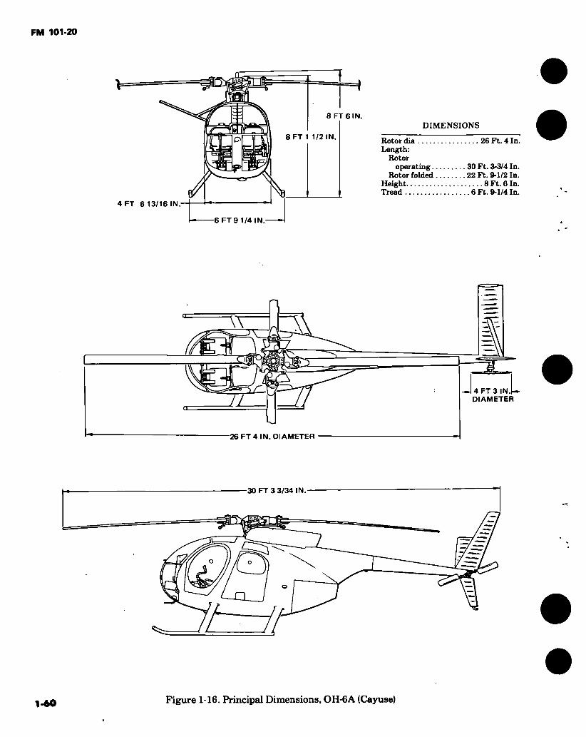
FM 101-20
8 FT 6 IN
8 FT 1 1/2 IN.
4 FT 6 13/16 IN
DIMENSIONS
Rotor dia 26 Ft. 4 In. Length:
Rotor operating 30 Ft. 3-3/4 In.
Rotor folded 22 Ft. 9-1/2 In. Height 8 Ft. 6 In. Tread 6 Ft. 9-1/4 In.
6 FT 9 1/4 IN.
J r L 4 FT 3 IN.t- DIAMETER LL
-26 FT 4 IN. DIAMETER
30 FT 3 3/34 IN
£5 o
1-60 Figure 1-16. Principal Dimensions, OH-6A (Cayuse)

1-61 :
1-33. 0H-6A (Cayuse) Characteristics.
ENGINE MISSION AND DESCRIPTION WEIGHTS No. & model .. (1) T63-A-5A/700 Mfr Detroit Diesel
Engine spec No. T63-A-5A
T63-A-700
Allison Div of CMC
58ÖJ, dtd 30 Sept 1970 803F, dtd 30 Sept 1970 Amend 1.
ENGINE RATINGS
Ratings Takeoff & mil Normal
Takeoff & mil Normal
Output SHP
*317 **270 Output speed
SFC lb/ SHP-
rpm HR .. 6000 0.697 .. 6000 0.706
Above ratings developed on standard sea level static conditions. •Derated to 252.5 for 5 min
••Derated to 214.5
TECHNICAL PUBLICATIONS
Airframe: TM55-1520-214-10 TM55-1520-214-23 TM55-1520-214-23P TM55-1520-214-PMS DMWR55-1520-214
Engine: TM55-2840-231-24 TM55-2840-231-23P
Mfr’s Model: Hughes 500
The principal missions of the OH-6A light observation helicopter are visual observation and target acquisition, reconnaissance, and command control. This helicopter is employed in support of combat companies, and will operate for extended periods of time with only such support as provided by one mechanic with handtools. Normal operation is limited to day or night visual flight conditions.
The light observation helicopter is a single-lifting, 4-blade rotor, 4-place helicopter with a normal gross weight of 2400 lb or less. It is powered by a T63-A-5A/700 free turbine engine with 317 SHP, derated to 252.5 SHP. It incorporates dual flight controls with the secondary cyclic control element easily removable. The flight instruments are limited to those required for day and night marginal visual conditions. The cargo area contains troop-type seats which are easily stowable when not in use.
DEVELOPMENT
Design competition initiated October 1960
Flight evaluation completed June 1964 Production contract May 1965
First production acft deliveries September 1966
FEATURES
Dual controls. Stowable troop seats.
PERSONNEL
Crew (normal) 1 Observer 2 Copilot 1
Empty 1158 Useful load 1242 Pilot 200 Observers (2),
Copilot (1) 600 Cargo 42 Fuel 400 Gross (FAA certified) 2400 Max structure 2700
FUEL AND OIL
Fuel: Grade JP-4 Spec ...... MIL-T-5624 Alternate ... JP-5, MIL-T-5624 • Qty 61.3 gal(non-crash
resistant) 54.4 gal (crash resistant)
Oil: Spec MIL-L-23699 Alternate ... MIL-L-7808 No. tanks .. 1 Location ... Engine section Qty 3 qt
Main Transmission: Spec MIL-L-23699 Alternate ... MIL-L-7808 Qty 8.0 pt
Tail Rotor Transmission: Spec MIL-L-23699 Alternate ... MIL-L-7808 Qty 0.5 pt
AVIONICS/ARMAMENT
Refer to chapter 2.
UNIT PRICE/NSN
NSN1520-00918-1523 Lin K30645
UNIT PRICE: Refer to Table 4-1.
FM 101-20

1-6
2
e
1-34. Loading and Performance — Typical Mission, OH-6A (Cayuse).
BASIC MISSION
I
ALTERNATE 1A (CLEAN)
II
ALTERNATE 1A (ARMED)
HI
24006/ 400 400 9.50 4.41 54.0 1560 58.0
3.3 7.0
15.850 6,500
316 100
9500 3.2 158 100
9500 3.2
2208 9500
112 1680
17.850 10,500
1860 56 100 110
2.54 0.50
FERRY RANGE
IV
HIGH SPEED SEA LEVEL MISSION
V
TAKEOFF WEIGHT Fuel Payload (not including pilot) Takeoff power loading Disk loading Speed for Min. R/D Max rate of climb at sea level Y ■ • • Speed for max R/C, sea level P Time: Sea level to 5000 ft -1/ Time: Sea level to 10,000 ft-P.... Service ceiling (100 fpm)-3^ Absolute hover ceiling-1/ COMBAT RANGE
Average cruising speed JZ/jj/ .... Cruising altitude Total mission time
COMBAT RADIUS Average cruising speedJZ/.§/... Cruising altitude Mission time
COMBAT WEIGHT^ COMBAT ALTITUDE
Combat speed-2/ Combat climb-1/ ;... Service ceiling-2/.
Absolute hover ceiling M Max rate of climb @ sea level -1/. Speed for max R/C, sea level Maximum speed^^ Basic speed at 5000 ft 2/
LIMIT FUGHT LOAD FACTORS Maneuver Positive Maneuver Negative
... (Ib)..
... (lb)..
... (lb).. (lb/bhp).. (Ib/sq ft)..
(knots).. .. (fpm)..
(knots).. (minutes). (minutes) . ... (ft).. ... (ft).. .. (nmi)..
(knots).. ... (ft).. ... (hr) .. .. (nmi) ..
(knots).. ... (ft).. ... (hr).. ... (lb).. ... (ft)..
(knots).. .. (fpm).. ... (ft).. ... (ft).. .. (fpm)..
(knots).. (knots).. (knots)..
(&>■■ (g)---
2159 400 400 8.55 3.96 54.0 1925 56.0
2.5 5.3
18.400 11,200
370 104
12,200 3.6 185 104
12,200 3.6
1961 12,200
116 1860
20,950 14.400
2250 55
104 117
2.82 0.50
2400 400 637^/
9.50 4.41 54.0 1560 58.0 3.3 7.0
15.850 6.500
330 102
9600 3.3 165 102
9600 3.3
2207 9600
112 1680
17.850 10.500
1860 56
102 113
2.54 0.50
1/ 2159 400 400 8.55 3.96 54.0 1925 56.0
2.5 5.3
18,400 11,200
294 130 SL 2.3 147 130 SL 2.3
1977 SL
130 2220
20,750 14,100
2220 55
130
2.82 0.50
-l/fakeoff power up to 5 minutes, ■formal power. S'For RADIUS mission, includes copilot at 200 lbs.
FM 101-20

1-6
3
I
1-34. Loading and Performance — Typical Miaalon, OH-6A (Cayuse)(CONT).
See Para 1-35.
^Includes . M-27 or A4-27E-1 Armament Kit. U Limited by Vne.
k\ combat altitude and combat weight.
Performance Basis:
a. Army flight test YOH-6A.
b. All performance is out of ground effect and for standard atmospheric conditions. Speeds given are true airspeed.
FM 101-20

FM 101-20
11-35. Performance Notes, 0H-6A (Cayuse).
FORMULA: RADIUS MISSION I, II, & III
Warm up, take off, climb on course at military power to altitude for best range at average cruise weight. Cruise to remote base at speed for best range. Do not land. Return to home base. Range-free allow- ances are 2 minutes of normal power for warmup and 10 percent of initial fuel for reserves.
FORMULA: RANGE MISSION I, II, & III
Warm up, take off, and climb on course at mili- tary power to altitude for best range at average cruise weight. Cruise to remote base at speed for best range. Range-free allowances are 2 minutes of normal power for warmup and 10 percent of initial fuel for reserve.
FORMULA: FERRY RANGE MISSION IV
Warm up, take off, and climb on course at mili- tary power to 5,000 feet. At steady cruise, climb to stay at optimum altitude as weight decreases. Range- free allowance is 2 minutes of normal power for warmup. No reserve fuel allowance.
FORMULA: RADIUS MISSION V
Warm up, take off, and accelerate to maximum speed. Cruise at sea level at maximum speed, as limited by normal power or Vne to remote base. Do not land. Return to home base. Range-free allowances are 2 minutes of normal power for warmup and 10 percent of initial fuel for reserve.
FORMULA: RANGE MISSION V
Warm up, take off, and accelerate, to maximum speed. Cruise at sea level at maximum speed, as limited by normal rated power Vne to remote base. Range-free allowances are 2 minutes of normal power for warmup and 10 percent of initial fuel for reserve.
GENERAL DATA
For detailed planning refer to applicable technical manual.
PERFORMANCE REFERENCE
Hughes Tool Company-Standard Aircraft Char- acteristics (OH-6A).
Source: TSARCOM-DRSTS-WO

FM 101-20
1,
Figure 1-17. OH-58A and C, Light observation helicopter (Kiowa), typical
1-65

FM 101-20
ö
5 FT 10 IN
-6 FT 5.4 IN-
DIMENSIONS
Rotor dia 35 Ft. 4 In. Length:
Rotors t operating 40 Ft. 11.8 In.
Blades removed 32 Ft. 2.0 In.
Height: To top of
rotor fairing 9 Ft. 7.0 In. Tread of skids 6 Ft. 5.4 In. Main rotor:
Disk area 979.8 Sq. Ft. Blade area 38.26 Sq. Ft..
Tail rotor: Disk area 20.97 Sq. Ft. Blade area 2.26 Sq. Ft.
2° 7'
BLADE DROOP-
STATIC 6 FT 8.0 IN
!
STA 107.1
20 FT 0.5 IN
TURNING 2 FT 3.3 IN
r 5 FT 4.7 IN 9 FT 7.0 IN
8 FT STATIC 1 FT 8.0 IN ooa 1.5 IN
fW-e/') ( W/e STA
6 FT 5.7 IN UNITED STATES ARMT
// 107.5 1 / 5 FT 2.0 IN
TL i*—8 FT 1. 3 IN
32 FT 2.0 IN.
TURNING 7 FT 0.8 IN
1 FT 1.0 IN
40 FT 11.8 IN
36 FT
12 FT 7.1 IN
6 FT 6.20 IN
1-66 Figure 1-18. Principal Dimensions, OH-58A (Kiowa
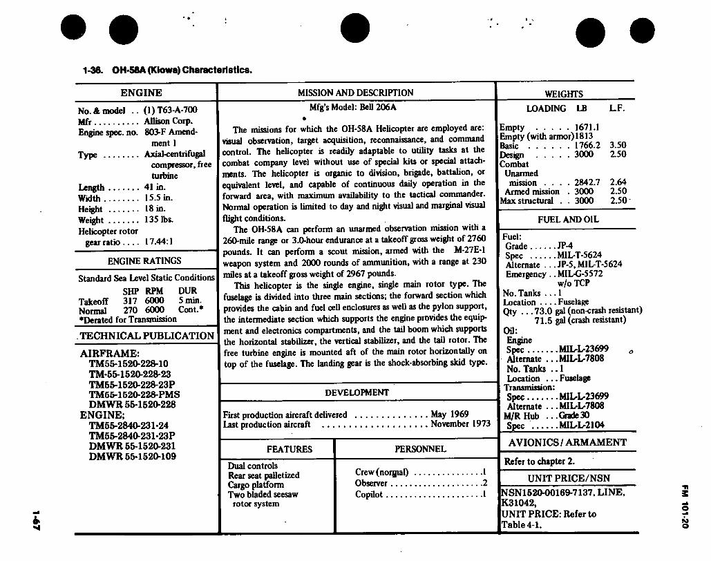
1-6
7
1 -36. OH-58A (Kiowa) Characteristics.
ENGINE MISSION AND DESCRIPTION
No. & model .. Mfr Engine spec. no.
Type
Length Width Height Weight Helicopter rotor
gear ratio ....
(1) T63-A-700 Allison Corp. 803-F Amend-
ment 1 Axial-centrifugal
compressor, free turbine
41 in. 1S.S in. 18 in. 135 lbs.
17.44:1
ENGINE RATINGS
Standard Sea Level Static Conditions
SHP RPM DUR Takeoff 317 6000 5 min. Normal 270 6000 Cont.* ♦Derated for Transmission
TECHNICAL PUBLICATION
Mfg’s Model: BeU 206A •
The missions for which the OH-58A Helicopter are employed are: visual observation, target acquisition, reconnaissance, and command control. The helicopter is readily adaptable to utility tasks at the combat company level without use of special kits or special attach- ments. The helicopter is organic to division, brigade, battalion, or equivalent level, and capable of continuous daily operation in the forward area, with maximum availability to the tactical commander. Normal operation is limited to day and night visual and marginal visual flight conditions.
The OH-58A can perform an unarmed observation mission with a 260-mile range or 3.0-hour endurance at a takeoff gross weight of 2760 pounds. It can perform a scout mission, armed with the M-27E-1 weapon system and 2000 rounds of ammunition, with a range at 230 miles at a takeoff gross weight of 2967 pounds.
This helicopter is the single engine, single main rotor type. The fuselage is divided into three main sections; the forward section which provides the cabin and fuel cell enclosures as well as the pylon support, the intermediate section which supports the engine provides the equip- ment and electronics compartments, and the tail boom which supports the horizontal stabilizer, the vertical stabilizer, and the tail rotor. The
AIRFRAME: TM55-1520-228-10 TM-55-1520-228-23 TM55-1520-228-23P TM55-1520-228-PMS DM WR 56-1520-228
ENGINE; TM55-2840-231-24 TM55-2840-231-23P DMWR 66-1520-231 DMWR 55-1520-109
free turbine engine is mounted aft of the main rotor horizontally on top of the fuselage. The landing gear is the shock-absorbing skid type.
DEVELOPMENT
First production aircraft delivered May 1969 Last production aircraft November 1973
FEATURES PERSONNEL
Dual controls Rear seat palletized Cargo platform Two bladed seesaw
Crew (norgial) Observer Copilot
1 2 1
rotor system
WEIGHTS
LOADING LB L.F.
Empty 1671.1 Empty (with armor) 1813 Basic 1766.2 3.50 Design 3000 2.50 Combat
Unarmed mission .... 2842.7 2.64
Armed mission . 3000 2.50 Max structural . . 3000 2.50'
FUEL AND OIL
Fuel: Grade JP-4 Spec M1L-T-5624 Alternate .. .JP-5, MILT-5624 Emergency .. MIL-G-5572
w/o TCP No. Tanks ... 1 Location Fuselage Qty ... 73.0 gal (non-crash resistant)
71.5 gal (crash resistant) Oil: Engine Spec M1LL23699 ö
Alternate ... MILL7808 No. Tanks .. 1 Location ... Fuselage
Transmission: Spec MILL23699 Alternate ... MILL7808
M/RHub .. .Grade30 Spec MILL2104
AVIONICS / ARMAMENT
Refer to chapter 2.
UNIT PRICE/NSN
NSN1520-00169-7137, LINE, K31042, UNIT PRICE: Refer to Table 4-1.
FM 101-20

FM 101-20
1-37. Loading and Performance —«Typical Mission, OH-58A (Kiowa).
CONDITIONS
I
BASIC MISSION
(Unarmed Observation)
II
ALTERNATE
(Armed Scout)
TAKEOFF WEIGHT Fuel Payload Takeoff Power Loading Disk Loading Speed for Min. R/D Vertical Rate of Climb @ Sea Level 1/ Max Rate of climb @ Sea Level 1/.. . . Speed for Max R/C @ Sea Level .. . . Time Sea Level to 5000 ft. Time Sea Level to 10,000 ft. 1/ Service Ceiling (100 fpm) 2/ Absolute Hover Ceiling -1/
COMBAT RANGE Average speed Cruising Altitude Total Mission Time
COMBAT RADIUS Average Speed Cruising Altitude Total Mission Time
COMBAT WEIGHT 2/ Combat Altitude Combat Speed Combat Climb i/ Service Ceiling Absolute Hover Ceiling
Max R/C @ Sea Level -1/ Speed for Max R/C Max Speed @ Sea Level Basic Speed @ 5000 ft
2760 455 170
9.15 2.82
49
1780 48 3.5 7.5
19.000 8,000
260 ' 102 14.000
2.98 147 102
14.000 2.98
2550 14.000
87 1090
21.000 10,600
1750 48
120 114
29674/ 428 298
9.84 3.03
49
1600 50
4.0 8.5
17.200 5,400
230 120
10,000 2.47 121 102
12.200 2.47 2770
10,000 99
1120*
19,500 8000 1600
50 120 114
4/Takeoff power up to 5 minutes. -2/Normal Power. 4/ For Radius Mission. 4/lncludes M-27E-1 Armament Kit.
Performance Basis: Bell flight test 206A MOD. All performance is out of ground effect and for standard atmospheric conditions.
1-38. Performance Notes, OH-58A (Kiowa). Warmup — Two minutes at normal power at sea level
Takeoff and Climb - On course at military power to RADIUS MISSION — I & II altitude for best range at average cruise weight
Cruise — At speed for best range RANGE MISSION — 1 & II Reserve — 10% takeoff fuel
Source: TSARC0M-DRSTS-W0
1-68
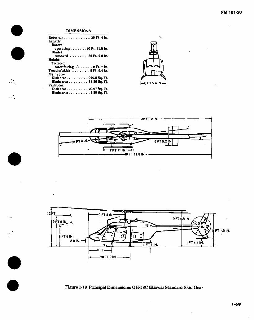
FM 101-20
DIMENSIONS
Rotor uiu 35 Ft. 4 In. Length:
Rotors operating 40 Ft. 11.8 In.
Blades removed 32 Ft. 2.0 In.
Height: To top of
rotor fairing. 0 Ft. 7 In. Tread of skids 8 Ft. 5.4 In. Main rotor:
Disk area 979.8 Sq. Ft. Blade area 38.26 Sq. Ft.
Tail rotor: Disk area 20.97 Sq. Ft. Blade area 2.26 Sq. Ft.
|^-6 FT 5.4 IN.-»I
32 FT 2 IN.
4’ a U 35 FT 4 IN. 6 FT 5.2 IN.
I—7 FT 11 IN.- 40 FT 11.8 IN.-
12 FT 9 FT 4 IN 9 FT 4.5 IN
9 FT 6 IN. FT IN
6 FT 8 IN.
I 6.8 IN.—I 1 FT 4.4 IN
t 1 FT1 IN
6 FT
—10 FT 9 IN
8 FT 1.5 IN.
Figure 1-19 Principal Dimensions, OH-58C (Kiowa) Standard Skid Gear
1-69
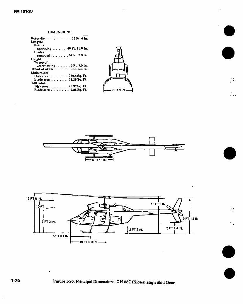
FM 101-20
DIMENSIONS
Rotor dia 35 Ft. 4 In. Length:
Rotors operating 40 Ft. 11.8 In. C[D
Blades I [ I removed 32 Ft. 2.0 In. /L Lr)
Height: P~ To top of if~~\ —Iv.
rotor fairing 9 Ft. 7.0 In. jli |Y\ Tread of skids 8 Ft. 5.4 In. f |j Main rotor: I I
Disk area 979.8 Sq. Ft. *\ Il P Blade area 38.26 Sq. Ft.
Tail rotor: if Disk area 20.97 Sq. Ft. * » Blade area 2.26 Sq. Ft. |.i 7 FT 3 IN.—
sTT\
t-^-8FT10IN.
12 FT 6 IN.
10FT9IN 10 FT
□ □ 7 FT 2 IN.
3 FT 4.4 IN. I
2 FT 3 IN
5 FT 9.4 IN 1 J ^ 10 FT6.3 IN.
klO FT 1.5 IN.
1-70 Figure 1-20. Principal Dimensions, OH-58C (Kiowa) High Skid Gear
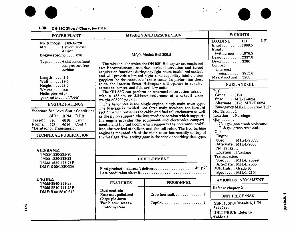
1-71
*- •
1-39. OH-58C (Kiowa) Characteristics.
POWER PLANT
No. & model T63-A-720 Mfr Detroit Diesel
Allison Engine spec, no 876
MISSION AND DESCRIPTION
Mfg’s Model: Bell 206.5
Type Axial-centrifugal compressor, free turbine
Length 41.1 Width 19.0 Height 23.2 Weight 158 Helicopter rotor gear ratio 17.44:1
ENGINE RATINGS
Standard Sea Level Static Conditions SHP RPM DUR
Takeoff 370 6016 5 min. Normal 278 6016 Cont.* ♦Derated for Transmission
TECHNICAL PUBLICATION
AIRFRAME: TM55-1520-235-10 T.M55-1520-228-23 TM 55-1520-228-23P DMWR 55-1520-228
The missions for which the OH-58C Helicopter are employed are: Reconnaissance, security, aerial observation and target acquisition functions during daylight hours (stabilized optics), and will provide a limited night time capability (night vision goggles) for the conduct of these tasks. In performing these roles, the Interim Scout Helicopter will operate in cavalry, attack helicopter, and field artillery units.”
The OH-58C can perform an unarmed observation mission with a 185-nm or 2.5-hour endurance at a takeoff gross weight of 3200 pounds.
This helicopter is the single engine, single main rotor type. The fuselage is divided into three main sections; the forward section which provides the cabin and fuel cell enclosures as well as the pylon support, the intermediate section which supports the engine provides the equipment and electronics compart- ments, and the tail boom which supports the horizontal stabil- izer, the vertical stabilizer, and the tail rotor. The free turbine engine is mounted aft of the main rotor horizontally on top of the fuselage. The landing gear is the shock-absorbing skid type.
DEVELOPMENT
First production aircraft delivered July 79 Last production aircraft
WEIGHTS
LOADING LB LT\ Empty 1868.5 Empty
(with armor)... 1976.5 Basic 2337.6 Design 3200 Combat
Unarmed mission 2915.6
Max structural .. 3200
FUEL AND OIL
Fuel: Grade JP-4 Spec MIL-T-4624 Alternate . JP-5, MIL-T-5624 Emergency MIL-G-5572 w/o TCP
No. Tanks .. 1 Location ... Fuselage Qty
73.0 gal (non-crash resistant) 71.5 gal (crash resistant)
Oil: Engine Spec MIL-L-23699 Alternate . MIL-L-7808 No. Tanks. 1 Location .. Fuselage
Transmission: Spec MIL-L-23699 Alternate . MIL-L-7808
M/R Hub... Grade 30 Spec MIL-L-2104
ENGINE: TM55-2840-241-23 TM55-2840-241-23P DMWR 55-2840-242
FEATURES
Dual controls Rear seat palletized Cargo platform Two bladed seesaw
rotor system
PERSONNEL
Crew (normal)
Copilot
AVIONICS / ARMAMENT
Refer to chapter 2.
UNIT PRICE/NSN
1 NSN, 1502-01020-4216, LIN J *233527, UNIT PRICE: Refer to Table 4-1.
FM
101-20
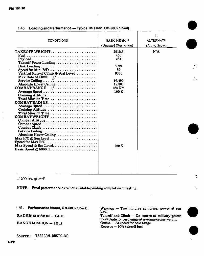
FM 101-20
1 -40. Loading and Performance — Typical Mission, OH-58C (Kiowa).
I ll
CONDITIONS BASIC MISSION ALTERNATE
TAKEOFF WEIGHT Fuel Payload Takeoff Power Loading Disk Loading Speed for Min. R/D Vertical Rate of Climb @ Seal Level Max Rate of Climb 1/
(Unarmed Observation) (Armed Scout)
2915.6 456 284
N/A
2.98 50
6300
Service Ceiling Absolute Hover Ceiling
COMBAT RANGE 1/ Average Speed Cruising Altitude .. Total Mission Time.
COMBAT RADIUS..
16,400 12,300
185 NM 100 K
Average Speed Cruising Altitude . Total Mission Time
COMBAT WEIGHT Combat Altitude.. Combat Speed Combat Climb Service Ceiling Absolute Hover Ceiling
Max R/C @ Sea Level Speed for Max R/C Max Speed @ Sea Level.. Basic Speed @ 5000 ft—
120 K
-V 2000 ft. ® 95#F
NOTE: Final performance data not available pending completion of testing.
1-41. Performance Notes, OH-58C (Kiowa).
RADIUS MISSION - I & II
RANGE MISSION - I & II
Warmup — Two minutes at normal power at sea level Takeoff and Climb — On course at military power to altitude for best range at average cruise weight Cruise — At speed for best range Reserve — 10% takeoff fuel
Source: TSARC0M-DRSTS-W0
1-72

FM 101-20 ;
ïf Sr
Figure 1-21.TH-55A (Osage)
1-73

7 F
T 5
-1/2
IN
.
FM 101*20
Sk
8 FT 2-1/2 IN.
6 FT 6-1/2 IN. LANDING GEAR FULLY COMPRESSED
□ 4 FT 3 IN.
L3T::
27 FT9-1/2 IN
DIMENSIONS
Rotor dia 22 Ft. 4 In. Length:
Rotors operating 28 Ft. 3 In. static 22 Ft. 4 In.
Fuselage 21 Ft. 10-3/4 In. Span (max
lateral) Height 8 Ft. 2-1/2 In. Tread 6 Ft. 3 In. Ground clearance
Static 3 Ft. 2-1/2 In.
— 3FT4IN.--
28 FT 3 IN.-
r—10 IN. 12 FT 6 IN.
7 FT 2 N
Q
8 FT 7-1/2 IN.
22 FT 4 IN.
Figure 1-22. Principal Dimensions, TH-55A (Osage)
1-74

1-73 > •
1 -42 TH-55A (Osage) Characteristics.
ENGINE
No. & model .. (l)H10-360-BlA Mfr Lycoming Engine spec. Na 2313-b Engine to main
rotor rear ratio 6:1
ENGINE RATINGS
BHP RFM MIN Takeoff 180 2900 5 Normal 160 2700-2900 Cont.
ma power
TECHNICAL PUBLICATIONS
AIRFRAME: TM55-1520-233-10
COMMERCIAL MANUALS (Contractor Supported)
ENGINE: COMMERCIAL MANUAL
MISSION AND DESCRIPTION WEIGHTS
The TH-55A helicopter is manufactured by the Hughes Heli- copter Company, Culver City, California. The mission of the TH-55A is the training of military pilots in the basic operation and perform- ance of a helicopter. Training will be accomplished only in CONUS and from an established aviation training base. %
The two-place cabin is designed to accommodate an instructor and student with the seating arrangement side by side. The instructor and student each have a complete set of flight controls.
DEVELOPMENT
Contract awarded June 1964 First acft delivered November 1964 Last production acft April 1969
FEATURES
Dual Controls
PERSONNEL
Crew (Normal) 2 Instructor Pilot 1 Student Pilot 1
LB Empty 1008.1 Useful load 591.9 Design (gross) .... 1600 Combat NA Max takeoff 1600
FUEL AND OIL
Fuel: Grade 115/145 Spec M1L-G-5572 No. of tanks 1
Location Left rear of cabin
Qty 25 gal OU:
Spec Temps above +60°F MILL-22851 Type II
Temps below +60°F MIL-L-22851 Type III
No. tanks 1 Qty 2 gal
AVIONICS / ARMAMENT
Refer to chapter 2.
UNIT PRICE/NSN
NSN-1520-00758-0289, Line K31153, UNIT PRICE: Refer to Table 4-1.
FM
10
1-2
0
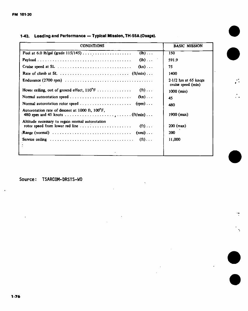
FM 101-20
1-43. Loading and Performance — Typical Mission, TH-S5A (Osage).
CONDITIONS
Fuel at 6.0 Ib/gal (grade 115/145)
Payload
Cruise speed at SL
Rate of climb at SL
Endurance (2700 rpm)
(lb)
(lb)
(kn)
(ft/min)
Hover ceiling, out of ground effect, 110°F
Normal autorotation speed
Normal autorotation rotor speed
Autorotation rate of descent at 1000 ft, 100°F, 480 rpm and 45 knots
Altitude necessary to regain normal autorotation rotor speed from lower red line . . . . '
.Range (normal)
Service ceiling
(ft)
(kn)
(rpm)
(ft/min)
(ft)
(nmi)
■ (ft)
BASIC MISSION
150
591.9
75
1400
2-1/2 hrs at 65 knojs cruise speed (min)
1000 (min)
45
480
1900 (max)
200 (max)
200
11,000
Source: TSARCOM-DRSTS-WO
1-76

Ffifl 1011-20
% ¿a
Figure 1-23. UH-1B (Iroquois)
1-77
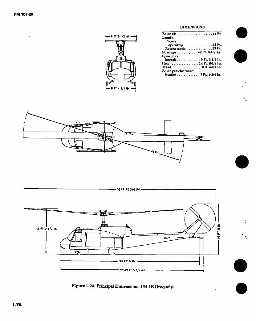
FM 101-20
DIMENSIONS
J-*—9 FT 3-1/2 IN.—*j
4*
q ♦ en 4-3/4 IN.
Rotor dia Length:
Rotors operating
Rotors static Fuselage Span (max
lateral) Height Tread Rotor gnd clearance:
(static)
44 Ft.
53 Ft. 53 Ft. 42 Ft. 8-1/2 la.
.9 Ft. 3-1/2 In. 14 Ft. 8-1/2 In. . 8 ft. 4-3/4 In.
7 Ft. 4-3/4 In.
n J—Q
<4
52 FT 10-3/4 IN
\
/ = 13 FT 2-1/2 IN.
Ù
38 FT 5 IN
42 FT 8-1/2 IN.
Figure 1-24. Principal Dimensions, UH-1B (Iroquois)
1-78
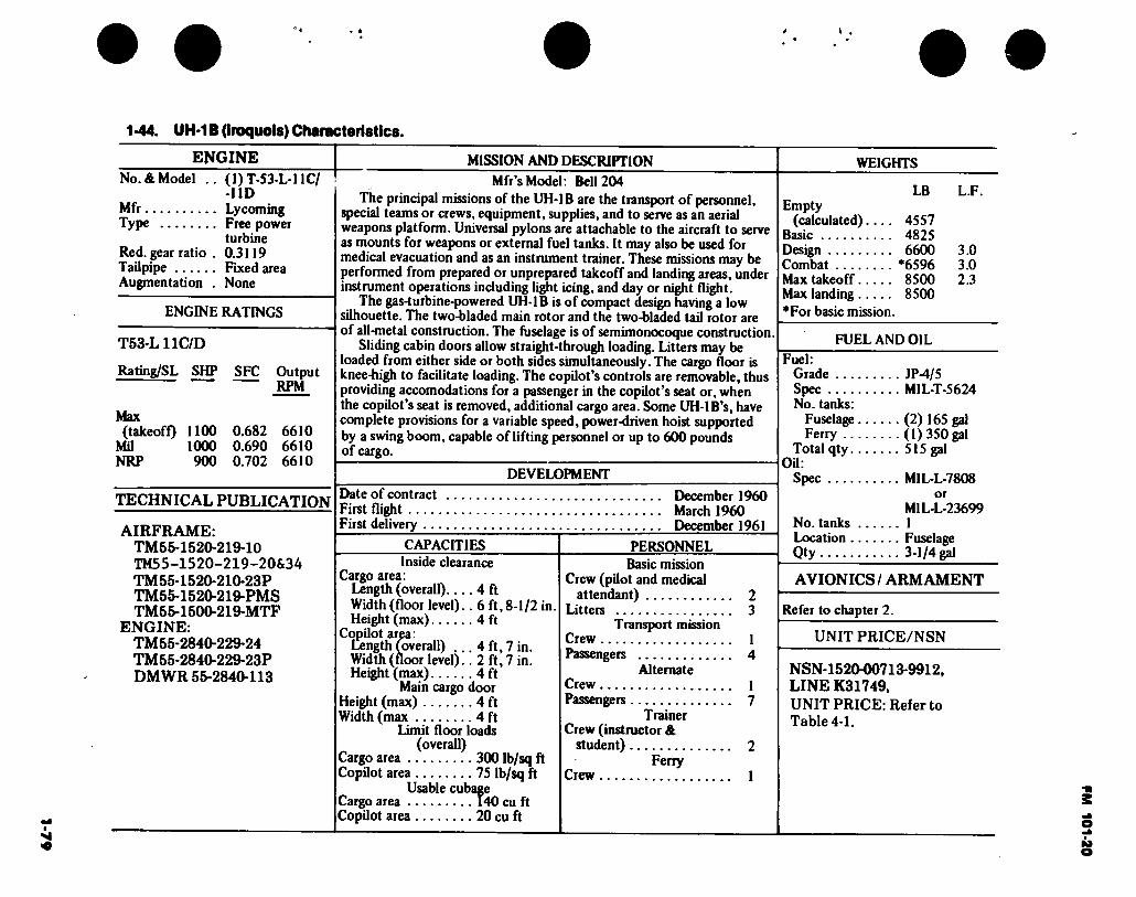
1 -44. UH-1B (Iroquois) Characteristics.
ENGINE I No. & Model ..
Mfr Type
Red. gear ratio . Tailpipe Augmentation .
(1)T-S3-L*11C/ -HD Lycoming Free power turbine 0.3119 Fixed area None
ENGINE RATINGS
T53-L11C/D
Rating/SL SHP SFC Output RPM
Max (takeofQ 1100 0.682 6610
MU 1000 0.690 6610 NRP 900 0.702 6610
TECHNICAL PUBLICATION
AIRFRAME: TM55-1520-219-10 TM55-1520-219-20&34 TM55-1520-210-23P TM55-1520-219-PMS TM55-1500-219-MTF
ENGINE: TM55-2840-229-24 TM55-2840-229-23P DMWR 55-2840-113
MISSION AND DESCRIPTION
Mfr’s Model: Bell 204 The principal missions of the UH-1B are the transport of personnel,
special teams or crews, equipment, supplies, and to serve as an aerial weapons platform. Universal pylons are attachable to the aircraft to serve as mounts for weapons or external fuel tanks. It may also be used for medical evacuation and as an instrument trainer. These missions may be performed from prepared or unprepared takeoff and landing areas, under instrument operations including light icing, and day or night flight.
The gas-turbine-powered UH-1B is of compact design having a low silhouette. The two-bladed main rotor and the two-bladed taU rotor are of all-metal construction. The fuselage is of semimonocoque construction.
Sliding cabin doors allow straight-through loading. Litters may be loaded from either side or both sides simultaneously. The cargo floor is knee-high to facUitate loading. The copUot's controls are removable, thus providing accomodations for a passenger in the copUot’s seat or, when the copUot’s seat is removed, additional cargo area. Some UH-lB’s, have complete provisions for a variable speed, power-driven hoist supported by a swing boom, capable of lifting personnel or up to 600 pounds of cargo.
DEVELOPMENT
WEIGHTS
LB L.F. Empty
(calculated).... 4557 Basic 4825 Design 6600 3.0 Combat *6596 3.0 Max takeoff 8500 2.3 Max landing 8500 *For basic mission.
FUEL AND OIL
Fuel: Grade JP-4/5 Spec M1L-T-5624 No. tanks:
Fuselage (2) 165 gal Ferry (1)350 gal
Total qty 515 gal OU:
Spec MIL-L-7808 Date of contract First flight First delivery
CAPACITIES Inside clearance
Cargo area: Length (overall).... 4 ft Width (floor level).. 6 ft, 8-1/2 in Height (max) 4 ft
CopUot area: Length (overaU) ... 4 ft, 7 in. Width (floor level).. 2 ft, 7 in. Height (max) 4 ft
Main cargo door Height (max) 4 ft Width (max 4 ft
Limit floor loads (overall)
Cargo area 300 Ib/sq ft CopUot area 75 Ib/sq ft
Usable cubage Cargo area 140 cu ft CopUot area 20 cu ft
December 1960 March 1960 December 1961
PERSONNEL Basic mission
Crew (pUot and medical attendant) 2
Litters 3 Transport mission
Crew 1 Passengers 4
Alternate Crew 1 Passengers 7
Trainer Crew (instructor &
student) 2 Ferry
Crew 1
or MIL-L-23699
No. tanks 1 Location Fuselage Qty 3-1/4 ¿1
AVIONICS / ARMAMENT
Refer to chapter 2.
UNIT PRICE/NSN
NSN-1520-00713-9912, LINE K31749, UNIT PRICE: Refer to Table 4-1.
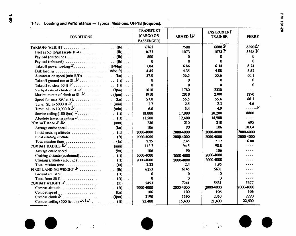
s 1-45. Loadingand Performance — Typical Missions, UH-1B (Iroquois).
CONDITIONS
TRANSPORT
(CARGO OR
PASSENGER) ARMED 12/
INSTRUMENT TRAINER FERRY
TAKEOFF WEIGHT Fuel at 6.5 Ib/gal (grade JP-4) ... Payload (outbound) Payload (inbound) Takeoff power loading^. Disk loading Autorotation speed (min R/D) ....
Takeoff ground run at SL -1/
Takeoff to clear 50 ft i/ Vertical rate of climb at SL i/ Maximum rate of climb at SL -=/... Speed for max R/C at SL
Time: SL to 5000 ft Time: SL to 10,000 ft-2/ Service ceiling ( 100 fpm) -2/ Absolute hovering ceiling -1/.
COMBAT RANGE W Average cruise speed Initial cruising altitude Final cruising altitude Total mission time
COMBAT RADIUS W Average cruise speed Cruising altitude (outbound) Cruising altitude (inbound) Total mission time
FIRST LANDING WEIGHT^ Ground roll at SL Total from 50 ft
COMBAT WEIGHT 2/ Combat altitude Combat speed Combat climb 2/ Combat ceiling (500 ft/min) 2/- 12/
• db) .. db)
• db) - (lb)
( lb/bhp) ib/sq ft)
(kn)
• (ft) . (ft) (fpm) (fpm)
(kn) (min) (min) . (ft)
(ft)
(nmi) (kn)
■ (ft) ■ (ft)
(hr)
(nmi) (kn)
• (ft) (ft)
• (hr) • (lb) • (ft)
(ft) ■ Ob)
(ft) (kn)
(fpm) (ft)
6762 1073 800
0 7.04 4.45 57.0
0 0
1610 1910 57.0
2.7 6.0
18,000 11,500
230 106
2000-4000 2000-4000
2.25 112.7
106 20004000 20004000
2.22 6253
0 0
5453 20004000
106 2190
22,400
7500 1073
0 0
6.86 4.35 56.5
0
0 1780 2010 56.5
2.5 5.4
17,000 12.400
210 90
20004000 20004000
2.45 94.5
90 20004000 20004000
2.4 6145
0 0
7241 20004000
100 1590
15.400
6088 3/ 1073^
0 0
6.34 4.00 55.6
0
0 2330 2300 55.6
2.3 4.9
20,200 14,900
218 106
20004000 20004000
2.12 98.8 106
20004000 20004000
1.95 5631
0 0
5631 20004000
106 2050
21,400
83902/ 33483/
0 0
8.74 5.52 60.1
0
0
1250 60.1 4.6
8800
695 103.4
20004000 20004000
6.88
5377 120004000
106 2220
22,600
FM
10
1-2
0

1-81
1-45. Loading and Performance • Typical Missions, UH-1B (Iroquois) (CONT.)
CONDITIONS TRANSPORT (CARGO OR
PASSENGER) ARMED 12/
INSTRUMENT TRAINER FERRY
Service ceiling (100 ft/min)-2/> 12/ (ft) Absolute hovering ceiling-!/ 12/ (ft) Takeoff ground run at SL-I/ (ft) Takeoff to clear 50 ft-I/ (ft) Maximum rate of climb at SL2/ (fpm) Speed for max R/C at SL (kn)
Max speed at SL-á/ (kn) Basic speed at 5000 ft^/ (kn)
LANDING WEIGHT-2/ (lb)
Ground roll at SL (ft) Total from 50 ft (ft)
23,100 18,200
0 0
2740 54.2 120
117.5 4996
0 0
16,000 9000
0 0
1740 58.0 105 100
5639 0 0
22,200 16,800
0 0
2620 54.6 120
117.5 5188
0 0
23,250 18,500
0 0
2810 54.1 120
117.5 5377
0 0
i/Takeoff power. ■2/Normal rated power. ■2/For RADIUS mission if radius is shown. ^Vne limit. 5^ Includes crew of 2 at 400 lb. ^Includes crew of 1 at 200 lb. 2/ Includes 1 x 350 gallon tank.
^ Based on engine specification takeoff shaft horsepower available. & Three 250-lb litter patients.
Detailed descriptions of RADIUS and RANGE missions are given in paragraph 1-33. I!/ Above service ceiling. 12/ Armed W/M -21 subsystem.
Performance Basis: a. Power required based on FTC-TDR-62-21, “YUH-1B Category II Performance Tests.” b. Power available and fuel flow are based on Lycoming Model Specification No. 104. 16-B. c. All data are at 6600 engine rpm. d. Except for Ferry Mission, data do not include ground effect. FM
101-20

FM 101-20
1-46. Pflrformanc« Not#», UH-1B (Iroquol#).
FORMULA: RADIUS MISSION I
Warm up, take off, climb on course to 20004000 feet at normal power, proceed at cruise speeds to remote base, and land. Without refueling, warm up, take off, climb on course to 20004000 feet at normal power, and return at cruise speeds. Range*free allowances are 4 minutes of normal power for warmups and takeoffs plus 10 percent of initial fuel for reserve.
FORMULA: RADIUS MISSION II
Warm up, take off, climb on course to 2000-4000 feet at normal power, proceed at cruise speeds to remote base, and land. Without refueling, warm up, take off, climb on course to 2000-4000 feet at normal power, and return at cruise speeds. Range-free allowances are 4 minutes of normal power for warmups and takeoffs plus 10 percent of initial fuel for reserve.
FORMULA. RADIUS MISSION III
Warm up, takeoff, climb on course to 2000-4000 feet at normal power, proceed at cruise speeds to remote base, and land. Without refueling, warm up, take off, climb on course to 2000-4000 feet at normal power, and return at cruise speed. Range-free allowances are 10 minutes of normal power for warmups and takeoffs plus 20 minutes at speeds for maximum endurance at sea level, plus 5 percent of initial fuel for reserve.
FORMULA: RANGE MISSION II
Warm up, take off, climb on course to 2000-4000 feet at normal power, and proceed at cruise speeds until 90 percent of initial fuel is consumed. Range-free allowances are 2 minutes of normal power for warmup and takeoff plus 10 percent of initial fuel for reserve.
FORMULA: RANGE MISSION III
Warm up, take off, climb on course to 2000-4000 feet initial altitude at normal power, proceed at cruise speeds to remote base, and land. Range-free allowances are 5 minutes of normal power for warmup and takeoff, plus 20 minutes at speeds for maximum endurance at sea level, plus S percent of initial fuel for reserve.
FORMULA: RANGE MISSION IV
Warm up, take off, climb on course to 2000-4000 feet initial altitude at normal power, maintain 30 feet per minute rate of climb to final altitude of 2000-4000 feet, and proceed at cruise speeds until 90 percent of initial fuel is consumed. Range-free allowances are 2 minutes of normal power for warmup and takeoff plus 10 percent of initial fuel for reserve.
GENERAL NOTES
a. Cruise speed as used above denotes airspeed for long-operation or maximum permissible speed, whichever is lower.
b. Except for ferry mission takeoff, data do not include ground effect.
Source: TSARCOM-DRSTS-WU
1-82

FM101-20
w
C7
r<7 V <7
c
0
Figure 1-25 UH-1M (Iroquois), typical
1-83

PM 101*20
9 FT 13/32 IN.-»-
[J 7 FT 1 3/4 IN.
[»-8 FT 4'/j IN. —»j
DIMENSIONS
Rotor dia 44 Ft. Length:
Rotors operating 53 Ft.
Rotors static 53 Ft. Fuselage 42 Ft. 8 In. Span (max
lateral) 9 Ft. 1/2 In. Height 14 Ft. 9 In. Tread 8 Ft. 4-1/2 In. Rotor gnd clearance:
(static) 7 Ft. 4-1/2 In.
52 FT KHi IN.
/
A 12 FT 8 IN. 13 FT 9 IN
2:
Figure 1-26. Principal Dimensions, UH-1M (Iroquois)
1-84

1-8
5
• i
1-47 UH-m (Iroquois) Characteristics.
ENGINE MISSION AND DESCRIPTION WEIGHTS
No. & model (1)T53-L-13B
Mfr Lycoming Type 104.33 Red. gear ratio ... 0.312 Tailpipe Fixed area Augmentation ... None
ENGINE RATINGS
T53-L-13B Rating/SL Mil NRP
SHP Output
SFC RPM 1400* 0.580 6300 1250* 0.598 6040
* 1400 SHP flat rated to 1100 SHP.
TECHNICAL PUBLICATION
AIRFRAME: TM55-1520-220-10 TM55-1520-210-23&P TM55-1500-219-MTF TM55-1520-220-PM TM55-1520-220-PMD
ENGINE: TM55-2840-229-23 TM55-2840-229-23P DMWR 55-2840-113
Mfr's Model: Bell The principal missions of the UH-lMhelicopter are transporting
personnel, special teams or crews, equipment and supplies; medical evacuation; ambulance service; reconnaissance and security; point target and area fire by attachment of appropriate weapons; and instrument trainer. These missions may be performed from prepared or unprepared takeoff and landing areas, under instrument operations including light icing, and day or night flight. Navigation may be by dead reckoning or by use of radio aids.
The main difference between the UH-lMand UH-1C is the T53-L-13.1. The UH-lMhas the 540 rotor system which has a flexure plate, hinge-half type hub and a wider chord blade. The 540 rotor system provides a more stable gun platform, higher maximum gross weight, and higher forward speed. Some UH-lMs have complete provisions for a variable speed, power driven hoist supported.by a swing boom, capable of lifting personnel or up to 600 pounds of cargo.
DEVELOPMENT
Contracting agency AVSCOM Delivery schedule June 1965 thru November 1967
CAPACITIES
Cargo area: Length (overall) Width (floor
level)
4 ft
6 ft. 8-1/2 in.
Height (max) ... 4 ft Copilot area:
Length (overall) .. 4 ft, 7 in. Width (floor
level) 2 ft, 7 in. Height (max) .... 4 ft
Main cargo door Height (max) 4 ft Weight (max) 4 ft
Limit floor loads (overall) Cargo area 3001b/sqft Copilot area 75 Ib/sq ft
Usable cubage Cargo area 140cuft Copilot area 20 cu ft
PERSONNEL
Basic mission Crew (pilot and medical
attendant) Litters
Transport mission Crew Passengers -
Alternate Crew Passengers
Trainer Crew (instructor &
student)
Ferry Crew
2 3
1 4
1 7
Empty Gross
LB L.F. 4830 9500
FUEL AND OIL
Fuel: Grade JP-4/5 Spec MIL-T-5624 Qty 242 gal
Oil: Spec MIL-L-7808
1 or MIL-L-23699
Qty-Engine .... 4 gal Qty-Transmission
and gear boxes 2.8 gal
AVIONICS / ARMAMENT
Refer to chapter 2.
UNIT PRICE/NSN
NSN, 1520-00809-2631. Line. K31804. UNIT PRICE: Refer to Table 4-1.
FM
101-20

FM101-20
1 - Ab performance — Typical Mission, UH-1M (Iroquois).
Takeoff distance . Rate of climb ... Service ceiling . .. Cruise speed-t/... Max speed Range Landing distance
• •(ft) (fpm)
••(ft) • (kn) • (kn) (nmi)
•(ft)
0 2,420
21,100 92-110
140 300
0
-J/toormal rated power (6600 rpm) at sea level.
Source: TSARCOM-DRSTS-WU
1-86

FM101-20
Figure 1-27. UH-1H, V (Iroquois), typical
1-87

FM 101-20
DIMENSIONS
Rotor día Length:
Rotors operating ...
Rotors static.. Fuselage
Span (max lateral)
Height Tread Gnd clearance
«static, against slops)
48 Ft.
67 Ft. 1 In. 67 Ft. 1 In. 41 Ft. 11-1/4 In.
9 Ft. 4 In. . 14 Ft. 6-1/2 In. .. 8 Ft. 6-1/2 In.
6 Ft. 6 In.
7 FT 8-7/16 IN
9 FT 13/32 IN
-8 Ft 6-39/64 IN.-
E> 9 FT 4 IN.
1 FT9IN O *8 FT
F
2 FT6-1/2 IN.— —
44 FT 10-3/32 IN
11 FT 8-21/32 IN “1
8 FT 6 IN
11 FT 9-3/4 IN □ □ □
1 FT. 3 IN. GROUND LINE DESIGN GROSS WEIGHT
u- 40 FT 7-3/32 IN.
41 FT 11-5/32 IN.
Figure l-,28 . Principal Dimensions, UH-1 H (Iroquois)
14
FT
5-1
/2 I
N.
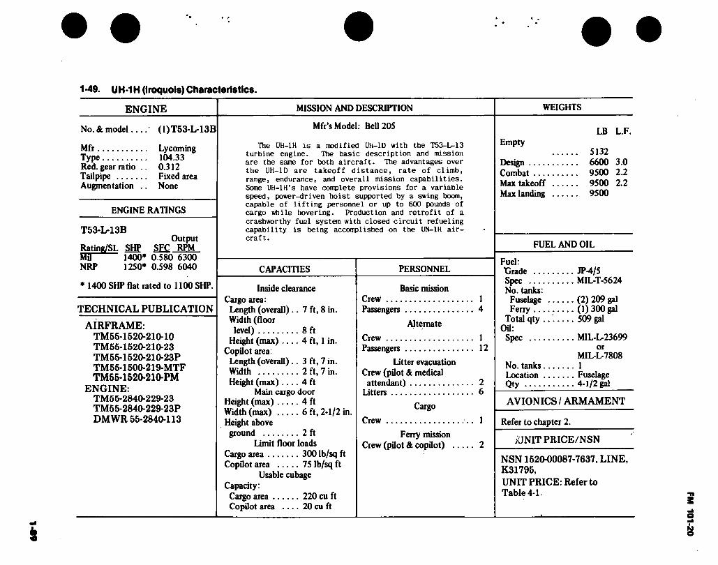
• f
1 *49. UH-1H (Iroquois) Characteristics.
ENGINE MISSION AND DESCRIPTION WEIGHTS
No. & model.... '
Mfr Type Red. gear ratio .. Tailpipe Augmentation ..
(1)T53-L-13B
Lycoming 104.33 0.312 Fixed area None
ENGINE RATINGS
T53-L-13B Output
Rating/SL SHP SFC RPM Mil 1400* 0.580 6300 NRP 1250* 0.598 6040
* 1400 SHP flat rated to 1100 SHP.
TECHNICAL PUBLICATION
AIRFRAME: TM55-1520-210-10 TM55-1520-210-23 TM55-1520-210-23P TM55-1500-219-MTF TM56-1520-210-PM
ENGINE: TM55-2840-229-23 TM55-2840-229-23P DMWR 55-2840-113
Mfr’s Model: Bell 205
The UH-1H is a modified Uh-ID with the T53-L-13 turbine engine. The basic description and mission are the same for both aircraft. The advantages over the UH-ID are takeoff distance, rate of climb,
range, endurance, and overall mission capabilities. Some UH-lH’s have complete provisions for a variable speed, power-driven hoist supported by a swing boom, capable of lifting personnel or up to 600 pounds of cargo while hovering. Production and retrofit of a
crashworthy fuel system with closed circuit refueling capability is being accomplished on the UN-1H air- craft.
CAPACITIES
Inside clearance Cargo area:
Length (overall) .. 7 ft, 8 in. Width (floor
level) 8 ft Height (max) .... 4 ft, 1 in.
Copilot area: Length (overall) .. 3 ft, 7 in. Width 2 ft, 7 in. Height (max).... 4 ft
Main cargo door Height (max) 4 ft Width (max) 6 ft, 2-1/2 in. Height above ground 2 ft
Limit floor loads Cargo area 3001b/sqft Copilot area 75 Ib/sq ft
Usable cubage Capacity:
Cargo area 220 cu ft Copilot area .... 20 cu ft
PERSONNEL
Basic mission Crew Passengers
Alternate
Crew Passengers
Litter evacuation Crew (pilot & medical
attendant) Litters
Cargo
Crew
Ferry mission Crew (pilot & copilot) .
1 4
1 12
2 6
LB L.F. Empty
5132 Design 6600 3.0 Combat 9500 2.2 Max takeoff 9500 2.2 Max landing 9500
FUEL AND OIL
Fuel: Grade JP-4/5 Spec MIL-T-5624 No. tanks:
Fuselage (2) 209 gal Ferry (1)300 gal
Total qty 509 gal Oil:
Spec MIL-L-23699 or
MIL-L-7808 No. tanks 1 Location Fuselage Qty 4-1/2 gal
AVIONICS / ARMAMENT
Refer to chapter 2.
j JNIT PRICE/NSN
NSN 1520-00087-7637, LINE, K31795, UNIT PRICE: Refer to Table 4-1.
*
FM 101-20

Z 1-50 Loading and Performance — Typical Missions, UH-1H (Iroquois).
CONDITIONS
TAKEOFF WEIGHT (lb)
Fuel at 6JS Ib/gal (grade JP-4) (lb)
Pfyload (outbound) (lb)
Fayload (inbound) (lb)
Takeoff power loading^/ (Ib/SHP)
Disk loading (Ib/sqft)
Autorotation speed (min R/D) (kn)
Takeoff ground run at SL (6600 rpm)i-/ (ft)
Takeoff to clear 50 ft (6600 rpm)!/. (ft)
Vertical rate of climb at SL (6600 rpm)!/ (fpm)
Maximum rate of climb at SL2/ (fpm)
Speed for max R/C at SL (kn)
Time: SL to 5000 ft 2/. (min)
Time: SL to lOjOOO ft 2
Service ceiling (100 fpm)2/ (ft)
Absolute hovering ceiling (6600 rpm)!/. (ft)
COMBAT RANGE Hy (nmi)
Average cruise speed (kn)
Cruising altitude (initial) (ft)
Cruising altitude (final) (ft)
Total mission time (hr)
COMBAT RADIUS!^ (nmi)
Average cruise speed (kn)
BASIC
(PERSONNEL
CARRIER)
7644i/
1370
800
0
6.94
4.22
61
0
0
1620
1653
61
3.1
6.2
18340
14300
275
111
2000-4000
2000-4000
2.46
141
111
TRANSPORT
(CARGO OR
TROOP)
9264Í/
1370
2420
0
8.42
5.11
65
,0
0
420
1126
65
4.6
9.9*
13360
4000
250
105
2000-4000
20004000
237
124
107
LITTER
EVACUATION
7414Í/
1370
0
1500 9/
6.74
4.10
60
0
0
1960
1691
60
2.9
5.9
19,140
16,000
133
121
FERRY
9305 i/
33202/
0
0
8.45
5.14
65
0
0
580
1112
65
4.1
10.2
13,640
3600
676
110
20004000
20004000
6.13
• l
FM 101-20
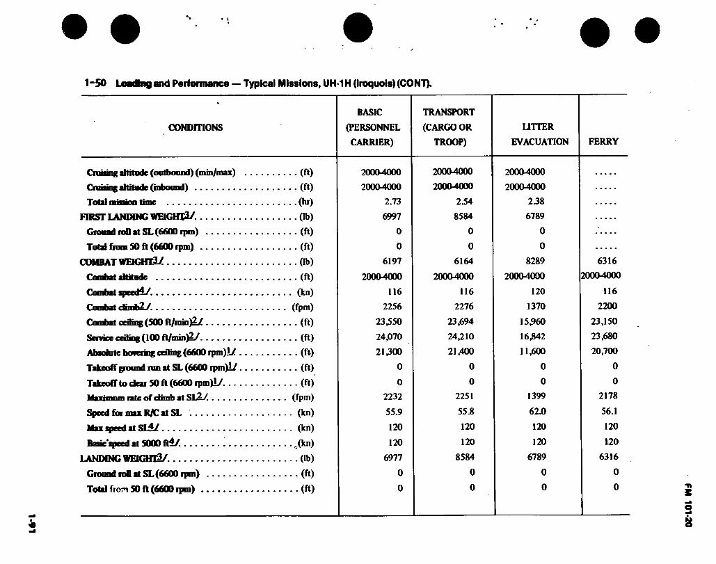
1-91 • l
1-50 Loadbig and Performance — Typical Missions, UH-1H (Iroquois) (CONT).
CONDITIONS
BASIC
(PERSONNEL
CARRIER)
TRANSPORT
(CARGO OR
TROOP)
LITTER
EVACUATION FERRY
Cnming attitude (outbound) (min/max)
Cniising altitude (inbound)
Total minion time
FIRST LANDING WEIGHT^/-
Ground roD at SL (6600 ipm)
Total from SO ft (6600 rpm)
COMBAT WEIGHT!^
Combat altitude
Combat qwedi/.
Combat ctimbL/.
Combat ceding (500
Service ceding (100 ft/nrin^y
Absolute hoaering ceiling (6600 rpm)i/
TakeofTpound run at SL(6600 rpm)i/
Takeoff to dear SO ft (6600 rpm)!/ (ft)
ifavimiim rate of dimb at SL2LZ (fpm)
Speed for max R/C at SL (kn)
Max speed at SLi/ (kn)
Basic'speed at SOOO ft4/ ,(kn)
LANDING WEKHfl^/. (lb)
Ground roD at SL(6600 rpm) (ft)
Total from SO ft (6600 rpm) (ft)
• • (ft)
• • (ft)
• •(hr)
••(lb)
• • (ft)
• • (ft)
• • Ob)
• • (ft)
• (kn)
(fpm)
• • (ft)
• • (ft)
• • (ft)
• - (ft)
20004000
20004000
2.73
6997
0
0
6197
20004000
116
2256
23,550
24,070
21,300
0
0
2232
55.9
120
120
6977
0
0
20004000
20004000
2.54
8584
0
0
6164
20004000
116
2276
23,694
24,210
21,400
0
0
2251
55.8
120
120
8584
0
0
20004000
20004000
238
6789
0
0
8289
20004000
120
1370
15,960
16342
11,600
0
0
1399
62.0
120
120
6789
0
0
6316
20004000
116
2200
23,150
23,680
20,700
0
0
2178
56.1
120
120
6316
0
0
FM 101-20

1-92
1-50 Loading and Performance — Typical Missions, UH-1H (Iroquois) (CONT).
-L/ Takeoff power.
2J Normal rated power. *
-3/ For RADIUS mission if radius is shown,
i/ Vne limit.
A/ Includes crew of 2 at 400 lb.
6/ Includes crew of 1 at 200 lb.
Includes two 150-gallon ferry tanks.
& Based on engine specification takeoff shaft horsepower.
-2/ Six 250-pound litter patients.
19/ Detailed descriptions of RADIUS and RANGE missions are same as shown in paragraph 1-38.
Performance Basis:
a. Reference operator’s Manual Army Model UH-1 H Helicopter TM 55-1520-210-10.
b. All data are at 6600 rpm unless otherwise noted.
Source: TSARCOM-DRSTS-WU
FM 101-20

FM 101-20
DIMENSIONS
Rotor día Length:
Rotors operating ...
Rotors static.. Fuselage
Span (max lateral)
Height Tread Gnd clearance
(static, against stops)
48 Ft.
57 Ft. 1 In. 57 Ft. 1 In. 41 Ft. 111/4 In.
9 Ft. 4 In. . 14 Ft. 5-1/2 In. .. 8 Ft. 6-1/2 In.
.6 Ft. 6 In
7 FT 8-7/16 IN
I— 9 FT 13/32 IN.—
- 8 FT 6-39/64 IN. -
9 FT 4 IN.
FT 9 IN. O
48 FT
D
2 FT 6-1/2 IN.—
44 FT 10-3/32 IN.
II FT 8-21/32 IN. “1 8 FT 6 IN
S3 11 FT 9-3/4 IN.
□ □ I FT 3 IN.
GROUND LINE DESIGN GROSS WEIGHT
40 FT 7-3/32 IN.
41 FT 11-5/32 IN.
Figure 1-29. Principal Dimensions, UH-1V (Iroquois)
1-93
14 F
T 5
-1/2
IN
.
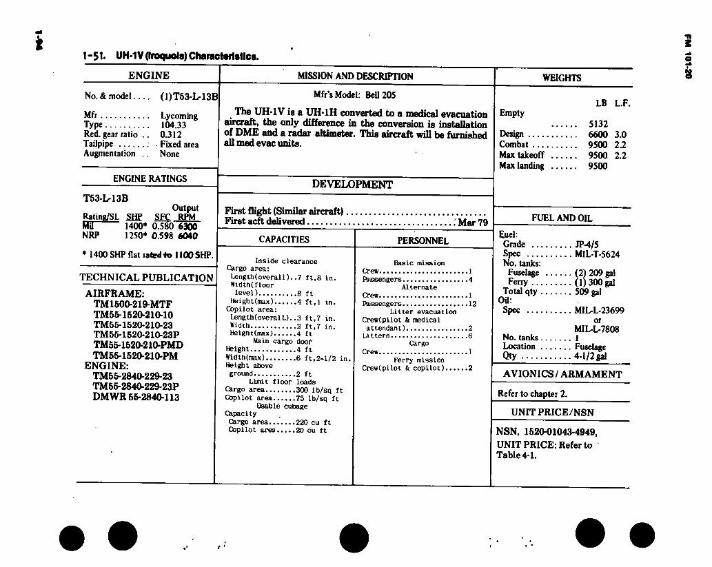
1-51- UH-1V (Iroquois) Characteristics.
ENGINE MISSION AND DESCRIPTION
No. & model.... (1)T53-L-13B Mfr’s Model: Bell 205
Mfr Lycoming Type 104.33 Red. gear ratio .. 0.312 Tailpipe Fixed area Augmentation .. None
ENGINE RATINGS
T53-L-13B
< The UH-1V is a UH-1H converted to a medical evacuation aircraft, the only difference in the conversion is inntj>lla«nn of DME and a radar altimeter. This aircraft will be furnished all med evac units.
DEVELOPMENT
WEIGHTS
LB L.F. Empty
5132 Design 6600 3.0 Combat 9500 2.2 Max takeoff 9500 2.2 Max landing 9500
First flight (Similar aircraft) First acft delivered 'Mar 79
CAPACITIES
Inside clearance Cargo area:
Length(overall). .7 ft,8 in.
PERSONNEL
FUEL AND OIL Output
Rating/SL SHP SFC RPM Mil 1400* 0.580 6300 NRP 1250* 0.598 6040
* 1400 SHP flat rated to 1100 SHP.
TECHNICAL PUBLICATION
AIRFRAME: TM1500-219-MTF TM55-1520-210-10 TM55-1520-210-23 TM55-1520-210-23P TM55-1520-210-PMD TM55-1520-210-PM
ENGINE: TM65-2840-229-23 TM55-2840-229-23P DMWR 56-2840-113
Width(floor level) 8 ft
Height(max) 4 ft,l in. Copilot area: Length(overalL). .3 ft,7 in. Width 2 ft,7 in. Height(max) 4 ft
Main cargo door Height 4 ft
Width (max) 6 ft,2-1/2 in. Height above ground 2 ft
Limit floor loads Cargo area 300 Ib/sq ft
Copilot area 75 Ib/sq ft Usable cubage
Capacity Cargo area 220 cu ft Copilot area 20 cu ft
Basic mission Crew 1 Passengers 4
Alternate Crew 1 Passengers 12
Litter evacuation Crew(pilot & medical attendant) 2 Litters 6
Cargo
Crew 1 Ferry mission
Crew(pilot & copilot) 2
Fuel: Grade JP-4/5 Spec MIL-T-5624 No. tanks:
Fuselage (2) 209 gal Ferry (1)300 gal
Total qty 509 gal Oil:
Spec MIL-L-23699 or
MIL-L-7808 No. tanks 1 Location Fuselage Qty 4-1/2 gal
AVIONICS / ARMAMENT
Refer to chapter 2.
UNIT PRICE/NSN
NSN, 1520-01043-4949, UNIT PRICE: Refer to Table 4-1.
FM 101-20

FM 101*20
DIMENSIONS
Rotor día Length:
Rotors operating ...
Rotors Static.. Fuselage Span (max
Lateral) Height Tread Gnd clearance
(static, against stops)
48 Ft.
.... 57 Ft. 1 In.
.... 57 Ft. 1 In. 41 Ft. 11-1/4 In.
9 Ft. 4 In. . 14 Ft. 5-1/2 In. .. 8 Ft. 6-1/2 In.
6 Ft. 6 In.
,—9 FT 13/32 IN,
8 FT 6-39/64 IN.
-1 FT.9 IN
9 FT 4 IN.
D 48 F*
IZ^ r-zs D
2 FT 6-1/2 IN.
■44 FT 10-3/32 IN.
11 FT 8-21/32 IN
FT
E 11 FT 9-3/4 IN
3 □ □ 1 FT 3 IN -GROUND LINE DESIGN GROSS WEIGHT
-40 FT 7-3/32IN.- •41 FT 11-5/32 IN.
Figure 1-30. Principal Dimpnsions EH-1H (Quick fix) 1-95
14
FT
5-1
/2 I
N.'

i 1-52. EH-1H (Quick Fix) Characteristics
ENGINE
No. & model.... (1)T53-L-
Mfr Lycoming Type 104.33 Red. gear ratio .. 0.312 Tailpipe Fixed area Augmentation .. None
ENGINE RATINGS
T53-L-13B Output
Rating/SL S±ff SFÇ RPM Mil " 1400* 0.580 6300 NRP 1250* 0.598 6040
MISSION AND DESCRIPTION
13B The EH-1H is a modified UH-1H configured to carry ECM equipment in the passenger/cargo area. The basic dynamic rranpnmanLa and airframe are the same as the standard aircraft.
The mission for the EH-1H weapon system consists of air- borne search, collection and jamming countermeasures of enemy aingla rhnnnol radio communications. This information is provided to Division/Brigade commanders in tactical situa- tions. Recording/Reproducing capability is also included in the information collection system.
DEVELOPMENT
* 1400 SHP flat rated to 1100 SHP.
TECHNICAL PUBLICATION
AIRFRAME: TM55-1500-219-MTF TM55-1520-210-10 TM55-1520-210-23 TM55-1520-210-23P TM55-1520-210-PM TM55-1520-210-PMD
ENGINE: TM55-2840-229-23 TM55-2840-229-23P DMWR 55-2840-113
Date of contract, MIPR 23 Jun 75 Contracting agency NARF Rsisaoola No. of test aircraft 1 First flight (scheduled) 4 Aug 77 Completiön of test and evaluation.. 16 Mar 77 Contract delivery schedule 1 Ju® 78
FEATURE PERSONNEL
Crashworthy Fuel System Retractable antennas Environmental control system
Pilot Copilot Mission Operators
1 1 2
WEIGHTS
LB L.F.
Empty 6258
Design 9500 Combat 9500 Max takeoff 9500 Max landing 9500
FUEL AND OIL
Fuel: Grade JP-4/5 Spec MIL-T-5624 No. tanks:
Fuselage (2) 209 gal Ferry (1) 300 gal
Total qty 509 gal Oil:
Spec MIL-L-23699 or
MIL-L-7808 No. tanks 1 Location Fuselage Qty 4-1/2 gal
AVIONICS / ARMAMENT
Refer to chapter 2.
UNIT PRICE/NSN
NSN, 15204)0368-8442 LINE K 30548 UNIT PRICE: Refer to Table 4-1.
r *
FM 101-20

FM 101-20
DIMENSIONS
Rotor día Length:
Rotors operating ...
Rotors Static.. Fuselage Span (max
Lateral) Height Tread Gnd clearance
(static, against stops)
48 Ft.
.... 57 Ft. 1 In.
....57 Ft. 1 In. 41 Ft 11-1/4 In.
9 Ft. 4 In. . 14 Ft. 5-1/2 In. .. 8 Ft. 6-1/2 In.
6 Ft. 6 In.
-•-9 FT 13/32 IN.
=3
8 FT 6-39/64 IN.
•1 FT.9IN
9 FT 4 IN.
D 48 FI
D
2 FT6-1/2 IN.
44 FT 10-3/32 IN.
11 FT 8-21/32 IN.
8FT6IN
11 FT 9-3/4 IN.
1 □ □ 1 FT 3 IN. GROUND LINE DESIGN GROSS WEIGHT
40 FT 7-3/32 IN.- 41FT11-5/32IN.-
Figure 1-31. Principal Dimensions EH-IX (Quick Fix 2) 1-07
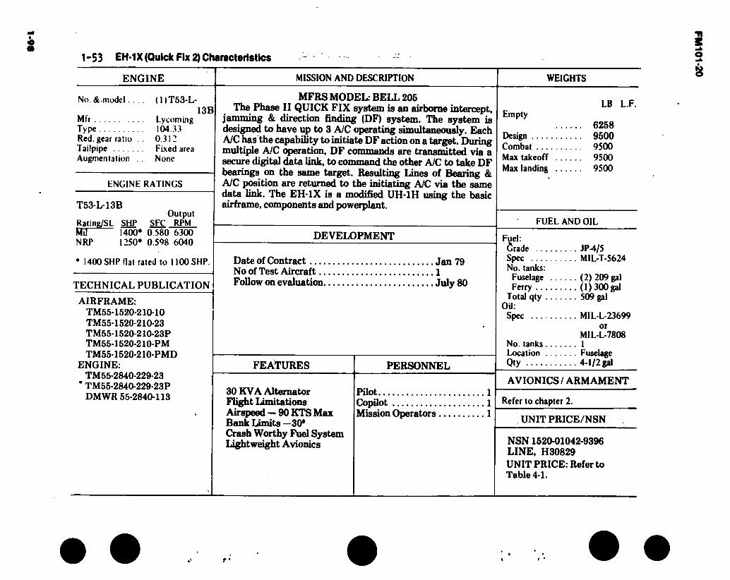
1-9«
1-53 EH-1X (Quick Fix 2) Characteristics
ENGINE MISSION AND DESCRIPTION WEIGHTS
No. & .model. .
Mfr Type Red. gear ratio Tailpipe Augmentation
(DT53-L-
Lycoming 104.33 0.312 Fixed area None
13B
ENGINE RATINGS
T53-L-13B
Rating/SL SHP Mil 1400* 0.580 NRP 1250* 0.598
Output SFC RPM
6300 6040
1400 SHP flat rated to 1100 SHP.
TECHNICAL PUBLICATION
AIRFRAME: TM55-1520-210-10 TM55-1520-210-23 TM55-1520-210-23P TM55-1520-210-PM TM55-1520-210-PMD
ENGINE: TM55-2840-229-23
’ TM55-2840-229-23P DMWR 55-2840-113
MFRS MODEL: BELL 205 The Phase II QUICK FIX system is an airborne intercept,
jamming & direction finding (DF) system. The system is designed to have up to 3 AIC operating simultaneously. Each AIC has the capability to initiate DF action on a target. During multiple AIC operation, DF commands are transmitted via a secure digital data link, to command the other AIC to take DF bearings on the same target. Resulting Lines of Bearing & AIC position are returned to the initiating AIC via the .«mnup data link. The EH-1X is a modified UH-1H using the basic airframe, components and powerplant.
DEVELOPMENT
Date of Contract Jan 79 No of Test Aircraft 1 Follow on evaluation July 80
FEATURES
30 KVA Alternator Flight Limitations Airspeed — 90 KTS Max Bank Limits —30s
Crash Worthy Fuel System Lightweight Avionics
PERSONNEL
Pilot Copilot Mission Operators
LB L.F. Empty
6258 Design 9500 Combat 9500 Max takeoff 9500 Max landing 9500
FUEL AND OIL
Fuel: Crade . JP-4/5 Spec MIL-T-5624 No. tanks:
Fuselage (2) 209 gal Ferry (1) 300 gal
Total qty 509 gal OU:
Spec MIL-L-23699 or
MIL-L-7808 No. tanks 1 Location Fuselage Qty 4-1/2 gill
AVIONICS / ARMAMENT
Refer to chapter 2.
, UNIT PRICE/NSN
NSN 1520-01042-9396 LINE, H30829 UNIT PRICE: Refer to Table 4-1.
r '
FM
101-20

1.54. Loading and Performance — Typical Missions, UH-1V, EH-1H and EH-1X (Iroquois).
CONDITIONS
TAKEOFF WEIGHT (Ib)
Fuel at 6.S Ib/gal (grade JP4) (lb)
Payload (outbound) (Ib)
Payload (inbound) (lb)
Takeoff power loading^/ (Ib/SHP)
Disk loading (Ib/sq ft)
Autorotation speed (min R/D) (kn)
Takeoff ground run at SL (6600 rpm)J-/ (ft)
Takeoff to clear 50 ft (6600 rpm) 1/ (ft)
Vertical rate of climb at SL (6600 rpm)JV (fpm)
Maximum rate of climb at SEI/ (fpm)
Speed for max R/C at SL (kn)
Time: SL to 5000 ft 2/. (min)
Time: SL to 10,000 .ft 2 (mjn)
Service ceiling (100 fpm)2/ (ft)
Absolute hovering ceiling (6600 rpm)i/. (ft)
COMBAT RANGE ]Q[ (nmi)
Average cruise speed (kn)
Cruising altitude (initial) (ft)
Cruising altitude (final) (ft)
Total mission time (hr)
COMBAT RADIUS (nmi)
Average cruise speed (kn)
BASIC
(PERSONNEL
CARRIER)
7644 6/
1370
800
0
6.94
4.22
61
0
0
1620
1653
61
3.1
6.2
18340
14300
275
111
20004000
20004000
2.46
141
111
TRANSPORT
(CARGO OR
TROOP)
92646/
1370
2420
0
8.42
5.11
65
0
0
420
1126
65
4.6
9.9
13,960
4000
250
105
20004000
20004000
2.37
124
107
LITTER
EVACUATION
7414.5/
1370
0
1500i/
6.74
4.10
60
0
0
1960
1691
60
2.9
5.9
19,140
16,000
FERRY
133
121
93051/
33202/
0
0
8.45
5.14
65
0
0
580
1112
65
4.1
10.2
13,640
3600
676
110
20004000
20004000
6.13
3
FM 101-20
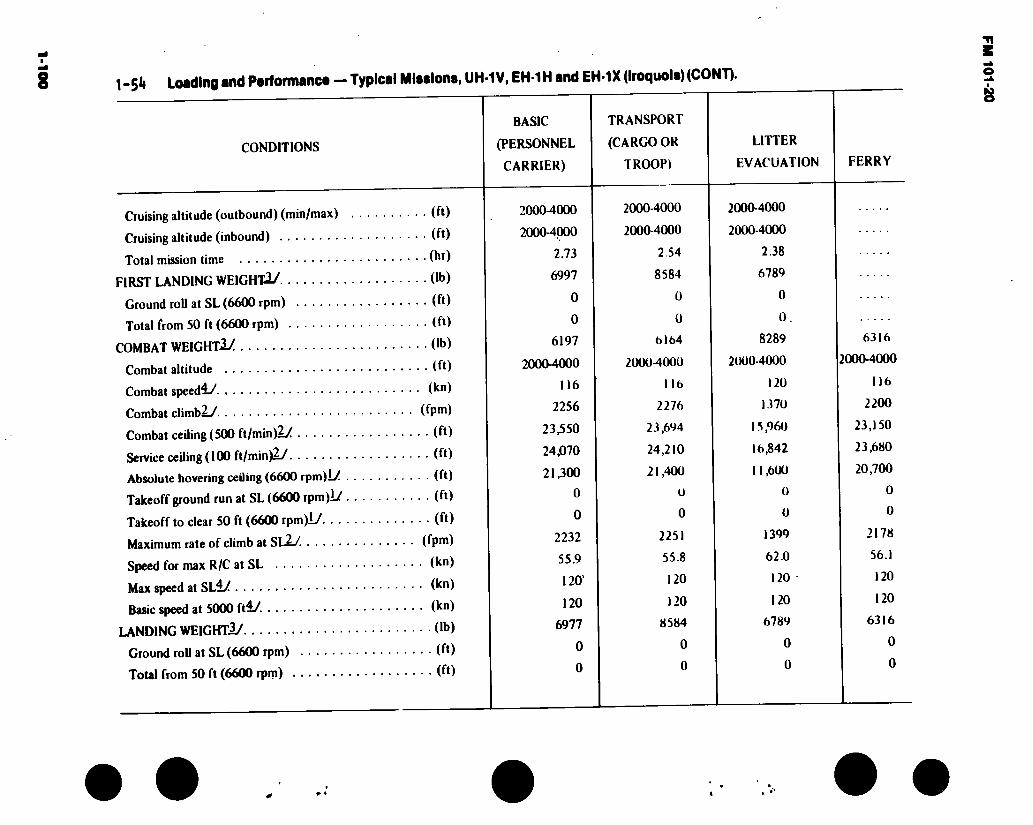
1-1
00
1 -SA Loading and Partormance — Typical
CONDITIONS
Cruising altitude (outbound) (min/max)
Cruising altitude (inbound)
Total mission time
FIRST LANDING WEIGHT.!/
Ground roll at SL (6600 rpm)
Total from 50 ft (6600 rpm)
COMBAT WEIGHT!/
Combat altitude
Combat speed4y
Combat climb!/
Combat ceiling (500 ft/min)!/
Service ceiling (100 ft/min)!/
Absolute hovering ceiling (6600 rpm)L/ .
Takeoff ground run at SL (6600 rpm)Lf
Takeoff to clear 50 ft (6600 rpm)L/
Maximum rate of climb at Si!-/.
Speed for max R/C at SL
Max speed at SLi/
Basic speed at 5000 ftl/
LANDING WEIGHT!/
Ground roll at SL (6600 rpm)
Total from 50 ft (6600 rpm)
Missions, UH-1V, EH-1H and EH-1X (Iroquois) (CONT).
BASIC
(PERSONNEL
CARRIER)
TRANSPORT
(CARGO OR
TROOP)
LITTER
EVACUATION FERRY
■ (ft)
■ (ft)
• (hr)
(lb)
.(ft)
. (ft)
.(lb)
• (ft)
(kn)
(fpm)
■ (ft)
• (ft)
■ (ft)
• • (ft)
• • (ft)
(fpm)
(kn)
(kn)
• (kn)
■ ■ Ob)
• • (ft)
• • (ft)
2000-4000
2000-4000
2.73
6997
0
0
6197
2000-4000
116
2256
23,550
24,070
21,300
0
0
2232
55.9
120’
120
6977
0
0
2000-4000
2000-4000
2.54
8584
0
0
6164
2000-4000
I lb
2276
23,694
24,210
21,400
U
0
2251
55.8
120
120
8584
0
0
2000-4000
2000-4000
2.38
6789
0
0.
8289
2000-4000
120
1370
15,960
16,842
11,600
0
0
1399
62.0
120
120
6789
0
0
6316
2000-4000
116
2200
23,150
23,680
20,700
0
0
2178
56.1
120
120
6316
0
0
«
FM
101-20

101*
1
1-54 Loading and Performance — Typical Missions, UH-1V, EH-1H and EH-1X (Iroquois) (CONT).
-L/ Takeoff power.
2j Normal rated power.
For RADIUS mission if radius is shown.
■Í/ Vne limit.
A/ Includes crew of 2 at 400 lb.
*?/ Includes crew of I at 200 lb.
-2/ Includes two 150-gallon ferry tanks.
Based on engine specification takeoff shaft horsepower.
-?/ Six 250-pound litter patients.
Detailed descriptions of RADIUS and RANGE missions are same as shown in paragraph I -38.
Performance Basis:
a. Reference operator's Manual Army Model UH-1 H Helicopter TM 55-1520-210-10.
b. All data are at 6600 rpm unless otherwise noted.
FM
101-20

FM 101-2U
1-55, Performance Notes, UH-1V, EH-1H and EH-1X (Iroquois).
FORMULA: RADIUS MISSION I
Warm up, take off, climb on course to 2000-4000 feet initial altitude at normal rated power, proceed at long range cruise speed to remote base, land, and unload passengers. Without refueling, warm up, take off, climb on course to 2000-4000 feet at normal rated power, and return at long range cruise speed. Range-free allowances are 4 minutes at normal rated power for warmups and takeoffs plus 10 percent of initial fuel for reserve.
FORMULA: RADIUS MISSION II
Warm up, take off, and climb on course to 2000-4000 feet at normal rated power. Cruise climb on course at long range cruise speed to final altitude of 2000-4000 feet. Proceed at long range speed to remote base, land, and unload cargo or troops. Without refueling, warm up, take off, climb on course to 2000-4000 feet at normal rated power, and return at long range cruise speed. Range-free allowances are 4 minutes at normal rated power for warmups and takeoffs plus 10 percent of initial fuel for reserve.
climb on course to 2000-4000 feet at normal rated power, and return at long range cruise speed. Range-free allowances are 4 minutes at normal rated power for warmups and takeoffs plus 10 percent of initial fuel for reserve.
FORMULA: RANGE MISSION I
Warm up, take off, and climb on course to 2000-4000 feet initial altitude at normal rated power. Proceed at long range cruise speed to remote base and land. Range-free allowances are 2 minutes at normal rated power for warmup and takeoff plus 10 percent of initial fuel for reserve.
FORMULA: RANGE MISSION II
Warm up, take off, and climb on course to 2000-4000 feet at normal rated power. Cruise climb on course at long range cruise speed to final altitude of 2000-4000 feet. Proceed at long range cruise speed to remote base and land. Range-free allowances are 2 minutes at normal rated power for warmup and takeoff plus 10 percent of initial fuel for reserve.
FORMULA: RANGE MISSION III
FORMULA: RADIUS MISSION III
Warm up, take off, and climb on course to 2000-4000 feet at normal rated power. Proceed at long range cruise speed to remote base, land, and pick up litter patients. Without npfiieling, warm up, take off.
Warm up, take off, and climb on course to 2000-4000 feet at normal power. Cruise climb on course at long range cruise speed to fmal altitude of 2000-4000 feet. Proceed at long range cruise speed to remote base and land. Range-free allowances are 2 minutes at normal rated power for warmup and takeoff plus 10 percent of initial fuel for reserve.
Source: TSARCOM- DRSTS-WU TSARCOM- DRCPM-AEL
1-102

FM 101-20
É-
%
Figure 1-32. UH-60A (Blackhawk)
1-103
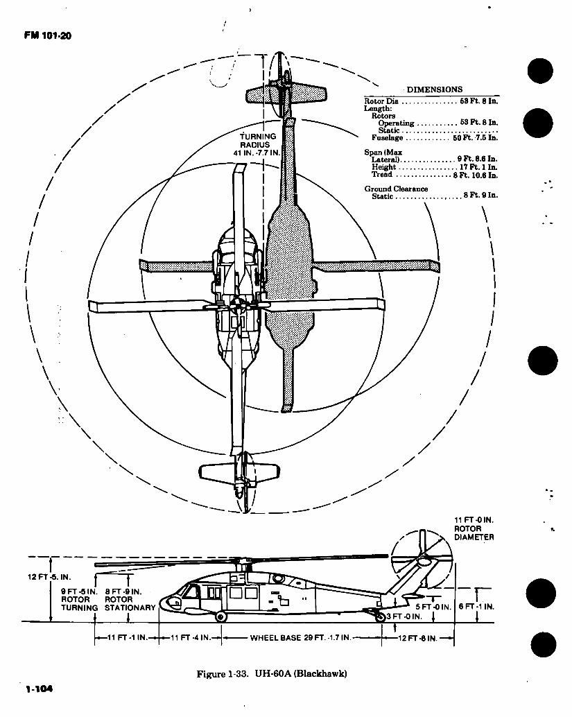
FM 101-20
DIMENSIONS Rotor Dia 63 Ft. 8 In. Length:
Rotors Operating 63 Ft. 8 In. Static
Fuselage 50 Ft. 7.6 In.
Span (Max Lateral) 0 Ft. 8.6 In. Height 17 Ft. 1 In. Tread 8 Ft. 10.6 In.
8 Ft. 9 In.
!
TURNING RADIUS
41 IN.-7.7 IN
27 Ground Clearance
Static
m r u
\ X \ \ \
\
11 FT -0 IN. ROTOR DIAMETER
/
,N f r 9 FT -5 IN. 8 FT -9 IN. ROTOR ROTOR TURNING STATIONARY
12 FT-5. IN.
□ □ r -b 6 FT -1 IN 5 FT-0 IN FT -OIN, I
11 FT -1 IN. 11 FT-4IN. WHEELBASE 29 FT.-1.7 IN 12 FT-6 IN
1-104 Figure 1-33. UH-60A (Blackhawk)
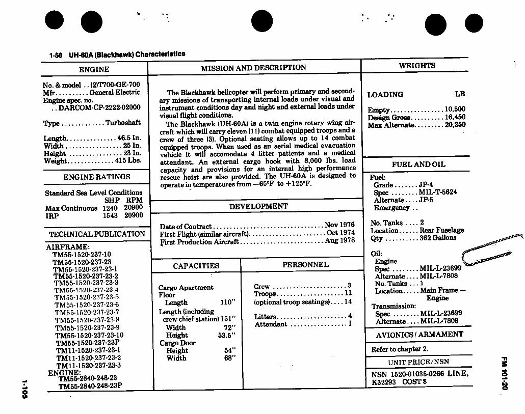
1-1
05
• •
1 -56 UH-60A (Blackhawk) Characteristics
ENGINE MISSION AND DESCRIPTION WEIGHTS
No. & model .. (2)T700-GE-700 Mfr General Electric Engine spec. no.
.. DARCOM-CP-2222-02000
Type Turboshaft
Length 46.5 In. Width 25 In. Height 23 In. Weight 415 Lbs.
ENGINE RATINGS
Standard Sea Level Conditions SHP RPM
Max Continuous 1240 20900 IRP 1543 20900
The Blackhawk helicopter will perform primary and second- ary missions of transporting internal loads under visual and instrument conditions day and night and external loads under visual flight conditions.
The Blackhawk (UH-60A) is a twin engine rotary wing air- craft which will carry eleven (11) combat equipped troops and a crew of three (3). Optional seating allows up to 14 combat equipped troops. When used as an aerial medical evacuation vehicle it will accomodate 4 litter patients and a medical attendant. An external cargo hook with 8,000 lbs. load capacity and provisions for an internal high performance rescue hoist are also provided. The UH-60A is designed to operate in temperatures from —65°F to -I-125°F.
DEVELOPMENT
Date of Contract TECHNICAL PUBLICATION
AIRFRAME: TM55-1520-237-10 TM55-1520-237-23 TM 55-1520-237-23-1 TM55-1520-237-23-2 TM55-1520-237-23-3 TM 55-1520-237-23-4 TM55-1520-237-23-5 TM 55-1520-237-23-6 TM 55-1520-237-23-7 TM 55-1520-237-23-8 TM 55-1520-237-23-9 TM55-1520-237-23-10 TM55-1520-237-23P TM 11-1520-237-23-1 TM11-1520-237-23-2 TM 11-1520-237-23-3
^NTM56-2840-248-23 TM55-2840-248-23P
First Flight (similar aircraft) first Production Aircraft...
CAPACITIES
Cargo Apartment Floor
Length 110” Length (including
crew chief station) 151” Width 72” Height 53.5”
Cargo Door Height 54” Width 68”
Nov 1976 . Oct 1974 Aug 1978
PERSONNEL
Crew 3 Troops 11 (optional troop seatings) 14
Litters 4 Attendant 1
LOADING LB
Empty 10,500 Design Gross 16,450 Max Alternate 20,250
FUEL AND OIL
Fuel: Grade JP-4 Spec MIL-T-5624 Alternate JP-5 Emergency ..
No. Tanks 2 Location Rear Fuselage Qty 362 Gallons
Oil: Engine Spec Alternate — No. Tanks .. Location
Transmission: Spec Alternate...
MIL-L-23699 MIL-L-7808
. 1
. Main Frame — Engine
. MIL-L-23699
. MIL-L-7808
AVIONICS / ARMAMENT
Refer to chapter 2.
UNIT PRICE/NSN
NSN 1520-01035-0266 LINE, K32293 COSTS
FM 101-20

«01-
1
1-57. Loading & Performance!/- Typical Missions, UH-60A (Black Hawk)
CONDITIONS
NO OF TROOPS/PA YLOAD
COMBAT ASSAULT SEA LEVEL
11 14
COMBAT ASSAULT 4000’/95#F
11 14
MAX ALT GROSS WT SEA LEVEL
MAX ALT GROSS WT
4000V95F
FERRY MISSION STD DAY
^/Estimated Gross Weight (lbs)
Payload (Outbound) (lbs)
Payload (Inbound) (lbs)
Vmax (IRP) (kts)
Max Cruize Speed (MCP) (kts)
Vcruize (Best Range) (kts)
Max Rate-of-Climb fIRP-Vbroc) (fpm)
Vert Rate-of-Climb (95% IRP) (fpm)
Service Ceiling (100 fpm) (ft)
Service Ceiling (Single Eng) (ft)
Hover Ceiling (Oge, IRP) (ft)
Hover Ceiling (2 ft Wheel Ht. IRP) (ft)
S/Radius of Action (nm)
Ferry Range (nm)
16700
2640
0
157
150
130
2735
1515
18.000
8700
9800
14800
106
17420
3360
0
156
149
130
2550
1220
17200
7500
8600
13600
105
16700
2640
0
156
137
135
2010
290
14000
3600
5000
9200
133
17420
3360
0
155
136
135
1840
13000
2400
4200
8400
133
20250
6195
3000
1284/
1211/
1001/
1645
13700
3000
4800
9600
901/
20250
6195
3000
1291/
1051/
1051/
1075
9800
4000
1101/
!/Performance with IR Suppressor Installed. 2/Empty Wt -10500 lbs. Fixed Useful Load with Crew of 3 - 935 lbs *^8 Min Ground Time, 1 Min Hover, Climbout. Vcruise, 5 Min Noe at 40 Kts & Return with 30 Minute Reserve. 1/Outbound Payload is External 30ft2 Equivalent Flat Plate Area
19500
149
143
126
2045
14600
4200
5000
10400
950
Source: AVRADC0M - DRCPM-BH
*
FM 101-20

FM 101-20
0 9o 9o
s.
Figure 1-34. C-12A (Huron)
1-107

FM 101-20 43 FT 10 IN
a 15 FT .5 IN
D OOOOO o 03)
I 14.5 IN o
14 FT 11.5 IN
29.6 IN.
I
\)
DIMENSIONS
Wing Span 54 Ft. 6 In. Length 43 Ft. 10 In. Height 15 Ft. 5 In. Tread 17 Ft. 2 In. Prop Grd Clearance 1 Ft.
18FT5IN.
54 FT. 6 IN. -fr-
8 FT. 2.5 IN. DIA
17 FT 2 IN
1-108 Figure 1-35. C-12A (Huron)
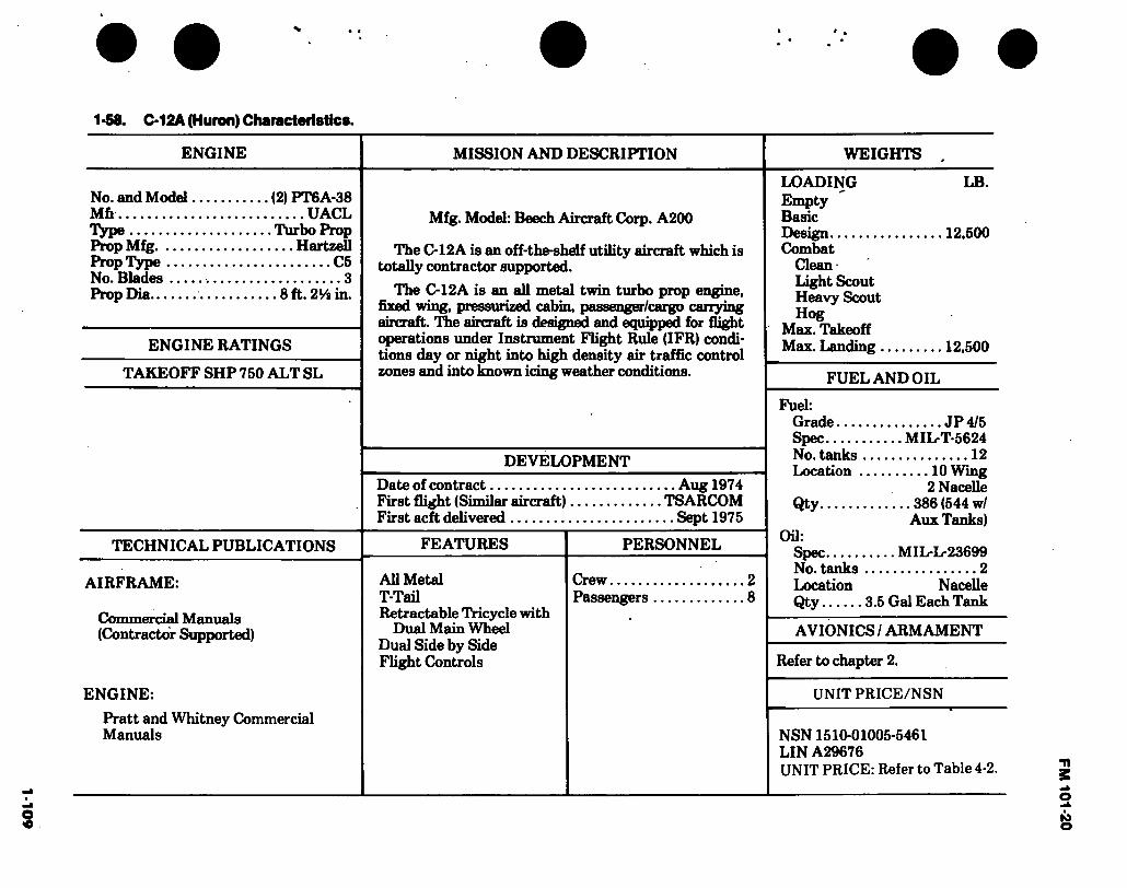
1-109 • «
1-58. C-12A (Huron) Characteristics.
ENGINE MISSION AND DESCRIPTION WEIGHTS
No. and Model (2) PT6A-38 Mfe UACL Type Turbo Prop Prop Mfg Hartzell Prop Type C5 No. Blades 3 Prop Dia 8 ft. 21/i in.
ENGINE RATINGS
TAKEOFF SHP 750 ALT SL
Mfg. Model: Beech Aircraft Corp. A200
The C-12A is an off-the-shelf utility aircraft which is totally contractor supported.
The C-12A is an all metal twin turbo prop engine, fixed wing, pressurized cabin, passenger/cargo carrying aircraft. The aircraft is designed and equipped for flight operations under Instrument Flight Rule (IFR) condi- tions day or night into high density air traffic control zones and into known icing weather conditions.
DEVELOPMENT
Date of contract First flight (Similar aircraft) First acft delivered
,.. Aug 1974 TSARCOM .. Sept 1975
TECHNICAL PUBLICATIONS FEATURES
AIRFRAME:
Commercial Manuals (Contractor Supported)
ENGINE:
Pratt and Whitney Commercial Manuals
All Metal T-Tail Retractable Tricycle with
Dual Main Wheel Dual Side by Side Flight Controls
PERSONNEL
Crew.
LOADING Empty Basic Design Combat
Clean Light Scout Heavy Scout Hog
Max. Takeoff Max. landing .
LB.
12,500
12,500
FUEL AND OIL
Fuel: Grade JP 4/5 Spec MIL-T-5624 No. tanks 12 Location 10 Wing
2 Nacelle Qty 386 (544 w/
Aux Tanks) Oil:
Spec MIL-L-23699 No. tanks 2 Location Nacelle Qty 3.5 Gal Each Tank
AVIONICS / ARMAMENT
Refer to chapter 2.
UNIT PRICE/NSN
NSN 1510-01005-5461 LIN A29676 UNIT PRICE: Refer to Table 4-2.
FM
101-20
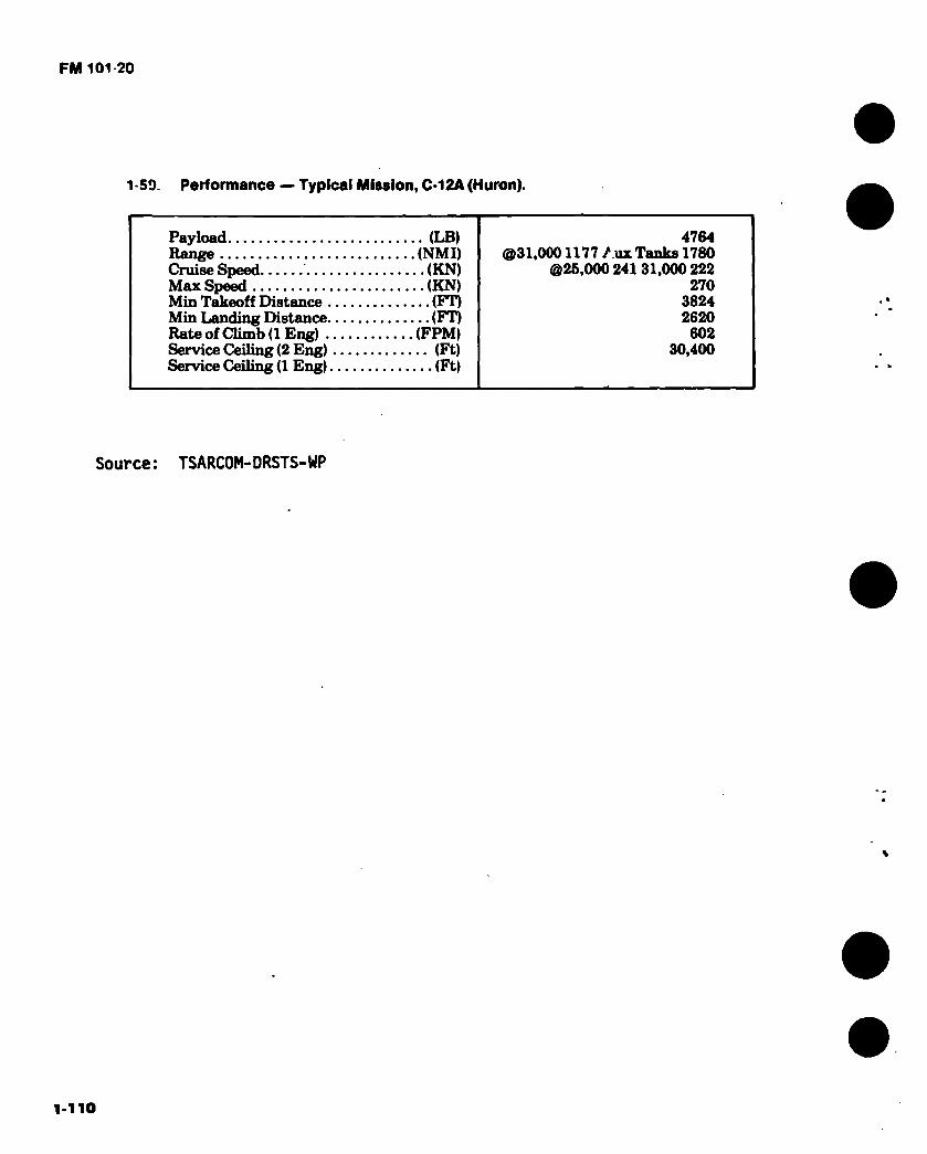
FM 101 20
1-59. Performance — Typical Mission, C-12A (Huron).
Payload (LB) Range (NMI) Cruise Speed (KN) Max Speed (KN) Min Takeoff Distance (FT) Min landing Distance (FT) Rate of Climb (1 Eng) (FPM) Service Ceiling (2 Eng) (Ft) Service Ceiling (1 Eng) (Ft)
4764 @31,0001177 /.ox Tanks 1780
@26,000 241 31,000 222 270
3824 2620 602
30,400
Source: TSARCOM-DRSTS-WP
1-110
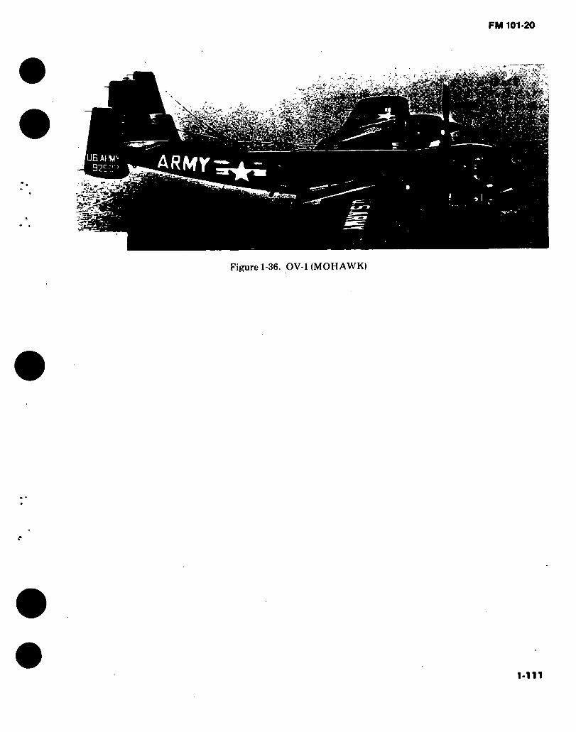
FM 101-20
& m
- rj*'
» • i -.«
Figure 1-36. OV-1 (MOHAWK)
1-111

12 F
T 9-3
/4 I
N.
FM 101-20
48 FT
□ □
10 FT
(-9 FT 2 IN. STATIC-
-l5FTI0IN.- DIMENSIONS
Wing: Area 360 Sq. Ft. Span 48 Ft. MAC 94.8 In. Length 43 Ft. 11-1/2 In. Height 12 Ft. 8 In. Tread 9 Ft. 2 In.
nfr"! rWr"!
n
U U
ü
i) — 11 FT 81/4 IN. J
43 FT 11-3/8 IN.
Figure 1-37. Principal Dimensions, 0V-1B and C (Mohawk)
1-112

FM 101-20
O
9
Figure 1-38. The 0V-1C (Mohawk) aircraft
1-119

1-1
14
1 -60. OV-1B (Mohawk) Characteristics.
ENGINE MISSION AND DESCRIPTION WEIGHTS
No. & model (2) T53-L-7 Mfr Lycoming Type Free power
turbine Engine spec No .. 104.21B&.11C Red. gear ratio ... 12.4 Prop mfr Hamstd Blade design No . 7125-6 No. of blades ... 3 Propdia 10 ft
ENGINE RATINGS
Output
Rating/SL SHP SFC RPM Max (takeoff) 1100 0.670 1700 Mil 1000 0.679 1700 NRP 900 0.692 1700
TECHNICAL PUBLICATION
AIRFRAME: TM55-1510-204-10/3 TM55-1510-204-CL/3 TM55-1510-204-23-1/-2/-3/-4 TM55-1510-204-23P1-P2-P3 TM55-1510-217-PM TM55-1510-217-PMD TM55-1510-217-S
ENGINE: TM55-2840-233-24 TM55-2840-233-23P
Mfr’s Model: Grumman
The primary mission of the OV-1B is electronic surveillance using the sidelooking airborne radar (SLAR). In addition, it is capable of performing missions of photographic reconnaissance, visual reconnais- sance and observation, artillery gunfire spotting, air control, and radiological monitoring.
The OV-1B is a two-place, twin-turboprop aircraft capable of operating from small ñelds and unimproved runways. Design features include a midwing, three-tail confíguration of semimonocoque construction equipped with wide span flaps.
The crew of two are seated side-by-side within a bubbled enclosure at the extreme forward end of the fuselage.
A remotely operated day-and-night KA-30 camera installation provides horizon-to-horizon photo coverage along the aircraft flight path.
The OV-1 B carries an APS-94 side looking airborne radar antenna as standard equipment.
External provisions are incorporated to carry two 150-gallon fuel tanks or two resupply containers.
DEVELOPMENT
LB L.F. Empty E 10,983 Basic 11.217 Design 13,100 4.0 Combat (basic
mission) 12,882 Normal takeoff . 13,654 * Max takeoff ... 16,643 Max landing ... 16,643
FUEL AND OIL
Fuel: Grade JP-4 Spec MILT-5624
No. tanks: Fuselage (1)297 gal External (2) 150 gal Total Qty ... 597 gal
Oil: Spec MILL-23699 Qty 5 gal
First flight (prototype) November 1961 Estimated first service use January 1963
FEATURES PERSONNEL
Ejection Seats Pilot Low Physical Profile Mission Operator.... All Weather Operation
Capability Capable of Deployment to Distant MSN Area by Using Extended Range Tanks (300 gal)l
AVIONICS / ARMAMENT
Refer to chapter 2.
UNIT PRICE/NSN
NSN 1510-00-715-9379
LIN A30221 UNIT PRICE: See Table 4-2.
* »
FM 101-20

1-115 « *
1-61. Loading and Performance - Typical Mission, OV-1B (Mohawk).
TAKEOFF LOADING CONDITION OBSERVATION,
NO STORES 1
NIGHT PHOTO, TWO A6
EJECTORS 3
EMERGENCY RESUPPLY,
TWO RESUPPLY CONTAINERS
5
FERRY, TWO 150GAL
EXT TANKS 7
TAKEOFF WEIGHT Fuel intemal/extemal Payload Wing loading Stall speed (power-off) 4/... Takeoff run at SL - calm Takeoff to clear SO ft - calm Max speed/altitude Rate of climb at SL 2/. Time: SL to 20,000 ft 2/... Time: SL to 25,000 ft 2/... Service ceiling ( 100 fpm) 2/. COMBAT RANGED
Average cruising speed Cruising altitude (s)
Cruise time Mission time
.... (lb) ... (lb). ... (lb). (Ib/sq ft). ... (kn) ... (ft). ... (ft). . (kn/ft). . (fpm).
(min). (min).
... (ft). (nmi).
... (kn). (ft). (hr) (hr).
13,654 1930
38 73
995 1625
240.5/12,500 2800
9.5 15.5
29,500 365 200
5000 1.80 1.84
13,915 1930 264
38.7 73.8 1040 1690
238/12,000 2700
10 16
28,750 358 200
5000 1.77 1.80
15,168 1930 15 00 42.1
77 1270 2000
226.8/10,000 2320
13 23
26,500 334 200
5000 1.64 1.69
15,918 1930/1950
44 >5 79
1410 2185
226/8000 2160
15 26.5
24,900 1053 203
20,000 4.98 5.30
COMBAT LOADING CONDITION NO STORES 2
TWO A6 EJECTORS
4
TWO RESUPPLY CONTAINERS
6
COMBAT WEIGHT (60 percent internal fuel) . (lb) . Engine power Fuel (lb). Combat speed/combat altitude 2/.... (kn/ft). Rate of climb/combat altitude 2/ (fpm/ft). Combat ceiling (500 fpm) 2/. (ft) . Rate of climb at SL 27. (fpm). Max speed at SL 2/ (kn). Max speed/altitude 2/ (kn/ft) .
LANDING WEIGHT (10 percent internal fuel) (lb). Fuel (lb). Stall speed-power-off/approach power ■S'... (kn) .. Landing distance clear 50-ft obstacle ... (ft) ..
12,882 Military
1158 250/5000
2660/5000 ' 27,700
3050 247.2
252/11,500 11,917
193 67.5/54.6
870
13,143 Military
1158 248/5000
2560/5000 26,900
2940 244.9
249.5/11,500 12,178
193 68.2/55.2
890
14,396 Military
1158 238/5000
2175/5000 23,800
2530 235.9
239.5/10,000 13,431
193 71.5/58
1330
FM
101-20
1 -61. Loading and Performance — Typcial Mission, OV-1B (Mohawk) (CONT).
-i/Normal rated power.
-2/Military rated power.
-3/ See notes on mission specifications.
^Flight idle power, propeller control at max rpm.
-2/ Power for level flight at 120 percent of stall speed, power off, propeller control at max rpm.
Source: TSARCOM-DRCPM-AEL

1-117 I
1-62 OV-1C (Mohawk) Characteristics.
ENGINE MISSION AND DESCRIPTION WEIGHTS
No. & model (2) T53-L-7/15 Mfr Lycoming Type Power free
turbine Engine spec No ... 104.11C, .21-B
and .35 Red. gear ratio .... 12.46 Prop mfr Ham std No. blades 3 Blade design No ...7125-6 Prop dia 10 ft
ENGINE RATINGS
T53-L-7
Rating/SL SHP SFC Max (takeoff) 1100 0.670 Mil 1000 0.679 NRP 900 0.692
T53-L-15
Rating/SL SHP SFC MU 1160* 0.620 NRP 1000* 0.650
*Mechanical limited.
‘ TECHNICAL PUBLICATION
Output RPM 1700 1700 1700
Output RPM 1700 1600
Mfr’s Model: Grumman
The primary mission of the OV-1C is to perform Infrared (IR) reconnaissance missions using the Infrared sensor. In addition it is capable of performing photographic missions, visual reconnaissance and observation, artUlery gunfire spotting, air control, and radiological monitoring.
The OV-1C is a two-place, twin-turboprop aircraft capable of operating from small fields and unimproved runways. Design features include a midwing, three-taU configuration of semi- monocoque construction equipped with wide span flaps.
The crew of two are seated side-by side within a bubbled enclosure at the extreme forward end of the fuselage.
A remotely operated day-and night KA-30 or KA-76 camera installation provides horizon-to-horizon photo coverage along the aircraft flight path. A nose-mounted KA-60, 70-mm panoramic camera is also provided. The OV-1C carries AN/ASS14 infrared detection equipment.
The infrared surveillance system makes it possible to detect military terrestrial targets by inherent characteristics that are distinguishable in the visual and infrared portion of the electro- magnetic spectrum.
External provisions are incorporated to carry two 150-gallon fuel tanks or two resupply containers.
DEVELOPMENT
First flight (prototype) March 1961 First service use July 1961
AIRFRAME: TM55-1510-204-10/4 TM55-1510-204-CL/4 TM55-1510-204-23/-1/-2/-3/-4 TM55-1510-204-23P1-P2-P3
ENGINE: TM55-2840-233-24 TM55-2840-233-23P
FEATURES PERSONNEL
Ejection Seats Pilot Low Physical Profile Mission Operator All Weather Operation
Capability
Capable of Deployment to Distant MSN Area by Using Extended Range Tanks (300 gal)
1 1
LB L.F. Empty 10,011 Basic 10,379 Design 11,924 4.9/4.0 Combat (basic
mission) 12,296 Normal takeoff . 12,682 Max takeoff ... 15,302 Max landing ... 15,302
FUEL AND OIL
Fuel: Grade .... Spec No. tanks:
Fuselage . External .
Total qty .. OU:
Spec Qty
JP-4 MIL-T-5624
(1) 297 gal (2) 150 gal 597 gal
MIL-L-23699 5 gal
AVIONICS / ARMAMENT
Refer to chapter 2.
UNIT PRICE/NSN
NSN 1510-00715-9380 LIN A30271 UNIT PRICE: See Table 4-2.
FM 1
01-2
0
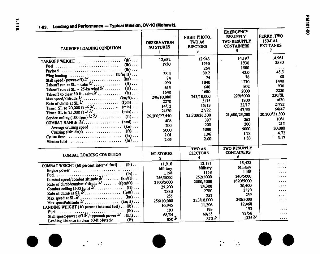
•!!■!
1-63. Loading and Performance — Typical Mission, OV-1C (Mohawk).
TAKEOFF LOADING CONDITION
NIGHT PHOTO,
OBSERVATION TWO A6 NO STORES EJECTORS
1 3
EMERGENCY RESUPPLY
TWO RESUPPLY CONTAINERS
5
FERRY, TWO 150-GAL
EXT TANKS 7
TAKEOFF WEIGHT Fuel Payload Wing loading Stall speed (power-off) & Takeoff run at SL - calm-» .. . • ■ Takeoff run at SL - 25-kn wind & Takeoff to clear 50 ft - calm-W ... Max speed/altitude-!/ Rate of climb at SL ^ Time: SL to 20,000 ft V' jf Time: SL to 25,000 ft -W2/ ..... Service ceiling (100 fpm)-l¿—/ ... COMBAT RANGE Ü
Average cruising speed Cruising altitude(s)
Cruise time Mission time
... (lb)...
... (lb)...
... (lb)... (Ib/sq ft) ... ... (kn)... ... (ft)... ... (ft)... ... (ft)... . (kn/ft)... .. (fpm) ...
(min) ... .. (min)...
... (ft)...
.. (nmi) .. •
... (kn)...
... (ft)...
... (hr) ...
... (hr)...
COMBAT LOADING CONDITION
COMBAT WEIGHT (60 percent internal fuel) .. (lb) ... Engine power Fuel (lb)... Combat speed/combat altitude 2/ (kn/ft) ... Rate of climb/combat altitude * (fpm/ft)... Combat ceiling (500 fpm) ^ (ft) • • • Rate of climb at SL 2? (fpm)... Max speed at SL 2^ (kn)...
Max speed/altitude 2/ (kn/ft) ... LANDING WEIGHT (10 percent internal fuel) .. (lb) ...
Fuel • Ob) • • • Stall speed-power off »/approach power-* . (kn) ... Landing distance to clear 50-ft obstacle (ft) • • •
12,682 1930
38.4 74
990 613
1640 246/10,000
2270 14/12 24/20
26,200/27,450 408 200
5000 2.01 2.05
12,943 1930 264 39.2
74 1040 640
1680 243/10,000
2175 15/13 27/22
25,700/26,500 397 200
5000 1.96 2.00
14,197 1930 1500 43.0
78 1270 802
2000 229/5000
1800 22/17 47/35
21,600/23,200 362 200
5000 1.78 1.83
14,961 3880
45.3 80
1440 930
2230 230/SL
1630 27/22 64/47
20,200/21,300 1081 215
20,000 4.72 5.17
NO STORES 2 11,910
Military 1158
256/5000 2100/5000
25,200 2880
255 256/10,000
10,945 193
68/54 850^
TWO A6 EJECTORS
4
TWO RESUPPLY CONTAINERS
6
12,171 13,425
Military 1158
252/5000 2000/5000
24,300 2780
252 253/10,000
11,206 193
69/55 870*
Military 1158
240/5000 1620/5000
20,400 2320
239 240/5000
12,460 193
72/58 1335 &
%
8
i
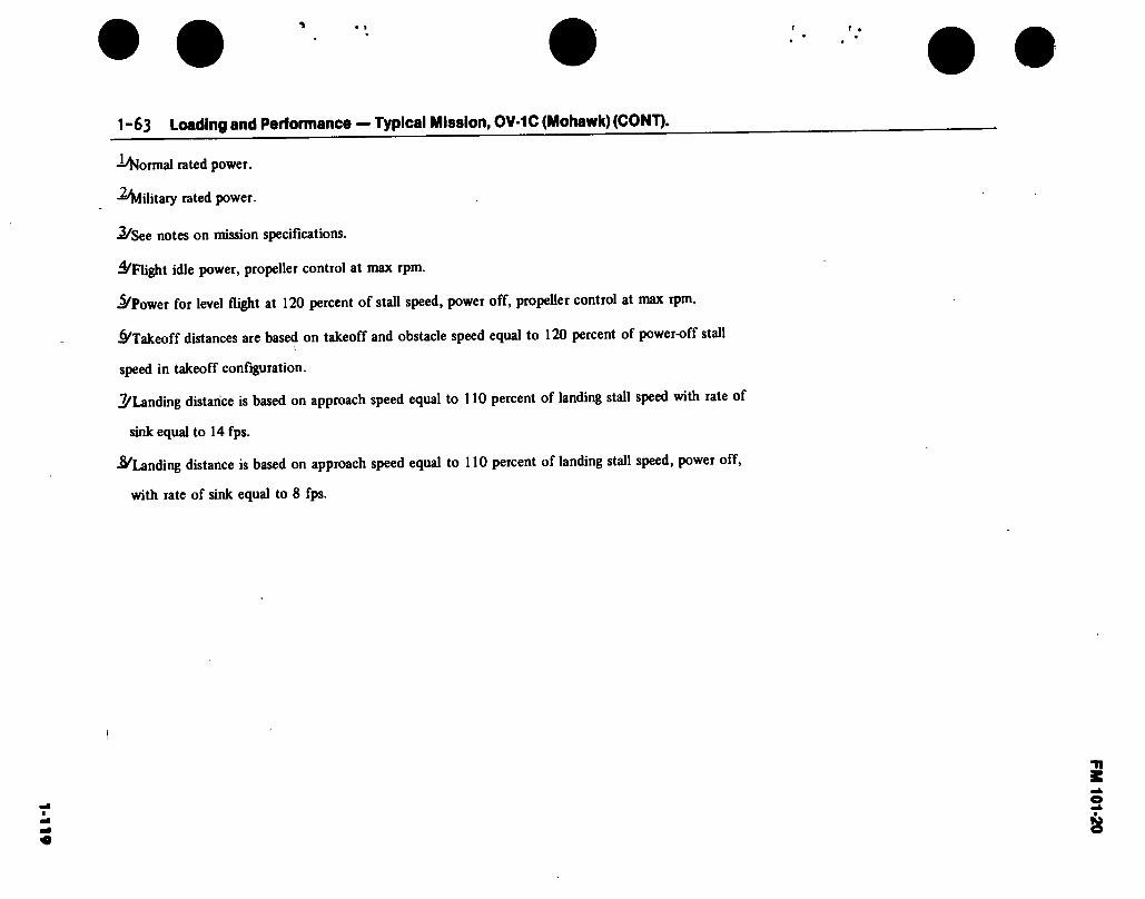
• 1 r •
1-63 Loading and Performance — Typical Mission, OV-1C (Mohawk) (CONT).
-formal rated power.
-Military rated power.
.2/See notes on mission specifications.
4/Flight idle power, propeller control at max rpm.
i^Power for level flight at 120 percent of stall speed, power off, propeller control at max rpm.
Jà'Takeoff distances are based on takeoff and obstacle speed equal to 120 percent of power-off stall (
speed in takeoff configuration.
^Landing distance is based on approach speed equal to 110 percent of landing stall speed with rate of
sink equal to 14 fps.
■^Landing distance is based on approach speed equal to 110 percent of landing stall speed, power off,
with rate of sink equal to 8 fps.
<•
FM
101-20

FM 101-20
1 -64. Performance Notee, OV-1B and C (Mohawk).
TACTICAL AIR OBSERVATION MISSION AND NIGHT PHOTOGRAPHY (Columns 1, 3, and 5, paragraph 1-61 and 1-63).
Warm up, taxi, take off, climb on course to 5000 feet at normal rated power, and cruise at 200 knots at 5000 feet until all but reserve fuel is consumed. Range-free allowances are 5 minutes at normal rated power for warmup, taxi, and take off, plus 10 percent of initial internal fuel for reserve.
FERRY MISSION (Column 7, paragraph 1-61 and 1-63). |
Warm up, taxi, take off, climb on course to altitude for maximum range at normal rated power, cruise at altitude and velocity for maximum range until all but reserve fuel is consumed, and drop externak fuel tanks when empty. Range- free allowances are 5 minutes at normal rated power for warmup, taxi, and take off, plus 10 percent of initial fuel for reserve.
Source: TSARCOM-DRCPM-AEL
1-120

Figure 1-39. 0V-1D (Mohawk)
1-121

FM 101-20
48 FT
TAIL SPAN 15 FT 10 IN.
HORIZWL 100
LD 0
10 FT WL9
WL 0.0
DIMENSIONS BL 0.0
STATIC TREAD — 9 FT 1.9 IN.—-
Wing Area 360 Sq. Ft. Span 4B~Ft. MAC 98 Ft. Length 41 Ft.
3.85 In. Height 12 Ft. 8 In. Tread 9 Ft. 2 In.
STA 0.00
VERTICAL REF LINE STA.5.75-1
HORIZWL 100
(HORIZONTAL REF LINE)
13 FT
12 FT 8 IN n LID □ Cl
© STATIC GL5°39 MIN
STATIC WHEELBASE 11 FT 8.2 IN.
MAX LENGTH 41 FT. 3.65 IN
(SLAR ANTENNA INSTALLED) 43 FT 3.25 IN.
Figure 1-40. Principal Dimensions, OV-1D (Mohawk)
1-122
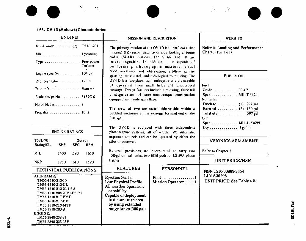
1-1
23
\ • t
1 -65. 0V-1D (Mohawk) Characteristics.
ENGINE
No. & model (2) T53-L-70I
Mfr Lycoming
Type Free power Turbine
•
Engine spec No 104.39
Red. gear ratio 12.38
Prop mfr Ham std
Blade design No 5157C-6
No of blades 3
Prop dia I Oft
ENGINE RATINGS
T53L-70I Rating/SL
MIL
NRP
SHP
1400
Output SFC RPM
.590 1650
1250 .610 1590
TECHNICAL PUBLICATIONS
AIRFRAME: TM55-1510-213-10 TM55-1510-213-CL TM55-1510-213-23-1-2-3 TM55-1510-204-23P1-P2-P3 TM55-1510-217-PMD TM55-1510-217-PM TM55-1510-213-MTF TM55-1510-200-S
ENGINE: TM55-2840-233-24 TM55-2840-233-23P
MISSION AND DESCRIPTION
The primary mission of the OV-ID is to perform either infrared (IR) reconnaissance or side looking airborne radar (SLAR) missions. The SLAR and IR are interchangeable. In addition, it is capable of performing photographic missions, visual reconnaissance and observation, artillery gunfire spotting, air control, and radiological monitoring. The OV-ID is a two-place, twin turboprop aircraft capable of operating from small fields and unimproved runways. Design features include a midwing, three-tail configuration of semimonocoque construction equipped with wide span flaps.
The crew of two are seated side-by-side within a bubbled enclosure at the extreme forward end of the fuselage.
The OV-ID is equipped with three independent photographic systems, all of which have automatic exposure controls and can be operated by either the pilot or observer.
External provisions, are incorporated to carry two 150-gallon fuel tanks, two ECM pods, or LS 59A photo flasher.
FEATURES
Ejection Seat’s Low Physical Profile All weather operation
capability Capable of deployment
to distant msn area by using extended range tanks (300 gal)
PERSONNEL
Pilot 1 Mission Operator 1
WEIGHTS
Refer to Loading and Performance Chart, (¡’¡ir 1-71!
FUEL & OIL
Fuel Grade JP^/5 Spec MIL-T-5624 No. tanks Fuselage (1) 297 gal External (2) 150 gal Total qty 597 gal
Oil: Spec M1L-L-23699 Qty 5 gallon
AVIONICS/ARMAMENT
Refer to Chapter 2.
UNIT PRICE/NSN
NSN 1510-00869-3654 LIN A30296 UNIT PRICE: See Table 4-2.
FM 101-20

FM101-20
c:
r
Figure 1-41. RV-1D (Mohawk)
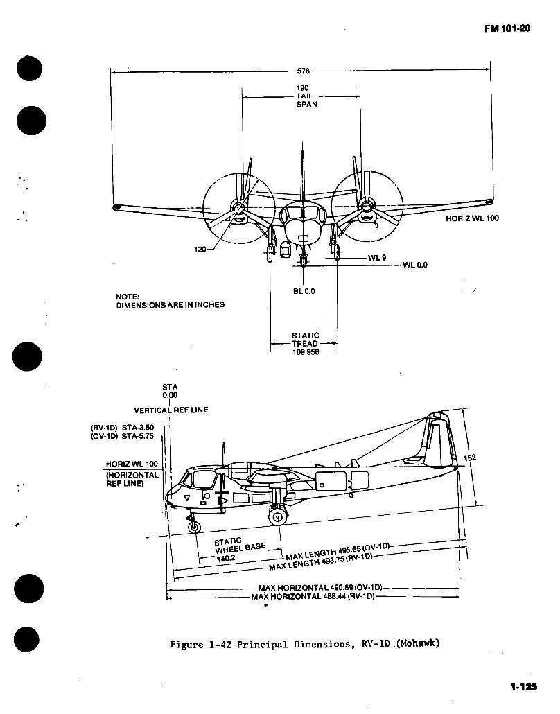
FM 101-20
576
190 TAIL SPAN
HORIZWL100 'ey
y LJ
120 WL9
NOTE: DIMENSIONS ARE IN INCHES
WLO.O
BLO.O
STATIC -TREAD-
109.956
STA 0.00
VERTICAL REF LINE
(RV-1D) STA-3.50 (OV-1D) STA-5.75-1
152 HORIZ WL 100 □ (HORIZONTAL REF LINE)
□ T
VJHEEL BASE . CNGTH 495.65 (OV-10)
- MAX HORIZONTAL 490.69 (OV-1D)- - MAX HORIZONTAL 488.44 (RV-1D)-
Figure 1-42 Principal Dimensions, RV-1D (Mohawk)
1-125

FMI 01-20
S s B
I CL,
§ _
I? "O s s J PL,
II (S U
O
■-}
us <N
T «O PL, »O •-SH
'J
O l> 05 lO 05 (N IÍ5
05 C 05 O (O â
^ a C4
B dS
« 1
J3
ra 5 &** S M ö J O B? d l£ w - EH jlj CQOf O
E- Z U S < S
< 55 o
Z O
> <
É'B’gfc •s p a _
•§ a «?
8 0 B-S U a .2 <b •ô
>?8 as T3 F*
la Q*S
SS g î|6l a
15 p,
.1 B 9
ro ja
PL T3 9 ■S ■p
■a -a Tj
Ü|1 w.S 4»
o
5 a
3 A S
Z w Z \ H ü HH
Pi DH EH HH
Z D
IO t- 3b *?o8
J (M t> 00 t— C . t* CH t*
Ü
9 è SZ<^
s®
1 a 8 3 3
N §>£ s,-g j "« 15
I»
EH O
Êï P 3
— « S 08 1 » S5 8o
+H a J3 .2 M-5
5ôl
! 8 b
-2 >
53 ä ^ ° ä
& ^ ±î Sa a
â£â
o Ht T1
00 ab co eo O T1
O Ht 6 ^ 1-H O ko co
Z ^ coS ZP
a> PC
Ü O HH PÍ IN CL 4 H jj 5 -o Ä (8
HJ U Z Z O co Pi U PL,
CO U pi D E- < U PH
JH
i i 1
O w
SJ
«O I <
13 I« «S 'Q,'
a 3 2 dS ’S “ " ^ — »W •
S HH3
>>31 J3 «J-S IS S
* il H\33
S
1
CO g s s s o
»I S c- HH ,0
U9
04
Z Z
I 4 3
III 4
! Z
1 *2
S U3
O
<P
a *
cô cô _ (N
rv] Ó O ¡2 i-H i—( S iß <! T* ^ ip LP ® àp àp fess SEHEH
CO PH
tvs <N °? ÛH Q
« ^ Pu S S w co i i CS) &4 & CO -4* b- b- O
b) ó ó ó 6 ^ rH ip ip ip LP
^ IO lP IP IP O lP lP LP ssss EH EH EH EH
CH P, ^H ^ C0
co cô cô •“H CO CO CS| (N (N ó ó ó *-H ^ ip .. 00 00 rH ¿q (N (N ip ^ IP 4P lO IP Ip
SüSS EH a: EH EH
U
1-126

FM 101-20
1-67. Loading & Pertormance • Typical Mission RV-1D (Mohawk)
TAKEOFF LOADING CONDITION
Take Off Weight Weight Empty Payload (useful>ây Fuel (Internal) Stall Speed (Power Off)!^ Take Off Run at SL-Calm M 5°C Take Off Run at SL-25 Kn Head Wind 015OC Take Off to Clear 50^ - CalmM5°C Max Speed/Altitude Rate of Climb at SL U Timp: SL to 20,000 ft Ig/ Time: SL to 25,000 ft 1ÊJ Service Ceiling (100 fpm)!/2y Combat Range 3/ Average Cruising Speed Cruise Altitude (5) Cruise Timeü/
COMBAT LOADING CONDITION
Combat Weight (60% Internal Fuel) Engine Power (Prop RPM, Eng Torque Press) Fuel Rate of Climb/Combat Altitude Combat Ceiling (500 fpm) Landing Weight (10% Internal Fuel) Fuel Stall Speed-Power-Off Approach Power 5/ Landing Distance to Clear 50ft Obstacle
(lb) (lb) (lb) (lb) (kn) (ft) (ft) (ft) (kn/ft) (fpm) (min) (min) (ft) (nm) (kn) (ft) (hr)
MAX GROSS WT. WITH AN/ALQ133 AND AN/USQ 61 NO EXT FUEL TANKS
15,532 11,905 '3,027 "1,930
80 1,300
975 1,900
215/5000 2,500 13/10 22/17
25,000 355-
180 5,000
1.9
(lb) (rpm/lb) (lb) (fpm/ft (ft) (lb) (lb) (kias/kn) (ft)
14,760 1720/122
1158 1800/5000
25,000 13,795
193 78/70 2,000
MAX GROSS WT. WITH AN/ALQ 133 AND AN/USQ 61 EXT FUEL TANKS
17,482 11,905
5,577 3,880
94 2.400 1,800 2.400
214/500 2,200 16/12 29/22
25,000 710 180
5,000 38
IJ
16,710 1720/122
3108 1500/5000
25,000 13,795
193 78/70 2,000 8/
1-127
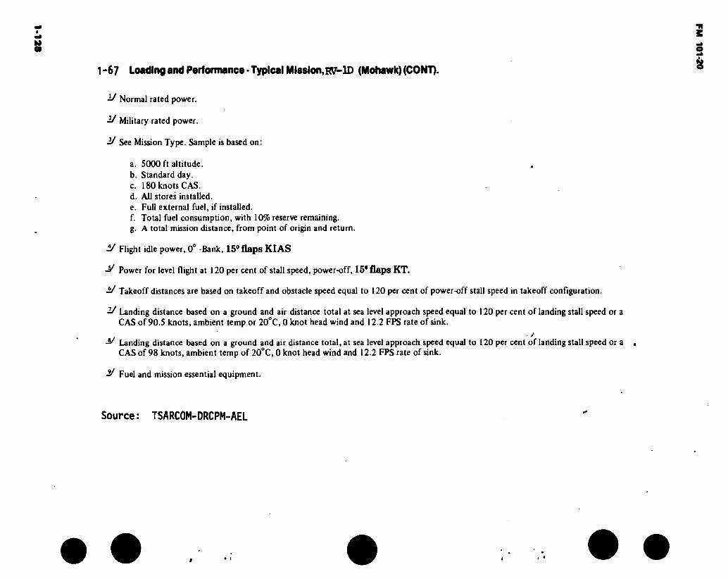
1-1
28
1 -67 Loading and Performance - Typical MIseion.RV’-lD (Mohawk) (CONT).
■!/ Normal rated power.
■2/ Military rated power.
•2/ See Mission Type. Sample is based on:
a. 5000 ft altitude. b. Standard day. c. 180 knots CAS. d. All stores installed. e. Full external fuel, if installed. f. Total fuel consumption, with 10% reserve remaining. g. A total mission distance, from point of origin and return.
■V Flight idle power, 0° -Bank, 15® flaps KIAS
Power for level flight at 120 per cent of stall speed, power-off, 15* flaps KT.
V Takeoff distances are based on takeoff and obstacle speed equal to 120 per cent of power-off stall speed in takeoff confíguration.
-2/ Landing distance based on a ground and air distance total at sea level approach speed equal to 120 per cent of landing stall speed or a CAS of 90.5 knots, ambient temp or 20°C, 0 knot head wind and 12.2 FPS rate of sink.
^ Landing distance based on a ground and air distance total, at sea level approach speed equal to 120 per cent of landing stall speed or a . CAS of 98 knots, ambient temp of 20°C, 0 knot head wind and 12.2 FPS rate of sink.
Fuel and mission essential equipment.
Source: TSARCOM-DRCPM-AEL
» « i
FM 1
0120

FM 101*20
15003
Figure 1-43. T-41B (Mescalero)
1-129

FM 101*20
5=
C3 □ n 3 DES
25 FT 6 IN
8 F111 IN.
11 FT4IN.-
DIMENSIONS
Wing span 36 Ft. 2 In. Height 8 Ft. 11 In. Tread 7 Ft. 2 In.
a
c 8 FT 4 IN
36 FT 2JN.
6 FT 4 IN
7 FT 2 IN.
Figure 1-44. Principal Dimensions, T-41B (Mescalero)
1-130

IC1-
L
1-68. T-41B (Mescalero) Characteristics.
ENGINE MISSION AND DESCRIPTION WEIGHTS
No. & model (1)IO-360D Mfr Continental Prop type CS, VP Prop dia 6 ft, 4 in.
ENGINE RATING
Takeoff Normal
BHP 210 210
RPM 2800 2800
TECHNICAL PUBLICATIONS
AIRFRAME: TM 55-1510-212-10
Commercial Manuals (Contractor Supported)
ENGINE:
Commercial Manual
Mfr’s Model: Cessna 172
The T-41B is an interim inventory fill to replace O-l drawdown pending availability of the OH-6A. Missions include primary and advanced contact trainer and installation support roles. The T-41B will be used in two configurations as follows:
Utility mission - FAA normal category to include aircraft empty weight, including electronics, crew of two (instructor and student), at 200 pounds each, and fuel for endurance for 4.5 hours at 110 knots.
Normal mission - FAA normal category to include aircraft empty weight, including electronics, crew of one, two passengers, at 200 pounds each, and fuel for endurance for 4.5 hours at 110 knots.
DEVELOPMENT
Date of contract 8 August 1966 First Production acft October 1966
FEATURES
All metal. High wing. Fixed tricycle landing gear. Dual side-by-side controls.
PERSONNEL
Crew Instructor pilot Student pilot ..
or Crew Passengers
2 1 1
1 2
LB Empty 1545 Utility 2200 Normal 2500
FUEL AND OIL
Fuel: Grade 115/145 Spec MIL-G-5572 Qty 52 gal
Oil: Spec Temps above +40 F MHS-24A (SAE 50)
Temps below +40 r MHS-24A (SAE 30)
AVIONICS/ARMAMENT
Refer to chapter 2.
UNIT PRICE/NSN
NSN 1510-00929-1012
LIN A30052 UNIT PRICE: Refer to Table 4-2.
FM 101-20
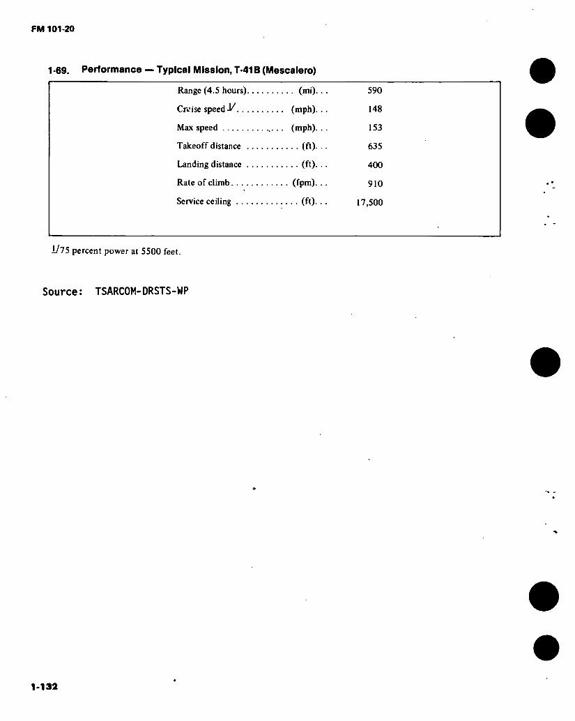
FM 101-20
1-69. Performance — Typical Mission, T-41B (Mescalero)
Range (4.5 hours) (mi).
Cruise speed J/ (mph).
Max speed .. (mph).
Takeoff distance (ft).
Landing distance (ft).
Rate of climb (fpm).
Service ceiling (ft).
590
148
153
635
400
910
17,500
1/75 percent power at 5500 feet.
Source: TSARCOM-DRSTS-WP
1-132

FM 101 *20
Figure 1-45. T-42A (Cochise)
1-133

FM 101-20
DIHEDRAL ó DEG
37 FT 10 IN.
6 FT 6 IN
9 FT 7 IN.
13FT9IN
S/1
DIMENSIONS
Wing: Span 37 Ft. 10 In. Incidence (root) 4°
(tip) -1» Dihedral 6° Sweepback 0.0°
Length 27 Ft. 3 In. Height 9 Ft. 7 In. Tread 9 Ft. 7 In. Prop and
clearance 10-1/2 In.
suns H DEG
*-10-1/2 IN.
— 7 FT
Figure 1-46. PrincipEil Dimensions, T-42A (Cochise)
1-134
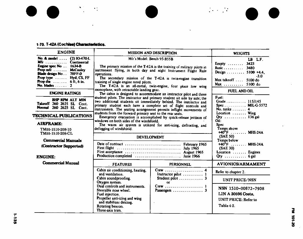
1-1
35
1-70. T-42A (CochiM) Characteristics.
ENGINE MISSION AND DESCRIPTION
No. A. model .... (2) IO-470-L Mfr Continental Engine spec No .. 1634-B Prop mfr McCauley Blade design No.. 78FF-0 Prop type Hyd.CS, FF Prop dia 6 ft, 6 in. No. blades 2
ENGINE RATINGS
BMP RPM ALT MIN Takeoff 260 2625 SL Cont. Normal 260 2625 SL Cont.
TECHNICAL PUBLICATIONS
AIRFRAME: TM55-1510-208-10 TM55-1510-208-CL
Mfr’s Model: Beech 95-B55B
The primary mission of the T-42A is the training of military pilots in instrument flying, in both day and night Instrument Flight Rule operations.
The secondary mission of the T-42A is twin-engine transition training of single engine rated pilots.
The T-42A is an all-metal, twin-engine, four place low wing monoplane, with retractable landing gear.
The cabin is designed to accommodate an instructor pilot and three student pilots. The instructor and primary student sit side by side; the two additional students sit immediately behind. The instructor and primary student each have a complete set of flight controls and instruments. The seating arrangement permits inflight movements of students from the forward primary seat to the rear seats.
Emergency evacuation is accomplished by quick-release jettison of windows on both sides of the windshield.
The warm air system is utilized for anti-icing, defrosting, and defogging of windshield.
Commercial Manuals (Contractor Supported)
ENGINE:
Commercial Manual
DEVELOPMENT
Date of contract .... First flight First acceptance .... Production completed
February 1965 July 1965 August 1965 June 1966
. FEATURES PERSONNEL
Cabin air conditioning, heating, and ventilation.
Cabin soundproofing. Oxygen system. Dual controls and instruments. Steerable nose wheel. Fuel injection. Propeller anti-icing and wing
and stabilizer deicing. Rotating beacon. Three-axis trim.
Crew 4 Instructor pilot 1 Student pilot 3
or Crew 1 Passengers 3
WEIGHTS
LB L.F. Empty 3423 Basic 3480 Design 5100 +4.4,
-3.0 Max takeoff .... 5100 do Max 5100 do
FUEL AND OIL
Fuel: —
Grade 115/145 Spec MIL-G-5572 No. tanks 4 Location Wing Qty 136 gal
OU: Spec Temps above +40® F MHS-24A (SAE 50)
Temps below +40° F MHS-24A (SAE 30)
Location Engines Qty 6 gal
AVIONICS/ARMAMENT
Refer to chapter 2.
UNIT PRICE/NSN
NSN 1510-00872-7908
LIN A 30596 Costs, UNIT PRICE: Refer to
Table 4-2. FM 101-20
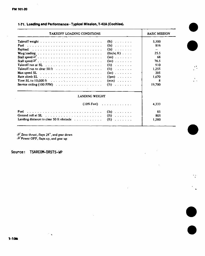
FM 101-20
1-71. Loading and Parformance • Typical Mission, T-42A (Cochise).
TAKEOFF LOADING CONDITIONS
Takeoff weight Fuel Payload Wing loading Stall speed-i/ Stall speed-2/ Takeoff run at SL ... Takeoff run to clear 50 ft Max speed SL Rate climb SL Time SL to 10,000 ft Service ceiling (100 FPM)
BASIC MISSION
(lb) Ob) (lb) (Ibs/sq ft) ... . (kn) (kn)
(ft) (ft) (kn)
(fpm) (min)
(ft)
5,100 816
25.5 68
76.5 910
1,255 205
1,670 8
19,700
LANDING WEIGHT
(10% Fuel) 4,333
Fuel Ground roll at SL Landing distance to clear 50 ft obstacle
(lb) (ft) (ft)
85 805
1,580
-1/ Zero thrust, flaps 28°, and gear down -2/ Power OFF, flaps up, and gear up
Source: TSARCOM-DRSTS-WP
1-13*

FM 101-20
0 *
Figure 1-47. U-8F (Seminole)
1-137
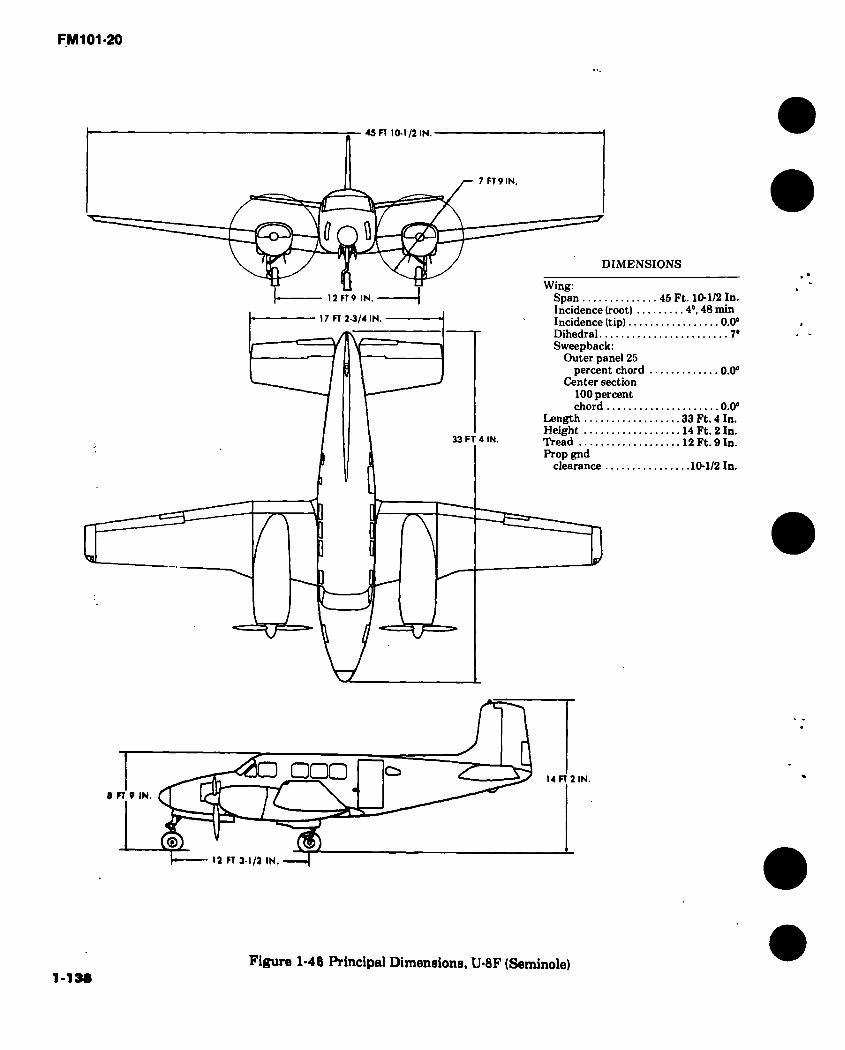
FM101-20
45 n 10-1/2 IN.
7 FT 9 IN
12 FT 9 IN.
DIMENSIONS
17 FT 2-3/4 IN.
33 FT 4 IN.
I
Wing: Span 45 Ft. 10-1/2 In. Incidence (root) 4°, 48 min Incidence (tip) 0.0° Dihedral 7° Sweepback:
Outer panel 25 percent chord 0.0°
Center section 100 percent chord 0.0°
Length 33 Ft. 4 In. Height 14 Ft. 2 In. Tread 12 Ft. 9 In. Prop gnd
clearance 10-1/2 In.
□□□ C5
E 12 FT 3-1/2 IN.
14 FT 2 IN.
9 FT 9 IN.
1-138 Figure 1*48 Principal Dimensions, U-8F (Seminole)

1-139
1-72. U-8F(Seminole) Characteristics
ENGINE MISSION AND DESCRIPTION WEIGHTS
No. & model .... Mfr Engine spec No .. Superch Red. gear ratio ... Prop mfr Blade design No .. Prop type No. blades Prop dia Augmentation ...
(2) 0-480-3A Lycoming 2228 1 stg, centrif 77:120 Hartzell 10151-B8 Hyd.FF.CS 3 7 ft, 9 in. Fuel injection (3-piston type)
ENGINE RATINGS
BHP RPM ALT MIN Takeoff 320 3400 SL 5
340 3400 11,000 5 Normal 320 3200 SL Cdnt.
320 3200 ll,000Cont.
TECHNICAL PUBLICATIONS
AIRFRAME: TM-55-1510-201-10/3 (DIF) TM-55-1510-201-10/5 (F) TM-55-1510-201-20 (D/G/F) TM-55-1510-201- 20P (D/G/F) TM-55-1510-201-34P1 (D/G/F) TM-55-1510-201-34P2 (D/G/F) TM-55-1510-201-35 (D/G/F) TM-55-1510-201-CL/5 (F) TM-55-1510-201-PMS (D/F/G) TM-55-1510-201-S
ENGINE: TM55-2810-218-10 TM55-2810-218-34 TM55-2810-218-34P
Mfg. Model: Beech The principal mission of the U-8F is the transportation of personnel. The U-8F is a semimonocoque, low-wing monoplane easily converted
into a cargo carrier by removing the passenger compartment seats. The U-8F is similar to the U-8D except the larger fuselage is arranged
with separate crew and passenger compartments. The crew compartment is arranged with the pilot’s seat on the left and the copilot’s seat on the right of a center aisle. It is equipped with dual flight controls and is separated from the passenger compartment with sliding doors. The passenger'compartment is arranged with two passenger seats on the left and two or three passenger seats on the right of the center aisle. The track-mounted seats facilitate removal or installation and permit versatile seating arrangements. The baggage compartment is located at the rear of the passenger compartment with access from the passenger compartment. The cabin access door on the left side of the fuselage, aft of the wing, incorporates stair-type steps and may be opened or closed and locked from either the inside or outside. A jettisonable escape hatch is located opposite the cabin access door. Powerplants feature fuel injection and manually selected, electrically actuated inlet air source selection.
DEVELOPMENT
First flight First delivery Production completed
FEATURES
Thermostatically controlled cabin heat.
Fresh air and oxygen outlets at each station.
Electrically actuated flaps. Conventional flight controls,
manually operated. Steerable nose wheel. Full feathering props. Hydraulically controlled brakes. Crossfeed fuel system. Windshield wipers. Deicing and anti-ice equipment.
August 1958 February 1959 December 1962
PERSONNEL
Crew 1 Passengers 5 Baggage compartment:
Floor 150 lb Shelf 1501b
LB L.F. Empty (calculated) 5246 Basic (calculated).. 5282 Design 7700 +6.6
-2.64 Combat (basic)
mission) 6276 Max takeoff:
(overload) *7700 (normal) *7700
Max landing .**7350 +6.6 -2.64
'Limited by strength. "Limited by gear strength.
FUEL AND OIL Fuel: Grade 115/145 Spec MIL-G-5572 No. tanks 8 Location Wing Qty 230 gal
OU: Spec Temps above +60r MIL-L-22851 Type II
Temps below +60° F MIL-L-22851 Type III
No. tanks 2 Qty 8 gal
AVIONICS/ARM AMENT
Refer to chapter 2.
UNIT PRICE/NSN
NSN 1510-00701-2233 LIN A30821 COSTS, UNIT PRICE: Refer to Table 4-2.
FM 101-20
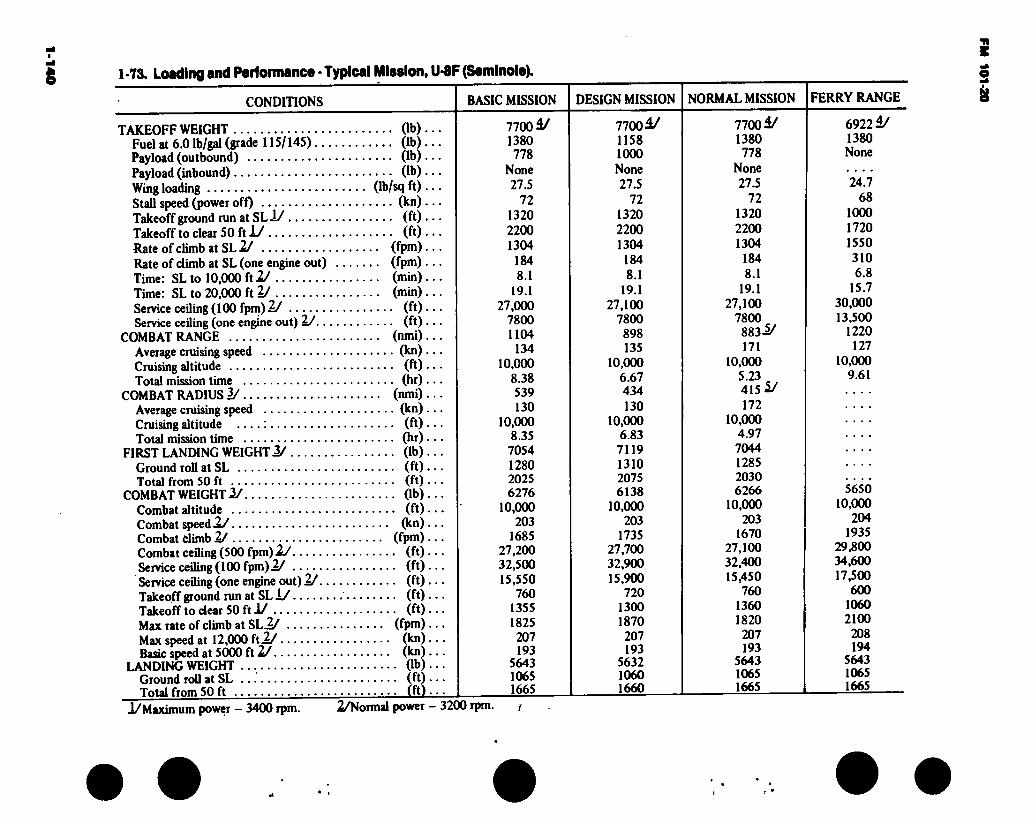
* 1-73. Loading and Parformance - Typical Mission, U-8F (Saminole).
CONDITIONS BASIC MISSION DESIGN MISSION NORMAL MISSION FERRY RANGE
TAKEOFF WEIGHT (lb).. Fuel at 6.0 Ib/gal (grade 115/145) (lb).. Payload (outbound) (lb).. Payload (inbound) (lb).. Wing loading (lb/sq ft) .. Stall speed (power off) (kn).. Takeoff ground run at SLÍ/ (ft) • • Takeoff to clear 50 ft X/ (ft).. Rate of climb at SL 2/ (fpm).. Rate of climb at SL (one engine out) (fpm).. Time: SL to 10,000 ft 2/ (min) .. Time: SL to 20,000 ft 2/ (min).. Service ceiling (100 fpm) 2/ (ft).. Service ceiling (one engine out) 2/ (ft) ..
COMBAT RANGE (nmi) .. Average cruising speed (kn) .. Cruising altitude (ft) •. Total mission time (hr) ..
COMBAT RADIUS 2/ (nmi).. Average cruising speed (kn) .. Cruising altitude (ft) .. Total mission time (hr) ..
FIRST LANDING WEIGHT 2/ (lb) . Ground roll at SL (ft) .. Total from 50 ft (ft) .
COMBAT WEIGHT 2/ (lb). Combat altitude (ft). Combat speedX/ (kn) . Combat climb 2/ (fpm) . Combat ceiling (500 fpm) 2J (ft) . Service ceiling (100 fpm) 2/ (ft). Service ceiling (one engine out) 2/ (ft) . Takeoff ground run at SL 1/ (ft) . Takeoff to clear 50 ft 1/ (ft) . Max rate of climb at Shi/ (fpm). Max speed at 12,000 ft 2/ (kn) . Basic speed at 5000 ft 2/ (kn) .
LANDING WEIGHT (lb) . Ground roll at SL (ft) • Total from 50 ft (ft) •
7700 4/ 1380 778
None 27.5
72 1320 2200 1304
184 8.1
19.1 27.000
7800 1104
134 10.000
8.38 539 130
10,000 8.35 7054 1280 2025 6276
10,000 203
1685 27,200 32,500 15,550
760 1355 1825 207 193
5643 1065 1665
77004/ 1158 1000 None 27.5
72 1320 2200 1304
184 8.1
19.1 27,100
7800 898 135
10,000 6.67 434 130
10,000 6.83 7119 1310 2075 6138
10,000 203
1735 27,700 32.900 15.900
720 1300 1870 207 193
5632 1060 1660
7700 4/ 1380 778
None 27.5
72 1320 2200 1304
184 8.1
19.1 27.100
7800 883-5/ 171
10,000 5.23 415 5/ 172
10,000 4.97 7044 1285 2030 6266
10,000 203
1670 27.100 32,400 15,450
760 1360 1820
207 193
5643 1065 1665
69224/ 1380 None
24.7 68
1000 1720 1550 310 6.8
15.7 30.000 13,500
1220 127
10.000 9.61
5650 10,000
204 1935
29,800 34,600 17,500
600 1060 2100
208 194
5643 1065 1665
1/Maximum power — 3400 rpm. 2/Normal power — 3200 rpm. /
FM 101-20

1-141
1-73 Loading Parlormanca ■ Typical Mlaalon, U-8F (Samlnole) (CONT).
-^For RADIUS mission if radius is shown,
includes crew of 1 at 200 lb.
-5/65-percent normal power used for cruise.
Performance Basis:
a. Data source. Contractor’s (light test.
b. Performance is based on powers shown
\
• •
FM
101-2
0
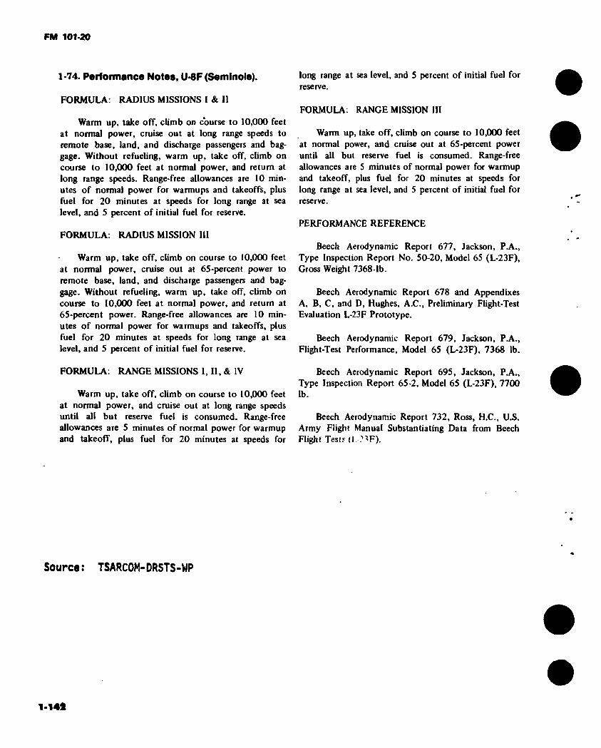
FM 101-20
1-74. Performance Notes, U-8F (Seminole).
FORMULA: RADIUS MISSIONS I & II
Warm up, take off, climb on course to 10,000 feet at normal power, cruise out at long range speeds to remote base, land, and discharge passengers and bag- gage. Without refueling, warm up, take off, climb on course to 10,000 feet at normal power, and return at long range speeds. Range-free allowances are 10 min- utes of normal power for warmups and takeoffs, plus fuel for 20 minutes at speeds for long range at sea level, and 5 percent of initial fuel for reserve.
FORMULA: RADIUS MISSION III
Warm up, take off, climb on course to 10,000 feet at normal power, cruise out at 65-percent power to remote base, land, and discharge passengers and bag- gage. Without refueling, warm up, take off, climb on course to 10,000 feet at normal power, and return at 65-percent power. Range-free allowances are 10 min- utes of normal power for warmups and takeoffs, plus fuel for 20 minutes at speeds for long range at sea level, and 5 percent of initial fuel for reserve.
FORMULA: RANGE MISSIONS I, II, & IV
Warm up, take off, climb on course to 10,000 feet at normal power, and cruise out at long range speeds until all but reserve fuel is consumed. Range-free allowances are 5 minutes of normal power for warmup and takeoff, plus fuel for 20 minutes at speeds for
long range at sea level, and 5 percent of initial fuel for reserve.
FORMULA: RANGE MISSION III
Warm up, take off, climb on course to 10,000 feet at normal power, and cruise out at 65-percent power until all but reserve fuel is consumed. Range-free allowances are 5 minutes of normal power for warmup and takeoff, plus fuel for 20 minutes at speeds for long range at sea level, and 5 percent of initial fuel for reserve.
PERFORMANCE REFERENCE
Beech Aerodynamic Report 677, Jackson, PA., Type Inspection Report No. 50-20, Model 65 (L-23F), Gross Weight 7368 1b.
Beech Aerodynamic Report 678 and Appendixes A, B, C, and D, Hughes, A.C., Preliminary Flight-Test Evaluation L-23F Prototype.
Beech Aerodynamic Report 679, Jackson, PA., Flight-Test Performance, Model 65 (L-23F), 7368 lb.
Beech Aerodynamic Report 695, Jackson, P.A., Type Inspection Report 65-2, Model 65 (L-23F), 7700 lb.
Beech Aerodynamic Report 732, Ross, H.C., U.S. Army Flight Manual Substantiating Data from Beech Flight Testy (1 ?^F).
Source : TSARCOM-DRSTS-WP

FM 101-20
Figure 1-49 U-lOA (Helio-Courier)
1-143

FM 101-20
39 ri
s; a
U FI 8 IN
9 FT DIMENSIONS
IS FT
O^-
□ O O I FT 8-I/2 IN.
I \0'** jjfT
Wing: Span 39 Ft. Incidence 3° Dihedral 1° Sweepback(LE)
outer panel 25 percent chord. 0.0°
Sweepback (LE) outer section 100 percent chord 0.0°
Length 30 Ft. 3-1/2 In. Height 8 Ft. 10 In. Tread 9Ft. Prop gnd
clearance 1 Ft. 8-1/2 In.
10 IN.
Figure 1-50. Principal Dimensions, U-10A (Helio-Courier)
1-144

1-1
45
1-75. U-10A (Hello Courier) Characteristics.
ENGINE MISSION AND DESCRIPTION WEIGHTS No. & model
Engine spec No Superch Red. gear ratio. Prop mfr ....... Blade design No.
Prop type ....
No. blades Prop dia Prop type certificate No
.(1)00480- G1D6
.2227B
.NA
.0.641(77:120)
.Hartzell
.B3Z20-1/ lOlSlc-5
•Hydraulic, constant speed
.3 ,8 ft
.P-907-10
ENGINE RATINGS
BHP PPM Takeoff 295 3400 Normal 280 2750
TECHNICAL PUBLICATIONS
AIRFRAME: Commercial Manuals
(Contractor Supported)
ENGINE:
Commercial Manual
Mfr’s Model: Helio-Courier
Basic mission assignments of the U-10A aircraft include courier, observation, cargo carrying, parachute delivery and small groups, radio relay for extended periods of time, evacuation, and utility transport.
The U-10A is a versatile air vehicle in the STOL category specifically designed to utilize small, rough, and unprepared fields and offering a maximum of protection for pilot and crew. Adaptability to floats and skis enables the airplane to operate on water and snow.
The U-10A is an all-metal, high-wing, conventional-geared, four- place aircraft. The aerodynamic characteristics feature such items as long-span, high-lift type slotted flaps, and full-span leading edge slots. Lateral control is obtained by short-span, Frise-type, balanced ailerons which are operated in conjunction with leading edge spoilers. Ailerons alone are used for lateral control at higher speed. The airplane has an all-movable, slab-type, horizontal stabilizer with antibalance tab and a large vertical stabilizer and rudder.
The U-10A is powered by a six-cylinder engine splined to a three- bladed propeller with a constant-speed control and spinner to aid engine cooling.
FEATURES
Adaptable to floats & skis STOL type aircraft
PERSONNEL
Crew (normal) (pilot, copilot) 2
Passengers 2
Empty Max takeoff (normal) . Max takeoff (overload)
LB 2249 3000 3920
FUEL AND OIL
Fuel: Grade 115/145 Spec MIL-G-5572 No. tanks: Wing, left (1)30 gal Wing, right (1)30 gal Qty 60 gal
OU: Spec Temps above +30° F MIL-L-22851 Type II
Temps below +30°F MIL-L-22851 Type III
No. tanks 1 Location Engine sump Qty 2-1/2 gal
AVIONICS/ARM AMENT
Refer to chapter 2.
UNIT PRICE/NSN
NSN 1510-00964-9780 LIN A 30971 UNIT PRICE: Refer to Table 4-2.
FM 101-20
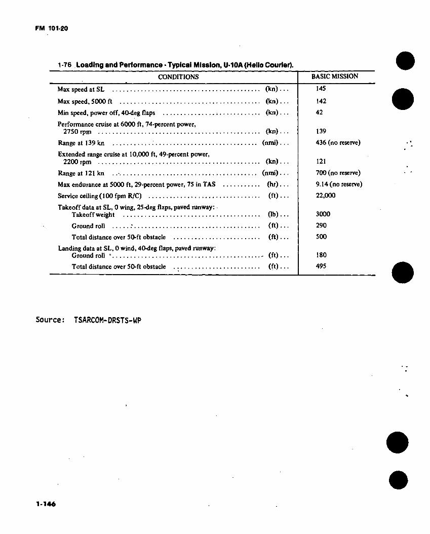
FM 101-20
1-76 Loading and Performance - Typical Mission, U-10A (Hello Courier).
CONDITIONS
Max speed at SL
Max speed, 5000 ft
Min speed, power off, 40-deg flaps
Performance cruise at 6000 ft, 74-percent power, 2750 rpm
Range at 139 kn :
Extended range cruise at 10,000 ft, 49-percent power, 2200 rpm
Range at 121 kn
Max endurance at 5000 ft, 29-percent power, 75 in TAS
Service ceiling ( 100 fpm R/C)
Takeoff data at SL, 0 wing, 25-deg flaps, paved runway: Takeoff weight
Ground roll .*
Total distance over 50-ft obstacle
Landing data at SL, 0 wind, 40-deg flaps, paved runway: Ground roll “
Total distance over 50-ft obstacle
(kn).
(kn).
(kn)
(kn).
(nmi).
(kn).
(nmi).
(hr),
(ft).
Ob).
(ft) (ft)
- (ft)
(ft)
BASIC MISSION
145
142
42
139
436 (no reserve)
121
700 (no reserve)
9.14 (no reserve)
22,000
3000
290
500
180
495
Source: TSARCOM-DRSTS-WP
1-146

FM 101-20
Figurei- 51. U-21 eind RU-21 (UteMpaint scheme differences)
1-147

FM 101-20
45 FT 10-1/2 IN
7 FT 9 IN
DIMENSIONS 12 FT 9 IN.
17 FT 2-23/32 IN.- Wing
Span 45 Ft. 10-1/2 In. Incidence
(root) 4.8° (tip) 0.0°
Dihedral 7° Sweepback (LE) 0.0° Sweep forward (TE) NVAL
Length 35 Ft. 6 In. Height 14 Ft. 2-1/2 In. Tread 12 Ft. 9 In. Prop gnd
clearance 1 Ft.
IZ n r\
35 FT 6 IN.
□ oo C3
-F
14 FT 2-9/16 IN.
2 DEG
12 FT 3-15/32 IN
Figure 1-52. Principal Dimensions, U-21A, U-21G, (Ute)
1-14«
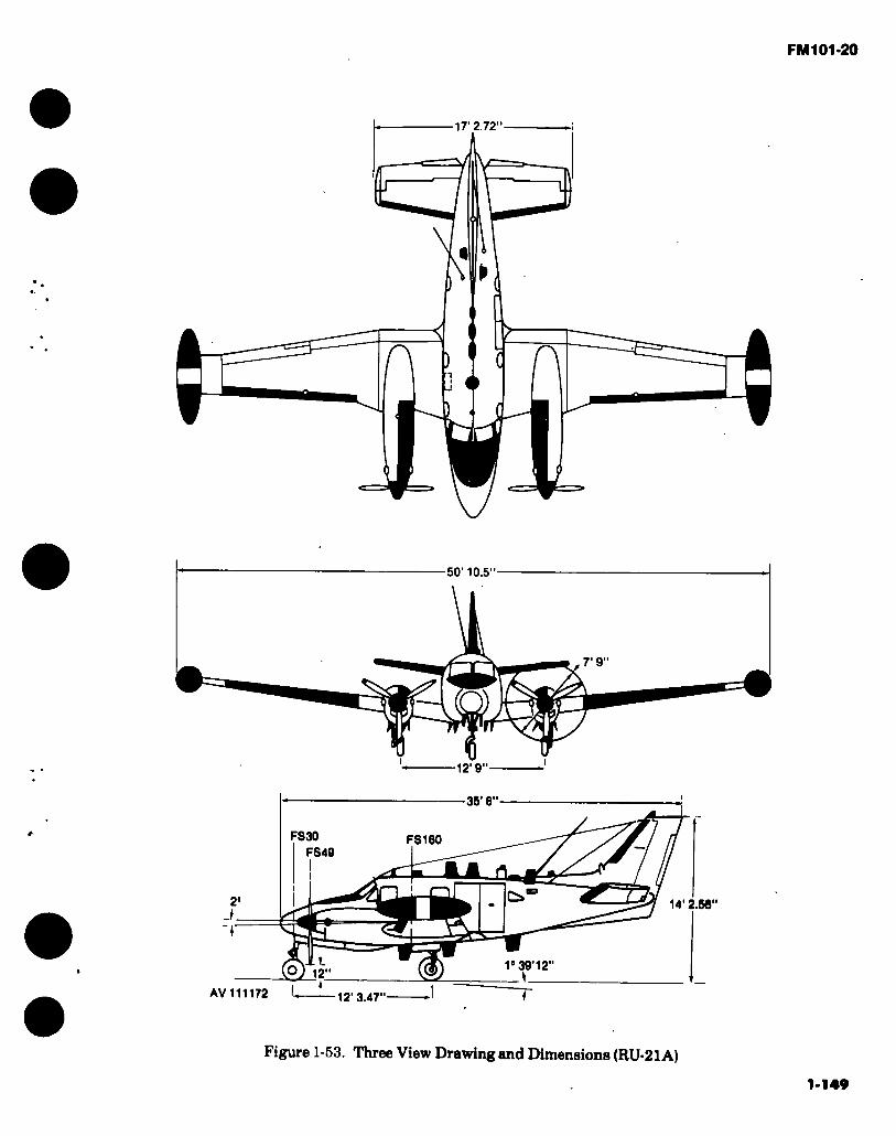
FM 101 *20
17’ 2.72”-
50’ 10.5"
7’9”
12’ 9"
35’6"
FS30
FS49 FS160
14' 2.56"
<3
1° 39 12 12
AV 111172 -12’ 3.47"
Figure 1-53. Three View Drawing and Dimensions (RU-21A)
1-149
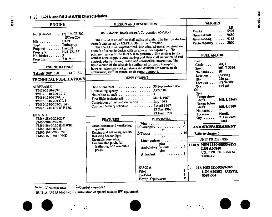
1-150
1-77 U-21A and RU-21A (UTE) Characteristics.
ENGINE
No. & model .... (2) T74-CP-700 (PT6A-20)
Mfr UACL Type Turboprop Prop mfr Hartzell Prop type Hyd.CS, FF No. blades 3 Propdia 7 ft. 9 in.
MISSION AND DESCRIPTION
ENGINE RATINGS
Takeoff SHP 550 ALT SL
TECHNICAL PUBLICATIONS
AIRFRAME: TM55-1510-209-10 TM55-1510-209-10-1 TM55-1510-209-CL TM55-1510-209-CL-1 TM55-1510-209-23-1&2 TM55-1510-209-23P-1&2
ENGINE: TM55-2840-232-23P TM55-2840-232-24 TM55-2840-120 (DMWR) TM55-1510-200-S TM55-1510-200-PM TM55-1510-200-PMD
Mfr’s Model: Beech Aircraft Corporation 65-A90-1
The U-21A is an off-the-shelf utility aircraft. The first production aircraft was tested by USATECOM for confirmation.
The U-21A is an unpressurized, low wing, all-metal construction aircraft of versatile design with an all-weather capability. The primary mission of the U-21 A is to perform utility services in the combat zone, support commanders and their staff in command and • control, adminstration, liaison and aeromedical evacuation. The basic version of the aircraft is configured for troop transport; however, alternate configurations are available for service as air ambulance, staff transport, or air cargo transport.
DEVELOPMENT
Date of contract 30 September 1966 Contracting agency AVSCOM No. of test aircraft 3 First flight (scheduled) March 1967 Completion of test and evaluation July 1967 Contract delivery schedule 2 April 1967
23 May 1967 23 June 1967
FEATURES
Cabin heating and ventilating system.
Deicing and anti-icing system. Rotating beacon light. Steerable nose wheel. Controllable pitch, full
feathering, and reversible props.
PERSONNEL
Pilot .... i/Passengers
2/Troops or
Litter patients .... plus
Ambulatory patients plus
Attendant
6
10
3
3
1
WEIGHTS LB
Empty 5401 Gross takeoff 9650 Gross landing 9168 Cargo capacity 3000
FUEL AND OIL
Fuel: Grade Spec No. tanks ... Location ... Qty Location — Qty
Oil: Spec Temps above -40°F
Temps below -40°F
No. tanks ... Location ... Qty
JP4/5 MIL-T-5624 10 (8) wing 256 gal (2) Nacelle 114 gal
MIL-L-23699
MILL-7808 2 Nacelle 23 gal each
tank
AVIONICS/ARMAMENT
Refer to chapter 2.
UNIT PRICE/NSN
U-21 A NSN1510-00933-8223 LIN A30946 UNIT PRICE: Refer to
RU-21A Pilot Co-Pilot Equip. Operators
RU-21A NSN 151000687-3375 LIN A30582 COSTS. $587.004
Note: i/Normal seats 1/Combat - equipped
RU-21 A: U-21 A Modified for installation of special mission EW equipment.
*
FM
10
1-2
0
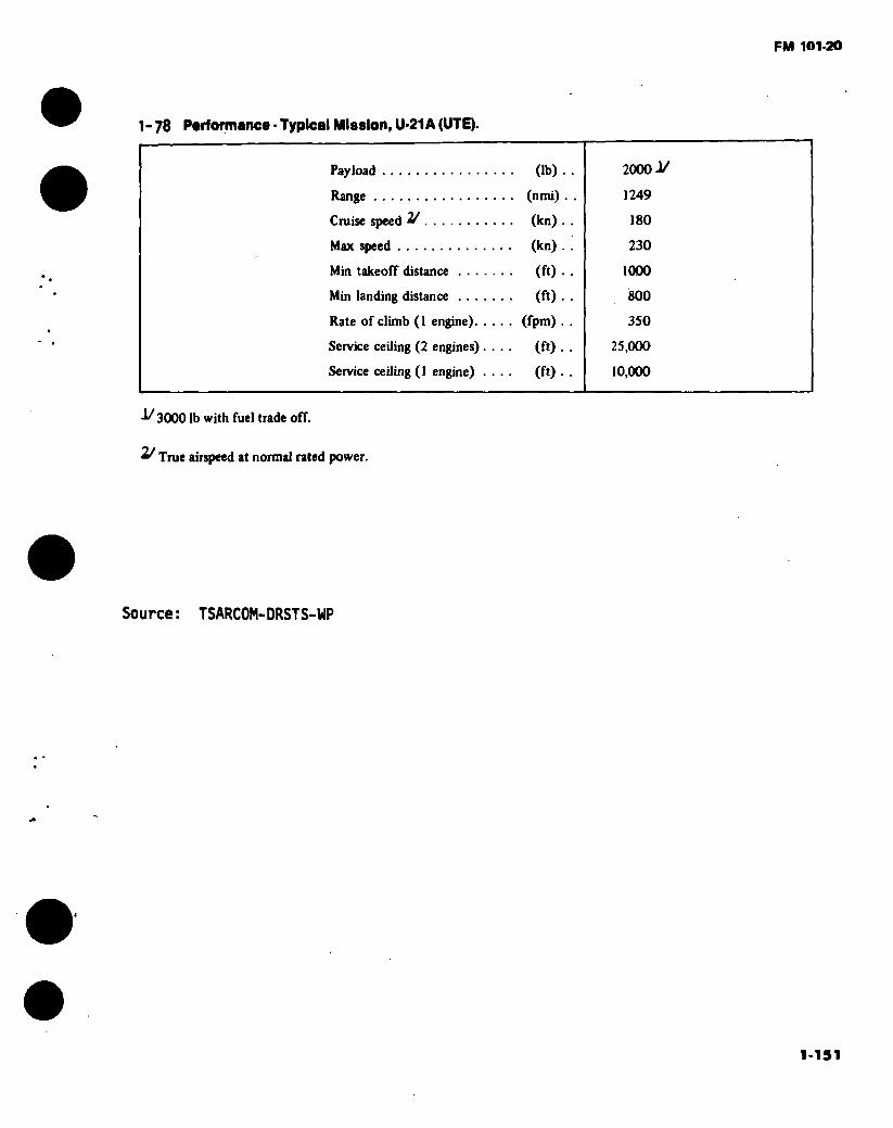
FM 101-20
1 - 78 Portormance • Typical Mission, U-21A (UTE).
Payload (lb) .
Range (nmi)
Cruise speed 2/ (kn) .
Max speed (kn) .
Min takeoff distance (ft) .
Min landing distance (ft) .
Rate of climb (1 engine) (fpm) .
Service ceiling (2 engines) .... (ft) .
Service ceiling (1 engine) .... (ft) .
2000 i/
1249
180
230
1000
800
350
25,000
10,000
-1/ 3000 lb with fuel trade off.
2/ True airspeed at normal rated power.
Source: TSARCOM-DRSTS-WP

FM101-20
17FT2.718IN
í\ r\ \/
45FT 10.500IN
7FT9IN
10.500IN 12FT9IN
35FT6IN—
FS 30
FS 160 FS 49
a i:
□ i. o 14FT 2.562IN 2» -J
1' 39MIN 12SEC O 121N
— 12FT 3.468IN '
Figure 1-54. Principal Dimensions Diagram U-21D
1*152
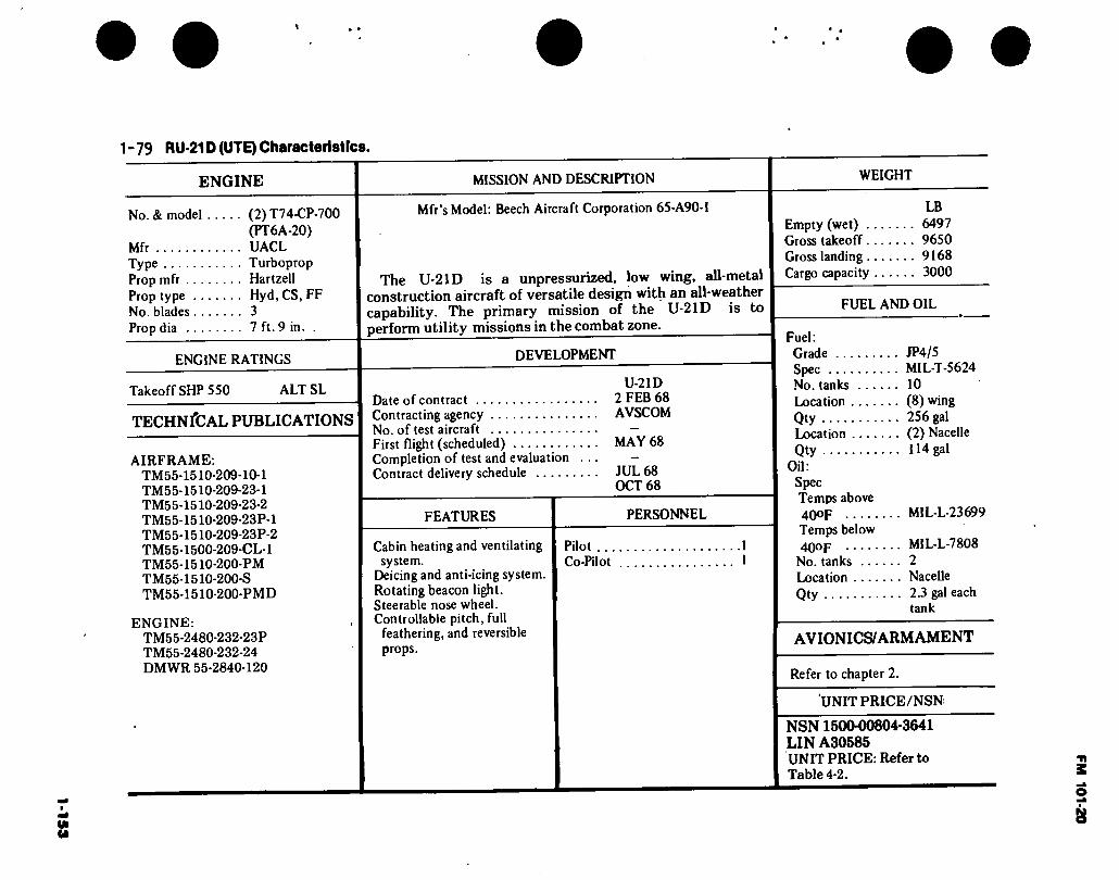
1-1
53
\
1-79 RU-21D (UTE) Characteristics.
ENGINE
No. & model (2) T74-CP-700 (PT6A-20)
Mfr UACL Type Turboprop Prop mfr Hartzell Prop type Hyd, CS, FF No. blades 3 Prop dia 7 ft. 9 in.
ENGINE RATINGS
Takeoff SHP 550 ALT SL
TECHNfCAL PUBLICATIONS
AIRFRAME: TM55-1510 TM55-1510 TM55-1510- TM55-1510- TM55-1510- TM55-1500 TM55-1510 TM55-1510 TM55-1510
•209-10-1 •209-23-1 ■209-23-2 ■209-23P-1 -209-23P-2 -209-CL-l ■200-PM -200-S •200-PMD
ENGINE: TM55-2480-232-23P TM55-2480-232-24 DMWR 55-2840-120
MISSION AND DESCRIPTION
Mfr’s Model: Beech Aircraft Corporation 65-A90-1
The U-21D is a unpressurized, low wing, all-metal construction aircraft of versatile design with an all-weather capability. The primary mission of the U-21D is to perform utility missions in the combat zone.
DEVELOPMENT
U-21D
Date of contract 2 FEB 68 Contracting agency AVSCOM No. of test aircraft — First flight (scheduled) MAY 68 Completion of test and evaluation ... - Contract delivery schedule JUL 68
OCT 68
FEATURES
Cabin heating and ventilating system.
Deicing and anti-icing system. Rotating beacon light. Steerable nose wheel. Controllable pitch, full
feathering, and reversible props.
PERSONNEL
Pilot ... Co-Pilot
WEIGHT
LB Empty (wet) 6497 Gross takeoff 9650 Gross landing 9168 Cargo capacity 3000
FUEL AND OIL
Fuel: Grade JP4/5 Spec MIL-T-5624 No. tanks 10 Location (8) wing Qty 256 gal Location (2) Nacelle Qty 114 gal
Oil: Spec Temps above 4QOF MIL-L-23699
Temps below 40op MIL-L-7808
No. tanks 2 Location Nacelle Qty 2.3 gal each
tank
AVIONICS/ARM AMENT
Refer to chapter 2.
UNIT PRICE/NSN
NSN 1500-00804-3641 LIN A30585 UNIT PRICE: Refer to Table 4-2.
FM 101-20
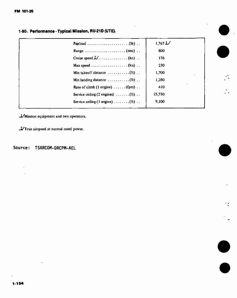
FM 101-20
1-80. Performance • Typical Mlaalon, RU-21D (UTE).
Payload
Range
Cruise speed 2/
Max speed
Min takeoff distance ....
Min landing distance ....
Rate of climb (1 engine) .
Service ceiling (2 engines)
Service ceiling ( 1 engine) .
. .(lb)
(nmi)
. (kn)
. (kn)
••(ft)
..(ft)
(fpm)
..(ft)
..(ft)
1,767 J-/
800
176
230
1,700
1,280
410
25,750
9,100
-1/Mission equipment and two operators.
-2/True airspeed at normal rated power.
Source: TSARCOM-DRCPM-AEL
1-154

FM 101-20
7.45 IN
fci Q
W \J
22 FT 4.6 I
DIMENSIONS
Wing: Span 45 Ft. 10.5 In. Incidence
(root) 4.8° (tip) 1.00
Dihedral 7° Sweepback (LE) 0.0° Sweepforward (TE) NVAL
Length 39 Ft. 11.36 In. Height 15 Ft. 4.25 In. Tread 13 Ft. Prop gnd
clearance 1 Ft. 1 In.
45 FT 10.5 IN
7 FT 6 IN DIA.
P
13 FT
39 FT 11.36 IN
D o o o o o o 15 FT 4 25 IN
50 IN (Q
■14 FT 11 IN
Figure 1-55. Principal Dimensions U-21F (Ute) 1-155

1-156
1 -él. U-21F (UTE) Characteristics.
ENGINE MISSION AND DESCRIPTION WEIGHTS
No. & model Mfr Type Prop mfr ... Prop type .. No. blades.. Prop dia ...
(2)PT6A-28 UACL Turboprop Hartzell Hyd.CS.FF 4 7 ft. 6 in.
Mfr’s Model: Beech Aircraft Corporation A100
The U-21 F is an off-the-shelf utility aircraft.
The U-21 F is a pressurized, low wing, all-metal construction aircraft of versatile design with an all-weather capability. The primary mission of the U-21 F is to transport high ranking military and government officials.
ENGINE RATINGS
Takeoff SHP 680 ALT SL
TECHNICAL PUBLICATIONS
Commercial Manuals (Contractor Supported)
DEVELOPMENT
Date of contract Contracting agency No. of test aircraft First flight (scheduled) Completion of test and evaluation Contract delivery schedule
30 JUN71 AVSCOM
MAY 71
30 JUL 71 30 AUG 71
FEATURES
Cabin heating and ventilating system.
Deicing and anti-icing system. Rotating beacon light. Steerable nose wheel. -Controllable pitch, full
feathering, and reversible props.
Pressurized cabin. Air conditioning.
PERSONNEL
Pilot 1 Co-Pilot 1 Passengers 7
LB Empty (wet) 6790 Gross takeoff 11,500 Gross landing 11,210
FUEL AND OIL
Fuel: Grade Spec No. tanks ... Location .... Qty Location .... Qty Location ....
Qty Oil:
Spec Temps above -40°F
Temps below 40°F
No. tanks ... Location .... Qty
AVIONICS/ARM AMENT
Refer to chapter 2.
UNIT PRICE/NSN
NSN1610-00169-0296 LIN A30951 I UNIT PRICE: Refer to Table 4-2.
JP4/5 ’ MIL-T-5624 14 lOwing 274 gal (2) Nacelle 114 gal (2) Center Section
82 gal
MIL-L-23699
MIL-L-7808 2 Nacelle 2.3 gal each tank
FM 101-20
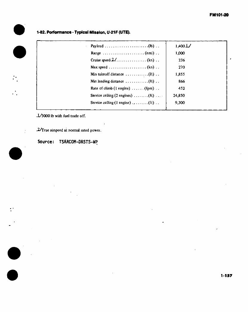
FM 101-20
1-82. Performance - Typical Mlsaion, U-21F (UTE).
Payload (lb)
Range (nmi)
Cruise speed .2/ (kn)
Max speed (kn)
Min takeoff distance (ft)
Min landing distance (ft)
Rate of climb (1 engine) (fpm)
Service ceiling (2 engines) (ft)
Service ceiling (1 engine) (ft)
1,4001/
1,000
236
270
1,855
866
452
24,850
9,300
-1/3000 lb with fuel trade off.
-2/True airspeed at normal rated power.
Source: TSARCOM-DRSTS-WP
1-137

FM 101-20
17 FT 2-23/32 IN
I n r\ V
DIMENSIONS
Wing Span ,46 Pt. 10-1/2 In. Incidence
(root) 4.8° (tip) 0.0° •
Dihedral 7° Sweepback (LE) 0.0o
Sweepforward (TE) NV AL Length 36 Ft. 6 In. Height 14 Ft. 2-1/2 In. Tread 12 Ft. 9 In. Propgnd
clearance 1 Ft.
45 FT 10-1/2 IN
7FT 91N
4 w
12 FT 9 IN
35 FT o IN
FS 30
FS 49 FS 160
c:
12 1*24 MIN o o
I—*-12 FT 3-15/32 IN —
14 FT 2-9/14 IN
1-1M
Figure 1-56. Principal Dimensions RU-21B and RU-21C (Ute)
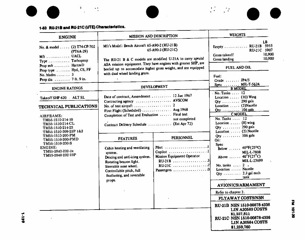
1-1
59
1-83 RU-21B and RU-21C (UTE) Characteristics.
ENGINE MISSION AND DESCRIPTION
No. & model (2) T74-CP-702 (PT6A-29)
Mfr UACL Type Turboprop Prop mfr Hartzell' Prop type Hyd, CS, FF No. blades 3 Prop dia 7 ft. 9 in.
ENGINE RATINGS
Mfr’s Model: Beech Aircraft 65-A90-2 (RU-21B) 65-A90-3 (RU-21C)
The RU-21 B & C models are modified U-21A to carry special ASA mission equipment. They have engines with greater SHP, are beefed up to accomodate higher gross weight, and are equipped with dual wheel landing gears.
DEVELOPMENT
Takeoff SHP 620 . ALT SL
TECHNICAL PUBLICATIONS
AIRFRAME: TM55-1510-214-10 TM55-1510-214-CL TM55-1510-214-23 TM55-1510-209-23P 1&2 TM55-1510-200-PM TM55-1510-200-PMD TM55-1510-200-S
ENGINE: TM55-2840-232- 24 TM55-2840-232-23P
Date of contract, Amendment .... Contracting agency No. of test aircraft First Flight (Scheduled) Completion of Test and Evaluation
Contract Delivery Schedule
FEATURES
Cabin heating and ventilating system. Deicing and anti-icing system. Rotating beacon light. Steerable nose wheel. Controllable pitch, full feathering, and reversible
12 Jun 1967 AVSCOM 2 Aug 1968 Final test not completed (Est Apr 72)
PERSONNEL
Pilot Copilot Mission Equipment Operator
RU-21B RU-21C
Passengers
props.
WEIGHTS
LB Empty RU-21B 5955
RU-21C 5907 Gross takeoff 10,900 Gross landing 10,900
FUEL AND OIL
Fuel: Grade JP4/5 Spec MIL-T-5624 B MODEL
No. Tanks .... 12 Location (10) Wing Qty 290 gals Location (2)Nacelle Qtv 106 eals
C MODEL . 12 . (8) wing . 290 gals . (2) Nacelle . 106 gals
40oF(25°C) MIL-L-7808 40°F(25O
C)
MIL-L-23699
2 . Nacelle 2.3 gal each tank
AVIONICS/ARMAMENT
Refer to chapter 2.
FLYAWAY COSTS/NSN
RU-21B NSN1510-00878-4338 LIN A30583 COSTS $1,257,811
RU-21C NSN 1510-00878-4336 LIN A30584 COSTS $1,259,760
No. Tanks ... Location .... Qty Location .... Qty
- OU: . Spec j Below ....
Above 3 2 No. tanks .. 0 Location ...
Qty
FM
101-20
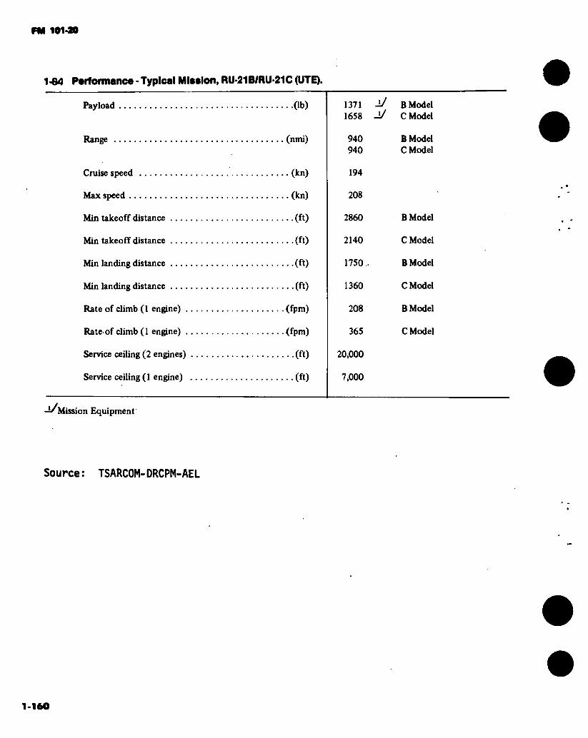
FM 101-30
1-64 Performance - Typical Miaslon, RU-21B/RU-21C (UTE).
Payload (lb)
Range (nmi)
Cruise speed (kn)
Max speed (kn)
Min takeoff distance (ft)
Min takeoff distance (ft)
Min landing distance (ft)
Min landing distance (ft)
Rate of climb (1 engine) (fpm)
Rate'of climb (1 engine) (fpm)
Service ceiling (2 engines) (ft)
Service ceiling (1 engine) (ft)
1371 -!/ 1658 -!/
940 940
194
208
2860
2140
1750,
1360
208
365
20,000
7,000
-l/Mission Equipment
Source: TSARCOM-DRCPM-AEL
B Model C Model
B Model C Model
B Model
C Model
B Model
C Model
B Model
C Model
1-160

FM 101-20
DIMENSIONS
Incidence (root) 4.81’ (tip) 0.0°
Dihedral 7° Sweepback (LE) 0.0° Sweepforward
(TE) NVAL Length 35 Ft. 26 In. Height 14 Ft. 2-1/2 In. Tread 12 Ft. 9 In. Prop gnd
clearance . 1 Ft.
17 FT 2.72 IN
CO
50FT11 IN.
FT. 9 IN
12 FT 9 IN
35 FT 6 IN.
a 14 FT 2.56 IN
12 IN I" 39 FT 12 IN. V
! 12 FT 3.47 IN.—7~
Figure 1- 57. Principal Dimensions RU-21H (Guardrail V)
1-161
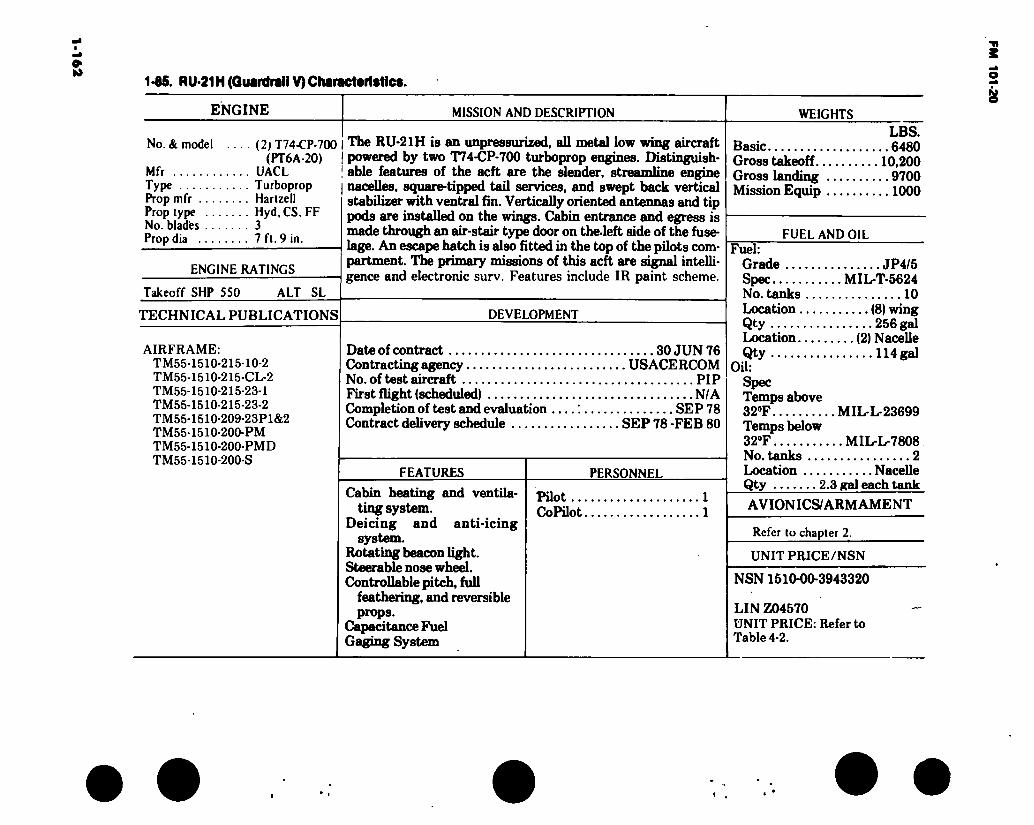
1-1
62
1-86. RU-21H (Guardrail V) Characteristics.
ENGINE MISSION AND DESCRIPTION WEIGHTS
No. & model (2) T74-CP-700 (PT6A-20)
Mfr UACL Type Turboprop Prop mfr Hartzell Prop type Hyd, CS, FF No. blades 3 Prop dia 7 ft. 9 in.
ENGINE RATINGS
Takeoff SHP 550 ALT SL
TECHNICAL PUBLICATIONS
AIRFRAME: TM55-1510-215-10-2 TM55-1510-215-CL-2 TM55-1510-215-23-1 TM55-1510-215-23-2 TM55-1510-209-23P1&2 TM55-1510-200-PM TM55-1510-200-PMD TM55-1510-200-S
The RU-21H is an unpressurized, all metal low wing aircraft powered by two T74-CP-700 turboprop engines. Distinguish- able features of the acft are the slender, streamline engine nacelles, square-tipped tail services, and swept back vertical stabilizer with ventral fin. Vertically oriented antennas and tip pods are installed on the wings. Cabin entrance and egress is made through an air-stair type door on the-left side of the fuse- lage. An escape hatch is also fitted in the top of the pilots com- partment. The primary missions of this acft are signal intelli- gence and electronic surv. Features include IR paint scheme.
DEVELOPMENT
Date of contract 30 JUN 76 Contracting agency USACERCOM No. of test aircraft PIP First flight (scheduled) N/A Completion of test and evaluation SEP 78 Contract delivery schedule SEP 78 -FEB 80
FEATURES
Cabin heating and ventila- ting system.
Deicing and anti-icing system.
Rotating beacon light. Steerable nose wheel. Controllable pitch, full
feathering, and reversible props.
Capacitance Fuel Gaging System
PERSONNEL
Pilot ... CoPilot.
LBS. Basic 6480 Gross takeoff 10,200 Gross landing 9700 Mission Equip 1000
FUEL AND OIL Fuel:
Grade JP4/5 Spec MIL-T-5624 No. tanks 10 Location (8) wing Qty 256 gal Location (2) Nacelle Qty 114 gal
OU: Spec Temps above 32°F MIL-L-23699 Temps below 32°F MIL-L-7808 No. tanks 2 Location NaceUe Qty 2.3 gal each tank
AVIONICS/ARMAMENT
Refer to chapter 2.
UNIT PRICE/NSN
NSN 1510-00-3943320
LIN Z04570 UNIT PRICE: Refer to Table 4-2.
FM 101-20
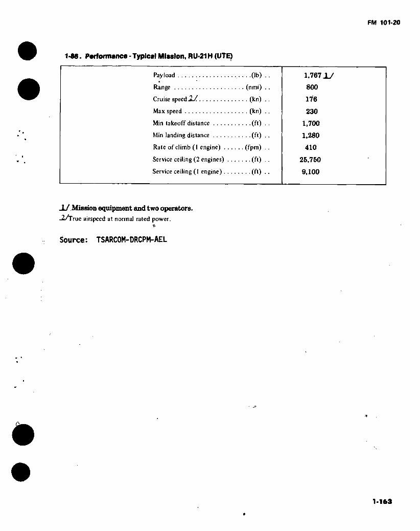
FM 101-20
1-86. Performance • Typical Miasion, RU-21H (UTE)
Payload .(lb)
Range (nmi)
Cruise speed .2-/ (kn)
Max speed (kn)
Min takeoff distance (ft)
Min landing distance (ft)
Rate of climb (1 engine) (fpm)
Service ceiling (2 engines) (ft)
Service ceiling ( I engine) (ft)
1,767 jy
800
176
230
1,700
1,280
410
25,750
9,100
-L/ Mission equipment and two operators. -2/True airspeed at normal rated power.
Source: TSARCOM-DRCPM-AEL
1-163
t
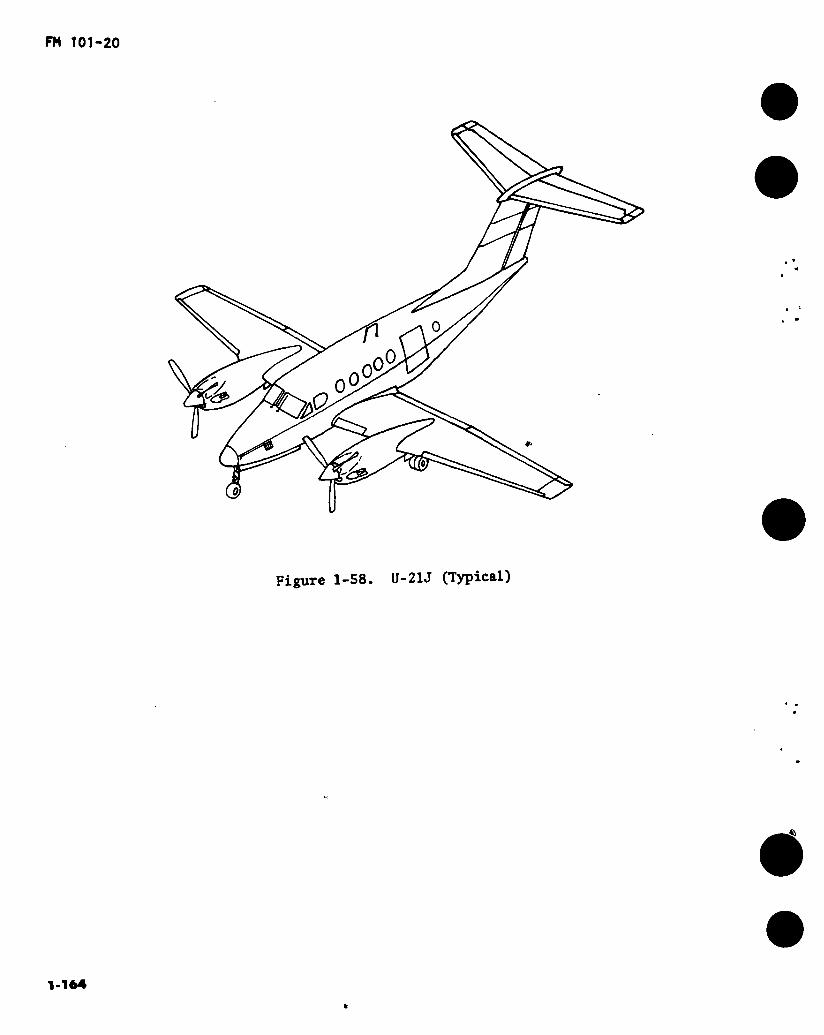
Figure 1-58. U-21J (Typical)
1.164
6
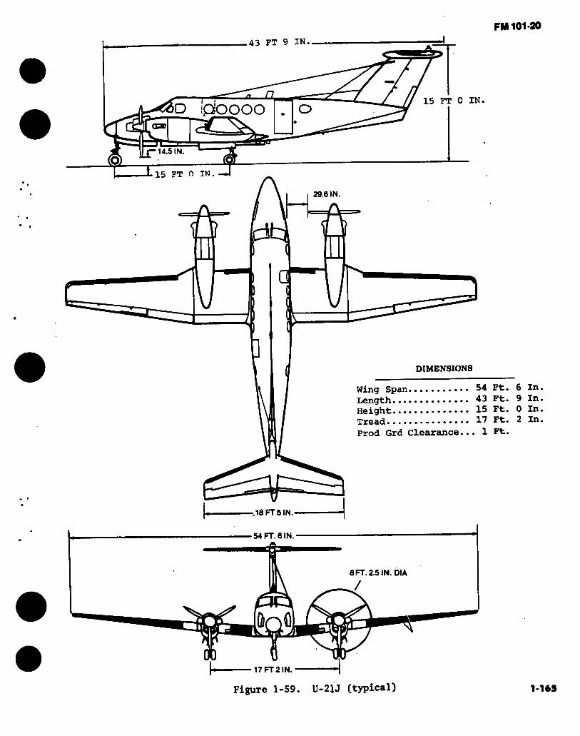
FM 101-20
43 FT 9 IN
a 15 FT 0 IN D QOOOO O
1 14.5 IN. r o —3 n IN. -J 15 FT
29.6 IN
a
DIMENSIONS
18 FT 5 IN
54 FT. 6 IN
8 FT. 2.5 IN. OIA
17FT2IN.
Wing Span 54 Ft. 6 In. Length 43 Ft. 9 In. Height 15 Ft. 0 In. Tread....••••••••••• 17 Ft. 2 In.
Prod Grd Clearance... 1 Ft.
Figure 1-59. U-21J (typical) 1-165
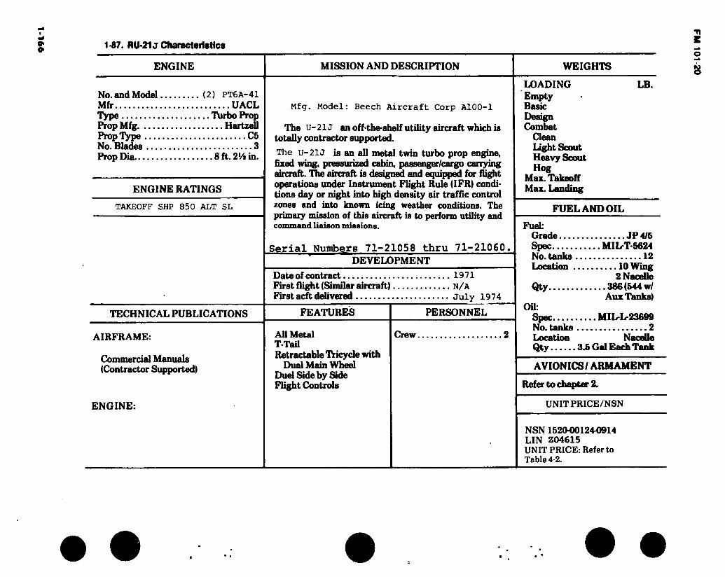
1-166 1-87. RU-21 j Characteristics
ENGINE MISSION AND DESCRIPTION WEIGHTS
No. and Model (2) PT6A-41 Mfr UACL Type Turbo Prop Prop Mfg Hartzell Prop Type C5 No. Blades 3 Prop Dia 8 ft. 2‘/i in.
ENGINE RATINGS
TAKEOFF SHP 850 ALT SL
Mfg. Model: Beech Aircraft Corp A100-1
The U-21J an off-the-shelf utility aircraft which is totally contractor supported.
The U-21J is an all metal twin turbo prop engine, fixed wing, pressurized cabin, passenger/cargo carrying aircraft. The aircraft is designed and equipped for flight operations under Instrument Flight Rule (IFR) condi- tions day or night into high density air traffic control zones and into known icing weather conditions. The primary mission of this aircraft is to perform utility and command liaison missions.
Serial Numbers 71-21058 thru 71-21060, DEVELOPMENT
Date of contract First flight (Similar aircraft). First acft delivered
1971
N/A July 1974
TECHNICAL PUBLICATIONS FEATURES
AIRFRAME:
Commercial Manuals (Contractor Supported)
ENGINE:
All Metal T-Tail Retractable TYicyde with
Dual Main Wheel Duel Side by Side Flight Controls
PERSONNEL
Crew.
LOADING Empty Basic Design Combat
Clean Light Scout Heavy Scout Hog
Max. Takeoff Max. Landing
LB.
FUEL AND OIL
Fuel: Grade JP 4/5 Spec MIL-T-5624 No. tanks 12 Location 10 Wing
2 Nacelle Qty 386 (544 w/
Aux Tanks) OU:
Spec MIL-L-23699 No. tanks 2 Location Nacelle Qty 3.5 Gal Each Tank
AVIONICS/ ARMAMENT
Refer to chapter 2.
UNIT PR1CE/NSN
NSN 1520-00124-0914 LIN Z04615 UNIT PRICE: Refer to Table 4-2.
FM 101-20

FM 101-20
1-88 Performance — Typical Mission,U-21J
Payload (LB) Range (NMI) Cruise Speed (KN) Max Speed (KN) Min Takeoff Distance (FT) Min Landing Distance (FT) Rate of Climb (1 Eng) (FPM) Service Ceiling (2 Eng) (Ft) Service Ceiling (1 Eng) (Ft)
Source : TSARCOM: DRCPM-AEL

FM 101-20
^ ^ l'VV'T'
T* r ‘ jsm> X- «a»
« «ri.
~*à3m£+
mt
•&&?i
¿ét Hk
- \ ’"■ •_* & -* 2
—^ ' 1 ' <JT il"'
Figure 1-60. UV-18A (Twin Otter)
1-16»
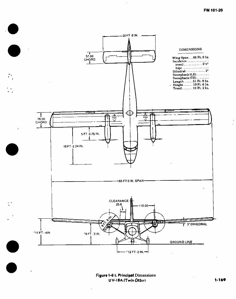
FM 101-20
DIMENSIONS
Wing Span .. .65 Ft. 0 In. Incidence
(root) 2'/20
(tip) Dihedral 3“ Sweepback (LE) Sweepback (TE) Length 51 Ft. 9 In. Height 19 Ft. 6 In. Tread 12 Ft. 2 In.
20 FT -SIN.
I 57.00
CHORD _L_
78.00 i i
CHORD
5 FT -3.75 IN.
—
18 FT -2.24 IN.
W 65 FT 0 IN.SPAN
CLEARANCE 25.6 110.00
f 3° DIHEDRAL
11 FT-4IN •9 FT-3 IN.
GROUND LINE
*12 FT -2IN.—
Figure 1-61. Principal Dimensions UV-18A (Twin Otter) 1-169

1-170 3
1-89 uV-18A Characteristics.
ENGINE
No. and Model.... (2) PT6A-27 Mfr Canadian P&W Engine Spec. No 583 Prop mfg Hartzell Prop type C5 No. blades 3
ENGINE RATINGS
SHP Condition Take-off 620 ISA+18°C Max Cruise 620 ISA-f-6°C
TECHNICAL PUBLICATIONS
AIRFRAME:
Commercial Manuals (Contractor Supported)
ENGINE:
Commercial Manual
MISSION AND DESCRIPTION
The aircraft with a crew of two is capable of carrying twenty passengers with baggage in the utility seating arrangement to provide command administrative, logistics and personnel flights from battalion headquar- ters to remote sites throughout western and northern Alaska on a year-round basis. With the utility seats folded a partial or full freight-carrying configuration is available. With necessary adaptations, the aircraft may be used in an air ambulance, rescue, forrestry / pipeline patrol and air drops of personnel equipment and supplies missions.
CABIN VOLUME (USEABLE) BAGGAGE OOMPT-VOLUME-REAR BAGGAGE OOMPT-VOLUME-REAR
(MOD 6/1075) BAGGAGE OOMPT-VOLUME-FWD
384 CU FT 52 CU FT 88 CU FT
22 CU FT
DEVELOPMENT
Date of contract First flight (Similar aircraft) First acft delivered Dec 1976
FEATURES
All metal, high wing monoplane
Fixed tricycle landing gear
Conventional three control, dual side-by-side rudder pedal / control column combination
PERSONNEL
Crew Passengers
.2 20
WEIGHTS
LOADING LB. Empty Basic Design Combat
‘ Clean Light Scout Heavy Scout Hog
Max. Takeoff 12,500 Max. Landing 12,300
(C) Calculated ♦For Basic Mission
FUEL AND OIL
Fuel: Grade JP4/5 Spec MIL-J-5624G No. tanks 10 Location 8 under floor,
2 in Wing Qty 2745 Lbs.
Oil: Spec MIL-L-23699 No. tanks 2 Location in Engines Qty
AVIONICS/ARM AMENT
Refer to chapter 2.
UNIT PRICE/NSN
NSN 1510-01011-1462 LIN A30989 COSTS UNIT PRICE: Refer to Table 4-2.
101-2
0

FM 101-20
1-90 Performance — Typical Mlaalon, UV-18A (Twin Otter).
Payload (LB) Range (NMI) Cruise Speed (KN) Max Speed (KN) Min Takeoff Distance .(FT) Min Landing Distance (FT) Rate of Climb (1 Engine) (FPM) Service Ceiling (2 Engines) .(FT) Service Ceiling (1 Engine) (FT)
_l/4fl8.3 Lb with fuel trade off.
Source: TSARCOM-DRSTS-WP
300317 400 181
1200 1050 340
26,700 11,600
1-171/(1-172 blank)

0

»
FM 101-20
CHAPTER 2
LOGISTICS AND MATERIAL
Section I. MAXIMUM ALLOWABLE OPERATINQ TIME (MAOT) (MAJOR COMPONENTS)
2-1. Major Components.
Ulis section was eliminated since the applicable Technical Manuals (TM’s) are now included in Chapter 1, Section IV, Standard Aircraft Charac- teristics. The TM is more current and in more
detail than FM 101-20. Refer to the characteristics pages of each individual aircraft in Section IV. The -20, Chapter 3 of the applicable TM lists all Maximum Allowable Operating Time (MAOT) and Time Between Overhaul (TBO).
%
2-1

FM 101-20
« Section II. AIRCRAFT EQUIPMENT
2.2 Avionics and Surveillance Equipment Configurations.*
The following avionics and surveillance con- figurations are typical and may vary depending on production run, changes incorporated through MWO action, and theater of operation in which the aircraft is employed. For further details on Army Aircraft configuration, including retrofit objec-
tives, refer to AR 95-71, U.S. Army Avionics. CERCOM does not maintain configuration in- formation for aircraft which are type classified contingency (U-l, U-6, U-9 etc.). The abbreviation CPO in this section is defined as “complete provi- sions only”. It indicates that power, space, weight and wiring have been incorporated and considered but the equipment has not been installed.
♦Source: CERCOM (DRSEL-MME-LAE) AND (DRSEL-LE-EA)
The following configuration depicts a typically configured AH-1( ). The actual configuration may vary depending on peculiar geographic re- quirements or changes incorporated through MWO action and special purpose alterations.
TYPE NUMBER
8
FUNCTION/NOUN X <
s a x « > fa
S <
X as 33 H
S <
V H 09 n 3> 09 Q 2 C
ob
09
33 <
AM-3209/ASN Servoamplifier
AN/ALQ-144 Countermeasures Set CPO
AN / APN-209(V)1 Radar Altimeter
AN / APR-39(V) 1 Radar Warning Set CPO CPO CPO
AN/APX-72 IFF Transponder Set
AN/ARC-61BX UHF-AM Radio Set
AN/ARC-64/131 VHF-FM Radio Set
AN/ARC-114A VHF-FM Radio Set
AN/ARC-115A VHF-AM Radio Set
AN/ARC-116 UHF-AM Radio Set O
AN/ARC-134 VHF-AM Radio Set
2-2
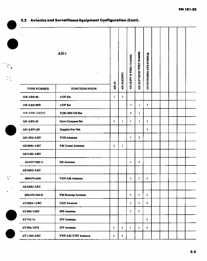
FM 101-20
2.2 Avionics and Surveillance Equipmenf Configuration (Cont).
TYPE NUMBER
AH-1
FUNCTION/NOUN
8
r-
g s
9 u
09
a
S
AN/ARN-83 ADF Set
AN/ARN-89B ADF Set
AN/ARN-123(V)3 VOR/MB/GS Set
AN/ASN-43 Gyro Compass Set
AN/ASN-128 Doppler Nav Set
AS-1304/ARN VOR Antenna
AS-2286/ARC FM Conun Antenna
AS-3188/ARN
(214-077-092-1) GS Antenna
AS-3204/ARC
(209-075-560) VHF-AM Antenna
AS-3206/ARC
(205-076-345-3) FM Homing Antenna
AT-256A/ARC UHF Antenna
AT-640/ARN MB Antenna
AT-741/A IFF Antenna
AT-884/APX IFF Antenna
AT-1108/ARC VHF-AM/UHF Antenna
2-3

FM 101-20
2.2 Avionics and Surveillance Equipment Configuration (Cont).
TYPE NUMBER
AH-1
FUN CTION/NOUN
8
S a H
& 09
Or «
£3 n a
BB-649/A Battery
CN-13X4/A Gyro
CN-1497/A Gyro
C-161X/AIC Intercomm Set
C-6347/ASN-43 Compass Control
C-6533/ARC Intercomm Set
C-8X67/ARC Control-Indicator
C-X0B33/APX-100 Control
ID-48/ARN Course Indicator
ID-260/ARN RMI
ID-998/ASN RMI
ID-2103/A
(209-076-660) Horn Situation Indicator
ID-2104/A
(209-076-661) Attitude Dir Indicator
ID-2106/A
(212-070-180) RMI
KIT-1A/TSEC IFF Computer CP0 CP0 CPO CP0 CPO
2-4
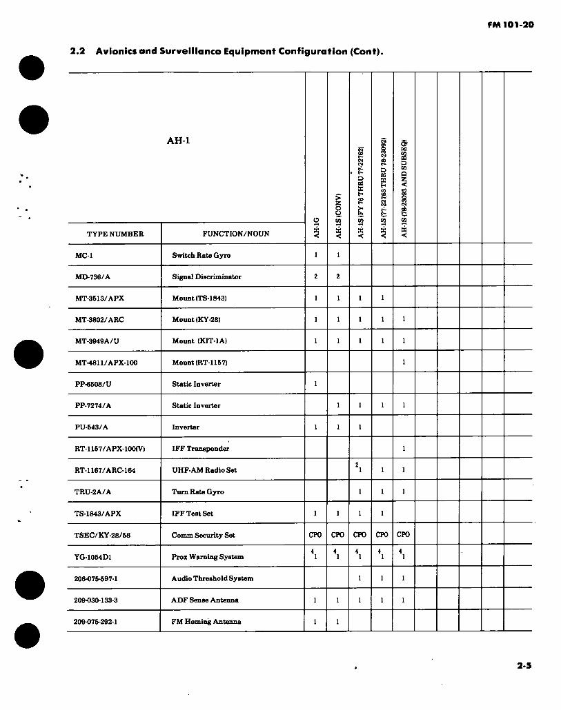
FM 101-20
2.2 Avionics and Surveillance Equipment Configuration (Cont).
TYPE NUMBER
MC-1
MD-736/A
MT-3B13/APX
MT-3802/ARC
MT-3949A/U
MT-4811/APX-100
PP-6608/U
PP-7274/A
PU-B43/A
RT-1167/APX-100(V)
RT-1167/ARC-164
TRU-2A/A
TS-1843/APX
TSEC/KY-28/58
YG-1054D1
206-075-597-1
209-030-133-3
209-075-292-1
AH-1
FUNCTION/NOUN
Switch Rate Gyro
Signal Discriminator
Mount (TS-1843)
Mount (KY-28)
Mount (KIT-1A)
Mount (RT-1157)
Static Inverter
Static Inverter
Inverter
IFF Transponder
UHF-AM Radio Set
Turn Rate Gyro
IFF Test Set
Comm Security Set
Proz Warning System
Audio Threshold System
ADF Sense Antenna
FM Homing Antenna
Ü
CP0 CP0
3 ot X fr- eo c- >-
X <
CP0
D « X H 3.
X <
<y u s s CO Q
cj cfa
CP0 CP0
2-5

FM 101-20
2.2 Avionics and Surveillance Equipment Configuration (Cont).
AH-1
TYPE NUMBER
209-077-203
670A
FUNCTION/NOUN
FM Comm Antenna
SCAS
8
C4 ob t- D « X H a g
5
or a 09 n D m Q
NOTES:
1. CPO in FY 76 aircraft. 2. The AN/ARC-116 was installed in lieu of the RT-1167/ARC-164 in a few early FY 76 aircraft. 3. Due to vibration requirements, only the MT-3791C/ARC-134 should be installed as a part
AN/ARC-134 system. 4. Equipment installed only in aircraft located at Ft. Bragg, Ft. Campbell, Ft. Hood and Ft. Rucker.
of the
GENERAL NOTE: The AH-1S (CONV) configuration pertains to converted AH-1G/Q aircraft. The AH- 1S (FY 76 thru 77-22762) configuration pertains to the first production aircraft. The AH-1S (77-22763 thru 78-23092) configuration is also known as EGAS aircraft. The AH-IS (78-23093 and subseq) configuration pertains to fully modernized aircraft. Present plans call for the conversion of all AH-1( ) aircraft to the fully modernized configuration by FY 84.
APPLICABLE AIRCRAFT AVIONICS MANUALS:
TM 11-1520-221 Series (Pertains to AH-1G and S (CONV)) TM 11-1520-236 and 239 Series (Pertains to AH-1S)
2-6
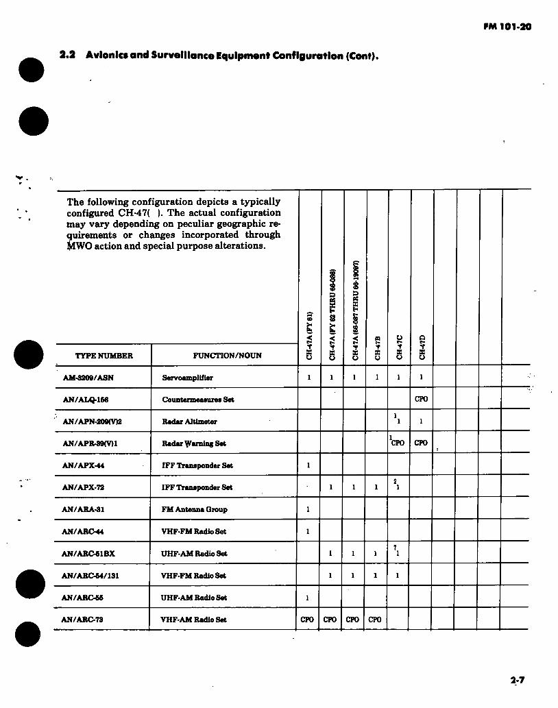
FM 101-20
2.2 Avionics and Surveillance Equipment Configuration (Cont).
The following configuration depicts a typically configured CH-47( ). The actual configuration may vary depending on peculiar geographic re- Suirements or changes incorporated through
IWO action and special purpose alterations.
s
H
D ee X E"
TYPE NUMBER FUNCTION/NOUN T X o
t,
V X o
V s Ü
s Y S Ü
Y X o
a t- Y X Ü
AM-3209/ASN Servoamplifier
AN/ALQ-166 Countermeasures Set CPO
AN / APN-209(V)2 Radar Altimeter
AN/APR-39(V)1 Radar learning Set CPO CPO
AN/APX-44 IFF Transponder Set
AN/APX-72 IFF Transponder Set
AN/ARA-31 FM Antenna Group
AN/ARC-44 VHF-FM Radio Set
AN/ARC-51BX UHF-AM Radio Set
AN/ARC64/131 VHF-FM Radio Set
AN/ARC-66 UHF-AM Radio Set
AN/ARC 73 VHF-AM Radio Set CPO CPO CPO CPO
2-7
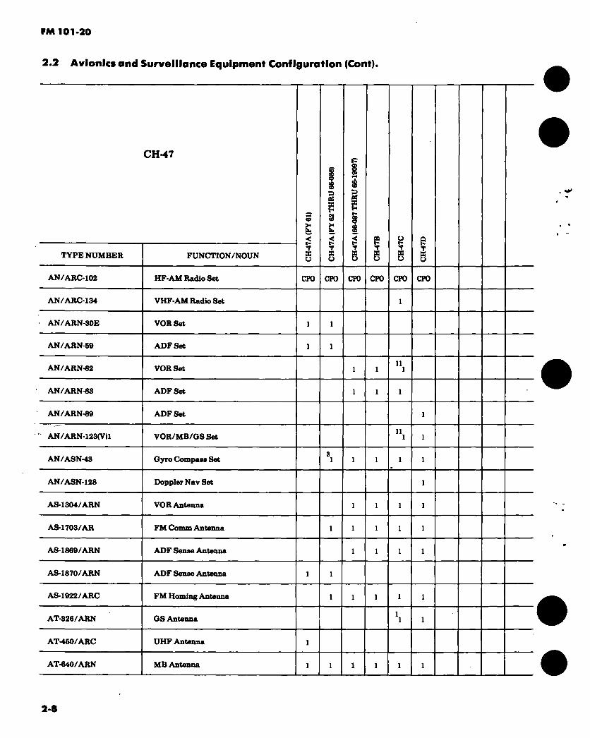
FM 101-20
2.2 Avionics and Surveillance Equipment Configuration (Cont).
CH-47
TYPE NUMBER FUNCTI0N/N0UN Y X Ü
D OS
£ < t- Y X u
D ee
X u
e Y
ë Y X U
e Y X U
AN/ARC-102 HF-AM Radio Set CTO CPO CPO CPO CPO CPO
AN/ARC-134 VHF-AM Radio Set
AN/ARN-30E VOR Set
AN/ARN-69 ADF Set
AN/ARN-82 VOR Set 11
AN/ARN-83 ADF Set
AN/ARN-89 ADF Set
AN/ARN-123(V)1 VOR/MB/GS Set 11
AN/ASN-43 Gyro Compase Set
AN/ASN-128 Doppler Nav Set
AS-1304/ARN VOR Antenna
AS-1703/AR FM Comm Antenna
AS-1869/ARN ADF Sense Antenna
AS-1870/ARN ADF Sense Antenna
AS-1922/ARC FM Homing Antenna
AT-326/ARN GS Antenna
AT-450/ARC UHF Antenna
AT-640/ARN MB Antenna
2-8

FM 101-20
2.2 Avionics and Surveillance Equipment Configuration (Cont).
TYPE NUMBER
AT-740/A
AT-884/APX
AT-1108/ARC
BB-432/A
CN-811/ASN
CU-942B/ARC
CU-991/AR
CU-1658/A
CV-1276/ARN
C-1611/AIC
C-4209/ARC
C-6633/ARC
CH-47
C-8157/ARC
ID-260/ARN
ID-998/ASN
. ID-1347C/ARN
ID-2103/A
J-2
FUNCTION/NOUN
IFF Antenna
IFF Antenna
VHF-AM/UHF Antenna
Battery
Gyro
FM Antenna Coupler
HF Antenna Coupler
HF Antenna Coupler
Converter
Interconun Set
Control (T-366)
Intercomm Set
Control-Indicator
RMI
RMI
Course Indicator
Horiz Situation Ind
Gyro Compass Set
<o >- Ü.
T S o
CPO
3 « X
>*
t s o
CPO
D oi X H t» oo S
Y 3 U
CPO
Y X Ü
o c- Y X u
Y X o
CPO CPO
CPO CPO
2-9

FM 101-20
2.2 Avionics and Surveillance Equipment Configuration (Cont).
TYPE NUMBER
KIT-1A/TSEC
CH-47
FUNCTION/NOUN
IFF Computer
<o
fa
T ¡C O
to
D a£ X H to ÏH
Y S O
CPO
Y K U
CPO
u r- Y S Ü
Y X u
CPO CPO CPO
MD-736/A
MT-1142/ARC
MT-1719/AR
MT-2292/ARN
MT-2641/ARC
MT-3613/APX
MT-3772/A
MT-3802/ARC
MT-3949A/U
M-40A
PP-2792/ARN-30
Signal Discriminator
Mount (T-366)
Mount (CU-991)
Mount (R-1041)
Mount (AN/ARC-102)
Mount (TS-1843)
Mount (CU-1658)
Mount (KY-28)
Mount (KIT-1 A)
Mount (CV-1275)
Power Supply
1 1
CPO CPO CPO CPO CPO
CPO CPO-
RT-1167/ARC-164 UHF-AM Radio Set 7 .1
RT-1285/APX-100
RT-1364/ARC-186
IFF Transponder
VHF-AM/FM Radio Set
R-1041/ARN MB Receiver CPO CPO CPO CPO 'fcpo
TS-1843/APX IFF Test Set
TSEC/KY-28/68 Comm Security Set CPO CPO CPO CPO CPO
2-10
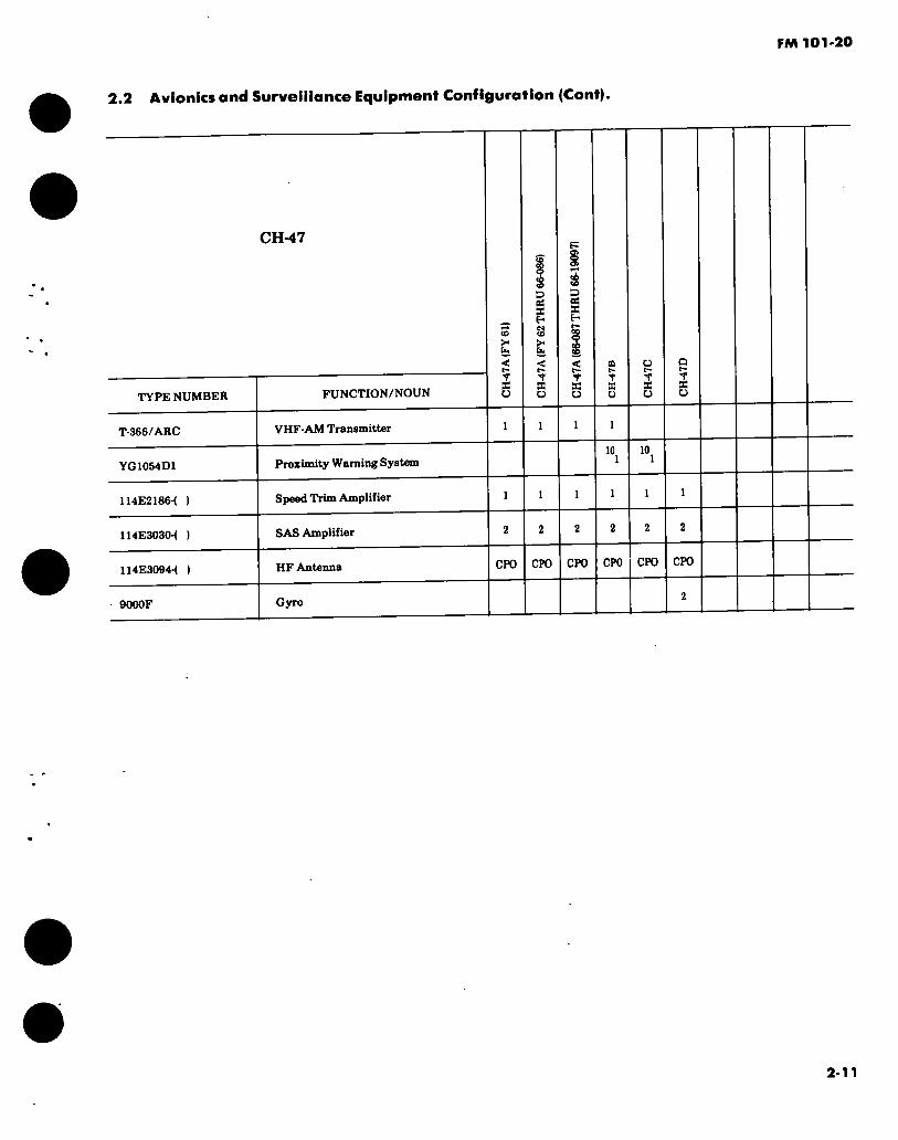
FM 101-20
2.2 Avionics and Surveillance Equipment Configuration (Cont).
TYPE NUMBER
T-366/ARC
CH-47
FUNCTION/NOUN
VHF-AM Transmitter
ID
>*
r s o
D BS S H
>
T S O
D « S H
T S o
T X o
T X Q
T X Ü
YG1054D1 Proximity Warning System 10 10
114E2186-4 )
114E303CM )
114E3094-1 )
9000F
Speed Trim Amplifier
SAS Amplifier
1 1
HF Antenna
Gyro
CPO CPO CPO CPO CPO CPO
2-11
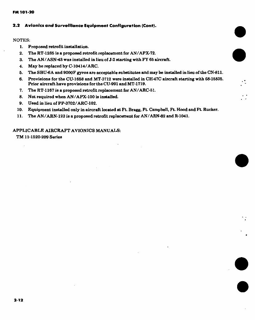
FM 101'20
2.2 Avionics and Surveillance Equipment Configuration (Cont).
NOTES: 1. Proposed retrofit installation. 2. The RT-1285 is a proposed retrofit replacement for AN/APX-72. 3. The AN /ASN-43 was installed in lieu of J-2 starting with FY 65 aircraft. 4. May be replaced by C-10414/ARC. 5. The SBU-6A and 9000F gyros are acceptable substitutes and may be installed in lieu of the CN-811. 6. Provisions for the CU-1658 and MT-3712 were installed in CH-47C aircraft starting with 68-15835.
Prior aircraft have provisions for the CU-991 and MT-1719. 7. The RT-1167 is a proposed retrofit replacement for AN/ARC-51. 8. Not required when AN/APX-100 is installed. 9. Used in lieu of PP-3702/ARC-102.
10. Equipment installed only in aircraft located at Ft. Bragg, Ft. Campbell, Ft. Hood and Ft. Rucker. 11. The AN/ARN-123 is a proposed retrofit replacement for AN/ARN-82 and R-1041.
APPLICABLE AIRCRAFT AVIONICS MANUALS: TM 11-1520-209 Senes
2-12

FM 101-20
2-2. Avionics and Surveillance Equipment Configurations (Cont).
The following configuration depicts a typically configured CH-54( ). The actual configuration may vary depending on peculiar geographic re- quirements or changes incorporated through MWO action and special purpose alterations.
TYPE NUMBER
AM-3209/ASN
•AM-6279/ASW
• AM-6280/ASW
AN/APX-72
AN/ARC-61BX
AN/ARC-54/131
AN/ARC-102
AN/ARC-134
AN/ARN-82
AN/ARN-83
AN/ASH-19
AN/ASH-23
FUNCTION/NOUN
•< s B O
BO S X Ü
Servoamplifier
Amplifier
Amplifier
IFF Transponder Set
UHF-AM Radio Set
VHF-FM Radio Set
HF-AM Radio Set
VHF-AM Radio Set
VOR Set
ADFSet
Voice Warning Set
Voice Warning Recorder
CPO CPO
2-13

FM 101-20
2-2. Avionics and Surveillance Equipment Configurations (Cont).
TYPE NUMBER
CH-54
FUNCTION/NOUN
< s x o
CQ S X Ü
AN/ASN-43 Gyro Compass Set
AN/ASW-29 Auto Fit Cont System
AS-1304/ARN VOR Antenna
AS-1703/AR FM Comm Antenna
AS-1922/ARC FM Homing Antenna
AT-326/ARN GS Antenna
AT-640/ARN . MB Antenna
AT-884/APX IFF Antenna
AT-1108/ARC VHF-AM/UHF Antenna
BB-434/A Battery
CN-1179/ASW Gyro
CN-1314/A Gyro
•CN-1326/ASW Gyro
CU-942/ARC FM Antenna Coupler
CU-991/AR HF Antenna Coupler CPO
CU-1668/A HF Antenna Coupler CPO CPO
C-1611/AIC Intercomm Set
•C-7266/ASW-29 Control
2-14
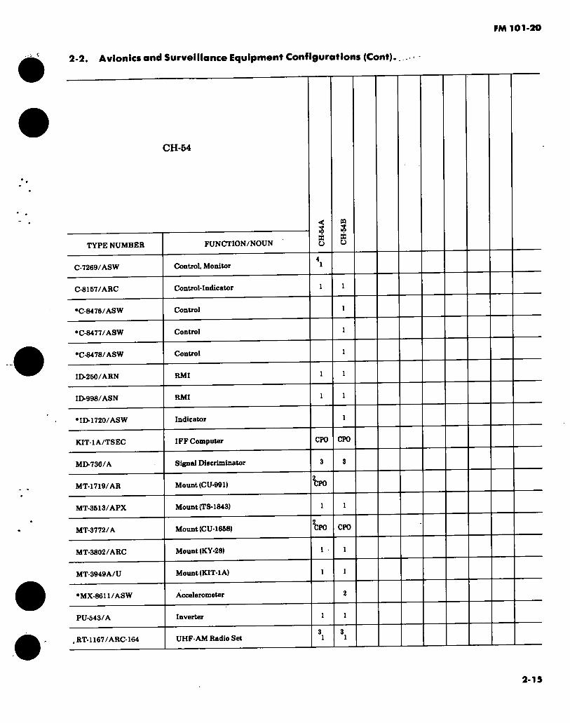
FM 101-20
2-2. Avionics and Surveillance Equipment Configurations (Cont).
CH-54
TYPE NUMBER
07269/ASW
08167/ARC
•08476/ASW
•C-8477/ASW
*08478/ASW
ID-250/ARN
ID-998/ASN
FUNCTION/NOUN
Control, Monitor
Control-Indicator
Control
Control
Control
RMI
RMI
< $ 35 O
« S 35 Ü
•ID-1720/ASW Indicator
KIT-1A/TSEC IFF Computer CPO CPO
MD-736/A Signal Discriminator
MT-1719/AR Mount (CU-991) ^PO
MT-3613/APX Mount (TS-1843)
MT-3772/A Mount (CU-1668) ^PO CPO
MT-3802/ARC Mount (KY-28)
MT-3949A/U Mount (KIT-1 A)
•MX-8611/ASW
PU-543/A
. RT-1167/ARC-164
Accelerometer
Inverter
UHF-AM Radio Set
2-15

FM 101-20
2-2. Avionics and Surveillance Equipment Configurations (Cont).
CH-54
TYPE NUMBER
R-1963/ARN
•SN-410/ASW-29
•SN-441/ASW
•SN-442/ASW
TS-1843/APX
TSEC/KY-28/58
6460-66010-041
FUNCTION/NOUN
MB/GS Receiver
Synchro
Synchronizer
Synchronizer
IFF Test Set
Comm Security Set
ADF Sense Antenna
< 2 a u
\a>o
CP0
n 2 x o
CP0
CP0
* Denotes components of Automatic Flight Control System (AFCS) installed on the CH-54B. Some of these items are components of the AN/ASW-29 AFCS installed on the CH-54 A.
NOTES:
1. Proposed retrofit installation.
2. Provisions for the CU-991 and MT-1719 were installed in 66-18408 thru 66-18413. All other CH-54A aircraft have provisions for the CU-1658 and MT-3772.
3. The RT-1167 is a proposed retrofit replacement for AN/ARC-51.
4. The C-7269 and CN-1179 are installed in some aircraft in lieu of the CN-1314/A.
APPLICABLE AIRCRAFT AVIONICS MANUALS:
TM 11-1520-217 Series
2-16
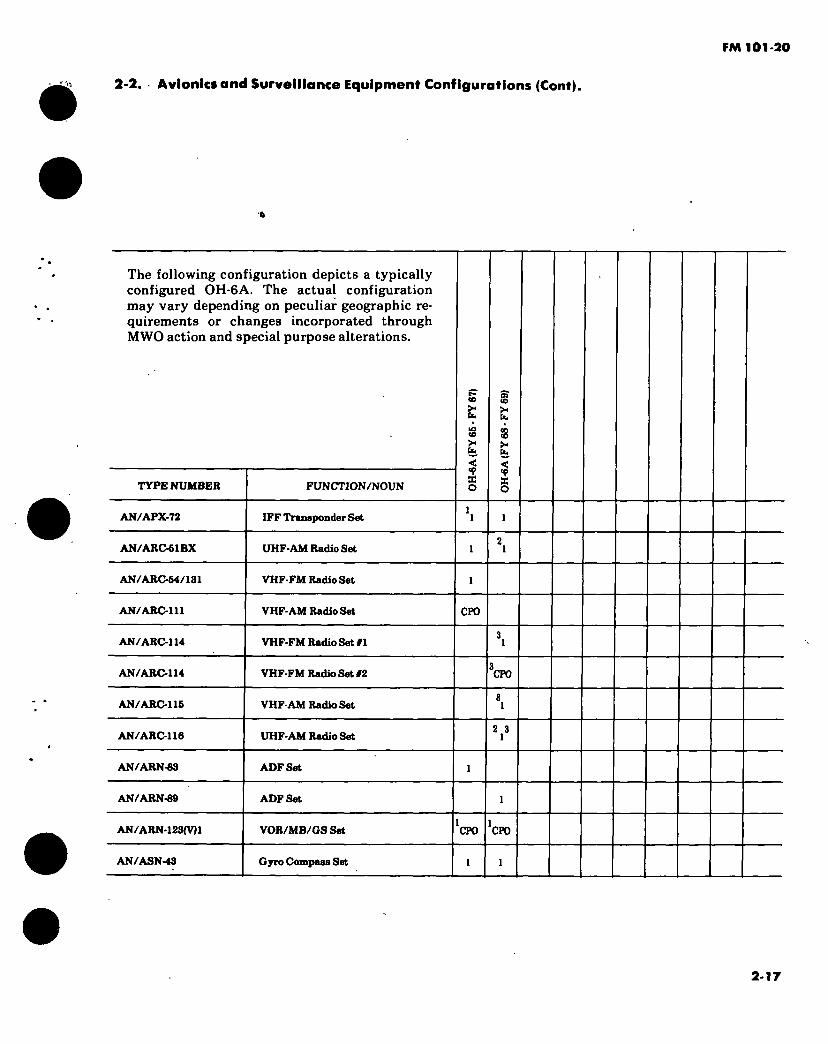
FM 101-20
2-2. ■ Avionics and Surveillance Equipment Configurations (Cont).
»
The following configuration depicts a typically configured 0H-6A. The actual configuration may vary depending on peculiar geographic re- quirements or changes incorporated through MWO action and special purpose alterations.
CO
TYPE NUMBER FUNCTION/NOUN
< 'P X o
>-
< <P X o
AN/APX-72 IFF Transponder Set
AN/ARC-61BX UHF-AM Radio Set
AN/ARC-64/131 VHF-FM Radio Set
AN/ARC-111 VHF-AM Radio Set CPO
AN/ARC-114 VHF-FM Radio Set #1
AN/ARC-114 VHF-FM Radio Set #2 CPO
AN/ARC-116 VHF-AM Radio Set
AN/ARC-116 UHF-AM Radio Set 2 3
1
AN/ARN-83 ADFSet
AN/ARN-89 ADFSet
AN/ARN-123(V)1 VOR/MB/GS Set CPO CPO
AN/ASN-43 Gyro Compass Set
2-17
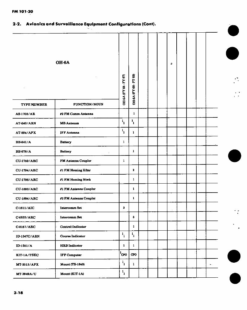
FM 101-20
2-2. Avionics and Surveillance Equipment Configurations (Cont).
TYPE NUMBER
OH-6A
FUNCTION/NOUN
<0
3 >
•< S o
3 >*
< X o
AS-1703/AR #2 FM Comm Antenna
AT-640/ARN MB Antenna
AT-884/APX IFF Antenna
BB-641/A Battery
BB-678/A Battery
CU-1759/ARC FM Antenna Coupler
CU-1794/ARC #1 FM Homing Xfmr
CU-1796/ARC #1 FM Homing Ntwk
CU-1893/ARC #1 FM Antenna Coupler
CU-1894/ARC #2 FM Antenna Coupler
C-1611/AIC Intercomm Set
C-6533/ARC Intercomm Set
C-8167/ARC Control-Indicator
ID-1347C/ARN Course Indicator
ID-1351/A HRB Indicator
KIT-1A/TSEC IFF Computer CPO CPO
MT-3513/APX Mount (TS-1843)
MT-3949A/U Mount (KIT-1 A)
2-18

FM 101*20
2*2. Avionics and Surveillance Equipment Configurations (Cont).
OH-6A
TYPE NUMBER FUNCTION/NOUN
§
é £
§
s £ <<
2 § PP-6376/A Static Inverter
PP-6674/A Static Inverter
TS-1843/APX IFF Test Set
TSEC/KY-28/68 Comm Security Set CFO
389A4664 Static Inverter
889 A 6471 Mount (KY-28)
869A6472 Mount (KIT-1 A)
1660OH6-193-1 VOR/GS Antenna
NOTES: 1. Proposed retrofit installation. 2. The AN/ARC-61 was installed in lieu of the AN/ARC-116 in some aircraft. 3. Wiring provisions exist for 2 each AN/ARC-114, 1 each AN/ARC-116 and 1 each AN/ARC-116.
However, the maximum number of sets that can be installed at any given time is limited to 3 each, i.e., 1 each AN/ARC-114, 116 and 116 or 2 each AN/ARC-114 and 1 each AN/ARC-115 or 2 each AN/ARC-114 and 1 each AN/ARC-116.
4. The PP-6376 is a proposed retrofit replacement for the PP-6674 and 369A 4564 inverters.
APPLICABLE AIRCRAFT AVIONICS MANUALS: TM11-1620-214 Series
2-19

FM 101-20
2-2. Avionies and Surveillance Equipment Configurations (Cont).
The following configuration depicts a typically configured OH-58( ). The actual configuration may vary depending on peculiar geographic re- quirements or changes incorporated through MWO action and special purpose alterations.
TYPE NUMBER FUNCTION/NOUN
< s § U ? §
AN/APN-209(V)1 Radar Altimeter CPO
AN / APR-38(V) 1 Radar Warning Set CPO CPO
AN/APX-72 IFF Transponder Set
AN/ARC-61BX UHF-AM Radio Set
AN/ARC-114 VHF-FM Radio Set #1
AN/ARC-114 VHF-FM Radio Set #2 CPO CPO
AN/ARC-116 VHF-AM Radio Set
AN/ARC-116 UHF-AM Radio Set
AN/ARN-89 ADF Set
AN/ARN-123(V)1 VOR/MB/OSSet CPO
AN/ASN-43 Gyro Compass Set
AS-1304/ARN VOR Antenna CPO
2-20
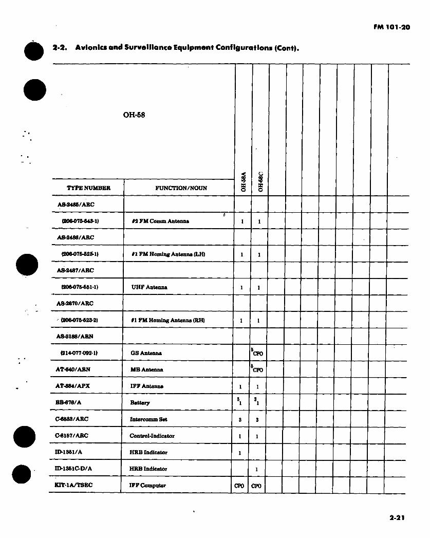
FM 101-20
2*2. Avionics and Surveillance Equipment Configurations (Cont).
OH-58
TYPE NUMBER FUNCTI0N/N0UN
< s § A8-2465/ARC
(£06-075-643-1) 12 FM Comm Antenna
AS-24S6/ARC
(20^076-623-1) #1 FM Homing Antenna (LH)
AS-2487/ARC
(20M76-661-1) UHF Antenna
AS-2670/ARC
(206-075-623-2) #1 FM Homing Antenna (RH) 1 1
A8-3188/ARN
(214-077-092-1) OS Antenna CP0
AT-640/ARN MB Antenna CP0
AT-884/APX IFF Antenna
BB-676/A Battery
06683/ARC Intercomm Set
08157/ARC Control-Indicator
ID-1361/A HRB Indicator
ID-18610D/A HRB Indicator
KIT-1A/TSEC IFF Computer CFO CPO
2-21

PM 101-20
2-2. Avionics and Surveillance Equipment Configurations (Cont).
OH-68
TYPE NUMBER FUNCTION/NOUN I O
u I MT-8818/APX Mount (TS-1843)
MT-3802/ARC Mount (KY-28)
MT-3949A/U Mount (KIT-1 A)
PP-6376/A Static Inverter
RT-1167/ARC-164 UHF-AM Radio Set
RT-1286/APX-100 IFF Transponder
TS-1843/APX IFF Test Set
TSEC/KY-28 Comm Security Set CPO CPO
YG-1054D1 Proximity Warning System
206-032-310-66 ADF Sense Antenna
2064)76-618 VHF-AM&#! VHF-FM Comm Ant
206-076-697-1 Audio Threshold System
206-076-716-1 Course Indicator
206-077-109-1 IFF Antenna
2-22

FM 101-20
2-2 Avionics and Surveillance Equipment Configurations (Cont).
NOTES: 1. The AN/ARC-51 was installed in lieu of the AN/ARC-116 in some aircraft. 2. Selected aircraft only. 3. BB-649/A installed as part of winterization kit. 4. Equipment installed only in aircraft located at Ft. Bragg, Ft. Campbell, Ft. Hood and Ft. Rucker. 5. Some aircraft may have this equipment installed as a part of Complete Provisions.
APPLICABLE AIRCRAFT AVIONICS MANUALS: TM11-1520-228 Series
o 2-23

FM 101-20
2-2. Avionics and Surveillance Equipment Configurations (Cent).
The following configuration depicts a typically configured TH-55A. The actual configuration may vary depending on peculiar geographic re- quirements or changes incorporated through MWO action and special purpose alterations.
TH-55A
TYPE NUMBER
MX-1646/AIC
A-26A
12-GCAB-9E
524A
FUNCTION/NOUN
Headset Adapter
VHF Comm Antenna
Battery
VHF-AM Radio Set
S E-
APPLICABLE PUBLICATIONS: DA publications are not available. Refer to applicable conunercial literature.
2-24
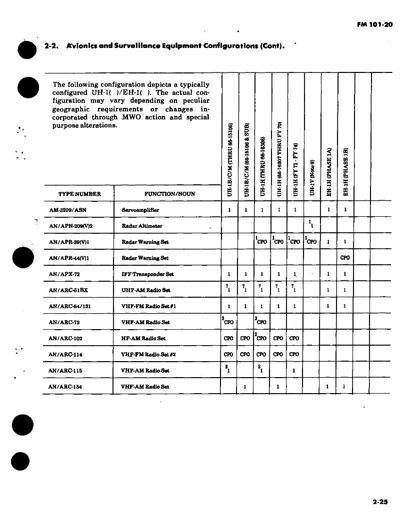
FM 101-20
2-2. Avionics and Surveillance Equipment Configurations (Cont).
The following configuration depicts a typically configured UH-1( )/EH-l( ). The actual con- figuration may vary depending on peculiar geographic requirements or changes in- corporated through MWO action and special purpose alterations.
TYPE NUMBER FUNCTION/NOUN
>o o
D os X fc s o n w B B
09 «0 S
2 ü DO
os X f-
g B b B
£ 8
a 3 ê >
8 D
B
& 8
£ B
DO
B
Si 8
8 B
AM-3209/ASN Servoamplifier
AN / APN-209(V)2 Radar Altimeter
AN/APR-39(V)1 Radar Warning Set CPO CPO CPO CPO
AN/APR-44(V)1 Radar Warning Set CPO
AN/APX-72 IFF Transponder Set
AN/ARC-6IBX UHF-AM Radio Set
AN/ARC-54/131 VHF-FM Radio Set #1
AN/ARC-73 VHF-AM Radio Set CPO CPO
AN/ARC-102 HF-AM Radio Set CPO CPO CPO CPO CPO
AN/ARC-114 VHF-FM Radio Set 12 CPO CPO CPO CPO CPO
AN/ARC-115 VHF-AM Radio Set
AN/ARC-134 VHF-AM Radio Set
2-25

FM 101-20
2-2. Avionics and Surveillance Equipment Configurations (Cont).
TYPE NUMBER
UH-1
FUNCTION/NOUN
á
g X H S \ O
S x D
OQ D CO
£ S '-s.
ü OQ
X X
co o CO CO
ó CO
D « s H
X 3
>< h 3 OJ X E-i
co
X 3
>* b*
>- b«
X 3
a i X
X 3
< U
h X X H
n H
b X aH
X H
AN/ARN-30 VOR Set
AN/ARN-59 ADF Set
AN/ARN-82 VOR Set
AN/ARN-83 ADF Set
AN/ARN-124 DME Set
AN/ARQ-33 Countermeasures Set
AN/ARQ-33 A Countermeasures Set
AN/ASN-43 Gyro Compass Set
AS-1304/ARN VOR Antenna
AS-1703/AR FM Comm Antenna 11 11 11 11 11
AS-1922/ARC 01 FM Homing Antenna
AS-3188/ARN GS Antenna
AS-3350/ARC FM Homing Antenna (RH)
AS-3351/ARC FM Homing Antenna (LH)
AS-3352/ARC FM Comm Antenna
AT-640/ARN MB Antenna
AT-884/APX IFF/DME Antenna
AT-1108/ARC VHF-AM/UHF Antenna
2-26

FM 101-20
2.2 Avionics and Surveillance Equipment Configurations (Cont).
TYPE NUMBER
UH-1
FUNCTION/NOUN
3 È § x b x X X
X X
o>
Î & >
H
S3 x a.
x H
Cd
S3 X &
5 x Ed
BB-433A/A Battery
CU-942B/ARC PM Antenna Coupler 11 11 11 11 11
CU-991/AR HF Antenna Coupler CPO CPO CPO CPO
CU-1668/A HF Antenna Coupler CPO CPO
CU-2239/ARC FM Antenna Coupler
CV-1275/ARN Converter
C-1611/AIC IntercommSet
C-6633/ARC IntercommSet
08167/ARC Control-Indicator
ID-260/ARN RMI
ID-998/ASN RMI
J-2 Gyro Compass Set
KIT-1A/TSEC IFF Computer CPO CPO CPO CPO CPO CPO CPO
MC-1 Rate Gyro 10 10 10 10 10
MD-1 Displacement Gyro
MD-736/AR Signal Discriminator
MT-1142/ARC Mount (T-366)
MT-1719/AR Mount (CU-991) CPO CPO CPO CPO
2-27
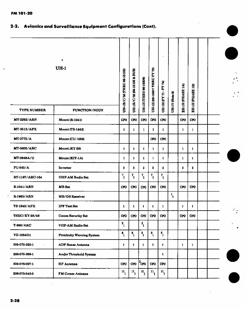
FM 101-20
2-2. Avionics and Surveillance Equipment Configurations (Cont).
TYPE NUMBER
UH-1
FUNCTION/NOUN
g X b
o a
CQ £9 09 <0 s 10
s o oo
X D
D 00 X fc X
>< h D OS »
£
r»
I a
& >
a a
3
H
& a à H
a H
fe a á H
MT-2292/ARN Mount (R-1041) CPO CP0 CFO CPO CPO CPO CPO
MT-3613/APX Mount (TS-1843)
MT-3772/A Mount (CU-1658) CPO CPO
MT-3802/ARC Mount (KY-28)
MT-3949A/U Mount (KIT-1 A)
PU-643/A Inverter
RT-1167/ARC-164 UHF-AM Radio Set
R-1041/ARN MB Set CPO CPO CPO CPO CPO CPO CPO
R-1963/ARN MB/OS Receiver
TS-1843/APX IFF Test Set
TSEC/KY-28/68 Conun Security Set CPO CPO CPO CPO CPO CPO CPO
T-366/ARC VHF-AM Radio Set
YG-1054D1 Proximity Warning System
206-076-326-1 ADF Sense Antenna
206-076-399-1 Audio Threshold System
206-076-027-1 HF Antenna CPO CPO CPO CPO CPO
206-076-643-3 FM Comm Antenna 11 11 11 11 11
2-28

FM 101-20
2-2. Avionics and Surveillance Equipment Configurations (Cont).
NOTES: 1. Proposed retrofit installation. 2. Provisions for the AN /ARC-102 system are not installed in FY 62 aircraft. 3. The AN/ARC-115 is a proposed retrofit replacement for AN/ARC-73 and T-366. 4. AN/ARN-30, CV-1275 and AN/ARN-59 installed in UH-1B/C/M through 66-601 and UH-1D/H
through FY 65. AN/ARN-82 and AN/ARN-83 installed in subsequent aircraft. 5. J-2 installed in UH-1B/C/M through 66-15147 and in UH-1D/H through 66-16446. AN/ASN-43
installed in subsequent aircraft. 6. Provisions for the CU-1658 and MT-3772 installed in FY68 and subsequent aircraft. 7. The RT-1167 is a proposed retrofit replacement for AN /ARC-51. 8. Equipment installed only in aircraft located at Ft. Bragg, Ft. Campbell, Ft. Hood and Ft. Rucker. 9. Only UH-1V peculiar avionics are listed. Other installed/CPO items will depend on the TMS of the
aricraft selected for UH-1Y designation. 10. All UH-1( ) aircraft were originally delivered with the MC-1 installed. However, it is presently
being removed (with no replacement) during depot overhaul. 11. The AS-1703 is used with the #1 FM (AN/ARC-131) system and the 2064)75-543-3 is used with the
#2 FM (AN/ARC-114) system in all aircraft except UH-1D/H (FY 71 - FY 74) which have the AS-1703 with the #2 system and the 206-075-543-3 with the II system.
APPLICABLE AIRCRAFT AVIONICS MANUALS: TM 11-1520-210 Series (Pertains to UH-1D/H) TM11-1520-211 Series (Pertains to UH-1B/C/M)

FM 101-20
2-2. Avionics and Surveillance Equipment Configurations (Cont).
The following configuration depicts a typically configured UH-60A. The actual configuration may vary depending on peculiar geographic re- quirements or changes incorporated through MWO action and special purpose alterations.
TYPE NUMBER FUNCTION/NOUN
AN/ALQ-144 Countermeasures Set CPO
AN/APN-209(V)2 Radar Altimeter
AN/APR-39(V)1 Radar Warning Set CPO
AN/ARC-114 VHF-FM Radio Set #1
AN/ARC-114 VHF-FM Radio Set #2 CPO
AN/ARC-115A VHF-AM Radio Set
AN/ARN-89 ADFSet
AN/ARN-123(V)4 VOR/MB/GS Set
AN/ASN-43 Gyro Compass Set
AN/ASN-128 Doppler Nav Set
CN-1314/A
06533/ARC
Gyro
IntercommSet
2-30
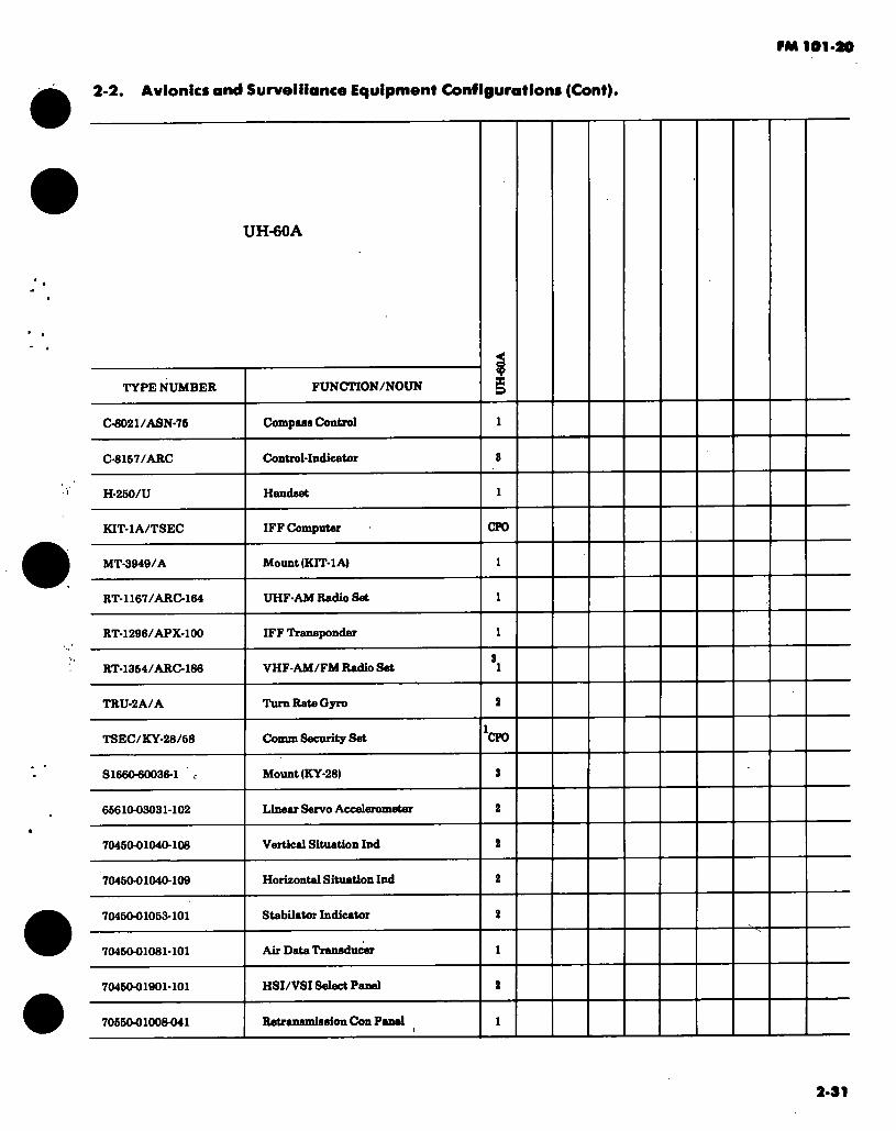
PM loi-ao
2-2. Avionics and Surveillance Equipment Configurations (Cont).
UH-60A
TYPE NUMBER FUNCTION/NOUN
C-6021/ASN-75 Compass Control
C-8167/ARC
H-250/U
Control-Indicator
Handset
KIT-1A/TSEC IFF Computer CPO
MT-3949/A Mount (KIT-1 A)
RT-1167/ARC-164 UHF-AM Radio Set
RT-1296/APX-100 IFF Transponder
RT-1354/ARC-186 VHF-AM/FM Radio Set
TRU-2A/A Turn Rate Gyro
TSEC/KY-28/68 Comm Security Set CPO
S1660-60036-1 c Mount (KY-28)
65610-03031-102 Linear Servo Accelerometer
70450-01040-108 Vertical Situation Ind
704504)1040-109 Horizontal Situation Ind
704604)1053-101 Stabilator Indicator
704604)1081-101 Air Data Transducer
704504)1901-101 HSI/VSI Select Panel
705504)10084)41 Retransmission Con Panel
2-31
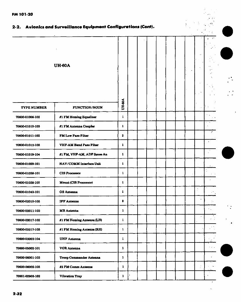
FM 101-20
2-2. Avionics and Surveillance Equipment Configurations (Cont).
UH-60A
TYPE NUMBER FUNCTION/NOUN
70600-01006-102 #1 FM Homing Equalizer
70600-01010-103 #1 FM Antenna Coupler
70600-01011-102 FM Low Pass Filter
7060001012-102 VHF-AM Band Pass Filter
70600-01010104 #1 FM. VHF-AM, ADF Sense An
7060001020101 NAV/COMM Interface Unit
7060001038-101 CIS Processor
70600-01038-102 Mount (CIS Processor)
7060001043-101 GS Antenna
7060002010103 IFF Antenna
7060002011-103 MB Antenna
7060002017-102 #1 FM Homing Antenna (LH)
7060002017-103 #1 FM Homing Antenna (RH)
7060003002-104 UHF Antenna
7060006002-101 VOR Antenna
7060006001-103 Troop Commander Antenna
7060006002-106 #2 FM Comm Antenna
70901-02903-102 Vibration Tray
2-32

FM 101-20
2.2. Avionics and Surveillance Equipment Configurations (Cont).
UH-60A
TYPE NUMBER I
FUNCTION/NOUN
70901-02908-103 SAS/FPS Computer
70901-02904-102 Rate Gyro
70901-02907-101 Airspeed Transducer
70901-02908-101
7090201070044
SAS Amplifier
Stabilster/AFCS Panel
7090201086041 Mode Select Panel
7090202001042 Stabilster Control Amp
NOTES: 1. Complete provisions installed for 3 each KY-28/58 sets. 2. Provisions for the AN/ALQ-144 installed in serial 78-22987 and subsequent aircraft.
3. The AN/ARC-115A is installed in serial 77-22714 through 79-23307 aircraft. The RT-1354 is installed in serial 79-23308 and subsequent aircraft.
APPLICABLE AIRCRAFT AVIONICS MANUALS TM 11-1520-237 Series
2-33

FM 101-20
2-2. Avionics and Surveillance Equipment Configurations (Cont).
AH-64
TYPE NUMBER ?
PUNCTION/NOUN
AN / APN-209fV)2 Radar Altimeter
AN / APR-39(V) 1 Radar Warning Set
AN/ARC-114 VHF-FM Radio Set
AN/ARC-116 YHF-AM Radio Set
AN/ARN-89B AUF Set
AN/ASN-43 Gyro Compasa Set
AN/ASN-128 Doppler Nav Set
CN-1S14/A Gyro
C-6533/ARC Intercomm Set
C-8167/ARC Control-Indicator
KIT-1A/TSEC
MC-1
IFF Computer
Gyro
CPO
2-34
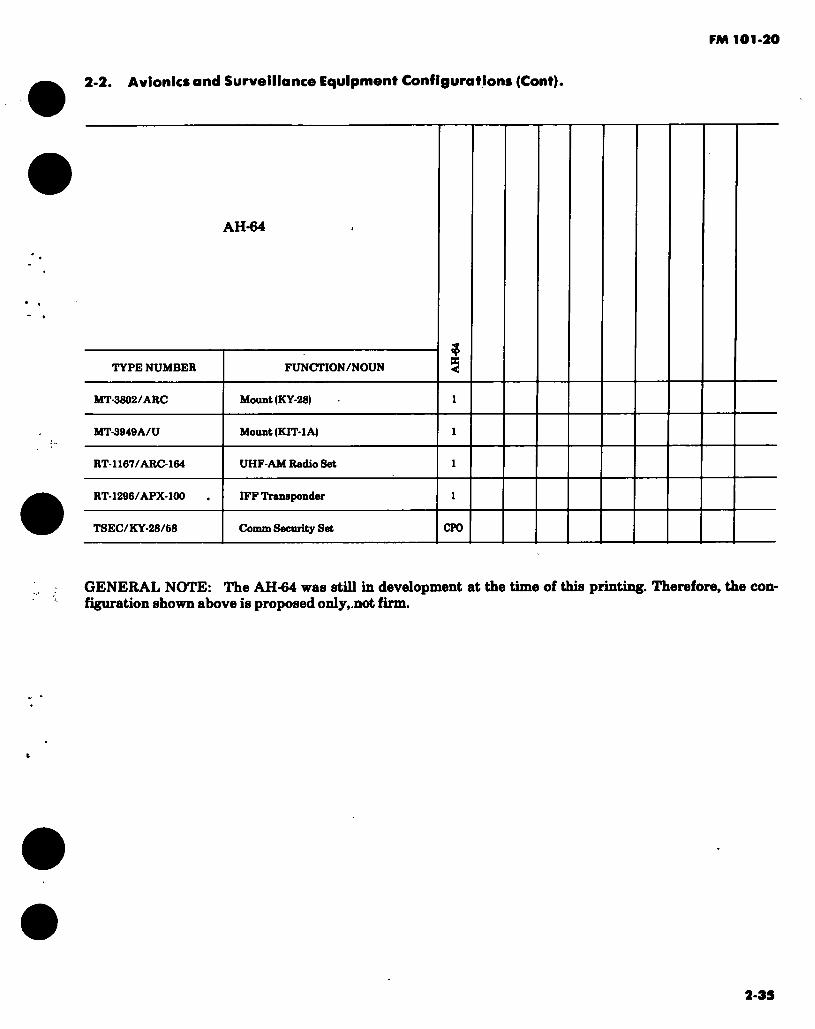
FM 101-20
2-2 Avionics and Surveillance Equipment Configurations (Cont).
AH-64
TYPE NUMBER FUNCTION/NOUN ?
MT-3802/ARC Mount (KY-28)
MT-3949A/U Mount (KIT-1 A)
RT-1167/ARC-164 UHF-AM Radio Set
RT-1296/APX-100 IFF Transponder
TSEC/KY-28/68 Comm Security Set CPO
GENERAL NOTE: The AH-64 was still in development at the time of this printing. Therefore, the con- figuration shown above is proposed only,.not firm.
2-39

FM 101-20
2-2. Avionics and Surveillance Equipment Configurations (Cont).
The following configuration depicts a typically configured C-12( ). The actual configuration may vary depending on peculiar geographic re- quirements or changes incorporated through MWO action and special purpose alterations.
TYPE NUMBER FUNCTION/NOUN
Û
O
04
e>
VHF-20B (Collins) VHF-AM Radio Sot
O 4683A (Cables) VHF-AM Control
04684A (Gables) VHF-AM Control
37R-2U (Collins) VHF-AM Antenna
36-6003 (Beech) VHF-AM Antenna
VIR-30AGM (Collins) VOR/MB/GS Set
VIR-30AG (Collins) VOR/GS Set
36-6017 (Beech) VOR Antenna
36-6016 (Beech) MB Antenna
37P-6 (Collins) GS Antenna
331A-8G (Collins) Course Indicator
331A-6P (Collins) Course Indicator
2-36

PM 101-20
2-2. " Avionics and Surveillance Equipment Configurations (Cent).
C-12
TYPE NUMBER FUNCTION/NOUN
0 O
8S6F-S (Collina) Aadk> Amplifier
86604 (Colline)
OF-808 (Colline)
leoletion Amplifier
AOF System c/o:
61Y-4A (Collins) Receiver
187A-4 (Collins) Loop Antenne
614L-8 (Collins) ADF Control
•7-840017-86 (Beech) AOF Sense Antenne
101-440019-16 (Beech) AOF Sense Antenne
DME-40 (Collins)
888F-18 (Collins)
Distence Meesnring Equip
DME Indicator
887Z-1 (Collins) DME Antenne
RT-1168/ARC-164 UHF-AM Redio Set CTO
RDR-1800 (Bendiz) Weether Reder c/o:
RT-1801A (Bondis) Rcvr-Trensmitter end Mount
IN-1802A (Bendiz) TwHIratrir
AT-1308A (Bendiz) Antenne
C-14-48 (Sperry)
666680 (Sperry)
Compess System c/o:
Flux Vslve
2-37

FM 101-20
2-2. Avionics and Surveillance Equipment Configurations (Cont).
TYPE NUMBER
C-12
FUNCTION/NOUN
a 's. o s Ô
2687193-43 (Sperry) Gyro and Synchronizer
341C-1 (Collins) Servo Amplifier
AN/APX-100 IFF Transponder
AN/APX-101 IFF Transponder
AT-884
718U-6 (Collins) HF-SSB Set c/o:
671U-4A (Collins) Rcvr-Exciter and Mount
648S-3 (Collins) Power Amplifier and Mount
614A-4 (Collins) Control
AP-106 (Collins) Integrated Flight System c/o:
344C-11 (Collins) Aileron Servo and Mount
344C-11 (Collins) Elevator Servo and Mount
344C-11 (Collins) Rudder Servo and Mount
344D-6 (Collins) Elevator Tab Servo and Mount
332D-12 (Collins) Vertical Gyro
662C-13A (Collins) Computer and Mount
329T-1 (Collins) Turn and Slip Indicator
329B-9A (Collins) Flight Director Indicator
2-38

FM 101-20
2-2. Avionics and Surveillance Equipment Configurations (Cont).
TYPE NUMBER
C-12
FUNCTION/NOUN
a o
832010 (Collins) RMI
t, 35604 (Collins) Interphone Amplifier
S66F-3 (Collins) Paging Amplifier
TR-70-17 (CCC) Emerg Locator Transmitter
ELT10-209 (CCC) Emerg Locator Transmitter Ant
NOTES: 1. Equipment installed in all oversea areas and selected CONUS areas. 2. The AN/APX-101 is installed in FY 73 C-12A aircraft. The AN/APX-100 is installed in all other
aircraft.
GENERAL NOTE: The C-12( ) avionics configuration contains all commercial equipment. As such, data sheets or supply data for these items will not appear in this publication. Sup- port of these items is the responsibility of the contractor.
APPLICABLE AIRCRAFT AVIONICS MANUALS: DA publications are not available. Refer to ap- plicable commercial literature.
2-39

PM 101-20
2-2. Avionics and Surveillance Equipment Configurations (Cont).
The following configuration depicts a typically configured OV-l( )/RV-lD. The actual con- figuration may vary depending on peculiar geographic requirements or changes in- corporated through MWO action and special purpose alterations.
TYPE NUMBER FUNCTION/NOUN o & o £
AN/AAS-14 IR Detecting Set
AN/AAS-24 IR Detecting Set CPO
AN/ADR-6 RadiacSet CPO
AN/AJA-6 Synchrophaaer
AN/AKT-18 Data Tranamitting Set
AN/AKT-18A/B Data Tranamitting Set
AN/ALQ-133 CoonteRneaearea Set CPO
AN/ALQ-136 Coontermeaaurea Set CPO CPO
AN/ALQ-147(V)1 Conntermeasoras Sat CPO
AN/ALQ-147(V)2 Conntenneaanres Set CPO
AN/ALQ-166 Coontermeaaurea Set CPO CPO
AN/ALQ-162 Conntonnaasnres Set CPO CPO
2-40

FM 101-20
2-2. Avionics and Surveillance Equipment Configurations (Cont).
TYPE NUMBER
OV-1
FUNCTION/NOUN > O
> o 5 > «
AN/ALR-46 Radar Warning Set 17
CPO 17CP0
AN/APN-22 Radar Altimeter
AN/APN-171A(V)1 Radar Altimeter
AN / APR-39(V)2 Radar Warning Set 17
CPO 17.
CPO
AN/APR-44 (V)3 Radar Warning Set CPO CPO
AN/APS-94C Radar Surveillance Set
AN/APS-94D/E/F Radar Surveillance Set CPO
AN/APX-72 IFF Transponder Set
AN/ARC-61BX UHF-AM Radio Set 16 16 16 16
AN/ARC-64/131 VHF-FM Radio Set
AN/ARC-102 HF-AM Radio Set CPO CPO CPO CPO
AN/ARC-114 VHF-FM Radio Set #1
AN/ARC-114 VHF-FM Radio Set 12 14.
CPO
AN/ARC-116 VHF-AM Radio Set
AN/ARC-134 VHF-AM Radio Set
AN/ARN-30E VOR Set
AN/ARN-59 ADFSet
AN/ARN-82 VOR Set
2-41

FM 101-20
2-2. Avionics and Surveillance Equipment Configurations (Cont).
TYPE NUMBER
OV-1
FUNCTION/NOUN
AN/ARN-83 ADFSet
AN/ARN-89 ADFSet
AN/ARN-103 TACAN Set
AN/ART-41A Date Transmitter
AN/ASN-33 Nav Computer Set
AN/ASN-64 Doppler Nav Set
AN/ASN-76 Attitude Ref Set
AN/ASN-86 Inertial Nav Set
AN / AS W-12 Autopilot Set
AN/AYA-10 Data Annotation System
AN/USQ-61 Digital Data System CPO
AS-1703/AR FM Comm Antenna
AS-2042/ARC FM Homing Antenna
AT-134A/ARN MB Antenna
AT-326/ARN GS Antenna
AT-460/A Data Link Antenna
AT-741/A IFF/TACAN Antenna
AT-1108/ARC VHF-AM/UHF Antenna
2-42

FM 101-90
2-2. Avionics and Surveillance Equipment Configurations (Cent).
0V-1
TYPE NUMBER FUNCTION/NOUN s BB-433A/A
CU-942/ARC
Battery
FM Antenna Coupler
CU-1668/A HF Antenna Coupler CPO
C-1611/AIC
06633/ARC
Intercomm Set
Intercomm Set
C-8167/ARC Control-Indicator
DT-173/AJN Magnetic Azimuth Detector
ID-260/ARN RMI
ID663/U BDH Indicator
KA-60C Camera 11
CPO 10.
CPO
HT-IA/TSEC IFF Computer CPO CPO CPO CPO
KS-61A Photo Surv System 13
CPO 12,13
CPO
KS-104A Photo Surv System 12,18
CPO
KS-104B Photo Surv System 12,18
CPO
KS-113A Photo Surv System IS.
CPO
MD736/A Signal Discriminator CPO CPO
MT-3513/APX Mount (TS-1843)
MT-3772/A Mount (CU-1668) CPO
2-43

FM 101-20
2-2. Avionics and Surveillance Equipment Configurations (Cont).
TYPE NUMBER
OV-1
FUNCTION/NOUN
«
È O
é o > os
MT-3802/ARC Mount (KY-28)
MT-3949A/U Mount (KIT-IA)
OK-279/A Voltage Controller Grp
PU-644/A Inverter
PU-646/A Inverter
PU-760/A Inverter
RT-1167/ARC-164 UHF-AM Radio Set 18. 16 16. 18.
R-844/ARN-68 MB/GS Set 15 15 16. 16.
R-1963/ARN MB/GS Set 16 16 15 15
SA-621/A Antenna Switch
T-M2/A True Airapeed Xmtr
TS-1843/APX IFF Test Set
TSEC/KY-28/68 Comm Security Set CPO CPO CPO CPO
134AV26618-1 ADF Sense Antenna
134AV36003-1 GS Antenna
134AV46511-6 HF Antenna
134CS30103-1 VOR Antenna
134SCAV247-1 FM Conun Antenna
2-44

FM 101-20
2-2. Avionics and Surveillance Equipment Configurations (Cont).
TYPE NUMBER
OV-1
FUNCTION/NOUN
CQ
> O
> o
> o
> cc
134AV45511-5 HE Antenna
134CS30103-1 VOR Antenna
134SCAV247-1 EM Comm Antenna
2-45

FM 10{1-20
2-2. Avionics and Surveillance Equipment Configurations (Cont).
NOTES: 1. Proposed retrofit installation. 2. Installed in selected aircraft only. 3. AN/APN-22 installed thru FY 67 aircraft. AN/APN-171 installed in FY 68 aircraft. 4. Either the AN/AAS-24 or the AN/APS-94D/E/F can be installed but not both. Equipment to be
installed will be issued on a TO&E basis only. 5. OV-1C aircraft prior to FY 66 and all OV-1B have the AN/ARN-30E and AN/ARN-69 installed.
FY 66 and subsequent OV-1C aircraft have the AN/ARN-82 and AN/ARN-83 installed. The retrofit replacement of the AN/ARN-30E by the AN/ARN-82 in all applicable aircraft is proposed.
6. The AT-134 is modified to become 134AV25508-1. 7. The AT-326 (Collins 37P4) or the 134AV35003-1 is installed on 0V-1C aircraft. 8. Either the DT-309 or DT-376 may be installed as a part of the DT-173. 9. The ID-260 is installed in lieu of the ID-663 in some OV-1B and 0V-1C aircraft.
10. Provisions installed for 2 each KA-60C in addition to KS-113A system. 11. Installed in FY 66, FY 67 and FY 68 aircraft in addition to KS-61 or KS-104( ) systems. 12. KS-61A installed thru FY 66 aircraft. KS-104A installed in FY 67 aircraft and KS-104B installed in
' FY 68 aircraft. 13. Some components of these systems are installed. However, the cameras and other major
components are issued on a TO&E basis only. 14. Equipment issued on a TO&E basis. 16. The R-1963 is a proposed retrofit replacement for R-844. 16. The RT-1167 is a proposed retrofit replacement for AN/ARC-51. 17. The AN/ APR-39(V)2 is a proposed retrofit replacement for AN/ALR-46.
APPLICABLE AIRCRAFT AVIONICS MANUALS: TM 11-1610-204 Series (Pertains to OV-1B, C, D) TM 11-1610-213 Series (Pertains to RV-1D)
2-46

2-2. Avionics and Surveillance Equipment Configurations (Cont).
FM 101-20
The following configuration depicts a typically configured T-41B. The actual configuration may vary depending on peculiar geographic re- quirements or changes incorporated through MWO action and special purpose alterations.
TYPE NUMBER FUNCTION/NOUN 2 AN/ARC-64/131 VHF-FM Radio Set CFO
AN/ARN-8q ADFSet
AS-1703/AR FM Comm Antenna CPO
AS-1922/ARC FM Homing Antenna CPO
C-1611/AIC Intereonun Set
CU-942/ARC FM Antenna Coupler CPO
ID-718/ARN Aximuth Indicator
A-26A VHF Comm Antenna
0670400-605 VOR Antenna
0570401-6 ADF Sense Antenna
0870060-1 Battery
31640 Indicator
615R VHF Comm/Nav Radio Set
MIC Emerg VHF Radio Set
2-47
FM 101-20
2-2. Avionics and Surveillance Equipment Configurations (Cont).
APPLICABLE AIRCRAFT AVIONICS MANUALS: DA publications are not available. Refer to applicable conunercial literature.
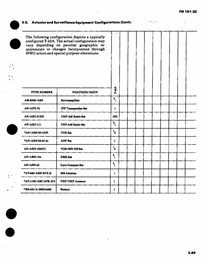
FM 101-20
2-2. Avionlci and Surveillance Equipment Configuration« (Cont).
The following configuration depicts a typically configured T-42A. The actual configuration may vary depending on peculiar geographic re- quirements or changes incorporated through MWO action and special purpose alterations.
TYPE NUMBER FUNCTION/NOUN
AM-3209/ASN Servoamplifier
AN/APX-72 IFF Transponder Set
AN/ARC-51BX UHF-AM Radio Set CPO
AN/ARC-111 VHF-AM Radio Set
•AN/ARN-30 (16F) VOR Set
*AN/ARN-69 (21A) ADFSet
AN/ARN-123(V)1 VOR/MB/QS Set
AN/ARN-124 DMESet
AN/ASN-43 Gyro Compasa Set
•AT-640/ARN (37X-2) MB Antenna
•ATI 108/ARC (37R- 2U) VHF/UHF Antenna
•BB-432/A (MS24496) Battery
2-49
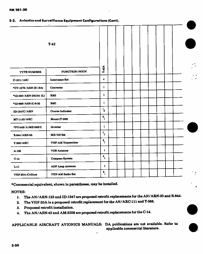
PM 101-20
2-2. Avionics and Surveillance Equipment Configurations (Cant).
T-42
TYPE NUMBER
C-I611/AIC
•CV-1276/ARN (B-18A)
* ID-260/ARN (36104- ID
•ID098/ASN (C-6-H)
FUNCTION/NOUN
Intercomm Set
Convertor
RMI
RMI
ID-1347C/ARN Course Indicator
MT-1142/ARC Mount (T-366)
•PU-642/A (MS16067) Inverter
R-844/ARN-68 MB/GS Set
T-366/ARC VHF-AM Transmitter
A-138 VOR Antenna
C-14 Compass System
L-ll ADF Loop Antenna
VHF-20A (Collins) VHF-AM Radio Set
•Commercial equivalent, shown in parentheses, may be installed.
NOTES: 1. The AN/ARN-123 and ID-1347 are proposed retrofit replacements for the AN/ARN-30 and R-844.
2. The VHF-20A is a proposed retrofit replacement for the AN/ ARC-111 and T-366. 3. Proposed retrofit installation. 4. The AN/ASN-43 and AM-3209 are proposed retrofit replacements for the C-14.
APPLICABLE AIRCRAFT AVIONICS MANUALS: DA publications are not available. Refer to applicable commercial literature.
2-50

PM 101*20
2-2. Avientes and Surveillance Equipment Configurations (Cont).
The following configuration depicts a typically configured U-8F. The actual configuration may vary depending on peculiar geographic re- quirements or changes incorporated through MWO action and special purpose alterations.
TYPE NUMBER FUNCTION/NOUN
s h
3 AM-3209/ASN Sarvoamplifler
AN/APN-158 Weather Radar
AN/APX-72 IFF Transponder Set
AN/ARA-M Glide Slope Receiver
AN/ARC-44 VHF-FM Radio Set
AN/ARC-61BX
AN/ARC-64/131
UHF-AM Radio Set
VHF-FM Radio Set
AN/ARC-66 UHF-AM Radio Set
AN/ARC-73 VHF-AM Radio Set
AN/ARC-102 HF-AM Radio Set CPO CPO
AN/ARC-184 VHF-AM Radio Set
AN/ARN-12/32 MB Receiver
2*51
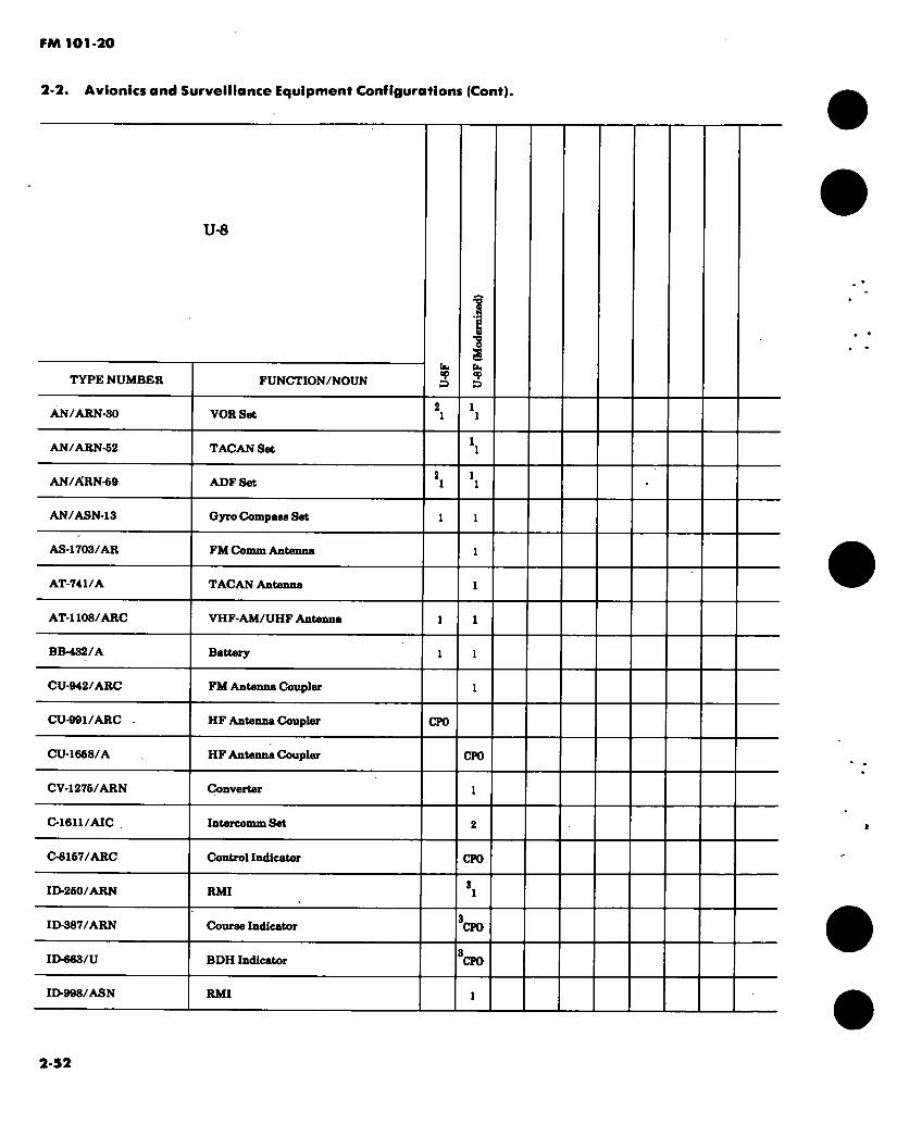
FM 101-20
2-2. Avionics and Surveillance Equipment Configurations (Cont).
TYPE NUMBER
U-8
FUNCTION/NOUN
1 s u. °p
AN/ARN-30 VOR Set
AN/ARN-62 TACAN Set
AN/ARN-69 ADFSet
AN/ASN-13 Gyro Compass Set
AS-1703/AR FM Comm Antenna
AT-741/A TACAN Antenna
AT-1108/ARC VHF-AM/UHF Antenna
BB-432/A Battery
CU-942/ARC FM Antenna Coupler
CU-991/ARC HF Antenna Coupler CPO
CU-1668/A HF Antenna Coupler CPO
CV-1276/ARN Converter
C-1611/AIC Intercomm Set
C-8157/ARC Control Indicator CPO
ID-260/ARN RMI
ID-387/ARN Course Indicator CPO
ID-663/U BDH Indicator CPO
ID-998/ASN RMI
2-52
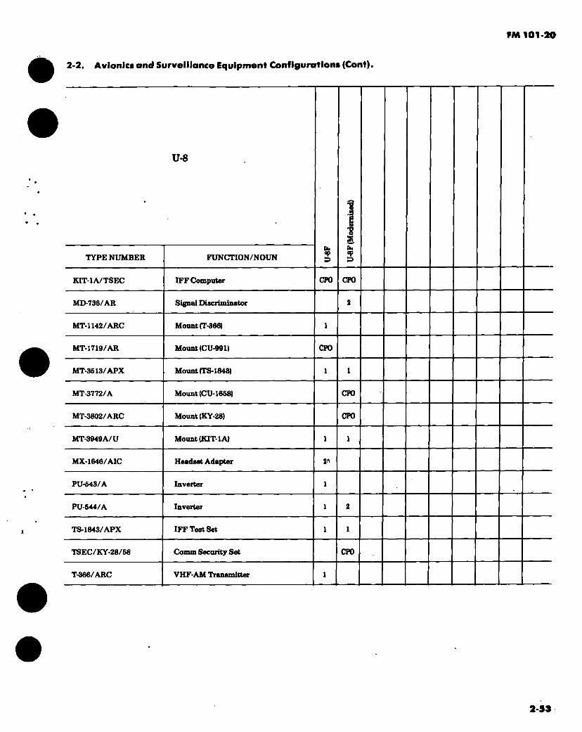
FM 101-20
2-2. Avionics and Surveillance Equipment Configurations (Cont).
TYPE NUMBER
U-8
FUNCTION/NOUN s ■8 s Qu s
KIT-1A/TSEC IFF Computer CPO CPO
MD-736/AR Signal Discriminator
MT-1142/ARC Mount (T-366)
MT-17I9/AR Mount (CU-99X) CPO
MT-3513/APX Mount (TS-1843)
MT-3772/A Mount (CU-1668) CPO
MT-3802/ARC Mount (KY-28) CPO
MT-3949A/U Mount (KIT-1A)
MX-1646/AIC Headset Adapter 2«
PU-643/A Inverter
PU-644/A Inverter
TS-1843/APX IFF Test Set
TSEC/KY-28/58 Comm Security Set CPO
T-366/ARC VHF-AM Transmitter
2-53
PM 101-20
2-2. Avionics and Surveillance Equipment Configurations (Cont).
NOTES: 1. Either 1 ea ADF, 1 ea VOR and 1 ea TACAN or 2 ea ADF and 1 ea VOR or 2 ea VOR and 1 ea ADF
may be installed. 2. Either 2 ea ADF and 1 ea VOR or 1 ea ADF and 2 ea VOR may be installed. 3. - The ID-387 and ID-663 are installed in lieu of the ID-250 with the TACAN, VOR and ADF
configuration.
GENERAL NOTE: The modernized configuration pertains to those aircraft which have had Avionics Standardization MWOs (ZYR/ZYU) applied.
APPUCABLE AIRCRAFT AVIONICS MANUALS: TM11-1510-201 Series
t
2-54

FM 101-20.
2-2. Avionics and Surveillance Equipment Configurations (Cont).
The following configuration depicts a. typically configured U-10A. The actual configuration may vary depending on peculiar geographic require- ments or changes incorporated through MWO action and special purpose alterations.
U-10
TYPE NUMBER
AN/ARA-31
FUNCTION/NOUN
FM Homing Antenna CPO
AN/ARC-44
AN/ARC-51BX
VHF-FM Radio Set CPO
UHF-AM Radio Set CPO
•AN/ARC-73
•AN/ARN-30D
VHF-AM Radio Set
VOR Sell
AN/ARN-32
•AN/ARN-69
MB Receiver
ADF Set
AT-640/ARN
•AT-1108/ARC
MB Antenna
VHF-AM/UHF Antenna
•BB-432/A
C-1611/AIC
•PU-542/A
CD-4
Battery
Intercomm Set
Inverter
Course Director
2-S5

FM 101-20
2-2. Avionics and Surveillance Equipment Configurations (Cont).
NOTES:
♦Commercial equivalent may be installed.
APPLICABLE AIRCRAFT AVIONICS MANUALS: DA Publications are not available.
2-56
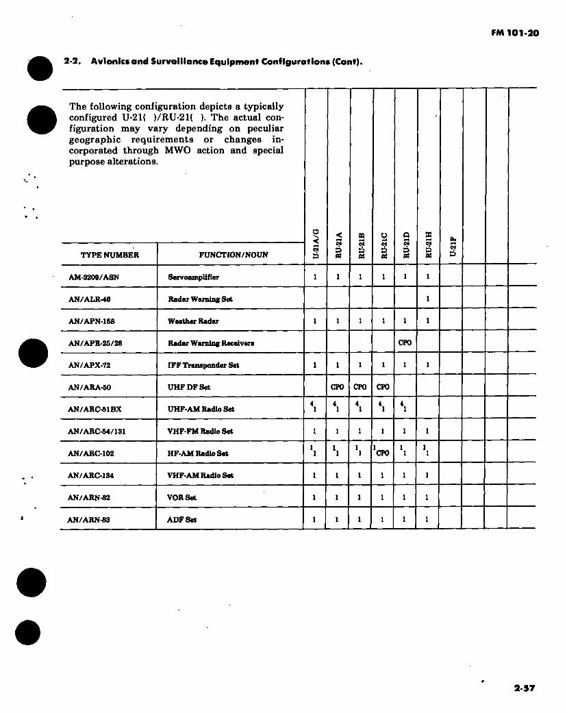
FM 101-20
2-2 Avionics and Surveillance Equipment Configurations (Cont).
The following configuration depicts a typically configured U-21( )/RU-21( ). The actual con- figuration may vary depending on peculiar geographic requirements or changes in- corporated through MWO action and special purpose alterations.
TYPE NUMBER FUNCTION/NOUN
O
pH 09
D
09
g
CQ 09
ó Oí
e*
g Ol
g x PH
09
g Ch PH
09
p
AM-3209/ASN Servoamplifier
AN/ALR-46 Radar Warning S«t
AN/APN-168 Weather Radar
AN/APR-25/26 Radar Warning Receivers CPO
AN/APX-72 IFF Transponder Set
AN/ARA-60 UHF DF Set CPO CPO CPO
AN/ARC-61BX UHF-AM Radio Set
AN/ARC-64/131 VHF-FM Radio Set
AN/ARC-102 HF-AM Radio Set CPO
AN/ARC-134 VHF-AM Radio Set
AN/ARN-82 VOR Set
AN/ARN-83 ADF Set
2-57

PM 101-20
2-2. Avionics and Surveillance Equipment Configurations (Cont).
U-21&RU-21
TYPE NUMBER FUNCTION /NOUN
O < e*
g C4
g
o 09
g 09
g C4
D BÄ
09
D
AN/ARN-102 TACAN Set
AN/ARN-103 TACAN Set
AN/ASN-43 Oyro Compass Set
AN/ASN-88 Inertiml Nev System
AS-680/ARN VOR/OS Antenne
AS-1703/AR FM Comm Antenne
AS-1922/ARC FM Homing Antenne
AS-2285/ARC FM Comm Antenne
AT-640/ARN MB Antenne
AT-884/APX EFF/TACAN Antenne
AT-U08/ARC VHF-AM/UHF Antenne
BB-433/A Battery
CN-405/ASN Flux Compensetor
CU-942/ARC FM Antenne Coupler
CU-I668/A HF Antenne Coupler CFO
C-1611/AIC Intercomm Set
C-8167/ARC Control-Indicator
ID-2B0/ARN RMI
't 2-50

PM 101-20
2-2. Avionics and Surveillance Equipment Configurations (Cont).
U-21&RU-21
TYPE NUMBER FUNCTION/NOUN
O
eN CO
C4
g eo
g
o 04 P
04
g C4
g CSf
D
10-361/387 Course Indicator
10998/ASN RMI
KIT-1A/TSEC IFF Computer CPO CPO CTO CPO CPO CPO
MC-1 Rete Switching Gyro
MOI Displacement Gyro
M0738/A Signal Discriminator
MT-3613/APX Mount (TS-1843)
MT-3772/A Mount (CU-1868) CPO
MT-3802/ARC Mount (KY-28)
MT-3949A/U Mount (KIT-1A)
PU-643/A Inverter
PU-644/A Inverter
RT-1167/ARC-164 UHF-AM Radio Set
R-844/ARN-68 MB/GS Receiver
R-1963/ARN MB/GS Receiver
TS-1843/APX IFF Test Set
TSEC/KY-28/68 Comm Security Set CPO CPO CPO CPO CPO CPO
2-59

FM 101-20
2-2. Avionics and Surveillance Equipment Configurations (Cant).
U-21 & RU-21
TYPE NUMBER FUNCTION/NOUN
O ■V.
< pH 04
ó g
n pH cs D BÈ
o pH 04
g g
04 Gh ■“H C4 S
VC-270D-XX (Gables) VHF Control
VT-10-02 VOR/GS Antenna
071-1034-00 (King) ADF Loop Antenna
1014A (Wilcox) Transponder
36-5003 (CCC) VHF Antenna
36-6016 (CCC) MB Antenna
36-6017 (CCC) VOR/GS Antenna
36-6018 (CCC) DME/Transponder Antennas
60-346611 (Beech) ADF Sense Antenna
60-346616 (Beech) HF Antenna CP0
60-346764-1 (Beech) Main Inverter 6,6,
60-346764-2 (Beech) Standby Inverter 6,6,
60-346764-6 (Beech) Main Inverter «.7,
60-346764-6 (Beech) Standby Inverter 6,7
60-346772 (Beech) Monnt (RT-698/ARC-102) CP0
60-346812 (Beech) ADF Sense Antenna
60-346974 (Beech) RMI
60-346063-3 (Beech) HF Antenna
2-60

FM 101-20
2.2. Avionics and Surveillance Equipment Configurations (Cont).
U-21&RU-21
TYPE NUMBER FUNCTION/NOUN
C* D Qâ
04
g
s C4
s Ch
04
D
T-611/ASN Compasa Transmitter
T-992/A Tras Airspeed Transmitter
AP-105 (Collins) Autopilot
AVq«S(RCA) Weather Radar
C-14-8 (Sperry) Compass System
CA-6H (Marathon) Battery
Dl1220-1 Battery
DME-40 (Collins) DMESet
E661-112204 Battery
FD-108N (Collins) Flight Director
H-14 (Honeywell) Autopilot
KDF-800 (King) ADFSet
KF-MO (King) ADF Control
MGH-182-100 (Leland) Inverter
MOH-229-100 (Leland) Inverter
PN-101 (Collins) Compass System
VC-160W (Gables) Transponder Control
VC-270D-PS (Gables) VHP Control
2-61
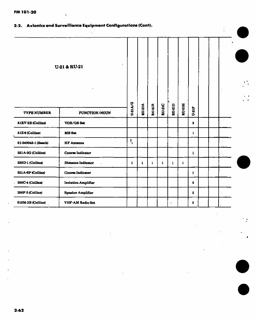
FM 101-20
2-2. Avionics and Surveillance Equipment Configurations (Cont).
U-21&RU-21
TYPE NUMBER FUNCTI0N/N0UN
O
(N g PB
§ C*
§ g g
b. ad M
s
61RV-2B (Collins) VOR/OSSet
51Z-6 (Collins) MB Sot
91-340046-1 (Beech) HF Antenna
331A-30 (Collins) Course Indicator
339D-1 (Collins) Distance Indicator
331A-6P (Collins) Course Indicator
366C-4 (Collins) Isolation Amplifier
366F-3 (Collins) Speaker Amplifier
618M-2B (Collins) VHF-AM Radio Set
2-62
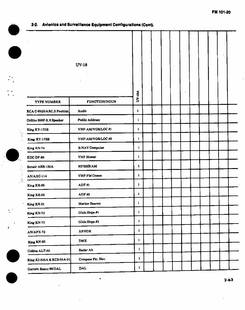
FM 101-20
2-2. Avionics and Survslllancs Equlpmsnt Configurations (Cont).
UV-18
TYPE NUMBER FUNCTION/NOUN
RCA C-8533/ARC.3 Position Audio
Collins 356F-3,0 Speaker Public Address
KingKY-176B VHF-AMA^OR/LOC #1
King KY-176B VHFAM/VOR/LOC #2
King KN-74 R-NAV Computer
EDC DF-88 VHF Homer
Sunair ASB-100A HF/SSB/AM
AN/ARC-U4 VHF-FM Comm
King KR-85 ADF #1
King KR-85 ADF #2
King KR-21 Marker Beacon
King KN-73 Glide Slope #1
King KN-73 Glide Slope #2
AN/APX-72 XPNDR
King KN-65 DME
Collins ALT-50 Radar Alt
King KI-525A & KCS-55A-01 Compass Pic. Nav.
DAL Garrett Rescu 99/DAL
2-63

FM 101-20
2-2. Avionics and Surveillance Equipment Configurations (Cont).
NOTES: 1. Made from a PP-3702. 2. AN/ARN-52 may be installed in some aircraft. 3. The R-1963 is a proposed retrofit replacement for R-844. 4. The RT-1167 is a proposed retrofit replacement for AN/ARC-51. 5. Installed in U-21A only. 6. Made from PU-545/A. 7. Installed in U-21G only. 8. Made form ID-998/ASN.
GENERAL NOTES: 1. The U-21F avionics configuration contains all commercial equipment. As such, data sheets and
supply data for these items will not appear in this publication. Information pertaining to the sup- port of these items is contained in AVSCOM Pamphlet 700-1.
2. The above configurations do not include mission equipment installed in the RU-21 series aircraft.
APPLICABLE AIRCRAFT AVIONICS MANUALS: TM 11-1510-209 Series TM 11-5825-252 Series (RU-21D Mission Equipment) TM 11-5865-216 Series (RU-21H Mission Equipment) TM 11-5895-809 Series (RU-21D Mission Equipment)
2-64

FM 101-20
2-3. Aircraft Armament.
The following aircraft armament subsystems and related components are either in the Research and Development stage, or have been type classified for field usage.
2-4. Aircraft Armament Application.
ARMT SS
M5
M18A1
M19
M21
M22
M23
. M27
M36
M28A1
M28A2
M28A3
M24
M41
M56
M65
XM97E1
M128
M136
Vi 138
AIRCRAFT APPLICATION
UH-1 B M H
X
X
X
AH-1 G S* S# S##
X X X X
X
X
XXX
X
X
X X
X X
OH-6A OH-58 A C
CH-47 ABC
YAH-64 A
X
XXX
2-65
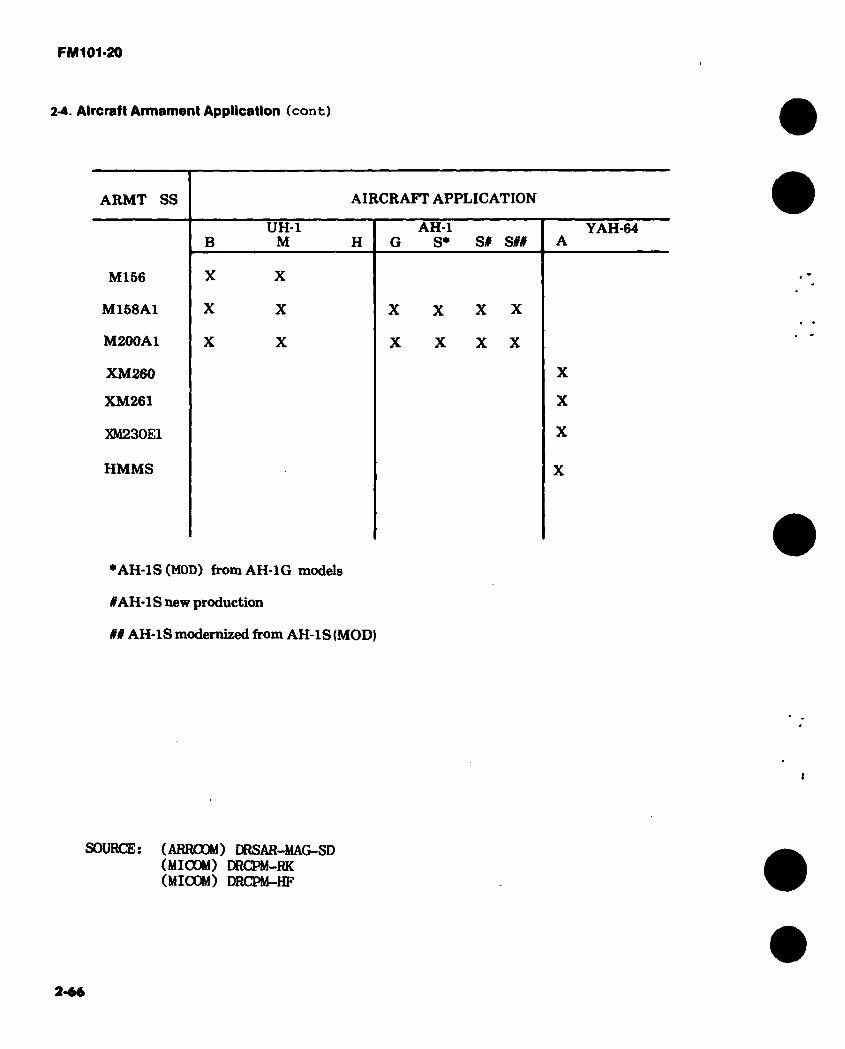
FM 101-20
2-4. Aircraft Armament Application (cont)
ARMT SS AIRCRAFT APPLICATION
M156
M158A1
M200A1
XM260
XM261
XM230E1
HMMS
B
X
X
X
UH-1 M
X
X
X
H AH-1
G S* S# SI#
X X X X
X X X X
YAH-64
X
X
X
♦AH-1S (HOD) from AH-1G models
if AH-IS new production
## AH-1S modernized from AH-1S (MOD)
SOURCE: (ARROOM) DRSAR-MAG-SD (MICOM) DRCPM-RK (MICOM) DRCPM-HF
2-««

FM 101-20
2-5. UH-1 B, and M Armament Configurations.
M-21 I XM-1S6 M-5
Figure 2-1. UH-1B, and M Armament configurations
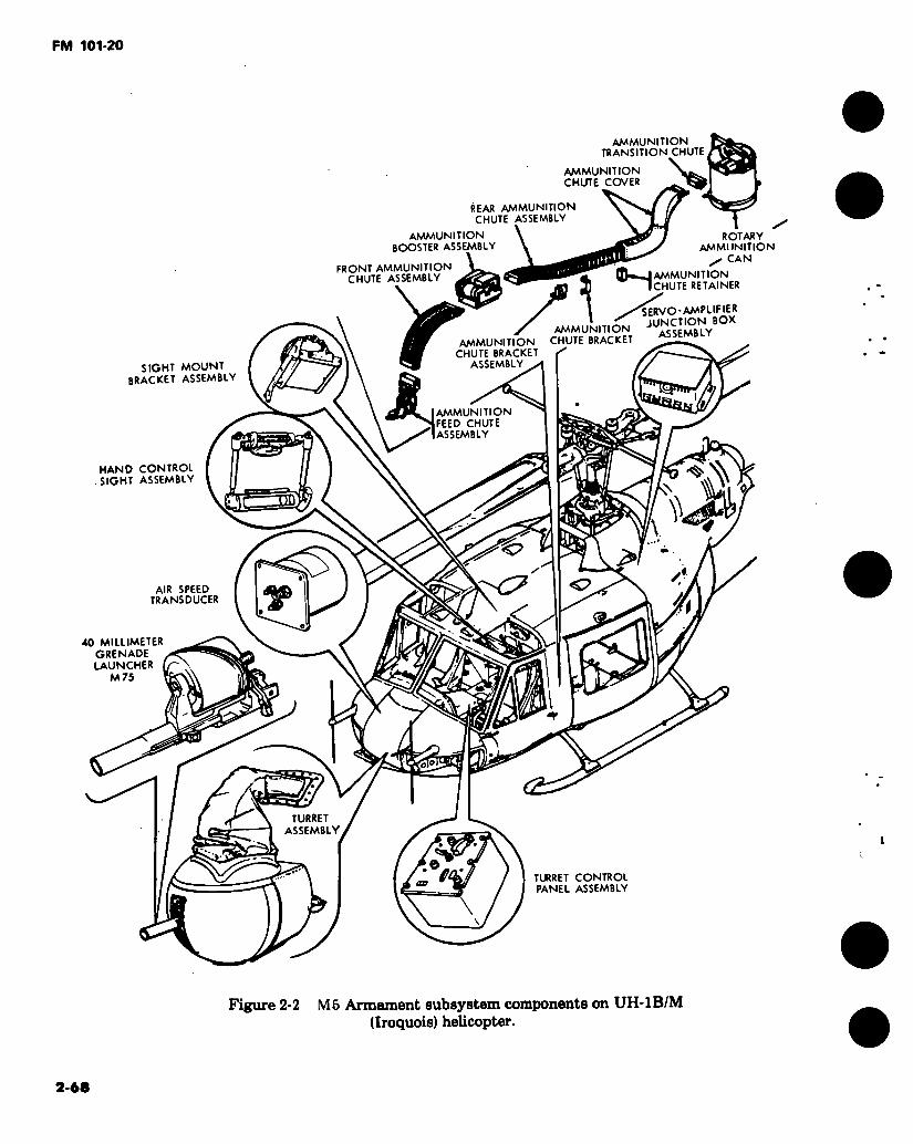
FM 101-20
AMMUNITION
TRANSITION CHUTE i
AMMUNITION
CHUTE COVER
REAR AMMUNITION CHUTE ASSEMBLY
AMMUNITION
BOOSTER ASSEMBLY
FRONT AMMUNITION CHUTE ASSEMBLY
«H AMMUNUJON
ROTARY AMMUNITION
/ CAN
CHUTE RETAINER
SERVO-AMPLIFIER JUNCTION BOX
ASSEMBLY
SIGHT MOUNT BRACKET ASSEMBLY
HAND CONTROL SIGHT ASSEMBLY
AMMUNITION CHUTE BRACKET AMMUNITION
CHUTE BRACKET ASSEMBLY
AMMUNITION
FEED CHUTE ASSEMBLY
CI % I8- ~TCD
<7 <7 AIR SPEED
TRANSDUCER T
«
s -p TURRET
ASSEMBLY
an
\
40 MILLIMETER GRENADE LAUNCHER
M75
TURRET CONTROL PANEL ASSEMBLY
Figure 2-2 M5 Armament subsystem components on UH-1B/M (Iroquois) helicopter.
2-68
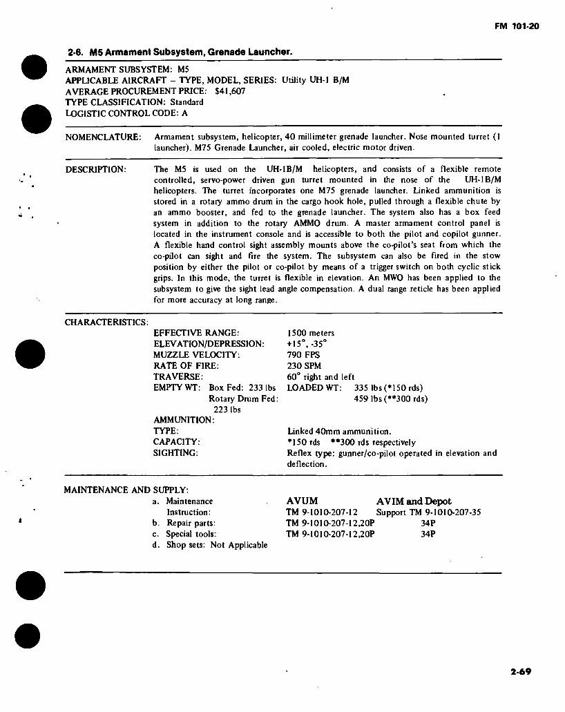
FM 101-20
2-6. MS Armament Subsystem, Grenade Launcher.
ARMAMENT SUBSYSTEM: M5 APPLICABLE AIRCRAFT - TYPE, MODEL, SERIES: UtUity UH-1 B/M AVERAGE PROCUREMENT PRICE: S41,607 TYPE CLASSIFICATION: Standard LOGISTIC CONTROL CODE: A
NOMENCLATURE: Armament subsystem, helicopter, 40 millimeter grenade launcher. Nose mounted turret (1 launcher). M75 Grenade Launcher, air cooled, electric motor driven.
DESCRIPTION: The MS is used on the UH-1B/M helicopters, and consists of a flexible remote controlled, servo-power driven gun turret mounted in the nose of the UH-1 B/M helicopters. The turret incorporates one M75 grenade launcher. Linked ammunition is stored in a rotary ammo drum in the cargo hook hole, pulled through a flexible chute by an ammo booster, and fed to the grenade launcher. The system also has a box feed system in addition to the rotary AMMO drum. A master armament control panel is located in the instrument console and is accessible to both the pilot and copilot gunner. A flexible hand control sight assembly mounts above the co-pilot’s seat from which the co-pilot can sight and fire the system. The subsystem can also be fired in the stow position by either the pilot or co-pilot by means of a trigger switch on both cyclic stick grips. In this mode, the turret is flexible in elevation. An MWO has been applied to the subsystem to give the sight lead angle compensation. A dual range reticle has been applied for more accuracy at long range.
CHARACTERISTICS: EFFECTIVE RANGE: ELEVATION/DEPRESSION : MUZZLE VELOCITY: RATE OF FIRE: TRAVERSE: EMPTY WT: Box Fed: 233 lbs
Rotary Drum Fed: 223 lbs
AMMUNITION: TYPE: CAPACITY. SIGHTING:
1500 meters + 15°, -35° 790 FPS 230 SPM 60° right and left LOADED WT: 335 lbs (*150 rds)
459 lbs (**300 rds)
Linked 40mm ammunition. *150 rds **300 rds respectively Reflex type: gunner/co-pilot operated in elevation and deflection.
MAINTENANCE AND SUPPLY: a. Maintenance
Instruction: b. Repair parts: c. Special tools: d. Shop sets: Not Applicable
AVUM AVIM and Depot TM 9-1010-207-12 Support TM 9-1010-207-35 TM 9-1010-207-12,20P 34P TM 9-1010-207-12,20P 34P
2-69

FM 101-20
2-6. MS Armament Subsystem, Grenade Launcher (CONT).
MODIFICATION DATA REQUIRED FOR INSTALLATION, FUNDING, CONTROLS, AND OPERATING INSTRUCTIONS:
KIT NSN A 1560-00.753-7294 C 1010-00-738-5811 *RAC 1560-00-936-4334
PUBLICATION NICP MWO 55-1520-211-34/33 B17 TM 9-1010-207-12 B14 MWO 55-1520-211-30/32 B17
FUND REQUIREMENTS DA Allocated DA Allocated DA Controlled
Initial issue of kits is DA Controlled and Procurement Appropriation Army (PAA) funded. Repair parts other than initial MWO procurement items are stock funded.
♦RAC — Rotary Ammo Can — Required to upgun the M5 subsystem.
Operational instructions for subsystem can be found in TM 66-1520-220 series manual.
i
r ..
2-70
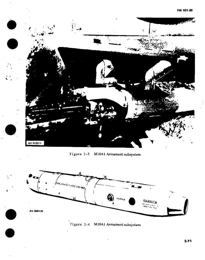
FM 101-20
%
Ui
ta
4 .■<»
t.r. •% «?
• «rfW“ ^
‘H
i ~
t.«*#
• »i
■V. s 0T
T AV 012011
Figure 2-3 MISAI Armament subsystem
futí
Mill IHM
■>..
• »A Ht "" M,r .
•»«A
AV 000139
Figure 2-4 MISAI Armament subsystem
2-71

FM 101-20
2-7. MISAI Armament Subsystem.
ARMAMENT SUBSYSTEM: MISAI APPLICABLE AIRCRAFT TYPE MODEL AND SERIES: Attack helicopter AH-1 SERIES AVERAGE PROCUREMENT PRICE: $20,070 TYPE CLASSIFICATION: Standard LOGISTIC CONTROL CODE: A
NOMENCLATURE: Armament pod, helicopter, 7.62mm machine gun: high-rate
DESCRIPTION: The MISAI armament pod consists of one 7.62mm automatic gun, Ml34, in a cylindrical pod mounted on the inboard wing stores of the aircraft. The pod stores 1500 rounds of ammunition in a linkless feed system. The gun is electrically driven at either low rate, 2000 shots per minute, or high rate, 4000 shots per minute. The pod is self-powered by a self contained battery with a power start feature using auxiliary aircraft power for more starting torque. The pod is rigidly mounted and aiming is accomplished by maneuvering the aircraft.
CHARACTERISTICS: MAXIMUM EFFECTIVE RANGE: ELEVATION: MUZZLE VELOCITY: RATE OF FIRE: TRAVERSE: EMPTY WT: 240 lbs AMMUNITION:
TYPE: CAPACITY: SIGHTING:
1500 meters Fixed 2750 FPS 2000 or 4000 SPM Fixed LOADED WT: 320 lbs
Linked 7.62mm 1500 rds M73 Reflex type
MAINTENANCE AND SUPPLY: Maintenance instruction: Repair parts: Special tools Shop sets: Not Applicable
AVUM TM 9-1005-257-12 TM 9-1005-257-20P TM 9-1005-257-20P
AVIM and Depot Support TM 9-1005-257-35 35P 35 and 35P
MODIFICATION DATA REQUIRED FOR INSTALLATION, FUNDING, CONTROLS, AND OPERATING INSTRUCTIONS:
KIT NSN PUBLICATION NICP 1005-00-832-7498 TM 9-1005-257-12 B14 •
FUND REQUIREMENTS DA controlled
Operational instructions for subsystem can be found in TM 55-1520-221-10.
2-72
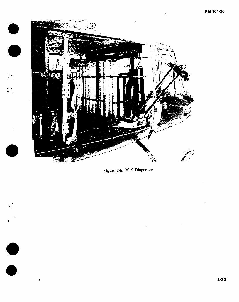
o FM 101-20
m-
1 t
m
?"
Figure 2-5. M19 Dispenser
2-73

FM 101-20
2-8. M19 Dispensing Subsystem.
Dispenser: Aircraft: Average procurement Application: Flares per dispenser: Weight:
Overall Length:
Width: Height: Rate of Ejection:
M19 UH-l/B/H
price: $1,500 One in troop cargo compartment 24 Flares, MK45 w/adapter 150 lbs empty 822 lbs with flares 118 inches w/snout extended 81.0 inches w/snout collapsed 16.0 inches 46.0 inches Manually controlled
Elevation: Transverse: Sighting: Status: DODIC:
Attitude of aircraft Attitude of aircraft Visual assessment LP LI 06
DESCRIPTION: MK45 Flares are loaded into the dispenser with pull cable assembly disk inserted in the overhead track. Immediately prior to launch, the flare safety pin is pulled. The flare to be launched is positioned so that its base is stopped by the foot on the base tray. The operator then pushes the upper portion of the flare outward. The base of the flare then swings outward, providing sufficient force on the pull cable assembly to shear a pin, permitting the flare to fall free. A pull pin is provided for manual jettisoning of the load and flare rack.
MK45 Flare, Aircraft, Parachute.
Illumination: Burntime: Weight: Overall Length: Diameter: Adjustable Time: Status: Logistic Control Code: DODIC:
2,000,000 candlepower 210 seconds 28 lbs 36 inches 4.87 inches Mechanical/pyrotechnic fuze Std
B 1370-L424
DESCRIPTION: Prior to launch, the fuze is set for the desired drop delay (in feet below the aircraft), and the safety pin removed. When launched, the weight of the falling flare against the pull cable exerts sufficient force to break a shear pin to initiate the delay and subsequently ignite the fuze. At the desired time, the parachute/candle assembly is ejected from the outer container, and activated. Near the end of burning, the parachute is collapsed and the spent flare falls rapidly to the ground.
2-74
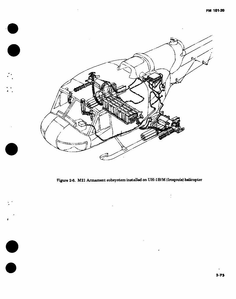
FM 101-20
> V. \
U
'ly?// TÏ
X J V'
JU y !; leí?-
..' \
Figure 2-6. M21 Armament subsystem installed on UH-IB/M (Iroqouis) helicopter
2-75

FM 101-20
2-9. M21 Armament Subsystem.
ARMAMENT SUBSYSTEM: M21 APPUCABLE AIRCRAFT - TYPE, MODEL, SERIES. Utility aircraft, UH-1B, M AVERAGE PROCUREMENT PRICE: $51,897 TYPE CLASSIFICATION: Standard LOGISTIC CONTROL CODE: A
NOMENCLATURE: Armament subsystem, helicopter, 7.62mm twin high rate machine gun with 2.75 inch rocket launchers.
DESCRIPTION: The M21 armament subsystem combines the 7.62 mm, high rate of fire machine gun M134 and the 2.75 inch Folding Fin Aerial Rocket (FFAR), M158A1 launchers. The subsystem consists of two remotely controlled, power operated, flexible pylons, each mounting one 7.62mm machine gun Ml34 and provisions for a non-flexible rocket pod containing seven 2.75 inch FFAR. The rocket launcher installation on each pylon contains associated hardware to fire the rockets and to jettison the launcher. Linked 7.62mm ammunition is stowed inboard and transported to the guns through flexible chuting. A flexible sighting system enables the copilot to remotely aim and fire the machine guns. The pilot may fire either the rockets or the machine guns when in stow position using a fixed sight. The subsystem utilizes all standard 7.62mm NATO ammunition and 2.75 inch rockets applicable to the M158A1 launcher.
CHARACTERISTICS: MAXIMUM EFFECTIVE RANGE: Machine Gun: 1500 meters
. Rocket: 3000 meters RATE OF FIRE: MUZZLE VELOCITY: TRAVERSE:
SIGHTING.
EMPTY WEIGHT: 804 lbs AMMUNITION: TYPE. CAPACITY. ROCKETS: TYPE. CAPACITY:
ELEVATION DEPRESSION: Machine Gun: +10° to -85° Rocket Launcher: Boresight only 2000 or 4000 SPM 2750 EPS Machine guns, inboard 12°, outboard 70° in azimuth from longitudinal axis Pilot-manual reflex type for machine gun and rocket. Copilot/gunner flexible reflex type sight for machine gun only LOADED WEIGHT: 1179.2 lbs
Linked 7.62MM 6000 rds
2.75 inch FFAR 14 RDS
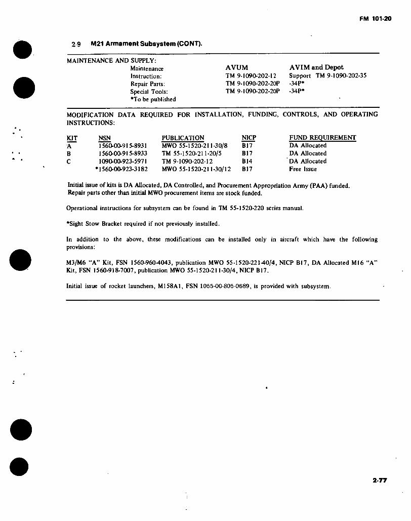
FM 101-20
2 9 M21 Armament Subsystem (CONT).
MAINTENANCE AND SUPPLY: Maintenance Instruction: Repair Parts: Special Tools: *To be published
AVUM TM 9-I090-202-12 TM 9-1090-202-20P TM 9-1090-202-20P
AVIM and Depot Support TM 9-1090-202-35 -34P* -34P*
MODIFICATION DATA REQUIRED FOR INSTALLATION, FUNDING, CONTROLS, AND OPERATING INSTRUCTIONS:
KIT NSN A 1560-00-915-8931 B 1560-00-915-8933 C 1090-00-923-5971
•1560-00-923-3182
PUBLICATION NICP MWO 55-1520-211-30/8 B17 TM 55-1520-211-20/5 B17 TM 9-1090-202-12 B14 MWO 55-1520-211-30/12 B17
FUND REQUIREMENT DA Allocated DA Allocated DA Allocated Free Issue
Initial issue of kits is DA Allocated, DA Controlled, and Procurement Appropriation Army (PAA) funded. Repair parts other than initial MWO procurement items are stock funded.
Operational instructions for subsystem can be found in TM 55-1520-220 series manual.
•Sight Stow Bracket required if not previously installed.
In addition to the above, these modifications can be installed only in aircraft which have the following provisions:
M3/M6 “A” Kit, FSN 1560-9604043, publication MWO 55-1520-22140/4, NICP B17, DA Allocated M16 “A” Kit, FSN 1560-918-7007, publication MWO 55-1520-211-30/4, NICP B17.
Initial issue of rocket launchers, M158A1, FSN 1055-00-805-0689, is provided with subsystem.
2-77
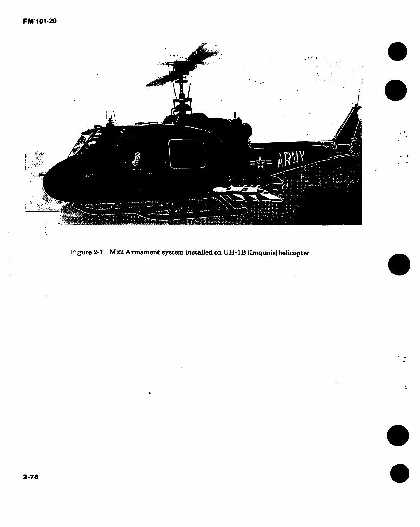
Figure 2-7. M22 Armament system installed on UH-1B (Iroquois) helicopter
2-78
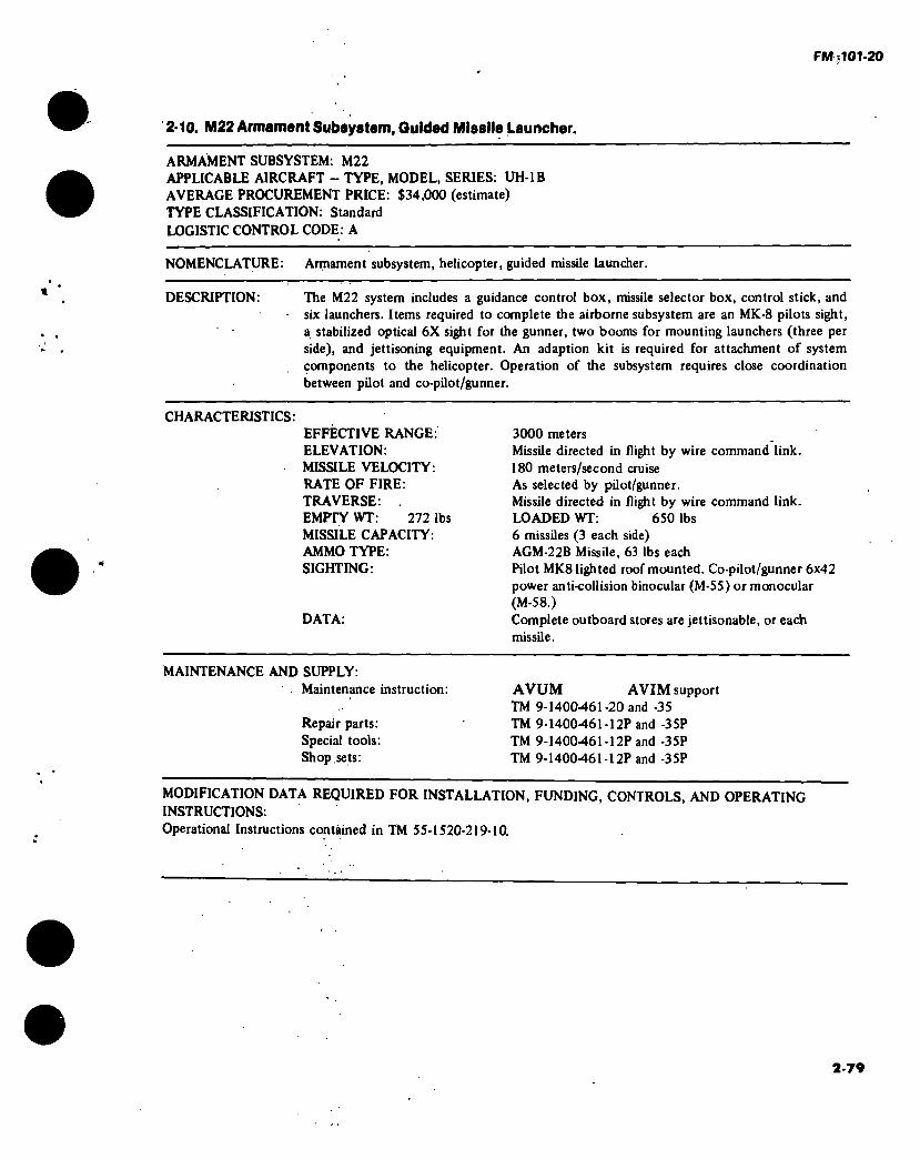
FM';101-20
2-10. M22 Armament Subsystem, Guided Missile Launcher.
ARMAMENT SUBSYSTEM: M22 APPLICABLE AIRCRAFT - TYPE, MODEL, SERIES: UH-1B AVERAGE PROCUREMENT PRICE: $34,000 (estimate) TYPE CLASSIFICATION: Standard LOGISTIC CONTROL CODE: A
NOMENCLATURE: Armament subsystem, helicopter, guided missile launcher.
DESCRIPTION: The M22 system includes a guidance control box, missile selector box, control stick, and - six launchers. Items required to complete the airborne subsystem are an MK-8 pilots sight,
a stabilized optical 6X sight for the gunner, two booms for mounting launchers (three per side), and jettisoning equipment. An adaption kit is required for attachment of system components to the helicopter. Operation of the subsystem requires close coordination between pilot and co-pilot/gunner.
CHARACTERISTICS. EFFECTIVE RANGE: ELEVATION: MISSILE VELOCITY: RATE OF FIRE: TRAVERSE: EMPTY WT: 272 lbs MISSILE CAPACITY: AMMO TYPE: SIGHTING:
DATA:
3000 meters Missile directed in flight by wire command link. 180 meters/second cruise As selected by pilot/gunner. Missile directed in flight by wire command link. LOADED WT: 650 lbs 6 missiles (3 each side) AGM-22B Missile, 63 lbs each Pilot MK8 lighted roof mounted. Co-pilot/gunner 6x42 power anti-collision binocular (M-55) or monocular (M-58.) Complete outboard stores are jettisonable, or each missile.
MAINTENANCE AND SUPPLY: Maintenance instruction:
Repair parts: Special tools: Shop sets:
AVUM AVIM support TM 9-1400-461-20 and -35 TM 9-1400-461-12P and -35P TM 9-1400461-12P and -35P TM 9-1400461-12P and -35P
MODIFICATION DATA REQUIRED FOR INSTALLATION, FUNDING, CONTROLS, AND OPERATING INSTRUCTIONS: Operational Instructions contained in TM 55-1520-219-10.
2-79
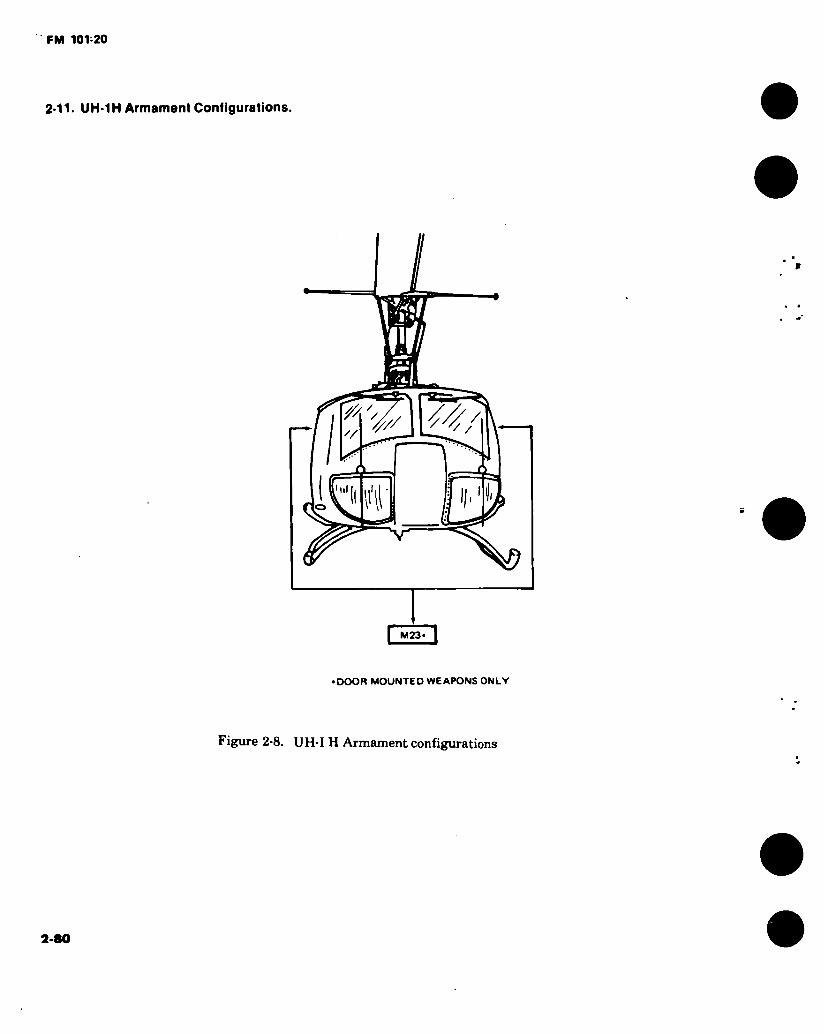
FM 101-20
2-11- UH-1H Armament Configurations.
4// /
ini
H O
• DOOR MOUNTED WEAPONS ONLY
Figure 2-8. UH-I H Armament configurations
2-80

Figure 2-9. M23 Armament subsystem on UH-1H (Iroquois) helicopter
2-81

FM 101-20°
• • i ■
' • ' ' UJ ïli '"’nTh*
Figure 2-10. M23 Armament subsystem in forward stowed position (front view)
2-S2

J FM 101-20
2-12. M23 Armament Subsystem.
ARMAMbNT SUBSYSTEM: M23 ' APPLICABLl: AIRCRAFT TYPE, MODEL, SERIES: Utility UH-lH AVERAGE PROCUREMENT PRICE. $4,282 TYPE CLASSIFICATION: Standard LOGISTIC CONTROL CODE: A
NOMENCLATURE: Armament subsystem, helicopter, door pintle mounted 7.62mm machine gun, M60D.
DESCRIPTION: The M23 armament subsystem consists of two 7.62mm, machine guns, M60D, and two mounts; one on each side of the aircraft in the doorways. The pintle post assembly is attached to a base tube assembly which is attached to hard points on the helicopter fuselage. The machine gun, which is a belt fed, gas operated, air-cooled automatic weapon, is attached to a pivot cradle on top of the pintle post. The base can be employed at either the right or left side, and the pedestal is designed for right or left installation. The machine gun installs on either right or left pintle mounts without adaptation, and is a modified machine gun, M60, with aircraft ring type sights, spade grips and an improved feed system. A rapid reloading capability is provided by a .550 round ammunition box attached to the weapon by a flexible chute. A canvas bag attaches to the right side of the receiver to catch links and ejected cartrid'ges. Free traverse and elevation is allowed within fixed stop limits to prevent self-inflicted damage to the helicopter. The subsystem utilizes all standard 7.62mm ammunition.
CHARACTERISTICS: MAXIMUM EFFECTIVE RANGE: 1100 meters ELEVATION FORWARD. MUZZLE VELOCITY: RATE OF FIRE: TRAVERSE. EMPTY WGT: 173 lbs AMMUNITION: CAPACITY. TYPE:
SIGHTING:
+3.5°, AFT +6.5° DEPRESSION -80° 2750 FPS 550 SPM 2° to 178° in Azimuth LOADED WGT:
550 rounds per gun Linked 7.62mm
Aircraft ring type
210 lbs
MAINTENANCE AND SUPPLY: Maintenance Instruction: Repair parts: Special tools: Shop sets:
AVUM AVIM and Depot TM 9-1005-262-14 TM 9-] 005-262-24P TM 9-I005-262-24P Not Applicable
MODIFICATION DATA REQUIRED FOR INSTALLATION INSTRUCTIONS:
FUNDING, CONTROLS, AND OPERATING
KIT NSN PUBLICATION NIPP 1005-00-907-0720 YM 9-1005-262-15 ‘BIT
Operational instructions for subsystem can be found in TM 9-1005-262-15.
FUND REQUIREMENTS DA Controlled
2-83
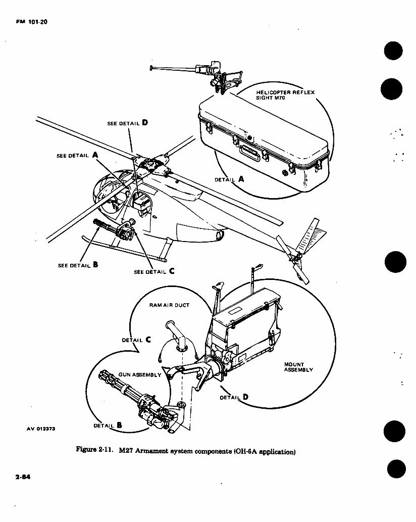
FM 101-20
G HELICOPTER REFLEX SIGHT M70
SEE DETAIL D "V
SEE DETAIL A
« A DETA
SEE DETAIL SEE DETAIL C
RAM AIR DUCT
DETAIL C
MOUNT ASSEMBLY
GUN ASSEMBLY
X _ DETAIL D
DETAIL B AV 012373
Figure 2-11. M27 Armament system components (OH-6A application)
2-84
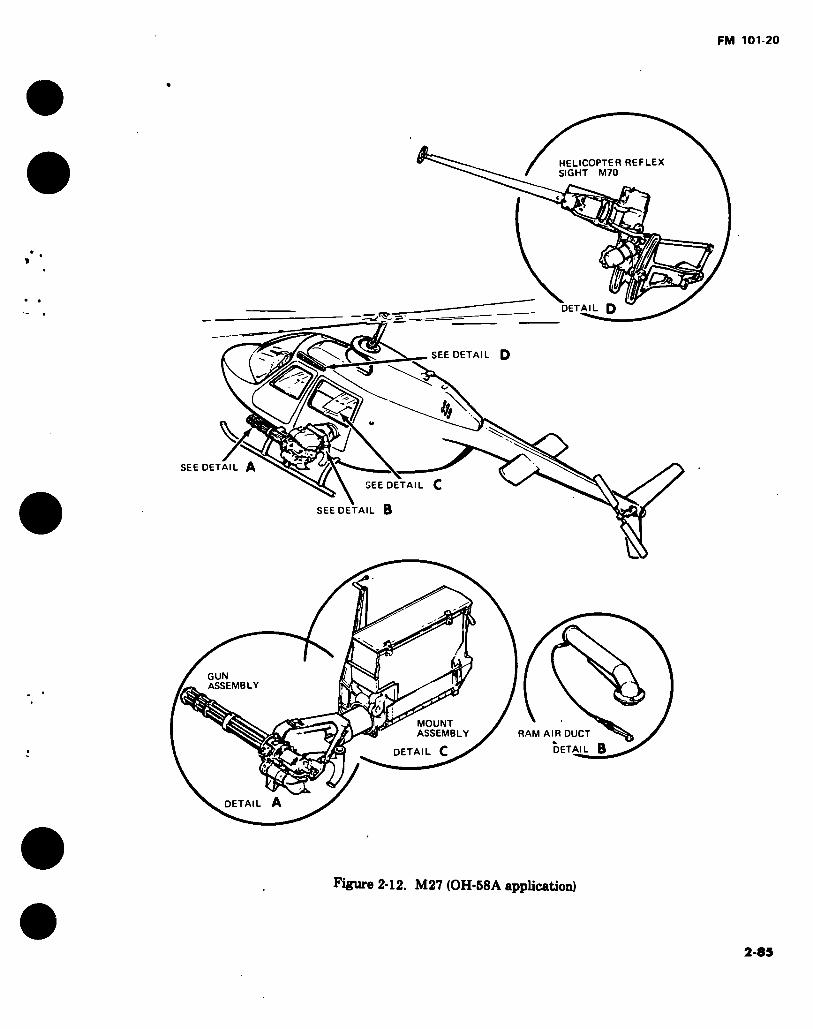
FM 101-20
HELICOPTER REFLEX SIGHT M70
DETAIL D — — .ra> -J
SEE DETAIL D
y SEE DETAIL
\ SEE DETAIL C
SEE DETAIL B
IS
GUN ASSEMBLY
MOUNT ASSEMBLY RAM AIR DUCT
DETAIL DETAIL C
DETAIL A
Figure 2-12. M27 (OH-58A application)
2-85

FM 101-20
2-13. M27 Armament Subsystem.
ARMAMENT SUBSYSTEM: M27 APPLICABLE AIRCRAFT - TYPE, MODEL, SERIES: OH-6A, OH-58A AVERAGE PROCUREMENT PRICE: $25,439 TYPE CLASSIFICATION: Standard LOGISTIC CONTROL CODE: B
NOMENCLATURE: Armament subsystem, helicopter, 7.62mm machine gun; high rate M27
DESCRIPTION: The M27 armament subsystem mounts the high rate of fire 7.62mm machine gun M134I The subsystem consists of a single, remote controlled, semi-flexible mount which supports the machine gun, Ml34, on the left (port) side of the OH-6 and OH-58 helicopters. Linked 7.62mm ammunition is stored inboard and transported to the gun through fixed chuting. A flexible, mechanically linked sighting system enables the pilot to remotely aim and fire the machine gun. The weapon subsystem'is flexible in elevation and depression only, being fixed in azimuth. The aircraft must be aimed by the pilot for target engagement. The armament subsystem is adaptable to the helicopter by means of quick release attachments. Complete internal provisions are incorporated in the production aircraft to accept the armament subsystem without modifications. The weapons subsystem complements weapon systems currently employed in the field.
1600 meters OH-6A+10°, to-24° OH-58A +5 1/2° to-20° 2750 FPS 2000 or 4000 SPM None
234 lbs
CHARACTERISTICS: MAXIMUM EFFECTIVE RANGE: ELEVATION/DEPRESSION:
MUZZLE VELOCITY: RATE OF FIRE: TRAVERSE: EMPTY WT: 100 lbs AMMUNITION: CAPACITY: TYPE: SIGHTING:
MAINTENANCE AND SUPPLY: Maintenance Instruction: Repair parts: Special tools: Shop sets:
MODIFICATION DATA REQUIRED FOR INSTALLATION, FUNDING, CONTROLS, AND OPERATING INSTRUCTIONS:
LOADED WT:
2000 rds. Linked 7.62mm Pilot M70 reflex type
AVUM TM 9-1005-298-12 TM 9-1005-298-20P TM 9-1005-298-20P Not Applicable
AVIM and Depot •34 -35P -35P DM WR 9-1005-298
KIT C
NSN PUBLICATION 1005-00-933-6242 TM 9-1005-298-12
N1CP B14
FUND REQUIREMENT DA Allocated
2-86

FM 101-20
H=
Figure 2-13. M35 Armament subsystem
2-87
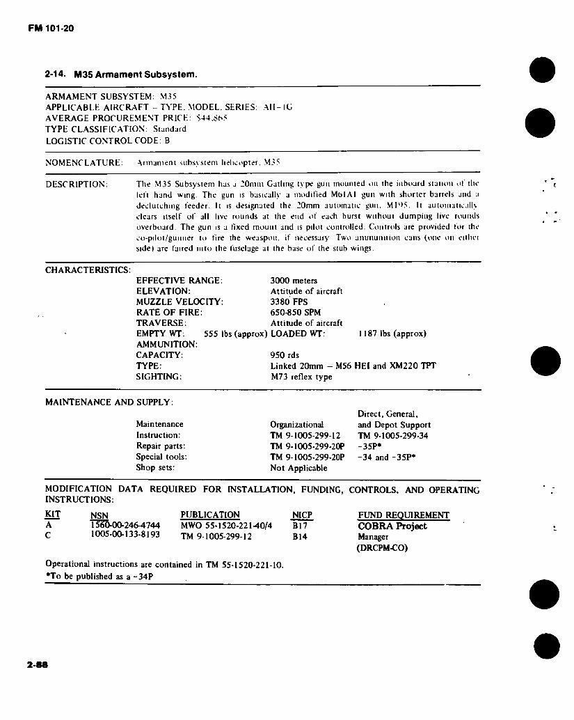
FM 101-20
2-14. M35 Armament Subsystem.
ARMAMENT SUBSYSTEM: M35 APPLICABLE AIRCRAFT - TYPE. MODEL. SERIES. AH- IG AVERAGE PROCUREMENT PRICE: $44.865 TYPE CLASSIFICATION: Standard
LOGISTIC CONTROL CODE: B
NOMENCLATURE: Armament subsystem helicopter. M35
DESCRIPTION: The M35 Subsystem has a 20mm Gatling type gun mounted on the inboard station ol the left hand wmg. The gun is basically a modified MbIAl gun with shorter barrels and a declutching feeder. It is designated the 20mm automatic gun. MD>5. It automaiicalK clears itself of all live rounds at the end of each burst without dumping live rounds overboard. The gun is a fixed mount and is pilot controlled. Controls are provided for the co-pilot/gunner to fire the weaspon. if necessary Two anunumtion cans (one on eithei side) are faired into the fuselage at the base of the stub wings.
CHARACTERISTICS: EFFECTIVE RANGE: ELEVATION: MUZZLE VELOCITY: RATE OF FIRE: TRAVERSE:
3000 meters Attitude of aircraft 3380 FPS 650-850 SPM Attitude of aircraft
1187 lbs (approx) EMPTY WT: 555 lbs (approx) LOADED WT: AMMUNITION: CAPACITY: 950 rds TYPE: Linked 20mm - M56 HEI and XM220 TPT SIGHTING: M73 reflex type
MAINTENANCE AND SUPPLY:
Maintenance Instruction: Repair parts: Special tools: Shop sets:
Organizational TM 9-1005-299-12 TM 9-1005-299-20P TM 9-1005-299-20P Not Applicable
Direct, General, and Depot Support TM 9-1005-299-34 -35P* -34 and -35P*
MODIFICATION DATA REQUIRED FOR INSTALLATION, FUNDING, CONTROLS, AND OPERATING INSTRUCTIONS:
KIT NSN PUBLICATION NICP A 1355-00-246-4744 MWO 55-1520-221-40/4 B17 C 1005-00-133-8193 JM 9-1005-299-12 B14
FUND REQUIREMENT COBRA Project Manager (DRCPM-CO)
Operational instructions are contained in TM 55-1520-221-10.
•To be published as a -34P
2-88
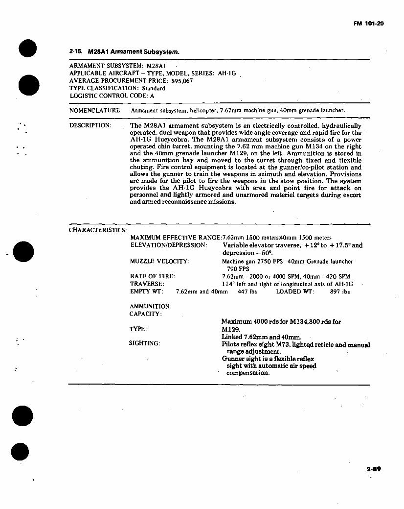
FM 101-20
2-15. M28A1 Armament Subsystem.
ARMAMENT SUBSYSTEM: M28A1 APPLICABLE AIRCRAFT - TYPE, MODEL, SERIES: AH-1G AVERAGE PROCUREMENT PRICE: $95,067 TYPE CLASSIFICATION: Standard LOGISTIC CONTROL CODE: A
NOMENCLATURE: Armament subsystem, helicopter, 7.62mm machine gun, 40mm grenade launcher.
DESCRIPTION: The M28A1 armament subsystem is an electrically controlled, hydraulically operated, dual weapon that provides wide angle coverage and rapid fire for the AH-1G Hueycobra. The M28A1 armament subsystem consists of a power operated chin turret, mounting the 7.62 mm machine gun Ml34 on the right and the 40mm grenade launcher Ml29, on the left. Ammunition is stored in the ammunition bay and moved to the turret through fixed and flexible chuting. Fire control equipment is located at the gunner/co-pilot station and allows the gunner to train the weapons in azimuth and elevation. Provisions are made for the pilot to fire the weapons in the stow position. The system, provides the AH-1G Hueycobra with area and point fire for attack on personnel and lightly armored and unarmored materiel targets during escort and armed reconnaissance missions.
CHARACTERISTICS: MAXIMUM EFFECTIVE RANGE:7.62mm 1500 meters;40mm 1500 meters ELEVATION/DEPRESSION: Variable elevator traverse, +12° to +17.5° and
depression —50°. MUZZLE VELOCITY: Machine gun 2750 FPS 40mm Grenade launcher
790 FPS RATE OF FIRE: 7.62mm - 2000 or 4000 SPM, 40mm - 420 SPM TRAVERSE: 114° left and right of longitudinal axis of AH-1G EMPTY WT: 7.62mm and 40mm 447 lbs LOADED WT: 897 lbs
AMMUNITION: CAPACITY:
Maximum 4000 rds for Ml34,300 rds for TYPE: Ml 29.
Linked 7.62mm and 40mm. SIGHTING : Pilots reflex sight M73, lighted reticle and mamml
range adjustment. Gunner sight is a flexible reflex
sight with automatic air speed compensation.
2-89

FM 101-20
2-16. M28A1 Armament Subsystem (Cont).
MAINTENANCE AND SUPPLY:
Maintenance Instruction: Repair parts: Special tools: Shop sets:
AVUM A vim and Depot TM 9-1090-203-12; -34 TM 9-1090-203-20P; -34P TM 9-1090-203-12 and 20P; -34 and -34P Not Applicable DMWR 9-1090-202-2
DMWR 9-1090-203-1
MODIFICATION DATA REQUIRED FOR INSTALLATION, FUNDING, CONTROLS, AND OPERATING INSTRUCTIONS:
KIT NSN PUBLICATION N1CP FUND REQUIREMENTS 1090-00-134-3071 TM 9-1090-203-12 B14 DA Controlled
I ,7 ri¿ // <
rvi ; f'cc.-O OO
/ I H fi •il
M28A1
Ha-
AV 000149 ...u
Figure 2-14. M28A1 Armament subsystem
2-90
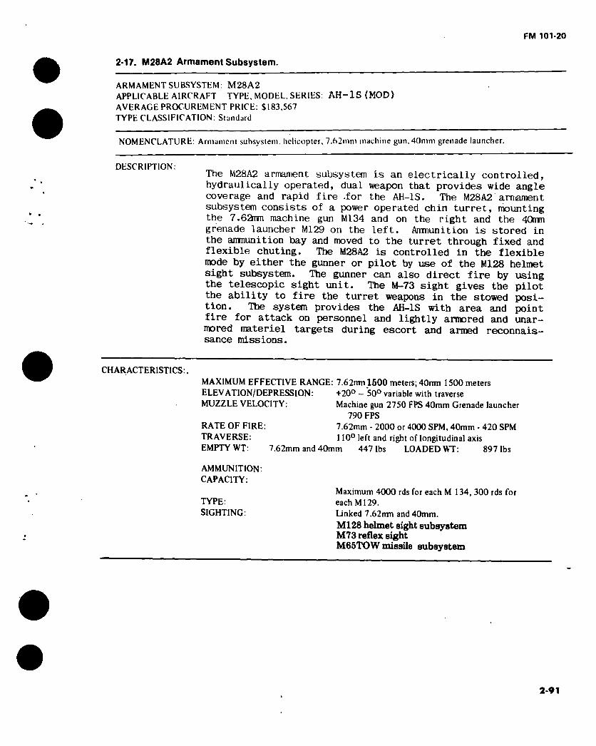
FM 101-20
2-17. M28A2 Armament Subsystem.
ARMAMENT SUBSYSTEM: M28A2 APPLICABLE AIRCRAFT TYPE, MODEL. SERIES: AH-1S (MOD) AVERAGE PROCUREMENT PRICE: $183,567 TYPE CLASSIFICATION: Standard
NOMENCLATURE: Armament subsystem, helicopter, 7.62mm machine gun, 40mm grenade launcher.
DESCRIPTION: The M28A2 armament subsystem is an electrically controlled,
hydraulically operated, dual weapon that provides wide angle coverage and rapid fire -for the AH-1S. The M28A2 armament subsystem consists of a power operated chin turret, mounting the 7.62hm machine gun M134 and on the right and the 40mm
grenade launcher M129 on the left. Ammunition is stored in the ammunition bay and moved to the turret through fixed and flexible chuting. The M28A2 is controlled in the flexible mode by either the gunner or pilot by use of the M128 helmet
sight subsystem. The gunner can also direct fire by using the telescopic sight unit. The M-73 sight gives the pilot the ability to fire the turret weapons in the stowed posi- tion. The system provides the AH-1S with area and point fire for attack on personnel and lightly armored and unar-
mored materiel targets during escort and armed reconnais- sance missions.
CHARACTERISTICS:. MAXIMUM EFFECTIVE RANGE: 7.62mn l500 meters; 40nm 1500 meters ELEVATION/DEPRESSION: +20° — SO0 variable with traverse MUZZLE VELOCITY : Machine gun 2750 FPS 40mm Grenade launcher
790 FPS RATE OF FIRE: 7.62mm - 2000 or 4000 SPM, 40mm - 420 SPM TRAVERSE: 110° left and right of longitudinal axis EMPTY WT: 7.62mm and 40mm 447 lbs LOADED WT: 897 lbs
AMMUNITION: CAPACITY:
Maximum 4000 rds for each M 134, 300 rds for TYPE: each Ml29. SIGHTING: Linked 7.62nm and 40mm.
Ml28 helmet sight subsystem M73 reflex sight M65TOW missile subsystem
2-91

FM 101-20
2-17. M28A2 - Armament Subsystem (Cent).
MAINTENANCE AND SUPPLY:
Maintenance Instruction: Repair parts: Special tools: Shop sets:
AVUM TM 9-1090-203-12-1 TM 9-1090-203-20P-1 TM 9-1090-203-12-1 and 20P-1 Not Applicable
AVIM and Depot -34-1 •34 P-1
Not Applicable
MODIFICATION DATA REQUIRED FOR INSTALLATION, FUNDING, CONTROLS, AND OPERATING INSTRUCTIONS:
KIT NSN PUBLICATION 1090-00-081-1046 TM 9-1090-203-12-1
NICP FUND REQUIREMENTS B14 DA Controlled
1 '
t I
UrA
s
Figure 2-15. M28A2 Armament subsystem
2-92
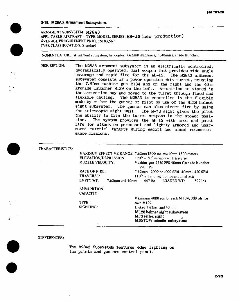
FM 101-20
2-18. M28A3 Armament Subsystem.
ARMAMENT SUBSYSTEM: M28A3 APPLICABLE AIRCRAFT - TYPE, MODEL, SERIES: AH-1S (new production) AVERAGE PROCUREMENT PRICE: $183,567 TYPE CLASSIFICATION: Standard
NOMENCLATURE: Armament subsystem, helicopter, 7.62mm machine gun, 40mm grenade launcher.
DESCRIPTION: The M28A3 armament subsystem is an electrically controlled,
hydraulically operated, dual weapon that provides wide angle coverage and rapid fire for the AH-1S. The M28A3 armament
subsystem consists of a power operated chin turret, mounting the 7.62mi machine gun M134 and on the right and the 40mm
grenade launcher M129 on the left. Ammunition is stored in the anmunition bay and moved to the turret through fixed and flexible chuting. The M28A3 is controlled in the flexible mode by either the gunner or pilot by use of the M128 helmet sight subsystem. The gunner can also direct fire by using the telescopic sight unit. The M-73 sight gives the pilot the ability to fire the turret weapons in the stowed posi- tion. The system provides the AH-1S with area and point fire for attack on personnel and lightly armored and unar-
mored materiel targets during escort and armed reconnais- sance missions.
CHARACTERISTICS. MAXIMUM EFFECTIVE RANGE: 7.62rrml500 meters; 40mn 1500 meters ELEVATION/DEPRESSION +20° - 50° variable with traverse MUZZLE VELOCITY : Machine gun 2750 FPS 40mm Grenade launcher
790 FPS RATE OF FIRE: 7.62mm - 2000 or 4000 SPM, 40mm - 420 SPM TRAVERSE: 110° left and right of longitudinal axis EMPTY WT: 7.62mm and 40mm 447 lbs LOADED WT: 897 lbs
AMMUNITION: CAPACITY:
Maximum 4000 rds for each M 134, 300 rds for TYPE: each Ml29. SIGHTING: Linked 7.62nm and 40mm.
M128 helmet sight subsystem M73 reflex sight # M65TOW missile subsystem
DIFFERENCES:
The M28A3 Subsystem features edge lighting on the pilots and gunners control panel.
2-93
FM 101-20
2-18 M28A3 - Armament Subsystem (Cent).
MAINTENANCE AND SUPPLY:
Maintenance Instruction: Repair parts: Special tools: Shop sets:
AVUM TM 9-1090-203-12-2 TM 9-1090-203-20P-1/-2 TM 9-1090-203-12-2, -20P-1 and -20P-2
Not Applicable
AVIM and Depot ;34-l, -34-2 -34-1, -34 P-2
Not Applicable
MODIFICATION DATA REQUIRED FOR INSTALLATION, FUNDING, CONTROLS, AND OPERATING INSTRUCTIONS:
KIT NSN PUBLICATION 1090-00-081-1046 TM 9-1090-203-12-2
NICP FUND REQUIREMENTS B14 DA Controlled
Illustration to be furnished next revision.
Figure 2-16. M28A3 Armament subsystem
2-94
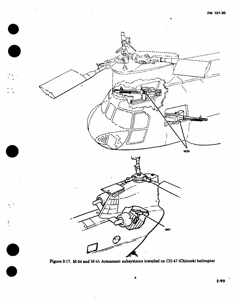
FM 101-20
fe
-æK"\
~"ñ 1 i
R,
H>,
Í
vs.
7)
tr-
1
M24
M41
&
Figure 2-17. M-24 «nri M-41 Armament subsystems installed on CH-47 (Chinook) helicopter
2-95

FM 101-20 Û
2-19. M24 Armament Subsystem.
ARMAMENT SUBSYSTEM: M24 APPLICABLE AIRCRAFT - TYPE, MODEL, SERIES: CH-47A AVERAGE PROCUREMENT PRICE: $3722 TYPE CLASSIFICATION: Standard LOGISTIC CONTROL CODE: A
NOMENCLATURE: Armament subsystem, helicopter, door pintle mounted 7.62mm M60D machine gun
DESCRIPTION: The subsystem consists of two machine guns, M60D, and two mounts, one mount on each side of the aircraft. The subsystem mount assemblies are located in the cabin doorway and forward escape hatch of the CH-47 type helicopter. The subsystem contains mechanical safeties and stops to preclude accidental damage to the aircraft due to inadvertent firing of the guns into the airframe. The mount assemblies are designed so that the left and right cams and stops cannot be installed and used incorrectly on the opposite side of the aircraft. The machine gun with bipod has the capability of being quickly removed from the mount and used as a ground weapon. A link and brass ejection control bag is attached to the right side of each machine gun to prevent the cartridge cases and links from being ejected into the paths of the rotor blades or turbine engine intake.
CHARACTERISTICS: MAXIMUM EFFECTIVE RANGE: 1100 meters ELEVATION: Forward +3°, Aft +6.5°, Depression 78° right side,
67° left side MUZZLE VELOCITY: RATE OF FIRE: TRAVERSE:
2750 FPS 550 SPM Left gun 71° fwd, 59° aft; right gun 74° fwd, 61° aft
EMPTY WT: 97 lbs AMMUNITION: CAPACITY: TYPE:
LOADED WT: 123 lbs
200 rds per side Linked 7.62mm
SIGHTING: Ring and post type
MAINTENANCE AND SUPPLY: Maintenance Instructions Repair parts: Special tools: Shop sets:
AVUM AVIM and Depot, TM 9-1005-262-14 TM 9-1005-262-24P TM 9-1005-262-24P Not Applicable
MODIFICATION DATA REQUIRED FOR INSTALLATION, FUNDING, CONTROLS, AND OPERATING INSTRUCTIONS:
None required
KIT NSN PUBLICATION NICP FUND REQUIREMENTS 1005-00-763-1404 TM 9-1005-262-15 B14 DAControUed
Operational instructions for subsystem can be found in TM 9-1005-262-15.
2-96 o
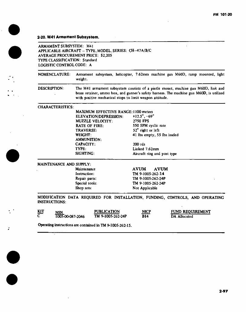
FM 101-20
2-20. M41 Armament Subsystem.
ARMAMENT SUBSYSTEM: M41 APPLICABLE AIRCRAFT - TYPE. MODEL, SERIES: ÇH^t7A/B/C AVERAGE PROCUREMENT PRICE: $2,205 TYPE CLASSIFICATION: Standard LOGISTIC CONTROL CODE: A
NOMENCLATURE: Armament subsystem, helicopter, 7.62mm machine gun M60D, ramp mounted, light weight.
DESCRIPTION: The M41 armament subsystem consists of a pintle mount, machine gun M60D, link and brass retainer, ammo box, and gunner’s safety harness. The machine gun M60D, is utilized with positive mechanical stops to limit weapon attitude.
CHARACTERISTICS: MAXIMUM EFFECTIVE RANGE: 1100 meters ELEVATION/DEPRESSION : +12.5°, - 69° MUZZLE VELOCITY: 2750 FPS RATE OF FIRE: 550 SPM cyclic rate TRAVERSE: 52° right or left WEIGHT: 41 lbs empty, 55 lbs loaded AMMUNITION: CAPACITY: 200 rds TYPE: Linked 7.62mm SIGHTING: Aircraft ring and post type
MAINTENANCE AND SUPPLY: Maintenance Instruction: Repair parts: Special tools: Shop sets:
AVUM AVUM TM 9-1005-262-14 TM 9-1005-262-24P TM 9-1005-262-24P Not Applicable
MODIFICATION DATA REQUIRED FOR INSTALLATION, FUNDING, CONTROLS, AND OPERATING INSTRUCTIONS:
Kiï NSN C 1005-00-087-2046
PUBLICATION NICP TM 9-1005-262-24P B14
FUND REQUIREMENT DA Allocated
Operating instructions are contained in TM 9-1005-262-15.
2-97
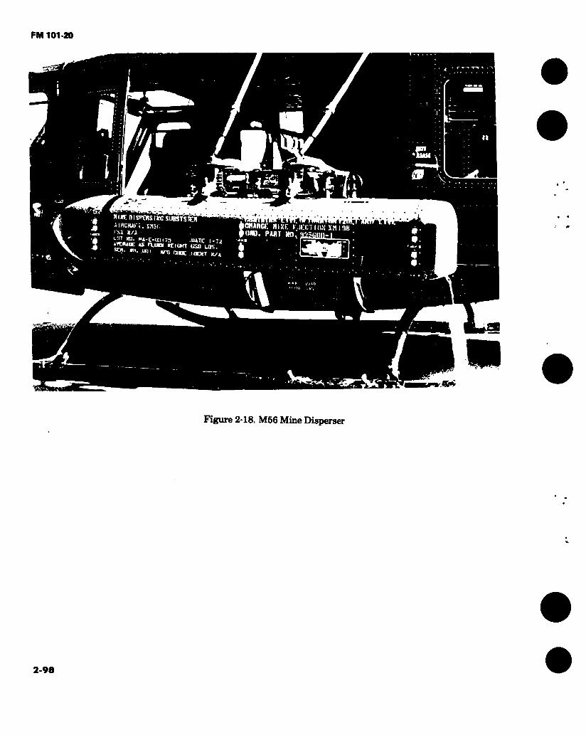
FM 101-20
/ flT\ fir
niwmsnoiïiKcs JIRCtUt î . Xîlji. I'SX X/A “'ÜJ.’Ï; "‘-C-'oiïn .iure i-7j ijciunc AX aunt rciunr uso LOS. st«, xn. un MTT* ewe inorr x/i
CHARO: RIXC UKCTIIW XiiinH iiRD. PART jm. a2?(¡nn-1
9*
Figure 2-18. M56 Mine Disperser
2-98
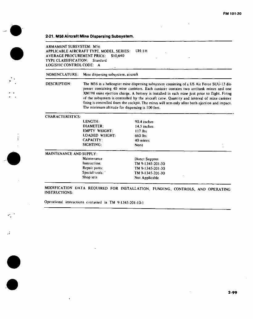
FM 101-20
2-21. M56 Aircraft Mine Dispersing Subsystem.
ARMAMENT SUBSYSTEM: M56 APPLICABLE AIRCRAFT TYPE, MODEL, SERIES: AVERAGE PROCUREMENT PRICE: $10,640 TYPE CLASSIFICATION: Standard LOGISTIC CONTROL CODE: A
UH: I H
NOMENCLATURE: Mine dispersing subsystem, aircraft
DESCRIPTION: The M56 is a helicopter mine dispersing subsystem consisting of a US Air Force SUU-13 dis- penser containing 40 mine canisters. Each canister contains two antitank mines and one XM198 mine ejection charge. A battery is installed in each mine just prior to flight. Firing of the subsystem is controlled by the aircraft crew. Quantity and interval of mine canister
firing is controlled from the cockpit. The mines will arm only after both ejection and impact. The minimum altitude for dispensing is 100 feet.
CHARACTERISTICS: LENGTH: DIAMETER: EMPTY WEIGHT: LOADED WEIGHT: CAPACITY: SIGHTING:
90.4 inches 14.5 inches
117 lbs 660 lbs 40 mines None
MAINTENANCE AND SUPPLY:
Maintenance Instruction: Repair parts: Special tools: Shop sets
Direct Support TM 9-1345-201-30 TM 9-1345-201-30 TM 9-1345-201-30 Not Applicable
MODIFICATION DATA REQUIRED FOR INSTALLATION, FUNDING, CONTROLS, AND OPERATING
INSTRUCTIONS:
Operational instructions contained in TM 9-1345-201-10-1
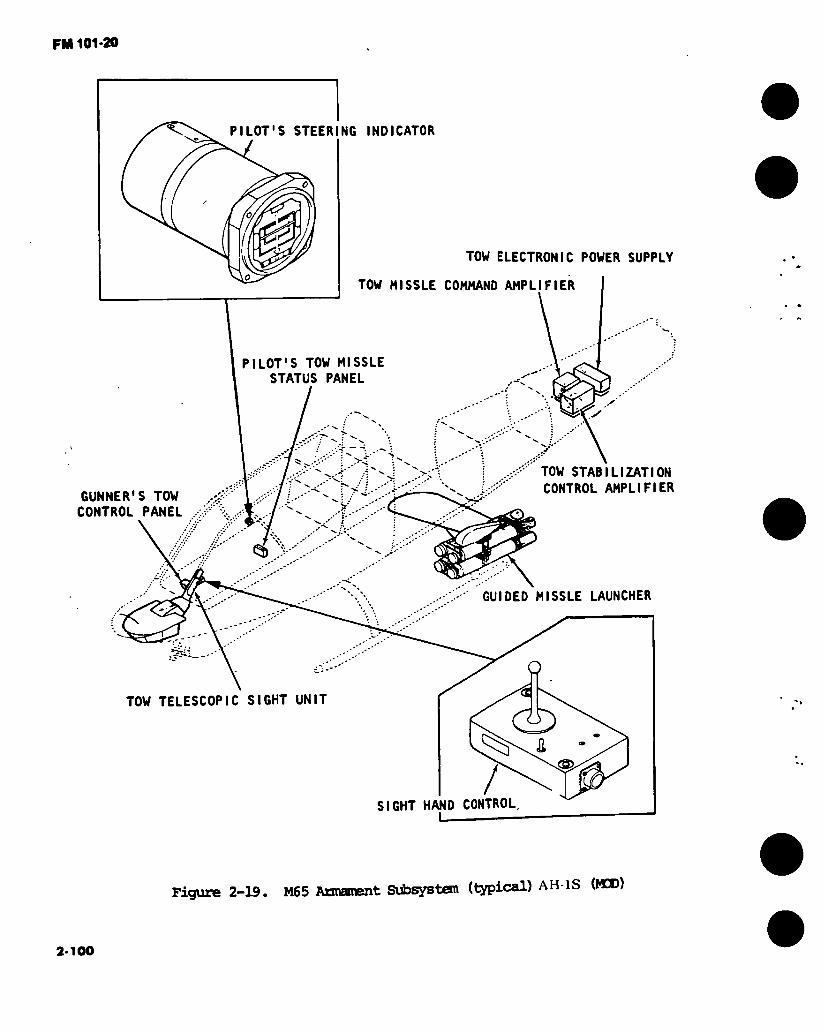
FM 101*20
PILOT'S STEERING INDICATOR
GUNNER'S TOW CONTROL PANEL
TOW ELECTRONIC POWER SUPPLY
TOW NISSLE COMMAND AMPLIFIER
PILOT'S TOW MISSLE STATUS PANEL
✓
TOW STABILIZATION CONTROL AMPLIFIER
GUIDED MISSLE LAUNCHER
O
(32 / D CONTROL HAN
TOW TELESCOPIC SIGHT UNIT
SIGHT
Figure 2-19. M65 Armament Subsystem (typical) AH-lS (MED)
2-100
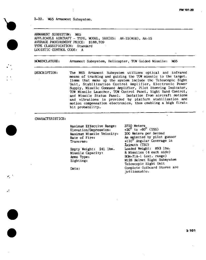
FM 101-20
r
2-22. M65 Armament Subsystem.
ARMAMENT SUBSYSTEM: M65 APPLICABLE AIRCRAFT - TYPE, MODEL, SERIES: AH-IS(MOD), AH-1S AVERAGE PROCUREMENT PRICE: $188,709 TYPE CLASSIFICATION: Standard LOGISTIC CONTROL CODE: A
NOMENCLATURE: Armament Subsystem, Helicopter, TOW Guided Missile: M65
DESCRIPTION: The M65 Armament Subsystem utilizes optical and infrared means of tracking and guiding the TOW missile to the target. Items that make up the system include the Telescopic Sight Unit, Stabilization Control Amplifier, Electronic Power Supply, Missile Conmand Amplifier, Pilot Steering Indicator, TOW Missile Launcher, TOW Control Panel, Sight Hand Control, and Missile Status Panel. Isolation from aircraft motions and vibrations is provided by platform stabilization ana motion compensation electronics, thus enabling a high first- hit probability.
CHARACTERISTICS:
Maximum Effective Range: Elevation/Depression:
Maximum Missile Velocity: Rate of Fire: Traverse:
Ehipty Weight: 241 lbs. Missile Capacity: Ammo Type: Sighting:
Data:
3750 Meters +30° to -60° (TSU) 300 Meters per Second As selected by pilot gunner +110° Angular Coverage in Sximuth (TSU) Loaded Weight: 893 lbs. 8 Missiles (4 each side) BGM-71A-1 (ext. range) Ml28 Helmet Sight Subsystem Telescopic Sight Unit Complete Outboard Stores are jettisonable.
2-101

FM 101-20
2-22. M65 Armament Subsystem.
MAINTENANCE AND SUPPLY:
* Maintenance Instructions:
Repair Parts:
Special Tools:
AVUM AVIM and Depot TW 9-1425-473-20 and -34 TM 9-1425-473-24P TW 9-1425-473-20 and-24P
MODIFICATION DATA REQUIRED FOR INSTALLATION, FUNDING, CONTROLS AND OPERATION INSTRUCTIONS:
Operational instructions contained in: TM 55-1520-234-10 and TW 55-1520-236-10
2-102

FM 101-20
TURRET CONTROL UNIT
M197 GUN
X--
LOGIC CONTROL UNIT
AIR DATA TRANSDUCER
l-GUN CONTROL UNIT
Figure 2-20. Armament Subsystem, XM97E1
2-103
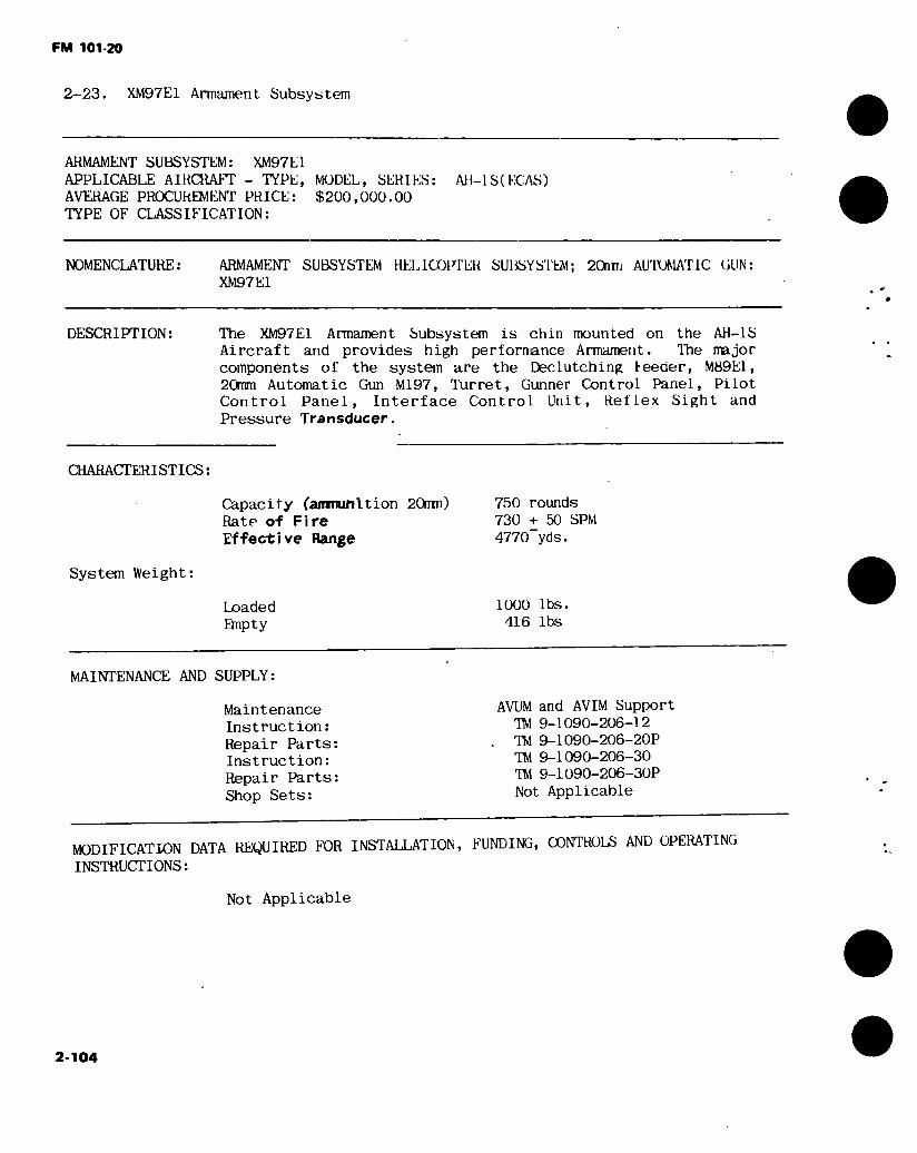
FM 101-20
2-23. XM97E1 Armament Subsystem
ARMAMENT SUBSYSTEM: XM97E1
APPLICABLE AIRCRAFT - TYPE, MODEL, SERIES:
AVERAGE PROCUREMENT PRICE: $200,000.00
TYPE OF CLASSIFICATION:
All-1 S( EGAS)
NOMENCLATURE: ARMAMENT SUBSYSTEM HELICOPTEK SUBSYSTEM; 20nm AUTOMATIC GUN:
XM97E1
DESCRIPTION: The XM97E1 Armament Subsystem is chin mounted on the AH-1S
Aircraft and provides high perfornance Armament. The major
components of the system are the Declutching teeder, M89E1,
20mm Automatic Gun M197, Turret, Gunner Control Panel, Pilot
Control Panel, Interface Control Unit, Reflex Sight and
Pressure Transducer.
CHARACTERISTICS:
Capacity (ammunition 20mm)
Rate of Fire
Effective Range
System Weight:
Loaded
Bnpty
750 rounds
730 + 50 SPM
4770 yds.
1000 lbs.
416 lbs
MAINTENANCE AND SUPPLY:
Maintenance
Instruction:
Repair Parts:
Instruction:
Repair Parts:
Shop Sets:
AVUM and AVIM Support
TIM 9-1090-206-12
TO 9-1090-206-20P
TO 9-1090-206-30
TO 9-1090-206-30P
Not Applicable
MODIFICATION DATA REQUIRED FOR INSTALLATION, FUNDING, CONTROLS AND OPERATING
INSTRUCTIONS:
Not Applicable
2-104

FM 101-20
2-23.1. M97E2 Armament Subsystem
ARMAMENT SUBSYSTEM: M97E2 APPLICABLE AIRCRAFT - TYPE, MODEL, SERIES: AH-lS (MODERNIZED) AVERAGE PROCUREMENT PRICE: Not Available TYPE OF CLASSIFICATION: Standard
NOMENCLATURE: ARMAMENT SUBSYSTEM, HELICOPTER; 20mm AUTOMATIC GUN.
DESCRIPTION: The XM97E2 Armament Subsystem is an improvement of the XM97E1 with the addition of the following highly sophisticated subsystems: Head Up Display (HUD), Rocket Management System (RMS), Air Data System (ADS), and the Fire Control Computer (FCC). Used in total, these sub- systems provide an accurate target pinpointing weapon system.
CHARACTERISTICS:
Capacity (ammunition 20mm) Rate of Fire Effective Range
750 rounds 730 ^ 50 SPM High Rate, 16 i 4 SPM 4770 yds.
System Weight:
Loaded Empty
Not Available Not Available
MAINTENANCE AND SUPPLY:
Maintenance Instruction: Repair Parts: Instruction: Repair Parts: Shop Sets:
AVUM and AVIM Support TM 9-1090-206-12 TM 9-1090-206-20P TM 9-1090-206-30 TM 9-1090-206-30P Not Applicable
MODIFICATION DATA REQUIRED FOR INSTALLATION, FUNDING, CONTROLS AND OPERATING INSTRUCTIONS:
Not Applicable
2-105

FM 101-20
Si
Si
P 51 ° S uj o £ o
VA
\ 'a \ CN » & ¿Y
* U
vv* ' \ 'Wi x àkô\ \3 \ V.p</ VA :V * V • \ ' V* » — rs
iV 'C3
1 \ r rr^
fú¿ & f7 CA >>
/ft VCî ÎV\V ^>V
) b J %
s \
SS Ñ O
2-106
Fig
ure
2-2
0.1.
XM
97E
2 S
ubsy
stem
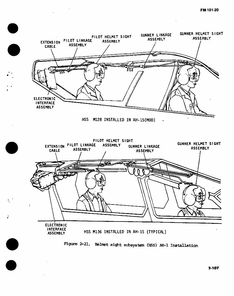
FM 101-20
PILOT HELMET SIGHT
EXTENSION LINKAGE ASSEMBLY
GUNNER LINKAGE GUNNER HELMET SIGHT ASSEMBLY ASSEMBLY
CABLE ASSEMBLY
a?
ELECTRONIC INTERFACE ASSEMBLY
HSS M128 INSTALLED IN AH-IS(MOD)
PILOT HELMET SIGHT
EXTENSION PIL0T LINKAGE ASSEMBLY GUNNER LINKAGE CABLE ASSEMBLY , ASSEMBLY
ELECTRONIC INTERFACE ASSEMBLY HSS Ml36 INSTALLED IN AH-1S (TYPICAL)
GUNNER HELMET SIGHT ASSEMBLY
m
'
Figure 2-21. Helmet ■ siÿit subsystem (HSS) AH-1 Installation
2-107

FM 101-20
2-24. HELMET SIGHT SUBSYSTEM (HSS)
liiere are two models of the HSS, M128 used in AH-1S (MOD) and M136 subsystem used in the AH-1S.
HELMET SIGHT SUBSYSTEM: M128 M136 APPLICABLE AIRCRAFT: AH-IS (MOD) AH-1S (New PROD/ECAS) TYPE CLASSIFICATION: Standard
NOMENCLATURE: Fire control subsystem, helmet-directed: M128 or M136
DESCRIPTION: The HSS is a helmet-directed sighting subsystem that interfaces
with the gun turret and the telescope sight unit (TSU) of the M65 TOW missile subsystem in the AH-1S (MOD) and AH-1S helicop- ters. The HSS operates from power supplied by the helicopter and consists of the following assemblies:
Helmet sight (2)
Pilot linkage
Gunner linkage
Electronic interface assembly
Extension cable
The HSS enables the helicopter pilot and copilot/gunner (herein- after referred to as gunner) to rapidly acquire visible targets and to direct either the gun turret or the TSU to those targets. The helmet-mounted optical sight extends over the operator's right eye, and an illuminated reticle pattern is projected into the optical sight. Electromechanical linkage sense the helmet
position and generate sight-line signals, which are processed by the electronic interface assembly (ElA) and used to control the angular position of the turret or the TSU.
Either operator can command the gun turret or TSU by means of
operator-selectable cockpit switches. When necessary, the gun turret and TSU can be comnanded simultaneously by the pilot and gunner, respectively.
2-108
FM 101-20
2-24. HKIAlhT SKillï SUHSYbTKM (libS)
Difteronœs between the two models of the HSb, Ml28 used in the All-lb (MOD) and Ml36. All of the differences, mechanical and electrical between the two models result from differences in HSS Installation in the helicopters with the flat plate canopy. The only major item that differs between the two models is the LIA. The helmet sight assemblies, pilot and gunner linkage assemblies, and extension cable are identical and interchange- able between models.
MAINTLNANCL AND SUPPLY:
PUBLICATIONS: ORG/DS/GS Operation Maintenance: TM 9-1270-212-14 and P
MODIFICATION DATA:
Not Applicable
2-109
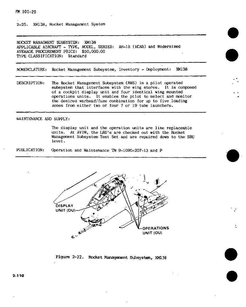
FM 101-20
2-25. XM138, Rocket Management System
ROCKET MANAGMENT SUBSYSTEM: XM138 APPLICABLE AIRCRAFT - TYPE, MODEL, SERIES: AH-1S (EGAS) and Modernized AVERAGE PROCUREMENT PRICE: $50,000.00 TYPE CLASSIFICATION: Standard
NOMENCLATURE: Rocket Management Subsystem, Inventory - Deployment: XM138
DESCRIPTION: The Rocket Management Subsystem (RMS) is a pilot operated subsystem that interfaces with the wing stores. It is composed of a cockpit display unit and four identical wing mounted operations units. It enables the pilot to select and monitor the desired warhead/fuze combination for up to five loading zones from either two or four 7 or 19 tube launchers.
PUBLICATION: Operation and Maintenance TM 9-1090-207-13 and P
MAINTENANCE AND SUPPLY:
The display unit and the operation units are line replaceable units. At AVIM, the LRU's are checked out with the Rocket Management Subsystem Test Set and are repaired down to the SRU level.
Figure 2-22. Rocket Management Subsystem, XM138
2-110

FM 101-20
2-25.1. XM76 Head Up Display Subsystem
ARMAMENT SUBSYSTEM: XM76 , APPLICABLE AIRCRAFT • TYPE, MODEL, SERIES: AH-1S (MODERNIZED) AVERAGE PROCUREMENT PRICE: Not Available TYPE OF CLASSIFICATION: Standard
NOMENCLATURE: ARMAMENT SUBSYSTEM, HEAD UP DISPLAY: XM76.
DESCRIPTION: The primary use of the (HUD) is for aiming the aircraft to fire rockets, for- ward gun, and to assist the copilot/gunner in operating the TOW missile system. The secondary use of the HUD is for display of the engine torque, radar altitude, magnetic reading, and range for flight safety purposes when the pilot is flying head-up with eyes focused outside the cockpit. The com- ponents of thé HUD are the Head up Display, Signal Processor, and HUD Boresightable Mount.
CHARACTERISTICS:
Capacity (ammunition) Not Applicable Rate of Fire Not Applicable Effective Range Not Applicable.
System Weight:
Not Available
MAINTENANCE AND SUPPLY:
Operation and Maintenance: TM 9-1270-220-138 and P
MODIFICATION DATA REQUIRED FOR INSTALLATION, FUNDING, CONTROLS AND OPERATING INSTRUCTIONS:
Not Applicable
2-111

FM 101-20
bd 0rr>^'iF k'ïK
épjpE AH-1S (MC) PILOTS
PANF.L
%
€ CP
CP
HEAD UP DISPLAY
ra
*-BORESIGHTABLE MOUNT
SIGNAL PROCESSOR
©
Figure 2-22.1. XM76 Head Up Display Subsystem
2-112
FM 101*20
2-25.2. XM-142 Air Data Subsystem (ADS)
ARMAMENT SUBSYSTEM: XM142 APPLICABLE AIRCRAFT - TYPE, MODEL, SERIES: AH-lS (XM97E2) MODERNIZED. AVERAGE PROCUREMENT PRICE: Not Available TYPE OF CLASSIFICATION: Standard
NOMENCLATURE: ARMAMENT SUBSYSTEM, AIR DATA SYSTEM
DESCRIPTION: The ADS provides accurate measurement of the air data parameters altitude, altitude rate, airspeed, sideslip angle, air temperature, and air den- sity. Components of the ADS are the Airspeed and Direction Sensor (AADS), the Electronics Processor Unit (EPU), and Low Airspeed Indicator (LAI).
CHARACTERISTICS:
Capacity (ammunition) Rate of Fire Effective Range
System Weight:
Not Applicable Not Applicable Not Applicable
Not Available
MAINTENANCE AND SUPPLY:
Operation and Maintenance: TM 9-4931-378-138 and P
MODIFICATION DATA REQUIRED FOR INSTALLATION, FUNDING, CONTROLS AND OPERATING INSTRUCTIONS:
Not Applicable
2-113
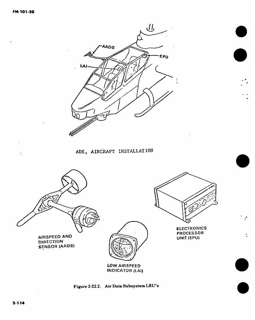
ADS, AIRCRAFT INSTALLATION
If. UA c l (a KLV'
AIRSPEED AND DIRECTION
SENSOR (AADS) *3
J)
ELECTRONICS PROCESSOR UNIT (EPU)
LOW AIRSPEED INDICATOR (LAI)
Figure 2-22.2. Air Data Subsystem LRU’s
2-114
FM 101-20
2-25.3. XM22 Fire Control Computer (FCC)
ARMAMENT SUBSYSTEM: XM22 APPLICABLE AIRCRAFT - TYPE, MODEL, SERIES: AH-1S (MODERNIZED) AVERAGE PROCUREMENT PRICE: Not Available TYPE OF CLASSIFICATION: Standard
NOMENCLATURE: ARMAMENT SUBSYSTEM, FIRE CONTROL COMPUTER.
DESCRIPTION: The FCC is a general purpose software, programmable, digital processing machine. Components of the FCC are the fire control computer and a boresight memory. The FCC provides solution data derived from the in- tegration of the heads up display, telescopic sight Unit, Helmet Sight Sub- system, M97 turret system, Rocket Management Subsystem, tow missile subsystem, Air data subsystem, Altitude Reference Gyro, Magnetic Com- pass Set, Radar Altimeter, torque meter and Lightweight Doppler Naviga- tion System. This data is then used to develop electrical drive signals to position the TSU, turret, and fuse setting and to generate displays in the TSU, Head up display, and helmet sight subsystem.
CHARACTERISTICS:
Capacity (ammunition) Rate of Fire Effective Range
System Weight:
Not Available
MAINTENANCE AND SUPPLY:
Operation and Maintenance: TM 9-1270-218-138 and P
Not Applicable Not Applicable Not Applicable
MODIFICATION DATA REQUIRED FOR INSTALLATION, FUNDING, CONTROLS AND OPERATING INSTRUCTIONS:
Not Applicable
2-115
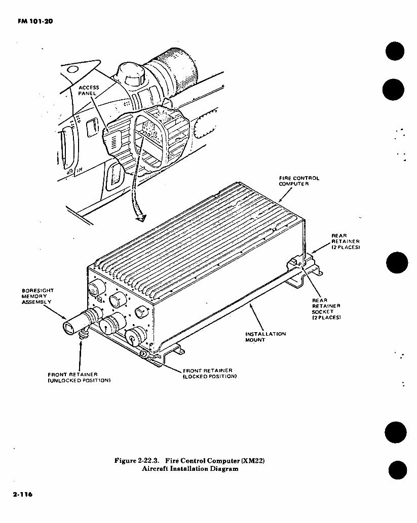
FM 101-20
BORESIGHT MEMORY ASSEMBLY
O
a ACCESS PANEL
o \ c
JTx S
iT
.-t
FIRE CONTROL COMPUTER
REAR RETAINER 12 PLACES)
REAR RETAINER SOCKET (2 PLACES)
INSTALLATION MOUNT
FRONT RETAINER (UNLOCKED POSITION)
.FRONT RETAINER (LOCKED POSITION»
Figure 2-22.3. Firë Control Computer (XM22) Aircraft Installation Diagram
2-116

FM 101-20
■ HELICOPTER CABIN ROOF IREFERENCEI
op O Q Q
INFINITY REFLEX SIGHT ROOF SIGHT (STOWEDI MOUNT |STOWED|
<7 /S'
r<7 </ v <7
9 0
a
S-i
/ INTERVAIOMETER
CONTROL PANEL
LEFT-HAND RACK
AND SUPPORT ASSEMBLY
ARM PANEL
Figure 2-23. Ml56 Armament subsystem components
2-117

FM 101-20
2-26. M156 Armament Subsystem.
ARMAMENT SUBSYSTEM : M156 APPLICABLE AIRCRAFT: UH-IB/M AVERAGE PROCUREMENT PRICE: $10,595 TYPE CLASSIFICATION: Limited Procurement LOGISTIC CONTROL CODE: U
NOMENCLATURE: Mount, multiarmament, helicopter
DESCRIPTION: This item consists of two separate mounts, one mount installed on each side of the UH-1 helicopter. It is capable of carrying and firing the M158A1 and M200A1 2.75 inch rocket launchers or carrying external stores suspended from 14 inch bomb racks, MA-4A. The external stores cannot exceed 540 lbs per mount. A product improvement proposal which will enable the Ml56 to carry a fully loaded 19 tube rocket launcher using the new heavy warhead rocket has been evaluated for incorporation into the subsystem.
CHARACTERISTICS: EFFECTIVE RANGE: Not applicable ELEVATION: Fixed TRAVERSE: Fixed EMPTY WEIGHT: 82 lbs without launcher LOADED WEIGHT: 540# per mount, maximum SIGHTING: XM60 Reflex
MAINTENANCE AND SUPPLY:
Maintenance Instruction: Repair parts: Special tools: Shop sets:
MODIFICATION DATA:
ORGANIZATIONAL INSTRUCTIONS: TM 55-1520-219-10.
TM 55-1520-220-10.
AVUM TM 9-1090-204-12 TM 9-1090-204-20P TM 9-1090-204-20P Not applicable
AVIM and Depot •34 -35P -35P
REMARKS:

FM 101-20
2-27. M158A1, 2.75 Inch Rocket Launcher (7-Tube).
Rockel Launcher: - M158AI Aircraft Series: UH1B/M Average Procurement Price: $808.
Type Classification: STD A Logistic Control Code: A
AH-1
Nomenclature: Launcher, Rocket Aircraft, 2.75 Inch - M158A1 (7-Tube).
Description: The MI58AI is a reparable 7-tube 2.75 inch rocket launcher used on the UH1/B/M and AH1 Aircrafts. It is 58 inches long and weighs 48 lbs.
Remarks: TOE Authorization - not available this printing.
Basis of Issue: Approved BOI not available. For planning purposes:
2 each per UH-1B/M armed with M21 Subsystem. 1 each per AH-I aircraft (all).
Maintenance and Supply: TM 9-1055-460-14. (TM 9-1055-460-13 now being prepared will replace -14).
«
Figure 2-24. Launcher, rocket aircraft, 2.75 inch-M158Al (7-tube)
2-119
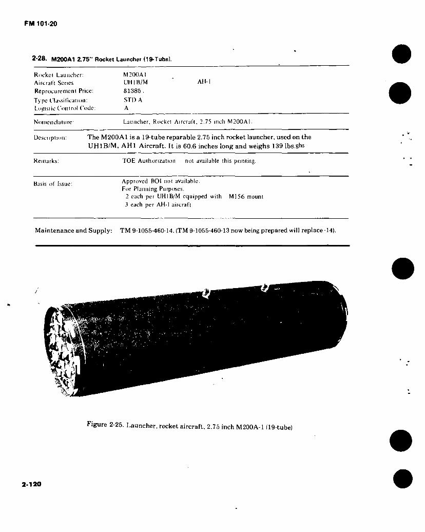
FM 101-20
2-28. M200A1 2.75" Rocket Launcher (19-Tube).
Rockel Launcher: M200AI Aircral I Scries UH I B/M
Reprocurcment Price: $1385 .
Type Classification: STD A
L.ogisiic Conlrol Code: A
AH-
Noincnclalurc Launcher, Rocket Aircraft, 2.75 inch M200AI.
Description: The M200A1 is a 19-tube reparable 2.75 inch rocket launcher, used on the UH1B/M, AH1 Aircraft. It is 60.6 inches long and weighs 139 Ibs.ghs
Remarks: TOE Authorization — not available this printing.
Basis of Issue: Approved BOI not available. For Planning Purposes.
2 each per UHIB/M equipped with Ml56 mount
3 each per AH-I aircraft
Maintenance and Supply: TM 9-1055-460-14. (TM 9-1055-460-13 now being prepared will replace -14).
s
Figure 2-25. Launcher, rocket aircraft, 2.75 inch M200A-1 (19-tube)
2-120
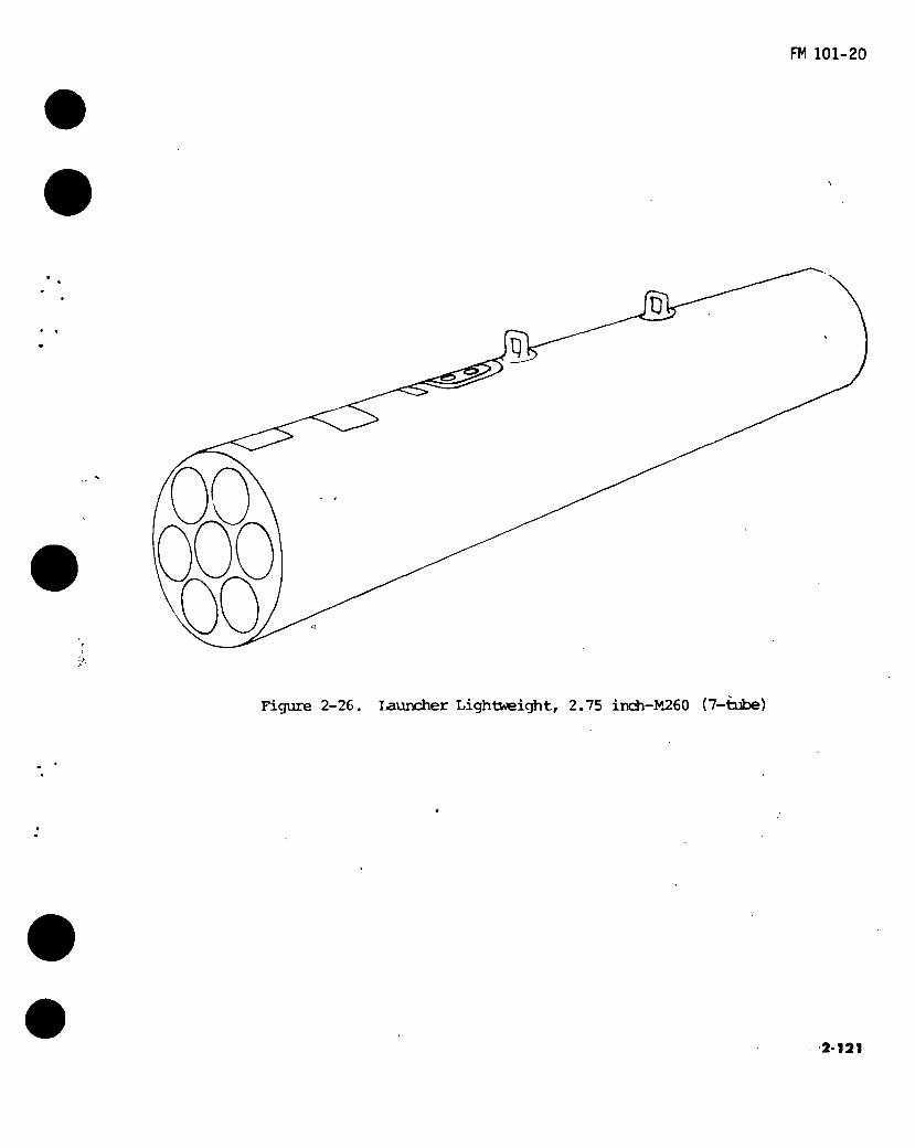
FM 101-20
U
Figure 2-26. Ijauncher Lightweight, 2.75 inch-M260 (7-tube)
2-121
FM 101-20
2-29. M260 2.75 Inch Rocket Launcher (7 Tube)
ROCKET LAUNCHER: M260 AIRCRAFT SERIES: AH-1 AH64 REPROCUREMENT PRICE: $1639 (First Buy) TYPE CLASSIFICATION: STD LOGISTIC CODE: A
NOMENCLATURE: Launcher, Rocket, Aircraft: 2.75 Inch M260.
DESCRIPTION: The M260 is a nonrepairable 2.75 Inch Rocket Launcher used on AH-lS air- craft equipped with rocket management subsystem and on AH64 aircraft. It is capable of at least eight missions. It is 65 inches long and weighs 35 pounds.
REMARKS: TOE Authorization - not available this printing.
BASIS OF ISSUE:
1 each per AH-IS aircraft 0.5 each per AH-64 aircraft. (Planning factor only)
MAINTENANCE AND SUPPLY:
TM 9-1055-460-13 (In Process)
2-122

FM 101-20
Figure 2-27. Launcher Lightweight, 2.75 inehM261 (19 tube)
2-123

FM 101-20
2-30. M261 2.75 Inch Rocket Launcher (19 Tube)
ROCKET LAUNCHER: M261 AIRCRAFT SERIES: AH-1 AH64 REPROCUREMENT PRICE: $2965 (First Buy) TYPE CLASSIFICATION: STD LOGISTIC CODE: A
NOMENCLATURE: Launcher, Rocket, Aircraft: 2.75 Inch M261.
DESCRIPTION: The M261 is a nonrepairable 2.75 Inch Rocket Launcher used on AH-1S aircraft equipped with rocket management subsystem and on AH64 aircraft. It is capable of at least eight missions. It is 65 inches long and weighs 80 pounds.
REMARKS: TOE Authorization - not available this printing.
BASIS OF ISSUE:
2 each per AH-IS 2 each per AH-64. (Planning factor only)
MAINTENANCE AND SUPPLY: TM 9-1055-460-13 (In Process)
2-124
FM 101-20
2-31. XM230EI Armament Subsystem, Helicopter, Turret Mounted, 30mm, YM230 ■
ARMAMENT SUBSYSTEM: XM230EI APPLICABLE AIRCRAFT TYPE. MODEL. SERIES YAH-64A AVERAGE PROCUREMENT PRICE: TBD TYPE CLASSIFICATION. Development LOGISTIC CONTROL CODE
NOMENCLATURE: ARMAMENT SUBSYSTEM. HELICOPTER, TURRET MOUNTED, 30MM, XM230
DESCRIPTION. Consists of the following major components: 30mm Chain Gun, Turret, Ammunition Storage and Transfer Mechanism and Control System. The Gun System is a 30mm XM239EI Hughes Chain Gun which fires 30mm XM788/789 (ADEN/DEFA class) am- munition having a rate of fire of 725 ± 25 RPM.The weapon with drive motor and recoil adapters attached weights 110 lbs. The Turret weight is 156 lbs.
CHARACTERISTICS.
Effective Range: 4000 Meters Elevation: +10° to-60° Muzzle Velocity: 805 MPS Rate of Fire: 725 + 25 RPM Traverse: ± 110° Empty Weight: 568 LBS. Ammuniton: 30mm XM788/789 and ADEN/DEFA class ammo Capacity: 1215 Rounds Sighting: I HAD SS and TADS
MAINTI NAN( I AND SUPPLY
Maintenance Instruction: Repair Parts: Special Tools: Shop Sets:
AVUM and AVIM Support TM9- TM 9- TM9- TM 9-
MUDIUCATION DA I A REQUIRED EOR INSTALLATION, EUNDING. CONTROLS AND OPERATING INSTRUCTIONS
JÜL -NJS> PUBLICATION NKT FUND REQUIREMENTS
Opoiatioiuil iiMnuiioii's lui Mihs\sium can he louiul in TM55"
( 2-125
FM 101-20
2-32. HELLP’I RE Modular Missile System (HJwMS).
ARMAMENT SUBSYSTEM: HELLEIRE APPLICABLE AIRCRAFT - TYPE, MODEL, SERIES: YAH-64A AVERAGE PROCUREMENT PRICE: TBD TYPE CLASSIFICATION: Engineering Development LOGISTIC CONTROL CODE:
NOMENCLATURE: HELLEIRE Modular Missile System (HMMS)
DESCRIPTION: The Point Target System (PTS) for the YAH-64-A is comprised of the HELLFIRE Modular Missile system (HMMS) (Missiles and laun- chers), HELLFIRE Missile Equipment (HME) (electronics and dedicated control panels), and associated multipurpose controls and displays. . This system can be used with any of three seeker heads: Laser, RF/IR, or IRIS. The YAH-64A carries eight HELLFIRE missiles for the primary mission and up to sixteen missiles in alternate configurations.
CHARACTERISICS:
Effective Range: Classified Missile Velocity: Classified Rate Of Fire: As Selected by Pilot/Gunner Ehipty Weight: Approximate Wt: Missile 90 lbs - Launcher 150 lbs Missile Capacity: 4 per Launcher up to 4 Launchers per YAH-64 Ammo Type : Heat Sighting: TADS
MAINTENANCE AND SUPPLY:
Maintenance Instructions: AVUM and AVIM Support
Aviation Unit Maintenance/Aviation DTM 9-6920-475-13 Intermediate Maintenance Manual, Dummy and Training Missile HMMS
Aviation Unit Maintenance Manual, DTM 9-1425-475-20 HMMS
Aviation Intermediate Maintenance Manual, HMMS
Operator, Unit and Intermediate
Support Maintenance Manual - Test Equiment, HMMS
Repair Parts Special Tools Shop Sets
DIM 9-1425-475-30
DTM 9-4935-475-13
TM 9- TM 9-
TMs9-
2-126

FM 101-20
2-32. HELLFIRE Modular Missile System (HMMS).
MODIFICATION DATA REQUIRED FOR INSTALLATION, FUNDING, CONTROLS, AND OPERATING INSTRUCTIONS:
KIT NSN PUBLICATION NICP FUND REQUIREMENTS
Operational instructions for subsystem can be found in TM- 55-
2-127

2-1
28
2-33. Aircraft Armament Subsyitems Ammunition.
7.62mm Cartridges*
MODEL DESIGNATION & TYPE STATUS PURPOSE
ROUNDS/ BOX
PACKAGING
TYPE BOX CU I T WEIGHT POUNDS
DOT CLASSIEICATION DOD1C REMARKS
7.62mm Ball Linked 4/1 w/Tracer
STD Anti- Personnel & Training
200 Metal M19A1
0.45 19 Small Arms Ammo Cl COD 1
1305-A13I l or M60 Scries Guns
7.62mm Ball Linked 4/1 w/Tracer
STD Anti- Personnel & Training
1500 Metal M548
1 30 120 Small Arms Ammo Cl COD 1
1305-A165 Mini-Gun
NOTE: 1. Although other linked 7.62mm ammunition may be used with the above weapons, a basis of issue has not been established for other 7.62mm types or packs for Army aircraft application.
2. Only the primary DODIC is shown.
3. Although the two types of ammunition are interchangeable, the Mini-Gun type is preferred for its ease in loading and its quality features (polished brass, position of links, etc.).
* Reference TM 9-1305-200
• 's
FM
101-2
0

2-1
29
» -•
2-33. Aircraft Armament Subsystems Ammunition (CONT).
50 ( alibcr ( jrlrulpo
MODI L m SK'.N ATION & TYPI s i \ as PIRPOSI
ROI NOS BOX
PAC KAOINC,
I'YPI BOX Cl' I T lOIIT
POUNDS DOI
C'LASSII IC AI ION DODK R1 MARKS
50 ( jlibirr. 4 API Linked »/API I
SID Anti-
PiTMinncI Si
Ann- M jterul
11)0 Mcul MM I
45 yi 5 Small Arm\ Amnio Cl ( OD I
I 305-A577
50 Caliber 4 Ball
Linked »/Tracer
STD Anti- Personnel &
T raining
100 Metal M 2 A I
45 57.5 Small Arms Ammo
Cl COD 1
I 305-A577
NOTP API/APIT may also be linked 3 to 1 ratio and may also be issued for training.
Only primary DODIC is shown.
• Reference TM 9-1 305-200
FM
10
1-2
0
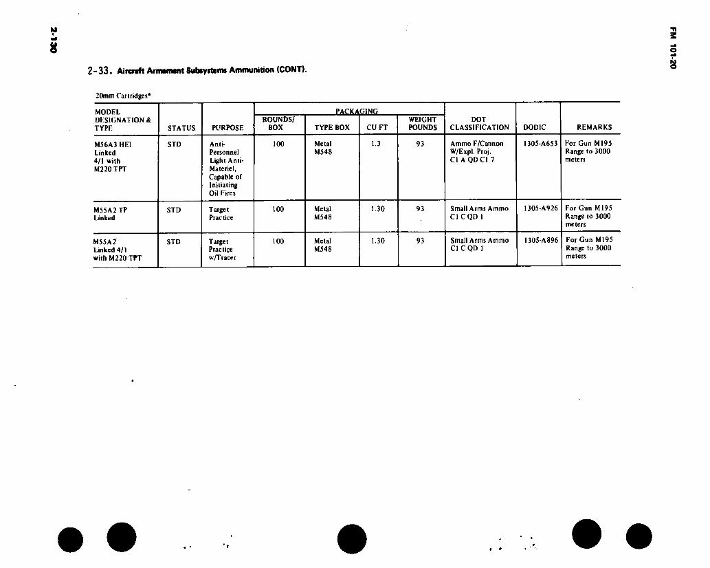
2-1
30
2-33. Aircraft Armament Subayrteira Ammunition (CONT).
20mm Cartridges*
MODEL DESIGNATION & TYPE STATUS PURPOSE
ROUNDS/ BOX
PACKAGING
TYPE BOX CU FT WEIGHT POUNDS
DOT CLASSIFICATION DODIC REMARKS
MS6A3 HEI Linked 4/1 with M220TPT
STD Anti- Personnel Light Anti- Materiel, Capable of Initiating Oil Fires
100 Metal M548
1.3 93 Ammo F/Cannon W/Expl. Proj. Cl A0DC1 7
1305-A653 For Gun M195 Range to 3000 meters
M55A2 TP Linked
STD Target Practice
100 Metal M548
1.30 93 Small Arms Ammo Cl CQD 1
1305-A926 For Gun M19S Range to 3000 meters
M55A7 Linked 4/1 with M220 TPT
STD Target Practice w/Tracer
100 Metal M548
1.30 93 Small Arms Ammo Cl CQD 1
1305-A896 For Gun M19S Range to 3000 meters
. 4
FM
10
1-2
0

2-1
31
2-33. Aircraft Armament Subsystems Ammunition (CONT).
40mm Cartridges*
MODEL DESIGNATION & TYPE
M383 HE
M384 HE
M385 Practice
STATUS
STD
STD
STD
PURPOSE
Anti- Personnel
Anti- Personnel
Practice (Solid Aluminum or Plastic Proj)
ROUNDS/ BOX
SO (all linked)
SO (all linked)
50 (all linked)
PACKAGING
TYPE BOX
Wood
Wood
Wood
CU FT
1.2
1.2
1.2
WEIGHT POUNDS
S3
S3
S3
DOT CLASSIFICATION
Ammo F/Cannon W/Expl. Proj. Dot Shipp. Cl A QD Cl 7
Ammo F/Cannon W/Expl. Proj. Dot Shipp. Cl A QD Cl 7
DODIC
1310B571
1310B572
1310 B470
Ammo F/Cannon W/lnert Proj. Dot Shipp. Cl C QD Cl 1
1310 B576
1310 B480
REMARKS
W/M16A2 link Ref. DTM 1310-221-12 (PA-AD-MB)
W/M 16 link
W/M16A1 link Ref. POMM 1310-204-12 (PA-DB7)
W/M 16 link
W/M16A1 link
M430 HE DP
STD Anti- Personnel Anti- Materiel (Shaped.Chg)
SO (all linked)
Wood 1.2 S3 Ammo F/Cannon W/Expl. Proj. Dot Shipp. Cl A QD Cl 7
1310 BS42 W/M16A2 link Ref. DTM 1310-223-12 (PA-AD-MB)
XM677 Linked 1/3 HET M383
Develop- ment
XM677 Linked 1/3 HET M384
Anti- Personnel W/T racer
SO (linked 1 rd to every 3 M383/M384)
Wood 1.2 S3 Ammo F/Cannon W/Expl. Proj. Dot Shipp. Cl A QD Cl 7
I310BS29
1310B527
Ref. DTM 1310-217-12 (PA-DB7)
XM683 HE
Develop- ment
Anti- Personnel (extended ranged RAP)
SO (all linked)
Wood 1.2 S3 Ammo F/Cannon W/Expl. Proj. Dot Shipp. Cl A QD Cl 7
1310B471
XM684 HE
Contin- gency
Anti- Personnel
50 (all linked)
Wood 1.2 S3 Ammo F/Cannon W/Expl. Proj. Dot Shipp. Cl A QD Cl 7
1310 BS73
Rocket Assisted Projectile Extended Range 3000 meters max. Ref. DTM 1310-220-12 (PA-DB7)
VT Fuie W/M 383 Proj. Body W/M16A2 Unk Ref. DTM 1310-218-12 (PA-DB7)
PM 101-20

2-1
32
2-33. Aircraft Armament Subsystems Ammuniton (CONT).
40mm Cartridges* (CONT).
NOTES: 1. All rds linked with M16A1 link unless otherwise specified.
2. Those rds linked with M16 link are for use Armament Subsystem using M7S Automatic Grenade Launcher. Those rds linked w/M16A 1 or M16A2 links are suitable for use in Armament Subsystem using the M75 or Ml 29 Automatic Grenade Launcher.
Source : AARCOM (DRSAR-MAG-SD)
/
FM 101-20

2-34. Aircraft Armament Subsystems Rockets.
2.75 inch Rockets*
TYPE STDZN PURPOSE PACKAGING
RDS/Per Box Type Cu Ft Wt Lbs DOT
CLASS FSC b DODIC
REMARKS
Wpn Lehr M158A1 M200A1 M260 M26I
Rkt 2.75" Flech w/whd WDU-4A/A w/base fuze w/Mtr MK40
Rkt 2.75" HE w/whd
M229 w/Fuze M429 w/Mtr MK40
Rkt 2.75" HE w/whd Ml51 w/Fuze M429 w/Mtr MK40
Rkt 2.75" HE w/whd Ml51 w/Fuze M423 w/Mtr MK40
Rkt 2.75" SMK WP Ml56 w/Fuze M423 w/Mtr MK40
Rkt 2.75" HE w/whd
M229 w/Fuze M423 w/Mtr MK40
Rkt 2.75" Practice WTU-l/B whd/slug w/Mtr MK40
w w
Anti- Personnel
Anti-
Personnel
Anti- Personnel
Anti- Personnel Anti- Materiel
Target Marking &
Incendiary
Anti-
Personnel
Anti- Materiel
Practice & Training
4 and 25
3, 4 and 25
3, 4 and 25
3, 4 and 25
3, 4 and 25
4 and 25
Wood
Wood
Wood Wood
Wood Wood Wood
Wood Wood Wood
Wood
Wood Wood Wood
Wood Wood
3.0
17.9
3.6
3.47 20.8
3.0 3.0 17.9
3.0 3.0 17.9
3.0
3.6 3.47
20.8
3.0 17.9
127
776
134
162 996
107 127
776
107
127 776
127
134 162 996
127 776
1340-H459
1340-H488
1340-H489
1340-H490
1340-H519
1340-H534
1340-H828
Same
Same
Same
Same
Same
Same
Same
FM 101-20

2-1
34
2-34. .Aircraft Armament Subsystems Rockets (Cont).
2.75 inch Rockets*
TYPE STDZN PURPOSE PACKAüI.AG
RDS/Per Box Type Cu H \\t Lbs DOT
CLASS FSC b D0D1C
REMARKS Wpn Ijchr MlorfAl \l2U0Al M260 M261
Rkt 2.7o" Flare w/whd V.257 w/Fuze MHO w/Mtr
MK40
Rkt 2.75" Smoke Screening %/whd M259 »/Fuze MBO uAitr MK40
Rkt 2.75" HEDP »tic M247 ». Fuze PIBÜ M438 ».. Vtr MK40
Rkt 2.75" HE w/»hd Vil51 w/Fuze M433 »/Mtr \!K40
Rkt 2.75" HE w/whd M151 Void sensing w/Mtr .ViK40
Target Illumination
Battlefield Obscuration
Armor Piercing Anti- Personnel
Selectable Functioning f/Bunker Ffenetration & Anti- Personnel
Anti- Bunker Anti- Canopy
3 »lids »7 fuze, 3 Mtrs unassembled
Wood
4 and 19
4 and 25
Wood
Wood
Wood Metal
Wood
3.0
3.5
3.47
3.0 9.9
3.0 16.5
117
135
147
127 490
127 776
1340-HlöO
1340-H116
1340-H82Ö
1340-H471
1340-H161
Same5
Same
Samt5
M200A1 Mod
Same
Source : MICOM-DRSMI-UR, AV 746-1206
FM 101 20

2-135
2-35 Aircraft Armament Subsystem Missiles
TYPE STDZN PURPOSE
Guided Missile, Surface Attack: BGM-71A-1 (TOW) A
Armor
Piercing Anti- Personnel
Guided Missile, Practice: BIM-71A-1 (TOW)
A Training
& Testing
PACKAGING
RDS/PER BOX TYPE
Wood
Wood
CU. FT.
4.38
4.38
WT. LBS
89
89
DOT CLASS
A *
FSC
1410
1410
FM 101-20

FM 101-20
2-36. Aircraft Armor Systems.
Armor protection against enemy small arms fire is provided for Army aircraft crew and critical components. Types of crew protection include armored seat bottoms, side panels, and floor plates. Protection of critical components is provided by
means of armor for engine, fuel and oil accessories, and flight control items. The amount and place- ment of protective armor varies among different types of aircraft*systems. The U-6, U-l, U-8, U-9, U-10, U-21, T-41, T-42, C-12 and UV-18 do not have armor. The backing for armor in the existing air- craft is mostly fiberglass. In the future fiberglass may be replaced by KEVLAR.
2-136
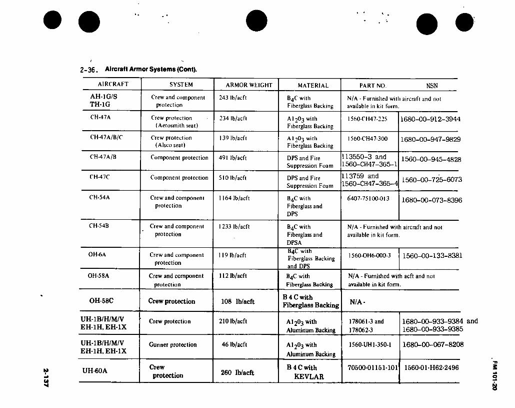
2-1
37
2-36. Aircraft Armor Systems (Cont).
AIRCRAFT SYSTFM ARMOR WKIGHT MATERIAL PART NO. NSN
AH-1G/S TH-1G
Crew and component
protection 243 lb/acft B4C with
Fiberglass Backing N/A - Furnished with aircraft and not available in kit form.
CH-47A Crew protection
(Aerosmith seat) 234 lb/acft A12O3 with
Fiberglass Backing 1560-CH47-225 1680-00-912-3944
CH-47A/B/C Crew protection (Alsco seat)
139 lb/acft Al 2O3 with Fiberglass Backing
I 560-CH47-300 1680-00-947-9829
CH-47A/B Component protection 491 lb/acft DPS and Fire Suppression Foam
113550-3 and 1560-CH47-365-1
1560-00-945-4828
CH-47C Component protection 510 lb/acft DPS and Fire Suppression Foam
113759 and 1560-CH47-365-4
1560-00-725-6073
CH-54A Crew and component
protection 1164 lb/acft B4C with
Fiberglass and
DPS
6407-75100-013 1680-00-073-8396
CH-54B Crew and component
protection 1233 lb/acft B4C with
Fiberglass and
DPSA
N/A - Furnished with aircraft and not
available in kit form.
OH-6A Crew and component
protection
119 lb/acft B4C with Fiberglass Backing
and DPS
1560-OH6-000-3 1560-00-133-8381
OH-5 8 A Crew and component
protection
112 lb/acft B4C with
Fiberglass Backing
N/A - Furnished with acft and not
available in kit form.
OH-58C Crew protection 108 lb/acft B 4 C with Fiberglass Backing N/A-
UH-1B/H/M/V EH-1H, EH-1X
Crew protection 210 lb/acft AI2O3 with
Aluminum Backing
178061- 3 and
178062- 3
1680-00-933-9384 and 1680-00-933-9385
UH-1B/H/M/V EH-1H, EH-1X
Gunner protection 46 lb/acft AI2O3 with
Aluminum Backing
1560-UH1-350-1 1680-00-067-8208
UH-60A Crew protection 260 lb/acft
B 4 C with
KEVLAR
70500-01151-101 1560-01-H62-2496
FM 101-20
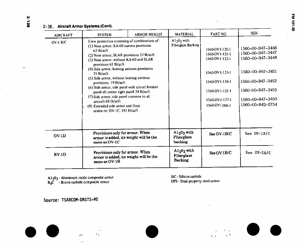
2-36. Aircralt Armor Systems (Cont).
AIRCRAFT
OV-1 B/C
SYSTEM ARMOR WEIGHT
Crew protection consisting of combinations of: (1) Nose armor, KA-60 camera provisions
63 lb/acft (2) Nose armor, SLAR provisions 53 lb/acft (3) Nose armor, without KA-60 and SLAR
provisions 65 lb/acft (4) Side armor, homing antenna provisions
21 lb/acft (5) Side armor, without homing antenna
provisions 19 lb/acft (6) Side armor, side panel with circuit breaker
panel aft center right panel 24 lb/acft (7) Side armor, side panel common to all
aircraft 68 lb/acft (8) Extended side armor and floor
armor on OV-lC, 181 lb/acft
MATERIAL
A12O3 with Fiberglass Backing
PART NO.
1560-OV1-120-1 1560-OV1-121-1 1560-OV 1-122-i
1560-OV 1-123-1
1560-OV 1-124-1
1560-OV 1-125-1
1560-OV 1-127-1
1560-OV 1-006-1
NSN
1560-00-947-3446 1560-00-947-3447 1560-00-947-3448
1560-00-947-3451
1560-00-947-3452
1560-00-947-3453
1560-00-947-3450 1560-00-943-0754
OV-1D Provisions only for armor. When armor is added, its weight will be the same as OV-lC
AI2O3 with Fiberglass backing
SeeOV-lB/C See 0V-1B/C
RV-1D Provisions only for armor. When armor is added, its weight will be the same as OV-1B
AI2O3 with Fiberglass Backing
SeeOV-lB/C See 0V-1B/C
AI2O3 - Aluminum oxide composite armor B4C - Boron carbide composite armor
SiC - Silicon carbide
DPS - Dual property steel armor
Source: TSARCOM-DRSTS-ME
FM 101-20

FM 101-20
2-37. AH-1G/S and TH-1G Armor
a. The AH-1Ci/S and TH-1G aircraft are provided with aircrew and critical component armor. The pilot's seat is made of dual hardness steel armor. The fixed side panels aie made of a hard faced composite material. The entire passive defense system for the gunner is made of a hard faced composite material.
b. Critical component armor is located on each side of the engine to protect the engine compressor section and the fuel control unit. The standard fuel cells are self-sealing as follows: bottom 33% capacity against .50 caliber, center 33%capacity 30 caliber, and the top 34% is not self-sealing. The fuel crossover line is also self-sealing. The new crashworthy fuel cells are self-sealing against 20mm over their entire capacity. The fuel crossover line is self-sealing.
ENGINE ANO TRANSMISSION OIL COOLER BY PASS SYSTEM
- /
0
/
ENGINE FUEL CONTROL ✓ AND COMPRESSOR ARMOR
/ ,
ARMOR STEEL PILOTS SEAT AND CERAMIC SIDE PANELS
CERAMIC GUNNERS SEAT AND SIDE PANELS
Figure 2-28. AH-lG/S and TH-lG Amor
2-139

FM 101-20
2-38. CH-47 Armor.
j. The CH-47 aircraft are provided with aircrew and critical component armor.
b. The aircrew armor material is aluminum oxide hard faced composite capable of defeating 30 caliber projectiles.
c. DPS armor has been provided for the following critical components:
(1) Armor for the fore and aft flight control actuators in four locations.
(2) Armor for the flight control closet.
(3) Armor for the fuel crossover valve.
(4) Fire suppression foam on fore and aft faces of both fuel tanks.
v
$
SWIVELING ACTUATOR
PIVOTING ACTUATOR AFT ROTOR DUAL BOOST ACTUATORS
r/'"' r/
/.
\ FORWARD V—.."■••• ROTOR DUAL \ '////, BOOST ACTUATORS
PIVOTING ACTUATOR
SWIVELING ACTUATOR
//-: VC. \ <:
FUEL CROSS OVER VALVE
K ; , r>.
i ./,
\ <•[».. ! r-'.
:
»orf1!
.. r •••// * f *
FIRE SHEATHING
y r*; TV».., r* ». . x* ♦. /
"
FLIGHT CONTROL CLOSET-
AV 000217
Figure 2-29. CH-47 Amor
2-140

FM 101-20
2-39. Armor for the Armed and Armored Chinook.
a. Armor for the armed and armored Chinook consists of aircrew and component armor. The pilot and copilot have been provided with a crash attentuating integral 30 caliber armor seat.
b. The total installed weight of the armor system is 2700 pounds. Armor is provided for the following critical components:
(1) Controls closet area of flight controls system.
(2) Swiveling and pivoting dual actuators in forward and aft pylons.
(3) Copilot’s control box.
(4) Linkage from copilot’s controls to closet.
(5) Flight controls mix complex.
(6) Walking beam rod ends and bellcrank.
(7) Aft fuselage controls, rods, and bellcrank.
(8) Aft pylon controls, rods, and bellcrank.
(9) Accessory gear box, quill shaft.
c. The armor material is dual property steel capable of defeating 50 caliber API projectiles.
2-141
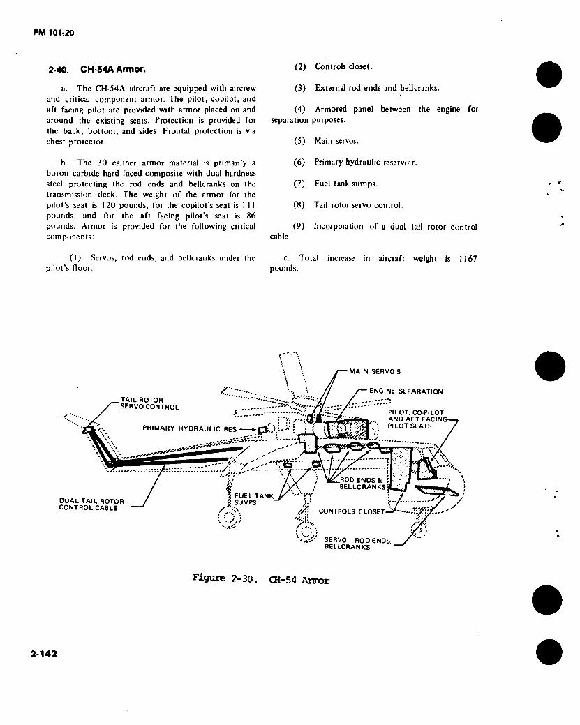
FM 101:20
2-40. CH-54A Armor.
a. The CH-54A aircraft are equipped with aircrew and critical component armor. The pilot, copilot, and aft facing pilot are provided with armor placed on and around the existing seats. Protection is provided for the back, bottom, and sides. Frontal protection is via chest protector.
b. The 30 caliber armor material is primarily a boron carbide hard faced composite with dual hardness steel protecting the rod ends and bellcranks on the transmission deck. The weight of the armor for the pilot’s seat is 120 pounds, for the copilot’s seat is 1 11 pounds, and for the aft facing pilot’s seat is 86 pounds. Armor is provided for the following critical components:
(2) Controls closet.
(3) External rod ends and bellcranks.
(4) Armored panel between the engine for
separation purposes.
(5) Main servos.
(6) Primary hydraulic reservoir.
(7) Fuel tank sumps.
(8) Tail rotor servo control.
(9) Incorporation of a dual tail rotor control cable.
(I) Servos, rod ends, and bellcranks under the c. Total increase in aircraft weight is 1167 pilot’s floor. pounds.
.TAIL ROTOR SERVO CONTROL
■S/yS*
PRIMARY HYDRAULIC RES.
.-.ssssS'''''!
AULIC RES. -jaj,!""-'! ! { ;
, - - - t"4
DUAL TAIL ROTOR CONTROL CABLE
FUEL TANK j! SUMPS
MAIN SERVO S
ENGINE SEPARATION
PILOT, CO-PILOT AND AFT FACINC PILOT SEATS
ROD ENDS & : BELLCRANKS;
\ f / /.V CONTROLS CLOSET
*\j r/
'•-.-.■ÿ SERVO RODENOS BELLCRANKS
Figure 2-30. CH-54 Arnor
2-142

FM 101-20
2-41. OH-6A Armor.
;i. The passive protection system foi the OH-6A aireralt eonsists of aircrew and critical component armor, flic pilot and copilot is provided with armor placed on the existing scats. Protection is provided for the hack, bottom, and sides. Frontal protection is via chest protector.
b The armor material is a 30 caliber boion carbide hard laced composite except for the panel under the seal and the engine eompressoi panel which aie i if dual piopei ty steel.
c The weiglil ol the complete installed system is I 30 pounds.
d. Armor is provided for the following critical components:
( I ) Fnginc compressor.
( 2) Self-scaling oil lines.
(3) Self-scaling fuel lines.
(4) Fnginc and transmission oil cooler bypass valves.
(5) Fuel control valve.
/'/
'/y '■v
■f. .'/‘Vt,:. '■
'■vy
-- %< gp <
" '■ /' / ENGINE AND TRANSMISSION —BY PASS SYSTEMS WITH
SELF SEALING LINES AND TANK'.
i n ul ARMOR
A W
n H /
y. , o/ 'r. y. >• n . it
COMPRESSOR ARMOR
FUEL CONTROL ARMOR
■ -I 7—T— CO PI LOT ARMOR r Oyt s '
: i •:.'// s' / ■ ; . : ;
Figure 2-31. 0H-6A armor
2-143

FM 101;20
2-42. UH-1 Series Armor.
a. The UH-1 series aircraft are equipped with aircrew armor for the pilot and copilot. The armor consists of an integrated armored seat. Protection is provided from the bottom, rear, and sides. Frontal protection is via chest protector.
b. The armor material is aluminum oxide hard faced composite capable of defeating 30 caliber projectiles.
c. The headguard is an armor panel which attaches to the back of the seats. The gunner’s seat armor unit is a plate of armor material securely fastened to the crew seats in the UH-1. It is provided with a cushion for the crewman to sit on.
Â-- ¥'/'& ••'■■■ '>■ H&y / • ''
S'.
..., \
/ ^ ' s'
F’lLOT
^ ' // s ' /- j/t. ✓ .
/ ^ ' / y ? 11' . ft é ,
✓✓, V#.
'Ä
7 /r/<
'4V
ARMORED SEAT ^ V
/ "Í Of. r 1
h ;/ r
/ •w, ^ ✓ » ». j rv* y
. V- J.v
/ /. A A
\ T f
COPILOT ARMORED SEAT
^"ivr’ vixr. j'.
Figure 2-32. UH-1 Armor
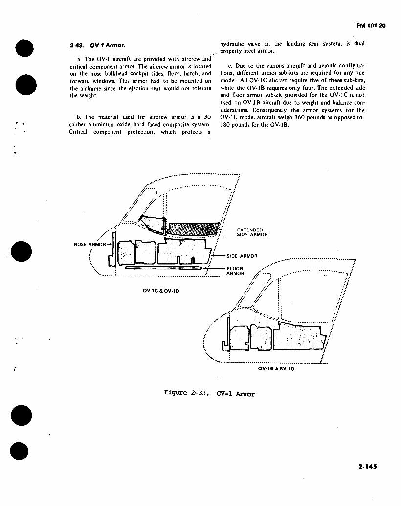
FM 101-20
2*43. OV-1 Armor.
a. The OV-1 aircraft are provided with aircrew and critical component armor. The aircrew armor is located on the nose bulkhead cockpit sides, floor, hatch, and forward windows. This armor had to be mounted on the airframe since the ejection seat would not tolerate the weight.
b. The material used for aircrew armor is a 30 caliber aluminum oxide hard faced composite system. Critical component protection, which protects a
hydraulic valve in the landing gear system, is dual property steel armor.
c. Due to the various aircraft and avionic configura- tions, different armor sub-kits are required for any one model. All OV-1C aircraft require five of these sub-kits, while the OV-1B requires only four. The extended side and floor armor sub-kit provided for the OV-1C is not used on OV-JB aircraft due to weight and balance con- siderations. Consequently the armor systems for the
OV-1C model aircraft weigh 360 pounds as opposed to 180 pounds for the OV-1B.
vVV .
a
NOSE ARMOR-►
EXTENDED SIDC ARMOR
SIDE ARMOR
FLOOR ARMOR .-i —
OV-1C & OV-1D
V-
r.
I C V
0V-1B4RV-10
Figure 2-33. OV-1 Armor
2-145

FM 101-20
Section III. FERRYING AND SHIPPING
2-44. Surface Shipment.
Preparation of large numbers ol aircraft for simultaneous mass movement by ocean transport had iu inception in the latter part of June 1965.
Deployment of the 1st Cavalry Division (Airmobile) involved movement of a large number of aircraft, which was a first of this type and magnitude for the U. S. Army. Since the operation involved movement of approximately 500 aircraft, staging areas had to be established to receive, process, and marshall in
accordance with the numbers designated for each of four vessels. Ports of loading were designated at Brookley Air Force Base, Mobile, Ala., and Mayport Naval Base, Jacksonville, Fla.
As a result of the experience with the 1st Cavalry Division deployment and other vessel shipments of aircraft to Southeast Asia, time/motion studies have provided input for developing the following table relating to processing Army aircraft for surface shipment.
Source: TSARCOM-DRSTS-SDP
2-146

2-1
47
2-45. Surface Shipment Processing Time.
MAN HOURS (M/H) AND ELAPSED TIME (ET) RQR TO PROCESS 1 EA. FOR OVERSEAS SHIPMENT
MAN-HOURS AND ELAPSED TIME
TO DEPROCESS 1 EA.
Type of Aircraft
Top Deck Reusable Below Deck Top Deck Reusable Below Deck
M/H ET M/H ET M/H ET M/H ET
AH-1— CH-47 CH-54 OH-6A OH-58 UH-1— U-8F U21/RU21 OV-1 UH-60A—
12^ 24l 48l_ NA NA 122
40 40 45 3
22 4 6 NA NA 2i 5 5 5 3
18 NA NA 3 3 18 NA NA NA 3
3 NA NA 1 1 4 NA NA NA 3
6 18 56 NA NA 6
48 48 55 3
1 3 8 NA NA 1
6
6 9 3
12 NA NA 3 3 12
NA NA NA 3
2 NA NA 1 1 2
NA NA NA 3
REFERENCED PUBLICATION
TM55-1500-339S TM1-CH47S TM1-CH54S TM1-OH6-S TM55-1500-338S TM55-1500-219S TM55-1510-201-S
TM55-1510-200-S TM55-1510-217-S 3
- Cover sets are not items to be requisitioned. Only CONUS and overseas outloading points preparing aircraft for movement are authorized to request cover sets.
— Not recommended, covers should be used if placed on top deck.
3. Not available, if information is needed contact DRSTS-SDP
FM 101-20
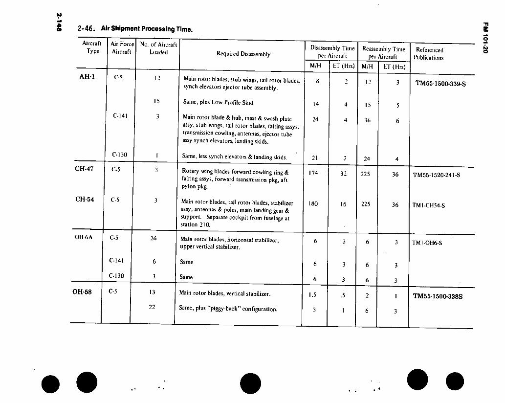
2-1
48
2- 46. Air Shipment Processing Time.
Aircraft Type
AH-1
Air Force Aircraft
C-5
C-141
C-130
No. of Aircraft Loaded
12
15
3
Required Disassembly
Main rotor blades, stub wings, tail rotor blades, synch elevators ejector tube assembly.
Same, plus Low Profile Skid
Main rotor blade & hub, mast & swash plate assy, stub wings, tail rotor blades, fairing assys, transmission cowling, antennas, ejector tube assy synch elevators, landing skids.
Same, less synch elevators & landing skids.
Disassembly Time per Aircraft
M/H ET (Hrs)
14
24
21
4
4
Reassembly Time per Aircraft
M/H
15
36
24
ET (Hrs)
Referenced Publications
TM55-1500-339-S
CH-47
CH-54
OH-6A
C-5
C-5
C-5
C-141
C-130
26
6
3
Rotary wing blades forward cowling ring & fairing assys, forward transmission pkg, aft pylon pkg.
Main rotor blades, tail rotor blades, stabilizer assy, antennas & poles, main landing gear & support. Separate cockpit from fuselage at station 210.
174
180
32
16
225
225
36
36
Main rotor blades, horizontal stabilizer, upper vertical stabilizer.
Same
Same
6
6
TM55-1520-241-S
TM1-CH54-S
TM1-OH6-S
OH-58 C-5 13
22
Main rotor blades, vertical stabilizer.
Same, plus “piggy-back” configuration.
1.5
3
2
6
TM55-1500-338S
« •
FM 101-20

2-1
49
2-46. Air Shipment Processing Time (Cont).
Aircraft Type
Air Force Aircraft
No. of Aircraft Loaded Required Disassembly
Disassembly Time per Aircraft
M/H ET (Mrs)
Reassembly Time per Aircraft
M/H ET (Hrs)
Referenced Publications
OH-58 (Cont.)
C-141
C-130
Main rotor blades & hub & mast, vertical stabilizer.
Same, plus “piggy-back” configuration.
Same, plus tail rotor blades.
7.5
3
3
1.5 10
6
6
UH-1 H,M,V
EH-1H EH-1X
U-8F
C-5
C-141
C-130
C-5
11
(C, M)
lor 2
3 (D, H)
1
(D, H)
Main rotor blades, stabilizer bar, synch elevators, antennas, hinged panels.
Same, plus “piggy-back” configuration.
Main rotor blades, stabilizer bar, rotor head
& mast assy, tail rotor blades, skid landing gear, antennas, rearview mirror, cargo suspension assy.
Same, plus “side-saddle” configuration.
Same
Same, plus “side saddle” configuration.
12
16
24
18
26
32
30
24
30
40
32
40
Wings 16 32
TM55-1500-219S
TM55-1510-201-S
U-21/
RU-21* C-5 Wings 16 32 TM55-1510-200-S
'Not practical due to disassembly requirements.
FM 101-20
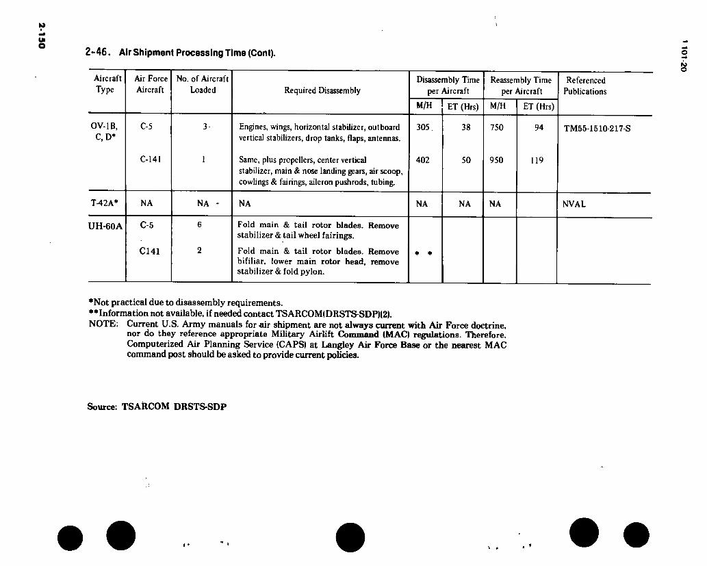
2-1
50
2-46. Air Shipment Processing Time (Cont).
Aircraft Type
Air Force Aircraft
No. of Aircraft Loaded Required Disassembly
Disassembly Time per Aircraft
M/H ET (Mrs)
Reassembly Time per Aircraft
M/H ET (Hrs)
Referenced Publications
0V-1B, C, D*
C-5
C-141
Engines, wings, horizontal stabilizer, outboard vertical stabilizers, drop tanks, flaps, antennas.
Same, plus propellers, center vertical stabilizer, main & nose landing gears, air scoop, cowlings & fairings, aileron pushrods, tubing.
305
402
38
50
750
950
94
119
TM55-1510-217-S
T-42A* NA NA NA NA NA NA NVAL
UH-60A C-5
C141
Fold main & tail rotor blades. Remove stabilizer & tail wheel fairings.
Fold main & tail rotor blades. Remove bifiliar, lower main rotor head, remove stabilizer & fold pylon.
* *
•Not practical due to disassembly requirements. ••Information not available, if needed contact TSARCOM(DRSTS-SDP)(2). NOTE: Current U.S. Army manuals for air shipment are not always current with Air Force doctrine,
nor do they reference appropriate Military Airlift Command (MAC) regulations. Therefore, Computerized Air Planning Service (CAPS) at Langley Air Force Base or the nearest MAC command post should be asked to provide current policies.
Source: TSARCOM DRSTS-SDP
1 •
1 101-20
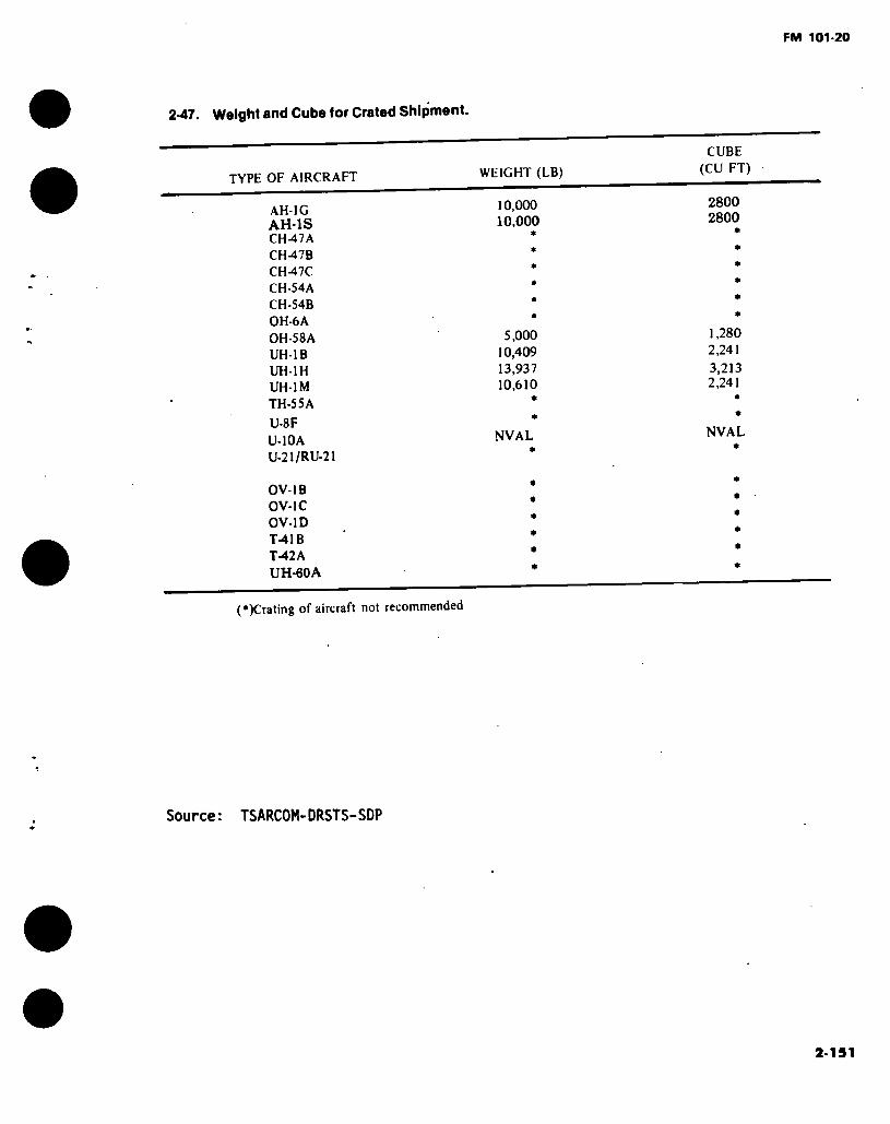
FM 101-20
2-47. Weight and Cube (or Crated Shipment.
CUBE (CU FT) WEIGHT (LB) TYPE OF AIRCRAFT
AH-1G AH-1S CH47A
10,000 10,000
2800 2800
CH-47B CH-47C CH-54A CH-54B OH-6A OH-58A UH-1B UH-1H UH-1M TH-55A
5,000 10,409 13,937 10,610
1,280 2.241
3,213 2.241
U-8F
U-10A U-21/RU-21
*
NVAL
*
NVAL *
OV-1B OV-1C OV-1D T-41B T-42A UH-60A
(*)Crating of aircraft not recommended
Source: TSARCOM-DRSTS-SDP
2-191
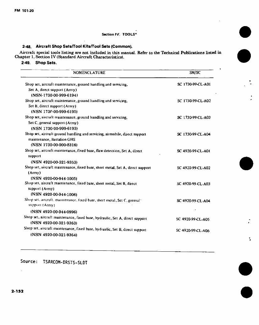
FM 101-20
Section IV. TOOLS*
2-48. Aircraft Shop Sets/Tool Kits/Tool Sets (Common). Aircraft special tools listing are not included in this manual. Refer to the Technical Publications listed in
Chapter 1, Section IV (Standard Aircraft Characteristics).
2-49. Shop Sets.
NOMENCLATURE SM/SC
Shop set, aircraft maintenance, ground handling and servicing,
Set A, direct support (Army)
(NSN-1730-00-999-6194) Shop set, aircraft maintenance, ground handling and servicing,
Set B, direct support (Army)
(NSN 1730-00-999-6195)
Shop set, aircraft maintenance, ground handling and servicing,
Set C, general support (Army)
(NSN 1730 00-999-6193) Shop set, aircraft ground handling and servicing, airmobile, direct support
maintenance, Battalion CHS
(NSN 1730-00-900-8316)
Shop set, aircraft maintenance, fixed base, flaw detection, Set A, direct
support
(NSN 4920-00-321-9353) Shop set, aircraft maintenance, fixed base, sheet metal, Set A, direct support
(Army)
(NSN 4920-00-944-1005) Shop set, aircraft maintenance, fixed base, sheet metal. Set B, direct
support (Army)
(NSN 4920-00-944-1006) Shop set. aircraft, maintenance, fixed base, sheet metal. Set C, general '
support (Army)
(NSN 4920-00-944-0996) Shop set, aircraft maintenance, fixed base, hydraulic, Set A, direct support
(NSN 4920-00-321-9363) Shop set, aircraft maintenance, fixed base, hydraulic, Set B, direct support
(NSN 4920-00-321-9364)
SC 1730-99-CL-A01
SC 1730-99-CL-A02
SC 1730-99-CL-A03
SC 1730-99-CL-A04
SC 4920-99-CL-A01
SC 4920-99-CL-A02
SC 4920-99-CL-A03
SC 4920-99-CL-A04
SC 4920-99-CL-A05
SC 4920-99-CL-A06
Source: TSARCOM-DRSTS-SLDT
2-152

FM 101-20
2-49. Shop Sets (Cont).
NOMENCLATURE
Shop set, aircraft maintenance, fixed base, hydraulic. Set C, general support
(NSN 4920-00-321-9373) Shop set, aircraft maintenance, fixed base, welding, Set A, direct support
(NSN 4920-00-321-9375) Shop set, aircraft maintenance, fixed base, welding, Set B, direct support
(NSN 4920-00-321-9376) Shop set, aircraft maintenance, fixed base, welding, Set C, general support
(Army)
(NSN 4920-00-944-0785) Shop set, aircraft maintenance, fixed base, tool crib. Set A, direct support
(NSN 4920-00-321-9397) Shop set, aircraft maintenance, fixed base, tool crib, Set B, direct support
(NSN 4920-00-321-9403) Shop set, aircraft maintenance, fixed base, tool crib, Set C, general support
(NSN 4920-00-321-9405) Shop set, aircraft maintenance, fixed base, electrical, Set A, direct support
(Army)
(NSN 4920-00-944-0761)
Shop set, aircraft maintenance, fixed base, electrical. Set B, direct support
(Army)
(NSN 4920-00-944-0760) Shop set, aircraft maintenance, fixed base, electrical, Set C, general support
(Army)
(NSN 4920-00-944-0757) Shop set, aircraft maintenance, fixed base, flaw detection. Set B, direct
support
(NSN 4920-00-321-9410)
Shop set, aircraft maintenance, fixed base, flaw detection, Set C, general
support
(NSN 4920-00-321-9411) Shop set, aircraft maintenance, fixed base, paint, Set B, direct support
(Army)
(NSN 4920-00-944-0759) Shop set, aircraft maintenance, fixed base, paint. Set C, general support
(Army)
(NSN 4920-00-944-1007) Shop set, aircraft maintenance, fixed base, instrument, Set B, direct support
(NSN 4920-00-321-9416)
SM/SC
SC 4920-99-CL-A07
SC 4920-99-C L-A08
SC 4920-99-CL-A09
SC 4920-99-CL-A10
SC 4920-99-CL-A11
SC 4920-99-CL-A12
SC 4920-99-CL-A13
SC 4920-99-CL-A14
SC 4920-99-CL-A15
SC 4920-99-CL-A16
SC 4920-99-CL-A17
SC 4920-99-CL-A18
SC 4920-99-CL-A19
SC 4920-99-C L-A 20
SC 4920-99-CL-A21
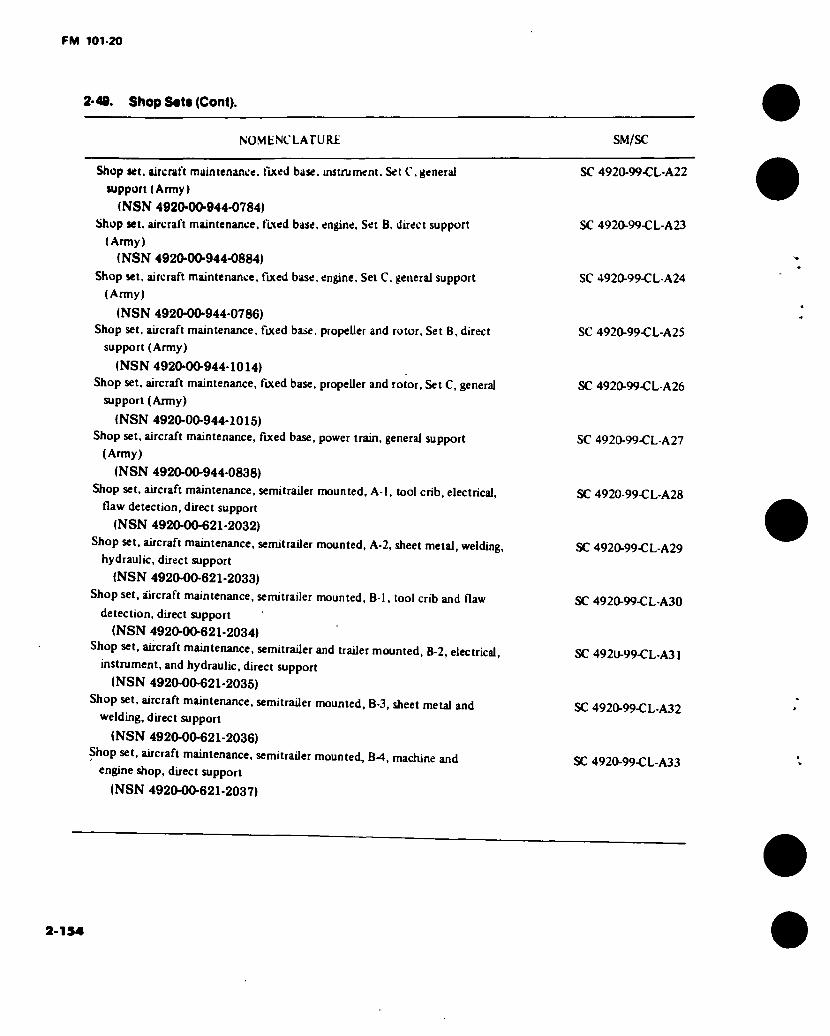
FM 101-20
2-40. Shop Sots (Cont).
NOMbNCLATURE SM/SC
Shop set. aircraft maintenance, fixed base, instrument. Set C,general
support (Army)
(NSN 4920-00-944-0784) Shop set. aircraft maintenance, fixed base, engine. Set B. direct support
(Army)
(NSN 4920-00-944-0884) Shop set, aircraft maintenance, fixed base, engine, Set C. general support
(Army)
(NSN 4920-00-944-0786) Shop set, aircraft maintenance, fixed base, propeller and rotor. Set B, direct
support (Army)
(NSN 4920-00-944-1014) Shop set, aircraft maintenance, fixed base, propeller and rotor. Set C, general
support (Army)
(NSN 4920-00-944-1015) Shop set, aircraft maintenance, fixed base, power train, general support
(Army)
(NSN 4920-00-944-0838) Shop set, aircraft maintenance, semitrailer mounted, A-l, tool crib, electrical,
flaw detection, direct support
(NSN 4920-00-621-2032) Shop set, aircraft maintenance, semitrailer mounted, A-2, sheet metal, welding,
hydraulic, direct support
(NSN 4920-00-621-2033) Shop set, aircraft maintenance, semitrailer mounted, B-l, tool crib and flaw
detection, direct support
(NSN 4920-00-621-2034) Shop set, aircraft maintenance, semitrailer and trailer mounted, B-2, electrical,
instrument, and hydraulic, direct support
(NSN 4920-00-621-2035) Shop set, aircraft maintenance, semitrader mounted, B-3, sheet metal and
welding, direct support
(NSN 4920-00-621-2036) Shop set, aircraft maintenance, semitrailer mounted, B-4, machine and
engine shop, direct support
(NSN 4920-00-621-2037)
SC 4920-99-CL-A22
SC 4920-99-CL-A23
SC 4920-99-CL-A24
SC 4920-99-CL-A25
SC 4920-99-CL-A26
SC 4920-99-CL-A27
SC 4920-99-CL-A28
SC 4920-99-C L-A29
SC 4920-99-CL-A30
SC 492U-99-CL-A31
SC 4920-99-CL-A32
SC 4920-99-CL-A33
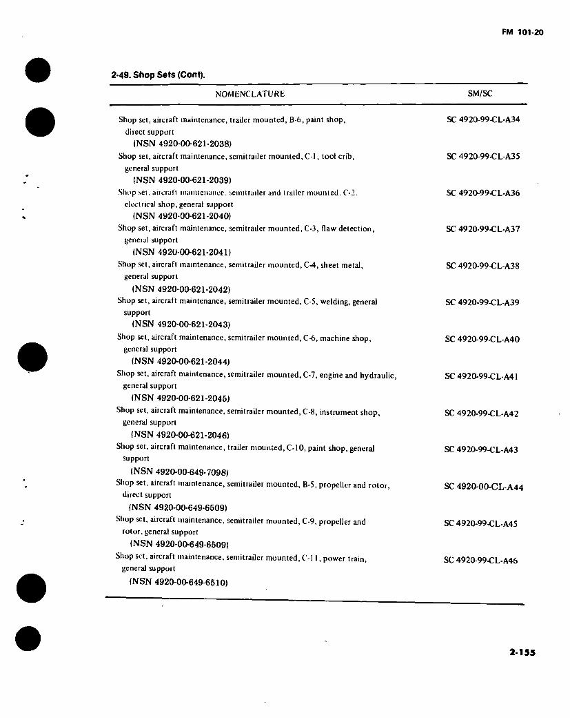
FM 101-20
2-49. Shop Sets (Cont).
NOMENCLATURE SM/SC
Shop set, aircraft maintenance, trailer mounted, B-6, paint shop, SC 4920-99-CL-A34
direct support
(NSN 4920-00-621-2038)
Shop set, aircraft maintenance, semitrailer mounted, C-l, tool crib, SC 4920-99-CL-A35
general support
(NSN 4920-00-621-2039)
Shop set, aircraft maintenance, semitrailer and trailer mounted. C-2. SC 4920-99-CL-A36
electrical shop, general support
(NSN 4920-00-621-2040)
Shop set, aircraft maintenance, semitrailer mounted, C-3, flaw detection, SC 4920-99-CL-A37
general support
(NSN 4920-00-621-2041)
Shop set, aircraft maintenance, semitrailer mounted, C-4, sheet metal, SC 4920-99-CL-A38
general support
(NSN 4920-00-621-2042)
Shop set, aircraft maintenance, semitrailer mounted, C-5, welding, general SC 4920-99-CL-A39
support
(NSN 4920-00-621-2043)
Shop set, aircraft maintenance, semitrailer mounted, C-6, machine shop, SC 4920-99-CL-A40
general support
(NSN 4920-00-621-2044)
Shop set, aircraft maintenance, semitrailer mounted, C-7, engine and hydraulic, SC 4920-99-CL-A41
general support
(NSN 4920-00-621-2045)
Shop set, aircraft maintenance, semitrailer mounted, C-8, instrument shop, SC 4920-99-CL-A42
general support
(NSN 4920-00-621-2046)
Shop set, aircraft maintenance, trailer mounted, C-10, paint shop, general SC 4920-99-CL-A43
support
(NSN 4920-00-649-7098)
Shop set, aircraft maintenance, semitrailer mounted, B-5, propeller and rotor, SC 4920-00-CL-A44
direct support
(NSN 4920-00-649-6509)
Shop set, aircraft maintenance, semitrailer mounted, C-9, propeller and SC 4920-99-CL-A45
rotor, general support
(NSN 4920-00-649-6509)
Shop set, aircraft maintenance, semitrailer mounted, C-l 1, power train, SC 4920-99-CL-A46
general support
(NSN 4920-00-649-6510)
2-159
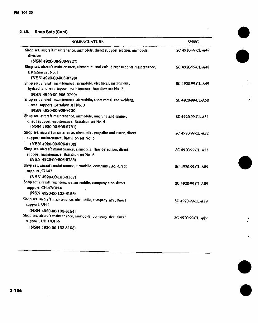
FM 101-20
2- 49. Shop Sets (Cent).
NOMENCLATURE SM/SC
Shop set, aircraft maintenance, airmobile, direct support section, airmobile SC 4920-99-CL-A47
division
(NSN 4920-00-906-9727)
Shop set, aircraft maintenance, airmobile, tool crib, direct support maintenance, SC 4920-99-CL-A48
Battalion set No. 1
(NSN 4920-00-906-9728)
Shop set, aircraft maintenance, airmobile, electrical, instrument, SC 4920-99-CL-A49
hydraulic, direct support maintenance, Battalion set No. 2
(NSN 4920-00-906-9729) Shop set, aircraft maintenance, airmobile, sheet metal and welding, SC 4920-99-CL-A50
direct support, Battalion set No. 3
(NSN 4920-00-906-9730)
Shop set, aircraft maintenance, airmobile, machine and engine, SC 4920-99-CL-A51
direct support maintenance, Battalion set No. 4
(NSN 4920-00-906-9731)
Shop set, aircraft maintenance, airmobile, propeller and rotor, direct SC 4920-99-CL-A52
lr. support maintenance, Battalion set No. 5
(NSN 4920-00-906-9732) Shop set, aircraft maintenance, airmobile, flaw detection, direct
support maintenance, Battalion set No. 6
(NSN 4920-00-906-9733)
Shop set, aircraft maintenance, airmobile, company size, direct
support, CH-47
(NSN 4920-00-133-8157)
Shop set aircraft maintenance, airmobile, company size, direct
support, CH-47/OH-6
(NSN 4920-00-133-8156)
Shop set, aircraft maintenance, airmobile, company size, direct
support, UH-I
(NSN 4920-00-133-8154) Shop set, aircraft maintenance, airmobile, company size, direct
support, UH-l/OH-6
(NSN 4920-00-133-8158)
SC 4920-99-CL-A53
SC 4920-99-CL-A89
SC 4920-99-CL-A89
SC 4920-99-CL-A89
SC 4920-99-CL-A89
2-156
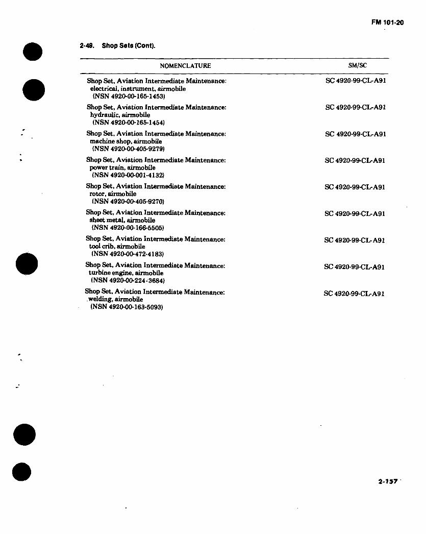
FM 101-20
Shop Sets (Cont).
NOMENCLATURE SM/SC
Shop Set, Aviation Intermediate Maintenance: electrical, instrument, airmobile (NSN 4920-00-165-1453)
Shop Set, Aviation Intermediate Maintenance: hydraulic, airmobile (NSN 4920-00-165-1454)
Shop Set, Aviation Intermediate Maintenance: machine shop, airmobile (NSN 4920-00-405-9279)
Shop Set, Aviation Intermediate Maintenance: power train, airmobile (NSN 4920-00-001-4132)
Shop Set, Aviation Intermediate Maintenance: rotor, airmobile (NSN 4920-00-405-9270)
Shop Set, Aviation Intermediate Maintenance: sheet metal, airmobile (NSN 4920-00-166-5505)
Shop Set, Aviation Intermediate Maintenance: tool crib, airmobile (NSN 4920-00-472*4183)
Shop Set, Aviation Intermediate Maintenance: turbine engine, airmobile (NSN 4920-00-224-3684)
Shop Set, Aviation Intermediate Maintenance: welding, airmobile (NSN 4920-00-163-5093)
SC 4920-99-CL-A91
SC 4920-99-CL-A91
SC 4920-99-CL-A91
SC 4920-99-CL-A91
SC 4920-99-CL-A91
SC 4920-99-CL-A91
SC 4920-99-CL-A91
SC 4920-99-CL-A91
SC 4920-99-CL-A91
2-157

FM 101-20
2-50. Tool Kits.
NOMENCLATURE
Tool kit, aircraft mechanic’s, general
(NSN 5180-00-323-4692) Tool kit, airframe repairer: Army aircraft
(NSN 5180-00-323-4876) Tool kit, hydraulic repairer, Army aircraft
(NSN 5180-00-323-4891)
SM/SC
SC 5180-99-CL-A01
SC 5180-99-CL-A02
SC 5180-99-CL-A03
Tool kit, instrument repairer, Army aircraft
(NSN 5180-00-323-4913) Tool kit, electrical repairer. Army aircraft
(NSN 5180-00-323-4915) Tool kit, power plant: Army aircraft
(NSN 5180-00-323-4944) Tool kit, aircraft inspection, technical
(NSN 5180-00-323-5114) Tool kit, trainer, flight simulator, set No. 1
(NSN 5180-00-859-0556) Tool kit, Army aircraft, crash investigation
(NSN 5180-00-903-1049) Tool kit, powertrain: Army aircraft
(NSN 5180-00-003-5267)
SC 5180-99-CL-A05
SC 4920-99.-CL-A06
SC 5180-99-CL-A07
SC 5180-99-CL-A09
SC 5180-99-CL-A10
SC 5180-99-CL-A11
SC 5180-99-CL-A13
2-51. Tool Sets.
NOMENCLATURE
Tool Set. Aviation Unit Maintenance. Set No. I: Airmobile (NSN 4920-00-159-8727)
Tool Set. Aviation Unit Maintenance. Set No. I : Fixed Base (NSN 4920-00-504-9258)
Tool Set. Aviation Unit Maintenance. Reciprocating Engine Supplement (NSN 4920-00-159-8728)
Tool Set, Aviation Unit Maintenance: company size, Set No. 2, airmobile (NSN 4920-00-567-0476)
SM/SC
SC 4920-99-CL-A90
SC 4920-99-CL-A90
SC 4920-99-CL-A90
SC 4920-99-CL-A92
2-158

FM 101-20
Section V. INSPECTIONS
2-52. Aircraft Inspections.
Aircraft Phased Maintenance (PM), Special (SP) Inspection Criteria,
Ti.ne Between Overhaul (TBO) and Retirement Life Schedules are not in- cluded in this manual. Refer to the Technical Publication listed.
AIRCRAFT TECHNICAL PUBLICATIONS TH5E CTÏÏ5FT
PM TBO RET SP
UH-1H UH-1H/V, EH-1H/X
TM 55-1520-210-PM TM 55-1520-210-23
X X X X
AH-1G, TH-1G AH-1G/TH-1G AH-1S (ALL) AH-1S (MOD) AH-1S (PROD/EGAS) AH-1S (MODERNIZED)
TM 55-1520-221-PM TM 55-1520-221-23 TM 55-1500-220-PM TM 55-1520-234-23 TM 55-1520-236-23 TM 55-1520-239-23
X X
X X X
X
X X X
X
CH-47B/C CH-47A CH-47B/C YCH-47D YCH-47D
TM 55-1520-227-PM TM 55-1520-209-23 TM 55-1520-227-23 TM 55-1520-240-PM TM 55-1520-240-23
X X
X X
X X
X
CH-54A CH-54B
TM 55-1520-217-23/1 TM 55-1520-217-23/2
X X X X
0H-6A TM 55-1520-214-23 X
2-159
XX X XX
XXX

FM 101-20
2-52. Aircraft Inspections.
AIRCRAFT TECHNICAL PUBLICATIONS
INSPECTION PM TBO RET SP
0H-5SA/C OH-58A/C
UH-1B
UH-1M UH-1M
UH-60A
0V-1B/C OV/RV-1 SERIES
0V/RV-1D
U-8F
U-21A, RU-21A/D U-21/RU-21
RU-21B/C
RU-21H
TM 55-1520- ™ 55-1520-
228-23 228-PM
TM 55-1520-219-20
TM 55-1520- rIM 55-1520-
220-23 220-PM
TM 55-1520-237-23
TM 55-1510- TM 55-1510-
TM 55-1510-
™ 55-1510-
TM 55-1510- TM 55-1510-
TM 55-1510-
TM 55-1510-
-204-23 -217-PM
-213-23
-201-20
209-23 •200-PM
214- 23
215- 23
X
X
X
X
X
X
X
X
X
X
X
X
X
X
X
X
X
X
X
X
X
X
X
X
X
X
X
Source: TSARCOM-DRSTS-MEN
2-160
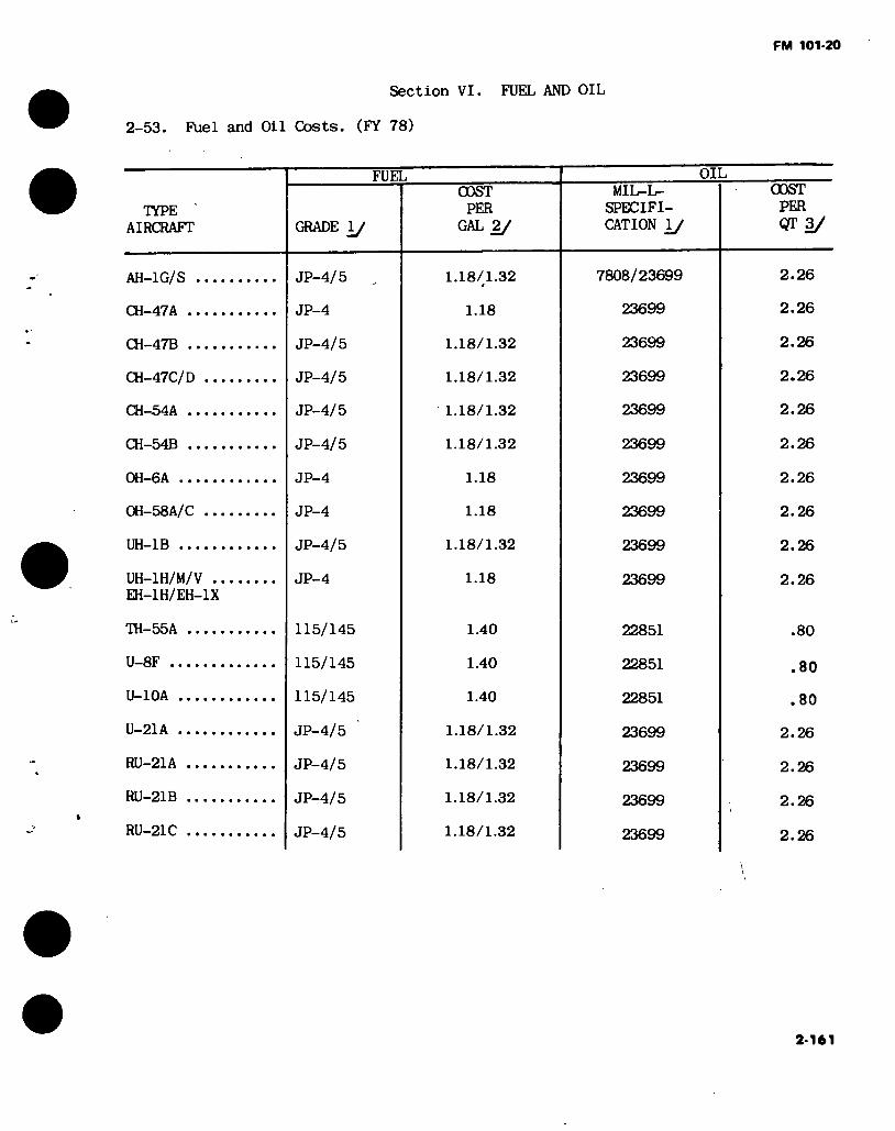
FM 101-20
Section VI. FUEL AND OIL
2-53. Fuel and Oil Costs. (FY 78)
TYPE ' AIRCRAFT
FUEL
GRADE 1/
COST PER
GAL 2/
OIL MIL-L-
SPECIFI- CATION 1/
COST PER QT 3/
AH-1G/S .
CH-47A ..
CH-47B ..
CH-47C/D
CH-54A ..
CH-54B ..
0H-6A ...
0H-58A/C
UH-1B ...
UH-1H/M/V .. EH-1H/EH-1X
TO-SSA
U-8F ..
U-10A .
U-21A .
RU-21A
RU-21B
RU-21C
JP-4/5
JP-4
JP-4/5
JP-4/5
JP-4/5
JP-4/5
JP-4
JP-4
JP-4/5
JP-4
115/145
115/145
115/145
JP-4/5
JP-4/5
JP-4/5
JP-4/5
1.18/1.32
1.18
1.18/1.32
1.18/1.32
1.18/1.32
1.18/1.32
1.18
1.18
1.18/1.32
1.18
1.40
1.40
1.40
1.18/1.32
1.18/1.32
1.18/1.32
1.18/1.32
7808/23699
23699
23699
23699
23699
23699
23699
23699
23699
23699
22851
22851
22851
23699
23699
23699
23699
2.26
2.26
2.26
2.26
2.26
2.26
2.26
2.26
2.26
2.26
.80
.80
.80
2.26
2.26
2.26
2.26
2-161
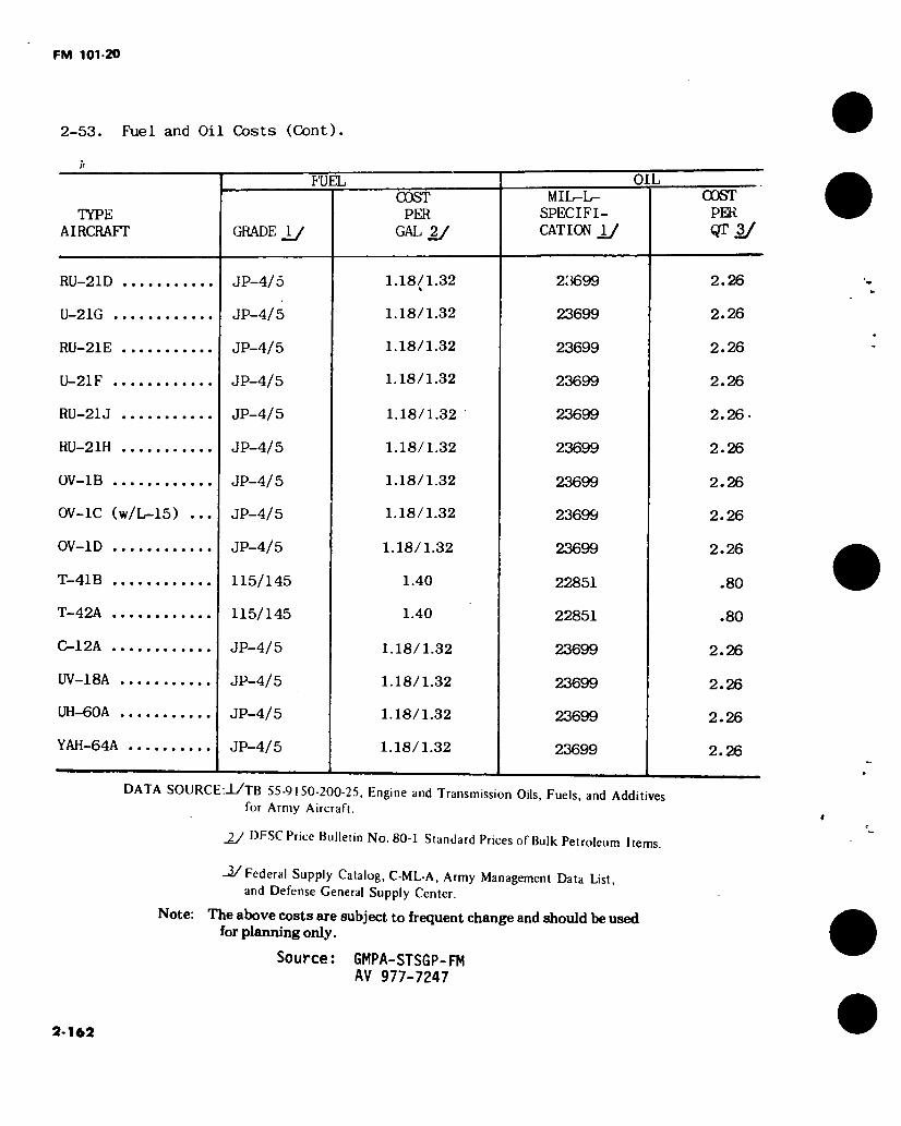
FM 101-20
2-53. Fuel and Oil Costs (Cont).
TYPE AIRCRAFT
FUEL
GRADE _iy
COST PER
GAL 2/
OIL MIL-L-
SPECIFI- CATION \J
COST PER QT 3/
RU-21D
U-21G
RLI-21E
U-21F
RU-21J
RU-21H
0V-1B
0V-1C (w/L-15)
0V-1D
T-41B
T-42A
C-12A
UV-18A
UH-60A
YAH-64A
JP-4/5
JP-4/5
JP-4/5
JP-4/5
JP-4/5
JP-4/5
JP-4/5
JP-4/5
JP-4/5
115/145
115/145
JP-4/5
JP-4/5
JP-4/5
JP-4/5
1.18/1.32
1.18/1.32
1.18/1.32
1.18/1.32
1.18/1.32
1.18/1.32
1.18/1.32
1.18/1.32
1.18/1.32
1.40
1.40
1.18/1.32
1.18/1.32
1.18/1.32
1.18/1.32
23699
23699
23699
23699
23699
23699
23699
23699
23699
22851
22851
23699
23699
23699
23699
1
2.26
2.26
2.26
2.26
2.26-
2.26
2.26
2.26
2.26
.80
.80
2.26
2.26
2.26
2.26
DATA SOURCE:J-/TB 55-9150-200-25, Engine and Transmission Oils, Fuels, and Additives for Army Aircraft.
JJ DFSC Price Bulletin No. 80-1 Standard Prices of Bulk Petroleum Items.
-2/Federal Supply Catalog, C-ML-A, Army Management Data List, and Defense General Supply Center.
Note: The above costs are subject to frequent change and should be used for planning only.
Source: GMPA-STSGP-FM AV 977-7247
2-162

2-1
63
'i • T
2-54. Fuel and Oil Comsumption.
TYPK
OF
AIRCRAFT
NUMBFR
OF
FNCilNES
ENGINE
MODEL
DESIGN POWER PER ENGINE (SHP)
MAXIMUM NORMAL CRUISE1
DRIVE
tRAIN LIMIT SHP
12903/ 1100 5200
5.200
6000
5400
6600
250
317
1100
1100
620
620
FUEL CONSUMPTION
GAL PER AIRCRAFT HR
MAXIMUM NORMAL CRUISE
OIL
CONSUMPTION
QTSPER
AIRCRAFT HR
IQO.SáJ ■“93.1
305.9
331.5
372.8
555.2^/
597.12/
17.6
23.6
78.5
93.1
80.2
80.2 97.5
97.5
80.2
80.2
80.2
89.1
139.2
148.5
174.6
AH-1S AH-1G CH-47A
CH-47B
CH-47C
CH-54A
CH-54B
OH-6A
OH-58 A/C UH-IB
UH-1H/M/V
EH-1H/EH-1X U-21A
RU-21A
RU-2IB
RU-2IC
RU-21D
U-21G
RU-21H U-21F
OV-IB
CV-1C
OV-1D
T53-L-703 T53-H3B
T55-L-7
T55-L-7C
T55-L-I IA
T73-P-I
T73-P-700
T63-A-5A/700
T63-700
T53-L-I ID
T53-L-13B
T74-CP-700
T74-CP-700
T74-CP-702
T74-CP-702
T74-CP-700
T74-CP-700
T74-CP-700
PT6A-28
T53-L-7
T53-L-15
T53-L-701
1800 1400
2650
2850
3750
4500
4800
317
317
1100
1400
550
550
750
750
550
550
550
680
1100
1150
1400
1400 1250
2200 2400
3000
4000
4430
270
270
900
1250
495
495
688 688
495
495
495
620
900
1000
1250
1050 937.5
1650.0
1800.0
2250.0
3000.0
3322.5
202.5
202.5
675.0
937.5
371.3
371.3
516.0
516.0
371.3
371.3
371.3
465.0
675.0
750.0
937.5
10924 101.55/ 482.0
478.8
497.1
656.7
716.4
29.0
33.7
114.5
106.0
115.4
115.4
117.1
117.1
115.4
115.4
115.4
. 128.1
225.0
219.6
252.2
109.24J 101.551
407.8
442.0
497.1
656.7
716.4
29.0
29.1
96.5
106.0
107.0
107.0
117.1
117.1
107.0
107.0
107.0
117.1
190.1
198.5
232.8
0.56 0.56
1.60
1.60
1.60
1.04
1.04
0.20
0.20
0.56
0.56
0.20 0.20 0.20 0.20
0.20 0.20
0.20 0.20
1.12 1.12 1.12
1/ Cruise = 75% Normal 2/ Based on 75% 3/ 30 Min. 4/ Eight Tow Missiles
5/ Hog Mission Drive Train Limit 2,000 Ft. Pressure Altitude
2.000 Ft. Pressure Altitude 9.000 Lbs. Gross Weight 9.000 Lbs. Gross Weight
Oc'
lOL
Wd
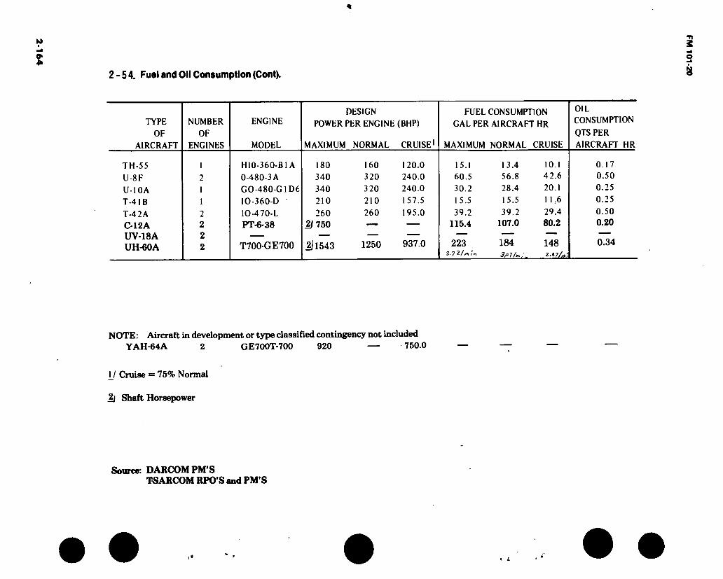
2-54. Fuel and Oil Consumption (Cont).
TYPE
OF
AIRCRAFT
NUMBER
OF
ENGINES
ENGINE
MODEL
DESIGN
POWER PER ENGINE (BHP)
MAXIMUM NORMAL CRUISE1
FUEL CONSUMPTION GAL PER AIRCRAFT HR
MAXIMUM NORMAL CRUISE
OIL CONSUMPTION
QTS PER
AIRCRAFT HR
TH-55
U-8F
U-10A
T-4IB
T-42A C-12A UV-18A UH-60A
1
2 1
1
2 2 2 2
HI0-360-B1 A
0-480-3A
GO-480-G 1D6
IO-360-D
IO-470-L
PT-6-38
T700-GE700
180
340
340
210
260 2/750
2)1543
160 320
320
210
260
1250
120.0 240.0 240.0
157.5
195.0
937.0
15.1 60.5
30.2
15.5
39.2 115.4
223 ■¡.yïf*:.
13.4 56.8 28.4
15.5
39.2 107.0
184 3fi 7 /»,,
10.1 42.6
20.1 11.6
29.4 80.2
148
0.17 0.50 0.25
0.25
0.50 0.20
0.34
NOTE: Aircraft in development or type classified contingency not included YAH-64A 2 GE700T-700 920 — 750.0
1_/ Cruise = 75% Normal
2j Shaft Horsepower
Source: DARCOM PM’S TSARCOM RPO’S and PM’S
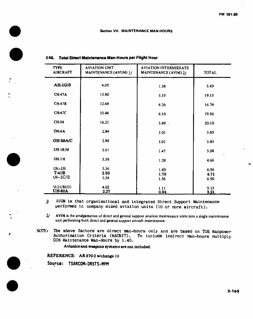
FM 101-20
Section VII. MAINTENANCE MAN-HOURS
2-55. Total Dlract Maintenance Man-Hours per Flight Hour
TYPE AIRCRAFT
AVIATION UNIT MAINTENANCE (AVUM) \J
AVIATION INTERMEDIATE MAINTENANCE (AVIM) 2/ TOTAL
AH-1G/S
CH-47A
CH-47B
CH-47C
CH-54
OH-6A
OH-58A/C
UH-1B/M
UH-1H
0V-1B T-41B 0V-1C/D
U-21/RU21 UH-60A
4.05
13.80
12.48
13.46
16.21
2.84
2.84
3.61
3.38
5.16 2.93 5.34
4.02 2.27
1.38
5.35
4.26
6.10
3.89
1.01
1.01
1.47
1.28
1.40 1.78 1.56
1.11 0.94
5.43
19.15
16.74
19.56
20.10
3.85
3.85
5.08
4.66
6.56 4.71 6.90
5.13 3.21
J/ AVUM is that organizational and integrated Direct Support Maintenance
performed in company sized aviation units (10 or more aircraft).
2J AVIM is the amalgamation of direct and general support aviation maintenance units into a single maintenance unit performing both direct and general support aircraft maintenance.
NOTEs The above factors are direct man-hours only and are based on TOE Manpower Authorization Criteria (MACRIT). To include indirect man-hours multiply DIH Maintenance Man-Hours by 1.40.
Avionics and weapons systems are not included.
REFERENCE: AR670-2 w/change 10
Source: TSARCOM-DRSTS-MPM
2-165

FM 101-20
2.56. Direct Maintenance Man-Hours^Per Flight Hour For Technical Inspectors.
TYPE AIRCRAFT
AH-1G/S
CH-47A
CH-47B
CH-47C
CH-54A
CH-54B
OH-6A
OH-58A
OH-58C
UH-1B/M
UH-1H
OV-1B
OV-1C/D
U-21/RU-21
T-41B
UH-60A
MOSC
67Y3
67U3
671)3
67U3
67X3
67X3
67V3
67V3
67N3
67*13
67G3
67G3
67G3
AVIATION UNIT MAINTENANCE (AVUM)
.46
2.03
2.03
2.03
2.20
2.20
.35
.35
.47
.51
.53
.53
.37
AVIATION INTERMEDIATE MAINTENANCE (AVIM)
.12
.45
.45
.45
.38
.38
.08
.08
.20
.15
.14
.14
.06
JJ To include indirect man-hours multiply maintenance man-hours by 1.40.
2-166

FM 101-20
2-5 7. Manpower Authorization Criteria(MACRIT).
AIRCRAFT MAINTENANCE AND
TECHNICAL INSPECTION OPERATIONS
(MOS 67/68 SERIES)
AIRCRAFT MAINTENANCE AND
♦ TECHNICAL INSPECTION OPERATION IMOS 67/68 SERIES)
1. Productive m«n-Hours. Ref AR570-2
2. Authorization formula and criteria.
a. Aviation Unit Maintenance (AVUM).
Ill Density of Aircraft MACRIT Factor Number Positions by Type X by MOS = Authorized
(1 to 9 Aircraft Category II USE TABLE I ONLY • MOS 67 Senes
12) Density of Aircraft MACRIT Factor Number Positions by Type x by MOS = Authorized
( 10 or more aircraft Category I) USE TABLES I AND la - MOS 67/68 Series
(3) Density of Aircraft MACRIT Factor Number Positions by Type X by MOS = Authorized
( 1 to 9 Aircraft Category II) USE TABLE 11 ONLY • MOS 67 Series
HI Density of Aircraft MACRIT Factor Number Positions by Type X by MOS = Authorzied
UOor more Aircraft Category II) USE TABLES II AND Ha • MOS 67/68 Series
b. Aviation Intermediate Maintenance (AVIM).
Denaity of Aircraft MACRIT Factor Number Positions byTyPe X by MOS » Authorized
(Table 111 Category II) (MOS 67 and 68 Series)
ARAmf2r.C„erf/r^OPer8ûh° “‘“T A^nua‘Au''
aUable Productive Man hour (AAPMH) other than those listed in paragraph 2-7W3). reoui^m.n«?n ,8 “ T,,b ® IV Column A below' substitute appropriate AAPMH and/or Flying Hours requirements m the following authorization formulae and criteria. J»“*
a. Aircraft Repairer (with FLYING CREWCHIEF) (MOS 67 Series).
STEPl: Maintenance
man-hours/ flight hour (Table V)
Annual flying hours (Table IV) or other source 2
STEP 2: Density of Aircraft
by Type MACRIT Factor (From Step 1 above) =
.50 Annual Available 1 productive man-hours by category or other source 3
Number Positions plus Number Positions plus one Crewchief per Aircraft
Annual Available productive man-hours by category MACRIT or other m Factor source 3 by MOS
2-167
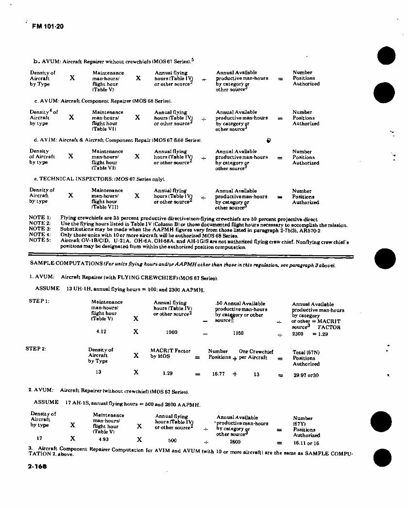
FM 101-20
b. AVUM: Aircraft Repairer without crewchiefs (MOS67 Series).®
Density of Maintenance Annual flying Aircraft X man-hours/ X hours (Table 1V) by Type flight hour or other source^
(Table V)
c. AVUM: Aircraft Component Repairer (MOS 68 Series).
Density4 of Maintenance Annual flying Aircraft X man-hours/ X hours (Table 1V) by type flight hour or other source2
(Table VI)
Annual Available productive man-hours by category or other source3
Annual Available productive man-hours by category or other source3
d. AVIM: Aircraft & Aircraft Component Repair (MOS 67 &68 Series). « Density Maintenance Annual flying of Aircraft X man-hours/ X hours (Table IV by type flight hour or other source2
(Table VI)
e. TECHNICAL INSPECTORS: (MOS 67 Series only).
Density of Aircraft X by type
Maintenance man-hours/ X flight hour (Table VII)
Annua) flying hours (Table I\0 or other source2
Annual Available productive man-hours by category or other source3
Annual Available productive man-hours by category or other source3
Number Positions Authorized
Number Positions Authorized
Number Positions Authorized
Number Positions Authorized
NOTE 1 NOTE 2 NOTE 3 NOTE 4 NOTES
Flying crewchiefs are 35 percent productive directive/non-flying crewchiefs are 50 percent projective direct Use the flying hours listed in Table IV (Column B) or those documented flight hours necessary to accomplish the mission. Substitutions may be made when the AAPMH figures vary from those listed in paragraph 2-7b(3), AR570-2 Only those units with 10 or more aircraft will be authorized MOS 68 Series. Aircraft OV-1B/C/D, U-21A, OH-6A, OH-58A, and AH-1G/S are not authorized flying crew chief. Nonflying crew chief's positions may be designated from within the authorized position computation.
SAMPLE COMPUTATIONS/For units/lying hours and/or AAPMH other than thosein this regulation, see paragraph 3 above).
1. AVUM: Aircraft Repairer (with FLYING CREWCHIEF) (MOS 67 Series).
ASSUME 13 UH-1H, annual flying hours = 100; and 2300 AAPMH.
STEP 1: Maintenance man-hours/ flight hour (Table V) X
Annual flying hours (Table IV) or other source2
.50 Annua] Available productive man-hours by category or other
— sourcei
4.12 1000 1150
Annual Available productive man-hours by category or other = MACRIT source3 FACTOR 2300 = 1.29
STEP 2: Density of Aircraft by Type
MACRIT Factor X by MOS
Number OneCrewchief Positions per Aircraft
Total (67N) Positions Authorized
!3 X 1.29 16.77 + 13 = 29.97 or30
2. AVUM: Aircraft Repairer (without crewchief) (MOS 67 Series).
ASSUME 17 AH-1S, annual flying hours = 500 and 2600 AAPMH.
Density of Aircraft by type X
17 X
Maintenance man-hours/ flight hour (Table V)
4.93
X
X
Annual flying hours (Table IV) or other source2
500
Annual Available • productive man-hours by category pr other source3
2600
TA’nONa2aatevePOnent ComPutation for AVIM ^ AVUM (with 10 or more aircraft) are the
Number (67Y) Positions Authorized 16.11 or 16
same as SAMPLE COMPU-
2-168

FM 101-20
AIRCRAFT OV íB
AIRPLANE REPAIRER l«TQ) I 76
UTILITY HELICOPTER REPAIRER («TNI
MEDIUM CARGO HELICOPTER REPAIRER <«7Ui
ORRERYATION HELICOPTER REPAIRER (87Vi
HEAVY CARGO HELICOPTER REPAIRER (67X>
ATTACK HELICOPTER REPAIRER 187YI
AIRPLANE INSPECTOR (870 31
UTILITY HELICOPTER INSPECTOR(87Ni
MEDIUM CARGO HELICOPTER INSPECTOR (67Ui
OBSERVATION HELICOPTER INSPECTOR (87V1 .
HEAVY CARGO HELICOPTER INSPECTOR (87X1 .
ATTACK HELICOPTER INSPECTOR(8TY) ..
MACRIT FACTORS
AVIATION UNIT MAINTENANCE IAVUM)
TABLE IIM0887 SERIES) CtUfory I Unit 18500 AAPMH)
A30271 A30896
*3)749'
K3160« *317961 *303781 *30383' *30449* *30645 K31048 *30818*
*30816 *89860
*89896
OV IOD U-81A UH lB'M
1 86 1 78
1 65
UH-lH CH-47A CH47B CH-47C 0H-6A OH-68A CH-64A/B AHIG^S
■80
NOTE l INCLUDE80NEFLYINGCREWCHIEF PER AIRCRAFT NOTE I: IN UNITS WITH IOOR MORE AIRCRAFT. FOR POSITIONS NOT JUSTIFIED BY MACRIT BUT ESSENTIAL FOR THE OPERATION OF THE UNIT, A TRADE-
OFF IS AUTHORISED AS LONG AS TOTAL AUTHORISATION FOR POSITIONS IS NOT EXCEEDED.
AIRCRAFT P0WERPLANTRKPAIRER(6BB) 08
AIRCRAFT POWERTRAIN REPAIRER<68D) 08
AIRCRAFT ELECTRICIAN (UP) .04
AIRCRAFT STRUCTURAL REPAIRER <68Q> .18
AIRCRAFT PNEUDRAULIC8REPAIRER<«8HI .08
TABLE UIMOSW SERIES! C«u«ory I Unit (8600 AAPMH)
.04 .08 06 .07
08 08
.08 .04
.18 .18
.04 .08
.06 .06
.01 .08
.06 .07
.01 .08
.11 10
.38 -84
.11 .10
.11 .10
.06 .04.
.11 06
.37 .06
.11 .03
.16 .09
.06 NONE
.03 .09
.04 .10
.01 .09
.16 .06
.01 .06
.07
.07
.08
.06
.08
AIRCRAFT OV-lB
AIRPLANE REPAIRER (67G) 162
UTILITY HELICOPTER REPAIRER(67N)
MEDIUM CARGO HELICOPTER REPAIRER (67U)
OBSERVATION HELICOPTER REPAIRER 187V). .
HEAVY CARGO HELICOPTER REPAIRER (67X) .
ATTACK HELICOPTER REPAIRER I8TY)
AIRPLANE INSPECTOR(67G) . 19
UTILITY HELICOPTER INSPECTOR (67N)
MEDIUM CARGO HELICOPTER INSPECTOR <87Ul
OBSERVATION HELICOPTER INSPECTOR(67V)
HEAVY CARGO HELICOPTER INSPECTOR I67X)
ATTACK HELICOPTER INSPECTOR l67Yi
MACRIT FACTORS*
AVIATION UNIT MAINTENANCE IAVUM)
TABLE IIIMOS67 SERIES)
CaUgory II Unit (8700 AAPMH)
A30281 A30271 A30948 K317491 K3W961 K303761 K303S31* K304491 *30646 *31042 *3051 ft1 *89660 A30296 *31804 *30516 K29694
OV IOD U-21A UH1BM UH lH CH-47A CH 47B CH 47C OH-6A OH-68A CH-64A/B AH-lG/S
171 1.86
166 1.96
4.82 4 46 4.63
1 00 1.00
4.49
.19
NOTE I INCLUDESONE FLYING CREWCHIEF PER AIRCRAFT
NOTE 3 IN UNITS WITH 10OR MORE AIRCRAFT. FOR POSITIONS NOT JUSTIFIED BY MACRIT BUT ESSENTIAL FOR THE OPERATION OF THE UNIT. A TRADE- OFF IS AUTHORIZED AS LONG AS TOTAL AUTHORIZATION FOR POSITIONS IS NOT EXCEEDED
AIRCRAFT POWERPLANT REPAIRER I68B) 06
AIRCRAFT POWERTRAIN REPAIRERI68D) 02
AIRCRAFT ELECTRICIAN (80F) 04
AIRCRAFT STRUCTURAL REPAIRER I86GI 11
AIRCRAFT PNEUDRAULICS REPAIRER I88HI 02
TABLE liaIMOS88SERIES) Caiafory II Unit (2700 AAPMH)
04 .02 .06 07
02 02
02 04
12 .11
04 02
06 06
01 01
05 07
01 01
10 09
30 22
10 09
10 09
06 03
10 06
34 .06
10 03
U .06
06 NONE
.03 06
04 09
01 09
U 04
01 04
06
.07
02
.06
02
2-169

FM 101-20
MACRIT FACTORS1
AVIATION INTERMEDIATE MAINTENANCE 1AVIM)
TABLE III Category H Unjt 12700 AAPMHl
LIN
AIRCRAFT
AIRPLANE REPAIRER(67G)
UTILITY HELICOPTER REPAIRER (67N). .
MEDIUM CARGO HELICOPTER REPAIRER (67U|..
OBSERVATION HELICOPTER REPAIRER (67V>....
HEAVY CARGO HELICOPTER REPAIRER Í67X».. .
ATTACK HELICOPTER REPAIRER (67X)
AIRCRAFT POWERPLANT REPAIRER <6SB>
AIRCRAFT POWERTRAIN REPAIRER(68D)
AIRCRAFT ELECTRICIAN (68F>
AIRCRAFT STRUCTURAL REPAIRER (66G|
AIRCRAFT PNEUDRAUL1CS REPAIRER (68HI
AIRPLANE INSPECTOR (67G
UTILITY HELICOPTER INSPECTOR (67N)
MEDIUM CARGO HELICOPTER INSPECTOR Í67U).
OBSERVATION HELICOPTER INSPECTOR (67V(...
HEAVY CARGO HELICOPTER INSPECTOR (67X»...
ATTACK HELICOPTER (67X)
A30221 A30271 A30946 K31749 K31795 K30378 K30383 K30449 K30645 K31042 K30615 K29660 A30296 K31804 K30516 K29604
0V1B OV-lC/D U-2IA UH1B/M UH-1 H CH-47A CH-47B CH-47C OH-6A OH-58A CH&4A/B AH-lG/S
. . . 26 .29 27
26 32
99 .78 1.14
24 .24
05
.01
01
.17
.01
06
.01
.01
.19
.01
.04
.04
06
-10
.02
.09
.05
.01
.09
.01
10
.08
01
.11
.01
.29
.27
.12
.19
.08.
.25
.20
.09
.16
.06
.35
.29
.09
.24
.09
.03 .17
.06 .03
.01 .01
.08 .12
None oi
.10
.05
.14
.13
.08
.27
.09
.08
.02
.09
.01
..07
.16
.03
NOTE 1: FOR POSITIONS NOT JUSTIFIED BY MACRJT. BUT ESSENTIAL FOR THE OPERATION OF THE UNIT, A TRADEOFF IS AUTHORIZED AS LONG AS TOTAL AUTHORIZATION FOR POSITIONS IS NOT EXCEEDED.
LIN
K29660
K29694
K30378 K30383 K30499
K31749 K31804
K31795
K30515
K30516
K30646
K3I042
A30221 A30271 A30296
A30946
TABLE IV FLYING HOURS DA APPROVED FLYING HOUR FACTORS
COLUMN A
AIRCRAFT
AH-lG/S
CH-47A/B/C
UH1B/M
UH1H
CH-54A/B
OH-6A
OH-&8A
OV-IB/C/D
TOE ACTIVE COMBAT ENVIRONMENT HOURS PER.
MONTH
58
79
68
68
68
YEAR
660
696
NOTE. Indiran ropportflying hour*. Column B above, are applicable to those units (excluding divisional unit Applicable to MTOE when directed by the M ACOM
Column B INDIRECT SUPPORT
AIRCRAFT HOUR PER:
MONTH
25
25
26
YEAR
300
300
300
units) that are not directly or titally relatable to combat operations.
2-170
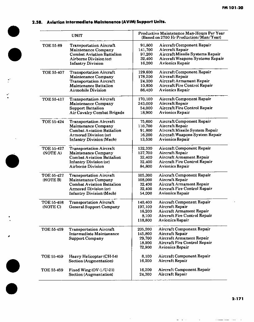
FM 101-20
2.58. Aviation Intermediate Maintenance (AVIM) Support Units.
UNIT Productive Maintenance Man-Hours Per Year (Based on 2700 Hr Production/Man/Year)
TOE 55-89 Transportation Aircraft Maintenance Company Combat Aviation Battalion Airborne Division (or) Infantry Division
91,800 Aircraft Component Repair 141,700 Aircraft Repair 97.200 Aircraft Missile Systems Repair 32,400 Aircraft Weapons Systems Repair 16.200 Avionics Repair
TOE 55-407 Transportation Aircraft Maintenance Company Transportation Aircraft Maintenance Battalion Airmobile Division
129,600 Aircraft Component Repair 178,200 Aircraft Repair 24,300 Aircraft Armament Repair 10,800 Aircraft Fire Control Repair 86,400 Avionics Repair
TOE 55-417 Transportation Aircraft Maintenance Company Support Battalion Air Cavalry Combat Brigade
170,100 Aircraft Component Repair 243,000 Aircraft Repair
54,000 Aircraft Fire Control Repair 18,900 Avionics Repair
TOE 55-424 Transportation Aircraft Maintenance Company Combat Aviation Battalion Armored Division (or) Infantry Division (Mech)
75,600 Aircraft Component Repair 110,700 Aircraft Repair 91,800 Aircraft Missile System Repair 16,200 Aircraft Weapons System Repair 13,500 Avionics Repair
TOE 55-427 Transportation Aircraft (NOTE A) Maintenance Company
Combat Aviation Battalion Infantry Division (or) Airborne Division
132,300 Aircraft Component Repair 137,700 Aircraft Repair 32.400 Aircraft Armament Repair 32.400 Aircraft Fire Control Repair 84,800 Avionics Repair
TOE 55-427 Transportation Aircraft (NOTE B) Maintenance Company
Combat Aviation Battalion Armored Division (or) Infantry Division (Mech)
105,300 Aircraft Component Repair 108,000 Aircraft Repair 32.400 Aircraft Armament Repair 32.400 Aircraft Fire Control Repair 54,000 Avionics Repair
TOE 55-458 Transportation Aircraft (NOTEC) General Support Company
140,400 Aircraft Component Repair 197,100 Aircraft Repair
16,200 Aircraft Armament Repair 8,100 Aircraft Fire Control Repair
118,800 Avionics Repair
TOE 55-459 Transportation Aircraft Intermediate Maintenance Support Company
TOE 55-459 Heavy Helicopter (CH-54) Section (Augmentation)
TOE 55-459 Fixed Wing (OV-l/U-21) Section (Augmentation)
205,200 Aircraft Component Repair 145,800 Aircraft Repair 29,700 Aircraft Armament Repair 18.900 Aircraft Fire Control Repair 72.900 Avionics Repair
8,100 Aircraft Component Repair 16.200 Aircraft Repair
16.200 Aircraft Component Repair 24,300 Aircraft Repair
2-171

FM 101-20
2.58. Aviation Intermediate Maintenance (AVIM) Support Units (Cont.).
UNIT
TOE 55-459 Heavy Helicopter Fixed Wing Avionics Section (Augmenta- tion)
Productive Maintenance Man-Hours Per Year (Based on 2700 Hr Production/Man/Year)
45,900 Avionics Repair
NOTE A. TOE 55-427H910 will replace TOE 55-89H in Infantry/Airborne Divisions.
NOTE B. TOE 55-427H920 will replace TOE 55-424H in Armored/Infantry (MECH) Divisions.
NOTE C. TOE 55-459H will replace TOE 55-458H.
Source: TSARCOM DRSTS-SPME
2-172

FM 101-20
Section VIII. MAINTENANCE CATEGORIES
2.59. The Three Categories of Maintenance are:
a. Aviation Unit Maintenance (AVUM):
This level includes all of the original organizational maintenance tasks plus some of the prior direct support maintenance tasks. It is that maintenance which is organic to the operating unit.
b. Aviation Intermediate Maintenance (AVIM):
This level of maintenance combines the remaining portions of capability of the prior direct and general support maintenance, thereby establishing a single
level of support between AVUM and the depot.
c. Aviation Overhaul Maintenance (Depot):
This level of maintenance provides for the repair/ overhaul of materiel beyond the capability of AVUM/ AVIM.
Reference AR 750-1.
NOTE: The three level maintenance concept replaces the previous four level maintenance categories of organization, direct support, general support
and depot.
2-60. Aircraft Overhaul/Repair and Modification Facilities.
ARMY DEPOT LOCATION TYPE AIRCRAFT
Corpus Christi (CCAD) Corpus Christi, Texas AH-1 Series UH-1 Series 0H-6A Crash Damage 0H-58A/C Crash Damage
New Cumberland (NCAD) Harrisburg, Pa. CH-47 Series (Modification)
NOTE: Aircraft not maintained at CCAD and NCAD are contractor supported.
Source: TSARCOM-DRSTS-MPP
2-173

FM 101-20
Section XIX. SURVIVAL EQUIPMENT
2-61. Survival Kits for Aviation Operations.
Survival Kit, Individual: hot climate (NSN 1680-00-973-1861)
Survival Kit, Individual: cold climate (NSN 1680-00-973-1862)
Survival Kit, Individual: Over-water (NSN 1680-00-973-1863)
Survival Kit, Individual Vest: large (NSN 1680-00-205-0474)
Survival Kit, Individual Vest: small (NSN 1680-00-187-5716)
Survival Kit Seat: Aircraft cold climate (NSN 1680-00-148-9233)
Survival Kit Seat: Aircraft hot climate (NSN 1680-00-148-9234)
Survival Kit Seat: Aircraft over-water (NSN 1680-00-140-3540)
SC 1680-97-CL-A02
SC 1680-97-CL-A03
SC 1680-99-C L-A04
SC 1680-99-CL-A07
SC 1680-99-CL-A07
SC 1680-99-C L-A08
SC 1680-00-CL-A08
SC 1680-99-CL-A08
2-174
FM 101-20
CHAPTER 3
PERSONNEL REQUIREMENTS
Section I. OFFICER/WARRANT OFFICER AVIATION PERSONNEL REQUIREMENTS
3*1. Of f ictr/Warranl Of dear Requirements.
AR 570-1 contains criteria for, and lists positions where commissioned officers are authorized. Linder these criteria, positions entailing essential command, staff, or supervisory functions for which an officer is especially required arc so designated. All other positions are designated as warrant officer.
3*2. Cockpit Seat Fill Requirements.
Cockpit scat-fill requirements vary with the type of aircraft and the mission of the unit. At least the
minimum crew complement prescribed in the operations handbook for a particular aircraft is author- ized except for proficiency, contractor operated, and maintenance float aircraft for which no Army aviators are programmed. In general, dual control aircraft in combat, combat support units, and indirect support
units will be manned with pilots and copilots to give the unit a sustained operational capability. Dual con- trol aircraft assigned in certain indirect support categories may not require copilots unless flight must
be performed under instrument conditions.
3-1

FM 101-20
Section IL ENLISTED AVIATION MAINTENANCE PERSONNEL REQUIREMENTS
3-3. Enlisted Personnel Requirements.
a. AR570-2 provides staff officers and aircraft maintenance officers with uniform guidance to accomplish the following:
( I ) Evaluate manpower requirements for TOE/TD units as pertains to user and support mainte- nance activities.
(2) Determine manpower requirements in
connection with procurement of aircraft maintenance services.
b. A relationship exists between the Hying hours accumulated on aircraft and the man-hours of mainte- nance required for its continued serviceability. The relationship is termed man-hour per flight-hour ratio (MH/FH) and prevails in both user and support level maintenance. The ratio varies by type and model of aircraft, depending on aircraft size and complexity.
3-2
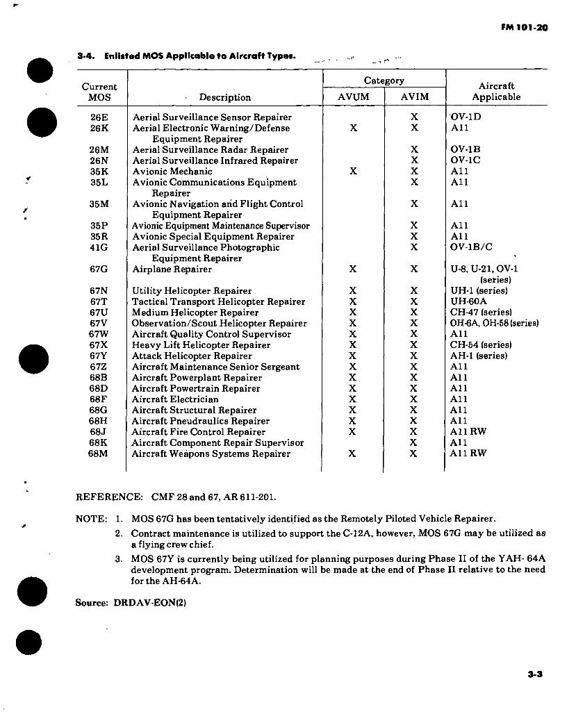
FM 101-20
3-4. Enlisted MOS Applicable to Aircraft Types. _ •« r*
Current MOS Description
Category
AVUM AVIM Aircraft
Applicable
26E 26K
26M 26N 35K 35L
35M
35P 35R 41G
67G
67N 67T 67U 67V 67W 67X 67Y 67Z 68B 68D 68F 68G 68H 68J 68K 68M
Aerial Surveillance Sensor Repairer Aerial Electronic Warning/Defense
Equipment Repairer Aerial Surveillance Radar Repairer Aerial Surveillance Infrared Repairer Avionic Mechanic Avionic Communications Equipment
Repairer Avionic Navigation arid Flight Control
Equipment Repairer Avionic Equipment Maintenance Supervisor Avionic Special Equipment Repairer Aerial Surveillance Photographic
Equipment Repairer Airplane Repairer
Utility Helicopter Repairer Tactical Transport Helicopter Repairer Medium Helicopter Repairer Observation/Scout Helicopter Repairer Aircraft Quality Control Supervisor Heavy Lift Helicopter Repairer Attack Helicopter Repairer Aircraft Maintenance Senior Sergeant Aircraft Powerplant Repairer Aircraft Powertrain Repairer Aircraft Electrician Aircraft Structural Repairer Aircraft Pneudraulics Repairer Aircraft Fire Control Repairer Aircraft Component Repair Supervisor Aircraft Weapons Systems Repairer
X
X X X X X X X X X X X X X X
X X
X X X X
X X X
X
X X X X X X X X X X X X X X X X
OV-1D All
OV-1B OV-1C All All
All
All All OV-1B/C
U-8, U-21, OV-1 (series)
UH-1 (series) UH-60A CH-47 (series) 0H-6A, OH-58 (series) All CH-54 (series) AH-1 (series) All All All All All All A11RW All All RW
REFERENCE: CMF 28 and 67, AR 611-201.
NOTE: 1. MOS 67G has been tentatively identified as the Remotely Piloted Vehicle Repairer.
2. Contract maintenance is utilized to support the C-12A, however, MOS 67G may be utilized as a flying crew chief.
3. MOS 67Y is currently being utilized for planning purposes during Phase II of the YAH- 64A development program. Determination will be made at the end of Phase II relative to the need for the AH-64A.
Source: DRDAV-EON(2)
3-3


FM 101-20
CHAPTER 4 COSTS
Section I. AIRCRAFT UNIT PRICES
4-1. Rotary Wing Unit Price.
HELICOPTER
AH-1G J7
TH-lG 2L/
CH-47A
CH-47B
CH-47G
YCH-47D
CH-54A 3/
CH-54B
OH-6A
OH-58A
OH-58C
UH-1B
UH-lC
UH-1D
UH-1V
UH-1H
EH-1H
UH-1M
EH-1X
TH-55A
AH-1S i/JV
UH-60A
YAH-64A
NATIONAL STOCK NUMBER
1520-00999-9821
1520-00804-3635
1520-00633-6836
1520-00990-2941
1520-00871-7308
1520-01088-3669
1520-00964-9601
1520-00113-5776
1520-00918-1523
1520-00169-7137
1520-01020-4216
1520-00713-9912
1520-00977-8862
1520-00859-2670
1520-01043-4949
1520-00087-7637
1520-00368-8442
1520-00809-2631
1520-01042-9396
1520-00758-0289
1520-00504-9112
1520-0135-0266
LINE ITEM NUMBER
K29660
K29762
K30378
K30383
K30449
Z33490
K30515
K30516
K30645
K31042
Z33527
K31749
K31767
K31786
H31872
K31795
K30548
K31804
H30829
K31153
K29694
K32293
Z33149
TYPE
Attack
Trainer
Cargo Transport
Cargo Transport
Cargo Transport
Cargo Transport
Cargo Transport
Cargo Transport
Observation
Observation
Observation
Utility
Utility
Utility
Utility/Med Evac
Utility
Utility/Quick Fix
Utility
Utility/Quick Fix
Primary Trainer
Attack
Utility
Attack
STANDARD PRICE*
509,833
531,679
990,717
1,063,448
2,956,896
2,847,303
3,014,803
140,450
143,782
201,898
244,760
224,415
237,405
618.055
618.055
1.920.000
247,758
1.920.000
35,590
Seei/JV
2,282,200
* Published in DA Supply Bulletin 700-20, effective 1 Sep 80, Army Adopted/Other Selected Items and List of Reportable Items. Price includes avionics and $1,500 first destination transportation charges. Excludes armament systems except where annotated. (Refer to chapter 2.)
_L/ Includes estimate of average cost of armament, $69,000. iL/ Includes estimate of average cost of armament, $58,242. j?/ Includes $13,000 ground equipment. ÏJ Cost (FY80 dollars) of AH-1S (Modernized) from new production including armament is $2,478,000. h Cost (FY80 dollars) of AH-1S (Modernized) from AH-lG to AH-1S conversion program including armament is $1,638,000.
NOTE: Aircraft type classified contingency or obsolete not included.
Source: DARCOM PM’s TSARCOM RPO’s & PM’s
4-1

FM 101-20
*•2. Fixed Wing Unit Price.
HELICOPTER
U-8D
U-8F
U-8G
C-12A
U-10A
U-21A
U-21F
U-21G
RU-8D
RU-21A
RU-21B
RU-21C
RU-21D
RU-21H
RU-21J
OV-IB
OV-1C
OV-1D
RV-1C
RV-ID
T-41B
T-42A
UV-18A
NATIONAL STOCK NUMBER
1510-00574-7938
1510-00701-2233
1510-00912-4084
1510-01005-5461
1510-00964-9780
1510-00933-8223
1510-00169-0295
1510-00140-1627
1510-00945-9998
1510-00587-3375
1510-00878-4338
1510-00878-4336
1510-00804-3641
1510-00394-3320
1520-00124-0914
1510-00715-9379
1510-00715-9380
1510-00869-3654
1510-00434-8983
1510-00368-8440
1510-00929-1012
1510-00872-7908
1510-01011-1462
LINE ITEM NUMBER
A30721
A30821
A30831
A29676
A30971
A30946
A30951
A30953
A30465
A30582
A30583
A30843
A30585
A30591
Z04615
A30221
A30271
A30296
A30593
A30444
A30053
A30596
A30989
TYPE
Utility
Utility
Utility
Utility
Utility STOL
Utility
Utility
Utility
Utility
Reconnaissance Utility
Reconnaissance Utility
Reconnaissance Utility
Reconnaissance Utility
Reconnaissance Utility
Reconnaissance Utility
Observation/Surveillance Observation/Surveillance
Observation/Surveillance
Reconnaissance V/STOL
Observation/Surveillance Trainer, Flight
Trainer, Instrument
Utility
STANDARD PRICE*
115.250
144,593
114,687
680,883
55,824
348,844
49^.800
391,218
295.250
587.004
1,257,811
1,259,760
875.004
1,501,200
1,817,888
976,437
1,058,540
2,033,066
2,500,000
2,886,664
16,200
102,907
714,945
‘Published in DA Supply Bulletin 700-20, effective 1 Sep 80, Army Adopted/Other Selected Items and List of Reportable Items. Price includes avionics and $1,500 first destination transportation charges. Excludes armament systems (Refer to chapter 2).
NOTE: Aircraft type classified contingency or obsolete not included.
Source: DARCOM PM’s TSARCOM RPO’s & PM’s
4-2
/
FM 101-30
Sectionil. FLYING HOUR COSTS
4-3. Aircraft Flying Hour Costs.
To obtain current parts, labor and POL flying hour costs contact DA (DALO-AV) AUTOVON 227-0487 or DACA-CA AUTOVON 225-7946. C ^ iWs
Section III. AVIONICS COSTS
4-4. Avionics Estimated Maintenance Cost Factors.
To obtain current data such as labor costs or parts costs on avionics equipment or systems contact CERCOM(DRSEL-ME-E)AUTOVON992-1685.
Source: CERCOM -DRSEL-ME-E
Section IV. ARMAMENT COSTS
4-5. Airborne Armament Maintenance Costs.
To obtain current labor and parts costs on aircrafUweapon subsystems contact ARRCOM-DRSAR-MAS-SS AUTOVON 793-5668. /4-r (
4-3/(4-4 blank)


FM 101-20
CHAPTER 5
RESEARCH AND DEVELOPMENT OF MATERIEL
Army aviation research and development is conducted on aircraft systems and in areas not directly related to specific aircraft systems. Research not directly related to aircraft systems includes low speed aerodynamics, structures, and propulsion. Exploratory development is conducted in such areas as area fluid dynamics, aeromechanics, flight dynamics, flight loads, aircraft structures and composite materials, power devices, propulsion components, aircraft survivability, aircraft ground support equipment, reliability/maintainability, avionics technology, and aircraft weapons.
5-1. Qanaral.
a. Research aircraft are procured in limited quantities to evaluate concepts during the Research, Exploratory Development and Advanced Development
phases of the RAP cycle.
b. Development aircraft systems are aircraft systems proposed for operational use to replace or complement current Army aircraft systems.
6-2. Development Aircraft Systems.
The following development aircraft systems are in order of priority.
8-3. YAH'64A(AAH).
The AAH la a twin englue rotary wing aircraft deaigned aa a stable, manned aerial weapons system. Hie AAH will become the primary attack helicopter and will be complemented by the AH-1 aeries attack helicopter.
6*1

c-c
n <2
Figure 5-1. Advanced Attack Helicopter (AAH) YAH-64
, 4
W-I
OI
WJ
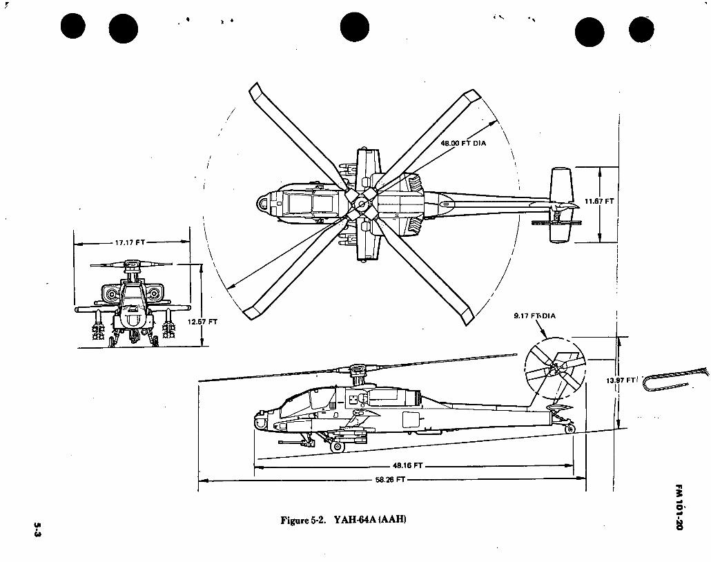
5-3
48 00 FT DIA
LTD 11.67 FT
□ 17.17 FT
\ 9.17 FT^DIA o 12.57 FT
97 13
Qffli r> sa
©
48.16 FT
58.26 FT
Figure 5-2. YAH-64A (AAH)
FM 1
01
-20
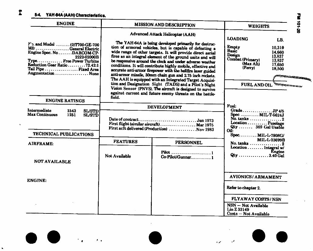
5-4. Y AH-64A (AAH) Characteristic».
ENGINE
No. and Model (2)T700-GE-700 Mfr General Electric Engine Spec. No DARCOM-CP-
2222-02000B Type Free Power Turbine Reduction Gear Ratio 72.42:1 Tail Pipe Fixed Area Augmentation None
ENGINE RATINGS
Intermediate Max Continuous
1643 SIVSTD 1261 SL/STD
TECHNICAL PUBLICATIONS
AIRFRAME:
NOT AVAILABLE
ENGINE:
MISSION AND DESCRIPTION
Advanced Attack Helicopter (AAH)
Hie YAH-64A is being developed primarily for destruc- tion of armored vehicles, but is capable of defeating a wide range of other targets. It will provide direct aerial fires as an integral element of the ground units and will be responsive around the dock and under adverse weather conditions. It will contribute highly mobile, effective and accurate anti-armor firepower with the hellfire l«»»r guided anti-armor missile, 30mm chain gun and 2.75 inrh rockets. The AAH is equipped with an Integrated Target Acquisi- tion and Designation Sight (TADS) and a Pilot’s Night Vision Sensor (PNVS). TTie aircraft is designed to survive against current and future enemy threats on the battle- field.
DEVELOPMENT
Date of contract jm, 1973 First flight (similar aircraft) Mar 1975 First acft delivered (Production) Nov 1983
FEATURES
Not Available
PERSONNEL
Pilot Co-Pilot/Gunner.
LOADING
Empty Basic Design Combat (Primary)
(Max Alt) (Ferry)
LB.
10,310 14.660 13.837 13.837 17.660 18,500
FUEL AND OIL
Fuel: Grade JP4/5 Spec MIL-T-5624J No. tanks 2 Location Fuselage Qty 369 Gal Usable
Oil: Spec MIL-L-7808G/
MIL-L-23699B No. tanks 2 Location Integral w/ ^ engine Qty 3.40 Gal
AVIONICS I ARMAMENT
Refer to chapter 2.
FLYAWAY COSTS / NSN
NSN — Not Available Un Z 33149 Costs — Not Available
>
FM 101-20

• • • •
«I
OI
5*5. Loading and Partormanca • Typical Mlaalon YAH-64A
Conditions Primary Mission
Mission I
Mission II
Mission III
Mission IV
Ferry Mission
Mission Gross Weight (Take Off) (lbs) Payload (Expendable Ordnance)
HELLFIRE (Ibs/no) 2.75” Rockets (ibs/no) 30MM (Ibs/no)
Fuel (Usable) (lbs) Vertical Rate of Climb ÜGE <g) 4000 ft,
95#F, 95% IRP <FPM> Rate of Climb @ 80 kts, 4000 ft, 95°F,
IRP (FPM) Cruise Speed @ 4000 ft, 95°F, MCP (KTAS)
Endurance @ 4000 ft, 95°F (Hrs)
Hover Ceiling OGE 95°F, 95% IRP (Ft)
Hover Ceiling IGE 95°F, 95% IRP (Ft) Service Ceiling Standard Day, IRP (Ft)
Service Ceiling Single Engine, Standard Day, IRP (Ft)
Service Ceiling Single Engine, 95°F, IRP (Ft)
Ferry Range (NM)
CONDITIONS
13837
704/8
247/320 1502
871
2475
146 1.83
6140
8000 IJ > 20000 ^
4/
14225
704/8
616/800
1520
607
2325
144
1.83
5440
8000
>20000
iy 4/
15570
1408/16
883/1146
1502
<0
137
1.68
3060
5880
15570
704/8 1072/38 605/786
1502
<0
139 1.68 3060
5880
11480
5560
10700
4/ 4900
4/
4/
Basic Structural
Design Gross Wt.
Alternate Mission
IA
Alternate Mission
IIA
Alternate Mission
IIIA
15570
2143/76 327/425
1502
<0
139 1.68
3060
5880
Alternate Mission
IVA
18500
6914 2/
<0
<0
1400
813 3/
Alternate Mission
VA
Mission Gross Weight (Take Off) (lbs) Payload (Expendable Ordnance)
HeUfire (Ibs/no) 2.75” Rockets (Ibs/no) 30MM (Ibs/no)
Fuel (lbs) Endurance @ Sea Level, Std. Day (hrs)
14660 same as above
2325 2.62
15030 same as above
l 2375 2.61
15030 same as above
2375 2.52
16393 sameasabov«
16393 elsameasabovc
2375 2.53
2375 2.54
16989
0 2143/76 924/1200 2375 2.50
U Engine Operating Limit - 8000 ft. 95°F ZJ With External Fuel Tanks Zi With 20 Knot Headwind 4/ At the Above Mission Gross Weights
FM 101-20

FM 101-20
5-6. Performance Notes, YAH-64A (AAH).
Formula: Primary Mission — Entire mission performed at 4000 ft, 95°F as follows: 1. 8 minutes at maximum continuous power 2. 30 minutes at 0-40 KTAS @ DGW* 3. 12 minutes at 80-100 KTAS @ DGW* 4. 5 minutes at 150 KTAS @ DGW 5. 25 minutes HOGE @ DGW* 6. 30 minutes reserve at maximum range speed @ DGW minus expendable ordnance minus fuel burned off in 1 through 5 * Compute 1/2 at DGW (primary mission gross weight) and 1/2 at DGW less 1/2 the expendable ordnance payload and less fuel for items 1 through 5.
Formula: Alternate Mission I • Same as Primary Mission.
Formula: Alternate Mission II - Same as Primary Mission, except time at 80-100 KTAS is 3.0 minutes.
Formula: Alternate Mission III - Same as Primary Mission, except time at 80-100 KTAS is 3.2 minutes.
Formula: Alternate Mission IV - Same as Primary Mission, except time at 80-100 KTAS is 3.2 minutes.
Formula: Ferry Mission - Auxiliary fuel tanks utilized. Twenty knot headwind. A 45 minute fuel reserve at max range speed shall be provided for flights up to 3 hrs in length. For flights over 3 hrs, reserve shall be increased by 10% of the additional fuel at the airspeed and headwind required above. Two minutes at MCP shall be allowed for warm-up and take-off. The mission shall be performed at stan- dard day conditions with takeoff at sea level.
Formula: Mission at Basic Structural Design Gross Weight - Entire mission performed at sea level standard day conditions as follows: 1. 8 minutes at maximum continuous power 2. 25 minutes HOGE @ BSDGW* 3. 30 minutes at 9-40 KTAS @BSDGW* 4. 22 minutes @ 150 KTAS @ BSDGW 5. 30 minutes at maximum endurance airspeed @ BSDGW * 6. 12 minutes at 80-100 KTAS @ BSDGW* 7. 30 minutes reserve at maximum range airspeed @ BSDGW minus expendable ordnance minus
fuel burned off in 1 through 6 ♦Compute 1/2 at BSDGW (basic structural design gross weight) and 1/2 at BSDGW less 1/2 the ex- pendable ordnance payload and less fuel for items 1 through 6.
Formula: Alternate Mission IA - Same as Mission at Basic Structural Design Gross Weight, except time at 150 KTAS is 21.44 minutes.
Formula: Alternate Mission HA - Same as Mission at Basic Structural Design Gross Weight, except time at 150 KTAS is 16.01 minutes.
Formula: Alternate Mission IIIA - Same as Mission at Basic Structural Design Gross Weight, except time at 150 KTAS is 17.08 minutes.
Formula: Alternate Mission IVA - Same as Mission at Basic Structural Design Gross Weight, except time at 150 KTAS is 17.13 minutes.
Formula: Alternate Mission VA - Same as Mission at Basic Structural Design Gross Weight, except time at 150 KTAS is 15.27 minutes.
Performance Reference: System Specification AMC-SS-AAH-H10000A, YAH-64 Phase 2 Advanced Attack Helicopter.
Source: AVRADCOM-DRCPM-AAH-LC (2)
5-6
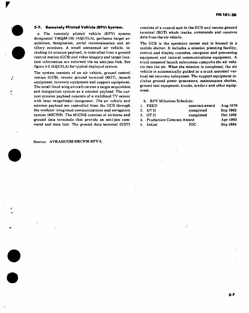
FM 101-20
5-7. Remotely Piloted Vehicle (RPV) System.
a. The remotely piloted vehicle (RPV) system designated YMQM-105 (AQUILA), performs target ac- quisition, designation, aerial reconnaissance and ar- tillery missions. A small unmanned air vehicle, in- cluding its mission payload, is controlled from a ground control station (GCS) and video imagery and target loca- tion information are returned via an anti-jam link. See figure 5-2 (AQUILA) for typical deployed system.
The system consists of an air vehicle, ground control station (GCS), remote ground terminal (RGT), launch equipment, recovery equipment and support equipment. The small fixed wing aircraft carries a target acquisition and designation system as a mission payload. The cur- rent mission payload consists of a stabilized TV sensor with laser rangefinder/designator. The air vehicle and mission payload are controlled from the GCS through the modular integrated communications and navigation system (MICNS). The MICNS consists of airborne and ground data terminals that provide an anti-jam com- mand and data link. The ground data terminal (GDT)
consists of a control unit in the GCS and remote ground terminal (RGT) which tracks, commands and receives data from the air vehicle.
The GCS is the operation center and is housed in a mobile shelter. It includes a mission planning facility, control and display consoles, computer and processing equipment, and tactical communications equipment. A truck mounted launch subsystem catapults the air vehi- cle into the air. When the mission is completed, the air vehicle is automatically guided to a truck mounted ver- tical net recovery subsystem. The support equipment in- cludes ground power generators, maintenance shelter, ground test equipment, trucks, trailers and other equip- ment.
b. RPV Milestone Schedule: 1. FSED contract award Aug 1979 2. DT II completed Sep 1982 3. OTII completed Dec 1982 4. Production Contract Award Apr 1983 5. Initial IOC Sep 1984
Source: AVRADCOM-DRCPM-RPV-L
5-7

5-8
RGT y*
-/
AV LAUNCHER
&
Hi
jjlfo -«se <n
V RECOVERY SYSTEM
Mi
N CCS
CARGO TRUCK à •=1 ñ
MAINTENANCE SHELTER
GENERATORS
AV HANDLER
SECTION LEADER'S VEHICLE
Figure 5-2. YMQM-105 (AQUILA) Typical Deployed System
k > y
FM 1
01
-20

V V
r
FM 101-20
APPENDIX A
REFERENCES
r
ARMY REGULATIONS (AR) (DA RAMP 310-1)
70-50 Designating and Naming Military Aircraft, Rockets, and Guided Missiles. 95-70 Army Aviation Planning Manual. 310-50 Authorized Abbreviations and Brevity Codes 310-25 Dictionary of United States Army Terms. 570-2 Organization and Equipment Authorization Tables - Personnel. 611-201 Enlisted Career Management Fields and Military Occupational Specialties. 750-1 Army Materiel Maintenance Concepts and Policies.
FIELD MANUALS (FM) (DA PAMP 310-3)
1-105 Army Aviation Techniques and Procedures. 21-6 How to Prepare and Conduct Military Training. 21-30 Military Symbols. 21-60 Visual Signals. 55-15 Transportation Reference Data. 55-40 Army Combat Service Support Air Transport Operations. 90-1 Employment of Army Aviation Units in a High Threat Environment (How to Fight) 90-4 Airmobile Operations (How to Fight) 101-10-1 Staff Officers’ Field Manual: Organization, Technical, and Logistical Data (Part I —
' Unclassified).
TRAINING CIRCULARS (TQ (DA PAMP 310-3)
21-5-7 Training Management in Battalions.
TECHNICAL MANUALS (TM) (DA PAMP 31 (W)
55-450-8 Air Transport of Supplies and Equipment: External-Transport Procedures. 55-450 series Air Transport of Supplies and Equipment: Internal-Transport Procedures.
A-l
S.
FM 101-20
APPENDIX A (CONT.)
55-450-15 Air Movement of Troops and Equipment (Non-Tactical).
SUPPLY BULLETIN(S)
SB 700-20 Army Adopted/Other Items Selected for Authorization/List of Reportable Items.
A-2

's ^
FM 101-20
1
INDEX
Page
Aircraft Armament Applications 2-65 r Aircraft Armament Subsystem Ammunition 2-128 Aircraft Armament Subsystem Missiles 2-135 Aircraft Armament Subsystem Rockets 2-133 Aircraft Armor Subsystems 2-136
AH-1 Series > 2-139 CH-47 Series 2-140 CH-54A 2-142 OH-6A 2-143 UH-1 Series 2-144 OV-1 Series 2-145
Aircraft Authorizations 1-1 1 Aircraft Unit Prices 4-1
Cost Per Flying Hour 4-3 Aircraft Designation iv Aircraft Inspections 2-159 Aircraft Type Classifications :. viii Armament Cost 4-3 Armament Subsystems
M5 2-69 M18A1 2-72 M19 2-74 M21 2-76 M22 2-79 M23 2-83 M27 2-86 M35 2-88 M28A1 2-89 M28A2 2-91 M28A3 2-93 M24 2-96 M41 2-97 M56. 2-99 M65 2-101 XM97E1/2 2-104 HSS 2-108 XM138 2-110 XM76 2-111 XM142 2-113 XM22 2-115 M156 2-118 M158A1 2-119 M200A1 2-120 XM260 2-122 XM261 2-124 XM230E1 2-125 HMMS 2-126
Authorized Aircraft Designations 1-7 AVIM Support Units 2-171 Avionics and Surveillance Equipment Configuration 2-2
Index 1

1 FM 101-20
Page
Avionics Cost 4-3 Basic Annual Flying Hour
Planning Factors 1-11 Replacement Factors 1-13
Ferrying Shipping 2-146 Fuel and Oil Consumption 2-163 Fuel and Oil Cost 2-161 MACRIT 2-167 Maintenance Categories 2-173 Maintenance Man-hours
Direct Man-hours Per Flight Hour 2-165 Direct Man-hours Technical Inspection 2-166
Major Components 2-1 Personnel Requirements 3-1 Research and Development
AAH-64A 5-1 Remotely Piloted Vehicle 5-7
Shop Sets 2-152 Standard Aircraft Characteristics/Performance 1-14
AH-1G/TH-1G 1-17 AH-1S (MOD) 1-21 AH-1S (PROD) 1-23 AH-1S (EGAS) 1-27 CH-47A 1-34 CH-47B 1-37 CH-47C 1-41 YCH-47D 1-46 CH-54A 1-52 CH-54B 1-55 OH-6A 1-61 OH-58A 1-67 OH-58C 1-71 TH-55A 1-75 UH-1B 1-79 UH-1M 1-85 UH-1H 1-89 UH-1V 1-94 EH-1H 1-96 EH-1X 1-98 UH-60A 1-105
. C-12A 1-109 OV-1B 1-114 OV-1C 1-117 OV-1D 1-123 RV-1D 1-126 T-41B 1-131 T-42A 1-135 U-8F 1-139 U-10A 1-145 U-21A/RV-21A 1-150 RV-21D 1-153 V-21F 1-156
Index 2

r FM 101-20
# RV-21B/RV-21C RV-21H RV-21J UV-18A
Tool Kits Tool Sets
Page
1-159 1-162 1-166 1- 170 2- 158 2-158
/
Index 3/(lndex 4 blank)

\
.’•4
By Order of the Secretary of the Army: f
Official:
E. C. MEYER General, United States Army
Chief of Staff
ROBERT M. JOYCE Brigadier General, United States Army
The Adjutant General
DISTRIBUTION:
Active Army, ARNG, USAR: To be distributed in accordance with DA Form 12-11B requirements for US Army Aviation Planning Manual.
ft U.S. GOVERNMENT PRINTING OFFICE: 1981—703029/1232
\

1
f
V
3000031506
«i
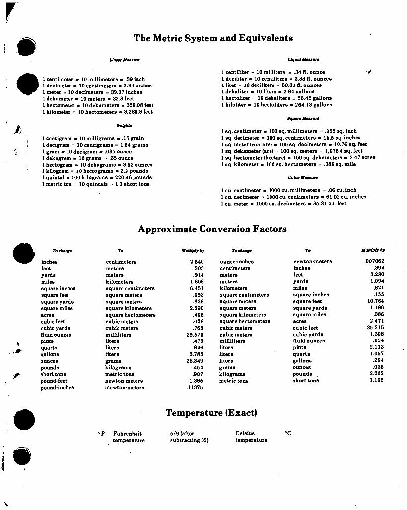
f & The Metric System and Equivalents
Liaatr ASéMBur* Liquid üßMBün
ß)
!
I
1 centimeter = 10 millimeters = .39 inch 1 decimeter = 10 centimeters = 3.94 inches 1 meter = 10 decimeters = 39.37 inches 1 dekameter = 10 meters = 32.8 feet 1 hectometer = 10 dekameters = 328.08 feet 1 kilometer a 10 hectometers = 3,280.8 feet
Wmifht*
1 centigram = 10 milligrams = .15 grain 1 decigram = 10 centigrams = 1.54 grains 1 gram = 10 decigram = .035 ounce 1 dekagram = 10 grams = .35 ounce 1 hectogram = 10 dekagrams = 3.52 ounces 1 kilogram = 10 hectograms = 2.2 pounds 1 quintal = 100 kilograms = 220.46 pounds 1 metric ton = 10 quintals = 1.1 short tons
1 centiliter = 10 milliters = .34 fl. ounce V 1 deciliter a 10 centiliters = 3.38 fl. ounces 1 liter = 10 deciliters = 33.81 fl. ounces 1 dekaliter = 10 liters = 2.64 gallons 1 hectoliter = 10 dekaliters = 26.42 gallons 1 kiloliter = 10 hectoliters = 264.18 gallons
Square lítamr»
1 sq. centimeter = 100 sq. millimeters = .155 sq. inch 1 sq. decimeter a 100 sq. centimeters a 15.5 sq. inches 1 sq. meter (centare) a 100 sq. decimeters a 10.76 sq. feet 1 sq. dekameter (are) = 100 sq. meters = 1,076.4 sq. feet 1 sq. hectometer (hectare) = 100 sq. dekameters = 2.47 acres 1 sq. kilometer a 100 sq. hectometers = .386 sq. mile
Cubic Measure
1 cu. centimeter a 1000 cu. millimeters = .06 cu. inch 1 cu. decimeter a 1000 cu. centimeters = 61.02 cu. inches 1 cu. meter a 1000 cu. decimeters a 35.31 cu. feet
Approximate Conversion Factors
Tocheafe
inches feet yards miles square inches square feet square yards square miles acres cubic feet cubic yards fluid ounces pints quarts gallons ounces pounds short tons pound-feet pound-inches
To
centimeters meters meters kilometers square centimeters square meters square meters square kilometers square hectometers cubic meters cubic meters milliliters liters liters liters grams kilograms metric tons newton-meters mAwtnnamAtArfl
Multiply by
2.540 .305 .914
1.609 6.451
.093
.836 2.590
.405
.028
.765 29,573
.473
.946 3.785
28.349 .454 .907
1.365 .11375
To change
ounce-inches centimeters meters meters kilometers square centimeters square meters square meters square kilometers square hectometers cubic meters cubic meters milliliters liters liters liters grams kilograms metric tons
To
newton-meters inches feet yards miles square inches square feet square yards square miles acres cubic feet cubic yards fluid ounces pints quarts gallons ounces pounds short tons
Multiply bj
.007062 .394
3.280 1.094
.621
.155 10.764
1.196 .386
2.471 35.315
1.308 .034
2.113 1.057 .264 .035
2.205 1.102
Temperature (Exact)
#
°F Fahrenheit 5/9 (after temperature subtracting 32)
Celsius °C temperature
V

1
DEPARTMENT OF THE ARMY
U^ytRMY AG PUBLICATIONS CENTER
2800 EASTERN BOULEVARD BALTIMORE MARYLAND 21 220
OFFICIAL BUSINESS
PENALTY FOR PRIVATE USE S300
I
POSTAGE AND FEES PAID DEPARTMENT OF THE ARMY
DOD 314
SPECIAL FOURTH CLASS BOOK \ RATE
\ \ \
ir
U.B.MAIL
V.
00 o o o o
(71 o
* r Y
/
I
•A-
i . i,