Army Aviation Digest - Jan 1987
48
-
Upload
aviationspace-history-library -
Category
Documents
-
view
46 -
download
3
Transcript of Army Aviation Digest - Jan 1987


JANUARY 1987 • VOLUME 33 • NUMBER 1
1 Aviation Doctrine Update, MG Ellis D. Parker
2 Cross-FLOT With the AH-64 Apache, LTC Kenneth R. McGinty and CPT Gregory A. Brockman
6 AH-64, A Total System for Battle, Mr. Wendell W. Shivers and Mr. Raymond L. Stockman page 34
18 Values-A Way of Life, SSG Theodore J. Stevenson Jr.
19 Army Aviation Branch Headquarters Directory
27 PEARL'S
28 The Effects of OTC Drugs
30 DES Report to the Field: Revised Army Flight Record System, CPT Christopher Harden
32 Aviation Personnel Notes: Regimental Proposal; Noncommissioned Officer Education System Update; Functional Review Update; Enlisted Aircraft Survivability Equipment Training page 42
34 Albatross X, Tri-National Aviation Exercise, LTC Kenneth E. Wilson
38 Light Helicopter Family Program Overview, BG (P) Ronald K. Andreson Honorable John O. Marsh Jr.
42 The Ghost of a Drill Sergeant Past, MAJ Larry Smith Secretary of the Army
Back Cover: ATC Action Line: Night Vision Goggles Exemption, Mr. Jesse M. Burch Jr.
Major General Ellis D. Parker Commander
U.S. Army Aviation Center
Cover: AH-64 cross-FLOT operations require indepth risk analysis involving assessment of the target priority, probability of success and survivability. Target evaluation for risk vs. payoff should reveal the target to
Brigadier General Rodney D. Wolfe Assistant Commandant
U.S. Army Aviation Center
Richard K. Tierney be high priority. Story begins on page 2.
The mission of the U.S. Army Aviation Digest (USPS 415-350) is to provide information of an operational, functional nature concerning safety and aircraft accident prevention, training, maintenance, operations, research and development, aviation medicine and other related data.
The Digest is an official Department of the Army periodical published monthly under the supervision of the commander, U.S. Army Aviation Center. Views expressed herein are not necessarily those of the Department of the Army nor the U.S. Army Aviation Center. Photos are U.S. Army unless otherwise specified. Use of the masculine pronoun is intended to include both genders unless otherwise stated. Material may be reprinted provided credit is given to the Aviation Digest and to the author unless otherwise indicated.
Articles, photos and items of interest on Army Aviation are invited. Direct communication is authorized by writing Editor, U.S. Army Aviation Digest, P.O. Box 699, Fort Rucker, AL 36362-5044, or by calling either AUTOVON 558-3178 or Commercial 205-255-3178. Manuscripts returned only upon request.
Editor
Use of funds for printing of this publication has been approved by the Secretary of the Army, 19 February 1985, in accordance with Army Regulation 310-1. Secondclass postage paid at Daleville, AL, and additional mailing offices.
Active Army units receive distribution under the pinpoint distribution system as outlined in AR 310-2. Complete DA Form 12-5-R and send directly to CDR, AG Publications Center, 2800 Eastern Boulevard, Baltimore, MD 21220. For any change in distribution requirements, initiate revised DA Form 12-5-R.
National Guard and Army Reserve units under pinpoint distribution should submit DA Form 12-5-R. Other National Guard units submit requests through their state adjutant general.
Those not eligible for official distribution or who desire personal copies of the Digest can order the magazine from the Superintendent of Documents, U.S. Government Printing Office, Washington, DC 20402.
POSTMASTER: Send address changes to Superintendent of Documents, U.S. Government Printing Office, Washington, DC 20402.

Major General Ellis D. Parker Chief, Army Aviation Branch
Aviation Doctrine Update
In May 1985, Army Aviation was progressing toward the goal to consolidate our doctrine under one umbrella. A need was identified to write and produce the most interesting and valuable doctrinal and training literature in the military. Our new battalion and brigade manuals have accomplished this goal.
In the summer and fall of 1986, we published FM 1-116, "Air Cavalry Troop"; FM 1-114, "Regimental Aviation Squadron"; FM 1-113, "Assault Helicopter Battalion"; FM 1-112, "Attack Helicopter Battalion"; and FM 1-111, "Aviation Brigade." As we completed these manuals, we saw the need for even more, and they're on the way. We are continuing the process with FC 1-115, "Cargo Helicopter Battalion"; FC 1-119, "Corps Aviation Brigade"; and a rewrite of FM 1-107, "Air-to-Air Combat," based on lessons learned from our air-to-air combat tests.
Each manual was developed with loving care by a subject matter expert in our Department of Combined Arms Tactics. Of course, the input from tactical units and numerous individual contributors added the practical touch so necessary in field publications.
FM 1-116, "Air Cavalry Troop," dated 14 August 1986, reflects the new cavalry organization and describes how to fight in both divisional and regimental organizations. We think it is a good down-to-earth portrayal of tactics and procedures and will enhance the security and reconnaissance capabilities of divisions and corps.
FM 1-114, "Regimental Aviation Squadron," dated 27 August 1986, describes how to fight the newest addition to the armored cavalry regiment. This new maneuver squadron expands the capabilities of regimental cavalry through its freedom from ground obstacles, thereby expanding regimental reconnaissance coverage. Its capabilities also allow it to protect and preserve the regiment by providing quickly massed firepower anywhere on the battlefield.
FM 1-113, "Assault Helicopter Battalion," dated 28 October 1986, is our latest doctrinal publication. It deals with unit responsibilities during all types of operations, as well as outlining roles and missions of the assault helicopter battalion found in the corps aviation brigade and the air assault division. This is a vital organization that will provide combat support
JANUARY 1987
and service support aviation to the combined arms team.
FM 1-112, "Attack Helicopter Battalion," dated 14 July 1986, is the latest word on the new battalions found in both divisional and corps brigades. This manual describes employment techniques for all types of combat operations in the close-in, deep and rear operations areas. Tactics described are for both AH-1S/0H-58C and AH-64/0H-58D equipped units. The recent decision of OH-58D fielding will necessitate an additional discussion on alternative mixes.
FM 1-111, "Aviation Brigade," dated 12 August 1986, describes both divisional and corps brigades. As I mentioned earlier, we are writing a new manual that will deal exclusively with the corps aviation brigade and the annex will eventually be dropped from this manual. This manual, more than any other, has benefitted from an impressive volume of field input. We believe it accurately portrays the command and control and logistical requirements to fight this organization on the air-land battlefield. Captured here is the essence of the contribution air maneuver makes to division and corps operations. It will be helpful to commanders and staffs of maneuver units at all levels.
The challenge remains to keep our doctrinal and training literature valid and up-to-date. I will need the help of every member of the Aviation Branch to accomplish this. We must know what our doctrine says and apply it with every bit of field lore and commonsense we possess. Only then can we assess its validity and make the appropriate changes.
We must be committed to the full integration of Army Aviation into all phases of air-land battle operations. Our units have the capability to add depth, agility and firepower to our combined arms partners. We owe them our best efforts toward achieving our full potential.
AIR ASSAULT
1
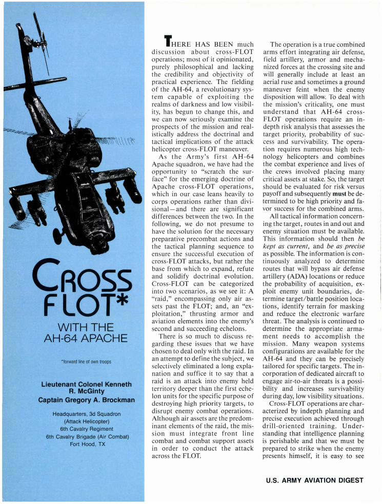
CROSS fLOT*
WITH THE AH-64 APACHE
'forward line of own troops
Lieutenant Colonel Kenneth R. McGinty
Captain Gregory A. Brockman
Headquarters. 3d Squadron (Attack Helicopter)
6th Cavalry Regiment
6th Cavalry Brigade (Air Combat) Fort Hood. TX
T HERE HAS BEEN much discussion about cross-FLOT operations; most of it opinionated, purely philosophical and lacking the credibility and objectivity of practical experience. The fielding of the AH-64, a revolutionary system capable of exploiting the realms of darkness and low visibility, has begun to change this, and we can now seriously examine the prospects of the mission and realistically address the doctrinal and tactical implications of the attack helicopter cross-FLOT maneuver.
As the Army's first AH-64 Apache squadron, we have had the opportunity to "scratch the surface" for the emerging doctrine of Apache cross-FLOT operations, which in our case leans heavily to corps operations rather than divi-ional- and there are signi ficant
differences between the two. In the following, we do not presume to have the solution for the necessary preparative precombat actions and the tactical planning sequence to ensure the successful execution of cross-FLOT attacks, but rather the base from which to expand, refute and solidify doctrinal evolution. Cross-FLOT can be categorized into two scenarios, as we see it: A "raid," encompassing only air assets past the FLOT; and, an "exploitation," thrusting armor and aviation elements into the enemy's second and succeeding echelons.
There is so much to discuss regarding these issues that we have chosen to deal only with the raid. In an attempt to define the subject, we selectively eliminated a long explanation and suffice it to ay that a raid is an attack into enemy held territory deeper than the first echelon units for the specific purpose of destroying high priority targets, to disrupt enemy combat operations. Although air assets are the predominant elements of the raid, the mission must integrate front line combat and combat support assets in order to conduct the attack across the FLOT.
The operation is a true combined arms effort integrating air defense, field artillery, armor and mechanized forces at the crossing site and will generally include at least an aerial ruse and sometimes a ground maneuver feint when the enemy disposition will allow. To deal with the mission's criticality, one must understand that AH-64 crossFLOT operations require an indepth risk analysis that assesses the target priority, probability of success and survivability. The operation requires numerous high technology helicopters and combines the combat experience and lives of the crews involved placing many critical assets at stake. So, the target should be evaluated for risk versus payoff and subsequently must be determined to be high priority and favor success for the combined arms.
All tactical information concerning the target, routes in and out and enemy situation must be available. This information should then be kept as current, and be as precise as possible. The information is continuously analyzed to determine routes that will bypass air defense artillery (ADA) locations or reduce the probability of acquisition, exploit enemy unit boundaries, determine target/battle position locations, identify terrain for masking and reduce the electronic warfare threat. The analysis is continued to determine the appropriate armament needs to accomplish the mission. Many weapon systems confi~urations are available for the AH-64 and they can be precisely tailored for specific targets. The incorporation of dedicated aircraft to engage air-to-air threats is a possibility and increases survivability during day, low visibility situations.
Cross-FLOT operations are characterized by indepth planning and precise execution achieved through drill-oriented training. Understanding that intelligence planning is perishable and that we must be prepared to strike when the enemy presents himself, it is easy to see
u.s. ARMY AVIATION DIGEST
why preplanning is of paramount importance - the corps or divi ion commander should give the aviation brigade a "be prepared" mis-ion to execute the operation and
then the corps or division should back it up with direct line intelligence and other critical resources not normally available at squadron or brigade level.
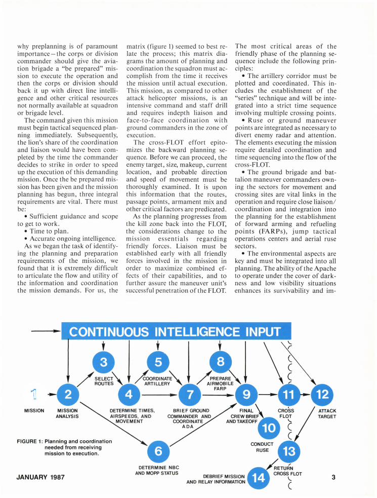
The command given this mission must begin tactical equenced planning immediately. Subsequently, the lion's hare of the coordination and liai on would have been completed by the time the commander decides to trike in order to peed up the execution of thi demanding mission. Once the be prepared mi -sion has been given and the mi ion planning has begun, three integral requirements are vital. There mu t be:
• Sufficient guidance and scope to get to work.
• Time to plan. • Accurate ongoing intelligence. As we began the task of identify-
ing the planning and preparation requirements of the mission, we found that it is extremely difficult to articulate the flow and utility of the information and coordination the mission demand. For us, the
MISSION MISSION ANALYSIS
FIGURE 1: Planning and coordination needed from receiving mission to execution .
JANUARY 1987
matrix (figure 1) eemed to best relate the proces ; this matrix diagram the amount of planning and coordination the quadron must accompli h from the time it receive the mi ion until actual execution . This mission, as compared to other attack helicopter mi ion, is an intensive command and taff drill and require indepth liai on and face-to-face coordination with ground commanders in the zone of execution.
The cross-FLOT effort epitomizes the backward planning equence. Before we can proceed, the enemy target, size, makeup, current location, and probable direction and speed of movement must be thoroughly examined. It is upon this information that the routes, passage points, armament mix and other critical factors are predicated.
As the planning progresses from the kill zone back into the FLOT, the considerations change to the mission essentials regarding friendly forces. Liaison must be established early with all friendly force involved in the mission in order to maximize combined effects of their capabilities, and to further assure the maneuver unit's succe ful penetration of the FLOT.
DETERMINE NBC AND MOPP STATUS
The most critical areas of the friendly phase of the planning equence include the following principles:
• The artillery corridor mu t be plotted and coordinated. Thi includes the establishment of the "series" technique and will be integrated into a strict time sequence involving multiple crossing points.
• Ruse or ground maneuver points are integrated as necessary to divert enemy radar and attention. The elements executing the mission require detailed coordination and time sequencing into the flow of the cross-FLOT.
• The ground brigade and battalion maneuver commanders owning the sectors for movement and crossing sites are vital links in the operation and require close liaison/ coordination and integration into the planning for the establishment of forward arming and refueling poi n ts (FARPs), jump tactical operations centers and aerial ruse sectors.
• The environmental aspects are key and must be integrated into all planning. The ability of the Apache to operate under the cover of darkness and low visibility situations enhance its survivability and im-
3

FIGURE 2: The effects of airspeed, ordnance and range.
-- 100/IZO~:..:..:..:.:..:~ I NGRESS7 EGRESS
Time Remaining
(Q
j ~ ---c c: --
6O/S0 INGRESS/EC
o 30
60 MINUTES
860PPH=416
1111111111111111111111111111 Time Remaining 29 MINUTES
1220 PPH =610 lBS 7S0 PPH =440 lBS
111111111111111111111111111111111 30 MI UTES 3S MINUTES
1+00 1+30
time
S6 MINUTES
Time Remaining
40 MINUTES
2+00 2+30 LEGEND
• Conditions: 30°C, 2,000 It PA, no winds, 17,000 Ibs takeoff gross weight. • Distance to be Covered: 100 km (54 NM)
lillTIilll NGRESS
ON STATION
mm EGRESS • Configuration : 8 HELLFIRE, 38 2.75 inch rockets, 1,200 rds 30 mm.
• Runup - All Events: 20 minutes and 155 pounds per hour (PPH). • Ammo Expended: 8 HELLFIRE, 38 rockets,
500 rds 30 mm.
proves its prospects of maintaining stealth and surprise; conversely, some weather will reduce the effectiveness of the aircraft and also must be considered.
The route planning, both behind and forward of the FLOT, will be based upon terrain that minimizes the enemy direct fire capabilities and provides concealment from electronic, radar and visual acquisition. The maneuver unit may use ridgelines to cover flanks; low ground to remain undetected; and, vegetation to mask behind and move through. The Doppler is a key navigational aid to the AH-64; however, to maximize the efficiency of the Doppler, it must be updated to known terrain points. During day operations, any terrain feature will provide reasonable Doppler update points (bridges, river crossings, road intersections and lakes). At night, however, such terrain features may not be readily identifiable and could compound the probability of errors in navigation unless vertical terrain features are
4
used to aid in FLIR (forward looking infrared) acquisition and confirmation: The use of hills and valleys with notable vertical relief will reduce night navigational errors. Critical to the night/low visibility operations is manmade obstacle information relating to powerlines, antennas and other like hazards to flight. Hazard information must be integrated into the execution plan to ensure the possibility of success. The potential of losing an aircraft to these hazards is as real as losing to the enemy threat and must be addressed accordingly.
Within the matrix, we estimated the times required for each event. These times are soft and worst cases and were omitted from this article since they change with each situation. If the squadron is given a quick-strike mission and required to perform every activity internally (planning, coordination and intelligence gathering), we suspect the squadron will need a great deal more time. If simultaneous brigade and corps support were ongoing
during the coordination process, corps and brigade taff help reduce lead time required and obviously produce quicker reaction to the most current intelligence. We can execute a mission with less planning and coordination time, but this may well reduce the survivability and effectiveness of the squadron. The range and time onstation capabilities of the AH-64 vary due to altitude, weather and armament; each affects the performance of the aircraft. Figure 2 depicts some of the effects of airspeed, ordnance and range.
We can transport a FARP clo e to enemy lines by using internal UH-60 assets thus increasing the distance and the time onstation. The possibility of increasing the range of the cross-FLOT will be achieved through the u e of the forthcoming extended range fuel tanks , but for now we are constrained to an airmobile FARP.
There are possible scenarios that may facilitate the use of an airmobile FARP across enemy lines
U.S. ARMY AVIATION DIGEST

and could greatly increase the range of the strike (history marks many opportunities to bypass enemy positions by taking advantage of voids in the front line trace). Again, the AH-64 has the capability to carry fuel in externally mounted fuel pods; however, this option reduces the ordnance load.
The AH-64 offers new vistas for target engagement. We have found that at night, the best method of attack was to begin the engagement via designators using the Apache's remote fire capability. This will confuse the enemy and allow the troop commander to better assess the target array without risking the entire team that inherently improves the troop's effectiveness through better fire distribution. Once the troop commander has seen the enemy and determined the threat density, he can amass all Apaches to bear on the kill zone by directing them to battle positions and engage the enemy choosing the autonomous firing mode.
The designators may then fire autonomously and use complementary engagement techniques with some aircraft designated to combat the air-to-air threat, some as remote designators and some as HELLFIRE launchers. These techniques can be complemented by different ordnance configurations; thus, the Apache introduces many variants to the attack process limited only by imagination.
The Apache's laser capability has added another dimension to the cross-FLOT. Air Force integration appears an even better prospect when combining the laser designation and precise accuracy that can be achieved between the Apache and various jet fighter aircraft. The use of the advanced joint air attack team is an outstanding method to disrupt enemy operations with maximum ordnance on target.
The communication phase is one of the most vulnerable and least addressed. The training goal of every helicopter mission is especially
JANUARY 1987
important during the quick-strike. When communications are required, they must be precise, short, and most important, secure. Again, since the battlefield intelligence is extremely perishable and the situation fluid, there exists a great need to fill the void of sending information to the attack team concerning changes in target location or even a mission change while the team is en route. We have examined several prospects to improve this current void with our onboard systems and at this juncture, the ability to provide any information to the team once it is well past the FLOT is tenuous at best - this particular area deserves immediate attention - better methods must be found to ensure attack helicopter combat success.
The use of the aeroscout as an integral part of the attack team continues to be a vital aspect in the quick-strike. Although never used across the FLOT because of their lack of night targeting capability, they perform various important functions that increase the survivability and effectiveness of ground and air assets, and the overall prospects of the mission. The key roles of the aerOSCf'ut are inherent during the liaison with ground commanders and other supporting elements. They will be employed to recon and secure the routes to and from the FLOT as well as to coordinate the location of the FARPs. The scouts ensure the passage points at the FLOT, in and out, are passable; the ADA windows are opened; and, artillery series are executed and adjusted. If the enemy or friendly situation has changed, the scouts can relay the information before the attack helicopters are committed to the crossing. The scouts also may execute the aerial ruse, and at this juncture they are the last communication link with the attack force across the FLOT.
We have found that once past the FLOT the AH-64 team must be drill oriented and have planned internal
miSSIOn contingencies to enable precise execution of the mission. They require estimated times and airspeeds to achieve sequence compliance. Also, they must:
• Establish the aircraft configurations.
• Plan and plot routes. • Determine battle positions and
battle position contingencies. • Select rally points. • Outline downed aircrew opera
tions. • Decide actions on contact. • Define all tactical aspects that
are required on such an indepth mission.
In conclusion, the quick-strike is a valid mission requiring intensive planning that exercises the command and staff elements of the unit to the greatest degree of all missions. Therefore, to succeed, attack helicopter units must train to attain a high level of expertise and confidence in both pilot and command and staff functions critical to accomplishing these missions. Due to the depth of the planning and coordination required, it is vital that there be an adequate amount of time allowed to accomplish these critical tasks. The tremendous engagement capabilities combined with the potential for surprise afforded by the unprecedented night systems of the Apache make it a formidable cross-FLOT package. Its employment through diversified combined arms tactics coupled with its weapons arrays and capabilities can only have a cataclysmic effect on the enemy. Not every enemy move will lend itself to crossFLOT operations; however, the corps and division commander can now overlap their areas of concern with an influence not before available. The aerial cross-FLOT ability now adds another dimension to the operational art of war and will diminish the prospects of a massing enemy by threatening its existence deep in its own territories - maybe to the point of hesitation; thus losing the moment. • f
5

6
Mr. Wendell W. Shivers Mr. Raymond L. Stockman
This fourth article in the AH-64A Apache series covers the hydraulics, pressurized air and fuel subsystems. As with all of the articles in the series, the information is for familiarization only and must not be referenced for operation or maintenance of the AH-64A.
u.S. ARMY AVIATION DIGEST

Hydraulic Systems Two hydraulic systems are used in
the AH-64 to provide redundancy in the event one of the systems fails.
The primary system provides hydraulic power to the primary side of all four flight control servoactuators and to the stability control augmentation system (SCAS) and backup control system (BUCS) provisions of each servoactuator. The SCAS provision in the collective servoactuator is not used.
The utility hydraulic system provides power to the utility side of each flight control servoactuator, plus the following components:
• rotor brake, • area weapon turret drives, • ammunition handling system, • auxiliary power unit start, • tail wheel unlock, • external stores evaluation and • emergency hydraulic system.
Each system has its own reservoir, filters, relief valves, pressure switches, pressure transducers and heat exchanger/eductors . Both systems:
• Use one-half of tandem servoactuators in the cyclic, collective and directional flow controls;
• Operate at 3,000 pounds per square inch (psi), 6 gallons per minute (gpm) flow;
• Use MIL-H-83282 hydraulic fluid above - 25 degrees Fahrenheit or MIL-H-5606 hydraulic fluid below - 25 degrees Fahrenheit;
• Can be serviced, and the utility accumulator charged from one onboard hand pump.
Major components of the primary system are in figure 1. The primary hydraulic manifold contains the reservoir; pump capacity is 3,000 psi with a 6.0 gpm, constant pressure variable delivery.
LONGITUDINAL SERVOACTUATOR
PRIMARY HYDRAULIC GSE PANEL ASSEMBLY
COLLECTIVE SERVOACTUATOR
LATERAL SERVOACTUATOR
FIGURE 1: Primary hydraulic system major components.
JANUARY 1987
PRIMARY HYDRAULIC MANIFOLD
- dt!1!! DIRECTIONAL If t:_~ ;1/, > SERVOACTUATOR . ~ '
PRIMARY HEAT EXCHANGER/ EDUCTOR ASSEMBLY
7

~·"'UI'MU4HiJl.z!. HEAT EXCHANGER/ EDUCTOR
DIRECTIONAL SERVO ACTUATOR
FIGURE 2: Primary hydraulic system.
System components, except for the servoactuators and the ground support equipment (GSE) panel, are installed on the left side of the main transmission deck. The GSE panel is on the right rear transmission deck.
The primary hydraulic system (figure 2) provides power for the longitudinal, collective and lateral servoactuators that are installed on the right front quadrant of the main transmission, and for the directional flight control tandem servoactuators located on top of the tail rotor gearbox.
Two filters (a pressure and a return) are used on the manifold. "Dirty-filter" indicators with red pop-up buttons on the manifold can be reset without removing the filter. The indicators are differential pressure actuated and temperature compensated, so they will not pop up below 85 degrees Fahrenheit.
A pressure switch illuminates caution/warning (C/W) segments PRI HYD PRESS on the pilot's and copilot gunner's (CPG's) C/W
8
II LATERAl SERVO ACTUATOR
COLLECTIVE SERVO AC'I'UATOR
LONGITUDINAL SERVO ACTUATOR
panels when primary hydraulic pressure is below 1,250 psi-decreasing or 2,050 psi-increasing on startup.
A reservoir low level switch illuminates OIL LOW PRI HYD on the pilot's panel when about 1.5 cubic inches of fluid remains in the primary hydraulic manifold. A pressurized air system (PAS) check valve maintains about 30 to 35 psi head pressure on the hydraulic fluid and a ground service visual fluid indicator is on the forward end of the manifold. An air pressure relief valve also located there can be used to release air pressure from the system before maintenance is performed .
The primary hydraulic system heat exchanger / eductor provides a route for PAS air and acts like a jet pump, creating a low pressure area, causing transmission deck air to flow through the heat exchanger. This cool deck air removes hydraulic fluid heat being radiated by the heat exchanger and exhausts the warm air overboard below the number 1 engine. A pressure regulator in
the heat exchanger bypasses return fluid that is more than 40 psi to prevent damage to the core while a temperature control valve routes fluid that is less than 49 degrees centigrade around the core, then back to the return system and to the manifold.
The primary hydraulic system GSE panel aft of the number 2 engine can be used to service the primary hydraulic system. A complete primary system checkout can be performed by connecting the pressure and return hoses of a ground power unit (GPU) to the panel and by regulating the GPU return, a complete system bleed and fill can be accomplished.
Under field conditions, a hydraulic fluid container can be connected to the fluid fill port, and by placing the pump selector handle inboard, the primary system can be filled.
The utility hydraulic system provides backup power for the longitudinal, collective, lateral and directional servoactuators.
The major components of the utility hydraulic system may be seen in figure 3. The rotor brake is mounted on and is part of the main transmission, but it uses utility system hydraulic power.
Apache's gun turret azimuth drive motor, elevation drive actuator, ammunition feed carrier drive and four pylon actuators use utility system pressure.
Four servoactuators served by the utility system are similar in operation to the primary hydraulic side. However, the utility side of the servoactuator does not have the SCAS or BUCS provisions.
The utility pump and the utility heat exchanger / eductor are identical to those in the primary system.
As in the primary system, the utility hydraulic manifold contains the fluid reservoir for the system and has a visual fluid level indicator, figure 4.
The manifold is the mount point for the:
U.S. ARMY AVIATION DIGEST

3 SERVO ACTUATORS
UTILITY HYDRAULIC MANIFOLD
FIGURE 3: Utility hydraulic system major components.
• Pressure transducers for pump and accumulator pressure,
• Low level fluid switch (10 cubic inches of fluid),
• Auxiliary power unit (APU) start isolation valve,
• Accumulator isolation valve, • Two filters, • Two dirty-filter (pop-up) indi
cators, • Rotor brake pressure regula
tion and • Internal routing provisions for
the utility system fluid. The dirty-filter indicators are
identical to and operate the same as those in the primary system.
Rotor brake BRAKE position pressure is regulated down from 3,000 to 337 psi by a regulator valve. In the switch LOCK position, full 3,000 psi pressure is routed to the rotor brake.
JANUARY 1987
DIRECTIONAL SERVO ACTUATOR
FIGURE 4: Utility hydraulic system.
An emergency hydraulic shutoff valve is mounted on the right for-
UTILITY HYDRAULIC GROUND SERVICE
EMERGENCY SHUTOFF VALVE
LONGITUDINAL AMMO LATERAL CARRIER DR COLLECTIVE EXT STORES SERVO PYLONS ACTUATORS AREA WEAPON
SYSTEM
HEAT EXCHANGER UTILITY
ward end of the tail boom, to the rear of the hydraulic manifold.
9

When a low fluid level is sensed by the manifold low level switch, a circuit is completed to ground; this illuminates a C/W light segment OIL LOW UTIL HYD on the pilot's panel and closes the shutoff valve. When closed, pressurized utility hydraulic fluid to the tail wheel lock control valve, lock actuator and the directional servoactuator is stopped. The valve will not open again until the utility manifold reservoir is serviced.
A tail wheel lock control valve, controlled by the pilot, routes 3,000 psi hydraulic pressure to the actuator to unlock the tail wheel so that it can swivel.
The actuator, mounted on the back side of the tail landing gear trailing arms, is spring loaded to the locked position.
The accumulator on the right side transmission deck under the APU supplies peak flow demands such as APU start, dampens fluid pressure surges, and isolates reserve
TAil WHEEL
@
LOCK
r--"TR aK--, 0"
~::(
r ENG START ,
[illJ, .. G " , 2
WI" I ~
c
«( ~i
FIGURE 5: Pilot's controls and indicators.
10
hydraulic power for emergency flight control.
External stores actuators inside each of the four pylons are controlled in response to fire control system commands.
An azimuth drive motor and elevation drive actuator mounted inside the turret assembly use 3,000 psi utility hydraulic power for positioning in response to fire control system commands.
Located on the forward end of the ammunition flat-pack, the ammunition carrier drive also uses 3,000 psi to drive the ammunition handling system for the area weapon system.
The utility GSE panel is mounted to the right of the primary hydraulic ground support equipment panel. A GPU can be attached to the utility GSE panel to check out the entire utility system.
The nitrogen pressure gauge on the GSE panel is used as a quick reference only to the condition of
the emergency system or nitrogen bottle charge. If the gauge reads about 1,650 psi, the nitrogen bottle is charged, but not the accumulator; if it reads 3,000 psi, the accumulator is charged. The hand pump can be used to fill the system and to charge the utility hydraulic accumulator.
Components of the utility system that make up the emergency system are the nitrogen gas storage bottle, the utility accumulator and check valves in the utility manifold. The emergency system stores 3,000 psi fluid pressure for emergency use of the flight controls, APU starts and rotor brake lock.
Flight control use of the emergency system is controlled by the EMER HYD switch on the pilot's instrument panel and the EMER HYD PWR switch on the copilot gunner's power lever quadrant.
Figure 5 shows locations of the pilot's controls and indicators and those of the CPG are in figure 6.
--
IDLE
OFF
N01 NO 2
FIGURE 6: Copilot/gunner's controls and indicators.
U.S. ARMY AVIATION DIGEST

Pressurized Air System The pressurized air system (PAS)
filters, pressurizes, regulates and distributes air to pneumatically operated systems and components of the AH-64. All PAS components, except the external air and utility receptacles, are located in the aft deck equipment bay area. The two receptacles are located at the bottom of the No.1 engine nacelle.
The shaft driven compressor (SDC) provides regulated, pressurized air to the engine cooling louver actuators, environmental control unit (ECU), nitrogen inerting system (NiS) and other units as shown in figure 7.
The pressurized air system consists of those items from the left in figure 7 up to and including the
AIR PARTICLE SEPARATOR (PRIMARY AIR)
AL TERNATE AIR SOURCE 5TH STAGE BLEED AIR ENGINE 1
PAS manifold and the pressure regulator valve, engine bleed shutoff valve and engine bleed check valve. Dirt and foreign objects from the inlet air are removed by the air particle separator to prevent foreign object damage to the pressurized air system and to provide clean air for the pilot and CPG crewstations .
A solenoid operated butterflytype throttle valve reduces starting loads on the auxiliary power unit. It is pneumatically regulated by outlet pressure from the shaft driven compressor. The SDC provides low pressure, high volume air flow from a single stage centrifugal compressor that develops 30 psi at sea level. It is mounted on and driven by the accessory gear box (AGB), lubri-
A S
M A N I F 0 L
AL TERNATE SOURCE 0
EXTERNAL AIR RECEPTACLE
FIGURE 7: Pressurized air system block diagram.
JANUARY 1987
cated by the AGB oil system and contains its own scavenge pump.
To eliminate pressure surges within the compressor during low system demands, the surge valve monitors shaft driven compressor pressure and opens/closes an overboard vent to maintain 30 psi at the SDC.
When the pressure switch functions, it illuminates SHAFT DRIVEN COMP on the pilot's C/W panel, opening when shaft driven compressor pressure is 15 psi increasing, and closing when SDC pressure is 7 ± 1 psi decreasing.
Indicated as an arrow in figure 7, the check valve is a one-way, flapper-type valve that prevents airflow back into the SDC when the pres-
FUel BOOST ...... PUMP
LOUVER ACTUATORS
FUel TRANSFER
PRESSURE PUMP REGULATOR
HYORAULIC HEAT
EXCHANGERS EXTERNAL FUel
TANKS HYDRAULIC RESERVOIRS
UTILITY RECEPTACLE
NIS
11

30 PSI AIR FROM SOC
FIGURE 8: Engine starting system.
surized air spindle manifold pressure is greater than SDC pressure.
Sources of alternate air are the external air receptacle (ground source) and the No. 1 engine fifth stage bleed air.
Ground source pressurized air is connected to the PAS manifold through the receptacle, located below the No. 1 engine nacelle. External air can be used for engine starting or maintenance operations on pressurized air system components.
Fifth stage bleed air from the No. 1 engine as an alternate air source is connected to the pressurized air system manifold by the bleed air shutoff valve and bleed air check valve. The bleed air shutoff valve lets No. 1 engine bleed air pressurize the PAS if the SDC fails. It opens when SDC outlet pressure drops to 10 psi. The check valve prevents PAS air back flow to the No. 1 engine.
12
ATS SPEED CUTOUT SWITCH (49 · 52% Ngl
The engine starting system, figure 8, for each engine is composed of the air turbine starter (ATS), and its pressure regulator/shutoff valve, and speed cutout switch. Flow and pressure of air to the ATS is controlled by the regulator/shutoff valve. It is mounted on the ATS and is electrically controlled by the engine start circuit. An ATS cutout switch senses engine Ng percent for operation of the ATS shutoff valve. Located on the aft electrical power center cover, the switch will close and cause the ATS shutoff valve to close, shutting off air from the PAS to the ATS when Ng reaches about 49 to 52 percent.
Located at about the one o'clock position, aft right side of each engine's accessory section, the ATS supplies torque to the engine for starting. Pressurized air will drive the ATS impeller until the engine Ng
is about 25 percent. When combustion begins to take place in the en-
gine, the ATS will continue to help the power turbine drive the engine Ng to about 49 to 52 percent for starting. When engine Ng exceeds air turbine starter revolutions per minute, the overrunning clutch will prevent the engine from driving the starter.
Other systems and components that use the PAS are the:
• Engine cooling louvers - allow air from the transmission deck area to flow through the engine firewall and across the engine. The louvers are spring-loaded open, and are closed by pressurized air spindle air when either the pilot's or the copilot/gunner's FIRE PULL handle is pulled.
• Canopy defog system - allows PAS air mixed with cabin air to be directed onto the interior sides of the crewstation canopy.
• Environmental control system (ECS) - provides for regulation of crewstation ambient temperature.
• Each hydraulic reservoir is pressurized in order to eliminate pump cavitation. PAS air is also directed to each hydraulic heat exchanger to promote hydraulic fluid cooling.
• Utility air receptacle for use by ground maintenance personnel, and at the external air receptacle for use in starting another AH -64 in an emergency situation.
• Nitrogen inerting system. • A ir pressure regulating valve,
where the pressure is reduced to 19 ± 3 psi. This lower pressure air is then directed to the fuel boost pump for engine start and high altitude operations, fuel transfer pump, to move fuel to forward or aft cells as needed and external fuel tank transfer system to move fuel from wing mounted tanks to the main fuel cells.
The ECS operation, figure 9, is controlled by the pilot and provides conditioned air to the crewstations. Conditioned air also is used to cool the forward avionics bays and the electrical power center. Ambient air cools the aft avionics bay.
U.S. ARMY AVIATION DIGEST

Two vaneaxial fans pull conditioned air from the CPG crewstation to cool or warm forward avionics bay components. Another vaneaxial fan in the aft avionics bay pulls outside ambient air into and through the bay to cool components. A small electrical power center fan draws crewstation air into the power center to dissipate heat, then exhausts into the transmission bay area.
With the ECS receiving PAS air, the ECU outlet temperature can
be regulated by rotating the ECS TEMP control from COLD to WARM. This rheostat regulates the temperature control valve for ECS air temperature.
ECU outlet air is routed into the crewstations through insulated ducts. Shoulder, waist and floor outlets in the crewstations can be opened or closed for air quantity.
With the CPG's standby fan in the OFF position, the pilot can select NORM fan operation (aft avionics bay fan high speed, electri-
cal power center fan normal speed and forward avionics bay fans slow speed).
In the event of ECU failure, the pilot can open his emergency air vent and select the STBY FAN position (aft avionics bay fan high speed, electrical power center fan normal speed and forward avionics bay fans high speed).
The CPG can select the STBY FAN position on his control panel. The pilot must open the emergency air vent for this mode of operation.
PILOTs ECS CONTROL PANEL
ECS ENVIRONMENTAL CONTROL UNIT ECS THERMAL OVERHEAT SWITCH
rID
ECS SHUTOFF VALVE
ENCU (ill) ON
~
~~' AFT AVIONICS~ ~ BAY CONDITIONED '----
a CPGs AUX
CONTROL PANEL
STBY FAN ON
el~ OFF A
v
A
v
FAN AIR SHOULDER OUTLET
FIGURE 9: Environmental control system operation.
JANUARY 1987
/;
CONDITIONED AIR DUCTS
ELECTRICAL POWER CENTER FAN
PILOT EMERGENCY INLET VENTS
FAN
FAN
13

FIGURE 10: Fuel cell locations.
Fuel System The fuel system provides fuel and
fuel management for aircraft engines during ground and flight operations, and for the auxiliary power unit during ground operations.
A full fuel load of about 375 gallons gives the Apache an endurance time of about 2.5 hours. Using 4 external fuel tanks with a capacity of 230 gallons each, the endurance time can be extended to about 8.5 hours for long-distance flights. There are provisions to transfer fuel from the external tanks into the fuel cells, and from one fuel cell to the other.
The forward fuel cell, figure 10, is located forward of the ammunition bay area while the aft fuel cell is in back of the bay area.
Apache's fuel cells are: • Crash-resistant, self-sealing
bladder units. They are self-sealing to 12.7 mm ammunition. A 30-minute fuel remaining portion of each cell is further shielded from 14.5 mm shells. This is partly due to a surrounding, woven fiberglass material designed to lessen the effect of small shell fragments and aircraft skin/stringer pieces.
• Designed to meet all crashworthy requirements. Breakaway valves are used at fuel line/fuel cell
14
connections and at firewalls to prevent fuel leakage and to minimize spillage.
• Built in is a gas vent/feed pressure relief valve unit that closes when the aircraft is positioned greater than 25 degrees from the horizontal. In the event of an aircraft rollover, the vent will close to prevent fuel spillage through the vent system.
• Protected from a pressure refueling malfunction by the main pressure relief valve that cracks at psi delta (±0.25) to allow the dumping of fuel. The gas relief valve allows the passage of pressurized nitrogen or air from the cells overboard.
Each fuel cell has a sump drain at its lowest point. A fuel baffle with two flappers in the forward cell prevents fuel starvation to the forward cell fuel sump by preventing fuel from shifting forward when flying in a nose low attitude. Fuel is permitted by the flapper valves to freeflow from the forward end of the cell to aft.
Also, the fuel system contains: • A fuel pressure service mani
fold, • A two-way air driven transfer
pump, • An air driven boost pump,
• An electrically operated refuel valve,
• Two four-position, electrically controlled fuel crossfeed/shutoff valves,
• A fuel pressure switch, • An electrically operated APU
fuel shutoff valve and boost pump, and
• A nitrogen inerting unit. The pilot's fuel control panel
provides normal control of the aircraft fuel system, figure 11. ENG 11 ENG 2 fuel valve switches provide operational power for the respective fuel crossfeed/shutoff valve.
• OFF-Disables the CROSSFEED switch and positions the respective fuel crossfeed/shutoff valve to the OFF (closed position).
• ON-Enables the CROSSFEED switch to control the fuel crossfeed/shutoff valves. The CROSSFEED switch allows the pilot to select the fuel source for engine operation.
• FWD TK - Positions both fuel crossfeed/shutoff valves so that both engines draw fuel only from the forward fuel cell.
• NORM-Positions the fuel crossfeed/shutoff valves so that engine 1 draws fuel from the forward cell and engine 2 draws from the aft fuel cell .
U.S. ARMY AVIATION DIGEST

OVERBOARD VENT
FIGURE 11: Fuel system operation.
• AFT TK - Positions both fuel crossfeed/shutoff valves so that both engines draw from the aft fuel cell only.
The boost pump, located in the aft fuel cell, provides pressure for engine starting and high altitude operations. It is activated by the automatic engine start sequence, or by placing the BOOST switch to the ON position (after the crossfeed switch has been positioned to the AFT TK position).
Engine mounted fuel pumps are suction pumps, and the boost pump is normally OFF. A ruptured fuel line will not pump fuel into the aircraft. Since the fuel cells are the lowest point in the system, siphoning of fuel from the fuel cells will not occur.
Whenever there is 8.5 to 10 psi pressure in the fuel line from the
JANUARY 1987
AUXILIARY FUEL TANK(S) RIGHT SIDE
boost pump to the engine 2 fuel crossfeed/shutoff valve, the pilot's C/W panel BOOST PUMP ON light segment will illuminate.
A reversible (bidirectional) transfer pump, controlled by the TRANS switch is provided for fuel management. When the refuel valve is closed, the transfer pump can transfer fuel either forward or aft.
• TO FWD - Moves the fuel from the aft fuel cell to the forward fuel cell at about 4 gallons per minute.
• OFF-Pump is disabled. • TO AFT-Moves fuel from the
forward fuel cell to the aft fuel cell at about 4 gallons per minute.
The NIS is located above the 30 mm ammunition "Flat Pack" and between the fuel cells. It weighs 11 pounds.
FUEl eNSSlilD
GIl I!] __ fWD Tl ----.~ O.
" ru--~.~~ ~ In Tl , .... S 100SI GIl rofWD n
~ ®~" @ Off '0 '" Off
PILOT'S FUEL CONTROL PANEL
AUXILIARY FUEL TANK(S) LEFT SIDE
Two power sources used by the NIS are pressurized air from the PAS and 115 Vac. The NIS automatically operates when these two sources are present.
The fire hazard associated with fuel cells that are less than full is greatly reduced by filling the empty volume of the fuel cells with air that is depleted of oxygen. This is accomplished by the NIS as it reduces the pressure and temperature of the PAS air and passes it through a molecular sieve cannister, purging about 70 percent of the oxygen present. This air is then regulated into the aft fuel cell and from there, on into the forward fuel cell. There isn't any means of inerting the extended range tanks.
Each external fuel tank is made of fiberglass, is jettisonable and holds 230 gallons of fuel.
15

OVRD FUEL CPG TRANS BOOST TKSEL ~
08 TOFWD
~OFF TO AFT
PLT
ON , OFF
FROM FWD
~ NRML
FROM AFT
OFF®O SELECT
TEST
FIGURE 12: Copilot/gunner's fuel control panel.
CPGs SELECTABLE DIGITAL DISPLAY
PAS air (16 to 22 psi) is routed into the outboard tanks. This pressurization forces fuel from the outboard tanks through the inboard tanks into the fuel cells. Fuel level control valves in both fuel cells prevent overfilling of the fuel cells when transferring fuel from the external tanks into the fuel cells.
The left tanks provide fuel to the forward cell while the right tanks replenish the aft fuel cell.
When external fuel tanks are empty (all fuel empty switches closed), the EXT EMP segment on the pilot's C/W panel illuminates.
The CPO's fuel control panel on the left console provides the means
16
145
FWD
TOTAL
AFT I.-II II~,-I
PILOTs FUEL OlfANTITY INDICATOR
FIGURE 13: Fuel system quantity indicators.
for fuel management. The panel, figure 12, is activated by the OVRD switch.
• PILOT position - Disables the copilot gunner's fuel control panel and activates the pilot's.
• CPO selection - Disables the pilot's fuel control panel and gives control to the copilot.
The CPOs TRANS, BOOST and TK SEL switch operation is identical to the pilot's.
Three capacitance-type fuel quantity probes are used to determine fuel quantity, figure 13. The aft cell has one probe; however, due to the irregular shape of the forward fuel cell, two probes are used.
A short probe is in the forward part of the cell, and a long probe is in the aft part of the cell. The two probes are wired in parallel to average the quantity of fuel remaining in the cell.
The total quantity of fuel in both cells is sensed by the probes and displayed in pounds x 10 on the fuel quantity gauges.
A Marconi-type vertical fuel gauge in the pilot's crewstation indicates pounds of fuel remaining in the forward cell x 10, and pounds of fuel remaining in the aft cell x 10, figure 13. A digital readout at the bottom of the gauge shows total pounds remaining x 10.
u.s. ARMY AVIATION DIGEST
~ ~ II iii PRI HYO UTil @] rUCS Oil HYO
BI PSI PSI
STAB ADS
• -BOOST Oil Oil lOW Oil PSI
~ PMP lOW UTll ACC 0111 PRI HYO HYO PUttP SPARE
'--- -
II -
B CHIPS 0ll8YP Oil BYP CHIPS IIIOSE PRI UTll lOSE
GR8X I HYO HYO GRBX 2 '------ - === ;:::=:: .-- .-- - -
CHIPS Oil PSI Oil PSI Oil PSI Oil PSI CHIPS EIliG I IIIOSE MAIIil MAIIil lOSE EIliG 2
GR8X 1 XMSIII 1 XMSI2 GR8X 2 -• B PRI HYO ~TIl HYO EJ ~ SPARE SPARE STAB ADS
,---- ,----Oil Oil HOT OIL HOT OIL HOT OIL HOT OIL PSI IIIOSE MAil MAil lOSE PSI
EIliG I GR8X 1 XMSN 1 XMSIII 2 GR8X 2 EIliG 2
I~ an - '--- - '---
Oil GEIII 1 B B GEN 2 OIL BYP - - BYP
EIliG 1 RECT 1 RECT 2 EIliG 2 - - - '---
• • ,---- ,----
B MAl III MAIIil ~ XMSN 1 XMSN 2 SPARE
'----- '-----
B ~ r CHIPS ~ ~ [:] MAIN ROCKET XMSIII TEMP TR GRBX
II ~ CHIPS l ~ ~ III RECT 1 MAil RECT 2 XMSI TEMP TR
Gj 9 I ElEC I EIG l B I§J SYS UTI Iff PRI MUX, fAIL ICE CIPHER
COPILOT/GUNNER • - • PRI MUX SHAfT
~ HOT 8AT
r----- DRIVEl GRBX -ROR JAM COMP CHARGER -
GUlli IR JAM BLADE
~ RTR BK CAlOPY
I-- r----- AIliTlICE ICE r--- -----1 ROCKET PIIIVS FAIL SPARE EXT PWR '---
~ ,...-------,
~ MISSILE
~ CAIliOPY EIG 1 I EIliG 21 APU 01
I-- AlllTlICE II AITI AIIITI ~pu FAIt I IFF TAOS fAIL ICE ICE '------ '---"
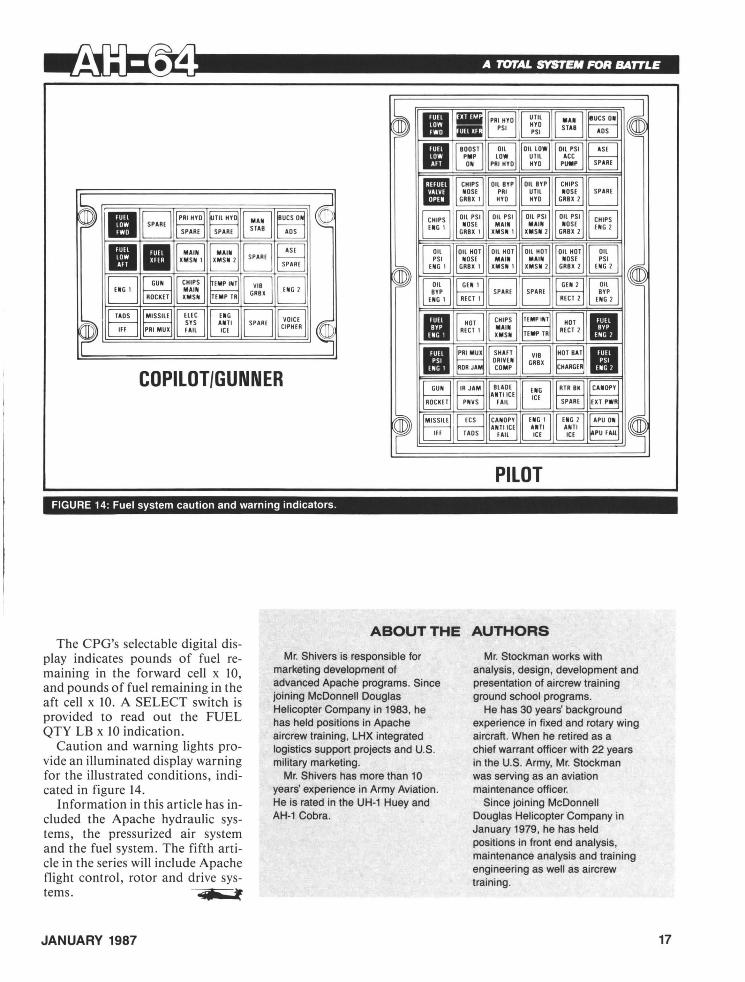
PILOT FIGURE 14: Fuel system caution and warning indicators.
ABOUT THE AUTHORS The CPG's selectable digital dis
play indicates pounds of fuel remaining in the forward cell x 10, and pounds of fuel remaining in the aft cell x 10. A SELECT switch is provided to read out the FUEL QTY LB x 10 indication.
Caution and warning lights provide an illuminated display warning for the illustrated conditions, indicated in figure 14.
Information in this article has included the Apache hydraulic systems, the pressurized air system and the fuel system. The fifth article in the series will include Apache flight control, rotor and drive systems. • f
JANUARY 1987
Mr. Shivers is responsible for marketing development of advanced Apache programs. Since joining McDonnell Douglas Helicopter Company in 1983, he has held positions in Apache aircrew training, LHX integrated logistics support projects and U.S. military marketing.
Mr. Shivers has more than 10 years' experience in Army Aviation. He is rated in the UH-1 Huey and AH-1 Cobra.
Mr. Stockman works with analysis, design, development and presentation of aircrew training ground school programs.
He has 30 years' background experience in fixed and rotary wing aircraft. When he retired as a chief warrant officer with 22 years in the U.S. Army, Mr. Stockman was serving as an aviation maintenance officer.
Since joining McDonnell Douglas Helicopter Company in January 1979, he has held positions in front end analysis, maintenance analysis and training engineering as well as aircrew training.
17

18
© SSG Theodore J. Stevenson Jr.
tE ENGLISH dictionary describes ''value'' as worth in usefulness or importance to the possessor; a principle, standard or quality considered worthwhile or desirable.
Values in the Army are largely traditional and mean many things such as 10~~.lty to:
• Our country and Army, • Go where nobody wants to, • Endure the hardships that are
constants in military careers.
Being loyal to our country leaves us with a sense of responsibility to be loyal to the Armed Forces and to the units in which we serve.
The pride one gets when wearing the Army uniform and being recognized as a member of the Army Aviation Branch, or when hearing the National Anthem or the Pledge of Allegiance is a value that is invaluable to me. One of the timely, outstanding principles in the Army is the building of the Army team. The Army builds upon the spirit of cooperation and teamwork. No other organization in the world teaches responsibility more effectively than does the U.S. Army. From
ANCOC Student Department of Enlisted Training
U.S. Army Aviation Center Fort Rucker, AL
the time young men or women enter the Army, they are taught how to handle responsibility - and not to be afraid to make a mistake, but how to learn from it. From this come forth our leaders.
As leaders we must teach what we have learned to those young soldiers who follow us so that they can mature and become tomorrow's leaders, fully capable to carry on Army traditions.
As these soldiers grow and mature and accept responsibilities, we begin to see another important trait - that of selfless service to the unit and country. There are many sacrifices asked by the Army. American soldiers accept them knowing that the importance of doing so is to protect our free and honorable society. These soldiers harbor selfless devotion to country, unit and to others.
'The willingness and ability to go forth on the air-land battlefield and against all odds defend this great country and our way of life are what make today's soldiers truly outstanding examples of all the good things of the American dream.
So, just what are values? They are a way of life in the military.
U.S. ARMY AVIATION DIGEST

ARMY AVIATION BRANCH DIRECTORY-FORT RUCKER
(Alphabetically listed after Command Group)
Aviation Center Fort Rucker, AL 36362-5000 AUTOVON: 558-XXXX FTS: 533-XXXX Comm: 205-255-XXXX Post Locator: 4580 Field Officer of the Day: 3400/3100 Aviation HOTLINE: 6487 (Duty Hours, 1530-0730 Central Time)
COMMAND GROUP (ATlO. Building 114)
Chief, Aviation Branch , Commanding General, Aviation Center, and Commandant, Aviation School: MG Ellis D. Parker ...... .. .......... 2600 (ATZQ-CG, Building 114)
Aide: CPT Talley ............................ 2606 Secretary: Mrs. Mclnnish . ......... ..... ...... 2606
Assistant Commandant, Aviation School : BG Rodney D. Wolfe ....................... 2808 (ATZQ-AC, Building 114)
Aide: CPT Shrum ........................... 2612 Secretary: Mrs. Rogers ................. .... . 2612
Deputy Assistant Commandant: COL E. Kirby Lawson III .................... 3028 (ATZQ-DAC, Building 114)
Secretary: Mrs. Jones ....................... 4130
Chief of Staff: COL Andrew J. Miller Jr .... . ..... 2500 (ATZQ-CS, Building 114)
Deputy Chiefs of Staff: MAJ (P) Butler and LTC Boccolucci ....... ' ..... . .............. 2000
Secretaries: Mrs. Adams and Mrs. Hinkle ........ 2000
Garrison Commander: COL Marnon ............ 4040 (ATZQ-GC, Building 114)
Secretary: Mrs. Fuller ............. .... ....... 4040 Assistant Deputy Garrison Commander:
LTC Paul D. Spangler ................ . .... . 3816
Command Sergeant Major: CSM Tilden R. Kirkland ............. ....... 4800 (ATZQ-CSM , Building 114)
Secretary: Mrs. Noriega ......... ... ........ .. 3528
AEROMEDICAL CENTER (Health Services Command Activity)
(HSXY-C, Building 301) TENANT
Army Aeromedical Center Commander and Aviation Medicine Consultant to Office of the Surgeon General: COL Jenkins .. ............ 7359
Deputy Commander for Admin : COL Webb ....... 7361 Deputy Commander for Clinical Services:
LTC Baldwin ............................. 7363
Army Aeromedical Activity Director and Army School of Aviation Medicine Dean: COL Garcia ..... .... ... .. . . . . .. .... . ... .. 7409 (HSHA-AVN, Building 301)
Army Medical Evacuation (Air/Ground) Proponency Action Office Chief: COL Ideus ... . 7427 (HSHA-ZAE, Building 301)
AEROMEDICAL RESEARCH LABORATORY (USAARL) (Medical R&D Command Activity)
(SGRD-UAC, Building 6901) TENANT
Commander: COL D. Price ................... 6917 Deputy Commander for Science:
COL J.D. LaMothe ...................... . . 6913 Deputy Commander for Administration:
LTC E. Enloe ............. .. . ... ..... ..... 6914 Information/CQ ............. ....... ... ...... 6920
AIR TRAFFIC CONTROL ACTIVITY (ATlO-ATC, Building 3503)
Director: COL McLemore ........ . .. ..... .. ... 3007 Deputy Director: Mr. East ..................... 6265 Admin Officer: Mrs. Ridenhour ................ 5340 CSM: SGM Hooper .................. _ ...... 6265 ATC Management*, Chief: Mr. Anderson .. ...... .4893 ATC Development*, Chief: Mr. Ayo .......... . ... 6534 System Eval/Maint*, Chief: LTC Bell ..... ... . ... 5532 * Late information added on page 8 of directory_
ARMY AVIATION MUSEUM (ATlO-PAM. Building 6007)
Curator: Mr. Sabiston ................ ........ 4507
1 Army Aviation DIRECTORY January 1987

ARMY RESEARCH INSTITUTE AVIATION R&D ACTIVITY (DCSPER Activity)
(PERI-IR, Building 501) TENANT
Chief: Mr. Gainer .............. ..... ...... . .4404
ARMY RESERVE CENTER (ARCOM Activity) (Knox Army Heliport) TENANT
Commander and 376th Aircraft Maintenance Company Commander: MAJ Borer ........... 4816
282d Aviation Company, Commander: MAJ Beaman ... .. ................. .. .... 2615
AVIATION BOARD (AlZO-OT, Cairns AAF. Building 30501)
President/Commander: COL Grett. ............. 2179 Executive Officer: LTC Biddle .................. 2179 Sergeant Major: SGM Smythe .. . .... ... ....... 2179 Technical Advisor: ... . ....................... 2179
RESOURCE MANAGEMENT DIVISION Chief: Mr. Tindell ..... .... . ........... ...... 3798
(ATZQ-OTR, Building 30501) Admin, Admin Officer: Mr. Gibson .............. 5815
(ATZQ-OTR-A, Building 30501) Logistics, Chief: Mr. Riley ..... ... ............. 3685
(ATZQ-OTR-L, Building 30602) Tech Publications, Chief: Mr. Kontos ............ 5320
(ATZQ-OTR-P, Building 30501)
TECHNICAL OPERATIONS DIVISION Chief: LTC Fanning ..... ..... ...... . ......... 2875
(ATZQ-OTC, Building 30501) Operations/Plans, Chief: MAJ Doherty .......... 2875
(ATZQ-OTC, Building 30501) Tech Analysis, Chief: MAJ Mulrooney . . ........ . 6085
(ATZQ-OTC-T, Building 30501) Instrumentation, Chief: MAJ Sims ........... . . . 6481
(ATZQ-OTC-I, Building 30104)
TEST DIVISION (AlZQ-OlA, Building 30501)
Chief: MAJ (P) Boykin .............. . ... ... .. 3683 Tech Advisor: Mr. Strange .................... 3683 Aviation Support Branch, Chief: CPT Swain . . .... 3690
(ATZQ-OTA-AA) Aviation Systems Branch, Chief: CPT Brooks . .... 4278
(ATZQ-OTA-AS) Headquarters Company, Commander:
CPT McVeigh ............................ 3803 (ATZQ-OTH)
First Sergeant: 1 SG Bensch ................... 3803
AVIATION DEVELOPMENT TEST ACTIVITY (STEBG)
(TECOM Activity) (Cairns AAF, Building 30601) TENANT
Commander: COL Karjala . ................... 8000 Technical Director: Mr. McCrory ............. ... 8001 Administrative Services: Mrs. Gardner ..... .. ... 8058 Aircraft Test Division: MAJ Crowe . . ..... . ...... 8161 Systems Test Division: MAJ Savage ...... .. .... 8169 Test Support & Log Division: LTC Mace .......... 8008 Management and Plans Division: LTC Mingus .... 8094
Directorate of AVIATION PROPON ENCY
(ATZO-DAP, Building 114)
Director: COL Bunting ........ . .... .. ........ 6023 Deputy Director: MAJ (P) Tallas ... . ...... ...... 3343 Historian: Dr. LePore ... ...... . . ...... . .... .. 5338
OFFICE OF PERSONNEL SYSTEMS (ATZQ-DAP-PS, Building 515)
Chief: LTC Sieving ....... .. ... ........ ..... . 3423 Deputy: MAJ Smith .......... ...... .. ..... ... 5706
OFFICE OF SCHOOL SECRETARY (ATZQ-DAP-SS, Building 114)
School Secretary: MAJ (P) Tallas ............. . . 3343 Assistant School Secretary: CPT Fowler ... . ..... 3488
ADMIN SUPPORT DIVISION (ATZQ-DAP-AS, Building 114)
Chief: CPT Williams . ... . ................ .. .. 6436 NCOIC: SSG Trusclair .. ........... . ......... 2748
ACADEMIC RECORDS DIVISION (ATZQ-DAP-AR, Building 9010)
Chief: Ms. Webb .. . .. .. .. . . . ...... . ... .. .... 2596
TRAINING SUPPORT DIVISION (ATZQ-DAP-TS, Building 3409)
Chief: Mr. Johnson .......................... 3283
AVIATION TECHNICAL LIBRARY (ATZQ-DAP-TL, Buildings 5906/5907)
Chief: Ms. Foreman ... ..... ............... .. 5018
AVIATION DIGEST (ATZQ-DAP-AD, Building 602)
Chief: Mr. Tierney ....... . ... ... .... ... . ..... 3619
OFFICE OF ALLIED MILITARY TRAINING (ATZQ-DAP-AM, Building 6610)
2 Army Aviation DIRECTORY January 1987

Chief: LTC Bass .. . .. . ..... ... .... . .. .... ... 5090
AVIATION LEARNING CENTER (AllO-OAP-LC, Building 101)
Chief: CW4 DeCurtis . .. .. . . . .. .. . .... ... . .. . 5082
AVIATION TRAINING BRIGADE (AllO·AlB , Building 2805)
Commander: COL Murphy . . . ... .. . . .. . ..... .. 2607 Deputy Commander: MAJ (P) Lockhart .. ........ 2881
BRIGADE S2 & S3 (AllO-AlB-O, Building 2805)
S2/S3: MAJ Morgan .. .. . ..... . .. . .. .. ....... 2188 Assistant S2/S3: CPT McCormack ....... .. .. ... 2188 Aircrew Training Manual/Standards:
CPT Selling .. ..... ... . . . .. ... . . . ...... . .. 2425 Aircrew Training Manuals: Mr. Perez, Mrs. Cox .... 5691 Training Literature Management: Mr. Cannon .. . . . 2464 Ranges LHX: Mr. Schwall ... . .. .. .. . ... ....... 2464 Bridgade SI P: CW3 Helmer . .. ..... .... ..... . . 2464 NCOIC: MSG Enoch ... .. . . . .. . ... . . .. ... . . . 2464
SHELL FIELD DETACHMENT (AllO-AlB-SO, Building 60103)
Commander: MAJ Hermsmeier ..... ... . .. .. .. . 5729 Airfield Commander: CPT Lassiter .. . . . . ... . ... 5434
7TH AVIATION TRAINING BATTALION (AllO-AlB-H, Building 50108H)
Commander: LTC Cobb ...... .... ... . .... .... 4301 Executive Officer: MAJ McGlothlin . . . . ....... .. 2289
TF 1-112 (AllO-AlB-IF, Hanchey AAF)
Commander: LTC Weaver ...... . ... . ... . . .. .. . 2527 S2/S3: MAJ McKillip .... . .. .. . .. .. . .. ..... ... 2306
8TH AVIATION TRAINING BATTALION (AllO-AlB-C, Building 30205, Cairns AAF)
Commander: LTC Just . . . . .. .. . . .. . . ... ... .. .4914 Executive Officer: MAJ Uttley . .... .... .... .... 4314
9TH AVIATION TRAINING BATTALION (AllO-AlB-L, Building 40115, Lowe AAF)
Commander: LTC Orahood . . ...... .. . .. ... .. . . 5904 Executive Officer: MAJ Korfhage ... ... . ........ 5395
10TH AIR TRAFFIC CONTROL BATTALION (SPT)
(AllO-AlB-l, Building 4301) Commander: LTC Gwin .... ... .. . .. .. . . ..... . 2173 CSM: CSM Lloyd .. . ..... .. ... ... ... .. ..... . 3725
Directorate of COMBAT DEVELOPMENTS
(AllO-CO, Building 507)
Director: COL Mayer .. . . .... .. . . . . . ... .. . .. . . 3203 Deputy Director: LTC Waldran ... . .. . .. ... ..... 2703 Technical Advisor: Mr. Maccabe . . . .. ...... . . ... 2703
CONCEPTS & STUDIES DIVISION Chief: LTC (P) MacWillie . . .... . .. . .. . .. .. .... . 3500
(ATZO-CDC, Building 508) Concepts Branch , Chief: MAJ Stempel . . .. ... .. . 4704
(ATZO-CDC-C, Building 508) Project Officers .. .... ..... ... . . . .. . . ........ 3489 Space Technology Branch , Chief:
MAJ (P) Velasquez . ...... ...... . .... ..... . 3185 (ATZO-CDC-SP, Building 508)
Project Officers . ... ... .. .. ....... .. ... ... . . . 3920 LHX Special Study Group, Coordinator:
MAJ Reames . .. . .. .. ..... . .... . . . . . ...... 6316 (ATZO-CDC-LX, Building 402)
Operations Requirements Concept Analysis Branch , Chief: MAJ Blakley ...... . ..... .. .. . 3485
Project Officers . . . . . .. .. ... .. . . . . .. .... 5864/3485 Cost of Operations Effective Analysis Branch ,
Chief: MAJ North .. .... ... .. .. . ... . . ..... . 2352 Project Officers . .. . ..... .. .. .. . .. . ..... . .. . . 5572 Requirements Branch , Chief: MAJ Horne ..... . . . 5572 Project Officers .......... . . . .. . .. ... ........ 2352 Crew Requirements Analysis Branch , Chief:
CPT Schandorf ....... . . . . . . .. . .. .. . . .. . .. 6316 SCORES Branch, Chief: MAJ (P) Iten .. .. ... . .. . 4322
(ATZO-CDC-S, Building 107) Project Officers .... . . . ... . ... . . .. .. ....... . . 5771 Mission Area Analysis Branch , Chief:
MAJ Ben n .. ...... .. ................ ... . . 4856 Project Officers ... . . . . . .... . .. .... .... .. . ... 4709
THREAT DIVISION Chief: LTC Keown ....... . ... . .. .. . . . . . .. .... 5671
(ATZO-CDT, Building 107) Project Officers ......... ... . .... . ........... 3506
MATERIEL & LOGISTICS SYSTEMS DIVISION Chief: LTC Riggs .......... . . ............ . . .. 5511
3 Army Aviation DIRECTORY January 1987

COMBAT DEVELOPMENTS, continued
(ATZO-CDM, Building 504) Systems Branch, Chief: MAJ Brecher ....... 2704/5817
(ATZO-CDM-S, Building 503) Project Officers .... ......... ........... 5817/5020 Avionics/Visionics/EW Branch, Chief:
MAJ Johnson .. . .... ..... .. ....... .. ..... 3973 (ATZO-CDM-A, Building 504)
Project Officers .. . . ..... . . .... .... ..... 5902/2406 Reliability, Availability, Maintainability Branch,
Chief: MAJ Hatch ......................... 5803 (ATZO-CDM-R, Building 513)
Project Officers ............................. 4576 Materiel Integration Branch, Chief:
Mr. Easterling ............................ 3271 (ATZO-CDM-M, Building 504)
Project Officers ...... ... ..... ............... 2914
TEST & EVALUATION DIVISION Chief: MAJ (P) Swank ............. .. ......... 2405
(ATZO-CDE, Building 503) Project Officers ................. ....... 4171/6016
ORGANIZATION/FORCE DEVELOPMENT DIVISION Chief: MAJ Batson ... ... . ..... ........ ...... 6112
(ATZO-CDO, Building 506) Aviation Force Development Branch, Chief:
CPT Warnock ............................ 2307 Project Officers ............................. 2701 Aviation Force Design Branch, Chief:
MAJ Buchanan ........................... 5375 Project Officers ............................. 4206 Aviation Equipment/Document Branch, Chief:
CPT Warnock ............................ 2307 Project Officers ............................. 2701
AIR TRAFFIC SERVICES DIVISION (AlZO-CDA, Building 513)
Chief: LTC Ferguson ..... . ................... 2147 Project Officers ............................. 2220
AIR COMBAT DIVISION (AlZO-CDD, Building 513)
Chief: MAJ Brittingham ...................... 3123 Project Officers ............................. 3124
Department of COMBINED ARMS TACTICS
(ATZO-CAT, Building 208)
Director: COL Hollwedel ... ............. .4328/6130
Deputy Director: LTC (P) Bodelson ......... 6130/5054 Admin Officer: Mrs. Newbury ............. 5884/6338
OPERATIONS BRANCH (AlZO-CAl-O, Building 208)
Chief: MAJ (P) Stewart .................. 5397/4913 Training Officer/Assistant Operations Officer:
CPT Goode ..... .. ................. .4750/6010 Educational Specialist: Ms. Strickland ...... 4025/2452 Documents: SFC Espinosa .. ..... .. .. . ... 2525/2544
COMBINED ARMS DIVISION (AlZO-CAl-CA, Building 209)
Chief: MAJ Anton ...................... 4951/3280 Aviation Operations Branch: CPT Rose . . ... 5725/2543 Combat Multiplier Branch: MAJ Ernzen ... . . 6516/2876 Combat Operations Branch: MAJ Eichling ... 4505/3045 Threat Intelligence Branch:
CPT (P) Campbell ................. . . .4530/6345
COMMAND/LEADERSHIP DIVISION (AlZO-CAl-Cl, Building 5302)
Chief: MAJ (P) Doyle .................... 4736/2786 Administration Branch:
CPT Garibaldi ....................... 3257/4714 Logistics Branch: MAJ Jackson ........... 6501/2376 Communications Arts Branch: CPT Ross .... 2023/4364 Management/Leadersh ip Branch:
MAJ Acree .......................... 4300/3286
DOCTRINE DIVISION (AlZO-CAl-DD, Building 9009)
Chief: LTC Carlin ....................... 5626/4882 Combat: MAJ (P) Mapes .... . ............ 4223/3947 Combat Support: MAJ Christman .... . ... .. 4882/4223
Department of ENLISTED TRAINING
(ATZO-DEl, Building 3507)
Director: CSM Traylor ........................ 4824 Deputy Director: SGM Smith .. .. . ..... . ....... 2454
OPERATIONS BRANCH (AlZO-DEl-O, Building 3507)
Chief: MSG Sutton .......................... 2361 Project NCOs: .............................. 2169 Education Specialist: Mr. Funkhouser ........... 4937
4 Army Aviation DIRECTORY January 1987

MAINTENANCE TRAINING DIVISION (AlZQ-DEl-Ml, Building 6005)
Chief: SGM Scott . ........ .. . . ....... . . .. . .. 6001 Operations Noncommissioned Officer:
SFC Kling . . . ........... . . . ........ . ..... 6301 Project Noncommissioned Officer:
MSG Townsend . . .......... . .. . ........... 6301 UH-1 MSG: MSG Howard .. ... ..... . .. .. ... . .. 6281 OH-58 MSG: MSG Bell . .. .. . .. . .............. 5383 Enabling Skills: MSG Rhea . .... .. ... .. .. . .. . . 6448
AIR TRAFFIC CONTROL DIVISION (AlZQ-DEl-Al, Building 6005)
Chief: MSG (P) Lewis . . . . .. . ........... . . ... . 4805 Operations Noncommissioned Officer:
MSG Shultz . . .... ............. ... . ....... 5186 Academic Branch: Mr. Vowvalidis ..... .. . . ... . . 4416 CST Branch: MSG Clevenger . ....... .. . .. .. . . 4416 ADV Branch: SFC Hughes .. ... . . . .. .. .. . .... . 4416
Directorate of EVALUATION AND STANDARDIZATION
(ATZO-ES, Building 5111)
Director: COL Shaw .. .. ..... .... .. ... . ..... . 2603 Deputy Director: LTC Bauer .. .... . .......... .. 2603 Safety Officer: CW4 Cooper ......... . .. . . ... .. 2770 NG Stdzn Advisor: LTC Ferreira . . ... ....... . .. . 3589
OPERATIONS/RESOURCE MANAGEMENT DIVISION
(AlZQ-ESO, Building 5111) Commander: MAJ Dixon . .... ... ....... .. . .. . 3589 Operations: CPT Nadeau .. ...... . ............ 2244 Technical Support: Mr. Rowe . .. ..... .. . . ..... . 4691 Literature Review, Chief: CPT Sutliff ... . .... .. .. 3029
(ATZQ-ESO-L, Building 5115) AR 95-1: Mr. Wall ...... .. .............. . . . .. 2453 RW dash 10s and checklists: Mr. Cameron and
Mr. Harris .. .. . ..... .. ..... . ... ....... .. .. 4770 FW dash 10s and checklists: Mr. James . .... . . . .4603
FLIGHT STANDARDIZATION DIVISION (AlZQ-ESF, Buildings 5111/5112)
Commander: LTC Wall .................... .. . 5411 Operations: CPT Jones .... .. ........ ... ..... 6309 Plans: CPT Antley . . ... . ..... . .. .. . .. ...... . 6346 NCOIC: SFC Buck . .. ...... . ... . .... . .. ... . . 6309 Aeroscout/Attack: CPT Ludowese . .... . ...... .. 3504 Utility: CPT Barth ........ .. .. . ......... . ... . 2442 Cargo/Fixed Wing: CPT Pitt ....... . .... . .... . . 2442
EVALUATION DIVISION (AlZQ-ESE, Building 5012)
Commander: MAJ (P) Scurzi ..... .. . .. ..... ... 6571 External Evaluation: CPT Weber .. .. .. . . ...... . 4691 Internal Evaluation: CPT Lewis ..... ........... 4691
Department of GUNNERY AND FLIGHT SYSTEMS
(ATZQ-GFS, Building 205)
Director: COL Nutt ... . ..... ...... .. .. .. ..... 5600 Deputy Director: LTC Harry . . . . ... .. . .. ....... 5308 SGM: SGM Haney .. ... . . ...... ... . ..... .. . . 5481
OPERATIONS BRANCH (AlZQ-GFS-O, Building 210)
Operations Officer: CPT Beato ... . ..... ... . . .. 2683 NCOIC: SFC Scott ...... . ....... . . ... . . . . .. . 4094 ETV Script Writers . . .. .. . . ..... . ....... . . .. . 2785
AVIATION DIVISION (AlZQ-GFS-A, Building 210)
Chief: CPT Jennings ......... . .. ... . .. . . . ... 4010 Undergraduate: CPT Flory ..... . . ... ....... ... 3635 Graduate: Mr. Sando . . .. .. . . . . .... .......... 2685 Cargo Utility Systems: CPT Connolly . . ....... . . 4292 Scout Systems: CPT Richards . . ... . . ......... . 2302
FLIGHT SIMULATOR DIVISION (AlZQ-GFS-FS, Building 4901)
Chief: MAJ Wheeler .. ... . ..... .. . . . . .. . .. ... 2480 Operations Officer: . ... . .. ... . ..... 2183 Flight Simulator Training: CPT Minchew .... . .... 2183 Wide World Software System Branch (Building
5102), Chief: Mr. Flohr ............. ..... ... 4071 Procedural Training Branch (Building 5102) .. . .... 2740
WEAPONS AND GUNNERY DIVISION (AlZQ-GFS-W, Building 5102)
Chief: MAJ Bonn . . .. ......... . ............. 5863 Range and Gunnery Operations: CPT Sisson . ... . 2047 Aviation Weapons and Gunnery System:
CPTMurtheh . . . .. . ....... . ... . . . ........ 4005 Weapons Simulator Training: CPT Branch ........ 2616
5 Army Aviation DIRECTORY January 1987

~irectorate of INFORMATION MANAGEMENT
(AlZO-I , Building 3906)
Director: LTC Knight .. . . . . ...... ..... . .... .. . 5722
LIAISON OFFICE (AlZO-SGS-lN , Building 602)
British Army: LTC Andrews ....... . . ....... . . .. 4585 Canadian Forces: MAJ Lowdon . . .. .. . ... ...... 3715 French Army: LTC Mollet . ....... ........ . .... 4514 German Army: LTC Steuernagel . . . .. . ......... 5309 Italian Army: LTC Carfagnini .. . ..... ..... . .... . 4585 Netherlands AF: MAJ Jansen . ..... . .... .... .. 4585 U.S. Marine (Building 504): LTCOL Pfeiffer . ...... 2016 Federal Aviation Administration Air Traffic
Representative (Building AB810): Mr. Smith .... 4317
NATIONAL GUARD BUREAU MULTI MEDIA BRANCH (NGB Activity)
(NGB-AVN-MMB, Building 5401) TENANT
Chief: MAJ Shawn ..... . . . . . . . . .. . . .. . . .... . 2520 Training Specialist (Aviation) : 2LT Cowart ... ... .. 2520 Training Specialist (Gen Safety): CW2 Cosco ..... 2903 Audiovisual Production Officer: W01 Hobbie . . . .. 2520 Visual Information Specialist: CW2 Swihart ...... 2903 Media Assistant: Mrs. Hughes ....... .. . . ...... 2903
Directorate of PLANS, TRAINING, MOBILIZATION AND SECURITY
I (AlZO-OPl, Building 114)
Director: COL Sauer . . . . .... . ... . ... . ... . . . .. 2300 Deputy Director: LTC Clark ....... .. .. . . ... . . . . 2187 SGM: SGM Arnold . ....... . ... . .. ... . ...... . 4281
RESOURCE MANAGEMENT DIVISION (AlZQ-oPl-RM, Building 114)
Chief: ......... . ................ 3200
RESIDENT TRAINING MANAGEMENT DIVISION
(ATZQ-oPT-RT, Building 114) Chief: Ms. Brown .. . . .... . ... .. . .. .... . . .. .. 4405
TRAINING DIVISION (ATZO-oPT-T, Building 114)
Chief: MAJ Carr . . ....... . .. . .. ... . ..... . ... 3804
PLANS, OPERATIONS AND MOBILIZATION DIVISION
(ATZO-oPl-P, Building 114) Chief: MAJ Krejci ...... . ... . . .... .. ..... . ... 6519
SECURITY DIVISION (ATZO-oPT-S, Building 116)
Chief: Mr. Hill ...... .. ....... ..... . .. ... . ... 2200
AVIATION DIVISION (ATZO-oPT-Ao, Building 116)
Chief: MAJ Young .. .. . .. ... . ... ..... .. .... . . 5427
TRAINING AND AUDIOVISUAL SUPPORT DIVISION
(ATZO-OPT-TA, Building 9313) Chief: Mr. Tullos ... .. . ... . .. .. .. . .. ..... 2116/2291
EDUCATION DIVISION (ATZO-oPT-E, Building 5009)
Chief: Mr. Rahenkamp . . .. . .... ...... . . . . . . . . 3613
DETACHMENT 9, 5TH WEATHER SQUADRON (Building 30101, Cairns AAF)
Commander: MAJ Markert . ... . ... . .. .. ...... . 3902 Duty Forecaster ... . ..... . .. . ...... . ..... . .. 2804
PUBLIC AFFAIRS OFFICE (AlZO-PAD, Building 122)
Public Affairs Officer: LTC Rausch ... .. ... .. .... 4117 Deputy Public Affairs Officer: Ms. Goodson ... . . . 4117 Public Information: Mr. Hayes . ... . . ... . ... . . .. 4118 Community Relations: Ms. Milum ..... . ... . ... . 4117 Command Information: Mr. Greene ... . ....... . . 4117 Army Flier: CPT Huyett .... .. . .. . ... . .... . . . .4118 NCOIC: SFC Malone ... .. . . . .. . .... . ....... . 4117
6 Army Aviation DIRECTORY January 1987

Directorate of RESERVE COMPONENT SUPPORT
(ATlO·DRe, Building 110)
Director: LTC Crawford ..... .. ....... ...... .. . 6315 RC/ROTC Supply Div: Mr. Alberson ......... .. .. 3208
u.s. Army SAFETY CENTER (A field operating agency of DeSPER)
(PESC, Building 4905) TENANT
Commander: COL Hervey, Jr. . ................ 2029 Senior Safety Manager: Mr. Schilder .... ........ 2029 Executive Officer: LTC Sathre . . ......... ..... . 3819 Special Actions: Mr. Williamson .. . . . .......... . 6385 Plans, Programs and Professional
Development: COL Harrison ..... ... ........ 3857 Research , Analysis and Investigation:
COL Jones ............ ... . ... . .......... 4510 Information Management: Mr. Myers .. ..... . .... 4200 Systems Management: COL Blount ...... . ...... 4202 Media and Marketing: Mr. Carter .. ... ........ .. 2062 Judge Advocate: MAJ Goetzke . . ..... .. .. .. ... 3960 Flight Surgeon: MAJ Hope ........ .. . .. . .. .... 2763 Staff Duty Officer/NCO . . .......... . ....... ... 3410 Professional Development (Building 4107):
Mr. Hammonds ...... . .. .. . ... .. .......... 4479
SAFETY OFFICE (AVIATION CENTER) (ATlO·S, Building 102)
Manager: Mr. Persch .. . .. ... .. . .. ..... .. 2301/3000 OSHA Safety .......................... 2388/6177 Aviation Safety . . ....... .. ...... .. ..... . 2491/2388 Hazard Reporting .... . ... ............ .. 3000/6177 Aircraft, Accident Investigation Board ...... . 5087/3210
SECRETARY GENERAL STAFF (ATlO·SG, Building 114)
Secretary General Staff: CPT Healy ............ 2973 Admin: 1 LT Fullerton .... ......... . ........ ... 2618 Protocol: CPT Parrish ............ .. .......... 3100
TRADOC SYSTEMS MANAGERS (ATlO, Building 512)
APACHE HELICOPTER (ATZO-TSM-A, Building 512)
TRADOC System Manager: COL Kennedy .... ... 3408 Training : LTC Wells . ......... . .. .. .... .. . .... 2108 Personnel: CPT Leskovec . ...... . ... . ........ 5171 Logistics: LTC Sale .... . . .. . ......... .. ...... 5171
SCOUT HELICOPTER (ATZO-TSM-S, Building 512)
TRADOC System Manager: COL Cox ..... ...... 3808 Test and Personnel: LTC Fallis ... . .. . ......... . 4909 Maintenance and Logistics: MAJ Ebbinga . ...... . 2872 Training : CPT Clark . . .. . .. . ... ... . ... . . .... . 2872
MISSILES (ATZO-TSM-M, Building 512)
TRADOC System Manager: LTC Hinman ... ... .. 6005 Logistics: .... ............. ... ....... . . .... 6005 Research , Development, Test and Evaluation: ____ ..... ....... ......... ......... 4072
Personnel and Training: MAJ Wynne ... . .... .... 4072
LHX HELICOPTERS (ATZO-TSM-LH, Building 512)
TRADOC System Manager: LTC (P) Gram ... .... 2160 Training: LTC Wallace .... .. ............ .... . . 3505 Personnel: MAJ Rusho .... ... .... . ... .. ...... 2205 Logistics: MAJ Delashaw ..................... 2205
Directorate of TRAINING AND DOCTRINE
(ATlO·TD, Building 502)
Director: COL Easton ... .. . ... ............... 3320 Deputy Director: LTC Wimberley ............... 3096 Deputy For Education Management: Mr.
Teague .................................. 3096 SGM: SGM Dixon ............ . ......... . .. .. 3096
OPERATIONS/PLANS BRANCH (ATZO-TOO, Building 502)
Chief: CPT Mason ....... . ... . .. . ......... .. 5529 Program Management Section: Ms. Harper .... .. 3212 Administrative Section: Mr. Gibson ............. 5893 Word Processing Center: Ms. Knott .... . .. . . . ... 4572
COMMUNICATIVE SKILLS OFFICE (ATZO-TDC, Building 514)
Chief: LTC Chandler .. ............ .. . ...... .. 2823
7 Army Aviation DIRECTORY January 1987

TRAINING AND DOCTRINE, continued
RESERVE COMPONENT DIVISION (AIlO-IOR, Building 5118)
Chief: CPT Amos . .. ............... . ........ 5415
INDIVIDUAL AND UNIT TRAINING DIVISION (AIlO-101, Building 5116)
Chief: MAJ (P) Meuli ........ .. ............... 2295 Education Specialist: Mr. Gibbs .... .... ........ 6457 Extension Training Section: Mr. Caskey .......... 3703 Officer Training: MAJ Lynde ..... . ............. 3786 Flight Systems: MAJ McDonnell . . ... . ......... 3119 Unit Training: MAJ Brown ..................... 4926 Enlisted Training: Mr. Wolfington . .. ..... ..... .. 2141 Army Aviation Annual Written Exam: CPT Stark ... 5417
NEW SYSTEMS TRAINING AND SIMULATOR ACQUISITION DIVISION
(AIlO-IOS, Building 603) Chief: LTC Schaefer .. .. ....... .. ............ 4463 New Equipment Training Development Branch:
MAJ Dunlap ...... .. ... ... .. . ..... ....... 3275 Aviation Simulation Materiel Development
Branch: Mr. Pate .......................... 2482 Aviation Systems Training Research Branch:
MAJ Whitaker . ...... ... ....... ..... .. .. .. 3148 Aircraft Survivability Equipment Branch:
Mr. Hogan .............................. .4110
STAFF AND FACULTY DEVELOPMENT DIVISION
(AIlO-lOF, Building 5013) Chief: Mr. Thomley ..... ........ ...... .. . .... 3793 Education Specialist: . . ............ 3170
DOCTRINAL/LITERATURE MANAGEMENT DIVISION
(AIlO-IOO, Building 516) Chief: LTC McAdams .............. . ..... , ... 2635 Editorial: CPT Russell ....................... 2635 Publications Production: . .......... 6028
1ST AVIATION BRIGADE (AIR ASSAULT) (AIlO-BOE, Building 4510)
Commander: COL Rosser .................... 5217 Deputy Commander: MAJ Merchen ... .......... 5284 CSM: CSM Sturgies .... . ....... .. .. ........ . 3405
1 ST BATTALION (AIlO-BOE-A, Building 4504A)
Commander: LTC Retta ... ..... . . ...... ...... 5315 Executive Officer: .......... .. ... .. 2102
4TH BATTALION (AIlO-BOE-E, Building 6201)
Commander: LTC Heath ......... ... .... . . .... 6601 Executive Officer: MAJ Messano . . .. ..... . . .. . . 6602
6TH BATTALION (AIlO-BOE-O, Building 4114)
Commander: LTC Yates ............ . ..... .. .. 3787 Executive Officer: CPT Casey .. . .......... . ... 4401
226TH ATTACK HELICOPTER BATTALION (AFFR-BAH-OC, Building 4914)
Commander: LTC Sloan .......... . ... ........ 2422 Executive Officer: MAJ Johnson . .... . .... . ... . 2282 CSM: 1 SG Rockwell ......................... 6575
4525TH COMBAT APPL SO/OLAK (TAC/USAF Activity)
(AIlO-AFR, Building 5305) TENANT
Senior USAF Representative: COL Beekman ..... 5664 Assistant USAF Representative: LTC Morris ...... 5664
3588TH FLYING TRAINING SQUADRON (ATC/USAF Activity)
(3588FTS/CC, Building 9011) TENANT
Commander: LTC Frye . ...................... 3089
* Late information for ATC Activity, page 1.
ATC Management Office: Opns & Procedures Div, Chief: Mr. Phillips ...................... 2025
Resources Div, Chief: Mrs. Godwin ... .. ........ 4893
ATC Development Office (Building 3712): Requirements Div, Chief: Mr. Peebles ........... 5670 Programs Div, Chief: Mr. Richards .............. 4386 Airfield Plans & Standards Div, Chief: MAJ Chase .5827
System Eval/Maint Office (Building 3713): System Eval Div, Chief: MAJ Allen .. ...... . . .... 2060 System Maint Div, Chief: Mr. Johnson ........ ... 5994 DX (Direct Exchange) Maint Div, Chief: Mr. Zornes. 5212 Mobile Maint Contact Team, Chief: Mr. Reynolds .. 3494 SGM: SGM Williams ......................... 5198
8 Army Aviation DIRECTORY January 1987

PEARL!S Personal Equipment And Rescue/survival Lowdown
ALSE Message 86-12 - Aircraft Individual Survival Kits, and OV-l/RV-l Aircraft Rigid Seat Survival Kits Components
Message, AMCPM-ALSE-L, 171700Z APR 86, subject as above (ALSE-86-3), added a knife sharpener, general purpose, as a component to subject survival kits. Procurement problems have delayed the item and it is not yet stocked. The requirement to add the knife sharpener is waived until further notice. We will keep you informed of the status.
Helmet, Flyer SPH-4, NSN 8415-00-144-4981 During a recent aircraft crash an SPH -4 helmet
failed at the area of the left ear cup due to impact with left wing of armor seat in the UH-l aircraft. The crewmember sustained a concussion as a result. This area of the helmet is inherently weak and does not contain any absorbing/attenuating material such as styrofoam as do other inner surfaces of the helmet.
The helmet received an impact severe enough to permanently compress a portion of the helmet liner and fracture the ear cup and helmet shell. It appears that the helmet performed as designed. USAARL concurs with this analysis and is of the opinion that the helmet probably saved the aviator's life.
A development program was established in fiscal year 1985 for energy absorbing "crushable" ear cups that will provide additional protection against lateral impacts. This program is due for completion in March 1988. Should additional information be desired, point of contact is Mr. lames Dittmer, AUTOVON 693-3215/3817.
SPH-4 Helmet Liner Silicon Adhesive We have received several calls pertaining to the cor
rect adhesive for SPH -4 helmet liner material. The correct silicon adhesive for the helmet liner is
NSN 8040-00-833-9563; this is also listed in the new TM 10-8415-206-12&P, dated 4 May 1986.
Donna Filipowski photo by Joe Lolley
courtesy of Sikorsky Support Services, Inc.
PEARL'S Observations Paragraph 2-9b, Army Regulation 95-17, "The
Army Aviation Life Support System Program," was effective 15 May 1984 and required each aircrewmember to be equipped with a survival radio. Message, DA DA~P-AV, 121551Z NOV 85, subject as above (SA B), delayed implementation of paragraph 2-9b until 15 November 1986. We are still short of adequate survival radios; will there be an extension to the waiver for each aircrewmember to have a survival radio?
Yes. DA message DALO-AV, 131824Z NOV 86, SAB, has been transmitted and will authorize a further delay of the implementation of the requirement until 15 May 1987. Emergency procurements are expected to significantly reduce the present shortages in the next 6 months. If these efforts are successful, further blanket waivers will not be necessary. In the interim, the pilot in command will continue to ensure that not less than one fully operational survival radio is onboard the aircraft during each flight. This does not preclude other crewmembers from carrying additional survival radios onboard the aircraft when assets are available. HQDA point of contact (POC) is MAl Hinds, DALO-AV, AUTOVON 227-0487; HQ TRADOC poe is MSG Lehnhardt, AUTOVON 680-3246; AMCPM-ALSE-L POC is Mr. Harlyn H. Hubbs, AUTOVON 693-3215/3817.
If you have a question about personal equipment or rescue/survival gear, write PEARL, AMC Product Management Office,
ATTN: AMCPM-ALSE, 4300 Goodfellow Blvd., St. Louis, MO 63120-1798 or call AUTOVON 693-3817 or Commercial 314-263-3817.
JANUARY 1987 27

u.s. ARMY SAFETY CENTER
THE FFECTS OF OTC DRUGS
Aircrewmembersl Know the facts
before you buy or consume any drugs,
including over-the-counter varieties.
WHAT IS A DRUG? A drug is any chemical substance that produces physical, mental, emotional or behavioral change in the user.
What is drug misuse? Drug misuse is the unintentional or inappropriate use of prescription or over-the-counter (OTC) drugs.
Many individuals, including aviators, believe that if a drug can be bought OTC it is safe. This is not true. Over-the-counter drugs can be just as misused as prescription or illicit drugs. Just because it's safe enough to be sold in the drugstore or supermarket without a prescription doesn't mean it can't affect your flying ability. It can!
28
Aircraft accidents in which drugs caused or contributed to the accident have been reported. Other instances are known where aviators took drugs that could easily have led to an accident. In some cases, the aviator apparently took the drug on his own. In others, physicians who were not knowledgeable in the specialty of aviation medicine may have prescribed the drugs.
Every crewmember has been cautioned to avoid the use of any drug, including those available without prescription, except on approval of a flight surgeon (see Army Regulation (AR) 40-8). This cannot be emphasized too much.
Over-the-counter medicines can have side effects. Those drugs containing relaxants or depressants carry cautions about driving or operating heavy machinery. Flying aircraft is included in this category.
Cold medicines and sinus remedies containing antihistamines may dry up the runny nose and the sinuses, but they may also cause drowsiness, dizziness, blurred vision and reduced mental ability. It's hard enough to stay awake and mentally alert after reporting for work early without the added effects the medicine may produce.
u.s. ARMY AVIATION DIGEST
Let's look at the potential effects of some of the more common OTC drugs.
Aspirin. Most everyone uses aspirin in one kind of tablet or another for headaches, body aches, fever, etc., and it does a good job. But it also has a few side effects that can make it dangerous. It causes greater heat loss because of increased blood flow to the extremities and increased sweating. It affects the acidbase balance of the body, causing a variation of the rate and depth of respiration. It can cause stomach bleeding, even if you've never had an ulcer. Two aspirin on an empty stomach can irritate the lining enough to draw a teaspoon of blood. Two aspirin will increase oxygen consumption and carbon dioxide production, which contribute to hypoxia and hyperventilation. Aspirin can decrease your night vision; make your blood clot less easily; and cause nausea, vomiting, drowsiness, heartburn, runny nose and allergic reactions.
Many pain medicines that do not contain aspirin, i.e., Tylenol, Datril, Anacine-3, Phenaphen, etc., contain acetaminophen. This drug can make you drowsy and cause allergic reactions, impaired thinking and impaired concentration. And, most of the side effects sneak up on you without your being aware they are there.
Cough drops. Did you ever think about overdosing with cough drops? To suppress the cough reflex, the drug in cough drops acts on the cough center of the brain. But to suppress the cough, you usually require a dosage three or four times higher than that recommended. High dosages of cougfi drops can cause depression of the central nervous system and reduced reaction time.
Many cough drops and cough syrups contain dextromethorphan. This drug can cause drowsiness, dizziness, allergic reactions, nausea ~nd indigestion. If you take too much, you may become euphoric, overactive or feel as if you're intoxicated.
Alcohol. Pilots should be especially attentive to the contents of medications in liquid form because many contain alcohol. Alcohol is a better solvent than
JANUARY 1987
water for some chemical mixtures. Water-based mixtures tend to separate after a while, whereas alcoholbased mixtures will keep almost indefinitely.
According to an article in the November 1984 FDA Consumer, these elixirs (whatever contains alcohol can be called an elixir) may be as much as 44 percent alcohol. Alcohol affects the inner ear, depresses the central nervous system, dulls critical judgment and releases inhibitions. It also decreases intellectual function, skilled responses, motor control and sensory perception.
Caffeine. Caffeine is also a drug. It is a stimulant and it is addictive. It causes nervousness, insomnia, tremors and increased urine output. It can also cause headache, irritability, lightheadedness, a feeling of drunkenness, impaired thinking, nausea, heartburn, indigestion and stomach irritation.
These symptoms are not likely to occur if caffeine is used in moderation. You don't have to give up your morning cup of coffee. Most experts tend to agree that less than 300 mgs of caffeine per day should not be hazardous, for most people. You must decide what is good for you. Remember, tea, many soft drinks, cocoa and some pain medications also contain caffeine.
A need for medicines of any kind is an indication of being unwell. Over-the-counter drugs are usually taken to relieve symptoms of an illness or condition, i.e., cold, flu, headache, sinus, etc., for which an aviator probably should have been grounded temporarily in the first place. Drugs mask the symptoms of the illness as well as produce side effects.
Aircrewmembers should avoid the use of any drug except on approval of a flight surgeon. Medical treatment of aircrewmembers should be under the supervision of a flight surgeon, and aircrewmembers should tell their flight surgeon when they have received treatment following which flying restrictions may be appropriate (see AR 600-107 and AR 40-8). If a flight surgeon is not locally available, consult one by telephone.
The bottom line is, it's dangerous to fly when you're using any medications - even those over-thecounter ones. • >(.
29

AVIATION STANDARDIZATION
REVISED ARMY FLIGHT RECORD SYSTEM
Captain Christopher Harden Directorate of Evaluation and Standardization
U.S. Army Aviation Center Fort Rucker, AL
IN 1984, BASED on an assessment of the Army fl ight record system, Headquarters, Department of the Army (HQDA) determined that a review was needed to ascertain the best method to track: aviator training, flight and aircraft qualifications, experience levels, safety records, and accident experience and exposure. DA requested that U.S. Army Training and Doctrine Command take the lead in the revision effort, and as a result, the Aviation Center, Ft. Rucker, AL, was tasked to conduct the analysis.
This analysis concluded that the flight records system was of little value to U.S. Army Military Personnel Center, other DA agencies, or unit commanders as a management tool. It was decided that the forms should be completely revised, automated and updated frequently.
A new manual flight record system will be implemented second quarter fiscal year 1987. It will enhance the management of aviation personnel by allowing flight time to be tracked by both duty position and flight condition for each aircraft or simulator in which an individual logs time. It also will provide a quick reference of an individual's qualifications and currency in various aircraft.
To effectively track the different duty positions and flight conditions an individual might fly under, 14 duty position and 10 flight condition symbols were developed . In addition, the flight record forms (Indi-
30
vidual Flight Record and Flight Certificate - Army) were redesigned. Descriptions of the symbols and forms are as follows:
AVIATION DUTY POSITIONS
CP copilot IE instrument examiner PI pilot SP standardization
instructor pilot PC pilot in command MP maintenance test pilot UT unit trainer ME maintenance test flight
evaluator IP instructor pilot XP experimental test pilot
NONAVIATOR DUTY POSITIONS
CE crewchief, flight engineer or aircraft mechanic assigned to a crewchief position
MO flight surgeon or other medical personnel AO aeroscout observer or aerial observer OR aircraft maintenance personnel, technical
observer, fire fighter, aerial photographer, gunner or other similar duties requiring aerial flights
FLIGHT CONDITIONS
0 day NG night goggles N night DG day goggles H hood NS night systems W weather OS day systems AA air-to-air TR terrain
Note: Complete descriptions of the new symbols and the conditions under which they will be used are contained in AR 95-1 , change 6.
u.s. ARMY AVIATION DIGEST

FORM DESCRIPTION I USE
DA Form 759 Historical record of an individual's
flying experience and training . To be used by DA managers as a quick reference to an aviator's flying experience and by unit managers as a quick reference of
an aviator's flying experience and
current training requirements.
DA Form 759-1 Aircraft Closeout Summary-
Annual record of flight time by duty position and flight condition for each aircraft/system an individual
flies. To be used by DA and unit managers as a reference of an individual's flight time in a specific
aircraft or system by duty position and flight condition.
DA Form 759-2 Flying Hours Work Sheet-
Temporary record of flights performed by an individual. To be used by flight records clerks in
preparing DA Forms 759 and 759-1 and by aviators as a monthly check of their flight time.
DA Form 759-3 Flight Record and Flight Pay Work
Sheet - Temporary record of all
flights performed by a nonaviator, permanent record of monthly flight
time for a nonaviator, and a flight
pay work sheet for all individuals required to fly for pay. To be used by flight records clerks in preparing
DA Forms 759 and 759-1 and in determining entitlement to flying
Procedures for the new flight records are contained in FM 1-300, "Flight Operations and Airfield Management," chapters 7 and 8, dated 31 October 1986.
For units with a personal computer (PC) available, a PC program has been developed to maintain the revised flight record system. This program is designed to run on IBM compatible PCs with 256 K memory, 2 floppy drives or 1 hard drive and 1 floppy drive.
Implementation of the new flight records will begin when a unit receives AR 95-1 change 6, FM 1-300, and the revised flight record forms (DA Forms 759, 759-1, 759-2 and 759-3). At that time the unit will begin recording flight time using the new duty position and flight condition symbols and tracking flight time using the new flight record forms.
The new flight records will be distributed in the same manner as in the present system, providing aviation managers information current only as of the last update. Plans are to develop an Armywide computer system with a real-time query capability for flight records.
For more information on the new flight records write to: Commander, U.S. Army Aviation Center, ATTN: ATZQ-ESO-L, Ft. Rucker, AL 36362-5211; or call AUTOVON 558-4770/2453, FTS 533-47701 2453 or Commercial 205-255-4770/2453.
For more information on the PC program write to: Commander, U.S. Army Aviation Center, ATTN: ATZQ-ESO-TS, Ft. Rucker, AL 36362-5212; or call AUTOVON 558-469116571, FTS 533-469116571 or Commercial 205-255-469116571.
duty pay. To be used by nonaviators
as a monthly check of their flight time. To be used by unit managers
as a reference of a nonaviator's flying experience by aircraft.
Individual Flight Record and Flight Certificate - Army
DES welcomes your inquiries and requests to focus attention on an area of major importance. Write to us at: Commander, U. S. Army A viation Center, A TTN: A TZQ-ES, Ft. Rucker, AL 36362-5000; or call us at AUTOVON 558-3504, FTS 533-3504 or Commercial 205-255-3504. After duty hours call Ft. Rucker Hotline, AUTOVON 558-6487 or 205-255-6487 and leave a message.
u.s. Army Class A Aviation Flight Mishaps
Total Cost Number Flying Hours Rate Fatalities (in millions)
FY 86 (to 31 January) 12 456,291 2.63 6 $16.4
FY 87 (to 31 January) 11 517,226* 2.13 13 $32.5 'estimated
JANUARY 1987 31

AVIATION PERSONNEL NOTES
Regimental Proposal The Aviation Branch's proposal for inclusion in the
Army's Regimental System has been recently submitted. The proposal was originated at the U. S. Army Aviation Center and is being staffed by the Office of Deputy Chief of Staff for Personnel, Headquarters, Department of the Army.
On the practical level, Aviation Branch soldiers will begin regimental affiliation 30 days after the proposal is approved for implementation. Once implemented, the U.S. Army Military Personnel Center will provide the "how to" of the affiliation process. They will do so in conjunction with local military personnel offices. Actual affiliation with a particular regiment will be based on the soldier's primary military occupational specialty (MOS), specialty code and special qualification or additional skill identifiers. A total of 25 regiments are considered in the Aviation Branch proposal.
The regimenting of the branch will enhance combat effectiveness by increasing habitual relationships within units, thus developing a stronger bond of loyalty and mutual commitment. Regimental affiliation will also foster a keener sense of belonging and build esprit de corps.
At the individual level, continued regimental association will be the first consideration in personnel assignments. Exceptions will be according to the specific needs of the Army. Further details will be published as the aviation proposal is finalized.
Noncommissioned Officer Education System Update A new aviation MOS 67/68 series Basic Noncom
missioned Officer Course (BNCOC) began in April 1986, at Ft. Eustis, VA. This new course is part of the Armywide effort to streamline and improve the Noncommissioned Officer Education System (NCOES) as detailed in this column (August 1986 issue).
In concert with the effort to strengthen the training noncommissioned officers receive in NCOES, several
32
changes in the BNCOC course for CMF 67 soldiers have been implemented. The following are the specific changes:
• Since 1 October 1986 BNCOC students have been required to live in the barracks and subsist in the dining facility. This is to comply with Army policy that discourages students from bringing their dependents to BNCOC. Furthermore, there are no facilities for dependents of BNCOC students at Ft. Eustis.
• BNCOC students will be trained in a much more stressful environment, including strong emphasis on soldierization tasks. Soldiers should report to BNCOC with their complete basic issue of personal clothing and be in the best possible physical condition.
This completely new aviation BNCOC resident course stresses leadership skills and MOS-specific technical expertise. Technical expertise is that required for aviation noncommissioned officers at skill level three. The leadership skills are incorporated during a common core leadership phase of instruction; the skills were developed by the U.S. Army Sergeants Major Academy. The BNCOC at Ft. Eustis joins the CMF 28 BNCOC already in place at Ft. Gordon, GA. A similar course for soldiers in CMF 93 is scheduled to start at Ft. Rucker, AL, in fiscal year 1988.
Although BNCOC will eventually be a prerequisite for promotion to staff sergeant, it is currently not a requirement because some BNCOC courses have yet to be started. Currently, the NCOES course prerequisite for promotion to staff sergeant is graduation from the Primary Leadership Development Course.
Another NCOES related issue centers on the Advanced Noncommissioned Officers Course (ANCOC). Aviation soldiers should be aware that possibly as early as June 1987, but not later than 1 October 1987, sergeants first class with a date of rank of 1 April 1981 or later will be required to be graduates of ANCOC, to be eligible for promotion to master sergeant.
u.s. ARMY AVIATION DIGEST

Specific questions regarding the CMF 67 BNCOC can be answered by calling Master Sergeant Ernie N. Waters, AUTOVON 927-2474 (U.S. Army Transportation School, Ft. Eustis.)
Further general questions regarding NCOES should be addressed to: U.S. Army Aviation Center, ATTN: ATZQ-DAP-PS, Ft. Rucker, AL 36362-5035; AUTOVON 558-3423/4313.
Functional Review Update A functional review is a comprehensive review of
the manpower, personnel and training impacts of force modernization efforts on a selected branch or functional area; thus the term functional review.
On 23 September 1986, the Aviation Branch presented an updated functional review to LTG Robert M. Elton, deputy chief of staff for personnel, Department of the Army. The agenda started with a current overview of issues originally discussed during the November 1985 Aviation Branch Functional Review and included the presentation of the Army Aviation Personnel Plan (A2P2) concept. First mentioned in MG Ellis D. Parker's lead article (Aviation Digest, October 1986), A2P2 will provide Army Aviation with a comprehensive master plan that will accurately project personnel requirements needed on the modern battlefield. Milestones are such that a completed draft of the entire A2P2 will be completed during the summer of 1987.
The bulk of the updated issues focused on personnel management for commissioned officers, warrant officers and enlisted soldiers. Particular emphasis was given to the matter of acquisitions. In the commissioned arena, there was a complete layout of the methodology for accurately determining the yearly number of accessions needed for the aviation force. The methodology mandated the need for year group management of commissioned officers. In the warrant officer arena, accessions and utilization were reviewed. They were considered in light of budgeted end-strength constraints. Enlisted issues, although likewise stressing accessions, included items from all three of the career management fields (CMF) (28, 67, 93).
The overall functional review update was well received by LTG Elton and he approved numerous proposals during the process. This affirmed that the Aviation Branch was on track and moving rapidly ahead as a proactive player in personnel matters.
JANUARY 1987
Enlisted Aircraft Survivability Equipment Training A new milestone in aircraft survivability equipment
(ASE) training was marked on 6 October 1986, as the first ASE maintenance class began at Ft. Gordon, GA. This date marks the transfer completion of the additional skill identifier (ASI) W6 course from the U.S. Army Intelligence Center (Ft. Huachuca, AZ) to the U.S. Army Signal Center (Ft. Gordon). The culmination of this move was made possible by a concerted team effort, jointly orchestrated by the Intelligence Center, the Signal Center, the Aviation Center and the Project Manager for ASE, Aviation Systems Command (AVSCOM, St. Louis, MO).
Relocating ASE training to Ft. Gordon is designed to consolidate and more effectively execute training. There are a number of advantages. First, there is a ready pool of advanced individual training graduates available to fill classes.
Previously, the ASI course was attended in a temporary duty (TDY) status or TDY en route to another assignment or school. Another advantage will be a greater degree of avionic expertise in the field. Because of the large number of avionic course instructors at Ft. Gordon, it will be practical to cross-train many of them in W6 skills. Upon rotation from instruction assignments, these cross-trained experts will infuse field units. Also, there will be an enhancement of the Basic Noncommissioned Officers Course (BNCOC) and the Advanced Noncommissioned Officers Course (ANCOC) for career management field 28. This will result from the availability of ASE equipment, now at Ft. Gordon, which can be used for familiarization and limited hands-on operation for the BNCOC and ANCOC students.
The most important benefit to the Army will be the tenfold increase of ASI W6 graduates within the next 3 years. Specifically, there will be 158 avionic special equipment repairer (35R) W6 and 300 avionic mechanic (35K) W6 graduates between fiscal years (FY) 1987 and 1989. Concurrently, the course lengths have been streamlined to 8 weeks and 3 days for 35R soldiers and 3 weeks 4 days for those holding military occupational specialty (MOS) 35K. Avionic equipment maintenance supervisors (MOS 35P) may also apply for award of ASI W6 by sending a completed Department of the Army Form 4187, Personnel Action, to:
Commander MILPERCEN ATTN: DAPC-EPC-TA 200 Stovall Street Alexandria, VA 22332-0400
33

From 2 to 6 June 1986, American, French and German units participated in an interoperability exercise to develop standing operating procedures among Allies. This article outlines the objectives of Albatross X and lessons learned to overcome obstacles that surfaced during this unique exercise.
Lieutenant Colonel Kenneth E. Wilson Commander
223d Aviation Battalion APO New York
ABOVE: A German CH-53 approaches the landing zone for insertion of
antitank elements.
''A FIRST IN EUROPE"
Albatross X
TRI-NATIONAL AVIATION EXERCISE
MULTINATIONAL operations will be the key to success on the European battlefield. To this end, the 11th Aviation Group, VII Corps, commanded by Colonel Marvin E. Mitchiner Jr., annually participates in Exercise Albatross.
In years past, Albatross has been an interoperability exercise between German and American aviation units designed to develop standing operating procedures between the two Allies. Albatross X offered a new and challenging aspect to the interoperability arena. For the first time, French Aviation units participated under the operational control of the 11th Aviation Group. Functioning as an aviation brigade, the 11th Aviation Group demonstrated its ability to operate as a maneuver brigade headquarters while commanding and controlling a trinational force.
Participants for the exercise, conducted 2 to 6 June 1986, included eight units from three nations. Ground units included: 1-52 (U.S.) Infantry Battalion, 1st Armored Division; 253 (GE) Airborne Battalion; 4/7 USAF Weather Detachment; and a Signal Detachment from the 93d Signal Brigade. Aviation units participating included the 11th Aviation Group headquarters; 223d Aviation Battalion, 11th Aviation Group; 2d Company (CH-53), 251st Battalion, 25th Regiment, Heeresfliegerkommando II (German); 1st Company (Reconnaissance) (Gazelle), 3d Company
u.s. ARMY AVIATION DIGEST

(Antitank) (Gazelle), and 5th Company (Puma), 2d Regiment Helicopter de Combat (French); and the 1st Platoon, 189th Company, 59th Air Traffic Control Battalion.
Objectives Albatross objectives included, but were not limited
to, the following: • Develop interoperability relationships. • Improve knowledge and procedures working in a
trinational environment. • Exchange ideas on tactics, equipment, capabili
ties, etc. • Cross attach platoon and company elements. • Exchange personnel to conduct liaison at bri
gade, battalion and company. • Command and control brigade/battalion tactical
operations taking into account language barriers and incompatibility of equipment.
• Plan and coordinate service support for all units at the brigade level to include Class I (subsistence) and Class III (petroleum and solid fuels) support.
• Train attached infantry units, both United States and German, on the employment of aviation assets during airmobile, air assault, and airborne operations in cross-forward line of own troops (FLOT) and rear battle area operations.
• Accomplish all objectives in a safe manner. Safety is paragraph 6 of all VII Corps operations orders.
Planning, Coordination and Control Pre-exercise planning and coordination were done
by the 11th Aviation Group headquarters. Pre-exercise coordination meetings were held during the timeframe 19 February to 14 May 1986, between the U.S., German and French units. The normal coordination required for the execution of an exercise was carried out at these meetings along with discussions of possible interoperability problem areas that might arise. All interoperability problems were solved with the exception of secure radio capability among the U.S., German and French units. Due to secure equipment incompatibility, all missions were conducted with radios in the unsecure mode. However, U.S. liaison teams equipped with secure frequency modulated (FM) radios were colocated with the German and French units, which allowed pre-mission planning to beconductedinthesecuremod~
Albatross X was controlled by the 11th Aviation Group headquarters. The group was task organized
JANUARY 1987
with the 253 German Airborne Battalion, the 1-52 U.S. Mechanized Infantry Battalion, and Task Force 223 consisting of the 223d Aviation Battalion headquarters; the subordinate 180th Aviation (CH-47) and 203d Aviation (UH-60) Companies; the 2/251 German CH-53 Company and the 5/2 French Purp.a Company.
Deployment and Safety Considerations Units deployed on Monday, 2 June 1986, and were
operational by 1200 hours. The remainder of the day consisted of assembly area preparations and exchange of liaison officers (LOs). German and French LOs
Black Hawks depart on an orientation flight (French C&C Puma on the ground).
35

were colocated with the 223d Aviation Battalion. An LO team from the 180th Aviation Company was located with the 251 German CH-53 Company. Another LO team from the 203d Aviation was located with the 5/2 French Puma Company. LOs were provided to the 11th Aviation Group from the 253 German Airborne Battalion and from the 1-52 Infantry Battalion.
A key training element during the exercise was the familiarization of all infantry soldiers with the four aircraft types used to conduct tactical missions. This familiarization was conducted on day two of ,the exercise by locating the four types of aircraft in four separate laager areas. The infantry soldiers were then organized into four groups and a "Round Robin" exercise was conducted. First, the infantry soldiers were given briefings on aircraft capabilities, missions and safety procedures. Next, they practiced static loading and off-loading on the aircraft. Finally, they were given an orientation flight in the aircraft to the next laager area where the process was repeated. This training was the highlight of the exercise for the infantry units.
Tactical Scenario At last light on the evening of 3 June, a U.S. infan
try platoon was inserted by UH-60 Black Hawk air-
36
U.S. troops briefed prior to orientation flights on French Pumas (above) loading into CH·47 Chinook (below left) while (bottom right) German Infantry prepare to board Pumas.
craft to secure and defend an objective area within the Albatross X maneuver box. On the morning of 4 June, elements of the German airborne battalion performed a cross-FLOT operation using both CH-47 and CH-53 aircraft under the command of the CH-47 company commander to seize the objective held by the U.S. infantry platoon. While the weather did not cooperate to allow the German unit to paradrop as planned, they were air assaulted into the objective area. One hour later they were reenforced by their own light antitank company consisting of 18 KRAKA vehicles (Mules w/TOWS). This mission was also executed using CH-53 and CH-47 aircraft, but commanded by the CH-53 company commander. During this phase of the operation, the remainder of the 1-52 Infantry conducted airmobile training in the UH-60 and Puma aircraft.
The final day of the exercise (5 June) provided the U.S. infantry battalion the opportunity to counterattack by air assaulting into the objective area (now held by the Germans) using both UH-60 and Puma helicopters under the command of the UH-60 company commander. For this mission the French regimental commander provided one reconnaissance company (Gazelle) and one antitank company (Gazelle armed with HOT missiles). These aircraft were detached from a French exercise about 75 kilometers
U.S. ARMY AVIATION DIGEST

to the south of the Albatross X maneuver area. The two companies were placed under operational control of the Task Force 223 commander.
Planning for the employment of the reconnaissance and antitank aircraft was done 1 day prior to execution. It was discovered that the antitank companies did not have personnel who were fluent in the English language; therefore, a French Puma command and control aircraft was provided with a French LO to relay orders from the commander of Task Force 223: This procedure proved to be very effective. The Gazelles arrived in the area of the landing zone (LZ) 10 minutes prior to touchdown of the UH -60 and Puma flight. They reported the enemy, provided preparatory fires in the LZ, and as the UH-60 and Puma aircraft landed, the Gazelles established a screen to protect the U.S. infantry battalion.
Once the infantry battalion consolidated, they began their attack to secure the objective from the German airborne battalion. The Task Force 223 commander continued to relay instructions from the infantry battalion commander to the Gazelle aircraft through the French command and control aircraft. Again, this method of control proved to be satisfactory.
When the U.S. infantry battalion came within individual weapons engagement range, the tactical portion of the exercise was terminated. The German airborne battalion was then transported back to its home station with a mixed flight of CH-53 and CH-47 aircraft while U.S. infantry battalion soldiers were transported to their home station in a mixed flight of UH -60 and Puma aircraft.
In addition to the training received during the execution of the 'Round Robin' and tactical scenarios, French and German aviators were afforded the opportunity to actually fly at the controls of UH-60 and CH-47 aircraft, thus enabling our Allies to better understand the capabilities of U.S. helicopters. *
General Support Class I and III was provided by the 11 th Aviation
Group. Other classes of supply were provided by the units participating. The Class I ration cycle was A-B-A due to the worldwide message preventing the use of meals-ready-to-eat. The 180th Aviation Company drew and prepared all rations for itself and the 2/251st Aviation Company for the first two meals
• For Allied aviators to fly u.s. helicopters they must meet requirements of paragraph 1-8, AR 95-1 and have major Army command approval.
JANUARY 1987
and then supplied rations to the company for the duration of the exercise. The 203d Aviation Company drew and prepared rations for itself and the 5th Company 2d French Regiment for the first day, after which the French became self-sufficient for rations for the duration of the exercise. Rations presented no problem during Albatross X; however, it should be noted here that detailed interoperability planning is required and every area must be examined closely during preplanning. For example, when U.S. mess halls prepare German rations, a German cook is required to accompany the rations and demonstrate the preparation of the bulk meat issue.
Class III support was provided by the 11 th Aviation Group for the entire exercise. A combined petroleum, oils and lubricants section of the U.S. and German equipment and personnel was established in a central location and functioned in an outstanding manner throughout the exercise. More than 75,000 gallons of fuel were consumed during the exercise. The only problem encountered was that the German CH-53 unit was not equipped to refuel UH-l and OH-58 aircraft.
Albatross X demonstrated that U.S., German and French operations can be conducted successfully under combat conditions. The major lesson learned from Albatross X was that the incompatibility of secure FM radio equipment is a major stumbling block to the conduct of secure tactical operations; however, this obstacle can be overcome by equipping LOs with secure equipment and placing them in key locations to include the air mission commanders' aircraft. Albatross X paved the way for establishing a formal partnership between elements of the 11th Aviation Group and the 2d Regiment Helicopter de Combat. The 11 th Aviation Group and subordinate units already have a formal partnership established with Heeresfliegerkommando II and its subordinate units.
In conclusion, Albatross X was an outstanding trinational exercise; one in which all objectives were met and, indeed, surpassed. American, German and French aviation units have developed a better understanding of each other's tactics, capabilities and operating procedures. Based on the outstanding success of Albatross X, the French have agreed to participate in Albatross on an annual basis and to host the exercise in 1988. This is a significant step in European aviation interoperability programs. Albatross exercises are a valuable tool in helping to establish aviation doctrine not only for U.S. Army Aviation but for Allied aviation operations as well. -.- '*
37

38
Brigadier General (P) Ronald K. Andreson Light Helicopter Family
Program Manager
LIGHT HELICOPTER
FAMILY (LHX)
PROGRAM VERVIEW
In an effort to improve and replace the Army's
aging fleet of aircraft, the Light Helicopter Family
(LHX) Program was conceived. Several articles have
been published in the Aviation Digest to keep our
audience abreast of this research and development
program's success. Two of the most recent articles
appeared in the December 1986 issue: "The Vision
of LHX," by MG Ellis D. Parker, and "LHX - The
Aviator's and Maintainer's Perspective," authored by
Major Christopher L. Sargent.
u.s. ARMY AVIATION DIGEST
I.E LHX PROGRAM is based on the Army's urgent need to replace the approximately 7,000 aging and technologically obsolescing light rotorcraft fleet of today with a highly supportable and survivable family of light helicopters to meet the tactical requirements of the 1990s and beyond. Key objectives of the LHX program are to increase Army Aviation worldwide readiness, increase support effectiveness, reduce operating and support costs, and correct major deficiencies in the current light fleet.
I am pleased to report that substantial progress has been made toward accomplishing these objectives as the LHX Program approaches full competitive development.
To briefly recap recent eventsthe basic Advanced Rotorcraft Technology Integration (ARTI) contractual work is complete. The LHX T800 Engine Program is well into development and is producing excellent results. The airframe manufacturers of Sikorsky Aircraft, Boeing Vertol, McDonnell Douglas Helicopter Company, and Bell Helicopter Textron - all of which have been heavily involved in efforts for LHX preliminary design studies, wind tunnel testing, ARTI and program risk reduction - have formed the teams of Sikorsky-Boeing and McDonnell Douglas-Bell, respectively, to bid on the Phase I competitive development contracts for the LHX Aircraft System, including training devices and combat mission simulators. The first draft of the LHX Aircraft System Request for Proposal (RFP) has been released to industry for comment.
THE LHX FLEET LHX will be a small, lightweight
and affordable family of twin-
JANUARY 1987
engine, advanced technology helicopters that will replace the AH-I Cobra, OH-58A/C Kiowa, OH-6 Cayuse and UH-I Huey fleets while augmenting and complementing the operational capabilities of the UH-60 Black Hawk, AH-64 Apache and AHIP (Army Helicopter Improvement Program).
There will be two variants of the LHX, a scout/attack (SCAT) and a light utility. The LHX fleet will be highly maneuverable; encompass a high degree of commonality; be operationally effective at night and in adverse weather; be capable of conducting nap-of-theearth operations continuously throughout the entire battlefield against a sophisticated threat; and, over its life cycle, will achieve significant savings in terms of cost and manpower compared to the current fleet.
LHX will incorporate emerging technologies, such as:
• Advanced composite airframe, • Advanced technology rotor
systems, • High-efficiency engine, • Lightweight drive trains, • Very High Speed Integrated
Circuits (VHSIC) processors, • Advanced displays, • Voice interactive subsystems, • Integrated aircraft surviva
bility equipment, • Digital avionics, • Fly-by-light/fly-by-wire flight
control system, and • Cockpit integration/automa
tion. SCAT will be capable of per
forming scout and fully armed attack missions. SCAT armament will include the HELLFIRE and air-to-air Stinger missile systems and a turreted automatic gun. The Utility will share the same advanced technology engine and dynamic components as the SCAT. The Utility cabin is sized to accommodate six crashworthy troop seats
with space for eight fully equipped combat troops, provide for internal and external cargo transport, tactical team transport, command and control and liaison transport. The Utility will be equipped for defensive air-to-air encounters.
Both configurations will be selfdeployable to Europe and rapidly transportable in C-17, C-141 and C-5A aircraft.
ARTI Over the last several years the fo
cus of advanced development activity has been concentrated in the Advanced Rotorcraft Technology Integration Program. In December 1983, firm fixed-price (FFP) contracts were awarded to Sikorsky Aircraft, Boeing Vertol, IBM, McDonnell Douglas Helicopter Company and Bell Helicopter Textron, with the objective of demonstrating the technical feasibility of the single-pilot SCAT through crew task analysis and the design and simulation of the required integrated/automated cockpit.
Modifications to the basic ARTI contracts were subsequently issued to incorporate two additional tasks - preliminary design of the VHSIC-based LHX computer, which is the foundation of the processor package necessary to achieve the required speed for subsystem data processing, and the preliminary design effort of the electro-optical target acquisition designation system (EOTADS) and the night vision pilotage system.
Coincident with ARTI is a cooperative effort between both the U.S. Army Aviation Systems Command (AVSCOM) and the U.S. Air Force Aerospace Medical Research Laboratory to clearly demonstrate the visual cockpit display technology, with the core effort focusing on the helmet mounted display (HMD).
39

The basic ARTI contractual effort was completed with the conduct of the single-pilot feasibility simulation demonstrations (February to May 1986) and the final ARTI contractor presentations to the Government (May to July 1986). Industry consensus is that a single-pilot LHX SCAT is technically feasible. The Government assessment of the ARTI results concluded that the basic tasks of aircraft flight control, navigation and communications could be effectively accomplished within acceptable workload for a single pilot, but additional effort will be required to adequately assess workload related to night pilotage, automatic target cueing and air-to-air. These efforts are currently being addressed under a follow-on risk reduction program.
FOLLOW-ON RISK REDUCTION
In fiscal year 1986, the basic ARTI program was restructured to provide for additional contractual risk reduction effort. Risk reduction areas may include VHSIC, EOTADS and HMD. Additionally, the contractors/contractor teams have been allowed to propose alternate/additional risk reduction tasks based on their own risk assessments. This will serve as a logical building block of continuous, progressive, risk reduction work, culminating in technology demonstration where practical.
40
MISSION EQUIPMENT PACKAGE
Key to producing a highly survivable and combat-effective, single-pilot scout/attack aircraft is the development of an integrated, advanced technology mission equipment package (MEP).
The LHX will incorporate an MEP using VHSIC processors; the latest in navigation equipment, wide-field-of-view HMD; night pilotage systems to allow conduct of combat missions at night and in adverse weather; integrated survivability equipment and a semiautomatic target acquisition system to effectively engage the enemy and survive. The semiautomatic target acquisition system includes an improved forward-looking infrared, combined with high-speed VHSIC processing, to accurately detect targets at significantly longer ranges than current systems.
Taoo ENGINE PROGRAM
Competitive FFP contracts for the development of the T800 FullScale Development (FSD) program were awarded in July 1985 to the contractor teams of AVCO/United (AVCO Lycoming and Pratt & Whitney) and LHTEC (Garrett and Allison).
The thrust of the overall program is to achieve a balance of commitment and risk. Develop-
ment costs have continued to climb in all Army programs; therefore, given the flexibility to use their corporate ingenuity, each contractor team can go a long way in reducing this trend of spiraling weapon system costs. The T800 contract allows them that flexibility.
Both teams have fully committed to provide the Army with the "best quality product" that can be designed and built - one that not only performs, but also provides for improved reliability and maintainability. Their current design effort in accommodation of the two-level maintenance concept has resulted in a system that puts the field maintainer first. Improved and simplified failure detection and isolation of field replaceable items will provide the user /maintainer the ability to return the system to mission status more rapidly. The designed-in simplicity also means the field maintainer will require less equipment and can have a lower skill level. Items that fail can now be forwarded directly to the depot rather than be delayed at an intermediate point for further analysis. This new philosophy makes maximum use of individually repairable modules rather than requiring total system disassembly and repair; it will provide for greater flexibility in number, size and location of depot facilities.
Industry's direct interaction of specialists in the design process has ensured positive influence through a balanced consideration of all re-
u.s. ARMY AVIATION DIGEST

quirements, early initiation of the manpower and personnel integration (MANPRINT) process, logistic support analysis, including direct computer links with AVSCOM and extensive use of mockup, direct user/field interactions and component effort.
Each team has completed a highly successful preliminary design review (PDR) and has achieved their first-engine-to-test (FETT). Each team's subcontractor vendors are solidly behind them and working hand-in-hand to ensure delivery and successful performance of hardware during initial build-up and run of their first complete T800 engine.
The contractual guarantees contained in the program underscore both teams' schedule commitments in the engine development program. Due to those commitments and guarantees, value engineering is being aggressively pursued in the form of trade studies, productionizing, system cost and engine subcontractor effort at no additional Government cost or contractor /Government sharing of cost. This departure from "business as usual" is working and is indicative of how streamlining initiatives and competition are being applied.
PROGRAM INNOVATIONS
Innovation has been instrumental throughout LHX program planning to streamline the acquisition process, shorten the development cycle, lower acquisition and operating costs, and provide a smoother transition from development to production compared to prior weapon systems programs. The LHX aircraft system is the first weapon system to be designed and procured as a total system - i. e., air vehicle with integrated mission equipment, engine, training devices and combat mission simulators. LHX is the first Army system to
JANUARY 1987
have the prime contractors develop and produce the training systems. Engines - the first hard metric engine produced for the Army using the International Standard Organization standard - will be Government-furnished equipment. Other major program innovations include competitive development and production, use of pilot production tooling in FSD, industry participation in the requirements process, power and growth margins (engine and air vehicle), MANPRINT integrated up front, twolevel maintenance, integrated fault detection, monitoring, recording systems and continuous comprehensive evaluation. The program incorporates performance-oriented RFPs structured to be simple, concise, very readable and easily understood as to what is needed.
ACQUISITION STRATEGY
Competition is the central focus of the LHX acquisition strategy. The T800 engine acquisition strategy is predicated on competitive development and procurement. A fundamental requirement for acquisition is a competitive procurement of the total engine end item by the Lot 3 production contract award. In the RFP, bidders were required to propose and justify their method of accomplishing this production competition requirement. Producibility, engineering and planning (PEP) funds will be provided, but this will not be construed as justification for detailed Army involvement in innovative industrial planning. The intent is to permit maximum flexibility and latitude in exercising corporate initiatives. Qualified engines will be manufactured using pilot production tooling; no maturity phase is planned. Reliability, availability and maintainability (RAM) requirements will be demonstrated
during development without follow-on RAM growth programs.
Competitive development and procurement is also integral to the LHX air vehicle acquisition strategy. Competition is sustained by two contractor teams. The Phase I scope will include detailed hardware and software design, demonstrations of key MEP components, and development of detailed plans to achieve RAM/integrated logistics system, MANPRINT /training, pilot production, and production competition goals. This competitive effort reduces overall program risk and significantly enhances industry's ability to provide meaningful unit production cost and operating cost guarantees. Competitive procurement of the end item is required by the Lot 3 production contract award.
SUMMARY The LHX concept of the mid-
1970s to develop a small, lightweight, highly survivable and supportable family of affordable light helicopters is fast approaching reality - and none too soon. The bulk of the Army's light fleet of helicopters is quite old and very diverse. In a decade, these Vietnam-vintage aircraft will have an average age in excess of 25 years . The operating, training and support costs are high and increasing significantly as the fleet ages. Survivability and effective battlefield operational capability are steadily diminishing - due in large part to the 1950s technology of the current fleet and the increasing Soviet counterpart capabilities.
The events over the next year will be fast paced. The advanced development work performed under ARTI, follow-on risk reduction, and the T800 Engine Program will continue to lead toward the beginning of the Army's most comprehensive fleet modernization ever-the LHX. LHX
41

Major larry Smith
erhe GIIOStC
of II DriB Sereellnt PlISt
As THE DRILL Sergeant passed under the bare bulb in the hallway, his shadow flowed into the open bay, growing in omnipotence until it stopped silently at my feet, 12 feet tall. I could not move; there was an icy grip that totally immobilized me. A chasm of silence engulfed us all. Then the barracks walls reverberated as the colossus barked, "Fall in you maggots, move it, move it, MOVE IT!"
There was a short but violent surge of activity and noise. Then the tremors subsided and it was silent again. We were all at attention at the foot of our beds.
"All right, listen up," he commanded. "I want you all to remember that everything you come into contact with in the military is the product of the lowest
42
bidder. It's up to YOU to make it work. It's up to YOU to get the most out of it!"
Even though those words were spoken more than 20 years ago, I still remember them today. And quite frankly there were times, when I was working with a piece of equipment that was malfunctioning, that those words revisited my mind. That was the way things used to be. We still have equipment around today that proves that point. The words of the Ghost of a Drill Sergeant Past live yet today. But let's not fault his words; he would have wanted it a better way. He was simply in touch with the reality of the way things were then.
We have since come a long way toward developing better ways of building combat systems that consider
U.S. ARMY AVIATION DIGEST
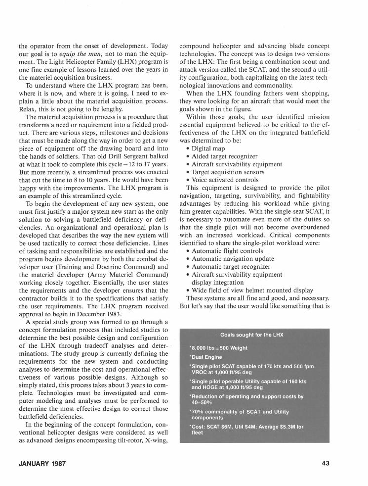
the operator from the onset of development. Today our goal is to equip the man, not to man the equipment. The Light Helicopter Family (LHX) program is one fine example of lessons learned over the years in the materiel acquisition business.
To understand where the LHX program has been, where it is now, and where it is going, I need to explain a little about the materiel acquisition process. Relax, this is not going to be lengthy.
The materiel acquisition process is a procedure that transforms a need or requirement into a fielded product. There are various steps, milestones and decisions that must be made along the way in order to get a new piece of equipment off the drawing board and into the hands of soldiers. That old Drill Sergeant balked at what it took to complete this cycle -12 to 17 years. But more recently, a streamlined process was enacted that cut the time to 8 to 10 years. He would have been happy with the improvements. The LHX program is an example of this streamlined cycle.
To begin the development of any new system, one must first justify a major system new start as the only solution to solving a battlefield deficiency or deficiencies. An organizational and operational plan is developed that describes the way the new system will be used tactically to correct those deficiencies. Lines of tasking and responsibilities are established and the program begins development by both the combat developer user (Training and Doctrine Command) and the materiel developer (Army Materiel Command) working closely together. Essentially, the user states the requirements and the developer ensures that the contractor builds it to the specifications that satisfy the user requirements. The LHX program received approval to begin in December 1983.
A special study group was formed to go through a concept formulation process that included studies to determine the best possible design and configuration of the LHX through tradeoff analyses and deter- . minations. The study group is currently defining the requirements for the new system and conducting analyses to determine the cost and operational effectiveness of various possible designs. Although so simply stated, this process takes about 3 years to complete. Technologies must be investigated and computer modeling and analyses must be performed to determine the most effective design to correct those battlefield deficiencies.
In the beginning of the concept formulation, conventional helicopter designs were considered as well as advanced designs encompassing tilt-rotor, X-wing,
JANUARY 1987
compound helicopter and advancing blade concept technologies. The concept was to design two versions of the LHX: The first being a combination scout and attack version called the SCAT, and the second a utility configuration, both capitalizing on the latest technological innovations and commonality.
When the LHX founding fathers went shopping, they were looking for an aircraft that would meet the goals shown in the figure.
Within those goals, the user identified mission essential equipment believed to be critical to the effectiveness of the LHX on the integrated battlefield was determined to be:
• Digital map • Aided target recognizer • Aircraft survivability equipment • Target acquisition sensors . • Voice activated controls This equipment is designed to provide the pilot
navigation, targeting, survivability, and fightability advantages by reducing his workload while giving him greater capabilities. With the single-seat SCAT, it is necessary to automate even more of the duties so that the single pilot will not become overburdened with an increased workload. Critical components identified to share the single-pilot workload were:
• Automatic flight controls • Automatic navigation update • Automatic target recognizer • Aircraft survivability equipment
display integration • Wide field of view helmet mounted display These systems are all fine and good, and necessary.
But let's say that the user would like something that is
Goals sought for the LHX
*8,000 Ibs ± 500 Weight
* Dual Engine
* Single pilot SCAT capable of 170 kts and 500 fpm VROC at 4,000 ft/95 deg
*Single pilot operable Utility capable of 160 kts and HOGE at 4,000 ft/95 deg
* Reduction of operating and support costs by 40-50%
* 70% commonality of SCAT and Utility components
*Cost: SCAT S6M, Util S4M; Average S5.3M for fleet
43

An artist's concept for the Utility LHX.
not technically possible within a given budget or timeframe that would allow a new technology to mature. If this occurs, then certain adjustments must be made.
It is very similar to buying a new car. When you go shopping for what you would like, you will certainly be attracted by the top-of-the-line model that has everything on it. However, when it comes down to writing the check, you will more than likely have to settle for a model with fewer options in order to match your checkbook. Whatever you select should certainly fulfill your original needs but may not be as well equipped as what you would have liked originally. And you always retain the ability to add on
44
c: o
'~
.. ~
more equipment to customize it at a later time. The final LHX design is not yet completed, but
tradeoff analyses, tradeoff determinations and engineering drawings depicting the best technical approach have been accomplished. The required operational capabilities are being further refined by analysis of the results of computer modeling of several alternative candidate designs.
The computer modeling is a vital part of the operational effectiveness analysis of the LHX alternatives, and it is ongoing at this time. This force-on-force modeling encompasses a variety of different mission profiles, putting each of the candidates through its paces in different locations, climatic conditions and
u.s. ARMY AVIATION DIGEST

JANUARY 1987
to define the future armored system for the year 2000 to 2020. He Dro'lIidEtd the iIIustretion for this article.
45
ATe ACTION LINE
Night Vision Goggles Exemption
Mr. Jesse M. Burch Jr. u.s. Army Air Traffic Control Activity Aeronautical Services Office
Cameron Station , Alexandria, VA
OVER THE YEARS numerous questions have been directed to this office concerning the Army's night vision goggles (NVG) exemption. The following has been extracted from AR 95-50 in response to these questions.
Department of the Army has been granted an exemption (No. 3946) from the provisions of Federal Aviation Regulation [FAR] parts 91.73(a) and (b). This permits certain phases of NVG training to be conducted in a lights-out mode provided certain conditions are satisfied. Conditions contained in the exemption are as follows:
a. This exemption is limited to night vision flight training in U.S. Army tactical helicopters.
b. Safety observers are required on each aircraft when operating in accordance with the grant of exemption.
c. A minimum of two helicopters, with crew and observers, is required when operating in accordance with the grant of exemption.
(1) The flight will be conducted at 200 feet or less above the ground in such a manner as to enable the crew and observers to be aware of any nonparticipating aircraft in the ' proximity of the training aircraft, or
(2) The training aircraft will be under constant surveillance of a properly lighted aircraft serving as an observation platform dedicated as a lookout for nonparticipating aircraft.
(a) Traffic notifications from the observation aircraft to the training flight will be timely and commensurate with the position and speed of the observed nonparticipating traffic.
(b) When nonparticipating traffic is relevant, the pilot of each training aircraft will turn on his or her aircraft's position lights and keep them on until
the nonparticipating traffic is no longer relevant. d. Airborne [NVG] training operations may not be
conducted above 200 feet above the surface and must be contained within a prescribed and publicized area that-
(1) Is simply defined, for example, the radius area from a specific point or location.
(2) Is established in a low traffic density location.
(3) Isn't within 5 miles of any public use airport. (4) Does not infringe on FAA designated air
space areas; for example, control zones and airport traffic areas .
(5) Has been coordinated with the appropriate FAA region's Air Traffic Division and Flight Standards Division offices.
e. Commanders will advertise each approved training area to operators at all airports within 50 miles of the training area for 60 days preceding its initial use.
r. Airport and staging area operations may be conducted in noncompliance with FAR 91. 73(b) at locations where only participating Army aircraft, involved in night vision flight training, are operating and suitable alternative measures for collision avoidance are instituted.
g. Commanders will provide real-time notification of training activities through Notices to Airmen (NOTAM) issued through FAA flight service stations at least 24 hours prior to commencement of the training activity. The NOTAM, as a minimum, will include the training area and the time of the training activity.
h. The holder will establish procedures for collision avoidance among its aircraft, including observer aircraft, operating pursuant to this exemption.
Any questions, comments or responses regarding night vision goggles exemption should be directed to Mr. Jesse M. Burch Jr., AUTOVON 284-7796/ 6304.
Correction , November 1986 Action Line: Second column, top line, sentence that begins "The second purpose . .. " and next sentence "The controller . . ." both should have been deleted.
Readers are encouraged to address matters concerning air traffic control to:
Director, Aeronautical Services Office, Cameron Station, Alexandria, VA 22304-5050.