Unit functions and operation - Belmontbelmont.ca/wp-content/uploads/2016/03/Quolis-unit...Unit...
26
VER1.1 (2012/09/10) 1 / 26 Unit functions and operation Takara Belmont Osaka Facotry Translation : 2013/12/13 Applicable for Program Number 1.1 I. Functions and Operations I-1 Control Panel, Name and Function Timer Start and Stop of timer alarm ( - )(+) switches Increase /decrease of Motor speed, scaler power, timer alarm etc. Spray SW ON/OFF of spray for handpieces Handpiece Light Handpiece light on/off Chair lock indicator Lits when the unit locks the movement of the chair. Power indicator Lits when the power is on. Chair switches, Manual You can operate chairs while you press and are holding the switch Chair switches, pre-set positions Once press and release, the chair moves to the programmed position. Also used for memory of positions Display Displays the status of setting or handpiece Function SW (F SW) For Various functions Auto return switch Select SW Selection of operation mode of micromotor, scaler. Selection of setting of function. Rotation direction SW Micromotor rotation direction Dental Light SW On/off of dental light. Store switch (Memory Switch) For storing the programmed value Cupfiller SW Start/Stop of cap water. Bowl flush SW Start/Stop of bowl flush supply water.
Transcript of Unit functions and operation - Belmontbelmont.ca/wp-content/uploads/2016/03/Quolis-unit...Unit...

VER1.1 (2012/09/10)
1 / 26
Unit functions and operation Takara Belmont Osaka Facotry
Translation : 2013/12/13 Applicable for Program Number 1.1 I. Functions and Operations
I-1 Control Panel, Name and Function
Timer Start and Stop of timer alarm
( - )(+) switchesIncrease /decrease of Motor speed, scalerpower, timer alarm etc.
Spray SWON/OFF of spray for handpieces
Handpiece LightHandpiece light on/off
Chair lock indicator Lits when the unit locks the movement of the chair.
Power indicator Lits when the power is on.
Chair switches, ManualYou can operate chairs while you press and are holding the switch
Chair switches, pre-set positions Once press and release, the chair moves to the programmed position. Also used for memory of positions
DisplayDisplays the status of setting or handpiece
Function SW (F SW) For Various functions
Auto return switch
Select SWSelection of operation mode of micromotor, scaler. Selection of setting of function.
Rotation direction SW Micromotor rotation direction
Dental Light SW On/off of dental light.
Store switch (Memory Switch) For storing the programmed value
Cupfiller SW Start/Stop of cap water.
Bowl flush SW Start/Stop of bowl flush supply water.
VER1.1 (2012/09/10)
2 / 26
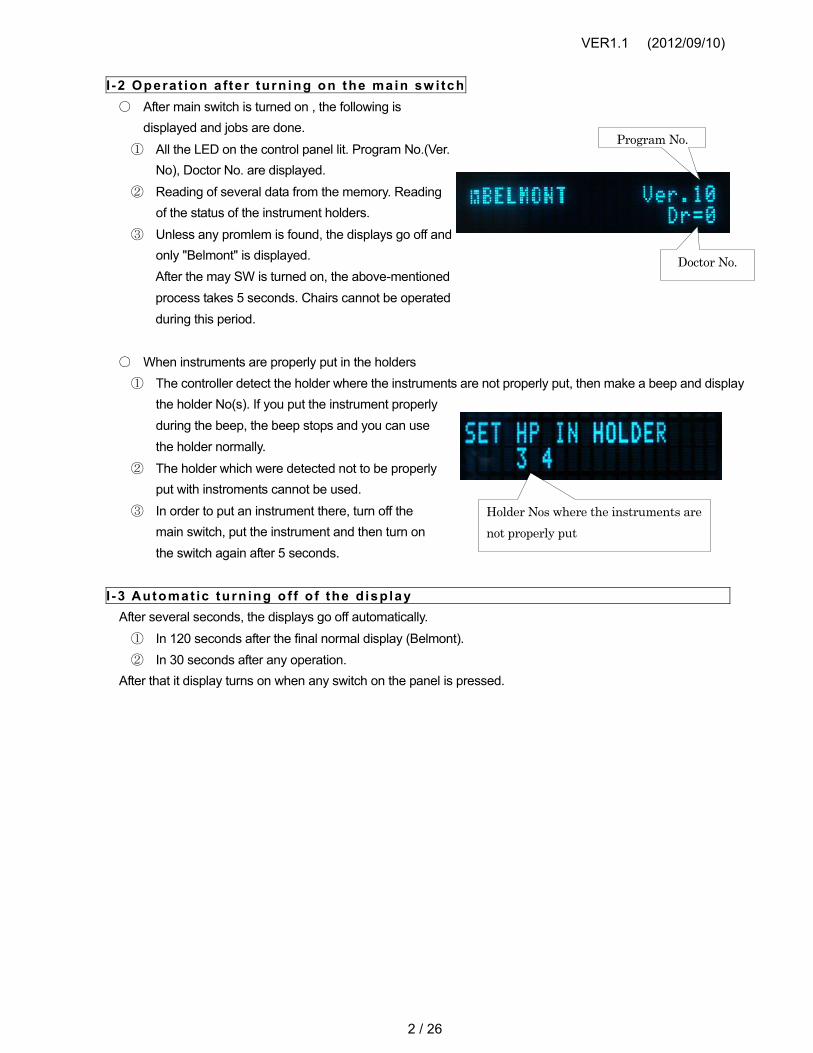
I -2 Operat ion a fte r turn ing on the main sw i tch○ After main switch is turned on , the following is
displayed and jobs are done.① All the LED on the control panel lit. Program No.(Ver.
No), Doctor No. are displayed.② Reading of several data from the memory. Reading
of the status of the instrument holders.③ Unless any promlem is found, the displays go off and
only "Belmont" is displayed.After the may SW is turned on, the above-mentionedprocess takes 5 seconds. Chairs cannot be operatedduring this period.
○ When instruments are properly put in the holders① The controller detect the holder where the instruments are not properly put, then make a beep and display
the holder No(s). If you put the instrument properlyduring the beep, the beep stops and you can usethe holder normally.
② The holder which were detected not to be properlyput with instroments cannot be used.
③ In order to put an instrument there, turn off themain switch, put the instrument and then turn onthe switch again after 5 seconds.
I -3 Automat ic turn ing o f f o f the d isp lay After several seconds, the displays go off automatically.
① In 120 seconds after the final normal display (Belmont).② In 30 seconds after any operation.
After that it display turns on when any switch on the panel is pressed.
Program No.
Doctor No.
Holder Nos where the instruments are not properly put

VER1.1 (2012/09/10)
3 / 26
I -4 Denta l l ight sw itch○ By pressing, send on /off signal to the control PCB of the dental light
I -5 L ight for handpiece on/of f and vol tage ad jus tment o f the l ight○ This swith is used to turn on/off the light of the handpiece instruments. When the light is set at ON, green
LED is ON.【Setting】 (When this switch is pressed, the selected status is remained until the main switch is turned off.
① Take one desired instrument from the holder.② At pressing the switch, it's set ON or OFF. When it is set ON, green LED at the
top right of the switch turns on.【Memory of the setting】 (Except the micromotor, the setting can be stored in the memory)
① Do the above-mentioned setting.② Press Store SW without rotating the instruments.
【Note】 The setting of the spray will be stored in the memory, too.
○ There are two modes for the timing of the light ON. This is programmable. You cannot program this for eachinstroments.
① F (Foot control) mode : The light turns on when the foot control is pressed. It turns off in the programmedtime after the foot control is released. Or, it turns off when the instrument is put back in the holder.
② H (Holder) mode : The light turns on when the instrument is taken from the holder. It turns off when theinstrument is put back in the holder.
○ Adjustment of the supplied voltage to the instuments can be done on VR1 on the main control PCB, withinthe range of 2.8 to 3.8V. Turn VR1 clockwise to increase the voltage. The supplied voltage cannot beadjusted independently for each instruments.(This is a voltage circuit, not a current circuit.)【Note】 Refer to [ Torque asjustment of Bien Air MX,MX2] section for brightness adjustment on light of BienAir MX, MX2 mocro motor.

VER1.1 (2012/09/10)
4 / 26
I -6 “Fi rs t pr ior i ty” funct ion of the inst ruments○ The priority of the operation is given only to the
instrument that has been withdrawed first. Onlythat instrument will be operable.
○ After all the handpiece are placed in the holders,the first instruments withdrawed will be operable.When more than one instruments are withdrawedand the first one is returned to the holder,[Return to the holder] will be displayed. After thesecond or third instrument are placed back to theholder, then withdraw agan the instrument that youwant to use.
○ The operable instrument number will be displayed(see example)
○ The instrument will not be operable if it is withdrawed with the foot controller being pressed. Make sure towithdraw the handpiece before pressing the foot controller. The orange LED for rotation direction(counterclockwise rotation) will lit.
VER1.1 (2012/09/10)
5 / 26
I-7 Rotation direction of the micromotor○ This function becomes available with a holder with micromotor setting. The LEDs by
the sides of [Rotation Direction Swtch] will lit. Green LED is for clockwise rotation,Orange for unticlockwise.
○ The direction cannot be switched during the rotation of the micromotor.○ The setting of the rotation direction can be done for each micromotor. The direction will be clockwise just
after the main switch is turned on.○ When change a doctors number, the rotation direction setting becomes clockwise rotation.○ When the micromotor is on the holder, green LED is displayed. However, if the setting (memory) is done as
“unticlockwise” for that holder, the orange LED will be displayed just after withdrawal of the motor from theholder, with a beep.
○ Anytime when you switch the direction to unticlocwise, the PCB makes beep.
I -8 (a ) Max imum rota t ion speed of micromotor (ava i lab le a t var iab le ro ta t ionspeed mode)
○ The maximum rotation speed (rotation speed range) can be set. The speed depend on the model of themicromotr.
○ The set speed remains until the man switch is turned off. Press [Store] switch to put it in memory.○ When two micromotor is used, the setting can be done for each one.
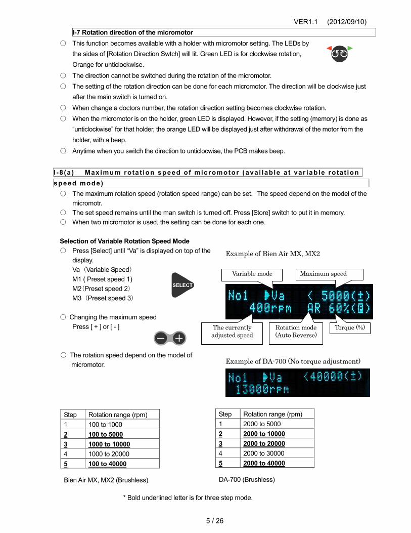
Selection of Variable Rotation Speed Mode ○ Press [Select] until “Va” is displayed on top of the
display. Va (Variable Speed) M1 ( Preset speed 1) M2(Preset speed 2) M3 (Preset speed 3)
○ Changing the maximum speedPress [ + ] or [ - ]
○ The rotation speed depend on the model ofmicromotor.
* Bold underlined letter is for three step mode.
Step Rotation range (rpm) 1 2000 to 5000 2 2000 to 10000 3 2000 to 20000 4 2000 to 30000 5 2000 to 40000
Step Rotation range (rpm) 1 100 to 1000 2 100 to 5000 3 1000 to 10000 4 1000 to 20000 5 100 to 40000
Example of Bien Air MX, MX2
Example of DA-700 (No torque adjustment)
Variable mode Maximum speed
The currently adjusted speed
Torque (%)Rotation mode (Auto Reverse)
Bien Air MX, MX2 (Brushless) DA-700 (Brushless)

VER1.1 (2012/09/10)
6 / 26
I-8 (b) Setting of pre-set speed of micromotor ○ In pre-set speed mode, the speed of micromotor can be fixed at specific values regardless the adjustment
of the potentiometer. ○ There are three pre-set memory. Press [Select] key until M1 / M2 / M3 is displayed. The programmed
speed will be displayed at the bottom of the display.【Setting】
① Withdraw a micromotor② Press [ Select ] switch until M1 / M2
/ M3 is displayed.
③ Press [ + ] or [ - ] to adjust the rotation speed. Bypressing the switch over two seconds, the speedcan be increased / decreased every 0.25 sec.
【How to use】 ① Withdraw a micromotor② Press [Select] to select M1 / M2 / M3.
Programmed speed
Preset 2
Rotation Speed
Rotation speed (Auto reverse)

VER1.1 (2012/09/10)
7 / 26
I -8 (C)Ca lcula t ing and d isplaying the micromotor gear re t io○ It is necessary to enable this function with a service mode. In F mode...Press [3] switch
【Setting of Gear Retio】
1. Pick up a micromotor from the holder2. Press the function switch once.3. Select the gear retio, Press [ + ] or [ - ]
4. Press the store swith to save it.
○ Press the function switch once to cancal the setting.○ Five gear ratios are converted: ×5, ÷4, ÷16, ÷64 and ÷128.○ ×1 should be used for low torque settings
【Display of Rotation speed】 When high speed or low speed are selected, [x] or [÷] is displayed on the indicator. The number of gear retio is not displayed.
Set high speed ( x 5) and indicated X.
Set low speed and indicated ÷.
When selected high speed (x 5)
When selected low speed (÷64)

VER1.1 (2012/09/10)
8 / 26
I -9 (a ) Torque ad jus tment o f B ien Ai r MX, MX2○Torque of rotation (%), Rotation mode (normal, auto forward, autoreverse), time of reverse rotation at auto forward setting and theintensity of the light can be adjusted.○The setting can be done both for variable rotation mode andpre-set rotation mode.○Torque adjustment and rotation mode change can be done only inlow rotation speed (100 to 5000rpm). In high rotation speed, thetorque remains 100%.【Set t ing】
1. Withdraw one motor.2. Press “F” until the display become like the example at right.3. Press [ Select ] and select the item to adjust.
“>” will be displayed at the left side of the item to be adjusted.4. Press [ - ] [ + ] to adjust.5. To finish the setting, press [Store] switch. To cancel, press [F].
[Torque Setting] ○The torque can be adjusted in the range of 10 to 100%○In high speed rotation mode, the torque stays 100%.○The actual torque value may change depending on the
power input or the status of the motor.
[Rotation mode] ○NOR(Normal Mode)The motor remain rotation in onedirection regardless theload to the motor.○A. Rev (Auto reverse)The motor stop by a specific (programmable) load and turnto oposit direction. When you stop the motor and the restart,the motor turns in original direction.○A.FOW(Auto Forward)
The motor stop by a specific (programmable) load and turnto oposit direction, then after a speficic (programmable)period, it the motor rotates in original direction again.
[Time of opposite rotation in Auto Forward mode] ○The time of rotation in opposite direction in Au toForward mode .
【Note】The actual rotation time in the opposite direction will be longer than the displayed time approximately by 2 seconds.
[Intensity of the light of micromotor] ○The intensity of the light of micromotor can be adjusted, within the range of 00 to 15.
Torque adjustment
Rotation mode adjustment
Time of opposite rotation in Auto Forward mode
Intensity of the light of micromotor

VER1.1 (2012/09/10)
9 / 26
I -10 Memory of var ious se t t ing for micromotorVarious setting of micromotor can be put in memory and this will be the setting that can be used when the main switch is turned on.
【Setting】 ① Withdraw a micromotor.② Set the following as you desire• Rotation mode (Normal, Auto Reverse, Auto forward)• Setting in each mode (Maximum speed, pre-set speed etc.)• Light on/off• Others
③ Press [Store] switch once. Do not hold.④ Press [Store] again until beep sound.

VER1.1 (2012/09/10)
10 / 26
I -11 Ul trasonic (E lect r ic ) sca ler ; Model and se t t ing【EMS】 Not Applicable 【P-MAX】 【VARIOS170】 ○ There are three mode for output . Endo, Perio and Scaling. Press [Select] switch to select.○ Before the operating the scaler, It is necessary to select the scaler power level. Please confirm in the bar graph.○ Can not adjust the scaler power during operation.
Once stop the scaler operation, adjust the scaler power and restart the operation.This operation is in accordance with specifications of P-MAX and VARIOS170.
【VARIOS】 ○ There are three mode for output . Endo, Perio and Scaling. Press [Select] switch to select.
I -12 Disp lay o f E lec t r ic sca ler○ 8-step graphic bar indicates the output of scaler.
(Varios170 : The bar graph and the power level (number) are displayed on the indicator.)
I-12 Ajustment of the output○ There are two ways. Adjustment by the control panel and the volume (potentiometer)[Adjustment by the control panel]
Press [ + ] [ - ] to adjust. [Adjustment by volume.]
Adjust the output power by turning the volume to clockwise or counterclockwise.
Varios, P-Max Scaling mode. Varios, P-Max Endo mode.
Varios, P-Max Perio mode.
Varios170 Scaling mode.
Varios170 Endo mode.

VER1.1 (2012/09/10)
11 / 26
I -14 Funct ion set t ing by "F" sw i tch○ The following can be done
① Selection of Doctor Number② Flush out operation③ Turning on/off the beep at pressing touchpad④ Timing of the litting of the light of instrument⑤ Selection of beep sound of the timer⑥ Changing the maximum speed of micromotor at Variable mode⑦ Spray mode of micromotor⑧ Selection of interlocked action of cupfiller and bowl flush
○ For details, see III.【Setting】
① Press [F] switch until the desired setting menu is displayed.Do not press and hold.
I -15 Safe ty cha i r lock funct ionThere's a chair lock function in emergency. 1. In the following conditions, chair lock signal is sent to chair's PCB and orange LED on the
touch pad will lit.① When the foot control is pressed.② When any switch on the control panel for operation of delivery system is pressed.
(This function can be removed by programming)③ During some setting, after pressing [F] or [Mode]
I -16 Safe ty lock o f ins t rumentThe instrument does not work if the foot controller is pressed when the instrument is withdrawed from the holder. Make sure to withdraw the instrument first, then press the foot controller. When this lock functions, the orange LED lits to indicate that the holder is locked. When the micromotor is set, reverse LED (orange) is flashes. When the micromotor isn’t set, both leds (orange and green) are flushes.

VER1.1 (2012/09/10)
12 / 26
I -17 Spray on /of f and memory○Turning on/off the coolant air/water for instruments.○ For micromotor, [Four Mode] can be selected. , Air and water / air only / water only /none.○ For air turbine and air motor, only [Two Mode] is available. Air and water / none.○ For electric scaler, only water is supplied.【Setting】(The setting here will remain until the main switch is turned off)
① Withdraw an instrument.② Select spray mode
【Setting and memory】 (The setting will remain eve if the main switch is turned off) ① Do the above mentioned setting② Press store switch. Do not press the foot control.
I-18 Timer alarms Timer can be set for 90min 59 sec at maximum.
【Pre-set time】 ① Press [Timer] switch on the control
panel.② Press [Select] to select the time.
The time is displayed on the bottom.
Press [ + ] [ - ] to change the time. To switch minute/second, press [Select].
③ Press [Timer] switch again to start timer. Theremaining time is diplayed at the bottom right.When programmed time has come, the beepsounds and the display of the time willdisappear.
【Manual timer】
① Press [Timer]② Press [ + ][ - ] to select the time.③ To switch minute/second, press [Select].④ Press [Timer] again to start.
【Memory of the pre-set timer】
① Press [Timer] switch.② Press [Select] to select amont 0, 1, 2 and 3.③ Adjust the time (see above)④ Press [Store]
Select Pre-set time
Selection of "minute"
Display of the remaining time. This is not displayed when any other function use large part of this display.

VER1.1 (2012/09/10)
13 / 26
I-19 Cupfiller Water is supplied through the cupfiller nozzle for certain time
【Operation】 ○ Water is supplied through the cupfiller nozzle for certain time when this switch is pressed.○ Eaven the cupfiller switch on the cuspidor side does the same function.
【Cancel Operation】 ○ Press the cupfiller switch again for stop feeding.
I-20 Bowl flush When this switch is pressed, water comes out of the bowl flush nozzle and flushes the cuspidor bowl. There are two modes for bowlflush operation for certain time or continuous bowl flushing. Also, linked with cupfiller motion setting is selectable.
【Operation】 ○ When pressing the bowl flush switch,
water comes out from the bowl flush nozzleand flushes the cuspidor bowl certain time.
○ The bowl flush switch on the cuspidor side doseThe same function.
○ For continuous bowl flushing, keep pressing this switch for 2 seconds until beep sound.
【Cancel Operation】 ○ Press the bowl flush switch again for stop flushing.
【Linked with Cupfiller motion】 ○ When the cupfiller switch is pressed, water is supplied to the cupfiller nozzle and bowl flush nozzle for
flushing the cuspidor bowl. Bowl flush time becomes, cupfiller time + bowl flushing time.○ To cancel the bowl flush motion, press the bowl flush switch again for stop flushing.
Can not cancel the bowl flush motion by pressing the cupfiller switch.○ For detal of setting, see III-8.
Cupfiller SW Example: when pressing a cupfiller SW
Bowl flush SW Flushing for Certain time
Flushing for Continuously

VER1.1 (2012/09/10)
14 / 26
II. Programming of the PCBI I -1 Set t ing a fter rep lacement o f PCB The following procedure needs to be done when you have installed a new control PCB on the unit, or you have made any mistake for setting and recovery to the oritinal setting are difficult.
① Carry out initial setting② Set the places of instrument holders to be used.
Among four (maximum) active holders, set the holders that you want to make active.③ Set the holder that you are installing electric micromotor. This has to be done even if you are not installing
a micromotor.Among those holders that you set at 2, program the holder to which you are installing the micromotor. SeeII-5.
④ Set the holder that you are installing an electric scaler. This has to be done even if you are not installing anelectric scaler.Among those holders that you set at 2, program the holder to which you are installing an electric scaler.See II-6
⑤ Program various settings for each doctor (upto four). See I-7, I-8, III.I I -2 In i t ia l Se t t ing (Essent ia l se t t ing)
Set all the programs to the initial status at the factory. 【Setting】
① Press MODE switch on the main control PCB andhold until beep sound.
② When you hear the beep and "Default Data Set" isdisplayed, release the MODE switch.
【Initial status】 ○ Beep : ON○ Power control of scaler : by control panel○ Timing of the litting of the light of the instruments :
Holder mode○ Chair lock switch : All switches of the control panel.○ Spray of the micromotor : "2" mode○ Cupfiller with Bowl flush : Non-Interlocking○ Maximum speed of micromotor : 3 steps○ Micromotor speed : Variable mode○ Transmission speed between the PCBs : 4800bps○ Doctor No.0○ Cupfiller time : 3.5 sec.○ The delay time of the litting off : 4 sec.○ Timer 0 : 1 min○ Timer 1 : 2 min○ Timer 2 : 3 min○ Timer 3 : 5 min○ Alarm type : Type 0○ Holder 1 : Spray off, Light ON, Standard speed○ Holder 2 : Spray off, Light ON, Standard speed

VER1.1 (2012/09/10)
15 / 26
○ Holder 3 : Spray off, Light ON, Standard speed○ Holder 4 : Spray off, Light ON, Standard speed○ Language : English○ Limit speed of micromotor at variable speed mode : Maximum (40,000 rpm)○ Rotarion level of mictomotor at preset mode : 20H○ Torque value of MX and MX2 micromotor : 60% without AR & AF.○ Manual switch of the chair : Used for manual operation of the chair.
I I -3 Adding or removing ac t ive inst rument holder When you have added, or removed, or change the positions of active instrument holders, the following settind need to be done according to the type of the handpiece. ① Set all the place of the instrument holders that are used. (See II-4)② Set the place of the holder(s) where micromotor is used. (See II-5)③ Set the place of the holder wher electric scaler is used (See II-6)
I I -4 Se t t ing of the ins t rument ho lders to be used Up to four active holders can be installed. Do this programming with instruments installed. If any holder is NOT set to be used, it become "inactive" holder. Carry out this setting no matter how many handpieces you are using. 【Setting】
① Press MODE on the control panel twice.② [HP HOLDER SET] will be displayed.③ Take a instruments from the holders where you are
going to use as active holders.Put some stick as a dummy on the holder that youare not going to make active, so the swich at theholder won't detect the place as "to be used".The numbers of the holders to be used will bedisplayed.
④ Press Store Switch on the control panel. The number of theholder that was programmed to be used will be displayed, as[T _ ]Return the instruments to the respective holders.
Example : "using all four holders"

VER1.1 (2012/09/10)
16 / 26
I I -5 Se t t ing of MicromotorsTwo motors at maximum can be installed. If you try to program for more than two motors, two motors at the left will be programmed as micromotor. If you are not installing micromotor, do the following setting without taking any instruments off the holders. 【Setting】
Make sure that II-4 has been done in advance. ① Press MODE switch on the control PCB three times.
[E. MOTORSET] will be displayed.② Take the micromotor off the holder.
If you are using two motors, take both of themat this time.
③ Select the model of the micromotor by pressing[+] /[-] switches. The model name will be displayed.
④ Press Store Switch on the control panel.The number of the holder that was programmed for micromotor will be displayed, as [T _ ]Return the motor to the respective holders.
I I -6 Se t t ing of u l t rasonic sca ler One scaler can be installed. If you try to program for more than one scaler, then one at the left will be programmed as scaler. If you are not installing scaler, do the following setting without taking any instruments off the holders. 【Setting】 Make sure that II-4 and II-5 have been done in advance.
① Press MODE switch on the control PCB four times.[SCALER SET] will be displayed.
② Take the scaler off the holder.③ Select the model of the scaler by pressing [+] /[-]
switches. The model name will be displayed.④ Press Store Switch on the control panel. The
number of the holder that was programmed forscaler will be displayed, as [T _ ]Return the scaler to the holder.
Example : Using Bien Air MX2 for holder No.3 and No.4.
Example : Varios170 saler on the holder No.4

VER1.1 (2012/09/10)
17 / 26
I I -7 Funct ion se t t ing F2 mode
① Press [MODE] on the control PCB once and release. Do not keep pressing.
② Press [F] switch on the control panel and release. Do not keep pressing.Displays as showing on the right.
③ Following changes of setting is possible by the following operations.
Functions to be changed Switches to press The programmed status and display
N/A Select SW N/A
N/A Handpiece Light Switch N/A
Language Rotation direction sitch Japanese Jap English Eng German DEU French FRA
Power control of ultrasonic scaler
Spray SW [+] [-] SW
Foot control FC (N/A)
④ After setting is done, press [F] to memory.If you turn off the main power without pressing [F], the setting will not be set in the memory.
⑤ Turn off the main power. Wait at least 5 seconds and turn on again. 【Note 】 ○ Do not change the setting which is "N/A". If something has changed by accident, use the switches in
the middle column and return it to the original display, as shown on the top right of this page.
【Note 1】
N/A

VER1.1 (2012/09/10)
18 / 26
II-8 Function setting (F3) mode ① Press [MODE] on the control PCB once and
release.Do not keep pressing.
② Press [F] switch on the control panel and hold.Displays as showin on the right.
③ Following changes of seting is possible by thefollowing operations.
Functions to be changed Switches to press Position of display Displayed sign
Timer of cupfiller (N/A)
(N/A) All
Timer of bowl flush (N/A)
(N/A) All
Timer of light of air turbine after releasing the foot pedal
Keep pressing the All
Selecting cancellation switch of programmed movement of the chair
Rotation direction switch
C.SW= A:Any switches C:Switches for chairs
Selectin of functions of Chair switches, Manual
Seat lowering switch M.SW= C:Seat, backrest H:Headrest (N/A)
④ After seting is done, press [F] to memory.If you turn off the main power without pressing [F], the setting will not be set in the memory.
⑤ Turn off the main power. Wait at least 5 seconds and turn on again.【Note】
The timer of the cup filler and bowl flush are not applicable for Quolis delivery sytems.

VER1.1 (2012/09/10)
19 / 26
III.Setting fo Functions
I I I -1 Selec t ion of Doctor Number○ Up to four dentists can program their own setting of the followings
① Pre-set speed of micromotor and on/off of the light. 3 speeds each.(For MX, torque and rotation mode are also pre-programmable)
② Timer of light of air turbine after releasing the foot pedal③ Pre-set positions of the chair, 3 positions each.
Note : The chair needs to be able to transmit signals with this PCB and be programmed for four doctors.④ Initial intensity (high / low) of the dental light.
Note : The dental light needs to be able to transmit signals with this PCB and be programmed for fourdoctors.
⑤ The setting of [F] switch.
【Setting】 ① Press [F] once.
The current docoto No. will be displayed.② Press any [Pre-set] switch of the chair. 0, 1 2 or
3.【Note】
Select doctor No. in 10 seconds after pressing [F].
VER1.1 (2012/09/10)
20 / 26
I I I -2 Flush out (F lush-out for cupf i l and bow l f lush is N /A for Quol is )
1. Flush out of instruments for 40 sec. ① Water line of the instruments off the holder will be flushed out for 40 seconds.② As soon as the instrument is put back to the holder, the flush-out ends for the instrument.③ As soon as all the instruments are put back to the hodler, the flush-out ends.
2. Flushout for 5 minutes ① Water line of the instruments off the holder will be flushed out for 5 minutes.② After flush-out of instruments are finished, flush-out of bowl flush and cupfil begin, for 5 minutes.③ If instrruents are not taken off from the holder, only【Note】 Quolis 5000 does not have electric cupfil or bowl flush, so it only carry out flush-out of
instroments.
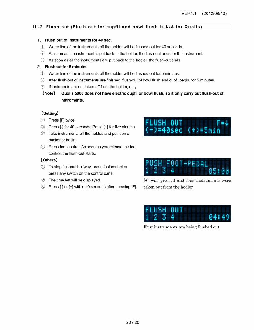
【Setting】 ① Press [F] twice.② Press [-] for 40 seconds. Press [+] for five ninutes.③ Take instruments off the holder, and put it on a
bucket or basin.④ Press foot control. As soon as you release the foot
control, the flush-out starts.【Others】 ① To stop flushout halfway, press foot control or
press any switch on the control panel,② The time left will be displayed.③ Press [-] or [+] within 10 seconds after pressing [F].
[+] was pressed and four instruments were taken out from the hodler.
Four instruments are being flushed-out
VER1.1 (2012/09/10)
21 / 26
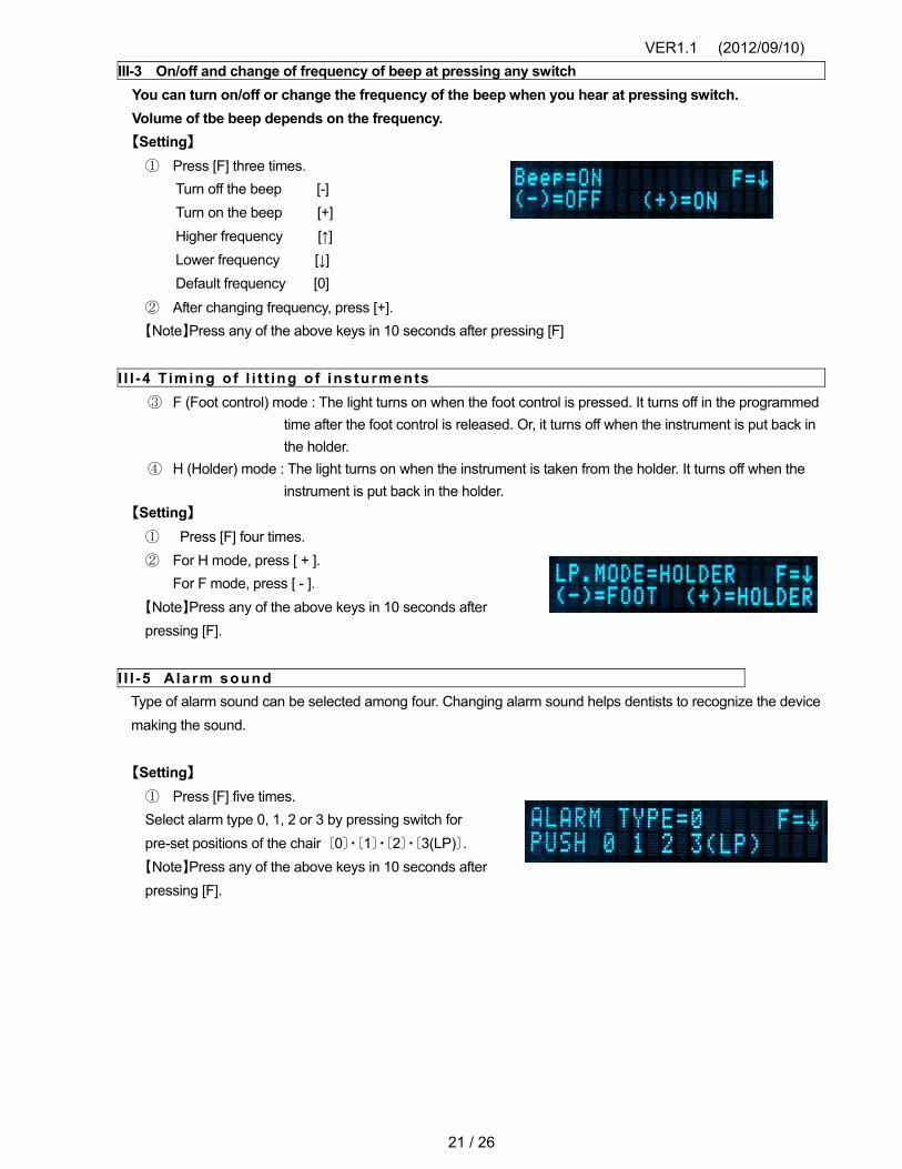
III-3 On/off and change of frequency of beep at pressing any switchYou can turn on/off or change the frequency of the beep when you hear at pressing switch. Volume of tbe beep depends on the frequency. 【Setting】
① Press [F] three times.Turn off the beep [-] Turn on the beep [+] Higher frequency [↑] Lower frequency [↓] Default frequency [0]
② After changing frequency, press [+].【Note】Press any of the above keys in 10 seconds after pressing [F]
I I I -4 Timing o f l i t t ing o f ins turments③ F (Foot control) mode : The light turns on when the foot control is pressed. It turns off in the programmed
time after the foot control is released. Or, it turns off when the instrument is put back in the holder.
④ H (Holder) mode : The light turns on when the instrument is taken from the holder. It turns off when theinstrument is put back in the holder.
【Setting】 ① Press [F] four times.② For H mode, press [ + ].
For F mode, press [ - ].【Note】Press any of the above keys in 10 seconds after pressing [F].
I I I -5 Alarm sound Type of alarm sound can be selected among four. Changing alarm sound helps dentists to recognize the device making the sound.
【Setting】 ① Press [F] five times.Select alarm type 0, 1, 2 or 3 by pressing switch forpre-set positions of the chair 〔0〕・〔1〕・〔2〕・〔3(LP)〕.【Note】Press any of the above keys in 10 seconds afterpressing [F].

VER1.1 (2012/09/10)
22 / 26
I I I -6 Maximum speed o f micromotor a t var iable mode The Maximum speed of micromotor at variable speed mode can be selected between “three steps” or “five steps”. At three steps, the maximum speed will be 10000, 20000 and 40000 rpm. At five steps, the maximum speed will be 5000, 10000, 20000, 30000 and 40000rpm. The rotation speed range depends on the model of the micromotor. 【Setting】
① Press [F] six times.② Press [ - ] for three steps
Press [+ ] for five steps.【Note】Press any of the above keys in 10 seconds after pressing [F].
I I I -7 Spray o f micromotor The coolant air and water for micromotor can be supplied in four modes or two modes. Four mode; air, water, air and water, none. Two mode; air and motor, none. 【Setting】
① Press [F] seven times.② Press [ - ] for two mode
Press [+ ] for four mode
【Note】Press any of the above keys in 10 seconds after pressing [F].
I I I -8 Link of movement of cupf i l This function is only available for cupfiller and bowl flush water controlled by the solenoid valve. It is necessary to enable the linkage setting. 【Setting】
① Press [F] switch eight times.② Press [ - ] for Non-Interlock
Press [+ ] for Interlock
【Note】Press [ - ] or [+] switch in 10 seconds after pressing [F].

VER1.1 (2012/09/10)
23 / 26
IV Service modeIn service mode, you can check the status of the PCB setting 【How to enter to service mode】 ① Press [F] and hold until the following is displayed.
* Press [F] to escape from service mode.
【Cupfiller items that can be checked】 ○ Cupfiller time - - - - - - - - - - - - - Press cupfiller switch.
○ Set the cupfiller time - - - - - - - - Press [ 0 ] switch once.Press cupfiller switch on control panel for the period desired for cupfiller, then release it.
Press [F] switch to save it.
1. Display for when pressing [0] SW.
2. Keep pressing cupfiller switch untildesired time.
3. After releasing the cupfiller switch,cup filler time is displayed.Press [F] to save.

VER1.1 (2012/09/10)
24 / 26
【Bowl flush items that can be checked】 ○ Bowl flush time - - - - - - - - - - - - - Press bowl flush switch.
○ Set the bowl flush time - - - - - - Press [ 0 ] switch once.Keep pressing bowl flush switch on the panel until desired time. , then release it.
Press [F] switch to save it.
○ The littiing time of the instrument in F mode, after releasing the foot pedalPress [Handpiece Light] switch to display
1. Display for when pressing [0] SW.
2. Keep pressing bowl flush switchuntil desired time.
3. After releasing the bowl flushswitch. (Bowl flush time is displayed)Press [F] to save.

VER1.1 (2012/09/10)
25 / 26
○ Check status of the holders ・・Press [Dental Light] switch◎ The number displayed on top is the number of the holder (From left, 1, 2, 3, 4)◎ The ○(circle) under the number mean the followings
Left (just under the number) … If the holder is active, ○ (circle) is displayed.Middle….If an instruments had been on the holder when the main switch were turned on, ○ (circle) is displayed. Right….If the instrument is now off the holder, ○ (circle) is displayed.
◎ The arrow upward (↑) means that the instruments have the priority, under “first priority” function.
Examples of display
◎ Micromotor will be displayed as belowModel Display Model 表示
DA-700 M70 Bien Air MX MMX
Bien Air MX2 MM2
� Scaller will be displayed as follow
Model Display Model Display
Varios SVA
P-Max SPM Varios170 SV2
Holder No.Bien air MX Micromotor
Varios scaler The instrument were
off the holder when main switch was turned on (Third blank)
The instrument is off the holder. (second circle)
This instrument has priority (arrow upward)
This holder is active (1st circle)

VER1.1 (2012/09/10)
26 / 26
○ Check the data of EEPROM・・・・・Press [ - ] [ + ]Address (ADR) and Data (DATA) will be displayed. The data will be displayed in hexadecimal number andbinary number.
○ Check the received data of the serial transmissionline…. Press [Select] ◎ Data of serial 1 will be displayed on top. Data of serial 3 will be displayed on bottom.◎ From left, 1st bite, 2nd bite, 3rd bite and 4th bite. The data are displayed at two digit hexadecimal
numbers.
○ Setting for enable or disable of calculating and displaying the micromotor gear ratio…. Press [3] switch
◎ This setting function converts the gear ratio of the contraangle handpiece to be mounted to the micromotor
and displays values near the actual revolutions.
Press [ - ] to disable a display functionPress [+] to enable a display function
IV Others 1. Priority of the operation by the control panel and serial transmission○ The priority of the operation is given in the following orders.
1. Control Panel2. Serial 13. Serial 3When any key on the control panel is pressed during any input of serial transmission, the PCB follow theoperation by the control panel temporarily, an then, follow the operation by the input serial transmission. Thismay sometimes cause confusion. Therefore, please do not operate more than one switch at the same time.
2. LED to confirm the serial transmission.○ The orange LED is for confirmation of serial transmission. The LED does not lit unless there’s any signal. It
does not lit if any cut wire or bad connection is there on the wires fore transmission.