Unit 2: Elements of Real-time Systems 1 Introduction · 1300 Henley Court Pullman, WA 99163...
19
1300 Henley Court Pullman, WA 99163 509.334.6306 www.store.digilentinc.com Unit 2: Elements of Real-time Systems Revised March 10, 2017 This manual applies to Unit 2. Unit 2 Copyright Digilent, Inc. All rights reserved. Other product and company names mentioned may be trademarks of their respective owners. Page 1 of 19 1 Introduction A real-time system is a combination of computer hardware and software that operates with time constraints. This unit investigates the concepts of multi-threaded process time management for a real-time dynamic system, using foreground-background task scheduling. Processor timers are used to start tasks with a high degree of accuracy. We will use the classic example application of controlling the rotor speed of a stepper motor to illustrate the software implementation of a dynamic system using timers and a finite state machine (FSM) controlling the execution of tasks in real-time. A PIC32 processor timer is used to control the period between steps of the stepper motor in a uniform manner, resulting in what appears to be constant angular velocity. This unit is concerned only with the dynamic behavior of the stepper motor (intervals between steps, the step mode, and direction of rotation), but not the rotor’s absolute position. The requirements of Lab 2b could be easily modified to add position control, but would require some type of position feedback or a starting reference. 2 Objectives 1. Implement task management based on polling PIC32 timers. 2. Implement task management based on PIC32 timer interrupts. 3. Understand the principles of a software implemented finite state machine (FSM). 4. Use time management and FSM code to control the speed of rotation of the stepper motor rotor. 5. Implement a multitasking real-time application using foreground-background scheduling. 3 Basic Knowledge 1. Understanding of combinational logic and sequential logic. 2. Using the SWITCH-CASE construct in C. 3. How to interpret a schematic diagram and electric circuits. 4. Fundamentals of stepper motors. 4 Equipment List 4.1 Hardware 1. Basys MX3 trainer board
Transcript of Unit 2: Elements of Real-time Systems 1 Introduction · 1300 Henley Court Pullman, WA 99163...

1300 Henley Court Pullman, WA 99163
509.334.6306 www.store.digilentinc.com
Unit 2: Elements of Real-time Systems
Revised March 10, 2017 This manual applies to Unit 2.
Unit 2 Copyright Digilent, Inc. All rights reserved. Other product and company names mentioned may be trademarks of their respective owners. Page 1 of 19
1 Introduction
A real-time system is a combination of computer hardware and software that operates with time constraints. This
unit investigates the concepts of multi-threaded process time management for a real-time dynamic system, using
foreground-background task scheduling. Processor timers are used to start tasks with a high degree of accuracy.
We will use the classic example application of controlling the rotor speed of a stepper motor to illustrate the
software implementation of a dynamic system using timers and a finite state machine (FSM) controlling the
execution of tasks in real-time.
A PIC32 processor timer is used to control the period between steps of the stepper motor in a uniform manner,
resulting in what appears to be constant angular velocity. This unit is concerned only with the dynamic behavior of
the stepper motor (intervals between steps, the step mode, and direction of rotation), but not the rotor’s absolute
position. The requirements of Lab 2b could be easily modified to add position control, but would require some
type of position feedback or a starting reference.
2 Objectives
1. Implement task management based on polling PIC32 timers.
2. Implement task management based on PIC32 timer interrupts.
3. Understand the principles of a software implemented finite state machine (FSM).
4. Use time management and FSM code to control the speed of rotation of the stepper motor rotor.
5. Implement a multitasking real-time application using foreground-background scheduling.
3 Basic Knowledge
1. Understanding of combinational logic and sequential logic.
2. Using the SWITCH-CASE construct in C.
3. How to interpret a schematic diagram and electric circuits.
4. Fundamentals of stepper motors.
4 Equipment List
4.1 Hardware
1. Basys MX3 trainer board

Unit 2: Elements of Real-time Systems
Copyright Digilent, Inc. All rights reserved. Other product and company names mentioned may be trademarks of their respective owners. Page 2 of 19
2. Micro USB cable
3. Workstation computer running Windows 10 or higher, MAC OS, or Linux
4. 4-wire stepper motor
5. 5V, 4A DC power supply
4.2 Software
The following programs must be installed on your development workstation:
1. Microchip MPLAB X® v3.35 or higher
2. XC32 Cross Compiler
3. PLIB Peripheral Library
5 Project Takeaways
1. How to set the period of a PIC32 Timer.
2. How to write a software state machine.
3. How to allocate tasks to either foreground or background scheduling.
4. Understanding of stepper motor operations and applications.
6 Fundamental Concepts
In the first unit, we looked at ways of implementing a static logical processing design that can be implemented
with a limited set of combinational digital logic circuits. In this unit, we will look at dynamic real-time systems that
require a history of state (memory) and sense of timing (deadlines). For microcontrollers, a “sense” of timing is
gained by using a timer.
The correct operation of a dynamic real-time scheduling scheme is predicated on two requirements. The first is
that the worst case (longest) execution time of the timer interrupt service routine (ISR) must be less than the
interrupt interval. The second is that the time remaining in the interrupt period after execution of the ISR must be
sufficient so that it appears to the user that the processor is acknowledging his or her inputs in a timely manner.
Real-time operation has two basic requirements: correct value at the correct time. A system that cannot always
meet both of these requirements is a failed system. Hence, it is not sufficient to just have the correct output
values; these outputs have to be generated at the correct time. You have already developed a real-time operating
system for Lab 1b.
The time required to service the ISR includes the execution time of the user ISR code in addition to the time
required to save and restore the system context. Using the MPLAB X Stopwatch debugging feature, we find that it
requires 33 machine cycles to save and restore the system context. Using a core frequency of 80 MHz, the context
saving and restoring time is 1.03 μs. The time to execute the user written code varies. In the case of Labs 2a and
2b, execution of the ISR code will vary based upon the conditional execution of the LED and stepper motor
functions.

Unit 2: Elements of Real-time Systems
Copyright Digilent, Inc. All rights reserved. Other product and company names mentioned may be trademarks of their respective owners. Page 3 of 19
7 Background Information
7.1 Real-time Operating Systems
“An operating system (OS) is system software that manages computer hardware and software resources and
provides common services for computer programs. All computer programs, excluding firmware, require an
operating system to function.”
When referring to real-time multi-threaded systems, we mean that to the observer, the system appears to be
simultaneously servicing multiple tasks. We often refer to this as multitasking. Timing becomes everything for
these types of applications. To achieve this goal, the PIC32 single-core processor must switch from running the
program code for one task to executing code for an entirely different task. The challenge for the developer is to
write an operating system that executes this task switching at a rate such that the processor appears to be
completing both tasks simultaneously.
Real-time systems can be categorized based on the need for tasks to be completed within a time constraint. Hard
real-time systems require all deadlines be met. Failure to do so constitutes a system failure. Completing a task
early is as bad as completing it late. Firm real-time systems allow for infrequently missing deadlines while still
maintaining required levels of performance. For soft real-time systems, the usefulness of the system degrades as
the rate of deadline misses increase.
Although there are different approaches to task switching, the two easiest are cooperative and preemptive. When
using the cooperative scheduling approach, each task willingly gives up running its computer code to allow another
task to run. To be effective, all tasks must work together “nicely” such that all tasks have an opportunity to meet
their time deadlines. Each task is responsible for determining when it is time to switch tasks. The various tasks
managed using a cooperative multitasking scheme are scheduled in a round-robin fashion. This is how the multiple
tasks needed to implement Lab 1a and Lab 1b are managed – they took turns executing in the main function’s
infinite loop.
7.1.1 Preemption
“In computing, preemption is the act of temporarily interrupting a task being carried out by a computer system,
without requiring its cooperation, and with the intention of resuming the task at a later time. It is normally carried
out by a privileged task or part of the system that has the power to interrupt, and later resume, other tasks in the
system.”
In software, a task is a basic unit of programming that has a constrained, defined purpose. For example, reading
the state of the input pins to determine if buttons are pressed or not can be considered a task. Multitasking implies
that more than one task is running at the same time. Single-core processors appear to be multitasking by time-
sharing the processor resources. No time sharing is required in Lab 1a and Lab 1b, where each task in the program
ran to its completion before the next task could begin. When multitasking with a single-core processor, some tasks
are suspended so that higher priority tasks can be serviced (executed).
7.1.2 Task Scheduling
Task scheduling for preemptive multitasking requires the use of one or more interrupts to determine when each
task is to be executed. These interrupts can be based on external events, such as a communications message, or
internal events, such as a timer clock. Typically, real-time systems use both cooperative and preemptive scheduling
to implement what’s called foreground-background scheduling. High priority tasks (time critical or hard real-time
tasks) are called the foreground tasks. The tasks that can be executed when no foreground tasks are pending are

Unit 2: Elements of Real-time Systems
Copyright Digilent, Inc. All rights reserved. Other product and company names mentioned may be trademarks of their respective owners. Page 4 of 19
called background tasks. Background tasks have low priority and can, in theory, wait forever without degrading
system performance.
7.1.3 Interrupts
In Unit 1, the order in which tasks were started and completed was strictly controlled by the order in which code
was executed in the program. In this unit, we will investigate the concept of altering program code execution using
preemption. Preemption by an interrupt causes the processor to stop the execution of the current code flow and
begin execution of a special function called an “interrupt handler” or “interrupt service routine” (ISR). In a
preemptive system, tasks are started and completed based on a programmed prioritization. The PIC32MX370 has
up to 76 different interrupt sources and 46 interrupt vectors. References 2, 3, and 4 provide background
information concerning processor interrupts.
As illustrated in Fig. 7.1, an interrupt is a signal triggered by an event internal to the processor or an external
signal. The computer suspends what would normally be the next instruction of a task in one part of a program and
begins executing code to complete an entirely different task. This occurrence of events can be periodic
(deterministic) or aperiodic (sporadic). An example of a deterministic event is a timer flag being set at a specified
interval. Sporadic interrupts are the result of an unpredictable event, such as a divide by zero error, detection of
low processor power, serial data received flag, or even pressing a button by a person. These signals cause the
microprocessor to implement a sequence of operations resulting in an orderly way of suspending one task,
executing an entirely different task, and subsequently resuming the original task.
Figure 7.1. PIC32 interrupt handler block diagram.
The three main types of interrupts are software, internal hardware, and external hardware. Software and internal hardware interrupts that are initiated by some event inside the microprocessor are also commonly referred to as exceptions or traps. Software interrupts are explicitly internally triggered by instructions within the current program, commonly referred to as trap instructions. Internally generated hardware interrupts triggered by timers, analog converters, serial communications, errors detected during software execution, such as illegal math scheduling instructions or operational codes (opcodes), are all known as exceptions. Finally, external hardware interrupts are interrupts initiated by hardware other than the CPU. Both the software code and the processor architecture determine how interrupts are prioritized and processed.
7.1.3.1 Context
The context of a microprocessor defines the state or operating conditions internal to the processor. In order to
properly resume executing the task that was interrupted, the ISR is responsible for saving and restoring the

Unit 2: Elements of Real-time Systems
Copyright Digilent, Inc. All rights reserved. Other product and company names mentioned may be trademarks of their respective owners. Page 5 of 19
context of the processor to before it was interrupted. At the very least, the context consists of the processor
register values, the CPU flag registers, and the program address of the next instruction to be executed when the
ISR has completed.
The C compiler is responsible for generating code segments called a prologue and an epilogue for functions
designated to be interrupt handlers. The prologue code saves the processor’s context prior to executing any code
that the developer generated to service the interrupt. The epilogue code restores the context at the end of the ISR
and redirects the execution of computer code back to the instruction that was preempted. For the PIC32
processor, the C compiler generates 33 assembly language instructions to save the processor context and an equal
number of instructions to restore the context, thus requiring approximately 8.5 µs before and after executing the
ISR code. PIC32 processors have one or more shadow registers that can all but eliminate the time needed for
executing prologue and epilogue code.
Interrupt latency is defined as the time between the instant when an event generates the interrupt signal and the
time when the first useful instruction in the ISR is executed. This latency is made up of two major components: the
time required to save the processor context and the amount of time that an interrupt is disabled or deferred by
higher priority interrupts as necessary.
7.1.3.2 Managing Interrupts
Preemptive programs usually consist of two types of tasks: foreground and background. Foreground tasks are
those preemptive tasks that the processor executes as soon as the need arises in response to an interrupt.
Interrupts are assigned priority levels that dictate the order in which interrupts will be serviced. In the case of
multiple foreground tasks both needing service at the same time, the higher the interrupt priority, the sooner the
microprocessor executes the code to service that interrupt. Code executed immediately following a power-up
reset runs at priority level zero and has no preemptive capability. This initial background task is responsible for
setting up the resources for tasks that will eventually run as foreground tasks.
Foreground tasks have preemptive capability by having higher priorities than background tasks. The foreground
task ensures adequate response times, while the background task manages deferred processing of the foreground
data. Background tasks are those that the processor executes whenever it has available time and is waiting for
something more important to do. Background tasks generally run at the interrupt priority level zero within a
while(1) { … } program loop, where event detection by polling flags and pins is common. Interrupt only systems,
which are those that only have foreground processes, respond quickly to both periodic and sporadic events but
ignore potential work that can be allocated to a background process. The use of interrupts falls under the broad
category of real-time task scheduling, and a thorough investigation of this topic is beyond the scope of this project.
There are two types of preemptive operating schemes: nested and non-nested. Nested interrupt schemes allow
higher priority level interrupts to preempt code that is servicing a lower priority interrupt. A non-nested interrupt
scheme completes the execution of the code currently servicing an interrupt before it begins to service the code
for any interrupt awaiting service, regardless of interrupt priorities.
Non-nested preemptive schemes are usually easier to manage, but they can result in priority inversion, where a
low priority task blocks a higher priority task from running. This scheme is easier to manage because the developer
only has to focus on one ISR, and the operation that determines which interrupts to service resembles the process
of polling, i.e., constantly checking to see if a specific event has occurred, which we did in Lab 1b. For non-nested
interrupt schemes, we must individually check the flags set by the interrupting event to determine which event to
service. All interrupts are assigned to priority level 1 and are vectored (sent) to the same ISR where the particular
interrupt flag must be cleared. For multiple simultaneous interrupts, tasks are serviced in the order that the
interrupt flags are polled. A non-nested priority scheme results whenever interrupts are enabled using the
instruction INTEnableSystemSingleVectoredINT(); provided in the peripheral library.
Unit 2: Elements of Real-time Systems
Copyright Digilent, Inc. All rights reserved. Other product and company names mentioned may be trademarks of their respective owners. Page 6 of 19
Nested priority schemes are generally more responsive, taking advantage of the fact that higher priority tasks can
preempt (interrupt) lower priority tasks. The highest priority interrupt is guaranteed to have the lowest latency;
however, nested priority schemes require more computer resources, such as time and memory, to accommodate
context saving and restoring. Some low-end microcontrollers simply do not have sufficient memory and/or speed
to support fully nested priority schemes. In reality, many embedded systems manage tasks using both nested and
non-nested preemptive schemes as a result of either hardware and/or software limitations. Either interrupt
management scheme can be used in combination with polling to detect events, as will be the case for the labs
associated with this unit.
The PIC32MX family of processors can use polling, nested priority, and non-nested priority schemes
simultaneously. The PIC32MX processors utilize two major software level priorities called the “Group Priority” and
the “Subgroup Priority.” There are seven levels that can be assigned for the group priority (1-7), with one being the
lowest priority and seven being the highest. An interrupt with a higher group priority will preempt an interrupt of a
lower priority group. There are four subgroup priority levels that can be assigned at each of the seven levels of
group priority. Interrupts assigned to different group priority levels operate as nested interrupts.
Multiple events can be assigned interrupt priorities at the same group level but at different subgroup levels. If two
interrupts with the same group priority level are pending, the interrupt with the highest sub-priority will be
handled first. The natural (hardware) priority scheme is asserted whenever multiple interrupts are generated
simultaneously for events that are set for the same group and subgroup priority levels. (The notion of
“simultaneous events” must be expanded to mean “if two interrupts are detected as waiting for service,” whether
or not they occur at the same precise instant of time.)
See the PIC32MX Family Reference Manual Section 8 for additional details of interrupt operations on the PIC32MX
family of processors.
7.1.3.3 General Interrupt Code Requirements
There are four essential code elements required for a program to process interrupts using C: the declaration of the
functions that will be used to service the interrupts, the code to initialize the resources that generate the interrupt,
the ISR code that will be executed in response to an interrupt, and the instructions that enable interrupts in a
global sense. There must be a specific ISR to handle each enabled interrupt, including the instruction to clear the
specific interrupt flag. Failing to clear the interrupt will cause the processor to repeatedly execute the ISR, thus
preventing the processor from executing any other application code.
Functions that have been declared as an ISR cannot be called by any other C function, although code within an ISR
can call other C functions. The two ways that the ISR code will be executed are, one, in response to the event that
sets the interrupt flag through hardware, and two, by setting the corresponding bit in the interrupt flag register
using a software instruction. A function that is declared as an ISR cannot have any variables passed to it (no
argument list) and must return a void data type.
In this project, two different interrupts will be generated: Timer 1 interrupt and an I/O pin change notice interrupt.
The programming requirements for each of these two interrupts are discussed below. The two statements in
Listing 7.1 apply to all interrupts and should be executed only once after all resources that are to generate an
interrupt have been initialized. In this instance, the program is using multi-vectored interrupts. Selected segments
of the code used in an application can be protected from preemption by any and all interrupts by bracketing the
code segment with the instructions INTEnalbeInterrupts(); and INTDisableInterrupts();.
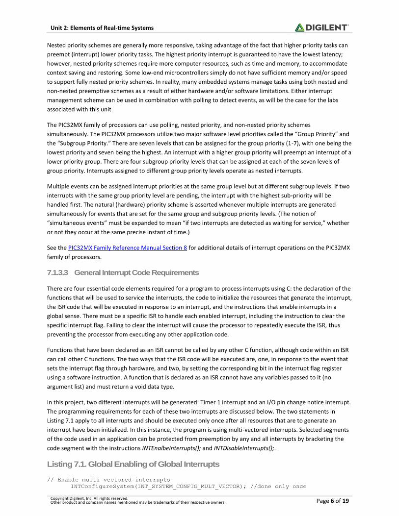
Listing 7.1. Global Enabling of Global Interrupts
// Enable multi vectored interrupts INTConfigureSystem(INT_SYSTEM_CONFIG_MULT_VECTOR); //done only once

Unit 2: Elements of Real-time Systems
Copyright Digilent, Inc. All rights reserved. Other product and company names mentioned may be trademarks of their respective owners. Page 7 of 19
INTEnableInterrupts(); //use as needed
7.2 Microprocessor Timers and Counters
Counter/timer hardware is a crucial component of most embedded systems. In some cases, a timer is needed to
measure elapsed time; in others, we want to count or time some external events. We will use timers to pace the
execution of specific segments of code either by polling timer flags or using interrupts generated by the timer. The
PIC32MX370 has a core timer, a watchdog timer, and five general purpose counters/timers that can use one of the
six PIC32 oscillator inputs.
The core timer and Timers 1 through 5 can be used to create blocking delays that are similar to the software delay
presented in Lab 1b and shown again here in Listing 7.2. The advantages of a software time delay based on CPU
execution speed, as shown here in Listing 7.2, are as follows:
1. This method of delay can be implemented on any microprocessor.
2. The range of delay can be from a few microseconds to days depending on the timing resolution.
The disadvantages are:
1. The delay must be calibrated using instrumentation and trial and error.
2. Although the delay function is blocking, it may be preempted in a foreground-background scheduling
scheme.
3. Preemption of this delay function causes the delay period to be extended.
Listing 7.2. Software Time Delay Based on the CPU Instruction Execution Speed
void sw_delay(int ms) { unsigned int ms_cnt; // 1 ms counter while(ms--) // ms loop counter { ms_cnt = 10000; // Reset ms counter while(--ms_cnt); // wait for 1 ms } }
In comparison to the software delay above, the CPU core timer and Timers 1 through 5 can be used to create a
blocking delay by polling a timer value, as shown in Listing 7.3. The advantages of implementing a delay by polling
a timer value are:
1. The delay period is from 1.08 μs to 1.78 minutes in steps of 1.08 μs. (Minimum time is a function of the
code execution speed.)
2. Preemption of this delay function does not interfere with the clock.
3. The core timer does not require any initialization code.
4. Timing resolution is twice the period of the core frequency, providing high resolution.
The disadvantages of polling a Timer to implement a delay are:
1. Delay periods longer than 1.78 minutes will result in very short delays due to 32-bit addition overflow.
2. The maximum delay for Timer 1 through Timer 5 is 4.2 seconds and requires a prescale value of 256 and a
10 MHz peripheral bus clock (Core clock / 8).
3. The minimum delay for Timer 1 through Timer 5 is 25.6 μs when the timer is configured to be capable of
the maximum delay.
Unit 2: Elements of Real-time Systems
Copyright Digilent, Inc. All rights reserved. Other product and company names mentioned may be trademarks of their respective owners. Page 8 of 19
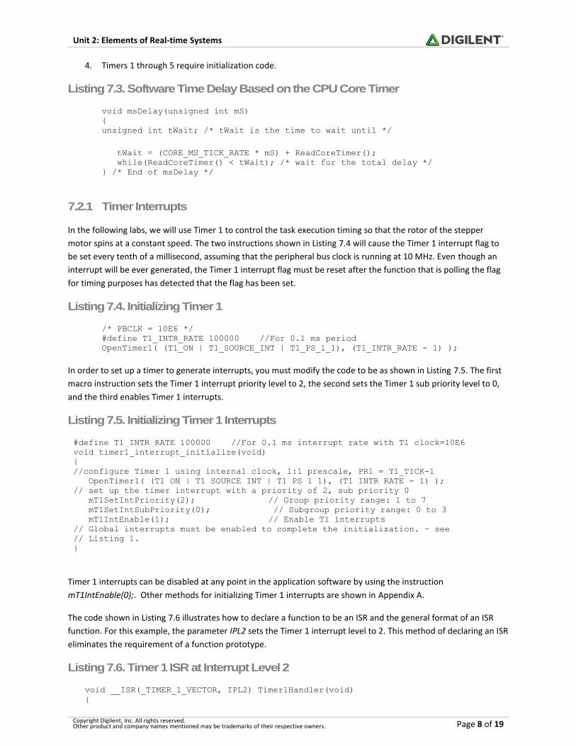
4. Timers 1 through 5 require initialization code.
Listing 7.3. Software Time Delay Based on the CPU Core Timer
void msDelay(unsigned int mS) { unsigned int tWait; /* tWait is the time to wait until */
tWait = (CORE_MS_TICK_RATE * mS) + ReadCoreTimer(); while(ReadCoreTimer() < tWait); /* wait for the total delay */ } /* End of msDelay */
7.2.1 Timer Interrupts
In the following labs, we will use Timer 1 to control the task execution timing so that the rotor of the stepper
motor spins at a constant speed. The two instructions shown in Listing 7.4 will cause the Timer 1 interrupt flag to
be set every tenth of a millisecond, assuming that the peripheral bus clock is running at 10 MHz. Even though an
interrupt will be ever generated, the Timer 1 interrupt flag must be reset after the function that is polling the flag
for timing purposes has detected that the flag has been set.
Listing 7.4. Initializing Timer 1
/* PBCLK = 10E6 */ #define T1_INTR_RATE 100000 //For 0.1 ms period OpenTimer1( (T1_ON | T1_SOURCE_INT | T1_PS_1_1), (T1_INTR_RATE - 1) );
In order to set up a timer to generate interrupts, you must modify the code to be as shown in Listing 7.5. The first
macro instruction sets the Timer 1 interrupt priority level to 2, the second sets the Timer 1 sub priority level to 0,
and the third enables Timer 1 interrupts.
Listing 7.5. Initializing Timer 1 Interrupts
#define T1_INTR_RATE 100000 //For 0.1 ms interrupt rate with T1 clock=10E6 void timer1_interrupt_initialize(void) { //configure Timer 1 using internal clock, 1:1 prescale, PR1 = T1_TICK-1 OpenTimer1( (T1_ON | T1_SOURCE_INT | T1_PS_1_1), (T1_INTR_RATE - 1) ); // set up the timer interrupt with a priority of 2, sub priority 0 mT1SetIntPriority(2); // Group priority range: 1 to 7 mT1SetIntSubPriority(0); // Subgroup priority range: 0 to 3 mT1IntEnable(1); // Enable T1 interrupts // Global interrupts must be enabled to complete the initialization. – see // Listing 1. }
Timer 1 interrupts can be disabled at any point in the application software by using the instruction
mT1IntEnable(0);. Other methods for initializing Timer 1 interrupts are shown in Appendix A.
The code shown in Listing 7.6 illustrates how to declare a function to be an ISR and the general format of an ISR
function. For this example, the parameter IPL2 sets the Timer 1 interrupt level to 2. This method of declaring an ISR
eliminates the requirement of a function prototype.
Listing 7.6. Timer 1 ISR at Interrupt Level 2
void __ISR(_TIMER_1_VECTOR, IPL2) Timer1Handler(void) {

Unit 2: Elements of Real-time Systems
Copyright Digilent, Inc. All rights reserved. Other product and company names mentioned may be trademarks of their respective owners. Page 9 of 19
/* User generated code to service the interrupt is inserted here */
mT1ClearIntFlag(); // Macro function to clear the interrupt flag
}
7.3 Change Notification Interrupts
A change notification (CN) interrupt indicates that an input pin has changed level from a high to low or low to high.
All of the PIC32MX370 IO pins are capable of generating a CN interrupt, except for RF6. All of the CN interrupts are
vectored to the same ISR, thus requiring polling the CN status registers, CNSTATA through CNSTATG, to determine
which pin or pins are responsible for generating the CN interrupt. The code in Listing 7.6 will initialize BTNC on the
Basys MX3 trainer board to generate a change notification interrupt at group level 1, sub group level 2. Listing 7.8
provides the code for the CN interrupt service routine.
Listing 7.7. Initializing the CN Interrupt for BTND
/* Configure BTNC for change notification */ TRISAbits.TRISA15 = 1; /* Set RA15 for digital input CNPDAbits.CNPA15 = 0; /* Disable RA15 pull down resistor */ CNPUAbits.CNPUA15 = 0; /* Disable RA15 pull up resistor */ CNENAbits.CNIEA15 = 1; /* Enable RA15 change notification */ CNCONAbits.ON = 1; /* Set RA15 change notification on */ IEC1bits.CNFIA = 1; /* Enable RA15 CN interrupts */ /* Set CN interrupt level */ IPC8bits.CNIP = 1; /* Set CN interrupt group level 1 */ IPC8bits.CNIS = 0; /* Set CN interrupt sub group level 0 */ /* Enable global nested interrupts */ INTConfigureSystem(INT_SYSTEM_CONFIG_MULT_VECTOR); /* Execute only once */ INTEnableInterrupts(); /* Execute as needed */
Listing 7.8. CN Interrupt Service Routing for BTNC
void __ISR(_CHANGE_NOTICE_VECTOR, IPL1SOFT) CNHandler(void) { if( IFS1bits.CNAIF ) /* Check if CN on BTND - RA15 */ { if(CNSTATA & BTND_bit) /* Check if CN on RA15 */ { // ISR user code } } }
7.4 Finite State Machines
A finite state machine (FSM) is a behavior model for dynamic systems that determines what to do next based upon
its current activity, the present conditions, and a stimulus. Current activities are called states. Present conditions
are inputs that determine where to go and possible transitory activities. The stimulus is a trigger that indicates
when to transition from one state to the next. A state diagram is a graphical representation (or model) of an FSM.
A timer is in fact an FSM that uses a clock source as a trigger to advance the count, which is the timer’s state.

Unit 2: Elements of Real-time Systems
Copyright Digilent, Inc. All rights reserved. Other product and company names mentioned may be trademarks of their respective owners. Page 10 of 19
As an example, consider a simple momentary contact push button that you want to operate in a push-on / push-
off fashion. Although the button is in the on condition only while being pressed, we want a system that remembers
that it was pressed and maintains the “on” condition. When the button is pressed the next time, we want the on
condition to be remembered so the output will transition to the “off” condition. Figure 7.2 is a state diagram
representation of the push-on / push-off operation. Although there are many variations to the actual drawing of a
state diagram, we will use one that follows the UML approach.
Each rounded box in Fig. 7.2 represents a stable state and each directed arrow represents a transition between
states. The circle containing the uppercase letter “I” is the initial conditions and is directed to the initial state. Each
state is identified by name or number above the horizontal line. The actions ascribed to the state are described
below the line. The state action is divided into two actions separated by a colon. The left action declares the action
generated on entry to the state. The action to the right of the colon declares the action generated on exit from the
state.
Transitions describe both events (triggers) with guards and actions associated with the transaction. Guards
represent conditions that inhibit the transaction. There may be multiple transitions between the same two states.
Each path represents differing guard conditions and differing transaction actions.
Figure 7.2. State diagram for a push-on / push-off button operation.
The button action described by Fig. 7.2 shows that four states are required to represent its operation: two states
are needed for a button press and release when the switch is on, as well as when the switch is off. There is only
one possible event that initiates a transition: the clock event, which for this example is a millisecond timer. The
number of clock pulses is counted to hold the system in a fixed state until the predefined delay period has expired.
This is used to eliminate multiple transitions due to switch contact bounce when a button is pressed.
The guard condition on the clock event inhibits the transition between states unless the button is in the proper
pressed or released condition. The action associated with the transaction controls an LED to indicate the condition
of the push-on/push-off switch output, sw. It is apparent from Fig. 7.2 that even relatively simple dynamic systems
can result in complex logic.

Unit 2: Elements of Real-time Systems
Copyright Digilent, Inc. All rights reserved. Other product and company names mentioned may be trademarks of their respective owners. Page 11 of 19
Software state machines inherently define control of the computer code. Our code execution control options
include “if-else” constructs, “do-while” loops, and “switch-case” software constructs. The most common software
control construct for software state machines is the “switch-case” implementation. Listing 7.9 is a C function that
implements the control flow represented in Fig. 7.2. This function is called each millisecond and is passed the
condition of the push button. Local variables are declared “static” to provide the state memory for the delay timer,
the process state, and the switch output. The implementation in Listing 7.9 is non-blocking, meaning that the
function immediately returns to the calling code regardless of the state of the push button or the delay timer.
Listing 7.9. Push-on / Push-off C Program
int push_on_off(int button ) { static int td = 10; /* Initial conditions */ static sw_state = 0; /* Switch state memory variable */ static int sw = 0; /* Switch output variable */ if(td) /* Debounce period timer */ --td; else switch(sw_state) { case 0:
if(button) /* Button pressed - switch on */ { setLED0(1); sw = 1; td = 10; sw_state = 1; /* Advance to next state */ } break; case 1: if(!button) /* Button released – advance to next state */ { td = 10; sw_state = 2; } break; case 2: if(button) /* Button pressed - switch off */ { setLED0(0); sw = 0; td = 10; sw_state = 3; /* Advance to next state */ } break; case 3: if(!button) /* Button released – advance to state 0 */ { td = 10; sw_state = 0; } break; } return sw; }
8 References
1. Real-time Operating Systems, https://en.wikipedia.org/wiki/Real-time_operating_system.
2. Tutorial-Interrupts - http://www.scriptoriumdesigns.com/embedded/interrupts.php.

Unit 2: Elements of Real-time Systems
Copyright Digilent, Inc. All rights reserved. Other product and company names mentioned may be trademarks of their respective owners. Page 12 of 19
3. Project 5: chipKIT™ Pro and Interrupts, https://learn.digilentinc.com/Documents/196.
4. chipKIT™ PIC32® Interrupt Handling, http://chipkit.net/wp-
content/uploads/2015/05/chipKIT_PIC32_Interrupt_Handling.pdf.
5. PIC32MX330/350/370/430/450/470 Data Sheet,
http://ww1.microchip.com/downloads/en/DeviceDoc/60001185D.pdf.
6. Timing is Everything – Embedded Systems Demand Early Teaching of Structured Time-Oriented
Programming, https://www.ics.uci.edu/~givargis/pubs/C38.pdf.
7. MPLAB X Stopwatch, https://learn.digilentinc.com/Documents/211.
8. How Stepper Motors Work, https://www.youtube.com/watch?v=bngx2dKl5jU.
9. How to code a State Machine in C or C++, http://www.barrgroup.com/Embedded-Systems/How-
To/Coding-State-Machines.

Unit 2: Elements of Real-time Systems
Copyright Digilent, Inc. All rights reserved. Other product and company names mentioned may be trademarks of their respective owners. Page 13 of 19
Appendix A: PIC32 Timers and Counters
Most microcontrollers are equipped with one or more timing systems that can be used to perform a variety of
precision timer functions, including generating events at specific times, determining the duration between two
events, or counting events. Example applications that require generating events include generating an accurate 1
Hz signal in a digital watch, keeping a traffic light green for a specific duration, or communicating bits serially
between devices at a specific rate.
The main component of such a timing system is a free running binary counter. The counter increments with each
incoming timing pulse. The counter counts continuously from 0 to 2n-1, where n is the number of bits in the
counter. Since it runs independently, it can count inputs or clock pulses concurrently while the microcontroller is
executing the main program. If the input clock to the binary counter has a fixed known frequency, we can make an
accurate measurement of time interval by counting the pulses of the clock. The PIC32MX370 processor has a
watchdog timer, five 16-bit counters/timers, and a 32-bit core timer.
A.1 Watchdog Timer
A watchdog timer (WDT) is a device used to protect a system from specific software or hardware failures that may
cause the system to stop responding. The application is first registered with the watchdog device. Once
the watchdog is running on your system, the application must periodically send information to
the watchdog device. The PIC32 watchdog timer is powered from the low power RC oscillator, and once enabled,
must be reset periodically or the system will undergo a power-on reset using software instructions. Although
watchdog timers are an important concept in developing secure and dependable code, their usage is beyond the
scope of this unit.
A.2 The Core Timer
Unlike 8- and 16-bit Microchip PIC processors, the PIC32 processor that uses the MIPS32® M4K® core has a core
timer that keeps time using the 32-bit MIPS32 internal register 9 named “Count.” Although infrequently used, the
core timer can generate an interrupt using the MIPS32 internal register 11 named “Compare.” The core oscillator
counts at one half the System Clock frequency, as shown in Fig. A.1, and can be used to generate a millisecond
software delay using the code shown in Listing A.1.
Listing A.1. Millisecond Delay Based on Polling the Core Timer
#define CORE_MS_TICK_RATE CORE_OSCILLATOR_FREQUERNCY/2/1000 void msDelay(unsigned int mS) { unsigned int tWait = (CORE_MS_TICK_RATE * mS) + ReadCoreTimer(); while(ReadCoreTimer() < tWait); // wait for the total delay } /* End of msDelay */
Refer to Section 2.12 of the PIC32 Family Reference Manual for additional information concerning uses of the core
timer.

Unit 2: Elements of Real-time Systems
Copyright Digilent, Inc. All rights reserved. Other product and company names mentioned may be trademarks of their respective owners. Page 14 of 19
Figure A.1. Core timer block diagram.
A.3 Types of Timers
Section 14 of the PIC32 Family Reference Manual identifies two types of timers. Generically, all timers have a block
diagram, as shown in Fig. A.2. A Type A timer is a 16-bit counter that can be clocked from either the peripheral bus
clock or from a secondary oscillator that typically uses a 32 kHz crystal and is used for the real-time clock
applications. This timer can be used to generate an interrupt that will wake up the processor after it has been put
into a sleep mode. The clock source for the timer has the option of four software-programmable pre-scale dividers:
1, 8, 64, or 256. The PIC32 Timer 1 is a Type A timer or counter.
Timers 1 through 5 are 16-bit timers which support both synchronous external timer modes of operation. Timer 1
also allows asynchronous external mode which enables operations during sleep mode when the master oscillator
is turned off and controller operation is done using a secondary oscillator.
Figure A.2. Simplified PIC32 timer block diagram.

Unit 2: Elements of Real-time Systems
Copyright Digilent, Inc. All rights reserved. Other product and company names mentioned may be trademarks of their respective owners. Page 15 of 19
Type B timers are similar to Type A timers in that they use 16-bit counters; however, two Type B timers can be
programmed to operate together to form a 32-bit counter. The Type B timers have eight possible pre-scale values
of 1, 2, 4, 8, 16, 32, 64, and 256.
The clock source for Timers 1 through 5 can be an external input or the peripheral clock. The external input for
Timer 1 is the output from the secondary oscillator. All timers can be gated by software that generates a timing
window.
A.4 Determining the Timer Input Clock and Rollover Frequency
The maximum counter value is determined by the size of the register that holds the counts. Common sizes for
microprocessors are 8, 16, and 32-bit. Including the core timer, the PIC32 processor has six timers that can be used
for delay timing. The core timer is 32 bits wide. Timers 2 and 3 along with Timers 4 and 5 can be used together as
32-bit counters, respectively, extending the count value range from 65,536 to 4,294,967,296. As shown in Fig. A.3,
when the counter register equals the value of the period register (PR), the counter is reset to zero and the timer
interrupt flag is set. Although the core timer can be reset to any value, PIC32 documentation recommends that
such practices be avoided.
The period register is used to set the timer’s maximum count. If a period equal to a value of N is set, then N-1 is
written to the PR register. The period registers are declared as PR1 for Timer 1, PR2 for Timer 2, and so on. Each
Timer 1 count is compared to the value of the PR1 register. When the PR1 register equals the Timer 1 register, the
timer has reached its terminal count and initiates two actions: first, the Timer 1 register is reset to zero, and
second, the Timer 1 Interrupt Flag (T1IF) bit is set in the Interrupt Flag Status register (IFS0). (See the
PIC32MX3xx/4xx/5xx User’s Manual Sheet Section 7, Table 7-1 for additional information.)
As Fig. A.3 illustrates, the Timer 1 clock frequency (T1CLK) is determined from the crystal frequency on the Basys
MX3 trainer board (XTAL), the PLL input divider (FPLLIDIV), the PLL multiplier (FPLLMUL), the PLL output divider
(FPLLODIV), the peripheral bus clock divider (FPBDIV), and the Timer pre-scale (TCKPS). This frequency is computed
using Eq.1. The values of XTAL, FPLLMUL, FPLLDIV, FPLLODIV, and FPBDIV are set in the common “config_bits.h”
header file.
T1CLK = (XTAL * FPLLMUL / ( FPLLIDIV * FPLLODIV * FPBDIV )) / TCKPS) Eq. 1
Figure A.3. Divider chain from the CPU crystal (oscillator) to the Timer 1 Interrupt flag.
Since the Timer 1 register is reset to zero, the value set into the PR register is one less than the desired number of
Timer 1 clock counts. Hence, the rate that the timer interrupt flag is set equals the timer clock frequency divided
by the value written to the PR register, as expressed by Eq. 2. For example, using the values shown in Fig. A.4, the
T1PS is set for 8 and the PR1 register is set to 24999. The result of these settings is that the T1 interrupt flag is set
at the rate of 50 Hz, provided that the subsequent interrupt flag is cleared in software. The T1IF can be polled or
used to generate interrupts. Timers 2 through 5 are similar to Timer 1, with the differences being the timer pre-
scale options and the period register.

Unit 2: Elements of Real-time Systems
Copyright Digilent, Inc. All rights reserved. Other product and company names mentioned may be trademarks of their respective owners. Page 16 of 19
A.5 Timer Interrupts
Once the timer interrupt flag is set, it will remain set until a software instruction clears the flag. (Since the timer
interrupt has not been enabled, although the timer interrupt flag is set, no interrupt will be generated. Thus, all
peripherals that can potentially be used to generate an interrupt can also be used in a polled mode.)
Section 11 of the 32-bit Peripheral Library Guide contains the functions pertaining to the core timer and Timers 1
through 5. Timers are initialized using the OpenTimer function that requires two arguments: the configuration
argument and the initial PR value. For example, initializing Timer 1 to use the peripheral bus clock, a pre-scale
value of 8, and an initial period of 1000 requires the following assignment:
OpenTimer1((T1_ON | T1_SOURCE_INT | T1_IDLE_CON | T1_PS_1_8), 999);
The arguments to this procedure are defined in timers.h of the peripheral library. The timer interrupt flag is polled
using the macro statement, mTxGetIntFlag();, and can be cleared using the macro mTxClearFlag(). Both macros are
defined by the peripheral library.
The PR register for the timers can be changed within the software at any time by simply using the assignment: PRx
= ###; or WritePeriodx (###);, where x is the timer number (1 through 5) and ### is the value to be set into the PR
register. The program shown in Listing A.3 illustrates using Timer 1 to implement a delay by polling the interrupt
flag.
Listing A.3. Example Timer Delay Using Interrupt Flag Polling
/********************************************************************* * The purpose of this example code is to demonstrate the use of polling Type A * Timer 1 interrupt flags to generate a 1 ms delay. * * Platform: Basys MX3 * * Features demonstrated: * - Timer configuration * - Timer Interrupt flag polling * - Timer Interrupt flag resetting * * Description: * - This example polls the Timer 1 interrupt flag and toggles LED0 and * * Oscillator Configuration Bit Settings: config_bits.h * Basys MX3 hardware initialization is provided by Hardware_Setup.c * Notes: * - Peripheral clock: BPCLK = FOSC/PB_DIV = 80E6/8 = 10MHz * - Timer 1 clock = T1_CLK = PBCLK / T1PS = 10E6 / 8 = 1.25E5 * - To generate a 1 ms delay, PR1 is loaded with T1_TICK = (10000-1) = 9999 * ********************************************************************/ #include "config_bits.h" #include <plib.h> /* Application constant */ #define T1_PRESCALE 8 #define TOGGLES_PER_SEC 1000 #define T1_TICK (GetPeripheralClock() / T1_PRESCALE / TOGGLES_PER_SEC) int main(void) { TRISACLR = 0x01; /* Set LED0 for output */ LATACLR = 0x01; /* Initialize LED for off */
Unit 2: Elements of Real-time Systems
Copyright Digilent, Inc. All rights reserved. Other product and company names mentioned may be trademarks of their respective owners. Page 17 of 19
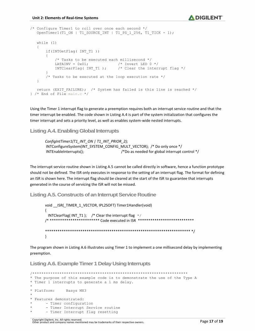
/* Configure Timer1 to roll over once each second */ OpenTimer1(T1_ON | T1_SOURCE_INT | T1_PS_1_256, T1_TICK - 1); while (1) { if(INTGetFlag( INT_T1 )) { /* Tasks to be executed each millisecond */ LATAINV = 0x01; /* Invert LED 0 */ INTClearFlag( INT_T1 ); /* Clear the interrupt flag */ } /* Tasks to be executed at the loop execution rate */ } return (EXIT_FAILURE); /* System has failed is this line is reached */ } /* End of File main.c */
Using the Timer 1 interrupt flag to generate a preemption requires both an interrupt service routine and that the
timer interrupt be enabled. The code shown in Listing A.4 is part of the system initialization that configures the
timer interrupt and sets a priority level, as well as enables system-wide nested interrupts.
Listing A.4. Enabling Global Interrupts
ConfigIntTimer1(T1_INT_ON | T1_INT_PRIOR_2); INTConfigureSystem(INT_SYSTEM_CONFIG_MULT_VECTOR); /* Do only once */ INTEnableInterrupts(); /*Do as needed for global interrupt control */
The interrupt service routine shown in Listing A.5 cannot be called directly in software, hence a function prototype
should not be defined. The ISR only executes in response to the setting of an interrupt flag. The format for defining
an ISR is shown here. The interrupt flag should be cleared at the start of the ISR to guarantee that interrupts
generated in the course of servicing the ISR will not be missed.
Listing A.5. Constructs of an Interrupt Service Routine
void __ISR(_TIMER_1_VECTOR, IPL2SOFT) Timer1Handler(void) { INTClearFlag( INT_T1 ); /* Clear the interrupt flag */ /* ************************ Code executed in ISR ***************************
********************************************************************** */ }
The program shown in Listing A.6 illustrates using Timer 1 to implement a one millisecond delay by implementing
preemption.
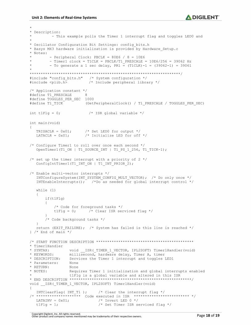
Listing A.6. Example Timer 1 Delay Using Interrupts
/********************************************************************* * The purpose of this example code is to demonstrate the use of the Type A * Timer 1 interrupts to generate a 1 ms delay. * * Platform: Basys MX3 * * Features demonstrated: * - Timer configuration * - Timer Interrupt Service routine * - Timer Interrupt flag resetting
Unit 2: Elements of Real-time Systems
Copyright Digilent, Inc. All rights reserved. Other product and company names mentioned may be trademarks of their respective owners. Page 18 of 19
* * Description: * - This example polls the Timer 1 interrupt flag and toggles LED0 and * * Oscillator Configuration Bit Settings: config_bits.h * Basys MX3 hardware initialization is provided by Hardware_Setup.c * Notes: * - Peripheral Clock: PBCLK = 80E6 / 8 = 10E6 * - Timer1 clock = T1CLK = PBCLK/T1_PRESCALE = 10E6/256 = 39062 Hz * - To generate a 1 sec delay, PR1 = (T1CLK)-1 = (39062-1) = 39061 * ********************************************************************/ #include "config_bits.h" /* System configuration */ #include <plib.h> /* Include peripheral library */ /* Application constant */ #define T1_PRESCALE 8 #define TOGGLES_PER_SEC 1000 #define T1_TICK (GetPeripheralClock() / T1_PRESCALE / TOGGLES_PER_SEC) int t1Flg = 0; /* ISR global variable */ int main(void) { TRISACLR = 0x01; /* Set LED0 for output */ LATACLR = 0x01; /* Initialize LED for off */ /* Configure Timer1 to roll over once each second */ OpenTimer1(T1_ON | T1_SOURCE_INT | T1_PS_1_256, T1_TICK-1); /* set up the timer interrupt with a priority of 2 */ ConfigIntTimer1(T1_INT_ON | T1_INT_PRIOR_2); /* Enable multi-vector interrupts */ INTConfigureSystem(INT_SYSTEM_CONFIG_MULT_VECTOR); /* Do only once */ INTEnableInterrupts(); /*Do as needed for global interrupt control */ while (1) { if(t1Flg) { /* Code for foreground tasks */ t1Flg = 0; /* Clear ISR serviced flag */ } /* Code background tasks */ } return (EXIT_FAILURE); /* System has failed is this line is reached */ } /* End of main */ /* START FUNCTION DESCRIPTION ******************************************** * Timer1Handler * SYNTAX: void __ISR(_TIMER_1_VECTOR, IPL2SOFT) Timer1Handler(void) * KEYWORDS: millisecond, hardware delay, Timer A, timer * DESCRIPTION: Services the Timer 1 interrupt and toggles LED1 * Parameters: None * RETURN: None * NOTES: Requires Timer 1 initialization and global interrupts enabled * t1Flg is a global variable and altered in this ISR * END DESCRIPTION *******************************************************/ void __ISR(_TIMER_1_VECTOR, IPL2SOFT) Timer1Handler(void) { INTClearFlag( INT_T1 ); /* Clear the interrupt flag */ /* ******************** Code executed in ISR ************************* */ LATAINV = 0x01; /* Invert LED 0 */ t1Flg = 1; /* Set Timer ISR serviced flag */

Unit 2: Elements of Real-time Systems
Copyright Digilent, Inc. All rights reserved. Other product and company names mentioned may be trademarks of their respective owners. Page 19 of 19
/* ********************************************************************* */ } /* End of File main.c */